

Buku Praktikum
97
LABORATORIUM SISTEM DISTRIBUSI TENAGA LISTRIK WORKBOOK PRAKTIKUM PROTEKSI SISTEM TENAGA LISTRIK PROTEKSI SISTEM TENAGA LISTRIK Email : [email protected] 5/26/2012 [email protected] 1
-
Upload
supriyanto-suhono -
Category
Documents
-
view
242 -
download
12
Transcript of Buku Praktikum
LABORATORIUM SISTEM DISTRIBUSI TENAGA LISTRIK
WORKBOOK
PRAKTIKUM PROTEKSI SISTEM TENAGA LISTRIK
PROTEKSI SISTEM TENAGA LISTRIK
Email : [email protected] 5/26/2012
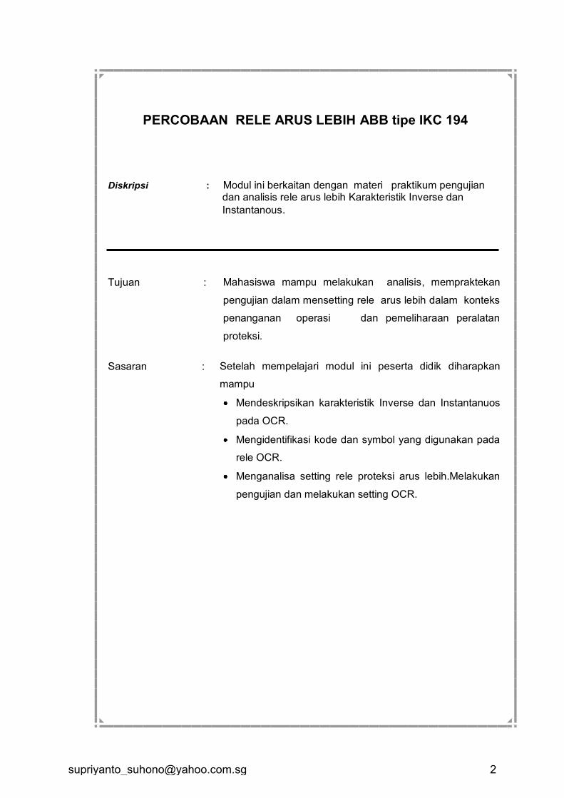
PERCOBAAN RELE ARUS LEBIH ABB tipe IKC 194 Diskripsi : Modul ini berkaitan dengan materi praktikum pengujian
dan analisis rele arus lebih Karakteristik Inverse dan
Instantanous.
Tujuan : Mahasiswa mampu melakukan analisis, mempraktekan
pengujian dalam mensetting rele arus lebih dalam konteks
penanganan operasi dan pemeliharaan peralatan
proteksi.
Sasaran : Setelah mempelajari modul ini peserta didik diharapkan
mampu
Mendeskripsikan karakteristik Inverse dan Instantanuos
pada OCR.
Mengidentifikasi kode dan symbol yang digunakan pada
rele OCR.
Menganalisa setting rele proteksi arus lebih.Melakukan
pengujian dan melakukan setting OCR.
I. Dasar Teori
Karakteristik Umum
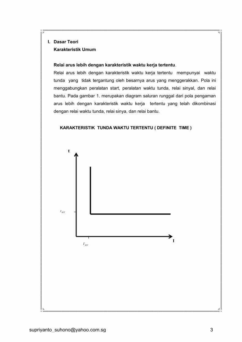
Relai arus lebih dengan karakteristik waktu kerja tertentu.
Relai arus lebih dengan karakteristik waktu kerja tertentu mempunyai waktu
tunda yang tidak tergantung oleh besarnya arus yang menggerakkan. Pola ini
menggabungkan peralatan start, peralatan waktu tunda, relai sinyal, dan relai
bantu. Pada gambar 1. merupakan diagram saluran runggal dari pola pengaman
arus lebih dengan karakteristik waktu kerja tertentu yang telah dikombinasi
dengan relai waktu tunda, relai sinya, dan relai bantu.
t
I
SETt
KARAKTERISTIK TUNDA WAKTU TERTENTU ( DEFINITE TIME )
SETI
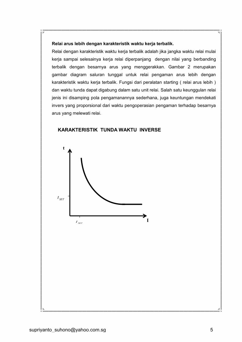
Relai arus lebih dengan karakteristik waktu kerja terbalik.
Relai dengan karakteristik waktu kerja terbalik adalah jika jangka waktu relai mulai
kerja sampai selesainya kerja relai diperpanjang dengan nilai yang berbanding
terbalik dengan besarnya arus yang menggerakkan. Gambar 2 merupakan
gambar diagram saluran tunggal untuk relai pengaman arus lebih dengan
karakteristik waktu kerja terbalik. Fungsi dari peralatan starting ( relai arus lebih )
dan waktu tunda dapat digabung dalam satu unit relai. Salah satu keunggulan relai
jenis ini disamping pola pengamanannya sederhana, juga keuntungan mendekati
invers yang proporsional dari waktu pengoperasian pengaman terhadap besarnya
arus yang melewati relai.
t
I
SETt
KARAKTERISTIK TUNDA WAKTU INVERSE
SETI
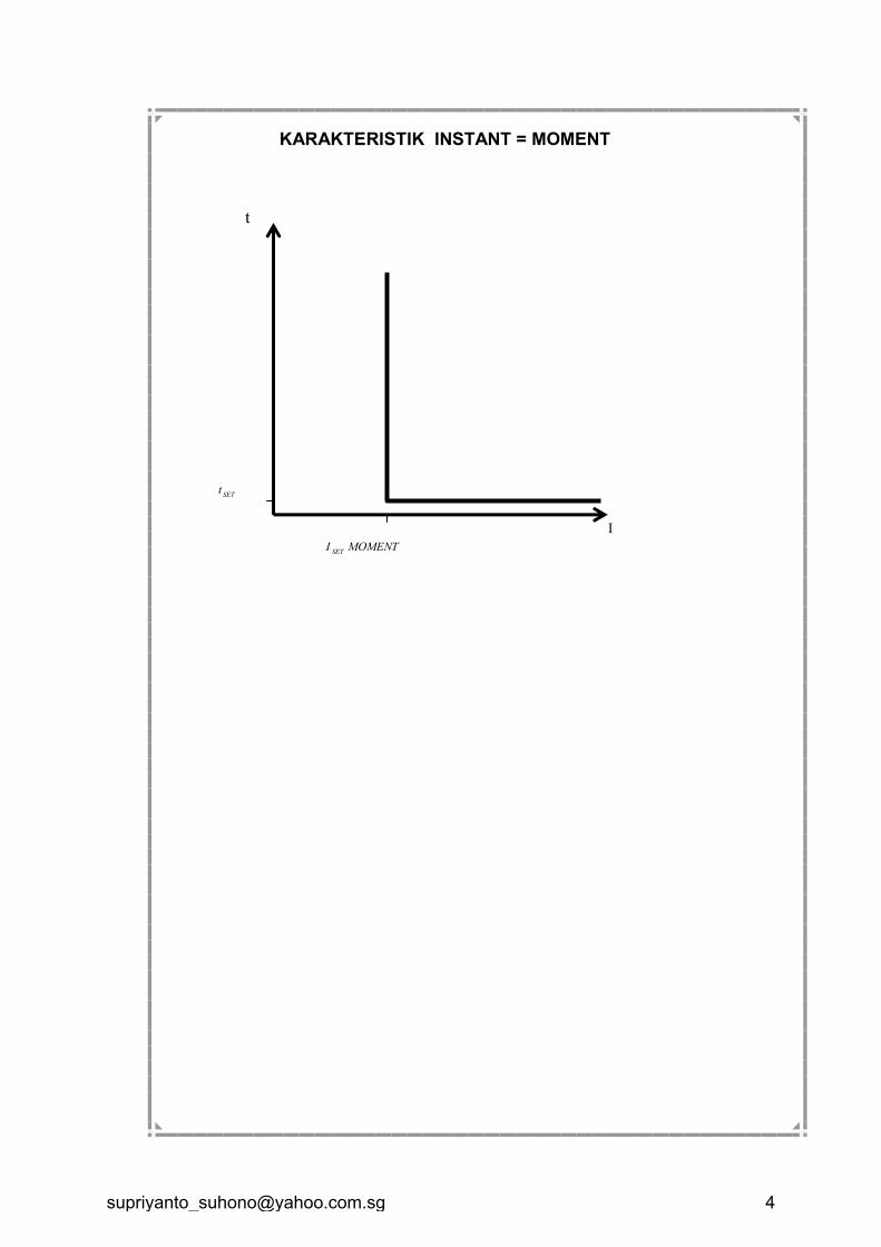
t
I
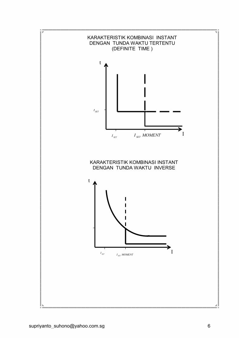
KARAKTERISTIK KOMBINASI INSTANT DENGAN TUNDA WAKTU INVERSE
SETI
MOMENTISET
t
I
SETt
KARAKTERISTIK KOMBINASI INSTANT DENGAN TUNDA WAKTU TERTENTU
(DEFINITE TIME )
SETI MOMENTI
SET
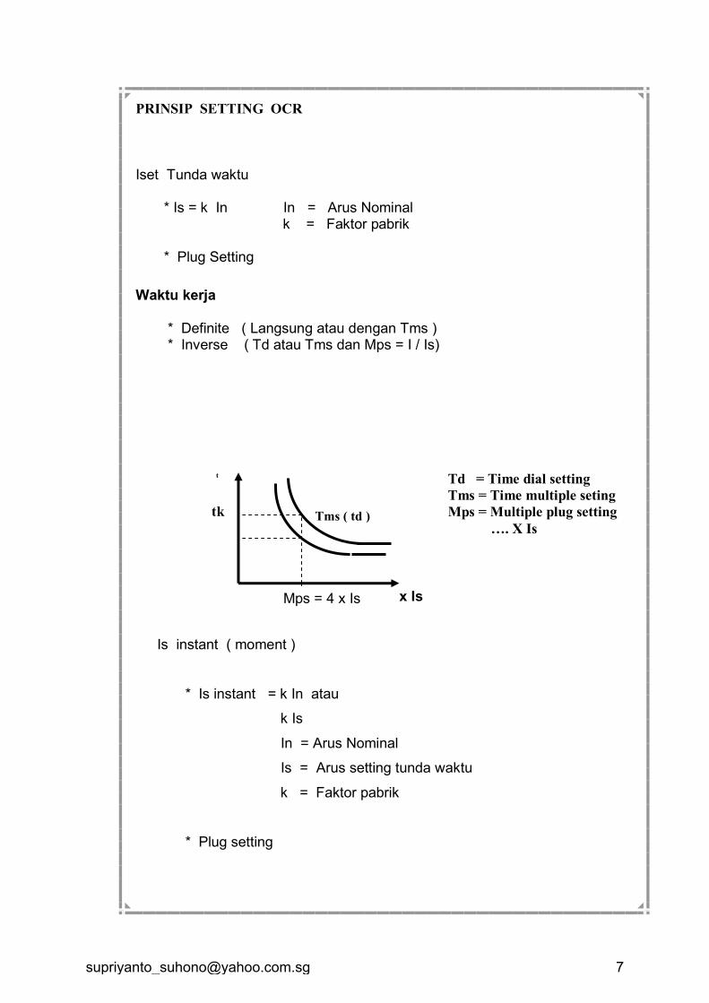
PRINSIP SETTING OCR
Iset Tunda waktu * Is = k In In = Arus Nominal k = Faktor pabrik * Plug Setting
Waktu kerja * Definite ( Langsung atau dengan Tms ) * Inverse ( Td atau Tms dan Mps = I / Is)
Is instant ( moment )
* Is instant = k In atau
k Is
In = Arus Nominal
Is = Arus setting tunda waktu
k = Faktor pabrik
* Plug setting
Tms ( td )
x Is Mps = 4 x Is
t
tk
Td = Time dial setting
Tms = Time multiple seting
Mps = Multiple plug setting
…. X Is
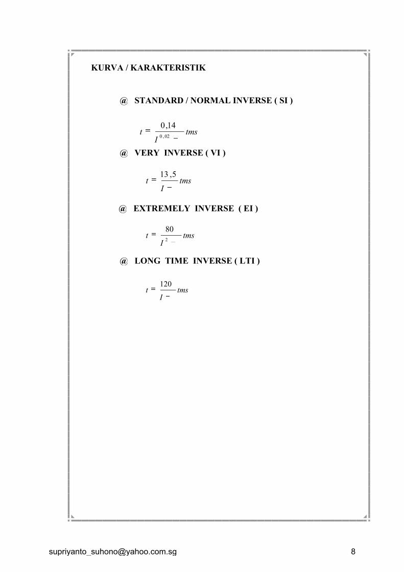
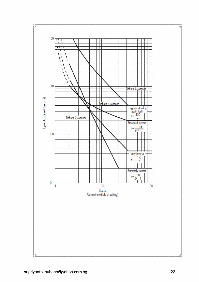
KURVA / KARAKTERISTIK
@ STANDARD / NORMAL INVERSE ( SI )
tmsI
t1
14,0
02,0
@ VERY INVERSE ( VI )
tmsI
t1
5,13
@ EXTREMELY INVERSE ( EI )
tmsI
t1
80
2
@ LONG TIME INVERSE ( LTI )
tmsI
t1
120
R
T E
PMT
CT
P1
P2
S1
S2
OCR
OCR GFR
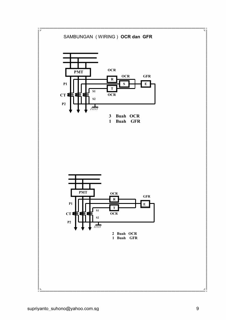
2 Buah OCR
1 Buah GFR
R
S
T
E
CT
P1
P2
S1
S2
OCR
OCR
GFR OCR
SAMBUNGAN ( WIRING ) OCR dan GFR
3 Buah OCR
1 Buah GFR
PMT
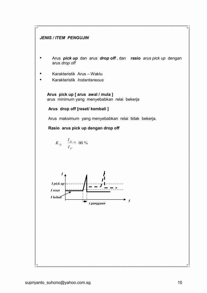
JENIS / ITEM PENGUJIN
• Arus pick up dan arus drop off , dan rasio arus pick up dengan arus drop off
• Karakteristik Arus – Waktu
• Karakteristik Instantaneous
Arus pick up [ arus awal / mula ] arus minimum yang menyebabkan relai bekerja
Arus drop off [reset/ kembali ]
Arus maksimum yang menyebabkan relai tidak bekerja.
Rasio arus pick up dengan drop off
I
t
I pick up
I reset
I beban
t gangguan
%100
P
D
DI
IK
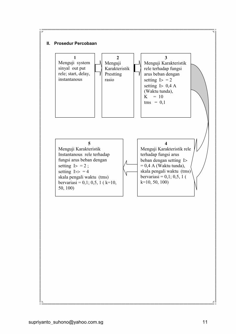
II. Prosedur Percobaan
3
Menguji Karakteristik
rele terhadap fungsi
arus beban dengan
setting I = 2
setting I 0,4 A (Waktu tunda),
K = 10
tms = 0,1
2
Menguji
Karakteristik
Prestting
rasio
1
Menguji system
sinyal out put
rele; start, delay,
instantanous
4
Menguji Karakteristik rele
terhadap fungsi arus
beban dengan setting I = 0,4 A (Waktu tunda),
skala pengali waktu (tms)
bervariasi = 0,1; 0,5, 1 (
k=10, 50, 100)
5
Menguji Karakteristik
Instantanous rele terhadap
fungsi arus beban dengan
setting I = 2 ;
setting I = 4
skala pengali waktu (tms)
bervariasi = 0,1; 0,5, 1 ( k=10,
50, 100)
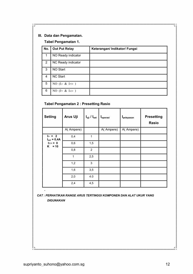
III. Data dan Pengamatan.
Tabel Pengamatan 1.
No. Out Put Relay Keterangan/ Indikator/ Fungsi
1 NO Ready indicator
2 NC Ready indicator
3 NO Start
4 NC Start
5 NO (I & I )
6 NO (I & I )
Tabel Pengamatan 2 : Presetting Rasio
Setiing
Arus Uji
Iuji / Iset
Ioperasi
Ipelepasan
Presetting
Rasio
A( Ampere) A( Ampere) A( Ampere)
I = 2 Iset = 0,4A
I = 0 K = 10
0,4 1
0,6 1,5
0,8 2
1 2,5
1,2 3
1,6 3,5
2,0 4.0
2,4 4,5
.
CAT : PERHATIKAN RANGE ARUS TERTINGGI KOMPONEN DAN ALAT UKUR YANG
DIGUNAKAN
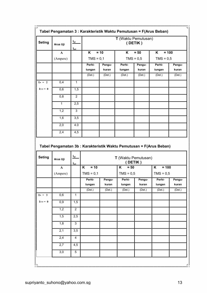
Tabel Pengamatan 3 : Karakteristik Waktu Pemutusan = F(Arus Beban)
Seting
Arus Uji
Iuji
Iset
T (Waktu Pemutusan) ( DETIK )
A
(Ampere)
K = 10
TMS = 0,1
K = 50
TMS = 0,5
K = 100
TMS = 0,5
Perhi-
tungan
Pengu-
kuran
Perhi-
tungan
Pengu-
kuran
Perhi-
tungan
Pengu-
kuran
(Det.) (Det.) (Det.) (Det.) (Det.) (Det.)
I = 2
I = 0
0,4 1
0,6 1,5
0,8 2
1 2,5
1,2 3
1,6 3,5
2,0 4.0
2,4 4,5
Tabel Pengamatan 3b : Karakteristik Waktu Pemutusan = F(Arus Beban)
Seting
Arus Uji
Iuji
Iset
T (Waktu Pemutusan)
( DETIK )
A
(Ampere)
K = 10
TMS = 0,1
K = 50
TMS = 0,5
K = 100
TMS = 0,5
Perhi-
tungan
Pengu-
kuran
Perhi-
tungan
Pengu-
kuran
Perhi-
tungan
Pengu-
kuran
(Det.) (Det.) (Det.) (Det.) (Det.) (Det.)
I = 3
I = 0
0,6 1
0,9 1,5
1,2 2
1,5 2,5
1,8 3
2,1 3,5
2,4 4
2,7 4,5
3,0 5
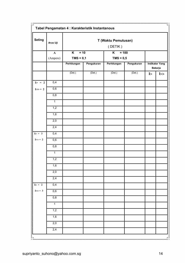
Tabel Pengamatan 4 : Karakteristik Instantanous
Seting
Arus Uji
T (Waktu Pemutusan)
( DETIK )
A
(Ampere)
K = 10
TMS = 0,1
K = 100
TMS = 0,5
Perhitungan Pengukuran Perhitungan Pengukuran Indikator Yang
Bekerja
(Det.) (Det.) (Det.) (Det.) I
I
I = 2
I = 2
0,4
0,6
0,8
1
1,2
1,6
2,0
2,4
I = 3
I = 2
0,4
0,6
0,8
1
1,2
1,6
2,0
2,4
I = 2
I = 3
0,4
0,6
0,8
1
1,2
1,6
2,0
2,4
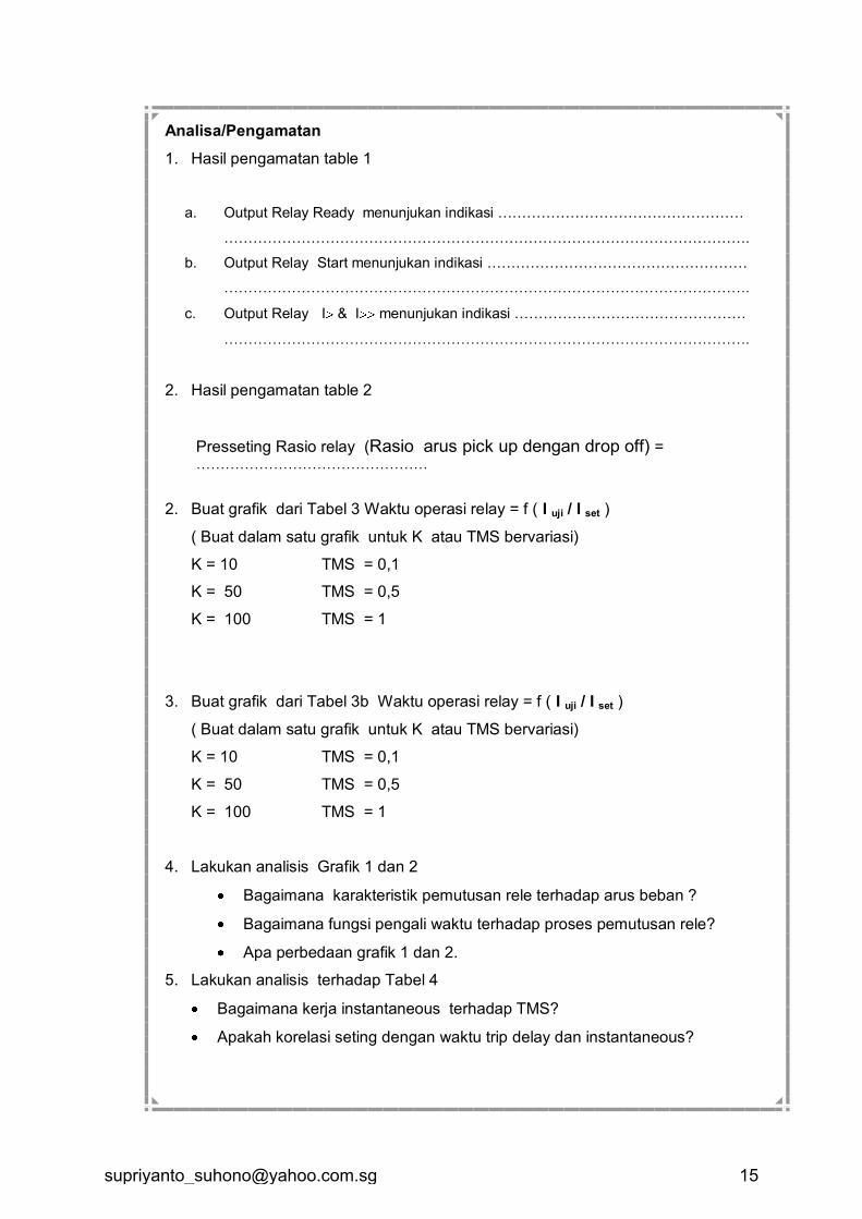
Analisa/Pengamatan
1. Hasil pengamatan table 1
a. Output Relay Ready menunjukan indikasi ……………………………………………
……………………………………………………………………………………………….
b. Output Relay Start menunjukan indikasi ………………………………………………
……………………………………………………………………………………………….
c. Output Relay I & I menunjukan indikasi …………………………………………
……………………………………………………………………………………………….
2. Hasil pengamatan table 2
Presseting Rasio relay (Rasio arus pick up dengan drop off) = …………………………………………
2. Buat grafik dari Tabel 3 Waktu operasi relay = f ( I uji / I set )
( Buat dalam satu grafik untuk K atau TMS bervariasi)
K = 10 TMS = 0,1
K = 50 TMS = 0,5
K = 100 TMS = 1
3. Buat grafik dari Tabel 3b Waktu operasi relay = f ( I uji / I set )
( Buat dalam satu grafik untuk K atau TMS bervariasi)
K = 10 TMS = 0,1
K = 50 TMS = 0,5
K = 100 TMS = 1
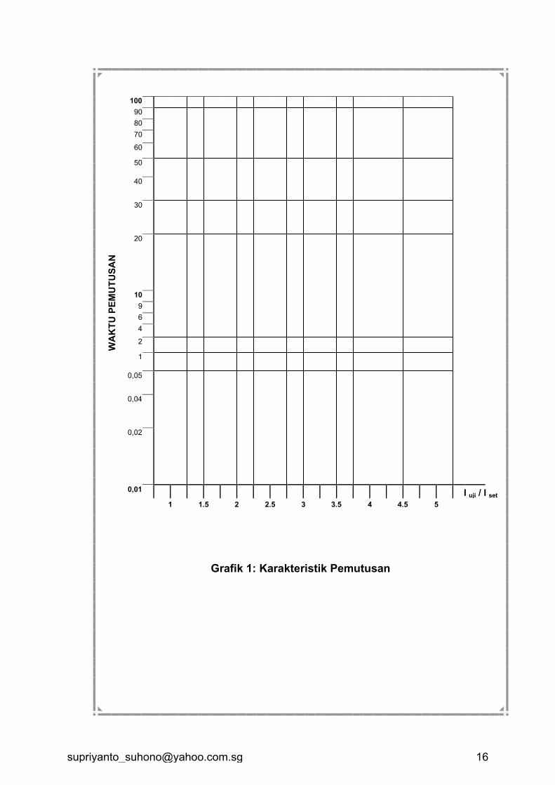
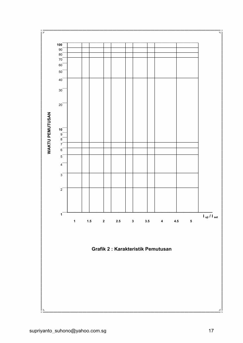
4. Lakukan analisis Grafik 1 dan 2
Bagaimana karakteristik pemutusan rele terhadap arus beban ?
Bagaimana fungsi pengali waktu terhadap proses pemutusan rele?
Apa perbedaan grafik 1 dan 2.
5. Lakukan analisis terhadap Tabel 4
Bagaimana kerja instantaneous terhadap TMS?
Apakah korelasi seting dengan waktu trip delay dan instantaneous?
WA
KT
U P
EM
UT
US
AN
100 90 80 70 60
50
40
30
20
10 9 6 4 2
1
0,05
0,04
0,02
0,01 I uji / I set
1 1.5 2 2.5 3 3.5 4 4.5 5
Grafik 1: Karakteristik Pemutusan
WA
KT
U P
EM
UT
US
AN
100
90 80 70 60
50
40
30
20
10 9 8 7 6
5
4
3
2
1 I uji / I set
1 1.5 2 2.5 3 3.5 4 4.5 5
Grafik 2 : Karakteristik Pemutusan
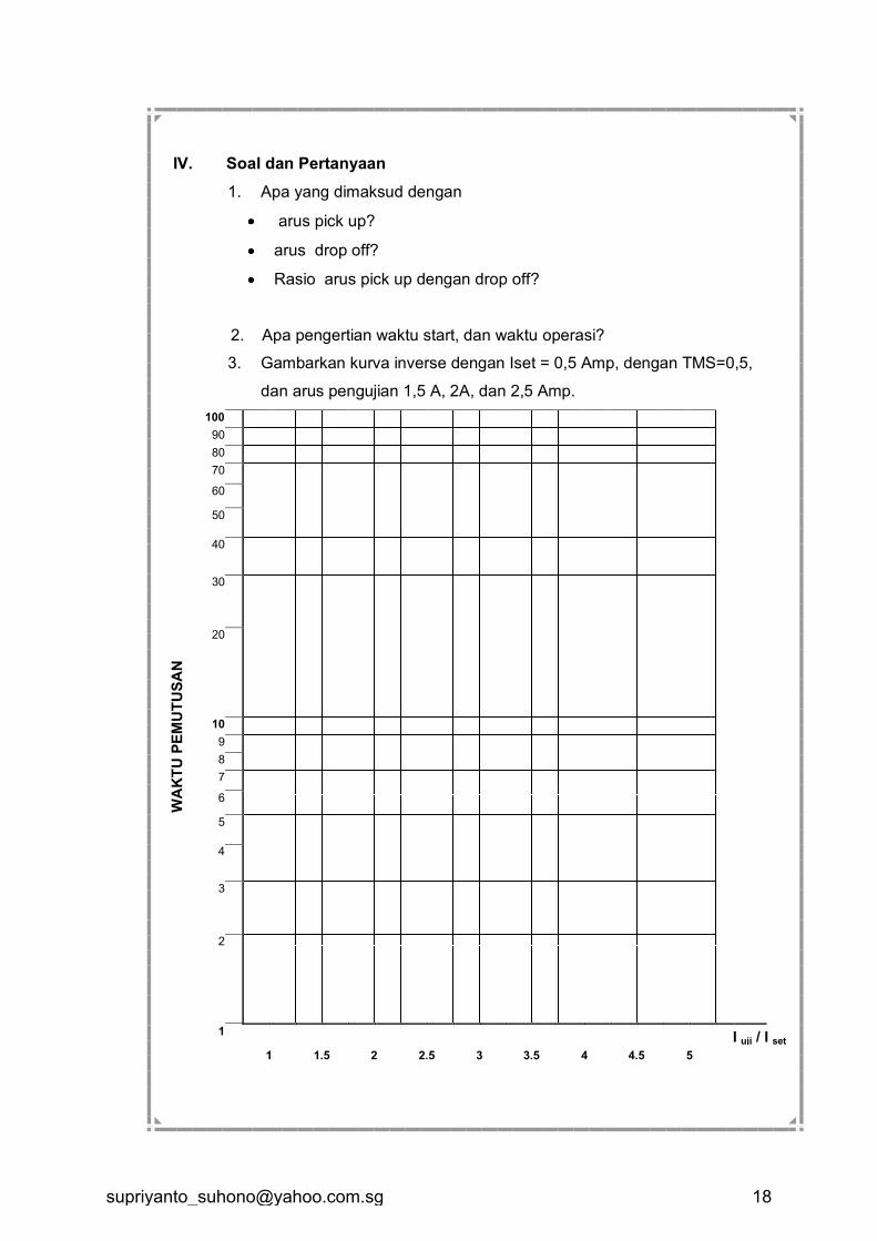
IV. Soal dan Pertanyaan
1. Apa yang dimaksud dengan
arus pick up?
arus drop off?
Rasio arus pick up dengan drop off?
2. Apa pengertian waktu start, dan waktu operasi?
3. Gambarkan kurva inverse dengan Iset = 0,5 Amp, dengan TMS=0,5,
dan arus pengujian 1,5 A, 2A, dan 2,5 Amp.
WA
KT
U P
EM
UT
US
AN
100 90 80 70 60
50
40
30
20
10 9 8 7 6
5
4
3
2
1 I uji / I set
1 1.5 2 2.5 3 3.5 4 4.5 5
PERCOBAAN RELE ARUS LEBIH DAN GANGGUAN TANAH MCGG52
Diskripsi : Modul ini berkaitan dengan materi praktikum pengujian
dan analisis rele arus lebih pada berbagai Karakteristik
Inverse , definite dan Instantanous.
Tujuan : Mahasiswa mampu melakukan analisis, mempraktekan
pengujian dalam mensetting rele arus lebih dalam konteks
penanganan operasi dan pemeliharaan peralatan proteksi.
Sasaran : Setelah mempelajari modul ini peserta didik diharapkan
mampu
Mendeskripsikan Beragam karakteristik Inverse dan
Instantanuos pada OCR.
Menganalisa setting rele proteksi arus lebih.Melakukan
pengujian dan melakukan setting OCR.
I. Dasar Teori
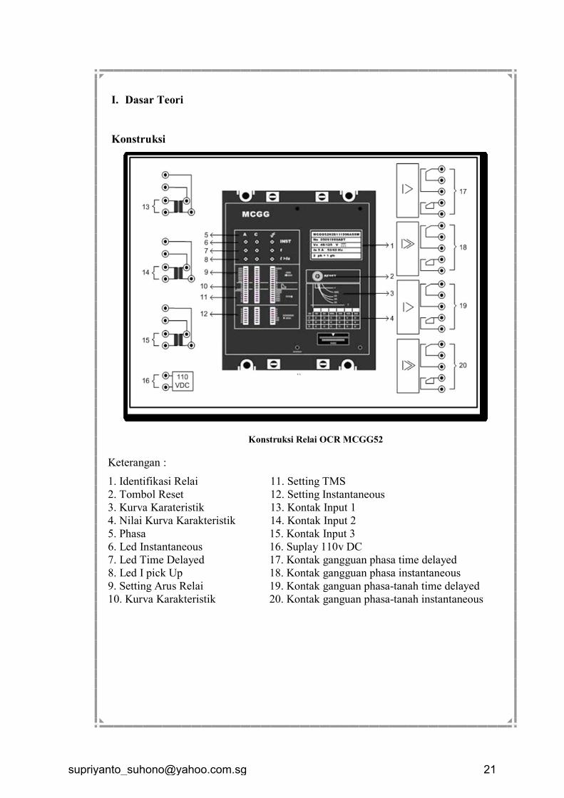
Konstruksi
Konstruksi Relai OCR MCGG52
Keterangan :
1. Identifikasi Relai 11. Setting TMS
2. Tombol Reset 12. Setting Instantaneous
3. Kurva Karateristik 13. Kontak Input 1
4. Nilai Kurva Karakteristik 14. Kontak Input 2
5. Phasa 15. Kontak Input 3
6. Led Instantaneous 16. Suplay 110v DC
7. Led Time Delayed 17. Kontak gangguan phasa time delayed
8. Led I pick Up 18. Kontak gangguan phasa instantaneous
9. Setting Arus Relai 19. Kontak ganguan phasa-tanah time delayed
10. Kurva Karakteristik 20. Kontak ganguan phasa-tanah instantaneous
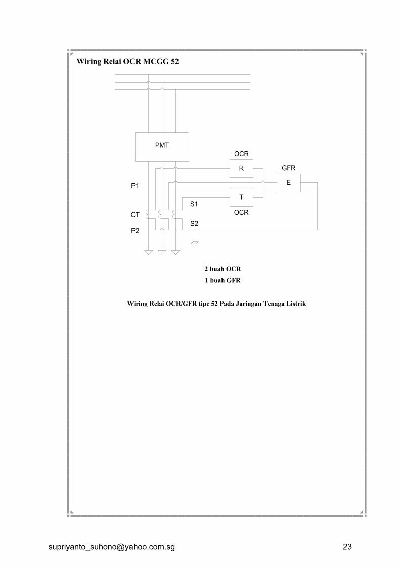
Wiring Relai OCR MCGG 52
PMT
R
E
T
OCR
OCR
GFR
P1
P2
CT
S1
S2
2 buah OCR
1 buah GFR
Wiring Relai OCR/GFR tipe 52 Pada Jaringan Tenaga Listrik
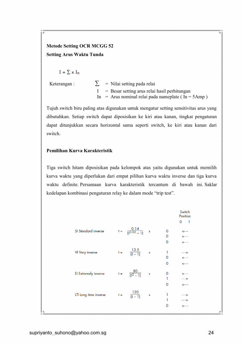
Metode Setting OCR MCGG 52
Setting Arus Waktu Tunda
Keterangan : = Nilai setting pada relai
I = Besar setting arus relai hasil perhitungan
In = Arus nominal relai pada nameplate ( In = 5Amp )
Tujuh switch biru paling atas digunakan untuk mengatur setting sensitivitas arus yang
dibutuhkan. Setiap switch dapat diposisikan ke kiri atau kanan, tingkat pengaturan
dapat ditunjukkan secara horizontal sama seperti switch, ke kiri atau kanan dari
switch.
Pemilihan Kurva Karakteristik
Tiga switch hitam diposisikan pada kelompok atas yaitu digunakan untuk memilih
kurva waktu yang diperlukan dari empat pilihan kurva waktu inverse dan tiga kurva
waktu definite. Persamaan kurva karakteristik tercantum di bawah ini. Saklar
kedelapan kombinasi pengaturan relay ke dalam mode “trip test”.
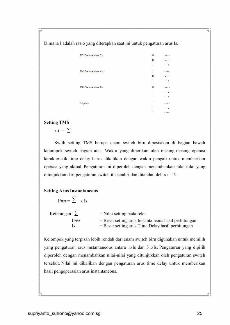
Dimana I adalah rasio yang diterapkan saat ini untuk pengaturan arus Is.
Setting TMS
x t =
Swith setting TMS berupa enam switch biru diposisikan di bagian bawah
kelompok switch bagian atas. Waktu yang diberikan oleh masing-masing operasi
karakteristik time delay harus dikalikan dengan waktu pengali untuk memberikan
operasi yang aktual. Pengaturan ini diperoleh dengan menambahkan nilai-nilai yang
ditunjukkan dari pengaturan switch itu sendiri dan ditandai oleh x t = Σ.
Setting Arus Instantaneous
Iinst = x Is
Keterangan :
= Nilai setting pada relai
Iinst = Besar setting arus Instantaneous hasil perhitungan
Is = Besar setting arus Time Delay hasil perhitungan
Kelompok yang terpisah lebih rendah dari enam switch biru digunakan untuk memilih
yang pengaturan arus instantaneous antara 1xIs dan 31xIs. Pengaturan yang dipilih
diperoleh dengan menambahkan nilai-nilai yang ditunjukkan oleh pengaturan switch
tersebut. Nilai ini dikalikan dengan pengaturan arus time delay untuk memberikan
hasil pengoperasian arus instantaneous.
Jika elemen instantaneous tidak diperlukan, maka semua switch harus diset ke kiri (
penunjukan nol ), atau saklar bawah harus diset ke kanan ( penunjukan tak hingga).
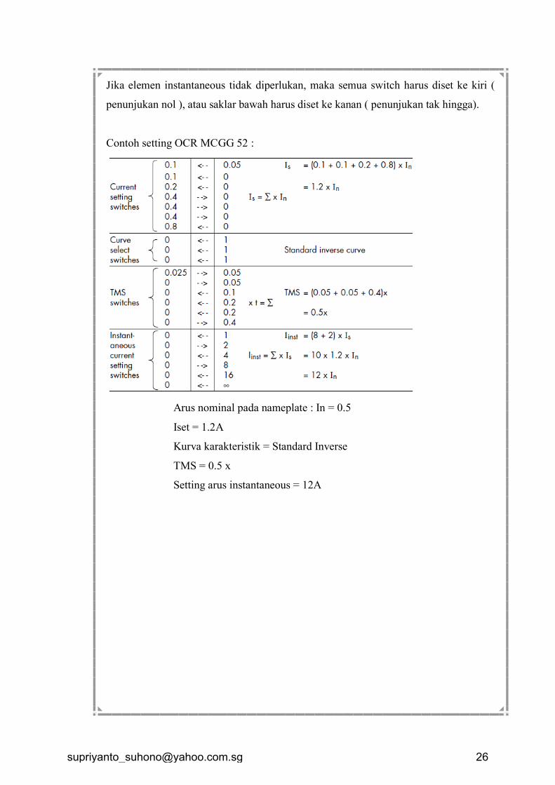
Contoh setting OCR MCGG 52 :
Arus nominal pada nameplate : In = 0.5
Iset = 1.2A
Kurva karakteristik = Standard Inverse
TMS = 0.5 x
Setting arus instantaneous = 12A
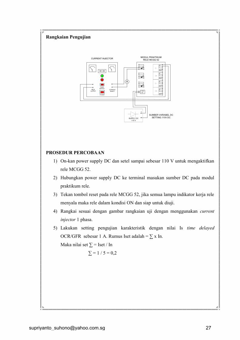
Rangkaian Pengujian
110V
DC
SUPPLY DC
110 V
_
+
MODUL PRAKTIKUM
RELE MCGG 52
SUMBER VARIABEL DC
SETTING 110V DC
A V00 :00
CURRENT
INJECT
RELE
OUTPUT
CURRENT INJECTOR
POWER
TIMER
SWITCH
A
PROSEDUR PERCOBAAN
1) On-kan power supply DC dan setel sampai sebesar 110 V untuk mengaktifkan
rele MCGG 52.
2) Hubungkan power supply DC ke terminal masukan sumber DC pada modul
praktikum rele.
3) Tekan tombol reset pada rele MCGG 52, jika semua lampu indikator kerja rele
menyala maka rele dalam kondisi ON dan siap untuk diuji.
4) Rangkai sesuai dengan gambar rangkaian uji dengan menggunakan current
injector 1 phasa.
5) Lakukan setting pengujian karakteristik dengan nilai Is time delayed
OCR/GFR sebesar 1 A. Rumus Iset adalah = ∑ x In.
Maka nilai set ∑ = Iset / In
∑ = 1 / 5 = 0,2
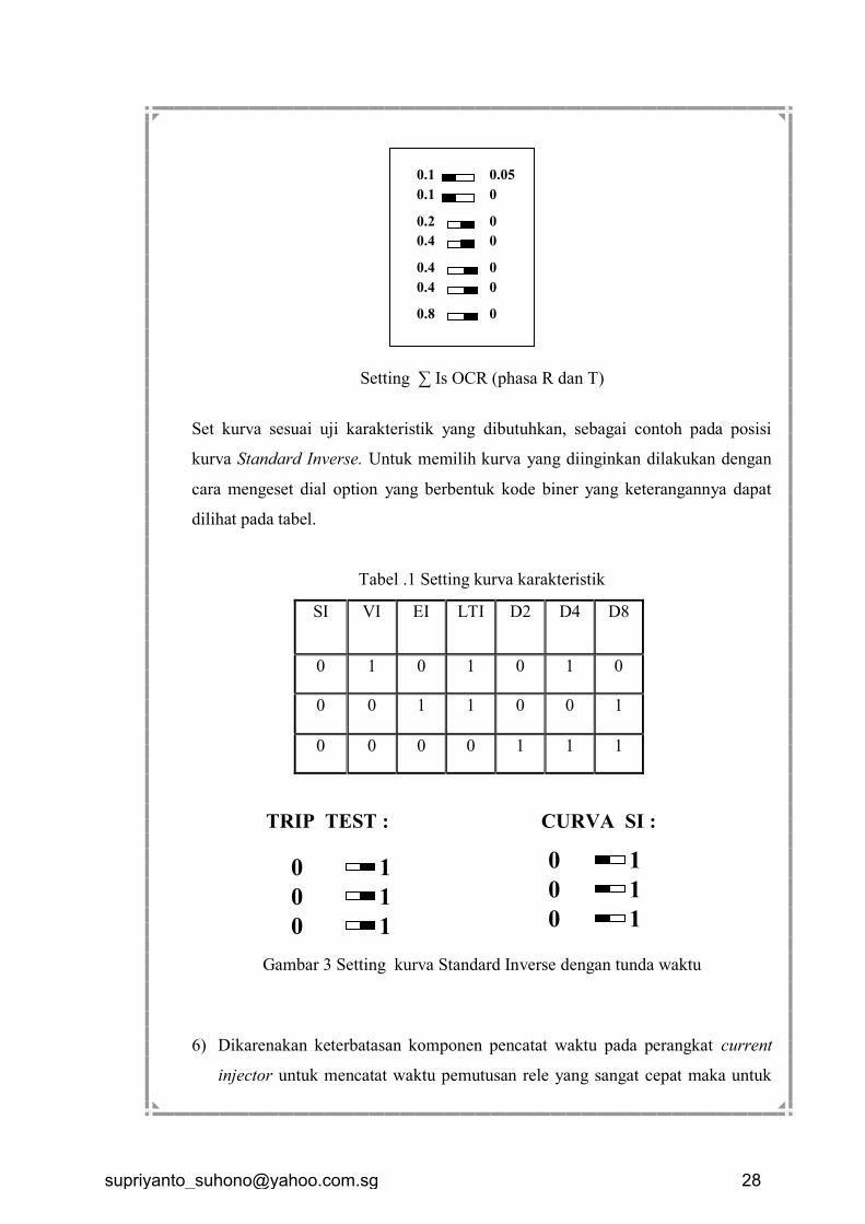
Setting ∑ Is OCR (phasa R dan T)
Set kurva sesuai uji karakteristik yang dibutuhkan, sebagai contoh pada posisi
kurva Standard Inverse. Untuk memilih kurva yang diinginkan dilakukan dengan
cara mengeset dial option yang berbentuk kode biner yang keterangannya dapat
dilihat pada tabel.
Tabel .1 Setting kurva karakteristik
SI VI EI LTI D2 D4 D8
0 1 0 1 0 1 0
0 0 1 1 0 0 1
0 0 0 0 1 1 1
Gambar 3 Setting kurva Standard Inverse dengan tunda waktu
6) Dikarenakan keterbatasan komponen pencatat waktu pada perangkat current
injector untuk mencatat waktu pemutusan rele yang sangat cepat maka untuk
1
0 1
1
1
0
0
0
1
1 0
0
TRIP TEST : CURVA SI :
0.1
0.1
0.2
0.4
0.4
0.4
0.8
0.05
0
0
0
0
0
0
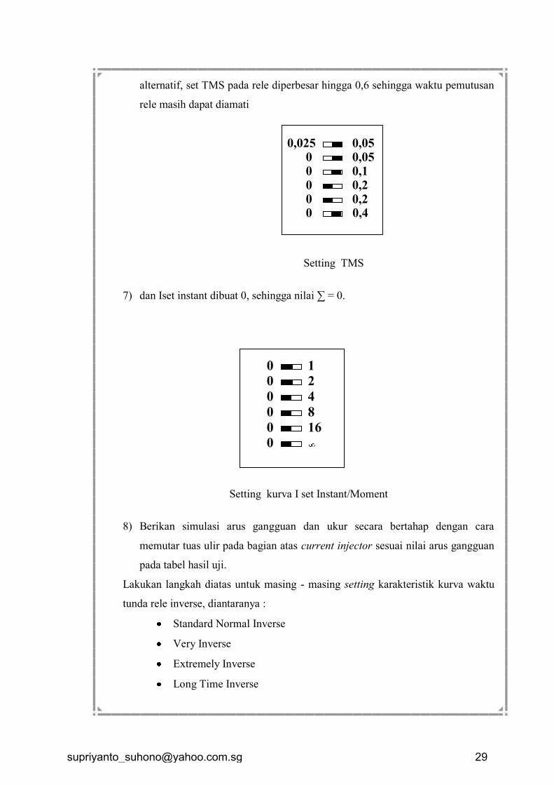
alternatif, set TMS pada rele diperbesar hingga 0,6 sehingga waktu pemutusan
rele masih dapat diamati
Setting TMS
7) dan Iset instant dibuat 0, sehingga nilai ∑ = 0.
Setting kurva I set Instant/Moment
8) Berikan simulasi arus gangguan dan ukur secara bertahap dengan cara
memutar tuas ulir pada bagian atas current injector sesuai nilai arus gangguan
pada tabel hasil uji.
Lakukan langkah diatas untuk masing - masing setting karakteristik kurva waktu
tunda rele inverse, diantaranya :
Standard Normal Inverse
Very Inverse
Extremely Inverse
Long Time Inverse
2
4
1
8
16
0
0
0
0
0
0
0,025 0,05 0,05 0,1 0,2 0,2 0,4
0 0
0 0 0
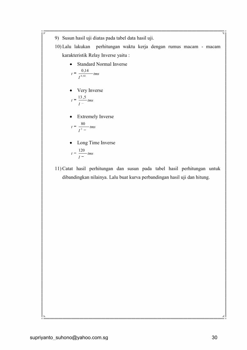
9) Susun hasil uji diatas pada tabel data hasil uji.
10) Lalu lakukan perhitungan waktu kerja dengan rumus macam - macam
karakteristik Relay Inverse yaitu :
Standard Normal Inverse
Very Inverse
Extremely Inverse
Long Time Inverse
11) Catat hasil perhitungan dan susun pada tabel hasil perhitungan untuk
dibandingkan nilainya. Lalu buat kurva perbandingan hasil uji dan hitung.
tmsI
t1
14,0
02,0
tmsI
t1
5,13
tmsI
t1
80
2
tmsI
t1
120
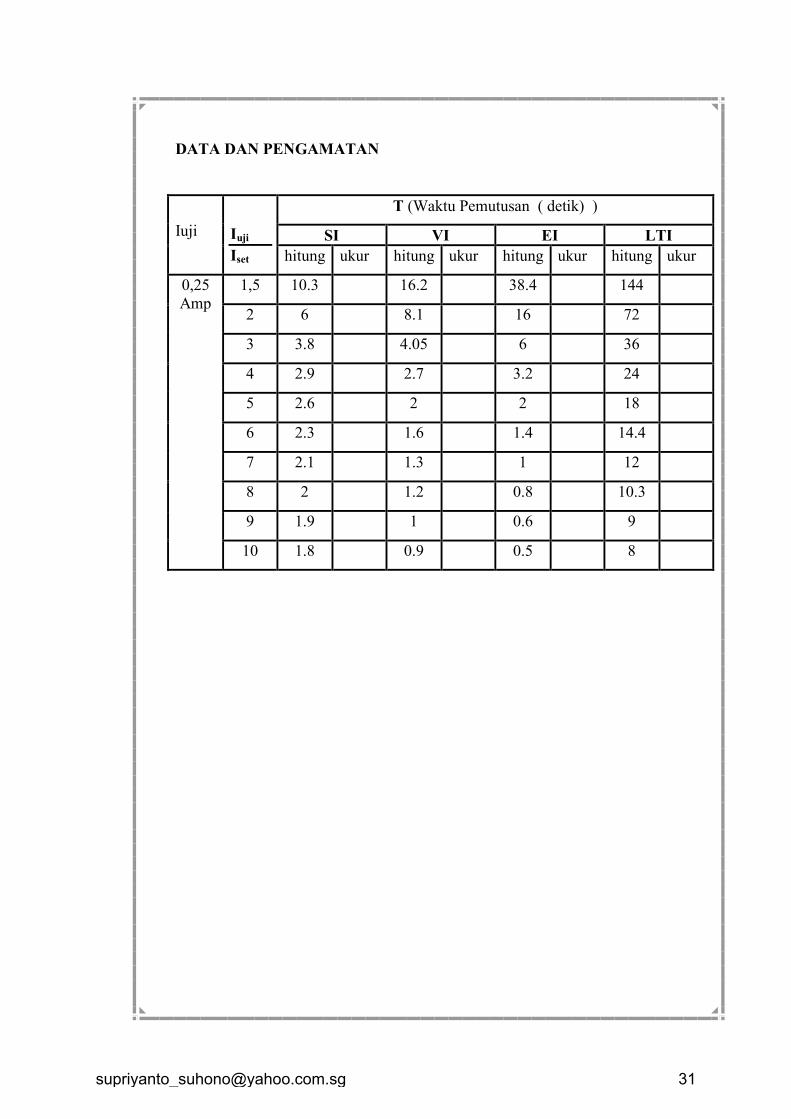
DATA DAN PENGAMATAN
Iuji
Iuji
Iset
T (Waktu Pemutusan ( detik) )
SI VI EI LTI
hitung ukur hitung ukur hitung ukur hitung ukur
0,25
Amp
1,5 10.3 16.2 38.4 144
2 6 8.1 16 72
3 3.8 4.05 6 36
4 2.9 2.7 3.2 24
5 2.6 2 2 18
6 2.3 1.6 1.4 14.4
7 2.1 1.3 1 12
8 2 1.2 0.8 10.3
9 1.9 1 0.6 9
10 1.8 0.9 0.5 8
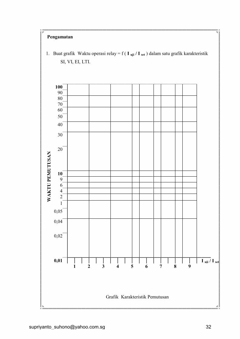
Pengamatan
1. Buat grafik Waktu operasi relay = f ( I uji / I set ) dalam satu grafik karakteristik
SI, VI, EI, LTI.
WA
KT
U P
EM
UT
US
AN
100
90
80
70
60
50
40
30
20
10
9
6
4
2
1
0,05
0,04
0,02
0,01 I uji / I set
1 2 3 4 5 6 7 8 9
Grafik Karakteristik Pemutusan
SIMULASI PROTEKSI PENYULANG
Diskripsi : Modul ini berkaitan dengan materi praktikum pengujian
dan analisis koordinasi proteksi pada penyulang.
Tujuan : Mahasiswa mampu melakukan analisis, mempraktekan
pengujian dalam mensetting rele arus lebih dalam konteks
penanganan operasi dan pemeliharaan peralatan proteksi
penyulang .
Sasaran : Setelah mempelajari modul ini peserta didik diharapkan
mampu
1. Dapat merangkai simulasi gangguan yang mungkin
terjadi pada jaringan distribusi tenaga listrik.
2. Dapat merangkai rangkaian simulasi kerja relai MCGG
52 pada jaringan distribusi tenaga listrik.
3. Mengetahui cara untuk menentukan setting relai.
4. Menganalisa kerja relai pada simulasi kerja saat terjadi
gangguan pada jaringan distribusi tenaga listrik.
I. Dasar Teori
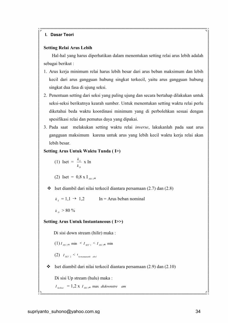
Setting Relai Arus Lebih
Hal-hal yang harus diperhatikan dalam menentukan setting relai arus lebih adalah
sebagai berikut :
1. Arus kerja minimum relai harus lebih besar dari arus beban maksimum dan lebih
kecil dari arus gangguan hubung singkat terkecil, yaitu arus gangguan hubung
singkat dua fasa di ujung seksi.
2. Penentuan setting dari seksi yang paling ujung dan secara bertahap dilakukan untuk
seksi-seksi berikutnya kearah sumber. Untuk menentukan setting waktu relai perlu
diketahui beda waktu koordinasi minimum yang di perbolehkan sesuai dengan
spesifikasi relai dan pemutus daya yang dipakai.
3. Pada saat melakukan setting waktu relai inverse, lakukanlah pada saat arus
gangguan maksimum karena untuk arus yang lebih kecil waktu kerja relai akan
lebih besar.
Setting Arus Untuk Waktu Tunda ( I>)
(1) Iset = D
S
k
k x In
(2) Iset = 0,8 x I2HS
Iset diambil dari nilai terkecil diantara persamaan (2.7) dan (2.8)
Sk = 1,1 1,2 In = Arus beban nominal
Dk > 80 %
Setting Arus Untuk Instantaneous ( I>>)
Di sisi down stream (hilir) maka :
(1) minmin312 HSSETHS
III
(2) abelkemampuankSET
II2
Iset diambil dari nilai terkecil diantara persamaan (2.9) dan (2.10)
Di sisi Up stream (hulu) maka :
SetInstI = 1,2 x amdidownstreI
HSmax
3
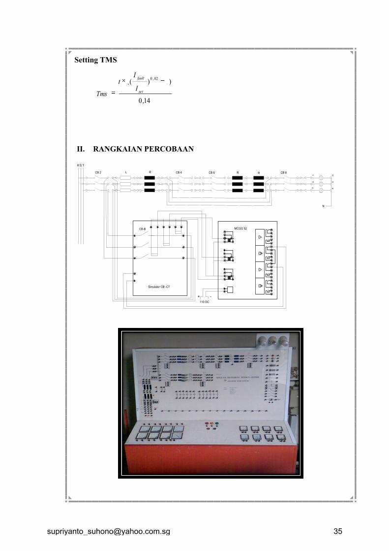
Setting TMS
14,0
)1)((02,0
set
fault
I
It
Tms
II. RANGKAIAN PERCOBAAN
MCGG 52
Simulator CB -CT
+ -
110 DC
R S T
CB 2 CB 4 CB 6 CB 8r1 r2
r3 r4
r5 r6
L R R R
CB-B
N
CB3
CB5
CB4
CB6
N
CB7 CB8r1 r2
r3 r4
r5 r6
c1 c2
c3 c4
c5 c6
Gardu
Distribusi TR
NPE
20 0 100
CB1
380
420400
360340220
127
CB 2
z1 z2
z3 z4
z5 z6
R S T
220
L
Gard
u D
istr
ibusi T
M
KONTAKTOR
220 Vac
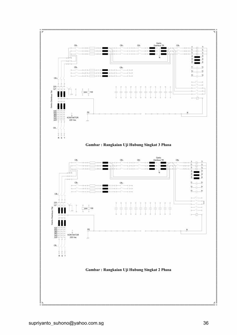
Gambar : Rangkaian Uji Hubung Singkat 3 Phasa
CB3
CB5
CB4
CB6
N
CB7 CB8r1 r2
r3 r4
r5 r6
c1 c2
c3 c4
c5 c6
Gardu
Distribusi TR
NPE
20 0 100
CB1
380
420400
360340220
127
CB 2
z1 z2
z3 z4
z5 z6
R S T
220
L
Gard
u D
istr
ibusi T
M
KONTAKTOR
220 Vac
Gambar : Rangkaian Uji Hubung Singkat 2 Phasa
CB3
CB5
CB4
CB6
N
CB7 CB8r1 r2
r3 r4
r5 r6
c1 c2
c3 c4
c5 c6
Gardu
Distribusi TR
NPE
20 0 100
CB1
380
420400
360340220
127
CB 2
z1 z2
z3 z4
z5 z6
R S T
220
L
Gard
u D
istr
ibusi T
M
KONTAKTOR
220 Vac
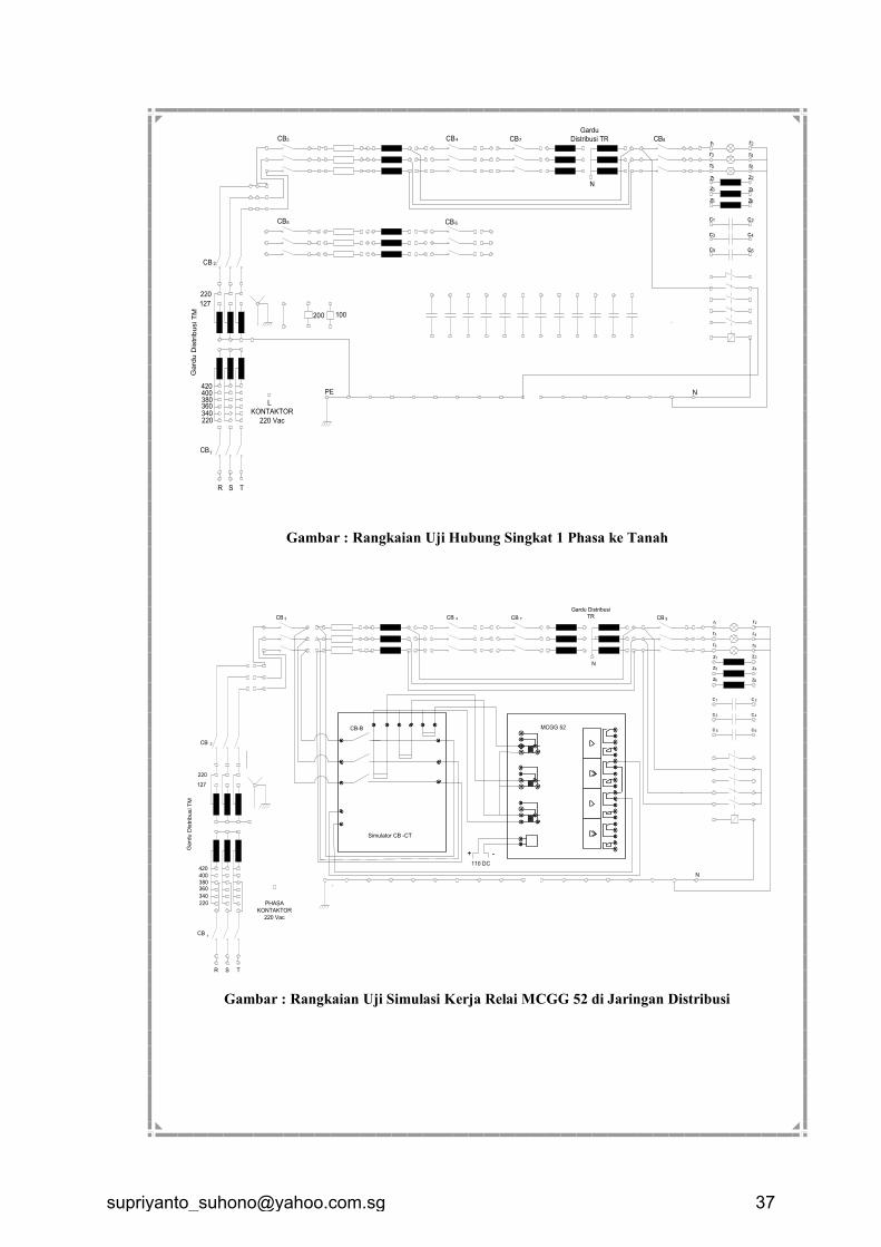
Gambar : Rangkaian Uji Hubung Singkat 1 Phasa ke Tanah
CB 3 CB 4
N
CB 7 CB 8r1 r2
r3 r4
r5 r6
c1 c 2
c3 c 4
c 5 c 6
Gardu Distribusi
TR
N
`
CB1
380
420
400
360
340
220
127
CB 2
z1 z2
z3 z4
z5 z6
R S T
220
Gard
u D
istr
ibusi T
M
PHASA
KONTAKTOR
220 Vac
MCGG 52
Simulator CB -CT
+ -
110 DC
CB-B
Gambar : Rangkaian Uji Simulasi Kerja Relai MCGG 52 di Jaringan Distribusi
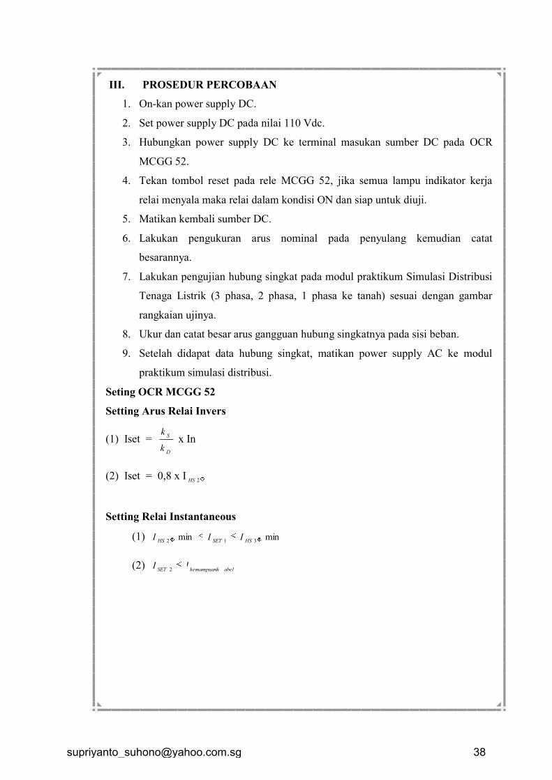
III. PROSEDUR PERCOBAAN
1. On-kan power supply DC.
2. Set power supply DC pada nilai 110 Vdc.
3. Hubungkan power supply DC ke terminal masukan sumber DC pada OCR
MCGG 52.
4. Tekan tombol reset pada rele MCGG 52, jika semua lampu indikator kerja
relai menyala maka relai dalam kondisi ON dan siap untuk diuji.
5. Matikan kembali sumber DC.
6. Lakukan pengukuran arus nominal pada penyulang kemudian catat
besarannya.
7. Lakukan pengujian hubung singkat pada modul praktikum Simulasi Distribusi
Tenaga Listrik (3 phasa, 2 phasa, 1 phasa ke tanah) sesuai dengan gambar
rangkaian ujinya.
8. Ukur dan catat besar arus gangguan hubung singkatnya pada sisi beban.
9. Setelah didapat data hubung singkat, matikan power supply AC ke modul
praktikum simulasi distribusi.
Seting OCR MCGG 52
Setting Arus Relai Invers
(1) Iset = D
S
k
k x In
(2) Iset = 0,8 x I2HS
Setting Relai Instantaneous
(1) minmin312 HSSETHS
III
(2) abelkemampuankSET
II2
ETAP 5.0ETAP 5.0
Copyright 2004 Operation Technology, Inc.
Protective DeviceCoordination
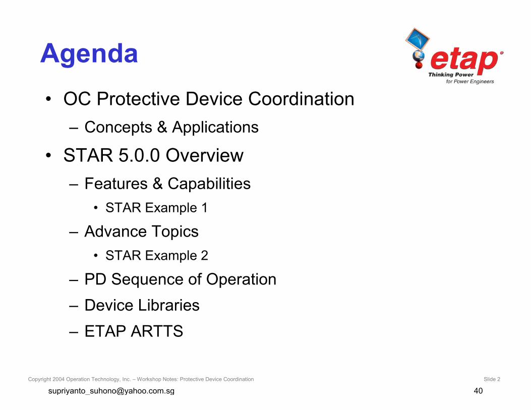
Copyright 2004 Operation Technology, Inc. – Workshop Notes: Protective Device Coordination Slide 2
Agenda• OC Protective Device Coordination
– Concepts & Applications
• STAR 5.0.0 Overview– Features & Capabilities
• STAR Example 1
– Advance Topics• STAR Example 2
– PD Sequence of Operation– Device Libraries– ETAP ARTTS
Copyright 2004 Operation Technology, Inc. – Workshop Notes: Protective Device Coordination Slide 3
Definition
• Overcurrent Coordination– A systematic study of current responsive
devices in an electrical power system.
Copyright 2004 Operation Technology, Inc. – Workshop Notes: Protective Device Coordination Slide 4
Objective
• To determine the ratings and settings offuses, breakers, relay, etc.
• To isolate the fault or overloads.
Copyright 2004 Operation Technology, Inc. – Workshop Notes: Protective Device Coordination Slide 5
Criteria
• Economics
• Available Measures of Fault
• Operating Practices
• Previous Experience
Copyright 2004 Operation Technology, Inc. – Workshop Notes: Protective Device Coordination Slide 6
Design
• Open only PD upstream of the fault oroverload
• Provide satisfactory protection for overloads
• Interrupt SC as rapidly (instantaneously) aspossible
• Comply with all applicable standards andcodes
• Plot the Time Current Characteristics ofdifferent PDs
Copyright 2004 Operation Technology, Inc. – Workshop Notes: Protective Device Coordination Slide 7
Analysis
When:
• New electrical systems
• Plant electrical system expansion/retrofits
• Coordination failure in an existing plant
Copyright 2004 Operation Technology, Inc. – Workshop Notes: Protective Device Coordination Slide 8
Protection vs. Coordination
• Coordination is not an exact science
• Compromise between protection andcoordination– Reliability
– Speed
– Performance
– Economics
– Simplicity
Copyright 2004 Operation Technology, Inc. – Workshop Notes: Protective Device Coordination Slide 9
Protection
• Prevent injury to personnel
• Minimize damage to components
– Quickly isolate the affected portion of the system
– Minimize the magnitude of available short-circuit
Copyright 2004 Operation Technology, Inc. – Workshop Notes: Protective Device Coordination Slide 10
Spectrum Of Currents
• Load Current– Up to 100% of full-load
– 115-125% (mild overload)
• Overcurrent– Abnormal loading condition (Locked-Rotor)
• Fault Current– Fault condition
– Ten times the full-load current and higher
Copyright 2004 Operation Technology, Inc. – Workshop Notes: Protective Device Coordination Slide 11
Coordination
• Limit the extent and duration of serviceinterruption
• Selective fault isolation
• Provide alternate circuits
Copyright 2004 Operation Technology, Inc. – Workshop Notes: Protective Device Coordination Slide 12
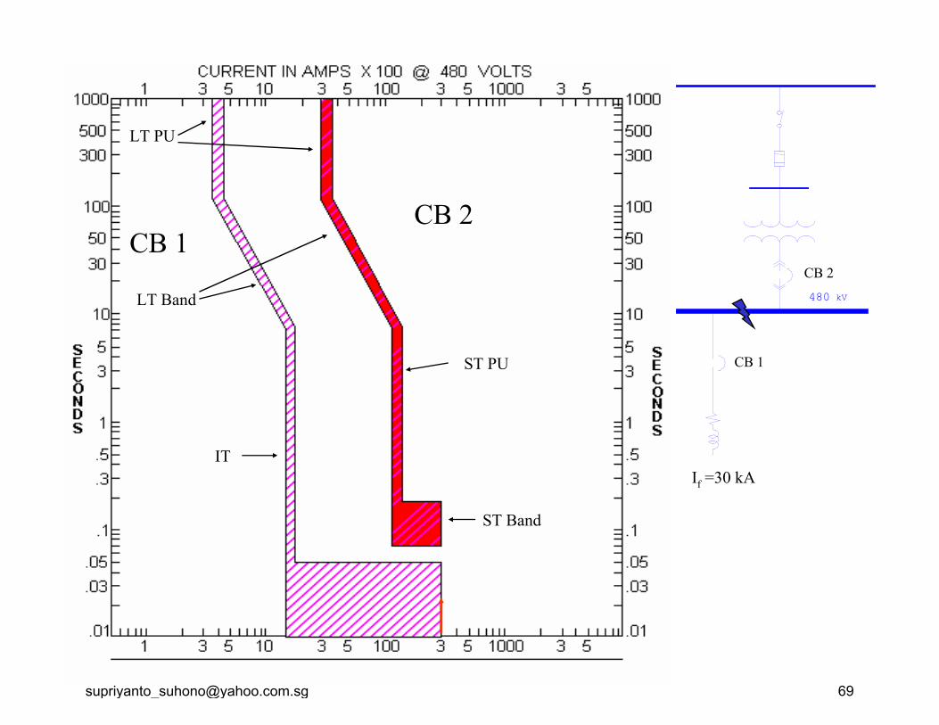
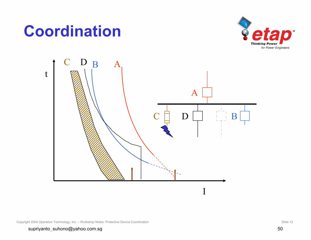
Coordination
t
I
C B A
C
D
D B
A
Copyright 2004 Operation Technology, Inc. – Workshop Notes: Protective Device Coordination Slide 13
Equipment
• Motor
• Transformer
• Generator
• Cable
• Busway
Copyright 2004 Operation Technology, Inc. – Workshop Notes: Protective Device Coordination Slide 14
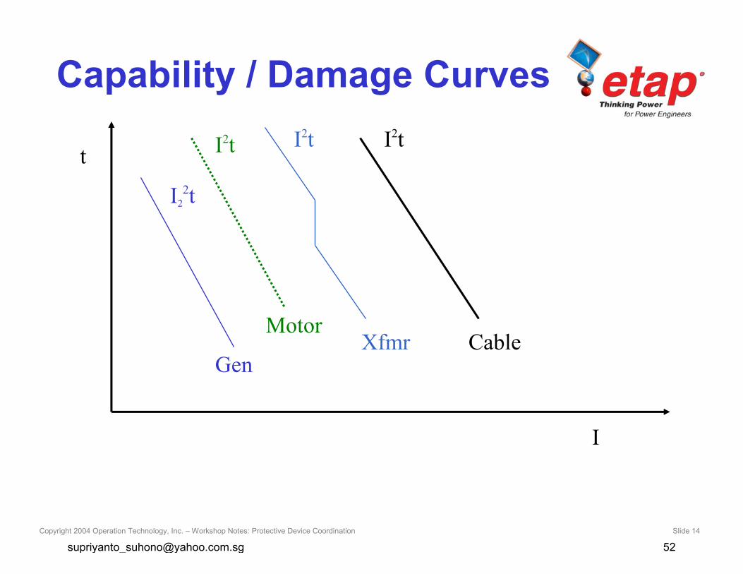
Capability / Damage Curves
t
I
I22t
Gen
I2t
MotorXfmr
I2t
Cable
I2t
Copyright 2004 Operation Technology, Inc. – Workshop Notes: Protective Device Coordination Slide 15
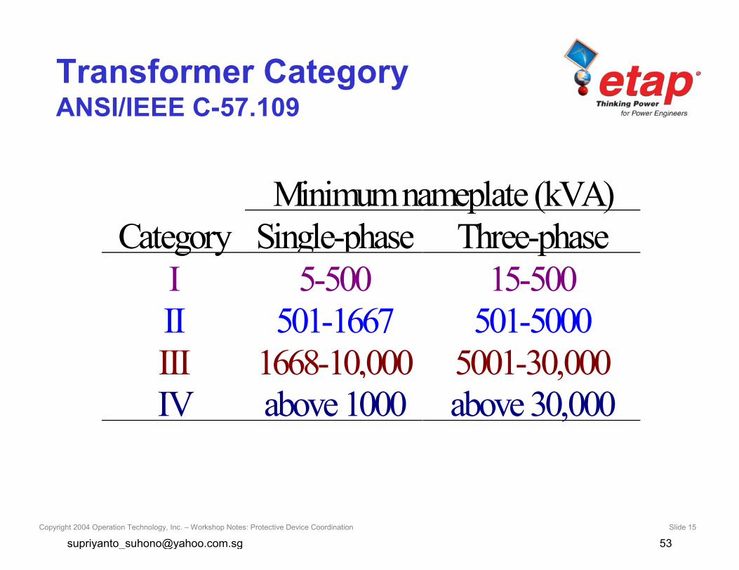
Transformer CategoryANSI/IEEE C-57.109
Minimumnameplate (kVA)Category Single-phase Three-phase
I 5-500 15-500II 501-1667 501-5000III 1668-10,000 5001-30,000IV above 1000 above 30,000
Copyright 2004 Operation Technology, Inc. – Workshop Notes: Protective Device Coordination Slide 16
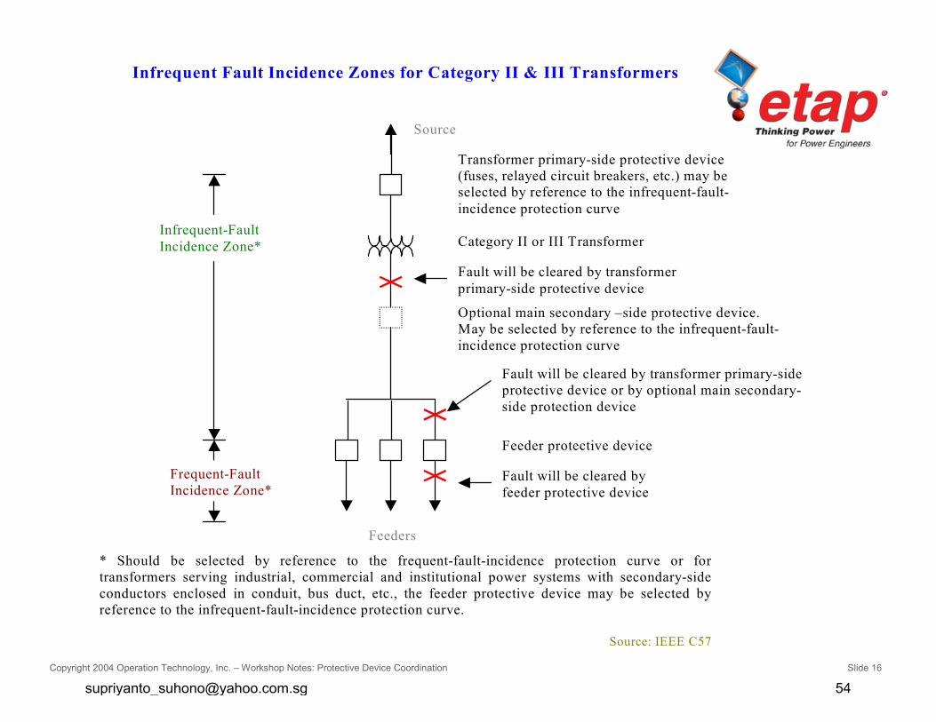
Infrequent Fault Incidence Zones for Category II & III Transformers
* Should be selected by reference to the frequent-fault-incidence protection curve or fortransformers serving industrial, commercial and institutional power systems with secondary-sideconductors enclosed in conduit, bus duct, etc., the feeder protective device may be selected byreference to the infrequent-fault-incidence protection curve.
Source: IEEE C57
Source
Transformer primary-side protective device(fuses, relayed circuit breakers, etc.) may beselected by reference to the infrequent-fault-incidence protection curve
Category II or III Transformer
Fault will be cleared by transformerprimary-side protective device
Optional main secondary –side protective device.May be selected by reference to the infrequent-fault-incidence protection curve
Feeder protective device
Fault will be cleared by transformer primary-sideprotective device or by optional main secondary-side protection device
Fault will be cleared byfeeder protective device
Infrequent-FaultIncidence Zone*
Feeders
Frequent-FaultIncidence Zone*
Copyright 2004 Operation Technology, Inc. – Workshop Notes: Protective Device Coordination Slide 17
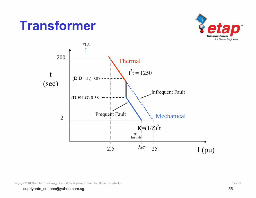
Transformer
t(sec)
I (pu)
Thermal200
2.5
I2t = 1250
2
25Isc
Mechanical
K=(1/Z)2t
(D-D LL) 0.87
(D-R LG) 0.58
Frequent Fault
Infrequent Fault
Inrush
FLA
Copyright 2004 Operation Technology, Inc. – Workshop Notes: Protective Device Coordination Slide 18
Copyright 2004 Operation Technology, Inc. – Workshop Notes: Protective Device Coordination Slide 19
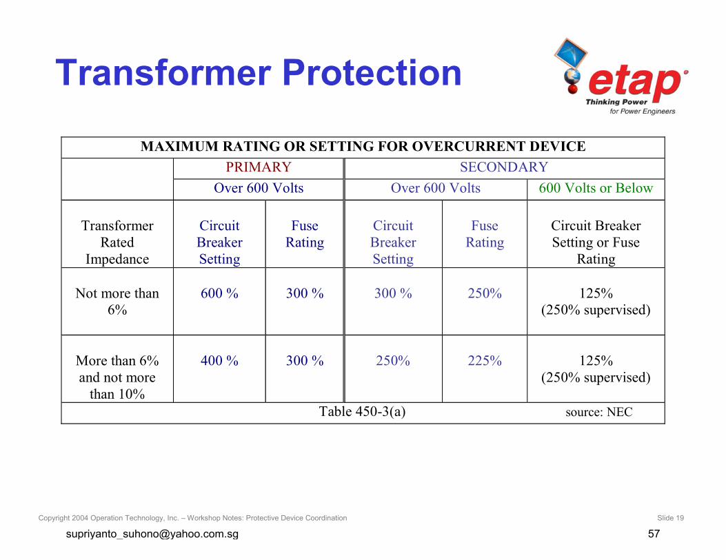
Transformer Protection
MAXIMUM RATING OR SETTING FOR OVERCURRENT DEVICEPRIMARY SECONDARY
Over 600 Volts Over 600 Volts 600 Volts or Below
TransformerRated
Impedance
CircuitBreakerSetting
FuseRating
CircuitBreakerSetting
FuseRating
Circuit BreakerSetting or Fuse
Rating
Not more than6%
600 % 300 % 300 % 250% 125%(250% supervised)
More than 6%and not more
than 10%
400 % 300 % 250% 225% 125%(250% supervised)
Table 450-3(a) source: NEC

Copyright 2004 Operation Technology, Inc. – Workshop Notes: Protective Device Coordination Slide 20
Protective Devices• Fuse
• Relay (50/51 P, N, G, SG, 51V, 67, 46, 79, 21, …)
• Thermal Magnetic
• Low Voltage Solid State Trip
• Electro-Mechanical
• MCP
• Overload Heater

Copyright 2004 Operation Technology, Inc. – Workshop Notes: Protective Device Coordination Slide 21
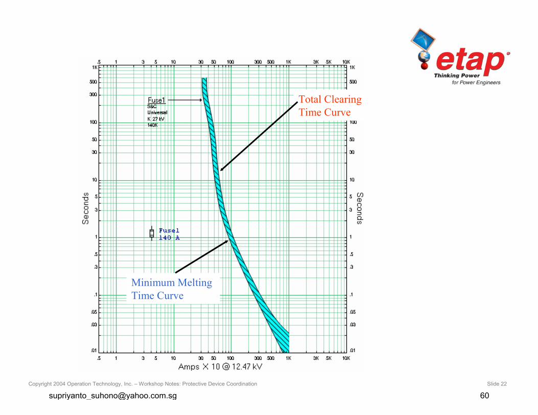
Fuse
• Non Adjustable Device
• Continuous and Interrupting Rating
• Voltage Levels
• Characteristic Curves
– Min. Melting
– Total Clearing
• Application
Copyright 2004 Operation Technology, Inc. – Workshop Notes: Protective Device Coordination Slide 22
Minimum MeltingTime Curve
Total ClearingTime Curve

Copyright 2004 Operation Technology, Inc. – Workshop Notes: Protective Device Coordination Slide 23
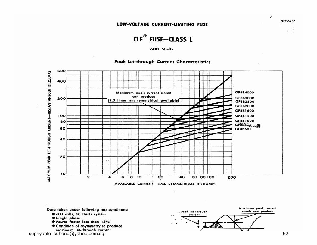
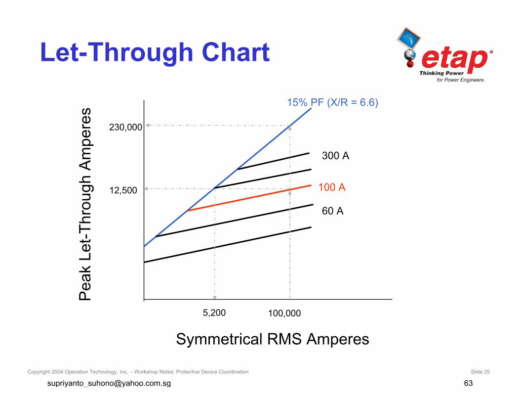
Current Limiting Fuse(CLF)• Limits the peak current of short-circuit
• Reduces magnetic stresses (mechanicaldamage)
• Reduces thermal energy
Copyright 2004 Operation Technology, Inc. – Workshop Notes: Protective Device Coordination Slide 25
Symmetrical RMS Amperes
Pea
k Le
t-Thr
ough
Am
pere
s
100 A
60 A
15% PF (X/R = 6.6)
12,500
5,200
230,000
300 A
100,000
Let-Through Chart

Copyright 2004 Operation Technology, Inc. – Workshop Notes: Protective Device Coordination Slide 26
Fuse
Generally:
• CLF is a better short-circuit protection
• Non-CLF (expulsion fuse) is a betterOverload protection
Copyright 2004 Operation Technology, Inc. – Workshop Notes: Protective Device Coordination Slide 27
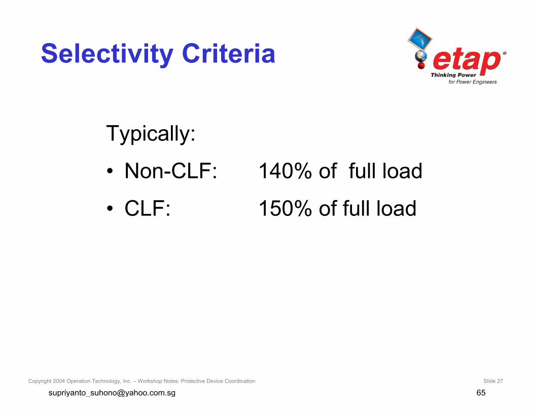
Selectivity Criteria
Typically:
• Non-CLF: 140% of full load
• CLF: 150% of full load
Copyright 2004 Operation Technology, Inc. – Workshop Notes: Protective Device Coordination Slide 28
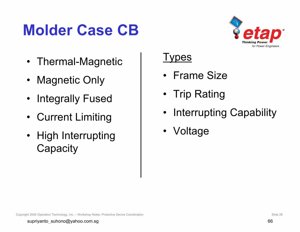
Molder Case CB
• Thermal-Magnetic
• Magnetic Only
• Integrally Fused
• Current Limiting
• High InterruptingCapacity
Types
• Frame Size
• Trip Rating
• Interrupting Capability
• Voltage
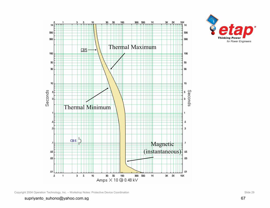
Copyright 2004 Operation Technology, Inc. – Workshop Notes: Protective Device Coordination Slide 29
Thermal Minimum
Thermal Maximum
Magnetic(instantaneous)
Copyright 2004 Operation Technology, Inc. – Workshop Notes: Protective Device Coordination Slide 30
LVPCB
• Voltage and Frequency Ratings
• Continuous Current / Frame Size
– Override (12 times cont. current)
• Interrupting Rating
• Short-Time Rating (30 cycle)
• Fairly Simple to Coordinate
Copyright 2004 Operation Technology, Inc. – Workshop Notes: Protective Device Coordination Slide 32
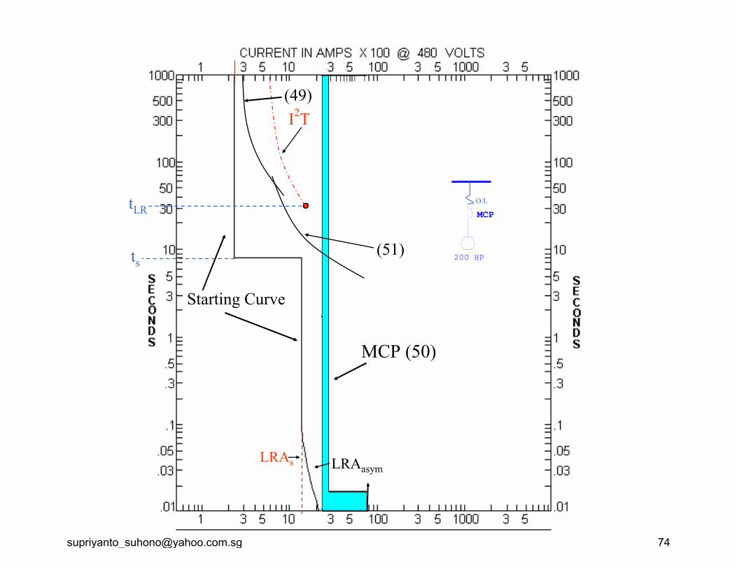
Motor Protection
• Motor Starting Curve
• Thermal Protection
• Locked Rotor Protection
• Fault Protection
Copyright 2004 Operation Technology, Inc. – Workshop Notes: Protective Device Coordination Slide 33
Motor Overload Protection(NEC Art 430-32)
• Thermal O/L (Device 49)
• Motors with SF not less than 1.15– 125% of FLA
• Motors with temp. rise not over 40– 125% of FLA
• All other motors– 115% of FLA
Copyright 2004 Operation Technology, Inc. – Workshop Notes: Protective Device Coordination Slide 34
Locked Rotor Protection
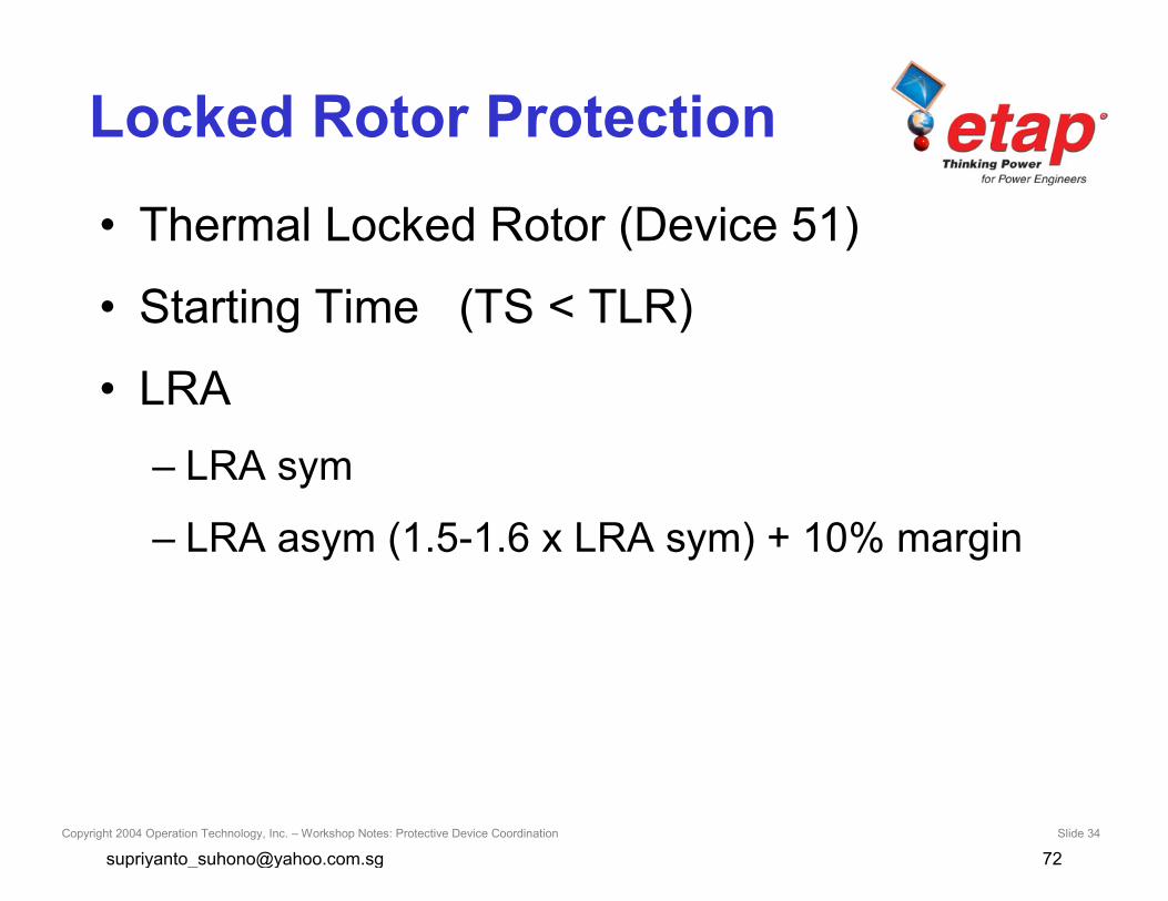
• Thermal Locked Rotor (Device 51)
• Starting Time (TS < TLR)
• LRA– LRA sym
– LRA asym (1.5-1.6 x LRA sym) + 10% margin
Copyright 2004 Operation Technology, Inc. – Workshop Notes: Protective Device Coordination Slide 35
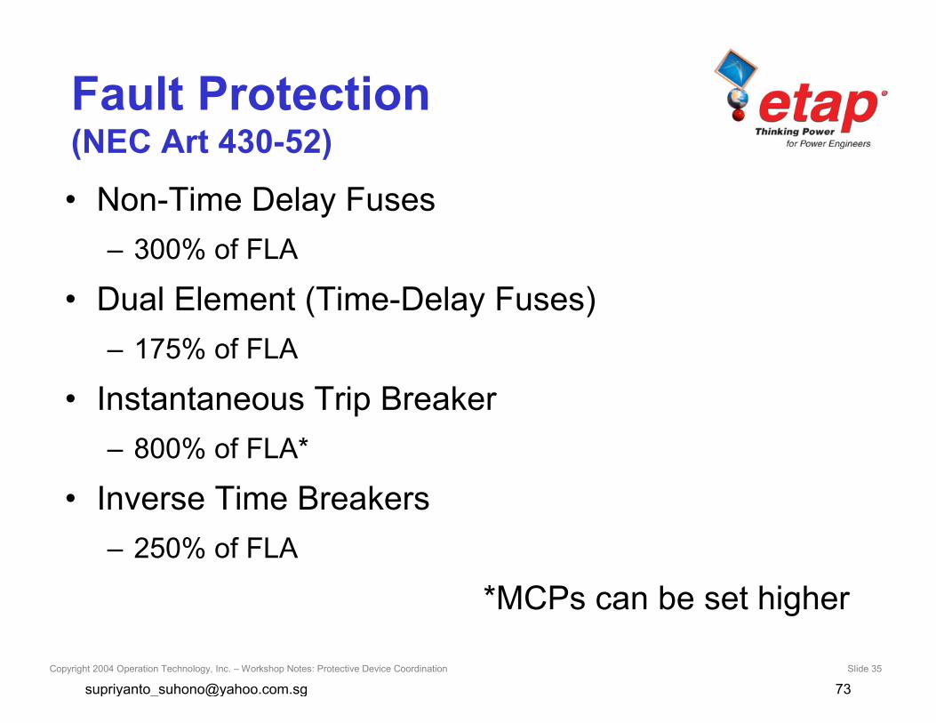
Fault Protection(NEC Art 430-52)
• Non-Time Delay Fuses– 300% of FLA
• Dual Element (Time-Delay Fuses)– 175% of FLA
• Instantaneous Trip Breaker– 800% of FLA*
• Inverse Time Breakers– 250% of FLA
*MCPs can be set higher
Copyright 2004 Operation Technology, Inc. – Workshop Notes: Protective Device Coordination Slide 37
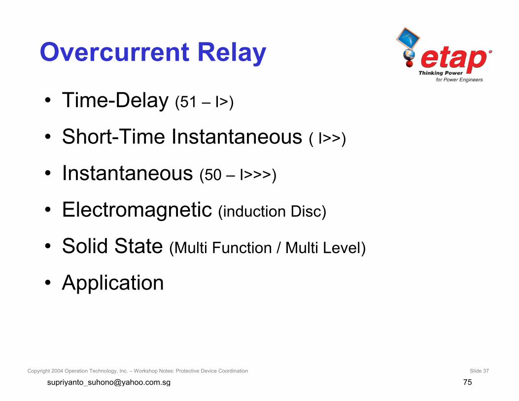
Overcurrent Relay
• Time-Delay (51 – I>)
• Short-Time Instantaneous ( I>>)
• Instantaneous (50 – I>>>)
• Electromagnetic (induction Disc)
• Solid State (Multi Function / Multi Level)
• Application
Copyright 2004 Operation Technology, Inc. – Workshop Notes: Protective Device Coordination Slide 39
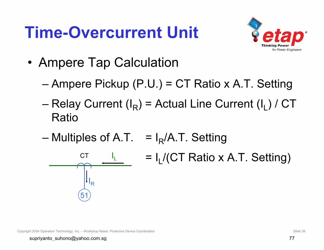
Time-Overcurrent Unit
• Ampere Tap Calculation– Ampere Pickup (P.U.) = CT Ratio x A.T. Setting
– Relay Current (IR) = Actual Line Current (IL) / CTRatio
– Multiples of A.T. = IR/A.T. Setting
= IL/(CT Ratio x A.T. Setting)IL
IR
CT
51
Copyright 2004 Operation Technology, Inc. – Workshop Notes: Protective Device Coordination Slide 40
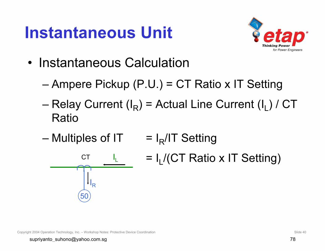
Instantaneous Unit
• Instantaneous Calculation– Ampere Pickup (P.U.) = CT Ratio x IT Setting
– Relay Current (IR) = Actual Line Current (IL) / CTRatio
– Multiples of IT = IR/IT Setting
= IL/(CT Ratio x IT Setting)IL
IR
CT
50
Copyright 2004 Operation Technology, Inc. – Workshop Notes: Protective Device Coordination Slide 41
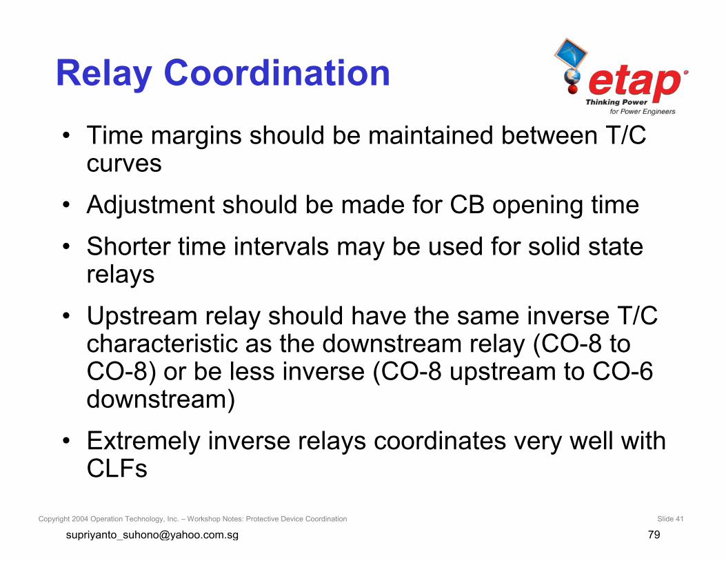
Relay Coordination• Time margins should be maintained between T/C
curves• Adjustment should be made for CB opening time• Shorter time intervals may be used for solid state
relays• Upstream relay should have the same inverse T/C
characteristic as the downstream relay (CO-8 toCO-8) or be less inverse (CO-8 upstream to CO-6downstream)
• Extremely inverse relays coordinates very well withCLFs
Copyright 2004 Operation Technology, Inc. – Workshop Notes: Protective Device Coordination Slide 42
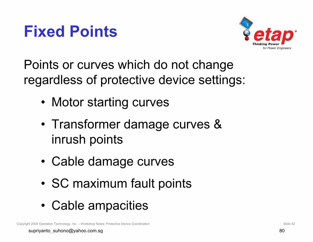
Fixed Points
• Motor starting curves
• Transformer damage curves &inrush points
• Cable damage curves
• SC maximum fault points
• Cable ampacities
Points or curves which do not changeregardless of protective device settings:
Copyright 2004 Operation Technology, Inc. – Workshop Notes: Protective Device Coordination Slide 43
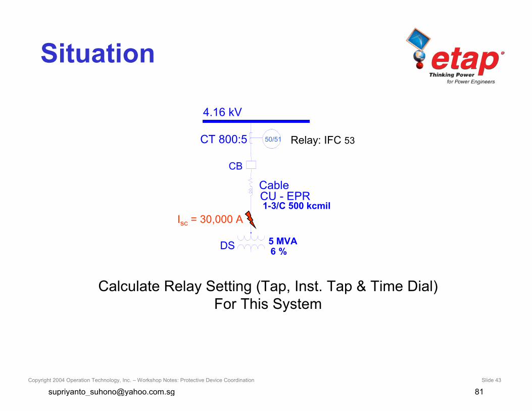
Situation
Calculate Relay Setting (Tap, Inst. Tap & Time Dial)For This System
4.16 kV
DS 5 MVA
Cable
1-3/C 500 kcmilCU - EPR
CB
Isc = 30,000 A
6 %
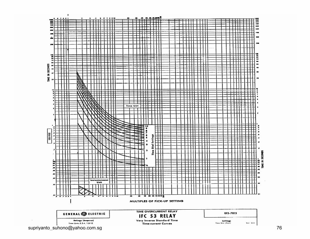
50/51 Relay: IFC 53CT 800:5
Copyright 2004 Operation Technology, Inc. – Workshop Notes: Protective Device Coordination Slide 44
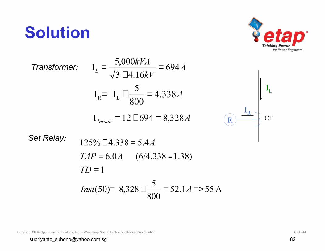
Solution
AInrsuh 328,869412I =×=
A338.4800
5II LR =×=
Transformer: AkV
kVAL 694
16.43000,5I =×
=
IL
CTRIR
Set Relay:
A551.52800
5328,8)50(
1)38.1(6/4.3380.6
4.5338.4%125
=>=×=
==
=×=
AInst
TDATAP
A

Copyright 2004 Operation Technology, Inc. – Workshop Notes: Protective Device Coordination Slide 45
Question
What is ANSI Shift Curve?
Copyright 2004 Operation Technology, Inc. – Workshop Notes: Protective Device Coordination Slide 46
Answer
• For delta-delta connected transformers, withline-to-line faults on the secondary side, thecurve must be reduced to 87% (shift to theleft by a factor of 0.87)
• For delta-wye connection, with single line-to-ground faults on the secondary side, thecurve values must be reduced to 58% (shiftto the left by a factor of 0.58)

Copyright 2004 Operation Technology, Inc. – Workshop Notes: Protective Device Coordination Slide 47
Question
What is meant by Frequent andInfrequent for transformers?
Copyright 2004 Operation Technology, Inc. – Workshop Notes: Protective Device Coordination Slide 48
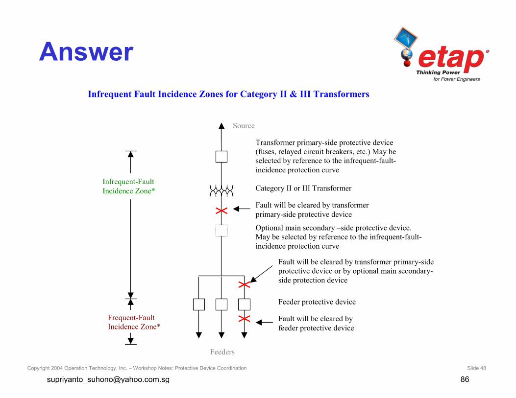
AnswerInfrequent Fault Incidence Zones for Category II & III Transformers
Source
Transformer primary-side protective device(fuses, relayed circuit breakers, etc.) May beselected by reference to the infrequent-fault-incidence protection curve
Category II or III Transformer
Fault will be cleared by transformerprimary-side protective device
Optional main secondary –side protective device.May be selected by reference to the infrequent-fault-incidence protection curve
Feeder protective device
Fault will be cleared by transformer primary-sideprotective device or by optional main secondary-side protection device
Fault will be cleared byfeeder protective device
Infrequent-FaultIncidence Zone*
Feeders
Frequent-FaultIncidence Zone*
Copyright 2004 Operation Technology, Inc. – Workshop Notes: Protective Device Coordination Slide 49
Question
What T/C Coordination interval should bemaintained between relays?
Copyright 2004 Operation Technology, Inc. – Workshop Notes: Protective Device Coordination Slide 50
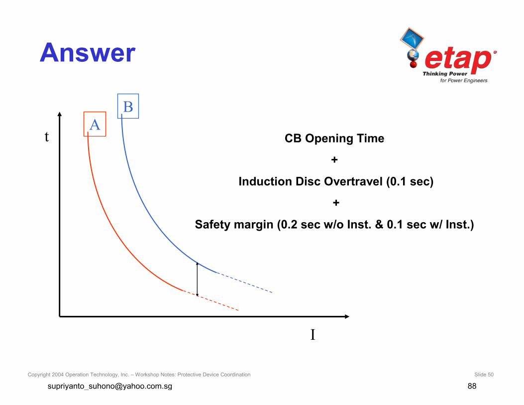
Answer
At
I
B
CB Opening Time
+
Induction Disc Overtravel (0.1 sec)
+
Safety margin (0.2 sec w/o Inst. & 0.1 sec w/ Inst.)

Copyright 2004 Operation Technology, Inc. – Workshop Notes: Protective Device Coordination Slide 51
Question
What is Class 10 and Class 20Thermal OLR curves?

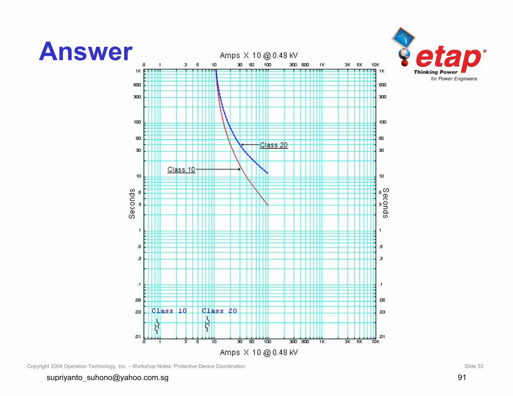
Copyright 2004 Operation Technology, Inc. – Workshop Notes: Protective Device Coordination Slide 52
Answer
• Class 10 for fast trip, 10 seconds or less
• Class 20 for, 20 seconds or less
• There is also a Class 30 for long trip time
Copyright 2004 Operation Technology, Inc. – Workshop Notes: Protective Device Coordination Slide 53
Answer
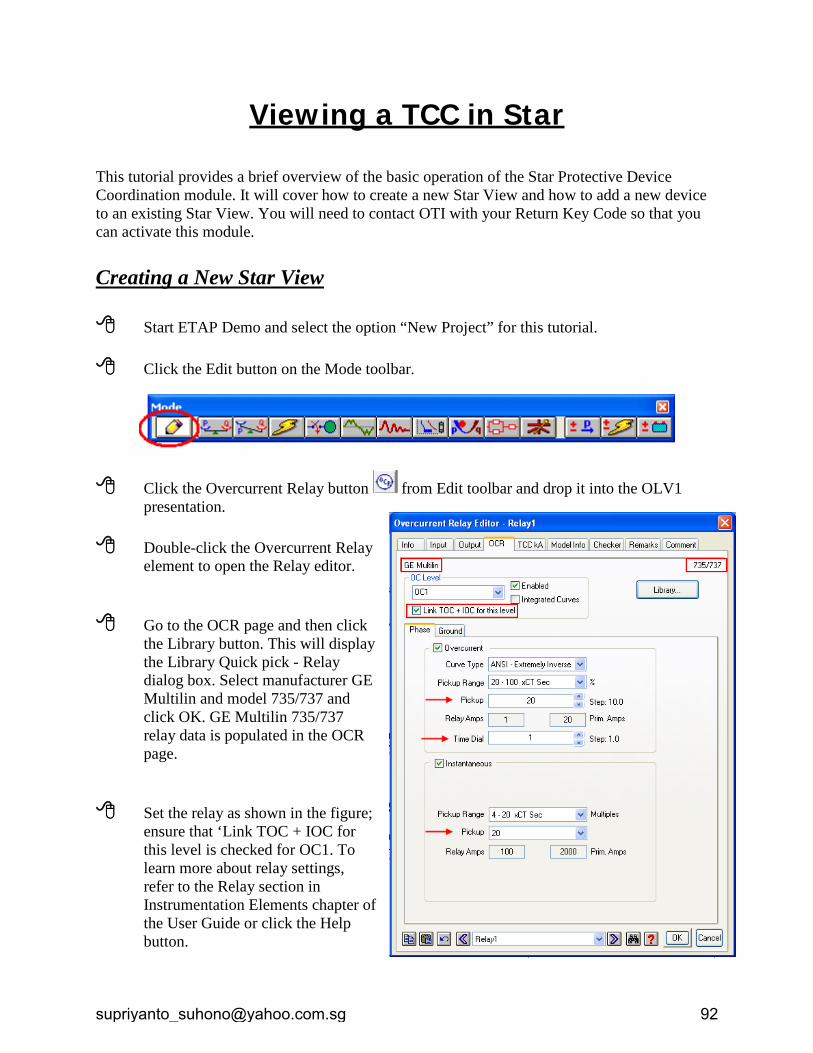
Viewing a TCC in Star This tutorial provides a brief overview of the basic operation of the Star Protective Device Coordination module. It will cover how to create a new Star View and how to add a new device to an existing Star View. You will need to contact OTI with your Return Key Code so that you can activate this module. Creating a New Star View Start ETAP Demo and select the option “New Project” for this tutorial. Click the Edit button on the Mode toolbar.
Click the Overcurrent Relay button from Edit toolbar and drop it into the OLV1 presentation.
Double-click the Overcurrent Relay
element to open the Relay editor.
Go to the OCR page and then click the Library button. This will display the Library Quick pick - Relay dialog box. Select manufacturer GE Multilin and model 735/737 and click OK. GE Multilin 735/737 relay data is populated in the OCR page.
Set the relay as shown in the figure; ensure that ‘Link TOC + IOC for this level is checked for OC1. To learn more about relay settings, refer to the Relay section in Instrumentation Elements chapter of the User Guide or click the Help button.
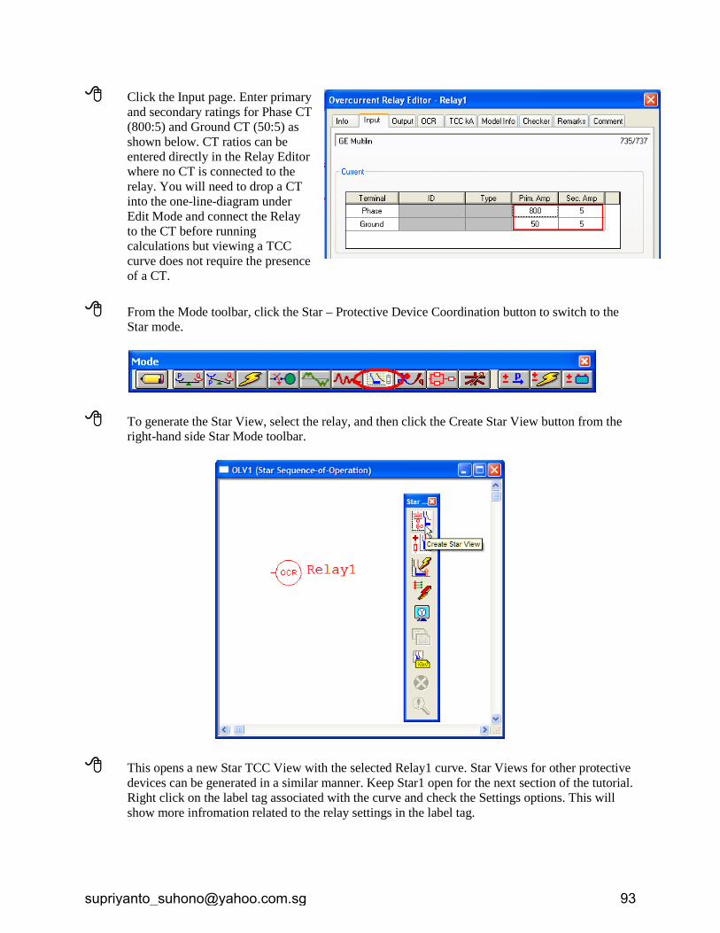
Click the Input page. Enter primary and secondary ratings for Phase CT (800:5) and Ground CT (50:5) as shown below. CT ratios can be entered directly in the Relay Editor where no CT is connected to the relay. You will need to drop a CT into the one-line-diagram under Edit Mode and connect the Relay to the CT before running calculations but viewing a TCC curve does not require the presence of a CT.
From the Mode toolbar, click the Star – Protective Device Coordination button to switch to the
Star mode.
To generate the Star View, select the relay, and then click the Create Star View button from the right-hand side Star Mode toolbar.
This opens a new Star TCC View with the selected Relay1 curve. Star Views for other protective devices can be generated in a similar manner. Keep Star1 open for the next section of the tutorial. Right click on the label tag associated with the curve and check the Settings options. This will show more infromation related to the relay settings in the label tag.
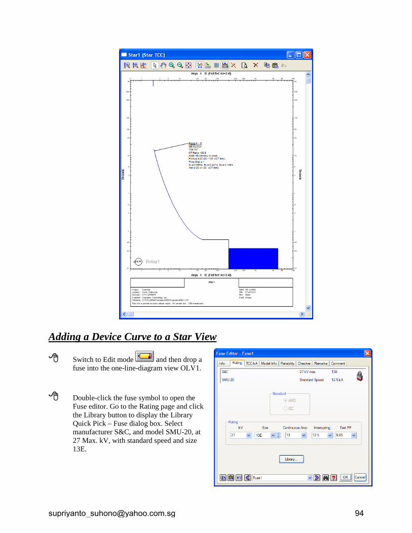
Adding a Device Curve to a Star View
Switch to Edit mode and then drop a fuse into the one-line-diagram view OLV1.
Double-click the fuse symbol to open the
Fuse editor. Go to the Rating page and click the Library button to display the Library Quick Pick – Fuse dialog box. Select manufacturer S&C, and model SMU-20, at 27 Max. kV, with standard speed and size 13E.
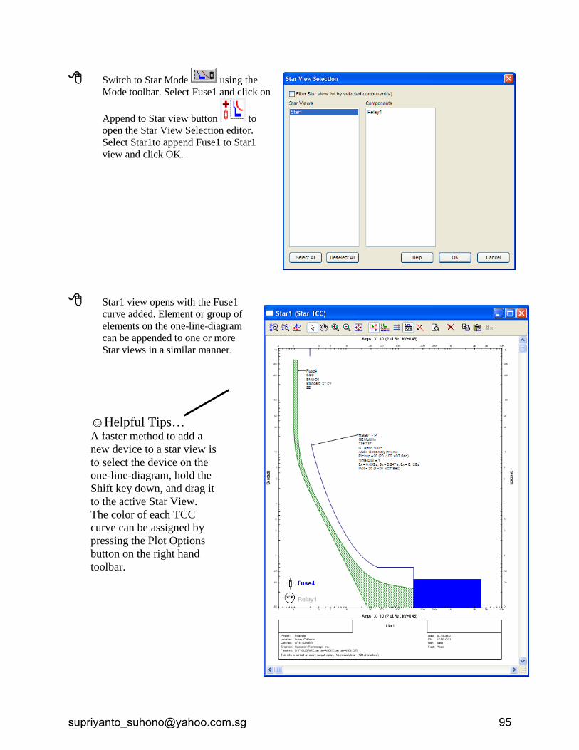
Switch to Star Mode using the Mode toolbar. Select Fuse1 and click on
Append to Star view button to open the Star View Selection editor. Select Star1to append Fuse1 to Star1 view and click OK.
Star1 view opens with the Fuse1
curve added. Element or group of elements on the one-line-diagram can be appended to one or more Star views in a similar manner.
☺Helpful Tips… A faster method to add a new device to a star view is to select the device on the one-line-diagram, hold the Shift key down, and drag it to the active Star View. The color of each TCC curve can be assigned by pressing the Plot Options button on the right hand toolbar.
www.etap.com 1 of 2 www.eltechs.com.ph
ETAP TECHNICAL INFORMATION POINTERS
ELTECHS E&C CORPORATION
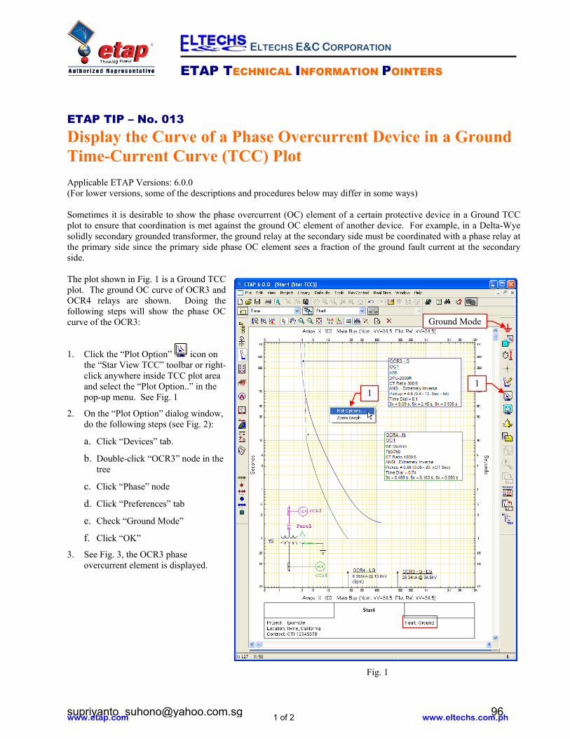
ETAP TIP – No. 013 Display the Curve of a Phase Overcurrent Device in a Ground Time-Current Curve (TCC) Plot Applicable ETAP Versions: 6.0.0 (For lower versions, some of the descriptions and procedures below may differ in some ways) Sometimes it is desirable to show the phase overcurrent (OC) element of a certain protective device in a Ground TCC plot to ensure that coordination is met against the ground OC element of another device. For example, in a Delta-Wye solidly secondary grounded transformer, the ground relay at the secondary side must be coordinated with a phase relay at the primary side since the primary side phase OC element sees a fraction of the ground fault current at the secondary side. The plot shown in Fig. 1 is a Ground TCC plot. The ground OC curve of OCR3 and OCR4 relays are shown. Doing the following steps will show the phase OC curve of the OCR3:
1. Click the “Plot Option” icon on the “Star View TCC” toolbar or right-click anywhere inside TCC plot area and select the “Plot Option..” in the pop-up menu. See Fig. 1
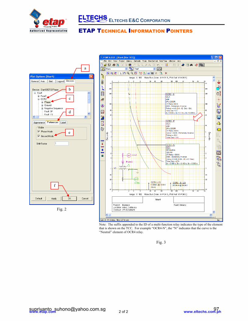
2. On the “Plot Option” dialog window, do the following steps (see Fig. 2):
a. Click “Devices” tab.
b. Double-click “OCR3” node in the tree
c. Click “Phase” node
d. Click “Preferences” tab
e. Check “Ground Mode”
f. Click “OK”
3. See Fig. 3, the OCR3 phase overcurrent element is displayed.
3.b
Fig. 1
1 1
Ground Mode
www.etap.com 2 of 2 www.eltechs.com.ph
ETAP TECHNICAL INFORMATION POINTERS
ELTECHS E&C CORPORATION
a
Fig. 3
e
b
c
f
Fig. 2
d
Note: The suffix appended to the ID of a multi-function relay indicates the type of the element that is shown on the TCC. For example “OCR4-N”, the “N” indicates that the curve is the “Neutral” element of OCR4 relay.