


Bahasa
Halaman
Hukum

Yb-fiber laser beam effects on the surface modification of Al–Fe aerospace alloyobtaining weld filet structures, low fine porosity and corrosion resistance
Moisés Meza Pariona a,⁎, Viviane Teleginski a, Kelly dos Santos a, Siliane Machado a, Alfredo José Zara a,Nadia Khaled Zurba a, Rudimar Riva b
a Department of Materials Engineering and Science (DEMA), Ponta Grossa State University, 84030-900 Ponta Grossa, PR, Brazilb Department of Aerospace Science and Technology, Institute for Advanced Studies (IEAv), General Command for Aerospace Technology, C. Postal 6044, 12228-970 São José dos Campos, SP, Brazil
a b s t r a c ta r t i c l e i n f o
Article history:
Received 10 May 2011
Accepted in revised form 4 October 2011
Available online 13 October 2011
Keywords:
Laser beam
Al–Fe alloy
Surface modification
Welding
Corrosion resistance
Yb-fiber laser beamwas used successfully to irradiate Al–1.5 wt.% Fe alloy, modifying its surface to improve its
corrosion resistance for aerospace applications. Laser-treated samples were examined by optical microscopy,
scanning electron microscopy, energy dispersive X-ray diffraction (EDX), and low-angle X-ray diffraction
(LA-XRD), and tested by Vickers microhardness. The alloy's corrosion resistance was tested by exposure to
H2SO4 solution, Tafel plots, polarization, and corrosion potentials. The results reveal the formation of weld filet
structures with metastable phases and finely dispersed precipitates. The creation of a finely porous layer of pro-
tective coating produced during the rapid remelting process contributed to increase the corrosion resistance of
laser-treated samples when compared with untreated samples. The Yb-fiber laser beam technology applied to
the surface treatment of aluminum alloys proved efficient in augmenting their corrosion resistance, thus
deserving further investigation for aerospace and automotive applications.
Crown Copyright © 2011 Published by Elsevier B.V. All rights reserved.
1. Introduction
Aluminum alloys are investigated extensively in the form of test
specimens, structural components and large metal surfaces for the
automotive and aerospace industries. These materials are usually
characterized by their low density, high thermal conductivity and
high corrosion resistance at room temperature [1]. According to
Borowski and Bartkowiak [2], the first large-scale use of aluminum
alloys was for the construction of airplanes. The increasing use of
aluminum and magnesium alloys in manufacturing may be explained
by their relatively low cost to high specific strength, which is aided by
the production technology of aluminum alloys or composites with Al
matrices. The use of new materials is tied to the possibility of modify-
ing the entire volume or the subsurface areas of alloys by changing
the properties of their surface layer. This is a branch of science that
has been expanding dynamically over the last few years [2].
According to Cotton and Kaufman [3], the Al–Fe alloy system is
particularly attractive for aerospace structures due to the extent to
which its microstructure can be altered. Surface modifications of
aluminum alloys are particularly desirable to improve their tribological
properties, especially when these materials will be exposed to highly
abrasive environments.
Cost-effective techniques of alloy surface modifications include
the formation of a thick layer of an oxide, or basically the use of
nitride compounds. One method for forming surface oxides is to melt
and partially ablate the aluminum surface using a laser beam. This
causes the depth of the surface oxide layer to increase significantly
[4]. In this context, rapid solidification processes (RSP) such as laser
surface treatment (LST), melt spinning or atomization allow for the
production of well-designed materials. LST requires a controlled
condition during solidification of the microstructure to obtain the
desired metastable phases and precipitates [5]. In addition, modeling
of laser heating procedures provides information about the physical
processes that take place during the heating process.
A recent LST application reported by Mahamoudi et al. [6] is based
on laser beam treatment to increase the cavitation erosion resistance
of martensitic stainless steel, specifically for use in the presence of
local pressures.
Laser surface melting (LSM) modifies the surface properties of a
material without affecting its bulk properties. High energy density
leads to the efficient use of energy for melting. LSM results in rapid
quenching of the molten material by conduction into the cold subsur-
face after a short period of irradiation [7]. This technique has elicited
growing interest in recent years for its unique capabilities, and the
popularity of laser working has caused this source of heat to become
a relatively common technology [2] and [7].
Laser treatments of metals have been applied at power in the
range of 0.5–10 kW, reaching a power density of 104–105 W/cm2,
since power lower than 104 W/cm2 does not penetrate the treated
Surface & Coatings Technology 206 (2012) 2293–2301
⁎ Corresponding author. Tel.: +55 42 3226 0356; fax: +55 42 3220 3000.
E-mail addresses: [email protected], [email protected]
(M.M. Pariona).
0257-8972/$ – see front matter. Crown Copyright © 2011 Published by Elsevier B.V. All rights reserved.
doi:10.1016/j.surfcoat.2011.10.007
Contents lists available at SciVerse ScienceDirect
Surface & Coatings Technology
j ourna l homepage: www.e lsev ie r .com/ locate /sur fcoat
material but only heats it [2]. Within the power range of 104–106W/
cm2, a required penetration occurs with mass loss due to vaporization
of the material. The effects of exposure to the laser beam depend
mostly on parameters such as the temperature created on the treated
surface, exposure time, cooling time, and the material's characteristics
[2]. The characteristics of these parameters, in turn, depend on factors
such as laser type and beam parameters (power and diameter), travel
speed, etc. In this type of treatment, temperature is an important
parameter, which is why the literature cites several parameters that
depend on its effect. In every case involving laser beam penetration
treatment, the surface layer of the metal structure is chemically and
structurally homogenous with a fine-grained structure [2]. Metals and
their alloys exhibit good impact strength, favorable self-stress patterns,
and high hardness and wear resistance. The tribological properties of
laser-treated surfaces are greatly improved and display increased
hardness [2].
The production of fine dispersions that exhibit unusually low
coarsening rates forms the basis for most of the high-temperature
aluminum alloys developed to date. Interpretations of the sequence
of solidification events that lead to such structures have varied
considerably due to the complexity of these microstructures [3]. One
aspect of these microstructures that is quite unusual is the formation
of randomly oriented intercellular dispersed intermetallic compounds
with diameters in the order of 50 nm in a microcellular matrix [3].
This is based on the fact that in typical cellular or microcellular micro-
structures, the formation of intercellular phase is the result of solute
rejection from the adjacent cells. This causes the intercellular regions
to reach a composition and temperature at which the formation of a
second phase ensues with an orientation relationship that minimizes
the local interfacial energies. In contrast, an orientation relationship
between a primary intermetallic compound and the matrix is not
expected. To explain the deviation of the Al–Fe system from typical
microcellular solidification behavior at high supercooling rates, it has
been suggested that the randomness of orientation stems from the
initial formation of amorphous intercellular regions. These regions
subsequently crystallize as their temperature increases due to re-
coalescence, which would result in randomly oriented particles in the
intercellular regions [3].
The formation of metastable phases during the rapid solidification
process has been studied by Adam and Hogan [8], Hughes and Jones
[9] and Dong and Jones [10]. Gremaud et al. [11] also investigated
the microstructure resulting from the laser remelting process. Note
that aluminum forms a simple eutectic with the stable intermetallic
phase, Al3Fe, as well as with the metastable phase, Al6Fe. Metastable
binary phases have been observed as interdendritic precipitates,
such as AlxFe (x=5.0–5.8), Al9Fe2 and AlmFe (m=4.0–4.4), which
is consistent with results reported in the literature [11]. A variety of
microstructures may be observed during solidification, resulting from
the competing nucleation and growth of these phases in Al-matrices
with a eutectic or dendritic morphology. Fine interdendritic dispersion
of some of these phases, which increases their resistance to grain
coarsening, is obtained under conditions of rapid solidification. On
the other hand, the presence of metastable phases has been shown to
produce optical defects, called “fir-tree” defects, on anodized surfaces.
It is therefore important to understand and control the solidification
microstructures of Al–Fe alloys [5].
Recently, Trdan et al. [12] reported the improved corrosion resis-
tance of aluminum alloy in response to surface modification by laser
shock processing (LSP) using a Nd:YAG laser with a wavelength of
1064 nm. Laser surface treatment was also efficient in improving
wear resistance [13] and hardening [14] of ferrous materials, including
surface remelting in a nitrogen atmosphere [15]. The surface hardness
increased substantially due to the formation of intermetallic phases,
which is consistent with an earlier study reported in the literature
[16]. The formation of intermetallic phases is a direct consequence of
laser treatments [17, 18]. However, for aerospace applications, the
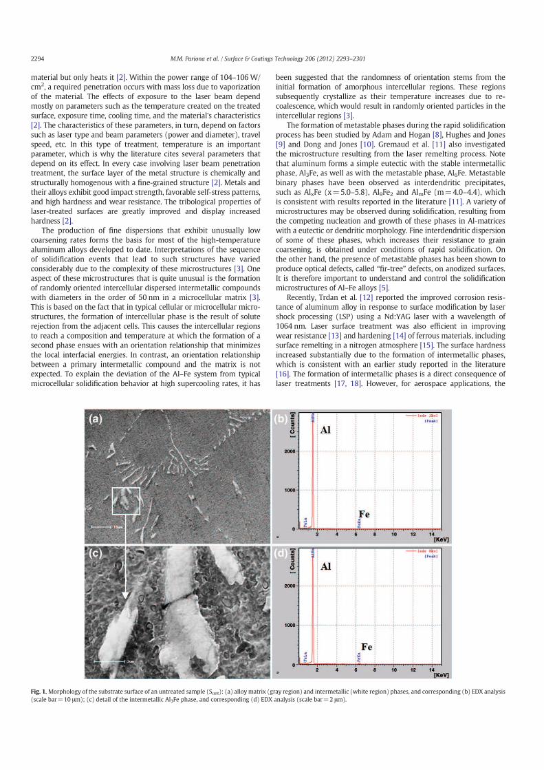
Fig. 1.Morphology of the substrate surface of an untreated sample (Sunt): (a) alloy matrix (gray region) and intermetallic (white region) phases, and corresponding (b) EDX analysis
(scale bar=10 μm); (c) detail of the intermetallic Al3Fe phase, and corresponding (d) EDX analysis (scale bar=2 μm).
2294 M.M. Pariona et al. / Surface & Coatings Technology 206 (2012) 2293–2301
experimental conditions and further characterization of the final
properties of Al–1.5 wt.% Fe alloy after laser treatments [8–19] are
incomplete. Thus, the present study examines the correlation between
the electrochemical properties and microstructure after laser remelting
of alloy for use in the aerospace industry.
This study is focused on the surface modifications of Al–1.5 wt.%
Fe alloy produced by Yb-fiber laser beam irradiation in consistently
reproducible conditions, aiming to improve the corrosion resistance
and homogeneous properties of this material for practical aerospace
applications. Large laser-treated samples were characterized by
optical microscopy (OM), scanning electron microscopy (SEM),
energy dispersive X-ray diffraction (EDX), low-angle X-ray diffraction
(LA-XRD) profiles, and Vickers hardness (VH). The alloy's corrosion
resistance was tested by exposure to H2SO4 solution, Tafel plots,
polarization, and corrosion potentials. This study on Yb-laser treat-
ment for the surface modification of alloys is expected to contribute
to related investigations, and may serve for a variety of applications
in the automotive, aeronautical, nautical and energy industries.
2. Materials and methods
2.1. Materials
In this study, Al–1.5 wt.% Fe alloy was cast using a commercially
pure raw material, and sand-blasted before the laser treatment. Fig. 1
(a) shows initial SEM images of the base material (untreated surface,
i.e., Sunt), revealing a microstructure of Al3Fe intermetallic phase
(white region) dispersed in a matrix phase (gray region) Fig. 1(b) illus-
trates the ED-XRD analysis of the matrix phase, while Table 1 describes
the respective element analysis. Fig. 1(d) shows the EDX analysis of the
intermetallic phase, while Table 2 quantifies the elements. Note that the
Fe content identified in these samples is in order of 1.5 wt.% in the ma-
trix (Fig. 1(c)) and 8.0 wt.% in the intermetallic phase (Fig. 1(d)). This
Al/Fe ratio in the starting material is consistent with the presence of
Al3Fe intermetallic phase, also identified by Goulart [20].
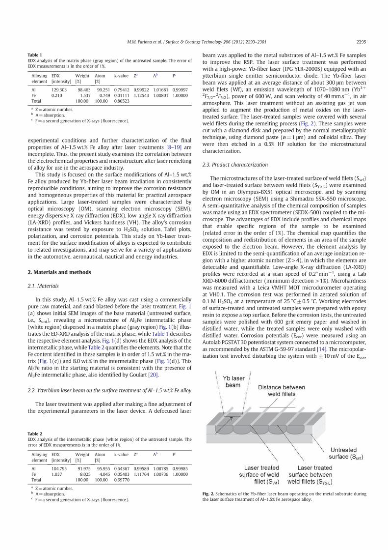
2.2. Ytterbium laser beam on the surface treatment of Al–1.5 wt.% Fe alloy
The laser treatment was applied after making a fine adjustment of
the experimental parameters in the laser device. A defocused laser
beam was applied to the metal substrates of Al–1.5 wt.% Fe samples
to improve the RSP. The laser surface treatment was performed
with a high-power Yb-fiber laser (IPG YLR-2000S) equipped with an
ytterbium single emitter semiconductor diode. The Yb-fiber laser
beam was applied at an average distance of about 300 μm between
weld filets (Wf), an emission wavelength of 1070–1080 nm (Yb3+
2F7/2–2F5/2), power of 600W, and scan velocity of 40 mm.s−1, in air
atmosphere. This laser treatment without an assisting gas jet was
applied to augment the production of metal oxides on the laser-
treated surface. The laser-treated samples were covered with several
weld filets during the remelting process (Fig. 2). These samples were
cut with a diamond disk and prepared by the normal metallographic
technique, using diamond paste (ø=1 μm) and colloidal silica. They
were then etched in a 0.5% HF solution for the microstructural
characterization.
2.3. Product characterization
Themicrostructures of the laser-treated surface of weld filets (Swf)
and laser-treated surface between weld filets (SYb-L) were examined
by OM in an Olympus-BX51 optical microscope, and by scanning
electron microscopy (SEM) using a Shimadzu SSX-550 microscope.
A semi-quantitative analysis of the chemical composition of samples
was made using an EDX spectrometer (SEDX-500) coupled to the mi-
croscope. The advantages of EDX include profiles and chemical maps
that enable specific regions of the sample to be examined
(related error in the order of 1%). The chemical map quantifies the
composition and redistribution of elements in an area of the sample
exposed to the electron beam. However, the element analysis by
EDX is limited to the semi-quantification of an average ionization re-
gion with a higher atomic number (Z>4), in which the elements are
detectable and quantifiable. Low-angle X-ray diffraction (LA-XRD)
profiles were recorded at a scan speed of 0.2°min−1, using a Lab
XRD-6000 diffractometer (minimum detection >1%). Microhardness
was measured with a Leica VMHT MOT microdurometer operating
at VH0.1. The corrosion test was performed in aerated solution of
0.1 M H2SO4 at a temperature of 25 °C±0.5 °C. Working electrodes
of surface-treated and untreated samples were prepared with epoxy
resin to expose a top surface. Before the corrosion tests, the untreated
samples were polished with 600 grit emery paper and washed in
distilled water, while the treated samples were only washed with
distilled water. Corrosion potentials (Ecor) were measured using an
Autolab PGSTAT 30 potentiostat system connected to a microcomputer,
as recommended by the ASTM G-59-97 standard [14]. The micropolar-
ization test involved disturbing the system with ±10 mV of the Ecor,
Table 2
EDX analysis of the intermetallic phase (white region) of the untreated sample. The
error of EDX measurements is in the order of 1%.
Alloying
element
EDX
[intensity]
Weight
[%]
Atom
[%]
k-value Za Ab Fc
Al 104.795 91.975 95.955 0.64367 0.99589 1.08785 0.99985
Fe 1.037 8.025 4.045 0.05403 1.11764 1.00739 1.00000
Total 100.00 100.00 0.69770
a Z=atomic number.b A=absorption.c F=a second generation of X-rays (fluorescence).
Fig. 2. Schematics of the Yb-fiber laser beam operating on the metal substrate during
the laser surface treatment of Al–1.5% Fe aerospace alloy.
Table 1
EDX analysis of the matrix phase (gray region) of the untreated sample. The error of
EDX measurements is in the order of 1%.
Alloying
element
EDX
[intensity]
Weight
[%]
Atom
[%]
k-value Za Ab Fc
Al 129.303 98.463 99.251 0.79412 0.99922 1.01681 0.99997
Fe 0.210 1.537 0.749 0.01111 1.12543 1.00801 1.00000
Total 100.00 100.00 0.80523
a Z=atomic number.b A=absorption.c F=a second generation of X-rays (fluorescence).
2295M.M. Pariona et al. / Surface & Coatings Technology 206 (2012) 2293–2301
with macropolarization carried out at ±150 mV and a scan speed of
0.1 mV.s−1. A platinum counter-electrode and a reference saturated
calomel electrode (SCE) were used. These corrosion characterization
techniques were pretested to ensure the repeatability of the
experiments.
3. Results and discussion
3.1. Formation of weld filet structures on the laser-treated surface
This section discusses the evolution of surface modifications
produced by Yb-fiber laser beam irradiation in Al–1.5 wt.% Fe alloy.
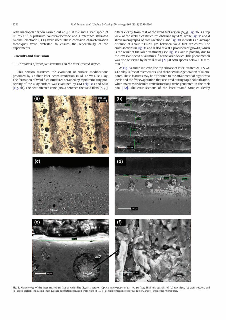
The formation of weld filet structures obtained by rapid remelting pro-
cessing of the alloy surface was examined by OM (Fig. 3a) and SEM
(Fig. 3b). The heat-affected zone (HAZ) between the weld filets (SYb-L)
differs clearly from that of the weld filet region (SWf). Fig. 3b is a top
view of the weld filet structures obtained by SEM, while Fig. 3c and d
show micrographs of cross-sections, and Fig. 3d indicates an average
distance of about 230–290 μm between weld filet structures. The
cross-sections in Fig. 3c and d also reveal a protuberant growth, which
is the result of the laser treatment (see Fig. 3e), and is possibly due to
the low scan speed of 40 mm.s−1 of the laser device. This phenomenon
was also observed by Bertelli et al. [21] at scan speeds below 100 mm.
min−1.
As Fig. 3a and b indicate, the top surface of laser-treated Al–1.5 wt.
% Fe alloy is free ofmicrocracks, and there is visible generation ofmicro-
pores. These features may be attributed to the attainment of high stress
levels and the fast evaporation that occurred during rapid solidification,
when martensite/bainite transformations were generated in the melt
pool [22]. The cross-sections of the laser-treated samples clearly
Fig. 3. Morphology of the laser-treated surface of weld filet (SWf) structures: Optical micrograph of (a) top surface; SEM micrographs of (b) top view, (c) cross-section, and
(d) cross-section, indicating their average separation between weld filets (SYb-L); (e) highlighted microporous region, and (f) inside the micropores.
2296 M.M. Pariona et al. / Surface & Coatings Technology 206 (2012) 2293–2301
indicate that the depth of the laser-melted layer extended to about
190 μm below the surface (Fig. 3c and d). This indicates the occurrence
of a homogeneousmelt depth in the surface region, whichwas attribut-
ed to the constant scan speed of the laser beam. A dense fine-grained
laser-melted layer is not visible at the surface. This may be due to the
high cooling rates at the surface and the formation of oxides and
metal alloys in this region. The HAZ appears in a narrow line, indicating
high cooling rates through conduction from this region towards the
solid bulk.
According to Kac and Kusinsky [23], the main application of the
laser melting technique is the modification of the surface properties
of materials through the formation of a hard, homogenous and ultra-
fine structure on the surface layer, without changing their chemical
composition. The steep temperature gradients and high solidification
rates associated with localized, rapid surface melting can lead to the
formation of novel non-equilibrium systems, including metastable
phases (in some materials amorphous phases) and supersaturated
solutions with fine microstructures and high homogeneity.
In the present work, the surface layers obtained in Al–1.5 wt.% Fe
after Yb-fiber laser melting were relatively smooth, morphologically
homogenous, and without cracks (Fig. 3c). The advantage of this tech-
nique is that it produces a microstructure that is chemically highly
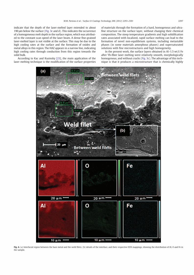
Fig. 4. (a) Interfacial region between the base metal and the weld filets; (b) details of the interface, and their respective EDX mappings, showing the distribution of Al, O and Fe in
the sample.
2297M.M. Pariona et al. / Surface & Coatings Technology 206 (2012) 2293–2301
homogeneous and refined, particularly in welded regions. These find-
ings are consistent with those reported by Kac and Kusinsky [24] and
Ryan and Prangnell [25] concerning the application of laser melting to
protect welded joints against corrosion. The most common effects of
laser treatment on Al-aerospace alloys and friction stir welds are pro-
duced on the grain structure and chemical homogeneity of the sur-
faces. Overall, this treatment produces a surface layer that is thin
compared to the thickness of the substrate material.
On the other hand, Cotton and Kaufman [3] reported some unusual
aspects about the microstructures of Al–Fe alloy systems. They
described the formation of randomly oriented intercellular dispersed
intermetallic compounds with diameters in the order of 50 nm in a
microcellular matrix, based on typical cellular or microcellular
microstructures.
In the present study, a distinct and unexpected boundary was
observed (Fig. 3c) between the fusion zone and the parent material,
considering that no pronounced HAZ was created. This specific charac-
teristic may be due to the short pulse length of the excimer laser, which
minimizes thermal diffusion, and the shallow absorption depth of UV
photons in metals [25]. In addition, the SEM analysis of the laser-
melted zone did not reveal any dendritic structures. It is therefore
believed that in the solidification of the laser-melted zone close to
the top layer, a planar solid–liquid interface may prevail [25]. This
differs from the cellular–dendritic structures obtained by laser surface
melting of Al-alloys using CO2 lasers [25]. The presence of precipitates
in the laser-melted zone may be caused by re-aging of the resolidified
zone [25] under the effect of the Yb-fiber laser beam.
3.2. Coating layer with a low fine microporous structure
The formation of fine micropores is visible in the surface-treated
sample (Fig. 3a and b), and is more concentrated near the weld filets
and in the cross-sections (Fig. 3c and d), showing a higher concentra-
tion between the weld filets. The fine microporosity depicted in
Fig. 3d is magnified in Fig. 3e and f.
Fig. 4a illustrates the interfacial region between the base metal
and the weld filets, revealing the presence of different phases in the
various regions of the sample. Fig. 4b shows the corresponding EDX
mapping of these micrographs, while Tables 3 and 4 describe the
respective semi-quantifications obtained in the EDX analysis. Note
that oxygen atoms are more concentrated in the weld filet region,
while Al atoms are located between weld filets. However, the
presence of iron showed an almost uniform distribution, since its con-
centration was low in this alloy.
These Fe/Al/O ratios and atomic distributions identified in the
sample are consistent with the formation of oxides and phases pro-
duced by the laser surface treatment. More specifically, the atomic
diffusion of oxygen inside the metal base was facilitated by the high
thermal gradient in air atmosphere, when the Al and Fe elements
reacted with oxygen at a high temperature, enabling the formation
of oxides inside the melt zone.
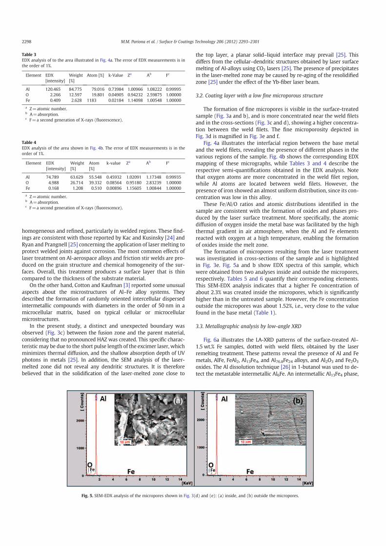
The formation of micropores resulting from the laser treatment
was investigated in cross-sections of the sample and is highlighted
in Fig. 3e. Fig. 5a and b show EDX spectra of this sample, which
were obtained from two analyses inside and outside the micropores,
respectively. Tables 5 and 6 quantify their corresponding elements.
This SEM-EDX analysis indicates that a higher Fe concentration of
about 2.3% was created inside the micropores, which is significantly
higher than in the untreated sample. However, the Fe concentration
outside the micropores was about 1.52%, i.e., very close to the value
found in the base metal (Table 1).
3.3. Metallographic analysis by low-angle XRD
Fig. 6a illustrates the LA-XRD patterns of the surface-treated Al–
1.5 wt.% Fe samples, dotted with weld filets, obtained by the laser
remelting treatment. These patterns reveal the presence of Al and Fe
metals, AlFe, FeAl2, Al13Fe4, and Al76.8Fe24 alloys, and Al2O3 and Fe2O3
oxides. The Al dissolution technique [26] in 1-butanol was used to de-
tect the metastable intermetallic Al6Fe. An intermetallic Al13Fe4 phase,
Table 3
EDX analysis of to the area illustrated in Fig. 4a. The error of EDX measurements is in
the order of 1%.
Element EDX
[intensity]
Weight
[%]
Atom [%] k-Value Za Ab Fc
Al 120.465 84.775 79.016 0.73984 1.00966 1.08222 0.99995
O 2.266 12.597 19.801 0.04905 0.94232 2.59875 1.00000
Fe 0.409 2.628 1183 0.02184 1.14098 1.00548 1.00000
a Z=atomic number.b A=absorption.c F=a second generation of X-rays (fluorescence).
Table 4
EDX analysis of the area shown in Fig. 4b. The error of EDX measurements is in the
order of 1%.
Element EDX
[intensity]
Weight
[%]
Atom
[%]
k-value Za Ab Fc
Al 74.789 63.629 55.548 0.45932 1.02091 1.17348 0.99935
O 4.988 26.714 39.332 0.08564 0.95180 2.83239 1.00000
Fe 0.168 1.208 0.510 0.00896 1.15605 1.00844 1.00000
a Z=atomic number.b A=absorption.c F=a second generation of X-rays (fluorescence).
Fig. 5. SEM-EDX analysis of the micropores shown in Fig. 3(d) and (e): (a) inside, and (b) outside the micropores.
2298 M.M. Pariona et al. / Surface & Coatings Technology 206 (2012) 2293–2301
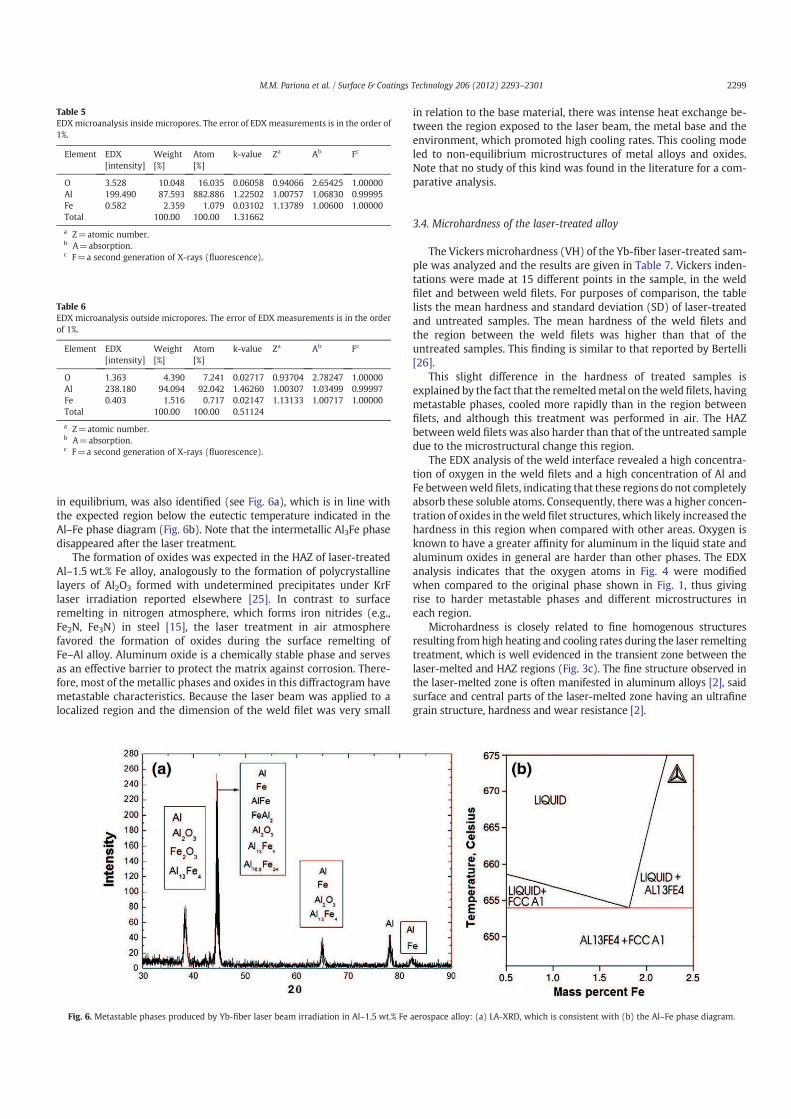
in equilibrium, was also identified (see Fig. 6a), which is in line with
the expected region below the eutectic temperature indicated in the
Al–Fe phase diagram (Fig. 6b). Note that the intermetallic Al3Fe phase
disappeared after the laser treatment.
The formation of oxides was expected in the HAZ of laser-treated
Al–1.5 wt.% Fe alloy, analogously to the formation of polycrystalline
layers of Al2O3 formed with undetermined precipitates under KrF
laser irradiation reported elsewhere [25]. In contrast to surface
remelting in nitrogen atmosphere, which forms iron nitrides (e.g.,
Fe2N, Fe3N) in steel [15], the laser treatment in air atmosphere
favored the formation of oxides during the surface remelting of
Fe–Al alloy. Aluminum oxide is a chemically stable phase and serves
as an effective barrier to protect the matrix against corrosion. There-
fore, most of the metallic phases and oxides in this diffractogram have
metastable characteristics. Because the laser beam was applied to a
localized region and the dimension of the weld filet was very small
in relation to the base material, there was intense heat exchange be-
tween the region exposed to the laser beam, the metal base and the
environment, which promoted high cooling rates. This cooling mode
led to non-equilibrium microstructures of metal alloys and oxides.
Note that no study of this kind was found in the literature for a com-
parative analysis.
3.4. Microhardness of the laser-treated alloy
The Vickers microhardness (VH) of the Yb-fiber laser-treated sam-
ple was analyzed and the results are given in Table 7. Vickers inden-
tations were made at 15 different points in the sample, in the weld
filet and between weld filets. For purposes of comparison, the table
lists the mean hardness and standard deviation (SD) of laser-treated
and untreated samples. The mean hardness of the weld filets and
the region between the weld filets was higher than that of the
untreated samples. This finding is similar to that reported by Bertelli
[26].
This slight difference in the hardness of treated samples is
explained by the fact that the remeltedmetal on theweld filets, having
metastable phases, cooled more rapidly than in the region between
filets, and although this treatment was performed in air. The HAZ
betweenweld filets was also harder than that of the untreated sample
due to the microstructural change this region.
The EDX analysis of the weld interface revealed a high concentra-
tion of oxygen in the weld filets and a high concentration of Al and
Fe betweenweld filets, indicating that these regions do not completely
absorb these soluble atoms. Consequently, there was a higher concen-
tration of oxides in theweld filet structures, which likely increased the
hardness in this region when compared with other areas. Oxygen is
known to have a greater affinity for aluminum in the liquid state and
aluminum oxides in general are harder than other phases. The EDX
analysis indicates that the oxygen atoms in Fig. 4 were modified
when compared to the original phase shown in Fig. 1, thus giving
rise to harder metastable phases and different microstructures in
each region.
Microhardness is closely related to fine homogenous structures
resulting fromhigh heating and cooling rates during the laser remelting
treatment, which is well evidenced in the transient zone between the
laser-melted and HAZ regions (Fig. 3c). The fine structure observed in
the laser-melted zone is often manifested in aluminum alloys [2], said
surface and central parts of the laser-melted zone having an ultrafine
grain structure, hardness and wear resistance [2].
Table 5
EDXmicroanalysis inside micropores. The error of EDX measurements is in the order of
1%.
Element EDX
[intensity]
Weight
[%]
Atom
[%]
k-value Za Ab Fc
O 3.528 10.048 16.035 0.06058 0.94066 2.65425 1.00000
Al 199.490 87.593 882.886 1.22502 1.00757 1.06830 0.99995
Fe 0.582 2.359 1.079 0.03102 1.13789 1.00600 1.00000
Total 100.00 100.00 1.31662
a Z=atomic number.b A=absorption.c F=a second generation of X-rays (fluorescence).
Table 6
EDX microanalysis outside micropores. The error of EDX measurements is in the order
of 1%.
Element EDX
[intensity]
Weight
[%]
Atom
[%]
k-value Za Ab Fc
O 1.363 4.390 7.241 0.02717 0.93704 2.78247 1.00000
Al 238.180 94.094 92.042 1.46260 1.00307 1.03499 0.99997
Fe 0.403 1.516 0.717 0.02147 1.13133 1.00717 1.00000
Total 100.00 100.00 0.51124
a Z=atomic number.b A=absorption.c F=a second generation of X-rays (fluorescence).
Fig. 6. Metastable phases produced by Yb-fiber laser beam irradiation in Al–1.5 wt.% Fe aerospace alloy: (a) LA-XRD, which is consistent with (b) the Al–Fe phase diagram.
2299M.M. Pariona et al. / Surface & Coatings Technology 206 (2012) 2293–2301
3.5. Corrosion resistance of laser-treated alloy
The effect of the laser treatment on the corrosion resistance of
laser-treated and untreated alloy samples was tested in sulfuric acid
(H2SO4) 0.1 M at 25 °C. For a comparative characterization, the chem-
ically corroded samples were tested using the open circuit potential
(OCP), micro- and macropolarization techniques.
The corrosion potentials of the laser-treated Al–1.5 wt.% Fe alloy
and untreated samples in aerated acid solution were investigated in
continuous measurements, as depicted in Fig. 7. The laser-treated sam-
ple presented an initial OCP of −0.532 V, which dropped sharply to
around −0.620 V, and stabilized at −0.628 V at end of the test. Note
that the OCP performance of the untreated material was initially
−0.642 V, decreasing to around −0.721 V, and remaining at this
value for around 420 min, after which it gradually increased up to
−0.695 V. The variation between the OCP performance (Fig. 7) of the
treated and untreated samples is due to the microstructural modifica-
tion of the laser-treated layer. The initial decrease in the OCP of the
laser-treated sample was related to the stability of the surface, which
showed a tendency for a more cathodic behavior, demonstrating that
stable corrosion resistance was improved by the laser treatment. The
shift of 70 mV of the treated sample towards a more anodic behavior
than that of the untreated sample is attributed to the formation of
aluminum oxide in the treated area. This is a chemically stable phase
that serves as an effective barrier to protect the matrix against corro-
sion attacks [25]. This more anodic behavior can also be attributed to
the formation of a homogeneous microstructure and composition
that enhances the material's corrosion resistance and mechanical
properties. This characteristic can be seen in the untreated sample as
a tendency to form a new layer. This result is promising, and may be
useful in various industrial applications.
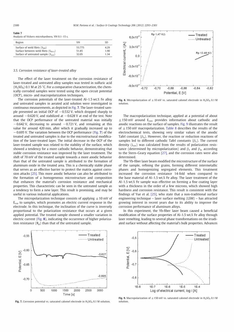
The micropolarization technique consists of applying ±10 mV of
Ecor to samples, which promotes an electric current response in the
electrode. In this technique, the inclination of the curve is inversely
proportional to the polarization resistance that occurs at a given
applied potential. The treated sample showed a smaller variation in
electric current (Fig. 8), indicating the occurrence of higher polariza-
tion resistance (Rp) than that of the untreated sample.
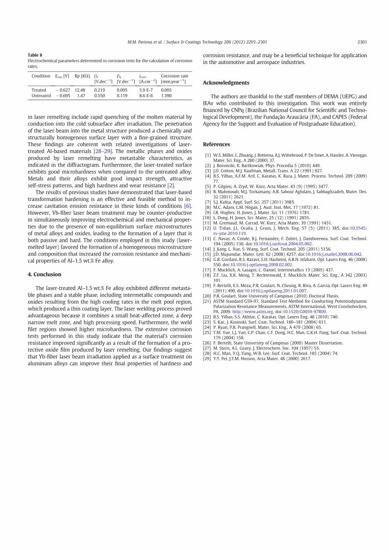
The macropolarization technique, applied at a potential of about
±150 mV around Ecor, provides information about cathodic and
anodic reactions on the surface of samples. Fig. 9 illustrates the result
of ±150 mV macropolarization. Table 8 describes the results of the
electrochemical tests, showing very similar values of the anodic
Tafel constant (βa). However, the reaction or reduction reactions of
samples led to different cathodic Tafel constants (βc). The current
density (icor) was calculated from the results of polarization resis-
tance (determined by micropolarization) and βc and βa, according
to the Stern–Geary equation [27], and the corrosion rates were also
determined.
The Yb-fiber laser beammodified the microstructure of the surface
of the sample, refining the grains, forming different intermetallic
phases and homogenizing segregated elements. This treatment
increased the corrosion resistance 14-fold when compared to
the base material of Al–1.5 wt.% Fe alloy. The laser treatment of the
Al–1.5 wt.% Fe sample was effective on forming a fine coating layer
with a thickness in the order of a few microns, which showed high
hardness and corrosion resistance. This result is consistent with the
findings of Yue et al. [25], who state that a non-traditional surface
engineering technique – laser surface melting (LSM) – has attracted
growing interest in recent years due to its ability to improve the
corrosion performance of aluminum alloys.
In this experiment, the Yb-fiber laser beam caused a beneficial
modification of the surface properties of Al–1.5 wt.% Fe alloy through
laser remelting, leading to several phase transformations on the irradi-
ated surface without affecting the material's bulk properties. Advances
Table 7
Analysis of Vickers microhardness, VH 0.1–15 s.
Region VH SD
Surface of weld filets (SWf) 53.775 4.29
Surface between weld filets (SYb-L) 51.85 1.90
Surface of untreated sample (Sunt) 32.05 1.34
Fig. 7. Corrosion potential vs. saturated calomel electrode in H2SO4 0.1 M solution.
Fig. 8. Micropolarization of ±10 mV vs. saturated calomel electrode in H2SO4 0.1 M
solution.
Fig. 9. Macropolarization of ±150 mV vs. saturated calomel electrode in H2SO4 0.1 M
solution.
2300 M.M. Pariona et al. / Surface & Coatings Technology 206 (2012) 2293–2301
in laser remelting include rapid quenching of the molten material by
conduction into the cold subsurface after irradiation. The penetration
of the laser beam into the metal structure produced a chemically and
structurally homogenous surface layer with a fine-grained structure.
These findings are coherent with related investigations of laser-
treated Al-based materials [28–29]. The metallic phases and oxides
produced by laser remelting have metastable characteristics, as
indicated in the diffractogram. Furthermore, the laser-treated surface
exhibits good microhardness when compared to the untreated alloy.
Metals and their alloys exhibit good impact strength, attractive
self-stress patterns, and high hardness and wear resistance [2].
The results of previous studies have demonstrated that laser-based
transformation hardening is an effective and feasible method to in-
crease cavitation erosion resistance in these kinds of conditions [6].
However, Yb-fiber laser beam treatment may be counter-productive
in simultaneously improving electrochemical and mechanical proper-
ties due to the presence of non-equilibrium surface microstructures
of metal alloys and oxides, leading to the formation of a layer that is
both passive and hard. The conditions employed in this study (laser-
melted layer) favored the formation of a homogeneous microstructure
and composition that increased the corrosion resistance and mechani-
cal properties of Al–1.5 wt.% Fe alloy.
4. Conclusion
The laser-treated Al–1.5 wt.% Fe alloy exhibited different metasta-
ble phases and a stable phase, including intermetallic compounds and
oxides resulting from the high cooling rates in the melt pool region,
which produced a thin coating layer. The laser welding process proved
advantageous because it combines a small heat-affected zone, a deep
narrow melt zone, and high processing speed. Furthermore, the weld
filet regions showed higher microhardness. The extensive corrosion
tests performed in this study indicate that the material's corrosion
resistance improved significantly as a result of the formation of a pro-
tective oxide film produced by laser remelting. Our findings suggest
that Yb-fiber laser beam irradiation applied as a surface treatment on
aluminum alloys can improve their final properties of hardness and
corrosion resistance, and may be a beneficial technique for application
in the automotive and aerospace industries.
Acknowledgments
The authors are thankful to the staff members of DEMA (UEPG) and
IEAv who contributed to this investigation. This work was entirely
financed by CNPq (Brazilian National Council for Scientific and Techno-
logical Development), the Fundação Araucária (FA), and CAPES (FederalAgency for the Support and Evaluation of Postgraduate Education).
References
[1] W.S. Miller, L. Zhuang, J. Bottema, A.J.Wittebrood, P. De Smet, A. Haszler, A. Vieregge,Mater. Sci. Eng., A 280 (2000) 37.
[2] J. Borowski, K. Bartkowiak, Phys. Procedia 5 (2010) 449.[3] J.D. Cotton, M.J. Kaufman, Metall. Trans. A 22 (1991) 927.[4] B.S. Yilbas, A.F.M. Arif, C. Karatas, K. Raza, J. Mater. Process. Technol. 209 (2009)
77.[5] P. Gilgien, A. Zryd, W. Kurz, Acta Mater. 43 (9) (1995) 3477.[6] B. Mahmoudi, M.J. Torkamany, A.R. Sabour Aghdam, J. Sabbaghzadeh, Mater. Des.
32 (2011) 2621.[7] S.J. Kalita, Appl. Surf. Sci. 257 (2011) 3985.[8] M.C. Adam, L.M. Hogan, J. Aust. Inst. Met. 17 (1972) 81.[9] I.R. Hughes, H. Jones, J. Mater. Sci. 11 (1976) 1781.
[10] L. Dong, H. Jones, Scr. Mater. 25 (12) (1991) 2855.[11] M. Gremaud, M. Carrad, W. Kurz, Acta Mater. 39 (1991) 1431.[12] U. Trdan, J.L. Ocaña, J. Grum, J. Mech. Eng. 57 (5) (2011) 385, doi:10.5545/
sv-jme.2010.119.[13] C. Navas, A. Conde, B.J. Fernandez, F. Zubiri, J. Damborenea, Surf. Coat. Technol.
194 (2005) 136, doi:10.1016/j.surfcoat.2004.05.002.[14] J. Jiang, L. Xue, S. Wang, Surf. Coat. Technol. 205 (2011) 5156.[15] J.D. Majumdar, Mater. Lett. 62 (2008) 4257, doi:10.1016/j.matlet.2008.06.042.[16] G.R. Gordani, R.S. Razavi, S.H. Hashemi, A.R.N. Isfahani, Opt. Lasers Eng. 46 (2008)
550, doi:10.1016/j.optlaseng.2008.02.002.[17] F. Mucklich, A. Lasagni, C. Daniel, Intermetallics 13 (2005) 437.[18] Z.F. Liu, X.K. Meng, T. Recktenwald, F. Mucklich, Mater. Sci. Eng., A 342 (2003)
101.[19] F. Bertelli, E.S. Meza, P.R. Goulart, N. Cheung, R. Riva, A. Garcia, Opt. Lasers Eng. 49
(2011) 490, doi:10.1016/j.optlaseng.2011.01.007.[20] P.R. Goulart, State University of Campinas (2010) Doctoral Thesis.[21] ASTM Standard G59-97, Standard Test Method for Conducting Potentiodynamic
Polarization Resistance Measurements, ASTM International, West Conshohocken,PA, 2009. http://www.astm.org, doi:10.1520/G0059-97R09.
[22] B.S. Yilbas, S.S. Akhtar, C. Karatas, Opt. Lasers Eng. 48 (2010) 740.[23] S. Kac, J. Kusinski, Surf. Coat. Technol. 180–181 (2004) 611.[24] P. Ryan, P.B. Prangnell, Mater. Sci. Eng., A 479 (2008) 65.[25] T.M. Yue, L.J. Yan, C.P. Chan, C.F. Dong, H.C. Man, G.K.H. Pang, Surf. Coat. Technol.
179 (2004) 158.[26] F. Bertelli, State University of Campinas (2009) Master Dissertation.[27] M. Stern, A.L. Geary, J. Electrochem. Soc. 104 (1957) 53.[28] H.C. Man, Y.Q. Yang, W.B. Lee, Surf. Coat. Technol. 185 (2004) 74.[29] Y.T. Pei, J.T.M. Hosson, Acta Mater. 48 (2000) 2617.
Table 8
Electrochemical parameters determined in corrosion tests for the calculation of corrosion
rates.
Condition Ecor [V] Rp [KΩ] βc
[V.dec−1]
βa
[V.dec−1]
icorr[A.cm−2]
Corrosion rate
[mm.year−1]
Treated −0.627 12.48 0.219 0.095 5.9 E-7 0.095
Untreated −0.695 1.47 0.550 0.119 8.6 E-6 1.390
2301M.M. Pariona et al. / Surface & Coatings Technology 206 (2012) 2293–2301
Top Related
Copyright © 2022 FDOKUMEN

