


Bahasa
Halaman
Hukum

Student Notes:
Weld Design������������
Copyright DASSAULT SYSTEMES 1
Cop
yrig
ht D
AS
SA
ULT
SY
STE
ME
S
Weld Design
CATIA V5 TrainingFoils
Version 5 Release 19January 2009
EDU_CAT_EN_WD1_FF_V5R19

Student Notes:
Weld Design������������
Copyright DASSAULT SYSTEMES 2
Cop
yrig
ht D
AS
SA
ULT
SY
STE
ME
S
About this courseObjectives of the courseUpon completion of this course you will be able to:- Weld parts, - Generate Weld reports, - Extract 2D views from 3D welds.
Targeted audienceMechanical and Structural Designers
PrerequisitesStudents attending this course should be familiar with CATIA V5 Fundamentals.
8 Hrs.

Student Notes:
Weld Design������������
Copyright DASSAULT SYSTEMES 3
Cop
yrig
ht D
AS
SA
ULT
SY
STE
ME
S
Table of Contents (1/2)
Workbench Presentation 5Accessing the Workbench 6Weld Information in the Specification Tree 7User Interface: Toolbars 8Where is Weld Design used? 9Why should we use the Weld Design Workbench? 10
Welds Creation 12Classification of Welds 13Welds definition inputs 14How to Create a Fillet Weld 16How to Create a Square Butt Weld 17How to Create a V Butt Weld 18How to Create Bevel Butt Weld 19How to Create a V Butt Weld with Broad Root Face 20How to Create a Bevel Butt Weld With Broad Root Face 21How to Create a J Butt Weld 22User Weld 23How to Create a User Weld 24

Student Notes:
Weld Design������������
Copyright DASSAULT SYSTEMES 4
Cop
yrig
ht D
AS
SA
ULT
SY
STE
ME
S
Table of Contents (2/2)
Symmetric Welds 25Weld Creation Mode 26How to Use 'Without Preparation Mode' 27Options in the Weld Creation Dialog Box 28
Weld Reports and Drawings 32Weld Report Generation 33Drawing Generation 343D to 2D Weld Annotations 35Inserting Weld Reports in Drawings 36

Student Notes:
Weld Design������������
Copyright DASSAULT SYSTEMES 5
Cop
yrig
ht D
AS
SA
ULT
SY
STE
ME
S
Workbench PresentationYou will be introduced to terminologies and tools specific to ‘Weld Design’ workbench.

Student Notes:
Weld Design������������
Copyright DASSAULT SYSTEMES 6
Cop
yrig
ht D
AS
SA
ULT
SY
STE
ME
S
Accessing the Workbench
You can access the Weld Design Workbench:From the Start MenuUsing the ‘Workbench Command’
To be able to access the workbench using the Workbench Command, the ‘Weld Design’ workbench should be included in the list of favorite workbenches.

Student Notes:
Weld Design������������
Copyright DASSAULT SYSTEMES 7
Cop
yrig
ht D
AS
SA
ULT
SY
STE
ME
S
Weld Information in the Specification Tree
On Creation of a weld, its information is stored in the specification tree as shown in the image below.
Annotation Set stores the weld annotations and Views
The weld information is stored as ‘Assembly Joints’
Dummy parts get created to store the specifications and material of the weld.
A Joint is a set of two or more components whose geometry is used for creating welds.A Joint Body is a set of welds. A Joint body is attached to a joint.While creating a weld, you can specify the Joint Body under which you want to put your weld.

Student Notes:
Weld Design������������
Copyright DASSAULT SYSTEMES 8
Cop
yrig
ht D
AS
SA
ULT
SY
STE
ME
S
User Interface: Toolbars
Apart from the ‘Welds’ and ‘Joints’ toolbar, the ‘Constraints’, ‘Move’ and ‘Annotations’ toolbars from Assembly Design workbench are also useful while working in Weld Design Workbench. These toolbars are also available in ‘Weld Design’ workbench.
Weld Creation Mode
Fillet Weld
Square Butt Weld
Single V Butt Weld
Single Bevel Butt Weld
Welds with broad root face.
Single U Butt Weld
Use Weld
Single J Butt Weld
Joint
Joint Body
Student Notes:
Weld Design������������
Copyright DASSAULT SYSTEMES 9
Cop
yrig
ht D
AS
SA
ULT
SY
STE
ME
S
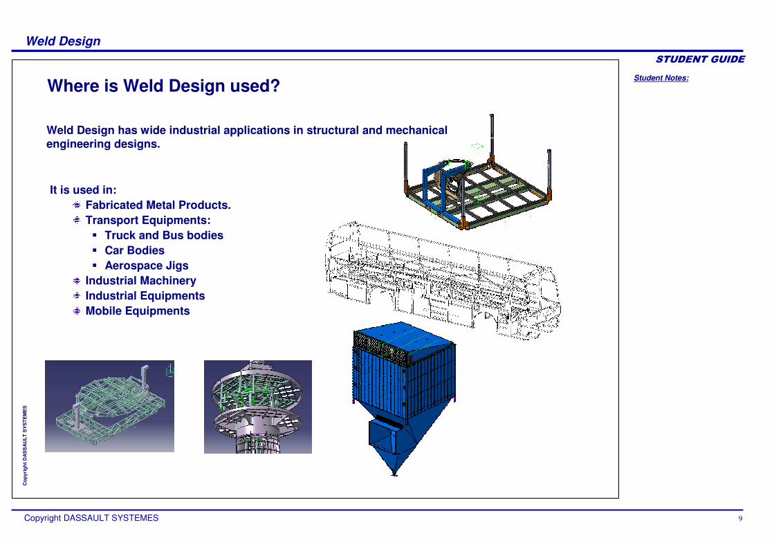
Where is Weld Design used?
Weld Design has wide industrial applications in structural and mechanical engineering designs.
It is used in:Fabricated Metal Products.Transport Equipments:� Truck and Bus bodies� Car Bodies� Aerospace Jigs
Industrial Machinery Industrial EquipmentsMobile Equipments

Student Notes:
Weld Design������������
Copyright DASSAULT SYSTEMES 10
Cop
yrig
ht D
AS
SA
ULT
SY
STE
ME
S
Why should we use the Weld Design Workbench? (1/2)
Deploying Weld Design Workbench has several advantages:
The creation of the weld in the 3D digital Mock-Up will allow designer to manage digital pre-assembly, mass inertia, space reservation and drafting annotation.
The parts to be welded get prepared automatically after creating the weld thus creating associative assembly features in addition to the physical weld element.
Weld Plates get automatically created as per the parameters used to define the weld.
Welds are integrated within 3D Design. Mass and the inertia of the weld ribbons are added to the mass and the inertia of the whole assembly so that User, specifying the weld material, can perform relevant calculation. Welds can also be integrated in the clash collision of the assembly and other structural and stress analysis.

Student Notes:
Weld Design������������
Copyright DASSAULT SYSTEMES 11
Cop
yrig
ht D
AS
SA
ULT
SY
STE
ME
S
Why should we use the Weld Design Workbench?(2/2)
Welds can be fully integrated with drafting. Welds are automatically generated in the standard views, section views and section cuts and are impacted by the Hidden Line Removal visualization mode of the assembly. 2D Welds annotations are also automatically created.

Student Notes:
Weld Design������������
Copyright DASSAULT SYSTEMES 12
Cop
yrig
ht D
AS
SA
ULT
SY
STE
ME
S
Welds CreationYou will learn to create different types of welds.

Student Notes:
Weld Design������������
Copyright DASSAULT SYSTEMES 13
Cop
yrig
ht D
AS
SA
ULT
SY
STE
ME
S
Classification of Welds
Welds are basically classified into two types:
Fillet weld and Butt weld
Fillet weld : Does not require any preparation. Butt Weld: Requires preparation of weld plates
Preparation
Fillet Welds are the welds which do not require any preparation before the creation of weld. Preparation means removal of material from the weld plates so as to accommodate the weld bead in it.
The ‘Butt Welds’ require the plates to be prepared to accommodate the weld bead.

Student Notes:
Weld Design������������
Copyright DASSAULT SYSTEMES 14
Cop
yrig
ht D
AS
SA
ULT
SY
STE
ME
S
Welds Definition Inputs (1/2)
Main Characteristics: The weld shape depends upon the ‘Characteristics’ that you select.
Offset
Flat Convex Concave
Results using various ‘Shape’ options.
Trimming limits: If you do not want the full edge to be welded, you can specify the trimming limits.

Student Notes:
Weld Design������������
Copyright DASSAULT SYSTEMES 15
Cop
yrig
ht D
AS
SA
ULT
SY
STE
ME
S
Welds Definition Inputs (2/2)
Geometric Inputs: The geometric inputs depend upon the type of weld you are creating. For example: A fillet weld requires two surfaces and V Butt weld requires four surfaces as the geometric inputs.
You can also use the ‘Selection Assistant’ which helps you select the geometric inputs in a sequence.

Student Notes:
Weld Design������������
Copyright DASSAULT SYSTEMES 16
Cop
yrig
ht D
AS
SA
ULT
SY
STE
ME
S
How to Create a Fillet Weld
Click the Fillet Weld tool.1
Select the faces as shown2
Enter Weld Height = 3mm. Re-limit the weld if required.
3
Fillet is created and stored in an Assembly Joint. Annotation is automatically created.
5
Click OK to the weld creation dialog box.
4

Student Notes:
Weld Design������������
Copyright DASSAULT SYSTEMES 17
Cop
yrig
ht D
AS
SA
ULT
SY
STE
ME
S
How to Create a Square Butt Weld
Click the Square Butt Weld tool.1
Check the ‘Selection Assistant’ option to open the ‘Assistant Viewer’.
2
Select two edges or four faces as geometric inputs for the weld.
3
The weld is created and stored in an Assembly Joint.
5
Enter Weld Width = 4 mm and click OK to the weld creation dialog box.
4
The Preparation which is created corresponds to a remove operation.

Student Notes:
Weld Design������������
Copyright DASSAULT SYSTEMES 18
Cop
yrig
ht D
AS
SA
ULT
SY
STE
ME
S
How to create a V Butt Weld
Click the V Butt Weld tool.1
Check the ‘Selection Assistant’ option to open the ‘Assistant Viewer’.
2
Select two edges or four faces as geometric inputs for the weld.
3
Enter Weld Width, Angle and Height as 2.0mm, 45deg and 1.0mm respectively and click OK.
4
The Preparation which is created corresponds to a remove operation.
The weld is created and stored in an Assembly Joint.
5

Student Notes:
Weld Design������������
Copyright DASSAULT SYSTEMES 19
Cop
yrig
ht D
AS
SA
ULT
SY
STE
ME
S
How to create Bevel Butt Weld
Click the Bevel Butt Weld tool.1
Check the ‘Selection Assistant’ option to open the ‘Assistant Viewer’.
2
Select two edges or three faces as geometric inputs for the weld.
3
Enter Weld Width, Angle and Height as 2.0mm, 15deg and 1.0mm respectively.
4
The weld is created and stored in an Assembly Joint.
6 The Preparation which is created corresponds to a remove operation.
Select Propagation mode as “Without Propagation” and click OK
5

Student Notes:
Weld Design������������
Copyright DASSAULT SYSTEMES 20
Cop
yrig
ht D
AS
SA
ULT
SY
STE
ME
S
How to Create a V Butt Weld with Broad Root Face
Click the V Butt Weld With Broad Root Face tool.
1
Check the ‘Selection Assistant’ option to open the ‘Assistant Viewer’.
2
Select two edges or four faces as geometric inputs for the weld.
3
Enter Weld Width, Angle and Height as 2.0mm, 15deg and 1.0mm respectively.
4
Select Propagation mode as “Without Propagation” and click OK
5
The weld is created and stored in an Assembly Joint.
6The Preparation which is
created corresponds to a remove operation.
Student Notes:
Weld Design������������
Copyright DASSAULT SYSTEMES 21
Cop
yrig
ht D
AS
SA
ULT
SY
STE
ME
S
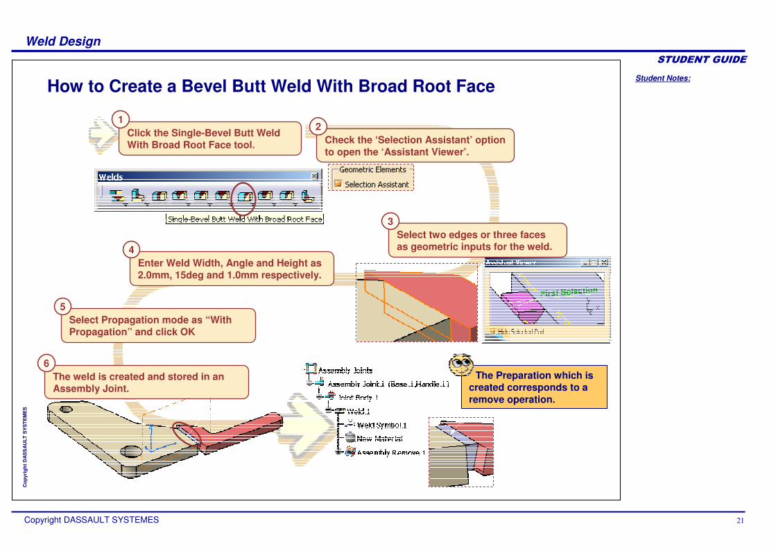
How to Create a Bevel Butt Weld With Broad Root Face
Click the Single-Bevel Butt Weld With Broad Root Face tool.
1
Check the ‘Selection Assistant’ option to open the ‘Assistant Viewer’.
2
Select two edges or three faces as geometric inputs for the weld.
3
Enter Weld Width, Angle and Height as 2.0mm, 15deg and 1.0mm respectively.
4
Select Propagation mode as “With Propagation” and click OK
5
The weld is created and stored in an Assembly Joint.
6The Preparation which is
created corresponds to a remove operation.

Student Notes:
Weld Design������������
Copyright DASSAULT SYSTEMES 22
Cop
yrig
ht D
AS
SA
ULT
SY
STE
ME
S
How to Create a J Butt Weld
Click the Single- J Butt Weld tool.1
Check the ‘Selection Assistant’ option to open the ‘Assistant Viewer’.
2
Select two edges (Select the edge of Base first) or three faces as geometric inputs for the weld.
3
Enter Width = 2mm, Angle = 10deg, Height = 3mm.
4
Select Propagation mode as “With Propagation” and click OK
5
The weld is created and stored in an Assembly Joint.
6
The Preparation which is created corresponds to a remove operation.

Student Notes:
Weld Design������������
Copyright DASSAULT SYSTEMES 23
Cop
yrig
ht D
AS
SA
ULT
SY
STE
ME
S
User Weld
A user weld is created using a predefined shape as the ‘Weld bead’.
The inputs for user weld are:
A ‘Part Body’ in which the weld bead is designed.An ‘Assembly Remove Feature’ containing the information of the remove operation between the ‘Weld Bead’ part and the parts to be welded.The Annotation associated to your weld.
+
+

Student Notes:
Weld Design������������
Copyright DASSAULT SYSTEMES 24
Cop
yrig
ht D
AS
SA
ULT
SY
STE
ME
S
How to Create a User Weld
In this example, the required inputs for the user weld are already created for you.
Click the User Weld tool.1
Enter a weld name.2
Select the Solid Body ‘WeldBead’from Weld.1 part as the Weld Bead.
3
Select ‘Base’ and ‘Handle’ as the welded Parts.
4Select ‘Assembly Remove.1’ as the ‘Associated Assembly Feature’
5
Select ‘Weld Symbol.1’ as the annotation for the weld and click OK.
6
The User Weld is createdYou can also remove the weld bead part from
bill of materials using the option shown above.

Student Notes:
Weld Design������������
Copyright DASSAULT SYSTEMES 25
Cop
yrig
ht D
AS
SA
ULT
SY
STE
ME
S
Symmetric Welds
You can also create symmetric welds using the ‘Double Weld’ tools available for Fillet, V-Groove, U, Bevel, Half-V and J-Groove welds.
Single V Butt Weld Double V Butt Weld
In symmetric welds, as the name suggests both the welds seams share the same parameters.

Student Notes:
Weld Design������������
Copyright DASSAULT SYSTEMES 26
Cop
yrig
ht D
AS
SA
ULT
SY
STE
ME
S
Weld Creation Mode
There are two weld creation modes available. The ‘Default’ mode and ‘Without Preparation Mode’
In the ‘Default mode’, the weld plates need not be already cut to accommodate the weld bead.
This mode requires geometrical inputs and parameters specifying the dimensions of the weld.
Default Mode
Without Preparation Mode
+Weld ParametersInput Geometry
=
Whereas in the ‘Without Preparation Mode’, you have to simply select the faces holding the weld bead. These faces can created by removing material from the weld plates. An example is shown ahead.

Student Notes:
Weld Design������������
Copyright DASSAULT SYSTEMES 27
Cop
yrig
ht D
AS
SA
ULT
SY
STE
ME
S
How to Use ‘Without Preparation Mode’
Before using the ‘Without Preparation Mode’, you have to make slots in the weld plates to accommodate the weld bead. In this example, the weld plates have been already created for you.
Change the ‘Default’ mode to ‘Without Preparation Mode’1
Check the ‘Selection Assistant’ option to open the ‘Assistant Viewer’.2
Select the faces as shown in the ‘Assistant Viewer’ and click OK. 3
The weld gets created in the prepared slot.
1Click the ‘Single V Butt weld’ tool. 2
2

Student Notes:
Weld Design������������
Copyright DASSAULT SYSTEMES 28
Cop
yrig
ht D
AS
SA
ULT
SY
STE
ME
S
Options in the Weld Creation Dialog Box
In this lesson, you will learn the use of various options in the Weld Creation Dialog box.

Student Notes:
Weld Design������������
Copyright DASSAULT SYSTEMES 29
Cop
yrig
ht D
AS
SA
ULT
SY
STE
ME
S
Tangent Propagation Option
For the fillet weld, you can use the ‘Tangent Propagation’ option to extend the weld to the adjacent tangent edges.
To use this option, you have to select the geometric elements from the dialog box and click the ‘Propagation’ button.
Result without Tangent Propagation
Result with Tangent Propagation

Student Notes:
Weld Design������������
Copyright DASSAULT SYSTEMES 30
Cop
yrig
ht D
AS
SA
ULT
SY
STE
ME
S
Preparation Mode Option
For welds which need preparation, two types of preparation modes are available.
Without Propagation With Propagation
The ‘Without Propagation’ option, removes the material from the welded part only at the portion of the weld whereas the ‘With Propagation’ option extends such removal of material throughout the edge of the welded part as shown above.

Student Notes:
Weld Design������������
Copyright DASSAULT SYSTEMES 31
Cop
yrig
ht D
AS
SA
ULT
SY
STE
ME
S
Other Useful Options
Simple Dashed
In the ‘Type’ tab of the Weld Creation panel, you can select the weld to be ‘Simple’ or ‘Dashed’. The results of both the options are shown above.
In the ‘Annotation’ tab, you can use the ‘Weld Symbol’ and ‘Length Always displayed options to display the weld symbol and length as shown.

Student Notes:
Weld Design������������
Copyright DASSAULT SYSTEMES 32
Cop
yrig
ht D
AS
SA
ULT
SY
STE
ME
S
Weld reports and DrawingsYou will learn to generate weld reports and drawings from 3D welds.

Student Notes:
Weld Design������������
Copyright DASSAULT SYSTEMES 33
Cop
yrig
ht D
AS
SA
ULT
SY
STE
ME
S
Weld Report Generation
You can generate a Weld Report using the ‘Weld Report’ command from the ‘Analyze’ menu.
This report can also be exported to a text or excel file using the ‘Save As’ button.

Student Notes:
Weld Design������������
Copyright DASSAULT SYSTEMES 34
Cop
yrig
ht D
AS
SA
ULT
SY
STE
ME
S
Drawing Generation
The welds are visible in the drawing views. To generate drawings:
Welds are visible in each view. You can also create a section view using any one of the commands in the ‘Sections’ toolbar.
Switch to the ‘Drafting’ workbench.Generate standard views.
Side View
Section View

Student Notes:
Weld Design������������
Copyright DASSAULT SYSTEMES 35
Cop
yrig
ht D
AS
SA
ULT
SY
STE
ME
S
3D to 2D Weld Annotations
Click on View from 3D icon
You can also transfer the 3D weld annotations into your drawings using the ‘View From 3D Tool. This tools is present in the menu ‘Insert > View > Projections’
From the specification tree, select the Annotation View containing the weld information.
1
2
The drawing will be updated with the weld information.

Student Notes:
Weld Design������������
Copyright DASSAULT SYSTEMES 36
Cop
yrig
ht D
AS
SA
ULT
SY
STE
ME
S
Inserting Weld Reports in Drawings
In the CATProduct, generate and save the weld report as an excel file.
You can insert the ‘Weld Report’ in the drawings using the ‘Insert Object’ command.
1
2 In the CATDrawing, from the menu select ‘Insert > Object’.
In the ‘Insert Object’ panel, select the ‘Create from File’ option and select the ‘Weld Report’ excel file.3
Select the ‘Link’ option to maintain associativity and click OK.4
3
4
The weld report will be inserted in the drawing.

Student Notes:
Weld Design������������
Copyright DASSAULT SYSTEMES 37
Cop
yrig
ht D
AS
SA
ULT
SY
STE
ME
S
Summary
In this course you have learned to:
Create Welds in an assembly context.Use various options available in the ‘Weld Creation’ dialog box.Generate and analyze weld reports.Generate drawings and include weld representation and annotations in them.
Top Related
Copyright © 2022 FDOKUMEN

