


Bahasa
Halaman
Hukum

1164 JOURNAL OF LIGHTWAVE TECHNOLOGY, VOL. 28, NO. 8, APRIL 15, 2010
Tunable Optical Dispersion Compensator Based onPower Splitting Between Two Dispersive Media
Miguel V. Drummond, Student Member, IEEE, Rogério N. Nogueira, Member, IEEE,Paulo P. Monteiro, Member, IEEE, Manuel A. Violas, Carola Sterner, and Pierre-Yves Fonjallaz
Abstract—In this paper, we propose and experimentally demon-strate a novel tunable optical dispersion compensator (TODC).Dispersion compensation is achieved by splitting the input signalbetween two dispersive media and adding the resulting signalsthereafter. Tunable compensation is attained by controlling thepower splitting ratio of the input signal between both dispersivemedia. The frequency response of the TODC is theoreticallyassessed considering signal addition in the optical and electricaldomains. The latter case is enabled by using optical single side-band (OSSB) modulation, which allows preserving the phaseinformation of dispersive media output signals after direct detec-tion. This is the only case experimentally tested, since it avoidsstability problems related with coherent addition of optical signals.A TODC with a tuning range of ��� to 0 ps/nm was designedand experimentally assessed for a 40 Gb/s nonreturn-to-zeroOSSB signal. The tunable power splitter consisted of an automaticpolarization controller and a polarization beam splitter, whichoffered a tuning time lower than 150 s. A bit error rate lowerthan ��
� was measured on the entire compensation range witha maximum power penalty of 3.3 dB relatively to an SSB signal inback-to-back.
Index Terms—Chromatic dispersion (CD), optical communica-tion systems, single sideband (SSB), tunable dispersion compensa-tion.
I. INTRODUCTION
C HROMATIC DISPERSION (CD) is a critical impairmentin current lightwave transmission systems. A fourfold in-
crease on the bit rate corresponds to a CD tolerance reductionof about 16 times [1]. Therefore, precise dispersion compensa-tion is needed for high-perchannel bit-rate lightwave systems inorder to allow the detection of information data with reducedbit error rate (BER). There are three main reasons why a static
Manuscript received August 31, 2009; revised December 18, 2009. First pub-lished February 08, 2010; current version published March 17, 2010. This workwas supported by THRONE (PTDC/EEA-TEL/66840/2006) Fundação para aCiência e Tecnologia (FCT) Project, and ISIS and BONE Networks of Excel-lence, funded by the European Commission. The work of M. V. Drummond wassupported by FCT under the SFRH/BD/40250/2007 Scholarship.
M. V. Drummond and M. A. Violas are with the Instituto de Telecomuni-cações, University of Aveiro, 3810-193 Aveiro, Portugal (email: [email protected]).
R. N. Nogueira and P. P. Monteiro are with the Instituto de Telecomuni-cações, University of Aveiro, 3810-193 Aveiro, Portugal, and also with NokiaSiemens Networks Portugal S.A., 2720-093 Amadora, Portugal.
C. Sterner and P.-Y. Fonjallaz are with Acreo AB, SE-164 40 Kista, Sweden,and also with Kista Photonics Research Center, Royal Institute of Technology,SE-164 40 Kista, Sweden.
Color versions of one or more of the figures in this paper are available onlineat http://ieeexplore.ieee.org.
Digital Object Identifier 10.1109/JLT.2010.2042031
optical dispersion compensator (ODC) may not be sufficient toguarantee a precise compensation. First, in reconfigurable net-works, signals travel through different paths that may have dif-ferent cumulative dispersion. Second, optical power variationsof the signal itself and other channels result in a variation of thenonlinear phase shift, that in turn changes the optimum amountof dispersion compensation [2]. Third, the fluctuation of envi-ronmental conditions such as the ambient temperature may alsochange the cumulative dispersion of a given path [3]. As such,tunable dispersion compensation should be employed to provideprecise compensation, with increased robustness to variation oftransmission conditions.
Tunable optical dispersion compensators (TODCs) basedon different passive techniques have been proposed. Infiniteimpulse response (IIR) all-pass filters based on ring resonatorsare reported in [4]. Compensation tunability is achieved byvarying the coupling ratio and phase of the ring relativelyto the line. Finite impulse response filters implemented withcascaded Mach–Zehnder interferometers, and parallel tappeddelay lines are discussed in [5] and [6], respectively. Similartuning processes to IIR filters are considered. Chirped fiberBragg gratings (CFBGs) are investigated in [7] and[8]. Tunablecompensation is obtained by applying a temperature [7] orstrain [8] gradient to the grating. Angularly dispersive gratingsare proposed in [9] and[10]. Tunable angularly dispersivegratings are implemented with movable parts [9], or by usingadjustable lens [10].
In this paper, we propose and experimentally assess a novelpassive TODC that presents a different tuning process fromthe aforementioned ones. It is based on splitting the signal bytwo dispersive media with different cumulative dispersions.Tunability is achieved by varying the splitting ratio. Thecompensated signal consists of the addition of the dispersivemedia output signals. Since the experimental assessment of theproposed TODC is done using discrete components, stabilityproblems associated with optical coherent addition can arise.In order to avoid such problems, the addition of the dispersivemedia output signals is done in the electrical domain. Thedispersive media output signals are combined in orthogonal po-larizations and then directly detected with a photodiode. Sincephase preservation is needed after direct detection to correctlyperform the addition, single sideband modulation (SSB) isemployed [11]. This is achieved through sideband suppressionfiltering (SSF)[12]. The power splitting ratio between bothdispersive media is varied using a polarization controller (PC)followed by a polarization beam splitter (PBS). Dependingon the state of polarization (SOP) rotation enabled by the PC,
0733-8724/$26.00 © 2010 IEEE
DRUMMOND et al.: TUNABLE OPTICAL DISPERSION COMPENSATOR 1165
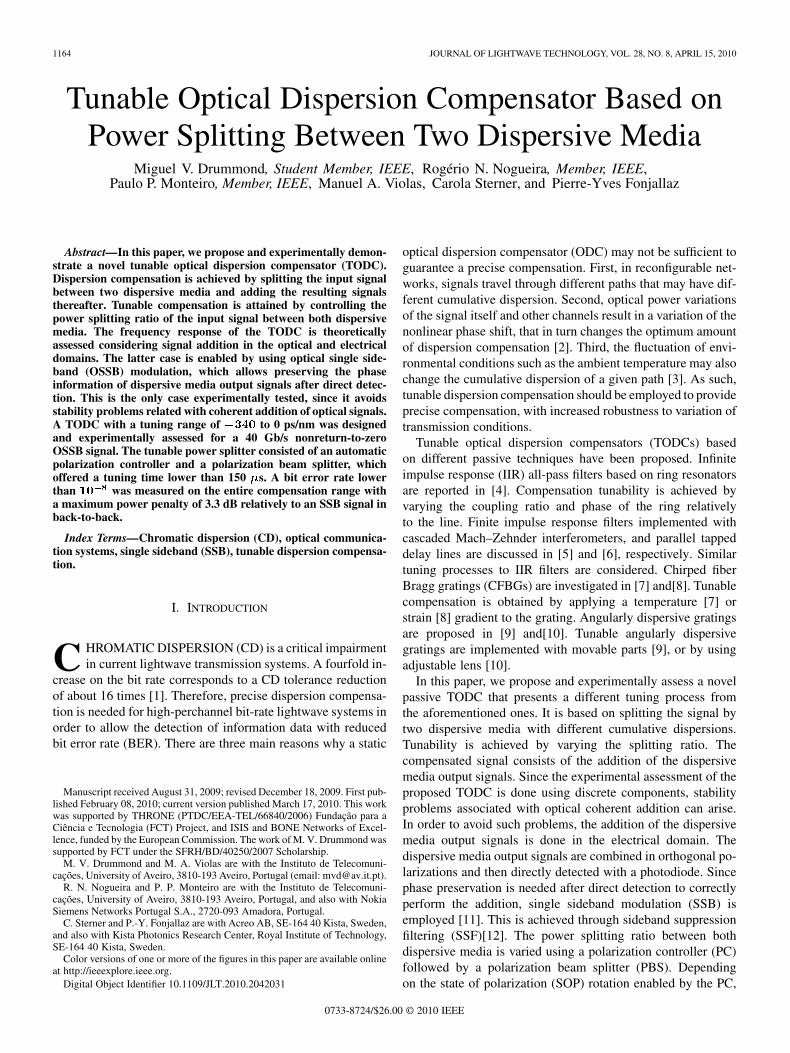
Fig. 1. General scheme of the TODC employing coherent addition of the dis-persive media � and � output signals.
the signal is coupled to both dispersive media with differentsplitting ratios. In order to reduce the polarization sensitivitythat results from using a PBS, an automatic PC is used. Withthe aid of a feedback loop, it sets a given output signal SOPindependently of the input signal SOP. Moreover, a low tuningtime in the order of tens of microseconds is achieved, since itonly depends on the polarization rotation speed imposed by theautomatic PC.
The remainder of this paper is organized as follows. Theoperation principle of the system is presented in Section II. Amathematical model of the TODC and analytical validation ofthe signal addition performed on the electrical domain withan input optical SSB (OSSB) signal are presented. Section IIIpresents the optimization of the TODC and SSF parameters,where a 40 Gb/s nonreturn-to-zero (NRZ) is considered.Transmission simulations are presented in order to analyze thecompensation effectiveness. In Section IV, the experiment isdescribed. The compensation effectiveness is experimentallyassessed through eye diagram analysis and BER measurements.Section V presents the final conclusions.
II. OPERATION PRINCIPLE
Fig. 1 presents the TODC general scheme. The input signal isdivided into two paths. The optical power in each path dependson the coupling ratio set by the tunable coupler. Both paths con-tain a dispersive medium with cumulative dispersions of and
. A 3-dB coupler coherently adds the output signals of bothdispersive media.
The mathematical analysis of the operation principle pre-sented in this section is first presented for the case where thedispersive media output signals are coherently added. In thesecond part of this section, the case where SSB modulation isemployed and the signal addition is performed in the electricaldomain is assessed.
A. Mathematical Analysis Considering Coherent Addition ofthe Dispersive Media Output Signals
Assuming that both dispersive media have unitary amplituderesponse for all considered wavelengths, the electric field
transfer function of the TODC depicted in Fig. 1 can be writtenas
(1)
Equation (1) neglects the 3 dB loss added by the 3 dB coupler.and are constants defined by the coupling ratio, through
is the detuned frequency relatively to the op-tical central frequency are the time delays associatedwith each dispersive medium. represent the cumulative dis-persion of the dispersive media through the relation
(2)
where are the cumulative dispersion of the dispersivemedia, is the optical central wavelength, and is the speedof light in vacuum. The amplitude response of (1) is given by
(3)
where
(4)
Equation (3) shows that the amplitude response is periodical.The period varies with the frequency and is dependent on thedifference between and , as well as and . This is easilyunderstandable if one looks at the TODC as an interferometerwith a time-delay difference between both arms that varies withthe frequency. The optical bandwidth is defined by the last termin (3). As such, the bandwidth is also dependent on the differ-ence between and as well as and . Independently ofthese differences, the lowest optical bandwidth is achieved whenthe last term in (3) is maximized, i.e., .
The group-delay response can be obtained by derivatingthe phase response through the relation
. In this way, the group-delay response isgiven by
(5)
where
(6)
Similarly to (3), (5) shows that the group delay has a periodicalresponse with a frequency-dependent period. The group-delayresponse is linear with respect to the frequency when the cosineterms are annulled. This occurs for , and 1. For
, (5) can be approximated by
(7)
1166 JOURNAL OF LIGHTWAVE TECHNOLOGY, VOL. 28, NO. 8, APRIL 15, 2010
As , (7) can be written as
(8)
According to (8), when the first term increases, i.e., increases,the second term decreases. This shows that the TODC total cu-mulative dispersion and time delay depend on the optical powercoupling ratio between both dispersive media. It is important tonote that the frequency range that complies with the approxima-tion increases with the decrease of the cumulativedispersion and time-delay differences between both dispersivemedia.
Since in practice dispersive media can have group delay ripple(GDR), which is generally the case of CFBGs, it is useful toconsider such parameter in the analysis. This can be done con-sidering
(9)
where represents the phase ripple of dispersive medium1 and 2, respectively. Analogously, to the group delay, the GDRis related to the derivative of the phase ripple in order to the fre-quency, here designated . In this way, (6) can be rewrittenas
(10)
By using (10) on (8), it can be seen that the GDR also depends onthe optical power coupling ratio between both dispersive media.This means that within the approximation , theGDR of the TODC depends only of the GDR of both dispersivemedia.
B. Mathematical Analysis Considering SSB Modulation andAddition of the Dispersive Media Output Signals Performed inthe Electrical Domain
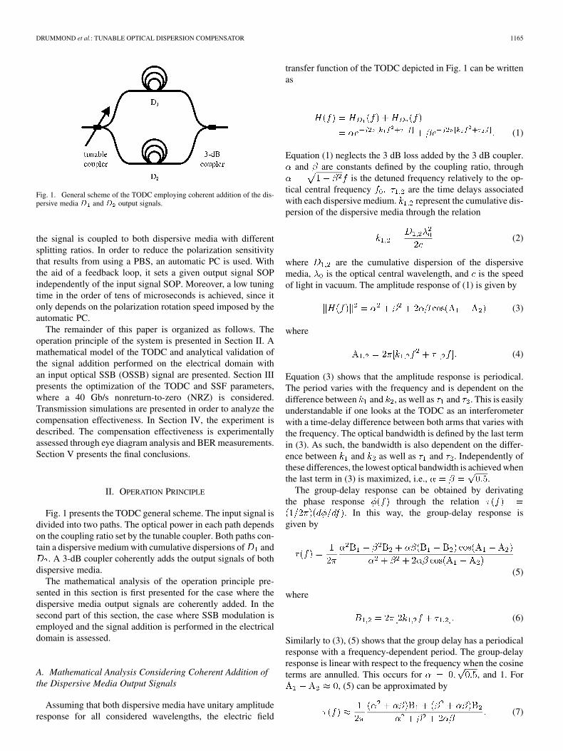
The analysis performed in the last section considers a co-herent addition of the output signals of both dispersive media. Inthis section, it is demonstrated that the same analysis is valid forthe scheme depicted in Fig. 2, if the input signal is SSB modu-lated. The output signals of both dispersive media are combinedin orthogonal polarizations using a polarization beam combiner(PBC). The PBC output signal is detected by a photodiode witha responsivity of . The frequency response of the photodiodeis neglected in the following analysis. The photodiode outputcurrent is given by
(11)
where and represent the orthogonally polarized signals inthe and polarization axis, respectively. According to Fig. 2,
and are the output signals of the dispersive mediumand , respectively. Equation (11) shows that the dispersivemedia output signals are first subject to direct detection andadded afterward. For double sideband (DSB) modulation, the
Fig. 2. TODC scheme with the addition of the dispersive media output signalsperformed in the electrical domain. PBC, p-i-n—photodiode.
phase information of the optical signal is lost after direct de-tection. As such, the signals are added without phase informa-tion. Since cumulative dispersion affects the phase of opticalsignals, the dispersion compensation performed by signal ad-dition is thereby invalidated. On the other hand, there is phasepreservation after direct detection for SSB signals.
The photodiode output current of an SSB signal propagatedin a dispersive line can be written as [13]
(12)
where is the optical power and is the modulation depth.and are the lower and upper sidebands of the
information signal , respectively. The symbol rep-resents the convolution operation. The phase response of thedispersive line is given by , where
. is the cumulative dispersion of the dispersive line.The time delay of the dispersive line is not defined since it is ir-relevant for the dispersion compensation. Using (11) and (12),the photocurrent generated by the signal can be written as
(13)
where . A similar expres-sion can be written for considering and in-stead of and , respectively, in which
. The photocurrent generated by both or-thogonal signals is then written as
(14)

DRUMMOND et al.: TUNABLE OPTICAL DISPERSION COMPENSATOR 1167
Fig. 3. Scheme considered for system optimization. CW—continuous-wave-length laser; � —dispersive fiber; PC; PBS; SSF.
Equation (14) shows that the upper sideband is affected by thedispersive line and TODC according to
(15)
As such, the dispersive line is compensated with a transfer func-tion that is given by (1), with the exception that and aresquared. The same analysis is valid for the lower sideband. Thisproves that the compensation principle presented in the pre-vious section is valid for the present case depicted in Fig. 2.The first three terms in (14) fully reconstruct the compensateddata signal, since they represent the optical carrier and lowerand upper sidebands, respectively. The fourth term consists ofthe beat between the optical sideband carrying information withitself. As pointed in [13], phase preservation is not kept for thisterm. Even in back-to-back situation it represents distortion dueto direct detection of the OSSB signal. Furthermore, since thereis no phase preservation, additional distortion arises if a disper-sive line and the TODC are considered. If an OSSB signal isused with the TODC scheme depicted in Fig. 1, this drawbackdoes not exist since phase preservation is not required after di-rect detection. However, there is a 3 dB loss intrinsic to the co-herent addition of two optical signals.
III. SYSTEM OPTIMIZATION
The system optimization is based on the scheme presentedin Fig. 3. The optimization is performed in two steps. First,the TODC parameters are optimized to achieve proper com-pensation for a 40 Gb/s NRZ OSSB signal. Second, the SSFparameters are optimized taking into account the TODC op-timized parameters. The optimized system performance is as-sessed through transmission simulations. The implementationof one dispersive medium and SSF using FBGs is discussed inthe last part of this section.
A. TODC Optimization
The TODC parameters are the splitting ratio, dispersivemedia cumulative dispersions and time delays. Since thefrequency response variation depends only on and
, in the remaining of this work, it is considered that thedispersive medium 1 is purely dispersive, and that the disper-sive medium 2 is nondispersive, being a tunable delay line. Assuch, and . The power splitting ratio depends on
Fig. 4. Optical�� dB bandwidth (in GHz) of the TODC for various values of� and � .
the polarization rotation imposed by the PC. Assuming that theinput signal at the TODC is linearly polarized along the -axis,then . is the polarization rotation angle imposedby the PC.
According to (3), the optical bandwidth of the TODC dependson and . Fig. 4 presents the optical dB bandwidth forvarious cumulative dispersions and time delays , consid-ering . This is the case where the lowest bandwidth isachieved, since it implies that . As it is pointed in theprevious section, the optical bandwidth decreases with the in-crease of , since . For a given dispersion value ,the bandwidth can be increased by optimizing . This meanstemporally displacing the optical pulses at the output of the dis-persive media so that the coherent addition of both results in apulse with increased bandwidth. Since it is the relative displace-ment between one pulse to the other that is important, the op-timum delay can be either positive or negative. For a given valueof , the optimum delay that maximizes the bandwidth de-pends on the splitting ratio. However, if a single delay value isconsidered for all splitting ratios, then the optimum delay cor-responding to should be the one used. Such delayguarantees that the lowest bandwidth is maximized.
Since the optimized system should achieve proper compen-sation for a 40 Gb/s NRZ OSSB signal, the TODC should havean optical bandwidth higher than 20 GHz. Such a low-band-width requirement is enabled by the SSB modulation, which re-duces the optical bandwidth of the signal to half the one of theoriginal DSB signal. According to Fig. 4, an optical bandwidthof 20 GHz enables the compensation of at least 620 ps/nm ofcumulative dispersion. However, the system optimization onlytaking into account the optical bandwidth is insufficient. Theshape of the amplitude response should be considered. More-over, (5) shows that the group delay response varies nonlinearlywith the frequency. Therefore, the impact of and in thegroup-delay response should also be analyzed.
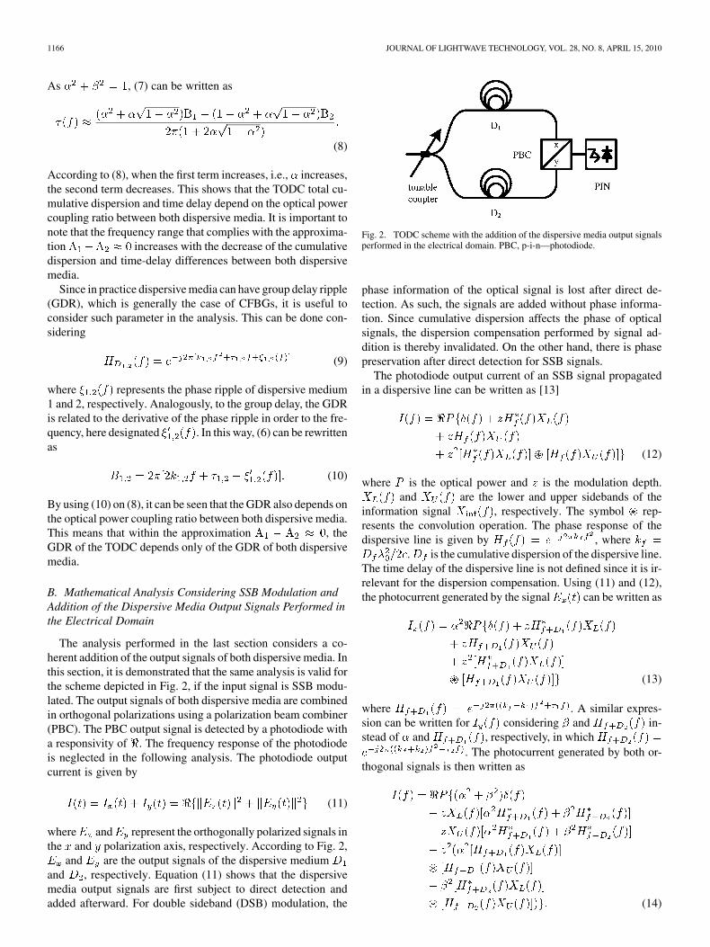
The amplitude, group delay, and cumulative dispersion re-sponses for four values of considering ps/nmare shown in Fig. 5. In order to observe the nonlinear responseof the group delay, the parameter must be different of ,and 1. A value of is used. The increase of the delay
1168 JOURNAL OF LIGHTWAVE TECHNOLOGY, VOL. 28, NO. 8, APRIL 15, 2010
produces three effects. First, there is a shift of the frequency re-sponse toward higher frequencies. This shift can be neglectedsince the central frequency depends on the optical central fre-quency , which in turn can be readjusted. Second, the increaseof the delay results in a higher bandwidth, as corroborated byFig. 4. However, this implies the formation of a valley locatedat the center of the amplitude response. For a given positive ornegative delay value, the valley reaches dB, resulting in anabrupt reduction of the dB optical bandwidth. This can bealso observed in Fig. 4, where these points represent the max-imum bandwidth for a given value of . The third effect isanalog to the second one, with the exception that the cumula-tive dispersion is considered instead of the amplitude response.The increase of the delay results in the increase of the frequencyrange where the cumulative dispersion is near the compensa-tion value. In the case of Fig. 5, the compensation value is of
ps/nm. However, the increase of such frequencyrange results in the formation of a peak. Nevertheless, the av-erage value of the dispersion on the given frequency range isapproximately the compensation value.
In summary, there are tradeoffs among various parameters.The bandwidth increases with the decrease of . It alsoincreases with the increase of , at the cost of amplitudeand phase response degradation imposed by the formationof a valley and peak, respectively. Since the OSSB signalhas a bandwidth of about 20 GHz, the TODC should have abandwidth significantly higher than 20 GHz. In the furthersimulation and experimental tests, it is consideredps/nm. This cumulative dispersion results in a dB opticalbandwidth of about 27 GHz for . Such a high bandwidthavoids signal degradation originated by narrow optical filtering.Moreover, since this bandwidth is achieved for , am-plitude and phase response degradations driven by time-delayoptimization are also alleviated.
B. SSF Optimization
The modulation of OSSB signals can be achieved resortingto electro-optic [11], [14] or all-optical techniques [12].Electro-optic techniques include special electro-optic mod-ulators [15] or electro-optic filters [14]. Both techniques arewavelength transparent. However, the maximum bit rate is in-herently limited by the electrical circuitry frequency response.All-optical techniques enable SSB modulation at high bit rates.The simplest all-optical technique consists on using SSF [12].This technique is considered in this work.
The SSB modulation achieved through SSF depends on thefilter parameters, which are the amplitude response and centralfrequency detuning from the optical carrier. In this paper, thefrequency response of the SSF is modeled by a super-Gaussianfunction given by
(16)
where is the frequency detuning relatively to the optical car-rier, BW is the dB bandwidth, and is the order.
The simulation scheme used for the optimization of the SSFparameters is shown in Fig. 3. The data signal consists of aDe Bruijn sequence with a length of bits and a bit rate of
Fig. 5. (a) Amplitude, (b) group delay, and (c) dispersion responses of theTODC corresponding to four values of � , considering � � ���� ps/nmand � �
�����.
40 Gb/s. The data signal and corresponding negated version areused to drive a Mach–Zehnder modulator (MZM) in chirp-freeoperation. The frequency response of the MZM is modeled bya third-order Bessel filter with a dB cutoff frequency of 30GHz. The DSB optical signal at the output of the MZM has anextinction ratio (ER) of 10 dB. The dispersive media ,and have the following transfer function
(17)
where is given by (2). The PBS and PBC have infinite polar-ization ER. The SSF is polarization insensitive. The p-i-n hasa unitary responsivity, and its frequency response is modeledby a third-order Bessel filter with a dB cutoff frequency of30 GHz.
The performance criteria are the eye-opening penalty (EOP)[14], sideband suppression ratio (SSR) and filtering loss. TheEOP is given by
(18)
DRUMMOND et al.: TUNABLE OPTICAL DISPERSION COMPENSATOR 1169
where and are the lowest and highest currents corre-sponding to the symbols “1” and “0” at the optimum samplingtime of the eye diagram at the output of the p-i-n, respectively.The eye aperture is thereby given by . isthe eye aperture of the reference signal, which is a DSB signalin back-to-back with dB. The SSR is given by thepower difference (in dB) of the spectral components 20 GHzapart the carrier frequency. The filtering loss is the difference(in dB) between the average optical powers of the SSF inputand output signals.
The filter parameters are optimized considering the casewhere the TODC bandwidth is the lowest. As such,ps/nm, ps/nm, and . A time delay of
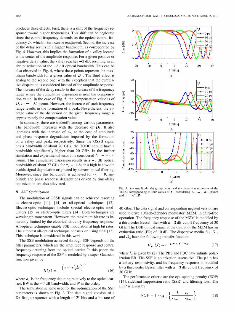
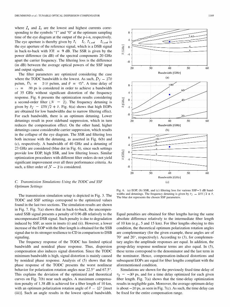
ps is considered in order to achieve a bandwidthof 35 GHz without significant distortion of the frequencyresponse. Fig. 6 presents the optimization results consideringa second-order filter . The frequency detuning isgiven by . Fig. 6(a) shows that high EOPsare obtained for low bandwidths due to narrow filtering effect.For each bandwidth, there is an optimum detuning. Lowerdetunings result in poor sideband suppression, which in turnreduces the compensation effect. On the other hand, higherdetunings cause considerable carrier suppression, which resultsin the collapse of the eye diagram. The SSR and filtering lossboth increase with the detuning, as asserted in Fig. 6(b) and(c), respectively. A bandwidth of 40 GHz and a detuning of23 GHz are considered (blue dot in Fig. 6), since such settingsprovide low EOP, high SSR, and low filtering losses. Similaroptimization procedures with different filter orders do not yieldsignificant improvement over all three performance criteria. Assuch, a filter order of is considered.
C. Transmission Simulations Using the TODC and SSFOptimum Settings
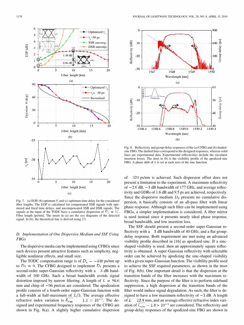
The transmission simulation setup is depicted in Fig. 3. TheTODC and SSF settings correspond to the optimized valuesfound in the last two sections. The simulation results are shownin Fig. 7. Fig. 7(a) shows that in back-to-back, the uncompen-sated SSB signal presents a penalty of 0.96 dB relatively to theuncompensated DSB signal. Such penalty is due to degradationinduced by SSF, as seen in insets (i) and (ii). However, a lowerincrease of the EOP with the fiber length is obtained for the SSBsignal due to its stronger resilience to CD in comparison to DSBsignaling.
The frequency response of the TODC has limited opticalbandwidth and nonideal phase response. Thus, dispersioncompensation also induces signal distortion. Since the TODCminimum bandwidth is high, signal distortion is mainly causedby nonideal phase response. Analysis of (5) shows that thephase response of the TODC presents the worst nonlinearbehavior for polarization rotation angles near 22.5 and 67.5 .This explains the deviation of the optimized and theoreticalcurves on Fig. 7(b) near such angles. A maximum compensa-tion penalty of 1.38 dB is achieved for a fiber length of 10 km,with an optimum polarization rotation angle of [inset(iii)]. Such an angle results in the lowest optical bandwidth.
Fig. 6. (a) EOP, (b) SSR, and (c) filtering loss for various SSF�� dB band-widths and detunings. The frequency detuning is given by � � ���� � �.The blue dot represents the chosen SSF parameters.
Equal penalties are obtained for fiber lengths having the sameabsolute difference relatively to the intermediate fiber lengthof 10 km (e.g., 5 and 15 km). For fiber lengths obeying to thiscondition, the theoretical optimum polarization rotation anglesare complementary (for the given example, these angles are of70 and 20 , respectively). According to (3), for complemen-tary angles the amplitude responses are equal. In addition, thegroup-delay response nonlinear terms are also equal. In (5),these terms correspond to the denominator and the last term inthe nominator. Hence, compensation-induced distortions andsubsequent EOPs are equal for fiber lengths compliant with theaforementioned condition.
Simulations are shown for the previously fixed time delay ofps, and for a time delay optimized for each given
fiber length. Fig. 7(a) shows that the time-delay optimizationresults in negligible gain. Moreover, the average optimum delayis about ps, as seen in Fig. 7(c). As such, the time delay canbe fixed for the entire compensation range.
1170 JOURNAL OF LIGHTWAVE TECHNOLOGY, VOL. 28, NO. 8, APRIL 15, 2010
Fig. 7. (a) EOP, (b) optimum �, and (c) optimum time delay for the consideredfiber lengths. The EOP is calculated for compensated SSB signals with opti-mized and fixed time delays, and uncompensated SSB and DSB signals. Thesignals at the input of the TODC have a cumulative dispersion of � � ��.Fiber length [ps/nm]. The insets in (a) are the eye diagrams of the detectedsignal. In (b), the theoretical line is derived using (7).
D. Implementation of One Dispersive Medium and SSF UsingFBGs
The dispersive media can be implemented using CFBGs sincesuch devices present attractive features such as simplicity, neg-ligible nonlinear effects, and small size.
The TODC compensation range is of ps/nm upto . The CFBG designed to implement presents asecond-order super-Gaussian reflectivity with a dB band-width of 160 GHz. Such a broad bandwidth avoids signaldistortion imposed by narrow filtering. A length ofmm and chirp of pm/cm are considered. The apodizationprofile consists of a fourth-order super-Gaussian function witha full-width at half-maximum of . The average effectiverefractive index variation is . The de-signed and experimental frequency responses of the CFBG areshown in Fig. 8(a). A slightly higher cumulative dispersion
Fig. 8. Reflectivity and group-delay responses of the (a) CFBG and (b) shaded-sinc FBG. The dashed lines correspond to the designed responses, whereas solidlines are experimental data. Experimental reflectivities include the circulatorinsertion losses. The inset in (b) is the visibility profile of the apodized-sincFBG. A phase shift of � is set at each zero of the sinc function.
of ps/nm is achieved. Such dispersion offset does notpresent a limitation to the experiment. A maximum reflectivityof dB, dB bandwidth of 177 GHz, and average reflec-tivity and GDRs of 1.6 dB and 9.5 ps are achieved, respectively.Since the dispersive medium presents no cumulative dis-persion, it basically consists of an all-pass filter with linearphase response. Although such filter can be implemented usingFBGs, a simpler implementation is considered. A fiber mirroris used instead since it presents nearly ideal phase response,broad bandwidth, and low insertion loss.
The SSF should present a second-order super-Gaussian re-flectivity with a dB bandwidth of 40 GHz, and a flat group-delay response. Both requirement are met using an advancedvisibility profile described in [16] as apodized-sinc. If a sinc-shaped visibility is used, then an approximately square reflec-tivity is obtained. A super-Gaussian reflectivity with selectableorder can be achieved by apodizing the sinc-shaped visibilitywith a given super-Gaussian function. The visibility profile usedto achieve the SSF required parameters, as shown in the insetof Fig. 8(b). One important detail is that the dispersion at thetransition bands of the filter increases with the maximum re-flectivity. Since the purpose of the filter is to perform sidebandsuppression, a high dispersion at the transition bands of thefilter would induce signal degradation. As such, the filter is de-signed to have a low maximum reflectivity of dB. A lengthof mm, and an average effective refractive index vari-ation of are considered. The reflectivity andgroup-delay responses of the apodized-sinc FBG are shown in
DRUMMOND et al.: TUNABLE OPTICAL DISPERSION COMPENSATOR 1171
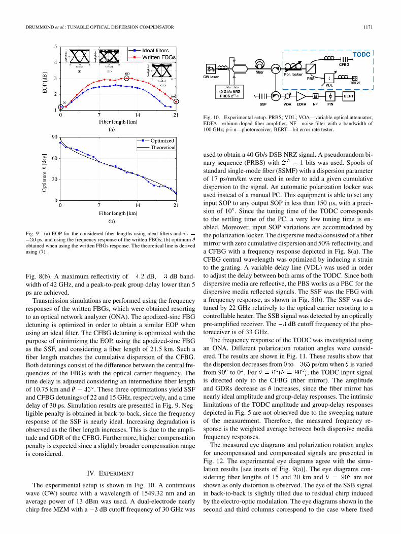
Fig. 9. (a) EOP for the considered fiber lengths using ideal filters and � �
��� ps, and using the frequency response of the written FBGs; (b) optimum �
obtained when using the written FBGs response. The theoretical line is derivedusing (7).
Fig. 8(b). A maximum reflectivity of dB, dB band-width of 42 GHz, and a peak-to-peak group delay lower than 5ps are achieved.
Transmission simulations are performed using the frequencyresponses of the written FBGs, which were obtained resortingto an optical network analyzer (ONA). The apodized-sinc FBGdetuning is optimized in order to obtain a similar EOP whenusing an ideal filter. The CFBG detuning is optimized with thepurpose of minimizing the EOP, using the apodized-sinc FBGas the SSF, and considering a fiber length of 21.5 km. Such afiber length matches the cumulative dispersion of the CFBG.Both detunings consist of the difference between the central fre-quencies of the FBGs with the optical carrier frequency. Thetime delay is adjusted considering an intermediate fiber lengthof 10.75 km and . These three optimizations yield SSFand CFBG detunings of 22 and 15 GHz, respectively, and a timedelay of 30 ps. Simulation results are presented in Fig. 9. Neg-ligible penalty is obtained in back-to-back, since the frequencyresponse of the SSF is nearly ideal. Increasing degradation isobserved as the fiber length increases. This is due to the ampli-tude and GDR of the CFBG. Furthermore, higher compensationpenalty is expected since a slightly broader compensation rangeis considered.
IV. EXPERIMENT
The experimental setup is shown in Fig. 10. A continuouswave (CW) source with a wavelength of 1549.32 nm and anaverage power of 13 dBm was used. A dual-electrode nearlychirp free MZM with a dB cutoff frequency of 30 GHz was
Fig. 10. Experimental setup. PRBS; VDL; VOA—variable optical attenuator;EDFA—erbium-doped fiber amplifier; NF—noise filter with a bandwidth of100 GHz; p-i-n—photoreceiver; BERT—bit error rate tester.
used to obtain a 40 Gb/s DSB NRZ signal. A pseudorandom bi-nary sequence (PRBS) with bits was used. Spools ofstandard single-mode fiber (SSMF) with a dispersion parameterof 17 ps/nm/km were used in order to add a given cumulativedispersion to the signal. An automatic polarization locker wasused instead of a manual PC. This equipment is able to set anyinput SOP to any output SOP in less than 150 s, with a preci-sion of 10 . Since the tuning time of the TODC correspondsto the settling time of the PC, a very low tuning time is en-abled. Moreover, input SOP variations are accommodated bythe polarization locker. The dispersive media consisted of a fibermirror with zero cumulative dispersion and 50% reflectivity, anda CFBG with a frequency response depicted in Fig. 8(a). TheCFBG central wavelength was optimized by inducing a strainto the grating. A variable delay line (VDL) was used in orderto adjust the delay between both arms of the TODC. Since bothdispersive media are reflective, the PBS works as a PBC for thedispersive media reflected signals. The SSF was the FBG witha frequency response, as shown in Fig. 8(b). The SSF was de-tuned by 22 GHz relatively to the optical carrier resorting to acontrollable heater. The SSB signal was detected by an opticallypre-amplified receiver. The dB cutoff frequency of the pho-toreceiver is of 33 GHz.
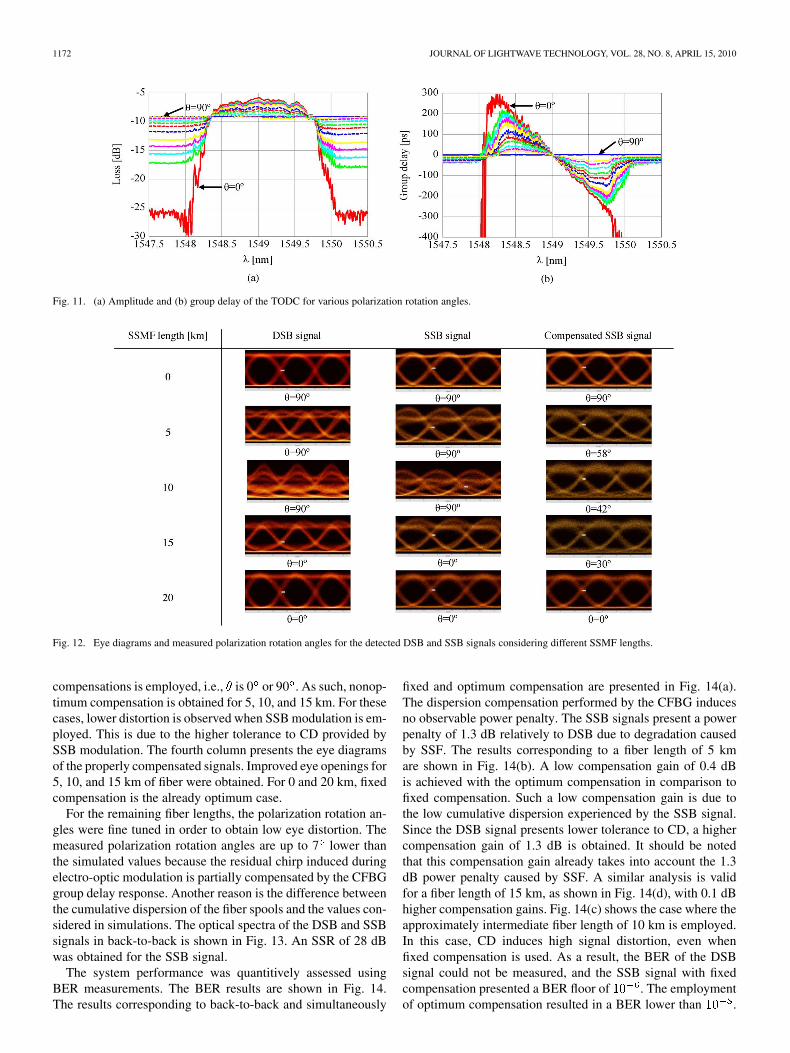
The frequency response of the TODC was investigated usingan ONA. Different polarization rotation angles were consid-ered. The results are shown in Fig. 11. These results show thatthe dispersion decreases from 0 to ps/nm when is variedfrom 90 to 0 . For , the TODC input signalis directed only to the CFBG (fiber mirror). The amplitudeand GDRs decrease as increases, since the fiber mirror hasnearly ideal amplitude and group-delay responses. The intrinsiclimitations of the TODC amplitude and group-delay responsesdepicted in Fig. 5 are not observed due to the sweeping natureof the measurement. Therefore, the measured frequency re-sponse is the weighted average between both dispersive mediafrequency responses.
The measured eye diagrams and polarization rotation anglesfor uncompensated and compensated signals are presented inFig. 12. The experimental eye diagrams agree with the simu-lation results [see insets of Fig. 9(a)]. The eye diagrams con-sidering fiber lengths of 15 and 20 km and are notshown as only distortion is observed. The eye of the SSB signalin back-to-back is slightly tilted due to residual chirp inducedby the electro-optic modulation. The eye diagrams shown in thesecond and third columns correspond to the case where fixed
1172 JOURNAL OF LIGHTWAVE TECHNOLOGY, VOL. 28, NO. 8, APRIL 15, 2010
Fig. 11. (a) Amplitude and (b) group delay of the TODC for various polarization rotation angles.
Fig. 12. Eye diagrams and measured polarization rotation angles for the detected DSB and SSB signals considering different SSMF lengths.
compensations is employed, i.e., is 0 or 90 . As such, nonop-timum compensation is obtained for 5, 10, and 15 km. For thesecases, lower distortion is observed when SSB modulation is em-ployed. This is due to the higher tolerance to CD provided bySSB modulation. The fourth column presents the eye diagramsof the properly compensated signals. Improved eye openings for5, 10, and 15 km of fiber were obtained. For 0 and 20 km, fixedcompensation is the already optimum case.
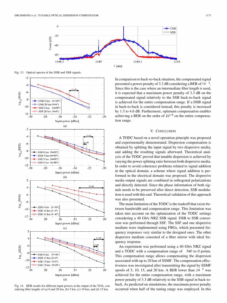
For the remaining fiber lengths, the polarization rotation an-gles were fine tuned in order to obtain low eye distortion. Themeasured polarization rotation angles are up to 7 lower thanthe simulated values because the residual chirp induced duringelectro-optic modulation is partially compensated by the CFBGgroup delay response. Another reason is the difference betweenthe cumulative dispersion of the fiber spools and the values con-sidered in simulations. The optical spectra of the DSB and SSBsignals in back-to-back is shown in Fig. 13. An SSR of 28 dBwas obtained for the SSB signal.
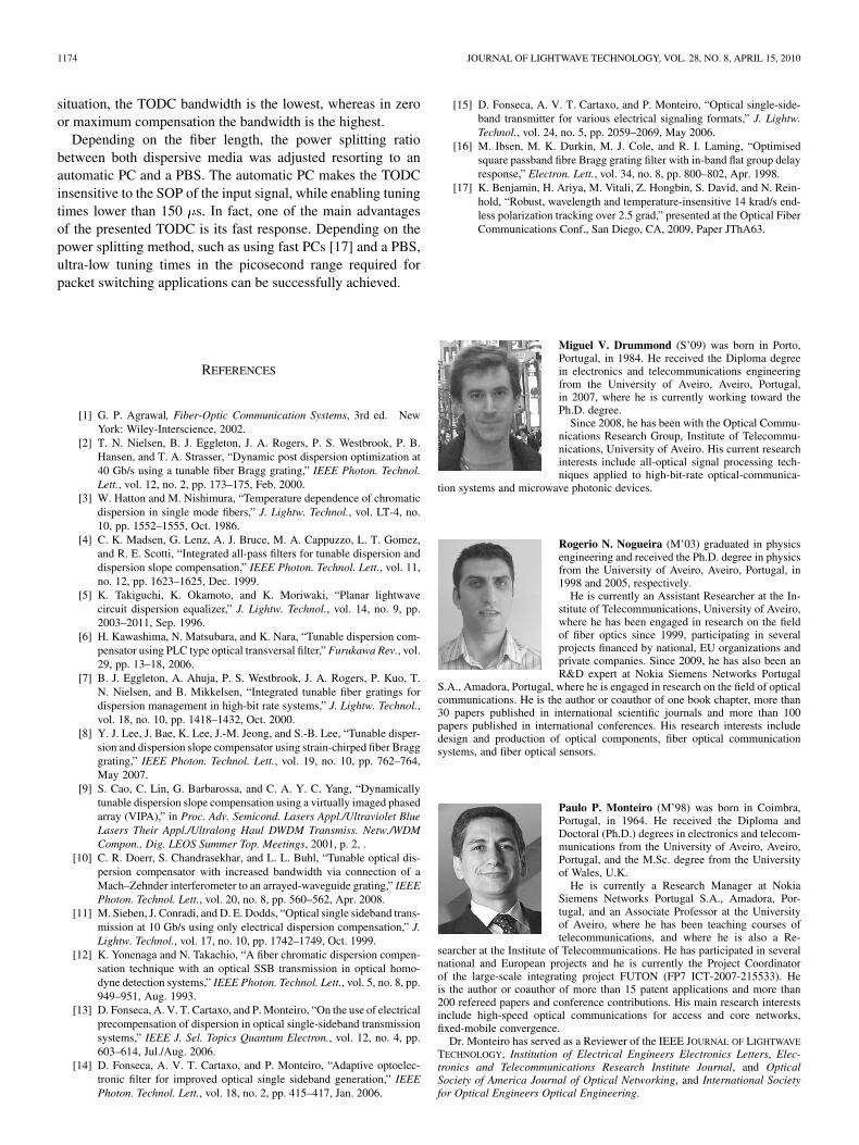
The system performance was quantitively assessed usingBER measurements. The BER results are shown in Fig. 14.The results corresponding to back-to-back and simultaneously
fixed and optimum compensation are presented in Fig. 14(a).The dispersion compensation performed by the CFBG inducesno observable power penalty. The SSB signals present a powerpenalty of 1.3 dB relatively to DSB due to degradation causedby SSF. The results corresponding to a fiber length of 5 kmare shown in Fig. 14(b). A low compensation gain of 0.4 dBis achieved with the optimum compensation in comparison tofixed compensation. Such a low compensation gain is due tothe low cumulative dispersion experienced by the SSB signal.Since the DSB signal presents lower tolerance to CD, a highercompensation gain of 1.3 dB is obtained. It should be notedthat this compensation gain already takes into account the 1.3dB power penalty caused by SSF. A similar analysis is validfor a fiber length of 15 km, as shown in Fig. 14(d), with 0.1 dBhigher compensation gains. Fig. 14(c) shows the case where theapproximately intermediate fiber length of 10 km is employed.In this case, CD induces high signal distortion, even whenfixed compensation is used. As a result, the BER of the DSBsignal could not be measured, and the SSB signal with fixedcompensation presented a BER floor of . The employmentof optimum compensation resulted in a BER lower than .
DRUMMOND et al.: TUNABLE OPTICAL DISPERSION COMPENSATOR 1173
Fig. 13. Optical spectra of the DSB and SSB signals.
Fig. 14. BER results for different input powers at the output of the VOA, con-sidering fiber lengths of (a) 0 and 20 km, (b) 5 km, (c) 10 km, and (d) 15 km.
In comparison to back-to-back situation, the compensated signalpresented a power penalty of 3.3 dB considering a BER of .Since this is the case where an intermediate fiber length is used,it is expected that a maximum power penalty of 3.3 dB on thecompensated signal relatively to the SSB back-to-back signalis achieved for the entire compensation range. If a DSB signalin back-to-back is considered instead, this penalty is increasedby 1.3 to 4.6 dB. Furthermore, optimum compensation enablesachieving a BER on the order of on the entire compensa-tion range.
V. CONCLUSION
A TODC based on a novel operation principle was proposedand experimentally demonstrated. Dispersion compensation isobtained by splitting the input signal by two dispersive media,and adding the resulting signals afterward. Theoretical anal-ysis of the TODC proved that tunable dispersion is achieved byvarying the power splitting ratio between both dispersive media.In order to avoid coherence problems related to signal additionin the optical domain, a scheme where signal addition is per-formed in the electrical domain was proposed. The dispersivemedia output signals are combined in orthogonal polarizationsand directly detected. Since the phase information of both sig-nals needs to be preserved after direct detection, SSB modula-tion is used with this end. Theoretical validation of this approachwas also presented.
The main limitation of the TODC is the tradeoff that exists be-tween bandwidth and compensation range. This limitation wastaken into account on the optimization of the TODC settingsconsidering a 40 Gb/s NRZ SSB signal. DSB to SSB conver-sion was performed through SSF. The SSF and one dispersivemedium were implemented using FBGs, which presented fre-quency responses very similar to the designed ones. The otherdispersive medium consisted of a fiber mirror with ideal fre-quency response.
An experiment was performed using a 40 Gb/s NRZ signaland a TODC with a compensation range of to 0 ps/nm.This compensation range allows compensating the dispersionassociated with up to 20 km of SSMF. The compensation effec-tiveness was investigated after transmitting the signal by SSMFspools of 5, 10, 15, and 20 km. A BER lower than wasachieved for the entire compensation range, with a maximumpower penalty of 3.3 dB relatively to the SSB signal in back-to-back. As predicted on simulations, the maximum power penaltyoccurred when half of the tuning range was employed. In this
1174 JOURNAL OF LIGHTWAVE TECHNOLOGY, VOL. 28, NO. 8, APRIL 15, 2010
situation, the TODC bandwidth is the lowest, whereas in zeroor maximum compensation the bandwidth is the highest.
Depending on the fiber length, the power splitting ratiobetween both dispersive media was adjusted resorting to anautomatic PC and a PBS. The automatic PC makes the TODCinsensitive to the SOP of the input signal, while enabling tuningtimes lower than 150 s. In fact, one of the main advantagesof the presented TODC is its fast response. Depending on thepower splitting method, such as using fast PCs [17] and a PBS,ultra-low tuning times in the picosecond range required forpacket switching applications can be successfully achieved.
REFERENCES
[1] G. P. Agrawal, Fiber-Optic Communication Systems, 3rd ed. NewYork: Wiley-Interscience, 2002.
[2] T. N. Nielsen, B. J. Eggleton, J. A. Rogers, P. S. Westbrook, P. B.Hansen, and T. A. Strasser, “Dynamic post dispersion optimization at40 Gb/s using a tunable fiber Bragg grating,” IEEE Photon. Technol.Lett., vol. 12, no. 2, pp. 173–175, Feb. 2000.
[3] W. Hatton and M. Nishimura, “Temperature dependence of chromaticdispersion in single mode fibers,” J. Lightw. Technol., vol. LT-4, no.10, pp. 1552–1555, Oct. 1986.
[4] C. K. Madsen, G. Lenz, A. J. Bruce, M. A. Cappuzzo, L. T. Gomez,and R. E. Scotti, “Integrated all-pass filters for tunable dispersion anddispersion slope compensation,” IEEE Photon. Technol. Lett., vol. 11,no. 12, pp. 1623–1625, Dec. 1999.
[5] K. Takiguchi, K. Okamoto, and K. Moriwaki, “Planar lightwavecircuit dispersion equalizer,” J. Lightw. Technol., vol. 14, no. 9, pp.2003–2011, Sep. 1996.
[6] H. Kawashima, N. Matsubara, and K. Nara, “Tunable dispersion com-pensator using PLC type optical transversal filter,” Furukawa Rev., vol.29, pp. 13–18, 2006.
[7] B. J. Eggleton, A. Ahuja, P. S. Westbrook, J. A. Rogers, P. Kuo, T.N. Nielsen, and B. Mikkelsen, “Integrated tunable fiber gratings fordispersion management in high-bit rate systems,” J. Lightw. Technol.,vol. 18, no. 10, pp. 1418–1432, Oct. 2000.
[8] Y. J. Lee, J. Bae, K. Lee, J.-M. Jeong, and S.-B. Lee, “Tunable disper-sion and dispersion slope compensator using strain-chirped fiber Bragggrating,” IEEE Photon. Technol. Lett., vol. 19, no. 10, pp. 762–764,May 2007.
[9] S. Cao, C. Lin, G. Barbarossa, and C. A. Y. C. Yang, “Dynamicallytunable dispersion slope compensation using a virtually imaged phasedarray (VIPA),” in Proc. Adv. Semicond. Lasers Appl./Ultraviolet BlueLasers Their Appl./Ultralong Haul DWDM Transmiss. Netw./WDMCompon., Dig. LEOS Summer Top. Meetings, 2001, p. 2, .
[10] C. R. Doerr, S. Chandrasekhar, and L. L. Buhl, “Tunable optical dis-persion compensator with increased bandwidth via connection of aMach–Zehnder interferometer to an arrayed-waveguide grating,” IEEEPhoton. Technol. Lett., vol. 20, no. 8, pp. 560–562, Apr. 2008.
[11] M. Sieben, J. Conradi, and D. E. Dodds, “Optical single sideband trans-mission at 10 Gb/s using only electrical dispersion compensation,” J.Lightw. Technol., vol. 17, no. 10, pp. 1742–1749, Oct. 1999.
[12] K. Yonenaga and N. Takachio, “A fiber chromatic dispersion compen-sation technique with an optical SSB transmission in optical homo-dyne detection systems,” IEEE Photon. Technol. Lett., vol. 5, no. 8, pp.949–951, Aug. 1993.
[13] D. Fonseca, A. V. T. Cartaxo, and P. Monteiro, “On the use of electricalprecompensation of dispersion in optical single-sideband transmissionsystems,” IEEE J. Sel. Topics Quantum Electron., vol. 12, no. 4, pp.603–614, Jul./Aug. 2006.
[14] D. Fonseca, A. V. T. Cartaxo, and P. Monteiro, “Adaptive optoelec-tronic filter for improved optical single sideband generation,” IEEEPhoton. Technol. Lett., vol. 18, no. 2, pp. 415–417, Jan. 2006.
[15] D. Fonseca, A. V. T. Cartaxo, and P. Monteiro, “Optical single-side-band transmitter for various electrical signaling formats,” J. Lightw.Technol., vol. 24, no. 5, pp. 2059–2069, May 2006.
[16] M. Ibsen, M. K. Durkin, M. J. Cole, and R. I. Laming, “Optimisedsquare passband fibre Bragg grating filter with in-band flat group delayresponse,” Electron. Lett., vol. 34, no. 8, pp. 800–802, Apr. 1998.
[17] K. Benjamin, H. Ariya, M. Vitali, Z. Hongbin, S. David, and N. Rein-hold, “Robust, wavelength and temperature-insensitive 14 krad/s end-less polarization tracking over 2.5 grad,” presented at the Optical FiberCommunications Conf., San Diego, CA, 2009, Paper JThA63.
Miguel V. Drummond (S’09) was born in Porto,Portugal, in 1984. He received the Diploma degreein electronics and telecommunications engineeringfrom the University of Aveiro, Aveiro, Portugal,in 2007, where he is currently working toward thePh.D. degree.
Since 2008, he has been with the Optical Commu-nications Research Group, Institute of Telecommu-nications, University of Aveiro. His current researchinterests include all-optical signal processing tech-niques applied to high-bit-rate optical-communica-
tion systems and microwave photonic devices.
Rogerio N. Nogueira (M’03) graduated in physicsengineering and received the Ph.D. degree in physicsfrom the University of Aveiro, Aveiro, Portugal, in1998 and 2005, respectively.
He is currently an Assistant Researcher at the In-stitute of Telecommunications, University of Aveiro,where he has been engaged in research on the fieldof fiber optics since 1999, participating in severalprojects financed by national, EU organizations andprivate companies. Since 2009, he has also been anR&D expert at Nokia Siemens Networks Portugal
S.A., Amadora, Portugal, where he is engaged in research on the field of opticalcommunications. He is the author or coauthor of one book chapter, more than30 papers published in international scientific journals and more than 100papers published in international conferences. His research interests includedesign and production of optical components, fiber optical communicationsystems, and fiber optical sensors.
Paulo P. Monteiro (M’98) was born in Coimbra,Portugal, in 1964. He received the Diploma andDoctoral (Ph.D.) degrees in electronics and telecom-munications from the University of Aveiro, Aveiro,Portugal, and the M.Sc. degree from the Universityof Wales, U.K.
He is currently a Research Manager at NokiaSiemens Networks Portugal S.A., Amadora, Por-tugal, and an Associate Professor at the Universityof Aveiro, where he has been teaching courses oftelecommunications, and where he is also a Re-
searcher at the Institute of Telecommunications. He has participated in severalnational and European projects and he is currently the Project Coordinatorof the large-scale integrating project FUTON (FP7 ICT-2007-215533). Heis the author or coauthor of more than 15 patent applications and more than200 refereed papers and conference contributions. His main research interestsinclude high-speed optical communications for access and core networks,fixed-mobile convergence.
Dr. Monteiro has served as a Reviewer of the IEEE JOURNAL OF LIGHTWAVE
TECHNOLOGY, Institution of Electrical Engineers Electronics Letters, Elec-tronics and Telecommunications Research Institute Journal, and OpticalSociety of America Journal of Optical Networking, and International Societyfor Optical Engineers Optical Engineering.
DRUMMOND et al.: TUNABLE OPTICAL DISPERSION COMPENSATOR 1175
Manuel A. Violas received a degree in electronicsand telecommunications engineering from theUniversity of Aveiro, Aveiro, Portugal, in 1982,the M.Sc. degree from the University of Coimbra,Coimbra, Portugal, 1988, and the Ph.D. degree inelectrical engineering from University of Aveiro, in1999.
From 1990 to 1992, he was with British Telecom,where he was involved in research on very broad-band optical receivers. Since 1982, he has been withthe Department of Electronics and Telecommunica-
tions, University of Aveiro, Portugal, where he is currently a Researcher atthe Institute of Telecommunications, where he has been involved in Nationaland International Projects in optical communications. His main research inter-ests include microwave and RF circuit design, microwave circuit/system simu-lation, electrical signal processing for very high speed lightwave communica-tions systems, and radio over fiber, for distributed antenna system, with focuson model electro-optical devices such as direct-modulated lasers and receiveroptical subassembly.
Carola Sterner was born in Umea, Sweden, on April 11, 1968. She received theMaster’s degree in engineering physics from the University of Uppsala, Upp-sala, Sweden, in 1993, and the Ph.D. degree from the Department of Solid-StateElectronics, Ångström Laboratory, Uppsala University, in 1998.
She is currently a Senior Scientist at Acreo AB, Kista, Sweden. She is amember of the Fiber Department working with fiber components mainly basedon fiber Bragg gratings. She is also with Kista Photonics Research Center, RoyalInstitute of Technology, Kista, Sweden. She has long experience in optoelec-tronic applications from past positions as Development Engineer at EricssonMicroelectronics and Optillion AB. At Ericsson’s Optoelectronic Division, shewas responsible for details in 10 Gbit/s laser products. At the start-up companyOptillion AB, she was responsible for the “in-house” carrier manufacturing for10 Gbit/s transceivers. At the Ångström Laboratory, Uppsala University, shewas a Researcher and Teacher.
Pierre-Yves Fonjallaz was born in France, on August 20, 1966. He receivedthe Master’s degree in physics and the Ph.D. degree in physics from theSwiss Federal Institute of Technology, Zurich, Switzerland, in 1990 and 1995,respectively.
In 1995, he joined the Royal Institute of Technology (KTH), Kista, Sweden,as a Postdoctoral Fellow for one year, and then joined the Institute of OpticalResearch, which became in 1999 the Research Institute Acreo AB after mergingwith the Industrial Microelectronics Centre. Since 2000, he has been the Headof the Fiber Optics Group, Acreo AB, Kista, Sweden. Since 2003, he has beenthe Director of Kista Photonics Research Center (KPRC), KTH, which is anumbrella organization facilitating the collaboration between Acreo and KTH inthe field of optics and photonics. He is active in different European organizationssuch as the European Optical Society, where he is now the treasurer, and in theEuropean Technology Platform Photonics21, where he is supporting the chairsof the working group 6 on Design and Manufacturing of Photonic Componentsand Systems. He is also in the Board of the Swedish Optical Society since 2008.
Top Related
Copyright © 2022 FDOKUMEN

