


Bahasa
Halaman
Hukum

RA 82 201
Ball Rail® Systems
ABINA
TELF. 938052434 FAX. 938052544 [email protected]
4 RA 82 201
STAR – Ball Rail® Systems
STSTARAR
STSTARAR
STSTARAR
STSTARAR
STSTARAR
STSTARAR
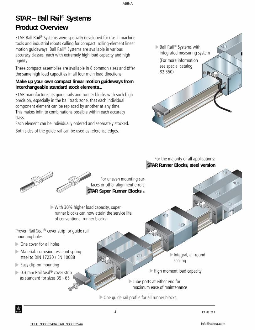
For uneven mounting sur-faces or other alignment errors:
STAR Super Runner Blocks s
Product OverviewSTAR Ball Rail® Systems were specially developed for use in machinetools and industrial robots calling for compact, rolling-element linearmotion guideways. Ball Rail® Systems are available in variousaccuracy classes, each with extremely high load capacity and highrigidity.
These compact assemblies are available in 8 common sizes and offerthe same high load capacities in all four main load directions.
Make up your own compact linear motion guideways frominterchangeable standard stock elements...
STAR manufactures its guide rails and runner blocks with such highprecision, especially in the ball track zone, that each individualcomponent element can be replaced by another at any time.This makes infinite combinations possible within each accuracyclass.Each element can be individually ordered and separately stocked.
Both sides of the guide rail can be used as reference edges.
Proven Rail Seal® cover strip for guide railmounting holes:
One cover for all holes
Material: corrosion resistant springsteel to DIN 17230 / EN 10088
Easy clip-on mounting
0.3 mm Rail Seal® cover stripas standard for sizes 35 - 65
With 30% higher load capacity, superrunner blocks can now attain the service lifeof conventional runner blocks
One guide rail profile for all runner blocks
Lube ports at either end formaximum ease of maintenance
High moment load capacity
Integral, all-roundsealing
Ball Rail® Systems withintegrated measuring system
(For more informationsee special catalog82 350)
For the majority of all applications:STAR Runner Blocks, steel version
ABINA
TELF. 938052434 FAX. 938052544 [email protected]

RA 82 201 5
For low-noise applications:
STAR Runner Blockswith spacer balls
STSTARAR
STAR
STSTARAR
STSTARAR
For lightweight applications:
STAR Runner Blocks,aluminum version
STAR
STAR
STAR
STAR
Guide rail with mountinghole plugs
For high moment loads:STAR Wide Ball Rail® Systems
Simline runner blocksfor all configurations
30% higher dynamic load capacities and momentsas standard in all accuracy classes:
– extends service life by a factor of 2.2– field-proven– Equal load rating in all four main load directions
4 differentpreload classes
Mounting of flanged runner block fromabove or below
Optimized entry-zone geometry and the highnumber of balls per track greatly reducevariations in elastic deflection
Smooth, light running due to optimizedball recirculation and ideal trackgeometry
End face mounting holes for attachmentof bellows, lubrication plates orscraper plates
ABINA
TELF. 938052434 FAX. 938052544 [email protected]

6 RA 82 201
STAR – Ball Rail® SystemsProduct Overview with Load Capacities
46
54
28
30
44
56
Super runner blocks,steel version withself-aligning feature
Slimline,short
1662-
STAR
STAR
STAR
STAR
C
CC
CCC
STAR
STAR
STAR
STAR
STAR
STAR
STAR
STAR
STAR
STAR
STAR
STAR
Standard width,short1665-
Standard width,long
1653-
Standard width1651-
Slimline,short
1666-
Slimline,long
1623-
Slimline1622-
48
58
Runner blocks,steel version
Standard width,short1661-
Observe maximum load!(for details, see individual types)
Special versions:
All steel runner blocks in accuracy class N(clearance and preload 0.02 C) are alsoavailable:
– with zinc-iron coating and yellowchromating(part numbers 16..-..4-30),
– with low-friction seal(part numbers 16..-..4-11).
Preferred versions:1651,- 1653-, 1622- and 1623-.
CC 0
C
C 0
C
C 0
CC 0
C
C 0
C
C 0
CC 0
C
C 0
C
C 0
CC 0
C
C 0
C
C 0
CC 0
C
C 0
C
C 0
CC 0
C
C 0
C
C 0
50
52
Standard width,short, low profile
1663-
Standard width,low profile
1693-
Page
CC 0
C
C 0
C
C 0
CC 0
C
C 0
C
C 0
ABINA
TELF. 938052434 FAX. 938052544 [email protected]

10 RA 82 201
STAR – Ball Rail® SystemsProduct Overview with Load Capacities
Wide1671-
CC 0
C
C 0
C
C 0
Wide Ball Rail Systems
Runner Blocks, steel version
Wide, for mountingfrom above*
1675-
Wide Ball Rail Systems
Guide rails98
96
102 Scraperplate
STAR
STAR
Accessories
- Rail Seal mounting hole cover strip- Mounting hole plugs- Protective caps
Wide, for mountingfrom below*
1677-
90
100
Page
80
82
Guide rails For mounting from above,with Rail Seal cover strip andscrew-down protective caps*
1605-.6.-
*Also available as special version:zinc-iron coating with yellow chromatingin accuracy class N
88For mounting
from below – thindense chrome plated
1647-
Front lube unit
STAR
STAR
84
86
For mountingfrom below*
1607-
For mountingfrom above – thin
dense chrome plated1645-
For mounting from above,with plastic (or steel)
mounting hole plugs*1605-.0.- (1606-.0.-)
*Also available as special version:zinc-iron coating with yellow chromatingin accuracy class N
Basis for load capacities p. 11:Determination of load dynamic capacity C is based on a travel lifeof 100,000 m to DIN 636. Load capacities on the basis of 50,000 mare also given for comparison.
ABINA
TELF. 938052434 FAX. 938052544 [email protected]

28 RA 82 201
STAR – Ball Rail® SystemsSuper Runner Blocks s Steel VersionSuper Runner Block swith self-aligning feature 1661-Standard width, short
Special versions:
Runner blocks in accuracy class N(clearance and preload 0.02 C) arealso available:
– with zinc-iron coating and yellowchromating(part numbers 16..-..4-30),
– with low friction seals(part numbers 16..-..4-11).
STSTARAR
STSTARAR
Permissible load
Note on dynamic load capacitiesand moments(see table)
Determination of dynamic load capacitiesand moments is based on a travel life of100,000 m.For comparison with the 50,000 m travelsometimes applied for rail-type guideways,the figures for C and Mt in the tableshould be multiplied by 1.26.
Part numbers Size Accuracy Part numbers for runner blockclass for preload class
up to approx. Preload10 µm clearance 0.02 C
15 H 1661-193-10 1661-113-10N 1661-194-10 1661-114-10
20 H 1661-893-10 1661-813-10N 1661-894-10 1661-814-10
25 H 1661-293-10 1661-213-10N 1661-294-10 1661-214-10
30 H 1661-793-10 1661-713-10N 1661-794-10 1661-714-10
35 H 1661-393-10 1661-313-10N 1661-394-10 1661-314-10
When calculating the service life, use themaximum load capacity figure.
The permissible load is only limited forstatistical purposes (see table).
ABINA
TELF. 938052434 FAX. 938052544 [email protected]

RA 82 201 29
Load capacities (N)
Dimensions (mm) Mass C Fmax Mt Mt
Size N5 N6±0.5 S1 S2 S5 S9 (kg) dyn. dyn. max.
15 4.0 10.3 4.4 M5 4.4 M2.5-3.5deep 0.19 3 900 1 500 39 1520 4.7 13.2 5.4 M6 6.0 M3-5 deep 0.43 10 100 3 900 130 5025 5.5 15.2 6.8 M8 7.0 M3-5 deep 0.50 11 400 4 400 170 6530 6.0 17.0 8.6 M10 9.0 M3-5 deep 0.90 15 800 6 100 270 10535 7.0 20.5 8.6 M10 9.0 M3-5 deep 1.35 21 100 8 100 450 175
C
CC
Recommended position for pin holes(dimension E4 see "Mounting Instruc-tions", under "Locating pins").
NoteReady-drilled holes made for productionreasons may exist at the recommendedpin hole position.
These may be extended and bored opento accommodate the locating pins.
Dimensions (mm)
Size A A1 A2 A3 B B1 H H1 H21) H2
2) V1 E1 E8 E9 N1
15 47 23.5 15 16.0 40.5 25.7 24 19.8 16.3 16.20 5.0 38 24.55 6.7 5.020 63 31.5 20 21.5 52.5 31.9 30 25.4 20.7 20.55 6.0 53 32.4 7.3 7.525 70 35.0 23 23.5 61.5 38.6 36 29.5 24.4 24.25 7.5 57 38.3 11.5 9.030 90 45.0 28 31.0 71.5 45.0 42 35.0 28.5 28.35 7.0 72 48.4 14.6 11.035 100 50.0 34 33.0 79.0 51.4 48 40.0 32.15 31.85 8.0 82 58.0 17.5 12.0
1) Dimension H2 with Rail Seal cover strip 2) Dimension H2 without Rail Seal cover strip
�H1
V1
E9
S9S2
S1
A3 A2
A1
E1
E4
B1
AE8
N5
N1
H2 N6
S5
B
10'
10'
10' 10'
B2
H
Lube nippleSize 15 and 20:Funnel-type nippleType B – Thread size M3B2 = 8 mm
Size 25 to 55:BM 6 DIN 71412B2 = 16 mm
at either end.
Moments (Nm)Permissible load(N)
30% higher dynamic load capacities and moments than previous design
ABINA
TELF. 938052434 FAX. 938052544 [email protected]

30 RA 82 201
STAR – Ball Rail® SystemsSuper Runner Blocks s Steel VersionSuper Runner Block swith self-aligning feature 1662-Slimline, short
Special versions:
Runner blocks in accuracy class N(clearance and preload 0.02 C) arealso available:
– with zinc-iron coating and yellowchromating(part numbers 16..-..4-30),
– with low friction seals(part numbers 16..-..4-11).
Size Accuracy Part numbers for runner blockclass for preload class
up to approx. Preload10 µm clearance 0.02 C
15 H 1662-193-10 1662-113-10N 1662-194-10 1662-114-10
20 H 1662-893-10 1662-813-10N 1662-894-10 1662-814-10
25 H 1662-293-10 1662-213-10N 1662-294-10 1662-214-10
30 H 1662-793-10 1662-713-10N 1662-794-10 1662-714-10
35 H 1662-393-10 1662-313-10N 1662-394-10 1662-314-10
Note on dynamic load capacitiesand moments(see table)
Determination of dynamic load capacitiesand moments is based on a travel life of100,000 m.For comparison with the 50,000 m travelsometimes applied for rail-type guideways,the figures for C and Mt in the tableshould be multiplied by 1.26.
Part numbers
Permissible load When calculating the service life, use themaximum load capacity figure.
The permissible load is only limited forstatistical purposes (see table).
ABINA
TELF. 938052434 FAX. 938052544 [email protected]

RA 82 201 31
Dimensions (mm) Mass C Fmax Mt Mt
Size N5 N6±0.5 S2 S5 S9 (kg) dyn. dyn. max.
15 4.0 10.3 M4 4.4 M2.5-3.5deep 0.12 3 900 1 500 39 1520 4.7 13.2 M5 6.0 M3-5 deep 0.30 10 100 3 900 130 5025 5.5 15.2 M6 7.0 M3-5 deep 0.40 11 400 4 400 170 6530 6.0 17.0 M8 9.0 M3-5 deep 0.65 15 800 6 100 270 10535 7.0 20.5 M8 9.0 M3-5 deep 0.95 21 100 8 100 450 175
CCC
Dimensions (mm)
Size A A1 A2 A3 B B1 H H1 H21) H2
2) V1 E1 E8 E9 N3
15 34 17 15 9.5 40.5 25.7 24 19.8 16.3 16.20 5.0 26 24.55 6.7 6.020 44 22 20 12.0 52.5 31.9 30 25.4 20.7 20.55 6.0 32 32.4 7.3 7.525 48 24 23 12.5 61.5 38.6 36 29.5 24.4 24.25 7.5 35 38.3 11.5 9.030 60 30 28 16.0 71.5 45.0 42 35.0 28.5 28.35 7.0 40 48.4 14.6 12.035 70 35 34 18.0 79.0 51.4 48 40.0 32.15 31.85 8.0 50 58.0 17.5
1) Dimension H2 with Rail Seal cover strip 2) Dimension H2 without Rail Seal cover strip
�H1
V1
E9
S9 S2
A3 A2
A1
AE8
N5
N3
H
E4
B1
10' 10'
H2 N6
S5
B
10'
10'
B2
Lube nippleSize 15 and 20:Funnel-type nippleType B – Thread size M3B2 = 8 mm
Size 25 to 55:BM 6 DIN 71412B2 = 16 mm
at either end.
30% higher dynamic load capacities and moments than previous design
Load capacities (N) Moments (Nm)Permissible load(N)
ABINA
TELF. 938052434 FAX. 938052544 [email protected]

STAR – Ball Rail® Systems
34 RA 82 201
Standard width Slimline
Product Description Runner Blocks, Steel Version
The Ball Rail® System consists of:
– A guide rail with all surfaces ground and ball track zones hardened
– A runner block with all surfaces ground and ball track zones hardened, made of rolling bearing steel or withhardened and ground steel load bearing plates with- cage designed for optimum ball recirculation- integral all-round sealing of all ball tracks- bearing steel balls
With steel load bearing plates
Slimline, high
�
�These figures are also valid for the long versions.
�
��
�
STAR
STAR
ABINA
TELF. 938052434 FAX. 938052544 [email protected]

RA 82 201 35
1000 2000 3000 4000 5000
10
20
30
0
40
0
50
6000
H
N
P
SP
UP
Technical Data
Accuracy classes and theirtolerances (µm)
Rail length (mm)
Parallelism offset P1 of theBall Rail® System in service
Measured at middle of runner block
II
II
IIH P1
P1
P1
A3
STSTARAR
For any runner block/rail com-bination at any position on rail
For different runner blocksat same position on rail
Measured atmiddle of
runner block:
STAR Ball Rail® Systems are offered inup to five different accuracy classes.
For available versions see table"Part Numbers".
Built-in interchangeabilitythrough precision machining
STAR manufactures its guide rails andrunner blocks with such high precision,especially in the ball track zone, that eachindividual component element can bereplaced by another at any time.
A runner block can be used without prob-lems on various guide rails of the same size,for example.
This applies equally to the use of differentrunner blocks on one and the same guiderail.
Para
llelis
m o
ffset
P1 (
µm)
Accuracy Dimensional Max. difference in dimensionsclasses tolerances H and A3 (µm) H and A3 on the same rail
H A3 ∆ H, ∆ A3 (µm)
UP ± 5 ± 5 3
SP ± 10 ± 7 5
P ± 20 ± 10 7
H ± 40 ± 20 15
N ± 100 ± 40 30
STSTARAR
STSTARAR
STSTARAR
STSTARAR
STSTARAR
ABINA
TELF. 938052434 FAX. 938052544 [email protected]

STAR – Ball Rail® Systems
36 RA 82 201
20
40
60
80
0
140
20000 400000 60000 80000 100000
15
25
30
3545
55
65100
120
20
20
40
60
80
0
100
120
140
20000 400000 60000 80000 100000
15
2530 35
4555
65
20
Elas
tic d
efle
ctio
n δ
el. (
µm)
Load F (N)
2. Lift-off load
20
40
60
80
0
140
20000 400000 60000 80000 100000
15
25
30 35
45
55
65100
120
20
3. Side load
Elas
tic d
efle
ctio
n δ
el. (
µm)
Load F (N)
Elas
tic d
efle
ctio
n δ
el. (
µm)
Load F (N)
Technical Data – Runner Blocks, Steel VersionRigidity of the Ball Rail®
System at 0.08 C preloadRunner block 1651-Standard width
measured values
Runner block mounted usingsix screws:
– 4 outer screws of strength class 12.9– 2 centerline screws of strength
class 8.8
1. Down load
ABINA
TELF. 938052434 FAX. 938052544 [email protected]

RA 82 201 37
20
40
60
80
0
100
5000 10000 15000 20000 25000 30000 350000
25
15
3035
20
40000 45000 50000
20
40
60
80
0
100
5000 10000 15000 20000 25000 30000 350000
25
15
30
35
20
20
40
60
80
0
100
5000 10000 15000 20000 25000 30000 350000
25
15
30 35
20
Elas
tic d
efle
ctio
n δ
el. (
µm)
Load F (N)
2. Lift-off load
3. Side load
Elas
tic d
efle
ctio
n δ
el. (
µm)
Load F (N)
Elas
tic d
efle
ctio
n δ
el. (
µm)
Load F (N)
Rigidity of the Ball Rail®
System at 0.02 C preloadRunner block 1666-Slimline, short
measured values
calculated values
1. Down load
Runner block mounted with twoscrews, screw strength class 8.8
ABINA
TELF. 938052434 FAX. 938052544 [email protected]
STAR – Ball Rail® Systems
38 RA 82 201
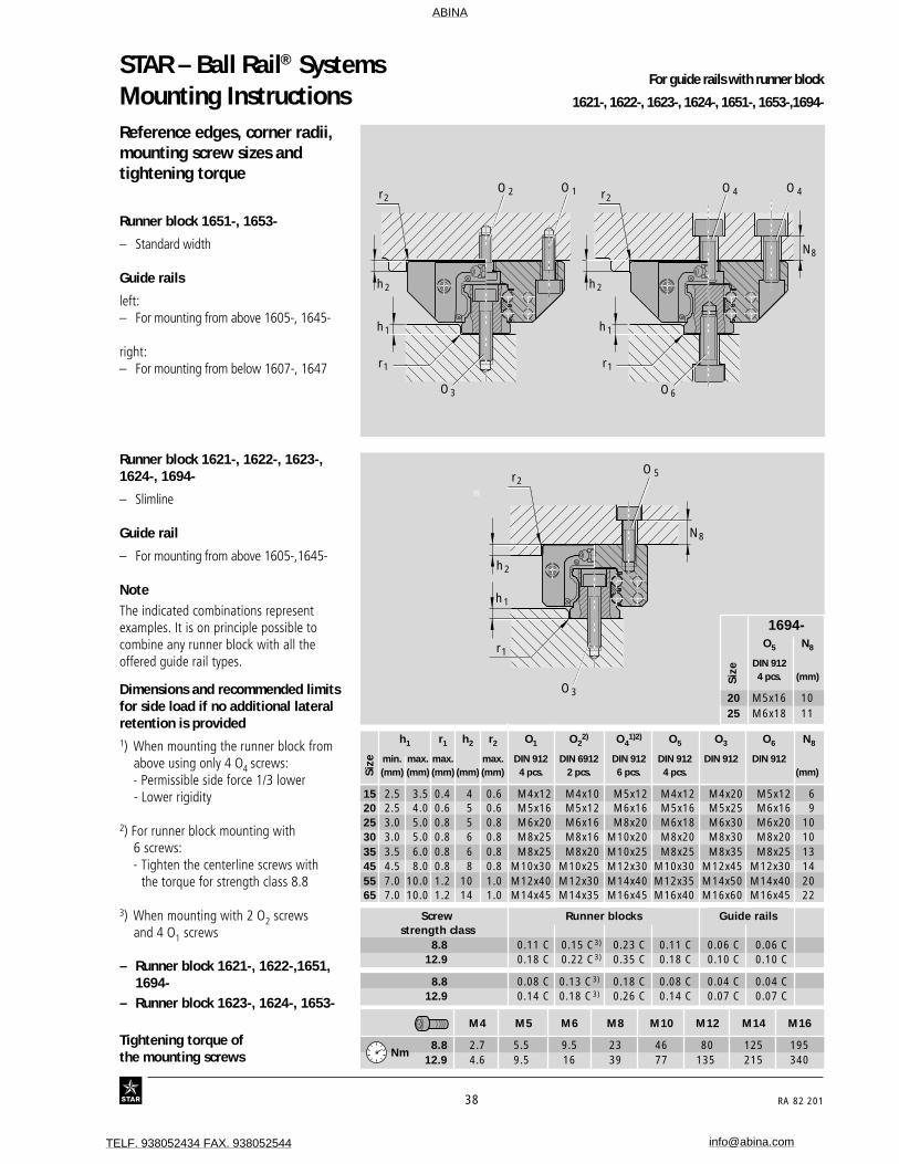
Mounting InstructionsReference edges, corner radii,mounting screw sizes andtightening torque
Runner block 1651-, 1653-
– Standard width
Guide rails
left:– For mounting from above 1605-, 1645-
right:– For mounting from below 1607-, 1647
Runner block 1621-, 1622-, 1623-,1624-, 1694-
– Slimline
Guide rail
– For mounting from above 1605-,1645-
NoteThe indicated combinations representexamples. It is on principle possible tocombine any runner block with all theoffered guide rail types.
��r2
r1
h1
h2
N8
O3
O 5
h1 r1 h2 r2 O1 O22) O4
1)2) O5 O3 O6 N8
min. max. max. max. DIN 912 DIN 6912 DIN 912 DIN 912 DIN 912 DIN 912(mm) (mm) (mm) (mm) (mm) 4 pcs. 2 pcs. 6 pcs. 4 pcs. (mm)
15 2.5 3.5 0.4 4 0.6 M4x12 M4x10 M5x12 M4x12 M4x20 M5x12 620 2.5 4.0 0.6 5 0.6 M5x16 M5x12 M6x16 M5x16 M5x25 M6x16 925 3.0 5.0 0.8 5 0.8 M6x20 M6x16 M8x20 M6x18 M6x30 M6x20 1030 3.0 5.0 0.8 6 0.8 M8x25 M8x16 M10x20 M8x20 M8x30 M8x20 1035 3.5 6.0 0.8 6 0.8 M8x25 M8x20 M10x25 M8x25 M8x35 M8x25 1345 4.5 8.0 0.8 8 0.8 M10x30 M10x25 M12x30 M10x30 M12x45 M12x30 1455 7.0 10.0 1.2 10 1.0 M12x40 M12x30 M14x40 M12x35 M14x50 M14x40 2065 7.0 10.0 1.2 14 1.0 M14x45 M14x35 M16x45 M16x40 M16x60 M16x45 22
����
r2
r1 r1
h1
h2
O 1O 2
O3
r2
h1
h2
N8
O 4
O6
O 4
For guide rails with runner block
1621-, 1622-, 1623-, 1624-, 1651-, 1653-,1694-
Tightening torque ofthe mounting screws
– Runner block 1623-, 1624-, 1653-M4 M5 M6 M8 M10 M12 M14 M16
8.8 2.7 5.5 9.5 23 46 80 125 19512.9 4.6 9.5 16 39 77 135 215 340
Dimensions and recommended limitsfor side load if no additional lateralretention is provided1) When mounting the runner block from
above using only 4 O4 screws:- Permissible side force 1/3 lower- Lower rigidity
2) For runner block mounting with6 screws:- Tighten the centerline screws with
the torque for strength class 8.8
3) When mounting with 2 O2 screwsand 4 O1 screws
– Runner block 1621-, 1622-,1651,1694-
Size
1694-O5 N8
DIN 9124 pcs. (mm)
20 M5x16 1025 M6x18 11
Screw Runner blocks Guide railsstrength class
8.8 0.11 C 0.15 C3) 0.23 C 0.11 C 0.06 C 0.06 C12.9 0.18 C 0.22 C3) 0.35 C 0.18 C 0.10 C 0.10 C
8.8 0.08 C 0.13 C3) 0.18 C 0.08 C 0.04 C 0.04 C12.9 0.14 C 0.18 C3) 0.26 C 0.14 C 0.07 C 0.07 C
Size
Nm
ABINA
TELF. 938052434 FAX. 938052544 [email protected]
RA 82 201 39
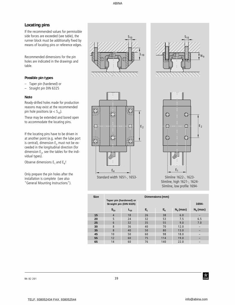
Size Dimensions (mm)Taper pin (hardened) orStraight pin (DIN 6325) 1694-
S10 L10 E1 E4 N9 (max) N9 (max)
15 4 18 26 38 6.0 –20 5 24 32 53 7.5 6.525 6 32 35 55 9.0 7.030 8 36 40 70 12.0 –35 8 40 50 80 13.0 –45 10 50 60 98 18.0 –55 12 60 75 114 19.0 –65 14 60 76 140 22.0 –
Locating pinsIf the recommended values for permissibleside forces are exceeded (see table), therunner block must be additionally fixed bymeans of locating pins or reference edges.
Recommended dimensions for the pinholes are indicated in the drawings andtable.
Possible pin types
– Taper pin (hardened) or– Straight pin DIN 6325
NoteReady-drilled holes made for productionreasons may exist at the recommendedpin hole positions (ø < S10).
These may be extended and bored opento accommodate the locating pins.
If the locating pins have to be driven inat another point (e.g. when the lube portis central), dimension E2 must not be ex-ceeded in the longitudinal direction (fordimension E2, see the tables for the indi-vidual types).
Observe dimensions E1 and E4!
Only prepare the pin holes after theinstallation is complete (see also"General Mounting Instructions").
Standard width 1651-, 1653- Slimline 1622-, 1623-Slimline, high 1621-, 1624-Slimline, low profile 1694-
��N9
S10
E2
E1
��
E2
L10
S10
E4
ABINA
TELF. 938052434 FAX. 938052544 [email protected]

STAR – Ball Rail® Systems
40 RA 82 201
Reference edges, corner radii,mounting screw sizes andtightening torque
Runner block 1665-
– Standard width, short
Guide rails
left:– For mounting from above 1605-
right:– For mounting from below 1607-
Runner block 1666-
– Slimline, short
Guide rails
– For mounting from above 1605-
Note
The indicated combinations representexamples. It is on principle possible tocombine any runner block with all theoffered guide rail types.
Screw mounting of runner blocks usingtwo screws is fully sufficient up to maxi-mum load. (See maximum permissibleforce and moment loads indicated underthe individual types.)
�
r2 r2
r1
h1
r1
h1
h2 h2
O 1 O 4
O3
N8
�� ��O6
M4 M5 M6 M8 M10 M12 M14 M16
8.8 2.7 5.5 9.5 23 46 80 125 195
12.9 4.6 9.5 16 39 77 135 215 340
Tightening torque of themounting screws
���
r2
r1
h1
h2
O5
O3
N8
Mounting Instructions For rail systems with runner block 1665-, 1666-
h1 r1 h2 r2 O1 O4 O5 O3 O6 N8
min. max. max. max. DIN 912 DIN 912 DIN 912 DIN 912 DIN 912(mm) (mm) (mm) (mm) (mm) 2 pcs. 2 pcs. 2 pcs. (rail) (rail) (mm)
15 2.5 3.5 0.4 4 0.6 M4x12 M5x12 M4x12 M4x20 M5x12 620 2.5 4.0 0.6 5 0.6 M5x16 M6x16 M5x16 M5x25 M6x16 925 3.0 5.0 0.8 5 0.8 M6x20 M8x20 M6x18 M6x30 M6x20 1030 3.0 5.0 0.8 6 0.8 M8x25 M10x20 M8x20 M8x30 M8x20 1035 3.5 6.0 0.8 6 0.8 M8x25 M10x25 M8x25 M8x35 M8x25 13
Screw Runner blocks Guide railsstrength class
8.8 0.08 C 0.12 C 0.08 C 0.09 C 0.09 C 12.9 0.13 C 0.21 C 0.13 C 0.15 C 0.15 C
Dimensions and recommended limitsfor side load if no additional lateralretention is provided(Runner blocks 1665-, 1666-)
Nm
Size
ABINA
TELF. 938052434 FAX. 938052544 [email protected]
RA 82 201 41
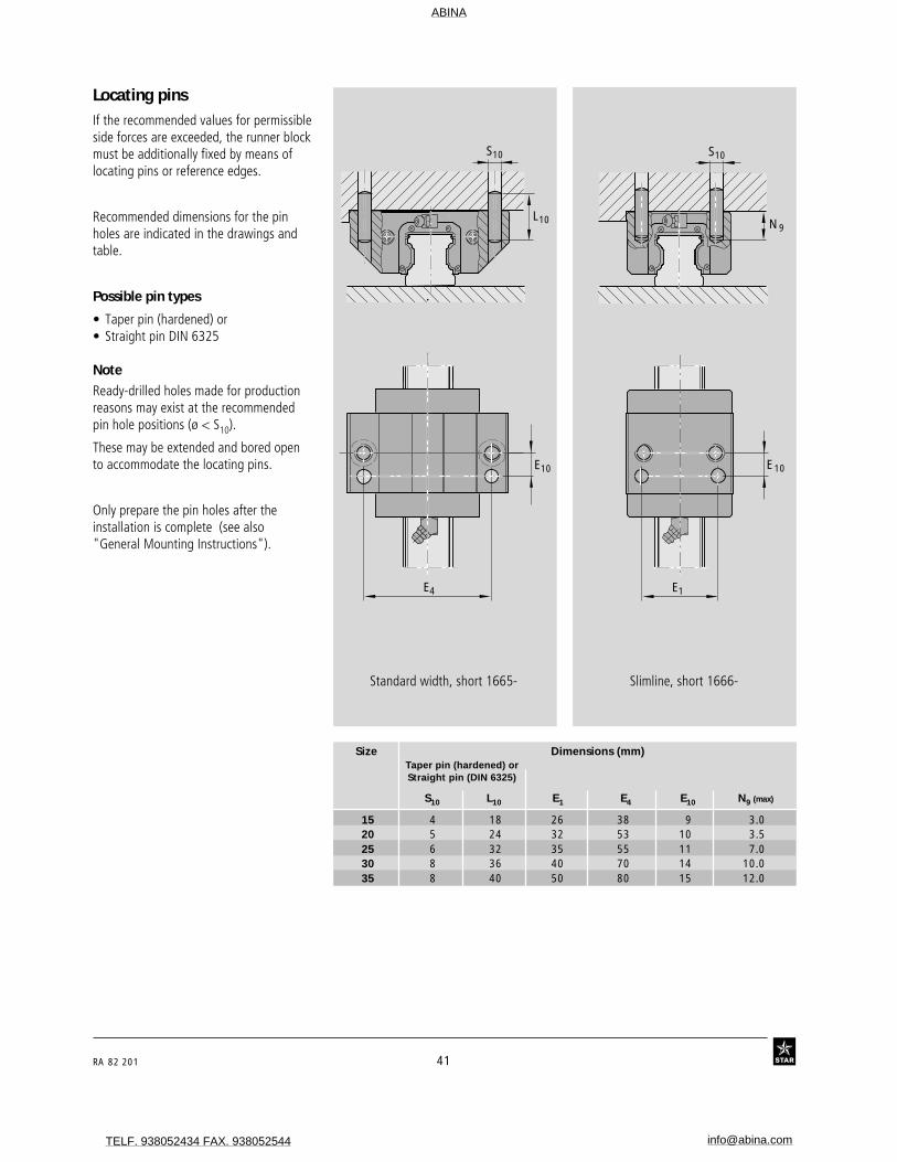
Locating pinsIf the recommended values for permissibleside forces are exceeded, the runner blockmust be additionally fixed by means oflocating pins or reference edges.
Recommended dimensions for the pinholes are indicated in the drawings andtable.
Possible pin types
• Taper pin (hardened) or• Straight pin DIN 6325
NoteReady-drilled holes made for productionreasons may exist at the recommendedpin hole positions (ø < S10).
These may be extended and bored opento accommodate the locating pins.
Only prepare the pin holes after theinstallation is complete (see also"General Mounting Instructions").
Size Dimensions (mm)Taper pin (hardened) orStraight pin (DIN 6325)
S10 L10 E1 E4 E10 N9 (max)
15 4 18 26 38 9 3.020 5 24 32 53 10 3.525 6 32 35 55 11 7.030 8 36 40 70 14 10.035 8 40 50 80 15 12.0
Standard width, short 1665- Slimline, short 1666-
E10
E1
��N9
S10
L10
S10
E10
E4
ABINA
TELF. 938052434 FAX. 938052544 [email protected]
STAR – Ball Rail® Systems
42 RA 82 201
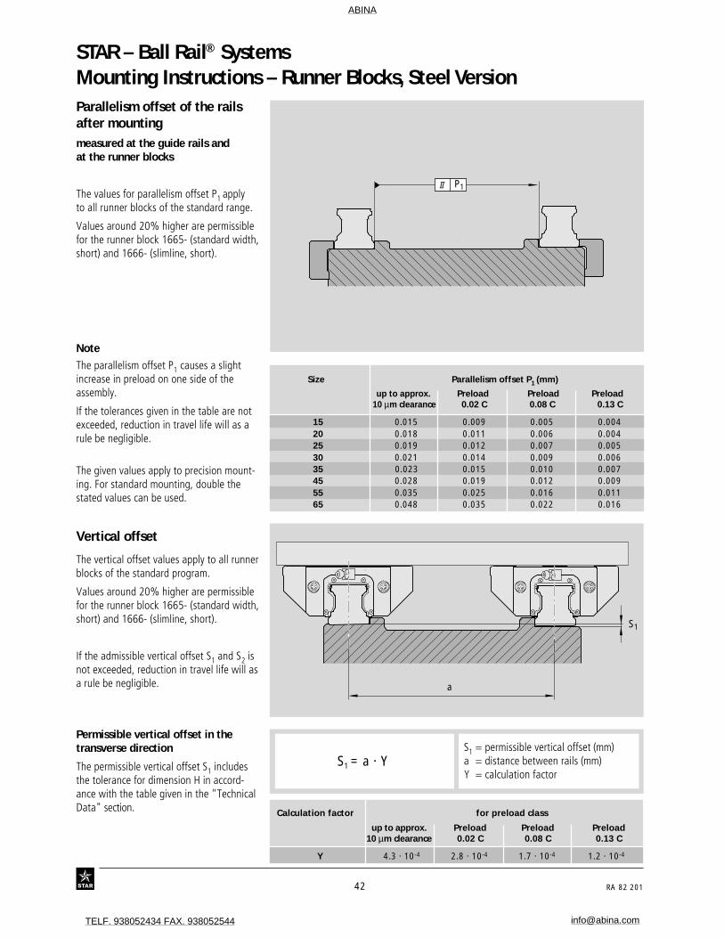
Mounting Instructions – Runner Blocks, Steel VersionParallelism offset of the railsafter mountingmeasured at the guide rails andat the runner blocks
The values for parallelism offset P1 applyto all runner blocks of the standard range.
Values around 20% higher are permissiblefor the runner block 1665- (standard width,short) and 1666- (slimline, short).
Size Parallelism offset P1 (mm)
up to approx. Preload Preload Preload 10 µm clearance 0.02 C 0.08 C 0.13 C
15 0.015 0.009 0.005 0.00420 0.018 0.011 0.006 0.00425 0.019 0.012 0.007 0.00530 0.021 0.014 0.009 0.00635 0.023 0.015 0.010 0.00745 0.028 0.019 0.012 0.00955 0.035 0.025 0.016 0.01165 0.048 0.035 0.022 0.016
a
S1
Permissible vertical offset in thetransverse direction
The permissible vertical offset S1 includesthe tolerance for dimension H in accord-ance with the table given in the "TechnicalData" section.
S1 = permissible vertical offset (mm)a = distance between rails (mm)Y = calculation factor
S1 = a · Y
Calculation factor for preload class
up to approx. Preload Preload Preload10 µm clearance 0.02 C 0.08 C 0.13 C
Y 4.3 · 10-4 2.8 · 10-4 1.7 · 10-4 1.2 · 10-4
Vertical offset
The vertical offset values apply to all runnerblocks of the standard program.
Values around 20% higher are permissiblefor the runner block 1665- (standard width,short) and 1666- (slimline, short).
If the admissible vertical offset S1 and S2 isnot exceeded, reduction in travel life will asa rule be negligible.
Note
The parallelism offset P1 causes a slightincrease in preload on one side of theassembly.
If the tolerances given in the table are notexceeded, reduction in travel life will as arule be negligible.
The given values apply to precision mount-ing. For standard mounting, double thestated values can be used.
II P1
ABINA
TELF. 938052434 FAX. 938052544 [email protected]

RA 82 201 43
b
S2
S2 = permissible vertical offset (mm)b = distance
between runner blocks (mm)S2 = b · 4.3 · 10-5
Permissible vertical offset in thelongitudinal direction
The permissible vertical offset S2 includesthe tolerance "Max. difference in dimen-sion H on the same rail" in accordancewith the table given in the "TechnicalData" section.
Values around 40% higher are permissiblefor the runner block 1665- (standard width,short) and 1666- (slimline, short).
Values around 30% lower are permissiblefor runner block1653- (standard width long),1623- (slimline, long) and1624- (slimline, high, long).
ABINA
TELF. 938052434 FAX. 938052544 [email protected]

STAR – Ball Rail® Systems
44 RA 82 201
Runner Blocks, Steel VersionRunner Block 1665-Standard width, short
Special versions:
Runner blocks in accuracy class N(clearance and preload 0.02 C) arealso available:
– with zinc-iron coating and yellowchromating(part numbers 16..-..4-30),
– with low friction seals(part numbers 16..-..4-11).
Part numbers
Note on dynamic load capacitiesand moments(see table)
Determination of dynamic load capacitiesand moments is based on a travel life of100,000 m.For comparison with the 50,000 m travelsometimes applied for rail-type guideways,the figures for C, Mt and ML in the tableshould be multiplied by 1.26.
Size Accuracy Part numbers for runner blockclass for preload class
up to approx. Preload10 µm clearance 0.02 C
15 H 1665-193-10 1665-113-10N 1665-194-10 1665-114-10
20 H 1665-893-10 1665-813-10N 1665-894-10 1665-814-10
25 H 1665-293-10 1665-213-10N 1665-294-10 1665-214-10
30 H 1665-793-10 1665-713-10N 1665-794-10 1665-714-10
35 H 1665-393-10 1665-313-10N 1665-394-10 1665-314-10
STSTARAR
STSTARAR
ABINA
TELF. 938052434 FAX. 938052544 [email protected]

RA 82 201 45
�H1
V1
E9
S9S2
S1
A3 A2
A1
AE8
N5
N1
HH2 N6
S5
B
B2
E1
E4
B1
Recommended position for pin holes(dimension E4 see "Mounting Instruc-tions", under "Locating pins").
NoteReady-drilled holes made for productionreasons may exist at the recommendedpin hole position.
These may be extended and bored opento accommodate the locating pins.
Lube nippleSize 15 and 20:Funnel-type nippleType B – Thread size M3B2 = 8 mm
Size 25 to 35:BM 6 DIN 71412B2 = 16 mm
at either end.
Load capacities (N) Moments (Nm)
Dimensions (mm) Mass C C0 Mt Mt0 ML ML0
Size N5 N6±0.5 S1 S2 S5 S9 (kg) dyn. stat. dyn. stat. dyn. stat.
15 4.0 10.3 4.4 M5 4.4 M2.5-3.5deep 0.19 5 400 8 100 52 80 19 2820 4.7 13.2 5.4 M6 6.0 M3-5 deep 0.43 12 400 13 600 150 170 52 5825 5.5 15.2 6.8 M8 7.0 M3-5 deep 0.50 15 900 18 200 230 260 82 9430 6.0 17.0 8.6 M10 9.0 M3-5 deep 0.90 22 100 24 800 380 430 133 15035 7.0 20.5 8.6 M10 9.0 M3-5 deep 1.35 29 300 32 400 640 700 200 220
CC0
C
C0
C
C0
1) Dimension H2 with Rail Seal® cover strip 2) Dimension H2 without Rail Seal® cover strip
Dimensions (mm)
Size A A1 A2 A3 B B1 H H1 H21) H2
2) V1 E1 E8 E9 N1
15 47 23.5 15 16.0 40.5 25.7 24 19.8 16.3 16.20 5.0 38 24.55 6.7 5.020 63 31.5 20 21.5 52.5 31.9 30 25.4 20.7 20.55 6.0 53 32.4 7.3 7.525 70 35.0 23 23.5 61.5 38.6 36 29.5 24.4 24.25 7.5 57 38.3 11.5 9.030 90 45.0 28 31.0 71.5 45.0 42 35.0 28.5 28.35 7.0 72 48.4 14.6 11.035 100 50.0 34 33.0 79.0 51.4 48 40.0 32.15 31.85 8.0 82 58.0 17.5 12.0
30% higher dynamic load capacities and moments
ABINA
TELF. 938052434 FAX. 938052544 [email protected]

STAR – Ball Rail® Systems
46 RA 82 201
Runner Blocks, Steel VersionRunner Block 1651-Standard width
Special versions:
Runner blocks in accuracy class N(clearance and preload 0.02 C) arealso available:
– with zinc-iron coating and yellowchromating(part numbers 16..-..4-30),
– with low friction seals(part numbers 16..-..4-11).
Size 15 to 35 in accuracy class H(clearance and preload 0.02 C) alsoavailable as low noise runner blockswith spacer balls.Dynamic load capacities and moments arereduced by 35%.(Part numbers 1651-..3-12)
Size Accuracy Part numbers for runner blocksclass for preload class
up to approx. Preload Preload Preload10 µm clearance 0.02 C 0.08 C 0.13 C
15 UP 1651-119-10* 1651-129-10* 1651-139-10*SP 1651-111-10* 1651-121-10* 1651-131-10*P 1651-112-10 1651-122-10 1651-132-10H 1651-193-10 1651-113-10 1651-123-10N 1651-194-10 1651-114-10 1651-124-10
20 UP 1651-819-10* 1651-829-10* 1651-839-10*SP 1651-811-10* 1651-821-10* 1651-831-10*P 1651-812-10 1651-822-10 1651-832-10H 1651-893-10 1651-813-10 1651-823-10N 1651-894-10 1651-814-10 1651-824-10
25 UP 1651-219-10* 1651-229-10* 1651-239-10*SP 1651-211-10* 1651-221-10* 1651-231-10*P 1651-212-10 1651-222-10 1651-232-10H 1651-293-10 1651-213-10 1651-223-10N 1651-294-10 1651-214-10 1651-224-10
30 UP 1651-719-10* 1651-729-10* 1651-739-10*SP 1651-711-10* 1651-721-10* 1651-731-10*P 1651-712-10 1651-722-10 1651-732-10H 1651-793-10 1651-713-10 1651-723-10N 1651-794-10 1651-714-10 1651-724-10
35 UP 1651-319-10* 1651-329-10* 1651-339-10*SP 1651-311-10* 1651-321-10* 1651-331-10*P 1651-312-10 1651-322-10 1651-332-10H 1651-393-10 1651-313-10 1651-323-10N 1651-394-10 1651-314-10 1651-324-10
45 UP 1651-419-10* 1651-429-10* 1651-439-10*SP 1651-411-10* 1651-421-10* 1651-431-10*P 1651-412-10 1651-422-10 1651-432-10H 1651-493-10 1651-413-10 1651-423-10N 1651-494-10 1651-414-10 1651-424-10
55 UP 1651-519-10* 1651-529-10* 1651-539-10*SP 1651-511-10* 1651-521-10* 1651-531-10*P 1651-512-10* 1651-522-10* 1651-532-10*H 1651-593-10* 1651-513-10* 1651-523-10*N 1651-594-10* 1651-514-10* 1651-524-10*
65 UP 1651-619-10* 1651-629-10* 1651-639-10*SP 1651-611-10* 1651-621-10* 1651-631-10*P 1651-612-10* 1651-622-10* 1651-632-10*H 1651-693-10* 1651-613-10* 1651-623-10*N 1651-694-10* 1651-614-10* 1651-624-10*
Part numbers
Note on dynamic load capacitiesand moments(see table)
Determination of dynamic load capacitiesand moments is based on a travel life of100,000 m.For comparison with the 50,000 m travelsometimes applied for rail-type guideways,the figures for C, Mt and ML in the tableshould be multiplied by 1.26.
STAR
STAR
* 30% higher dynamic load capacities onrequest
ABINA
TELF. 938052434 FAX. 938052544 [email protected]

RA 82 201 47
Load capacities (N) Moments (Nm)
Dimensions (mm)
Size A A1 A2 A3 B B1 H H1 H21) H2
2) V1 E1 E2 E3 E8 E9 N1 N2
15 47 23.5 15 16.0 54 39.2 24 19.8 16.3 16.20 5.0 38 30 26 24.55 6.7 5.0 4.420 63 31.5 20 21.5 70 49.6 30 25.0 20.7 20.55 6.0 53 40 35 32.4 7.3 7.5 5.225 70 35.0 23 23.5 81 57.8 36 29.5 24.4 24.25 7.5 57 45 40 38.3 11.5 9.0 7.030 90 45.0 28 31.0 94 67.4 42 35.0 28.5 28.35 7.0 72 52 44 48.4 14.6 11.0 8.035 100 50.0 34 33.0 105 77.0 48 40.0 32.15 31.85 8.0 82 62 52 58.0 17.5 12.0 10.245 120 60.0 45 37.5 133 97.0 60 50.0 40.15 39.85 10.0 100 80 60 70.0 21.0 15.0 12.455 140 70.0 53 43.5 159 115.5 70 57.0 48.15 47.85 12.0 116 95 70 80.0 22.3 18.0 13.565 170 85.0 63 53.5 188 139.6 90 76.0 60.15 59.85 15.0 142 110 82 76.0 11.0 23.0 14.0
Dimensions (mm) Mass C C0 Mt Mt0 ML ML0
Size N5 N6±0.5 S1 S2 S5 S9 (kg) dyn. stat. dyn. stat. dyn. stat.
15 4.0 10.3 4.4 M5 4.4 M2.5-3.5deep 0.23 7 800 13 500 74 130 40 7120 4.7 13.2 5.4 M6 6.0 M3-5deep 0.55 18 800 24 400 240 310 130 16525 5.5 15.2 6.8 M8 7.0 M3-5deep 0.70 22 800 30 400 320 430 180 24030 6.0 17.0 8.6 M10 9.0 M3-5deep 1.10 31 700 41 300 540 720 290 38035 7.0 20.5 8.6 M10 9.0 M3-5deep 1.75 41 900 54 000 890 1 160 440 56545 8.0 23.5 10.5 M12 14.0 M4-7deep 3.15 68 100 85 700 1 830 2 310 890 1 13055 9.0 29.0 12.5 M14 16.0 M5-8deep 5.20 98 200 121 400 3 100 3 860 1 540 1 90565 16.0 38.5 14.5 M16 18.0 M4-7deep 10.25 160 000 192 700 6 300 7 610 3 160 3 815
CC 0
C
C 0
C
C 0
1) Dimension H2 with Rail Seal® cover strip 2) Dimension H2 without Rail Seal® cover strip
30% higher dynamic load capacities and moments
����S9
S2
S5
B2S1
S2
S1
A
BE8
N5 N2
A3 A2
A1
N1
H1H2 N6
V1
E9
H
E4
B1 E2E3
�
E1
Lube nippleSize 15 and 20:Funnel-type nippleType B – Thread size M3B2 = 8 mm
Size 25 to 55:BM 6 DIN 71412B2 = 16 mm
Size 65:BM 8 x 1 DIN 71412B2 = 16 mm
at either end.
Recommended position for pin holes(dimension E4 see "Mounting Instruc-tions", under "Locating pins").
NoteReady-drilled holes made for productionreasons may exist at the recommendedpin hole position.These may be extended and bored opento accommodate the locating pins.
Size 65
E8.1
E8
E9
E9.1Dimensions
(mm)Size E8.1 E9.1
65 100 53.5
ABINA
TELF. 938052434 FAX. 938052544 [email protected]

STAR – Ball Rail® Systems
48 RA 82 201
Runner block 1653-Standard width, long
Special versions:
Runner blocks in accuracy class N(clearance and preload 0.02 C) arealso available:
– with zinc-iron coating and yellowchromating(part numbers 16..-..4-30),
– with low friction seals(part numbers 16..-..4-11).
Size 15 to 35 in accuracy class H(clearance and preload 0.02 C) alsoavailable as low noise runner blockswith spacer balls.Dynamic load capacities and moments arereduced by 35%.(Part numbers 1653-..3-12)
Runner Blocks, Steel Version
Part numbers
Note on dynamic load capacitiesand moments(see table)
Determination of dynamic load capacitiesand moments is based on a travel life of100,000 m.For comparison with the 50,000 m travelsometimes applied for rail-type guideways,the figures for C, Mt and ML in the tableshould be multiplied by 1.26.
Size Accuracy Part numbers for runner blocksclass for preload class
up to approx. Preload Preload Preload10 µm clearance 0.02 C 0.08 C 0.13 C
15 N 1653-194-10 1653-114-1020 UP 1653-819-10* 1653-829-10* 1653-839-10*
SP 1653-811-10* 1653-821-10* 1653-831-10*P 1653-812-10 1653-822-10 1653-832-10H 1653-893-10 1653-813-10 1653-823-10N 1653-894-10 1653-814-10 1653-824-10
25 UP 1653-219-10* 1653-229-10* 1653-239-10*SP 1653-211-10* 1653-221-10* 1653-231-10*P 1653-212-10 1653-222-10 1653-232-10H 1653-293-10 1653-213-10 1653-223-10N 1653-294-10 1653-214-10 1653-224-10
30 UP 1653-719-10* 1653-729-10* 1653-739-10*SP 1653-711-10* 1653-721-10* 1653-731-10*P 1653-712-10 1653-722-10 1653-732-10H 1653-793-10 1653-713-10 1653-723-10N 1653-794-10 1653-714-10 1653-724-10
35 UP 1653-319-10* 1653-329-10* 1653-339-10*SP 1653-311-10* 1653-321-10* 1653-331-10*P 1653-312-10 1653-322-10 1653-332-10H 1653-393-10 1653-313-10 1653-323-10N 1653-394-10 1653-314-10 1653-324-10
45 UP 1653-419-10* 1653-429-10* 1653-439-10*SP 1653-411-10* 1653-421-10* 1653-431-10*P 1653-412-10 1653-422-10 1653-432-10H 1653-493-10 1653-413-10 1653-423-10N 1653-494-10 1653-414-10 1653-424-10
55 UP 1653-519-10* 1653-529-10* 1653-539-10*SP 1653-511-10* 1653-521-10* 1653-531-10*P 1653-512-10* 1653-522-10* 1653-532-10*H 1653-593-10* 1653-513-10* 1653-523-10*N 1653-594-10* 1653-514-10* 1653-524-10*
65 UP 1653-619-10* 1653-629-10* 1653-639-10*SP 1653-611-10* 1653-621-10* 1653-631-10*P 1653-612-10* 1653-622-10* 1653-632-10*H 1653-693-10* 1653-613-10* 1653-623-10*N 1653-694-10* 1653-614-10* 1653-624-10*
STST
ARAR
* 30% higher dynamic load capacities onrequest
ABINA
TELF. 938052434 FAX. 938052544 [email protected]

RA 82 201 49
�S9
S2
S1
S2
S1
AE8
N5 N2
A3 A2
A1
N1
H2 N6
S5
B
B2
H1
V1
E9
H
E1
E4
B1 E2E3
Load capacities (N) Moments (Nm)
Dimensions (mm)
Size A A1 A2 A3 B B1 H H1 H21) H2
2) V1 E1 E2 E3 E8 E9 N1 N2
15 47 23.5 15 16.0 68.5 53.6 24 19.8 16.3 16.20 5.0 38 30 26 24.55 6.7 5.0 4.420 63 31.5 20 21.5 86.0 65.6 30 25.0 20.7 20.55 6.0 53 40 35 32.4 7.3 7.5 5.225 70 35.0 23 23.5 103.0 79.5 36 29.5 24.4 24.25 7.5 57 45 40 38.3 11.5 9.0 7.030 90 45.0 28 31.0 116.0 89.4 42 35.0 28.5 28.35 7.0 72 52 44 48.4 14.6 11.0 8.035 100 50.0 34 33.0 133.0 105.5 48 40.0 32.15 31.85 8.0 82 62 52 58.0 17.5 12.0 10.245 120 60.0 45 37.5 170.0 133.5 60 50.0 40.15 39.85 10.0 100 80 60 70.0 21.0 15.0 12.455 140 70.0 53 43.5 200.0 155.5 70 57.0 48.15 47.85 12.0 116 95 70 80.0 22.3 18.0 13.565 170 85.0 63 53.5 243.0 194.6 90 76.0 60.15 59.85 15.0 142 110 82 76.0 11.0 23.0 14.0
Dimensions (mm) Mass C C0 Mt Mt0 ML ML0
Size N5 N6±0.5 S1 S2 S5 S9 (kg) dyn. stat. dyn. stat. dyn. stat.
15 4.0 10.3 4.4 M5 4.4 M2.5-3.5deep 0.32 10 000 20 200 130 190 98 15020 4.7 13.2 5.4 M6 6 M3-5 deep 0.80 24 400 35 200 310 450 225 33025 5.5 15.2 6.8 M8 7 M3-5 deep 1.00 30 400 45 500 430 650 345 51030 6.0 17.0 8.6 M10 9 M3-5 deep 1.60 40 000 57 800 690 1 000 495 71535 7.0 20.5 8.6 M10 9 M3-5 deep 2.45 55 600 81 000 1 200 1 740 830 1 21545 8.0 23.5 10.5 M12 14 M4-7 deep 4.50 90 400 128 500 2 440 3 470 1 700 2 42555 9.0 29.0 12.5 M14 16 M5-8 deep 7.50 124 200 170 000 3 950 5 400 2 630 3 60065 16.0 38.5 14.5 M16 18 M4-7 deep 14.15 211 900 289 000 8 370 11 420 6 000 8 190
CC 0
C
C 0
C
C 0
Lube nippleSize 20:Funnel-type nippleType B – Thread size M3B2 = 8 mm
Size 25 to 55:BM 6 DIN 71412B2 = 16 mm
Size 65:BM 8 x 1 DIN 71412B2 = 16 mm
at either end.
Size 65
1) Dimension H2 with Rail Seal® cover strip 2) Dimension H2 without Rail Seal® cover strip
30% higher dynamic load capacities and moments
E8.1
E8
E9
E9.1
Recommended position for pin holes(dimension E4 see "Mounting Instruc-tions", under "Locating pins").
NoteReady-drilled holes made for productionreasons may exist at the recommendedpin hole position.These may be extended and bored opento accommodate the locating pins.
Dimensions(mm)
Size E8.1 E9.1
65 100 53.5
ABINA
TELF. 938052434 FAX. 938052544 [email protected]

STAR – Ball Rail® Systems
50 RA 82 201
Runner Blocks, Steel VersionRunner block 1663-Standard width, short, low profile
Special versions:
Runner blocks in accuracy class N(clearance and preload 0.02 C) arealso available:
– with zinc-iron coating and yellowchromating(part numbers 16..-..4-30),
– with low friction seals(part numbers 16..-..4-11).
Size Accuracy Part numbers for runner blocksclass for preload class
up to approx. Preload10 µm clearance 0.02 C
20 H 1663-893-10 1663-813-10N 1663-894-10 1663-814-10
25 H 1663-293-10 1663-213-10N 1663-294-10 1663-214-10
Note on dynamic load capacitiesand moments(see table)
Determination of dynamic load capacitiesand moments is based on a travel life of100,000 m.For comparison with the 50,000 m travelsometimes applied for rail-type guideways,the figures for C, Mt and ML in the tableshould be multiplied by 1.26.
Part numbers
ABINA
TELF. 938052434 FAX. 938052544 [email protected]

RA 82 201 51
Load capacities (N) Moments (Nm)
Dimensions (mm) Mass C C0 Mt Mt0 ML ML0
Size N6±0.5 N7 S1 S2 S5 S9 (kg) dyn. stat. dyn. stat. dyn. stat.
20 13.2 – 5.4 M6 6.0 M3-5 deep 0.43 9 600 13 600 120 170 40 5825 15.2 6.0 6.8 M8 7.0 M3-5 deep 0.50 15 900* 18 200 235 260 82 94
Dimensions (mm)
Size A A1 A2 A3 B B1 H H1 H21) H2
2) V1 E1 E8 E9 K1 N1 N5
20 59 29.5 20 19.5 55 31.9 28 23.0 20.7 20.55 6.0 49 30.5 5.6 20.1 7.7 3.625 73 36.5 23 25.0 62 38.6 33 26.5 24.4 24.25 7.5 60 38.3 8.5 24.5 9.3 4.1
�H2
S9S2
S1
AE8
N5
H1
V1E9
H
N1
A3 A2
A1
H2 N6
S5
B
B2
E1
B1
K1
N7
For O-ring ø 5 · 1 mm
Open lube port if necessary.Send for instructions.
Lube port with additionalanti-twist feature.
Lube nippleFunnel-type nippleType B – Thread size M3B2 = 8 mm
at either end.
Size 25:Provided with ports at side.
1) Dimension H2 with Rail Seal® cover strip 2) Dimension H2 without Rail Seal® cover strip
CC 0
C
C 0
C
C 0
* 30% higher dynamic load capacity
ABINA
TELF. 938052434 FAX. 938052544 [email protected]

STAR – Ball Rail® Systems
52 RA 82 201
Runner Blocks, Steel Version
Note on dynamic load capacitiesand moments(see table)
Determination of dynamic load capacitiesand moments is based on a travel life of100,000 m.For comparison with the 50,000 m travelsometimes applied for rail-type guideways,the figures for C, Mt and ML in the tableshould be multiplied by 1.26.
Runner block 1693-Standard width, low profile
Special versions:
Runner blocks in accuracy class N(clearance and preload 0.02 C) arealso available:
– with zinc-iron coating and yellowchromating(part numbers 16..-..4-30),
– with low friction seals(part numbers 16..-..4-11).
Size Accuracy Part numbers for runner blocksclass for preload class
up to approx. Preload10 µm clearance 0.02 C
20 H 1693-893-10 1693-813-10N 1693-894-10 1693-814-10
25 H 1693-293-10 1693-213-10N 1693-294-10 1693-214-10
Part numbers
ABINA
TELF. 938052434 FAX. 938052544 [email protected]

RA 82 201 53
Load capacities (N) Moments (Nm)
Dimensions (mm) Mass C C0 Mt Mt0 ML ML0
Size N6±0.5 N7 S1 S2 S5 S9 (kg) dyn. stat. dyn. stat. dyn. stat.
20 13.2 – 5.4 M6 6.0 M3-5 deep 0.50 14 500 24 400 190 310 100 16525 15.2 6.0 6.8 M8 7.0 M3-5 deep 0.65 22 800* 30 400 320 430 180 240
S9S2
S1
AE8
N5
H1
V1E9
H
N1
A3 A2
A1
H2 N6
S5
B
B2N7
E1
B1
K1
E2
For O-ring ø 5 · 1 mm
Open lube port if necessary.Send for instructions.
Lube port with additionalanti-twist feature.
Lube nippleFunnel-type nippleType B – Thread size M3B2 = 8 mm
at either end.
Size 25:Provided with ports at side.
Dimensions (mm)
Size A A1 A2 A3 B B1 H H1 H21) H2
2) V1 E1 E2 E8 E9 K1 N1 N5
20 59 29.5 20 19.5 72.5 49.6 28 23.0 20.7 20.55 6.0 49 32 30.5 5.6 13.0 7.7 3.625 73 36.5 23 25.0 81.0 57.8 33 26.5 24.4 24.25 7.5 60 35 38.3 8.5 16.6 9.3 4.1
1) Dimension H2 with Rail Seal® cover strip 2) Dimension H2 without Rail Seal® cover strip
CC 0
C
C 0
C
C 0
* 30% higher dynamic load capacity
ABINA
TELF. 938052434 FAX. 938052544 [email protected]

STAR – Ball Rail® Systems
54 RA 82 201
Runner Blocks, Steel VersionRunner block 1666-Slimline, short
Special versions:
Runner blocks in accuracy class N(clearance and preload 0.02 C) arealso available:
– with zinc-iron coating and yellowchromating(part numbers 16..-..4-30),
– with low friction seals(part numbers 16..-..4-11).
Size Accuracy Part numbers for runner blocksclass for preload class
up to approx. Preload10 µm clearance 0.02 C
15 H 1666-193-10 1666-113-10N 1666-194-10 1666-114-10
20 H 1666-893-10 1666-813-10N 1666-894-10 1666-814-10
25 H 1666-293-10 1666-213-10N 1666-294-10 1666-214-10
30 H 1666-793-10 1666-713-10N 1666-794-10 1666-714-10
35 H 1666-393-10 1666-313-10N 1666-394-10 1666-314-10
Note on dynamic load capacitiesand moments(see table)
Determination of dynamic load capacitiesand moments is based on a travel life of100,000 m.For comparison with the 50,000 m travelsometimes applied for rail-type guideways,the figures for C, Mt and ML in the tableshould be multiplied by 1.26.
Part numbers
ABINA
TELF. 938052434 FAX. 938052544 [email protected]

RA 82 201 55
�H1
V1
E9
S9 S2
A3 A2
A1
AE8
N5
N3
HH2 N6
S5
BB2
E1
B1
Lube nippleSize 15 and 20:Funnel-type nippleType B – Thread size M3B2 = 8 mm
Size 25 to 35:BM 6 DIN 71412B2 = 16 mm
at either end.
Dimensions (mm)
Size A A1 A2 A3 B B1 H H1 H21) H2
2) V1 E1 E8 E9 N3
15 34 17 15 9.5 40.5 25.7 24 19.8 16.3 16.20 5.0 26 24.55 6.7 6.020 44 22 20 12.0 52.5 31.9 30 25.4 20.7 20.55 6.0 32 32.4 7.3 7.525 48 24 23 12.5 61.5 38.6 36 29.5 24.4 24.25 7.5 35 38.3 11.5 9.030 60 30 28 16.0 71.5 45.0 42 35.0 28.5 28.35 7.0 40 48.4 14.6 12.035 70 35 34 18.0 79.0 51.4 48 40.0 32.15 31.85 8.0 50 58.0 17.5 13.0
Load capacities (N) Moments (Nm)
Dimensions (mm) Mass C C0 Mt Mt0 ML ML0
Size N5 N6±0.5 S2 S5 S9 (kg) dyn. stat. dyn. stat. dyn. stat.
15 4.0 10.3 M4 4.4 M2.5-3.5deep 0.12 5 400 8 100 52 80 19 2820 4.7 13.2 M5 6.0 M3-5 deep 0.30 12 400 13 600 150 170 52 5825 5.5 15.2 M6 7.0 M3-5 deep 0.40 15 900 18 200 230 260 82 9430 6.0 17.0 M8 9.0 M3-5 deep 0.65 22 100 24 800 380 430 133 15035 7.0 20.5 M8 9.0 M3-5 deep 0.95 29 300 32 400 640 700 200 220
1) Dimension H2 with Rail Seal® cover strip 2) Dimension H2 without Rail Seal® cover strip
30% higher dynamic load capacities and moments
ABINA
TELF. 938052434 FAX. 938052544 [email protected]

STAR – Ball Rail® Systems
56 RA 82 201
Runner block 1622-Slimline
Special versions:
Runner blocks in accuracy class N(clearance and preload 0.02 C) arealso available:
– with zinc-iron coating and yellowchromating(part numbers 16..-..4-30),
– with low friction seals(part numbers 16..-..4-11).
Size 15 to 35 in accuracy class H(clearance and preload 0.02 C) alsoavailable as low noise runner blockswith spacer balls.Dynamic load capacities and moments arereduced by 35%.(Part numbers 1622-..3-12)
Part numbers
Runner Blocks, Steel Version
Size Accuracy Part numbers for runner blocksclass for preload class
up to approx. Preload Preload Preload10 µm clearance 0.02 C 0.08 C 0.13 C
15 P 1622-112-10 1622-122-10 1622-132-10H 1622-193-10 1622-113-10 1622-123-10N 1622-194-10 1622-114-10 1622-124-10
20 P 1622-812-10 1622-822-10 1622-832-10H 1622-893-10 1622-813-10 1622-823-10N 1622-894-10 1622-814-10 1622-824-10
25 P 1622-212-10 1622-222-10 1622-232-10H 1622-293-10 1622-213-10 1622-223-10N 1622-294-10 1622-214-10 1622-224-10
30 P 1622-712-10 1622-722-10 1622-732-10H 1622-793-10 1622-713-10 1622-723-10N 1622-794-10 1622-714-10 1622-724-10
35 P 1622-312-10 1622-322-10 1622-332-10H 1622-393-10 1622-313-10 1622-323-10N 1622-394-10 1622-314-10 1622-324-10
45 P 1622-412-10 1622-422-10 1622-432-10H 1622-493-10 1622-413-10 1622-423-10N 1622-494-10 1622-414-10 1622-424-10
55 P 1622-512-10* 1622-522-10* 1622-532-10*H 1622-593-10* 1622-513-10* 1622-523-10*N 1622-594-10* 1622-514-10* 1622-524-10*
65 P 1622-612-10* 1622-622-10* 1622-632-10*H 1622-693-10* 1622-613-10* 1622-623-10*N 1622-694-10* 1622-614-10* 1622-624-10*
Note on dynamic load capacitiesand moments(see table)
Determination of dynamic load capacitiesand moments is based on a travel life of100,000 m.For comparison with the 50,000 m travelsometimes applied for rail-type guideways,the figures for C, Mt and ML in the tableshould be multiplied by 1.26.
* 30% higher dynamic load capacities onrequest
ABINA
TELF. 938052434 FAX. 938052544 [email protected]

RA 82 201 57
Load capacities (N) Moments (Nm)
Dimensions (mm)
Size A A1 A2 A3 B B1 H H1 H21) H2
2) V1 E1 E2 E8 E9 N3
15 34 17 15 9.5 54 39.2 24 19.8 16.3 16.20 5.0 26 26 24.55 6.7 6.020 44 22 20 12.0 70 49.6 30 25.4 20.7 20.55 6.0 32 36 32.4 7.3 7.525 48 24 23 12.5 81 57.8 36 29.5 24.4 24.25 7.5 35 35 38.3 11.5 9.030 60 30 28 16.0 94 67.4 42 35.0 28.5 28.35 7.0 40 40 48.4 14.6 12.035 70 35 34 18.0 105 77.0 48 40.0 32.15 31.85 8.0 50 50 58.0 17.5 13.045 86 43 45 20.5 133 97.0 60 50.0 40.15 39.85 10.0 60 60 70.0 21.0 18.055 100 50 53 23.5 159 115.5 70 57.0 48.15 47.85 12.0 75 75 80.0 22.3 19.065 126 63 63 31.5 188 139.6 90 76.0 60.15 59.85 15.0 76 70 76.0 11.0 21.0
Dimensions (mm) Mass C C0 Mt Mt0 ML ML0
Size N5 N6±0.5 S2 S5 S9 (kg) dyn. stat. dyn. stat. dyn. stat.
15 4.0 10.3 M4 4.4 M2.5-3.5deep 0.15 7 800 13 500 74 130 40 7120 4.7 13.2 M5 6.0 M3-5 deep 0.40 18 800 24 400 240 310 130 16525 5.5 15.2 M6 7.0 M3-5 deep 0.55 22 800 30 400 320 430 180 24030 6.0 17.0 M8 9.0 M3-5 deep 0.90 31 700 41 300 540 720 290 38035 7.0 20.5 M8 9.0 M3-5 deep 1.20 41 900 54 000 890 1 160 440 56545 8.0 23.5 M10 14.0 M4-7 deep 2.30 68 100 85 700 1 830 2 310 890 1 13055 9.0 29.0 M12 16.0 M5-8 deep 3.80 98 200 121 400 3 100 3 860 1 540 1 90565 16.0 38.5 M16 18.0 M4-7 deep 6.90 160 000 192 700 6 300 7 610 3 160 3 815
H2 N6
S5
BB2
H1
V1
E9
S9 S2
A3 A2
A1
AE8
N5
N3
H
E1
E2B1
Size 65
E8.1
E8
E9
E9.1
Lube nippleSize 15 and 20:Funnel-type nippleType B – Thread size M3B2 = 8 mm
Size 25 to 55:BM 6 DIN 71412B2 = 16 mm
Size 65:BM 8 x 1 DIN 71412B2 = 16 mm
at either end.
1) Dimension H2 with Rail Seal® cover strip 2) Dimension H2 without Rail Seal® cover strip
30% higher dynamic load capacities and moments
Dimensions(mm)
Size E8.1 E9.1
65 100 53.5
ABINA
TELF. 938052434 FAX. 938052544 [email protected]

STAR – Ball Rail® Systems
58 RA 82 201
Runner Blocks, Steel VersionRunner block 1623-Slimline, long
Special versions:
Runner blocks in accuracy class N(clearance and preload 0.02 C) arealso available:
– with zinc-iron coating and yellowchromating(part numbers 16..-..4-30),
– with low friction seals(part numbers 16..-..4-11).
Size 15 to 35 in accuracy class H(clearance and preload 0.02 C) alsoavailable as low noise runner blockswith spacer balls.Dynamic load capacities and momentsare reduced by 35%.(Part numbers 1623-..3-12)
Part numbers
Note on dynamic load capacitiesand moments(see table)
Determination of dynamic load capacitiesand moments is based on a travel life of100,000 m.For comparison with the 50,000 m travelsometimes applied for rail-type guideways,the figures for C, Mt and ML in the tableshould be multiplied by 1.26.
Size Accuracy Part numbers for runner blocksclass for preload class
up to approx. Preload Preload Preload10 µm clearance 0.02 C 0.08 C 0.13 C
15 N 1623-194-10 1623-114-1020 P 1623-812-10 1623-822-10 1623-832-10
H 1623-893-10 1623-813-10 1623-823-10N 1623-894-10 1623-814-10 1623-824-10
25 P 1623-212-10 1623-222-10 1623-232-10H 1623-293-10 1623-213-10 1623-223-10N 1623-294-10 1623-214-10 1623-224-10
30 P 1623-712-10 1623-722-10 1623-732-10H 1623-793-10 1623-713-10 1623-723-10N 1623-794-10 1623-714-10 1623-724-10
35 P 1623-312-10 1623-322-10 1623-332-10H 1623-393-10 1623-313-10 1623-323-10N 1623-394-10 1623-314-10 1623-324-10
45 P 1623-412-10 1623-422-10 1623-432-10H 1623-493-10 1623-413-10 1623-423-10N 1623-494-10 1623-414-10 1623-424-10
55 P 1623-512-10* 1623-522-10* 1623-532-10*H 1623-593-10* 1623-513-10* 1623-523-10*N 1623-594-10* 1623-514-10* 1623-524-10*
65 P 1623-612-10* 1623-622-10* 1623-632-10*H 1623-693-10* 1623-613-10* 1623-623-10*N 1623-694-10* 1623-614-10* 1623-624-10*
* 30% higher dynamic load capacities onrequest
ABINA
TELF. 938052434 FAX. 938052544 [email protected]

RA 82 201 59
Load capacities (N) Moments (Nm)
Dimensions (mm)
Size A A1 A2 A3 B B1 H H1 H21) H2
2) V1 E1 E2 E8 E9 N3
15 34 17 15 9.5 68.5 53.6 24 19.8 16.3 16.2 5.0 26 26 24.55 6.7 6.020 44 22 20 12.0 86.0 65.6 30 25.4 20.7 20.55 6.0 32 50 32.4 7.3 7.525 48 24 23 12.5 103.0 79.5 36 29.5 24.4 24.25 7.5 35 50 38.3 11.5 9.030 60 30 28 16.0 116.0 89.4 42 35.0 28.5 28.35 7.0 40 60 48.4 14.6 12.035 70 35 34 18.0 133.0 105.5 48 40.0 32.15 31.85 8.0 50 72 58.0 17.5 13.045 86 43 45 20.5 170.0 133.5 60 50.0 40.15 39.85 10.0 60 80 70.0 21.0 18.055 100 50 53 23.5 200.0 155.5 70 57.0 48.15 47.85 12.0 75 95 80.0 22.3 19.065 126 63 63 31.5 243.0 194.6 90 76.0 60.15 59.85 15.0 76 120 76.0 11.0 21.0
Dimensions (mm) Mass C C0 Mt Mt0 ML ML0
Size N5 N6±0.5 S2 S5 S9 (kg) dyn. stat. dyn. stat. dyn. stat.
15 4.0 10.3 M4 4.4 M2.5-3.5deep 0.2 10 000 20 200 130 190 98 15020 4.7 13.2 M5 6.0 M3-5 deep 0.5 24 400 35 200 310 450 225 33025 5.5 15.2 M6 7.0 M3-5 deep 0.7 30 400 45 500 430 650 345 51030 6.0 17.0 M8 9.0 M3-5 deep 1.1 40 000 57 800 690 1 000 495 71535 7.0 20.5 M8 9.0 M3-5 deep 1.7 55 600 81 000 1 200 1 740 830 1 21545 8.0 23.5 M10 14.0 M4-7 deep 3.1 90 400 128 500 2 440 3 470 1 700 2 42555 9.0 29.2 M12 16.0 M5-8 deep 4.8 124 200 170 000 3 950 5 400 2 630 3 60065 16.0 38.5 M16 18.0 M4-7 deep 9.8 211 900 289 000 8 370 11 420 6 000 8 190
H1
V1
E9
S9 S2
A3 A2
A1
AE8
N5
N3
HH2 N6
S5
BB2
E1
E2B1
Size 65
E8.1
E8
E9
E9.1
Lube nippleSize 15 to 20:Funnel-type nippleType B – Thread size M3B2 = 8 mm
Size 25 to 55:BM 6 DIN 71412B2 = 16 mm
Size 65:BM 8 x 1 DIN 71412B2 = 16 mm
at either end.
1) Dimension H2 with Rail Seal® cover strip 2) Dimension H2 without Rail Seal® cover strip
30% higher dynamic load capacities and moments
Dimensions(mm)
Size E8.1 E9.1
65 100 53.5
ABINA
TELF. 938052434 FAX. 938052544 [email protected]

STAR – Ball Rail® Systems
60 RA 82 201
Runner Blocks, Steel VersionRunner block 1664-Slimline, short, low profile
Special versions:
Runner blocks in accuracy class N(clearance and preload 0.02 C) arealso available:
– with zinc-iron coating and yellowchromating(part numbers 16..-..4-30),
– with low friction seals(part numbers 16..-..4-11).
Note on dynamic load capacitiesand moments(see table)
Determination of dynamic load capacitiesand moments is based on a travel life of100,000 m.For comparison with the 50,000 m travelsometimes applied for rail-type guideways,the figures for C, Mt and ML in the tableshould be multiplied by 1.26.
Size Accuracy Part numbers for runner blocksclass for preload class
up to approx. Preload10 µm clearance 0.02 C
20 H 1664-893-10 1664-813-10N 1664-894-10 1664-814-10
25 H 1664-293-10 1664-213-10N 1664-294-10 1664-214-10
Part numbers
ABINA
TELF. 938052434 FAX. 938052544 [email protected]

RA 82 201 61
Load capacities (N) Moments (Nm)
Dimensions (mm) Mass C C0 Mt Mt0 ML ML0
Size N5 N6±0.5 N7 S2 S5 S9 (kg) dyn. stat. dyn. stat. dyn. stat.
20 3.6 13.2 – M5 6.0 M3-5 deep 0.30 9 600 13 600 120 170 40 5825 4.1 15.2 6.0 M6 7.0 M3-5 deep 0.40 15 900* 18 200 235 260 82 94
Dimensions (mm)
Size A A1 A2 A3 B B1 H H1 H21) H2
2) V1 E1 E8 E9 K1 N3
20 42 21 20 11.0 55 31.9 28 23.0 20.7 20.55 6.0 32 30.5 5.6 20.1 6.325 48 24 23 12.5 62 38.6 33 26.5 24.4 24.25 7.5 35 38.3 8.5 24.5 7.0
For O-ring ø 5 · 1 mm
Open lube port if necessary.Send for instructions.
Lube port with additionalanti-twist feature.
Lube nippleFunnel-type nippleType B – Thread size M3B2 = 8 mm
at either end.
Size 25:Provided with ports at side.
1) Dimension H2 with Rail Seal® cover strip 2) Dimension H2 without Rail Seal® cover strip
CC 0
C
C 0
C
C 0
�H1
V1
E9
H
A3 A2
A1
S9 S2
AE8
N5
N3
E1
B1
K1
H2 N6
S5
BB2N 7
* 30% higher dynamic load capacity
ABINA
TELF. 938052434 FAX. 938052544 [email protected]
STAR – Ball Rail® Systems
62 RA 82 201
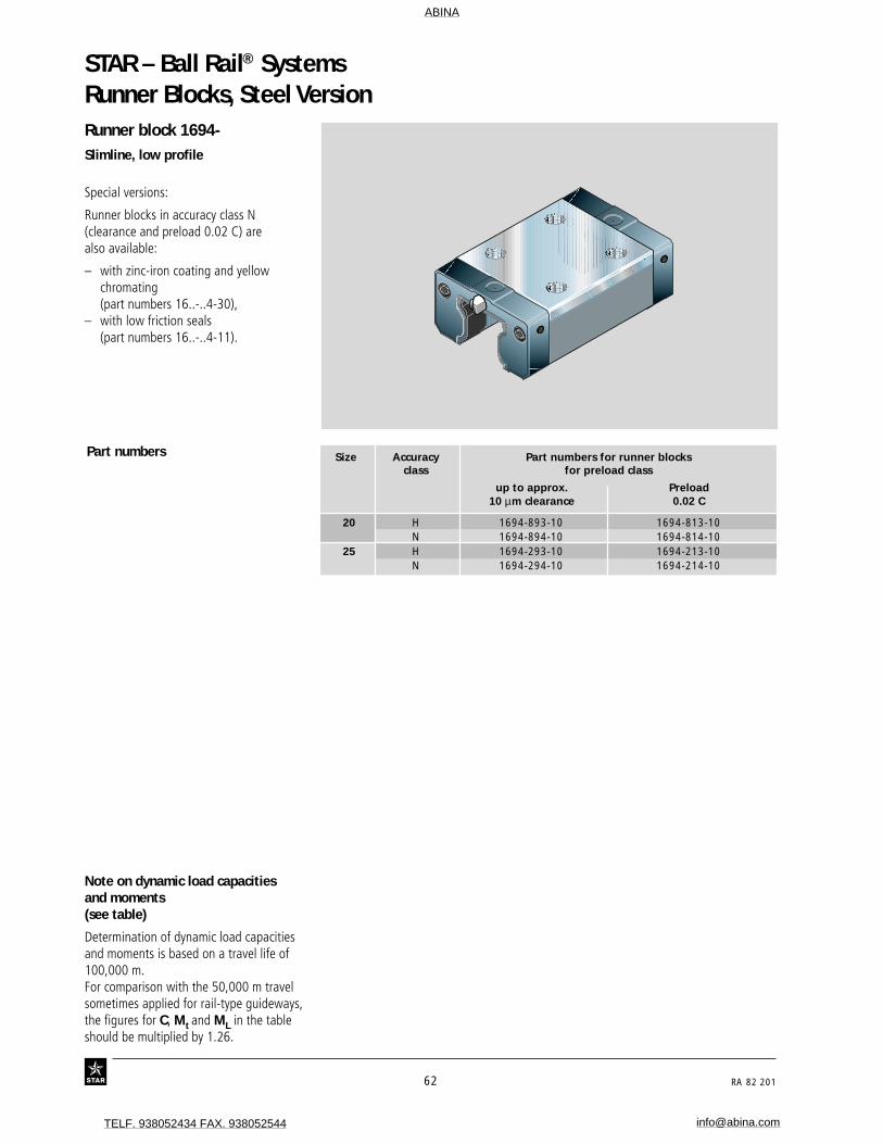
Runner block 1694-Slimline, low profile
Special versions:
Runner blocks in accuracy class N(clearance and preload 0.02 C) arealso available:
– with zinc-iron coating and yellowchromating(part numbers 16..-..4-30),
– with low friction seals(part numbers 16..-..4-11).
Part numbers
Runner Blocks, Steel Version
Note on dynamic load capacitiesand moments(see table)
Determination of dynamic load capacitiesand moments is based on a travel life of100,000 m.For comparison with the 50,000 m travelsometimes applied for rail-type guideways,the figures for C, Mt and ML in the tableshould be multiplied by 1.26.
Size Accuracy Part numbers for runner blocksclass for preload class
up to approx. Preload10 µm clearance 0.02 C
20 H 1694-893-10 1694-813-10N 1694-894-10 1694-814-10
25 H 1694-293-10 1694-213-10N 1694-294-10 1694-214-10
ABINA
TELF. 938052434 FAX. 938052544 [email protected]

RA 82 201 63
Load capacities (N) Moments (Nm)
Dimensions (mm) Mass C C0 Mt Mt0 ML ML0
Size N5 N6±0.5 N7 S2 S5 S9 (kg) dyn. stat. dyn. stat. dyn. stat.
20 3.6 13.2 – M5 6.0 M3-5 deep 0.40 14 500 24 400 190 310 100 16525 4.1 15.2 6.0 M6 7.0 M3-5 deep 0.55 22 800* 30 400 320 430 180 240
Maße (mm)
Größe A A1 A2 A3 B B1 H H1 H21) H2
2) V1 E1 E2 E8 E9 K1 N3
20 42 21 20 11.0 72.5 49.6 28 23.0 20.7 20.55 6.0 32 32 30.5 5.6 13.0 6.325 48 24 23 12.5 81.0 57.8 33 26.5 24.4 24.25 7.5 35 35 38.3 8.5 16.6 7.0
1) Dimension H2 with Rail Seal® cover strip 2) Dimension H2 without Rail Seal® cover strip
H2 N6
S5
B
B2N 7
E1
B1E 2
�H1
V1
E9
H
A3 A2
A1
S9 S2
AE8
N5
N3
For O-ring ø 5 · 1 mm
Open lube port if necessary.Send for instructions.
Lube port with additionalanti-twist feature.
Lube nippleFunnel-type nippleType B – Thread size M3B2 = 8 mm
at either end.
Size 25:Provided with ports at side.
* 30% higher dynamic load capacity
ABINA
TELF. 938052434 FAX. 938052544 [email protected]

STAR – Ball Rail® Systems
64 RA 82 201
Runner block 1621-Slimline, high
Part numbers
Runner Blocks, Steel Version
Size Accuracy Part numbers for runner blocksclass for preload class
up to approx. Preload Preload Preload10 µm clearance 0.02 C 0.08 C 0.13 C
15 P 1621-112-10 1621-122-10 1621-132-10H 1621-193-10 1621-113-10 1621-123-10N 1621-194-10 1621-114-10 1621-124-10
25 P 1621-212-10 1621-222-10 1621-232-10H 1621-293-10 1621-213-10 1621-223-10N 1621-294-10 1621-214-10 1621-224-10
30 P 1621-712-10 1621-722-10 1621-732-10H 1621-793-10 1621-713-10 1621-723-10N 1621-794-10 1621-714-10 1621-724-10
35 P 1621-312-10 1621-322-10 1621-332-10H 1621-393-10 1621-313-10 1621-323-10N 1621-394-10 1621-314-10 1621-324-10
45 P 1621-412-10 1621-422-10 1621-432-10H 1621-493-10 1621-413-10 1621-423-10N 1621-494-10 1621-414-10 1621-424-10
55 P 1621-512-10* 1621-522-10* 1621-532-10*H 1621-593-10* 1621-513-10* 1621-523-10*N 1621-594-10* 1621-514-10* 1621-524-10*
Special versions:
Runner blocks in accuracy class N(clearance and preload 0.02 C) arealso available:
– with zinc-iron coating and yellowchromating(part numbers 16..-..4-30),
– with low friction seals(part numbers 16..-..4-11).
Note on dynamic load capacitiesand moments(see table)
Determination of dynamic load capacitiesand moments is based on a travel life of100,000 m.For comparison with the 50,000 m travelsometimes applied for rail-type guideways,the figures for C, Mt and ML in the tableshould be multiplied by 1.26.
* 30% higher dynamic load capacities onrequest
ABINA
TELF. 938052434 FAX. 938052544 [email protected]

RA 82 201 65
Load capacities (N) Moments (Nm)
Dimensions (mm) Mass C C0 Mt Mt0 ML ML0
Size N5 N6±0.5 S2 S5 S9 (kg) dyn. stat. dyn. stat. dyn. stat.
15 8.0 10.3 M4 4.4 M2.5-3.5deep 0.20 7 800 13 500 74 130 40 7125 9.5 15.2 M6 7.0 M3-5 deep 0.65 22 800 30 400 320 430 180 24030 9.0 17.0 M8 9.0 M3-5 deep 1.00 31 700 41 300 540 720 290 38035 14.0 20.5 M8 9.0 M3-5 deep 1.50 41 900 54 000 890 1 160 440 56545 18.0 23.5 M10 14.0 M4-7 deep 3.00 68 100 85 700 1 830 2 310 890 1 13055 19.0 29.0 M12 16.0 M5-8 deep 4.70 98 200 121 400 3 100 3 860 1 540 1 905
Dimensions (mm)
Size A A1 A2 A3 B B1 H H1 H21) H2
2) V1 E1 E2 E8 E9 N3
15 34 17 15 9.5 54.0 39.2 28 23.8 16.3 16.20 5.0 26 26 24.55 10.7 625 48 24 23 12.5 81.0 57.8 40 33.5 24.4 24.25 7.5 35 35 38.3 15.5 930 60 30 28 16.0 94.0 67.4 45 38.0 28.5 28.35 7.0 40 40 48.4 17.6 1235 70 35 34 18.0 105.0 77.0 55 47.0 32.15 31.85 8.0 50 50 58.0 24.5 1345 86 43 45 20.5 133.0 97.0 70 60.0 40.15 39.85 10.0 60 60 70.0 31.0 1855 100 50 53 23.5 159.0 115.5 80 67.0 48.15 47.85 12.0 75 75 80.0 32.3 19
CC0
C
C0
C
C0
Lube nipple
Size 15:Funnel-type nippleType B – Thread size M3B2 = 8 mm
Size 25 to 55:BM 6 DIN 71412B2 = 16 mm
at either end.
�H1
V1
E9
H
S9 S2
AE8
N5
A3 A2
A1
N3
H2 N6
S5
B
B2
E1
B1 E 2
1) Dimension H2 with Rail Seal® cover strip 2) Dimension H2 without Rail Seal® cover strip
30% higher dynamic load capacities and moments
ABINA
TELF. 938052434 FAX. 938052544 [email protected]

STAR – Ball Rail® Systems
66 RA 82 201
Runner Blocks, Steel Version
Size Accuracy Part numbers for runner blocksclass for preload class
up to approx. Preload Preload Preload10 µm clearance 0.02 C 0.08 C 0.13 C
25 P 1624-212-10 1624-222-10 1624-232-10H 1624-293-10 1624-213-10 1624-223-10N 1624-294-10 1624-214-10 1624-224-10
30 P 1624-712-10 1624-722-10 1624-732-10H 1624-793-10 1624-713-10 1624-723-10N 1624-794-10 1624-714-10 1624-724-10
35 P 1624-312-10 1624-322-10 1624-332-10H 1624-393-10 1624-313-10 1624-323-10N 1624-394-10 1624-314-10 1624-324-10
45 P 1624-412-10 1624-422-10 1624-432-10H 1624-493-10 1624-413-10 1624-423-10N 1624-494-10 1624-414-10 1624-424-10
55 P 1624-512-10* 1624-522-10* 1624-532-10*H 1624-593-10* 1624-513-10* 1624-523-10*N 1624-594-10* 1624-514-10* 1624-524-10*
Runner block 1624-Slimline, high, long
Special versions:
Runner blocks in accuracy class N(clearance and preload 0.02 C) arealso available:
– with zinc-iron coating and yellowchromating(part numbers 16..-..4-30),
– with low friction seals(part numbers 16..-..4-11).
Part numbers
Note on dynamic load capacitiesand moments(see table)
Determination of dynamic load capacitiesand moments is based on a travel life of100,000 m.For comparison with the 50,000 m travelsometimes applied for rail-type guideways,the figures for C, Mt and ML in the tableshould be multiplied by 1.26.
* 30% higher dynamic load capacities onrequest
ABINA
TELF. 938052434 FAX. 938052544 [email protected]
RA 82 201 67
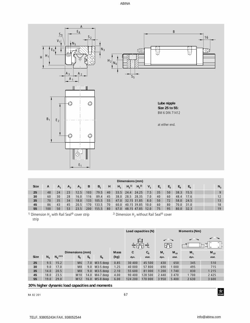
Dimensions (mm) Mass C C0 Mt Mt0 ML ML0
Size N5 N6±0.5 S2 S5 S9 (kg) dyn. stat. dyn. stat. dyn. stat.
25 9.5 15.2 M6 7.0 M3-5 deep 0.85 30 400 45 500 430 650 345 51030 9.0 17.0 M8 9.0 M3-5 deep 1.25 40 000 57 800 690 1 000 495 71535 14.0 20.5 M8 9.0 M3-5 deep 2.10 55 600 81 000 1 200 1 740 830 1 21545 18.0 23.5 M10 14.0 M4-7 deep 4.00 90 400 128 500 2 440 3 470 1 700 2 42555 19.0 29.0 M12 16.0 M5-8 deep 6.00 124 200 170 000 3 950 5 400 2 630 3 600
Dimensions (mm)
Size A A1 A2 A3 B B1 H H1 H21) H2
2) V1 E1 E2 E8 E9 N3
25 48 24 23 12.5 103 79.5 40 33.5 24.4 24.25 7.5 35 50 38.3 15.5 930 60 30 28 16.0 116 89.4 45 38.0 28.5 28.35 7.0 40 60 48.4 17.6 1235 70 35 34 18.0 133 105.5 55 47.0 32.15 31.85 8.0 50 72 58.0 24.5 1345 86 43 45 20.5 170 133.5 70 60.0 40.15 39.85 10.0 60 80 70.0 31.0 1855 100 50 53 23.5 200 155.5 80 67.0 48.15 47.85 12.0 75 95 80.0 32.3 19
Lube nippleSize 25 to 55:BM 6 DIN 71412
at either end.
�H1
V1
E9
H
S9 S2
AE8
N5
A3 A2
A1
N3
H2 N6
S5
B
16
E1
B1 E 2
1) Dimension H2 with Rail Seal® cover strip 2) Dimension H2 without Rail Seal® coverstrip
CC0
C
C0
C
C0
30% higher dynamic load capacities and moments
Load capacities (N) Moments (Nm)
ABINA
TELF. 938052434 FAX. 938052544 [email protected]

STAR – Ball Rail® Systems
68 RA 82 201
Product Overview – Runner Blocks, Aluminum VersionSTAR Ball Rail® Systems with aluminum runner blocks were specificallydevel-oped for use in industrial robots and general purpose machinescalling for compact, rolling-element linear motion guideways and areavailable in different accuracy classes, each with high load capacity andhigh rigidity.
These compact and weight-saving assemblies are available in 6 commonsizes and offer the same high dynamic load capacities in all four main loaddirections.
Make up your own compact linear motion guidewaysfrom interchangeable standard stock elements...
STAR manufactures its guide rails and runner blocks with such high pre-cision, especially in the ball track zone, that each individual componentelement can be replaced by another at any time. This makes infinitecombinations possible within each accuracy class.Each element can be individually ordered and separately stocked.
Both sides of the guide rail can be used as reference edges.The runner block is simply pushed onto the rail.
Accuracy classes H and N can be combinedwith any of the rails in each accuracy class
Lube ports possible at eitherend for added ease ofmaintenance
Very low weight: 60% lighter thanthe equivalent steel version
Guide rails in accuracy class N also availablewith surface protection
Greater permissible parallelism offset aswell as greater permissible vertical andhorizontal offset of mounting surfaces
End face mounting holes for attachmentof bellows or scraper plates
For mounting from above or below
ABINA
TELF. 938052434 FAX. 938052544 [email protected]

RA 82 201 69
High moment load capacity
Optimized entry-zone geometry and the highnumber of balls per track greatly reducevariations in elastic deflection
Two holes at the centre of the runner blockpermit insertion of additional mounting screwsfor improved rigidity under lift-off and sideloading conditions
Mounting of attachments torunner block from aboveor below
Pre-drilled locating pin holesin runner blocks
Smooth, light running due to optimized ballrecirculation and ideal track geometry
Proven Rail Seal® cover strip for guide railmounting holes:
One cover for all holes
Material: corrosion resistant spring steelto DIN 17230 / EN 10088
Easy clip-on mounting
30% higher dynamic load capacities and momentsthan previous design.
– extends service life by a factor of 2.2– field-proven– identical in all four main load directions
ABINA
TELF. 938052434 FAX. 938052544 [email protected]
STAR – Ball Rail® Systems
70 RA 82 201
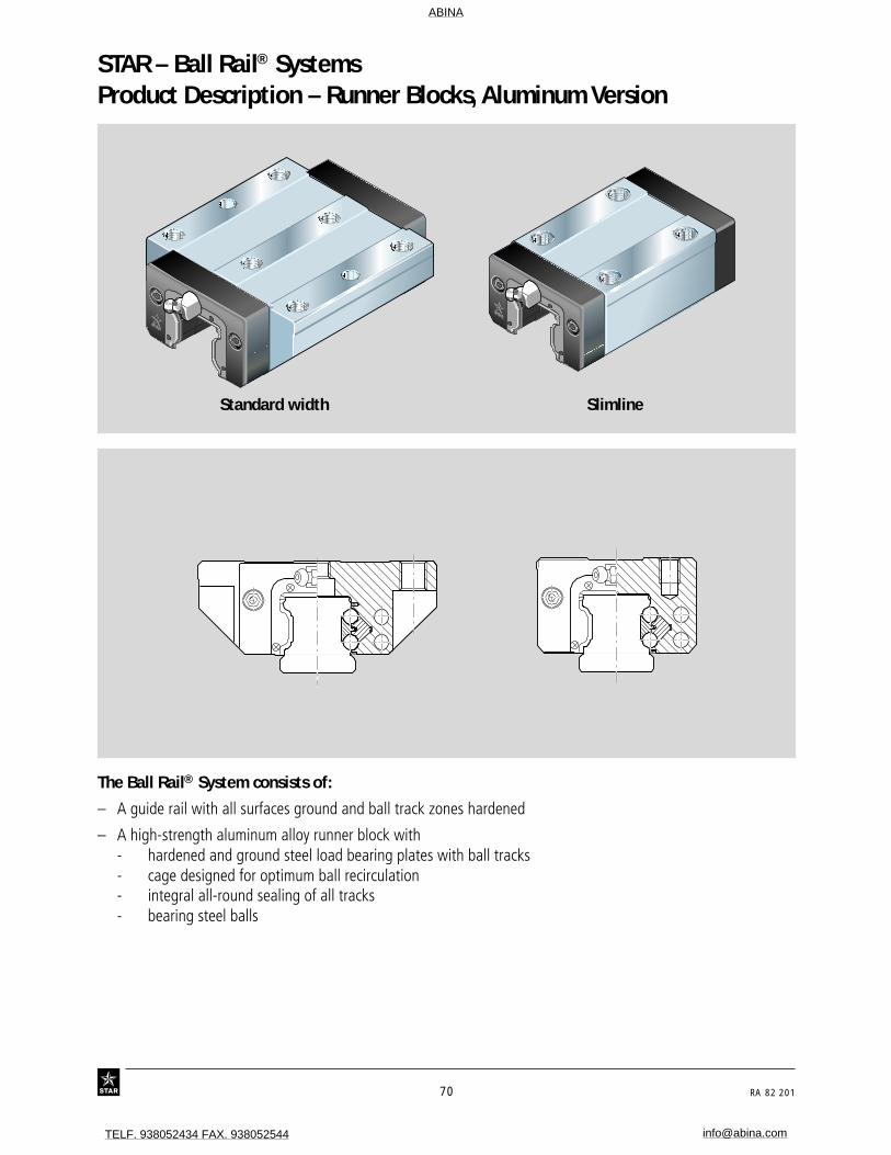
Product Description – Runner Blocks, Aluminum Version
The Ball Rail® System consists of:
– A guide rail with all surfaces ground and ball track zones hardened
– A high-strength aluminum alloy runner block with- hardened and ground steel load bearing plates with ball tracks- cage designed for optimum ball recirculation- integral all-round sealing of all tracks- bearing steel balls
��
Standard width Slimline
ABINA
TELF. 938052434 FAX. 938052544 [email protected]

RA 82 201 71
1000 2000 3000 4000 5000 6000 70000
N
8000 9000 10000 1100012000
H
Technical Data – Runner Blocks, Aluminum VersionAccuracy classes and theirtolerances (µm)
STAR Ball Rail® Systems with runnerblocks in aluminum are offered in twodifferent accuracy classes.
However, these can be combined withguide rails of all accuracy classes.
Rail length (mm)
Parallelism offset P1 of theBall Rail System in service
Measured at middle of runner block
Accuracy Dimensional Max difference in dimensionsclasses tolerances H and A3 (µm) H and A3 on the same rail
H A3 ∆ H, ∆ A3 (µm)
H ± 40 ± 20 15
N ± 100 ± 40 30
STSTARAR
For any runner block/rail combi-nation at any position on rail
For different runner blocksat same position on rail
Measured atmiddle of
runner block:
II
II
IIH P1
P1
P1
A3
STSTARAR
STSTARAR
STSTARAR
STSTARAR
STSTARAR
Built-in interchangeabilitythrough precision machining
STAR manufactures its guide rails andrunner blocks with such high precision,especially in the ball track zone, that eachindividual component element can bereplaced by another at any time.
A runner block can be used without pro-blems on various guide rails of the samesize, for example.This applies equally to the use of differentrunner blocks on one and the same guiderail.
Para
llelis
m o
ffset
P1 (
µm)
ABINA
TELF. 938052434 FAX. 938052544 [email protected]
STAR – Ball Rail® Systems
72 RA 82 201
Technical Data – Runner Blocks, Aluminum Version
25
20
40
60
80
0
100
10000 20000 30000 40000 500000
35
25
20
40
60
80
0
100
5000 10000 15000 20000 250000
35
120
25
25
20
40
60
80
0
100
5000 10000 15000 20000 250000
35
25
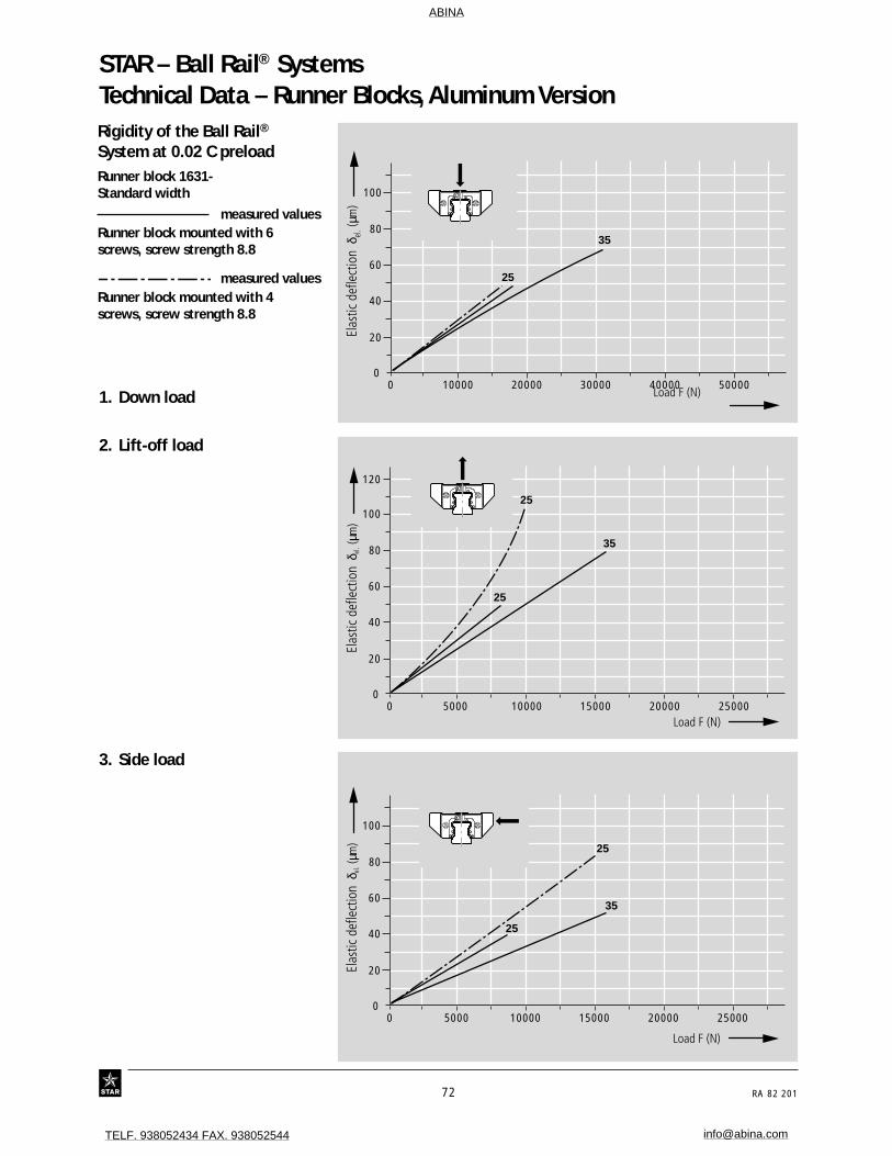
Rigidity of the Ball Rail®
System at 0.02 C preloadRunner block 1631-Standard width
measured valuesRunner block mounted with 6screws, screw strength 8.8
measured valuesRunner block mounted with 4screws, screw strength 8.8
2. Lift-off load
3. Side load
Elas
tic d
efle
ctio
n δ
el. (
µm)
Load F (N)
Elas
tic d
efle
ctio
n δ
el. (
µm)
Load F (N)
Elas
tic d
efle
ctio
n δ
el. (
µm)
Load F (N)
1. Down load
ABINA
TELF. 938052434 FAX. 938052544 [email protected]
RA 82 201 73
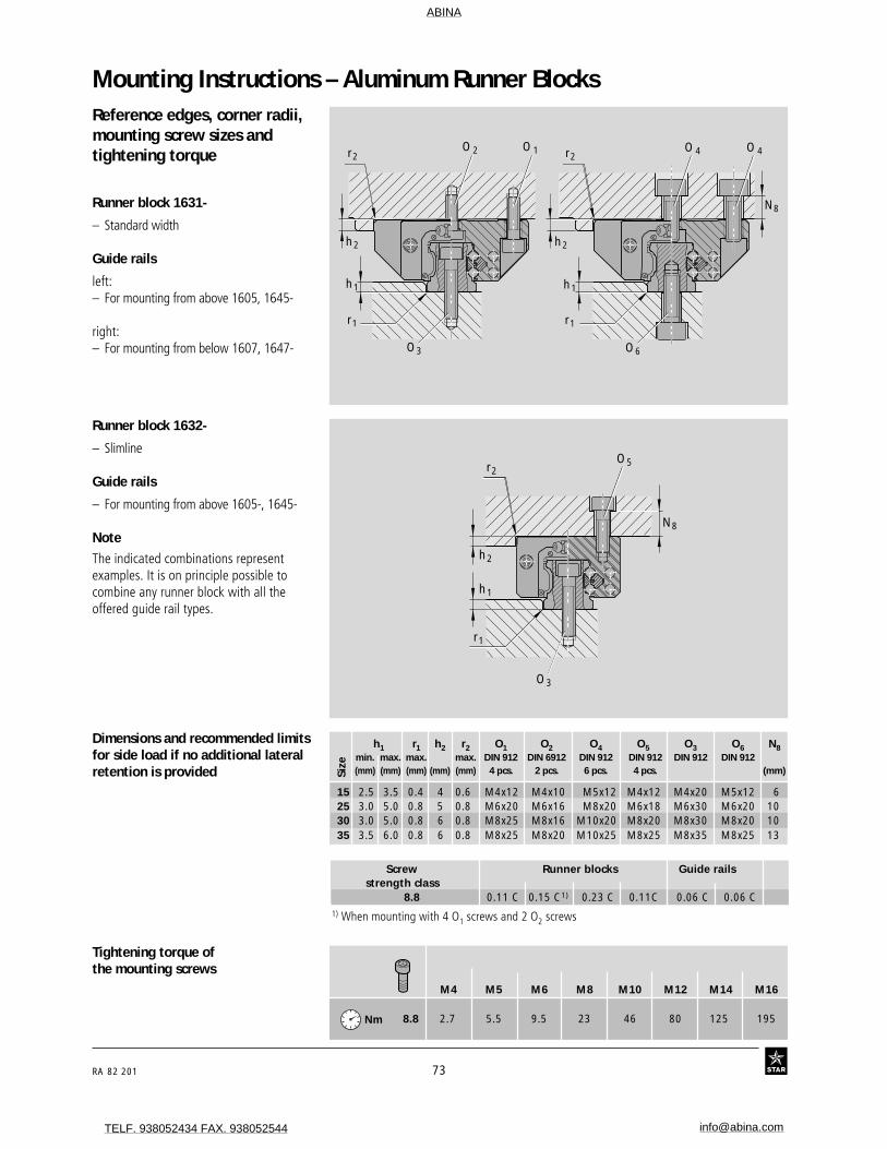
h1 r1 h2 r2 O1 O2 O4 O5 O3 O6 N8min. max. max. max. DIN 912 DIN 6912 DIN 912 DIN 912 DIN 912 DIN 912(mm) (mm) (mm) (mm) (mm) 4 pcs. 2 pcs. 6 pcs. 4 pcs. (mm)
15 2.5 3.5 0.4 4 0.6 M4x12 M4x10 M5x12 M4x12 M4x20 M5x12 625 3.0 5.0 0.8 5 0.8 M6x20 M6x16 M8x20 M6x18 M6x30 M6x20 1030 3.0 5.0 0.8 6 0.8 M8x25 M8x16 M10x20 M8x20 M8x30 M8x20 1035 3.5 6.0 0.8 6 0.8 M8x25 M8x20 M10x25 M8x25 M8x35 M8x25 13
Size
Mounting Instructions – Aluminum Runner BlocksReference edges, corner radii,mounting screw sizes andtightening torque
Runner block 1631-
– Standard width
Guide rails
left:– For mounting from above 1605, 1645-
right:– For mounting from below 1607, 1647-
Runner block 1632-
– Slimline
Guide rails
– For mounting from above 1605-, 1645-
Note
The indicated combinations representexamples. It is on principle possible tocombine any runner block with all theoffered guide rail types.
M4 M5 M6 M8 M10 M12 M14 M16
8.8 2.7 5.5 9.5 23 46 80 125 195
Tightening torque ofthe mounting screws
Screw Runner blocks Guide railsstrength class
8.8 0.11 C 0.15 C1) 0.23 C 0.11C 0.06 C 0.06 C1) When mounting with 4 O1 screws and 2 O2 screws
Dimensions and recommended limitsfor side load if no additional lateralretention is provided
Nm
���
r2
r1
h1
h2
O5
O3
N8
��� �r2 r2
r1
h1
r1
h1
h2 h2
O3
N8
O 2 O 1
O6
O 4O 4
ABINA
TELF. 938052434 FAX. 938052544 [email protected]
STAR – Ball Rail® Systems
74 RA 82 201
Mounting Instructions – Aluminum Runner Blocks
���L10
E2
E4
S10
E2E1
��N9
S10
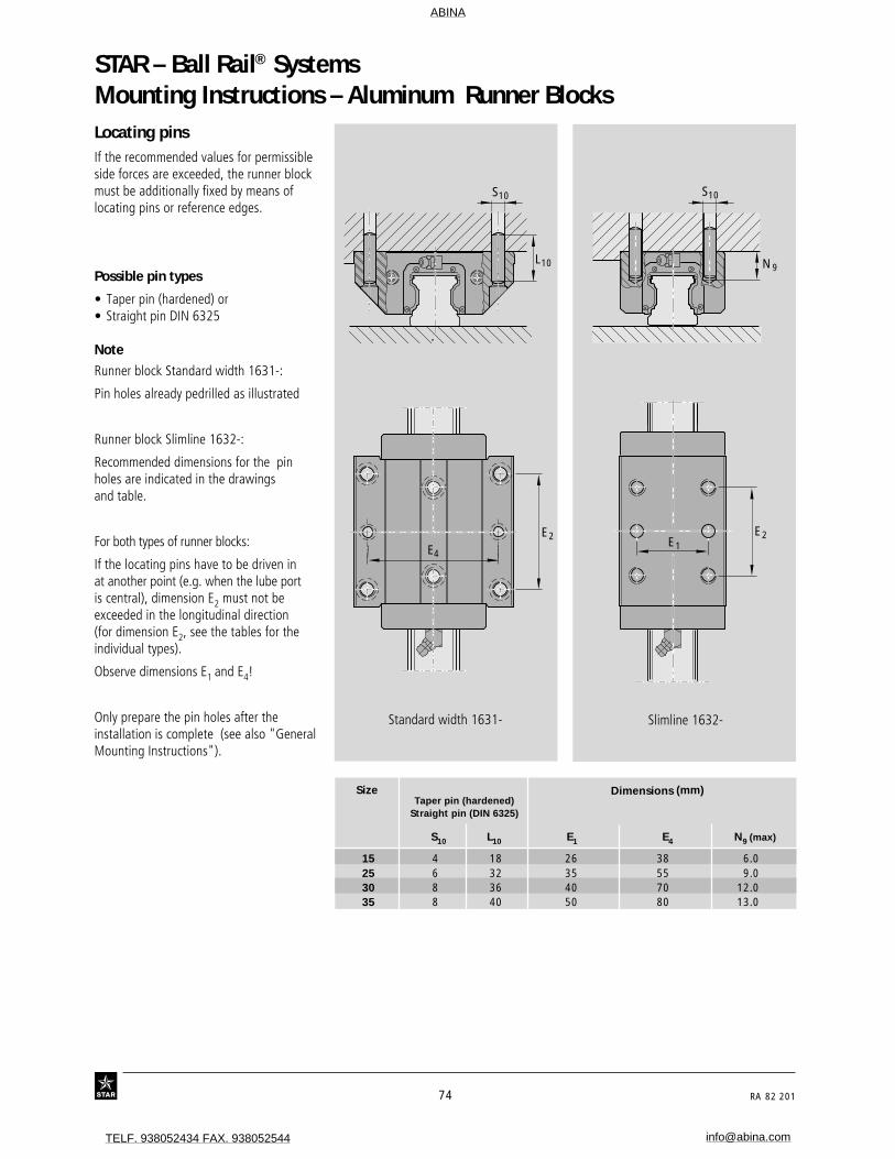
Locating pinsIf the recommended values for permissibleside forces are exceeded, the runner blockmust be additionally fixed by means oflocating pins or reference edges.
Possible pin types
• Taper pin (hardened) or• Straight pin DIN 6325
Note
Runner block Standard width 1631-:
Pin holes already pedrilled as illustrated
Runner block Slimline 1632-:
Recommended dimensions for the pinholes are indicated in the drawingsand table.
For both types of runner blocks:
If the locating pins have to be driven inat another point (e.g. when the lube portis central), dimension E2 must not beexceeded in the longitudinal direction(for dimension E2, see the tables for theindividual types).
Observe dimensions E1 and E4!
Only prepare the pin holes after theinstallation is complete (see also "GeneralMounting Instructions").
Size Dimensions (mm)Taper pin (hardened)
Straight pin (DIN 6325)
S10 L10 E1 E4 N9 (max)
15 4 18 26 38 6.025 6 32 35 55 9.030 8 36 40 70 12.035 8 40 50 80 13.0
Standard width 1631- Slimline 1632-
ABINA
TELF. 938052434 FAX. 938052544 [email protected]

RA 82 201 75
Vertical offsetProvided the permissible vertical offsetS1 and S2 is not exceeded, any resultantreduction in travel life will as a rule benegligible.
S2 =Permissible vertical offset (mm)b =Distance between
runner blocks (mm)
Permissible vertical offset in thelongitudinal direction
The permissible vertical offset S2 takesinto account the tolerance for the "max.difference in dimensions H on the samerail" according to the table givenin the "Technical Data" section.
Calculation factor for preload class
up to approx. Preload10 µm clearance 0.02 C
Y 7 · 10-4 5 · 10-4
S2 = b · 6 · 10-5
Permissible vertical offset in thetransverse direction
The permissible vertical offset S1 includesthe tolerance for dimension H in accordancewith the table given in the "Technical Data"section.
Size Parallelism offset P1 (mm)
up to approx. Preload10 µm clearance 0.02 C
15 0.021 0.01425 0.026 0.01730 0.029 0.01935 0.035 0.022
Parallelism of the rails aftermountingmeasured at the guide rails and atthe runner blocks
The parallelism offset P1 causes a slightincrease in preload on one side of theassembly. If the tolerances given in thetable are not exceeded, reduction intravel life will as a rule be negligible.
The given values apply to precisionmounting. For standard mounting,double the stated values can be used.
a
S1
II P1
b
S2
S1 = Permissible vertical offset (mm)a = Distance between rails (mm)Y = Calculation factor
S1 = a · Y
b
S1
a
S2
ABINA
TELF. 938052434 FAX. 938052544 [email protected]

STAR – Ball Rail® Systems
76 RA 82 201
Runner Blocks, Aluminum Version
Size Accuracy Part numbers for runner blocks class for preload class
up to approx. Preload10 µm clearance 0.02 C
15 H 1631-193-10 1631-113-10N 1631-194-10 1631-114-10
25 H 1631-293-10 1631-213-10N 1631-294-10 1631-214-10
30 H 1631-793-10 1631-713-10N 1631-794-10 1631-714-10
35 H 1631-393-10 1631-313-10N 1631-394-10 1631-314-10
Runner block 1631-Standard width
Special versions:
Runner blocks in accuracy class N(clearance and preload 0.02 C) areavailable:
– with low-friction seals(Part numbers 16..-..4-11).
Part numbers
Sizes 45 and 55 available asspecial versions.
Note on dynamic load capacitiesand moments(see table)
Determination of dynamic load capacitiesand moments is based on a travel life of100,000 m.For comparison with the 50,000 m travelsometimes applied for rail-type guideways,the figures for C, Mt and ML in the tableshould be multiplied by 1.26.
Permissible load When calculating the service life, use themaximum load capacity figure.
The permissible load is only limited forstatistical purposes (see table).
ABINA
TELF. 938052434 FAX. 938052544 [email protected]

RA 82 201 77
Dimensions (mm) Mass C Fmax Mt Mt ML ML
Size N5 N6±0.5 S1 S2 S3 S5 S9 (kg) dyn. dyn. max. dyn. max.
15 4.0 10.3 4.4 M5 3.7 4.4 M2.5-3.5deep 0.15 7 800 3 000 74 29 40 1625 5.5 15.2 6.8 M8 5.7 7.0 M3-5 deep 0.35 22 800 8 800 320 125 180 7030 6.0 17.0 8.6 M10 7.7 9.0 M3-5 deep 0.45 31 700 12 200 540 210 290 11035 7.0 20.5 8.6 M10 7.7 9.0 M3-5 deep 0.80 41 900 16 200 890 345 440 170
Dimensions (mm)
Size A A1 A2 A3 B B1 H H1 H21) H2
2) V1 E1 E2 E3 E4 E8 E9 N1 N2 N4
15 47 23.5 15 16.0 54 39.2 24 19.8 16.3 16.20 5.0 38 30 26 38 24.55 6.7 5 4.4 1025 70 35.0 23 23.5 81.0 57.8 36 29.5 24.4 24.25 7.5 57 45 40 55 38.3 11.5 9 7.0 1830 90 45.0 28 31.0 94.0 67.4 42 35.0 28.5 28.35 7.0 72 52 44 70 48.4 14.6 11 8.0 1835 100 50.0 34 33.0 105.0 77.0 48 40.0 32.15 31.85 8.0 82 62 52 80 58.0 17.5 12 10.2 21
����S9
S2
S1
S2
S1
AE8
N5 N2
H1
V1
E9
H
N1 N4
A3 A2
A1
H2 N6
S5
B
B2
E1
E4
B1 E2E3
S3
1) Dimension H2 with Rail Seal® cover strip 2) Dimension H2 without Rail Seal® cover strip
Lube nippleSize15:Funnel-type nippleType B - Thread M3B2 = 8 mm
Size 25 - 35:BM 6 DIN 71412B2 = 16 mm
at either end.
Loadcapacities (N)
Moments (Nm)Permissibleload (N)
30% higher dynamic load capacities and moments
ABINA
TELF. 938052434 FAX. 938052544 [email protected]

STAR – Ball Rail® Systems
78 RA 82 201
Runner Blocks, Aluminum Version
Size Accuracy Part numbers for runner blocks class for preload class
up to approx. Preload10 µm clearance 0.02 C
15 H 1632-193-10 1632-113-10N 1632-194-10 1632-114-10
25 H 1632-293-10 1632-213-10N 1632-294-10 1632-214-10
30 H 1632-793-10 1632-713-10N 1632-794-10 1632-714-10
35 H 1632-393-10 1632-313-10N 1632-394-10 1632-314-10
Runner block 1632-Slimline
Special versions:
Runner blocks in accuracy class N(clearance and preload 0.02 C) areavailable:
– with low-friction seals(Part numbers 16..-..4-11).
Part numbers
Note on dynamic load capacitiesand moments(see table)
Determination of dynamic load capacitiesand moments is based on a travel life of100,000 m.For comparison with the 50,000 m travelsometimes applied for rail-type guideways,the figures for C, Mt and ML in the tableshould be multiplied by 1.26.
Sizes 45 and 55 available asspecial versions.
Permissible load When calculating the service life, use themaximum load capacity figure.
The permissible load is only limited forstatistical purposes (see table).
ABINA
TELF. 938052434 FAX. 938052544 [email protected]

RA 82 201 79
Dimensions (mm) Mass C Fmax Mt Mt ML ML
Size N5 N6±0.5 S2 S5 S9 (kg) dyn. dyn. max. dyn. max.
15 4.0 10.3 M4 4.4 M2.5-3.5deep 0.08 7 800 3 000 74 29 40 1625 5.5 15.2 M6 7.0 M3-5 deep 0.25 22 800 8 800 320 125 180 7030 6.0 17.0 M8 9.0 M3-5 deep 0.45 31 700 12 200 540 290 290 11035 7.0 20.5 M8 9.0 M3-5 deep 0.60 41 900 16 200 890 440 440 170
Dimensions (mm)
Size A A1 A2 A3 B B1 H H1 H21) H2
2) V1 E1 E2 E8 E9 N3
15 34 17 15 9.5 53.5 39.2 24 19.8 16.3 16.20 5.0 26 26 - - 625 48 24 23 12.5 81.0 57.8 36 29.5 24.4 24.25 7.5 35 35 38.3 11.5 930 60 30 28 16.0 94.0 67.4 42 35.0 28.5 28.35 7.0 40 40 48.4 14.6 1235 70 35 34 18.0 105.0 77.0 48 40.0 32.15 31.85 8.0 50 50 58.0 17.5 13
Lube nippleSize15:Funnel-type nippleType B - Thread M3B2 = 8 mm
Size 25 - 35:BM 6 DIN 71412B2 = 16 mm
at either end.
1) Dimension H2 with Rail Seal® cover strip 2) Dimension H2 without Rail Seal® cover strip
�H1
V1
E9
S9 S2
A3 A2
A1
AE8
N5
N3
HH2 N6
S5
BB2
E1
E2B1
Loadcapacities (N)
Moments (Nm)Permissibleload (N)
30% higher dynamic load capacities and moments
ABINA
TELF. 938052434 FAX. 938052544 [email protected]

STAR – Ball Rail® Systems
94 RA 82 201
Elas
tic d
efle
ctio
n δ
el. (
µm)
Rigidity of the wide Ball Rail®
System at 0.02 C preloadRunner block 1671-Wide
measured values
Runner block mounted with sixscrews:
– 4 outer screws of strength class 12.9– 2 centerline screws of strength class 8.8
2. Lift-off load
3. Side load
Technical Data – Wide Ball Rail® Systems
20
40
60
80
0
140
10000 200000 30000 40000 50000
25/7020/40
100
120
160
35/90
20
40
60
80
0
140
10000 200000 30000 40000 50000
25/7020/40
100
120
160
35/90
20
40
60
80
0
140
10000 200000 30000 40000 50000
25/7020/40
100
120
160
35/90
1. Down load
Elas
tic d
efle
ctio
n δ
el. (
µm)
Elas
tic d
efle
ctio
n δ
el. (
µm)
Load F (N)
Load F (N)
Load F (N)
ABINA
TELF. 938052434 FAX. 938052544 [email protected]

RA 82 201 95
Reference edges, corner radii,mounting screw sizes andtightening torque
Runner block 1671-
– Wide
Guide rail:
– Wide, for mounting from above 1675-
M4 M5 M6 M8 M10
8.8 2.7 5.5 9.5 23 46
12.9 4.6 9.5 16 39 77
Tightening torque ofthe mounting screws
Mounting Instructions
��
r2
r1
h1
h2
O 1O 2
O3
���r2
r1
h1
h2
N8
O3
O 4O 4
Dimensions and recommended limitsfor side load if no additional lateralretention is provided1) When mounting the runner block from
above using only 4 O4 screws:- Permissible side force 1/3 lower- Lower stiffness
2) For runner block mounting with6 screws:- Tighten the centerline screws with the torque for strength class 8.8.
3) When mounting with 2 O2 screwsand 4 O1 screws
Runner block1671-
– Wide
Guide rail:
– Wide, for mounting from below 1677-
h1 r1 h2 r2 O1 O22) O4
1)2) O3 N8min. max.max.max. DIN 912 DIN 6912 DIN 912 DIN 912(mm) (mm)(mm)(mm) (mm) 4 pcs. 2 pcs. 6 pcs. (mm)
20/40 2.0 3.0 0.5 4 0.5 M5x16 M5x12 M6x16 M4x20 9.525/70 3.0 4.5 0.8 5 0.8 M6x20 M6x16 M8x20 M6x30 10.035/90 3.5 6.0 0.8 6 0.8 M8x25 M8x20 M10x25 M8x35 13.0
Screw Runner block Railsstrength class
8.8 0.08 C 0.113) C 0.16 C 0.08 C12.9 0.13 C 0.163) C 0.24 C 0.13 C
Nm
Size
ABINA
TELF. 938052434 FAX. 938052544 [email protected]

STAR – Ball Rail® Systems
96 RA 82 201
Wide Ball Rail® SystemsRunner blockssteel version 1671-
Part numbers
STSTAR
AR
STSTAR
AR
Determination of dynamic load capacitiesand moments is based on a travel life of100,000 m.For comparison with the 50,000 m travelsometimes applied for rail-type guideways,the figures for C, Mt and ML inthe table should be multiplied by 1.26 .
Note on dynamic load capacitiesand moments (see table)
Wide
Special versions:
Runner blocks in accuracy class N(clearance and preload 0.02 C) arealso available:
– with zinc-iron coating and yellowchromating(Part numbers 16..-..4-30).
Size Accuracy Part numbers for runner blocks class for preload class
up to approx. Preload10 µm clearance 0.02 C
P 1671-812-1020/40 H 1671-893-10 1671-813-10
N 1671-894-10 1671-814-10P 1671-212-10
25/70 H 1671-293-10 1671-213-10N 1671-294-10 1671-214-10P 1671-312-10
35/90 H 1671-393-10 1671-313-10N 1671-394-10 1671-314-10
ABINA
TELF. 938052434 FAX. 938052544 [email protected]

RA 82 201 97
Load Moments (Nm) capacities (N)
H1
V1
E9.1
E9
H
A3 A2
A1
A
N1
S2
S1S9
N5 N2
E8
E8.1
S2
S1
H2 N6
S5
B
10
N10
E4
E1
B1 E2
K2K1
Recommended position for pin holes(dimension E4, see table).
NoteReady-drilled holes made for productionreasons may exist at the recommendedpin hole position.
These may be extended and bored opento accommodate the locating pin.
Lube nippleAM 6 DIN 71412
connectable to any side.
The runner block featurestwo additional lube ports forthe connecting structure.
Dimensions (mm)
Size A A1 A2 A3 B B1 H H1 H2 V1 E1 E2 E8 E8.1 E9 E9.1 N1 N2 N5
20/40 80 40 42 19.0 73 52.0 27 23.5 19.05 6.0 70 40 36.0 57.5 3.55 15.5 7.7 3.7 4.025/70 120 60 69 25.5 105 79.5 35 30.0 23.40 7.5 107 60 70.2 90.7 5.6 20.3 9.0 7.0 5.535/90 162 81 90 36.0 142 113.6 50 42.5 32.00 8.0 144 80 79.0 116.0 6.8 29.9 14.0 12.0 9.0
Dimensions (mm) Mass C C0 Mt Mt0 ML ML0
Size N6±0.5 N10 S1 S2 K1 K2 S9 (kg) dyn. stat. dyn. stat. dyn. stat.
20/40 13.2 5.5 5.4 M6 10.6 11.0 M2.5-3.5deep 0.45 15 600 24 100 370 640 116 20025/70 14.4 8.0 6.4 M8 15.4 16.3 M3-5 deep 1.70 30 400* 45 500 1 130 1 690 345 51035/90 20.5 9.0 8.4 M10 22.8 24.8 M3-5 deep 3.70 58 200* 86 300 2 880 4 270 920 1 370
Dimensions (mm)
Size E4 ø Depth
20/40 70 4.7 725/70 107 5.7 835/90 144 7.7 8
* 30 % higher dynamic load capacities and moments
ABINA
TELF. 938052434 FAX. 938052544 [email protected]

STAR – Ball Rail® Systems
98 RA 82 201
Wide Ball Rail® SystemsGuide Rail 1675-Wide, for mounting from above
– Plastic mounting hole plugs aresupplied along with the rail.Reordering data: see table inset onright for part numbers.
– For special applications:Guide rails for steel mounting holeplugs, Part numbers: 1676-.5.-
Steel mounting hole plugs to be orderedseparately.A mounting jig with instruction leaflet isavailable for mounting steel mounting holeplugs.
Special version:Zinc-iron coating with yellow chromatingin accuracy class N.
Part numbers:
1674-.14-3. (end faces uncoated)1674-.14-4. (end faces coated)
Part numbers
Mounting hole plugs
Size Part numbers
20/40 1605-100-9025/70 1605-200-9035/90 1605-300-90Part numbers
Size Mounting jig
25/70 1619-210-4035/90 1619-310-40
Size Accuracy Guide Railclass One-piece Composite
Part number,Part number, Number of sections
Rail length L (mm) Rail length L (mm)
P 1675-802-31,.... 1675-852-3.,....
20/40 H 1675-803-31,.... 1675-853-3.,....
N 1675-804-31,.... 1675-854-3.,....
P 1675-202-31,.... 1675-202-3.,....
25/70 H 1675-203-31,.... 1675-203-3.,....
N 1675-204-31,.... 1675-204-3.,....
P 1675-302-31,.... 1675-302-3.,....
35/90 H 1675-303-31,.... 1675-303-3.,....
N 1675-304-31,.... 1675-304-3.,....
ABINA
TELF. 938052434 FAX. 938052544 [email protected]

RA 82 201 99
H2
S5
N 6
T1 T
L
D
A2
T3
T1
n T · TT1T
L ± 1.5
L = nB · T - 4
or
L = nT · T + 2 · T1S
Dimensions (mm) Mass
Size A2 H2 N6±0.5 D S5 T1S
±0.5 T1min T T3 Lmax kg/m
20/40 42 19.05 13.2 7.4 4.4 28 10 60 24 4 000 5.325/70 69 23.40 14.4 11.0 7.0 38 10 80 40 4 000 11.635/90 90 32.00 20.5 15.0 9.0 38 12 80 60 4 000 21.0
Dimensions and masses
L = rail length (mm)T = hole spacing*) (mm)T1S = preferred dimension*) (mm)nB = number of holes per rownT = number of spaces*) see table for values
Rail lengths above Lmax are made up offitted rail sections mounted end to end.
Ordering example 3 (over Lmax):
Guide rail size 35/90,accuracy class P,rail length 5036 mm, 2 sections(62 · T, preferred dimension T1S = 38 mm;number of holes nB = 63 giving 126 holesin 2 rows)
Ordering data:
Part number and number of sections,length (mm)T1S / nT · T / T1S (mm)
1675-302-32, 5036 mm38 / 62 · 80 / 38 mm
Ordering example 2 (up to Lmax):
Guide rail size 35/90,accuracy class P,rail length 1676 mm,(20 · T, preferred dimension T1S = 38 mm;number of holes nB = 21 giving 42 holesin 2 rows)
Ordering data:
Part number, length (mm)T1S / nT · T / T1S (mm)
1675-302-31, 1676 mm38 / 20 · 80 / 38 mm
Ordering a guide rail
Ordering example 1:
Guide rail size 35/90,accuracy class H,rail length 1756 mm,(21 · T, number of holes nB = 22giving 44 holes in 2 rows)Ordering data: 1675-303-31, 1756 mm
Intermediate lengths
Calculation of rail length L and orderingexamples:
• The preferred dimension is T1S
• If T1S cannot be used, then
- Select an end space T1 betweenT1S and T1 min
- Do not go below the minimumspacing T1 min!
Note- T1, T1 min, T1S are the same at either
end of the rail.
ABINA
TELF. 938052434 FAX. 938052544 [email protected]

STAR – Ball Rail® Systems
100 RA 82 201
Wide Ball Rail® SystemsGuide rail 1677-Wide, for mounting from below
Special version:Zinc-iron coating with yellow chromatingin accuracy class N available on request.
Part numbers Size Accuracy Guide Railclass One-piece Composite
Part number,Part number, Number of sections
Rail length L (mm) Rail length L (mm)
P 1677-802-31,.... 1677-852-3.,....
20/40 H 1677-803-31,.... 1677-853-3.,....
N 1677-804-31,.... 1677-854-3.,....
P 1677-202-31,.... 1677-202-3.,....
25/70 H 1677-203-31,.... 1677-203-3.,....
N 1677-204-31,.... 1677-204-3.,....
P 1677-302-31,.... 1677-302-3.,....
35/90 H 1677-303-31,.... 1677-303-3.,....
N 1677-304-31,.... 1677-304-3.,....
Holespacing T
(mm)
60
80
ABINA
TELF. 938052434 FAX. 938052544 [email protected]

RA 82 201 101
A2
T3
H2
S7
N 7
T1 T
L
T1
n T · TT1T
L ± 1.5
L = nB · T - 4
or
L = nT · T + 2 · T1S
Dimensions (mm) Mass
Size A2 H2 N7 S7 T1S ±0.5 T1min T T3 Lmax kg/m
20/40 42 19.05 7.5 M5 28 10 60 24 4 000 5.325/70 69 23.40 12.0 M6 38 10 80 40 4 000 11.635/90 90 32.00 15.0 M8 38 12 80 60 4 000 21.0
Dimensions and masses
L = rail length (mm)T = hole spacing*) (mm)T1S = preferred dimension*) (mm)nB = number of holes per rownT = number of spaces*) see table for values
Rail lengths above Lmax are made up offitted rail sections mounted end to end.
Ordering example 3 (over Lmax):
Guide rail size 35/90,accuracy class P,rail length 5036 mm, 2 sections(62 · T, preferred dimension T1S = 38 mm;number of holes nB = 63giving 126 holes in 2 rows)
Ordering data:
Part number and number of sections,length (mm)T1S / nT · T / T1S (mm)
1677-302-32, 5036 mm38 / 62 · 80 / 38 mm
Ordering example 2 (up to Lmax):
Guide rail size 35/90,accuracy class P,rail length 1676 mm,(20 · T, preferred dimension T1S = 38 mm;number of holes nB = 21 giving 42 holesin 2 rows)
Ordering data:
Part number, length (mm)T1S / nT · T / T1S (mm)
1677-302-31, 1676 mm38 / 20 · 80 / 38 mm
Ordering a guide rail
Ordering example 1:
Guide rail size 35/90,accuracy class H,rail length 1756 mm,(21 · T, number of holes nB = 22giving 44 holes in 2 rows)Ordering data: 1677-303-31, 1756 mm
Intermediate lengths
Calculation of rail length L and orderingexamples:
• The preferred dimension is T1S
• If T1S cannot be used, then
- Select an end space T1 betweenT1S and T1 min
- Do not go below the minimumspacing T1 min!
Note– T1, T1 min, T1S are the same at either
end of the rail.
ABINA
TELF. 938052434 FAX. 938052544 [email protected]

STAR – Ball Rail® Systems
102 RA 82 201
Accessories, Standard Ball Rail® SystemsLubrication plate– Material: aluminumVersions:– Standard (for standard lube nipple)– G 1/8 connection
Mounting:
The parts required for mounting on therunner block are supplied along with theoptional attachments.
Size 25 - 65:The runner block lube nipple can be used.
Size 15 and 20:A funnel-type lube nipple with a knock-inspigot is supplied ready for insertion.
For mounting details, see "MountingInstructions for Ball Rail® Systems".
Standard lubrication platePart numbers, dimensionsand masses.
Size Part Dimensions (mm) Mass
numbers A4 B3 H H3 N8 N9 S8 S9 (g)
15 1620-111-20 32 11 24 19.0 3.4 5.5 ø3 M3 1520 1620-811-20 42 12 30 24.8 3.5 6.0 ø3 M3 2525 1620-211-20 47 12 36 28.3 6.0 6.0 M6 M3 3030 1620-711-20 59 12 42 33.8 8.0 6.0 M6 M6 4535 1620-311-20 69 12 48 39.1 8.0 6.0 M6 M6 6045 1620-411-20 85 12 60 48.5 8.0 6.0 M6 M6 8555 1620-511-20 98 12 70 56.0 9.0 6.0 M6 M6 11565 1620-611-20 124 14 90 75.7 18.0 7.0 M8x1 M8x1 250
S9
S8
H3H
A4
N8
B3
N9
Lubrication plate G 1/8Part numbers, dimensions andmasses.
With slimline runner block size 25,remember that the lubrication platewill project at the side.
Size Part Dimensions (mm) Mass
numbers A4 B3 H H3 N8 N9 S8 (g)
25 1620-211-30 57 16 36 28.3 7.0 8 G 1/8 - 8 tief 4030 1620-711-30 59 16 42 33.8 7.0 8 G 1/8 - 8 tief 5935 1620-311-30 69 16 48 39.1 8.0 8 G 1/8 - 8 tief 7945 1620-411-30 85 16 60 48.5 8.0 8 G 1/8 - 8 tief 11255 1620-511-30 98 16 70 56.0 9.0 8 G 1/8 - 8 tief 15265 1620-611-30 124 16 90 75.7 18.0 8 G 1/8 - 8 tief 285
Size 25 (slimline runner block)
H3H
A4
S9 B3
N9
N8
S8
S910 23,5
H3H
A4
ABINA
TELF. 938052434 FAX. 938052544 [email protected]
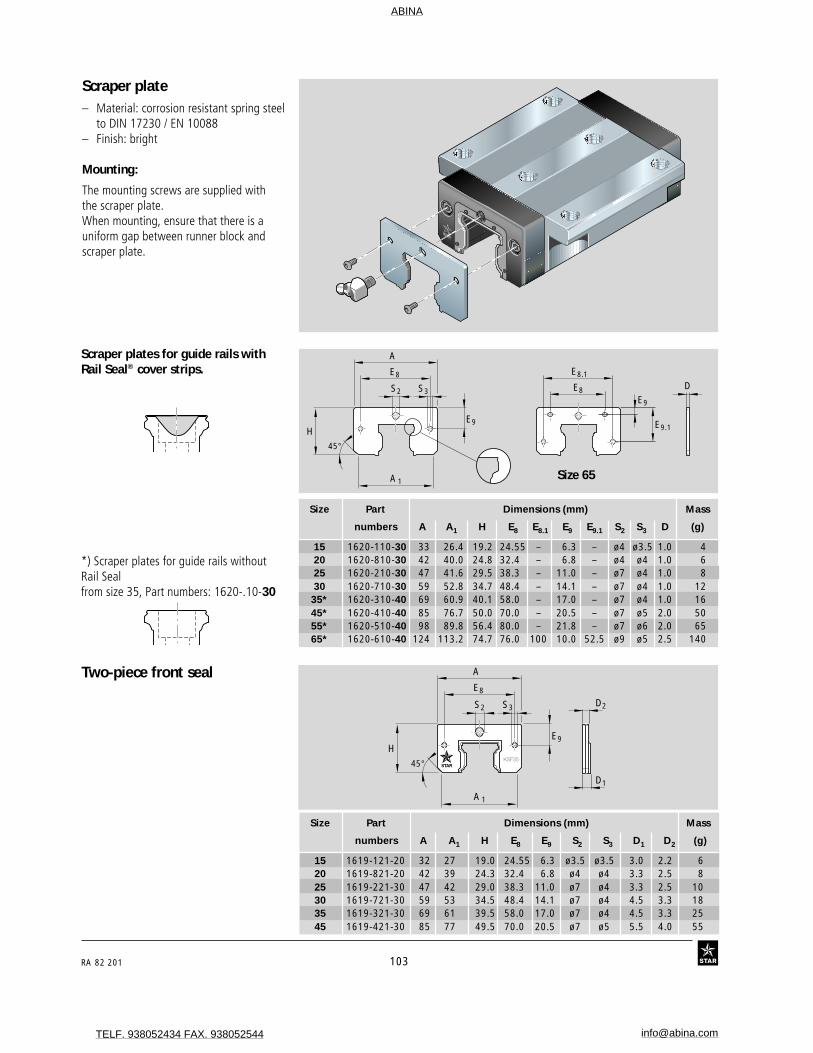
RA 82 201 103
Scraper plate– Material: corrosion resistant spring steel
to DIN 17230 / EN 10088– Finish: bright
Mounting:
The mounting screws are supplied withthe scraper plate.When mounting, ensure that there is auniform gap between runner block andscraper plate.
Size Part Dimensions (mm) Mass
numbers A A1 H E8 E8.1 E9 E9.1 S2 S3 D (g)
15 1620-110-30 33 26.4 19.2 24.55 – 6.3 – ø4 ø3.5 1.0 420 1620-810-30 42 40.0 24.8 32.4 – 6.8 – ø4 ø4 1.0 625 1620-210-30 47 41.6 29.5 38.3 – 11.0 – ø7 ø4 1.0 830 1620-710-30 59 52.8 34.7 48.4 – 14.1 – ø7 ø4 1.0 12
35* 1620-310-40 69 60.9 40.1 58.0 – 17.0 – ø7 ø4 1.0 1645* 1620-410-40 85 76.7 50.0 70.0 – 20.5 – ø7 ø5 2.0 5055* 1620-510-40 98 89.8 56.4 80.0 – 21.8 – ø7 ø6 2.0 6565* 1620-610-40 124 113.2 74.7 76.0 100 10.0 52.5 ø9 ø5 2.5 140
Scraper plates for guide rails withRail Seal® cover strips.
Two-piece front seal
Size Part Dimensions (mm) Mass
numbers A A1 H E8 E9 S2 S3 D1 D2 (g)
15 1619-121-20 32 27 19.0 24.55 6.3 ø3.5 ø3.5 3.0 2.2 620 1619-821-20 42 39 24.3 32.4 6.8 ø4 ø4 3.3 2.5 825 1619-221-30 47 42 29.0 38.3 11.0 ø7 ø4 3.3 2.5 1030 1619-721-30 59 53 34.5 48.4 14.1 ø7 ø4 4.5 3.3 1835 1619-321-30 69 61 39.5 58.0 17.0 ø7 ø4 4.5 3.3 2545 1619-421-30 85 77 49.5 70.0 20.5 ø7 ø5 5.5 4.0 55
45°
A
H
S2
E8 E8.1
E8
E9 E9.1
E9
S3D
A1Size 65
*) Scraper plates for guide rails withoutRail Sealfrom size 35, Part numbers: 1620-.10-30
45°
A
H
S2
E8
E9
S3
A1
D1
D2
ABINA
TELF. 938052434 FAX. 938052544 [email protected]

STAR – Ball Rail® Systems
104 RA 82 201
Accessories, Standard Ball Rail® SystemsProtective bellows– Material: Bellows-type protective cover
of polyurethane-coated polyester fabric– Aluminum lubrication platesThe runner block lube nipple can be used.
Heat resistant bellows– Material: Nomex fabric, metallized on
both sides.– Non combustible, non flammable– Resistant to sparks, welding splashes
and hot chips– Temperature resistance:
Temperatures of up to 200°C near theprotective metal coat possible.Operating temperature for the entirebellows: 100°C.
Available in sizes 25-55.The runner block lube nipple can be used.
STAR
STAR
Part numbers, Bellows
Bellows size 35, standard version,type 6 (with FLU* and end plate),number of folds: 36
15 1620-10.-00 ... 1620-102-00 ... 1620-10.-00 ...20 1620-80.-00 ... 1620-802-00 ... 1620-80.-00 ...25 1620-20.-00 ... 1620-202-00 ... 1620-20.-00 ...30 1620-70.-00 ... 1620-702-00 ... 1620-70.-00 ...35 1620-30.-00 ... 1620-302-00 ... 1620-30.-00 ...45 1620-40.-00 ... 1620-402-00 ... 1620-40.-00 ...55 1620-50.-00 ... 1620-502-00 ... 1620-50.-00 ...65 1620-60.-00 ... 1620-602-00 ... 1620-60.-00 ..
25 1620-25.-00 ... 1620-252-00 ... 1620-25.-00 ...30 1620-75.-00 ... 1620-752-00 ... 1620-75.-0035 1620-35.-00 ... 1620-352-00 ... 1620-35.-00 ...45 1620-45.-00 ... 1620-452-00 ... 1620-45.-00 ...55 1620-55.-00 ... 1620-552-00 ... 1620-55.-00 ...
15 1620-104-00 ... 1620-10.-00 ... 1600-109-00 ...20 1620-804-00 ... 1620-80.-00 ... 1600-809-00 ...25 1620-204-00 ... 1620-20.-00 ... 1600-209-00 ...30 1620-704-00 ... 1620-70.-00 ... 1600-709-00 ...35 1620-304-00 ... 1620-30.-00 ... 1600-309-00 ...45 1620-404-00 ... 1620-40.-00 ... 1600-409-00 ...55 1620-504-00 ... 1620-50.-00 ... 1600-509-00 ...65 1620-604-00 ... 1620-60.-00 ... 1600-609-00 ...
25 1620-254-00 ... 1620-25.-00 ... 1600-259-00 ...30 1620-754-00 ... 1620-75.-00 ... 1600-759-00 ...35 1620-354-00 ... 1620-35.-00 ... 1600-359-00 ...45 1620-454-00 ... 1620-45.-00 ... 1600-459-00 ...55 1620-554-00 ... 1620-55.-00 ... 1600-559-00 ...
Typ 1with lubrication plate
and end plateTyp 6
with FLU*and end plate
Typ 2with mounting
frameand end plate
Typ 3with 2 lubrication
plates
Typ 7with 2 FLU*
Numberof
folds
Numberof
folds
Numberof
folds
* FLU = front lube unit
Size
Typ 4with 2 mounting
frames
Typ 5with lubrication plate
and mounting frame (MF)
Typ 8with FLU*and MF
Typ 9Bellows, loose supply
(spare part)
Numberof
folds
Numberof
folds
Numberof
foldsSize
Example: 1620-306-00, 36 folds
Standard = 0 Fire resistant = 5
Type 1 to 9
ABINA
TELF. 938052434 FAX. 938052544 [email protected]

RA 82 201 105
Mounting instructions
The bellows are delivered preassembledready for installation, complete with thescrews required for attachment to theguide rail.
In types 1 and 2, thread size M4 10 mmdeep and countersunk 2 x 45° must betapped in each end face of the rail.
Size 25 - 65:The runner block lube nipple can be used.
Size 15 and 20:A funnel-type lube nipple with knock-inspigot is supplied.
For mounting details, see "MountingInstructions for Lubrication Plates andBellows".
Dimensions (mm) Factor
Size A4 B3 H H3 H4 N7 N8 S7 S8 S9 W U
15 45 11 24 26.5 31.5 11 3.4 M4 ø3 M3 19.9 1.1820 42 12 30 24.0 29.2 13 3.5 M4 ø3 M3 10.3 1.3325 45 12 36 28.5 35.0 15 6.0 M4 M6 M3 12.9 1.3230 55 12 42 34.0 41.0 18 8.0 M4 M6 M6 15.4 1.2535 64 12 48 39.0 47.0 22 8.0 M4 M6 M6 19.9 1.1845 83 12 60 49.0 59.0 30 8.0 M4 M6 M6 26.9 1.1355 96 12 70 56.0 69.0 30 9.0 M4 M6 M6 29.9 1.1265 120 14 90 75.0 89.0 40 18.0 M4 M8x1 M8x1 40.4 1.08
2
N7
H
W
N8
12
S8
H3 H4
H3 H4
B3 L max.L min.
S9
S7
S9
A 4
Hook and loopfastener
Heat-resistant bellows
L = Rail length (mm)
Rail length formula
Lmax = Bellows extended
Lmin = Bellows compressed
Stroke in mm
U = Calculation factor
W = Maximum extension (mm)
Dimensions:Bellows
Dimensions:Heat-resistant bellows
Bellows design formulasLmax = (Stroke + 30) · U
Lmin = Lmax - Stroke
No. of folds = + 2
L = Lmin + Lmax + LA
Dimensions (mm) Factor
Size A4 B3 H H3 H4 N7 N8 S7 S8 S9 W U
25 62 12 36 39.0 44.5 15 6.0 M4 M6 M3 25.9 1.2530 67 12 42 42.0 47.5 18 8.0 M4 M6 M6 25.9 1.2535 76 12 48 47.0 54.0 22 8.0 M4 M6 M6 29.9 1.2145 90 12 60 55.0 64.0 30 8.0 M4 M6 M6 32.9 1.1855 104 12 70 63.0 75.0 30 9.0 M4 M6 M6 37.9 1.16
Lmax
W
L min. L A L max.
L
ABINA
TELF. 938052434 FAX. 938052544 [email protected]

STAR – Ball Rail® Systems
106 RA 82 201
Accessories, Wide Ball Rail® Systems
Wide scraper plate
Size Part Dimensions (mm) Mass
numbers A A1 H E8 E8.1 E9 E9.1 S2 S3 D (g)
25/70 1670-210-00 101 92.7 28.6 70.2 90.7 5.1 19.7 ø7 ø4 1.0 1435/90 1670-310-00 129 124.2 40.8 79.0 116 5.6 28.7 ø7 ø4 1.0 25
D
45°
A
H
S2
E8.1
E8
E9.1
E9
S3
A1
Wide lubrication plate, G 1/8– Material: aluminum
Mounting:
The parts required for mounting on therunner block are supplied along with theoptional attachments.
The runner block lube nipple can be used.
For mounting details, see "MountingInstructions for Ball Rail® Systems".
Size Part Dimensions (mm) Mass
numbers A4 B3 H H3 N8 N9 S8 (g)
25/70 1670-211-30 101 16 36 29 7.7 8 G 1/8 - 8 tief 6535/90 1670-311-30 129 16 42 41 8.3 8 G 1/8 - 8 tief 120
H3H
A4
N8
B3
N9S8
ABINA
TELF. 938052434 FAX. 938052544 [email protected]

RA 82 201 107
Wide bellows– Material: Bellows-type protective
cover of polyurethane-coatedpolyester fabric
The runner block lube nipple can be used.
Part numbers, Bellows
Ordering example for bellows
Size 35/90, Type 2,Number of folds: 361670-302-00, 36 folds
Size Typ 2 Typ 4 Typ 9
with mounting frame Number with 2 Number Bellows, Numberand end plate of mounting of loose supply of
folds frames folds (spare part) folds
25/70 1670-202-00 ... 1670-204-00 ... 1670-209-00 ...35/90 1670-302-00 ... 1670-304-00 ... 1670-309-00 ...
STSTARAR
STSTARAR
Mounting instructions
The bellows are delivered preassembledready for installation, complete with thescrews required for attachment to theguide rail.
In types 2 and 4, two threads size M4 10 mmdeep and countersunk 2 x 45° must betapped in each end face of the rail.
The runner block lube nipple can be used.
Dimensions (mm) Factor
Size A4 H H3 H4 N7 N9 S7 W U
25/70 101 35 29 35 14.0 26 M4 12.9 1.2535/90 128 50 42 49 21.5 40 M4 19.9 1.18
Dimensions:Bellows
N7
H
M6
12
S7
A 4
N9
W
2
H3 H4
L max.L min.
Hook and loopfastener
ABINA
TELF. 938052434 FAX. 938052544 [email protected]

STAR – Ball Rail® Systems
108 RA 82 201
Mounting Instructions forAccessoriesFor details of how to mount accessoriessuch as the lubrication plate, bellows etc,see Mounting Instructions for Ball Rail®
Systems RDEFI 82 270.
L = Lmin + Lmax + LA L = Rail length (mm)
Rail length formula
Bellows design formulas
L min. L A L max.
L
Lmax
W
Accessories, Wide Ball Rail® Systems
1RDEFI 82 270/01.99
RDEFI 82 270/01.99
Montageanleitung für
KugelschienenführungenMounting Instructions for
Ball Rail SystemsInstructions de montage pour
Guidages à billes sur railsIstruzioni di montaggio per
Guide a sfere su rotaia
MontageMountingMontageMontaggio
Lmax = Bellows extended
Lmin = Bellows compressed
Stroke in mm
U = Calculation factor
W = Maximum extension (mm)
Lmax = (Stroke + 30) · U
Lmin = Lmax - Stroke
No. of folds = + 2
ABINA
TELF. 938052434 FAX. 938052544 [email protected]

RA 82 201 109
Size Wedge profile Wedge profile groove
Part Dimensions (mm) Dimensions (mm)numbers A7 E7 H7 S7 T T1 L O5 h1 h3 h4 l1 l3 l4 S8 r1 r3
DIN 6912 -0.2 +1 +2 ±0.05 -0.1 ±0.1 max. max.-0.2
15 3.5 12.5 15 27 15 21 M5 0.4 0.520 4 12.5 15 32 20 26 M5 0.5 0.525 1619-200-01 12 6 10 5.5 60 28.5 957 M5x20 5 12.5 15 35 23 29 M5 0.8 0.530 5 12.5 15 40 28 34 M5 0.8 0.535 6 12.5 15 46 34 40 M5 0.8 0.545 8 19.0 16 64 45 54 M8 0.8 0.555 1619-400-01 19 9 16 9.0 105 51.0 942 M8x25 10 19.0 16 72 53 62 M8 1.2 0.565 10 19.0 16 82 63 72 M8 1.2 0.5
H7
h 4
A7
T1 T
L
h3h1
r1 r3
l1
S8
l 4
l3
E7
S7
8°
8°±15'
Part numbers and dimensions
Wedge profile for Ball Rail® Systems-Lateral retention
– Material: steel– Finish: black
O5
Accessories, General
ABINA
TELF. 938052434 FAX. 938052544 [email protected]

STAR – Ball Rail® Systems
110 RA 82 201
Accessories, General
Reducing adapters
Swiveling screw fitting
22W/F 11 8
M6
M8x
1
6.5
8.5
12.5
20
W/F 12 8
M6
G 1
/ 8"
7
15.5W/F 19 8
M6
M6x
0.75
4.55.5
8.5
Part number
8455-030-34
Part number
8455-030-37
Part number
8455-030-38
Part number
8417-018-09
20
W/F 108
M6
17
M8x1
Part number
8417-008-02
for tube
ø 6 mm
for tube
ø 4 mm
Part number
8417-007-02
(Supplied as standard)
Part number
8417-004-09
8
M6
(Supplied as standard)
Hydraulic-type lube nippleFunnel-type lube nipple
Extension
Part number
8455-030-69
8
M6
max. 115
M3
max
.6
21
7
����������
M6
M6 Ø3
min. 8
10.5
Ø5.
3
ABINA
TELF. 938052434 FAX. 938052544 [email protected]

RA 82 201 111
Accessories, General
Elbow fitting
Part number
8417-015-09
Rotary elbow fitting
Fittings for plastic hosesFor runner blocks without scraper plates
Swiveling elbow fitting
Straight fitting
Dimensions (mm)
dA d L W/F G LG
8417-013-09 11.0 4 21 10 M6x1 5.5 8417-014-09 13.5 6 21 12 M6x1 5.5
Partnumbers
Part number
8417-012-09
Dimensions (mm)
dA d L L1 W/F G LG
8417-016-09 11.0 4 24 19 9 M6x1 5.5 8417-017-09 13.5 6 27 21 10 M6x1 5.5
Partnumbers
LGW/F
L
GddA
25
9
410
25
5.5
M6x1
10
L G
L 1
W/F
L
ddA
G
GdL
W/F
LG
dA
M3
6
13.7
5.83
3
39.5
Dimensions (mm)
dA d L W/F G LG
8417-010-09 5.8 3 12.5 1.5 M3 3 8417-011-09 7.8 3 13.5 2.0 M5 4
Partnumbers
ABINA
TELF. 938052434 FAX. 938052544 [email protected]

STAR – Ball Rail® Systems
112 RA 82 201
Maintenance and Lubrication
Short stroke.Stroke < 2 runner block lengths:
– Provide 2 lube ports per runner blockand lubricate these!
Stroke < 0.5 runner block length:
– Provide 2 lube ports per runner blockand lubricate these!
– Move the runner block 2x runner blocklength per lubricating cycle. If this is notpossible, please consult Star.
Lubricant quantities as per Table 1.
Apply the specified lubricant quantity perlube port.
Grease Lubricants
We recommend a grease lubricant toDIN 51825:
– K2KFor higher loads:– KP2K
Consistency class NLGI 2 toDIN 51818
Observe the manufacturer’s instructions.
Add the entire oil quantityat one time!
Lubrication interval ≤ 40000 m
Oil lubricants
In-service lubrication of runnerblocks
• Once the in-service lubrication intervalas given in Table 2 is reached, apply thelubricant quantity as stated in Table 1.
If the equipment is to operate in an en-vironment subject to dirt or vibration andshock loads, etc., we recommend shorten-ing the in-service lubrication interval.
The smaller the load, the longer the inter-vals between in-service lubrication will be.
Maintenance Dirt can settle and encrust on guide rails,especially when these are not enclosed. Toensure that seals and Rail Seal® coverstrips will retain their functionality, this dirtmust be removed at regular intervals.
It is advisable to run the machine througha full "cleaning cycle" over the entireinstalled rail length at least twice a day,but no later than the end of every 8-hourshift. Always run a cleaning cycle beforeshutting down the machine.
Lubrication Star Ball Rail® Systems are delivered filledwith an anti-corrosion agent. Either oil orgrease can be used as a lubricant.
Before start-up, make sure the sys-tem has sufficient initial lubrication.
Size Grease lubricants Initial lubrication In-service partial quantity lubrication
(cm3) (cm3)
15 0.4 (x 3) 0.420 0.7 (x 3) 0.725 1.4 (x 3) 1.430 2.2 (x 3) 2.235 2.2 (x 3) 2.245 4.7 (x 3) 4.755 9.4 (x 3) 9.465 15.4 (x 3) 15.4
20/40 1.0 (x 3) 1.025/70 1.4 (x 3) 1.435/90 2.7 (x 3) 2.7
Always lubricate runner blocksbefore start up (initial lubrication)
Initial lubrication requires a total of threetimes the partial quantity given in Table 1:
1. Apply the first partial quantity of lubri-cant as per Table 1 to runner block.
2. Slide runner blocks back and forth overat least three times the block length forthree full cycles.
3. Repeat steps 1. and 2. twice more4. Check whether a film of lubricant is
visible on the guide rail.
Table 1
Size In-service lubrication intervals under normal operating conditions
Travel (km)
Load≤ 0,15 C
15 100020 100025 100030 100035 50045 25055 15065 100
Table 2
Size Oil LubricationInitial and in-service
lubrication (cm3)
15 0.420 0.725 0.830 1.135 1.245 2.255 3.665 6.0
20/40 0.725/70 1.135/90 1.8
Table 3
ABINA
TELF. 938052434 FAX. 938052544 [email protected]

RA 82 201 113
Stroke > 2 runner block lengths:
– Provide 1 lube port per runner block.Oil lubricant to ISO VG 220.Lubricant quantities to Table 4.
Installation at an angleabout the centerlineStroke < 2 runner block lengths:
– Provide 2 lube ports per runnerblock.
Add the lubricant quantity as specifiedin Table 4 in one pulse.
If this is not possible, please consult STAR.
1 lube port
1 lube port
0 - max. 90º
0 - max. 90º
Table 4
2 lube ports
2 lube ports
0 - max. 90º
Stroke < 2 runner block lengths:
- Provide 2 lube ports per runnerblock.
Oil lubricant to ISO VG 220.Lubricant quantities to Table 4.
Apply the specified lubricant quantityper lube port.
One-point oil lubricationNotes
Recommended interval between twopulses: 10 seconds.
Example for size 45:4 pulses of 0.6 cm3 each in 50 seconds.
The quantities listed in the tableare valid for:
F ≤ 0.3 Cv ≤ 1 m/sLubrication interval ≤ 40,000 m
If the equipment is to operate in an en-vironment subject to dirt or vibration andshock loads, etc., we recommend shorten-ing the in-service lubrication interval.
Lubricant quantities for one-point oil lubrication
Size Oil lubricant quantity / pulse Pulses(cm3) per lube cycle
15 0.6 120 0.6 225 0.6 230 0.6 235 0.6 245 0.6 455 1.5 365 1.5 4
20/40 0.6 225/70 0.6 235/90 0.6 3
Special Lube PortsLube ports mounted on the top (1) or onthe sides (2) are available on request.
1 2
ABINA
TELF. 938052434 FAX. 938052544 [email protected]

STAR – Ball Rail® Systems
114 RA 82 201
Ports provided at end and side forconvenient refilling using lube nipple
Advantages during mounting and in service:
– Up to 10,000 km travel
– Only initial lubrication of the runner block necessary
– Front Lube Units at both runner block ends
– Minimal lubricant loss
– Reduced oil consumption
– No lubrication lines
– Max. operating temperature 60C°
STAR – Ball Rail® Systems
Runner block with two front lubrication units
2
Wipers
1
Oilreservoir
Specially designed oil distribution channelsensure that lubricant is applied only whereneeded: directly to the ball tracks and theguide rail surfaces (2).
Front Lubricant quantity Travel Consumptionlubrication per lubrication cycle
units (cm3) (m) (cm3/km)
without 1.2 20 000 0.06 100 %
with 5.2 5 000 000 0.00104 1.73 %
!
!
2000 4000 6000 8000 10000 (km)
with front lube units
previously (without front lube units)
Oil
Grease
Travel
up to 1000 km
up to 100 km
Oil consumption comparison (Ball Rail® System size 25)
Front Lube Unit
Size Travel under normal operating conditions
Travel (km)
Load≤ 0,15 C
15 1000020 1000025 1000030 1000035 400045 250055 150065 1000
Lube port on end face also suitable forlubricating runner block with grease
ABINA
TELF. 938052434 FAX. 938052544 [email protected]

RA 82 201 115
Front Lube Units forBall Rail® Systems- Material: special plastic.
Mounting instructions:
Comes complete with coated mountingscrews and lubricating nipple.
Front Lube Units with the part numbersstated below: ...-00 are supplied ready-filled with oil and can be mountedimmediately.
*Also available with dry reservoir forspecial lubricants.
N8
N8
N9
B5
E8
H3H
A4
S9
S8H4
Size 65
E 9
E9.1
E 8.1
E 8
Part numbers, dimensions. Size Part Dimensions (mm) Oil
numbers A4 B5 H H3 H4 N8 N9 S8 S9 (cm3)
15 1619-125-00 31.8 11.5 24 19.2 0.20 3.4 5 M3 M3 1.0020 1619-825-00 43.0 12.5 30 24.8 0.50 3.4 5 M3 M3 2.2025 1619-225-00 47.0 13.0 36 29.3 0.50 5.2 5 M6 M6 2.6030 1619-725-00 58.8 14.5 42 34.8 0.75 5.5 6 M6 M6 3.8535 1619-325-00 69.0 16.0 48 39.8 0.55 6.6 6 M6 M6 5.7045 1619-425-00 84.0 17.0 60 49.8 0.50 8.0 7 M6 M6 9.6055 1619-525-00 99.0 18.0 70 56.8 0.75 8.5 8 M6 M6 14.5065 1619-625-00 124.2 19.0 90 75.8 1.00 15.2 8 M8 M8 30.00
20 1619-826-00 41.0 12.5 28 22.8 0.50 2.4 – M3 – 1.825 1619-226-00 47.0 13.0 33 26.3 0.50 3.8 5 M6 M3 2.5
Ball Rail® Systems, low profile:Sizes 20 and 25 in preparation.
Dimensions E8, E8.1, E9, E9.1see catalog
ABINA
TELF. 938052434 FAX. 938052544 [email protected]
Copyright © 2022 FDOKUMEN

