


Bahasa
Halaman
Hukum


youtube.com/NTKCUTTINGTOOLSNTKCUTTINGTOOLS.com
App for iOS App for ANDROID
CUTTING TOOLSSolut ions for Machining
Heat Resistant Al loys 8000

Guidelines for Booklet◦This catalog lists products as of August 2019.◦ Please note that specifications of the products listed in this catalog may be
changed without notice due to continuous research & development and product improvements.
◦ This catalog contains the major features and relevant information on all of our products. Please contact our sales representatives or dealers if more detailed information is needed.
◦Stock Status Symbols ●:Standard stock available for Right-Hand, Left-Hand and neutral products R:Stock available only in Right-Hand L:Stock available only in Left-Hand ○:1-2 weeks delivery Ⓡ:1-2 weeks delivery only in Right-Hand Ⓛ:1-2 weeks delivery only in Left-Hand ■:While stock lasts No symbol:Not stocked
◦ Please note that this catalog was prepared based on products intended mainly for sale in North and South America.
■ Standard1) Holder Type Package quantity Notes
Turning holder 1 pc/caseMilling cutter 1 pc/case
2) Spare parts Package quantity Notes
Screw 10 pcs/case Clamp screw, Clamp bolt, Double screw, Button screw
Seat 10 pcs/case Shim seatClamp 10 pcs/case ClampWrench and cutter parts(such as cartridges) 5 pcs/case Wrench, bit, cutter product
Blade 1 pc/caseHandle, Hose 1 pc/case Handle with magnet, handle and bit
3) Insert Type Package quantity NotesBIDEMICS (Brazed) 1 pc/case JP2End mill 1 pc/case SX9 Ceramic end millCBN 1 pc/case B23, B30, B36, B40, B52, B5K, B6K, B99PCD, Diamond coating 1 pc/case PD1, PD2, UC1CTPW insert for cut-off 5 pcs/case CTPW seriesSTICK DUOSolid carbide bar 1 pc/case SHFS, SHFB, SBFS, SBFB, SBB, SBG, SBT, SSP
All others 10 pcs/case* Packaging may vary depending on the product size. For more information, please contact your nearest distributor or our sales office.
Non-returnable items
1
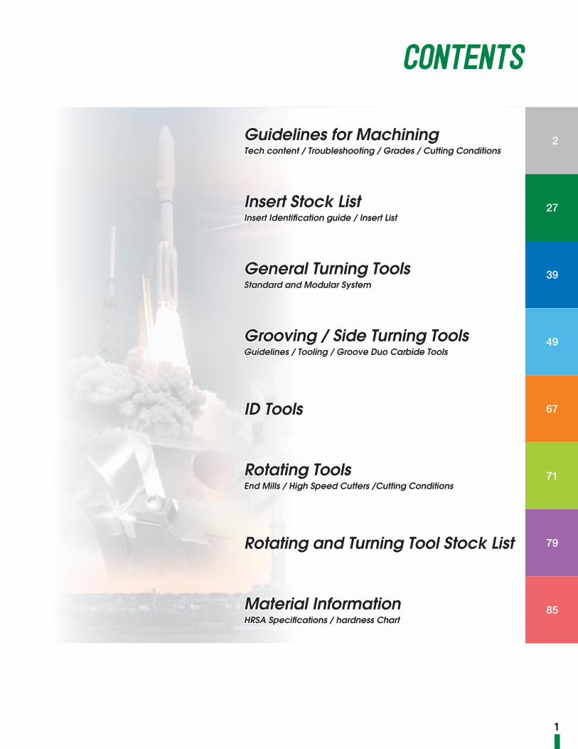
CONTENTS
Guidelines for MachiningTech content / Troubleshooting / Grades / Cutting Conditions
2
Insert Stock ListInsert Identification guide / Insert List
27
General Turning ToolsStandard and Modular System
39
Grooving / Side Turning ToolsGuidelines / Tooling / Groove Duo Carbide Tools
49
ID Tools 67
Rotating ToolsEnd Mills / High Speed Cutters /Cutting Conditions
71
Rotating and Turning Tool Stock List 79
Material InformationHRSA Specifications / hardness Chart
85

2
Guidelines for Machining HRSA Materials
Strength Increases
S CR C T D V
80° 55°60°
35°100° 90°
■ Guidelines for Insert Selection
For the best performance always use the strongest possible insert shape to maximize corner strength and productivity. If the operation allows, it is best to use round inserts or square inserts with a large nose radius and a small entering angle.Use the largest nose radius possible for the operation, so you increase the strength of the insert which will result in better tool life but remember that this will result in increased tool pressure.Larger insert thickness gives added strength and integrity during machining offering far better impact resistance, heat dispersion, and longer tool life. This results in higher productivity.
Insert Nose Radius InchesInsert Thickness
High LowProductivity & Radial forces
High LowStrength
35°
55°
80°
90°
70
80
100
35
10
40
60°
RCGXRNG
CN...CP...
TN... SN...SP...
DN...VN...
100°
Perc
enta
ge o
f geo
met
ry s
treng
th(%
)
0 25 50
Strength comparison(%)75 100
.187”(4.76㎜)
.250”(6.35㎜)
.312”(7.94㎜)
.125”(3.18㎜)
.031”(0.79㎜)
.047”(1.19㎜)
.062”(1.59㎜)
.015”(0.4㎜)
10020 40 60 80
Strength comparison(%)

3
■ Edge Conditions are a Key to SuccessAn important factor for achieving success when machining with ceramic inserts is to use the correct edge preparation. Ceramic is a hard material therefore the insert needs some edge work in order to withstand cutting forces and optimize the cutting tool performance. The edge preparation must correspond to the ceramic grade selected, the type of HRSA material being machined and the machining operation being performed. The majority of ceramic applications can be handled with NTK’s standard edge preparations.In unique circumstances that may arise, an edge preparation may need to be specialized to meet the conditions.The chart below describes standard edge preps.
Edge
Str
engt
h In
crea
ses
FNX Style
Up sharp edges are not recommended for ceramics.
E Style
Hones help protect the edge of ceramics from chipping or fracturing. Feed rates must be greater than the hone size to prevent a rubbing rather than a cutting action. Excessive honing reduces tool life.
Width of T-LandAngle of T-Land
T Style
This geometry is typically the most common ceramic edge preparation. The cutting forces are distributed over a concentrated area of the ceramic edge.
Width of T-Land
R (hone)
Angle of T-Land
Z & S Style
A hone added to a T-land provides a stronger edge to prevent chipping. Usually this type of geometry works best on interrupted cuts or turning hardened steels.
Width of T-Land
R (hone)
Angle of T-Land
J, P & Q Style
Double T-lands and hones are generally used in heavy roughing cuts or hardened materials. This edge is extremely shock resistant but also generates large cutting forces.
■ Description of Insert Edge Preparations

Hardness Rc
1500
1200
1000
800
600
400
30 35 40 45 50
Sur
face
Sp
eed
(Tu
rnin
g)
.002
.004
.006
.008
.010
.012
.014
.016
30 35 40 45 50
Hardness Rc
Feed
Rat
e
4
Guidelines for Machining HRSA Materials
■ Know the Workpiece Material to Determine ParametersTo effectively machine with ceramic inserts it is important to factor in the physical hardness of the material and the surface condition to determine the starting speed and feed. The chart information is based on using an RNG 45 insert with a depth of cut from .125 inches or less. In rough / scale conditions, use the lower side of the speed range for the hardness of the material. If machining clean HRSA material use the higher speed range based on the hardness. When using weaker geometry inserts such as triangles it is important to reduce feeds.The formation of the chip is a good indicator of the material hardness, the chips will break easily. The cutting temperatures will be higher with hardened materials resulting in more notch wear on the insert edge.Softer HRSA materials machine similar to stainless steels. Insert grades with greater toughness and reduced hot hardness resistance are ideal in these conditions due to reduced machining temperatures and an increase of the chip breaking against the insert.
Parts that have a forged scale work surface, typically machined in soft state around 26 Rc, require a 25% speed reduction and an increase of the feed until the scale is gone. When cutting cast HRSA material speeds can be increased from those indicated on the graph and it is recommended to reduce feeds to one half of the value indicated on the chart. The maximum depth of cut should be around .060” (for an RNG45) and use flood coolant conditions where applicable. Bar stock is the easiest to machine allowing the use of harder more wear resistant insert grades than when machining forgings.
Feed
f/2f
Material Components Advantage Machinability
Forging Large High strength Medium
Casting Complex shapes Low strength Poor
Bar Stock Less than 7.5” dia. Availability/strength good

5
■ Guidelines for Machining Heat Resistant Alloy
Repeated passes with same depth of cutThis is not a beneficial practice because the insert will develop severe notching at the point of therepetition of DOC. This will result in indexing the insert often. For this reason it is best to vary the depth of cut point by utilizing one of two techniques.
Vary the Depth of cut through multiple passes.Gradually reduce the depth of cut with every pass. This may increase the operation time slightly but will result in longer tool life for the insert and less indexing of the insert.
Multiple passes using ramping programmingThis technique has a proven benefit to roughing operations. Gradually feed out while traversing the part will result in significant reductions in notching. The subsequent pass is programmed at a constant cut since the surface is now ramped.
Same Depth of Cut Varying Depth of Cut
Ramping
◦ Rough
Feed
Note) Notch wear on the insert cutting edge as shown in is the result of multiple passes being taken at the same depth of cut. This type of wear will minimize tool life. The following programming examples will help to minimize this mode of failure.
change to
Note) Another programming change that may help to reduce notching is by varying the depth of cut. Again, the same principle applies, notching takes place at various points on the cutting edge rather than concentrated at one point.
Feed
Note) Programming " Ramping " cuts in the same cutting direction is one of the best procedures to use to minimize notching. By varying the DOC, wear is distributed over the entire cutting edge not on one point.
Feed

6
Guidelines for Machining HRSA Materials
■ Depth of Cut and Tool LifeInsert failure due to depth of cut notching is a typical result when machining heat resistant alloys and must be controlled to prevent a catastrophic failure of the cutting edge. The depth of cut is a key consideration during the machining operation to maximize tool life and minimize notch wear on the cutting edge. A decrease in the lead angle results in increased cutting forces on the insert edge. As the DOC exceeds beyond the point on the insert edge where a 45 degree line from the center of the insert intersects the cutting edge the greater the notch wear and the increased risk for failure of the insert edge. There is a direct relationship between the insert radius size and the maximum depth of cut (at around 60 deg. mark) which should be taken. See the chart below for recommendations. Any increase in DOC requires a reduction of the speed and feed rates. Parameters are based on the ceramic insert's ability to withstand high temperatures and run with a chip thickness that allows the heat to be concentrated in the zone ahead of the insert resulting in low cutting pressure and minimal wear. If the speed is reduced without a corresponding reduction in feed, this effect will be lost and the performance will fall off due to chipping of the insert edge from a cooler chip.
Direction of cut
Finished surfaceDOC
45°
Speed and Feed Rate (%) vs. Depth of Cut on the Radius
Insert RadiusInches (mm)
Ideal DOCInches (mm) Insert Descriptions
.125 (3.18) .038 (0.93) RCGX / RPGX23; RPG21..
.187 (4.76) .056 (1.40) RCGX / RPGX35; RNG / RPG32
.250 (6.35) .075 (1.86) RCGX / RPGX45; RNG43 / 45; RPG 43
.312 (7.94) .092 (2.33) RNG55
.375 (9.53) .110 (2.79) RNG64 / 65; RPG65
.50 (12.70) .147 (3.72) RNG85 / 86
144 % 119% 100%
Surface Speed and Feed Rate (Percentage)
Insert Diameter
177%
15°30°
45°60°
75°.250” .375” .50”
.063” .094” .125”
.038” .056” .075”
.018” .028” .035”
Rad
ial l
oca
tion
of d
epth
of c
ut
Dep
th o
f C
ut (I
nche
s)

7
■ Guidelines for Machining Heat Resistant AlloyDepth of Cut Recommendation based on Insert Corner RadiusTo maximize tool life when using straight-edged inserts (C, D, or S) with corner radii , as opposed to a round insert, the allowable depths of cut are related to the radius and not the insert size. To minimize notching and allow a cut from both directions, the effective machining procedure is to take more material off during the roughing operation, with a round insert. Then the material removal amount for the finishing operation, with a straight edge insert, should be suitable for the nose radius of the insert.It is important to choose the insert with the appropriate corner radius to complete the finishing operation’s depth of cut. If the part has a required radius feature called out, then do not leave more than the amount of material called out for the required insert radius to finish the part and feature. A large corner radius may deflect a part with thin walls because of radial forces generated between the workpiece and insert.
As seen in these photos, by removing the appropriate amount of stock for the nose radius of the insert and staying below the 45° mark of the corner radius notching is minimized allowing a cutting operation to be programmed from both directions on the insert.
Insert Corner RadiusInch (mm)
Ideal Depth of CutInch (mm)
Corner Radius DesignationInch (mm)
.015 (0.38) .0046 (0.12) 1 (04)
.031 (0.80) .0092 (0.23) 2 (08)
.048 (1.21) .0139 (0.35) 3 (12)
.063 (1.59) .0183 (0.47) 4 (16)
.094 (2.38) .0275 (0.70) 6 (24)
.125 (3.18) .0370 (0.93) 8 (32)
Optimum DOC is 5-15% of insert diameter (based on 0 deg. Lead angle)
45°
45°
Depth of Cut
Increasing DOC
Notch Wear Decreases
α=45°
45°
45°
Depth of Cut

8
Guidelines for Machining HRSA Materials
■ Lead Angles
■ Milling Operations on Heat Resistant Alloys (High Nickel)
■ Feed
When cutting heat resistant alloys consideration should be given to using the largest lead angle possible. A large lead angle allows the cutting forces to be spread over a larger surface area of the insert. This will also improve tool life and surface finish while reducing notching. As the lead angle increases the chip will flow more easily.
Button inserts in a milling cutter rotate in and out of the cut during a revolution this reaction on the insert edge is comparable to machining an interrupted cut on a turning operation. This rotation in and out of the material also can hinder achieving the desired temperature ahead of the tool. So, an increase in speed, reduced feed/tooth in order or a combination will help generate the heat. It is recommended to use climb milling techniques to avoid elevated temperatures in a thin area of the chip which could create chip welding and re-cutting of the chip which reduces tool life.
Increase speeds from turning recommendations in chart according to width of cut. Reduce the feed rate recommendations for turning in chart by about 50% (This is feed per tooth, not per revolution of the cutter)The width of the cut has a direct relationship to the temperature generated ahead of the inserts. As the width is decreased the temperature decreases because the insert is out of the cut more than in the cut. The chart below shows the percentage to increase speeds given in the previous chart for various widths of cut. The widths are also expressed as percentages of the cutter diameter (so all cutter sizes apply)A milling insert can only be cutting 50% of each revolution if the path of cut is equal to the cutter diameter. So, it will always be necessary to increase speed and reduce feed compared to the turning recommendations to achieve the temperatures needed.
Surface finish is directly related to the insert nose radius and the feed rate programmed. The larger the radius on the insert the faster the tool can be fed to achieve the appropriate finish. When machining HRSA materials with SiAlON ceramics utilize their superior strength by increasing the feed rate which will minimize wear and cutting time.
Typical insert wear pattern showing the effect of various lead angle changes and the resulting increase of depth of cut notching
Width of cut in % of cutter diameter
engaged
Surface speed in % of Graph
100% 125%
90% 150%
80% 220%
70% 280%
60% 340%
50% 400%
40% 460%
45° 15° 0°

9
■ Minimize overhang
■ Pre-chamferring
Too much overhang causes the holder to deflect resulting in vibration and chatter which is damaging to ceramic inserts and can lead to insert breakage. When working with turret style machines, straight edged inserts should be considered in place of round inserts. The straight edge eliminates radial tool forces and chatter issues.
Pre-chamferring the part reduces the potential for insert chipping or breaking upon the entry or exit point of work material. To effectively complete a pre-chamfer operation it is important to program the feed at a 90 degree angle to the chamfer in order to prevent notching and increase insert tool life.
■ No dwellingInserts wear out when rubbing the part instead of cutting
■ CoolantWhen turning with BIDEMICS, SiAlON and Whisker a flood coolant ondition should be used In some cases where a high interruption is encountered it may be best to shut off the coolant No coolant should be used while milling with SX3, SX7 and SX9
■ Edge preparationsTypical HRSA machining requires the insert cutting edge to be sharp. Using a slight T-land or honed edge is also effective to reduce notching, flaking and built up edge
90 deg.

10
Guidelines for Machining HRSA Materials
Cutting speed (SFM) Feed rate (IPR) Grade attributeSiAlON BIDEMICS SiAlON BIDEMICS BIDEMICS SiAlON Whisker
Notching ➡「a」 ➡「b」
Flank wear ➡「c」 ➡「d」
Breakage ➡ ➡
Heat ➡ ➡ ➡ ➡ ― ― ―
Chatter ➡ ➡ ➡ ➡ ― ― ―
Cutting Conditions & Parameters Adjustment
Test Results「a」 WA1 : Increase cutting speed
500 SFM 1800 SFM「b」 SX7・SX3・SX9・SX5 : Increase feed rate
.008 IPR .016 IPR「c」 SX7・SX3・SX9・SX5 : Decrease cutting speed
1300 SFM 500 SFM
「d」 SX7・SX3・SX9・SX5 : Increase feed rate
In some cases, in order to increase the wear resistance of SX7 & SX3 & SX9 & SX5, the feed must be increased. By increasing the feed and utilizing the toughness of SX7 & SX3 & SX9 & SX5, the inserts are off the part sooner causing less wear. Increasing the feed also decreases cycle time and improves productivity and profitability.
Note : Be careful to reduce the feed rate by 25%, when going into a corner.
Note : Speed and feed rates shown are recorded test data and should not be thought of as recommended cutting conditions.
.000 .004 .008 .012 .016 .020.000
.025
.050
.075
.100
Whisker rainforcedceramic
Feed (IPR)
Flank wear (inch)
Cutting conditionWork material : Inco718Insert shape : RNG45
Cutting Speed : 800 SFMDepth of Cut : .080"WET
SX7・SX3・SX9・SX5Whisker ceramic
Feed rate increased decreases wear amount of SiAION
■ Troubleshooting
1st Choice 2nd Choice
SX3SX7

11
Grade Recommendations based on Material's Machinability and Application
【Guidelines for actually finished surface roughness】Steel type work: Theoretical surface roughness × 1.5 to 3Cast iron type work: Theoretical surface roughness × 3 to 5
ab
:Cutting speed(SFM):Machining diameter(inch):Spindle speed(rpm)
π:Pi(3.14)
T:Cutting time(min):Cutting length(inch):Feed rate(IPR):Spindle speed(rpm)
:Theoretical surface roughness(μinch):Feed amount (IPR):Corner radius(inch)
T:Cutting time(min):Cutting speed(m/min):Feed amount(㎜/rev)
π:Pi(3.14)
π× ×12(SFM)
=
×(min)T=
8(μinch)= ×10002
12×π×(rpm)
=
π×(a2-b2)4000× ×(min)
T=
Calculating the cutting speed from the rotation speed
Calculating the cutting time for OD (ID) machining
Calculating the revolution speed from the cutting speed
Calculating the cutting time for facing
■ Formula for Turning ● Calculating the cutting speed
● Calculating the cutting time
● Calculating the theoretical surface roughness
Work MaterialRough Turning w/ Scale Rough no scale & Semifinishing Grooving Milling
1st 2nd 1st 2nd High RPM Potential use 1st 2nd 1st 2nd
Hastelloy C SX5 SX9 SX7 SX3 JX1 SX7 SX3 SX7 WA1Inconel 625 SX5 SX7 SX7 SX3 JX1 SX7 SX3 SX7 SX9Inconel 718 SX5 SX9 SX9 SX7 JX1 SX7 SX9 SX9 SX7Mar M247 SX5 SX3 SX3 SX7 JX1 SX7 WA1 SX7 WA1
Udimet 720 SX5 SX9 SX7 WA1 JX3 SX7 SX3 SX7 WA1Waspaloy SX5 SX9 SX7 WA1 JX3 SX5 SX3 SX7 WA1
Rene SX3 SX7 SX3 SX7 JX1 SX7 SX3 SX3 SX7Stellite 6 SX5 SX9 SX9 WA1 JX3 SX7 SX3 SX9 SX7MP35N SX5 SX3 SX3 WA1 JX3 SX7 WA1 SX7 WA1Monel SX3 WA1 SX7 SX3 JX1 SX7 WA1 SX7 SX3Haynes SX9 WA1 SX9 SX3 JX1 SX7 WA1 SX7 SX3
Inconel 903 SX3 SX9 SX7 SX3 JX1 SX7 WA1 SX7 SX3Invar SX5 SX9 SX9 SX3 JX1 SX7 WA1 SX9 SX3

1212
Technical Data
Corrective measures
Possible cause
Type of problem
Material/grade selection Cutting conditions Tool shape Machine/installation
Chan
ge to
a ha
rder m
ateria
l/grad
e
Chan
ge to
a tou
gher
mater
ial/g
rade
Change
to a ma
terial/gra
de more
resistant
to therm
al shock
Change
to a m
aterial/g
rade mo
re resis
tant to
deposit
ion
Cutt
ing
spee
d
Feed
rate
Dep
th o
f cut Coolant
Revie
w th
e ty
pe o
f chip
brea
ker
Rake
ang
le
Nose
radiu
s of t
he in
sert
Side c
uttin
g edg
e ang
le
Cuttin
g edg
e stre
ngth, h
oning
Impr
ove
the
accu
racy
of in
sert
Impr
ove t
he rig
idity
of the
holde
r
Improv
e the in
stallatio
n accu
racy o
f the cu
tting to
ol
Revie
w the
overh
ang o
f the c
utting
tool
Prevent
vibration
of the m
achine, i
mprove
the ma
chine rig
idity
Use n
on-w
ater-s
oluble
type
Revie
w dry
or w
et op
eratio
n
Decrease Increase➡ ➡Decrease Increase➡ ➡
Shor
t too
l life
Excessive insert wear
Unsuitable tool material/grade ●Unsuitable cutting edge shape ● ➡ ➡ ➡ ➡
Improper cutting conditions ➡ ➡ Wet
Fracture/chipping of the cutting
edge
Unsuitable tool material/grade ●Improper cutting conditions ➡ ➡
Insufficient cutting edge strength ● ➡ ➡Thermal shock ● ➡ ➡ ➡ ● DryBuilt-up edge ● ➡ ➡ ● WetInsufficient toughness ● ● ● ●
Poor
dimen
siona
l accu
racy Variation in
dimensions during cutting
Improper accuracy of insert ●Clearance/relief of the work/tool ● ➡ ➡ ➡ ➡ ● ● ● ●
Need for offsetting
during cutting
Increased flank wear ● ➡Built-up edge ● ➡Improper cutting conditions ➡ ➡
Poor su
rface fi
nish Poor surface
roughness
Deposition ➡ ● WetUnsuitable cutting edge shape ● ➡Chatter ➡ ➡ ➡ ● ● ● ●
Heat Deterioration in tool
life/accuracy due to excessive heat generation
Improper cutting conditions ➡ ➡ ➡
Unsuitable cutting edge shape ● ➡ ➡
Burr
ing,
chi
ppin
g, s
cuffi
ng
Burring
Boundary wear ●Improper cutting conditions ➡ ➡
➡ WetUnsuitable cutting edge shape ● ➡ ➡ ➡ ➡
Chipping
Improper cutting conditions ➡ ➡
Unsuitable cutting edge shape ● ➡ ➡ ➡ ➡
Vibration ● ● ● ●
Scuffing
Unsuitable tool material/grade ●Improper cutting conditions ➡ ● WetUnsuitable cutting edge shape ● ➡ ➡
Vibration ● ● ● ●
Chip
cont
rol
Elongated chips
Improper cutting conditions ➡ ➡ ➡ WetChipbreaker’s effective chip control range ●Unsuitable cutting edge shape ➡ ➡
■ Troubleshooting for Turning

1313
Case/Symptom Possible causes Corrective measuresIn
sert
VB wear ●The material / grade is too soft●Cutting speed is too high●Relief angle is too small
●Use a coated grade● Choose a material/grade highly resistant
to wear●Decrease the cutting speed
Wear on face● High temperature causes chemical
reactions between the insert material and chips
●Use a coated grade● Decrease both of the cutting speed and feed rate●Widen the rake angle
Notching wear●The work surface is too hard●Boundary area has been oxidized● Burrs, caused by chips in the sheared
form, have been cut
●Widen the side cutting edge angle● Make the nose radius larger so that cutting
is performed within the radius●Use a round insert
Chipping/ fracture●Feed rate is too high●Chips have become trapped●Chatter resulting in vibration
●Enlarge the honed edge●Make the nose radius larger● Narrow the rake angle to secure the
cutting edge strength
Flaking
● This is due to compressive forces being applied to the cutting edge from elastic deformation in the area being cut
● This occurs when deposited/adhered material is peeled off
● Change the cutting conditions by checking the cutting edge
● Choose a material/grade highly resistant to fracture●Increase the coolant rate and pressure●Improve the run-out of the main spindle of the machine
Plastic deformation
● High cutting force and excessive heat is applied to the cutting edge
● Choose a material/grade highly resistant to wear●Decrease both of the cutting speed and feed rate●Make the nose radius larger●Use coolant
Built-up edge● This occurs because the cutting temperature
is lower than the recrys tal l i za t ion temperature of the work material
●Increase the cutting speed● Use coolant with excellent lubrication performance●Change to a grade with less affinity to the work material
Deposition● The deposition is caused to the face
by a chemical reactions of the work material due to heat generation
●Increase the cutting speed●Widen the relief angle●Hone the face with a mirror-like-surface finish●Change to a grade with less affinity to the work material
Clamping crack
● The inser t was clamped under improper seating conditions
● Clean the clamping areas and install the insert in the recommended way
●Tighten to the specified torque
Wor
k pi
ece
Chipping ●The feed rate is too high●An unsuitable insert was selected
●Decrease the feed rate●Use a smaller edge preparation● Change to a grade highly resistant to boundary wear●Change the cutting edge angle of the holder
Burring ●The feed rate is incorrect●The shape of insert is not suitable
●Decrease the feed rate●Use a smaller edge preparation
Chatter mark●The cutting force is too great● The rigidity of the work piece and
cutting tool is insufficient
●Decrease the feed rate●Use a smaller edge preparation●Ensure tool overhang is minimised●Change the cutting edge angle of the holder
Gouging ● Vibration of the cutting edge due to deposition/built-up edge
●Increase the cutting speed●Use cutting oil excellent in lubrication performance● Change to a grade with less affinity to the work material
■ Troubleshooting Case Studies: Turning

1414
Technical Data
Corrective measures
Possible cause
Type of problem
Material/grade selection Cutting conditions Tool shape
Chan
ge to
a ha
rder m
ateria
l/grad
e
Chan
ge to
a tou
gher
mater
ial/g
rade
Change
to a ma
terial/gra
de more
resistant
to therm
al shock
Change
to a m
aterial/g
rade mo
re resis
tant to
deposit
ion
Cutt
ing
spee
d
Feed
rate
Dep
th o
f cut
Review
cutte
r diam
eter a
nd cut
ting wi
dth
Revi
ew to
ol p
ath Coolant
Relie
f ang
le o
f inse
rt
Nose
radius
of cu
tting e
dge
Cuttin
g edge
streng
th, hon
ing
Num
ber o
f tee
th/b
lade
s
Enla
rge
the
chip
poc
ket
Chec
k th
e w
iper
sha
pe
Improv
e accu
racy o
f cuttin
g edge
run-ou
t
Impr
ove
rigid
ity o
f too
l
Wet
Dry
Decrease Increase➡ ➡Decrease Increase➡ ➡
Dama
ged
or b
roke
n cu
tting
edge
of t
he in
sert Increased
flank wearImproper cutting conditions ➡ ●Unsuitable cutting edge shape ● ➡ ➡ ●
Increased wear on face
Improper cutting conditions ➡ ➡ ➡ ●Unsuitable cutting edge shape ● ➡ ➡ ➡
Fracture/chipping on cutting edge
Improper cutting conditions ➡ ➡ ●Unsuitable cutting edge shape ● ➡ ➡ ➡ ● ● ●
Thermal shock
Improper cutting conditions ➡ ➡ ➡ ●Unsuitable cutting edge shape ● ➡ ➡
Built-up edge
Improper cutting conditions ➡ ➡ ●Unsuitable cutting edge shape ● ➡ ➡
Mac
hini
ng a
ccur
acy
Poor surface finish
Improper cutting conditions ➡ ➡ ➡ ●Unsuitable cutting edge shape ● ● ➡ ➡ ● ●
BurringImproper cutting conditions
➡
➡
➡ ● ●Unsuitable cutting edge shape ➡ ➡ ➡ ●
ChippingImproper cutting conditions ➡ ➡ ●Unsuitable cutting edge shape ➡ ➡ ➡ ➡ ●
Poor flatness and parallelism Improper cutting conditions ➡ ➡ ● ➡ ➡ ➡ ➡ ● ● ●
Oth
ers
Increased chatter/vibration Improper cutting conditions ➡ ➡ ➡ ● ● ➡ ➡ ➡ ➡
Poor chip evacuation
Improper cutting conditions ➡ ➡ ● ● ●Unsuitable tool/blade edge shape ➡ ➡ ●
■ Troubleshooting for Milling

1515
Case/Symptom Possible causes Corrective measuresIn
sert
VB wear
●Cutting speed is too high.●Feed rate is too low.●The shape of the insert is not suitable.● The material / grade of the insert is
not suitable.
●Decrease the cutting speed.●Increase the feed rate.●Make the nose radius larger.● Change to a grade highly resistant to boundary wear.
Notching wear
● The material / grade of the inserts is not suitable.
●The shape of the cutter is not suitable●The shape of insert is not suitable.
●Change to a grade highly resistant to boundary wear.●Widen the rake angle.●Change the Insert shape to a different one.
Chipping / fracture
●The cutting speed is incorrect.●The shape of the cutter is not suitable●The shape of insert is not suitable.
● Decrease the feed rate and depth of cut in order to reduce the cutting force.
●Use a smaller edge preparation.●Prepare the cutting edge to give it a round honing.●Change to a grade highly resistant to fracture.
Thermal crack
●The cutting conditions are incorrect● The material / grade of insert is not
suitable
●Decrease the cutting speed.●Change to dry cutting from wet cutting.● Use a material / grade highly resistant to thermal shock
Wor
k pi
ece Chipping
●The feed rate is too high.●An unsuitable insert is selected.●The shape of the cutter is not suitable.
●Decrease the feed rate.●Use a smaller edge preparation●Change to a grade highly resistant to boundary wear.●Set the lead angle at 45 degrees.
Burring●The feed rate is incorrect.●The shape of insert is not suitable.●The shape of the cutter is not suitable.
●Adjust the feed rate.●Use a smaller edge preparation.●Make the lead angle narrower.
■ Troubleshooting Case Studies: Milling
:Cutting speed(SFM):Cutter diameter(inch):Spindle speed(rpm)
π:Pi(3.14)
:Inch amount per tooth(IPT):Table feed(inch/min):Number of tooth:Spindle speed(rpm)
T:Cutting time(min)L :Total length of table feed
( + ):Table feed(inch/min)
π× ×12(SFM)
=
L(min)T=
12×π×(rpm)
=
Calculating the cutting speed from the rotation speed
×(IPT)=
Calculating the feed rate per blade
Calculating the revolution speed from the cutting speed
= × ×(inch/min)
Calculating the feeding speed per minute
■ Formula for Milling● Calculating the cutting speed
● Calculating the feeding speed and feed rate
● Calculating the machining time
16
Rough with No Scale
Rough with No Scale
JP2
JP
2
SX7SX7
Rough with
Scale
Rough with
Scale
TougherTougher
Harder
Harder
SiAlONSiAlON
Whisker
Whisker
BIDEMICSBIDEMICS
JX1JX1
SX3SX3 SX9SX9
JX3JX3
WA1
WA1
SX5
SX5
Toug
her
Toug
her
Har
der
Har
der
Finish
Finish
Semi-Finish
Semi-Finish
Rough to Semi �nish
Rough to Semi �nish
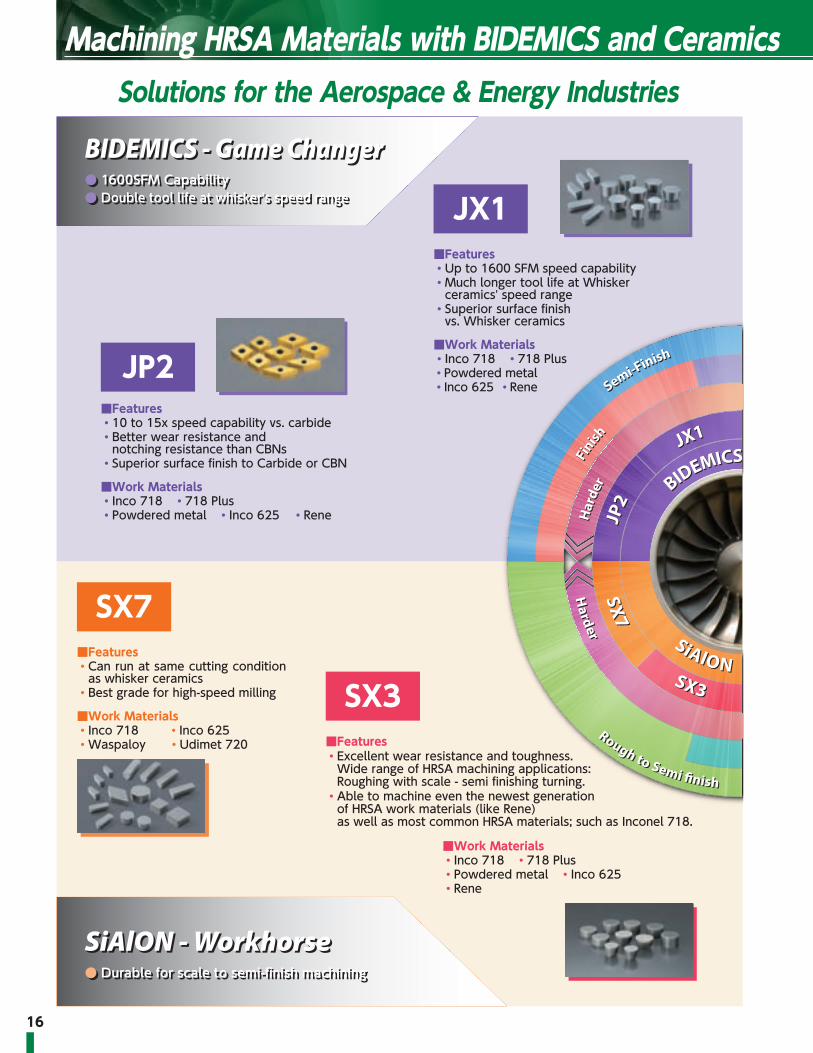
BIDEMICS - Game Changer● 1600SFM Capability● Double tool life at whisker's speed range
BIDEMICS - Game Changer● 1600SFM Capability● Double tool life at whisker's speed range
SiAlON - Workhorse● Durable for scale to semi-finish machining
SiAlON - Workhorse● Durable for scale to semi-finish machining
Whisker - Versatile Player● Productivity and reliability
Whisker - Versatile Player● Productivity and reliability
Machining HRSA Materials with BIDEMICS and CeramicsSolutions for the Aerospace & Energy Industries
JX1■Features・ Up to 1600 SFM speed capability・ Much longer tool life at Whisker
ceramics' speed range・ Superior surface finish
vs. Whisker ceramics
■Work Materials・Inco 718 ・718 Plus ・Powdered metal・Inco 625 ・Rene
SX7■Features・ Can run at same cutting condition
as whisker ceramics・ Best grade for high-speed milling
■Work Materials・Inco 718 ・ Inco 625・ Waspaloy ・ Udimet 720
■Work Materials・Inco 718 ・718 Plus・Powdered metal ・Inco 625・Rene
SX3■Features・ Excellent wear resistance and toughness.
Wide range of HRSA machining applications: Roughing with scale - semi finishing turning.
・ Able to machine even the newest generation of HRSA work materials (like Rene) as well as most common HRSA materials; such as Inconel 718.
JP2■Features・ 10 to 15x speed capability vs. carbide・ Better wear resistance and
notching resistance than CBNs・ Superior surface finish to Carbide or CBN
■Work Materials・Inco 718 ・718 Plus・Powdered metal ・Inco 625 ・Rene

17
Rough with No Scale
Rough with No Scale
JP2
JP
2
SX7SX7
Rough with
Scale
Rough with
Scale
TougherTougher
Harder
Harder
SiAlONSiAlON
Whisker
Whisker
BIDEMICSBIDEMICS
JX1JX1
SX3SX3 SX9SX9
JX3JX3
WA1
WA1
SX5
SX5
Toug
her
Toug
her
Har
der
Har
der
Finish
Finish
Semi-Finish
Semi-Finish
Rough to Semi �nish
Rough to Semi �nish
BIDEMICS - Game Changer● 1600SFM Capability● Double tool life at whisker's speed range
BIDEMICS - Game Changer● 1600SFM Capability● Double tool life at whisker's speed range
SiAlON - Workhorse● Durable for scale to semi-finish machining
SiAlON - Workhorse● Durable for scale to semi-finish machining
Whisker - Versatile Player● Productivity and reliability
Whisker - Versatile Player● Productivity and reliability
JX3■Features・ Added toughness in BIDEMICS・ Same speed capability as JX1
■Work Materials・Inco 718 ・718 Plus ・Powdered metal・Inco 625 ・Rene
SX5■Features・ Best grade for scale and interruptions・ Best grade for machining high-cobalt alloys
■Work Materials・Waspaloy ・Udimet 720・ 718 Plus ・Rene 41
WA1■Features・ Better flank wear resistance compared
to SiAlON ceramics・ Better notching resistance compared
to competitor's whisker ceramics
■Work Materials・Inco 718 ・Inco 625
SX9■Features・ Extreme toughness makes higher feed
and heavier DOC machining possible・ Best grade for machining Inco 718 with
scale
■Work Materials・Inco 718 ・ Inco 706・ Inco 713 ・Rene

18
NEW BIDEMICS New Era in HRSA Machining
◦ Significantly extended tool life compared to whisker ceramics
◦ Double cutting speed potential compared to whisker ceramics
◦ Superior surface finish compared to whisker ceramics◦ Applicable to powder-metallurgical heat
resistant alloys◦ Newly added JX3 provides toughness to BIDEMICS family
Features
Increase Productivity vs. Whisker Ceramics
① Significantly extended tool life at same speed
② Double speed capability
Grade Work material Application Purpose Cutting speed (SFM)
Feed (IPR)
Depth of cut(inch) DRY WET
JX1
JX3Heat Resistant
Alloy
TurningRough no scale 600–1600 .005–.011 .040–.100 ●
Semi finishing 600–1600 .004–.010 .020–.080 ●
Grooving Rough no scale 600–1600 .002–.005 ― ●
JP2 Heat ResistantAlloy Turning Finishing 600–1700 .002–.007 .005–.030 ●
JX1JX3Whisker Cut Downtime
JX1JX3Whisker More Production
Patented
◦ High speed finish turning can be performed at 800SFM or higher
◦ Superior wear resistance compared to CBN's◦ Superior notching resistance vs CBN or carbides◦ Superior surface finishes vs CBNs and coated
carbides
Features
Increase Productivity vs. Carbide
① 10 to 15 times higher speed capability
Wide brazed area
JP2
CBN
Carbide
TiN coating
Multi-edges
Strong brazing
Patented
■ JX1/JX3 ■ JP2

19
JX1/JX3's combination of High Hardness, Superior Thermal Conductivity and Improved Strength compared to Whisker ceramics results in significantly longer tool life when applied at typical Whisker ceramic speeds, feeds, and depth of cut.
BIDEMICS has success on
Inconel 718Inconel 625◦718 Plus ◦Rene104◦Rene41 ◦Waspaloy◦Rene88 etc.
JX1/JX3's superior physical properties compared to Whisker ceramic enable you to increase speeds; potentially as much as 2X Whisker ceramic speeds; increasing productivity and potentially offsetting the need for additional equipment to meet increasing demands.Chips break easily at higher cutting speeds vs the typically continuous chips of HRSA materials. The result is more efficient chip removal.
JP2's outstanding Wear Resistance and Notching Resistance results in work piece surface finishes consistently superior to either CBN or Carbide
VGW style grooving inserts are now available
2 Longer tool life
3 Works well on wide range of High Temperature Alloys
1 Higher Speeds, More Productivity
4 Superior surface finish
5 Speed up grooving operations
JP2 CBN Carbide
Machinedsurface
Roughness
Ra 0.64 μm 1.18 μm 2.75 μmRz 3.36 μm 5.56 μm 9.64 μm
Cutting speed 800 SFM ➡ 120 SFMFeed rate .006 IPR ➡ ➡Cycle time 3.3 min ➡ 14.7 min
Removed chip 48 cc ➡ ➡
Turbine case (718 Plus semi finish)Comp. coated Whisker JX1
Shape RNG45 ➡Cutting speed (SFM) 800 ➡Feed (IPR) .010 ➡Depth of cut (inch) .020 ➡
WET ➡
NTK:JX1 3 passCompetitor’s
Whisker ceramic 1 pass◦ JX1 produced 3 times longer tool life than coated Whisker ceramic on difficult to cut material, 718 Plus.
LPT disc (Inco718)Comp. Whisker JX3
Shape RPGX45 ➡Cutting speed (SFM) 700 1200Feed (IPR) .006 ➡Depth of cut (inch) .070 ➡
WET ➡
NTK:JX3 100 cc/min JX3
Competitor’s Whisker ceramic 60 cc/min
◦ JX3 cut 1.7 times faster than competitor’s whisker and kept good edge.
Disk (Inco718 Finishing)Competitor’s
Coated Carbide JP2
Shape CNGG432 CNGA432Cutting speed (SFM) 70 800Feed (IPR) .003 ➡Depth of cut (inch) .010 ➡
WET ➡Tool life 1pc ➡
NTK:JP2 525 cc/minCompetitor’s
Coated Carbide 45 cc/min
Ring (Inco625 Finishing)Comp. Whisker JP2
Shape CNGA433 ➡Cutting speed (SFM) 1100 1400Feed (IPR) .008 ➡Depth of cut (inch) .012 ➡
WET ➡
NTK:JP2 20 pcs/corner with 27% higher productivityCompetitor’s
Whisker ceramic 13 pcs/corner◦ JP2 got both better productivity and tool life over Competitor's Whisker.

2020
■ SiAlON Ceramics◦ SiAlON ceramic is a silicon nitride based ceramic
combined with “Al” and “O”. SiAlON ceramic offers excellent heat resistance, mechanical strength under high temperature, thermal shock resistance and wear resistance in addition to the toughness of silicon nitride.SiAlON shows superb performance in high speed machining of high temperature alloys.
Wea
r res
istan
ce
High
HighToughness / strength
【Machining of Inco 718】
JX1
SX7SX3
SX9SX5
WA1
JP2
Ceramics For Heat Resistant Alloys
SX3 Best balance of toughness and wear resistance
Grade Work material Application Purpose Cutting speed (SFM)
Feed (IPR / IPT)
Depth of cut(inch) DRY WET
SX3 Heat resistant alloyTurning
Rough scale 600–900 .008–.014 .040–.200 ●Rough no scale 600–900 .008–.016 .040–.100 ●
Semi finish / profiling 600–900 .004–.012 .040–.080 ●Grooving 500–900 .003–.007 – ●
Milling – 2000–4000 .004–.006 .040–.100 ●
◦ Excellent wear resistance and toughness. Wide range of HRSA machining applications: Rough turning with scale ~ semi-finish turning.
◦ Able to machine even the newest generation of HRSA work materials (like Rene) as well as today's most common HRSA materials; such as Inconel 718.
◦ Able to mill with high efficiency.
Features
Rough turning(Rene130)with ScaleSNG656
380 SFM
.006 IPR
Various DOC
WET
NTK:SX3 10 minCompetitor’s
SiAlON 10 min * Was chipping a lot
Competitor’s SiAlON Ceramic SX3
NEW

2121
SX9 Best grade for roughing Inco 718 with scale
Grade Work material Application Purpose Cutting speed (SFM)
Feed (IPR / IPT)
Depth of cut(inch) DRY WET
SX9 Heat resistant alloy TurningRough scale 600–800 .008–.014 .040–.200 ●
Rough no scale 600–800 .008–.016 .040–.100 ●Semi finish / profiling 600–800 .004–.012 .040–.080 ●
Milling – 1500–3500 .004–.006 .040–.100 ●
◦ Excellent notch wear resistance◦ Better flank wear resistance
compared to competitor's silicon nitride ceramics
◦ Superior toughness compared to Whisker-reinforced ceramics
◦ Best thermal shock resistance◦ Best grade for roughing Inco 718
with scale
Features Housing(Inco 718 with scale)Comp. Whisker SX9
5.805"
3.983"
VANES
Shape RCGX45 ➡Cutting speed (SFM) 600 ➡Feed (IPR) .005 .008Depth of cut (inch) .100 ➡
WET ➡
NTK:SX9 * High productivity
Competitor’s Whisker ceramic
SX5 Best grade for roughing Waspaloy with scale
Grade Work material Application Purpose Cutting speed (SFM)
Feed (IPR / IPT)
Depth of cut(inch) DRY WET
SX5 Heat resistant alloy TurningRough scale 600–800 .008–.014 .040–.200 ●
Rough no scale 600–800 .008–.016 .040–.100 ●Grooving 600–800 .003–.007 – ●
◦ Excellent notch wear resistance◦ Toughest SiAlON grade on the
market◦ Better thermal shock resistance
compared to Whisker-reinforced ceramics◦ Use SX5 where heavy scale or
interruptions exist
Features Ring(Waspaloy with scale)RCGX35650 SFM.008 IPR.750-.100 DOCWET
NTK:SX5 10 minCompetitor’s
SiAION ceramic 10 min * Was chipping a lot
SX7 Wear resistant SiAlON ceramic
Grade Work material Application Purpose Cutting speed (SFM)
Feed (IPR / IPT)
Depth of cut(inch) DRY WET
SX7 Heat resistant alloy Turning
Rough scale 600–900 .004–.009 .040–.200 ●Rough no scale 600–900 .006–.012 .040–.100 ●
Semi finish / profiling 600–900 .005–.010 .040–.080 ●Grooving 500–900 .003–.006 – ●
Milling – 2000–4000 .003–.005 .040–.100 ●
Turbine case(Waspaloy semi finish)RPGX45
φ39"
800 SFM.012 IPRVarious DOCWET
NTK:SX7 7.2 minCompetitor’s
Whisker ceramic 5.3 min * Broken
◦ Better notching resistance compared to Whisker ceramics
No need to program ramping◦ Better flank wear resistance compared to
other SiAlON ceramics Superior performance vs. whisker
ceramics under same conditions-even higher productivity at higher feed rates
◦Excellent thermal shock resistance High speed milling can be performed at
3000SFM or higher
Features

2222
Ceramics
HousingInco 625
900 SFM
.006 IPR
.020"-.030" DOC
WET
NTK:WA1 1 passCompetitor’s
whisker ceramic 1 pass
WA1 High-speed machining of heat resistant alloys and cast iron
◦ Good flank wear resistance at high speed◦ Best notch wear resistance compared to competitor's Whisker-reinforced ceramics◦ Increased toughness compared to competitor's Whisker-reinforced ceramics
Features
Wear resistance
High
HighToughness / strength
【Machining of Inco 718】
WA1 SX7
SX9SX5
JX1
■ Whisker-reinforced ceramicsWA1 ceramic grade has a unique combination of superior wear resistance, toughness and flaking resistance as a result of adding SiC Whiskers to Alumina. WA1 is primarily used in machining continuous cuts of aerospace alloys because of its productivity and reliability characteristics. WA1 can also be used to machine gray cast iron and hardened steels because of its excellent thermal shock resistance.
【Heat-resistant alloy】 【WA1 structure】
Recommended applications
Grade Work material Application Purpose Cutting speed (SFM)
Feed (IPR)
Depth of cut(inch) DRY WET
WA1
Heat resistantalloy Turning
Rough no scale 600–1000 .005–.010 .040–.100 ●
Semi finishProfiling 600–1100 .004–.010 .020–.080 ●
Grooving 600–1100 .002–.004 – ●
Gray cast iron Turning Semi finishFinish 1200–2100 .004–.016 .020–.120 ● ●
Mill roll (Carbide) Turning Rough–Semi finish 150–500 .003–.008 .020–.140 ●
Hardened Material (HRC 45–62) Milling 550–850 .0025–.005 .030–.075 ●
Competitor’s Whisker Ceramic WA1
2323
Field Results for Carbides
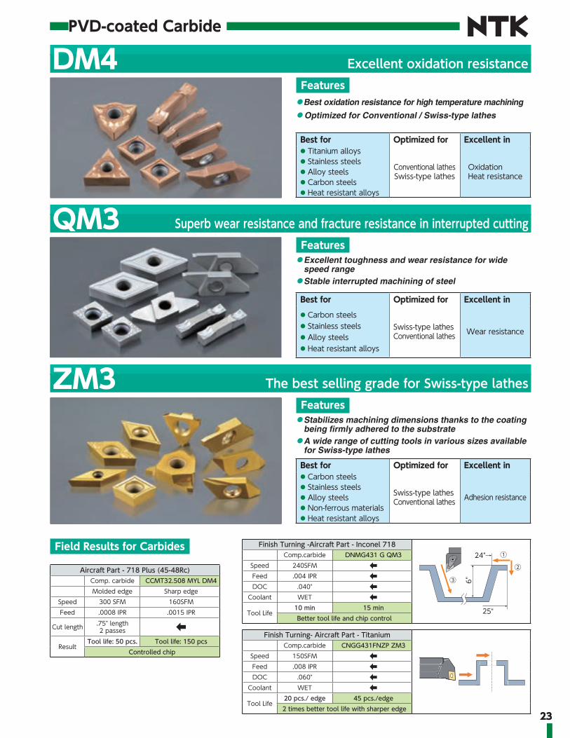
DM4 Excellent oxidation resistance
◦ Best oxidation resistance for high temperature machining
◦ Optimized for Conventional / Swiss-type lathes
Features
Best for Optimized for Excellent in● Titanium alloys● Stainless steels● Alloy steels● Carbon steels● Heat resistant alloys
Conventional lathesSwiss-type lathes
Oxidation Heat resistance
QM3 Superb wear resistance and fracture resistance in interrupted cutting
◦ Excellent toughness and wear resistance for wide speed range
◦ Stable interrupted machining of steel
Features
Best for Optimized for Excellent in● Carbon steels● Stainless steels● Alloy steels● Heat resistant alloys
Swiss-type lathesConventional lathes Wear resistance
PVD-coated Carbide
ZM3 The best selling grade for Swiss-type lathes
◦ Stabilizes machining dimensions thanks to the coating being firmly adhered to the substrate
◦ A wide range of cutting tools in various sizes available for Swiss-type lathes
Features
Best for Optimized for Excellent in● Carbon steels● Stainless steels● Alloy steels● Non-ferrous materials● Heat resistant alloys
Swiss-type lathesConventional lathes Adhesion resistance
Aircraft Part - 718 Plus (45-48Rc)Comp. carbide CCMT32.508 MYL DM4Molded edge Sharp edge
Speed 300 SFM 160SFMFeed .0008 IPR .0015 IPR
Cut length .75" length2 passes ➡
ResultTool life: 50 pcs. Tool life: 150 pcs
Controlled chip
Finish Turning -Aircraft Part - Inconel 718
6"
25"
24" ① ②
③
Comp.carbide DNMG431 G QM3Speed 240SFM ➡Feed .004 IPR ➡DOC .040" ➡
Coolant WET ➡Tool Life
10 min 15 minBetter tool life and chip control
Finish Turning- Aircraft Part - TitaniumComp.carbide CNGG431FNZP ZM3
Speed 150SFM ➡Feed .008 IPR ➡DOC .060" ➡
Coolant WET ➡Tool Life
20 pcs./ edge 45 pcs./edge2 times better tool life with sharper edge

24
Guidelines for Machining HRSA Materials
■Grade Map
■ Insert Grade
Category Grade Attributes
ApplicationsScale No scale Profiling Finishing Grooving Milling End milling
BIDEMICS
JX1Special grade with higher speed and longer tool life potential
JP2 Special grade for finish turning
JX3 Added toughness inBIDEMICS
Whisker WA1 General versatile grade for turning
SiAlON
SX3Best balance of toughness and hardness
SX5 Best grade for Waspaloy with scale
SX7 Versatile grade for turning and milling
SX9 Best grade for scale of Inco718
CarbideDM4QM3ZM3
Finish turning
1st Choice 2nd Choice
Continuous Light-interruption
interrupted
Cutti
ng S
peed
(SFM
)
1000
800
600
1800
1600
1400
1200
400
200
JX1JP2
JX3
SX9SX5
WA1SX3SX7
DM4, QM3, ZM3
Grade Rough with Scale Rough Semi-Finishing Finishing
BIDEMICS JP2
JX1
JX3
Whisker
WA1
SiAlON
SX7
SX3
SX9
SX5
Carbide DM4
QM3ZM3

25
■ ApplicationsApplication Grade Work
materialCutting speed Feed Depth of cut
Coolant600 800 1000 1200 1400 1600 .004 .008 .012 .016 .020 .020 .040 .060 .080 .100
Roughwith Scale SX5 Waspaloy
WET650 (600-800) SFM .012 (.008-.014) IPR .080 (.040-.200)"
SX9 Inco718650 (600-800) SFM .012 (.008-.014) IPR .080 (.040-.200)"
SX3 Overall800 (600-900) SFM .008 (.004-.009) IPR .080 (.040-.200)"
Roughno Scale
JX1JX3 Overall
WET700-1300 (600-1600) SFM .008 (.005-.011) IPR .070 (.040-.100)"SX9SX3SX7
Overall700 (600-900) SFM .009 (.006-.012) IPR .080 (.040-.100)"
WA1 Overall800 (600-1000) SFM .008 (.005-.010) IPR .070 (.040-.100)"
Profiling &Semi-Finish
JX1JX3 Overall
WET700-1500 (600-1600) SFM .008 (.004-.010) IPR .060 (.040-.080)"
SX3SX7 Overall
800 (600-900) SFM .008 (.005-.010) IPR .060 (.040-.080)"
WA1 Overall800 (600-1100) SFM .008 (.004-.010) IPR .060 (.040-.080)"
Finishing
JP2 OverallWET
700-1600 (600-1700) SFM .004 (.002-.007) IPR .010 (.005-.030)"
GroovingJX1JX3 Overall
WET1200 (600-1600) SFM .003 (.002-.004) IPR
SX5 Waspaloy700 (600-800) SFM .006 (.003-.007) IPR
SX3SX7 Overall
750 (600-900) SFM .0045 (.003-.006) IPR
WA1 Overall800 (600-1100) SFM .003 (.002-.004) IPR
Application Grade Workmaterial
Cutting speed Feed Depth of cutCoolant1500 2000 2500 3000 3500 4000 .002 .003 .004 .005 .006 .020 .040 .060 .080 .100
Milling SX3SX7 Overall DRY
×2700 (2000-4000) SFM .004 (.003-.005) IPT .070 (.040-.100)"
SX9 Overall2500 (1500-3500) SFM .005 (.004-.006) IPT .080 (.040-.100)"
End milling
SX9 Overall
DRY
×2000 (980-3300) SFM .0008-.0013 IPT
Application Grade Workmaterial
Cutting speed Feed Depth of cutCoolant100 150 200 250 300 350 .0005 .001 .0015 .002 .0025 .020 .040 .060 .080 .100
FinishingDM4QM3ZM3
HRSA&
Stainless
WET
130–330 SFM .0005-.002 IPR .020 - .080”
Rough with scale Rough&semi-finish Profiling Grooving Milling End milling
■ Applications
When using SX7/SX3/SX5, increase feed rates 100% vs. Whisker Ceramics

MEMO

Insert Stock List

2828
Insert Identification Guide
1 Shape
C 80°
D 55°
E 75°
L
P
R
S
T
V 35°
W 80°
2 Clearances 4 Type
0°
5°
7°
11°
15°
20°
N
B
C
P
D
E
SInch N G A1 2 3 4
SMetric N G A
S TC
D K
φd
m m
φd s
3 Tolerance Class
Symbol d (inch) m (inch) s (inch)
M tolerance
M tolerance
Inscribed Circle
Inscribed Circle
d (inch)
d (inch)
1/4"3/8"1/2"5/8"3/4"1"
±.002±.002±.003±.004±.004±.005
m (inch)
m (inch)
±.003±.003±.005±.006±.006±.007
AFCHEGJKLMNU
±.0010±.0050±.0010±.0050±.0010±.0010±.0020
±.002 ~±.005±.002 ~±.005±.002 ~±.005±.002 ~±.005±.003 ~±.010
±.0002±.0002±.0005±.0005±.0010±.0010±.0020±.0005±.0010
±.003 ~±.007±.003 ~±.007±.005 ~±.015
±.0010±.0010±.0010±.0010±.0010±.0050±.0050±.0010±.0010±.0050±.0010±.0050
1/4"3/8"1/2"5/8"3/4"
±.002±.002±.003±.004±.004
±.004±.004±.006±.006±.007
6 Thickness
ThicknessS(inch)
3/32"
1/8"
5/32"
3/16"
1/4"
5/16"
3/8"
1/2"
Inch Metric
02
03
T3
04
06
07
09
12
1.5
2
2.5
3
4
5
6
8Special design
70°-90°
70°-90°
40°-60°
40°-60°
Type Symbol Type Symbol
N (E)
F
R
A
G
M
X
H
B
T
W
■ ANSI / ISO Insert Nomenclature

2929
4 3 3 T 04 205 6 7 8 9 10
12 04 12 T 010 20
C D R S T V WInscribed Circle
1/4"
3/8"
1/2"
5/8"
3/4"
1"
Inch Metric
06
09
12
16
19
25
07
11
15
19
23
31
06
09
12
15
19
25
11
16
22
27
33
44
11
16
22
27
33
44
04
06
08
10
13
17
2
3
4
5
6
8
5 Symbol for Insert Size
R
7 Corner RadiusCorner Radius Inch Metric
1/64"
1/32"
3/64"
1/16"
5/64"
3/32"
1/8"
1
2
3
4
5
6
8
04
08
12
16
20
24
32
ba
r
8 Edge Condition 9 Negative Land Width 10 Negative Land Angle
Sharp FNX08
E
T
Z
S
U
K
J
P
Q
Honed
Chamfered
Chamfered and Honed
Double Chamfered
Double Chamfered and Honed
inchDescription
metrica
(inch)r
(inch)
E
T
Z
S
UKJPQ
0102020304050608040804081628607195
002004005008010012015020010020010020040070150180240
--
.002
.003
.004
.005
.006
.008
.004
.008
.004
.008
.016
.028
.060
.071
.095
.001
.002------
.001
.001
.002
.002
.003-
.001
.002
.003Note: K, J, P & Q show its primary land width
Description b10
15
20
25
30
10°
15°
20°
25°
30°Note: K, J, P & Q show its primary land angle

30
BIDEMICS / Ceramics
Finishing ● ◦ ◦
Semi-Finising ● ● ◦ ◦ ◦
Rough ● ● ● ● ◦ ◦ ◦
Rough with Scale ◦ ◦ ● ●
■ CNGA (inch) IC TCNGA 43 1/2 3/16CNGA 54 5/8 1/4CNGA 64 3/4 1/4
R T
R
IC 90°
80°
100°
●:1st Choice ◦: 2nd choice
Item Number ISO Item Number R
BIDEMICS CeramicsCoated SiAlON WhiskerJP2 JX1 JX3 SX7 SX3 SX9 SX5 WA1
EDP stock EDP stock EDP stock EDP stock EDP stock EDP stock EDP stock EDP stock
CNGA 431 BQ T0220 CNGA 120404 BQ T00520
.016
5925813 ●
CNGA 431 BQE02 CNGA 120404 BQENB 5964069 ●
CNGA 431 T0220 CNGA 120404 T00520 5708102 ●
CNGA 432 BQ T0220 CNGA 120408 BQ T00520
.031
5925839 ●
CNGA 432 BQE02 CNGA 120408 BQENB 5964051 ●
CNGA 432 T0220 CNGA 120408 T00520 5650031 ● 5649645 ● 5660741 ●
CNGA 432 T0225 CNGA 120408 T00525 5649264
CNGA 432 T0320 CNGA 120408 T00820 5851548 ●
CNGA 432 T0420 CNGA 120408 T01020 5660535 ●
CNGA 432 T0825 CNGA 120408 T02025 5570262 ○
CNGA 432 Z0820 CNGA 120408 Z02020 5752779 ●
CNGA 433 BQ T0220 CNGA 120412 BQ T00520
.047
5925854 ●
CNGA 433 BQE02 CNGA 120412 BQENB 5964044 ●
CNGA 433 T0220 CNGA 120412 T00520 5650049 ● 5649652 ● 5660675 ●
CNGA 433 T0225 CNGA 120412 T00525 5649272
CNGA 433 T0320 CNGA 120412 T00820 5851555 ●
CNGA 433 T0420 CNGA 120412 T01020 5686316 ● 5660691 ●
CNGA 433 T0820 CNGA 120412 T02020 5655816 ●
CNGA 433 Z0820 CNGA 120412 Z02020 5752787 ●
CNGA 433 T0825 CNGA 120412 T02025 5679113 ○
CNGA 434 T0220 CNGA 120416 T00520
.063
5649280 ○ 5660436 ● 5660717 ●
CNGA 434 T0420 CNGA 120416 T01020 5664750 5660519 ●
CNGA 434 T0825 CNGA 120416 T02025 5570288 ○
CNGA 543 T0220 CNGA 160612 T00520.047
5660451 ● 5660493 ●
CNGA 543 Z0825 CNGA 160612 Z02025 5926894 ●
CNGA 544 T0220 CNGA 160616 T00520 .063 5660477 ● 5660469 ●
CNGA 643 T0220 CNGA 190612 T00520
.047
5660485 ● 5660444 ●
CNGA 643 T0420 CNGA 190612 T01020 5660402 ●
CNGA 643 Z0620 CNGA 190612 Z01520 5686506 ●
CNGA 644 T0220 CNGA 190616 T00520.063
5660501 ● 5660428 ●
CNGA 644 T1020 CNGA 190616 T00520 5779681

31
Finishing ● ◦ ◦
Semi-Finising ● ● ◦ ◦ ◦
Rough ● ● ● ● ◦ ◦ ◦
Rough with Scale ◦ ◦ ● ●
(inch) IC TDNGA 43 1/2 3/16
■ DNGA
55°
90°
TR
IC
●:1st Choice ◦: 2nd choice
Item Number ISO Item Number R
BIDEMICS CeramicsCoated SiAlON WhiskerJP2 JX1 JX3 SX7 SX3 SX9 SX5 WA1
EDP stock EDP stock EDP stock EDP stock EDP stock EDP stock EDP stock EDP stockDNGA 431 BQ T0220 DNGA 150404 BQ T00520
.0165925870 ●
DNGA 431 BQE02 DNGA 150404 BQENB 5964077 ●DNGA 431 T0220 DNGA 150404 T00520 5708094 ●DNGA 432 BQ T0220 DNGA 150408 BQ T00520
.031
5925888 ●DNGA 432 BQE02 DNGA 150408 BQENB 5964093 ●DNGA 432 T0220 DNGA 150408 T00520 5650072 ● 5649686 ● 5660386 ●DNGA 432 T0320 DNGA 150408 T00820 5852165 ●DNGA 432 T0420 DNGA 150408 T01020 5660329 ●DNGA 432 T0825 DNGA 150408 T02025 5570361 ○DNGA 432 Z0820 DNGA 150408 Z02020 5752829 ●DNGA 433 BQ T0220 DNGA 150412 BQ T00520
.047
5925896 ●DNGA 433 BQE02 DNGA 150412 BQENB 5964127 ●DNGA 433 T0220 DNGA 150412 T00520 5650080 ● 5649694 ● 5660303 ●DNGA 433 T0320 DNGA 150412 T00820 5849286 ●DNGA 433 T0420 DNGA 150412 T01020 5660279 ●DNGA 433 T0525 DNGA 150412 T01225 5790209DNGA 433 T0620 DNGA 150412 T01520 5669999DNGA 433 T0825 DNGA 150412 T02025 5570379 ●DNGA 434 T0220 DNGA 150416 T00520 .063 5660261 ●DNGA 434 T0420 DNGA 150416 T01020 5660253 ●DNGA 436 T0420 DNGA 150424 T01020 .094 5660360 ●
7°
θ
IC T
■ RCGX (inch) IC T θRCGX 23 1/4 3/16 120RCGX 25 1/4 5/16 120RCGX 35 3/8 5/16 120RCGX 45 1/2 5/16 120●:1st Choice ◦: 2nd choice
Finishing ● ◦ ◦
Semi-Finising ● ● ◦ ◦ ◦
Rough ● ● ● ● ◦ ◦ ◦
Rough with Scale ◦ ◦ ● ●
Item Number ISO Item Number R
BIDEMICS CeramicsCoated SiAlON WhiskerJP2 JX1 JX3 SX7 SX3 SX9 SX5 WA1
EDP stock EDP stock EDP stock EDP stock EDP stock EDP stock EDP stock EDP stockRCGX 23 E02 RCGX 060400 E004 5945647RCGX 23 T0220 RCGX 060400 T00520 5679329 ● 5660527 ● 5661012 ●RCGX 23 T0320 RCGX 060400 T00820 5945654 ● 5041645 ● 5822143 ●RCGX 25 T0220 RCGX 060700 T00520 5998034 ● 5677075 ● 5660576 ● 5661087 ●RCGX 25 Z0820 RCGX 060700 Z02020 5781398 ●RCGX 35 E02 RCGX 090700 E004 5918719 ● 5041652 ● 5689005 ●RCGX 35 T0220 RCGX 090700 T00520 5998042 ● 5650130 ● 5649744 ● 5650429 ●RCGX 35 T0320 RCGX 090700 T00820 5918685 ● 5041678 ● 5822150 ● 5763131 ●RCGX 35 T0420 RCGX 090700 T01020 5659941 ● 5661103 ●RCGX 35 Z0420 RCGX 090700 Z01020 5756812 ●RCGX 35 Z0820 RCGX 090700 Z02020 5756796 ●RCGX 45 E02 RCGX 120700 E004 5918776 ● 5041686 ● 5822242 ● 5877345 5689013 ●RCGX 45 T0220 RCGX 120700 T00520 5998059 ● 5650148 ● 5649751 ● 5650437 ●RCGX 45 T0320 RCGX 120700 T00820 5918784 ● 5041694 ● 5822168 ● 5763875 ●RCGX 45 T0420 RCGX 120700 T01020 5659958 ● 5661111 ●RCGX 45 Z0620 RCGX 120700 Z01520 5666243 ●RCGX 45 Z0820 RCGX 120700 Z02020 5807516 ●

32
BIDEMICS / Ceramics
Item Number ISO Item Number R
BIDEMICS CeramicsCoated SiAlON WhiskerJP2 JX1 JX3 SX7 SX3 SX9 SX5 WA1
EDP stock EDP stock EDP stock EDP stock EDP stock EDP stock EDP stock EDP stock
RNG 32 E02 RNGN 090300 E004 5046453
RNG 32 T0220 RNGN 090300 T00520 5534573 ●
RNG 32 T0320 RNGN 090300 T00820 5932645 5046446 5046461
RNG 32 S0820 RNGN 090300 S02020 5862685
RNG 33 T0320 RNGN 090400 T00820 5835459 ●
RNG 43 E01 RNGN 120400 E002 5959895 ●
RNG 43 E02 RNGN 120400 E004 5918727 5959945 ● 5997937 ●
RNG 43 T0220 RNGN 120400 T00520 5997929 ● 5650098 ● 5649702 ● 5637848 ●
RNG 43 T0225 RNGN 120400 T00525 5570403 ○ 5905666 ○
RNG 43 T0320 RNGN 120400 T00820 5918735 5822176 ●
RNG 43 T0420 RNGN 120400 T01020 5655972 ● 5951538 ●
RNG 43 T0825 RNGN 120400 T02025 5570411 ○
RNG 43 S0820 RNGN 120400 S02020 5697180
RNG 45 E01 RNGN 120700 E002 5693957 ● 5661129 ●
RNG 45 E02 RNGN 120700 E004 5918743 ● 5041769 ● 5822317 ● 5997952 ●
RNG 45 T0220 RNGN 120700 T00520 5997945 ● 5650106 ● 5649710 ● 5637855 ●
RNG 45 T0225 RNGN 120700 T00525 5570106 ○ 5905690 ○
RNG 45 T0320 RNGN 120700 T00820 5918768 ● 5041751 ● 5822184 ● 5408992
RNG 45 T0420 RNGN 120700 T01020 5656657 ● 5624069 ● 5624051 ●
RNG 45 Z0620 RNGN 120700 Z01520 5666250 ●
RNG 55 T0220 RNGN 150700 T00520 5997960 ● 5650114 ● 5649728 ● 5650395 ●
RNG 55 T0225 RNGN 150700 T00525 5570197 ○ 5971254 ○
RNG 55 T0320 RNGN 150700 T00820 5839048 ●
RNG 65 T0220 RNGN 190700 T00520 5997978 ● 5650122 ● 5649736 ● 5650403 ●
RNG 65 T0225 RNGN 190700 T00525 5570148 ○
RNG 65 T0320 RNGN 190700 T00820 5822192 ●
RNG 65 T0420 RNGN 190700 T01020 5656665 ● 5661137 ●
RNG 85 T0220 RNGN 250700 T00520 5997986 ● 5700703 ○ 5955158 ● 5661095 ○
RNG 85 S6015 RNGN 250700 S15015 5660378 ●
RNG 86 T0220 RNGN 250900 T00520 5997994 ● 5660337 ●
■ RNG (inch) IC TRNG 32 3/8 1/8RNG 33 3/8 3/16RNG 43 1/2 3/16RNG 45 1/2 5/16
(inch) IC TRNG 55 5/8 5/16RNG 65 3/4 5/16RNG 85 1 5/16RNG 86 1 3/8
90°IC
T
●:1st Choice ◦: 2nd choice
Finishing ● ◦ ◦
Semi-Finising ● ● ◦ ◦ ◦
Rough ● ● ● ● ◦ ◦ ◦
Rough with Scale ◦ ◦ ● ●

33
Finishing ● ◦ ◦
Semi-Finising ● ● ◦ ◦ ◦
Rough ● ● ● ● ◦ ◦ ◦
Rough with Scale ◦ ◦ ● ●
■ RPG
■ RPGX
(inch) IC TRPG 43 1/2 3/16RPG 65 3/4 5/16
(inch) IC TRPG 21.5 1/4 3/32RPG 32 3/8 1/8RPG 42 1/2 1/8
11°
T
IC
(inch) IC T θRPGX 23 1/4 3/16 120RPGX 25 1/4 5/16 120RPGX 35 3/8 5/16 120RPGX 45 1/2 5/16 120
11°
IC T
φ
●:1st Choice ◦: 2nd choice
●:1st Choice ◦: 2nd choice
Finishing ● ◦ ◦
Semi-Finising ● ● ◦ ◦ ◦
Rough ● ● ● ● ◦ ◦ ◦
Rough with Scale ◦ ◦ ● ●
Item Number ISO Item Number R
BIDEMICS CeramicsCoated SiAlON WhiskerJP2 JX1 JX3 SX7 SX3 SX9 SX5 WA1
EDP stock EDP stock EDP stock EDP stock EDP stock EDP stock EDP stock EDP stockRPG 21.5 E02 RPGN 060200 E004 5822309 ●RPG 21.5 T0220 RPGN 060200 T00520 5998000 ● 5659891 ● 5660352 ● 5660931 ●RPG 21.5 T0320 RPGN 060200 T00820 5822200 ●RPG 21.5 T0420 RPGN 060200 T01020 5631874 5926951 ●RPG 22 E02 RPGN 060300 E004 5923552RPG 22 T0220 RPGN 060300 T00520 5909270RPG 22 T0320 RPGN 060300 T00820 5909338RPG 32 E02 RPGN 090300 E004 5822259 ● 5856141RPG 32 T0220 RPGN 090300 T00520 5998018 ● 5650155 ● 5637905 ●RPG 32 T0320 RPGN 090300 T00820 5023288 5822218 ●RPG 32 T0420 RPGN 090300 T01020 5786116 ●RPG 43 E01 RPGN 120400 EX0002 5695184 ●RPG 43 E02 RPGN 120400 E004 5822275 ●RPG 43 T0220 RPGN 120400 T00520 5998026 ● 5659875 ● 5660295 ● 5637913 ●RPG 43 T0225 RPGN 120400 T00525 5570395 ○RPG 43 T0320 RPGN 120400 T00820 5822226 ●RPG 43 T0420 RPGN 120400 T01020 5659883 ● 5660311 ● 5660949 ●RPG 43 Z0620 RPGN 120400 Z01520 5687496 ●RPG 65 T0220 RPGN 190700 T00520 5660220 ●
Item Number ISO Item Number R
BIDEMICS CeramicsCoated SiAlON WhiskerJP2 JX1 JX3 SX7 SX3 SX9 SX5 WA1
EDP stock EDP stock EDP stock EDP stock EDP stock EDP stock EDP stock EDP stockRPGX 23 E02 RPGX 060400 E004 5973649RPGX 23 T0220 RPGX 060400 T00520 5686878 5660246 ● 5660956 ●RPGX 23 T0320 RPGX 060400 T00820 5953823RPGX 23 Z0820 RPGX 060400 Z02020 5756838RPGX 25 T0220 RPGX 060700 T00520 5998067 ●RPGX 35 E02 RPGX 090700 E004 5918701 ● 5041702 ● 5689021 ●RPGX 35 T0220 RPGX 090700 T00520 5998075 ● 5650171 ● 5649801 ● 5650478 ●RPGX 35 T0320 RPGX 090700 T00820 5918693 ● 5041710 ● 5822291 ● 5720297RPGX 35 T0420 RPGX 090700 T01020 5662101 ●RPGX 35 Z0820 RPGX 090700 Z02020 5756820RPGX 45 E02 RPGX 120700 E004 5918800 ● 5041728 ● 5689039 ●RPGX 45 T0220 RPGX 120700 T00520 5998083 ● 5650189 ● 5649819 ● 5650486 ●RPGX 45 T0320 RPGX 120700 T00820 5918792 ● 5041744 ● 5822283 ● 5709233RPGX 45 T0420 RPGX 120700 T01020 5659859 ● 5660964 ●

34
BIDEMICS / Ceramics
35°
90°
IC
TR
■ SNGA (inch) IC TSNGA 43 1/2 3/16SNGA 54 5/8 1/4●:1st Choice ◦: 2nd choice
90°90°IC
TR
Finishing ● ◦ ◦
Semi-Finising ● ● ◦ ◦ ◦
Rough ● ● ● ● ◦ ◦ ◦
Rough with Scale ◦ ◦ ● ●
Finishing ● ◦ ◦
Semi-Finising ● ● ◦ ◦ ◦
Rough ● ● ● ● ◦ ◦ ◦
Rough with Scale ◦ ◦ ● ●
Item Number ISO Item Number R
BIDEMICS CeramicsCoated SiAlON WhiskerJP2 JX1 JX3 SX7 SX3 SX9 SX5 WA1
EDP stock EDP stock EDP stock EDP stock EDP stock EDP stock EDP stock EDP stock
SNGA 432 T0220 SNGA 120408 T00520.031
5660238 ●
SNGA 432 T0420 SNGA 120408 T01020 5660006
SNGA 433 T0220 SNGA 120412 T00520.047
5650221 ● 5660188 ●
SNGA 433 T0420 SNGA 120412 T01020 5664354 ● 5604855 ● 5660212 ●
SNGA 434 T0220 SNGA 120416 T00520 .063 5904719
SNGA 543 T0220 SNGA 150612 T00520.047
5660121 ● 5659776 ●
SNGA 543 T0225 SNGA 150612 T00525 5643168 ●
SNGA 544 T0220 SNGA 150616 T00520.063
5660147 ●
SNGA 544 T0820 SNGA 150616 T02020 5660139 ●
Item Number ISO Item Number R
BIDEMICS CeramicsCoated SiAlON WhiskerJP2 JX1 JX3 SX7 SX3 SX9 SX5 WA1
EDP stock EDP stock EDP stock EDP stock EDP stock EDP stock EDP stock EDP stock
VNGA 331 BQ T0220 VNGA 160404 BQ T00520.016
5925904 ●
VNGA 331 BQ E02 VNGA 160404 BQ ENB 5964135 ●
VNGA 332 BQ T0220 VNGA 160408 BQ T00520.031
5925912 ●
VNGA 332 BQ E02 VNGA 160408 BQ ENB 5964143 ●
VNGA 333 BQ T0220 VNGA 160412 BQ T00520.047
5925920 ●
VNGA 333 BQ E02 VNGA 160412 BQ ENB 5964150 ●
■ VNGA (inch) IC TVNGA 33 3/8 3/16●:1st Choice ◦: 2nd choice

35
Finishing ◦ ◦
Semi-Finising ● ● ◦ ◦ ◦
Rough ● ● ● ● ◦ ◦
Rough with Scale ◦ ◦ ●
Item Number W R
BIDEMICS CeramicsSiAlON Whisker
JX1 JX3 SX7 SX3 SX5 WA1EDP stock EDP stock EDP stock EDP stock EDP stock EDP stock
VGW 41251 E02
.125
.0155990585 ● 5041413 ●
VGW 41251 EX001 5663315 ●VGW 41251 T0220 5851969 ● 5045281 ●VGW 41252 E02
.0315990593 ● 5041421 ●
VGW 41252 EX001 5663323 ●VGW 41252 T0220 5851985 ● 5045299VGW 41561 E02
.156
.0155990619 ● 5041447 ●
VGW 41561 EX001 5663331 ●VGW 41561 T0220 5852033 ● 5045307 ●VGW 41562 E02
.0315990627 ● 5041454 ●
VGW 41562 EX001 5663349 ●VGW 41562 T0220 5852025 ● 5045315 ●VGW 41871 E02
.187 .0155990650 ● 5041470 ●
VGW 41871 EX001 5663356 ●VGW 41871 T0220 5851951 ● 5045323 ● 5662911VGW 41872 E02
.187 .0315990668 ● 5041488 ●
VGW 41872 EX001 5663364 ●VGW 41872 T0220 5851936 ● 5045331 5662929 ●VGW 62501 E02
.250 .015
5990684 ● 5041504 ●VGW 62501 T0220 5851928 ● 5045349 ● 5667225 ●VGW 62501 T0420 5667233 ●VGW 62501 Z0420 5663398 ●VGW 62502 E02
.250 .0315990726 ● 5041512 ●
VGW 62502 EX001 5663414 ●VGW 62502 T0220 5851910 ● 5045356 ● 5662937 ●VGW 62503 E02
.250 .0465990734 ● 5041538 ●
VGW 62503 T0220 5851894 ● 5045364 ● 5662945 ●VGW 62814 E02
.281 .0625990767 ● 5041579 ●
VGW 62814 T0220 5852173 ● 5045372 ●VGW 83122 E02
.312 .0315990775 ● 5041587 ●
VGW 83122 EX001 5663448 ●VGW 83122 T0220 5851852 ● 5045380 ●VGW 83124 E02
.312 .0625990783 ● 5041595 ●
VGW 83124 EX001 5663455 ●VGW 83124 T0220 5851845 ● 5045398 ● 5662952 ●VGW 83752 E02
.375 .0315990809 ● 5041611 ●
VGW 83752 EX001 5663463 ●VGW 83752 T0220 5851878 ● 5045406 ● 5662960 ●VGW 83754 E02
.375 .0625990817 ● 5041629 ●
VGW 83754 EX001 5663471 ●VGW 83754 T0220 5851860 ● 5045414 ● 5662978 ● 5667258 ●
90°T
W
R
L
■ VGW
●:1st Choice ◦: 2nd choice
(inch) T LVGW 41 0.187 0.500VGW 62 0.250 0.750VGW 83 0.337 1.000

36
BIDEMICS / Ceramics
Finishing ◦ ◦
Semi-Finising ● ● ◦ ◦ ◦
Rough ● ● ● ● ◦ ◦ ◦
Rough with Scale ◦ ◦ ● ●
Item Number W R
BIDEMICS CeramicsSiAlON Whisker
JX1 JX3 SX7 SX3 SX9 SX5 WA1EDP stock EDP stock EDP stock EDP stock EDP stock EDP stock EDP stock
VGW 4125R E02
.125 .063
5990601 ● 5041439 ●
VGW 4125R EX001 5663489 ●
VGW 4125R T0220 5851993 ● 5045422 ● 5706064
VGW 4156R E02
.156 .078
5990635 ● 5041462 ●
VGW 4156R EX001 5663497 ●
VGW 4156R T0220 5852017 ● 5045430 ● 5767348 ●
VGW 4156R Z0820 5800214 ●
VGW 4187R E02
.187 .094
5990676 ● 5041496 ●
VGW 4187R EX001 5663505 ●
VGW 4187R T0220 5851944 ● 5045448 ● 5662986 ●
VGW 6218R E02
.218 .109
5990742 ● 5041553 ●
VGW 6218R EX001 5663513 ●
VGW 6218R T0220 5852009 ● 5045455 ●
VGW 6250R E02
.250 .125
5990759 ● 5041561 ●
VGW 6250R EX001 5663521 ●
VGW 6250R T0220 5851902 ● 5045471 ● 5662994 ●
VGW 6281R EX001 .281 .141 5663539 ●
VGW 8312R E02
.312 .156
5990791 ● 5041603 ●
VGW 8312R EX001 5663547 ●
VGW 8312R T0220 5851829 ● 5011887 ● 5663000 ●
VGW 8344R EX001 .344 .172 5663554 ●
VGW 8375R E02
.375 .188
5990825 ● 5041637 ●
VGW 8375R EX001 5663562 ●
VGW 8375R T0220 5851886 ● 5045489 ● 5663018 ●
■ VGW..R
90°T
WR
L
●:1st Choice ◦: 2nd choice
(inch) T LVGW 41 0.187 0.500VGW 62 0.250 0.750VGW 83 0.337 1.000

37
RT
R
IC 90°
80°
100°Finishing ● ● ●
Semi-Finising
Rough
Rough with Scale
RT
IC 90°
55°
Finishing ● ● ●
Semi-Finising
Rough
Rough with Scale
Shape Item Number ISO Item Number R
CarbidePVD Coated
DM4 QM3 ZM3EDP stock EDP stock EDP stock
CNGG 431 FNUL CNGG 120404 FNUL
.016
5922067 ● 5018742 ●
CNGG 431 FNZP CNGG 120404 FNZP 5844709 ● 5157961 ● 5157953 ●
CNGG 432 FNUL CNGG 120408 FNUL
.031
5922059 ● 5018759 ●
CNMG 432 Z5 CNMG 120408 TNBZ5 5816673 ○ 5157367 ○
CNGG 432 FNZP CNGG 120408 FNZP 5840467 ● 5157979 ● 5161161 ●
Shape Item Number ISO Item Number R
CarbidePVD Coated
DM4 QM3 ZM3EDP stock EDP stock EDP stock
DNGG 431 FNZP DNGG 150404 FNZP
.016
5840442 ● 5211057 ● 5211040 ●
DNMG 431 G DNMG 150404 TNG 5138508 ○
DNGG 432 FNZP DNGG 150408 FNZP
.031
5847686 ● 5211032 ● 5211065 ●
DNMG 432 Z5 DNMG 150408 TNBZ5 5847694 ○ 5163407 ○
Carbide■ 80 degree Diamond Negative type(CN..) (inch) IC T
CN..43 1/2 3/16●:1st Choice ◦: 2nd choice
■ 55 degree Diamond Negative type(DN..)
■ Carbide Grooving Inserts
(inch) IC TDN..43 1/2 3/16●:1st Choice ◦: 2nd choice
Side Turn GWPG... - GW DM4GWPG... - GV DM4 See Page P.59
Face Turn GWPFM... - GT DM4 See Page P.62
38
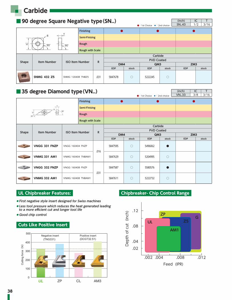
Carbide■ 90 degree Square Negative type(SN..) (inch) IC T
SN..43 1/2 3/16●:1st Choice ◦: 2nd choice
■ 35 degree Diamond type(VN..) (inch) IC TVN..33 3/8 3/16●:1st Choice ◦: 2nd choice
R T
IC 90° 90°
Finishing ● ● ●
Semi-Finising
Rough
Rough with Scale
Shape Item Number ISO Item Number R
CarbidePVD Coated
DM4 QM3 ZM3EDP stock EDP stock EDP stock
SNMG 432 Z5 SNMG 120408 TNBZ5 .031 5847678 ○ 5222245 ○
90°
35°
IC
R
T
Finishing ● ● ●
Semi-Finising
Rough
Rough with Scale
Shape Item Number ISO Item Number R
CarbidePVD Coated
DM4 QM3 ZM3EDP stock EDP stock EDP stock
VNGG 331 FNZP VNGG 160404 FNZP
.016
5847595 ○ 5496062 ●
VNMG 331 AM1 VNMG 160404 TNBAM1 5847629 ○ 5204995 ○
VNGG 332 FNZP VNGG 160408 FNZP
.031
5847587 ○ 5580576 ●
VNMG 332 AM1 VNMG 160408 TNBAM1 5847611 ○ 5222732 ○
UL Chipbreaker Features:
Cuts Like Positive Insert
Chipbreaker- Chip Control Range◦ First negative style insert designed for Swiss machines◦ Less tool pressure which reduces the heat generated leading
to a more efficient cut and longer tool life◦ Good chip control
()
UL ZP CL AM3
ZP
UL Z5G
.12
.08
.04
.02
.002Feed (IPR)
Dep
th o
f cut
(in
ch)
.012.008.004
AM1

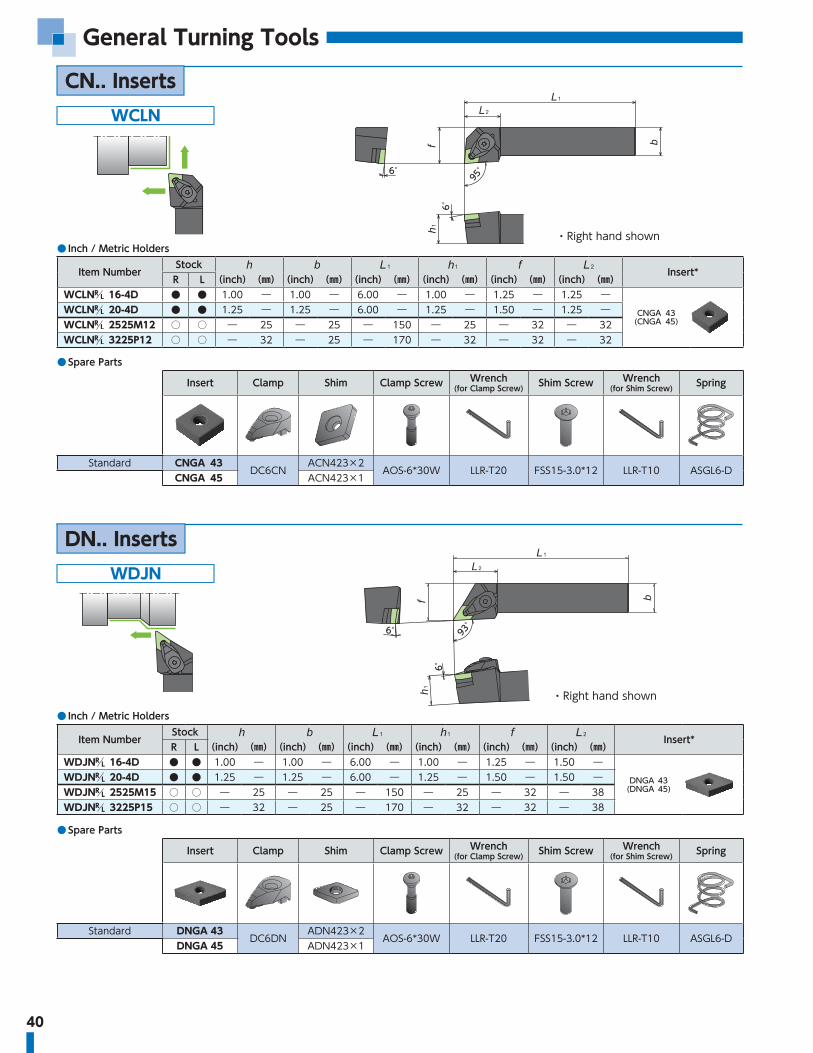
General Turning Tools
40
General Turning Tools
WCLN
● Inch / Metric Holders
Item NumberStock
Insert*R L (inch)(㎜)(inch)(㎜)(inch)(㎜)(inch)(㎜)(inch)(㎜)(inch)(㎜)
WCLN 16-4D ● ● 1.00 ― 1.00 ― 6.00 ― 1.00 ― 1.25 ― 1.25 ―CNGA 43
(CNGA 45)WCLN 20-4D ● ● 1.25 ― 1.25 ― 6.00 ― 1.25 ― 1.50 ― 1.25 ―WCLN 2525M12 ○ ○ ― 25 ― 25 ― 150 ― 25 ― 32 ― 32WCLN 3225P12 ○ ○ ― 32 ― 25 ― 170 ― 32 ― 32 ― 32
● Spare Parts
Insert Clamp Shim Clamp Screw Wrench (for Clamp Screw) Shim Screw Wrench
(for Shim Screw) Spring
Standard CNGA 43DC6CN
ACN423×2AOS-6*30W LLR-T20 FSS15-3.0*12 LLR-T10 ASGL6-D
CNGA 45 ACN423×1
6°
6°
95°
・ Right hand shown
CN.. Inserts
WDJN
● Inch / Metric Holders
Item NumberStock
Insert*R L (inch)(㎜)(inch)(㎜)(inch)(㎜)(inch)(㎜)(inch)(㎜)(inch)(㎜)
WDJN 16-4D ● ● 1.00 ― 1.00 ― 6.00 ― 1.00 ― 1.25 ― 1.50 ―DNGA 43
(DNGA 45)WDJN 20-4D ● ● 1.25 ― 1.25 ― 6.00 ― 1.25 ― 1.50 ― 1.50 ―WDJN 2525M15 ○ ○ ― 25 ― 25 ― 150 ― 25 ― 32 ― 38WDJN 3225P15 ○ ○ ― 32 ― 25 ― 170 ― 32 ― 32 ― 38
● Spare Parts
Insert Clamp Shim Clamp Screw Wrench (for Clamp Screw) Shim Screw Wrench
(for Shim Screw) Spring
Standard DNGA 43DC6DN
ADN423×2AOS-6*30W LLR-T20 FSS15-3.0*12 LLR-T10 ASGL6-D
DNGA 45 ADN423×1
6°
6°
93°
・ Right hand shown
DN.. Inserts

41●:Stock RL:Stock(Right / Left-hand only) ○: 1-2 week delivery ⓇⓁ:1-2 week delivery(Right / Left-hand only)●:Stock(Newly added) RL:Stock(Right / Left-hand only, Newly added) ○: 1-2 week delivery(Newly added) ⓇⓁ:1-2 week delivery(Right / Left-hand only, Newly added) ■□RL:While stocks last M :Mirror finish :Coolant through
WDHN
● Inch / Metric Holders
Item NumberStock
Insert*R L (inch)(㎜)(inch)(㎜)(inch)(㎜)(inch)(㎜)(inch)(㎜)(inch)(㎜)
WDHN 16-4D ● ● 1.00 ― 1.25 ― 6.00 ― 1.00 ― 1.25 ― 1.38 ―DNGA 43
(DNGA 45)WDHN 20-4D 1.00 ― 1.25 ― 6.00 ― 1.25 ― 1.50 ― 1.38 ―WDHN 2525M15 ○ ○ ― 25 ― 25 ― 150 ― 25 ― 32 ― 35
● Spare Parts
Insert Clamp Shim Clamp Screw Wrench (for Clamp Screw) Shim Screw Wrench
(for Shim Screw) Spring
Standard DNGA 43DC6DN
ADN423×2AOS-6*30W LLR-T20 FSS15-3.0*12 LLR-T10 ASGL6-D
DNGA 45 ADN423×1
8°
8°
107°30'
・ Right hand shown
WDNN
● Inch / Metric Holders
Item Number Stock Insert*(inch)(㎜)(inch)(㎜)(inch)(㎜)(inch)(㎜)(inch)(㎜)(inch)(㎜)WDNNN 16-4D ● 1.00 ― 1.00 ― 6.00 ― 1.00 ― .500 ― 1.67 ―
DNGA 43(DNGA 45)WDNNN 20-4D 1.25 ― 1.25 ― 6.00 ― 1.25 ― .625 ― 1.67 ―
WDNNN 2525M15 ○ ― 25 ― 25 ― 150 ― 25 ― 12.5 ― 42.5
● Spare Parts
Insert Clamp Shim Clamp Screw Wrench (for Clamp Screw) Shim Screw Wrench
(for Shim Screw) Spring
Standard DNGA 43DC6DN
ADN423×2AOS-6*30W LLR-T20 FSS15-3.0*12 LLR-T10 ASGL6-D
DNGA 45 ADN423×1
10°
62°30'

42
General Turning ToolsWSDN
45°
8°
・ Right hand shown
8°
45°
WSSN
● Inch / Metric Holders
Item NumberStock
Insert*R L inch ㎜ inch ㎜ inch ㎜ inch ㎜ inch ㎜ inch ㎜
WSSN 16-4D ● ● 1.00 ― 1.00 ― 6.00 ― 1.00 ― 1.25 ― 1.38 ―SNGA 43
(SNGA 45)WSSN 20-4D 1.25 ― 1.25 ― 6.00 ― 1.25 ― 1.50 ― 1.38 ―WSSN 2525M12 ● ○ ― 25 ― 25 ― 150 ― 25 ― 32 ― 35
Item Number Stock Insert*inch ㎜ inch ㎜ inch ㎜ inch ㎜ inch ㎜ inch ㎜
WSDNN 16-4D ● 1.00 ― 1.00 ― 6.00 ― 1.00 ― .500 ― 1.42 ―SNGA 43
(SNGA 45)WSDNN 20-4D 1.25 ― 1.25 ― 6.00 ― 1.25 ― .625 ― 1.42 ―WSDNN 2525M12 ○ ― 25 ― 25 ― 150 ― 25 ― 12.5 ― 35WSDNN 3225P12 ○ ― 32 ― 25 ― 170 ― 32 ― 12.5 ― 35
● Spare PartsInsert Clamp Shim Clamp Screw Wrench
(for Clamp Screw) Shim Screw Wrench (for Shim Screw) Spring
Standard SNGA 43DC6CN
ASN423×2AOS-6*30W LLR-T20 FSS15-3.0*12 LLR-T10 ASGL6-D
SNGA 45 ASN423×1
・ Right hand shown
CRGN
● Inch Holders
Item NumberStock Dimensions (inch)
Insert*R L
CRGN 164 CD ● ● 1.00 1.00 6.00 1.00 1.25 1.34 RNG 45(RNG 43)CRGN 204 CD ● ● 1.25 1.25 6.00 1.25 1.50 1.34
CRGN 165 CD ● ● 1.00 1.00 6.00 1.00 1.25 1.34RNG 55
CRGN 205 CD ● ● 1.25 1.25 6.00 1.25 1.50 1.34
CRGN 206 CD ● ● 1.25 1.25 6.00 1.25 1.50 1.65 RNG 65
● Spare PartsInsert Clamp Blade Shim Shim Screw Wrench
Standard RNG 452413
9414
IRSN 431160
LW-4RNG 43 IRSN 45 (OP)
Standard RNG 55 IRSN 53 1180Standard RNG 65 2417 3919 1182
RN.. Inserts

43●:Stock RL:Stock(Right / Left-hand only) ○: 1-2 week delivery ⓇⓁ:1-2 week delivery(Right / Left-hand only)●:Stock(Newly added) RL:Stock(Right / Left-hand only, Newly added) ○: 1-2 week delivery(Newly added) ⓇⓁ:1-2 week delivery(Right / Left-hand only, Newly added) ■□RL:While stocks last M :Mirror finish :Coolant through
RCGX/RPGX InsertsGTWP-H
GKWP-H
Edge height
.945"(24)
Edge height
Right-Hand style shown
● Toolholder Body
Holder NumberStock
DimensionsBlade
Spare Parts
Clamp Screw WrenchR L (Inch) (㎜) (Inch) (㎜) (Inch) (㎜) (Inch) (㎜) (Inch) (㎜) (Inch) (㎜) (Inch) (㎜)
GTWP 16-IN-H ● ● 1.000 ― 1.000 ― 1.000 ― 5.311 134.9 0.567 14.4 0.260 6.6 0.965 24.5 GBRR/L FSI28-6.0×18 LW-4
GTWP 20-IN-H ● ● 1.250 ― 1.250 ― 1.250 ― 6.311 160.3 0.817 20.75 ― ― ― ― GBRR/L FSI28-6.0×18 LW-4
GTWP 24-IN-H 1.500 ― 1.500 ― 1.500 ― 6.311 160.3 1.067 27.1 ― ― ― ― GBRR/L FSI28-6.0×18 LW-4
GTWP 32-IN-H 2.000 ― 2.000 ― 2.000 ― 6.311 160.3 1.567 39.8 ― ― ― ― GBRR/L FSI28-6.0×18 LW-4
GTWP 2020-H ○ ○ 0.787 20.0 0.787 20.0 0.787 20.0 4.232 107.5 0.354 9 0.315 8 1.122 28.5 GBRR/L FSI28-6.0×18 LW-4
GTWP 2525-H ● ● 0.984 25.0 0.984 25.0 0.984 25.0 5.217 132.5 0.551 14 0.276 7 0.965 24.5 GBRR/L FSI28-6.0×18 LW-4
GTWP 3232-H ○ ○ 1.260 32.0 1.000 32.0 1.260 32.0 6.004 152.5 0.827 21 ― ― ― ― GBRR/L FSI28-6.0×18 LW-4
Straight style toolholder
L-style toolholder
● Toolholder Body
Holder NumberStock
DimensionsBlade
Spare Parts
Clamp Screw WrenchR L (Inch) (㎜) (Inch) (㎜) (Inch) (㎜) (Inch) (㎜) (Inch) (㎜) (Inch) (㎜)
GKWP 16-IN-H ● ● 1.000 ― 1.000 ― 1.000 ― 5.961 151.4 0.260 6.6 0.260 6.6 GBRR/L FSI28-6.0×18 LW-4
GKWP 20-IN-H ● ● 1.250 ― 1.250 ― 1.250 ― 6.961 176.8 ― ― ― ― GBRR/L FSI28-6.0×18 LW-4
GKWP 2020-H ○ ○ 0.787 20.0 0.787 20.0 0.787 20.0 4.882 124 0.472 12 0.315 8 GBRR/L FSI28-6.0×18 LW-4
GKWP 2525-H ● ● 0.984 25.0 0.984 25.0 0.984 25.0 5.866 149 0.276 7 0.276 7 GBRR/L FSI28-6.0×18 LW-4
GKWP 3232-H ○ ○ 1.260 32.0 1.000 32.0 1.260 32.0 6.654 169 ― ― ― ― GBRR/L FSI28-6.0×18 LW-4
Right-Hand style shown*Use opposite hand blade

44
General Turning Tools
GBR
● Right hand
Hand Blade number Stock InsertDimensions (Inch)
HolderDimensions (Inch)
GTWPR-H GKWPL-H
R
GBRR-R23-19 ● RCGX23RPGX23 .750 .889
GTWPR16-IN-H6.200 1.854 1.118 6.000 1.889
GKWPL16-IN-HGTWPR20-IN-H
7.200 ― 1.368 7.000 2.139GKWPL20-IN-HGTWPR2020-H
5.121 2.011 .906 4.921 1.676GKWPL2020-HGTWPR2525-H
6.106 1.854 1.102 5.906 1.873GKWPL2525-HGTWPR3232-H
6.893 ― 1.378 6.693 2.149GKWPL3232-H
GBRR-R35-25 ●RCGX35RPGX35RCGX103
1.000 1.089
GTWPR16-IN-H6.400 2.054 1.118 6.000 2.089
GKWPL16-IN-HGTWPR20-IN-H
7.400 ― 1.368 7.000 2.339GKWPL20-IN-HGTWPR2020-H
5.321 2.211 .906 4.921 1.876GKWPL2020-HGTWPR2525-H
6.306 2.054 1.102 5.906 2.073GKWPL2525-HGTWPR3232-H
7.093 ― 1.378 6.693 2.349GKWPL3232-H
GBRR-R45-28 ●RCGX45RPGX45RCGX104
1.125 1.189
GTWPR16-IN-H6.500 2.154 1.118 6.000 2.189
GKWPL16-IN-HGTWPR20-IN-H
7.500 ― 1.368 7.000 2.439GKWPL20-IN-HGTWPR2020-H
5.421 2.311 .906 4.921 1.976GKWPL2020-HGTWPR2525-H
6.406 2.154 1.102 5.906 2.173GKWPL2525-HGTWPR3232-H
7.193 ― 1.378 6.693 2.449GKWPL3232-H
Blade
For GKWPFor GTWP

45●:Stock RL:Stock(Right / Left-hand only) ○: 1-2 week delivery ⓇⓁ:1-2 week delivery(Right / Left-hand only)●:Stock(Newly added) RL:Stock(Right / Left-hand only, Newly added) ○: 1-2 week delivery(Newly added) ⓇⓁ:1-2 week delivery(Right / Left-hand only, Newly added) ■□RL:While stocks last M :Mirror finish :Coolant through
● Left hand
Hand Blade number Stock InsertDimensions (Inch)
HolderDimensions (Inch)
GTWPL-H GKWPL-H
L
GBRL-R23-19 ● RCGX23RPGX23 .750 .889
GTWPL16-IN-H6.200 1.854 1.118 6.000 1.889
GKWPR16-IN-HGTWPL20-IN-H
7.200 ― 1.368 7.000 2.139GKWPR20-IN-HGTWPL2020-H
5.121 2.011 .906 4.921 1.676GKWPR2020-HGTWPL2525-H
6.106 1.854 1.102 5.906 1.873GKWPR2525-HGTWPL3232-H
6.893 ― 1.378 6.693 2.149GKWPR3232-H
GBRL-R35-25 ●RCGX35RPGX35RCGX103
1.000 1.089
GTWPL16-IN-H6.400 2.054 1.118 6.000 2.089
GKWPR16-IN-HGTWPL20-IN-H
7.400 ― 1.368 7.000 2.339GKWPR20-IN-HGTWPL2020-H
5.321 2.211 .906 4.921 1.876GKWPR2020-HGTWPL2525-H
6.306 2.054 1.102 5.906 2.073GKWPR2525-HGTWPL3232-H
7.093 ― 1.378 6.693 2.349GKWPR3232-H
GBRL-R45-28 ●RCGX45RPGX45RCGX104
1.125 1.189
GTWPL16-IN-H6.500 2.154 1.118 6.000 2.189
GKWPR16-IN-HGTWPL20-IN-H
7.500 ― 1.368 7.000 2.439GKWPR20-IN-HGTWPL2020-H
5.421 2.311 .906 4.921 1.976GKWPR2020-HGTWPL2525-H
6.406 2.154 1.102 5.906 2.173GKWPR2525-HGTWPL3232-H
7.193 ― 1.378 6.693 2.449GKWPR3232-H
For GTWP For GKWPGBR Blade

46
General Turning Tools
・ Right hand shown
VRAO
● Inch Holders
Item NumberStock Dimensions (inch)
InsertR L
VRAO 16-2D ● ● 1.00 1.00 6.00 1.00 1.00 RCGX 23RCGX 25RPGX 23RPGX 25VRAO 20-2D ● ● 1.25 1.25 6.00 1.25 1.00
VRAO 16-3D ● ● 1.00 1.00 6.00 1.00 1.25
RCGX 35RPGX 35VRAO 20-3D ● ● 1.25 1.25 6.00 1.25 1.25
VRAO 24-3E ● ● 1.50 1.50 7.00 1.50 1.25
VRAO 16-4D ● ● 1.00 1.00 6.00 1.00 1.50
RCGX 45RPGX 45VRAO 20-4D ● ● 1.25 1.25 6.00 1.25 1.50
VRAO 24-4E ● ● 1.50 1.50 7.00 1.50 1.50
RCGX / RPGX Inserts
● Spare PartsParts
Toolholder
Clamp Clamp Screw Shim Shim Screw
VRAO 16-2DCL2RVRL
(comes with screw)SM2RV(RCGX102 / R.GX25)
SM2RVS(R.GX23)(OP) SC02C-08VRAO 20-2D
VRAO 16-3D
CL3RV SC10F-10 SM3RV
SC05C-08
VRAO 20-3DSC05C-10
VRAO 24-3E
VRAO 16-4D
CL4RV SC40F-12 SM4RV
SC06C-08
VRAO 20-4DSC06C-10
VRAO 24-4E

47●:Stock RL:Stock(Right / Left-hand only) ○: 1-2 week delivery ⓇⓁ:1-2 week delivery(Right / Left-hand only)●:Stock(Newly added) RL:Stock(Right / Left-hand only, Newly added) ○: 1-2 week delivery(Newly added) ⓇⓁ:1-2 week delivery(Right / Left-hand only, Newly added) ■□RL:While stocks last M :Mirror finish :Coolant through
VRAON
● Inch Holders
Item Number StockDimensions (inch)
Insert
VRAON 16-2D ● 1.00 1.00 6.00 1.00 RCGX 23RCGX 25RPGX 23RPGX 25VRAON 20-2D ● 1.25 1.25 6.00 1.00
VRAON 16-3D ● 1.00 1.00 6.00 1.25RCGX 35RPGX 35VRAON 20-3D ● 1.25 1.25 6.00 1.25
VRAON 24-3E ● 1.50 1.50 7.00 1.25
VRAON 16-4D ● 1.00 1.00 6.00 1.50RCGX 45RPGX 45VRAON 20-4D ● 1.25 1.25 6.00 1.50
VRAON 24-4E ● 1.50 1.50 7.00 1.50
● Spare PartsParts
Toolholder
Clamp Shim Clamp Screw Shim Screw
VRAON 16-2D
CL2RV SM2RV(RCGX102 / R.GX25)SM2RVS(R.GX23)(OP) SC40F-16 SC02C-08
VRAON 20-2DVRAON 16-3D
CL3RV SM3RV SC10F-10SC05C-08
VRAON 20-3DSC05C-10
VRAON 24-3EVRAON 16-4D
CL4RV SM4RV SC40F-12SC06C-08
VRAON 20-4DSC06C-10
VRAON 24-4E
(CL2RV)

MEMO

49
Grooving / Side Turning Tools

50
Grooving / Side Turning Tools
Guideline for grooving HRSA materials
≧45° Work HardeningLayer
45°
When applying JX1/JX3, increase speed to over 1000 SFMWhen applying SX3/SX7/SX5, increase feed rates 100% vs. Whisker Ceramics
JX1 JX3 SX3 SX7 SX5 WA1
SpeedFeed
VersatilityToughness
Can run at up to 1500 SFM.Double the speed of whisker Double the feed of whisker Best for Scale and interruption Versatile grade
When machining a grooved area with multiple passes, the insert radius engages a potentially work hardened area during the last remaining plunge. This programming procedure sets up the potential of corner radius chipping or notching.
BIDEMICS / Ceramic grooving inserts provide high speed capability to your process. Whisker ceramic is the most versatile option in this category. NTK also offers BIDEMICS and SiAlON grades for more productivity and stability.
The grooving insert is plunged down both outside walls thus maintaining a good finish. The remaining material can be removed by using a stronger insert shape such as a RCGX style.
Change to
■ Application Information
:1st choice : 2nd choice
Application Grade Workmaterial
Cutting speed Feed Depth of cut Coolant600 800 1000 1200 1400 1600 .004 .008 .012 .016 .020 .020 .040 .060 .080 .100
GroovingJX1JX3 Overall
WET1200 (600-1600) SFM .003 (.002-.004) IPR
SX5 Waspaloy700 (600-800) SFM .006 (.003-.007) IPR
SX3SX7 Overall
750 (600-900) SFM .0045 (.003-.006) IPR
WA1 Overall800 (600-1100) SFM .003 (.002-.004) IPR
Application Grade Workmaterial
Cutting speed Feed Depth of cut Coolant100 150 200 250 300 350 .001 .002 .005 .010 .015 .020 .040 .060 .080 .100
Finishing DM4QM3ZM3
HRSAWET
75-225 SFM .002-.014 IPR
When using SX7/SX5, increase feed rates 100% vs. Whisker Ceramics
Width: .118-.157" Feed .002 - .006"Width: .157-.197" Feed .004 - .008"Width: > .197" Feed .006 - .014"

51●:Stock RL:Stock(Right / Left-hand only) ○: 1-2 week delivery ⓇⓁ:1-2 week delivery(Right / Left-hand only)●:Stock(Newly added) RL:Stock(Right / Left-hand only, Newly added) ○: 1-2 week delivery(Newly added) ⓇⓁ:1-2 week delivery(Right / Left-hand only, Newly added) ■□RL:While stocks last M :Mirror finish :Coolant through
GTWP-H
Groove DUO Blade Straight style toolholder
GKWP-H
Groove DUO Blade L-style toolholder
Edge height
Right-Hand style shown
● Toolholder Body
Holder NumberStock
DimensionsBlade
Spare Parts
Clamp Screw WrenchR L (Inch) (㎜) (Inch) (㎜) (Inch) (㎜) (Inch) (㎜) (Inch) (㎜) (Inch) (㎜) (Inch) (㎜)
GTWP 16-IN-H ● ● 1.000 ― 1.000 ― 1.000 ― 5.311 134.9 0.567 14.4 0.260 6.6 0.965 24.5 GBVR/L FSI28-6.0×18 LW-4GTWP 20-IN-H ● ● 1.250 ― 1.250 ― 1.250 ― 6.311 160.3 0.817 20.75 ― ― ― ― GBVR/L FSI28-6.0×18 LW-4GTWP 24-IN-H 1.500 ― 1.500 ― 1.500 ― 6.311 160.3 1.067 27.1 ― ― ― ― GBRR/L FSI28-6.0×18 LW-4GTWP 32-IN-H 2.000 ― 2.000 ― 2.000 ― 6.311 160.3 1.567 39.8 ― ― ― ― GBRR/L FSI28-6.0×18 LW-4GTWP 2020-H ○ ○ 0.787 20.0 0.787 20.0 0.787 20.0 4.232 107.5 0.354 9 0.315 8 1.122 28.5 GBVR/L FSI28-6.0×18 LW-4GTWP 2525-H ● ● 0.984 25.0 0.984 25.0 0.984 25.0 5.217 132.5 0.551 14 0.276 7 0.965 24.5 GBVR/L FSI28-6.0×18 LW-4GTWP 3232-H ○ ○ 1.260 32.0 1.000 32.0 1.260 32.0 6.004 152.5 0.827 21 ― ― ― ― GBVR/L FSI28-6.0×18 LW-4
.945"(24)
Edge height
● Toolholder Body
Holder NumberStock
DimensionsBlade
Spare Parts
Clamp Screw WrenchR L (Inch) (㎜) (Inch) (㎜) (Inch) (㎜) (Inch) (㎜) (Inch) (㎜) (Inch) (㎜)
GKWP 16-IN-H ● ● 1.000 ― 1.000 ― 1.000 ― 5.961 151.4 0.260 6.6 0.260 6.6 GBVR/L FSI28-6.0×18 LW-4GKWP 20-IN-H ● ● 1.250 ― 1.250 ― 1.250 ― 6.961 176.8 ― ― ― ― GBVR/L FSI28-6.0×18 LW-4GKWP 2020-H ○ ○ 0.787 20.0 0.787 20.0 0.787 20.0 4.882 124 0.472 12 0.315 8 GBVR/L FSI28-6.0×18 LW-4GKWP 2525-H ● ● 0.984 25.0 0.984 25.0 0.984 25.0 5.866 149 0.276 7 0.276 7 GBVR/L FSI28-6.0×18 LW-4GKWP 3232-H ○ ○ 1.260 32.0 1.000 32.0 1.260 32.0 6.654 169 ― ― ― ― GBVR/L FSI28-6.0×18 LW-4
Right-Hand style shown*Use opposite hand blade

52
Grooving / Side Turning Tools
VGW
Blade for Straight Grooving
● Right hand
Hand Blade number Stock InsertDimensions (inch)
Holder InsertDimensions (inch)
GTWPR-H GKWPL-H
R
GBVR-VGW4-3T09 ● VGW4125 VGW4156 .375 .441
GTWPR16-IN-H VGW4125 5.750 1.404 1.090 5.972 1.439GKWPL16-IN-H VGW4156 1.106 5.987GTWPR20-IN-H VGW4125 6.750 ― 1.340 6.972 1.689GKWPL20-IN-H VGW4156 1.356 6.987GTWPR2020-H VGW4125 4.671 1.561 0.878 4.893 1.226GKWPL2020-H VGW4156 0.893 4.909GTWPR2525-H VGW4125 5.656 1.404 1.074 5.878 1.423GKWPL2525-H VGW4156 1.090 5.893GTWPR3232-H VGW4125 6.443 ― 1.350 6.665 1.699GKWPL3232-H VGW4156 1.365 6.680
GBVR-VGW4-4T14 ● VGW4156 VGW4187 .562 .689
GTWPR16-IN-H VGW4156 6.000 1.654 1.094 5.976 1.689GKWPL16-IN-H VGW4187 1.109 5.991GTWPR20-IN-H VGW4156 7.000 ― 1.344 6.976 1.939GKWPL20-IN-H VGW4187 1.359 6.991GTWPR2020-H VGW4156 4.921 1.811 0.881 4.897 1.476GKWPL2020-H VGW4187 0.897 4.913GTWPR2525-H VGW4156 5.906 1.654 1.078 5.881 1.673GKWPL2525-H VGW4187 1.094 5.897GTWPR3232-H VGW4156 6.693 ― 1.354 6.669 1.949GKWPL3232-H VGW4187 1.369 6.684
GBVR-VGW6-6T14 ● VGW6218 VGW6250 .562 .689
GTWPR16-IN-H VGW6218 6.000 1.654 1.109 5.991 1.689GKWPL16-IN-H VGW6250 1.125 6.007GTWPR20-IN-H VGW6218 7.000 ― 1.359 6.991 1.939GKWPL20-IN-H VGW6250 1.375 7.007GTWPR2020-H VGW6218 4.921 1.811 0.897 4.913 1.476GKWPL2020-H VGW6250 0.913 4.928GTWPR2525-H VGW6218 5.906 1.654 1.094 5.897 1.673GKWPL2525-H VGW6250 1.109 5.913GTWPR3232-H VGW6218 6.693 ― 1.369 6.684 1.949GKWPL3232-H VGW6250 1.385 6.700
GBVR-VGW6-6T19 ● VGW6250 VGW6281 .750 .890
GTWPR16-IN-H VGW6250 6.200 1.854 1.106 5.987 1.889GKWPL16-IN-H VGW6281 1.121 6.003GTWPR20-IN-H VGW6250 7.200 ― 1.356 6.987 2.139GKWPL20-IN-H VGW6281 1.371 7.003GTWPR2020-H VGW6250 5.121 2.011 0.893 4.909 1.676GKWPL2020-H VGW6281 0.908 4.924GTWPR2525-H VGW6250 6.106 1.854 1.090 5.893 1.873GKWPL2525-H VGW6281 1.105 5.908GTWPR3232-H VGW6250 6.893 ― 1.365 6.680 2.149GKWPL3232-H VGW6281 1.381 6.696
GBVR-VGW8-8T19 ● VGW8312 VGW8344 .750 1.089
GTWPR16-IN-H VGW8312 6.400 2.054 1.138 6.020 2.089GKWPL16-IN-H VGW8344 1.154 6.036GTWPR20-IN-H VGW8312 7.400 ― 1.388 7.020 2.339GKWPL20-IN-H VGW8344 1.404 7.036GTWPR2020-H VGW8312 5.321 2.211 0.926 4.941 1.876GKWPL2020-H VGW8344 0.942 4.957GTWPR2525-H VGW8312 6.306 2.054 1.122 5.926 2.073GKWPL2525-H VGW8344 1.139 5.942GTWPR3232-H VGW8312 7.093 ― 1.398 6.713 2.349GKWPL3232-H VGW8344 1.414 6.729
GBVR-VGW8-8T28 ● VGW8344 VGW8375 1.125 1.189
GTWPR16-IN-H VGW8344 6.500 2.154 1.133 6.015 2.189GKWPL16-IN-H VGW8375 1.148 6.030GTWPR20-IN-H VGW8344 7.500 ― 1.383 7.015 2.439GKWPL20-IN-H VGW8375 1.398 7.030GTWPR2020-H VGW8344 5.421 2.311 0.920 4.936 1.976GKWPL2020-H VGW8375 0.935 4.951GTWPR2525-H VGW8344 6.406 2.154 1.117 5.920 2.173GKWPL2525-H VGW8375 1.132 5.935GTWPR3232-H VGW8344 7.193 ― 1.393 6.707 2.449GKWPL3232-H VGW8375 1.408 6.723
For GTWP For GKWP

53●:Stock RL:Stock(Right / Left-hand only) ○: 1-2 week delivery ⓇⓁ:1-2 week delivery(Right / Left-hand only)●:Stock(Newly added) RL:Stock(Right / Left-hand only, Newly added) ○: 1-2 week delivery(Newly added) ⓇⓁ:1-2 week delivery(Right / Left-hand only, Newly added) ■□RL:While stocks last M :Mirror finish :Coolant through
● Left hand
Hand Blade number Stock InsertDimensions (inch)
Holder InsertDimensions (inch)
GTWPL-H GKWPR-H
L
GBVL-VGW4-3T09 ● VGW4125 VGW4156 .375 .441
GTWPL16-IN-H VGW4125 5.750 1.404 1.090 5.972 1.439GKWPR16-IN-H VGW4156 1.106 5.987GTWPL20-IN-H VGW4125 6.750 ― 1.340 6.972 1.689GKWPR20-IN-H VGW4156 1.356 6.987GTWPL2020-H VGW4125 4.671 1.561 0.878 4.893 1.226GKWPR2020-H VGW4156 0.893 4.909GTWPL2525-H VGW4125 5.656 1.404 1.074 5.878 1.423GKWPR2525-H VGW4156 1.090 5.893GTWPL3232-H VGW4125 6.443 ― 1.350 6.665 1.699GKWPR3232-H VGW4156 1.365 6.680
GBVL-VGW4-4T14 ● VGW4156 VGW4187 .562 .689
GTWPL16-IN-H VGW4156 6.000 1.654 1.094 5.976 1.689GKWPR16-IN-H VGW4187 1.109 5.991GTWPL20-IN-H VGW4156 7.000 ― 1.344 6.976 1.939GKWPR20-IN-H VGW4187 1.359 6.991GTWPL2020-H VGW4156 4.921 1.811 0.881 4.897 1.476GKWPR2020-H VGW4187 0.897 4.913GTWPL2525-H VGW4156 5.906 1.654 1.078 5.881 1.673GKWPR2525-H VGW4187 1.094 5.897GTWPL3232-H VGW4156 6.693 ― 1.354 6.669 1.949GKWPR3232-H VGW4187 1.369 6.684
GBVL-VGW6-6T14 ● VGW6218 VGW6250 .562 .689
GTWPL16-IN-H VGW6218 6.000 1.654 1.109 5.991 1.689GKWPR16-IN-H VGW6250 1.125 6.007GTWPL20-IN-H VGW6218 7.000 ― 1.359 6.991 1.939GKWPR20-IN-H VGW6250 1.375 7.007GTWPL2020-H VGW6218 4.921 1.811 0.897 4.913 1.476GKWPR2020-H VGW6250 0.913 4.928GTWPL2525-H VGW6218 5.906 1.654 1.094 5.897 1.673GKWPR2525-H VGW6250 1.109 5.913GTWPL3232-H VGW6218 6.693 ― 1.369 6.684 1.949GKWPR3232-H VGW6250 1.385 6.700
GBVL-VGW6-6T19 ● VGW6250 VGW6281 .750 .890
GTWPL16-IN-H VGW6250 6.200 1.854 1.106 5.987 1.889GKWPR16-IN-H VGW6281 1.121 6.003GTWPL20-IN-H VGW6250 7.200 ― 1.356 6.987 2.139GKWPR20-IN-H VGW6281 1.371 7.003GTWPL2020-H VGW6250 5.121 2.011 0.893 4.909 1.676GKWPR2020-H VGW6281 0.908 4.924GTWPL2525-H VGW6250 6.106 1.854 1.090 5.893 1.873GKWPR2525-H VGW6281 1.105 5.908GTWPL3232-H VGW6250 6.893 ― 1.365 6.680 2.149GKWPR3232-H VGW6281 1.381 6.696
GBVL-VGW8-8T19 ● VGW8312 VGW8344 .750 1.089
GTWPL16-IN-H VGW8312 6.400 2.054 1.138 6.020 2.089GKWPR16-IN-H VGW8344 1.154 6.036GTWPL20-IN-H VGW8312 7.400 ― 1.388 7.020 2.339GKWPR20-IN-H VGW8344 1.404 7.036GTWPL2020-H VGW8312 5.321 2.211 0.926 4.941 1.876GKWPR2020-H VGW8344 0.942 4.957GTWPL2525-H VGW8312 6.306 2.054 1.122 5.926 2.073GKWPR2525-H VGW8344 1.139 5.942GTWPL3232-H VGW8312 7.093 ― 1.398 6.713 2.349GKWPR3232-H VGW8344 1.414 6.729
GBVL-VGW8-8T28 ● VGW8344 VGW8375 1.125 1.189
GTWPL16-IN-H VGW8344 6.500 2.154 1.133 6.015 2.189GKWPR16-IN-H VGW8375 1.148 6.030GTWPL20-IN-H VGW8344 7.500 ― 1.383 7.015 2.439GKWPR20-IN-H VGW8375 1.398 7.030GTWPL2020-H VGW8344 5.421 2.311 0.920 4.936 1.976GKWPR2020-H VGW8375 0.935 4.951GTWPL2525-H VGW8344 6.406 2.154 1.117 5.920 2.173GKWPR2525-H VGW8375 1.132 5.935GTWPL3232-H VGW8344 7.193 ― 1.393 6.707 2.449GKWPR3232-H VGW8375 1.408 6.723
For GTWP For GKWP

54
Grooving / Side Turning Tools
Blade for Face Grooving
● Right hand
Curve Blade number Stock Insert O.D. rangeDimensions (inch)
Holder InsertDimensions (inch)
GTWPR-H GKWPL-H
in
GBI-VGW4R3T15-101177 ● VGW4125VGW4156 4"-7" .600 .829
GTWPR16-IN-H VGW4125 6.000 1.909 1.055 5.937 1.949GKWPL16-IN-H VGW4156 1.070 5.952GTWPR20-IN-H VGW4125 7.000 1.909 1.305 6.937 1.939GKWPL20-IN-H VGW4156 1.320 6.952GTWPR2020-H VGW4125 4.921 1.909 0.842 4.858 1.949GKWPL2020-H VGW4156 0.857 4.873GTWPR2525-H VGW4125 5.906 1.909 1.039 5.842 1.949GKWPL2525-H VGW4156 1.054 5.857GTWPR3232-H VGW4125 6.693 1.909 1.315 6.630 1.949GKWPL3232-H VGW4156 1.330 6.645
GBI-VGW4R3T15-177999 ● VGW4125VGW4156 7" and over .600 .829
GTWPR16-IN-H VGW4125 6.000 1.909 1.055 5.937 1.949GKWPL16-IN-H VGW4156 1.070 5.952GTWPR20-IN-H VGW4125 7.000 1.909 1.305 6.937 1.939GKWPL20-IN-H VGW4156 1.320 6.952GTWPR2020-H VGW4125 4.921 1.909 0.842 4.858 1.949GKWPL2020-H VGW4156 0.857 4.873GTWPR2525-H VGW4125 5.906 1.909 1.039 5.842 1.949GKWPL2525-H VGW4156 1.054 5.857GTWPR3232-H VGW4125 6.693 1.909 1.315 6.630 1.949GKWPL3232-H VGW4156 1.330 6.645
GBI-VGW4R4T15-101177 ● VGW4156VGW4187 4"-7" .600 .829
GTWPR16-IN-H VGW4156 6.000 1.909 1.058 5.940 1.949GKWPL16-IN-H VGW4187 1.074 5.956GTWPR20-IN-H VGW4156 7.000 1.909 1.308 6.940 1.939GKWPL20-IN-H VGW4187 1.324 6.956GTWPR2020-H VGW4156 4.921 1.909 0.846 4.861 1.949GKWPL2020-H VGW4187 0.861 4.877GTWPR2525-H VGW4156 5.906 1.909 1.043 5.846 1.949GKWPL2525-H VGW4187 1.058 5.861GTWPR3232-H VGW4156 6.693 1.909 1.318 6.633 1.949GKWPL3232-H VGW4187 1.334 6.649
GBI-VGW4R4T15-177999 ● VGW4156VGW4187 7" and over .600 .829
GTWPR16-IN-H VGW4156 6.000 1.909 1.058 5.940 1.949GKWPL16-IN-H VGW4187 1.074 5.956GTWPR20-IN-H VGW4156 7.000 1.909 1.308 6.940 1.939GKWPL20-IN-H VGW4187 1.324 6.956GTWPR2020-H VGW4156 4.921 1.909 0.846 4.861 1.949GKWPL2020-H VGW4187 0.861 4.877GTWPR2525-H VGW4156 5.906 1.909 1.043 5.846 1.949GKWPL2525-H VGW4187 1.058 5.861GTWPR3232-H VGW4156 6.693 1.909 1.318 6.633 1.949GKWPL3232-H VGW4187 1.334 6.649
GBI-VGW6R6T15-101177 ● VGW6218VGW6250 4"-7" .600 .829
GTWPR16-IN-H VGW6218 6.000 1.909 1.078 5.960 1.949GKWPL16-IN-H VGW6250 1.094 5.976GTWPR20-IN-H VGW6218 7.000 1.909 1.328 6.960 1.939GKWPL20-IN-H VGW6250 1.344 6.976GTWPR2020-H VGW6218 4.921 1.909 0.865 4.881 1.949GKWPL2020-H VGW6250 0.881 4.897GTWPR2525-H VGW6218 5.906 1.909 1.062 5.865 1.949GKWPL2525-H VGW6250 1.078 5.881GTWPR3232-H VGW6218 6.693 1.909 1.338 6.653 1.949GKWPL3232-H VGW6250 1.354 6.669
GBI-VGW6R6T15-177999 ● VGW6218VGW6250 7" and over .600 .829
GTWPR16-IN-H VGW6218 6.000 1.909 1.082 5.964 1.949GKWPL16-IN-H VGW6250 1.098 5.980GTWPR20-IN-H VGW6218 7.000 1.909 1.332 6.964 1.939GKWPL20-IN-H VGW6250 1.348 6.980GTWPR2020-H VGW6218 4.921 1.909 0.869 4.885 1.949GKWPL2020-H VGW6250 0.885 4.901GTWPR2525-H VGW6218 5.906 1.909 1.066 5.869 1.949GKWPL2525-H VGW6250 1.082 5.885GTWPR3232-H VGW6218 6.693 1.909 1.342 6.657 1.949GKWPL3232-H VGW6250 1.357 6.672
φ max φ min
VGW For GTWP For GKWP

55●:Stock RL:Stock(Right / Left-hand only) ○: 1-2 week delivery ⓇⓁ:1-2 week delivery(Right / Left-hand only)●:Stock(Newly added) RL:Stock(Right / Left-hand only, Newly added) ○: 1-2 week delivery(Newly added) ⓇⓁ:1-2 week delivery(Right / Left-hand only, Newly added) ■□RL:While stocks last M :Mirror finish :Coolant through
● Right hand
Curve Blade number Stock Insert O.D. rangeDimensions (inch)
Holder InsertDimensions (inch)
GTWPL-H GKWPR-H
out
GBO-VGW4R3T15-101177 ● VGW4125VGW4156 4"-7" .600 .829
GTWPR16-IN-H VGW4125 6.000 1.909 1.055 5.937 1.949GKWPL16-IN-H VGW4156 1.070 5.952GTWPR20-IN-H VGW4125 7.000 1.909 1.305 6.937 1.939GKWPL20-IN-H VGW4156 1.320 6.952GTWPR2020-H VGW4125 4.921 1.909 0.842 4.858 1.949GKWPL2020-H VGW4156 0.857 4.873GTWPR2525-H VGW4125 5.906 1.909 1.039 5.842 1.949GKWPL2525-H VGW4156 1.054 5.857GTWPR3232-H VGW4125 6.693 1.909 1.315 6.630 1.949GKWPL3232-H VGW4156 1.330 6.645
GBO-VGW4R3T15-177999 ● VGW4125VGW4156 7" and over .600 .829
GTWPR16-IN-H VGW4125 6.000 1.909 1.094 5.976 1.949GKWPL16-IN-H VGW4156 1.109 5.991GTWPR20-IN-H VGW4125 7.000 1.909 1.344 6.976 1.939GKWPL20-IN-H VGW4156 1.359 6.991GTWPR2020-H VGW4125 4.921 1.909 0.881 4.897 1.949GKWPL2020-H VGW4156 0.897 4.913GTWPR2525-H VGW4125 5.906 1.909 1.078 5.881 1.949GKWPL2525-H VGW4156 1.094 5.897GTWPR3232-H VGW4125 6.693 1.909 1.354 6.669 1.949GKWPL3232-H VGW4156 1.369 6.684
GBO-VGW4R4T15-101177 ● VGW4156VGW4187 4"-7" .600 .829
GTWPR16-IN-H VGW4156 6.000 1.909 1.058 5.940 1.949GKWPL16-IN-H VGW4187 1.074 5.956GTWPR20-IN-H VGW4156 7.000 1.909 1.308 6.940 1.939GKWPL20-IN-H VGW4187 1.324 6.956GTWPR2020-H VGW4156 4.921 1.909 0.846 4.861 1.949GKWPL2020-H VGW4187 0.861 4.877GTWPR2525-H VGW4156 5.906 1.909 1.043 5.846 1.949GKWPL2525-H VGW4187 1.058 5.861GTWPR3232-H VGW4156 6.693 1.909 1.318 6.633 1.949GKWPL3232-H VGW4187 1.334 6.649
GBO-VGW4R4T15-177999 ● VGW4156VGW4187 7" and over .600 .829
GTWPR16-IN-H VGW4156 6.000 1.909 1.094 5.976 1.949GKWPL16-IN-H VGW4187 1.109 5.991GTWPR20-IN-H VGW4156 7.000 1.909 1.344 6.976 1.939GKWPL20-IN-H VGW4187 1.359 6.991GTWPR2020-H VGW4156 4.921 1.909 0.881 4.897 1.949GKWPL2020-H VGW4187 0.897 4.916GTWPR2525-H VGW4156 5.906 1.909 1.078 5.881 1.949GKWPL2525-H VGW4187 1.094 5.897GTWPR3232-H VGW4156 6.693 1.909 1.354 6.669 1.949GKWPL3232-H VGW4187 1.369 6.684
GBO-VGW6R6T15-101177 ● VGW6218VGW6250 4"-7" .600 .829
GTWPR16-IN-H VGW6218 6.000 1.909 1.078 5.960 1.949GKWPL16-IN-H VGW6250 1.094 5.976GTWPR20-IN-H VGW6218 7.000 1.909 1.328 6.960 1.939GKWPL20-IN-H VGW6250 1.344 6.976GTWPR2020-H VGW6218 4.921 1.909 0.865 4.881 1.949GKWPL2020-H VGW6250 0.881 4.897GTWPR2525-H VGW6218 5.906 1.909 1.062 5.865 1.949GKWPL2525-H VGW6250 1.078 5.881GTWPR3232-H VGW6218 6.693 1.909 1.338 6.653 1.949GKWPL3232-H VGW6250 1.354 6.669
GBO-VGW6R6T15-177999 ● VGW6218VGW6250 7" and over .600 .829
GTWPR16-IN-H VGW6218 6.000 1.909 1.082 5.964 1.949GKWPL16-IN-H VGW6250 1.098 5.980GTWPR20-IN-H VGW6218 7.000 1.909 1.332 6.964 1.939GKWPL20-IN-H VGW6250 1.348 6.980GTWPR2020-H VGW6218 4.921 1.909 0.869 4.885 1.949GKWPL2020-H VGW6250 0.885 4.901GTWPR2525-H VGW6218 5.906 1.909 1.066 5.869 1.949GKWPL2525-H VGW6250 1.082 5.885GTWPR3232-H VGW6218 6.693 1.909 1.342 6.657 1.949GKWPL3232-H VGW6250 1.357 6.672
φ max φ min
For GTWP For GKWP

56
Grooving / Side Turning Tools
Blade for Face Grooving
● Left hand
Curve Blade number Stock Insert O.D. rangeDimensions (inch)
Holder InsertDimensions (inch)
GTWPR-H GKWPL-H
in
GBI-VGW4L3T15-101177 ● VGW4125VGW4156 4"-7" .600 .829
GTWPR16-IN-H VGW4125 6.000 1.909 1.055 5.937 1.949GKWPL16-IN-H VGW4156 1.070 5.952GTWPR20-IN-H VGW4125 7.000 1.909 1.305 6.937 1.939GKWPL20-IN-H VGW4156 1.320 6.952GTWPR2020-H VGW4125 4.921 1.909 0.842 4.858 1.949GKWPL2020-H VGW4156 0.857 4.873GTWPR2525-H VGW4125 5.906 1.909 1.039 5.842 1.949GKWPL2525-H VGW4156 1.054 5.857GTWPR3232-H VGW4125 6.693 1.909 1.315 6.630 1.949GKWPL3232-H VGW4156 1.330 6.645
GBI-VGW4L3T15-177999 ● VGW4125VGW4156 7" and over .600 .829
GTWPR16-IN-H VGW4125 6.000 1.909 1.055 5.933 1.949GKWPL16-IN-H VGW4156 1.070 5.952GTWPR20-IN-H VGW4125 7.000 1.909 1.305 6.937 1.939GKWPL20-IN-H VGW4156 1.320 6.952GTWPR2020-H VGW4125 4.921 1.909 0.842 4.858 1.949GKWPL2020-H VGW4156 0.857 4.873GTWPR2525-H VGW4125 5.906 1.909 1.039 5.842 1.949GKWPL2525-H VGW4156 1.054 5.857GTWPR3232-H VGW4125 6.693 1.909 1.315 6.630 1.949GKWPL3232-H VGW4156 1.330 6.645
GBI-VGW4L4T15-101177 ● VGW4156VGW4187 4"-7" .600 .829
GTWPR16-IN-H VGW4156 6.000 1.909 1.058 5.940 1.949GKWPL16-IN-H VGW4187 1.074 5.956GTWPR20-IN-H VGW4156 7.000 1.909 1.308 6.940 1.939GKWPL20-IN-H VGW4187 1.324 6.956GTWPR2020-H VGW4156 4.921 1.909 0.846 4.861 1.949GKWPL2020-H VGW4187 0.861 4.877GTWPR2525-H VGW4156 5.906 1.909 1.043 5.846 1.949GKWPL2525-H VGW4187 1.058 5.861GTWPR3232-H VGW4156 6.693 1.909 1.318 6.633 1.949GKWPL3232-H VGW4187 1.334 6.649
GBI-VGW4L4T15-177999 ● VGW4156VGW4187 7" and over .600 .829
GTWPR16-IN-H VGW4156 6.000 1.909 1.058 5.940 1.949GKWPL16-IN-H VGW4187 1.074 5.956GTWPR20-IN-H VGW4156 7.000 1.909 1.308 6.940 1.939GKWPL20-IN-H VGW4187 1.324 6.956GTWPR2020-H VGW4156 4.921 1.909 0.846 4.861 1.949GKWPL2020-H VGW4187 0.861 4.877GTWPR2525-H VGW4156 5.906 1.909 1.043 5.846 1.949GKWPL2525-H VGW4187 1.058 5.861GTWPR3232-H VGW4156 6.693 1.909 1.318 6.633 1.949GKWPL3232-H VGW4187 1.334 6.649
GBI-VGW6L6T15-101177 ● VGW6218VGW6250 4"-7" .600 .829
GTWPR16-IN-H VGW6218 6.000 1.909 1.078 5.960 1.949GKWPL16-IN-H VGW6250 1.094 5.976GTWPR20-IN-H VGW6218 7.000 1.909 1.328 6.960 1.939GKWPL20-IN-H VGW6250 1.344 6.976GTWPR2020-H VGW6218 4.921 1.909 0.865 4.881 1.949GKWPL2020-H VGW6250 0.881 4.897GTWPR2525-H VGW6218 5.906 1.909 1.062 5.865 1.949GKWPL2525-H VGW6250 1.078 5.881GTWPR3232-H VGW6218 6.693 1.909 1.338 6.653 1.949GKWPL3232-H VGW6250 1.354 6.669
GBI-VGW6L6T15-177999 ● VGW6218VGW6250 7" and over .600 .829
GTWPR16-IN-H VGW6218 6.000 1.909 1.082 5.964 1.949GKWPL16-IN-H VGW6250 1.098 5.980GTWPR20-IN-H VGW6218 7.000 1.909 1.332 6.964 1.939GKWPL20-IN-H VGW6250 1.348 6.980GTWPR2020-H VGW6218 4.921 1.909 0.869 4.885 1.949GKWPL2020-H VGW6250 0.885 4.901GTWPR2525-H VGW6218 5.906 1.909 1.066 5.869 1.949GKWPL2525-H VGW6250 1.082 5.885GTWPR3232-H VGW6218 6.693 1.909 1.342 6.657 1.949GKWPL3232-H VGW6250 1.357 6.672
For GTWPVGW For GKWPφ max φ min

57●:Stock RL:Stock(Right / Left-hand only) ○: 1-2 week delivery ⓇⓁ:1-2 week delivery(Right / Left-hand only)●:Stock(Newly added) RL:Stock(Right / Left-hand only, Newly added) ○: 1-2 week delivery(Newly added) ⓇⓁ:1-2 week delivery(Right / Left-hand only, Newly added) ■□RL:While stocks last M :Mirror finish :Coolant through
● Left hand
Curve Blade number Stock Insert O.D. rangeDimensions (inch)
Holder InsertDimensions (inch)
GTWPL-H GKWPR-H
out
GBO-VGW4L3T15-101177 ● VGW4125VGW4156 4"-7" .600 .829
GTWPR16-IN-H VGW4125 6.000 1.909 1.055 5.937 1.949GKWPL16-IN-H VGW4156 1.070 5.952GTWPR20-IN-H VGW4125 7.000 1.909 1.305 6.937 1.939GKWPL20-IN-H VGW4156 1.320 6.952GTWPR2020-H VGW4125 4.921 1.909 0.842 4.858 1.949GKWPL2020-H VGW4156 0.857 4.873GTWPR2525-H VGW4125 5.906 1.909 1.039 5.842 1.949GKWPL2525-H VGW4156 1.054 5.857GTWPR3232-H VGW4125 6.693 1.909 1.315 6.630 1.949GKWPL3232-H VGW4156 1.330 6.645
GBO-VGW4L3T15-177999 ● VGW4125VGW4156 7" and over .600 .829
GTWPR16-IN-H VGW4125 6.000 1.909 1.094 5.976 1.949GKWPL16-IN-H VGW4156 1.109 5.991GTWPR20-IN-H VGW4125 7.000 1.909 1.344 6.976 1.939GKWPL20-IN-H VGW4156 1.359 6.991GTWPR2020-H VGW4125 4.921 1.909 0.881 4.897 1.949GKWPL2020-H VGW4156 0.897 4.913GTWPR2525-H VGW4125 5.906 1.909 1.078 5.881 1.949GKWPL2525-H VGW4156 1.094 5.897GTWPR3232-H VGW4125 6.693 1.909 1.354 6.669 1.949GKWPL3232-H VGW4156 1.369 6.684
GBO-VGW4L4T15-101177 ● VGW4156VGW4187 4"-7" .600 .829
GTWPR16-IN-H VGW4156 6.000 1.909 1.058 5.940 1.949GKWPL16-IN-H VGW4187 1.074 5.956GTWPR20-IN-H VGW4156 7.000 1.909 1.308 6.940 1.939GKWPL20-IN-H VGW4187 1.324 6.956GTWPR2020-H VGW4156 4.921 1.909 0.846 4.861 1.949GKWPL2020-H VGW4187 0.861 4.877GTWPR2525-H VGW4156 5.906 1.909 1.043 5.846 1.949GKWPL2525-H VGW4187 1.058 5.861GTWPR3232-H VGW4156 6.693 1.909 1.318 6.633 1.949GKWPL3232-H VGW4187 1.334 6.649
GBO-VGW4L4T15-177999 ● VGW4156VGW4187 7" and over .600 .829
GTWPR16-IN-H VGW4156 6.000 1.909 1.094 5.976 1.949GKWPL16-IN-H VGW4187 1.109 5.991GTWPR20-IN-H VGW4156 7.000 1.909 1.344 6.976 1.939GKWPL20-IN-H VGW4187 1.359 6.991GTWPR2020-H VGW4156 4.921 1.909 0.881 4.897 1.949GKWPL2020-H VGW4187 0.897 4.916GTWPR2525-H VGW4156 5.906 1.909 1.078 5.881 1.949GKWPL2525-H VGW4187 1.094 5.897GTWPR3232-H VGW4156 6.693 1.909 1.354 6.669 1.949GKWPL3232-H VGW4187 1.369 6.684
GBO-VGW6L6T15-101177 ● VGW6218VGW6250 4"-7" .600 .829
GTWPR16-IN-H VGW6218 6.000 1.909 1.078 5.960 1.949GKWPL16-IN-H VGW6250 1.094 5.976GTWPR20-IN-H VGW6218 7.000 1.909 1.328 6.960 1.939GKWPL20-IN-H VGW6250 1.344 6.976GTWPR2020-H VGW6218 4.921 1.909 0.865 4.881 1.949GKWPL2020-H VGW6250 0.881 4.897GTWPR2525-H VGW6218 5.906 1.909 1.062 5.865 1.949GKWPL2525-H VGW6250 1.078 5.881GTWPR3232-H VGW6218 6.693 1.909 1.338 6.653 1.949GKWPL3232-H VGW6250 1.354 6.669
GBO-VGW6L6T15-177999 ● VGW6218VGW6250 7" and over .600 .829
GTWPR16-IN-H VGW6218 6.000 1.909 1.082 5.964 1.949GKWPL16-IN-H VGW6250 1.098 5.980GTWPR20-IN-H VGW6218 7.000 1.909 1.332 6.964 1.939GKWPL20-IN-H VGW6250 1.348 6.980GTWPR2020-H VGW6218 4.921 1.909 0.869 4.885 1.949GKWPL2020-H VGW6250 0.885 4.901GTWPR2525-H VGW6218 5.906 1.909 1.066 5.869 1.949GKWPL2525-H VGW6250 1.082 5.885GTWPR3232-H VGW6218 6.693 1.909 1.342 6.657 1.949GKWPL3232-H VGW6250 1.357 6.672
For GTWP For GKWPφ max φ min

58
Grooving / Side Turning Tools
GTWP
GKWP
A
Max. grooving depth
Back side clamping is possible
● Toolholder Body
Holder NumberStock Width Max. Grooving
DepthDimensions
Seat Size Applicable
Insert
Spare Parts
Bolt WrenchR L (Inch) (㎜) (Inch) (㎜) (Inch) (㎜) (Inch) (㎜) (Inch) (㎜) (Inch) (㎜) (Inch) (㎜) (Inch) (㎜) (Inch) (㎜) (Inch) (㎜)
GTWP 2020K-3D10 ○ ○ .118 3 .394 10 .787 20 .787 20 .787 20 .315 8 .795 20.2 4.921 125 1.142 29 .102 2.6 D GWP○300 CS0520W LW-4GTWP 2525M-3D10 ○ ○ .118 3 .394 10 .984 25 .984 25 .984 25 .354 9 .992 25.2 5.906 150 1.260 32 .102 2.6 D GWP○300 CS0625W LW-5GTWP 2020K-3D20 ○ ○ .118 3 .787 20 .787 20 .787 20 .787 20 .315 8 .795 20.2 4.921 125 1.614 41 .102 2.6 D GWP○300 CS0520W LW-4GTWP 2525M-3D20 ○ ○ .118 3 .787 20 .984 25 .984 25 .984 25 .354 9 .992 25.2 5.906 150 1.732 44 .102 2.6 D GWP○300 CS0625W LW-5GTWP 2020K-4E10 ○ ○ .157 4 .394 10 .787 20 .787 20 .787 20 .315 8 .799 20.3 4.921 125 1.142 29 .138 3.5 E GWP○400 CS0520W LW-4GTWP 2525M-4E10 ○ ○ .157 4 .394 10 .984 25 .984 25 .984 25 .354 9 .996 25.3 5.906 150 1.260 32 .138 3.5 E GWP○400 CS0625W LW-5GTWP 2020K-4E20 ○ ○ .157 4 .787 20 .787 20 .787 20 .787 20 .315 8 .799 20.3 4.921 125 1.614 41 .138 3.5 E GWP○400 CS0520W LW-4GTWP 2525M-4E20 ○ ○ .157 4 .787 20 .984 25 .984 25 .984 25 .354 9 .996 25.3 5.906 150 1.732 44 .138 3.5 E GWP○400 CS0625W LW-5GTWP 2020K-5F10 ○ ○ .197 5 .394 10 .787 20 .787 20 .787 20 .315 8 .799 20.3 4.921 125 1.142 29 .177 4.5 F GWP○500 CS0520W LW-4GTWP 2525M-5F10 ○ ○ .197 5 .394 10 .984 25 .984 25 .984 25 .354 9 .996 25.3 5.906 150 1.260 32 .177 4.5 F GWP○500 CS0625W LW-5GTWP 2020K-5F20 ○ ○ .197 5 .787 20 .787 20 .787 20 .787 20 .315 8 .799 20.3 4.921 125 1.614 41 .177 4.5 F GWP○500 CS0520W LW-4GTWP 2525M-5F20 ○ ○ .197 5 .787 20 .984 25 .984 25 .984 25 .354 9 .996 25.3 5.906 150 1.732 44 .177 4.5 F GWP○500 CS0625W LW-5GTWP 2020K-6G12 ○ ○ .236 6 .472 12 .787 20 .787 20 .787 20 .315 8 .801 20.35 4.921 125 1.339 34 .209 5.3 G GWP○600 CS0520W LW-4GTWP 2525M-6G12 ○ ○ .236 6 .472 12 .984 25 .984 25 .984 25 .354 9 .998 25.35 5.906 150 1.457 37 .209 5.3 G GWP○600 CS0625W LW-5GTWP 2020K-6G25 ○ ○ .236 6 .984 25 .787 20 .787 20 .787 20 .315 8 .801 20.35 4.921 125 1.929 49 .209 5.3 G GWP○600 CS0520W LW-4GTWP 2525M-6G25 ○ ○ .236 6 .984 25 .984 25 .984 25 .984 25 .354 9 .998 25.35 5.906 150 2.047 52 .209 5.3 G GWP○600 CS0625W LW-5
Holder NumberStock Width Max. Grooving
DepthDimensions
Seat Size Applicable
Insert
Spare Parts
Bolt WrenchR L (Inch) (㎜) (Inch) (㎜) (Inch) (㎜) (Inch) (㎜) (Inch) (㎜) (Inch) (㎜) (Inch) (㎜) (Inch) (㎜) (Inch) (㎜) (Inch) (㎜)
GKWP 2020K-3D10 ○ .118 3 .394 10 .787 20 .787 20 .787 20 .315 8 1.260 32 4.921 125 .906 23 .102 2.6 D GWP○300 CS0520W LW-4GKWP 2020K-4E10 ○ .157 4 .394 10 .787 20 .787 20 .787 20 .315 8 1.260 32 4.921 125 .906 23 .138 3.5 E GWP○400 CS0520W LW-4GKWP 2020K-5F10 ○ .197 5 .394 10 .787 20 .787 20 .787 20 .315 8 1.260 32 4.921 125 .906 23 .177 4.5 F GWP○500 CS0520W LW-4GKWP 2020K-6G12 ○ .236 6 .472 12 .787 20 .787 20 .787 20 .315 8 1.339 34 4.921 125 .906 23 .209 5.3 G GWP○600 CS0520W LW-4
・ Right-hand shown
・ L-hand shown
Recommended tightening torque 7.0[N・m]
A
Max
. gro
ovin
g de
pth
back side clamping is possible
Recommended tightening torque 7.0[N・m]
Groove DUO Mono-shank style

59●:Stock RL:Stock(Right / Left-hand only) ○: 1-2 week delivery ⓇⓁ:1-2 week delivery(Right / Left-hand only)●:Stock(Newly added) RL:Stock(Right / Left-hand only, Newly added) ○: 1-2 week delivery(Newly added) ⓇⓁ:1-2 week delivery(Right / Left-hand only, Newly added) ■□RL:While stocks last M :Mirror finish :Coolant through
Max grooving depth:
A
A A
Right-Hand style shown
Left-Hand style
● Toolholder
Gage Insert Item Number FigureStock Groove Width
Seat Size Clamp Screw Wrench
R L (Inch) (㎜) (Inch) (㎜) (Inch) (㎜) (Inch) (㎜) (Inch) (㎜) (Inch) (㎜) (Inch) (㎜) (Inch) (㎜) (Inch) (㎜) (Inch) (㎜)
GWP ○ 300
GTWP 08-IN3D07 1 ● .118 3 .275 7 1/2 .630 16 1/2 4.724 120 0 0 .012 0.3 .748 19 .102 2.6 D AOB-5 × 14 LW-3SGTWP 10-IN3D09 1 ● .118 3 .354 9 5/8 .630 16 5/8 4.724 120 0 0 .012 0.3 .866 22 .102 2.6 D AOB-5 × 16 LW-3SGTWP 1016-3D07 1 ○ .118 3 .275 7 .394 10 .630 16 .472 12 4.724 120 .079 2 .012 0.3 .748 19 .102 2.6 D AOB-5 × 14 LW-3SGTWP 1216-3D07 1 ● ○ .118 3 .275 7 .472 12 .630 16 .472 12 4.724 120 0 0 .012 0.3 .768 19.5 .102 2.6 D AOB-5 × 16 LW-3SGTWP 1616-3D09 1 ○ ○ .118 3 .354 9 .630 16 .630 16 .630 16 4.724 120 0 0 .012 0.3 .866 22 .102 2.6 D AOB-5 × 16 LW-3S
GWP ○ 400
GTWP 08-IN4E07 1 ● .157 4 .275 7 1/2 .630 16 1/2 4.724 120 0 0 .012 0.3 .748 19 .138 3.5 E AOB-5 × 14 LW-3SGTWP 10-IN4E09 1 ● .157 4 .354 9 5/8 .630 16 5/8 4.724 120 0 0 .012 0.3 .866 22 .138 3.5 E AOB-5 × 16 LW-3SGTWP 1016-4E07 1 ○ .157 4 .275 7 .394 10 .630 16 .472 12 4.724 120 .079 2 .012 0.3 .748 19 .138 3.5 E AOB-5 × 14 LW-3SGTWP 1216-4E07 1 ● ○ .157 4 .275 7 .472 12 .630 16 .472 12 4.724 120 0 0 .012 0.3 .768 19.5 .138 3.5 E AOB-5 × 16 LW-3SGTWP 1616-4E09 1 ○ ○ .157 4 .354 9 .630 16 .630 16 .630 16 4.724 120 0 0 .012 0.3 .866 22 .138 3.5 E AOB-5 × 16 LW-3S
GWP ○ 500GTWP 1016-5F07 1 ○ .197 5 .275 7 .394 10 .630 16 .472 12 4.724 120 .079 2 .012 0.3 .748 19 .177 4.5 F AOB-5 × 14 LW-3SGTWP 1216-5F07 1 ○ ○ .197 5 .275 7 .472 12 .630 16 .472 12 4.724 120 0 0 .012 0.3 .768 19.5 .177 4.5 F AOB-5 × 16 LW-3SGTWP 1616-5F09 1 ○ ○ .197 5 .354 9 .630 16 .630 16 .630 16 4.724 120 0 0 .012 0.3 .866 22 .177 4.5 F AOB-5 × 16 LW-3S
GWP ○ 600GTWP 1020-6G07 1 ○ .236 6 .275 7 .394 10 .787 20 .394 10 4.724 120 .079 2 .012 0.3 .866 22 .209 5.3 G AOB-5 × 14 LW-3SGTWP 1220-6G07 1 ○ .236 6 .275 7 .472 12 .787 20 .472 12 4.724 120 0 0 .012 0.3 .886 22.5 .209 5.3 G AOB-5 × 16 LW-3SGTWP 1620-6G09 1 ○ ○ .236 6 .354 9 .630 16 .787 20 .630 16 4.724 120 0 0 .012 0.3 .984 25 .209 5.3 G AOB-5 × 16 LW-3S
Shape Item Number M Seat SizeCoated Carbide
Groove Width Width Tolerance DM4(Inch) (㎜) (Inch) (㎜) (Inch) (㎜) (Inch) (㎜) (Inch) (㎜)
M
GWPG300N02D-GW .118 3.0 .001 ± 0.025 .008 0.2 .098 2.5 .811 20.6 D ● 5848023GWPG300N04D-GW .118 3.0 .001 ± 0.025 .016 0.4 .098 2.5 .811 20.6 D ● 5848031GWPG400N02E-GW .157 4.0 .001 ± 0.025 .008 0.2 .134 3.4 .811 20.6 E ● 5848064GWPG400N04E-GW .157 4.0 .001 ± 0.025 .016 0.4 .134 3.4 .811 20.6 E ● 5848072GWPG400N08E-GW .157 4.0 .001 ± 0.025 .031 0.8 .134 3.4 .811 20.6 E ● 5852868GWPG500N02F-GW .197 5.0 .001 ± 0.025 .008 0.2 .169 4.3 .811 20.6 F ○ 5848106GWPG500N04F-GW .197 5.0 .001 ± 0.025 .016 0.4 .169 4.3 .811 20.6 F ○ 5848114GWPG500N08F-GW .197 5.0 .001 ± 0.025 .031 0.8 .169 4.3 .811 20.6 F ○ 5852876GWPG600N02G-GW .236 6.0 .001 ± 0.025 .008 0.2 .205 5.2 1.008 25.6 G ○ 5848148GWPG600N04G-GW .236 6.0 .001 ± 0.025 .016 0.4 .205 5.2 1.008 25.6 G ○ 5848155GWPG600N08G-GW .236 6.0 .001 ± 0.025 .031 0.8 .205 5.2 1.008 25.6 G ○ 5852900GWPM300N04D-GW .118 3.0 .002 ± 0.05 .016 0.4 .098 2.5 .811 20.6 D ○ 5848171GWPM400N04E-GW .157 4.0 .002 ± 0.05 .016 0.4 .134 3.4 .811 20.6 E ○ 5848197GWPM500N04F-GW .197 5.0 .002 ± 0.05 .016 0.4 .169 4.3 .811 20.6 F ○ 5848213GWPM600N04G-GW .236 6.0 .002 ± 0.05 .016 0.4 .205 5.2 1.008 25.6 G ○ 5848239
M
GWPG300N02D-GV .118 3.0 .001 ± 0.025 .008 0.2 .205 2.5 .811 20.6 D ● 5848262GWPG300N04D-GV .118 3.0 .001 ± 0.025 .016 0.4 .205 2.5 .811 20.6 D ● 5848270GWPG400N02E-GV .157 4.0 .001 ± 0.025 .008 0.2 .169 4.3 .811 20.6 E ● 5848353GWPG400N04E-GV .157 4.0 .001 ± 0.025 .016 0.4 .169 4.3 .811 20.6 E ● 5848361GWPG500N02F-GV .197 5.0 .001 ± 0.025 .008 0.2 .169 4.3 .811 20.6 F ○ 5848395GWPG500N04F-GV .197 5.0 .001 ± 0.025 .016 0.4 .169 4.3 .811 20.6 F ○ 5848403GWPG600N02G-GV .236 6.0 .001 ± 0.025 .008 0.2 .169 4.3 1.008 25.6 G ○ 5848437GWPG600N04G-GV .236 6.0 .001 ± 0.025 .016 0.4 .169 4.3 1.008 25.6 G ○ 5848445
◦Excellent chip control◦Best for side turning
GWPG: Outside groundGWPM: Full-molded
◦Less tool pressure design
Groove DUO
Groove DUO Series - Inserts
GTWPFor Swiss Style Machine

60
Grooving / Side Turning Tools
Groove Duo Blade - Carbide Face Grooving Tool -
Features
◦ New GT Chipbreaker designed for face-grooving◦ The best rigidity in a Modular system◦ Excellent chip-control and great finish
■ Excellent Chip Control
Unique S-shape design
◦ Excellent chip control for side-turning process
◦Shiny surface finish
IPR
.002 .004 .008
D.O
.C (
inch
)
.118
.039
.008
Material:4130, 450SFM, WETInsert:GWPFM500N04-GT DM4 Holder:GBWPFR-5T15-050120
◦ Excellent chip control and superior surface finish
◦ Good chip control without a peck cycle
NTK:GT chipbreaker Competitor
Chip
Surface finish
Material:4130, 450SFM, .004IPR, 2"diameter, .040depth, No step feed, WETInsert: GWPFM500N04-GT DM4 Holder:GBWPFR-5T15-050120
Tangled chips during deep
grooving
Scratches inside bottom
Grooving
Side-turning

61
Edge height
.945"(24)
Edge height
Right-Hand style shown
Right-Hand style shown
GTWP-H
● Toolholder Body
Holder NumberStock
DimensionsBlade
Spare Parts
Clamp Screw WrenchR L (Inch) (㎜) (Inch) (㎜) (Inch) (㎜) (Inch) (㎜) (Inch) (㎜) (Inch) (㎜) (Inch) (㎜)
GTWP 16-IN-H ● ● 1.000 ― 1.000 ― 1.000 ― 5.311 134.9 0.567 14.4 0.260 6.6 0.965 24.5 GBWPFR/L FSI28-6.0×18 LW-4GTWP 20-IN-H ● ● 1.250 ― 1.250 ― 1.250 ― 6.311 160.3 0.817 20.75 ― ― ― ― GBWPFR/L FSI28-6.0×18 LW-4GTWP 24-IN-H 1.500 ― 1.500 ― 1.500 ― 6.311 160.3 1.067 27.1 ― ― ― ― GBRR/L FSI28-6.0 × 18 LW-4GTWP 32-IN-H 2.000 ― 2.000 ― 2.000 ― 6.311 160.3 1.567 39.8 ― ― ― ― GBRR/L FSI28-6.0 × 18 LW-4GTWP 2020-H ○ ○ 0.787 20.0 0.787 20.0 0.787 20.0 4.232 107.5 0.354 9 0.315 8 1.122 28.5 GBWPFR/L FSI28-6.0×18 LW-4GTWP 2525-H ● ● 0.984 25.0 0.984 25.0 0.984 25.0 5.217 132.5 0.551 14 0.276 7 0.965 24.5 GBWPFR/L FSI28-6.0×18 LW-4GTWP 3232-H ○ ○ 1.260 32.0 1.000 32.0 1.260 32.0 6.004 152.5 0.827 21 ― ― ― ― GBWPFR/L FSI28-6.0×18 LW-4
Groove DUO Blade Straight style toolholder
GKWP-H
GBWPF
Groove DUO Blade L-style toolholder
● Toolholder Body
Holder NumberStock
DimensionsBlade
Spare Parts
Clamp Screw WrenchR L (Inch) (㎜) (Inch) (㎜) (Inch) (㎜) (Inch) (㎜) (Inch) (㎜) (Inch) (㎜)
GKWP 16-IN-H ● ● 1.000 ― 1.000 ― 1.000 ― 5.961 151.4 0.260 6.6 0.260 6.6 GBWPFR/L FSI28-6.0×18 LW-4GKWP 20-IN-H ● ● 1.250 ― 1.250 ― 1.250 ― 6.961 176.8 ― ― ― ― GBWPFR/L FSI28-6.0×18 LW-4GKWP 2020-H ○ ○ 0.787 20.0 0.787 20.0 0.787 20.0 4.882 124 0.472 12 0.315 8 GBWPFR/L FSI28-6.0×18 LW-4GKWP 2525-H ● ● 0.984 25.0 0.984 25.0 0.984 25.0 5.866 149 0.276 7 0.276 7 GBWPFR/L FSI28-6.0×18 LW-4GKWP 3232-H ○ ○ 1.260 32.0 1.000 32.0 1.260 32.0 6.654 169 ― ― ― ― GBWPFR/L FSI28-6.0×18 LW-4
● Blade
Blade NumberStock Width Face grooving OD Max. grooving
depthApplicable insert Height Tightening
screwφ min φ max
R L (Inch) (㎜) (Inch) (㎜) (Inch) (㎜) (Inch) (㎜)GBWPF -3T13-029035 ● ●
.118 3
1.142 29 1.378 35 .512 13 GWPFM300
C CS0515
GBWPF -3T13-035045 ● ● 1.378 35 1.772 45 .512 13 GWPFM300GBWPF -3T15-045060 ● ● 1.772 45 2.362 60 .591 15 GWPFM300GBWPF -3T15-060100 ● ● 2.362 60 3.937 100 .591 15 GWPFM300GBWPF -3T15-100250 ● ● 3.937 100 9.843 250 .591 15 GWPFM300GBWPF -4T15-030040 ● ●
.157 41.181 30 1.575 40 .591 15 GWPFM400
GBWPF -4T15-040060 ● ● 1.575 40 2.362 60 .591 15 GWPFM400GBWPF -4T15-060120 ● ● 2.362 60 4.724 120 .591 15 GWPFM400GBWPF -4T15-120300 ● ● 4.724 120 11.81 300 .591 15 GWPFM400GBWPF -5T15-030050 ● ●
.197 51.181 30 1.969 50 .591 15 GWPFM500
GBWPF -5T15-050120 ● ● 1.969 50 4.724 120 .591 15 GWPFM500GBWPF -5T15-120999 ● ● 4.724 120 ∞ ∞ .591 15 GWPFM500GBWPF -6T15-035080 ● ● .236 6 1.378 35 3.150 80 .591 15 GWPFM600GBWPF -6T15-080999 ● ● 3.150 80 ∞ ∞ .591 15 GWPFM600
φ max φ min
14
φ
●:Stock ○: 1-2 week delivery
Right-Hand style shown*Use opposite hand blade
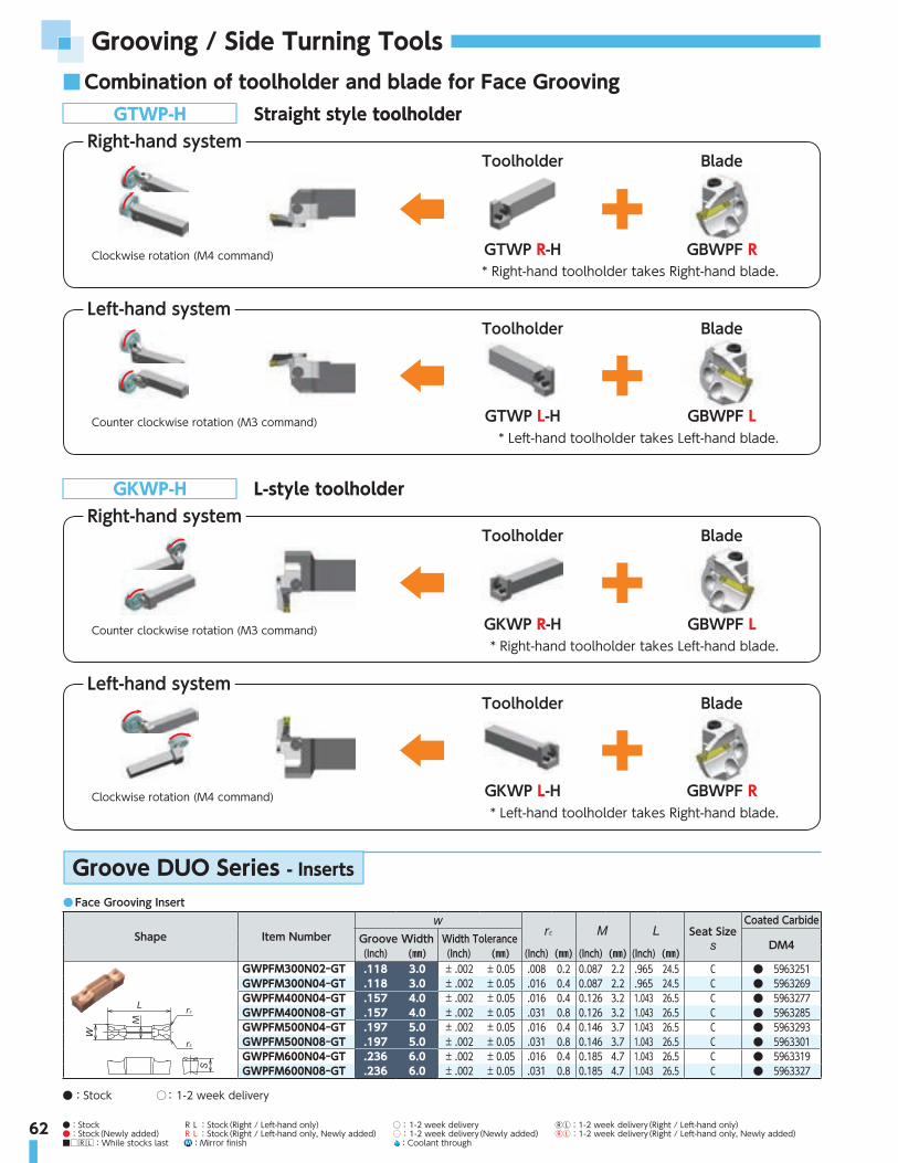
62
Grooving / Side Turning Tools
●:Stock RL:Stock(Right / Left-hand only) ○: 1-2 week delivery ⓇⓁ:1-2 week delivery(Right / Left-hand only)●:Stock(Newly added) RL:Stock(Right / Left-hand only, Newly added) ○: 1-2 week delivery(Newly added) ⓇⓁ:1-2 week delivery(Right / Left-hand only, Newly added) ■□RL:While stocks last M :Mirror finish :Coolant through
■ Combination of toolholder and blade for Face GroovingGTWP-H Straight style toolholder
Right-hand systemToolholder
GTWP R-H GBWPF R
Blade
* Right-hand toolholder takes Right-hand blade.Clockwise rotation (M4 command)
Left-hand systemToolholder
GTWP L-H GBWPF L
Blade
* Left-hand toolholder takes Left-hand blade.Counter clockwise rotation (M3 command)
GKWP-H L-style toolholderRight-hand system
Toolholder
GKWP R-H GBWPF L
Blade
* Right-hand toolholder takes Left-hand blade.Counter clockwise rotation (M3 command)
Left-hand systemToolholder
GKWP L-H GBWPF R
Blade
* Left-hand toolholder takes Right-hand blade.Clockwise rotation (M4 command)
● Face Grooving Insert
Shape Item Number Seat SizeCoated Carbide
Groove Width Width Tolerance DM4(Inch) (㎜) (Inch) (㎜) (Inch) (㎜) (Inch) (㎜) (Inch) (㎜)
M
GWPFM300N02-GT .118 3.0 ± .002 ± 0.05 .008 0.2 0.087 2.2 .965 24.5 C ● 5963251GWPFM300N04-GT .118 3.0 ± .002 ± 0.05 .016 0.4 0.087 2.2 .965 24.5 C ● 5963269GWPFM400N04-GT .157 4.0 ± .002 ± 0.05 .016 0.4 0.126 3.2 1.043 26.5 C ● 5963277GWPFM400N08-GT .157 4.0 ± .002 ± 0.05 .031 0.8 0.126 3.2 1.043 26.5 C ● 5963285GWPFM500N04-GT .197 5.0 ± .002 ± 0.05 .016 0.4 0.146 3.7 1.043 26.5 C ● 5963293GWPFM500N08-GT .197 5.0 ± .002 ± 0.05 .031 0.8 0.146 3.7 1.043 26.5 C ● 5963301GWPFM600N04-GT .236 6.0 ± .002 ± 0.05 .016 0.4 0.185 4.7 1.043 26.5 C ● 5963319GWPFM600N08-GT .236 6.0 ± .002 ± 0.05 .031 0.8 0.185 4.7 1.043 26.5 C ● 5963327
Groove DUO Series - Inserts
●:Stock ○: 1-2 week delivery

63
GTWPR
Right-hand shown
Groove DUO Blade 0°Straight type holder
Hand(R/L)
Width (㎜)
Face grooving OD Max.grooving depth Holder number Blade number
Dimensions - inch(㎜) Applicable insertφ min φ max
(inch)(㎜)(inch)(㎜)(inch)(㎜)(inch)(㎜)
R
.118 3
1.142 29 1.378 35 .512 13
GTWPR16-IN-H
GBWPFR-3T13-029035
1"(25.4)
1"(25.4)
6"(152.4)
1"(25.4)
1.102"(28)
1.654"(42) ―
GWPFM3001.378 35 1.772 45 GBWPFR-3T13-0350451.772 45 2.362 60
.591 15GBWPFR-3T15-045060
2.362 60 3.937 100 GBWPFR-3T15-0601003.937 100 9.843 250 GBWPFR-3T15-100250
.157 41.181 30 1.575 40
.591 15GBWPFR-4T15-030040
GWPFM4001.575 40 2.362 60 GBWPFR-4T15-0400602.362 60 4.724 120 GBWPFR-4T15-0601204.724 120 11.811 300 GBWPFR-4T15-120300
.197 51.181 30 1.969 50
.591 15GBWPFR-5T15-030050
GWPFM5001.969 50 4.724 120 GBWPFR-5T15-0501204.724 120 ∞ ∞ GBWPFR-5T15-120999
.236 6 1.378 35 3.150 80 .591 15 GBWPFR-6T15-035080 GWPFM6003.150 80 ∞ ∞ GBWPFR-6T15-080999
.118 3
1.142 29 1.378 35 .512 13
GTWPR20-IN-H
GBWPFR-3T13-029035
1.25"(31.75)
1.25"(31.75)
7"(177.8)
1.25"(31.75)
1.378"(35) ― ―
GWPFM3001.378 35 1.772 45 GBWPFR-3T13-0350451.772 45 2.362 60
.591 15GBWPFR-3T15-045060
2.362 60 3.937 100 GBWPFR-3T15-0601003.937 100 9.843 250 GBWPFR-3T15-100250
.157 41.181 30 1.575 40
.591 15GBWPFR-4T15-030040
GWPFM4001.575 40 2.362 60 GBWPFR-4T15-0400602.362 60 4.724 120 GBWPFR-4T15-0601204.724 120 11.811 300 GBWPFR-4T15-120300
.197 51.181 30 1.969 50
.591 15GBWPFR-5T15-030050
GWPFM5001.969 50 4.724 120 GBWPFR-5T15-0501204.724 120 ∞ ∞ GBWPFR-5T15-120999
.236 6 1.378 35 3.150 80 .591 15 GBWPFR-6T15-035080 GWPFM6003.150 80 ∞ ∞ GBWPFR-6T15-080999
.118 3
1.142 29 1.378 35 .512 13
GTWPR2020-H
GBWPFR-3T13-029035
.787"(20)
.787"(20)
4.921"(125)
.787"(20)
.906"(23)
1.81"(46)
.315"(8)
GWPFM3001.378 35 1.772 45 GBWPFR-3T13-0350451.772 45 2.362 60
.591 15GBWPFR-3T15-045060
2.362 60 3.937 100 GBWPFR-3T15-0601003.937 100 9.843 250 GBWPFR-3T15-100250
.157 41.181 30 1.575 40
.591 15GBWPFR-4T15-030040
GWPFM4001.575 40 2.362 60 GBWPFR-4T15-0400602.362 60 4.724 120 GBWPFR-4T15-0601204.724 120 11.811 300 GBWPFR-4T15-120300
.197 51.181 30 1.969 50
.591 15GBWPFR-5T15-030050
GWPFM5001.969 50 4.724 120 GBWPFR-5T15-0501204.724 120 ∞ ∞ GBWPFR-5T15-120999
.236 6 1.378 35 3.150 80 .591 15 GBWPFR-6T15-035080 GWPFM6003.150 80 ∞ ∞ GBWPFR-6T15-080999
.118 3
1.142 29 1.378 35 .512 13
GTWPR2525-H
GBWPFR-3T13-029035
.984"(25)
.984"(25)
5.906"(150)
.984"(25)
1.102"(28)
1.654"(42)
.276"(7)
GWPFM3001.378 35 1.772 45 GBWPFR-3T13-0350451.772 45 2.362 60
.591 15GBWPFR-3T15-045060
2.362 60 3.937 100 GBWPFR-3T15-0601003.937 100 9.843 250 GBWPFR-3T15-100250
.157 41.181 30 1.575 40
.591 15GBWPFR-4T15-030040
GWPFM4001.575 40 2.362 60 GBWPFR-4T15-0400602.362 60 4.724 120 GBWPFR-4T15-0601204.724 120 11.811 300 GBWPFR-4T15-120300
.197 51.181 30 1.969 50
.591 15GBWPFR-5T15-030050
GWPFM5001.969 50 4.724 120 GBWPFR-5T15-0501204.724 120 ∞ ∞ GBWPFR-5T15-120999
.236 6 1.378 35 3.150 80 .591 15 GBWPFR-6T15-035080 GWPFM6003.150 80 ∞ ∞ GBWPFR-6T15-080999
.118 3
1.142 29 1.378 35 .512 13
GTWPR3232-H
GBWPFR-3T13-029035
1.260"(32)
1.260"(32)
6.693"(170)
1.260"(32)
1.378"(35) ― ―
GWPFM3001.378 35 1.772 45 GBWPFR-3T13-0350451.772 45 2.362 60
.591 15GBWPFR-3T15-045060
2.362 60 3.937 100 GBWPFR-3T15-0601003.937 100 9.843 250 GBWPFR-3T15-100250
.157 41.181 30 1.575 40
.591 15GBWPFR-4T15-030040
GWPFM4001.575 40 2.362 60 GBWPFR-4T15-0400602.362 60 4.724 120 GBWPFR-4T15-0601204.724 120 11.811 300 GBWPFR-4T15-120300
.197 51.181 30 1.969 50
.591 15GBWPFR-5T15-030050
GWPFM5001.969 50 4.724 120 GBWPFR-5T15-0501204.724 120 ∞ ∞ GBWPFR-5T15-120999
.236 6 1.378 35 3.150 80 .591 15 GBWPFR-6T15-035080 GWPFM6003.150 80 ∞ ∞ GBWPFR-6T15-080999
※1
41φ
φ max φ min
Right-hand toolholder takes Right-hand blade.
Clockwise rotation (M4 command)

64
Grooving / Side Turning Tools
Hand(R/L)
Width (㎜)
Face grooving OD Max.grooving depth Holder number Blade number
Dimensions - inch(㎜) Applicable insertφ min φ max
(inch)(㎜)(inch)(㎜)(inch)(㎜)(inch)(㎜)
L
.118 3
1.142 29 1.378 35 .512 13
GTWPL16-IN-H
GBWPFL-3T13-029035
1"(25.4)
1"(25.4)
6"(152.4)
1"(25.4)
1.102"(28)
1.654"(42) ―
GWPFM3001.378 35 1.772 45 GBWPFL-3T13-0350451.772 45 2.362 60
.591 15GBWPFL-3T15-045060
2.362 60 3.937 100 GBWPFL-3T15-0601003.937 100 9.843 250 GBWPFL-3T15-100250
.157 41.181 30 1.575 40
.591 15GBWPFL-4T15-030040
GWPFM4001.575 40 2.362 60 GBWPFL-4T15-0400602.362 60 4.724 120 GBWPFL-4T15-0601204.724 120 11.811 300 GBWPFL-4T15-120300
.197 51.181 30 1.969 50
.591 15GBWPFL-5T15-030050
GWPFM5001.969 50 4.724 120 GBWPFL-5T15-0501204.724 120 ∞ ∞ GBWPFL-5T15-120999
.236 6 1.378 35 3.150 80 .591 15 GBWPFL-6T15-035080 GWPFM6003.150 80 ∞ ∞ GBWPFL-6T15-080999
.118 3
1.142 29 1.378 35 .512 13
GTWPL20-IN-H
GBWPFL-3T13-029035
1.25"(31.75)
1.25"(31.75)
7"(177.8)
1.25"(31.75)
1.378"(35) ― ―
GWPFM3001.378 35 1.772 45 GBWPFL-3T13-0350451.772 45 2.362 60
.591 15GBWPFL-3T15-045060
2.362 60 3.937 100 GBWPFL-3T15-0601003.937 100 9.843 250 GBWPFL-3T15-100250
.157 41.181 30 1.575 40
.591 15GBWPFL-4T15-030040
GWPFM4001.575 40 2.362 60 GBWPFL-4T15-0400602.362 60 4.724 120 GBWPFL-4T15-0601204.724 120 11.811 300 GBWPFL-4T15-120300
.197 51.181 30 1.969 50
.591 15GBWPFL-5T15-030050
GWPFM5001.969 50 4.724 120 GBWPFL-5T15-0501204.724 120 ∞ ∞ GBWPFL-5T15-120999
.236 6 1.378 35 3.150 80 .591 15 GBWPFL-6T15-035080 GWPFM6003.150 80 ∞ ∞ GBWPFL-6T15-080999
.118 3
1.142 29 1.378 35 .512 13
GTWPL2020-H
GBWPFL-3T13-029035
.787"(20)
.787"(20)
4.921"(125)
.787"(20)
.906"(23)
1.81"(46)
.315"(8)
GWPFM3001.378 35 1.772 45 GBWPFL-3T13-0350451.772 45 2.362 60
.591 15GBWPFL-3T15-045060
2.362 60 3.937 100 GBWPFL-3T15-0601003.937 100 9.843 250 GBWPFL-3T15-100250
.157 41.181 30 1.575 40
.591 15GBWPFL-4T15-030040
GWPFM4001.575 40 2.362 60 GBWPFL-4T15-0400602.362 60 4.724 120 GBWPFL-4T15-0601204.724 120 11.811 300 GBWPFL-4T15-120300
.197 51.181 30 1.969 50
.591 15GBWPFL-5T15-030050
GWPFM5001.969 50 4.724 120 GBWPFL-5T15-0501204.724 120 ∞ ∞ GBWPFL-5T15-120999
.236 6 1.378 35 3.150 80 .591 15 GBWPFL-6T15-035080 GWPFM6003.150 80 ∞ ∞ GBWPFL-6T15-080999
.118 3
1.142 29 1.378 35 .512 13
GTWPL2525-H
GBWPFL-3T13-029035
.984"(25)
.984"(25)
5.906"(150)
.984"(25)
1.102"(28)
1.654"(42)
.276"(7)
GWPFM3001.378 35 1.772 45 GBWPFL-3T13-0350451.772 45 2.362 60
.591 15GBWPFL-3T15-045060
2.362 60 3.937 100 GBWPFL-3T15-0601003.937 100 9.843 250 GBWPFL-3T15-100250
.157 41.181 30 1.575 40
.591 15GBWPFL-4T15-030040
GWPFM4001.575 40 2.362 60 GBWPFL-4T15-0400602.362 60 4.724 120 GBWPFL-4T15-0601204.724 120 11.811 300 GBWPFL-4T15-120300
.197 51.181 30 1.969 50
.591 15GBWPFL-5T15-030050
GWPFM5001.969 50 4.724 120 GBWPFL-5T15-0501204.724 120 ∞ ∞ GBWPFL-5T15-120999
.236 6 1.378 35 3.150 80 .591 15 GBWPFL-6T15-035080 GWPFM6003.150 80 ∞ ∞ GBWPFL-6T15-080999
.118 3
1.142 29 1.378 35 .512 13
GTWPL3232-H
GBWPFL-3T13-029035
1.260"(32)
1.260"(32)
6.693"(170)
1.260"(32)
1.378"(35) ― ―
GWPFM3001.378 35 1.772 45 GBWPFL-3T13-0350451.772 45 2.362 60
.591 15GBWPFL-3T15-045060
2.362 60 3.937 100 GBWPFL-3T15-0601003.937 100 9.843 250 GBWPFL-3T15-100250
.157 41.181 30 1.575 40
.591 15GBWPFL-4T15-030040
GWPFM4001.575 40 2.362 60 GBWPFL-4T15-0400602.362 60 4.724 120 GBWPFL-4T15-0601204.724 120 11.811 300 GBWPFL-4T15-120300
.197 51.181 30 1.969 50
.591 15GBWPFL-5T15-030050
GWPFM5001.969 50 4.724 120 GBWPFL-5T15-0501204.724 120 ∞ ∞ GBWPFL-5T15-120999
.236 6 1.378 35 3.150 80 .591 15 GBWPFL-6T15-035080 GWPFM6003.150 80 ∞ ∞ GBWPFL-6T15-080999
GTWPL
Left-hand shown
Groove DUO Blade 0°Straight type holder
Left-hand toolholder takes Left-hand blade.
Counter clockwise rotation (M3 command)
※1
41
φ
φ max φ min

65●:Stock RL:Stock(Right / Left-hand only) ○: 1-2 week delivery ⓇⓁ:1-2 week delivery(Right / Left-hand only)●:Stock(Newly added) RL:Stock(Right / Left-hand only, Newly added) ○: 1-2 week delivery(Newly added) ⓇⓁ:1-2 week delivery(Right / Left-hand only, Newly added) ■□RL:While stocks last M :Mirror finish :Coolant through
GKWPR
Right-hand shown
Groove DUO Blade 90°L style holders
Right-hand toolholder takes Left-hand blade.
Counter clockwise rotation (M3 command)
17.5
25
25
φ
φ max φ min
Hand(R/L)
Width (㎜)
Face grooving OD Max.grooving depth Holder number Blade number
Dimensions - inch(㎜) Applicable insertφ min φ max
(inch)(㎜)(inch)(㎜)(inch)(㎜)(inch)(㎜)
R
.118 3
1.142 29 1.378 35 .512 13
GKWPR16-IN-H
GBWPFL-3T13-029035
1"(25.4)
1"(25.4)
6"(152.4)
1"(25.4)
1.689"(42.9)
.260"(6.6)
.260"(6.6)
GWPFM3001.378 35 1.772 45 GBWPFL-3T13-0350451.772 45 2.362 60
.591 15GBWPFL-3T15-045060
2.362 60 3.937 100 GBWPFL-3T15-0601003.937 100 9.843 250 GBWPFL-3T15-100250
.157 41.181 30 1.575 40
.591 15GBWPFL-4T15-030040
GWPFM4001.575 40 2.362 60 GBWPFL-4T15-0400602.362 60 4.724 120 GBWPFL-4T15-0601204.724 120 11.811 300 GBWPFL-4T15-120300
.197 51.181 30 1.969 50
.591 15GBWPFL-5T15-030050
GWPFM5001.969 50 4.724 120 GBWPFL-5T15-0501204.724 120 ∞ ∞ GBWPFL-5T15-120999
.236 6 1.378 35 3.150 80 .591 15 GBWPFL-6T15-035080 GWPFM6003.150 80 ∞ ∞ GBWPFL-6T15-080999
.118 3
1.142 29 1.378 35 .512 13
GKWPR20-IN-H
GBWPFL-3T13-029035
1.25"(31.75)
1.25"(31.75)
7"(177.8)
1.25"(31.75)
1.939"(49.25) ― ―
GWPFM3001.378 35 1.772 45 GBWPFL-3T13-0350451.772 45 2.362 60
.591 15GBWPFL-3T15-045060
2.362 60 3.937 100 GBWPFL-3T15-0601003.937 100 9.843 250 GBWPFL-3T15-100250
.157 41.181 30 1.575 40
.591 15GBWPFL-4T15-030040
GWPFM4001.575 40 2.362 60 GBWPFL-4T15-0400602.362 60 4.724 120 GBWPFL-4T15-0601204.724 120 11.811 300 GBWPFL-4T15-120300
.197 51.181 30 1.969 50
.591 15GBWPFL-5T15-030050
GWPFM5001.969 50 4.724 120 GBWPFL-5T15-0501204.724 120 ∞ ∞ GBWPFL-5T15-120999
.236 6 1.378 35 3.150 80 .591 15 GBWPFL-6T15-035080 GWPFM6003.150 80 ∞ ∞ GBWPFL-6T15-080999
.118 3
1.142 29 1.378 35 .512 13
GKWPR2020-H
GBWPFL-3T13-029035
.787"(20)
.787"(20)
4.921"(125)
.787"(20)
1.476"(37.5)
.472"(12)
.315"(8)
GWPFM3001.378 35 1.772 45 GBWPFL-3T13-0350451.772 45 2.362 60
.591 15GBWPFL-3T15-045060
2.362 60 3.937 100 GBWPFL-3T15-0601003.937 100 9.843 250 GBWPFL-3T15-100250
.157 41.181 30 1.575 40
.591 15GBWPFL-4T15-030040
GWPFM4001.575 40 2.362 60 GBWPFL-4T15-0400602.362 60 4.724 120 GBWPFL-4T15-0601204.724 120 11.811 300 GBWPFL-4T15-120300
.197 51.181 30 1.969 50
.591 15GBWPFL-5T15-030050
GWPFM5001.969 50 4.724 120 GBWPFL-5T15-0501204.724 120 ∞ ∞ GBWPFL-5T15-120999
.236 6 1.378 35 3.150 80 .591 15 GBWPFL-6T15-035080 GWPFM6003.150 80 ∞ ∞ GBWPFL-6T15-080999
.118 3
1.142 29 1.378 35 .512 13
GKWPR2525-H
GBWPFL-3T13-029035
.984"(25)
.984"(25)
5.906"(150)
.984"(25)
1.673"(42.5)
.276"(7)
.276"(7)
GWPFM3001.378 35 1.772 45 GBWPFL-3T13-0350451.772 45 2.362 60
.591 15GBWPFL-3T15-045060
2.362 60 3.937 100 GBWPFL-3T15-0601003.937 100 9.843 250 GBWPFL-3T15-100250
.157 41.181 30 1.575 40
.591 15GBWPFL-4T15-030040
GWPFM4001.575 40 2.362 60 GBWPFL-4T15-0400602.362 60 4.724 120 GBWPFL-4T15-0601204.724 120 11.811 300 GBWPFL-4T15-120300
.197 51.181 30 1.969 50
.591 15GBWPFL-5T15-030050
GWPFM5001.969 50 4.724 120 GBWPFL-5T15-0501204.724 120 ∞ ∞ GBWPFL-5T15-120999
.236 6 1.378 35 3.150 80 .591 15 GBWPFL-6T15-035080 GWPFM6003.150 80 ∞ ∞ GBWPFL-6T15-080999
.118 3
1.142 29 1.378 35 .512 13
GKWPR3232-H
GBWPFL-3T13-029035
1.260"(32)
1.260"(32)
6.693"(170)
1.260"(32)
1.949"(49.5) ― ―
GWPFM3001.378 35 1.772 45 GBWPFL-3T13-0350451.772 45 2.362 60
.591 15GBWPFL-3T15-045060
2.362 60 3.937 100 GBWPFL-3T15-0601003.937 100 9.843 250 GBWPFL-3T15-100250
.157 41.181 30 1.575 40
.591 15GBWPFL-4T15-030040
GWPFM4001.575 40 2.362 60 GBWPFL-4T15-0400602.362 60 4.724 120 GBWPFL-4T15-0601204.724 120 11.811 300 GBWPFL-4T15-120300
.197 51.181 30 1.969 50
.591 15GBWPFL-5T15-030050
GWPFM5001.969 50 4.724 120 GBWPFL-5T15-0501204.724 120 ∞ ∞ GBWPFL-5T15-120999
.236 6 1.378 35 3.150 80 .591 15 GBWPFL-6T15-035080 GWPFM6003.150 80 ∞ ∞ GBWPFL-6T15-080999

66
Grooving / Side Turning Tools
GKWPL
Left-hand shown
Groove DUO Blade 90°L style holders
Left-hand toolholder takes Right-hand blade.
Clockwise rotation (M4 command)
17.5
25
25
φφ max φ min
Hand(R/L)
Width (㎜)
Face grooving OD Max.grooving depth Holder number Blade number
Dimensions - inch(㎜) Applicable insertφ min φ max
(inch)(㎜)(inch)(㎜)(inch)(㎜)(inch)(㎜)
L
.118 3
1.142 29 1.378 35 .512 13
GKWPL16-IN-H
GBWPFR-3T13-029035
1"(25.4)
1"(25.4)
6"(152.4)
1"(25.4)
1.689"(42.9)
.260"(6.6)
.260"(6.6)
GWPFM3001.378 35 1.772 45 GBWPFR-3T13-0350451.772 45 2.362 60
.591 15GBWPFR-3T15-045060
2.362 60 3.937 100 GBWPFR-3T15-0601003.937 100 9.843 250 GBWPFR-3T15-100250
.157 41.181 30 1.575 40
.591 15GBWPFR-4T15-030040
GWPFM4001.575 40 2.362 60 GBWPFR-4T15-0400602.362 60 4.724 120 GBWPFR-4T15-0601204.724 120 11.811 300 GBWPFR-4T15-120300
.197 51.181 30 1.969 50
.591 15GBWPFR-5T15-030050
GWPFM5001.969 50 4.724 120 GBWPFR-5T15-0501204.724 120 ∞ ∞ GBWPFR-5T15-120999
.236 6 1.378 35 3.150 80 .591 15 GBWPFR-6T15-035080 GWPFM6003.150 80 ∞ ∞ GBWPFR-6T15-080999
.118 3
1.142 29 1.378 35 .512 13
GKWPL20-IN-H
GBWPFR-3T13-029035
1.25"(31.75)
1.25"(31.75)
7"(177.8)
1.25"(31.75)
1.939"(49.25) ― ―
GWPFM3001.378 35 1.772 45 GBWPFR-3T13-0350451.772 45 2.362 60
.591 15GBWPFR-3T15-045060
2.362 60 3.937 100 GBWPFR-3T15-0601003.937 100 9.843 250 GBWPFR-3T15-100250
.157 41.181 30 1.575 40
.591 15GBWPFR-4T15-030040
GWPFM4001.575 40 2.362 60 GBWPFR-4T15-0400602.362 60 4.724 120 GBWPFR-4T15-0601204.724 120 11.811 300 GBWPFR-4T15-120300
.197 51.181 30 1.969 50
.591 15GBWPFR-5T15-030050
GWPFM5001.969 50 4.724 120 GBWPFR-5T15-0501204.724 120 ∞ ∞ GBWPFR-5T15-120999
.236 6 1.378 35 3.150 80 .591 15 GBWPFR-6T15-035080 GWPFM6003.150 80 ∞ ∞ GBWPFR-6T15-080999
.118 3
1.142 29 1.378 35 .512 13
GKWPL2020-H
GBWPFR-3T13-029035
.787"(20)
.787"(20)
4.921"(125)
.787"(20)
1.476"(37.5)
.472"(12)
.315"(8)
GWPFM3001.378 35 1.772 45 GBWPFR-3T13-0350451.772 45 2.362 60
.591 15GBWPFR-3T15-045060
2.362 60 3.937 100 GBWPFR-3T15-0601003.937 100 9.843 250 GBWPFR-3T15-100250
.157 41.181 30 1.575 40
.591 15GBWPFR-4T15-030040
GWPFM4001.575 40 2.362 60 GBWPFR-4T15-0400602.362 60 4.724 120 GBWPFR-4T15-0601204.724 120 11.811 300 GBWPFR-4T15-120300
.197 51.181 30 1.969 50
.591 15GBWPFR-5T15-030050
GWPFM5001.969 50 4.724 120 GBWPFR-5T15-0501204.724 120 ∞ ∞ GBWPFR-5T15-120999
.236 6 1.378 35 3.150 80 .591 15 GBWPFR-6T15-035080 GWPFM6003.150 80 ∞ ∞ GBWPFR-6T15-080999
.118 3
1.142 29 1.378 35 .512 13
GKWPL2525-H
GBWPFR-3T13-029035
.984"(25)
.984"(25)
5.906"(150)
.984"(25)
1.673"(42.5)
.276"(7)
.276"(7)
GWPFM3001.378 35 1.772 45 GBWPFR-3T13-0350451.772 45 2.362 60
.591 15GBWPFR-3T15-045060
2.362 60 3.937 100 GBWPFR-3T15-0601003.937 100 9.843 250 GBWPFR-3T15-100250
.157 41.181 30 1.575 40
.591 15GBWPFR-4T15-030040
GWPFM4001.575 40 2.362 60 GBWPFR-4T15-0400602.362 60 4.724 120 GBWPFR-4T15-0601204.724 120 11.811 300 GBWPFR-4T15-120300
.197 51.181 30 1.969 50
.591 15GBWPFR-5T15-030050
GWPFM5001.969 50 4.724 120 GBWPFR-5T15-0501204.724 120 ∞ ∞ GBWPFR-5T15-120999
.236 6 1.378 35 3.150 80 .591 15 GBWPFR-6T15-035080 GWPFM6003.150 80 ∞ ∞ GBWPFR-6T15-080999
.118 3
1.142 29 1.378 35 .512 13
GKWPL3232-H
GBWPFR-3T13-029035
1.260"(32)
1.260"(32)
6.693"(170)
1.260"(32)
1.949"(49.5) ― ―
GWPFM3001.378 35 1.772 45 GBWPFR-3T13-0350451.772 45 2.362 60
.591 15GBWPFR-3T15-045060
2.362 60 3.937 100 GBWPFR-3T15-0601003.937 100 9.843 250 GBWPFR-3T15-100250
.157 41.181 30 1.575 40
.591 15GBWPFR-4T15-030040
GWPFM4001.575 40 2.362 60 GBWPFR-4T15-0400602.362 60 4.724 120 GBWPFR-4T15-0601204.724 120 11.811 300 GBWPFR-4T15-120300
.197 51.181 30 1.969 50
.591 15GBWPFR-5T15-030050
GWPFM5001.969 50 4.724 120 GBWPFR-5T15-0501204.724 120 ∞ ∞ GBWPFR-5T15-120999
.236 6 1.378 35 3.150 80 .591 15 GBWPFR-6T15-035080 GWPFM6003.150 80 ∞ ∞ GBWPFR-6T15-080999

ID Tools

68
ID Tools■ RN.. Inserts
■ RP.. Inserts
S-CRGN (Coolant through)
S-CRGP (Coolant through)
● Inch Holders
Item NumberStock Min. Bore Dia.
(inch)Dimensions (inch)
Insert*R L
S50-CRGN -32-4 ● 3.0 2.0 1.87 16.0 1.281 2.362 7RNG 45
(RNG 43)S50-CRGN -40-4 ● 3.5 2.5 2.38 16.0 1.531 2.950 7
● Inch Holders
Item NumberStock Min. Bore Dia.
(inch)Dimensions (inch)
InsertR L
S12-CRGP -16-3 ● 1.25 1.0 0.89 12.0 .640 1.574 1 RPG 32
● Spare PartsInsert Clamp Blade Shim Shim Screw Wrench
Standard RNG 452413 9414
IRSN 431161 5104
RNG 43 IRSN 45 (OP)
● Spare PartsInsert Clamp Diff Screw Wrench
Standard RPG 32 CL-7 XNS-36 5124
3/8-18NPT
0°0°
1/4-18NPT
Min. Bore Diameter φ3.0" -
Min. Bore Diameter φ1.25" -

69●:Stock RL:Stock(Right / Left-hand only) ○: 1-2 week delivery ⓇⓁ:1-2 week delivery(Right / Left-hand only)●:Stock(Newly added) RL:Stock(Right / Left-hand only, Newly added) ○: 1-2 week delivery(Newly added) ⓇⓁ:1-2 week delivery(Right / Left-hand only, Newly added) ■□RL:While stocks last M :Mirror finish :Coolant through
■ CN.. Inserts
■ DN.. Inserts
S-WCLN
S-WDUN
● Spare Parts
Insert Clamp Shim Clamp Screw Wrench (for Clamp Screw) Shim Screw Wrench
(for Shim Screw) Spring
Standard CNGA 43DC6CN
ACN423×1 AOS-6*26W(S25R-WCLN 12)
AOS-6*30W(Others)
LLR-T20FSS16-3.0*8 LLR-T10
ASGL6-DCNGA 45 ― ― ―
● Spare Parts
Insert Clamp Shim Clamp Screw Wrench (for Clamp Screw) Shim Screw Wrench
(for Shim Screw) Spring
Standard DNGA 43DC6DN
ADN423×1 AOS-6*26W(S32S-WDUN 15)
AOS-6*30W(S40T-WDUN 15)
LLR-T20FSS16-3.0*8 LLR-T10
ASGL6-DDNGA 45 ― ― ―
6
95
6
3
● Metric Holders
Item NumberStock Min. Bore Dia.
(㎜)Dimensions (㎜)
Insert*R L
S25R-WCLN 12 ○ ○ 33 25 24 200 17 40 14CNGA 43
(CNGA 45)S32S-WCLN 12 ○ ○ 40 32 30 250 22 50 12S40T-WCLN 12 ○ ○ 50 40 38 300 27 60 10S50U-WCLN 12 ○ ○ 63 50 47 350 35 65 8
● Metric Holders
Item NumberStock Min. Bore Dia.
(㎜)Dimensions (㎜)
Insert*R L
S32S-WDUN 15 ○ ○ 42 32 30 250 22 50 12 DNGA 43(DNGA 45)(DNGX 45)S40T-WDUN 15 ○ ○ 50 40 38 300 27 60 10
Min. Bore Diameter φ1.299" -
Min. Bore Diameter φ1.654" -
・ Right hand shown
・ Right hand shown
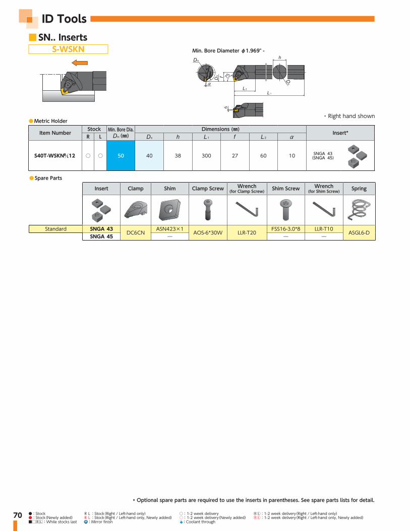
70
ID Tools■ SN.. Inserts
S-WSKN
● Spare Parts
Insert Clamp Shim Clamp Screw Wrench (for Clamp Screw) Shim Screw Wrench
(for Shim Screw) Spring
Standard SNGA 43DC6CN
ASN423×1AOS-6*30W LLR-T20
FSS16-3.0*8 LLR-T10ASGL6-D
SNGA 45 ― ― ―
675
● Metric Holder
Item NumberStock Min. Bore Dia.
(㎜)Dimensions (㎜)
Insert*R L
S40T-WSKN 12 ○ ○ 50 40 38 300 27 60 10 SNGA 43(SNGA 45)
Min. Bore Diameter φ1.969" -
・ Right hand shown
* Optional spare parts are required to use the inserts in parentheses. See spare parts lists for detail.
●:Stock RL:Stock(Right / Left-hand only) ○: 1-2 week delivery ⓇⓁ:1-2 week delivery(Right / Left-hand only)●:Stock(Newly added) RL:Stock(Right / Left-hand only, Newly added) ○: 1-2 week delivery(Newly added) ⓇⓁ:1-2 week delivery(Right / Left-hand only, Newly added)■□RL:While stocks last M :Mirror finish :Coolant through

Rotating Tools

72
Rotating Tools
Features
Solid Ceramic End Mill ◦ Extremely high speed machining for HRSA
materials with our durable SiAlON grade "SX9"◦ More than 15 times higher productivity than a
Carbide end mill◦ 4, 6 and 8 flutes are available ◦ Unique patent pending design provides
toughness to the edge
● Ceramic specialist's designHelix angle・ Designed for the purpose of:
・4-flute: toughness ・ 6-flute: less tool pressure and
better chip evacuation
Helix angle・ Designed for the purpose of:
・4-flute: toughness ・ 6/8-flute: less tool pressure and
better chip evacuation
Bottom edge・ Unique shape
provides toughness
End Gash・ Bigger end gash
brings toughness
Edge・ Added chamfer provides
toughness for cast iron machining
Flute・ Three flute
options up to 8 flute
Flute・ Optimized for HRSA
materials・ Excellent toughness
SX9(SiAlON)・ Well balanced for
toughness and wear resistance
Face Milling Side Milling
Slotting Pocketing RampingProfiling Ramping
NEW[
IPM
]
135.
4 IP
M
9.0
IPM
0
100
150Dia 10mm - 6 flute
50
Inco 718
15×Productivity
[cc
/min
]
234
cc/m
in
74 c
c/m
in
0
100
150
250Dia 12mm - 6 flute
50
Cast Iron
3×Productivity
RCE for HRSA materials RCS for Cast iron / HRSA materials
4-flute 6-flute 8-flute
SX9 Carbide
SFM 1970 130IPT .0012 ➡
DOC .118 ➡
SX9 Carbide
SFM 2300 360IPT .002 ➡
DOC .138 .275

73
● Recommend Cutting Conditions for HRSA materialApplication Grade φ Flute Cutting Speed (SFM) Feed
(IPT)Depth of cut ( ―inch)
Width of cut ( ―inch) Coolant500 2000 3500
Face Milling
SX9
3/8"
4/6/8 .0012
.056
―
DRY
×1/2" .0755/8" .0943/4" .1138㎜ .04710㎜ .05912㎜ .07116㎜ .09420㎜ .118
Side Milling
SX9
3/8"
4/6/8 .0012
.187 .037
DRY
×1/2" .250 .0505/8" .313 .0633/4" .375 .0758㎜ .157 .03110㎜ .197 .03912㎜ .236 .04716㎜ .315 .06320㎜ .394 .079
Slotting
SX9
3/8"
4 .0012
.094
―
DRY
×1/2" .1255/8" .1568㎜ .07910㎜ .09812㎜ .11816㎜ .1573/8"
6 .0012
.056
―
DRY
×1/2" .0755/8" .0948㎜ .04710㎜ .05912㎜ .07116㎜ .0943/4" 8 .0012 .113 ―16㎜ .118
● Recommended cutting conditions for Cast IronApplication Grade φ Flute Cutting Speed (SFM) Feed
(IPT)Depth of cut ( ―inch)
Width of cut ( ―inch) Coolant500 2000 3500
Face Milling
SX9
1/2"
4/6/8 .004
.094
―
DRY
×5/8" .1563/4" .18712㎜ .11816㎜ .15820㎜ .197
Side Milling
SX9
1/2"
4/6/8 .004
.375 .083DRY
×5/8" .469 .1043/4" .563 .12512㎜ .354 .07916㎜ .472 .09820㎜ .591 .130
Slotting
SX9
1/2"
4/6/8 .004
.094
―
DRY
×5/8" .1563/4" .18712㎜ .11816㎜ .15720㎜ .197
For Maximum Productivity
◦ A continuous cut is recommended. An interrupted cut may cause chipping or breakage.◦ When using a Hydraulic or Shrink chuck, blow air to the arbor body, DON'T blow air to the endmill itself.◦ A Minimum speed of 980 SFM is required. (Don't run at lower speed.)◦ A 1.5 degree ramping angle is recommended. Run at 50% lower feed rate when ramping cut.When cutting HRSA materials◦ Continue to machine even if you see BUE, removing BUE may cause chipping or breakage to the edge.◦ High speed machining work hardens the material. For this reason, leave at least 0.3mm of material for a finishing process.

74
Rotating Tools
Heat Resistant Alloy S ●
Item NumberGrade
Flute φ φ φ maxSX9 (Inch) (㎜) (Inch) (㎜) (Inch) (㎜) (Inch) (㎜) (Inch) (㎜) (Inch) (㎜) (Inch) (㎜)
RCEI375H4R047S ● 4 3/8 3/8 .359 .047 9/32 2.50 3/4
RCEI500H4R068S ● 4 1/2 1/2 .484 .068 3/8 2.75 1
RCEM080H4R100S ● 4 .315 8 .315 8 .299 7.6 .039 1.0 .236 6 2.362 60 0.630 16
RCEM100H4R125S ● 4 .394 10 .394 10 .378 9.6 .049 1.25 .295 7.5 2.559 65 0.787 20
RCEM120H4R150S ● 4 .472 12 .472 12 .457 11.6 .059 1.5 .354 9 2.756 70 0.945 24
Heat Resistant Alloy S ●
Item NumberGrade
Flute φ φ maxSX9 (Inch) (㎜) (Inch) (㎜) (Inch) (㎜) (Inch) (㎜) (Inch) (㎜)
RCEI375J6R047S ● 6 3/8 3/8 .047 9/32 2.50
RCEI500J6R068S ● 6 1/2 1/2 .068 3/8 2.75
RCEM080J6R100S ● 6 .315 8 .315 8 .039 1.0 .236 6 2.362 60
RCEM100J6R125S ● 6 .394 10 .394 10 .049 1.25 .295 7.5 2.559 65
RCEM120J6R150S ● 6 .472 12 .472 12 .059 1.5 .354 9 2.756 70
RCE-H4 (4-flute with Neck)○No center cutting edge
RCE-J6 (6-flute)○No center cutting edge
max
φ(e8)
φφ
±.0008
(h6)
Slotting Pocketing Ramping Z=4
35° 1.5°
Face Milling Side Milling Profiling Ramping Z=6
40° 1.5°
φ /φ e8 h63/8", 8mm, 10mm -.00098/-.00185" +0/-.00035"
1/2", 12mm -.00126/-.00232" +0/-.00043"
φ /φ e8 h63/8", 8mm, 10mm -.00098/-.00185" +0/-.00035"
1/2", 12mm -.00126/-.00232" +0/-.00043"
Tolerances
Tolerances
max
φ(e8)
φ
±.0008
(h6)
■ RCE for HRSA Materials
●:1st Choice ◦: 2nd choice
●:1st Choice ◦: 2nd choice

75●:Stock RL:Stock(Right / Left-hand only) ○: 1-2 week delivery ⓇⓁ:1-2 week delivery(Right / Left-hand only)●:Stock(Newly added) RL:Stock(Right / Left-hand only, Newly added) ○: 1-2 week delivery(Newly added) ⓇⓁ:1-2 week delivery(Right / Left-hand only, Newly added) ■□RL:While stocks last M :Mirror finish :Coolant through
Cast Iron K ●Heat Resistant Alloy S ●
Item NumberGrade
Flute φ φ φ maxSX9 (Inch) (㎜) (Inch) (㎜) (Inch) (㎜) (Inch) (㎜) (Inch) (㎜) (Inch) (㎜) (Inch) (㎜)
RCS-H4
RCSI500H4R068S ● 4 1/2 1/2 .484 12.3 .068 1.73 3/8 2.75 69.85 1 25.4
RCSI625H4R078S ● 4 5/8 5/8 .605 15.4 .078 1.98 .469 11.91 3 76.2 1.25 31.75
RCSM120H4R150S ● 4 .472 12 .472 12 .457 11.6 .059 1.5 .354 9 2.76 70 .954 24
RCSM160H4R200S ● 4 .630 16 .630 16 .610 15.5 .079 2.0 .472 12 2.95 75 1.26 32
RCS-H4○No center cutting edge
max
φ(e8)
φφ
(h6)
Slotting Pocketing Ramping Z=4
35° 1.5°
RCS-J6 / RCS-J8○No center cutting edge
Face Milling Side Milling Profiling Ramping Z=6
40° 1.5°
max
φ(e8)
φ(h6)
max
φ(e8)
φ(h6)
φ /φ e8 h61/2", 12mm, 5/8", 16mm -.00126/-.00232" +0/-.00043"
3/4", 20mm -.00157/-.00287" +0/-.00051"
Tolerances
φ /φ e8 h61/2", 12mm, 5/8", 16mm -.00126/-.00232" +0/-.00043"
Tolerances
■ RCS for HRSA Materials
Z=8
●:1st Choice ◦: 2nd choice
Cast Iron K ●Heat Resistant Alloy S ●
Item NumberGrade
Flute φ φ maxSX9 (Inch) (㎜) (Inch) (㎜) (Inch) (㎜) (Inch) (㎜) (Inch) (㎜)
RCS-J6
RCSI500J6R068S ● 6 1/2 1/2 .068 1.73 3/8 2.75
RCSI625J6R078S ● 6 5/8 5/8 .078 1.98 .469 11.91 3
RCSM120J6R150S ● 6 .472 12 .472 12 .059 1.5 .354 9 2.76 70
RCSM160J6R200S ● 6 .630 16 .630 16 .079 2.0 .472 12 2.95 75
RCS-J8RCSI750J8R094S ● 8 3/4 3/4 .094 2.38 .563 14.29 4.25
RCSM200J8R250S ● 8 .787 20 .787 20 .098 2.5 .984 15 4.33 110
●:1st Choice ◦: 2nd choice

76
Rotating Tools
● Inch size cutters
Item Number StockDimensions (inch)
Clamp Clamp Screw Weight(lbs) Insert
φRPIW0625E0625R02 ● 2 .625 .625 3.160 1.250 C-423978 S-3-48*1/4SHCS 0.2 RPG 21.5RPIW075E075R02 ● 2 .750 .750 3.270 1.220 AMS-3 AOB-3S 0.4 RPG 21.5RPIW100E100R03 ● 3 1.000 1.000 3.270 1.000 AMS-4 AOB-4S 0.6 RPG 32RPIW125E125R03 ● 3 1.250 1.250 4.000 1.640
AMS-5T AOB-5S-T251.1
RPG 43RPIW150E150R03 ● 3 1.500 1.500 4.000 1.830 1.6
● Inch size cutters
Item Number StockDimensions (inch)
Shim Shim Screw Clamp Clamp
Screw A.R. R.R. Weight(lbs) Insert
φRPIW200S075R04 ● 4 2.00 2.00 .750 .32 .75 .22
ARP42A M3*8 AMS-5T AOB-5S-T25
+5° +5° 0.9RPG 43RPIW300S100R05 ● 5 3.00 2.00 1.000 .38 .75 .22 +5° +5° 2.0
RPIW400S125R06 ● 6 4.00 2.00 1.250 .50 .82 .30 +5° +5° 4.2
●Metric size cutters
Item Number StockDimensions (㎜)
Shim Shim Screw Clamp Clamp
Screw A.R. R.R. Weight(㎏) Insert
φJRPMW050S220R04 ○ 4 50 50 22 10.4 20 6.3
ARP42A M3*8 AMS-5T AOB-5S-T25
+5° +5° 0.4RPG 43JRPMW063S220R04 ○ 4 63 50 22 10.4 20 6.3 +5° +5° 0.6
JRPMW080S254R05 ○ 5 80 50 25.4 9.5 25 6.0 +5° +2°30′ 0.9
● Metric size cutters
Item Number StockDimensions (㎜)
Clamp Clamp Screw Weight(㎏) Insert
φJRPMW032E250R03 ○
332 25
120 40 AMS-5T AOB-5S-T250.4
RPG 43JRPMW032E320R03 ○ 32 32 0.6JRPMW040E320R03 ○ 40 32 0.7
H
φD2
φD1
L2
A.R.+5°R.R.–7°30'
ccel igh speed illccel igh speed ill series
W
H
φD2
φD1
L2
L1
A.R.+5°R.R.–2°30' ~ –5°
* Recommend using torque wrench @35lbs(4Nm)

77●:Stock RL:Stock(Right / Left-hand only) ○: 1-2 week delivery ⓇⓁ:1-2 week delivery(Right / Left-hand only)●:Stock(Newly added) RL:Stock(Right / Left-hand only, Newly added) ○: 1-2 week delivery(Newly added) ⓇⓁ:1-2 week delivery(Right / Left-hand only, Newly added) ■□RL:While stocks last M :Mirror finish :Coolant through
● Recommend Cutting Conditions
Work Material Grade Dry Wet
Cutting Speed (SFM) Feed (IPT) Depth of Cut (inch)200 700 1200 1700 2200 2700 3200 3700 .002 .003 .004 .005 .006 .007
S SX7 ● ~.150
Heat Resistant Alloys
SX3 ● ~.150
SX9 ● ~.150
H WA1 ● ○ ~.150
Hardened Steel
HRC45-55 HC7 ● ○ ~.150
HRC55-65
WA1 ● ○ ~.150
HC7 ● ○ ~.150

78
Rotating Tools
● Inch size cutters
Item Number StockDimensions (inch)
Clamp Clamp Screw Weight(lbs) Insert
φ φRNIW200S075R04-43 ● 4 2.00 2.00 .750 .32 .75 .22
AMS-6T AOB-6S-T30
1.0 RNG 43
RNIW200S075R03 ● 3 2.00 2.00 .750 .32 .75 .22 1.0
RNG 45RNIW250S075R04 ● 4 2.50 2.00 .750 .32 .75 .22 1.3
RNIW300S100R05 ● 5 3.00 2.00 1.000 .38 .75 .22 1.6
RNIW400S125R06 ● 6 4.00 2.00 1.250 .51 .82 .30 4.2
● Metric size cutters
Item Number StockDimensions (㎜)
Clamp Clamp Screw Weight(㎏) Insert
φ φJRNMW050S220R03 ○ 3 50 50 22 10.4 20 6.3
AMS-6T AOB-6S-T30
0.4
RNG 45JRNMW063S220R04 ○ 4 63 50 22 10.4 20 6.3 0.6
JRNMW080S254R05 ○ 5 80 50 25.4 9.5 25 6.0 0.9
W
H
φD2
φD1
L2
L1
A.R.–5°R.R.–10°
* Recommend using torque wrench @35lbs(4Nm)
● Recommend Cutting Conditions
Work Material Grade Dry Wet
Cutting Speed (SFM) Feed (IPT) Depth of Cut (inch)200 700 1200 1700 2200 2700 3200 3700 .002 .003 .004 .005 .006 .007
S SX7 ● ~.150
Heat Resistant Alloys
SX3 ● ~.150
SX9 ● ~.150
H WA1 ● ○ ~.150
Hardened Steel
HRC45-55 HC7 ● ○ ~.150
HRC55-65
WA1 ● ○ ~.150
HC7 ● ○ ~.150

Rotating & Turning Tool Stock List

80
Rotating & Turning Tool Stock List
Item Description EDP Stock Status Product Page Number1160 #US6990018 ● Part 421161 #US6000984 ● Part 681180 $_1180 ● Part 421182 $_1182 ● Part 422413 #US6000018 ● Part 42,682417 #US6000020 ● Part 429414 $_9414 ● Part 42,68AOB-4S 5380993 ● Part 76AOB-5S-T25 5660667 ● Part 76AOB-5X14 5913942 ○ Part 59AOB-6S-T30 5660683 ● Part 78AOS-6X26W 5663729 ○ Part 63AOS-6X30W 5641402 ● Part 40,41,42,69,70ACN423 5355730 ● Part 40,69ADN423 5605613 ● Part 40,41,69AMS-3 5777354 ● Part 76AMS-4 5380985 ● Part 76AMS-5T 5060132 ● Part 76AMS-6T 5060116 ● Part 78AOB-3S 5578331 ● Part 76AOB-5X16 5859590 ○ Part 59ARP42A 5660659 ● Part 76ASGL6-D 5686647 ● Part 69,70ASN423 5060827 ● Part 42,70C-423978 #US6000926 ● Part 76CL2RV #US6000106 ● Part 46CL2RVRL #US6000107 ● Part 46CL3RV #US6000108 ● Part 47CL4RV #US6000110 ● Part 47CL-7 #US6000114 ● Part 68CRGNL164CD 5731989 ● Holder 42CRGNL165CD 5731930 ● Holder 42CRGNL204CD 5731963 ● Holder 42CRGNL205CD 5731914 ● Holder 42CRGNL206CD 5731898 ● Holder 42CRGNR164CD 5731997 ● Holder 42CRGNR165CD 5731948 ● Holder 42CRGNR204CD 5731971 ● Holder 42CRGNR205CD 5731922 ● Holder 42CRGNR206CD 5731906 ● Holder 42CS0515 5442199 ● Part 61CS0520W 5859616 ○ Part 58CS0625W 5859608 ○ Part 58DC6CN 5686530 ● Part 40,69,70DC6DN 5686548 ● Part 40,41,69FSI28-6.0X18 5967062 ● Part 43,51FSS15-3.0X12 5657010 ● Part 40,41FSS16-3.0X8 5681390 ● Part 69,70GBI-VGW4L3T15-101177 5043260 ● Part Blade 56GBI-VGW4L3T15-177999 5044987 ● Part Blade 56GBI-VGW4L4T15-101177 5045042 ● Part Blade 56GBI-VGW4L4T15-177999 5043278 ● Part Blade 56GBI-VGW4R3T15-101177 5043187 ● Part Blade 54GBI-VGW4R3T15-177999 5044979 ● Part Blade 54GBI-VGW4R4T15-101177 5045034 ● Part Blade 54GBI-VGW4R4T15-177999 5043195 ● Part Blade 54
END MILLS / HOLDERS / CUTTERS / PARTSItem Description EDP Stock Status Product Page Number
GBI-VGW6L6T15-101177 5043286 ● Part Blade 56GBI-VGW6L6T15-177999 5043294 ● Part Blade 56GBI-VGW6R6T15-101177 5043203 ● Part Blade 54GBI-VGW6R6T15-177999 5043211 ● Part Blade 54GBO-VGW4L3T15-101177 5043229 ● Part Blade 57GBO-VGW4L3T15-177999 5045026 ● Part Blade 57GBO-VGW4L4T15-101177 5045067 ● Part Blade 57GBO-VGW4L4T15-177999 5043237 ● Part Blade 57GBO-VGW4R3T15-101177 5043138 ● Part Blade 55GBO-VGW4R3T15-177999 5044995 ● Part Blade 55GBO-VGW4R4T15-101177 5045059 ● Part Blade 55GBO-VGW4R4T15-177999 5043146 ● Part Blade 55GBO-VGW6L6T15-101177 5043245 ● Part Blade 57GBO-VGW6L6T15-177999 5043252 ● Part Blade 57GBO-VGW6R6T15-101177 5043161 ● Part Blade 55GBO-VGW6R6T15-177999 5043179 ● Part Blade 55GBRL-R23-19 5990221 ● Part Blade 45GBRL-R35-25 5990270 ● Part Blade 45GBRL-R45-28 5990304 ● Part Blade 45GBRR-R23-19 5990247 ● Part Blade 44GBRR-R35-25 5990296 ● Part Blade 44GBRR-R45-28 5990312 ● Part Blade 44GBVL-VGW4-3T09 5989926 ● Part Blade 53GBVL-VGW4-4T14 5990072 ● Part Blade 53GBVL-VGW6-6T14 5990098 ● Part Blade 53GBVL-VGW6-6T19 5990122 ● Part Blade 53GBVL-VGW8-8T19 5990155 ● Part Blade 53GBVL-VGW8-8T28 5990171 ● Part Blade 53GBVR-VGW4-3T09 5990064 ● Part Blade 52GBVR-VGW4-4T14 5990080 ● Part Blade 52GBVR-VGW6-6T14 5990114 ● Part Blade 52GBVR-VGW6-6T19 5990130 ● Part Blade 52GBVR-VGW8-8T19 5990163 ● Part Blade 52GBVR-VGW8-8T28 5990189 ● Part Blade 52GBWPFL-3T13-029035 5963491 ● Part Blade 64,65GBWPFL-3T13-035045 5963509 ● Part Blade 64,65GBWPFL-3T15-045060 5963517 ● Part Blade 64,65GBWPFL-3T15-060100 5963525 ● Part Blade 64,65GBWPFL-3T15-100250 5963533 ● Part Blade 64,65GBWPFL-4T15-030040 5963558 ● Part Blade 64,65GBWPFL-4T15-040060 5963566 ● Part Blade 64,65GBWPFL-4T15-060120 5963574 ● Part Blade 64,65GBWPFL-4T15-120300 5963582 ● Part Blade 64,65GBWPFL-5T15-030050 5963715 ● Part Blade 64,65GBWPFL-5T15-050120 5963608 ● Part Blade 64,65GBWPFL-5T15-120999 5963616 ● Part Blade 64,65GBWPFL-6T15-035080 5963632 ● Part Blade 64,65GBWPFL-6T15-080999 5963640 ● Part Blade 64,65GBWPFR-3T13-029035 5963335 ● Part Blade 63,66GBWPFR-3T13-035045 5963343 ● Part Blade 63,66GBWPFR-3T15-045060 5963350 ● Part Blade 63,66GBWPFR-3T15-060100 5963368 ● Part Blade 63,66GBWPFR-3T15-100250 5963376 ● Part Blade 63,66GBWPFR-4T15-030040 5963392 ● Part Blade 63,66GBWPFR-4T15-040060 5963426 ● Part Blade 63,66GBWPFR-4T15-060120 5963434 ● Part Blade 63,66

81
Item Description EDP Stock Status Product Page NumberGBWPFR-4T15-120300 5963442 ● Part Blade 63,66GBWPFR-5T15-030050 5963707 ● Part Blade 63,66GBWPFR-5T15-050120 5963459 ● Part Blade 63,66GBWPFR-5T15-120999 5963467 ● Part Blade 63,66GBWPFR-6T15-035080 5963475 ● Part Blade 63,66GBWPFR-6T15-080999 5963483 ● Part Blade 63,66GKWPL16-IN-H 5923875 ● Holder 51,52,54,55,
56,64,66
GKWPL2020-H 5923834 ○ Holder 51,52,54,55,56,64,66
GKWPL2020K-3D10 5893607 ○ Holder 58GKWPL2020K-4E10 5893615 ○ Holder 58GKWPL2020K-5F10 5893623 ○ Holder 58GKWPL2020K-6G12 5893631 ○ Holder 58GKWPL20-IN-H 5923891 ● Holder 51,52,54,55,
56,64,66
GKWPL2525-H 5923859 ● Holder 51,52,54,55,56,64,66
GKWPL3232-H 5963699 ○ Holder 51,52,54,55,56,64,66
GKWPR16-IN-H 5923867 ● Holder 51,53,55GKWPR2020-H 5923826 ○ Holder 51,53,55GKWPR20-IN-H 5923883 ● Holder 51,53,55GKWPR2525-H 5923842 ● Holder 51,53,55GKWPR3232-H 5963681 ○ Holder 51,53,55GTWPL1216-3D07 5852280 ○ Holder 59GTWPL1216-4E07 5852314 ○ Holder 59GTWPL1216-5F07 5852355 ○ Holder 59GTWPL1616-3D09 5852306 ○ Holder 59GTWPL1616-4E09 5852322 ○ Holder 59GTWPL1616-5F09 5852371 ○ Holder 59GTWPL1620-6G09 5893599 ○ Holder 59GTWPL16-IN-H 5919428 ● Holder 51,53,61,64GTWPL2020-H 5923792 ○ Holder 51,53,61,64GTWPL2020K-3D10 5852397 ○ Holder 58GTWPL2020K-3D20 5852421 ○ Holder 58GTWPL2020K-4E10 5852447 ○ Holder 58GTWPL2020K-4E20 5852470 ○ Holder 58GTWPL2020K-5F10 5852496 ○ Holder 58GTWPL2020K-5F20 5852520 ○ Holder 58GTWPL2020K-6G12 5852546 ○ Holder 58GTWPL2020K-6G25 5852561 ○ Holder 58GTWPL20-IN-H 5919444 ● Holder 51,53,61,64GTWPL-24-IN-H 5996624 Holder 51GTWPL2525-H 5923818 ● Holder 51,53,61,64GTWPL2525M-3D10 5852405 ○ Holder 58GTWPL2525M-3D20 5852439 ○ Holder 58GTWPL2525M-4E10 5852454 ○ Holder 58GTWPL2525M-4E20 5852488 ○ Holder 58GTWPL2525M-5F10 5852512 ○ Holder 58GTWPL2525M-5F20 5852538 ○ Holder 58GTWPL2525M-6G12 5852553 ○ Holder 58GTWPL2525M-6G25 5852587 ○ Holder 58GTWPL3232-H 5963673 ○ Holder 51,53,61,64GTWPL-32-IN-H 5000658 Holder 51GTWPR08-IN-3D07 5914593 ● Holder 59GTWPR08-IN-4E07 5914627 ● Holder 59GTWPR1016-3D07 5875125 ○ Holder 59GTWPR1016-4E07 5875133 ○ Holder 59GTWPR1016-5F07 5875141 ○ Holder 59GTWPR1020-6G07 5893565 ○ Holder 59GTWPR10-IN-3D09 5914601 ● Holder 59
Item Description EDP Stock Status Product Page NumberGTWPR10-IN-4E09 5914650 ● Holder 59GTWPR1216-3D07 5849054 ● Holder 59GTWPR1216-4E07 5849088 ● Holder 59GTWPR1216-5F07 5849104 ○ Holder 59GTWPR1220-6G07 5893573 ○ Holder 59GTWPR1616-3D09 5849070 ○ Holder 59GTWPR1616-4E09 5849096 ○ Holder 59GTWPR1616-5F09 5849112 ○ Holder 59GTWPR1620-6G09 5893581 ○ Holder 59GTWPR16-IN-H 5919410 ● Holder 51,52,54,55,
56,57,61,63
GTWPR2020-H 5923784 ○ Holder 51,52,54,55,56,57,61,63
GTWPR2020K-3D10 5849120 ○ Holder 58GTWPR2020K-3D20 5849146 ○ Holder 58GTWPR2020K-4E10 5849161 ○ Holder 58GTWPR2020K-4E20 5849187 ○ Holder 58GTWPR2020K-5F10 5849203 ○ Holder 58GTWPR2020K-5F20 5849229 ○ Holder 58GTWPR2020K-6G12 5849245 ○ Holder 58GTWPR2020K-6G25 5849260 ○ Holder 58GTWPR20-IN-H 5919436 ● Holder 51,52,54,55,
56,57,61,63
GTWPR-24-IN-H 5000633 Holder 51GTWPR2525-H 5923800 ● Holder 51,52,54,55,
56,57,61,63
GTWPR2525M-3D10 5849138 ○ Holder 58GTWPR2525M-3D20 5849153 ○ Holder 58GTWPR2525M-4E10 5849179 ○ Holder 58GTWPR2525M-4E20 5849195 ○ Holder 58GTWPR2525M-5F10 5849211 ○ Holder 58GTWPR2525M-5F20 5849237 ○ Holder 58GTWPR2525M-6G12 5849252 ○ Holder 58GTWPR2525M-6G25 5849278 ○ Holder 58GTWPR3232-H 5963657 ○ Holder 51,52,54,55,
56,57,61,63
GTWPR-32-IN-H 5000641 Holder 51JRNMW050S220R03 5719950 ○ Milling Cutter 78JRNMW063S220R04 5719968 ○ Milling Cutter 78JRNMW080S254R05 5719976 ○ Milling Cutter 78JRPMW032E250R03 5720719 ○ Milling Cutter 76JRPMW032E320R03 5719919 ○ Milling Cutter 76JRPMW040E320R03 5719927 ○ Milling Cutter 76JRPMW050S220R04 5719935 ○ Milling Cutter 76JRPMW063S220R04 5726096 ○ Milling Cutter 76JRPMW080S254R05 5719943 ○ Milling Cutter 76LLR-T10 5657028 ● Part 40,41,42,69,70LLR-T20 5657036 ● Part 41LW-3S 5859624 ○ Part 59LW-4 5521208 ● Part 42,43,51,58,
61,69,70
LW-5 5418520 ● Part 58M3X8 5225453 ● Part 76RCEI375H4R047S SX9 5995519 ● End Mill 74RCEI375J6R047S SX9 5995568 ● End Mill 74RCEI500H4R068S SX9 5995527 ● End Mill 74RCEI500J6R068S SX9 5995576 ● End Mill 74RCEM080H4R100S SX9 5995535 ● End Mill 74RCEM080J6R100S SX9 5995584 ● End Mill 74RCEM100H4R125S SX9 5995543 ● End Mill 74RCEM100J6R125S SX9 5995592 ● End Mill 74RCEM120H4R150S SX9 5995550 ● End Mill 74RCEM120J6R150S SX9 5995600 ● End Mill 74

82
Rotating & Turning Tool Stock ListItem Description EDP Stock Status Product Page Number
RCEM160J6R200S SX9 5023544 End Mill 74RCSI500H4R068S SX9 5040878 ● End Mill 75RCSI500J6R068S SX9 5040928 ● End Mill 75RCSI625H4R078S SX9 5040894 ● End Mill 75RCSI625J6R078S SX9 5040936 ● End Mill 75RCSI750J8R094S SX9 5040951 ● End Mill 75RCSM120H4R150S SX9 5040852 ● End Mill 75RCSM120J6R150S SX9 5040902 ● End Mill 75RCSM160H4R200S SX9 5040860 ● End Mill 75RCSM160J6R200S SX9 5040910 ● End Mill 75RCSM200J8R250S SX9 5040944 ● End Mill 75RNIW200S075R03 5660626 ● Milling Cutter 78RNIW200S075R04-43 #US6000978 ● Milling Cutter 78RNIW250S075R04 5660634 ● Milling Cutter 78RNIW300S100R05 5660642 ● Milling Cutter 78RNIW400S125R06 #US6000897 ● Milling Cutter 78RPIW0625E0625R02 #US6000884 ● Milling Cutter 76RPIW075E075R02 5732565 ● Milling Cutter 76RPIW100E100R03 5732557 ● Milling Cutter 76RPIW125E125R03 5660584 ● Milling Cutter 76RPIW150E150R03 5660592 ● Milling Cutter 76RPIW200S075R04 5660600 ● Milling Cutter 76RPIW300S100R05 5660618 ● Milling Cutter 76RPIW400S125R06 #US6000896 ● Milling Cutter 76S12-CRGPL-163 #US6000909 Holder 68S12-CRGPR-163 #US6000910 ● Holder 68S25R-WCLNL12 5682653 ○ Holder 69S25R-WCLNR12 5682646 ○ Holder 69S25R-WWLNL08 5683040 ○ Holder 69S25R-WWLNR08 5683032 ○ Holder 69S32S-WCLNL12 5682679 ○ Holder 69S32S-WCLNR12 5682661 ○ Holder 69S32S-WDUNL15 5682802 ○ Holder 69S32S-WDUNR15 5682794 ○ Holder 69S-3-48X1/4SHCS #US6000927 ● Part 76S40T-WCLNL12 5682695 ○ Holder 69S40T-WCLNR12 5682687 ○ Holder 69S40T-WDUNL15 5701560 ○ Holder 69S40T-WDUNR15 5701545 ○ Holder 69S40T-WSKNL12 5682968 ○ Holder 69S40T-WSKNR12 5682950 ○ Holder 69S50-CRGNL-324 #US6000913 Holder 68S50-CRGNL-404 #US6000914 Holder 68S50-CRGNR-324 9100002 ● Holder 68S50-CRGNR-404 #US6000915 ● Holder 68S50U-WCLNL12 5682711 ○ Holder 69S50U-WCLNR12 5682703 ○ Holder 69SC02C-08 #US6000437 ● Part 46,47SC05C-08 #US6000438 ● Part 46,47SC05C-10 #US6000439 ● Part 46,47SC06C-08 #US6000440 ● Part 46,47SC06C-10 #US6000441 ● Part 46,47SC10F-10 #US6000444 ● Part 46,47SC40F-12 #US6000447 ● Part 46,47SC40F-16 #US6000448 ● Part 46,47SM2RV #US6000461 ● Part 46,47SM2RVS #US6000462 ● Part 46,47
Item Description EDP Stock Status Product Page NumberSM3RV #US6000464 ● Part 46,47SM4RV #US6000465 ● Part 46,47VRAOL16-2D #US6000901 ● Holder 46VRAOL16-2D (RCGX23 OPTION) #US6001036 ● Holder 46VRAOL16-3D 5732524 ● Holder 46VRAOL16-4D 5732672 ● Holder 46VRAOL20-2D 5732516 ● Holder 46VRAOL20-2D (RCGX23 OPTION) #US6001038 ● Holder 46VRAOL20-3D 5732508 ● Holder 46VRAOL20-4D 5732490 ● Holder 46VRAOL24-3E 5732482 ● Holder 46VRAOL24-4E 5732474 ● Holder 46VRAON16-2D 5732466 ● Holder 47VRAON16-2D (RCGX23 OPTION) #US6001039 ● Holder 47VRAON16-3D 5732458 ● Holder 47VRAON16-4D 5732441 ● Holder 47VRAON20-2D 5732433 ● Holder 47VRAON20-2D (RCGX23 OPTION) #US6001040 ● Holder 47VRAON20-3D 5732425 ● Holder 47VRAON20-4D 5732417 ● Holder 47VRAON24-3E 5732391 ● Holder 47VRAON24-4E 5732375 ● Holder 47VRAOR16-2D 5732342 ● Holder 46VRAOR16-2D (RCGX23 OPTION) #US6001009 ● Holder 46VRAOR16-3D 5732243 ● Holder 46VRAOR16-4D 5732219 ● Holder 46VRAOR20-2D 5732201 ● Holder 46VRAOR20-2D (RCGX23 OPTION) #US6001037 ● Holder 46VRAOR20-3D 5732185 ● Holder 46VRAOR20-4D 5732177 ● Holder 46VRAOR24-3E 5732169 ● Holder 46VRAOR24-4E 5732151 ● Holder 46WCLNL16-4D 5853361 ● Holder 40WCLNL20-4D 5657176 ● Holder 40WCLNL2525M12 5682588 ○ Holder 40WCLNL3225P12 5682612 ○ Holder 40WCLNR16-4D 5853353 ● Holder 40WCLNR20-4D 5657168 ● Holder 40WCLNR2525M12 5682570 ○ Holder 40WCLNR3225P12 5682604 ○ Holder 40WDHNL16-4D 5853445 ● Holder 41WDHNL20-4D Holder 41WDHNL2525M15 5682786 ○ Holder 41WDHNR16-4D 5853437 ● Holder 41WDHNR20-4D Holder 41WDHNR2525M15 5682778 ○ Holder 41WDHNR3225P15 5764469 Holder 41WDJNL16-4D 5680012 ● Holder 40WDJNL20-4D 5657192 ● Holder 40WDJNL2525M15 ○ Holder 40WDJNL3225P15 ○ Holder 40WDJNR16-4D 5680004 ● Holder 40WDJNR20-4D 5657184 ● Holder 40WDJNR2525M15 5682729 ○ Holder 40WDJNR3225P15 5682745 ○ Holder 40WDNNN16-4D 5853940 ● Holder 41WDNNN20-4D 5853957 Holder 41

83
Item Description EDP Stock Status Product Page NumberWDNNN2525M15 5682760 ○ Holder 41WSDNN16-4D 5853502 ● Holder 42WSDNN20-4D Holder 42WSDNN2525M12 5682935 ○ Holder 42WSDNN3225P12 5682943 ○ Holder 42WSSNL16-4D 5853676 ● Holder 42WSSNL2525M12 5682919 ○ Holder 42WSSNR16-4D 5853668 ● Holder 42WSSNR2525M12 5682901 ● Holder 42XNS-36 #US6000709 ● Part 68

MEMO

Material Information

86
Material Information
● Material Specifications Cross-Reference List-Aerospace Material Designation■ Ni-based Heat Resistant Alloys
* These alloys can be hardened by an aging process
Commercialdesignation
HardnessBrinell HB
Nominal compositionApproximate content in % USA UK France Germany Others
Ann. Aged Ni Cr Co Fe Mo C Mn Si Al Ti Others SAE AMS BS AFNOR Werkst.-Nr DIN1706
Astroloy* — — 56.9 15.0 15.0 — 5.25 0.06 — — 4.0 3.5 0.05 — — — — — — —AerMet 100 11.1 3.1 13.4 70.0 1.20 0.23 0.05GMR 235* — — 63.3 15.5 — 10.0 5.2 0.15 0.25 0.6 3.0 2.0 0.06 — — — — — — AISI:686GMR 235D — — 63.0 15.5 — 4.5 5.0 0.15 0.1 0.3 3.5 2.5 0.05 — — — — — NiCr16MoAl —Hastalloy B* 140 — 64.3 0.6 1.25 5.5 28.0 0.1 0.8 0.7 — — — 5396A 5396 — ND37FeV 2.48 S-NiMo30 N10001Hastalloy B-3 65.0 1.5 3.00 1.5 28.5 0.01 3.0 0.1 0.5 1.0Hastalloy C* 200 — 54.1 16.0 1.25 5.75 17.0 0.07 0.8 0.7 — — 4.0 5388C 5388 — — 2.4602 NiCr17Mo17FeW N10002Hastalloy C-22 56.0 22.0 2.50 3.00 0.5 0.1 3.8Hastalloy C*22HS 74.0 22.0 1.00 2.00 0.0Hastalloy C-276 57.0 16.0 2.50 5.00 16.0 0.01 1.0 0.1 1.0Hastalloy N* — — 72.2 7.0 0.25 3.0 16.5 0.06 0.4 0.25 0.5 — 0.21 5771 5607 — — — — N10003Hastalloy W* — — 62.7 5.0 1.25 5.5 24.5 0.06 0.5 0.5 — — — — 5786 — — — — N10004Hastalloy X* 160 — 47.1 22.0 1.5 18.5 9.0 0.1 0.6 0.6 — — 0.6 5390A 5390 — NC22FeD 2.4603 — N06002Hastelloy R235* — — 61.0 15.0 2.5 10.0 5.5 0.15 0.25 0.6 3.0 2.0 — — — — — — — —Haynes 25 10.0 20.0 51.0 3.0 1.0 0.10 1.50 0.4 15.0Haynes 75 — — 73.7 20.0 — 5.0 — 0.12 — — 0.25 0.4 0.5 — — — — — — —Haynes 80A — — 70.9 20.0 2.0 3.0 — 0.1 — — 1.5 2.5 — — — — — — — —Haynes 188 22.0 22.0 39.0 3.0 0.1 1.25 0.35 1.0Haynes 263 — 25 51.4 20.0 20.0 — 6.0 0.06 — — 1.0 1.5 — — 5872 — — — — —Haynes 600 — — 75.9 16.0 — 8.0 — 0.08 — — — — — — — — — — — —Haynes 625 — — 61.4 21.0 — 5.0 9.0 0.1 — — — — 3.5 — — — — — — —Haynes 718 — 43 53.5 18.0 — 19.0 3.0 0.08 — — 0.5 0.9 5.0 — 5596/5597 — — — — —Haynes X-750 — 37 74.9 16.0 — 7.0 — 0.08 — — 0.8 0.25 1.0 — 5542/5593 — NC15TNbA — — —IN-100* — — 61.6 10.0 15.0 — 3.0 0.18 1.2 0.5 5.5 4.75 — — 5397 — — LW2.4674 NiCo15Cr10MoAITi N13100Incoloy A-286 25.5 15.0 56.5 2.10Incoloy 800 35.0 23.0 39.5 0.10 0.6 0.60 1.8Incoloy 804* — — 41.0 29.5 — 26.0 — 0.1 1.0 0.75 0.25 0.6 0.5 — — — — — — —Incoloy 825* 180 — 42.0 21.0 — 30.0 3.0 0.04 — — — 1.0 2.0 — — 3072-76 NC21FeDU 2.4858 NiCr21Mo N08825Incoloy 901* 180 300 44.3 12.5 — 34.0 6.0 0.05 0.24 0.12 0.15 2.7 0.15 — 5660 — ZSNCDT42 LW2.4662 NiFe35Cr14MoTi N09901Incoloy 903* — 380 39.0 — 15.0 41.0 — 0.02 — — 0.7 1.4 3.0 — — — — — — —Incoloy 909 38.0 13.0 42.0 1.25 0.4 0.0 1.5 4.7Incoloy MA956 20.0 74.0 4.5 0.5 0.5Inconel 600* 170 — 75.0 15.5 — 8.0 — 0.05 — — — — — 5540 5580 3072-76 NC15Fe 2.4816 NiCr15Fe N06600Inconel 601* 150 — 60.0 23.0 — 14.0 — 0.05 — — 1.4 — — — 5715 — — 2.4851 NiCr23Fe N06601Inconel 604* 180 — 74.4 15.8 — 7.2 — 0.04 0.2 0.2 — — 0.1 — — — — — — —Inconel 617 52.0 22.0 12.5 1.5 9.5 1.2 5887-89Inconel 625* 180 — 61.0 21.5 — 2.5 9.0 0.04 0.5 0.5 0.4 0.4 3.6 — 5666 — NC22FeDNB 2.4856 NiCr22Mo9Nb N06625Inconel 625CLF 61.0 21.5 2.5 9.0 3.6 5879Inconel 700* — 350 46.0 15.0 23.5 0.7 3.75 0.12 0.1 0.3 3.0 2.2 — — — — NK27CADT — NiCo29Cr15MoAITi —Inconel 702* — — 79.6 15.6 — 0.35 — 0.04 0.05 0.2 3.0 0.7 — — 5550 — — — — N07702Inconel 706* — — 42.0 16.0 — 40.0 — 0.03 0.2 0.3 0.4 1.75 — — 5702 — — — — N09707Inconel 713* — — 75.0 12.5 — — 4.2 0.12 — — 6.1 0.8 — — 5391 3146-3 NC12AD LW2.4670 S-NiCr13AI6MoNb —Inconel 718* 180 380 52.5 19.0 — 19.0 3.0 0.04 0.35 0.35 0.9 0.9 0.1 5383 5589 HR8 NC19FeNB LW24668 NiCr19Fe19NbMo N07713Inconel 718SPF 54.0 18.0 18.5 3.0 1.0 5.0 5596GInconel 722* — 380 74.8 15.0 — 6.5 — 0.04 0.55 0.2 0.6 2.4 — — 5541 — NC16FeTi — NiCr16FeTi N07722Inconel 751* — — 70.0 15.5 — 7.0 — 0.1 1.0 0.5 1.5 2.6 0.5 — — — — — — N07751Inconel 781 — — 70.0 16.0 — 8.0 — 0.07 2.25 0.15 0.1 3.0 0.2 — — — — — — —Inconel 783 30.0 3.5 26.5 27.0 0.03 0.05 6.0 0.4Inconel HX 47.0 22.0 1.5 18.0 9.0 0.6 5536Inconel MA754 77.5 20.0 1.0 0.3 0.5 0.6Inconel X-750* — 390 73.0 15.5 — 7.0 — 0.04 0.35 0.35 0.7 2.5 — 5542G 5582 — NC16FeTNb 2.4669 NiCr16FeTi N07750Invar 36 36.0 0.25 0.5 62.0 0.15 0.60 0.40 1.00Invar 42 41.0 56.0 0.50 0.40 1.00Jessop G39* 130 — 67.5 19.5 — 5.0 3.0 0.5 — — — — 4.5 — — — — — NiCr20MoW —Jessop G64* 220 — 60.7 11.0 — 2.0 3.0 0.15 — — 6.0 — 4.0 — — — — — NiCr11AIWNb —Jessop G81* — 300 79.3 20.0 13.0 — — 0.05 — — 1.3 2.3 — — — — — — NiCr20Co18Ti —Jethete M-152 2.5 16.8 1.8 0.12 0.7 0.18 0.6Jethete M-252* — 320 55.3 20.0 10.0 — 10.0 0.15 0.5 0.5 1.0 2.6 — — 5551 — — 2.4916 S-NiCr19Co N07252MAR-M 200* — — 69.4 9.0 10.0 — — 0.15 — — 5.0 2.0 13.5 — — — — — NiW13Co10Cr9AITi —MAR-M 246* — 270 59.5 9.0 10.0 0.2 2.5 0.15 — — 5.5 1.5 11.5 — — — — 2.4675 NiCo10W10Cr9AITi —MAR-M 421* — — 62.3 15.5 10.0 — 1.7 0.15 — — 4.3 1.75 5.3 — — — — — NiCR16Co10WAlTi —MAR-M 432* — — 52.3 15.5 20.0 — — 0.15 — — 2.8 4.3 5.0 — — — — — NiCo20Cr16WAITi —Monel 400* 110 — 65.0 — — 1.5 — 0.12 1.0 — — — 32.0 4544 4574 3072-76 NU30 2.436 NiCu30Fe N04400Monel 405 63.0 2.5 0.30 2.0 0.5 34.0Monel K-500* 120 290 64.0 — — 1.0 — 0.13 0.8 — 2.8 0.6 30.0 4676 — 3072-76 — 2.4375 NiCu30AI N05500

87
Commercialdesignation
HardnessBrinell HB
Nominal compositionApproximate content in % USA UK France Germany Others
Ann. Aged Ni Cr Co Fe Mo C Mn Si Al Ti Others SAE AMS BS AFNOR Werkst.-Nr DIN1706
Astroloy* — — 56.9 15.0 15.0 — 5.25 0.06 — — 4.0 3.5 0.05 — — — — — — —AerMet 100 11.1 3.1 13.4 70.0 1.20 0.23 0.05GMR 235* — — 63.3 15.5 — 10.0 5.2 0.15 0.25 0.6 3.0 2.0 0.06 — — — — — — AISI:686GMR 235D — — 63.0 15.5 — 4.5 5.0 0.15 0.1 0.3 3.5 2.5 0.05 — — — — — NiCr16MoAl —Hastalloy B* 140 — 64.3 0.6 1.25 5.5 28.0 0.1 0.8 0.7 — — — 5396A 5396 — ND37FeV 2.48 S-NiMo30 N10001Hastalloy B-3 65.0 1.5 3.00 1.5 28.5 0.01 3.0 0.1 0.5 1.0Hastalloy C* 200 — 54.1 16.0 1.25 5.75 17.0 0.07 0.8 0.7 — — 4.0 5388C 5388 — — 2.4602 NiCr17Mo17FeW N10002Hastalloy C-22 56.0 22.0 2.50 3.00 0.5 0.1 3.8Hastalloy C*22HS 74.0 22.0 1.00 2.00 0.0Hastalloy C-276 57.0 16.0 2.50 5.00 16.0 0.01 1.0 0.1 1.0Hastalloy N* — — 72.2 7.0 0.25 3.0 16.5 0.06 0.4 0.25 0.5 — 0.21 5771 5607 — — — — N10003Hastalloy W* — — 62.7 5.0 1.25 5.5 24.5 0.06 0.5 0.5 — — — — 5786 — — — — N10004Hastalloy X* 160 — 47.1 22.0 1.5 18.5 9.0 0.1 0.6 0.6 — — 0.6 5390A 5390 — NC22FeD 2.4603 — N06002Hastelloy R235* — — 61.0 15.0 2.5 10.0 5.5 0.15 0.25 0.6 3.0 2.0 — — — — — — — —Haynes 25 10.0 20.0 51.0 3.0 1.0 0.10 1.50 0.4 15.0Haynes 75 — — 73.7 20.0 — 5.0 — 0.12 — — 0.25 0.4 0.5 — — — — — — —Haynes 80A — — 70.9 20.0 2.0 3.0 — 0.1 — — 1.5 2.5 — — — — — — — —Haynes 188 22.0 22.0 39.0 3.0 0.1 1.25 0.35 1.0Haynes 263 — 25 51.4 20.0 20.0 — 6.0 0.06 — — 1.0 1.5 — — 5872 — — — — —Haynes 600 — — 75.9 16.0 — 8.0 — 0.08 — — — — — — — — — — — —Haynes 625 — — 61.4 21.0 — 5.0 9.0 0.1 — — — — 3.5 — — — — — — —Haynes 718 — 43 53.5 18.0 — 19.0 3.0 0.08 — — 0.5 0.9 5.0 — 5596/5597 — — — — —Haynes X-750 — 37 74.9 16.0 — 7.0 — 0.08 — — 0.8 0.25 1.0 — 5542/5593 — NC15TNbA — — —IN-100* — — 61.6 10.0 15.0 — 3.0 0.18 1.2 0.5 5.5 4.75 — — 5397 — — LW2.4674 NiCo15Cr10MoAITi N13100Incoloy A-286 25.5 15.0 56.5 2.10Incoloy 800 35.0 23.0 39.5 0.10 0.6 0.60 1.8Incoloy 804* — — 41.0 29.5 — 26.0 — 0.1 1.0 0.75 0.25 0.6 0.5 — — — — — — —Incoloy 825* 180 — 42.0 21.0 — 30.0 3.0 0.04 — — — 1.0 2.0 — — 3072-76 NC21FeDU 2.4858 NiCr21Mo N08825Incoloy 901* 180 300 44.3 12.5 — 34.0 6.0 0.05 0.24 0.12 0.15 2.7 0.15 — 5660 — ZSNCDT42 LW2.4662 NiFe35Cr14MoTi N09901Incoloy 903* — 380 39.0 — 15.0 41.0 — 0.02 — — 0.7 1.4 3.0 — — — — — — —Incoloy 909 38.0 13.0 42.0 1.25 0.4 0.0 1.5 4.7Incoloy MA956 20.0 74.0 4.5 0.5 0.5Inconel 600* 170 — 75.0 15.5 — 8.0 — 0.05 — — — — — 5540 5580 3072-76 NC15Fe 2.4816 NiCr15Fe N06600Inconel 601* 150 — 60.0 23.0 — 14.0 — 0.05 — — 1.4 — — — 5715 — — 2.4851 NiCr23Fe N06601Inconel 604* 180 — 74.4 15.8 — 7.2 — 0.04 0.2 0.2 — — 0.1 — — — — — — —Inconel 617 52.0 22.0 12.5 1.5 9.5 1.2 5887-89Inconel 625* 180 — 61.0 21.5 — 2.5 9.0 0.04 0.5 0.5 0.4 0.4 3.6 — 5666 — NC22FeDNB 2.4856 NiCr22Mo9Nb N06625Inconel 625CLF 61.0 21.5 2.5 9.0 3.6 5879Inconel 700* — 350 46.0 15.0 23.5 0.7 3.75 0.12 0.1 0.3 3.0 2.2 — — — — NK27CADT — NiCo29Cr15MoAITi —Inconel 702* — — 79.6 15.6 — 0.35 — 0.04 0.05 0.2 3.0 0.7 — — 5550 — — — — N07702Inconel 706* — — 42.0 16.0 — 40.0 — 0.03 0.2 0.3 0.4 1.75 — — 5702 — — — — N09707Inconel 713* — — 75.0 12.5 — — 4.2 0.12 — — 6.1 0.8 — — 5391 3146-3 NC12AD LW2.4670 S-NiCr13AI6MoNb —Inconel 718* 180 380 52.5 19.0 — 19.0 3.0 0.04 0.35 0.35 0.9 0.9 0.1 5383 5589 HR8 NC19FeNB LW24668 NiCr19Fe19NbMo N07713Inconel 718SPF 54.0 18.0 18.5 3.0 1.0 5.0 5596GInconel 722* — 380 74.8 15.0 — 6.5 — 0.04 0.55 0.2 0.6 2.4 — — 5541 — NC16FeTi — NiCr16FeTi N07722Inconel 751* — — 70.0 15.5 — 7.0 — 0.1 1.0 0.5 1.5 2.6 0.5 — — — — — — N07751Inconel 781 — — 70.0 16.0 — 8.0 — 0.07 2.25 0.15 0.1 3.0 0.2 — — — — — — —Inconel 783 30.0 3.5 26.5 27.0 0.03 0.05 6.0 0.4Inconel HX 47.0 22.0 1.5 18.0 9.0 0.6 5536Inconel MA754 77.5 20.0 1.0 0.3 0.5 0.6Inconel X-750* — 390 73.0 15.5 — 7.0 — 0.04 0.35 0.35 0.7 2.5 — 5542G 5582 — NC16FeTNb 2.4669 NiCr16FeTi N07750Invar 36 36.0 0.25 0.5 62.0 0.15 0.60 0.40 1.00Invar 42 41.0 56.0 0.50 0.40 1.00Jessop G39* 130 — 67.5 19.5 — 5.0 3.0 0.5 — — — — 4.5 — — — — — NiCr20MoW —Jessop G64* 220 — 60.7 11.0 — 2.0 3.0 0.15 — — 6.0 — 4.0 — — — — — NiCr11AIWNb —Jessop G81* — 300 79.3 20.0 13.0 — — 0.05 — — 1.3 2.3 — — — — — — NiCr20Co18Ti —Jethete M-152 2.5 16.8 1.8 0.12 0.7 0.18 0.6Jethete M-252* — 320 55.3 20.0 10.0 — 10.0 0.15 0.5 0.5 1.0 2.6 — — 5551 — — 2.4916 S-NiCr19Co N07252MAR-M 200* — — 69.4 9.0 10.0 — — 0.15 — — 5.0 2.0 13.5 — — — — — NiW13Co10Cr9AITi —MAR-M 246* — 270 59.5 9.0 10.0 0.2 2.5 0.15 — — 5.5 1.5 11.5 — — — — 2.4675 NiCo10W10Cr9AITi —MAR-M 421* — — 62.3 15.5 10.0 — 1.7 0.15 — — 4.3 1.75 5.3 — — — — — NiCR16Co10WAlTi —MAR-M 432* — — 52.3 15.5 20.0 — — 0.15 — — 2.8 4.3 5.0 — — — — — NiCo20Cr16WAITi —Monel 400* 110 — 65.0 — — 1.5 — 0.12 1.0 — — — 32.0 4544 4574 3072-76 NU30 2.436 NiCu30Fe N04400Monel 405 63.0 2.5 0.30 2.0 0.5 34.0Monel K-500* 120 290 64.0 — — 1.0 — 0.13 0.8 — 2.8 0.6 30.0 4676 — 3072-76 — 2.4375 NiCu30AI N05500

88
Material Information
* These alloys can be hardened by an aging process
● Material Specifications Cross-Reference List-Aerospace Material Designation■ Ni-based Heat Resistant Alloys
Commercialdesignation
HardnessBrinell HB
Nominal compositionApproximate content in % USA UK France Germany Others
Ann. Aged Ni Cr Co Fe Mo C Mn Si Al Ti Others SAE AMS BS AFNOR Werkst.-Nr DIN1706
Monel R-405* 110 — 66.0 — — 1.2 — 0.15 1.0 — — — 31.06 4674 7234 — — — — N04405Multimet N155 21.0 22.5 21 3.5 0.16 2.0 1.0 4.50Nickel 200 99.0 0.4 0.15 0.35 0.35 0.26Nickel 201 99.0 0.4 0.02 0.35 0.35 0.26Nimocast 80* — — 69.9 20.0 2.0 5.0 — 0.1 — — 1.0 2.0 — — — 3146 — — — —Nimocast 90* — — 52.9 20.0 18.0 5.0 — 0.1 — — 1.5 2.5 — — — — — — — —Nimocast 713 — — 72.6 13.4 — — 4.5 0.12 — — 6.2 1.0 2.3 — — — — — — —Nimocast 842 — — 57.7 22.0 10.0 — 10.0 0.3 — — — — — 5391A — HC203 NC13AD 2.467 S-NiCr13AI6MoNb —Nimocast PD16 — — 43.8 16.5 — 34.0 3.3 0.06 — — 1.2 1.2 — — 5397 HC204 NK15CAT LW2.4674 — —Nimocast PE10 — — 56.4 20.0 — — 6.0 — — — — — 9.0 — — — — — NiFe33Cr17Mo —Nimocast PK24 — — 61.1 9.5 15.0 — 3.0 0.17 — — 5.5 4.7 1.0 — — 3146 — — — —Nimonic 75* 170 — 75.0 19.5 — 4.0 — 0.12 — — — 0.4 — — — HR5,203-4 NC20T 2.463 NiCr20Ti —Nimonic 80A* — 350 75.0 19.5 — — — 0.08 — — 1.4 2.4 — — — Hr401,601 NC20TA 2.4631 NiCr20TiAk N07080Nimonic 86 65.0 25.0 10.0Nimonic 90* — 346 59.0 19.5 16.5 — — 0.08 — — 1.5 2.5 — — — Hr2,202 Nc20ATV 2.4632 NiCr20Co18Ti N07090Nimonic 95 — — 49.9 19.5 — 5.0 — 0.11 — 1.0 2.0 3.5 — — — — — — — —Nimonic 101 48.0 24.2 19.7 1.5 1.4 3.0Nimonic 105* — 320 53.0 15.0 20.0 — 5.0 0.12 — — 4.7 1.2 — — — HR3 NCKD20ATV 2.4634 NiCo20C15MoAITi —Nimonic 115* — 350 59.0 14.2 13.2 — 4.0 0.16 — — 5.0 4.0 — — — HR4 NCK15ATD 2.4636 NiCo15Cr15MoAITi —Nimonic 242 — — 58.0 21.5 10.0 — 10.5 — — — — — — — — — — — — —Nimonic 263/C263* — 275 51.5 20.2 20.0 — 6.0 0.06 — — 0.5 2.0 — — — HR10 NCK20D 2.465 NiCr15Co19MoTi —Nimonic 901* — 350 44.0 12.5 — 35.0 5.7 0.04 — — 0.3 2.9 — 5660C 5661A — ZSNCDT42 2.4662 NiCr15MoTi —Nimonic PE11 39.0 18.0 34.0 5.2 0.8 2.3Nimonic PE13 — — 49.0 21.8 1.5 18.5 9.0 0.1 0.5 0.5 — — 0.6 5536E 5754E HR6,204 NC22FeD 2.4665 NiCr22Fe18Mo —Nimonic PE16* — 250 43.5 16.5 — 34.0 3.3 0.06 — — 1.2 1.2 — — — HR207 NW11AC — NiFe33Cr17Mo —Nimonic PK25 — — 49.9 19.0 19.5 — 4.0 0.08 0.8 0.8 2.9 2.9 — 5751A 5753 — NKOD20ATU 2.4666 NiCr18CoMo —Nimonic PK31 — — 53.8 20.0 14.0 — 4.5 — — — 0.4 2.3 5.0 — — — — — — —Nimonic PK33* — 350 55.9 18.0 14.0 0.5 7.0 0.05 0.25 0.25 2.1 2.2 — — — — NC19KDUV — NiCr20Co16MoTi —R-235* — — 63.3 15.0 1.2 10.0 5.5 0.12 0.1 0.3 2.0 2.5 — — — — — — — —Refractaloy 26 — — 38.0 19.0 20.0 16.0 3.2 0.03 0.8 1.0 0.2 2.75 — — — — Z6NKCDT38 — — —Rene 41 — — 53.1 19.0 11.0 1.8 10.0 0.09 0.3 0.3 1.5 3.1 — — 5399 — NC19KDT 2.4973 NiCr19Co11MoTi N07041Rene 63 — — 54.4 14.0 15.0 0.5 6.0 0.05 0.1 0.2 3.8 2.5 3.5 — — — — — — —Rene 77 — — 57.6 15.0 15.0 0.4 4.2 0.17 0.1 0.1 4.3 3.3 — — — — — — — —Rene 80 — — 61.0 14.0 9.5 — 4.0 0.15 — — — 4.0 8.0 — — — — — — —Rene 95 — — 64.5 14.0 8.0 — 3.5 0.15 — — — 2.5 3.5 — — — NC14K8 — — —Rene 100 — — 60.6 10.0 15.0 — 3.0 0.18 — — 5.5 4.7 — — — — — — NiCo15Cr10MoAITi —Rene 125 — — 60.0 8.9 10.0 — 2.0 0.1 — — 4.7 2.5 7.0 — — — — — — —TRW 1800 — — 70.0 13.0 — — — 0.1 — — 6.0 0.06 10.5 — — — — — — —TRW V1 A — — 70.5 6.0 7.5 — 2.0 0.13 — — 5.4 1.0 6.3 — — — — — NiTa9Co8W6CrAI —Udimar 250 18.0 8.0 68.0 5.0 0.1 0.4 6512Udimar 300 18.5 9.0 66.0 5.0 0.1 0.7Udimet 500* — — 51.7 19.0 19.0 — 4.0 0.1 0.1 0.1 3.0 3.0 — — 5751 — NCK19DAT 2.4983 NiCr18Co18MoTi N07500Udimet 520 56.0 19.0 12.0 6.0 2.0 3.0 1.0Udimet 630 — — 51.0 17.0 — 17.5 3.0 0.04 — — 0.6 1.1 4.1 — — — — 2.4668 NiCr19NbMo —Udimel 700 — — 54.6 15.0 17.5 — — 0.1 — — 4.4 3.4 — — — — NCKD20AT 2.4636 NiCo15CrMoAlTi —Udimet 710 — — 55.0 18.0 15.0 0.5 1.5 0.07 — — 2.5 5.0 1.5 — — — NC18TDA — — —Udimet 718* 180 380 52.5 18.0 — 18.0 3.0 0.05 — — 0.6 0.1 5.2 5383 5589 HR8 NC19FeN LW2.4668 NiCr19Fe19NbMo N07718Udimet 720 56.0 16.0 14.7 3.0 2.5 5.0 1.3Udimet alloy D-979 45.0 15.0 27.0 4.0 1.0 3.0 4.0Udimet L-605 10.0 20.5 50.0 3.0 1.5 15.0 5759Udimet alloy R41 55.0 19.0 11.0 10.0 1.5 3.1Waspaloy* — HRC35-42 56.9 19.8 13.5 0.8 4.45 0.07 0.1 0.1 1.4 3.0 — — 5544 — NC20K14 LW2.4668 NiCr19Fe19NbMo N07001

89
Commercialdesignation
HardnessBrinell HB
Nominal compositionApproximate content in % USA UK France Germany Others
Ann. Aged Ni Cr Co Fe Mo C Mn Si Al Ti Others SAE AMS BS AFNOR Werkst.-Nr DIN1706
Monel R-405* 110 — 66.0 — — 1.2 — 0.15 1.0 — — — 31.06 4674 7234 — — — — N04405Multimet N155 21.0 22.5 21 3.5 0.16 2.0 1.0 4.50Nickel 200 99.0 0.4 0.15 0.35 0.35 0.26Nickel 201 99.0 0.4 0.02 0.35 0.35 0.26Nimocast 80* — — 69.9 20.0 2.0 5.0 — 0.1 — — 1.0 2.0 — — — 3146 — — — —Nimocast 90* — — 52.9 20.0 18.0 5.0 — 0.1 — — 1.5 2.5 — — — — — — — —Nimocast 713 — — 72.6 13.4 — — 4.5 0.12 — — 6.2 1.0 2.3 — — — — — — —Nimocast 842 — — 57.7 22.0 10.0 — 10.0 0.3 — — — — — 5391A — HC203 NC13AD 2.467 S-NiCr13AI6MoNb —Nimocast PD16 — — 43.8 16.5 — 34.0 3.3 0.06 — — 1.2 1.2 — — 5397 HC204 NK15CAT LW2.4674 — —Nimocast PE10 — — 56.4 20.0 — — 6.0 — — — — — 9.0 — — — — — NiFe33Cr17Mo —Nimocast PK24 — — 61.1 9.5 15.0 — 3.0 0.17 — — 5.5 4.7 1.0 — — 3146 — — — —Nimonic 75* 170 — 75.0 19.5 — 4.0 — 0.12 — — — 0.4 — — — HR5,203-4 NC20T 2.463 NiCr20Ti —Nimonic 80A* — 350 75.0 19.5 — — — 0.08 — — 1.4 2.4 — — — Hr401,601 NC20TA 2.4631 NiCr20TiAk N07080Nimonic 86 65.0 25.0 10.0Nimonic 90* — 346 59.0 19.5 16.5 — — 0.08 — — 1.5 2.5 — — — Hr2,202 Nc20ATV 2.4632 NiCr20Co18Ti N07090Nimonic 95 — — 49.9 19.5 — 5.0 — 0.11 — 1.0 2.0 3.5 — — — — — — — —Nimonic 101 48.0 24.2 19.7 1.5 1.4 3.0Nimonic 105* — 320 53.0 15.0 20.0 — 5.0 0.12 — — 4.7 1.2 — — — HR3 NCKD20ATV 2.4634 NiCo20C15MoAITi —Nimonic 115* — 350 59.0 14.2 13.2 — 4.0 0.16 — — 5.0 4.0 — — — HR4 NCK15ATD 2.4636 NiCo15Cr15MoAITi —Nimonic 242 — — 58.0 21.5 10.0 — 10.5 — — — — — — — — — — — — —Nimonic 263/C263* — 275 51.5 20.2 20.0 — 6.0 0.06 — — 0.5 2.0 — — — HR10 NCK20D 2.465 NiCr15Co19MoTi —Nimonic 901* — 350 44.0 12.5 — 35.0 5.7 0.04 — — 0.3 2.9 — 5660C 5661A — ZSNCDT42 2.4662 NiCr15MoTi —Nimonic PE11 39.0 18.0 34.0 5.2 0.8 2.3Nimonic PE13 — — 49.0 21.8 1.5 18.5 9.0 0.1 0.5 0.5 — — 0.6 5536E 5754E HR6,204 NC22FeD 2.4665 NiCr22Fe18Mo —Nimonic PE16* — 250 43.5 16.5 — 34.0 3.3 0.06 — — 1.2 1.2 — — — HR207 NW11AC — NiFe33Cr17Mo —Nimonic PK25 — — 49.9 19.0 19.5 — 4.0 0.08 0.8 0.8 2.9 2.9 — 5751A 5753 — NKOD20ATU 2.4666 NiCr18CoMo —Nimonic PK31 — — 53.8 20.0 14.0 — 4.5 — — — 0.4 2.3 5.0 — — — — — — —Nimonic PK33* — 350 55.9 18.0 14.0 0.5 7.0 0.05 0.25 0.25 2.1 2.2 — — — — NC19KDUV — NiCr20Co16MoTi —R-235* — — 63.3 15.0 1.2 10.0 5.5 0.12 0.1 0.3 2.0 2.5 — — — — — — — —Refractaloy 26 — — 38.0 19.0 20.0 16.0 3.2 0.03 0.8 1.0 0.2 2.75 — — — — Z6NKCDT38 — — —Rene 41 — — 53.1 19.0 11.0 1.8 10.0 0.09 0.3 0.3 1.5 3.1 — — 5399 — NC19KDT 2.4973 NiCr19Co11MoTi N07041Rene 63 — — 54.4 14.0 15.0 0.5 6.0 0.05 0.1 0.2 3.8 2.5 3.5 — — — — — — —Rene 77 — — 57.6 15.0 15.0 0.4 4.2 0.17 0.1 0.1 4.3 3.3 — — — — — — — —Rene 80 — — 61.0 14.0 9.5 — 4.0 0.15 — — — 4.0 8.0 — — — — — — —Rene 95 — — 64.5 14.0 8.0 — 3.5 0.15 — — — 2.5 3.5 — — — NC14K8 — — —Rene 100 — — 60.6 10.0 15.0 — 3.0 0.18 — — 5.5 4.7 — — — — — — NiCo15Cr10MoAITi —Rene 125 — — 60.0 8.9 10.0 — 2.0 0.1 — — 4.7 2.5 7.0 — — — — — — —TRW 1800 — — 70.0 13.0 — — — 0.1 — — 6.0 0.06 10.5 — — — — — — —TRW V1 A — — 70.5 6.0 7.5 — 2.0 0.13 — — 5.4 1.0 6.3 — — — — — NiTa9Co8W6CrAI —Udimar 250 18.0 8.0 68.0 5.0 0.1 0.4 6512Udimar 300 18.5 9.0 66.0 5.0 0.1 0.7Udimet 500* — — 51.7 19.0 19.0 — 4.0 0.1 0.1 0.1 3.0 3.0 — — 5751 — NCK19DAT 2.4983 NiCr18Co18MoTi N07500Udimet 520 56.0 19.0 12.0 6.0 2.0 3.0 1.0Udimet 630 — — 51.0 17.0 — 17.5 3.0 0.04 — — 0.6 1.1 4.1 — — — — 2.4668 NiCr19NbMo —Udimel 700 — — 54.6 15.0 17.5 — — 0.1 — — 4.4 3.4 — — — — NCKD20AT 2.4636 NiCo15CrMoAlTi —Udimet 710 — — 55.0 18.0 15.0 0.5 1.5 0.07 — — 2.5 5.0 1.5 — — — NC18TDA — — —Udimet 718* 180 380 52.5 18.0 — 18.0 3.0 0.05 — — 0.6 0.1 5.2 5383 5589 HR8 NC19FeN LW2.4668 NiCr19Fe19NbMo N07718Udimet 720 56.0 16.0 14.7 3.0 2.5 5.0 1.3Udimet alloy D-979 45.0 15.0 27.0 4.0 1.0 3.0 4.0Udimet L-605 10.0 20.5 50.0 3.0 1.5 15.0 5759Udimet alloy R41 55.0 19.0 11.0 10.0 1.5 3.1Waspaloy* — HRC35-42 56.9 19.8 13.5 0.8 4.45 0.07 0.1 0.1 1.4 3.0 — — 5544 — NC20K14 LW2.4668 NiCr19Fe19NbMo N07001

90
Material Information
* These alloys can be hardened by an aging process
● Material Specifications Cross-Reference List-Aerospace Material Designation■ Co-based Heat Resistant Alloys
Commercialdesignation
HardnessBrinell HB
Nominal compositionApproximate content in % USA UK France Germany Others
Ann. Aged Ni Cr Co Fe Mo W Mn Si Al Ti Others SAE AMS BS AFNOR Werkst.-Nr DIN1706
Air Resist 13 — — 1.0 — 79.6 2.5 — 11.0 — — 3.5 — 4.12 — — — — — — —Air Resist 213 — — — 19.0 65.8 — — 4.7 — — 3.5 — 6.68 — — — — — — —Altemp S 816 — — 20.0 20.0 47.6 — 4.0 4.0 — — — — 0.4 — (5534) — — LW2.4989 CoCr20Ni20W —FSX 414 — — 10.0 29.0 52.8 1.0 — 7.0 — — — — 0.25 — — — — — — —Haynes 25* — — 10.0 20.0 49.0 3.0 — 15.0 1.5 0.5 — — 0.1 5537C 5759 — KC20WN LW2.4964 CoCr20W15Ni —Haynes 36 — — 10.0 18.5 52.8 2.0 — 14.5 1.2 0.6 — — 0.4 — — — — — CoCr19W14NiB —Haynes 151 — — — 20.0 65.6 — — 12.8 0.5 0.5 — 0.15 0.47 — — — — — CoCr20W13 —Haynes 188* — — 22.0 22.0 38.0 2.5 — 14.0 1.0 0.4 — — 0.1 — 5772 — KC22WN — CoCr22W14Ni —HS 6* — — 2.5 28.0 60.5 3.0 — 5.0 — — — — 1.0 — 5373 — — — — R30006HS 21* — — 3.0 27.0 62.6 2.0 5.0 — 0.6 0.6 — — 0.25 — 5385 3531 — — CoCr29Mo R30021HS 25 — — 10.0 20.0 48.4 3.0 — 15.0 1.5 2.0 — — 0.1 5759 — KC20WN LW2.4964 CoCr20W15Ni —HS 30 — — 16.0 24.0 51.4 1.0 6.0 — 0.6 0.6 — — 0.4 5380 — — — — CoCr25NiW R30030HS 31 — — 10.0 25.0 53.8 1.5 — 8.0 0.6 0.8 — — 0.4 5382 — 3146 — LW2.4670 CoCr25NiW R30031HS 36 — — 10.0 18.0 53.1 2.0 — 15.0 1.5 — — — 0.4 — — — — — CoCr19W14NiB —Inconel 783 28.5 3.0 34.0 26.0 5.4 0.1 3.0 5940J 1570* — — 28.0 19.0 39.0 2.0 — 7.0 — — — — — — — — — — — —J 1650 — — 27.0 19.0 38.0 — — 12.0 — — — — 0.2 — — — — — — —Jessop 832 — — 12.0 19.0 44.0 17.0 2.0 — 0.8 0.3 — — 3.5 — — — — — CoCr19Fe16NiMoVNb —Jessop 834 — — 12.0 19.0 42.0 20.0 2.0 — — — — — 6.5 — — — — — CoCr19Fe20NiMoVNb —Jessop 865 — — 10.5 25.5 53.0 2.0 — 7.5 0.6 0.6 — — 0.45 — — — — — CoCr25Niw —Jessop 875 — — — 21.0 66.0 — — 11.0 — — — — 2.45 — — — — — CoCr21W11Nb —Jessop 887 — — 10.0 20.0 50.0 3.0 — 15.0 0.5 1.5 — — 0.1 — — — — — CoCr20W15Ni —Jessop X-40 10.5 25.5 53.0 1.5 — 7.5 0.75 0.75 — — 0.5 — 5382 3156-2 — LW2.4670 CoCr25NiW —Jessop X-45 10.5 25.5 54.7 2.0 — 7.0 — — — — 0.25 — — — — — — —Jessop X-50 20.5 25.5 40.3 4.0 — 12.0 — — — — 0.75 — — — — — — —Jessop X-63 10.0 25.0 57.6 1.0 6.0 — — — — — 0.45 — — — — — — —Jetalloy 209 — — 10.0 20.0 52.0 1.0 — 15.0 — — — 2.0 0.02 — — — — — — —L-251 — — 10.0 19.0 56.0 1.0 — 14.0 — — — — 0.4 — — — — — — —L-605 — — 10.0 20.0 51.0 1.6 — 15.0 1.5 0.6 — — 0.1 — 5759 — — 2.4964 CoCr20W15Ni R30605M 203 — — 25.0 20.0 38.0 1.6 — 12.0 0.8 1.0 0.7 2.0 1.67 — — — — — — —M 204 — — 25.0 18.0 42.0 1.6 — 12.0 — — — — 1.27 — — — — — — —M 205 — — 25.0 18.0 40.0 1.6 — 12.0 — — 2.7 — 1.67 — — — — — — —ME16 15.0 23.0 2.0 5 5.0 22.25MP35N 37.0 21.0 29.2 1.0 10.5 0.15 0.15 1.0 0.04 5844MAR-M 302 — — — 21.5 57.0 0.75 — 10.0 0.1 0.2 — — 10.0 — — — — — CoCrW10TaZrB —MAR-M 322 — — — 21.5 60.0 0.75 — 9.0 0.1 0.1 — 0.75 7.7 — — — — — CoCr22W9TaZrNb —MAR-M 509 — — 10.0 23.0 55.0 — — 7.0 0.05 0.05 — 0.2 4.6 — — 3146-3 — — CoCr24Ni10WTaZrB —MAR-M 905 — — 20.0 20.0 55.0 — — — — — — 0.5 7.65 — — — — — — —MAR-M 918 — — 20.0 20.0 52.0 0.4 — — 0.1 0.1 — 0.5 7.65 — — — — — CoCr20Ni20Ta —NF3 14.3 22.4 3.9 4.8 4.6 17.90Refractaloy 70 — — 20.0 21.0 46.0 0.5 8.0 4.0 — — — — 0.08 — — — — — — —STELLITE 6 26.0 72.0 5.0UDIMET 188 22.0 22.0 38.0 3.0 14.0 1.25V-36 — — 20.0 25.0 43.2 2.4 4.0 2.0 0.6 0.5 — — 2.29 — — — — — CoCr25NiMoWNb —Wl-52 0.5 21.0 62.6 2.0 — 11.0 0.25 0.25 — — 2.45 — — — — — CoCr12MoW —

91
Commercialdesignation
HardnessBrinell HB
Nominal compositionApproximate content in % USA UK France Germany Others
Ann. Aged Ni Cr Co Fe Mo W Mn Si Al Ti Others SAE AMS BS AFNOR Werkst.-Nr DIN1706
Air Resist 13 — — 1.0 — 79.6 2.5 — 11.0 — — 3.5 — 4.12 — — — — — — —Air Resist 213 — — — 19.0 65.8 — — 4.7 — — 3.5 — 6.68 — — — — — — —Altemp S 816 — — 20.0 20.0 47.6 — 4.0 4.0 — — — — 0.4 — (5534) — — LW2.4989 CoCr20Ni20W —FSX 414 — — 10.0 29.0 52.8 1.0 — 7.0 — — — — 0.25 — — — — — — —Haynes 25* — — 10.0 20.0 49.0 3.0 — 15.0 1.5 0.5 — — 0.1 5537C 5759 — KC20WN LW2.4964 CoCr20W15Ni —Haynes 36 — — 10.0 18.5 52.8 2.0 — 14.5 1.2 0.6 — — 0.4 — — — — — CoCr19W14NiB —Haynes 151 — — — 20.0 65.6 — — 12.8 0.5 0.5 — 0.15 0.47 — — — — — CoCr20W13 —Haynes 188* — — 22.0 22.0 38.0 2.5 — 14.0 1.0 0.4 — — 0.1 — 5772 — KC22WN — CoCr22W14Ni —HS 6* — — 2.5 28.0 60.5 3.0 — 5.0 — — — — 1.0 — 5373 — — — — R30006HS 21* — — 3.0 27.0 62.6 2.0 5.0 — 0.6 0.6 — — 0.25 — 5385 3531 — — CoCr29Mo R30021HS 25 — — 10.0 20.0 48.4 3.0 — 15.0 1.5 2.0 — — 0.1 5759 — KC20WN LW2.4964 CoCr20W15Ni —HS 30 — — 16.0 24.0 51.4 1.0 6.0 — 0.6 0.6 — — 0.4 5380 — — — — CoCr25NiW R30030HS 31 — — 10.0 25.0 53.8 1.5 — 8.0 0.6 0.8 — — 0.4 5382 — 3146 — LW2.4670 CoCr25NiW R30031HS 36 — — 10.0 18.0 53.1 2.0 — 15.0 1.5 — — — 0.4 — — — — — CoCr19W14NiB —Inconel 783 28.5 3.0 34.0 26.0 5.4 0.1 3.0 5940J 1570* — — 28.0 19.0 39.0 2.0 — 7.0 — — — — — — — — — — — —J 1650 — — 27.0 19.0 38.0 — — 12.0 — — — — 0.2 — — — — — — —Jessop 832 — — 12.0 19.0 44.0 17.0 2.0 — 0.8 0.3 — — 3.5 — — — — — CoCr19Fe16NiMoVNb —Jessop 834 — — 12.0 19.0 42.0 20.0 2.0 — — — — — 6.5 — — — — — CoCr19Fe20NiMoVNb —Jessop 865 — — 10.5 25.5 53.0 2.0 — 7.5 0.6 0.6 — — 0.45 — — — — — CoCr25Niw —Jessop 875 — — — 21.0 66.0 — — 11.0 — — — — 2.45 — — — — — CoCr21W11Nb —Jessop 887 — — 10.0 20.0 50.0 3.0 — 15.0 0.5 1.5 — — 0.1 — — — — — CoCr20W15Ni —Jessop X-40 10.5 25.5 53.0 1.5 — 7.5 0.75 0.75 — — 0.5 — 5382 3156-2 — LW2.4670 CoCr25NiW —Jessop X-45 10.5 25.5 54.7 2.0 — 7.0 — — — — 0.25 — — — — — — —Jessop X-50 20.5 25.5 40.3 4.0 — 12.0 — — — — 0.75 — — — — — — —Jessop X-63 10.0 25.0 57.6 1.0 6.0 — — — — — 0.45 — — — — — — —Jetalloy 209 — — 10.0 20.0 52.0 1.0 — 15.0 — — — 2.0 0.02 — — — — — — —L-251 — — 10.0 19.0 56.0 1.0 — 14.0 — — — — 0.4 — — — — — — —L-605 — — 10.0 20.0 51.0 1.6 — 15.0 1.5 0.6 — — 0.1 — 5759 — — 2.4964 CoCr20W15Ni R30605M 203 — — 25.0 20.0 38.0 1.6 — 12.0 0.8 1.0 0.7 2.0 1.67 — — — — — — —M 204 — — 25.0 18.0 42.0 1.6 — 12.0 — — — — 1.27 — — — — — — —M 205 — — 25.0 18.0 40.0 1.6 — 12.0 — — 2.7 — 1.67 — — — — — — —ME16 15.0 23.0 2.0 5 5.0 22.25MP35N 37.0 21.0 29.2 1.0 10.5 0.15 0.15 1.0 0.04 5844MAR-M 302 — — — 21.5 57.0 0.75 — 10.0 0.1 0.2 — — 10.0 — — — — — CoCrW10TaZrB —MAR-M 322 — — — 21.5 60.0 0.75 — 9.0 0.1 0.1 — 0.75 7.7 — — — — — CoCr22W9TaZrNb —MAR-M 509 — — 10.0 23.0 55.0 — — 7.0 0.05 0.05 — 0.2 4.6 — — 3146-3 — — CoCr24Ni10WTaZrB —MAR-M 905 — — 20.0 20.0 55.0 — — — — — — 0.5 7.65 — — — — — — —MAR-M 918 — — 20.0 20.0 52.0 0.4 — — 0.1 0.1 — 0.5 7.65 — — — — — CoCr20Ni20Ta —NF3 14.3 22.4 3.9 4.8 4.6 17.90Refractaloy 70 — — 20.0 21.0 46.0 0.5 8.0 4.0 — — — — 0.08 — — — — — — —STELLITE 6 26.0 72.0 5.0UDIMET 188 22.0 22.0 38.0 3.0 14.0 1.25V-36 — — 20.0 25.0 43.2 2.4 4.0 2.0 0.6 0.5 — — 2.29 — — — — — CoCr25NiMoWNb —Wl-52 0.5 21.0 62.6 2.0 — 11.0 0.25 0.25 — — 2.45 — — — — — CoCr12MoW —

92
Material InformationVi
cker
s Ha
rdne
ss
(HV
)
Rockwell hardnessBrinell hardness,
10 mm balls, 3000 kgf load
Shor
e ha
rdne
ss Tensile strengthKgf/mm2
[N/m2]Approximate value MPa ⑴
Scale A Load: 60 kgf
brale indenter(HRA)
Scale CLoad: 150 kgf
brale indenter(HRC)
Scale BLoad: 100 kgf
Diameter 1/16’’ indenter
(HRB)
Tungsten carbide ball
2200 (95.1) - - - -2100 (94.6) - - - -2000 94.2 - - - -1900 93.7 (80.5) - - -1800 93.2 (79.2) - - -1700 92.7 (77.9) - - -1600 91.8 (76.6) - - -1500 91.0 (75.3) - - -1450 90.4 (74.6) - - -1400 90.0 74.0 - - -1350 89.6 73.4 - - -1300 89.1 72.7 - - -1250 88.6 72.1 - - -1200 88.1 71.5 - - -1150 87.6 70.9 - - -1100 87.1 70.3 - - -1050 86.6 69.6 - - -1000 86.2 68.9 - - -940 85.6 68.0 - - 97920 85.3 67.5 - - 96900 85.0 67.0 - - 95880 84.7 66.4 - (767) 93860 84.4 65.9 - (757) 92840 84.1 65.3 - (745) 91820 83.8 64.7 - (733) 90800 83.4 64.0 - (722) 88780 83.0 63.3 - (710) 87760 82.6 62.5 - (698) 86740 82.2 61.8 - (684) 84720 81.8 61.0 - (670) 83700 81.3 60.1 - (656) 81690 81.1 59.7 - (647) -680 80.8 59.2 - (638) 80670 80.6 58.8 - 630 -660 80.3 58.3 - 620 79650 80.0 57.8 - 611 -640 79.8 57.3 - 601 77630 79.5 56.8 - 591 -620 79.2 56.3 - 582 75610 78.9 55.7 - 573 -600 78.6 55.2 - 564 74590 78.4 54.7 - 554 -580 78.0 54.1 - 545 72570 77.8 53.6 - 535 -560 77.4 53.0 - 525 71550 77.0 52.3 - 517 -540 76.7 51.7 - 507 69530 76.4 51.1 - 497 -520 76.1 50.5 - 488 67510 75.7 49.8 - 479 -500 75.3 49.1 - 471 66
Vick
ers
Hard
ness
(HV
)
Rockwell hardnessBrinell hardness,
10 mm balls, 3000 kgf load
Shor
e ha
rdne
ss Tensile strengthKgf/mm2
[N/m2]Approximate value MPa ⑴
Scale A Load: 60 kgf
brale indenter(HRA)
Scale CLoad: 150 kgf
brale indenter(HRC)
Scale BLoad: 100 kgf
Diameter 1/16’’ indenter
(HRB)
Tungsten carbide ball
490 74.9 48.4 - 460 -480 74.5 47.7 - 452 64470 74.1 46.9 - 442 -460 73.6 46.1 - 433 62450 73.3 45.3 - 425 -440 72.8 44.5 - 415 59430 72.3 43.6 - 405 -420 71.8 42.7 - 397 57410 71.4 41.8 - 388 -400 70.8 40.8 - 379 55390 70.3 39.8 - 369 -380 69.8 38.8 (110.0) 360 52370 69.2 37.7 - 350 -360 68.7 36.6 (109.0) 341 50350 68.1 35.5 - 331 -340 67.6 34.4 (108.0) 322 47330 67.0 33.3 - 313 -320 66.4 32.2 (107.0) 303 45310 65.8 31.0 - 294 -300 65.2 29.8 (105.5) 284 42295 64.8 29.2 - 280 -290 64.5 28.5 104.5 275 41285 64.2 27.8 - 270 -280 63.8 27.0 103.5 265 40275 63.5 26.4 - 261 -270 63.1 25.6 102.0 256 38265 62.7 24.8 - 252 -260 62.4 24.0 101.0 247 37 825255 62.0 23.1 - 243 - 805250 61.6 22.2 99.5 238 36 795245 61.2 21.3 - 233 - 780240 60.7 20.3 98.1 228 34 765230 - 18.0 96.7 219 33 730220 - 15.7 95.0 209 32 695210 - 13.4 93.4 200 30 670200 - (11.0) 91.5 190 29 635190 - (8.5) 89.5 181 28 605180 (6.0) 87.1 171 26 580170 (3.0) 85.0 162 25 545160 (0.0) 81.7 152 24 515150 78.7 143 22 490140 75.0 133 21 455130 71.2 124 20 425120 66.7 114 390110 52.3 105 -100 56.2 95 -95 52.0 90 -90 48.0 86 -85 41.0 81 -
⑴ 1 MPa = 1 N/mm2
⑵This table is an excerpt from the JIS Iron and Steel Handbook⑶Values in parentheses in the above table are not usually used
■ Hardness Comparison Chart


46929 Magellan Drive, Wixom,MI 48393, U.S.A.
Tel.; +1-248-668-0100Fax; +1-248-668-0200
www.ntkcuttingtools.com
Carretera Lago de Guadalupe,Km. 27.5, S/N, Bodega 3-A,Col. San Pedro Barrientos,Tlalnepantla, Estado deMéxico, C.P. 54010
Tel.; +52-55-5317-5872Fax; +52-55-5317-5876
www.ntkcuttingtools.com/mx/
Rodovia Professor AlfredoRolim de Moura(SP-88),km.61, s/n, Bairro Cocuera,Caixa Postal 2540,CEP 08780-970,Mogi das Cruzes-SP, Brasil
Tel.; +55-11-4793-8264Fax ;+55-11-4793-8270
www.ntkcuttingtools.com/br/
North and South America
2808,Iwasaki, Komaki, Aichi485-8510, Japan
Tel.; +81-568-76-1538Fax; +81-568-76-1288
www.ntkcuttingtools.com/jp/
JAPAN / Head officeNTK CUTTING TOOLS JAPANa division of NGK SPARK PLUG CO.,LTD.
Maylands Avenue,Hemel Hempstead Herts.HP2 4SD, U.K.
Tel.; +44 1442-281-000Fax; +44 1442-281-080
www.ntkcuttingtools.co.uk
NTK CUTTING TOOLS UKa division of NGK SPARK PLUGS (U.K), LTD.
NTK CUTTING TOOLS USAa division of NGK SPARK PLUGS (U.S.A), INC.
17, Bodeum 6-ro, Seo-gu, Incheon Korea
Tel.; +82-32-815-6763Fax; +82-32-815-6762
www.kntktool.co.kr
NTK CUTTING TOOLS KOREAa division of NTK TECHNICAL CERAMICS KOREA CO.,LTD.
NTK CUTTING TOOLS BRAZILa division of NGK DO BRASIL LTDA.
NTK CUTTING TOOLS MEXICOa division of Bujías NGK de México, S.A. DE C.V.
ASIA
No.736Songsheng RoadSongjiang Industrial Zone,Shanghai 201613,The People'sRepublic of China
Tel.; +86-21-63857652Fax; +86-21-63853690
www.ntkcuttingtools.com/cn/
NTK CUTTING TOOLS CHINAa division of NGK Spark Plug (Shanghai) Co., Ltd.
JI. RayaJakarta-Bogor,Km 26, 6 Ciracas,Pasar Rebo,Jakarta Timur,Indonesia
Tel. ; +62-21-8710974Fax ; +62-21-8710965
NTK CUTTING TOOLS INDONESIAa division of P.T. NGK Busi Indonesia
Harkortstr41, 40880 Ratingen, Germany
Tel.; +49 2102 974-350Fax; +49 2102 974-399
www.ntk-cutting-tools.com
EUROPENTK CUTTING TOOLS EUROPEa division of NGK SPARK PLUG EUROPE GmbH
3F, No.102, Dunhua North Rd., Taipei City, 10595, Taiiwan (R.O.C.)
Tel.; +02-2717-3483#14Fax; +02-2717-3330
NTK CUTTING TOOLS TAIWANa division of TAIWAN NGK SPARK PLUG CO., LTD.
Amata City ChonburiIndustrial Estate (PH10)700/1006 Moo.9Tumbon Mappong, Amphur Panthong, Chonburi 20160 Thailand
Tel.; +66-38-109-305-10Fax; +66-38-109-311
NTK CUTTING TOOLS THAILANDa division of NGK SPARK PLUGS (ASIA) CO., LTD.
DISTRIBUTED BY
【August.,2019】
SPARK PLUGS (USA), INC.
NTK Cutting Tools USAa division of NGK SPARK PLUGS (U.S.A), INC.46929 Magellan Drive, Wixom, MI 48393, U.S.A.
www.ntkcuttingtools.com
Top Related
Copyright © 2022 FDOKUMEN

