


Bahasa
Halaman
Hukum

SIP Based IPTV Architecture for HeterogeneousNetworks
Server Architecture
Leandro Santana Menezes
Dissertacao para obtencao do Grau de Mestre emEngenharia de Redes de Comunicacoes
JuriPresidente: Professor Doutor Rui Jorge Morais Tomaz ValadasOrientador: Professor Doutor Mario Serafim dos Santos NunesCo-Orientador: Professor Rui Antonio dos Santos CruzVogais: Professor Doutor Paulo Luıs Serras Lobato Correia
Abril de 2009


Acknowledgments
I would like to thank my parents for their friendship, encouragement and caring over all these
years, for always being there for me through thick and thin and without whom this project would
not be possible. I would also like to thank my grandparents, aunts, uncles and cousins for their
understanding and support throughout all these years.
I would also like to acknowledge my dissertation supervisors Prof. Mario Nunes and Prof. Rui
Cruz for their insight, support and sharing of knowledge that has made this dissertation possible.
Also, to my friend and colleague Joao Domingues, for his comradeship, support and friendship
throughout our whole academic life and particularly during the time we spent working on this
project.
Last but not least, to all my friends and colleagues that helped me grow as a person and were
always there for me during the good and bad times in my life. Thank you.
To each and every one of you - thank you.

Abstract
This dissertation presents an IP Television (IPTV) service architecture that applies the Session
Initiation Protocol (SIP) for session and media control, while incorporating a design suitable for
deployment in the context of an IP Multimedia Subsystem (IMS) architectural framework.
The main features of the architecture include flexible delivery of personalized multimedia streams,
adaptability to the characteristics of the networking infrastructures and channels used for trans-
mission, and a modular design to facilitate implementation of new functionalities and services.
In order to maximize the end users Quality Of Experience (QoE) independently of the access
medium used, a Quality Of Service (QoS) adaptation method is proposed allowing dynamic
realtime updates of session attributes. The developed solution is specifically designed for live
multimedia streaming, such as broadcasted events, independently of the cast mode (unicast or
multicast). Private Video Recorder (PVR) functions and Video On Demand (VoD) services are
supported, their control is assured by standard SIP messages.
This dissertation is focused on the development of an IPTV Application Server (AS), that interacts
with an IPTV Client developed under the same research project. The functionalities and scalabil-
ity of the AS were tested on a live wireless 3G Code Division Multiple Access 2000 (CDMA2000)
network and on a campus high speed network.
Keywords
Internet Protocol Television, Session Initiation Protocol, Next Generation Networks, IP Multi-
media Subsystem, Streaming, Multimedia Multicast
iii

Resumo
Esta dissertacao apresenta uma arquitectura para servicos IPTV que utiliza o Session Initia-
tion Protocol (SIP) para estabelecimento e controlo do servico e de fluxos multimedia. A arqui-
tectura tem como objectivo ser implementado num contexto de rede de proxima geracao, atraves
da arquitectura IMS.
As principais funcionalidades incluem mecanismos de entrega flexıvel de conteudos de mul-
timedia personalizados, um metodo de adaptar a transmissao multimedia as caracterısticas do
canal e infra-estruturas de rede e uma definicao de arquitectura modular que facilita a implementacao
de novas funcionalidades e servicos.
Propoe-se um novo mecanismo de adaptacao e monitorizacao da Qualidade de Servico QoS,
que permite actualizacoes da parametrizacao multimedia em tempo real, que tem como objectivo
maximizar a Qualidade de Experiencia QoE. A solucao desenvolvida e especificamente focada
em ambientes de transmissao multimedia em directo, tais como servicos de difusao em directo,
para servicos em unicast e multicast. Funcionalidades de gravacao vıdeo privado PVR e de
conteudos on-demand VoD sao tambem suportados, sendo que o seu controlo e assegurado
pelo protocolo SIP.
Este trabalho e focado no desenvolvimento da arquitectura de um Servidor Aplicacional IPTV,
que interage com um Cliente IPTV desenvolvido no contexto do mesmo projecto de investigacao.
As funcionalidades e escalabilidade do Servidor Aplicacional sao tambem testados, recorrendo a
utilizacao de uma rede movel de 3a geracao CDMA2000 e numa rede universitaria de alto debito.
Palavras Chave
Internet Protocol Television, Session Initiation Protocol, Redes de Proxima Geracao, Subsis-
tema Multimedia IP, Streaming, Multimedia Multicast
v


Contents
1 Introduction 1
1.1 Motivation and Objectives . . . . . . . . . . . . . . . . . . . . . . . . . . . . . . . . 2
1.2 Contributions . . . . . . . . . . . . . . . . . . . . . . . . . . . . . . . . . . . . . . . 2
1.2.1 My eDirector 2012 . . . . . . . . . . . . . . . . . . . . . . . . . . . . . . . . 3
1.3 Dissertation Research Topics . . . . . . . . . . . . . . . . . . . . . . . . . . . . . . 3
1.4 Dissertation Layout . . . . . . . . . . . . . . . . . . . . . . . . . . . . . . . . . . . . 4
2 State-of-the-Art 7
2.1 Introduction . . . . . . . . . . . . . . . . . . . . . . . . . . . . . . . . . . . . . . . . 8
2.2 IPTV and Internet TV . . . . . . . . . . . . . . . . . . . . . . . . . . . . . . . . . . . 8
2.2.1 IPTV Services . . . . . . . . . . . . . . . . . . . . . . . . . . . . . . . . . . 8
2.3 Content Transmission . . . . . . . . . . . . . . . . . . . . . . . . . . . . . . . . . . 9
2.3.1 Unicast . . . . . . . . . . . . . . . . . . . . . . . . . . . . . . . . . . . . . . 9
2.3.2 Network Multicast . . . . . . . . . . . . . . . . . . . . . . . . . . . . . . . . 9
2.3.3 End-to-end Transmission . . . . . . . . . . . . . . . . . . . . . . . . . . . . 11
2.4 Quality of Service in IPTV Systems . . . . . . . . . . . . . . . . . . . . . . . . . . . 12
2.5 Architectures . . . . . . . . . . . . . . . . . . . . . . . . . . . . . . . . . . . . . . . 13
2.5.1 Server-Client Architecture . . . . . . . . . . . . . . . . . . . . . . . . . . . . 13
2.5.2 Peer-to-Peer Architecture . . . . . . . . . . . . . . . . . . . . . . . . . . . . 13
2.6 Transport, Control and Signaling Protocols . . . . . . . . . . . . . . . . . . . . . . . 14
2.6.1 Realtime Transport Protocol . . . . . . . . . . . . . . . . . . . . . . . . . . . 14
2.6.2 Real Time Streaming Protocol . . . . . . . . . . . . . . . . . . . . . . . . . 15
2.6.3 Session Initiation Protocol . . . . . . . . . . . . . . . . . . . . . . . . . . . . 17
2.7 Multimedia Codecs . . . . . . . . . . . . . . . . . . . . . . . . . . . . . . . . . . . . 19
2.7.1 MPEG-2 Coding . . . . . . . . . . . . . . . . . . . . . . . . . . . . . . . . . 21
2.7.2 MPEG-4 - Advanced Video Coding . . . . . . . . . . . . . . . . . . . . . . . 22
2.7.3 VC-1 Coding . . . . . . . . . . . . . . . . . . . . . . . . . . . . . . . . . . . 24
2.7.4 AAC Coding . . . . . . . . . . . . . . . . . . . . . . . . . . . . . . . . . . . 24
2.7.5 Codec Comparison . . . . . . . . . . . . . . . . . . . . . . . . . . . . . . . 25
2.8 Streaming Servers . . . . . . . . . . . . . . . . . . . . . . . . . . . . . . . . . . . . 25
vii
2.8.1 Quicktime Streaming Server . . . . . . . . . . . . . . . . . . . . . . . . . . 25
2.8.2 Helix Video Server . . . . . . . . . . . . . . . . . . . . . . . . . . . . . . . . 27
2.8.3 VideoLan Media Player . . . . . . . . . . . . . . . . . . . . . . . . . . . . . 27
2.8.4 Server Comparison . . . . . . . . . . . . . . . . . . . . . . . . . . . . . . . 28
2.9 Conclusion . . . . . . . . . . . . . . . . . . . . . . . . . . . . . . . . . . . . . . . . 29
3 IPTV in Next Generation Network environments 31
3.1 Introduction . . . . . . . . . . . . . . . . . . . . . . . . . . . . . . . . . . . . . . . . 32
3.2 Overview of the IMS Architecture . . . . . . . . . . . . . . . . . . . . . . . . . . . . 32
3.2.1 The IMS User Plane . . . . . . . . . . . . . . . . . . . . . . . . . . . . . . . 33
3.2.2 The IMS Control Plane . . . . . . . . . . . . . . . . . . . . . . . . . . . . . . 33
3.2.3 The IMS Application Plane . . . . . . . . . . . . . . . . . . . . . . . . . . . 34
3.3 Overview of the IPTV Service Model . . . . . . . . . . . . . . . . . . . . . . . . . . 35
3.4 The ETSI View of IPTV in IMS . . . . . . . . . . . . . . . . . . . . . . . . . . . . . 35
3.5 IPTV in IMS Requirements . . . . . . . . . . . . . . . . . . . . . . . . . . . . . . . 37
3.5.1 IPTV Network Architectural Aspects . . . . . . . . . . . . . . . . . . . . . . 37
3.5.2 QoS and Performance Aspects . . . . . . . . . . . . . . . . . . . . . . . . . 38
3.5.3 Security and Content Protection Aspects . . . . . . . . . . . . . . . . . . . 38
3.5.4 Network and Control Aspects . . . . . . . . . . . . . . . . . . . . . . . . . . 38
3.5.5 End Systems and Middleware Aspects . . . . . . . . . . . . . . . . . . . . . 39
3.5.6 Public Interest Aspects . . . . . . . . . . . . . . . . . . . . . . . . . . . . . 39
3.6 Benefits of a IMS IPTV Architecture . . . . . . . . . . . . . . . . . . . . . . . . . . 39
3.7 Conclusion . . . . . . . . . . . . . . . . . . . . . . . . . . . . . . . . . . . . . . . . 39
4 Architecture 41
4.1 Introduction . . . . . . . . . . . . . . . . . . . . . . . . . . . . . . . . . . . . . . . . 42
4.2 Functional and Non-functional Requirements . . . . . . . . . . . . . . . . . . . . . 42
4.3 Architectural Design . . . . . . . . . . . . . . . . . . . . . . . . . . . . . . . . . . . 43
4.3.1 Overview . . . . . . . . . . . . . . . . . . . . . . . . . . . . . . . . . . . . . 43
4.3.1.A Per-client Stream . . . . . . . . . . . . . . . . . . . . . . . . . . . 43
4.3.1.B General Purpose Stream . . . . . . . . . . . . . . . . . . . . . . . 44
4.3.2 IPTV AS Modules . . . . . . . . . . . . . . . . . . . . . . . . . . . . . . . . 45
4.3.2.A Server Block . . . . . . . . . . . . . . . . . . . . . . . . . . . . . . 45
4.3.2.B Session Block . . . . . . . . . . . . . . . . . . . . . . . . . . . . . 46
4.4 Signaling Structure . . . . . . . . . . . . . . . . . . . . . . . . . . . . . . . . . . . . 46
4.4.1 Overview . . . . . . . . . . . . . . . . . . . . . . . . . . . . . . . . . . . . . 46
4.4.2 Session Establishment . . . . . . . . . . . . . . . . . . . . . . . . . . . . . . 47
4.4.3 Session Control . . . . . . . . . . . . . . . . . . . . . . . . . . . . . . . . . 49
4.4.4 Session Quality Update . . . . . . . . . . . . . . . . . . . . . . . . . . . . . 50
viii

4.4.5 Session Teardown . . . . . . . . . . . . . . . . . . . . . . . . . . . . . . . . 50
4.5 Integration in IMS . . . . . . . . . . . . . . . . . . . . . . . . . . . . . . . . . . . . . 51
4.5.1 Architecture Limitations . . . . . . . . . . . . . . . . . . . . . . . . . . . . . 53
4.6 Conclusion . . . . . . . . . . . . . . . . . . . . . . . . . . . . . . . . . . . . . . . . 53
5 Implementation 55
5.1 Introduction . . . . . . . . . . . . . . . . . . . . . . . . . . . . . . . . . . . . . . . . 56
5.2 Development Process . . . . . . . . . . . . . . . . . . . . . . . . . . . . . . . . . . 56
5.3 Software Libraries . . . . . . . . . . . . . . . . . . . . . . . . . . . . . . . . . . . . 57
5.3.1 SIP Stack Implementation - liboSIP . . . . . . . . . . . . . . . . . . . . . . . 57
5.3.2 Multimedia Streaming and Encoding Library - libVLC . . . . . . . . . . . . . 58
5.4 Modules . . . . . . . . . . . . . . . . . . . . . . . . . . . . . . . . . . . . . . . . . . 58
5.4.1 Server Runtime . . . . . . . . . . . . . . . . . . . . . . . . . . . . . . . . . . 58
5.4.2 Configuration Module . . . . . . . . . . . . . . . . . . . . . . . . . . . . . . 60
5.4.3 Signaling and Control Module . . . . . . . . . . . . . . . . . . . . . . . . . . 60
5.4.4 Streaming Module . . . . . . . . . . . . . . . . . . . . . . . . . . . . . . . . 60
5.4.5 Logging and Output Module . . . . . . . . . . . . . . . . . . . . . . . . . . . 61
5.4.6 Add-on Module . . . . . . . . . . . . . . . . . . . . . . . . . . . . . . . . . . 62
5.5 Implementation Limitations . . . . . . . . . . . . . . . . . . . . . . . . . . . . . . . 62
5.5.1 SIP Signaling . . . . . . . . . . . . . . . . . . . . . . . . . . . . . . . . . . . 62
5.5.2 Transition Between Qualities . . . . . . . . . . . . . . . . . . . . . . . . . . 62
5.6 Conclusion . . . . . . . . . . . . . . . . . . . . . . . . . . . . . . . . . . . . . . . . 63
6 Evaluation Tests 65
6.1 Introduction . . . . . . . . . . . . . . . . . . . . . . . . . . . . . . . . . . . . . . . . 66
6.2 Evaluation Test Objectives . . . . . . . . . . . . . . . . . . . . . . . . . . . . . . . . 66
6.3 Test Environment . . . . . . . . . . . . . . . . . . . . . . . . . . . . . . . . . . . . . 66
6.3.1 Server Metrics . . . . . . . . . . . . . . . . . . . . . . . . . . . . . . . . . . 67
6.4 Functional Tests . . . . . . . . . . . . . . . . . . . . . . . . . . . . . . . . . . . . . 67
6.4.1 Signaling Protocol . . . . . . . . . . . . . . . . . . . . . . . . . . . . . . . . 68
6.4.2 Transition of Content Quality . . . . . . . . . . . . . . . . . . . . . . . . . . 69
6.5 System Tests . . . . . . . . . . . . . . . . . . . . . . . . . . . . . . . . . . . . . . . 70
6.5.1 Test Description . . . . . . . . . . . . . . . . . . . . . . . . . . . . . . . . . 70
6.5.2 Test Results . . . . . . . . . . . . . . . . . . . . . . . . . . . . . . . . . . . . 71
6.5.2.A Per-client Stream Mode . . . . . . . . . . . . . . . . . . . . . . . . 71
6.5.2.B General Purpose Stream Mode . . . . . . . . . . . . . . . . . . . 73
6.6 Conclusion . . . . . . . . . . . . . . . . . . . . . . . . . . . . . . . . . . . . . . . . 74
ix

7 Future Work and Final Conclusions 75
7.1 System Limitations and Future Work . . . . . . . . . . . . . . . . . . . . . . . . . . 76
7.2 Conclusion . . . . . . . . . . . . . . . . . . . . . . . . . . . . . . . . . . . . . . . . 77
Bibliography 79
A Appendix A 85
A.1 Session Establishment, Modification and Teardown . . . . . . . . . . . . . . . . . . 86
B Appendix B 91
B.1 Libraries and OS . . . . . . . . . . . . . . . . . . . . . . . . . . . . . . . . . . . . . 92
B.2 Installation . . . . . . . . . . . . . . . . . . . . . . . . . . . . . . . . . . . . . . . . 92
B.3 Configuration . . . . . . . . . . . . . . . . . . . . . . . . . . . . . . . . . . . . . . . 92
B.4 Execution . . . . . . . . . . . . . . . . . . . . . . . . . . . . . . . . . . . . . . . . . 92
x
List of Figures
2.1 Unicast transmission of content to four clients . . . . . . . . . . . . . . . . . . . . . 10
2.2 Multicast transmission of content to four clients . . . . . . . . . . . . . . . . . . . . 11
2.3 Server-client IP based television architecture . . . . . . . . . . . . . . . . . . . . . 14
2.4 Peer-2-Peer IP based television architecture . . . . . . . . . . . . . . . . . . . . . . 15
2.5 A RTSP session setup and control . . . . . . . . . . . . . . . . . . . . . . . . . . . 16
2.6 A hybrid SIP-RTSP approach . . . . . . . . . . . . . . . . . . . . . . . . . . . . . . 18
2.7 A 12 frame Group of Pictures . . . . . . . . . . . . . . . . . . . . . . . . . . . . . . 20
2.8 MPEG-4 H-264 profiles and tools [1] . . . . . . . . . . . . . . . . . . . . . . . . . . 23
3.1 ETSIs IMS Functional Entities and interfaces [2] . . . . . . . . . . . . . . . . . . . 32
3.2 IMS architectural Planes and Layers [2] . . . . . . . . . . . . . . . . . . . . . . . . 33
3.3 International Telecommunication Union (ITU) reference model for IPTV in next gen-
eration networks . . . . . . . . . . . . . . . . . . . . . . . . . . . . . . . . . . . . . 35
3.4 The ETSI proposed IPTV architecture in the IMS framework [2] . . . . . . . . . . . 36
4.1 IPTV Application Server spawning a new client instance . . . . . . . . . . . . . . . 44
4.2 Per-client stream interaction with clients . . . . . . . . . . . . . . . . . . . . . . . . 44
4.3 General purpose stream with dedicated encoding machines . . . . . . . . . . . . . 45
4.4 IPTV Application Server architectural blocks, modules and interaction with the client
and network . . . . . . . . . . . . . . . . . . . . . . . . . . . . . . . . . . . . . . . . 45
4.5 SIP signaling overview . . . . . . . . . . . . . . . . . . . . . . . . . . . . . . . . . . 47
4.6 Server and client SIP message protocol . . . . . . . . . . . . . . . . . . . . . . . . 48
4.7 SIP messages exchanged during session setup . . . . . . . . . . . . . . . . . . . . 49
4.8 SIP messages transferred during a session pause . . . . . . . . . . . . . . . . . . 49
4.9 SIP messages transferred during a session quality update . . . . . . . . . . . . . . 50
4.10 SIP session termination procedure on clients request . . . . . . . . . . . . . . . . . 51
4.11 Application Server integration in the IP Multimedia Subsystem architectural frame-
work . . . . . . . . . . . . . . . . . . . . . . . . . . . . . . . . . . . . . . . . . . . . 52
xi
5.1 Five stage development process . . . . . . . . . . . . . . . . . . . . . . . . . . . . 56
5.2 IPTV Application Server implementation modules . . . . . . . . . . . . . . . . . . . 59
5.3 Server runtime process . . . . . . . . . . . . . . . . . . . . . . . . . . . . . . . . . 59
5.4 Signaling and control process . . . . . . . . . . . . . . . . . . . . . . . . . . . . . . 61
5.5 Transition between qualities . . . . . . . . . . . . . . . . . . . . . . . . . . . . . . . 63
6.1 Application server test environment layout . . . . . . . . . . . . . . . . . . . . . . . 67
6.2 Central Processing Unit (CPU) load comparison with the per-client mode . . . . . 71
6.3 CPU usage comparison with the per-client mode . . . . . . . . . . . . . . . . . . . 72
6.4 Interpolation of outbound traffic on Network Interface Card (NIC) . . . . . . . . . . 72
6.5 CPU usage comparison with the general purpose mode . . . . . . . . . . . . . . . 73
6.6 System load and usage with various clients for both server modes . . . . . . . . . 74
xii

List of Tables
2.1 Comparison between codecs (adapted from [3]) . . . . . . . . . . . . . . . . . . . 26
2.2 Comparison between streaming servers . . . . . . . . . . . . . . . . . . . . . . . . 28
4.1 Comparison between Realtime Streaming Protocol (RTSP) and SIP messages . . 47
6.1 Signaling execution times in a LAN . . . . . . . . . . . . . . . . . . . . . . . . . . . 68
6.2 Signaling execution times in a wireless CDMA2000 network . . . . . . . . . . . . . 68
6.3 Dynamic quality level adaptation to network conditions . . . . . . . . . . . . . . . . 69
xiii

xiv
List of Acronyms
3GPP 3rd Generation Partnership Project
3GPP2 3rd Generation Partnership Project 2
AAA Authentication, Authorization and Accounting
AAC Advanced Audio Coding
A-BGF Core Border Gateway Function
AMR Adaptive Multi-Rate Compression
API Application Programming Interface
AS Application Server
AVC Advanced Video Codec
BER Bit Error Rate
CABAC Context-adaptive binary arithmetic coding
CAVLC Context-adaptive variable-length coding
CDMA2000 Code Division Multiple Access 2000
CGF Charging Gateway Function
CNAME Canonical Name
CPU Central Processing Unit
CSCF Call Session Control Function
DCT Discrete Cosine Transform
DHCP Dynamic Host Configuration Protocol
DRM Digital Rights Management
xv

DSL Digital subscriber line
DSS Darwin Streaming Server
DVB Digital Video Broadcasting
DVD Digital Video Disc
EPG Electronic Programming Guide
ES Elementary stream
ETSI European Telecommunications Standards Institute
FP7 Seventh Framework Programme
GOP Group Of Pictures
GUI Graphical User Interface
HD High Definition
HSS Home Subscriber Server
HTTP Hypertext Transfer Protocol
I-BCF Interconnect Border Control Function
I-BGF Interconnect Border Gateway Function
I-CSCF Interrogating Call Session Control Function
IETF Internet Engineering Task Force
IGMP Internet Group Management Protocol
IM Instant Messaging
IMS IP Multimedia Subsystem
IP Internet Protocol
IPsec IP Security
IPTV IP Television
IPv4 Internet Protocol Version 4
IPv6 Internet Protocol Version 6
ISO International Organization for Standardization
xvi
ISP Internet Service Provider
ITU International Telecommunication Union
ITU-T ITU Telecommunication Standardization Sector
JVT Joint Video Team
LAN Local Area Network
MCF Media Control Function
MDF Media Delivery Function
MIME Multipurpose Internet Mail Extensions
MoD Music On Demand
MP3 MPEG-1 Audio Layer 3
MPEG Moving Picture Experts Group
MPEG-1 first group of MPEG codecs
MPEG-2 second group of MPEG codecs
MPEG-4 fourth group of MPEG codecs
NAPT Network Address and Port Translation
NASS Network Attachment Subsystem
NGN Next Generation Network
P2P Peer-To-Peer
P-CSCF Proxy Call Session Control Function
PDF Policy Decision Function
PES Packetized Elementary Stream
PHB Per Hop Behavior
PIM Protocol Independent Multicast
POSIX Portable Operating System Interface for Unix
POTS Plain Old Telephone Service
PS Program Stream
xvii

PSNR Peak Signal-to-Noise Ratio
PTT Push-to-Talk
PVR Private Video Recorder
QoE Quality Of Experience
QoS Quality Of Service
QTSS QuickTime Streaming Server
RACF Resource Access Control Function
RACS Resource and Admission Control Subsystem
RDP Real Networks Transport Protocol
RGB Red Green Blue
RLP Radio Link Protocol
RSVP Resource Reservation Protocol
RTCP RTP Control Protocol
RTP Realtime Transport Protocol
RTSP Realtime Streaming Protocol
RTT Round Trip Time
S/MIME Secure / Multipurpose Internet Mail Extensions
SCF Service Control Functions
S-CSCF Serving Call Session Control Function
SD Standard Definition
SDF Service Discovery Functions
SDP Session Description Protocol
SI Switching Slice Intra Frame
SIP Session Initiation Protocol
SLA System Load Average
SP Switching Slice Predicted Frame
xviii

SSF Service Selection Function
SVC Scalable Video Coding
TCP Transport Control Protocol
THIG Topology Hiding Inter-Network Gateway
TISPAN Telecoms & Internet converged Services & Protocols for Advanced Networks
TLS Transport Layer Security
TS Transport Stream
TV Television
UDP User Datagram Protocol
UE User Equipment
UI User Interface
UMTS Universal Mobile Telephone System
UPSF User Profile Server Function
URI Uniform Resource Identifier
VCEG Video Coding Expert Group
VLC Video Lan Media Player
VoD Video On Demand
VoIP Voice Over IP
WMV8 Windows Media Video 8
WMV9 Windows Media Video 9
xix

xx

1Introduction
Contents
1.1 Motivation and Objectives . . . . . . . . . . . . . . . . . . . . . . . . . . . . . . 2
1.2 Contributions . . . . . . . . . . . . . . . . . . . . . . . . . . . . . . . . . . . . . 2
1.3 Dissertation Research Topics . . . . . . . . . . . . . . . . . . . . . . . . . . . . 3
1.4 Dissertation Layout . . . . . . . . . . . . . . . . . . . . . . . . . . . . . . . . . . 4
1
1.1 Motivation and Objectives
The telecommunications world has dramatically evolved over the last 20 years. Until recently
telephone network operators were focused mainly on telephony and data services, cable network
operators focused on television distribution and mobile network operators primarily offered mobile
telephony.
This market and service segmentation vanished as different types of operators started provid-
ing services out of their previously core business. As a result, competition has emerged between
markets that were previously unrelated. Nowadays a telecommunication operator can offer the
so called Triple-Play packages; essentially made as a bundle of three basic services: voice (tele-
phony), video (television) and data. One common technology allows these services to co-exist
on one network infrastructure, the Internet Protocol (IP) [4]. The implementation of IP technology
over many access technologies, such as Digital subscriber line (DSL), 3G Mobile networks and
Cable Networks (DOCSIS) [5], has allowed a convergence of data services on all fronts. Currently
It is even possible to provide television services on a mobile device or over a phone line (with DSL
technology), something that was considered unfeasible a mere decade ago.
Providing these multimedia services requires guarantees of stability and reliability in order
to fulfill user expectations and sustain satisfactory levels of quality of experience. To respect
these requirements many procedures need to be applied for maximizing the efficiency of the
transmission channel. Techniques such as video and audio compression, transport, control and
signaling protocols and streaming architectures [6] allow a service to minimize its transmission
footprint and to subsist along with various other services in the same infrastructure.
Next Generation Networks are introducing new concepts to integrate services on a common
platform. When fully implemented, these services will not be limited to a single access network,
but rather available from a single source to any IP enabled device on any type of access net-
work. This integrated diversity poses a huge challenge for a service like television, as current
deployments are highly customized to the network they are offered on.
This dissertation presents a novel architecture for providing converged SIP based IPTV server
in an IMS environment and describes the experience of the development and evaluation of the
IPTV Server prototype for that architecture.
1.2 Contributions
The presented architecture was developed as part of the European project My eDirector
2010 [7] and the implemented architectural prototype was deployed and tested on a third gen-
eration CDMA2000 mobile network operator in Portugal. This dissertation is focused on the ap-
plication server part of the project while another project developed the client application. The
2
described architecture also resulted in an article [8] that has been accepted for the Workshop
on IPTV Technologies and Multidisciplinary Applications of the 10th International Conference on
Telecommunications 2009 [9].
1.2.1 My eDirector 2012
Under the European Seventh Framework Programme (FP7) [10], the My eDirector project [7]
aims to provide an innovative interactive television service to viewers. The interactivity is available
through an automated intelligent director which will provide a means for end-users to identify,
select and watch certain points of interest within live broadcasted scenes.
Its deployment should be feasible for large scale broadcasting events, where several smaller
events take place over a span of multiple venues with multiple actors in rapid changing scenes.
Such an event is the 2012 Olympic games, where the system will be showcased.
This thesis aims to provide a initial study into the adaptation of live content to heterogeneous
devices, such as common STB! (STB!) and smartphones which may be used in the My eDirector
project. The content adaptation mechanism described in this document describes a terminal
centric approach which allows the end device to request content that it can support. As such, it
may provide the My eDirector project with the ability to be deployed as a generic service that can
be suitable to provide service to a wide variety of end user technologies.
1.3 Dissertation Research Topics
For the development of an IPTV Application Server architecture several research topics were
explored:
• IPTV architectures. What are the various technologies that are the basis of the IPTV ser-
vice? How are they currently deployed?
• Video Technology. How is multimedia content delivered over digital networks? What are the
requirements from a network perspective?
• IPTV integration in Next Generation Network (NGN). How can NGN be leveraged to deploy
an IPTV service? What are the benefits that arise from this integration?
• Adapting to Heterogeneous Networks. What mechanisms can be defined to allow a dynamic
adaptation of the IPTV service to network conditions and characteristics?
These topics are discussed throughout the dissertation and are answered in the final chapter.
3
1.4 Dissertation Layout
This dissertation is composed of 7 chapters that share a common structure. They are logically
separated in three main sections: a general introduction, the body of the chapter (where the
subject matter is discussed), followed by a succinct summary and conclusion of the discussed
topics.
Chapter 2 gives a introduction to the state-of-the-art technologies and methods used to pro-
vide television service over IP enabled networks as well as the related standards. It is important
to follow these standards as to provide the Application Server with the necessary characteristics
for interaction with user equipment. The main technologies used in the provision of IPTV are dis-
cussed, including: multimedia encoding algorithms, signaling protocols, architectures and modes
of transmission. Some commercial and open source application servers available are also studied
and compared.
In chapter 3 the NGN concept is introduced and the IMS architecture is described. If inte-
grated with IPTV, the networks can leverage existing, previously independent services, to create
new composite applications to the user. The European Telecommunications Standards Institute
provides a framework for this integration, based on the IMS architecture. Providing an IPTV ser-
vice on the IMS architecture presents various requirements that the service and network must
abide to, these are also detailed within the chapter. Finally, benefits of the IPTV and IMS consoli-
dation are analyzed.
Chapter 4 describes the SIP based IPTV architecture developed with the focus on the Applica-
tion Server. It starts with the requirements that the Application Server must conform to, followed
design of the architecture and signaling protocol the SIP for all session and media signaling. This
protocol is used in IP-based telephony, Instant Messaging (IM), Push-to-Talk (PTT) and other ser-
vices, it can be easily expanded for IPTV services with methods also described in this chapter.
To provide PVR functionalities in addition to the traditional television service several scalability (in
terms of concurrent client sessions) and functionality considerations are made. As such, the AS
implements two modes of operation, a per client mode and a general purpose mode. Finally, the
connection of the AS in the IMS architecture is analyzed and final conclusions are made.
Chapter 5 describes the prototype implementation process of the AS. The features and limita-
tions of the libraries used are also presented. These libraries implement streaming functionalities
and session protocol used in the prototype. The AS architecture is modular and consists of main
blocks containing several modules each. Each module and block are explained and their limita-
tions discussed.
Chapter 6 describes the AS evaluation tests. The two operation modes that the server allows
are studied and the overall media functionalities are validated. The proposed IPTV signaling
protocol is studied and compared with most commonly used protocols for IPTV. The tests were
4

executed on a mobile CDMA2000 network and on a Local Area Network (LAN) in order to validate
the adaptation methods on heterogeneous networks.
Chapter 7 summarizes the contributions of the dissertation, and also presents the architectural
shortcomings and suggests areas for future work.
5

6

2State-of-the-Art
Contents
2.1 Introduction . . . . . . . . . . . . . . . . . . . . . . . . . . . . . . . . . . . . . . 8
2.2 IPTV and Internet TV . . . . . . . . . . . . . . . . . . . . . . . . . . . . . . . . . 8
2.3 Content Transmission . . . . . . . . . . . . . . . . . . . . . . . . . . . . . . . . 9
2.4 Quality of Service in IPTV Systems . . . . . . . . . . . . . . . . . . . . . . . . . 12
2.5 Architectures . . . . . . . . . . . . . . . . . . . . . . . . . . . . . . . . . . . . . . 13
2.6 Transport, Control and Signaling Protocols . . . . . . . . . . . . . . . . . . . . 14
2.7 Multimedia Codecs . . . . . . . . . . . . . . . . . . . . . . . . . . . . . . . . . . 19
2.8 Streaming Servers . . . . . . . . . . . . . . . . . . . . . . . . . . . . . . . . . . . 25
2.9 Conclusion . . . . . . . . . . . . . . . . . . . . . . . . . . . . . . . . . . . . . . . 29
7
2.1 Introduction
This chapter starts with an overview of the models that allow streaming of multimedia con-
tent along with the platforms and architectures for video streaming, followed by the protocols for
signaling and the multimedia codecs used on network elements and client devices. The chap-
ter finishes with an overview of the online services available for both mobile and fixed streaming
applications.
2.2 IPTV and Internet TV
With the definition of multiple protocols that allow video and audio streams to be sent over
IP networks, we have witnessed two main IP network based television concepts arise, the IPTV
and the Internet Video. These two concepts are based on the same basic multimedia encoding
techniques and transport protocols, but similarities end there [11].
IPTV can be described as the delivery of televised multimedia services over IP based net-
works. These networks must be managed to provide the required level of quality of service and
experience, security, interactivity and reliability [12]. The network is usually an operators private
network, where it can duplicate or exceed services offered by traditional broadcast television.
2.2.1 IPTV Services
There are two main services offered in IPTV, the continuous stream transmission and the VoD
content. Continuous stream transmission is analogous to traditional television distribution, where
a live channel is broadcasted to the viewer. The viewer has to join a ongoing stream in order to
watch its contents. Video on Demand, as the name suggests, allows the viewer to request a server
to stream pre-stored content. Additionally, IPTV can offer interactive sessions over these two
services to create a variety of derived services. This is possible due to the underlying bidirectional
communication that these services provide, allowing viewers to manipulate content and participate
actively during the session.
By providing an interactive and unique platform for multimedia distribution, IPTV enables the
creation of innovative services that may be used as building blocks for future IPTV’s killer applica-
tion 1. These services are:
• Broadcast Television - Traditional television, multiple–view television and subscription ser-
vices (pay-per-view), in Standard Definition (SD) or High Definition (HD) and Electronic Pro-
gramming Guide (EPG);
1Killer Application - a feature, function, or application of a new technology or product that is presented as virtually
indispensable or much superior to rival products.
8
• On request services - Video and music on demand, respectively VoD and Music On Demand
(MoD);
• Public interest - Emergency broadcasts, information and news feeds;
• Advertising - Segmented and interactive advertising, on request advertising (such as movie
trailers);
• Interactive services - Communication (such as social networking, IM and e-mail), general
information (such as weather forecasts and forums), commerce (e-Commerce and Online
Banking) and entertainment (such as games and blogs);
2.3 Content Transmission
In IPTV, content has to be sent from a serving entity to one or more receiving clients. In
IP networks, data packets (e.g., multimedia packets) are usually sent from a single source to a
single client. Protocols that support this one-to-one transmission are known as unicast protocols.
But there are other cast modes that may provide network conditions for distributing content from
the same source to multiple clients without overloading the network. These are the multicast
protocols.
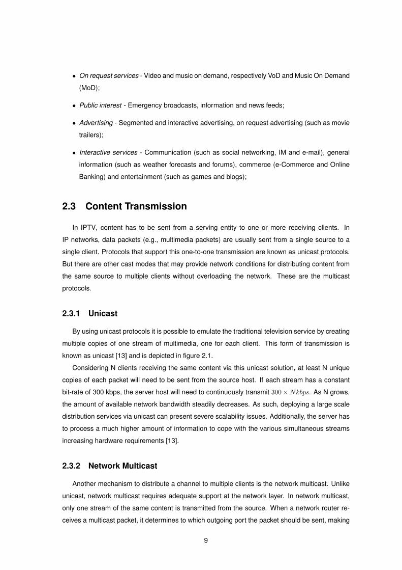
2.3.1 Unicast
By using unicast protocols it is possible to emulate the traditional television service by creating
multiple copies of one stream of multimedia, one for each client. This form of transmission is
known as unicast [13] and is depicted in figure 2.1.
Considering N clients receiving the same content via this unicast solution, at least N unique
copies of each packet will need to be sent from the source host. If each stream has a constant
bit-rate of 300 kbps, the server host will need to continuously transmit 300×Nkbps. As N grows,
the amount of available network bandwidth steadily decreases. As such, deploying a large scale
distribution services via unicast can present severe scalability issues. Additionally, the server has
to process a much higher amount of information to cope with the various simultaneous streams
increasing hardware requirements [13].
2.3.2 Network Multicast
Another mechanism to distribute a channel to multiple clients is the network multicast. Unlike
unicast, network multicast requires adequate support at the network layer. In network multicast,
only one stream of the same content is transmitted from the source. When a network router re-
ceives a multicast packet, it determines to which outgoing port the packet should be sent, making
9
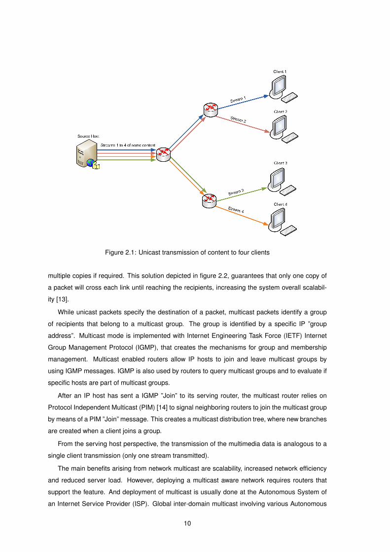
Figure 2.1: Unicast transmission of content to four clients
multiple copies if required. This solution depicted in figure 2.2, guarantees that only one copy of
a packet will cross each link until reaching the recipients, increasing the system overall scalabil-
ity [13].
While unicast packets specify the destination of a packet, multicast packets identify a group
of recipients that belong to a multicast group. The group is identified by a specific IP ”group
address”. Multicast mode is implemented with Internet Engineering Task Force (IETF) Internet
Group Management Protocol (IGMP), that creates the mechanisms for group and membership
management. Multicast enabled routers allow IP hosts to join and leave multicast groups by
using IGMP messages. IGMP is also used by routers to query multicast groups and to evaluate if
specific hosts are part of multicast groups.
After an IP host has sent a IGMP ”Join” to its serving router, the multicast router relies on
Protocol Independent Multicast (PIM) [14] to signal neighboring routers to join the multicast group
by means of a PIM ”Join” message. This creates a multicast distribution tree, where new branches
are created when a client joins a group.
From the serving host perspective, the transmission of the multimedia data is analogous to a
single client transmission (only one stream transmitted).
The main benefits arising from network multicast are scalability, increased network efficiency
and reduced server load. However, deploying a multicast aware network requires routers that
support the feature. And deployment of multicast is usually done at the Autonomous System of
an Internet Service Provider (ISP). Global inter-domain multicast involving various Autonomous
10

Figure 2.2: Multicast transmission of content to four clients
Systems, although technically possible is difficult to implement due to economic and commercial
interconnect issues [15].
2.3.3 End-to-end Transmission
In order to assess the feasibility of a transmission of multimedia data from server to client there
are three metrics that can influence the End User’s experience: the start-up delay, the end-to-end
delay and the playback continuity. The start-up delay represents the delay between the request
for the media and its subsequent display on the client. The end-to-end delay is the playback delay
between the source and the destination of the media. And the playback continuity (measured
by the percentage of received packets) in practice represents the ”hiccups” that a user witnesses
when watching streamed content [16]. Multimedia data transmission may be done in three modes,
streaming, downloading and hybrid progressive downloading.
The Streaming mode allows a client to view compressed video and audio without having to
download the entire content. This is accomplished by using a buffer to store codec frames. With
the use of buffers, the client is not required to store any persistent data. With this mode, random
access functionalities such as PVR functions - are feasible during playback and start-up delays are
typically short. However playback continuity is dependent on the status of the buffer as whenever
data in the buffer is low the continuity can be broken [17].
The Downloading mode implies receiving the whole multimedia content from the server in
the form of a file then reproducing it locally on the client. Typically, IPTV does not support this
11
form of transmission due to large start-up delays with large content, however, once the file is
stored, playback continuity is guaranteed. The disadvantage of this form of transmission is that
traditional television service cannot be offered, because broadcast television channels are a set of
continuous streams of video and audio (for each channel). On the other hand content provided by
downloading mode, corresponds to discrete content elements [11]. The advantages are: no time
sensitive encoding requirements and simplicity of deployment over any type of network regardless
of bandwidth and latency. The typical service that is offered in this mode is VoD of finite length
videos.
The Progressive Downloading mode is a hybrid approach that allows a client to download part
of the file and visualize its content as it arrives. Just as Downloading mode, this streaming mode
uses the persistent storage in the client to save the files. This method does not allow full random
access features as is the case with the Streaming mode, but bears similar start-up delays and
better playback continuity.
2.4 Quality of Service in IPTV Systems
In real-time based systems, such as streaming applications, QoS is an important factor in
the deployment of a commercial IPTV system. QoS can be described as an network operator’s
commitment with its customers to provide and maintain values of service parameters and char-
acteristics that are acceptable and expected [18]. For realtime based applications, such as IPTV,
the goal of QoS is to offer a minimum level of control over the current ”best-effort” service provided
by typical IP networks [19].
However, QoS management for digital video transmission over the Internet is an overwhelming
task, due to the lack of guarantees of data transfer speeds and delivery times. The difficulties are
increased if mobile wireless networks are considered, as available resources such as bandwidth
and capacity are scarce and vary immensely over time [18] [20]. Additionally, as more end users
connect to a service, degradation of service quality is seen in direct result of diminished network
capacity [19].
QoS is not limited to the physical aspects of transmission as the overall quality of the session
is greatly influenced by the encoding parameters used and the error and congestion control. The
variety of end user equipment also bring particular QoS requirements in terms of latency, encoding
parameters, processing power and bandwidth.
In order to provide video services with end-to-end QoS support there are two main approaches:
QoS provisioning from a network perspective and QoS control from the end-system’s perspec-
tive [20].
Network centric QoS provisioning mechanisms have been standardized by the IETF and are
the Integrated Services (IntServ) [21] and Differentiated Services (DiffServ) [22] mechanisms.
12

DiffServ sets a marker in a data packet to select the next Per Hop Behavior (PHB) at a network el-
ement level. The PHB specifies how the scheduler should queue and transmit the packet, allowing
packets to be prioritized according to their Class of Service. This provides a network QoS mecha-
nism that is a improvement over the ”Best-effort” mechanisms present in IP networks [22]. IntServ
on the other hand integrates services by means of a Resource Reservation Protocol (RSVP) that
signals the network elements in a path to create an end-to-end reserved channel. The reserved
channel can act on resource reservation or on admission control of data in the network. Both stan-
dards provide QoS on a network level however DiffServ provides a simpler mechanism that does
not require explicit resource reservation and network signaling, needing just pre-programmed
router parameters and marked packets, making it the most used QoS mechanism in best-effort
networks [19].
End-system QoS control mechanisms provide end-to-end QoS support using various tech-
niques, such as error, congestion and power control as well as multimedia encoding algorithms
(such as the MPEG-4 Part 10 codec [1]). The goal of these techniques are to maximize QoS
while not requiring any core network QoS mechanisms. This minimizes change requirements in
the network but requires highly efficient control mechanisms.
2.5 Architectures
There are two main architectures for IP based television. Both architectures have their ad-
vantages and disadvantages and can be applied concurrently by an operator or service provider.
They are the Server-Client architecture and the Peer-To-Peer architecture.
2.5.1 Server-Client Architecture
The first and simplest architecture is client-server based depicted in figure 2.3, where the client
downloads or plays streams of multimedia content from a server. Typically the multimedia files
are stored in a server or transcoded from a headend and sent to the client. This simplicity has
allowed for a rapid deployment of infrastructures offering this type of service, such as the popular
Youtube [23] for downloadable media or the Justin.tv [24] for live streaming channels.
2.5.2 Peer-to-Peer Architecture
With the ever increasing bit-rates that end users connect nowadays to the Internet, a more
recent architecture for IP television has surfaced. It is based on a distributed Peer-To-Peer (P2P)
model; in the P2P model each client receives video and audio chunks from other participants on
the network and displays the output as it arrives, as shown in figure 2.4. The client then acts as a
serving host and can forward the chunks to other requesting participants (see figure 2.4).
13

Figure 2.3: Server-client IP based television architecture
The benefits of this architecture are the scalability that P2P systems offer and the affordability
of maintaining such a system. However, the nature of this solution makes other pressing issues
difficult, such as digital rights management, longer start times compared to other solutions and
the inherent instability due to the lack of well known serving hosts [16].
2.6 Transport, Control and Signaling Protocols
Just like traditional telephony, IPTV requires a signaling protocol in order to initiate, modify
and terminate sessions under an IP environment. Control protocols are responsible for controlling
the multimedia streams, introducing networked features that were previously restricted to video
recorders, such as play, pause, rewind and forward. Finally, transport protocols are responsible
for transporting the multimedia streams to the end device, be it a set-top-box or mobile device.
2.6.1 Realtime Transport Protocol
The Realtime Transport Protocol (RTP) is an application-layer protocol responsible for realtime
delivery of, typically, multimedia data between two or more endpoints [25]. The primary services
that RTP offers are:
1. Payload Type - The type of data transported in a RTP packet. There are formats specified
for each type of data. As example formats 96 and 97, correspond to video and audio;
2. Sequence Numbering - A number present in the RTP packet header, that increments by one
for each RTP packet sent. The initial number sent is random to increase security (in order to
14

Figure 2.4: Peer-2-Peer IP based television architecture
make known-plaintext attacks more difficult). This numbering scheme allows the destination
to detect packet loss and out-of-sequence packets;
3. Timestamping - In real-time sensitive applications, it is important to keep synchronization
between sender and receiver. RTP implements a timestamping feature in its header, re-
flecting the sampling instant of the first octet of the data packet. The timestamp also allows
statistical measurements, such as the calculation of end-to-end jitter;
4. Delivery monitoring - By using the RTP Control Protocol (RTCP) it is possible to monitor
data distribution [25]. This is accomplished by a periodic transmission of control packets by
all participants in the session. Services performed by RTCP are:
(a) Feedback of quality of received data. It is related to flow and congestion control func-
tions of lower level protocols;
(b) RTCP carries a transport-level identifier for an RTP source, the Canonical Name (CNAME).
This allows receivers to identify participants in one or more related RTP sessions, as
well as multiple streams (such as video and audio multiplexed streams);
(c) In an environment of multiple participants, control packets can flood the network with
session reports. For this, RTCP has a self controlling mechanism to prevent such a
situation;
2.6.2 Real Time Streaming Protocol
The RTSP [26] unlike the it suggests does not typically stream contents (although it can) or
define the media to the end client. It is an application level protocol that establishes and controls
media streams (e.g., Setup, Teardown, Play and Pause).
15
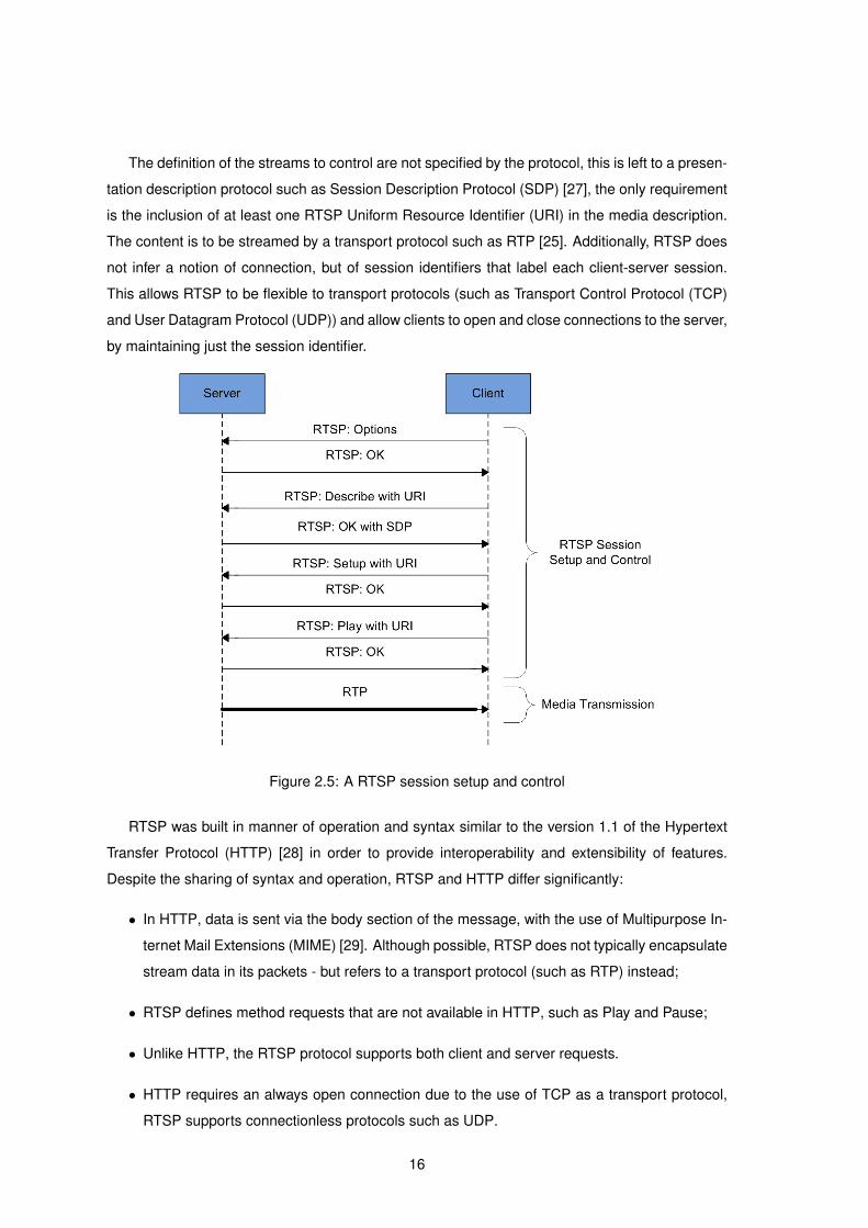
The definition of the streams to control are not specified by the protocol, this is left to a presen-
tation description protocol such as Session Description Protocol (SDP) [27], the only requirement
is the inclusion of at least one RTSP Uniform Resource Identifier (URI) in the media description.
The content is to be streamed by a transport protocol such as RTP [25]. Additionally, RTSP does
not infer a notion of connection, but of session identifiers that label each client-server session.
This allows RTSP to be flexible to transport protocols (such as Transport Control Protocol (TCP)
and User Datagram Protocol (UDP)) and allow clients to open and close connections to the server,
by maintaining just the session identifier.
Figure 2.5: A RTSP session setup and control
RTSP was built in manner of operation and syntax similar to the version 1.1 of the Hypertext
Transfer Protocol (HTTP) [28] in order to provide interoperability and extensibility of features.
Despite the sharing of syntax and operation, RTSP and HTTP differ significantly:
• In HTTP, data is sent via the body section of the message, with the use of Multipurpose In-
ternet Mail Extensions (MIME) [29]. Although possible, RTSP does not typically encapsulate
stream data in its packets - but refers to a transport protocol (such as RTP) instead;
• RTSP defines method requests that are not available in HTTP, such as Play and Pause;
• Unlike HTTP, the RTSP protocol supports both client and server requests.
• HTTP requires an always open connection due to the use of TCP as a transport protocol,
RTSP supports connectionless protocols such as UDP.
16
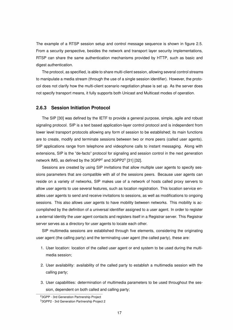
The example of a RTSP session setup and control message sequence is shown in figure 2.5.
From a security perspective, besides the network and transport layer security implementations,
RTSP can share the same authentication mechanisms provided by HTTP, such as basic and
digest authentication.
The protocol, as specified, is able to share multi-client session, allowing several control streams
to manipulate a media stream (through the use of a single session identifier). However, the proto-
col does not clarify how the multi-client scenario negotiation phase is set up. As the server does
not specify transport means, it fully supports both Unicast and Multicast modes of operation.
2.6.3 Session Initiation Protocol
The SIP [30] was defined by the IETF to provide a general purpose, simple, agile and robust
signaling protocol. SIP is a text based application-layer control protocol and is independent from
lower level transport protocols allowing any form of session to be established; its main functions
are to create, modify and terminate sessions between two or more peers (called user agents).
SIP applications range from telephone and videophone calls to instant messaging. Along with
extensions, SIP is the ”de-facto” protocol for signaling and session control in the next generation
network IMS, as defined by the 3GPP2 and 3GPP23 [31] [32].
Sessions are created by using SIP invitations that allow multiple user agents to specify ses-
sions parameters that are compatible with all of the sessions peers. Because user agents can
reside on a variety of networks, SIP makes use of a network of hosts called proxy servers to
allow user agents to use several features, such as location registration. This location service en-
ables user agents to send and receive invitations to sessions, as well as modifications to ongoing
sessions. This also allows user agents to have mobility between networks. This mobility is ac-
complished by the definition of a universal identifier assigned to a user agent. In order to register
a external identity the user agent contacts and registers itself in a Registrar server. This Registrar
server serves as a directory for user agents to locate each other.
SIP multimedia sessions are established through five elements, considering the originating
user agent (the calling party) and the terminating user agent (the called party), these are:
1. User location: location of the called user agent or end system to be used during the multi-
media session;
2. User availability: availability of the called party to establish a multimedia session with the
calling party;
3. User capabilities: determination of multimedia parameters to be used throughout the ses-
sion, dependent on both called and calling party;
23GPP - 3rd Generation Partnership Project33GPP2 - 3rd Generation Partnership Project 2
17
4. Session setup: Establishment of session between both called and calling parties. In tele-
phony this is the ”ringing” stage, dictating when both ends of the user agents are ready to
receive the multimedia stream;
5. Session management: this facet of SIP manages the modification of session parameters,
invocation of services and termination of the session.
From a security point of view, SIP offers some security mechanisms. It allows replay protec-
tion and one-way authentication. Confidentiality issues are not easily addressed because proxy
servers need to have access to the SIP headers in order to forward the SIP requests to their des-
tinations. Secure / Multipurpose Internet Mail Extensions (S/MIME) [33] can be used to secure
the body of the SIP messages, but it still allows an attacker to see the header of the packet [32].
At this level, content security or data encryption can be provided by using network level security
(such as the IP Security (IPsec) [34] - suite of protocols) or Transport Layer Security (TLS) [32].
Authentication is provided by mechanisms offered by HTTP, by placing digital signatures in the
header and non-repudiation and integrity measures.
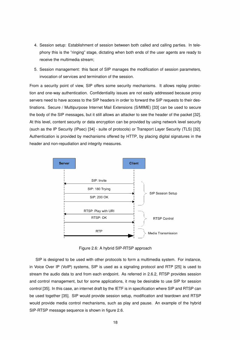
Figure 2.6: A hybrid SIP-RTSP approach
SIP is designed to be used with other protocols to form a multimedia system. For instance,
in Voice Over IP (VoIP) systems, SIP is used as a signaling protocol and RTP [25] is used to
stream the audio data to and from each endpoint. As referred in 2.6.2, RTSP provides session
and control management, but for some applications, it may be desirable to use SIP for session
control [35]. In this case, an internet draft by the IETF is in specification where SIP and RTSP can
be used together [35]. SIP would provide session setup, modification and teardown and RTSP
would provide media control mechanisms, such as play and pause. An example of the hybrid
SIP-RTSP message sequence is shown in figure 2.6.
18
This approach allows a new composite media control protocol, other than RTSP, that can
provide additional commands for multimedia streaming content. The requirements for such a
media control protocol are as follows [35]:
1. The media control protocol (in this case RTSP) must support the following trick functions:
play, pause, rewind, forward, fast forward, slow forward, rewind, fast rewind and slow rewind;
2. Negotiation of the media control protocol must be supported;
3. It must be possible to specify which media streams can be controlled by a given media
control protocol;
4. The media control protocol must support asynchronous media notifications, such as end-of-
stream;
5. TCP should be supported as a transport protocol;
6. A client can control a media stream independently of its location (on a home network or any
other network);
7. If needed, the media control protocol should implement additional commands that are not
available in RTSP to control the multimedia stream.
2.7 Multimedia Codecs
Streaming of multimedia content is quite demanding in terms of network capacity namely be-
cause bandwidth is a shared and scarce resource. As such, bandwidth toggling when streaming
video is an important feature in order to provide scalability and reliability of an IP based video so-
lution [36]. The easiest way to limit network usage is to consume as little bandwidth as possible.
Because video and audio data are by far the most transferred in a multimedia session, it is im-
portant to compress the data before it is sent over the network. Compression and decompression
of streams is achieved using encoders and decoders (codecs). Codecs have been constantly
developed, and as such there are many specialized versions available. Examples are the ITUs 4
H.26x, focused on telecommunication applications such as video-telephony and MPEGs 5 stan-
dards, focused on rich multimedia applications such as high definition videos.
In order to achieve compression rates, video codecs rely on mathematical techniques, such as
frame compression and adaptive perceptual quantization [37]. A video feed is comprised of many
individual luminance and chrominance frames, these frames are then compressed by reducing
4ITU-T - The body of the ITU that coordinates standards for telecommunications.5MPEG - Moving Pictures Experts Group, formed by the International Organization for Standardization (ISO) to set
standards for video and audio compression.
19
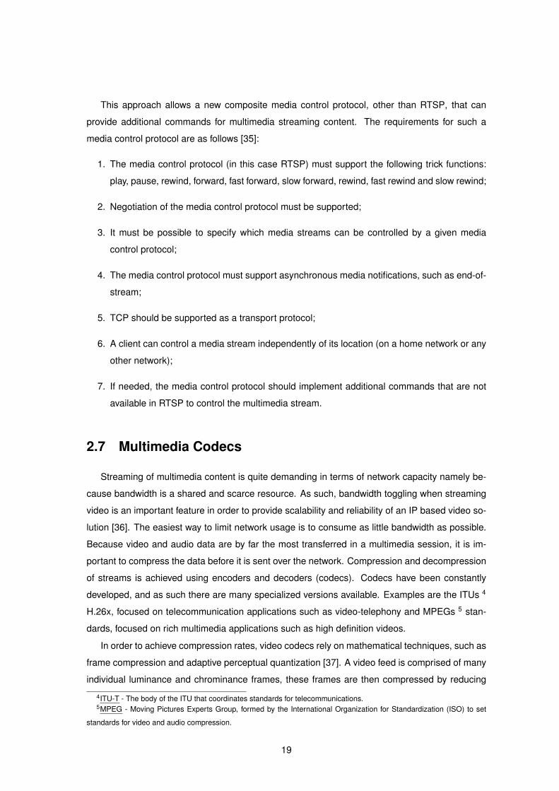
spatial and temporal redundancy, using entropy encoding and motion compensation. Generally,
codecs use three main types of frames (see figure 2.7):
I-Frames called Intra-frames, rely on Discrete Cosine Transform (DCT) (in the case of the MPEG
family of codecs [1]) and entropy encoding (used by individual digital images), basically
becoming compressed images of the original frames;
P-Frames (predicted frames) use similar encoding algorithms as the Intra-frames but adds mo-
tion compensation to previous Intra or Predicted frames allowing temporal redundancy to be
explored, achieving a higher compression factor;
B-Frames (Bi-directional frames) just like Predicted frames, use the same spatial compression
techniques, but can rely on previous and next Intra and Predicted frames. Bi-directional
frames tend to achieve the highest compression factors.
A grouping of inter-dependent Intra, Predicted and Bi-directional frames are called a Group Of
Pictures (GOP).
Figure 2.7: A 12 frame Group of Pictures
Quantization takes advantage of the human perception of lower and higher frequencies in im-
ages. In adaptive perceptual quantization, the images are split into a fixed number of frequency
ranges. Less visually important frequencies have their DCT factor set to zero, while other frequen-
cies are applied to predetermined coefficients, allowing only the visually important frequencies to
20

be compressed and transmitted [38].
2.7.1 MPEG-2 Coding
Until recently, the most successful codec used has been the Moving Picture Experts Group
(MPEG) second standard in compression algorithms second group of MPEG codecs (MPEG-
2) [39]. It’s predecessor, first group of MPEG codecs (MPEG-1) [40], introduced the bidirectional
dependent frames (B-Frames) but lacked overall quality at target bit rates [41].
MPEG-2 is interesting for streaming because it supports transport multiplexing of different
MPEG-2 streams. Each stream, be it video or audio, is an Elementary stream (ES) that after
packetizing composes a Packetized Elementary Stream (PES). After creating the PES stream, it
is possible to multiplex the data in two formats:
MPEG Program Stream By tightly coupling various PES synchronized to a common time base.
The usage of the MPEG Program Stream (PS) is better suited for low error transport medi-
ums (such as Digital Video Disc (DVD)’s);
MPEG Transport Stream PES packets are split and packetized into the transport stream Transport
Stream (TS). The TS possesses error correction mechanisms that make bit errors more re-
coverable, and so TS streams are more suited for higher Bit Error Rate (BER) media (such
as the Digital Video Broadcasting (DVB) family of technologies).
Due to the widespread deployment of the MPEG-2 codec, many hardware and software based
solutions have been designed, making coding and decoding of the multimedia fast enough to
be compressed and decompressed on the fly, making it highly suitable for Live Television (TV)
streams. The typical compression factors while keeping good video quality for MPEG-2 video are
around 30:1 [41]. However, this value is highly dependent on the nature of the multimedia to com-
press, as the main factors for high compression values are low levels of motion (videoconferencing
and video surveillance) and low level of detail.
Streaming a standard definition television quality channel using MPEG-2 can be roughly cal-
culated, considering a Red Green Blue (RGB) 24 bit color pallet for each pixel and a resolution of
704 pixels wide and 576 pixels height at a compression factor of 30:1, each video frame will have
a size of:
Bits per frame =24× (704× 576)
30= 324403.2bits = 0.3Mbits (2.1)
At a constant 25 frames per second, even with the 30:1 compression factor, the average output
will be roughly 8 Mbps per channel not including any audio channels and, in the case of delivery
over IP, not including the overhead from headers of the various protocols discussed.
21
2.7.2 MPEG-4 - Advanced Video Coding
A more recent video coding standard is the H.264 Advanced Video Codec (AVC) [42]. This
standard started being developed in 1998 when the Video Coding Expert Group (VCEG) as part
of the ITU Telecommunication Standardization Sector (ITU-T), created a project called H.26L.
The target for this project was to double the coding efficiency, meaning that for the same quality
offered by MPEG-2, the new standard that resulted from H.26L would use half of the bit rate. For
the example above and the same conditions, the coded bit-rate should be roughly 4 Mbps. After a
call for proposals for the project, the MPEG formed a Joint Video Team (JVT) with the ITU-T and
submitted for approval the H.264 AVC in 2003 [43].
As in previous projects, only the decoder is standardized allowing any video coding imple-
mentation to work with the decoder as long as it is in conformity with the restrictions specified
by the standard. This freedom of implementation, allows optimization and customization of the
coding block for different scenarios, be it over a low BER medium, like DVD, or highly error prone
medium like satellite transmission, making it interesting for implementation on streaming solutions
over mobile networks [1].
Several enhancements over MPEG-2 were implemented in order to improve compression and
provide better resilience to errors:
Enhanced entropy encoding H.264 included a advanced arithmetic coding scheme known as
Context-adaptive binary arithmetic coding (CABAC) and a context adaptive coding scheme
known as Context-adaptive variable-length coding (CAVLC). Both coding schemes allow a
higher compression performance than previous video standards.
Motion compensation Unlike MPEG-2, the size and shape of blocks referenced by motion vec-
tors are variable, the motion vectors have quarter-pixel resolution (in MPEG-2 the resolution
is of half-pixel), multiple reference pictures can be used for motion compensation and motion
vectors may now point to outer picture areas;
Artifact reduction H.264 allows an adaptive filter to reduce the blocking artifacts found in block
based video coding (such as MPEG-2 and fourth group of MPEG codecs (MPEG-4)). The
filter is tightly coupled to the motion compensation prediction loop and so, all improvements
found in the Intra frames will be propagated to the other derived Predicted and Bi-directional
frames. This filter is known as In-the-loop deblocking filtering. Artifact reduction is accom-
plished by improvement in the spatial redundancy calculations using smaller block sizes
(4x4) and an integer transform instead of the DCT.
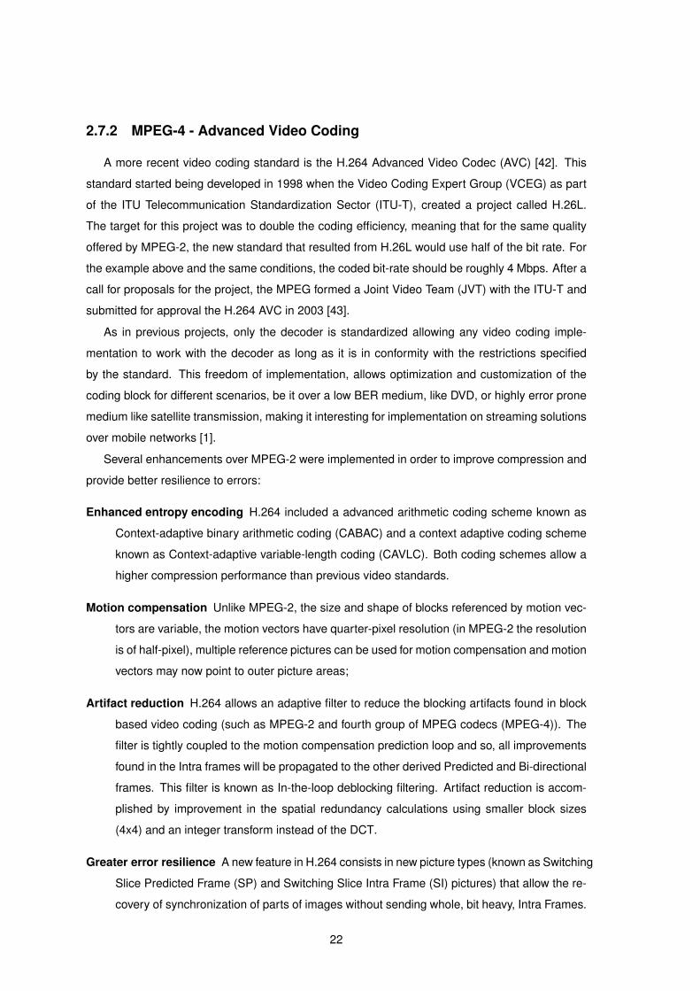
Greater error resilience A new feature in H.264 consists in new picture types (known as Switching
Slice Predicted Frame (SP) and Switching Slice Intra Frame (SI) pictures) that allow the re-
covery of synchronization of parts of images without sending whole, bit heavy, Intra Frames.
22
In addition to the SP/SI pictures, H.264 allows the encoder to include within the video stream
redundant low-quality sections of pictures. Sections of coded pictures may be sent and de-
coded with relative independence of the rest of the coded pictures. This design provides
robustness on networks that have an out-of-order delivery behavior.
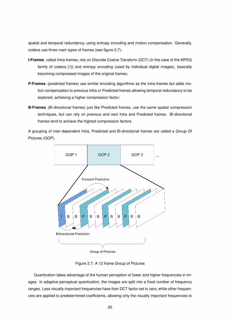
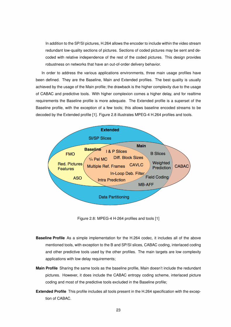
In order to address the various applications environments, three main usage profiles have
been defined. They are the Baseline, Main and Extended profiles. The best quality is usually
achieved by the usage of the Main profile; the drawback is the higher complexity due to the usage
of CABAC and predictive tools. With higher complexion comes a higher delay, and for realtime
requirements the Baseline profile is more adequate. The Extended profile is a superset of the
Baseline profile, with the exception of a few tools; this allows baseline encoded streams to be
decoded by the Extended profile [1]. Figure 2.8 illustrates MPEG-4 H.264 profiles and tools.
Figure 2.8: MPEG-4 H-264 profiles and tools [1]
Baseline Profile As a simple implementation for the H.264 codec, it includes all of the above
mentioned tools, with exception to the B and SP/SI slices, CABAC coding, interlaced coding
and other predictive tools used by the other profiles. The main targets are low complexity
applications with low delay requirements;
Main Profile Sharing the same tools as the baseline profile, Main doesn’t include the redundant
pictures. However, it does include the CABAC entropy coding scheme, interlaced picture
coding and most of the predictive tools excluded in the Baseline profile;
Extended Profile This profile includes all tools present in the H.264 specification with the excep-
tion of CABAC.
23

With the standard defined, proliferation of the H.264 AVC codec has been possible, being
currently used in numerous devices, from IPTV set-top-boxes to cellular telephones, and has
also been deployed in numerous IPTV architectures and commercial solutions. Several studies
have shown that H.264 provides real and effective improvements on video transmission over IP
networks [44].
2.7.3 VC-1 Coding
This coding scheme was developed and implemented by Microsoft for their proprietary video
format, Windows Media Video 9 (WMV9). The VC-1 is a video coding format standardized by the
SMPTE 6. It provides higher compression factors and quality improvements than those found in
Microsoft’s Windows Media Video 8 (WMV8) codec. The VC-1 represents an alternative to ITU-Ts
H.264 AVC, showing substantial benefits when compared to MPEG-2 [45].
VC-1’s main features include the ones already discussed in paragraph 2.7.2 MPEG-4, with
little variation between the two codecs . Tests have shown that both video coding standards have
similar subjective quality and compression results. Complexity comparisons between the two
codecs have shown favorable results for the VC-1 codec. While it is difficult to evaluate quality of
experience, Peak Signal-to-Noise Ratio (PSNR) comparisons have shown a VC-1 image quality
to be slightly superior to that of H.264 [46].
2.7.4 AAC Coding
While video occupies most of the bandwidth in a multimedia session, audio quality is also an
important component in the overall QoE while watching a video stream. The most promising codec
for audio is the MPEG-4 Advanced Audio Coding (AAC) [47], based on the previous standard
MPEG-2 AAC. The MPEG-2 version of AACs main goal is to provide an indistinguishable quality
encoder when compared to the original uncompressed audio signal.
The AAC encoder is a time/frequency (T/F) based codec, which means, audio is encoded us-
ing spectral representations (in the frequency domain) of the input audio. This type of encoder
has numerous benefits for audio compression: it allows filtering of irrelevant audio input and ex-
plores redundancy removal techniques. With these techniques, it is possible to compress audio
while keeping the perceptual quality unaltered. Due to the outstanding quality and performance
achieved at low bit-rates (from as low as 16 kbps), MPEG-2 AAC was chosen as the main audio
encoder for the MPEG-4 format as MPEG-2 AAC already provides indistinguishable audio encod-
ing from bit-rates at 96 to 128 kbps for stereo audio and 256 to 320 kbps for 5 channel audio
signals.
6SMPTE - Society of Motion Picture Engineers
24

The main additions of the MPEG-4 version of AAC to MPEG-2 AAC are related to streaming
applications such as low delay encoding, error resilience and robustness. As mentioned before,
error robustness at the encoding level is an important feature to reduce transmission protocol
dependence and delay in any realtime system.
2.7.5 Codec Comparison
Although the MPEG-2 video coding and compression algorithm is still the most supported
standard, the H.264 and the VC-1 encoders are becoming the replacement of choice due to
their higher compression factors. In fact, the two codecs have a compression efficiency that
approximately doubles that of the MPEG-2 video codec. However, both H.264 and VC-1s complex
algorithms make real time encoding very computationally demanding.
A moderated video standard included in the MPEG-4 group of standards is the MPEG-4 Part
2 [48], also known as MPEG-4 Visual. This video codec shares many of the features found in
MPEG-2 and the MPEG-4 Part 10 (H.264) codec. As such, it achieves a compression rate better
than that of MPEG-2 while being less complex than H.264 and VC-1. Table 2.1 summarizes the
main differences between the four codecs.
Various services appeared based on the H.264 codec, from IPTV to DVB, taking advantage of
the high compression factors and better error resilience. A few examples of services using these
codecs are the MEO family of products by Portugal Telecom [49], that offers IPTV and Satellite
broadcasting as well as the terrestrial DVB service currently being implemented in Portugal [50].
Additionally, in Portugal the ISP Sonaecom [51] currently offers its IPTV platform using MPEG-2
Visual codec instead of the MPEG-4 family of codecs.
2.8 Streaming Servers
As video streaming interest increases, many servers capable of streaming multimedia content
over IP connections are being developed. The main solutions available nowadays can supply pre-
configured systems providing advanced streaming options on a User Interface (UI) that is both
powerful and easy to manipulate. These solutions are the Apple Quicktime Streaming Server, the
Helix Video Server and the VideoLan Media Server.
2.8.1 Quicktime Streaming Server
Created by Apple, the QuickTime Streaming Server (QTSS) offers a multimedia streaming
server based on RTSP and RTP protocols [52]. Codecs supported are the MPEG-4 family and
MPEG-1 Audio Layer 3 (MP3). Management is facilitated by means of a simple Graphical User
25
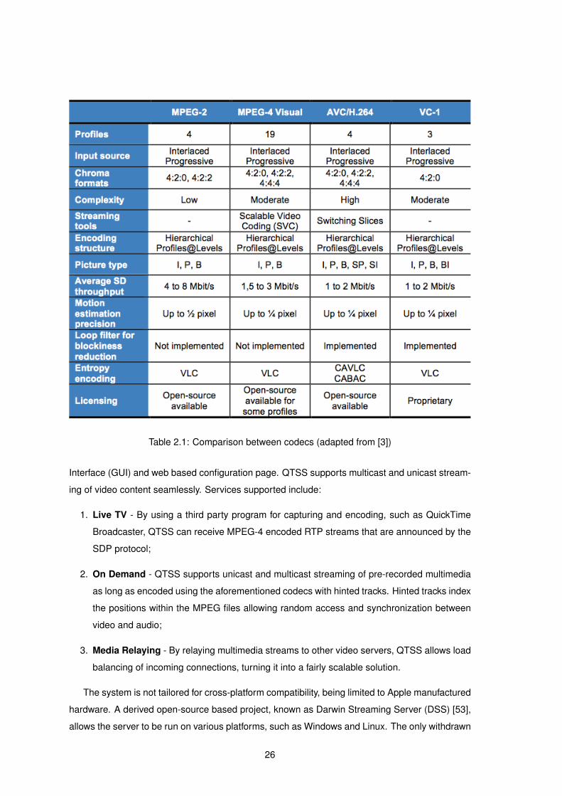
Table 2.1: Comparison between codecs (adapted from [3])
Interface (GUI) and web based configuration page. QTSS supports multicast and unicast stream-
ing of video content seamlessly. Services supported include:
1. Live TV - By using a third party program for capturing and encoding, such as QuickTime
Broadcaster, QTSS can receive MPEG-4 encoded RTP streams that are announced by the
SDP protocol;
2. On Demand - QTSS supports unicast and multicast streaming of pre-recorded multimedia
as long as encoded using the aforementioned codecs with hinted tracks. Hinted tracks index
the positions within the MPEG files allowing random access and synchronization between
video and audio;
3. Media Relaying - By relaying multimedia streams to other video servers, QTSS allows load
balancing of incoming connections, turning it into a fairly scalable solution.
The system is not tailored for cross-platform compatibility, being limited to Apple manufactured
hardware. A derived open-source based project, known as Darwin Streaming Server (DSS) [53],
allows the server to be run on various platforms, such as Windows and Linux. The only withdrawn
26
functionality is the system GUI. Other issues on both versions are the format of the videos, which
have to be encoded on Quicktime derived products. On-the-fly transcoding can only be done
using a separate streaming application and clients are limited to MPEG-4 compatible devices.
2.8.2 Helix Video Server
Helix Video Server is at time of written at version 12 and is produced by Real Networks soft-
ware company [54]. It supports RTSP masked as HTTP for signaling. Codecs that are fully sup-
ported are the proprietary RealVideo and RealAudio, the MPEG-4 video, the H.264, H.263, AAC
and the Adaptive Multi-Rate Compression (AMR). Two transport protocols are supported: RTP
and Real Networks Transport Protocol (RDP) [54]. Services supported are identical to Apple’s
solution with the following additional services:
1. Fast-channel switching - Helix supports a web based feature that allows seamless chang-
ing of video or audio channels. The client starts by requesting a new channel via HTTP, the
server proceeds to stop transmitting the previous channel and immediately starts the new
channel with the most recent available intra frame [55];
2. Web portal - Helix allows third party web portals to act as interface for users to select
multimedia streams. Streams are selected using a normal HTTP Get command;
3. Authentication, Authorization and Accounting (AAA) support - AAA functions are sup-
ported by the Helix streaming server.
Being a proprietary server implementation, Helix comes with increased cost. But an open-
source project known as Helix DNA allows a free solution to be used. It also has a licensed
mobile version specifically tailored for mobile devices. Although using, by default, proprietary
protocols and encoders, users are required to install Real Networks client media player to use
most of its functions. Additionally stored content cannot be transcoded on-the-fly.
2.8.3 VideoLan Media Player
Starting off as a engineering project for a university in France, Video Lan Media Player (VLC)
has evolved to a highly customizable open-source multimedia streaming application [56]. The
media player is the result of media player and media server integration into one simple application.
It currently supports most codecs and offers various open source implementations of coders and
encoders [57], providing transcoding mechanisms from acquired content.
Unlike previous streaming servers, it is highly portable, ranging from UNIX-based enterprise
systems to handheld devices. Non-proprietary signaling and transport protocols (such as HTTP
and RTP) are also supported.
27
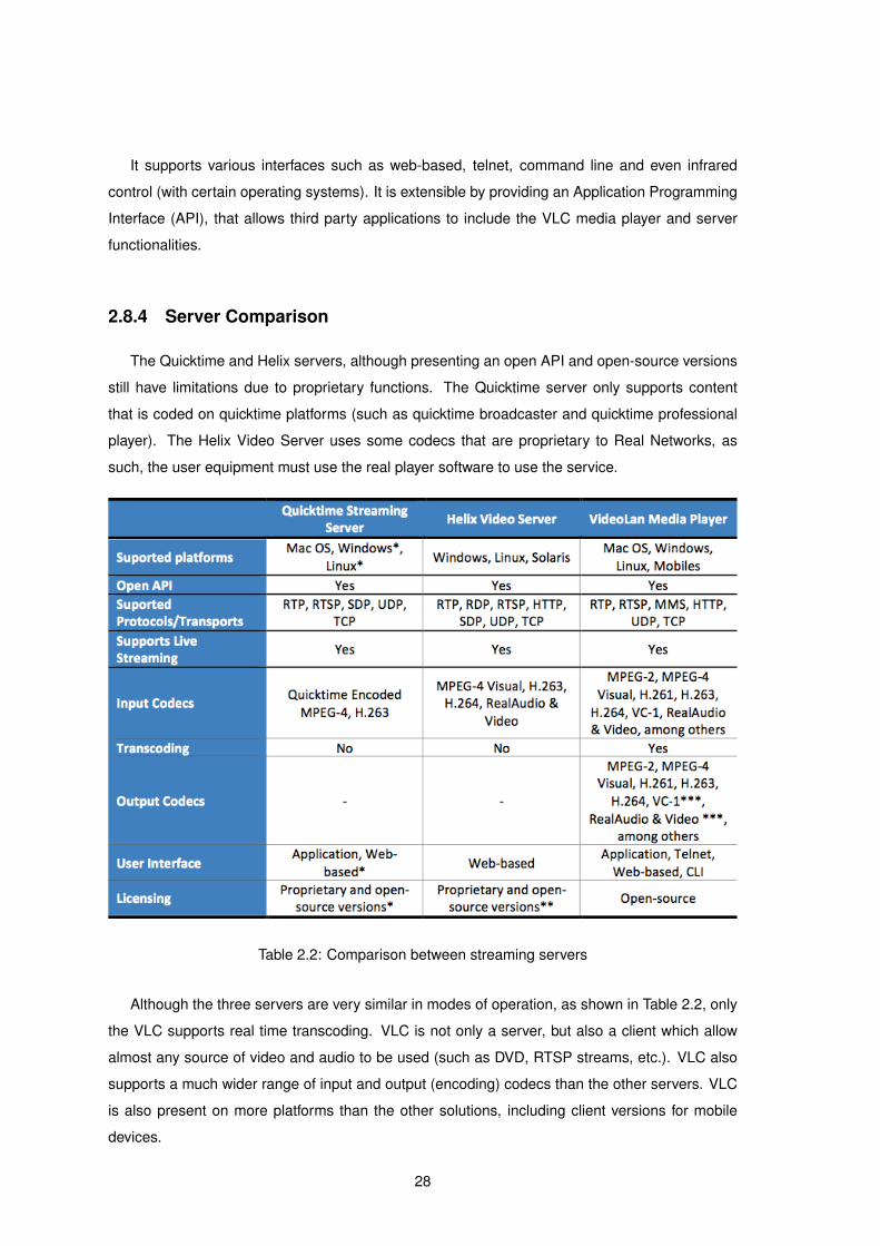
It supports various interfaces such as web-based, telnet, command line and even infrared
control (with certain operating systems). It is extensible by providing an Application Programming
Interface (API), that allows third party applications to include the VLC media player and server
functionalities.
2.8.4 Server Comparison
The Quicktime and Helix servers, although presenting an open API and open-source versions
still have limitations due to proprietary functions. The Quicktime server only supports content
that is coded on quicktime platforms (such as quicktime broadcaster and quicktime professional
player). The Helix Video Server uses some codecs that are proprietary to Real Networks, as
such, the user equipment must use the real player software to use the service.
Table 2.2: Comparison between streaming servers
Although the three servers are very similar in modes of operation, as shown in Table 2.2, only
the VLC supports real time transcoding. VLC is not only a server, but also a client which allow
almost any source of video and audio to be used (such as DVD, RTSP streams, etc.). VLC also
supports a much wider range of input and output (encoding) codecs than the other servers. VLC
is also present on more platforms than the other solutions, including client versions for mobile
devices.
28

2.9 Conclusion
The goals in this chapter were to study and analyze the state-of-the-art technologies in the
dissemination of multimedia contents over IP networks and to clarify the differences between the
often confused IPTV and Internet television concepts.
The benefits and drawbacks of the unicast and multicast multimedia transmission mechanisms
were discussed for a better understanding of the scenarios where they can be applied. Therefore
it was shown that unicast is more suited for personalized streaming, such as video on demand
services, whilst the benefits of multicasts inherent scalability makes it more appropriate for broad-
casting of multimedia to several users.
Also discussed was the importance of assuring quality of service and how it affects the user
experience.
The server to client architecture was also presented and the more recent peer-to-peer architec-
ture was introduced. Each of the architectures has benefits, but the greater ease in management
of the server to client architecture reflects its widespread usage.
Signaling protocols that make the IPTV service possible are also discussed. Specifically the
RTP which is responsible for transporting the audio and video streams to the end user and pro-
vides mechanisms to assure the correct visualization of the content. Followed by the RTSP and
SIP protocols which allow Trick Functions and session control.
Finally a brief introduction to the state-of-the-art in multimedia codification and compression
standards was discussed as well as the most common open-source streaming servers.
29

30
3IPTV in Next Generation Network
environments
Contents
3.1 Introduction . . . . . . . . . . . . . . . . . . . . . . . . . . . . . . . . . . . . . . 32
3.2 Overview of the IMS Architecture . . . . . . . . . . . . . . . . . . . . . . . . . . 32
3.3 Overview of the IPTV Service Model . . . . . . . . . . . . . . . . . . . . . . . . 35
3.4 The ETSI View of IPTV in IMS . . . . . . . . . . . . . . . . . . . . . . . . . . . . 35
3.5 IPTV in IMS Requirements . . . . . . . . . . . . . . . . . . . . . . . . . . . . . . 37
3.6 Benefits of a IMS IPTV Architecture . . . . . . . . . . . . . . . . . . . . . . . . . 39
3.7 Conclusion . . . . . . . . . . . . . . . . . . . . . . . . . . . . . . . . . . . . . . . 39
31

3.1 Introduction
This chapter starts with brief overview of the IMS architecture and the IPTV service model to
bridge the converged model of IPTV in IMS and its requirements.
3.2 Overview of the IMS Architecture
In terms of convergence, IMS originally designed by 3rd Generation Partnership Project (3GPP)
and later updated by 3GPP, 3rd Generation Partnership Project 2 (3GPP2) and Telecoms & In-
ternet converged Services & Protocols for Advanced Networks (TISPAN) [58] is considered the
”de facto” architecture for many within the telecommunications industry [59] and presents itself
as the framework that allows the convergence of the Internet, wireless and wireline networks and
the global platform for the delivery of IP multimedia applications in NGN. This All-IP network
architecture is access medium independent and is based on packet based networks [31].
Figure 3.1: ETSIs IMS Functional Entities and interfaces [2]
The IMS architecture defines how services or applications interact with the underlying hetero-
geneous networks and how they communicate with the network provider’s back-end systems [60].
This architecture defines Functional Entities (3.1) and their roles organized in layers and planes
(Figure 3.2):
• Service Plane (Application Layer)
• Session Control Plane (Session and Database Layer)
32

• Media Control Plane (Media Control and Gateway Layer)
• User Plane (Access and Transport Layer)
Figure 3.2: IMS architectural Planes and Layers [2]
3.2.1 The IMS User Plane
The IMS user plane provides a QoS-enabled IP core network with access from a User Equipment
(UE) over various access technologies. It is designed to provide a wide range of IP multime-
dia server-based and P2P services. The access to the core network is through Border Gate-
ways (such as the Interconnect Border Gateway Function (I-BGF) and Core Border Gateway
Function (A-BGF)). These gateways enforce policies provided by the IMS core, controlling the
flow of traffic between access and core networks.
Within the IMS User Plane the Resource and Admission Control Subsystem (RACS) controls
the resources required for a session, these resources are defined by Interconnect Border Control
Function (I-BCF) present in the Control Plane. The I-BGF and A-BGF provide media relay for hid-
ing endpoint addresses with the use of Network Address and Port Translation (NAPT) functions.
3.2.2 The IMS Control Plane
The control plane is located between the Service and User Planes. It routes call signaling
(Session Control), informs the User Plane of traffic flow policies (Media Control) and generates
billing information for the use of the network. At the core of this is the Call Session Control
Function (CSCF), which is composed of the following functions:
33

• The Proxy Call Session Control Function (P-CSCF) is the first point of contact for the users
with the IMS. The P-CSCF is responsible for the security of messages transferred between
the users and the network, it also allocates the necessary resources for media flows.
• The Interrogating Call Session Control Function (I-CSCF) is the first point of contact with
other IMS networks, it is responsible for querying the Home Subscriber Server (HSS) the
Serving-CSCF for a user and may use a Topology Hiding Inter-Network Gateway (THIG) to
hide the network topology from other peer networks.
• The Serving Call Session Control Function (S-CSCF) controls the call sessions. It is re-
sponsible for processing user and call registrations to record each user location, user au-
thentication and call processing. The S-CSCFs operation is controlled by policies stored by
the HSS.
The Control Plane includes the User Profile Server Function (UPSF), it is responsible for
maintaining the service policies for each user in a central location. It includes services such
as: roaming information, telephony service information (such as call forwarding information), IM
information (such as buddy lists), etc. This centralization simplifies user management and insures
a consistent view of subscribers across all services.
The IMS Control Plane also controls the traffic within the User Plane through the RACS. This
control consists of two functions:
• The Policy Decision Function (PDF) implements the local policy on resource usage.
• The Resource Access Control Function (RACF) controls the QoS within the access network.
3.2.3 The IMS Application Plane
The IMS Application Plane provides an infrastructure that allows the management and provi-
sion of services. It defines standard interfaces to IMS functions which include:
• The UPSF which provides configuration storage, location and presence of users and identity
management.
• The Charging Gateway Function (CGF) that provides the billing functions.
• The control of multimedia calls and messaging which is provided by the Control Plane.
The various Application Servers (AS) are implemented in the Application Plane, they provide
end-user service logic. AS have been developed for services such as telephony, PTT and IM.
34
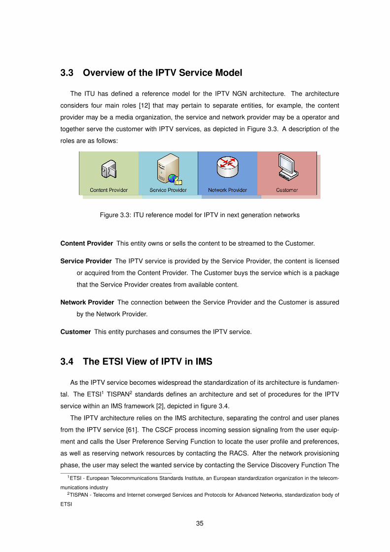
3.3 Overview of the IPTV Service Model
The ITU has defined a reference model for the IPTV NGN architecture. The architecture
considers four main roles [12] that may pertain to separate entities, for example, the content
provider may be a media organization, the service and network provider may be a operator and
together serve the customer with IPTV services, as depicted in Figure 3.3. A description of the
roles are as follows:
Figure 3.3: ITU reference model for IPTV in next generation networks
Content Provider This entity owns or sells the content to be streamed to the Customer.
Service Provider The IPTV service is provided by the Service Provider, the content is licensed
or acquired from the Content Provider. The Customer buys the service which is a package
that the Service Provider creates from available content.
Network Provider The connection between the Service Provider and the Customer is assured
by the Network Provider.
Customer This entity purchases and consumes the IPTV service.
3.4 The ETSI View of IPTV in IMS
As the IPTV service becomes widespread the standardization of its architecture is fundamen-
tal. The ETSI1 TISPAN2 standards defines an architecture and set of procedures for the IPTV
service within an IMS framework [2], depicted in figure 3.4.
The IPTV architecture relies on the IMS architecture, separating the control and user planes
from the IPTV service [61]. The CSCF process incoming session signaling from the user equip-
ment and calls the User Preference Serving Function to locate the user profile and preferences,
as well as reserving network resources by contacting the RACS. After the network provisioning
phase, the user may select the wanted service by contacting the Service Discovery Function The
1ETSI - European Telecommunications Standards Institute, an European standardization organization in the telecom-
munications industry2TISPAN - Telecoms and Internet converged Services and Protocols for Advanced Networks, standardization body of
ETSI
35
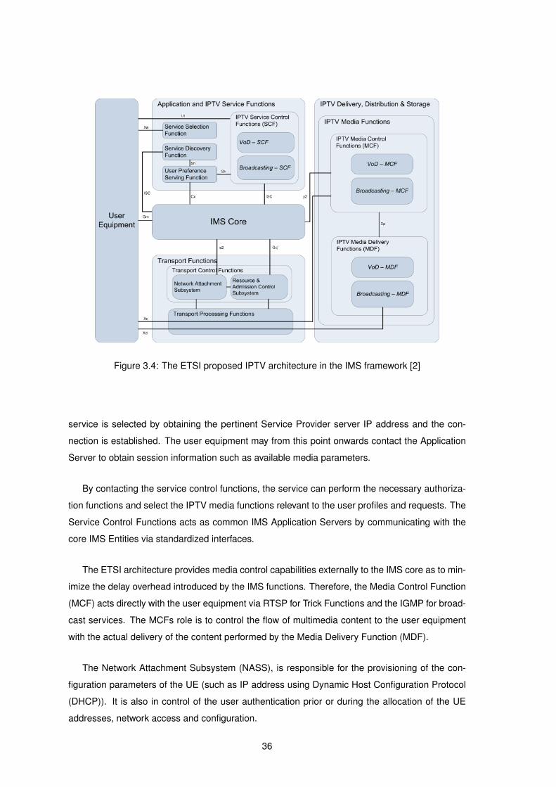
Figure 3.4: The ETSI proposed IPTV architecture in the IMS framework [2]
service is selected by obtaining the pertinent Service Provider server IP address and the con-
nection is established. The user equipment may from this point onwards contact the Application
Server to obtain session information such as available media parameters.
By contacting the service control functions, the service can perform the necessary authoriza-
tion functions and select the IPTV media functions relevant to the user profiles and requests. The
Service Control Functions acts as common IMS Application Servers by communicating with the
core IMS Entities via standardized interfaces.
The ETSI architecture provides media control capabilities externally to the IMS core as to min-
imize the delay overhead introduced by the IMS functions. Therefore, the Media Control Function
(MCF) acts directly with the user equipment via RTSP for Trick Functions and the IGMP for broad-
cast services. The MCFs role is to control the flow of multimedia content to the user equipment
with the actual delivery of the content performed by the Media Delivery Function (MDF).
The Network Attachment Subsystem (NASS), is responsible for the provisioning of the con-
figuration parameters of the UE (such as IP address using Dynamic Host Configuration Protocol
(DHCP)). It is also in control of the user authentication prior or during the allocation of the UE
addresses, network access and configuration.
36

3.5 IPTV in IMS Requirements
The 3GPP efforts to standardize the IMS as a NGN architecture also provides a general
overview of the functionalities that the IPTV architecture should support. The requirements are
separated into three main groups: User, Network and Services [4]:
• User Perspective: The customer and user expects IPTV to provide the traditional television
service in addition to: VoD, e-learning, personalized content and interactivity. Being all-
IP based services, they may be used as building blocks for new services such as instant
multimedia messaging, online games and conferencing.
• Network Perspective: As for IMS, the IPTV architecture should support and seamlessly
integrate various access networks, such as wireless and fixed networks. In order to support
scalable video distribution services, the network should support multicast and broadcast.
• Services Perspective: The service must support billing functions, such as subscriber based
online and offline charging, pay per view mechanisms and content and service charging.
The IPTV architecture should also provide setup and modification of services according to
users preferences and capabilities, as well as adapting and monitoring sessions. Finally, the
NGN architecture must provide service discovery and it consumed, the consequent resource
reservation.
The ITU’s NGN architecture has also presented requirements for the deployment of IPTV
services and are separated in six areas [12], they are:
1. IPTV network architecture
2. QoS and performance
3. Security and content protection
4. Network and control
5. End and middleware systems
6. Public service
3.5.1 IPTV Network Architectural Aspects
IPTV services shall be integrated into existing services (such as Plain Old Telephone Service
(POTS), VoIP and video conferencing) allowing all services to be available under one unified
platform. This implies that an interface between administrative domains should exist.
37
In order to supply the IPTV service over heterogeneous environments, dynamic network reac-
tion to changes should be implemented. This is especially relevant for wireless networks due to
their dynamic characteristics.
As IPTV systems can amount to a large number of network devices, the ability for remote
network management of service elements should also be available.
Finally, the IPTV system should allow private entities (such as end users) to act as content-
providers, in order to allow content sharing.
3.5.2 QoS and Performance Aspects
The architecture should provide mechanisms to guarantee IPTV service as defined by the
Service Level Agreement (SLA) provided by the operator. In order to provide satisfactory end
user experience, this may range from a given minimum supported bitrate to a certain service
availability.
The network must provide the capability to monitor the QoS and may support dynamic adjust-
ment of QoS/QoE parameters. To manage these parameters the network operators may accom-
modate a QoS management system that integrates with other NGN services.
The IPTV architecture shall provide service differentiation mechanisms by assigning packet
priority based on the provided service. Such methods include identification and marking, policing
and conditioning as well as scheduling and discarding the packets. Dynamic traffic load balancing
should also be supported as to adjust to instant network conditions at any given time.
3.5.3 Security and Content Protection Aspects
To prevent piracy of content, Digital Rights Management (DRM) on content and secure storage
shall be provided by the IPTV architectures security mechanisms. Authorization and authentica-
tion of both user and content shall also be provided by the system before service delivery, in order
to guarantee access to subscribed users only and to authenticate the source of the content.
3.5.4 Network and Control Aspects
From the network point of view, service providers shall be able to use unicast and multicast
transmission and bi-directional communications for their services. The network should also pro-
vide PVR functions by using either the Service Providers networks or end-user’s devices. It shall
also support Internet Protocol Version 4 (IPv4) and Internet Protocol Version 6 (IPv6) protocols
through static and dynamic address allocation schemes.
38
3.5.5 End Systems and Middleware Aspects
The IPTV service mediation system (middleware) shall be able to communicate with service
providers for media control functions, with DRM systems and be able to provide mechanisms to
allow end systems to negotiate service sessions.
The IPTV architecture should also support the capability for end-users to access different IPTV
content on distinct terminal devices. These terminal devices must have the ability to easily identify
television channels and its progress position.
3.5.6 Public Interest Aspects
In order to make usability facilitated and the IPTV service available to a broader population
of users, some universal design principles should be followed when designing applications and
equipment. For people with disabilities, closed captioning mechanisms should be provided by the
architecture.
Regulatory information services and notifications should also be made available by the system
(e.g., EPG guides). Finally, customers should be able to select IPTV network providers, service
providers and content providers through mechanisms available in the IPTV architecture.
3.6 Benefits of a IMS IPTV Architecture
The service oriented aspects of the IMS architecture allow IPTV to leverage on many aspects
to improve its services and overall quality.
IMS provides many of the underlying platforms needed to deploy a commercial IPTV service,
such as authentication, security and network assurance mechanisms. This allows future IMS
enabled IPTV applications to focus solely on providing television over IP. Additionally, as IMS is
agnostic to network topology and technology, operators can deploy services over a wide array of
independent operating domains and access technologies.
With the integration of the service within the IMS core, combining IPTV with other multimedia
services such as VoIP and IM is simplified. All these services can share user preferences and
properties as well as unified billing, delivering true triple or quadruple-play offers. Associated to
the agnostic nature of the architecture, these unified services are no longer limited to a single
technology.
3.7 Conclusion
IMS is, by design, a point-to-point architecture, while IPTV services are typically point-to-
multipoint in nature. So, by a design perspective, broadcast service should prove to be a greater
39
challenge than VoD service in a IMS environment [59]. Existing multimedia signaling protocols
and IMS signaling protocols need also to be adapted to provide interoperability and support for the
various functions within the IMS architecture. Finally, the traditional client and server streaming
architecture has to be adjusted to the more complex structure of several Entity Functions and
logical components that make up the IMS architecture.
Despite these integration issues, the benefits that the architecture provides are enough to
encourage the development of a IMS based implementation of the IPTV service. The adaptability
to the various access technologies and the possibility to provide seamless integration of legacy
and new services, enables network operators to leverage existing networks and services to new
and existing clients. Additionally, the user personalization of services that IMS allows can truly
change the way users make use of television services.
40

4Architecture
Contents
4.1 Introduction . . . . . . . . . . . . . . . . . . . . . . . . . . . . . . . . . . . . . . 42
4.2 Functional and Non-functional Requirements . . . . . . . . . . . . . . . . . . . 42
4.3 Architectural Design . . . . . . . . . . . . . . . . . . . . . . . . . . . . . . . . . 43
4.4 Signaling Structure . . . . . . . . . . . . . . . . . . . . . . . . . . . . . . . . . . 46
4.5 Integration in IMS . . . . . . . . . . . . . . . . . . . . . . . . . . . . . . . . . . . 51
4.6 Conclusion . . . . . . . . . . . . . . . . . . . . . . . . . . . . . . . . . . . . . . . 53
41

4.1 Introduction
This chapter describes the architecture of the SIP based IPTV system with focus on the IPTV
Application Server developed within the scope of the European project My eDirector 2012 [7] and
respecting the requirements specified by a Portuguese 3G CDMA2000 mobile network operator.
The first part details the functional and non-functional requirements that the AS design must follow.
The following part details the two main modes of operation for the AS, each mode providing a
separate service (VoD and Live Broadcasting). The third part describes the proposed AS SIP
signaling and control structure and some of the limitations of the design. The Final part describes
the connection of the AS in IMS environments.
4.2 Functional and Non-functional Requirements
The features and requirements for the AS prototype are the following:
1. SIP Signaling: the signaling used between AS and client must be accomplished with the
SIP, while maintaining the standard SIP messages and attributes;
2. Network agnostic: the AS shall provide service to clients on several access technologies,
such as Ethernet LAN, DSL, CDMA2000, Universal Mobile Telephone System (UMTS) or
WiFi;
3. Client agnostic: through the use of encoding standards and parameters, the multimedia
content must be adaptable to various UE, ranging from desktop computers to cellular mobile
devices;
4. Seamless quality transition: when signaled, the AS must change streamed multimedia
parameters (such as bitrate, codecs, among others) without the end user being aware that
a change has occurred;
5. MPEG-4 AVC: The default supported video encoding standard shall be the MPEG-4 AVC
standard, commonly known as H.264. Other codecs should also be supported to maximize
the scope of compatibility with older and less powerful UE;
6. IMS compatibility: the AS architecture shall be modular in order to support connection to
an IMS environment with functions mappable to corresponding parts and Functional Entities
of the IMS architecture;
7. Scalable and Reliable: the AS should use hardware and network resources efficiently while
performing its required functions under a variety of conditions.
42
The design, implementation and testing of the AS prototype relies on the design and imple-
mentation of the corresponding IPTV Client, developed in a parallel project [62]. The IPTV client
project objectives are, among others, the design of an end client that can interact with the IPTV
AS, analyze network conditions and provide proof-of-concept of the requirements.
4.3 Architectural Design
The goals for the IPTV AS design were to surpass the functional requirements specified. In
order to accomplish this the IPTV AS main functionalities were focused on providing service es-
tablishment, control and termination. The architecture follows a modular design that facilitates the
implementation of new functionalities. An example of such future functionalities might be the addi-
tion of a context-aware module to explicitly change video streams based on content or Customer
preferences. The IPTV AS design also caters for scalability in terms of both concurrent client load
and multimedia encoding process distribution.
The architecture that was developed for the IPTV AS includes some extra functions required
to simulate the Control Plane functions of the IMS environment. This option was necessary in
order to test the system without a real IMS environment.
4.3.1 Overview
As earlier discussed, the IPTV Application Server is aimed to be deployable in a IMS network
core. As such, streamed content is supplied by Content Providers and its transmission to the
Customer is assured by Network Providers.
The scalability requirement for this AS prototype consists on providing service for several
clients, each with different service parameters. The AS tackles for load distribution by spawning
a process for each IPTV client that establishes a session, as exemplified in the diagram of figure
4.1. Each process handles all session control between server and client, and terminates after the
client-server session is closed. This method of process spawning allows the implementation of
clusters, by distributing processes over several machines, dramatically increasing scalability [63].
The multimedia encoding of video streams is another scalability issue as it corresponds to
resource heavy processes. As such, the encoding process distribution of the AS is done in two
scenarios, a Per-client encoding stream and a General Purpose encoding stream.
4.3.1.A Per-client Stream
The per-client stream provides high adaptability to client requests but is a very high resource
consuming process. For N clients connected to the AS, there are N encoding processes run-
ning. This solution allows a wide set of combinations for service attributes and client control,
43

Figure 4.1: IPTV Application Server spawning a new client instance
freely defined by each client process (such as multimedia codecs, frame rates, group-of-picture
sizes, etc.). Figure 4.2 illustrates the Per-client stream mode. This Per-client encoding stream is
Figure 4.2: Per-client stream interaction with clients
appropriate to VoD content transmission.
4.3.1.B General Purpose Stream
The General Purpose approach provides high scalability but at a cost of a smaller set of
available options for service attributes and client control. With this fixed amount of encoding
processes are running at any given time and clients have to select one of the encoding streams
from the available pool. Figure 4.3 illustrates the General Purpose stream mode. This scenario is
well suited for live content transmission as each stream is being watched simultaneously by one
or more clients. From a implementation perspective each stream must be predetermined on the
44
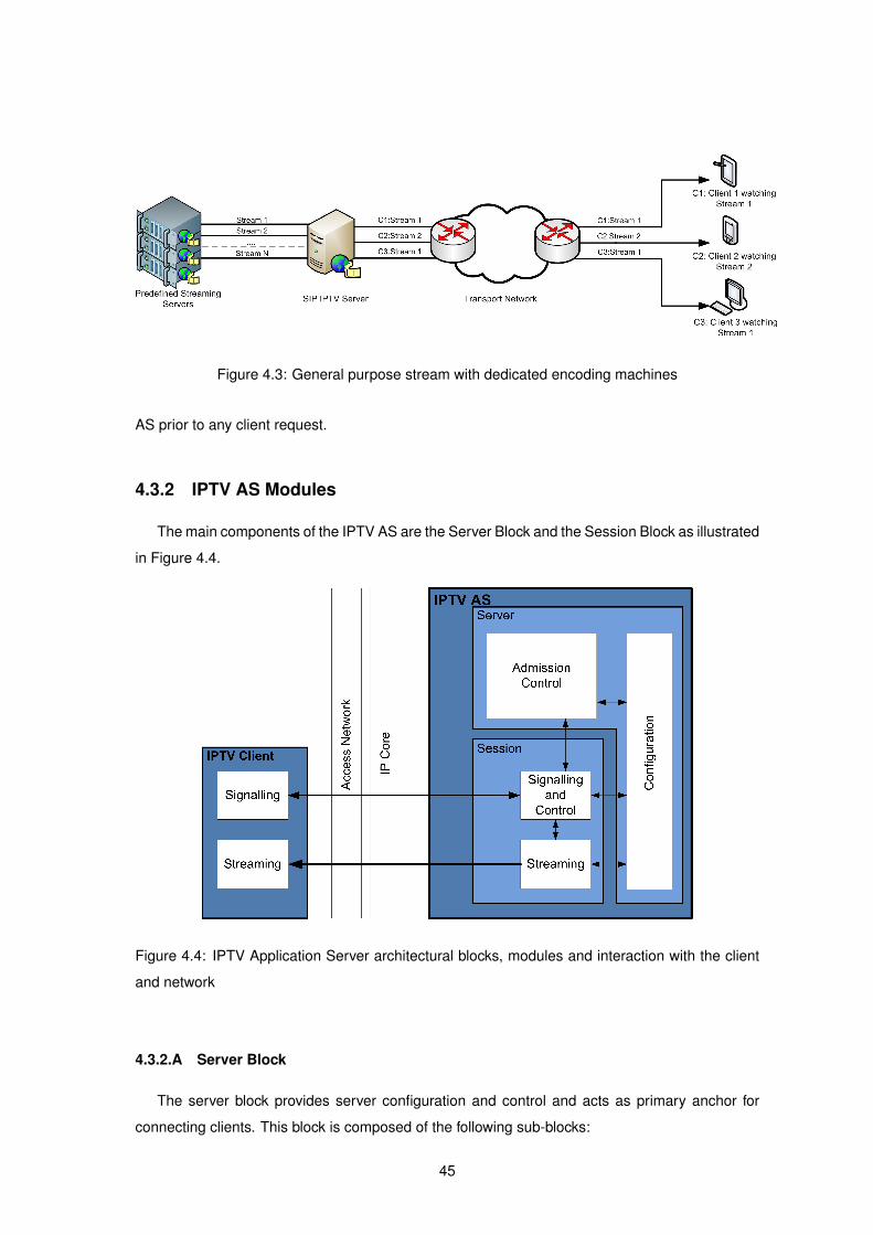
Figure 4.3: General purpose stream with dedicated encoding machines
AS prior to any client request.
4.3.2 IPTV AS Modules
The main components of the IPTV AS are the Server Block and the Session Block as illustrated
in Figure 4.4.
Figure 4.4: IPTV Application Server architectural blocks, modules and interaction with the client
and network
4.3.2.A Server Block
The server block provides server configuration and control and acts as primary anchor for
connecting clients. This block is composed of the following sub-blocks:
45
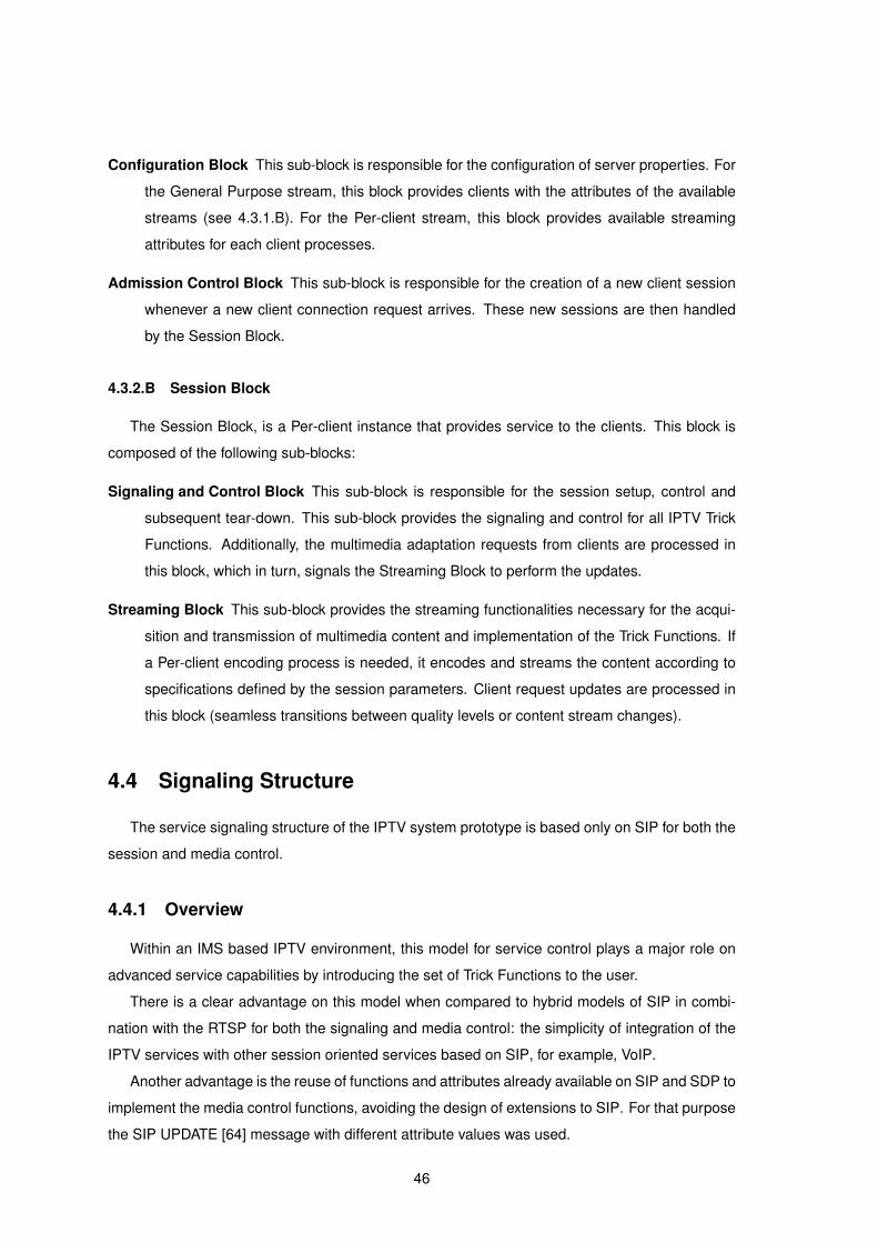
Configuration Block This sub-block is responsible for the configuration of server properties. For
the General Purpose stream, this block provides clients with the attributes of the available
streams (see 4.3.1.B). For the Per-client stream, this block provides available streaming
attributes for each client processes.
Admission Control Block This sub-block is responsible for the creation of a new client session
whenever a new client connection request arrives. These new sessions are then handled
by the Session Block.
4.3.2.B Session Block
The Session Block, is a Per-client instance that provides service to the clients. This block is
composed of the following sub-blocks:
Signaling and Control Block This sub-block is responsible for the session setup, control and
subsequent tear-down. This sub-block provides the signaling and control for all IPTV Trick
Functions. Additionally, the multimedia adaptation requests from clients are processed in
this block, which in turn, signals the Streaming Block to perform the updates.
Streaming Block This sub-block provides the streaming functionalities necessary for the acqui-
sition and transmission of multimedia content and implementation of the Trick Functions. If
a Per-client encoding process is needed, it encodes and streams the content according to
specifications defined by the session parameters. Client request updates are processed in
this block (seamless transitions between quality levels or content stream changes).
4.4 Signaling Structure
The service signaling structure of the IPTV system prototype is based only on SIP for both the
session and media control.
4.4.1 Overview
Within an IMS based IPTV environment, this model for service control plays a major role on
advanced service capabilities by introducing the set of Trick Functions to the user.
There is a clear advantage on this model when compared to hybrid models of SIP in combi-
nation with the RTSP for both the signaling and media control: the simplicity of integration of the
IPTV services with other session oriented services based on SIP, for example, VoIP.
Another advantage is the reuse of functions and attributes already available on SIP and SDP to
implement the media control functions, avoiding the design of extensions to SIP. For that purpose
the SIP UPDATE [64] message with different attribute values was used.
46
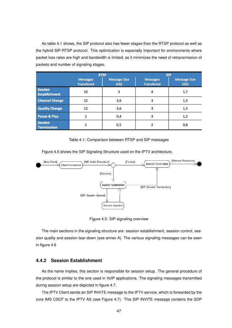
As table 4.1 shows, the SIP protocol also has fewer stages than the RTSP protocol as well as
the hybrid SIP-RTSP protocol. This optimization is especially important for environments where
packet loss rates are high and bandwidth is limited, as it minimizes the need of retransmission of
packets and number of signaling stages.
Table 4.1: Comparison between RTSP and SIP messages
Figure 4.5 shows the SIP Signaling Structure used on the IPTV architecture.
Figure 4.5: SIP signaling overview
The main sections in the signaling structure are: session establishment, session control, ses-
sion quality and session tear-down (see annex A). The various signaling messages can be seen
in figure 4.6
4.4.2 Session Establishment
As the name implies, this section is responsible for session setup. The general procedure of
the protocol is similar to the one used in VoIP applications. The signaling messages transmitted
during session setup are depicted in figure 4.7.
The IPTV Client sends an SIP INVITE message to the IPTV service, which is forwarded by the
core IMS CSCF to the IPTV AS (see Figure 4.7). This SIP INVITE message contains the SDP
47
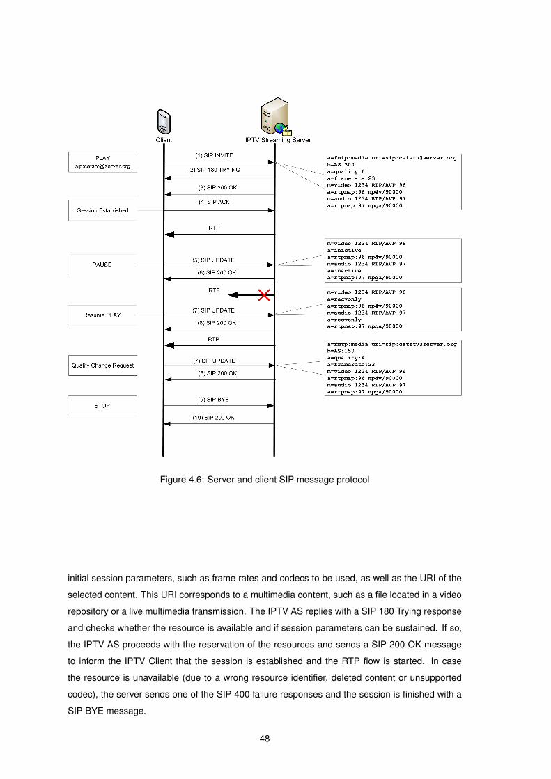
Figure 4.6: Server and client SIP message protocol
initial session parameters, such as frame rates and codecs to be used, as well as the URI of the
selected content. This URI corresponds to a multimedia content, such as a file located in a video
repository or a live multimedia transmission. The IPTV AS replies with a SIP 180 Trying response
and checks whether the resource is available and if session parameters can be sustained. If so,
the IPTV AS proceeds with the reservation of the resources and sends a SIP 200 OK message
to inform the IPTV Client that the session is established and the RTP flow is started. In case
the resource is unavailable (due to a wrong resource identifier, deleted content or unsupported
codec), the server sends one of the SIP 400 failure responses and the session is finished with a
SIP BYE message.
48

Figure 4.7: SIP messages exchanged during session setup
4.4.3 Session Control
Session control allows the server to change session attributes without impacting the state of
the SIP dialog between the client and server. This is accomplished with SIP UPDATE messages.
When issued from the server side, an UPDATE allows the callee (client) to update session at-
tributes (such as available encoding options). From the client side it implements Trick Functions
to update the state of the media being received (such as playing or paused). The SIP Update
should contain a SDP message [64]. The content of the session Control UPDATE message is
shown in Figure 4.8.
Figure 4.8: SIP messages transferred during a session pause
Session Control can be accomplished during or after the session establishment phase. For a
PAUSE the client sends a SIP UPDATE message with the attribute a=inactive for the RTP/AVP
49

streams. The server attempts to apply the requested updates to the session parameters and,
if successful, responds to the client with a SIP 200 OK message. If the parameters cannot be
applied, the server replies with a non-200 SIP message, such as 415 Unsupported Media Type
or 420 Bad Extension messages. To resume the session the client sends another SIP UPDATE
message with the attribute ”a=recvonly” for the RTP/AVP streams.
4.4.4 Session Quality Update
The IPTV AS does not monitor the session quality, instead this function is delegated to the
IPTV Client. The dynamic QoS adaptation is signaled by the IPTV Client using the standard SIP
UPDATE messages. Figure 4.9 depicts a quality change during a session.
Figure 4.9: SIP messages transferred during a session quality update
The Quality UPDATE message is sent from the IPTV Client with a SDP quality attribute
”a=quality:xx”, the quality values range from 0 to 10. The IPTV AS interprets the SIP message
and proceeds to adapts the multimedia stream by reducing the target bit-rate, without interrupting
the ongoing session. There is a visual impact when the stream is updated, but the session is not
compromised. This method was based on the QoS negotiation for IPTV using SIP as described
in [65].
4.4.5 Session Teardown
The session tear-down is a two stage procedure. The requesting party, which can be either
the client or server, sends a SIP BYE message that is accepted or rejected by the other party. If
the receiving party decides to end the session, all of its resources dedicated to the session should
be terminated. The content of the session Tear-down BYE message is shown in Figure 4.10.
50

Figure 4.10: SIP session termination procedure on clients request
On the requesting side, after receiving the BYE response, all resources dedicated to the ses-
sion should also terminate. If the BYE response is rejected, the originating party should retry to
end the session by sending another BYE message.
4.5 Integration in IMS
As previously stated the IPTV AS is aimed to connect to an IMS core. Most of the require-
ments presented in section 3.5 were addressed in the IPTV AS prototype architecture. However,
because a real IMS environment was not available, the developed AS prototype includes function-
alities that simulate the Control Plane functions of the IMS environment.
Figure 4.11 demonstrates the relation between the developed IPTV AS components and the
Functional Entities of the IPTV architecture proposed by European Telecommunications Stan-
dards Institute (ETSI) [2].
By controlling and delegating each session to individual processes, the IPTV AS Admission
Control block is able to implement a session routing mechanism and provides rudimentary user
authentication and charging functions. This block also shares the IPTV service location functions
provided by the Service Discovery Functions (SDF) and some of the accounting and authentica-
tion functions present in the Service Control Functions (SCF). Some of the core IMS functions
are also implemented in this AS block as it is responsible for the SIP message redirection to the
session processes.
By providing available configuration parameters, the AS configuration block shares some func-
tionality with the ETSI Service Selection Function (SSF) and the UPSF. The SSF and UPSF
provide the end user system with a list of available streams based on client capabilities and pref-
erences. These user preferences and capabilities are taken into account when they are specified
51

Figure 4.11: Application Server integration in the IP Multimedia Subsystem architectural frame-
work
in the SIP Invite and Update messages. For implementation simplicity, the Configuration block
does not implement an explicit Xa interface with the client, delegating the function to the signaling
and control block.
As previously discussed, all session logic is present in the Signaling and Control block, and
so most of the IMS functions are here implemented. Service session setup, control, update, tear-
down and media control (play, pause, stop, etc.) functionalities are also implemented in this block,
they correspond to the IMS IPTV service control functions and the IPTV media control functions.
Particularly, each application mode - Per-client and General Purpose - implement the two main
IPTV functions, VoD and Broadcasting respectively. Finally, the multimedia streaming functions of
the AS streaming block directly implements the IPTV media delivery functions as specified by the
52
ETSI IMS architecture.
4.5.1 Architecture Limitations
The architecture of the prototype provides a rich set of functionalities, but also a few shortcom-
ings that may be overcome with future enhancements. The main disadvantage of the described
architecture is the centralization of the IPTV Application Server, even with clustering, all content
streams for clients are sent from a single cluster of machines. This is due to the Streaming block
being attached to the Session block. This can be partially solved by delegating the Streaming
blocks to independent media servers, but implies that the Signaling server must support a com-
munication protocol between the two applications. Although not described, load balancing by
means of additional IPTV Application Servers can be accomplished by redirecting clients upon
the initial signaling. But this requires additional components at the network level for service virtu-
alization. The IPTV AS prototype architecture was specifically tailored for live streaming. For VoD
content streaming and multiple network characteristics, the real-time encoding of the Per-client
process is not scalable. An alternative would be the use of Scalable Video Coding (SVC) [66].
4.6 Conclusion
The architecture of the prototype solution allows a hybrid approach to the two main services
that IPTV provides, Live Broadcasting and Video on Demand. Using the Per-client approach
it is possible to provide a fully customized set of attributes that allow an end user to tailor the
stream to the device capabilities and user preferences. Using the General Purpose mode it is
possible to deliver Live Broadcasting that seamlessly adapts to disparate transmission conditions
and different types of user devices.
The modular design of the AS provides independence between each module and an architec-
ture that allow its connection to the IMS framework. The modular design also allows the addition
of several enhancements to the application server functionalities.
The proposed SIP signaling structure is not that different from other IMS enabled multimedia
services, such as VoIP. It is important to retain that all the messages types used in the signaling
structure are defined in the SIP and SDP standards.
53

54

5Implementation
Contents
5.1 Introduction . . . . . . . . . . . . . . . . . . . . . . . . . . . . . . . . . . . . . . 56
5.2 Development Process . . . . . . . . . . . . . . . . . . . . . . . . . . . . . . . . . 56
5.3 Software Libraries . . . . . . . . . . . . . . . . . . . . . . . . . . . . . . . . . . . 57
5.4 Modules . . . . . . . . . . . . . . . . . . . . . . . . . . . . . . . . . . . . . . . . . 58
5.5 Implementation Limitations . . . . . . . . . . . . . . . . . . . . . . . . . . . . . 62
5.6 Conclusion . . . . . . . . . . . . . . . . . . . . . . . . . . . . . . . . . . . . . . . 63
55

5.1 Introduction
This chapter describes the various stages that were followed during the development process
for the implementation of the server prototype. A general overview of the programming language
and libraries used to build the various modules is also detailed. The chapter concludes with
consideration about the implementation limitations and suggests some possible solutions.
5.2 Development Process
The main objectives defined for the prototype developed, were to support streaming multi-
media content over an IP network using SIP as a signaling and control protocol. The streaming
requirements were those typical for Live video streaming and Video-on-Demand. Additionally,
seamless transition between qualities of a stream was also required.
The development process can be separated into five stages, the initial requirement phase,
the research phase, the architecture definition phase, the implementation phase and finally the
validation and analyses phase.
Figure 5.1: Five stage development process
The first phase corresponded to the specification of functional and non-functional requirements
and the general planning of what was to be accomplished. The main functional requirements
were video and audio streaming in live and VoD scenarios, integration in an IMS architecture and
seamless transition between streaming parameters. The primary non-functional requirement was
to provide a scalable and highly available architectural solution, capable of being deployed in a
wireless operators network.
With the requirements defined, a research phase started, where various streaming servers
and client implementations were tested, such as the Darwin Streaming Server, the VLC Server
and the Helix DNA server. Quicktime and VLC Clients were studied for client applications. In this
phase various encoding and decoding libraries were also analyzed, such as the FFMPEG project
libraries and the x264 project.
The third phase of the project corresponded to the selection of the tools to be used and the
definition of the prototype architecture. This architecture was defined in close collaboration with
the IPTV client development project. In this stage the SIP signaling structure was defined as well
56
as the general architecture of the system.
After selecting the tools and defining the architecture, the next phase consisted on building
the prototype for the Application Server. This was a gradual process that began with the SIP
signaling structure and the base logic of the prototype without any content transmission, followed
by the integration with the streaming and encoding functionalities and the application to a scenario
where multiple clients could interact with the service. The final step of the implementation phase
was the inclusion of features such as providing central configuration of server parameters and
also optimization of the code.
The last phase corresponded to the validation of the prototype in a live network for conformity
to requirements and to the testing and analyses of its capabilities and features.
5.3 Software Libraries
The application development environment used was the Ubuntu distribution of the Linux oper-
ating system [67], currently available for a large set of different devices, ranging from enterprise
servers to small embedded systems. The programming language used was the C language, com-
pliant with the Portable Operating System Interface for Unix (POSIX) standard1. The choice of this
language was due to the portability, stability, reliability and speed factors that it provides, especially
for the development of network enabled applications. Additionally, in order to maximize portability
of the application to various platforms, only open-source and platform independent libraries were
used.
The two main libraries used were LiboSIP [68] for SIP and SDP message generation and
parsing and the libVLC library [69] for media streaming and encoding.
5.3.1 SIP Stack Implementation - liboSIP
LiboSIP is an open-source implementation of a SIP stack library, it provides a API that allows
simplified SIP message generation and parsing [68]. Although liboSIP provides a platform for
SIP parsing, it does not implement the SIP logic. Therefore the SIP signaling structure is part
of the prototype logic and not handled by the oSIP library. This allows full control of message
transmission throughout the signaling session.
The library also provides SDP message generation and parsing. This is used throughout the
project to describe the multimedia session parameters. It is of the upmost importance to generate
valid SDP messages because most of the Trick functions and quality adaptations are described
using this protocol.
1POSIX - IEEE defined family of standards that specify a common application programming interface for UNIX systems
57
5.3.2 Multimedia Streaming and Encoding Library - libVLC
Based on the VLC application [70], libVLC supports interaction between external applications
and the VLC functionalities [69]. Its usage in the prototype is primarily as a encoding and stream-
ing platform. The libVLC library provides and API and so third party applications may use the
features found in VLC. The available functions in the library are:
• VLC instantiation: the most powerful functionality, it allows instantiation of VLC processes
with all the input options that the command line interface allows, such as transcoding op-
tions, streaming parameters and subtitle overlaying;
• Playlist manipulation: the basic Trick Functions are supported, such as play, pause and stop;
• Stream control and information: these functions allow multimedia information and control,
i.e., getting input stream position and setting the position of the current playing item. These
simple commands allow rewind and forward capabilities to be implemented in the applica-
tion.
With these API functions, the server is capable of opening a wide array of media sources and
encoding schemes. External RTSP streams, DVD sources, camera capturing and local files can
be used as a source of video. The transcoding options also allow any codec supported by VLC
to be used in the prototype and changed during runtime (for example, H.264 and MPEG-2 video
coding).
Similarly, the streaming features that are used are those made available by the VLC application
and can be also changed during runtime, for switching streaming sources and destinations or for
IPv4 to IPv6 network addressing.
The prototype design aimed at providing a means to rapidly and easily add new features and
this was achieved by using a modular design and by defining interfaces between each module.
5.4 Modules
To simplify the usage of the prototype, some support modules were added. An add-on module
was implemented to allow additions of new features with minimum change to the overall architec-
ture. Generic to all modules is a logging and output module to permit analyses of the program
functions. The modules are depicted in Figure 5.2
5.4.1 Server Runtime
The server runtime implements all functionalities that are related to server setup and client
management. When the server initiates, this module is run and follows the steps depicted in
Figure 5.3:
58
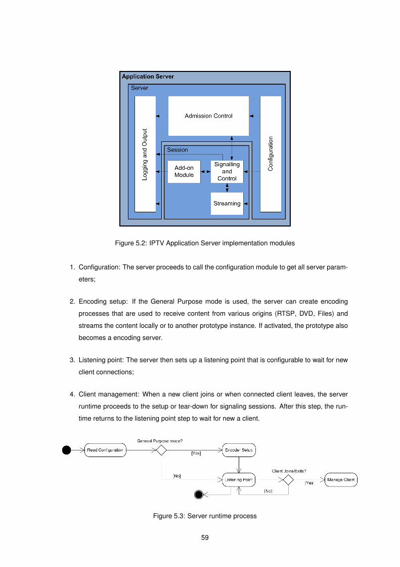
Figure 5.2: IPTV Application Server implementation modules
1. Configuration: The server proceeds to call the configuration module to get all server param-
eters;
2. Encoding setup: If the General Purpose mode is used, the server can create encoding
processes that are used to receive content from various origins (RTSP, DVD, Files) and
streams the content locally or to another prototype instance. If activated, the prototype also
becomes a encoding server.
3. Listening point: The server then sets up a listening point that is configurable to wait for new
client connections;
4. Client management: When a new client joins or when connected client leaves, the server
runtime proceeds to the setup or tear-down for signaling sessions. After this step, the run-
time returns to the listening point step to wait for new a client.
Figure 5.3: Server runtime process
59
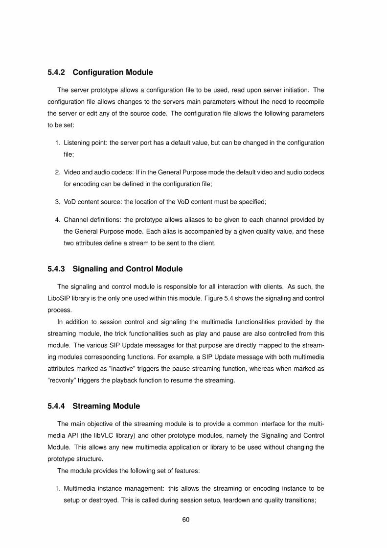
5.4.2 Configuration Module
The server prototype allows a configuration file to be used, read upon server initiation. The
configuration file allows changes to the servers main parameters without the need to recompile
the server or edit any of the source code. The configuration file allows the following parameters
to be set:
1. Listening point: the server port has a default value, but can be changed in the configuration
file;
2. Video and audio codecs: If in the General Purpose mode the default video and audio codecs
for encoding can be defined in the configuration file;
3. VoD content source: the location of the VoD content must be specified;
4. Channel definitions: the prototype allows aliases to be given to each channel provided by
the General Purpose mode. Each alias is accompanied by a given quality value, and these
two attributes define a stream to be sent to the client.
5.4.3 Signaling and Control Module
The signaling and control module is responsible for all interaction with clients. As such, the
LiboSIP library is the only one used within this module. Figure 5.4 shows the signaling and control
process.
In addition to session control and signaling the multimedia functionalities provided by the
streaming module, the trick functionalities such as play and pause are also controlled from this
module. The various SIP Update messages for that purpose are directly mapped to the stream-
ing modules corresponding functions. For example, a SIP Update message with both multimedia
attributes marked as ”inactive” triggers the pause streaming function, whereas when marked as
”recvonly” triggers the playback function to resume the streaming.
5.4.4 Streaming Module
The main objective of the streaming module is to provide a common interface for the multi-
media API (the libVLC library) and other prototype modules, namely the Signaling and Control
Module. This allows any new multimedia application or library to be used without changing the
prototype structure.
The module provides the following set of features:
1. Multimedia instance management: this allows the streaming or encoding instance to be
setup or destroyed. This is called during session setup, teardown and quality transitions;
60
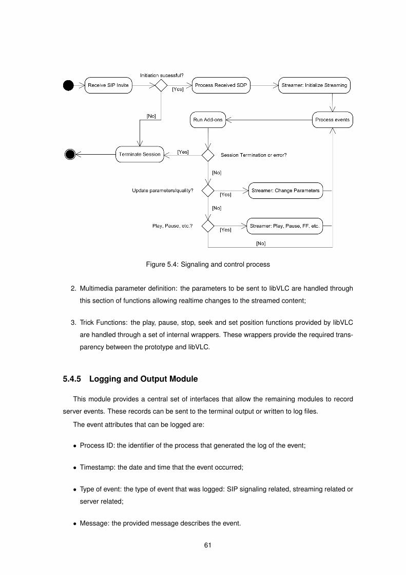
Figure 5.4: Signaling and control process
2. Multimedia parameter definition: the parameters to be sent to libVLC are handled through
this section of functions allowing realtime changes to the streamed content;
3. Trick Functions: the play, pause, stop, seek and set position functions provided by libVLC
are handled through a set of internal wrappers. These wrappers provide the required trans-
parency between the prototype and libVLC.
5.4.5 Logging and Output Module
This module provides a central set of interfaces that allow the remaining modules to record
server events. These records can be sent to the terminal output or written to log files.
The event attributes that can be logged are:
• Process ID: the identifier of the process that generated the log of the event;
• Timestamp: the date and time that the event occurred;
• Type of event: the type of event that was logged: SIP signaling related, streaming related or
server related;
• Message: the provided message describes the event.
61
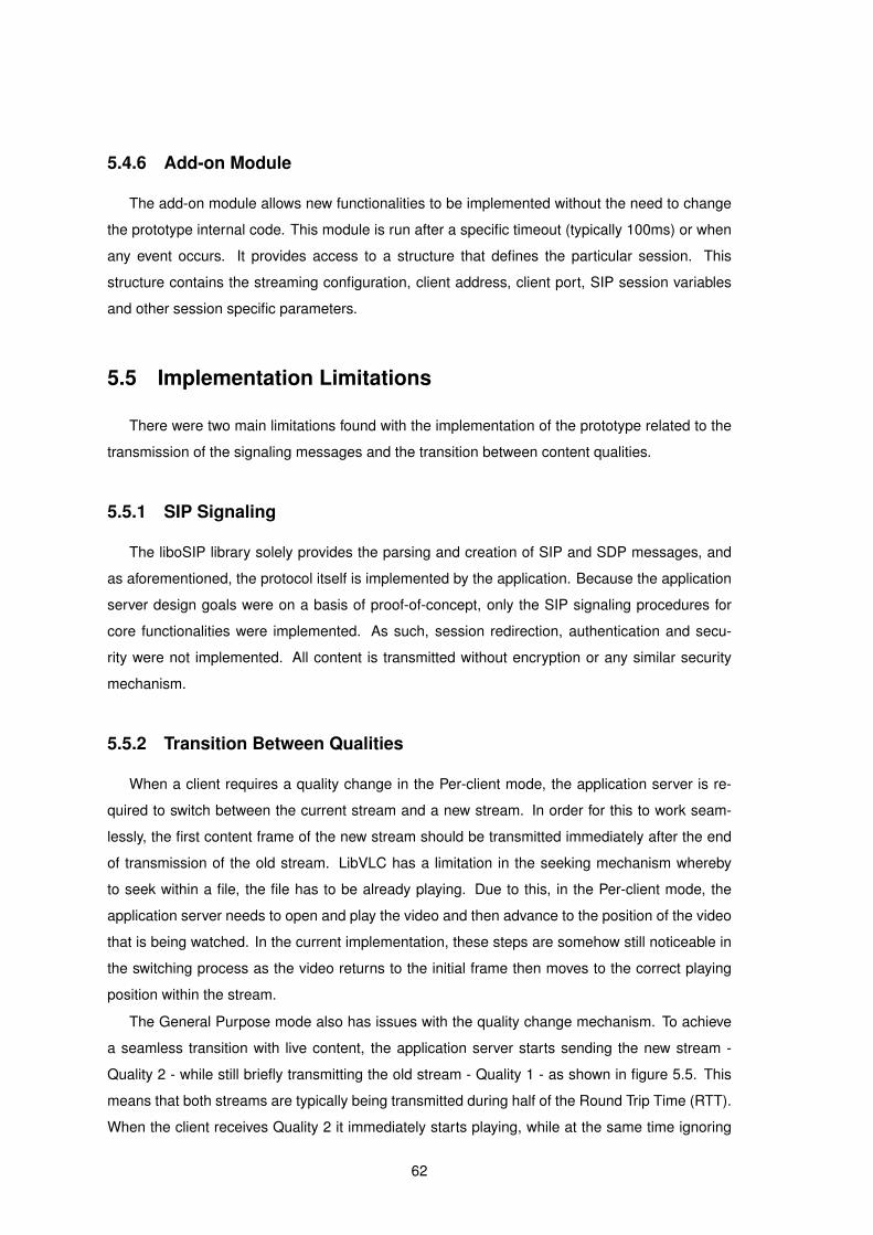
5.4.6 Add-on Module
The add-on module allows new functionalities to be implemented without the need to change
the prototype internal code. This module is run after a specific timeout (typically 100ms) or when
any event occurs. It provides access to a structure that defines the particular session. This
structure contains the streaming configuration, client address, client port, SIP session variables
and other session specific parameters.
5.5 Implementation Limitations
There were two main limitations found with the implementation of the prototype related to the
transmission of the signaling messages and the transition between content qualities.
5.5.1 SIP Signaling
The liboSIP library solely provides the parsing and creation of SIP and SDP messages, and
as aforementioned, the protocol itself is implemented by the application. Because the application
server design goals were on a basis of proof-of-concept, only the SIP signaling procedures for
core functionalities were implemented. As such, session redirection, authentication and secu-
rity were not implemented. All content is transmitted without encryption or any similar security
mechanism.
5.5.2 Transition Between Qualities
When a client requires a quality change in the Per-client mode, the application server is re-
quired to switch between the current stream and a new stream. In order for this to work seam-
lessly, the first content frame of the new stream should be transmitted immediately after the end
of transmission of the old stream. LibVLC has a limitation in the seeking mechanism whereby
to seek within a file, the file has to be already playing. Due to this, in the Per-client mode, the
application server needs to open and play the video and then advance to the position of the video
that is being watched. In the current implementation, these steps are somehow still noticeable in
the switching process as the video returns to the initial frame then moves to the correct playing
position within the stream.
The General Purpose mode also has issues with the quality change mechanism. To achieve
a seamless transition with live content, the application server starts sending the new stream -
Quality 2 - while still briefly transmitting the old stream - Quality 1 - as shown in figure 5.5. This
means that both streams are typically being transmitted during half of the Round Trip Time (RTT).
When the client receives Quality 2 it immediately starts playing, while at the same time ignoring
62
Figure 5.5: Transition between qualities
the Quality 1 stream. In order for this mechanism to work properly, the transmission of streams
has to be carefully synchronized. As to minimize visual artifacts at the client, the transition should
be carried out with the use of an Intra frame. Due to the limited functionality of the libVLC API, this
detailed control of frames during transmission is not achievable meaning that it is not possible to
specify at what frame the transition shall occur. With this limitation the content has to be encoded
with a small GOP size, i.e. the number of frames between two Intra frames must be small. This
solution increases the bitrate of the streamed content as smaller GOP sizes translate to higher
encoded bitrates.
5.6 Conclusion
The successful implementation of this prototype was highly dependent on the correct definition
of the overall architecture. In this chapter the development process was discussed, from the
research to the evaluation phase, with each step described and detailed.
The libraries used to implement the application server prototype were also described. LiboSIP
was used for parsing and generation of SIP and SDP messages and the libVLC API was integrated
to implement the transcoding and streaming functions.
Finally, the various core and support modules of the IPTV Application Server were described,
focused on the logical architecture. The chapter concludes with the limitations that affect the
server functionalities.
63

64

6Evaluation Tests
Contents
6.1 Introduction . . . . . . . . . . . . . . . . . . . . . . . . . . . . . . . . . . . . . . 66
6.2 Evaluation Test Objectives . . . . . . . . . . . . . . . . . . . . . . . . . . . . . . 66
6.3 Test Environment . . . . . . . . . . . . . . . . . . . . . . . . . . . . . . . . . . . 66
6.4 Functional Tests . . . . . . . . . . . . . . . . . . . . . . . . . . . . . . . . . . . . 67
6.5 System Tests . . . . . . . . . . . . . . . . . . . . . . . . . . . . . . . . . . . . . . 70
6.6 Conclusion . . . . . . . . . . . . . . . . . . . . . . . . . . . . . . . . . . . . . . . 74
65

6.1 Introduction
This chapter describes the evaluation tests of the IPTV AS. The objectives of these tests are
detailed, followed by a brief description of the test environment and metrics used. The test results
are then described and studied and final conclusions are made.
6.2 Evaluation Test Objectives
The goals while testing the prototype system were to evaluate the overall scalability of the
solution as well as the functionalities it provides. The tests provide information on the quality of
the IPTV Application Server as well as the service provided to the various clients. In order to
assess the overall nature of the AS, the tests are separated into functional and system tests.
The functional tests evaluate the services that the AS provides to the clients. These tests
analyze various AS functionalities, such as session setup, teardown, trick functions (play, pause
and stop), quality and content transitions.
The system tests - or non-functional tests - were designed to evaluate the AS qualities, such
as the reliability and scalability it provides. As the AS developed is only a prototype, security
measures are not included in the tests. The system evaluation is separated in Per-client and
General Purpose tests, as to study each AS mode. Each test implements both MPEG-4 video
codecs (MPEG-4 AVC and MPEG-4 Visual) as to evaluate the overall response of the system.
6.3 Test Environment
A campus High-Speed LAN and a wireless CDMA2000 network were used throughout the
tests (see Figure 6.1). The encoder was set up with 10 different quality levels for each stream,
ranging from 16 Kbps to 292 Kbps. The functionalities under test included:
• Session establishment and tear-down;
• Trick Functions (e.g., play, pause);
• Dynamic QoS/QoE parameter adaptation for both Per-client and General Purpose streams.
The IPTV AS scalability was evaluated measuring CPU load and memory usage. In the general
purpose mode, two of the client machines were used as transcoders to simulate the transmission
of live content to the application server.
Scalability tests were conducted using more than one client instance on each client machine.
On the server machine a single instance of the prototype was run with solely relevant operating
system processes.
66
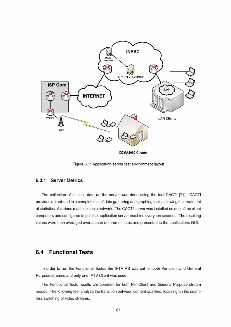
Figure 6.1: Application server test environment layout
6.3.1 Server Metrics
The collection of statistic data on the server was done using the tool CACTI [71]. CACTI
provides a front-end to a complete set of data gathering and graphing tools, allowing the treatment
of statistics of various machines on a network. The CACTI server was installed on one of the client
computers and configured to poll the application server machine every ten seconds. The resulting
values were then averaged over a span of three minutes and presented to the applications GUI.
6.4 Functional Tests
In order to run the Functional Testes the IPTV AS was set for both Per-client and General
Purpose streams and only one IPTV Client was used.
The Functional Tests results are common for both Per Client and General Purpose stream
modes. The following test analyze the transition between content qualities, focusing on the seam-
less switching of video streams.
67
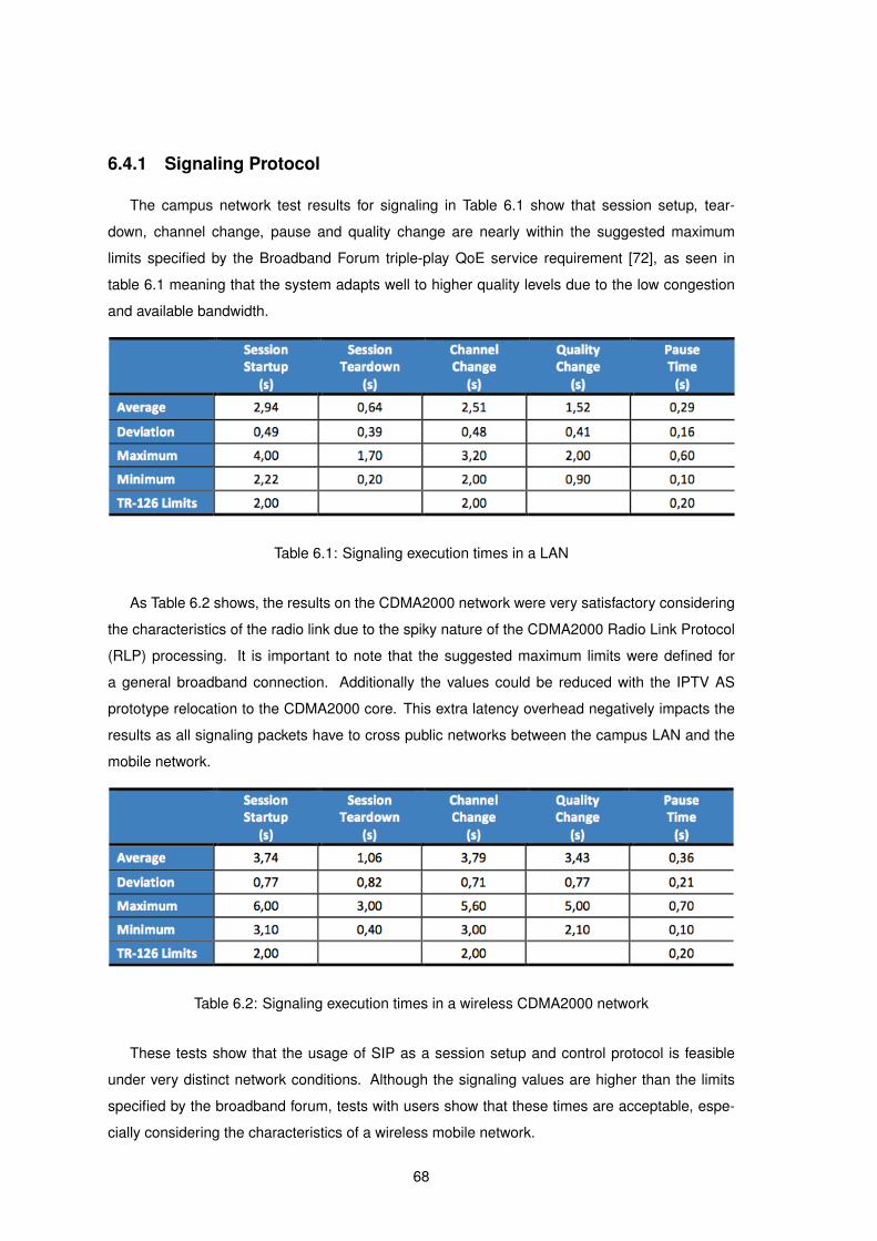
6.4.1 Signaling Protocol
The campus network test results for signaling in Table 6.1 show that session setup, tear-
down, channel change, pause and quality change are nearly within the suggested maximum
limits specified by the Broadband Forum triple-play QoE service requirement [72], as seen in
table 6.1 meaning that the system adapts well to higher quality levels due to the low congestion
and available bandwidth.
Table 6.1: Signaling execution times in a LAN
As Table 6.2 shows, the results on the CDMA2000 network were very satisfactory considering
the characteristics of the radio link due to the spiky nature of the CDMA2000 Radio Link Protocol
(RLP) processing. It is important to note that the suggested maximum limits were defined for
a general broadband connection. Additionally the values could be reduced with the IPTV AS
prototype relocation to the CDMA2000 core. This extra latency overhead negatively impacts the
results as all signaling packets have to cross public networks between the campus LAN and the
mobile network.
Table 6.2: Signaling execution times in a wireless CDMA2000 network
These tests show that the usage of SIP as a session setup and control protocol is feasible
under very distinct network conditions. Although the signaling values are higher than the limits
specified by the broadband forum, tests with users show that these times are acceptable, espe-
cially considering the characteristics of a wireless mobile network.
68
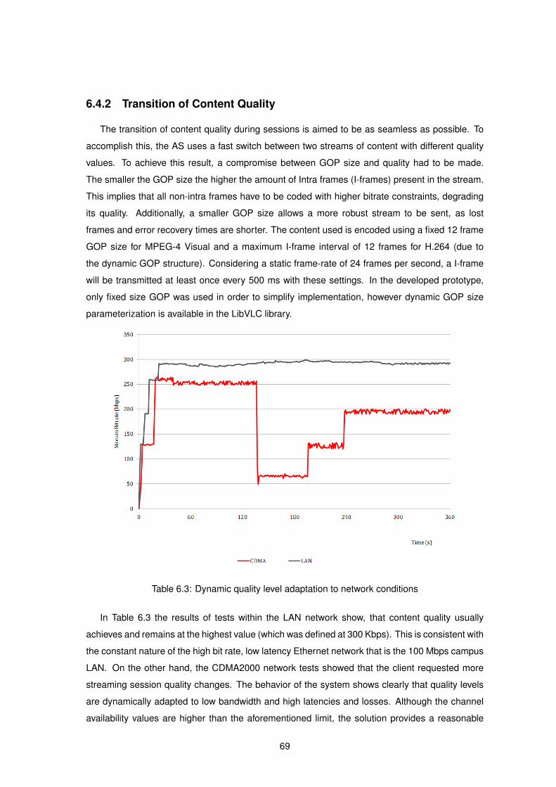
6.4.2 Transition of Content Quality
The transition of content quality during sessions is aimed to be as seamless as possible. To
accomplish this, the AS uses a fast switch between two streams of content with different quality
values. To achieve this result, a compromise between GOP size and quality had to be made.
The smaller the GOP size the higher the amount of Intra frames (I-frames) present in the stream.
This implies that all non-intra frames have to be coded with higher bitrate constraints, degrading
its quality. Additionally, a smaller GOP size allows a more robust stream to be sent, as lost
frames and error recovery times are shorter. The content used is encoded using a fixed 12 frame
GOP size for MPEG-4 Visual and a maximum I-frame interval of 12 frames for H.264 (due to
the dynamic GOP structure). Considering a static frame-rate of 24 frames per second, a I-frame
will be transmitted at least once every 500 ms with these settings. In the developed prototype,
only fixed size GOP was used in order to simplify implementation, however dynamic GOP size
parameterization is available in the LibVLC library.
Table 6.3: Dynamic quality level adaptation to network conditions
In Table 6.3 the results of tests within the LAN network show, that content quality usually
achieves and remains at the highest value (which was defined at 300 Kbps). This is consistent with
the constant nature of the high bit rate, low latency Ethernet network that is the 100 Mbps campus
LAN. On the other hand, the CDMA2000 network tests showed that the client requested more
streaming session quality changes. The behavior of the system shows clearly that quality levels
are dynamically adapted to low bandwidth and high latencies and losses. Although the channel
availability values are higher than the aforementioned limit, the solution provides a reasonable
69

QoE for users with seamless channel changes and quality adaptation.
6.5 System Tests
The scalability of the architecture and prototype was assessed using several IPTV clients and
a single IPTV AS prototype. These tests had a duration of thirty minutes each.
To provide a reference for a comparison of all measurements an initial test was run with the
server in idle mode. This test consisted in running the server with no connecting clients.
6.5.1 Test Description
The system tests were run in the two modes allowed by the server. In the Per-client mode it
was important to ascertain the load on the server by each client, as such, concurrent sessions
were tested until the server achieved the maximum load. The tests were as follows:
1. One client using H.264: a test using the H.264 video codec with a single client session;
2. One client using MPEG-4 Visual: a test using the the MPEG-4 video codec with one client
session;
3. Multiple clients: a series of tests ranging from three to ten clients using the Per-client mode
and five to fifty clients. Due to high complexity of H.264 encoding and the server hardware
used, only the MPEG-4 Visual codec was used in these tests.
The metrics analyzed for each test were:
1. Percentage of CPU usage: the CPU measurements are separated into three categories:
user, system and nice. The user category consists of CPU usage by user applications. The
system and nice categories relate to system specific functions and applications being run.
The relevant category studied in the tests is the user category for the IPTV AS runtime;
2. System Load Average: the System Load Average (SLA) in Unix based operating systems is
represents the average amount of processes in the system run queue. This allows a general
perspective on the system load.
3. Memory usage: the systems memory usage was monitored to detect memory leaks. Even
though this problem is not directly related to the servers architecture it yields information
about the prototype implementation and stability;
4. Network utilization: the network input and output of data was monitored on the active net-
work interface. This allows assessing the amount of bandwidth required to sustain the
service for the various clients.
70

6.5.2 Test Results
The scalability results vary significantly between the two AS streaming modes. The first group
of tests uses the AS Per-client stream mode. The second group of tests uses the General Purpose
stream mode.
6.5.2.A Per-client Stream Mode
The analysis of the results of the tests, as may be observed in Figures 6.2 and 6.3, show
that using the described hardware, the H.264 codec does not scale well for live encoding when
handling more than one client. With one client requesting a live stream the CPU usage is generally
over 90%. On average there are 1.60 processes in the run queue, therefore the SLA raises to
160%. The scalability tests were performed both on a private LAN and on a CDMA2000 wireless
network, streaming quality is always set to a pre-configured highest value, approximately 300
Kbps. With H.264, two client sessions were tested, but the multimedia streams exhibited high
losses and out of synchronization frames, dramatically lowering the QoE. This limitation with
H.264 is due to the higher processing power required by the codec. The MPEG-4 Visual codec
Figure 6.2: CPU load comparison with the per-client mode
shows a CPU usage and load considerably reduced when compared to the H.264 codec. One
client represents approximately 20% of system usage and 0.2 processes in the run queue for
CPU load, i.e., SLA of 20%. With 3 clients the AS system usage rises to approximately 40% and
CPU load increases to 0.4 processes in the run queue.
With the machine used for the AS the service can be supplied to a maximum of 10 concurrent
clients with the CPU usage reaching sporadically 100%. Similarly, the average run queue length
rises to 1.3 processes, which amounts to a SLA of 130%. Even though these values are high, the
71
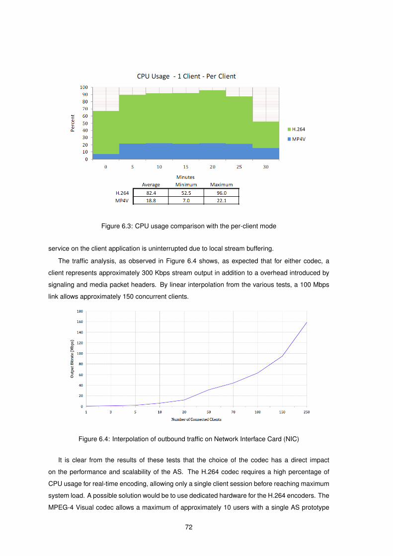
Figure 6.3: CPU usage comparison with the per-client mode
service on the client application is uninterrupted due to local stream buffering.
The traffic analysis, as observed in Figure 6.4 shows, as expected that for either codec, a
client represents approximately 300 Kbps stream output in addition to a overhead introduced by
signaling and media packet headers. By linear interpolation from the various tests, a 100 Mbps
link allows approximately 150 concurrent clients.
Figure 6.4: Interpolation of outbound traffic on Network Interface Card (NIC)
It is clear from the results of these tests that the choice of the codec has a direct impact
on the performance and scalability of the AS. The H.264 codec requires a high percentage of
CPU usage for real-time encoding, allowing only a single client session before reaching maximum
system load. A possible solution would be to use dedicated hardware for the H.264 encoders. The
MPEG-4 Visual codec allows a maximum of approximately 10 users with a single AS prototype
72
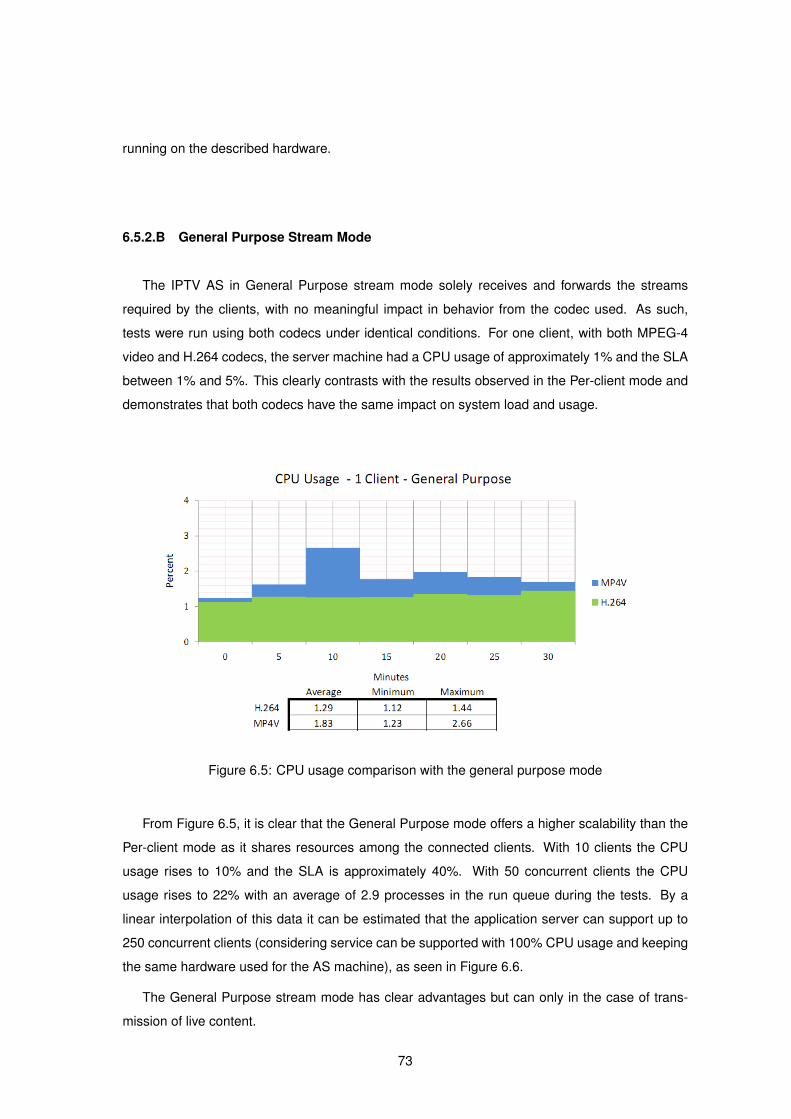
running on the described hardware.
6.5.2.B General Purpose Stream Mode
The IPTV AS in General Purpose stream mode solely receives and forwards the streams
required by the clients, with no meaningful impact in behavior from the codec used. As such,
tests were run using both codecs under identical conditions. For one client, with both MPEG-4
video and H.264 codecs, the server machine had a CPU usage of approximately 1% and the SLA
between 1% and 5%. This clearly contrasts with the results observed in the Per-client mode and
demonstrates that both codecs have the same impact on system load and usage.
Figure 6.5: CPU usage comparison with the general purpose mode
From Figure 6.5, it is clear that the General Purpose mode offers a higher scalability than the
Per-client mode as it shares resources among the connected clients. With 10 clients the CPU
usage rises to 10% and the SLA is approximately 40%. With 50 concurrent clients the CPU
usage rises to 22% with an average of 2.9 processes in the run queue during the tests. By a
linear interpolation of this data it can be estimated that the application server can support up to
250 concurrent clients (considering service can be supported with 100% CPU usage and keeping
the same hardware used for the AS machine), as seen in Figure 6.6.
The General Purpose stream mode has clear advantages but can only in the case of trans-
mission of live content.
73

Figure 6.6: System load and usage with various clients for both server modes
6.6 Conclusion
This chapter described the functional and system tests that were carried out and analyzed.
An important test result relates the content adaptation technique that proved the expected
behavior for seamless transition upon client requests. This feature allows a client to change
streaming parameters on request with little or no influence on the Quality of Experience. In IMS
environments, this is of utmost importance as heterogeneous and very distinct access networks
are used.
Tests on both LAN and CDMA2000 wireless networks show that the IPTV service is sustain-
able on both networks. The delivery of the service in these networks prove the dynamic nature of
the IPTV AS to adapt to varying network conditions.
The non-functional aspects also show relevant results, as the two AS stream modes have very
distinct hardware requirements. These requirements have direct impact on the number of client
sessions that are sustainable. The Per-client mode demonstrated very limited scalability mainly
due to the encoding mechanisms used. On the other hand, the General Purpose mode offers a
highly scalable solution and is not significantly influenced by the encoding used. For both stream
modes, the AS scalability can be improved by delegating the encoding and streaming selection
mechanisms to independent media servers.
74

7Future Work and Final Conclusions
Contents
7.1 System Limitations and Future Work . . . . . . . . . . . . . . . . . . . . . . . . 76
7.2 Conclusion . . . . . . . . . . . . . . . . . . . . . . . . . . . . . . . . . . . . . . . 77
75
7.1 System Limitations and Future Work
The developed IPTV AS prototype presents various limitations that can be overcome with fu-
ture work. The main focus would be on Access Control and Charging functions, content adaptation
mechanisms and scalability of the AS for both Broadcasting and VoD services.
Although the AS implements some Access Control and Charging (accounting) mechanisms,
these are quite rudimentary. A dedicated AAA module within the architecture could be deployed
using the diameter protocol [73]. This protocol allows the AAA functions to be delegated to a
dedicated AAA Diameter server. Among other features the protocol provides: reliable transport of
AAA messages (important for accounting where message losses may translate into revenue loss),
proxy agent support (which allows roaming mechanisms to be in place) and most importantly it is
specified within the IMS architecture and can provide a single AAA platform. This will allow user
profiles to be in stored in the network, thus freeing the need for the user equipment to maintain
user preferences.
The current content adaptation mechanisms that the AS prototype provides are very simple,
and while effective in most scenarios, they do not fully support the H.264 codec. When a seamless
transition is needed, the AS needs to interrupt the current stream and switch to a new one. This
transition can be accomplished without impacting the users visualization, but only if the content
bitrate is low. This is primarily due to buffering in the switching mechanism. Future work in
this area would be required to a seamless content adaptation improvement, eventually using a
leaky-bucket type of transmission mechanism. Additionally, in order to provide a flexible means
of increasing compression factors, a dynamic GOP functionality can be implemented using the
current LibVLC API.
As seen in chapter 6, the AS performance is highly degraded when in the Per-client mode. This
is due to the live encoding mechanisms that are needed for personalized streaming of broadcast-
ing events (such as temporary defer of live content or replay mechanisms). A simple solution that
can be easily implemented is to save the previously encoded content to a file on the video server.
This means that, even though multiple copies of the stream are saved, the need for encoding is
removed and thus processing power is greatly reduced.
In the General Purpose mode, scalability can be hindered by the amount of encoders in use.
As the amount of channels increase and dissimilar users join the streams, more encoders are
needed to supply different streams. To improve this mechanism an innovative encoding mecha-
nism can be used, called SVC [74]. As part of the MPEG-4 group of codecs SVC allows multiple
subsets of a stream to be encoded, thus allowing multiple qualities to be transcoded with a sin-
gle encoding algorithm. This solution can also be applied to the content adaptation mechanism
referred above. This codec, however still has limited applications due to the processing power
required to encode and even decode the stream. Despite the hardware requirements, more pow-
76
erful future equipment may make feasible and common the applications of this codec.
7.2 Conclusion
This dissertation proposes a novel IPTV client-server architecture that can be used on het-
erogenous networks. The main goals of the dissertation were the study of the state-of-the-art
technologies that make possible offering the IPTV services and, in a second phase, to develop an
IPTV system, for broadcasting or for content on demand, independent of the end users terminal
type or network access technology.
As a starting point, the major IPTV technologies and concepts were studied. These included
the network architectures and protocols used for IPTV service delivery as well as the video and
audio encoding algorithms for transmission of multimedia content over digital mediums. The inte-
gration of IPTV service in next generation networks was also studied as well as the requirements
it entails and advantages of such an integration.
The second phase was dedicated to the design and implementation of the IPTV architecture,
an Application Server capable of delivering IPTV service in an Next Generation Network envi-
ronment with adaptation of content being transmitted to the network used to access it. Another
design goal was to respect the conditions for integration in an IMS framework.
A new IPTV signaling structure is proposed based on the Session Initiation Protocol (SIP)
widely used for other multimedia applications. The SIP signaling structure allows the IPTV service
to be integrated with other SIP services supported in IMS environments, such as VoIP or IM. By
leveraging SIP flexibility, Trick Functions are incorporated without the need to extend SIP with
new message types. This is accomplished by receiving SIP Update messages from the client to
dynamically change video, audio and transmission attributes to reflect the requested changes.
From a service perspective, two main IPTV stream modes of operation were identified: Video-
on-Demand (VoD) and Broadcasting, that vary in requirements and applications. VoD delivers
a personalized and unique stream to a end user client. The Broadcasting mode, as the name
implies, is suited for the delivery of traditional television service, where multiple clients consume
the same content. From a platform perspective two related stream modes were developed for
the IPTV AS: a Per-client stream and a General Purpose stream, respectively suited for VoD and
Broadcasting operations.
The architecture was tested from functional and non-functional perspectives. The functional
tests showed that the IPTV AS successfully delivers the IPTV service using SIP as a signaling
protocol, requiring less messages to be transmitted for setup, modify and tear-down sessions,
when compared to RTSP or SIP+RTSP. The Trick Functions provided are able to be used within
specified limits for broadband connections. The new QoS adaptation method implemented allows
dynamic updates of session attributes
77

From a non-functional perspective, the prototype was able to sustain various clients. In the
Per-client mode, a maximum of 10 clients were supported using the MPEG-4 Visual codec. With
the H.264 codec a single instance was deployed for the Per-client stream mode as the encoding
mechanism required 100% of CPU usage. In the General Purpose mode, independently of the
encoding scheme or network parameters, 50 clients could be served using only 20% of the avail-
able system resources. The tests have proved that the overall performance of the system can
gracefully adapt and scale to a large number of clients with different network conditions, always
offering the highest possible QoE to the user, making the proposed architecture suitable for live
multimedia streaming.
Future work will cope with further service developments, essentially related to Media Delivery
Functions, such as, adaptive content processing, enhancements to minimize channel switching
delays and to dynamically adjust QoS/QoE parameters
78
Bibliography
[1] J. Ostermann, J. Bormans, P. List, D. Marpe, M. Narroschke, F. Pereira, T. Stockhammer, and
T. Wedi, “Video coding wih H.264/AVC: Tools, Performance and Complexity,” IEEE Circuits
and Systems Magazine, pp. 7–28, 2004.
[2] N. Tispa, “Draft ETSI TS 182 027 V0.0.9: IPTV Architecture; IPTV functions supported by
the IMS subsystem,” ETSI, Tech. Rep., 2007.
[3] Paola Sunna, “AVC/H.264 - An Advanced Video Coding System for SD and HD Broadcast-
ing,” EBU Technical, 2005.
[4] A. Al-Hezmi, F. C. de Gouveia, M. Sher, O. Friedrich, and T. Magedanz, “Provisioning IMS-
based Seamless Triple Play Services over Different Access Networks,” Network Operations
and Management Symposium, 2008. NOMS 2008. IEEE, pp. 927–930, April 2008.
[5] CableLabs, “DOCSIS,” 2009. [Online]. Available: http://www.cablemodem.com/
[6] S. Vanhastel and R. Hernandez, “Enabling IPTV: What’s Needed in the Access Network,”
Communications Magazine, IEEE, vol. 46, no. 8, pp. 90–95, August 2008.
[7] My eDirector, “My eDirector Website.” [Online]. Available: http://www.myedirector2012.eu
[8] R. Santos Cruz, M. Serafim Nunes, L. Menezes, and J. Domingues, “SIP Based
IPTV Architecture for Heterogeneous Networks,” in The 10th International Conference on
Telecommunications, Zagreb, Croatia, June 2009.
[9] “ConTEL 2009 - 10th International Conference on Telecommunications, June 8-10, 2009,
Zagreb, Croatia.” [Online]. Available: http://www.contel.hr/
[10] Europa: Cordis FP7, “Seventh Framework Programme.” [Online]. Available: http:
//cordis.europa.eu/fp7
[11] W. Simpson and H. Greenfield, IPTV and Internet Video - Expanding the reach of television
broadcasting, 1st ed. Focal Press, 2007.
[12] C.-S. Lee, “IPTV over Next Generation Networks in ITU-T,” Broadband Convergence
Networks, pp. 1–18, May 2007.
79
[13] J. F. Kurose and K. W. Ross, Computer Networking: A Top-Down Approach, 4th ed. Addison
Wesley, 2007.
[14] D. Estrin, D. Farinacci, A. Helmi, D. Thaler, S. Deering,
M. Handley, V. Jacobson, C. Liu, P. Sharma, and L. Wei,
RFC 2362 - Protocol Independent Multicast-Sparse Mode (PIM-SM): Protocol Specification,
IETF, June 1998.
[15] J. Legatheaux Martins, “Algoritmos distribuıdos de encaminhamento para comunicacao
multi-ponto e sua utilizacao na Internet,” Relatorio Tecnico DI-FCT/UNL 2-2007, Agosto
2007.
[16] A. Sentinelli, G. Marfia, M. Gerla, and L. Kleinrock, “Will IPTV Ride the Peer-to-Peer Stream?”
Communications Magazine, IEEE, pp. 86–92, June 2007.
[17] R. Tusch, “Design And Implementation of An Adaptive Distributed Multimedia Streaming
Server,” Ph.D. dissertation, Universitat Klagenfurt, April 2004.
[18] N. Cranley and L. Murphy, “Adaptive Quality of Service for Streamed MPEG-4 over the In-
ternet,” Communications, 2001. ICC 2001. IEEE International Conference on, vol. 4, pp.
1206–1210, November 2001.
[19] A. Ponnappan, L. Yang, R. Pillai, and P. Braun, “A policy based QoS management system for
the IntServ/DiffServ based Internet,” Policies for Distributed Systems and Networks, 2002.
Proceedings. Third International Workshop on, pp. 159–168, 2002.
[20] Q. Zhang, W. Zhu, and Y.-Q. Zhang, “End-to-End QoS for Video Delivery Over Wireless
Internet,” Proceedings of the IEEE, vol. 93, no. 1, pp. 123–134, January 2005.
[21] R. Braden, D. Clark, and S. Shenker, Integrated Services in the Internet Architecture: an
Overview, IETF, June 1994.
[22] D. Grossman, RFC 3260 - New Terminology and Clarifications for DiffServ, IETF, April 2002.
[23] Google Inc., “Youtube - Broadcast Yourself.” [Online]. Available: http://www.youtube.com
[24] Justin TV, Inc., “Justin.tv - Live Streaming Video.” [Online]. Available: http://www.justin.tv
[25] H. Schulzrinne, S. Casner, R. Frederick, and V. Jacobson,
RFC 1889 - RTP: A Transport Protocol for Real-Time Application, January 1996.
[26] H. Schulzrinne, A. Rao, and R. Lanphier, RFC 2326 - Real Time Streaming Protocol, RFC,
IETF, 1998.
[27] M. Handley and V. Jacobson, RFC 2327 - SDP: Session Description Protocol, 1998.
80
[28] R. Fielding, J. Gettys, J. Mogul, H. Frystyk, and T. Berners-Lee,
RFC 2068 - Hypertext Transfer Protocol - HTTP/1.1, 1997.
[29] N. Borenstein and N. Freed, RFC 1521 - MIME (Multipurpose Internet Mail Extensions) Part
One, IETF, September 1993.
[30] J. Rosenburg, M. Shulzrinne, G. Camarillo, A. Johnston, J. Peterson, R. Sparks, M. Handley,
and E. Schooler, RFC 3261 - SIP: Session Initiation Protocol, ITEF.
[31] J. Fabini, M. Happenhofer, and R. Pailer, “Terminal-Centric Location Services for the IP Mul-
timedia Subsystem,” Vehicular Technology Conference, 2006. VTC 2006-Spring. IEEE 63rd,
vol. 2, pp. 881–885, May 2006.
[32] S. Salsano, L. Vetri, and D. Papalilo, “SIP security issues: the SIP authentication procedure
and its processing load,” IEEE Network, vol. 16, pp. 38–44, November 2002.
[33] B. Ramsdell, RFC 3851 - Secure/Multipurpose Internet Mail Extensions (S/MIME) Version
3.1 Message Specification, IETF, July 2004.
[34] S. Kent and R. Atkinson, RFC 2401 - Security Architecture for the Internet Protocol, IETF,
November 1998.
[35] S. Whitehead, M. Montpetit, X. Marjou, S. Ganesan, and J.Lindiquist,
Internet Draft - Media Playback Control Protocol Requirements (Rev 5), IETF, 2008.
[36] R. Rejaie, M. Handley, and D. Estrin, “Layerd quality adaptation for Internet video streaming,”
Selected Areas in Communications, IEEE Journal, vol. 18, no. 12, December 2000.
[37] O. Rose, “Statistical properties of MPEG video traffic and their impact on traffic modeling
in ATM systems,” Local Computer Networks, 1995., Proceedings. 20th Conference on, pp.
397–406, October 1995.
[38] Y. Nakajima, H. Hori, and T. Kanoh, “Rate conversion of MPEG coded video by re-
quantization process,” 1995 International Conference on Image Processing (ICIP’95), p.
3408, 1995.
[39] MPEG, ISO/IEC 13818-1:2000 - MPEG-2: Generic coding of moving pictures and associated
audio information, International Organization for Standardization.
[40] ——, ISO/IEC 11172 - MPEG-1: Coding of moving pictures and associated audio for digital
storage media, International Organization for Standardization, 1993.
[41] J. Golston, “Comparing Media Codecs for Video Content,” Embedded Systems Conference,
2004.
81
[42] MPEG, ISO/IEC 14496-10:2005 - Coding of audio-visual objects - Part 10: Advanced Video
Coding, International Organization for Standardization.
[43] T. Wiegand, G. Sullivan, G. Bjontegaard, and A. Luthra, “Overview of the H.264/AVC video
coding standard,” Circuits and Systems for Video Technology, IEEE Transactions on, vol. 13,
no. 7, pp. 560–576, July 2003.
[44] S. Wenger, “H.264/AVC over IP,” Circuits and Systems for Video Technology, IEEE
Transactions on, vol. 13, no. 7, pp. 645–656, July 2003.
[45] S. Srinivasan and S. Regunathan, “An overview of VC-1,” Visual Communications and Image
Processing, pp. 720–729, 2005.
[46] S. Srinivasan, P. Hsu, T. Holcomb, K. Mukerjee, and S. Regunathan, “Windows Media Video
9: overview and applications,” Signal Processing Image Communication, vol. 19, pp. 851–
874, 2004.
[47] MPEG, ISO/IEC 13818-7:2003 - Generic coding of moving pictures and associated audio
information - Part 7: Advanced Audio Coding (AAC), International Organization for Stan-
dardization.
[48] ——, ISO/IEC 11172 - MPEG-1: Coding of moving pictures and associated audio for digital
storage mediaSO/IEC 14496-2:2004 - MPEG-4: Coding of audio-visual objects – Part 2:
Visual, International Organization for Standardization.
[49] Portugal Telecom Comunicacoes, “MEO IPTV and Satellite Service.” [Online]. Available:
http://www.meo.pt
[50] ——, “TDT em Portugal.” [Online]. Available: http://tdt.telecom.pt
[51] Sonaecom - Servicos de Comunicacoes, “Clix IPTV Service,” June 2009. [Online]. Available:
http://acesso.clix.pt/tv/
[52] Apple Inc., “Apple Quicktime Streaming Server Webpage,” Last accessed on the 20th of
December 2008. [Online]. Available: http://www.apple.com/quicktime/streamingserver/
[53] “Open Source - Server - Streaming Server.” [Online]. Available: http://developer.apple.com/
opensource/server/streaming/index.html
[54] Real Networks, “Helix Streaming Server.” [Online]. Available: http://www.realnetworks.com/
info/helixserverv12.html
[55] ——. (2008) Fast Channel Switching. Real Networks.
[56] VideoLan, “VideoLan Project.” [Online]. Available: http://www.videolan.org/project/
82
[57] ——, “VideoLan Features.” [Online]. Available: http://www.videolan.org/features/
[58] “TISPAN - Telecoms and Internet converged Services and Protocols for Advanced
Networks.” [Online]. Available: http://www.etsi.org/tispan/
[59] R. Shiroor, “IPTV and VoD services in the context of IMS,”
IP Multimedia Subsystem Architecture and Applications, 2007 International Conference on,
vol. 0, no. 0, pp. 1–5, December 2007.
[60] M. Koukal and R. Bestak, “Architecture of IP Multimedia Subsystem,”
ELMAR 48th International Symposium, pp. 323–326, June 2006.
[61] B. Chatras and M. Said, “Delivering Quadruple Play with IPTV over IMS,”
Journal of the Institute of Telecommunications Professionals, 2007.
[62] J. Domingues, “Arquitectura SIP IPTV para redes heterogeneas - Arquitectura de Client,”
Master’s thesis, Instituto Superior Tecnico, 2009.
[63] A. Fox, S. D. Gribble, Y. Chawathe, E. A. Brewer, and P. Gauthier, “Cluster-based scalable
network services,” SIGOPS Oper. Syst. Rev., vol. 31, no. 5, pp. 78–91, October 1997.
[64] J. Rosenburg, RFC 3311 - The Session Initiation Protocol (SIP) UPDATE Method, IETF,
September 2002.
[65] H. Park, J. Yang, J. Choi, and H. Kim, “QoS negotiation for IPTV service using
SIP,” Advanced Communication Technology, The 9th International Conference on, vol. 2, pp.
945–948, February 2008.
[66] H. M. Radha, M. van der Schaar, and Y. Chen, “The MPEG-4 Fine-Grained Scalable Video
Coding Method for Multimedia Streaming Over IP,” IEEE Transactions on Multimedia, vol. 3,
no. 1, pp. 53–69, March 2001.
[67] “Ubuntu.” [Online]. Available: http://www.ubuntu.com/
[68] “The GNU oSIP Library.” [Online]. Available: http://www.gnu.org/software/osip/
[69] “libVLC - VideoLan Wiki.” [Online]. Available: http://wiki.videolan.org/Libvlc
[70] “VLC media player - Overview.” [Online]. Available: http://www.videolan.org/vlc/
[71] “Cacti: The Complete RRDTool-Based Graphing Solution.” [Online]. Available: http:
//www.cacti.net
[72] Broadband Forum (former DSL Forum), “Triple-play Services Quality of Experience (QoE)
Requirements,” Tech. Rep. TR-126, December 2006.
83

[73] P. Calhoun, J. Loughney, E. Guttman, G. Zorn, and J. Arkko,
RFC 3588 - Diameter Base Protocol, IETF, September 2003.
[74] H. Schwarz, D. Marpe, and T. Wiegand, “Overview of the Scalable Video Coding Extension
of the H.264/AVC Standard,” IEEE TRANSACTIONS ON CIRCUITS AND SYSTEMS FOR
VIDEO TECHNOLOGY, vol. 17, no. 9, pp. 1103–1120, July 2007.
84

AAppendix A
85
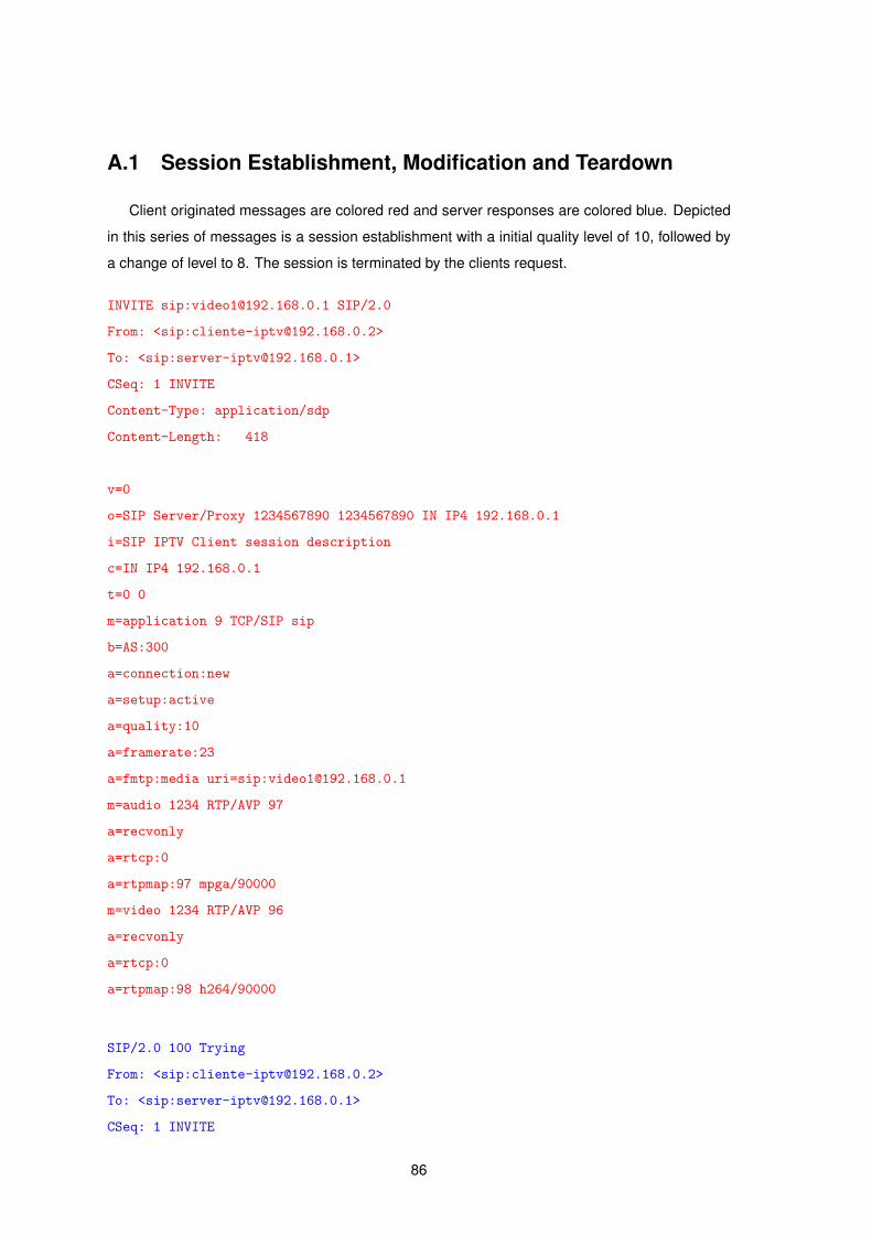
A.1 Session Establishment, Modification and Teardown
Client originated messages are colored red and server responses are colored blue. Depicted
in this series of messages is a session establishment with a initial quality level of 10, followed by
a change of level to 8. The session is terminated by the clients request.
INVITE sip:[email protected] SIP/2.0
From: <sip:[email protected]>
To: <sip:[email protected]>
CSeq: 1 INVITE
Content-Type: application/sdp
Content-Length: 418
v=0
o=SIP Server/Proxy 1234567890 1234567890 IN IP4 192.168.0.1
i=SIP IPTV Client session description
c=IN IP4 192.168.0.1
t=0 0
m=application 9 TCP/SIP sip
b=AS:300
a=connection:new
a=setup:active
a=quality:10
a=framerate:23
a=fmtp:media uri=sip:[email protected]
m=audio 1234 RTP/AVP 97
a=recvonly
a=rtcp:0
a=rtpmap:97 mpga/90000
m=video 1234 RTP/AVP 96
a=recvonly
a=rtcp:0
a=rtpmap:98 h264/90000
SIP/2.0 100 Trying
From: <sip:[email protected]>
To: <sip:[email protected]>
CSeq: 1 INVITE
86

Max-Forwards: 70
Content-Length: 0
SIP/2.0 200 OK
From: <sip:[email protected]>
To: <sip:[email protected]>
CSeq: 1 INVITE
Content-Type: application/sdp
Max-Forwards: 70
Content-Length: 360
v=0
o=SIP Server 1234567890 1234567890 IN IP4 192.168.0.1
i=SIP IPTV Client session description
c=IN IP4 192.168.0.1
t=0 0
m=application 1234 TCP/SIP sip
b=AS:300.000
a=connection:new
a=setup:active
a=quality:10
a=framerate:23.00
a=fmtp:media url=video1
m=audio 1234 RTP/AVP 97
a=recvonly
a=rtcp:0
m=video 1234 RTP/AVP 96
a=recvonly
a=rtcp:0
ACK sip:[email protected] SIP/2.0
From: <sip:[email protected]>
To: <sip:[email protected]>
CSeq: 2 ACK
Content-Length: 0
UPDATE sip:[email protected] SIP/2.0
87

From: <sip:[email protected]>
To: <sip:[email protected]>
CSeq: 3 UPDATE
Content-Type: application/sdp
Content-Length: 418
v=0
o=SIP Server/Proxy 1234567890 1234567890 IN IP4 192.168.0.1
i=SIP IPTV Client session description
c=IN IP4 192.168.0.1
t=0 0
m=application 9 TCP/SIP sip
b=AS:250.00
a=connection:new
a=setup:active
a=quality:8
a=framerate:23
a=fmtp:media uri=sip:[email protected]
m=audio 1236 RTP/AVP 97
a=recvonly
a=rtcp:0
a=rtpmap:97 mpga/90000
m=video 1236 RTP/AVP 96
a=recvonly
a=rtcp:0
a=rtpmap:98 h264/90000
SIP/2.0 200 OK
From: <sip:[email protected]>
To: <sip:[email protected]>
CSeq: 3 UPDATE
Content-Type: application/sdp
Max-Forwards: 70
Content-Length: 374
v=0
o=SIP Server 1234567890 1234567890 IN IP4 192.168.0.1
i=SIP IPTV Client session description
88

c=IN IP4 192.168.0.1
t=0 0
m=application 1236 TCP/SIP sip
b=AS:300.000
a=connection:new
a=setup:active
a=quality:10
a=framerate:23.00
a=fmtp:media url=sip:[email protected]
m=audio 1236 RTP/AVP 97
a=recvonly
a=rtcp:0
m=video 1236 RTP/AVP 96
a=recvonly
a=rtcp:0
ACK sip:[email protected] SIP/2.0
From: <sip:[email protected]>
To: <sip:[email protected]>
CSeq: 4 ACK
Content-Length: 0
BYE sip:[email protected] SIP/2.0
From: <sip:[email protected]>
To: <sip:[email protected]>
CSeq: 5 BYE
Content-Length: 0
SIP/2.0 200 OK
From: <sip:[email protected]>
To: <sip:[email protected]>
CSeq: 5 BYE
Max-Forwards: 70
Content-Length: 0
89

90

BAppendix B
Contents
A.1 Session Establishment, Modification and Teardown . . . . . . . . . . . . . . . 86
91

B.1 Libraries and OS
The application server was developed and tested on Ubuntu 8.04 and the following libraries
were used:
• libvlc0 - VLC API library;
• libosip2 version 3.1.0 - The SIP stack library used with the AS.
To install on Ubuntu run the following commands:
# sudo apt-get install build-essential
# wget http://ftp.gnu.org/gnu/osip/libosip2-3.1.0.tar.gz
# tar -zxvf libosip2-3.1.0.tar.gz
# cd libosip2-3.1.0
# ./configure && sudo make && sudo make install
# sudo apt-get install libvlc0-dev vlc
B.2 Installation
To compile the server simply type:
# make
B.3 Configuration
To change the configuration of the server please edit the ’config.txt’ present in the config folder.
Instructions are in the file.
B.4 Execution
To run it simply type.
# ./server
Optionally you can specify a port to listen on in the configuration file or as an argument in the CLI.
92
Top Related
Copyright © 2022 FDOKUMEN

