


Bahasa
Halaman
Hukum


Journal of Chemical and Petroleum Engineering 2020, 54(2): 323-339
DOI: 10.22059/jchpe.2020.303778.1318
RESEARCH PAPER
Sensitivity Analysis and Prediction of Gas Reservoirs
Performance Supported by an Aquifer Based using Box-Behnken
Design and Simulation Studies
Amir Hossein Saeedi Dehaghani*, Saeed Karami
Petroleum Engineering Department, Faculty of Chemical Engineering, Tarbiat Modares University,
Tehran, Iran
Received: 01 June 2020, Revised: 07 July 2020, Accepted: 27 July 2020
© University of Tehran 2020
Abstract
Prediction of gas reservoir performance in some industrial cases requires costly and
time-consuming simulation runs and a strong CPU must be involved in the
simulation procedure. Many reservoir parameters conform to a strong aquifer
behavior on gas reservoir performance. Effects of parameters, including reservoir
permeability, aquifer permeability, initial reservoir pressure, brine water salinity,
gas zone thickness, water zone thickness, temperature, tubing diameter, reservoir
inclination, the effective intruding angle of the aquifer, and porosity were
investigated using Tornado chart, and seven parameters were filtered. Response
functions of aquifer productivity index, gas recovery factor, initial maximum gas
production, water sweep efficiency, gas production rate, water breakthrough time,
and water production were defined statistically, using Eclipse E100 and Box-
Behnken design (BBD). According to the formulae generated by the BBD based on
simulation runs, reservoir permeability, aquifer permeability, well-head pressure,
and gas zone thickness are the most influencing parameters on the gas reservoir
performance supported by the strong aquifer. The aquifer was found to be important
especially due to its productivity index and sweep water efficiency. Validation of
results given by the BBD through simulation runs showed response functions of
aquifer productivity index, sweep water efficiency, maximum gas production, and
recovery factor are of deviation percentages in the ranges of 10.61%, 6.302%,
3.958%, and 2.04%, respectively.
Keywords: Aquifer,
Box-Behnken,
Gas Reservoir,
Gas Production
Permeability
Introduction
Although gas reservoirs are commonly suffered from fewer problems, there are still troubling
issues related to gas production. The creation of condensate liquid, condensate blockage of the
wellbore, and water aquifer are some of the frequent predicaments in the production from a gas
reservoir [1]. The connection of the strong aquifer to the oil reservoirs increases the oil
production recovery factor due to the supplement of reservoir production energy and pressure.
In contrast to the oil reservoirs, the existence of aquifer makes some troubles in the gas
production from gas reservoirs. The trapping of gas bubbles in the water phase, which was
induced due to water flooding or aquifer encroachment, is the main reason for production
reduction in gas reservoirs attached to the aquifer [2]. Based on the level of the pressure
maintenance, aquifers could be divided into three categories of a) active water drive, b) partial
water drive, and c) limited water drive. The degree of pressure maintenance decreases the
classification, respectively [3].
* Corresponding author:
Email: [email protected] (A. H. Saeedi Dehaghani)
324 Saeedi Dehaghani and Karami
It is essential to produce carefully with a high level of monitoring in such sensitive
reservoirs. The accurate simulation of these types of gas reservoir seems critical. Simulation
costs, CPU requirements, and time-consuming runs are some common problems in the
simulation of a huge reservoir or the heterogenic ones [4]. In the rest of the manuscript, after
reviewing issues related to gas reservoirs connected to an aquifer, the Box-Behnken design
(BBD) as a deployed method for the prediction of the gas reservoir performance will be
discussed.
Li et al. [5] proposed a new methodology for the determination of the status of an aquifer
supporting a gas reservoir. Their proposed methodology was based on the diagnostic curves
determined by the flow rate and the pressure data of the gas production from a single well. The
status of the aquifer was divided into sections of no aquifer influx period, early aquifer influx
period, and middle-late aquifer influx period. Their new approach was validated according to
the production data of a gas well in China.
The production from a gas reservoir connected to the aquifer leads to the invasion of the
aquifer into the virgin gas zone. Water breakthrough in the production well increases the liquid
phase near the wellbore region that results in the skin zone. Damage to the well, which is due
to the liquid phase induced by the bottom water zone, has been surveyed via a mathematical
model. Huang et al.[6] used the Forcheimer quadratic equation in conjugation with eight
primary assumptions to propose a new model describing the damage to the well due to the
aquifer water invasion. Any changes in the gas-water ratio strongly influence the gas open-flow
capability, according to their research. The increment of water/gas ratio from 0.5 to 15
m3/104m3 resulted in a reduction of the gas well open-flow capability to 59% of the initial one.
A logarithmic relationship between the gas well production capability and the water-gas ratio
drop was reported.
Hashem et al. [7] have surveyed the effect of aquifer size on the performance of partial water
drive gas reservoirs. They proposed a model to define the sensitivity of the gas reservoir
performance, regarding the aquifer size, based on the gas material balance equation. The
reservoir permeability is assumed to be 300 mD in all of the cases, and the gas-water contact is
considered to be horizontal. They concluded that the impact of the aquifer on gas reservoir
performance is negligible, where the ratio of aquifer radius to the radius of the reservoir is less
than 0.2.
Geffen et al.[8] investigated the efficiency of gas displacement from porous media using
liquid flooding. They surveyed the effects of water advance rate, static pressure, pressure, and
temperature on gas displacement diving by the water force. They concluded that the gas
saturation varies from 15 to 50 % for different sands at the end of the flooding.
Average gas reservoir pressures are used in the van Everdingen-Hurst unsteady state
equation to compute water influx, and it may lead to a deviation from the real state when
average input pressure is incorrect or even inaccurate. Saleh [9] employed a mathematical
model that combines the material balance equation for a partial water-drive gas reservoir and
the van Everdingen-Hurst unsteady state equation to investigate the error. Two cases of A and
B are representations of using average reservoir pressures in the van Everdingen-Hurst unsteady
state equation and method of using pressures at the original gas-water contact, respectively. The
difference between the two cases considered to be the error. According to their results, the error,
which is caused by the incorrect implementation of the average reservoir pressures in the van
Everdingen-Hurst unsteady state, is significant and increases by increasing the aquifer size and
permeability reduction.
Armenta et al. [10] attempted to solve the problem of the liquid loading in the gas wells
caused by water coning, via a dual-completed well with a down-hole water sink (DWS)
drainage and injection installation. The results of Eclipse simulation software showed a
Journal of Chemical and Petroleum Engineering 2020, 54(2): 323-339 325
considerable advantage of dual completion over conventional wells in the low-pressure tight
reservoirs, before killing the production well.
Li et al. [11]determined the aquifer activity level by using a new methodology. To define
the status of the aquifer, a new parameter called "B," relative pressure, and degree of reserve
recovery with different values have been introduced into calculations producing charts.
According to the charts, they classified the water drive gas reservoirs into three types of active,
moderately active, and inactive influx. It is possible to define the status of the aquifer regarding
related characteristics by using the proposed charts.
Wang et al. [12] tried to use geological and production data to investigate the intensity of
water influx based on water activity and reservoir types. According to their results, the H2S
production from each gas well increases as the pressure declines.
A gas-condensate sandstone reservoir in Vietnam has been surveyed as a case study of
reservoir performance regarding the bottom-water drive mechanism. All the parameters that
influence the gas recovery factor, including gas production rate, completion length, aquifer size,
horizontal reservoir permeability, and permeability anisotropy, have been investigated.
According to their model, aquifer size has no impact on water breakthrough time in the gas
condensate reservoir, but strongly influences the final recovery factor and the total water
production [13]. In another case study, aquifers corresponded to Pliocene reservoirs of the
North Adriatic were investigated by a developed integrating geological/geophysical
interpretations, petrophysical data, and pressure/production ones. It was found that in the poorly
consolidated reservoirs, the decrement of permeability with increasing net confining pressure
comes to the reduction in the water permeability in the water-invaded zone [14].
Yu et al. [15] implemented three calculation methods of the Blasingame, the flowing
material balance, and the Material balance equation to evaluate the aquifer influx for gas
reservoirs with aquifer support. According to their results, the normalized data of the gas well,
influenced by aquifers, can be subcategorized into three influx periods: no-aquifer, early-
aquifer, and middle-late-aquifer influx period [15].
Kim et al. [16] proposed the Ensemble Kalman filter with covariance localization to
characterize aquifer factors. They applied the covariance localization to take account of the
adequate relationship between well production data and the grid properties. Hence, they could
define permeability distribution and aquifer sizes by using production data.
Yue [17] performed a sensitivity analysis on a simplified model in Eclipse software
regarding factors of reservoir pressure gradient, permeability, reservoir width, aquifer size,
reservoir thickness, tubing size, tubing head pressure, and reservoir dip. The gas recovery
factor, the water breakthrough time, the sweep efficiency, and the gas production rate
parameters were all obtained through equations, derived by the BBD. Proposed equations that
were functions of mentioned factors were validated by the Eclipse software at some random
data points [17]. Authors think that other parameters, including aquifer permeability, and initial
reservoir pressure, could strongly affect the performance of a gas reservoir attached to the
aquifer. Fifty-seven simulation runs were performed using the Eclipse E100 to investigate the
mentioned issue. Obtained results were used to find the sensitivity of the gas reservoir
performance regarding each of the input factors. BBD was used to find sensitivity analysis of
affecting factors. In the rest of the manuscript, the Eclipse model, input parameters, Tornado
charts, response functions, final results, and model validation will be discussed.
Model Description
To investigate the sensitivity analysis and prediction of the gas reservoir performance under the
influence of the strong aquifer, the Eclipse E100 software, and the BBD was implemented. The
Eclipse software is used for simulation of the gas reservoirs under the desired circumstances
326 Saeedi Dehaghani and Karami
defined by the BBD at three levels over seven factors. To do this, the aquifer productivity index,
gas recovery factor, initial maximum gas production, and sweep efficiency of water were
surveyed as the response functions. All of the independent parameters of the well radius, the
thickness of aquifer zone, the effective inclination of water zone, permeability of water zone,
reservoir inclination, production tube diameter, temperature, wellhead pressure, salinity, the
thickness of gas zone, initial reservoir pressure, porosity, and reservoir permeability were all
converted to a number between -1 to 1 using conversion functions. The effects of all the
mentioned parameters were investigated through the tornado chart. The advantages of the
mentioned conversion functions are ease of calculation and using the dimensionless form of the
parameters.
Input data in the model
To construct the desired model, an aquifer that is overlaid by a gas zone was defined in a cubic
medium with dimensions of 31×31×10 ft. The inclination of the model was 5-degree respect to
the vertical direction, and the production well has been located at the center of the model. The
reservoir rock and fluid properties are shown in Table 1.
Table 1. Reservoir rock and fluid properties used in the Eclipse model
Reservoir temperature (℉) 220
Porosity 0.11
Rock compressibility psi−1) 1.2 × 10⁻⁶
Water compressibility (psi−1) 3 × 10⁻⁶
Water density (Ib/ft3) 62.4
The specific gravity of the gas 0.7
The gas viscosity was estimated using Lee and Gonzales correlation [18]. The deviation
factor of gas was also correlated using Dranchuk and Abou Ghasem correlation [19]. Relative
permeabilities of gas and water phases are shown in Table 2 which are selected from the
experimental data of Chierici et al. [20].
Table 2. Relative permeability of gas and water used in Eclipse software
Sg Krg Krw Pc (atm)
0.00 0.000 1.000 0.00
0.10 0.000 0.875 0.07
0.20 0.000 0.750 0.15
0.30 0.020 0.625 0.23
0.40 0.085 0.500 0.30
0.50 0.200 0.375 0.37
0.60 0.370 0.225 0.45
0.70 0.650 0.125 0.53
0.80 1.000 0.000 0.60
Tornado Chart
Many parameters are involved in the performance of the gas reservoirs, and some of them have
a negligible effect on the gas reservoir performance. This could be detected using the tornado
chart given by the design of experiment (DOE), based on the Eclipse results. The tornado chart,
which was shown in Fig. 1, is a representation of a basis to select the more influencing
parameters on a response surface. In another word, when the number of possible variables is
large enough to make the response surface methodology (RSM) analysis difficult, DOE is
implemented to reduce the number of the enormous variables to the ones that are mainly
influencing the response function. The number of initial parameters, including brine water

Journal of Chemical and Petroleum Engineering 2020, 54(2): 323-339 327
salinity, is thirteen. By elimination of less affecting parameters, the number of parameters is
reduced to seven. The DOE defines the influencing degree of parameters by comparing the
difference between the highest and the lowest values of each of them [21]. Thirteen affecting
parameters of well-radius, the thickness of aquifer layer, the effective angle of aquifer layer,
aquifer layer permeability, reservoir inclination, production tube diameter, temperature,
wellhead pressure, brine water salinity, the thickness of gas column, initial reservoir pressure,
porosity, and reservoir permeability were investigated in high, medium, and low levels to find
their possible effect, while other parameters remain unchanged (Table 3).
Table 3. Three levels of under debated parameters used to find Tornado chart
Parameter/level -1 0 1
Reservoir permeability (MD) 1 10 100
Aquifer permeability (MD) 1 10 100
Wellhead pressure (psi) 700 1000 1300
Temperature (℃) 60 100 140
Aquifer zone thickness (ft) 400 600 800
Effective aquifer intruding angle 120 240 360
Wellbore radius (ft) 2.2 3.5 4.8
The salinity of brine water (ppm) 100000 200000 300000
Reservoir inclination angle (degree) 0 45 90
Porosity (percent) 5 12.5 20
The thickness of the gas zone (ft) 200 300 400
Reservoir initial pressure (psi) 4300 4800 5300
Tubing diameter (in) 4 5.5 7
Reservoir permeability, initial reservoir pressure, gas column thickness, wellhead pressure,
production tube diameter, aquifer layer permeability, and effective angle of the aquifer layer
are conforming to the gas reservoir performance, according to the tornado chart. Removed
parameters such as wellbore radius influence the simulation results. However, the difference
between the highest and the lowest levels of the parameters indicates that it has a negligible
effect concerning the other factors.
The primary purpose of using the BBD is the reduction of simulation time duration and
lowering its related costs. Using numerous parameters in the simulation without considering
their affecting level misleads the primary goal. Therefore, six parameters of well-radius, the
thickness of the aquifer layer, temperature, salinity, reservoir dip angle, and porosity, which
have a weaker impact on the gas reservoir performance, were removed from the input
parameters in the BBD. The procedure for the selection of appropriate parameters was based
on the tornado chart, which is shown in Fig. 1.
Table 4. Parameters involved in the prediction of gas reservoir performance with corresponding conversion
functions
Factor Parameter Coded
parameter Level
Conversion
function
Reservoir permeability Kres(MD) X1 1 10 100 Log( Kres)-1
Initial reservoir pressure Pi(psi) X2 4300 4800 5300 Pi − 4800
500
Gas column thickness Hgas(ft) X3
200 300 400
Hgas − 300
100
Wellhead pressure Pwh(psi) X4 700 1000 1300 Pwh − 1000
300
Production tube diameter Dt(in) X5 4 5.5 7 Dt − 5.5
1.5
Aquifer zone permeability Kaq(MD) X6 1 10 100 Log( Kres)-1
Effective aquifer intruding angle IA(degree) X7 120 240 360 IA − 240
120

328 Saeedi Dehaghani and Karami
Fig. 1. Tornado chart: influencing level of parameters
In the cases where the wellbore radius was 0.2 and 1 ft, the difference between the gas
recovery factors was 0.3 %. Just 0.5% deviation obtained via simulation runs where the
thickness of the aquifer column was identical and it was five folds of the gas zone thickness.
The difference obtained by the simulation in two cases of 0 and 90-degree inclination of the
reservoir was 0.4%. By changing the temperature from 150 to 70 C, the difference between the
gas recoveries obtained to be 0.2%. By changing the salinity from 150000 ppm to 300000 ppm,
the recovery factor changed by 0.3 %. The difference between the gas recoveries was only 0.3%
when the wellbore radii were 0.2 and 1 ft. Table 4 shows investigated parameters besides their
conversion functions.
According to the BBD, 57 simulation runs are required to investigate the effects of seven
factors on the water aquifer over three levels.
Response functions
BBD is one of the response surface methods (RSM) which are implemented in researches where
the number of variables increases. RSM refers to statistical methods defining the relationships
between a target parameter and dependant variables. Eq. 1 could be used to explain the RSM.
𝑦 = 𝑓 (𝛼1, 𝛼2, 𝛼3, … ) + 𝜀 (1)
0.3
0.5
0.9
3.8
0.4
4
0.2
7.6
0.3
1.1
1.2
0.7
10.7
0 2 4 6 8 10 12
Difference value
Par
amet
ers
Reservoir permeability
Porosity
Initial reservoir pressure
Gas coloumn thickness
Brine water salinity
Well head pressure
Temperature
Production tube diameter
Reservoir inclination
Aquifer layer permeability
Effective angle of aquifer layer
Aquifer layer thickness
Well radius

Journal of Chemical and Petroleum Engineering 2020, 54(2): 323-339 329
In Eq. 1, 𝛼𝑖, 𝜀, and 𝑦 stand for independent variables, the error caused by the difference
between actual and predicted response and dependant target parameter. It is common to convert
the natural parameters of 𝛼 to a dimensionless one. Hence, a new dimensionless equation could
be described as Eq. 2.
𝑦 = 𝑓 (𝑥1, 𝑥2, 𝑥3, … ) + 𝜀 (2)
Due to more flexibility and using the least squared method, quadratic functions were used in
this research. Therefore, the general form of the quadratic equations could be described as Eq.
3 [21].
𝜂 = 𝛽𝑜 + ∑ 𝛽𝑗 𝑥𝑗
𝑘
𝑗=1
+ ∑ 𝛽𝑗𝑗 𝑥𝑗2
𝑘
𝑗=1
+ ∑ ∑ 𝛽𝑖𝑗𝑥𝑖 𝑥𝑗
𝑘
𝑗=2𝑖<
(3)
As mentioned before, the performance of gas reservoirs could be assessed by the evaluation
of P/z at each pressure. It could be found in Eq. 4[3].
P
z=
Pi
zi(1 −
Gp
G )
1 −PizscTsc
GPscziT(We − WpBw)
(4)
The performance of the gas reservoir and initial gas in place could be approximated by
obtaining values of Gp, We, and Wp. As a whole, understanding the parameters in Eq. 4 helps
engineers to gain a more accurate site from the gas reservoir. To find the mentioned parameters,
six response functions of f1 to f6 were employed to define aquifer productivity index, water
production, gas recovery factor, sweep water efficiency, initial maximum gas production, the
breakthrough time, and its related constants ("a" and "b"). "a" and "b" should be known to
estimate water encroachment. It should be mentioned that all of the response functions are linear
and nonlinear functions of parameters were filtered through the tornado chart. According to the
BBD, 57 simulation runs are required to find the response functions.
Result and Discussion
Aquifer Productivity Index
The aquifer productivity index (Jw) is used to explain the water influx volume into the reservoir
in a specific pressure drop. This index is a function of all under-debated parameters selected in
the tornado chart.
Jw = f1(x1. x2. x3. x4. x5. x6. x7) (5)
Using the BBD, the productivity index of the aquifer predicted is reported as Eq. 6.
Jw = 7.933 + 16.32Kres + 1.59Pi + 1.15Hgas + 7.15 Pwh + 2.54 D t + 9.77Kres2
+ 3.36 KresHgas + 11.74 Kres Pwh + 3.7Kres Dt
(6)
All of the parameters in Eq. 6 are of positive coefficients, and it means that the increment of
all the parameters comes to increase the aquifer productivity index. The reservoir permeability
and wellhead pressure affect stronger water productivity index, from a statistical point of view.
All the multiplied coefficients of each parameter, standard error, and "t" values of Eq. 6 are
shown in Table 5. Besides, Table 6 shows the variance analysis of the aquifer productivity index
equation. Both R2 and re-adjusted R2 of aquifer productivity indexes were reported 0.9531 and
0.9441, respectively.

330 Saeedi Dehaghani and Karami
Table 5. Multiplied coefficients of each parameter, standard error, and "t" value of aquifer productivity index
Factor coefficient Standard error t value
Average 7.933 0.5733 13.83
Kres 16.132 0.6723 23.99
Hgas 1.595 0.6723 2.372
Dt 7.157 0.6723 1.722
Kaq 9.771 0.6723 10.646
IA 2.549 0.6723 3.792
Kres × Kres 9.771 0.8835 11.059
Kres × Dt 3.360 1.1644 2.886
Kres × Kaq 11.740 1.1644 10.082
Kres × IA 3.707 1.1644 3.182
Table 6. Variance analysis of aquifer productivity index
Source Degree of freedom SS MS F
Model 9 10353.9 1150.43 106.06 <0.0001
Error 47 509.8 10.85
Summation 56 10863.7
Fig. 2 shows a sensitivity analysis of the aquifer productivity index for aquifer and reservoir
permeability. It reveals that the aquifer productivity index increases drastically as both reservoir
and aquifer permeability increase. Besides, the increment of reservoir permeability has more
influence than the aquifer one.
Fig. 2. Sensitivity analysis of aquifer productivity index respect to aquifer and reservoir permeability
Water Production
Water production is zero before the breakthrough of the waterfront. After reaching
breakthrough time, related production rate and cumulative water production could be
calculated, using Eq. 6 and Eq. 11, as a quadratic equation, respectively. The quadratic equation
constants will be discussed by equations given by the BBD after running all simulation cases.
Theoretically, the integration of the water production rate during production time is equal to
water encroachment. The breakthrough time could be evaluated as following statistical points
of view through Eq. 12.
tb = f2(x1. x2. x3. x4. x5. x6. x7) (7)

Journal of Chemical and Petroleum Engineering 2020, 54(2): 323-339 331
Qw = a(t − tb) + b(t − tb)2 (8)
a = f3(x1. x2. x3. x4. x5. x6. x7) (9)
b = f4(x1. x2. x3. x4. x5. x6. x7) (10)
Wp = ∫ Qwdt = ∫[a(t − tbt) + b(t − tb)2]dt (11)
Functions of a, b, and tb obtained with the BBD are as follows:
tb = 3.01940 − 11.6633Kres − 1.93521Pi − 2.04521Hgas + 0.717500 Pwh −
1.04542 Dt + 9.97029Kres2 + 0.893415Dt
2 + 3.64625KresPi + 4.70125KresHgas −
1.71625Kres Pwh
(12)
a = f 3 = 0.005221 + 0.037023Kres + 0.019897 Dt − 0.004583Pwh +0.03195Kres
2 + 0.009347Dt2 + 0.00955Kaq
2 + 0.054059 Kres Dt −
0.012875Kres K aq
(13)
b = f 4 = 2.9924 + 5.8154Kres + 1.0135Pi + 0.8367Hgas + 1.6345 Dt +
3.1650Kres2 + 1.1463KresPi + 4.1463Kres D t +
0.9727Hgas Dt
(14)
As could be seen from Eq. 12, reservoir permeability, initial pressure, gas zone thickness,
and tubing diameter influence the breakthrough time, negatively. It means that the increment
of the mentioned parameters come to the retardation of breakthrough time. Some parameters,
including tubing diameter, may have no impact on breakthrough time theoretically, but from
the statistical point of view, this parameter is of a negative effect on response function based
on simulation runs. However, it could be seen that the coefficient corresponded to the tubing
diameter is negligible. Similar to breakthrough time, reservoir permeability has more effect on
breakthrough time. The next affecting parameter is gas zone thickness. The R2 and re-adjusted
R2 of water breakthrough time were 0.9693 and 0.9626, respectively. Hence, Eq. 12 seems
adaptive to simulation results. Response functions of "a" and "b" are related to water
encroachment, and increasing each of them results in increasing water encroachment. Table 7
represents multiplied coefficients, standard error, and "t" value of parameters involved in Eq.
12. Moreover, Table 8 shows the variance analysis of the breakthrough time equation.
Table 7. Multiplied coefficients related to water production equation, corresponded standard error, and “t” value
Factor coefficient Standard error t value
Average 3.0194 0.4114 34.7
𝐾𝑟𝑒𝑠 -11.663 0.384 -30.309
𝑃𝑖 -1.9352 0.384 -5.029
𝐻𝑔𝑎𝑠 -2.0452 0.384 -5.315
Pwh 0.7175 0.384 1.865
Dt -1.045 0.3848 -2.717
𝐾𝑟𝑒𝑠 × 𝐾𝑟𝑒𝑠 9.9703 0.5117 19.486
𝐷𝑡 × Dt 0.8934 0.5117 1.746
𝑘𝑎𝑞 × 𝑝𝑖 3.6462 0.6645 5.471
𝐾𝑟𝑒𝑠 × 𝐻𝑔𝑎𝑠 4.701 0.6645 7.053
𝐾𝑟𝑒𝑠 × 𝑝𝑤ℎ -1.7162 0.6645 -2.575
Table 8. Variance analysis of water breakthrough time
Source Degree of freedom SS MS F
Model 10 5155.21 515.52 145.22 <1.1111
Error 46 163.48 3.55
Summation 56 5318.69
332 Saeedi Dehaghani and Karami
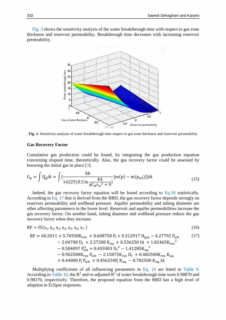
Fig. 3 shows the sensitivity analysis of the water breakthrough time with respect to gas zone
thickness and reservoir permeability. Breakthrough time decreases with increasing reservoir
permeability.
Fig. 3. Sensitivity analysis of water breakthrough time respect to gas zone thickness and reservoir permeability
Gas Recovery Factor
Cumulative gas production could be found, by integrating the gas production equation
concerning elapsed time, theoretically. Also, the gas recovery factor could be assessed by
knowing the initial gas in place [3].
Gp = ∫ Qgdt = ∫{kh
1422T(0.5 ln4A
γCArw2 + S
)[m(p) − m(pwf)]}dt
(15)
Indeed, the gas recovery factor equation will be found according to Eq.16 statistically.
According to Eq. 17 that is derived from the BBD, the gas recovery factor depends strongly on
reservoir permeability and wellhead pressure. Aquifer permeability and tubing diameter are
other affecting parameters in the lower level. Reservoir and aquifer permeabilities increase the
gas recovery factor. On another hand, tubing diameter and wellhead pressure reduce the gas
recovery factor when they increase.
RF = f5(x1. x2. x3. x4. x5. x6. x7 ) (16)
RF = 60.2011 + 5.76958Kres + 0.608750 Pi + 0.312917 Hgas − 4.27792 Pwh
− 2.04708 Dt + 2.27208 Kaq + 0.536250 IA + 1.82465Kres2
− 0.584097 Pwh2 + 0.455903 Dt
2 − 1.41285Kaq2
− 0.902500Kres Pwh − 2.15875Kres Dt + 0.482500Kres Kaq
+ 0.44000 Pi Pwh + 0.456250Pi Kaq − 0.782500 Kaq IA
(17)
Multiplying coefficients of all influencing parameters in Eq. 14 are listed in Table 9.
According to Table 10, the R2 and re-adjusted R2 of water breakthrough time were 0.98870 and
0.98370, respectively. Therefore, the proposed equation from the BBD has a high level of
adaption to Eclipse responses.
Journal of Chemical and Petroleum Engineering 2020, 54(2): 323-339 333
Table 9. Multiplying coefficients of all of influencing parameters in the gas recovery with related standard error
and "t" value
Factor coefficient Standard error t value
Average 69.201 0.2305 30.148
𝐾𝑟𝑒𝑠 5.7697 0.1412 40.868
𝑃𝑖 0.6087 0.1412 4.312
𝐻𝑔a𝑠 0.3129 0.1412 2.216
Pwh -4.2779 0.1412 -30.302
Dt 2.0471 0.1412 -14.5
𝑘𝑎𝑞 2.2721 0.1412 16.094
IA 0.5362 0.1412 3.798
𝐾𝑟𝑒𝑠 × 𝐾𝑟𝑒𝑠 1.8247 0.1955 9.336
𝑃𝑤ℎ × 𝑃𝑤ℎ -0.5841 0.1955 -2.988
𝐷𝑡 × Dt 0.4559 0.1955 2.333
𝑘𝑎𝑞 × 𝑘𝑎𝑞 -1.4128 0.1955 -7.229
𝑘𝑟𝑒𝑠 × 𝑝𝑤ℎ -0.9025 0.2445 -3.691
𝐾𝑟𝑒𝑠 × Dt -2.1588 0.2445 -8.828
𝐾𝑟𝑒𝑠 × 𝑘𝑎𝑞 0.4828 0.2445 1.973
𝑃𝑖 × Pwh 40.4 0.2445 1.799
𝑃𝑖 × 𝑘𝑎𝑞 0.4563 0.2445 1.866
𝑘𝑎𝑞 × 𝐼𝐴 -0.7825 0.2445 -3.2
Table 10. Variance analysis of gas recovery factor equation
Source Degree of
freedom SS MS F
Model 17 1628.34 95.875 200.58 <1.1111
Error 39 18.66 0.478
Summation 56 1646.99
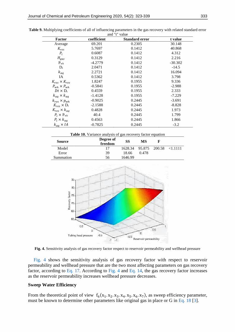
Fig. 4. Sensitivity analysis of gas recovery factor respect to reservoir permeability and wellhead pressure
Fig. 4 shows the sensitivity analysis of gas recovery factor with respect to reservoir
permeability and wellhead pressure that are the two most affecting parameters on gas recovery
factor, according to Eq. 17. According to Fig. 4 and Eq. 14, the gas recovery factor increases
as the reservoir permeability increases wellhead pressure decreases.
Sweep Water Efficiency
From the theoretical point of view f6(x1. x2. x3. x4. x5. x6. x7), as sweep efficiency parameter,
must be known to determine other parameters like original gas in place or G in Eq. 18 [3].
334 Saeedi Dehaghani and Karami
P
z=
Pi
zi(1 −
Gp
G )
f6[Sgr
Sg+
1 − f6
f6]
(18)
Ev = f6(x1. x2. x3. x4. x5. x6. x7) (19)
Sweep efficiency is given by the BBD, as Eq. 20.
Ev = 60.2011 + 5.76958Kres + 0.608750Pi + 0.312917Hgas − 4.27792Pwh
−2.04708Dt + 2.27208 Kaq + 0.53650 IA + 1.82465Kres2 − 0.58409Pwh
2 +
0.455903Dt2 − 1.412850 Kaq
2 − 0.902500 Kres Pwh − 2.15875 Kres Dt +
0.482500Kres Pwh + 0.44000Pi Pwh + 0.45625Pi Kaq − 0.782500 Kaq (IA)
(20)
The sweep water efficiency depends on reservoir permeability, aquifer permeability,
wellhead pressure, and tubing diameter, according to Eq. 20. It could be dedicated that both
reservoir and wellhead pressures are primary and secondary affecting parameters on sweep
water efficiency. Increasing reservoir permeability increases sweep efficiency, in contrast to
wellhead pressure that causes the reduction in response function when it increases. Multiplying
coefficients of all influencing parameters in Eq. 20 are listed in Table 11. According to Tables
10 and 12, the R2 and re-adjusted R2 related to sweep water efficiency is calculated to be 0.9556
and 0.9408, respectively.
The sensitivity analysis of sweep water efficiency is visually shown in Fig. 5. Aquifer
permeability and reservoir permeability have consistent effects on response functions, and both
of them cause an increase in the sweep efficiency.
Table 11. Multiplying coefficients of all of influencing parameters in sweep water efficiency with related
standard error and "t" value
Factor Coefficient Standard error ‘t’ value
Average 40.54 0.8312 48.782
𝐾𝑟𝑒𝑠 5.14 0.6303 8.17
𝑃𝑖 2.87 0.6303 4.558
𝐻𝑔𝑎𝑠 -1.102 0.6303 -1.749
Pwh -4.434 0.6303 -7.035
Dt -5.238 0.6303 -8.311
𝑘𝑎𝑞 13.06 0.6303 20.73
IA 4.234 0.6303 6.718
𝐾𝑟𝑒𝑠 × 𝐾𝑟𝑒𝑠 3.61 0.8517 4.249
𝐷𝑡 × Dt 1.953 0.8517 2.293
𝑘𝑎𝑞 × 𝑘𝑎𝑞 -4.486 0.8517 -5.267
𝑘𝑟𝑒𝑠 × 𝑝𝑤ℎ -2.499 1.0917 -2.289
𝐾𝑟𝑒𝑠 × Dt -8.248 1.0917 -7.555
𝐾𝑟𝑒𝑠 × 𝑘𝑎𝑞 10.46 1.0917 9.585
𝐻𝑔𝑎𝑠 × 𝑘𝑎𝑞 2.143 1.0917 1.963
Table 12. Variance analysis of sweep water efficiency
Source Degree of freedom SS MS F
Model 14 8618.15 615.58 64.59 <1.1111
Error 42 400.42 9.53
Sum 56 9018.57

Journal of Chemical and Petroleum Engineering 2020, 54(2): 323-339 335
Fig. 5. Sensitivity analysis of sweep water efficiency with respect to aquifer and reservoir permeability
Initial Maximum Gas Production
Gas production at the pseudo-steady state could be evaluated through Eq. 21 theoretically [3].
Qg =kh
1422T(0.5 ln4A
γCArw2 + S
)[m(p) − m(pwf)]
(21)
The equation that is proposed by the BBD could approximate the dependency of gas
recovery factor regarding maximum initial gas production rate.
Qg = 70.368 + 20.363Kres + 1.882Pi + 3.66Hgas + 4.61 Pwh + 10.49Kres2 +
3.77KresHgas + 11.82Kres Pwh + 3.26Hgas Pwh
(22)
Table 13. Multiplying coefficients of all of influencing parameters in maximum initial gas production with
related standard error and "t" value
Factor Coefficient Standard error ‘t’ value
Average 70.368 0.7792 90.308
𝐾𝑟𝑒𝑠 20.363 0.9137 22.287
𝑃𝑖 1.882 0.9137 2.06
𝐻𝑔𝑎𝑠 3.664 0.9137 4.01
Dt 4.614 0.9137 5.05
𝐾𝑟𝑒𝑠 × 𝐾𝑟𝑒𝑠 10.498 1.2008 8.742
𝐾𝑟𝑒𝑠 × 𝐻𝑔𝑎𝑠 3.773 1.5836 2.384
𝐾𝑟𝑒𝑠 × 𝐷𝑡 11.827 1.5826 7.473
𝐻𝑔𝑎𝑠 × 𝐷𝑡 3.261 1.5826 2.061
Table 14. Variance analysis of the maximum Initial gas production rate
Source Degree of freedom SS MS F
Model 8 13718.9 1714.86 85.57 <1.1111
Error 48 961.7 20.04
Sum 56 14680.6

336 Saeedi Dehaghani and Karami
According to Eq. 22 the maximum initial gas production rate of a gas reservoir, connected
to an aquifer, highly depends on reservoir permeability. The wellhead pressure and gas zone
thickness could be considered as affecting parameters in the lower level of influence. Increment
of reservoir permeability, initial pressure, gas zone thickness, and wellhead pressure increase
the initial gas production rate. Table 13. shows multiplying coefficients, standard errors, and
"t" values. According to Table 14, the R2 and re-adjusted R2 of maximum initial gas production
are 0.9345 and 0.9236, respectively.
Fig. 6 is a representation of the sensitivity analysis of the maximum initial gas production
rate regarding reservoir permeability and tubing diameter. As could be seen in Fig. 6 an increase
of reservoir permeability, strongly enhances the initial production rate. The effect of tubing
diameter is more noticeable when reservoir permeability is high.
Fig. 6. Sensitivity analysis of maximum initial gas production rate respect to reservoir permeability and tubing
diameter
Validation of Proposed Models
All of the mentioned obtained response functions have high R2 and readjusted R2. Hence, they
are adapted to the input data. To survey the validity of proposed relations for response functions,
the authors selected five data points to check if there is consistency between Eclipse software
results and the BBD outcomes. Five data points that are used for the validation are shown in
Table 15. Table 16 represents that the results of the Eclipse software and response functions of
the aquifer productivity index, sweep water efficiency, water production, gas recovery factor,
and maximum initial gas production rate have excellent consistency. To visualize the deviation
of the RSM model from simulation results, an arithmetic average from data points are shown
in Fig. 6. According to Table 16, the response functions of breakthrough time show very poor
adaption in comparison with Eclipse software results, similar to 'a' and 'b. It may be an
indication of the other possible affecting parameters requirement that has not been taken into
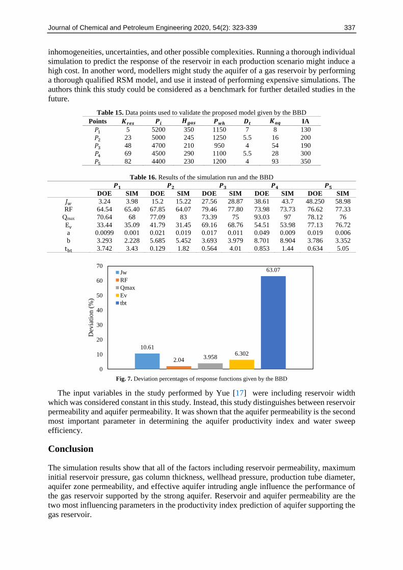
account to predict the breakthrough time. As could be seen from Fig. 7, the response functions
of aquifer productivity index, sweep water efficiency, maximum gas production, and recovery
factor are of deviation percentages in the ranges of 10.61%, 6.302%, 3.958%, and 2.04%
respectively. In contrast, water breakthrough time, which has a deviation percentage of 63.07%,
was poorly fitted with simulation results. The best adaption was found to be the recovery factor,
and the worst one is the breakthrough time.
The authors tried to show that using Box- Behnken design is feasible for describing
phenomena related to a gas reservoir supported by an active aquifer. The actual models used in
the oil and gas industry are probably comprised of plenty of faults, discontinuities,
Journal of Chemical and Petroleum Engineering 2020, 54(2): 323-339 337
inhomogeneities, uncertainties, and other possible complexities. Running a thorough individual
simulation to predict the response of the reservoir in each production scenario might induce a
high cost. In another word, modellers might study the aquifer of a gas reservoir by performing
a thorough qualified RSM model, and use it instead of performing expensive simulations. The
authors think this study could be considered as a benchmark for further detailed studies in the
future.
Table 15. Data points used to validate the proposed model given by the BBD
Points 𝑲𝒓𝒆𝒔 𝑷𝒊 𝑯𝒈𝒂𝒔 𝑷𝒘𝒉 𝑫𝒕 𝑲𝒂𝒒 IA
𝑃1 5 5200 350 1150 7 8 130
𝑃2 23 5000 245 1250 5.5 16 200
𝑃3 48 4700 210 950 4 54 190
𝑃4 69 4500 290 1100 5.5 28 300
𝑃5 82 4400 230 1200 4 93 350
Table 16. Results of the simulation run and the BBD
𝑷𝟏 𝑷𝟐 𝑷𝟑 𝑷𝟒 𝑷𝟓
DOE SIM DOE SIM DOE SIM DOE SIM DOE SIM
𝐽𝑤 3.24 3.98 15.2 15.22 27.56 28.87 38.61 43.7 48.250 58.98
RF 64.54 65.40 67.85 64.07 79.46 77.80 73.98 73.73 76.62 77.33
Qmax 70.64 68 77.09 83 73.39 75 93.03 97 78.12 76
Ev 33.44 35.09 41.79 31.45 69.16 68.76 54.51 53.98 77.13 76.72
a 0.0099 0.001 0.021 0.019 0.017 0.011 0.049 0.009 0.019 0.006
b 3.293 2.228 5.685 5.452 3.693 3.979 8.701 8.904 3.786 3.352
tbt 3.742 3.43 0.129 1.82 0.564 4.01 0.853 1.44 0.634 5.05
Fig. 7. Deviation percentages of response functions given by the BBD
The input variables in the study performed by Yue [17] were including reservoir width
which was considered constant in this study. Instead, this study distinguishes between reservoir
permeability and aquifer permeability. It was shown that the aquifer permeability is the second
most important parameter in determining the aquifer productivity index and water sweep
efficiency.
Conclusion
The simulation results show that all of the factors including reservoir permeability, maximum
initial reservoir pressure, gas column thickness, wellhead pressure, production tube diameter,
aquifer zone permeability, and effective aquifer intruding angle influence the performance of
the gas reservoir supported by the strong aquifer. Reservoir and aquifer permeability are the
two most influencing parameters in the productivity index prediction of aquifer supporting the
gas reservoir.
10.61
2.043.958
6.302
63.07
0
10
20
30
40
50
60
70
Dev
iati
on (
%)
Jw
RF
Qmax
Ev
tbt

338 Saeedi Dehaghani and Karami
Reservoir permeability and gas zone thickness are two affecting parameters in the prediction
of water breakthrough time. Increasing both of them comes to the reduction of breakthrough
time.
Reservoir permeability and wellhead pressure are of the highest impact on the recovery
factor of the gas reservoir supported by a strong water aquifer. In contrast to the reservoir
permeability factor, the increase of the wellhead pressure leads to a reduction in the recovery
factor.
Unlike all other factors, reservoir permeability is not the most affecting parameter in the
prediction of sweep water efficiency. The aquifer permeability was found to be the most
influencing parameter in the prediction of the sweep efficiency equation given by the BBD.
According to equations derived by the BBD, reservoir permeability, and the thickness of the
gas zone are the most affecting parameters in the prediction of the initial gas flow rate.
The main target of using the BBD is to manage the time duration of the simulation, high
costs, and CPU requirements. Conventional reservoir models in the gas industry are not as
simple as the mentioned cubic simple model used in this research. The simulation of gas
reservoirs with a high degree of heterogeneity requires time-consuming and costly simulations.
It seems reasonable to perform a similar statistical procedure for each gas reservoir supported
by the strong aquifer. Every statistical scenario must be examined using other data point results
given by Eclipse software or history match of reservoir production data.
Acknowledgments
This research did not receive any specific grant from funding agencies in the public,
commercial, or not-for-profit sectors.
Nomenclature
P Pressure, psi
Psc Pressure at standard condition (14.7 psi)
CA Shape factor
Gp Cumulative gas production, MSCF
G Initial gas in place, MSCF
Bw Water formation factor, bbl/STB
γ 1.78
Z Compressibility factor, dimensionless
k Permeability, Darcy
T Temperature ( R )
A Reservoir area, across
Sgr residual gas saturation, dimensionless
m(p) Pseudo-pressure
S Skin factor, dimensionless
Tsc Temperature and standard condition, R
We Cumulative water influx, bbl
Sg Gas saturation
h Reservoir thickness, ft
Qg Gas flow rate, Scf
References
[1] Karami, S., A.H.S. Dehaghani, and S.A.H.S. Mousavi, Condensate blockage removal using
Microwave and Ultrasonic waves: discussion on rock mechanical and electrical properties. Journal
of Petroleum Science and Engineering, 2020. 193.
[2] Suzanne, K., et al. Distribution of trapped gas saturation in heterogeneous sandstone reservoirs. in
Proceedings of the Annual Symposium of the Society of Core Analysts. 2011.
Journal of Chemical and Petroleum Engineering 2020, 54(2): 323-339 339
[3] Ahmed, T., reservoir engineering handbook. 2006: Elsevier.
[4] Telishev, A., et al. Hybrid Approach to Reservoir Modeling Based on Modern CPU and GPU
Computational Platforms in SPE Russian Petroleum Technology Conference. 2017. Society of
Petroleum Engineers.
[5] Li, Y., et al., New methodology for aquifer influx status classification for single wells in a gas
reservoir with aquifer support. Journal of Natural Gas Geoscience, 2016. 1(5): p. 407-411.
[6] Huang, X., et al., Mathematical model study on the damage of the liquid phase to productivity in
the gas reservoir with a bottom water zon. petroleum, 2018. 4(2): p. 209-214.
[7] Al-Hashim and J. Bass, Effect of aquifer size on the performance of partial waterdrive gas
reservoirs. SPE reservoir engineering, 1988. 3(2): p. 380-386.
[8] Geffen, T., et al., Efficiency of gas displacement from porous media by liquid flooding. Journal of
Petroleum Technology, 1952. 4(2): p. 29-38.
[9]. Saleh, S. A Model for Development and Analysis of Gas Reservoirs With Partial Water Drive. in
SPE Annual Technical Conference and Exhibition. 1988.
[10] Armenta, M. and A. Wojtanowicz. Incremental recovery using dual-completed wells in gas
reservoirs with bottom water drive: a feasibility study. in Canadian International Petroleum
Conference. 2003.
[11] Li, M., H.R. Zhang, and W.J. Yang. Determination of the aquifer activity level and the recovery of
water drive gas reservoir. in North Africa Technical Conference and Exhibition. 2010.
[12] Wang, J., et al. The Prediction Methods of the Water Influx Intensity of the Non-homogeneous
Aquifer Gas Reservoir. in Fourth International Conference on Computational and Information
Sciences (ICCIS). 2012.
[13] Tran, T.V., et al., A case study of gas-condensate reservoir performance under bottom water drive
mechanism. Journal of Petroleum Exploration Production Technology, 2018: p. 1-17.
[14] Stright Jr, D., et al., Characterization of the Pliocene gas reservoir aquifers for predicting
subsidence on the Ravenna coast. Petroleum Science Technology, 2008. 56(10-11): p. 1267-1281.
[15] Yu, Q., et al., Researches on calculation methods of aquifer influx for gas reservoirs with aquifer
support. Journal of Petroleum Science and Engineering, 2019. 177: p. 889-898.
[16]. Kim, S., et al., Aquifer characterization of gas reservoirs using ensemble Kalman filter and
covariance localization. Journal of Petroleum Science and Engineering, 2016. 146: p. 446-456.
[17] Yue, J., Water-drive gas reservoir: sensitivity analysis and simplified prediction. 2002.
[18] Lee, A.L., M.H. Gonzalez, and B.E. Eakin, The viscosity of natural gases. Journal of Petroleum
Technology, 1966. 18(8): p. 997-1,000.
[19] Dranchuk, P., R. Purvis, and D. Robinson. Computer calculation of natural gas compressibility
factors using the Standing and Katz correlation. in Annual Technical Meeting. 1973.
[20] Long, L.C. Experimental research on gas saturation behind the water front in gas reservoirs
subjected to water drive. in 6th World Petroleum Congress. 1963.
[21] Myers, R.H., D.C. Montgomery, and C.M. Anderson-Cook, Response surface methodology:
process and product optimization using designed experiments. 2016: John Wiley & Sons.
This article is an open-access article distributed under the terms and conditions
of the Creative Commons Attribution (CC-BY) license.
Top Related
Copyright © 2022 FDOKUMEN

