


Bahasa
Halaman
Hukum

Real-time Moving Object Recognition and Tracking Using Computation
Offloading
Yamini Nimmagadda, Karthik Kumar, Yung-Hsiang Lu, and C. S. George Lee
Abstract— Mobile robots are widely used for computation-intensive tasks such as surveillance, moving object recogni-tion and tracking. Existing studies perform the computationentirely on robot processors or on dedicated servers. Therobot processors are limited by their computation capability;real-time performance may not be achieved. Even thoughservers can perform tasks faster, the communication timebetween robots and servers is affected by variations in wirelessbandwidths. In this paper, we present a system for real-time moving object recognition and tracking using computationoffloading. Offloading migrates computation to servers to reducethe computation time on the robots. However, the migrationconsumes additional time, referred as communication time inthis paper. The communication time is dependent on data sizeexchanged and the available wireless bandwidth. We estimatethe computation and communication needed for the tasks andchoose to execute them on robot processors or servers tominimize the total execution time, in order to satisfy real-timeconstraints.
Index Terms— mobile robots, surveillance and tracking, com-putation offloading, moving object recognition
I. INTRODUCTION
Video surveillance, moving object recognition, and robotic
platforms are the fields that have been extensively studied in
recent years. Most of the existing studies on surveillance
systems use stationary cameras and can track objects only
within limited ranges. Moving objects can be tracked by
placing cameras on mobile robots. These robots can be
used in a variety of fields such as recognizing and tracking
suspicious persons or objects. In this paper, we present a real-
time mobile robot surveillance system to recognize and track
moving objects. Our system has five modules: (1) image
capture, (2) motion detection, (3) object recognition, (4)
binocular stereovision, and (5) path-planning and tracking.
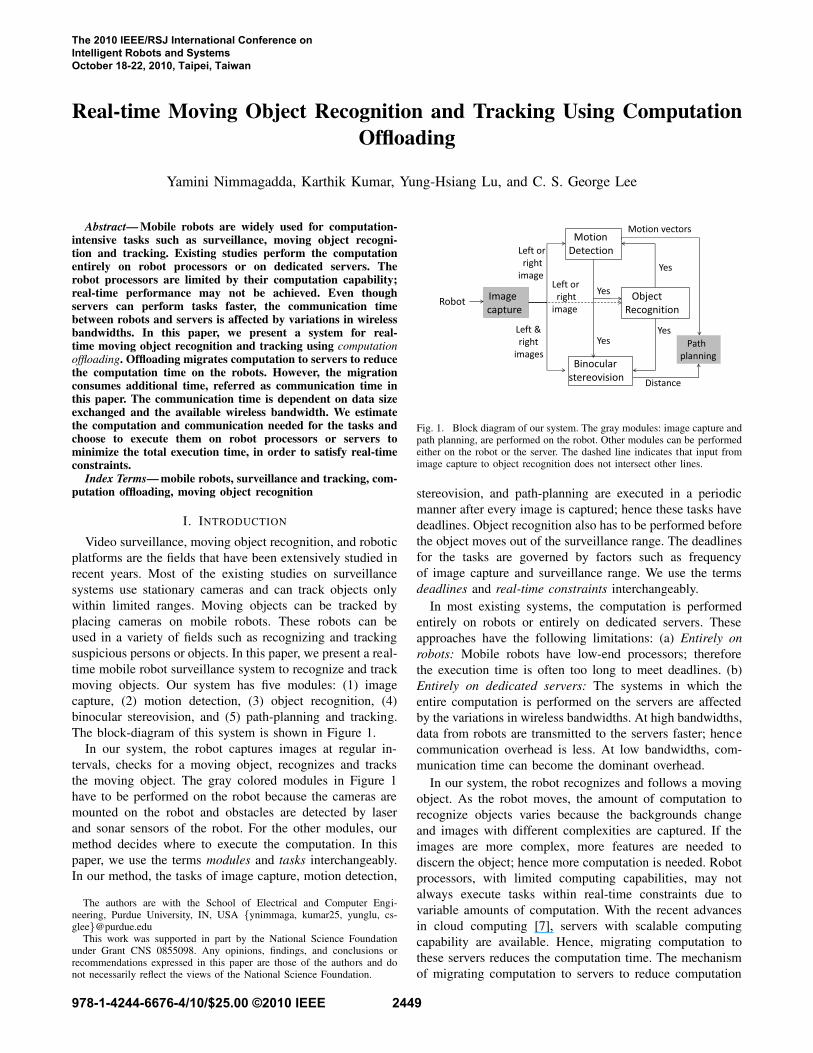
The block-diagram of this system is shown in Figure 1.
In our system, the robot captures images at regular in-
tervals, checks for a moving object, recognizes and tracks
the moving object. The gray colored modules in Figure 1
have to be performed on the robot because the cameras are
mounted on the robot and obstacles are detected by laser
and sonar sensors of the robot. For the other modules, our
method decides where to execute the computation. In this
paper, we use the terms modules and tasks interchangeably.
In our method, the tasks of image capture, motion detection,
The authors are with the School of Electrical and Computer Engi-neering, Purdue University, IN, USA {ynimmaga, kumar25, yunglu, cs-glee}@purdue.edu
This work was supported in part by the National Science Foundationunder Grant CNS 0855098. Any opinions, findings, and conclusions orrecommendations expressed in this paper are those of the authors and donot necessarily reflect the views of the National Science Foundation.
Fig. 1. Block diagram of our system. The gray modules: image capture andpath planning, are performed on the robot. Other modules can be performedeither on the robot or the server. The dashed line indicates that input fromimage capture to object recognition does not intersect other lines.
stereovision, and path-planning are executed in a periodic
manner after every image is captured; hence these tasks have
deadlines. Object recognition also has to be performed before
the object moves out of the surveillance range. The deadlines
for the tasks are governed by factors such as frequency
of image capture and surveillance range. We use the terms
deadlines and real-time constraints interchangeably.
In most existing systems, the computation is performed
entirely on robots or entirely on dedicated servers. These
approaches have the following limitations: (a) Entirely on
robots: Mobile robots have low-end processors; therefore
the execution time is often too long to meet deadlines. (b)
Entirely on dedicated servers: The systems in which the
entire computation is performed on the servers are affected
by the variations in wireless bandwidths. At high bandwidths,
data from robots are transmitted to the servers faster; hence
communication overhead is less. At low bandwidths, com-
munication time can become the dominant overhead.
In our system, the robot recognizes and follows a moving
object. As the robot moves, the amount of computation to
recognize objects varies because the backgrounds change
and images with different complexities are captured. If the
images are more complex, more features are needed to
discern the object; hence more computation is needed. Robot
processors, with limited computing capabilities, may not
always execute tasks within real-time constraints due to
variable amounts of computation. With the recent advances
in cloud computing [7], servers with scalable computing
capability are available. Hence, migrating computation to
these servers reduces the computation time. The mechanism
of migrating computation to servers to reduce computation
The 2010 IEEE/RSJ International Conference on Intelligent Robots and Systems October 18-22, 2010, Taipei, Taiwan
978-1-4244-6676-4/10/$25.00 ©2010 IEEE 2449
time is called “computation offloading” [8]. Computation
offloading, however, has communication overhead. We es-
timate the computation and communication involved in each
of the tasks. Based on this estimation, we choose to perform
a task either on the robot or the server such that the execution
time is minimized and the tasks satisfy real-time constraints.
We believe this is the first study to use computation of-
floading for applications with variable computation and real-
time constraints. Our contributions include: (1) We propose a
method to adaptively estimate the computation based on the
complexity of images captured. (2) We analyze the effect of
wireless bandwidths on data exchange between the robot and
the server. (3) Based on the computation and communication
of the tasks, we present an offloading framework to reduce
the execution time, while satisfying real-time constraints.
II. RELATED WORK
Many studies have been conducted on moving object
recognition and object tracking. The majority of these studies
consider the two modules separately. Each module requires
heavy computation, hence consuming tremendous amounts
of time on robot processors. We propose a computation of-
floading framework to divide the computation between robot
processors and servers to achieve real-time performance.
A. Object Recognition
Object recognition usually uses the following steps: (1)
feature extraction, (2) training, and (3) testing. Features
extracted from Haar wavelets [12], intensity/color histograms
[14], and visual cortex models [11] are widely used for
recognizing objects. Serre et al. [11] use Gabor filters to
model visual cortex for recognizing objects. They show
that the visual cortex model outperforms many methods in
recognizing multi-class objects. We use the same method to
recognize objects in our system. The feature extraction and
training are performed offline in our method. The feature
database is stored in both robots and servers.
B. Moving Object Tracking
Several methods have been proposed for tracking moving
objects. Schulz et al. [10] track multiple objects with a
mobile robot. Chen et al. [1] present real-time tracking of
a single moving object. Gohring et al. [4] use multiple
robots for finding positions of moving objects. Kobilarov et
al. [5] present an algorithm to track people outdoors. Qian
et al. [9] propose a probabilistic approach for simultaneous
robot localization and tracking people. Chen et al. [2] use a
background subtraction method for real-time tracking. These
systems track and follow moving objects or recognize single-
class objects. In contrast, we present a real-time tracking
system with multi-class object recognition.
C. Computation Offloading
Migrating computation was proposed in [8]. Computa-
tion offloading was used in grid computing to perform
collaborative (and thus faster) computation. Offloading is
emerging as a solution to bridge the gap between the limited
Technique Processing Real Object BA CALocation time Recognition
[10] server Yes None No No[1] server Yes None No No[4] robot No None No No[5] robot No single-class No No[9] server Yes single-class No No[2] server Yes None No No
Our method server Yes multi-class Yes Yesor robot
TABLE I
COMPARISON OF OUR SYSTEM WITH EXISTING STUDIES (BA:
BANDWIDTH ADAPTIVE, CA: COMPUTATION ADAPTIVE).
computational capabilities of mobile systems and demand
for increasingly complex functionalities. Existing studies use
computation offloading to reduce energy consumption [6] or
to reduce execution time [13]. We believe this is the first
study to use computation offloading for applications with
real-time constraints in mobile robots.
D. Our Contributions
Table I shows the comparison of our system with existing
systems. Existing systems use single-class object recogni-
tion. They transmit data from robots and use servers for
computation. They assume that the wireless bandwidths are
always sufficient for exchanging data in real-time. However,
the wireless bandwidths may vary due to signal strength
attenuation or channel contention. These systems also do
not consider tasks with variable amounts of computation.
Our system differs from existing studies with the following
contributions: (1) We present a real-time tracking system
with multi-class object recognition. (2) We consider tasks
with variable amounts of computation; we estimate the com-
putation and communication of the tasks before executing
them. (3) We present an offloading decision framework for
different amounts of computation and wireless bandwidths.
III. OFFLOADING DECISIONS FOR MOVING OBJECT
RECOGNITION AND TRACKING
Our system consists of five modules as shown in Figure
1. Image capture and path-planning are performed on the
robot. The other modules: motion detection, stereovision,
and object recognition may execute on the robot or on a
server. The data exchange between these modules is small.
For example, the data sent from motion detection to object
recognition is only one bit: the bit 1 (shown as yes in the
figure) is sent if motion is detected and the object recognition
starts, otherwise 0 is sent. Hence, we consider these modules
independently.
The decision of where to execute the modules depends
on their amounts of computation and communication. We
first estimate the computation involved in the modules, then
estimate the communication consumed by offloading these
tasks to servers. Based on this estimation, we decide where to
execute the tasks such that they satisfy real-time constraints.
Motion detection and stereovision have fixed amounts of
computation for a given image resolution. We determine the
relationship between the amounts of computation for these
2450
two modules and show that their offloading decisions are
related. Under some conditions, elaborated in Section III-C,
the same offloading decision holds for both motion detection
and stereovision. Object recognition, however, has a variable
amount of computation; hence we estimate the computation
and communication to make a decision, irrespective of the
other two modules’ decisions. We first describe the setup of
our system in III-A and identify the real-time constraints.
Next, we provide an offloading decision framework for
motion detection, stereovision, and object recognition.
A. System Setup
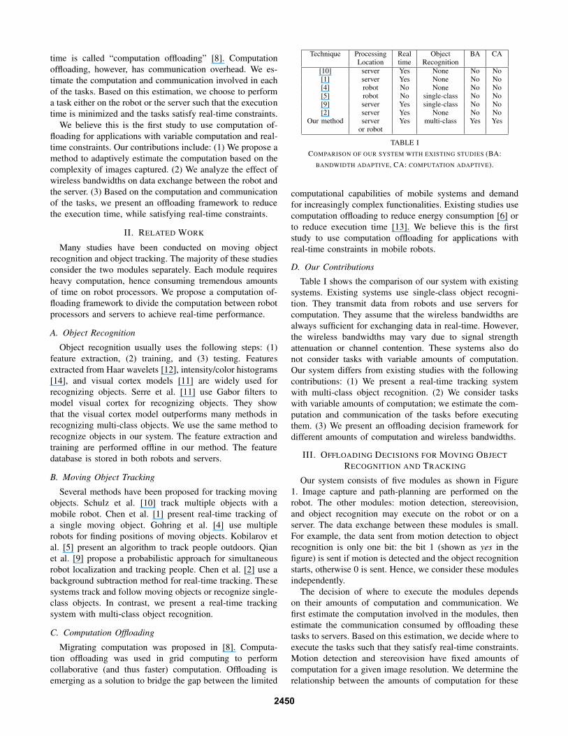
Our system consists of a pioneer 3DX mobile robot and an
on-board computer with a Intel core2-duo 2 GHz processor
and two stationary cameras, each with a resolution of 640 ×
480. We use a Intel Xeon Linux server, with eight quad-core
2.33 GHz processors and 8 GB RAM. When parallel tasks
are executed on the server, we achieve a speedup of about 20
times. The robot setup is shown in Figure 2 (a). The robot is
stationed at the surveillance location and images are captured
at a frequency of 20 images/sec to detect motion. Once
motion is detected, the features of the object are extracted
and compared against the categories in a target database. If
the object belongs to the target database, the location of the
object is computed using stereovision. The robot then follows
the object by continuously capturing images and computing
the location of the object. To detect motion and to recognize
the object, images from one camera are used, whereas for
stereovision, images from both cameras are used. We use
the following assumptions in our system: (1) The velocity of
the moving object is less than the maximum velocity of the
robot. (2) There is only a single moving object.
The tasks involved in moving object recognition and
tracking are governed by deadlines. Motion detection and
stereovision have to finish execution by the time the next
image is captured. The deadline for motion detection is ts,
the image capture period (1/20th sec in our system). The
selection of ts depends on the algorithm used to detect
motion, and is described in Section III-B. Stereovision is
performed after motion detection to compute the object’s
distance. Hence, the deadline for stereovision is ts − tmd,
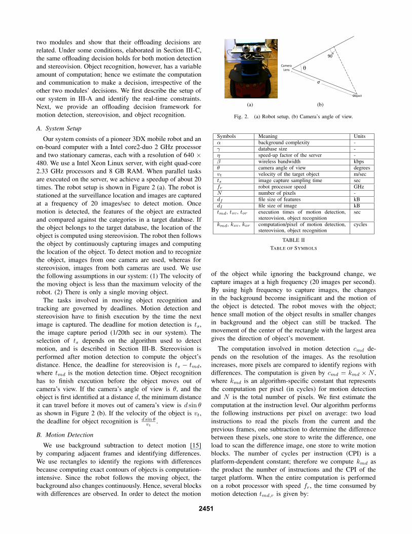
where tmd is the motion detection time. Object recognition
has to finish execution before the object moves out of
camera’s view. If the camera’s angle of view is θ, and the
object is first identified at a distance d, the minimum distance
it can travel before it moves out of camera’s view is d sin θ
as shown in Figure 2 (b). If the velocity of the object is vt,
the deadline for object recognition is d sin θvt
.
B. Motion Detection
We use background subtraction to detect motion [15]
by comparing adjacent frames and identifying differences.
We use rectangles to identify the regions with differences
because computing exact contours of objects is computation-
intensive. Since the robot follows the moving object, the
background also changes continuously. Hence, several blocks
with differences are observed. In order to detect the motion
(a) (b)
Fig. 2. (a) Robot setup, (b) Camera’s angle of view.
Symbols Meaning Units
α background complexity -
γ database size -
η speed-up factor of the server -
β wireless bandwidth kbps
θ camera angle of view degrees
vt velocity of the target object m/sec
ts image capture sampling time sec
fr robot processor speed GHz
N number of pixels -
df file size of features kB
dI file size of image kB
tmd, tsv , tor execution times of motion detection,stereovision, object recognition
sec
kmd, ksv , kor computation/pixel of motion detection,stereovision, object recognition
cycles
TABLE II
TABLE OF SYMBOLS
of the object while ignoring the background change, we
capture images at a high frequency (20 images per second).
By using high frequency to capture images, the changes
in the background become insignificant and the motion of
the object is detected. The robot moves with the object;
hence small motion of the object results in smaller changes
in background and the object can still be tracked. The
movement of the center of the rectangle with the largest area
gives the direction of object’s movement.
The computation involved in motion detection cmd de-
pends on the resolution of the images. As the resolution
increases, more pixels are compared to identify regions with
differences. The computation is given by cmd = kmd × N ,
where kmd is an algorithm-specific constant that represents
the computation per pixel (in cycles) for motion detection
and N is the total number of pixels. We first estimate the
computation at the instruction level. Our algorithm performs
the following instructions per pixel on average: two load
instructions to read the pixels from the current and the
previous frames, one subtraction to determine the difference
between these pixels, one store to write the difference, one
load to scan the difference image, one store to write motion
blocks. The number of cycles per instruction (CPI) is a
platform-dependent constant; therefore we compute kmd as
the product the number of instructions and the CPI of the
target platform. When the entire computation is performed
on a robot processor with speed fr, the time consumed by
motion detection tmd,r is given by:
2451
tmd,r =cmd
fr
=kmd × N
fr
. (1)
If the entire computation is offloaded to a server, with an
effective speed-up factor of η, the computation time becomestmd,r
ηseconds because the images can be divided into sev-
eral parts and the differences can be computed in parallel.
However, transmitting images to the server consumes an
additional dI
βseconds for every image of file size dI at a
wireless bandwidth of β. The total time tmd,s required for
motion detection, when offloaded to the server is given by:
tmd,s =cmd
η × fr
+dI
β. (2)
We offload the computation to the server when tmd,r >
tmd,s as shown in Equation (3). If this inequality does not
hold, we perform motion detection on the robot. Hence
the time for motion detection is the smaller value between
tmd,r and tmd,s. If the smaller value exceeds the deadline
ts, we skip motion detection for the next sample to avoid
accumulation of delay for later samples.
kmd × N
fr
>kmd × N
η × fr
+dI
β. (3)
C. Binocular Stereovision
We use binocular stereovision [3] to compute the distance
of an object. The left and right images are rotated and shifted
to find matching parts. The shifted amount in pixels is called
disparity. We use the disparity map to compute the distance
of the object. The actual distance x of an object is computed
as x =y×i
j, where y is a known distance of an object, i is the
disparity map intensity of the object, and j is the disparity
map intensity of the object whose distance is measured [3].
The amount of computation required by stereovision csv is
proportional to the resolution of the images. As the resolution
increases, more pixels are used to compute disparity maps.
The computation is given by csv = ksv ×N , where ksv is an
algorithm-specific constant that represents the computation
per pixel (in cycles) and N is the total number of pixels. At
the instruction level, our algorithm needs 8 loads, 5 stores
and 4 arithmetic operations per pixel on average, to read both
left and right images, rotate and shift them, and compute the
disparity. The value of ksv is computed similar to kmd as
the product of the number of instructions and the CPI. For
our algorithms, we observe that ksv ≈ 3 × kmd.
The analysis for offloading stereovision is similar to the
motion detection. Similar to Equation (3), stereovision is
offloaded to the server if tsv,r > tsv,s, where tsv,r and
tsv,s are the execution times on the robot and the server
respectively. The computation for stereovision is larger than
motion detection because ksv > kmd. The communication
for stereovision is twice that of motion detection ( 2dI
β) be-
cause two images are sent to the server. Similar to Equation
(3), stereovision should be offloaded if:
ksv × N
fr
>ksv × N
η × fr
+ 2 ×dI
β. (4)
By comparing Equations (3) and (4), we infer that stere-
ovision is always offloaded, when motion detection is of-
floaded, provided stereovision consumes at least twice the
amount of computation as motion detection (ksv ≥ 2kmd).
This eliminates an additional step of decision for stereo-
vision. However, if the motion detection is not offloaded,
nothing can be inferred about the decision for stereovision;
hence Equation (4) is used for the decision. If stereovision
consumes less than twice the amount of computation as
motion detection (ksv < 2kmd), we perform stereovision
on the robot, if motion is detected on the robot. However, if
the motion detection is offloaded, we use Equation (4) for
the decision. Table III summarizes the relationship between
offloading decisions of motion detection and stereovision.
In our system, ksv > 2kmd; hence we always offload
stereovision, when motion detection is offloaded.
Condition Motion Detection Stereovision
ksv ≥ 2kmdoffload offloadrobot Equation (4)
ksv < 2kmdoffload Equation (4)robot robot
TABLE III
OFFLOADING RELATIONSHIP BETWEEN MOTION DETECTION AND
STEREOVISION.
The time for stereovision is the smaller value between
tsv,r and tsv,s. If the smaller value exceeds the deadline
ts − tmd, we skip stereovision for the next sample to avoid
accumulation of delay for later samples.
D. Object Recognition
We recognize objects using visual cortex model [11] in
two steps: (1) feature extraction and (2) search through the
feature database. Features are extracted by applying a set of
Gabor filters with different scales and orientations to images
and combining their outputs to form complex vectors [11].
Serre et al. [11] show that 16 Gabor filters model the visual
cortex sufficiently. The computation of feature extraction is
proportional to the number of features nf . As the robot
moves, nf varies because images with different complexities
are captured; these images require different numbers of
features for discerning objects. The amount of computation
for search depends on the number of features compared and
the size of the object database γ. The computation is given
by cor = cf +cs = kf×nf +ks×nf×γ, where cf and cs are
computations of feature extraction and search, kf and ks are
algorithm-specific constants for computation per feature (in
cycles) for feature extraction and search, computed similarly
to kmd and ksv .
Existing studies treat images with different complexities
equally; hence the same computation is consumed. However,
as the robot moves, object recognition requires variable
amounts of computation. If the same nf is used for all the
images, performance of object recognition deteriorates for
small nf ’s and real-time constraints may not be met for
large nf ’s. Hence, we develop a metric called “background
complexity” (α) to estimate the complexity of images and
2452
(a)
0 50 100 150 200 250
100
200
300
400
Luminance Intensity
Nu
mb
er
of
Pix
els
(b) (c)
0 50 100 150 200 2500
10
20
Luminance Intensity
Nu
mb
er
of
Pix
els
x104
(d)
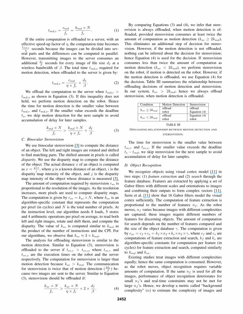
Fig. 3. (a) Image with background clutter, (b) Luminance histogram of (a). The histogram is dispersed,(c) Image without background clutter, (d) Luminance histogram of (c). The histogram has long narrowpeaks. Images are taken from Caltech 101 object database.
(a) (b)
Fig. 4. Object and background with (a)similar colors, (b) different colors. Imagesbelong to Caltech 101 database.
determine nf adaptively for different images. The complexity
α arises from two factors namely clutter (αc) and similarity
(αs) and is given by α =αc+αs
2.
Clutter αc: The difficulty of discerning an object from its
background increases with the background clutter. Figures 3
(a) and (c) show images with and without background clutter.
We quantify the amounts of clutter as the dispersion of the
images’ luminance histograms, measured using a statistical
metric called quartile coefficient of dispersion measured as
follows: The data are sorted in increasing order of their
magnitudes and three numbers from the sorted data are
selected such that they divide the data into four almost equal
sums. These numbers are called quartiles. Quartile coefficient
is defined as q3−q1
q1+q3
, where q1, q2, and q3 are the three
quartiles. Quartile coefficient of dispersion ranges between
0 and 1. Figures 3 (b) and (d) show luminance histograms
of (a) and (c). Figure 3 (b) has short dispersed peaks (αc =
0.8) whereas (d) has long narrow peaks (αc = 0.1).
Similarity αs: The complexity also increases with the
similarity between the colors of object and background. We
consider all the pixels in the rectangle determined by the
motion detection as the object. We use correlation between
chrominance histograms of the object and its background to
quantify the similarity. The value of αs ranges between 0
(no correlation) and 1 (100% correlation). Figures 4 (a) and
(b) show two images with and without background similarity
(αs = 0.79 and 0.02 respectively).
The value of α ranges between 0 and 1, because α =αc+αs
2. For images with different values of α, we need
different numbers of features to achieve a given accuracy
of classification [11]. The classification accuracy is defined
as the ratio of number of objects similar to the query object
to the total number of objects in the category. We use 20
categories from Caltech101 object database, each category
containing 200 to 500 images. To obtain a classification
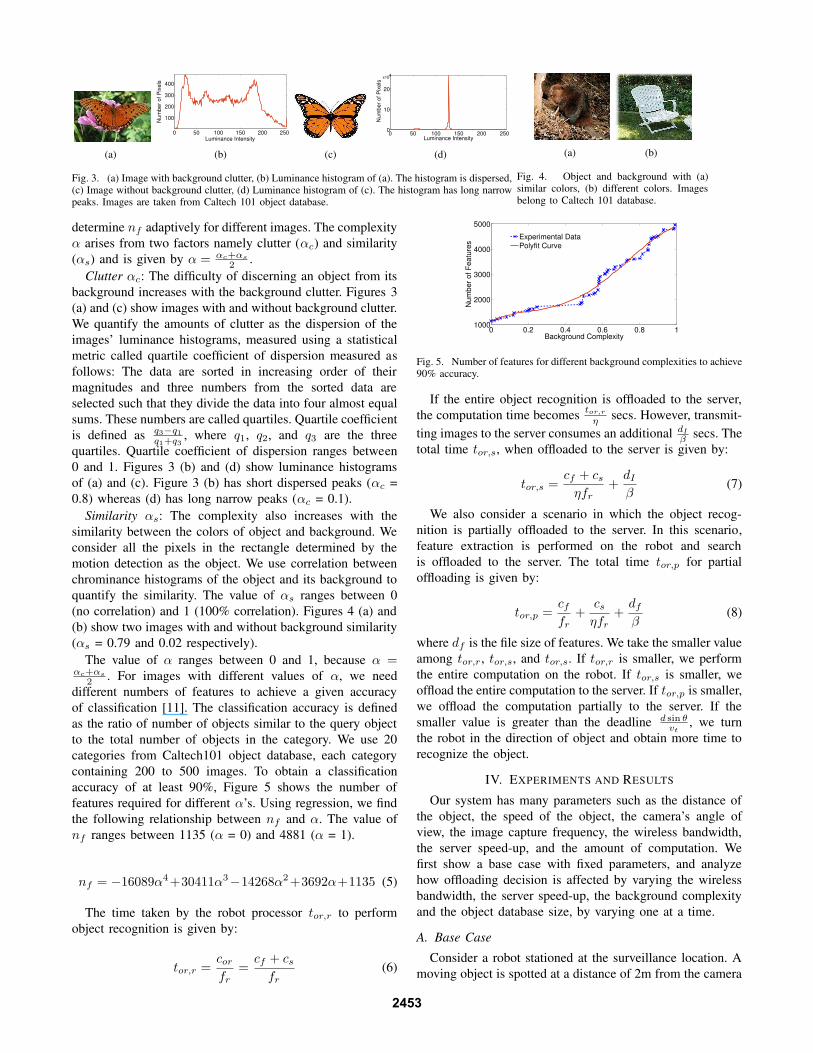
accuracy of at least 90%, Figure 5 shows the number of
features required for different α’s. Using regression, we find
the following relationship between nf and α. The value of
nf ranges between 1135 (α = 0) and 4881 (α = 1).
nf = −16089α4+30411α3
−14268α2+3692α+1135 (5)
The time taken by the robot processor tor,r to perform
object recognition is given by:
tor,r =cor
fr
=cf + cs
fr
(6)
0 0.2 0.4 0.6 0.8 11000
2000
3000
4000
5000
Background Complexity
Num
ber
of F
eatu
res
Experimental DataPolyfit Curve
Fig. 5. Number of features for different background complexities to achieve90% accuracy.
If the entire object recognition is offloaded to the server,
the computation time becomestor,r
ηsecs. However, transmit-
ting images to the server consumes an additional dI
βsecs. The
total time tor,s, when offloaded to the server is given by:
tor,s =cf + cs
ηfr
+dI
β(7)
We also consider a scenario in which the object recog-
nition is partially offloaded to the server. In this scenario,
feature extraction is performed on the robot and search
is offloaded to the server. The total time tor,p for partial
offloading is given by:
tor,p =cf
fr
+cs
ηfr
+df
β(8)
where df is the file size of features. We take the smaller value
among tor,r, tor,s, and tor,s. If tor,r is smaller, we perform
the entire computation on the robot. If tor,s is smaller, we
offload the entire computation to the server. If tor,p is smaller,
we offload the computation partially to the server. If the
smaller value is greater than the deadline d sin θvt
, we turn
the robot in the direction of object and obtain more time to
recognize the object.
IV. EXPERIMENTS AND RESULTS
Our system has many parameters such as the distance of
the object, the speed of the object, the camera’s angle of
view, the image capture frequency, the wireless bandwidth,
the server speed-up, and the amount of computation. We
first show a base case with fixed parameters, and analyze
how offloading decision is affected by varying the wireless
bandwidth, the server speed-up, the background complexity
and the object database size, by varying one at a time.
A. Base Case
Consider a robot stationed at the surveillance location. A
moving object is spotted at a distance of 2m from the camera
2453
ts d vt tmd,r tsv,r tor,r α η
0.05s 2m 1.5m/s 0.06s 0.2s 1.7s 0.5 10
β γ dI df tmd,s tsv,s tor,p tor,s
50kbps 1000 20 kB 10 kB 0.41s 0.82s 0.55s 0.57s
TABLE IV
VALUES FOR BASE CASE.
with an angle of view 90◦. The velocity of the object is
1.5m/sec and the maximum velocity of the robot is 1.6m/sec.
The execution times for motion detection and stereovision on
the robot are 60 msec and 200 msec respectively. The object
recognition time on the robot with a background complexity
0.5 is 1.7sec (0.2sec for feature extraction and 1.5sec for
search) for a database containing 1000 images. The execution
times on the server for these modules are computed using
Equations (3), (4), (7) and (8). The values for the base case
are listed in Table IV. Motion detection and stereovision are
performed on the robot and object recognition is partially
offloaded for the base case.
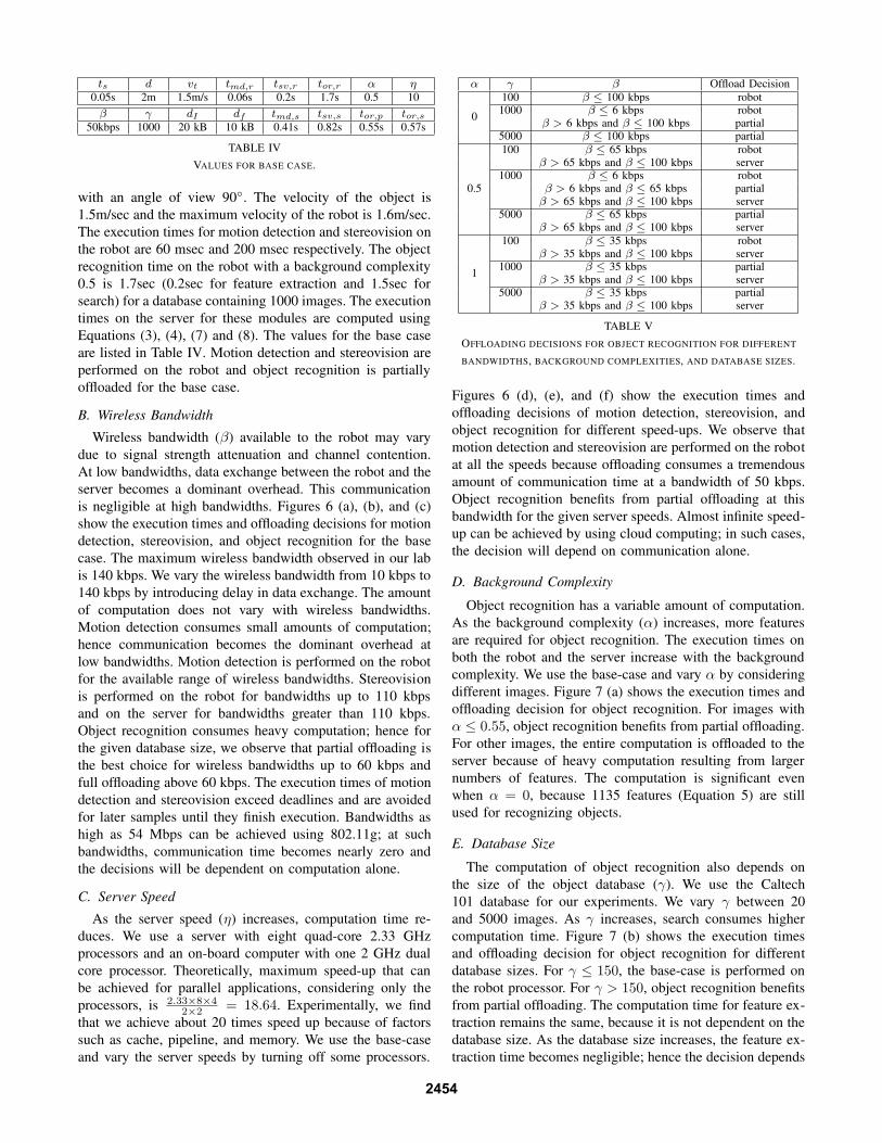
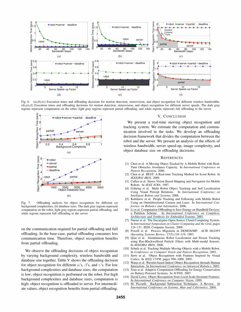
B. Wireless Bandwidth
Wireless bandwidth (β) available to the robot may vary
due to signal strength attenuation and channel contention.
At low bandwidths, data exchange between the robot and the
server becomes a dominant overhead. This communication
is negligible at high bandwidths. Figures 6 (a), (b), and (c)
show the execution times and offloading decisions for motion
detection, stereovision, and object recognition for the base
case. The maximum wireless bandwidth observed in our lab
is 140 kbps. We vary the wireless bandwidth from 10 kbps to
140 kbps by introducing delay in data exchange. The amount
of computation does not vary with wireless bandwidths.
Motion detection consumes small amounts of computation;
hence communication becomes the dominant overhead at
low bandwidths. Motion detection is performed on the robot
for the available range of wireless bandwidths. Stereovision
is performed on the robot for bandwidths up to 110 kbps
and on the server for bandwidths greater than 110 kbps.
Object recognition consumes heavy computation; hence for
the given database size, we observe that partial offloading is
the best choice for wireless bandwidths up to 60 kbps and
full offloading above 60 kbps. The execution times of motion
detection and stereovision exceed deadlines and are avoided
for later samples until they finish execution. Bandwidths as
high as 54 Mbps can be achieved using 802.11g; at such
bandwidths, communication time becomes nearly zero and
the decisions will be dependent on computation alone.
C. Server Speed
As the server speed (η) increases, computation time re-
duces. We use a server with eight quad-core 2.33 GHz
processors and an on-board computer with one 2 GHz dual
core processor. Theoretically, maximum speed-up that can
be achieved for parallel applications, considering only the
processors, is 2.33×8×4
2×2= 18.64. Experimentally, we find
that we achieve about 20 times speed up because of factors
such as cache, pipeline, and memory. We use the base-case
and vary the server speeds by turning off some processors.
α γ β Offload Decision
0
100 β ≤ 100 kbps robot1000 β ≤ 6 kbps robot
β > 6 kbps and β ≤ 100 kbps partial5000 β ≤ 100 kbps partial
0.5
100 β ≤ 65 kbps robotβ > 65 kbps and β ≤ 100 kbps server
1000 β ≤ 6 kbps robotβ > 6 kbps and β ≤ 65 kbps partial
β > 65 kbps and β ≤ 100 kbps server5000 β ≤ 65 kbps partial
β > 65 kbps and β ≤ 100 kbps server
1
100 β ≤ 35 kbps robotβ > 35 kbps and β ≤ 100 kbps server
1000 β ≤ 35 kbps partialβ > 35 kbps and β ≤ 100 kbps server
5000 β ≤ 35 kbps partialβ > 35 kbps and β ≤ 100 kbps server
TABLE V
OFFLOADING DECISIONS FOR OBJECT RECOGNITION FOR DIFFERENT
BANDWIDTHS, BACKGROUND COMPLEXITIES, AND DATABASE SIZES.
Figures 6 (d), (e), and (f) show the execution times and
offloading decisions of motion detection, stereovision, and
object recognition for different speed-ups. We observe that
motion detection and stereovision are performed on the robot
at all the speeds because offloading consumes a tremendous
amount of communication time at a bandwidth of 50 kbps.
Object recognition benefits from partial offloading at this
bandwidth for the given server speeds. Almost infinite speed-
up can be achieved by using cloud computing; in such cases,
the decision will depend on communication alone.
D. Background Complexity
Object recognition has a variable amount of computation.
As the background complexity (α) increases, more features
are required for object recognition. The execution times on
both the robot and the server increase with the background
complexity. We use the base-case and vary α by considering
different images. Figure 7 (a) shows the execution times and
offloading decision for object recognition. For images with
α ≤ 0.55, object recognition benefits from partial offloading.
For other images, the entire computation is offloaded to the
server because of heavy computation resulting from larger
numbers of features. The computation is significant even
when α = 0, because 1135 features (Equation 5) are still
used for recognizing objects.
E. Database Size
The computation of object recognition also depends on
the size of the object database (γ). We use the Caltech
101 database for our experiments. We vary γ between 20
and 5000 images. As γ increases, search consumes higher
computation time. Figure 7 (b) shows the execution times
and offloading decision for object recognition for different
database sizes. For γ ≤ 150, the base-case is performed on
the robot processor. For γ > 150, object recognition benefits
from partial offloading. The computation time for feature ex-
traction remains the same, because it is not dependent on the
database size. As the database size increases, the feature ex-
traction time becomes negligible; hence the decision depends
2454
20 40 60 80 100 120 1400
0.5
1
1.5
Bandwidth (kbps)Motion D
ete
ction T
ime (
secs)
r robot server deadline
robot
(a)
20 40 60 80 100 120 1400
0.5
1
1.5
Bandwidth (kbps)
Ste
reovis
ion T
ime (
secs)
r robot server deadline
robot server
(b)
20 40 60 80 100 120 1400
0.5
1
1.5
2
Bandwidth (kbps)Obje
ct R
ecognitio
n T
ime (
secs)
p robot server partial deadline
Deadline Crossing Point
partial server
(c)
5 10 150
0.2
0.4
0.6
0.8
Server Speed−up FactorMotion D
ete
ction T
ime (
secs)
f robot server deadline
robot
(d)
5 10 150
0.2
0.4
0.6
0.8
Server Speed−up Factor
Ste
reovis
ion T
ime (
secs)
robot server deadline
robot
(e)
5 10 150
0.5
1
1.5
2
Server Speed−up FactorObje
ct R
ecognitio
n T
ime (
secs)
f robot server partial deadline
partial
(f)
Fig. 6. (a),(b),(c) Execution times and offloading decisions for motion detection, stereovision, and object recognition for different wireless bandwidths.(d),(e),(f) Execution times and offloading decisions for motion detection, stereovision, and object recognition for different server speeds. The dark grayregions represent computation on the robot, light gray regions represent partial offloading, and white regions represent full offloading to the server.
0.2 0.4 0.6 0.8 10
1
2
3
4
Background ComplexityOb
ject
Re
co
gn
itio
n T
ime
(se
cs)
robot server partial deadline
partial server
(a)
1000 2000 3000 4000 50000
2
4
6
8
Object Database Size
Ob
ject
Re
co
gn
itio
n T
ime
(se
cs)
robot
server
partial
deadline
robot partial
(b)
Fig. 7. Offloading analysis for object recognition for different (a)background complexities, (b) database sizes. The dark gray regions representcomputation on the robot, light gray regions represent partial offloading, andwhite regions represent full offloading to the server.
on the communication required for partial offloading and full
offloading. In the base-case, partial offloading consumes less
communication time. Therefore, object recognition benefits
from partial offloading.
We observe the offloading decisions of object recognition
by varying background complexity, wireless bandwidth and
database size together. Table V shows the offloading decision
for object recognition for different α’s, β’s, and γ’s. For low
background complexities and database sizes, the computation
is low; object recognition is performed on the robot. For high
background complexities and database sizes, computation is
high; object recognition is offloaded to server. For intermedi-
ate values, object recognition benefits from partial offloading.
V. CONCLUSION
We present a real-time moving object recognition and
tracking system. We estimate the computation and commu-
nication involved in the tasks. We develop an offloading
decision framework that divides the computation between the
robot and the server. We present an analysis of the effects of
wireless bandwidth, server speed-up, image complexity, and
object database size on offloading decisions.
REFERENCES
[1] Chen et al. A Moving Object Tracked by A Mobile Robot with Real-Time Obstacles Avoidance Capacity. In International Conference on
Pattern Recognition, 2006.[2] Chen et al. BEST: A Real-time Tracking Method for Scout Robot. In
IEEE/RSJ IROS, 2009.[3] Cullen et al. Stereo Vision Based Mapping and Navigation for Mobile
Robots. In IEEE ICRA, 1997.[4] Gohring et al. Multi Robot Object Tracking and Self Localization
Using Visual Percept Relations. In International Conference on
Intelligent Robots and Systems, 2006.[5] Kobilarov et al. People Tracking and Following with Mobile Robot
Using an Omnidirectional Camera and Laser. In International Con-
ference on Robotics and Automation, 2006.[6] Li et al. Computation Offloading to Save Energy on Handheld Devices:
a Partition Scheme. In International Conference on Compilers,
Architecture and Synthesis for Embedded Systems, 2001.[7] Nurmi et al. The Eucalyptus Open-Source Cloud-Computing System.
In International Symposium on Cluster Computing and the Grid, pages124–131. IEEE Computer Society, 2009.
[8] Powell et al. Process Migration in DEMOS/MP. ACM SIGOPS
Operating Systems Review, 17(5):110–119, 1983.[9] Qian et al. Simultaneous Robot Localization and Person Tracking
using Rao-Blackwellised Particle Filters with Multi-modal Sensors.In IEEE/RSJ IROS, 2008.
[10] Schulz et al. Tracking Multiple Moving Objects with a Mobile Robot.In Conference on Computer Vision and Pattern Recognition, 2001.
[11] Serre et al. Object Recognition with Features Inspired by VisualCortex. In IEEE CVPR, pages 994–1000, 2005.
[12] Wang et al. Wavelet-based Indoor Object Recognition through HumanInteraction. In International Conference on Advanced Robotics, 2003.
[13] Xian et al. Adaptive Computation Offloading for Energy Conservationon Battery-Powered Systems. In ICPDS, 2007.
[14] David Lowe. Object Recognition from Local Scale-Invariant Features.In International Conference on Computer Vision, 1999.
[15] M. Piccardi. Background Subtraction Techniques: A Review. InInternational Conference on Systems, Man and Cybernetics, 2004.
2455
Top Related
Copyright © 2022 FDOKUMEN

