


Bahasa
Halaman
Hukum

Precise Local Geoid
Using Surface Fitting Methods
Mahmoud El-Mewafi Associate Professor, Public Works Dept.,
Faculty of Engineering, Mansoura University, Egypt
أعطي االنتشار السريع الستخدام األقمار الصناعية في تحديد إحداثيات النقط :الملخصأعطي اهتماما كبيرا لحساب سطح الجيويد مما يزيد من دقة حساب مناسيب النقط من
. أرصاد األقمار الصناعية كبديل سريع ألعمال الميزانيات في األعمال المساحيةوالهدف من هذا البحث هو إيجاد طريقة رياضية مثلي وبسيطة لحساب سطح الجيويد
ولذلك قدم البحث األسس الرياضية لثالث طرق لتوقيع األسطح بدقة عالية . في مصر(. HARN)مع دراسة تطبيقها علي الشبكة الجيودسية المصرية عالية الدقة
وقد أوضحت النتائج إمكانية استخدام الطرق الرياضية الثالث لتوقيع سطح الجيويد في
مصر بدقة عالية إال أن اعلي دقة أمكن الحصول عليها كانت من طريقة اقل تحدب كما تم الحصول علي دقة عالية . مقارنة بالطرق العالمية والمحلية (MCS )لألسطح
.عند تطبيق هذه الطريقة عمليا في منطقة بحيرة ناصر
ABSTRACT
According to wide spread use of satellite based positioning techniques, especially GPS
(Global Positioning System), a greater attention has started to be paid to precise
determination of geoid models with an aim to replace the geometric leveling
measurements with GPS measurements during geodetic and surveying works. This paper
briefly discusses the data and methodology used in the establishment of an Egyptian local
geoid with high accuracy . Numerical solution of geoid modeling determination applying
Surface fitting ; regression models; least square collocation with linear basis functions;
and minimum curvature surface (MCS) with Laplace equation are presented.
In addition a comparative study of these techniques, mainly it is going to emphasize the
applicability of interpolation techniques as a tool for modeling the geoid in a local area
precisely using GPS/ Levelling data to serve practical applications of geodesy. Also, The
obtained results revealed that, the applicability of MCS technique as a tool for
determining the Egyptian Local Geoid precisely with law distortion at common points.
1. INTRODUCTION
A precise geoid model is an important part of the geodetic infrastructure. Geodetic
infrastructure includes whole of the geodetic networks, which realize the coordinate
systems and datum definitions as the bases of geodetic works. The heights of points on
land are traditionally determined by leveling technique. However, GPS derived heights
are referred to WGS-84 ellipsoid, while the leveled heights are referred to geoid. Their
difference is called geoidal height or geoid undulation. In practices, most of survey
projects require leveled heights, for they have physical meaning. Therefore precise geoid
must be available to transform GPS derived heights to leveled heights. The fundamental
expression of relationship between ellipsoidal heights obtained from GPS measurements
and heights with respect to a vertical geodetic datum established from leveling data with
gravimetric corrections is given in [Moritz, 1980 ].
The transformation of ellipsoidal heights to orthometric ones requires that the geoid
height must refer to the same reference ellipsoid (to the WGS-84 ellipsoid). With the
spreading of the GPS measurements the need for a good geoid model has been increased.
The geoid can be calculated from different types of input data. The simplest method is to
use GPS and leveling points, where both the ellipsoidal and orthometric heights are given.
Another possibility and the most commonly used technique for precise determination of
geoid is using the gravimetric solution. In this paper, geoid modeling is evaluated as a
surface fitting problem according to GPS and Leveling data and the focus is modeling the
geoid of a local area as an analytical surface to serve practical geodetic applications.
During implementation of the subject, three different interpolation methods are
considered. The presented interpolation methods were programmed as to be computation
modules of a geoid modelling software and the results of the computation algorithms are
going to be mentioned. A comparative study between surface fitting methods and both of
OSU91 and EGM96 are also presented.
2. Egyptian Geoid Determination
In Egypt considerable investigations are in progress for the determination of the
separation of the geoid: GPS/leveling data geoid solution [Nassar et al., 1993], [ El-
Tokhey and Maghraby, 1995], [Shaker et al., 1997], and [Amin et al., 2005]. This
solution was based on GPS and leveling observations data, and the EGM96 geopotential
model. Gravimetric solution based on terrestrial gravity data was carried out by many
authors: [ Saad et al., 2002], [ Dawod, 2005] . Previous studies have shown that the
accuracy of GPS/leveling data geoid solution model over Egypt is almost 1.5 meter
accuracy [Saad and Dawod, 2002 ]. Even the new global models, such as EGM96,
PGM2000, and UCPH2002, do not represent the gravitational field over Egypt better than
0.80 meter[ Dawod, 2005]. Therefore to improve the estimation of the geoid with high
accuracy we had to look for a new method. Surface fitting methods may be give a high
accuracy geoid determination in Egypt.
3. Surface Fitting Methods
Surface fitting is a method that uses the difference in position at each common point to
in effect fit a surface, which can then be used to interpolate the change for other points.
This means that there will be a surface for the change in latitude, and another for the
change in longitude. Examples of this type of transformation are the Minimum Curvature
method used in the USA; the Multiple Regression method used in Canada; and the
Collocation method used in Australia.
3.1 POLYNOMIAL FITTING
The mathematical formula of the polynomial model fitting was used to approximate the
geoid heights as a function of geographic coordinates latitude Φ and longitude λ. The
formula of the used 6th order fitting polynomial is the following [Erol, B., and Çelik, R.,
2004] :

N= A0+A1λ+A2Φ+A3 λ2+A4 λ Φ +A5Φ
2 + A6 λ
3+A7 λ
2 Φ + A8 λ Φ
2 + A9Φ
3 + A10
λ4+A11 λ
3 Φ + A12 λ
2Φ
2 + A13 λ Φ
3 + A14 Φ
4 + A15 λ
5+A16 λ
4 Φ + A17 λ
3 Φ
2 + A18 λ
2Φ
3
+ A19 λ Φ4 + A20 Φ
5 + A21 λ
6+A22 λ
5 Φ + A23 λ
4 Φ
2 + A24 λ
3Φ
3 + A25 λ
2 Φ
4 + A26 λ Φ
5
+ A27 Φ6 …………(1)
Where N is the geoid height and Ai are the coefficients of the polynomial.
Using general least square technique to solve this system for every point altogether and
notice that, the coordinates (Φ,λ) will be considered as observations and the unknowns
are the A0,A1,A2,A3,A4,A5,A6,……and An. The maximum accuracy in this study resulted
by applying 2nd
order polynomial.
3.2 Least - Squares Collocation Fitting
Least - squares collocation can be applied on the interpolation of the geoid undulation
depending only on the GPS/Leveling observations at common points. When predicting
(interpolating) the value of geoid undulation and the distortion at each grid node, the
geoid undulation and the distortion at neighboring data points is considered. The grid
spacing used in this paper for the Egyptian model is ∆Φ = 0.50o and Δλ = 0.50
o and was
computed from points which have leveling and GPS data. The contribution to the
predicted value of each data point is determined from a weighting (covariance) function.
Therefore, the covariance matrix must be constructed from the distances (r) between
points and coordinate differences as follows, [Cross, 1983]:
1. Calculation of the height differences.
The difference between datum heights at stations
N = h – H ………………………………….. (2)
Where: h is the ellipsoidal height, H is an orthometric height, and N is the geoid
undulation
2. Estimation of a priori variance-covariance matrix (Cij) using the general form of least-
squares technique.
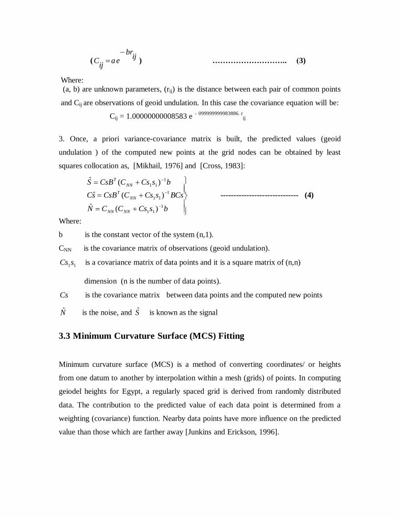
(ij
brea
ijC
) ……………………….. (3)
Where:
(a, b) are unknown parameters, (rij) is the distance between each pair of common points
and Cij are observations of geoid undulation. In this case the covariance equation will be:
Cij = 1.00000000008583 e - 0 .99999999983886 r
ij
3. Once, a priori variance-covariance matrix is built, the predicted values (geoid
undulation ) of the computed new points at the grid nodes can be obtained by least
squares collocation as, [Mikhail, 1976] and [Cross, 1983]:
bsCsCCN
BCssCsCCsBsC
bsCsCCsBS
NNNN
NN
T
NN
T
1
11
1
11
1
11
)(ˆ
)(ˆ
)(ˆ
------------------------------ (4)
Where:
b is the constant vector of the system (n,1).
CNN is the covariance matrix of observations (geoid undulation).
11sCs is a covariance matrix of data points and it is a square matrix of (n,n)
dimension (n is the number of data points).
Cs is the covariance matrix between data points and the computed new points
N is the noise, and S is known as the signal
3.3 Minimum Curvature Surface (MCS) Fitting
Minimum curvature surface (MCS) is a method of converting coordinates/ or heights
from one datum to another by interpolation within a mesh (grids) of points. In computing
geiodel heights for Egypt, a regularly spaced grid is derived from randomly distributed
data. The contribution to the predicted value of each data point is determined from a
weighting (covariance) function. Nearby data points have more influence on the predicted
value than those which are farther away [Junkins and Erickson, 1996].

As mentioned above, the grid spacing used in this paper for the Egyptian model is ∆Φ =
0.50o and Δλ = 0.50
o and was computed from points having leveling and GPS data.
Minimum curvature surface (MCS) creates a surface from three-dimensional point
elements, the nodes and edges that have X, Y and Z coordinate fields for each node from
common point's record. Minimum curvature surface (MCS) algorithm works in two
stages, initialization and iteration. In the initialization stage, Minimum curvature surface
(MCS) method applies a Laplacian power or, an alternative function (Poissan), satisfies
the bi-harmonic to the set of input coordinates values and fits a smooth surface to the
elevation values [Nikos, 1997].
D
dxdyyxf2
2 ),( …………… (5)
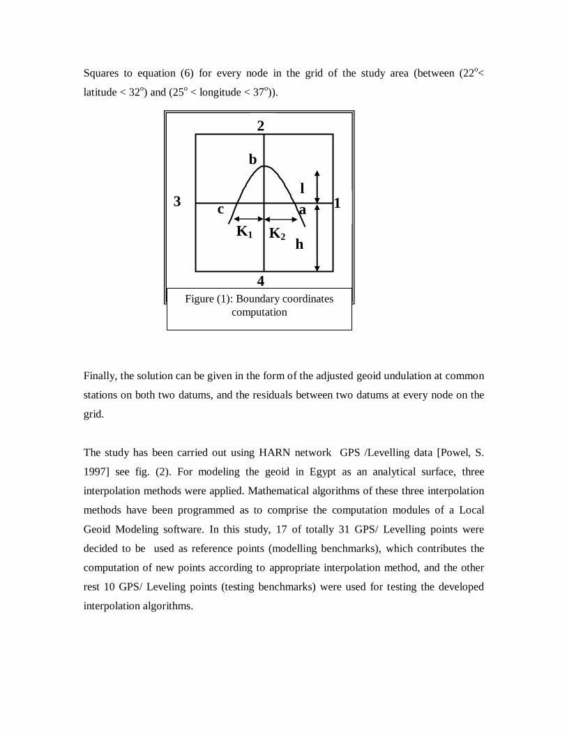
For the general case, equation (5) can be rearranged (when the four arms about the nods
may be not completed) referring fig. (1), to give the final form of the observation
equation as:
(6) Poisson )
0,
0(2h
Laplace ,0
)
21
2
21
2(
)21
(2
42
)21
(1
2
)21
(2
2
)21
(1
2
yxfkkllllllll
b
kkk
c
kkk
a
where k1,k2,l are the ratios from complete grid arm h as shown in fig. (1),
fo is the function of unknown value Φo و
2
2
2
2)2
(
2 c,
2
2
2
2)1
(
1 a
ox
hk
oxhko
ox
hk
oxhko
2
2
2
2 4,
2
2
2
2)(
b oy
hoy
hoando
y
hLoy
hLo
Once initialization is completed, iterations of the algorithm adjust output values so that a
smooth, uniformly representative surface is produced. A Special program using c-
language was written [Delores, 1996] . The program automatically calculate the effect of
stations position on the neighbor nodes by asking the user about the number of unknown
nodes and the number of stations. The program automatically apply the unified Least
l
h
K2 K1
b
a c
4
2
1 3
Figure (1): Boundary coordinates
computation
Squares to equation (6) for every node in the grid of the study area (between (22o<
latitude < 32o) and (25
o < longitude < 37
o)).
Finally, the solution can be given in the form of the adjusted geoid undulation at common
stations on both two datums, and the residuals between two datums at every node on the
grid.
The study has been carried out using HARN network GPS /Levelling data [Powel, S.
1997] see fig. (2). For modeling the geoid in Egypt as an analytical surface, three
interpolation methods were applied. Mathematical algorithms of these three interpolation
methods have been programmed as to comprise the computation modules of a Local
Geoid Modeling software. In this study, 17 of totally 31 GPS/ Levelling points were
decided to be used as reference points (modelling benchmarks), which contributes the
computation of new points according to appropriate interpolation method, and the other
rest 10 GPS/ Leveling points (testing benchmarks) were used for testing the developed
interpolation algorithms.
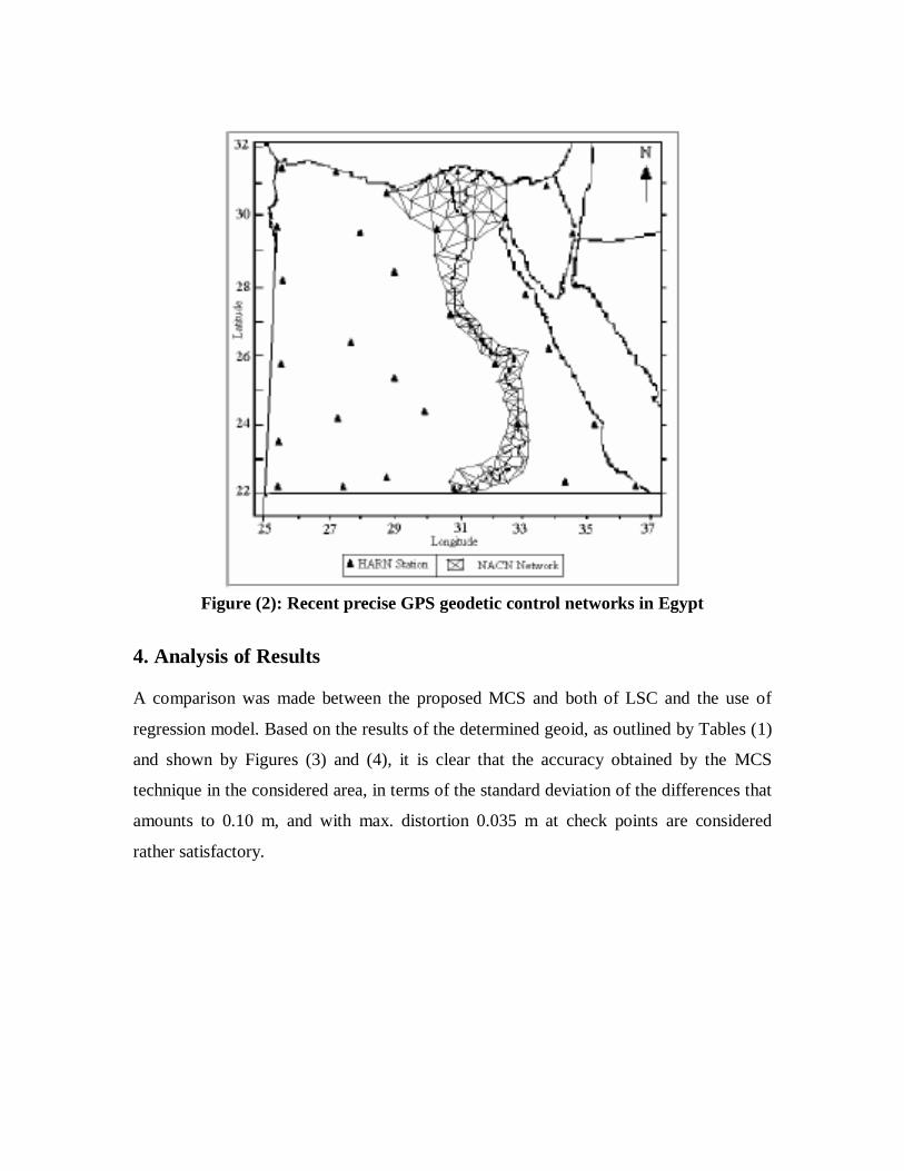
Figure (2): Recent precise GPS geodetic control networks in Egypt
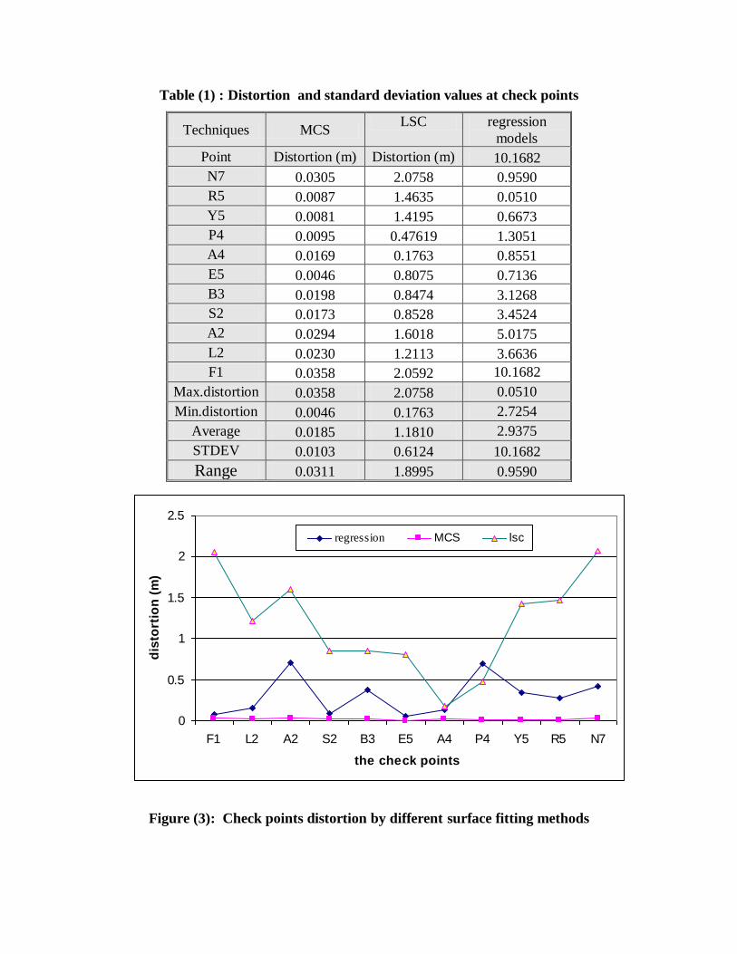
4. Analysis of Results
A comparison was made between the proposed MCS and both of LSC and the use of
regression model. Based on the results of the determined geoid, as outlined by Tables (1)
and shown by Figures (3) and (4), it is clear that the accuracy obtained by the MCS
technique in the considered area, in terms of the standard deviation of the differences that
amounts to 0.10 m, and with max. distortion 0.035 m at check points are considered
rather satisfactory.
0
0.5
1
1.5
2
2.5
N7R5Y5P4A4E5B3S2A2L2F1
the check points
dis
tort
ion
(m
)
regression MCS lsc
Table (1) : Distortion and standard deviation values at check points
Techniques MCS LSC regression
models
Point Distortion (m) Distortion (m) 10.1682
N7 0.0305 2.0758 0.9590
R5 0.0087 1.4635 0.0510
Y5 0.0081 1.4195 0.6673
P4 0.0095 0.47619 1.3051
A4 0.0169 0.1763 0.8551
E5 0.0046 0.8075 0.7136
B3 0.0198 0.8474 3.1268
S2 0.0173 0.8528 3.4524
A2 0.0294 1.6018 5.0175
L2 0.0230 1.2113 3.6636
F1 0.0358 2.0592 10.1682
Max.distortion 0.0358 2.0758 0.0510
Min.distortion 0.0046 0.1763 2.7254
Average 0.0185 1.1810 2.9375
STDEV 0.0103 0.6124 10.1682
Range 0.0311 1.8995 0.9590
Figure (3): Check points distortion by different surface fitting methods

Figure (4) Contour line of the geoid undulation by using MCS model
The second test was carried out by analyzing the difference between computed geoid
heights from the MCS model and geoid heights from most common geoid models in the
world EGM96 using Geomatics program , and OSU91A as shown in (Scott, 1997). As
the result of these analysis as shown in table (2) and figure (5), it was seen that the model
fitted the data with ±1.032 cm root means square error and max. distortion 3.58 cm at
check points. This is also an indicator for usability of the model for computing the new
points. At the end of the analysis, it was decided that both interpolation method gave
reasonable results for The Egypt and they are applicable for modelling the geoid of this
area as an analytical surface and to serve practical geodetic applications.
The third test were carried out in a local area of " Naser lack", to verify the MCS model
(NMCS) and available data from the NRI(Nobs). As shown in table (3) the different in the

geoid undulation at this zone varied between maximum different (0.833 cm) and
minimum different (0.798 cm) with ± 0.012 cm root means square error. This is also an
indicator for usability of the model for computing the new points of any local area in
Egypt.
Table (2): The comparison between different geoid model at check points
point OSU-91A EGM-96 MCS
N7 2.21 0.827 0.030
R5 0.549 0.376 0.008
Y5 0.669 0.561 0.008
P4 0.708 0.928 0.009
A4 0.387 0.581 0.016
E5 0.701 0.149 0.004
B3 0.453 0.05 0.019
S2 0.226 0.322 0.017
A2 0.456 0.024 0.029
L2 0.835 0.278 0.023
F1 1.068 0.163 0.035
max 2.21 0.928 0.035
min 0.226 0.024 0.004
STD 0.535 0.303 0.010
average 0.751 0.387 0.018
The third test were carried out in a local area of " Naser lack", to verify the MCS model
(NMCS) and available data from the NRI(Nobs). As shown in table (3) the different in the
geoid undulation at this zone varied between maximum different (0.833 cm) and
minimum different (0.798 cm) with ± 0.012 cm root means square error. This is also an
indicator for usability of the model for computing the new points of any local area in
Egypt.

Table (3) The comparison between the geoid undulation ( Nobs and NMCS.)
5. Conclusions and Recommendations
It is obvious that after GPS techniques have become widespread in geodetic practice,
geoid model determination for especially use in practical applications of geodesy has an
increased importance. Hence, the aim of this study was to produce some solutions to
practical applications, such as large scale map production, engineering surveying
applications etc. especially at a national level. Therefore, to test the performances and
applicability of surface fitting methods in geoid modeling using GPS/ Leveling
measurements in a local area, this study was carried out. In the study, three interpolation
techniques, ; regression models; least square collocation with linear basis functions; and
minimum curvature surface (MCS) were applied separately. In the results, it has been
seen that the interpolation methods are applicable for modelling the geoid of study area as
an analytical surface; however, MCS method fits the data better than both method
according to tests criteria.
point latitu. longitu. h H Nobs
(m)
NMCS
(m)
Diff.
dam13 24.032368 32.863689 131.84 121.298 10.5414 10.5497 0.0083 dam12 24.030022 32.860706 153.51 142.927 10.5826 10.5909 0.0083 dam11 24.025503 32.858181 151.8 141.204 10.596 10.6042 0.0082 dam10 24.018234 32.857872 178.13 167.582 10.5476 10.5558 0.0082 dam09 24.014378 32.853733 184.23 173.624 10.6066 10.6147 0.0081 dam08 24.004421 32.852749 186.38 175.894 10.4857 10.4938 0.0081 dam07 23.994453 32.854034 192.19 181.611 10.5789 10.5869 0.0080 dam06 23.989676 32.853607 196.69 186.176 10.5138 10.5218 0.0080 dam04 23.981094 32.853863 200.32 189.819 10.5002 10.5081 0.0079 dam03 23.978214 32.855679 196.4 185.910 10.49 10.4979 0.0079 dam02 23.977167 32.860516 197.81 187.299 10.5101 10.5180 0.0079 dam01 23.976591 32.864426 202.73 191.912 10.8177 10.8257 0.0080 dam00 23.970802 32.868248 200.76 190.209 10.551 10.5589 0.0079
Max. dist. 0.0083
Min. dist. 0.0079
Average 0.0081
STDEV 0.0001
Therefore, the obtained geoid using MCS is highly recommended to be used for any
future rigorous geodetic computation in the newly developed sector of the any part of
Egypt. It is also recommended to be utilized for densifying leveling networks of lower
order through rigorous GPS observations, especially in remote areas of the western or
eastern desert of that part of Egypt. Consequently, appropriate future planning for
rigorous GPS measurements in these areas is highly recommended.
References
1. Amin, M. , EL-FATAIRY, S. and HASSOUNA, R. (2005) “ A Precise Geoidal
Map of the Southern Part of Egypt by Collocation Toshka Geoid”, FIG Working
Week 2005 and GSDI-8 Cairo, Egypt April 16-21, 2005.
2. Cross P., (1983), “Advanced Least Square Applied to Position Fixing.” (April)
1983. North East London Polytechnic Department of Land Surveying.
3. Dawod, G., (2005), “Developing a precise geoid model for hydrographic
surveying of the River Nile”, Al-Azhar Engineering Al-Azhar University
Engineering Journal (AUEJ), V. 8, No. 1, January, pp. 96 – 107.
4. Delores M. ,(1996), “ Introduction to Matlap For Engineers and Scientists.”
Department of Electrical and Computer Engineering, University of Colorado,
Boulder
5. El-Tokhey, M. (1995): “Comparison of some Geopotential Geoid solutions for
Egypt”, Ain Shams University Scientific Bulletin, Vol. 30, No. 2: 82-101.
6. El-Tokhey, M. (2000):”On the Determination of Consistent Transformation
Parameters between GPS and the Egyptian Geodetic Reference System”, Paper
presented at the Gravity, Geoid and Geodynamics (GGG2000), Banff, Alberta,
Canada.

7. Erol, B., Çelik, R. N., 2004. Precise Local Geoid Determination to Make GPS
Technique more Effective in Practical Applications of Geodesy, FIG Working
Week 2004, 22-27 May, Athens, Greece
8. Junkins D. and Erickson C., (1996) "Version 2 of the National Transformation
Between NAD27 and NAD83 and its Importance for GPS Positioning in Canada."
Internal Report, Geodetic Survey Division, Geomatics Canada, May 1996. 17pp.
9. Mikhail E., “Observations and Least Squares. “, (1976). Dun Donnelly New York.
10. Moritz, H. (1980): “Advanced Physical Geodesy”, Herbert Wichmann Verlag,
Karlsruhe.
11. Nassar, M., Hanafy, M. and El-Tokhey, M. (1993), “ The 1993Ain Shams
University (ASU93) Geoid Solution for Egypt.” Proceedings of Al-Azhar Third
International Engineering Conference, Cairo, Sep. 18-21, v.4.pp. 395-407.
12. Nikos D., (1997), "Regularizing Smooth Data with Splines in Tension." Computer
Based Learning Unit. University of Lead.
13. Saad, A., and Dawod, G., 2002, A Precise Integrated GPS/Gravity Geoid Model
for Egypt, Civil Engineering Research Magazine (CERM), Al-Azhar University,
V.24, No. 1, pp.391-405.
14. Scott P., (1997), “ Results of The Final Adjustment of the New National
Geodetic Network.” Geodetic Advisor For the Egyptian Survey Authority.
15. Shaker, A., Saad, A., and EL Sagheer. A., (1997) “ Enhancement of the Egyptian
Gravimetric Geoid 1995 Using GPS Observations, .” Proceedings of the
International Symposium on GIS/ GPS, Istanbul, Turkey Sept. 15-19.
16. Soycan M,(2002) “Determination of Geoid Heights by GPS and precise
trigonometric levelling” ,Phd. Thesis ,ISTANBUL.
Top Related
Copyright © 2022 FDOKUMEN

