Fitting and Service Manual - Mobility Networks
103
Revision: 7.0 Year: 2021 Fitting and Service Manual iCLASS FP iCLASS P iCLASS SP ISO 9001:2015 certified
-
Upload
khangminh22 -
Category
Documents
-
view
1 -
download
0
Transcript of Fitting and Service Manual - Mobility Networks

Revision: 7.0 Year: 2021
Fitting and Service Manual
iCLASS FP iCLASS P iCLASS SP
ISO 9001:2015 certified

Page 1
Lift Installation and Maintenance must be performed by an approved engineer.
Non-compliance may result in serious personal injury, damage to the vehicle and may affect or even void the product warranty.
Revision Status
REVISION DATE NOTE
1.0 SEPTEMBER 2020 ORIGINAL VERSON
2.0 OCTOBER 2020 CONTENT UPDATE
3.0 OCTOBER 2020 CONTENT UPDATE
4.0 DEC 2020 WARNING UPDATE
5.0 FEB 2021 CONTENT UPDATE
6.0 JULY 2021 CONTENT UPDATE
7.0 JULY 2021 CONTENT UPDATE

Page 2
Lift Installation and Maintenance must be performed by an approved engineer.
Non-compliance may result in serious personal injury, damage to the vehicle and may affect or even void the product warranty.
WARNING: The Lift may be packaged and shipped WITHOUT Safety
Handrails.
Handrail type should be selected and correctly installed BEFORE the first
operation of the lift.
Correct installation should be carried out by an approved engineer.
See SECTION 5.7 for installation details.
Safety Handrails

Page 3
Lift Installation and Maintenance must be performed by an approved engineer.
Non-compliance may result in serious personal injury, damage to the vehicle and may affect or even void the product warranty.
Contents
1 General ........................................................................................................................................ 6
1.1 Manufacturer ...................................................................................................................... 6
1.2 Safety Rules and Symbols ................................................................................................ 6
1.3 Using the Manual ............................................................................................................... 8
1.4 Warnings ............................................................................................................................ 9
1.5 Documentation ................................................................................................................... 9
1.6 IMPORTANT Wheelchair Integrated Occupant Seatbelts ............................................. 10
1.7 Lift Owner and Lift Operator ............................................................................................ 11
1.8 Connectivity ..................................................................................................................... 12
2 Warranty .................................................................................................................................... 13
2.1 Genuine Spare Parts ....................................................................................................... 13
3 Technical ................................................................................................................................... 14
3.1 Technical Description ...................................................................................................... 14
3.2 iCLASS Model Types ...................................................................................................... 14
3.3 Technical Specifications .................................................................................................. 18
3.4 Safety Devices ................................................................................................................. 18
3.5 Doorsafe........................................................................................................................... 19
3.6 mobility RDO REAR DOOR OPENER ..................................................................................... 20
3.7 iCLASS Accessibility ........................................................................................................... 20
4 Logistics .................................................................................................................................... 21
4.1 Transport and movement ................................................................................................ 21
4.2 Packaging ........................................................................................................................ 22
4.3 Storage ............................................................................................................................. 22
5 Fitting and Installation ............................................................................................................. 23
5.1 iCLASS P Dimensions ........................................................................................................ 23
5.2 iCLASS SP Dimensions ..................................................................................................... 24
5.3 iCLASS FP Dimensions...................................................................................................... 24
5.4 iCLASS Lift Fitting Kit ......................................................................................................... 26
5.5 Lift positioning and fixing ................................................................................................. 27
5.6 Correcting the angle of the towers .................................................................................. 30
5.7 Fitting Safety Handrails ................................................................................................... 30

Page 4
Lift Installation and Maintenance must be performed by an approved engineer.
Non-compliance may result in serious personal injury, damage to the vehicle and may affect or even void the product warranty.
6 Electrical.................................................................................................................................... 32
6.1 Power Supply ................................................................................................................... 32
6.2 RDO Rear Door Opener Interface socket ....................................................................... 35
7 Power Pack ............................................................................................................................... 36
7.1 Power Pack ...................................................................................................................... 36
7.2 Hydraulic Oil level check and top-up ............................................................................... 37
7.3 Hydraulic Pressure Control ............................................................................................. 38
7.4 Pressure Control Switch and Pressure Connection Socket ........................................... 38
7.5 Pressure Control Switch Adjustment .............................................................................. 39
8 Commissioning ........................................................................................................................ 39
8.1 Lift Position Setting .......................................................................................................... 40
8.2 iCLASS Weight Test Certificate ......................................................................................... 45
8.3 ECU and the Mobility Networks – Smart Lift App ........................................................... 48
8.4 Installing the Mobility Networks – Smart Lift App and Pairing to the ECU..................... 48
8.5 Mobility Networks – Smart Lift App DEBUG Mode and Installer ECU Tools ................. 49
8.6 Changing from ‘Safety Mode’ to ‘Full Operation Mode’ .................................................. 50
8.7 ECU Details ..................................................................................................................... 50
8.8 Commissioning Log ......................................................................................................... 51
9 Operation................................................................................................................................... 53
9.1 Operation Introduction ..................................................................................................... 53
9.2 Standard Operation ......................................................................................................... 55
9.3 Emergency Operation ...................................................................................................... 58
10 Reference Material ................................................................................................................. 60
10.1 Torque Settings ............................................................................................................. 60
10.2 Fastener Strength Conversion Chart ............................................................................ 61
10.3 iCLASS Electrical Schematic ........................................................................................... 62
10.4 iCLASS Hydraulic Schematic .......................................................................................... 67
11 ECU .......................................................................................................................................... 68
11.1 Setting ‘Full Operation Mode’ (non-Mobility Networks – Smart Lift App method) ....... 68
11.2 Electrostatic Precautions ............................................................................................... 69
11.3 Firmware Updates ......................................................................................................... 70
11.4 Firmware Update using the Mobility Networks App ...................................................... 71
11.5 ECU Pin Configurations ................................................................................................ 72
11.6 RTC - Battery Replacement .......................................................................................... 73
11.7 ECU Display Messages ................................................................................................. 74
12 Inspection and Servicing ...................................................................................................... 77

Page 5
Lift Installation and Maintenance must be performed by an approved engineer.
Non-compliance may result in serious personal injury, damage to the vehicle and may affect or even void the product warranty.
12.1 Service Intervals ............................................................................................................ 77
12.2 Daily Checks .................................................................................................................. 77
12.3 Checks to be performed every 2 Weeks ....................................................................... 78
12.4 Service Type A .............................................................................................................. 79
12.5 Service Type B .............................................................................................................. 80
12.6 Service Type C .............................................................................................................. 81
12.7 Set lift to work height ..................................................................................................... 81
12.8 Service Type D .............................................................................................................. 82
12.8.1 Replace Arm Pivot Pin ............................................................................................... 82
12.8.2 Oil Check and Change ............................................................................................... 82
12.9 iCLASS Workshop Manual: Arm Cylinder Replacement ................................................. 83
12.10 iCLASS Workshop Manual: Arm Gas Spring Replacement .......................................... 84
12.11 iCLASS Workshop Manual: Safety Handrail Gas Spring Replacement ....................... 85
12.12 iCLASS Workshop Manual: Safety Hook Replacement ................................................ 86
12.13 iCLASS Workshop Manual: Power Pack Replacement ................................................ 87
12.14 iCLASS Workshop Manual: ECU Removal ................................................................... 89
12.15 iCLASS Workshop Manual: ECU Cover Removal ........................................................ 90
12.16 iCLASS Workshop Manual: Rotary Switch Replacement ............................................. 90
12.17 iCLASS Workshop Manual: Platform Levelling ............................................................. 91
13 Cleaning .................................................................................................................................. 93
14 Lubrication .............................................................................................................................. 94
15 Inspection and Servicing ...................................................................................................... 95
15.1 Inspection and Service Data Sheet ............................................................................... 95
16 Troubleshooting ..................................................................................................................... 96
6.1 Switch Locations ............................................................................................................ 101
17 iCLASS Labelling..................................................................................................................... 101
17.1 Lift Labelling ................................................................................................................. 101
17.2 Power Pack Labels - Outside ...................................................................................... 102
Page 6
Lift Installation and Maintenance must be performed by an approved engineer.
Non-compliance may result in serious personal injury, damage to the vehicle and may affect or even void the product warranty.
1 General
1.1 Manufacturer
Mobility Networks Holdings Ltd. 12 Estuary View Business Park Whitstable Kent, CT5 3SE United Kingdom Tel: +44(0) 1227 505 022
The iCLASS wheelchair lift, is manufactured by Mobility Networks Holdings Ltd.
(Mobility Networks)
ISO 9001:2015 certified
These registrations have been assessed and registered by NQA against the provisions the
above International Standards.
1.2 Safety Rules and Symbols
Read this manual completely before commencing installation.
Particular care should be taken when these symbols are used:
WARNING This symbol identifies the presence of instructions which need to be read and followed carefully in order to avoid potentially dangerous situations.
DANGER
This symbol identifies the presence of essential information needed to avoid potentially dangerous situations that could cause physical injuries and/or damage to the equipment.
To ensure smooth and safe operation, it is necessary to follow the procedures for the
installation and servicing of the wheelchair lift.

Page 7
Lift Installation and Maintenance must be performed by an approved engineer.
Non-compliance may result in serious personal injury, damage to the vehicle and may affect or even void the product warranty.
WARNING
Carefully follow the instructions for the installation and service of the wheelchair lift within this
manual. If the instructions within this manual have not been fully understood or further
information is required, please contact Mobility Networks immediately. To avoid risk of personal
injury, material damage to the equipment and vehicles or incorrect installation and use be sure
to read and follow the contents of this manual.
DANGER
Should it be necessary to raise the vehicle being equipped, please check that the
characteristics of the vehicle lifting device is compatible with the volume and weight of the
actual vehicle otherwise there is a risk of serious damage and personal injury.
The Identification Plate, see Figure 1.2.1 is stamped with the data indicating the lift serial
number. The Operator Manual requires these details to be recorded.
NOTE: The Lift Serial number is required for ALL correspondence with factory
Figure 1.2.1 Identification Plate
Installer
Installation Date
Serial Number
WARNING
DO NOT REMOVE OR TAMPER WITH THE IDENTIFICATION PLATE, THIS WILL VOID WARRANTY
Page 8
Lift Installation and Maintenance must be performed by an approved engineer.
Non-compliance may result in serious personal injury, damage to the vehicle and may affect or even void the product warranty.
1.3 Using the Manual
This manual aims to provide users and operators with all the information they require to ensure
that they are able both to use the lift appropriately and are able to manage it as autonomously
and safely as possible.
Before performing any operations on the lift, users and operators must carefully read the
instructions given in this publication.
WARNING All installation and service procedures should be carried out in
accordance with current health and safety laws. Changes or modifications made
to the device not approved expressly by the party responsible for compliance
could void the user’s authority to use the equipment.
The Approved Service Engineer must:
Ensure the vehicle stability is not affected by the lift, either stowed or fully deployed and
fully loaded.
Carry out the installation in accordance to the indications detailed within this manual.
Carry out the installation by following the indications of the vehicle manufacturer.
Complete the Warranty registration card.
Carry out the verification check procedure for the first commissioning by following the
instructions detailed in this manual.
Register the verification check procedure for the first commissioning in the “use and
maintenance” manual.
Pass the required documentation to the final customer, in compliance to rules and
regulations in force. Send another copy to the Mobility Networks to register the warranty.
Carry out the inspections in compliance with the instructions detailed in this manual.
Register the inspections in this manual.

Page 9
Lift Installation and Maintenance must be performed by an approved engineer.
Non-compliance may result in serious personal injury, damage to the vehicle and may affect or even void the product warranty.
1.4 Warnings
Stand clear of lift when in operation and keep bystanders away
Park on level ground with plenty of manoeuvring
space around the vehicle
The disabled person must
always face away from the vehicle the vehicle. Do not approach the vehicle threshold with your back
to it. Make sure the platform is in position
before leaving the vehicle
Do not remain stood on the inner barrier /
threshold plate when lowering or stowing the
lift. Do not push against it
during use.
1.5 Documentation
The end user should receive with the iCLASS wheelchair lift:
The installation and weight test certification completed and signed by the installer.
Use and maintenance manual completed by the installer.
The latest version of all product documentation is available from the
Mobility Networks App and website.
Mobility Networks is at your complete disposal for further clarification and
instructions.

Page 10
Lift Installation and Maintenance must be performed by an approved engineer.
Non-compliance may result in serious personal injury, damage to the vehicle and may affect or even void the product warranty.
1.6 IMPORTANT Wheelchair Integrated Occupant Seatbelts
It is recommended to follow the Best Practice Guidelines of PMG.
Wheelchairs that are suitable for use as a seat in transport are recommended to comply with
ISO 7176-19:2008+A1:2015 may be fitted with crashworthy integrated lap belts for use during
transport.
It is recommended that when fitted, a crashworthy integrated lap belt is correctly fitted,
positioned low on the passenger’s pelvis and buckled-up before using the passenger lift.
Operators must be fully trained in the use of wheelchair tiedowns and occupant restraint
systems (WTORS) that are compliant with ISO 10542-1:2012.
Operators should also be familiar with the use of other equipment used to assist people with
different types of disability and the various types of wheelchair that may be encountered.
The wheelchair user or their family or care provider are responsible for ensuring that the
wheelchair has the correct equipment installed and maintained, as recommended by the
wheelchair manufacturer and equipment supplier.
*The above standards should be checked to make sure the latest version is used.

Page 11
Lift Installation and Maintenance must be performed by an approved engineer.
Non-compliance may result in serious personal injury, damage to the vehicle and may affect or even void the product warranty.
1.7 Lift Owner and Lift Operator
The lift owner is the person who purchases the product, uses or oversees
the use of the lift, this person is legally responsible for the lift’s safe use.
They are responsible for distributing and ensuring that a copy of this
manual is read and fully understood by all potential lift operators before
operating the lift.
The operator is individually responsible for the safe use and maintenance of the lift. They are
also responsible for the lift users and their own personal safety and in the event of an accident
they will be prosecuted to the full extent of the law if they are deemed negligent. No operator
will use the lift if they believe it is unsafe and doing so could injury themselves or others, they
MUST report their concerns directly to their manager or Mobility Networks.
Legal action will also be taken if any unauthorized modifications are made to the lift without
direct prior written authority by Mobility Networks.
The operator must be fully trained in all the operation aspects of the lift such as the
transportation of people with motor deficiencies or disabilities. The operator must exhibit the
following characteristics/ attributes for them to safely operate the lift:
PHYSICAL Possess the required physical qualities/ characteristics sufficiently to ensure safe
operation of lift in a safe and controlled manner. Examples include:
• Good hearing & sight
• Physically capable of performing all operational functions of lift
• Not impaired by the consumption of legal and/or illegal substances (such as alcohol and / or drugs)
MENTAL Possess the required mental qualities / characteristics sufficiently to ensure safe
operation of lift in a safe and controlled manner. Examples include:
• Understanding & application of the safety rules and procedures while operating the lift.
• Be constantly aware and pro-active to ensure the safety of operator, consumer and nearby people.
• Have the knowledge / skills to perform as an assistant and/ or operator in all aspects of lift
operation, e.g. the safe transportation, loading and unloading of disabled and other passengers.
EMOTIONAL Possess the required emotional qualities / characteristics sufficiently to ensure safe
operation of lift in a safe and controlled manner. Examples include:
• Work in a calm & safe manner while under stress so to prevent stress from impairing good judgement.
• To be emotionally stable during normal or abnormal situations
TRAINING Possess the required training qualities sufficiently to ensure safe operation of lift in a safe
and controlled manner. Examples include:
• Completed operational training supervised by an experienced operator in Mobility Networks lifts in an environment which is safe and controlled. Such supervised training should allow the trainee to gain working experience in all operation aspects of the lift.
WARNING

Page 12
Lift Installation and Maintenance must be performed by an approved engineer.
Non-compliance may result in serious personal injury, damage to the vehicle and may affect or even void the product warranty.
1.8 Connectivity
If the Powerpack has an LCD screen then lift functionality can
be achieved wirelessly.
The lift can be controlled / programmed using the Mobility Networks – Smart Lift App.
(Download using the QR Code on front of manual / on the lift).
To pair:
On your mobile device, open the application and follow the instructions on the screen.
For both iOS / Android the app will ask for Bluetooth and Location settings to be turned
on – otherwise the app cannot be used and it will close.
Connectivity works in the 3m zone shown in Figure 1.8.1
When operating the lift, ensure you are within reach of the power switch at all times and that
you are able to view all corners of the platform.
Figure 1.8.1 Wireless Connectivity Zone
WARNING
BEFORE OPERATING THE LIFT WITH THE App:
Make sure the lift and App are paired.
The PIN can be found on the Power Pack LCD Screen

Page 13
Lift Installation and Maintenance must be performed by an approved engineer.
Non-compliance may result in serious personal injury, damage to the vehicle and may affect or even void the product warranty.
2 Warranty
Mobility Networks Holdings Ltd. assures the hydraulic lift for 12 months from the date of
delivery.
The Warranty covers defects concerning material quality and product manufacturing.
The Warranty does not cover consumables and defects or failures as a result of incorrectly
performed installation. Ensure installation is performed in compliance with the manufacturer’s
instructions.
The Warranty becomes void in case of impacts caused by accidents and/or tampering carried
out by personnel not authorized by Mobility Networks Holdings Ltd.
The Warranty will be automatically extended to 24 months when the installer
uses the App to complete the installation process and product registration.
Mobility Networks refuses all responsibility for damages caused by:
Improper use of the hydraulic lift.
Platform overloading.
A failure in carrying out “use and maintenance” manual instructions.
A failure in carrying out maintenance operation as detailed in the “use and maintenance” manual.
Interventions or modifications to the lift without Mobility Networks authorisation.
WARNING
Non-fulfilment of the manufacturer’s specified regular inspection dates may affect or
even void the product warranty.
2.1 Genuine Spare Parts
WARNING
USE ONLY GENUINE PARTS
USE OF NON-GENUINE PARTS AND HARDWARE MAY AFFECT OR EVEN VOID THE PRODUCT
WARRANTY

Page 14
Lift Installation and Maintenance must be performed by an approved engineer.
Non-compliance may result in serious personal injury, damage to the vehicle and may affect or even void the product warranty.
3 Technical
3.1 Technical Description
The iCLASS wheelchair lift is installed on the deck of vehicles used for transporting persons with
reduced mobility (PRM) in wheelchairs, allowing them to get into and out of the vehicle.
The lift consists of a base fixed to the vehicle loading deck, a pair of outer lifting arms installed
on the sides of the base, and a loading platform, hinged between these.
Deploying/stowing and lifting/lowering movements of the lift are made by means of a
parallelogram leverage mechanism driven by a pair of hydraulic cylinders (one for each outer
arm). The machine is equipped with a hydraulic control unit and an electronic control box – the
Power Pack which by means of a remote control performs the various functional movements.
The entire system is electrically powered by the batteries of the vehicle to which it is installed.
3.2 iCLASS Model Types
The iCLASS wheelchair lift is available in three models, which differ from one another in type of
loading platform:
iCLASS P, with a whole one-piece platform: during stowing phase platform simply rotates from
loading position to vertical and back during the deployment phase.
iCLASS SP, with a loading platform split longitudinally: the two parts of the platforms rotate to
form a single loading platform during the deployment phase and they are separated
automatically when stowing creating a space that can be used as an emergency exit from the
vehicle.
iCLASS FP, with a folded platform deployed automatically during the opening phase and folds
automatically during stowing in order to reduce the overall height of the lift at rest resulting in
improved rear visibility for the driver of the vehicle.
It is also possible to prepare the wheelchair lift with following options:
Power supply voltage: 12V or 24V, Power Pack: fitted right or left.

Page 15
Lift Installation and Maintenance must be performed by an approved engineer.
Non-compliance may result in serious personal injury, damage to the vehicle and may affect or even void the product warranty.
Figure 3.2.1 The iCLASS P wheelchair lift
Outer (Vertical) Arm
Lifting
Arm
Base
Warning
light
Horizontal Arm
Inner
Barrier
Locks
Auxiliary Light
Platform
Arm lifting
cylinder
Power
Pack
Lower Telescopic Arm Linkage
Bridging
Device /
Inner Barrier
Outer
Barrier Safety
Handrail
Arm lifting
cylinder
Bridging
Device /
Inner Barrier
Base
Power
Pack
Outer (Vertical) Arm
Platform
Outer
Barrier
Lifting
Arm Warning
light
Safety
Handrail
Inner Barrier Locks
Lower Telescopic Arm Linkage
Horizontal Arm

Page 16
Lift Installation and Maintenance must be performed by an approved engineer.
Non-compliance may result in serious personal injury, damage to the vehicle and may affect or even void the product warranty.
Above: Figure 3.2.2 The iCLASS SP wheelchair lift
Above: Figure 3.2.3 The iCLASS FP wheelchair lift
Above: Figure 3.2.4 iCLASS SP Stowed Above: Figure 3.2.5 iCLASS FP Stowed
Outer (Vertical) Arm Lifting
Arm
Base
Horizontal Arm
Auxiliary Light
Platform
Arm lifting
cylinder
Power
Pack
Lower Telescopic Arm Linkage Bridging
Device /
Inner Barrier
Outer
Barrier Safety
Handrail
Inner
Barrier
Locks Stowage
Roller
Platform
Folding
Linkage
Warning light

Page 17
Lift Installation and Maintenance must be performed by an approved engineer.
Non-compliance may result in serious personal injury, damage to the vehicle and may affect or even void the product warranty.
Power Pack
Wired Remote Control Connection
Manual Pump Connection
Manual Release Valve
Circuit Breaker
Wireless Remote-Control Receiver Connection
Door Opener Connection
Power ON / OFF Switch

Page 18
Lift Installation and Maintenance must be performed by an approved engineer.
Non-compliance may result in serious personal injury, damage to the vehicle and may affect or even void the product warranty.
Above: Figure 3.2.5 Power Pack
Cycle Counter &
Function Indicator
Manual Pump Handle
Above: Figure 3.2.6 Power Pack Top View
3.3 Technical Specifications
Supply Voltage 12 V / 24 V (option)
Electric motor power 500W
Maximum hydraulic system pressure 170 bar
Oil tank capacity iCLASS Steel Reservoir: 1.5 l
iCLASS Plastic Reservoir: 1.0 l
Safe Working Limit (uniformly distributed) 425kg
Maximum height reached (dependent on model) 0.79 - 1.22 m
Total mass of the lift (dependent on options fitted) 125 - 160 kg
Manual auxiliary hand pump Included in Power Pack
Hydraulic oil (relevant to local environment) 15w – 32w (ATF type not recommended)
Sound Pressure (Normal)
With audible warning
<70 dB
>90 dB
Gas Spring operating temperature -30°C to 80°C
3.4 Safety Devices
The items already described in previous section of the manual already provide a good level of
safety, capable of avoiding danger if followed properly.
The iCLASS lifts are also equipped with additional safety and security devices:
• Safety handrails: To ensure a ’firm hold’ during the lifting / lowering phase.
• Bridging Device / Inner Barrier (Inner Roll Stop): Portion of the platform lift that provides a transitional surface between the platform surface and the surface of the vehicle floor within the platform threshold area. Designed to retain mobility aids on the platform surface during the range of passenger operation.

Page 19
Lift Installation and Maintenance must be performed by an approved engineer.
Non-compliance may result in serious personal injury, damage to the vehicle and may affect or even void the product warranty.
• Outer Barrier: Wheelchair retention device that is located on the edge of the platform, is
traversed during ground level loading and unloading, and is designed to retain wheelchairs on the platform surface during the range of passenger operation.
• Guarding: Covers are present on moving parts.
• Protection against overturning: Stops platform lowering in case of an obstacle which could induce overturning.
• Safety pressure switch: Prevents stowing when platform is still loaded.
• Protection against overloading: Prevents overload of the nominal loading capability of the lift.
• Protection against hydraulic system leakage: Maximum speed 150mm/s, typically 75mm/s. Hoses tested to over 4x max pressure
value. • Safety Lock:
Prevents the unintentional opening of the platform in case of low hydraulic system pressure when the lift is closed.
• External signalling: Amber warning lights are fitted on each outer arm.
It is recommended that the iCLASS lift is used in conjunction with the Inboard Lift
Doorsafe, as shown in Fig 3.5.1
See mobilitynetworksgroup.com for more details.
3.5 Doorsafe
The Inboard Lift DoorSafe has been
specifically engineered to act as a fixed,
strong, physical barrier, used to protect
passengers when the rear doors to a vehicle
are open. LED lights and clear warnings give
operators peace of mind that passengers are
safe at all times. LED lights are an optional
extra with the Inboard Lift DoorSafe barrier.
The Inboard Lift DoorSafe is an automatic
barrier with a manual override option. The
manual override allows the barrier to be
moved up and down in case sudden access is
needed.
Above: Fig 3.5.1 The Doorsafe
The Inboard Lift DoorSafe is the perfect addition to any of Mobility Networks’ Inboard lifts such
as the iCLASS.

Page 20
Lift Installation and Maintenance must be performed by an approved engineer.
Non-compliance may result in serious personal injury, damage to the vehicle and may affect or even void the product warranty.
3.6 mobility RDO REAR DOOR OPENER
The mobilityRDO is an
electrically operated rear door
opener, which is often used in
combination with the iCLASS
Inboard wheelchair lift. The
system is designed to be a “plug
and play” system making it easy
to mount, connect and use, thus
saving man-hours.
Above: Figure 3.6.1 The RDO REAR DOOR OPENER
3.7 iCLASS Accessibility
The iCLASS lift is designed To Transport:
One person in a wheelchair with or without an
attendant, with a size not larger than the width/ length
of platform space available, or weight over the stated
SWL capacity.
Or:
Two walking passengers. The operator should not attempt to transport more than two people at a time because of increased risk of passenger discomfort. The passengers also may require extra space for mobility devices such as sticks and frames.
Page 21
Lift Installation and Maintenance must be performed by an approved engineer.
Non-compliance may result in serious personal injury, damage to the vehicle and may affect or even void the product warranty.
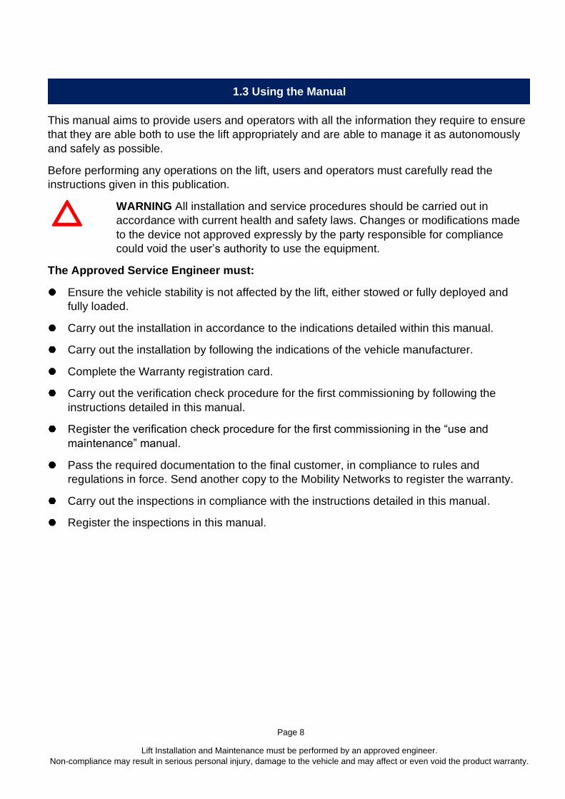
WARNING The Operator must perform their proper hazard assessment and define the best practice for boarding and alighting the vehicle and lift.
4 Logistics
4.1 Transport and movement
For transportation, the lift must be secured to a pallet and packed with sheets of protective plastic and / or cardboard. For transportation purposes, a fork lift truck or a hoist is advised. All packing materials are recyclable. The packing materials should be disposed of correctly. If necessary, contact your local waste department for advice regarding disposal requirements.
DANGER Cardboard and protective plastic sheets used for packing purposes can cause suffocation. Dispose of responsibly.
Figure 4.1 iCLASS P
Shipped on pallet showing fixing screw positions (RED). Use 10mm wrench to remove.
IF BANDED (BLUE), do not remove until instructed.

Page 22
Lift Installation and Maintenance must be performed by an approved engineer.
Non-compliance may result in serious personal injury, damage to the vehicle and may affect or even void the product warranty.
4.2 Packaging
Packaging may vary depending on model ordered and shipping methods. The packaging weight is 15 kg.
WARNING During the unpacking process be very careful to not damage the contents.
Upon delivery of the lift perform the following inspections: Ensure the product delivered corresponds to the relevant documentation e.g. the order
specification and the transport document. Examine packaging to ensure it is undamaged and all parts are intact during transportation. With great care, examine all devices to ensure they haven’t been damaged during
transportation and all parts haven’t been tampered or removed. Ensure all documentation required for installation has been supplied. Store safely.
WARNING Before beginning any installation procedure of the wheelchair lift, you should:
Verify if there are any specifications from the vehicle manufacturers to respect. Remove from the vehicle any unnecessary object that could impede the installation
procedure of the lift (spare wheel, accessories etc.). Disconnect the electrical supply from the battery. Disconnect any electronic control units from the vehicle as specified by the manufacturer
4.3 Storage
If the lift is not used straight away, proceed as follows:
Transport lift to an appropriate storage area, free from atmospheric agents / elements.
Ensure all electrical / electronic devices are insulated from external environment so to prevent
humidity damaging those components.
Storage area selected MUST ensure maximum temperature fluctuation is between 5°C to 50°C
and humidity controlled.
Ensure all sliding parts (guides, cylinders ...) are adequately protected from dust, rust and water
damage.
Note: If a lift is to be dry stored for more than 12 months then the condition of all cylinder seals
MUST be checked before operation.
WARNING
STORAGE OF THE LIFT IN CONDITIONS THAT DO NOT
COMPLY WITH THE ABOVE MAY VOID
THE WARRANTY FOR ANY PARTS THAT REQUIRE REPLACEMENT

Page 23
Lift Installation and Maintenance must be performed by an approved engineer.
Non-compliance may result in serious personal injury, damage to the vehicle and may affect or even void the product warranty.
5 Fitting and Installation
5.1 iCLASS P Dimensions
The following diagrams show
indicative overall dimensions of the
versions and set-ups available of
the iCLASS P wheelchair lift:
iCLASS P A A1 B C D E Platform Length
Capacity Lift
Weight
Height from
Ground Max
Clearance of arms from
bumper
iCLASS
P90138 1106 1196 325 1285 1486 900 1380 425 kg 148 kg 1000 300
iCLASS
P80130 1006 1096 325 1185 1406 800 1300 425 kg 140 kg 1000 300
Measurements are approximate.
Mobility Networks reserve the right to carry out product changes and improvements in order to enhance their quality at any time and without
notice. In case of doubt, please contact Mobility Networks for the latest model updates.

Page 24
Lift Installation and Maintenance must be performed by an approved engineer.
Non-compliance may result in serious personal injury, damage to the vehicle and may affect or even void the product warranty.
5.2 iCLASS SP Dimensions
** =
Width with fixed handrails
Measurements are approximate.
Mobility Networks reserve the right to carry out product changes and improvements in order to enhance their quality at any time and without
notice. In case of doubt, please contact Mobility Networks for the latest model updates.
5.3 iCLASS FP Dimensions
iCLASS SP
iCLASS FP

Page 25
Lift Installation and Maintenance must be performed by an approved engineer.
Non-compliance may result in serious personal injury, damage to the vehicle and may affect or even void the product warranty.
iCLASS FP A A1 **
B C D D1 E Platform Length
Capacity Lift
Weight
Height from
Ground Max
Clearance of arms
from bumper
("X")
iCLASS
FP84138 1106 1196 385 1275 1181 1230 840 1380 425 kg 149 kg 1000 340
iCLASS
FP80150 1058 1148 385 1195 1191 1240 800 1500 425 kg 151 kg 1000 340
iCLASS
FP70115 1006 1096 385 1175 1074 1230 700 1150 425 kg 130 kg 790 320
iCLASS
FP74138 966 - 385 1190 1181 - 740 1380 425 kg 145 kg 1000 340
Measurements are approximate.
Mobility Networks reserve the right to carry out product changes and improvements in order to enhance their quality at any time and without
notice. In case of doubt, please contact Mobility Networks for the latest model updates.
Page 26
Lift Installation and Maintenance must be performed by an approved engineer.
Non-compliance may result in serious personal injury, damage to the vehicle and may affect or even void the product warranty.
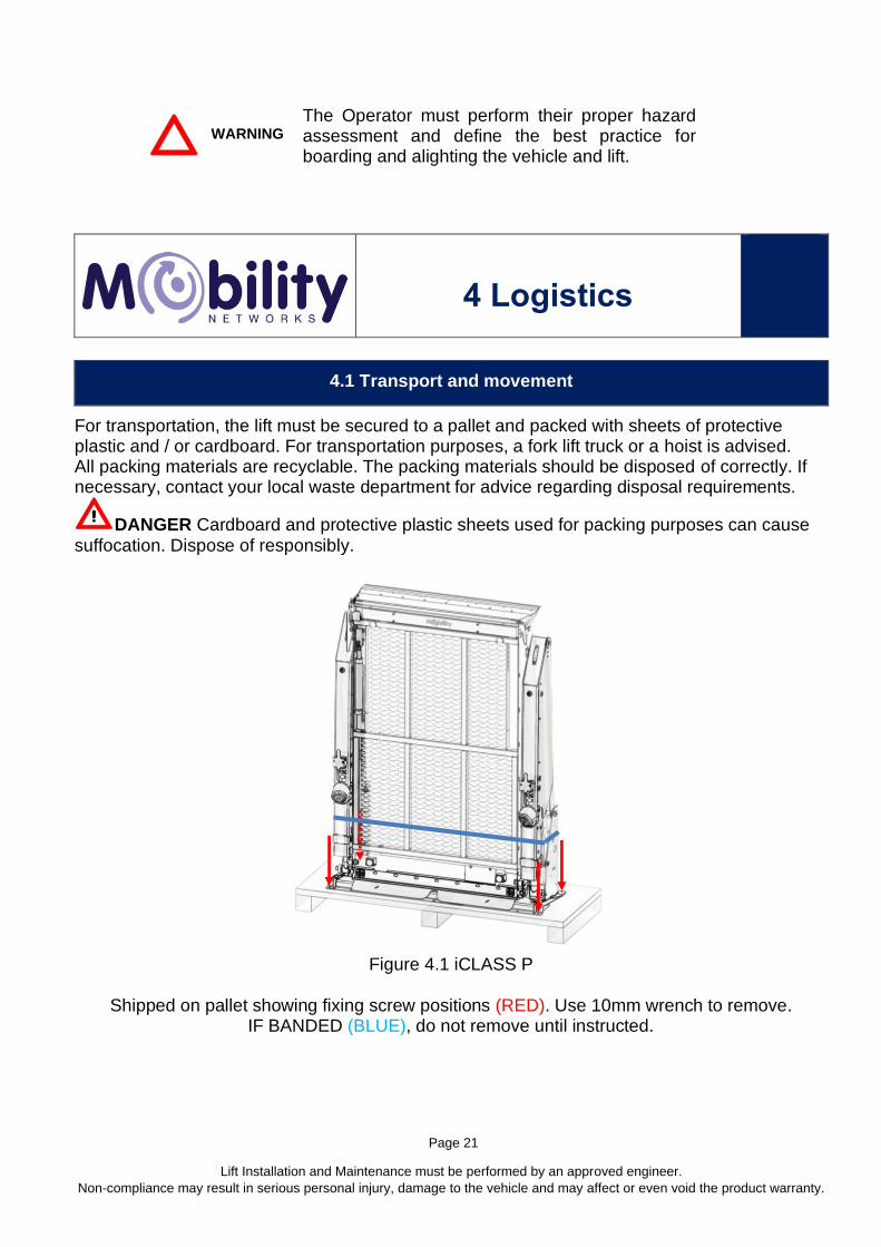
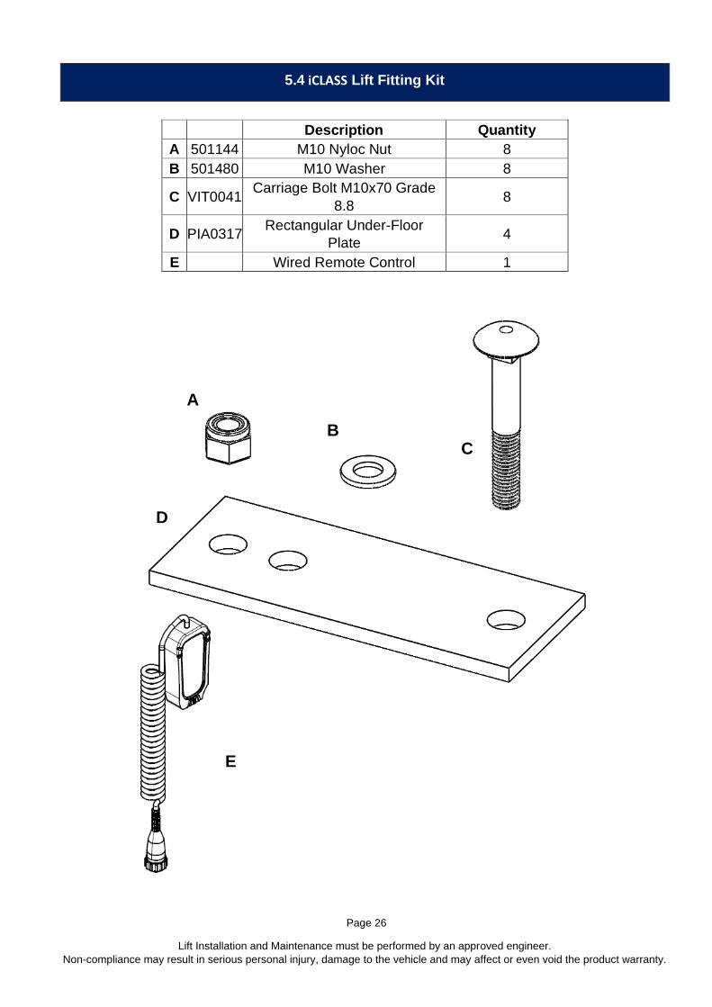
5.4 iCLASS Lift Fitting Kit
Description Quantity
A 501144 M10 Nyloc Nut 8
B 501480 M10 Washer 8
C VIT0041 Carriage Bolt M10x70 Grade
8.8 8
D PIA0317 Rectangular Under-Floor
Plate 4
E Wired Remote Control 1
B
A
C
D
E

Page 27
Lift Installation and Maintenance must be performed by an approved engineer.
Non-compliance may result in serious personal injury, damage to the vehicle and may affect or even void the product warranty.
5.5 Lift positioning and fixing
• DO NOT REMOVE INNER BANDING UNTIL THE LIFT HAS BEEN POSITIONED
ONTO THE FLOOR IN THE VEHICLE AND SECURED
• Pressurize the hydraulic system of the lift by using its hand pump: screw the provided
lever into its proper place in the hydraulic control unit (Figure 5.5.1) and put the hand
pump into action with an alternate vertical up-down movement until the pump
resistance blocks the lift in the stowed position.
• Open the door(s) of the vehicle where the lift will be placed, and block them open.
Measure the height and the width of the compartment and verify that they are bigger
than the overall dimensions of the lift (Figure 5.5.2).
• Using a forklift or equivalent, raise the iCLASS lift to the same height as vehicle floor.
Push the lift inside the vehicle in a central position in respect to the volume of the
compartment. Align the external edge at the base of the lift parallel to the closing
edge of the door(s).
Verify, both inside and outside of the vehicle, that the doors of the vehicle close correctly with
no interference with the lift. Measure the minimum distance between the doors and the lift; if it is
more than 40 mm (1-1/2 inch) (minimum distance) (Figure 5.5.3) it is possible to move the lift
toward the doors until it reaches the minimum distance. Ensure the lift is horizontally centred
within the width of the compartment (Figure 5.5.2). Pay attention to the external edge at the
base of the lift and the closing edge are positioned parallel (Figure 5.5.4).
Above: Figure 5.5.1

Page 28
Lift Installation and Maintenance must be performed by an approved engineer.
Non-compliance may result in serious personal injury, damage to the vehicle and may affect or even void the product warranty.
Above: Figure 5.5.2 Above: Figure 5.5.3
Above: Figure 5.5.4
WARNING
Before fixing the lift, ensure that there will be no interference of the fixing bolts
with parts under the frame, such as fuel lines, hydraulic conduits or wireways,
electrical wiring, cables etc. Move the lift sideways to avoid interference.
Having identified the exact position of the lift on the fitting surface area of the vehicle:
1. Trial Fit. Drill pilot holes, then 10mm to allow M10 Bolts to pass through. Initially, only drill and fix Holes 8 and 6. Fix lift using mounting bolts.
2. The shipping straps can now be removed 3. Deploy lift to make sure there is enough bumper clearance. 4. When sure that the position is OK, use the other 6 x holes at the base of the lift as a
guide to drill holes. Refer to Figure 5.5.5
∥
∥
⊥
Page 29
Lift Installation and Maintenance must be performed by an approved engineer.
Non-compliance may result in serious personal injury, damage to the vehicle and may affect or even void the product warranty.
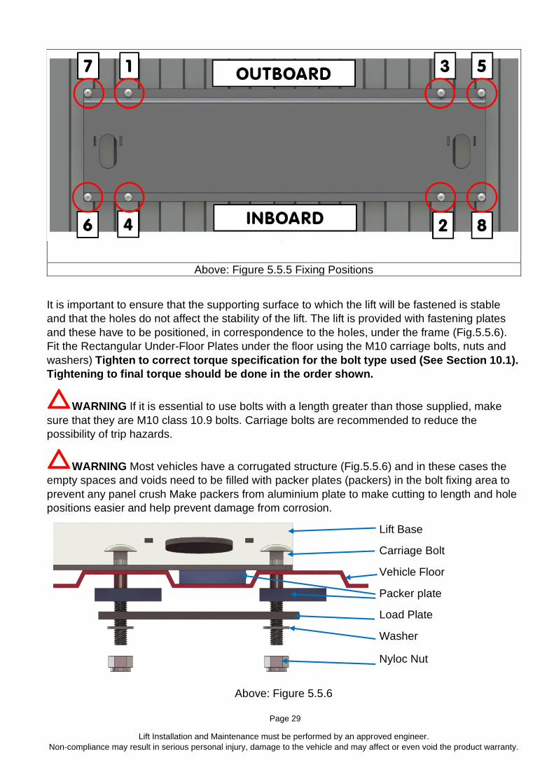
Above: Figure 5.5.5 Fixing Positions
It is important to ensure that the supporting surface to which the lift will be fastened is stable
and that the holes do not affect the stability of the lift. The lift is provided with fastening plates
and these have to be positioned, in correspondence to the holes, under the frame (Fig.5.5.6).
Fit the Rectangular Under-Floor Plates under the floor using the M10 carriage bolts, nuts and
washers) Tighten to correct torque specification for the bolt type used (See Section 10.1).
Tightening to final torque should be done in the order shown.
WARNING If it is essential to use bolts with a length greater than those supplied, make
sure that they are M10 class 10.9 bolts. Carriage bolts are recommended to reduce the
possibility of trip hazards.
WARNING Most vehicles have a corrugated structure (Fig.5.5.6) and in these cases the
empty spaces and voids need to be filled with packer plates (packers) in the bolt fixing area to
prevent any panel crush Make packers from aluminium plate to make cutting to length and hole
positions easier and help prevent damage from corrosion.
Lift Base
Carriage Bolt
Vehicle Floor
Packer plate
Load Plate
Washer
Nyloc Nut
Above: Figure 5.5.6

Page 30
Lift Installation and Maintenance must be performed by an approved engineer.
Non-compliance may result in serious personal injury, damage to the vehicle and may affect or even void the product warranty.
WARNING - IF, in order to stiffen the area that will support the lift welding is needed, first
unplug all the existing electrical connections on the vehicle and follow the manufacturer’s
instructions with care.
WARNING - It is the responsibility of the installer to verify the adequate resistance and
crush proof characteristics of the surface of the vehicle to which the lift will be attached.
Mobility Networks Holdings Ltd. declines all responsibility for any damage to the vehicle or lift
caused by these requirements.
Incorrect fitting to that specified voids the warranty of the lift.
5.6 Correcting the angle of the towers
If, after fitting, the towers are not vertical it is possible to correct this as follows:
Figure 5.6.1 Towers angled inwards: Slacken the bolts and add packing under the base around
the centre fastenings, working outwards with thinner packing until the towers are perpendicular
to the base. Once adjustment is completed, tighten to correct torque.
Figure 5.6.2 Towers angled outwards: Slacken the bolts and add packing under the base
around the outer fastenings, working inwards with thinner packing until the towers are
perpendicular to the base. Once adjustment is completed, tighten to correct torque.
Above: Figure 5.6.1 Above: Figure 5.6.2
5.7 Fitting Safety Handrails
WARNING: The Lift may be packaged and shipped WITHOUT
Safety Handrails.
Handrail type should be selected and correctly
installed BEFORE the first operation of the lift.
Socket Cap Hex Screws are factory fitted to the lift.

Page 31
Lift Installation and Maintenance must be performed by an approved engineer.
Non-compliance may result in serious personal injury, damage to the vehicle and may affect or even void the product warranty.
Tools Required: 3, 5, 6mm Hex (Allen) wrenches,
13mm Combination Wrench
Disassemble handle flange:
Remove cover plate (Quantity 2 M5 x 10mm
dome hex screws) (with 3mm Hex (Allen) key
(A)
Remove M8 x 70mm dome hex screw (with
5mm hex (Allen) key, nut (with 13mm
combination wrench) and washer. Note
position of reinforcement plates and remove.
(B)
Remove M8 x 30mm (with 6mm hex (Allen)
key) hex cap screw. (C)
Fit safety handrail and reverse the above to
re-assemble.
Thread lock (medium strength) must be used.
Tighten to torque specified in Section 10.1
A B
C

Page 32
Lift Installation and Maintenance must be performed by an approved engineer.
Non-compliance may result in serious personal injury, damage to the vehicle and may affect or even void the product warranty.
6 Electrical
6.1 Power Supply
After correct positioning and fastening of the lift to the loading deck of the vehicle:
Fit the battery isolation device.
On the Powerpack, toggle down the LIFT
POWER switch to OFF (Anti-clockwise)
.
Above: Figure 6.1.1 Power Pack Connections
Connect the eyelet connectors of the 16 mm2 wires to the vehicle battery.

Page 33
Lift Installation and Maintenance must be performed by an approved engineer.
Non-compliance may result in serious personal injury, damage to the vehicle and may affect or even void the product warranty.
RED wire to the POSITIVE (+) pole. The POSITIVE connection MUST have an 80A breaker
(trip or MEGAFUSE, Figure 6.1.3) connected within 150mm (6”) of the battery.
Left: Figure 6.1.2 Megafuse - shown open
Connect the BLACK wire to the NEGATIVE (-) pole.
WARNING
Minimum wire size for main power connections is 16 mm2 (5 AWG).
DO NOT use transformers or similar to convert AC supply to DC.
Mobility Networks is not responsible for damage caused by incorrect power
connections.
Connect the Door Interlock Switch (Figure 6.1.3) so that it operates when the door is closed.
When the door is closed, the switched relay cuts off the power to the ECU even if the manual
battery switch remains on.
The connection in then made to the relay within the powerpack (See Figure 6.1.4).

Page 34
Lift Installation and Maintenance must be performed by an approved engineer.
Non-compliance may result in serious personal injury, damage to the vehicle and may affect or even void the product warranty.
Above: Figure 6.1.3 Door Switch Above: Figure 6.1.4 Power Pack Connection

Page 35
Lift Installation and Maintenance must be performed by an approved engineer.
Non-compliance may result in serious personal injury, damage to the vehicle and may affect or even void the product warranty.
6.2 RDO Rear Door Opener Interface socket
Refer to the Door Opener Instruction Manual for further information.
Above: Figure 6.2.1 RDO Rear Door Opener Interface socket location
The connections are as follows:
4. Not Connected
1. +12V Door Switch
‘Door Open’
5. Supply +12V 30A
2. +12V ‘Door Closed’
command to Door
Opener
6. +12V Door Switch
‘Door Closed’ 3. Ground

Page 36
Lift Installation and Maintenance must be performed by an approved engineer.
Non-compliance may result in serious personal injury, damage to the vehicle and may affect or even void the product warranty.
7 Power Pack
7.1 Power Pack
Rotary Switch
Geared Motor
ECU
Door Interlock
Connection
Motor Solenoid
Manual Pump
Hydraulic Oil Tank
Pressure Control
Switch
Breather (remove to top
up hydraulic oil)

Page 37
Lift Installation and Maintenance must be performed by an approved engineer.
Non-compliance may result in serious personal injury, damage to the vehicle and may affect or even void the product warranty.
7.2 Hydraulic Oil level check and top-up
With the platform FULLY stowed regularly check that the oil level in the hydraulic oil tank is
above the minimum level.
iCLASS with Steel Tank
– check eyeglass oil level is at red circle
iCLASS with Plastic Tank
– check level is between MIN and MAX
See Section 10.4 for full hydraulic schematic diagram. See previous page.
WARNING When the vehicle engine is switched off do not to operate the hydraulic unit for
more than one minute to prevent excess drain of batteries.
WARNING When checking and filling/topping up oil, LIFT MUST BE FULLY STOWED.
WARNING Top-up hydraulic fluid with the same type fitted (see Technical Specification
3.3).
• Remove breather
• Top-up to correct level
• Replace breather

Page 38
Lift Installation and Maintenance must be performed by an approved engineer.
Non-compliance may result in serious personal injury, damage to the vehicle and may affect or even void the product warranty.
7.3 Hydraulic Pressure Control
WARNING
These instructions are for the exclusive use of appropriately trained technical personnel.
Serious personal injury and damage to vehicle could be caused if these instructions are not
adhered to.
DANGER
Inside the hydraulic control unit there is a pressure socket. A pressure check can be made by connecting a pressure gauge (manometer) to the pressure socket, see Figure 7.4.1.
WARNING
After disconnecting from the pressure socket replace the fitting cover or cap. Mobility Networks decline all responsibility for damage caused by non-fulfilment of these instructions and automatically deem the warranty to be void in such cases.
7.4 Pressure Control Switch and Pressure Connection Socket
Pressure Control Switch: Platform Stow
Pressure Connection Socket
Above: Figure 7.4.1 iCLASS Stow Pressure Control Switch and Pressure Connection Socket

Page 39
Lift Installation and Maintenance must be performed by an approved engineer.
Non-compliance may result in serious personal injury, damage to the vehicle and may affect or even void the product warranty.
7.5 Pressure Control Switch Adjustment
DANGER
These instructions are for the exclusive use of
appropriately trained technical personnel. Serious
personal injury and damage to vehicle could be caused if
these instructions are not fulfilled.
If necessary, the Platform Stow actuator can be adjusted as follows:
Turn Clockwise (CW) to decrease pressure sensitivity when moving platform to stowage position
Turn Counter-clockwise (CCW) to increase pressure sensitivity when moving platform to stowage position
If triggered, the display will show:
See Section 10 for ECU Messages, see Section 12 for adjustment procedures
8 Commissioning
WARNING
These instructions are for the exclusive use of appropriately trained technical personnel.
WARNING
The following verification checks are required for completion of the commissioning of the iCLASS
wheelchair lift.
Page 40
Lift Installation and Maintenance must be performed by an approved engineer.
Non-compliance may result in serious personal injury, damage to the vehicle and may affect or even void the product warranty.
Ensure the instructions in this manual have been fully understood. If further information is
required, please contact Mobility Networks immediately. Serious personal injury and damage to
vehicle could be caused if these instructions are not adhered to.
Mobility Networks declines all responsibility if:
• the verification check for the first commissioning is not followed properly
• the appropriate records are not compiled correctly
as this will void the warranty.
Pre-Operation:
Ensure that there are no missing or damaged parts of the machine and there is no
structural failure.
Check that all pins are correctly housed in their seats, and that they are their respective
locking stops aren’t missing.
Check the integrity of the spiral cable of the control pendent and the electrical connectors.
Check the fasteners for all the pins of the lifting arms.
Ensure that there are no loose bolts.
Check for clashing between cables and hoses by performing five cycles and listening for
unusual noises, whilst maintaining a safe distance from the lift.
Ensure you perform the platform inclination adjustments. Adjusting the inclination of the
platform is a fundamental operation for the correct operation of the lift. See section 12.17 for
details.
IMPORTANT: Perform the following during commissioning and at 6-Monthly (or 5000
cycle) Check:
• Outer Barrier Check, Stow Check, Inner Barrier Check
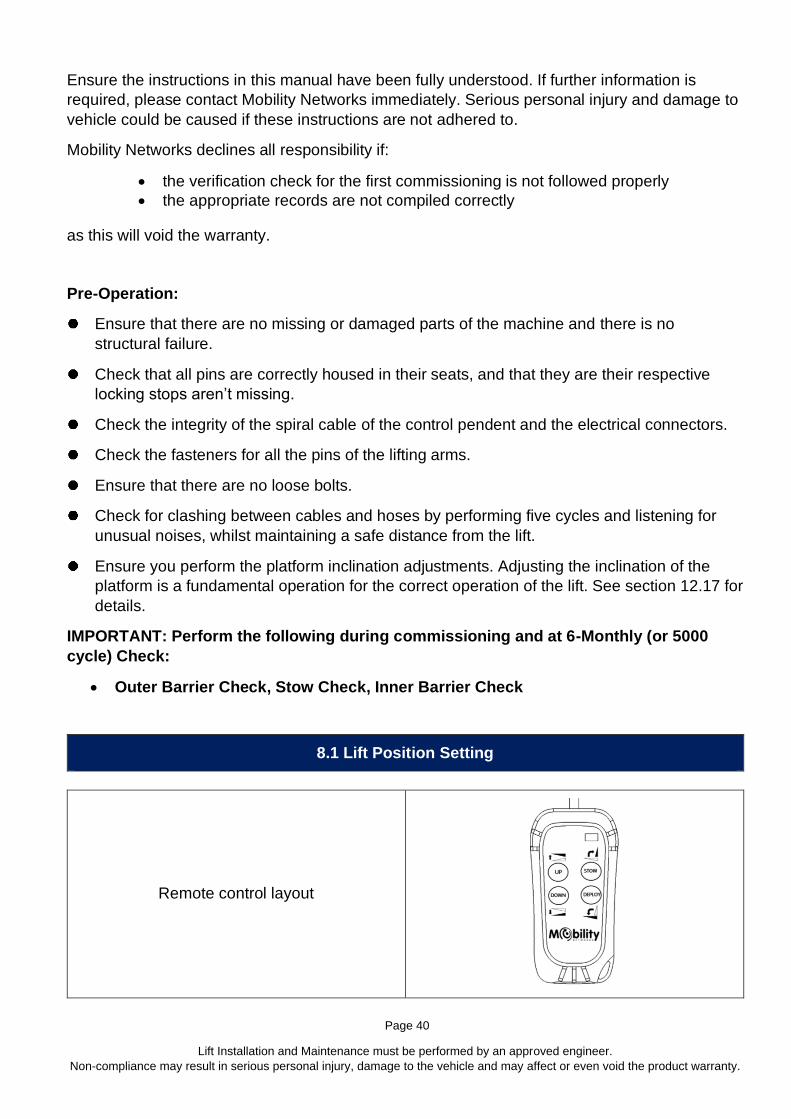
8.1 Lift Position Setting
Remote control layout

Page 41
Lift Installation and Maintenance must be performed by an approved engineer.
Non-compliance may result in serious personal injury, damage to the vehicle and may affect or even void the product warranty.
In order to set the Stowed position or the Floor Level proceed as follows:
Turn Power Pack OFF, wait a few seconds then:
Turn Power Pack ON
To set the STOW position:
1
• STOW the lift to fully
closed position
(use power or manual
pump)
2 Switch power to OFF
3
• Press and hold
STOW & DEPLOY
Page 42
Lift Installation and Maintenance must be performed by an approved engineer.
Non-compliance may result in serious personal injury, damage to the vehicle and may affect or even void the product warranty.
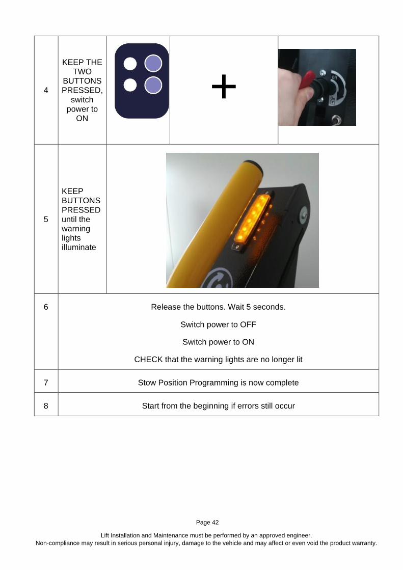
4
• KEEP THE TWO
BUTTONS PRESSED,
switch power to
ON
+
5
KEEP BUTTONS PRESSED until the warning lights illuminate
6
Release the buttons. Wait 5 seconds.
Switch power to OFF
Switch power to ON
CHECK that the warning lights are no longer lit
7 Stow Position Programming is now complete
8 Start from the beginning if errors still occur

Page 43
Lift Installation and Maintenance must be performed by an approved engineer.
Non-compliance may result in serious personal injury, damage to the vehicle and may affect or even void the product warranty.
To set the Floor Level:
1
DEPLOY to
open lift to
floor level
2 Switch power
to OFF
3
Press and
hold UP &
DOWN
simultaneously
4
With the two
buttons
pressed switch
power to ON
+

Page 44
Lift Installation and Maintenance must be performed by an approved engineer.
Non-compliance may result in serious personal injury, damage to the vehicle and may affect or even void the product warranty.
5
KEEP
BUTTONS
PRESSED
until the
warning lights
illuminate
6 Release the buttons
Wait until lights blink
While waiting
DO NOT
press any other buttons
7 Then…
8 Switch OFF
9 Switch ON
10 Floor Level Programming Complete
11 Restart from stow programming if errors still occur

Page 45
Lift Installation and Maintenance must be performed by an approved engineer.
Non-compliance may result in serious personal injury, damage to the vehicle and may affect or even void the product warranty.
8.2 iCLASS Weight Test Certificate
Once fitted, the lift installation MUST be certified and the results recorded on the
following pages. Send a copy of these to the manufacturer either by copy and mail or
photo / email. The lift warranty may be void without this.

………………………………….…...….Copy and cut out, send the copy to Manufacturer.... ................................................
Lift Installation and Maintenance must be performed by an approved engineer.
Non-compliance may result in serious personal injury, damage to the vehicle and may affect or even void the product warranty.
iCLASS Weight Test Certificate
Installer: Serial Number: Date:
Perform the Static deformation test:
Position the platform at ‘all out’ position with lifting arms horizontal.
Measure the height of the platform and its angular alignment in relation to the loading area of the vehicle.
APPLY a load of SWL x 1.25 onto the platform and then remove it. REPEAT the test.
Static Deformation Test 1: Apply a load of SWL x 1.25 onto the platform and then remove it.
Static Deformation Test 2: Repeat the height and angular measurements of the platform.
Static Deformation Test 1 Height = Angle =
Static Deformation Test 2 Height = Angle =
Check there are no permanent deformations either to the lift or the vehicle fixings which could be a detriment to the correct functioning of the lift
Are permanent deformations visible? YES / NO
FAIL if YES, PASS if NO FAIL / PASS
Perform the Static Deviation Test:
Deploy the lift to vehicle floor level.
Apply a load of SWL x 1.25 onto the platform.
Static Deformation Test 1: Measure the height of the platform and its angular alignment in relation to the loading area of the vehicle.
Static Deformation Test 2: Repeat the measurements after 15 minutes.
Weight Test Certificate continues next page

………………………………….…...….Copy and cut out, send the copy to Manufacturer.... ................................................
Lift Installation and Maintenance must be performed by an approved engineer.
Non-compliance may result in serious personal injury, damage to the vehicle and may affect or even void the product warranty.
Static Deviation Test 1 Height = Angle =
Static Deviation Test 2 Height = Angle =
Is the vertical deviation of the platform between the two measurements
greater than 15 mm and the angular change greater than 2 degrees? YES / NO
FAIL if YES, PASS if NO FAIL / PASS
Perform the Dynamic Test: Position the platform at ground level. Apply SWL load onto the platform.
Does the lift function correctly, with a full cycle of movements,
when fully loaded? YES / NO
PASS if YES, FAIL if NO PASS / FAIL
Perform the overload safety check:
Position the platform at ground level. Apply a load SWL x 1.25 the platform.
Does the lift platform leave ground level? YES / NO
FAIL if YES, PASS if NO PASS / FAIL
If any checks are negative contact the lift manufacturer

Page 48
Lift Installation and Maintenance must be performed by an approved engineer.
Non-compliance may result in serious personal injury, damage to the vehicle and may affect or even void the product warranty.
8.3 ECU and the Mobility Networks – Smart Lift App
If there is an LCD screen on the power pack then the lift can be controlled / programmed using the Mobility Networks – Smart Lift App.
(Download using the QR Code shown on the front of manual / on the quick-start guide or on the lift).
Lift functionality can be achieved using Bluetooth® in the zone shown in Figure 1.8.1
8.4 Installing the Mobility Networks – Smart Lift App and Pairing to the ECU
1. Switch on Bluetooth & Location services
For both iOS and Android, the app will ask for Bluetooth & Location services.
The App will automatically prompt the user to switch the services on.
Without these, the App will not work and will close.
Open the application and follow on-screen
instructions. Enable Location Services /
Settings – the App will show a popup if the
Location Services / Settings are not switched
on and redirect the user to the Location
Settings, allow when prompted
Enable Bluetooth – the App will show a
popup if the Bluetooth services are not
switched on, allow when prompted
2. Press Add to search for a new ECU if no devices were registered previously to the Mobility Networks App.
Page 49
Lift Installation and Maintenance must be performed by an approved engineer.
Non-compliance may result in serious personal injury, damage to the vehicle and may affect or even void the product warranty.
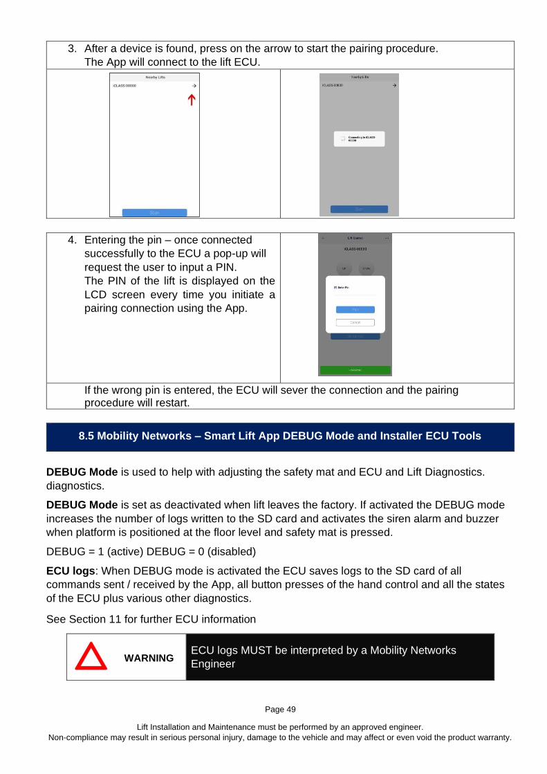
3. After a device is found, press on the arrow to start the pairing procedure.
The App will connect to the lift ECU.
4. Entering the pin – once connected
successfully to the ECU a pop-up will
request the user to input a PIN.
The PIN of the lift is displayed on the
LCD screen every time you initiate a
pairing connection using the App.
If the wrong pin is entered, the ECU will sever the connection and the pairing procedure will restart.
8.5 Mobility Networks – Smart Lift App DEBUG Mode and Installer ECU Tools
DEBUG Mode is used to help with adjusting the safety mat and ECU and Lift Diagnostics.
diagnostics.
DEBUG Mode is set as deactivated when lift leaves the factory. If activated the DEBUG mode
increases the number of logs written to the SD card and activates the siren alarm and buzzer
when platform is positioned at the floor level and safety mat is pressed.
DEBUG = 1 (active) DEBUG = 0 (disabled)
ECU logs: When DEBUG mode is activated the ECU saves logs to the SD card of all
commands sent / received by the App, all button presses of the hand control and all the states
of the ECU plus various other diagnostics.
See Section 11 for further ECU information
WARNING ECU logs MUST be interpreted by a Mobility Networks
Engineer

Page 50
Lift Installation and Maintenance must be performed by an approved engineer.
Non-compliance may result in serious personal injury, damage to the vehicle and may affect or even void the product warranty.
8.6 Changing from ‘Safety Mode’ to ‘Full Operation Mode’
Safety Mode delays or stops the operation of the lift if the lift was not taken out of safety mode
or if one of the lift modules and / or sensors has started malfunctioning.
‘Full Operation Mode’ Once proper checks have been made by the engineers at the factory /
by the final installer or after repairs have been made and checked, the lift can be put in ‘Full
Operation Mode’.
If activated, Safety Mode delays the Deploy operation by 10 seconds, activates the buzzer and
the LCD displays ‘SAFETY MODE’ every time the lift is powered on. After the initial 10 second
delay, the lift will resume operation but will reset the delay every time the lift is powered off.
Safety mode will stop all operations if the temperature of the ECU exceeds 80°C (176°F), Angle
Sensor is disconnected or malfunctions, or if the battery voltage is low.
All lifts leave the factory with Safety Mode active and it is the Installer’s responsibility to put the
lift in Full Operation Mode. Upon finishing the installation, it is recommended that the Installer
pairs the lift to the Mobility Networks – Smart Lift App and sets the lift to Full Operation Mode.
The date and time will also be recorded and the Mobility Networks – Smart Lift App will forward
this info to the service provider as a record of a successful installation.
Full Operation Mode through the Mobility Networks – Smart Lift App
Change from Safety Mode as follows:
1. Login to the Mobility Networks – Smart Lift App
2. Pair with the lift
3. In the right-hand menu, navigate to the Installer section
4. Scroll to the bottom of the page
5. Toggle the checks and press the Ready button
6. Using the App, the Engineer can only set the Safety Mode to Active /
Installer can only set Full Operation Mode to Active
Alternatively, ‘Safety Mode’ can be set to ‘Full Operation Mode’ using the wired remote, see
Section 11
8.7 ECU Details
The ECU Hardware, Software and Serial Number details can be found on a label on the ECU,
an example is shown in Figure 8.7.1.
Figure 8.7.1 ECU Battery Type: CR1220
ECU Memory Card Type: Micro SD

Page 51
Lift Installation and Maintenance must be performed by an approved engineer.
Non-compliance may result in serious personal injury, damage to the vehicle and may affect or even void the product warranty.
8.8 Commissioning Log
The Installer shall check the following boxes to confirm and validate as follows:
1 IDENTIFICATION PLATE:
ID plate installed and fixings secure?
Is the ID plate serial number legible?
2 ENCLOSED DOCUMENTATION:
3 LABELS AND SAFETY WARNING:
If cabin light fitted, does it work? (Section 3) (if not fitted note n/a)
If signalling lights are fitted, do they work? (Section 3) (if not fitted note n/a)
All Labels present and legible (Section 17)
4 CONTROLLER:
Wired control pendent present? (if not note option fitted)
Emergency manual controls operate and label present?
5 STRUCTURE AND ASSEMBLY:
Confirm fastening bolts to the platform to correct torque
Visual inspection of the integrity of all welds
Absence of structural deformation
Safety Handrails fitted, thread locked and fasteners torqued to specification
6 HYDRAULIC SYSTEM:
Correct oil in the tank (Specification in Section 3.3)
No oil leakage
No oil in hydraulic cylinder breather holes (e.g. seal integrity)
Hoses correctly routed
Manual for use and maintenance compiled
Manufacture’s Declaration of Conformity
Installer’s Declaration of Conformity
Operator Manual Supplied. Installer Information and Serial Number Recorded

Page 52
Lift Installation and Maintenance must be performed by an approved engineer.
Non-compliance may result in serious personal injury, damage to the vehicle and may affect or even void the product warranty.
7 FUNCTIONING OF THE LIFT:
Levelling of the platform at the loading floor in opening
Levelling of the platform vs. loading floor in ascent / descent
Closes Fully
Ensure Functionality of Bridging Device
Ensure Functionality of Outer Barrier
8 ELECTRICAL SYSTEM:
Ensure operation of main Isolator switch
Battery connected properly
Vehicle battery fully charged
9 SAFETY DEVICES:
Safety hook fitted and operational
Safety pressure switch fitted and set correctly
10 LOAD TESTS:
Verify static deformation
Verify static deviation test
Verify dynamic test
Verify protection against overloading
11 FULL OPERATION MODE:
Set Lift to Full Operation Mode
Check all lift functions operate correctly in Full Operation Mode
12 MOBILITY NETWORKS SMART LIFT APP
During handover the vehicle to the customer, inform them about the Mobility
Networks Smart Lift App, show them how to download it to their smart phone
Before using the lift make sure the user or operator knows how to confirm
connection (Pairing) to the lift using the App
WARNING
BEFORE OPERATING THE LIFT WITH THE APP:
Make sure the lift and App are paired.
The PIN can be found on the Power Pack LCD Screen

Page 53
Lift Installation and Maintenance must be performed by an approved engineer.
Non-compliance may result in serious personal injury, damage to the vehicle and may affect or even void the product warranty.
9 Operation
9.1 Operation Introduction
Before operating tail lift:
Fully familiarize yourself with lift controls, relevant safety procedures and possible hazards
signified by warning labels or highlighted in your Operator Hazard Assessment.
iCLASS lift safety:
Only an authorized fully trained operator must control the lift.
Secure vehicle doors fully open, well clear of the lift platform.
Keep within the stated maximum safe working load (SWL).
Keep people away from the operating area (inside and outside the vehicle).
Ensure the platform is always level (horizontal, not more than 5°) see Figures 9.1.1 and 9.1.2.
NEVER leave the lift unattended at ground level if passengers are onboard.
When the lift is not in use controls should be deactivated.
Ensure that the lift is correctly stowed after loading.
Figure 9.1.1
Figure 9.1.2

Page 54
Lift Installation and Maintenance must be performed by an approved engineer.
Non-compliance may result in serious personal injury, damage to the vehicle and may affect or even void the product warranty.
Operators ensure that:
Lift will lower to firm, level ground
Scooter or powered wheelchair is not larger than the lift platform in any direction
Tail lift is in a FULLY operational condition. Report any defects.
Lift internal flap lands flat onto vehicle floor.
Lift external flap is set vertically (minimum 80°) and fully operational.
Accompany the passenger on the lift is possible, but do not overload the lift.
You have a clear view of the lift platform before the passenger moves onto it.
NEVER leave passengers unattended at any time.
The passenger should not be required to operate ANY controls.
When operating the lift, ensure you are within reach of the power switch at all times and that you are able to view all corners of the platform.
Loading and Unloading procedure:
Explain to passenger the sequence of movements that will occur.
Where possible passenger should dismount the scooter / wheelchair and board the vehicle separately. Wheelchair user should point away from the Vehicle for loading
and unloading.
Ensure the lift platform and area around the lift are free from obstruction.
Ensure the lift platform is in the correct position before moving onto it.
Scooter / Powered Wheelchair should be pushed onto the lift platform, NOT DRIVEN.
Ensure that persons or equipment do not overhang the platform.
BEFORE the lift begins motion Scooter / Wheelchair brakes to be applied (or wheels blocked). Wheelchair integrated occupant seatbelts should be used.
All power to the scooter / powered wheelchair is turned OFF.
Operate lift platform to the vehicle floor.
Scooter / Wheelchair should be pushed off the lift platform, NOT DRIVEN
Scooter / Wheelchair and passenger should be restrained in the vehicle using the correct the correct equipment. (Wheelchair Tiedown and Occupant Restraint System, WTORS).
Please note: The transportation of scooters and large powered wheelchairs may require a NON-
STANDARD tail lift size or specification. Where possible Mobility Networks can provide longer, wider
platforms, higher roll-off ramps, to help combat the increased hazards related to larger passenger
vehicle transportation

Page 55
Lift Installation and Maintenance must be performed by an approved engineer.
Non-compliance may result in serious personal injury, damage to the vehicle and may affect or even void the product warranty.
9.2 Standard Operation
In a safe area, park the vehicle on level ground, make sure there is enough room around the
vehicle to enable safe operation. Open door(s) and secure fully open.
If automatic doors are fitted, refer to those instructions.
WARNING
Make sure that the relative movement of the platform corresponds to each command without
jamming and unusual noises. STOP AND CHECK!
Power On:
Toggle Clockwise the LIFT POWER switch to the ON Position (Section 5.1) and 9.2.1
Fig. 9.2.1 Power On Fig. 9.2.2 Control Pendent
Deploy Platform:
Opening is a rotational movement that moves the loading platform from the vertical (closed)
position to the horizontal loading position at vehicle floor level. (Figure 9.2.3).
Operator MUST stand clear of deploying lift.
Push and hold DEPLOY (Figure 9.2.2) button until platform stops at the horizontal loading
position on the floor of the vehicle (Figure 9.2.4).
Release button.
The platform can now be loaded.

Page 56
Lift Installation and Maintenance must be performed by an approved engineer.
Non-compliance may result in serious personal injury, damage to the vehicle and may affect or even void the product warranty.
WARNING
Once the user is on the platform or before starting the lifting/lowering operation:
the wheelchair MUST BE braked.
fit wheelchair occupant seatbelts.
Figure 9.2.3 Platform deploy Fig 9.2.4 Platform at vehicle floor
level
Lowering Platform:
Push and hold DOWN (Figure 9.2.2) button
until platform stops at the horizontal loading position on the ground.
Release button.
Once stopped at the ground level, platform is
ready to be loaded or unloaded.
Raising Platform:
Push and hold UP (Figure 9.2.2) button until
platform stops at the horizontal loading
position on the floor of the vehicle.
Release button.
At this point the platform can be unloaded.

Page 57
Lift Installation and Maintenance must be performed by an approved engineer.
Non-compliance may result in serious personal injury, damage to the vehicle and may affect or even void the product warranty.
Stowing the Platform: After making sure that no object has been left on the loading platform, proceed as follows for the closing manoeuvre:
Stowing is a rotational movement that moves the loading platform from the horizontal
position to the vertical (closed) position at vehicle floor level.
Push and hold STOW (Fig 9.2.2) button until platform stops at the vertical loading position
on the floor of the vehicle. Keep pressing until the power is interrupted.
Release button.
Power Off:
Toggle anti-clockwise the LIFT POWER switch to
OFF
The passenger compartment warning light
extinguishes to confirm lift power is disabled.
WARNING
To avoid draining the batteries of the vehicle,
remember to disable the system after each use of
the lift.
OFF

Page 58
Lift Installation and Maintenance must be performed by an approved engineer.
Non-compliance may result in serious personal injury, damage to the vehicle and may affect or even void the product warranty.
9.3 Emergency Operation
WARNING
Note: For Emergency Operations, the lift must always be completely closed. Use the
emergency hand pump to close the lift. Only when the lift is completely closed, the
hook can be unlocked; this allows Emergency Operations to be performed safely.
Emergency manual controls are to be used to operate the lift in case of power supply
failure. They are not intended for ‘normal’ use as an alternative to powered operation.
Emergency manual controls must be exclusively used to help the user during lifting/lowering
onto / off the vehicle and to close the opened lift, allowing to the vehicle to start again.

Page 59
Lift Installation and Maintenance must be performed by an approved engineer.
Non-compliance may result in serious personal injury, damage to the vehicle and may affect or even void the product warranty.
A complete Emergency Operation cycle is as follows:
DANGER
WITH LIFT CLOSED, RELEASE THE SAFETY HOOK AND CARRY OUT THE EMERGENCY OPERATIONS AS BELOW.
BEWARE OF MOVING PARTS.
DEPLOY/DOWN On the hydraulic unit, turn the manual override valve counterclockwise lowering using the black knob (marked by its relevant label).
The platform will open and will descend until making contact with the ground or if the lowering valve is closed (by turning the knob clockwise).
IMPORTANT Before any other operation, close the lowering valve, by turning its knob clockwise.
UP/STOW Tighten the lever, into the threaded hole. (inside the vertical slot marked by the relevant label).
Operate the pump manually alternating up / down vertical movements.
The platform will reach vehicle floor level to allow user on / off the platform. Continue to operate the pump to stow the platform.

Page 60
Lift Installation and Maintenance must be performed by an approved engineer.
Non-compliance may result in serious personal injury, damage to the vehicle and may affect or even void the product warranty.
10 Reference Material
10.1 Torque Settings
Thread Size Torque Setting (Nm)
HTS 8.8 10.9 12.9
M4 2.9 4.1 4.95
M5 5.75 8.1 9.7
M6 9.9 14 16.5
M8 12 34 40
M10 48 67 81
M12 83 117 140
M14 132 185 220
M16 200 285 340
Thread Size Torque Setting (Nm)
HTS Hex Flange 8.8 10.9 12.9
M6 9 14.7 16.8
M8 20 35.6 41
M10 40 70.6 81
Thread Size Torque Setting (Nm)
Stainless Steel A2-70 A4-80
M4 2.6 3.5
M5 5.1 6.9
M6 8.8 11.8
M8 21.4 28.8
M10 44 58
M12 74 100
M14 119 159
M16 183 245
M20 135 165
Thread Size Torque Setting (Nm)
BSP A2-70
1/8 17
1/4 35
3/8 47

Page 61
Lift Installation and Maintenance must be performed by an approved engineer.
Non-compliance may result in serious personal injury, damage to the vehicle and may affect or even void the product warranty.
10.2 Fastener Strength Conversion Chart

Page 62
Lift Installation and Maintenance must be performed by an approved engineer.
Non-compliance may result in serious personal injury, damage to the vehicle and may affect or even void the product warranty.
10.3 iCLASS Electrical Schematic
Code Description Position on
Schematic Code Description
Position on
Schematic
A1 Controller 17-19 MP Motor 06
A2 LCD 32-35 RP1 Rotary (Angle)
Sensor 23
EL1 –
X13C
Connection to
Warning Light 40 SA2 Power Switch Not Shown
EL2 –
X13C
Connection to
Warning Light 57 SP1 Pressure Switch 28
FU1
Main Fuse
(MEGAFUSE)
80A
00 SW1 Safety Belt Switch 58
STC Power Switch 00 YA1 Safety Hook 50
FR1 Circuit Breaker /
Trip Switch 5A 09 YV1 Motor Solenoid 09-10
FR2 Circuit Breaker /
Trip Switch 30A 08 KIT0375 Door Interlock 16
GB1 Battery 00 X1 Hydraulic Wiring 20
XR Remote Control 36-39 X8 ECU Wiring 16
KM2 Solenoid 04 MSW Door open
microswitch 19
EL3 –
X13A LED 42
EL5 -
X13B LED 45
EL4 –
X13A LED 57
EL6-
X13B LED 57

Page 63
Lift Installation and Maintenance must be performed by an approved engineer.
Non-compliance may result in serious personal injury, damage to the vehicle and may affect or even void the product warranty.

Page 64
Lift Installation and Maintenance must be performed by an approved engineer.
Non-compliance may result in serious personal injury, damage to the vehicle and may affect or even void the product warranty.
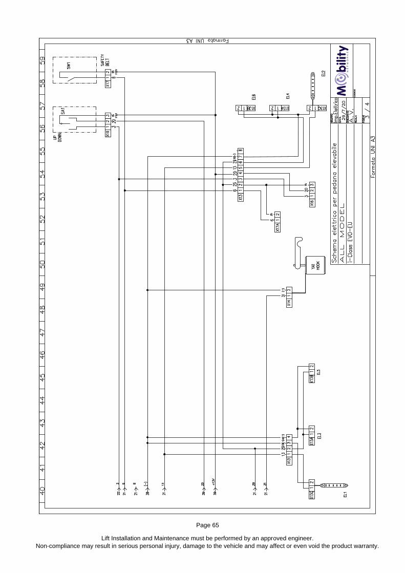
Page 65
Lift Installation and Maintenance must be performed by an approved engineer.
Non-compliance may result in serious personal injury, damage to the vehicle and may affect or even void the product warranty.

Page 66
Lift Installation and Maintenance must be performed by an approved engineer.
Non-compliance may result in serious personal injury, damage to the vehicle and may affect or even void the product warranty.

Page 67
Lift Installation and Maintenance must be performed by an approved engineer.
Non-compliance may result in serious personal injury, damage to the vehicle and may affect or even void the product warranty.
10.4 iCLASS Hydraulic Schematic
Code Description Code Description
CS Lift Cylinder PP Pressure Socket
EV Lowering Valve PR Pressure Switch
F Filter S Pressure Reduction Valve
GEP Electric Pump SC Flow Restrictor
M Electric Geared Motor SCR Compensated Flow Restrictor
P Hydraulic Pump SI Oil Tank
PM Manual Hydraulic Pump VM Relief Valve

Page 68
Lift Installation and Maintenance must be performed by an approved engineer.
Non-compliance may result in serious personal injury, damage to the vehicle and may affect or even void the product warranty.
11 ECU
Full Operation Mode Purpose: To ensure that the proper checks were made by the engineers
at the factory & by the final installer.
Safety Mode delays or stops the operation of the lift if it was not taken out of safety mode or if
one of the lift modules and / or sensors has started malfunctioning.
If activated, Safety Mode delays the Deploy operation by 10 seconds, activates the buzzer and
the LCD displays ‘SAFETY MODE’ every time the lift is powered on. After initial 10 seconds
delay, the lift will resume operation but will reset the delay every time the lift is powered off.
Safety mode will stop all operations if the temperature of the ECU exceeds 80°C, Angle Sensor
is disconnected or malfunctions, or if the battery voltage is low.
All lifts leave the factory with Safety Mode active and it is the Installer’s responsibility to put the
lift in Full Operation Mode. Upon finishing installation, it is recommended that the Installer
pairs the lift to the Mobility Networks – Smart Lift App and sets the lift in Full Operation
Mode. The date and time will also be recorded and the App will forward this info to
Manufacturer/Customer as a record of successful installation.
Alternatively, switching between Full Operation Mode and Safety Mode can be set using the
wired remote as follows:
1. Power OFF ECU
2. Press and hold buttons DEPLOY & DOWN on the hand control
3. Power ON ECU
4. While holding DEPLOY & DOWN wait 5 seconds
5. On the LCD the message will display:
UPDATING SAFETY MODE X
X- will be the current value of the SAFETY MODE
6. 5 second timer starts
7. If SAFETY MODE is 0 and you want to KEEP lift in ‘SAFETY MODE’, power off
the ECU now.
8. If SAFETY MODE is 0 and you want to ENABLE ‘FULL OPERATION MODE’,
wait 5 seconds.
9. If SAFETY MODE is 1 and you want to put lift in ‘SAFETY MODE’, wait 5 seconds
10. After 5 seconds the LCD message will display:
SAFETY SET= [X]
REBOOT
X- will be the current value of the SAFETY mode
11.1 Setting ‘Full Operation Mode’ (non-Mobility Networks – Smart Lift App method)

Page 69
Lift Installation and Maintenance must be performed by an approved engineer.
Non-compliance may result in serious personal injury, damage to the vehicle and may affect or even void the product warranty.
11.2 Electrostatic Precautions
Electrostatic discharge or ESD is the sudden flow of electricity between two objects. ESD
occurs when an object with a static electricity charge nears an object with a lower charge. When
removing and working on the ECU, make sure to ground yourself on the metal case.
Static electricity commonly builds up when there is friction between two materials. Some of the
components inside the ECU are sensitive to ESD and could be damaged.
The best method to prevent ESD is using a grounding wrist band, mat or table. They are
designed to dissipate the static charge safely.
Whenever working inside the power pack disconnect the battery and all power supply cords
before opening. Cycle and hold the power button to ON for five seconds after everything is
disconnected. This will help prevent an unexpected shock and help eliminate sources of ESD.
Next, equalize the charge between yourself and the ECU. Touch the ground contact inside the
power pack for two seconds before handling the circuit to discharge any residual electricity
stored in your body.
Avoid clothing which conducts static electricity like wool and synthetic fabrics. It's also helpful to
remove metal jewellery. Collect all the tools and supplies you'll need before you open the power
pack. You may create unexpected charge each time you walk away.
If you have to open the ECU cover, avoid touching the surface of the circuit board. Special care
should be taken to ensure the pins of the components inside the circuit board are not touched.
Install the circuit board into the correct position using only as much pressure is needed to snap
it into place. Never force the board into a position, and avoid bending it.
Only handle the ECU board if you are a trained installer.
When handling the circuit board, if possible, only touch the edges.
When handling the onboard components (SD Card and battery) make sure you are grounded.
WARNING Failure to observe these precautions may cause irreversible
damage to the ECU and / or its components.
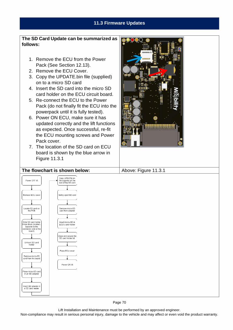
Page 70
Lift Installation and Maintenance must be performed by an approved engineer.
Non-compliance may result in serious personal injury, damage to the vehicle and may affect or even void the product warranty.
11.3 Firmware Updates
The SD Card Update can be summarized as
follows:
1. Remove the ECU from the Power
Pack (See Section 12.13).
2. Remove the ECU Cover.
3. Copy the UPDATE.bin file (supplied)
on to a micro SD card
4. Insert the SD card into the micro SD
card holder on the ECU circuit board.
5. Re-connect the ECU to the Power
Pack (do not finally fit the ECU into the
powerpack until it is fully tested).
6. Power ON ECU, make sure it has
updated correctly and the lift functions
as expected. Once successful, re-fit
the ECU mounting screws and Power
Pack cover.
7. The location of the SD card on ECU
board is shown by the blue arrow in
Figure 11.3.1
The flowchart is shown below: Above: Figure 11.3.1

Page 71
Lift Installation and Maintenance must be performed by an approved engineer.
Non-compliance may result in serious personal injury, damage to the vehicle and may affect or even void the product warranty.
11.4 Firmware Update using the Mobility Networks App
The firmware update using the Mobility Networks App can be summarized as follows:
Users can download the latest version of the lift firmware which in turn directly upgrades the
lift’s functionality.
1. Power OFF lift
2. Open the Mobility Networks Smart App
3. Pair the Mobility Networks Smart App with your lift
4. Enter the PIN as it is displayed on the LCD
5. Tap on side menu and navigate to the Firmware update page
6. On the Firmware update page tap on the icon to begin the firmware update process.
Note 1. The firmware update will take anywhere between 5 to 7 minutes. Your saved settings
such as floor / stow position will remain unchanged.
Note 2. As an Installer, you have the option to change the type of firmware (iCLASS 2021 &
ADA / iCLASS FMVSS / FP / S).

Page 72
Lift Installation and Maintenance must be performed by an approved engineer.
Non-compliance may result in serious personal injury, damage to the vehicle and may affect or even void the product warranty.
11.5 ECU Pin Configurations
32-Pin Connector
Note: Supply Voltage
can be 12V or 24V
depending on lift
configuration
Note: Supply Voltage
can be 12V or 24V
depending on lift
configuration

Page 73
Lift Installation and Maintenance must be performed by an approved engineer.
Non-compliance may result in serious personal injury, damage to the vehicle and may affect or even void the product warranty.
4-Pin Connector (Battery Input, Relay & Solenoid)
11.6 RTC - Battery Replacement
DANGER
This product contains a coin/button cell battery. If the cell battery is
swallowed, it can cause severe internal burns and can lead to death. Keep
away from babies and small children at all times.
• If the battery is swallowed, immediately seek medical help
• Risk of explosion if battery is replaced by an incorrect type
• Dispose of used battery properly
If the ECU clock is no longer accurate or losing time, change the RTC battery. After replacing
the battery, it is necessary to pair the lift with the Mobility Networks app to reset the clock.
Refer to Figure 11.3.1.
The red arrow shows the battery position on the ECU board.
1. Remove the ECU from the Power Pack (See Section 12.14).
2. Remove the ECU Cover (See Section 12.15).
3. The battery is installed with +positive side up.
4. To remove the RTC battery, use a non-metallic pry tool to push the battery out of its
slot.
5. Wait at least thirty seconds before replacing the battery.
6. Replace the battery (1220 type) in the same socket it was removed from. Observe
correct polarity.

Page 74
Lift Installation and Maintenance must be performed by an approved engineer.
Non-compliance may result in serious personal injury, damage to the vehicle and may affect or even void the product warranty.
11.7 ECU Display Messages
Information is displayed on the LCD as the following example:
("CHK?","VEHICLE CONSENT")
CHK? displayed on the first line of the LCD
VEHICLE CONSENT displayed on the second line of the LCD
Error Messages are summarized below:
("CHK?","VEHICLE CONSENT") Vehicle consent input disconnected
("CHK?", "DISCONNECT BELT") When deploying the lift, the safety belt must be
un-latched and the belt retracted fully
("CHK?", "PRESSURE SWITCH") When stowing if pressure microswitch is pressed
(will be displayed briefly)
("CHK?", "RETURN FLOOR LVL") When stowing - pressure microswitch was
pressed
(will not allow stowing if pressure microswitch
was pressed at any time when stowing)
Platform must return to floor level
("CHK?", "SAFETY SWITCH") Occurs when lifting – if platform is not levelled
("CHK?", "BELT") Occurs when lifting / lowering, safety belt
installed and belt is not connected (latched).
Connect (latch) safety belt to allow lift to operate.
("SAFETY MODE","HIGH TEMP") Triggered any time that at any time if internal
ECU temp exceeds 80°C (176°F)
("SAFETY MODE","ANGLE SENSOR”) Triggered any time if the signal received from the
angle sensor is faulty:
- disconnected sensor - broken sensor
("SAFETY MODE","LOW BAT VOLTAGE") Triggered any time if the battery voltage goes
under 9V (with the relay LOW)
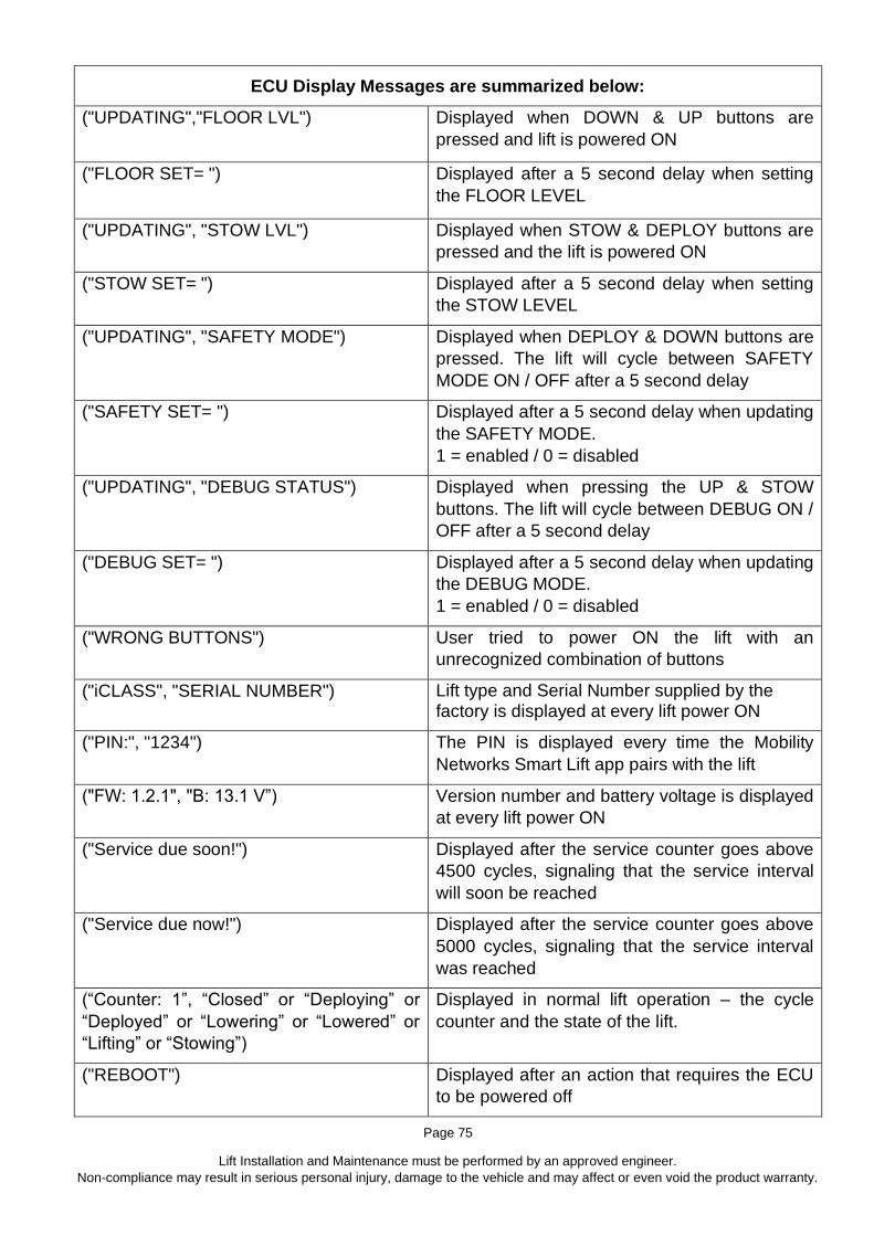
Page 75
Lift Installation and Maintenance must be performed by an approved engineer.
Non-compliance may result in serious personal injury, damage to the vehicle and may affect or even void the product warranty.
ECU Display Messages are summarized below:
("UPDATING","FLOOR LVL") Displayed when DOWN & UP buttons are
pressed and lift is powered ON
("FLOOR SET= ") Displayed after a 5 second delay when setting
the FLOOR LEVEL
("UPDATING", "STOW LVL") Displayed when STOW & DEPLOY buttons are
pressed and the lift is powered ON
("STOW SET= ") Displayed after a 5 second delay when setting
the STOW LEVEL
("UPDATING", "SAFETY MODE") Displayed when DEPLOY & DOWN buttons are
pressed. The lift will cycle between SAFETY
MODE ON / OFF after a 5 second delay
("SAFETY SET= ") Displayed after a 5 second delay when updating
the SAFETY MODE.
1 = enabled / 0 = disabled
("UPDATING", "DEBUG STATUS") Displayed when pressing the UP & STOW
buttons. The lift will cycle between DEBUG ON /
OFF after a 5 second delay
("DEBUG SET= ") Displayed after a 5 second delay when updating
the DEBUG MODE.
1 = enabled / 0 = disabled
("WRONG BUTTONS") User tried to power ON the lift with an
unrecognized combination of buttons
("iCLASS", "SERIAL NUMBER") Lift type and Serial Number supplied by the factory is displayed at every lift power ON
("PIN:", "1234") The PIN is displayed every time the Mobility
Networks Smart Lift app pairs with the lift
("FW: 1.2.1", "B: 13.1 V”) Version number and battery voltage is displayed
at every lift power ON
("Service due soon!") Displayed after the service counter goes above
4500 cycles, signaling that the service interval
will soon be reached
("Service due now!") Displayed after the service counter goes above
5000 cycles, signaling that the service interval
was reached
(“Counter: 1”, “Closed” or “Deploying” or
“Deployed” or “Lowering” or “Lowered” or
“Lifting” or “Stowing”)
Displayed in normal lift operation – the cycle
counter and the state of the lift.
("REBOOT") Displayed after an action that requires the ECU
to be powered off

Page 76
Lift Installation and Maintenance must be performed by an approved engineer.
Non-compliance may result in serious personal injury, damage to the vehicle and may affect or even void the product warranty.
("UPDATING…","DO NOT POWER OFF”)
ECU Firmware Update using the Mobility
Networks App is underway. Do not power off the
lift while the update is in progress. During
installation you cannot use the lift nor your
device. Do not close the application and keep the
device in range of the lift. The update will take a
few minutes to complete and the lift will restart
when the update completes.
("REPLACE NOW”, DAMAGED ECU”) Replace ECU, short circuit detected.

Page 77
Lift Installation and Maintenance must be performed by an approved engineer.
Non-compliance may result in serious personal injury, damage to the vehicle and may affect or even void the product warranty.
12 Inspection and Servicing
12.1 Service Intervals
Service Interval Service Type
Daily Daily Complete Service Schedule for 4000 cycles or 12 months
(whichever comes first)
2 Weeks 2 Weeks
1000 cycles (or 3 months - whichever first) A
2000 cycles (or 6 months - whichever first) B
3000 cycles (or 9 months - whichever first) A
4000 cycles (or 12 months - whichever first) C
8000 cycles (or 24 months - whichever first) D
12.2 Daily Checks
Lift Inspection checks are required on a DAILY basis by the lift operating company.
The working life of the lift will be greatly prolonged if these steps are adhered to:
Daily Inspection Check List Date:
Lift
Vehicle #
Engineer’s Name:
Customer Name:
Customer Address:
Phone #
Check OK ?
Visually Check Condition of Safety Belt. Deploy all webbing, check both sides and that stitching is in good condition (if fitted)
YES / NO
Visually check hydraulic fluid level using eyeglass YES / NO
Visually check for any leaks or damage YES / NO
Check for obvious signs of damage, and notify manager if necessary YES / NO

Page 78
Lift Installation and Maintenance must be performed by an approved engineer.
Non-compliance may result in serious personal injury, damage to the vehicle and may affect or even void the product warranty.
Operation instruction labels are visible? YES / NO
Check the hand pump handle is present YES / NO
Handset control is working correctly and no signs of damage? YES / NO
Platform is clean and dry? YES / NO
Ensure the Handrail guards are present and undamaged YES / NO
Check correct operation of Bridging Device / Inner Roll Stop YES / NO
Check correct operation of Outer Barrier YES / NO
Check warning lights are operating correctly YES / NO
IF IN DOUBT CONTACT THE MANUFACTURER
12.3 Checks to be performed every 2 Weeks
Perform the following checks every 2 Weeks:
As Daily Checks plus:
Check OK ?
Lubricate relevant parts with ACF-50 YES / NO
Check under the vehicle for damage and / or corrosion and that all fasteners are present and tight YES / NO
Check condition of all cabling YES / NO
Check that the vehicle interlock operates correctly – the lift cannot move out of stow position unless the interlock is
operational YES / NO
Check that the bridge plate warning system operates when it is occupied YES / NO
Check that the outer barrier operates correctly when occupied YES / NO
Check correct operation of emergency (manual) pump YES / NO
With the lift is on the ground check that the oil level has not dropped, if so, check system for leaks and make
necessary repairs. YES / NO

Page 79
Lift Installation and Maintenance must be performed by an approved engineer.
Non-compliance may result in serious personal injury, damage to the vehicle and may affect or even void the product warranty.
12.4 Service Type A
Regular lift maintenance is recommended at the time or the cycles specified in 12.1
by the lift operating company. The working life of your lift will be greatly prolonged if
these steps are adhered to.
This should include the following:
1. Check for obvious signs of damage and corrosion, replace parts as necessary.
2. Check the operation and stowing of the lift.
3. Check the rear roll-off-ramp operation. Lubricate with silicone spray.
4. Check bridging plate operates correctly, adjust as necessary.
5. Check handrail operation and security. If components are corroded, they
should be replaced due to potential hazard to users! Check location pivot
pins, these should be fully secure.
6. When cleaning the vehicle wash the working platform of the lift in
accordance with instructions Section 13.
7. Check Up/ Down pump for fluid leaks and loose/ corroded electrics.
Top up reservoir (with lift at ground position) with recommended
Hydraulic Oil, do NOT overfill. Coat any exposed electrics with
dielectric grease (to protect).
8. Lubricate lift in accordance with instructions Section 14.
IF IN DOUBT, CONTACT THE MANUFACTURER

Page 80
Lift Installation and Maintenance must be performed by an approved engineer.
Non-compliance may result in serious personal injury, damage to the vehicle and may affect or even void the product warranty.
12.5 Service Type B
Regular lift maintenance is recommended at the time or the cycles specified in 12.1 and records kept.
They are required for warranty claim. Without them the warranty may be void.
For Factory Trained Lift Engineers
As Service Type A checks plus:
Task Description Check Box When Completed
1 Check arm pivot pins, bushes, bearings and retaining grub screws, in particular the check the arm pin for wear and that fasteners are secure and torqued correctly.
2 Check cylinder rod clevis and grub screws.
3 Check all cylinders for oil leaks. Replace piston seal if
excessive oil leaking from the cylinder.
4 Check electrical cabling for signs of wear, if split or damaged
this must be replaced!
5
Check platform wear strips (on underside of platform
extension surface) for wear, or ‘fastening protrusion’ replace
if necessary.
6
Check bridging plate for correct operation. The bridging plate
must land flush with the vehicle floor and NOT form a trip
hazard.
7 Check that the platform does not have a side-to-side ‘skew’. If a
‘skew’ is present the lifting cylinders should be adjusted.
8
Check that the lift mounting brackets and track bolts are tight
/ secure and free from damage. Corrosion in this area of the
lift is likely to occur, however if in an advanced state,
components should be exchanged for new items.
9 Check manual hand pump operation (see Auxiliary Hand Pump Operation Procedure), lubricate all pivot points. REMEMBER TO RETURN ANY
MANUAL OVERRIDE KNOBS TO THEIR CLOSED POSITION.
10 Check the handset wiring by powering the lift whilst
manipulating the cable in any direction.
IF IN DOUBT CONTACT THE MANUFACTURER

Page 81
Lift Installation and Maintenance must be performed by an approved engineer.
Non-compliance may result in serious personal injury, damage to the vehicle and may affect or even void the product warranty.
The following should be performed during Commissioning and at the
Service Type B check:
A - Outer Barrier Function Check and Adjustment
Performed
B - Platform Stow Check and Adjustment
Performed
C - Inner Barrier Function Checked and
Adjustment Performed
12.6 Service Type C
Perform the same checks as Service Type A and B plus:
Check Hydraulic Fluid Level, Check the condition of all pins, arms and bearings, gas springs,
power cables, fixing to vehicle, decals, anti-skid.
12.7 Set lift to work height
Preparation: Ensure a clean and uncontaminated work area.
Tools required: None
Disengage the Safety Hook and hold it open when manually deploying lift.
DANGER
Stand clear of deployment area of the lift when disengaging the Safety Hook. After completing
the task ALWAYS make sure the Safety Hook operates correctly.

Page 82
Lift Installation and Maintenance must be performed by an approved engineer.
Non-compliance may result in serious personal injury, damage to the vehicle and may affect or even void the product warranty.
Use the manual release valve to lower the
lift (A) onto a
work station
(B), allow all
oil pressure to drain from system, outer-barrier will
drop (C)
12.8 Service Type D
12.8.1 Replace Arm Pivot Pin
Lower the lift onto a workstation (Section 12.7)
Replace the Arm pivot pin and retaining
fasteners (circled red, right) (Use 4mm Hex
(Allen) wrench, punch and hammer).
On re-assembly use thread locker on the
fasteners (NOT the pins!)
12.8.2 Oil Check and Change
For translucent (plastic) tanks, check for dirt / debris and colour change. If there are signs of
these then change the oil.
Lifts with steel tanks should have the fluid replaced regardless of condition.
To change the oil, deploy the lift to ground level. Supporting the tank, remove the 4 nuts using
10mm wrench.
Empty the oil, clean the tank and re-fit it. Top up with the specified hydraulic oil (see
specification section 3.3).
A
B
C

Page 83
Lift Installation and Maintenance must be performed by an approved engineer.
Non-compliance may result in serious personal injury, damage to the vehicle and may affect or even void the product warranty.
12.9 iCLASS Workshop Manual: Arm Cylinder Replacement
Tools required:
15mm diameter drift or punch set,
and hammer.
Hex (Allen) Wrenches 3, 4, 5mm.
Adjustable Pin Wrench.
13,14mm Combination Wrenches
Diagonal cutters
With lift stowed, deploy slightly to
allow access to M6 x 20mm grub-
screw then fully remove it. (Use
3mm hex (Allen) key).
Cut 2 x cable (zip) ties holding
hydraulic pipes (not shown).
Disengage Safety Hook, Open manual release valve, allow platform to descend to GROUND
LEVEL.
Remove Side Covers
Remove M6 x 10mm dome head
hex screw from piston end pin (use
4mm hex (Allen) key.
Remove pin using drift then remove the drift.

Page 84
Lift Installation and Maintenance must be performed by an approved engineer.
Non-compliance may result in serious personal injury, damage to the vehicle and may affect or even void the product warranty.
Remove tower end pin using drift.
Remove cylinder but use the drift
to support the upper arm hinge on
the inside.
Place absorbent cloth under hydraulic pipe connection, disconnect pipe using 14mm wrench.
Protect pipe from dirt ingress.
Disconnect breather connection using 13mm wrench. Cylinder can now be removed.
Refitting Arm Cylinder:
Reconnect breather hose then fit the cylinder to the top of the arm / tower. Fit pin from the
outside then push through gently using a punch to re-align if required.
Loosely reconnect hydraulic hose.
Pull piston from cylinder then re-align with hole in vertical outer arm.
Fit next pin, outer side to inner. Re-fit lower M5 fasteners using thread locker.
Raise lift to almost stow position, make sure grub screw hole is accessible.
Use the Pin Wrench to rotate the
pin to allow threaded holes to
align.
Refit grub screw using 3mm hex
key and thread locker.
Lower back to ground level, bleed hydraulic system if required.
Make sure all fasteners are tightened and perform lift cycles to check.
12.10 iCLASS Workshop Manual: Arm Gas Spring Replacement
Tools required:
Small External Angled Circlip Pliers Pin punch set and Hammer
Small Lever Bar Small Locking Pliers

Page 85
Lift Installation and Maintenance must be performed by an approved engineer.
Non-compliance may result in serious personal injury, damage to the vehicle and may affect or even void the product warranty.
With the lift stowed, remove the lower inner
circlip (blue).
With the lever bar push the pin slightly
outwards (red).
Deploy lift to working height so gas spring is fully decompressed (open)
WARNING DO NOT ATTEMPT TO REMOVE COMPRESSED GAS SPRING
Remove Side Covers
Remove lower outer circlip (green).
On the upper mounting pin (orange), remove
outer circlip then, using correct size punch, tap
the retaining pin inwards. Retrieve the spacer.
Release gas spring from upper pin.
Using locking pliers, pull the lower pin
outwards (use a hammer to tap gently
outwards if required).
The Arm Gas Spring can now be replaced.
Assembly is reverse of the above.
12.11 iCLASS Workshop Manual: Safety Handrail Gas Spring Replacement
Tools required:
Small External Circlip Pliers
Pin punch set and Hammer

Page 86
Lift Installation and Maintenance must be performed by an approved engineer.
Non-compliance may result in serious personal injury, damage to the vehicle and may affect or even void the product warranty.
4mm Hex (Allen) wrench
Access is tight, if necessary, remove Arm Gas Spring.
Deploy lift to working height so gas spring is fully decompressed (open)
WARNING DO NOT ATTEMPT TO REMOVE COMPRESSED GAS SPRING
Remove the relevant arm
Remove Side Covers
Remove lower outer circlip (red) then,
using correct size punch, tap the
retaining pin inwards (Just enough to
release spacer). Retrieve the spacer.
Release Safety Rail Gas Spring from
lower pin.
Remove upper safety rail mounting pin
fasteners (green) M6 x 10mm dome
head hex screw and washers (use
4mm hex (Allen) key).
Push upper safety rail mount inwards,
remove sub assembly.
Release Safety Rail Gas Spring
circlips and drift the pin out (blue),
noting the position of the spacers.
Replace the Safety Rail Gas Spring.
Re-Assembly is reverse of the above.
12.12 iCLASS Workshop Manual: Safety Hook Replacement
Tools required:
Hex (Allen) Wrench 4mm.
13mm Combination Wrench

Page 87
Lift Installation and Maintenance must be performed by an approved engineer.
Non-compliance may result in serious personal injury, damage to the vehicle and may affect or even void the product warranty.
Parts D1, D2, D3 are optional, used when the door opener is fitted.
Deploy lift to ground level.
Release B3 and B4, remove safety hook assembly from the lift tower.
Release C2, remove the Safety Hook Pin from the tower.
Replace Safety Hook Assembly and Safety Hook Pin.
Re-Assembly is reverse of the above.
Cycle the lift a few times to make sure that the hook engages properly with the pin and that the
release solenoid functions correctly. Make necessary positional adjustments if required.
12.13 iCLASS Workshop Manual: Power Pack Replacement
Tools required:
Flat-blade screwdriver

Page 88
Lift Installation and Maintenance must be performed by an approved engineer.
Non-compliance may result in serious personal injury, damage to the vehicle and may affect or even void the product warranty.
19mm Combination Wrench
Long reach 6mm T-Handle ball end hex (Allen) key
Release Safety Hook, Open manual release valve, allow platform to descend to GROUND
LEVEL.
Power Off Lift
Disconnect Vehicle Battery
Remove Pump Handle
Remove Power Pack Cover (Quantity 6 1/4 -turn screws, disconnect display, disconnect
warning beacon, disconnect and remove remote control.
Disconnect vehicle negative (-) Power Pack connection
Disconnect vehicle positive (+) Power Pack connection (Do not allow red cable to touch any
other part of the lift or vehicle body)
Disconnect all lift loom connections within the powerpack
The Power Pack is fixed to the lift
tower using Qty 3 M8x30mm Hex
Cap Screws. The positions are
circled in the diagram right (the ECU
and oil reservoir have been removed
from the image for clarity).
It is not necessary to remove oil
reservoir to be able to remove the
Power Pack.
To access these, proceed as follows:
Above: Figure 12.13.1
Remove and disconnect the ECU (See Section 12.14)
1
2
3

Page 89
Lift Installation and Maintenance must be performed by an approved engineer.
Non-compliance may result in serious personal injury, damage to the vehicle and may affect or even void the product warranty.
Slacken the hydraulic pump
assembly fasteners, M10x25mm
with 19mm combination wrench.
Remove the fastener closest to the
arm (green), retrieve star washer,
(leave the fastener closest to the
tower (red) slack and in place). The
hydraulic pump assembly can now
rotate.
Above: Figure 12.13.2
Remove the Power Pack Fasteners shown in Figure 12.13.1, remove centre (1), then bottom
(2) then top (3). Use long reach 6mm T-Handle ball end hex (Allen) key.
Release the powerpack from the tower assembly (slightly turn the Power Pack to clear the
rotary sensor).
Take care to prevent snagging of any cables. Pass them one by one through the aperture in
the back of the Power Pack.
Refit then tighten the hydraulic pump assembly fasteners in Figure 12.13.2.
12.14 iCLASS Workshop Manual: ECU Removal
Tools Required: Flat blade screwdriver.
Make sure the lift is powered OFF then
disconnect it from the vehicle battery.
Observe the warnings for ESD in the
ECU section of the manual.
Remove the Power Pack cover, turn the ¼-turn
screws counter-clockwise with a flat blade
screwdriver. Carefully set the cover to one side
(there is no need to disconnect the warning
beacon light or display wiring) and lean it safely
against the lift tower.
The ECU is held in place by 3 screws, see
Figure 12.14.1. Remove them.
Above: Figure 12.14.1
Gently pull the ECU out of the Power Pack to be able to unclip the connectors from it. Set the
ECU onto a flat, stable surface. Refitting is the reverse of the above.

Page 90
Lift Installation and Maintenance must be performed by an approved engineer.
Non-compliance may result in serious personal injury, damage to the vehicle and may affect or even void the product warranty.
12.15 iCLASS Workshop Manual: ECU Cover Removal
Tools Required: Phillips screwdriver.
1. Remove ECU from Power Pack (See section 12.14)
2. Observe ESD precautions 3. Remove the 4 screws. The ECU
cover can now be taken off. 4. Reassembly is the reverse of the
above
Above: Figure 12.15.1
12.16 iCLASS Workshop Manual: Rotary Switch Replacement
Tools required:
Hex (Allen) Wrench 3mm
Diagonal (side) cutters
Pliers
1. Make sure the Power Pack is switched OFF.
2. Using the Hex (Allen) Wrench 3mm, slacken the rotary sensor cam grub-screw.
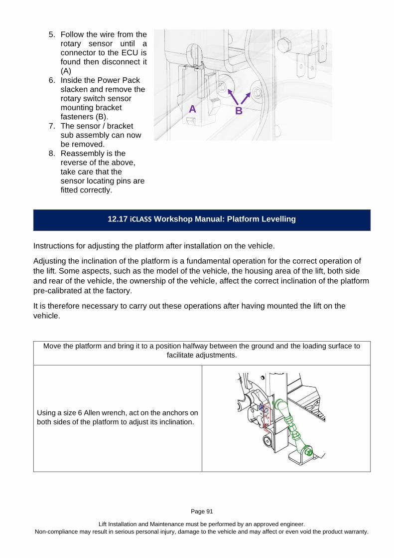
Page 91
Lift Installation and Maintenance must be performed by an approved engineer.
Non-compliance may result in serious personal injury, damage to the vehicle and may affect or even void the product warranty.
5. Follow the wire from the rotary sensor until a connector to the ECU is found then disconnect it (A)
6. Inside the Power Pack slacken and remove the rotary switch sensor mounting bracket fasteners (B).
7. The sensor / bracket sub assembly can now be removed.
8. Reassembly is the reverse of the above, take care that the sensor locating pins are fitted correctly.
12.17 iCLASS Workshop Manual: Platform Levelling
Instructions for adjusting the platform after installation on the vehicle.
Adjusting the inclination of the platform is a fundamental operation for the correct operation of
the lift. Some aspects, such as the model of the vehicle, the housing area of the lift, both side
and rear of the vehicle, the ownership of the vehicle, affect the correct inclination of the platform
pre-calibrated at the factory.
It is therefore necessary to carry out these operations after having mounted the lift on the
vehicle.
Move the platform and bring it to a position halfway between the ground and the loading surface to
facilitate adjustments.
Using a size 6 Allen wrench, act on the anchors on
both sides of the platform to adjust its inclination.
A B
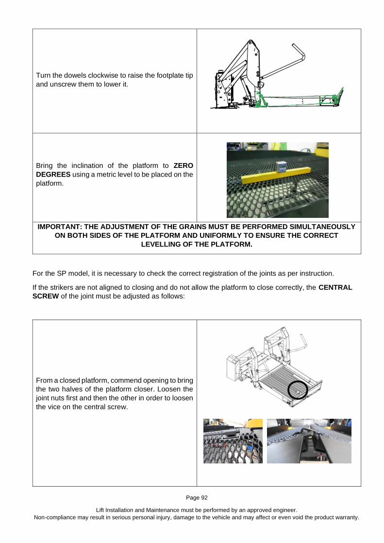
Page 92
Lift Installation and Maintenance must be performed by an approved engineer.
Non-compliance may result in serious personal injury, damage to the vehicle and may affect or even void the product warranty.
Turn the dowels clockwise to raise the footplate tip
and unscrew them to lower it.
Bring the inclination of the platform to ZERO
DEGREES using a metric level to be placed on the
platform.
IMPORTANT: THE ADJUSTMENT OF THE GRAINS MUST BE PERFORMED SIMULTANEOUSLY
ON BOTH SIDES OF THE PLATFORM AND UNIFORMLY TO ENSURE THE CORRECT
LEVELLING OF THE PLATFORM.
For the SP model, it is necessary to check the correct registration of the joints as per instruction.
If the strikers are not aligned to closing and do not allow the platform to close correctly, the CENTRAL
SCREW of the joint must be adjusted as follows:
From a closed platform, commend opening to bring
the two halves of the platform closer. Loosen the
joint nuts first and then the other in order to loosen
the vice on the central screw.

Page 93
Lift Installation and Maintenance must be performed by an approved engineer.
Non-compliance may result in serious personal injury, damage to the vehicle and may affect or even void the product warranty.
To adjust the height of the half-platform, unscrew
the CENTRAL SCREW clockwise or anti-
clockwise. The half-platform will rise or lower,
according to the data revolutions.
NOTE: Each joint moves the adjacent half-platform. The manoeuvre must be performed on
both joints to obtain a correct platform set-up.
ONCE VERIFYING THAT THE STRIKERS OF THE TWO HALF-PLATFORMS DO NOT
TOUCH, TIGHTEN THE NUTS NEAR THE JOINTS.
ATTENTION: The rotation of the screw
depends on the joint. If it rotates right, it is the
right joint. If it rotates left, it is the left joint.
13 Cleaning
Great care needs to be taken during the cleaning process, all cleaning should be carried out by hand using a gentle cloth or sponge soaked in non-aggressive detergent and then rinsed with a cloth dampened with water. Ensure all moving parts are re-lubricated where necessary.
WARNING DO NOT USE AGGRESSIVE DETERGENTS
DO NOT USE PRESSURE WASHERS OR HOT WATER JET CLEANERS

Page 94
Lift Installation and Maintenance must be performed by an approved engineer.
Non-compliance may result in serious personal injury, damage to the vehicle and may affect or even void the product warranty.
After cleaning, check and re-lubricate parts per Section 14
14 Lubrication
See Figure 14.1 for lubrication, grease all pins, use ACF-50 for all other parts.

Page 95
Lift Installation and Maintenance must be performed by an approved engineer.
Non-compliance may result in serious personal injury, damage to the vehicle and may affect or even void the product warranty.
Figure 14.1 Lubrication points
15 Inspection and Servicing
15.1 Inspection and Service Data Sheet
Inspection / Service 1
Date
Driver/ Operator
Name
Signature
Inspection / Service 2
Date
Driver/ Operator
Name
Signature
Inspection / Service 3
Date
Driver/ Operator
Name
Signature

Page 96
Lift Installation and Maintenance must be performed by an approved engineer.
Non-compliance may result in serious personal injury, damage to the vehicle and may affect or even void the product warranty.
Inspection / Service 4
Date
Driver/ Operator
Name
Signature
Inspection / Service 5
Date
Driver/ Operator
Name
Signature
Inspection / Service 6
Date
Driver/ Operator
Name
Signature
Inspection / Service 7
Date
Driver/ Operator
Name
Signature
Inspection / Service 8
Date
Driver/ Operator
Name
Signature
Inspection / Service 9
Date
Driver/ Operator
Name
Signature
Inspection / Service 10
Date
Driver/ Operator
Name
Signature
Inspection / Service 11
Date
Driver/ Operator
Name
Signature
Inspection / Service 12
Date
Driver/ Operator
Name
Signature
This page MUST be produced when claiming warranty repairs
16 Troubleshooting
Control Handset Electrical Issue
Hydraulic Oil or Component ECU Related
Problem Cause Solution
Lift not working / slow Lower power available (less than 9 volts) Charge battery, start engine, swap battery
Lift not working / slow Low oil level in pump Lower lift to ground, fill tank to within 20mm
from top
Lift not working Main Fuse / Circuit breaker blown or tripped Reset or replace (should be location next to
power source)
Lift not working / erratic Control handset faulty Check wires, pins, plugs replace handset if
necessary

Page 97
Lift Installation and Maintenance must be performed by an approved engineer.
Non-compliance may result in serious personal injury, damage to the vehicle and may affect or even void the product warranty.
Platform does not deploy
Safety lock not unlocking (does hook lift when press DEPLOY?)
Manually override safety hook (to test)
Control handset connected incorrectly Check handset plug & pins are mated correctly
Control handset faulty Replace handset
Lowering valve solenoid electrical circuit OPEN Check and close circuit
Lowering valve/solenoid broken (or blocked) Replace (or remove and clean) lowering valve
Deploy gas-springs not working Test gas-springs, replace if not working to full
power
Closed position incorrectly programmed Reprogram CLOSED position on ECU
Platform TWISTING when Deployed
Restriction in hydraulic cylinder / system? Check for pinched hoses, replace if necessary
Restriction in hydraulic cylinder / system? Hydraulic cylinder restrictor blocked
Damaged lifting hydraulic cylinder seals strip and replace cylinder seals (or swap
cylinder)
Lift FALLING out from vertical Stow and NOT unfolding
Arm gas-spring lost power Replace if required
Anti-rattle plate too tight (or wheel) Adjust plate angle
Platform does not lower to Ground
Control handset connected incorrectly Check handset plug & pins are mated correctly
Control handset faulty Replace handset
Lowering valve/solenoid broken (or blocked) Replace (or remove and clean) lowering valve
ECU issue Reprogram ECU (replace as last resort)
Mechanical system dry / dirty Clean and lubricate moving parts
Lifting cylinder damaged (or corroded) Check and replace if necessary
Platform does not STOP at correct vehicle floor height (when operating Up or Down?)
Loading level incorrectly programmed Reprogram Floor-height level
Rotary sensor issue Adjust, re-set or replace
Control handset connected incorrectly Check handset plug & pins are mated correctly
Control handset faulty Replace handset
Platform does not lift UP from Ground (is main pump motor working or not?)
Motor working but no pressure: Manual override valve OPEN
Close valve
Lowering valve solenoid electrical circuit OPEN Check and close circuit
Lowering valve/solenoid broken (or blocked) Replace (or remove and clean) lowering valve
Hydraulic pressure switch fault Adjust pressure switch (replace if cannot adjust)

Page 98
Lift Installation and Maintenance must be performed by an approved engineer.
Non-compliance may result in serious personal injury, damage to the vehicle and may affect or even void the product warranty.
Control handset faulty Replace handset
Hydraulic Powerpack fault Replace whole powerpack unit
ECU issue Reprogram ECU (replace as last resort)
Platform does not STOW (fully up and vertical)
Hydraulic pressure switch fault Adjust pressure switch (replace if cannot adjust)
Lowering valve/solenoid broken (or blocked) Replace (or remove and clean) lowering valve
ECU issue (correct angle not programmed) Reprogram ECU (replace as last resort)
Control handset faulty Replace handset
Hydraulic Powerpack fault Replace whole powerpack unit
Mechanical parts locked/jammed Trace broken/stuck linkage. Replace, clean,
lubricate
Auxiliary handpump not working
Air in system To bleed air out: open manual override tap,
pump 10 times, close and retry
Handpump broken (locked or pumping loose) Replace handpump
Manual override valve OPEN Close valve
Inner barrier not lifting UP
Arm linkage not moving correctly Check, clean adjust, lubricate
Gas-strut lost pressure Swap out for new
Arm gas-spring lost power Replace if required
Inner barrier not lowering
locking hooks stuck Adjust hook and/or pins to suit. If worn replace
parts
Arm linkage not triggering hooks Adjust to suit or replace striker/hook
components
Inner barrier not locking
locking hooks not engaging Springs not effective, adjust or replace
locking hooks not engaging Adjust hook and/or pins to suit. If worn replace
parts
Arm linkage not moving correctly Check, clean adjust, lubricate
Handrail not deploying (or sticking)
Adjustment bolts incorrect position Adjust to suit
Handrail gas-strut worn / lost pressure Swap out for new
Internal cam worn Adjust or replace cam / internal linkage parts
Manual Control Valve not working Turning too far OPEN or CLOSED Adjust OPEN or CLOSED, replace valve if
required
Lift Pump issues: Noisy, Slow, cannot produce pressure
Lower power available (less than 10.5 volts) Charge battery, start engine, swap battery
Low oil level in pump Lower lift to ground, fill tank to within 20mm
from top

Page 99
Lift Installation and Maintenance must be performed by an approved engineer.
Non-compliance may result in serious personal injury, damage to the vehicle and may affect or even void the product warranty.
Contaminated oil (swarf, grit, dirt, old oil, etc) Check oil, flush system and add new oil
Air in system Operate system approx. 20 times to bleed
Worn DC motor Replace motor or pump
Worn hydraulic pump Replace powerpack
ECU issue Reprogram ECU (replace as last resort)
Platform not horizontal
Not adjusted correctly from installation Adjust angle up or down (outer barrier should
land first)
Platform / parts damaged assess and replace where required
Auxiliary Lights not on
Faulty wires Check wires repair or replace
Faulty Lights Check repair or replace
ECU board blown Replace ECU

Page 100
Lift Installation and Maintenance must be performed by an approved engineer.
Non-compliance may result in serious personal injury, damage to the vehicle and may affect or even void the product warranty.

Page 101
Lift Installation and Maintenance must be performed by an approved engineer.
Non-compliance may result in serious personal injury, damage to the vehicle and may affect or even void the product warranty.
6.1 Switch Locations
17 iCLASS Labelling
17.1 Lift Labelling

Page 102
Lift Installation and Maintenance must be performed by an approved engineer.
Non-compliance may result in serious personal injury, damage to the vehicle and may affect or even void the product warranty.
17.2 Power Pack Labels - Outside