


Bahasa
Halaman
Hukum

www.elsevier.com/locate/diamond
Diamond & Related Materials 13 (2004) 2140–2146
On the kinetics of carbon nanotube growth by thermal CVD method
Z.Y. Juanga, J.F. Laib, C.H. Wenga, J.H. Leea, H.J. Laic, T.S. Laib, C.H. Tsaia,*
aDepartment of Engineering and System Science, National Tsing Hua University, 101, Section 2 Kuang Fu Road, Hsinchu 300, Taiwan, ROCbDepartment of Physics, Chung-Yuan Christian University, Taiwan, ROC
cMaterials Research Laboratories, Industrial Technology Research Institute, Taiwan, ROC
Available online 18 May 2004
Abstract
The role of ammonia (NH3) on obtaining good quality vertically aligned multi-walled carbon nanotubes (CNTs) in thermal chemical
vapor deposition (CVD) method has been widely studied. It was generally agreed that NH3 helps to maintain catalyst metal surface active by
reacting with amorphous carbon. In this article, a systematic study in varying the temperature and mixing ratio of gases was conducted in
order to clarify the role of NH3 and revealed a criterion for optimized condition window in the growth processes. In addition, this study has
also carried out a statistical analysis through intensive TEM observations on the tube diameters, bamboo spacing, and the formation rate of
each diaphragm under various temperatures and carbon source/NH3 ratios. While the formation of the separation diaphragms were indeed a
result of bulk diffusion of carbon atoms from bottom of the Ni nanoparticle following thermal dehydrogenization to the top of the Ni
nanoparticle, there were other carbon atoms diffusing presumably via surface diffusion to the CNT-metal interface and contributed to the
growth of tube wall; in other words, the CNTs growth is simultaneous renucleation and growth processes, instead of a continuous
renucleation and growth process. This kinetics-based mechanism in combination with the proposed role of NH3 could not only successfully
explain the effects of the process parameters including temperature and the mixing gas ratio, but also could be used for pursuing the goal of
lower growth temperature for thermal CVD method which is very important for many applications of CNTs.
D 2004 Elsevier B.V. All rights reserved.
Keywords: Carbon nanotube; Mechanism; Thermal CVD; Ammonia
1. Introduction
Carbon nanotubes (CNTs) have great potential for vari-
ous nanotechnology applications. Since their first successful
synthesis by arc-discharge technique and observation by the
transmission electron microscope (TEM) analysis [1], and
the subsequent methods with the metal catalyst in an
hydrocarbon/inert mixing gas atmosphere [2,3], extensive
investigations on CNTs have been carried out due to their
unique physical properties [4,5] and potential applications
[6–8]. Compared to the earlier gas phase synthesis techni-
ques, the catalytic chemical vapor deposition (CVD) meth-
ods [9–15], either thermal pyrolysis or plasma-enhanced,
have the advantageous ability in in-situ selective growth on
patterned area for large area array fabrication in the appli-
cations such as field emission display (FED), chemical
0925-9635/$ - see front matter D 2004 Elsevier B.V. All rights reserved.
doi:10.1016/j.diamond.2004.03.007
* Corresponding author. Tel.: +886-3571-5131x5804; fax: +886-3572-
0724.
E-mail address: [email protected] (C.H. Tsai).
sensors, etc. Thus far, catalytic metals deposited on sub-
strates, such as nickel (Ni) film on silicon or glass sub-
strates, have been widely used for this purpose. Methane
(CH4), acetylene (C2H2) or ethylene (C2H4) was often used
as carbon source and ammonia (NH3) was sometimes used
as reactive gas for the growth of aligned CNTs in thermal
CVD method [12,13,16,17]. Even thought it was general-
ly agreed that NH3 helps to maintain catalyst metal sur-
face active [18], whether NH3 is needed in every stage of
CNTs synthesis is controversial and the detailed mecha-
nism of how CNTs grow vertically aligned is still unclear
[12,18,19]. In our previous work [20], we found that the
effects of NH3/CH4 ratios on the CNTs growth in atmo-
spheric thermal CVD process at a fixed temperature of 900
jC showed distinct trends with and without diluting gas
argon (Ar). Our experimental results suggested that there
exists a critical supply of CH4 or other carbon source when
CNTs growth is limited by carbon atom diffusion that might
be determined by the growth temperature or/and effective
active area of catalyst particles. In the case of low carbon
supply and high carbon diffusion, so called carbon supply
Z.Y. Juang et al. / Diamond & Related Materials 13 (2004) 2140–2146 2141
on catalyst surface limited (CSL), either graphite structure
formation/CNTs growth is hampered, or CNTs grow in
spaghetti-like morphology; whereas in the case of high
carbon supply and low carbon diffusion, so called carbon
diffusion rate limited (CDL), carbon atoms will saturate on
nanoparticle surface and excess carbon atoms form amor-
phous carbon and CNTs growth is hampered due to catalyst
passivation. It is therefore believed that the optimal CNTs
growth situated on the condition that carbon atom supply
and diffusion reach an identical rate; that is, CNTs grow
with ‘‘best quality’’ at this optimal growth condition. In this
article, systematic experiments were performed furthermore
to examine the role of NH3 on the growth of CNTs in
atmospheric thermal CVD under various temperatures and
carbon source/NH3 ratios. In addition, since there have been
numerous papers attempted to investigate the growth mech-
anisms by examining the bamboo-like structure [21–25],
this study has also carried out a statistical analysis through
an intensive TEM observations on the tube diameters,
bamboo spacing (or called inter-bamboo-layer distance),
and the formation rate of each diaphragm under various
temperatures and carbon source/NH3 ratios. It is hoped that,
in combining the kinetics-based model and the examined
role of NH3 on CNTs growth as well as bamboo-like
morphology, a better understanding and better control of
CNTs catalytic growth can be achieved.
2. Experimental
Patterned (10� 10 Am2) Ni catalyst films of thickness 10
nm were deposited on SiO2/p-Si(100) wafer by optical
lithography and e-gun evaporation followed by lift-off pro-
cess. The pieces of catalyst deposited substrates were then
placed on a quartz plate and leaded into a 46-mm inner-
diameter resistance heated quartz tube furnace at atmospheric
pressure. The quartz tube was pumped down to f 10� 3
mbar using amechanical pump, before purgingAr gas back to
atmospheric pressure. The substrates were then heated to 900
jC at a heating rate of 60 jC/min with Ar gas supplied
continuously.When the temperature was stable at 900 jC,Ar/NH3 mixing gas (1:1) was introduced into the quartz tube for
10 min pretreatment. At the end of pretreatment process, the
C2H4 gas was introduced into the quartz tube for CNTs
growth. In order to precisely control the synthesis tempera-
ture, the furnace was equipped with three individual thermal
couples to in-situ monitor the temperature independently to
avoid overheating. All specimens of different growth con-
ditions were treated with the same pretreatment process. Note
that most of the reports in the literature used the temperature
of pretreatment the same as that for growth process. That
means the experimental results in different growth temper-
atures were not only influenced by the difference of the
growth temperature, but also affected by different pretreat-
ment temperatures. For this reason, a better experimental
design to study the effects of temperatures should be that with
fixed pretreatment temperature. The time of CNTs growth
was 10 min and the pressure was 1 atm. At the end of the
growth, the quartz tube was pumped down to f 10� 3 mbar
again to avoid the interference with remaining gaseous
species. After that, the specimens were furnace-cooled to
room temperature in an Ar flowing environment at 1 atm.
Note that the total flow rate, even in varying the ratio of Ar/
NH3/C2H4 mixed gases, was always kept at 400 sccm via
mass flow controller (MFC, LINTEC MC-2100ENC). The
field emission scanning electron microscopy (SEM, JEOL
JSM-6330F) and transmission electron microscopes (TEM,
JEOL JEM 2000FXII/2010/2010F) were used to examine the
morphologies, dimensions, bamboo structure and the atomic-
resolution images of CNTs, respectively.
3. Results and discussion
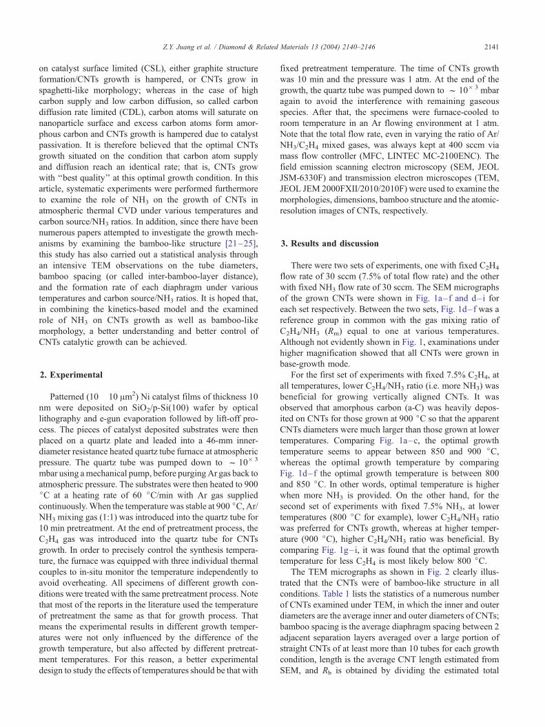
There were two sets of experiments, one with fixed C2H4
flow rate of 30 sccm (7.5% of total flow rate) and the other
with fixed NH3 flow rate of 30 sccm. The SEM micrographs
of the grown CNTs were shown in Fig. 1a–f and d–i for
each set respectively. Between the two sets, Fig. 1d–f was a
reference group in common with the gas mixing ratio of
C2H4/NH3 (Rm) equal to one at various temperatures.
Although not evidently shown in Fig. 1, examinations under
higher magnification showed that all CNTs were grown in
base-growth mode.
For the first set of experiments with fixed 7.5% C2H4, at
all temperatures, lower C2H4/NH3 ratio (i.e. more NH3) was
beneficial for growing vertically aligned CNTs. It was
observed that amorphous carbon (a-C) was heavily depos-
ited on CNTs for those grown at 900 jC so that the apparent
CNTs diameters were much larger than those grown at lower
temperatures. Comparing Fig. 1a–c, the optimal growth
temperature seems to appear between 850 and 900 jC,whereas the optimal growth temperature by comparing
Fig. 1d–f the optimal growth temperature is between 800
and 850 jC. In other words, optimal temperature is higher
when more NH3 is provided. On the other hand, for the
second set of experiments with fixed 7.5% NH3, at lower
temperatures (800 jC for example), lower C2H4/NH3 ratio
was preferred for CNTs growth, whereas at higher temper-
ature (900 jC), higher C2H4/NH3 ratio was beneficial. By
comparing Fig. 1g–i, it was found that the optimal growth
temperature for less C2H4 is most likely below 800 jC.The TEM micrographs as shown in Fig. 2 clearly illus-
trated that the CNTs were of bamboo-like structure in all
conditions. Table 1 lists the statistics of a numerous number
of CNTs examined under TEM, in which the inner and outer
diameters are the average inner and outer diameters of CNTs;
bamboo spacing is the average diaphragm spacing between 2
adjacent separation layers averaged over a large portion of
straight CNTs of at least more than 10 tubes for each growth
condition, length is the average CNT length estimated from
SEM, and Rb is obtained by dividing the estimated total
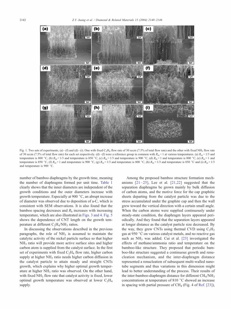
Fig. 1. Two sets of experiments, (a)– (f) and (d)– (i). One with fixed C2H4 flow rate of 30 sccm (7.5% of total flow rate) and the other with fixed NH3 flow rate
of 30 sccm (7.5% of total flow rate) for each set respectively. (d)– (f) were a reference group in common with Rm= 1 at various temperatures. (a) Rm= 1/3 and
temperature is 800 jC, (b) Rm= 1/3 and temperature is 850 jC, (c) Rm= 1/3 and temperature is 900 jC, (d) Rm= 1 and temperature is 800 jC, (e) Rm= 1 and
temperature is 850 jC, (f) Rm= 1 and temperature is 900 jC, (g) Rm= 1/3 and temperature is 800 jC, (h) Rm= 1/3 and temperature is 850 jC and (i) Rm= 1/3
and temperature is 900 jC.
Z.Y. Juang et al. / Diamond & Related Materials 13 (2004) 2140–21462142
number of bamboo diaphragms by the growth time, meaning
the number of diaphragms formed per unit time. Table 1
clearly shows that the inner diameters are independent of the
growth conditions and the outer diameters increase with
growth temperature. Especially at 900 jC, an abrupt increaseof diameter was observed due to deposition of a-C, which is
consistent with SEM observations. It is also found that the
bamboo spacing decreases and Rb increases with increasing
temperature, which are also illustrated in Figs. 3 and 4. Fig. 5
shows the dependence of CNT length on the growth tem-
perature at different C2H4/NH3 ratios.
In discussing the observations described in the previous
paragraphs, the role of NH3 is assumed to maintain the
catalytic activity of the nickel particle surface so that higher
NH3 ratio will provide more active surface sites and higher
carbon atom is supplied from the catalyst surface. In the first
set of experiments with fixed C2H4 flow rate, higher carbon
supply at higher NH3 ratio needs higher carbon diffusion in
the catalyst particle to attain steady and straight CNTs
growth, which explains why higher optimal growth temper-
ature at higher NH3 ratio was observed. On the other hand,
with fixed NH3 flow rate that catalyst activity is fixed, lower
optimal growth temperature was observed at lower C2H4
supply.
Among the proposed bamboo structure formation mech-
anisms [21–25], Lee et al. [21,22] suggested that the
separation diaphragms be grown mainly by bulk diffusion
of carbon atoms, and the motive force for the cap graphitic
sheets departing from the catalyst particle was due to the
stress accumulated under the graphite cap and then the wall
grew toward the vertical direction with a certain small angle.
When the carbon atoms were supplied continuously under
steady-state condition, the diaphragm layers appeared peri-
odically. And they found that the separation layers appeared
at longer distance as the catalyst particle size decreased. By
the way, they grew CNTs using thermal CVD using C2H2
gas at 950 jC on various catalyst metals, and no reactive gas
such as NH3 was added. Cui et al. [23] investigated the
effects of methane/ammonia ratio and temperature on the
bamboo-like structure. They proposed that periodic bam-
boo-like structure suggested a continuous growth and renu-
cleation mechanism, and the inter-diaphragm distance
represented a renucleation of subsequent multi-walled nano-
tube segments and thus variations in this dimension might
lead to better understanding of the process. Their results of
the inter-bamboo-diaphragm distance for different CH4/NH3
concentrations at temperature of 810 jC showed an increase
in spacing with partial pressure of CH4 (Fig. 4 of Ref. [23]),
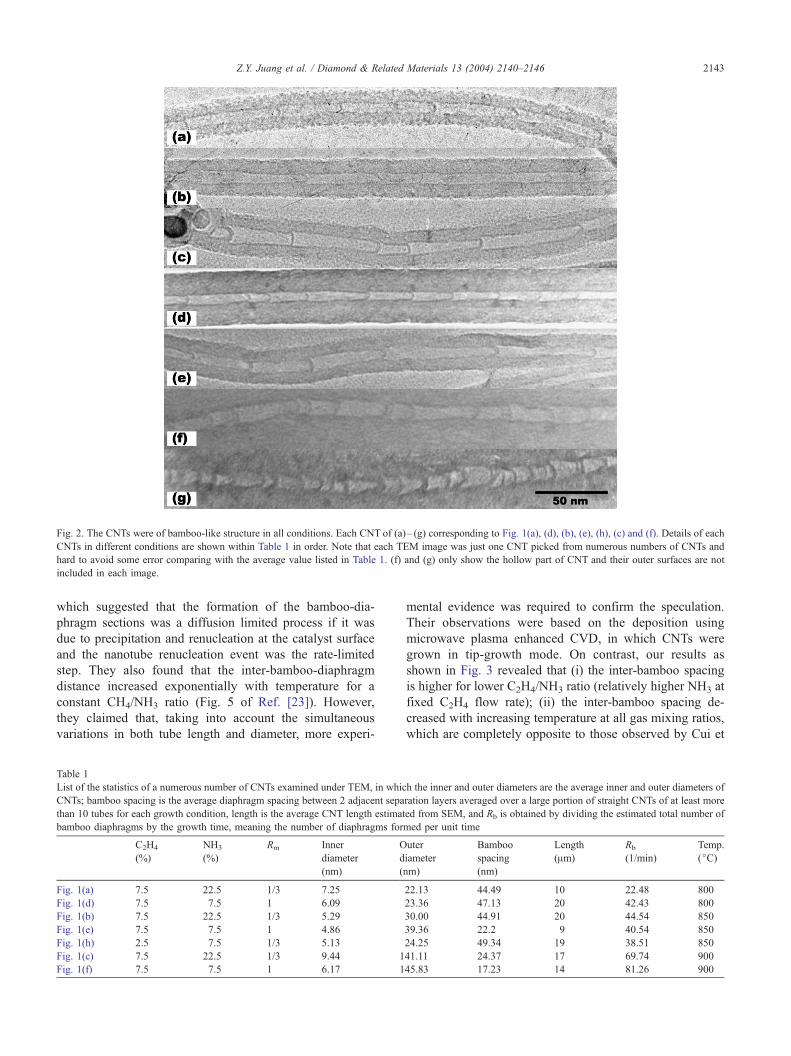
Fig. 2. The CNTs were of bamboo-like structure in all conditions. Each CNT of (a)– (g) corresponding to Fig. 1(a), (d), (b), (e), (h), (c) and (f). Details of each
CNTs in different conditions are shown within Table 1 in order. Note that each TEM image was just one CNT picked from numerous numbers of CNTs and
hard to avoid some error comparing with the average value listed in Table 1. (f) and (g) only show the hollow part of CNT and their outer surfaces are not
included in each image.
Z.Y. Juang et al. / Diamond & Related Materials 13 (2004) 2140–2146 2143
which suggested that the formation of the bamboo-dia-
phragm sections was a diffusion limited process if it was
due to precipitation and renucleation at the catalyst surface
and the nanotube renucleation event was the rate-limited
step. They also found that the inter-bamboo-diaphragm
distance increased exponentially with temperature for a
constant CH4/NH3 ratio (Fig. 5 of Ref. [23]). However,
they claimed that, taking into account the simultaneous
variations in both tube length and diameter, more experi-
Table 1
List of the statistics of a numerous number of CNTs examined under TEM, in whic
CNTs; bamboo spacing is the average diaphragm spacing between 2 adjacent sepa
than 10 tubes for each growth condition, length is the average CNT length estimat
bamboo diaphragms by the growth time, meaning the number of diaphragms for
C2H4
(%)
NH3
(%)
Rm Inner
diameter
(nm)
O
d
(n
Fig. 1(a) 7.5 22.5 1/3 7.25
Fig. 1(d) 7.5 7.5 1 6.09
Fig. 1(b) 7.5 22.5 1/3 5.29
Fig. 1(e) 7.5 7.5 1 4.86
Fig. 1(h) 2.5 7.5 1/3 5.13
Fig. 1(c) 7.5 22.5 1/3 9.44 1
Fig. 1(f) 7.5 7.5 1 6.17 1
mental evidence was required to confirm the speculation.
Their observations were based on the deposition using
microwave plasma enhanced CVD, in which CNTs were
grown in tip-growth mode. On contrast, our results as
shown in Fig. 3 revealed that (i) the inter-bamboo spacing
is higher for lower C2H4/NH3 ratio (relatively higher NH3 at
fixed C2H4 flow rate); (ii) the inter-bamboo spacing de-
creased with increasing temperature at all gas mixing ratios,
which are completely opposite to those observed by Cui et
h the inner and outer diameters are the average inner and outer diameters of
ration layers averaged over a large portion of straight CNTs of at least more
ed from SEM, and Rb is obtained by dividing the estimated total number of
med per unit time
uter
iameter
m)
Bamboo
spacing
(nm)
Length
(Am)
Rb
(1/min)
Temp.
(jC)
22.13 44.49 10 22.48 800
23.36 47.13 20 42.43 800
30.00 44.91 20 44.54 850
39.36 22.2 9 40.54 850
24.25 49.34 19 38.51 850
41.11 24.37 17 69.74 900
45.83 17.23 14 81.26 900
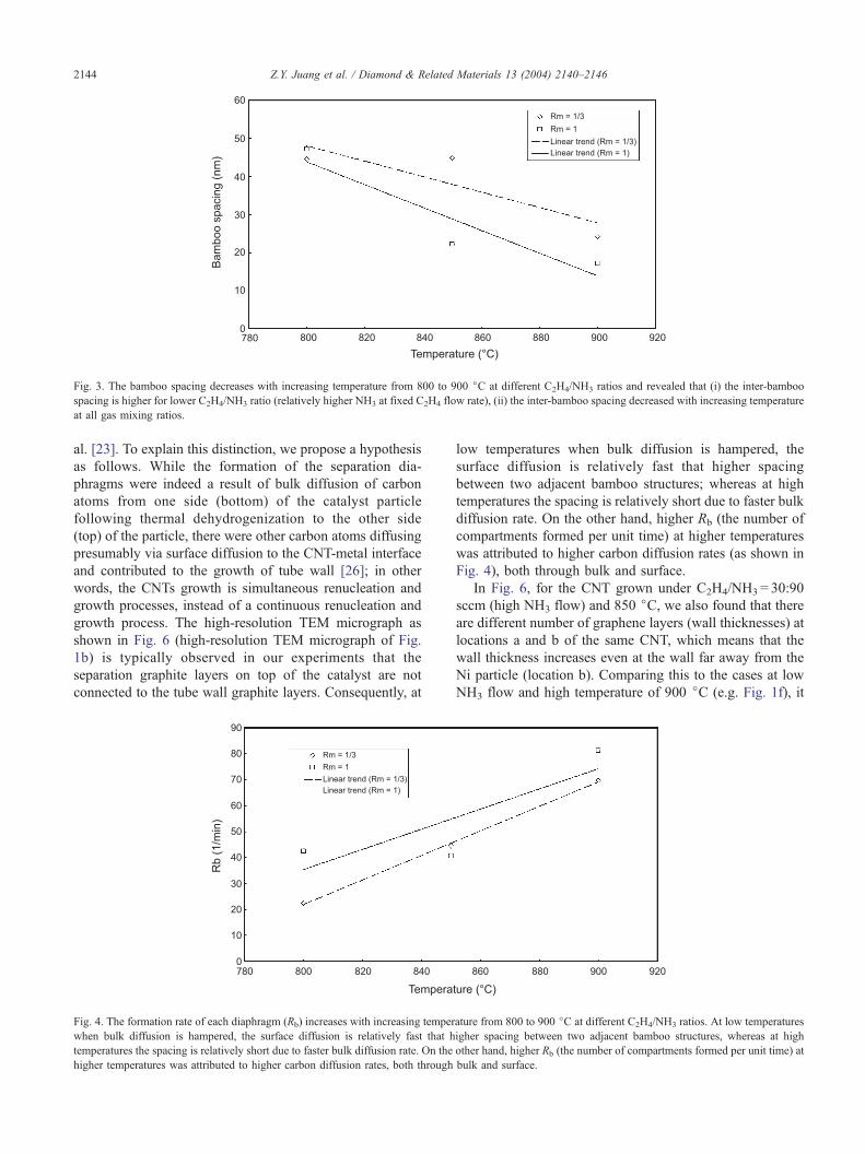
Fig. 3. The bamboo spacing decreases with increasing temperature from 800 to 900 jC at different C2H4/NH3 ratios and revealed that (i) the inter-bamboo
spacing is higher for lower C2H4/NH3 ratio (relatively higher NH3 at fixed C2H4 flow rate), (ii) the inter-bamboo spacing decreased with increasing temperature
at all gas mixing ratios.
Z.Y. Juang et al. / Diamond & Related Materials 13 (2004) 2140–21462144
al. [23]. To explain this distinction, we propose a hypothesis
as follows. While the formation of the separation dia-
phragms were indeed a result of bulk diffusion of carbon
atoms from one side (bottom) of the catalyst particle
following thermal dehydrogenization to the other side
(top) of the particle, there were other carbon atoms diffusing
presumably via surface diffusion to the CNT-metal interface
and contributed to the growth of tube wall [26]; in other
words, the CNTs growth is simultaneous renucleation and
growth processes, instead of a continuous renucleation and
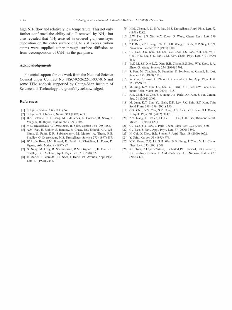
growth process. The high-resolution TEM micrograph as
shown in Fig. 6 (high-resolution TEM micrograph of Fig.
1b) is typically observed in our experiments that the
separation graphite layers on top of the catalyst are not
connected to the tube wall graphite layers. Consequently, at
Fig. 4. The formation rate of each diaphragm (Rb) increases with increasing temper
when bulk diffusion is hampered, the surface diffusion is relatively fast that h
temperatures the spacing is relatively short due to faster bulk diffusion rate. On the
higher temperatures was attributed to higher carbon diffusion rates, both through
low temperatures when bulk diffusion is hampered, the
surface diffusion is relatively fast that higher spacing
between two adjacent bamboo structures; whereas at high
temperatures the spacing is relatively short due to faster bulk
diffusion rate. On the other hand, higher Rb (the number of
compartments formed per unit time) at higher temperatures
was attributed to higher carbon diffusion rates (as shown in
Fig. 4), both through bulk and surface.
In Fig. 6, for the CNT grown under C2H4/NH3 = 30:90
sccm (high NH3 flow) and 850 jC, we also found that there
are different number of graphene layers (wall thicknesses) at
locations a and b of the same CNT, which means that the
wall thickness increases even at the wall far away from the
Ni particle (location b). Comparing this to the cases at low
NH3 flow and high temperature of 900 jC (e.g. Fig. 1f), it
ature from 800 to 900 jC at different C2H4/NH3 ratios. At low temperatures
igher spacing between two adjacent bamboo structures, whereas at high
other hand, higher Rb (the number of compartments formed per unit time) at
bulk and surface.
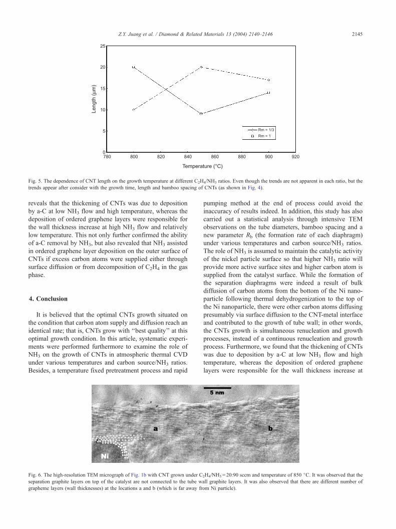
Fig. 5. The dependence of CNT length on the growth temperature at different C2H4/NH3 ratios. Even though the trends are not apparent in each ratio, but the
trends appear after consider with the growth time, length and bamboo spacing of CNTs (as shown in Fig. 4).
Z.Y. Juang et al. / Diamond & Related Materials 13 (2004) 2140–2146 2145
reveals that the thickening of CNTs was due to deposition
by a-C at low NH3 flow and high temperature, whereas the
deposition of ordered graphene layers were responsible for
the wall thickness increase at high NH3 flow and relatively
low temperature. This not only further confirmed the ability
of a-C removal by NH3, but also revealed that NH3 assisted
in ordered graphene layer deposition on the outer surface of
CNTs if excess carbon atoms were supplied either through
surface diffusion or from decomposition of C2H4 in the gas
phase.
4. Conclusion
It is believed that the optimal CNTs growth situated on
the condition that carbon atom supply and diffusion reach an
identical rate; that is, CNTs grow with ‘‘best quality’’ at this
optimal growth condition. In this article, systematic experi-
ments were performed furthermore to examine the role of
NH3 on the growth of CNTs in atmospheric thermal CVD
under various temperatures and carbon source/NH3 ratios.
Besides, a temperature fixed pretreatment process and rapid
Fig. 6. The high-resolution TEM micrograph of Fig. 1b with CNT grown under C
separation graphite layers on top of the catalyst are not connected to the tube w
grapheme layers (wall thicknesses) at the locations a and b (which is far away fr
pumping method at the end of process could avoid the
inaccuracy of results indeed. In addition, this study has also
carried out a statistical analysis through intensive TEM
observations on the tube diameters, bamboo spacing and a
new parameter Rb (the formation rate of each diaphragm)
under various temperatures and carbon source/NH3 ratios.
The role of NH3 is assumed to maintain the catalytic activity
of the nickel particle surface so that higher NH3 ratio will
provide more active surface sites and higher carbon atom is
supplied from the catalyst surface. While the formation of
the separation diaphragms were indeed a result of bulk
diffusion of carbon atoms from the bottom of the Ni nano-
particle following thermal dehydrogenization to the top of
the Ni nanoparticle, there were other carbon atoms diffusing
presumably via surface diffusion to the CNT-metal interface
and contributed to the growth of tube wall; in other words,
the CNTs growth is simultaneous renucleation and growth
processes, instead of a continuous renucleation and growth
process. Furthermore, we found that the thickening of CNTs
was due to deposition by a-C at low NH3 flow and high
temperature, whereas the deposition of ordered graphene
layers were responsible for the wall thickness increase at
2H4/NH3 = 20:90 sccm and temperature of 850 jC. It was observed that the
all graphite layers. It was also observed that there are different number of
om Ni particle).
Z.Y. Juang et al. / Diamond & Related Materials 13 (2004) 2140–21462146
high NH3 flow and relatively low temperature. This not only
further confirmed the ability of a-C removal by NH3, but
also revealed that NH3 assisted in ordered graphene layer
deposition on the outer surface of CNTs if excess carbon
atoms were supplied either through surface diffusion or
from decomposition of C2H4 in the gas phase.
Acknowledgements
Financial support for this work from the National Science
Council under Contract No. NSC-92-2622-E-007-016 and
some TEM analysis supported by Chung-Shan Institute of
Science and Technology are gratefully acknowledged.
References
[1] S. Iijima, Nature 354 (1991) 56.
[2] S. Iijima, T. Ichihashi, Nature 363 (1993) 603.
[3] D.S. Bethune, C.H. Kiang, M.S. de Vries, G. Gorman, R. Saroy, J.
Vazguez, R. Beyers, Nature 363 (1993) 605.
[4] M.S. Dresselhaus, G. Dreselhaus, R. Saito, Carbon 33 (1995) 883.
[5] A.M. Rao, E. Richter, S. Bandow, B. Chase, P.C. Eklund, K.A. Wil-
liams, S. Fang, K.R. Subbaswamy, M. Menon, A. Thess, R.E.
Smalley, G. Dresselhaus, M.S. Dresselhaus, Science 275 (1997) 187.
[6] W.A. de Heer, J.M. Bonard, K. Fauth, A. Chatelian, L. Forro, D.
Ugarte, Adv. Mater. 9 (1997) 87.
[7] G. Nagy, M. Levy, R. Scarmozzino, R.M. Osgood Jr., H. Dai, R.E.
Smalley, G.F. McLane, Appl. Phys. Lett. 73 (1998) 529.
[8] R. Martel, T. Schmidt, H.R. Shea, T. Hertel, Ph. Avouris, Appl. Phys.
Lett. 73 (1998) 2447.
[9] H.M. Cheng, F. Li, H.Y. Pan, M.S. Dresselhaus, Appl. Phys. Lett. 72
(1998) 3282.
[10] Z.W. Pan, S.S. Xie, W.Y. Zhou, G. Wang, Chem. Phys. Lett. 299
(1999) 97.
[11] Z.F. Ren, Z.P. Huang, J.W. Xu, J.H. Wang, P. Bush, M.P. Siegel, P.N.
Provencio, Science 282 (1998) 1105.
[12] C.J. Lee, D.W. Kim, T.J. Lee, Y.C. Choi, Y.S. Park, Y.H. Lee, W.B.
Choi, N.S. Lee, G.S. Park, J.M. Kim, Chem. Phys. Lett. 312 (1999)
461.
[13] W.Z. Li, S.S. Xie, L.X. Qian, B.H. Chang, B.S. Zou, W.Y. Zhou, R.A.
Zhao, G. Wang, Science 274 (1996) 1701.
[14] S. Fan, M. Chapline, N. Franklin, T. Tombler, A. Cassell, H. Dai,
Science 283 (1999) 512.
[15] W. Zhu, C. Bower, O. Zhou, G. Kochanski, S. Jin, Appl. Phys. Lett.
75 (1999) 873.
[16] M. Jung, K.Y. Eun, J.K. Lee, Y.T. Baik, K.R. Lee, J.W. Park, Dia-
mond Relat. Mater. 10 (2001) 1235.
[17] K.S. Choi, Y.S. Cho, S.Y. Hong, J.B. Park, D.J. Kim, J. Eur. Ceram.
Soc. 21 (2001) 2095.
[18] M. Jung, K.Y. Eun, Y.J. Baik, K.R. Lee, J.K. Shin, S.T. Kim, Thin
Solid Films 398–399 (2001) 150.
[19] G.S. Choi, Y.S. Cho, S.Y. Hong, J.B. Park, K.H. Son, D.J. Kima,
J. Appl. Phys. 91 (2002) 3847.
[20] Z.Y. Juang, I.P. Chien, J.F. Lai, T.S. Lai, C.H. Tsai, Diamond Relat.
Mater. 13 (2004) 1203.
[21] C.J. Lee, J.H. Park, J. Park, Chem. Phys. Lett. 323 (2000) 560.
[22] C.J. Lee, J. Park, Appl. Phys. Lett. 77 (2000) 3397.
[23] H. Cui, O. Zhou, B.R. Stoner, J. Appl. Phys. 88 (2000) 6072.
[24] Y. Saito, Carbon 33 (1995) 979.
[25] X.X. Zhang, Z.Q. Li, G.H. Wen, K.K. Fung, J. Chen, Y. Li, Chem.
Phys. Lett. 333 (2001) 509.
[26] S. Helveg, C. Lopez-Cartes1, J. Sehested, P.L. Hansen1, B.S. Clausen1,
J.R. Rostrup-Nielsen, F. Abild-Pedersen, J.K. Nørskov, Nature 427
(2004) 426.
Top Related
Copyright © 2022 FDOKUMEN

