


Bahasa
Halaman
Hukum

Ocular Rotation Axes during Dynamic BielschowskyHead-Tilt Testing in Unilateral Trochlear Nerve Palsy
Konrad P. Weber,1 Klara Landau,2 Antonella Palla,1 Thomas Haslwanter,1 andDominik Straumann1
PURPOSE. To explain the positive Bielschowsky head-tilt (BHT)sign in unilateral trochlear nerve palsy (uTNP) by the kinemat-ics of three-dimensional eye rotations.
METHODS. Twelve patients with uTNP monocularly fixed ontargets on a Hess screen were oscillated (� 35°, 0.3 Hz) aboutthe roll axis on a motorized turntable (dynamic BHT). Three-dimensional eye movements were recorded with dual searchcoils. Normal data were collected from 11 healthy subjects.
RESULTS. The rotation axis of the viewing paretic or unaffectedeye was nearly parallel to the line of sight. The rotation axis ofthe covered fellow eye, however, was tilted inward relative tothe other axis. This convergence of axes increased with gazetoward the unaffected side. Over entire cycles of head roll, therotation axis of either eye remained relatively stable in both theviewing and covered conditions.
CONCLUSIONS. In patients with uTNP, circular gaze trajectoriesof the covered paretic or unaffected eye during dynamic BHTare a direct consequence of the nasal deviation of the rotationaxis from the line of sight. This, in turn, is a geometrical resultof decreased force by the superior oblique muscle (SO) of thecovered paretic eye or, according to Hering’s law, increasedforce parallel to the paretic SO in the covered unaffected eye.The horizontal incomitance of rotation axes along horizontaleye positions can be explained by the same mechanism. (In-vest Ophthalmol Vis Sci. 2004;45:455–465) DOI:10.1167/iovs.02-1223
Oscillation of the head in the roll plane leads to conjugateocular counterroll through the vestibulo-ocular reflex.1,2
If a subject binocularly fixes on a visual target during thistorsional vestibular stimulation, the ocular rotation axis ofeither eye aligns with the line of sight to maintain fixation,3
whereas in the dark, the ocular rotation axis tilts into theopposite direction by half the angle whenever the line of sightis directed eccentrically.4 During monocular fixation, with the
head not moving, the line of sight of the covered eye pointstoward the same target as the viewing eye, in accordance withHering’s law of equal innervation.5 This is also observed duringconcurrent torsional vestibular stimulation, as the ocular rota-tion axis aligns with the line of sight in both eyes.6
In trochlear nerve palsy, the line of sight of the covered eyeno longer points toward the target, but deviates up- or down-ward when the paretic or healthy eye is covered, respectively.As a consequence of Hering’s law, this torsional–vertical devi-ation is incomitant—that is, it increases when gaze is moved inthe pulling direction of the paretic superior oblique muscle byvertical (evoked by visual targets) or torsional (evoked byocular counterroll) eye displacements. Based on this observa-tion, Bielschowsky and Hofmann7 described the head-tilt testfor diagnosing trochlear nerve palsies. Rolling the head towardthe side of the paretic eye leads to an increase of verticaldeviation between the two eyes. In clinical use, this test isperformed in a static fashion, comparing the vertical deviationon head roll to both sides.
The change in torsional–vertical deviation between the cov-ered and the viewing eye (torsional–vertical incomitance) dur-ing Bielschowsky head-tilt testing requires that the ocular ro-tation axis of the covered eye is no longer aligned with the lineof sight. Otherwise, no vertical incomitance could be observedas a function of ocular counterroll.
We asked whether the orientation of ocular rotation axesthat leads to the pattern of binocular deviations observedduring Bielschowsky head-tilt testing could be predicted by theanatomy of the paretic superior oblique muscle. Three-dimen-sional eye positions evoked by static head roll, however, arenot sufficient to trigonometrically reconstruct the exact orien-tation of ocular rotation axes, because the amount of oculartorsion is relatively small and fluctuates considerably.8 Wetherefore used continuous sinusoidal vestibular stimulationabout the naso-occipital axis and analyzed whether the orien-tation of ocular rotation axes would change as a function ofocular counterroll. By presenting targets at different locationson a head-fixed Hess screen,9 we also tested whether ocularrotation axes would change with eye position and whetherthere was incomitance between the rotation axes of both eyes,which would extend Hering’s law for binocular eye positionsto binocular rotation axes.
METHODS
Subjects
We tested 12 patients (age 15–57 years, two female) with untreatedunilateral trochlear nerve palsy. The clinical diagnosis of trochlearnerve palsy was based on the three-step procedure described byParks,10 including Bielschowsky head-tilt testing.7 In all patients, inter-mittent or constant vertical double vision was present for more than 6months. The comparison group consisted of 11 healthy subjects (age21–40 years, 6 women). Informed consent was obtained from patientsand healthy subjects after the experimental procedure was explained.The protocol was approved by a local ethics committee and was in
From the 1Department of Neurology, Zurich University Hospital,Zurich, Switzerland; 2Department of Ophthalmology, Zurich Univer-sity Hospital, Zurich, Switzerland.
Supported by Swiss National Science Foundation Grant32-51938.97 SCORE A (DS), 31-63465.00 (DS), and 3100-063669 (TH);and the Betty and David Koetser Foundation for Brain Research, Zu-rich, Switzerland.
Presented in part at the meeting of Physiology and Disorders ofOculomotor and Vestibular Control, Wildbad Kreuth, Germany, April2003.
Submitted for publication November 28, 2002; revised June 7 andOctober 6, 2003; accepted October 26, 2003.
Disclosure: K.P. Weber, None; K. Landau, None; A. Palla, None;T. Haslwanter, None; D. Straumann, None
The publication costs of this article were defrayed in part by pagecharge payment. This article must therefore be marked “advertise-ment” in accordance with 18 U.S.C. §1734 solely to indicate this fact.
Corresponding author: Dominik Straumann, Department of Neu-rology, Zurich University Hospital, Frauenklinikstrasse 26, CH-8091,Zurich, Switzerland; [email protected].
Investigative Ophthalmology & Visual Science, February 2004, Vol. 45, No. 2Copyright © Association for Research in Vision and Ophthalmology 455
accordance with the ethical standards laid down in the Declaration ofHelsinki for research involving human subjects.
Setup
Subjects were seated upright on a turntable with three servocontrolledmotor driven axes (prototype built by Acutronic, Jona, Switzerland).The head was restrained with an individually molded thermoplasticmask (Sinmed BV, Reeuwijk, The Netherlands) and was positionedsuch that the center of the interaural line was at the intersection of thethree axes of the turntable. Pillows and safety belts minimized move-ments of the body. Movements of both eyes were recorded in threedimensions11 (horizontal, vertical, torsional) on the turntable. Subjectsmonocularly fixed on nine laser dots projected on a spherical screen ata distance of 1.4 m, whereas the other eye was covered. Healthy andparetic eye viewing conditions were intermingled.
The dots were located straight ahead and at eight eccentric head-fixed positions—that is, on a 0° � 20° horizontal and vertical squaregrid in stereographic coordinates. Dot positions were calibrated byrotations of a laser placed in the center of the turntable. For secondarydot positions, the laser was rotated about the horizontal or vertical axisby 20° from the straight-ahead position. For tertiary dot positions, thelaser was rotated about oblique axes (45° between horizontal andvertical) by 28.3° from the straight-ahead position.
Three-dimensional eye movements were binocularly recorded withdual search coils manufactured by Skalar (Delft, The Netherlands). Thecoils were mounted on both eyes after anesthetizing the conjunctivaand cornea with oxybuprocaine hydrochloride 0.4% (Novartis Oph-thalmics, Hettlingen, Switzerland). A chair-fixed coil frame (sidelength, 0.5 m) that produced three orthogonal magnetic fields withfrequencies of 80, 96, and 120 kHz surrounded the subject’s head.Subjects were seated inside the frame so that the center of the inter-pupillary line coincided with the center of the frame. The signals wereamplified and multiplexed before passing through the turntable sliprings. A high performance 12-bit digital signal processor computed aFast Fourier transform in real time on the digitized search coil signal todetermine the voltage induced in the coil by each magnetic field(system manufactured by Primelec, Regensdorf, Switzerland). Dualsearch coils were calibrated in vitro on a gimbal system before eachexperiment. Details of the procedure are given elsewhere.12 The ori-entation of the coil could be determined with an error of less than 7%over a range of �30° and with a noise level of less than 0.05° (rootmean square deviation). Eye- and chair-position signals were digitizedwith 16-bit accuracy. All data were sampled at 1 kHz and analyzedoffline with statistical software (MatLab; The MathWorks, Inc., Natick,MA).
Experimental Procedure
One eye was covered at least 5 minutes before measurements to breakthe fusional reflex between the two eyes. First, binocular eye positionsduring the static Bielschowsky head-tilt test7 were recorded with eithereye covered in upright, 35° left ear down, and 35° right ear downwhole-body roll position. In each static turntable position, the subjectssequentially fixed on the nine head-fixed Hess screen targets during 3seconds each. This was repeated with the other eye viewing. Then,patients were oscillated about the naso-occipital (roll) axis (�35°, 0.3Hz). During this dynamic paradigm, subjects had to fix on the ninehead-fixed Hess screen targets during 18 seconds each. Thus, eyeposition data of five oscillation cycles could be obtained for every gazedirection with either eye covered (see video, Bielschowsky.mov, Ap-pendix B).
Data Analysis
Detailed explanations and corresponding equations are given in Ap-pendix A. Three-dimensional eye positions in the magnetic coil framewere expressed as rotation vectors.13 A rotation vector re describes theinstantaneous orientation of the eye as a single rotation from thereference position looking straight ahead. The rotation vector re is
oriented parallel to the axis of this rotation, and its length is defined bytan (�/2), where � is the angle of rotation. The signs of rotation vectorsare determined by the right-hand rule—that is, clockwise, downward,and leftward rotations, as seen from the subject, are positive. Fromrotation vectors, angular velocity vectors � were derived to determinethe rotation axes.14 Angular velocity vectors point along the instanta-neous rotation axis. Their length is proportional to the rotationalspeed.
Gaze vectors were projected stereographically13 on a Hess screenchart. This chart represents gaze direction from the patient’s point ofview. Because the stereographic projection is conformal, local anglesare preserved and circular gaze movements about a fixed axis appearequally circular. (Note that this is different from rotation vector space,in which a rotation about a single axis is represented by a straight line.)
To relate ocular rotation axes with the corresponding gaze trajec-tories on the same Hess screen chart, the orientations of the angularvelocity vectors (representing ocular rotation axes) were also pro-jected stereographically.
The nine data clouds of gaze directions associated with fixations ofthe nine Hess screen targets by the viewing eye were selected with aninteractive computer program. In patients with left-sided trochlearnerve palsy, the directions of three-dimensional eye position werehorizontally mirrored, as if the right eye had been affected by the palsy.In the static paradigm, the median three-dimensional rotation vectorsof both eyes were computed for each gaze direction. In the dynamicparadigm, torsional saccades were eliminated from the angular velocitydata by iterative sinusoidal fitting.
Computer Simulations
Simulations to predict eye positions based on geometric considerationswere written in commercial software (MatLab; The MathWorks). Wealso checked whether the recorded three-dimensional eye positiondata in patients could be predicted by a current biomechanical soft-ware model, EyeLab 2000,15 based on Orbit version 1.516 and writtenin MatLab.
RESULTS
Experimental Findings
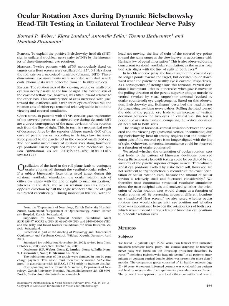
Figure 1 depicts a typical example of static Bielschowsky head-tilt testing in a patient with congenital trochlear nerve palsy. Inthe Hess screen projection, the right covered paretic eye (cir-cles connected with solid lines) showed the characteristicpattern of vertical–horizontal gaze deviation, including theincreasing hyperdeviation relative to the healthy viewing eye(circles connected with dashed lines) with adduction (Figs.1A–C). On head tilt to the paretic side, the entire grid formedby the gaze directions of the covered paretic eye shifted up-ward relative to the viewing healthy eye and vice versa. Whenthe healthy eye was covered, its pattern of vertical-horizontalgaze directions vertically mirrored the covered pathologiceye—that is, the hypodeviation relative to the viewing patho-logic eye increased with abduction (Fig. 1D–F). On head tilt tothe paretic side, the entire grid formed by the gaze directionsof the covered healthy eye shifted downward.
To describe and model trajectories of the covered eyeduring dynamic Bielschowsky testing, when the viewing eyefixes on a specific target, two geometric locations must beknown: (1) the starting position of the covered eye—that is, itsposition when the upright sitting patient monocularly fixes ona target with the other eye, and (2) the orientation of the axisabout which the covered eye rotates during dynamic torsionalvestibular stimulation.
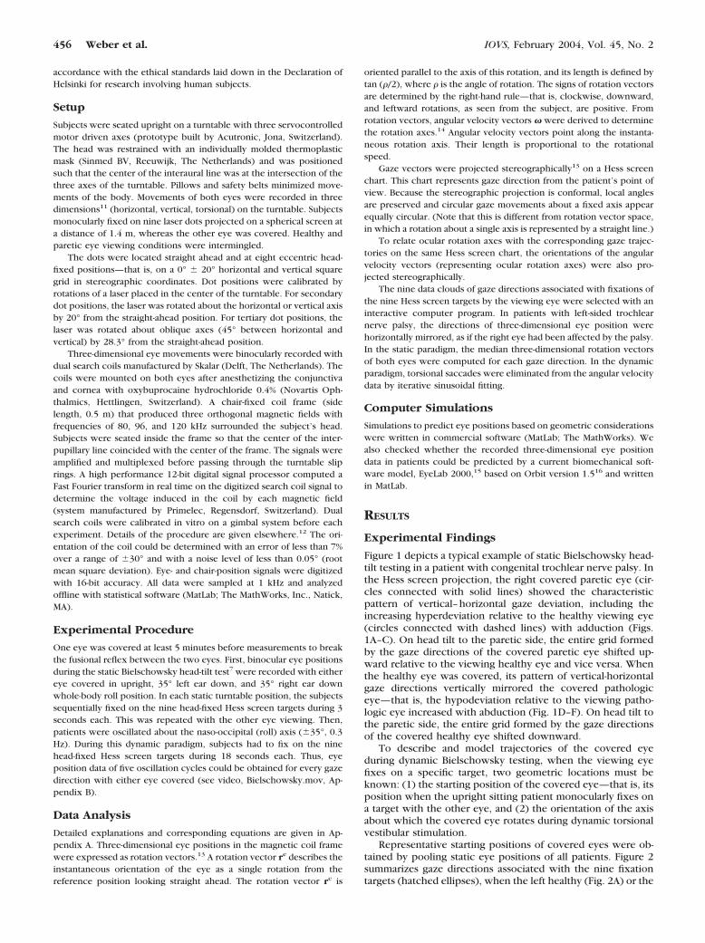
Representative starting positions of covered eyes were ob-tained by pooling static eye positions of all patients. Figure 2summarizes gaze directions associated with the nine fixationtargets (hatched ellipses), when the left healthy (Fig. 2A) or the
456 Weber et al. IOVS, February 2004, Vol. 45, No. 2
right paretic eye (Fig. 2B) was covered. Compared with healthysubjects (filled ellipses), average positions (�1 SD: horizontaland vertical radii of ellipses) of the covered paretic eyes inpatients showed the typical pattern of increasing hyperdevia-tion in adduction, whereas the covered healthy eyes in patientsshowed the vertically mirrored pattern (see also Fig. 1).
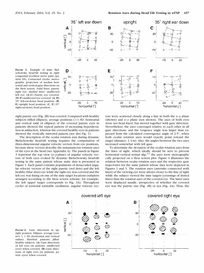
The description of the ocular rotation axis during dynamicBielschowsky head-tilt testing requires the computation ofthree-dimensional angular velocity vectors from eye positions,because these vectors describe the instantaneous rotation axesof the eyes in the head (see Appendix A). The panels in Figure3 represent the top view (x–y-plane) of angular velocity vec-tors of both eyes evoked by dynamic Bielschowsky head-tilttesting in the same patient whose static data is presented inFigure 1. Each panel contains populations of desaccaded angu-lar velocity vectors of the right paretic (red dots) and the lefthealthy (blue dots) eye while the right eye was covered and theleft eye was fixing on one of the nine target locations (subplotsarranged according to the Hess screen scheme; for example,the left upper target corresponds to Fig. 3A). Throughoutcycles of torsional turntable oscillation, angular velocity vec-
tors were scattered closely along a line in both the x–y plane(shown) and x–z plane (not shown). The axes of both eyeswere not head fixed, but moved together with gaze direction.Nevertheless, the axes converged relative to each other in allgaze directions, and the vergence angle was larger than ex-pected from the calculated convergence angle of 2.5°, whenboth ocular rotation axes would exactly point toward thetarget (distance: 1.4 m). Also, the angles between the two axesincreased somewhat with left gaze.
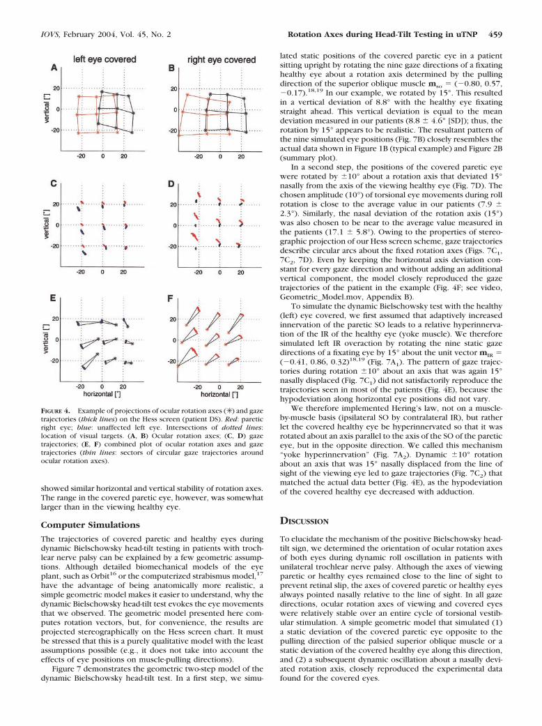
To determine the deviation of the ocular rotation axes fromthe lines of sight, which ideally should be zero to preventhorizontal–vertical retinal slip,3,6 the axes were stereographi-cally projected on a Hess screen plot. Figure 4 illustrates therelation between ocular rotation axes and the respective gazetrajectories for the same patient whose data were depicted inFigures 1 and 3. The rotation axes (asterisks connected withlines) of the viewing eye were always closer to the line of sightwhile the subject viewed the nine targets (crossings of dottedlines) than the rotation axes of the covered eye. The latter axeswere displaced nasally, irrespective of whether the coveredeye was the paretic one (Fig. 4B) or not (Fig. 4A). Thus, the
FIGURE 1. Example of static Biel-schowsky head-tilt testing in rightcongenital trochlear nerve palsy (pa-tient DS). Connected circles: stereo-graphic projection of median hori-zontal and vertical gaze directions onthe Hess screen. Solid lines: pareticright eye; dashed lines: unaffectedleft eye. (A–C) Paretic eye covered;(D–F) unaffected eye covered. (A, D)35° left-ear-down head position; (B,E) upright head position; (C, F) 35°right-ear-down head position.
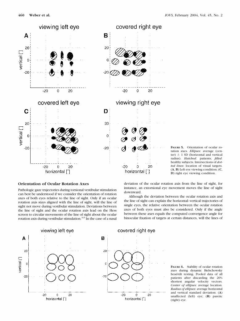
FIGURE 2. Gaze directions in up-right position. Ellipses: average (cen-ter) � 1 SD (horizontal and verticalradius). Hatched: patients; filled:healthy subjects. (A) Gaze directionsof left eyes (in patients: unaffectedeyes) when covered. (B) Gaze direc-tions of right eyes (in patients: pa-retic eyes) when covered.
IOVS, February 2004, Vol. 45, No. 2 Rotation Axes during Head-Tilt Testing in uTNP 457
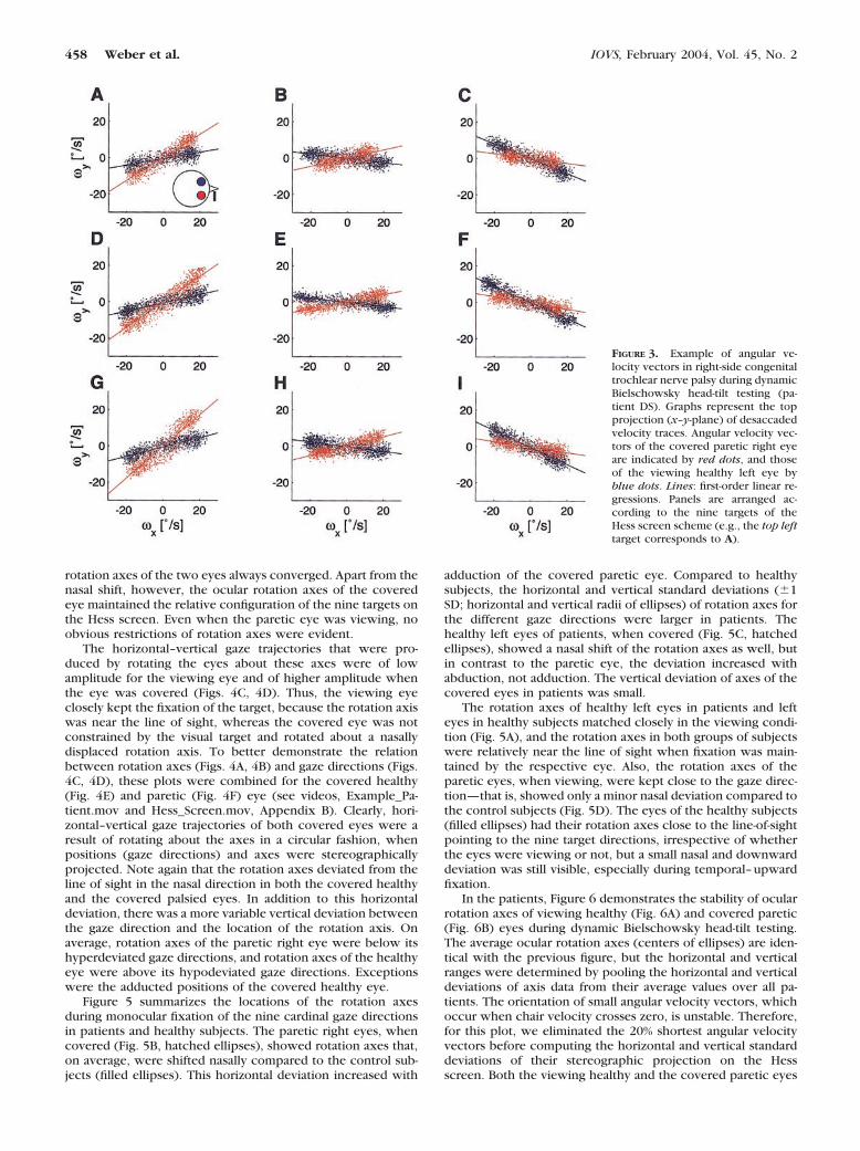
rotation axes of the two eyes always converged. Apart from thenasal shift, however, the ocular rotation axes of the coveredeye maintained the relative configuration of the nine targets onthe Hess screen. Even when the paretic eye was viewing, noobvious restrictions of rotation axes were evident.
The horizontal–vertical gaze trajectories that were pro-duced by rotating the eyes about these axes were of lowamplitude for the viewing eye and of higher amplitude whenthe eye was covered (Figs. 4C, 4D). Thus, the viewing eyeclosely kept the fixation of the target, because the rotation axiswas near the line of sight, whereas the covered eye was notconstrained by the visual target and rotated about a nasallydisplaced rotation axis. To better demonstrate the relationbetween rotation axes (Figs. 4A, 4B) and gaze directions (Figs.4C, 4D), these plots were combined for the covered healthy(Fig. 4E) and paretic (Fig. 4F) eye (see videos, Example_Pa-tient.mov and Hess_Screen.mov, Appendix B). Clearly, hori-zontal–vertical gaze trajectories of both covered eyes were aresult of rotating about the axes in a circular fashion, whenpositions (gaze directions) and axes were stereographicallyprojected. Note again that the rotation axes deviated from theline of sight in the nasal direction in both the covered healthyand the covered palsied eyes. In addition to this horizontaldeviation, there was a more variable vertical deviation betweenthe gaze direction and the location of the rotation axis. Onaverage, rotation axes of the paretic right eye were below itshyperdeviated gaze directions, and rotation axes of the healthyeye were above its hypodeviated gaze directions. Exceptionswere the adducted positions of the covered healthy eye.
Figure 5 summarizes the locations of the rotation axesduring monocular fixation of the nine cardinal gaze directionsin patients and healthy subjects. The paretic right eyes, whencovered (Fig. 5B, hatched ellipses), showed rotation axes that,on average, were shifted nasally compared to the control sub-jects (filled ellipses). This horizontal deviation increased with
adduction of the covered paretic eye. Compared to healthysubjects, the horizontal and vertical standard deviations (�1SD; horizontal and vertical radii of ellipses) of rotation axes forthe different gaze directions were larger in patients. Thehealthy left eyes of patients, when covered (Fig. 5C, hatchedellipses), showed a nasal shift of the rotation axes as well, butin contrast to the paretic eye, the deviation increased withabduction, not adduction. The vertical deviation of axes of thecovered eyes in patients was small.
The rotation axes of healthy left eyes in patients and lefteyes in healthy subjects matched closely in the viewing condi-tion (Fig. 5A), and the rotation axes in both groups of subjectswere relatively near the line of sight when fixation was main-tained by the respective eye. Also, the rotation axes of theparetic eyes, when viewing, were kept close to the gaze direc-tion—that is, showed only a minor nasal deviation compared tothe control subjects (Fig. 5D). The eyes of the healthy subjects(filled ellipses) had their rotation axes close to the line-of-sightpointing to the nine target directions, irrespective of whetherthe eyes were viewing or not, but a small nasal and downwarddeviation was still visible, especially during temporal–upwardfixation.
In the patients, Figure 6 demonstrates the stability of ocularrotation axes of viewing healthy (Fig. 6A) and covered paretic(Fig. 6B) eyes during dynamic Bielschowsky head-tilt testing.The average ocular rotation axes (centers of ellipses) are iden-tical with the previous figure, but the horizontal and verticalranges were determined by pooling the horizontal and verticaldeviations of axis data from their average values over all pa-tients. The orientation of small angular velocity vectors, whichoccur when chair velocity crosses zero, is unstable. Therefore,for this plot, we eliminated the 20% shortest angular velocityvectors before computing the horizontal and vertical standarddeviations of their stereographic projection on the Hessscreen. Both the viewing healthy and the covered paretic eyes
FIGURE 3. Example of angular ve-locity vectors in right-side congenitaltrochlear nerve palsy during dynamicBielschowsky head-tilt testing (pa-tient DS). Graphs represent the topprojection (x–y-plane) of desaccadedvelocity traces. Angular velocity vec-tors of the covered paretic right eyeare indicated by red dots, and thoseof the viewing healthy left eye byblue dots. Lines: first-order linear re-gressions. Panels are arranged ac-cording to the nine targets of theHess screen scheme (e.g., the top lefttarget corresponds to A).
458 Weber et al. IOVS, February 2004, Vol. 45, No. 2
showed similar horizontal and vertical stability of rotation axes.The range in the covered paretic eye, however, was somewhatlarger than in the viewing healthy eye.
Computer Simulations
The trajectories of covered paretic and healthy eyes duringdynamic Bielschowsky head-tilt testing in patients with troch-lear nerve palsy can be explained by a few geometric assump-tions. Although detailed biomechanical models of the eyeplant, such as Orbit16 or the computerized strabismus model,17
have the advantage of being anatomically more realistic, asimple geometric model makes it easier to understand, why thedynamic Bielschowsky head-tilt test evokes the eye movementsthat we observed. The geometric model presented here com-putes rotation vectors, but, for convenience, the results areprojected stereographically on the Hess screen chart. It mustbe stressed that this is a purely qualitative model with the leastassumptions possible (e.g., it does not take into account theeffects of eye positions on muscle-pulling directions).
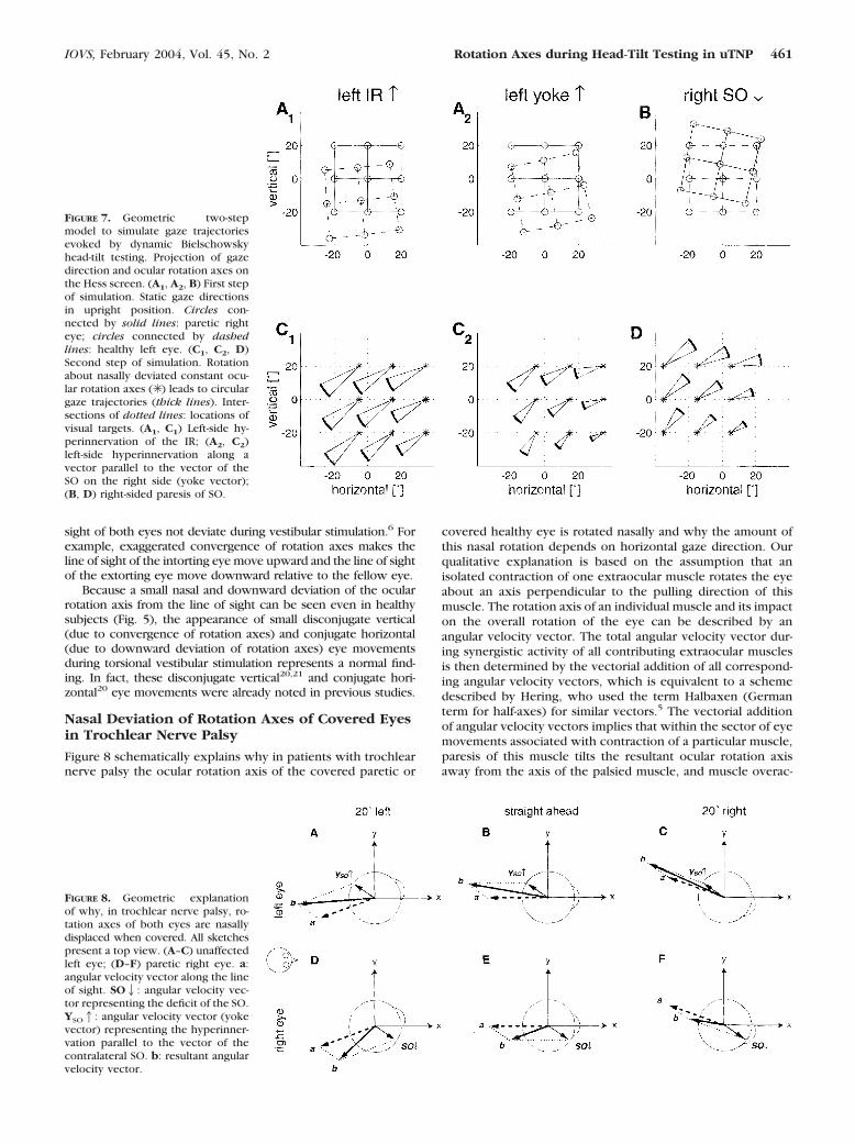
Figure 7 demonstrates the geometric two-step model of thedynamic Bielschowsky head-tilt test. In a first step, we simu-
lated static positions of the covered paretic eye in a patientsitting upright by rotating the nine gaze directions of a fixatinghealthy eye about a rotation axis determined by the pullingdirection of the superior oblique muscle mso � (�0.80, 0.57,�0.17).18,19 In our example, we rotated by 15°. This resultedin a vertical deviation of 8.8° with the healthy eye fixatingstraight ahead. This vertical deviation is equal to the meandeviation measured in our patients (8.8 � 4.6° [SD]); thus, therotation by 15° appears to be realistic. The resultant pattern ofthe nine simulated eye positions (Fig. 7B) closely resembles theactual data shown in Figure 1B (typical example) and Figure 2B(summary plot).
In a second step, the positions of the covered paretic eyewere rotated by �10° about a rotation axis that deviated 15°nasally from the axis of the viewing healthy eye (Fig. 7D). Thechosen amplitude (10°) of torsional eye movements during rollrotation is close to the average value in our patients (7.9 �2.3°). Similarly, the nasal deviation of the rotation axis (15°)was also chosen to be near to the average value measured inthe patients (17.1 � 5.8°). Owing to the properties of stereo-graphic projection of our Hess screen scheme, gaze trajectoriesdescribe circular arcs about the fixed rotation axes (Figs. 7C1,7C2, 7D). Even by keeping the horizontal axis deviation con-stant for every gaze direction and without adding an additionalvertical component, the model closely reproduced the gazetrajectories of the patient in the example (Fig. 4F; see video,Geometric_Model.mov, Appendix B).
To simulate the dynamic Bielschowsky test with the healthy(left) eye covered, we first assumed that adaptively increasedinnervation of the paretic SO leads to a relative hyperinnerva-tion of the IR of the healthy eye (yoke muscle). We thereforesimulated left IR overaction by rotating the nine static gazedirections of a fixating eye by 15° about the unit vector mIR �(�0.41, 0.86, 0.32)18,19 (Fig. 7A1). The pattern of gaze trajec-tories during rotation �10° about an axis that was again 15°nasally displaced (Fig. 7C1) did not satisfactorily reproduce thetrajectories seen in most of the patients (Fig. 4E), because thehypodeviation along horizontal eye positions did not vary.
We therefore implemented Hering’s law, not on a muscle-by-muscle basis (ipsilateral SO by contralateral IR), but ratherlet the covered healthy eye be hyperinnervated so that it wasrotated about an axis parallel to the axis of the SO of the pareticeye, but in the opposite direction. We called this mechanism“yoke hyperinnervation” (Fig. 7A2). Dynamic �10° rotationabout an axis that was 15° nasally displaced from the line ofsight of the viewing eye led to gaze trajectories (Fig. 7C2) thatmatched the actual data better (Fig. 4E), as the hypodeviationof the covered healthy eye decreased with adduction.
DISCUSSION
To elucidate the mechanism of the positive Bielschowsky head-tilt sign, we determined the orientation of ocular rotation axesof both eyes during dynamic roll oscillation in patients withunilateral trochlear nerve palsy. Although the axes of viewingparetic or healthy eyes remained close to the line of sight toprevent retinal slip, the axes of covered paretic or healthy eyesalways pointed nasally relative to the line of sight. In all gazedirections, ocular rotation axes of viewing and covered eyeswere relatively stable over an entire cycle of torsional vestib-ular stimulation. A simple geometric model that simulated (1)a static deviation of the covered paretic eye opposite to thepulling direction of the palsied superior oblique muscle or astatic deviation of the covered healthy eye along this direction,and (2) a subsequent dynamic oscillation about a nasally devi-ated rotation axis, closely reproduced the experimental datafound for the covered eyes.
FIGURE 4. Example of projections of ocular rotation axes (✳ ) and gazetrajectories (thick lines) on the Hess screen (patient DS). Red: pareticright eye; blue: unaffected left eye. Intersections of dotted lines:location of visual targets. (A, B) Ocular rotation axes; (C, D) gazetrajectories; (E, F) combined plot of ocular rotation axes and gazetrajectories (thin lines: sectors of circular gaze trajectories aroundocular rotation axes).
IOVS, February 2004, Vol. 45, No. 2 Rotation Axes during Head-Tilt Testing in uTNP 459
Orientation of Ocular Rotation Axes
Pathologic gaze trajectories during torsional vestibular stimulationcan best be understood if we consider the orientation of rotationaxes of both eyes relative to the line of sight. Only if an ocularrotation axis stays aligned with the line of sight, will the line ofsight not move during vestibular stimulation. Deviations betweenthe line of sight and the ocular rotation axis lead on the Hessscreen to circular movements of the line of sight about the ocularrotation axis during vestibular stimulation.3,6 In the case of a nasal
deviation of the ocular rotation axis from the line of sight, forinstance, an extorsional eye movement moves the line of sightdownward.
Although the deviation between the ocular rotation axis andthe line of sight can explain the horizontal–vertical trajectories ofsingle eyes, the relative orientation between the ocular rotationaxes of both eyes must also be considered. Only if the anglebetween these axes equals the computed convergence angle forbinocular fixation of targets at certain distances, will the lines of
FIGURE 5. Orientation of ocular ro-tation axes. Ellipses: average (cen-ter) � 1 SD (horizontal and verticalradius). Hatched: patients; filled:healthy subjects. Intersections of dot-ted lines: location of visual targets.(A, B) Left eye viewing condition; (C,D) right eye viewing condition.
FIGURE 6. Stability of ocular rotationaxes during dynamic Bielschowskyhead-tilt testing. Pooled data of allpatients after discarding the 20%shortest angular velocity vectors.Center of ellipses: average location.Radius of ellipses: average horizontaland vertical standard deviation. (A)unaffected (left) eye; (B) paretic(right) eye.
460 Weber et al. IOVS, February 2004, Vol. 45, No. 2
sight of both eyes not deviate during vestibular stimulation.6 Forexample, exaggerated convergence of rotation axes makes theline of sight of the intorting eye move upward and the line of sightof the extorting eye move downward relative to the fellow eye.
Because a small nasal and downward deviation of the ocularrotation axis from the line of sight can be seen even in healthysubjects (Fig. 5), the appearance of small disconjugate vertical(due to convergence of rotation axes) and conjugate horizontal(due to downward deviation of rotation axes) eye movementsduring torsional vestibular stimulation represents a normal find-ing. In fact, these disconjugate vertical20,21 and conjugate hori-zontal20 eye movements were already noted in previous studies.
Nasal Deviation of Rotation Axes of Covered Eyesin Trochlear Nerve Palsy
Figure 8 schematically explains why in patients with trochlearnerve palsy the ocular rotation axis of the covered paretic or
covered healthy eye is rotated nasally and why the amount ofthis nasal rotation depends on horizontal gaze direction. Ourqualitative explanation is based on the assumption that anisolated contraction of one extraocular muscle rotates the eyeabout an axis perpendicular to the pulling direction of thismuscle. The rotation axis of an individual muscle and its impacton the overall rotation of the eye can be described by anangular velocity vector. The total angular velocity vector dur-ing synergistic activity of all contributing extraocular musclesis then determined by the vectorial addition of all correspond-ing angular velocity vectors, which is equivalent to a schemedescribed by Hering, who used the term Halbaxen (Germanterm for half-axes) for similar vectors.5 The vectorial additionof angular velocity vectors implies that within the sector of eyemovements associated with contraction of a particular muscle,paresis of this muscle tilts the resultant ocular rotation axisaway from the axis of the palsied muscle, and muscle overac-
FIGURE 7. Geometric two-stepmodel to simulate gaze trajectoriesevoked by dynamic Bielschowskyhead-tilt testing. Projection of gazedirection and ocular rotation axes onthe Hess screen. (A1, A2, B) First stepof simulation. Static gaze directionsin upright position. Circles con-nected by solid lines: paretic righteye; circles connected by dashedlines: healthy left eye. (C1, C2, D)Second step of simulation. Rotationabout nasally deviated constant ocu-lar rotation axes (✳ ) leads to circulargaze trajectories (thick lines). Inter-sections of dotted lines: locations ofvisual targets. (A1, C1) Left-side hy-perinnervation of the IR; (A2, C2)left-side hyperinnervation along avector parallel to the vector of theSO on the right side (yoke vector);(B, D) right-sided paresis of SO.
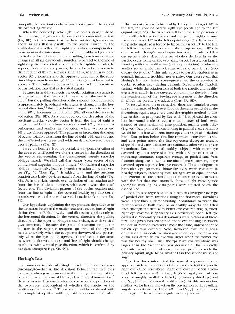
FIGURE 8. Geometric explanationof why, in trochlear nerve palsy, ro-tation axes of both eyes are nasallydisplaced when covered. All sketchespresent a top view. (A–C) unaffectedleft eye; (D–F) paretic right eye. a:angular velocity vector along the lineof sight. SO2: angular velocity vec-tor representing the deficit of the SO.YSO1: angular velocity vector (yokevector) representing the hyperinner-vation parallel to the vector of thecontralateral SO. b: resultant angularvelocity vector.
IOVS, February 2004, Vol. 45, No. 2 Rotation Axes during Head-Tilt Testing in uTNP 461
tion pulls the resultant ocular rotation axis toward the axis ofthe overacting muscle.
When the covered paretic right eye points straight ahead,the line of sight aligns with the x-axis of the coordinate system(Fig. 8E). Let us assume that the head rotates right-ear-downabout an axis that is parallel to the x-axis. Driven by thevestibulo-ocular reflex, the right eye makes a compensatorymovement in the intorsional direction. In healthy subjects, theelicited angular velocity vector a, resulting from transient forcechanges in all six extraocular muscles, is parallel to the line ofsight (negatively directed according to the right-hand rule). Insuperior oblique muscle paresis, the angular velocity vector inthe direction of this muscle is lacking. Thus, an angular velocityvector SO2 pointing into the opposite direction of the supe-rior oblique muscle vector (35.5° abduction) must be added tovector a. The resultant angular velocity vector b represents anocular rotation axis that is deviated nasally.
Because in healthy subjects the ocular rotation axis tends tobe aligned with the line of sight, even when the eye is cov-ered,6 but the pulling direction of the superior oblique muscleis approximately head-fixed when gaze is changed in the hor-izontal direction,19 the angle between angular velocity vectorsa and SO2 increases in abduction (Fig. 8F) and decreases inadduction (Fig. 8D). As a consequence, the deviation of theresultant angular velocity vector b from the line of sight islargest in adduction, where vectors a and SO2 are almostorthogonal, and smallest in abduction, where vectors a andSO2 are almost opposed. This pattern of increasing deviationof ocular rotation axes from the line of sight with gaze towardthe unaffected eye agrees well with our data of covered pareticeyes in patients (Fig. 5B).
Based on Hering’s law, we postulate a hyperinnervation ofthe covered unaffected eye along a vector in the direction ofthe vector representing the contralateral paretic superioroblique muscle. We shall call that vector “yoke vector of thecontralateral superior oblique muscle.” Contralateral superioroblique muscle palsy leads to hyperinnervation along this vec-tor (YSO1). Thus, YSO1 is added to a, and the resultantrotation axis b also deviates nasally from the line of sight (Fig.8B). As in the right paretic eye, deviation of the rotation axisfrom the line of sight increases with gaze toward the unaf-fected eye. This deviation pattern of the ocular rotation axisfrom the line of sight in the covered healthy eye also corre-sponds well with the one observed in patients (compare Fig.5C).
Our hypothesis explaining the eye-position dependence ofthe deviation between the ocular rotation axis and line of sightduring dynamic Bielschowsky head-tilt testing applies only tothe horizontal direction. In the vertical direction, the pullingdirection of the superior oblique muscle changes with verticalgaze direction,19 because the point of insertion behind theequator in the superior–temporal quadrant of the eyeballmoves anteriorly when the eye points downward and posteri-orly when the eye points upward. Therefore, the deviationbetween ocular rotation axis and line of sight should changemuch less with vertical gaze direction, which is confirmed byour data (compare Figs. 5B, 5C).
Hering’s Law
Strabismus due to palsy of a single muscle in one eye is alwaysdisconjugate—that is, the deviation between the two eyesincreases when gaze is moved in the pulling direction of theparetic muscle. Because of Hering’s law of equal innervation,5
there is an unambiguous relationship between the positions ofthe two eyes, independent of whether the paretic or thehealthy eye is covered.22 This rule can best be explained withan example of a patient with right-side abducens nerve palsy.
If this patient fixes with his healthy left eye on a target 10° tothe left, the covered paretic right eye points 15° to the left(squint angle: 5°). The two eyes will keep the same position, ifthe healthy left eye is covered and the paretic right eye nowfixes on a target 15° to the left (squint angle: 5°). If, however,the paretic right eye is forced to fix on the target 10° to the left,the left healthy eye points straight ahead (squint angle: 10°). Inother words, Hering’s law of equal innervation leads to differ-ent squint angles, depending on whether the healthy or theparetic eye is fixing on the very same target. For a given target,viewing with the healthy eye (primary deviation) produces asmaller squint angle than viewing with the paretic eye (sec-ondary deviation).23 This rule applies to paretic strabismus ingeneral, including trochlear nerve palsy. Our data reveal thatHering’s law has similar consequences on the orientation ofocular rotation axes during dynamic Bielschowsky head-tilttesting. While the rotation axis of both the paretic and healthyeye moves nasally in the covered condition, its deviation fromthe rotation axis of the viewing eye increases in the directionin which the paretic eye adducts (Figs. 8A, 8D).
To test whether the eye-position–dependent angle betweenthe rotation axes of both eyes follows the same principle as theincomitant squint angle, we used the graphic method to ana-lyze strabismus proposed by Zee et al.22 but plotted the abso-lute horizontal angle of ocular rotation axes of both eyes,instead of their horizontal gaze position, against each other(Fig. 9A). Data points of axes moving in parallel (i.e., comitant)would lie on a line with zero intercept and a slope of 1 (dashedline). Data points below this line represent convergent axes,and data points above the line represent divergent axes. Aslope of 1 indicates that axes are comitant; otherwise they areincomitant. Data points of healthy subjects with either eyecovered lay on a regression line with a slope of almost 1,indicating comitance (squares: average of pooled data fromfixations along the horizontal meridian; filled squares: right eyecovered; open squares: left eye covered). Thus, analogous tobinocular eye positions, binocular axes were comitant inhealthy subjects, indicating that Hering’s law of equal innerva-tion extends to the orientation of rotation axes. Consistentwith the fact that axes normally show a slight convergence(compare with Fig. 5), data points were situated below thedashed line.
The slopes of regression lines in patients (triangles: averageof pooled data from fixations along the horizontal meridian)were larger than 1, demonstrating incomitance between therotation axes of both eyes. As in healthy subjects, the fittedlines through the data with either eye covered (Fig. 9, filled:right eye covered is “primary axis deviation”; open: left eyecovered is “secondary axis deviation”) were similar and there-fore, for a given axis orientation of one eye, the angle betweenthe ocular rotation axes was almost the same, independent ofwhich eye was covered. Note, however, that, for a givenorientation of an ocular rotation axis in one eye, the deviationof the axis of the fellow eye was larger when the former eyewas the healthy one. Thus, the “primary axis deviation” waslarger than the “secondary axis deviation.” This is exactlyopposite to what one observes for eye positions with theprimary squint angle being smaller than the secondary squintangle.
The two lines intersected the normal regression line atapproximately 40° abduction of the rotation axis of the pareticright eye (filled arrowhead: right eye covered; open arrow-head: left eye covered). In fact, At 35.5° right gaze, rotationaxes are roughly parallel to the SO2 (covered palsied eye) andthe YSO1 vector (covered healthy eye). At this orientation,neither vector has an impact on the orientation of the resultantangular velocity vector. Here, SO2 and YSO1 only influencethe length of the resultant angular velocity vector.
462 Weber et al. IOVS, February 2004, Vol. 45, No. 2
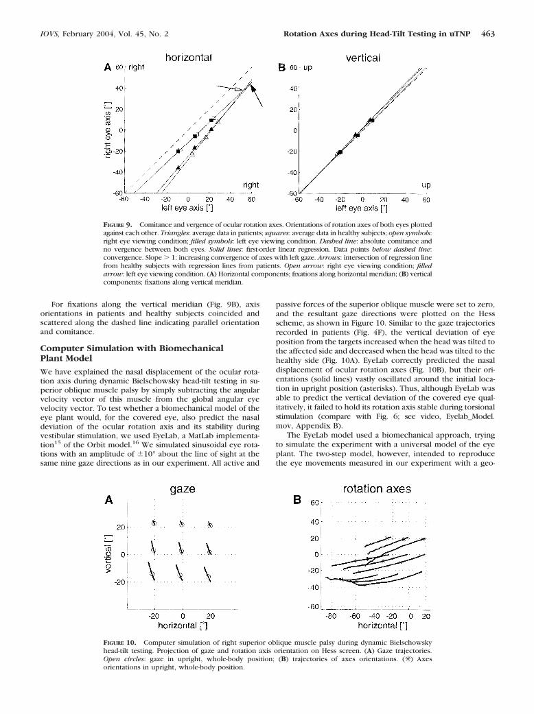
For fixations along the vertical meridian (Fig. 9B), axisorientations in patients and healthy subjects coincided andscattered along the dashed line indicating parallel orientationand comitance.
Computer Simulation with BiomechanicalPlant Model
We have explained the nasal displacement of the ocular rota-tion axis during dynamic Bielschowsky head-tilt testing in su-perior oblique muscle palsy by simply subtracting the angularvelocity vector of this muscle from the global angular eyevelocity vector. To test whether a biomechanical model of theeye plant would, for the covered eye, also predict the nasaldeviation of the ocular rotation axis and its stability duringvestibular stimulation, we used EyeLab, a MatLab implementa-tion15 of the Orbit model.16 We simulated sinusoidal eye rota-tions with an amplitude of �10° about the line of sight at thesame nine gaze directions as in our experiment. All active and
passive forces of the superior oblique muscle were set to zero,and the resultant gaze directions were plotted on the Hessscheme, as shown in Figure 10. Similar to the gaze trajectoriesrecorded in patients (Fig. 4F), the vertical deviation of eyeposition from the targets increased when the head was tilted tothe affected side and decreased when the head was tilted to thehealthy side (Fig. 10A). EyeLab correctly predicted the nasaldisplacement of ocular rotation axes (Fig. 10B), but their ori-entations (solid lines) vastly oscillated around the initial loca-tion in upright position (asterisks). Thus, although EyeLab wasable to predict the vertical deviation of the covered eye qual-itatively, it failed to hold its rotation axis stable during torsionalstimulation (compare with Fig. 6; see video, Eyelab_Model.mov, Appendix B).
The EyeLab model used a biomechanical approach, tryingto simulate the experiment with a universal model of the eyeplant. The two-step model, however, intended to reproducethe eye movements measured in our experiment with a geo-
FIGURE 9. Comitance and vergence of ocular rotation axes. Orientations of rotation axes of both eyes plottedagainst each other. Triangles: average data in patients; squares: average data in healthy subjects; open symbols:right eye viewing condition; filled symbols: left eye viewing condition. Dashed line: absolute comitance andno vergence between both eyes. Solid lines: first-order linear regression. Data points below dashed line:convergence. Slope � 1: increasing convergence of axes with left gaze. Arrows: intersection of regression linefrom healthy subjects with regression lines from patients. Open arrow: right eye viewing condition; filledarrow: left eye viewing condition. (A) Horizontal components; fixations along horizontal meridian; (B) verticalcomponents; fixations along vertical meridian.
FIGURE 10. Computer simulation of right superior oblique muscle palsy during dynamic Bielschowskyhead-tilt testing. Projection of gaze and rotation axis orientation on Hess screen. (A) Gaze trajectories.Open circles: gaze in upright, whole-body position; (B) trajectories of axes orientations. (✳ ) Axesorientations in upright, whole-body position.
IOVS, February 2004, Vol. 45, No. 2 Rotation Axes during Head-Tilt Testing in uTNP 463
metric approach, using the fewest assumptions possible. Com-paring the relative accuracy of the two models, the two-stepmodel holds for our paradigm and elucidates the underlyingaxis deviations, but allows only qualitative statements aboutthe ocular kinematics in trochlear nerve palsy. The EyeLabmodel on the other hand, attempts to be anatomically realistic.It was able to predict the vertical deviation of the covered eyequalitatively, but it failed to hold its rotation axis stable. Thisfailure to reproduce the experimental data could be due tocompensatory changes in other eye muscles. Because little isknown about the biomechanical changes of individual musclesin chronic trochlear nerve palsy, we did not simulate morecomplicated scenarios.
CONCLUSION
Based on three-dimensional eye movement recordings in pa-tients with unilateral trochlear nerve palsy, we provided akinematic explanation of the Bielschowsky head-tilt sign. Thepattern of incomitance of ocular rotation axes suggests thatHering’s law of equal innervation has not only positional, butalso kinematical consequences on eye rotation in patients witheye muscle palsies.
Acknowledgments
The authors thank Chris Bockisch and Albert Zuger for technicalsupport and Tanja Schmuckle for assistance during the experiments.
References
1. Schmid-Priscoveanu A, Straumann D, Kori AA. Torsional vestibulo-ocular reflex during whole-body oscillation in the upright and thesupine position. I. Responses in healthy human subjects. ExpBrain Res. 2000;134:212–219.
2. Groen E, Bos JE, de Graaf B. Contribution of the otoliths to thehuman torsional vestibulo-ocular reflex. J Vestib Res. 1999;9:27–36.
3. Misslisch H, Tweed D, Fetter M, et al. Interaction of smoothpursuit and the vestibuloocular reflex in three dimensions. J Neu-rophysiol. 1996;75:2520–2532.
4. Misslisch H, Tweed D, Fetter M, et al. Rotational kinematics of thehuman vestibuloocular reflex III. Listing’s Law. J Neurophysiol.1994;72:2490–2502.
5. Hering E. Die Lehre vom binocularen Sehen. Leipzig, Germany:Verlag von Wilhelm Engelmann; 1868.
6. Bergamin O, Straumann D. Three-dimensional binocular kinemat-ics of torsional vestibular nystagmus during convergence on head-fixed targets in humans. J Neurophysiol. 2001;86:113–122.
7. Bielschowsky A, Hofmann FB. Die Verwerthung der Kopfneigungzur Diagnostik von Augenmuskellahmungen aus der Heber- undSenkergruppe. The evaluation of head inclination for the diagnosisof pareses of ocular muscles from the group of elevators anddepressors (in German). Graefes Arch Opth. 1900;51:174–185.
8. van Rijn LJ, Van der SJ, Collewijn H. Instability of ocular torsionduring fixation: cyclovergence is more stable than cycloversion.Vision Res. 1994;34:1077–1087.
9. Hess WR. Eine neue Untersuchungsmethode bei Doppelbildern.Arch Augenhk. 1909;62:233–238.
10. Parks MM. Isolated cyclovertical muscle palsy. Arch Ophthalmol.1958;60:1027–1035.
11. Bergamin O, Zee DS, Roberts DC, et al. Three-dimensional Hessscreen test with binocular dual search coils in a three-field mag-netic system. Invest Ophthalmol Vis Sci. 2001;42:660–667.
12. Straumann D, Zee DS, Solomon D, et al. Transient torsion duringand after saccades. Vision Res. 1995;35:3321–3334.
13. Haustein W. Considerations on Listing’s Law and the primaryposition by means of a matrix description of eye position control.Biol Cybern. 1989;60:411–420.
14. Hepp K. On Listing’s law. Commun Math Phys. 1990;132:285–292.15. Porrill J, Warren PA, Dean P. A simple control law generates
Listing’s positions in a detailed model of the extraocular musclesystem. Vision Res. 2000;40:3743–3758.
16. Miller JM, Shamaeva I, Pavlovski DS. Orbit™ Gaze MechanicsSimulation (Version 1.5). San Francisco: Eidactics; 1995.
17. Simonsz HJ, Spekreijse H. Robinson’s computerized strabismusmodel comes of age. Strabismus. 1996;4:31–46.
18. Volkmann AW. Zur Mechanik der Augenmuskeln. Ber Verh SachsGes Wsch. 1869;21:28–69.
19. Robinson DA. A quantitative analysis of extraocular muscle coop-eration and squint. Invest Ophthalmol. 1975;14:801–825.
20. Jauregui-Renaud K, Faldon ME, Gresty MA, et al. Horizontal ocularvergence and the three-dimensional response to whole-body rollmotion. Exp Brain Res. 2001;136:79–92.
21. Kori AA, Schmid-Priscoveanu A, Straumann D. Vertical divergenceand counterroll eye movements evoked by whole-body positionsteps about the roll axis of the head in humans. J Neurophysiol.2001;85:671–678.
22. Zee DS, Chu FC, Optican LM, et al. Graphic analysis of paralyticstrabismus with the Lancaster red-green test. Am J Ophthalmol.1984;97:587–592.
23. von Noorden GK, Campos EC. Binocular Vision and OcularMotility. 6th ed. St. Louis: Mosby; 2002:415–416.
APPENDIX A
A rotation vector re(rx,ry,rz) uniquely represents an eye posi-tion. Rotation vectors were derived from the voltages inducedin scleral search coils.12 We computed the stereographic pro-jection of the normalized gaze vector onto a tangent screen.For the Hess screen plots, this gives
he ��rz � rxry
1 � rx2
(1)
ve ��ry � rxrz
1 � rx2
where he is the horizontal and ve the vertical component.13
Cyclotorsion t, which is not displayed on the Hess screen, isdefined by
te � rx (2)
The angular velocity vector �, which describes the instan-taneous eye movement corresponding to the rotation vectorre(t), is given by14:
� �2�re � re � re�
1 � �re�2 (3)
To compare the orientation of � to the gaze direction, we
normalized � by n� � (nx,ny,nz) ��
��� , and also determined its
stereographic projection:
h� ��2ny
1 � nx
(4)
v� �2nz
1 � nx
464 Weber et al. IOVS, February 2004, Vol. 45, No. 2

For convenience, Hess screen charts were labeled in de-grees:
hdeg � tan�1�h�2 � 180
�(5)
vdeg � tan�1�v�2 � 180
�
APPENDIX B
Videos
The following videos are available online at http://www.iovs.org/cgi/content/full/45/2/455/DC1.
Bielschowsky.mov. Documentation of dynamicBielschowsky head-tilt test. First scene: three-dimensional turn-table oscillating �35° at 0.3 Hz. Second scene: binocular andmonocular video recording during oscillation of a patient withacquired left trochlear nerve palsy in right gaze. The pareticleft eye was covered with a cyan filter blocking the red laserlight but allowing video recording. Increasing hyperdeviationof the covered eye with intorsion. Third scene: computeranimation of desaccaded original search-coil data of the samepatient at the same gaze direction as in scene two. Red linesindicate instantaneous ocular rotation axes. Axis of the coveredeye is shifted nasally relative to the axis of the fellow eye andaway from the line of sight.
Example_Patient.mov (complementary to Fig. 4, but adifferent patient). Acquired right trochlear nerve palsy. Patientlooking at nine different target directions during sinusoidalhead roll with the palsied eye covered. Rotation axis of viewingeye roughly aligns with the line of sight. Rotation axis ofcovered eye deviates nasally relative to the axis of the felloweye, but remains fairly stable.
Hess_Screen.mov (complementary to Figs. 1 and 4, butdifferent patient). Reconstruction of Hess screen grid duringdynamic Bielschowsky head-tilt testing of a congenital righttrochlear nerve palsy. For every gaze direction, mean eyeposition during oscillation cycles was calculated for each chairposition in steps of 1°. Covered right eye: red. Viewing left eye:blue.
Geometric_Model.mov (complementary to Fig. 7D). Com-puter animation of geometric two-step model simulating righttrochlear nerve palsy. Left healthy eye (viewing): sinusoidal�10° torsion about the line of sight in nine different gazedirections. Right affected eye (covered): rotation about a stablerotation axis (red line) deviated 15° nasally relative to the axisof the healthy eye and not aligned with the line of sight.
Eyelab_Model.mov (complementary to Fig. 10). Com-puter animation of EyeLab model simulating right trochlearnerve palsy. Left viewing eye (healthy: model input): sinusoidal�10° torsion about the line of sight at nine different gazedirections. Right covered eye (affected: model output): oscil-lating deviation of rotation axis (red line) toward the nose andvertical deviation of gaze as a function of torsion.
IOVS, February 2004, Vol. 45, No. 2 Rotation Axes during Head-Tilt Testing in uTNP 465
Top Related
Copyright © 2022 FDOKUMEN

