


Bahasa
Halaman
Hukum


1
Modelling of autoresonant control of a parametrically excited screen machine
S. Abolfazl Zahedi1, Vladimir Babitsky2
1School of Mechanical, Aerospace and Civil Engineering, University of Manchester,
Manchester, M13 9PL, UK, Corresponding author: [email protected]
2Wolfson School of Mechanical and Manufacturing Engineering, Loughborough University,
LE11 3TU, UK, [email protected]
Abstract
Modelling of nonlinear dynamic response of a screen machine described by the nonlinear coupled
differential equations and excited by the system of autoresonant control is presented. The
displacement signal of the screen is fed to the screen excitation directly by means of positive
feedback. Negative feedback is used to fix the level of screen amplitude response within the
expected range. The screen is anticipated to vibrate with a parametric resonance and the excitation,
stabilisation and control response of the system are studied in the stable mode. Autoresonant
control is thoroughly investigated and output tracking is reported. The control developed provides
the possibility of self-tuning and self-adaptation mechanisms that allow the screen machine to
maintain a parametric resonant mode of oscillation under a wide range of uncertainty of mass and
viscosity.
Keyword: parametric resonance, screen oscillation, autoresonant control
1. Introduction
Vibratory machines and structures are used in many industrial applications, either as components
or individual pieces of equipment [1-3]. The vibrating screen is an example of a vibratory machine
used to separate bulk materials from a mixture of particles of different sizes. These machines can
perform simple safety screening as well as accurately grade powders or granules. For example,
sand, gravel, river rock, crushed rock and other aggregates are often separated by size using
vibrating screens. To increase the intensity and energy efficiency, resonant modes will be effective
for vibratory screen machines. In addition to giving a high-efficiency performance, operating a

2
system in a resonant mode also provides the additional advantages of being able to separate large
particles from fine, and dry from wet. However, the practical use of resonant modes is hindered
by difficulty of the resonant tuning under the variable processing loads.
In general, two types of resonant response can be distinguished in mechanical systems, forced
resonance and parametric resonance (PR). If the frequency of an external periodic excitation is
close to the natural frequency of a system, the system will experience forced resonance. Parametric
oscillations occur in systems having time-varying (periodic) parameters. In PR the amplitude of
the response grows exponentially, and linear damping elements do not help to saturate this growth.
In contrast, forced resonance is caused by an additive driving force. Compared with the forced
resonance response, PR is characterized by a much higher intensity within a broad range of
frequencies. This type of oscillation occurs in a wide variety of engineering applications and when
the excitation term appears as the time dependence parameter in the governing equations of motion
[4].
The PR condition can display various behaviours including periodic, quasi-periodic, non-periodic
and chaotic behaviours [5]. Moreover, resonance often occurs along with saturation phenomena.
In particular, when the secondary system enters into PR it functions as an energy absorber by
draining energy from the external excitation through the primary system. This entails a large
increase in the amplitude of the displacements of the secondary system, whereas the oscillation
amplitude of the primary system is maintained as almost constant.
The idea of applying PR to drive screen motion was patented in 2009 [6]. The new generation of
machines using PR have some advantages over conventional machines, in which the transverse
oscillations are excited directly. PR-based machines have been demonstrated to have large
amplitudes of high-frequency oscillations with a high rate of energy transfer, wide resonant-
frequency region, low sensitivity to damping, in-plane coupling properties, lateral oscillations and
convenient vibration insulation. This type of oscillation has been used in screen machines for the
transportation and separation of granular media, which are characterized by larger amplitude
values and insensitivity to the dissipation level across a rather wide range of viscosities [7].
PR demonstrates large amplitudes of high-frequency lateral oscillations, robust vibration
operation, and the ability to process naturally wet, fine granular material. Although
implementation of the PR regime is generally the most efficient method to drive the screen

3
machine, its maintenance is subject to difficulties, especially in systems with high Q-factors and
varying parameters and loads [8]. Dangerous high-amplitude oscillations may arise in the system,
potentially leading to catastrophic failures (Figure 1). This is due to the strong sensitivity of
resonant tuning to parameters and structural deviations. The problem of managing a finely tuned
resonance control is drastically complicated when nonlinear factors, unpredictable variable loads,
or limited excitation forces produced by the energy source occur.
Figure 1: Screen failure due to high-amplitude oscillations
In most resonance-related research, the motivation is to develop techniques to avoid or minimize
the damaging effects of PR on the structure operating within the expected range of excitation
frequencies and forces [9-10]. Few potential methods have been tried in the past to make the
amplitude elevate to the desired level, and make the PR oscillations well-ordered, to create a stable
regime. Okuma et al. [11] and Yabuno et al. [12] researched the nonlinear characteristics of PR
induced in a cantilever beam by a linear feedback control, based on the passive pendulum control
method. The study by Oueini and Nayfeh, [13] showed that PR-induced high amplitude vibrations
cannot be fully prevented by linear or quadratic feedback control. Chen et al. [14] implemented
combined linear and nonlinear-velocity feedback control to suppress the principal PR in a flexible
cantilever beam structure. These studies were mainly dedicated to the use of lumped-parameter
vibration absorbers to suppress the principal PR in structures, however, implementation of such
absorbers is subject to limitations for large flexible structures like vibrating screens. It is

4
noteworthy, that due to geometrical and non-linear oscillations in the screen drive motion, the
system follows several possible regimes of vibration when the same frequency control is applied.
Therefore, the actual steady-state response of the system under frequency control is determined
by the history of the control and limited by the use of frequency control to achieve steady
performance of the screen system.
The central problem in PR applications is to control the oscillation instability with the aim of
keeping the amplitude at a desired level, and making the PR oscillations well-ordered to create a
stable response. The autoresonance method is used in the current research for screen systems to
control the system response due to its ability to deal with nonlinearity and its robustness when
confronting systems with a wide range of uncertainties. This method is well established for
machining applications [1, 15-20].
The paper is organized as follows: in Section 2, the dynamic model of the screen is described in
detail; the principle of autoresonant control is introduced in Section 3; and in Section 4, features
of the tuning system are explained, followed by two case studies of mass and viscosity
uncertainties.
2. Dynamic model of the screen
The PR-based vibrating screen machine manufactured by Loginov and Partner Mining Company
(Kiev, Ukraine) is presented in Figure 2(a). The machine includes: the vibrator (1), the base (2),
the beams fastening the sieve (3), the side springs (4) and the sieve plate (5) (which is mainly
under the lid). The schematic diagram of the dynamic model of the machine is shown in Figure
2(b). This mechanism is simplified by synchronously moving end mass in opposite horizontal
directions, while the string is able to oscillate laterally. These two modes of oscillation are coupled
because the tensile force depends on both the longitudinal displacements of the masses and the
transverse displacements of the string (the latter dependence is nonlinear).
The dynamic model of the PR-based vibrating screen (Fig. 2(b)) represents an initially stretched
system of two equal masses connected by an elastic string. The end masses, which can move
horizontally, are also connected with a rigid frame by the side springs. The longitudinal
oscillations are excited by harmonic external forces acting synchronically on the left and right

5
masses in opposite horizontal directions. Under certain conditions this motion results in transverse
oscillations of the string. For simplicity, planar motion of the screen is assumed and the treated
granular material action is reflected by linear viscosity.
(a) (b)
Figure 2: The vibrating screen machine (a) vibrator (1), base (2), beams fastening the sieve (3),
side springs (4) and the sieve plate (5) and its dynamic model (b), after [7]
The dynamic model of two ordinary differential equations coupled by the geometric nonlinearity
as presented by L. Slepyan and V. Slepyan [7] is considered the equation of motion in this
research. Eqs.1 are subject to longitudinal and transverse oscillations.
{
𝑀𝑑2𝑢(𝑡)
𝑑𝑡2+ 𝛽
𝑑𝑢(𝑡)
𝑑𝑡+ 𝑇1(𝑡) = 𝑄𝑐𝑜𝑠(𝛾𝑡 + 𝜑)
𝜌𝑑2𝑣(𝑥, 𝑡)
𝑑𝑡2+ 𝛼
𝑑𝑣(𝑥, 𝑡)
𝑑𝑡− 𝑇(𝑡)
𝑑2𝑣(𝑥, 𝑡)
𝑑𝑥2= 0
(1)
In these equations, M and 𝜌 are the end mass value and mass per unit length, respectively; β and
α are the viscosity numbers associated with the longitudinal and transverse oscillations; 𝑢(𝑡) is
the displacement of the right end mass (−𝑢(𝑡) corresponds to the left), 𝑣(𝑥, 𝑡) is the transverse
displacement of the string at the first mode of vibration. The equation 𝑣(0, 𝑡) = 𝜔(𝑡) shows that
the transverse displacement depends only on time. The excitation signal (𝑄𝑐𝑜𝑠(𝛾𝑡 + 𝜑)) is noted
with 𝑄, as an excitation amplitude, 𝛾 as a frequency and 𝜑 as a phase. The dynamic behaviour of
the treated material depends on weight and effective viscosity. In particular, the maximal weight
of the material placed on the sieve plate determines the 𝜌 parameter. The current model is

6
described by a system of nonlinear differential equations, tracing the influence of the screen
structure, setting, granular material weight and effective viscosity.
The relation between tensile force 𝑇1(𝑡), and total force 𝑇(𝑡) in the string was expressed by the
following equations [7]
𝑇1(𝑡) = 𝑘(𝑢(𝑡) +𝜋2
16𝐿𝜔2(𝑡))
𝑇(𝑡) = 𝑇0 + 𝑇1(𝑡)
(2)
where 𝑇0 is initial tensile force, 𝐿 is the string length and 𝑘 is the side spring stiffness. Replacing
Eqs. 2 in Eqs.1 and rearranging them, results in:
{
𝑀𝑑2𝑢(𝑡)
𝑑𝑡2+ 𝛽
𝑑𝑢(𝑡)
𝑑𝑡+ 𝑘𝑢(𝑡) = 𝑄𝑐𝑜𝑠(𝛾𝑡 + 𝜑) − 𝑘
𝜋2
16𝐿𝜔2(𝑡)
𝜌𝑑2𝜔(𝑡)
𝑑𝑡2+ 𝛼
𝑑𝜔(𝑡)
𝑑𝑡+𝜋2
4𝐿2(𝑇0 + 𝑘𝑢(𝑡))𝜔(𝑡) =
𝜋2𝑘
64𝐿2𝜔3(𝑡),
(3)
where the primary system is externally excited by a harmonic force, and the secondary system is
parametrically excited. The parametric excitation term (𝜋2
4𝐿2 (𝑇0 + 𝑘𝑢(𝑡))) results in the observed
PR response in the screen motion. This system represents a system of Mathieu-Hill equations,
where the effects of damping are added [21].
During the resonant mode of operation, the displacement of the sieve plate increases, and the
screen oscillates with higher amplitude. PR has the ability to exhibit higher mechanical
amplification than direct resonance when operating in favourable conditions. The displacement
responses of the system are shown in Figure 3, while the frequency of external excitation is close
to twice that of the natural frequency of the string equation. The steady state responses of the
system show that small oscillations of the mass (𝑢(𝑡)) lead to a large amplitude of the sieve plate
(𝜔(𝑡)) when PR is fulfilled in the screen machine. The ratio of maximum longitudinal
displacement to transverse displacement level (𝑢(𝑡)
𝜔(𝑡)) is around 10, showing dramatic improvement
of the screen efficiency. Implementation of PR allows the company to reduce costs and equipment
downtime, and enables them to gain a market advantage by being able to make fine separations,
and provide higher purity and more precise sizing control of the product than a traditional vibrating

7
screen. With a traditional vibration screen, the dissipation is highest at the centre, and the material
gathers there, but with PR not only is the amplitude larger for a given amount of input energy, but
the dissipation is better distributed, so material does not clump. Both initial conditions and
constant parameter values, used to produce this figure, are noted as 𝑀 =400 kg, k=400 Nm-1,
Q=0.7 N, 𝛾 = 1 s-1, 𝛼 = 4/3 N.s m-1, 𝛽 = 8/3 N.s m-1, 𝑇0 = 1 N, 𝑢(0) = 0.0025 m, 𝜔(0) = −0.06
m and �̇�(0) = �̇�(0) = 0.
(a)
(b)
Figure 3: The longitudinal 𝑢(𝑡) (a) and transverse 𝜔(𝑡) (b) displacements of screen machine
variables
The amplitude-frequency characteristics for the parametrically excited non-linear system with two
degrees of freedom are shown in Figure 4. For the particular system chosen, the harmonic PR is
predicted to occur at a frequency around 1 s-1. The natural frequency of the sieve plate is around
0.5 s-1 while the external excitation frequency is around 1 s-1. Therefore, while the first system

8
vibrates in normal resonance mode the second operates at twice its natural frequency. The
fundamental resonance peaks for longitudinal 𝑢(𝑡) and transverse 𝜔(𝑡) displacements were
observed to occur at the same frequency. It can clearly be seen that the peak value in the amplitude-
frequency curve is very sharp which makes fixed frequency control insufficient.
Figure 4: Illustration of amplitude-frequency characteristics of the nonlinear screen system
The loss of stability (quasi-periodic or chaotic) of a vibrating sieve plate can occur at detuning
values corresponding to changing screen parameters such as mass or viscosity, or excitation
parameters such as phase or frequency. In the next section the principle of the autoresonant control
method is presented, which is used for the stabilization of PR.
3. The principle of autoresonant control
The main purpose of a control system is to keep the vibrations at a specified level during the
oscillation process. In autoresonant control the resonant domain of oscillation is automatically
maintained by positive feedback using transformation (phase shift) and an amplification signal
from a movement sensor of the sieve. This is based on the fact that during resonance, the phase
lag between the vibration of the working element (screen) and the applied excitation force is
constant. This control method does not have a prescribed excitation frequency. A general
schematic of a control feedback system is presented in Figure 5.

9
Figure 5: General schematic of control feedback system
The control feedback system includes a sensor, control system unit and actuators. The input of the
system is a sensor signal measuring the sieve vibration 𝜔(𝑡), and the output is 𝑄𝑐𝑜𝑠(𝛾𝑡 + 𝜑), the
excitation force generated by machine actuators. In the case of the described model the sensor is
attached to the screen machine to measure the mechanical characteristics of the oscillations
(displacement of the sieve plate). The signal is used by the control system unit, and generates a
control signal, in its simplest form, shifting the phase of the vibration signal from the sensor and
amplifying its magnitude. The powerful signal produced feeds a synchronous type power actuator
which transforms the signal to the excitation force (𝑄𝑐𝑜𝑠(𝛾𝑡 + 𝜑)) with the same frequency and
phase shift calculated by a control system unit. This force oscillates the beams that fasten the sieve
plate.
The schematic diagram of autoresonant control is shown in more detail in Figure 6, and
demonstrates positive feedback including a phase shifter, limiter and filter. The parameters of self-
sustaining vibration can be controlled by changing the phase shift and/or the limitation level in the
feedback circuit.

10
Figure 6: Schematic diagram of the autoresonant control, Rd is the desired RMS, Rc is the critical
RMS, and Ri is the present RMS control signal
In order to compute the root mean square (RMS) value, the following equation is used:
𝑅 = √1
𝑇∫ 𝜔(𝑡)2𝑑𝑡,𝑇
0
(4)
where 𝑅 is the RMS of a control cycle, 𝑇 represents the period of a control cycle which equals 100
oscillation periods in this case, and ω(t) denotes sieve vibration. The 𝑅 value remains constant within one
control cycle and will not change until the beginning of the next one. In Figure 6, Rd represents the
desired RMS of a sensor signal (fixed at 0.08 in this case); Rc is the critical RMS value fixed at
5% Rd and Ri is the RMS of the current control signal.
In the condition |0.08 − 𝑅𝑖| < 0.04 the phase unit is executed. This unit includes phase control
and phase shift blocks designed to shift the system into the PR domain of oscillation according to
the change in the RMS of a control cycle. In this unit, the RMS of each control cycle is calculated
and compared with the RMS of the previous cycle (𝑅𝑖−1). When 𝑅𝑖 > 𝑅𝑖−1, the phase will be

11
increased by 0.5°; otherwise 0.5° will be subtracted from the phase. There is a domain for changing
the phase, discussed later. Therefore, the phase control signal is constantly changed by 0.5°
between the threshold values. The inputs to the phase control block are the RMS values and a
parameter called counter. Counter values are recorded as the number of oscillation periods that
form one control cycle. The output from this block is the actual phase shift value (𝜑) determined
by the phase control algorithm which is further processed by the phase shifter block.
The phase shifter block is designed to add the phase (𝜑) calculated from the phase control block
to the control signal. Since this block is only applicable to a square wave signal, a sinusoidal wave
is transformed to a square wave with a unity gain. Basically, for a symmetric sinusoidal signal
centred around zero, this block converts the positive half wave into a positive straight unity line,
and transforms the negative half wave into a negative straight unity line. Therefore, a square wave
is generated with exactly the same frequency as the original sensor signal. The counter values
determine each oscillation period. The detail of converting a sinusoidal wave to a square wave is
well presented in Li [22] and Voronina [23] PhD theses. The newly generated square wave can be
further processed by an amplifier.
An amplitude unit is designed to control the PR domain automatically, by adjusting the
amplification gain in order to provide extra power to the actuator to maintain the vibration at the
desired level during operation. This unit operates in the condition |0.08 − 𝑅𝑖| > 0.04 and consists
of two blocks, amplitude control and amplitude shift. There are two inputs to this unit which are
identical to those of the phase unit, RMS and counter value. The amplitude control algorithm
provides automatic control of the limiter threshold to keep the RMS value of the reference signal
at the same level during oscillation. It is performed by a nonlinear transducer with a variable level
of saturation. The new amplitude Qi+1, was calculated based on following equation:
𝑄𝑖+1 = 𝑄𝑖𝑅𝑑𝑅𝑖+1
(5)
where Qi is the amplitude of the present control cycle signal, 𝑄𝑖+1 is the elaborated control signal
value, and Ri+1 is the RMS of a sensor signal obtained from the next control cycle. If 𝑅𝑖+1 is greater
than 𝑅𝑑, then the amplitude 𝑄𝑖+1 will decline and vice versa. The value 𝑄i+1 would be set if, and
only if, 𝑅𝑖+1 differs from 𝑅𝑑 by more than 5%, otherwise the 𝑄𝑖 value would be retained. The
output from this block is the calculated amplitude value (Q) which is fed into the amplifier shift
block. The amplitude shift block, as with the phase shift block, needs a square wave, and is

12
designed to amplify the shifted square wave by multiplying by a gain (Q) calculated from the
amplitude control block.
In order to rectify (smooth) the amplified square wave and generate a quasi-sine wave, which
eliminates the high-frequency components, a second-order low-pass filter is used [18-20]. The
transfer function of the second-order low-pass filter used in this case is as follows:
𝐺𝑠 =1
𝑠 + 2000, (6)
where s is the complex variable. This passes low-frequency signals but attenuates signals with
frequencies higher than the cut-off frequency. The excitation signal is applied to a synchronous
type power actuator to produce an excitation force with the same frequency and phase shift
calculated for the vibrating system.
To sum up for every control cycle, the level of change in oscillation is evaluated as a RMS value
and then the phase is shifted by the phase control unit and the amplitude by an amplitude control
block. Basically, the amplitude control is applied when the RMS of a sensor’s signal is detected
to deviate of more than 5% from the desired RMS; otherwise, phase control is used by the system
to shift it to a PR oscillation domain. Therefore, typically, both amplitude and phase control signals
change during the operation and keep the vibration level of the screen oscillation at the desired
value. As a result, realisation of autoresonant control is achieved with positive feedback,
containing phase shifter, limiter and filters. The total transformation of a signal in the controller
can be described in operator form as:
𝑓(𝑡) = 𝐹[𝜔(𝑡)exp (𝑗𝜑)] (7)
where nonlinear characteristics F include the limitation and filtering of the RMS signal, 𝜑 is the
phase shift due to action of the phase shifter, and 𝑗2 = −1. After harmonic linearization of Eq. (7)
a complex amplitude of vibration is achieved as follows:
�̃� = 𝑍(𝑎1)�̃�1exp (𝑗𝜑) (8)
where 𝑍(𝑎1) is a coefficient of harmonic linearization for the limiter. A maximum response of the
limiter is fixed to 𝑄, i.e.
|𝐹[𝜔(𝑡)exp (𝑗𝜑)]| ≤ 𝑄 (9)

13
The periodic function 𝑓(𝑡) in this case, cannot have a fundamental amplitude exceeding 4𝑄/𝜋
[19]. The frequency and amplitude of the vibration are determined by the parameters of the
mechanical system and feedback. Self-adaptation and self-tuning are the principle features of an
autoresonant control system. This system automatically changes its regime of function in order to
have the maximum dynamic effect. It always follows the state that brings the system to resonance
independence in which the parameters are changed.
It is known that the nonlinear term influences the resonant frequency of the system. Eqs. 3 have
stable solutions in a domain of the problem parameters due to the presence of the nonlinearity in
the background. In this case, coupling plays the role of the automatic stabiliser. It is remarkable
that in the case of resonant excitation, where the external force frequency is twice the frequency
of the free longitudinal oscillations, the amplitudes are independent of the viscosity and the
nonlinearity bounds the amplitudes.
In order to excite the autoresonant control, the possibility of phase and amplitude shift needs to be
found and set. The range of change in amplitude and phase is calculated and used as the boundary
of the phase and amplitude control units. In the next section the amplitude and phase limits to keep
the PR mode of oscillations stable are discussed. Setting these values allows the desired level of
oscillation to be approached.
4. Setting the boundaries of the phase and amplitude
The first step in the autoresonant control system is tuning the system for the PR domain. This is
done by accomplishing the initial preparation procedure. The procedure allows identification of
the optimal phase shift in the system (the phase shift gives a stable PR response). To define the
optimal phase shift, the amplitude-phase characteristic of the closed loop system has to be obtained
for control signals. This is achieved by slowly changing the phase shift to provide the full range
from 0° to 360° in the system and tracing the screen oscillation. The increment step of 0.5° is fixed
for phase shift in each numerical model, and the amplitude peak value after initial oscillations was
extracted. Figure 7 represents the results of autoresonant excitation in the closed loop control
system with positive feedback under various phase shifts (provided by the phase shifter), but with
the same level of limiter threshold.
14
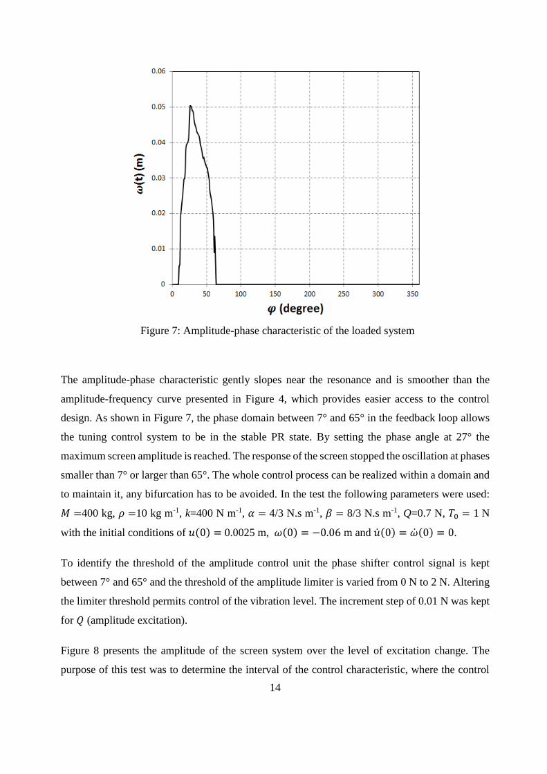
Figure 7: Amplitude-phase characteristic of the loaded system
The amplitude-phase characteristic gently slopes near the resonance and is smoother than the
amplitude-frequency curve presented in Figure 4, which provides easier access to the control
design. As shown in Figure 7, the phase domain between 7° and 65° in the feedback loop allows
the tuning control system to be in the stable PR state. By setting the phase angle at 27° the
maximum screen amplitude is reached. The response of the screen stopped the oscillation at phases
smaller than 7° or larger than 65°. The whole control process can be realized within a domain and
to maintain it, any bifurcation has to be avoided. In the test the following parameters were used:
𝑀 =400 kg, 𝜌 =10 kg m-1, k=400 N m-1, 𝛼 = 4/3 N.s m-1, 𝛽 = 8/3 N.s m-1, Q=0.7 N, 𝑇0 = 1 N
with the initial conditions of 𝑢(0) = 0.0025 m, 𝜔(0) = −0.06 m and �̇�(0) = �̇�(0) = 0.
To identify the threshold of the amplitude control unit the phase shifter control signal is kept
between 7° and 65° and the threshold of the amplitude limiter is varied from 0 N to 2 N. Altering
the limiter threshold permits control of the vibration level. The increment step of 0.01 N was kept
for 𝑄 (amplitude excitation).
Figure 8 presents the amplitude of the screen system over the level of excitation change. The
purpose of this test was to determine the interval of the control characteristic, where the control

15
signal causes linear dependence of the reference RMS signal. The minimum level of 𝑄 for
excitation of the screen is around 0.48 N while setting the values of the threshold to larger than
1.22 N lead to a chaotic response. Therefore, 0.48 N < 𝑄 < 1.22 N is the limit of the output
control signal amplitude. Each time Q is increased in this domain the level of screen displacement
is increased, however, where Q > 1.22 N the level of vibration cannot be controlled properly.
Figure 8: Threshold of the amplitude limiter
The control unit is now defined to limit the phase and amplitude response of the system in a proper
domain. The performance of the control evaluation for two case studies is presented in the next
section.
5. The performance of the control system
In Eqs.3, ρ and α denote the mass per unit length and the viscosity, respectively, associated with
transverse oscillations. When the mass or viscosity change, the resonance frequency of the system
changes. Thus, to obtain the PR regime which is the most efficient domain in which to drive the
screen machine, the excitation signal should be changed. The results of autoresonant control, with
positive feedback, using screen displacement as a mechanical control signal are studied under
mass and viscosity variation with the same level of limiting and phase. In particular, the induction
of PR is achieved by shifting the system into the principal PR region, that is, where the frequency
of the parametric excitation is approximately equal to twice the natural frequency of the string

16
system. It is notable that the values of mass and viscosity should be considered in the acceptable
range to have oscillation in the system.
5.1. Case study 1: Changing the screen mass
Figure 9 shows the ability of the displacement control to control the level of vibration under
conditions of mass uncertainty. For illustrative purposes, the mass values are monitored together
with the displacement of the screen. The level of changing mass (𝜌 in Eqs.3) varies from 6 kg to
10 kg (Fig. 9(a)). The other parameters in the system are fixed: 𝑀 =400 kg, k=400 Nm-1, 𝛼 = 4/3
N.s m-1, 𝛽 = 8/3 N.s m-1, Q=0.7 N, 𝑇0 = 1 N with the initial conditions of 𝑢(0) = -0.0025 m,
𝜔(0) = 0.06 m and �̇�(0) = �̇�(0) = 0. A time of 105 s elapses between each mass increment.
Figure 9(b) describes the response of the screen system over the selected time. The control system
uses the RMS value of the displacement signal as a control signal, which is shown in Fig. 9(c) as
a solid line; the dashed line depicts the desired value of the RMS of the displacement signal. The
desired RMS value was defined as 0.08 m, corresponding to the proper amplitude of oscillation
of the loaded system. The derivation of the RMS from the desired value becomes nearly constant
by changing the mass from 6 kg to 10 kg. The phase and amplitude shifter signals are presented
in Fig. 9(d) and Fig. 9(e). The phase shift signal is in radians, therefore, 0.485 phase shift is equal
to 27.80°. To keep the vibration at the desired level of oscillation, both amplitude and phase control
signals are changed during the operation. It can be seen that when the amplitude control is applied
and the amplitude value is changing, the phase shift value remains unchanged. As soon as the
RMS value enters the phase control zone the amplitude control stops working and the phase
control starts. By this action the control system keeps the RMS value relatively stable in spite of
a considerable increase in loadings Implementation of phase control only, is insufficient to keep
the desired level of vibration under such loading, and amplitude control should be considered.

17
(a)
(b)
(c)
(d)

18
(e)
Figure 9: Performance of the autoresonant control system, mass changing (a), displacement of
the screen (b), RMS value (c), phase shift signal (d) and amplitude shift signal (e)
The combined amplitude-phase control algorithm allows for the possibility of simultaneous
control of the phase (phase control) and the level of oscillation (amplitude control). When the
mass changes, the resonance frequency of the system changes. This results in the system being
excited at different frequencies. Fixing the amplitude and phase boundary to achieve a stable PR
state in the system is ensured by stabilising the oscillations of the screen system.
5.2. Case study 2: Changing the viscosity
The main goal of the autoresonant control system is to keep the displacement of the screen stable
during the process of oscillation, while different loading conditions are induced. The influence of
viscosity on control system performance is now considered. Figure 10(a) represents variations of
viscosity over time, from 4/3 N.m s-1 to 8/3 N.m s-1. The previous test (105 s) brought the system
to a stable state after each viscosity increment. The response of the screen operation during the
test is presented in Figure 10(b). The fluctuation response just after the viscosity changes shows
that even small changes in the viscosity condition lead to changes in the performance of the
system’s vibration. Figure 10(c) shows the RMS value of the displacement signal (solid curve);
the dashed line corresponds to the desired value of the RMS of the displacement signal. The
desired value for this test is the same as for the previous test, 0.08 m. When the RMS value leaves
the phase control zone, the amplitude control starts. Figures 10(d) and (e) represent the phase
control and amplitude control signal operation. When the amplitude control is applied and the
amplitude value changed, the phase shift value remains unchanged. As soon as the RMS value
enters the phase control zone, the amplitude control stops working and the phase control begins.

19
(a)
(b)
(c)
(d)

20
(e)
Figure 10: Performance of the control system, mass changing (a), displacement of the screen
(b), RMS value (c), phase shift (d) and amplitude shift (e) of the displacement signal
This test shows the autoresonant control system keeping the displacement of the screen at the
desired vibration level while as the viscosity varies between 4/3 N.m s-1 and 7/4 N.m s-1.
5. Conclusions
PR is a widespread phenomenon that may be threatening or beneficial according to the particular
system where it takes place since very large oscillations can be generated by rather small
parametric excitations. The exponentially growing response of the system creates awareness of
the potential danger hidden in such a phenomenon. That is why a profound knowledge of the
dynamics of systems where PR is to be induced is needed, in order to capture the energy flow
between the different system modes when resonance takes place. Control strategies are designed
to induce and stabilize unstable oscillations. In this paper autoresonant control was implemented
for the intensification and stabilisation of a PR vibration screen in conditions of variable loading.
The efficacy of the proposed control strategy has been verified in simulation, where both induction
and stabilization of PR in screen machines have been successfully obtained. The results show that
these characteristics retain robustness under a wide deviation of processing loads such as mass
and viscosity uncertainties. Application of a robust and high-quality autoresonant control system
offers the opportunity to increase productivity and efficiency, while improving design.
Acknowledgement
The work was performed with a financial support provided by FP7-People-2011-IAPP, Marie
Curie Actions, Grant No. 281544. The model of the screen machine developed by L.Slepyan and

21
V.Slepyan for the project was used as an object of control, V.Silberschmidt supported the
investigation.
References
[1] V.K. Astashev, V.I. Babitsky, M.Z. Kolovsky, Dynamics and control of machines, Springer,
Berlin, 2000.
[2] W .Ammann, H. Bachmann, Vibrations in structures: induced by man and machines, IABSE-
AIPC-IVBH, 1987.
[3] R.B. Randall, Vibration-based condition monitoring: industrial, aerospace and automotive
applications, Wiley, New-York, 2011.
[4] V. Babitsky, Theory of vibro-impact systems and applications, Springer, Berlin, 1998.
[5] T.I. Fossen, H. Nijmeijer, Parametric resonance in dynamical systems, Springer Science &
Business Media, 2011.
[6] V. Slepyan, G. Loginov, L. Slepyan, The method of resonance excitation of a vibrating sieve
and the vibrating screen for its implementation. Ukrainian Patent No. 87369, 2009.
[7] L. Slepyan, V. Slepyan, Coupled model parametric resonance in a vibrating screen, Mechanical
Systems and Signal Processing 43 (2014) 295-304.
[8] W. Lacarbonara, H. Yabuno, K. Hayashi, Non-linear cancellation of the parametric resonance
in elastic beams: Theory and experiment. International Journal of Solids and Structures 44
(7–8) (2007) 2209–2224.
[9] S.K. Dwivedy, R.C. Kar, Simultaneous combination, principal parametric and internal
resonances in a slender beam with a lumped mass: three-mode interactions. Journal of Sound
and Vibration 242 (1) (2001) 27–46.
[10] A.H. Nayfeh, Parametric excitation of two internally resonant oscillators. Journal of Sound
and Vibration 119 (1987) 95–109.
[11] M. Okuma, H. Yabuno, N. Aoshima, Nonlinear bifurcation control of a parametrically excited
cantilever beam. Proceedings of the 9th International Congress on Sound and Vibration, Paper
No. 581 (2002).
[12] H. Yabuno, T. Murakami, J. Kawazoe, N. Aoshima, Suppression of parametric resonance in
cantilever beam with a pendulum (effect of static friction at the supporting point of the
pendulum). ASME Journal of Vibration and Acoustics 126 (2004) 149–162.

22
[13] S. Oueini, A.H. Nayfeh, Single-mode control of a cantilever beam under principal parametric
excitation. Journal of Sound and Vibration 224 (1999) 33–47.
[14] L. Chen, F. He, K. Sammut, Vibration suppression of a principal parametric resonance.
Journal of Vibration and Control 15 (2009) 439-463.
[15] V. Babitsky, A.N. Kalashnikov, V.K. Astashev, Autoresonant control of nonlinear mode in
ultrasonic transducer for machining applications. Ultrasonics 42 (2004) 29–35.
[16] V. Babitsky, A.N. Kalashnikov, F.V. Molodtsov, Autoresonant control of ultrasonically
assisted cutting, Mechatronics 14(1) (2004) 91–114.
[17] V. Babitsky, J. Sokolov, Autoresonant homeostat concept for engineering application of
nonlinear vibration modes, Nonlinear Dynamics 50 (3) (2007) 447–460.
[18] S. Voronina, V. Babitsky, Autoresonant control strategies of loaded ultrasonic transducer for
machining applications. Journal of Sound and Vibration 313 (3-5) (2008) 395–417.
[19] V.K. Astashev, V.I. Babitsky, Ultrasonis Processes and Machines. Dynamics, Control and
Applications, Springer, Berlin, 2007.
[20] X. Li, V. Babitsky, R.Parkin, A.Meadows, Autoresonant excitation and control of nonlinear
mode for ultrasonically assisted drilling. ZAMM, 94 (2014) 904-910.
[21] F. Verhulst, Perturbation analysis of parametric resonance. Encyclopedia of Complexity and
Systems Science. (2009) 6625-6639.
[22] S. Voronina, Modelling of autoresonant control of an ultrasonic transducer for machining
applications, PhD thesis, 2008
[23] X. Li, Modelling and autoresonant control design of ultrasonically assisted drilling
applications, PhD thesis, 2014
Top Related
Copyright © 2022 FDOKUMEN

