


Bahasa
Halaman
Hukum


�������� ����� ��
Microstructures, Hardness and Bioactivity of Hydroxyapatite CoatingsDeposited by Direct Laser Melting Process
Monnamme Tlotleng, Esther Akinlabi, Mukul Shukla, Sisa Pityana
PII: S0928-4931(14)00394-4DOI: doi: 10.1016/j.msec.2014.06.032Reference: MSC 4735
To appear in: Materials Science & Engineering C
Received date: 5 December 2013Revised date: 23 May 2014Accepted date: 30 June 2014
Please cite this article as: Monnamme Tlotleng, Esther Akinlabi, Mukul Shukla, SisaPityana, Microstructures, Hardness and Bioactivity of Hydroxyapatite Coatings De-posited by Direct Laser Melting Process, Materials Science & Engineering C (2014), doi:10.1016/j.msec.2014.06.032
This is a PDF file of an unedited manuscript that has been accepted for publication.As a service to our customers we are providing this early version of the manuscript.The manuscript will undergo copyediting, typesetting, and review of the resulting proofbefore it is published in its final form. Please note that during the production processerrors may be discovered which could affect the content, and all legal disclaimers thatapply to the journal pertain.

ACC
EPTE
D M
ANU
SCR
IPT
ACCEPTED MANUSCRIPT
1
Microstructures, Hardness and Bioactivity of Hydroxyapatite Coatings Deposited by Direct
Laser Melting Process
Monnamme Tlotleng1, 2*
, Esther Akinlabi2, Mukul Shukla
3, 4 and Sisa Pityana
1, 5
1Laser Materials Processing Group, National Laser Center CSIR, Pretoria, 0001, South Africa
2Department of
Mechanical Engineering Science, University of Johannesburg, Auckland Park, Kingsway Campus,
Johannesburg, 2006, South Africa. 3Department of Mechanical Engineering Technology, University of
Johannesburg, Doornfontein Campus, Johannesburg, 2006, South Africa, 4Department of Mechanical
Engineering, MNNIT, Allahabad UP, 211004, India. 5 Department of Chemical and Metallurgical Engineering,
Tshwane University of Technology, Pretoria, 0001, South Africa.
*Corresponding author:[email protected]
Abstract
Hydroxyapatite (HAP) coatings on bioinert metals such as Ti-6Al-4V are necessary for
biomedical applications. Together, HAP and Ti-6Al-4V are biocompatible and bioactive. The
challenges of depositing HAP on Ti-6Al-4V with traditional thermal spraying techniques are
well founded. In this paper, HAP was coated on Ti-6Al-4V using direct laser melting (DLM)
process. This process, unlike the traditional coating processes, is able to achieve coatings
with good metallurgical bonding and little dilution. The microstructural and mechanical
properties, chemical composition and bio-activities of the produced coatings were studied
with optical microscopy, scanning electron microscope equipped with energy dispersive X-
ray spectroscopy, and Vickers hardness machine, and by immersion test in Hank’s solution.
The results showed that the choice of the laser power has much influence on the evolving
microstructure, the mechanical properties and the retainment of HAP on the surface of the
coating. Also, the choice of laser power of 750 W led to no dilution. The microhardness
results inferred a strong intermetallic-ceramic interfacial bonding; which meant that the 750
W coating could survive long in service. Also, the coating was softer at the surface and
stronger in the heat affected zones. Hence, this process parameter setting can be considered as
an optimal setting. The soak tests revealed that the surface of the coating had unmelted
crystals of HAP. The CaP ratio conducted on the soaked coating was 2.00 which
corresponded to tetra calcium phosphate. This coating seems attractive for metallic implants
applications.
Keywords: Direct laser melting, Hydroxyapatite (HAP), laser power, Ti-6Al-4V, Powder
beds and polyvinyl alcohol.
ACC
EPTE
D M
ANU
SCR
IPT
ACCEPTED MANUSCRIPT
2
1. Introduction
Artificial, osteo-applications require material implants with coatings which are bioactive,
corrosion resistant and last long in-service [1-2]. In the past, coated cobalt-chromium alloys
and stainless steel metals were used as load-bearing materials; however, artificial bone
implants made from these metal alloys were characterised mainly of poor mechanical
properties and in vitro corrosion side effects [3]. Currently, research makes use of titanium
alloy (Ti-6Al-4V) for load bearing applications; with a particular focus on hip, long bones
and teeth replacements. Ti-6Al-4V is the leading material for bone replacement since it is
corrosion resistant, bio-compatible and has the required elastic modulus and good yield
strength [4], but show poor osteo-conductivity [5]. Nonetheless, Ti-6Al-4V implants which
are left to serve long are known to cause health problems [3]. Geetha et al [3] revealed that
when left long in service, Ti-6Al-4V will release aluminium (Al) and vanadium (V) ions into
the human body fluid system thereby becoming cyto-toxic. Both V and Al ions are associated
with long term health problems [6] such as Alzheimer’s, neuropathy and Osteomalacia [3].
To suppress Al and V ions from leaching into the human body fluids while correcting for the
wear debris of this alloy, it is practised that their surface be modified via coating with a thin
layer of a bio-active ceramic material [7]. Hydroxyapatite (HAP) is a preferred bio-active
ceramic material; not only because it has a similar crystal structure as that of the human
natural bone [5, 8-12], but also because HAP coatings can induce osteo-conductivity between
the metal implant and the human tissues in vivo [10, 13-17]. Moreover, in clinical practises,
HAP is a preferred coating material since it cannot be used as a load-bearing implant material
due to its poor mechanical properties (low plasticity, fatigue, and creep resistance) [5, 8-12,
14,18-19]. Given the outstanding individual properties of both HAP and Ti-6Al-4V, it can be
inferred that as associates, these materials can perform better when used as load bearing
materials.
In fact, several techniques have been used to modify the surface of this alloy by coating it
with a thin layer of HAP [7, 17, and 20]. The most prominent surface modification techniques
that have been used, with or without positive success, include and are not limited to
magnetron sputtering [13], pulse laser deposition [16 and 21], laser cladding [15 and 22],
thermal spraying techniques [23], seeded hydrothermal deposition [8], cold spraying
techniques [24-25], Laser-engineered net shaping technique [10], laser assisted cold spraying
[26] and direct laser melting [11, 27-28]. Of all the said techniques, plasma spraying is the

ACC
EPTE
D M
ANU
SCR
IPT
ACCEPTED MANUSCRIPT
3
most commonly used. However, given the limitations with plasma coatings, research has
been conducted on post surface treatment of plasma sprayed HAP coatings by high power
lasers.
Thermal sprayed HAP coatings, including those produced by plasma spraying, are mainly
presented with problems such as weak bonding, cracks, and phase transformation (low
crystallinity) which reduce the life span of the coating in service. Sol-gel HAP coatings are
characterised of lower adhesion strength, but improved phase composition when compared to
plasma sprayed HAP coatings. The limiting factor in coating HAP onto Ti-6Al-4V using cold
spray based techniques stems from the low plasticity of HAP particles which during spraying
are unable to deform. Even so, a theoretical modelling study by Singh [29] gives a different
view on the matter. Nevertheless, research continues to strive for a break-through in
modifying the surface of Ti-6Al-4V with HAP. Surface coating of HAP on Ti-6Al-4V will
eventually lead to a desirable coating that can be used to manufacture bone and teeth
scaffolds that mimic the natural human bone.
Surface modification using lasers seem attractive given that they have high coherence and are
directional; in which case they offer precise modification and treatment on specific area
without harming the entire serviced part [30]. Thermal and thermo-chemical processes are
two known distinct process where lasers are used to modify surfaces. The former process
relates to the melting of the surface while leaving its initial properties unchanged. The latter
process relates to material being added onto a treated surface in order to change their initial
properties or just leading to the inter-metallic bonding between the clad and the substrate with
little dilution being experienced [10, 31-32]. The thermo-chemical process includes laser
alloying and laser cladding. In this study, another form of laser cladding called direct laser
melting is investigated [33-34]. Laser cladding is used to produce surface coatings with
thickness that ranges from 0.3-1 mm. Coatings produced by laser cladding are achieved by
either injecting solid powder particles that flow considerably into a laser generated melt pool
whereby a fusion layer with good metallurgical bonding is produced or by preplaced
methods. Preplaced methods are applied to powders which are resistant to flowing or too fine.
HAP powder is normally supplied in a fine particle size distribution range. In this state, the
HAP powder has poor flowability characteristics whence it can simply be processed into a
ACC
EPTE
D M
ANU
SCR
IPT
ACCEPTED MANUSCRIPT
4
coating by first preplacing it with binders onto the Ti-6Al-4V substrate before directly
melting it with coherent, high power laser like Nd:YAG.
Nag et al [12] indicated that direct laser melting process of HAP onto Ti-6Al-4V is by far
more successful than any other coating techniques since the achieved metallurgical bonding
are far better than those achieved with tradition coating techniques. Despite this, Nag et al.
argue that HAP coatings achieved by direct laser melting process lack a highly concentrated
content of HAP at the top of the clad with retained chemical properties that are similar to the
precursor HAP powder. This means even though direct laser melting is seen as a successful
tool in producing HAP coatings on Ti-6Al-4V, the produced coating have little or reduced
content of HAP with reduced crystallinity. This is very concerning since HAP coatings
produced by traditional coating methods suffer from the same results. These observations are
attributed to the occurring reaction between the pre-placed and the substrate that occurs
during dilution and rapid solidification process. To tackle this problem different researches
have been conducted detailing the effects of laser scanning speed, laser power and powder
feed rates [12, 28]. Most recently, studies on the effects of different binders and their effects
on the resulting microstructures of HAP coatings produced by direct laser melting process
were reported followed by their bio-activity studies [11, 28]. Kusinski et al [33] showed the
required intermediate metal-powder region desirable in laser cladding; which speak to the
bonding ability of the coating and the substrate. Roy et al [10] explained that HAP laser
processed coatings that possess characteristics such as high content of HAP at the surface and
low dilution have the potential to reduce the interfacial bonding problems (metal-ceramic
region) while prolonging the life expectance of the coating in vitro. Roy et al [10] is in
agreement with Nag et al [12] as they both believed that by controlling dilution effects, the
resulting coating will have good content of HAP on the surface with little decomposition of
the precursor-preplace HAP powder.
Nag et al [12] studied the microstructure of Ca-P on Ti-6Al-4V produced by direct laser
melting process without reporting on their mechanical properties and bio-activity. Chien et al
[11] and [22] investigated the microstructures, binder effects, laser output power, laser
traverse speed and hardness of the coatings during laser cladding. Chien et al [28]
subsequently characterised the bioactivity of the optimised samples from their previous work
reported in Ref [22]. The latter authors reported hardness of about 1000 Hv when PVA was
used as a binder at 740 W laser power. In references [10] and [35], hardness of about 702 Hv
ACC
EPTE
D M
ANU
SCR
IPT
ACCEPTED MANUSCRIPT
5
and 260 Hv using LENS and laser surface engineering process independently are reported.
These values differ from that of pure HAP which is 535 Hv [21]. Cheng et al [35] highlighted
that there is little published information on the hardness of laser coated HAP. Even so, the
available information does not relate hardness to the quality of the coating.
Laser melting processes such as laser cladding and direct laser melting, which are unlike
traditional deposition techniques, can produce coatings with good metallurgical bonding. The
mechanical properties, microstructures, and bioactivity of laser melted HAP powder beds on
Ti-6Al-4V are yet to be widely reported in open literature. In addition, optimised process
parameters that lead to the retainment of bulk quantity of HAP at the surface of the coating
during direct laser melting are still to be established. This paper reports on the
microstructures, microhardness and bioactivity of HAP coatings fabricated on Ti-6Al-4V by
direct laser melting process. In addition, this work has compared different coatings of HAP
produced on Ti-6Al-4V with different laser powers using direct laser melting process, and
reported the process parameters that led to the retainment of HAP on the surface of the
coating.
2. Materials and method
2.1. Sample preparation
PVA granules with specifications of 0.001% chlorine, 0.2% water and pH range of 5-7,
supplied by Merck KGaA, 64271 Darmstadt, Germany, were mixed with deionised water and
heated to 100 °C while magnetically being stirred for 3-4 hours to create a thick colourless
paste which was mixed with the hydroxyapatite powder, CAPTAL 90, supplied by Plasma
BIOTAL, United Kingdom to create a slurry which was pre-placed, as a powder bed, on the
Ti-6Al-4V substrate which were initially sand-blasted and chemically cleaned with ethanol.
The HAP elemental analysis conducted by SEM-EDS, in weight %, concluded that this
powder had Ca/P ratio of 1.80 before processing. The Ti-6Al-4V substrates had dimensions
of 70x70x5 mm3. The preplaced HAP powder beds were left to dry in a fume cupboard
overnight before processing and their thickness was measured to being 0.9 mm.

ACC
EPTE
D M
ANU
SCR
IPT
ACCEPTED MANUSCRIPT
6
2.2. Direct laser melting process
The already prepared pre-placed HAP powder beds were used to carry out direct laser
melting process. The prepared powder beds were directly melted with a laser source of 044
Rofin, Nd:YAG utilising 750 W and 1.0 kW laser powers. The laser spot of 5 mm width, now
inclined at 27°, was scanned across the surface of the powder beds using a Kuka robot arm at
5 mm s-1
. The produced specimens were then taken for preparation and characterisation as
detailed in section 2.3.
2.3. Specimen preparation, characterisation and micro-hardness test
Post processing, the produced coatings were sectioned and mounted with poly-fast resin
using a hot mounting press. The mounted samples were finished by first grounding with a
SiC bonded paper of 320 and 1000 grit using 9 micron diamond suspension in MD
ALLEGRO. The samples were polished with MD CHEM using 0.04 micron silicon
suspension. The samples were etched in Kroll’s reagent for 20-30 seconds. The etched
samples were analysed under a white light using Olympus optical microscope (OM) fitted
with a SZ 30 camera for their microstructural evaluation. The optimally analysed samples
were taken for further analyses, for microstructures and elemental, using JEOL scanning
electron microscope equipped with Energy Dispersive X-ray spectroscopy (SEM-EDS), JSM-
6510. This helped in quantifying the Ca/P ratio. The Vickers hardness (Hv) of the coatings
was determined using Matsizawa Seiki Vickers microhardness tester. The indentation load of
300g, spaced at 100 µm was applied on the coating with a dwelling time of 10 seconds. The
average diagonal lengths of the indents were measure 2 times for each sample and the
average values were used to calculate the coating hardness following ASTM E1184.
2.4. Immersion test in Hanks’ solution, characterisation and phase analysis
A Hanks’ balanced salt solution supplied by gibco life technologies, Johannesburg, South
Africa was used to soak the prepared coatings. The metal pieces, with the coatings on, were
cut to 15x10 mm2 and then immersed in the Hank’s solution that was contained in the perish
dish placed inside the water bath that allowed a well-controlled environment. During the soak
test, only the coatings were allowed to immerse into the solution; leaving the metal base
exposed to the enclosed environment. The water bath had temperature controls which

ACC
EPTE
D M
ANU
SCR
IPT
ACCEPTED MANUSCRIPT
7
allowed for the temperature to be regulated between 37.5- and 38°C therefore being able to
simulate the human body temperature. The soak test was carried out over 2 days without
interruptions. Post soaking, the produced coatings were analysed using OM and Auriga,
CrossBeam FIB Workstation with GEMINI FESEM column equipped with The Oxford X-
Max instrument with 20 mm square window, Aztec Software for their microstructure and
elemental composition. The composition and structural properties of the 750 W coating was
investigated using a Panalytical X’pert PRO PW3040/60 X-ray diffractometer fitted with a
Cu Kα (l=0.154 nm) monochromated radiation source.
3. Results
3.1.Microstructure studied by SEM and OM
SEM images taken from the etched cross-sections of the HAP coatings processed at 750 W
laser power are displayed in Figure 1 (a)-(d).
Figure 1: Etched SEM images of (a) direct laser melted HAP at 750 W, (b) cross section
view of the clad, (c) cross section view of the Clad and HAZ, and (d) cross section view
of the HAZ and Ti-6Al-4V substrate.
Figure 1 reports the SEM micrograph at every zone of the HAP coating produced by direct
laser melting process using 750 W laser power. Figure 1 (a) shows the clad layers and the

ACC
EPTE
D M
ANU
SCR
IPT
ACCEPTED MANUSCRIPT
8
substrate. Figure 1 (b), which is the top surface of the coating, shows titanium needles
(weave-like) occurring with particles that are hexagonal, tree leaf, octagonal and semi-
circular in structure. Similar structures were observed from reference [10] and [35] where it
was concluded that they are from the HAP material. Figure 1 (c) shows the inter-layer
between the transition layer (TL) and the HAZ. The TL layer is mainly characterised of
dendritic structures which are cubic as oppose to being hexagonal [36]. This observation is in
support of that by Chien et al [11]. These dendrites appear to be coated with a thick paste that
can be attributed to melted HAP. The HAZ layer has a porous white layer which is definitely
HAP (see also Figure 1 (d)). From Figure 1 (d), it is possible to see where the coating and the
substrate meet. This is clearly distinguished by the Ti-6Al-4V (bottom layer) alpha phase.
Bonding between the coating and substrate was good. At the bonding interface, the coating
was characterised with a thin strip that was immensely covered with a porous layer of HAP.
Looking at Figure 1 (d), it is possible to deduce that there was little intrusion of HAP into the
substrate. This observation infers that little dilution was achieved which means less heat
energy was produced during processing. Else, it could mean that the interaction time between
the material and laser was short-lived. From these deductions, it can be summarised that this
coating had a strong intermediate metal-ceramic region with little dilution and a high content
of HAP at the top surface of the coating.
SEM images taken from the polished cross-sections of the HAP coatings processed with 1.0
kW laser power are displayed in Figure 2. The polished cross-sections were etched with
Kroll’s reagent in order to reveal the grain boundaries. Three zones of interest are shown by
Figure 2 (a) with the high magnification of each zone shown by Figures 2 (b)-(d). Figure 2
(b) shows the difference in the microstructures of the clad and HAZ zone. It can be seen from
the Figure that the dominating microstructure was the hexagonal dendrites that occurs with
finer flakes or grains that originated from the HAP material. These finer grains are clearly
seen from the bottom half of Figure 2 (c). Figure 2 (d) reports the micrograph of the HAZ and
substrate. The bonding between the substrate and the clad seem to be weak since the interface
seen is characterised of a wide gap that looks like a dug hole. While it was not clear to
distinguish between the clad and HAZ which then led to a conclusion that this coating
sustained high dilution which was as a result of high processing temperatures being generated
during processing. Otherwise, fine needles of titanium are shown (bottom right of Figure 2
(d)), but are mapped within the dominating titanium hexagonal dendrites. The results
presented in Figure 2 are similar to those reported in Ref [22].

ACC
EPTE
D M
ANU
SCR
IPT
ACCEPTED MANUSCRIPT
9
Figure 2: Etched SEM images of direct laser melted HAP at 1 KW laser power on Ti-
6Al-4V: (a) The macrograph of the coating and the substrate, (b) Cross section view of
the clad and HAZ, (c) High magnification for the clad, (d) High magnification of HAZ
and Ti-6Al-4V.
In comparing, Figures 1 and 2 micrographs it is simple to see that a 750 W produced clad,
Figure 1, is characterised of good bonding while that produced with 1 kW laser power had
poor bonding. A 750W clad had titanium needles at the top of the clad with cubic dendrite
forming in the HAZ zone while the 1 kW clad was characterised mainly of hexagonal
dendrite at the top and a mixture of cubic, hexagonal and few titanium needles in the HAZ
zone. The HAP content at the top surface of the 750 W clad was high and somewhat
preserved (structurally); an observation which could not be made for the 1 kW clad.
Minimum dilution was seen with 750 W clad as oppose to 1 kW clad. A strong intermetallic-
ceramic region was observed only with the 750 W. These deductions conclude that a 750 W
laser power can be used successfully to fabricate HAP coatings using direct laser melting
process.

ACC
EPTE
D M
ANU
SCR
IPT
ACCEPTED MANUSCRIPT
10
3.2. Composition analysis of clads using SEM-EDS
Chemical composition analyses of the coatings were performed using SEM-EDS. The
analysis was done on the clad and in the HAZ for both 750 W and 1 kW coatings. It is
already established in the literature that by studying the Ca and P ions in these regions, it is
possible to first establish the Ca/P ratio thus being able to know if the starting material (HAP)
was heat affected and which form of the secondary phase HAP material dominated within the
produced coatings. Secondly, it is possible to establish if bond breaking of P ion from parent
HAP material occurred. When this happens P ions dissociated into the HAZ and the
reconcentrate [28]. Figures 3 and 4 show the EDS analysis of the coating produced with 750
W and 1 kW laser powers respectively.
Figure 3: EDS image of 750 W coating showing (a) Spot analysis on the coating, and (b-
d) The EDS spectrum of the coating at different area across the coating.
Figures 3 (b)-(d) show the elemental analysis, at the surface, of the 750 W produced coating.
The spectra report contents of Ca, Ti, TiO and average P content. The EDS spectra show that

ACC
EPTE
D M
ANU
SCR
IPT
ACCEPTED MANUSCRIPT
11
Ca and P are well distributed within the coating. There is some oxygen detected (TiO) which
is due to open environments under which the coatings were manufactured. This is known to
occur given that titanium is readily reactive in open oxygen environments, and it is even
reactive above room temperature. TiO correspond to low processing temperatures. The
results of Figure 3 are summarised in Table 1.
Table 1: Composition analysis of the top and heat affected zone of the coating.
Element Clad, wt. % HAZ, wt.%
Calcium (Ca) 29.38 10.03
Phosphorus (P) 3.31 3.33
Aluminium (Al) 2.83 2.09
Vanadium (V) 0.00 1.38
Ratio (Ca/P) 8.80 3.01
The EDS analyses given in Table 1 show that on average a 750 W, HAP coating had 3.31 %
P, 2.83% Al, 29.38% Ca and 0% V ions in the clad while the HAZ had 3.33% P, 2.09% Al,
1.38% Al and 10.03% Ca. The P ions were balanced in both layers which can infer that the
bond breaking of P ions from the parent material [(Ca10 (PO4)6(OH) 2)] did not occur.
Meanwhile, this observation infers that during processing, low temperatures that were below
melting point of HAP were generated. Similarly, the Ca content was higher in the clad than in
the HAZ. Comparing the content of the two zones, it is clear that high Ca content was present
at the top of the clad which can be indication of the retainment of high Hap content on the
surface of the coating. V ions were absent in the top of the clad with little Al ions being
present. Overall, these EDS result show that higher quantity of HAP was retained at the
surface of this coating. Also, little heating was experienced by the coating during processing
which led to no significant dilution being experienced by this coating.
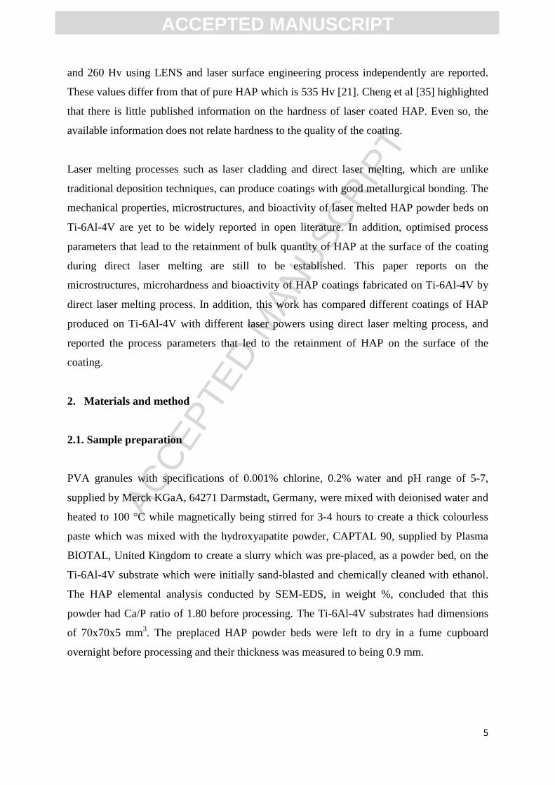
Figure 4 shows the EDS mapping for the top surface of the coating produced with 1.0 kW
laser power. Since it was not possible to distinguish between the clad and the HAZ, mapping
was done on the different phases present on the coating. The chosen area represented both the
clad (top half) and the HAZ (bottom half). High content of Ca, Ti and TiO2 and no P ions
were detected when mapping on the dendrites. When the flake like coated dendrite was
mapped with EDS little P ions were detected together with reduced content of Ca and TiO2
ACC
EPTE
D M
ANU
SCR
IPT
ACCEPTED MANUSCRIPT
12
while the increase in the Ti content was experienced. High content of P ions with reduced
content of Ca ions was presented when mapping was done inside the voids. This systematic
analysis reveals that dissociation of P and Ca into the substrate occurred. The conclusion
being that high heat was generated which led to intense dilution. These results are
summarised in Table 2.
Figure 4: SEM-EDS image of 1.0 kW coating showing (a) Spot analysis on the coating
and The EDS spectrum taken at the (b) Top surface of the coating, (c) Clad and HAZ,
and (d) HAZ and substrate.
These EDS results are summarised in Table 2, detailed only on the top surface of the coating
(clad) and the HAZ.
Table 2: EDS analysis of 1 kW produced clad.
Element Clad, wt.% HAZ, wt.%
Calcium (Ca) 20.15 20.79
Phosphorus (P) 0.86 11.00
Aluminium (Al) 2.06 0.69
Vanadium (V) 0.00 0.00
Ratio (Ca/P) 23.43 1.89

ACC
EPTE
D M
ANU
SCR
IPT
ACCEPTED MANUSCRIPT
13
These EDS results conclude that 0.86 % P, 2.06 % Al, and 20.15% Ca were present at the top
of the clad. 11% P weight % is reported in the HAZ while average equivalent amount of Ca
was reported for both. The higher content of P ions in the HAZ can only infer that
temperature greater than 700 °C were generated when a 1 kW laser power was used to melt
the powder beds. In this instance vaporisation or the oxidisation of P from HAP (Ca10
(PO4)6(OH) 2) was experienced hence the high content of P ions in the HAZ zone than the top
of the clad. The CaP ratio for the 1 kW is 23.43 for the clad which is higher than that already
reported [28]. These results are consistent with those reported in [11].
By comparison, the EDS analysis of both the 750 W and 1 kW clads revealed that both layers
had no content of V ions on the clad which imply that a thin layer produced was able to
suppress it. A high content of Ca ions was found on the top of the 750 W clad as oppose to
the 1 kW clad. Conversely, a high content of Ca ions in the HAZ was found in the 1 kW clad
as opposed to 750 W clad. This is simple due to high energy density felt by the preplaced
HAP powder. The Ca/P ratio of the 750 W clad was lower in the clad when compared to the 1
kW produced clad. This is an indication that high heat was generated during the 1 kW laser
melting. When this happens, the coating will have a deficiency in P which will correspond to
high Ca/P ratio. This observation is supported by the P ions which were higher in the HAZ
for the 1 kW clad. This high content of P ions in the HAZ zone conclude that the bond
breaking of P from the HAP (Ca10(PO4)6(OH)2) was severe, in part inferring that high
temperatures were produced thereby freeing P which then dissociated from the top into the
HAZ.
3.2. Hardness
Microhardness is used typically to indicate how resistive, during service, a coating could be
to plastic deformation [26]. Vickers microhardness profiles and indents of the coating, HAZ
and the substrate were conducted following ASTM E1184. The coatings were indented from
the top of the coatings through the coating until the substrate. The indentations and hardness
profile results are shown in Figures 6 and 8, and Figures 5 and 7 respectively.

ACC
EPTE
D M
ANU
SCR
IPT
ACCEPTED MANUSCRIPT
14
Figure 5: Hardness profile for a clad produced with 750 W laser power.
Figure 5 presents the hardness profiles of the 750 W coating. The substrate used had hardness
value of 355 Hv. On average, hardness values for the clad and the HAZ were 165.8 Hv and
945.1 Hv respectively. The transition point between the coating and the HAZ was 706.0 Hv.
These results conclude that the coating was soft which meant it might be elastic and could not
crack or fracture easily. These results are consistent with those reported in the literature [10,
11, and 22]. To examine these hardness values critically, the indentation profile was used as
shown in Figure 6.

ACC
EPTE
D M
ANU
SCR
IPT
ACCEPTED MANUSCRIPT
15
Figure 6: Optical pictures of 750 W coating showing (a) Vickers indentation markings,
and (b) Median crack system.
The indentation is shown in Figure 6. The pyramids are well identifiable in the substrates into
the heat affected zone (bottom-up), but the same cannot be said for the indents at the top
surface of the coating at this magnification. The edge points of the indents, at the top surface
of the coating, are easy to comprehend at high magnification were it was possible to see that
after loading the cracks were induced by the indenting pin and propagated, not extensively,
into the coating (median crack system-Figure 6 (b)). This is an indication that the material at
the top surface of the coating was brittle which synonymous to the ceramics (e.g. HAP). This
observation is consistent with the hardness profile as shown by Figure 5. The pyramid indents
in the HAZ are well defined. A well-defined pyramid indents can indicate resistance to
fracturing of material. The hardness value at the interface between the coating and the
substrate was 678.5 Hv. This was twice the hardness values of the substrate. This value is
acceptable and might infer strong metallurgical bonding between the coating and the
substrate. These results are consistent with those reported in Ref [22] and infer that this
coating might not degrade or will degrade slowly over time. The hardness profile for the 1
kW produced coating was also examined. The hardness profiles are given in Figure 7.
ACC
EPTE
D M
ANU
SCR
IPT
ACCEPTED MANUSCRIPT
16
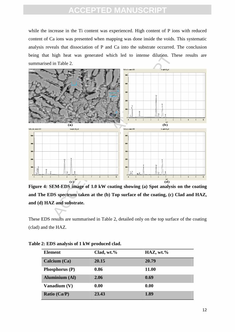
Figure 7: Hardness profile for a clad produced with 1 kW laser power.
Figure 7 presents the hardness profiles for the 1 kW coating. The substrate used had hardness
value of 355 Hv. On average, hardness values for the coating (top layer) and the HAZ were
479.1 Hv and 813.4 Hv respectively. The transition point between the coating and the HAZ
was 936.4 Hv. The HAZ is characterised of rise and fall in the hardness value which could be
due to inherent pores and cracks in the coating (See Figure 8). These results conclude that the
coating was less hard at the surface but became hard in the HAZ. A transition layer between
coating and substrate had hardness of about 590.1 Hv. Even though the hardness increased
when compared to that of the substrate, it was less hard when compared to the 750 W coating
which could mean their metallurgical bonding differ greatly. These results are consistent with
those reported in Ref [10, 11, and 22]. To examine this hardness values critically, the
indentation profile was used as shown in Figure 8.

ACC
EPTE
D M
ANU
SCR
IPT
ACCEPTED MANUSCRIPT
17
Figure 8: Vickers indentation markings on the 1 kW clad.
Figure 8 presents the indents that were carried out on the coating. The pyramids are clearly
marked in the three zones of interest without cracking. Since no cracks were generated during
the indentation process, it can be concluded that this coating was not brittle or was harder
than the one presented in Figure 6. By comparison, the coating produced with 1.0 kW was
weakly bonded to the substrate (TL value of 590.1Hv) when compared to the 750 W coating
(TL value of 678.5 Hv). The coating at the surface was hard than the 750 W produced coating
with the hardness value of 479.1 Hv; almost three times harder which meant the 1 kW might
be stiff and fracture easily when compared to the 750 W laser power produced coating.
3.3. Bio-corrosion test and analyses
Implants made from materials such as Ti-6Al-4V coated with HAP will only be accepted if
the coatings last long in vitro and show no signs of corrosion. In general, the functionality
and durability of any fabricated implant will depend completely on the microstructures,
mechanical and chemical properties of the coatings. Moreover, in addition to the
microstructures, mechanical and chemical properties of the coatings, if the produced coating
can resist corrosion then the implant will last long in vivo. The microstructures, mechanical
and chemical properties of the produced coatings have been discussed. To further evaluate
ACC
EPTE
D M
ANU
SCR
IPT
ACCEPTED MANUSCRIPT
18
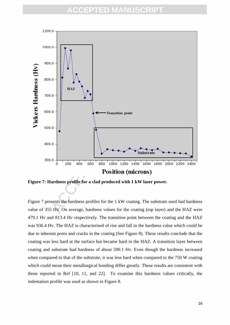
the potential of the produced coatings for bio-medical application, it was decided that they
should be tested for bio-activity using the soaking methods. The produced coatings were
soaked in the Hank’s solution for a given number of days. The results of the coatings after
two days are given in Figure 9.
Figure 9: Micrograph of the HAP clad after soaking in Hank's solution: (a) 750 W laser
power and (b) 1 kW laser power.
Figure 9 represents the optical micrographs of direct laser melted coatings of HAP soaked in
Hanks’ solution for 2-days. The coatings were processed with 750 W laser power (Figure 9
(a)) and 1 kW (Figure 9 (b)) respectively. The HAP crystals can be seen from Figure 9 (a).
This observation deducing that at 750 W HAP, the HAP was preserved in the coating. Figure
9 (b) shows a white flake layer of melted HAP that covers some parts of the substrate.
Comparison between Figures 9 (a) and (b) is that the HAP has grown on top of the substrate
and was not completely melted (Figure 9 (a)) while Figure 9 b) the available HAP was in a
flake format which partially covered the oxidised substrate. These observations concluding
that HAP could best be processed with 750 W laser powder during direct laser melting
process as oppose to 1 kW [11]. The SEM-EDS analysis of Figure 9 (a) is presented by
Figure 10.

ACC
EPTE
D M
ANU
SCR
IPT
ACCEPTED MANUSCRIPT
19
Figure 10: SEM-EDS of a 750 W clad after soaking in Hank's solution.
Figure 10 reports the back scattering image of HAP clad produced by 750 W laser power
after immersion in the Hank’s solution. It is evident from the figure that semi-molten crystals
of HAP are present in the clad. This observation indicates that HAP was somewhat preserved
in the coating post laser melting. The EDS analysis of the micrograph is given by Table 3.
Table 3: EDS analysis of 750 W clad after immersion in Hank's solution.
Element Clad, wt.%
Calcium (Ca) 9.24
Phosphorus (P) 4.18
Aluminium (Al) 0.33
Vanadium (V) 0.49
Ratio (Ca/P) 2.20
Table 3 indicate that Ca/P ratio of the soaked coating. Bear in mind, the powder had Ca/P of
1.80 before processing. In Table 1 a Ca/P of 8.80 after processing was reported, now after
soaking a Ca/P ratio of 2.20 is reported. A considerable drop in Ca/P ratio post soaking has
ACC
EPTE
D M
ANU
SCR
IPT
ACCEPTED MANUSCRIPT
20
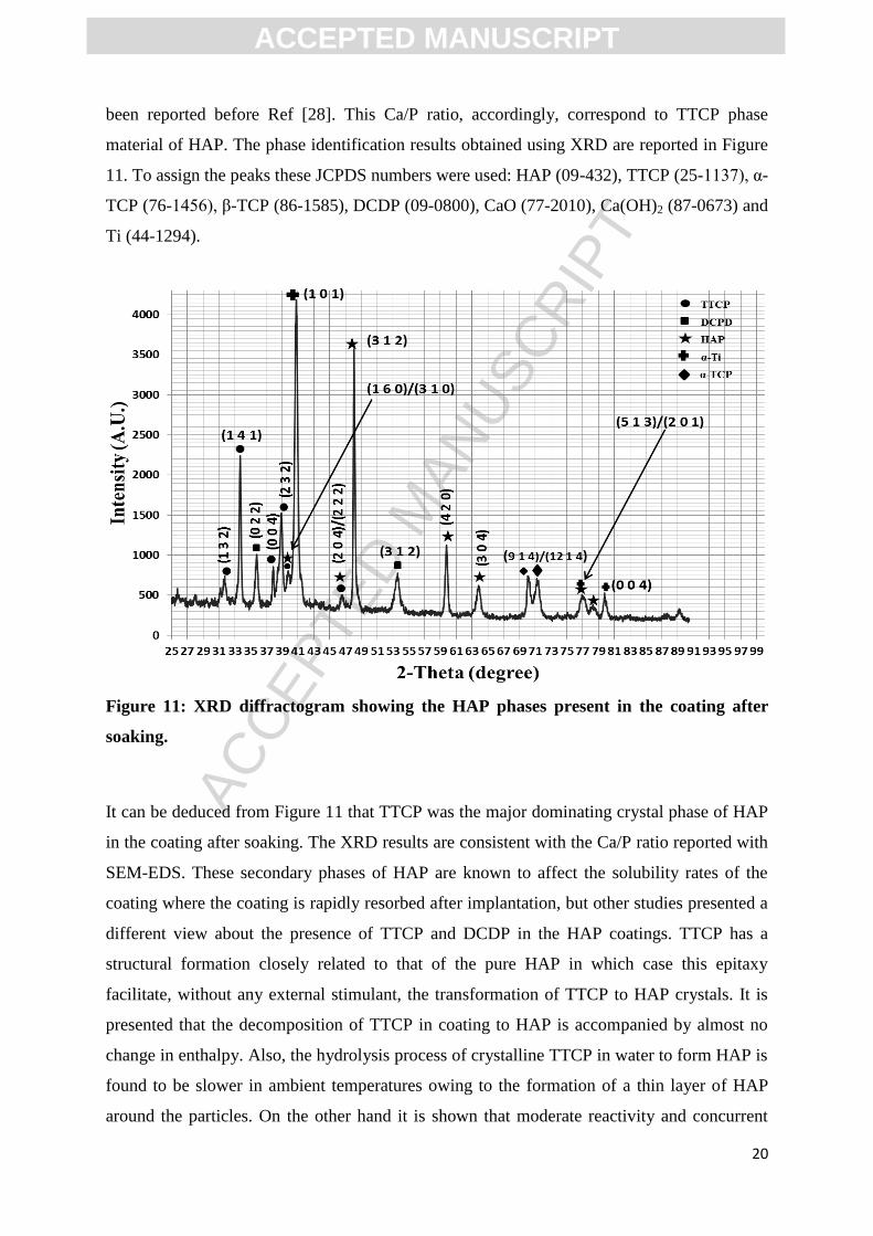
been reported before Ref [28]. This Ca/P ratio, accordingly, correspond to TTCP phase
material of HAP. The phase identification results obtained using XRD are reported in Figure
11. To assign the peaks these JCPDS numbers were used: HAP (09-432), TTCP (25-1137), α-
TCP (76-1456), β-TCP (86-1585), DCDP (09-0800), CaO (77-2010), Ca(OH)2 (87-0673) and
Ti (44-1294).
Figure 11: XRD diffractogram showing the HAP phases present in the coating after
soaking.
It can be deduced from Figure 11 that TTCP was the major dominating crystal phase of HAP
in the coating after soaking. The XRD results are consistent with the Ca/P ratio reported with
SEM-EDS. These secondary phases of HAP are known to affect the solubility rates of the
coating where the coating is rapidly resorbed after implantation, but other studies presented a
different view about the presence of TTCP and DCDP in the HAP coatings. TTCP has a
structural formation closely related to that of the pure HAP in which case this epitaxy
facilitate, without any external stimulant, the transformation of TTCP to HAP crystals. It is
presented that the decomposition of TTCP in coating to HAP is accompanied by almost no
change in enthalpy. Also, the hydrolysis process of crystalline TTCP in water to form HAP is
found to be slower in ambient temperatures owing to the formation of a thin layer of HAP
around the particles. On the other hand it is shown that moderate reactivity and concurrent

ACC
EPTE
D M
ANU
SCR
IPT
ACCEPTED MANUSCRIPT
21
solubility of TTCP can be achieved when it exist in coating with DCPD; which also boost the
self-hardening process of TTCP leading completely to the formation of HAP during
dissolution in aqueous phase solutions [36-38]. Brown and Epstein [37] concluded that the
hexagonal symmetry that forms when TTCP is synthesised will eventually conform to HAP.
In addition, they explained that when TTCP and HAP exist together due to the foretold
crystal structure, the (00 Ɩ) reflections of odd Ɩ values will be missing for HAP while the even
Ɩ values will be highly prominent because of the heavy atoms and 12 of the 26 oxygen’s
which have z parameters that are multiples of ¼. This observation is supported by the
reported XRD data where the peak (211) at 2θ value of 31.6 is weaker than the (312) peak at
2θ value of 48.4 and the TTCP finger print (141) peak is stronger than the (211) peak for
HAP. This XRD data conclude that in fact HAP was preserved post processing.
4. Conclusion
This study reports on the microstructures and elemental analysis, microhardness, bioactivity
and composition of the HAP coatings achieved by direct laser melting process. The HAP
powder beds, made by mixing HAP powder into slurry with polyvinyl alcohol, were pre-
placed on Ti-6Al-4V substrates and melted at 750 W and 1.0 kW laser powers using the
Nd:YAG laser. The outcomes of this work can be summarised as follows:
The 750 W laser power produced coating is characterised of good metallurgical
bonding, no cracks, no dilution, and significant quantity of unmelted particles of HAP
on the surface and titanium needles at the surface with dendrite dominant in the heat
affected zone while the 1.0 kW was highly dendritic, good bonding, but no HAP at
the surface of the coating;
The 750 W and 1.0 kW coating had similar hardness values at the interface and HAZ
while the hardness values at the interface were different: (678.5 Hv) for 750 W as
oppose to (590.1 Hv) for the 1.0 kW clad.
The top surface of the coatings had Vickers hardness of 165.9 and 479.1 for 750 W
and 1 kW coating respectively. The former hardness value is closer to that of the pure
HAP reported in literature.

ACC
EPTE
D M
ANU
SCR
IPT
ACCEPTED MANUSCRIPT
22
By contrast, the 750 W coating had reduced hardness which together with the
achieved inter-metallic-ceramic metallurgical bonding could mean this coating will
have good fracture toughness and elasticity properties and will not degrade faster in
service (in vivo).
The P and Ca elemental analyses conducted at the top of the coating and in the HAZ
inferred that no excess heating was experienced with the 750 W produced coating.
This therefore eliminated dilution completely. It is known that elevated temperatures
are able to break free the P ions from the HAP [(Ca10 (PO4)6(OH) 2)] which then can
freely migrate from the clad into the HAZ during laser processing.
The bioactivity test conducted by soaking the coatings in the Hank’s solution showed
that 750 W coating will remain intact and undissolved as oppose to the 1.0 kW
produced coating.
The CaP ratio of the 750 W soaked coatings dropped from 8.80 to 2.20 over two days.
This value, accordingly, corresponds to TTCP. TTCP is one of the calcium phosphate
materials that can be used for the bone and teeth replacement.
This inference was corroborated by the XRD results.
Future work
FEBSEM was used to pick a lamella from one of the crystals seen with the 750 produced
with laser power of 750 W. This lamella will be studied with TEM so that the crystalline
phases can be ascertained. Further studies on biocomposite of Ti-HAP will be deposited
using the Laser Engineered Net Shaping (LENS) machine.
Acknowledgements
The authors wish to thank Tlhalefo Seloane for helping with the experimental set-up and for
operating the Kuka robot arm during the experiment. We also acknowledge Tebogo
Mathebula, Khro Malabi and the colleagues at the laser material processing laboratories for
their metallurgical insights. Most importantly, we are grateful to the Council for Scientific
and Industrial Research for making available their research resources to us, and the National
Research Foundation for their continued financial support.

ACC
EPTE
D M
ANU
SCR
IPT
ACCEPTED MANUSCRIPT
23
References
[1] R. Geetha, D. Durgalakshmi, R. Asokamani, Recent Patents Corr. Sci. 2 (2010), 40-54.
[2] M.B. Nasab, M.R. Hassan, Trends Biomater. Artif. Organs. 24 (1)(2010) 69-82.
[3] R. Geetha, A.K. Singh, R. Asokamani, A.K. Gogia, Progress in Mater. Sci. 54 (2009)397-
425.
[4] G. Zhao, L. Xia, G. Wen, L.Song, X. Wang, K. Wu, Surf. Coat. Technol. 206 (2012)
4711-4719.
[5] X. Zhou, R. Siman, L. Lu, P. Mohanty, Surf. Coat. Technol. 207 (2012) 343-349.
[6] R. Banerjee, S. Nag, H.L. Fraser, Mater. Sci. Eng. C, 25 (2005) 282-289.
[7] S.V. Dorozhkin, J. Funct. Biomater. 1 (2012) 22-107.
[8] D. Liu, K. Savino, M.Z. Yates, Surf. Coat. Technol. 205 (2011) 3975-3986.
[9] D.G. Wang, C.Z. Chen, J. Ma, G. Zhang, Surf. Coat. Technol. 66 (2008) 155-162.
[10] M. Roy, B.V. Krishna, A. Bandyopadhyay, S. Bose, Acta Biomater. 4 (2008) 324-333.
[11] C.S. Chien, T.F. Hong, T.J. Han, T.Y. Kuo, T.Y. Liao, Appl. Surf. Sci. 257 (2011) 2387-
2393.
[12] S. Nag, S.R. Paital, P. Nandawana, K. Mahdak, Y.H. Ho, H.D. Vora, R. Banerjee, N.B.
Dahotre, Mater. Sci. Eng. C, 33 (2013) 165-173.
[13] S.J. Ding, C.P. Ju, J.H. Lin, J. Biomed. Mater. Res. 44 (3) (1999) 266-279.
[14] I-S. Lee, C-N. Chang, H-E. Kim, J-C. Park, J.H. Song, S-R. Kim, Mater. Sci. Eng. C, 22
(2002) 15-20.
[15] D. Wang, C. Chen, J. Ma, T. Lei, Appl. Surf. Sci. 253 (2007) 4016-4020.
[16] V. Kokenyesi, I. Popovich, M. Kikineshi, L. Daroczi, D. Beke, Y. Sharkany, C.S.
Hegedus, Opto-Electro. Adv. Mater. Rapid. Commun. 1 (4) (2007) 171-175.
[17] S.V. Dorozhkin, Prog. Biomater. 1 (1) (2010) 1-40.
[18] S. Lopez-Esteban, E. Saiz, S. Fujino, T. Oku, K. Suganuma, A.P. Tomsia, J. Euro.
Ceram. Soc. 23 (2003) 2921-2930.
[19] R. Sultana, J. Yang, X. Hu, J. Am. Ceram. Soc. 95 (4) (2012) 1212-1215.
[20] M. Roy, A. Bandyopadhyay, S. Bose, Surf. Coat. Technol. 205 (8-9) (2008) 2785-2792.
[21] R.A. Ismail, E.T. Salim, W.K. Hamoudi, Mater. Sci. Eng. C 33 (2013) 47-52.
[22] C.S. Chien, T.J. Han, T.F. Hong, T.Y. Kuo, T.Y. Liao, Mater. Trans. 50 (12) (2009)
2852-2857.
[23] K.A. Gross, C.C. Berndt Gross, J. Biomed. Mater. Res. 39 (4) (1998) 580-587.
[24] A. Choudhuri, P.S. Mohaunty, J. Karthikeyan, Thermal Spraying. (2009) 391-396.
[25] X. Zhou and P. Mohanty, Electrochimita Acta 65 (2012) 134-140.

ACC
EPTE
D M
ANU
SCR
IPT
ACCEPTED MANUSCRIPT
24
[26] M.R. Mansur, J. Wang, C.C. Berndt, Surf. Coat. Technol. 232 (2013) 482-488.
[27] R. Singh, S.K. Tiwari, S.K. Mishra, N.B. Dahotre, J. Mater. Sci.: Mater. Med. 22 (2011)
1787-1796.
[28] C-S. Chien, T-Y. Liao, T-F. Hong, T-Y. Kuo, C-H. Chang, M-L. Yeh, T-M. Lee, J. Med.
Biol. Eng. (Article in Press) 2013, 1-28. doi: 10.5405/jmbe.1379.
[29] S. Singh, Int. J. Eng. Sci. Tech. 3 (9) (2011) 7006-7015.
[30] Y.S. Tian, C.Z. Chen, S.T. Li, Q.H. Huo, Appl. Surf. Sci. 242 (2005) 177-184.
[31] L. Pawlowski, (1999), J. Thermal Spray Tech. 8 (2) (1999), 279.
[32] M.A. Montealegre, G. Castro, P. Rey, J.L. Arias, P. Vasquez, M. Gonzalez, Contemp.
Mater. I (1) (2010), 19-30.
[33] J. Kusinski, S. Kac, A. Kopia, A. Radziszewska, M. Rozmus-Gornikowska, B. Major, J.
Marczak, A. Lisiecki, Bullet. Polish Acad. Sci. Tech. Sci. 60 (4) (2012), 711-728.
[34] J-H. Jang, B-D. Joo. C.J. van Tyne, Y-H. Moon, Met. Mater. Int. 19 (3) (2013), 497-506.
[35] G.C. Cheng, D. Pirzada, M. Cai, P. Mohanty, A. Bandyopadhyay, Mater. Sci. Eng. C, 25
(2005) 541-547.
[36] C. Moseke, U. Gbureck, Acta Biomaterialia 6 (2010) 3815-3823.
[37] W.E. Brown, E.F. Epstein, J. Res. Nat. Bur. Std. A-Phys and Chem. 69A (6) (1965) 547-
551.
[38] B. Dickens, W.E. Brown, G.J. Kruger, J.M. Stewart, Acta Cryst. 29 (B) (1973) 2046-
2056.
ACC
EPTE
D M
ANU
SCR
IPT
ACCEPTED MANUSCRIPT
25
The highlights of this manuscript are hereby presented:
Characteristics of HAP coatings produced on Ti-6Al-4V achieved with direct laser
melting are reported.
Optimal process parameters necessary to achieve biocompatible coating are reported.
The SEM micrograph of the soaked HAP coating revealed partially melted crystals of
HAP.
The HAP coating was retained at the surface of the coating that was produced with
750 W laser power.
The 750W produced coating was deemed necessary for the biomedical applications.
Top Related
Copyright © 2022 FDOKUMEN

