


Bahasa
Halaman
Hukum


Quasar 950/960
Toxic Open-Path Gas Detection System
User and Maintenance Manual
6021 Innovation Blvd, Shakopee, MN 55379 , USA
Phone: +1 (973) 239 8398 Fax: +1 (973) 239 7614
Website: www.spectrex.net Email: [email protected]

Legal Notice
The SPECTREX SafEye monitoring system described in this document is the property of Rosemount.
No part of the hardware, software or documentation may be reproduced, transmitted, transcribed, stored in a
retrieval system, or translated into any language or computer language, in any form or by any means, without
prior written permission of Rosemount.
While great efforts have been made to assure the accuracy and clarity of this document, Rosemount assumes no
liability resulting from any omissions in this document, or from misuse of the information obtained herein. The
information in this document has been carefully checked and is believed to be entirely reliable with all of the
necessary information included. Rosemount reserves the right to make changes to any products described herein
to improve reliability, function, or design, and reserves the right to revise this document and make changes from
time to time in content hereof with no obligation to notify any persons of revisions or changes. Rosemount does not
assume any liability arising out of the application or any use of any product or circuit described herein; neither
does it convey license under its patent rights or the rights of others.
Warranty
SPECTREX agrees to extend to Purchaser/Distributor a warranty on the SPECTREX supplied components of the
SharpEye products. SPECTREX warrants to Purchaser/Distributor that the products are free from defects in
materials and workmanship for a period of three (3) years, commencing with the date of delivery to
Purchaser/Distributor. SPECTREX expressly excludes damage incurred in transit from the factory or other damage
due to abuse, misuse, improper installation, or lack of maintenance or “Act of God” which are above and beyond its
control. SPECTREX will, upon receipt of any defective product, transportation prepaid, repair or replace it at its sole
discretion if found to have been defective when shipped. Said repair or replacement is SPECTREX’S sole liability
under this warranty and SPECTREX’S liability shall be limited to repair or replacement of the component found
defective and shall not include any liability for consequential or other damages. The customer is responsible for all
freight charges and taxes due on shipments both ways. This warranty is exclusive of all other warranties express or
implied.
TM888300 Rev. (An), March 2020


TM888300 Rev. (An), March 2020 v
Table of Contents
Table of Contents ............................................................................................ v
List of Figures ................................................................................................ ix
List of Tables .................................................................................................. ix
1 About this Guide ...................................................................................... 11
1.1 Release History ..................................................................................... 12
1.2 Glossary and Abbreviations .................................................................... 13
1.3 Notifications ......................................................................................... 14
2 Product Overview .................................................................................... 15
3 Technical Description .............................................................................. 17
3.1 Features .............................................................................................. 17
3.2 Applications .......................................................................................... 18
3.3 Principles of Operation ........................................................................... 18
3.3.1 Definitions of Terms ........................................................................ 18
3.3.2 Spectral Fingerprint ......................................................................... 18
3.3.3 Optical Path ................................................................................... 18
3.3.4 Detected Gases .............................................................................. 19
3.3.5 UV Source ...................................................................................... 19
3.3.6 Heated Optics ................................................................................. 19
3.3.7 HART Protocol ................................................................................ 20
3.3.8 Modbus RS-485 .............................................................................. 20
3.3.9 Tilt Mount ...................................................................................... 20
3.4 Product Certification .............................................................................. 21
3.4.1 ATEX, IECEx ................................................................................... 21
3.4.2 SIL-2 ............................................................................................. 21
3.4.3 TR CU/EAC ..................................................................................... 21
3.4.4 Inmetro (UL) .................................................................................. 21
3.4.5 CSA C/US ...................................................................................... 22
3.5 Models and Types ................................................................................. 22
3.6 Description ........................................................................................... 24
3.6.1 UV Source Unit ............................................................................... 24
3.6.2 Detector Unit .................................................................................. 25
4 Operating Modes...................................................................................... 27
4.1 Operational Modes ................................................................................ 27
vi SafEye™ Toxic Open-Path Gas Detection System
4.1.1 Normal Mode .................................................................................. 27
4.1.2 Maintenance Call Mode (3mA Output) ................................................ 27
4.1.3 Fault Mode ..................................................................................... 27
4.1.4 Zero Calibration Mode (1mA Output) ................................................. 28
4.2 Visual Indicators ................................................................................... 28
4.3 Output Signals ...................................................................................... 29
4.3.1 0–20mA Current Output .................................................................. 29
4.3.2 RS-485 Interface ............................................................................ 29
4.4 System Setup ....................................................................................... 30
4.4.1 Detection Function Programming ...................................................... 30
4.4.2 Detection Setup Function ................................................................. 30
4.4.3 Detector Default Setup .................................................................... 31
5 Technical Specifications ........................................................................... 33
5.1 General Specifications ........................................................................... 33
5.2 Electrical Specifications .......................................................................... 34
5.2.1 Current Consumption ...................................................................... 34
5.2.2 Electrical input protection ................................................................ 34
5.2.3 Electrical outputs ............................................................................ 34
5.3 Mechanical Specifications ....................................................................... 36
5.4 Environmental Specifications .................................................................. 36
5.4.1 High Temperature ........................................................................... 36
5.4.2 Low Temperature ............................................................................ 36
5.4.3 Humidity ........................................................................................ 37
5.4.4 Enclosure ....................................................................................... 37
5.4.5 Water and Dust .............................................................................. 37
5.4.6 Vibration ........................................................................................ 37
5.4.7 Electromagnetic Compatibility (EMC) ................................................. 37
6 Installation Instructions .......................................................................... 39
6.1 Introduction ......................................................................................... 39
6.2 General Considerations .......................................................................... 39
6.2.1 Personnel ....................................................................................... 39
6.2.2 Required Tools................................................................................ 39
6.2.3 Site Requirements .......................................................................... 39
6.2.4 The Source and Detector ................................................................. 40
6.2.5 Tips for Selecting a Gas Detector Location ......................................... 40
6.2.6 Separation Distances ....................................................................... 40

TM888300 Rev. (An), March 2020 vii
6.2.7 Wiring ........................................................................................... 41
6.3 Preparations for Installation ................................................................... 41
6.3.1 General ......................................................................................... 41
6.3.2 Equipment ..................................................................................... 41
6.3.3 Unpacking the Product ..................................................................... 42
6.4 Certification Instructions ........................................................................ 43
6.4.1 General Instructions ........................................................................ 43
6.4.2 Intrinsically Safe Outputs ................................................................. 44
6.4.3 Special Conditions for Safe Use for ATEX/IECEx Only ........................... 45
6.4.4 North American Conditions of Acceptability from certificate CSA 8002301646
6.5 Conduit/Cable Installation ...................................................................... 48
6.6 Detector/Source Mounting ...................................................................... 48
6.6.1 Tilt Kit ........................................................................................... 48
6.6.2 Detector/Source Installation ............................................................. 49
6.7 Detector Wiring .................................................................................... 50
6.8 Detector Terminal Wiring ....................................................................... 54
6.9 UV Source Wiring .................................................................................. 54
6.9.1 Wiring ........................................................................................... 54
6.9.2 Terminal Wiring .............................................................................. 55
7 Operating Instructions ............................................................................ 57
7.1 SafEye Operation .................................................................................. 57
7.2 Alignment of Unit .................................................................................. 57
7.3 Powering up the System ........................................................................ 58
7.4 Safety Precautions ................................................................................ 59
7.5 Signal Verification ................................................................................. 59
7.5.1 Signal Values Limitation ................................................................... 59
7.6 Zero Calibration .................................................................................... 60
7.7 Functional Check ................................................................................... 61
8 Maintenance Instructions ........................................................................ 63
8.1 General Maintenance ............................................................................. 63
8.2 Periodic Maintenance ............................................................................. 63
8.2.1 Routine Optical Surface Cleaning ...................................................... 64
8.2.2 Signal Verification ........................................................................... 64
8.2.3 Functional Check of Unit .................................................................. 64

viii SafEye™ Toxic Open-Path Gas Detection System
9 Troubleshooting ...................................................................................... 65
Appendix A: Wiring Configurations ........................................................... 67
A.1 RS-485 Communication Network ............................................................. 69
Appendix B: Accessories ........................................................................... 71
B.1 Tilt Mount ............................................................................................ 71
B.2 Pole Mount (U-Bolt 2–3”) ....................................................................... 71
B.3 Pole Mount (U-Bolt 4–5”) ....................................................................... 71
B.4 Wall Mount ........................................................................................... 71
B.5 Commissioning Kit ................................................................................ 71
B.6 HART Handheld Diagnostic Unit .............................................................. 71
B.7 HART Handheld Harness Kit .................................................................... 72
B.8 USB/RS-485 Harness Converter Kit ......................................................... 72
B.9 Protective Cover ................................................................................... 72
Appendix C: SIL-2 Features ...................................................................... 73
C.1 Safety Relevant Parameters ................................................................... 73
C.2 General Conditions for Safe Use .............................................................. 74
Technical Support ......................................................................................... 80

TM888300 Rev. (An), March 2020 ix
List of Figures
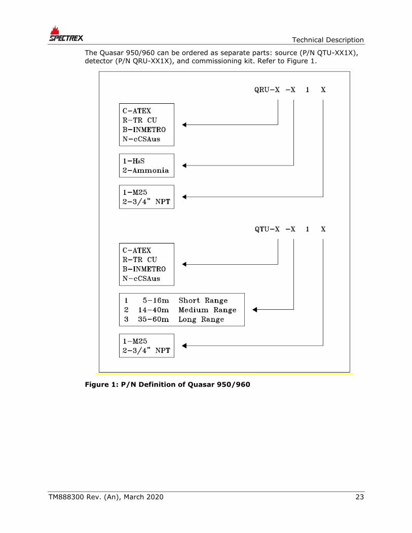
Figure 1: P/N Definition of Quasar 950/960 .......................................................... 23
Figure 2: UV Source .......................................................................................... 24
Figure 3: Detector ............................................................................................. 25
Figure 4: Tilt Mount ........................................................................................... 51
Figure 5: Detector and Tilt Mount Assembly .......................................................... 52
Figure 6: Detector with Cover Removed ............................................................... 53
Figure 7: Source with Cover Removed ................................................................. 55
Figure 8: Magnetic Mode Selector ........................................................................ 61
Figure 9: Detector Wiring Terminal ...................................................................... 67
Figure 10: Source Wiring Terminal ...................................................................... 68
Figure 11: 0–20mA Sink 4-Wire .......................................................................... 68
Figure 12: 0–20mA Non-Isolated Sink 3-Wire ....................................................... 69
Figure 13: 0–20mA Source 3-Wire ...................................................................... 69
Figure 14: RS-485 Networking for Wiring Option 3 ................................................ 70
List of Tables
Table 1: Model Numbers and Installation Distances ............................................... 22
Table 2: Detector LED Indications ....................................................................... 28
Table 3: Source LED Indications .......................................................................... 29
Table 4: Standard (default) 0–20mA Current for the Gas Channel ........................... 29
Table 5: Detector Default Setup .......................................................................... 31
Table 6: Source Default Setup ............................................................................ 31
Table 7: Detection Distance Range ...................................................................... 33
Table 8: Detector and Source Maximum Current Consumption ................................ 34
Table 9: Tools ................................................................................................... 39
Table 10: Separation Distances ........................................................................... 40
Table 11: Tilt Mount Kit ...................................................................................... 48
Table 12: Wiring Options .................................................................................... 54
Table 13: UV Source Wiring Options .................................................................... 55
Table 14: Maintenance Channel Limitation Values ................................................. 59
Table 15: Troubleshooting .................................................................................. 65
Table 16: Check Filters ...................................................................................... 71

About this Guide
TM888300 Rev. (An), March 2020 11
1 About this Guide
This guide describes the Quasar 950/960 Open-Path Gas Detection System and
its features, and provides instructions on how to install, operate, and maintain
the detector.
Note:
This user guide should be read carefully by all individuals who have or
will have responsibility for using, maintaining, or servicing the
product.
This guide includes the following chapters and appendices:
• Chapter 1, About this Guide, details the layout of the guide, includes the
release history, a glossary and abbreviations, and explains how notifications
are used in the guide.
• Chapter 2, Product Overview, provides a general introduction and overview
of the product.
• Chapter 3, Technical Description, describes the detector’s theory of
operation.
• Chapter 4, Operating Modes, describes the detector’s operation modes,
user interface, and indications.
• Chapter 5, Technical Specifications, describes the detector’s electrical,
mechanical, and environmental specifications.
• Chapter 6, Installation Instructions, describes how to install the detector,
including wiring and mode settings.
• Chapter 7, Operating Instructions, describes the operating instructions
and power-up procedures.
• Chapter 8, Maintenance Instructions, describes the maintenance and
support procedures.
• Chapter 9, Troubleshooting, describes the solutions to problems that may
arise with the detector.
• Appendix A, Wiring Configurations, provides wiring diagrams for
installation.
• Appendix B, Accessories, lists accessories for the detector.
• Appendix C, SIL-2 Features, details the special conditions for compliance
with SIL-2 requirements.

About this Guide
12 SafEye™ Toxic Open-Path Gas Detection System
1.1 Release History
Rev Date Revision History Prepared by Approved by
0 December 2013 First Release Ian Buchanan Eric Zinn
1 September 2014 Second Release Ian Buchanan Eric Zinn
2 October 2014 Third Release Ian Buchanan Eric Zinn
3 November 2014 Fourth Release Ian Buchanan Eric Zinn
4 November 2014 Fifth Release Ian Buchanan Eric Zinn
5 November 2014 Sixth Release Ian Buchanan Eric Zinn
6 January 2015 Seventh Release Ian Buchanan Eric Zinn
7 March 2016 Eighth Release Ian Buchanan Eric Zinn
8 June 2016 Ninth Release Ian Buchanan Eric Zinn
9 January 2017 Tenth Release Jay Cooley Ian Buchanan
10 February 2017 Eleventh Release Jay Cooley Ian Buchanan
Ak July 2018 Twelfth Release Michal Heller Udi Tzuri
Al August 2019 Thirteenth
Release
Michal Heller Udi Tzuri
Am February 2020 Fourteenth
Release
Michal Heller Udi Tzuri
An March 2020 Fifteenth Release Michal Heller Udi Tzuri

About this Guide
TM888300 Rev. (An), March 2020 13
1.2 Glossary and Abbreviations
Abbreviation/Term Meaning
Analog Video Video values are represented by a scaled signal
ATEX Atmosphere Explosives
AWG American Wire Gauge
BIT Built-In-Test
CMOS Complementary Metal-Oxide Semiconductor image
sensor
Digital Video Each component is represented by a number
representing a discrete quantization
DSP Digital Signal Processing
EMC Electromagnetic Compatibility
EMI Electromagnetic Interference
EOL End of Line
FOV Field of View
HART Highway Addressable Remote Transducer –
communications protocol
IAD Immune at Any Distance
IECEx International Electro-Technical Commission
Explosion
IP Internet Protocol
IPA Isopropyl Alcohol
IR Infrared
IR3 Refers to the 3 IR sensors
JP5 Jet Fuel
LED Light Emitting Diode
MODBUS Serial communicatisons protocol using Master-
Slave messaging
N/A Not Applicable
N.C. Normally Closed
NFPA National Fire Protection Association
N.O. Normally Open
NPT National Pipe Thread
NTSC National Television System Committee (a color encoding
system)
PAL Phase Alternation by Line (a color encoding
system)

About this Guide
14 SafEye™ Toxic Open-Path Gas Detection System
Abbreviation/Term Meaning
P/N Part Number
RFI Radio Frequency Interference
RTSP Real Time Streaming Protocol
SIL Safety Integrity Level
UNC Unified Coarse Thread
VAC Volts Alternating Current
1.3 Notifications
This section explains and exemplifies the usage of warnings, cautions, and notes
throughout this guide:
Warning:
This indicates a potentially hazardous situation that could result in
serious injury and/or major damage to the equipment.
Caution:
This indicates a situation that could result in minor injury and/or
damage to the equipment.
Note:
This provides supplementary information, emphasizes a point or
procedure, or gives a tip to facilitate operation.

Product Overview
TM888300 Rev. (An), March 2020 15
2 Product Overview
The SafEye Quasar 950/960 UV Open-Path Gas Detector employs an advanced
Xenon UV Source and integrated electronics package, both of which are encased
in improved stainless steel housings, which provide high quality and performance,
fast response, and line-of-sight gas monitoring. The source/detector is backed by
a 3-year warranty.
The Quasar 950/960 is manufactured only from stainless steel, with a heated
optical window to improve performance in ice, snow, and condensation
conditions. The programmable functions are available through a RS-485 or HART
port used with host software supplied by SPECTREX, and a standard PC or IS
handheld unit.
The Quasar Source and Detector unit enclosures are ATEX and IECEx approved.
They are Exd flameproof with an integral segregated rear, and an Exe terminal
compartment, which avoids exposure of the sensors and electronics to the
surrounding environment. The detector also has a plug interface for connection to
a handheld PC or HART unit, which meets intrinsically safe standards.
This manual provides a full description of the system and its features. It includes
instructions on the installation, operation, and maintenance of the detector.
• To use the WinHost software to change the required functions, and for a
description of its maintenance, please refer to Manual TM899050 for
instructions.
• To use the HART Protocol to change the required functions, and for a
description of its maintenance, please refer to Manual TM899030. To set
functions, the HART can be connected on the 0–20mA line or through the IS
port.
The SafEye Quasar 950/960 detects and monitors toxic gases, such as NH3 and
H2S, ppm.m concentrations in the air. SafEye has a response detection time of
under 3 seconds, and under 10 seconds to T90.
The SafEye system uses an open path beam of flashlight pulses that provides a
long line of sight coverage equivalent to a large number of point detectors along
the path. The transmitted beam covers a UV spectrum from 200–300nm. The
SafEye Quasar 950/960 constantly monitors for the gas through the collimated
beam, over an optical path from 17ft/5m and up to 200ft/60m.
Warning:
The source and detector are not field-repairable due to the meticulous
alignment and calibration of the sensors and the respective circuits.
Do not attempt to modify or repair the internal circuits or change their
settings, as this will impair the system's performance and void the
SPECTREX Product warranty.


Technical Description
TM888300 Rev. (An), March 2020 17
3 Technical Description
3.1 Features
• Long-range gas detection from 17ft/5m up to 200ft/60m
• Detection of toxic gases (H2S, NH3)
• High sensitivity and fast response to toxic gases
• Heated optics to improve performance in ice, condensation, and snow
conditions
• Continuous operation in extreme or harsh environmental conditions
• Solar blind and immune to industrial environments
• Withstands extreme vibrations
• Standard 0–20mA output
• “Maintenance Call Mode” (3mA)
• HART protocol: communications protocol
• RS-485 Output Modbus compatible with PC communications network for a
maximum of 247 systems
• Simple one-person installation, alignment, and calibration
• ATEX and IECEx approved per:
Ex II 2(2) G D
Ex db eb ib [ib Gb] IIB+H2 T4 Gb
Ex tb [ib Db] IIIC T135°C Db
• TR CU approved per:
1Ex db eb ib [ib Gb] IIB + H2 T4 Gb X
Ex tb IIIC T135°C Db X
–55°C ≤ Ta ≤ +65°C
• CSA C/US approved per: Canada USA
Ex db eb ib [ib Gb] IIB+H2 T4 Gb
Ex tb [ib Db] IIIC T135°C Db
Ta = -55ºC to +65ºC
Class I Zone 1 AEx db eb ib [ib Gb] IIB+H2 T4 Gb
Zone 21 AEx tb [ib Db] IIIC T135°C Db
Ta = -55ºC to +65ºC
• TUV approved per SIL2 requirements
• Inmetro (UL) approved
• Programmable configuration via the handheld unit
• Fast connection to IS-approved handheld diagnostic/calibration unit
• A 3-year warranty

Wiring Configurations
18 SafEye™ Toxic Open-Path Gas Detection System
3.2 Applications
The Quasar 950/960 SafEye system can be used to monitor toxic gas
concentration in various applications, such as:
• Petrochemical, pharmaceutical, and other chemical storage and production
areas
• Toxic chemical storage sites and hazardous waste disposal areas
• Detection of H2S in desulfurization processes at refineries, oil platforms,
pipelines, refueling stations, and fuel storage facilities
• Transportation depots and shipping warehouses of solvents, degreasing and
cleaning solvents
• Styrene monomer, polymers, and plastic industries
• NH3 production facilities, storage, and transportation
• Air conditioning, refrigeration, and agriculture application areas for NH3 and
derivatives
• Semiconductor industry, in which NH3 concentration monitoring is required
3.3 Principles of Operation
The Quasar system detects gases through dual-spectral range monitoring,
analyzing the absorption of radiation caused by gases in the atmosphere, and
comparing the ratio to background atmospheric absorption.
3.3.1 Definitions of Terms
The following list defines gas concentration measurement terms that are used in
this manual:
• TLV-TWA: The time average concentration for a normal 8-hour workday (40-
hour work-week) to which all workers may be repeatedly exposed, day after
day, without adverse effects.
• ppm: Concentration in parts per million. Defines the amount of gas molecule
parts per million molecules of common atmosphere gases.
• ppm.m: Integral of concentration in ppm multiplied by the distance in
meters.
3.3.2 Spectral Fingerprint
Each hazardous material is detected at a specific wavelength selected according
to its specific spectral absorption or “fingerprint.” The detection process involves
2 separate filters: one transmitting radiation that is absorbed by a particular gas,
and one that is not sensitive to it.
3.3.3 Optical Path
The presence of toxic airborne vapors, gases, or aerosols in a monitored area is
detected when the defined substance crosses/enters the optical path between the
radiation source unit and the detector.

Technical Description
TM888300 Rev. (An), March 2020 19
Toxic gases/vapors present in the atmosphere cause absorption of the radiation
pulse at specific wavelengths in the optical path between the radiating source and
the detector unit. This causes a change in the signal intensity received by the
detector, which is translated into an output related to the detector’s measuring
scale.
The system analyzes the defined open path at the spectral bands specific to the
materials being monitored. The Automatic Gain Control (AGC) unit compensates
for environmental disturbances such as fog and rain through a constant
comparison with its dual spectral beam.
3.3.4 Detected Gases
The following toxic gases and vapors are detected by the UV SafEye models
according to their unique spectral absorption in the UV solar blind range:
• Ammonia (NH3): A flammable and toxic gas that is highly irritant, colorless,
and with a pungent odor.
The early detection of NH3 is essential in order to prevent its toxic effects,
such as respiratory tract paralysis. In the UV band, NH3 gas has a typically
strong absorption in the solar blind range of 189–210nm that enables its fast
and reliable detection at low concentrations.
• Hydrogen Sulfide (H2S): A flammable, poisonous gas with a characteristic
smell of rotten eggs.
H2S is heavier than air and very dangerous to humans, causing collapse,
coma, or death from respiratory failure within a few seconds of inhalation.
In the UV band, H2S has a characteristically strong absorption in the solar
blind range of 189–270nm, which enables its fast and reliable detection at low
concentrations.
3.3.5 UV Source
The Xenon UV Source was introduced in the initial SafEye development, and was
designed to overcome false alarms, which were experienced by early generations
of the open path system. The new SafEye Quasar 950/960 employs the latest
generation of UV bulbs to provide even more power, and an extended operation
life.
3.3.6 Heated Optics
SafEye Quasar includes heated optics for the detector and source. To improve
performance in conditions where there is ice, condensation, or snow, the heater
increases the temperature of the optical surface by 5–8°F / 3–5°C above the
ambient temperature. The heated optics are configured to automatically operate
when the change in temperature requires heating (default).
However, the heated optics can be defined as one of the following modes:
• Not operated (not an option on the source unit)
• On continuously
• Automatic, per temperature change (default)

Wiring Configurations
20 SafEye™ Toxic Open-Path Gas Detection System
See System Setup, page 30.
When operated “per temperature change,” the user can define the start
temperature below which the window will be heated (default is 41°F/5°C). This
temperature can be defined from 32°F/0°C to 122°F/50°C. Heating stops when
the temperature is 27°F/15°C above the start temperature.
3.3.7 HART Protocol
The Quasar 950/960 uses the HART Protocol.
HART Communication is a bi-directional industrial field communication protocol
used to communicate between intelligent field instruments and host systems.
HART is the global standard for smart instrumentation, and the majority of smart
field devices installed in plants worldwide are HART-enabled.
HART technology is easy to use and very reliable.
Through the HART connection, the SafEye is able to perform:
• Detector setup
• Detector troubleshooting
• Detector health and status
For more details, refer to the HART Manual TM899030.
HART communication can be connected on the 0–20mA line, or through the IS
connection, with a standard handheld unit loaded with the host software and
attached by a special harness.
3.3.8 Modbus RS-485
For more advanced communications, the Quasar 950/960 has a RS-485 Modbus-
compatible output that provides data communication from a network (up to 247
detectors) to a host computer or universal controller for central monitoring. This
feature enables easy maintenance, with local and remote diagnostic tools.
3.3.9 Tilt Mount
The newly designed stainless steel tilt mount provides a smaller installation
footprint that can conform to limited space constraints, while the sturdy
construction maintains alignment even with constant vibration. The improved X
and Y axis worm-gear adjustments provide quick and easy alignment for
installation and maintenance procedures.

Technical Description
TM888300 Rev. (An), March 2020 21
3.4 Product Certification
The SafEye 950/960 Series is approved by the following certifications:
3.4.1 ATEX, IECEx
The Quasar 950/960 is approved per ATEX and IECEx certifications:
• ATEX Ex II 2(2)G D
Ex db eb ib [ib Gb] IIB+H2 T4 Gb
Ex tb [ib Db] IIIC T135°C Db
• T Ambient –55°C to +65°C
This product is suitable for use in hazardous zones 1 and 2 with IIB+H2 group
vapors present, and zones 21 and 22 with IIIC combustible dust types.
3.4.2 SIL-2
The Quasar 950/960 is TUV approved for SIL-2 requirements per IEC 61508.
According to SIL-2 requirements, the alert condition can be implemented by an
alert signal via the 0–20mA current loop.
3.4.3 TR CU/EAC
The Open Path Quasar 950/960 is in compliance with the standard TR CU
012/2011 per:
1Ex db eb ib [ib Gb] IIB+H2 T4 Gb X
Ex tb IIIC T135°C Db X
–55°C ≤ Ta ≤ +65°C
For more details, see TR CU certificate No. ТR CU C- US.МЮ62.В.05536.
3.4.4 Inmetro (UL)
The Quasar 950/960 is in compliance with the standards ABNT NBR IEC 60079-0,
ABNT NBR IEC 60079-1, ABNT NBR IEC 60079-7, ABNT NBR IEC 60079-11, ABNT
NBR IEC 60079-31, and INMETRO decree No. 179 as of May 18th, 2010. Further
details may be found on Certificate of Compliance No. UL-BR 16.106XX.

Wiring Configurations
22 SafEye™ Toxic Open-Path Gas Detection System
3.4.5 CSA C/US
The Quasar 950/960 is approved per CSA C/US for Hazardous & Ordinary
Locations:
Canada USA
Ex db eb ib [ib Gb] IIB+H2 T4 Gb
Ex tb [ib Db] IIIC T135°C Db
Ta = -55ºC to +65ºC
Class I Zone 1 AEx db eb ib [ib Gb] IIB+H2 T4 Gb
Zone 21 AEx tb [ib Db] IIIC T135°C Db
Ta = -55ºC to +65ºC
The Quasar 950/960 is a 'Class 1 Laser Product' per IEC 60825-1:2014 ed. 05.
3.5 Models and Types
The Quasar 950/960 is available in 3 models for each type. Each model has the
same detector but a different source. This allows for detection at distances of 5–
60m. The various options are listed in Table 1.
Table 1: Model Numbers and Installation Distances
Model
No. Detector Source
Min.
Installation
Distance
(ft/m)
Max.
Installation
Distance
(ft/m)
H2S
951 QRU-X-11X QTU-X-11X 17/5 52/16
952 QRU-X-11X QTU-X-21X 46/14 132/40
953 QRU-X-11X QTU-X-31X 115/35 200/60
NH3
961 QRU-X-21X QTU-X-11X 17/5 52/16
962 QRU-X-21X QTU-X-21X 46/14 132/40
963 QRU-X-21X QTU-X-31X 115/35 200/60
Technical Description
TM888300 Rev. (An), March 2020 23
The Quasar 950/960 can be ordered as separate parts: source (P/N QTU-XX1X),
detector (P/N QRU-XX1X), and commissioning kit. Refer to Figure 1.
Figure 1: P/N Definition of Quasar 950/960

Wiring Configurations
24 SafEye™ Toxic Open-Path Gas Detection System
3.6 Description
The SafEye system consists of 2 main units:
• UV source (transmitter)
• Infrared detector (receiver)
Quasar 950/960 detects gases over an open path transmitted from the UV source
to the detector.
3.6.1 UV Source Unit
The UV source unit emits UV radiation pulses at the rate of 1 pulse per second.
The pulse width (5–10µsec) is very powerful. The front of the SafEye Source has
an internal reflector that collimates the UV beam for maximum intensity. The
front window is heated to improve performance in ice, condensation, and snow
conditions.
There are 3 source types:
• For short range – 951/961 – Source P/N QTU-X-11X
• For medium range – 952/962 – Source P/N QTU-X-21X
• For long range – 953/963 – Source P/N QTU-X-31X
1 Front window section 7 Earth terminal
2 Label 8 Front window
3 Main housing 10 Cable inlet
4 Mounting plate 11 Indicator LED
5 Junction box 12 Weather shield
6 Back cover
Figure 2: UV Source
The sources for models 951, 952, and 953 are the same electronically and
optically. The only distinction between them is that each detector apparatus is
suitable for a different distance.

Technical Description
TM888300 Rev. (An), March 2020 25
3.6.2 Detector Unit
The detector receives the transmitted pulsed radiation signals from the UV
source. The signals are then amplified and fed into an analog–to-digital signal
converter to be processed by the internal microprocessor. When the signals drop
below a prescribed level, the internal microprocessor compensates for them. This
allows the signals to be maintained even in severe weather conditions. The data
is sent to the output interface section.
The front window of the detector is heated to improve performance in ice,
condensation, and snow conditions.
The P/N QRU-X-11X Detector is suitable for Quasar models 951, 952, and 953.
The P/N QRU-X-21X Detector is suitable for Quasar models 961, 962, and 963.
1 Front window section 7 Earth terminal
2 Label 8 Front window
3 Main housing 9 Handheld fast connection
4 Mounting plate 10 Cable inlet
5 Junction box 11 Indicator LED
6 Back cover 12 Weather shield
Figure 3: Detector


Operating Modes
TM888300 Rev. (An), March 2020 27
4 Operating Modes
4.1 Operational Modes
The Quasar 950/960 has 4 operational modes.
4.1.1 Normal Mode
This mode is used for gas detection. In normal mode, the following statuses are
possible:
• Normal (N): Gases have been detected at safe levels.
• Warning (W): Gases have been detected at warning levels.
• Alarm (A): Gases have been detected at alarm levels.
Note:
The user defines the alarm levels at the controller. The output
detector is 4mA at zero reading and 20mA for full-scale reading
For the standard 0–20mA output, the warning and alarm levels are not relevant.
If the RS-485 output is used, the detector status changes from N to W at warning
level, and to A at alarm level.
4.1.2 Maintenance Call Mode (3mA Output)
The maintenance call mode indicates a low signal or low signal ratio that may be
caused by a dirty window, misalignment, poor source, or that one of the
detector’s parameters is at the “limit” value.
The detector continues to operate, reading any gas present, but provides a
(3mA) pre-warning signal that a maintenance procedure is required.
4.1.3 Fault Mode
In fault mode, there are 3 fault types:
• Fault 1 (2mA Output)
This occurs due to a blockage, misalignment, low signal, partial obscuration,
or full beam block. With a fault of this type, detection is no longer possible.
Operation can be restored (auto reset) if the condition causing the problem is
removed or resolved. There is a delay of 60sec after the fault before switching
to this mode. This delay is important to rule out a momentary obscuration
due to passing through the beam.

Wiring Configurations
28 SafEye™ Toxic Open-Path Gas Detection System
• Low Voltage Fault (1mA Output)
Detection is disabled due to a low voltage supply. The detector returns to
proper operation when the correct voltage level is restored.
• Fault 2 (1mA Output)
Detection is disabled due to an electrical/software operational failure, or to a
memory/processor fault. A fault of this type causes the detector to cease
operation.
If there is a fault in the 0–20mA loop, the output is 0mA.
4.1.4 Zero Calibration Mode (1mA Output)
This mode calibrates the base level, from which gas is detected, to zero.
It should only be performed when the following criteria are met:
• No combustible gases are present
• A clear path exists between the UV source and the detector
• Clear weather conditions are present
Zero calibration must be performed after installation, re-alignment, or cleaning,
using the handheld unit or host software on a PC.
4.2 Visual Indicators
One 3-color LED indicator is located in the back of the detector/source and can be
seen through the back cover window (Figure 2 and Figure 3, Item 11).
The detector statuses are listed in Table 2.
Table 2: Detector LED Indications
Detector Status LED Color LED Mode
Fault Yellow 4Hz, flashing
Alignment/Standby Yellow 1Hz, flashing
Zero Calibration Yellow Constant
Normal Green 1Hz, flashing
Warning Red 2Hz, flashing
Alarm Red Constant
Operating Modes
TM888300 Rev. (An), March 2020 29
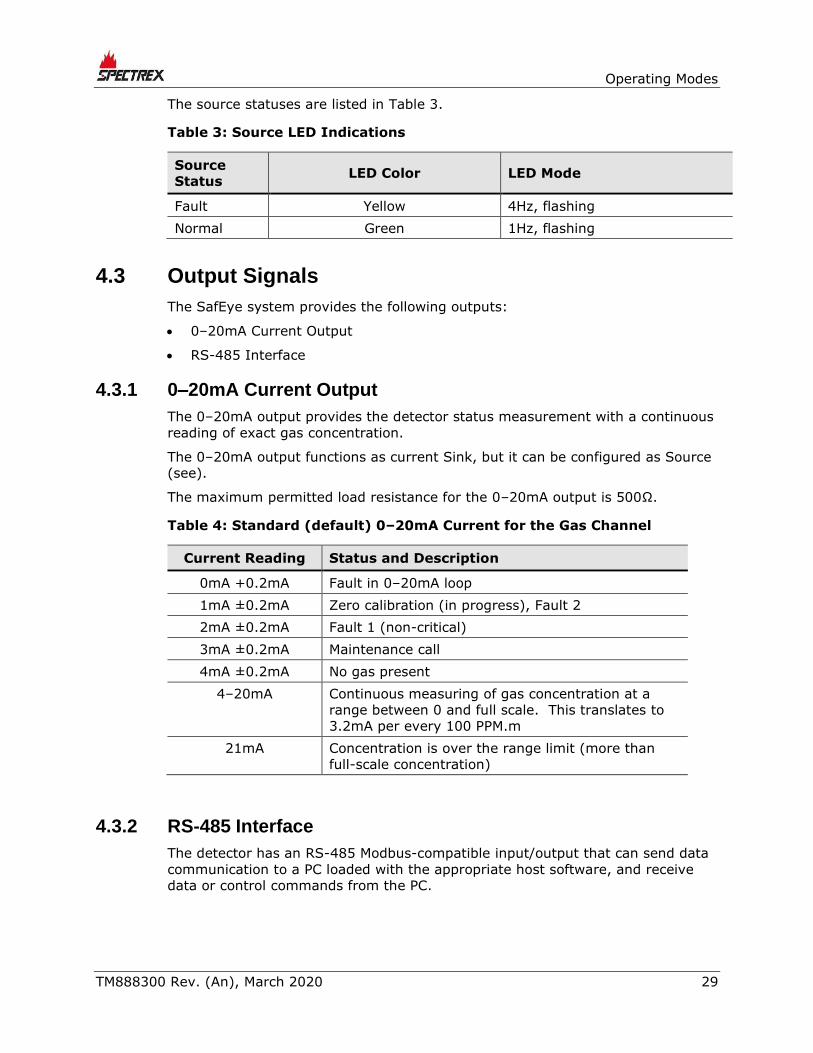
The source statuses are listed in Table 3.
Table 3: Source LED Indications
Source
Status LED Color LED Mode
Fault Yellow 4Hz, flashing
Normal Green 1Hz, flashing
4.3 Output Signals
The SafEye system provides the following outputs:
• 0–20mA Current Output
• RS-485 Interface
4.3.1 0–20mA Current Output
The 0–20mA output provides the detector status measurement with a continuous
reading of exact gas concentration.
The 0–20mA output functions as current Sink, but it can be configured as Source
(see).
The maximum permitted load resistance for the 0–20mA output is 500Ω.
Table 4: Standard (default) 0–20mA Current for the Gas Channel
Current Reading Status and Description
0mA +0.2mA Fault in 0–20mA loop
1mA ±0.2mA Zero calibration (in progress), Fault 2
2mA ±0.2mA Fault 1 (non-critical)
3mA ±0.2mA Maintenance call
4mA ±0.2mA No gas present
4–20mA Continuous measuring of gas concentration at a
range between 0 and full scale. This translates to
3.2mA per every 100 PPM.m
21mA Concentration is over the range limit (more than
full-scale concentration)
4.3.2 RS-485 Interface
The detector has an RS-485 Modbus-compatible input/output that can send data
communication to a PC loaded with the appropriate host software, and receive
data or control commands from the PC.

Wiring Configurations
30 SafEye™ Toxic Open-Path Gas Detection System
4.4 System Setup
4.4.1 Detection Function Programming
The SafEye Quasar 950/960 incorporates several functions that can be set by the
customer, using:
• Host software: Refer to the manual for programming instructions.
• HART handheld diagnostic unit provides an easy, economical connection to
the quick plug. This unit provides verification, status and instructions for
correcting the detector's parameters. It also includes a harness and a special
host for maintenance and commissioning.
4.4.2 Detection Setup Function
See Detector Default Setup, page 31 for default settings.
Setup includes the following options:
• Address Setup
• Heated Optics Operation
• Range
4.4.2.1 Address Setup
The detector provides up to 247 addresses that can be used with the RS-485
communication link.
4.4.2.2 Heated Optics Operation
The heated optics for the detector unit can be defined as one of the following
modes:
• Off: Not operated
• On: Operated continuously
• Auto: On, per temperature change (default)
In Auto mode, the start temperature below which the window will be heated can
be defined. Heating stops when the temperature is 27°F/15°C above the start
temperature.
The temperature can be defined between 32–122°F / 0–50°C.
This feature applies only to the detector.
The source heated optics must be defined when the detector is ordered as 1 of 2
options:
• Heated continuously
Or
• Start heating below 41°F/5°C (default)

Operating Modes
TM888300 Rev. (An), March 2020 31
4.4.2.3 Range
Selection between short and mid/long range
4.4.3 Detector Default Setup
The detector has 3 functions that can be programmed according to customer
requirements, either at the factory or at the customer facility, using a PC
software host or a handheld unit. The standard setup is as follows:
Table 5: Detector Default Setup
Function Setup
0–20mA Continuous
Heat mode Auto
Heat on 5
Table 6: Source Default Setup
Function Setup
Heat mode Auto
Heat on 5
The source default can be changed with the same host.


Technical Specifications
TM888300 Rev. (An), March 2020 33
5 Technical Specifications
5.1 General Specifications
Detected Gases: H2S, NH3,
Detection Distance Range: Table 7
Table 7: Detection Distance Range
Model
No. Detector Source
Minimum
Installation
Distance
(ft/m)
Maximum
Installation
Distance
(ft/m)
H2S
951 QRU-X-11X QTU-X-11X 17/5 52/16
952 QRU-X-11X QTU-X-21X 46/14 132/40
953 QRU-X-11X QTU-X-31X 115/35 200/60
NH3
961 QRU-X-21X QTU-X-11X 17/5 52/16
962 QRU-X-21X QTU-X-21X 46/14 132/40
963 QRU-X-21X QTU-X-31X 115/35 200/60
Response Time: <3 sec, <10 sec to T90
Spectral Response: 200–300nm
Sensitivity Range: Full Scale Warning Alarm
ppm.m ppm.m ppm.m
500 100 300
Field of View: Line of sight
Alignment Tolerance: ± 1°
Drift: Long: term ± 5% of full scale
Minimum Detectable
Level:
50 ppm.m
Temperature Range: –67°F/–55°C to +149°F/+65°C
Immunity to False
Alarm:
Does not produce a false alarm and is not
influenced by solar radiation, hydrocarbon
flames, or other external IR radiation sources

Wiring Configurations
34 SafEye™ Toxic Open-Path Gas Detection System
5.2 Electrical Specifications
Operating Voltage: 18–32VDC
5.2.1 Current Consumption
Table 8: Detector and Source Maximum Current Consumption
Without Heated Optic (Max.) With Heated Optic (Max.)
Detector 150mA 300mA
Source 200mA 300mA
5.2.2 Electrical input protection
The input circuit is protected against voltage-reversed polarity, voltage
transients, surges, and spikes, according to EN50270.
5.2.3 Electrical outputs
5.2.3.1 0–20mA Current Output
The 0–20mA is an isolated Sink option. This output can also be configured as
Source (see Wiring Configurations on page 67). The maximum permitted load
resistance is 500Ω.
5.2.3.2 Communication Network
The detector is equipped with an RS-485 communication link that can be used in
installations with computerized controllers.
Communication is compatible with the Modbus protocol:
• This protocol is standard and widely used.
• The protocol enables continuous communication between a single standard
Modbus controller (master device) and a serial network of up to 247
detectors.
• The protocol enables connections between different types of SPECTREX
detectors or other Modbus devices to the same network.

Technical Specifications
TM888300 Rev. (An), March 2020 35
5.2.3.3 HART Protocol
The HART protocol is a digital communication signal at low levels in addition to
the 0–20mA.
This bi-directional field communication protocol is used to communicate between
intelligent field instruments and the host system.
Through the HART protocol, the detector can:
• Display setup
• Reconfigure setup
• Display detector status and definition
• Perform detector diagnostics
• Troubleshoot

Wiring Configurations
36 SafEye™ Toxic Open-Path Gas Detection System
5.3 Mechanical Specifications
Enclosure: The detector, source and tilt mount are stainless
steel 316 electrochemical and passivated coating
Explosion Proof: ATEX and
IECEx
Ex II 2(2)G D
Ex db eb ib [ib Gb] IIB+H2 T4 Gb
Ex tb [ib Db] IIIC T135°C Db
Water and Dust
Tight:
IP66 and IP68
IP68 is rated for 2m depth for 45 minutes
NEMA 250 type 6p
Electrical
Modules:
Conformal coated
Electrical
Connection:
(2 options, specified at time of order)
2 X M25 (ISO)
2 X 3/4” – 14 NPT conduits
Dimensions: Detector 10.5” x 5.1” x 5.1” / 267 x 130 x 130mm
Source 10.5” x 5.1” x 5.1” / 267 x 130 x 130mm
Tilt mount 4.7” x 4.7” x 5.5” / 120 x 120 x 40mm
Weight: Detector 11lb/5kg
Source 11lb/5kg
Tilt mount 4.2lb/1.9kg
5.4 Environmental Specifications
The SafEye system is designed to withstand harsh environmental conditions. The
source and detector units compensate for adverse conditions while maintaining
accuracy.
5.4.1 High Temperature
The SafEye system is designed to meet DNVGL-CG-0339, class D.
• Operating temperature: +149ºF/+65ºC
• Storage temperature: +149ºF/+65ºC
5.4.2 Low Temperature
The SafEye system is designed to meet DNVGL-CG-0339, class D.
• Operating temperature: –67ºF/–55ºC
• Storage temperature: –67ºF/–55ºC

Technical Specifications
TM888300 Rev. (An), March 2020 37
5.4.3 Humidity
The SafEye system is designed to meet DNVGL-CG-0339, class B.
5.4.4 Enclosure
The SafEye system is designed to meet DNVGL-CG-0339, class C.
5.4.5 Water and Dust
• IP68 per EN60529
• IP66 per EN60529
Dust: Completely protected against dust
Liquids: Protected against immersion between
15cm and 1m in depth. Protected against
water jets from all directions.
5.4.6 Vibration
The SafEye system is designed to meet DNVGL-CG-0339, class B.
5.4.7 Electromagnetic Compatibility (EMC)
This product is in conformance with EMC per EN50270:
Radiated Emission: EN55022
Conducted Emission: EN55022
Radiated Immunity: EN61000-4-3
Conducted Immunity: EN61000-4-6
ESD: EN61000-4-2
Burst: EN61000-4-4
Surge: EN61000-4-5
Magnetic Field: EN61000-4-8
To fully comply with EMC directive 2014/30/EU and protect against interference
caused by RFI and EMI, the cable to the detector must be shielded and the
detector must be grounded. The shield should be grounded at the detector end.


Installation Instructions
TM888300 Rev. (An), March 2020 39
6 Installation Instructions
6.1 Introduction
The detector and UV source units can be installed and maintained using general-
purpose common tools and equipment. The installation procedure must be
performed by suitably qualified personnel.
This section does not attempt to cover all of the standard practices and codes of
installation. Rather, it emphasizes specific points of consideration and provides
some general rules for suitably qualified personnel. Special safety precautions are
stressed wherever applicable.
6.2 General Considerations
6.2.1 Personnel
Only suitably qualified personnel, familiar with the local codes and practices, and
trained for gas detection maintenance, should be employed. Wiring should only
be performed or supervised by someone with knowledge of electronics, and in
particular wiring installation.
6.2.2 Required Tools
The detector can be installed using general-purpose common tools and
equipment. Table 9 lists the specific tools required to install the detector.
Table 9: Tools
Tools Function
Hex key 10mm Mount the detector on the tilt mount
Hex key 3/16” Align the detector
Hex key 5/16” Screw detector plug
Flat screwdriver 4mm Connect the ground terminal
Flat screwdriver 2.5mm Connect wires to the terminal blocks
6.2.3 Site Requirements
When selecting a site location and position for the SafEye system, the following
points must be considered:
• Whether the gas being monitored is heavier or lighter than air
• The individual site requirements
• The detector should have a direct view of the source
• The mounting point for each item should be secure and stable with minimal
vibrations
• Equipment should be either mounted in a position where it cannot be knocked
out of alignment, or it is guarded from physical impact

Wiring Configurations
40 SafEye™ Toxic Open-Path Gas Detection System
6.2.4 The Source and Detector
The model of detector suitable should be selected according to the length of open
path to be monitored. To allow for ageing of the source, and a reduction of the
UV signal due to adverse weather, it is recommended to use a detector that is
not at the limit of its operating range. The general recommendation is to install
the detector at a distance from the Source of no more than 75% of the specified
operating distance. In severe weather conditions such as offshore oil production
and exploration, this should be reduced to 50%.
The open path between the source and detector and the immediate surroundings
should be kept clear of obscuration that might hinder the free movement of air in
the protected area, or block the infrared beam.
6.2.5 Tips for Selecting a Gas Detector Location
The following are some tips for selecting gas detector locations, in order to
provide the best detection coverage:
• For heavier-than-air gases: below potential leak sources.
• For lighter-than-air gases: above potential leak sources.
• Along the expected leak trajectory: near leak sources, considering prevailing
wind directions.
• Between leak sources and potential ignition sources.
• In areas with expected heavy fog, rain, snow, or extremely hot conditions,
consider the effects of long-range installation and install the detector at no
more than 80% from the maximum installation distance.
6.2.6 Separation Distances
To avoid cross talk between adjacent Open Path Gas Detector Systems where
Transmitters are installed on the same side, keep the relevant separation
distance between the neighboring OPGD systems according to the installation
lengths as listed in Table 10.
Table 10: Separation Distances
Installation Line of Sight
Distance, m (ft.) Minimum Separation, m (ft)
10 (33) 1 (3.3)
20 (66) 1.5 (5)
30 (98) 2.5 (6.5)
40 (131) 3.5 (11.5)
50 (164) 4.5 (15)
60 (197) 5 (16.5)

Installation Instructions
TM888300 Rev. (An), March 2020 41
6.2.7 Wiring
• For wiring, use color-coded conductors, suitable wire markings, or labels. The
wire cross-section must be between 0.5–2.5mm² / 28–14AWG.
• The selected wire gauge should be based on the number of detectors used on
the same loop, and the distance from the control unit. The maximum number
of wire connections in a terminal is 2 wire cross-sections, each of 1mm².
• To fully comply with EMC directive and protect against interference caused by
RFI and EMI, the cable to the detector must be shielded and the detector
must be grounded. The shield should be grounded at the detector end.
6.3 Preparations for Installation
6.3.1 General
Installation should comply with local, national, and international regulations and
norms, as applicable to gas detectors and approved electrical devices installed in
hazardous areas. The detectors can be installed with general-purpose common
tools and equipment.
6.3.2 Equipment
In addition to this manual, the system should include the following:
• Detector unit: QRU-X-X1X (See Models and Types, page 22)
• Source unit: QTU-X-X1X (See Models and Types, page 22)
• 2 tilt mount bases:
• 1 base is used for the detector
• 1 base is used for the UV source
• The commissioning kit for H2S or NH3 includes:
• Magnetic mode selector
• Handle for cover opening
• Alignment tool kit
• Function check filter: H2S or NH3
• Other accessories are available (per customer request):
• Pole mount:
• U-bolt 2-3”
• U-bolt 4-5”
• HART handheld diagnostic unit
• HART handheld harness kit
• USB/RS-485h harness converter kit
• Protective cover
For additional details, see Accessories on page 71.

Wiring Configurations
42 SafEye™ Toxic Open-Path Gas Detection System
6.3.3 Unpacking the Product
Upon receipt of the detector, check and record the following:
• Verify that the model matches the purchase order.
• Record the part number (P/N) and serial number of the detectors and source
units, and the installation date in an appropriate logbook.
• Open the container package immediately, prior to detector installation, and
visually inspect the detectors, sources, and accessories.
• Verify that all components required for the detector installation are readily
available before beginning the installation. In the event that the installation is
not completed in a single session, secure and seal the detectors and conduits.

Installation Instructions
TM888300 Rev. (An), March 2020 43
6.4 Certification Instructions
6.4.1 General Instructions
Warning:
Do not open the detector, even when isolated, when a flammable atmosphere
is present.
Use the following certification instructions:
• The cable entry point may not exceed 182°F/83°C. Suitable precautions
should be taken when selecting the cable.
• Only suitably certified cable entry devices or conduit shall be used for
connections and unused openings shall be blanked off using a suitably
certified stopping plugs.
• The marking of the equipment is: Ex II 2(2)G D
Ex db eb ib [ib Gb] IIB+H2 T4 Gb
Ex tb [ib Db] IIIC T135°C Db
• The equipment may be used with flammable gases and vapors with apparatus
groups IIA and IIB +H2 T4 in the ambient temperature range
–67°F/–55°C to +149°F/+65°C.
• Installation should be carried out by suitably trained personnel, in accordance
with the applicable code of practice, e.g. EN 60079-14:1997.
• Inspection and maintenance of this equipment should be carried out by
suitably trained personnel, in accordance with the applicable code of practice,
e.g. EN 60079-17.
• Repair of this equipment should be carried out by suitably trained personnel,
in accordance with the applicable code of practice, e.g. EN 60079-19.
• The certification of this equipment relies upon use of the following materials in
its construction:
• Enclosure: 316L Stainless Steel
• Window: Sapphire Glass
• Seals: EPDM
• If the equipment is likely to come into contact with aggressive substances as
described below, then it is the responsibility of the user to take suitable
precautions to prevent the equipment from being adversely affected, thus
ensuring that the type of protection provided by the equipment is not
compromised.
• Examples of aggressive substances: acidic liquids or gases that may
attack metals, solvents that may affect polymeric materials
Wiring Configurations
44 SafEye™ Toxic Open-Path Gas Detection System
• Examples of suitable precautions: routine inspections, establishing
resistance to specific chemicals from the material’s data sheets.
• The output of the optical radiation source with respect to explosion protection
meets Exception 3 from the scope of UL 60079-28.
• Special conditions for safe use: The Quasar 950/960 Open Path Gas Detectors
and UV Source Units should not be used as safety related devices, in
accordance with directive 2014/34/EU.
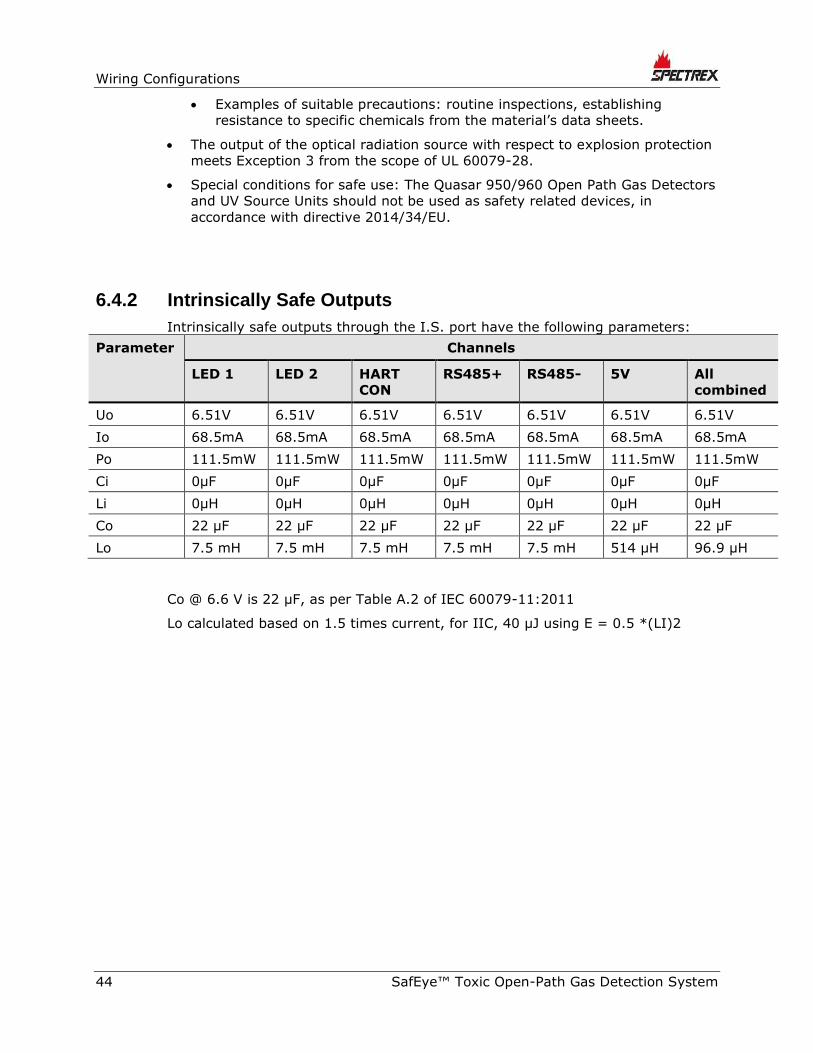
6.4.2 Intrinsically Safe Outputs
Intrinsically safe outputs through the I.S. port have the following parameters:
Parameter Channels
LED 1 LED 2 HART
CON
RS485+ RS485- 5V All
combined
Uo 6.51V 6.51V 6.51V 6.51V 6.51V 6.51V 6.51V
Io 68.5mA 68.5mA 68.5mA 68.5mA 68.5mA 68.5mA 68.5mA
Po 111.5mW 111.5mW 111.5mW 111.5mW 111.5mW 111.5mW 111.5mW
Ci 0µF 0µF 0µF 0µF 0µF 0µF 0µF
Li 0µH 0µH 0µH 0µH 0µH 0µH 0µH
Co 22 µF 22 µF 22 µF 22 µF 22 µF 22 µF 22 µF
Lo 7.5 mH 7.5 mH 7.5 mH 7.5 mH 7.5 mH 514 µH 96.9 µH
Co @ 6.6 V is 22 µF, as per Table A.2 of IEC 60079-11:2011
Lo calculated based on 1.5 times current, for IIC, 40 µJ using E = 0.5 *(LI)2

Installation Instructions
TM888300 Rev. (An), March 2020 45
6.4.3 Special Conditions for Safe Use for ATEX/IECEx Only
• The dimensions of the flameproof joints differ from the relevant minimum or
maximum values required by Table 2 of IEC/EN 60079-1:2007 for IIB + H2,
as detailed below:
Flamepath Description Type of
Joint
Minimum
Width “L”
(mm)
Maximum
Gap “iC”
(mm)
Cylindrical section of spigot (both ends of
Ex d compartment)
Cylindrical 15 0.08
30mm diameter window fitted against
enclosure Flanged 10.7 0.02
39.5mm diameter window fitted against
enclosure
Flanged 10 0.02
• Gaps, “ic,” should not be modified to be any larger, and widths, “L,” should not
be modified to be any shorter than the values shown in the table above.
1. Connections to the IS port on the side of the detector enclosure should be made
using equipment that maintains the intrinsically safe levels of protection.
• The Um should be installed in accordance with one of the following:
• The Um is 18–32VDC, in a SELV/PELV system
• Via a safety isolating transformer complying with the requirements of IEC
61588-2-6 or technically equivalent standard
• Directly connected to apparatus complying with IEC 60950, IEC 61010-1,
or technically equivalent standard
• Fed directly from cells or batteries

Wiring Configurations
46 SafEye™ Toxic Open-Path Gas Detection System
6.4.4 North American Conditions of Acceptability from certificate CSA 80023016
6.4.4.1 Conditions for Canadian Installations
1. The dimensions of the flameproof joints are other than the relevant minimum or
maximum values required by Table 2 of CAN/CSA-C22.2 No 60079-0:19 Ed.4 for
IIB + H2, as detailed below:
Flamepath Description Type of
Joint
Minimum
Width “L”
(mm)
Maximum
Gap “iC”
(mm)
Cylindrical section of spigot (both
ends of Ex d compartment)
Cylindrical 15 0.08
30 mm diameter window fitted
against enclosure
Flanged 10.7 0.02
39.5 mm diameter window fitted
against enclosure
Flanged 10 0.02
Gaps shall not be machined to be any larger than the values of ‘iC’, and
widths shall not be modified to be any smaller than the values of ‘L’, shown in
the table above.
2. Connections to the I.S. port on the side of the detector enclosure shall be made
via equipment which maintains the intrinsically safe levels of protection.
• Where Um marked on the associated apparatus is less than 250V it shall be
installed in accordance with one of the following:
• Where Um does not exceed 50 Vac or 120 Vdc, in a SELV or PELV system or,
• Via a safety isolating transformer complying with the requirements of
CAN/CSA-C22.2 No. 66.1 or technically equivalent standard, or
• Directly connected to apparatus complying with CAN/CSA-C22.2 No. 60950-1,
CAN/CSA-C22.2 No. 61010-1 or technically equivalent standard, or
• Fed directly from cells or batteries.
3. The output of the optical radiation source with respect to explosion protection
meets Exception 3) from the scope of CAN/CSA-C22.2 No. 60079-28:16 Ed.1
4. Upon installation remove the plastic transit plug from the cable entry and use a
cable fitting or a conduit fitting with the following specification to connect the
cable to the equipment:
• Ex marking: Ex eb IIC Gb, Ex tb IIIC Db
• Temperature rating: -55°C to +83°C or better
• Connecting thread: M25x1.5 or ¾” NPT
5. Equipment is only to be installed by manufacturer trained personnel.

Installation Instructions
TM888300 Rev. (An), March 2020 47
6. Equipment has only been tested for electrical safety. No evaluation of functional
safety and performance characteristics has been conducted.
7. The equipment shall be supplied with Limited Energy Circuit (LEC) as defined in
CSA C22.2 No. 61010-1-12 or Limited Power Source (LPS) as defined in CAN/CSA
C22.2 No. 60950-1.
6.4.4.2 Conditions for US Installations
1. The dimensions of the flameproof joints are other than the relevant minimum or
maximum values required by Table 2 of UL 60079-0:2019 Ed. 7 for IIB + H2, as
detailed below:
Flamepath Description Type of
Joint
Minimum
Width “L”
(mm)
Maximum
Gap “iC”
(mm)
Cylindrical section of spigot (both
ends of Ex d compartment)
Cylindrical 15 0.08
30 mm diameter window fitted
against enclosure
Flanged 10.7 0.02
39.5 mm diameter window fitted
against enclosure
Flanged 10 0.02
Gaps shall not be machined to be any larger than the values of ‘iC’, and
widths shall not be modified to be any smaller than the values of ‘L’, shown in
the table above.
2. Connections to the I.S. port on the side of the detector enclosure shall be made
via equipment which maintains the intrinsically safe levels of protection.
3. Where Um marked on the associated apparatus is less than 250V it shall be
installed in accordance with one of the following:
• Where Um does not exceed 50 Vac or 120 Vdc, in a SELV or PELV system or,
• Via a safety isolating transformer complying with the requirements of UL
5085-1 or technically equivalent standard, or
• Directly connected to apparatus complying with UL 60950-1, UL 61010-1 or
technically equivalent standard, or
• Fed directly from cells or batteries.
4. The output of the optical radiation source with respect to explosion protection
meets Exception 3) from the scope of UL 60079-28:2017 Ed.2
5. Upon installation remove the plastic transit plug from the cable entry and use a
cable fitting or a conduit fitting with the following specification to connect the
cable to the equipment:
• Ex marking: Class I Zone 1 AEx eb IIC Gb, Zone 21 AEx tb IIIC Db
• Temperature rating: -55°C to +83°C or better

Wiring Configurations
48 SafEye™ Toxic Open-Path Gas Detection System
• Connecting thread: M25x1.5 or ¾” NPT
6. Equipment is only to be installed by manufacturer trained personnel.
7. Equipment has only been tested for electrical safety. No evaluation of functional
safety and performance characteristics has been conducted.
8. The equipment shall be supplied with Class 2 as defined in article 725.121 of
NFPA 70
6.5 Conduit/Cable Installation
The conduit and cable installation must comply with the following guidelines:
• To avoid water condensation in the detector, install the detector with the
conduits/cable entries facing downward.
• Use flexible conduits/cables for the last portion that connects to the detector.
• When pulling the cables through the conduits, ensure that they are not
tangled or stressed. Extend the cables about 12”/30cm beyond the detector
location to accommodate wiring after installation.
• After the conductor cables have been pulled through the conduits, perform a
continuity test.
6.6 Detector/Source Mounting
Mount the detector source with the tilt mount kit. The tilt mount enables the
detector to be rotated up to 60º in all directions, with a fine alignment of up to
10º.
6.6.1 Tilt Kit
The following contents are included with the tilt mount kit:
Table 11: Tilt Mount Kit
Item Qty Type
Tilt mount 1
Screw 1 M10 x 1.5
Spring washer 1 No. 10

Installation Instructions
TM888300 Rev. (An), March 2020 49
6.6.2 Detector/Source Installation
(Figure 4 and Figure 5)
The detector and the source can be installed in 2 ways with the same tilt mount.
To install the detector/source:
1 Place the tilt mount holding plate (Item 1) in its designated location and
secure it with 4 fasteners through 4 holes of an 8.5mm diameter.
Notes:
• Skip this step if the tilt mount is already installed.
• Detector removal for maintenance purposes does not require
tilt mount removal.
2 Place the detector, with its conduit/cable inlets pointing downwards on the
detector holding plate of the tilt mount (Item 2). Secure the detector with an
M10 x 1.5 screw with No. M10 spring washers (9, 10). Secure the detector to
the tilt mount using Hex Key No. 7 for M10 x 1.5 screws (Item 9).
3 Repeat Steps 1–2 for installing the source.

Wiring Configurations
50 SafEye™ Toxic Open-Path Gas Detection System
6.7 Detector Wiring
To install the detector wiring:
1 Release the back cover secure bolt (Figure 5, Item 15), and open the detector
back cover (Figure 5, Item 14). The chamber is now exposed.
2 Remove the protective plug mounted on the detector conduit/cable entry
inlet, and pull the wires through the detector inlet (Figure 6, Item 4). Use a
3/4” – 14 NPT or M25x1.5 conduit connection/cable gland to assemble the
cable/ conduit to the detector.
3 Connect the wires to the required terminals (Figure 6, Item 2) according to
the wiring diagram. See Detector Terminal Wiring, page 54 and Figure 8,
Figure 10, Figure 12, and Figure 13 in Wiring Configurations on page 67.
4 Connect the grounding wire to the ground screw located on the exterior of the
detector (Figure 6, Item 3). The detector must be well grounded to earth
ground.
Note:
In case of installations in the US, the internal grounding
connection shall be used for the equipment grounding connection
and the external connection is for a supplementary bonding
connection where local codes or authorities permit or require such
connection. The external bonding conductor shall be manufactured
from copper and shall have a size of 4 mm2 . A tightening torque
of 16 inlb (1.8 Nm) shall be used to secure the bonding conductor.
5 Place and secure the detector’s back cover by screwing on the cover and
securing it using the secure bolt (Figure 5, Item 15).

Installation Instructions
TM888300 Rev. (An), March 2020 51
1 Tilt mount holding plate 5 Vertical fine alignment tightening
screw
2 Detector/source holding
plate 6
Vertical crude alignment
tightening screw
3
Horizontal crude
alignment tightening
screw
7 Vertical fine alignment screw
4
Horizontal fine
alignment tightening
screw
8 Horizontal fine alignment screw
Figure 4: Tilt Mount

Wiring Configurations
52 SafEye™ Toxic Open-Path Gas Detection System
1 Tilt mount holding plate 9 Detector tightening screw
2 Detector/source holding
plate 10 Detector tightening washer
3
Horizontal crude
alignment tightening
screw
11 Detector
4
Horizontal fine
alignment tightening
screw
12 Alignment tool
5 Vertical fine alignment
tightening screw 13 Alignment tool tightening bolt
6 Vertical crude alignment
tightening screw 14 Detector back cover
7 Vertical fine alignment
screw 15 Detector back cover secure bolt
8 Horizontal fine
alignment screw
Figure 5: Detector and Tilt Mount Assembly
Installation Instructions
TM888300 Rev. (An), March 2020 53
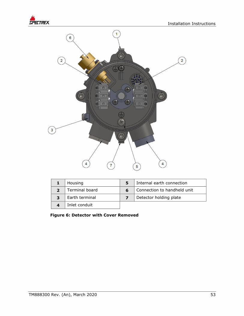
1 Housing 5 Internal earth connection
2 Terminal board 6 Connection to handheld unit
3 Earth terminal 7 Detector holding plate
4 Inlet conduit
Figure 6: Detector with Cover Removed

Wiring Configurations
54 SafEye™ Toxic Open-Path Gas Detection System
6.8 Detector Terminal Wiring
The detector has 6 wiring terminals.
Table 12 lists the functions of each electrical terminal of the detector.
Table 12: Wiring Options
Terminal No. Function
1 Power +24VDC
2 Return –24VDC
3 0–20mA In (+)
4 0–20mA Out (–)
5 RS-485 (+)
6 RS-485 (–)
6.9 UV Source Wiring
6.9.1 Wiring
To install the wiring:
1 Release the back screw bolt (Figure 5, Item 15), and open the source back
cover (Figure 4, Item 14). The chamber is now exposed.
2 Remove the protective plug mounted on the source conduit/cable entry inlet,
and pull the wires through the source inlet (Figure 7, Item 4). Use a 3/4” – 14
NPT or M25x1.5 conduit connection/cable gland to assemble the cable/
conduit to the detector.
3 Connect the wires to the required terminals (Figure 7, Item 2) according to
the wiring diagram. See Terminal Wiring, page 55 and Figure 12 in Wiring
Configurations on page 67.
4 Connect the grounding wire to the ground screw located on the exterior of the
detector (Figure 7, Item 3). The source must be well grounded to earth
ground.
Note:
In case of installations in the US, the internal grounding
connection shall be used for the equipment grounding connection
and the external connection is for a supplementary bonding
connection where local codes or authorities permit or require such
connection. The external bonding conductor shall be manufactured
from copper and shall have a size of 4 mm2 . A tightening torque
of 16 inlb (1.8 Nm) shall be used to secure the bonding conductor.
5 Place and secure the source unit’s back cover by screwing on the cover and
securing the back screw bolt.
Installation Instructions
TM888300 Rev. (An), March 2020 55
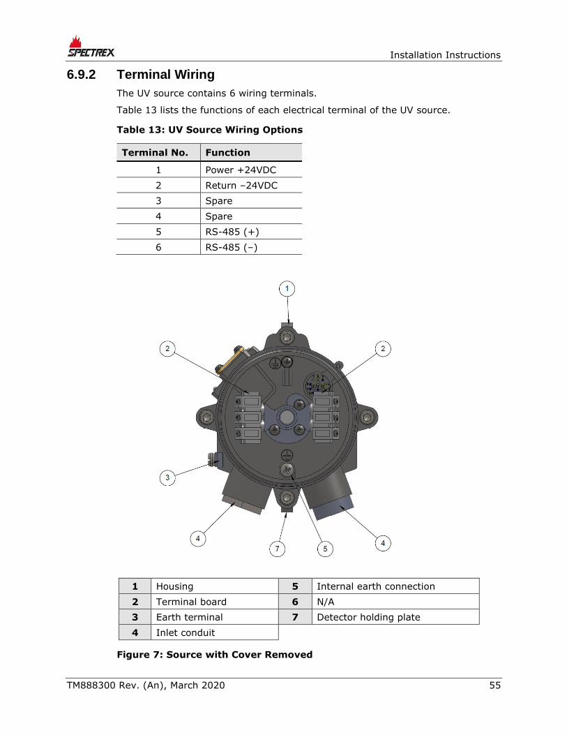
6.9.2 Terminal Wiring
The UV source contains 6 wiring terminals.
Table 13 lists the functions of each electrical terminal of the UV source.
Table 13: UV Source Wiring Options
Terminal No. Function
1 Power +24VDC
2 Return –24VDC
3 Spare
4 Spare
5 RS-485 (+)
6 RS-485 (–)
1 Housing 5 Internal earth connection
2 Terminal board 6 N/A
3 Earth terminal 7 Detector holding plate
4 Inlet conduit
Figure 7: Source with Cover Removed


Operating Instructions
TM888300 Rev. (An), March 2020 57
7 Operating Instructions
7.1 SafEye Operation
Once the system is in place, it automatically monitors for the specified gases, and
sends signals to a standard control panel or PC. This section describes the
alignment, calibration, and operation of the SafEye System.
Caution:
Accurate alignment is essential for proper operation of the SafEye
system.
7.2 Alignment of Unit
The alignment tool is used to perform full alignment.
Perform the alignment procedure in 2 stages:
• Crude alignment
• Fine adjustment
The alignment tool includes a periscope that consists of a prism and an ocular
that are located vertical to the alignment tool assembly. This allows the user to
look into the opposite unit perpendicularly to the one being aligned, when access
from the rear of the unit is impossible. For installations where rear access is
possible, the periscope is not necessary, and it can be removed by releasing the
periscope fastening screw.
Notes:
• To ensure proper alignment according to factory calibration, prior
to alignment tool installation, verify that the alignment tool and its
sight mounting are free of dirt.
• To ensure optimal alignment, do not attempt to change any
factory calibration of the alignment tool or its mounting.
To align the unit (see Figure 4):
1 Ensure that the detector and the UV source are installed properly. Installation
instructions are described in Installation Instructions, page 39.
2 Remove the front shield using the 2 captive screws.
3 Install the alignment tool assembly (Item 12) on the front of the
detector/source. Fasten the alignment tool with fastening screws (Item 13).
4 Crude Alignment:
a Use a ¼” Allen screwdriver for all alignment screws.

Wiring Configurations
58 SafEye™ Toxic Open-Path Gas Detection System
b Loosen screws 5 and 6.
c Approximately aim the source horizontally toward the detector.
d Tighten screw 6.
e Loosen screws 3 and 4.
f Approximately aim the source vertically toward the detector.
g Tighten screw 3.
5 Repeat Step 4 for the detector towards the source.
6 Fine Alignment:
a Aim the source toward the detector within a horizontal axis using screw 7.
Aim the alignment tool cross toward the center of the front window of the
detector or source (see Figure 2 and Figure 3, Item 8).
b Tighten screw 5.
c Aim within the vertical axis using screw 8.
d Tighten screw 4.
e Make sure the alignment tool cross is pointing to the center of the
detector and source window.
7 Repeat Step 6 for the detector alignment.
8 Remove the alignment tool and replace the front shield.
7.3 Powering up the System
Warning:
Prior to any operation or maintenance, check the Safety Precautions,
page 59.
To power up the system:
1 Connect the source and detector to the power source.
2 Connect the 4–20mA meter to the detector.
3 Power up the system using 18–32VDC.
After 30 seconds, the current meter indicates 4mA.
Note:
Perform zero calibration after powering up the system (see Zero
Calibration, page 60).

Operating Instructions
TM888300 Rev. (An), March 2020 59
7.4 Safety Precautions
After powering up, the detector requires minimal attention for proper functioning,
but the following should be noted:
• Follow the manual instructions, and refer to the drawings and specifications
issued by the manufacturer.
• Do not open the detector/source housing while power is connected.
• External devices such as automatic extinguishing systems must be
disconnected before performing maintenance tasks required by the warranty.
7.5 Signal Verification
Perform signal verification through the host software supplied by SPECTREX
(refer to Manual TM899050) or by the HART handheld unit (refer to Manual
TM899030).
7.5.1 Signal Values Limitation
Table 14 describes the maintenance data channels limitation values.
Table 14: Maintenance Channel Limitation Values
Channel
Short
Range
Medium
Range
Long
Range
Maintenance 5m 16m 14m 40m 35m 60m
Reference 2V
Gain
0
1.5V
Gain
2
2V
Gain
0
1V
Gain
1
2V
Gain
1
1V
Gain
2
The minimum
signal allowed
is 2V at Gain 4
Signal 1 and 2 2V
Gain
0
1.5V
Gain
2
2V
Gain
0
1V
Gain
1
2V
Gain
1
1V
Gain
2
The minimum
signal allowed
is 2V at Gain 4
Ratio 1 and 2 0.6–1.4 0.5–3
NQRat
1 and 2 0.97–1.03
Must be 0.97–
1.03
ppm.m 0ppm.m 0ppm.m
Temperature Up to 77°F/25°C beyond room temperature Up to
77°F/25°C
beyond room
temperature
Voltage 32VDC > V > 18VDC 32VDC > V >
18VDC
Note:
The installation information refers to the installation distance.
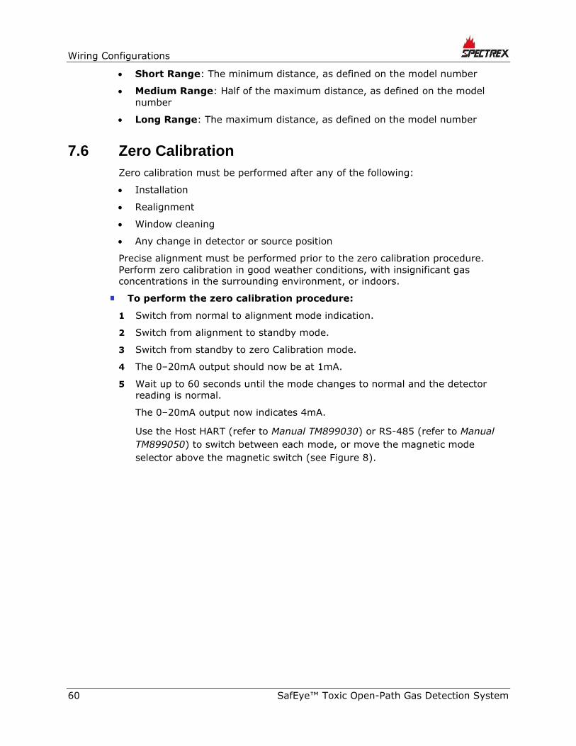
Wiring Configurations
60 SafEye™ Toxic Open-Path Gas Detection System
• Short Range: The minimum distance, as defined on the model number
• Medium Range: Half of the maximum distance, as defined on the model
number
• Long Range: The maximum distance, as defined on the model number
7.6 Zero Calibration
Zero calibration must be performed after any of the following:
• Installation
• Realignment
• Window cleaning
• Any change in detector or source position
Precise alignment must be performed prior to the zero calibration procedure.
Perform zero calibration in good weather conditions, with insignificant gas
concentrations in the surrounding environment, or indoors.
To perform the zero calibration procedure:
1 Switch from normal to alignment mode indication.
2 Switch from alignment to standby mode.
3 Switch from standby to zero Calibration mode.
4 The 0–20mA output should now be at 1mA.
5 Wait up to 60 seconds until the mode changes to normal and the detector
reading is normal.
The 0–20mA output now indicates 4mA.
Use the Host HART (refer to Manual TM899030) or RS-485 (refer to Manual
TM899050) to switch between each mode, or move the magnetic mode
selector above the magnetic switch (see Figure 8).

Operating Instructions
TM888300 Rev. (An), March 2020 61
Figure 8: Magnetic Mode Selector
7.7 Functional Check
The SafEye system has been calibrated at the factory for the user's specific gas
or vapor detection requirements. The functional check procedure validates the
system’s functional operation.
The functional check filter is a convenient operational check used to confirm that
a response has not changed from previous readings. The filter is not used for
calibration, since it is unnecessary in the procedure, nor does it equate to a
particular quantity of gas.
Caution:
Disable automatic activation and disconnect any external device that
should not be activated during the calibration check.
Notes:
• This functional verification procedure is for a standard 0–20mA
output.
• Prior to starting the functional check, verify that the power to the
units is on, and that the current of the 0–20mA channel is stable.
Record the reading.
Wiring Configurations
62 SafEye™ Toxic Open-Path Gas Detection System
To perform the functional check:
1 Position the functional check filter in front of the SafEye detector.
2 Center the functional check filter’s window over the viewing window of the
detector.
3 Wait 20 seconds.
4 Read the 0–20mA current. Determine the difference between the reading
taken with and without the functional check filter. This difference is the 0–
20mA current variance.
5 Record the 0–20mA current variance in the maintenance logbook. If the
variance is more than a 30% change when compared to the previous check
(see delivery form), repeat the alignment.

Maintenance Instructions
TM888300 Rev. (An), March 2020 63
8 Maintenance Instructions
8.1 General Maintenance
Only basic periodic maintenance is required to keep the SafEye Quasar 950/960
at maximum performance and reliability levels. The detector and source units can
be maintained with the use of common tools and equipment. The test results
should be recorded in a maintenance logbook, together with a copy of the
delivery form.
8.2 Periodic Maintenance
The source and detector viewing windows should be kept as clean as possible, as
they are active devices. Perform proper maintenance procedures periodically to
allow the SafEye system to retain maximum performance and reliability.
Note:
The frequency of cleaning operations depends on the existing
environmental conditions and the applications used.
To perform periodic maintenance:
1 Perform alignment procedures each time that the source or the detector unit
are opened or moved for any reason.
2 The signal verification check corroborates the current signals from the UV
source compared to that of previous alignments. This check should be
performed every 6–12 months. The signal should be checked according to
threshold levels (see Signal Verification, page 59).
3 Perform a functional check every 6 months (see Functional Check, page 61).
4 Perform the alignment procedure only if the signals are below threshold value
(see Signal Verification, page 59).
5 Perform zero calibration (see Zero Calibration, page 60) every time the
detector or source is realigned, or the windows are cleaned.

Wiring Configurations
64 SafEye™ Toxic Open-Path Gas Detection System
8.2.1 Routine Optical Surface Cleaning
The SafEye system, being an optical device, must be kept as clean as possible.
The optical surfaces involved are the source and detector viewing windows.
To clean the optical window:
1 Disconnect the power to the SafEye Detector and Source.
2 In places where dust or dirt has accumulated on the optical surface, clean the
surface with a small, soft-bristle brush.
3 Wash the surfaces thoroughly with water and a mild non-abrasive detergent.
4 Thoroughly rinse the glass surface with clean water, ensuring no residue is
left behind.
5 Dry the glass with a clean, dry, soft cloth.
6 Enter the date, name of company, and person who performed the
maintenance service into the maintenance logbook.
7 Reconnect the power to the SafEye detector and source.
8 Perform signal verification (see Signal Verification, page 59).
9 Perform zero calibration (see Zero Calibration, page 60).
10 Perform a functional check (see Functional Check, page 61)
8.2.2 Signal Verification
The signal verification check determines the proper operation of the open path. It
checks the alignment and cleanliness of the window or any problem in the source
or detector. Use the PC Host software to measure the signal verification.
Refer to the manual or use the IS handheld unit.
8.2.3 Functional Check of Unit
The SafEye Quasar has been calibrated at the factory according to the user’s
specific gas or vapor detection requirements. Use the check filters included in the
commissioning kit according to the corresponding calibrating gas to validate
correct installation. Refer to Functional Check, page 61 for instructions.
Caution:
Disable automatic activation, and disconnect any external device that
should not be activated during the calibration check.

Troubleshooting
TM888300 Rev. (An), March 2020 65
9 Troubleshooting
Table 15: Troubleshooting
Problem Cause Solution
“Maintenance call”
Status OMN: Signals are
below 2.5VDC at Gain 4
Status RMN: Ratios are
below 0.5
Poor alignment Perform alignment
Dirt on the window Clean the window
Poor light source Replace the light source
Detector fault Replace/repair detector
NQR at below the
permitted limit
Gas in the path Make sure that the path is
clean and that the weather
conditions are good
NQR at above the
permitted limit
Poor alignment Perform alignment
Temperature higher than
77°F/25°C beyond the
room temperature
Electronic problem Replace/repair detector
Ratio1 and Ratio2 out of
the limit
Poor alignment Perform alignment
Dirt on the window Clean the window
Detector fault Replace/repair detector
Voltage less than 16VDC.
The Detector at “V” fault.
Low input voltage Check the power supply
and installation


Wiring Configurations
TM888300 Rev. (An), March 2020 67
Appendix A: Wiring Configurations
Figure 9: Detector Wiring Terminal
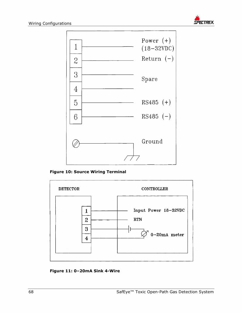
Wiring Configurations
68 SafEye™ Toxic Open-Path Gas Detection System
Figure 10: Source Wiring Terminal
Figure 11: 0–20mA Sink 4-Wire

Wiring Configurations
TM888300 Rev. (An), March 2020 69
Figure 12: 0–20mA Non-Isolated Sink 3-Wire
Figure 13: 0–20mA Source 3-Wire
A.1 RS-485 Communication Network
By using the RS-485 network capability of the SafEye Quasar 950/960 Detector
and additional software, it is possible to connect up to 32 detectors in an
addressable system with 4 wires only (2 for power and 2 for communication).
Using repeaters, the number of detectors can be much larger (32 detectors for
each repeater): up to 247 on the same 4 wires. When using the RS-485 network,
it is possible to read each detector status (Fault, Warning, and Alarm)
individually.
For more details, contact SPECTREX.

Wiring Configurations
70 SafEye™ Toxic Open-Path Gas Detection System
Figure 14: RS-485 Networking for Wiring Option 3

Accessories
TM888300 Rev. (An), March 2020 71
Appendix B: Accessories
B.1 Tilt Mount
The tilt mounting brackets allow for accurate alignment of the detector/source for
proper operation of the open path. The brackets give a crude alignment of ±60°,
and a fine alignment of ±10°.
B.2 Pole Mount (U-Bolt 2–3”)
The U-bolt mount is available to facilitate 2”–3” pipe mounting.
B.3 Pole Mount (U-Bolt 4–5”)
The U-bolt mount is available to facilitate 4”–5” pipe mounting.
B.4 Wall Mount
The wall mount is available to facilitate wall mounting.
B.5 Commissioning Kit
The commissioning/alignment kit unit for H2S or for NH3 is required for
commissioning and future maintenance checks. Only 1 kit is required per site.
The kit includes an alignment tool, a magnetic mode selector, a functional check
filters (H2S or NH3) for system installation and periodical functional testing, and
socket keys for access to units.
Table 16: Check Filters
Check Filter Part Number Gas Concentration
888280-1 >120ppm.m H2S
888280-2 >120ppm.m Ammonia
B.6 HART Handheld Diagnostic Unit
The HART handheld diagnostic unit is fitted with a harness to the quick-plug
connection, providing an easy, economical connection. The HART handheld unit
provides verification, status, and instructions for correcting the detector’s
parameters. The unit is IS-approved, with a special harness to suit the detector,
and a host for maintenance and commissioning.

Accessories
72 SafEye™ Toxic Open-Path Gas Detection System
B.7 HART Handheld Harness Kit
A quick-plug connection with a harness is connected on one side to a standard
HART handheld unit. This includes the Spectrex host software that can be
uploaded to an existing handheld unit. The kit does not include the handheld unit.
Refer to the manual for more information.
B.8 USB/RS-485 Harness Converter Kit
The USB RS-485 Harness Kit with RS-485/USB converter, together with Spectrex
host software, enables the user to connect to any available PC or laptop to
reconfigure settings or perform diagnostics on the Quasar 950/960 Gas
Detector.
Refer to the manual for programming instructions.
B.9 Protective Cover
The protective cover is designed to protect the detector from the heat of the sun.

SIL-2 Features
TM888300 Rev. (An), March 2020 73
Appendix C: SIL-2 Features
This appendix details the special conditions for compliance with the requirements
of EN 61508 for SIL-2.
The SafEye Quasar 950/960 Open-Path Gas Detector can be used in low and high
demand mode applications – see IEC 61508-4:2010, Chapter 3.5.16.
C.1 Safety Relevant Parameters
Type: B
Structure: 1oo1
HFT: 0
Mean time to repair: 72hr
Ambient temperature: max. 149°F/65°C
Proof-Test-Interval: 52 weeks (1 year)
λS = 1762⋅fit
λD = 1722⋅fit
λDU = 97.4⋅fit
λSD = 1660.7⋅fit
λDD = 1624.7⋅fit
DC = 94%
SFF = 97%
PFDavg = 5.5 E− 04; PFD%_SIL2 = 5.5%
PFH = 9.7 E−08 1/h; PFH%_SIL2 = 9.7%

SIL-2 Features
74 SafEye™ Toxic Open-Path Gas Detection System
C.2 General Conditions for Safe Use
• The SafEye Quasar 950/960 Open-Path Gas Detector should consist only of
the approved hardware and software modules.
• Take note of the application advice and limitations listed in this manual. The
regional and national regulations should be considered when performing
calibration/maintenance tasks.
• The 24V power supply must fulfill the requirements for SELV/PELV of EN
60950.
• Do not use the HART and RS-485 interfaces for transmission of safety-related
data.
• According to SIL-2 requirements, the alert conditions can be implemented by
an alert signal via the 0-20mA current loop.
• After installation and configuration, the setup parameters must be verified
and the function of the SafEye Quasar 950/960 Open-Path Gas Detector must
be checked completely.
• The alarm conditions of the transmitter must be checked periodically together
with standard gas calibration checks. The SafEye Quasar 950/960 Open-Path
Gas Detector must be switched off and on.
• The connected controller must monitor the 0–20mA signal current for values
below 4mA and above 20mA.
• Mean time to repair should be 72 hours.


Technical Support
For technical assistance or support, contact:
6021 Innovation Blvd,
Shakopee, MN 55379 ,
USA
Phone: +1 (973) 239 8398
Fax: +1 (973) 239 7614
Email: [email protected]
Website: www.spectrex.net
Top Related
Copyright © 2022 FDOKUMEN

