


Bahasa
Halaman
Hukum


1
Machine Automation ControllerNX1P
Compact package-type machine automation controller
Features• Integrated sequence control and motion control• Up to eight axes of control via EtherCAT• Up to four synchronized axes - electronic gear/cam and linear/circular interpolation• Standard-feature EtherCAT control network support• Safety subsystem on EtherCAT• Standard-feature EtherNet/IP port• Built-in I/O• Up to eight NX I/O Units connectable• Up to sixteen remote NX I/O Units connectable via EtherCAT coupler• Up to two option boards connectable to add serial communications or analog I/O functionality• Battery-free operation• Fully conforms with IEC 61131-3 standard programming
NX1P2-9024DTNX1P2-9024DT1
NX1P2-140DTNX1P2-140DT1

Machine Automation Controller NX1P
2
System ConfigurationBasic System Configuration
Interpreting Model NumbersNot all combinations are possible. Refer to List of Models in Ordering Information, below.
* The number of synchronized motion control axes when "2 Control engine" is "1".When "2 Control engine" is "9", "3 Synchronized motion control axes" is always "0" but there is no synchronized motion control axis.
No Item Symbol Specifications
1 Type P DC power supply model with built-in I/O
2 Control engine1 Motion control axes
9 No motion control axis (Single-axis position control axes only)
3 Synchronized motion control axes *0 2 axes
1 4 axes
4 Built-in I/O24 24 (14 inputs, 10 outputs)
40 40 (24 inputs, 16 outputs)
5 Built-in input type D DC inputs
6 Built-in output type T NPN transistor outputs
T1 PNP transistor outputs
Support Software
EtherNet/IP
LAN
Slave TerminalNX Units
(16 units max. *)Servo Drives/
Encoder input slavesGeneral-purpose
slaves
EtherCAT
Built-in EtherCAT port
CPU Rack
NX Units (8 units max.*)
EtherCATnetwork configuration
Built-in EtherNet/IP port
NX Unit configuration
NX-series NX1P2 CPU Unit
Up to 16 EtherCAT slaves
* Includes System Units such as Additional I/O Power Supply Unit.
Option Board
Note: When I/O power is supplied from the NX bus to NX Units connected to the CPU Unit, one or more NX-PF Additional I/O Power Supply Units may need to be added.See page 12 for details.
NX1P2-����D�21 3 4 65

Machine Automation Controller NX1P
3
Ordering InformationApplicable standardsRefer to the OMRON website (www.ia.omron.com) or ask your OMRON representative for the most recent applicable standards for each model.
NX-series NX1P2 CPU Units
Note: One NX-END02 End Cover is provided with the NX1P2 CPU Unit.*1. The following table shows the enabled functions.
*You can use only the MC_MoveVelocity (Velocity Control) instruction.*2. With the load short-circuit protection.
Option Boards (For CPU Units)The Option Boards are mounted to the option board slot on the CPU Unit.
Product Name Program capacity
Memory capacity for variables
Maximum number of used real axes Total number of built-in I/O points
ModelUsed motion control servo
axes *1
Used single-axis
position control servo axes *1
Number of input points
Number of output points
NX1P2 CPU Unit
1.5 MB
32 KB (Retained during power interruptions) or 2 MB (Not retained during power interruptions)
8 axes 4 axes 4 axes
40 points 24 points
16 points, NPN transistor NX1P2-1140DT
16 points, PNP transistor *2 NX1P2-1140DT1
6 axes 2 axes 4 axes16 points, NPN transistor NX1P2-1040DT
16 points, PNP transistor *2 NX1P2-1040DT1
4 axes 0 axes 4 axes 24 points 14 points
10 points, NPN transistor NX1P2-9024DT
10 points, PNP transistor *2 NX1P2-9024DT1
Motion control function Motion control servo axes Single-axis position control servo axes
Single-axis position control Yes Yes
Single-axis synchronized control Yes No
Single-axis velocity control Yes Yes *
Single-axis torque control Yes No
Multi-axes coordinated control Yes No
Product Name Specification Supported protocol Model
Serial Communications Option Board One RS-232C port.
Transmission distance: 15 m.Connection type: Screwless clamping terminal block (9 terminals).
Host link, Modbus-RTU master, and no-protocol
NX1W-CIF01
One RS-422A/485 port. Transmission distance: 50 m.Connection type: Screwless clamping terminal block (5 terminals)
NX1W-CIF11
One RS-422A/485 port (isolated). Transmission distance: 500 m.Connection type: Screwless clamping terminal block (5 terminals)
NX1W-CIF12
Analog I/O Option Board Analog input: 2
Voltage input: 0 to 10 V (Resolution: 1/4,000). Current input: 0 to 20 mA (1/2,000)Connection type: Screwless clamping terminal block (5 terminals)
NX1W-ADB21
Analog output: 2Voltage output: 0 to 10 V (Resolution: 1/4,000)Connection type: Screwless clamping terminal block (3 terminals)
NX1W-DAB21V
Analog input: 2/Analog output: 2Voltage input: 0 to 10 V (Resolution: 1/4,000). Current input: 0 to 20 mA (1/2,000)Voltage output: 0 to 10 V (Resolution: 1/4,000)Screwless clamping terminal block (8 terminals)
NX1W-MAB221

Machine Automation Controller NX1P
4
NX UnitsUp to eight NX Units can be connected to an NX1P2 CPU Unit.
Digital Input Units
* To use input refreshing with input changed time, the EtherCAT Coupler Unit with unit version 1.1 or later and the Sysmac Studio version 1.07 or higher are required.
Product NameSpecification
ModelNumber of points
Internal I/O common
Rated input voltage I/O refreshing method ON/OFF
response time
DC Input Unit
(Screwless Clamping Terminal Block, 12 mm Width)
4 points
NPN
12 to 24 VDC Switching Synchronous I/O refreshing and Free-Run refreshing
20 μs max./400 μs max. NX-ID3317
24 VDC 100 ns max./100 ns max.NX-ID3343
Input refreshing with input changed time only * NX-ID3344
PNP
12 to 24 VDC Switching Synchronous I/O refreshing and Free-Run refreshing
20 μs max./400 μs max. NX-ID3417
24 VDC
100 ns max./100 ns max.NX-ID3443
Input refreshing with input changed time only * NX-ID3444
8 pointsNPN
Switching Synchronous I/O refreshing and Free-Run refreshing 20 μs max./400 μs max.
NX-ID4342
PNP NX-ID4442
16 pointsNPN NX-ID5342
PNP NX-ID5442
DC Input Unit
(M3 Screw Terminal Block, 30 mm Width)
16 points For both NPN/PNP 24 VDC Switching Synchronous I/O refreshing and Free-
Run refreshing 20 μs max./400 μs max. NX-ID5142-1
DC Input Unit
(MIL Connector, 30 mm Width)
16 points
For both NPN/PNP 24 VDC Switching Synchronous I/O refreshing and Free-
Run refreshing 20 μs max./400 μs max.
NX-ID5142-5
32 points NX-ID6142-5
DC Input Unit
(Fujitsu Connector, 30 mm Width)
32 points For both NPN/PNP 24 VDC Switching Synchronous I/O refreshing and Free-
Run refreshing 20 μs max./400 μs max. NX-ID6142-6
AC Input Unit
(Screwless Clamping Terminal Block, 12 mm Width)
4 points 200 to 240 VAC, 50/60 Hz(170 to 264 VAC, ±3 Hz) Free-Run refreshing 10 ms max./40 ms max. NX-IA3117

Machine Automation Controller NX1P
5
Digital output Units
* To use input refreshing with input changed time, the EtherCAT Coupler Unit with unit version 1.1 or later and the Sysmac Studio version 1.07 or higher are required.
Product NameSpecification
ModelNumber of points
Internal I/O common
Maximum value of load current
Rated voltage I/O refreshing method ON/OFF
response time
Transistor Output Unit
(Screwless Clamping Terminal Block, 12 mm Width)
2 pointsNPN 0.5 A/point,
1 A/Unit 24 VDC Output refreshing with specified time stamp only *
300 ns max./ 300 ns max.
NX-OD2154PNP NX-OD2258
4 points
NPN
0.5 A/point, 2 A/Unit
12 to 24 VDC
Switching Synchronous I/O refreshing and Free-Run refreshing
0.1 ms max./ 0.8 ms max. NX-OD3121
24 VDC
300 ns max./300 ns max. NX-OD3153
PNP
0.5 ms max./1.0 ms max. NX-OD3256
300 ns max./300 ns max. NX-OD3257
2 A/point, 8 A/Unit
0.5 ms max./1.0 ms max. NX-OD3268
8 pointsNPN
0.5 A/point, 4 A/Unit
12 to 24 VDC 0.1 ms max./0.8 ms max. NX-OD4121
PNP 24 VDC 0.5 ms max./1.0 ms max. NX-OD4256
16 pointsNPN 12 to 24 VDC 0.1 ms max./
0.8 ms max. NX-OD5121
PNP 24 VDC 0.5 ms max./1.0 ms max. NX-OD5256
Transistor Output Unit
(M3 Screw Terminal Block, 30 mm Width)
16 points
NPN
0.5 A/point, 5 A/Unit
12 to 24 VDC
Switching Synchronous I/O refreshing and Free-Run refreshing
0.1 ms max./0.8 ms max. NX-OD5121-1
PNP 24 VDC 0.5 ms max./1.0 ms max. NX-OD5256-1
Transistor Output Unit
(MIL Connector, 30 mm Width)
16 points
NPN0.5 A/point, 2 A/Unit
12 to 24 VDC
Switching Synchronous I/O refreshing and Free-Run refreshing
0.1 ms max./0.8 ms max. NX-OD5121-5
PNP 24 VDC 0.5 ms max./1.0 ms max. NX-OD5256-5
32 points
NPN0.5 A/point,2 A/common, 4 A/Unit
12 to 24 VDC 0.1 ms max./0.8 ms max. NX-OD6121-5
PNP 24 VDC 0.5 ms max./1.0 ms max. NX-OD6256-5
Transistor Output Unit
(Fujitsu Connector, 30 mm Width)
32 points NPN0.5 A/point,2 A/common, 4 A/Unit
12 to 24 VDC Switching Synchronous I/O refreshing and Free-Run refreshing
0.1 ms max./0.8 ms max. NX-OD6121-6
Relay Output Unit
(Screwless Clamping Terminal Block, 12 mm Width/24 mm Width)
2 points
N.O. 250 VAC/2 A (cosφ=1)250 VAC/2 A (cosφ=0.4)24 VDC/2 A4 A/Unit
Free-Run refreshing 15 ms max./15 ms max.
NX-OC2633
N.O.+N.C. NX-OC2733
8 points N.O.
250 VAC/2 A (cosφ=1)250 VAC/2 A (cosφ=0.4)24 VDC/2 A8 A/Unit
Free-Run refreshing 15 ms max./15 ms max. NX-OC4633
Machine Automation Controller NX1P
6
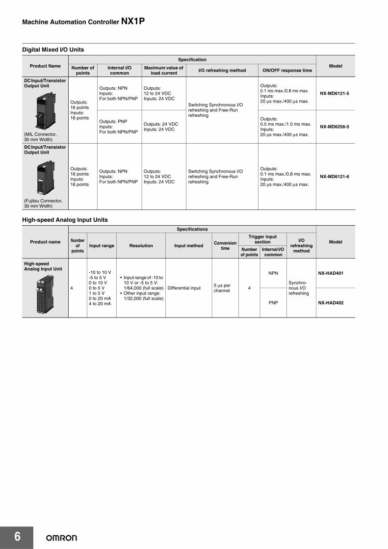
Digital Mixed I/O Units
High-speed Analog Input Units
Product NameSpecification
ModelNumber of points
Internal I/O common
Maximum value of load current I/O refreshing method ON/OFF response time
DC Input/Transistor Output Unit
(MIL Connector, 30 mm Width)
Outputs:16 pointsInputs:16 points
Outputs: NPNInputs: For both NPN/PNP
Outputs:12 to 24 VDCInputs: 24 VDC
Switching Synchronous I/O refreshing and Free-Run refreshing
Outputs:0.1 ms max./0.8 ms max.Inputs:20 μs max./400 μs max.
NX-MD6121-5
Outputs: PNPInputs: For both NPN/PNP
Outputs: 24 VDCInputs: 24 VDC
Outputs:0.5 ms max./1.0 ms max.Inputs:20 μs max./400 μs max.
NX-MD6256-5
DC Input/Transistor Output Unit
(Fujitsu Connector, 30 mm Width)
Outputs:16 pointsInputs:16 points
Outputs: NPNInputs: For both NPN/PNP
Outputs:12 to 24 VDCInputs: 24 VDC
Switching Synchronous I/O refreshing and Free-Run refreshing
Outputs:0.1 ms max./0.8 ms max.Inputs:20 μs max./400 μs max.
NX-MD6121-6
Product name
Specifications
ModelNumber of
pointsInput range Resolution Input method Conversion
time
Trigger input section I/O
refreshing methodNumber
of pointsInternal I/O common
High-speed Analog Input Unit
4
-10 to 10 V-5 to 5 V0 to 10 V0 to 5 V1 to 5 V0 to 20 mA4 to 20 mA
• Input range of -10 to 10 V or -5 to 5 V:1/64,000 (full scale)
• Other input range:1/32,000 (full scale)
Differential input 5 μs per channel 4
NPN
Synchro-nous I/O refreshing
NX-HAD401
PNP NX-HAD402

Machine Automation Controller NX1P
7
Analog Input Units
Analog Output Units
Product Name
Specification
ModelNumber of
points
Input range Resolution
Conversion value, decimal number
(0 to 100%)
Over all accuracy
(25°C)Input method Conversion
timeInput
impedance I/O refreshing method
Voltage Input Unit
2 points
-10 to +10 V
1/8000 -4000 to 4000 ±0.2%(full scale)
Single-ended input 250 μs/
point
1 MΩ min.
Free-Run refreshingNX-AD2603
Differential Input NX-AD2604
1/30000 -15000 to 15000 ±0.1%(full scale) Differential Input 10 μs/
point
Selectable Synchronous I/O refreshing or Free-Run refreshing
NX-AD2608
4 points
1/8000 -4000 to 4000 ±0.2%(full scale)
Single-ended input 250 μs/
point Free-Run refreshingNX-AD3603
Differential Input NX-AD3604
1/30000 -15000 to 15000 ±0.1%(full scale) Differential Input 10 μs/
point
Selectable Synchronous I/O refreshing or Free-Run refreshing
NX-AD3608
8 points
1/8000 -4000 to 4000 ±0.2%(full scale)
Single-ended input 250 μs/
point Free-Run refreshingNX-AD4603
Differential Input NX-AD4604
1/30000 -15000 to 15000 ±0.1%(full scale) Differential Input 10 μs/
point
Selectable Synchronous I/O refreshing or Free-Run refreshing
NX-AD4608
Current Input Unit
2 points
4 to 20 mA
1/8000 0 to 8000 ±0.2%(full scale)
Single-ended input 250 μs/
point
250 Ω
Free-Run refreshingNX-AD2203
Differential Input NX-AD2204
1/30000 0 to 30000 ±0.1%(full scale) Differential Input 10 μs/
point
Selectable Synchronous I/O refreshing or Free-Run refreshing
NX-AD2208
4 points
1/8000 0 to 8000 ±0.2%(full scale)
Single-ended input 250 μs/
point Free-Run refreshingNX-AD3203
Differential Input NX-AD3204
1/30000 0 to 30000 ±0.1%(full scale) Differential Input 10 μs/
point
Selectable Synchronous I/O refreshing or Free-Run refreshing
NX-AD3208
8 points
1/8000 0 to 8000 ±0.2%(full scale)
Single-ended input 250 μs/
point85 Ω
Free-Run refreshingNX-AD4203
Differential Input NX-AD4204
1/30000 0 to 30000 ±0.1%(full scale) Differential Input 10 μs/
point
Selectable Synchronous I/O refreshing or Free-Run refreshing
NX-AD4208
Product Name
Specification
ModelNumber of
pointsInput range Resolution
Output setting value, decimal
number (0 to 100%)
Over all accuracy
(25°C)Conversion time I/O refreshing method
Voltage Output Unit
2 points
-10 to +10 V
1/8000 -4000 to 4000 ±0.3%(full scale) 250 μs/point Free-Run refreshing NX-DA2603
1/30000 -15000 to 15000 ±0.1%(full scale) 10 μs/point Selectable Synchronous I/O
refreshing or Free-Run refreshing NX-DA2605
4 points1/8000 -4000 to 4000 ±0.3%
(full scale) 250 μs/point Free-Run refreshing NX-DA3603
1/30000 -15000 to 15000 ±0.1%(full scale) 10 μs/point Selectable Synchronous I/O
refreshing or Free-Run refreshing NX-DA3605
Current Output Unit
2 points
4 to 20 mA
1/8000 0 to 8000 ±0.3%(full scale) 250 μs/point Free-Run refreshing NX-DA2203
1/30000 0 to 30000 ±0.1%(full scale) 10 μs/point Selectable Synchronous I/O
refreshing or Free-Run refreshing NX-DA2205
4 points1/8000 0 to 8000 ±0.3%
(full scale) 250 μs/point Free-Run refreshing NX-DA3203
1/30000 0 to 30000 ±0.1%(full scale) 10 μs/point Selectable Synchronous I/O
refreshing or Free-Run refreshing NX-DA3205

Machine Automation Controller NX1P
8
Temperature Control Units
Temperature Input Units
*1. The resolution is 0.2°C max. when the input type is R, S, or W.*2. The NX-TS2202 and NX-TS3202 only supports Pt100 three-wire sensor.
Heater Burnout Detection Units
Product name
Specifications
ModelNumber of
channelsInput type Output
Number of output
points
Number of CT input points
Control type Conversion time
I/O refreshing
method
Temperature Control Unit 2-channel Type
2
Universal input (thermocou-ple, resistance thermometer)
Voltage output (for driving SSR) 2
2 Standard control
50 ms Free-Run refreshing
NX-TC2405
None Standard control NX-TC2406
Voltage output (for driving SSR) 4 None Heating/cooling control NX-TC2407
Linear current output 2 None Standard control NX-TC2408
Temperature Control Unit 4-channel Type
4
Voltage output (for driving SSR) 4
4 Standard control NX-TC3405
None Standard control NX-TC3406
Voltage output (for driving SSR) 8 None Heating/cooling control NX-TC3407
Linear current output 4 None Standard control NX-TC3408
Product Name
SpecificationModelNumber
of points Input type Resolution(25°C) Over all accuracy (25°C) Conversion time I/O refreshing
method Terminals
Thermocouple Input type
2 points
Thermocouple
0.1°C max. *1
Refer to your OMRON website for details.
250 ms/Unit
Free-Run refreshing
16 Terminals NX-TS2101
4 points 16 Terminals x 2 NX-TS3101
2 points0.01°C max. 10 ms/Unit
16 Terminals NX-TS2102
4 points 16 Terminals x 2 NX-TS3102
2 points0.001°C max. 60 ms/Unit
16 Terminals NX-TS2104
4 points 16 Terminals x 2 NX-TS3104
Resistance Thermometer Input type
2 points
Resistance Thermometer(Pt100/Pt1000, three-wire) *2
0.1°C max. 250 ms/Unit16 Terminals NX-TS2201
4 points 16 Terminals x 2 NX-TS3201
2 points0.01°C max. 10 ms/Unit
16 Terminals NX-TS2202
4 points 16 Terminals x 2 NX-TS3202
2 points0.001°C max. 60 ms/Unit
16 Terminals NX-TS2204
4 points 16 Terminals x 2 NX-TS3204
Product Name
Specification
ModelCT input section Control output sectionNumber of
inputsMaximum heater
currentNumber of
outputs Internal I/O common Maximum load current Rated voltage I/O refreshing
method
Heater Burnout Detection Unit
4 50 AAC 4
NPN
0.1 A/point, 0.4 A/Unit
12 to 24 VDC
Free-Run refreshing
NX-HB3101
PNP 24 VDC NX-HB3201

Machine Automation Controller NX1P
9
Load Cell Input Unit
* Refer to the NX-series Load Cell Input Unit User’s Manual (W565) for detailed information on I/O refresh cycle.
Position interface: Incremental Encoder Input Units
Position interface: SSI Input Units
Position interface: Pulse Output Units
*1. This is the number of pulse output channels.*2. Unit version 1.2 or later and an NX-ECC203 EtherCAT Coupler Unit are required.
Communications Interface Units
Product NameSpecification
ModelNumber of Model Standards points
Conversion cycle I/O refreshing method * Load cell excitation
voltage Input range
Load Cell Input Unit
1 125 μs• Free-Run refreshing• Synchronous I/O refreshing• Task period prioritized refreshing
5 VDC ± 10% -5.0 to 5.0 mV/V NX-RS1201
Product NameSpecification
ModelNumber of channels
External inputs
Maximum response frequency I/O refreshing method Number of I/O
entry mappingsIncremental Encoder Input Unit
1 (NPN) 3 (NPN)500 kHz
• Free-Run refreshing• Synchronous I/O refreshing
1/1
NX-EC0112
1 (PNP) 3 (PNP) NX-EC0122
13 (NPN)
4 MHzNX-EC0132
3 (PNP) NX-EC0142
2 (NPN)None 500 kHz 2/2
NX-EC0212
2 (PNP) NX-EC0222
Product NameSpecification
ModelNumber of channels Input/Output form Maximum data length Encoder power
supply Type of external connections
SSI Input Unit
1 EIA standard RS-422-A 32 bits 24 VDC,
0.3 A/CHScrewless push-in terminal block (12 terminals) NX-ECS112
2 EIA standard RS-422-A 32 bits 24 VDC,
0.3 A/CHScrewless push-in terminal block (12 terminals) NX-ECS212
Product Name
Specification
ModelNumber of channels *1
External inputs
External outputs
Maximum pulse output
speedI/O refreshing method Number of I/O
entry mappingsControl output
interface
Pulse Output Unit
1 (NPN) 2 (NPN) 1 (NPN)500 kpps
• Synchronous I/O refreshing• Task period prioritized
refreshing *2
1/1 Open collector output
NX-PG0112
1 (PNP) 2 (PNP) 1 (PNP) NX-PG0122
2
5 inputs/CH (NPN)
3 outputs/CH (NPN)
4 Mpps
2/2
Line driver output
NX-PG0232-5
5 inputs/CH (PNP)
3 outputs/CH (PNP) NX-PG0242-5
4
5 inputs/CH (NPN)
3 outputs/CH (NPN)
4/4NX-PG0332-5
5 inputs/CH (PNP)
3 outputs/CH (PNP) NX-PG0342-5
Product Name Serial interface External connection terminals Number of serial ports Communications protocol Model
Communications Interface Unit
RS-232C
Screwless Clamping Terminal Block 1 port
• No-protocol• Signal lines
NX-CIF101
RS-422A/485 NX-CIF105
RS-232C D-Sub connector 2 ports NX-CIF210

Machine Automation Controller NX1P
10
RFID Units
IO-Link Master Unit
System Units
* Use the NX-PF0730 at 4 A or less on the CPU Rack where the NX1P2 CPU Unit is mounted.
Product name Amplifier/Antenna No. of unit numbers used ModelRFID Unit (1Ch)
V680 series
1 NX-V680C1
RFID Unit (2Ch)
2 NX-V680C2
Product NameSpecification
ModelNumber of IO-Link ports I/O refreshing method I/O connection terminals
IO-Link Master Unit
4 Free-Run refreshing Screwless clamping terminal block NX-ILM400
Product Name Specification Model
Additional NX Unit Power Supply Unit
Power supply voltage: 24 VDC (20.4 to 28.8 VDC)NX Bus power supply capacity: 10 W max. NX-PD1000
Additional I/O Power Supply Unit Power supply voltage: 5 to 24 VDC (4.5 to 28.8 VDC)
I/O power feed maximum current: 4 A NX-PF0630
Power supply voltage: 5 to 24 VDC (4.5 to 28.8 VDC)I/O power feed maximum current: 10 A * NX-PF0730
I/O Power Supply Connection Unit Number of I/O power terminals: IOG: 16 terminals
Current capacity of I/O power terminal: 4 A/terminal max. NX-PC0010
Number of I/O power terminals: IOV: 16 terminalsCurrent capacity of I/O power terminal: 4 A/terminal max. NX-PC0020
Number of I/O power terminals: IOV: 8 terminals, IOG: 8 terminalsCurrent capacity of I/O power terminal: 4 A/terminal max NX-PC0030
Shield Connection Unit
Number of shield terminals: 14 terminals(The following two terminals are functional ground terminals.) NX-TBX01

Machine Automation Controller NX1P
11
EtherCAT Coupler UnitsNX-series Units on previous pages and NX-series Safety Units can be used by connecting to the EtherCAT Coupler Unit that is connected to the built-in EtherCAT port on the NX1P2 CPU Unit.
*1. One End Cover NX-END01 is provided with the EtherCAT Coupler Unit.*2. This depends on the specifications of the EtherCAT master. For example, the values are as follows when the EtherCAT Coupler Unit is
connected to the built-in EtherCAT port on an NJ5-series CPU Unit: 500 μs, 1,000 μs, 2,000 μs, and 4,000 μs. Refer to the NJ/NX-series CPU Unit Built-in EtherCAT Port User’ Manual (Cat. No. W505) for the specifications of the built-in EtherCAT ports on NJ/NX-series CPU Units. This also depends on the unit configuration.
Safety CPU Units
Note: Connect the Safety CPU Unit to the NX1P2 CPU Unit via the EtherCAT Coupler Unit.
Safety Input Units
Note: Connect the Safety Input Unit to the NX1P2 CPU Unit via the EtherCAT Coupler Unit.
Safety Output Units
Note: Connect the Safety Output Unit to the NX1P2 CPU Unit via the EtherCAT Coupler Unit.
Product Name Communications cycle in DC Mode Current consumption Maximum I/O power supply current Model
EtherCAT Coupler Unit *1 250 to 4000 μs *2
1.45 W max.
4 A NX-ECC201
250 to 4000 μs *2
10 A
NX-ECC202
125 to 10000 μs *2 1.25 W max. NX-ECC203
AppearanceSpecification
ModelMaximum number of safety I/O points Program capacity Number of safety master
connections I/O refreshing method Unit version
256 points 512 KB 32 Free-Run refreshing Ver.1.1 NX-SL3300
1024 points 2048 KB 128 Free-Run refreshing Ver.1.1 NX-SL3500
Appearance
Specification
ModelNumber of safety input points
Number of test output points
Internal I/O common
Rated input
voltage
OMRON special safety input
devices
Number of safety slave
connections
I/O refreshing
method
Unit version
4 points 2 pointsSinking inputs (PNP)
24 VDC Can be connected. 1 Free-Run
refreshing Ver.1.1 NX-SIH400
8 points 2 pointsSinking inputs (PNP)
24 VDC Cannot be connected. 1 Free-Run
refreshing Ver.1.0 NX-SID800
Appearance
Specification
ModelNumber of Model safety output points
Internal I/O common Maximum load current Rated voltage
Number of safety slave connections
I/O refreshing
method
Unit version
2 pointsSourcingoutputs(PNP)
2.0 A/point, 4.0 A/Unit at 40°C, and 2.5A/Unit at 55°CThe maximum load current depends on the installation orientation and ambient temperature.
24 VDC 1 Free-Run refreshing Ver.1.0 NX-SOH200
4 pointsSourcingoutputs(PNP)
0.5 A/pointand2.0 A/Unit
24 VDC 1 Free-Run refreshing Ver.1.0 NX-SOD400

Machine Automation Controller NX1P
12
NX Unit Power Supply SystemAdd one or more NX-PF Additional I/O Power Supply Units when I/O power is supplied from the NX bus to NX Units connected to the CPU Unit. Check the table below.
Note: Refer to the NX-series NX1P2 CPU Unit Hardware User’s Manual (Cat. No. W578) for the NX Unit power supply system.
NX Units ModelNX-PF Additional I/O Power Supply
Unit required
Digital Input Units
NX-ID3317 YesNX-ID3343 YesNX-ID3344 YesNX-ID3417 YesNX-ID3443 YesNX-ID3444 YesNX-ID4342 YesNX-ID4442 YesNX-ID5342 YesNX-ID5442 YesNX-ID5142-1 NoNX-ID5142-5 NoNX-ID6142-5 NoNX-ID6142-6 NoNX-IA3117 No
Digital output Units
NX-OD2154 YesNX-OD2258 YesNX-OD3121 YesNX-OD3153 YesNX-OD3256 YesNX-OD3257 YesNX-OD3268 NoNX-OD4121 YesNX-OD4256 YesNX-OD5121 YesNX-OD5256 YesNX-OD5121-1 NoNX-OD5256-1 NoNX-OD5121-5 NoNX-OD5256-5 NoNX-OD6121-5 NoNX-OD6256-5 NoNX-OD6121-6 NoNX-OC2633 NoNX-OC2733 NoNX-OC4633 No
Digital Mixed I/O Units
NX-MD6121-5 NoNX-MD6256-5 NoNX-MD6121-6 No
High-speed Analog Input Units
NX-HAD401 YesNX-HAD402 Yes
Analog Input Units
NX-AD2603 YesNX-AD2604 NoNX-AD2608 NoNX-AD3603 YesNX-AD3604 NoNX-AD3608 NoNX-AD4603 YesNX-AD4604 NoNX-AD4608 NoNX-AD2203 YesNX-AD2204 NoNX-AD2208 NoNX-AD3203 YesNX-AD3204 No
NX Units ModelNX-PF Additional I/O Power Supply
Unit required
Analog Input Units
NX-AD3208 NoNX-AD4203 YesNX-AD4204 NoNX-AD4208 No
Analog Output Units
NX-DA2603 YesNX-DA2605 YesNX-DA3603 YesNX-DA3605 YesNX-DA2203 YesNX-DA2205 YesNX-DA3203 YesNX-DA3205 Yes
Temperature Control Units
NX-TC2405 YesNX-TC2406 YesNX-TC2407 YesNX-TC2408 YesNX-TC3405 YesNX-TC3406 YesNX-TC3407 YesNX-TC3408 Yes
Temperature Input Units
NX-TS2101 NoNX-TS3101 NoNX-TS2102 NoNX-TS3102 NoNX-TS2104 NoNX-TS3104 NoNX-TS2201 NoNX-TS3201 NoNX-TS2202 NoNX-TS3202 NoNX-TS2204 NoNX-TS3204 No
Heater Burnout Detection Units
NX-HB3101 YesNX-HB3201 Yes
Load Cell Input Unit NX-RS1201 No
Position interface: Incremental Encoder Input Units
NX-EC0112 YesNX-EC0122 YesNX-EC0132 YesNX-EC0142 YesNX-EC0212 YesNX-EC0222 Yes
Position interface: SSI Input Units
NX-ECS112 YesNX-ECS212 Yes
Position interface: Pulse Output Units
NX-PG0112 YesNX-PG0122 YesNX-PG0232-5 NoNX-PG0242-5 NoNX-PG0332-5 NoNX-PG0342-5 No
Communications Interface Units
NX-CIF101 NoNX-CIF105 NoNX-CIF210 No
RFID UnitsNX-V680C1 YesNX-V680C2 Yes
IO-Link Master Unit NX-ILM400 Yes

Machine Automation Controller NX1P
13
Automation Software Sysmac StudioPlease purchase a DVD and required number of licenses the first time you purchase the Sysmac Studio. DVDs and licenses are available individually. Each model of licenses does not include any DVD.
*1. Model "SYSMAC-SE200D-64" runs on Windows 10 (64 bit).*2. Multi licenses are available for the Sysmac Studio (3, 10, 30, or 50 licenses).
Collection of software functional components Sysmac LibraryPlease download it from following URL and install to Sysmac Studio.
http://www.ia.omron.com/sysmac_library/
Typical Models
Product NameSpecification
ModelNumber of licenses Media
Sysmac StudioStandard EditionVer.1.
The Sysmac Studio is the software that provides an integrated environment for setting, programming, debugging and maintenance of machine automation controllers including the NJ/NX-series CPU Units, NY-series Industrial PC, EtherCAT Slave, and the HMI.
Sysmac Studio runs on the following OS.Windows 7 (32-bit/64-bit version)/Windows 8 (32-bit/64-bit version)/Windows 8.1 (32-bit/64-bit version)/Windows 10 (32-bit/64-bit version) *1
The Sysmac Studio Standard Edition DVD includes Support Software to set up EtherNet/IP Units, DeviceNet slaves, Serial Communications Units, and Support Software for creating screens on HMIs (CX-Designer).Refer to your OMRON website for details.
--- (Media only)
Sysmac Studio (32-bit) DVD SYSMAC-SE200D
--- (Media only)
Sysmac Studio (64-bit) DVD SYSMAC-SE200D-64
1 license *2 --- SYSMAC-SE201L
Product Features Model
Vibration Suppression Library The Vibration Suppression Library is used to suppress residual vibration caused by the operation of machines. SYSMAC-XR006
Device Operation Monitor Library The Device Operation Monitor Library is used to monitor the operation of devices such as air cylinders, sensors, motors, and other devices. SYSMAC-XR008
Dimension Measurement Library The Dimension Measurement Library is used to dimension measurement with ZW-8000/7000/5000 Confocal Fiber Displacement Sensor, or E9NC-TA0 Contact-Type Smart Sensor. SYSMAC-XR014

Machine Automation Controller NX1P
14
Recommended EtherCAT and EtherNet/IP Communications CablesUse Straight STP (shielded twisted-pair) cable of category 5 or higher with double shielding (braiding and aluminum foil tape) for EtherCAT.For EtherNet/IP, required specification for the communications cables varies depending on the baud rate.For 100BASE-TX/10BASE-T, use an STP (shielded twisted-pair) cable of Ethernet category 5 or higher.
Cable with Connectors
*1. Cables with standard RJ45 plugs are available in the following lengths: 0.2 m, 0.3 m, 0.5 m, 1 m, 1.5 m, 2 m, 3 m, 5 m, 7.5 m, 10 m, 15 m, 20 m.Cables with rugged RJ45 plugs are available in the following lengths: 0.3 m, 0.5 m, 1 m, 2 m, 3 m, 5 m, 10 m, 15 m.For details, refer to the Industrial Ethernet Connectors Catalog (Cat. No. G019).
*2. The lineup features Low Smoke Zero Halogen cables for in-cabinet use and PUR cables for out-of-cabinet use. Although the LSZH cable is single shielded, its communications and noise characteristics meet the standards.
*3. Cable colors are available in yellow, green, and blue.*4. For details, contact your OMRON representative.
Cables / Connectors
*1. We recommend you to use the above Cable and RJ45 Connector together.*2. We recommend you to use the above Cable and RJ45 Assembly Connector together.
Item Recommendedmanufacturer Cable length (m) Model
Wire Gauge and Number of Pairs: AWG26, 4-pair CableCable Sheath material: LSZH *2
Cable with Connectors on Both Ends (RJ45/RJ45)Standard RJ45 plug type *1Cable color: Yellow *3
OMRON 0.3 XS6W-6LSZH8SS30CM-Y
0.5 XS6W-6LSZH8SS50CM-Y
1 XS6W-6LSZH8SS100CM-Y
2 XS6W-6LSZH8SS200CM-Y
3 XS6W-6LSZH8SS300CM-Y
5 XS6W-6LSZH8SS500CM-Y
Wire Gauge and Number of Pairs: AWG22, 2-pair cable
Cable with Connectors on Both Ends (RJ45/RJ45)Rugged RJ45 plug type *1Cable color: Light blue
OMRON 0.3 XS5W-T421-AMD-K
0.5 XS5W-T421-BMD-K
1 XS5W-T421-CMD-K
2 XS5W-T421-DMD-K
5 XS5W-T421-GMD-K
10 XS5W-T421-JMD-K
Cable with Connectors on Both Ends (M12 Straight/M12 Straight)Shield Strengthening Connector cable *4M12/Smartclick ConnectorsCable color: Black
OMRON 0.5 XS5W-T421-BM2-SS
1 XS5W-T421-CM2-SS
2 XS5W-T421-DM2-SS
3 XS5W-T421-EM2-SS
5 XS5W-T421-GM2-SS
10 XS5W-T421-JM2-SS
Cable with Connectors on Both Ends (M12 Straight/RJ45)Shield Strengthening Connector cable *4M12/Smartclick ConnectorsRugged RJ45 plug typeCable color: Black
OMRON 0.5 XS5W-T421-BMC-SS
1 XS5W-T421-CMC-SS
2 XS5W-T421-DMC-SS
3 XS5W-T421-EMC-SS
5 XS5W-T421-GMC-SS
10 XS5W-T421-JMC-SS
Item Recommended manufacturer Model
Products for EtherCAT or EtherNet/IP(1000BASE-T/100BASE-TX)
Wire Gauge and Number ofPairs: AWG24, 4-pairCable
CablesHitachi Metals, Ltd. NETSTAR-C5E SAB
0.5 × 4P CP *1
Kuramo Electric Co. KETH-SB *1
RJ45 Connectors Panduit Corporation MPS588-C *1
Products for EtherCAT or EtherNet/IP(100BASE-TX/10BASE-T) Wire Gauge and Number of
Pairs: AWG22, 2-pairCable
Cables Kuramo Electric Co. KETH-PSB-OMR *2
JMACS Japan Co., Ltd. PNET/B *2
RJ45 Assembly Connector OMRON
XS6G-T421-1 *2

Machine Automation Controller NX1P
15
Optional Products/Maintenance Products/DIN Track Accessories
*1. EtherCAT junction slaves cannot be used for EtherNet/IP and Ethernet.*2. Industrial switching hubs cannot be used for EtherCAT.*3. 16 GB memory card can be used for a CPU Unit with unit version 1.21 or later.*4. Use the NX-END02 End Cover only for the CPU Unit and the NX-END01 End Cover only for the EtherCAT Coupler Unit.
Product Name Specification Model
EtherCAT junction slaves *1
3 ports. Power supply voltage: 20.4 to 28.8 VDC (24 VDC -15 to +20%).Current consumption (A): 0.08 GX-JC03
6 ports. Power supply voltage: 20.4 to 28.8 VDC (24 VDC -15 to +20%).Current consumption (A): 0.17 GX-JC06
Industrial Switching Hubs for EtherNet/IP and Ethernet *2
Quality of Service (QoS):EtherNet/IP control data priority
10/100BASE-TX, Auto-Negotiation
5 ports. Current consumption (A): 0.07Power supply connector included. W4S1-05D
Memory CardsSD memory card, 2 GB HMC-SD291SDHC memory card, 4 GB HMC-SD492
SDHC memory card, 16GB HMC-SD1A1 *3
BatteryThe battery is not mounted when the product is shipped.To turn OFF the power supply to the equipment for a certain period of time by using the clock data for programming, event logs, etc., you need a separately-sold battery to retain the clock data. Refer to the Battery page for details.
CJ1W-BAT01
End Cover(For NX1P2 CPU Unit) *4
Must be connected to the right end of the CPU Rack. One End Cover is provided with the CPU Unit. NX-END02
End Cover(For EtherCAT Coupler Unit) *4
One End Cover is provided with the EtherCAT Coupler Unit. NX-END01
DIN TracksLength: 0.5 m; Height: 7.3 mm PFP-50N
Length: 1 m; Height: 7.3 mm PFP-100N
End Plate There are 2 stoppers provided with CPU Units and I/O Interface Units as standard accessories to secure the Units on the DIN Track. PFP-M
Unit/Terminal Block Coding Pins
For 10 Units(Terminal Block: 30 pins, Unit: 30 pins) NX-AUX02
DIN Track Insulation Spacers
A Spacer to insulate the control panel from the DIN Track.To insulate the EtherCAT Slave Terminal from the control panel, use Din Track Insulation Spacers. NX-AUX01
Product NameSpecification
ModelNo. of terminals Terminal number
indications Ground terminal mark Terminal current capacity
Terminal Blocks
8 A/B
None
10 A
NX-TBA08212 A/B NX-TBA122
16 A/B NX-TBA162
12 C/D NX-TBB12216 C/D NX-TBB162
8 A/BProvided
NX-TBC082
16 A/B NX-TBC162

Machine Automation Controller NX1P
16
Electrical and Mechanical Specifications
*1. Includes the End Cover, and does not include projecting parts.*2. Includes the End Cover. The weight of the End Cover is 82 g.*3. Includes the SD Memory Card and Option Board. The NX Unit power consumption to NX Units is not included.*4. The inrush current may vary depending on the operating condition and other conditions. Therefore, select fuses, breakers, and external power
supply devices that have enough margin in characteristic and capacity, considering the condition under which the devices are used.*5. The amount of current that can be passed constantly through the terminal. Do no exceed this current value when you use a through-wiring for
the Unit power supply.*6. When the type of the I/O power supply to NX Units you use is the supply from NX bus, an Additional I/O Power Supply Unit is required. The
maximum I/O power supply current from an Additional I/O Power Supply Unit is 4 A. Refer to the NX-series NX1P2 CPU Unit Hardware User’s Manual (Cat. No. W578) for details.
General Specifications
* Refer to the OMRON website (http://www.ia.omron.com/) or consult your OMRON representative for the most recent applicable standards for each model.
Item SpecificationModel NX1P2-140DT NX1P2-9024DT
Enclosure Mounted in a panel
Dimensions (mm) *1 154 × 100 × 71 mm (W×H×D) 130 × 100 × 71 mm (W×H×D)
Weight *2 NX1P2-140DT: 650 gNX1P2-140DT1: 660 g
NX1P2-9024DT: 590 gNX1P2-9024DT1: 590 g
Unit power supply
Power supply voltage 24 VDC (20.4 to 28.8 VDC)
Unit power consumption *3 NX1P2-140DT: 7.05 WNX1P2-140DT1: 6.85 W
NX1P2-9024DT: 6.70 WNX1P2-9024DT1: 6.40 W
Inrush current *4
For cold start at room temperature:10 A max./0.1 ms max.and2.5 A max./150 ms max.
Current capacity of power supply terminal *5 4 A max.
Isolation method No isolation: between the Unit power supply terminal and internal circuit
Power supply to the NX Unit power supply
NX Unit power supply capacity 10 W max.
NX Unit power supply efficiency 80 %
Isolation method No isolation: between the Unit power supply terminal and NX Unit power supply
I/O Power Supply to NX Units Not provided *6
External connection terminals
Communication connector RJ45 for EtherNet/IP Communications × 1RJ45 for EtherCAT Communications × 1
Screwless clamping terminal block
For Unit power supply input, grounding, and input signal: 1 (Removable)For output signal: 1 (Removable)
Output terminal (service supply) Not provided
RUN output terminal Not provided
NX bus connector 8 NX Units can be connected
Option board slot 2 1
Item Specification
Enclosure Mounted in a panel
Grounding method Ground to less than 100 Ω.
Operating environment
Ambient operating temperature 0 to 55°C
Ambient operating humidity 10% to 95% (with no condensation)
Atmosphere Must be free from corrosive gases.
Ambient storage temperature -25 to 70°C (excluding battery)
Altitude 2,000 m max.
Pollution degree 2 or less: Meets IEC 61010-2-201.
Noise immunity 2 kV on power supply line (Conforms to IEC 61000-4-4.)
Overvoltage category Category II: Meets IEC 61010-2-201.
EMC immunity level Zone B
Vibration resistanceConforms to IEC 60068-2-6.5 to 8.4 Hz with 3.5-mm amplitude, 8.4 to 150 Hz, acceleration of 9.8 m/s2
100 min each in X, Y, and Z directions (10 sweeps of 10 min each = 100 min total)
Shock resistance Conforms to IEC 60068-2-27.147 m/s2, 3 times in X, Y, and Z directions
BatteryLife 5 years (Power ON time rate 0% (power OFF))
Model CJ1W-BAT01 (sold separately)
Applicable standards *
EU Directives EN 61131-2
cULus Listed UL 61010-2-201 and ANSI/ISA 12.12.01
Shipbuilding Standards NK, LR
Other than the above. RCM, KC, EAC

Machine Automation Controller NX1P
17
Performance Specifications
ItemNX1P2-
11/111
10/101
90/901
Processing time
Instruction execution times
LD instruction 3.3 ns
Math instructions (for long real data) 70 ns or more
Programming
Program capacity *1
Size 1.5 MB
QuantityNumber of POU definitions 450
Number of POU Instances 1,800
Memory capacity for variables *2
Retain attributes
Size 32 kB
Number of variables 5,000
No Retain attributes
Size 2 MB
Number of variables 90,000
Data types Number of data types 1,000
Memory for CJ-series Units (Can be specified with AT specifications for variables.)
CIO Area 0 to 6,144 channel (0 to 6,143) *3
Work Area 0 to 512 channel (W0 to W511) *3
Holding Area 0 to 1,536 channel (H0 to H1,535) *4
DM Area 0 to 16,000 channel (D0 to F15,999) *4
EM Area ---
Motion control
Number of controlled axes *5
Maximum number of controlled axes 12 axes 10 axes 4 axes
Motion control axes 8 axes 6 axes ---
Single-axis position control axes 4 axes 4 axes 4 axes
Maximum number of used real axes 8 axes 6 axes 4 axes
Used motion control servo axes 4 axes 2 axes ---
Used single-axis position control servo axes 4 axes 4 axes 4 axes
Maximum number of axes for linear interpolation axis control 4 axes per axes group ---
Number of axes for circular interpolation axis control 2 axes per axes group ---
Maximum number of axes groups 8 axes groups ---
Motion control period Same as the period for primary periodic task
CamsNumber of cam data points
Maximum points per cam table 65,535 points ---
Maximum points for all cam tables 262,140 points ---
Maximum number of cam tables 80 tables ---
Position units Pulse, mm, μm, nm, degree, and inch
Override factors 0.00% or 0.01% to 500.00%
Built-in EtherNet/IP port
Number of ports 1
Physical layer 10BASE-T, 100BASE-TX
Frame length 1,514 bytes max.
Media access method CSMA/CD
Modulation Baseband
Topology Star
Baud rate 100 Mbps/s (100BASE-TX)
Transmission media STP (shielded, twisted-pair) cable of Ethernet category 5, 5e or higher
Maximum transmission distance between Ethernet switch and node 100 m
Maximum number of cascade connections There are no restrictions if an Ethernet switch is used.
CIP service: Tag data links (cyclic communications)
Maximum number of connections 32
Packet interval *6 Can be set for each connection.2 to 10,000 ms in 1-ms increments
Permissible communications band 3,000 pps *7 (including heartbeat)
Maximum number of tag sets 32
Tag types Network variablesCIO/WR/HR/DM
Number of tags per connection (i.e., per tag set) 8 (7 tags if Controller status is included in the tag set.)
Maximum number of tags 256
Maximum link data size per node (total size for all tags) 19,200 bytes
Maximum data size per connection 600 bytes
Maximum number of registrable tag sets 32(1 connection = 1 tag set)
Maximum tag set size 600 bytes (Two bytes are used if Controller status is included in the tag set.)
Multi-cast packet filter *8 Supported.

Machine Automation Controller NX1P
18
*1. Execution objects and variable tables (including variable names)*2. Memory used for CJ-series Units is included.*3. The value can be set in 1 ch increments. The value is included in the total size of variables without a Retain attribute.*4. The value can be set in 1 ch increments. The value is included in the total size of variables with a Retain attribute.*5. Refer to the NJ/NX-series CPU Unit Motion Control User’s Manual (Cat. No. W507) for the description of this term.*6. Data will be refreshed at the set interval, regardless of the number of nodes.*7. “pps“ means packets per second, i.e., the number of communications packets that can be sent or received in one second.*8. As the EtherNet/IP port implements the IGMP client, unnecessary multi-cast packets can be filtered by using an Ethernet switch that supports
IGMP Snooping.*9. Ring topology is supported with the project version 1.40 or later.
Slaves on a ring topology should support a ring topology. If Omron slaves, please see the user's manual of slaves.*10.For project unit version earlier than 1.40, the data must be within one frame.
Built-in EtherNet/IP port
CIP message service:Explicit messages
Class 3 (number of connections) 32 (clients plus server)
UCMM (non-connection type)
Maximum number of clients that can communicate at one time 32
Maximum number of servers that can communicate at one time 32
Number of TCP sockets 30
Secure Socket Service
Maximum number of Secure Socket 30
TLS Version 1.2
Built-in EtherCAT port
Communications standard IEC 61158 Type12
EtherCAT master specifications Class B (Feature Pack Motion Control compliant)
Physical layer 100BASE-TX
Modulation Baseband
Baud rate 100 Mbps (100BASE-TX)
Duplex mode Auto
Topology Line, daisy chain, branching and ring *9
Transmission media Twisted-pair cable of category 5 or higher (double-shielded straight cable with aluminum tape and braiding)
Maximum transmission distance between nodes 100 m
Maximum number of slaves 16
Range of node addresses that can be set 1 to 192
Maximum process data size Input: 1,434 bytesOutput: 1,434 bytes *10
Maximum process data size per slave Input: 1,434 bytesOutput: 1,434 bytes
Communications cycle 2,000 μs to 8,000 μs in 250-μs increments
Sync jitter 1 μs max.
Serial Communications (Serial Communications Option Board)
Communications method half duplex
Synchronization Start-stop
Baud rate 1.2/2.4/4.8/9.6/19.2/38.4/57.6/115.2 kbps
Transmission distance Depends on Option Board.
Supported protocol Host link, Modbus-RTU master, and no-protocol
Unit configuration
Maximum number of connectable Units
Maximum number of NX Units that can be mounted to the CPU Unit 8
Maximum number of NX Units for entire controller24On CPU Rack: 8On EtherCAT Slave Terminals: 16
Power supplyModel A non-isolated power supply for DC input is built into the CPU Unit.
Power OFF detection time 2 to 8 ms
Option Board Number of slots 2 2 1
Built-in I/O
Input Number of points 24 24 14
OutputNumber of points 16 16 10
Load short-circuit protection 11DT/10DT/9024DT: Not provided (NPN)11DT1/10DT1/9024DT1: Provided (PNP)
Internal clockAccuracy
At ambient temperature of 55°C: -3.5 to 0.5 min error per monthAt ambient temperature of 25°C: -1.5 to 1.5 min error per monthAt ambient temperature of 0°C: -3 to 1 min error per month
Retention time of built-in capacitor At ambient temperature of 40°C: 10 days
ItemNX1P2-
11/111
10/101
90/901

Machine Automation Controller NX1P
19
Function SpecificationsItem NX1P2
Tasks
Function I/O refresh and the user program are executed in units that are called tasks. Tasks are used to specify execution conditions and execution priority.
Periodically Executed Tasks
Maximum Number of Primary Periodic Tasks
1
Maximum Number of Periodic Tasks 2
Conditionally Executed Tasks
Maximum Number of Event Tasks 32
Execution Condition When Activate Event Task instruction is executed or when condition expression for variable is met
Setup System Service Monitoring Settings Not supported
Programming
POUs (programorganization units)
Programs POUs that are assigned to tasks.
Function Blocks POUs that are used to create objects with specific conditions.
Functions POUs that are used to create an object that determine unique outputs for the inputs, such as for data processing.
Programming Languages Types Ladder diagrams * and structured text (ST)
Namespaces Namespaces are used to create named groups of POU definitions.
Variables External Access of variables Network Variables The function which allows access from the HMI, host computers, or other
Controllers
Data Types
Data types
Boolean BOOL
Bit Strings BYTE, WORD, DWORD, LWORD
Integers INT, SINT, DINT, LINT, UINT, USINT, UDINT, ULINT
Real Numbers REAL and LREAL
Durations TIME
Dates DATE
Times of Day TIME_OF_DAY
Date and Time DATE_AND_TIME
Text Strings STRING
Derivative Data Types Structures, Unions, and Enumerations
Structures
Function A derivative data type that groups together data with different data types.
Maximum Number of Members 2048
Nesting Maximum Levels 8
Member Data Types Basic data types, structures, unions, enumerations, array variables
Specifying Member Offsets
You can use member offsets to place structure members at any memory locations.
Union
Function A derivative data type that enables access to the same data with different data types.
Maximum Number of Members 4
Member Data Types BOOL, BYTE, WORD, DWORD, and LWORD
Enumeration Function A derivative data type that uses text strings called enumerators to express variable values.
Data Type Attributes
Array Specifications
FunctionAn array is a group of elements with the same data type. You specify the number (subscript) of the element from the first element to specify the element.
Maximum Number of Dimensions 3
Maximum Number of Elements 65535
Array Specifications for FB Instances Supported
Range Specifications You can specify a range for a data type in advance. The data type can take only values that are in the specified range.
Libraries You can use user libraries.
Motion Control
Control Modes Position control, Velocity control, and Torque control
Axis Types Servo axes, Virtual servo axes, Encoder axes, and Virtual encoder axes
Positions that can be managed Command positions and actual positions

Machine Automation Controller NX1P
20
Motion Control Single Axes
Single-Axis Position Control
Absolute Positioning
Positioning is performed for a target position that is specified with an absolute value.
Relative Positioning Positioning is performed for a specified travel distance from the command current position.
Interrupt Feeding Positioning is performed for a specified travel distance from the position where an interrupt input was received from an external input.
Cyclic Synchronous Absolute Positioning
A positioning command is output each control period in Position Control Mode.
Single-axis Velocity Control
Velocity Control Velocity control is performed in Position Control Mode.
Cyclic Synchronous Velocity Control A velocity command is output each control period in Velocity Control Mode.
Single-axis Torque Control Torque Control The torque of the motor is controlled.
Single-axis Synchronized Control
Starting Cam Operation A cam motion is performed using the specified cam table.
Ending Cam Operation
The cam motion for the axis that is specified with the input parameter is ended.
Starting Gear Operation
A gear motion with the specified gear ratio is performed between a master axis and slave axis.
Positioning Gear Operation
A gear motion with the specified gear ratio and sync position is performed between a master axis and slave axis.
Ending Gear Operation The specified gear motion or positioning gear motion is ended.
Synchronous Positioning Positioning is performed in sync with a specified master axis.
Master Axis Phase Shift The phase of a master axis in synchronized control is shifted.
Combining Axes The command positions of two axes are added or subtracted and the result is output as the command position.
Single-axis Manual Operation
Powering the Servo The Servo in the Servo Drive is turned ON to enable axis motion.
Jogging An axis is jogged at a specified target velocity.
Auxiliary Functions for Single-axis Control
Resetting Axis Errors Axes errors are cleared.
Homing A motor is operated and the limit signals, home proximity signal, and home signal are used to define home.
Homing with specified parameters
The parameters are specified, the motor is operated, and the limit signals, home proximity signal, and home signal are used to define home.
High-speed Homing Positioning is performed for an absolute target position of 0 to return to home.
Stopping An axis is decelerated to a stop.
Immediately Stopping An axis is stopped immediately.
Setting Override Factors The target velocity of an axis can be changed.
Changing the Current Position
The command current position or actual current position of an axis can be changed to any position.
Enabling External Latches The position of an axis is recorded when a trigger occurs.
Disabling External Latches The current latch is disabled.
Zone Monitoring You can monitor the command position or actual position of an axis to see when it is within a specified range (zone).
Enabling Digital Cam Switches You can turn a digital output ON and OFF according to the position of an axis
Monitoring Axis Following Error
You can monitor whether the difference between the command positions or actual positions of two specified axes exceeds a threshold value.
Resetting the Following Error
The error between the command current position and actual current position is set to 0.
Torque Limit The torque control function of the Servo Drive can be enabled or disabled and the torque limits can be set to control the output torque.
Slave Axis Position Compensation
This function compensates the position of the slave axis currently in synchronized control.
Cam monitor Outputs the specified offset position for the slave axis in synchronous control.
Start Velocity You can set the initial velocity when axis motion starts.
Item NX1P2

Machine Automation Controller NX1P
21
Motion Control
Axes Groups
Multi-axes Coordinated Control
Absolute Linear Interpolation Linear interpolation is performed to a specified absolute position.
Relative Linear Interpolation Linear interpolation is performed to a specified relative position.
Circular 2D Interpolation Circular interpolation is performed for two axes.
Axes Group Cyclic Synchronous Absolute Positioning
A positioning command is output each control period in Position Control Mode.
Auxiliary Functions for Multi-axes Coordinated Control
Resetting Axes Group Errors Axes group errors and axis errors are cleared.
Enabling Axes Groups Motion of an axes group is enabled.
Disabling Axes Groups Motion of an axes group is disabled.
Stopping Axes Groups All axes in interpolated motion are decelerated to a stop.
Immediately Stopping Axes Groups
All axes in interpolated motion are stopped immediately.
Setting Axes Group Override Factors The blended target velocity is changed during interpolated motion.
Reading Axes Group Positions
The command current positions and actual current positions of an axes group can be read.
Changing the Axes in an Axes Group
The Composition Axes parameter in the axes group parameters can be overwritten temporarily.
Common Items
Cams
Setting Cam Table Properties
The end point index of the cam table that is specified in the input parameter is changed.
Saving Cam Tables The cam table that is specified with the input parameter is saved in non-volatile memory in the CPU Unit.
Generating Cam Tables
The cam table is generated from the cam property and cam node that is specified in input parameters.
ParametersWriting MC Settings Some of the axis parameters or axes group parameters are overwritten
temporarily.
Changing Axis Parameters You can access and change the axis parameters from the user program.
Auxiliary Functions
Count Modes You can select either Linear Mode (finite length) or Rotary Mode (infinite length).
Unit Conversions You can set the display unit for each axis according to the machine.
Acceleration/Deceleration Control
Automatic Acceleration/Deceleration Control
Jerk is set for the acceleration/deceleration curve for an axis motion or axes group motion.
Changing the Acceleration and Deceleration Rates
You can change the acceleration or deceleration rate even during acceleration or deceleration.
In-Position Check You can set an in-position range and in-position check time to confirm when positioning is completed.
Stop Method You can set the stop method to the immediate stop input signal or limit input signal.
Re-execution of Motion Control Instructions
You can change the input variables for a motion control instruction during execution and execute the instruction again to change the target values during operation.
Multi-execution of Motion Control Instructions (Buffer Mode)
You can specify when to start execution and how to connect the velocities between operations when another motion control instruction is executed during operation.
Continuous Axes Group Motions (Transition Mode)
You can specify the Transition Mode for multi-execution of instructions for axes group operation.
Monitoring Functions
Software limits The movement range of an axis is monitored.
Following Error The error between the command current value and the actual current value is monitored for each axis.
Velocity, Acceleration Rate, Deceleration Rate, Torque, Interpolation Velocity, Interpolation Acceleration Rate, and Interpolation Dceleration Rate
You can set and monitor warning values for each axis and each axes group.
Absolute Encoder Support You can use an OMRON 1S-series Servomotor or G5-series Servomotor with an Absolute Encoder to eliminate the need to perform homing at startup.
Input Signal Logic Inversion You can inverse the logic of immediate stop input signal, positive limit input signal, negative limit input signal, or home proximity input signal.
Item NX1P2

Machine Automation Controller NX1P
22
Motion Control External Interface Signals
The Servo Drive input signals listed on the right are used.Home signal, home proximity signal, positive limit signal, negative limit signal, immediate stop signal, and interrupt input signal
Unit (I/O) Management
EtherCAT slaves Maximum Number of Slaves 16
CJ-Series Units Maximum Number of Units Not supported
Communications
Peripheral USB Port Not supported
Built-in EtherNet/IP Port
Communications Protocol TCP/IP and UDP/IP
CIP Communications Service
Tag Dta Links Programless cyclic data exchange is performed with the devices on the EtherNet/IP network.
Message Communications
CIP commands are sent to or received from the devices on the EtherNet/IP network.
TCP/IP Applications
Socket Services Data is sent to and received from any node on Ethernet using the UDP or TCP protocol. Socket communications instructions are used.
Secure Socket service (Client)
Establishes a TLS session with the TCP protocol, and sends and receives arbitrary data to and from the server and any node on the Ethernet using instructions for secure socket communication.
FTP Client Files are transferred via FTP from the CPU Unit to computers or Controllers at other Ethernet nodes. FTP client communications instructions are used.
FTP Server Files can be read from or written to the SD Memory Card in the CPU Unit from computers at other Ethernet nodes.
Automatic Clock Adjustment
Clock information is read from the NTP server at the specified time or at a specified interval after the power supply to the CPU Unit is turned ON. The internal clock time in the CPU Unit is updated with the read time.
SNMP Agent Built-in EtherNet/IP port internal status information is provided to network management software that uses an SNMP manager.
EtherCAT Port
Supported Services
Process Data Communications
A communications method to exchange control information in cyclic communications between the EtherCAT master and slaves. This communications method is defined by CoE.
SDO Communications
A communications method to exchange control information in noncyclic event communications between EtherCAT master and slaves.This communications method is defined by CoE.
Network Scanning Information is read from connected slave devices and the slave configuration is automatically generated.
DC (Distributed Clock) Time is synchronized by sharing the EtherCAT system time among all EtherCAT devices (including the master).
Enable/Disable Settings for Slaves The slaves can be enabled or disabled as communications targets.
Disconnecting/Connecting Slaves Temporarily disconnects a slave from the EtherCAT network for maintenance, such as for replacement of the slave, and then connects the slave again.
Supported Application Protocol
CoE SDO messages of the CAN application can be sent to slaves via EtherCAT
Serial Communication Protocol Host link (FINS), no-protocol, and Modbus-RTU master (when connected to
the Serial Communications Option Board)
Communications InstructionsFTP client instructions, CIP communications instructions, socket communications instructions, SDO message instructions, noprotocol communications instructions, and Modbus RTU protocol instructions
Operation Management RUN Output Contacts Not supported
System Management
Event Logs Function Events are recorded in the logs
Maximum Number of Events
System Event Log 576 *2
Access Event Log 528 *3
User-defined Event Log 512
Debugging
Online Editing SinglePrograms, function blocks, functions, and global variables can be changed online.More than one operators can change POUs individually via network.
Forced Refreshing The user can force specific variables to TRUE or FALSE.
Maximum Number of Forced Variables
Device Variables for EtherCAT Slaves 64
Device Variables for CJ-series Units and Variables with AT Specifications
Not supported
MC Test Run Motor operation and wiring can be checked from the Sysmac Studio.
Synchronizing The project file in the Sysmac Studio and the data in the CPU Unit can be made the same when online.
Differentiation Monitoring You can monitor when a variable changes to TRUE or changes to FALSE.
Maximum Number of Contacts 8
Item NX1P2

Machine Automation Controller NX1P
23
*1. Inline ST is supported. (Inline ST is ST that is written as an element in a ladder diagram.)*2. This is the total of 512 events for the CPU Unit and 64 events for the NX Unit.*3. This is the total of 512 events for the CPU Unit and 16 events for the NX Unit.*4. Restore is supported with unit version 1.14 or later.
DebuggingData Tracing
Types
Single Triggered Trace
When the trigger condition is met, the specified number of samples are taken and then tracing stops automatically.
Continuous Trace Data tracing is executed continuously and the trace data is collected by the Sysmac Studio.
Maximum Number of Simultaneous Data Traces 2
Maximum Number of Records 10000
Maximum Number of Sampled Variables 48 variables
Timing of Sampling Sampling is performed for the specified task period, at the specified time, or when a sampling instruction is executed.
Triggered Traces Trigger conditions are set to record data before and after an event.
Trigger Conditions
When BOOL variable changes to TRUE or FALSEComparison of non-BOOL variable with a constantComparison Method: Equals (=), Greater than (>), Greater than or equals (≥), Less Than (<), Less than or equals (≤), Not equal (≠)
Delay Trigger position setting: A slider is used to set the percentage of sampling before and after the trigger condition is met.
Simulation The operation of the CPU Unit is emulated in the Sysmac Studio.
Reliability functions Self-Diagnosis
Controller ErrorsLevels Major faults, partial faults, minor faults, observation, and information
Maximum number of message languages
9 (Sysmac Studio)2 (NS-series PT)
User-defined Errors
Function User-defined errors are registered in advance and then records are created by executing instructions.
Levels 8
Maximum number of message languages 9
Security
Protecting Software Assets and Preventing Operating Mistakes
CPU Unit Names and Serial IDs When going online to a CPU Unit from the Sysmac Studio, the CPU Unit name in the project is compared to the name of the CPU Unit being connected to.
Protection
User Program Transfer with no Restoration Information
You can prevent reading data in the CPU Unit from the Sysmac Studio.
CPU Unit Write Protection
You can prevent writing data to the CPU Unit from the Sysmac Studio or SD Memory Card.
Overall Project File Protection
You can use passwords to protect .smc files from unauthorized opening on the Sysmac Studio.
Data Protection You can use passwords to protect POUs on the Sysmac Studio.
Verification of Operation Authority Online operations can be restricted by operation rights to prevent damage to equipment or injuries that may be caused by operating mistakes.
Number of Groups 5
Verification of User Program Execution ID The user program cannot be executed without entering a user program execution ID from the Sysmac Studio for the specific hardware (CPU Unit).
SD Memory Card functions
Storage Type SD Memory Card, SDHC Memory Card
Application
Automatic Transfer from SD Memory Card
When the power supply to the Controller is turned ON, the data that is stored in the autoload directory of the SD Memory Card is transferred to the Controller.
Program transfer from SD Memory Card With the specification of the system-defined variable, you can transfer a program that is stored in the SD Memory Card to the Controller.
SD Memory Card Operation Instructions You can access SD Memory Cards from instructions in the user program.
File Operations from the Sysmac Studio You can perform file operations for Controller files in the SD Memory Card and read/write general-purpose document files on the computer.
SD Memory Card Life Expiration Detection
Notification of the expiration of the life of the SD Memory Card is provided in a system-defined variable and event log.
Backing updata
SD Memory Card backups
Operating methods
CPU Unit front panel DIP switch
Backup, verification, and restoration operations are performed by manipulating the front-panel DIP switch on the CPU Unit.
Specification with system-defined variables
Backup, verification, and restoration operations are performed by manipulating system-defined variables.*4
SD Memory Card Window in Sysmac Studio
Backup and verification operations are performed from the SD Memory Card Window of the Sysmac Studio.
Special instruction The special instruction is used to backup data.
Protection Disabling backups to SD Memory Cards Backing up data to a SD Memory Card is prohibited.
Sysmac Studio Controller backups The Sysmac Studio is used to backup, restore, or verify Controller data.
Item NX1P2

Machine Automation Controller NX1P
24
Input Terminal BlockTerminal ArrangementThe description is given for each CPU Unit model.
NX1P2-140DT
NX1P2-9024DT
Symbol Terminal name Description Reference
Functional ground terminal The functional ground terminal. Connect the ground wire to the terminal. Refer to the NX-series NX1P2
CPU Unit Hardware User’s Manual (Cat. No. W578) for details.+/- Unit power supply terminals
These terminals are connected to the Unit power supply.The + terminals and - terminals are internally connected to each other.
COM Common terminal Common terminal for the input circuitsRefer to the Input Specifications page.00 to 15 Input terminals General-purpose input A
16 to 23 Input terminals General-purpose input B
Symbol Terminal name Description Reference
Functional ground terminal The functional ground terminal. Connect the ground wire to the terminal. Refer to the NX-series NX1P2
CPU Unit Hardware User’s Manual (Cat. No. W578) for details.+/- Unit power supply terminals
These terminals are connected to the Unit power supply.The + terminals and - terminals are internally connected to each other.
COM Common terminal Common terminal for the input circuits Refer to the Input Specifications page.00 to 13 Input terminals General-purpose input A
NC NC Do not connect anything. ---
+ -
-+
COM
00
17
18
15
16
13
14
11
12
09
10
07
08
05
06
03
04
01
02
19
20
21
22 23
NC
13
NC
11
12
09
10
07
08
05
06
03
04
01
02
COM
00
-
-
+
+

Machine Automation Controller NX1P
25
Input SpecificationsThe specifications depends on the input terminal numbers of the model. *1
*1. The following specifications apply to models with lot number 18321M (products produced in March 2021) or earlier.
*2. These values are the fixed response time needed by the hardware. A value from 0 to 32 ms (default: 1 ms) that is set on the Support Software is added to these values.
*3. Set the filter time for every 4 points.
Item SpecificationInput type General-purpose input A General-purpose input B
Input terminal number NX1P2-140DT: 00 to 15NX1P2-9024DT: 00 to 13
NX1P2-140DT: 16 to 23NX1P2-9024DT: None
Internal I/O common For both NPN/PNP
Input voltage 24 VDC (15 to 28.8 VDC)
Connected sensor Two-wire or three-wire sensors
Input impedance −−− 4.3 kΩInput current 4.22 mA 5.3 mA typical
ON voltage 15 VDC min.
OFF voltage/current 5 VDC max./1 mA max.
ON response time *2 2.5 µs max. 1 ms max.
OFF response time *2 2.5 µs max. 1 ms max.
ON/OFF filter time *3 No filter, 0.25 ms, 0.5 ms, 1 ms (default), 2 ms, 4 ms, 8 ms, 16 ms, 32 ms, 64 ms, 128 ms, 256 ms
Circuit configuration
Item SpecificationInput type General-purpose input A General-purpose input B
Input terminal number NX1P2-140DT: 00 to 15NX1P2-9024DT: 00 to 13
NX1P2-140DT: 16 to 23NX1P2-9024DT: None
Internal I/O common For both NPN/PNP
Input voltage 24 VDC (15 to 28.8 VDC)
Connected sensor Two-wire or three-wire sensors
Input impedance 4.0 kΩ 4.3 kΩInput current 5.8 mA typical 5.3 mA typical
ON voltage 15 VDC min.
OFF voltage/current 5 VDC max./1 mA max.
ON response time *2 2.5 µs max. 1 ms max.
OFF response time *2 2.5 µs max. 1 ms max.
ON/OFF filter time *3 No filter, 0.25 ms, 0.5 ms, 1 ms (default), 2 ms, 4 ms, 8 ms, 16 ms, 32 ms, 64 ms, 128 ms, 256 ms
Circuit configuration
Input indicator
Isola-tion
circuits
Internalcircuits
COM
00
15(13). . . . . .
IN 23
16
IN
910
Ω
4.3 kΩ
Input indicator
Internalcircuits
COM
. . .
. . .
. . . . . .
IN Input indicator
Isola-tion
circuits
Internalcircuits
COM
00
4.0 kΩ
1.1
kΩ
15 (13) 23
16
IN
910
Ω
4.3 kΩ
Input indicator
Internalcircuits
COM
. . .
. . .

Machine Automation Controller NX1P
26
Output Terminal BlockTerminal ArrangementThe description is given for each CPU Unit model.
NX1P2-140DT
NX1P2-140DT1The appearance of the terminal block is the same as NX1P2-140DT.
NX1P2-9024DTThe appearance of the terminal block is the same as NX1P2-140DT.
Symbol Terminal name Description Reference
C0 (0V), C1 (0V) Common terminal
Connected to the 0-V side of the I/O power supply.C0 (0V) and C1 (0V) are independent from each other inside the CPU Unit.
Refer to the Output Specifications page.
00 to 15 Output terminals NPN (sinking) type output
NC NC Do not connect anything. ---
Symbol Terminal name Description Reference
C0 (+V),C1 (+V) Common terminal
Connected to the 24-V side of the I/O power supply.C0 (+V) and C1 (+V) are independent from each other inside the CPU Unit.
Refer to the Output Specifications page.0V0, 0V1 0 V terminal
Supplies 0 V for the internal circuits for driving.0V0 and 0V1 are independent from each other inside the CPU Unit.
00 to 15 Output terminals PNP (sourcing) type output with the load short-circuit protection function
NC NC Do not connect anything. ---
Symbol Terminal name Description ReferenceC0 (0V) Common terminal Connected to the 0-V side of the I/O power supply. Refer to the Output Specifications
page.00 to 09 Output terminals NPN (sinking) type output
NC NC Do not connect anything. ---
NC
14
15
12
13
10
11
08
09
NCC1
(0V)
06
07
04
05
02
03
00
01
NCNCC0
(0V)
NC
14
15
12
13
10
11
08
09
C1(+V)0V1
06
07
04
05
02
03
00
01
C0(+V)NC
0V0
NC
NC
NC
NC
NC
NC
NC
NC08
NC09
06
07
04
05
02
03
00
01C0(0V)
NC NC

Machine Automation Controller NX1P
27
NX1P2-9024DT1The appearance of the terminal block is the same as NX1P2-140DT.
Output SpecificationsThe models of the CPU Units are divided according to the following two output types: the NPN (sinking) type and PNP (sourcing) type.There is no difference in specifications between the models with different output terminal numbers.
*1. The internally consumed current from I/O power supply. The current flows from the common terminal Cn (+V) to the 0Vn terminal. The current consumption of any external load is excluded.
*2. The load short-circuit protection is provided for each point of the PNP (sourcing) type output terminal. It protects the output circuits when a load short circuit occurs.
Symbol Terminal name Description ReferenceC0 (+V) Common terminal Connected to the 24-V side of the I/O power supply.
Refer to the Output Specifications page.
0V0 0 V terminal Supplies 0 V for the internal circuits for driving.
00 to 09 Output terminals PNP (sourcing) type output with the load short-circuit protection function
NC NC Do not connect anything. ---
ItemSpecification
NX1P2-DT NX1P2-DT1Internal I/O common NPN (sinking) PNP (sourcing)
Maximum switching capacity12 to 24 VDC (10.2 to 28.8 VDC), 300 mA per point 24 VDC (15 to 28.8 VDC), 300 mA per point
NX1P2-140DT: 1.8 A/common (3.6 A/Unit)NX1P2-9024DT: 2.4 A/common (2.4 A/Unit)
Minimum switching capacity 12 to 24 VDC (10.2 to 28.8 VDC), 1 mA 24 VDC (15 to 28.8 VDC), 1 mA
Leakage current 0.1 mA max.
Residual voltage 1.5 V max.
ON response time 0.1 ms max. 0.5 ms max.
OFF response time 0.8 ms max. 1.0 ms max.
Current consumption from I/O power supply *1 --- NX1P2-140DT1: 40 mA/common
NX1P2-9024DT1: 50 mA/common
Load short-circuit protection Not provided Provided *2
Circuit configuration
NX1P2-140DT NX1P2-140DT1
NX1P2-9024DT NX1P2-9024DT1
NC
NC
NC
NC
NC
NC
NC
NC08
NC09
06
07
04
05
02
03
00
010V0
NC C0(+V)
Output indicator
08
07
L
L
Internalcircuits
10.2
to 2
8.8
VDC
10.2
to 2
8.8
VDC
C1 (0V)
C0 (0V)
15
00
L
L
OUT
. . .
. . .
. . .
. . .
Output indicator
L
Internalcircuits
08
15L
L
L
15 to
28.
8 VD
CC1 (+V)
0V1
C0 (+V) 15
to 2
8.8
VDC
07
000V0
OUT
Sho
rt-ci
rcui
t pr
otec
tion
Sho
rt-ci
rcui
t pr
otec
tion
. . .
. . .
. . .
. . .
Output indicator
L
Internalcircuits
10.2
to 2
8.8
VDC
09
00
C0 (0V)
L
OUT
. . .
. . .
Output indicator
Internalcircuits
Sho
rt-ci
rcui
t pr
otec
tion
15 to
28.
8 VD
CC0 (+V)
L
L
09
00
0V0
OUT
. . .
. . .

Machine Automation Controller NX1P
28
Part Names and FunctionsCPU UnitThe following two models have the different numbers of the option board slots and built-in I/O points, but the names and functions of their parts are the same. Refer to the Ordering Information page for the CPU Unit models and specifications such as the number of built-in I/O points.
*1. To use Safe Mode, set the DIP switch as shown below and then turn ON the power supply to the Controller.
If the power supply to the Controller is turned ON with the CPU Unit in Safe Mode, the CPU Unit will start in PROGRAM mode. Use the Safe Mode if you do not want to execute the user program when the power supply is turned ON or if it is difficult to connect the Sysmac Studio.For information on Safe Mode, refer to the NJ/NX-series Troubleshooting Manual (Cat. No. W503).
*2. Refer to the NJ/NX-series CPU Unit Software User’s Manual (Cat. No. W501) for details on backing up data.
Letter Name FunctionA SD Memory Card connector Connects the SD Memory Card to the CPU Unit.
B DIP switch Used in Safe Mode *1 or when backing up data *2. Normally, turn OFF all of the pins.
C SD Memory Card power supply switch Turns OFF the power supply so that you can remove the SD Memory Card.
D DIN Track mounting hook These hooks are used to mount the Unit to a DIN Track.
E Input terminal block This terminal block is used for wiring for the Unit power supply, grounding, and built-in input.
F Input indicator Shows the operation status of the built-in input.
G Unit hookup guides These guides are used to mount an NX Unit or End Cover.
H NX bus connector This connector is used to connect the CPU Unit to the NX Unit on the right of the CPU Unit.
I Option board slot 1 (left),Option board slot 2 (right)
Remove the covers of the slots and mount Option Boards. For the models with 24 built-in I/O points, only one slot is provided. Keep the removed covers in a safe place.
J Output indicator Shows the operation status of the built-in output.
K Output terminal block This terminal block is used to wire the built-in output.
L CPU Unit operation status indicator Shows the operation status of the CPU Unit.
M Battery connector Connector to mount the backup battery that is sold separately.
N Battery slot Used to mount the backup battery that is sold separately.
O Built-in EtherCAT port (port 2) Connects the built-in EtherCAT with an Ethernet cable.
P Built-in EtherNet/IP port (port 1) Connects the built-in EtherNet/IP with an Ethernet cable.
Q SD Memory Card cover Cover for the SD Memory Card and DIP switch. The cover swings upward.
R End Cover Cover to protect the CPU Unit and NX Units.One End Cover is provided with the CPU Unit.
S Battery cover Cover for the battery slot. Remove this cover when you mount/remove the battery.
T ID information indication Shows the ID information of the CPU Unit.
U DIN Track contact plate This plate is connected internally to the functional ground terminal on the terminal block.
NX1P2-1�40��� NX1P2-9024���
(A)(B)(C) (D) (G)
(G)(J)(U)
(H)
(I)
(E) (F) (Q)
(K) (R)(S)(T)
(L)(M)(N)(O)(P)
(M) and (N) details
(N)
(M)
OFF
ON
ON1
2
3
4

Machine Automation Controller NX1P
29
Option Board
Specifications of Serial Communications Option Board
*1. Projecting parts such as a terminal block is not included. When the Option Board is mounted to the CPU Unit, it protrudes through the CPU Unit surface. Refer to the NX-series NX1P2 CPU Unit Hardware User’s Manual (Cat. No. W578) for details.
*2. The terminals are isolated from the internal circuits of the CPU Unit.
RS-232C Option Board (NX1W-CIF01)
Item SpecificationModel NX1W-CIF01 NX1W-CIF11 NX1W-CIF12
Communications port One RS-232C port One RS-422A/485 port One RS-422A/485 port (isolated)
Communications method Half-duplex
Synchronization method Start-stop synchronization
Baud rate 1.2/2.4/4.8/9.6/19.2/38.4/57.6/115.2 kbps
Transmission distance 15 m 50 m 500 m
Supported protocol Host link, Modbus-RTU master, and no-protocol
Connection type Screwless clamping terminal block (9 terminals) Screwless clamping terminal block (5 terminals)
Applicable wire size AWG28 to 20 AWG24 to 20
Dimensions (mm) *1 35.9 × 35.9 × 13.5 (W×H×D)
Weight 16 g 13 g 14 g
Power consumption Included in the CPU Unit power consumption.The Option Board power consumption is included in the definition of the CPU Unit power consumption.
Isolation method No isolation Isolation *2
NX-series NX1P2 CPU Unit
Option Board(NX1W-CIF01)RS-232C
Option Board(NX1W-CIF11/12)RS-422A/485
Analog InputOption Board(NX1W-ADB21)
Analog OutputOption Board(NX1W-DAB21V)
Analog I/OOption Board(NX1W-MAB221)
COMM
Communications status indicator
RS232C terminal block
SG0 RD SDER SG1 DR RS CS SHLD
RS-232C Terminal Block Abbreviation Signal name I/OSG0 Signal grounding ---
RD Receive data Input
SD Send data Output
ER Data terminal ready Output
SG1 Signal grounding ---
DR Data set ready Input
RS Send request Output
CS Data can be sent Input
SHLD Shield ---
Note: 1. As the Option Board does not have a 5 V power supply terminal, it cannot be connected to external converters such as an CJ1W-CIF11 and NT-AL001, or an NV3W-M20L Programmable Terminal.
2. The terminal block is not removable.

Machine Automation Controller NX1P
30
RS-422A/485 Option Board (NX1W-CIF11/NX1W-CIF12)
RS-422A/485 terminal block
Operation setting DIP switch (SW1)
Operation setting DIP switch (SW1)
Operation setting DIP switch (SW2)
Communications status indicator CPU Unit connector
Front Back (CIF11) Back (CIF12)
SW 1
1 2 3 4 5 6
O N
1 2 3 4
O N
1 2O N
SW 1 SW 2
COMM
RDA- RDB+ SDA- SDB+ SHLD
RS-422A/485 Terminal Block
RDA- RDB+ SDA- SDB+ SHLD
* For two-wire connection, either the RDA-/RDB+ pair or SDA-/SDB+ pair can be used.
AbbreviationFour-wire type selected Two-wire type selected
Signal name I/O Signal name I/ORDA- Reception data -
InputCommunication data -
I/O *RDB+ Reception data + Communication data +
SDA- Transmission data -Output
Communication data -I/O *
SDB+ Transmission data + Communication data +
SHLD Shield
Note: All pins are turned OFF by default.Use a narrow-tipped tool such as a flat-blade screwdriver to change the settings of the DIP switches.

Machine Automation Controller NX1P
31
Specifications of Analog I/O Option Board
* Projecting parts such as a terminal block is not included. When the Option Board is mounted to the CPU Unit, it protrudes through the CPU Unit surface. Refer to the NX-series NX1P2 CPU Unit Hardware User’s Manual (Cat. No. W578) for details.
Analog Input Option Board (NX1W-ADB21)
Item SpecificationModel NX1W-ADB21 NX1W-DAB21V NX1W-MAB221
I/O Analog input Analog output Analog I/O
Voltage input 0 to 10 V2 words total
--- 0 to 10 V2 words total
Current input 0 to 20 mA --- 0 to 20 mA
Voltage output --- 0 to 10 V 2 words 0 to 10 V 2 words
Connection type Screwless clamping terminal block (5 terminals)
Screwless clamping terminal block (3 terminals)
Screwless clamping terminal block (8 terminals)
Applicable wire size AWG24 to 20
Dimensions (mm) * 35.9 × 35.9 × 28.2 (W×H×D)
Weight 24 g 24 g 26 g
Power consumption Included in the CPU Unit power consumption.The Option Board power consumption is included in the definition of the CPU Unit power consumption.
Isolation method No isolation
ERRIN
VI1
I I1
VI2
I I2
COM
Analog input terminal block
Status indicator Analog Input Terminal Array
Note: When you use the current input, be sure to short-circuit V I1 with I I1, and short-circuit V I2 with I I2.
Abbreviation Signal nameV I1 Voltage input 1
I I1 Current input 1
V I2 Voltage input 2
I I2 Current input 2
COM Input common
Analog Input Specifications
* Refer to the NX-series NX1P2 CPU Unit Built-in I/O and Option Board User’s Manual (Cat. No. W579) for information on refresh time.
ItemSpecification
Voltage input Current inputInput method Single-ended input Single-ended input
Input range 0 to 10 V 0 to 20 mA
Input conversion range 0 to 10.24 V 0 to 30 mA
Absolute maximum rating -1 to 15 V -4 to 30 mA
Input impedance 200 kΩ min. Approx. 250 Ω
Resolution 1/4,000 (full scale) 1/2,000 (full scale)
Overall accuracy
25°C ±0.5% (full scale) ±0.6% (full scale)
0 to 55°C ±1.0% (full scale) ±1.2% (full scale)
Averaging processing Not provided
Conversion time Internal sampling time: 2 ms per point *

Machine Automation Controller NX1P
32
Analog Output Option Board (NX1W-DAB21V)
Analog I/O Option Board (NX1W-MAB221)
ERROUT
VO1
VO2
COM
Analog output terminal block
Status indicator Analog Output Terminal Array
Abbreviation Signal nameVO1 Voltage output 1
VO2 Voltage output 1
COM Output common
Analog Output Specifications
* Refer to the NX-series NX1P2 CPU Unit Built-in I/O and Option Board User’s Manual (Cat. No. W579) for information on refresh time.
ItemSpecification
Voltage output Current output
Output range 0 to 10 V ---
Output conversion range 0 to 10.24 V ---
Allowable load resistance 2 kΩ min. ---
Output impedance 0.5 Ω max. ---
Resolution 1/4,000 (full scale: 4,000) ---
Overall accuracy
25°C ±0.5% (full scale) ---
0 to 55°C ±1.0% (full scale) ---
Conversion time Internal sampling time: 2 ms per point *
ERROUT
VO1
VO2
COM
IN
VI1
I I1
VI2
I I2
COM
Analog output terminal block
Status indicator Analog I/O Terminal Array
Note: When you use the current input, be sure to short-circuit VI1 with II1, and short-circuit VI2 with II2.
Abbreviation Signal name
IN
VI1 Voltage input 1
II1 Current input 1
VI2 Voltage input 2
II2 Current input 2
COM Input common
OUT
VO1 Voltage output 1
VO2 Voltage output 2
COM Output common
Analog I/O Specifications
* Refer to the NX-series NX1P2 CPU Unit Built-in I/O and Option Board User’s Manual (Cat. No. W579) for information on refresh time.
ItemSpecification
Voltage I/O Current I/O
Analog input section
Input method Single-ended input Single-ended input
Input range 0 to 10 V 0 to 20 mA
Input conversion range 0 to 10.24 V 0 to 30 mA
Absolute maximum rating -1 to 15 V -4 to 30 mA
Input impedance 200 kΩ min. Approx. 250 Ω
Resolution 1/4,000 (full scale) 1/2,000 (full scale)
Overall accuracy
25°C ±0.5% (full scale) ±0.6% (full scale)
0 to 55°C ±1.0% (full scale) ±1.2% (full scale)
Averaging processing Not provided
Analog output section
Output range 0 to 10 V ---
Output conversion range 0 to 10.24 V ---
Allowable load resistance 2 kΩ min. ---
Output impedance 0.5 Ω max. ---
Resolution 1/4,000 (full scale) ---
Overall accuracy
25°C ±0.5% (full scale) ---
0 to 55°C ±1.0% (full scale) ---Conversion time Internal conversion time: 6 ms (Total of 4 channels) *

Machine Automation Controller NX1P
33
NX Unit ConfigurationCPU RackThe CPU Rack consists of an NX-series NX1P2 CPU Unit, NX Units, and an End Cover.Up to eight NX Units can be connected.
Configuration RemarksNX-series NX1P2 CPU Unit One required for every CPU Rack.
End Cover Must be connected to the right end of the CPU Rack. One End Cover is provided with the CPU Unit.
NX Unit
Digital I/O Unit • Up to eight Units (including System Units such as Additional I/O Power Supply Unit) can be mounted to each Expansion Rack.
• For the NX Units connectable to the CPU Unit, refer to the Ordering Information page.
• You cannot mount NX-series Safety Control Units on the CPU Unit and use them. Use NX-series Safety Control Units as a subsystem on EtherCAT.
• Refer to the NX-series Data Reference Manual (Cat. No. W525. Revision 11 or later) for information such as restrictions on the NX Units.
Analog I/O Unit
System Unit
Position Interface Unit
Communication Interface Unit
Load Cell Input Unit
Option BoardSerial Communications Option Board One or two Option Boards can be connected to the CPU Unit.Analog I/O Option Board
SD Memory Card Install as required.
NX-series NX1P2 CPU Unit
Option Board(1 or 2)
SD Memory Card
End CoverNX Units(8 Units max.)

Machine Automation Controller NX1P
34
BatteryThe battery is not mounted when the product is shipped.To turn OFF the power supply to the equipment for a certain period of time by using the clock data for programming, event logs, etc., you need a separately-sold battery to retain the clock data.The following describes the purpose of the battery mounting, the battery model, and the battery-related error detection and clock data settings.
Purpose of the Battery MountingThe battery is used to retain the clock data while the power is not supplied to the CPU Unit. The clock data is retained by the built-in capacitor whether the battery is mounted or not, but the retention period depends on the continuous power-ON time of the CPU Unit, as shown below.
* This is equivalent to the time to charge a built-in capacitor in which no electric charge is accumulated.
When you use the clock data for programming, use a battery if you cannot ensure the continuous power-ON time shown above or the power-OFF time is longer than the above power-ON time.
The following data (other than the clock data) is retained in the built-in non-volatile memory, so they are not lost even if the battery and built-in capacitor are fully discharged.• User program• Set values• Variables retained during power interruption• Event logs
Battery ModelThe table below shows the model and specifications of the battery that can be used.
Continuous power-ON time of CPU Unit * Retention period during no power supply at an ambient temperature of 40°C
100 hours Approx. 10 days
8 hours Approx. 8 days
1 hour Approx. 7 days
Model Appearance Specification
CJ1W-BAT01
Service life: 5 yearsRefer to the NX-series NX1P2 CPU Unit Hardware User’s Manual (Cat. No. W578) for details.The clock information is retained during power interruptions.

Machine Automation Controller NX1P
35
Sysmac StudioThe Sysmac Studio is a Support Software package that provides an integrated development environment to design, program, debug, and maintain Sysmac NJ/NX-series Controllers.
ConfigurationWith an NX1P2 CPU Unit, you can connect the Sysmac Studio online in the following ways.
Connection with EtherNet/IP
Version InformationUnit Versions and Corresponding Sysmac Studio VersionsRefer to NX-series NX1P2 CPU Unit Hardware User's Manual (W578).
• 1:1 Connection • 1:N Connection
• A direct connection is made from the Sysmac Studio. The IP address and connection device do not need to be specified.
• You can make the connection whether or not a switching hub is used.
• Support for Auto-MDI enables the use of cross cables or straight cables if a direct connection is made.
• Directly specify the IP address of the remote device.
EtherNet/IP
Sysmac Studio
EtherNet/IP
Sysmac Studio

Machine Automation Controller NX1P
36
Dimensions (Unit: mm)
NX-series NX1P2 CPU Units
End cover
65.2 *
71
1.52.1148
100
3
4.5
3
NX1P2-140
* The dimension from the attachment surface of the DIN Track to the front surface of the CPU Unit.
65.2 *
71
1.52.1124
100
3
4.5
3
NX1P2-9024
* The dimension from the attachment surface of the DIN Track to the front surface of the CPU Unit.
65.2 *
71
6
100
1.5
1.5NX-END02
* The dimension from the attachment surface of the DIN Track to the front surface of the CPU Unit.

Machine Automation Controller NX1P
37
Related ManualsManual name Cat. No. Model numbers Application Description
NX-series NX1P2CPU Unit Hardware User’s Manual
W578 NX1P2-
Learning the basic specifications of the NX-series NX1P2 CPU Units, including introductory information, designing, installation, and maintenance.Mainly hardware information is provided.
An introduction to the entire NX1P2 CPU Unit system is provided along with the following information on the NX1P2 CPU Unit.• Features and system configuration• Introduction• Part names and functions• General specifications• Installation and wiring• Maintenance and inspection
NX-seriesNX1P2 CPU UnitBuilt-in I/O and Option Board User's Manual
W579 NX1P2-
Learning about the details of functions only for an NX-series NX1P2 CPU Unit and an introduction of functions for an NJ/NX-series CPU Unit.
Of the functions for an NX1P2 CPU Unit, the following information is provided.• Built-in I/O• Serial Communication Option Boards• Analog I/O Option Boards
An introduction of following functions for an NJ/NX-series CPU Unit is also provided.• Motion control functions• EtherNet/IP communications functions• EtherCAT communications functions
NJ/NX-seriesCPU Unit Software User’s Manual
W501
NX701-NJ501-NJ301-NJ101-NX1P2-NX102-
Learning how to program and set up an NJ/NX-series CPU Unit.Mainly software information is provided.
The following information is provided on a Controller built with an NJ/NX-series CPU Unit.• CPU Unit operation• CPU Unit features• Initial settings• Programming based on IEC 61131-3 language
specifications
NJ/NX-seriesInstructions Reference Manual
W502
NX701-NJ501-NJ301-NJ101-NX1P2-NX102-
Learning detailed specifications on the basic instructions of an NJ/NX-series CPU Unit.
The instructions in the instruction set (IEC 61131-3 specifications) are described.
NJ/NX-seriesCPU Unit Motion Control User’s Manual
W507
NX701-NJ501-NJ301-NJ101-NX1P2-NX102-
Learning about motion control settings and programming concepts.
The settings and operation of the CPU Unit and programming concepts for motion control are described.
NJ/NX-seriesMotion Control Instructions Reference Manual
W508
NX701-NJ501-NJ301-NJ101-NX1P2-NX102-
Learning about the specifications of the motion control instructions. The motion control instructions are described.
NJ/NX-seriesCPU Unit Built-in EtherCAT® PortUser’s Manual
W505
NX701-NJ501-NJ301-NJ101-NX1P2-NX102-
Using the built-in EtherCAT port on an NJ/NX-series CPU Unit.
Information on the built-in EtherCAT port is provided.This manual provides an introduction and provides information on the configuration, features, and setup.
NJ/NX-series CPU UnitBuilt-in EtherNet/IP™ port User’s Manual
W506
NX701-NJ501-NJ301-NJ101-NX1P2-NX102-
Using the built-in EtherNet/IP port on an NJ/NX-series CPU Unit.
Information on the built-in EtherNet/IP port is provided.Information is provided on the basic setup, tag data links, and other features.
NJ/NX-seriesTroubleshooting Manual W503
NX701-NJ501-NJ301-NJ101-NX1P2-NX102-
Learning about the errors that may be detected in an NJ/NX-series Controller.
Describes concepts on managing errors that may be detected in an NJ/NX-series Controller and information on individual errors.
Sysmac Studio Version 1 Operation Manual W504 SYSMAC-SE2
Learning about the operating procedures and functions of the Sysmac Studio.
Describes the operating procedures of the Sysmac Studio.
NX-seriesEtherCAT® Coupler UnitUser’s Manual
W519 NX-ECC20Leaning how to use an NX-series EtherCAT Coupler Unit and EtherCAT Slave Terminals
The following items are described: the overall system and configuration methods of an EtherCAT Slave Terminal (which consists of an NX-series EtherCAT Coupler Unit and NX Units), and information on hardware, setup, and functions to set up, control, and monitor NX Units through EtherCAT.
NX-seriesData Reference Manual W525 NX-
Referencing lists of the data that is required to configure systems with NX-series Units
Lists of the power consumptions, weights, and other NX Unit data that is required to configure systems with NX-series Units are provided.
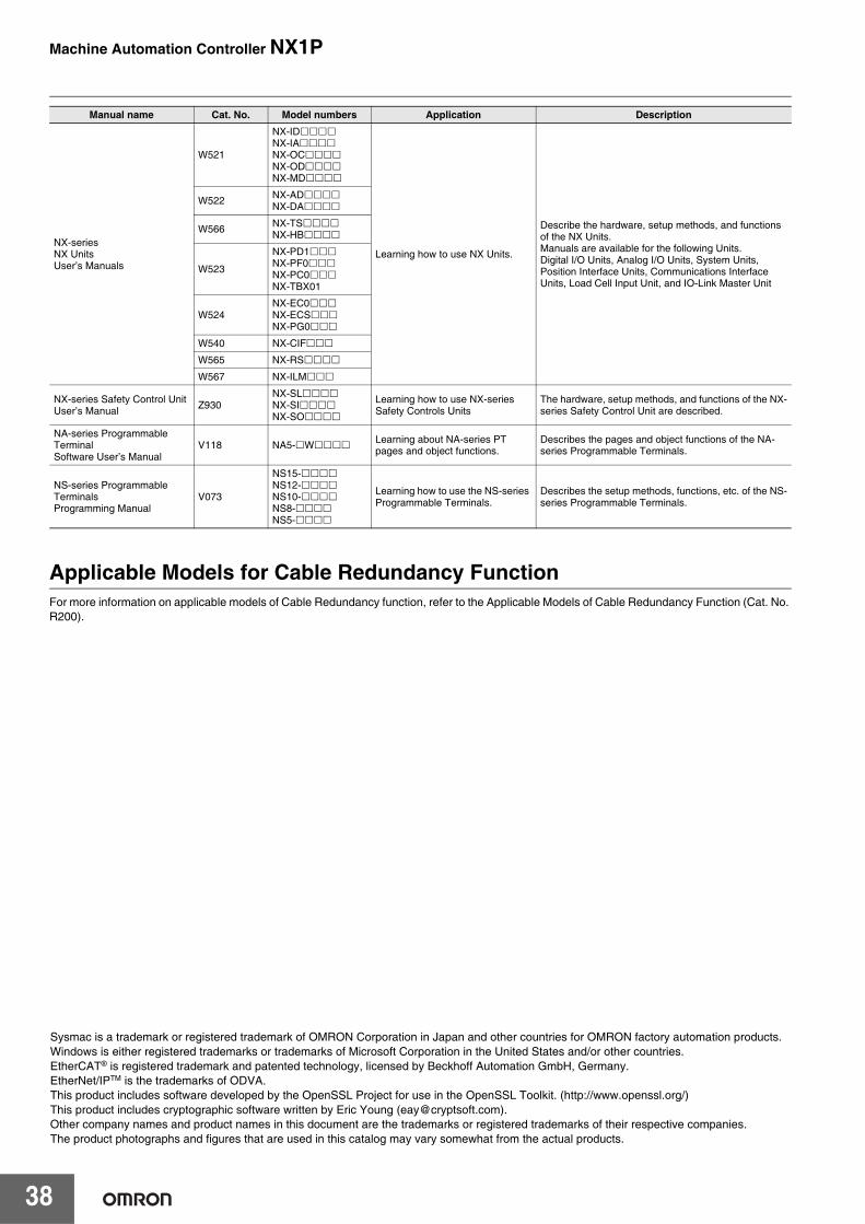
Machine Automation Controller NX1P
38
Applicable Models for Cable Redundancy FunctionFor more information on applicable models of Cable Redundancy function, refer to the Applicable Models of Cable Redundancy Function (Cat. No. R200).
NX-seriesNX UnitsUser’s Manuals
W521
NX-IDNX-IANX-OCNX-ODNX-MD
Learning how to use NX Units.
Describe the hardware, setup methods, and functions of the NX Units.Manuals are available for the following Units.Digital I/O Units, Analog I/O Units, System Units, Position Interface Units, Communications Interface Units, Load Cell Input Unit, and IO-Link Master Unit
W522 NX-ADNX-DA
W566 NX-TSNX-HB
W523
NX-PD1NX-PF0NX-PC0NX-TBX01
W524NX-EC0NX-ECSNX-PG0
W540 NX-CIF
W565 NX-RS
W567 NX-ILM
NX-series Safety Control Unit User’s Manual Z930
NX-SLNX-SINX-SO
Learning how to use NX-series Safety Controls Units
The hardware, setup methods, and functions of the NX-series Safety Control Unit are described.
NA-series Programmable TerminalSoftware User’s Manual
V118 NA5- W Learning about NA-series PT pages and object functions.
Describes the pages and object functions of the NA-series Programmable Terminals.
NS-series Programmable Terminals Programming Manual
V073
NS15-NS12-NS10-NS8-NS5-
Learning how to use the NS-series Programmable Terminals.
Describes the setup methods, functions, etc. of the NS-series Programmable Terminals.
Manual name Cat. No. Model numbers Application Description
Sysmac is a trademark or registered trademark of OMRON Corporation in Japan and other countries for OMRON factory automation products.Windows is either registered trademarks or trademarks of Microsoft Corporation in the United States and/or other countries.EtherCAT® is registered trademark and patented technology, licensed by Beckhoff Automation GmbH, Germany.EtherNet/IPTM is the trademarks of ODVA.This product includes software developed by the OpenSSL Project for use in the OpenSSL Toolkit. (http://www.openssl.org/)This product includes cryptographic software written by Eric Young ([email protected]).Other company names and product names in this document are the trademarks or registered trademarks of their respective companies.The product photographs and figures that are used in this catalog may vary somewhat from the actual products.

Terms and Conditions AgreementRead and understand this catalog.
Please read and understand this catalog before purchasing the products. Please consult your OMRON representative if you have any questions or comments.
Warranties.(a) Exclusive Warranty. Omron’s exclusive warranty is that the Products will be free from defects in materials and workmanship
for a period of twelve months from the date of sale by Omron (or such other period expressed in writing by Omron). Omron disclaims all other warranties, express or implied.
(b) Limitations. OMRON MAKES NO WARRANTY OR REPRESENTATION, EXPRESS OR IMPLIED, ABOUT NON-INFRINGEMENT, MERCHANTABILITY OR FITNESS FOR A PARTICULAR PURPOSE OF THE PRODUCTS. BUYER ACKNOWLEDGES THAT IT ALONE HAS DETERMINED THAT THE PRODUCTS WILL SUITABLY MEET THE REQUIREMENTS OF THEIR INTENDED USE.
Omron further disclaims all warranties and responsibility of any type for claims or expenses based on infringement by the Products or otherwise of any intellectual property right. (c) Buyer Remedy. Omron’s sole obligation hereunder shall be, at Omron’s election, to (i) replace (in the form originally shipped with Buyer responsible for labor charges for removal or replacement thereof) the non-complying Product, (ii) repair the non-complying Product, or (iii) repay or credit Buyer an amount equal to the purchase price of the non-complying Product; provided that in no event shall Omron be responsible for warranty, repair, indemnity or any other claims or expenses regarding the Products unless Omron’s analysis confirms that the Products were properly handled, stored, installed and maintained and not subject to contamination, abuse, misuse or inappropriate modification. Return of any Products by Buyer must be approved in writing by Omron before shipment. Omron Companies shall not be liable for the suitability or unsuitability or the results from the use of Products in combination with any electrical or electronic components, circuits, system assemblies or any other materials or substances or environments. Any advice, recommendations or information given orally or in writing, are not to be construed as an amendment or addition to the above warranty.
See http://www.omron.com/global/ or contact your Omron representative for published information.
Limitation on Liability; Etc.OMRON COMPANIES SHALL NOT BE LIABLE FOR SPECIAL, INDIRECT, INCIDENTAL, OR CONSEQUENTIAL DAMAGES, LOSS OF PROFITS OR PRODUCTION OR COMMERCIAL LOSS IN ANY WAY CONNECTED WITH THE PRODUCTS, WHETHER SUCH CLAIM IS BASED IN CONTRACT, WARRANTY, NEGLIGENCE OR STRICT LIABILITY.
Further, in no event shall liability of Omron Companies exceed the individual price of the Product on which liability is asserted.
Suitability of Use.Omron Companies shall not be responsible for conformity with any standards, codes or regulations which apply to the combination of the Product in the Buyer’s application or use of the Product. At Buyer’s request, Omron will provide applicable third party certification documents identifying ratings and limitations of use which apply to the Product. This information by itself is not sufficient for a complete determination of the suitability of the Product in combination with the end product, machine, system, or other application or use. Buyer shall be solely responsible for determining appropriateness of the particular Product with respect to Buyer’s application, product or system. Buyer shall take application responsibility in all cases.
NEVER USE THE PRODUCT FOR AN APPLICATION INVOLVING SERIOUS RISK TO LIFE OR PROPERTY OR IN LARGE QUANTITIES WITHOUT ENSURING THAT THE SYSTEM AS A WHOLE HAS BEEN DESIGNED TO ADDRESS THE RISKS, AND THAT THE OMRON PRODUCT(S) IS PROPERLY RATED AND INSTALLED FOR THE INTENDED USE WITHIN THE OVERALL EQUIPMENT OR SYSTEM.
Programmable Products.Omron Companies shall not be responsible for the user’s programming of a programmable Product, or any consequence thereof.
Performance Data.Data presented in Omron Company websites, catalogs and other materials is provided as a guide for the user in determining suitability and does not constitute a warranty. It may represent the result of Omron’s test conditions, and the user must correlate it to actual application requirements. Actual performance is subject to the Omron’s Warranty and Limitations of Liability.
Change in Specifications.Product specifications and accessories may be changed at any time based on improvements and other reasons. It is our practice to change part numbers when published ratings or features are changed, or when significant construction changes are made. However, some specifications of the Product may be changed without any notice. When in doubt, special part numbers may be assigned to fix or establish key specifications for your application. Please consult with your Omron’s representative at any time to confirm actual specifications of purchased Product.
Errors and Omissions.Information presented by Omron Companies has been checked and is believed to be accurate; however, no responsibility is assumed for clerical, typographical or proofreading errors or omissions.

Authorized Distributor:
In the interest of product improvement, specifications are subject to change without notice.
Cat. No. P116-E1-17 1021(0916)
© OMRON Corporation 2016-2021 All Rights Reserved.
OMRON Corporation Industrial Automation Company
OMRON ELECTRONICS LLC2895 Greenspoint Parkway, Suite 200 Hoffman Estates, IL 60169 U.S.A.Tel: (1) 847-843-7900/Fax: (1) 847-843-7787
Regional HeadquartersOMRON EUROPE B.V.Wegalaan 67-69, 2132 JD HoofddorpThe NetherlandsTel: (31)2356-81-300/Fax: (31)2356-81-388
Contact: www.ia.omron.comKyoto, JAPAN
OMRON ASIA PACIFIC PTE. LTD.No. 438A Alexandra Road # 05-05/08 (Lobby 2), Alexandra Technopark, Singapore 119967Tel: (65) 6835-3011/Fax: (65) 6835-2711
OMRON (CHINA) CO., LTD.Room 2211, Bank of China Tower, 200 Yin Cheng Zhong Road, PuDong New Area, Shanghai, 200120, ChinaTel: (86) 21-5037-2222/Fax: (86) 21-5037-2200
CSM_9_2
Copyright © 2022 FDOKUMEN

