


Bahasa
Halaman
Hukum


Installation & Operation ManualM31
Ver.1.1

mechanical shockcorrosive gas or corrosive liquid
Extreme heat and cold, acceptable temperature range:-25°C +55°C
Installation & Operation Manual Ver.1.1
Intelligent Pump Controller______________________ Installation & Operation Manual
Conventions used in this manual
In the manual the following symbols will be used:
A Generic danger Failure to comply with the safety regulations that follow can irreparably damage the controller or equipment.
A Electric shock risk Failure to comply with the safety regulations that follow can cause death or serious personal injury.
WARNINGSRead this manual carefully before any operation.Please keep this manual forfuture use.
A WARNING!!
■ Before carrying out any installation or maintenance operation, controller must be disconnected form the
power suppiy;
■ Don't open the cover during running the controller;
■ Don't put wire ,metal bar filaments etc into the controller;
■ Don't splash water or other liquid over the controller;
CAUTION
■The electrical and hydraulic connections must be carried out by competent, skilled.qualfied personnel;
■ Never connect AC power to output uvw terminals;
■ Ensure the motor, controller and power specifications matching;
■ Don't install the controller in the following condition;

intelligent Pump Controller______________________ Installation & Operation Manual
TABLE OF CONTENS
1 INTRODUCTION .............................................................................................................丄
1.1 Applications ............................................................................................................. .1.
1.2 Technical parameter & fea tu res.................................................................................... .1.
1.3 Controller components..................................................................................................3.
2 INSTALLATION............................................................................................................. .5.
2.1 Electrical connection to the power supply line and electrical pump .......................................5.
2.2 Function switch setting................................................................................................ .6.
2.3 Parameter Calibration setting & erasing ...................................................................... .7.
3ELEC TR ICALCO NNECT IO N ..............................................................................................8 .
3.1 Installing liquid probe & float switch ...............................................................................8.
3.2 Electrical connection for different application ................................................................. .9.
3.2.1 Water supply by liquid level control through float switch or liquid probe ..........................................9.
3.2.2 Water supply by pressure control through pressure switch & pressure tank................................... .14.
3.2.3 Drainage by liquid level control through float switch & liquid probe ............................................18.
4 BASIC OPERATION........................................................................................................ .21.
4.1 Switching to MANULA mode..........................................................................................21.
4.2 Switching to AUTO mode............................................................................................ .21.
4.3 Pump protection........................................................................................................ .21.
4.4 Pump last five failure record displaying........................................................................ .21 ■
4.5 Pump accumulative running time displaying.....................................................................22.
5 COMMUNICATION LINK.................................................................................................. .23.
5.1 Basic Function ....................................................................................................... .24.
5.2 Special Application ..................................................................................................24.
5.3 Technical parameter .................................................................................................24.
6 TROUBLE SHOOTING GUIDE ......................................................................................... .25.
Installation & Operation Manual Ver.1.1

intelligent Pump Controller______________________ Installation & Operation Manual
RESPONSIBILITYThe manufacturer is not liable for malfunctioning if the product has not correctly been installed, damaged, modified, and /or run outside the recommended work range or run outside the recommended work range or in contrast with other indications given in this manual.
The manufacturer declines all responsibility for possible errors in this operation manual, if due to misprints or errors in copying.
The manufacturer reserves the right to make any modifications to products that it may consider necessary or useful, without affecting the essential characteristics.
1 INTRODUCTIONThank you for choosing our products, we will supply you with cordial and well-around service as well as ever.
Intelligent Pump Controller model M 31 is an easy to use, programmable controlling & protection device for direct start, three phase deep well submersible pump, centrifugal pump, pipeline pump etc with output power from 0.75KWto 7.5KW (1HP-10HP)
Model M31 has many operation modes by adopting different electric installations. An important feature that makes the difference between Model M31 and common On/Off pump control box is the probe / sensor free in the well. Our special design makes it a very reliable and sensitive protection against pump dry run without installation probe / sensor in the well.
1.1 ApplicationsModel M31 is useful in all cases we need turn off by different electric installations.
to control and protect single pump managing its turn-on and
Typical usage scenarios include:-Houses-Flats-Holidays houses -Farms-Water supply from wells-Irrigations of greenhouses, gardens, agriculture-Rain water reuse-Industrial plants-Waste water tank / Sewage sink
1.2 Technical parameter & featuresMain features:■ Built In function switch
applied for water supply by liquid level control through float switch or liquid probe
applied for water supply by pressure control through pressure switch and pressure tank
applied for drainage by liquid level control through float switch or liquid probe■ Automatic stops the pump in the case of water shortage, protecting it from dry running
without installing float switch or liquid probe in the well
■ Auto I Manual switch■ Dynamic LCD displaying pump running state
■ Protect the pump against many faults
■ Push Button Calibration■ Pump Accumulative Running Time Displaying
■ Pump Last Five Fault Record Displaying
■ RS485 Communication■ Starts and stops the pump in accordance with the different liquid level or pressure setting
.1. Installation & Operation Manual Ver.1.1

intelligent Pump Controller______________________ Installation & Operation Manual
The following chart shows main technical parameters of Model M31
Main technical characteristic
Control characteristicdouble liquid level control
pressure control
Control method Manual / Auto
Liquid level control characteristic pulse electrode probe & float switch
Pressure control characteristic pressure switch (n/c) & pressure tank
Main technical data
Rated output power 0.75-4KW(1HP-5.5HP) 5.5-7.5KW (7.5HP-10HP)
Rated input voltage AC380V/50HZ Three Phase
Trip response time of over load 5sec-5min
Trip response time of open phase <2sec
Trip response time of short circuit <0.1 sec
Trip response time of under / overvoltage <5sec
Trip response time of dry run 6sec
Recovery time of over load 30min
Recovery time of under / over voltage 5min
Recovery time of dry run 30min
Trip voltage of over voltage 437V
Trip voltage of under voltage 323V
Liquid level transfer distance 彡1000m
Protection function
Dry run Over load Transient surge Under voltage Over voltage Open phase Pump stalled Short circuit
Main installation data
Working temperature -25V -+55°C
Working humidity 20% - 90%RH, no drips concreted
Degree of protection IP22
Install position Vertical
Unit dimensions ( Lx Wx H) 16 x 8.2 x 22.8 cm
Unit weight (net) 1.3kg
RS485 technical data
Physics Interface RS485 Bus Interface: asynchronism semiduplex
Baud rate 1200 bps、2400 bps、4800 bps、9600bps Default: 9600bps
Protocol type MODBUS Protocol (RTU)
Installation & Operation Manual Ver.1.1

Main terminals for electrical connection to the power supply and electrical pump
voltage displaying- area
fault displaying- area
%
®% _ v !
[u n d e r y [o v e r v d r y r u n
O V E R L O A D 丨[PUIVP STA LLE D
PUIVP N O C A LIB R A T IO N |
OPEN PHASE
EEZIE
I
RS485 terminals for communication link
Functionswitch
Control terminals for electrical connection to the probe /float switch/pressure switch
MSHV%A <- ampere displaying
area
pump running status displaying area
Installation & Operation Manual Ver.1.1
Intelligent Pump Controller Installation & Operation Manual

intelligent Pump Controller______________________ Installation & Operation Manual
Meaning of the icons shown on the LCD
Ic o n M e a n in g / D e s c r ip t io n
、 --
pump parameter configuration icon, when this icon appears, pump control box is in parameter adjusting manual;
time displaying icon, when this icon appears, it means pump control box is displaying some parameter of time, eg: pump accumulative running time (unit: hour); counting down etc
pumpfault icon, when this icon appears, it means pump control box is displaying some fault information;
ON LINE
network connection error icon, when this icon appears, it means there is no network connections or network connection error between pump control box and SC(slave controller) or computer;
ON LINE
network normal connection icon, when this icon appears, it means the network connection between pump control box and SC (slave controller) or computer is n o rm a l;
V v o lta g e
M m in u te
S s e c o n d
H h o u r
% p e rc e n t
A a m p e re
© pump running
© pump stops running
©low pressure or lack of pressure in the pipeline or pressure tank
Q high pressure or full of pressure in the pipeline or pressure tank
Installation &Operation Manual Ver.1.1 .4.

2 INSTALLATION
Intelligent Pump Controller______________________ Installation & Operation Manual
2.1 Electrical connection to the power supply line and electrical pump
"S TOR E"button P function
■ switch
I©e © |
GND A+ B-
A DANGER Electric shock riskBefore carrying out any installation or maintenance operation, the M31 should be disconnected from the power supply and one should wait at least 2 minutes before opening the appliance.
Never connect AC power to output UV W terminals.
A Don’t put wire, metal bar filaments etc into the controller.
Ensure the motor, controller and power specifications matching.
A The electrical and hydraulic connections must be carried out by competent, skilled,
qualified personnel.
Installation & Operation Manual Ver.1.1

Intelligent Pump Controller Installation & Operation Manual
2.2 Function switch setting
Pump users can set the function switch to meet different application requirement, before setting the
function switch, the M31 should be disconnected from the power supply, after complete the setting,
apply power to M31 and observe the application sign displayed on the LCD conforming to the
following list.
PL
P
PL
item Swith position Messages & Graphic Application
B I S I p Applied for water supply or drainage by liquid level control through float switch or liquid sensor
2EE SiP Applied for water supply by pressure
control through pressure switch & pressure tank
3E dsp Applied for drainage by liquid level
control through float switch & liquid probe
Installation & Operation Manual Ver.1.1

Intelligent Pump Controller Installation & Operation Manual
2.3 Parameter Calibration setting & erasing
To achieve best level of protection of the pump, it is essential that parameter calibration must be done
immediately after successful pump installation or pump maintenance.
Setting the parameter calib ra tion
Press t h e ^ ^ y key to switch to manual state, make sure the pump not running and LCD screen
displaying:
flash
38H [ill) PUMP NO CALIBRATION |
丨&1 ^ 2 T
Press key to run pump, confirm the pump
(including voltage, running ampere et); LCD screen
and all pipe network in normal working state
displaying:
f l a S h ----------------- I PUMP HQ CALIBRftTIQH )
STORE
T-Y
I
s
83
Press the button; The M31 makes a "Di" sound and starts 20 seconds countdown, LCD
screen displaying:
1 c s1 J
n
Pump stops running and parameter calibration completed, LCD screen displaying:
M31 is ready for running.
381:I U J l
Vi
OIED rjt——r\
LNe ̂i iErasing former parameter calib ra tionWhen pump is reinstalled after maintenance or new pump is installed, user must erase the former
parameter calibration and a new calibration must be done.
Erasing the parameter calib ration
- Press the key to switch to manual state, make sure the pump not running and LCD screendisplaying:
o83
■
Installation & Operation Manual Ver.1.1

Intelligent Pump Controller____________________________________________________________ Installation & Operation Manual____M931
Press the and
setting and LCD screen
release till M31 makes a "Di" sound, M31 recover the default factory
displaying:
3SH 0.0a
j PUMP NO CALIBRATION ]™n f=«a
3 ELECTRICAL CONNECTION
3.1 Installing liquid probe & float switch
L iqu id probe insta lla tion
installation stand
Wrap the signal cable and down-lead of sensor
fixation cone
down-lead of sensor
~Upper probe
— Lower probe
Com probe
A in event of high risk of electric storms (lightning) or when liquid medium in well or tank or sump is very dirty it is recommended float switch is used.
Float sw itch insta lla tion
/ L If the float switch is equipped with three wires use the BLACK and BROWN wires. In event of different colors use a multimeter to identify correct connections as follows:
Lower level no reading OFF Upper level-positive reading-ON
A d o n o t e n c a s e s e n s o r l e a d s , f l o a t s w it c h w ir e o r s ig n a l c a b l e s in m e t a l p ip e s , u s e
PVCOR PE TUBING.
Installation & Operation Manual Ver.1.1

Intelligent Pump Controller Installation & Operation Manual
3.2 Electrical connection for different application
3.2.1 Water supp ly by liqu id leve l contro丨 th rough float sw itch or liqu id probe
m SIS]
DBFunction9witch
"Store" button
R S T PE U V W ① ② ③ ④ ⑤ ⑥
— Upper probe
— Lower probe
Com probe
Y T "C;lower water tank
(water well)
*check valve valve
Upper probe
Lower probe
Com probe
water tank (water tower)
E■B
FunctionSwitch
"Store" button
R S T P E U V W ® ② ③ ④ ⑤ ⑥
Installation & Operation Manual Ver.1.1
Intelligent Pump Controller Installation & Operation Manual
_ p
"Store" buttonSlili
FunctionSwitch
R S T PE U V W ① ② ③ ④ ⑤ ⑥
0 |0丨0 險 101010110|0 |0 |0 |0|0d J I I I I T U l T
Upper water tank (water tower)
lower water tank (water well)
on I® 1
FunctionSwitch
"Store" button
R S T PE U V W ① ② ③ ④ ⑤ ⑥
Installation & Operation Manual Ver.1.1

Intelligent Pump Controller Installation & Operation Manual
SC
"S to re ” button
FunctionSwitch
R S T PE U V W ① ② ③ ④ ⑤ ⑥
lower water tank (water well)
R S T P E U V W ① ② ③ ④ ⑤ ⑥
.11. Installation & Operation Manual Ver.1.1

Intelligent Pump Controller Installation & Operation Manual
j
----------
一
圍
"Store" button
FunctionSwitch
R S T PE U V W ① ② ③ ④ ⑤ ⑥
Upper water tank (water tower)
lower water tank (water well)
R S T P E U V W ① ② ③ ④ ⑤ ⑥

1). S tarting condition
liquid level in the water tank is below Lower probe (float switch: Down level) and liquid level in the water
well is above Lower probe (float switch: Up level), the M31 will run pump;
2). Stop condition
liquid level in the water tank reaches Upper probe (float switch: Up level) or liquid level in the water well
is below Lower probe (float switch: Down level); the M31 will stop pump running;
3). The probe / sensor free in the water well
as the M31 has reliable and automatic stop function against pump dry-run (dewatering), if it is used in
submersible pump for deep well, pipeline pump or other situations when it is inconvenient to install
lower liquid probe in the well, pump users can put terminals ① 、② 、(3) in short circuit, which minimize
the troubles and costs.
4). Meaning of the messages & graphic shown on the LCD screen
Intelligent Pump Controller_____________________ Installation & Operation Manual________________________________________
Messages & Graphic Description
Lack of water in water well
Full of water in water well
Lack of water in water tank
bbh
Full of water in water tank
.13. Installation & Operation Manual Ver.1.1

Intelligent Pump Controller Installation & Operation Manual
3.2.2 Water supp ly by p ressure contro l th rough pressure sw itch & pressure tank
Pressure
A
B
C
SIS
"S tore" button fmFunctionSwitch
© © ©
R S T PE U V w ① ② ③ ④ ⑤ ⑥
— M )—
pf?l
s
pFunctionS w itch
"S to re " b u tto n
R S T P E U V W ® ② ③ ④ ⑤ ⑥
Installation & Operation Manual Ver.1.1 .14.

Intelligent Pump Controller Installation & Operation Manual
m EKi ittrvn
FunctionSwitch
"S tore" button
R S T PE U V W ① ② ③ ④ ⑤ ⑥
— Upper probe
Lower probe
Com probe
water well
Pressure
checkvalve valve
S 'o a i
FunctionSwitch
"Store" button
R S T P E U V W ① ② ③ ④ ⑤ ⑥
.15. Installation & Operation Manual Ver.1.1

Inte
lligent P
ump
Contro
ller
Insta
llatio
n
&
Opera
tion
MQ)nuQ)l
Pre
ssure
-store" buttol
H—t a IS m3
Functio
nSwitch

73CO
—I
c
<
㊀
©
©@©
Insta
llatio
n
&
opera
tion
Manual
ver.1.1
.16.
Intelligent Pump Controller Installation & Operation Manual
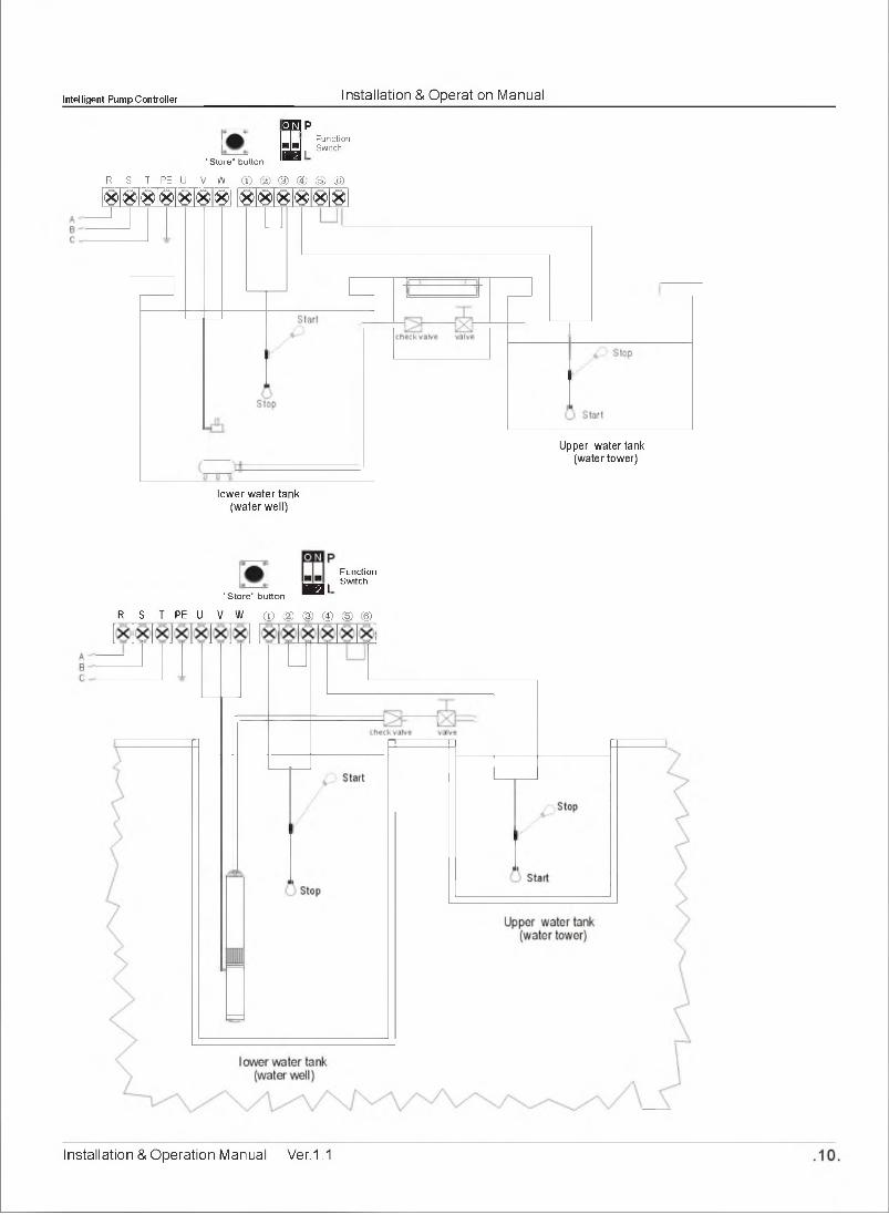
1). S tarting condition
there is no pressure in the pipeline or pressure tank, contacting point of pressure switch is ON and liquid
level in the water well is above Lower probe (float switch: Up level), the M31 will run pump;
2). Stop condition
there is full pressure in the pipeline or pressure tank, contacting point of pressure switch is OFF, the
M31 will stop pump running;
Note: pressure switch with N/C (normal close) contacting point:
no pressure, contacting point is ON; meet the pressure setting, contacting point is OFF
3). The probe I sensor free in the water well
as the M31 has reliable and automatic stop function against pump dry-run (dewatering), if it is used in
submersible pump for deep well, pipeline pump or other situations when it is inconvenient to install lower
liquid probe in the w e ll,pump users can put terminals ① 、② 、③ in short circuit, which minimize the
troubles and costs.
4). Meaning of the messages & graphic shown on the LCD screen
Messages & Graphic Description
Lack of water in water well
Full of water in water well
Full of pressure in pipeline or pressure tank
Lack of pressure in pipeline or pressure tank
.17. Installation & Operation Manual Ver.1.1

Intelligent Pump Controller Installation & Operation Manual
3.2.3 Drainage by liquid level control through float switch & liquid probe
Ip
_ H:FunctionSw itch
"S to re" b u tton
R S T PE U V W ① ② ③ ④ ⑤ ⑥
-Overflow probe
-A
-Upper probe
Lower probe
Com probe
=&checkvalve valve
Sump
I ;FunctionSwitch
"Store" button
R S T P E U V W ① ② ③ ④ ⑤ ⑥
Installation & Operation Manual Ver.1.1 .18.

intelligent Pump Controller______________________ Installation & Operation Manual
R S T PE U V W ① ② ③ ④ ⑤ ⑥
Sump
E
B l00 Function
Switch
R S T PE U
"Store" button
V W ① ② ③ ④ ⑤ ⑥
.19. Installation & Operation Manual Ver.1.1

intelligent Pump Controller______________________ Installation & Operation Manual
1). Starting condition
liquid level in the sump reaches Upper probe (float switch A: Up level), the M31 will run pump;
2). Stop condition
liquid level in the sump is below Lower probe (float switch A: Down level), the M31 will stop pump running;
3). Over Flow alarm
when pump is draining water, liquid level in the sump is still rising to Overflow probe (float switch B: Up level),
the M31 will sound the overflow alarm to warn pump user to take further action.
4). Meaning of the messages & graphic shown on the LCD screen
Installation & Operation Manual Ver.1.1 .20.

intelligent Pump Controller______________________ Installation & Operation Manual
4 BASIC OPERATION
4.1 Switching to MANULA mode
Press the to switch to manual state, M31 is under the manual control state;under manual
state, press the to run pump; p re s s th e ^ ^ Q key to stop pump running;
Note: under manual state, the M31 can not receive the signal from liquid level probe or pressure switch.
4.2 Switching to AUTO mode
Press the key to switch to auto state, M31 is under the auto control state;under auto state, M31
will run or stop the pump according to the signal from liquid level probe or pressure switch.
Note: under auto state, if the pump is running and pump user wants to stop pump running compulsory,
press the key to switch to manual state and pump stops running;
Note: under auto state, if the input power being cut off and recovery power again, the M31 will enter
operation state after 10seconds countdown;
Note: no matterthe M31 is under auto or manual state, if the input power being cut off and recovery
power again, the M31 will resume its operation state as the operation state before power being
cut off;
4.3 Pump protection
During pump running, if dry run, over load, under voltage, over voltage etc failures happened, the M31
will immediately shut down the pump running and automatically execute a check for restarting conditions
after a built in time delay has elapsed. The M31 will not recover automatically until all the abnormal
situation(s) have been cleared.
If pump stalled, open phase etc serious failures happened, pump user must check the pump and motor
immediately and repair the pump.
4.4 Pump last five failure record displaying
The M31 can memorize the last five failures of pump, so it is very convenient for the pump users to
analyse the pump running conditions.
D isp laying the pump last five fa ilu re record
-Press the key to switch to manual state, make sure the pump not running and LCD screen
displaying:
.21.
M I [ U lOffiD
!
a y r s:'
Installation & Operation Manual Ver.1.1

Intelligent Pump Controller Installation & Operation Manual
Hold pressing key and press key, the M31 makes a "Di" sound, the M31 displays
pump failure record;
Press to quit the failure record displaying;
S/N of Failure Failure Sequence Number
Failure Icon W J
QQE3SBD
THE LATEST FAILURE IS PUMP STALLED
4-5 Pump accumulative running time displaying
The M931 can memorize how many hours of pump running, so it is very convenient for the pump users to
analyse the pump running conditions and do maintenance
D isplaying the
Press the
displaying
e pump
k
accumulative runn ing time
key to switch to manual state, make sure the pump not running and LCD screen
38l:I 0.0A
STORE
Hold p ress ing〔• ] button and press key, the M31 makes a "Di" sound, the M31
displays pump failure record;
Time Icon
sinrc
_o
o ro
西
THE PUMP HAS RUN FOR 23 HOURS
Press key to quit the accumulative running time displaying;
Installation & Operation Manual Ver.1.1 .22.
intelligent Pump Controller______________________ Installation & Operation Manual
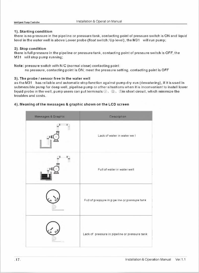
5 COMMUNICATION LINK
Model M31 has communication interface, To adopting simple peripheral equipment (Slave Controller), pump users can realize long distance monitoring function.
This function is applied for M31 installed in the basement, pumping room etc, but pump users require to monitor and control the pump on the ground or in the control room.
GND A+ B- GND A+ B-
I 0 I 0 I 0 I
1200 meter Max
C ontro l R oom
shield tw isted pair cable (SPT)
.23. Installation & Operation Manual Ver.1.1

intelligent Pump Controller______________________ Installation & Operation Manual
5.1 Basic Function
Slave Controller, model SC1 with communication interface can realize long distance monitoring function. In the control room, pump users can realize all functions of M31 (Master Controller) through SC1,including:
voltage & ampere displaying, pump fault displaying, auto / manual switch, pump start/ stop switch, pump running status displaying etc
5.2 Special Application
As adopting communication interface, the wire communication distance is lessthan 1200metres. For those installation environment which require long distance communication, say: mine, water tower, across railway, road and bridge etc, users can adopt RS485 extender, wireless communication or GSM system.Please contact the manufacturer for more information.
5.3 Technical parameterThe following chart shows main technical parameters of communication link between M931 & Slave Controller (SC)
The following chart shows main technical parameters of communication link between M931 & Slave Controller (SC)
Main technica l data
Physics Interface RS485 Bus Interface: asynchronism semiduplex
Data format
1 start bit 8data bit, 1 stop bit, no verify 1 start bit 8data bit, 2stop bit, no verify Default: 1 start bit 8data bit, 1 stop bit,no verify
Baud rate 1200 bps、2400 bps、4800 bps、9600bps Default: 9600bps
Communication address
Setting range of controller address: 1-126127: broadcast address, Host computer broadcasting, Slave machine responsion forbidden
Protocol type MODBUS Protocol (RTU)
Rated input voltage for SC AC220V/50Hz, Single phase
Main insta lla tion data
wire communication distance1200meters max by shield twisted pair cable (STP) for RS485 & CAN 5000meters max by STP and RS485 extender
STP STP-120Q one pair 20AWG for RS485 & CAN
RS485 extender 5000meters (9600bps)
Installation &Operation Manual Ver.1.1 .24.

Intelligent Pump Controller______________________ Installation & Operation Manual
6 TROUBLE SHOOTING GUIDE
Fault Message Possible Cause Solutions
flashing of UNDER Vthe real running voltage is lower than the calibrated voltage, pump is in under voltage protection state
report low line voltage to the power supply company
M31 will attempt to restart the pump every 5minutes until line voltage is restored to normal
flashing of OVER V
the real running voltage is higher than the calibrated voltage, pump is in over voltage protection state
report high line voltage to the power supply company
M31 will attempt to restart the pump every 5minutes until line voltage is restored to normal
flashing of OVER LOAD
the real running ampere is higher than the calibrated running ampere, pump is in over load protection state
M31 will attempt to restart the pump every 30minutes until running ampere is restored to normal
pump impeller is jammed / pump motor dragging / pump bearing broken
check pump impeller or bearing
power supply lose phase report to the power supply company
flashing of OPEN PHASEcontroller inlet wire or pump cable broken
repair inlet wire or pump cable
flashing of
PUMP NO CALIBRATION parameter calibration not completed refer to parameter calibration setting
flashing of DRY RUNliquid level in the well / sump is below the pump intake, pump stops running
M31 will attempt to restart the pump every 3〇minutes until liquid level above the pump intake
flashing of PUMP STALLED
pump motor running ampere increasing was greater than the normal running ampere (calibrated ampere) by more than 200%
cut off power supply & repair or replace pump immediately
ON LINE
no communication link between SC / computer and M31
connecting the M31 to SC / computer to realize long distance monitoring
• 25. Installation & Operation Manual Ver.1.1
Top Related
Copyright © 2022 FDOKUMEN

