


Bahasa
Halaman
Hukum

1
1. IntroductionThe Harmonas-FLeX Distributed controller (FLC) is a compactcontroller designed to be installed in a local control panel. Thefunctions and features of the FLC are described briefly below.
Control• The FLC has the functionality of process controllers like those
in Azbil Corporation’s DCS series. It can handle both PID andsequence control and is equipped with a rich set of functions.
• The user generates control programs and carries outmaintenance in the RTC integrated engineering environment.By means of virtual simulation software that runs on a personalcomputer, debugging can be done efficiently.
• Control programs can be represented with logic diagramsusing function blocks for easy understanding and debugging.Generated programs can be displayed in the form of drawings.
Installation• The FLC is compact enough to be installed in a small box
(400 400 mm). It can be mounted in an existing controlcabinet or wall-mounted box.Mountable on an existing control cabinet or wall-mounted box.
• Power supply and wiring for field device signals, with a shortprotection circuit, are built in. Since the FLC can be connecteddirectly to field wiring, installation is complete simply byinstalling the FLC and connecting the power supply to thefield wiring.
• There are up to 368 input/output points (or approximately 256points with a typical configuration). Various input/output typescan be combined to suit the application.
• The FLC was designed to resist environmental factors, andcan be operated in a sealed box.
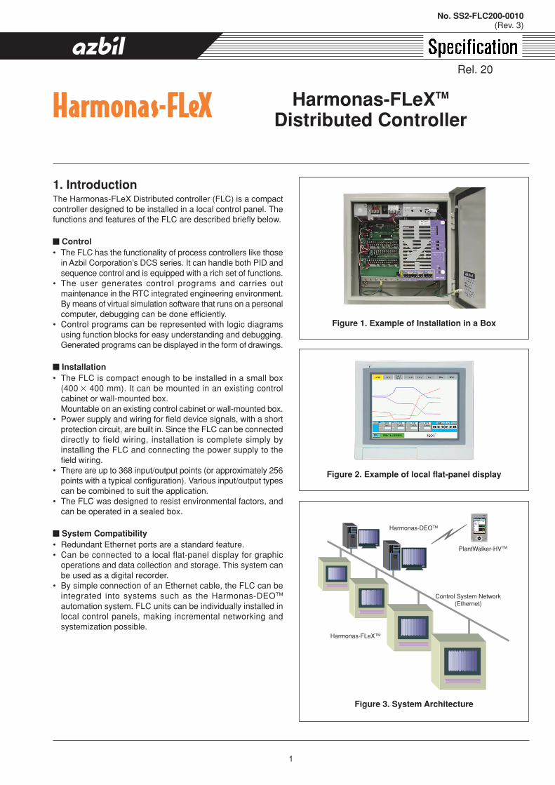
System Compatibility• Redundant Ethernet ports are a standard feature.• Can be connected to a local flat-panel display for graphic
operations and data collection and storage. This system canbe used as a digital recorder.
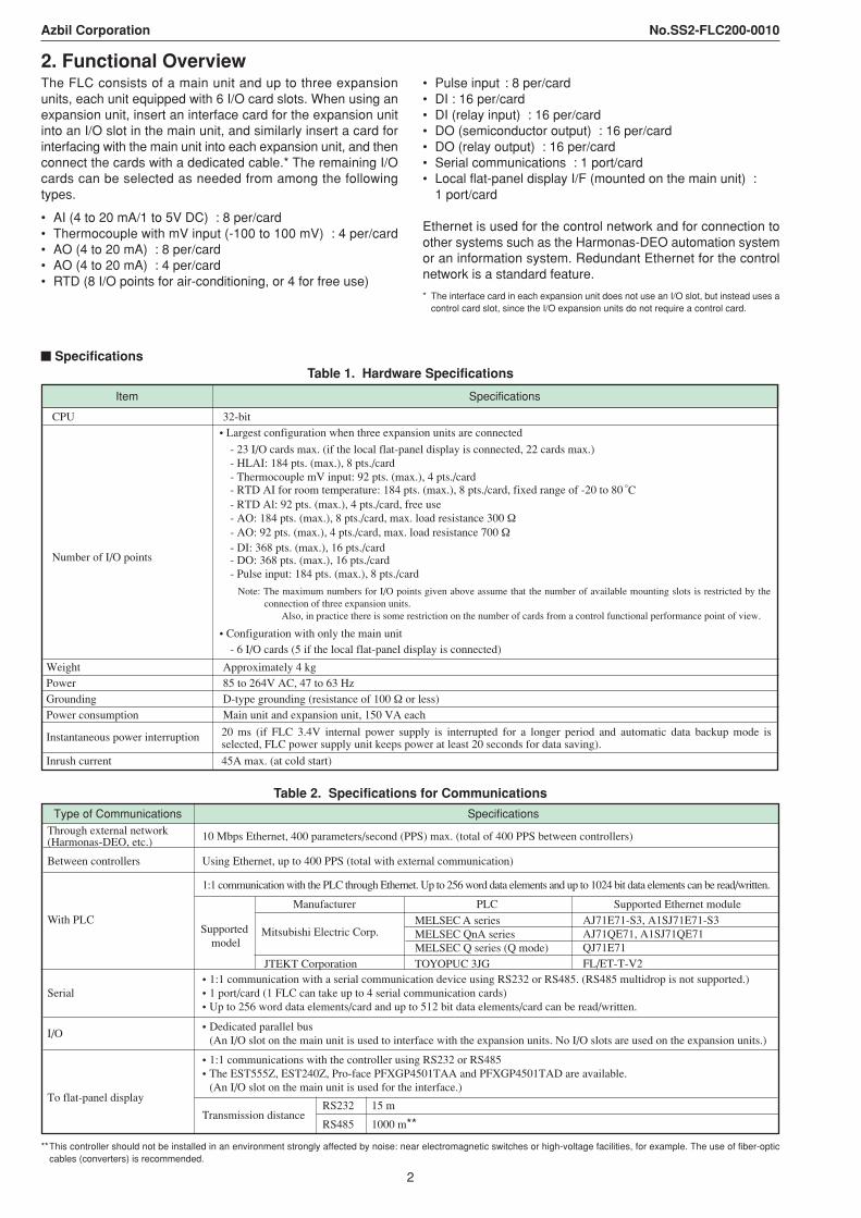
• By simple connection of an Ethernet cable, the FLC can beintegrated into systems such as the Harmonas-DEOTM
automation system. FLC units can be individually installed inlocal control panels, making incremental networking andsystemization possible.
Harmonas-FLeXTM
Distributed Controller
Figure 1. Example of Installation in a Box
Figure 2. Example of local flat-panel display
PlantWalker-HV
Harmonas-FLeX
Harmonas-DEO
Control System Network(Ethernet)
TM
TM
TM
Figure 3. System Architecture
No. SS2-FLC200-0010(Rev. 3)
Rel. 20
2
Azbil Corporation No.SS2-FLC200-0010
2. Functional OverviewThe FLC consists of a main unit and up to three expansionunits, each unit equipped with 6 I/O card slots. When using anexpansion unit, insert an interface card for the expansion unitinto an I/O slot in the main unit, and similarly insert a card forinterfacing with the main unit into each expansion unit, and thenconnect the cards with a dedicated cable.* The remaining I/Ocards can be selected as needed from among the followingtypes.
• AI (4 to 20 mA/1 to 5V DC) : 8 per/card• Thermocouple with mV input (-100 to 100 mV) : 4 per/card• AO (4 to 20 mA) : 8 per/card• AO (4 to 20 mA) : 4 per/card• RTD (8 I/O points for air-conditioning, or 4 for free use)
• Pulse input : 8 per/card• DI : 16 per/card• DI (relay input) : 16 per/card• DO (semiconductor output) : 16 per/card• DO (relay output) : 16 per/card• Serial communications : 1 port/card• Local flat-panel display I/F (mounted on the main unit) :
1 port/card
Ethernet is used for the control network and for connection toother systems such as the Harmonas-DEO automation systemor an information system. Redundant Ethernet for the controlnetwork is a standard feature.
* The interface card in each expansion unit does not use an I/O slot, but instead uses acontrol card slot, since the I/O expansion units do not require a control card.
SpecificationsTable 1. Hardware Specifications
Item Specifications
CPU
Number of I/O points
- 23 I/O cards max. (if the local flat-panel display is connected, 22 cards max.) - HLAI: 184 pts. (max.), 8 pts./card- Thermocouple mV input: 92 pts. (max.), 4 pts./card- RTD AI for room temperature: 184 pts. (max.), 8 pts./card, fixed range of -20 to 80- RTD Al: 92 pts. (max.), 4 pts./card, free use
- DI: 368 pts. (max.), 16 pts./card- DO: 368 pts. (max.), 16 pts./card- Pulse input: 184 pts. (max.), 8 pts./card
- 6 I/O cards (5 if the local flat-panel display is connected)
Weight Approximately 4 kgPower 85 to 264V AC, 47 to 63 HzGrounding D-type grounding (resistance of 100 Ω or less)Power consumption Main unit and expansion unit, 150 VA each
• Largest configuration when three expansion units are connected
• Configuration with only the main unit
32-bit
- AO: 184 pts. (max.), 8 pts./card, max. load resistance 300 Ω- AO: 92 pts. (max.), 4 pts./card, max. load resistance 700 Ω
Instantaneous power interruption
Inrush current 45A max. (at cold start)
Note: The maximum numbers for I/O points given above assume that the number of available mounting slots is restricted by the connection of three expansion units.
Also, in practice there is some restriction on the number of cards from a control functional performance point of view.
20 ms (if FLC 3.4V internal power supply is interrupted for a longer period and automatic data backup mode is selected, FLC power supply unit keeps power at least 20 seconds for data saving).
Table 2. Specifications for Communications
Type of Communications SpecificationsThrough external network (Harmonas-DEO, etc.)
Between controllers
I/O
To flat-panel display
10 Mbps Ethernet, 400 parameters/second (PPS) max. (total of 400 PPS between controllers)
Using Ethernet, up to 400 PPS (total with external communication)
• 1:1 communications with the controller using RS232 or RS485• The EST555Z, EST240Z, Pro-face PFXGP4501TAA and PFXGP4501TAD are available. (An I/O slot on the main unit is used for the interface.)
• Dedicated parallel bus (An I/O slot on the main unit is used to interface with the expansion units. No I/O slots are used on the expansion units.)
With PLC
1:1 communication with the PLC through Ethernet. Up to 256 word data elements and up to 1024 bit data elements can be read/written.
Supported model
Manufacturer
Mitsubishi Electric Corp.
JTEKT Corporation
PLC
MELSEC A seriesMELSEC QnA seriesMELSEC Q series (Q mode)TOYOPUC 3JG
Supported Ethernet moduleAJ71E71-S3, A1SJ71E71-S3AJ71QE71, A1SJ71QE71QJ71E71FL/ET-T-V2
Serial• 1:1 communication with a serial communication device using RS232 or RS485. (RS485 multidrop is not supported.)• 1 port/card (1 FLC can take up to 4 serial communication cards) • Up to 256 word data elements/card and up to 512 bit data elements/card can be read/written.
Transmission distanceRS232
RS485
15 m
1000 m**
**This controller should not be installed in an environment strongly affected by noise: near electromagnetic switches or high-voltage facilities, for example. The use of fiber-opticcables (converters) is recommended.
3
Azbil Corporation No.SS2-FLC200-0010
Table 4. Environmental Conditions
Standard operatingconditions
Normal operatingconditions
Restricted operating conditions
Conditions for storageand transport
Range ( ) 23 2 0 to 50 0 to 60 -40 to 70
Rate of change ( /h) 5 20 20
Relative humidity (%) 50 105 to 95
(0.020 kg/kg')25 to 95
(0.020 kg/kg')5 to 95
(0.020 kg/kg')
Amplitude 0 0.35 mm or less(2 to 9 Hz)
0.35 mm or less(2 to 9 Hz)
1.5 mm or less(2 to 9 Hz)
Acceleration 0 1m/s2 or less(9 to 150 Hz)
1m/s2 or less(9 to 150 Hz)
5m/s2 or less(9 to 150 Hz)
Item
Ambient temperature 1
Vibration 3
Notes:1. The atmosphere should not contain corrosive gas. Installation in a control panel where the temperature is 45 °C or less is recommended.2. In humid air, the ratio of kilograms of water vapor to kilograms of dry air.3. Do not install where there is continuous strong vibration.
Definitions1) Standard operating conditions: range of operating conditions under which external influences on performance can be ignored.
2) Normal operating conditions: range of operating conditions under which equipment or devices are designed to operate within the specified error rate and range of operatingconditions recommended by the manufacturer from all viewpoints such as functions, performance, and reliability.
3) Restricted operating conditions: operating conditions which are outside the normal operating range, and under which the absence of fluctuations in product performancecannot be guaranteed, but under which the equipment can be used without receiving permanent damage; a range of conditions, under which only temporary use ispermitted.
4) Transport and storage conditions: range of conditions required for preventing permanent damage during transport, during storage in a warehouse, or while unused.
(Equipment requires appropriate protective packing to prevent damage.)
Note 1: Equipment requires appropriate protecting packing to prevent irrecoverable damage.
Note 2: that in some cases, equipment must be adjusted to recover normal performance.
Environmental conditionsSuitable conditions for FLC installation, use, storage andtransport are shown in the following table. Be sure to leaveclearance in the specified amount around the main unit. In
Table 3. Software Specifications
Item Specifications
Control point32 Regulatory control points32 Regulatory PV points
Control algorithm
Control cycle
Sequence program
Logic program
SAMA function block
Digital composite
Numeric value variable
Flag variable
Timer variable
• 64 points • 1024 blocks max., 16 blocks max. for each logic point• 25 algorithms
256 points max.
8192* + (80 the number of sequences used) points
8192** + (128 the number of sequences used) points
32 points
19 types (48 formulas)
• Basic cycle is selectable from 0.1, 0.2, 0.5 and 1 second. (CL is fixed at 1 second.)• In part, 0.1 second execution processing is possible (also for CL).
• 128 CL (control language) programs (max.) • 6080 MU: 18240–24480 CL statements
(The CL memory has no relation to other functions and can be used as dedicated memory.)
• 128 points max. • 2048 blocks max. • 91 algorithms
(When monitoring from the Harmonas-DEO Supervisory Station and/or local flat-panel display is necessary, values and/or status of block calculations are allocated to numeric variables or flag variables.)
* 3,000 points are for use by the user, and the rest are reserved for the system.**3,000 points (including 512 for alarms are for use by the user, and the rest are reserved for the system.
addition to the following conditions, give due consideration toexternal magnetic fields, electrostatic discharge, radiointerference, and the like.
4
Azbil Corporation No.SS2-FLC200-0010
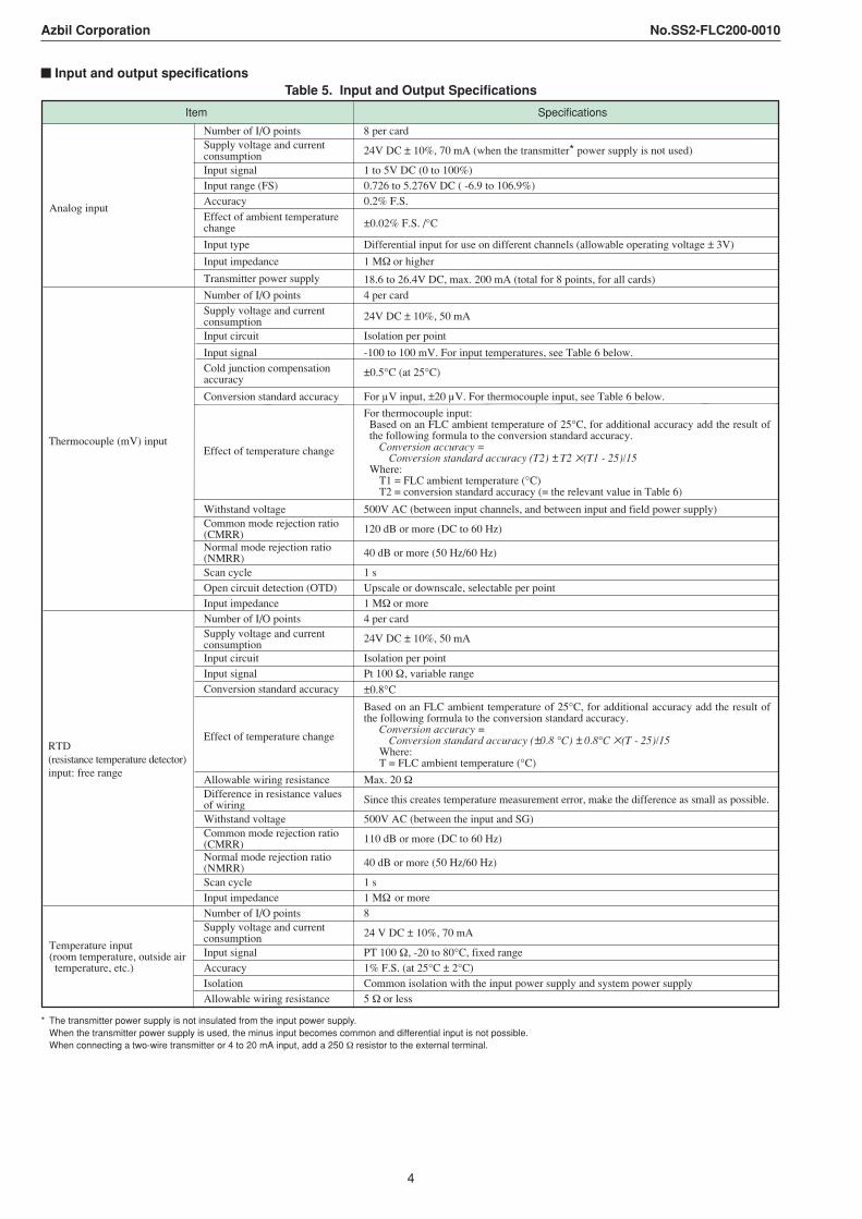
Input and output specificationsTable 5. Input and Output Specifications
Specifications
Number of I/O points 8 per cardSupply voltage and current consumption 24V DC ± 10%, 70 mA (when the transmitter* power supply is not used)
Input signal 1 to 5V DC (0 to 100%)Input range (FS) 0.726 to 5.276V DC ( -6.9 to 106.9%)Accuracy 0.2% F.S.
Effect of ambient temperature change
Differential input for use on different channels (allowable operating voltage ± 3V)
Input impedance 1 MΩ or higher
Transmitter power supply 18.6 to 26.4V DC, max. 200 mA (total for 8 points, for all cards)
Number of I/O points 4 per cardSupply voltage and current consumption 24V DC ± 10%, 50 mA
Input circuit Isolation per point
Input signal -100 to 100 mV. For input temperatures, see Table 6 below. Cold junction compensation accuracy
±0.5°C (at 25°C)
±0.02% F.S. /°C
Conversion standard accuracy For µV input, ±20 µV. For thermocouple input, see Table 6 below.
Item
Effect of temperature change
Input type
Analog input
Thermocouple (mV) input
Withstand voltage 500V AC (between input channels, and between input and field power supply)Common mode rejection ratio(CMRR) 120 dB or more (DC to 60 Hz)
Normal mode rejection ratio(NMRR) 40 dB or more (50 Hz/60 Hz)
Scan cycle 1 sOpen circuit detection (OTD) Upscale or downscale, selectable per pointInput impedance 1 MΩ or moreNumber of I/O points 4 per cardSupply voltage and current consumption
24V DC ± 10%, 50 mA
Input circuit Isolation per pointInput signal Pt 100 Ω , variable rangeConversion standard accuracy
Effect of temperature change
Allowable wiring resistance Max. 20 Ω Difference in resistance valuesof wiringWithstand voltage 500V AC (between the input and SG) Common mode rejection ratio(CMRR) 110 dB or more (DC to 60 Hz)
Normal mode rejection ratio(NMRR) 40 dB or more (50 Hz/60 Hz)
Scan cycle 1 sInput impedance 1 MΩ or moreNumber of I/O points 8Supply voltage and current consumption 24 V DC ± 10%, 70 mA
Input signal PT 100 Ω, -20 to 80°C, fixed rangeAccuracy 1% F.S. (at 25°C ± 2°C)Isolation Common isolation with the input power supply and system power supplyAllowable wiring resistance 5 Ω or less
RTD (resistance temperature detector)input: free range
Temperature input (room temperature, outside air temperature, etc.)
±0.8°C
For thermocouple input: Based on an FLC ambient temperature of 25°C, for additional accuracy add the result of the following formula to the conversion standard accuracy.
Conversion accuracy = Conversion standard accuracy (T2) ± T2 (T1 - 25)/15
Where:T1 = FLC ambient temperature (°C) T2 = conversion standard accuracy (= the relevant value in Table 6)
Based on an FLC ambient temperature of 25°C, for additional accuracy add the result of the following formula to the conversion standard accuracy.
Conversion accuracy = Conversion standard accuracy (±0.8 °C) ± 0.8°C (T - 25)/15
Where:T = FLC ambient temperature (°C)
Since this creates temperature measurement error, make the difference as small as possible.
* The transmitter power supply is not insulated from the input power supply.When the transmitter power supply is used, the minus input becomes common and differential input is not possible.When connecting a two-wire transmitter or 4 to 20 mA input, add a 250 Ω resistor to the external terminal.
5
Azbil Corporation No.SS2-FLC200-0010
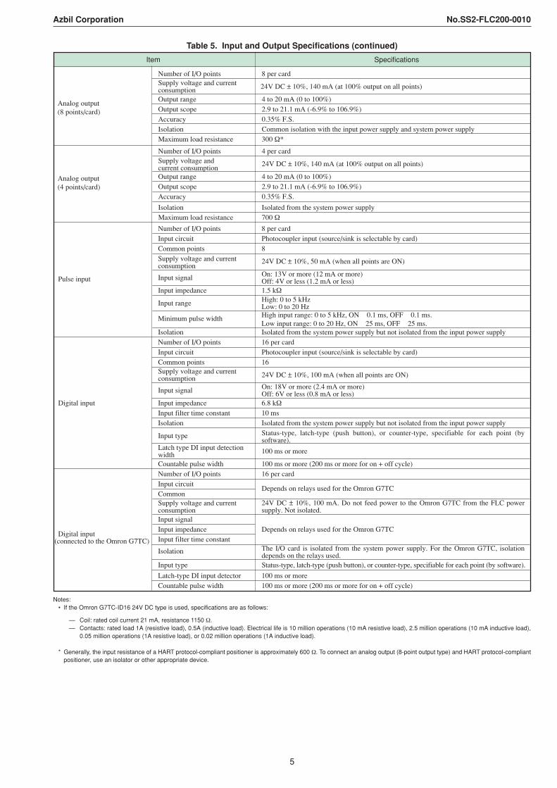
Table 5. Input and Output Specifications (continued)
24V DC ± 10%, 140 mA (at 100% output on all points)
SpecificationsItem
Number of I/O points 8 per cardInput circuit Photocoupler input (source/sink is selectable by card)Common points 8Supply voltage and current consumption
24V DC ± 10%, 50 mA (when all points are ON)
Input signal On: 13V or more (12 mA or more)Off: 4V or less (1.2 mA or less)
Input impedance 1.5 kΩ
Input range High: 0 to 5 kHz Low: 0 to 20 Hz
Isolation Isolated from the system power supply but not isolated from the input power supplyNumber of I/O points 16 per cardInput circuit Photocoupler input (source/sink is selectable by card)Common points 16Supply voltage and current consumption 24V DC ± 10%, 100 mA (when all points are ON)
Input signal On: 18V or more (2.4 mA or more)Off: 6V or less (0.8 mA or less)
Input impedance 6.8 kΩInput filter time constant 10 msIsolation Isolated from the system power supply but not isolated from the input power supply
Input type
Latch type DI input detectionwidth 100 ms or more
Countable pulse width 100 ms or more (200 ms or more for on + off cycle)Number of I/O points 16 per cardInput circuitCommonSupply voltage and current consumptionInput signalInput impedanceInput filter time constant
Isolation
Input type Status-type, latch-type (push button), or counter-type, specifiable for each point (by software).
Latch-type DI input detector 100 ms or moreCountable pulse width 100 ms or more (200 ms or more for on + off cycle)
Depends on relays used for the Omron G7TC
Depends on relays used for the Omron G7TC
Pulse input
Digital input(connected to the Omron G7TC)
Digital input
Minimum pulse width High input range: 0 to 5 kHz, ON 0.1 ms, OFF 0.1 ms.Low input range: 0 to 20 Hz, ON 25 ms, OFF 25 ms.
Number of I/O points 4 per cardSupply voltage and current consumption
24V DC ± 10%, 140 mA (at 100% output on all points)
Output range 4 to 20 mA (0 to 100%)Output scope 2.9 to 21.1 mA (-6.9% to 106.9%)Accuracy 0.35% F.S.
Isolation Isolated from the system power supplyMaximum load resistance 700 Ω
Analog output (4 points/card)
Number of I/O points 8 per cardSupply voltage and current consumptionOutput range 4 to 20 mA (0 to 100%)Output scope 2.9 to 21.1 mA (-6.9% to 106.9%)Accuracy 0.35% F.S.Isolation Common isolation with the input power supply and system power supplyMaximum load resistance 300 Ω*
Analog output (8 points/card)
24V DC ± 10%, 100 mA. Do not feed power to the Omron G7TC from the FLC power supply. Not isolated.
The I/O card is isolated from the system power supply. For the Omron G7TC, isolation depends on the relays used.
Status-type, latch-type (push button), or counter-type, specifiable for each point (by software).
Notes:• If the Omron G7TC-ID16 24V DC type is used, specifications are as follows:
— Coil: rated coil current 21 mA, resistance 1150 Ω.— Contacts: rated load 1A (resistive load), 0.5A (inductive load). Electrical life is 10 million operations (10 mA resistive load), 2.5 million operations (10 mA inductive load),
0.05 million operations (1A resistive load), or 0.02 million operations (1A inductive load).
* Generally, the input resistance of a HART protocol-compliant positioner is approximately 600 Ω. To connect an analog output (8-point output type) and HART protocol-compliantpositioner, use an isolator or other appropriate device.
6
Azbil Corporation No.SS2-FLC200-0010
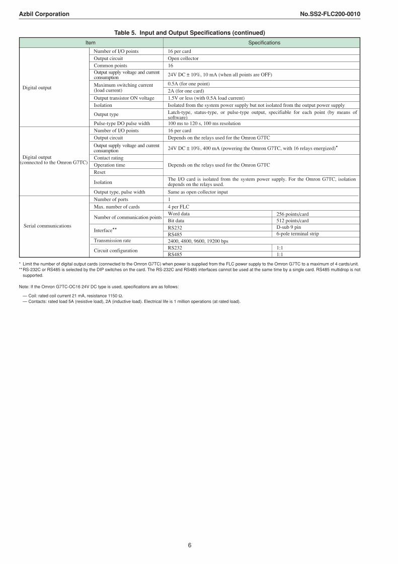
Table 5. Input and Output Specifications (continued)
SpecificationsItem
Number of I/O points 16 per cardOutput circuit Open collectorCommon points 16
24V DC ± 10%, 10 mA (when all points are OFF)
0.5A (for one point)2A (for one card)
Output transistor ON voltage 1.5V or less (with 0.5A load current)Isolation Isolated from the system power supply but not isolated from the output power supply
Output type
Pulse-type DO pulse width 100 ms to 120 s, 100 ms resolutionNumber of I/O points 16 per cardOutput circuit Depends on the relays used for the Omron G7TC
24V DC ± 10%, 400 mA (powering the Omron G7TC, with 16 relays energized)*
Contact ratingOperation timeReset
Isolation
Output type, pulse width Same as open collector input
Digital output(connected to the Omron G7TC) Depends on the relays used for the Omron G7TC
Digital output Maximum switching current (load current)
Serial communications
Number of ports
Max. number of cards
Number of communication points
Interface**
Transmission rate
Circuit configuration
1
4 per FLCWord dataBit data
256 points/card 512 points/cardD-sub 9 pin6-pole terminal strip
RS232RS4852400, 4800, 9600, 19200 bpsRS232RS485
1:11:1
The I/O card is isolated from the system power supply. For the Omron G7TC, isolation depends on the relays used.
Latch-type, status-type, or pulse-type output, specifiable for each point (by means of software)
Output supply voltage and current consumption
Output supply voltage and current consumption
* Limit the number of digital output cards (connected to the Omron G7TC) when power is supplied from the FLC power supply to the Omron G7TC to a maximum of 4 cards/unit.**RS-232C or RS485 is selected by the DIP switches on the card. The RS-232C and RS485 interfaces cannot be used at the same time by a single card. RS485 multidrop is not
supported.
Note: If the Omron G7TC-OC16 24V DC type is used, specifications are as follows:
— Coil: rated coil current 21 mA, resistance 1150 Ω.— Contacts: rated load 5A (resistive load), 2A (inductive load). Electrical life is 1 million operations (at rated load).
7
Azbil Corporation No.SS2-FLC200-0010
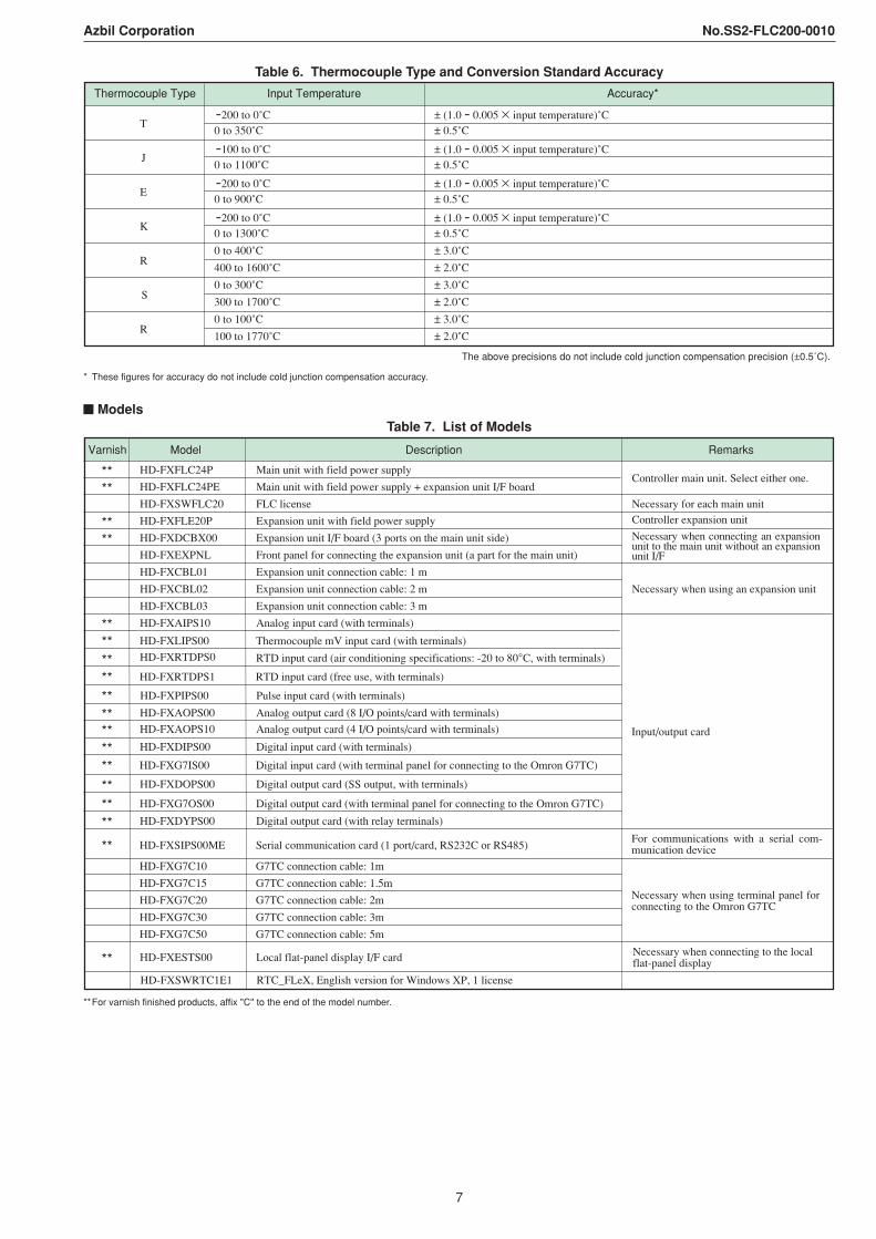
Table 6. Thermocouple Type and Conversion Standard Accuracy
Thermocouple Type
-200 to 0˚C ± (1.0 - 0.005 input temperature)˚C 0 to 350˚C ± 0.5˚C
-100 to 0˚C ± (1.0 - 0.005 input temperature)˚C 0 to 1100˚C ± 0.5˚C
-200 to 0˚C ± (1.0 - 0.005 input temperature)˚C 0 to 900˚C ± 0.5˚C
-200 to 0˚C ± (1.0 - 0.005 input temperature)˚C 0 to 1300˚C ± 0.5˚C
0 to 400˚C ± 3.0˚C
400 to 1600˚C ± 2.0˚C
0 to 300˚C ± 3.0˚C
300 to 1700˚C ± 2.0˚C
0 to 100˚C ± 3.0˚C
100 to 1770˚C ± 2.0˚C
The above precisions do not include cold junction compensation precision (±0.5˚C).
Accuracy*
R
S
R
Input Temperature
T
J
E
K
* These figures for accuracy do not include cold junction compensation accuracy.
ModelsTable 7. List of Models
Varnish Model Description Remarks
** HD-FXFLC24P Main unit with field power supply
** HD-FXFLC24PE Main unit with field power supply + expansion unit I/F board
HD-FXSWFLC20 FLC license Necessary for each main unit
** HD-FXFLE20P Expansion unit with field power supply
** HD-FXDCBX00 Expansion unit I/F board (3 ports on the main unit side)
HD-FXEXPNL Front panel for connecting the expansion unit (a part for the main unit)
HD-FXCBL01 Expansion unit connection cable: 1 m
HD-FXCBL02 Expansion unit connection cable: 2 m
HD-FXCBL03 Expansion unit connection cable: 3 m
** HD-FXAIPS10 Analog input card (with terminals)
** HD-FXRTDPS0 RTD input card (air conditioning specifications: -20 to 80°C, with terminals)
** HD-FXAOPS00 Analog output card (8 I/O points/card with terminals)
** HD-FXDIPS00 Digital input card (with terminals)
** HD-FXDOPS00 Digital output card (SS output, with terminals)
** HD-FXDYPS00 Digital output card (with relay terminals)
** HD-FXESTS00 Local flat-panel display I/F card
HD-FXSWRTC1E1 RTC_FLeX, English version for Windows XP, 1 license
Controller main unit. Select either one.
Controller expansion unit
Necessary when using an expansion unit
Input/output card
HD-FXLIPS00 Thermocouple mV input card (with terminals)**
HD-FXRTDPS1 RTD input card (free use, with terminals)**HD-FXPIPS00 Pulse input card (with terminals)**
** HD-FXG7IS00 Digital input card (with terminal panel for connecting to the Omron G7TC)
** HD-FXG7OS00 Digital output card (with terminal panel for connecting to the Omron G7TC)
HD-FXG7C10 G7TC connection cable: 1m
HD-FXG7C15 G7TC connection cable: 1.5m
HD-FXG7C20 G7TC connection cable: 2m
HD-FXG7C30 G7TC connection cable: 3m
HD-FXG7C50 G7TC connection cable: 5m
** HD-FXAOPS10 Analog output card (4 I/O points/card with terminals)
** HD-FXSIPS00ME Serial communication card (1 port/card, RS232C or RS485)
Necessary when using terminal panel for connecting to the Omron G7TC
Necessary when connecting an expansion unit to the main unit without an expansion unit I/F
For communications with a serial com-munication device
Necessary when connecting to the local flat-panel display
**For varnish finished products, affix "C" to the end of the model number.
8
Azbil Corporation No.SS2-FLC200-0010
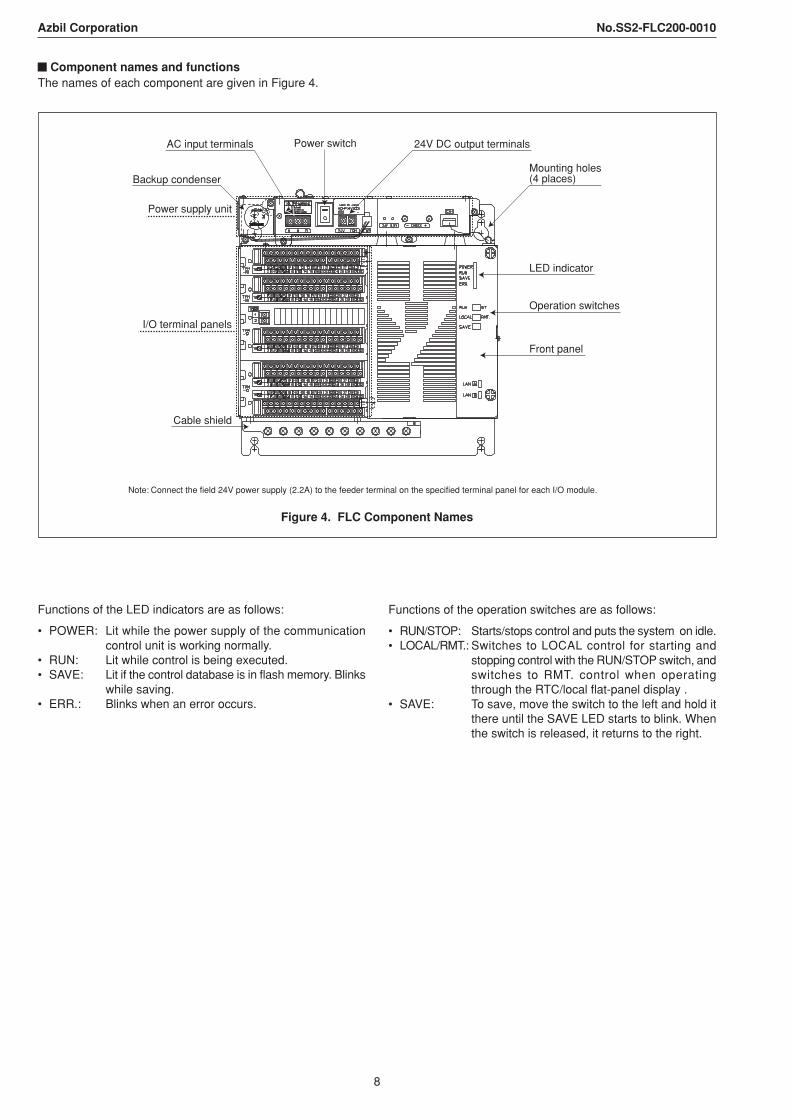
Component names and functionsThe names of each component are given in Figure 4.
Front panel
AC input terminals Power switch 24V DC output terminals
Power supply unit
Backup condenser
I/O terminal panels
Cable shield
Mounting holes (4 places)
LED indicator
Operation switches
Note: Connect the field 24V power supply (2.2A) to the feeder terminal on the specified terminal panel for each I/O module.
Figure 4. FLC Component Names
Functions of the LED indicators are as follows:
• POWER: Lit while the power supply of the communicationcontrol unit is working normally.
• RUN: Lit while control is being executed.• SAVE: Lit if the control database is in flash memory. Blinks
while saving.• ERR.: Blinks when an error occurs.
Functions of the operation switches are as follows:
• RUN/STOP: Starts/stops control and puts the system on idle.• LOCAL/RMT.: Switches to LOCAL control for starting and
stopping control with the RUN/STOP switch, andswitches to RMT. control when operatingthrough the RTC/local flat-panel display .
• SAVE: To save, move the switch to the left and hold itthere until the SAVE LED starts to blink. Whenthe switch is released, it returns to the right.
9
Azbil Corporation No.SS2-FLC200-0010
3. Control Functions (Control Points)Control functions are classified into the following types of control point:
Regulatory PV Point (RegPV)Standard I/O processing functions, like industrial unit conversionand alarms, are directly carried out by the above-mentioned I/Omonitoring functions. The regulatory PV point performs processvariable (PV) calculations and compensation functions. PVprocessing is accomplished using algorithms such as flowcompensation, integration and variable dead time compensation.Detailed configuration possibilities include alarm suppression,signal filtering, and algorithm and calculation formula options. Foravailable algorithms and other supported functions, see Table 8.
Table 8. Regulatory PV Point Features
Data acquisition PV source selection (automatic, manual, substitution)Flow compensation
Middle of three PV clampingHigh/low/average selector Engineering unit conversion and PV
extention range check (sensor failure)SummerTotalizer PV status
PV filteringPV alarmingGeneral linearization- Bad PV (sensor failure)Calculator algorithm
- PVHI, PVLO- PVHIHI, PVLOLO- PV rate of change alarm
Available algorithms Support functions
Variable dead time with lead/lag
Regulatory Control Point (Reg Ctl)Regulatory control points are used to carry out the controlfunctions of the FLC. Configuration of the algorithms listed inTable 9 determines the regulatory control point functions. Eachalgorithm has configurable options, allowing complicated controlto be achieved by simple menu selection. Standard functionsinclude initialization and windup protection. Set point lamping(by operator entry of target values and lamp time) is alsoavailable.
Table 9. Regulatory Control Point Features
PID Mode/mode attributePID with feed forward Red tagPID with external feedback InitializationPosition proportional Anti-reset windup
Safety shutdownOutput limitPV source selectionPV alarming
External mode switchingRatio controlRamp/soakAuto/manual stationIncremental summingSwitchOverride selector - Bad PV (sensor failure)
- PVHI, PVLO- PVHIHI, PVLOLO- PV rate of change alarm
Available algorithms Support functions
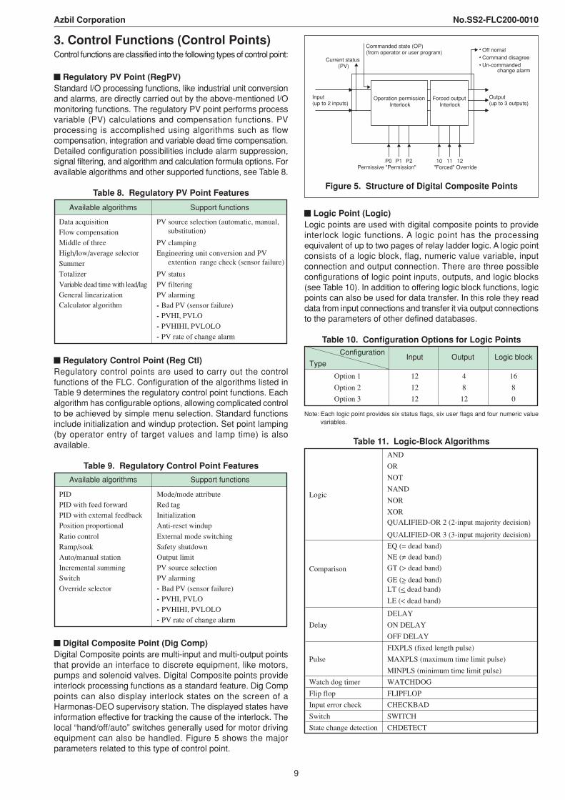
Digital Composite Point (Dig Comp)Digital Composite points are multi-input and multi-output pointsthat provide an interface to discrete equipment, like motors,pumps and solenoid valves. Digital Composite points provideinterlock processing functions as a standard feature. Dig Comppoints can also display interlock states on the screen of aHarmonas-DEO supervisory station. The displayed states haveinformation effective for tracking the cause of the interlock. Thelocal “hand/off/auto” switches generally used for motor drivingequipment can also be handled. Figure 5 shows the majorparameters related to this type of control point.
Current status (PV)
Commanded state (OP)(from operator or user program)
Input(up to 2 inputs)
Operation permission Interlock
P0 P1 P2 10 11 12Permissive "Permission" "Forced" Override
Forced output Interlock
Output(up to 3 outputs)
Off nomal
Un-commanded change alarm
Command disagree
Figure 5. Structure of Digital Composite Points
Logic Point (Logic)Logic points are used with digital composite points to provideinterlock logic functions. A logic point has the processingequivalent of up to two pages of relay ladder logic. A logic pointconsists of a logic block, flag, numeric value variable, inputconnection and output connection. There are three possibleconfigurations of logic point inputs, outputs, and logic blocks(see Table 10). In addition to offering logic block functions, logicpoints can also be used for data transfer. In this role they readdata from input connections and transfer it via output connectionsto the parameters of other defined databases.
Table 10. Configuration Options for Logic PointsConfiguration
Type
Option 1 12 4 16
Option 2 12 8 8
Option 3 12 12 0
Input Output Logic block
Note: Each logic point provides six status flags, six user flags and four numeric valuevariables.
Table 11. Logic-Block Algorithms
AND
OR
NOT
NAND
NOR
XORQUALIFIED-OR 2 (2-input majority decision)
QUALIFIED-OR 3 (3-input majority decision)
EQ (= dead band)
NE (= dead band)
GT (> dead band)
LE (< dead band)
Logic
Comparison
DELAY
ON DELAY
OFF DELAY
FIXPLS (fixed length pulse)
MAXPLS (maximum time limit pulse)
MINPLS (minimum time limit pulse)
Watch dog timer WATCHDOG
Flip flop FLIPFLOP
Input error check CHECKBAD
Switch SWITCH
State change detection CHDETECT
Delay
Pulse
LT (< dead band)GE (> dead band)
10
Azbil Corporation No.SS2-FLC200-0010
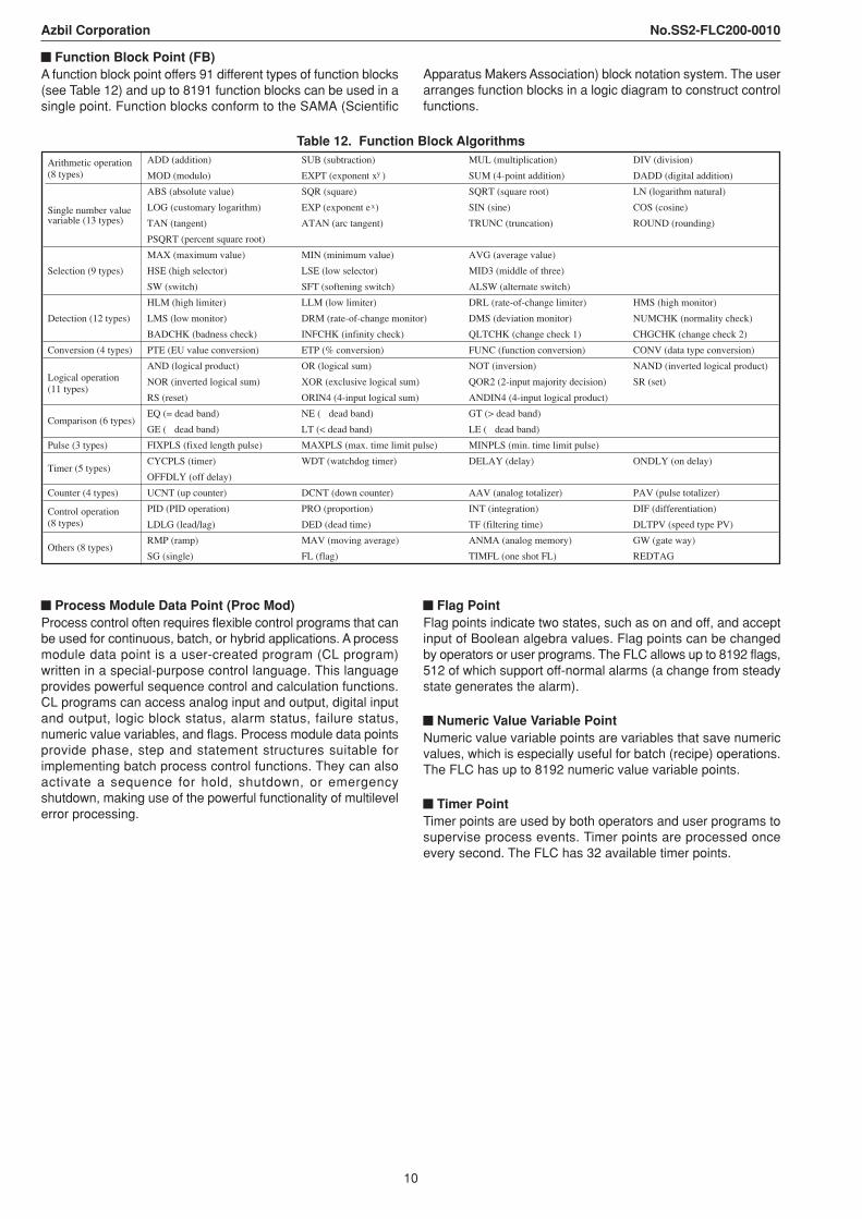
Function Block Point (FB)A function block point offers 91 different types of function blocks(see Table 12) and up to 8191 function blocks can be used in asingle point. Function blocks conform to the SAMA (Scientific
Apparatus Makers Association) block notation system. The userarranges function blocks in a logic diagram to construct controlfunctions.
Table 12. Function Block AlgorithmsADD (addition) SUB (subtraction) MUL (multiplication) DIV (division)
MOD (modulo) EXPT (exponent x ) SUM (4-point addition) DADD (digital addition)
ABS (absolute value) SQR (square) SQRT (square root) LN (logarithm natural)
LOG (customary logarithm) EXP (exponent e ) SIN (sine) COS (cosine)
TAN (tangent) ATAN (arc tangent) TRUNC (truncation) ROUND (rounding)
PSQRT (percent square root)
MAX (maximum value) MIN (minimum value) AVG (average value)
HSE (high selector) LSE (low selector)
SW (switch) SFT (softening switch)
HLM (high limiter) LLM (low limiter) DRL (rate-of-change limiter) HMS (high monitor)
LMS (low monitor) DRM (rate-of-change monitor) DMS (deviation monitor) NUMCHK (normality check)
BADCHK (badness check) INFCHK (infinity check) QLTCHK (change check 1) CHGCHK (change check 2)
Conversion (4 types) PTE (EU value conversion) ETP (% conversion) FUNC (function conversion) CONV (data type conversion)
AND (logical product) OR (logical sum) NOT (inversion) NAND (inverted logical product)
NOR (inverted logical sum) XOR (exclusive logical sum) QOR2 (2-input majority decision) SR (set)
RS (reset) ORIN4 (4-input logical sum) ANDIN4 (4-input logical product)
EQ (= dead band) NE ( dead band) GT (> dead band)
GE ( dead band) LT (< dead band) LE ( dead band)
Pulse (3 types) FIXPLS (fixed length pulse) MAXPLS (max. time limit pulse)
CYCPLS (timer) WDT (watchdog timer) DELAY (delay) ONDLY (on delay)
OFFDLY (off delay)
Counter (4 types) UCNT (up counter) DCNT (down counter) AAV (analog totalizer) PAV (pulse totalizer)
PID (PID operation) PRO (proportion) INT (integration) DIF (differentiation)
LDLG (lead/lag) DED (dead time) TF (filtering time) DLTPV (speed type PV)
RMP (ramp) MAV (moving average) ANMA (analog memory) GW (gate way)
SG (single) FL (flag) TIMFL (one shot FL) REDTAG
MID3 (middle of three)
ALSW (alternate switch)
Others (8 types)
Control operation(8 types)
MINPLS (min. time limit pulse)
Arithmetic operation(8 types)
Logical operation(11 types)
Comparison (6 types)
Timer (5 types)
Selection (9 types)
Detection (12 types)
Single number valuevariable (13 types)
y
x
Process Module Data Point (Proc Mod)Process control often requires flexible control programs that canbe used for continuous, batch, or hybrid applications. A processmodule data point is a user-created program (CL program)written in a special-purpose control language. This languageprovides powerful sequence control and calculation functions.CL programs can access analog input and output, digital inputand output, logic block status, alarm status, failure status,numeric value variables, and flags. Process module data pointsprovide phase, step and statement structures suitable forimplementing batch process control functions. They can alsoactivate a sequence for hold, shutdown, or emergencyshutdown, making use of the powerful functionality of multilevelerror processing.
Flag PointFlag points indicate two states, such as on and off, and acceptinput of Boolean algebra values. Flag points can be changedby operators or user programs. The FLC allows up to 8192 flags,512 of which support off-normal alarms (a change from steadystate generates the alarm).
Numeric Value Variable PointNumeric value variable points are variables that save numericvalues, which is especially useful for batch (recipe) operations.The FLC has up to 8192 numeric value variable points.
Timer PointTimer points are used by both operators and user programs tosupervise process events. Timer points are processed onceevery second. The FLC has 32 available timer points.
11
Azbil Corporation No.SS2-FLC200-0010
4. Alarm System FunctionsFLC supports a variety of alarm functions. When an alarmoccurs, notifications appear at the open supervisory station onvarious types of screens. Alarms are generally classified as PValarms or digital alarms.
PV AlarmsThe types of configurable alarm for process variables are listedbelow. Alarms can be set in both I/O points and control points.In general, if a control point uses an I/O point, the alarm is set inthe control point. Otherwise, it is set in the I/O point.• High • Change rate high• High high • Change rate low• Low • Significant change• Low lowA dead band can be set in all PV alarms mentioned above.
Digital AlarmsThere are three types of digital alarm:• Off-normal alarm• Uncommanded change alarm• Command disagree alarmOff-normal alarms are activated when the status changes toON. Both uncommanded change alarms and command disagreealarms are set within digital composite points and detect adisagreement between input and output. A command disagreealarm detects a disagreement between input and output justafter an output change, while an uncommanded change alarmdetects a disagreement between input and output when nooutput change has been made. Both alarms can set dead bandtime.
Alarm PriorityAlarm priority can be configured for individual alarm types foreach point. A choice of seven alarm priorities can be assigned:• Emergent (emergency)• Important (high)• Ordinary (low)• Journal only• Only journal printer output (not used when the local flat-panel
display is connected)• Journal recording + printer output (not used when the local
flat-panel display is connected)• None (no action)
Contact CutoutThe contact cutout function allows a program to temporarily stopan alarm for any point (or all points) having alarm functions.The “CONTCUT” parameter, which is available for points havingalarm functions, can be turned on to put points in the alarmstop status.
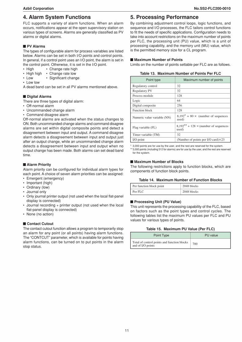
5. Processing PerformanceBy combining adjustment control loops, logic functions, andsequence and I/O processes, the FLC tailors control functionsto fit the needs of specific applications. Configuration needs totake into account restrictions on the maximum number of pointsper FLC, the processing unit (PU) value, which is a unit ofprocessing capability, and the memory unit (MU) value, whichis the permitted memory size for a CL program.
Maximum Number of PointsLimits on the number of points settable per FLC are as follows.
Table 13. Maximum Number of Points Per FLC
Regulatory control 32
Regulatory PV 32
Process module 128
Logic 64
Digital composite 256
Function block 128
Numeric value variable (NN)
Flag variable (FL)
Timer variable (TM) 32
I/O point (Number of points per I/O card) 23
Point type Maximum number of points
8,192* + 80 (number of sequences used)
8,192** + 128 (number of sequences used)
* 3,000 points are for use by the user, and the rest are reserved for the system.**3,000 points (including 512 for alarms) are for use by the user, and the rest are reserved
for the system.
Maximum Number of BlocksThe following restrictions apply to function blocks, which arecomponents of function block points.
Table 14. Maximum Number of Function Blocks
Per function block point
Per FLC 2048 blocks
2048 blocks
Processing Unit (PU Value)This unit represents the processing capability of the FLC, basedon factors such as the point types and control cycles. Thefollowing tables list the maximum PU values per FLC and PUvalues for various types of points.
Table 15. Maximum PU Value (Per FLC)
Point Type PU value
Total of control points and function blocksand of I/O points 700
12
Azbil Corporation No.SS2-FLC200-0010
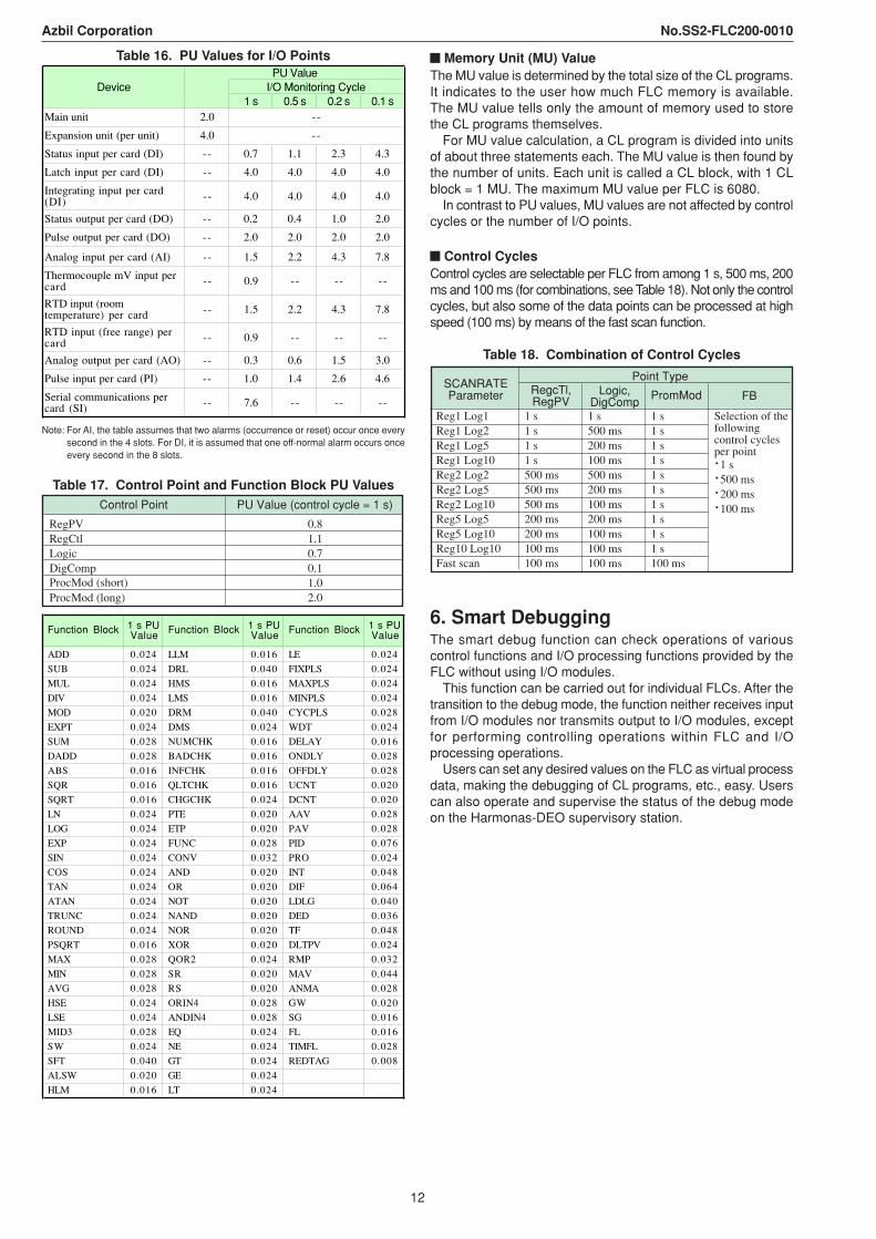
Table 16. PU Values for I/O Points
1 s 0.5 s 0.2 s 0.1 sMain unit 2.0
Expansion unit (per unit) 4.0
Status input per card (DI) -- 0.7 1.1 2.3 4.3
Latch input per card (DI) -- 4.0 4.0 4.0 4.0
Integrating input per card(DI) -- 4.0 4.0 4.0 4.0
Status output per card (DO) -- 0.2 0.4 1.0 2.0
Pulse output per card (DO) -- 2.0 2.0 2.0 2.0
Analog input per card (AI) -- 1.5 2.2 4.3 7.8
Thermocouple mV input percard -- 0.9 -- -- --
RTD input (roomtemperature) per card -- 1.5 2.2 4.3 7.8
RTD input (free range) percard -- 0.9 -- -- --
Analog output per card (AO) -- 0.3 0.6 1.5 3.0
Pulse input per card (PI) -- 1.0 1.4 2.6 4.6
Serial communications percard (SI) -- 7.6 -- -- --
Device I/O Monitoring CyclePU Value
--
--
Note: For AI, the table assumes that two alarms (occurrence or reset) occur once everysecond in the 4 slots. For DI, it is assumed that one off-normal alarm occurs onceevery second in the 8 slots.
Table 17. Control Point and Function Block PU ValuesPU Value (control cycle = 1 s)
RegPV 0.8RegCtl 1.1Logic 0.7DigComp 0.1
1.0ProcMod (long) 2.0
Control Point
ProcMod (short)
1 s PUValue
1 s PUValue
1 s PUValue
ADD 0.024 LLM 0.016 LE 0.024
SUB 0.024 DRL 0.040 FIXPLS 0.024
MUL 0.024 HMS 0.016 MAXPLS 0.024
DIV 0.024 LMS 0.016 MINPLS 0.024
MOD 0.020 DRM 0.040 CYCPLS 0.028
EXPT 0.024 DMS 0.024 WDT 0.024
SUM 0.028 NUMCHK 0.016 DELAY 0.016
DADD 0.028 BADCHK 0.016 ONDLY 0.028
ABS 0.016 INFCHK 0.016 OFFDLY 0.028
SQR 0.016 QLTCHK 0.016 UCNT 0.020
SQRT 0.016 CHGCHK 0.024 DCNT 0.020
LN 0.024 PTE 0.020 AAV 0.028
LOG 0.024 ETP 0.020 PAV 0.028
EXP 0.024 FUNC 0.028 PID 0.076
SIN 0.024 CONV 0.032 PRO 0.024
COS 0.024 AND 0.020 INT 0.048
TAN 0.024 OR 0.020 DIF 0.064
ATAN 0.024 NOT 0.020 LDLG 0.040
TRUNC 0.024 NAND 0.020 DED 0.036
ROUND 0.024 NOR 0.020 TF 0.048
PSQRT 0.016 XOR 0.020 DLTPV 0.024
MAX 0.028 QOR2 0.024 RMP 0.032
MIN 0.028 SR 0.020 MAV 0.044
AVG 0.028 RS 0.020 ANMA 0.028
HSE 0.024 ORIN4 0.028 GW 0.020
LSE 0.024 ANDIN4 0.028 SG 0.016
MID3 0.028 EQ 0.024 FL 0.016
SW 0.024 NE 0.024 TIMFL 0.028
SFT 0.040 GT 0.024 REDTAG 0.008
ALSW 0.020 GE 0.024
HLM 0.016 LT 0.024
Function Block Function Block Function Block
Memory Unit (MU) ValueThe MU value is determined by the total size of the CL programs.It indicates to the user how much FLC memory is available.The MU value tells only the amount of memory used to storethe CL programs themselves.
For MU value calculation, a CL program is divided into unitsof about three statements each. The MU value is then found bythe number of units. Each unit is called a CL block, with 1 CLblock = 1 MU. The maximum MU value per FLC is 6080.
In contrast to PU values, MU values are not affected by controlcycles or the number of I/O points.
Control CyclesControl cycles are selectable per FLC from among 1 s, 500 ms, 200ms and 100 ms (for combinations, see Table 18). Not only the controlcycles, but also some of the data points can be processed at highspeed (100 ms) by means of the fast scan function.
Table 18. Combination of Control Cycles
RegcTl,RegPV
Logic,DigComp
PromMod FB
Reg1 Log1 1 s 1 s 1 sReg1 Log2 1 s 500 ms 1 sReg1 Log5 1 s 200 ms 1 sReg1 Log10 1 s 100 ms 1 sReg2 Log2 500 ms 500 ms 1 sReg2 Log5 500 ms 200 ms 1 sReg2 Log10 500 ms 100 ms 1 sReg5 Log5 200 ms 200 ms 1 sReg5 Log10 200 ms 100 ms 1 sReg10 Log10 100 ms 100 ms 1 sFast scan 100 ms 100 ms 100 ms
Point Type
Selection of thefollowingcontrol cyclesper point·1 s·500 ms·200 ms·100 ms
SCANRATEParameter
6. Smart DebuggingThe smart debug function can check operations of variouscontrol functions and I/O processing functions provided by theFLC without using I/O modules.
This function can be carried out for individual FLCs. After thetransition to the debug mode, the function neither receives inputfrom I/O modules nor transmits output to I/O modules, exceptfor performing controlling operations within FLC and I/Oprocessing operations.
Users can set any desired values on the FLC as virtual processdata, making the debugging of CL programs, etc., easy. Userscan also operate and supervise the status of the debug modeon the Harmonas-DEO supervisory station.
13
Azbil Corporation No.SS2-FLC200-0010
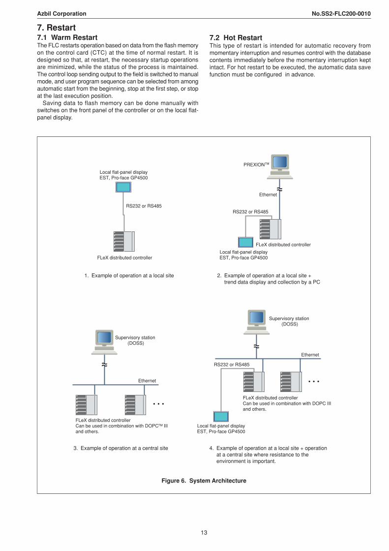
3. Example of operation at a central site
Supervisory station (DOSS)
FLeX distributed controllerCan be used in combination with DOPC III and others.
TM
Ethernet
Local flat-panel displayEST, Pro-face GP4500
RS232 or RS485
FLeX distributed controller
1. Example of operation at a local site
PREXION
Ethernet
FLeX distributed controller
Local flat-panel displayEST, Pro-face GP4500
RS232 or RS485
TM
2. Example of operation at a local site + trend data display and collection by a PC
RS232 or RS485
Supervisory station (DOSS)
Ethernet
FLeX distributed controllerCan be used in combination with DOPC III and others.
Local flat-panel displayEST, Pro-face GP4500
4. Example of operation at a local site + operation at a central site where resistance to the environment is important.
Figure 6. System Architecture
7. Restart7.1 Warm RestartThe FLC restarts operation based on data from the flash memoryon the control card (CTC) at the time of normal restart. It isdesigned so that, at restart, the necessary startup operationsare minimized, while the status of the process is maintained.The control loop sending output to the field is switched to manualmode, and user program sequence can be selected from amongautomatic start from the beginning, stop at the first step, or stopat the last execution position.
Saving data to flash memory can be done manually withswitches on the front panel of the controller or on the local flat-panel display.
7.2 Hot RestartThis type of restart is intended for automatic recovery frommomentary interruption and resumes control with the databasecontents immediately before the momentary interruption keptintact. For hot restart to be executed, the automatic data savefunction must be configured in advance.
14
Azbil Corporation No.SS2-FLC200-0010
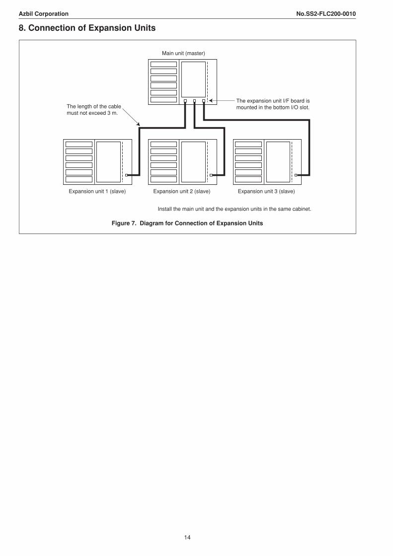
8. Connection of Expansion Units
Expansion unit 2 (slave)Expansion unit 1 (slave) Expansion unit 3 (slave)
Main unit (master)
The expansion unit I/F board is mounted in the bottom I/O slot.The length of the cable
must not exceed 3 m.
Install the main unit and the expansion units in the same cabinet.
Figure 7. Diagram for Connection of Expansion Units
15
Azbil Corporation No.SS2-FLC200-0010
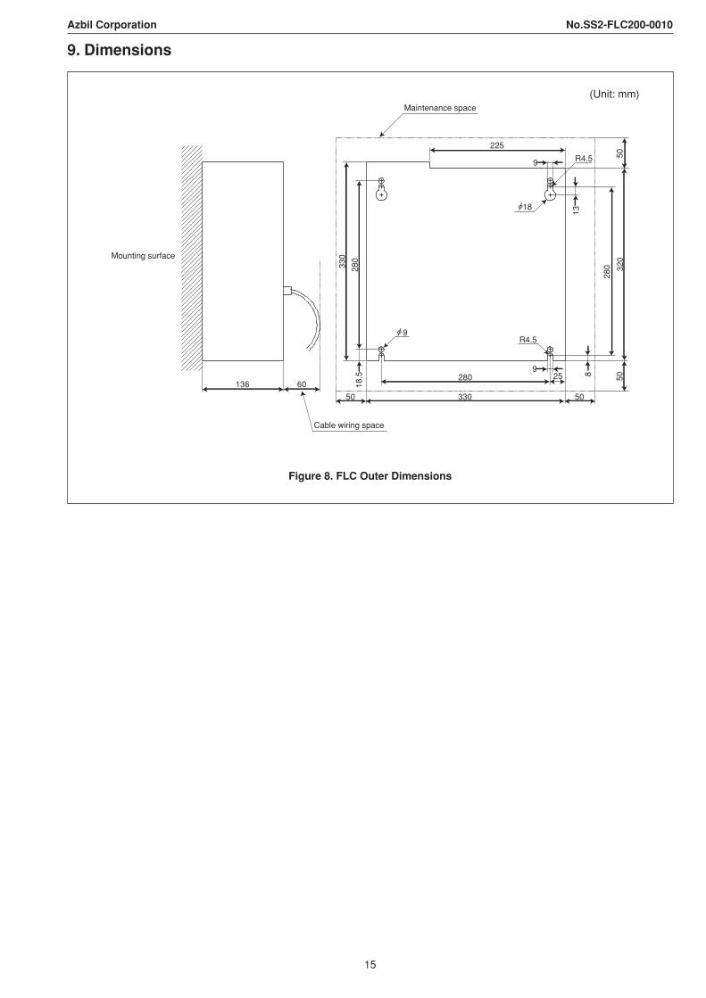
9. Dimensions
(Unit: mm)
Mounting surface
136
Cable wiring space
60
50 330 50
280 259
R4.59
330
280
18.5
Maintenance space
18
R4.59
225
13
5032
0
280
50
8
Figure 8. FLC Outer Dimensions

16
Azbil Corporation No.SS2-FLC200-0010
• Harmonas-FLeX, Harmonas-DEO and PlantWalker-HV are trademarks of Azbil Corporation in Japan.• Windows and Windows NT are registered trademarks of Microsoft Corporation in the U.S.A. and other countries.• Ethernet is a registered trademark of XEROX Corporation.• MELSEC is a trademark of Mitsubishi Electric Corporation, Ltd.• TOYOPUC is a trademark of JTECT Corporation.• Other product names, model nos., and company names may be trademarks.
4th edition: Aug. 2013
Copyright © 2022 FDOKUMEN

