


Bahasa
Halaman
Hukum


JOURNAL OF RESOURCE
MANAGEMENT AND TECHNOLOGY
ISSN NO: 0745-6999
Vol12, Issue3, 2021
Page No:238
Fuzzy Control Based Adaptive Maximum Power Point Tracking
Control Algorithm for Wind Energy Conversion Systems
1Boddu Pavan Teja, UG Student, Department of EEE, Pragati Engineering college, Surampalem
2Damodhara Naveen, UG Student, Department of EEE, Pragati Engineering college, Surampalem
3Kutha Vishal Reddy, UG Student, Department of EEE, Pragati Engineering college, Surampalem
4Mandapalli Sam Moses Sastry, UG Student, Department of EEE, Pragati Engineering college, Surampalem
5Pothuraju Teja Venkata Siva Ganesh, UG Student, Department of EEE, Pragati Engineering college, Surampalem
Abstract—this paper presents an Fuzzy
control based adaptive maximum power
point tracking (MPPT) algorithm for small
scale wind energy conversion systems
(WECSs) to harvest more energy from
unstable wind. The proposed algorithm
combines the computational behavior of hill
climb search, tip speed ratio, and power
signal feedback fuzzy control for its
adaptability over wide range of WECSs and
fast tracking of maximum power point. In
this paper, the proposed MPPT algorithm is
implemented by using buck– boost featured
single ended primary inductor converter to
extract maximum power from full range of
wind velocity profile. Evaluation of the
Fuzzy based MPPT controller is done on
MATLAB/SIMULINK Environment.
Matlab Simulation results show that tracking
capability of the proposed System under
sudden and gradual fluctuating wind
conditions is efficient and effective.
Index Terms—Maximum power point
tracking, Fuzzy Logic Control (FLC), tip
speed ratio algorithm, power signal feedback
algorithm, single-ended primary inductor
converter (SEPIC) dc-dc converter.
I. INTRODUCTION
Interest in renewable energy is
increasing as alternative energy source to
conventional fossil fuel, because of latter’s
soaring prices, limited reserve capacity, and
environmental concerns. Across the globe,
research community is exploring all
possibilities for the efficient energy
conversion from freely available abundant
renewable energy sources. Among the
popular renewable energy sources, wind
energy is gaining more support due to its
less space occupancy and zero-carbon
emission during operation. Variable speed
wind energy conversion systems (WECSs)
can harness more electrical energy than
fixed speed WECSs by controlling their
speed according to the variations in wind
velocity [1], [2]. Optimal speed for the
turbine ωm (rad/s) is calculated by using
wind velocity Vw(m/s), turbine rotating
speed ωm (rad/s), and optimal TSR λopt of
the system as follows [4]–[6],

JOURNAL OF RESOURCE
MANAGEMENT AND TECHNOLOGY
ISSN NO: 0745-6999
Vol12, Issue3, 2021
Page No:239
where R is rotor radius in meter.
Implementation of TSR algorithm requires
the knowledge of λopt of the turbine and is
system dependent.
In PSF control method, wind turbine
operates at optimal operating point by using
the prior knowledge of turbine’s maximum
power curve [7]–[10]. Implementation of
this method requires the prior knowledge of
maximum power curves which can be
obtained through off-line experiments or
system simulations. In HCS control method,
an arbitrary small perturbation is given to
one of the independent variables of the
system and next perturbation is decided
based on the changes in output power due to
preceding perturbation [11], [12].
Drawbacks of this algorithm are, slow
tracking response, especially for high inertia
systems. Advanced HCS based on-line
training algorithms are reported in [13] and
[14] to improve the system tracking
response of its maximum power point
(MPP). In the present work, a simplified
algorithm than [14] has been implemented to
improve the system tracking response under
rapid fluctuating wind velocity conditions.
Microgrid is essentially a collection
of distributed energy resources (DERs),
potential energy storage devices, and loads
connected together to form a relatively
small-size distribution network [15]. Small-
scale WECSs are main resources for DERs
in microgrid systems and are usually
installed at congested places with turbulent
wind conditions where wind speed and
direction vary frequently. Extraction of
maximum power with fast tracking control
strategy under fluctuating wind conditions is
a challenging issue. In small-scale WECSs,
power conditioning converter’s control is
most frequently adapting strategy to extract
maximum power since pitch angle control is
impractical due to their mechanical
structure. In this work buck–boost featured
single-ended primary inductor converter
(SEPIC) dc–dc converter has been used to
extract maximum power from total range of
wind velocity profile.
This work assumes that the WECS
has effective yaw mechanism to turn the
turbine nacelle in the direction of the wind
immediately against to the variations in
wind flow direction. In this paper, a hybrid
nature of MPPT control algorithm which
combines the computational behavior of
HCS-TSR-PSF Fuzzy based Control for
system independent adaptivity and fast
tracking capability of MPP is presented. The
proposed MPPT- Fuzzy based Control has
been evaluated by using a Matlab/Simulink.
Simulation results show that the proposed
Fuzzy based Control enables the WECS to
harvest more energy by tracking the MPP
under turbulent wind conditions.
Fig. 1. WECS configuration.
II. SYSTEM CONFIGURATION AND
MODELING
In the process of developing a
laboratory-scaled dc microgrid platform,
WECS related system configuration is
shown in Fig. 1. In small scale variable

JOURNAL OF RESOURCE
MANAGEMENT AND TECHNOLOGY
ISSN NO: 0745-6999
Vol12, Issue3, 2021
Page No:240
speed WECS, direct driven permanent
magnet synchronous generator (PMSG) with
diode rectifier is the most preferred
configuration due to PMSG’s high air-gap
flux density, and high torque-to-inertia ratio.
Its decoupling control performance is much
less sensitive to the parameter variations of
the generator [16]–[19].
A. Wind Turbine Aerodynamic Model
Mechanical output power Pm
extracted from wind by the wind turbine and
corresponding torque Tm imparted onto WG
can be modeled as [20],
where ρ is air density (kg/m3 ), Cp is power
coefficient which is function of TSR λ and
pitch angle β. The coefficient, Cp can be
modeled by using rotor blade’s aerodynamic
design principles [21],
and empirical constants, C1 = 0.5176; C2 =
116; C3 = 0.4; C4 = 5; C5 = 21; C6 =
0.0068.
In this work, DC motor based
hardware wind turbine emulator is
developed in the laboratory by using (2) and
(3).
B. PMSG-Diode Rectifier Model
Induced emf, es (V), in stator
winding of PMSG, when it is subjected to a
constant flux, φ (Wb), while rotating with a
speed, ωm (rad/s), is given by
where k (V·s/rad) is machine induced
voltage constant, P is total number of rotor
pole pairs and ωe is electrical angular
frequency of PMSG stator induced voltage.
In steady state, PMSG’s terminal phase
voltage, Vs, and output power, Pg, are given
by
where Es , Is and Ls are induced voltage in
PMSG’s stator winding, stator current and
inductance respectively. To derive the basic
relations, assuming that both the
commutating angle and commutating
inductance are negligible, the relation
between diode rectifier output voltage, VDC
and line voltage at terminals of PMSG, Vt,
can be related as [22],
where Vt is RMS value of line-to-line
voltage of PMSG. By ignoring the power
loss during diode circuit rectification, output
power of WECS Pg can be equated to
PMSG output power Pg and electromagnetic
torque Tg can be expressed as function of
diode rectifier output current IDC by using
(4)–(7), and are given as

JOURNAL OF RESOURCE
MANAGEMENT AND TECHNOLOGY
ISSN NO: 0745-6999
Vol12, Issue3, 2021
Page No:241
Wind turbine rotor speed can be controlled
by controlling the generator torque as
follows
where Bt (Nm · s/rad) is turbine rotor
friction coefficient. Based on (8) and (9), it
can be concluded that by controlling diode
rectifier output current, load torque on wind
turbine and finally turbine speed can be
controlled. This principle is employed to
extract maximum power by a given WECS
under different wind velocities.
C. Small-Signal Modeling of SEPIC DC–DC
Converter
Through off-line experiments on the
developed laboratory scaled wind turbine
emulator, it is noticed that operating range
of the dc–dc converter’s input voltage is 21–
135 V. Among the conventional dc–dc
converters, boost converter is one of the
frequently used dc–dc converters in
distributed generation systems, because of
its higher efficiency in energy transfer.
However, it can able to transfer energy only
when its output stage voltage is higher than
the input stage voltage.
Equivalent circuit of the SEPIC dc–
dc converter is shown in Fig. 2. Output stage
of the SEPIC converter is modeled as a
combination of constant voltage source with
series internal resistance of the battery.
Further, for a given wind velocity and load,
the WG and rectifier can be replaced by
Thevenin’s equivalent voltage, Veq and a
series resistor, req at input stage of the
SEPIC converter [24]. In this work to
develop a suitable controller, state-space
averaging method [25] is used for small-
signal modeling of the SEPIC converter. A
small-signal ac model (10) which describes
the linear operation of SEPIC based plant is
derived and is given in (11).
Fig. 2. Equivalent circuit of plant.
Fig. 3. MPPT converter input voltage and
turbine power characteristics.
III. ADAPTIVE MPPT - FUZZY BASED
CONTROL
At constant wind velocity, wind
turbine output power becomes function of
power coefficient (2), and at constant pitch
angle, power coefficient becomes function
of rotor speed as given in (1) and (3). From
this discussion, condition for MPP can be
obtained as,

JOURNAL OF RESOURCE
MANAGEMENT AND TECHNOLOGY
ISSN NO: 0745-6999
Vol12, Issue3, 2021
Page No:242
Relation between turbine output power and
rectifier output voltage is shown in Fig. 3. It
is observed that this relation has a
corresponding single optimal VDC value for
every wind velocity and objective of the
proposed Fuzzy based Control is to search
for this optimal operating point vDCo p t.
This sampling During steady wind,
as described in flowchart, based on the
changes in output power with respect to the
changes in control variable, Fuzzy based
Control provides reference signal vDCr e f
(k + 1) by implementing HCS control Fuzzy
based Control. Meanwhile, Fuzzy based
Control performs memory updating
computations to optimize the existing data
of the lookup table and optimal TSR vector.
A. Fuzzy logic controller (FLC)
Fuzzy logic expressed operational
laws in linguistics terms instead of
mathematical equations. Many systems are
too complex to model accurately, even with
complex mathematical equations; therefore
traditional methods become infeasible in
these systems. However fuzzy logics
linguistic terms provide a feasible method
for defining the operational characteristics
of such system. Fuzzy logic controller can
be considered as a special class of symbolic
controller. The configuration of fuzzy logic
controller block diagram is shown in Fig.4.
Fig4. Structure of Fuzzy logic controller
The fuzzy logic controller has three main
components
1. Fuzzification
2. Fuzzy inference
3. Defuzzification
The following functions:
1. Multiple measured crisp inputs first must
be mapped into fuzzy membership function
this process is called fuzzification.
2. Performs a scale mapping that transfers
the range of values of input variables into
corresponding universes of discourse.
3. Performs the function of fuzzification that
converts input data into suitable linguistic
values which may be viewed as labels of
fuzzy sets.
Fuzzy logic linguistic terms are often
expressed in the form of logical implication,
such as if then rules. These rules define a
range of values known as fuzzy member
ship functions .Fuzzy membership function
may be in the form of a triangular, a
trapezoidal, a bell (as shown in Fig.4.2) or
another appropriate from. The triangle
membership function is defined in (4.1).
Triangle membership functions limits
defined by al Va1, Va2 and Va3.

JOURNAL OF RESOURCE
MANAGEMENT AND TECHNOLOGY
ISSN NO: 0745-6999
Vol12, Issue3, 2021
Page No:243
(3.27)
The bell membership functions are defined
by parameters XP, w and m as follows
Where XP the midpoint and w is the width
of bell function .m ≥ 1, and describe the
convexity of the bell function.
(a)
(b)
(c)
Fig5. (a) Triangle, (b) Trapezoid, and (c)
Bell membership functions.
The inputs of the fuzzy controller are
expressed in several linguist levels. As
shown inFig.4.3 these levels can be
described as Positive big (PB), Positive
medium (PM), Positive small (PS) Negative
small (NS), Negative medium (NM),
Negative big (NB) or in other levels. Each
level is described by fuzzy set.
Fig6. Seven levels of fuzzy membership
function
Fuzzy inference
Fuzzy inference is the process of
formulating the mapping from a given input
to an output using fuzzy logic. The mapping
then provides a basis from which decisions
can be made, or patterns discerned. There
are two types of fuzzy inference systems
that can be implemented in the Fuzzy Logic
Toolbox: Mamdani-type and Sugeno-type.
These two types of inference systems vary
somewhat in the way outputs are
determined. Fuzzy inference systems have
been successfully applied in fields such as
automatic control, data classification,

JOURNAL OF RESOURCE
MANAGEMENT AND TECHNOLOGY
ISSN NO: 0745-6999
Vol12, Issue3, 2021
Page No:244
decision analysis, expert systems, and
computer vision.
Fig. 7. Adaptive MPPT- Fuzzy based
Control flowchart.
Frequency of the Fuzzy based Control is
adequately chosen based on the dynamics of
the wind turbine. If the difference between
two consequent samples of wind velocity is
within ± 0.25 m/s, the Fuzzy based Control
treats that the wind is steady wind otherwise
turbulent wind.
If the turbine extracts more power compared
to previous iteration PDC(k) > PDC(k − 1),
Fuzzy based Control checks the stored value
of PDCmax at the index of the present wind
velocity Vwin d ex in lookup table and
updates the memory if PDC(k) > PDCmax
at Vwin dex as depicted in flowchart. After
updating the lookup table, updated value for
TSR is calculated and is filled at the next
entry location of the optimal TSR vector as
follows,
Fig. 8. Double loop current-mode control
structure.
TABLE I
SEPIC CONVERTER PARAMETERS
Whenever wind turbine operates
with better optimal performance than the
stored operating point at a given wind
velocity, Fuzzy based Control modifies the
programmable memory. These continuous
modifications of the memory towards the

JOURNAL OF RESOURCE
MANAGEMENT AND TECHNOLOGY
ISSN NO: 0745-6999
Vol12, Issue3, 2021
Page No:245
optimal operating points enable the Fuzzy
based Control to acquire optimal
characteristics of the given WECS. This
adaptivity feature of the Fuzzy based
Control makes it suitable to apply on wide
range of WECSs. During turbulent wind
conditions, Fuzzy based Control provides
reference signal by implementing either PSF
or TSR Fuzzy based Control ic
computations. Fuzzy based Control searches
the lookup table for vDCo p t at Vw (k)
index. If the entry of vDCo p t at vwin d ex
is nonzero, PSF control Fuzzy based Control
will be implemented by giving this entry as
reference value vDCr e f (k + 1) for the next
iteration. If the value of vDCo p t at vwin
dex is zero, Fuzzy based Control
implements TSR control. The adaptability of
the Fuzzy based Control allows the system
to extract as much available wind
V. MATLAB SIMULINK RESULTS
An Matlab Simulink Model shown in
Fig. 9, has been developed for the
performance evaluation of the proposed
MPPT control Fuzzy based Control in
extracting maximum power by a given
WECS. Schematic of this test rig is shown
in Fig. 9. SEPIC dc–dc converter’s response
in reference signal tracking with double loop
current mode controller has been verified
and is shown in Fig. 8. The observed
performance ensures that the tracking
behavior of the converter is satisfactory even
at wide variations in reference signal.
Fig. 9. MATLAB SIMULINK Model of the
Proposed Fuzzy based PMSG.
Fig. 9. SEPIC’s reference signal tracking
response.
This controller can be used for
understanding the behavioral characteristics
of WECS and to evaluate the performance
of newly proposed MPPT control Fuzzy
based Controls. In host system, a MATLAB
graphical user interface environment.
After running the system with
proposed MPPT- Fuzzy based Control for
the duration of 5000 s, it is observed that
average value of the optimal TSR vector
λopt average is 7.91 and data stored in
lookup table is presented in Table II. In this
section, behavior of the WECS with
proposed MPPT- Fuzzy based Control is
analyzed by using two stages of evaluations.
In first stage, effectiveness of the proposed
MPPT Fuzzy based Control is evaluated by
JOURNAL OF RESOURCE
MANAGEMENT AND TECHNOLOGY
ISSN NO: 0745-6999
Vol12, Issue3, 2021
Page No:246
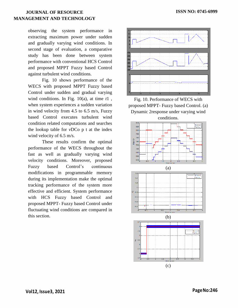
observing the system performance in
extracting maximum power under sudden
and gradually varying wind conditions. In
second stage of evaluation, a comparative
study has been done between system
performance with conventional HCS Control
and proposed MPPT Fuzzy based Control
against turbulent wind conditions.
Fig. 10 shows performance of the
WECS with proposed MPPT Fuzzy based
Control under sudden and gradual varying
wind conditions. In Fig. 10(a), at time t1 ,
when system experiences a sudden variation
in wind velocity from 4.5 to 6.5 m/s, Fuzzy
based Control executes turbulent wind
condition related computations and searches
the lookup table for vDCo p t at the index
wind velocity of 6.5 m/s.
These results confirm the optimal
performance of the WECS throughout the
fast as well as gradually varying wind
velocity conditions. Moreover, proposed
Fuzzy based Control’s continuous
modifications in programmable memory
during its implementation make the optimal
tracking performance of the system more
effective and efficient. System performance
with HCS Fuzzy based Control and
proposed MPPT- Fuzzy based Control under
fluctuating wind conditions are compared in
this section.
Fig. 10. Performance of WECS with
proposed MPPT- Fuzzy based Control. (a)
Dynamic 2response under varying wind
conditions.
(a)
(b)
(c)

JOURNAL OF RESOURCE
MANAGEMENT AND TECHNOLOGY
ISSN NO: 0745-6999
Vol12, Issue3, 2021
Page No:247
Fig 11. Performance evaluation of proposed
MPPT- Fuzzy based Control. (a)Output
Power in W (b) Turbine Power Coefficient
(c) Wind Velocity
Whereas proposed Fuzzy based
Control makes the system to track MPP
immediately without any intermediate
random search operations as shown in Fig.
11. By observing the variations in Cp , it can
be concluded that WECS with proposed
Fuzzy based Control harvests more energy
than with HCS Control.
VI. CONCLUSION
In this paper, an adaptive MPPT -
Fuzzy based Control has been proposed for
the fast tracking of MPP under tumultuous
wind conditions for small scale WECSs.
System behavior with proposed Fuzzy based
Control under fast changing wind conditions
has been observed and it is evident that the
proposed MPPT - Fuzzy based Control can
put the system at optimal operating point
promptly against random variations in the
wind velocity. System performance with
proposed MPPT - Fuzzy based Control is
compared with the HCS Control and
MATLAB Simulation results proved that
WECS with proposed MPPT - Fuzzy based
Control harvests more energy than with
HCS Control. The proposed MPPT - Fuzzy
based Control provides the following
advantages: 1) improved dynamic response
of the system; 2) prerequisite of system’s
optimal characteristics data is not required
and hence the Fuzzy based Control is
adaptive; To extract maximum power from
the wide range of wind conditions. Since
small scale WECSs are main resources for
DERs in microgrid systems, the proposed
Fuzzy based Control is very much
applicable for microgrid systems.
REFERENCES [1] D. S. Zinger and E. Muljadi, “Annualized wind energy
improvement using variable speeds,” IEEE Trans. Ind.
Appl., vol. 33, no. 6, pp. 1444–1447, Nov./Dec. 1997.
[2] A. Miller, E. Muljadi, and D. Zinger, “A variable speed
wind turbine power control,” IEEE Trans. Energy
Convers., vol. 12, no. 2, pp. 181–186, Jun. 1997.
[3] R. Chedid, F. Mrad, and M. Basma, “Intelligent control
of a class of wind energy conversion systems,” IEEE
Trans. Energy Convers., vol. 14, no. 4, pp. 1597–1604,
Dec. 1999.
[4] H. Li, K. Shi, and P. McLaren, “Neural-network-based
sensorless maximum wind energy capture with
compensated power coefficient,” IEEE Trans. Ind. Appl.,
vol. 41, no. 6, pp. 1548–1556, Nov./Dec. 2005.
[5] A. S. Satpathy, N. Kishore, D. Kastha, and N. Sahoo,
“Control scheme for a stand-alone wind energy conversion
system,” IEEE Trans. Energy Convers., vol. 29, no. 2, pp.
418–425, Jun. 2014.
[6] S. Morimoto, H. Nakayama, M. Sanada, andY. Takeda,
“Sensorless output maximization control for variable-speed
wind generation system using ipmsg,” in Proc. IEEE 38th
Ind. Appl. Annu. Meeting Conf. Rec., 2003, vol. 3, pp.
1464–1471.
[7] R. M. Hilloowala and A. M. Sharaf, “A rule-based
fuzzy logic controller for a pwm inverter in a stand alone
wind energy conversion scheme,” in Proc. IEEE Ind. Appl.
Soc. Annu. Meeting Conf. Rec., 1993, pp. 2066– 2073.
[8] V. Galdi, A. Piccolo, and P. Siano, “Designing an
adaptive fuzzy controller for maximum wind energy
extraction,” IEEE Trans. Energy Convers., vol. 23, no. 2,
pp. 559–569, Jun. 2008.
[9] A. Raju, B. Fernandes, and K. Chatterjee, “A upf power
conditioner with maximum power point tracker for grid
connected variable speed wind energy conversion system,”
in Proc. IEEE 1st Int. Conf. Power Electron. Syst. Appl.,
2004, pp. 107–112.
[10] M. Chinchilla, S. Arnaltes, and J. C. Burgos, “Control
of permanentmagnet generators applied to variable-speed
wind-energy systems connected to the grid,” IEEE Trans.
Energy Convers., vol. 21, no. 1, pp. 130–135, Mar. 2006.
[11] E. Koutroulis and K. Kalaitzakis, “Design of a
maximum power tracking system for wind-energy-
conversion applications,” IEEE Trans. Ind. Electron., vol.
53, no. 2, pp. 486–494, Apr. 2006.
[12] S. M. R. Kazmi, H. Goto, H.-J. Guo, and O.
Ichinokura, “A novel Fuzzy based Control for fast and
efficient speed-sensorless maximum power point tracking
in wind energy conversion systems,” IEEE Trans. Ind.
Electron., vol. 58, no. 1, pp. 29–36, Jan. 2011.

JOURNAL OF RESOURCE
MANAGEMENT AND TECHNOLOGY
ISSN NO: 0745-6999
Vol12, Issue3, 2021
Page No:248
[13] Q. Wang and L. Chang, “An intelligent maximum
power extraction Fuzzy based Control for inverter-based
variable speed wind turbine systems,” IEEE Trans. Power
Electron., vol. 19, no. 5, pp. 1242–1249, Sep. 2004.
[14] J. Hui and A. Bakhshai, “A new adaptive control
Fuzzy based Control for maximum power point tracking for
wind energy conversion systems,” in Proc. IEEE Power
Electron. Spec. Conf., 2008, pp. 4003–4007.
[15] M. Zadeh, A. Hajimiragha, M. Adamiak, A. Palizban,
and S. Allan, “Design and implementation of a microgrid
controller,” in Proc. 64th Annu. Conf. Protective Relay
Eng. Conf., 2011, pp. 137–145.
[16] J. Carroll, A. McDonald, and D. McMillan,
“Reliability comparison of wind turbines with dfig and pmg
drive trains,” IEEE Trans. Energy Convers., vol. 30, no. 2,
pp. 663–670, Jun. 2015.
[17] W.Wu, V. Ramsden, T. Crawford, and G. Hill, “A low
speed, high-torque, direct-drive permanent magnet
generator for wind turbines,” in Proc. IEEE Ind. Appl.
Conf. Rec., 2000, vol. 1, pp. 147–154.
[18] Z. M. Dalala, Z. U. Zahid, W. Yu, Y. Cho, and J.-S.
Lai, “Design and analysis of an mppt technique for small-
scale wind energy conversion systems,” IEEE Trans.
Energy Convers., vol. 28, no. 3, pp. 756–767, Sep. 2013.
Top Related
Copyright © 2022 FDOKUMEN

