


Bahasa
Halaman
Hukum


Field Engineer Handbook - Volume II
This Field Engineer Handbook edition, dated 9/18/00, replaces the Volume I and Volume II contents and tabs.
Volume I CPU is now two tabs; Workstation CPU and Server CPU.
Volume II Sun-4u Systems is now two tabs; Sun-4u Workstation and Sun-4u Server.
Systems and Peripherals added to the twenty-first edition:
Netra ct 400 Netra ct 800 Netra S220 StorEdge L9 StorEdge L20, L40, and L60 StorEdge L 180 StorEdge T3 Sun Blade 100 Sun Blade 1000 Sun Ray 100 Sun Ray 150
For your filing convenience, a title page with a bar strip on the right edge separates each section, so that you can easily place a new section after the appropriate tab.
The Field Engineer Handbook, Volumes I and II, is a copyrighted publication of Sun Microsystems, Inc. Additional copies must be purchased.
Email your comments and suggestions to the authors at [email protected].
Sun Microsystems, Inc. 901 San Antonio Road, Mail Stop MTV16-127 Palo Alto, California 94303-4900 U.S.A.
The JavaStation JJ and JavaStation JK systems are serviced as whole unit replacements. The CPU boards for these systems are not illustrated in this edition.
The SPARCcluster and MediaCenter chapters are not in this edition. These products were a combination of a workstation or server, a peripheral, and software" The workstations, servers, and peripherals used to build these products can still be found in their respective chapters.
The Netra xt 600 was announced in August 1999 and discontinued in January 2000. The Netra xt 600 is not in this edition.
You may wish to save this product information from the twentieth edition of the Field Engineer Handbook for reference.
VOLUME I CPU-32 CPU-33 CPU-34 CPU-35 CLUSTER-1 CLUSTER-2 CLUSTER-3 CLUSTER-4 CLUSTER-5 CLUSTER-6 CLUSTER-? CLUSTER-8 CLUSTER-9
CLUSTER-10 CLUSTER-11 CLUSTER-12 CLUSTER-13 CLUSTER-14 CLUSTER-15 CLUSTER-16 CLUSTER-17 MEDIA-1 MEDIA-2 MEDIA-3 MEDIA-4 MEDIA-5 MEDIA-6
MEDIA-? TELC0-41 TELC0-42
Field Engineer Handbook Volume II
+sun m1crosystems
Part No: 800-4247-17 ©1999 Sun Microsystems, Inc.

Written and published by Mike Persichetty and Gerri Roe
Copyright 1987 - 2000 by Sun Microsystems, Inc. 901 San Antonio Road, Palo Alto, California 94303-4900 U.S.A. All rights reserved.
This product or document is protected by copyright and distributed under licenses restricting its use, copying, distribution, and decompilation. No part of this product or document may be reproduced in any form by any means without prior written authorization of Sun and its licensors, if any. Third party software, including font technology, is copyrighted and licensed from Sun suppliers.
Portions of this product may be derived from the UNIX® system, licensed from Novell, Inc., and the Berkeley 4.3 BSD system, licensed from the University of California. UNIX is a registered trademark in the United States and in other countries and is exclusively licensed by X/OpenCompany LTD. Third-party software, including font technology in this product, is protected by copyright and licensed from Sun's suppliers.
Sun, Sun Microsystems, the Sun logo, Sun Ray, Solaris, Open Boot, Ultra, Ultra Computing, Ultra Enterprise, Ultra Enterprise Cluster, UntraServer, UltraSPARC, JavaStation, Neira, MediaCenter, Sun StorEdge, SunPCI, Sun BladeSunSwift, SunSwitch, SunFastEthernet, Quad FastEthernet, and Solaris are trademarks, or registered trademarks, or service marks of Sun Microsystems, Inc. in the United States and in other countries. All SPARC trademarks are used under license and are trademarks or registered trademarks of SPARC International, Inc. in the United States and in other countries. Products bearing SPARC trademarks are based upon an architecture developed by Sun Microsystems, Inc. All other product names mentioned herein are trademarks of their respective owners.
The OPEN LOOK® and Sun™ Graphical User Interface was developed by Sun Microsystems, Inc. for its users and licensees. Sun acknowledges the pioneering efforts of Xerox in researching and developing the concept of visual or graphical user interfaces for the computer industry. Sun holds a non-exclusive license from Xerox to the Xerox Graphical User Interface, which license also covers Sun licensees who implement OPEN LOOK GUls and otherwise comply with Sun written license agreements.
RESTRICTED RIGHTS: Use, duplication, or disclosure by the U.S. Government is subject to restrictions of FAR 52.227 -14(g)(2)(6/87) and FAR 52.227-19(6/87), or DFAR 252.227-7015(b)(6/95 and DFAR 227.7202-3(a).
DOCUMENTATION IS PROVIDED "AS IS" AND ALL EXPRESS OR IMPLIED CONDITIONS, REPRESENTATIONS AND WARRANTIES, INCLUDING ANY IMPLIED WARRANTY OF MERCHANTABILITY, FITNESS FOR A PARTICULAR PURPOSE OR NON-INFRINGEMENT ARE DISCLAIMED, EXCEPT TO THE EXTENT THAT SUCH DISCLAIMERS ARE HELD TO BE LEGALLY INVALID.
THIS PUBLICATION COULD INCLUDE TECHNICAL INACCURACIES OR TYPOGRAPHICAL ERRORS. CHANGES ARE PERIODICALLY ADDED TO THE INFORMATION HEREIN: THESE CHANGES WILL BE INCORPORATED IN NEW EDITIONS OF THE PUBLICATION. SUN MICROSYSTEM, INC. MAY MAKE IMPROVEMENTS AND/OR CHANGES IN THE PRODUCT(S) AND/OR THE PROGRAM(S) DESCRIBED IN THIS PUBLICATION AT ANY TIME.
Printed in the USA

Preface
The Field Engineer Handbook, Volumes I and II, illustrates and describes Sun™ Workstations, Servers, and Options. This hardware manual set is available to Sun service providers and customers.
This handbook complements other Sun technical publications and education courses. We assume that Sun service providers and customers who service and repair Sun products have access to these resources.
The Field Engineer Handbook does not include installation, removal, replacement, and troubleshooting procedures documented in other Sun publications.
The complexity of products requiring extensive training is beyond the scope of this hardware manual set. These products are not covered in detail. Refer to the manuals.
The Field Engineer Handbook is not an official configuration guide or sales guide. Configurations and options supported and sold by Sun Microsystems are documented in the End User and Reseller Price Lists. Installation Manuals, User's Guides, Product Notes, and the Hardware Platform Guide are other sources of supported configuration information.
Send email to [email protected] to receive the errata for the Field Engineer Handbook.
Email your comments and suggestions to the authors at [email protected].

9/18/00
Handbook Organization
The Field Engineer Handbook is organized into two volumes.
Volume I includes the Configuration section.
• Configurations contains board and peripheral part numbers, option numbers, and illustrations; jumper and switch settings; video resolutions; memory module compatibility; and notes and references.
Volume II includes the following sections:
iv
• Parts Breakdown contains workstation, server, and option illustrations; part number listings; and monitor specifications.
• Troubleshooting contains system LED error codes; SCSI connector pin assignments, SCSI sense keys and codes; tape drive manual ejection procedures; and communications device pin assignments.
• Power contains fuse and power cord charts; system wiring diagrams; and illustrations of power plugs, power supplies power sequencers, and power distribution units.
Field Engineer Handbook
9/18/00
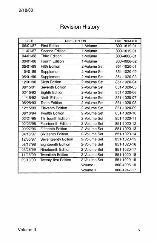
Revision History
DATE DESCRIPTION PART NUMBER
06/01/87 First Edition 1-Volume 800-1819-01 11/01/87 Second Edition 1-Volume 800-1819-01
04/01/88 Third Edition 1-Volume 800-4006-01
09/01/88 Fourth Edition 1-Volume 800-4006-02
05/01/89 Fifth Edition 2-Volume Set 851-1020-01
10//0189 Supplement 2-Volume Set 851-1020-02
05/01/90 Supplement 2-Volume Set 851-1020-03
12/01 /90 Sixth Edition 2-Volume Set 851-1020-04
08/15/91 Seventh Edition 2-Volume Set 851-1020-05
02/15/92 Eighth Edition 2-Volume Set 851-1020-06
11/15/92 Ninth Edition 2-Volume Set 851-1 020-07
05/28/93 Tenth Edition 2-Volume Set 851-1020-08
12/15/93 Eleventh Edition 2-Volume Set 851-1020-09
06/10/94 Twelfth Edition 2-Volume Set 851-1020-10
02/21/95 Thirteenth Edition 2-Volume Set 851-1020-11
02/23/96 Fourteenth Edition 2-Volume Set 851-1020-12
09/27/96 Fifteenth Edition 2-Volume Set 851-1020-13
04/16/97 Sixteenth Edition 2-Volume Set 851-1020-14
12/05/97 Seventeenth Edition 2-Volume Set 851-1020-15
06/17/98 Eighteenth Edition 2-Volume Set 851-1020-16
03/26/99 Nineteenth Edition 2-Volume Set 851-1020-17
11/26/99 Twentieth Edition 2-Volume Set 851-1020-18
09/18/00 Twenty-first Edition 2-Volume Set 851-1 020-19
Volume I 800-4006-19
Volume II 800-4247-17
Volume II v

This page intentionally left blank.

PARTS BREAKDOWN

9/18/00
Parts Breakdown
This section contains illustrations, part numbers, and descriptions of Sun Systems, Options, Boards, Input Devices, Monitors, and Printers.
Options such as processor modules, SIMMs, and SBus cards are not included in the System chapter. Internal system peripheral options are not included in the Disk, Removable Media, or Miscellaneous chapters.
Parts listed as (obsolete) or (obs) are no longer used to build new systems. Obsolete parts may be replaced with newer part numbers and may not be available.
This manual provides a list of part numbers used to assemble the system or option. Many of the part numbers listed are not normally available as spare parts or as field replaceable service spares, also referred to as Field Replaceable Units, or FRUs.
Spare parts available for purchase are listed in the SunSpares Price List. A list of valid FRU part numbers and part substitutions is available to Sun service and support personnel from Enterprise Services logistics.
Abbreviations
Assy Assembly
Bkt Bracket
FRU Field Replaceable Unit
NS Not shown
OBP Open Boot PROM
Obs Obsolete
OS Operating System
w With
w/o Without
• Indicates the part is used in an assembly
Field Engineer Handbook - Volume II

PARTS BREAKDOWN
Option Abbreviations
SSA SPARCstorage Array A 1 000 StorEdge A 1 000 01000 StorEdge 01000 A3000 StorEdge A3000 (RSM Array 2000) A3500 StorEdge A3500 A5000 Enterprise Network Array A5000
ASOOO StorEdge A5000 A7000 StorEdge A7000
System Abbreviations SC SPARCcenter
9/18/00
SS SPARCserver, SPARCstation, or SPARCsystem A 11 Ultra 1 Models 140 and 170 A 12 Ultra 1 Models 140E, 170E, and 200E
A14 Ultra 2 A16 Ultra 30 A 17 Ultra Enterprise 3000 Workstation A 18 Ultra Enterprise 4000 Workstation
A20 Ultra 450 Workstation A21 Ultra 5 A22 Ultra 10 A23 Ultra 60 A25 Ultra Enterprise 450 Server A26 Enterprise 250 A27 Ultra 80 A28 Sun Blade 1000 A33 Enterprise 420R A34 Enterprise 220R
A38 Sun Blade 100 E150 Ultra Enterprise 150 ExOOO Ultra Enterprise 3000/4000/5000/6000
ExSOO Enterprise 3500/4500/5500/6500
INTR0-2 Field Engineer Handbook

9/18/00 PARTS BREAKDOWN
Class Codes
The first three digits of a Sun part number are the class code. Representative class codes are listed below.
CLASS CODE DESCRIPTION
270-xxxx-xx PCB Fabrication
300-xxxx-xx Power Supply
330-xxxx-xx Plastic Part
340-xxxx-xx Sheet Metal Part
365-xxxx-xx Monitor Assembly
370-xxxx-xx OEM Part
375-xxxx-xx OEM Part
390-xxxx-xx OEM Part
500-xxxx-xx Untested PCB
501-xxxx-xx Tested PCB
520-xxxx-xx Programmed IC
525-xxxx-xx Programmed IC
530-xxxx-xx Cable
540-xxxx-xx Assembly
555-xxxx-xx FRU Assembly
560-xxxx-xx Shipping Kit
570-xxxx-xx Electro Mechanical Assembly
595-xxxx-xx Top Level Option Assembly
596-xxxx-xx Configured Option Assembly
600-xxxx-xx Top Level System Assembly
700-xxxx-xx Software Tape
704-xxxx-xx Software CD-ROM
790-xxxx-xx Software Tape and Manual
794-xxxx-xx Software CD-ROM and Manual
800-xxxx-xx Sun Manual
801-xxxx-xx Sun Manual
802-xxxx-xx Sun Manual
804-xxxx-xx CD-ROM Insert
805-xxxx-xx Sun Manual
807-xxxx-xx FCO Kit
813-xxxx-xx Configuration Manual
825-xxxx-xx Manual Set
855-xxxx-xx Manual Set
950-xxxx-xx Engineering Specification
Volume II INTR0-3
PARTS BREAKDOWN 9/18/00
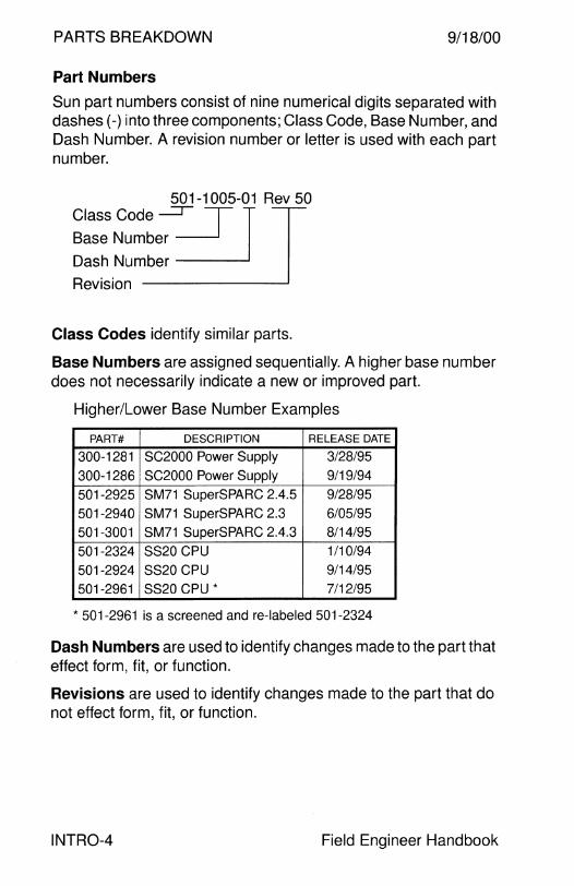
Part Numbers
Sun part numbers consist of nine numerical digits separated with dashes(-) into three components; Class Code, Base Number, and Dash Number. A revision number or letter is used with each part number.
501-1005-01 Rev 50
Class Code I J Base Number
Dash Number
Revision
Class Codes identify similar parts.
Base Numbers are assigned sequentially. A higher base number does not necessarily indicate a new or improved part.
Higher/Lower Base Number Examples
PART# DESCRIPTION RELEASE DATE
300-1281 SC2000 Power Supply 3/28/95
300-1286 SC2000 Power Supply 9/19/94
501-2925 SM71 SuperSPARC 2.4.5 9/28/95
501-2940 SM71 SuperSPARC 2.3 6/05/95
501-3001 SM71 SuperSPARC 2.4.3 8/14/95
501-2324 SS20 CPU 1/10/94
501-2924 SS20 CPU 9/14/95
501-2961 SS20 CPU* 7/12/95
* 501-2961 is a screened and re-labeled 501-2324
Dash Numbers are used to identify changes made to the part that effect form, fit, or function.
Revisions are used to identify changes made to the part that do not effect form, fit, or function.
INTR0-4 Field Engineer Handbook
9/18/00 PARTS BREAKDOWN
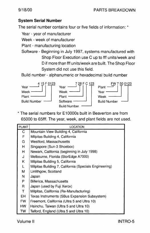
System Serial Number
The serial number contains four or five fields of information: *
Year - year of manufacturer
Week - week of manufacturer
Plant - manufacturing location
Software - Beginning in July 1997, systems manufactured with
Shop Floor Execution use C up to fff units/week and
D if more than fff units/week are built. The Shop Floor
System did not use this field.
Build number - alphanumeric or hexadecimal build number
Year -=!JITF I 0123 Year __J=gu7 2 T8illF I C 123 Plant~ TITO 0123
Week .=J Week =.J Year ~ Plant Plant Week
Build Number Software Build Number Build Number
* The serial numbers for E10000s built in Beaverton are from
65000 to 65fff. The year, week, and plant fields are not used.
PLANT LOCATION
c Mountain View Building 4, California
F Milpitas Building 4, California
G Westford, Massachusetts
H Singapore (Sun-3 Shoebox)
H Newark, California (beginning in July 1998)
J Melbourne, Florida (StorEdge A7000)
K Milpitas Building 5, California
L Milpitas Building 7, California (Specials Engineering)
M Linlithgow, Scotland
N Japan p Billerica, Massachusetts
R Japan (used by Fuji Xerox)
T Milpitas, California (Re-Manufacturing)
EH Texas Instruments (SBus Expansion Subsystem)
FW Freemont, California (Ultra 5 and Ultra 10)
HW Hsinchu, Taiwan (Ultra 5 and Ultra 10)
TW Telford, England (Ultra 5 and Ultra 10)
Volume II INTR0-5

PARTS BREAKDOWN 9/18/00
Recommended Tools
Tools
PART# DESCRIPTION
250-1028 Field Engineer Toolkit (Jensen JTK-679-1)
250-1024 T9 Torx Screwdriver
250-1025 T7 Torx Screwdriver
250-1026 T25 Torx Blade
250-1027 #2 Pozidrive Blade
250-1029 3/32" Hexdriver Blade
250-1030 7/64" Hexdriver Blade
250-1031 14 mm Deep Socket
250-1032 T20 Torx Blade
250-1033 Blue Cordora Zipper Case
250-1034 3 1 /8" Driver Handle
250-1035 4 1 /8" Driver Handle
250-1036 1/4" Drive Spinner Handle
250-1037 5" Extension Blade
250-1038 #1 Phillips Blade
250-1039 #2 Phillips Blade
250-1040 1 /4" Slotted Blade
250-1041 3/16" Slotted Blade
250-1042 Alignment Tool
250-1043 Alignment Tool
250-1044 4 1/2" Miniature Diagonal Cutter
250-1045 5.25" Diagonal Cutting Pliers
250-1046 6.5" Thin Needlenose Pliers
250-1047 4" Adjustable Wrench
250-1048 6" Adjustable Wrench
250-1049 Crimping Tool/Wire Stripper
250-1050 Fluke 75 Digital Multimeter
250-1051 1 .27 mm Hexdriver Blade
250-1052 1.5 mm Hexdriver Blade
250-1053 2 mm Hexdriver Blade
250-1054 2.5 mm Hexdriver Blade
250-1055 3 mm Hexdriver Blade
250-1056 4 mm Hexdriver Blade
250-1057 5 mm Hexdriver Blade
INTR0-6 Field Engineer Handbook

9/18/00 PARTS BREAKDOWN
Recommended Tools
Tools - Continued
PART# DESCRIPTION
250-1058 4 mm Nutdriver Blade
250-1059 4.5 mm Nutdriver Blade
250-1060 5 mm Nutdriver Blade
250-1061 5.5 mm Nutdriver Blade
250-1062 6 mm Nutdriver Blade
250-1063 7 mm Nutdriver Blade
250-1064 8 mm Nutdriver Blade
250-1065 9 mm Nutdriver Blade
250-1066 10 mm Nutdriver Blade
250-1067 11 mm Nutdriver Blade
250-1068 T15 Torx Blade
Power Screwdriver Kit
PART# DESCRIPTION
250-1075 Cordless Power Screwdriver Kit (Jensen JTK-864)
250-1076 • Two Speed Power Screwdriver
250-1077 • Screwdriver Carrying Case
250-1078 • Screwdriver Battery Charger, 115V
250-1079 • Screwdriver Battery
250-1084 • Power Screwdriver Xcelite Adapter
Vacuum Cleaner Kit
PART# DESCRIPTION
250-1080 Vacuum Cleaner Kit (Jensen JTK-863)
250-1081 • Vacuum Cleaner, 115V
250-1082 • Vacuum Cleaner Filters (qty 6)
250-1083 • Vacuum Cleaner Carrying Bag
Volume II INTR0-7
PARTS BREAKDOWN 9/18/00
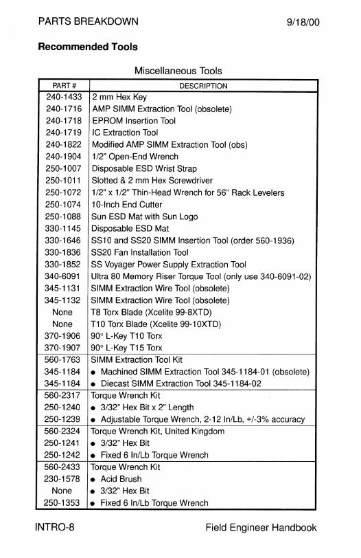
Recommended Tools
Miscellaneous Tools
PART# DESCRIPTION
240-1433 2 mm Hex Key
240-1716 AMP SIMM Extraction Tool (obsolete)
240-1718 EPROM Insertion Tool
240-1719 IC Extraction Tool
240-1822 Modified AMP SIMM Extraction Tool (obs)
240-1904 1 /2" Open-End Wrench
250-1007 Disposable ESD Wrist Strap
250-1011 Slotted & 2 mm Hex Screwdriver
250-1072 1/2" x 1/2" Thin-Head Wrench for 56" Rack Levelers
250-1074 10-lnch End Cutter
250-1088 Sun ESD Mat with Sun Logo
330-1145 Disposable ESD Mat
330-1646 SS10 and SS20 SIMM Insertion Tool (order 560-1936)
330-1836 SS20 Fan Installation Tool
330-1852 SS Voyager Power Supply Extraction Tool 340-6091 Ultra 80 Memory Riser Torque Tool (only use 340-6091-02)
345-1131 SIMM Extraction Wire Tool (obsolete)
345-1132 SIMM Extraction Wire Tool (obsolete)
None TB Torx Blade (Xcelite 99-8XTD)
None T10 Torx Blade (Xcelite 99-1 OXTD)
370-1906 90° L-Key T1 O Torx
370-1907 90° L-Key T15 Torx
560-1763 SIMM Extraction Tool Kit
345-1184 • Machined SIMM Extraction Tool 345-1184-01 (obsolete)
345-1184 • Diecast SIMM Extraction Tool 345-1184-02
560-2317 Torque Wrench Kit
250-1240 • 3/32" Hex Bit x 2" Length
250-1239 • Adjustable Torque Wrench, 2-12 In/Lb, +/-3% accuracy
560-2324 Torque Wrench Kit, United Kingdom
250-1241 • 3/32" Hex Bit
250-1242 • Fixed 6 In/Lb Torque Wrench
560-2433 Torque Wrench Kit
230-1578 • Acid Brush None • 3/32" Hex Bit
250-1353 • Fixed 6 In/Lb Torque Wrench
INTR0-8 Field Engineer Handbook
PARTS BREAKDOWN
4m SYSTEM

9/18/00 PARTS BREAKDOWN
Sun-4m System
Sun-4m Architecture SPARC Xterminal 1 ........................................................... 2 SPARCstation 4 ................................................................ 4 SPARCstation 5 ................................................................ 12 SPARCstation 20 .............................................................. 20
Field Engineer Handbook - Volume II
PARTS BREAKDOWN 9/18/00
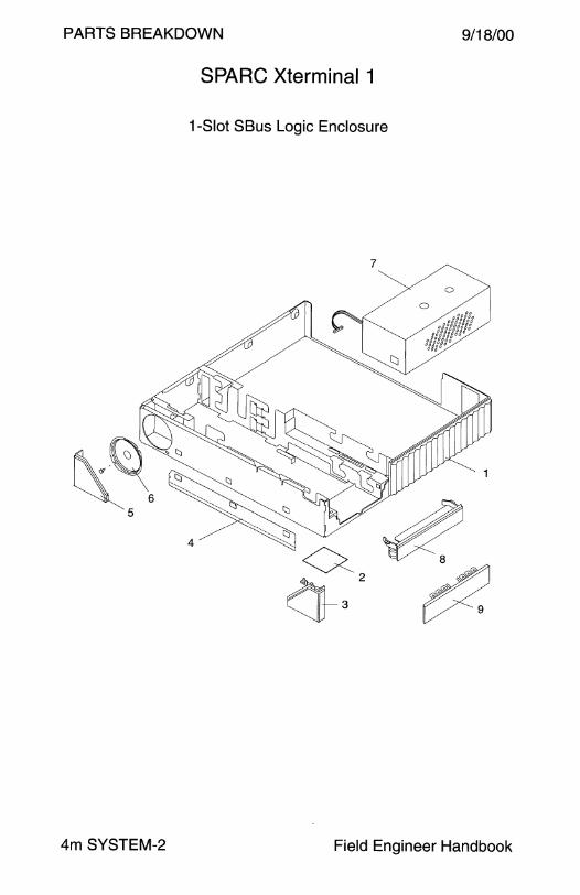
SPARC Xterminal 1
1-Slot SBus Logic Enclosure
4m SYSTEM-2 Field Engineer Handbook
9/18/00 PARTS BREAKDOWN
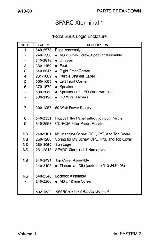
SPARC Xterminal 1
1-Slot SBus Logic Enclosure
CODE PART# DESCRIPTION
1 540-2578 Base Assembly
- 240-1530 • M3 x 6 mm Screw, Speaker Assembly
- 340-2915 • Chassis 2 330-1450 • Foot 3 540-2547 • Right Front Corner
4 261-1009 • Purple Chassis Label
5 330-1683 • Left Front Corner
6 370-1579 • Speaker
- 530-2080 • Speaker and LED Wire Harness
- 530-2130 • DC Wire Harness
7 300-1257 50 Watt Power Supply
8 540-2551 Floppy Filler Panel without cutout, Purple
9 540-2553 CD-ROM Filler Panel, Purple
NS 240-2101 M3 Machine Screw, CPU, P/S, and Top Cover
NS 250-1200 Spring for M3 Screw, CPU, P/S, and Top Cover
NS 260-3059 Sun Logo
NS 261-2818 SPARC Xterminal 1 Nameplate
NS 540-2434 Top Cover Assembly
- 240-2195 • Tinnerman Clip (added to 540-2434-03)
NS 540-2540 Lockbox Assembly
- 240-2206 • M3 x 12 mm Screw
802-1529 SPARCstation 4 Service Manual
Volume II 4m SYSTEM-3
PARTS BREAKDOWN
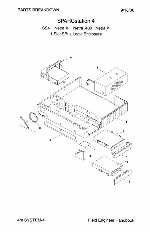
SPARCstation 4 SS4 Netra i4 Netra i400 Netra j4
1-Slot SBus Logic Enclosure
7
9/18/00
4m SYSTEM-4 Field Engineer Handbook

9/18/00
CODE
1
---2
3
4
5
6
--
7
7
----
-NS
7
7
---
-NS
8
8
PARTS BREAKDOWN
SPARCstation 4 SS4 Netra i4 Netra i400 Netra j4
1-Slot SBus Logic Enclosure
PART# DESCRIPTION
540-2664 Base Assembly (phased out Nov/Dec 1996)
240-1530 • M3 x 6 mm Screw, Speaker Assembly
340-2915 • Chassis 540-2548 • Right Side Vent Panel
330-1450 • Foot 540-2547 • Right Front Corner 261-1009 • Purple Chassis Label 330-1683 • Left Front Corner 370-1579 • Speaker 530-2130 • DC Wire Harness 530-2080 • Speaker and LED Wire Harness
540-2443 535MB Disk Drive Assembly/FRU
540-2631 535MB Disk Drive Assembly/FRU
370-1425 • 535MB Disk Drive (:::;540-2443-03)
370-1425 • 535MB Disk Drive (540-2631-xx)
370-1844 • 535MB Disk Drive (;:::540-2443-04)
240-2208 • #6-32 x 1/4" Screw 540-2570 • Mounting Bracket 530-2146 Internal SCSI Cable, Disk Drive, 33 mm
540-2560 1.05GB Disk Drive Assy/FRU (discontinued 6/95)
540-2733 1.05GB Disk Drive Assembly/FRU
240-2208 • #6-32 x 1/4" Screw 370-1753 • 1.05GB Disk Drive, Seagate ST31200WC 370-1964 • 1.05GB Disk Drive, Conner CFP1 OBOE
540-2570 • Mounting Bracket 530-2146 Internal SCSI Cable, Disk Drive, 33 mm
300-1257 50 Watt Power Supply
300-1279 150 Watt Power Supply 1
1 Power Supply 300-1279 is used in SPARCserver 4 configurations because the 150 Watt power supply supports the power state memory feature. SPARCstation 4 configurations use Power Supply 300-1257.
Volume II 4m SYSTEM-5

PARTS BREAKDOWN 9/18/00
CODE
9
-----
NS
NS
10
11
---
11 --
NS
12
12
NS
NS
NS
NS
NS
NS
NS
NS
NS
NS
-
SPARCstation 4 884 Netra i4 Netra i400 Netra j4
1-Slot SBus Logic Enclosure- Continued
PART# DESCRIPTION
540-2500 CD-ROM Assembly/FRU 240-1463 • #6-32 x 1/4" Screw 240-2086 • M3 x 4 mm Screw 330-1748 • Mounting Grommet 340-3046 • Mounting Bracket 370-1679 • CD-ROM Drive 530-2079 CD-ROM to Audio Module Cable, 435 mm
530-2129 Internal SCSI Cable, CD-ROM, 350 mm 540-2553 CD-ROM Filler Panel, Purple
540-2509 Floppy Drive Assembly/FRU 240-2121 • #6-32 Shoulder Screw 330-1748 • Drive Mounting Grommet 370-1419 • Floppy Drive 370-2151 Floppy Drive Assy/FRU (replaced 540-2509 12/95) 240-1530 • M3 x 6 mm Screw 240-2295 • M3 Shoulder Screw 530-2067 Internal Floppy Cable, 190 mm
540-2551 Floppy Filler Panel without cutout, Purple 540-2552 Floppy Filler Panel with cutout, Purple
240-2101 M3 Machine Screw, CPU, P/S, and Top Cover
250-1200 Spring for M3 Screw, CPU, P/S, and Top Cover
260-3059 Sun Logo 261-2699 SPARCstation 4 Nameplate
261-4380 SPARCserver 4 Nameplate 261-4598 Netra i Nameplate
540-2434 Top Cover Assembly 240-2195 • Tinnerman Clip (added to 540-2434-03)
501-5468 Floppy Interface Board
540-2540 Lockbox Assembly
240-2206 • M3 x 12 mm Screw
802-1529 SPARCstation 4 Service Manual
4m SYSTEM-6 Field Engineer Handbook
9/18/00 PARTS BREAKDOWN
This page intentionally left blank.
Volume II 4m SYSTEM-?
PARTS BREAKDOWN
SPARCstation 4 884 Netra i4 Netra i400 Netra j4
1-Slot SBus Logic Enclosure
7
9/18/00
4m SYSTEM-8 Field Engineer Handbook
9/18/00
CODE
1
--
-2
3
4
5
6 -
--
7
-----
7
--
---
B
B
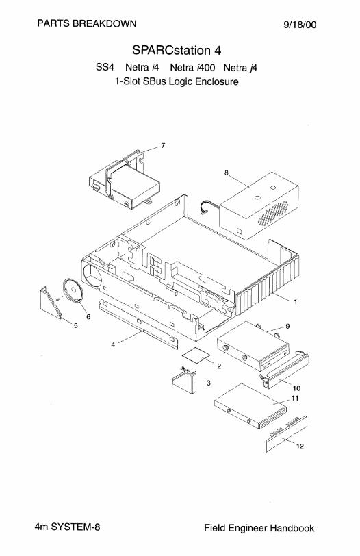
PARTS BREAKDOWN
SPARCstation 4 884 Netra i4 Netra i400 Netra j4
1-Slot SBus Logic Enclosure
PART# DESCRIPTION
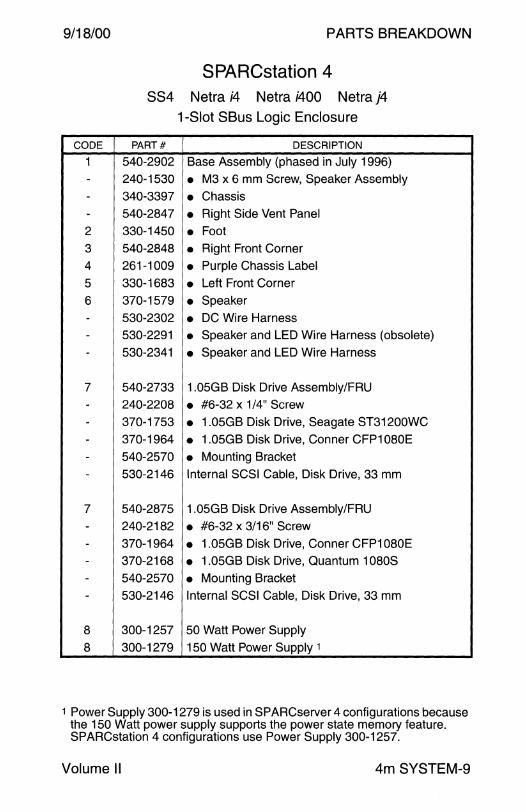
540-2902 Base Assembly (phased in July 1996) 240-1530 • M3 x 6 mm Screw, Speaker Assembly
340-3397 • Chassis 540-2B47 • Right Side Vent Panel
330-1450 • Foot 540-2B4B • Right Front Corner
261-1009 • Purple Chassis Label
330-16B3 • Left Front Corner 370-1579 • Speaker 530-2302 • DC Wire Harness 530-2291 • Speaker and LED Wire Harness (obsolete)
530-2341 • Speaker and LED Wire Harness
540-2733 1.05GB Disk Drive Assembly/FRU
240-220B • #6-32 x 1/4" Screw
370-1753 • 1.05GB Disk Drive, Seagate ST31200WC 370-1964 • 1.05GB Disk Drive, Conner CFP1 OBOE
540-2570 • Mounting Bracket 530-2146 Internal SCSI Cable, Disk Drive, 33 mm
540-2B75 1.05GB Disk Drive Assembly/FRU
240-21B2 • #6-32 x 3/16" Screw
370-1964 • 1.05GB Disk Drive, Conner CFP1 OBOE 370-216B • 1.05GB Disk Drive, Quantum 10BOS
540-2570 • Mounting Bracket
530-2146 Internal SCSI Cable, Disk Drive, 33 mm
300-1257 50 Watt Power Supply
300-1279 150 Watt Power Supply 1
1 Power Supply 300-1279 is used in SPARCserver 4 configurations because the 150 Watt power supply supports the power state memory feature. SPARCstation 4 configurations use Power Supply 300-1257.
Volume II 4m SYSTEM-9
PARTS BREAKDOWN 9/18/00
CODE
9
---
NS
NS 10
11
----
NS
12
12
SPARCstation 4 884 Netra i4 Netra i400 Netra j4
1-Slot SBus Logic Enclosure - Continued
PART# DESCRIPTION
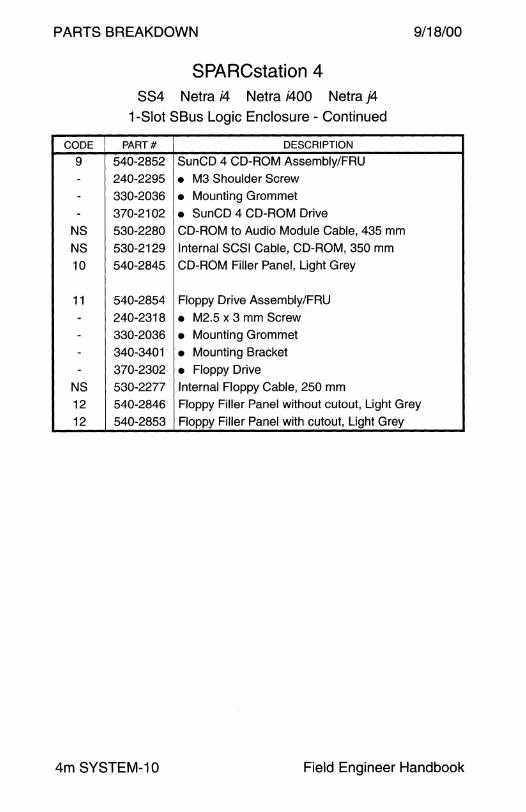
540-2852 SunCD 4 CD-ROM Assembly/FRU
240-2295 • M3 Shoulder Screw 330-2036 • Mounting Grommet
370-2102 • SunCD 4 CD-ROM Drive 530-2280 CD-ROM to Audio Module Cable, 435 mm
530-2129 Internal SCSI Cable, CD-ROM, 350 mm
540-2845 CD-ROM Filler Panel, Light Grey
540-2854 Floppy Drive Assembly/FRU
240-2318 • M2.5 x 3 mm Screw 330-2036 • Mounting Grommet
340-3401 • Mounting Bracket
370-2302 • Floppy Drive
530-2277 Internal Floppy Cable, 250 mm
540-2846 Floppy Filler Panel without cutout, Light Grey
540-2853 Floppy Filler Panel with cutout, Light Grey
4m SYSTEM-10 Field Engineer Handbook
9/18/00
CODE
NS
NS
NS
NS
NS
NS
NS
NS
NS
-
NS
NS
NS NS
NS
Volume II
PARTS BREAKDOWN
SPARCstation 4 SS4 Netra i4 Netra i400 Netra j4
1-Slot SBus Logic Enclosure - Continued
PART# DESCRIPTION
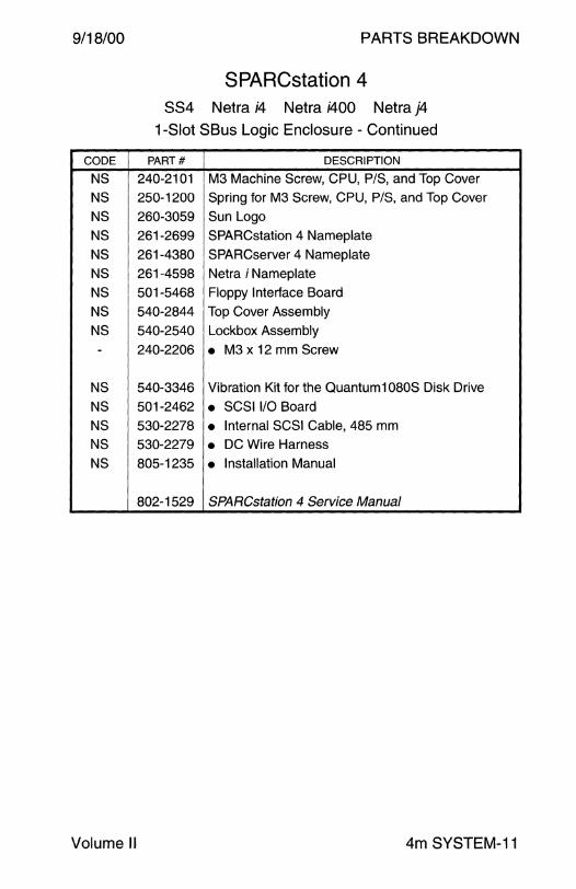
240-2101 M3 Machine Screw, CPU, P/S, and Top Cover
250-1200 Spring for M3 Screw, CPU, P/S, and Top Cover
260-3059 Sun Logo
261-2699 SPARCstation 4 Nameplate
261-4380 SPARCserver 4 Nameplate
261-4598 Netra i Nameplate
501-5468 Floppy Interface Board
540-2844 Top Cover Assembly
540-2540 Lockbox Assembly
240-2206 • M3 x 12 mm Screw
540-3346 Vibration Kit for the Quantum1 OBOS Disk Drive
501-2462 • SCSI 1/0 Board 530-2278 • Internal SCSI Cable, 485 mm 530-2279 • DC Wire Harness 805-1235 • Installation Manual
802-1529 SPARCstation 4 Service Manual
4m SYSTEM-11

PARTS BREAKDOWN 9/18/00
SPARCstation 5 885 Netra i5 Netra s5 Netra i500 Netra i525
3-Slot SBus Logic Enclosure
4m SYSTEM-12 Field Engineer Handbook
9/18/00 PARTS BREAKDOWN
CODE
1 -
--
2
3
4
5
6
7
---
--8
---8 -
-----8 -
--
---
SPARCstation 5 885 Netra i5 Netra s5 Netra i500 Netra i525
3-Slot SBus Logic Enclosure
PART# DESCRIPTION
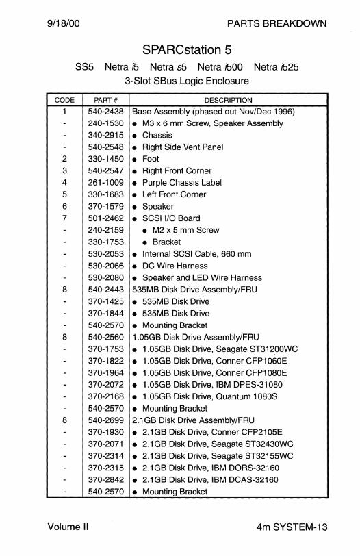
540-2438 Base Assembly (phased out Nov/Dec 1996)
240-1530 • M3 x 6 mm Screw, Speaker Assembly
340-2915 • Chassis 540-2548 • Right Side Vent Panel
330-1450 • Foot 540-2547 • Right Front Corner
261-1009 • Purple Chassis Label
330-1683 • Left Front Corner
370-1579 • Speaker 501-2462 • SCSI 1/0 Board
240-2159 • M2 x 5 mm Screw
330-1753 • Bracket 530-2053 • Internal SCSI Cable, 660 mm
530-2066 • DC Wire Harness 530-2080 • Speaker and LED Wire Harness
540-2443 535MB Disk Drive Assembly/FRU
370-1425 • 535MB Disk Drive
370-1844 • 535MB Disk Drive 540-2570 • Mounting Bracket
540-2560 1.05GB Disk Drive Assembly/FRU
370-1753 • 1.05GB Disk Drive, Seagate ST312_00WC
370-1822 • 1.05GB Disk Drive, Conner CFP1060E
370-1964 • 1.05GB Disk Drive, Conner CFP1 OBOE 370-2072 • 1.05GB Disk Drive, IBM DPES-31080
370-2168 • 1.05GB Disk Drive, Quantum 1080S
540-2570 • Mounting Bracket
540-2699 2.1 GB Disk Drive Assembly/FRU
370-1930 • 2.1 GB Disk Drive, Conner CFP2105E
370-2071 • 2.1 GB Disk Drive, Seagate ST32430WC
370-2314 • 2.1 GB Disk Drive, Seagate ST32155WC
370-2315 • 2.1GB Disk Drive, IBM DORS-32160 370-2842 • 2.1 GB Disk Drive, IBM DCAS-32160
540-2570 • Mounting Bracket
Volume II 4m SYSTEM-13

PARTS BREAKDOWN 9/18/00
CODE
8 -9
9
9
--
10
-----
NS 11
12
---
12
--
NS 13
13
SPARCstation 5 885 Netra i5 Netra s5 Netra i500 Netra i525
3-Slot SBus Logic Enclosure - Continued
PART# DESCRIPTION
540-3988 4.2GB Disk Drive Assembly/FRU
540-2570 • Mounting Bracket 300-1215 150 Watt Power Supply (obsolete)
300-1279 150 Watt Power Supply
540-2657 Nordic Country Power Supply Assembly
300-1279 • 150 Watt Power Supply 370-1873 • Noise Kit 540-2500 CD-ROM Assembly/FRU
240-1463 • #6-32 x 1/4" Screw 240-2086 • M3 x 4 mm Screw 330-1748 • Mounting Grommet 340-3046 • Mounting Bracket 370-1679 • CD-ROM Drive 530-2079 CD-ROM to CPU Audio Cable, 435 mm
540-2553 CD-ROM Filler Panel, Purple
540-2509 Floppy Drive Assembly/FRU
240-2121 • #6-32 Shoulder Screw 330-1748 • Drive Mounting Grommet
370-1419 • Floppy Drive 370-2151 Floppy Drive Assy/FRU (replaced 540-2509 12/95)
240-1530 • M3 x 6 mm Screw 240-2295 • M3 Shoulder Screw 530-2067 Internal Floppy Cable, 190 mm 540-2551 Floppy Filler Panel without cutout, Purple
540-2552 Floppy Filler Panel with cutout, Purple
4m SYSTEM-14 Field Engineer Handbook
9/18/00 PARTS BREAKDOWN
CODE
NS
NS
NS
NS
NS
NS
NS
NS
NS
-NS
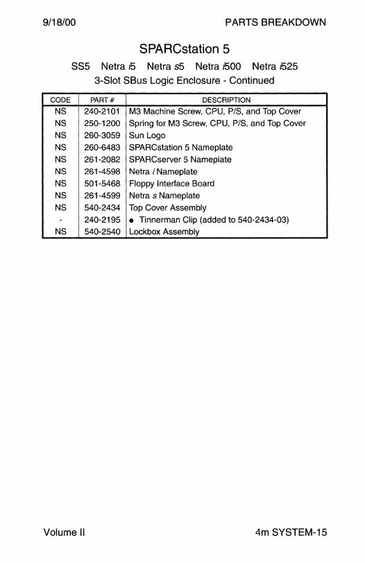
SPARCstation 5 SSS Netra 15 Netra s5 Netra i500 Netra i525
3-Slot SBus Logic Enclosure - Continued
PART# DESCRIPTION
240-2101 M3 Machine Screw, CPU, P/S, and Top Cover
250-1200 Spring for M3 Screw, CPU, P/S, and Top Cover
260-3059 Sun Logo
260-6483 SPARCstation 5 Nameplate
261-2082 SPARCserver 5 Nameplate
261-4598 Netra i Nameplate
501-5468 Floppy Interface Board
261-4599 Netra s Nameplate
540-2434 Top Cover Assembly
240-2195 • Tinnerman Clip (added to 540-2434-03)
540-2540 Lockbox Assembly
Volume II 4m SYSTEM-15
PARTS BREAKDOW
SPARCstation 5 SSS N~ra/5 N~raj&1ro
3-Slot SBus Logic Enclosure
9 8
4
9/18/00
~ 12
4m SYSTEM-16 Field Engineer Handbook
9/18/00
CODE
1
-
-
-2
3
4
5
6
7
---
---B
--
-
--
-B
------B
-
Volume II
PARTS BREAKDOWN
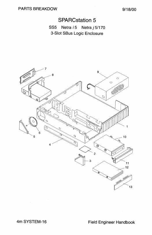
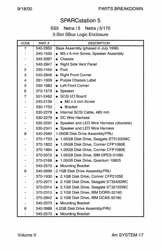
SPARCstation 5 SS5 N~rai5 N~raj~1ro
3-Slot SBus Logic Enclosure
PART# DESCRIPTION
540-2B50 Base Assembly (phased in July 1996)
240-1530 • M3 x 6 mm Screw, Speaker Assembly
340-3397 • Chassis 540-2B47 • Right Side Vent Panel
330-1450 • Foot 540-2B4B • Right Front Corner
261-1009 • Purple Chassis Label
330-16B3 • Left Front Corner
370-1579 • Speaker 501-2462 • SCSI 1/0 Board
240-2159 • M2 x 5 mm Screw
330-1753 • Bracket
530-227B • Internal SCSI Cable, 4B5 mm
530-2279 • DC Wire Harness
530-2291 • Speaker and LED Wire Harness (obsolete)
530-2341 • Speaker and LED Wire Harness
540-2560 1.05GB Disk Drive Assembly/FRU
370-1753 • 1.05GB Disk Drive, Seagate ST31200WC
370-1B22 • 1.05GB Disk Drive, Conner CFP1060E
370-1964 • 1.05GB Disk Drive, Conner CFP1 OBOE
370-2072 • 1.05GB Disk Drive, IBM DPES-31 OBO
370-216B • 1.05GB Disk Drive, Quantum 1 OBOS
540-2570 • Mounting Bracket 540-2699. 2.1 GB Disk Drive Assembly/FRU
370-1930 • 2.1 GB Disk Drive, Conner CFP2105E
370-2071 • 2.1 GB Disk Drive, Seagate ST32430WC
370-2314 • 2.1 GB Disk Drive, Seagate ST32155WC
370-2315 • 2.1 GB Disk Drive, IBM DORS-32160
370-2B42 • 2.1GB Disk Drive, IBM DCAS-32160
540-2570 • Mounting Bracket
540-39BB 4.2GB Disk Drive Assembly/FRU
540-2570 • Mounting Bracket
4m SYSTEM-17

PARTS BREAKDOWN 9/18/00
CODE
9
9
--
10
---
10
--
-NS
11
12
----
NS
13
13
NS
NS
NS
NS
NS
NS
NS
NS
NS
NS -
SPARCstation 5 SSS N~rai5 N~raj5~70
3-Slot SBus Logic Enclosure - Continued
PART# DESCRIPTION
300-1279 150 Watt Power Supply
540-2657 Nordic Country Power Supply Assembly
300-1279 • 150 Watt Power Supply
370-1873 • Noise Kit 540-2852 SunCD 4 CD-ROM Assembly/FRU
240-2295 • M3 Shoulder Screw 330-2036 • Mounting Grommet
370-2102 • SunCD 4 CD-ROM Drive
540-2901 SunCD 12x CD-ROM Assembly
240-2295 • M3 Shoulder Screw 330-2036 • Mounting Grommet 370-2816 • 12X CD-ROM Drive
530-2280 CD-ROM to CPU Audio Cable, 435 mm
540-2845 CD-ROM Filler Panel, Light Grey
540-2854 Floppy Drive Assembly/FRU
240-2318 • M2.5 x 3 mm Screw 330-2036 • Mounting Grommet
340-3401 • Mounting Bracket 370-2302 • Floppy Drive 530-2277 Internal Floppy Cable, 250 mm
540-2846 Floppy Filler Panel without cutout, Light Grey
540-2853 Floppy Filler Panel with cutout, Light Grey
240-2101 M3 Machine Screw, CPU, P/S, and Top Cover
250-1200 Spring for M3 Screw, CPU, P/S, and Top Cover
260-3059 Sun Logo
260-6483 SPARCstation 5 Nameplate
261-2082 SPARCserver 5 Nameplate
261-4598 Netra i Nameplate
261-4599 Netra s Nameplate
501-5468 Floppy Interface Board
540-2844 Top Cover Assembly
540-2540 Lockbox Assembly
240-2206 • M3 x 12 mm Screw
4m SYSTEM-18 Field Engineer Handbook

9/18/00 PARTS BREAKDOWN
This page intentionally left blank.
Volume II 4m SYSTEM-19
PARTS BREAKDOWN 9/18/00
SPARCstation 20 SS20 Netra i2.0 Netra s20 Netra i600 Netra i625
4-Slot SBus Logic Enclosure
4m SYSTEM-20 Field Engineer Handbook

9/18/00 PARTS BREAKDOWN
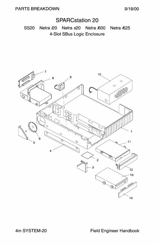
SPARCstation 20 SS20 Netra i20 Netra s20 Netra i600 Netra i625
4-Slot SBus Logic Enclosure
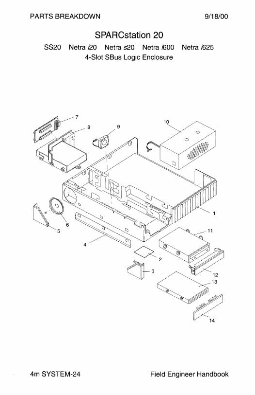
CODE PART# DESCRIPTION
1 540-2438 Base Assembly (phased out Nov/Dec 1996) - 240-1530 • M3 x 6 mm Screw, Speaker Assembly
- 340-2915 • Chassis - 540-2548 • Right Side Vent Panel (TurboZX requires 2548-02)
2 330-1450 • Foot 3 540-2547 • Right Front Corner
4 261-1009 • Purple Chassis Label
5 330-1683 • Left Front Corner
6 370-1579 • Speaker 7 501-2462 • SCSI 1/0 Board - 240-2159 • M2 x 5 mm Screw
- 330-1753 • Bracket - 530-2053 • Internal SCSI Cable, 660 mm
- 530-2066 • DC Wire Harness
- 530-2080 • Speaker and LED Wire Harness
8 540-2443 535MB Disk Drive Assembly/ FRU
- 370-1425 • 535MB Disk Drive
- 370-1844 • 535MB Disk Drive - 540-2570 • Mounting Bracket
8 540-2560 1.05GB Disk Drive Assembly/FRU
- 370-1753 • 1.05GB Disk Drive, Seagate ST31200WC
- 370-1822 • 1.05GB Disk Drive, Conner CFP1060E
- 370-1964 • 1.05GB Disk Drive, Conner CFP1 OBOE
- 370-2072 • 1.05GB Disk Drive, IBM DPES-31080 - 370-2168 • 1.05GB Disk Drive, Quantum 1080S
- 540-2570 • Mounting Bracket
8 540-2699 2.1 GB Disk Drive Assembly/FRU
- 370-1930 • 2.1 GB Disk Drive, Conner CFP2105E - 370-2071 • 2.1 GB Disk Drive, Seagate ST32430WC
- 370-2314 • 2.1 GB Disk Drive, Seagate ST32155WC
- 370-2315 • 2.1 GB Disk Drive, IBM DORS-32160 - 370-2842 • 2.1 GB Disk Drive, IBM DCAS-32160
- 540-2570 • Mounting Bracket
Volume II 4m SYSTEM-21
PARTS BREAKDOWN 9/18/00
SPARCstation 20 8820 Netra i20 Netra s20 Netra i600 Netra i625
4-Slot SBus Logic Enclosure - Continued
CODE PART# DESCRIPTION
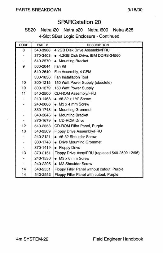
8 540-3988 4.2GB Disk Drive Assembly/FRU
- 370-3403 • 4.2GB Disk Drive, IBM DDRS-34560
- 540-2570 • Mounting Bracket
9 560-2044 Fan Kit
540-2640 Fan Assembly, 4 CFM
330-1836 Fan Installation Tool
10 300-1215 150 Watt Power Supply (obsolete)
10 300-1279 150 Watt Power Supply
11 540-2500 CD-ROM Assembly/FRU
- 240-1463 • #6-32 x 1/4" Screw - 240-2086 • M3 x 4 mm Screw - 330-1748 • Mounting Grommet
- 340-3046 • Mounting Bracket - 370-1679 • CD-ROM Drive
12 540-2553 CD-ROM Filler Panel, Purple
13 540-2509 Floppy Drive Assembly/FRU
- 240-2121 • #6-32 Shoulder Screw
- 330-1748 • Drive Mounting Grommet - 370-1419 • Floppy Drive
13 370-2151 Floppy Drive Assy/FRU (replaced 540-2509 12/95)
- 240-1530 • M3 x 6 mm Screw - 240-2295 • M3 Shoulder Screw
14 540-2551 Floppy Filler Panel without cutout, Purple
14 540-2552 Floppy Filler Panel with cutout, Purple
4m SYSTEM-22 Field Engineer Handbook
9/18/00 PARTS BREAKDOWN
SPARCstation 20 8820 Netra i20 Netra s20 Netra i600 Netra i625
4-Slot SBus Logic Enclosure - Continued
CODE PART# DESCRIPTION
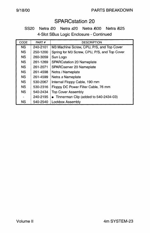
NS 240-2101 M3 Machine Screw, CPU, P/S, and Top Cover
NS 250-1200 Spring for M3 Screw, CPU, P/S, and Top Cover
NS 260-3059 Sun Logo
NS 261-1269 SPARCstation 20 Nameplate
NS 261-2071 SPARCserver 20 Nameplate NS 261-4598 Netra i Nameplate
NS 261-4599 Netra s Nameplate
NS 530-2067 Internal Floppy Cable, 190 mm
NS 530-2316 Floppy DC Power Filter Cable, 76 mm
NS 540-2434 Top Cover Assembly - 240-2195 • Tinnerman Clip (added to 540-2434-03)
NS 540-2540 Lockbox Assembly
Volume II 4m SYSTEM-23
PARTS BREAKDOWN 9/18/00
SPARCstation 20 SS20 Netra i2.0 Netra s20 Netra i600 Netra i625
4-Slot SBus Logic Enclosure
4m SYSTEM-24 Field Engineer Handbook
9/18/00 PARTS BREAKDOWN
SPARCstation 20 SS20 Netra i2.0 Netra s20 Netra i600 Netra i625
4-Slot SBus Logic Enclosure
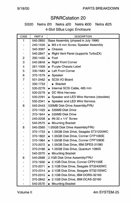
CODE PART# DESCRIPTION
1 540-2B50 Base Assembly (phased in July 1996) - 240-1530 • M3 x 6 mm Screw, Speaker Assembly
- 340-3397 • Chassis - 540-2B47 • Right Vent Panel (supports TurboZX)
2 330-1450 • Foot 3 540-2B4B • Right Front Corner
4 261-1009 • Purple Chassis Label
5 330-16B3 • Left Front Corner
6 370-1579 • Speaker
7 501-2462 • SCSI 1/0 Board
- 330-1753 • Bracket
- 530-227B • Internal SCSI Cable, 4B5 mm
- 530-2279 • DC Wire Harness
- 530-2291 • Speaker and LED Wire Harness (obsolete)
- 530-2341 • Speaker and LED Wire Harness
B 540-2443 535MB Disk Drive Assembly/FRU
- 370-1425 • 535MB Disk Drive
- 370-1B44 • 535MB Disk Drive
- 240-220B • #6-32 x 1/4" Screw
- 540-2570 • Mounting Bracket
B 540-2560 1.05GB Disk Drive Assembly/FRU
- 370-1753 • 1.05GB Disk Drive, Seagate ST31200WC
- 370-1B22 • 1.05GB Disk Drive, Conner CFP1060E
- 370-1964 • 1.05GB Disk Drive, Conner CFP1 OBOE
- 370-2072 • 1.05GB Disk Drive, IBM DPES-31 OBO
- 370-216B • 1.05GB Disk Drive, Quantum 1 OBOS
- 540-2570 • Mounting Bracket
B 540-2699 2.1 GB Disk Drive Assembly/FRU
- 370-1930 • 2.1 GB Disk Drive, Conner CFP2105E
- 370-2071 • 2.1 GB Disk Drive, Seagate ST32430WC
- 370-2314 • 2.1 GB Disk Drive, Seagate ST32155WC
- 370-2315 • 2.1 GB Disk Drive, IBM DORS-32160
- 370-2B42 • 2.1 GB Disk Drive, IBM DCAS-32160
- 540-2570 • Mounting Bracket
Volume II 4m SYSTEM-25

PARTS BREAKDOWN 9/18/00
SPARCstation 20 8820 Netra i2.0 Netra s20 Netra i600 Netra i625
4-Slot SBus Logic Enclosure - Continued
CODE PART# DESCRIPTION
8 540-3988 4.2GB Disk Drive Assembly/FRU
- 370-3403 • 4.2GB Disk Drive, IBM DDRS-34560 - 540-2570 • Mounting Bracket
9 560-2044 Fan Kit
540-2640 Fan Assembly, 4 CFM
330-1836 Fan Installation Tool 10 300-1279 150 Watt Power Supply 11 540-2852 SunCD 4 CD-ROM Assembly/FRU
- 240-2295 • M3 Shoulder Screw - 330-2036 • Mounting Grommet - 370-2102 • SunCD 4 CD-ROM Drive
12 540-2845 CD-ROM Filler Panel, Light Grey 13 540-2854 Floppy Drive Assembly/FRU
- 240-2318 • M2.5 x 3 mm Screw - 330-2036 • Mounting Grommet - 340-3401 • Mounting Bracket - 370-2302 • Floppy Drive
NS 530-2277 Internal Floppy Cable, 250 mm
NS 530-2316 Floppy DC Power Filter Cable, 76 mm 14 540-2846 Floppy Filler Panel without cutout, Light Grey 14 540-2853 Floppy Filler Panel with cutout, Light Grey
NS 240-2101 M3 Machine Screw, CPU, P/S, and Top Cover NS 250-1200 Spring for M3 Screw, CPU, P/S, and Top Cover NS 260-3059 Sun Logo NS 261-1269 SPARCstation 20 Nameplate NS 261-2071 SPARCserver 20 Nameplate NS 261-4598 Netra i Nameplate NS 261-4599 Netra s Nameplate
NS 540-2844 Top Cover Assembly NS 540-2540 Lockbox Assembly
- 240-2206 • M3 x 12 mm Screw
4m SYSTEM-26 Field Engineer Handbook
PARTS BREAKDOWN
4d SYSTEM
9/18/00 PARTS BREAKDOWN
Sun-4d System
Sun-4d Architecture SPARCserver 1000 and 1 OOOE ......................................... 2 SPARCcenter 2000 and 2000E ......................................... 6
Sun-4d6 Architecture Cray Superserver 6400 . . . . . . . . . . . . . . . . . . . . . . . . . . . . . . . . . . . . . . . . . . . . . . . . . . . . . 18
Field Engineer Handbook - Volume II
PARTS BREAKDOWN
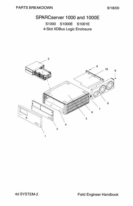
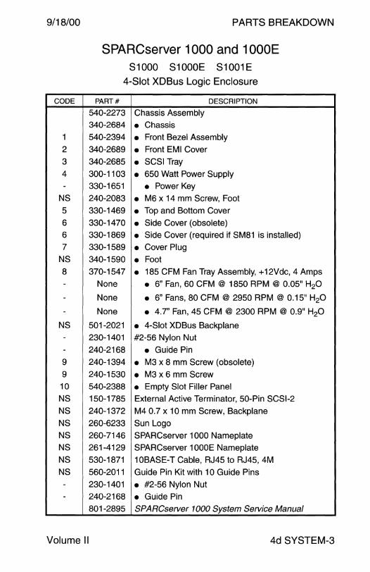
SPARCserver 1000 and 1 OOOE 81000 S1000E S1001E
4-Slot XDBus Logic Enclosure
3
/9
9/18/00
4d SYSTEM-2 Field Engineer Handbook
9/18/00
CODE
1
2
3
4 -
NS
5
6
6
7
NS
8
---
NS
--9
9 10
NS
NS
NS
NS
NS
NS
NS -
-
Volume II
PARTS BREAKDOWN
SPARCserver 1000 and 1 OOOE S1000 S1000E S1001E
4-Slot XDBus Logic Enclosure
PART# DESCRIPTION
540-2273 Chassis Assembly 340-2684 • Chassis 540-2394 • Front Bezel Assembly
340-2689 • Front EMI Cover 340-2685 • SCSI Tray 300-1103 • 650 Watt Power Supply 330-1651 • Power Key 240-2083 • M6 x 14 mm Screw, Foot 330-1469 • Top and Bottom Cover 330-1470 • Side Cover (obsolete) 330-1869 • Side Cover (required if SM81 is installed)
330-1589 • Cover Plug 340-1590 • Foot 370-1547 • 185 CFM Fan Tray Assembly, + 12Vdc, 4 Amps
None • 6" Fan, 60 CFM @ 1850 RPM @ 0.05" H20
None • 6" Fans, 80 CFM @ 2950 RPM @ 0.15" H20
None • 4.7" Fan, 45 CFM @ 2300 RPM @ 0.9" H20
501-2021 • 4-Slot XDBus Backplane 230-1401 #2-56 Nylon Nut
240-2168 • Guide Pin 240-1394 • M3 x 8 mm Screw (obsolete) 240-1530 • M3 x 6 mm Screw 540-2388 • Empty Slot Filler Panel
150-1785 External Active Terminator, 50-Pin SCSl-2
240-1372 M4 0.7 x 10 mm Screw, Backplane
260-6233 Sun Logo
260-7146 SPARCserver 1000 Nameplate
261-4129 SPARCserver 1 OOOE Nameplate
530-1871 10BASE-T Cable, RJ45 to RJ45, 4M
560-2011 Guide Pin Kit with 10 Guide Pins
230-1401 • #2-56 Nylon Nut 240-2168 • Guide Pin 801-2895 SPARCserver 1000 System Service Manual
4d SYSTEM-3
PARTS BREAKDOWN
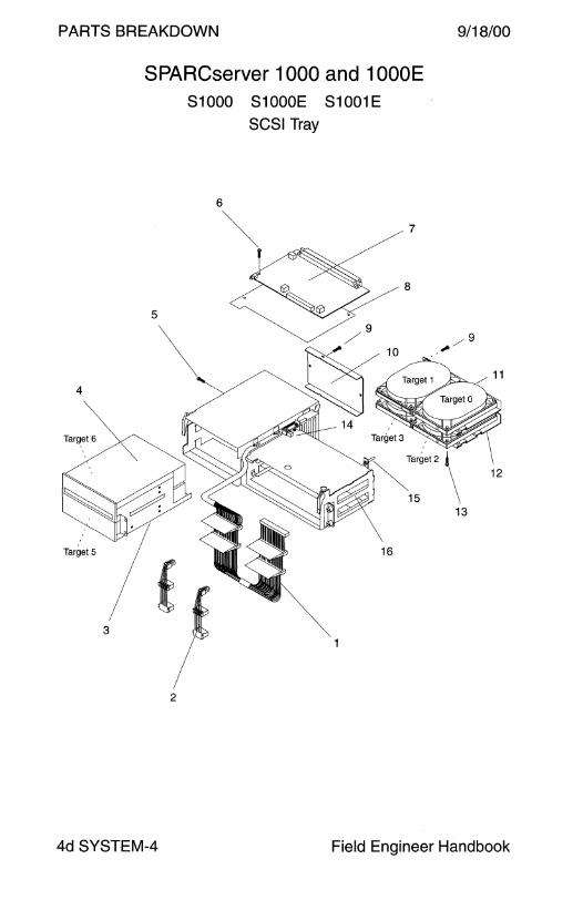
SPARCserver 1000 and 1 OOOE S1000 S1000E S1001E
SCSI Tray
2
9/18/00
4d SYSTEM-4 Field Engineer Handbook
9/18/00
CODE
1
2
3
4
4
4
4
4
5
5
6
7
7
7
7
8
9
10
11
11
11
11
11
11
12
13
13
14
15
16
NS
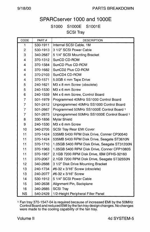
PARTS BREAKDOWN
SPARCserver 1000 and 1 OOOE S1000 S1000E S1001E
SCSI Tray
PART# DESCRIPTION
530-1911 Internal SCSI Cable, 1 M
530-1913 3 1/2" SCSI Power Cable
340-2687 5 1/4" SCSI Mounting Bracket
370-1312 SunCD CD-ROM
370-1584 SunCD Plus CD-ROM
370-1682 SunCD2 Plus CD-ROM
370-2103 SunCD4 CD-ROM
370-1571 5.0GB 4 mm Tape Drive
240-1621 M3 x 8 mm Screw (obsolete)
240-1530 M3 x 6 mm Screw
240-1559 M4 x 6 mm Screw, Control Board
501-1979 Programmed 40MHz SS1000 Control Board
501-2412 Unprogrammed 40MHz SS1000 Control Board
501-2667 Programmed 50MHz SS1000E Control Board 1
501-2673 Unprogrammed 50MHz SS1 OOOE Control Board 1
330-1856 Mylar Shield
240-1530 M3 x 6 mm Screw
340-2705 SCSI Tray Rear EMI Cover
370-1424 535MB 5400 RPM Disk Drive, Conner CP30540
370-1424 535MB 5400 RPM Disk Drive, Seagate ST361 ON
370-1710 1.05GB 5400 RPM Disk Drive, Seagate ST31200N
370-1963 1.05GB 5400 RPM Disk Drive, Conner CFP1 OBOS
370-1957 2.1 GB 7200 RPM Disk Drive, IBM DFHS-32160
370-2067 2.1 GB 7200 RPM Disk Drive, Seagate ST32550N
340-2688 3 1/2" Disk Drive Mounting Bracket
240-1734 #6-32 x 3/16" Screw (obsolete)
240-2077 #6-32 x 3/16" Screw
530-1912 5 1/4" SCSI Power Cable
340-2638 Alignment Pin, Backplane
340-2685 SCSI Tray
540-2429 1/2-Height Peripheral Filler Panel
1 Fan tray 370-1547-04 is required because of increased EMI by the 50MHz Control Board and reduced EM I by the fan tray design changes. No changes were made to the cooling capability of the fan tray.
Volume II 4d SYSTEM-5
PARTS BREAKDOWN
SPARCcenter 2000 and 2000E 82000 S2000E S2001E 56-inch Data Center Cabinet
Left Side View
9/18/00
4d SYSTEM-6 Field Engineer Handbook

9/18/00
CODE
1
2
3
3
4
5
6
7
8
9
10 11
12
13
13
13
13
14
NS
NS
15
16
NS NS
NS
NS
NS NS
NS
NS
NS
NS
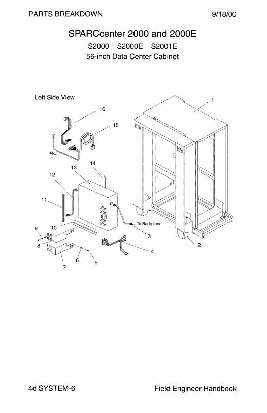
PARTS BREAKDOWN
SPARCcenter 2000 and 2000E 82000 S2000E S2001E 56-inch Data Center Cabinet
PART# DESCRIPTION
599-1821 SC2000 and SC2000E Rack Assembly
240-1717 Caster
530-1728 Power Supply Sense to Backplane Harness
530-2210 Power Supply Sense to Backplane Harness 1
530-1743 Power Supply +/- 12 Volt to Backplane Harness
240-1372 M4 0.7 x 10 mm Screw
240-1952 M4 Washer (Bus Bar to Backplane)
340-2620 Power Supply + 1.2Vdc Lower Bus Bar
340-2621 Power Supply +5Vdc Upper Bus Bar
240-2213 MB 1.25 Nut, Washer, and Lock Washer
340-2414 Power Supply Mounting Bracket, Lower
340-2416 Power Supply Mounting Bracket, Front
530-1738 Power Supply to AC Distribution Unit Harness
300-1073 241 O Watt Power Supply (obsolete)
300-1258 2410 Watt Power Supply (obsolete)
300-1286 241 O Watt Power Supply
300-1281 241 O Watt Power Supply 1
340-2415 Power Supply Mounting Bracket, Rear
340-2394 Power Supply Mounting Shelf
340-2395 Power Supply EMI Cover
530-1724 AC Dist to Blower to Filter to Keyswitch Harness
530-1725 Backplane to DB25 Filter Harness
130-2034 DB-25 Filter
130-1080 Jackscrew for DB25 Filter
240-1957 M4 0.7 x 25 mm Screw (Power Supply EMI Cover)
340-2400 Cardcage EMI Cover
340-2412 Cardcage Support Rail, Lower Left 340-2413 Cardcage Support Rail, Upper Left
340-2396 Cardcage Support Rail, Upper Right
340-2397 Cardcage Support Rail, Lower Right
340-2563 Cardcage Lower Access Panel
540-2114 Cardcage Slot Filler Panel
1 The PCM_FAIL signal prevents booting when Sense Cable 530-1728 is used with Power Supply 300-1281. Use Sense Cable 530-2210.
Volume II 4d SYSTEM-7

PARTS BREAKDOWN
Front View
Rear View
1-c?·
16
.""'
SPARCcenter 2000 and 2000E 82000 S2000E S2001E
Logic Enclosure and Data Center Cabinet
d'_· - 1
9/18/00
4d SYSTEM-8 Field Engineer Handbook
9/18/00
CODE
1
2
3
-4
5
6
7
7 -
-
8
9
10 11
12
12
13
14
15
16
NS
NS
NS
NS
NS
NS NS
NS
NS
Volume II
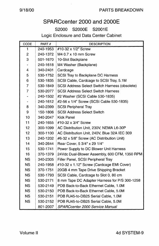
PARTS BREAKDOWN
SPARCcenter 2000 and 2000E 82000 S2000E S2001E
Logic Enclosure and Data Center Cabinet
PART# DESCRIPTION
240-1953 #10-32 x 1/2" Screw 240-1372 M4 0.7 x 10 mm Screw
501-1670 10-Slot Backplane
240-1618 M4 Washer (Backplane)
340-2401 Cardcage
530-1752 SCSI Tray to Backplane DC Harness
530-1835 SCSI Cable, Cardcage to SCSI Tray, 5.1 M
530-1849 SCSI Address Select Switch Harness (obsolete)
530-2077 SCSI Address Select Switch Harness
240-1502 #2 Washer (SCSI Cable 530-1835) 240-1612 #2-56 x 1/4" Screw (SCSI Cable 530-1835)
340-2399 SCSI Peripheral Tray
150-1806 SCSI Address Select Switch
340-2047 Kick Panel
240-1655 #10-32 x 3/4" Screw
300-1099 AC Distribution Unit, 230V, NEMA L6-30P
300-1100 AC Distribution Unit, 240V, Blue 32A IEC 309
240-1202 #6-32 x 5/8" Screw (AC Distribution Unit)
340-2644 Rear Cover, 5 3/4" x 29 1/4"
530-1741 Power Supply to DC Blower Unit Harness
370-1379 24Vdc Dual-Blower Assembly, 600 CFM, 1350 RPM
340-2305 Filler Panel, SCSI Peripheral Tray
240-1958 #10-32x1.12" Screw (Cardcage EMI Cover)
370-1751 20GB 4 mm Tape Drive Shipping Bracket
530-1793 SCSI Cable, Cardcage to Slot 0, 80 cm
530-2171 8 mm Tape DC Adapter Harness for P/S 300-1258
530-2149 PDB Back-to-Back Ethernet Cable, 1.0M
530-2150 PDB Back-to-Back Ethernet Cable, 5.0M
530-2151 PDB RJ45-to-DB25 Serial Cable, 1.0M
530-2152 PDB RJ45-to-DB25 Serial Cable, 5.0M
801-2007 SPARCcenter 2000 Service Manual
4d SYSTEM-9
PARTS BREAKDOWN
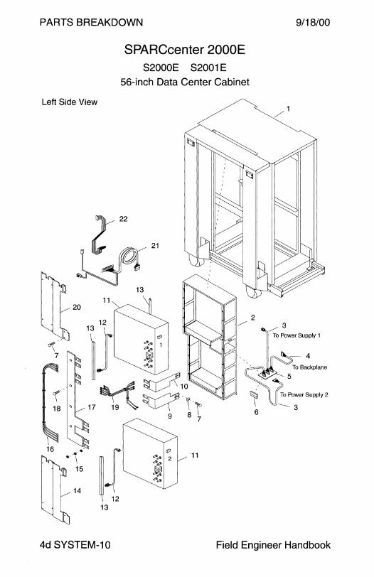
Left Side View
20 11
12
SPARCcenter 2000E S2000E S2001E
56-inch Data Center Cabinet
'iJ it'
°\ "'"' 1
7 ~ "" "'"'
r 18 °
I 16 --·
~{ it'
• I "'"' 2 11
15 ~ "" "'"'
14
13
9/18/00
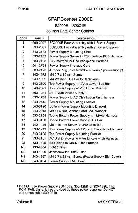
4d SYSTEM-10 Field Engineer Handbook
9/18/00
CODE PART#
1 599-2027
1 599-2031
2 340-3133
3 530-2162
4 530-2163
5 501-2724
6 530-2170
7 240-1372
8 240-1952
9 340-2620 10 340-2621
11 300-1281
12 530-1738
13 340-2415 14 340-3190
15 240-2213
16 530-2164
17 340-3163 18 240-1435
19 530-1743
20 340-3135
21 530-2161
22 530-1725
NS 130-2034
NS 130-1080
NS 240-1957
NS 340-3134
PARTS BREAKDOWN
SPARCcenter 2000E S2000E S2001E
56-inch Data Center Cabinet
DESCRIPTION
SC2000E Rack Assembly with 1 Power Supply
SC2000E Rack Assembly with 2 Power Supplies
Power Supply Mounting Shelf
Power Supply Sense to P/S Interface PCB Harness
P/S Interface PCB to Backplane Harness
Power Supply Interface Card
Jumper Plug (installed if there is only 1 power supply)
M4 0.7 x 10 mm Screw
M4 Washer (Bus Bar to Backplane)
Top Power Supply + 1.2Vdc Lower Bus Bar Top Power Supply +5Vdc Upper Bus Bar
241 O Watt Power Supply 1
Power Supply to AC Distribution Unit Harness
Power Supply Mounting Bracket Bottom Power Supply Mounting Bracket
M8 1.25 Nut, Washer, and Lock Washer
Top to Bottom Power Supply +/- 12Vdc Harness
Top to Bottom Power Supply Bus Bar
M6 x 18 mm Screw for 340-3136 (x4)
Top Power Supply +/- 12Vdc to Backplane Harness
Top Power Supply Mounting Bracket
AC Dist to Blower to Filter to Keyswitch Harness
Backplane to DB25 Filter Harness
DB-25 Filter
Jackscrew for DB25 Filter
M4 0.7 x 25 mm Screw (Power Supply EMI Cover)
Power Supply EMI Cover
1 Do NOT use Power Supply 300-1073, 300-1258, or 300-1286. The PCM_FAIL signal is not provided by these power supplies. Do NOT use sense cable 530-2210.
Volume II 4d SYSTEM-11

PARTS BREAKDOWN
Front View
Rear View
SPARCcenter 2000E S2000E S2001E
Logic Enclosure and Data Center Cabinet
17
9/18/00
4d SYSTEM-12 Field Engineer Handbook

9/18/00
CODE
1
2
3
-4
5
6 -
-7
8
9
10
11
12
13
14
14 15
16
17
18
19
20
21
22
23
NS
NS
NS
NS
Volume II
PARTS BREAKDOWN
SPARCcenter 2000E S2000E S2001E
Logic Enclosure and Data Center Cabinet
PART# DESCRIPTION
240-1953 #10-32 x 1 /2" Screw
240-1372 M4 0.7 x 10 mm Screw
501-1670 10-Slot Backplane
240-1618 M4 Washer (Backplane)
340-2401 Cardcage
530-1752 SCSI Tray to Backplane DC Harness
530-1835 SCSI Cable, Cardcage to SCSI Tray, 5.1 M
240-1502 #2 Washer (SCSI Cable 530-1835)
240-1612 #2-56 x 1/4" Screw (SCSI Cable 530-1835)
530-2077 SCSI Address Select Switch Harness
340-2399 SCSI Peripheral Tray
150-1806 SCSI Address Select Switch
340-3189 EMI Cover for Bottom Power Supply
340-3157 EMI Cover for Bottom Power Supply
240-1655 #10-32 x 3/4" Screw
340-2047 Kick Panel
300-1099 AC Distribution Unit, 230V, NEMA L6-30P
300-1100 AC Distribution Unit, 240V, Blue 32A IEC 309
240-1202 #6-32 x 5/8" Screw (AC Distribution Unit)
530-2160 AC Receptacle to Lower Power Supply Cable
540-2689 AC Receptacle Assembly
530-2160 AC Receptacle to Upper Power Supply Cable
340-2644 Rear Cover, 5 3/4" x 29 1/4"
340-3161 Filter Cover
150-2357 Filter, AC Dist to Power Supply to Blower Harness
340-3160 Filter Chassis
370-1853 24Vdc Quad-Blower Assembly
340-2305 Filler Panel, SCSI Peripheral Tray
240-1958 #10-32 x 1.12" Screw (Cardcage EMI Cover)
370-1751 20GB 4 mm Tape Drive Shipping Bracket
530-1793 SCSI Cable, Cardcage to Slot 0, 80 cm
801-2007 SPARCcenter 2000 Service Manual
4d SYSTEM-13
PARTS BREAKDOWN
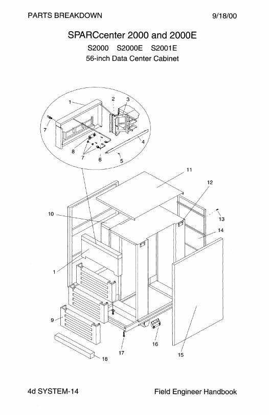
SPARCcenter 2000 and 2000E 82000 S2000E S2001E
56-inch Data Center Cabinet
9/18/00
4d SYSTEM-14 Field Engineer Handbook
9/18/00
CODE
1
2
3
4
5
6
7
-8
9 10
11
12
13 14
15
16
17
NS
18
NS
NS
NS
NS
NS
NS
NS
NS
NS
NS
NS
Volume II
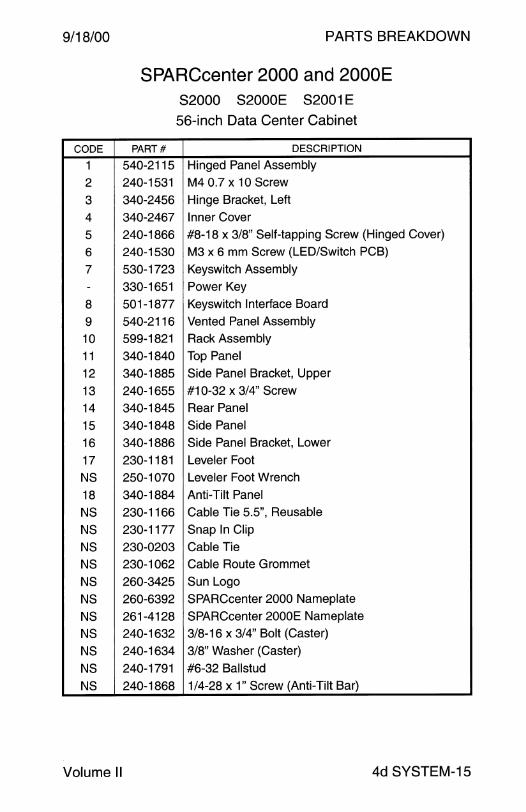
PARTS BREAKDOWN
SPARCcenter 2000 and 2000E 82000 S2000E S2001E
56-inch Data Center Cabinet
PART# DESCRIPTION
540-2115 Hinged Panel Assembly
240-1531 M4 0.7 x 10 Screw
340-2456 Hinge Bracket, Left
340-2467 Inner Cover
240-1866 #8-18 x 3/8" Self-tapping Screw (Hinged Cover)
240-1530 M3 x 6 mm Screw (LED/Switch PCB)
530-1723 Keyswitch Assembly
330-1651 Power Key
501-1877 Keyswitch Interface Board
540-2116 Vented Panel Assembly
599-1821 Rack Assembly
340-1840 Top Panel
340-1885 Side Panel Bracket, Upper
240-1655 #10-32 x 3/4" Screw
340-1845 Rear Panel
340-1848 Side Panel
340-1886 Side Panel Bracket, Lower
230-1181 Leveler Foot
250-1070 Leveler Foot Wrench
340-1884 Anti-Tilt Panel
230-1166 Cable Tie 5.5", Reusable
230-1177 Snap In Clip
230-0203 Cable Tie
230-1062 Cable Route Grommet
260-3425 Sun Logo
260-6392 SPARCcenter 2000 Nameplate
261-4128 SPARCcenter 2000E Nameplate
240-1632 3/8-16 x 3/4" Bolt (Caster)
240-1634 3/8" Washer (Caster)
240-1791 #6-32 Ballstud
240-1868 1/4-28 x 1" Screw (Anti-Tilt Bar)
4d SYSTEM-15
PARTS BREAKDOWN 9/18/00
SPARCcenter 2000 and 2000E 82000 S2000E S2001E
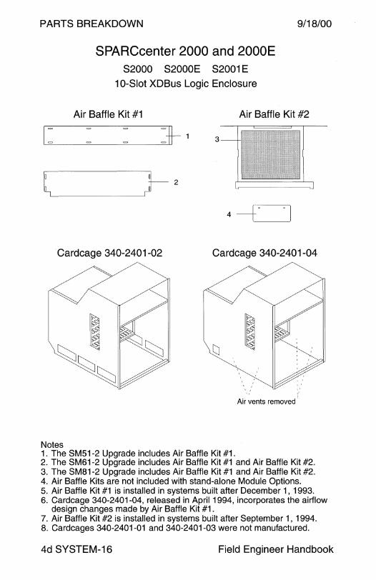
10-Slot XDBus Logic Enclosure
Air Baffle Kit #1 Air Baffle Kit #2
3
l~---~)-2 4 ----c=J
Cardcage 340-2401-02 Cardcage 340-2401-04
Air vents removed'
Notes 1. The SM51-2 Upgrade includes Air Baffle Kit #1. 2. The SM61-2 Upgrade includes Air Baffle Kit #1 and Air Baffle Kit #2. 3. The SM81-2 Upgrade includes Air Baffle Kit #1 and Air Baffle Kit #2. 4. Air Baffle Kits are not included with stand-alone Module Options. 5. Air Baffle Kit #1 is installed in systems built after December 1, 1993. 6. Cardcage 340-2401-04, released in April 1994, incorporates the airflow
design changes made by Air Baffle Kit #1. 7. Air Baffle Kit #2 is installed in systems built after September 1, 1994. 8. Cardcages 340-2401-01 and 340-2401-03 were not manufactured.
4d SYSTEM-16 Field Engineer Handbook

9/18/00
CODE
NS
--
-
-1
2
-3
4
-
PARTS BREAKDOWN
SPARCcenter 2000 and 2000E S2000 S2000E S2001E
10-Slot XDBus Logic Enclosure
PART# DESCRIPTION
560-2011 Backplane Guide Pin Kit
230-1401 • #2-56 Nut 240-2168 • Guide Pin 801-6248 • Guide Pin Upgrade Manual
595-3290 Air Baffle Kit #1
230-1402 • Snap Fastener (x20) 340-3036 • Side Plate (x2)
340-3037 • End Plate
595-3509 Air Baffle Kit #2
230-1402 • Snap Fastener (x4)
340-3099 • Baffle 340-3132 • Baffle Support Bracket 801-6727 • SPARCenter 2000 Air Baffle Upgrade Manual
Chassis Air Baffle Kit Requirements
CHASSIS MANUFACTURING DATE
CHASSIS Pre-fcs - 12/93 12/93 - 4/94 4/94 - 9/94 9/94 - Present
340-2401-02 SM51-2 requires SM51-2 has no Not Not Air Baffle Kit #1 requirements Manufactured Manufactured
SM61-2 requires SM61-2 requires Not Not - Air Baffle Kit #1 Air Baffle Kit #2 Manufactured Manufactured
Air Baffle Kit #2
SM81-2 requires SM81-2 requires Not Not - Air Baffle Kit #1 Air Baffle Kit #2 Manufactured Manufactured
Air Baffle Kit #2
340-2401-04 Not Not SM51-2 has no SM51-2 has no
Manufactured Manufactured requirements requirements
Not Not SM61-2 requires SM61-2 has no Manufactured Manufactured Air Baffle Kit #2 requirements
Not Not SM81-2 requires SM81-2 has no Manufactured Manufactured Air Baffle Kit #2 requirements
Volume II 4d SYSTEM-17
PARTS BREAKDOWN 9/18/00
PART#
370-2732
370-2733
370-2734
370-2735
370-2736
370-2737
370-2738
370-2739
370-2740
370-2741
370-2742
370-2743
370-2744
370-2745
370-2746
370-2747
370-2748
370-2749
370-2750
370-2751
370-2752
370-2753
370-2754 370-2755
370-2756
370-2757
370-2758
370-2759
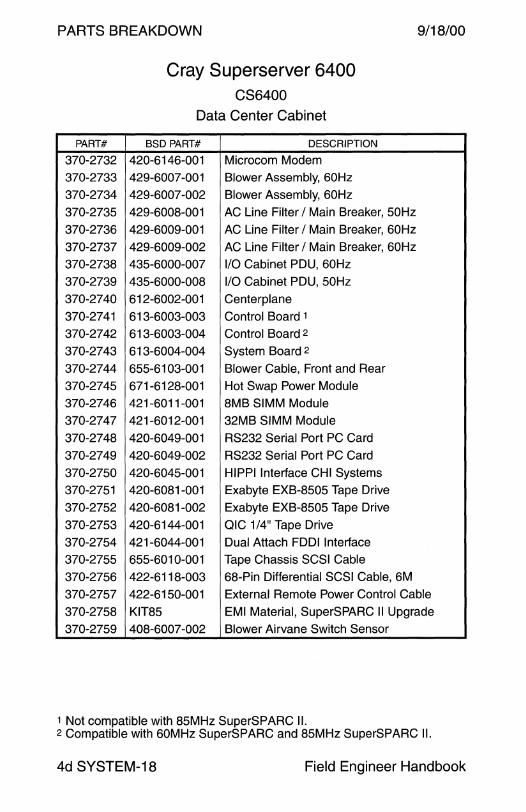
Cray Superserver 6400 CS6400
Data Center Cabinet
BSD PART# DESCRIPTION
420-6146-001 Microcom Modem
429-6007-001 Blower Assembly, 60Hz
429-6007-002 Blower Assembly, 60Hz
429-6008-001 AC Line Filter I Main Breaker, 50Hz
429-6009-001 AC Line Filter I Main Breaker, 60Hz
429-6009-002 AC Line Filter I Main Breaker, 60Hz
435-6000-007 110 Cabinet PDU, 60Hz
435-6000-008 1/0 Cabinet PDU, 50Hz
612-6002-001 Centerplane
613-6003-003 Control Board 1
613-6003-004 Control Board 2
613-6004-004 System Board 2
655-6103-001 Blower Cable, Front and Rear
671-6128-001 Hot Swap Power Module
421-6011-001 8MB SIMM Module
421-6012-001 32MB SIMM Module
420-6049-001 RS232 Serial Port PC Card
420-6049-002 RS232 Serial Port PC Card
420-6045-001 HIPPI Interface CHI Systems
420-6081-001 Exabyte EXB-8505 Tape Drive
420-6081-002 Exabyte EXB-8505 Tape Drive
420-6144-001 QIC 1/4" Tape Drive
421-6044-001 Dual Attach FDDI Interface
655-6010-001 Tape Chassis SCSI Cable
422-6118-003 68-Pin Differential SCSI Cable, 6M
422-6150-001 External Remote Power Control Cable
KIT85 EMI Material, SuperSPARC II Upgrade
408-6007 -002 Blower Airvane Switch Sensor
1 Not compatible with 85MHz SuperSPARC II. 2 Compatible with 60MHz SuperSPARC and 85MHz SuperSPARC II.
4d SYSTEM-18 Field Engineer Handbook
9/18/00
PART#
370-2760 370-2761
370-2762
370-2763
370-2764
370-2765
370-2766
370-2767
370-2768
370-2769
370-2770
370-2771
370-2772
370-2773 370-2774
370-2775
370-2776
370-2777
370-2778
370-2779
370-2780
370-2781
370-2782
370-2783
370-2784
370-2785
370-2786
370-2787
370-2788
Volume II
PARTS BREAKDOWN
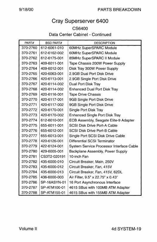
Cray Superserver 6400 CS6400
Data Center Cabinet - Continued
BSD PART# DESCRIPTION
612-6061-010 60MHz SuperSPARC Module 612-6162-002 60MHz SuperSPARC Module
612-6175-001 85MHz SuperSPARC II Module
409-6011-001 Tape Chassis 200W Power Supply 409-6012-001 Disk Tray 300W Power Supply
420-6063-001 2.9GB Dual Port Disk Drive
420-6113-001 2.9GB Single Port Disk Drive
420-6114-002 Dual Port Disk Tray
420-6114-002 Enhanced Dual Port Disk Tray
420-6116-001 Tape Drive Chassis 420-6117-001 9GB Single Port Disk Drive
420-6117 -002 9GB Single Port Disk Drive
420-6170-001 Single Port Disk Tray
420-6170-002 Enhanced Single Port Disk Tray 612-6010-001 ECB Assembly, Seagate Elite-9 Adapter
655-6011-001 SCSI Disk Drive Port-A Cable
655-6012-001 SCSI Disk Drive Port-B Cable
655-6013-001 Single Port SCSI Disk Drive Cable
420-6126-001 Differential SCSI Terminator
422-6124-001 System Service Processor Interface Cable
429-6005-001 Backplane Assembly, Power Supply
CS3T2-020191 10-inch Fan
435-6000-010 Circuit Breaker, Main, 250V
435-6000-012 Circuit Breaker, Fan, 415V
435-6000-013 Circuit Breaker, Fan, 415V, 62DL
436-6000-003 Air Filter, 9.5" x 22.75" x 0.43"
SP-16ASYN-01 16 Port Asynchronous Interface SP-ATM100-01 4615 SBus with 100MB ATM Adapter
SP-ATM155-01 4615 SBus with 155MB ATM Adapter
4d SYSTEM-19
PARTS BREAKDOWN 9/18/00
PART#
370-2789
370-2790
370-2791
370-2792
370-2793
370-2794
370-2795
370-2796
370-2797
370-2798
370-2799
370-2800
370-.2801
370-2802
370-2803
370-2804
370-2806
370-2807
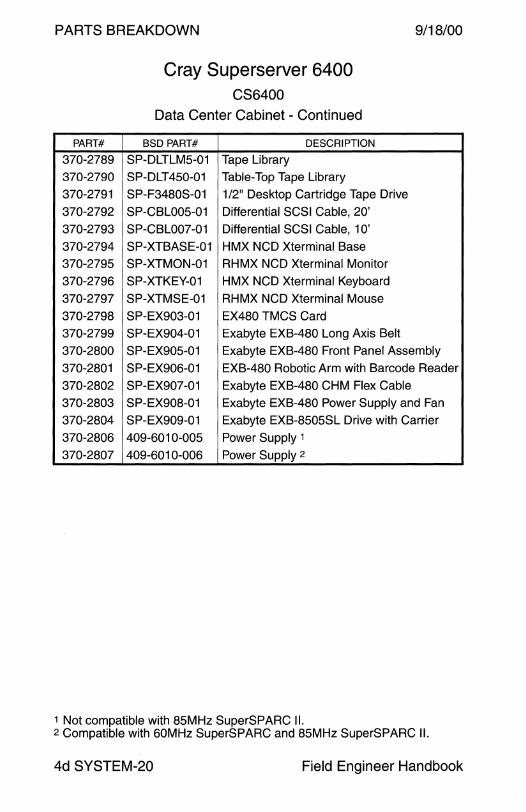
Cray Superserver 6400 CS6400
Data Center Cabinet - Continued
BSD PART# DESCRIPTION
SP-DLTLM5-01 Tape Library SP-DLT450-01 Table-Top Tape Library
SP-F3480S-01 1/2" Desktop Cartridge Tape Drive
SP-CBL005-01 Differential SCSI Cable, 20'
SP-CBL007-01 Differential SCSI Cable, 1 O'
SP-XTBASE-01 HMX NCO Xterminal Base
SP-XTMON-01 RHMX NCO Xterminal Monitor
SP-XTKEY-01 HMX NCO Xterminal Keyboard
SP-XTMSE-01 RHMX NCO Xterminal Mouse
SP-EX903-01 EX480 TMCS Card
SP-EX904-01 Exabyte EXB-480 Long Axis Belt
SP-EX905-01 Exabyte EXB-480 Front Panel Assembly
SP-EX906-01 EXB-480 Robotic Arm with Barcode Reader
SP-EX907-01 Exabyte EXB-480 CHM Flex Cable
SP-EX908-01 Exabyte EXB-480 Power Supply and Fan
SP-EX909-01 Exabyte EXB-8505SL Drive with Carrier
409-6010-005 Power Supply 1
409-6010-006 Power Supply 2
1 Not compatible with 85MHz SuperSPARC II. 2 Compatible with 60MHz SuperSPARC and 85MHz SuperSPARC II.
4d SYSTEM-20 Field Engineer Handbook

PARTS BREAKDOWN
4u WORKSTATION

9/18/00 PARTS BREAKDOWN
Sun-4u Workstation
Sun-4u Architecture Ultra 1 Model 140 .............................................................. 2 Ultra 1 Model 170 . ... .. ... .. ..... .. .. .. .. .. .. ..... ... . ... .. .. .. .. ... .... .. .. ... 2 Ultra 1 Model 140E ......................................... ,.................. 6 Ultra 1 Model 170E . ... .......... .. .. . .. ... ....... .. .. ..... .. . ... ... .... .. .. .. . 6 Ultra 1 Model 200E . .. . .... ... .. . ..... .. ...... .. .. .. .. .. ... . .. ..... .. .. .. ... .. . 6 Ultra 2 ................................................................................ 10 Ultra 5 ................................................................................ 14 Ultra 10 .............................................................................. 16 Ultra 30 .............................................................................. 18 Ultra 60 .............................................................................. 22 Ultra 80 .............................................................................. 26 Sun Blade 100 . . . . . . . . . .. . . .. . . . . . .. . . . . . . . . . . . . . . . . . . . .. . . . . . .. . .. .. . . . . . . . . . . . . 30 Sun Blade 1000 . . . . . .. . . . . . . .. . . . . . . . . . . . . . . . . . . . . .. . . . . . . . . . . . . . . . .. . . . . . . . . . .. 32
Field Engineer Handbook - Volume II

PARTS BREAKDOWN 9/18/00
Ultra 1 Models 140 and 170 A 11 Netra i 1 /140 Netra j 1 /145 Netra i 1 /170 Netra j 1 /170
3-Slot SBus Logic Enclosure
4u WORKSTATION-2 Field Engineer Handbook

9/18/00 PARTS BREAKDOWN
Ultra 1 Models 140 and 170 A 11 Netra i 1 /140 Netra j 1 /145 Netra i 1 /170 Netra j 1 /170
3-Slot SBus Logic Enclosure
CODE PART# DESCRIPTION
1 540-2540 Lockbox 2 540-2650 Top Cover Assembly
3 300-1248 180W Power Supply (obsolete)
3 300-1308 180W Power Supply
4 530-2176 Peripheral and Fan Wire Harness
5 240-2101 M3 Captive Screw
6 330-1896 Power Supply Bezel 7 530-2175 Speaker and LED Wire Harness
8 See next page Removable Media Option
9 370-2151 3D Floppy Drive
9 370-3212 3D Floppy Drive
- 530-2316 • Floppy DC Power Filter Cable, 76 mm
10 340-3186 Floppy and CD-ROM Mounting Bracket
11 240-1878 #6-32 x 5/16" Screw (CD-ROM) 12 240-1530 M3 x 6 mm Screw (Floppy Drive)
13 530-2187 Floppy Data Cable, 205 mm
14 330-1895 Floppy and CD-ROM Bezel
15 540-2700 Floppy Filler Panel
16 540-2701 CD-ROM Filler Panel
17 540-2710 Speaker Assembly
18 370-1579 • Speaker 19 540-2666 Fan Assembly
20 See next page Disk Drive Assembly (maximum 1.0" height)
21 240-2080 #6-32 x 3/16" Torx Screw
22 340-3201 Disk Drive Access Cover
23 530-2153 Peripheral Data Cable Assembly, 410 mm
NS 260-6233 Sun Logo
NS 263-0063 Ultra 1 Nameplate
NS 263-0066 Ultra 1 Server Nameplate
NS 262-0060 Netra i Nameplate
NS 330-1839 Foot
802-3819 Sun Ultra 1 Series Service Manual
Volume II 4u WORKSTATION-3
PARTS BREAKDOWN 9/18/00
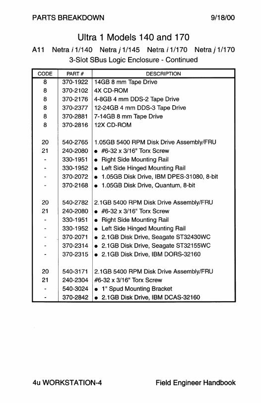
Ultra 1 Models 140 and 170 A 11 Netra i 1 /140 Netra j 1 /145 Netra i 1 /170 Netra j 1 /170
3-Slot SBus Logic Enclosure - Continued
CODE PART# DESCRIPTION
8 370-1922 14GB 8 mm Tape Drive
8 370-2102 4XCD-ROM
8 370-2176 4-8GB 4 mm DDS-2 Tape Drive
8 370-2377 12-24GB 4 mm DDS-3 Tape Drive
8 370-2881 7-14GB 8 mm Tape Drive
8 370-2816 12X CD-ROM
20 540-2765 1.05GB 5400 RPM Disk Drive Assembly/FRU
21 240-2080 • #6-32 x 3/16" Torx Screw
- 330-1951 • Right Side Mounting Rail
- 330-1952 • Left Side Hinged Mounting Rail - 370-2072 • 1.05GB Disk Drive, IBM DPES-31080, 8-bit
- 370-2168 • 1.05GB Disk Drive, Quantum, 8-bit
20 540-2782 2.1 GB 5400 RPM Disk Drive Assembly/FRU
21 240-2080 • #6-32 x 3/16" Torx Screw
- 330-1951 • Right Side Mounting Rail - 330-1952 • Left Side Hinged Mounting Rail - 370-2071 • 2.1 GB Disk Drive, Seagate ST32430WC - 370-2314 • 2.1 GB Disk Drive, Seagate ST32155WC
- 370-2315 • 2.1 GB Disk Drive, IBM DORS-32160
20 540-3171 2.1 GB 5400 RPM Disk Drive Assembly/FRU
21 240-2304 #6-32 x 3/16" Torx Screw
- 540-3024 • 1" Spud Mounting Bracket
- 370-2842 • 2.1GB Disk Drive, IBM DCAS-32160
4u WORKSTATION-4 Field Engineer Handbook
9/18/00 PARTS BREAKDOWN
This page intentionally left blank.
Volume II 4u WORKSTATION-5

PARTS BREAKDOWN 9/18/00
Ultra 1 Models 140E/170E/200E A 12 Netra i 1 /170E Netra i 1 /200E
2-Slot SBus Logic Enclosure
4u WORKSTATION-6 Field Engineer Handbook
9/18/00
CODE
1
2
3
3 4
5 6
7
8
9
9
-10 11
12
13
14
15
16
17
18 19
20 21
22
23
NS
NS
NS
NS
NS
NS
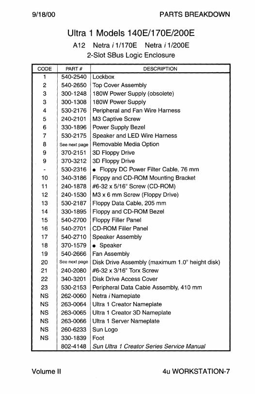
PARTS BREAKDOWN
Ultra 1 Models 140E/170E/200E A12 Netra i 1/170E Netra i 1/200E
2-Slot SBus Logic Enclosure
PART# DESCRIPTION
540-2540 Lockbox 540-2650 Top Cover Assembly
300-1248 180W Power Supply (obsolete)
300-1308 180W Power Supply
530-2176 Peripheral and Fan Wire Harness
240-2101 M3 Captive Screw 330-1896 Power Supply Bezel
530-2175 Speaker and LED Wire Harness
See next page Removable Media Option
370-2151 3D Floppy Drive
370-3212 3D Floppy Drive
530-2316 • Floppy DC Power Filter Cable, 76 mm
340-3186 Floppy and CD-ROM Mounting Bracket
240-1878 #6-32 x 5/16" Screw (CD-ROM)
240-1530 M3 x 6 mm Screw (Floppy Drive)
530-2187 Floppy Data Cable, 205 mm
330-1895 Floppy and CD-ROM Bezel
540-2700 Floppy Filler Panel
540-2701 CD-ROM Filler Panel
540-2710 Speaker Assembly
370-1579 • Speaker 540-2666 Fan Assembly
See next page Disk Drive Assembly (maximum 1.0" height disk)
240-2080 #6-32 x 3/16" Torx Screw
340-3201 Disk Drive Access Cover
530-2153 Peripheral Data Cable Assembly, 41 O mm
262-0060 Netra i Nameplate
263-0064 Ultra 1 Creator Nameplate
263-0065 Ultra 1 Creator 3D Nameplate
263-0066 Ultra 1 Server Nameplate
260-6233 Sun Logo
330-1839 Foot
802-4148 Sun Ultra 1 Creator Series Service Manual
Volume II 4u WORKSTATION-?
PARTS BREAKDOWN 9/18/00
CODE
8
8
8
8
8
8
20
21
---
20
21
----
20
21
-----
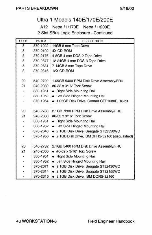
Ultra 1 Models 140E/170E/200E A 12 Netra i 1 /170E Netra i 1 /200E
2-Slot SBus Logic Enclosure - Continued
PART# DESCRIPTION
370-1922 14GB 8 mm Tape Drive
370-2102 4X CD-ROM
370-2176 4-8GB 4 mm DDS-2 Tape Drive
370-2377 12-24GB 4 mm DDS-3 Tape Drive
370-2881 7-14GB 8 mm Tape Drive
370-2816 12X CD-ROM
540-2729 1.05GB 5400 RPM Disk Drive Assembly/FRU
240-2080 #6-32 x 3/16" Torx Screw
330-1951 • Right Side Mounting Rail 330-1952 • Left Side Hinged Mounting Rail
370-1964 • 1.05GB Disk Drive, Conner CFP1080E, 16-bit
540-2730 2.1 GB 7200 RPM Disk Drive Assembly/FRU
240-2080 #6-32 x 3/16" Torx Screw
330-1951 • Right Side Mounting Rail
330-1952 • Left Side Hinged Mounting Rail 370-2040 • 2.1 GB Disk Drive, Seagate ST32550WC 370-1956 • 2.1 GB Disk Drive, IBM DFHS-32160 (disqualified)
540-2782 2.1 GB 5400 RPM Disk Drive Assembly/FRU
240-2080 • #6-32 x 3/16" Torx Screw
330-1951 • Right Side Mounting Rail 330-1952 • Left Side Hinged Mounting Rail
370-2071 • 2.1 GB Disk Drive, Seagate ST32430WC
370-2314 • 2.1GB Disk Drive, Seagate ST32155WC 370-2315 • 2.1 GB Disk Drive, IBM DORS-32160
4u WORKSTATION-a Field Engineer Handbook
9/18/00
CODE
20
21
---
20
21
--
20
21
-----
Volume II
PARTS BREAKDOWN
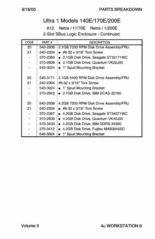
Ultra 1 Models 140E/170E/200E A 12 Netra i 1 /170E Netra i 1 /200E
2-Slot SBus Logic Enclosure - Continued.
PART# DESCRIPTION
540-2936 2.1 GB 7200 RPM Disk Drive Assembly/FRU 240-2304 • #6-32 x 3/16" Torx Screw
370-2365 • 2.1GB Disk Drive, Seagate ST32171WC 370-2808 • 2.1 GB Disk Drive, Quantum VK22J05
540-3024 • 1" Spud Mounting Bracket
540-3171 2.1 GB 5400 RPM Disk Drive Assembly/FRU
240-2304 #6-32 x 3/16" Torx Screw
540-3024 • 1" Spud Mounting Bracket
370-2842 • 2.1 GB Disk Drive, IBM DCAS-32160
540-2938 4.2GB 7200 RPM Disk Drive Assembly/FRU
240-2304 • #6-32 x 3/16" Torx Screw 370-2367 • 4.2GB Disk Drive, Seagate ST34371 WC 370-2809 • 4.2GB Disk Drive, Quantum VK45J05 370-3403 • 4.2GB Disk Drive, IBM DDRS-34560
370-3412 • 4.2GB Disk Drive, Fujitsu MAB3045SC
540-3024 • 1" Spud Mounting Bracket
4u WORKSTATION-9
PARTS BREAKDOWN 9/18/00
Ultra 2 A 14 Netra i 211200 Netra j 211200 Netra i 211300
Netra NFS 2/1300 Netra NFS 212300 4-Slot SBus Logic Enclosure
4
4u WORKSTATION-10
~6
7
~ 'P ~~ :o 10
. . ""' : : 11
Field Engineer Handbook
9/18/00 PARTS BREAKDOWN
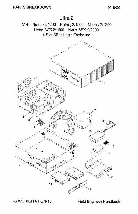
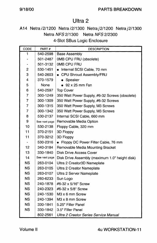
Ultra 2 A14 Netrai2/1200 Netrai2/1300 Netraj2/1200 Netraj2/1300
Netra NFS 2/1300 Netra NFS 212300 4-Slot SBus Logic Enclosure
CODE PART# DESCRIPTION
1 540-2598 Base Assembly
- 501-2487 OMB CPU FRU (obsolete) - 501-3132 OMB CPU FRU
2 530-1451 • Internal SCSI Cable, 70 mm 3 540-2603 • CPU Shroud Assembly/FRU 4 370-1579 • Speaker 5 None • 92 x 25 mm Fan 6 540-2597 Top Cover 7 300-1249 350 Watt Power Supply, #6-32 Screws (obsolete) 7 300-1309 350 Watt Power Supply, #6-32 Screws 7 300-1315 350 Watt Power Supply, M3 Screws 7 300-1342 350 Watt Power Supply, M3 Screws
8 530-2137 Internal SCSI Cable, 660 mm
9 See next page Removable Media Option 10 530-2138 Floppy Cable, 320 mm 11 370-2151 3D Floppy 11 370-3212 3D Floppy - 530-2316 • Floppy DC Power Filter Cable, 76 mm
12 340-3184 Removable Media Mounting Bracket
13 330-1840 Disk Drive Access Cover 14 See next page Disk Drive Assembly (maximum 1.0" height disk)
NS 263-0104 Ultra 2 Creator3D Nameplate NS 263-0105 Ultra 2 Creator Nameplate
NS 263-0107 Ultra 2 Server Nameplate
NS 260-6233 Sun Logo
NS 240-1878 #6-32 x 5/16" Screw NS 240-2323 #6-32 x 5/8" Screw NS 240-1530 M3 x 6 mm Screw
NS 240-1394 M3 x 8 mm Screw NS 330-1841 5.25" Filler Panel NS 330-1842 3.5" Filler Panel
802-2561 Ultra 2 Creator Series Service Manual
Volume II 4u WORKST ATION-11
PARTS BREAKDOWN 9/18/00
Ultra 2 A14 Netrai2/1200 Netrai2/1300 Netraj2/1200 Netraj2/1300
Netra NFS 2/1300 Netra NFS 212300
4-Slot SBus Logic Enclosure - Continued
CODE PART# DESCRIPTION
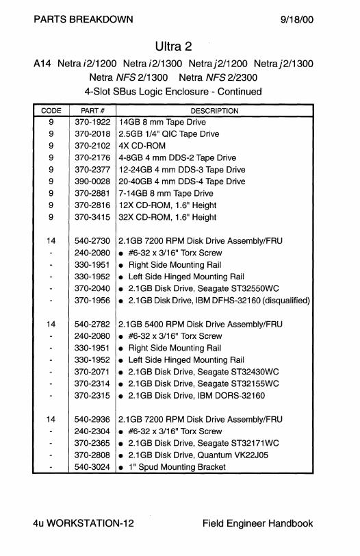
9 370-1922 14GB 8 mm Tape Drive
9 370-2018 2.5GB 1/4" QIC Tape Drive
9 370-2102 4X CD-ROM
9 370-2176 4-8GB 4 mm DDS-2 Tape Drive
9 370-2377 12-24GB 4 mm DDS-3 Tape Drive 9 390-0028 20-40GB 4 mm DDS-4 Tape Drive
9 370-2881 7-14GB 8 mm Tape Drive
9 370-2816 12X CD-ROM, 1.6" Height
9 370-3415 32X CD-ROM, 1.6" Height
14 540-2730 2.1 GB 7200 RPM Disk Drive Assembly/FRU
- 240-2080 • #6-32 x 3/16" Torx Screw - 330-1951 • Right Side Mounting Rail - 330-1952 • Left Side Hinged Mounting Rail
- 370-2040 • 2.1 GB Disk Drive, Seagate ST32550WC
- 370-1956 • 2.1 GB Disk Drive, IBM DFHS-32160 (disqualified)
14 540-2782 2.1 GB 5400 RPM Disk Drive Assembly/FRU
- 240-2080 • #6-32 x 3/16" Torx Screw - 330-1951 • Right Side Mounting Rail - 330-1952 • Left Side Hinged Mounting Rail
- 370-2071 • 2.1 GB Disk Drive, Seagate ST32430WC
- 370-2314 • 2.1GB Disk Drive, Seagate ST32155WC
- 370-2315 • 2.1GB Disk Drive, IBM DORS-32160
14 540-2936 2.1 GB 7200 RPM Disk Drive Assembly/FRU - 240-2304 • #6-32 x 3/16" Torx Screw
- 370-2365 • 2.1 GB Disk Drive, Seagate ST32171 WC - 370-2808 • 2.1GB Disk Drive, Quantum VK22J05
- 540-3024 • 1" Spud Mounting Bracket
4u WORKSTATION-12 Field Engineer Handbook
9/18/00 PARTS BREAKDOWN
Ultra 2 A14 Netrai2/1200 Netrai2/1300 Netraj2/1200 Netraj2/1300
Netra NFS 2/1300 Netra NFS 2/2300
4-Slot SBus Logic Enclosure - Continued
CODE PART# DESCRIPTION
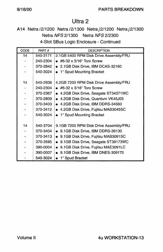
14 540-3171 2.1 GB 5400 RPM Disk Drive Assembly/FRU
- 240-2304 • #6-32 x 3/16" Torx Screw - 370-2842 • 2.1GB Disk Drive, IBM DCAS-32160 - 540-3024 • 1" Spud Mounting Bracket
14 540-2938 4.2GB 7200 RPM Disk Drive Assembly/FRU
- 240-2304 • #6-32 x 3/16" Torx Screw - 370-2367 • 4.2GB Disk Drive, Seagate ST34371WC - 370-2809 • 4.2GB Disk Drive, Quantum VK45J05 - 370-3403 • 4.2GB Disk Drive, IBM DDRS-34560 - 370-3412 • 4.2GB Disk Drive, Fujitsu MAB3045SC
- 540-3024 • 1" Spud Mounting Bracket
14 540-3704 9.1 GB 7200 RPM Disk Drive Assembly/FRU
- 370-3404 • 9.1GB Disk Drive, IBM DDRS-39130
- 370-3413 • 9.1 GB Disk Drive, Fujitsu MAB3091 SC - 370-3595 • 9.1 GB Disk Drive, Seagate ST39173WC
- 390-0004 • 9.1 GB Disk Drive, Fujitsu MAE3091 LC
- 390-0007 • 9.1GB Disk Drive, IBM DNES-309170 - 540-3024 • 1" Spud Bracket
Volume II 4u WORKSTATION-13

PARTS BREAKDOWN
Ultra 5 A21
9/18/00
3-Slot PCI Logic Enclosure
~ 5e
5d~~
Sb~~~
10 11
13
8
2
6 5a
4u WORKSTATION-14 Field Engineer Handbook

9/18/00
CODE PART#
1 370-3689
2 None
3 None
4 None
Sa-d 370-3266
Sa 370-316S
Sb 370-3163
Sb 370-3205
Sc 370-3276
Sd 370-3164
Se 370-3275
6 None
7 None
8 370-3162
8 370-4326
9 370-3176
9 370-3692
9 370-3863
9 370-3693
9 370-4327
10 None
11 None
11 370-31S9
12 370-3319
12 370-3694
13 370-3168
14 370-3170
14 370-4212
NS 370-3196
NS None
NS None
NS None
NS None
NS 370-4101
Volume II
Ultra 5 A21
PARTS BREAKDOWN
3-Slot PCI Logic Enclosure
DESCRIPTION
Front Bezel
Chassis
Chassis Stiffener
Vertical Hold-down BrackeVStrut
Ultra 5 Cable Service KiVFRU
• Serial B and Parallel Cable Assembly
• Single EIDE Disk Cable
Dual EIDE Disk Cable
• CD-ROM Cable
• Floppy Cable • CD-ROM to System Board Audio Cable
PCI Filler Panel
PCI Slot 2 Filler Panel Adapter Bracket
200 Watt Power Supply
200 Watt Power Supply w Power Factor Correction
4.3GB 4SOO RPM EIDE Disk Drive
4.3GB S400 RPM EIDE Disk Drive
8.4GB S400 RPM EIDE Disk Drive
9.1 GB 7200 RPM EIDE Disk Drive
20GB 7200 RPM EIDE Disk Drive
Floppy Mounting Bracket
Secondary/Front Disk Mounting Bracket
Floppy Drive 24xCD-ROM
32x CD-ROM
8 Centimeter Fan
Speaker Assy (not interchangeable with 370-4212) Speaker Assy (not interchangeable with 370-3170)
3-Slot PCI Riser Card
Power Switch
Top Cover
Primary/Rear Disk Mounting Bracket
CPU Module Hold-down Bracket
Peripheral Filler Panel Kit (340-4068 + 340-4126)
4u WORKSTATION-15

PARTS BREAKDOWN
7
8
Ultra 10 A22
4-Slot PCI Logic Enclosure
9
3e
~ 3d
''~~o ~~- ~3b
~ 14
3a
9/18/00
2
4u WORKSTATION-16 Field Engineer Handbook
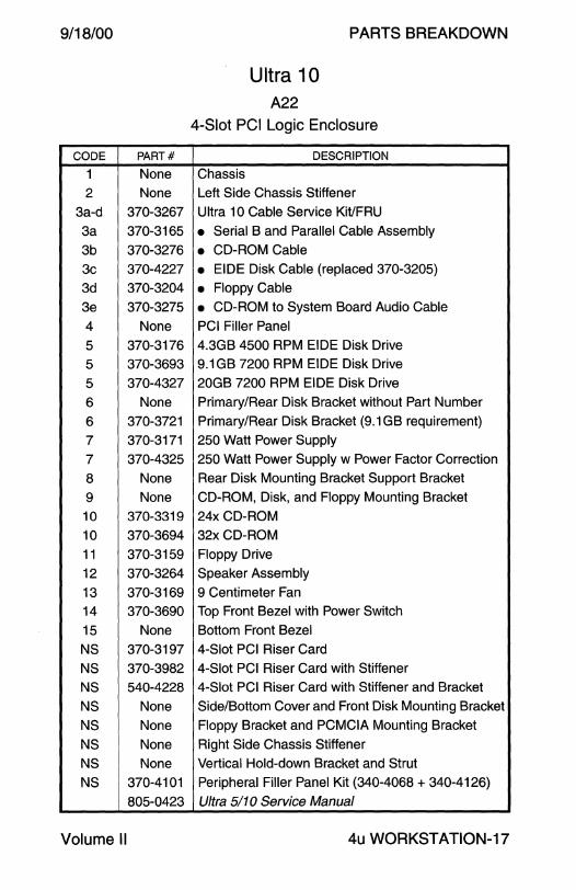
9/18/00
CODE PART#
1 None
2 None
3a-d 370-3267
3a 370-3165
3b 370-3276
3c 370-4227
3d 370-3204
3e 370-3275
4 None
5 370-3176
5 370-3693
5 370-4327
6 None
6 370-3721
7 370-3171
7 370-4325
8 None
9 None
10 370-3319
10 370-3694
11 370-3159
12 370-3264
13 370-3169
14 370-3690
15 None
NS 370-3197
NS 370-3982
NS 540-4228
NS None
NS None
NS None NS None
NS 370-4101
805-0423
Volume II
Ultra 10 A22
PARTS BREAKDOWN
4-Slot PCI Logic Enclosure
DESCRIPTION
Chassis
Left Side Chassis Stiffener
Ultra 10 Cable Service Kit/FRU
• Serial B and Parallel Cable Assembly
• CD-ROM Cable
• EIDE Disk Cable (replaced 370-3205)
• Floppy Cable • CD-ROM to System Board Audio Cable
PCI Filler Panel
4.3GB 4500 RPM EIDE Disk Drive 9.1 GB 7200 RPM EIDE Disk Drive
20GB 7200 RPM EIDE Disk Drive
Primary/Rear Disk Bracket without Part Number
Primary/Rear Disk Bracket (9.1 GB requirement)
250 Watt Power Supply
250 Watt Power Supply w Power Factor Correction
Rear Disk Mounting Bracket Support Bracket
CD-ROM, Disk, and Floppy Mounting Bracket
24x CD-ROM
32xCD-ROM
Floppy Drive
Speaker Assembly
9 Centimeter Fan
Top Front Bezel with Power Switch
Bottom Front Bezel
4-Slot PCI Riser Card
4-Slot PCI Riser Card with Stiffener
4-Slot PCI Riser Card with Stiffener and Bracket
Side/Bottom Cover and Front Disk Mounting Bracket
Floppy Bracket and PCMCIA Mounting Bracket
Right Side Chassis Stiffener
Vertical Hold-down Bracket and Strut
Peripheral Filler Panel Kit (340-4068 + 340-4126)
Ultra 5110 Service Manual
4u WORKSTATION-17

PARTS BREAKDOWN
Ultra 30
A16
9/18/00
4-Slot PCI Logic Enclosure
8 1~ 9
~ 9 ,14 f.,~'
15 16
' /~ ~ 0 :)]]17 ~
18 16
6 ~. 19 .. · 0,-4
3~ " r 1 "1 17
2
20
4u WORKSTATION-18 Field Engineer Handbook
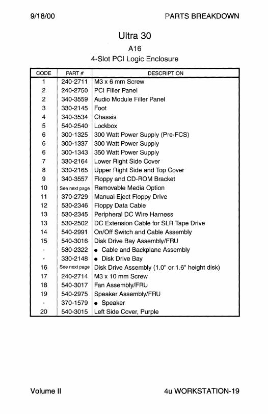
9/18/00
CODE PART#
1 240-2711
2 240-2750
2 340-3559
3 330-2145
4 340-3534
5 540-2540
6 300-1325
6 300-1337
6 300-1343
7 330-2164
8 330-2165
9 340-3557
10 See next page
11 370-2729 12 530-2346
13 530-2345
13 530-2502
14 540-2991
15 540-3016 - 530-2322
- 330-2148
16 See next page
17 240-2714
18 540-3017
19 540-2975
- 370-1579
20 540-3015
Volume II
Ultra 30 A16
PARTS BREAKDOWN
4-Slot PCI Logic Enclosure
DESCRIPTION
M3 x 6 mm Screw PCI Filler Panel
Audio Module Filler Panel
Foot
Chassis
Lockbox
300 Watt Power Supply (Pre-FCS)
300 Watt Power Supply
350 Watt Power Supply
Lower Right Side Cover
Upper Right Side and Top Cover
Floppy and CD-ROM Bracket
Removable Media Option
Manual Eject Floppy Drive
Floppy Data Cable
Peripheral DC Wire Harness
DC Extension Cable for SLR Tape Drive
On/Off Switch and Cable Assembly
Disk Drive Bay Assembly/FRU
• Cable and Backplane Assembly
• Disk Drive Bay Disk Drive Assembly (1.0" or 1.6" height disk)
M3 x 10 mm Screw Fan Assembly/FRU
Speaker Assembly/FRU
• Speaker Left Side Cover, Purple
4u WORKSTATION-19

PARTS BREAKDOWN 9/18/00
CODE PART#
10 370-3279
10 370-2176
10 370-2377
10 370-2816
10 370-3415
10 370-2881
16 540-2936
- 240-2304
- 370-2365
- 370-2808 - 540-3024
16 540-2938
- 240-2304 - 370-2367
- 370-2809
- 370-3403
- 370-3412
- 540-3024
16 540-2951 - 370-2369
- 540-3025
16 540-3704
- 370-3404
- 370-3413
- 370-3595
- 390-0004
- 390-0007 - 540-3024
16 540-3881
- 370-3649
- 390-0005
- 390-0009 - 540-3024
Ultra 30 A16
Logic Enclosure - Continued
DESCRIPTION
4-8GB 1/4" SLR Tape Drive
4-8GB 4 mm DDS-2 Tape Drive
12-24GB 4 mm DDS-3 Tape Drive
12x CD-ROM, 1.6" Height
32x CD-ROM, 1.6" Height
7-14GB 8 mm Tape Drive
2.1 GB 7200 RPM Disk Drive Assembly/FRU
• #6-32 x 3/16" Torx Screw
• 2.1 GB Disk Drive, Seagate ST32171 WC
• 2.1 GB Disk Drive, Quantum VK22J05
• 1 " Spud Mounting Bracket 4.2GB 7200 RPM Disk Drive Assembly/FRU
• #6-32 x 3/16" Torx Screw
• 4.2GB Disk Drive, Seagate ST34371 WC
• 4.2GB Disk Drive, Quantum VK45J05
• 4.2GB Disk Drive, IBM DDRS-34560
• 4.2GB Disk Drive, Fujitsu MAB3045SC
• 1 " Spud Mounting Bracket 9.1 GB 7200 RPM Disk Drive Assembly/FRU
• 9.1 GB Disk Drive, Seagate ST19171 WC
• 1.6" Spud Bracket 9.1 GB 7200 RPM Disk Drive Assembly/FRU
• 9.1 GB Disk Drive, IBM DDRS-39130
• 9.1 GB Disk Drive, Fujitsu MAB3091 SC
• 9.1 GB Disk Drive, Seagate ST39173WC
• 9.1 GB Disk Drive, Fujitsu MAE3091 LC
• 9.1GB Disk Drive, IBM DNES-309170
• 1 " Spud Bracket 9.1 GB 10000 RPM Disk Drive Assembly/FRU
• 9.1GB Disk Drive, Seagate ST39102LC
• 9.1 GB Disk Drive, Fujitsu MAG3091 LC
• 9.1 GB Disk Drive, Seagate ST39103LC
• 1" Spud Bracket
4u WORKSTATION-20 Field Engineer Handbook

9/18/00
CODE PART#
NS 330-2186
NS 330-2187
NS 340-4067
NS 340-4068
NS 540-2923 NS 330-2141
NS 330-2142
NS 330-2143
NS 330-2166
NS 540-2986 NS 595-5364
- 530-2867
- 806-2887
802-7719
Volume II
Ultra 30 A16
PARTS BREAKDOWN
Logic Enclosure - Continued
DESCRIPTION
5 1/4" Device External Filler Panel
3 1/2" Device External Filler Panel
3 1/2" Device Internal Filler Panel
5 1/4" Device Internal Filler Panel
Front Bezel Assembly
• Front Bezel, Light Grey
• Dress Panel, Purple
• Power Switch Cover
• Peripheral Bezel with Cutouts
System Board Fan and Shroud Assembly Noise Reduction Kit, Option 2087
• Voltage Regulated Fan Power Cable
• Noise Reduction Kit Installation Instructions Ultra 30 Service Manual
4u WORKSTATION-21
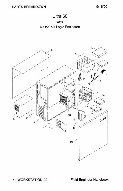
PARTS BREAKDOWN
Ultra 60 A23
9/18/00
4-Slot PCI Logic Enclosure
20
4u WORKSTATION-22 Field Engineer Handbook

9/18/00
CODE PART#
1 240-2711
2 240-2750
2 340-3559
3 330-2145
4 340-3534
5 540-2540
6 300-1343
7 330-2164
8 330-2165
9 340-3557
10 See next page
11 370-2729
12 530-2346
13 530-2345
13 530-2502
14 540-2991
15 540-3016
- 530-2322
- 330-2148
16 See next page
17 240-2714
18 540-3017
19 540-2975
- 370-1579
20 540-3365
Volume II
Ultra 60 A23
PARTS BREAKDOWN
4-Slot PCI Logic Enclosure
DESCRIPTION
M3 x 6 mm Screw
PCI Filler Panel
Audio Module Filler Panel
Foot
Chassis
Lockbox
350 Watt Power Supply
Lower Right Side Cover
Upper Right Side and Top Cover
Floppy and CD-ROM Bracket Removable Media Option
Manual Eject Floppy Drive
Floppy Data Cable
Peripheral DC Wire Harness
DC Extension Cable for SLR Tape Drive
On/Off Switch and Cable Assembly
Disk Drive Bay Assembly/FRU
• Cable and Backplane Assembly
• Disk Drive Bay
Disk Drive Assembly (1.0" or 1.6" height disk)
M3 x 10 mm Screw
Fan Assembly/FRU
Speaker Assembly/FRU
• Speaker Left Side Cover, Light Grey
4u WORKSTATION-23
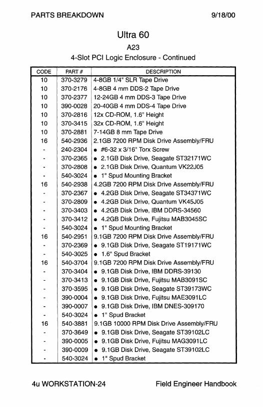
PARTS BREAKDOWN 9/18/00
CODE
10 10
10
10
10
10
10 16
----
16
-----
16
--
16
------
16
----
Ultra 60 A23
4-Slot PCI Logic Enclosure - Continued
PART# DESCRIPTION
370-3279 4-8GB 1/4" SLR Tape Drive
370-2176 4-8GB 4 mm DDS-2 Tape Drive
370-2377 12-24GB 4 mm DDS-3 Tape Drive
390-0028 20-40GB 4 mm DDS-4 Tape Drive
370-2816 12x CD-ROM, 1.6" Height
370-3415 32x CD-ROM, 1.6" Height
370-2881 7-14GB 8 mm Tape Drive
540-2936 2.1 GB 7200 RPM Disk Drive Assembly/FRU
240-2304 • #6-32 x 3/16" Torx Screw
370-2365 • 2.1 GB Disk Drive, Seagate ST32171 WC 370-2808 • 2.1 GB Disk Drive, Quantum VK22J05
540-3024 • 1" Spud Mounting Bracket
540-2938 4.2GB 7200 RPM Disk Drive Assembly/FRU
370-2367 • 4.2GB Disk Drive, Seagate ST34371 WC 370-2809 • 4.2GB Disk Drive, Quantum VK45J05
370-3403 • 4.2GB Disk Drive, IBM DDRS-34560
370-3412 • 4.2GB Disk Drive, Fujitsu MAB3045SC
540-3024 • 1" Spud Mounting Bracket
540-2951 9.1 GB 7200 RPM Disk Drive Assembly/FRU
370-2369 • 9.1GB Disk Drive, Seagate ST19171WC
540-3025 • 1.6" Spud Bracket 540-3704 9.1 GB 7200 RPM Disk Drive Assembly/FRU
370-3404 • 9.1GB Disk Drive, IBM DDRS-39130
370-3413 • 9.1 GB Disk Drive, Fujitsu MAB3091 SC
370-3595 • 9.1 GB Disk Drive, Seagate ST39173WC
390-0004 • 9.1 GB Disk Drive, Fujitsu MAE3091 LC
390-0007 • 9.1GB Disk Drive, IBM DNES-309170
540-3024 • 1" Spud Bracket 540-3881 9.1GB 10000 RPM Disk Drive Assembly/FRU
370-3649 • 9.1 GB Disk Drive, Seagate ST39102LC
390-0005 • 9.1 GB Disk Drive, Fujitsu MAG3091 LC
390-0009 • 9.1 GB Disk Drive, Seagate ST39102LC
540-3024 • 1 " Spud Bracket
4u WORKSTATION-24 Field Engineer Handbook
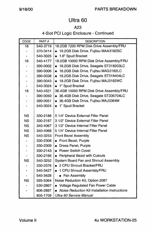
9/18/00
CODE
16
--
16
---
--
16
---
NS
NS
NS
NS
NS
----
NS
---
NS
--
Volume II
Ultra 60 A23
PARTS BREAKDOWN
4-Slot PCI Logic Enclosure - Continued
PART# DESCRIPTION
540-3719 18.2GB 7200 RPM Disk Drive Assembly/FRU
370-3414 • 18.2GB Disk Drive, Fujitsu MAA3182SC
540-3025 • 1 .6" Spud Bracket
540-4177 18.2GB 10000 RPM Disk Drive Assembly/FRU
390-0002 • 18.2GB Disk Drive, Seagate ST318203LC
390-0006 • 18.2GB Disk Drive, Fujitsu MAG3182LC
390-0038 • 18.2GB Disk Drive, Seagate ST318404LC
390-0043 • 18.2GB Disk Drive, Fujitsu MAJ3182WC
540-3024 • 1" Spud Bracket 540-4521 36.4GB 10000 RPM Disk Drive Assembly/FRU
390-0050 • 36.4GB Disk Drive, Seagate ST336704LC
390-0051 • 36.4GB Disk Drive, Fujitsu MAJ3364M
540-3024 • 1" Spud Bracket
330-2186 5 1/4" Device External Filler Panel
330-2187 3 1/2" Device External Filler Panel
340-4067 3 1/2" Device Internal Filler Panel
340-4068 5 1/4" Device Internal Filler Panel
540-3253 Front Bezel Assembly
330-2308 • Front Bezel, Purple
330-2309 • Dress Panel, Purple
330-2143 • Power Switch Cover
330-2166 • Peripheral Bezel with Cutouts
540-3252 System Board Fan and Shroud Assembly
330-2376 • 2 CPU Shroud Bracket/FRU
540-3427 • 1 CPU Shroud Assembly/FRU
540-3428 • Fan Assembly 595-5364 Noise Reduction Kit, Option 2087
530-2867 • Voltage Regulated Fan Power Cable
806-2887 • Noise Reduction Kit Installation Instructions
805-1709 Ultra 60 Service Manual
4u WORKSTATION-25
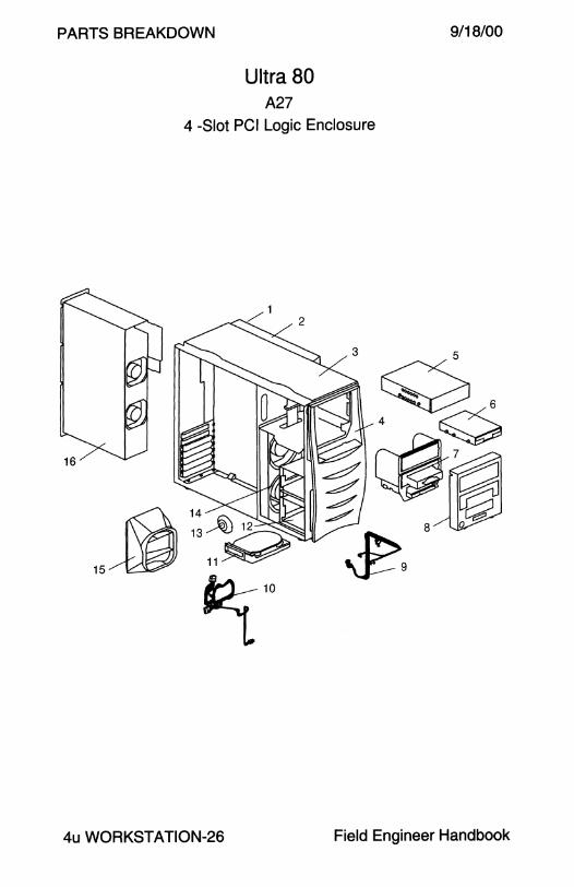
PARTS BREAKDOWN
Ultra 80 A27
9/18/00
4 -Slot PCI Logic Enclosure
4u WORKSTATION-26 Field Engineer Handbook

9/18/00
CODE PART#
1 599-2256
1 599-2269
- 540-4073
- 540-3871
- 540-3876 - 330-4033
- 330-4034
- 340-4037 - 340-5227
2 330-2685
3 330-2686
4 540-3877
5 See next page
6 370-2729
7 540-3265
- 340-4067
- 340-4068
- 340-4764
- 540-3681 - 340-4858
- 340-4859
8 540-3878
- 330-2186 - 330-2187
- 330-2324
- 330-2691
- 330-2693 - 330-2736
9 530-2583
10 530-2582
11 See next page
12 540-3874
- 530-2691
13 370-1579
Volume II
Ultra 80 A27
PARTS BREAKDOWN
4-Slot PCI Logic Enclosure
DESCRIPTION
Chassis Assembly
Danish Chassis Assembly
• Receiving Chassis Assembly
• Chassis Assembly
• Chassis Housing Assembly
• Chassis Front
• Chassis Rear
• Peripheral Bay Shelf
• 1/0 Panel
Right Side Cover
Top Cover
Curved Front Bezel Assembly
Removable Media Option
Manual Eject Floppy Drive
Peripheral Assembly
• 3 1/2" Filler Panel
• 5 1/4" Filler Panel
• 5 1/4" Filler Panel with 3 1/2" Cutout
• Peripheral Bracket with Faceplate
• Bracket
• Faceplate
Peripheral Bezel Assembly
• 5 1/4" Filler Panel
• 3 1/2" Filler Panel
• Lightpipe (not replaceable)
• 5 1/4" Filler Panel with 3 1/2" Cutout
• Bezel (not replaceable)
• Power Button (not replaceable)
Interlock, LED, Power Switch, and Speaker Cable
Peripheral DC Power Cable
Disk Drive Option
Drive Bay Assembly (1.0" or 1.6" height disk)
• Backplane Assembly
Speaker
4u WORKSTATION-27

PARTS BREAKDOWN 9/18/00
CODE
14
--
15
--
16
16
5
5
5
5
5
11
11
11
NS
NS
NS
NS
NS NS
NS
NS
NS
NS
NS
NS
Ultra 80 A27
4-Slot PCI Logic Enclosure - Continued
PART# DESCRIPTION
540-3637 Fan Assembly 540-3637-04 370-3718 • 120 mm Fan (x2) 330-2416 • Fan Bracket 540-4048 CPU Airguide Assembly
330-2803 • Dual Vane Snap 330-2709 • Airguide 300-1357 660 Watt Power Supply
300-1411 Danish Power Supply
370-2377 12-24GB 4 mm DDS-3 Tape Drive
390-0028 20-40GB 4 mm DDS-4 Tape Drive
370-2881 7-14GB 8 mm Tape Drive
370-3279 4-8GB 1/4" SLR Tape Drive
370-3415 32x CD-ROM, 1.6" Height
540-3719 18.2GB 7200 RPM 1.6" Disk Drive Assembly/FRU
540-4177 18.2GB 10000 RPM 1.0" Disk Drive Assembly/FRU
540-4521 36.4GB 10000 RPM 1.0" Disk Drive Assembly/FRU
150-3112 On/Off Switch 150-3114 Interlock Switch
240-2750 PCI Filler Panel
300-1407 125 Watt DC-DC Converter with Fan
330-2805 Processor Module Filler Panel 340-6091 Memory Riser Torque Tool (only use 340-6091-02)
340-3559 Audio Module Filler Panel
330-2321 Foot
530-2346 Floppy Data Cable
530-2937 2nd Removable Media Device SCSI Cable, 180 mm
540-2540 Lockbox
540-3874 Left Cover Assembly
805-6618 Ultra 80 Service Manual
4u WORKSTATION-28 Field Engineer Handbook
9/18/00 PARTS BREAKDOWN
This page intentionally left blank.
Volume II 4u WORKSTATION-29
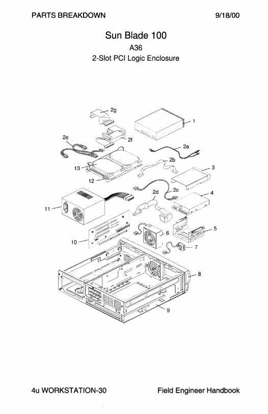
PARTS BREAKDOWN
Sun Blade 100 A36
2-Slot PCI Logic Enclosure
9/18/00
5
4u WORKSTATION-30 Field Engineer Handbook
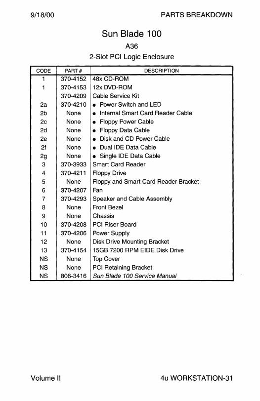
9/18/00
CODE PART#
1 370-4152
1 370-4153
370-4209
2a 370-4210
2b None
2c None
2d None
2e None
2f None
2g None
3 370-3933
4 370-4211
5 None
6 370-4207
7 370-4293
8 None
9 None
10 370-4208
11 370-4206
12 None
13 370-4154
NS None
NS None
NS 806-3416
Volume II
PARTS BREAKDOWN
Sun Blade 100 A36
2-Slot PCI Logic Enclosure
DESCRIPTION
48xCD-ROM
12x DVD-ROM
Cable Service Kit
• Power Switch and LED
• Internal Smart Card Reader Cable
• Floppy Power Cable
• Floppy Data Cable
• Disk and CD Power Cable
• Dual IDE Data Cable
• Single IDE Data Cable Smart Card Reader
Floppy Drive
Floppy and Smart Card Reader Bracket
Fan Speaker and Cable Assembly
Front Bezel
Chassis
PCI Riser Board
Power Supply
Disk Drive Mounting Bracket
15GB 7200 RPM EIDE Disk Drive
Top Cover
PCI Retaining Bracket
Sun Blade 100 Service Manual
4u WORKSTATION-31

PARTS BREAKDOWN
Sun Blade 1000 A28
4-Slot Logic Enclosure
'1'0
9/18/00
4u WORKSTATION-32 Field Engineer Handbook
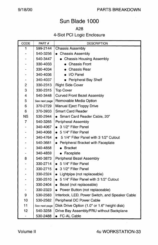
9/18/00
CODE PART#
1 599-2144
- 540-3256
- 540-3447
- 330-4033
- 330-4034 - 340-4036
- 340-4037
2 330-2313
3 330-2315
4 540-3448
5 See next page
6 370-2729
6 370-3933
NS 530-2944
7 540-3265
- 340-4067
- 340-4068
- 340-4764 - 540-3681 - 340-4858
- 340-4859
8 540-3873
- 330-2714
- 330-2715 - 330-2324
- 330-2510 - 330-2404
- 330-2323
9 530-2583
10 530-2582
11 See next page
12 540-3258
- 530-2488
Volume II
PARTS BREAKDOWN
Sun Blade 1000 A28
4-Slot PCI Logic Enclosure
DESCRIPTION
Chassis Assembly
• Chassis Assembly
• Chassis Housing Assembly
• Chassis Front
• Chassis Rear
• 1/0 Panel • Peripheral Bay Shelf
Right Side Cover
Top Cover
Curved Front Bezel Assembly Removable Media Option
Manual Eject Floppy Drive
Smart Card Reader
• Smart Card Reader Cable, 20" Peripheral Assembly
• 3 1/2" Filler Panel
• 5 1/4" Filler Panel
• 5 1/4" Filler Panel with 3 1/2" Cutout
• Peripheral Bracket with Faceplate
• Bracket
• Faceplate Peripheral Bezel Assembly
• 5 1/4" Filler Panel
• 3 1 /2" Filler Panel
• Lightpipe (not replaceable)
• 5 1/4" Filler Panel with 3 1/2" Cutout
• Bezel (not replaceable)
• Power Button (not replaceable)
Interlock, LED, Power Switch, and Speaker Cable
Peripheral DC Power Cable
Disk Drive Option (1.0" or 1.6" height disk) Drive Bay Assembly/FRU without Backplane
• FC-AL Cable
4u WORKSTATION-33

PARTS BREAKDOWN 9/18/00
CODE
12 --
13
14 14 15
15
5 5
11 11
NS
NS NS
NS NS NS
NS
NS NS NS
NS NS NS NS
NS NS
Sun Blade1000 A28
4-Slot PCI Logic Enclosure - Continued
PART# DESCRIPTION
540-4182 FC-AL Backplane Assembly/FRU 501-4586 • FC-AL Backplane 530-2488 • FC-AL Cable 370-1579 Speaker
370-3718 120 mm Fan (x2) 330-2416 Fan Bracket 300-1357 660 Watt Power Supply 300-1411 Danish Power Supply
370-3415 32X CD-ROM, 1.6" Height 390-0025 1 OX DVD-ROM, 1.6" Height
540-4673 18.2GB 10000 RPM FC-AL Disk Assembly/FRU 540-4525 36.4GB 10000 RPM FC-AL Disk Assembly/FRU
150-3112 On/Off Switch
150-3114 Interlock Switch 240-2750 PCI Filler Panel
340-3559 Audio Module Filler Panel 330-2321 Foot 330-2937 Torque Tool Carrier
340-6395 Torque Tool
370-3718 120 mm Fan 530-2346 Floppy Data Cable 530-2881 Glow-Go Cable
530-2913 Smart Card Reader Cable, 15" (Obsolete) 540-2540 Lockbox 540-3257 Left Cover Assembly (540-3256-16 6/20/00)
560-2613 Cable Service Kit 530-2688 • SCSI Data Cable 530-2944 • Smart Card Reader Cable, 20" 805-4496 Service Manual
4u WORKSTATION-34 Field Engineer Handbook

PARTS BREAKDOWN
4u SERVER
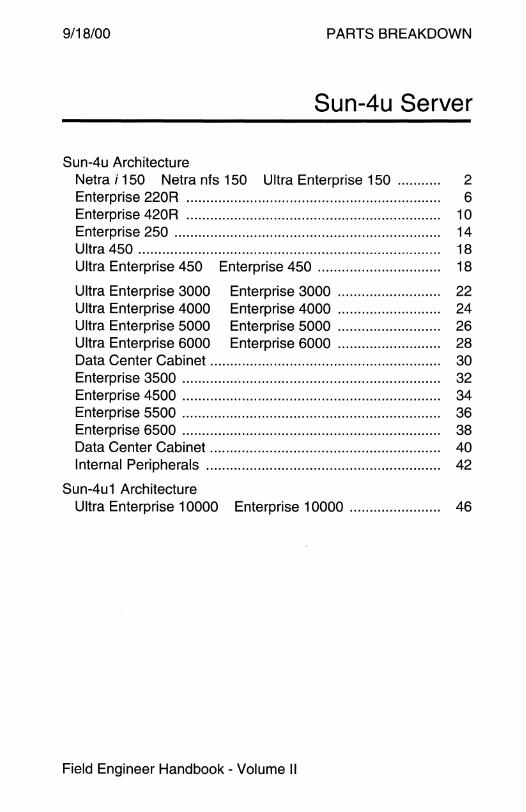
9/18/00 PARTS BREAKDOWN
Sun-4u Server
Sun-4u Architecture Netra i 150 Netra nfs 150 Ultra Enterprise 150 ........... 2 Enterprise 220R . . . . . . . . . . . . . . . . . . . . . . . . . . . . . . . . . . . . . . . . . . . . . . . . . . . . . . . . . . . . . . . . 6 Enterprise 420R . . . . . . . . . . . . . . . . . . . . . . . . . . . . . . . . . . . . . . . . . . . . . . . . . . . . . . . . . . . . . . . . 10 Enterprise 250 . . . . . . . . . . . . . . . . . . . . . . . . . . . . . . . . . . . . . . . . . . . . . . . . . . . . . . . . . . . . . . . . . . . 14 Ultra 450 ............................................................................ 18 Ultra Enterprise 450 Enterprise 450 ............................... 18
Ultra Enterprise 3000 Enterprise 3000 . . . .. .. .. ... .. . . .. .. ...... 22 Ultra Enterprise 4000 Enterprise 4000 .......................... 24 Ultra Enterprise 5000 Enterprise 5000 ..... .. .. ... .. . ... .. ... .. . 26 Ultra Enterprise 6000 Enterprise 6000 . .. .. .... .. .... .. ... .. .... 28 Data Center Cabinet . . . . . . . . . . . . . . . . . . . . . . . . . . . . . . . . . . . . . . . . . . . . . . . . . . . . . . . . . . 30 Enterprise 3500 ................................................................. 32 Enterprise 4500 ................................................................. 34 Enterprise 5500 . . . . . . . . . . . . . . . . . . . . . . . . . . . . . . . . . . . . . . . . . . . . . . . . . . . . . . . . . . . . . . . . . 36 Enterprise 6500 ................................................................. 38 Data Center Cabinet . ..... .. ... . ... .. .. .. .. . .. ... . .. .. .. .. .. .. ... . .. .. ... .. .. . 40 Internal Peripherals .. . ...... .. .. ..... .. . . ... .. .. . . . ... . .. .. . . ... .. .. .. .. ...... 42
Sun-4u1 Architecture Ultra Enterprise 10000 Enterprise 10000 ....................... 46
Field Engineer Handbook - Volume II
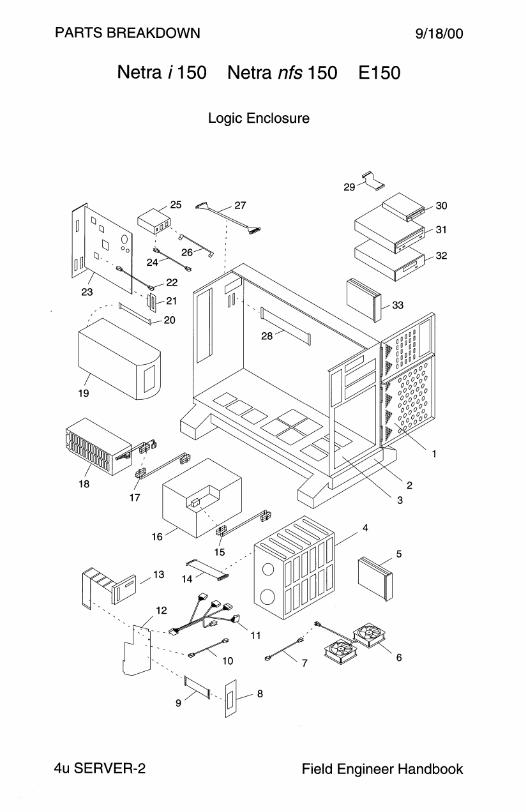
PARTS BREAKDOWN 9/18/00
Netra i 150 Netra nfs 150 E 150
Logic Enclosure
29~
4u SERVER-2 Field Engineer Handbook

9/18/00 PARTS BREAKDOWN
Netra i 150 Netra nfs 150 E 150
Logic Enclosure
CODE PART# DESCRIPTION
1 540-2878 Front Door Assembly (metal hinges) (obsolete)
1 540-2912 Front Door Assembly (plastic hinges)
2 540-2800 Base Assembly
- 240-2307 • Caster 3 540-2801 Chassis Assembly w 330-2024 and 330-2027 (obs)
3 540-3040 Chassis Assembly with 330-2254 and 330-2255
4 None Cardcage Assembly - 330-3025 • Cardcage Chassis
- 501-3081 • Backplane
- 540-2860 • Spacer Assembly
5 540-2730 2.1 GB 7200 RPM Disk Drive Assembly/FRU
5 540-2936 2.1 GB 7200 RPM Disk Drive Assembly/FRU
5 540-2938 4.2GB 7200 RPM Disk Drive Assembly/FRU
6 F370-2266 Fan Assembly/FRU (2 fans with connector)
- 370-2266 • Fan (1 fan without connector)
7 530-2262 Fan DC Power Cable
8 370-2259 LCD Assembly
9 530-2261 Controller to LCD Cable
10 530-2256 Backplane to Controller DC Wire Harness
11 530-2255 Peripheral DC Wire Harness
12 501-3089 System Controller
12 501-4308 System Controller
13 530-2253 Floppy/SCSI Data Cable, =:1 M
14 530-2268 Backplane SCSI Loopback Cable, 194 mm
15 530-2257 185W Power Supply to Backplane DC Wire Harness
16 300-1283 185W Power Supply
16 300-1330 185W Power Supply
17 530-2281 180W Power Supply DC Extension Cable
18 300-1308 180W Power Supply
19 370-2240 11 OV Uninterruptible Power Supply (Netra nfs 150)
19 370-2241 230V Uninterruptible Power Supply (Netra nfs 150)
20 530-2259 Controller to UPS Cable (Netra nfs 150)
Volume II 4u SERVER-3
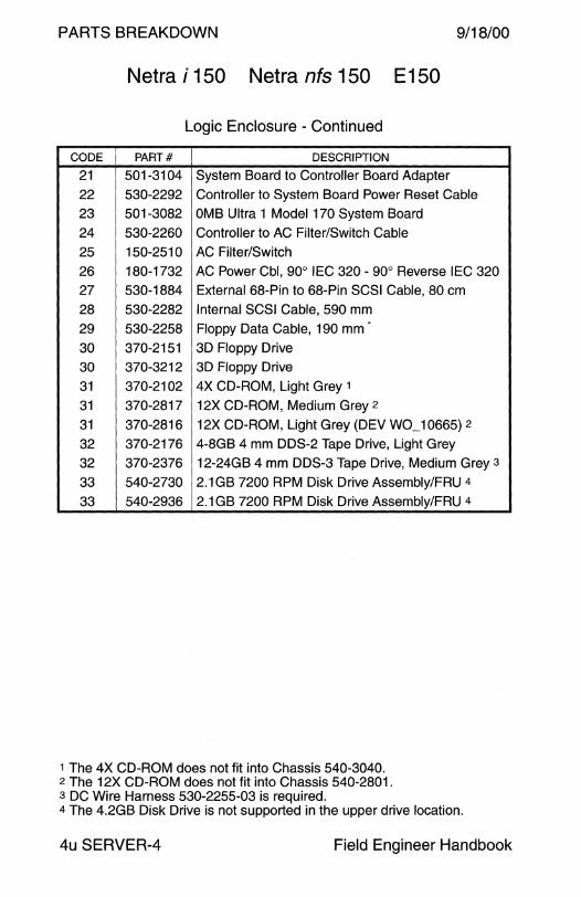
PARTS BREAKDOWN 9/18/00
Netra i 150 Netra nfs 150 E150
Logic Enclosure - Continued
CODE PART# DESCRIPTION
21 501-3104 System Board to Controller Board Adapter
22 530-22g2 Controller to System Board Power Reset Cable
23 501-3082 OMB Ultra 1 Model 170 System Board
24 530-2260 Controller to AC Filter/Switch Cable
25 150-2510 AC Filter/Switch
26 180-1732 AC Power Cbl, go0 IEC 320 - go0 Reverse IEC 320
27 530-1884 External 68-Pin to 68-Pin SCSI Cable, 80 cm
28 530-2282 Internal SCSI Cable, 5go mm 2g 530-2258 Floppy Data Cable, 1 go mm
30 370-2151 3D Floppy Drive
30 370-3212 3D Floppy Drive
31 370-2102 4X CD-ROM, Light Grey 1
31 370-2817 12X CD-ROM, Medium Grey 2
31 370-2816 12X CD-ROM, Light Grey (DEV W0_ 10665) 2
32 370-2176 4-8GB 4 mm DDS-2 Tape Drive, Light Grey
32 370-2376 12-24GB 4 mm DDS-3 Tape Drive, Medium Grey 3
33 540-2730 2.1GB 7200 RPM Disk Drive Assembly/FRU 4
33 540-2g36 2.1 GB 7200 RPM Disk Drive Assembly/FRU 4
1 The 4X CD-ROM does not fit into Chassis 540-3040. 2 The 12X CD-ROM does not fit into Chassis 540-2801. 3 DC Wire Harness 530-2255-03 is required. 4 The 4.2GB Disk Drive is not supported in the upper drive location.
4u SERVER-4 Field Engineer Handbook
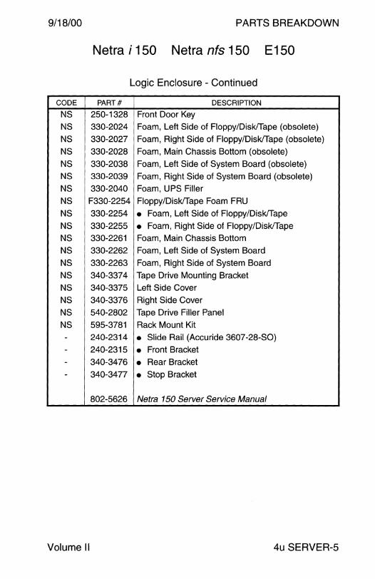
9/18/00 PARTS BREAKDOWN
Netra i 150 Netra nfs 150 E150
Logic Enclosure - Continued
CODE PART# DESCRIPTION
NS 250-1328 Front Door Key
NS 330-2024 Foam, Left Side of Floppy/Disk/Tape (obsolete)
NS 330-2027 Foam, Right Side of Floppy/Disk/Tape (obsolete)
NS 330-2028 Foam, Main Chassis Bottom (obsolete)
NS 330-2038 Foam, Left Side of System Board (obsolete)
NS 330-2039 Foam, Right Side of System Board (obsolete)
NS 330-2040 Foam, UPS Filler
NS F330-2254 Floppy/Disk/Tape Foam FRU
NS 330-2254 • Foam, Left Side of Floppy/Disk/Tape
NS 330-2255 • Foam, Right Side of Floppy/Disk/Tape
NS 330-2261 Foam, Main Chassis Bottom
NS 330-2262 Foam, Left Side of System Board
NS 330-2263 Foam, Right Side of System Board
NS 340-3374 Tape Drive Mounting Bracket
NS 340-3375 Left Side Cover
NS 340-3376 Right Side Cover
NS 540-2802 Tape Drive Filler Panel
NS 595-3781 Rack Mount Kit - 240-2314 • Slide Rail (Accuride 3607-28-SO)
- 240-2315 • Front Bracket
- 340-3476 • Rear Bracket - 340-3477 • Stop Bracket
802-5626 Netra 150 Server Service Manual
Volume II 4u SERVER-5
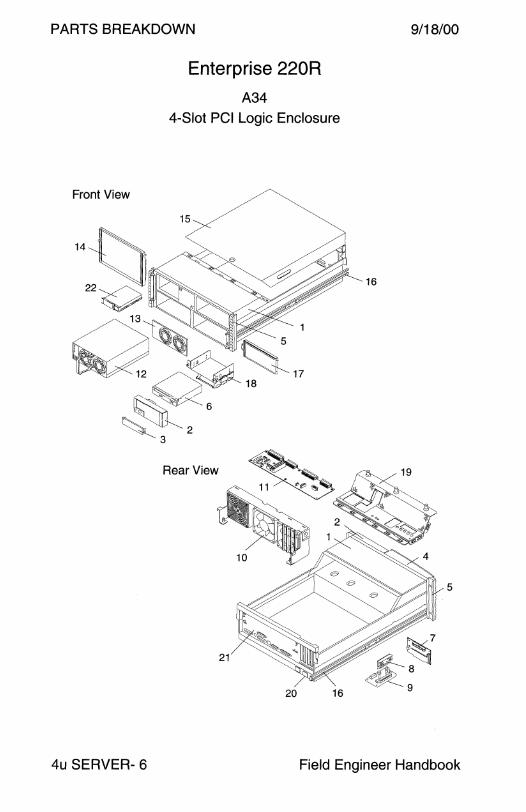
PARTS BREAKDOWN
Front View
14~
,,~I
Enterprise 220R
A34
4-Slot PCI Logic Enclosure
15
Rear View
21
20 16
9/18/00
16
~7 £--a ~~9
5
4u SERVER- 6 Field Engineer Handbook

9/18/00
CODE PART#
1 599-2330
2 540-4219
3 330-2400
4 330-2911
5 540-4315
- 540-4316
6 370-3416
6 390-0025
1 540-4316
NS 330-2805
NS 540-4327
NS 540-4329
- 540-4284
1 540-4284
7 501-5505
8 300-1455
9 375-0094
10 540-4169
10 540-4434
11 501-5506
12 300-1449
13 340-6001
NS 340-6118
NS 530-2824
NS 530-2826
NS 530-2827
NS 530-2828
NS 530-2829
NS 530-2830
NS 530-2864
- 540-4283
Volume II
PARTS BREAKDOWN
Enterprise 220R A34
4-Slot PCI Logic Enclosure
DESCRIPTION
Enclosure Assembly
• RMA Bezel
• Floppy Filler Panel
• Curved Bezel
• 4U Trim Strip
• Enclosure Assembly with System Board
• 32x CD-ROM, Medium Grey
• 1 Ox DVD-ROM, Medium Grey
Enclosure Assembly with System Board
• Processor Module Slot Filler Panel
• Processor Module Cardcage Assembly
• Airguide Assembly
• Enclosure Assembly
Enclosure Assembly
• 2-Slot SCSI Disk Backplane
• VRM DC-DC Converter
• VRM Interposer Board
• Fan Tray with 3x 120 mm Fans (Obsolete)
• Fan Tray with 3x 120 mm Fans
• DC Power Distribution Board
• 380 Watt Power Supply • Power Supply Filler Panel
• Security Switch Lock
• Keyswitch/LED/Power Cable
• RMA 8-Bit SCSI Cable
• SCSI Cable
• DC Power Cable
• DC Power Signal Cable
• Control Cable
• 1/0 Power Cable
• Chassis Assembly
4u SERVER-7

PARTS BREAKDOWN 9/18/00
Enterprise 220R A34
4-Slot PCI Logic Enclosure - Continued
CODE PART# DESCRIPTION
1 540-4283 Chassis Assembly
14 540-4186 • Left Door 15 540-4188 • Rear Enclosure Top Cover
16 340-6131 • Inner Slide Rail 17 540-4230 • Right Door 18 540-4253 • Media Drive Mounting Assembly
19 340-5834 • Power Distribution Board Cover
20 540-4232 • AC Outlet to Power Supply
21 540-4282 • Rear Panel
NS 370-4099 • AC Receptacle and Line Filter
NS 530-2819 • AC Power Cable
NS 530-2861 • AC Ground Cable
NS 540-4251 • Ultra 60 System Board Mounting Tray
1 540-4231 • Chassis Assembly - 340-5827 • Base Enclosure
- 340-5830 • Disk Drive Bay
- 340-5831 • Front Enclosure Top Cover
340-5996 • Front Enclosure
540-4185 • Power Bay Cover
22 540-3881 9.1 GB 10000 RPM Disk Drive Assembly/FRU
22 540-4177 18.2GB 10000 RPM Disk Drive Assembly/FRU
22 540-4521 36.4GB 10000 RPM Disk Drive Assembly/FRU
NS 340-6124 Short Rack Mounting Bracket
NS 340-6125 Long Rack Mounting Bracket
NS 340-5883 Outer Slide Rail
NS 370-2376 12-24GB 4 mm DDS-3 Tape Drive, Medium Grey 1
NS 390-0028 20-40GB 4 mm DDS-4 Tape Drive, Medium Grey 1
NS 370-2882 7-14GB 8 mm Tape Drive, Medium Grey 1
1 DC Power cable 530-2864-02 is too short. Use 530-2864-03 or DC Power Extension cable 530-2502.
4u SERVER-8 Field Engineer Handbook

9/18/00 PARTS BREAKDOWN
This page intentionally left blank.
Volume II 4u SERVER-9

PARTS BREAKDOWN
Enterprise 420R
A33
4-Slot PCI Logic Enclosure
Front View
13
Rear View
19
18 14
9/18/00
14
5
4u SERVER- 10 Field Engineer Handbook
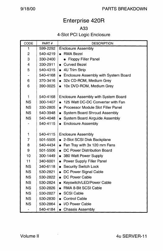
9/18/00
CODE PART#
1 599-2292
2 540-4219
3 330-2400
4 330-2911
5 540-4315
- 540-4168
6 370-3416
6 390-0025
1 540-4168
NS 300-1407
NS 330-2805
NS 540-3948
NS 540-4048
- 540-4115
1 540-4115
7 501-5505
8 540-4434
9 501-5506
10 300-1449
11 340-6001
NS 340-6118
NS 530-2821
NS 530-2822
NS 530-2824
NS 530-2826
NS 530-2827
NS 530-2830
NS 530-2864
- 540-4184
Volume II
PARTS BREAKDOWN
Enterprise 420R A33
4-Slot PCI Logic Enclosure
DESCRIPTION
Enclosure Assembly
• RMA Bezel
• Floppy Filler Panel
• Curved Bezel
• 4U Trim Strip
• Enclosure Assembly with System Board
• 32x CD-ROM, Medium Grey
• 1 Ox DVD-ROM, Medium Grey
Enclosure Assembly with System Board
• 125 Watt DC-DC Converter with Fan
• Processor Module Slot Filler Panel
• System Board Shroud Assembly
• System Board Airguide Assembly
• Enclosure Assembly
Enclosure Assembly
• 2-Slot SCSI Disk Backplane
• Fan Tray with 3x 120 mm Fans
• DC Power Distribution Board
• 380 Watt Power Supply
• Power Supply Filler Panel
• Security Switch Lock • DC Power Signal Cable
• DC Power Cable
• Keyswitch/LED/Power Cable
• RMA 8-Bit SCSI Cable
• SCSI Cable
• Control Cable
• 1/0 Power Cable
• Chassis Assembly
4u SERVER-11
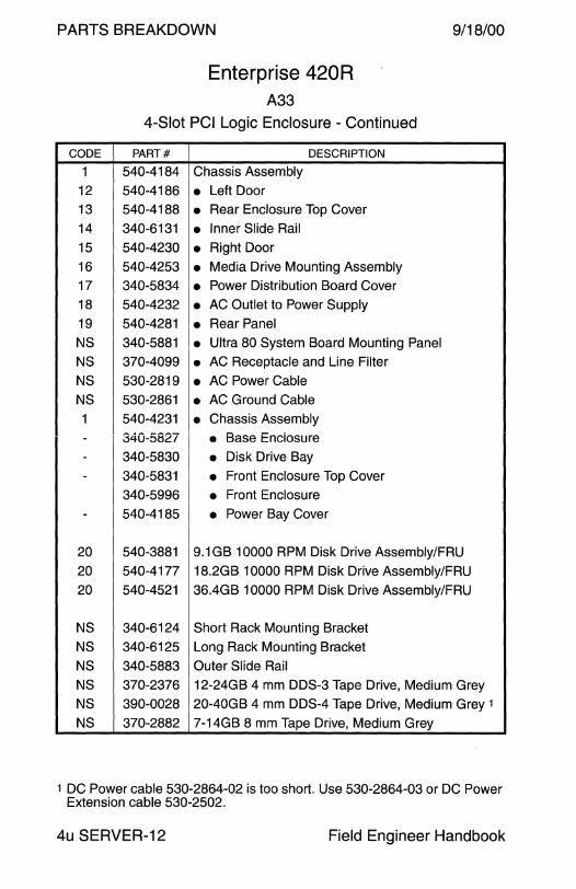
PARTS BREAKDOWN 9/18/00
Enterprise 420R A33
4-Slot PCI Logic Enclosure - Continued
CODE PART# DESCRIPTION
1 540-4184 Chassis Assembly
12 540-4186 • Left Door 13 540-4188 • Rear Enclosure Top Cover
14 340-6131 • Inner Slide Rail
15 540-4230 • Right Door
16 540-4253 • Media Drive Mounting Assembly
17 340-5834 • Power Distribution Board Cover
18 540-4232 • AC Outlet to Power Supply
19 540-4281 • Rear Panel
NS 340-5881 • Ultra 80 System Board Mounting Panel
NS 370-4099 • AC Receptacle and Line Filter
NS 530-2819 • AC Power Cable
NS 530-2861 • AC Ground Cable
1 540-4231 • Chassis Assembly
- 340-5827 • Base Enciosure
- 340-5830 • Disk Drive Bay
- 340-5831 • Front Enclosure Top Cover
340-5996 • Front Enclosure
- 540-4185 • Power Bay Cover
20 540-3881 9.1 GB 10000 RPM Disk Drive Assembly/FRU
20 540-4177 18.2GB 10000 RPM Disk Drive Assembly/FRU
20 540-4521 36.4GB 10000 RPM Disk Drive Assembly/FRU
NS 340-6124 Short Rack Mounting Bracket
NS 340-6125 Long Rack Mounting Bracket
NS 340-5883 Outer Slide Rail
NS 370-2376 12-24GB 4 mm DDS-3 Tape Drive, Medium Grey
NS 390-0028 20-40GB 4 mm DDS-4 Tape Drive, Medium Grey 1
NS 370-2882 7-14GB 8 mm Tape Drive, Medium Grey
1 DC Power cable 530-2864-02 is too short. Use 530-2864-03 or DC Power Extension cable 530-2502.
4u SERVER-12 Field Engineer Handbook

9/18/00 PARTS BREAKDOWN
This page intentionally left blank.
Volume II 4u SERVER-13
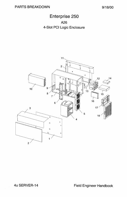
PARTS BREAKDOWN
Enterprise 250 A26
4-Slot PCI Logic Enclosure
11
~ 10 9
5
4
2
9/18/00
12 ~4
9 c;:JJ 1s 0
16
17
4u SERVER-14 Field Engineer Handbook

9/18/00
CODE PART#
1 540-3453 2 330-2152
3 330-2137
4 540-3355
- 501-4682
5 540-3274
6 501-4683
7 340-4070
8 340-3256
9 501-4818
- 530-2526
10 300-1352
11 330-2138
12 540-3351 - 340-4072
13 540-3604
- 370-3324
- 530-2527 14 370-2730
15 See next page
16 See next page
17 540-3273
18 540-3352
NS 250-1317
NS 330-2399
NS 330-2400
NS 330-2522 NS 340-4067
NS 340-4068
NS 340-4416
Volume II
PARTS BREAKDOWN
Enterprise 250 A26
4-Slot PCI Logic Enclosure
DESCRIPTION
Left Side Cover
Purple Lower Left and Right Side Cover
Light Grey Upper Left Side and Top Cover
Disk Drive Backplane Assembly
• 6-Disk Backplane 3-Fan Fan Assembly
DC Power Distribution Board
Chassis
PCI Filler Panel
Remote System Control Board and Cable
• Remote System Control Cable
360 Watt Power Supply
Light Grey Upper Right Side and Top Cover
RMA Assembly
• Removable Media Bracket
Keyswitch and LED Assembly with Cables
• LED and Cable Assembly
• Keyswitch Assembly Manual Eject Floppy Drive, Medium Grey
Removable Media Option
Disk Drive Assembly (1.0" or 1.6" height disk)
Front Top Bezel Assembly
Front Bottom Door Assembly
Key
5 1/4" Device External Filler Panel
3 1 /2" Device External Filler Panel
Foot, Option 9605 3 1/2" Device Internal Filler Panel
5 1/4" Device Internal Filler Panel
Power Supply Filler Panel
4u SERVER-15
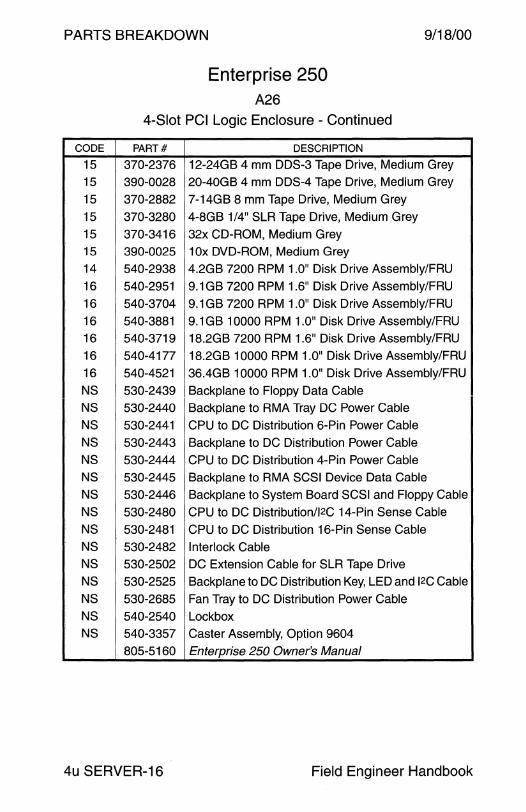
PARTS BREAKDOWN 9/18/00
Enterprise 250 A26
4-Slot PCI Logic Enclosure - Continued
CODE PART# DESCRIPTION
15 370-2376 12-24GB 4 mm DDS-3 Tape Drive, Medium Grey
15 390-0028 20-40GB 4 mm DDS-4 Tape Drive, Medium Grey
15 370-2882 7-14GB 8 mm Tape Drive, Medium Grey
15 370-3280 4-8GB 1/4" SLR Tape Drive, Medium Grey
15 370-3416 32x CD-ROM, Medium Grey 15 390-0025 1 Ox DVD-ROM, Medium Grey
14 540-2938 4.2GB 7200 RPM 1.0" Disk Drive Assembly/FRU
16 540-2951 9.1 GB 7200 RPM 1.6" Disk Drive Assembly/FRU
16 540-3704 9.1 GB 7200 RPM 1.0" Disk Drive Assembly/FRU
16 540-3881 9.1 GB 10000 RPM 1.0" Disk Drive Assembly/FRU
16 540-3719 18.2GB 7200 RPM 1.6" Disk Drive Assembly/FRU
16 540-4177 18.2GB 10000 RPM 1.0" Disk Drive Assembly/FRU
16 540-4521 36.4GB 10000 RPM 1.0" Disk Drive Assembly/FRU
NS 530-2439 Backplane to Floppy Data Cable NS 530-2440 Backplane to RMA Tray DC Power Cable
NS 530-2441 CPU to DC Distribution 6-Pin Power Cable
NS 530-2443 Backplane to DC Distribution Power Cable
NS 530-2444 CPU to DC Distribution 4-Pin Power Cable
NS 530-2445 Backplane to RMA SCSI Device Data Cable
NS 530-2446 Backplane to System Board SCSI and Floppy Cable
NS 530-2480 CPU to DC Distribution/l2C 14-Pin Sense Cable
NS 530-2481 CPU to DC Distribution 16-Pin Sense Cable
NS 530-2482 Interlock Cable NS 530-2502 DC Extension Cable for SLR Tape Drive
NS 530-2525 Backplane to DC Distribution Key, LED and 12c Cable
NS 530-2685 Fan Tray to DC Distribution Power Cable
NS 540-2540 Lockbox NS 540-3357 Caster Assembly, Option 9604
805-5160 Enterprise 250 Owner's Manual
4u SERVER-16 Field Engineer Handbook

9/18/00 PARTS BREAKDOWN
This page intentionally left blank.
Volume II 4u SERVER-17
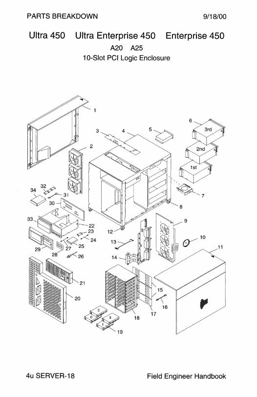
PARTS BREAKDOWN 9/18/00
Ultra 450 Ultra Enterprise 450 Enterprise 450 A20 A25
10-Slot PCI Logic Enclosure
3
8
4?~ 18
19
16 ,
17
4u SERVER-18 Field Engineer Handbook

9/18/00 PARTS BREAKDOWN
Ultra 450 Ultra Enterprise 450 Enterprise 450 A20 A25
10-Slot PCI Logic Enclosure
CODE PART# DESCRIPTION
1 540-2835 Left Panel
2 540-2840 CPU Fan Tray Assembly
- 370-4041 • 120 mm Fan (x3) (replaced 370-2292)
3 540-3032 Cable Access Door Assembly
4 540-2833 Chassis Enclosure Assembly - 340-3420 • Chassis
5 370-2160 AC Line Filter
5 370-2440 Danish AC Line Filter
6 300-1302 560W Power Supply
6 300-1359 605W Power Supply
6 340-3516 Power Supply Filler Panel
7 540-3023 Blower Assembly (discontinued 8/97) 1
- 370-2337 • Blower - 340-3648 • Blower Plate
8 240-2312 Caster (x2)
9 540-4364 Disk Fan Assembly
9 540-2841 Disk Fan/Speaker Assembly (discontinued 9/99)
10 370-1579 • Speaker - 370-2322 • 120 mm Fan (x3)
11 540-2836 Right Panel
12 240-2343 Locking Caster (x2)
13 530-2364 DC Power Cable, 4-Disk and 8-Disk Backplane
13 530-2365 DC Power Cable, Removable Media Tray
14 501-3100 DC Power Distribution Board
15 501-4189 8-Slot SCSI Backplane
15 501-5274 8-Slot SCSI Backplane
16 530-2355 12c Cable, 4-Disk and 8-Disk Backplane
17 501-4148 4-Slot SCSI Backplane
18 540-2831 20-Slot Disk Drive Chassis
19 See next page Disk Drive Assembly (maximum 1.0" height disk)
805-0429 Ultra Enterprise 450 Server Owner's Guide
805-0430 Ultra 450 Workstation Owner's Guide
1 The Wrench Icon is lit when Blower 540-3023 or Loopback Plug 530-2509 is not connected to J4705 on the System Board.
Volume II 4u SERVER-19
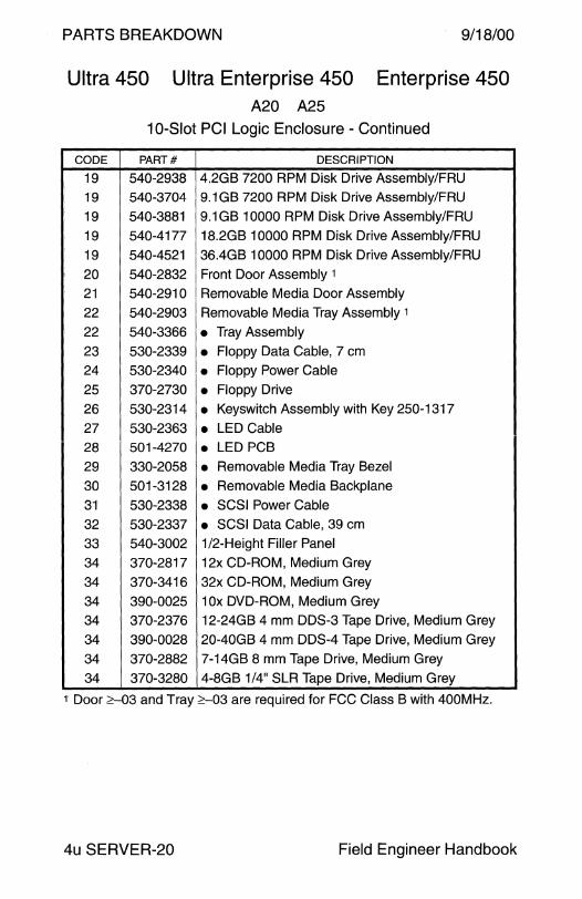
PARTS BREAKDOWN 9/18/00
Ultra 450 Ultra Enterprise 450 Enterprise 450 A20 A25
10-Slot PCI Logic Enclosure - Continued
CODE PART# DESCRIPTION
19 540-2938 4.2GB 7200 RPM Disk Drive Assembly/FRU
19 540-3704 9.1 GB 7200 RPM Disk Drive Assembly/FRU
19 540-3881 9.1 GB 10000 RPM Disk Drive Assembly/FRU
19 540-4177 18.2GB 10000 RPM Disk Drive Assembly/FRU
19 540-4521 36.4GB 10000 RPM Disk Drive Assembly/FRU
20 540-2832 Front Door Assembly 1
21 540-2910 Removable Media Door Assembly
22 540-2903 Removable Media Tray Assembly 1
22 540-3366 • Tray Assembly
23 530-2339 • Floppy Data Cable, 7 cm
24 530-2340 • Floppy Power Cable 25 370-2730 • Floppy Drive
26 530-2314 • Keyswitch Assembly with Key 250-1317
27 530-2363 • LED Cable 28 501-4270 • LED PCB 29 330-2058 • Removable Media Tray Bezel
30 501-3128 • Removable Media Backplane
31 530-2338 • SCSI Power Cable
32 530-2337 • SCSI Data Cable, 39 cm
33 540-3002 1 /2-Height Filler Panel
34 370-2817 12x CD-ROM, Medium Grey
34 370-3416 32x CD-ROM, Medium Grey
34 390-0025 1 Ox DVD-ROM, Medium Grey
34 370-2376 12-24GB 4 mm DDS-3 Tape Drive, Medium Grey
34 390-0028 20-40GB 4 mm DDS-4 Tape Drive, Medium Grey
34 370-2882 7-14GB 8 mm Tape Drive, Medium Grey
34 370-3280 4-8GB 1/4" SLR Tape Drive, Medium Grey
1 Door :::::-03 and Tray ::=::-03 are required for FCC Class B with 400MHz.
4u SERVER-20 Field Engineer Handbook
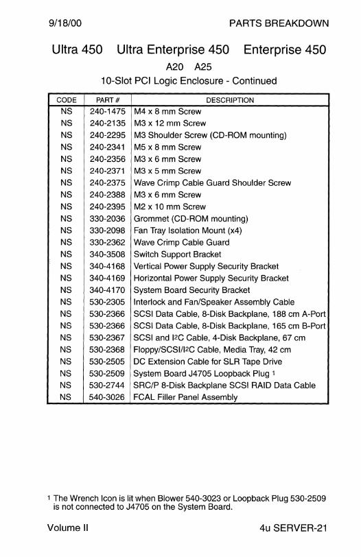
9/18/00 PARTS BREAKDOWN
Ultra 450 Ultra Enterprise 450 Enterprise 450 A20 A25
10-Slot PCI Logic Enclosure - Continued
CODE PART# DESCRIPTION
NS 240-1475 M4 x 8 mm Screw NS 240-2135 M3 x 12 mm Screw
NS 240-2295 M3 Shoulder Screw (CD-ROM mounting)
NS 240-2341 MS x 8 mm Screw
NS 240-2356 M3 x 6 mm Screw NS 240-2371 M3 x 5 mm Screw
NS 240-2375 Wave Crimp Cable Guard Shoulder Screw
NS 240-2388 M3 x 6 mm Screw
NS 240-2395 M2 x 10 mm Screw
NS 330-2036 Grommet (CD-ROM mounting)
NS 330-2098 Fan Tray Isolation Mount (x4)
NS 330-2362 Wave Crimp Cable Guard
NS 340-3508 Switch Support Bracket
NS 340-4168 Vertical Power Supply Security Bracket
NS 340-4169 Horizontal Power Supply Security Bracket
NS 340-4170 System Board Security Bracket
NS 530-2305 Interlock and Fan/Speaker Assembly Cable
NS 530-2366 SCSI Data Cable, 8-Disk Backplane, 188 cm A-Port
NS 530-2366 SCSI Data Cable, 8-Disk Backplane, 165 cm B-Port
NS 530-2367 SCSI and 12c Cable, 4-Disk Backplane, 67 cm
NS 530-2368 Floppy/SCSl/l2C Cable, Media Tray, 42 cm
NS 530-2505 DC Extension Cable for SLR Tape Drive
NS 530-2509 System Board J4705 Loopback Plug 1
NS 530-2744 SRC/P 8-Disk Backplane SCSI RAID Data Cable
NS 540-3026 FCAL Filler Panel Assembly
1 The Wrench Icon is lit when Blower 540-3023 or Loopback Plug 530-2509 is not connected to J4705 on the System Board.
Volume II 4u SERVER-21
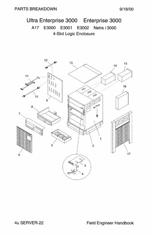
PARTS BREAKDOWN 9/18/00
6
Ultra Enterprise 3000 Enterprise 3000 A 17 E3000 E3001 E3002 Netra i 3000
4-Slot Logic Enclosure
5 2
q, ~4
17
4u SERVER-22 Field Engineer Handbook
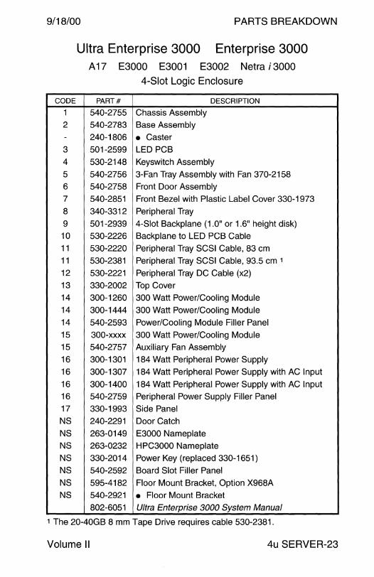
9/18/00 PARTS BREAKDOWN
CODE
1
2
-3 4
5
6
7
8
9 10
11
11
12
13
14
14
14
15
15
16
16
16
16
17
NS
NS
NS
NS
NS
NS
NS
Ultra Enterprise 3000 Enterprise 3000 A 17 E3000 E3001 E3002 Netra i 3000
4-Slot Logic Enclosure
PART# DESCRIPTION
540-2755 Chassis Assembly
540-2783 Base Assembly
240-1806 • Caster 501-2599 LED PCB
530-2148 Keyswitch Assembly
540-2756 3-Fan Tray Assembly with Fan 370-2158
540-2758 Front Door Assembly
540-2851 Front Bezel with Plastic Label Cover 330-1973
340-3312 Peripheral Tray
501-2939 4-Slot Backplane (1.0" or 1.6" height disk)
530-2226 Backplane to LED PCB Cable
530-2220 Peripheral Tray SCSI Cable, 83 cm
530-2381 Peripheral Tray SCSI Cable, 93.5 cm 1
530-2221 Peripheral Tray DC Cable (x2)
330-2002 Top Cover
300-1260 300 Watt Power/Cooling Module
300-1444 300 Watt Power/Cooling Module
540-2593 Power/Cooling Module Filler Panel
300-xxxx 300 Watt Power/Cooling Module
540-2757 Auxiliary Fan Assembly
300-1301 184 Watt Peripheral Power Supply
300-1307 184 Watt Peripheral Power Supply with AC Input
300-1400 184 Watt Peripheral Power Supply with AC Input 540-2759 Peripheral Power Supply Filler Panel
330-1993 Side Panel
240-2291 Door Catch
263-0149 E3000 Nameplate 263-0232 HPC3000 Nameplate
330-2014 Power Key (replaced 330-1651)
540-2592 Board Slot Filler Panel
595-4182 Floor Mount Bracket, Option X968A
540-2921 • Floor Mount Bracket
802-6051 Ultra Enterprise 3000 System Manual
1 The 20-40GB 8 mm Tape Drive requires cable 530-2381.
Volume II 4u SERVER-23

PARTS BREAKDOW 9/18/00
Ultra Enterprise 4000 Enterprise 4000 A 18 E4000 E4001 E4002 Netra i 4000 Netra j 4000
8-Slot Logic Enclosure
9
4u SERVER-24
~ ~16
17
Field Engineer Handbook
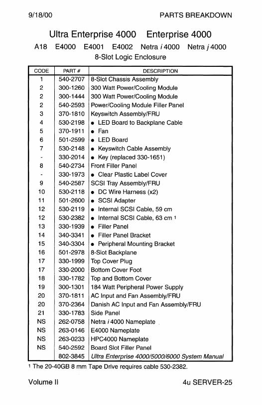
9/18/00 PARTS BREAKDOWN
Ultra Enterprise 4000 Enterprise 4000 A 18 E4000 E4001 E4002 Netra i 4000 Netra j 4000
8-Slot Logic Enclosure
CODE PART# DESCRIPTION
1 540-2707 8-Slot Chassis Assembly
2 300-1260 300 Watt Power/Cooling Module
2 300-1444 300 Watt Power/Cooling Module
2 540-2593 Power/Cooling Module Filler Panel
3 370-1810 Keyswitch Assembly/FRU
4 530-2198 • LED Board to Backplane Cable
5 370-1911 • Fan 6 501-2599 • LED Board 7 530-2148 • Keyswitch Cable Assembly
- 330-2014 • Key (replaced 330-1651) 8 540-2734 Front Filler Panel
- 330-1973 • Clear Plastic Label Cover 9 540-2587 SCSI Tray Assembly/FRU
10 530-2118 • DC Wire Harness (x2) 11 501-2600 • SCSI Adapter 12 530-2119 • Internal SCSI Cable, 59 cm 12 530-2382 • Internal SCSI Cable, 63 cm 1
13 330-1939 • Filler Panel 14 340-3341 • Filler Panel Bracket 15 340-3304 • Peripheral Mounting Bracket 16 501-2978 8-Slot Backplane
17 330-1999 Top Cover Plug 17 330-2000 Bottom Cover Foot 18 330-1782 Top and Bottom Cover
19 300-1301 184 Watt Peripheral Power Supply 20 370-1811 AC Input and Fan Assembly/FRU
20 370-2364 Danish AC Input and Fan Assembly/FRU 21 330-1783 Side Panel
NS 262-0758 Netra i 4000 Nameplate .
NS 263-0146 E4000 Nameplate NS 263-0233 HPC4000 Nameplate NS 540-2592 Board Slot Filler Panel
802-3845 Ultra Enterprise 4000/500016000 System Manual
1 The 20-40GB 8 mm Tape Drive requires cable 530-2382.
Volume II 4u SERVER-25

PARTS BREAKDOWN 9/18/00
3
Ultra Enterprise 5000 Enterprise 5000 E5000 E5001 E5002 Netra i 5000 Netra j 5000
8-Slot Logic Enclosure
6
~ 8
11
14
4u SERVER-26 Field Engineer Handbook

9/18/00 PARTS BREAKDOWN
Ultra Enterprise 5000 Enterprise 5000 E5000 E5001 E5002 Netra i 5000 Netra j 5000
8-Slot Logic Enclosure
CODE PART# DESCRIPTION
1 540-2774 8-Slot Chassis Assembly 540-277 4-01
2 340-3473 Lower Left Chassis Mounting Bracket
2 340-3474 Lower Right Chassis Mounting Bracket
3 300-1301 184 Watt Peripheral Power Supply
4 370-1812 AC Input and Fan Assembly/FRU
5 340-3169 Upper Chassis Mounting Bracket
6 501-2978 8-Slot Backplane
7 300-1260 300 Watt Power/Cooling Module
7 300-1444 300 Watt Power/Cooling Module
8 540-2593 Power/Cooling Module Filler Panel
9 370-2073 Keyswitch Adapter Assembly/FRU
10 530-2214 • Keyswitch Adapter Cable
11 540-2713 SCSI Adapter Tray Assembly/FRU
12 501-2600 • SCSI Adapter 13 530-2218 • DC Wire Harness
14 530-2217 • Internal SCSI Cable, 26 cm
NS 262-0759 Netra i 5000 Nameplate
NS 263-0146 E5000 Nameplate
NS 263-0234 HPC5000 Nameplate
NS 330-2014 Power Key (replaced 330-1651)
NS 530-2213 AC Input Power Cable, IEC320 C19-C20
NS 530-2223 SCSI Adapter Tray to SCSI Tray Power Cable
NS 530-2224 SCSI Adapter Tray to SCSI Tray SCSI Cable, 1.0M
NS 530-2225 Keyswitch Adapter to Keyswitch Assembly Cable
NS 530-2234 AC Sequencer to Fan Tray Sense Cable
NS 530-2235 AC Input and Fan Assy to AC Sequencer Cable (obs)
NS 530-2325 AC Input and Fan Assembly to AC Sequencer Cable
NS 540-2592 Board Slot Filler Panel
802-3845 Ultra Enterprise 4000/5000/6000 System Manual
Volume II 4u SERVER-27
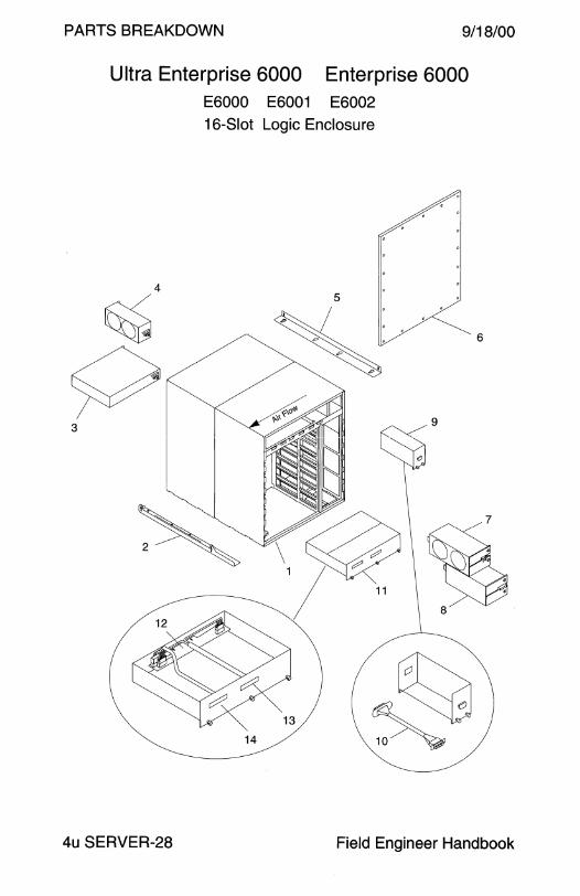
PARTS BREAKDOWN 9/18/00
Ultra Enterprise 6000 Enterprise 6000 E6000 E6001 E6002
16-Slot Logic Enclosure
14
6
4u SERVER-28 Field Engineer Handbook
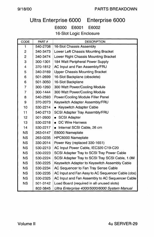
9/18/00 PARTS BREAKDOWN
CODE
1
2
2
3 4
5 6
6
7
7
8
9
10
11
12
13
14
NS
NS
NS
NS
NS
NS NS
NS
NS
NS
NS
Ultra Enterprise 6000 Enterprise 6000 E6000 E6001 E6002
16-Slot Logic Enclosure
PART# DESCRIPTION
540-2708 16-Slot Chassis Assembly
340-3473 Lower Left Chassis Mounting Bracket
340-3474 Lower Right Chassis Mounting Bracket
300-1301 184 Watt Peripheral Power Supply
370-1812 AC Input and Fan Assembly/FRU
340-3169 Upper Chassis Mounting Bracket
501-2699 16-Slot Backplane (obsolete)
501-3050 16-Slot Backplane
300-1260 300 Watt Power/Cooling Module
300-1444 300 Watt Power/Cooling Module
540-2593 Power/Cooling Module Filler Panel
370-2073 Keyswitch Adapter Assembly/FRU
530-2214 • Keyswitch Adapter Cable
540-2713 SCSI Adapter Tray Assembly/FRU
501-2600 • SCSI Adapter
530-2218 • DC Wire Harness 530-2217 • Internal SCSI Cable, 26 cm
263-0147 E6000 Nameplate
263-0235 HPC6000 Nameplate
330-2014 Power Key (replaced 330-1651)
530-2213 AC Input Power Cable, IEC320 C19-C20
530-2223 SCSI Adapter Tray to SCSI Tray Power Cable
530-2224 SCSI Adapter Tray to SCSI Tray SCSI Cable, 1.0M
530-2225 Keyswitch Adapter to Keyswitch Assembly Cable
530-2234 AC Sequencer to Fan Tray Sense Cable
530-2235 AC Input and Fan Assy to AC Sequencer Cable (obs)
530-2325 AC Input and Fan Assembly to AC Sequencer Cable
501-3142 Load Board (required in all unused slots)
802-3845 Ultra Enterprise 4000/5000/6000 System Manual
Volume II 4u SERVER-29
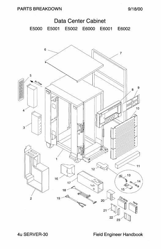
PARTS BREAKDOWN 9/18/00
Data Center Cabinet E5000 E5001 E5002 E6000 E6001 E6002
4u SERVER-30 Field Engineer Handbook
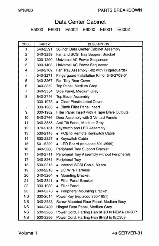
9/18/00 PARTS BREAKDOWN
Data Center Cabinet E5000 E5001 E5002 E6000 E6001 E6002
CODE PART# DESCRIPTION
1 540-2591 56-inch Data Center Cabinet Assembly
2 340-3259 Fan and SCSI Tray Support Bracket
3 300-1290 Universal AC Power Sequencer
3 300-1403 Universal AC Power Sequencer
4 540-2709 Fan Tray Assembly (-02 with Fingerguards)
- 540-3271 Fingerguard Installation Kit for 540-2709-01
5 340-3267 Fan Tray Rear Cover
6 340-3352 Top Panel, Medium Grey
7 340-3354 Side Panel, Medium Grey
8 540-2746 Top Bezel Assembly
- 330-1973 • Clear Plastic Label Cover - 330-1983 • Blank Filler Panel Insert
9 330-1982 Filler Panel Insert with 4 Tape Drive Cutouts
10 540-2766 Door Assembly with 3 Vented Panels
11 340-3355 Anti-Tilt Panel, Medium Grey
12 370-2161 Keyswitch and LED Assembly
13 530-2148 • PCB to Remote Keyswitch Cable
14 530-2227 • Keyswitch Cable
15 501-5329 • LED Board (replaced 501-2599)
16 340-3260 Peripheral Tray Support Bracket
17 540-2711 Peripheral Tray Assembly without Peripherals
17 340-3261 Peripheral Tray
18 530-2215 • Internal SCSI Cable, 89 cm
19 530-2216 • DC Wire Harness
20 340-3264 • Mounting Bracket
21 340-3341 • Filler Panel Bracket
22 330-1939 • Filler Panel 23 340-3270 • Peripheral Mounting Bracket
NS 330-2014 Power Key (replaced 330-1651)
NS 340-3353 Screw Mounted Rear Panel, Medium Grey
NS 340-3489 Hinged Rear Panel, Medium Grey
NS 530-2265 Power Cord, Harting Han 6HsB to NEMA L6-30P
NS 530-2266 Power Cord, Harting Han 6HsB to IEC309
Volume II 4u SERVER-31
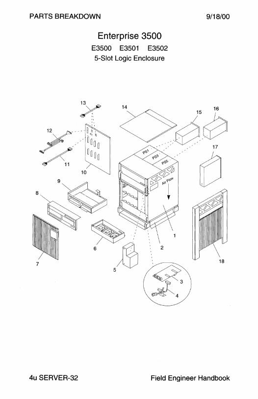
PARTS BREAKDOWN
7
Enterprise 3500 E3500 E3501 5-Slot Logic Encl:~r~2
13~
~:·. 14
2
« ~3
4
9/18/00
18
4u SERVER-32 Field En · gineer Handbook

9/18/00
CODE PART#
1 540-3531 2 540-3743
- 240-1806
3 501-2599
4 530-2148
5 300-1358
5 540-3815
6 540-3566
7 540-3501
8 540-2851
9 340-3312
10 501-4799
11 530-2226
12 530-2381 13 530-2221
14 330-2002
15 300-1260
15 300-1444
15 540-2593
16 300-xxxx
16 540-2757
16 540-4053
17 300-1307 17 300-1400
18 330-1993
NS 240-2291
NS 262-4171 NS 330-2014
NS 330-1939
NS 340-3304
NS 340-3341
NS 540-2592
NS 540-3795
805-2630
Volume II
PARTS BREAKDOWN
Enterprise 3500 E3500 E3501 E3502 5-Slot Logic Enclosure
DESCRIPTION
Upper Chassis Assembly
Lower Base Assembly
• Caster LED PCB
Keyswitch Assembly
195 Watt Peripheral Power Supply
Peripheral Power Supply Filler Panel
3-Fan Tray Assembly with Fan 370-3321
Front Door Assembly
Front Bezel with Plastic Label Cover 330-1973 Peripheral Tray
5-Slot Backplane
Backplane to LED PCB Cable
Peripheral Tray SCSI Cable, 93.5 cm
Peripheral Tray DC Cable (x2)
Top Cover
300 Watt Power/Cooling Module
300 Watt Power/Cooling Module
Power/Cooling Module Filler Panel
300 Watt Power/Cooling Module
Auxiliary Fan Assembly
Auxiliary Fan Assembly
184 Watt Peripheral Power Supply with AC Input 184 Watt Peripheral Power Supply with AC Input
Side Panel
Door Catch
E3500 Nameplate Power Key
CD-ROM Filler Bracket Bezel
Removable Media Device Mounting Bracket
CD-ROM Filler Bracket
Board Slot Filler Panel
Fiber Channel Interface Board Slot Filler Panel
Enterprise 3500 Reference Manual
4u SERVER-33

PARTS BREAKDOW
Enterprise 4500 E4500 E4501 E4502 8-Slot Logic Enclosure
9/18/00
4u SERVER-34 Field Engineer Handbook
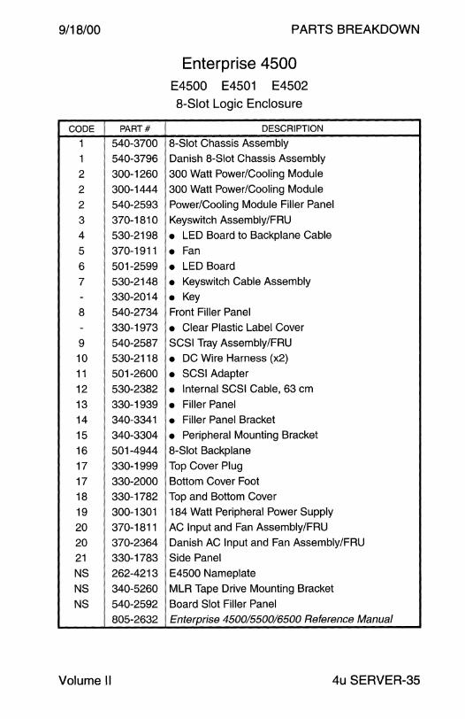
9/18/00
CODE PART#
1 540-3700
1 540-3796
2 300-1260
2 300-1444
2 540-2593
3 370-1810
4 530-2198
5 370-1911
6 501-2599
7 530-2148
- 330-2014
8 540-2734
- 330-1973
9 540-2587
10 530-2118
11 501-2600
12 530-2382
13 330-1939
14 340-3341
15 340-3304
16 501-4944
17 330-1999
17 330-2000
18 330-1782
19 300-1301
20 370-1811
20 370-2364
21 330-1783
NS 262-4213
NS 340-5260
NS 540-2592
805-2632
Volume II
PARTS BREAKDOWN
Enterprise 4500 E4500 E4501 E4502
8-Slot Logic Enclosure
DESCRIPTION
8-Slot Chassis Assembly
Danish 8-Slot Chassis Assembly
300 Watt Power/Cooling Module
300 Watt Power/Cooling Module
Power/Cooling Module Filler Panel
Keyswitch Assembly/FRU
• LED Board to Backplane Cable
• Fan • LED Board
• Keyswitch Cable Assembly
• Key Front Filler Panel
• Clear Plastic Label Cover
SCSI Tray Assembly/FRU
• DC Wire Harness (x2)
• SCSI Adapter
• Internal SCSI Cable, 63 cm
• Filler Panel
• Filler Panel Bracket
• Peripheral Mounting Bracket
8-Slot Backplane
Top Cover Plug
Bottom Cover Foot
Top and Bottom Cover
184 Watt Peripheral Power Supply
AC Input and Fan Assembly/FRU
Danish AC Input and Fan Assembly/FRU
Side Panel
E4500 Nameplate
MLR Tape Drive Mounting Bracket
Board Slot Filler Panel
Enterprise 450015500/6500 Reference Manual
4u SERVER-35
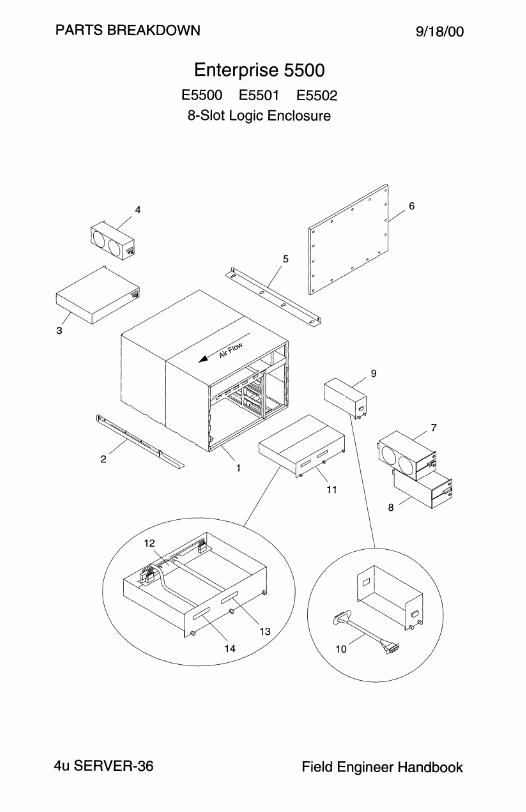
PARTS BREAKDOWN
3
Enterprise 5500 E5500 E5501 E5502 8-Slot Logic Enclosure
11
14
9/18/00
6
4u SERVER-36 Field Engineer Handbook

9/18/00
CODE PART#
1 540-3573
1 540-4164
2 340-3473
2 340-3474
3 300-1301
4 370-1812
5 340-3169
6 501-4944
7 300-1260
7 300-1444
8 540-2593
9 370-2073
10 530-2214
11 540-2713
12 501-2600
13 530-2218
14 530-2217
NS 262-4120
NS 330-2014
NS 530-2213
NS 530-2224
NS 530-2325
NS 530-2587
NS 530-2645
NS 530-2655
NS 540-2592
805-2632
Volume II
PARTS BREAKDOWN
Enterprise 5500 E5500 E5501 E5502 8-Slot Logic Enclosure
DESCRIPTION
8-Slot E5500 Chassis Assembly 8-Slot E5501 Chassis Assembly
Lower Left Chassis Mounting Bracket
Lower Right Chassis Mounting Bracket
184 Watt Peripheral Power Supply
AC Input and Fan Assembly/FRU
Upper Chassis Mounting Bracket
8-Slot Backplane
300 Watt Power/Cooling Module
300 Watt Power/Cooling Module Power/Cooling Module Filler Panel
Keyswitch Adapter Assembly/FRU
• Keyswitch Adapter Cable
SCSI Adapter Tray Assembly/FRU
• SCSI Adapter
• DC Wire Harness
• Internal SCSI Cable, 26 cm
E5500 Nameplate
Power Key
AC Input Power Cable, IEC320 C19-C20
SCSI Adapter Tray to SCSI Tray SCSI Cable, 1.0M
AC Input and Fan Assembly to AC Sequencer Cable
Keyswitch Adptr to Keyswitch to SCSI Tray Fan Cable
AC Sequencer to Fan Tray Sense Cable
SCSI Adapter Tray to SCSI Tray Power Cable
Board Slot Filler Panel
Enterprise 450015500/6500 Reference Manual
4u SERVER-37
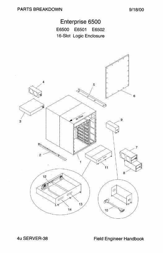
PARTS BREAKDOWN
Enterprise 6500 E6500 E6501 E6502 16-Slot Logic Enclosure
9/18/00
4u SERVER-38 Field Engineer Handbook

9/18/00
CODE PART#
1 540-3572
1 540-4165
2 340-3473
2 340-3474
3 300-1301
4 370-1812
5 340-3169
6 501-5010
7 300-1260
7 300-1444
8 540-2593
9 370-2073
10 530-2214
11 540-2713
12 501-2600
13 530-2218
14 530-2217
NS 262-4121
NS 330-2014
NS 530-2213
NS 530-2224
NS 530-2325
NS 530-2587
NS 530-2645
NS 530-2655
NS 501-3142
805-2632
Volume II
PARTS BREAKDOWN
Enterprise 6500 E6500 E6501 E6502
16-Slot Logic Enclosure
DESCRIPTION
16-Slot E6500 Chassis Assembly
16-Slot E6501 Chassis Assembly
Lower Left Chassis Mounting Bracket
Lower Right Chassis Mounting Bracket
184 Watt Peripheral Power Supply
AC Input and Fan Assembly/FRU
Upper Chassis Mounting Bracket
16-Slot Backplane
300 Watt Power/Cooling Module
300 Watt Power/Cooling Module
Power/Cooling Module Filler Panel
Keyswitch Adapter Assembly/FRU
• Keyswitch Adapter Cable
SCSI Adapter Tray Assembly/FRU
• SCSI Adapter
• DC Wire Harness • Internal SCSI Cable, 26 cm
E6500 Nameplate
Power Key
AC Input Power Cable, IEC320 C19-C20
SCSI Adapter Tray to SCSI Tray SCSI Cable, 1.0M
AC Input and Fan Assembly to AC Sequencer Cable
Keyswitch Adptrto Keyswitch to SCSI Tray Fan Cable
AC Sequencer to Fan Tray Sense Cable
SCSI Adapter Tray to SCSI Tray Power Cable
Load Board (required in all unused slots)
Enterprise 45001550016500 Reference Manual
4u SERVER-39

PARTS BREAKDOWN
Data Center Cabinet E5500 E5501 E6500 E6501
9/18/00
~11
'\ ~2 13~
8
4u SERVER-40 Field Engineer Handbook
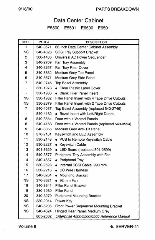
9/18/00
CODE
1
NS
2
3
4
5
6
7
--
NS
NS
7 -
8
8
9
10
11
12
13
14
14
15
16
17
NS
18
19
20
NS NS
NS
Volume II
PARTS BREAKDOWN
Data Center Cabinet E5500 E5501 E6500 E6501
PART# DESCRIPTION
540-3571 68-inch Data Center Cabinet Assembly 340-4628 SCSI Tray Support Bracket
300-1403 Universal AC Power Sequencer
540-2709 Fan Tray Assembly
340-3267 Fan Tray Rear Cover
340-3352 Medium Grey Top Panel 340-3671 Medium Grey Side Panel
540-2746 Top Bezel Assembly
330-1973 • Clear Plastic Label Cover
330-1983 • Blank Filler Panel Insert 330-1982 Filler Panel Insert with 4 Tape Drive Cutouts 330-2379 Filler Panel Insert with 2 Tape Drive Cutouts
540-4087 Top Bezel Assembly (replaced 540-2746) 540-4162 • Bezel Insert with Left/Right Doors 540-3554 Door with 4 Vented Panels
540-4163 Door with 4 Vented Panels (replaced 540-3554)
340-3355 Medium Grey Anti-Tilt Panel
370-2161 Keyswitch and LED Assembly
530-2148 • PCB to Remote Keyswitch Cable 530-2227 • Keyswitch Cable 501-5329 • LED Board (replaced 501-2599) 540-3577 Peripheral Tray Assembly with Fan
340-4657 • Peripheral Tray 530-2528 • Internal SCSI Cable, 990 mm 530-2216 • DC Wire Harness 340-3264 • Mounting Bracket 370-3321 • 92 mm Fan 340-3341 Filler Panel Bracket
330-1939 Filler Panel
340-3270 Peripheral Mounting Bracket
330-2014 Power Key
340-5205 Front Power Sequencer Mounting Bracket 340-4624 Hinged Rear Panel, Medium Grey
805-2632 Enterprise 4500/550016500 Reference Manual
4u SERVER-41
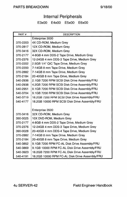
PARTS BREAKDOWN 9/18/00
PART#
370-2203
370-2817
370-3416
370-2177
370-2376 370-2202
370-2200
370-2882
370-2184
540-2936
540-2938
540-2951
540-3704
540-37i 9
540-4177
370-3416 390-0025
370-2177
370-2376
390-0028
370-2882
370-2184
540-3852
540-3869
540-3923
540-4191
Internal Peripherals E3x00 E4x00 E5x00 E6x00
DESCRIPTION
Enterprise 3000
4X CD-ROM, Medium Grey
12X CD-ROM, Medium Grey
32X CD-ROM, Medium Grey
4-8GB 4 mm DDS-2 Tape Drive, Medium Grey
12-24GB 4 mm DDS-3 Tape Drive, Medium Grey
2.5GB 1/4" QIC Tape Drive, Medium Grey
7-14GB 8 mm Tape Drive, Medium Grey
7-14GB 8 mm Tape Drive, Medium Grey
20-40GB 8 mm Tape Drive, Medium Grey
2.1 GB 7200 RPM SCSI Disk Drive Assembly/FRU
4.2GB 7200 RPM SCSI Disk Drive Assembly/FRU
9.1 GB 7200 RPM SCSI Disk Drive Assembly/FRU
9.1 GB 7200 RPM SCSI Disk Drive Assembly/FRU
i 8.2GB 7200 RPM SCSI Disk Drive Assembly/FRU
18.2GB 10000 RPM SCSI Disk Drive Assembly/FRU
Enterprise 3500
32X CD-ROM, Medium Grey 1 OX DVD-ROM, Medium Grey
4-8GB 4 mm DDS-2 Tape Drive, Medium Grey
12-24GB 4 mm DDS-3 Tape Drive, Medium Grey
20-40GB 4 mm DDS-4 Tape Drive, Medium Grey
7-14GB 8 mm Tape Drive, Medium Grey
20-40GB 8 mm Tape Drive, Medium Grey
9.1 GB 7200 RPM FC-AL Disk Drive Assembly/FRU
9.1 GB 10000 RPM FC-AL Disk Drive Assembly/FRU
18.2GB 7200 RPM FC-AL Disk Drive Assembly/FRU
18.2GB 10000 RPM FC-AL Disk Drive Assembly/FRU
4u SERVER-42 Field Engineer Handbook

9/18/00
PART#
370-2203
370-2817
370-3416
370-2177
370-2376
370-2202
370-2200
370-2882
370-2184
370-3416
390-0025
370-2177
370-2376
390-0028
370-2882
370-2184
Volume II
PARTS BREAKDOWN
Internal Peripherals - Continued E3x00 E4x00 E5x00 E6x00
DESCRIPTION
Enterprise 4000
4X CD-ROM, Medium Grey
12X CO-ROM, Medium Grey
32X CD-ROM, Medium Grey
4-8GB 4 mm DDS-2 Tape Drive, Medium Grey
12-24GB 4 mm DDS-3 Tape Drive, Medium Grey
2.5GB 1/4" QIC Tape Drive, Medium Grey
7-14GB 8 mm Tape Drive, Medium Grey
7-14GB 8 mm Tape Drive, Medium Grey
20-40GB 8 mm Tape Drive, Medium Grey
Enterprise 4500
32X CD-ROM, Medium Grey
10X DVD-ROM, Medium Grey
4-8GB 4 mm DDS-2 Tape Drive, Medium Grey
12-24GB 4 mm DDS-3 Tape Drive, Medium Grey
20-40GB 4 mm DDS-4 Tape Drive, Medium Grey
7-14GB 8 mm Tape Drive, Medium Grey
20-40GB 8 mm Tape Drive, Medium Grey
4u SERVER-43

PARTS BREAKDOWN
PART#
370-2203
370-2817
370-3416
370-2177
370-2376
370-2202
370-2200
370-2184
370-3416
390-0025
370-2177
370-2376
390-0028
370-2200
370-2184
Internal Peripherals - Continued E3x00 E4x00 E5x00 E6x00
DESCRIPTION
Enterprise 5000 and 6000
4X CD-ROM, Medium Grey
12X CD-ROM, Medium Grey
32X CD-ROM, Medium Grey
4-8GB 4 mm DDS-2 Tape Drive, Medium Grey
12-24GB 4 mm DDS-3 Tape Drive, Medium Grey
2.5GB 1/4" QIC Tape Drive, Medium Grey
7-14GB 8 mm Tape Drive, Medium Grey
20-40GB 8 mm Tape Drive, Medium Grey
Enterprise 5500 and 6500
32X CD-ROM, Medium Grey
10X DVD-ROM, Medium Grey
4-8GB 4 mm DDS-2 Tape Drive, Medium Grey
i 2-24GB 4 mm DDS-3 Tape Drive, Medium Grey
20-40GB 4 mm DDS-4 Tape Drive, Medium Grey
7-14GB 8 mm Tape Drive, Medium Grey
20-40GB 8 mm Tape Drive, Medium Grey
9/18/00
4u SERVER-44 Field Engineer Handbook
9/18/00 PARTS BREAKDOWN
This page intentionally left blank.
Volume II 4u SERVER-45
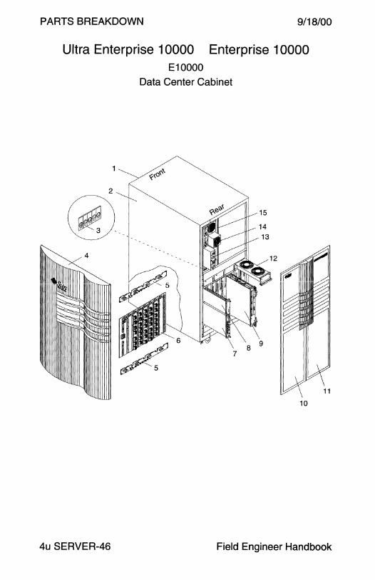
PARTS BREAKDOWN 9/18/00
Ultra Enterprise 10000 Enterprise 10000 E10000
Data Center Cabinet
10
4u SERVER-46 Field Engineer Handbook
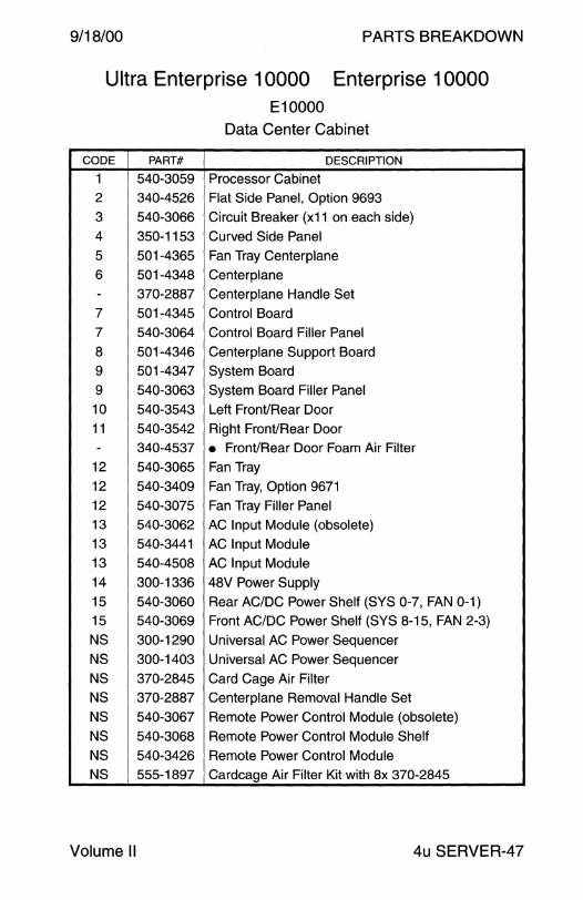
9/18/00 PARTS BREAKDOWN
Ultra Enterprise 10000 Enterprise 10000 E10000
Data Center Cabinet
CODE PART# DESCRIPTION
1 540-3059 Processor Cabinet 2 340-4526 Flat Side Panel, Option 9693
3 540-3066 Circuit Breaker (x11 on each side)
4 350-1153 Curved Side Panel
5 501-4365 Fan Tray Centerplane
6 501-4348 Centerplane
- 370-2887 Centerplane Handle Set 7 501-4345 Control Board
7 540-3064 Control Board Filler Panel
8 501-4346 Centerplane Support Board
9 501-4347 System Board
9 540-3063 System Board Filler Panel
10 540-3543 Left Front/Rear Door
11 540-3542 Right Front/Rear Door
- 340-4537 • Front/Rear Door Foam Air Filter 12 540-3065 Fan Tray
12 540-3409 Fan Tray, Option 9671
12 540-3075 Fan Tray Filler Panel
13 540-3062 AC Input Module (obsolete)
13 540-3441 AC Input Module
13 540-4508 AC Input Module
14 300-1336 48V Power Supply
15 540-3060 Rear AC/DC Power Shelf (SYS 0-7, FAN 0-1)
15 540-3069 Front AC/DC Power Shelf (SYS 8-15, FAN 2-3)
NS 300-1290 Universal AC Power Sequencer
NS 300-1403 Universal AC Power Sequencer
NS 370-2845 Card Cage Air Filter NS 370-2887 Centerplane Removal Handle Set
NS 540-3067 Remote Power Control Module (obsolete)
NS 540-3068 Remote Power Control Module Shelf
NS 540-3426 Remote Power Control Module
NS 555-1897 Cardcage Air Filter Kit with Bx 370-2845
Volume II 4u SERVER-47
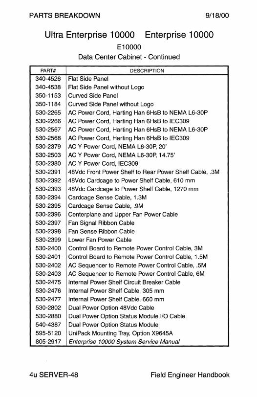
PARTS BREAKDOWN 9/18/00
Ultra Enterprise 10000 Enterprise 10000 E10000
Data Center Cabinet - Continued
PART# DESCRIPTION
340-4526 Flat Side Panel 340-4538 Flat Side Panel without Logo
350-1153 Curved Side Panel
350-1184 Curved Side Panel without Logo
530-2265 AC Power Cord, Harting Han 6HsB to NEMA L6-30P
530-2266 AC Power Cord, Harting Han 6HsB to IEC309 530-2567 AC Power Cord, Harting Han 6HsB to NEMA L6-30P
530-2568 AC Power Cord, Harting Han 6HsB to IEC309
530-2379 ACY Power Cord, NEMA L6-30P, 20'
530-2503 ACY Power Cord, NEMA L6-30P, 14.75' 530-2380 ACY Power Cord, IEC309
530-2391 48Vdc Front Power Shelf to Rear Power Shelf Cable, .3M
530-2392 48Vdc Cardcage to Power Shelf Cable, 610 mm
530-2393 48Vdc Cardcage to Power Shelf Cable, 1270 mm 530-2394 Cardcage Sense Cable, 1.3M
530-2395 Cardcage Sense Cable, .9M 530-2396 Centerplane and Upper Fan Power Cable
530-2397 Fan Signal Ribbon Cable
530-2398 Fan Sense Ribbon Cable 530-2399 Lower Fan Power Cable
530-2400 Control Board to Remote Power Control Cable, 3M
530-2401 Control Board to Remote Power Control Cable, 1.5M
530-2402 AC Sequencer to Remote Power Control Cable, .5M 530-2403 AC Sequencer to Remote Power Control Cable, 6M
530-2475 Internal Power Shelf Circuit Breaker Cable
530-2476 Internal Power Shelf Cable, 305 mm 530-2477 Internal Power Shelf Cable, 660 mm 530-2802 Dual Power Option 48Vdc Cable
530-2880 Dual Power Option Status Module 1/0 Cable 540-4387 Dual Power Option Status Module
595-5120 UniPack Mounting Tray, Option X9645A 805-2917 Enterprise 10000 System Service Manual
4u SERVER-48 Field Engineer Handbook

PARTS BREAKDOWN
TEL CO
9/18/00 PARTS BREAKDOWN
Tel co
ft-SPARC.............................................................................. 2 Netra ft 1800 . . . . . . . . . . . . . . . . . . . . . . . . . . . . . . . . . . . . . . . . . . . . . . . . . . . . . . . . . . . . . . . . . . . . . . . . . 1 8
Netra t 11 00 . . . . . . . . . . . . . . . . . . . . . . . . . . . . . . . . . . . . . . . . . . . . . . . . . . . . . . . . . . . . . . . . . . . . . . . . . . 22 Netra t 1120 . . . . . . . . . . . . . . . . . . . . . . . . . . . . . . . . . . . . . . . . . . . . . . . . . . . . . . . . . . . . . . . . . . . . . . . . . . 23 Netra t 1125 . . . . . . . . . . . . . . . . . . . . . . . . . . . . . . . . . . . . . . . . . . . . . . . . . . . . . . . . . . . . . . . . . . . . . . . . . . 26 Netra t 1400 . . . . . . . . . . . . . . . . . . . . . . . . . . . . . . . . . . . . . . . . . . . . . . . . . . . . . . . . . . . . . . . . . . . . . . . . . . 30 Netra t 1405 . . . . . . . . . . . . . . . . . . . . . . . . . . . . . . . . . . . . . . . . . . . . . . . . . . . . . . . . . . . . . . . . . . . . . . . . . . 30 Netra t1 Model 100 . . . . . . . . . . . . . . . . . . . . . . . . . . . . . . . . . . . . . . . . . . . . . . . . . . . . . . . . . . . . . . . 34 Netra t1 Model 105 . . . . . . . . . . . . . . . . . . . . . . . . . . . . . . . . . . . . . . . . . . . . . . . . . . . . . . . . . . . . . . . 35 Netra ct 400 . . . . . . . . . . . . . . . . . . . . . . . . . . . . . . . . . . . . . . . . . . . . . . . . . . . . . . . . . . . . . . . . . . . . . . . . . . 38 Netra ct 800 . . . . . . . . . . . . . . . . . . . . . . . . . . . . . . . . . . . . . . . . . . . . . . . . . . . . . . . . . . . . . . . . . . . . . . . . . . 40 Netra ct 1600 . . . . . . . . . . . . . . . . . . . . . . . . . . . . . . . . . . . . . . . . . . . . . . . . . . . . . . . . . . . . . . . . . . . . . . . . 43
Netra st A 1 000 . . . . . . . . . . . . . . . . . . . . . . . . . . . . . . . . . . . . . . . . . . . . . . . . . . . . . . . . . . . . . . . . . . . . . 44 Netra st 01000 ..................................................................... 46 Netra st 0130 ....................................................................... 48
Field Engineer Handbook - Volume II

PARTS BREAKDOW 9/18/00
ft-SPARC
Model 1500
OPTION MEMORY PROCESSOR 5800 32MB Model 1500 with 1 x 40MHz SuperSPARC
5801 64MB Model 1500 with 1 x 40MHz SuperSPARC
5802 128MB Model 1500 with 1 x 40MHz SuperSPARC
5803 256MB Model 1500 with 1 x 40MHz SuperSPARC
5804 512MB Model 1500 with 1 x 40MHz SuperSPARC
5810 32MB Model 1500 with 2x 40MHz SuperSPARC
5811 64MB Model 1500 with 2x 40MHz SuperSPARC
5812 128MB Model 1500 with 2x 40MHz SuperSPARC
5813 256MB Model 1500 with 2x 40MHz SuperSPARC
5814 512MB Model 1500 with 2x 40MHz SuperSPARC
5820 32MB Model 1500 with 4x 40MHz SuperSPARC
5821 64MB Model 1500 with 4x 40MHz SuperSPARC
5822 128MB Model 1500 with 4x 40MHz SuperSPARC
5823 256MB Model 1500 with 4x 40MHz SuperSPARC
5824 5i2MB Model 1500 with 4x 40MHz SuperSPARC
5830 32MB Model 1500 with 1 x 80MHz SuperSPARC
5831 64MB Model 1500 with 1 x 80MHz SuperSPARC
5832 128MB Model 1500 with 1 x 80MHz SuperSPARC
5833 256MB Model 1500 with 1 x 80MHz SuperSPARC
5834 512MB Model 1500 with 1 x 80MHz SuperSPARC
5840 32MB Model 1500 with 2x 80MHz SuperSPARC
5841 64MB Model 1500 with 2x 80MHz SuperSPARC
5842 128MB Model 1500 with 2x 80MHz SuperSPARC
5843 256MB Model 1500 with 2x 80MHz SuperSPARC
5844 512MB Model 1500 with 2x 80MHz SuperSPARC
5850 32MB Model 1500 with 4x 80MHz SuperSPARC
5851 64MB Model 1500 with 4x 80MHz SuperSPARC
5852 128MB Model 1500 with 4x 80MHz SuperSPARC
5853 256MB Model 1500 with 4x 80MHz SuperSPARC
5854 512MB Model 1500 with 4x 80MHz SuperSPARC
TELC0-2 Field Engineer Handbook
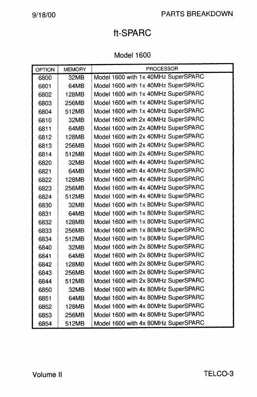
9/18/00 PARTS BREAKDOWN
ft-SPARC
Model 1600
OPTION MEMORY PROCESSOR
6800 32MB Model 1600 with 1 x 40MHz SuperSPARC
6801 64MB Model 1600 with 1 x 40MHz SuperSPARC
6802 128MB Model 1600 with 1 x 40MHz SuperSPARC
6803 256MB Model 1600 with 1 x 40MHz SuperSPARC
6804 512MB Model 1600 with 1 x 40MHz SuperSPARC
6810 32MB Model 1600 with 2x 40MHz SuperSPARC
6811 64MB Model 1600 with 2x 40MHz SuperSPARC
6812 128MB Model 1600 with 2x 40MHz SuperSPARC
6813 256MB Model 1600 with 2x 40MHz SuperSPARC
6814 512MB Model 1600 with 2x 40MHz SuperSPARC
6820 32MB Model 1600 with 4x 40MHz SuperSPARC
6821 64MB Model 1600 with 4x 40MHz SuperSPARC
6822 128MB Model 1600 with 4x 40MHz SuperSPARC
6823 256MB Model 1600 with 4x 40MHz SuperSPARC
6824 512MB Model 1600 with 4x 40MHz SuperSPARC
6830 32MB Model 1600 with 1 x 80MHz SuperSPARC
6831 64MB Model 1600 with 1 x 80MHz SuperSPARC
6832 128MB Model 1600 with 1 x 80MHz SuperSPARC
6833 256MB Model 1600 with 1 x 80MHz SuperSPARC
6834 512MB Model 1600 with 1 x 80MHz SuperSPARC
6840 32MB Model 1600 with 2x 80MHz SuperSPARC
6841 64MB Model 1600 with 2x 80MHz SuperSPARC
6842 128MB Model 1600 with 2x 80MHz SuperSPARC
6843 256MB Model 1600 with 2x 80MHz SuperSPARC
6844 512MB Model 1600 with 2x 80MHz SuperSPARC
6850 32MB Model 1600 with 4x 80MHz SuperSPARC
6851 64MB Model 1600 with 4x 80MHz SuperSPARC
6852 128MB Model 1600 with 4x BOMHz SuperSPARC
6853 256MB Model 1600 with 4x 80MHz SuperSPARC
6854 512MB Model 1600 with 4x 80MHz SuperSPARC
Volume II TELC0-3
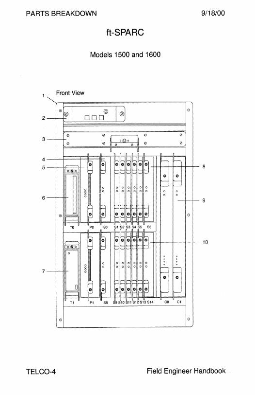
PARTS BREAKDOWN 9/18/00
2
3
4
5
6
7
TELC0-4
Front View
0®1 0
0
,.---
rm ~
0~ II---
TO
,---------. 1-ooo' ~
0
,d I---
T1
0
ft-SPARC
Models 1500 and 1600
@ l® 0 ODO
0 1 0 0
Jt o@o 0 " """]
0 0
lf n_ n_ JL n_
~ I~ II- I!- II- I!- II-
I§ v--- v---
G G G G a
~ :~ I~ I~ ~ 0 0
8
I-- 1---0 0 0 0 0 0 0 t-- t--
0 0 0 0 0 0 0 0 0 0 0 0 0 0 0
9
§ I§ 0 0 0 0 o§ 0 PO so S1 S2 S3 S4 SS S6
§ :~ GISI a a a ol ~
10
0 0 0 0 0 0 0 0 0 0 0 0 0 0 0 0 r----- r--0 0 t--- r--
§ h H h h ~ § 0 0
§ "'-' H H P-0 0 0 0 0 1--' h-1 I\-) 1--' I\-) II---' II---'
P1 S8 S9 S10 S11 S12 S13 S14 co C1
0
Field Engineer Handbook

9/18/00 PARTS BREAKDOWN
ft-SPARC
Models 1500 and 1600
CODE PART# IMP# DESCRIPTION
1 f370-2445 0001A CHASSIS-D 1
1 f370-2446 0004B CHASSIS-Li (1500 chassis)
1 f370-2447 0005B CHASSIS-DRIVE
1 f370-2530 0089A CHASSIS-COMMS
1 f370-2552 0125A CHASSIS-D 1
1 f370-2553 0125B CHASSIS-D 1
1 f370-3288 0125C CHASSIS-D 1
1 f370-2557 0142A CHASSIS-OT 2
1 f370-2558 0143A CHASSIS-D 1
1 f370-2559 0144B CHASSIS-OT 2
1 f370-3289 0144C CHASSIS-OT 2
1 f370-2627 0219A CHASSIS-U-110 (110V 1500 chassis)
1 f370-2628 0220A CHASSIS-U-220 (220V 1500 chassis)
1 f370-2631 0224A CHASSIS-F 3
1 f370-2644 0236A CHASSIS-DRIVE
1 f370-2649 0241A CHASSIS-600-48NB (1600 chassis)
2 f370-2487 0041A CONTROL-D (DSC chassis)
2 f370-2488 0042A CONTROL-Li (1500 chassis)
2 f370-2547 0117A CONTROL-Li (1500 chassis)
3 f370-2486 0040C FANS
4 - - IOSET Slots SO and S8
5 f370-2483 0037A POWER-AC
5 f370-2484 0038B POWER-48
5 f370-2485 0039A POWER-48NB
6 f370-2584 0173B CD ROM
6 f370-2585 0173C CD ROM
7 f370-2470 0028B TAPE-DAT-8
7 f370-2471 0028C TAPE-DAT-8
7 f370-3687 00280 TAPE-DAT-8
8 - - FTIO Bus BO Slots SO - S6
9 - - CPUSET Slots CO and C1
10 - - FTIO Bus Slots S8 - S 14
1 A 24-inch wide chassis designed for Digital Switch Corporation (DSC). 2 DSC chassis that does not support the drive chassis. 3 Reduced depth chassis designed to fit the Fujitsu FETEX-150 rack.
Volume II TELC0-5
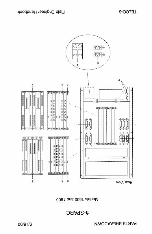
)jOoqpueH Jaau,6u3 P19!.::I 9-08131
L
0 0 0 0 0 0 0 0
~[ ~~ ~l ~~ ~ ~~ ~ 0 0 0 0 0 0 0 0
0 0 0 0 0 0 0 0
~~ ~~ ~~ ~~
~~ ~~ 0 0 0 0 0 0 0 0
B
00/8 ~/6
9 s
DD DD DD DD DD DD DD DD DD DD DD DD
glDDggDDJg DIDI I IDID
®l®l®l®l®l®l®I®
®1®1@1®1®1@1®1®
DDDD DDDD DDDD DDDD DDDD DIDIDID ~)~)DD D Di~)~ DIDIDID
®)®l®l®)@)itl®
9 s
~ j7
0,,
0
l·~·I@
~@ 8
®® ®® ®® ®®
®® ®® ®® ®®
0
M8!/\ Jeati
009 ~ pue 009 ~ s1apOV\I
8HV'dS-U
NMOO>lV3l:l8 Sll:IVd
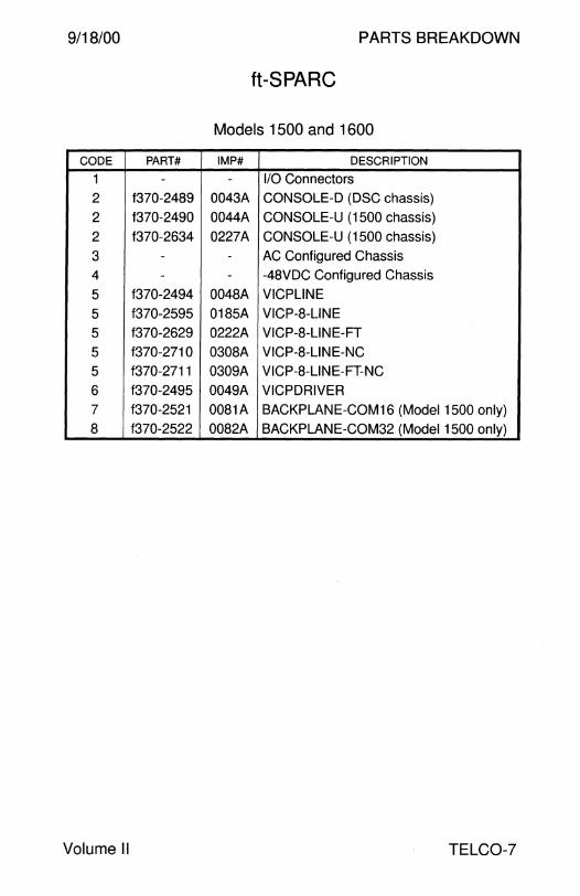
9/18/00 PARTS BREAKDOWN
ft-SPARC
Models 1 500 and 1600
CODE PART# IMP# DESCRIPTION
1 - - 1/0 Connectors
2 f370-2489 0043A CONSOLE-D (DSC chassis)
2 f370-2490 0044A CONSOLE-Li (1500 chassis)
2 f370-2634 0227A CONSOLE-Li (1500 chassis)
3 - - AC Configured Chassis
4 - - -48VDC Configured Chassis
5 f370-2494 0048A VICPLINE
5 f370-2595 0185A VICP-8-LINE
5 f370-2629 0222A VICP-8-LINE-FT
5 f370-2710 0308A VICP-8-LINE-NC
5 f370-2711 0309A VICP-8-LINE-FT-NC
6 f370-2495 0049A VICPDRIVER
7 f370-2521 0081A BACKPLANE-COM16 (Model 1500 only)
8 f370-2522 0082A BACKPLANE-COM32 (Model 1500 only)
Volume II TELC0-7

PARTS BREAKDOW 9/18/00
ft-SPARC
Models 1500 and 1600 CPU
PART# IMP# DESCRIPTION
1370-2456 0013C CPUSET-SPARC-1-32-40
1370-2457 00140 CPUSET-SPARC-1-64-40
1370-2458 0015C CPUSET-SPARC-1-128-40
1370-2459 0016C CPUSET-SPARC-1-256-40
1370-2460 0017C CPUSET-SPARC-1-512-40
1370-2461 0019C CPUSET-SPARC-1-32-40-LA
1370-2462 0020A CPUSET-SPARC-1-64-40-LA
1370-2463 00218 CPUSET-SPARC-1-128-40-LA
1370-2464 0022C CPUSET-SPARC-1-256-40-LA
1370-2465 0023C CPUSET-SPARC-1-512-40-LA
1370-2501 00558 PACK-CPUS ET
1370-2531 0091C CPUSET-SPARC-2-32-40
1370-2532 0092C CPUSET-SPARC-2-64-40
1370-2533 00930 CPUSET-SPARC-2-128-40
1370-2534 0094C CPUSET-SPARC-2-256-40
1370-2535 00940 CPUSET-SPARC-2-256-40
1370-2536 0095C CPUSET-SPARC-2-512-40
1370-2537 0097C CPUSET-SPARC-2-32-40-LA
1370-2538 0098C CPUSET-SPARC-2-64-40-LA
1370-2539 0099C CPUSET-SPARC-2-128-40-LA
1370-2540 0100C CPUSET-SPARC-2-256-40-LA
1370-2541 0101C CPUSET-SPARC-2-512-40-LA
1370-2542 0103C CPUSET-SPARC-4-32-40
1370-2543 0104C CPUSET-SPARC-4-64-40
1370-2544 0105C CPUSET-SPARC-4-128-40
1370-2545 0106C CPUSET-SPARC-4-256-40
1370-2546 0107C CPUSET-SPARC-4-512-40
1370-2550 0120C CPUSET-SPARC-1-64-40-LA
1370-2551 0121C CPUSET-SPARC-1-128-40-LA
1370-2570 0157A FU-CPUSET-PROM
1370-2596 01868 CPUSET-SPARC-1-32-80
1370-2597 01878 CPUSET-SPARC-1-64-80
1370-2598 01888 CPUSET-SPARC-1-128-80
TELC0-8 Field Engineer Handbook

9/18/00 PARTS BREAKDOWN
ft-SPARC
Models 1500 and 1600 CPU - Continued
PART# IMP# DESCRIPTION
1370-2599 01898 CPUSET-SPARC-1-256-80
1370-2600 01908 CPUSET-SPARC-1-512-80
1370-2601 01918 CPUSET-SPARC-1-32-80-LA
1370-2602 01928 CPUSET-SPARC-1-64-80-LA
1370-2603 01938 CPUSET-SPARC-1-128-80-LA
1370-2604 01948 CPUSET-SPARC-1-256-80-LA
1370-2605 01958 CPUSET-SPARC-1-512-80-LA
1370-2606 01968 CPUSET-SPARC-2-32-80
1370-2607 01978 CPUSET-SPARC-2-64-80
1370-2608 01988 CPUSET-SPARC-2-128-80
1370-2609 01998 CPUSET-SPARC-2-256-80
1370-2610 02008 CPUSET-SPARC-2-512-80
1370-2611 02018 CPUSET-SPARC-2-32-80-LA
1370-2612 02028 CPUSET-SPARC-2-64-80-LA
1370-2613 02038 CPUSET-SPARC-2-128-80-LA
1370-2614 02048 CPUSET-SPARC-2-256-80-LA
1370-2615 02058 CPUSET-SPARC-2-512-80-LA
1370-2616 02068 CPUSET-SPARC-4-32-80
f370-2617 02078 CPUSET-SPARC-4-64-80
1370-2618 02088 CPUSET-SPARC-4-128-80
1370-2619 02098 CPUSET-SPARC-4-256-8
1370-2620 02108 CPUSET-SPARC-4-512-8
1370-2639 0233A FRU-CPUSET-PROM
1370-2655 02488 CPUSET-SPARC-1-32-40
1370-2656 02498 CPUSET-SPARC-1-32-40-LA
1370-2657 02508 CPUSET-SPARC-1-64-40
f370-2658 02518 CPUSET-SPARC-1-64-40-LA
1370-2659 02528 CPUSET-SPARC-1-128-40
1370-2660 02538 CPUSET-SPARC-1-128-40-LA
f370-2661 02548 CPUSET-SPARC-1-256-40
1370-2662 02558 CPUSET-SPARC-1-256-40-LA
f370-2663 02568 CPUSET-SPARC-1-512-40
1370-2664 02578 CPUSET-SPARC-1-512-40-LA
Volume II TELC0-9
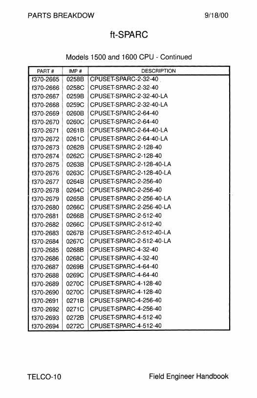
PARTS BREAKDOW 9/18/00
ft-SPARC
Models 1500 and 1600 CPU - Continued
PART# IMP# DESCRIPTION
f370-2665 02588 CPUSET-SPARC-2-32-40
f370-2666 0258C CPUSET-SPARC-2-32-40
f370-2667 02598 CPUSET-SPARC-2-32-40-LA
f370-2668 0259C CPUSET-SPARC-2-32-40-LA
f370-2669 02608 CPUSET-SPARC-2-64-40
f370-2670 0260C CPUSET-SPARC-2-64-40
f370-2671 02618 CPUSET-SPARC-2-64-40-LA
f370-2672 0261C CPUSET-SPARC-2-64-40-LA
f370-2673 02628 CPUSET-SPARC-2-128-40
f370-2674 0262C CPUSET-SPARC-2-128-40
f370-2675 02638 CPUSET-SPARC-2-128-40-LA
f370-2676 0263C CPUSET-SPARC-2-128-40-LA
f370-2677 02648 CPUSET-SPARC-2-256-40
f370-2678 0264C CPUSET-SPARC-2-256-40
f370-2679 02658 CPUSET-SPARC-2-256-40-LA
f370-2680 0266C CPUSET-SPARC-2-256-40-LA
f370-2681 02668 CPUSET-SPARC-2-512-40
f370-2682 0266C CPUSET-SPARC-2-512-40
f370-2683 02678 CPUSET-SPARC-2-512-40-LA
f370-2684 0267C CPUSET-SPARC-2-512-40-LA
f370-2685 02688 CPUSET-SPARC-4-32-40
f370-2686 0268C CPUSET-SPARC-4-32-40
f370-2687 02698 CPUSET-SPARC-4-64-40
f370-2688 0269C CPUSET-SPARC-4-64-40
f370-2689 0270C CPUSET-SPARC-4-128-40
f370-2690 0270C CPUSET-SPARC-4-128-40
f370-2691 02718 CPUSET-SPARC-4-256-40
f370-2692 0271C CPUSET-SPARC-4-256-40
f370-2693 02728 CPUSET-SPARC-4-512-40
f370-2694 0272C CPUSET-SPARC-4-512-40
TELC0-10 Field Engineer Handbook
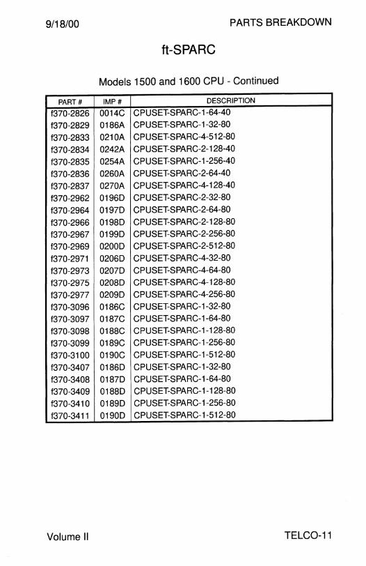
9/18/00 PARTS BREAKDOWN
ft-SPARC
Models 1500 and 1600 CPU - Continued
PART# IMP# DESCRIPTION
1370-2826 0014C CPUSET-SPARC-1-64-40
1370-2829 0186A CPUSET-SPARC-1-32-80
1370-2833 0210A CPUSET-SPARC-4-512-80
1370-2834 0242A CPUSET-SPARC-2-128-40
1370-2835 0254A CPUSET-SPARC-1-256-40
1370-2836 0260A CPUSET-SPARC-2-64-40
1370-2837 0270A CPUSET-SPARC-4-128-40
1370-2962 01960 CPUSET-SPARC-2-32-80
1370-2964 01970 CPUSET-SPARC-2-64-80
1370-2966 01980 CPUSET-SPARC-2-128-80
1370-2967 01990 CPUSET-SPARC-2-256-80
1370-2969 02000 CPUSET-SPARC-2-512-80
1370-2971 02060 CPUSET-SPARC-4-32-80
1370-2973 02070 CPUSET-SPARC-4-64-80
1370-2975 02080 CPUSET-SPARC-4-128-80
1370-2977 02090 CPUSET-SPARC-4-256-80
1370-3096 0186C CPUSET-SPARC-1-32-80
1370-3097 0187C CPUSET-SPARC-1-64-80
1370-3098 0188C CPUSET-SPARC-1-128-80
1370-3099 0189C CPUSET-SPARC-1-256-80
1370-3100 0190C CPUSET-SPARC-1-512-80
1370-3407 01860 CPUSET-SPARC-1-32-80
1370-3408 01870 CPUSET-SPARC-1-64-80
1370-3409 01880 CPUSET-SPARC-1-128-80
1370-3410 01890 CPUSET-SPARC-1-256-80
1370-3411 01900 CPUSET-SPARC-1-512-80
Volume II TELC0-11

PARTS BREAKDOW 9/18/00
ft-SPARC
Models 1500 and 1600 IOSET
PART# IMP# DESCRIPTION
f370-2466 00248 DISK-1000
f370-2467 0024C DISK-1000
f370-2468 00258 DISK-2000
f370-2469 0025C DISK-2000
f370-2473 0031J IOSET-1000
f370-2474 0031K IOSET-1000
f370-2475 0032J IOSET-2000
f370-2476 0032K IOSET-2000
f370-2500 00548 PACK-10-1
f370-2506 00598 PACK-10-2
f370-2652 0245C IOSET-4000
f370-2653 0246A DISK-4000
f370-2653 0317A IOSET-8000
f370-2994 0031F IOSET-1000
f370-2996 0032F IOSET-2000
f370-3131 0320A DISK-8000
f370-3136 0031L IOSET-1000
f370-3137 0032L IOSET-2000
f370-3139 0317A IOSET-8000
f370-3561 0031M IOSET-1000
f370-3562 0032M IOSET-2000
f370-3563 0025E DISK-2000
f370-3566 0031N IOSET-1000
f370-3574 0032N IOSET-2000
TELC0-12 Field Engineer Handbook
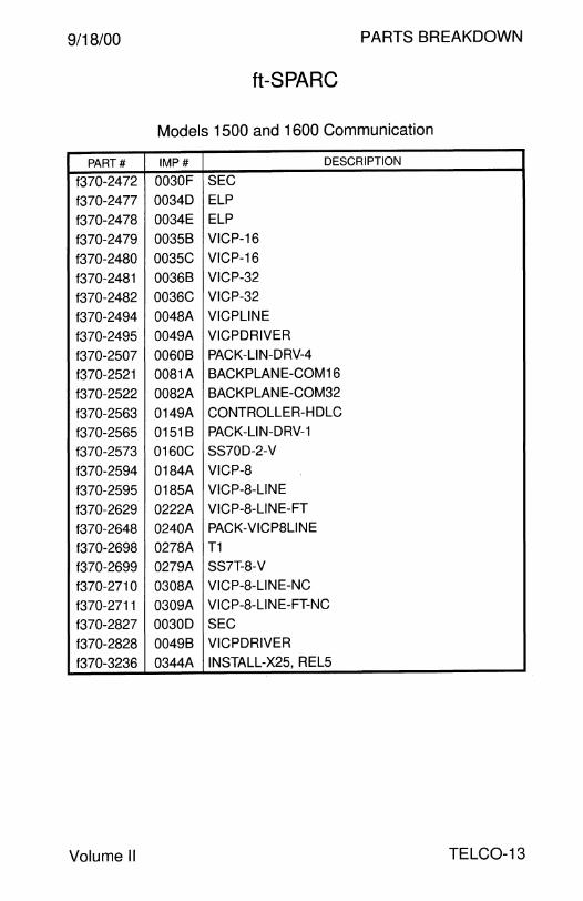
9/18/00 PARTS BREAKDOWN
ft-SPARC
Models 1500 and 1600 Communication
PART# IMP# DESCRIPTION
1370-2472 0030F SEC
1370-2477 00340 ELP
1370-2478 0034E ELP
1370-2479 00358 VICP-16
1370-2480 0035C VICP-16
1370-2481 00368 VICP-32
1370-2482 0036C VICP-32
1370-2494 0048A VICPLINE
1370-2495 0049A VICPORIVER
1370-2507 00608 PACK-LIN-ORV-4
1370-2521 0081A 8ACKPLANE-COM16
1370-2522 0082A 8ACKPLANE-COM32
1370-2563 0149A CONTROLLER-HO LC
1370-2565 01518 PACK-LIN-ORV-1
f370-2573 0160C 88700-2-V
f370-2594 0184A VICP-8
f370-2595 0185A VICP-8-LINE
f370-2629 0222A VICP-8-LINE-FT
f370-2648 0240A PACK-VICP8LINE
1370-2698 0278A T1
1370-2699 0279A 887T-8-V
f370-2710 0308A VICP-8-LINE-NC
f370-2711 0309A VICP-8-LINE-FT-NC
f370-2827 00300 SEC
f370-2828 00498 VICPORIVER
1370-3236 0344A IN8TALL-X25, REL5
Volume II TELC0-13

PARTS BREAKDOW 9/18/00
ft-SPARC
Models 1500 and 1600 Miscellaneous
PART# IMP# DESCRIPTION
f370-2493 0047B SCSI-TERM
f370-2496 00518 8RIDGE-VME
f370-2497 0052B BRIDGE-VME2
f370-2498 0052C BRIDGE-VME2
f370-2548 0118A BLANK-LOW-DRIVE
f370-2549 0119A BLANK-UPP-DRIVE
f370-2569 0156A RACKMOUNT
f370-2572 0159C CCP
f370-2589 0179A BLANK-CPUSET
f370-2590 0180A BLANK-DRIVE
f370-2591 0181A BLANK-POWER
f370-2592 0182A BLANK-IQ-SLOT
f370-2593 0183A BLANK-WIDE-IQ
f370-2632 0225A RACKMOUNT-23
f370-2643 0235A ACP
f370-2695 0275A RACKMOUNT-19
f370-2696 0276A RACKMOUNT-24
f370-2697 0277A RACKMOUNT-600
f370-3243 0346A CHASSIS-D STIFFINER KIT
f370-3365 0346B CHASSIS-D STIFFINER KIT
f370-2983 0315A CHASSIS-D-SPLIT
f370-2984 0322A CHASSIS-D-SPLIT-BPA
f370-2985 0323A CHASSIS-D-SPLIT-BPB
f370-2987 0325A CHASSIS-D-CPR
f370-2999 0163A CHASSIS-S
f370-3113 02218 CHASSIS-U-48
f370-2825 0027A TAPE-QIC-525
f370-3155 00278 TAPE-QIC-2500
f370-3551 0027C TAPE-QIC-4000
f560-2562 None Auxiliary Grounding Kit
TELC0-14 Field Engineer Handbook

9/18/00 PARTS BREAKDOWN
ft-SPARC
Models 1500 and 1600 Cables
PART# IMP# DESCRIPTION
f370-2448 0006A CABLE-CONTROL-D (DSC chassis)
f370-2449 0006B CABLE-CONTROL-D (DSC chassis)
f370-2450 0008A CABLE-SCSl-F
f370-2451 0009A CABLE-DRIVE
f370-2452 0009B CABLE-DRIVE
f370-2453 0010B CABLE-ENET-F
f370-2454 0011C CABLE-EN ET
f370-2455 0012B CABLE-VICP-U
f370-2491 0045A PWRCORD-110
f370-2492 0046A PWRCORD-220
f370-2523 0083A CABLES-DRVGRND
f370-2524 0084A CABLES-MAINGRND
f370-2525 0084B CABLES-MAINGRND
f370-2526 0085A CABLES-BATTGRND
f370-2527 0086A CABLES-CONTROL-LI (1500 chassis)
f370-2556 0129A CABLE-SCSI-EN ET
f370-2560 0146A CABLE-SCSI-SEC
f370-2561 0147A CABLE-EN ET-SEC
f370-2562 0148A PWRCORD-E
f370-2571 0158B CABLE-VICP-L
f370-2577 0165B CABLE-V35
f370-2587 0175C CABLE-X25-2-449
f370-2588 0176C CABLE-X25-4-449
f370-2640 0234A CABLE-SS7D-2-V
f370-2641 0234B CABLE-SS7D-2-V
f370-2642 0234C CABLE-SS7D-2-V
f370-2645 0237A CABLE-SCSl-F
f370-2646 0238A CABLE-SCSI-SEC
f370-2647 0239A CABLE-SCSI-EN ET
f370-2700 0280A CABLE-SS7T-4-V
f370-2706 0288A CABLE-CONTROL-600
f370-2712 0310A CABLE-SS7T-4-V-NC
f370-2986 0324A CABLE-IBP
Volume II TELC0-15
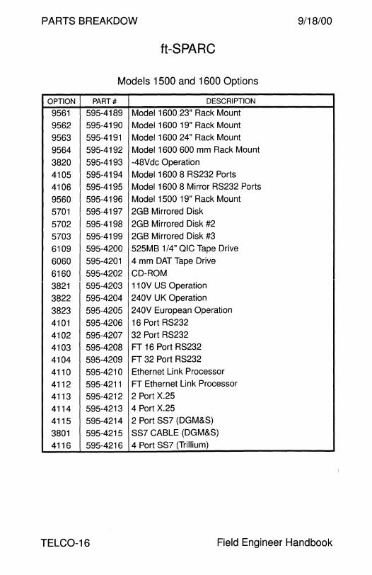
PARTS BREAKDOW 9/18/00
ft-SPARC
Models 1500 and 1600 Options
OPTION PART# DESCRIPTION
9561 595-4189 Model 1600 23" Rack Mount
9562 595-4190 Model 1600 19" Rack Mount
9563 595-4191 Model 1600 24" Rack Mount
9564 595-4192 Model 1600 600 mm Rack Mount
3820 595-4193 -48Vdc Operation
4105 595-4194 Model 1600 8 RS232 Ports
4106 595-4195 Model 1600 8 Mirror RS232 Ports
9560 595-4196 Model 1500 19" Rack Mount
5701 595-4197 2GB Mirrored Disk
5702 595-4198 2GB Mirrored Disk #2
5703 595-4199 2GB Mirrored Disk #3
6109 595-4200 525MB 1/4" QIC Tape Drive
6060 595-4201 4 mm DAT Tape Drive
6160 595-4202 CD-ROM
3821 595-4203 11 OV US Operation
3822 595-4204 240V UK Operation
3823 595-4205 240V European Operation
4101 595-4206 16 Port RS232
4102 595-4207 32 Port RS232
4103 595-4208 FT 16 Port RS232
4104 595-4209 FT 32 Port RS232
4110 595-4210 Ethernet Link Processor
4112 595-4211 FT Ethernet Link Processor
4113 595-4212 2 Port X.25
4114 595-4213 4 Port X.25
4115 595-4214 2 Port SS? (DGM&S)
3801 595-4215 SS? CABLE (DGM&S)
4116 595-4216 4 Port SS? (Trillium)
TELC0-16 Field Engineer Handbook
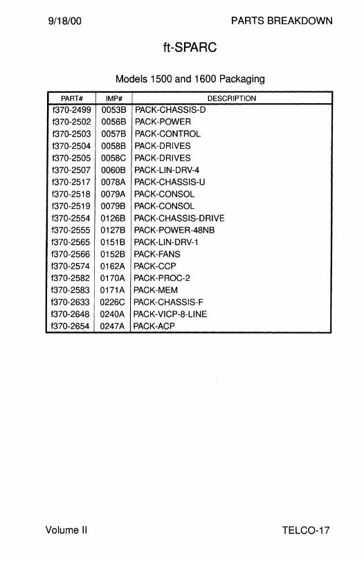
9/18/00 PARTS BREAKDOWN
ft-SPARC
Models 1500 and 1600 Packaging
PART# IMP# DESCRIPTION
f370-2499 00538 PACK-CHASSIS-D
f370-2502 00568 PACK-POWER
f370-2503 00578 PACK-CONTROL
f370-2504 00588 PACK-DRIVES
f370-2505 0058C PACK-DRIVES
f370-2507 00608 PACK-LIN-DRV-4
f370-2517 0078A PACK-CHASSIS-Li
f370-2518 0079A PACK-CONSOL
f370-2519 00798 PACK-CONSOL
f370-2554 01268 PACK-CHASSIS-DRIVE
f370-2555 01278 PACK-POWER-48N8
f370-2565 01518 PACK-LIN-DRV-1
f370-2566 01528 PACK-FANS
f370-2574 0162A PACK-CCP
f370-2582 0170A PACK-PROC-2
f370-2583 0171A PACK-MEM
f370-2633 0226C PACK-CHASSIS-F
f370-2648 0240A PACK-VICP-8-LINE
f370-2654 0247A PACK-ACP
Volume II TELC0-17
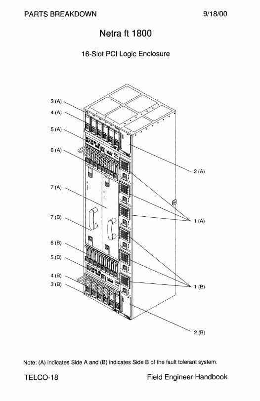
PARTS BREAKDOWN 9/18/00
Netra ft 1800
16-Slot PCI Logic Enclosure
3 (A)
4 (A)
5 (A)
6 (A)
7 (B)
6 (B)
5 (B)
4 (B)
3 (B)
2 (A)
1 (A)
1 (B)
2 (B)
Note: (A) indicates Side A and (8) indicates Side B of the fault tolerant system.
TELC0-18 Field Engineer Handbook
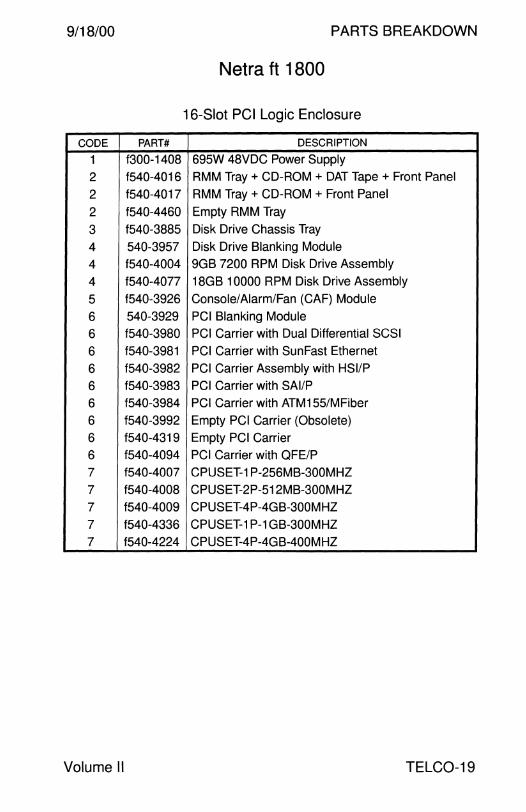
9/18/00 PARTS BREAKDOWN
Netra ft 1800
16-Slot PCI Logic Enclosure
CODE PART# DESCRIPTION
1 f300-1408 695W 48VDC Power Supply
2 f540-4016 RMM Tray + CD-ROM + DAT Tape + Front Panel
2 f540-4017 RMM Tray + CD-ROM + Front Panel
2 f540-4460 Empty RMM Tray
3 f540-3885 Disk Drive Chassis Tray
4 540-3957 Disk Drive Blanking Module
4 f540-4004 9GB 7200 RPM Disk Drive Assembly
4 f540-4077 18GB 10000 RPM Disk Drive Assembly
5 f540-3926 Console/Alarm/Fan (GAF) Module
6 540-3929 PCI Blanking Module
6 f540-3980 PCI Carrier with Dual Differential SCSI
6 f540-3981 PCI Carrier with Sun Fast Ethernet
6 f540-3982 PCI Carrier Assembly with HSl/P
6 f540-3983 PCI Carrier with SAl/P
6 f540-3984 PCI Carrier with ATM155/MFiber
6 f540-3992 Empty PCI Carrier (Obsolete)
6 f540-4319 Empty PCI Carrier
6 f540-4094 PCI Carrier with QFE/P
7 f540-4007 CPUSET-1 P-256MB-300MHZ
7 f540-4008 CPUSET-2P-512MB-300MHZ
7 f540-4009 CPUSET-4P-4GB-300MHZ
7 f540-4336 CPUSET-1 P-1 GB-300MHZ
7 f540-4224 CPUSET-4P-4GB-400MHZ
Volume II TELC0-19
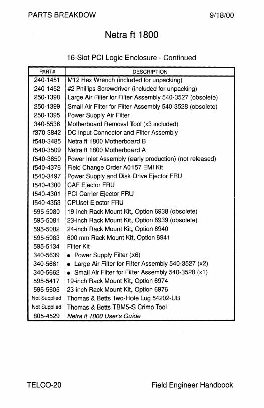
PARTS BREAKDOW 9/18/00
Netra ft 1800
16-Slot PCI Logic Enclosure - Continued
PART# DESCRIPTION
240-1451 M12 Hex Wrench (included for unpacking)
240-1452 #2 Phillips Screwdriver (included for unpacking)
250-1398 Large Air Filter for Filter Assembly 540-3527 (obsolete)
250-1399 Small Air Filter for Filter Assembly 540-3528 (obsolete)
250-1395 Power Supply Air Filter
340-5536 Motherboard Removal Tool (x3 included)
f370-3842 DC Input Connector and Filter Assembly
f540-3485 Netra ft 1800 Motherboard B
f540-3509 Netra ft 1800 Motherboard A
f540-3650 Power Inlet Assembly (early production) (not released)
f540-4376 Field Change Order A0157 EMI Kit
f540-3497 Power Supply and Disk Drive Ejector FRU
f540-4300 GAF Ejector FRU
f540-4301 PCI Carrier Ejector FRU
f540-4353 CPUset Ejector FRU
595-5080 19-inch Rack Mount Kit, Option 6938 (obsolete)
595-5081 23-inch Rack Mount Kit, Option 6939 (obsolete)
595-5082 24-inch Rack Mount Kit, Option 6940
595-5083 600 mm Rack Mount Kit, Option 6941
595-5134 Filter Kit
340-5639 • Power Supply Filter (x6)
340-5661 • Large Air Filter for Filter Assembly 540-3527 (x2)
340-5662 • Small Air Filter for Filter Assembly 540-3528 (x1)
595-5417 19-inch Rack Mount Kit, Option 697 4
595-5605 23-inch Rack Mount Kit, Option 6976 Not Supplied Thomas & Betts Two-Hole Lug 54202-UB Not Supplied Thomas & Betts TBM5-S Crimp Tool
805-4529 Netra ft 1800 User's Guide
TELC0-20 Field Engineer Handbook

9/18/00 PARTS BREAKDOWN
This page intentionally left blank.
Volume II TELC0-21

PARTS BREAKDOW 9/18/00
Netra t 1100
4-Slot PCI Logic Enclosure
PART# DESCRIPTION
262-2662 Logo
262-2663 Nameplate
300-1355 350 Watt Power Supply
501-xxxx OMB Ultra 30 System Board
501-4669 Alarm Module
540-3349 Chassis Assembly with 1 Removable Media Bay
None • Chassis 370-3273 • PCI Filler Panel
530-2514 • Power Switch
540-3350 • Disk Drive Bay Assembly (1.0" or 1.6" height)
530-2473 • SCSI Cable and Backplane Assembly
540-3490 • Top Cover
540-3491 • Front Panel Assembly
250-1392 • Fan Filter 530-2536 • Ground Strap 540-3514 • 12V Fan Assembly
540-3605 • LED PCB/Cable Assembly
501-4670 • LED Module 530-2490 • LED Cable
370-2816 12x CD-ROM, 1.6" Height
370-3415 32x CD-ROM, 1.6" Height
540-2938 4.2GB 7200 RPM 1.6" Height Disk Drive Assembly
540-2951 9.1 GB 7200 RPM 1.6" Height Disk Drive Assembly
805-1893 Netra t 1100 Service Manual
TELC0-22 Field Engineer Handbook
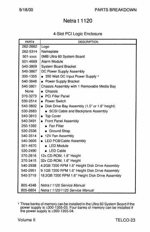
9/18/00 PARTS BREAKDOWN
Netra t 1120
4-Slot PCI Logic Enclosure
PART# DESCRIPTION
262-2662 Logo
262-5314 Nameplate
501-xxxx OMB Ultra 60 System Board
501-4669 Alarm Module
540-3809 System Board Bracket
540-3867 DC Power Supply Assembly
300-1355 • 350 Watt DC Input Power Supply 1
540-3848 • Power Supply Bracket 540-3801 Chassis Assembly with 1 Removable Media Bay
None • Chassis 370-3273 • PCI Filler Panel 530-2514 • Power Switch 540-3802 • Disk Drive Bay Assembly (1.0" or 1.6" height)
530-2683 • SCSI Cable and Backplane Assembly 540-3810 • Top Cover 540-3491 • Front Panel Assembly
250-1392 • Fan Filter 530-2536 • Ground Strap 540-3514 • 12V Fan Assembly 540-3605 • LED PCB/Cable Assembly
501-4670 • LED Module 530-2490 • LED Cable 370-2816 12x CO-ROM, 1.6" Height
370-3415 32x CD-ROM, 1.6" Height
540-2938 4.2GB 7200 RPM 1.6" Height Disk Drive Assembly
540-2951 9.1 GB 7200 RPM 1.6" Height Disk Drive Assembly 540-3719 18.2GB 7200 RPM 1.6" Height Disk Drive Assembly
805-4348 Netra t 1120 Service Manual
805-6804 Netra t 112011125 Service Manual
1 Three banks of memory can be installed in the Ultra 60 System Board if the power supply is :s;300-1355-03. Four banks of memory can be installed if the power supply is ~300-1355-04.
Volume II TELC0-23

PARTS BREAKDOWN 9/18/00
Netra t 1120
4-Slot PCI Logic Enclosure
10 9 8
TELC0-24 Field Engineer Handbook

9/18/00 PARTS BREAKDOWN
Netra t 1120
4-Slot PCI Logic Enclosure
CODE PART# DESCRIPTION
1 540-3830 Chassis Assembly with 2 Removable Media Bays
- None • Chassis
- 370-3273 • PCI Filler Panel
- 540-3831 • Disk Drive Bay Assembly (1 .O" or 1.6" height)
- 530-2684 • SCSI Cable and Backplane Assembly
- 540-3810 • Top Cover
2 540-3491 • Front Panel Assembly
- 250-1392 • Fan Filter
- 530-2536 • Ground Strap
3 540-3855 • Drive Cover
4 530-2514 • Power Switch
5 540-3605 • LED PCB/Cable Assembly
- 501-4670 • LED Module
- 530-2490 • LED Cable
6 540-3514 • 12V Fan Assembly
7 540-3867 DC Power Supply Assembly
- 300-1355 • 350 Watt DC Input Power Supply, Mate-N-Lok 1
- 300-1405 • 350 Watt DC Input Power Supply, Mate-N-Lok
- 300-1462 • 350 Watt DC Input Power Supply, Wago
- 540-3848 • Power Supply Bracket
8 370-2816 12x CD-ROM, 1.6" Height
8 370-3415 32x CD-ROM, 1.6" Height
9 370-2377 12-24GB 4 mm DDS-3 Tape Drive
10 540-3704 9.1 GB 7200 RPM 1.0" Height Disk Drive Assembly
10 540-3719 18.2GB 7200 RPM 1.6" Height Disk Drive Assembly
10 540-4177 18.2GB 10000 RPM 1.0" Height Disk Drive Assembly
NS 370-3696 Power Supply to Removable Media Cable
NS 501-xxxx OMB Ultra 60 System Board
NS 501-4669 Alarm Module
NS 540-3809 System Board Bracket with Fan
805-4348 Netra t 1120 Service Manual
805-6804 Netra t 112011125 Service Manual
1 Three memory banks can be installed if the power supply is :'.".:300-1355-03. Four memory banks can be installed if the power supply is 2300-1355-04.
Volume II TELC0-25
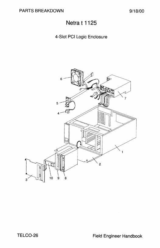
PARTS BREAKDOWN 9/18/00
Netra t 1125
4-Slot PCI Logic Enclosure
10 9 8
TELC0-26 Field Engineer Handbook

9/18/00 PARTS BREAKDOWN
Netra t 1125
4-Slot PCI Logic Enclosure
CODE PART# DESCRIPTION
1 540-3830 Chassis Assembly with 2 Removable Media Bays
- None • Chassis - 370-3273 • PCI Filler Panel
- 540-3831 • Disk Drive Bay Assembly (1.0'' or 1.6" height}
- 530-2684 • SCSI Cable and Backplane Assembly
- 540-3810 • Top Cover
2 540-3491 • Front Panel Assembly
- 250-1392 • Fan Filter
- 530-2536 • Ground Strap
3 540-3855 • Drive Cover
4 530-2514 • Power Switch
5 540-3605 • LED PCB/Cable Assembly
- 501-4670 • LED Module - 530-2490 • LED Cable
6 540-3514 • 12V Fan Assembly
7 540-3916 AC Power Supply Assembly
- 300-1406 • 325 Watt AC Input Power Supply
- 540-3848 • Power Supply Bracket
8 370-2816 12x CD-ROM, 1.6" Height
8 370-3415 32x CD-ROM, 1.6" Height
9 370-2377 12-24GB 4 mm DDS-3 Tape Drive
10 540-3704 9.1 GB 7200 RPM 1.0" Height Disk Drive Assembly
10 540-3719 18.2GB 7200 RPM 1.6" Height Disk Drive Assembly
10 540-4177 18.2GB 1000 RPM 1.0" Height Disk Drive Assembly
NS 262-2662 Logo
NS 263-0533 Nameplate
NS 370-3696 Power Supply to Removable Media Cable
NS 501-xxxx OMB Ultra 60 System Board
NS 501-4669 Alarm Module
NS 540-3809 System Board Bracket with Fan
805-6043 Netra t 1125 Service Manual (inactivated)
805-6804 Netra t 110011125 Service Manual
Volume II TELC0-27
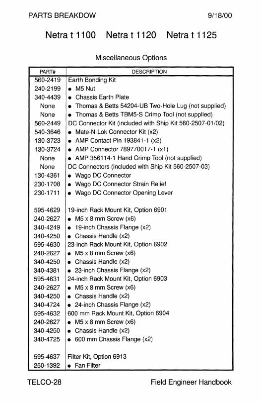
PARTS BREAKDOW 9/18/00
Netra t 1100 Netra t 1120 Netra t 1125
Miscellaneous Options
PART# DESCRIPTION
560-2419 Earth Bonding Kit
240-2199 • MS Nut 340-4439 • Chassis Earth Plate
None • Thomas & Betts 54204-UB Two-Hole Lug (not supplied)
None • Thomas & Betts TBM5-S Crimp Tool (not supplied)
560-2449 DC Connector Kit (included with Ship Kit S60-2507-01/02)
540-3646 • Mate-N-Lok Connector Kit (x2)
130-3723 • AMP Contact Pin 193841-1 (x2)
130-3724 • AMP Connector 789770017-1 (x1)
None • AMP 3S6114-1 Hand Crimp Tool (not supplied)
None DC Connectors (included with Ship Kit 560-2S07-03)
130-4361 • Wago DC Connector
230-1708 • Wago DC Connector Strain Relief
230-1711 • Wago DC Connector Opening Lever
595-4629 19-inch Rack Mount Kit, Option 6901
240-2627 • MS x 8 mm Screw (x6)
340-4249 • 19-inch Chassis Flange (x2)
340-42SO • Chassis Handle (x2)
595-4630 23-inch Rack Mount Kit, Option 6902
240-2627 • M5 x 8 mm Screw (x6)
340-4250 • Chassis Handle (x2)
340-4381 • 23-inch Chassis Flange (x2)
595-4631 24-inch Rack Mount Kit, Option 6903
240-2627 • M5 x 8 mm Screw (x6)
340-4250 • Chassis Handle (x2)
340-4724 • 24-inch Chassis Flange (x2)
S95-4632 600 mm Rack Mount Kit, Option 6904
240-2627 • M5 x 8 mm Screw (x6)
340-4250 • Chassis Handle (x2)
340-472S • 600 mm Chassis Flange (x2)
595-4637 Filter Kit, Option 6913
250-1392 • Fan Filter
TELC0-28 Field Engineer Handbook

9/18/00 PARTS BREAKDOWN
This page intentionally left blank.
Volume II TELC0-29

PARTS BREAKDOWN 9/18/00
Netra t 1400
4-Slot PCI Logic Enclosure
6
0
TELC0-30 Field Engineer Handbook

9/18/00 PARTS BREAKDOWN
Netra t 1400 Netra t 1405
4-Slot PCI Logic Enclosure
CODE PART# DESCRIPTION
1 599-2295 AC Chassis Assembly
1 599-2349 DC Chassis Assembly
2 300-1407 • 125 Watt DC-DC Converter with Fan
3 540-4262 • Ultra 80 System Board Fan Assembly/FRU
4 540-3948 • Ultra 80 System Board Shroud Assembly/FRU
5 501-xxxx Ultra 80 System Board
6 300-1434 • AC Input Power Supply Type A 142
6 300-1435 • DC Input Power Supply Type D129
NS 501-5437 • RCP/Alarm Board
1 540-4065 • Chassis Assembly
7 370-3976 • Fan 8 501-5561 • Fan Control Board
9 370-4039 • LED/Alarm Cable
10 370-3920 • Power Distribution Backplane Assembly/FRU
11 370-4040 • LED/Motherboard Cable
12 530-2514 • Power Switch and Cable
13 501-5560 • LED Board
14 330-2809 • Switch and LED Cover
15 540-4311 • Disk Bay Assembly/FRU (1.0" or 1.6" height)
370-3929 • Disk Bay Power Cable
16 340-5568 • Removable Media Mounting Bracket
17 540-4068 • Fan Cover
18 540-4066 • Removable Media Cover
NS 370-3273 • PCI Slot Filler Panel
NS 370-3927 • Removable Media SCSI Cable
NS 370-3928 • Removable Media Power Cable
NS 501-5125 • Removable Media SCSI Adapter
NS 540-4067 • Top Cover
19 540-4177 18.2GB 10000 RPM Disk Drive Assembly/FRU
20 370-3416 32x CD-ROM, Medium Grey
20 370-2376 12-24GB 4 mm DDS-3 Tape Drive, Medium Grey
21 340-5595 DAT Outer Filler Panel
22 340-5594 CD-ROM Outer Filler Panel
Volume II TELC0-31

PARTS BREAKDOW 9/18/00
Netra t 1400 Netra t 1405
4-Slot PCI Logic Enclosure - Continued
PART# DESCRIPTION
540-3551 CD-ROM/DAT Inner Filler Panel
565-1639 Cable Kit, 370-3927/3928/3929/4039/4040
560-2579 T1400 Ship Kit
130-4361 • Wago DC Connector
230-1708 • Wago DC Connector Strain Relief
230-1711 • Wago DC Connector Opening Lever
340-6091 • Memory Riser Torque Tool
560-2569 • Flange Kit
340-4250 • 4U Chassis Handle
340-5904 • 19-inch Flange
560-2568 T1405 Ship Kit
340-6091 • Memory Riser Torque Tool
560-2569 • Fiange Kit
340-4250 • 4U Chassis Handle
340-5904 • 19-inch Flange
595-5355 Air Filter Kit, Option X7075A
330-2930 • Air Filter (x5)
595-5356 Trim Kit, Option X7076A
263-xxxx • Netra t 1400/1405 Nameplates
330-2809 • Switch and LED Cover
540-4066 • Removable Media Cover Assembly
540-4068 • Fan Cover Assembly
595-5351 19-inch Rack Mount Kit, Option X7071 A
595-5352 23-inch Rack Mount Kit, Option X7072A
595-5353 24-inch Rack Mount Kit, Option X7073A
595-5354 600 mm Rack Mount Kit, Option X707 4A
806-0576 Service and System Reference Manual
TELC0-32 Field Engineer Handbook
9/18/00 PARTS BREAKDOWN
This page intentionally left blank.
Volume II TELC0-33
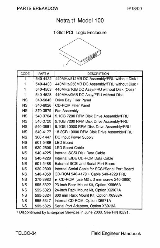
PARTS BREAKDOW 9/18/00
Netra t1 Model 100
1-Slot PCI Logic Enclosure
CODE PART# DESCRIPTION
1 540-4432 440MHz/512MB DC Assembly/FRU without Disk 1
1 540-4433 440MHz/256MB DC Assembly/FRU without Disk 1
1 540-4503 440MHz/1 GB DC Assy/FRU without Disk (Obs) 1
1 540-4528 440MHz/OMB DC Assy/FRU without Disk
NS 340-5843 Drive Bay Filler Panel
NS 340-6026 CD-ROM Filler Panel
NS 370-3979 Fan Assembly
NS 540-3704 9.1 GB 7200 RPM Disk Drive Assembly/FRU l\IC t::.Af'\ 0"71'}1"\ 9.1 GB 7200 RPM Disk Drive Assembiy/FRU .. u .J""tV-'-'1 .C..U
NS 540-3881 9.1 GB 10000 RPM Disk Drive Assembly/FRU
NS 540-4177 18.2GB 10000 RPM Disk Drive Assembly IF RU
NS 300-1447 DC Input Power Supply
NS 501-5489 LED Board
NS 530-2806 LED Board Cable
NS 540-4225 Internal SCSI Disk Data Cable
NS 540-4229 Internal EIDE CD-ROM Data Cable
NS 501-5488 External SCSI and Serial Port Board
NS 530-2809 Internal Serial Cable for SCSI/Serial Port Board
NS 540-4358 CD-ROM 540-4179 + Cable 540-4229 FRU
NS 370-3983 • CD-ROM (use M2 x 3 mm screw 240-3800)
NS 595-5322 23-inch Rack Mount Kit, Option X6966A
NS 595-5323 24-inch Rack Mount Kit, Option X6967 A
NS 595-5324 600 mm Rack Mount Kit, Option X6968A
NS 595-5317 Internal CD-ROM, Option X6971A
NS 595-5325 Serial Port Adapters, Option X6973A
1 Discontinued by Enterprise Services in June 2000. See FIN 10591.
TELC0-34 Field Engineer Handbook

9/18/00
CODE PART#
1 540-4317
1 540-4385
1 540-4318
1 540-4424
1 540-4498
1 540-4529
1 540-4564
NS 340-5843
NS 340-6026
NS 370-3979
NS 540-3704
NS 540-3720
NS 540-3881
NS 540-4177
NS 300-1448
NS 501-5489
NS 530-2806
NS 540-4225
NS 540-4229
NS 501-5488
NS 530-2809
NS 540-4358
NS 370-3983
NS 595-5322
NS 595-5323
NS 595-5324
NS 595-5317
NS 595-5325
PARTS BREAKDOWN
Netra t1 Model 105 1-Slot PCI Logic Enclosure
DESCRIPTION
360MHz/64MB AC Assembly/FRU without Disk 1
360MHz/512MB AC Assembly/FRU without Disk 1
440MHz/256MB AC Assembly/FRU without Disk 1
440MHz/512MB AC Assembly/FRU without Disk 1
440MHz/1 GB AC Assy/FRU without Disk (Obs) 1
440MHz/OMB AC Assy/FRU without Disk
360MHz/OMB AC Assy/FRU without Disk
Drive Bay Filler Panel
CD-ROM Filler Panel
Fan Assembly
9.1 GB 7200 RPM Disk Drive Assembly/FRU
9.1 GB 7200 RPM Disk Drive Assembly/FRU
9.1 GB 10000 RPM Disk Drive Assembly/FRU
18.2GB 10000 RPM Disk Drive Assembly/FRU
AC Input Power Supply
LED Board
LED Board Cable
Internal SCSI Disk Data Cable Internal EIDE CD-ROM Data Cable
External SCSI and Serial Port Board
Internal Serial Cable for SCSI/Serial Port Board
CD-ROM 540-4179 + Cable 540-4229 FRU
• CD-ROM (use M2 x 3 mm screw 240-3800)
23-inch Rack Mount Kit, Option X6966A
24-inch Rack Mount Kit, Option X6967 A
600 mm Rack Mount Kit, Option X6968A
Internal CD-ROM, Option X6971 A
Serial Port Adapters, Option X6973A
1 Discontinued by Enterprise Services in June 2000. See FIN 10591.
Volume II TELC0-35

PARTS BREAKDOW 9/18/00
Netra t1 Models 100 and 105
Boards
PART# DESCRIPTION
540-4348 64MB Memory Board Assembly/FRU
501-5210 • 64MB Memory Board FRU
540-4349 256MB Memory Board Assembly/FRU)
501-5388 • 256MB Memory Board FRU
370-4096 • 256MB Memory Board
540-4547 256MB Memory Board Assembly/FRU 1
370-4155 • 256MB Memory Board (use hardware kit 540-4532) 1
540-4350 512MB Memory Board Assembly/FRU
501-5389 • 512MB Memory Board FRU
540-4260 360MHz CPU and 1/0 Interface Assembly
501-5478 • 1/0 Interface Board 501-5577 • OMB 360MHz CPU without Front Panel
595-5254 • OMB 360MHz CPU without Front Panel
540-4258 440MHz CPU and 1/0 Interface Assembly
501-5478 • 1/0 Interface Board 501-5578 • OMB 440MHz CPU without Front Panel
1 Up to four memory boards of this design can be installed.
TELC0-36 Field Engineer Handbook
9/18/00 PARTS BREAKDOWN
This page intentionally left blank.
Volume II TELC0-37

PARTS BREAKDOWN 9/18/00
Netra ct 400
5-Slot cPCI Logic Enclosure
3
TELC0-38 Field Engineer Handbook
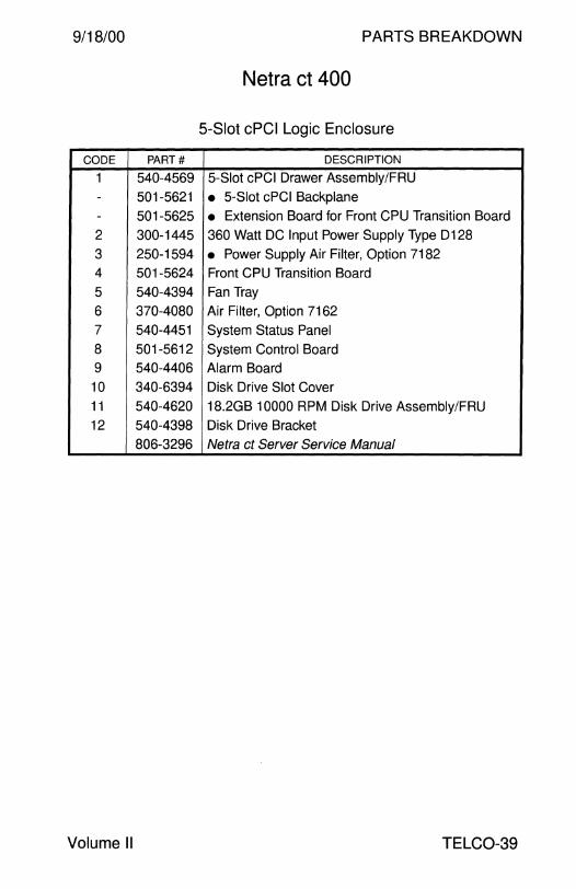
9/18/00 PARTS BREAKDOWN
Netra ct 400
5-Slot cPCI Logic Enclosure
CODE PART# DESCRIPTION
1 540-4569 5-Slot cPCI Drawer Assembly/FRU - 501-5621 • 5-Slot cPCI Backplane - 501-5625 • Extension Board for Front CPU Transition Board
2 300-1445 360 Watt DC Input Power Supply Type D128
3 250-1594 • Power Supply Air Filter, Option 7182 4 501-5624 Front CPU Transition Board
5 540-4394 Fan Tray
6 370-4080 Air Filter, Option 7162
7 540-4451 System Status Panel
8 501-5612 System Control Board
9 540-4406 Alarm Board
10 340-6394 Disk Drive Slot Cover
11 540-4620 18.2GB 10000 RPM Disk Drive Assembly/FRU
12 540-4398 Disk Drive Bracket
806-3296 Netra ct Server Service Manual
Volume II TELC0-39
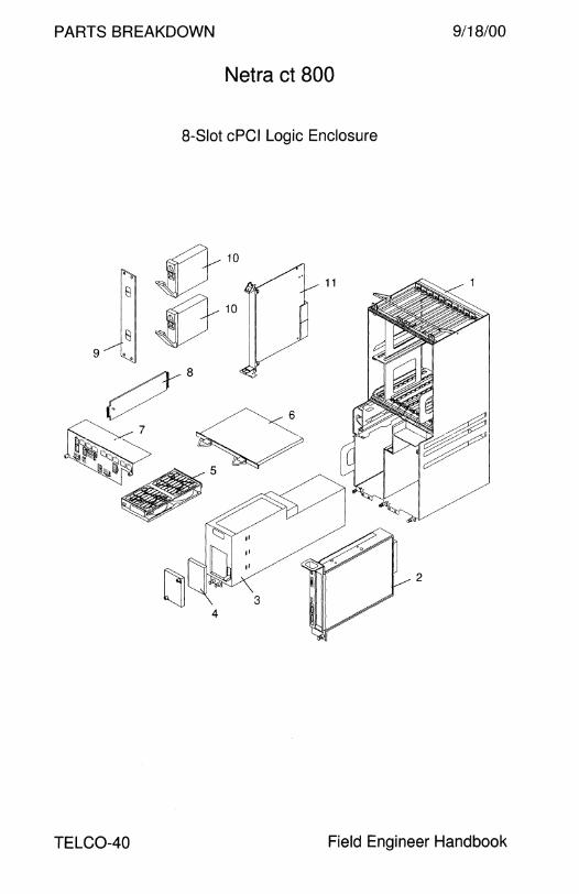
PARTS BREAKDOWN 9/18/00
Netra ct 800
8-Slot cPCI Logic Enclosure
4
TELC0-40 Field Engineer Handbook
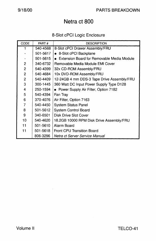
9/18/00 PARTS BREAKDOWN
Netra ct 800
8-Slot cPCI Logic Enclosure
CODE PART# DESCRIPTION
1 540-4568 8-Slot cPCI Drawer Assembly/FRU - 501-5617 • 8-Slot cPCI Backplane - 501-5615 • Extension Board for Removable Media Module
2 340-6732 Removable Media Module EMI Cover
2 540-4399 32x CD-ROM Assembly/FRU
2 540-4684 1 Ox DVD-ROM Assembly/FRU
2 540-4409 12-24GB 4 mm DDS-3 Tape Drive Assembly/FRU
3 300-1445 360 Watt DC Input Power Supply Type D128
4 250-1594 • Power Supply Air Filter, Option 7182
5 540-4394 Fan Tray
6 370-4076 Air Filter, Option 7163
7 540-4450 System Status Panel
8 501-5612 System Control Board
9 340-6501 Disk Drive Slot Cover 10 540-4620 18.2GB 10000 RPM Disk Drive Assembly/FRU 11 501-5610 Alarm Board 11 501-5618 Front CPU Transition Board
806-3296 Netra ct Server Service Manual
Volume II TELC0-41

PARTS BREAKDOW 9/18/00
Netra ct 400 Netra ct 800
Boards
PART# DESCRIPTION
501-5209 128MB Memory Board FRU
540-4349 256MB Memory Board Assembly/FRU)
501-5388 • 256MB Memory Board FRU
370-4096 • 256MB Memory Board
540-4350 512MB Memory Board Assembly/FRU
501-5389 • 512MB Memory Board FRU
501-5731 OMS 440MHz CP1500 CPU with Front Panel FRU
501-5473 • OMS 440MHz CP1500 CPU with Front Panel
501-5795 128MB 440MHz CP1500 CPU with Front Panel
501-5796 512MB 440MHz CP1500 CPU with Front Panel
501-5800 1 GB 440MHz CP1500 CPU with Front Panel
340-6483 SU cPCI Slot Filler Panel
501-5609 Rear CPU Transition Board, Netra ct 400/800
501-5611 Rear Alarm Transition Board, Netra ct 800
501-5616 Removable Media Module Termination Board, Netra ct 800
501-5619 Shunt Board, Slot 1 to Slot 2, Netra ct 400/800
TELC0-42 Field Engineer Handbook

9/18/00 PARTS BREAKDOWN
Netra ct 1600
Netra ct 400 and Netra ct 800 Chassis
CODE PART# DESCRIPTION
1 596-2711 N08-DF Front Access DC Chassis Assembly
NS 340-6399 • Rear DC Connector Cover NS 540-4391 • DC Chassis Assembly NS 530-2895 • Front Access DC Input Cable
NS 540-4397 • DC Input Filter Assembly 1 596-2710 NOS-DR Rear Access DC Chassis Assembly
NS 540-4391 • DC Chassis Assembly
NS 540-4397 • DC Input Filter Assembly
806-3296 Netra ct Server Service Manual
Volume II TELC0-43

PARTS BREAKDOWN 9/18/00
Netra st A 1000 ARY144A-36GAC ARY144A-36GDC
AC Input Power DC Input Power 4 9.1 GB 10000 RPM Disks 4 9.1GB 10000 RPM Disks
ARY151A-72GAC ARY151A-72GDC AC Input Power DC Input Power
4 18.2GB 10000 RPM Disks 4 18.2GB 10000 RPM Disks
3
5
4
6
a.
TELC0-44 Field Engineer Handbook
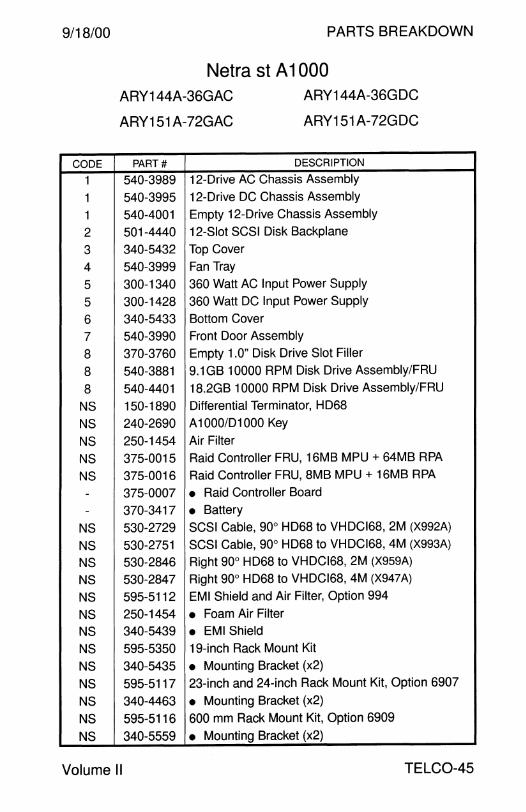
9/18/00
CODE
1
1
1
2
3
4
5
5
6 7
8
8
8 NS
NS
NS
NS
NS -
-NS
NS NS
NS
NS
NS NS
NS
NS
NS
NS
NS
NS
PARTS BREAKDOWN
Netra st A 1 000 ARY144A-36GAC
ARY151 A-72GAC
ARY144A-36GDC
ARY151A-72GDC
PART# DESCRIPTION
540-3989 12-Drive AC Chassis Assembly
540-3995 12-Drive DC Chassis Assembly
540-4001 Empty 12-Drive Chassis Assembly
501-4440 12-Slot SCSI Disk Backplane
340-5432 Top Cover
540-3999 Fan Tray
300-1340 360 Watt AC Input Power Supply
300-1428 360 Watt DC Input Power Supply
340-5433 Bottom Cover
540-3990 Front Door Assembly
370-3760 Empty 1.0" Disk Drive Slot Filler
540-3881 9.1 GB 10000 RPM Disk Drive Assembly/FRU
540-4401 18.2GB 10000 RPM Disk Drive Assembly/FRU
150-1890 Differential Terminator, HD68
240-2690 A 1OOO/D1000 Key
250-1454 Air Filter
375-0015 Raid Controller FRU, 16MB MPU + 64MB RPA
375-0016 Raid Controller FRU, 8MB MPU + 16MB RPA
375-0007 • Raid Controller Board
370-3417 • Battery
530-2729 SCSI Cable, 90° HD68 to VHDCl68, 2M (X992A)
530-2751 SCSI Cable, 90° HD68 to VHDCl68, 4M (X993A)
530-2846 Right 90° HD68 to VHDCl68, 2M (X959A)
530-2847 Right 90° HD68 to VHDCl68, 4M (X947A)
595-5112 EMI Shield and Air Filter, Option 994
250-1454 • Foam Air Filter 340-5439 • EMI Shield
595-5350 19-inch Rack Mount Kit
340-5435 • Mounting Bracket (x2)
595-5117 23-inch and 24-inch Rack Mount Kit, Option 6907
340-4463 • Mounting Bracket (x2)
595-5116 600 mm Rack Mount Kit, Option 6909
340-5559 • Mounting Bracket (x2)
Volume II TELC0-45

PARTS BREAKDOWN 9/18/00
Netra st 01000 ARY145A-36GAC ARY145A-36GDC
AC Input Power DC Input Power 4 9.1 GB 10000 RPM Disks 4 9.1 GB 10000 RPM Disks
ARY153A-72GAC ARY153A-72GDC AC Input Power DC Input Power
4 18.2GB 10000 RPM Disks 4 18.2GB 10000 RPM Disks
3
5
4
TELC0-46 Field Engineer Handbook
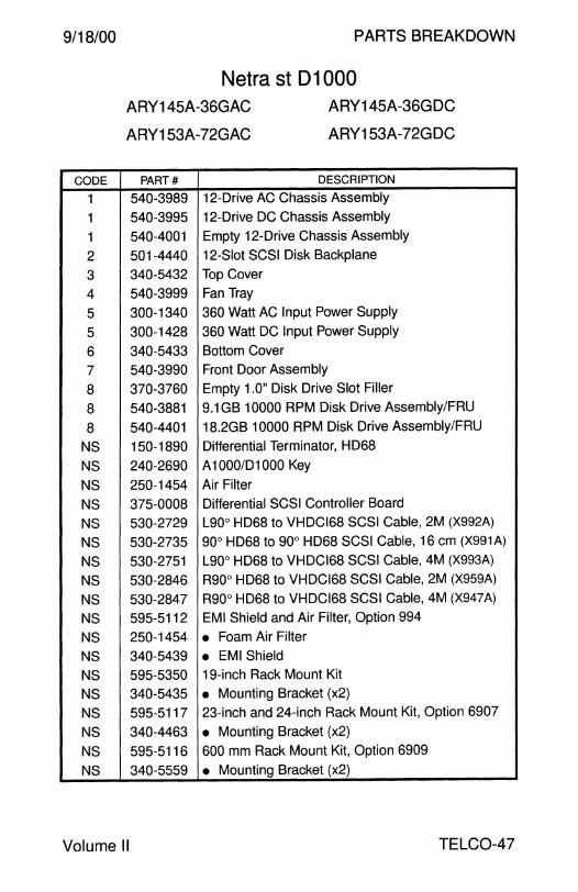
9/18/00
CODE
1
1
1
2
3 4
5
5
6 7
8
8
8 NS
NS
NS
NS
NS
NS
NS
NS
NS NS
NS
NS
NS
NS
NS
NS
NS
NS
PARTS BREAKDOWN
Netra st 01000 ARY145A-36GAC
ARY153A-72GAC
ARY145A-36GDC
ARY153A-72GDC
PART# DESCRIPTION
540-3989 12-Drive AC Chassis Assembly
540-3995 12-Drive DC Chassis Assembly
540-4001 Empty 12-Drive Chassis Assembly
501-4440 12-Slot SCSI Disk Backplane
340-5432 Top Cover
540-3999 Fan Tray
300-1340 360 Watt AC Input Power Supply
300-1428 360 Watt DC Input Power Supply
340-5433 Bottom Cover
540-3990 Front Door Assembly
370-3760 Empty 1.0" Disk Drive Slot Filler
540-3881 9.1 GB 10000 RPM Disk Drive Assembly/FRU
540-4401 18.2GB 10000 RPM Disk Drive Assembly/FRU
150-1890 Differential Terminator, HD68
240-2690 A 1OOO/D1000 Key
250-1454 Air Filter
375-0008 Differential SCSI Controller Board
530-2729 L90° HD68 to VHDC168 SCSI Cable, 2M (X992A)
530-2735 90° HD68 to 90° HD68 SCSI Cable, 16 cm (X991A)
530-2751 L90° HD68 to VHDCl68 SCSI Cable, 4M (X993A)
530-2846 R90° HD68 to VHDCl68 SCSI Cable, 2M (X959A)
530-2847 R90° HD68 to VHDCl68 SCSI Cable, 4M (X947A)
595-5112 EMI Shield and Air Filter, Option 994
250-1454 • Foam Air Filter
340-5439 • EMI Shield
595-5350 19-inch Rack Mount Kit
340-5435 • Mounting Bracket (x2)
595-5117 23-inch and 24-inch Rack Mount Kit, Option 6907
340-4463 • Mounting Bracket (x2)
595-5116 600 mm Rack Mount Kit, Option 6909
340-5559 • Mounting Bracket (x2)
Volume II TELC0-47
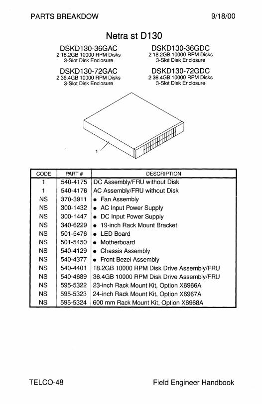
PARTS BREAKDOW 9/18/00
CODE
1
1
i\iS
NS
NS
NS
NS
NS
NS
NS
NS
NS
NS
NS
NS
Netra st D 1 30 DSKD130-36GAC
2 18.2GB 10000 RPM Disks 3-Slot Disk Enclosure
DSKD130-36GDC 2 18.2GB 10000 RPM Disks
3-Slot Disk Enclosure
DSKD 130-72GAC 2 36.4GB 10000 RPM Disks
3-Slot Disk Enclosure
DSKD 130-72G DC 2 36.4GB 10000 RPM Disks
3-Slot Disk Enclosure
PART# DESCRIPTION
540-4175 DC Assembly/FRU without Disk
540-4176 AC Assembly/FRU without Disk
370-39i i • Fan Assembly 300-1432 • AC Input Power Supply 300-1447 • DC Input Power Supply 340-6229 • 19-inch Rack Mount Bracket 501-5476 • LED Board 501-5450 • Motherboard 540-4129 • Chassis Assembly 540-4377 • Front Bezel Assembly 540-4401 18.2GB 10000 RPM Disk Drive Assembly IF RU 540-4689 36.4GB 10000 RPM Disk Drive Assembly IF RU
595-5322 23-inch Rack Mount Kit, Option X6966A 595-5323 24-inch Rack Mount Kit, Option X6967 A
595-5324 600 mm Rack Mount Kit, Option X6968A
TELC0-48 Field Engineer Handbook

This page intentionally left blank.

This page intentionally left blank.

PARTS BREAKDOWN
DISK

9/18/00 PARTS BREAKDOWN
Disk
disktower 1000 2.1GB .............................................................................. 4 4.2GB .............................................................................. 4
Differential SCSI Disk Subsystem 2.1GB .............................................................................. 6 2.9GB .............................................................................. 8 9.0GB .............................................................................. 8
Desktop Disk Pack 104MB .............................................................................. 10 207MB .............................................................................. 10 424MB .............................................................................. 10 207MB .............................................................................. 12 535MB .............................................................................. 14 1.05GB .............................................................................. 14 2.1GB .............................................................................. 14
Desktop Storage Module 1.3GB .............................................................................. 16
Multi-Disk Pack 1.05GB 5400 RPM ................................. ........................... 18 2.1GB 5400 RPM .............................................................. 18 2.1GB 7200 RPM .............................................................. 18 4.2GB 5400 RPM ................................... ........................... 18
SPARCstorage UniPack 1.05GB 5400 RPM ............................................................ 20 2.1GB 7200 RPM .............................................................. 20 4.2GB 5400 RPM . ..... .. .. . . .. .. . .. .. . . . . . . . . . . . .. . . . . . . .. . . . . . . . . . . . .. . .. . . . . 22 4.2GB 7200 RPM .............................................................. 22 9.1 GB 7200 RPM .. ... .. .. .. .. ... .. .. .. .. .. .. .. . .. . . . ... . . . . . .. . . . . . .. . . . . . . .. . 22
SPARCstorage MultiPack 6-Slot Chassis 4.2GB 5400 RPM . .. ..... .. .. .... .. ... . . . . .. .. . . . .. . . .. .. .. . . . . . .. .. . .. ... . .. .. 24 9.1 GB 7200 RPM .. .... ... .. . ... .. ... .. .. .. .. .. . . . .. . .. . .. . .. . .. .. . .. . .. . .. . . . . 24
Field Engineer Handbook - Volume II
PARTS BREAKDOWN 9/18/00
Disk - Continued
SPARCstorage MultiPack 12-Slot Chassis 2.1 GB 7200 RPM . ... . ... .. .. .... .... ... ... ... .. .. ... .. .... .. . .. .. ... ... .. ... . . 26 4.2GB 7200 RPM ........ ... .. .. .... ... ...... .... .... ........ .. ..... .. ......... 26
SPARCstorage MultiPack 2 6-Slot Chassis 9.1 GB 7200 RPM .............................................................. 28
StorEdge UniPack 4.2GB 7200 RPM .... ... .. ... .. .. .... ... ... . .. . . .... .. .. .. .. ... .. . . . .. ...... ... 30 9.1 GB 7200 RPM .. ... . .. ... .. .. ..... .. .... ... .. .. .. .. .. ..... ... .. ... ... ... ... . 32 9.1GB 10000 RPM ............................................................ 32 18.2GB 7200 RPM .. .. . . .. .. .. .. ..... .. .. .. ... .. ... ... . . . .. ..... .. . .. . .. .. . .. . 34 18.2GB 10000 RPM . . .. ... .. .. ..... .. .... ... .. .. .. . . .. ..... .. . .. ... ... .. . .. . . 34 36.4GB 10000 RPM .. . .. .. ... ... .. .. .. .. .. . .. .... .. .. .. .. ..... ... . . .. ... . .. . . 34
StorEdge MultiPack 4.2GB 7200 RPM .............................................................. 36 9.1GB 7200 RPM .............................................................. 38 9.1GB 10000 RPM ............................................................ 38 18.2GB 7200 RPM ... . .... .. ...... .. .. . .. .. .. . .. . .. .. .. .. .. .. ... ... . ... .. . .. . . 40 18.2GB 10000 RPM .. .... ....... ... .. . .. .. . . .. .. .. .. .. .. . . ... ...... .. . .. .. . . . 40 36.4GB 10000 RPM........................................................... 40
DISK-2 Field Engineer Handbook
9/18/00 PARTS BREAKDOWN
This page intentionally left blank.
Volume II DISK-3
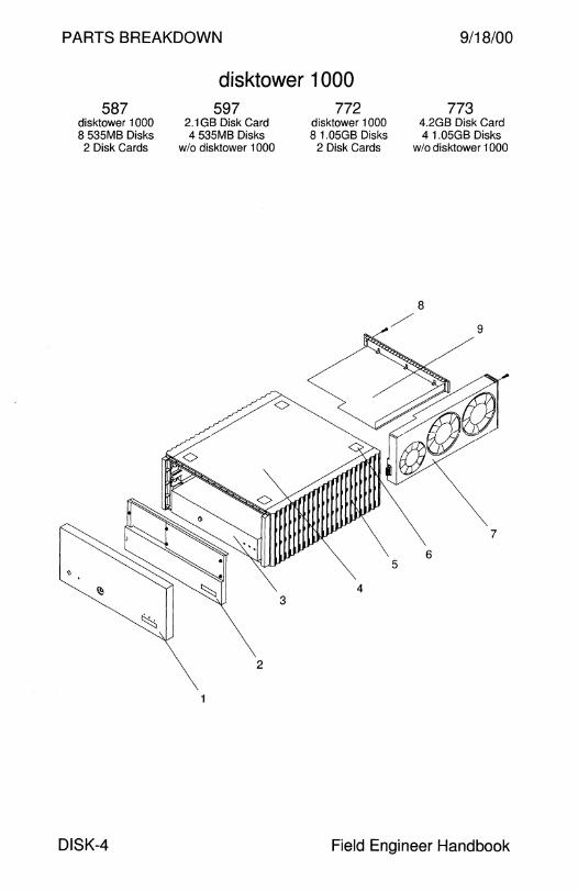
PARTS BREAKDOWN
disktower 1 000 587
disktower 1000 8 535MB Disks 2 Disk Cards
597 2.1 GB Disk Card 4 535MB Disks
wlo disktower 1000
772 disktower 1000 8 1.0SGB Disks
2 Disk Cards
9/18/00
773 4.2GB Disk Card 4 1.0SGB Disks
w!o disktower 1000
8
/ 9
7
6
DISK-4 Field Engineer Handbook
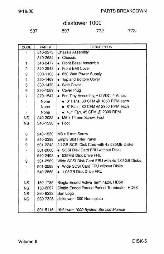
9/18/00 PARTS BREAKDOWN
disktower 1000 587 597 772 773
CODE PART# DESCRIPTION
- 540-2273 Chassis Assembly
- 340-2684 • Chassis
1 540-2477 • Front Bezel Assembly
2 340-2943 • Front EMI Cover
3 300-1103 • 650 Watt Power Supply
4 330-1469 • Top and Bottom Cover
5 330-1470 • Side Cover
6 330-1589 • Cover Plug
7 370-1547 • Fan Tray Assembly, +12VDC, 4 Amps
- None • 6" Fans, 60 CFM @ 1850 RPM each
- None • 6" Fans, 80 CFM @ 2950 RPM each
- None • 4.7" Fan, 45 CFM@ 2300 RPM
NS 240-2083 • M6 x 14 mm Screw, Foot
NS 340-1590 • Foot
8 240-1530 M3 x 6 mm Screw
9 540-2388 Empty Slot Filler Panel
9 501-2242 2.1 GB SCSI Disk Card with 4x 535MB Disks
- 501-2066 • SCSI Disk Card FRU without Disks
- 540-2403 • 535MB Disk Drive FRU
9 501-2589 Wide SCSI Disk Card FRU with 4x 1.05GB Disks
- 501-2588 • Wide SCSI Card FRU without Disks
- 540-2568 • 1.05GB Disk Drive FRU
NS 150-1785 Single-Ended Active Terminator, HD50
NS 150-2267 Single-Ended Forced Perfect Terminator, HD68
NS 260-6233 Sun Logo
NS 260-7326 disktower 1 000 Nameplate
801-5116 disktower 1000 System Service Manual
Volume II DISK-5
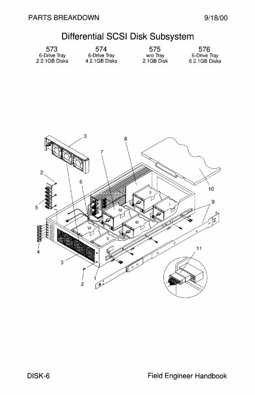
PARTS BREAKDOWN 9/18/00
Differential SCSI Disk Subsystem 573
6-Drive Tray 2 2.1 GB Disks
DISK-6
574 6-Drive Tray
4 2.1 GB Disks
575 wlo Tray
2.1GB Disk
576 6-Drive Tray
6 2.1GB Disks
Field Engineer Handbook
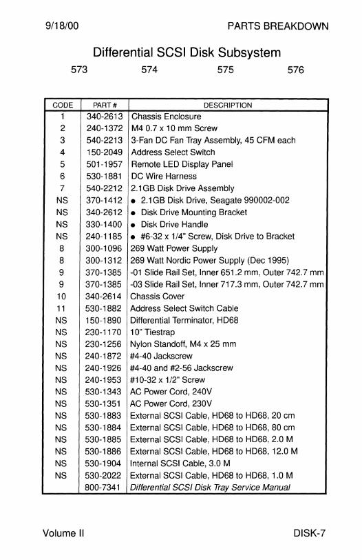
9/18/00 PARTS BREAKDOWN
Differential SCSI Disk Subsystem 573 574 575 576
CODE PART# DESCRIPTION
1 340-2613 Chassis Enclosure
2 240-1372 M4 0.7 x 10 mm Screw
3 540-2213 3-Fan DC Fan Tray Assembly, 45 CFM each
4 150-2049 Address Select Switch
5 501-1957 Remote LED Display Panel
6 530-1881 DC Wire Harness
7 540-2212 2.1GB Disk Drive Assembly
NS 370-1412 • 2.1 GB Disk Drive, Seagate 990002-002
NS 340-2612 • Disk Drive Mounting Bracket
NS 330-1400 • Disk Drive Handle
NS 240-1185 • #6-32 x 1/4" Screw, Disk Drive to Bracket
8 300-1096 269 Watt Power Supply
8 300-1312 269 Watt Nordic Power Supply (Dec 1995)
9 370-1385 -01 Slide Rail Set, Inner 651.2 mm, Outer 742.7 mm
9 370-1385 -03 Slide Rail Set, Inner 717.3 mm, Outer 742.7 mm
10 340-2614 Chassis Cover
11 530-1882 Address Select Switch Cable
NS 150-1890 Differential Terminator, HD68
NS 230-1170 1 O" Tiestrap
NS 230-1256 Nylon Standoff, M4 x 25 mm
NS 240-1872 #4-40 Jackscrew
NS 240-1926 #4-40 and #2-56 Jackscrew
NS 240-1953 #1 0-32 x 1 /2" Screw
NS 530-1343 AC Power Cord, 240V
NS 530-1351 AC Power Cord, 230V
NS 530-1883 External SCSI Cable, HD68 to HD68, 20 cm
NS 530-1884 External SCSI Cable, HD68 to HD68, 80 cm
NS 530-1885 External SCSI Cable, HD68 to HD68, 2.0 M
NS 530-1886 External SCSI Cable, HD68 to HD68, 12.0 M
NS 530-1904 Internal SCSI Cable, 3.0 M
NS 530-2022 External SCSI Cable, HD68 to HD68, 1.0 M
800-7341 Differential SCSI Disk Tray Service Manual
Volume II DISK-7

PARTS BREAKDOWN 9/18/00
Differential SCSI Disk Subsystem 583 584 585 586
6-Drive Tray 6-Drive Tray w/o Tray 6-Drive Tray 2 2.9GB Disks 4 2.9GB Disks 2.9GB Disk 6 2.9GB Disks
783 784 785 786 6-Drive Tray 6-Drive Tray w/o Tray 6-Drive Tray
2 9.0GB Disks 4 9.0GB Disks 9.0GB Disk 6 9.0GB Disks
8
DISK-8 Field Engineer Handbook

9/18/00
583
783
CODE
1
2
3
4
4
5
6
7
NS
NS
NS
7
NS
NS
NS
8
8
9
9 10
11
NS NS
NS
NS
NS NS
NS
NS
NS
Volume II
PARTS BREAKDOWN
Differential SCSI Disk Subsystem
PART#
340-2613
240-1372
540-2213
150-2190
150-2431
501-2426
530-2097
540-2521
370-1695
340-2612
330-1400
540-2646
370-1868
340-2612
330-1400
300-1096
300-1312
370-1385
370-1385
340-2614
530-2097
150-1890 530-1343
530-1351
530-1883
530-1884
530-1885
530-1886
530-2096
530-2022
800-7341
584
784
585
785
586
786
DESCRIPTION
Chassis Enclosure
M4 0.7 x 10 mm Screw
3-Fan DC Fan Tray Assembly, 45 CFM each
15-Segment Address Select Switch (obsolete)
15-Segment Address Select Switch
Remote LED Display Panel
DC Wire Harness and Address Select Cable
2.9GB Disk Drive Assembly
• 2.9GB Disk Drive, Seagate • Disk Drive Mounting Bracket
• Disk Drive Handle
9.0GB Disk Drive Assembly
• 9.0GB Disk Drive, Seagate
• Disk Drive Mounting Bracket
• Disk Drive Handle
269 Watt Power Supply 269 Watt Nordic Power Supply (Dec 1995) -01 Slide Rail Set, Inner 651.2 mm, Outer 742.7 mm
-03 Slide Rail Set, Inner 717.3 mm, Outer 742.7 mm
Chassis Cover
Address Select Switch Cable
Differential Terminator, HD68
AC Power Cord, 240V
AC Power Cord, 230V External SCSI Cable, HD68 to HD68, 20 cm
External SCSI Cable, HD68 to HD68, 80 cm
External SCSI Cable, HD68 to HD68, 2.0 M
External SCSI Cable, HD68 to HD68, 12.0 M
Internal SCSI Cable, 68-Pin, 3.0 M
External SCSI Cable, HD68 to HD68, 1.0 M
Differential SCSI Disk Tray Service Manual
DISK-9
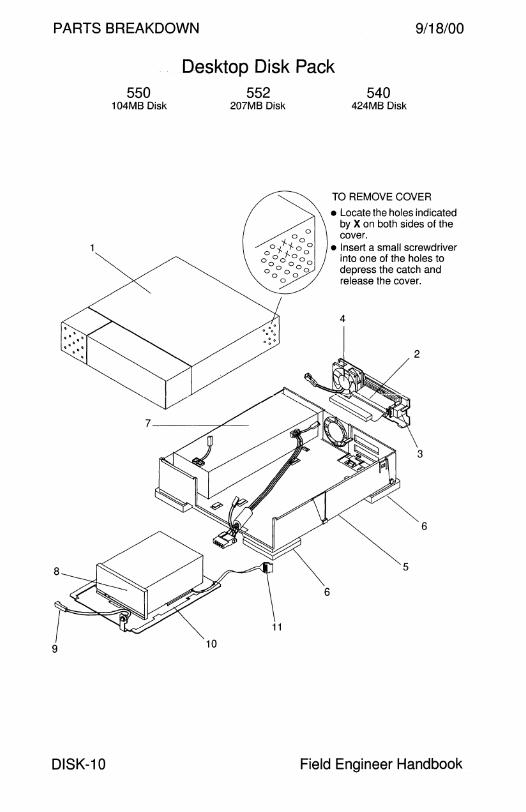
PARTS BREAKDOWN 9/18/00
8
9
DISK-10
550 104MB Disk
Desktop Disk Pack 552 540
207MB Disk
10
6
424MB Disk
TO REMOVE COVER
• Locate the holes indicated by X on both sides of the cover.
• Insert a small screwdriver into one of the holes to depress the catch and release the cover.
4
2
3
Field Engineer Handbook

9/18/00
550
CODE PART#
1 540-1777
2 540-1776
3 150-1338
4 540-1802 - 150-1174
2 540-1978
3 150-1557
3 150-2049
4 150-1174
5 540-1773
6 330-1214
7 300-1037
7 300-1090
7 300-1105
8 370-1200
8 370-1376
8 370-1392
9 530-1522
10 340-1966
11 530-1454
11 530-1825
NS 150-1346
NS 150-1785
NS 530-1434
NS 530-1508
NS 530-1793
NS 530-1836
NS 530-1852
NS 800-4895
PARTS BREAKDOWN
Desktop Disk Pack 552
DESCRIPTION
Disk Drive Cover Assembly
540
Fan/SCSI Cable/Address Select Assembly (obs)
• Unit Select Switch (obsolete)
• Fan Assembly
• 2A Subminiature Fuse
Fan/SCSI Cable/Address Select Assembly
Address Select Switch (obsolete)
Address Select Switch
• 2A Subminiature Fuse
Base Assembly
• Rubber Foot 35 Watt Power Supply (obsolete) 1
35 Watt Power Supply (obsolete)
44 Watt Power Supply
104MB Disk Drive, Quantum 105S
207MB Disk Drive, Quantum 21 OS 2
424MB Disk Drive, Seagate ST1480N
Power Indicator LED Cable
Disk Drive Mounting Bracket Address Select Switch Cable, 5.25" (obsolete)
Address Select Switch Cable, 8.5"
Single-Ended Terminator, HD50
Single-Ended Active Terminator, HD50
External SCSI Cable, HD50 to HD50, 45 cm
External SCSI Cable, HD50 to HD50, 80 cm
External SCSI Cable, HD50 to HD50, 80 cm
External SCSI Cable, HD50 to HD50, 2.0M
External SCSI Cable, HD50 to HD50, 4.0M
Desktop Storage Pack Field Service Manual
1 Power Supply 300-1037 does not have IEC950 or UL 1950 approval. Do NOT install 300-1037 into options manufactured after March 1991.
2 Maxtor Disk 370-1327 is not qualified in the Desktop Disk Pack.
Volume II DISK-11
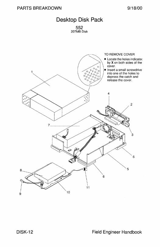
PARTS BREAKDOWN 9/18/00
9
DISK-12
Desktop Disk Pack 552
207MB Disk
TO REMOVE COVER
• Locate the holes indicatec by X on both sides of the cover.
• Insert a small screwdrive into one of the holes to depress the catch and release the cover.
4
2
3
~~6 5
6
11
10
Field Engineer Handbook
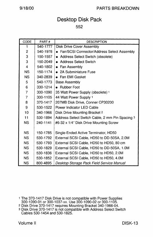
9/18/00
CODE PART#
1 540-1777
2 540-1978
3 150-1557
3 150-2049
4 540-1802
NS 150-1174
NS 340-2839
5 540-1773
6 330-1214
7 300-1090
7 300-1105
8 370-1417
9 530-1522
10 340-1966
11 530-1894
NS 240-1141
NS 150-1785
NS 530-1792
NS 530-1793 NS 530-1829
NS 530-1836
NS 530-1852 NS 800-4895
PARTS BREAKDOWN
Desktop Disk Pack 552
DESCRIPTION
Disk Drive Cover Assembly
• Fan/SCSI Connector/Address Select Assembly
• Address Select Switch (obsolete)
• Address Select Switch
• Fan Assembly
• 2A Subminiature Fuse
• Fan EMI Gasket
Base Assembly
• Rubber Foot 35 Watt Power Supply (obsolete) 1
44 Watt Power Supply 1
207MB Disk Drive, Conner CP30200
Power Indicator LED Cable
Disk Drive Mounting Bracket 2
Address Select Switch Cable, 2 mm Pin Spacing 3
#6-32 x 1 /4" Disk Drive Mounting Screw
Single-Ended Active Terminator, HD50
External SCSI Cable, HD50 to DD-50SA, 2.0M
External SCSI Cable, HD50 to HD50, 80 cm
External SCSI Cable, HD50 to DD-50SA, 1.0M
External SCSI Cable, HD50 to HD50, 2.0M
External SCSI Cable, HD50 to HD50, 4.0M
Desktop Storage Pack Field Service Manual
1 The 370-1417 Disk Drive is not compatible with Power Supplies 300-1090-01or300-1037-xx. Use 300-1090-02 or 300-1105.
2 Disk Drive 370-1417 requires Mounting Bracket 340-1966-04. 3 Disk Drive 370-1417 is not compatible with Address Select Switch
Cables 530-1454 and 530-1825.
Volume II DISK-13
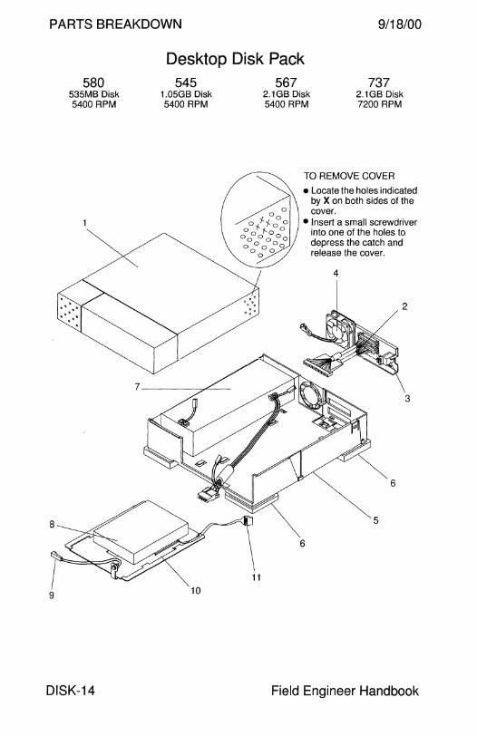
PARTS BREAKDOWN 9/18/00
Desktop Disk Pack
9
580 535MB Disk 5400 RPM
DISK-14
545 1.05GB Disk 5400 RPM
10
567 2.1GB Disk 5400 RPM
737 2.1GB Disk 7200 RPM
TO REMOVE COVER
• Locate the holes indicated by X on both sides of the cover.
• Insert a small screwdriver into one of the holes to
. depress the catch and release the cover.
2
3
Field Engineer Handbook

9/18/00 PARTS BREAKDOWN
Desktop Disk Pack 580 545 567 737
CODE PART# DESCRIPTION
1 540-1777 Disk Drive Cover Assembly
2 540-1978 Fan/SCSI Connector/Address Select Assy (obs) 1
NS 150-1174 • 2A Subminiature Fuse
2 540-2470 • Fan/SCSI Cable/Address Select Assembly
3 150-2049 • Address Select Switch
4 540-2185 • Fan Assembly
NS 340-2839 • Fan EMI Gasket
NS 530-1844 • Internal SCSI Cable, 300 mm
5 540-1773 Base Assembly
6 330-1214 • Rubber Foot
7 300-1105 44 Watt Power Supply
8 370-1424 535MB Disk Drive, Seagate ST361 ON
8 370-1424 535MB Disk Drive, Connor CP30540
8 370-1668 535MB Disk Drive, Connor CP30540
8 370-1843 535MB Disk Drive, Seagate ST5660N
8 370-1546 1.05GB Disk Drive, 1.5", Seagate ST11200N
8 370-1710 1.05GB Disk Drive, 1.0", Seagate ST31200N
8 370-1963 1.05GB Disk Drive, 1.0", Conner CFP1080S
8 370-1709 2.1 GB 5400 RPM Disk Drive, Seagate ST12400N
8 370-1929 2.1 GB 5400 RPM Disk Drive, Conner CFP2105S
8 370-2070 2.1 GB 5400 RPM Disk Drive, Seagate ST32430N
8 370-1957 2.1 GB 7200 RPM Disk Drive, IBM DFHS-32160-S2F
8 370-2067 2.1 GB 7200 RPM Disk Drive, Seagate ST32550N
9 530-1522 Power Indicator LED Cable
10 340-1966 Disk Drive Mounting Bracket
11 530-1894 Address Select Switch Cable, 2 mm Pin Spacing
NS 150-1785 Single-Ended Active Terminator, HD50
NS 530-1793 External SCSI Cable, HD50 to HD50, 80 cm
NS 530-1836 External SCSI Cable, HD50 to HD50, 2.0M
NS 530-1852 External SCSI Cable, HD50 to HD50, 4.0M
NS 800-4895 Desktop Storage Pack Field Service Manual
1 Assembly 540-24 70 replaced 540-1978 in May 1993. Assembly 540-1978 was not used in Options 580, 567, or 737.
Volume II DISK-15
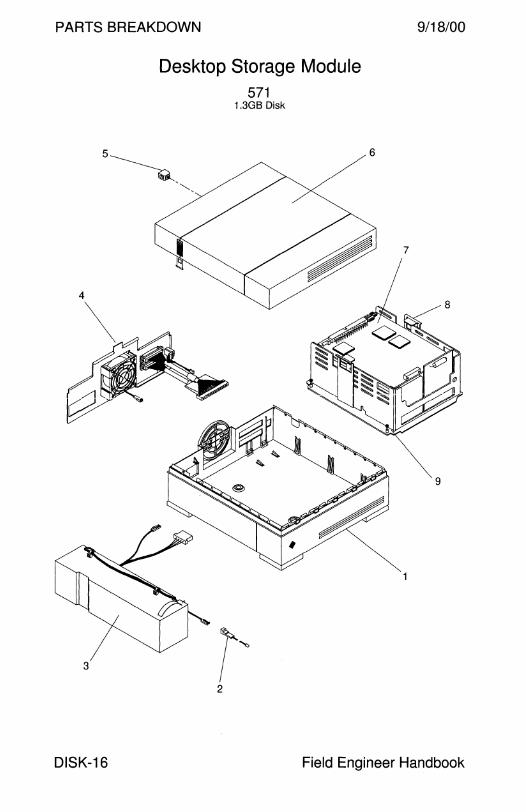
PARTS BREAKDOWN
3
Desktop Storage Module 571
1.3GB Disk
r~ 2
9/18/00
7
8
9
DISK-16 Field Engineer Handbook

9/18/00
CODE
1
2
3
4
--
-
-
-
-
-
-
-
--
-
-
-
5
6
7
8
8
9
NS
NS
NS
NS
NS
NS
NS
NS
Volume II
PARTS BREAKDOWN
Desktop Storage Module 571
PART# DESCRIPTION
540-2139 Base Assembly, Disk Drive Option
530-1522 Power Indicator LED Cable
300-1080 60 Watt Power Supply
540-2145 1/0 Bracket Assembly
150-1557 • Address Select Switch (obsolete)
150-2049 • Address Select Switch
340-2506 • 1/0 Bracket
501-1468 • 1/0 PCB and Cable Assembly (obsolete)
530-1790 • Address Select Switch Cable (obsolete)
530-2117 • Address Select Switch Cable
530-1844 • Internal SCSI Cable, -01 Rev 50 = 300 mm
530-1844 • Internal SCSI Cable, -01 Rev 51 = 250 mm
530-1844 • Internal SCSI Cable, -02 Rev 50 = 240 mm
530-1844 • Internal SCSI Cable, -03 Rev 50 = 240 mm
530-1844 • Internal SCSI Cable, -03 Rev A= 260 mm
530-2125 • Internal SCSI Cable, 308 mm
540-2142 • DC Fan Assembly, 17 CFM (obsolete)
540-2142 • DC Fan Assembly, 14 CFM
540-1982 Top Cover Lockbox Assembly
540-2141 Top Cover Assembly, Disk Drive Option
370-1377 1.3GB Disk Drive, Seagate 976002-012, PA4E1
340-2571 Peripheral Removal Handle (obsolete)
540-2263 Peripheral Removal Handle
340-2507 Disk Drive Mounting Bracket
150-1785 Single-Ended Active Terminator, HD50
240-1141 #6-32 x 1 /4" Disk Drive Mounting Screw
240-1912 #6-32 x 1/4" Disk Drive Mounting Screw (obs)
530-1792 External SCSI Cable, HD50 to DD-50SA, 2.0M
530-1793 External SCSI Cable, HD50 to HD50, 80 cm
530-1829 External SCSI Cable, HD50 to DD-50SA, 1.0M
530-1836 External SCSI Cable, HD50 to HD50, 2.0M
530-1852 External SCSI Cable, HD50 to HD50, 4.0M
800-6219 Desktop Storage Module Service Manual
800-7236 Desktop Storage Module Service Manual
DISK-17
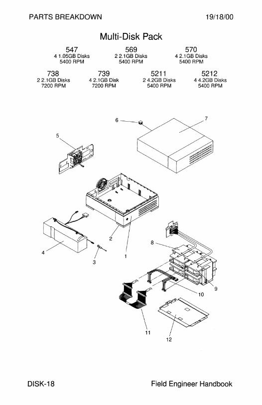
PARTS BREAKDOWN
547 4 1.05GB Disks
5400 RPM
738
Multi-Disk Pack 569
2 2.1 GB Disks 5400 RPM
5211
19/18/00
570 4 2.1 GB Disks
5400 RPM
5212 2 2.1GB Disks
7200 RPM
739 42.1GBDisk
7200 RPM 2 4.2GB Disks
5400 RPM 4 4.2GB Disks
5400 RPM
6- 7
5
,
4
3
11 12
DISK-18 Field Engineer Handbook

9/18/00
547
738
CODE PART#
1 540-2422
2 330-1214 - 260-3059
3 530-1522
4 300-1080
5 540-2424 - 540-2466
6 540-1982
7 540-2425
8 540-xxxx - 340-2848 - 340-2850
9 370-1546
9 370-1710
9 370-1963
9 370-1709
9 370-1929
9 370-2070
9 370-1957
9 370-2067
9 370-2153
10 530-2024
11 530-2025
12 340-2849
NS 150-1785
NS 530-1836
NS 530-1852
801-3422
801-6119
Volume II
PARTS BREAKDOWN
Multi-Disk Pack 569
739 5211
DESCRIPTION
Base Assembly
• Rubber Foot
• Sun Logo Power Indicator LED Cable
60 Watt Power Supply
Fan Assembly
• Variable Speed Fan Assembly
Lockbox Assembly
Cover Assembly
570
Disk Drive Superstructure Assembly
• Disk Drive Bracket
• Superstructure
5212
• 1.05GB Disk Drive, Seagate ST11200N
• 1.05GB Disk Drive, Seagate ST31200N
• 1.05GB Disk Drive, Conner CFP1080S
• 2.1 GB 5400 RPM Disk, Seagate ST12400N
• 2.1 GB 5400 RPM Disk, Conner CFP2105S
• 2.1 GB 5400 RPM Disk, Seagate ST32430N
• 2.1 GB 7200 RPM Disk, IBM DFHS-32160-S2F
• 2.1 GB 7200 RPM Disk, Seagate ST32550N
• 4.2GB 5400 RPM Disk, Seagate ST15230N
DC Wire Harness Internal SCSI Cable, 880 mm
Superstructure Mounting Plate
Single-Ended Active Terminator, HD50
External SCSI Cable, HD50 to HD50, 2.0M
External SCSI Cable, HD50 to HD50, 4.0M
Multi-Disk Pack Field Service Manual
Multi-Disk Pack Installation and Service Guide
DISK-19
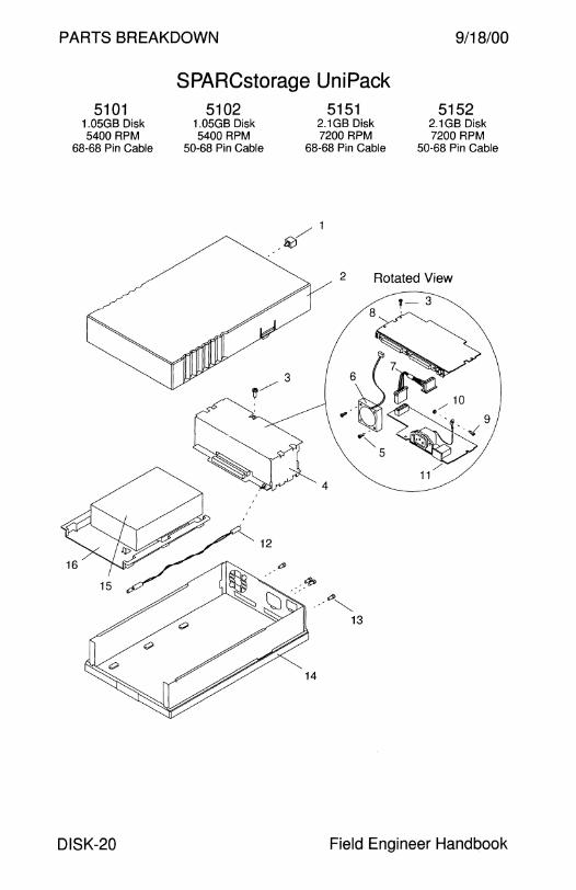
PARTS BREAKDOWN 9/18/00
SPARCstorage UniPack 5101
1.05GB Disk 5400 RPM
68-68 Pin Cable
DISK-20
5102 1.05GB Disk 5400 RPM
50-68 Pin Cable
5151 2.1GB Disk 7200 RPM
68-68 Pin Cable
/1 41
5152 2.1GB Disk 7200 RPM
50-68 Pin Cable
2 Rotated View
14
Field Engineer Handbook

9/18/00 PARTS BREAKDOWN
SPARCstorage UniPack 5101 5102 5151 5152
CODE PART# DESCRIPTION
- 595-3709 Disk Drive Enclosure without Disk Drive FRU
- 599-2045 • Disk Drive Enclosure without Disk Drive
1 540-1982 • Lockbox
2 540-2673 • Disk Drive Cover Assembly
3 240-1530 • M3x6mmScrew
4 540-2694 • Disk Drive Power Supply Assembly
5 240-2246 • M3 x 25 mm Screw (obsolete)
5 240-2294 • M3 x 25 mm Pan-Head Screw
6 370-1986 • Fan
7 530-2180 • Disk Drive DC Power Cable
8 501-2790 • Disk Drive SCSI Interface Card
9 240-1434 • M4 x 10 mm Screw
10 240-1373 • M4 Nut
11 300-1282 • 30 Watt Power Supply
12 530-2183 • LED Cable
13 240-1926 • #4-40M/2-56F Jackscrew
14 540-2672 • Base Assembly
15 540-2675 1.05GB 5400 RPM Disk Drive Assembly
15 540-2697 2.1 GB 7200 RPM Disk Drive Assembly
16 340-3222 • Mounting Bracket
- 370-1964 • 1.05GB 5400 RPM Disk Drive, Conner 1
- 370-1956 • 2.1 GB 7200 RPM Disk, IBM (disqualified)
- 370-2040 • 2.1 GB 7200 RPM Disk, Seagate ST32550WC
- 370-2365 • 2.1 GB 7200 RPM Disk, Seagate ST32171 WC
- 370-2366 • 2.1 GB 7200 RPM Disk, Fujitsu M2952
- 370-2808 • 2.1 GB 7200 RPM Disk, Quantum VK22J05
NS 261-5678 Sun Logo
NS 530-1884 External SCSI Cable, HD68 to HD68, 80 cm
NS 530-2115 External SCSI Cable, HD68 to HD50, 1.2M
NS 530-2383 External SCSI Cable, HD68 to HD68, 80 cm
802-3229 SPARCstorage UniPack Hard Drive Replacement
1Seagate370-1753, Conner 370-1822, IBM 370-2072, and Quantum 370-2168 Disk Drives were not qualified in the Uni Pack.
Volume II DISK-21

PARTS BREAKDOWN 9/18/00
SPARCstorage UniPack 5203 5204
4.2GB Disk 4.2GB Disk 5400 RPM 5400 RPM
68-68 Pin Cable 50-68 Pin Cable
5253 9.1GB Disk 7200 RPM
68-68 Pin Cable
DISK-22
5209 5213 4.2GB Disk 4.2GB Disk 7200 RPM 7200 RPM
68-68 Pin Cable 50-68 Pin Cable
5254 9.1GB Disk 7200 RPM
50-68 Pin Cable
/1 ~
4
14
2 Rotated View
·- 3
\$> ,··fJJ~~ <1,0../9
'"-... . "• 5
11/
Field Engineer Handbook
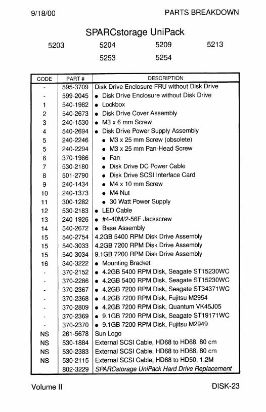
9/18/00 PARTS BREAKDOWN
SPARCstorage UniPack 5203
CODE PART#
- 595-3709
- 599-2045
1 540-1982
2 540-2673
3 240-1530
4 540-2694
5 240-2246
5 240-2294
6 370-1986
7 530-2180
8 501-2790
9 240-1434
10 240-1373
11 300-1282
12 530-2183
13 240-1926
14 540-2672
15 540-2754
15 540-3033
15 540-3034
16 340-3222
- 370-2152 - 370-2286
- 370-2367
- 370-2368
- 370-2809
- 370-2369 - 370-2370
NS 261-5678
NS 530-1884
NS 530-2383
NS 530-2115
802-3229
Volume II
5204
5253
5209
5254
5213
DESCRIPTION
Disk Drive Enclosure FRU without Disk Drive
• Disk Drive Enclosure without Disk Drive
• Lockbox • Disk Drive Cover Assembly
• M3 x 6 mm Screw • Disk Drive Power Supply Assembly
• M3 x 25 mm Screw (obsolete)
• M3 x 25 mm Pan-Head Screw
• Fan • Disk Drive DC Power Cable
• Disk Drive SCSI Interface Card
• M4 x 10 mm Screw
• M4 Nut • 30 Watt Power Supply
• LED Cable • #4-40M/2-56F Jackscrew
• Base Assembly 4.2GB 5400 RPM Disk Drive Assembly 4.2GB 7200 RPM Disk Drive Assembly
9.1 GB 7200 RPM Disk Drive Assembly
• Mounting Bracket • 4.2GB 5400 RPM Disk, Seagate ST15230WC • 4.2GB 5400 RPM Disk, Seagate ST15230WC
• 4.2GB 7200 RPM Disk, Seagate ST34371 WC
• 4.2GB 7200 RPM Disk, Fujitsu M2954
• 4.2GB 7200 RPM Disk, Quantum VK45J05
e 9.1GB 7200 RPM Disk, Seagate ST19171WC
• 9.1 GB 7200 RPM Disk, Fujitsu M2949
Sun Logo External SCSI Cable, HD68 to HD68, 80 cm
External SCSI Cable, HD68 to HD68, 80 cm
External SCSI Cable, HD68 to HD50, 1.2M
SPARCstorage UniPack Hard Drive Replacement
DISK-23

PARTS BREAKDOWN 9/18/00
SPARCstorage MultiPack 5501 5502 5503
2 4.2GB Disks 4 4.2GB Disks 6 4.2GB Disks 5400 RPM 5400 RPM 5400 RPM
5504 5505 5506 29.1GBDisks 4 9.1 GB Disks 6 9.1 GB Disks
7200 RPM 7200 RPM 7200 RPM
3
cP", •
""' ~ 12 13
~ 11
DISK-24 Field Engineer Handbook
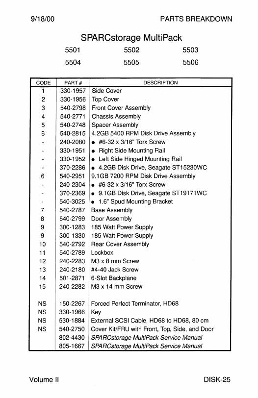
9/18/00
CODE
1
2
3
4
5
6
--
--6
--
-7
8
9 9
10 11
12
13
14
15
NS
NS
NS
NS
Volume II
PARTS BREAKDOWN
SPARCstorage MultiPack 5501
5504
PART#
330-1957
330-1956
540-2798
540-2771
540-2748
540-2815
240-2080
330-1951 330-1952
370-2286
540-2951
240-2304
370-2369
540-3025
540-2787
540-2799
300-1283
300-1330
540-2792
540-2789
240-2283
240-2180
501-2871
240-2282
150-2267
330-1966
530-1884
540-2750
802-4430
805-1667
Side Cover
Top Cover
5502
5505
DESCRIPTION
Front Cover Assembly
Chassis Assembly
Spacer Assembly
5503
5506
4.2GB 5400 RPM Disk Drive Assembly
• #6-32 x 3/16" Torx Screw
• Right Side Mounting Rail • Left Side Hinged Mounting Rail
• 4.2GB Disk Drive, Seagate ST15230WC
9.1 GB 7200 RPM Disk Drive Assembly
• #6-32 x 3/16" Torx Screw
• 9.1GB Disk Drive, Seagate ST19171WC
• 1.6" Spud Mounting Bracket
Base Assembly
Door Assembly
185 Watt Power Supply
185 Watt Power Supply
Rear Cover Assembly
Lockbox
M3 x 8 mm Screw
#4-40 Jack Screw
6-Slot Backplane
M3 x 14 mm Screw
Forced Perfect Terminator, HD68
Key
External SCSI Cable, HD68 to HD68, 80 cm
Cover Kit/FRU with Front, Top, Side, and Door
SPARCstorage MultiPack Service Manual
SPARCstorage MultiPack Service Manual
DISK-25
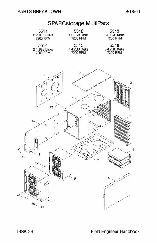
PARTS BREAKDOWN 9/18/00
SPARCstorage MultiPack 5511 5512 5513
2 2.1GB Disks 4 2.1GB Disks 6 2.1 GB Disks 7200 RPM 7200 RPM 7200 RPM
5514 5515 5516 2 4.2GB Disks 4 4.2GB Disks 6 4.2GB Disks
7200 RPM 7200 RPM 7200 RPM
"' .
""' 13
~ 11
10
DISK-26 Field Engineer Handbook

9/18/00
CODE
1
2
3
4
5
6 -
-
6 -
-
6 -
-
-
-
7
8
9
9
10 11
12
13
14
15
NS
NS
NS
NS
Volume II
PARTS BREAKDOWN
SPARCstorage MultiPack 5511
5514
PART#
330-1957
330-1956
540-2772
540-3397
540-3400
540-2730
370-2040
370-1956
540-2936
370-2808
370-2365
540-2938
370-2367 370-2809
370-3403
370-3412
540-2787 540-2751
300-1283
300-1330
540-2792
540-2789
240-2283
240-2180
501-2899
240-2282
150-2267
330-1966
530-1884
540-2749
802-4430
805-1667
Side Cover
Top Cover
5512
5515
DESCRIPTION
Front Cover Assembly
5513
5516
Chassis Assembly (replaced 540-2771)
Spacer Assembly (replaced 540-2748)
2.1 GB 7200 RPM Disk Drive Assembly/FRU
• 2.1 GB Disk Drive, Seagate ST32550WC • 2.1 GB Disk Drive, IBM DFHS-32160 (disqualified)
2.1 GB 7200 RPM Disk Drive Assembly/FRU
• 2.1 GB Disk Drive, Quantum VK22J05
• 2.1 GB Disk Drive, Seagate ST32171 WC
4.2GB 7200 RPM Disk Drive Assembly/FRU
• 4.2GB Disk Drive, Seagate ST34371WC • 4.2GB Disk Drive, Quantum VK45J05
• 4.2GB Disk Drive, IBM DDRS-34560
• 4.2GB Disk Drive, Fujitsu MAB3045SC
Base Assembly
Door Assembly
185 Watt Power Supply
185 Watt Power Supply
Rear Cover Assembly
Lockbox
M3 x 8 mm Screw
#4-40 Jack Screw
12-Slot Backplane M3 x 14 mm Screw
Forced Perfect Terminator, HD68
Key External SCSI Cable, HD68 to HD68, 80 cm
Cover Kit/FRU with Front, Top, Side, and Door
SPARCstorage MultiPack Service Manual
SPARCstorage MultiPack Service Manual
DISK-27
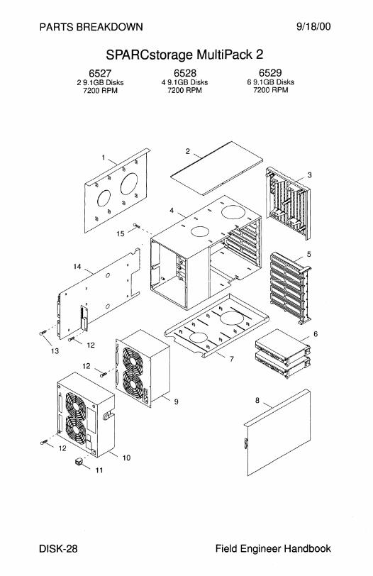
BREAKDOWN
PARTS MultiPack 2 SPARCstorage 6529
9/18/00
6527 2 9 1GB Disks
7200 RPM
DISK-28
6528 6 9.1 GB Disks 4 9.1 GB Disks 7200 RPM
7200 RPM
H ndbook Field Engineer a
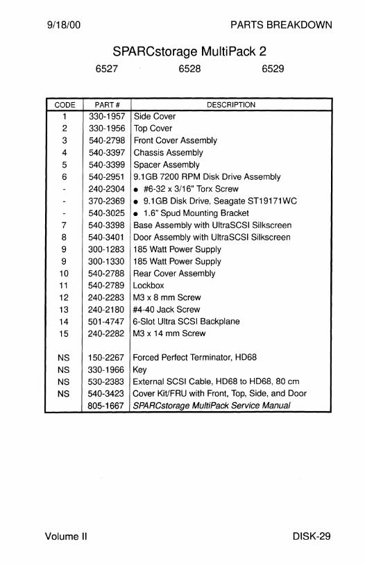
9/18/00 PARTS BREAKDOWN
SPARCstorage MultiPack 2 6527 6528 6529
CODE PART# DESCRIPTION
1 330-1957 Side Cover
2 330-1956 Top Cover
3 540-2798 Front Cover Assembly
4 540-3397 Chassis Assembly
5 540-3399 Spacer Assembly
6 540-2951 9.1 GB 7200 RPM Disk Drive Assembly
- 240-2304 • #6-32 x 3/16" Torx Screw - 370-2369 • 9.1 GB Disk Drive, Seagate ST19171 WC - 540-3025 • 1.6" Spud Mounting Bracket
7 540-3398 Base Assembly with UltraSCSI Silkscreen
8 540-3401 Door Assembly with UltraSCSI Silkscreen
9 300-1283 185 Watt Power Supply
9 300-1330 185 Watt Power Supply
10 540-2788 Rear Cover Assembly
11 540-2789 Lockbox
12 240-2283 M3 x 8 mm Screw
13 240-2180 #4-40 Jack Screw
14 501-4747 6-Slot Ultra SCSI Backplane
15 240-2282 M3 x 14 mm Screw
NS 150-2267 Forced Perfect Terminator, HD68
NS 330-1966 Key
NS 530-2383 External SCSI Cable, HD68 to HD68, 80 cm
NS 540-3423 Cover Kit/FRU with Front, Top, Side, and Door
805-1667 SPARCstorage MultiPack Service Manual
Volume II DISK-29

PARTS BREAKDOWN
StorEdge UniPack DSK010A-4G
4.2GB Disk 7200 RPM
/1 ~
2 Rotated View
9/18/00
DISK-30 Field Engineer Handbook
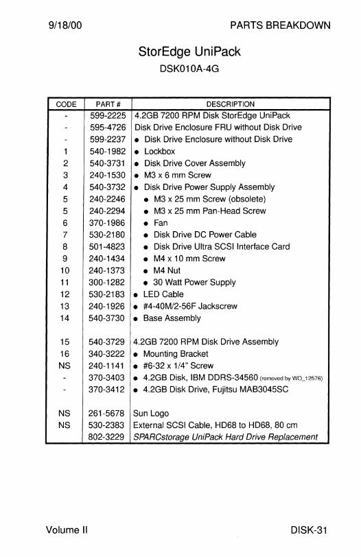
9/18/00
CODE PART#
- 599-2225 - 595-4726 - 599-2237
1 540-1982
2 540-3731
3 240-1530
4 540-3732
5 240-2246
5 240-2294
6 370-1986
7 530-2180
8 501-4823
9 240-1434
10 240-1373 11 300-1282
12 530-2183
13 240-1926
14 540-3730
15 540-3729
16 340-3222
NS 240-1141 - 370-3403 - 370-3412
NS 261-5678
NS 530-2383
802-3229
Volume II
PARTS BREAKDOWN
StorEdge UniPack DSK010A-4G
DESCRIPTION
4.2GB 7200 RPM Disk StorEdge Uni Pack
Disk Drive Enclosure FRU without Disk Drive
• Disk Drive Enclosure without Disk Drive
• Lockbox • Disk Drive Cover Assembly
• M3 x 6 mm Screw
• Disk Drive Power Supply Assembly
• M3 x 25 mm Screw (obsolete)
• M3 x 25 mm Pan-Head Screw
• Fan • Disk Drive DC Power Cable
• Disk Drive Ultra SCSI Interface Card
• M4 x 10 mm Screw
• M4 Nut • 30 Watt Power Supply
• LED Cable • #4-40M/2-56F Jackscrew
• Base Assembly
4.2GB 7200 RPM Disk Drive Assembly
• Mounting Bracket
• #6-32 x 1/4" Screw • 4.2GB Disk, IBM DDRS-34560 (removect by wo_12s?6l
• 4.2GB Disk Drive, Fujitsu MAB3045SC
Sun Logo
External SCSI Cable, HD68 to HD68, 80 cm
SPARCstorage UniPack Hard Drive Replacement
DISK-31
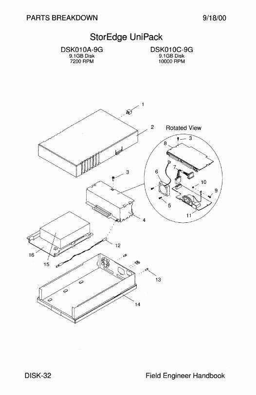
PARTS BREAKDOWN 9/18/00
StorEdge UniPack
DISK-32
DSK010A-9G 9.1GB Disk 7200 RPM
/1 ~
4
14
DSK010C-9G 9.1GB Disk 10000 RPM
2 Rotated View
Field Engineer Handbook

9/18/00 PARTS BREAKDOWN
StorEdge UniPack DSK010A-9G DSK010C-9G
CODE PART# DESCRIPTION
- 599-2229 9.1 GB 7200 RPM Disk StorEdge Uni Pack
- 599-2325 9.1 GB 10000 RPM Disk StorEdge Uni Pack
- 595-4726 Disk Drive Enclosure FRU without Disk Drive
- 599-2237 • Disk Drive Enclosure without Disk Drive
1 540-1982 • Lockbox
2 540-3731 • Disk Drive Cover Assembly
3 240-1530 • M3 x 6 mm Screw
4 540-3732 • Disk Drive Power Supply Assembly
5 240-2246 • M3 x 25 mm Screw (obsolete)
5 240-2294 • M3 x 25 mm Pan-Head Screw
6 370-1986 • Fan 7 530-2180 • Disk Drive DC Power Cable
8 501-4823 • Disk Drive Ultra SCSI Interface Card
9 240-1434 • M4 x 10 mm Screw
10 240-1373 • M4 Nut
11 300-1282 • 30 Watt Power Supply
12 530-2183 • LED Cable
13 240-1926 • #4-40M/2-56F Jackscrew
14 540-3730 • Base Assembly
15 540-3734 9.1 GB 7200 RPM Disk Drive Assembly
16 340-3222 • Mounting Bracket
- 370-3404 • 9.1 GB Disk, IBM DDRS-39130 (removed by wo_12576)
- 370-3413 • 9.1 GB Disk Drive, Fujitsu MAB3091 SC
- 370-3595 • 9.1 GB Disk Drive, Seagate ST39173WC
- 390-0004 • 9.1 GB Disk Drive, Fujitsu MAE3091 LC
- 390-0005 • 9.1 GB Disk Drive, Fujitsu MAG3091 LC
- 390-0007 • 9.1 GB Disk Drive, IBM DNES-309170
15 540-4304 9.1 GB 10000 RPM Disk Drive Assembly
16 340-3222 • Mounting Bracket
- 390-0009 • 9.1 GB Disk, Seagate ST39103LC
NS 261-5678 Sun Logo
NS 530-2383 External SCSI Cable, HD68 to HD68, 80 cm
802-3229 SPARCstorage UniPack Hard Drive Replacement
Volume II DISK-33

PARTS BREAKDOWN 9/18/00
StorEdge UniPack DSK01 OA-18G
18.2GB Disk 7200 RPM
DISK-34
DSK01 OC-18G DSK01 OC-36G 18.2GB Disk 36.4GB Disk 10000 RPM 10000 RPM
/1 ~
2 Rotated View
Field Engineer Handbook

9/18/00 PARTS BREAKDOWN
StorEdge UniPack DSK01 OA-18G DSK01 OC-18G DSK01 OC-36G
CODE PART# DESCRIPTION
- 599-2230 18.2GB 7200 RPM Disk UniPack
- 599-2326 18.2GB 10000 RPM Disk Uni Pack
- 599-2433 36.4GB 10000 RPM Disk Uni Pack
- 595-4726 Disk Drive Enclosure FRU without Disk Drive
- 599-2237 • Disk Drive Enclosure without Disk Drive
1 540-1982 • Lockbox
2 540-3731 • Disk Drive Cover Assembly
3 240-1530 • M3 x 6 mm Screw
4 540-3732 • Disk Drive Power Supply Assembly
5 240-2246 • M3 x 25 mm Screw (obsolete)
5 240-2294 • M3 x 25 mm Pan-Head Screw
6 370-1986 • Fan 7 530-2180 • Disk Drive DC Power Cable
8 501-4823 • Disk Drive Ultra SCSI Interface Card
9 240-1434 • M4 x 10 mm Screw
10 240-1373 • M4 Nut
11 300-1282 • 30 Watt Power Supply
12 530-2183 • LED Cable
13 240-1926 • #4-40M/2-56F Jackscrew
14 540-3730 • Base Assembly
15 370-3414 18.2GB 7200 RPM Disk, Fujitsu MAA3182SC
15 370-3596 18.2GB 7200 RPM Disk, Seagate ST118273LC
15 390-0002 18.2GB 10000 RPM Disk, Seagate ST318203LC
15 390-0038 18.2GB 10000 RPM Disk, Seagate ST318404LC
15 390-0060 18.2GB 10000 RPM Disk, Fujitsu MAJ3182M
15 390-0050 36.4GB 10000 RPM Disk, Seagate ST336704LC
15 390-0059 36.4GB 10000 RPM Disk, Fujitsu MAJ3364M
16 340-3222 Mounting Bracket
NS 261-5678 Sun Logo
NS 530-2383 External SCSI Cable, HD68 to HD68, 80 cm
802-3229 SPARCstorage UniPack Hard Drive Replacement
Volume II DISK-35
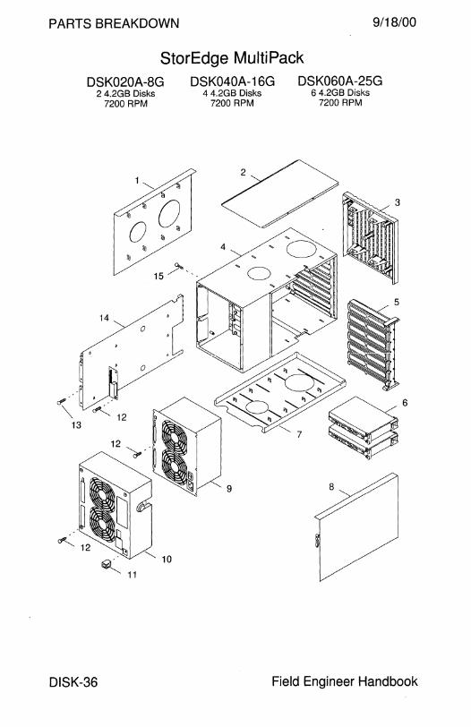
PARTS BREAKDOWN 9/18/00
StorEdge MultiPack DSK020A-8G DSK040A-16G DSK060A-25G
2 4.2GB Disks 7200 RPM
14 0
""' 15 / ',
~···l>Y "" ~ 12 ' 13 Q
~ 11
DISK-36
4 4.2GB Disks 7200 RPM
6 4.2GB Disks 7200 RPM
Field Engineer Handbook
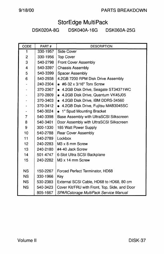
9/18/00 PARTS BREAKDOWN
StorEdge MultiPack DSK020A-8G DSK040A-16G DSK060A-25G
CODE PART# DESCRIPTION
1 330-1957 Side Cover
2 330-1956 Top Cover
3 540-2798 Front Cover Assembly
4 540-3397 Chassis Assembly
5 540-3399 Spacer Assembly
6 540-2938 4.2GB 7200 RPM Disk Drive Assembly
- 240-2304 • #6-32 x 3/16" Torx Screw - 370-2367 • 4.2GB Disk Drive, Seagate ST34371 WC - 370-2809 • 4.2GB Disk Drive, Quantum VK45J05
- 370-3403 • 4.2GB Disk Drive, IBM DDRS-34560 - 370-3412 • 4.2GB Disk Drive, Fujitsu MAB3045SC
- 540-3024 • 1" Spud Mounting Bracket
7 540-3398 Base Assembly with UltraSCSI Silkscreen
8 540-3401 Door Assembly with UltraSCSI Silkscreen
9 300-1330 185 Watt Power Supply
10 540-2788 Rear Cover Assembly
11 540-2789 Lockbox
12 240-2283 M3 x 8 mm Screw
13 240-2180 #4-40 Jack Screw
14 501-4747 6-Slot Ultra SCSI Backplane
15 240-2282 M3 x 14 mm Screw
NS 150-2267 Forced Perfect Terminator, HD68 NS 330-1966 Key
NS 530-2383 External SCSI Cable, HD68 to HD68, 80 cm
NS 540-3423 Cover Kit/FRU with Front, Top, Side, and Door
805-1667 SPARCstorage MultiPack Service Manual
Volume II DISK-37
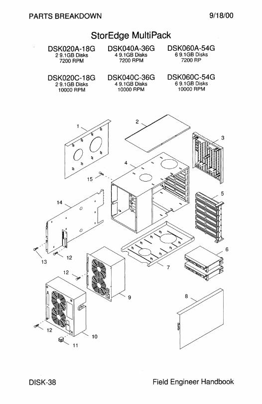
PARTS BREAKDOWN 9/18/00
StorEdge MultiPack DSK020A-18G DSK040A-36G DSK060A-54G
2 9.1GB Disks 4 9.1 GB Disks 6 9.1 GB Disks 7200 RPM 7200 RPM 7200 RP
DSK020C-18G DSK040C-36G DSK060C-54G 2 9.1 GB Disks 4 9.1 GB Disks 6 9.1 GB Disks
10000 RPM 10000 RPM 10000 RPM
3
o? ..
"' ~ 12 13
9
~ 11
DISK-38 Field Engineer Handbook
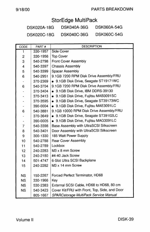
9/18/00 PARTS BREAKDOWN
StorEdge MultiPack DSK020A-18G DSK040A-36G DSK060A-54G
DSK060C-54G DSK020C-18G DSK040C-36G
CODE PART# DESCRIPTION
1 330-1957 Side Cover
2 330-1956 Top Cover
3 540-2798 Front Cover Assembly
4 540-3397 Chassis Assembly
5 540-3399 Spacer Assembly
6 540-2951 9.1 GB 7200 RPM Disk Drive Assembly/FRU
- 370-2369 • 9.1 GB Disk Drive, Seagate ST19171 WC
6 540-3704 9.1 GB 7200 RPM Disk Drive Assembly/FRU
- 370-3404 • 9.1 GB Disk Drive, IBM DDRS-39130
- 370-3413 • 9.1 GB Disk Drive, Fujitsu MAB3091 SC
- 370-3595 • 9.1 GB Disk Drive, Seagate ST39173WC
- 390-0004 • 9.1 GB Disk Drive, Fujitsu MAE3091 LC
6 540-3881 9.1 GB 10000 RPM Disk Drive Assembly/FRU
- 370-3649 • 9.1 GB Disk Drive, Seagate ST39102LC
- 390-0005 • 9.1 GB Disk Drive, Fujitsu MAG3091 LC
7 540-3398 Base Assembly with UltraSCSI Silkscreen
8 540-3401 Door Assembly with UltraSCSI Silkscreen
9 300-1330 185 Watt Power Supply
10 540-2788 Rear Cover Assembly
11 540-2789 Lockbox
12 240-2283 M3 x 8 mm Screw
13 240-2180 #4-40 Jack Screw
14 501-4747 6-Slot Ultra SCSI Backplane
15 240-2282 M3 x 14 mm Screw
NS 150-2267 Forced Perfect Terminator, HD68
NS 330-1966 Key
NS 530-2383 External SCSI Cable, HD68 to HD68, 80 cm
NS 540-3423 Cover Kit/FRU with Front, Top, Side, and Door
805-1667 SPARCstorage MultiPack Service Manual
Volume II DISK-39
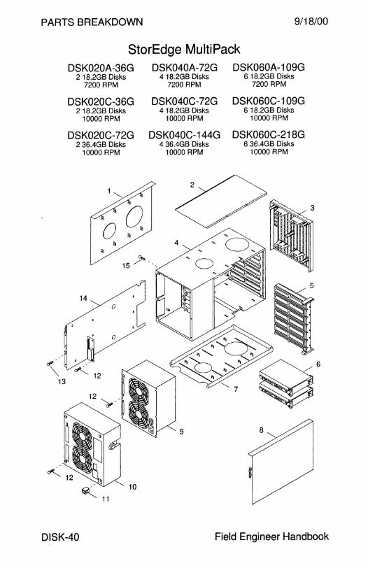
PARTS BREAKDOWN 9/18/00
StorEdge MultiPack DSK020A-36G DSK040A-72G DSKOSOA-109G
2 18.2GB Disks 4 18.2GB Disks 6 18.2GB Disks 7200 RPM 7200 RPM 7200 RPM
DSK020C-36G DSK040C-72G DSKOSOC-109G 2 18.2GB Disks 4 18.2GB Disks 6 18.2GB Disks
10000 RPM 10000 RPM 10000 RPM
DSK020C-72G DSK040C-144G DSK060C-218G 2 36.4GB Disks 4 36.4GB Disks 6 36.4GB Disks
10000 RPM 10000 RPM 10000 RPM
(jlP. •
"" ~ 12 13
~ 11
DISK-40 Field Engineer Handbook
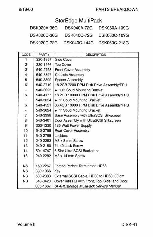
9/18/00 PARTS BREAKDOWN
StorEdge MultiPack DSK020A-36G DSK040A-72G DSKOSOA-109G
DSK020C-36G DSK040C-72G DSKOSOC-109G
DSK020C-72G DSK040C-144G DSK060C-218G
CODE PART# DESCRIPTION
1 330-1957 Side Cover
2 330-1956 Top Cover
3 540-2798 Front Cover Assembly 4 540-3397 Chassis Assembly
5 540-3399 Spacer Assembly
6 540-3719 18.2GB 7200 RPM Disk Drive Assembly/FRU - 540-3025 • 1.6" Spud Mounting Bracket 6 540-4177 18.2GB 10000 RPM Disk Drive Assembly/FRU - 540-3024 • 1" Spud Mounting Bracket
6 540-4521 36.4GB 10000 RPM Disk Drive Assembly/FRU - 540-3024 • 1" Spud Mounting Bracket 7 540-3398 Base Assembly with UltraSCSI Silkscreen
8 540-3401 Door Assembly with UltraSCSI Silkscreen
9 300-1330 185 Watt Power Supply
10 540-2788 Rear Cover Assembly
11 540-2789 Lockbox
12 240-2283 M3 x 8 mm Screw
13 240-2180 #4-40 Jack Screw
14 501-4747 6-Slot Ultra SCSI Backplane
15 240-2282 M3 x 14 mm Screw
NS 150-2267 Forced Perfect Terminator, HD68
NS 330-1966 Key
NS 530-2383 External SCSI Cable, HD68 to HD68, 80 cm
NS 540-3423 Cover Kit/FRU with Front, Top, Side, and Door
805-1667 SPARCstorage MultiPack Service Manual
Volume II DISK-41

This page intentionally left blank.

PARTS BREAKDOWN
DISK ARRAY

9/18/00 PARTS BREAKDOWN
Disk Array
SPARCstorage Array Model 101 .......................................... 4
SPARCstorage Array Model 102 .......................................... 6
SPARCstorage Array Model 112 .......................................... 8
SPARCstorage Array Model 114 .......................................... 12
SPARCstorage Array Model 200 .......................................... 14
SPARCstorage Array Model 210 .......................................... 16
SPARCstorage Array Model 214 RSM 7-Slot Disk Array . . . . . . . . . . . . . . . . . . . . . . . . . . . . . . . . . . . . .. . . . .. . . . . . . . . . . . . . . . . . . . . 18 Rack Mounted Disk Array with SSA Model 210 . .. .. ..... ... .. . 20
SPARCstorage Array Model 219 RSM 7-Slot Disk Array . . . . . . . . . . . . . . . . . . . . . . . . . . . . . . . . . . . . . . . . . . . . . . . . . . . . . . . . . . . . . . . 22 Rack Mounted Disk Array with SSA Model 210 . .... .. .. . ...... 24
RSM Array 2000 StorEdge A3000 Array Controller . . . . . . . . . . . . . . . . . . . . . . . . . . . . . . . . . . . . . . . . . . . .. . . . . . . . . . . . . . . . . . . . . 26 Rack Mounted Array Controller with RSM 214/219 ........... 28
StorEdge A 1000 8-Slot Disk Array . . . . . . . . . . . . . . . . . . . . . . . . . . . . . . . . . . . . . . . . . .. . . . . . . . . . . . . . . . . . . . . 30 12-Slot Disk Array . . . . . . . . . . . . . . . . . . . . . . . . . . . . . . . . . . .. . . . . . . . . . . . . . . . . . . . . . . . . . 32
StorEdge D1000 8-Slot Disk Array . . . . . . . . . . . . . . . . . . . . . . . . . . . . . . . . . . . . .. . . . . . . . . . . . . . . . . . . . . . . . . . 38 12-Slot Disk Array ... ..... .. ... .. ... .. . .. .. .. .. ..... ... .... .... .. .. .. ...... ... . 40
StorEdge A3500 Array Controller . . . . . . . . . . . . . . . . . . . . . . . . . . . . . . . . . . . . . . .. . . . .. . . . . . . . . . . . . . . . . . . . . 46
StorEdge A3500-Light Array Controller with D1000 Disk Array . . ..... .. .. . .. .. .. ... .. ... .. . 48
StorEdge A3500 Rack Mounted Array Controller with D1000 Disk Array . . .. 50
Field Engineer Handbook - Volume II
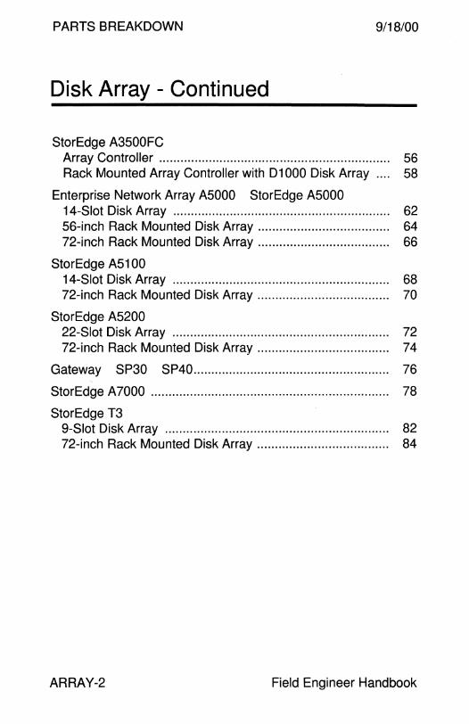
PARTS BREAKDOWN 9/18/00
Disk Array - Continued
StorEdge A3500FC Array Controller . . . . . . . . . . . . . . . . . . . . . . . . . . . . . . . . . . . . . . . . . . . . . . . . . . . . . . . . . . . . . . . . . 56 Rack Mounted Array Controller with D1000 Disk Array .. .. 58
Enterprise Network Array A5000 StorEdge A5000 14-Slot Disk Array . . . . . . . . . . . . . . . . . . . . . . . . . . . . . . . . . . . . . . . . . . . . . . . . . . . . . . . . . . . . . 62 56-inch Rack Mounted Disk Array .. . ...... .. ... .. ... .. ... .. . .... ...... 64 72-inch Rack Mounted Disk Array ..................................... 66
StorEdge A5100 14-Slot Disk Array . . . . . . . . . . . . . . . . . . . . . . . . . . . . . . . . . . . . . . . . . . . . . . . . . . . . . . . . . . . . . 68 72-inch Rack Mounted Disk Array .... .. ...... .. ... .. ... .. .. . .... .. .... 70
StorEdge A5200 22-Slot Disk Array . . . . . . . . . . . . . . . . . . . . . . . . . . . . . . . . . . . . . . . . . . . . . . . . . . . . . . . . . . . . . 72 72-inch Rack Mounted Disk Array ..................................... 74
Gateway SP30 SP40....................................................... 76
StorEdge A7000 ................................................................... 78
StorEdge T3 9-Slot Disk Array . . . . . . . . . . . . . . . . . . . . . . . . . . . . . . . . . . . . . . . . . . . . . . . . . . . . . . . . . . . . . . . 82 72-inch Rack Mounted Disk Array .. . ........ ... .. . .. ... .. . .. .... ...... 84
ARRAY-2 Field Engineer Handbook

9/18/00 PARTS BREAKDOWN
This page intentionally left blank.
Volume II ARRAY-3

PARTS BREAKDOWN 9/18/00
SPARCstorage Array Model 101
653 SSA 101 Array 6 1.05GB Disks
5400 RPM
ARRAY-4
651 1.05GB Disk 5400 RPM
w/o SSA Tray
654
652 6 1.05GB Disks
5400 RPM w/o SSA Tray
SSA 101 Array 18 1 .05GB Disks
5400 RPM
655 SSA 101 Array
30 1 .05GB Disks 5400 RPM
Field Engineer Handbook

9/18/00 PARTS BREAKDOWN
SPARCstorage Array Model 101 651 652 653 654 655
CODE PART# DESCRIPTION
NS 540-2406 Chassis Assembly
1 330-1469 • Top and Bottom Cover
2 330-1470 • Side Cover (obsolete) 2 330-1869 • Side Cover 3 330-1589 • Cover Plug
NS 330-1590 • Foot 4 501-2029 • Backplane
5 540-2245 • Drive Tray Assembly/FRU
6 501-2010 • Drive Tray Backplane
NS 540-2248 • Chassis Subassembly NS 340-2670 • Chassis 7 540-2465 • Power Supply Assembly/FRU - 300-1098 • 440 Watt Power Supply
8 540-2573 • Fan Tray Assembly/FRU - 370-1801 • 120 x 38 mm Fan, 1 OOCFM (obsolete)
- 370-1885 • 120 x 38 mm Fan, 1 OOCFM - 260-6233 Sun Logo - 260-6604 SPARCstorage Array Nameplate
9 501-2552 Configured Array Controller
- 501-2080 • Array Controller (40MHz microSPARC II) - 501-2028 • Battery Module (obsolete) - 501-2857 • Battery Module - 370-1426 • Fibre Channel Optical Module
10 540-2382 Front Bezel Assembly
11 540-2568 1.05GB Disk Drive FRU - 240-2080 • #6-32 x 3/16 Button Screw, Torx
- 370-1822 • 1.05GB Disk Drive, Conner CFP1060E - 370-1964 • 1.05GB Disk Drive, Conner CFP1 OBOE - 540-2412 • Conner Disk Drive Mounting Bracket - 370-1753 • 1.05GB Disk Drive, Seagate ST31200WC
- 540-2413 • Seagate Disk Drive Mounting Bracket NS 537-1004 Fibre Optical Cable, 2M
NS 537-1006 Fibre Optical Cable, 15M
Volume II ARRAY-5
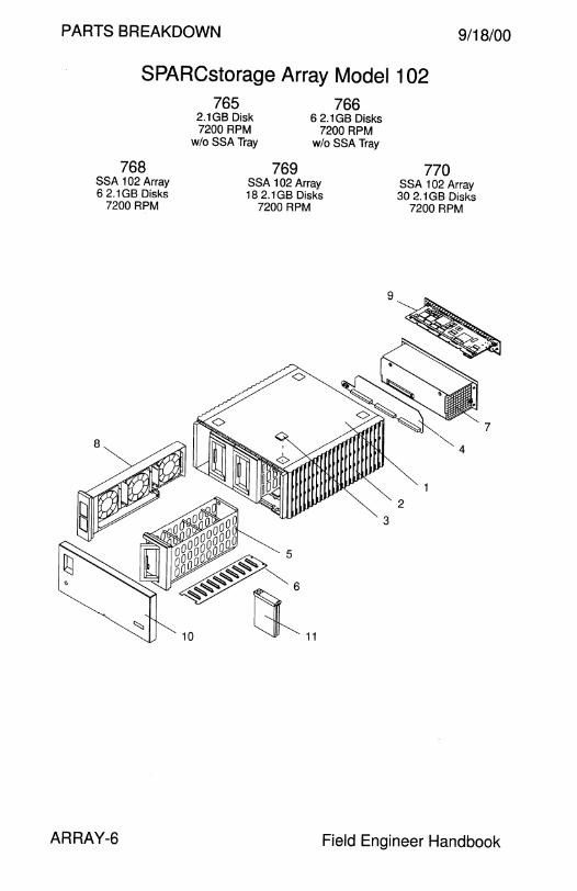
PARTS BREAKDOWN 9/18/00
SPARCstorage Array Model 102
768 SSA 102 Array 6 2.1GB Disks
7200 RPM
ARRAY-6
765 2.1GB Disk 7200 RPM
w/o SSA Tray
769
766 6 2.1 GB Disks
7200 RPM w/oSSATray
SSA 102 Array 18 2.1GB Disks
7200 RPM
770 SSA 102 Array 30 2.1GB Disks
7200 RPM
Field Engineer Handbook
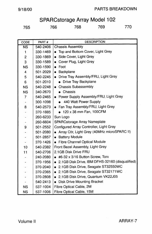
9/18/00 PARTS BREAKDOWN
SPARCstorage Array Model 102 765 766 768 769 770
CODE PART# DESCRIPTION
NS 540-2406 Chassis Assembly
1 330-1469 • Top and Bottom Cover, Light Grey
2 330-1869 • Side Cover, Light Grey
3 330-1589 • Cover Plug, Light Grey
NS 330-1590 • Foot 4 501-2029 • Backplane
5 540-2245 • Drive Tray Assembly/FRU, Light Grey
6 501-2010 • Drive Tray Backplane
NS 540-2248 • Chassis Subassembly
NS 340-2670 • Chassis
7 540-2465 • Power Supply Assembly/FRU, Light Grey
- 300-1098 • 440 Watt Power Supply
8 540-2573 • Fan Tray Assembly/FRU, Light Grey
- 370-1885 • 120 x 38 mm Fan, 1 OOCFM
- 260-6233 Sun Logo
- 260-6604 SPARCstorage Array Nameplate
9 501-2552 Configured Array Controller, Light Grey
- 501-2080 • Array Ctlr, Light Grey (40MHz microSPARC II)
- 501-2857 • Battery Module
- 370-1426 • Fibre Channel Optical Module
10 540-2382 Front Bezel Assembly, Light Grey
11 540-2706 2.1 GB Disk Drive FRU
- 240-2080 • #6-32 x 3/16 Button Screw, Torx
- 370-1956 • 2.1 GB Disk Drive, IBM DFHS-32160 (disqualified)
- 370-2040 • 2.1 GB Disk Drive, Seagate ST32550WC
- 370-2365 • 2.1GB Disk Drive, Seagate ST32171WC
- 370-2808 • 2.1 GB Disk Drive, Quantum VK22J05
- 540-2413 • Disk Drive Mounting Bracket
NS 537-1004 Fibre Optical Cable, 2M
NS 537-1006 Fibre Optical Cable, 15M
Volume II ARRAY-7
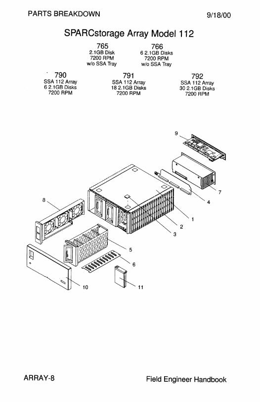
PARTS BREAKDOWN 9/18/00
SPARCstorage Array Model 112
. 790 SSA 112 Array 6 2.1 GB Disks
7200 RPM
ARRAY-8
765 2.1GB Disk 7200 RPM
wlo SSA Tray
791
766 6 2.1 GB Disks
7200 RPM wlo SSA Tray
SSA 112 Array 182.1GB Disks
7200 RPM
792 SSA 112 Array 30 2.1 GB Disks
7200 RPM
Field Engineer Handbook

9/18/00 PARTS BREAKDOWN
SPARCstorage Array Model 112 765 766 790 791 792
CODE PART# DESCRIPTION
NS 540-2406 Chassis Assembly
1 330-1469 • Top and Bottom Cover, Light Grey
2 330-1869 • Side Cover, Light Grey
3 330-1589 • Cover Plug, Light Grey
NS 330-1590 • Foot 4 501-2029 • Backplane
5 540-2245 • Drive Tray Assembly/FRU, Light Grey
6 501-2010 • Drive Tray Backplane
NS 540-2248 • Chassis Subassembly
NS 340-2670 • Chassis 7 540-2465 • Power Supply Assembly/FRU, Light Grey
- 300-1098 • 440 Watt Power Supply
8 540-2573 • Fan Tray Assembly/FRU, Light Grey
- 370-1885 • 120 x 38 mm Fan, 100CFM
- 260-6233 Sun Logo
- 260-6604 SPARCstorage Array Nameplate
9 501-2982 Configured Array Controller, Light Grey
- 501-2872 • Array Ctlr, Light Grey (110MHz microSPARC II) - 501-2857 • Battery Module
- 370-1426 • Fibre Channel Optical Module 10 540-2382 Front Bezel Assembly, Light Grey
11 540-2706 2.1 GB Disk Drive FRU
- 240-2080 • #6-32 x 3/16 Button Screw, Torx
- 370-1956 • 2.1 GB Disk Drive, IBM DFHS-32160 (disqualified)
- 370-2040 • 2.1 GB Disk Drive, Seagate ST32550WC
- 370-2365 • 2.1 GB Disk Drive, Seagate ST32171 WC
- 370-2808 • 2.1 GB Disk Drive, Quantum VK22J05
- 540-2413 • Disk Drive Mounting Bracket
NS 537-1004 Fibre Optical Cable, 2M
NS 537-1006 Fibre Optical Cable, 15M
Volume II ARRAY-9

PARTS BREAKDOWN 9/18/00
SPARCstorage Array Model 112
6590 SSA 112 Array 6 2.1GB Disks
7200 RPM
ARRAY-10
766 765 2.1GB Disk 7200 RPM
w/oSSA Tray
6 2.1 GB Disks 7200 RPM
w/o SSA Tray
6591 SSA 112 Array 18 2.1GB Disks
7200 RPM
6592 SSA 112 Array 30 2.1 GB Disks
7200 RPM
Field Engineer Handbook

9/18/00 PARTS BREAKDOWN
SPARCstorage Array Model 112 765 766 6590 6591 6592
CODE PART# DESCRIPTION
NS 540-2985 Chassis Assembly without Covers, Medium Grey
NS 540-2977 Chassis Assembly with Covers, Medium Grey
1 330-2078 • Top and Bottom Cover, Medium Grey
2 330-2079 • Side Cover, Medium Grey
3 330-1999 • Cover Plug, Medium Grey
NS 330-2000 • Foot 4 501-2029 • Backplane
5 540-2982 • Drive Tray Assembly/FRU, Medium Grey
6 501-2010 • Drive Tray Backplane
NS 540-2979 • Chassis Subassembly
NS 340-2670 • Chassis
7 540-2981 • Power Supply Assembly/FRU, Medium Grey
- 300-1098 • 440 Watt Power Supply
8 540-2980 • Fan Tray Assembly/FRU, Medium Grey
- 370-1885 • 120 x 38 mm Fan, 1 OOCFM - 260-6233 Sun Logo
- 260-6604 SPARCstorage Array Nameplate
9 501-4272 Configured Array Controller, Medium Grey - 501-4271 • Array Ctlr, Medium Grey (11 OMHz microSPARC II) - 501-2857 • Battery Module
- 370-1426 • Fibre Channel Optical Module
10 540-2978 Front Bezel Assembly, Medium Grey
11 540-2706 2.1 GB Disk Drive FRU
- 240-2080 • #6-32 x 3/16 Button Screw, Torx
- 370-1956 • 2.1 GB Disk Drive, IBM DFHS-32160 (disqualified)
- 370-2040 • 2.1 GB Disk Drive, Seagate ST32550WC
- 370-2365 • 2.1 GB Disk Drive, Seagate ST32171 WC
- 370-2808 • 2.1 GB Disk Drive, Quantum VK22J05
- 540-2413 • Disk Drive Mounting Bracket
NS 537-1004 Fibre Optical Cable, 2M
NS 537-1006 Fibre Optical Cable, 15M
Volume II ARRAY-11

PARTS BREAKDOWN 9/18/00
SPARCstorage Array Model 114
6517 SSA 114 Array 6 4.2G Disks 7200 RPM
ARRAY-12
5207 5206 4.2GB Disk 7200 RPM
wlo SSA Tray
6 4.2GB Disks 7200 RPM
w/o SSA Tray
6518 SSA 114 Array 18 4.2GB Disks
7200 RPM
6519 SSA 114 Array 30 4.2GB Disks
7200 RPM
Field Engineer Handbook

9/18/00 PARTS BREAKDOWN
SPARCstorage Array Model 114 5206 5207 6517 6518 6519
CODE PART# DESCRIPTION
NS 540-2985 Chassis Assembly without Covers, Medium Grey
NS 540-2977 Chassis Assembly with Covers, Medium Grey
1 330-2078 • Top and Bottom Cover, Medium Grey
2 330-2079 • Side Cover, Medium Grey
3 330-1999 • Cover Plug, Medium Grey NS 330-2000 • Foot 4 501-2029 • Backplane 5 540-2982 • Drive Tray Assembly/FRU, Medium Grey
6 501-2010 • Drive Tray Backplane NS 540-2979 • Chassis Subassembly NS 340-2670 • Chassis 7 540-2981 • Power Supply Assembly/FRU, Medium Grey
- 300-1098 • 440 Watt Power Supply
8 540-2980 • Fan Tray Assembly/FRU, Medium Grey - 370-1885 • 120 x 38 mm Fan, 1 OOCFM
- 260-6233 Sun Logo - 260-6604 SPARCstorage Array Nameplate
9 501-4272 Configured Array Controller, Medium Grey - 501-4271 • Array Ctlr, Medium Grey (11 OM Hz microSPARC II)
- 501-2857 • Battery Module - 370-1426 • Fibre Channel Optical Module
10 540-2978 Front Bezel Assembly, Medium Grey
11 540-2937 4.2GB Disk Drive FRU
- 240-2304 • #6-32 x 3/16 Button Screw, Torx - 370-2367 • 4.2GB Disk Drive, Seagate ST34371WC
- 370-2809 • 4.2GB Disk Drive, Quantum VK45J05 - 370-3403 • 4.2GB Disk Drive, IBM DDRS-34560 - 540-2764 • Disk Drive Mounting Bracket
NS 537-1004 Fibre Optical Cable, 2M
NS 537-1006 Fibre Optical Cable, 15M
Volume II ARRAY-13

PARTS BREAKDOWN
SPARCstorage Array Model 200 781
9/18/00
ARRAY-14 Field Engineer Handbook
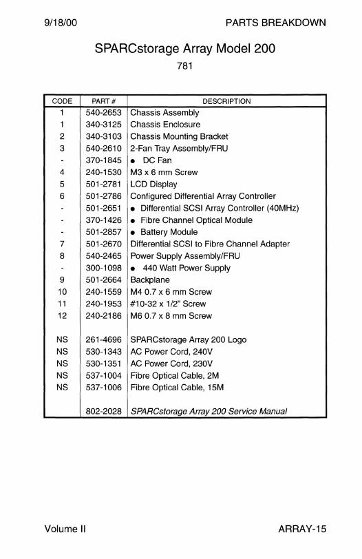
9/18/00
CODE
1 1
2
3
-4
5
6
--
-7
8
-9
10
11
12
NS
NS
NS
NS
NS
Volume II
PARTS BREAKDOWN
SPARCstorage Array Model 200 781
PART# DESCRIPTION
540-2653 Chassis Assembly
340-3125 Chassis Enclosure
340-3103 Chassis Mounting Bracket
540-2610 2-Fan Tray Assembly/FRU
370-1845 • DC Fan
240-1530 M3 x 6 mm Screw
501-2781 LCD Display
501-2786 Configured Differential Array Controller
501-2651 • Differential SCSI Array Controller (40MHz)
370-1426 • Fibre Channel Optical Module 501-2857 • Battery Module 501-2670 Differential SCSI to Fibre Channel Adapter
540-2465 Power Supply Assembly/FRU
300-1098 • 440 Watt Power Supply
501-2664 Backplane
240-1559 M4 0.7 x 6 mm Screw
240-1953 #10-32 x 1 /2" Screw
240-2186 M6 0.7 x 8 mm Screw
261-4696 SPARCstorage Array 200 Logo
530-1343 AC Power Cord, 240V
530-1351 AC Power Cord, 230V
537-1004 Fibre Optical Cable, 2M 537-1006 Fibre Optical Cable, 15M
802-2028 SPARCstorage Array 200 Service Manual
ARRAY-15
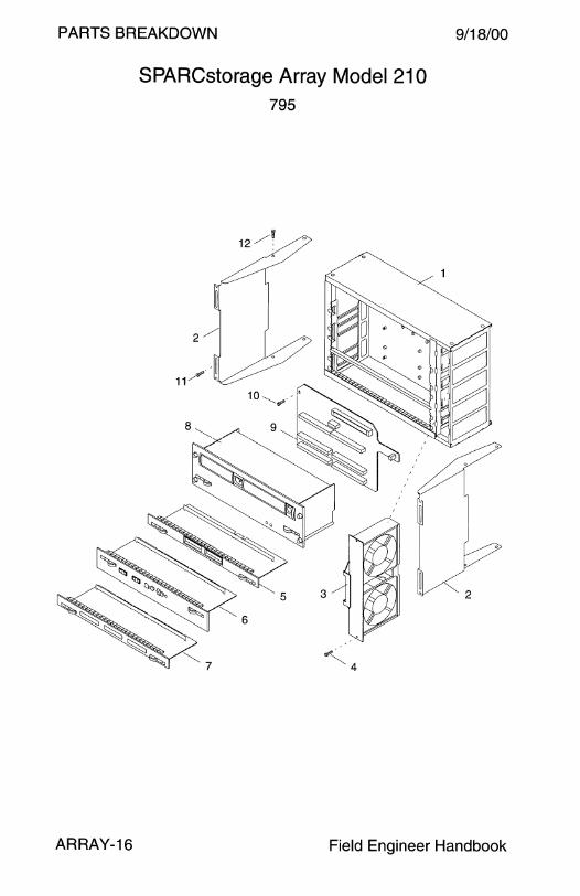
PARTS BREAKDOWN
SPARCstorage Array Model 21 O 795
9/18/00
ARRAY-16 Field Engineer Handbook

9/18/00
CODE
1
1
2
3
-4
5
6
---7
8
-9
10
11
12
NS
NS
NS
NS
NS
Volume II
PARTS BREAKDOWN
SPARCstorage Array Model 21 O 795
PART# DESCRIPTION
540-2653 Chassis Assembly
340-3125 Chassis Enclosure
340-3103 Chassis Mounting Bracket
540-2610 2-Fan Tray Assembly/FRU
370-1845 • DC Fan
240-1530 M3 x 6 mm Screw
501-2781 LCD Display
501-3024 Configured Differential Array Controller
501-3021 • Differential SCSI Array Controller (11 OMHz)
370-1426 • Fibre Channel Optical Module 501-2857 • Battery Module 501-2670 Differential SCSI to Fibre Channel Adapter
540-2465 Power Supply Assembly/FRU
300-1098 • 440 Watt Power Supply
501-2664 Backplane
240-1559 M4 0.7 x 6 mm Screw
240-1953 #10-32 x 1 /2" Screw
240-2186 M6 0.7 x 8 mm Screw
261-4696 SPARCstorage Array 200 Logo
530-1343 AC Power Cord, 240V
530-1351 AC Power Cord, 230V
537-1004 Fibre Optical Cable, 2M
537-1006 Fibre Optical Cable, 15M
802-2028 SPARCstorage Array 200 Service Manual
ARRAY-17
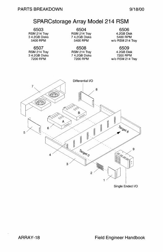
PARTS BREAKDOWN 9/18/00
SPARCstorage Array Model 214 RSM 6503 6504 6506
RSM 214 Tray RSM 214 Tray 4.2GB Disk 3 4.2GB Disks 7 4.2GB Disks 5400 RPM
5400 RPM 5400 RPM wlo RSM 214 Tray
6507 6508 6509 RSM 214 Tray RSM 214 Tray 4.2GB Disk 3 4.2GB Disks 7 4.2GB Disks 7200 RPM
7200 RPM 7200 RPM wlo RSM 214 Tray
Single Ended 1/0
ARRAY-18 Field Engineer Handbook

9/18/00 PARTS BREAKDOWN
SPARCstorage Array Model 214 RSM
CODE
-
1
2
3
4
5
6
6
7
8
8
9
9
NS
NS
NS
NS
NS
NS
NS
NS
-----
6503
6507
PART#
370-2194
370-2955
540-3085
230-1545
370-2198
None
None
None
None
370-2195
300-1311
300-1328
370-2197
370-2196
370-3375
540-2784
540-2939
180-1189
180-1190
340-3627
530-1351
530-1343 530-2197
530-2264
370-2343
None
None
None
None
565-1478
802-5062
Volume II
6504
6508
DESCRIPTION
6506
6509
Chassis, Power Modules, and WD2S Card
Chassis, Power Modules, and WD2S Card
Chassis, Power Modules, Dampers, and WD2S Card
• Vibration Dampers (x28)
Chassis FRU
• Operator Panel
• Operator Panel Cable
• Chassis • Centerplane Environmental Sensor Card
200 Watt Power Supply Modules A and B
200 Watt Power Supply Modules A and B
Fan Assembly
WD2S Single-Ended to Differential Interface Card
WD2S Single-Ended to Differential Interface Card
4.2GB 5400 RPM Disk Drive Assembly/FRU
4.2GB 7200 RPM Disk Drive Assembly/FRU
230V AC Power Cord, IEC-320 to NEMA 6-15
240V AC Power Cord, IEC-320 to Reverse IEC-320
Shipping Bracket
230V AC Power Cord, IEC-320 to NEMA 6-15
240V AC Power Cord, IEC-320 to Reverse IEC-320
AC Power Cord, AMP Mate-N-Lok to IEC 320
AC Power Cord, AMP Mate-N-Lok to Y IEC-320
Rack Mount Tray (replaced 370-2306)
• Tray 4486-3447 (obs) or Tray 4486-9550
• Top Bracket 4486-2993
• Front Shipping Bracket 4486-3454
• Rear Shipping Bracket 4486-9535
• Front Bkt 250-1237 and Rear Bkt 250-1238 SPARCstorage RSM Installation and Service
ARRAY-19
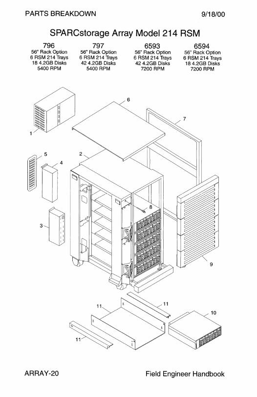
PARTS BREAKDOWN 9/18/00
SPARCstorage Array Model 214 RSM 796
56" Rack Option 6 RSM 214 Trays 18 4.2GB Disks
5400 RPM
5
~:
fl!' ~ ?:/; ~-;: ~: ";:"°""
~
3 1 I 1 I
1 I 1 I
ARRAY-20
797 56" Rack Option 6 RSM 214 Trays 42 4.2GB Disks
5400 RPM
6
6593 56" Rack Option 6 RSM 214 Trays 42 4.2GB Disks
7200 RPM
11 -~
~
6594 56" Rack Option 6 RSM 214 Trays 18 4.2GB Disks
7200 RPM
~
• • • 9
Field Engineer Handbook
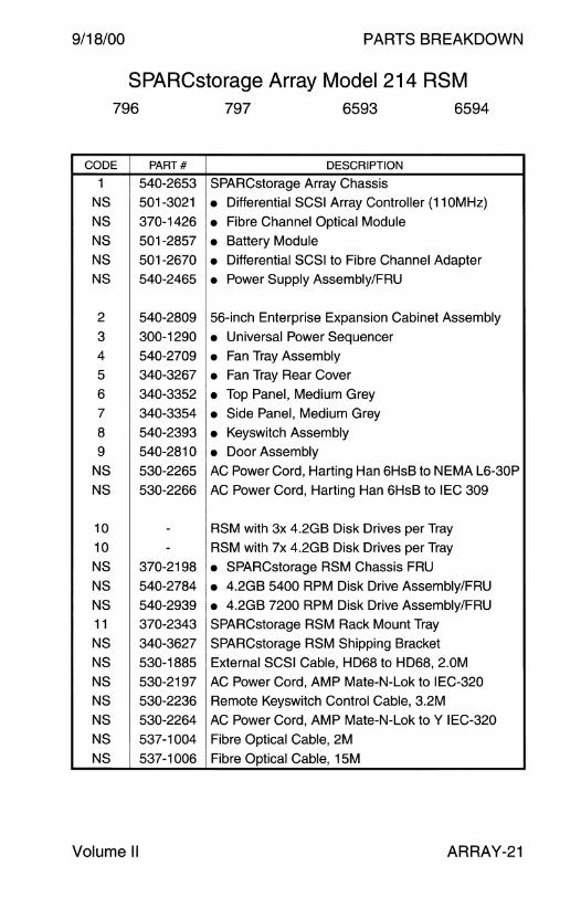
9/18/00 PARTS BREAKDOWN
SPARCstorage Array Model 214 RSM 796 797 6593 6594
CODE PART# DESCRIPTION
1 540-2653 SPARCstorage Array Chassis
NS 501-3021 • Differential SCSI Array Controller (11 OMHz)
NS 370-1426 • Fibre Channel Optical Module NS 501-2857 • Battery Module NS 501-2670 • Differential SCSI to Fibre Channel Adapter NS 540-2465 • Power Supply Assembly/FRU
2 540-2809 56-inch Enterprise Expansion Cabinet Assembly
3 300-1290 • Universal Power Sequencer 4 540-2709 • Fan Tray Assembly 5 340-3267 • Fan Tray Rear Cover
6 340-3352 • Top Panel, Medium Grey 7 340-3354 • Side Panel, Medium Grey
8 540-2393 • Keyswitch Assembly
9 540-2810 • Door Assembly NS 530-2265 AC Power Cord, Harting Han 6HsB to NEMA L6-30P
NS 530-2266 AC Power Cord, Harting Han 6HsB to IEC 309
10 - RSM with 3x 4.2GB Disk Drives per Tray
10 - RSM with 7x 4.2GB Disk Drives per Tray
NS 370-2198 • SPARCstorage RSM Chassis FRU NS 540-2784 • 4.2GB 5400 RPM Disk Drive Assembly/FRU
NS 540-2939 • 4.2GB 7200 RPM Disk Drive Assembly/FRU 11 370-2343 SPARCstorage RSM Rack Mount Tray
NS 340-3627 SPARCstorage RSM Shipping Bracket
NS 530-1885 External SCSI Cable, HD68 to HD68, 2.0M
NS 530-2197 AC Power Cord, AMP Mate-N-Lok to IEC-320
NS 530-2236 Remote Keyswitch Control Cable, 3.2M
NS 530-2264 AC Power Cord, AMP Mate-N-Lok to Y IEC-320
NS 537-1004 Fibre Optical Cable, 2M
NS 537-1006 Fibre Optical Cable, 15M
Volume II ARRAY-21
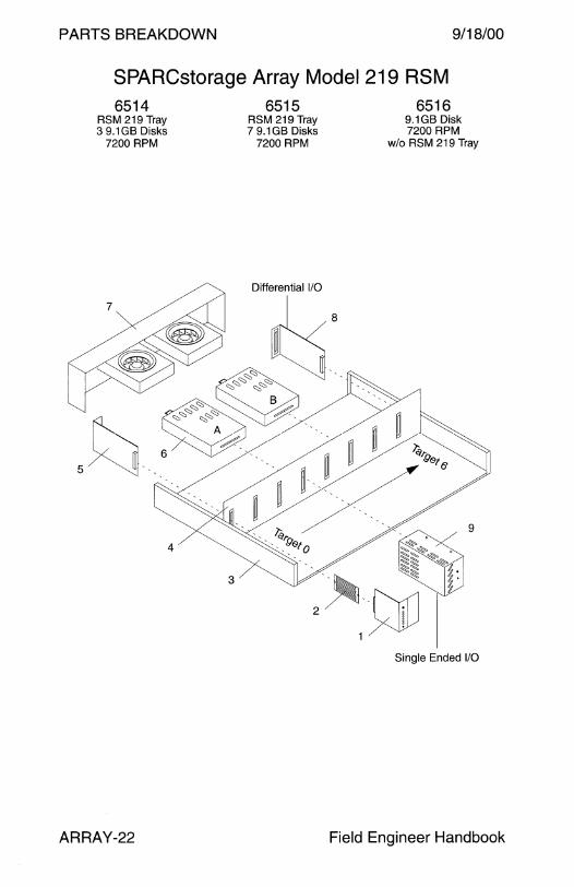
PARTS BREAKDOWN 9/18/00
SPARCstorage Array Model 219 RSM 6514
RSM 219 Tray 3 9.1 GB Disks
7200 RPM
ARRAY-22
6515 RSM 219 Tray 7 9.1GB Disks
7200 RPM
6516 9.1GB Disk 7200 RPM
w/o RSM 219 Tray
Single Ended 1/0
Field Engineer Handbook

9/18/00 PARTS BREAKDOWN
SPARCstorage Array Model 219 RSM 6514 6515 6516
CODE PART# DESCRIPTION
370-2194 Chassis with Power Modules and WD2S Card 370-2955 Chassis with Power Modules and WD2S Card
540-3085 Chassis, Power Modules, Dampers, and WD2S Card - 230-1545 • Vibration Damper for the ST19171WC (x28)
370-2198 Chassis FRU 1 None • Operator Panel 2 None • Operator Panel Cable 3 None • Chassis 4 None • Centerplane 5 370-2195 Environmental Sensor Card
6 300-1311 200 Watt Power Supply Modules A and B
6 300-1328 200 Watt Power Supply Modules A and B 7 370-2197 Fan Assembly
8 370-2196 WD2S Single-Ended to Differential Interface Card
8 370-3375 WD2S Single-Ended to Differential Interface Card
9 540-2942 9.1 GB 7200 RPM Disk Drive Assembly/FRU
- 370-2304 • Disk Drive Enclosure
- 370-2369 • 9.1GB Disk Drive, Seagate ST19171WC - 370-2370 • 9.1 GB Disk Drive, Fujitsu M2949
NS 180-1189 230V AC Power Cord, IEC-320 to NEMA 6-15 NS 180-1190 240V AC Power Cord, IEC-320 to Reverse IEC-320
NS 250-1305 RSM Tray EMI Shield (required for EMI reduction)
NS 340-3627 Shipping Bracket NS 530-1351 230V AC Power Cord, IEC-320 to NEMA 6-15
NS 530-1343 240V AC Power Cord, IEC-320 to Reverse IEC-320 NS 530-2197 AC Power Cord, AMP Mate-N-Lok to IEC-320
NS 530-2264 AC Power Cord, AMP Mate-N-Lok to Y IEC-320 NS 565-1421 Damper Kit with 35x 230-1545 Dampers
NS 370-2343 Rack Mount Tray
- 565-1478 • Front Bkt 250-1237 and Rear Bkt 250-1238
802-5062 SPARCstorage RSM Installation and Service
Volume II ARRAY-23

AKDOWN
PARTS BRE d 1219 RSM Array Mo e SPARCstorage 6596."
11/26/99
ARRAY-24
6595 56" Rack Option 6 RSM 219 Trays 18 9.1GB Disks
7200 RPM
6
56" Rack Opt10 6 RSM 219 Trays 42 9.1 GB Disks
7200RPM
H ndbook Field Engineer a
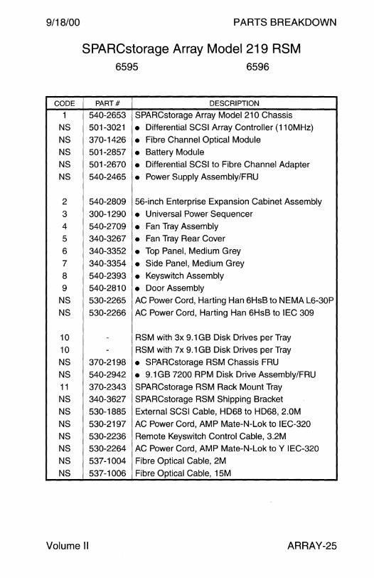
9/18/00 PARTS BREAKDOWN
SPARCstorage Array Model 219 RSM 6595 6596
CODE PART# DESCRIPTION
1 540-2653 SPARCstorage Array Model 21 O Chassis
NS 501-3021 • Differential SCSI Array Controller (11 OM Hz)
NS 370-1426 • Fibre Channel Optical Module
NS 501-2857 • Battery Module
NS 501-2670 • Differential SCSI to Fibre Channel Adapter
NS 540-2465 • Power Supply Assembly/FRU
2 540-2809 56-inch Enterprise Expansion Cabinet Assembly
3 300-1290 • Universal Power Sequencer
4 540-2709 • Fan Tray Assembly
5 340-3267 • Fan Tray Rear Cover
6 340-3352 • Top Panel, Medium Grey
7 340-3354 • Side Panel, Medium Grey
8 540-2393 • Keyswitch Assembly
9 540-2810 • Door Assembly
NS 530-2265 AC Power Cord, Harting Han 6HsB to NEMA L6-30P
NS 530-2266 AC Power Cord, Harting Han 6HsB to IEC 309
10 - RSM with 3x 9.1 GB Disk Drives per Tray
10 - RSM with 7x 9.1 GB Disk Drives per Tray
NS 370-2198 • SPARCstorage RSM Chassis FRU
NS 540-2942 • 9.1 GB 7200 RPM Disk Drive Assembly/FRU
11 370-2343 SPARCstorage RSM Rack Mount Tray
NS 340-3627 SPARCstorage RSM Shipping Bracket
NS 530-1885 External SCSI Cable, HD68 to HD68, 2.0M
NS 530-2197 AC Power Cord, AMP Mate-N-Lok to IEC-320
NS 530-2236 Remote Keyswitch Control Cable, 3.2M
NS 530-2264 AC Power Cord, AMP Mate-N-Lok to Y IEC-320
NS 537-1004 Fibre Optical Cable, 2M
NS 537-1006 Fibre Optical Cable, 15M
Volume II ARRAY-25
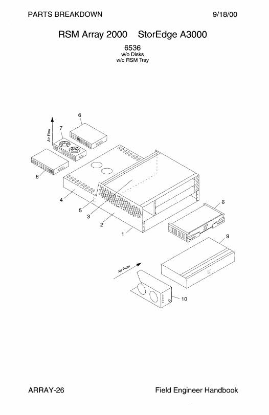
PARTS BREAKDOWN 9/18/00
RSM Array 2000 StorEdge A3000 6536
6
ARRAY-26
w/o Disks w/o RSM Tray
Field Engineer Handbook
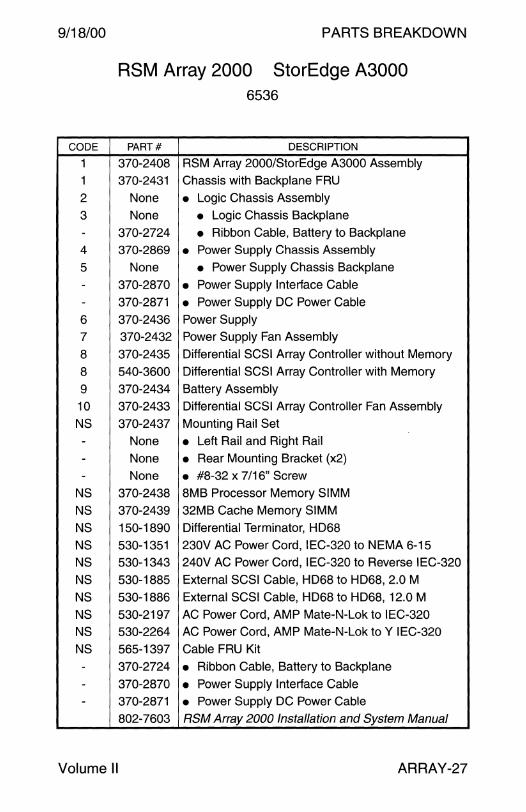
9/18/00 PARTS BREAKDOWN
CODE
1
1
2
3 -
4
5
--6 7
8
8
9 10 NS
---
NS
NS
NS
NS
NS
NS
NS
NS
NS
NS
---
Volume II
RSM Array 2000 StorEdge A3000 6536
PART# DESCRIPTION
370-2408 RSM Array 2000/StorEdge A3000 Assembly
370-2431 Chassis with Backplane FRU
None • Logic Chassis Assembly
None • Logic Chassis Backplane
370-2724 • Ribbon Cable, Battery to Backplane
370-2869 • Power Supply Chassis Assembly
None • Power Supply Chassis Backplane
370-2870 • Power Supply Interface Cable
370-2871 • Power Supply DC Power Cable
370-2436 Power Supply
370-2432 Power Supply Fan Assembly
370-2435 Differential SCSI Array Controller without Memory
540-3600 Differential SCSI Array Controller with Memory
370-2434 Battery Assembly
370-2433 Differential SCSI Array Controller Fan Assembly
370-2437 Mounting Rail Set
None • Left Rail and Right Rail
None • Rear Mounting Bracket (x2}
None • #8-32 x 7/16" Screw
370-2438 8MB Processor Memory SIMM
370-2439 32MB Cache Memory SIMM
150-1890 Differential Terminator, HD68
530-1351 230V AC Power Cord, IEC-320 to NEMA 6-15
530-1343 240V AC Power Cord, IEC-320 to Reverse IEC-320
530-1885 External SCSI Cable, HD68 to HD68, 2.0 M
530-1886 External SCSI Cable, HD68 to HD68, 12.0 M
530-2197 AC Power Cord, AMP Mate-N-Lok to IEC-320 530-2264 AC Power Cord, AMP Mate-N-Lok to Y IEC-320
565-1397 Cable FRU Kit
370-2724 • Ribbon Cable, Battery to Backplane
370-2870 • Power Supply Interface Cable 370-2871 • Power Supply DC Power Cable
802-7603 RSM Array 2000 Installation and System Manual
ARRAY-27
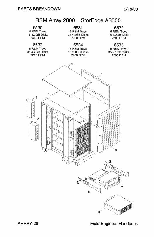
PARTS BREAKDOWN 9/18/00
RSM Array 2000 StorEdge A3000 6530 6531 6532
5 RSM Trays 5 RSM Trays 5 RSM Trays 15 4.2GB Disks 35 4.2GB Disks 15 4.2GB Disks
5400 RPM 7200 RPM 7200 RPM
6533 6534 6535 5 RSM Trays 5 RSM Trays 5 RSM Trays
35 4.2GB Disks 15 9.1GB Disks 35 9.1GB Disks 7200 RPM 7200 RPM 7200 RPM
3
ARRAY-28 Field Engineer Handbook

9/18/00 PARTS BREAKDOWN
RSM Array 2000 StorEdge A3000
CODE
1
2
3
4
5
6
NS
NS
7
7
----
---
8
9
9 NS
NS
NS
NS
NS
NS
NS
NS
NS
NS
6530
6533
PART#
540-2809
300-1290
340-3352
340-3354
540-2393
540-2810
530-2265
530-2266
370-2408
370-2431
370-2869
370-2436
370-2432
370-2435
540-3600
370-2434
370-2433 370-2437
-
-370-2198
540-2784
540-2939
540-2942
340-3627
530-1885
530-1886
530-2197
530-2236
530-2264
Volume II
6531
6534
DESCRIPTION
6532
6535
56-inch Enterprise Expansion Cabinet Assembly
• Universal Power Sequencer
• Top Panel, Medium Grey
• Side Panel, Medium Grey
• Keyswitch Assembly
• Door Assembly AC Power Cord, Harting Han 6HsB to NEMA L6-30P
AC Power Cord, Harting Han 6HsB to IEC 309
RSM Array 2000/StorEdge A3000 Assembly
• Chassis with Backplane FRU
• Power Supply Chassis Assembly
• Power Supply • Power Supply Fan Assembly • Differential SCSI Array Controller without Memory
• Differential SCSI Array Controller with Memory
• Battery Assembly
• Differential SCSI Array Controller Fan Assembly
Mounting Rail Set
RSM with 3x Disk Drives per Tray
RSM with 7x Disk Drives per Tray
• SPARCstorage RSM Chassis FRU
• 4.2GB 5400 RPM Disk Drive Assembly/FRU
• 4.2GB 7200 RPM Disk Drive Assembly/FRU
• 9.1 GB 7200 RPM Disk Drive Assembly/FRU SPARCstorage RSM Shipping Bracket
External SCSI Cable, HD68 to HD68, 2.0 M
External SCSI Cable, HD68 to HD68, 12.0 M
AC Power Cord, AMP Mate-N-Lok to IEC-320
Remote Keyswitch Control Cable, 3.2M
AC Power Cord, AMP Mate-N-Lok to Y IEC-320
ARRAY-29

PARTS BREAKDOWN 9/18/00
StorEdge A 1000 ARY126A-72G ARY126A-144G ARY135A-72G
Tabletop Option Tabletop Option 72" Rack Option w/o Rack 4 18.2GB Disks 8 18.2GB Disks 4 18.2GB Disks
7200 RPM 7200 RPM 7200 RPM
ARY161A-145G ARY161 A-291 G ARY162A-145G Tabletop Option Tabletop Option 72" Rack Option w/o Rack 4 36.4GB Disks 8 36.4GB Disks 4 36.4GB Disks
10000 RPM 10000 RPM 10000 RPM
3
ARRAY-30 Field Engineer Handbook

9/18/00
ARY126A-72G
ARY161A-145G
CODE PART#
1 540-3270
1 540-3761
1 540-3325
2 501-4560
3 330-2535
4 540-3323
5 300-1340
6 330-2000
7 330-2267
8 330-2266
9 540-3324
10 540-3721
- 370-3414
- 370-3596 - 540-3025
10 540-4263 - 390-0014
- 390-0020
- 540-3025
10 370-3291
NS 375-0015
NS 375-0016 NS 375-0007
NS 370-3417
NS 330-1999
NS 240-2690
NS 150-1890
NS 530-1885
NS 340-4469
NS 340-4470
NS 340-4471
NS 370-4472
805-2624
Volume II
PARTS BREAKDOWN
StorEdge A 1000 ARY126A-144G
ARY161A-291G
ARY135A-72G
ARY162A-145G
DESCRIPTION
Empty 8-Drive Chassis Assembly
Empty 8-Drive Chassis with Rack Mount Tray
Empty Chassis Assembly
8-Slot SCSI Disk Backplane
Top Cover
Fan Tray
360 Watt Power Supply
Foot
Bottom Cover
Vented Side Panel
Front Door Assembly (-01 w Frame -02 w/o Frame)
18.2GB 7200 RPM Disk Drive Assembly/FRU
• 18.2GB Disk Drive, Fujitsu MAA3182SC
• 18.2GB Disk Drive, Seagate ST118273LC
• 1.6" Spud Bracket 36.4GB 10000 RPM Disk Drive Assembly/FRU
• 36.4GB Disk Drive, Fujitsu MAF3364LC
• 36.4GB Disk Drive, Seagate ST136403LC
• 1.6" Spud Bracket
Empty 1.6" Disk Drive Slot Filler
RAID Controller FRU, 16MB MPU + 64MB RPA
RAID Controller FRU, 8MB MPU + 16MB RPA
• RAID Controller, 8MB MPU + 16MB RPA
• Battery Top and Bottom Cover Plug
A 1000/D1000 Key
Differential Terminator, HD68
External SCSI Cable, HD68 to HD68, 2M
A 1 000/D 1 000 Tray
A 1OOO/D1000 Rack Mounting Bracket (x2)
A1000/D1000 Right Clamp
A 1OOO/D1000 Left Clamp
A 1000/D 1000 Installation/Operation/Service Manual
ARRAY-31
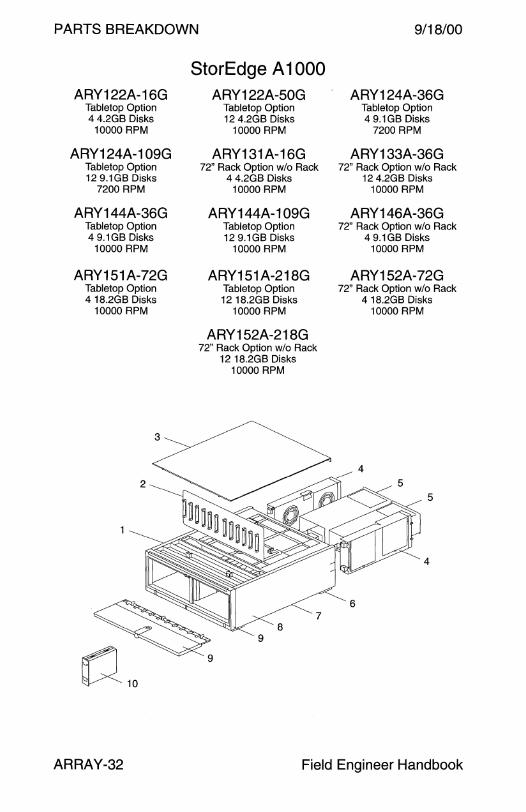
PARTS BREAKDOWN 9/18/00
StorEdge A 1000 ARY122A-16G ARY122A-50G ARY124A-36G
Tabletop Option Tabletop Option Tabletop Option 4 4.2GB Disks 12 4.2GB Disks 4 9.1GB Disks
10000 RPM 10000 RPM 7200 RPM
ARY124A-109G ARY131A-16G ARY133A-36G Tabletop Option 72" Rack Option w/o Rack 72" Rack Option w/o Rack 12 9.1GB Disks 4 4.2GB Disks 12 4.2GB Disks
7200 RPM 10000 RPM 10000 RPM
ARY144A-36G ARY144A-109G ARY146A-36G Tabletop Option Tabletop Option 72" Rack Option w/o Rack 4 9.1 GB Disks 12 9.1GB Disks 4 9.1 GB Disks
10000 RPM 10000 RPM 10000 RPM
ARY151A-72G ARY151 A-21 BG ARY152A-72G Tabletop Option Tabletop Option 72" Rack Option w/o Rack 4 18.2GB Disks 12 18.2GB Disks 4 18.2GB Disks
10000 RPM 10000 RPM 10000 RPM
ARY152A-218G 72" Rack Option w/o Rack
12 18.2GB Disks 10000 RPM
3
5
4
ARRAY-32 Field Engineer Handbook

9/18/00 PARTS BREAKDOWN
StorEdge A 1000 ARY122A-16G ARY122A-50G ARY124A-36G
ARY124A-109G ARY131A-16G ARY133A-36G
ARY144A-36G ARY144A-109G ARY146A-36G
ARY151A-72G ARY151 A-218G ARY152A-72G
ARY152A-218G
CODE PART# DESCRIPTION
1 540-3269 Empty 12-Drive Chassis Assembly
1 540-3325 Empty Chassis Assembly
2 501-4440 12-Slot SCSI Disk Backplane
3 330-2535 Top Cover
4 540-3323 Fan Tray
5 300-1340 360 Watt Power Supply
6 330-2000 Foot
7 330-2267 Bottom Cover
8 330-2266 Vented Side Panel
9 540-3324 Front Door Assembly (-01 w Frame -02 w/o Frame)
10 See next page Disk Drive Assembly/FRU
NS 375-0015 RAID Controller FRU, 16MB MPU + 64MB RPA
NS 375-0016 RAID Controller FRU, 8MB MPU + 16MB RPA - 375-0007 • RAID Controller, 8MB MPU + 16MB RPA
- 370-3417 • Battery
NS 150-1890 Differential Terminator, HD68
NS 240-2690 A 1OOO/D1000 Key
NS 330-1999 Top and Bottom Cover Plug
NS 340-4469 A1000/D1000 Tray
NS 340-4470 A 1OOO/D1000 Rack Mounting Bracket (x2)
NS 340-4471 A1000/D1000 Right Clamp
NS 370-4472 A 1OOO/D1000 Left Clamp
NS 530-1885 External SCSI Cable, HD68 to HD68, 2M
NS 530-2384 External SCSI Cable, HD68 to HD68, 2M
805-2624 A 1000/D 1000 Installation/Operation/Service Manual
Volume II ARRAY-33
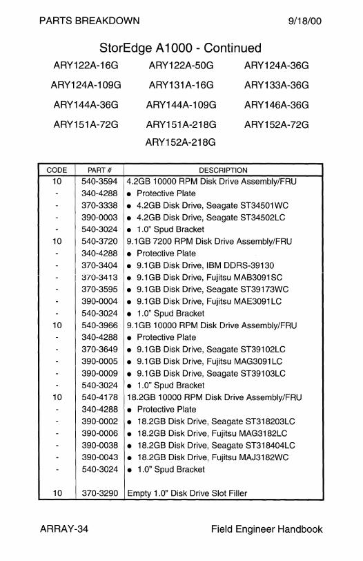
PARTS BREAKDOWN 9/18/00
StorEdge A 1000 - Continued ARY122A-16G
ARY124A-109G
ARY144A-36G
ARY151A-72G
CODE PART#
10 540-3594 - 340-4288
- 370-3338 - 390-0003 - 540-3024
10 540-3720
- 340-4288
- 370-3404 - 370-3413
- 370-3595
- 390-0004 - 540-3024
10 540-3966 - 340-4288
- 370-3649
- 390-0005 - 390-0009
- 540-3024
10 540-4178
- 340-4288
- 390-0002
- 390-0006 - 390-0038
- 390-0043
- 540-3024
10 370-3290
ARRAY-34
ARY122A-50G
ARY131A-16G
ARY144A-109G
ARY151 A-218G
ARY152A-218G
ARY124A-36G
ARY133A-36G
ARY146A-36G
ARY152A-72G
DESCRIPTION
4.2GB 10000 RPM Disk Drive Assembly/FRU
• Protective Plate
• 4.2GB Disk Drive, Seagate ST34501WC
• 4.2GB Disk Drive, Seagate ST34502LC
• 1.0'' Spud Bracket 9.1 GB 7200 RPM Disk Drive Assembly/FRU
• Protective Plate
• 9.1GB Disk Drive, IBM DDRS-39130
• 9.1 GB Disk Drive, Fujitsu MAB3091 SC
• 9.1 GB Disk Drive, Seagate ST39173WC
• 9.1 GB Disk Drive, Fujitsu MAE3091 LC
• 1.0" Spud Bracket 9.1 GB 10000 RPM Disk Drive Assembly/FRU
• Protective Plate
• 9.1 GB Disk Drive, Seagate ST39102LC
• 9.1 GB Disk Drive, Fujitsu MAG3091 LC
• 9.1 GB Disk Drive, Seagate ST39103LC
• 1.0" Spud Bracket 18.2GB 10000 RPM Disk Drive Assembly/FRU
• Protective Plate
• 18.2GB Disk Drive, Seagate ST318203LC
• 18.2GB Disk Drive, Fujitsu MAG3182LC
• 18.2GB Disk Drive, Seagate ST318404LC
• 18.2GB Disk Drive, Fujitsu MAJ3182WC
• 1.0" Spud Bracket
Empty 1.0" Disk Drive Slot Filler
Field Engineer Handbook

9/18/00 PARTS BREAKDOWN
This page intentionally left blank.
Volume II ARRAY-35

PARTS BREAKDOWN
ARY150A-72G Tabletop Option 4 18.2GB Disks
10000 RPM
ARY155A-218G 72" Rack Option w/o Rack
12 18.2GB Disks 10000 RPM
StorEdge A 1 000 ARY150A-218G
Tabletop Option 12 18.2GB Disks
10000 RPM
ARY170A-145G Tabletop Option 4 36.4GB Disks
10000 RPM
9/18/00
ARY155A-72G 72" Rack Option w/o Rack
418.2GB Disks 10000 RPM
ARY170A-436G Tabletop Option 12 36.4GB Disks
10000 RPM
ARY171 A-145G ARY171A-436G 72" Rack Option w/o Rack
4 36.4GB Disks 10000 RPM
ARRAY-36
72" Rack Option w/o Rack 12 36.4GB Disks
10000 RPM
5
4
Field Engineer Handbook

9/18/00
ARY150A-72G
ARY155A-218G
PARTS BREAKDOWN
StorEdge A 1000 ARY150A-218G
ARY170A-145G
ARY155A-72G
ARY170A-436G
ARY171 A-145G ARY171A-436G
CODE PART# DESCRIPTION
1 540-3269 Empty 12-Drive Chassis Assembly
1 540-3325 Empty Chassis Assembly
2 501-4440 12-Slot SCSI Disk Backplane
3 330-2535 Top Cover
4 540-3323 Fan Tray
5 300-1340 360 Watt Power Supply
6 330-2000 Foot
7 330-2267 Bottom Cover
8 330-2266 Vented Side Panel
9 540-3324 Front Door Assembly (-02 w/o Frame)
10 540-4178 18.2GB 10000 RPM Disk Drive Assembly/FRU
10 540-4520 36.4GB 10000 RPM Disk Drive Assembly/FRU
NS 375-0135 RAID Controller FRU, 8MB MPU + 16MB RPA
NS 375-0136 RAID Controller FRU, 16MB MPU + 64MB RPA
- 375-0134 • RAID Controller, 8MB MPU + 16MB RPA - 370-3417 • Battery
NS 150-1890 Differential Terminator, HD68
NS 240-2690 A 1000/D1000 Key
NS 330-1999 Top and Bottom Cover Plug
NS 340-4469 A 1000/D1000 Tray NS 340-4470 A 1 OOO/D1000 Rack Mounting Bracket (x2)
NS 340-4471 A1000/D1000 Right Clamp
NS 370-4472 A 1OOO/D1000 Left Clamp
NS 530-1885 External SCSI Cable, HD68 to HD68, 2M
NS 530-2384 External SCSI Cable, HD68 to HD68, 2M
805-2624 A 1000/D 1000 Installation/Operation/Service Manual
Volume II ARRAY-37

PARTS BREAKDOWN 9/18/00
StorEdge 01000 ARY127A-72G ARY127A-144G ARY136A-72G
Tabletop Option Tabletop Option 72" Rack Option w/o Rack 4 18.2GB Disks 8 18.2GB Disks 4 18.2GB Disks
7200 RPM 7200 RPM 7200 RPM
ARY163A-145G ARY163A-291 G ARY164A-145G Tabletop Option Tabletop Option 72" Rack Option w/o Rack 4 36.4GB Disks 8 36.4GB Disks 4 36.4GB Disks
10000 RPM 10000 RPM 10000 RPM
5
4
ARRAY-38 Field Engineer Handbook

9/18/00
ARY127 A-72G
ARY163A-145G
CODE PART#
1 540-3270
1 540-3761
1 540-3325
2 501-4560
3 330-2535
4 540-3323
5 300-1340
6 330-2000
7 330-2267
8 330-2266
9 540-3324
10 540-3721 - 340-4288
- 370-3414
- 370-3596 - 540-3025
10 540-4263
- 340-4288 - 390-0014
- 390-0020 - 540-3025
10 370-3291 NS 375-0008
NS 330-1999
NS 240-2690
NS 150-1890
NS 530-1883
NS 530-1885
NS 340-4469
NS 340-4470
NS 340-4471
NS 370-4472
805-2624
Volume II
PARTS BREAKDOWN
StorEdge D 1000 ARY127A-144G
ARY163A-291 G
ARY136A-72G
ARY164A-145G
DESCRIPTION
Empty 8-Drive Chassis Assembly
Empty 8-Drive Chassis with Rack Mount Tray
Empty Chassis Assembly
8-Slot SCSI Disk Backplane
Top Cover
Fan Tray
360 Watt Power Supply
Foot
Bottom Cover
Vented Side Panel
Front Door Assembly (-01 w Frame -02 w/o Frame)
18.2GB 7200 RPM Disk Drive Assembly/FRU
• Protective Plate • 18.2GB Disk Drive, Fujitsu MAA3182SC
• 18.2GB Disk Drive, Seagate ST118273LC
• 1.6" Spud Bracket 36.4GB 10000 RPM Disk Drive Assembly/FRU
• Protective Plate
• 36.4GB Disk Drive, Fujitsu MAF3364LC
• 36.4GB Disk Drive, Seagate ST136403LC
• 1.6" Spud Bracket Empty 1.6" Disk Drive Slot Filler
Differential SCSI Controller Board
Top and Bottom Cover Plug
A 1000/D 1000 Key
Differential Terminator, HD68
External SCSI Cable, HD68 to HD68, 20 cm
External SCSI Cable, HD68 to HD68, 2M
A1000/D1000 Tray
A 1 OOO/D1000 Rack Mounting Bracket (x2)
A1000/D1000 Right Clamp
A 1OOO/D1000 Left Clamp
A 1000/D 1000 Installation/Operation/Service Manual
ARRAY-39
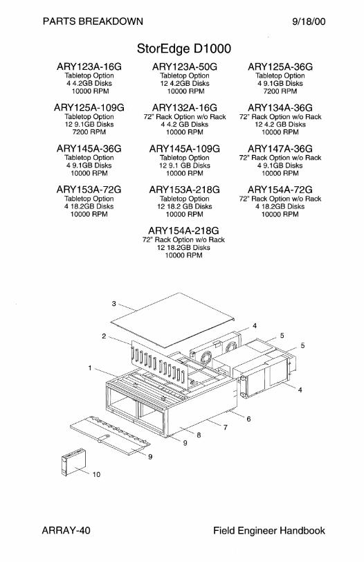
PARTS BREAKDOWN 9/18/00
StorEdge 01000 ARY123A-16G ARY123A-50G ARY125A-36G
Tabletop Option Tabletop Option Tabletop Option 4 4.2GB Disks 12 4.2GB Disks 4 9.1GB Disks
10000 RPM 10000 RPM 7200 RPM
ARY125A-109G ARY132A-16G ARY134A-36G Tabletop Option 72" Rack Option w/o Rack 72" Rack Option w/o Rack 12 9.1GB Disks 4 4.2 GB Disks 12 4.2 GB Disks
7200 RPM 10000 RPM 10000 RPM
ARY145A-36G ARY145A-109G ARY147A-36G Tabletop Option Tabletop Option 72" Rack Option w/o Rack 4 9.1 GB Disks 12 9.1 GB Disks 4 9.1GB Disks
10000 RPM 10000 RPM 10000 RPM
ARY153A-72G ARY153A-218G ARY154A-72G Tabletop Option Tabletop Option 72" Rack Option w/o Rack 4 18.2GB Disks 12 18.2 GB Disks 4 18.2GB Disks
10000 RPM 10000 RPM 10000 RPM
ARY154A-218G 72" Rack Option w/o Rack
12 18.2GB Disks 10000 RPM
3
5
4
ARRAY-40 Field Engineer Handbook

9/18/00 PARTS BREAKDOWN
StorEdge D 1000 ARY123A-16G ARY123A-50G ARY125A-36G
ARY125A-109G ARY132A-16G ARY134A-36G
ARY145A-36G ARY145A-109G ARY147A-36G
ARY153A-72G ARY153A-218G ARY154A-72G
ARY154A-218G
CODE PART# DESCRIPTION
1 540-3269 Empty 12-Drive Chassis Assembly
1 540-3325 Empty Chassis Assembly
2 501-4440 12-Slot SCSI Disk Backplane
3 330-2535 Top Cover
4 540-3323 Fan Tray
5 300-1340 360 Watt Power Supply
6 330-2000 Foot
7 330-2267 Bottom Cover
8 330-2266 Vented Side Panel
9 540-3324 Front Door Assembly (-01 w Frame -02 w/o Frame)
10 See next page Disk Drive Assembly/FRU
NS 150-1890 Differential Terminator, HD68
NS 240-2690 A 1000/D1000 Key
NS 330-1999 Top and Bottom Cover Plug
NS 330-2270 Door Frame
NS 375-0008 Differential SCSI Controller Board
NS 530-1885 External SCSI Cable, HD68 to HD68, 2M
NS 530-2384 External SCSI Cable, HD68 to HD68, 2M
NS 340-4469 A 1OOO/D1000 Tray
NS 340-4470 A 1OOO/D1000 Rack Mounting Bracket {x2)
NS 340-4471 A 1OOO/D1000 Right Clamp
NS 370-4472 A 1 OOO/D1000 Left Clamp
805-2624 A 1000/D 1000 Installation/Operation/Service Manual
Note: Option ARY123A-50G was originally price listed as ARY023A-50G.
Volume II ARRAY-41

PARTS BREAKDOWN 9/18/00
StorEdge 01000 - Continued ARY123A-16G
ARY125A-109G
ARY145A-36G
ARY153A-72G
CODE PART#
10 540-3594
- 340-4288 - 370-3338
- 390-0003
- 540-3024
10 540-3720
- 340-4288
- 370-3404
- 370-3413
- 370-3595
- 390-0004
- 540-3024
10 540-3966
- 340-4288 - 370-3649
- 390-0005
- 390-0009
- 540-3024
10 540-4178 - 340-4288
- 390-0002 - 390-0006
- 390-0038
- 390-0043
- 54.0-3024
10 370-3290
ARRAY-42
ARY123A-50G
ARY132A-16G
ARY145A-109G
ARY153A-218G
ARY154A-218G
ARY125A-36G
ARY134A-36G
ARY147A-36G
ARY154A-72G
DESCRIPTION
4.2GB 10000 RPM Disk Drive Assembly/FRU
• Protective Plate
• 4.2GB Disk Drive, Seagate ST34501 WC
• 4.2GB Disk Drive, Seagate ST34502LC
• 1 .O" Spud Bracket
9.1 GB 7200 RPM Disk Drive Assembly/FRU
• Protective Plate
• 9.1 GB Disk Drive, IBM DDRS-39130
• 9.1 GB Disk Drive, Fujitsu MAB3091 SC
• 9.1 GB Disk Drive, Seagate ST39173WC
• 9.1 GB Disk Drive, Fujitsu MAE3091 LC
• 1.0" Spud Bracket
9.1 GB 10000 RPM Disk Drive Assembly/FRU
• Protective Plate
• 9.1 GB Disk Drive, Seagate ST39102LC
• 9.1 GB Disk Drive, Fujitsu MAG3091 LC
• 9.1GB Disk Drive, Seagate ST39103LC
• 1.0" Spud Bracket
18.2GB 10000 RPM Disk Drive Assembly/FRU
• Protective Plate
• 18.2GB Disk Drive, Seagate ST318203LC
• 18.2GB Disk Drive, Fujitsu MAG3182LC
• 18.2GB Disk Drive, Seagate ST318404LC
• 18.2GB Disk Drive, Fujitsu MAJ3182WC
• 1.0" Spud Bracket
Empty 1.0'' Disk Drive Slot Filler
Field Engineer Handbook
9/18/00 PARTS BREAKDOWN
This page intentionally left blank.
Volume II ARRAY-43

PARTS BREAKDOWN 9/18/00
StorEdge 01000 ARY172A-145G
Tabletop Option 4 36.4GB Disks
10000 RPM
ARY173A-145G 72" Rack Option w/o Rack
4 36.4GB Disks 10000 RPM
ARRAY-44
ARY172A-436G Tabletop Option 12 36.4GB Disks
10000 RPM
ARY173A-436G 72" Rack Option w/o Rack
12 36.4GB Disks 10000 RPM
5
4
Field Engineer Handbook
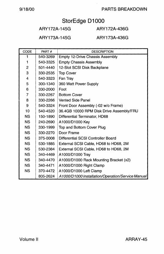
9/18/00
CODE
1
1
2
3
4
5
6
7
8
9
10
NS
NS
NS
NS
NS
NS
NS
NS
NS
NS
NS
Volume II
PARTS BREAKDOWN
StorEdge 01000 ARY172A-145G
ARY173A-145G
ARY172A-436G
ARY173A-436G
PART# DESCRIPTION
540-3269 Empty 12-Drive Chassis Assembly
540-3325 Empty Chassis Assembly
501-4440 12-Slot SCSI Disk Backplane
330-2535 Top Cover
540-3323 Fan Tray
300-1340 360 Watt Power Supply
330-2000 Foot
330-2267 Bottom Cover
330-2266 Vented Side Panel
540-3324 Front Door Assembly (-02 w/o Frame)
540-4520 36.4GB 10000 RPM Disk Drive Assembly/FRU
150-1890 Differential Terminator, HD68
240-2690 A 1000/D1000 Key
330-1999 Top and Bottom Cover Plug
330-2270 Door Frame
375-0008 Differential SCSI Controller Board
530-1885 External SCSI Cable, HD68 to HD68, 2M
530-2384 External SCSI Cable, HD68 to HD68, 2M
340-4469 A 1000/D1000 Tray
340-4470 A 1OOO/D1000 Rack Mounting Bracket (x2)
340-4471 A 1OOO/D1000 Right Clamp
370-4472 A 1OOO/D1000 Left Clamp
805-2624 A 1000/D 1000 Installation/Operation/Service Manual
ARRAY-45
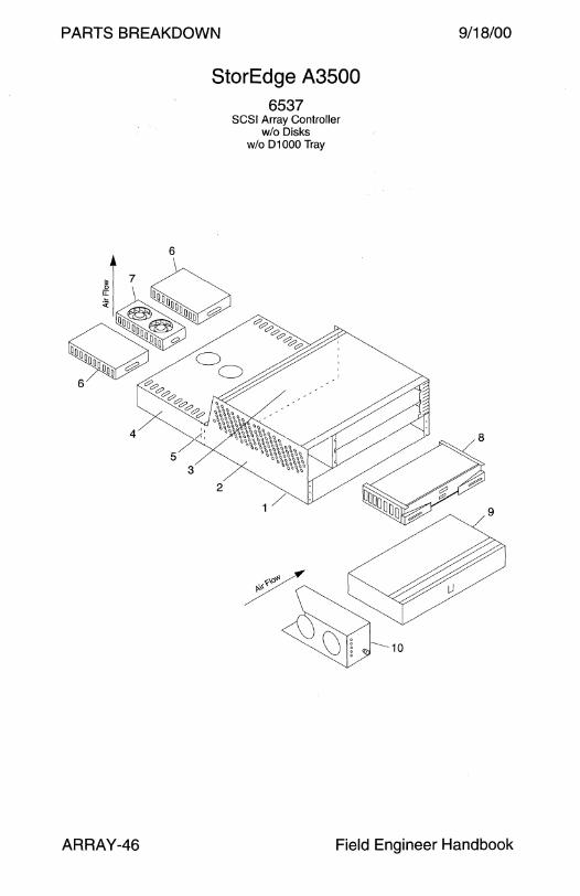
PARTS BREAKDOWN
StorEdge A3500 6537
SCSI Array Controller wlo Disks
w/o D1000 Tray
9/18/00
ARRAY-46 Field Engineer Handbook

9/18/00
CODE PART#
1 380-0083
1 370-2431
2 None
3 None
- 370-2724
4 370-2869
5 None
- 370-2870
- 370-2871
6 370-2436 7 370-2432
8 370-3656
8 540-3083
9 370-2434
10 370-2433
NS 370-2437
- None - None
- None
NS 370-2438
NS 370-2439
NS 150-1890
NS 530-1351
NS 530-1343
NS 530-1885
NS 530-1886
NS 530-2197
NS 530-2264
NS 565-1397
- 370-2724
- 370-2870
- 370-2871
805-4980
Volume II
PARTS BREAKDOWN
StorEdge A3500 6537
DESCRIPTION
StorEdge A3500 Assembly Chassis with Backplane FRU
• Logic Chassis Assembly
• Logic Chassis Backplane
• Ribbon Cable, Battery to Backplane
• Power Supply Chassis Assembly
• Power Supply Chassis Backplane
• Power Supply Interface Cable
• Power Supply DC Power Cable
Power Supply
Power Supply Fan Assembly
Differential SCSI Array Controller without Memory
Differential SCSI Array Controller with Memory
Battery Assembly
Differential SCSI Array Controller Fan Assembly
Mounting Rail Set (370-2437-02 recommended)
• Left Rail and Right Rail
• Rear Mounting Bracket (x2)
• #8-32 x 7/16" Screw
8MB Processor Memory SIMM
32MB Cache Memory SIMM
Differential Terminator, HD68
230V AC Power Cord, IEC-320 to NEMA 6-15 240V AC Power Cord, IEC-320 to Reverse IEC-320
External SCSI Cable, HD68 to HD68, 2.0 M
External SCSI Cable, HD68 to HD68, 12.0 M
AC Power Cord, AMP Mate-N-Lok to IEC-320
AC Power Cord, AMP Mate-N-Lok to Y IEC-320
Cable FRU Kit
• Ribbon Cable, Battery to Backplane
• Power Supply Interface Cable
• Power Supply DC Power Cable
StorEdge A3000 Controller Module Guide
ARRAY-47

PARTS BREAKDOWN 9/18/00
StorEdge A3500-Light ARY356A-72G Rack Option w/o Rack 1 A3500 + 2 D1000s
8 9.1 GB Disks 7200 RPM
ARRAY-48
ARY366A-72G Rack Option w/o Rack 1A3500+2 D1000s
8 9.1 GB Disks 10000 RPM
ARY386A-145G Rack Option w/o Rack 1 A3500 + 2 D1 OOOs
8 18.2GB Disks 10000 RPM
Field Engineer Handbook
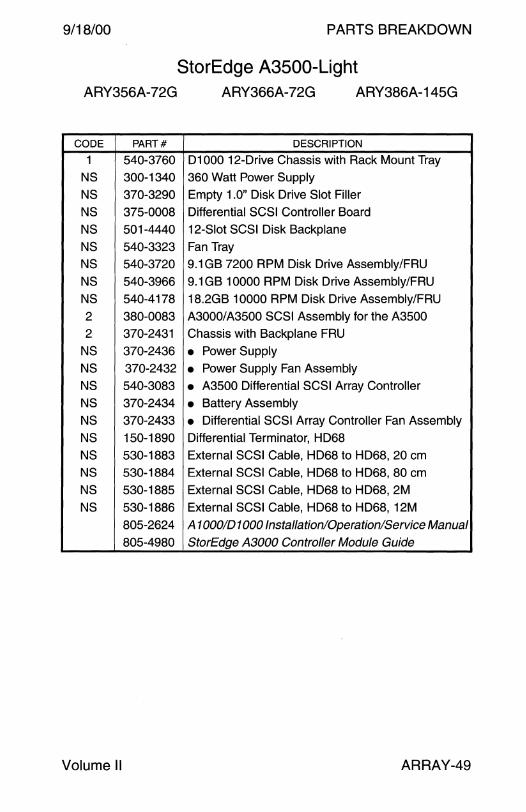
9/18/00 PARTS BREAKDOWN
StorEdge A3500-Light ARY356A-72G ARY366A-72G ARY386A-145G
CODE PART# DESCRIPTION
1 540-3760 D1000 12-Drive Chassis with Rack Mount Tray
NS 300-1340 360 Watt Power Supply
NS 370-3290 Empty 1.0" Disk Drive Slot Filler
NS 375-0008 Differential SCSI Controller Board
NS 501-4440 12-Slot SCSI Disk Backplane
NS 540-3323 Fan Tray
NS 540-3720 9.1 GB 7200 RPM Disk Drive Assembly/FRU
NS 540-3966 9.1 GB 10000 RPM Disk Drive Assembly/FRU
NS 540-4178 18.2GB 10000 RPM Disk Drive Assembly/FRU
2 380-0083 A3000/A3500 SCSI Assembly for the A3500
2 370-2431 Chassis with Backplane FRU
NS 370-2436 • Power Supply NS 370-2432 • Power Supply Fan Assembly
NS 540-3083 • A3500 Differential SCSI Array Controller
NS 370-2434 • Battery Assembly NS 370-2433 • Differential SCSI Array Controller Fan Assembly
NS 150-1890 Differential Terminator, HD68
NS 530-1883 External SCSI Cable, HD68 to HD68, 20 cm
NS 530-1884 External SCSI Cable, HD68 to HD68, 80 cm
NS 530-1885 External SCSI Cable, HD68 to HD68, 2M
NS 530-1886 External SCSI Cable, HD68 to HD68, 12M
805-2624 A 1000/D 1000 Installation/Operation/Service Manual
805-4980 StorEdge A3000 Controller Module Guide
Volume II ARRAY-49

PARTS BREAKDOWN 9/18/00
StorEdge A3500 ARY351 A-180G ARY353A-360G ARY353A-1008G
72" Rack Option 72" Rack Option 72" Rack Option 1A3500+5 D1000s 2 A3500s + 7 D1000s 2 A3500s + 7 D 1000s
10 18.2GB Disks 20 18.2GB Disks 56 18.2GB Disks 7200 RPM 7200 RPM 7200 RPM
ARY355A-2160G ARY381 A-364G ARY381A-1456G 72" Rack Option 72" Rack Option 72" Rack Option
2 A3500s + 15 D1 OOOs 1 A3500 + 5 D1 OOOs 1 A3500 + 5 D1 OOOs 20 18.2GB Disks
7200 RPM
ARY383A-728G 72" Rack Option
2 A3500s + 7 D1000s 20 36.4GB Disks
10000 RPM
ARRAY-50
10 36.4GB Disks 40 36.4GB Disks 10000 RPM 10000 RPM
ARY385A-1092G
2
72" Rack Option 3 A3500s + 15 D1 OOOs
30 36.4GB Disks 10000 RPM
4
Field Engineer Handbook
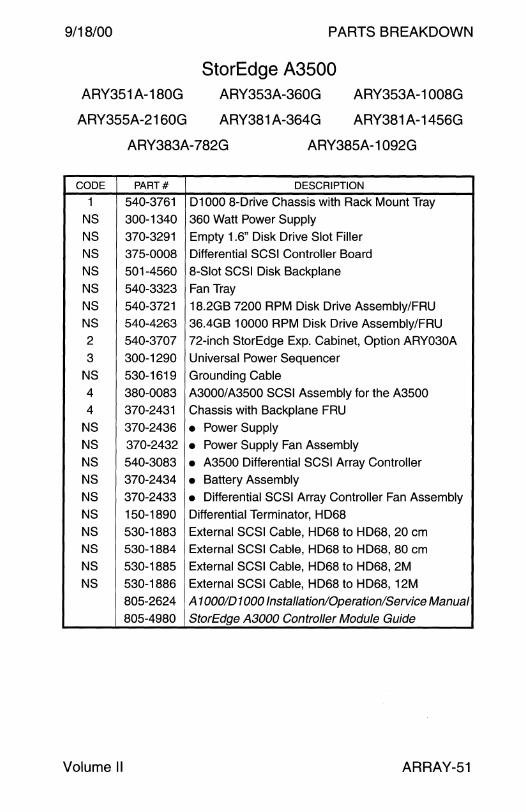
9/18/00
ARY351A-180G
ARY355A-2160G
PARTS BREAKDOWN
StorEdge A3500 ARY353A-360G
ARY381 A-364G
ARY353A-1008G
ARY381 A-1456G
ARY383A-782G ARY385A-1092G
CODE PART# DESCRIPTION
1 540-3761 D1000 8-Drive Chassis with Rack Mount Tray
NS 300-1340 360 Watt Power Supply
NS 370-3291 Empty 1.6" Disk Drive Slot Filler
NS 375-0008 Differential SCSI Controller Board
NS 501-4560 8-Slot SCSI Disk Backplane
NS 540-3323 Fan Tray
NS 540-3721 18.2GB 7200 RPM Disk Drive Assembly/FRU
NS 540-4263 36.4GB 10000 RPM Disk Drive Assembly/FRU
2 540-3707 72-inch StorEdge Exp. Cabinet, Option ARY030A
3 300-1290 Universal Power Sequencer
NS 530-1619 Grounding Cable
4 380-0083 A3000/A3500 SCSI Assembly for the A3500
4 370-2431 Chassis with Backplane FRU
NS 370-2436 • Power Supply NS 370-2432 • Power Supply Fan Assembly
NS 540-3083 • A3500 Differential SCSI Array Controller
NS 370-2434 • Battery Assembly
NS 370-2433 • Differential SCSI Array Controller Fan Assembly
NS 150-1890 Differential Terminator, HD68
NS 530-1883 External SCSI Cable, HD68 to HD68, 20 cm NS 530-1884 External SCSI Cable, HD68 to HD68, 80 cm
NS 530-1885 External SCSI Cable, HD68 to HD68, 2M
NS 530-1886 External SCSI Cable, HD68 to HD68, 12M
805-2624 A 1000/D 1000 Installation/Operation/Service Manual
805-4980 StorEdge A3000 Controller Module Guide
Volume II ARRAY-51

PARTS BREAKDOWN 9/18/00
StorEdge A3500 ARY350A-90G ARY350A-545G ARY352A-180G 1A3500+5 D1000s 1 A3500 + 5 D1000s 2 A3500s + 7 D1 OOOs
10 9.1GB Disks 60 9.1 GB Disks 20 9.1 GB Disks 7200 RPM 7200 RPM 7200 RPM
ARY352A-763G ARY354A-1635G ARY360A-90G 2 A3500s + 7 D 1 OOOs 3 A3500s + 15 D1000s 1 A3500 + 5 D1 OOOs
84 9.1 GB Disks 180 9.1GB Disks 10 9.1GB Disks 7200 RPM 7200 RPM 10000 RPM
ARY360A-545G ARY362A-180G ARY362A-763G 1 A3500 + 5 D1000s 2 A3500s + 7 D1 OOOs 2 A3500s + 7 D 1 OOOs
60 9.1 GB Disks 180 9.1GB Disks 180 9.1GB Disks 10000 RPM 10000 RPM 10000 RPM
ARY364A-1635G ARY370A-91 G ARY372A-182G 3 A3500s + 15 D1 OOOs 1A3500+5 D1000s 1 A3500 + 7 D1 OOOs
180 9.1GB Disks 10 9.1GB Disks 20 9.1 GB Disks 10000 RPM 10000 RPM 10000 RPM
ARY37 4A-273G 3 A3500s + 15 D1000s
30 9.1GB Disks 10000 RPM
2
4
ARRAY-52 Field Engineer Handbook

9/18/00 PARTS BREAKDOWN
StorEdge A3500 ARY350A-90G ARY350A-545G ARY352A-180G
ARY352A-763G ARY354A-1635G ARY360A-90G
ARY360A-545G ARY362A-180G ARY362A-763G
ARY364A-1635G ARY370A-91 G ARY372A-182G
ARY37 4A-273G
CODE PART# DESCRIPTION
1 540-3760 D1000 12-Drive Chassis with Rack Mount Tray
NS 300-1340 360 Watt Power Supply
NS 370-3290 Empty 1.0" Disk Drive Slot Filler
NS 375-0008 Differential SCSI Controller Board
NS 501-4440 12-Slot SCSI Disk Backplane
NS 540-3323 Fan Tray
NS 540-3720 9.1 GB 7200 RPM Disk Drive Assembly/FRU
NS 540-3966 9.1 GB 10000 RPM Disk Drive Assembly/FRU
2 540-3707 72-inch StorEdge Exp. Cabinet, Option ARY030A
3 300-1290 Universal Power Sequencer
NS 530-1619 Grounding Cable
4 380-0083 A3000/A3500 SCSI Assembly for the A3500
4 370-2431 Chassis with Backplane FRU
NS 370-2432 • Power Supply Fan Assembly
NS 370-2433 • Array Controller Fan Assembly
NS 370-2434 • Battery Assembly NS 370-2436 • Power Supply NS 540-3083 • A3500 Differential SCSI Array Controller
NS 150-1890 Differential Terminator, HD68
NS 530-1883 External SCSI Cable, HD68 to HD68, 20 cm
NS 530-1884 External SCSI Cable, HD68 to HD68, 80 cm
NS 530-1885 External SCSI Cable, HD68 to HD68, 2M
NS 530-1886 External SCSI Cable, HD68 to HD68, 12M
805-2624 A 1000/D 1000 Installation/Operation/Service Manual
805-4980 StorEdge A3000 Controller Module Guide
Volume II ARRAY-53
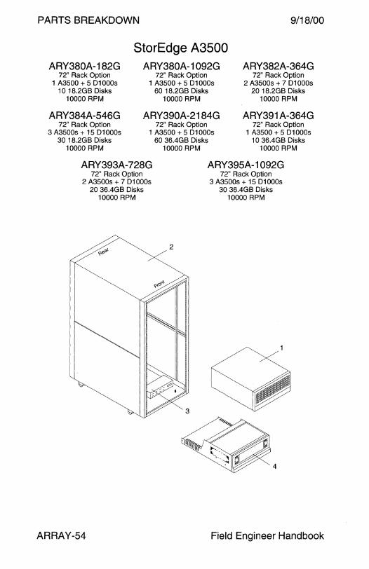
PARTS BREAKDOWN 9/18/00
StorEdge A3500 ARY380A-182G ARY380A-1092G ARY382A-364G
72" Rack Option 72" Rack Option 72" Rack Option 1 A3500 + 5 D1 OOOs 1A3500+5 D1000s 2 A3500s + 7 D1000s
10 18.2GB Disks 60 18.2GB Disks 20 18.2GB Disks 10000 RPM 10000 RPM 10000 RPM
ARY384A-546G ARY390A-2184G ARY391 A-364G 72" Rack Option 72" Rack Option 72" Rack Option
3 A3500s + 15 D1 OOOs 1 A3500 + 5 D1 OOOs 1A3500+5 D1000s 30 18.2GB Disks
10000 RPM
ARY393A-728G 72" Rack Option
2 A3500s + 7 D1000s 20 36.4GB Disks
10000 RPM
ARRAY-54
60 36.4GB Disks 10 36.4GB Disks 10000 RPM 10000 RPM
ARY395A-1092G
2
72" Rack Option 3 A3500s + 15 D1000s
30 36.4GB Disks 10000 RPM
4
Field Engineer Handbook

9/18/00
ARY380A-182G
ARY384A-546G
PARTS BREAKDOWN
StorEdge A3500 ARY380A-1092G
ARY390A-2184G
ARY382A-364G
ARY391 A-364G
ARY393A-728G ARY395A-1092G
CODE PART# DESCRIPTION
1 540-3760 D1000 12-Drive Chassis with Rack Mount Tray
NS 300-1340 360 Watt Power Supply
NS 370-3290 Empty 1.0" Disk Drive Slot Filler
NS 375-0008 Differential SCSI Controller Board
NS 501-4440 12-Slot SCSI Disk Backplane
NS 540-3323 Fan Tray
NS 540-3721 18.2GB 7200 RPM Disk Drive Assembly/FRU NS 540-4178 18.2GB 10000 RPM Disk Drive Assembly/FRU
NS 540-4520 36.4GB 10000 RPM Disk Drive Assembly/FRU
2 540-3707 72-inch StorEdge Exp. Cabinet, Option ARY030A
3 300-1290 Universal Power Sequencer
NS 530-1619 Grounding Cable 4 380-0083 A3000/A3500 SCSI Assembly for the A3500
4 370-2431 Chassis with Backplane FRU
NS 370-2432 • Power Supply Fan Assembly NS 370-2433 • Array Controller Fan Assembly NS 370-2434 • Battery Assembly NS 370-2436 • Power Supply NS 540-3083 • A3500 Differential SCSI Array Controller
NS 150-1890 Differential Terminator, HD68
NS 530-1883 External SCSI Cable, HD68 to HD68, 20 cm
NS 530-1884 External SCSI Cable, HD68 to HD68, 80 cm
NS 530-1885 External SCSI Cable, HD68 to HD68, 2M
NS 530-1886 External SCSI Cable, HD68 to HD68, 12M
805-2624 A 1000/D 1000 Installation/Operation/Service Manual
805-4980 StorEdge A3000 Controller Module Guide
Volume II ARRAY-55

PARTS BREAKDOWN
StorEdge A3500FC 6538
FC-AL Array Controller w/o Disks
w/o 01000 Tray
9/18/00
ARRAY-56 Field Engineer Handbook
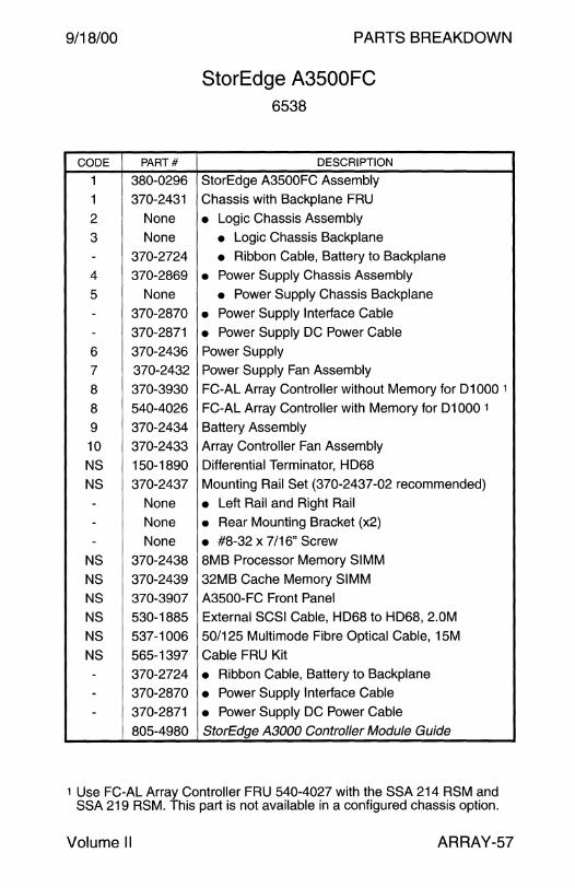
9/18/00
CODE PART#
1 380-0296
1 370-2431
2 None
3 None
- 370-2724
4 370-2869
5 None
- 370-2870
- 370-2871
6 370-2436
7 370-2432
8 370-3930
8 540-4026
9 370-2434
10 370-2433
NS 150-1890
NS 370-2437
- None
- None
- None
NS 370-2438
NS 370-2439
NS 370-3907
NS 530-1885
NS 537-1006
NS 565-1397
- 370-2724
- 370-2870
- 370-2871
805-4980
PARTS BREAKDOWN
StorEdge A3500FC 6538
DESCRIPTION
StorEdge A3500FC Assembly
Chassis with Backplane FRU
• Logic Chassis Assembly
• Logic Chassis Backplane
• Ribbon Cable, Battery to Backplane
• Power Supply Chassis Assembly
• Power Supply Chassis Backplane
• Power Supply Interface Cable
• Power Supply DC Power Cable
Power Supply
Power Supply Fan Assembly
FC-AL Array Controller without Memory for D1000 1
FC-AL Array Controller with Memory for D1000 1
Battery Assembly
Array Controller Fan Assembly
Differential Terminator, HD68
Mounting Rail Set (370-2437-02 recommended)
• Left Rail and Right Rail • Rear Mounting Bracket (x2)
• #8-32 x 7 /16" Screw
8MB Processor Memory SIMM
32MB Cache Memory SIMM
A3500-FC Front Panel
External SCSI Cable, HD68 to HD68, 2.0M
50/125 Multimode Fibre Optical Cable, 15M
Cable FRU Kit
• Ribbon Cable, Battery to Backplane
• Power Supply Interface Cable
• Power Supply DC Power Cable
StorEdge A3000 Controller Module Guide
1 Use FC-AL Array Controller FRU 540-4027 with the SSA 214 RSM and SSA 219 RSM. This part is not available in a configured chassis option.
Volume II ARRAY-57
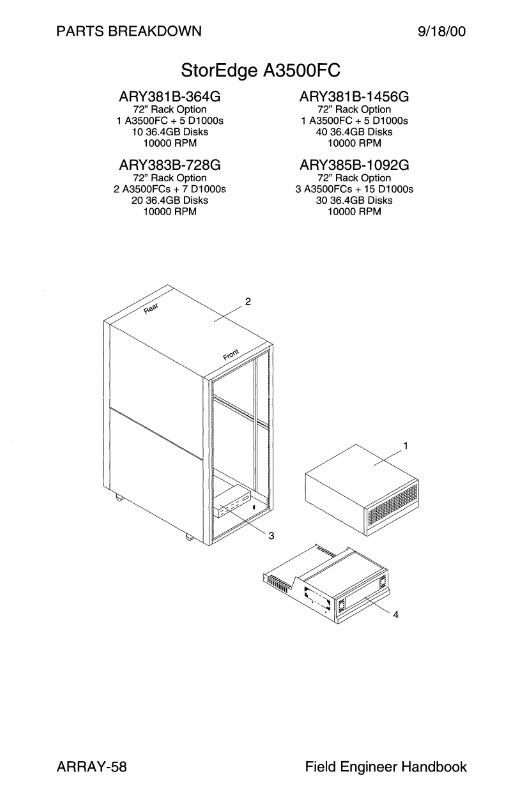
PARTS BREAKDOWN 9/18/00
StorEdge A3500FC ARY381 B-364G
72" Rack Option 1 A3500FC + 5 D1000s
10 36.4GB Disks 10000 RPM
ARY383B-728G 72" Rack Option
2 A3500FCs + 7 D1 OOOs 20 36.4GB Disks
10000 RPM
ARRAY-58
2
ARY381 B-1456G 72" Rack Option
1 A3500FC + 5 D1000s 40 36.4GB Disks
10000 RPM
ARY385B-1092G 72" Rack Option
3 A3500FCs + 15 D1 OOOs 30 36.4GB Disks
10000 RPM
4
Field Engineer Handbook

9/18/00
CODE
1
NS
NS
NS
NS
NS
NS
2
3 NS
4
4
NS NS
NS
NS
NS
NS
NS
NS
NS
NS NS
NS
Volume II
PARTS BREAKDOWN
StorEdge A3500FC ARY381 B-364G
ARY383B-728G
ARY381 B-1456G
ARY385B-1092G
PART# DESCRIPTION
540-3761 D1000 8-Drive Chassis with Rack Mount Tray
300-1340 360 Watt Power Supply
370-3291 Empty 1.6" Disk Drive Slot Filler
375-0008 Differential SCSI Controller Board
501-4560 8-Slot SCSI Disk Backplane
540-3323 Fan Tray
540-4263 36.4GB 10000 RPM Disk Drive Assembly/FRU
540-3707 72-inch StorEdge Exp. Cabinet, Option ARY030A
300-1290 Universal Power Sequencer
530-1619 Grounding Cable
380-0296 A3500-FC Assembly
370-2431 Chassis with Backplane FRU
370-2432 • Power Supply Fan Assembly
370-2433 • Array Controller Fan Assembly
370-2434 • Battery Assembly
370-2436 • Power Supply 540-4026 • A3500 FC-AL Array Controller FRU
150-1890 Differential Terminator, HD68
370-3907 A3500-FC Front Panel
530-1883 External SCSI Cable, HD68 to HD68, 20 cm
530-1884 External SCSI Cable, HD68 to HD68, 80 cm
530-1885 External SCSI Cable, HD68 to HD68, 2M
530-1886 External SCSI Cable, HD68 to HD68, 12M
537-1006 50/125 Multimode Fibre Optical Cable, 15M
805-2624 A 1000/D 1000 Installation/Operation/Service Manual
805-4980 StorEdge A3000 Controller Module Guide
ARRAY-59

PARTS BREAKDOWN 19/18/00
StorEdge A3500FC ARY360B-90G
72" Rack Option 1 A3500FC + 5 D1 OOOs
10 9.1GB Disks 10000 RPM
ARY37 4B-273G 72" Rack Option
3 A3500FCs + 15 D1 OOOs 30 9.1 GB Disks
10000 RPM
ARY382B-364G 72" Rack Option
2 A3500FCs + 7 D1000s 20 18.2GB Disks
10000 RPM
ARY391 B-364G 72" Rack Option
1A3500FC+5 D1000s 10 36.4GB Disks
10000 RPM
ARRAY-60
ARY360B-545G 72" Rack Option
1 A3500FC + 5 D1000s 60 9.1 GB Disks
10000 RPM
ARY380B-182G 72" Rack Option
1 A3500FC + 5 D1000s 1 O 18.2GB Disks
10000 RPM
ARY384B-546G 72" Rack Option
3 A3500FCs + 15 D1000s 30 18.2GB Disks
10000 RPM
ARY393B-728G 72" Rack Option
3 A3500FCs + 7 D1000s 20 36.4GB Disks
10000 RPM
2
ARY362B-180G 72" Rack Option
2 A3500FCs + 7 D1 OOOs 20 9.1 GB Disks
10000 RPM
ARY380B-1092G 72" Rack Option
1A3500FC+5 D1000s 60 18.2GB Disks
10000 RPM
ARY390B-2184G 72" Rack Option
1A3500FC+5 D1000s 60 36.4GB Disks
10000 RPM
ARY395B-1092G 72" Rack Option
3 A3500FCs + 15 D1 OOOs 30 36.4GB Disks
10000 RPM
4
Field Engineer Handbook

9/18/00
ARY360B-90G
ARY37 4B-273G
ARY382B-364G
ARY391 B-364G
CODE PART#
1 540-3760
NS 300-1340 NS 370-3290
NS 375-0008
NS 501-4440
NS 540-3323 NS 540-3966
NS 540-4178
NS 540-4520
2 540-3707
3 300-1290
NS 530-1619
4 380-0296
4 370-2431
NS 370-2432
NS 370-2433
NS 370-2434
NS 370-2436
NS 540-4026
NS 150-1890
NS 370-3907
NS 530-1883
NS 530-1884 NS 530-1885
NS 530-1886
NS 537-1006
805-2624
805-4980
Volume II
PARTS BREAKDOWN
StorEdge A3500FC ARY360B-545G ARY362B-180G
ARY380B-182G
ARY384B-546G
ARY393B-728G
ARY380B-1092G
ARY390B-2184G
ARY395B-1092G
DESCRIPTION
D1000 12-Drive Chassis with Rack Mount Tray
360 Watt Power Supply
Empty 1.0'' Disk Drive Slot Filler
Differential SCSI Controller Board
12-Slot SCSI Disk Backplane
Fan Tray 9.1 GB 10000 RPM Disk Drive Assembly/FRU
18.2GB 10000 RPM Disk Drive Assembly/FRU
36.4GB 10000 RPM Disk Drive Assembly/FRU
72-inch StorEdge Exp. Cabinet, Option ARY030A
Universal Power Sequencer
Grounding Cable
A3500-FC Assembly
Chassis with Backplane FRU
• Power Supply Fan Assembly
• Array Controller Fan Assembly
• Battery Assembly
• Power Supply • A3500 FC-AL Array Controller FRU
Differential Terminator, HD68
A3500-FC Front Panel
External SCSI Cable, HD68 to HD68, 20 cm
External SCSI Cable, HD68 to HD68, 80 cm
External SCSI Cable, HD68 to HD68, 2M
External SCSI Cable, HD68 to HD68, 12M
50/125 Multimode Fibre Optical Cable, 15M
A 1000/D 1000 Installation/Operation/Service Manual
StorEdge A3000 Controller Module Guide
ARRAY-61

PARTS BREAKDOWN 9/18/00
Enterprise Network Array A5000 StorEdge A5000 ARY01 OA-45G
Tabletop Option 5 9.1GB Disks
7200 RPM
ARY51 OA-127G Tabletop Option 14 9.1GB Disks
7200 RPM
ARRAY-62
ARY010A-127G Tabletop Option 14 9.1GB Disks
7200 RPM
ARY011A-127G 68" Rack Option w/o Rack
14 9.1GB Disks 7200 RPM
ARY512A-127G 68" Rack Option w/o Rack
14 9.1 GB Disks 7200 RPM
ARY51 OA-45G Tabletop Option 5 9.1GB Disks
7200 RPM
ARY511A-127G 72" Rack Option w/o Rack
14 9.1GB Disks 7200 RPM
Field Engineer Handbook
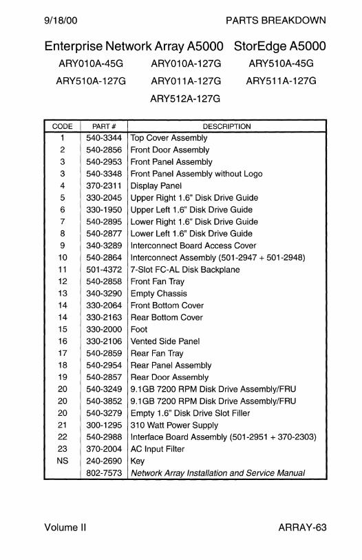
9/18/00 PARTS BREAKDOWN
Enterprise Network Array A5000 StorEdge A5000 ARY01 OA-45G
ARY51 OA-127G
CODE PART#
1 540-3344
2 540-2856
3 540-2953
3 540-3348
4 370-2311
5 330-2045
6 330-1950 7 540-2895
8 540-2877
9 340-3289
10 540-2864
11 501-4372 12 540-2858
13 340-3290
14 330-2064
14 330-2163
15 330-2000
16 330-2106
17 540-2859
18 540-2954
19 540-2857
20 540-3249
20 540-3852
20 540-3279
21 300-1295
22 540-2988
23 370-2004
NS 240-2690
802-7573
Volume II
ARY010A-127G
ARY011 A-127G
ARY512A-127G
ARY51 OA-45G
ARY511A-127G
DESCRIPTION
Top Cover Assembly
Front Door Assembly
Front Panel Assembly
Front Panel Assembly without Logo
Display Panel
Upper Right 1.6" Disk Drive Guide
Upper Left 1.6" Disk Drive Guide
Lower Right 1.6" Disk Drive Guide
Lower Left 1.6" Disk Drive Guide
Interconnect Board Access Cover
Interconnect Assembly (501-294 7 + 501-2948)
7-Slot FC-AL Disk Backplane
Front Fan Tray
Empty Chassis
Front Bottom Cover
Rear Bottom Cover
Foot
Vented Side Panel
Rear Fan Tray
Rear Panel Assembly Rear Door Assembly
9.1GB 7200 RPM Disk Drive Assembly/FRU
9.1GB 7200 RPM Disk Drive Assembly/FRU
Empty 1.6" Disk Drive Slot Filler
310 Watt Power Supply Interface Board Assembly (501-2951 + 370-2303)
AC Input Filter
Key
Network Array Installation and Service Manual
ARRAY-63
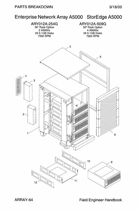
PARTS BREAKDOWN 9/18/00
Enterprise Network Array A5000 StorEdge A5000
~: ~ ~ :;;: ~ :;,;;•
4
ARY012A-254G 56" Rack Option
2 A5000s 28 9.1 GB Disks
7200 RPM
W' 10
2 1 I 1 I
1 I 1 I
ARRAY-64
5
ARY012A-509G 56" Rack Option
4 A5000s 56 9.1 GB Disks
7200 RPM
~ ~
• • 8
Field Engineer Handbook
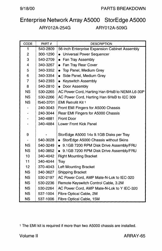
9/18/00 PARTS BREAKDOWN
Enterprise Network Array A5000 StorEdge A5000 ARY012A-254G ARY012A-509G
CODE PART# DESCRIPTION
1 540-2809 56-inch Enterprise Expansion Cabinet Assembly
2 300-1290 • Universal Power Sequencer
3 540-2709 • Fan Tray Assembly
4 340-3267 • Fan Tray Rear Cover
5 340-3352 • Top Panel, Medium Grey
6 340-3354 • Side Panel, Medium Grey
7 540-2393 • Keyswitch Assembly
8 540-2810 • Door Assembly NS 530-2265 AC Power Cord, Harting Han 6HsB to NEMA L6-30P
NS 530-2266 AC Power Cord, Harting Han 6HsB to IEC 309 NS f540-3701 EMI Retrofit Kit 1
- 240-3043 Front EMI Fingers for A5000 Chassis
- 240-3044 Rear EMI Fingers for A5000 Chassis
- 340-4881 Front Door
- 340-4884 Lower Front Kick Panel
9 - StorEdge A5000 14x 9.1 GB Disks per Tray
- 540-3028 • StorEdge A5000 Chassis without Skins NS 540-3249 • 9.1 GB 7200 RPM Disk Drive Assembly/FRU NS 540-3852 • 9.1 GB 7200 RPM Disk Drive Assembly/FRU 10 340-4042 Right Mounting Bracket
11 340-4044 Tray
12 370-4043 Left Mounting Bracket
NS 340-3627 Shipping Bracket
NS 530-2197 AC Power Cord, AMP Mate-N-Lok to IEC-320
NS 530-2236 Remote Keyswitch Control Cable, 3.2M
NS 530-2264 AC Power Cord, AMP Mate-N-Lok to Y IEC-320 NS 537-1004 Fibre Optical Cable, 2M
NS 537-1006 Fibre Optical Cable, 15M
1 The EMI kit is required if more than two A5000 chassis are installed.
Volume II ARRAY-65
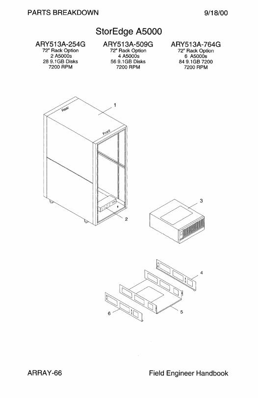
PARTS BREAKDOWN
ARY513A-254G 72" Rack Option
2 A5000s 28 9.1 GB Disks
7200 RPM
StorEdge ASOOO ARY513A-509G
72" Rack Option 4 A5000s
56 9.1 GB Disks 7200 RPM
9/18/00
ARY513A-764G 72" Rack Option
6 A5000s 84 9.1GB 7200
7200 RPM
3
ARRAY-66 Field Engineer Handbook
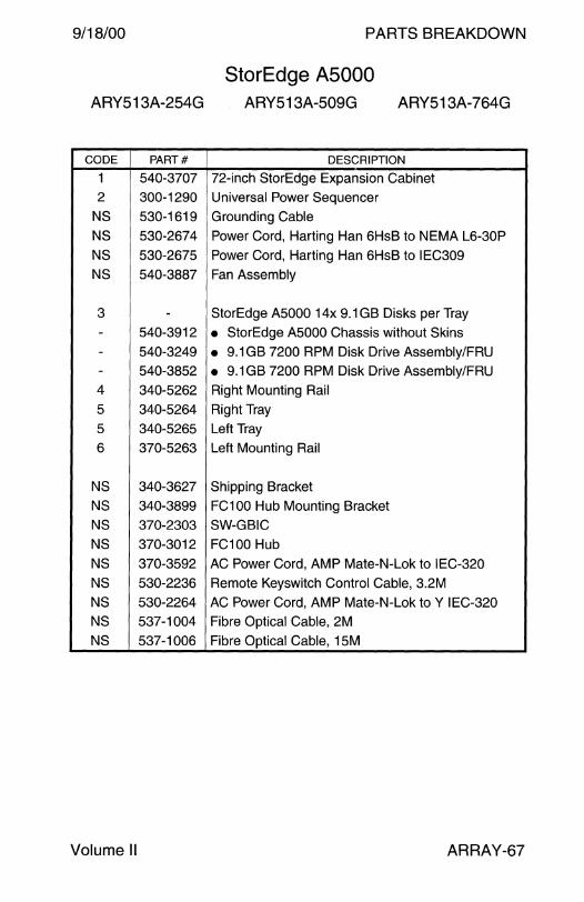
9/18/00
ARY513A-254G
CODE PART#
1 540-3707
2 300-1290
NS 530-1619
NS 530-2674
NS 530-2675
NS 540-3887
3 -- 540-3912
- 540-3249 - 540-3852
4 340-5262
5 340-5264
5 340-5265
6 370-5263
NS 340-3627
NS 340-3899
NS 370-2303
NS 370-3012
NS 370-3592
NS 530-2236
NS 530-2264
NS 537-1004
NS 537-1006
Volume II
PARTS BREAKDOWN
StorEdge A5000 ARY513A-509G ARY513A-764G
DESCRIPTION
72-inch StorEdge Expansion Cabinet Universal Power Sequencer
Grounding Cable
Power Cord, Harting Han 6HsB to NEMA L6-30P
Power Cord, Harting Han 6HsB to IEC309
Fan Assembly
StorEdge A5000 14x 9.1 GB Disks per Tray
• StorEdge A5000 Chassis without Skins
• 9.1 GB 7200 RPM Disk Drive Assembly/FRU • 9.1 GB 7200 RPM Disk Drive Assembly/FRU
Right Mounting Rail
Right Tray
Left Tray
Left Mounting Rail
Shipping Bracket
FC100 Hub Mounting Bracket
SW-GBIC
FC100 Hub
AC Power Cord, AMP Mate-N-Lok to IEC-320
Remote Keyswitch Control Cable, 3.2M
AC Power Cord, AMP Mate-N-Lok to Y IEC-320 Fibre Optical Cable, 2M
Fibre Optical Cable, 15M
ARRAY-67
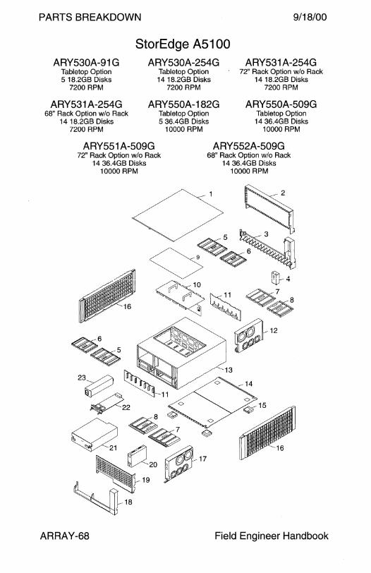
PARTS BREAKDOWN 9/18/00
ARY530A-91 G Tabletop Option 5 18.2GB Disks
7200 RPM
ARY531A-254G 68" Rack Option w/o Rack
14 18.2GB Disks 7200 RPM
StorEdge A5100 ARY530A-254G
Tabletop Option 14 18.2GB Disks
7200 RPM
ARY550A-182G Tabletop Option 5 36.4GB Disks
10000 RPM
ARY531 A-254G 72" Rack Option w/o Rack
14 18.2GB Disks 7200 RPM
ARY550A-509G Tabletop Option 14 36.4GB Disks
10000 RPM
ARY551 A-509G ARY552A-509G 72" Rack Option w/o Rack
14 36.4GB Disks 10000 RPM
ARRAY-68
68" Rack Option w/o Rack 14 36.4GB Disks
10000 RPM
Field Engineer Handbook
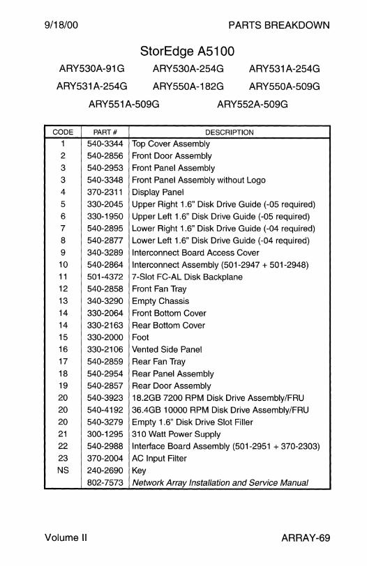
9/18/00
ARY530A-91 G
ARY531 A-254G
PARTS BREAKDOWN
StorEdge A5100 ARY530A-254G
ARY550A-182G
ARY531 A-254G
ARY550A-509G
ARY551 A-509G ARY552A-509G
CODE PART# DESCRIPTION
1 540-3344 Top Cover Assembly
2 540-2856 Front Door Assembly
3 540-2953 Front Panel Assembly
3 540-3348 Front Panel Assembly without Logo 4 370-2311 Display Panel
5 330-2045 Upper Right 1.6" Disk Drive Guide (-05 required)
6 330-1950 Upper Left 1.6" Disk Drive Guide (-05 required) 7 540-2895 Lower Right 1.6" Disk Drive Guide (-04 required)
8 540-2877 Lower Left 1.6" Disk Drive Guide (-04 required)
9 340-3289 Interconnect Board Access Cover
10 540-2864 Interconnect Assembly (501-2947 + 501-2948) 11 501-4372 7-Slot FC-AL Disk Backplane 12 540-2858 Front Fan Tray 13 340-3290 Empty Chassis
14 330-2064 Front Bottom Cover
14 330-2163 Rear Bottom Cover 15 330-2000 Foot
16 330-2106 Vented Side Panel
17 540-2859 Rear Fan Tray
18 540-2954 Rear Panel Assembly 19 540-2857 Rear Door Assembly
20 540-3923 18.2GB 7200 RPM Disk Drive Assembly/FRU
20 540-4192 36.4GB 10000 RPM Disk Drive Assembly/FRU
20 540-3279 Empty 1.6" Disk Drive Slot Filler 21 300-1295 310 Watt Power Supply
22 540-2988 Interface Board Assembly (501-2951 + 370-2303) 23 370-2004 AC Input Filter
NS 240-2690 Key
802-7573 Network Array Installation and Service Manual
Volume II ARRAY-69
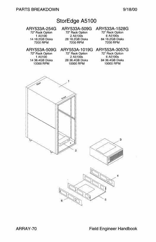
PARTS BREAKDOWN 9/18/00
StorEdge A5100 ARY533A-254G ARY533A-509G ARY533A-1528G
72" Rack Option 1 A5100
1418.2GB Disks 7200 RPM
72" Rack Option 2 A5100s
28 18.2GB Disks 7200 RPM
72" Rack Option 6 A5100s
84 18.2GB Disks 7200 RPM
ARY553A-509G ARY553A-1019G ARY553A-3057G 72" Rack Option
1 A5100 14 36.4GB Disks
10000 RPM
ARRAY-70
72" Rack Option 2 A5100s
28 36.4GB Disks 10000 RPM
72" Rack Option 6 A5100s
84 36.4GB Disks 10000 RPM
3
Field Engineer Handbook
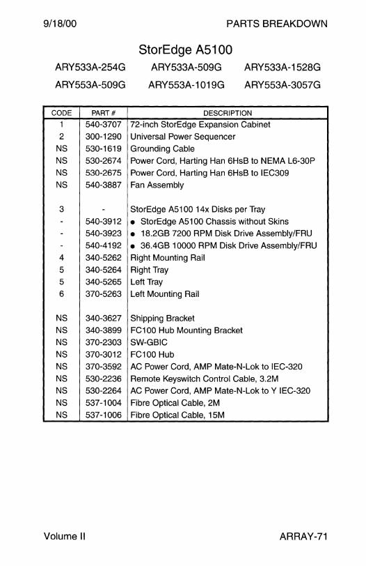
9/18/00
ARY533A-254G
ARY553A-509G
CODE PART#
1 540-3707
2 300-1290
NS 530-1619
NS 530-2674
NS 530-2675
NS 540-3887
3 -- 540-3912 - 540-3923
- 540-4192
4 340-5262
5 340-5264
5 340-5265
6 370-5263
NS 340-3627 NS 340-3899
NS 370-2303
NS 370-3012
NS 370-3592
NS 530-2236 NS 530-2264
NS 537-1004
NS 537-1006
Volume II
PARTS BREAKDOWN
StorEdge A5100 ARY533A-509G
ARY553A-1019G
ARY533A-1528G
ARY553A-3057G
DESCRIPTION
72-inch StorEdge Expansion Cabinet
Universal Power Sequencer
Grounding Cable
Power Cord, Harting Han 6HsB to NEMA L6-30P
Power Cord, Harting Han 6HsB to IEC309
Fan Assembly
StorEdge A5100 14x Disks per Tray
• StorEdge A5100 Chassis without Skins • 18.2GB 7200 RPM Disk Drive Assembly/FRU
• 36.4GB 10000 RPM Disk Drive Assembly/FRU
Right Mounting Rail
Right Tray
Left Tray
Left Mounting Rail
Shipping Bracket
FC100 Hub Mounting Bracket
SW-GB IC
FC100 Hub
AC Power Cord, AMP Mate-N-Lok to IEC-320
Remote Keyswitch Control Cable, 3.2M
AC Power Cord, AMP Mate-N-Lok to Y IEC-320
Fibre Optical Cable, 2M
Fibre Optical Cable, 15M
ARRAY-71

PARTS BREAKDOWN 9/18/00
StorEdge A5200 ARY520A-63G ARY520A-200G ARY521 A-200G
Tabletop Option Tabletop Option 72" Rack Option w/o Rack 7 9.1GB Disks 22 9.1GB Disks 22 9.1GB Disks
ARY522A-200G ARY540A-127G ARY540A-400G 68" Rack Option w/o Rack Tabletop Option Tabletop Option
22 9.1 GB Disks 7 18.2GB Disks 22 18.2GB Disks
ARY541 A-400G ARY542A-400G ARY560A-254G 72" Option w/o Rack 68" Rack Option w/o Rack Tabletop Option
22 18.2GB Disks 22 18.2GB Disks 7 18.2GB Disks
ARY560A-800G
ARRAY-72
Tabletop Option 22 36.4GB Disks
ARY562A-800G 72" Rack Option w/o Rack
22 36.4GB Disks
Field Engineer Handbook

9/18/00
ARY520A-63G
ARY522A-200G
ARY541 A-400G
PARTS BREAKDOWN
StorEdge A5200 ARY520A-200G
ARY540A-127G
ARY542A-400G
ARY521 A-200G
ARY 540A-400
ARY560A-254G
ARY560A-800G ARY562A-800G
CODE PART# DESCRIPTION
1 540-3344 Top Cover Assembly
2 540-2856 Front Door Assembly
3 540-2953 Front Panel Assembly
3 540-3348 Front Panel Assembly without Logo
4 370-2311 Display Panel
5 330-2047 Upper Right 1" Disk Drive Guide
6 330-1948 Upper Left 1" Disk Drive Guide
7 540-3814 Lower Right 1" Disk Drive Guide
8 540-3813 Lower Left 1" Disk Drive Guide
9 340-3289 Interconnect Board Access Cover
10 540-2864 Interconnect Assembly (501-2947 + 501-2948)
11 501-4158 11-Slot FC-AL Disk Backplane
12 540-2858 Front Fan Tray
13 340-3290 Empty Chassis
14 330-2064 Front Bottom Cover
14 330-2163 Rear Bottom Cover
15 330-2000 Foot
16 330-2106 Vented Side Panel
17 540-2859 Rear Fan Tray
18 540-2954 Rear Panel Assembly
19 540-2857 Rear Door Assembly
20 540-3869 9.1 GB 10000 RPM Disk Drive Assembly/FRU
20 540-4191 18.2GB 10000 RPM Disk Drive Assembly/FRU
20 540-4525 36.4GB 10000 RPM Disk Drive Assembly/FRU
20 540-3469 Empty 1" Disk Drive Slot Filler
21 300-1295 31 O Watt Power Supply
22 540-2988 Interface Board Assembly (501-2951 + 370-2303)
23 370-2004 AC Input Filter
NS 240-2690 Key
802-7573 Network Array Installation and Service Manual
Volume II ARRAY-73

PARTS BREAKDOWN 9/18/00
StorEdge A5200 ARY523A-200G ARY523A-400G ARY523A-800G
72" Rack Option 72" Rack Option 72" Rack Option 1 A5200 2 A5200s 4 A5200s
22 9.1GB Disks 44 9.1 GB Disks 88 9.1 GB Disks
ARY523A-1200G ARY543A-400G ARY543A-800G 72" Rack Option 72" Rack Option 72" Rack Option
6 A5200s 1 A5200 2 A5200s 132 9.1GB Disks 22 18.2GB Disks 44 18.2GB Disks
ARY543A-2400G ARY561 A-800G ARY563A-800G 72" Rack Option 72" Rack Option 72" Rack Option
6 A5200s 1 A5200 1 A5200 132 18.2GB Disks 36.4GB Disks 36.4GB Disks
ARY563A-1601G ARY563A-4804G
ARRAY-74
72" Rack Option 2 A5200s
36.4GB Disks
72" Rack Option 6 A5200s
36.4GB Disks
3
Field Engineer Handbook
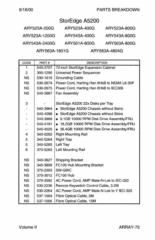
9/18/00
ARY523A-200G
ARY523A-1200G
ARY543A-2400G
PARTS BREAKDOWN
StorEdge A5200 ARY523A-400G
ARY543A-400G
ARY561 A-800G
ARY523A-800G
ARY543A-800G
ARY563A-800G
ARY563A-1601 G ARY563A-4804G
CODE PART# DESCRIPTION
1 540-3707 72-inch StorEdge Expansion Cabinet
2 300-1290 Universal Power Sequencer
NS 530-1619 Grounding Cable
NS 530-2674 Power Cord, Harting Han 6HsB to NEMA L6-30P
NS 530-2675 Power Cord, Harting Han 6HsB to IEC309
NS 540-3887 Fan Assembly
3 - StorEdge A5200 22x Disks per Tray
- 540-3964 • StorEdge A5200 Chassis without Skins
- 540-4098 • StorEdge A5200 Chassis without Skins
- 540-3869 • 9.1 GB 10000 RPM Disk Drive Assembly/FRU - 540-4191 • 18.2GB 10000 RPM Disk Drive Assembly/FRU
- 540-4525 • 36.4GB 10000 RPM Disk Drive Assembly/FRU
4 340-5262 Right Mounting Rail
5 340-5264 Right Tray
5 340-5265 Left Tray
6 370-5263 Left Mounting Rail
NS 340-3627 Shipping Bracket
NS 340-3899 FC100 Hub Mounting Bracket
NS 370-2303 SW-GB IC
NS 370-3012 FC100 Hub
NS 370-3592 AC Power Cord, AMP Mate-N-Lok to IEC-320
NS 530-2236 Remote Keyswitch Control Cable, 3.2M
NS 530-2264 AC Power Cord, AMP Mate-N-Lok to Y IEC-320
NS 537-1004 Fibre Optical Cable, 2M
NS 537-1006 Fibre Optical Cable, 15M
Volume II ARRAY-75
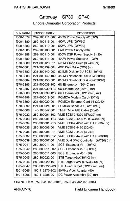
PARTS BREAKDOWN 9/18/00
SUN PART#
f300-1379
f300-1380
f300-1383
f300-1385
f300-1388
f300-1389
f370-3380
f370-3381
f370-3382
f370-3383
f370-3384
f370-3386
f370-3387
f370-3388
f370-3389
f370-3390
f370-3392
f370-3506
f375-0032
f375-0033
f375-0034
f375-0035
f375-0036
f375-0037
f375-0039
f375-0041
f375-0042
f375-0043
f375-0045
f375-0046
f375-0047
f501-5065
f501-5066
Gateway SP30 SP40 Encore Computer Corporation Products
ENCORE PART# DESCRIPTION
269-100111-002 400W Power Supply #2 (GW)
269-100115-001 4KVA UPS (GW/30)
269-100119-001 5KVA UPS (GW/30)
269-100108-001 LAD Power Supply (30)
269-100110-001 800W DSP Power Supply B (30)
269-100111-001 400W Power Supply #1 (GW)
221-300128-011 525MB Tape Drive (30/40) (nr)
221-300139-004 4GB Disk Drive (GW) (nr)
221-300140-003 524MB Disk for 9U SCSI (30/40)
221-300142-100 450MB Notebook Disk (GW/30/40)
221-300153-001 81 OMB Notebook Disk (GW/30/40)
221-500039-1 03 6U Ethernet #1 (30/40) (nr)
221-500039-113 6U Ethernet #2 (30/40) (nr)
221-500039-123 6U Ethernet #3 (GW/30/40) (nr)
221-600019-001 PCM!CA Modem Card (30/40)
221-600020-001 PCMICA Ethernet Card #1 (30/40)
221-600024-001 PCMICA Serial 1/0 (GW/30/40)
145-103542-001 TMl/FTM to ATB Cable (30/40)
280-300001-103 VME SCSl-2 4220 (GW/30) (nr)
280-300001-113 VME SCSl-2 4220 #2 (GW/30) (nr)
280-300001-213 VME SCSl-2 4220 with RAID (30) (nr)
280-300006-001 VME SCSl-2 4420 (30/40)
280-300006-011 VME SCSl-2 4420 (30/40)
280-300006-012 VME SCSl-2 4420 with RAID (30/40)
280-300007-001 VME Dual BMC Controller (GW/30) (nr)
280-300011-001 SCSI Expander #1 1 (30/40)
280-300011-002 SCSI Expander #2 1 (30/40)
280-300011-003 SCSI Expander #3 1 (30)
280-300022-001 STE Target (GW/30/40) (nr)
280-300022-101 STE Target F&W (GW/30/40) (nr)
280-300022-203 STE Quad Target (GW/30/40) (nr)
160-113270-302 50MHz Viper Adapter (40)
160-113285-001 DC Power Assembly (30) (nr)
1 Do NOT mix 375-0041, 375-0042, 375-0043, and 375-0044.
ARRAY-76 Field Engineer Handbook
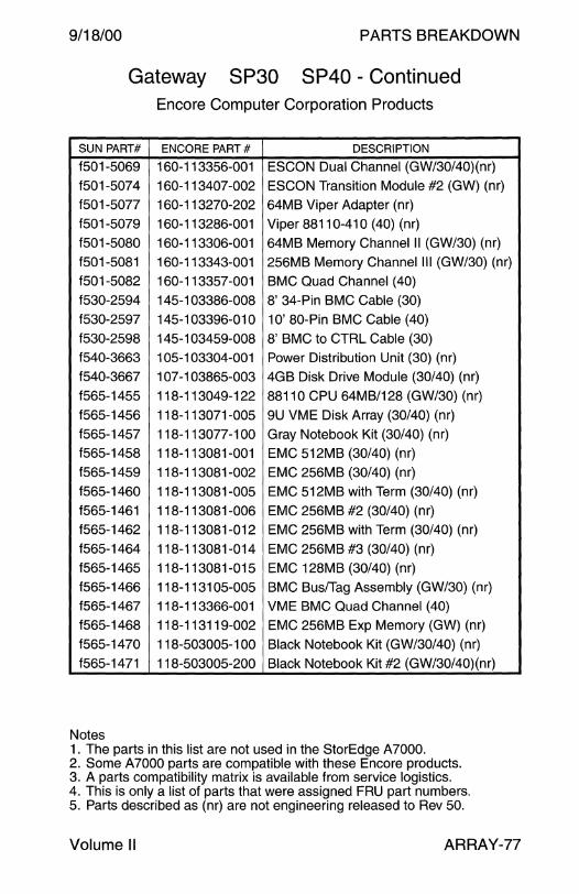
9/18/00 PARTS BREAKDOWN
Gateway SP30 SP40 - Continued Encore Computer Corporation Products
SUN PART# ENCORE PART# DESCRIPTION
f501-5069 160-113356-001 ESCON Dual Channel (GW/30/40)(nr) f501-5074 160-113407-002 ESCON Transition Module #2 (GW) (nr) f501-5077 160-113270-202 64MB Viper Adapter (nr) f501-5079 160-113286-001 Viper 88110-41 O (40) (nr) f501-5080 160-113306-001 64MB Memory Channel II (GW/30) (nr)
f501-5081 160-113343-001 256MB Memory Channel Ill (GW/30) (nr) f501-5082 160-113357-001 BMC Quad Channel (40) f530-2594 145-1 03386-008 8' 34-Pin BMC Cable (30) f530-2597 145-1 03396-01 0 1 O' 80-Pin BMC Cable (40) f530-2598 145-103459-008 8' BMC to CTRL Cable (30) f540-3663 105-103304-001 Power Distribution Unit (30) (nr) f540-3667 107-103865-003 4GB Disk Drive Module (30/40) (nr) f565-1455 118-113049-122 88110 CPU 64MB/128 (GW/30) (nr) f565-1456 118-113071-005 9U VME Disk Array (30/40) (nr) f565-1457 118-113077-100 Gray Notebook Kit (30/40) (nr) f565-1458 118-113081-001 EMC 512MB (30/40) (nr) f565-1459 118-113081-002 EMC 256MB (30/40) (nr) f565-1460 118-113081-005 EMC 512MB with Term (30/40) (nr) f565-1461 118-113081-006 EMC 256MB #2 (30/40) (nr) f565-1462 118-113081-012 EMC 256MB with Term (30/40) (nr) f565-1464 118-113081-014 EMC 256MB #3 (30/40) (nr) f565-1465 118-113081-015 EMC 128MB (30/40) (nr) f565-1466 118-1131 05-005 BMC Bus/Tag Assembly (GW/30) (nr) f565-1467 118-113366-001 VME BMC Quad Channel (40) f565-1468 118-113119-002 EMC 256MB Exp Memory (GW) (nr) f565-1470 118-503005-1 00 Black Notebook Kit (GW/30/40) (nr) f565-1471 118-503005-200 Black Notebook Kit #2 (GW/30/40)(nr)
Notes 1. The parts in this list are not used in the StorEdge A7000. 2. Some A7000 parts are compatible with these Encore products. 3. A parts compatibility matrix is available from service logistics. 4. This is only a list of parts that were assigned FRU part numbers. 5. Parts described as (nr) are not engineering released to Rev 50.
Volume II ARRAY-77

PARTS BREAKDOWN 9/18/00
SUN PART#
f150-3028
f150-3029 f300-1381
f300-1381
f300-1382
f300-1384
f300-1386
f300-1387
f300-1391
f370-3378
f370-3379
f370-3385
f370-3391
f370-3393
f370-3394
f370-3395
f370-3396
f370-3405
f370-3443
f370-3475
f370-3497
f370-3498
f370-3500
f370-3501
f370-3502
f370-3503
f370-3507
f370-3537
f370-3538
f370-3540
f370-3624
f370-3663
f370-3699
f370-3717
ARRAY-78
StorEdge A 7000 ARY002A-OG
Base Package w Two Disk Drawers
ENCORE PART# DESCRIPTION
278-100019-001 Bus Terminator
278-100020-001 Tag Terminator 269-100116-001 8KVA UPS (-01 with 1x 50A outlet)
269-100116-001 8KVA UPS (-02 with 2x 50A outlets)
269-100118-001 250W Dual Output Power Supply
269-100107-001 14-Slot Chassis 800W Power Supply A/B
269-100109-001 DC Bulk Power Supply Chassis
269-100109-002 Power Supply Converter Module
269-1 001 09-004 360VDC Power Supply
207-300036-001 HDSA Fan
221-300128-009 SCSI Tape Drive (nr)
221-300161-100 1.2GB Disk Drive for Notebook
221-600023-001 Microxctvr2 Ethernet
221-600027-001 Syntex Notebook Kit
221-600028-00~ PC~ .. 41C~~ Ethernet Card #2 207-300037-002 Fan, 3.62 x 3.62 56
221-300154-001 2GB Seagate Hawk 2XL Disk Drive
221-300165-002 2GB Seagate Barracuda 4XL Disk Drive
145-103351-007 50-Pin HDSA Bkpl to Bkpl Cable
145-1 034 77 -003 CPU to Systech Adapter Cable
144-1 03003-005 TMl-FTM Ribbon Cable
144-103175-012 SH Right Angle Cable
145-1 03415-008 Dual DIN CPU to Bulkhead Cable
145-103416-030 PCU to Bulkhead Cable
145-1 03473-001 Fan FORMS IV Cable
145-1 03495-008 Bulkhead to Controller Cable
145-103549-001 FORMS IV Jumper Cable
145-1 03194-003 CPU to CPU lntc lntrt Cable
145-1 03266-002 CPU to CPU Cable
145-1 03431-008 CPU/Differential SCSI Cable
221-600033-001 PCMCIA Ethernet Board
145-1 03350-017 HDSA B/P 50-Pin Cable, 17' None Assigned PCMCIA Global 56K Modem Board
145-103375-017 50-Pin HDSA Bkpl to Bkpl Cable
Field Engineer Handbook
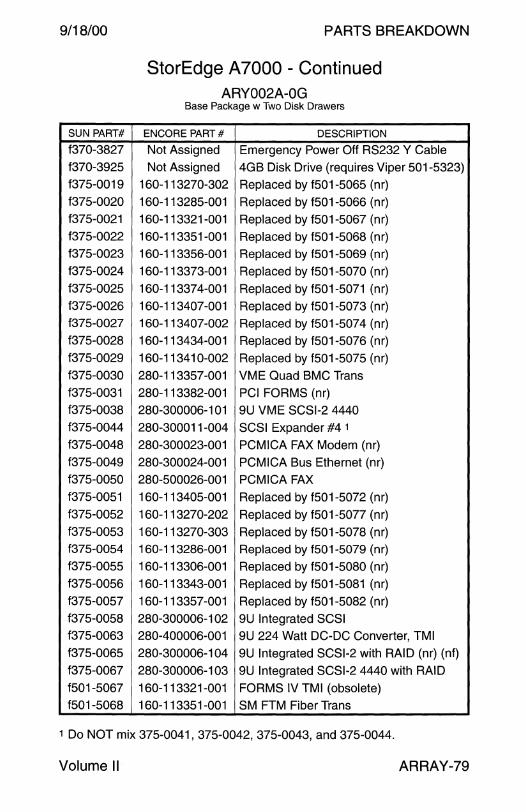
9/18/00
SUN PART#
f370-3827
f370-3925
f375-0019
f375-0020
f375-0021
f375-0022
f375-0023
f375-0024
f375-0025
f375-0026
f375-0027
f375-0028
f375-0029
f375-0030
f375-0031
f375-0038
f375-0044
f375-0048
f375-0049
f375-0050
f375-0051
f375-0052
f375-0053 f375-0054
f375-0055
f375-0056
f375-0057
f375-0058
f375-0063
f375-0065
f375-0067
f501-5067
f501-5068
PARTS BREAKDOWN
StorEdge A7000 - Continued ARY002A-OG
Base Package w Two Disk Drawers
ENCORE PART# DESCRIPTION
Not Assigned Emergency Power Off RS232 Y Cable
Not Assigned 4GB Disk Drive (requires Viper 501-5323)
160-113270-302 Replaced by f501-5065 (nr)
160-113285-001 Replaced by f501-5066 (nr)
160-113321-001 Replaced by f501-5067 (nr)
160-113351-001 Replaced by f501-5068 (nr) 160-113356-001 Replaced by f501-5069 (nr)
160-113373-001 Replaced by f501-5070 (nr)
160-11337 4-001 Replaced by f501-5071 (nr)
160-113407-001 Replaced by f501-5073 (nr)
160-113407-002 Replaced by f501-5074 (nr)
160-113434-001 Replaced by f501-5076 (nr)
160-11341 0-002 Replaced by f501-5075 (nr)
280-113357-001 VME Quad BMC Trans
280-113382-001 PCI FORMS (nr)
280-300006-1 01 9U VME SCSl-2 4440
280-300011-004 SCSI Expander #4 1
280-300023-001 PCMICA FAX Modem (nr)
280-300024-001 PCMICA Bus Ethernet (nr)
280-500026-001 PCMICA FAX
160-113405-001 Replaced by f501-5072 (nr)
160-113270-202 Replaced by f501-5077 (nr)
160-113270-303 Replaced by f501-5078 (nr) 160-113286-001 Replaced by f501-5079 (nr)
160-113306-001 Replaced by f501-5080 (nr)
160-113343-001 Replaced by f501-5081 (nr)
160-113357-001 Replaced by f501-5082 (nr)
280-300006-1 02 9U Integrated SCSI 280-400006-001 9U 224 Watt DC-DC Converter, TMI
280-300006-1 04 9U Integrated SCSl-2 with RAID (nr) (nf)
280-300006-1 03 9U Integrated SCSl-2 4440 with RAID
160-113321-001 FORMS IV TMI (obsolete) 160-113351-001 SM FTM Fiber Trans
1 Do NOT mix 375-0041, 375-0042, 375-0043, and 375-0044.
Volume II ARRAY-79
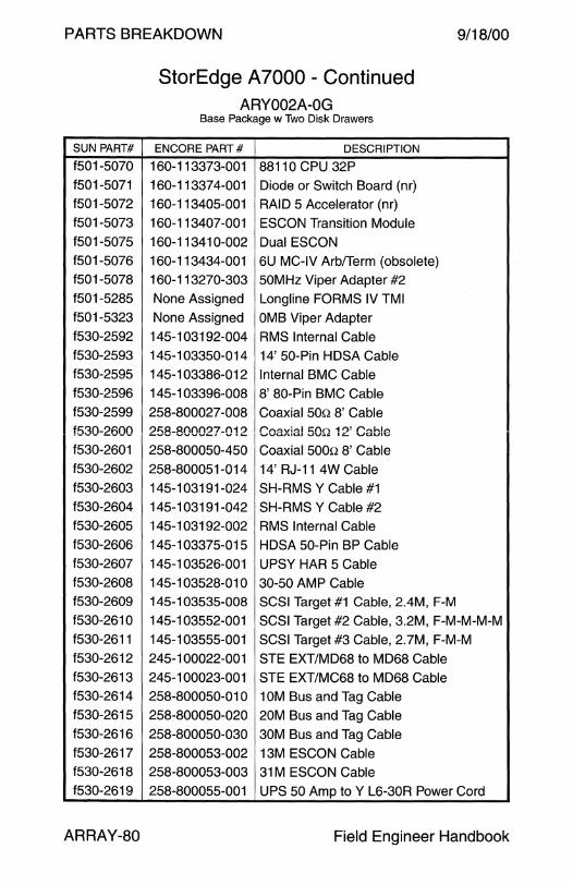
PARTS BREAKDOWN 9/18/00
SUN PART#
f501-5070
f501-5071
f501-5072
f501-5073
f501-5075
f501-5076
f501-5078
f501-5285
f501-5323
f530-2592
f530-2593
f530-2595
f530-2596
f530-2599
f530-2600
f530-2601
f530-2602
f530-2603
f530-2604
f530-2605
f530-2606
f530-2607
f530-2608
f530-2609
f530-2610
f530-2611
f530-2612
f530-2613
f530-2614
f530-2615
f530-2616
f530-2617
f530-2618
f530-2619
ARRAY-80
StorEdge A7000 - Continued ARY002A-OG
Base Package w Two Disk Drawers
ENCORE PART# DESCRIPTION
160-113373-001 88110 CPU 32P
160-11337 4-001 Diode or Switch Board (nr)
160-113405-001 RAID 5 Accelerator (nr)
160-113407-001 ESCON Transition Module
160-113410-002 Dual ESCON
160-113434-001 6U MC-IV Arb!Term (obsolete)
160-113270-303 50MHz Viper Adapter #2
None Assigned Longline FORMS IV TMI
None Assigned OMB Viper Adapter
145-103192-004 RMS Internal Cable
145-103350-014 14' 50-Pin HDSA Cable
145-103386-012 Internal BMC Cable
145-1 03396-008 8' 80-Pin BMC Cable
258-800027 -008 Coaxial 500 8' Cable
258-800027-012 r"n0ivi".3I C:.f'\n. 11)' f" .... hl"' '-'V'\Al\.U..A.1 vv~~ It:.. \,J'ULllV
258-800050-450 Coaxial 5000 8' Cable 258-800051-014 14' RJ-11 4W Cable
145-103191-024 SH-RMS Y Cable #1
145-103191-042 SH-RMS Y Cable #2
145-1 03192-002 RMS Internal Cable
145-103375-015 HDSA 50-Pin BP Cable
145-103526-001 UPSY HAR 5 Cable
145-103528-010 30-50 AMP Cable
145-1 03535-008 SCSI Target #1 Cable, 2.4M, F-M
145-103552-001 SCSI Target #2 Cable, 3.2M, F-M-M-M-M
145-103555-001 SCSI Target #3 Cable, 2.7M, F-M-M
245-100022-001 STE EXT/MD68 to MD68 Cable
245-100023-001 STE EXT/MC68 to MD68 Cable
258-800050-010 1 OM Bus and Tag Cable
258-800050-020 20M Bus and Tag Cable
258-800050-030 30M Bus and Tag Cable
258-800053-002 13M ESCON Cable
258-800053-003 31M ESCON Cable
258-800055-001 UPS 50 Amp to Y L6-30R Power Cord
Field Engineer Handbook
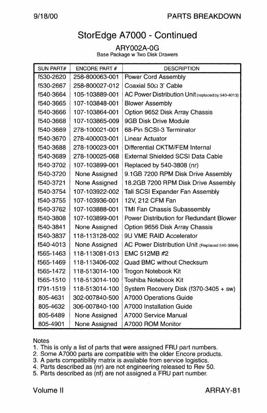
9/18/00
SUN PART#
f530-2620
f530-2667
f540-3664
f540-3665
f540-3666
f540-3668
f540-3669
f540-3670
f540-3688
f540-3689
f540-3702
f540-3720
f540-3721
f540-3754
f540-3755
f540-3762
f540-3808
f540-3841
f540-3837
f540-4013
f565-1463
f565-1469
f565-1472
f565-1510
f791-1519
805-4631
805-4632
805-6489
805-4901
Notes
PARTS BREAKDOWN
StorEdge A7000 - Continued ARY002A-OG
Base Package w Two Disk Drawers
ENCORE PART# DESCRIPTION
258-800063-001 Power Cord Assembly
258-800027-012 Coaxial 50n 3' Cable
1 05-1 03889-001 AC Power Distribution Unit(replacedby540-4013)
107-103848-001 Blower Assembly
1 07 -1 03864-001 Option 9652 Disk Array Chassis
107-103865-009 9GB Disk Drive Module
278-100021-001 68-Pin SCSl-3 Terminator
278-400003-001 Linear Actuator
278-100023-001 Differential CKTM/FEM Internal
278-1 00025-068 External Shielded SCSI Data Cable
107-103899-001 Replaced by 540-3808 (nr)
None Assigned 9.1 GB 7200 RPM Disk Drive Assembly
None Assigned 18.2GB 7200 RPM Disk Drive Assembly
107-103922-002 Tall SCSI Expander Fan Assembly
107-103936-001 12V, 212 CFM Fan
1 07-1 03888-001 TMI Fan Chassis Subassembly
1 07 -1 03899-001 Power Distribution for Redundant Blower
None Assigned Option 9656 Disk Array Chassis
118-113128-002 9U VME RAID Accelerator
None Assigned AC Power Distribution Unit (Replaced 540-3664)
118-113081-013 EMC 512MB#2
118-113406-002 Quad BMC without Checksum
118-513014-100 Trogon Notebook Kit
118-513014-100 Toshiba Notebook Kit
118-513014-100 System Recovery Disk (f370-3405 + sw)
302-007840-500 A7000 Operations Guide
306-007840-100 A7000 Installation Guide
None Assigned A7000 Service Manual
None Assigned A?OOO ROM Monitor
1. This is only a list of parts that were assigned FRU part numbers. 2. Some A7000 parts are compatible with the older Encore products. 3. A parts compatibility matrix is available from service logistics. 4. Parts described as (nr) are not engineering released to Rev 50. 5. Parts described as (nf) are not assigned a FRU part number.
Volume II ARRAY-81
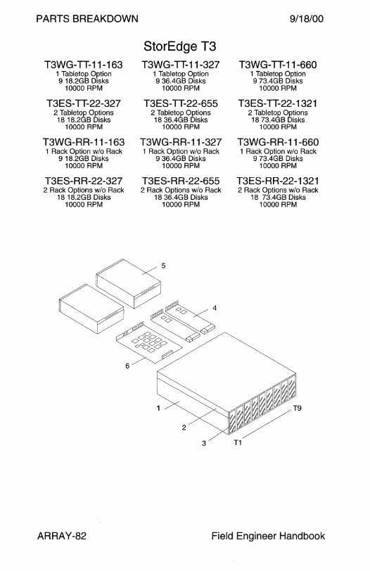
PARTS BREAKDOWN 9/18/00
StorEdge T3 T3WG-TT-11-163 T3WG-TT-11-327 T3WG-TT-11-660
1 Tabletop Option 1 Tabletop Option 1 Tabletop Option 9 18.2GB Disks 9 36.4GB Disks 9 73.4GB Disks
10000 RPM 10000 RPM 10000 RPM
T3ES-TT-22-327 T3ES-TT-22-655 T3ES-TT-22-1321 2 Tabletop Options 2 Tabletop Options 2 Tabletop Options 18 18.2GB Disks 18 36.4GB Disks 18 73.4GB Disks
10000 RPM 10000 RPM 10000 RPM
T3WG-RR-11-163 T3WG-RR-11-327 T3WG-RR-11-660 1 Rack Option w/o Rack 1 Rack Option w/o Rack 1 Rack Option w/o Rack
9 18.2GB Disks 9 36.4GB Disks 9 73.4GB Disks 10000 RPM 10000 RPM 10000 RPM
T3ES-RR-22-327 T3ES-RR-22-655 T3ES-RR-22-1321 2 Rack Options w/o Rack 2 Rack Options w/o Rack 2 Rack Options w/o Rack
18 18.2GB Disks 18 36.4GB Disks 18 73.4GB Disks 10000 RPM 10000 RPM 10000 RPM
ARRAY-82 Field Engineer Handbook
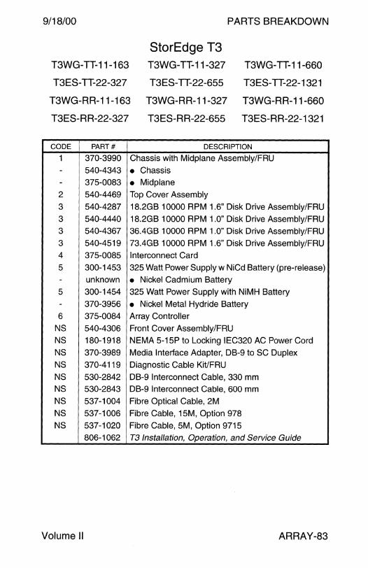
9/18/00 PARTS BREAKDOWN
StorEdge T3 T3WG-TT-11-163 T3WG-TT-11-327 T3WG-TT-11-660
T3ES-TT-22-327 T3ES-TT-22-655 T3ES-TT-22-1321
T3WG-RR-11-163 T3WG-RR-11-327 T3WG-RR-11-660
T3ES-RR-22-327 T3ES-RR-22-655 T3ES-RR-22-1321
CODE PART# DESCRIPTION
1 370-3990 Chassis with Midplane Assembly/FRU - 540-4343 • Chassis - 375-0083 • Midplane 2 540-4469 Top Cover Assembly
3 540-4287 18.2GB 10000 RPM 1.6" Disk Drive Assembly/FRU
3 540-4440 18.2GB 10000 RPM 1.0" Disk Drive Assembly/FRU
3 540-4367 36.4GB 10000 RPM 1.0" Disk Drive Assembly/FRU
3 540-4519 73.4GB 10000 RPM 1.6" Disk Drive Assembly/FRU
4 375-0085 Interconnect Card
5 300-1453 325 Watt Power Supply w NiCd Battery (pre-release) - unknown • Nickel Cadmium Battery
5 300-1454 325 Watt Power Supply with NiMH Battery
- 370-3956 • Nickel Metal Hydride Battery
6 375-0084 Array Controller
NS 540-4306 Front Cover Assembly/FRU
NS 180-1918 NEMA 5-15P to Locking IEC320 AC Power Cord
NS 370-3989 Media Interface Adapter, DB-9 to SC Duplex
NS 370-4119 Diagnostic Cable Kit/FRU
NS 530-2842 DB-9 Interconnect Cable, 330 mm NS 530-2843 DB-9 Interconnect Cable, 600 mm
NS 537-1004 Fibre Optical Cable, 2M
NS 537-1006 Fibre Cable, 15M, Option 978
NS 537-1020 Fibre Cable, 5M, Option 9715 806-1062 T3 Installation, Operation, and Service Guide
Volume II ARRAY-83

PARTS BREAKDOWN 9/18/00
StorEdge T3 T3ES-RH-44-655 T3ES-RH-44-1310 T3ES-RH-44-2642 4 T3 Arrays + 72" Rack 4 T3 Arrays + 72" Rack 4 T3 Arrays + 72" Rack
2 Hubs + 10 GBICs 2 Hubs + 10 GBICs 2 Hubs+ 10 GBICs 36 18.2GB Disks 36 36.4GB Disks 36 73.4GB Disks
10000 RPM 10000 RPM 10000 RPM
T3ES-RH-88-1310 T3ES-RH-88-2620 T3ES-RH-88-5284 8 T3 Arrays + 72" Rack 8 T3 Arrays + 72" Rack 8 T3 Arrays + 72" Rack
2 Hubs + 10 GBICs 2 Hubs + 10 GBICs 2 Hubs+ 10 GBICs 72 18.2GB Disks 72 36.4GB Disks 72 73.4GB Disks
10000 RPM 10000 RPM 10000 RPM
T3ES-RK-44-655 T3ES-RK-44-1310 T3ES-RK-44-2642 4 T3 Arrays + 72" Rack 4 T3 Arrays + 72" Rack 4 T3 Arrays + 72" Rack
36 18.2GB Disks 36 36.4GB Disks 36 73.4GB Disks 10000 RPM 10000 RPM 10000 RPM
T3ES-RK-88-1310 T3ES-RK-88-2620 T3ES-RK-88-5284 8 T3 Arrays + 72" Rack 8 T3 Arrays + 72" Rack 8 T3 Arrays + 72" Rack
72 18.2GB Disks 72 36.4GB Disks 72 73.4GB Disks 10000 RPM 10000 RPM 10000 RPM
~1 /
ARRAY-84 Field Engineer Handbook
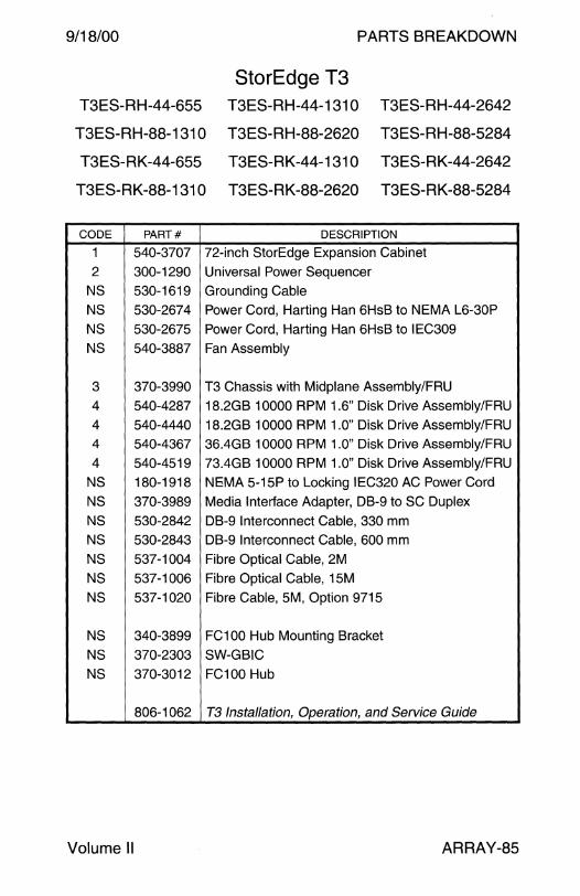
9/18/00 PARTS BREAKDOWN
StorEdge T3 T3ES-RH-44-655 T3ES-RH-44-1310 T3ES-RH-44-2642
T3ES-RH-88-1310 T3ES-RH-88-2620 T3ES-RH-88-5284
T3ES-RK-44-655 T3ES-RK-44-1310 T3ES-RK-44-2642
T3ES-RK-88-1310 T3ES-RK-88-2620 T3ES-RK-88-5284
CODE PART# DESCRIPTION
1 540-3707 72-inch StorEdge Expansion Cabinet
2 300-1290 Universal Power Sequencer
NS 530-1619 Grounding Cable
NS 530-2674 Power Cord, Harting Han 6HsB to NEMA L6-30P
NS 530-2675 Power Cord, Harting Han 6HsB to IEC309
NS 540-3887 Fan Assembly
3 370-3990 T3 Chassis with Midplane Assembly/FRU
4 540-4287 18.2GB 10000 RPM 1.6" Disk Drive Assembly/FRU
4 540-4440 18.2GB 10000 RPM 1.0" Disk Drive Assembly/FRU
4 540-4367 36.4GB 10000 RPM 1 .O" Disk Drive Assembly/FRU
4 540-4519 73.4GB 10000 RPM 1.0" Disk Drive Assembly/FRU
NS 180-1918 NEMA 5-15P to Locking IEC320 AC Power Cord
NS 370-3989 Media Interface Adapter, DB-9 to SC Duplex
NS 530-2842 DB-9 Interconnect Cable, 330 mm
NS 530-2843 DB-9 Interconnect Cable, 600 mm
NS 537-1004 Fibre Optical Cable, 2M
NS 537-1006 Fibre Optical Cable, 1 SM
NS 537-1020 Fibre Cable, SM, Option 9715
NS 340-3899 FC100 Hub Mounting Bracket
NS 370-2303 SW-GB IC
NS 370-3012 FC100 Hub
806-1062 T3 Installation, Operation, and Service Guide
Volume II ARRAY-85

PARTS BREAKDOWN 9/18/00
PART#
595-5557 340-6485
595-5368
330-2618
330-2619
340-6035
340-6139
340-6140
340-6226
595-5517
340-6499
340-6500
595-5487
330-2619
340-6032
340-6033
340-6035
340-6226
595-5517
340-6497
340-6498
595-5487
340-6031
ARRAY-86
StorEdge T3 Mounting Options
DESCRIPTION
E5500/6500 68" Cabinet Air Baffle, Option 9629
• Air Baffle
72" Cabinet/E10000 7U Rack Mount Kit, Option 9663
• 3U Trim Strip
• 4U Trim Strip
• Non Sun Rack Adapter
• Left Side Rail
• Right Side Rail
• 1/2 Height Filler Panel
E5500/6500 68" Cabinet 7U Rack Mount Kit, Option 9664
• Left Side Rail
• Right Side Rail
72" Cabinet/E10000 4U Rack Mount Kit, Option 9673
• 4U Trim Strip
• Left Side Rail
• Right Side Rail
• Non Sun Rack Adapter
• 1/2 Height Filler Panel
E5500/6500 68" Cabinet 4U Rack Mount Kit, Option 9674
• Left Side Rail
• Right Side Rail
Mounting Tray Kit, Option 9676
• Top/Bottom Support Plate
Field Engineer Handbook

PARTS BREAKDOWN
REMOVEABLE MEDIA

9/18/00 PARTS BREAKDOWN
Removable Media
Desktop SunCD Pack........................................................... 4
Desktop Sun CD Plus Pack .. . ... .. ... . .. .. .. ..... .. ..... .. ... .. .. .. . . .. .. .. . . 6
SunCD 2Plus Desktop Pack ............................................ ..... 8
Desktop Backup Pack 150MB 1/4" ....................................................................... 10 5.0GB 4 mm DDS-1 .......................................................... 12 10GB 8 mm ....................................................................... 14 14GB8mm ....................................................................... 14
Desktop Storage Module 2.3GB 8 mm ...................................................................... 16 5.0GB 8 mm ...................................................................... 16 20GB 4 mm DDS-1 ........................................................... 18 16-32GB 4 mm DDS-2 ...................................................... 20
SPARCstorage DLT4000 20-40GB 1/2" DL T ............................................................. 22
Multi-Tape Backup Tray 5GB 8 mm ......................................................................... 24 10GB 8 mm ....................................................................... 24 14GB 8 mm ....................................................................... 24 20GB 4 mm DDS-1 ........................................................... 26 20-40GB 1/2" DL T4000 ..................................................... 28 7-14GB 8 mm .................................................................... 30 16-32GB 4 mm DDS-2 .. ... ..... ... ... .. .. .. .. .. .. .. .. . . . . . . . . .. .. . .... . .. . . 32 72-144GB 4 mm DDS-3 .................................................... 34
SPARCstorage Unipack 2.5GB 1 /4" ......................................................................... 36 7-14GB 8 mm .................................................................... 38 5GB 4 mm ......................................................................... 40 4-8GB 4 mm DDS-2 .. . ...... ................... .. . .. . . . .. . . .. . ... . . .. .. .. . .. . 40
Field Engineer Handbook - Volume II
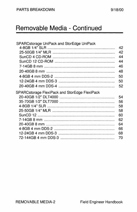
PARTS BREAKDOWN 9/18/00
Removable Media - Continued
SPARCstorage UniPack and StorEdge UniPack 4-8GB 1 /4" SLR .. .. ......... .. .. .. .. .. . . .. .. .. .. .. .. .. .. .. . ... .. .. ......... .. ... 42 25-50GB 1/4" MLR ............................................................ 42 SunCD 4 CD-ROM ... .. ... . .. .. .. ... ..... .. .. .. . .... .. .. .. ... .. ... .. .. . .. . .. .. 44 Sun CD 12 CD-ROM . .. .. ... .. .. ... .. .. .. .. .. .. .. .. .. .. . .. .. ..... .... .. . .. . . . . 44 7-14GB 8 mm .................................................................... 46 20-40GB 8 mm .................................................................. 48 4-8GB 4 mm DDS-2 . .. . .. . .. . .. . ... .. . . . ... .. .. .. .. .. .. ... . . . . . .. .. .. . . . . . .. . 50 12-24GB 4 mm DDS-3 ...................................................... 50 20-40GB 4 mm DDS-4 ...................................................... 52
SPARCstorage FlexiPack and StorEdge FlexiPack 20-40GB 1/2" DLT4000 ..................................................... 54 35-?0GB 1/2" DLT7000 ..................................................... 56 4-8GB 1/4" SLR ................................................................. 58 25-50GB 1 /4" MLR . ... ... .. ... . ... . .. . .. .. .. .. .. .. .. . . . . .. .. . .. .. . . .. .. . . . . .. . 58 SunCD 12 .......................................................................... 60 7-14GB 8 mm .................................................................... 62 20-40GB 8 mm .................................................................. 64 4-8GB 4 mm DDS-2 .......................................................... 66 12-24GB 4 mm DDS-3 ...................................................... 68 72-144GB 4 mm DDS-3 ... . .. . . .. . . .. .. .. . . . . .. . .. .. ... . . .. ... .. .. . . . .. . .. . 70
REMOVABLE MEDIA-2 Field Engineer Handbook
9/18/00 PARTS BREAKDOWN
This page intentionally left blank.
Volume II REMOVABLE MEDIA-3

PARTS BREAKDOWN 9/18/00
Desktop SunCD Pack
9
8
558 SunCD CD-ROM
10
REMOVABLE MEDIA-4
11
559 SunCD CD-ROM
6
TO REMOVE COVER
• Locate the holes indicated by X on both sides of the cover.
• Insert a small screwdriver into one of the holes to depress the catch and release the cover.
4
2
6
5
Field Engineer Handbook
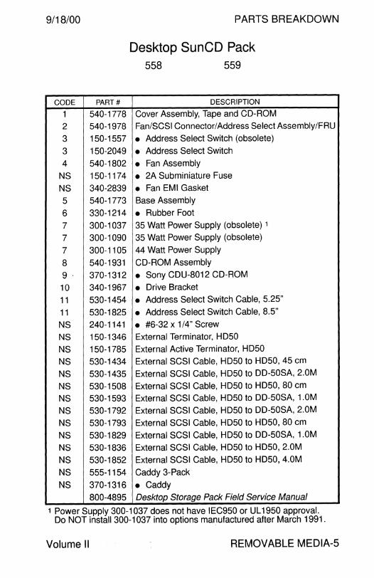
9/18/00 PARTS BREAKDOWN
Desktop SunCD Pack 558 559
CODE PART# DESCRIPTION
1 540-1778 Cover Assembly, Tape and CD-ROM
2 540-1978 Fan/SCSI Connector/Address Select Assembly/FRU
3 150-1557 • Address Select Switch (obsolete)
3 150-2049 • Address Select Switch
4 540-1802 • Fan Assembly
NS 150-1174 • 2A Subminiature Fuse
NS 340-2839 • Fan EMI Gasket
5 540-1773 Base Assembly
6 330-1214 • Rubber Foot
7 300-1037 35 Watt Power Supply (obsolete) 1
7 300-1090 35 Watt Power Supply {obsolete)
7 300-1105 44 Watt Power Supply
8 540-1931 CD-ROM Assembly
9· 370-1312 • Sony CDU-8012 CD-ROM
10 340-1967 • Drive Bracket
11 530-1454 • Address Select Switch Cable, 5.25"
11 530-1825 • Address Select Switch Cable, 8.5"
NS 240-1141 • #6-32 x 1 /4" Screw
NS 150-1346 External Terminator, HD50
NS 150-1785 External Active Terminator, HD50
NS 530-1434 External SCSI Cable, HD50 to HD50, 45 cm
NS 530-1435 External SCSI Cable, HD50 to DD-50SA, 2.0M
NS 530-1508 External SCSI Cable, HD50 to HD50, 80 cm
NS 530-1593 External SCSI Cable, HD50 to DD-50SA, 1.0M
NS 530-1792 External SCSI Cable, HD50 to DD-50SA, 2.0M
NS 530-1793 External SCSI Cable, HD50 to HD50, 80 cm
NS 530-1829 External SCSI Cable, HD50 to DD-50SA, 1.0M
NS 530-1836 External SCSI Cable, HD50 to HD50, 2.0M
NS 530-1852 External SCSI Cable, HD50 to HD50, 4.0M
NS 555-1154 Caddy 3-Pack
NS 370-1316 • Caddy 800-4895 Desktop Storage Pack Field Service Manual
1 Power Supply 300-1037 does not have IEC950 or UL1950 approval. Do NOT install 300-1037 into options manufactured after March 1991.
Volume II REMOVABLE MEDIA-5

PARTS BREAKDOWN 9/18/00
Desktop SunCD Plus Pack 557
8
REMOVABLE MEDIA-6
SunCD Plus CD-ROM
TO REMOVE COVER
• Locate the holes indicated by X on both sides of the cover.
• Insert a small screwdriver into one of the holes to depress the catch and release the cover.
4
2
3
6
Field Engineer Handbook

9/18/00
CODE
1
1
2
3
4
NS
NS
5
6
7
8
9 10
11
NS
NS
8 9
10
11
NS
NS
NS
NS
NS
Volume II
PARTS BREAKDOWN
Desktop SunCD Plus Pack 557
PART# DESCRIPTION
540-1778 Cover Assembly
540-2431 Modified Cover Assembly for 557-KDK Option
540-1978 Fan/SCSI Connector/ Address Select Assembly IF RU
150-2049 • Address Select Switch
540-2185 • Fan Assembly
150-1174 • 2A Subminiature Fuse
340-2839 • Fan EMI Gasket
540-1773 Base Assembly
330-1214 • Rubber Foot
300-1105 44 Watt Power Supply
540-2449 CD-ROM Assembly for 557-KDK Option
370-1573 • Sony CDU-561 CD-ROM
340-1967 • Drive Bracket
530-1825 • Address Switch Cable, 0.1 O" Pin Spacing, 8.5"
240-1530 • M3 0.5 x 6mm Screw
250-1194 • Adhesive Backed RFI Strip, 140 mm
540-2478 CD-ROM Assembly
370-1584 • Sony CDU-561 CD-ROM
340-1967 • Drive Bracket
530-1825 • Address Switch Cable, 0.1 O" Pin Spacing, 8.5''
240-1141 • #6-32 x 1/4" Screw
150-1785 External Active Terminator, HD50
530-1793 External SCSI Cable, HD50 to HD50, 80 cm
530-1836 External SCSI Cable, HD50 to HD50, 2.0M
530-1852 External SCSI Cable, HD50 to HD50, 4.0M
800-4895 SunCD Plus Desktop Pack Installation Manual
REMOVABLE MEDIA-7
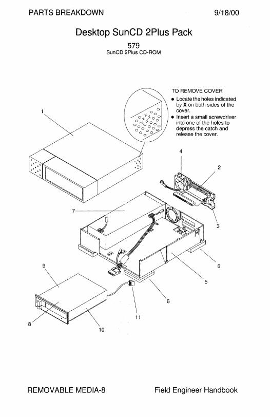
PARTS BREAKDOWN 9/18/00
Desktop SunCD 2Plus Pack 579
8 10
REMOVABLE MEDIA-8
SunCD 2Plus CD-ROM
TO REMOVE COVER
• Locate the holes indicated by X on both sides of the cover.
• Insert a small screwdriver into one of the holes to depress the catch and release the cover.
4
2
3
6
Field Engineer Handbook
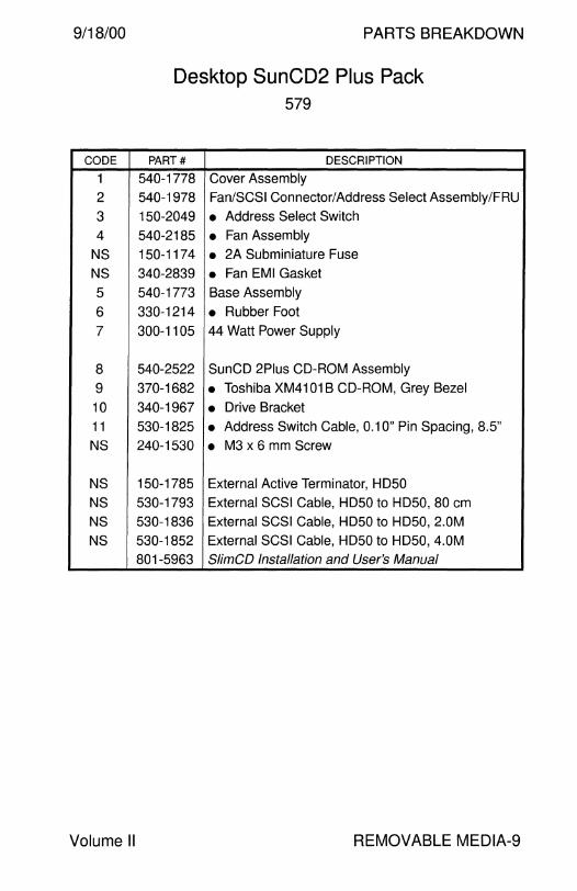
9/18/00
CODE
1
2
3
4
NS NS
5
6
7
8
9
10
11
NS
NS
NS NS
NS
Volume II
PARTS BREAKDOWN
Desktop SunCD2 Plus Pack 579
PART# DESCRIPTION
540-1778 Cover Assembly
540-1978 Fan/SCSI Connector/Address Select Assembly/FRU
150-2049 • Address Select Switch
540-2185 • Fan Assembly 150-1174 • 2A Subminiature Fuse
340-2839 • Fan EMI Gasket
540-1773 Base Assembly
330-1214 • Rubber Foot 300-1105 44 Watt Power Supply
540-2522 SunCD 2Plus CD-ROM Assembly
370-1682 • Toshiba XM4101 BCD-ROM, Grey Bezel
340-1967 • Drive Bracket
530-1825 • Address Switch Cable, 0.1 O" Pin Spacing, 8.5"
240-1530 • M3 x 6 mm Screw
150-1785 External Active Terminator, HD50
530-1793 External SCSI Cable, HD50 to HD50, 80 cm
530-1836 External SCSI Cable, HD50 to HD50, 2.0M
530-1852 External SCSI Cable, HD50 to HD50, 4.0M
801-5963 SlimCD Installation and User's Manual
REMOVABLE MEDIA-9
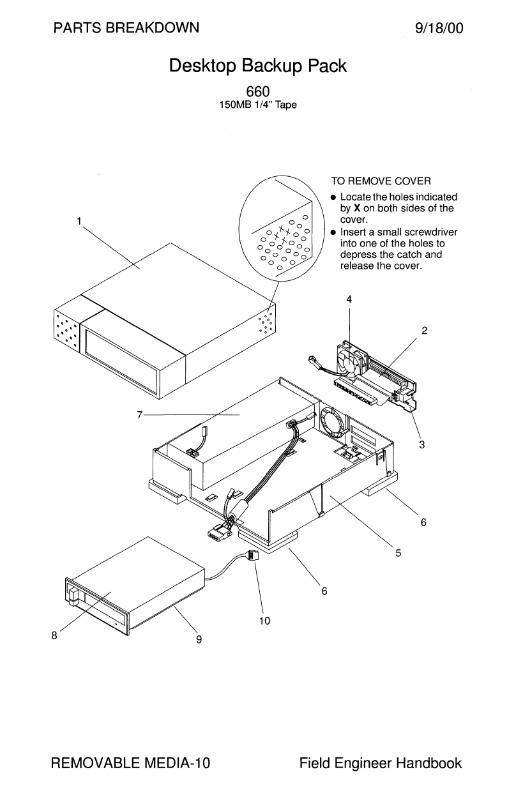
PARTS BREAKDOWN 9/18/00
Desktop Backup Pack 660
150MB 1/4" Tape
8 9
REMOVABLE MEDIA-10
TO REMOVE COVER
• Locate the holes indicated by X on both sides of the cover.
• Insert a small screwdriver into one of the holes to depress the catch and release the cover.
4
2
3
6
Field Engineer Handbook
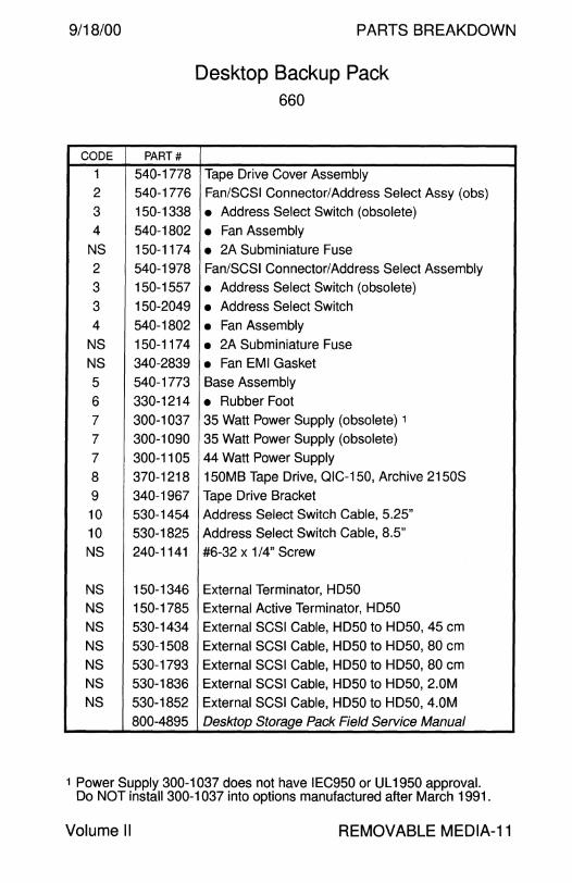
9/18/00
CODE PART#
1 540-1778 2 540-1776
3 150-1338
4 540-1802
NS 150-1174
2 540-1978
3 150-1557
3 150-2049
4 540-1802
NS 150-1174
NS 340-2839
5 540-1773
6 330-1214
7 300-1037
7 300-1090
7 300-1105
8 370-1218
9 340-1967
10 530-1454
10 530-1825
NS 240-1141
NS 150-1346
NS 150-1785
NS 530-1434
NS 530-1508
NS 530-1793
NS 530-1836
NS 530-1852
800-4895
PARTS BREAKDOWN
Desktop Backup Pack 660
Tape Drive Cover Assembly
Fan/SCSI Connector/Address Select Assy (obs)
• Address Select Switch (obsolete)
• Fan Assembly
• 2A Subminiature Fuse
Fan/SCSI Connector/Address Select Assembly
• Address Select Switch (obsolete)
• Address Select Switch
• Fan Assembly
• 2A Subminiature Fuse
• Fan EMI Gasket Base Assembly
• Rubber Foot 35 Watt Power Supply (obsolete) 1
35 Watt Power Supply (obsolete)
44 Watt Power Supply
150MB Tape Drive, QIC-150, Archive 2150S
Tape Drive Bracket Address Select Switch Cable, 5.25"
Address Select Switch Cable, 8.5''
#6-32 x 1 /4" Screw
External Terminator, HD50
External Active Terminator, HD50
External SCSI Cable, HD50 to HD50, 45 cm
External SCSI Cable, HD50 to HD50, 80 cm
External SCSI Cable, HD50 to HD50, 80 cm External SCSI Cable, HD50 to HD50, 2.0M
External SCSI Cable, HD50 to HD50, 4.0M
Desktop Storage Pack Field Service Manual
1 Power Supply 300-1037 does not have IEC950 or Ul1950 approval. Do NOT install 300-1037 into options manufactured after March 1991.
Volume II REMOVABLE MEDIA-11
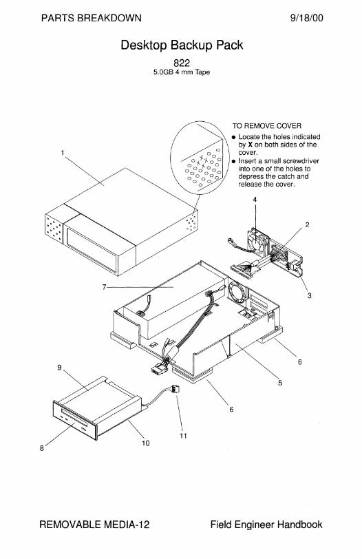
PARTS BREAKDOWN 9/18/00
Desktop Backup Pack 822
5.0GB 4 mm Tape
9
11
8
REMOVABLE MEDIA-12
TO REMOVE COVER
• Locate the holes indicated by X on both sides of the cover.
• Insert a small screwdriver into one of the holes to depress the catch and release the cover.
4
2
3
6
5
Field Engineer Handbook
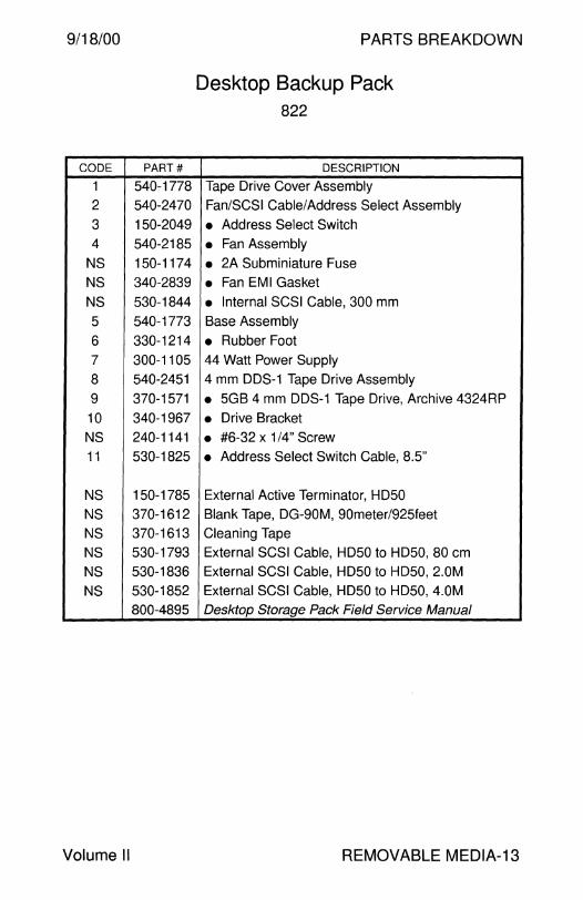
9/18/00
CODE PART#
1 540-1778
2 540-2470
3 150-2049
4 540-2185
NS 150-1174
NS 340-2839
NS 530-1844
5 540-1773
6 330-1214
7 300-1105
8 540-2451
9 370-1571
10 340-1967
NS 240-1141
11 530-1825
NS 150-1785
NS 370-1612
NS 370-1613
NS 530-1793
NS 530-1836
NS 530-1852
800-4895
Volume II
PARTS BREAKDOWN
Desktop Backup Pack 822
DESCRIPTION
Tape Drive Cover Assembly
Fan/SCSI Cable/Address Select Assembly
• Address Select Switch
• Fan Assembly
• 2A Subminiature Fuse
• Fan EMI Gasket
• Internal SCSI Cable, 300 mm
Base Assembly
• Rubber Foot 44 Watt Power Supply
4 mm DDS-1 Tape Drive Assembly
• 5GB 4 mm DDS-1 Tape Drive, Archive 4324RP
• Drive Bracket
• #6-32 x 1 /4" Screw
• Address Select Switch Cable, 8.5"
External Active Terminator, HD50
Blank Tape, DG-90M, 90meter/925feet
Cleaning Tape
External SCSI Cable, HD50 to HD50, 80 cm
External SCSI Cable, HD50 to HD50, 2.0M
External SCSI Cable, HD50 to HD50, 4.0M
Desktop Storage Pack Field Service Manual
REMOVABLE MEDIA-13

PARTS BREAKDOWN 9/18/00
Desktop Backup Pack 834
1 OGB 8 mm Tape
9
11
8
REMOVABLE MEDIA-14
844 14GB 8 mm Tape
6
TO REMOVE COVER
• Locate the holes indicated by X on both sides of the cover.
• Insert a small screwdriver into one of the holes to depress the catch and release the cover.
2
3
5
Field Engineer Handbook
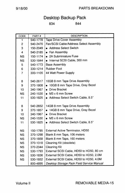
9/18/00 PARTS BREAKDOWN
Desktop Backup Pack 834 844
CODE PART# DESCRIPTION
1 540-1778 Tape Drive Cover Assembly
2 540-2470 Fan/SCSI Cable/Address Select Assembly
3 150-2049 • Address Select Switch
4 540-2185 • Fan Assembly
NS 150-1174 • 2A Subminiature Fuse
NS 530-1844 • Internal SCSI Cable, 300 mm
5 540-1773 Base Assembly
6 330-1214 Rubber Foot
7 300-1105 44 Watt Power Supply
8 540-2617 1 OGB 8 mm Tape Drive Assembly
9 370-1808 • 1 OGB 8 mm Tape Drive, Grey Bezel
10 340-1967 • Drive Bracket
NS 240-1530 • M3 x 6 mm Screw
11 530-1825 • Address Select Switch Cable, 8.5"
8 540-2652 14GB 8 mm Tape Drive Assembly
9 370-1857 • 14GB 8 mm Tape Drive, Grey Bezel
10 340-1967 • Drive Bracket
NS 240-1530 • M3 x 6 mm Screw
11 530-1825 • Address Select Switch Cable, 8.5''
NS 150-1785 External Active Terminator, HD50
NS 370-1298 Blank 8 mm Tape, 106 meters
NS 370-1858 Blank 8 mm Tape, 160 meters
NS 370-1318 Cleaning Kit (obsolete)
NS 370-2344 Cleaning Kit
NS 530-1793 External SCSI Cable, HD50 to HD50, 80 cm
NS 530-1836 External SCSI Cable, HD50 to HD50, 2.0M
NS 530-1852 External SCSI Cable, HD50 to HD50, 4.0M
800-4895 Desktop Storage Pack Field Service Manual
Volume II REMOVABLE MEDIA-15

PARTS BREAKDOWN 9/18/00
Desktop Storage Module
2
804 2.3GB 8 mm Tape
REMOVABLE MEDIA-16
814 5.0GB 8 mm Tape
6
Field Engineer Handbook
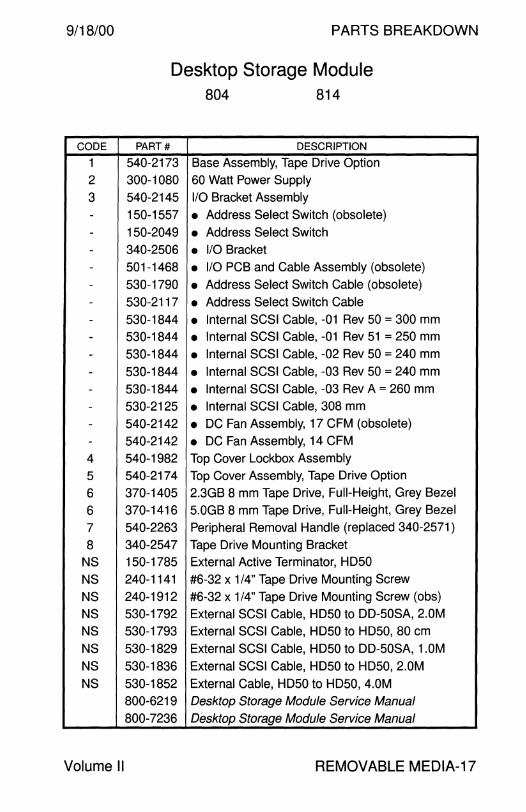
9/18/00 PARTS BREAKDOWN
Desktop Storage Module 804 814
CODE PART# DESCRIPTION
1 540-2173 Base Assembly, Tape Drive Option
2 300-1080 60 Watt Power Supply
3 540-2145 1/0 Bracket Assembly
- 150-1557 • Address Select Switch (obsolete) - 150-2049 • Address Select Switch - 340-2506 • 1/0 Bracket
- 501-1468 • 1/0 PCB and Cable Assembly (obsolete) - 530-1790 • Address Select Switch Cable (obsolete)
- 530-2117 • Address Select Switch Cable
- 530-1844 • Internal SCSI Cable, -01 Rev 50 = 300 mm - 530-1844 • Internal SCSI Cable, -01 Rev 51 = 250 mm
- 530-1844 • Internal SCSI Cable, -02 Rev 50 = 240 mm
- 530-1844 • Internal SCSI Cable, -03 Rev 50 = 240 mm - 530-1844 • Internal SCSI Cable, -03 Rev A = 260 mm
- 530-2125 • Internal SCSI Cable, 308 mm
- 540-2142 • DC Fan Assembly, 17 CFM (obsolete)
- 540-2142 • DC Fan Assembly, 14 CFM
4 540-1982 Top Cover Lockbox Assembly
5 540-2174 Top Cover Assembly, Tape Drive Option
6 370-1405 2.3GB 8 mm Tape Drive, Full-Height, Grey Bezel
6 370-1416 5.0GB 8 mm Tape Drive, Full-Height, Grey Bezel
7 540-2263 Peripheral Removal Handle (replaced 340-2571)
8 340-2547 Tape Drive Mounting Bracket
NS 150-1785 External Active Terminator, HD50
NS 240-1141 #6-32 x 1/4" Tape Drive Mounting Screw
NS 240-1912 #6-32 x 1/4" Tape Drive Mounting Screw (obs)
NS 530-1792 External SCSI Cable, HD50 to DD-50SA, 2.0M
NS 530-1793 External SCSI Cable, HD50 to HD50, 80 cm
NS 530-1829 External SCSI Cable, HD50 to DD-50SA, 1.0M
NS 530-1836 External SCSI Cable, HD50 to HD50, 2.0M
NS 530-1852 External Cable, HD50 to HD50, 4.0M
800-6219 Desktop Storage Module Service Manual 800-7236 Desktop Storage Module Service Manual
Volume II REMOVABLE MEDIA-17
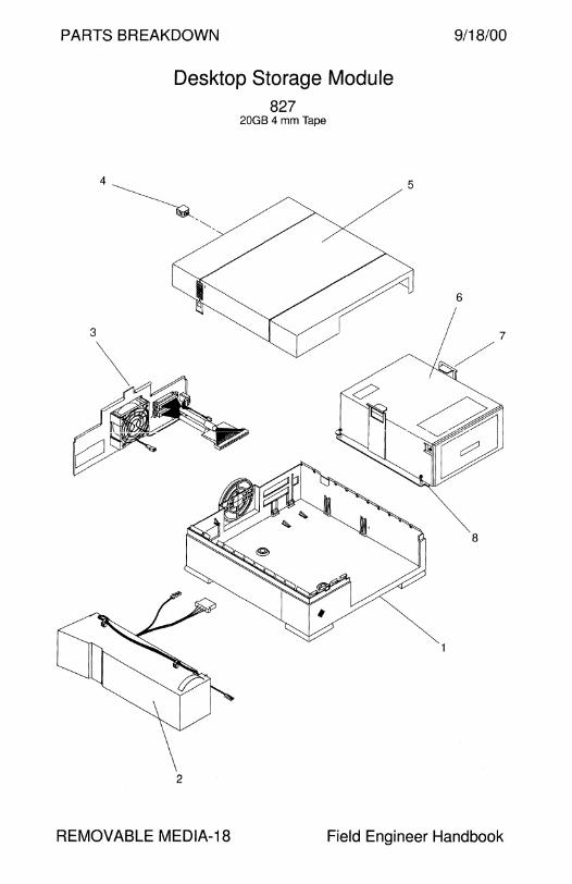
PARTS BREAKDOWN 9/18/00
Desktop Storage Module 827
20GB 4 mm Tape
4~- 5
6
2
REMOVABLE MEDIA-18 Field Engineer Handbook

9/18/00
CODE
1
2
3 -
-
-
-
-
4
5
6
7
8
NS
NS
NS
NS
NS
NS
NS
NS
NS --
-
PARTS BREAKDOWN
Desktop Storage Module 827
PART# DESCRIPTION
540-2173 Base Assembly, Tape Drive Option
300-1080 60 Watt Power Supply
540-2145 1/0 Bracket Assembly 1
150-2049 • Address Select Switch
340-2506 • 1/0 Bracket 530-2117 • Address Select Switch Cable, 0.1 O" Spacing 2
530-2125 • Internal SCSI Cable, 308 mm 3
540-2142 • DC Fan Assembly, 14 CFM
540-1982 Top Cover Lockbox Assembly
540-2174 Top Cover Assembly, Tape Drive Option
370-1616 20GB 4 mm DDS-1 Autoloader, Grey Bezel
540-2263 Peripheral Removal Handle
340-2547 Tape Drive Mounting Bracket
150-1785 External Active Terminator, HD50
240-1530 M3 0.5 x 6 mm Tape Drive Mounting Screw
370-1612 90 Meter Tape
370-1613 Cleaning Tape
370-1683 4-Tape Magazine
530-1793 External SCSI Cable, HD50 to HD50, 80 cm
530-1836 External SCSI Cable, HD50 to HD50, 2.0M
530-1852 External SCSI Cable, HD50 to HD50, 4.0M
540-2561 Shipping Restraint Assembly
230-1404 • Shipping Restraint Belt
230-1405 • Shipping Restraint Buckle
340-3045 • Shipping Restraint Bracket
800-7236 Desktop Storage Module Service Manual
1 The 20GB Tape Drive requires 1/0 Assembly 540-2145-02. 2 The 20GB Tape Drive is not compatible with Address Cable 530-1790. 3 The 20GB Tape Drive is not compatible with SCSI Cable 530-1844.
Volume II REMOVABLE MEDIA-19
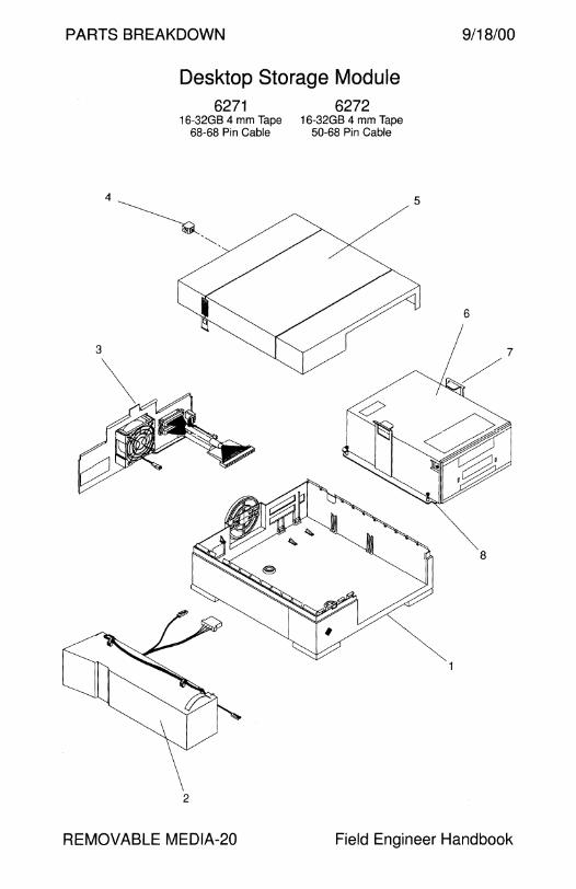
PARTS BREAKDOWN 9/18/00
Desktop Storage Module 6271
16-32GB 4 mm Tape 68-68 Pin Cable
·~·"·
2
REMOVABLE MEDIA-20
6272 16-32GB 4 mm Tape
50-68 Pin Cable
5
6
Field Engineer Handbook
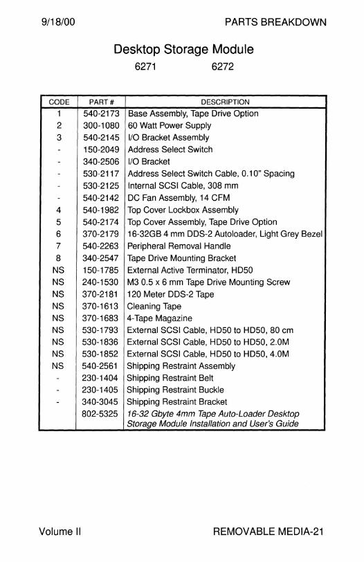
9/18/00 PARTS BREAKDOWN
Desktop Storage Module 6271 6272
CODE PART# DESCRIPTION
1 540-2173 Base Assembly, Tape Drive Option
2 300-1080 60 Watt Power Supply
3 540-2145 1/0 Bracket Assembly - 150-2049 Address Select Switch
- 340-2506 1/0 Bracket - 530-2117 Address Select Switch Cable, 0.1 O" Spacing - 530-2125 Internal SCSI Cable, 308 mm - 540-2142 DC Fan Assembly, 14 CFM
4 540-1982 Top Cover Lockbox Assembly
5 540-2174 Top Cover Assembly, Tape Drive Option
6 370-2179 16-32GB 4 mm DDS-2 Autoloader, Light Grey Bezel
7 540-2263 Peripheral Removal Handle
8 340-2547 Tape Drive Mounting Bracket
NS 150-1785 External Active Terminator, HD50
NS 240-1530 M3 0.5 x 6 mm Tape Drive Mounting Screw
NS 370-2181 120 Meter DDS-2 Tape
NS 370-1613 Cleaning Tape
NS 370-1683 4-Tape Magazine
NS 530-1793 External SCSI Cable, HD50 to HD50, 80 cm
NS 530-1836 External SCSI Cable, HD50 to HD50, 2.0M
NS 530-1852 External SCSI Cable, HD50 to HD50, 4.0M
NS 540-2561 Shipping Restraint Assembly - 230-1404 Shipping Restraint Belt - 230-1405 Shipping Restraint Buckle - 340-3045 Shipping Restraint Bracket
802-5325 16-32 Gbyte 4mm Tape Auto-Loader Desktop Storage Module Installation and User's Guide
Volume II REMOVABLE MEDIA-21
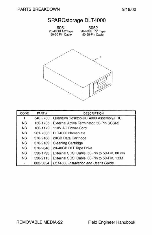
PARTS BREAKDOWN 9/18/00
CODE
1
NS
NS
NS NS
NS
NS
NS
NS -
SPARCstorage DLT4000 6051
20-40GB 1/2"Tape 50-50 Pin Cable
6052 20-40GB 1/2" Tape
50-68-Pin Cable
PART# DESCRIPTION
540-2780 Quantum Desktop:DLT4000 Assembly/FRU
150-1785 External Active Terminator, 50-Pin SCSl.2
180-1179 11 OV AC Power Cord
261-7606 DLT4000 Nameplate
370-2188 20GB Data Cartridge
370-2189 Cleaning Cartridge
370-2848 20-40GB DLT Tape Drive
530-1793 External SCSI Cable, 50-Pin to 50·Pin, 80 cm
530-2115 External SCSl,Cable, 68-Pin to 50-Pin, 1:2M
802-5054 DLT4000 Installation and User's Guide
'I i
REMOVABLE MEDIA-22 Field Engineer Handbook
9/18/00 PARTS BREAKDOWN
This page intentionally left blank.
Volume II REMOVABLE MEDIA-23
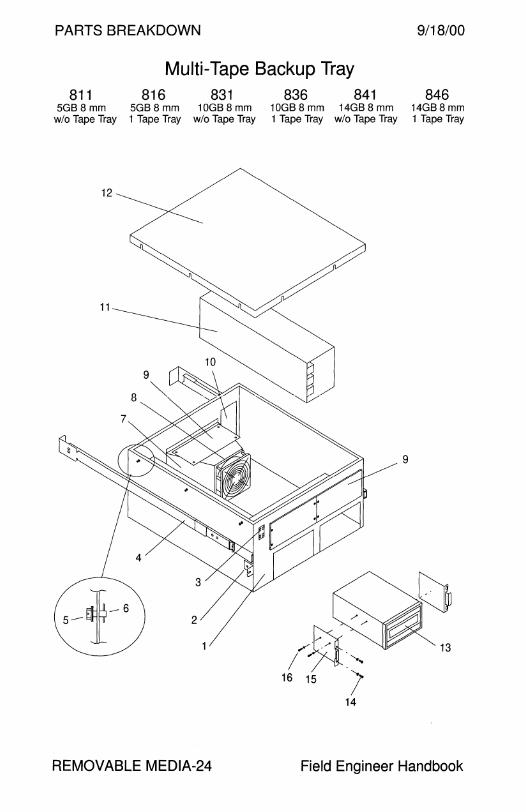
PARTS BREAKDOWN 9/18/00
Multi-Tape Backup Tray 811 816 831 836 841 846
5GB8 mm 5GB 8 mm 10GB 8 mm 10GB 8 mm 14GB 8 mm 14GB8 mm w/o Tape Tray 1 Tape Tray w/o Tape Tray 1 Tape Tray w/o Tape Tray 1 Tape Tray
12
REMOVABLE MEDIA-24 Field Engineer Handbook

9/18/00 PARTS BREAKDOWN
Multi-Tape Backup Tray 811 816 831 836 841 846
CODE PART# DESCRIPTION
1 340-2566 Chassis Enclosure
2 340-2861 Tray Retaining Bracket (obsolete)
2 340-2862 Tray Retaining Bracket
3 150-1806 SCSI Address Select Switch
4 370-1385 -01 Slide Rail Set, Inner 651.2 mm, Outer 742.7 mm
4 370-1385 -03 Slide Rail Set, Inner 717.3 mm, Outer 742.7 mm
5 None Cross-Drilled Screw (use 240-1732-01)
6 None Screw Retaining Clip
7 340-2564 Fan Enclosure
8 370-1214 DC Fan, 105 CFM
9 340-2641 Filler Panel (obsolete)
9 340-2835 Full-Height Filler Panel
9 340-2859 Half-Height Filler Panel
9 340-3369 Half-Height Filler Panel
10 340-2601 Connector Panel
11 300-1096 269 Watt Power Supply
11 300-1312 269 Watt Nordic Power Supply (Available 12/95)
12 340-2565 Top Cover
13 370-1415 5.0GB 8 mm Tape Drive, Full-Height, Black Bezel
13 370-1809 1 OGB 8 mm Tape Drive, Half-Height, Black Bezel
13 370-1856 14GB 8 mm Tape Drive, Half-Height, Black Bezel
14 240-1372 M4 0.7 x 10 mm Screw
15 340-2148 Peripheral Mounting Bracket
16 240-1141 #6-32 x 1/4" Screw for 5GB
16 240-1530 M3 0.5 x 6 mm Screw for 10GB and 14GB
NS 370-2344 8 mm Cleaning Kit
NS 530-1849 Address Select Switch Cable (obsolete)
NS 530-1891 Internal SCSI Bus Cable, 1.8M
NS 530-1892 DC Wire Harness
NS 530-2058 4-Drive Address Select Switch Cable
NS 540-2252 Front Panel, 56-inch Rack with 4 Tape Drive Cutouts
800-7008 5.0 Gbyte Bmm Tape Drive Tray Service Manual
800-7340 Multi-Tape Backup Tray Service Manual
Volume II REMOVABLE MEDIA-25

PARTS BREAKDOWN 9/18/00
Multi-Tape Backup Tray
12
825 20GB 4 mm Tape
wlo Tape Tray
REMOVABLE MEDIA-26
826 20GB 4 mm Tape
1 Tape Tray
Field Engineer Handbook

9/18/00 PARTS BREAKDOWN
Multi-Tape Backup Tray 825 826
CODE PART# DESCRIPTION
1 340-2566 Chassis Enclosure
2 340-2681 Tray Retaining Bracket {obsolete)
2 340-2862 Tray Retaining Bracket
3 150-1806 SCSI Address Select Switch
4 370-1385 -01 Slide Rail Set, Inner 651.2 mm, Outer 742.7 mm
4 370-1385 -03 Slide Rail Set, Inner 717.3 mm, Outer 742.7 mm
5 None Cross-Drilled Screw (use 240-1732-01)
6 None Screw Retaining Clip
7 340-2564 Fan Enclosure
8 370-1214 DC Fan, 105 CFM
9 340-2641 Filler Panel (obsolete)
9 340-2835 Full-Height Filler Panel
9 340-2859 Half-Height Filler Panel
9 340-3369 Half-Height Filler Panel
10 340-2601 Connector Panel
11 300-1096 269 Watt Power Supply
11 300-1312 269 Watt Nordic Power Supply (Available 12/95)
12 340-2565 Top Cover
13 540-2607 Fan, Wire Harness, and Bracket Assy, 20GB 4 mm
13 540-2606 • Fan and Wire Harness Assembly
14 370-1617 20GB 4 mm Autoloader, Full-Height, Black Bezel
15 240-1372 M4 0.7 x 10 mm Screw
16 340-2148 Peripheral Mounting Bracket
17 240-1530 M3 0.5 x 6 mm Screw for 1 OGB, 14GB, and 20GB
NS 150-1785 External Active Terminator, HD50
NS 340-3044 4 mm Tape Drive Padded Shipping Bracket
NS 370-1751 4 mm Tape Drive Shipping Bracket (obsolete)
NS 530-1849 Address Select Switch Cable (obsolete)
NS 530-1891 Internal SCSI Bus Cable, 1.8M
NS 530-1892 DC Wire Harness
NS 530-2058 4-Drive Address Select Switch Cable
NS 540-2252 Front Panel, 56-inch Rack with 4 Tape Drive Cutouts
800-7340 Multi-Tape Backup Tray Service Manual
Volume II REMOVABLE MEDIA-27
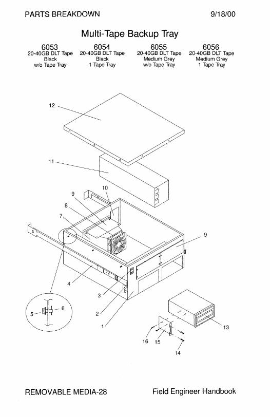
PARTS BREAKDOWN 9/18/00
Multi-Tape Backup Tray 6053
20-40GB DLT Tape Black
wlo Tape Tray
12
6054 20-40GB DLT Tape
Black 1 Tape Tray
REMOVABLE MEDIA-28
6055 20-40GB DLT Tape
Medium Grey wlo Tape Tray
6056 20-40GB DLT Tape
Medium Grey 1 Tape Tray
13
Field Engineer Handbook

9/18/00 PARTS BREAKDOWN
Multi-Tape Backup Tray 6053 6054 6055 6056
CODE PART# DESCRIPTION
1 340-2566 Chassis Enclosure 2 340-2862 Tray Retaining Bracket
3 150-1806 SCSI Address Select Switch
4 370-1385 -03 Slide Rail Set, Inner 717.3 mm, Outer 742.7 mm
5 None Cross-Drilled Screw (use 240-1732-01)
6 None Screw Retaining Clip
7 340-2564 Fan Enclosure
8 370-1214 DC Fan, 105 CFM
NS 340-0265 • Fan Fingerguard NS 240-1740 • #6-32 x 2" Screw
9 340-2835 Full-Height Filler Panel
9 340-3369 Half-Height Filler Panel
10 340-2601 Connector Panel
11 300-1096 269 Watt Power Supply
11 300-1312 269 Watt Nordic Power Supply (available 12/95)
12 340-2565 Top Cover
13 370-2187 20-40GB DLT Tape Drive, Medium Grey Bezel
13 370-2255 20-40GB DLT Tape Drive, Black Bezel
14 240-1372 M4 0.7 x 10 mm Screw
15 340-2148 Peripheral Mounting Bracket
16 240-1530 M3 0.5 x 6 mm Screw (wrong. thread size)
16 240-1878 #6-32 x 5/16" Screw
NS 150-1785 External Active Terminator, HD50
NS 370-2188 20GB Data Cartridge
NS 370-2189 Cleaning Cartridge
NS 530-1891 Internal SCSI Bus Cable, 1.8M
NS 530-1892 DC Wire Harness NS 530-2058 4-Drive Address Select Switch Cable
NS 540-2252 Front Panel, 56-inch Rack with 4 Tape Drive Cutouts
800-7340 Multi-Tape Backup Tray Service Manual
Volume II REMOVABLE MEDIA-29
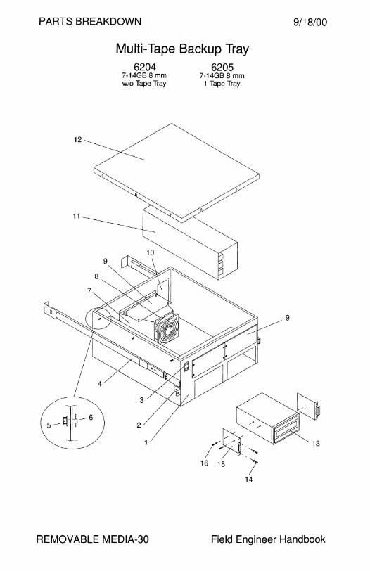
PARTS BREAKDOWN 9/18/00
Multi-Tape Backup Tray
12
6204 7-14GB 8 mm wlo Tape Tray
REMOVABLE MEDIA-30
6205 7-14GB 8 mm
1 Tape Tray
Field Engineer Handbook

9/18/00 PARTS BREAKDOWN
Multi-Tape Backup Tray 6204 6205
CODE PART# DESCRIPTION
1 340-2566 Chassis Enclosure
2 340-2862 Tray Retaining Bracket
3 150-1806 SCSI Address Select Switch
4 370-1385 -01 Slide Rail Set, Inner 651.2 mm, Outer 742.7 mm
4 370-1385 -03 Slide Rail Set, Inner 717.3 mm, Outer 742.7 mm
5 None Cross-Drilled Screw (use 240-1732c01)
6 None Screw Retaining Clip
7 340-2564 Fan Enclosure
8 370-1214 DC Fan, 105 CFM
NS 340-0265 • Fan Fingerguard NS 240-1740 • #6-32 x 2" Screw
9 340-2641 Filler Panel (obsolete)
9 340-2835 Full-Height Filler Panel
9 340-2859 Half-Height Filler Panel
9 340-3369 Half-Height Filler Panel
10 340-2601 Connector Panel
11 300-1096 269 Watt Power Supply
11 300-1312 269 Watt Nordic Power Supply (Available 12/95)
12 340-2565 Top Cover
13 370-2200 14GB 8 mm Tape Drive, Half-Height, Dk Grey Bezel
' 14 240-1372 M4 0.7 x 10 mm Screw
I 15 340-2148 Peripheral Mounting Bracket
16 240-1141 #6-32 x 1/4" Screw for 5GB ,, 16 240-1530 M3 0.5 x 6 mm Screw for 1 OGB and 14GB
800-7008 5.0 Gbyte Bmm Tape Drive Tray Service Manual
800-7340 Multi- Tape Backup Tray Service Manual
Volume II REMOVABLE MEDIA-31

PARTS BREAKDOWN 9/18/00
Multi-Tape Backup Tray 6273 6274 6275 6276
16-32GB 4 mm Tape 16-32GB 4 mm Tape 16-32GB 4 mm Tape 16-32GB 4 mm Tape Light Grey Light Grey Medium Grey Medium Grey
w/o Tape Tray w Tape Tray wlo Tape Tray w Tape Tray
12
REMOVABLE MEDIA-32 Field Engineer Handbook
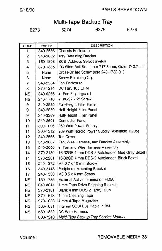
9/18/00 PARTS BREAKDOWN
Multi-Tape Backup Tray 6273 6274 6275 6276
CODE PART# DESCRIPTION
1 340-2566 Chassis Enclosure
2 340-2862 Tray Retaining Bracket
3 150-1806 SCSI Address Select Switch
4 370-1385 -03 Slide Rail Set, Inner 717.3 mm, Outer 742.7 mm
5 None Cross-Drilled Screw (use 240-1732-01)
6 None Screw Retaining Clip
7 340-2564 Fan Enclosure
8 370-1214 DC Fan, 105 CFM
NS 340-0265 • Fan Fingerguard
NS 240-1740 • #6-32 x 2" Screw
9 340-2835 Full-Height Filler Panel
9 340-2859 Half-Height Filler Panel
9 340-3369 Half-Height Filler Panel
10 340-2601 Connector Panel
11 300-1096 269 Watt Power Supply
11 300-1312 269 Watt Nordic Power Supply (Available 12/95)
12 340-2565 Top Cover
13 540-2607 Fan, Wire Harness, and Bracket Assembly
13 540-2606 • Fan and Wire Harness Assembly
14 370-2180 16-32GB 4 mm DDS-2 Autoloader, Med Grey Bezel
14 370-2201 16-32GB 4 mm DDS-2 Autoloader, Black Bezel
15 240-1372 M4 0.7 x 10 mm Screw
16 340-2148 Peripheral Mounting Bracket
17 240-1530 M3 0.5 x 6 mm Screw
NS 150-1785 External Active Terminator, HD50
NS 340-3044 4 mm Tape Drive Shipping Bracket
NS 370-2181 Blank 4 mm DDS-2 Tape, 120M
NS 370-1613 4 mm Cleaning Tape
NS 370-1683 4 mm 4-Tape Magazine
NS 530-1891 Internal SCSI Bus Cable, 1.8M
NS 530-1892 DC Wire Harness
800-7340 Multi-Tape Backup Tray Service Manual
Volume II REMOVABLE MEDIA-33
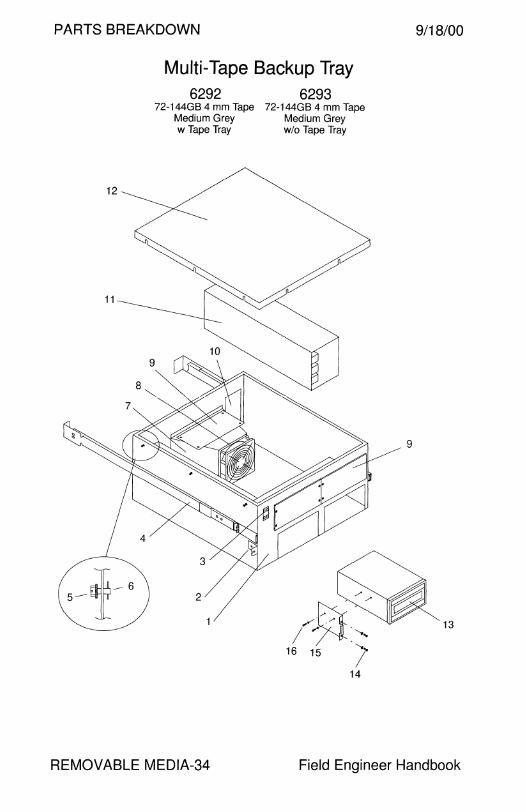
PARTS BREAKDOWN
12
11
J~6 5-1
Multi-Tape Backup Tray 6292 6293
72-144GB 4 mm Tape 72-144GB 4 mm Tape Medium Grey Medium Grey w Tape Tray w/o Tape Tray
2
9/18/00
9
13
REMOVABLE MEDIA-34 Field Engineer Handbook
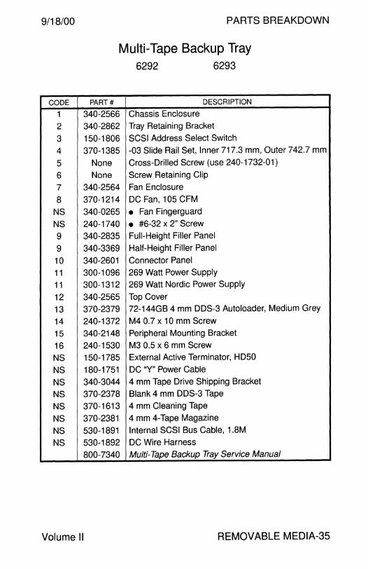
9/18/00 PARTS BREAKDOWN
Multi-Tape Backup Tray 6292 6293
CODE PART# DESCRIPTION
1 340-2566 Chassis Enclosure
2 340-2862 Tray Retaining Bracket
3 150-1806 SCSI Address Select Switch
4 370-1385 -03 Slide Rail Set, Inner 717.3 mm, Outer 742.7 mm
5 None Cross-Drilled Screw (use 240-1732-01)
6 None Screw Retaining Clip
7 340-2564 Fan Enclosure
8 370-1214 DC Fan, 105 CFM
NS 340-0265 • Fan Fingerguard
NS 240-1740 • #6-32 x 2" Screw
9 340-2835 Full-Height Filler Panel
9 340-3369 Half-Height Filler Panel
10 340-2601 Connector Panel
11 300-1096 269 Watt Power Supply
11 300-1312 269 Watt Nordic Power Supply
12 340-2565 Top Cover
13 370-2379 72-144GB 4 mm DDS-3 Autoloader, Medium Grey
14 240-1372 M4 0.7 x 10 mm Screw
15 340-2148 Peripheral Mounting Bracket
16 240-1530 M3 0.5 x 6 mm Screw
NS 150-1785 External Active Terminator, HD50
NS 180-1751 DC "Y" Power Cable
NS 340-3044 4 mm Tape Drive Shipping Bracket
NS 370-2378 Blank 4 mm DDS-3 Tape
NS 370-1613 4 mm Cleaning Tape
NS 370-2381 4 mm 4-Tape Magazine
NS 530-1891 Internal SCSI Bus Cable, 1.8M
NS 530-1892 DC Wire Harness
800-7340 Multi-Tape Backup Tray Service Manual
Volume II REMOVABLE MEDIA-35
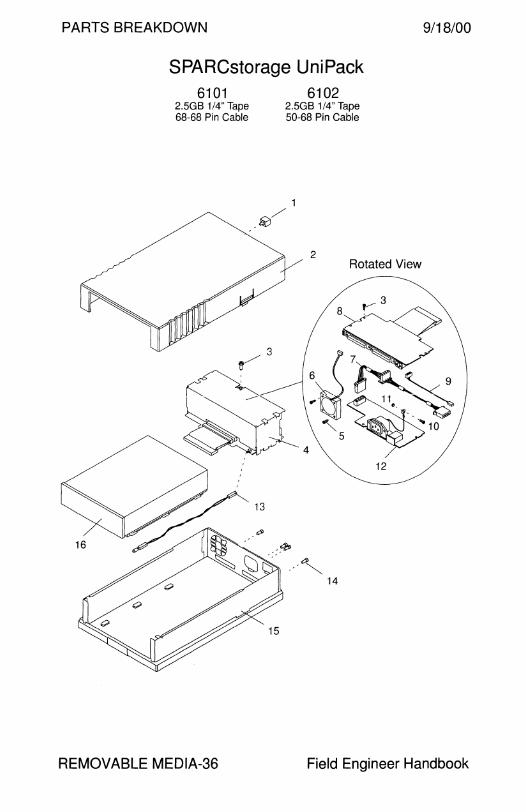
PARTS BREAKDOWN 9/18/00
SPARCstorage UniPack 6101
2.5GB 1 /4" Tape 68-68 Pin Cable
REMOVABLE MEDIA-36
6102 2.5GB 1/4" Tape 50-68 Pin Cable
1
-~/
2 Rotated View
Field Engineer Handbook

9/18/00 PARTS BREAKDOWN
SPARCstorage UniPack 6101 6102
CODE PART# DESCRIPTION
- 599-2042 2.5GB 1/4" Tape UniPack
- 595-3711 Tape Enclosure FRU without Tape Drive
- 599-2046 • Tape Enclosure without Tape Drive
1 540-1982 • Lockbox
2 540-2676 • Tape Drive Cover Assembly
3 240-1530 • M3 x 6 mm Screw
4 540-2674 • Tape Drive Power Supply Assembly
5 240-2246 • M3 x 25 mm Screw (obsolete)
5 240-2294 • M3 x 25 mm Pan-Head Screw
6 370-1986 • Fan 7 530-2179 • Tape Drive DC Power Cable
8 501-2791 • Tape Drive SCSI Interface Card
9 530-1790 • Address Select Cable
9 530-2181 • Address Select Cable
10 240-1434 • M4 x 10 mm Screw
11 240-1373 • M4 Nut
12 300-1282 • 30 Watt Power Supply
13 530-2183 • LED Cable
14 240-2180 • #4-40M/2-56F Jackscrew
15 540-2672 • Base Assembly
16 540-2698 Tape Drive Assembly
NS 240-1530 • M3 x 6 mm Screw
NS 340-3222 • Mounting Bracket
- 370-2018 • 2.5GB Tape Drive
NS 261-5678 Sun Logo
NS 530-1884 External SCSI Cable, HD68 to HD68, 80 cm
NS 530-2115 External SCSI Cable, HD68 to HD50, 1.2M
802-3230 SPARCstorage UniPack Tape Drive Replacement
Volume II REMOVABLE MEDIA-37

PARTS BREAKDOWN
SPARCstorage UniPack
6201 6202 7-14GB 8 mm Tape 7-14GB 8 mm Tape
68-68 Pin Cable 50-68 Pin Cable
1
-~/
2 Rotated View
12
9/18/00
REMOVABLE MEDIA-38 Field Engineer Handbook
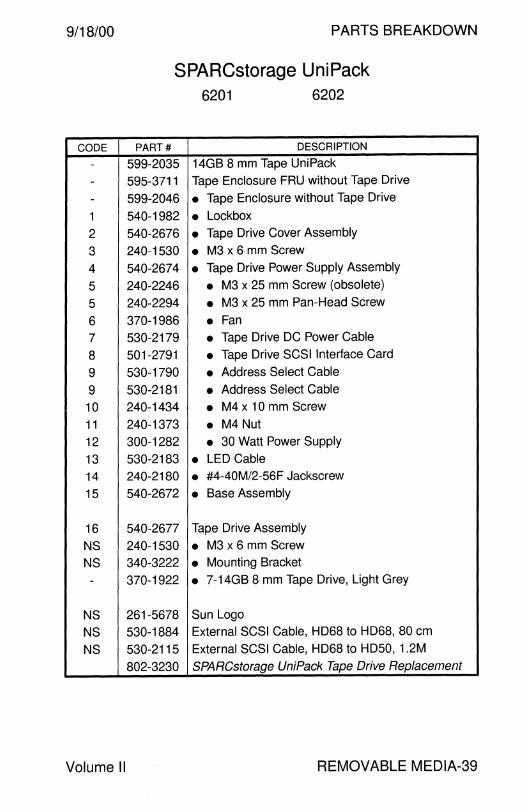
9/18/00 PARTS BREAKDOWN
SPARCstorage UniPack 6201 6202
CODE PART# DESCRIPTION
- 599-2035 14GB 8 mm Tape UniPack
- 595-3711 Tape Enclosure FRU without Tape Drive
- 599-2046 • Tape Enclosure without Tape Drive
1 540-1982 • Lockbox
2 540-2676 • Tape Drive Cover Assembly
3 240-1530 • M3 x 6 mm Screw
4 540-2674 • Tape Drive Power Supply Assembly
5 240-2246 • M3 x 25 mm Screw (obsolete)
5 240-2294 • M3 x 25 mm Pan-Head Screw
6 370-1986 • Fan 7 530-2179 • Tape Drive DC Power Cable
8 501-2791 • Tape Drive SCSI Interface Card
9 530-1790 • Address Select Cable
9 530-2181 • Address Select Cable
10 240-1434 • M4 x 10 mm Screw
11 240-1373 • M4 Nut
12 300-1282 • 30 Watt Power Supply
13 530-2183 • LED Cable
14 240-2180 • #4-40M/2-56F Jackscrew
15 540-2672 • Base Assembly
16 540-2677 Tape Drive Assembly
NS 240-1530 • M3 x 6 mm Screw
NS 340-3222 • Mounting Bracket
- 370-1922 • 7-14GB 8 mm Tape Drive, Light Grey
NS 261-5678 Sun Logo
NS 530-1884 External SCSI Cable, HD68 to HD68, 80 cm
NS 530-2115 External SCSI Cable, HD68 to HD50, 1.2M
802-3230 SPARCstorage UniPack Tape Drive Replacement
Volume II REMOVABLE MEDIA-39
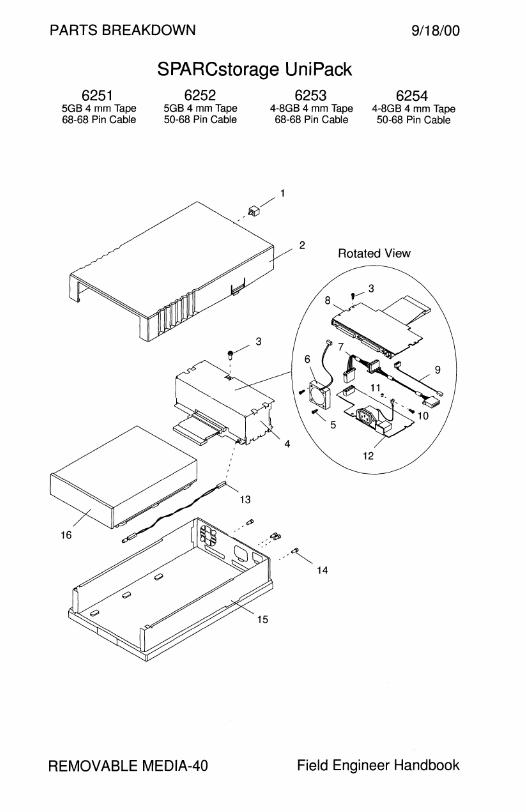
PARTS BREAKDOWN 9/18/00
SPARCstorage UniPack 6251
5GB 4 mm Tape 68-68 Pin Cable
6252 5GB 4 mm Tape 50-68 Pin Cable
REMOVABLE MEDIA-40
6253 6254 4-8GB 4 mm Tape 4-8GB 4 mm Tape 68-68 Pin Cable 50-68 Pin Cable
1
-~/
2 Rotated View
Field Engineer Handbook

9/18/00 PARTS BREAKDOWN
SPARCstorage UniPack 6251 6252 6253 6254
CODE PART# DESCRIPTION
- 599-2040 5GB 4 mm DDS-1 Tape UniPack
- 599-2072 4-8GB 4 mm DDS-2 Tape Uni Pack
- 595-3711 Tape Enclosure FRU without Tape Drive
- 599-2046 • Tape Enclosure without Tape Drive
1 540-1982 • Lockbox
2 540-2676 • Tape Drive Cover Assembly
3 240-1530 • M3 x 6 mm Screw
4 540-2674 • Tape Drive Power Supply Assembly
5 240-2246 • M3 x 25 mm Screw (obsolete)
5 240-2294 • M3 x 25 mm Pan-Head Screw
6 370-1986 • Fan 7 530-2179 • Tape Drive DC Power Cable
8 501-2791 • Tape Drive SCSI Interface Card
9 530-1790 • Address Select Cable
9 530-2181 • Address Select Cable
10 240-1434 • M4 x 10 mm Screw
11 240-1373 • M4 Nut 12 300-1282 • 30 Watt Power Supply
13 530-2183 • LED Cable
14 240-2180 • #4-40M/2-56F Jackscrew
15 540-2672 • Base Assembly
16 540-2696 5GB 4 mm DDS-1 Tape Drive Assembly
NS 340-3222 • Mounting Bracket
- 370-2088 • 5GB 4 mm DDS-1 Tape Drive
16 540-2793 4-8GB 4 mm DDS-2 Tape Drive Assembly
NS 340-3222 • Mounting Bracket - 370-2176 • 4-8GB 4 mm DDS-2 Tape Drive
NS 261-5678 Sun Logo
NS 370-2181 120 Meter DDS-2 Tape
NS 370-1613 Cleaning Tape
NS 530-1884 External SCSI Cable, HD68 to HD68, 80 cm
NS 530-2115 External SCSI Cable, HD68 to HD50, 1.2M
802-3230 SPARCstorage UniPack Tape Drive Replacement
Volume II REMOVABLE MEDIA-41
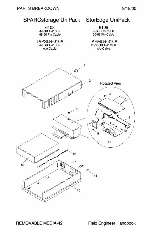
PARTS BREAKDOWN
SPARCstorage UniPack 6108
4-8GB 1 /4" SLR 68-68 Pin Cable
TAPSLR-01 OA 4-8GB 1/4" SLR
w/o Cable
REMOVABLE MEDIA-42
1
~/
9/18/00
StorEdge UniPack 6109
4-8GB 1 /4" SLR 50-68 Pin Cable
TAPMLR-31 OA 25-50GB 1/4" MLR
wlo Cable
2 Rotated View
Field Engineer Handbook
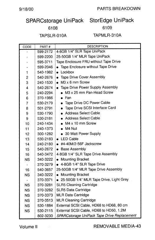
9/18/00 PARTS BREAKDOWN
SPARCstorage UniPack StorEdge UniPack 6108 6109
TAPSLR-01 OA TAPMLR-31 OA
CODE PART# DESCRIPTION
- 599-2172 4-8GB 1/4" SLR Tape UniPack
- 599-2200 25-50GB 1/4" MLR Tape UniPack
- 595-3711 Tape Enclosure FRU without Tape Drive
- 599-2046 • Tape Enclosure without Tape Drive
1 540-1982 • Lockbox
2 540-2676 • Tape Drive Cover Assembly
3 240-1530 • M3 x 6 mm Screw
4 540-2674 • Tape Drive Power Supply Assembly
5 240-2294 • M3 x 25 mm Pan-Head Screw
6 370-1986 • Fan
7 530-2179 • Tape Drive DC Power Cable
8 501-2791 • Tape Drive SCSI Interface Card
9 530-1790 • Address Select Cable
9 530-2181 • Address Select Cable
10 240-1434 • M4 x 10 mm Screw
11 240-1373 • M4 Nut
12 300-1282 • 30 Watt Power Supply
13 530-2183 • LED Cable
14 240-2180 • #4-40M/2-56F Jackscrew
15 540-2672 • Base Assembly
16 540-3472 4-8GB 1/4" SLR Tape Drive Assembly
NS 340-3222 • Mounting Bracket
- 370-3279 • 4-8GB 1/4" SLR Tape Drive
16 540-3657 25-50GB 1 /4" MLR Tape Drive Assembly
NS 340-3222 • Mounting Bracket
- 370-3371 • 25-50GB 1/4" MLR Tape Drive, Light Grey
NS 370-3281 SLR5 Cleaning Cartridge
NS 370-3282 SLR5 Data Cartridge
NS 370-3373 MLR Data Cartridge
NS 370-3513 MLR Cleaning Cartridge
NS 530-1884 External SCSI Cable, HD68 to HD68, 80 cm
NS 530-2115 External SCSI Cable, HD68 to HD50, 1.2M
802-3230 SPARCstorage UniPack Tape Drive Replacement
Volume 11 REMOVABLE MEDIA-43

PARTS BREAKDOWN 9/18/00
SPARCstorage UniPack StorEdge UniPack 6151 6152 6157 6158
SunCD 4 CD-ROM SunCD 4 CD-ROM SunCD 12 CD-ROM SunCD 12 CD-ROM 68-68 Pin Cable 50-68 Pin Cable
REMOVABLE MEDIA-44
68-68 Pin Cable 50-68 Pin Cable
1
-~/
Rotated View
Field Engineer Handbook
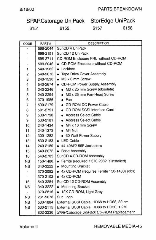
9/18/00 PARTS BREAKDOWN
SPARCstorage UniPack StorEdge UniPack 6151 6152 6157 6158
CODE PART# DESCRIPTION
- 599-2044 SunCD 4 UniPack - 599-2151 SunCD 12 UniPack
- 595-3711 CD-ROM Enclosure FRU without CD-ROM
- 599-2046 • CD-ROM Enclosure without CD-ROM
1 540-1982 • Lockbox
2 540-2676 • Tape Drive Cover Assembly
3 240-1530 • M3 x 6 mm Screw
4 540-2674 • CD-ROM Power Supply Assembly
5 240-2246 • M3 x 25 mm Screw (obsolete)
5 240-2294 • M3 x 25 mm Pan-Head Screw
6 370-1986 • Fan 7 530-2179 • CD-ROM DC Power Cable
8 501-2791 • CD-ROM SCSI Interface Card
9 530-1790 • Address Select Cable
9 530-2181 • Address Select Cable
10 240-1434 • M4 x 10 mm Screw
11 240-1373 • M4 Nut
12 300-1282 • 30 Watt Power Supply
13 530-2183 • LED Cable
14 240-2180 • #4-40M/2-56F Jackscrew
15 540-2672 • Base Assembly
16 540-2705 SunCD 4 CD-ROM Assembly
NS 150-1480 • Ferrite (required if 370-2082 is installed)
NS 340-3222 • Mounting Bracket
- 370-2082 • 4x CD-ROM (requires Ferrite 150-1480) (obs)
- 370-2102 • 4x CD-ROM
16 540-3284 SunCD 12 CD-ROM Assembly
NS 340-3222 • Mounting Bracket
- 370-2816 • 12X CD-ROM, Light Grey
NS 261-5678 Sun Logo
NS 530-1884 External SCSI Cable, HD68 to HD68, 80 cm
NS 530-2115 External SCSI Cable, HD68 to HD50, 1.2M
802-3230 SPARCstorage UniPack CD-ROM Replacement
Volume II REMOVABLE MEDIA-45
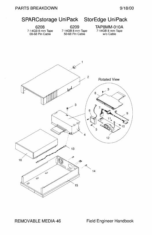
PARTS BREAKDOWN 9/18/00
SPARCstorage UniPack StorEdge UniPack 6208
7-14GB 8 mm Tape 68-68 Pin Cable
REMOVABLE MEDIA-46
6209 7-14GB 8 mm Tape
50-68 Pin Cable
1
~/
2
TAP8MM-01 QA 7-14GB 8 mm Tape
wlo Cable
Rotated View
12
Field Engineer Handbook
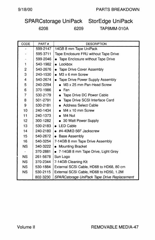
9/18/00 PARTS BREAKDOWN
SPARCstorage UniPack StorEdge UniPack 6208 6209 TAP8MM-01 OA
CODE PART# DESCRIPTION
- 599-2147 14GB 8 mm Tape UniPack - 595-3711 Tape Enclosure FRU without Tape Drive - 599-2046 • Tape Enclosure without Tape Drive
1 540-1982 • Lockbox 2 540-2676 • Tape Drive Cover Assembly 3 240-1530 • M3 x 6 mm Screw 4 540-2674 • Tape Drive Power Supply Assembly
5 240-2294 • M3 x 25 mm Pan-Head Screw
6 370-1986 • Fan 7 530-2179 • Tape Drive DC Power Cable
8 501-2791 • Tape Drive SCSI Interface Card
9 530-2181 • Address Select Cable
10 240-1434 • M4 x 10 mm Screw 11 240-1373 • M4 Nut 12 300-1282 • 30 Watt Power Supply
13 530-2183 • LED Cable 14 240-2180 • #4-40M/2-56F Jackscrew
15 540-2672 • Base Assembly 16 540-3254 7-14GB 8 mm Tape Drive Assembly
NS 340-3222 • Mounting Bracket - 370-2881 • 7-14GB 8 mm Tape Drive, Light Grey
NS 261-5678 Sun Logo
NS 370-2344 7-14GB Cleaning Kit
NS 530-1884 External SCSI Cable, HD68 to HD68, 80 cm
NS 530-2115 External SCSI Cable, HD68 to HD50, 1.2M
802-3230 SPARCstorage UniPack Tape Drive Replacement
Volume II REMOVABLE MEDIA-47

PARTS BREAKDOWN 19/18/00
SPARCstorage UniPack StorEdge UniPack 6230 6231 TAP8MM-011 A
20-40GB 8 mm Tape 20-40GB 8 mm Tape 20-40GB 8 mm Tape 68-68 Pin Cable 50-68 Pin Cable w/o Cable
REMOVABLE MEDIA-48
1
-~/
2 Rotated View
12
Field Engineer Handbook
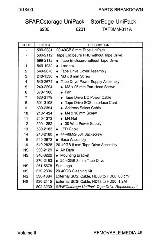
9/18/00 PARTS BREAKDOWN
SPARCstorage UniPack StorEdge UniPack 6230 6231 TAPBMM-011 A
CODE PART# DESCRIPTION
- 599-2081 20-40GB 8 mm Tape UniPack - 599-2112 Tape Enclosure FRU without Tape Drive - 599-2112 • Tape Enclosure without Tape Drive
1 540-1982 • Lockbox 2 540-2676 • Tape Drive Cover Assembly
3 240-1530 • M3 x 6 mm Screw
4 540-2674 • Tape Drive Power Supply Assembly
5 240-2294 • M3 x 25 mm Pan-Head Screw
6 370-1986 • Fan 7 530-2179 • Tape Drive DC Power Cable
8 501-3108 • Tape Drive SCSI Interface Card
9 530-2354 • Address Select Cable
10 240-1434 • M4 x 10 mm Screw
11 240-1373 • M4 Nut 12 300-1282 • 30 Watt Power Supply
13 530-2183 • LED Cable 14 240-2180 • #4-40M/2-56F Jackscrew
15 540-2672 • Base Assembly 16 540-2828 20-40GB 8 mm Tape Drive Assembly
NS 330-2129 • Air Dam NS 340-3222 • Mounting Bracket
- 370-2183 • 20-40GB 8 mm Tape Drive NS 261-5678 Sun Logo
NS 370-2396 20-40GB Cleaning Kit
NS 530-1884 External SCSI Cable, HD68 to HD68, 80 cm
NS 530-2115 External SCSI Cable, HD68 to HD50, 1.2M
802-3230 SPARCstorage UniPack Tape Drive Replacement
Volume II REMOVABLE MEDIA-49
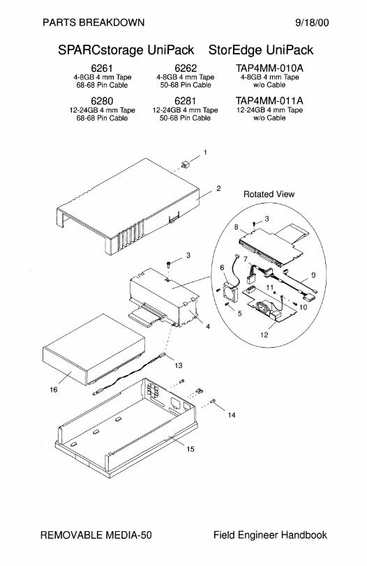
PARTS BREAKDOWN 9/18/00
SPARCstorage UniPack StorEdge UniPack 6261 6262 TAP4MM-01 QA
4-8GB 4 mm Tape 4-8GB 4 mm Tape 4-8GB 4 mm Tape 68-68 Pin Cable 50-68 Pin Cable w/o Cable
6280 6281 TAP4MM-011 A 12-24GB 4 mm Tape 12-24GB 4 mm Tape 12-24GB 4 mm Tape
68-68 Pin Cable 50-68 Pin Cable
1
,~/
/3 jt
-~:
REMOVABLE MEDIA-50
w/o Cable
2 Rotated View
12
Field Engineer Handbook

9/18/00 PARTS BREAKDOWN
SPARCstorage UniPack StorEdge UniPack
CODE
--
-
-
1
2
3 4
5 5
6
7
8 9
10
11
12
13
14
15
16
NS -
16
NS
-NS
NS
NS
NS
NS
NS
Volume II
6261
6280
PART#
599-2105
599-2107
595-3711
599-2046
540-1982
540-2676
240-1530
540-2674
240-2246
240-2294
370-1986
530-2179
501-2791
530-2181
240-1434
240-1373
300-1282
530-2183
240-2180
540-2672
540-2946
340-3222 370-2375
540-2972
340-3222
370-2377 261-5678
370-2181
370-2381
370-1613
530-1884
530-2115
802-3230
6262
6281
TAP4MM-01 OA
TAP4MM-011 A
DESCRIPTION
4-8GB 4 mm DDS-2 Tape Uni Pack
12-24GB 4 mm DDS-3 Tape UniPack
Tape Enclosure FRU without Tape Drive
• Tape Enclosure without Tape Drive
• Lockbox
• Tape Drive Cover Assembly
• M3 x 6 mm Screw • Tape Drive Power Supply Assembly
• M3 x 25 mm Screw (obsolete)
• M3 x 25 mm Pan-Head Screw
• Fan • Tape Drive DC Power Cable
• Tape Drive SCSI Interface Card
• Address Select Cable
• M4 x 10 mm Screw
• M4 Nut • 30 Watt Power Supply
• LED Cable • #4-40M/2-56F Jackscrew
• Base Assembly 4-8GB 4 mm Tape Drive Assembly
• Mounting Bracket • 4-8GB 4 mm DDS-2 Tape Drive 12-24GB 4 mm Tape Drive Assembly
• Mounting Bracket • 12-24GB 4 mm DDS-3 Tape Drive, Light Grey
Sun Logo
Blank DDS-2 Tape
Blank DDS-3 Tape
Cleaning Tape External SCSI Cable, HD68 to HD68, 80 cm
External SCSI Cable, HD68 to HD50, 1.2M
SPARCstorage UniPack Tape Drive Replacement
REMOVABLE MEDIA-51

PARTS BREAKDOWN
StorEdge UniPack TAP4MM-012A 20-40GB 4 mm Tape
w/o Cable
1
,41/
2
9/18/00
Rotated View
REMOVABLE MEDIA-52 Field Engineer Handbook

9/18/00
CODE PART#
- 599-2350
- None
- 540-4465
1 540-1982
2 540-4466
3 240-1530
4 540-3004
5 240-2246
5 240-2294
6 370-1986
7 530-2179
8 501-3108
9 530-2354
10 240-1434
11 240-1373
12 300-1282
13 530-2183
14 240-2180
15 540-2672
16 540-4415
NS 340-3222
- 390-0027
NS 261-5678
NS 370-4083
NS 370-1613
NS 370-4085
NS 530-1884
NS 530-2115
802-3230
Volume II
PARTS BREAKDOWN
StorEdge UniPack TAP4MM-012A
DESCRIPTION
20-40GB 4 mm DDS-4 Tape UniPack
Tape Enclosure FRU without Tape Drive
• Lower Enclosure, Dark Purple
• Lockbox • Tape Drive Cover Assembly, Medium Grey
• M3 x 6 mm Screw • Tape Drive Power Supply Assembly
• M3 x 25 mm Screw (obsolete)
• M3 x 25 mm Pan-Head Screw
• Fan • Tape Drive DC Power Cable
• Tape Drive SCSI Interface Card
• Address Select Cable
• M4 x 10 mm Screw
• M4 Nut • 30 Watt Power Supply
• LED Cable • #4-40M/2-56F Jackscrew
• Base Assembly 20-40GB 4 mm Tape Drive Assembly
• Mounting Bracket • 20-40GB 4 mm DDS-4 Tape Drive, Medium Grey
Sun Logo Blank DDS-4 Tape
Cleaning Tape
Internal SCSI Cable Ferrite External SCSI Cable, HD68 to HD68, 80 cm
External SCSI Cable, HD68 to HD50, 1.2M
SPARCstorage UniPack Tape Drive Replacement
REMOVABLE MEDIA-53
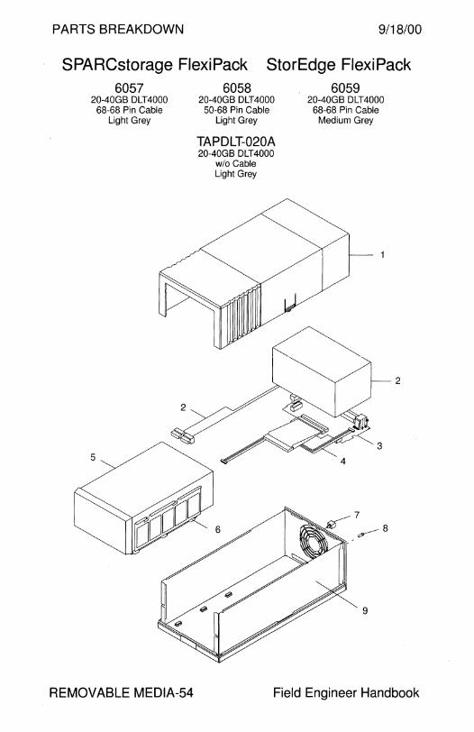
PARTS BREAKDOWN 9/18/00
SPARCstorage FlexiPack StorEdge FlexiPack 6057
20-40GB DLT4000 68-68 Pin Cable
Light Grey
5
REMOVABLE MEDIA-54
6058 20-40GB DLT4000
50-68 Pin Cable Light Grey
TAPDLT-020A 20-40GB DLT4000
wlo Cable Light Grey
6059 20-40GB DLT4000
68-68 Pin Cable Medium Grey
7
,y--- 8
9
2
Field Engineer Handbook
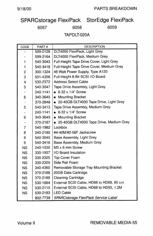
9/18/00 PARTS BREAKDOWN
SPARCstorage FlexiPack StorEdge FlexiPack 6057
CODE PART#
- 599-2128
- 599-2164
1 540-3043
1 540-3418
2 300-1324
3 501-4356
4 530-2372
5 540-3047
- 240-1141
6 340-3645
- 370-2848
5 540-3413
- 240-1141
6 340-3645
- 370-2187
7 540-1982
8 240-2180
9 540-3045
9 540-3416
NS 240-1530
NS 330-1937
NS 330-2325
NS 330-2325
NS 340-4360
NS 370-2188
NS 370-2189
NS 530-1884
NS 530-2115
NS 530-2183
802-7739
Volume II
6058
TAPDLT-020A
DESCRIPTION
DLT4000 FlexiPack, Light Grey
6059
DLT4000 FlexiPack, Medium Grey
Full-Height Tape Drive Cover, Light Grey
Full-Height Tape Drive Cover, Medium Grey
48 Watt Power Supply, Type A 120
Full-Height 8-Bit SCSI 1/0 Board
Address Select Cable
Tape Drive Assembly, Light Grey
• 6-32 x 1 /4" Screw
• Mounting Bracket
• 20-40GB DLT4000 Tape Drive, Light Grey
Tape Drive Assembly, Medium Grey
• 6-32 x 1/4" Screw
• Mounting Bracket
• 20-40GB DLT4000 Tape Drive, Medium Grey
Lockbox
#4-40M/#2-56F Jackscrew
Base Assembly, Light Grey
Base Assembly, Medium Grey
M3 x 6 mm Screw
1/0 Board Insulation
Top Cover Foam
Side Rail Foam
Removable Storage Tray Mounting Bracket
20GB Data Cartridge
Cleaning Cartridge
External SCSI Cable, HD68 to HD68, 80 cm
External SCSI Cable, HD68 to HD50, 1.2M
LED Cable
SPARCstorage FlexiPack Service Label
REMOVABLE MEDIA-55

PARTS BREAKDOWN 9/18/00
SPARCstorage FlexiPack StorEdge FlexiPack
5
6060 35-?0GB DLT?OOO 68-68 Pin Cable
Light Grey
REMOVABLE MEDIA-56
6061 35-?0GB DLT?OOO 50-68 Pin Cable
Light Grey
TAPDLT-021A 35-?0GB DLT?OOO
wlo Cable Light Grey
6062 35-?0GB DLT?OOO 68-68 Pin Cable
Medium Grey
7
~8
9
2
Field Engineer Handbook

9/18/00 PARTS BREAKDOWN
SPARCstorage FlexiPack StorEdge FlexiPack 6060
CODE PART#
- 599-2127
- 599-2165
1 540-3043
1 540-3418
2 300-1324
3 501-4357
4 530-2372
5 540-3046
- 240-1141
6 340-3645
- 370-2847
- 370-3330
5 540-3414
- 240-1141
6 340-3645
- 370-2329
- 370-3331
7 540-1982
8 240-2180
9 540-3045
9 540-3416
NS 240-1530
NS 330-1937
NS 330-2325
NS 330-2325
NS 340-4360
NS 370-2188
NS 370-2189
NS 530-1884
NS 530-2115
NS 530-2183
802-7739
Volume II
6061
TAPDLT-021 A
6062
DESCRIPTION
DLT7000 FlexiPack, Light Grey
DLT?OOO FlexiPack, Medium Grey
Full-Height Tape Drive Cover, Light Grey
Full-Height Tape Drive Cover, Medium Grey
48 Watt Power Supply, Type A 120
Full-Height 16-Bit SCSI 1/0 Board
Address Select Cable DLT7000 Tape Drive Assembly, Light Grey
• 6-32 x 1/4" Screw
• Mounting Bracket
• 35-70GB DLT7000 Tape Drive, Light Grey
• 35-70GB DLT7000 Tape Drive, Light Grey
DLT7000 Tape Drive Assembly, Medium Grey
• 6-32 x 1 /4" Screw
• Mounting Bracket
• 35-70GB DLT7000 Tape Drive, Medium Grey
• 35-70GB DLT7000 Tape Drive, Medium Grey
Lockbox
#4-40M/#2-56F Jackscrew
Base Assembly, Light Grey
Base Assembly, Medium Grey
M3 x 6 mm Screw
1/0 Board Insulation
Top Cover Foam
Side Rail Foam
Removable Storage Tray Mounting Bracket
Data Cartridge
Cleaning Cartridge
External SCSI Cable, HD68 to HD68, 80 cm
External SCSI Cable, HD68 to HD50, 1.2M
LED Cable
SPARCstorage FlexiPack Service Label
REMOVABLE MEDIA-57
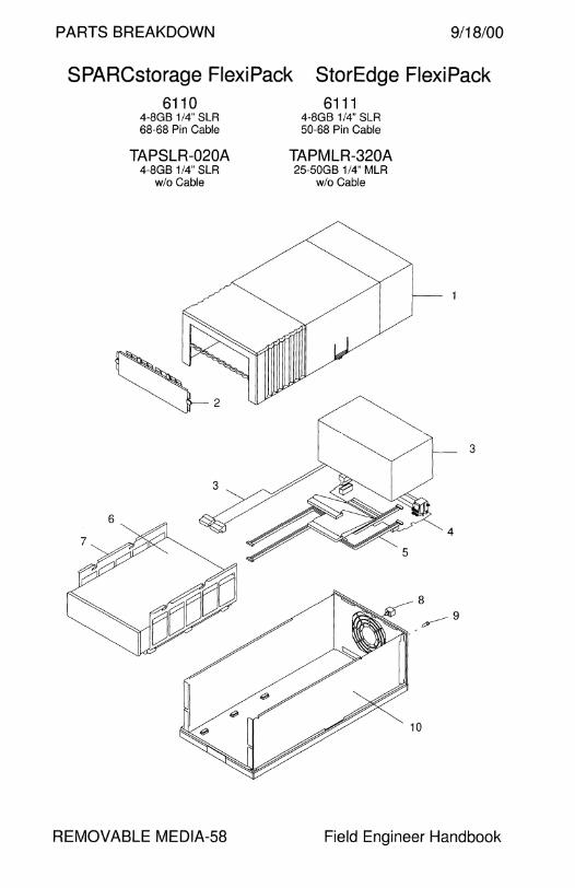
PARTS BREAKDOWN 9/18/00
SPARCstorage FlexiPack StorEdge Flexi Pack 6110
4-8GB 1/4" SLR 68-68 Pin Cable
TAPSLR-020A 4-8GB 1 /4" SLR
w/o Cable
REMOVABLE MEDIA-58
6111 4-8GB 1/4" SLR 50-68 Pin Cable
TAPMLR-320A 25-50GB 1/4" MLR
w/o Cable
3
Field Engineer Handbook

9/18/00 PARTS BREAKDOWN
SPARCstorage FlexiPack 6110
TAPSLR-020A
StorEdge FlexiPack 6111
TAPMLR-320A
CODE PART# DESCRIPTION
- 599-2173 4-8GB 1/4" SLR FlexiPack
- 599-2198 25-50GB 1/4" MLR FlexiPack, Light Grey
1 540-3044 Half-Height Peripheral Cover
2 540-3125 • Half-Height Filler Panel
3 300-1324 48 Watt Power Supply, Type A 120
4 501-4327 Half-Height 16-Bit SCSI 1/0 Board
5 530-2181 SLR Address Select Cable
5 560-2327 MLR Adapter Ship Kit
- 370-2819 • HD50-HD68-Pin Adapter Board
- 530-2354 • Address Cable
6 540-3473 4-8GB 1/4" SLR Tape Drive Assembly
7 340-3645 • Mounting Bracket
- 370-3279 • 4-8GB 1/4" SLR Tape Drive, Light Grey
6 540-3658 25-50GB 1 /4" MLR Tape Drive Assembly, Light Grey
7 340-3645 • Mounting Bracket
- 370-3371 • 25-50GB 1/4" MLR Tape Drive, Light Grey
8 540-1982 Lockbox
9 240-2180 #4-40M/#2-56F Jackscrew
10 540-3045 Base Assembly
NS 240-1530 M3 x 6 mm Screw
NS 340-4312 Adapter Board Mounting Bracket
NS 330-1937 1/0 Board Insulation
NS 370-2819 HD50-HD68-Pin Adapter Board
NS 370-3281 Cleaning Cartridge
NS 370-3282 SLR5 Data Cartridge
NS 370-3373 MLR Data Cartridge
NS 530-1884 External SCSI Cable, HD68 to HD68, 80 cm
NS 530-2115 External SCSI Cable, HD68 to HD50, 1.2M
NS 530-2183 LED Cable
NS 530-2502 SLR Adapter Cable
802-7739 SPARCstorage FlexiPack Service Label
Volume II REMOVABLE MEDIA-59

PARTS BREAKDOWN 9/18/00
SPARCstorage FlexiPack StorEdge FlexiPack 6159
SunCD 12 CD-ROM 68-68 Pin Cable
REMOVABLE MEDIA-60
6160 SunCD 12 CD-ROM
50-68 Pin Cable
6161 SunCD 12 CD-ROM
Expansion Drive
3
Field Engineer Handbook

9/18/00 PARTS BREAKDOWN
SPARCstorage FlexiPack StorEdge FlexiPack 6159 6160 6161
CODE PART# DESCRIPTION
- 599-2127 SunCD 12 FlexiPack
1 540-3044 Half-Height Peripheral Cover
2 540-3125 • Half-Height Filler Panel
3 300-1324 48 Watt Power Supply, Type A 120
4 501-4327 Half-Height SCSI 1/0 Board
5 530-2181 Address Select Cable
6 540-3053 SunCD 12 Drive Assembly
- 240-1530 • M3 x 6 mm Screw (obsolete) - 240-2730 • M3 x 6 mm Screw
7 340-3645 • Mounting Bracket - 370-2816 • 12X CD-ROM Drive, Light Grey
8 540-1982 Lockbox
9 240-2180 #4-40M/#2-56F Jackscrew
10 540-3045 Base Assembly
NS 240-1530 M3 x 6 mm Screw
NS 330-1937 1/0 Board Insulation
NS 370-2819 HD50-HD68-Pin Adapter Board
NS 530-1884 External SCSI Cable, HD68 to HD68, 80 cm
NS 530-2115 External SCSI Cable, HD68 to HD50, 1.2M
NS 530-2183 LED Cable
802-7739 SPARCstorage FlexiPack Service Label
Volume II REMOVABLE MEDIA-61
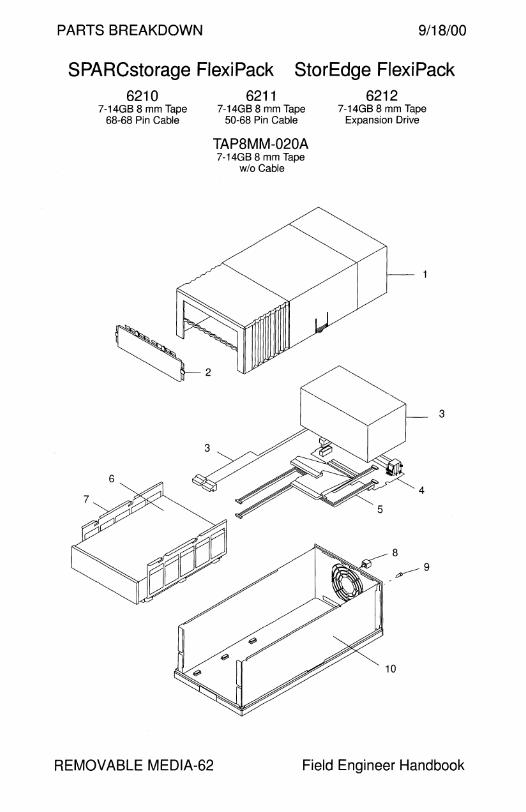
PARTS BREAKDOWN 9/18/00
SPARCstorage FlexiPack StorEdge FlexiPack 6210
7-14GB 8 mm Tape 68-68 Pin Cable
6211 7-14GB 8 mm Tape
50-68 Pin Cable
TAP8MM-020A 7-14GB 8 mm Tape
w/o Cable
6212 7-14GB 8 mm Tape
Expansion Drive
3
REMOVABLE MEDIA-62 Field Engineer Handbook
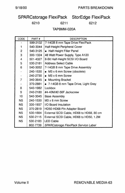
9/18/00 PARTS BREAKDOWN
SPARCstorage FlexiPack StorEdge FlexiPack 6210
CODE PART#
- 599-2132
1 540-3044
2 540-3125
3 300-1324 4 501-4327
5 530-2181
6 540-3052 - 240-1530 - 240-2730
7 340-3645
- 370-2881
8 540-1982
9 240-2180
10 540-3045
NS 240-1530
NS 330-1937
NS 370-2819
NS 530-1884
NS 530-2115
NS 530-2183
802-7739
Volume II
6211
TAP8MM-020A
DESCRIPTION
6212
7-14GB 8 mm Tape Drive FlexiPack
Half-Height Peripheral Cover
• Half-Height Filler Panel 48 Watt Power Supply, Type A 120
8-Bit Half-Height SCSI 1/0 Board
Address Select Cable
7-14GB 8 mm Tape Drive Assembly
• M3 x 6 mm Screw (obsolete)
• M3 x 6 mm Screw • Mounting Bracket
• 7-14GB 8 mm Tape Drive, Light Grey
Lockbox
#4-40M/#2-56F Jackscrew
Base Assembly
M3 x 6 mm Screw
1/0 Board Insulation
HD50-HD68-Pin Adapter Board
External SCSI Cable, HD68 to HD68, 80 cm
External SCSI Cable, HD68 to HD50, 1.2M
LED Cable
SPARCstorage FlexiPack Service Label
REMOVABLE MEDIA-63
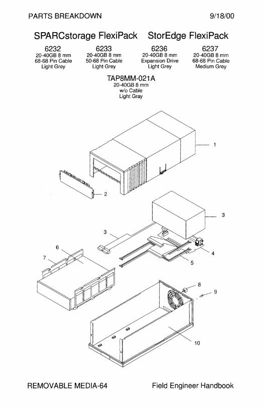
PARTS BREAKDOWN 9/18/00
SPARCstorage FlexiPack StorEdge FlexiPack 6232
20-40GB 8 mm 68-68 Pin Cable
Light Grey
6233 20-40GB8 mm 50-68 Pin Cable
Light Grey
6236 20-40GB 8 mm Expansion Drive
Light Grey
TAPBMM-021 A 20-40GB 8 mm
w/o Cable Light Gray
6237 20-40GB 8 mm 68-68 Pin Cable
Medium Grey
3
REMOVABLE MEDIA-64 Field Engineer Handbook
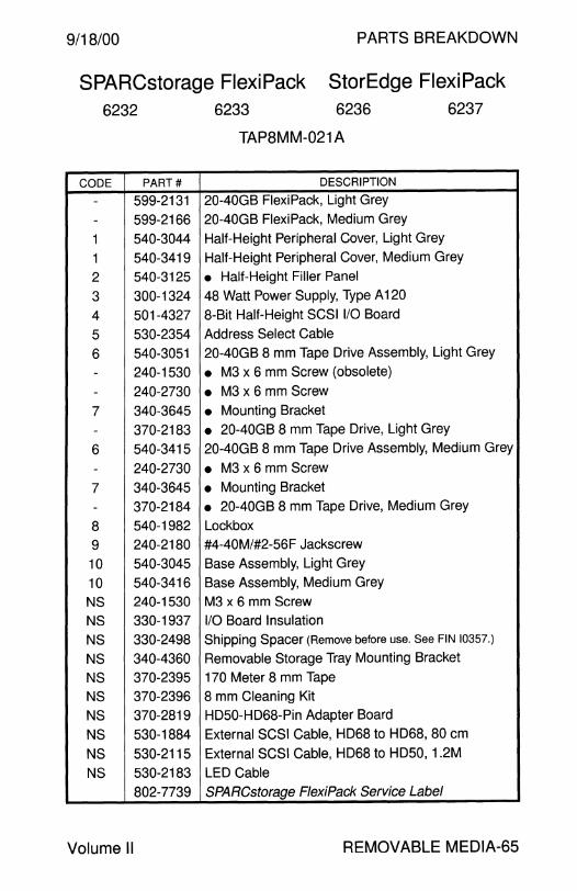
9/18/00 PARTS BREAKDOWN
SPARCstorage FlexiPack StorEdge FlexiPack 6232 6233 6236 6237
TAPBMM-021 A
CODE PART# DESCRIPTION
- 599-2131 20-40GB FlexiPack, Light Grey
- 599-2166 20-40GB FlexiPack, Medium Grey
1 540-3044 Half-Height Peripheral Cover, Light Grey
1 540-3419 Half-Height Peripheral Cover, Medium Grey
2 540-3125 • Half-Height Filler Panel
3 300-1324 48 Watt Power Supply, Type A 120
4 501-4327 8-Bit Half-Height SCSI 1/0 Board
5 530-2354 Address Select Cable
6 540-3051 20-40GB 8 mm Tape Drive Assembly, Light Grey
- 240-1530 • M3 x 6 mm Screw (obsolete)
- 240-2730 • M3 x 6 mm Screw
7 340-3645 • Mounting Bracket
- 370-2183 • 20-40GB 8 mm Tape Drive, Light Grey
6 540-3415 20-40GB 8 mm Tape Drive Assembly, Medium Grey
- 240-2730 • M3 x 6 mm Screw
7 340-3645 • Mounting Bracket
- 370-2184 • 20-40GB 8 mm Tape Drive, Medium Grey
8 540-1982 Lockbox
9 240-2180 #4-40M/#2-56F Jackscrew
10 540-3045 Base Assembly, Light Grey
10 540-3416 Base Assembly, Medium Grey
NS 240-1530 M3 x 6 mm Screw
NS 330-1937 1/0 Board Insulation
NS 330-2498 Shipping Spacer (Remove before use. See FIN 10357.)
NS 340-4360 Removable Storage Tray Mounting Bracket
NS 370-2395 170 Meter 8 mm Tape
NS 370-2396 8 mm Cleaning Kit
NS 370-2819 HD50-HD68-Pin Adapter Board
NS 530-1884 External SCSI Cable, HD68 to HD68, 80 cm
NS 530-2115 External SCSI Cable, HD68 to HD50, 1.2M
NS 530-2183 LED Cable
802-7739 SPARCstorage FlexiPack Service Label
Volume II REMOVABLE MEDIA-65

PARTS BREAKDOWN 9/18/00
SPARCstorage FlexiPack StorEdge FlexiPack 6263
4-8GB 4 mm Tape 68-68 Pin Cable
6264 4-8GB 4 mm Tape 50-68 Pin Cable
6265 4-8GB 4 mm Tape Expansion Drive
TAP4MM-020A
REMOVABLE MEDIA-66
4-8GB 4 mm Tape wlo Cable
3
Field Engineer Handbook
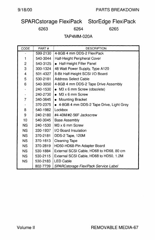
9/18/00 PARTS BREAKDOWN
SPARCstorage FlexiPack StorEdge FlexiPack 6263
CODE PART#
- 599-2130
1 540-3044
2 540-3125
3 300-1324
4 501-4327
5 530-2181
6 540-3050 - 240-1530
- 240-2730
7 340-3645
- 370-2375
8 540-1982
9 240-2180
10 540-3045
NS 240-1530
NS 330-1937
NS 370-2181
NS 370-1613
NS 370-2819
NS 530-1884
NS 530-2115
NS 530-2183
802-7739
Volume II
6264
TAP4MM-020A
DESCRIPTION
4-8GB 4 mm DDS-2 FlexiPack
Half-Height Peripheral Cover
• Half-Height Filler Panel
48 Watt Power Supply, Type A 120
8-Bit Half-Height SCSI 1/0 Board
Address Select Cable
6265
4-8GB 4 mm DDS-2 Tape Drive Assembly
• M3 x 6 mm Screw (obsolete)
• M3 x 6 mm Screw
• Mounting Bracket
• 4-8GB 4 mm DDS-2 Tape Drive, Light Grey
Lockbox
#4-40M/#2-56F Jackscrew
Base Assembly
M3 x 6 mm Screw
1/0 Board Insulation
DDS-2 Tape, 120M
Cleaning Tape
HD50-HD68-Pin Adapter Board
External SCSI Cable, HD68 to HD68, 80 cm
External SCSI Cable, HD68 to HD50, 1.2M
LED Cable
SPARCstorage F/exiPack Service Label
REMOVABLE MEDIA-67

PARTS BREAKDOW 9/18/00
SPARCstorage FlexiPack StorEdge FlexiPack 6284
12-24GB 4 mm Tape 68-68 Pin Cable
REMOVABLE MEDIA-68
6285 12-24GB 4 mm Tape
50-68 Pin Cable
TAP4MM-021 A 12-24GB 4 mmTape
wlo Cable
3
Field Engineer Handbook
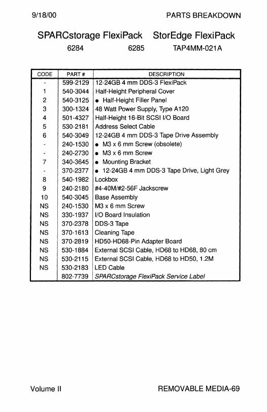
9/18/00 PARTS BREAKDOWN
SPARCstorage FlexiPack StorEdge FlexiPack 6284 6285 TAP4MM-021 A
CODE PART# DESCRIPTION
- 599-2129 12-24GB 4 mm DDS-3 FlexiPack
1 540-3044 Half-Height Peripheral Cover
2 540-3125 • Half-Height Filler Panel
3 300-1324 48 Watt Power Supply, Type A 120
4 501-4327 Half-Height 16-Bit SCSI 1/0 Board
5 530-2181 Address Select Cable
6 540-3049 12-24GB 4 mm DDS-3 Tape Drive Assembly
- 240-1530 • M3 x 6 mm Screw (obsolete)
- 240-2730 • M3 x 6 mm Screw
7 340-3645 • Mounting Bracket
- 370-2377 • 12-24GB 4 mm DDS-3 Tape Drive, Light Grey
8 540-1982 Lockbox
9 240-2180 #4-40M/#2-56F Jackscrew
10 540-3045 Base Assembly
NS 240-1530 M3 x 6 mm Screw
NS 330-1937 1/0 Board Insulation
NS 370-2378 DDS-3 Tape
NS 370-1613 Cleaning Tape
NS 370-2819 HD50-HD68-Pin Adapter Board
NS 530-1884 External SCSI Cable, HD68 to HD68, 80 cm
NS 530-2115 External SCSI Cable, HD68 to HD50, 1.2M
NS 530-2183 LED Cable
802-7739 SPARCstorage FlexiPack Service Label
Volume II REMOVABLE MEDIA-69
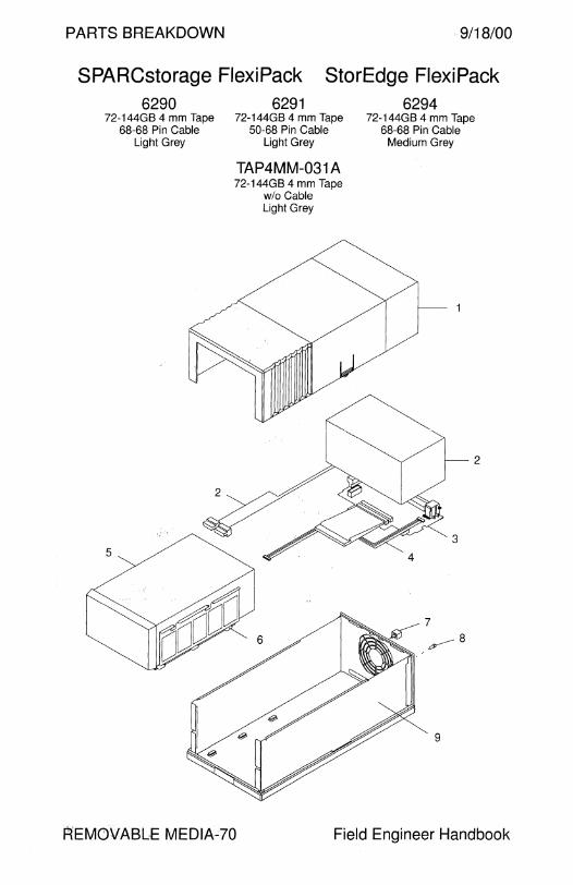
PARTS BREAKDOWN 9/18/00
SPARCstorage FlexiPack StorEdge FlexiPack 6290
72-144GB 4 mm Tape 68-68 Pin Cable
Light Grey
5
2
6291 72-144GB 4 mm Tape
50-68 Pin Cable Light Grey
TAP4MM-031 A 72-144GB 4 mm Tape
w/o Cable Light Grey
6294 72-144GB 4 mm Tape
68-68 Pin Cable Medium Grey
3
7
~8
9
2
REMOVABLE MEDIAc?O Field Engineer Handbook

9/18/00 PARTS BREAKDOWN
SPARCstorage FlexiPack StorEdge FlexiPack 6290
CODE PART#
- 599-2133
- 599-2163
1 540-3043
1 540-3418
2 300-1324
3 501-4356
4 530-2181
5 540-3048
- 240-2660
- 240-2731
6 340-3645
- 370-2380
5 540-3412
- 240-2731
6 340-3645
- 370-2379
7 540-1982
8 240-2180
9 540-3045
9 540-3416
NS 240-1585
NS 330-1937
NS 340-4360
NS 370-2378
NS 370-2381
NS 370-1613
NS 370-2819
NS 530-1884
NS 530-2115
NS 530-2183
802-7739
Volume II
6291
TAP4MM-031 A
DESCRIPTION
DDS-3 FlexiPack, Light Grey
DDS-3 FlexiPack, Medium Grey
6294
Full-Height Tape Drive Cover, Light Grey
Full-Height Tape Drive Cover, Medium Grey
48 Watt Power Supply, Type A 120
8-Bit Full-Height SCSI 1/0 Board
Address Select Cable
72-144GB 4 mm DDS-3 Autoloader Assembly
• M3 x 4 mm Screw (obsolete)
• M3 x 5 mm Screw
• Mounting Bracket
• 72-144GB 4 mm DDS-3 Autoloader, Light Grey
72-144GB 4 mm DDS-3 Autoloader Assembly
• M3 x 5 mm Screw
• Mounting Bracket
• 72-144GB 4 mm DDS-3 Autoloader, Medium Grey
Lockbox
#4-40M/#2-56F Jackscrew
Base Assembly, Light Grey
Base Assembly, Medium Grey
M3 x 4 mm Screw
1/0 Board Insulation Removable Storage Tray Mounting Bracket
DDS-3 Tape
DDS-3 Magazine
Cleaning Tape
HD50-HD68-Pin Adapter Board
External SCSI Cable, HD68 to HD68, 80 cm
External SCSI Cable, HD68 to HD50, 1.2M
LED Cable
SPARCstorage FlexiPack Service Label
REMOVABLE MEDIA-71

This page intentionally left blank.

PARTS BREAKDOWN
TAPE LIBRARY
9/18/00 PARTS BREAKDOWN
Tape Library
SPARCstorage Library Model 8/140 .................................... 2
SPARCstorage Library Model 8/140 .................................... 10 StorEdge L 140 . . . . . . . . . . . . . . . . . . . . . . . . . . . . . . . . . . . . . . . . . . . . . . . . . . . . . . . . . . . . . . . . . . . . . 10
SPARCstorage Library Model 8/400 .................................... 12
StorEdge L400 . . . . . . . . . . . . . . . . . . . . . . . . . . . . . . . . . . . . . . . . . . . . . . . . . . . . . . . . . . . . . . . . . . . . . 14
SPARCstorage DLT4700 ..................................................... 16
StorEdge L280 . . . . . . . . . . . . . . . . . . . . . . . . . . . . . . . . . . . . . . . . . . . . . . . . . . . . . . . . . . . . . . . . . . . . . 17
StorEdge L 1000 . . . . . . . . . . . . . . . . . . . . . . . . . . . . . . . . . . . . . . . . . . . . . . . . . . . . . . . . . . . . . . . . . . . 18
ETL 4/1000 . . . . . . . . . . . . . . . . .. . . . .. .. . . . . . . . . . . . . . . . . . . . . . . . . . . . . . . . . . . . . . . . . . . . . . . . . . . 22
ETL 4/1800 . . . . . . . . . . . . . . . . . . . . . . . . . . . . . . . . . . . . . . . . . . . . . . . . . . . . . . . . . . . . . . . . . . . . . . . . . . . 26 StorEdge L 1800 . . . . . . . . . . . . . . . . . . . . . . . . . . . . . . . . . . . . . . . . . . . . . . . . . . . . . . . . . . . . . . . . . . . 26
ETL 7 /3500 . . . . . . . . . . . . . . . . . . . . . . . . . . . . . . . . . . . . . . . . . . . . . . . . . . . . . . . . . . . . . . . . . . . . . . . . . . . 30 StorEdge L3500 . . . . . . . . . . . . . . . . . . . . . . . . . . . . . . . . . . . . . . . . . . . . . . . . . . . . . . . . . . . . . . . . . . . 30
StorEdge L 11000 . . . . . . . . . . . . . . . . . . . . . . . . . . . . . . . . . . . . . . . . . . . . . . . . . . . . . . . . . . . . . . . . . 34
StorEdge L9 . . . . . . . . . . . . . . . . . . . . . . . . . . . . . . . . . . . . . . . . . . . . . . . . . . . . . . . . . . . . . . . . . . . . . . . . . 37
StorEdge L20 . . . . . . . . . . . . . . . . . . . . . . . . . . .. . . . . . . . . . . . . . . . . . . . . . . . . . . . . . . . . . . . . . . . . . . . 38 StorEdge L40 . . . . . . . . . . . . . . .. .. . . . . . . . . . . . . . . . . . . . . . . . . . . . . . . . . . . . . . . . . . . . . . . . . .. . . . 38 StorEdge L60 . . . . . . . . . . . . . . . . . . . . . . . . . . . . . . . . . . . . . . . . . . . . . . . . . . . . . . . . . . . . . . . . . . . . . . . 38
StorEdge L 180 . . . . . . . . . . . . . . . . . . . . . . . . . . .. . . . . . . . . . . . . . . . . . . . . . . . . . . . . . . . . . . . .. . . . . 40
StorEdge L700 ..................................................................... 41
Field Engineer Handbook - Volume II

PARTS BREAKDOWN 9/18/00
SPARCstorage Library Model 8/140 847 848 849 867 868 869
140-280GB 140-280GB 140-280GB 140-280GB 140-280GB 140-280GB 14GB 8 mm 14GB 8 mm 14GB 8 mm 14GB 8 mm 14GB 8 mm 14GB 8 mm
Deskside Rack Mount Stackable Deskside Rack Mount Stackable Light Grey Light Grey Light Grey Light Grey Light Grey Light Grey
w/o Scanner wlo Scanner w/o Scanner w Scanner w Scanner wScanner
LIBRARY-2 Field Engineer Handbook
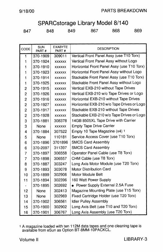
9/18/00 PARTS BREAKDOWN
SPARCstorage Library Model 8/140 847 848 849 867 868 869
CODE SUN EXABYTE DESCRIPTION
PART# PART#
1 370-1909 309011 Vertical Front Panel Assy (use T10 Torx)
1 370-1924 xx xx xx Vertical Front Panel Assy without Logo
1 370-1910 xxxxxx Horizontal Front Panel Assy (use T10 Torx)
1 370-1923 xxxxxx Horizontal Front Panel Assy without Logo
1 370-1914 xxxxxx Stackable Front Panel Assy (use T10 Torx)
1 370-1925 xxxxxx Stackable Front Panel Assy without Logo
2 370-1915 xxxxxx Vertical EXB-210 without Tape Drives
2 370-1926 xxxxxx Vertical EXB-210 w/o Tape Drives or Logo
2 370-1916 xxxxxx Horizontal EXB-210 without Tape Drives
2 370-1927 xxxxxx Horizontal EXB-210 w/o Tape Drives or Logo
2 370-1917 xxxxxx Stackable EXB-210 without Tape Drives
2 370-1928 xxxxxx Stackable EXB-210 w/o Tape Drives or Logo
3 370-1881 308378 14GB 8505XL Tape Drive with Carrier
3 None xxxxxx Empty Tape Drive Carrier
4 370-1884 307522 Empty 10 Tape Magazine (x4) 1
5 None 110181 Service Access Cover (use T10 Torx)
6 370-1896 3701896 SMCS Card Assembly
6 370-2097 311397 SMCS Card Assembly
7 370-1897 306558 Operator Panel Cable (use T8 Torx)
7 370-1898 306557 CHM Cable (use T8 Torx)
8 370-1887 303247 Long Axis Motor Module (use T20 Torx)
9 370-1893 303078 Motor Distribution Card
10 370-1899 302906 Motor Module Belt
11 370-1894 302396 160 Watt Power Supply
- 370-1895 302692 • Power Supply External 2.5A Fuse
12 None 302413 Magazine Mounting Plate (use T15 Torx)
13 None 302969 Fixed Cartridge Holder (use T20 Torx)
14 370-1902 306561 Idler Pulley Assembly
15 370-1900 302902 Long Axis Belt (use T10 and T20 Torx)
16 370-1901 306767 Long Axis Assembly (use T20 Torx)
1 A magazine loaded with ten 112M data tapes and one cleaning tape is available from eSun as Option BT-8MM-10PACKCL.
Volume II LIBRARY-3
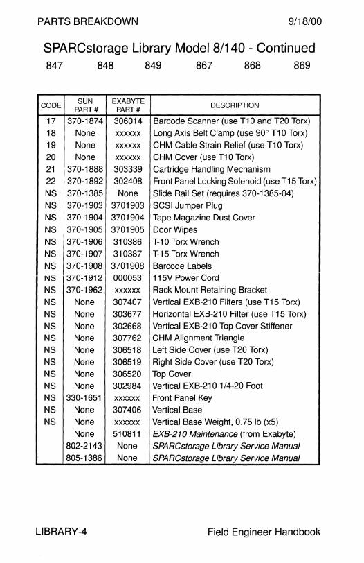
PARTS BREAKDOWN 9/18/00
SPARCstorage Library Model 8/140 - Continued 847 848 849 867 868 869
CODE SUN EXABYTE
DESCRIPTION PART# PART#
17 370-1874 306014 Barcode Scanner (use T10 and T20 Torx)
18 None xxxxxx Long Axis Belt Clamp (use 90° T10 Torx)
19 None xxxxxx CHM Cable Strain Relief (use T10 Torx)
20 None xxxxxx CHM Cover (use T10 Torx)
21 370-1888 303339 Cartridge Handling Mechanism
22 370-1892 302408 Front Panel Locking Solenoid (use T15 Torx)
NS 370-1385 None Slide Rail Set (requires 370-1385-04)
NS 370-1903 3701903 SCSI Jumper Plug
NS 370-1904 3701904 Tape Magazine Dust Cover
NS 370-1905 3701905 Door Wipes
NS 370-1906 310386 T-10 Torx Wrench
NS 370-1907 310387 T-15 Torx Wrench
NS 370-1908 3701908 Barcode Labels
NS 370-1912 000053 115V Power Cord
NS 370-1962 xxxxxx Rack Mount Retaining Bracket
NS None 307407 Vertical EXB-210 Filters (use T15 Torx)
NS None 303677 Horizontal EXB-210 Filter (use T15 Torx)
NS None 302668 Vertical EXB-210 Top Cover Stiffener
NS None 307762 CHM Alignment Triangle
NS None 306518 Left Side Cover (use T20 Torx)
NS None 306519 Right Side Cover (use T20 Torx)
NS None 306520 Top Cover
NS None 302984 Vertical EXB-210 1 /4-20 Foot
NS 330-1651 xxxxxx Front Panel Key
NS None 307406 Vertical Base NS None xxxxxx Vertical Base Weight, 0. 75 lb (x5)
None 510811 EXB-210 Maintenance (from Exabyte)
802-2143 None SPARCstorage Library Service Manual
805-1386 None SPARCstorage Library Service Manual
LIBRARY-4 Field Engineer Handbook

9/18/00 PARTS BREAKDOWN
This page intentionally left blank.
Volume II LIBRARY-5
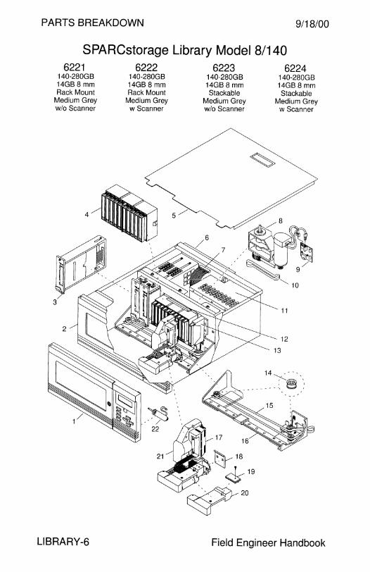
PARTS BREAKDOWN 9/18/00
SPARCstorage Library Model 8/140 6221 6222
140-280GB 140-280GB 14GB 8 mm 14GB 8 mm Rack Mount Rack Mount
Medium Grey Medium Grey w/o Scanner w Scanner
LIBRARY-6
6223 140-280GB 14GB 8 mm Stackable
Medium Grey w/o Scanner
,ty- 18
~19
~20
6224 140-280GB 14GB 8 mm Stackable
Medium Grey w Scanner
14 , , - -'-.., '
'"'(@) , ____ :, ~/
Field Engineer Handbook
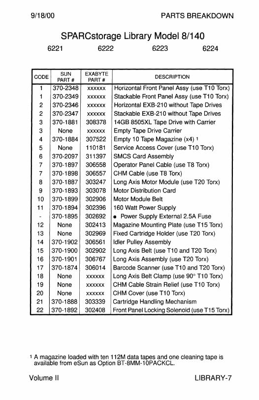
9/18/00 PARTS BREAKDOWN
SPARCstorage Library Model 8/140 6221 6222 6223 6224
CODE SUN EXABYTE DESCRIPTION
PART# PART#
1 370-2348 xxxxxx Horizontal Front Panel Assy (use T10 Torx)
1 370-2349 xxxxxx Stackable Front Panel Assy (use T10 Torx)
2 370-2346 xxxxxx Horizontal EXB-210 without Tape Drives
2 370-2347 xxxxxx Stackable EXB-210 without Tape Drives
3 370-1881 308378 14GB 8505XL Tape Drive with Carrier
3 None xxxxxx Empty Tape Drive Carrier
4 370-1884 307522 Empty 10 Tape Magazine (x4) 1
5 None 110181 Service Access Cover (use T10 Torx)
6 370-2097 311397 SMCS Card Assembly
7 370-1897 306558 Operator Panel Cable (use TB Torx)
7 370-1898 306557 CHM Cable (use T8 Torx)
8 370-1887 303247 Long Axis Motor Module (use T20 Torx)
9 370-1893 303078 Motor Distribution Card
10 370-1899 302906 Motor Module Belt
11 370-1894 302396 160 Watt Power Supply - 370-1895 302692 • Power Supply External 2.5A Fuse
12 None 302413 Magazine Mounting Plate (use T15 Torx)
13 None 302969 Fixed Cartridge Holder (use T20 Torx)
14 370-1902 306561 Idler Pulley Assembly
15 370-1900 302902 Long Axis Belt (use T10 and T20 Torx)
16 370-1901 306767 Long Axis Assembly (use T20 Torx)
17 370-1874 306014 Barcode Scanner (use T10 and T20 Torx) 18 None xxxxxx Long Axis Belt Clamp (use 90° T10 Torx)
19 None xxxxxx CHM Cable Strain Relief (use T10 Torx)
20 None xxxxxx CHM Cover (use T10 Torx)
21 370-1888 303339 Cartridge Handling Mechanism 22 370-1892 302408 Front Panel Locking Solenoid (use T15 Torx)
1 A magazine loaded with ten 112M data tapes and one cleaning tape is available from eSun as Option BT-8MM-10PACKCL.
Volume II LIBRARY-?

PARTS BREAKDOWN 9/18/00
SPARCstorage Library Model 8/140 - Continued 6221 6222 6223 6224
SUN EXABYTE DESCRIPTION
PART# PART#
370-2815 None Slide Rail Set
370-1903 3701903 SCSI Jumper Plug
370-1904 3701904 Tape Magazine Dust Cover 370-1905 3701905 Door Wipes
370-1906 310386 T-10 Torx Wrench
370-1907 310387 T-15 Torx Wrench
370-1908 3701908 Barcode Labels
370-1912 000053 115V Power Cord
370-1962 xxxxxx Rack Mount Retaining Bracket
None 303677 Horizontal EXB-210 Filter (use T15 Torx)
None 307762 CHM Alignment Triangle
None 306518 Left Side Cover (use T20 Torx)
None 306519 Right Side Cover (use T20 Torx) None 306520 Top Cover
330-1651 xxxxxx Front Panel Key
None 510811 EXB-210 Maintenance (available from Exabyte) 802-2143 None SPARCstorage Library Service Manual 805-1386 None SPARCstorage Library Service Manual
LIBRARY-8 Field Engineer Handbook

9/18/00 PARTS BREAKDOWN
This page intentionally left blank.
Volume II LIBRARY-9
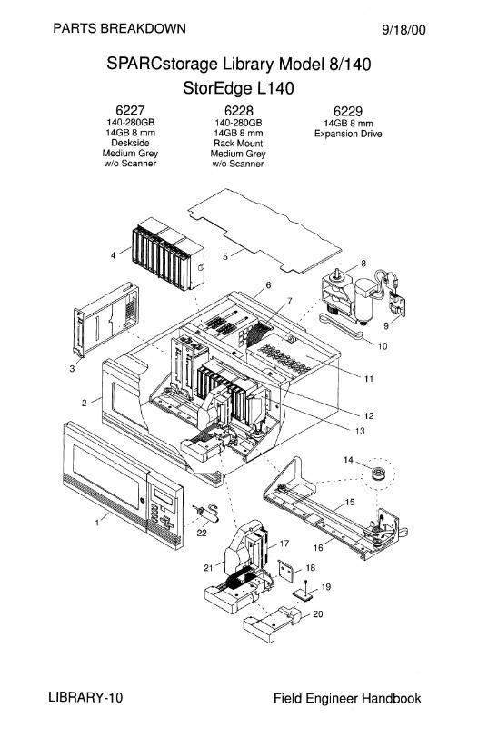
PARTS BREAKDOWN
SPARCstorage Library Model 8/140
StorEdge L 140 6227
140-280GB 14GB 8 mm
Deskside Medium Grey w/o Scanner
6228 140-280GB 14GB 8 mm Rack Mount
Medium Grey w/o Scanner
6229 14GB 8 mm
Expansion Drive
9/18/00
LIBRARY-10 Field Engineer Handbook
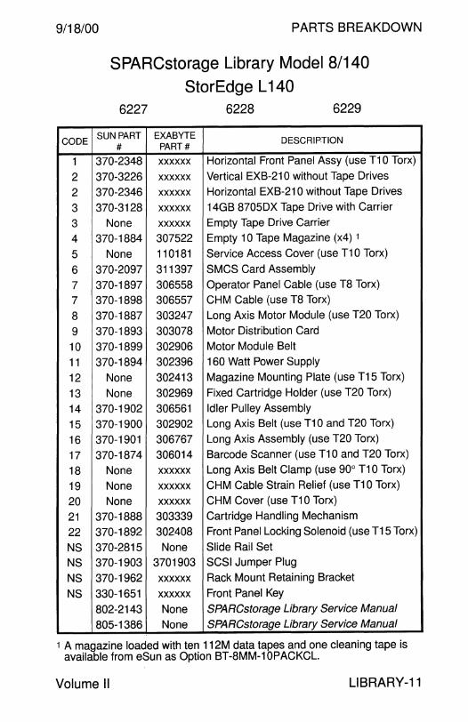
9/18/00 PARTS BREAKDOWN
SPARCstorage Library Model 8/140
StorEdge L 140 6227 6228 6229
CODE SUN PART EXABYTE DESCRIPTION
# PART#
1 370-2348 xxxxxx Horizontal Front Panel Assy (use T10 Torx)
2 370-3226 xxxxxx Vertical EXB-210 without Tape Drives
2 370-2346 xxxxxx Horizontal EXB-210 without Tape Drives
3 370-3128 xxxxxx 14GB 8705DX Tape Drive with Carrier
3 None xxxxxx Empty Tape Drive Carrier
4 370-1884 307522 Empty 10 Tape Magazine (x4) 1
5 None 110181 Service Access Cover (use T10 Torx)
6 370-2097 311397 SMCS Card Assembly
7 370-1897 306558 Operator Panel Cable (use T8 Torx)
7 370-1898 306557 CHM Cable (use T8 Torx)
8 370-1887 303247 Long Axis Motor Module (use T20 Torx)
9 370-1893 303078 Motor Distribution Card
10 370-1899 302906 Motor Module Belt
11 370-1894 302396 160 Watt Power Supply
12 None 302413 Magazine Mounting Plate (use T15 Torx)
13 None 302969 Fixed Cartridge Holder (use T20 Torx)
14 370-1902 306561 Idler Pulley Assembly
15 370-1900 302902 Long Axis Belt (use T10 and T20 Torx)
16 370-1901 306767 Long Axis Assembly (use T20 Torx)
17 370-1874 306014 Barcode Scanner (use T10 and T20 Torx)
18 None xxxxxx Long Axis Belt Clamp (use 90° T10 Torx)
19 None xxxxxx CHM Cable Strain Relief (use T10 Torx)
20 None xxxxxx CHM Cover (use T10 Torx)
21 370-1888 303339 Cartridge Handling Mechanism
22 370-1892 302408 Front Panel Locking Solenoid (use T15 Torx)
NS 370-2815 None Slide Rail Set
NS 370-1903 3701903 SCSI Jumper Plug
NS 370-1962 xxxxxx Rack Mount Retaining Bracket
NS 330-1651 xxxxxx Front Panel Key
802-2143 None SPARCstorage Library Service Manual
805-1386 None SPARCstorage Library Service Manual
1 A magazine loaded with ten 112M data tapes and one cleaning tape is available from eSun as Option BT-8MM-10PACKCL.
Volume II LIBRARY-11
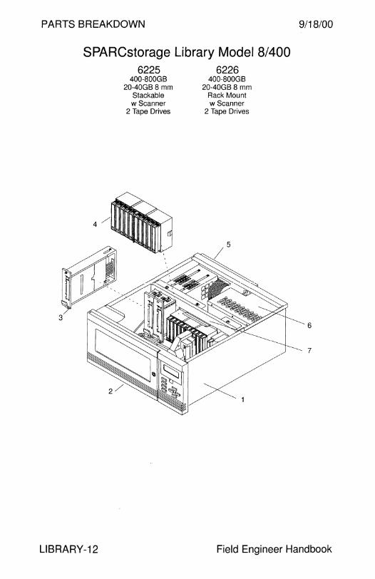
PARTS BREAKDOWN 9/18/00
SPARCstorage Library Model 8/400
LIBRARY-12
6225 400-BOOGB
20-40GB 8 mm Stackable w Scanner
2 Tape Drives
6226 400-BOOGB
20-40GB 8 mm Rack Mount w Scanner
2 Tape Drives
6
7
Field Engineer Handbook
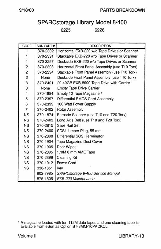
9/18/00 PARTS BREAKDOWN
SPARCstorage Library Model 8/400 6225 6226
CODE SUN PART# DESCRIPTION
1 370-2392 Horizontal EXB-220 w/o Tape Drives or Scanner 1 370-2391 Stackable EXB-220 w/o Tape Drives or Scanner
1 370-3257 Deskside EXB-220 w/o Tape Drives or Scanner
2 370-2393 Horizontal Front Panel Assembly (use T10 Torx)
2 370-2394 Stackable Front Panel Assembly (use T10 Torx)
2 None Deskside Front Panel Assembly (use T10 Torx)
3 370-2401 20-40GB EXB-8900 Tape Drive with Carrier
3 None Empty Tape Drive Carrier
4 370-1884 Empty 10 Tape Magazine 1
5 370-2397 Differential SMCS Card Assembly
6 370-2399 1. 60 Watt Power Supply
7 370-2402 Rotor Assembly
NS 370-1874 Barcode Scanner (use T10 and T20 Torx)
NS 370-2403 Long Axis Belt (use T10 and T20 Torx)
NS 370-2815 Slide Rail Set
NS 370-2400 SCSI Jumper Plug, 55 mm
NS 370-2398 Differential SCSI Terminator
NS 370-1904 Tape Magazine Dust Cover
NS 370-1905 Door Wipes
NS 370-2395 170M 8 mm AME Tape
NS 370-2396 Cleaning Kit
NS 370-1912 Power Cord
NS 330-1651 Key
802-7985 SPARCstorage 81400 Service Manual
875-1805 EXB-220 Maintenance
1 A magazine loaded with ten 112M data tapes and one cleaning tape is available from eSun as Option BT-8MM-10PACKCL.
Volume II LIBRARY-13

PARTS BREAKDOWN
LIB8MM1-400G 400-SOOGB
20-40GB8 mm Deskside
w Scanner 2 Tape Drives
StorEdge L400 LIB8MMB-400G
400-SOOGB 20-40GB 8 mm
Deskside w scanner
1 Tape Drive
9/18/00
LIB8MMC-400G 400-SOOGB
20-40GB 8 mm Rack Mount w Scanner
1 Tape Drive
6
7
LIBRARY-14 Field Engineer Handbook

9/18/00 PARTS BREAKDOWN
StorEdge L400 LIB8MM1-400G LIB8MMB-400G LIB8MMC-400G
CODE SUN PART# DESCRIPTION
1 370-2392 Horizontal EXB-220 w/o Tape Drives or Scanner
1 370-3257 Deskside EXB-220 w/o Tape Drives or Scanner
2 370-2393 Horizontal Front Panel Assembly (use T10 Torx)
2 None Deskside Front Panel Assembly (use T10 Torx)
3 370-2401 20-40GB EXB-8900 Tape Drive with Carrier
3 None Empty Tape Drive Carrier
4 370-1884 Empty 10 Tape Magazine 1
5 370-2397 Differential SMCS Card Assembly
6 370-2399 160 Watt Power Supply
7 370-2402 Rotor Assembly
NS 370-1874 Barcode Scanner (use T10 and T20 Torx)
NS 370-2403 Long Axis Belt (use T10 and T20 Torx)
NS 370-2815 Slide Rail Set
NS 370-2400 SCSI Jumper Plug, 55 mm
NS 370-2398 Differential SCSI Terminator
NS 370-1904 Tape Magazine Dust Cover
NS 370-1905 Door Wipes
NS 370-2395 170M 8 mm AME Tape
NS 370-2396 Cleaning Kit
NS 370-1912 Power Cord
NS 330-1651 Key
802-7985 SPARCstorage 81400 Service Manual
875-1805 EXB-220 Maintenance
1 A magazine loaded with ten 112M data tapes and one cleaning tape is available from eSun as Option BT-8MM-10PACKCL.
Volume II LIBRARY-15

PARTS BREAKDOWN 9/18/00
CODE
1
1
1
1
NS
NS
NS
NS
NS
NS
NS
NS NS
NS
NS
SPARCstorage DLT4700 6071
PART#
540-2781
#540-2781
f540-2781 540-4478
150-1785
180-1179
261-7607
261-7608
370-2188
370-2189
370-2253
370-2254
370-2264
530-1792
530-2115
802-5688
140-280GB Autoloader 20-40GB DLT4000
DESCRIPTION
DLT4700 Tape Library
DLT4700 Tape Library Spare
DLT4700 Tape Library FRU (discontinued)
DLT4700 Tape Library FRU w/o Tape Drive
Terminator
11 OV AC Power Cord
Sun Logo
Nameplate Data Cartridge IV (20GB-40GB DLT4000 Capacity)
Cleaning Cartridge
Key
Seven Tape Magazine 20-40GB DLT4000 Tape Drive
External SCSI Cable, 50-Pin to 50-Pin, 2.0M
External SCSI Cable, 68-Pin to 50-Pin, 1.2M
DLT4700 Installation and User's Guide
LIBRARY-16 Field Engineer Handbook

9/18/00 PARTS BREAKDOWN
CODE
1
1
1
1
1
1
2
3 4
5
6 NS
NS NS
NS
NS
NS NS
NS
NS
NS
NS
NS
StorEdge L280 LIBDLT1-280G
Desktop 280-560GB DLT7000 HP SureStore Autoloader 718
LIBDLT2-280G Rack Mount 280-560GB DLT7000
HP SureStore Autoloader 718
4
3
PART# DESCRIPTION
540-3722 Desktop Autoloader
380-0079 Desktop Autoloader (replaces 540-3722)
540-3725 Rack Mount Autoloader
380-0080 Rack Mount Autoloader (replaces 540-3725)
540-3723 Autoloader without Drive or Skins
380-0081 Autoloader w/o Drive or Skins (replaces 540-3723)
540-3724 Front Door, Medium Grey
370-3425 Tabletop Top Cover, Medium Grey
370-3421 Power Supply with Fan
370-3424 Controller C6280-66510
370-3423 DLT Tape Drive with Fan
150-1890 Differential SCSI Terminator with LED
370-2188 Data Cartridge 370-2189 Cleaning Cartridge
370-3422 6-Tape Magazine
370-3549 Differential SCSI Terminator without LED
370-3554 SCSI Jumper Ribbon Cable, 15 cm
530-2352 SCSI Cable, HD68 to HD68, 4M
530-2384 SCSI Cable, HD68 to HD68, 2M
530-2647 IEC320 - NEMA 5-15 Grey Power Cord
595-4719 Rack Mount Kit, Option X9643A
540-3726 • Rack Mount Kit 370-3630 • Rack Mount Kit (replaces 540-3726)
805-3958 L280 Service Manual
Volume II LIBRARY-17
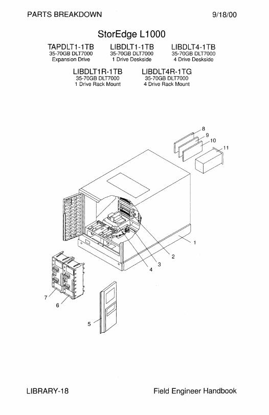
PARTS BREAKDOWN 9/18/00
7
TAPDLT1-1TB 35-?0GB DLT?OOO
Expansion Drive
StorEdge L 1000 LIBDLT1-1 TB 35-?0GB DLT?OOO 1 Drive Deskside
LIBDLT4-1TB 35-?0GB DLT7000 4 Drive Deskside
LIBDLT1 R-1 TB 35-?0GB DLT?OOO
LIBDLT4R-1TG 35-?0GB DLT?OOO 4 Drive Rack Mount 1 Drive Rack Mount
~11
2
6
5
LIBRARY-18 Field Engineer Handbook
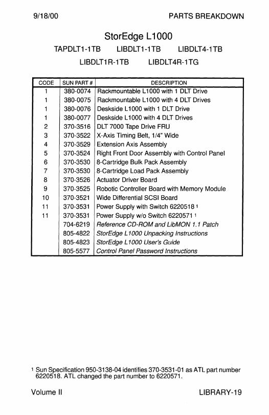
9/18/00 PARTS BREAKDOWN
TAPDLT1-1TB
StorEdge L 1 000 LIBDLT1-1TB LIBDLT4-1TB
LIBDLT1 R-1TB LIBDLT4R-1TG
CODE SUN PART# DESCRIPTION
1 380-0074 Rackmountable L 1000 with 1 DLT Drive
1 380-0075 Rackmountable L 1000 with 4 DLT Drives
1 380-0076 Deskside L 1000 with 1 DLT Drive
1 380-0077 Deskside L 1000 with 4 DLT Drives
2 370-3516 DLT 7000 Tape Drive FRU
3 370-3522 X-Axis Timing Belt, 1/4" Wide
4 370-3529 Extension Axis Assembly
5 370-3524 Right Front Door Assembly with Control Panel
6 370-3530 8-Cartridge Bulk Pack Assembly
7 370-3530 8-Cartridge Load Pack Assembly
8 370-3526 Actuator Driver Board
9 370-3525 Robotic Controller Board with Memory Module
10 370-3521 Wide Differential SCSI Board
11 370-3531 Power Supply with Switch 6220518 1
11 370-3531 Power Supply w/o Switch 6220571 1
704-6219 Reference CD-ROM and UbMON 1. 1 Patch
805-4822 StorEdge L 1000 Unpacking Instructions
805-4823 StorEdge L 1000 User's Guide
805-5577 Control Panel Password Instructions
1 Sun Specification 950-3138-04 identifies 370-3531-01 as ATL part number 6220518. ATL changed the part number to 6220571.
Volume II LIBRARY-19
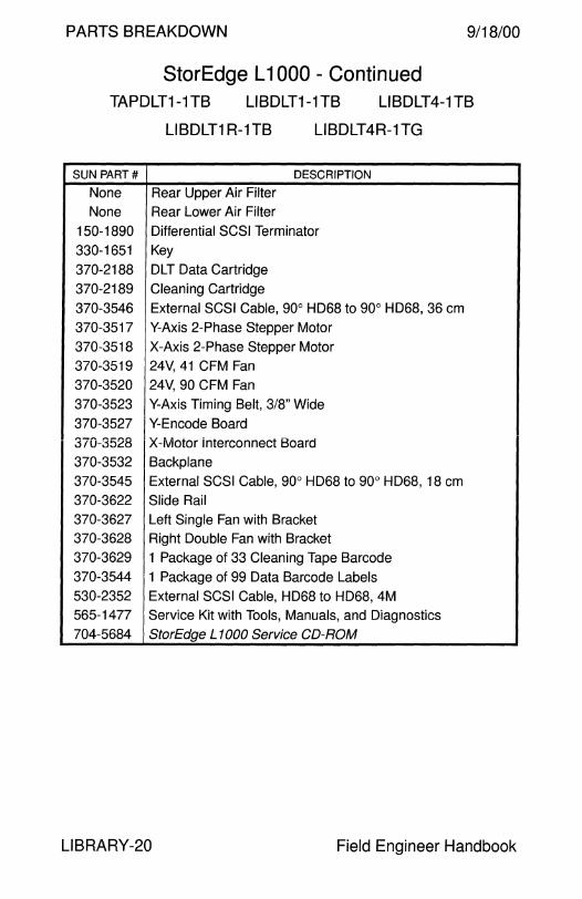
PARTS BREAKDOWN 9/18/00
StorEdge L 1000 - Continued TAPDLT1-1TB LIBDLT1-1TB LIBDLT4-1TB
LIBDLT1R-1TB LIBDLT4R-1TG
SUN PART# DESCRIPTION
None Rear Upper Air Filter
None Rear Lower Air Filter
150-1890 Differential SCSI Terminator
330-1651 Key
370-2188 DLT Data Cartridge
370-2189 Cleaning Cartridge
370-3546 External SCSI Cable, 90° HD68 to 90° HD68, 36 cm
370-3517 Y-Axis 2-Phase Stepper Motor
370-3518 X-Axis 2-Phase Stepper Motor
370-3519 24V, 41 CFM Fan
370-3520 24V, 90 CFM Fan
370-3523 Y-Axis Timing Belt, 3/8" Wide
370-3527 Y-Encode Board
370-3528 X-Motor interconnect Board
370-3532 Backplane
370-3545 External SCSI Cable, 90° HD68 to 90° HD68, 18 cm
370-3622 Slide Rail
370-3627 Left Single Fan with Bracket 370-3628 Right Double Fan with Bracket
370-3629 1 Package of 33 Cleaning Tape Barcode 370-3544 1 Package of 99 Data Barcode Labels 530-2352 External SCSI Cable, HD68 to HD68, 4M 565-1477 Service Kit with Tools, Manuals, and Diagnostics
704-5684 StorEdge L 1000 Service CD-ROM
LIBRARY-20 Field Engineer Handbook

9/18/00 PARTS BREAKDOWN
This page intentionally left blank.
Volume II LIBRARY-21
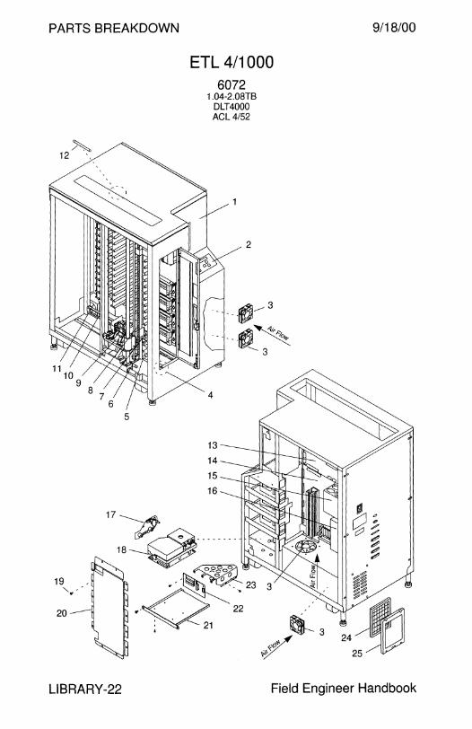
PARTS BREAKDOWN
5
19 " '' .
LIBRARY-22
ETL 4/1000 6072
1.04-2.0BTB DLT4000 AGL 4/52
9/18/00
Field Engineer Handbook
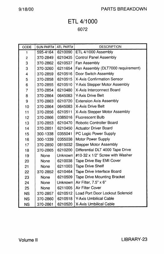
9/18/00
CODE SUN PART#
1 595-4164
2 370-2849
3 370-2862
3 370-3260
4 370-2859
5 370-2858
6 370-2855
7 370-2854
8 370-2864
9 370-2863
10 370-2864
11 370-2856
12 370-2866
13 370-2853
14 370-2851
15 300-1338
16 300-1339
17 370-2850
18 370-2865
19 None
20 None
21 None
22 370-2852
23 None
24 None
25 None
NS 370-2857
NS 370-2860
NS 370-2861
Volume II
PARTS BREAKDOWN
ETL 4/1000 6072
ATL PART# DESCRIPTION
6210090 ETL 4/1000 Assembly
6210435 Control Panel Assembly
6210537 Fan Assembly
6211654 Fan Assembly (DLT7000 requirement)
6210516 Door Switch Assembly
6210515 X-Axis Confirmation Sensor
6210510 Y-Axis Stepper Motor Assembly
6210480 X-Axis Interconnect Board
0645083 Y-Axis Drive Belt
6210720 Extension Axis Assembly
0645083 X-Axis Drive Belt
6210511 X-Axis Stepper Motor Assembly
0385016 Fluorescent Bulb
6210470 Robotic Controller Board
6210450 Actuator Driver Board
0355041 PC Logic Power Supply
0355038 Motor Power Supply
0815032 Stepper Motor Assembly
6210200 Differential DLT 4000 Tape Drive
Unknown #10-32 x 1 /2" Screw with Washer
6210038 Tape Drive Bay EMI Cover
6211003 Tape Drive Shelf
6210464 Tape Drive Interface Board
6210509 Tape Drive Mounting Bracket
Unknown Air Filter, 7.5" x 6"
6211005 Air Filter Cover
6210512 Load Port Door Lockout Solenoid
6210518 Y-Axis Umbilical Cable
6210520 X-Axis Umbilical Cable
LIBRARY-23

PARTS BREAKDOWN 9/18/00
SUN PART#
None None
None
None
None
None None None
None
None None None
None None None None
None None
150-1890 370-2188 370-2189
530-2383 530-2352 565-1395
None None
None 704-5684 875-1807
875-1808
875-1809 875-1810
ETL 4/1000 - Continued 6072
ATL PART# DESCRIPTION
6210526 Actuator Driver to Robotics Controller Cable
6210558 Actuator Driver 48V Power Cable
6210525 Control Panel Cable
6210527 X-Axis Motor Drive Cable
6210538 Fan Power Cable
6210539 Internal 9-Pin RS-232 Cable
6210564 DC "Y" Power Extension Cable
6210561 DC Power Extension Cable
6210565 68-Pin SCSI #1 Cable, 120 cm
6210566 68-Pin SCSI #2 Cable, 60 cm
6210567 68-Pin SCSI #3 Cable, 12 cm
6210573 Miscellaneous Sensor Cable
6210562 Tape Drive Interface 2 Cable
6210563 Tape Drive lnport Solenoid Cable
6210542 White AC Cable
6210542 Black AC Cable
0325004 AC Line Filter
0455175 AC Power Switch
0415692 Differential SCSI Terminator
0525006 Data Cartridge
0525005 Cleaning Cartridge
0425033 External SCSI Cable, HD68 to HD68, 80 cm
0425034 External SCSI Cable, HD68 to HD68, 4M
6210160 Service and Training Kit
6210151 • Training Video 0425003 • Serial Cable 6210150 • Permatex 82324 Lubricant 6211266 • Diagnostic and Manuals CD 6211222 • Operator's Guide 6211221 • Planning and Installation Guide 6211223 • Service Manual 6211224 • Diagnostic Software Manual
LIBRARY-24 Field Engineer Handbook

9/18/00 PARTS BREAKDOWN
This page intentionally left blank.
Volume II LIBRARY-25
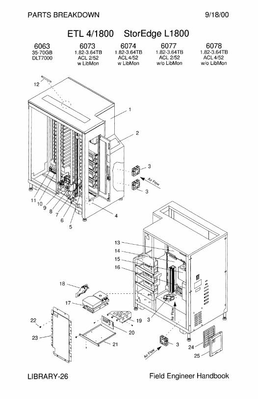
PARTS BREAKDOWN 9/18/00
6063 35-?0GB DLT?OOO
~ 12 '
11 I 10
9 8
23-
7 6
LIBRARY-26
ETL 4/1800 StorEdge L 1800
5
6073 1.82-3.64TB
AGL 2/52 w LibMon
6074 1.82-3.64TB
AGL4/52 w LibMon
13
14
15
16
2
6077 1.82-3.64TB
AGL 2/52 wlo LibMon
6078 1.82-3.64TB
AGL4/52 wlo LibMon
Field Engineer Handbook
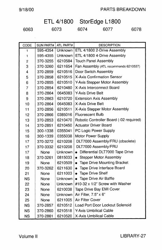
9/18/00 PARTS BREAKDOWN
ETL 4/1800 StorEdge L 1800 6063 6073 6074 6077 6078
CODE SUN PART# ATL PART# DESCRIPTION
1 595-4354 Unknown ETL 4/1800 2-Drive Assembly
1 595-4355 Unknown ETL 4/1800 4-Drive Assembly
2 370-3255 6210584 Touch Panel Assembly
3 370-3260 6211654 Fan Assembly (ATL recommends 6210537)
4 370-2859 6210516 Door Switch Assembly
5 370-2858 6210515 X-Axis Confirmation Sensor
6 370-2855 6210510 Y-Axis Stepper Motor Assembly
7 370-2854 6210480 X-Axis Interconnect Board
8 370-2864 0645083 Y-Axis Drive Belt
9 370-2863 6210720 Extension Axis Assembly
10 370-2864 0645083 X-Axis Drive Belt
11 370-2856 6210511 X-Axis Stepper Motor Assembly
12 370-2866 0385016 Fluorescent Bulb
13 370-2853 6210470 Robotic Controller Board (-02 required)
14 370-2851 6210450 Actuator Driver Board
15 300-1338 0355041 PC Logic Power Supply
16 300-1339 0355038 Motor Power Supply
17 370-3272 6210208 DLT7000 Assembly/FRU (obsolete)
17 370-3332 6210208 DLT7000 Assembly/FRU
17 None Unknown • Differential DLT7000 Tape Drive
18 370-3261 0815033 • Stepper Motor Assembly
19 None 6210509 • Tape Drive Mounting Bracket
20 370-3262 6211630 • Tape Drive Interface Board
21 None 6211003 • Tape Drive Shelf
NS None Unknown • Tape Drive Air Baffle
22 None Unknown #10-32 x 1 /2" Screw with Washer
23 None 6210038 Tape Drive Bay EMI Cover
24 None Unknown Air Filter, 7.5" x 6"
25 None 6211005 Air Filter Cover
NS 370-2857 6210512 Load Port Door Lockout Solenoid
NS 370-2860 6210518 Y-Axis Umbilical Cable
NS 370-2861 6210520 X-Axis Umbilical Cable
Volume II LIBRARY-27
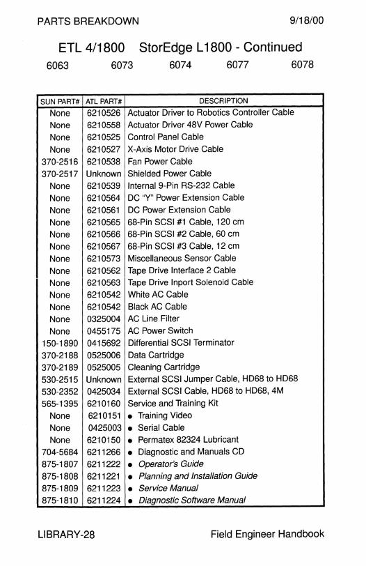
PARTS BREAKDOWN 9/18/00
ETL 4/1800 StorEdge L 1800 - Continued 6063 6073 6074 6077 6078
SUN PART# ATL PART# DESCRIPTION
None 6210526 Actuator Driver to Robotics Controller Cable
None 6210558 Actuator Driver 48V Power Cable
None 6210525 Control Panel Cable
None 6210527 X-Axis Motor Drive Cable
370-2516 6210538 Fan Power Cable
370-2517 Unknown Shielded Power Cable
None 6210539 Internal 9-Pin RS-232 Cable
None 6210564 DC "Y" Power Extension Cable
None 6210561 DC Power Extension Cable
None 6210565 68-Pin SCSI #1 Cable, 120 cm
None 6210566 68-Pin SCSI #2 Cable, 60 cm
None 6210567 68-Pin SCSI #3 Cable, 12 cm
None 6210573 Miscellaneous Sensor Cable
None 6210562 Tape Drive Interface 2 Cable
None 6210563 Tape Drive lnport Solenoid Cable
None 6210542 White AC Cable
None 6210542 Black AC Cable
None 0325004 AC Line Filter
None 0455175 AC Power Switch
150-1890 0415692 Differential SCSI Terminator
370-2188 0525006 Data Cartridge
370-2189 0525005 Cleaning Cartridge
530-2515 Unknown External SCSI Jumper Cable, HD68 to HD68
530-2352 0425034 External SCSI Cable, HD68 to HD68, 4M
565-1395 6210160 Service and Training Kit
None 6210151 • Training Video
None 0425003 • Serial Cable None 6210150 • Permatex 82324 Lubricant
704-5684 6211266 • Diagnostic and Manuals CD
875-1807 6211222 • Operator's Guide
875-1808 6211221 • Planning and Installation Guide 875-1809 6211223 • Service Manual
875-1810 6211224 • Diagnostic Software Manual
LIBRARY-28 Field Engineer Handbook

9/18/00 PARTS BREAKDOWN
This page intentionally left blank.
Volume II LIBRARY-29
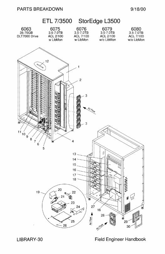
PARTS BREAKDOWN 9/18/00
6063 35-70GB
DLT?OOO Drive
19
LIBRARY-30
ETL 7 /3500 StorEdge L3500
5
6075 3.5-7.0TB AGL 2/100 w LibMon
6076 3.5-7.0TB AGL 7/100 w LibMon
6079 3.5-7.0TB AGL 2/100 wlo LibMon
6080 3.5-7.0TB AGL 7/100 w/o LibMon
Field Engineer Handbook

9/18/00 PARTS BREAKDOWN
ETL 7 /3500 StorEdge L3500 6063 6075 6076 6079 6080
CODE SUN PART# ATL PART# DESCRIPTION
1 595-4444 Unknown ETL7/3500 2-Drive Assembly
1 595-4445 Unknown ETL?/3500 4-Drive Assembly
2 370-3255 6210584 Touch Panel Assembly (-02 required)
3 370-3297 6240516 31.8 CFM Fan Assembly
4 370-2859 6210516 Door Switch Assembly
5 370-2858 6210515 X-Axis Confirmation Sensor
6 370-2855 6210508 Y-Axis Stepper Motor Assembly
7 370-2854 6210480 X-Axis Interconnect Board
8 370-3305 0645115 Y-Axis Drive Belt, 188"
9 370-2863 6210720 Extension Axis Assembly (-02 required)
10 370-3304 0645116 X-Axis Drive Belt, 240"
11 370-2856 6210511 X-Axis Stepper Motor Assembly
12 370-2866 0385016 Fluorescent Bulb
13 370-3299 6240330 Tape Drive Distribution Board
14 370-3295 6210470 Robotic Controller Board
15 370-2851 6210450 Actuator Driver Board
16 300-1338 0355041 PC Logic Power Supply
17 370-3298 6240320 Tape Drive Multiplexor Board
18 300-1339 0355038 Motor Power Supply
19 370-3272 6210208 DLT7000 Assy/FRU (-02 required) (obs)
19 370-3332 tbd DLT7000 Assembly/FRU
20 None Unknown • Tape Drive Fan Shield
21 370-3261 0815033 • Stepper Motor Assembly
22 370-3262 6211630 • Tape Drive Interface Board
23 None Unknown • Differential DLT7000 Tape Drive
24 None Unknown • Tape Drive Mounting Bracket
25 None Unknown • Tape Drive Shelf
26 None Unknown • #10-32 x 1 /2" Screw with Washer
- None Unknown • Internal SCSI Cable
27 370-3297 6240516 Controller Electronics Assembly Fan
28 370-3296 6240515 108 CFM Fan (ATL recommends 6210537)
29 None Unknown Air Filter, 7.5" x 6"
30 None 6211005 Air Filter Cover
Volume II LIBRARY-31

PARTS BREAKDOWN 9/18/00
ETL 7/3500 StorEdge L3500 - Continued 6063 6075 6076 6079 6080
SUN PART# ATL PART# DESCRIPTION
150-1890 0415692 Differential SCSI Terminator 370-2857 6210512 Load Port Door Lockout Solenoid
370-2860 6210518 Y-Axis Umbilical Cable
370-2188 0525006 Data Cartridge
370-2189 0525005 Cleaning Cartridge
370-3300 6210520 X-Axis Umbilical Cable
530-2352 0425034 External SCSI Cable, HD68 to HD68, 4M
530-2515 Unknown External SCSI Jumper Cable, HD68 to HD68
565-1395 6210160 Service and Training Kit
None 6210151 • Training Video None 0425003 • Serial Cable None 6210150 • Permatex 82324 Lubricant
704-5684 6211266 • Diagnostic and Manuals CD 875-xxxx 62112xx • ETL 411000 Installation and Service Manuals 875-xxxx 62112xx • ETL 411800 Installation and Service Manuals
805-1034 Unknown • ETL 713500 Facilities Planning and Installation
805-1035 Unknown • ETL 713500 Operator's Guide
805-1036 Unknown • ETL 713500 Diagnostic Software Guide 805-1037 Unknown • ETL 713500 Software Interface Guide
805-1038 Unknown • ETL 713500 Service Manual
LIBRARY-32 Field Engineer Handbook

9/18/00 PARTS BREAKDOWN
This page intentionally left blank.
Volume II LIBRARY-33

PARTS BREAKDOWN 9/18/00
StorEdge L 11 000
10
TAPDLT2-11TB 35-?0GB DLT7000
Expansion Drive
~ro 8
LIBRARY-34
LIBDLT4-11TB 35-?0GB DLT?OOO
4 Drive Cabinet
LIBDLT16-11TB 35-?0GB DLT?OOO 16 Drive Cabinet
Field Engineer Handbook

9/18/00 PARTS BREAKDOWN
StorEdge L 11 000 TAPDLT2-11TB LIBDLT4-11TB LIBDLT16-11TB
CODE SUN PART# DESCRIPTION
1 380-0217 L 11000 with 4 DLT Drive
1 380-0218 L 11000 with 16 DLT Drives
2 None DC-DC Converter 6310495
3 370-3733 Backplane
4 370-3731 Actuator Driver #1 (service manual lists these boards as identical)
5 370-3730 Actuator Driver #0 (service manual lists these boards as identical)
6 370-3728 Robotics Controller Board with Memory
- None • Memory Module 6220349
7 370-3732 Differential SCSI Board
8 370-3726 AC Power Distribution Assembly (up to 2)
9 370-3725 Power Supply Rack Assembly
10 370-3724 400 Watt Power Supply (up to 8)
11 370-3723 DLT 7000 Tape Drive FRU (up to 16)
12 370-3727 Fan Module (x3)
NS 370-3729 US Power Cord
NS 370-3734 Control Panel Assembly
NS 370-3735 Extension Axis Assembly
NS 370-3736 X-Axis and Y-Axis Stepper Motor
NS 370-3737 Rotary Axis Stepper Motor
NS 370-3738 X-Axis Interconnect Board
NS 370-3739 Y-Axis Interconnect Board
NS 370-3740 Rotary Axis Sensor Board
NS 370-3741 Motor Power Converter (listed as DC-DC Converter in service manual)
NS 370-3742 Left Drive Tray Board (replaced by 375-0108)
NS 370-3743 Right Drive Tray Board (replaced by 375-0106)
NS 370-3744 Left Drive Sideboard Board (replaced by 375-0109)
NS 370-3745 Right Drive Sideboard Board (replaced by 375-0107)
NS 370-3746 Y-Axis Belt, 1" Wide x 3/8" Pitch
NS 370-3747 X-Axis Belt, 1" Wide x 3/8" Pitch
NS 375-0106 Right Drive Tray Board (replaces 370-3743)
NS 375-0107 Right Drive Sideboard Board (replaces 370-3745)
NS 375-0108 Left Drive Tray Board (replaces 370-3742)
NS 375-0109 Left Drive Sideboard Board (replaces 370-37 44)
Volume II LIBRARY-35

PARTS BREAKDOWN 9/18/00
StorEdge L 11000 - Continued TAPDLT2-11TB LIBDLT4-11TB LIBDLT16-11TB
CODE SUN PART# DESCRIPTION
NS 150-1890 Differential SCSI Terminator
NS 330-1651 Key
NS 370-2188 DLT Data Cartridge
NS 370-2189 Cleaning Cartridge
NS 370-3544 4 Packages of 99 Data Barcode Labels
NS 370-3629 1 Package of 33 Cleaning Tape Barcode
NS 370-3729 IEC320-C19 to NEMA 5-20 AC Power Cord
NS 370-4185 Left Drive Board Kit, 375-0108 + 375-0109 1 2
NS 370-4186 Right Drive Board Kit, 375-0106 + 375-0107 1 2
NS None 5/32" Hex Wrench for Rear Doors (not included) NS None International AC Power Cords
NS None Internal Cables
NS None Internal SCSI Cable 0425017, HD68 to HD68, 1 M
NS 530-2352 External SCSI Cable, HD68 to HD68, 4M NS 565-1540 Service Kit with Tools, Manuals, and Diagnostics
704-6526 StorEdge L 11000 Reference CD-ROM
704-6527 StorEdge L 11000 Service CD-ROM
805-5577 Control Panel Password Instructions
805-7275 StorEdge L 11000 User's Guide
805-7276 StorEdge L 11000 Service Manual
805-7277 StorEdge L 11000 Unpacking Instructions
805-7278 StorEdge L 11000 Uncrating Instructions
1 New Drive Tray Boards are not compatible with old Drive Sideboard Boards. 2 New Drive Sideboard Boards are not compatible with old Drive Tray Boards.
LIBRARY-36 Field Engineer Handbook
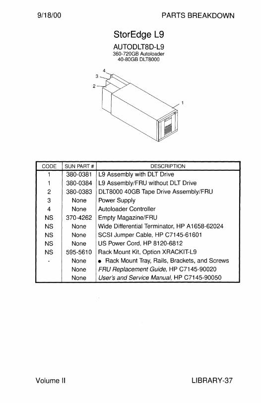
9/18/00
2
CODE SUN PART#
1 380-0381
1 380-0384
2 380-0383
3 None
4 None
NS 370-4262
NS None
NS None
NS None
NS 595-5610 - None
None None
Volume II
PARTS BREAKDOWN
4
StorEdge L9 AUTODLT8D-L9 360-720GB Autoloader
40-SOGB DLT8000
DESCRIPTION
L9 Assembly with DLT Drive
L9 Assembly/FRU without DLT Drive
DLT8000 40GB Tape Drive Assembly/FRU
Power Supply
Autoloader Controller
Empty Magazine/FRU
Wide Differential Terminator, HP A 1658-62024
SCSI Jumper Cable, HP C7145-61601
US Power Cord, HP 8120-6812
Rack Mount Kit, Option XRACKIT-L9
• Rack Mount Tray, Rails, Brackets, and Screws
FRU Replacement Guide, HP C7145-90020 User's and Service Manual, HP C7145-90050
LIBRARY-37

PARTS BREAKDOWN 9/18/00
StorEdge L20 StorEdge L40 StorEdge L60 TAPDLT7-L20 LIBDLT71-L20 LIBDLT71 R-L20 35-?0GB DLT?OOO 700GB-1.4TB Library 700GB-1.4TB Library
Expansion Drive 1 Drive 20 Slots 1 Drive 20 Slots Deskside Option Rackmount Option
LIBDLT72-L20 LIBDLT72-L40 LIBDLT72R-L20 700GB-1.4TB Library 1.4TB-2.8TB Library 700GB-1.4TB Library
2 Drives 20 Slots 2 Drives 40 Slots 2 Drives 20 Slots Deskside Option Deskside Option Rackmount Option
LIBDLT72R-L40 1.4TB-2.8TB Library
2 Drives 40 Slots Rackmount Option
LIBDLT74R-L60 2.1TB-4.2TB Library
4 Drive 60 Slots Rackmount Option
LIBRARY-38 Field Engineer Handbook
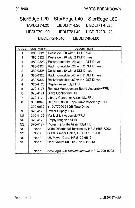
9/18/00 PARTS BREAKDOWN
StorEdge L20 StorEdge L40 StorEdge L60 TAPDLT7-L20 LIBDLT71-L20 LIBDLT71 R-L20
LIBDLT72-L20 LIBDLT72-L40 LIBDLT72R-L20
LIBDLT72R-L40 LIBDLT74R-L60
CODE SUN PART# DESCRIPTION
1 380-0321 Deskside L20 with 1 DLT Drive
1 380-0322 Deskside L20 with 2 DLT Drives
1 380-0323 Rackmountable L20 with 1 DLT Drive
1 380-0324 Rackmountable L20 with 2 DLT Drives
2 380-0325 Deskside L40 with 2 DLT Drives
2 380-0326 Rackmountable L40 with 2 DLT Drives
3 380-0327 Rackmountable L60 with 4 DLT Drives
4 370-4176 Display Assembly/FRU
5 370-4175 Remote Management Board Assembly/FRU
6 370-4171 Slave Controller/FRU
7 370-4174 Library Controller Assembly/FRU
8 380-0346 DLT7000 35GB Tape Drive Assembly/FRU
- 390-0032 • DLT7000 35GB Tape Drive
9 370-4178 Power Supply/FRU
NS 370-4172 Vertical Lift Assembly/FRU
NS 370-4173 Empty Magazine/FRU
NS 370-4177 Picker Translate Assembly/FRU
NS None Wide Differential Terminator, HP A 1658-62024
NS None SCSI Jumper Cable, HP C7210-61600
NS None US Power Cord, HP 8120-6812
NS None Rack Mount Kit, HP C7200-67913
None StorEdge L20 Service Manual, HP C7200-90031
Volume II LIBRARY-39

PARTS BREAKDOWN
SUN PART#
595-5626
380-0385
595-5657
380-0390
595-5265
380-0315
595-5266 380-0316
595-5267
370-4032
595-5268
370-4033
595-5292
370-4034
595-5265
380-0328
390-0049
StorEdge L 180 XLIBL 180-BASE
DESCRIPTION
Base, Option SG-XLIBL 180-BASE
• L180 Base
96 Cartridge Upgrade, Option SG-XTXP1OOA-L180
• L 180 Cartridge Upgrade
Tape Drive, Option SG-XLIB9840-DRV
• 9840 20GB Tape Drive Assembly
Starter Kit, Option SG-XMED9840-STR
• Media Starter Kit
Media, Option SG-XMED9840-20
• 9840 Media 20 Pack
Cleaning Cartridge, Option SG-XMED9840CL-5
• 9840 Cleaning Cartridge 5 Pack
Media Magazine, Option SG-XMEDCART-1 MA
• 9840 Media Magazine
Tape Drive, Option SG-XTAPDLT7-DRV
• DLT7000 35GB Tape Drive Assembly
• DLT7000 35GB Tape Drive
Note: There are no Sun FRU part numbers for the L 180.
9/18/00
LIBRARY-40 Field Engineer Handbook
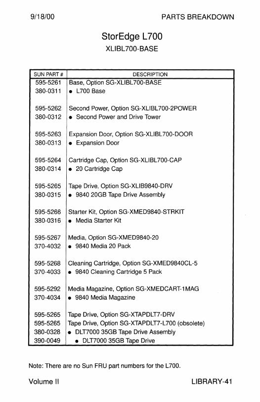
9/18/00
SUN PART#
595-5261
380-0311
595-5262
380-0312
595-5263
380-0313
595-5264
380-0314
595-5265
380-0315
595-5266
380-0316
595-5267
370-4032
595-5268
370-4033
595-5292
370-4034
595-5265
595-5265
380-0328
390-0049
PARTS BREAKDOWN
StorEdge L 700 XLIBL700-BASE
DESCRIPTION
Base, Option SG-XLIBL700-BASE
• L700 Base
Second Power, Option SG-XLIBL700-2POWER
• Second Power and Drive Tower
Expansion Door, Option SG-XLIBL700-DOOR
• Expansion Door
Cartridge Cap, Option SG-XLIBL700-CAP
• 20 Cartridge Cap
Tape Drive, Option SG-XLIB9840-DRV
• 9840 20GB Tape Drive Assembly
Starter Kit, Option SG-XMED9840-STRKIT
• Media Starter Kit
Media, Option SG-XMED9840-20
• 9840 Media 20 Pack
Cleaning Cartridge, Option SG-XMED9840CL-5
• 9840 Cleaning Cartridge 5 Pack
Media Magazine, Option SG-XMEDCART-1 MAG
• 9840 Media Magazine
Tape Drive, Option SG-XTAPDLT7-DRV
Tape Drive, Option SG-XTAPDLT7-L700 (obsolete)
• DLT7000 35GB Tape Drive Assembly
• DLT7000 35GB Tape Drive
Note: There are no Sun FRU part numbers for the L700.
Volume II LIBRARY-41

This page intentionally left blank.

PARTS BREAKDOWN
MISCELLANEOUS
9/18/00 PARTS BREAKDOWN
Miscellaneous
56-inch Expansion Cabinet . ...... .. .... .. .. . .. .. . ... ..... .. . .. .. .. ... .. . .. . . 4 56-inch Enterprise Expansion Cabinet ... ...... .. .. . .... .. ... ..... ... .. 6 68-inch Enterprise Expansion Cabinet.................................. 8 72-inch StorEdge Expansion Cabinet ... ..... .. ..... .. .. .. .. ... . .. .. . ... 10
E4x00 SSA SPARCstorage Library Caster Base . . . . . . . . . . . . . . . . . . . . . . . . . . . .. . . .. . . .. . . . . . . . . . . . . . . . . . .. . . . . . . . . . . . . . . . 12 Locking Module ................................................................. 12
SS 1 000 Tow er Stand . . . . . . . . . . . . . . . . . .. . . . . . . . . . . . . . . . . . . . . . . . . . . . . . . . . . . . . . . . . 13
SS1000 and SPARCstorage Array Locking Module ... .. ... .. .. .. .. .... .. .. .. .. .. .. . ... .. .. .. .. . .. .. . .... .. . .. .. . .. . 14 Stacking Unit .. . . . .. . .. . . . .... ... .. .. .. .. . . . . ... . . . .. .......... ... .. .. ... .. .. . . .. . 14 56-inch Cabinet Rack Mount Kit . .. .. . . . . .. .. .. .. .. . .. .. .. ........ .. . .. . 15 56-inch Cabinet Rack Mount Kit .. . .. .. ... .. .... .. ... .. .. . .. . . . .. .. . .. . . 16 56-inch Cabinet Blower . . . . . . . . . . . . . . . . .. . . . .. . . . . . . . . . . . . . . .. . . . . . . . . . . . . . . 16
E3x00 Floor Mount Brackets .. .. .. ... .. .. .. . ..... .... ... .... .. ..... .. ... ... . 17 E5x00 and E6x00 Floor Mount Brackets .. .... .. ... .. .. . ... . .. . .. .. . .. 17 StorEdge A1000 and 01000 Tower Stand ........................... 17
E4000 and E4500 56-inch Cabinet Rack Mount Kit . . ..... .. .. .. .. .. .. . .......... .. .. .. . .. . 18 Air Baffle ..... .. ... .... .. ... .. .. ... .. .. ... .... .. .. .. . . ... . .. .. .. . .. .. .... ... .. .. . ... . 18 68-inch Cabinet Rack Mount Kit .. .. . .. . .... . ... .. ... .. .. . .. . . ... .. .. . .. 18
68-inch Enterprise Expansion Cabinet Second Power Sequencer .. .. .. ... .. . . . .. . .. .. . .... .... .. . .. .. .. . ... ... . .. 19 Second Power Sequencer Rack Mount Kit . . .... . .. . . .. ... .. . . . . . 19
FlexiPack Removable Storage Tray ..................................... 19
FC-AL Hub Rack Mount Kit ... ... .... ... .. ... . .. .. .. .. .. . .. ... .... .. . .. ... ... 20 FC-AL Switch . . . . . . . . . . . . . . . .. . . . . . . . . . . . . . . . . . . . . . . . . . . . . . . . . . . .. . . . . . . . . . . . . . . . . . . 20
StorEdge A5x00 68-inch Cabinet Air Baffle Kit .. ..... .. ... . ... . .. .. .. . .. .. .... . .. .. .. . . . . . 21 68-inch Cabinet EMI Kit ..................................................... 21
Field Engineer Handbook - Volume II
PARTS BREAKDOWN 9/18/00
Miscellaneous Options - Continued
StorEdge A5x00 56-inch Cabinet Rack Mount Kit .. .... .. ..... .. . .... ..... ..... .. ... ... .. 22
StorEdge A 1000 and D1000 Rack Mount Kit ....................... 22
StorEdge A5x00 68-inch Cabinet Rack Mount Kit ........................................ 23 72-inch Cabinet Rack Mount Kit . .. .. .. .. . .. . ... .. .. ..... .. . . ...... .. .. . 23
E4500 and E5500 Air Baffle Kit . . . . . . . . . . . . . . . . . . . . . . . . . . . . . . . . . . . . . . . . . . . . 24
E4000 and E4500 72-inch Cabinet Rack Mount Kit .. .. .. .. ... .. . .. ....... .... .... .. . . .. . .. 24 72-inch Cabinet Air Baffle Kit .. .... .... .. . .. .. .. . . . . .. .. .. .. .. . . .. .. .. . . . . 24
Ultra 30/60/80 72-inch Cabinet Rack Mount Kit . . .. .. .. .. .. . .. . .. .. .. .. .. .. . ... .. .. .. . . 25
Ultra Enterprise 450 Rack Mount Kit .................................... 25
Enterprise 250 Deskside to Rack Mount Kit .... .. . .. .. .. .. . .. .. .. . .. .. ... .. .. . . .. .... .. .. 26 Rack Mount to Deskside Kit . . .. . . .. .. .. .. .. .. ... . .... .. . . . ... . .. .. . . .. .. . 26
72-inch StorEdge Expansion Cabinet Front Door Kit . .. . . . .. . . . . .. .. ... .. ... ..... .. .. .. .. ...... .. .. .. .. ...... .. .. . . .. .. . 27 Cabinet Cooling Kit .. .. .. . ..... ...... .. ....... .. .. .. . .. ... . ... .. ... . ... .. .. .. . . 27
SB us Expansion Subsystem . . . .. . . . . . . . . . . . . . .. . . . . . . . . . . .. . . . . . . . .. . . . . . . . 28
Sunscreen SPF-100 . .. .. .. .... ... .. ... .... .. .. .. . . . .. ... .. . ... . .. ... .. .. ... .. .. . 30
Sunscreen SPF-100G .......................................................... 31
JavaStation JJ . . . . . . . . . . . . . . . . . . . . . . . . . . . . . . . . . . . . . . . . . . . . . . . . . . . . . . . . . . . . . . . . . . . . . . 32
JavaStation JK ...................................................................... 33
Sun Ray 1 ............................................................................. 34
Sun Ray 100 ......................................................................... 35
Sun Ray 150 ......................................................................... 36
MI SC ELLAN EOUS-2 Field Engineer Handbook

9/18/00 PARTS BREAKDOWN
This page intentionally left blank.
Volume II MISCELLANEOUS-3

PARTS BREAKDOWN 9/18/00
56-inch Expansion Cabinet
3
Rear View
MISCELLANEOUS-4
I 1a 19
955
23
~--22 24
13
Field Engineer Handbook
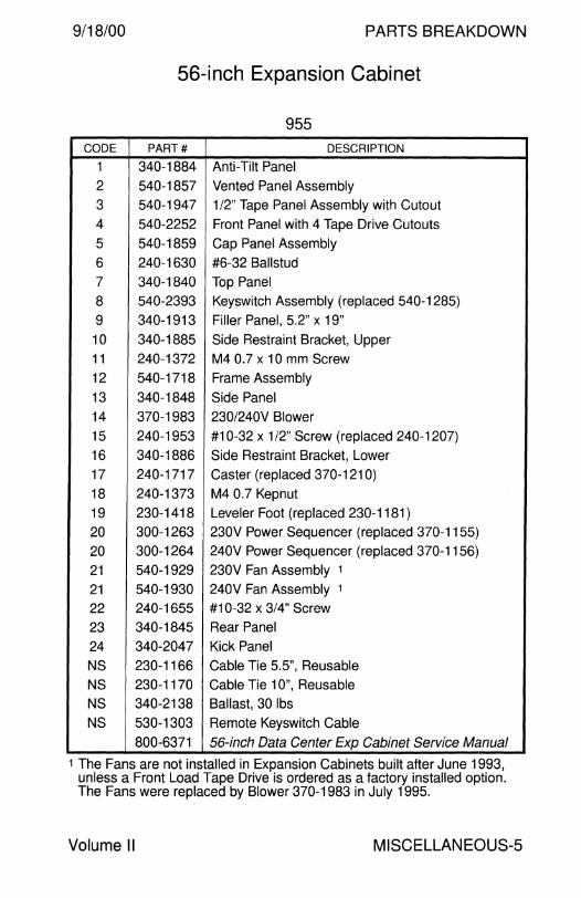
9/18/00 PARTS BREAKDOWN
56-inch Expansion Cabinet
955
CODE PART# DESCRIPTION
1 340-1884 Anti-Tilt Panel
2 540-1857 Vented Panel Assembly
3 540-1947 1/2" Tape Panel Assembly with Cutout
4 540-2252 Front Panel with 4 Tape Drive Cutouts
5 540-1859 Cap Panel Assembly
6 240-1630 #6-32 Ballstud
7 340-1840 Top Panel
8 540-2393 Keyswitch Assembly (replaced 540-1285)
9 340-1913 Filler Panel, 5.2" x 19"
10 340-1885 Side Restraint Bracket, Upper
11 240-1372 M4 0.7 x 10 mm Screw
12 540-1718 Frame Assembly
13 340-1848 Side Panel
14 370-1983 230/240V Blower
15 240-1953 #10-32 x 1/2" Screw (replaced 240-1207)
16 340-1886 Side Restraint Bracket, Lower
17 240-1717 Caster (replaced 370-1210)
18 240-1373 M4 0.7 Kepnut
19 230-1418 Leveler Foot (replaced 230-1181 )
20 300-1263 230V Power Sequencer (replaced 370-1155)
20 300-1264 240V Power Sequencer (replaced 370-1156)
21 540-1929 230V Fan Assembly 1
21 540-1930 240V Fan Assembly 1
22 240-1655 #10-32 x 3/4" Screw
23 340-1845 Rear Panel
24 340-2047 Kick Panel
NS 230-1166 Cable Tie 5.5", Reusable
NS 230-1170 Cable Tie 1 O", Reusable
NS 340-2138 Ballast, 30 lbs
NS 530-1303 Remote Keyswitch Cable
800-6371 56-inch Data Center Exp Cabinet Service Manual
1 The Fans are not installed in Expansion Cabinets built after June 1993, unless a Front Load Tape Drive is ordered as a factory installed option. The Fans were replaced by Blower 370-1983 in July 1995.
Volume II MISCELLANEOUS-5
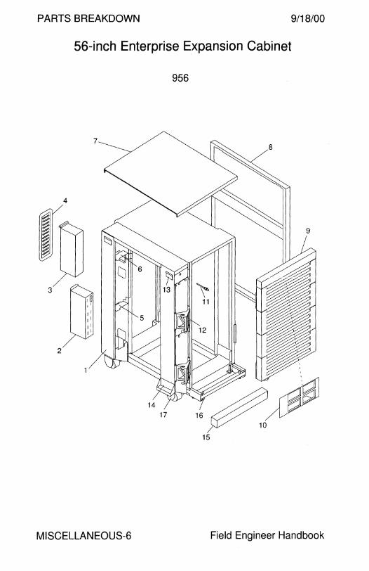
PARTS BREAKDOWN 9/18/00
56-inch Enterprise Expansion Cabinet
I z . .
/ 3
2
MISCELLANEOUS-6
956
15
Field Engineer Handbook

9/18/00 PARTS BREAKDOWN
56-inch Enterprise Expansion Cabinet
956 CODE PART# DESCRIPTION
1 540-2809 56-inch Cabinet Assembly
- 540-2591 • Frame Assembly
- 340-3360 • Frame
2 300-1290 Universal Power Sequencer
2 300-1403 Universal Power Sequencer
3 540-2709 Fan Tray Assembly (-02 with Fingerguards)
- 540-3271 Fingerguard Installation Kit for 540-2709-01
4 340-3267 Fan Tray Rear Cover
5 340-3405 Fan Tray Mounting Bracket, Bottom
6 340-3434 Fan Tray Mounting Bracket, Top
7 340-3352 Top Panel, Medium Grey
8 340-3354 Side Panel, Medium Grey
9 540-2810 Door Assembly with 4 Vented Panels
10 540-2746 Top Door Panel Assembly with Blank Filler Insert
- 330-1983 • Blank Filler Panel Insert
- 330-1982 Filler Panel Insert with 4 Tape Drive Cutouts
11 540-2393 Keyswitch Assembly with Key 330-2014
12 340-3272 Door Hinge Bracket
13 340~1885 Side Restraint Bracket, Upper
14 340-1886 Side Restraint Bracket, Lower
15 340-3355 Anti-Tilt Panel, Medium Grey
16 230-1418 Leveler Foot
17 240-1717 Caster
NS 340-3394 Front Door Catch
NS 340-3353 Screw Mounted Rear Panel, Medium Grey
NS 595-4389 Hinged Rear Panel Assy (UG-ENT-BKDOOR = 556-3386)
NS 530-1619 Ground Cable
NS 530-2234 Fan Sense Cable to AC Power Sequencer
NS 530-2236 Remote Keyswitch Control Cable, 3.2M
NS 530-2284 Keyswitch Cable Extension, Single Sequencer
NS 530-2369 Keyswitch Cable Extension, Dual Sequencers
Volume II MISCELLANEOUS-?
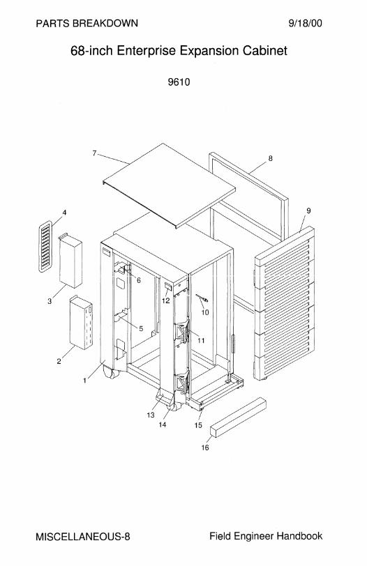
PARTS BREAKDOWN 9/18/00
68-inch Enterprise Expansion Cabinet
9610
7
4
N1 ~ ~ ~ ~ II 3
10
i 1
• 11
1 I 1 I
2 P3
16
MISCELLANEOUS-8 Field Engineer Handbook

9/18/00 PARTS BREAKDOWN
68-inch Enterprise Expansion Cabinet
9610
CODE PART# DESCRIPTION
1 540-3574 68-inch Cabinet Assembly - 540-3571 • Frame Assembly
- 340-4711 • Frame 2 300-1403 Universal Power Sequencer
3 540-2709 Fan Tray Assembly
4 340-3267 Fan Tray Rear Cover
5 340-3405 Fan Tray Mounting Bracket, Bottom
6 340-3434 Fan Tray Mounting Bracket, Top
7 340-3352 Top Panel, Medium Grey
8 340-3671 Side Panel, Medium Grey
9 540-3555 Door Assembly with 5 Vented Panels
10 540-2393 Keyswitch Assembly with Key 330-2014
11 340-3272 Door Hinge Bracket
12 340-1885 Side Restraint Bracket, Upper
13 340-1886 Side Restraint Bracket, Lower
14 240-1717 Caster
15 230-1418 Leveler Foot
16 340-3355 Anti-Tilt Panel, Medium Grey
NS 340-3266 Lower Sequencer Mounting Bracket
NS 340-3394 Front Door Catch
NS 340-4624 Hinged Rear Panel, Medium Grey
NS 340-5189 Front Power Sequencer Mounting Bracket
NS 340-5251 Front Sequencer Mounting Bracket Filler Panel
NS 530-1619 Ground Cable
NS 530-2197 IEC320 to AMP Mate-N-Lok Power Cord
NS 530-2234 Fan Sense Cable to AC Power Sequencer
NS 530-2236 Remote Keyswitch Control Cable, 3.2M
NS 530-2284 Keyswitch Cable Extension, Single Sequencer
NS 530-2369 Keyswitch Cable Extension, Dual Sequencers
NS 530-2265 Power Cord, Harting Han 6HsB to NEMA L6-30P
NS 530-2266 Power Cord, Harting Han 6HsB to IEC309
NS 530-2567 Power Cord, Harting Han 6HsB to NEMA L6-30P
NS 530-2568 Power Cord, Harting Han 6HsB to IEC309
NS 530-2645 Fan Tray to Sequencer Sense Cable
Volume II MI SC ELLAN EOUS-9
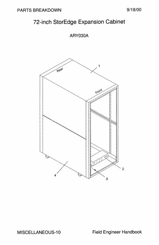
PARTS BREAKDOWN
72-inch StorEdge Expansion Cabinet
ARY030A
2
4
9/18/00
MISCELLANEOUS-10 Field Engineer Handbook

9/18/00 PARTS BREAKDOWN
72-inch StorEdge Expansion Cabinet
ARY030A
CODE PART# DESCRIPTION
1 595-4706 72-inch Cabinet Assembly
1 540-3707 72-inch Cabinet Assembly
1 370-3406 72-inch Cabinet
2 300-1393 Universal Power Sequencer
3 370-3547 Keyswitch
4 340-4939 Side Panel
NS 330-2610 1 U Filler Panel
NS 330-2611 2U Filler Panel
NS 330-2612 2U Power Sequencer Keyswitch Filler Panel
NS 330-2613 3U Filler Panel
NS 330-2614 4U Filler Panel
NS 330-2615 5U Filler Panel
NS 330-2616 1 U Trim Strip
NS 330-2617 2U Trim Strip
NS 330-2618 3U Trim Strip
NS 330-2619 4U Trim Strip
NS 330-2620 5U Trim Strip
NS 340-4471 Sequencer Mounting Bracket
NS 340-4472 Sequencer Mounting Bracket
NS 340-4624 Hinged Rear Panel
NS 340-4940 Rear Door Assembly
NS 370-3592 IEC320 to AMP Mate-N-Lok Power Cord
NS 370-3675 Front Door for A5000/5100/5200, Option X9818A
NS 530-2369 Keyswitch Cable Extension, Dual Sequencers
NS 530-1619 Ground Cable
NS 530-2236 Remote Keyswitch Control Cable, 3.2M
NS 530-2284 Keyswitch Cable Extension, Single Sequencer
NS 530-2674 Power Cord, Harting Han 6HsB to NEMA L6-30P
NS 530-2675 Power Cord, Harting Han 6HsB to IEC309
NS 540-3887 AC Fan Assembly, Option X9819A
- 370-3674 • Fan (x3)
805-3067 Installation and Service Manual
Note: There is no Sun Part Number for the Caster, Rack Foot, Side Cover, Left Slide Rail, Right Slide Rail, Slide Rail Foot, Slide Rail Retaining Screw, 1/4-20 Slide Rail Shoulder Screw, or Top Cover.
Volume II MISCELLANEOUS-11

PARTS BREAKDOW 10/17/00
Caster Base and Locking Module E4000 E4500 SPARCstorage Array SPARCstorage Library
952 953 Caster Base Locking Module
CODE PART# DESCRIPTION
595-4055 Caster Base, Option X952A 540-2956 • Caster Base Assembly
1 340-3600 • Caster Base 2 240-2184 • Swivel Caster (x2) 3 240-1368 • M61.0x16 mm Screw 4 370-1794 • Locking Caster (x2) 5 540-2958 • Locking Module (x1)
NS 340-3578 • Right Shroud NS 340-3579 • Left Shroud
802-5034 • Installation Guide
5 595-4056 Locking Module, Option X953A 540-2958 • Locking Module
Notes 1. The Caster Base supports one E4x00 and two peripheral enclosures. 2. Supported peripheral enclosures are the SPARCstorage Array Model
100 Series and the SPARCstorage Library. 3. Install the SPARCstorage Library in the top position. 4. Only one SPARCstorage Library is supported.
MISCELLANEOUS-12 Field Engineer Handbook

9/18/00
CODE PART#
- 540-2485
1 330-1686
2 370-1659
3 240-2136
4 330-1687
NS 250-1196
NS 330-1589
801-5344
Volume II
Tower Stand 881000
962
4
PARTS BREAKDOWN
DESCRIPTION
Tower Stand Assembly, Option X962A
• Vertical Support
• Caster (x2)
• #8-32 x 3/8" Screw
• Horizontal Support • Air Filter, 179 x 428 mm
• Cover Plug (x4) Tower Stand Installation Instructions
MISCELLANEOUS-13

PARTS BREAKDOWN 9/18/00
CODE
-
-
-
1
2
3
3 4
5
6 7
NS
NS
NS
NS
NS
Locking Module and Stacking Unit 881000
963 SPARCstorage Array
964
3
PART#
540-2506
540-2508
540-2581
540-2383
530-2121
300-1216
300-1217
340-2907
240-2184
240-1368
370-1794
180-1683
Unknown
540-2579
540-2580
801-5343
Locking Module Stacking Unit
i
~7
DESCRIPTION
230V Stacking Unit Assembly, Option X964A 240V Stacking Unit Assembly, Option X964A
• Locking Module Assembly (x2)
• Locking Module Assembly, Option X963A
• Remote Sequencer Cable, 2M
• 230V Power Sequencer
• 240V Power Sequencer
• Base • Rear Caster (x2)
• M6 1.0 x 16mm Screw
• Front Caster (x2)
• IEC 320 -Reverse IEC 320 Power Cord, 240V
• IEC 320 - NEMA 6-15 Power Cord, 230V
• Cable Management Assembly
• Cable Cover Assembly
• Stacker Unit Installation Instructions
MISCELLANEOUS-14 Field Engineer Handbook
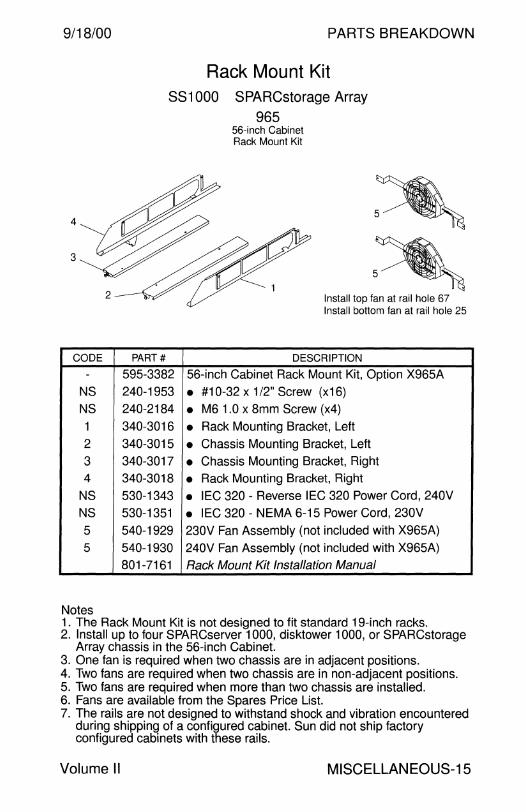
9/18/00
4
3
CODE
-
NS
NS
1
2
3 4
NS NS
5
5
Notes
PARTS BREAKDOWN
Rack Mount Kit SS1000 SPARCstorage Array
965
PART#
595-3382
240-1953
240-2184
340-3016
340-3015
340-3017
340-3018
530-1343
530-1351
540-1929
540-1930 801-7161
56-inch Cabinet Rack Mount Kit
Install top fan at rail hole 67 Install bottom fan at rail hole 25
DESCRIPTION
56-inch Cabinet Rack Mount Kit, Option X965A
• #10-32 x 1 /2" Screw (x16)
• M6 1.0 x 8mm Screw (x4)
• Rack Mounting Bracket, Left
• Chassis Mounting Bracket, Left
• Chassis Mounting Bracket, Right • Rack Mounting Bracket, Right
• IEC 320 - Reverse IEC 320 Power Cord, 240V
• IEC 320 - NEMA 6-15 Power Cord, 230V
230V Fan Assembly (not included with X965A)
240V Fan Assembly (not included with X965A)
Rack Mount Kit Installation Manual
1. The Rack Mount Kit is not designed to fit standard 19-inch racks. 2. Install up to four SPARCserver 1000, disktower 1000, or SPARCstorage
Array chassis in the 56-inch Cabinet. 3. One fan is required when two chassis are in adjacent positions. 4. Two fans are required when two chassis are in non-adjacent positions. 5. Two fans are required when more than two chassis are installed. 6. Fans are available from the Spares Price List. 7. The rails are not designed to withstand shock and vibration encountered
during shipping of a configured cabinet. Sun did not ship factory configured cabinets with these rails.
Volume II MISCELLANEOUS-15
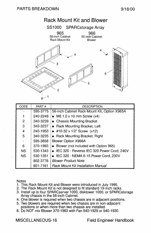
PARTS BREAKDOWN
CODE
Rack Mount Kit and Blower SS1000 SPARCstorage Array
PART#
965 966 56-inch Cabinet Rack Mount Kit
-.....------ 4
56-inch Cabinet Blower
DESCRIPTION
9/18/00
- 595-3775 56-inch Cabinet Rack Mount Kit, Option X965A
1 240-2248 • M6 1.0 x 10 mm Screw (x4) 2 340-3239 • Chassis Mounting Bracket
3 340-3237 • Rack Mounting Bracket, Left 4 240-1953 • #10-32 x 1 /2" Screw (x12)
5 340-3235 • Rack Mounting Bracket, Right - 595-3858 Blower Option X966A
6 370-1983 • Blower (not included with Option 965)
NS 530-1343 • IEC 320 - Reverse IEC 320 Power Cord, 240V
NS 530-1351 • IEC 320 - NEMA 6-15 Power Cord, 230V
802-3778 Blower Product Note
801-7161 Rack Mount Kit Installation Manual
Notes 1. This Rack Mount Kit and Blower were introduced in July 1995. 2. The Rack Mount Kit is not designed to fit standard 19-inch racks. 3. Install up to four SPARCserver 1000, disktower 1000, or SPARCstorage
Array chassis in the 56-inch Cabinet. 4. One blower is required when two chassis are in adjacent positions. 5. Two blowers are required when two chassis are in non-adjacent
positions or when more than two chassis are installed. 6. Do NOT mix Blower 370-1983 with Fan 540-1929 or 540-1930.
MISCELLANEOUS-16 Field Engineer Handbook
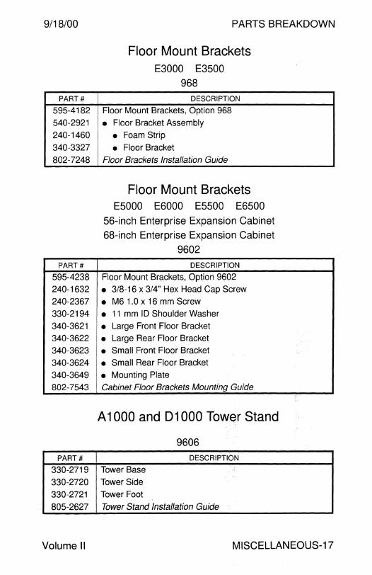
9/18/00
PART#
595-4182 540-2921
240-1460
340-3327
802-7248
PART#
595-4238 240-1632
240-2367 330-2194 340-3621 340-3622 340-3623
340-3624 340-3649 802-7543
PART#
330-2719
330-2720 330-2721
805-2627
Volume II
PARTS BREAKDOWN
Floor Mount Brackets E3000 E3500
968
DESCRIPTION
Floor Mount Brackets, Option 968
• Floor Bracket Assembly
• Foam Strip • Floor Bracket
Floor Brackets Installation Guide
Floor Mount Brackets E5000 E6000 E5500 E6500
56-inch Enterprise Expansion Cabinet 68-inch Enterprise Expansion Cabinet
9602
DESCRIPTION
Floor Mount Brackets, Option 9602
• 3/8-16 x 3/4" Hex Head Cap Screw • M61.0x16 mm Screw • 11 mm ID Shoulder Washer • Large Front Floor Bracket • Large Rear Floor Bracket • Small Front Floor Bracket • Small Rear Floor Bracket
• Mounting Plate Cabinet Floor Brackets Mounting Guide
A 1000 and 01000 Tower Stand
9606
DESCRIPTION
Tower Base
Tower Side Tower Foot
Tower Stand Installation Guide
MISCELLANEOUS-17
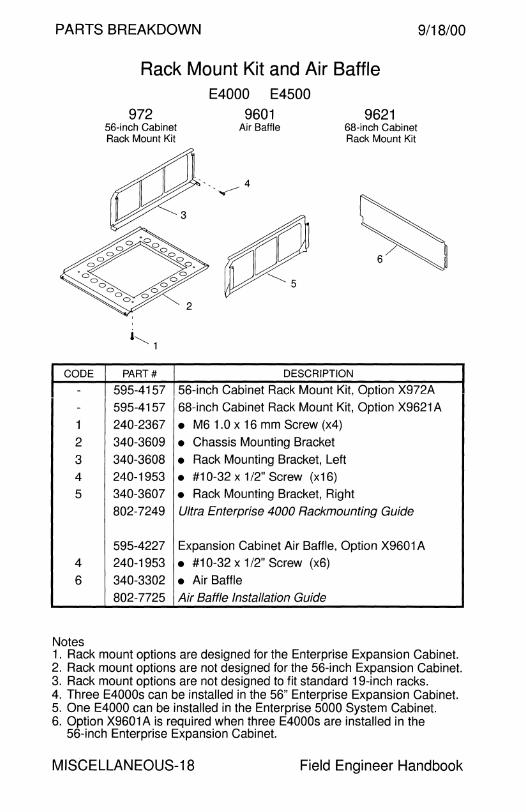
PARTS BREAKDOWN 9/18/00
CODE
--
1
2
3 4
5
4
6
Notes
Rack Mount Kit and Air Baffle
972 56-inch Cabinet Rack Mount Kit
,........_ 1
PART#
595-4157 595-4157
240-2367
340-3609 340-3608 240-1953 340-3607
802-7249
595-4227 240-1953 340-3302
802-7725
E4000 E4500
9601 9621 Air Baffle 68-inch Cabinet
Rack Mount Kit
··.. 4 ·....-----
2
DESCRIPTION
56-inch Cabinet Rack Mount Kit, Option X972A 68-inch Cabinet Rack Mount Kit, Option X9621 A
• M6 1.0 x 16 mm Screw (x4)
• Chassis Mounting Bracket
• Rack Mounting Bracket, Left • #10-32 x 1/2" Screw (x16) • Rack Mounting Bracket, Right Ultra Enterprise 4000 Rackmounting Guide
Expansion Cabinet Air Baffle, Option X9601A • #10-32 x 1 /2" Screw (x6)
• Air Baffle Air Baffle Installation Guide
1. Rack mount options are designed for the Enterprise Expansion Cabinet. 2. Rack mount options are not designed for the 56-inch Expansion Cabinet. 3. Rack mount options are not designed to fit standard 19-inch racks. 4. Three E4000s can be installed in the 56" Enterprise Expansion Cabinet. 5. One E4000 can be installed in the Enterprise 5000 System Cabinet. 6. Option X9601A is required when three E4000s are installed in the
56-inch Enterprise Expansion Cabinet.
MISCELLANEOUS-18 Field Engineer Handbook
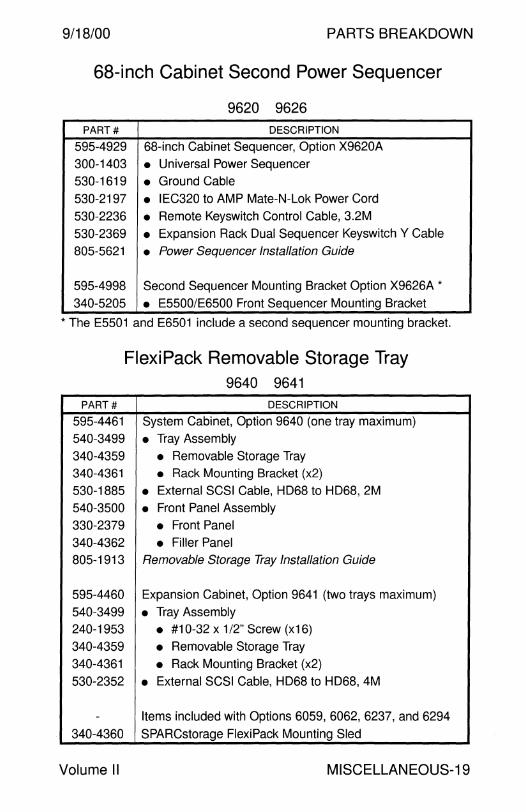
9/18/00 PARTS BREAKDOWN
68-inch Cabinet Second Power Sequencer
9620 9626 PART# DESCRIPTION
595-4929 68-inch Cabinet Sequencer, Option X9620A
300-1403 • Universal Power Sequencer 530-1619 • Ground Cable
530-2197 • IEC320 to AMP Mate-N-Lok Power Cord
530-2236 • Remote Keyswitch Control Cable, 3.2M
530-2369 • Expansion Rack Dual Sequencer Keyswitch Y Cable
805-5621 • Power Sequencer Installation Guide
595-4998 Second Sequencer Mounting Bracket Option X9626A *
340-5205 • E5500/E6500 Front Sequencer Mounting Bracket
*The E5501 and E6501 include a second sequencer mounting bracket.
PART#
595-4461
540-3499
340-4359
340-4361
530-1885
540-3500
330-2379
340-4362 805-1913
595-4460
540-3499 240-1953
340-4359
340-4361
530-2352
-
340-4360
Flexi Pack Removable Storage Tray 9640 9641
DESCRIPTION
System Cabinet, Option 9640 (one tray maximum)
• Tray Assembly
• Removable Storage Tray • Rack Mounting Bracket (x2)
• External SCSI Cable, HD68 to HD68, 2M
• Front Panel Assembly
• Front Panel
• Filler Panel Removable Storage Tray Installation Guide
Expansion Cabinet, Option 9641 (two trays maximum)
• Tray Assembly • #10-32 x 1/2" Screw (x16)
• Removable Storage Tray
• Rack Mounting Bracket (x2)
• External SCSI Cable, HD68 to HD68, 4M
Items included with Options 6059, 6062, 6237, and 6294
SPARCstorage FlexiPack Mounting Sled
Volume II MISCELLANEOUS-19
PARTS BREAKDOWN 9/18/00
FC-AL Hub Rack Mount Kit
6735 PART# DESCRIPTION
595-4551 Option X6735A
240-1396 • #10-32 x 318" Screw (x8) 340-3899 • Tray 805-0315 Installation Guide
FC-AL Switch
6744 6746 PART# DESCRIPTION
595-5358 Option UG-X6744A
595-5560 Option X67 46A Switch
595-5562 Option X6746A Documentation
595-5563 Option X6746A Rack Mounting Kit
180-1932 AC Power Cord
599-2340 Switch Assembly
340-5771 Rail
340-5889 Baffle
530-1871 RJ45 to RJ45 Cable, 4M
540-4189 3U Vented Panel
540-4372 Switch Assembly/FRU
340-5773 • Slide Rail 370-4035 • Ancor SANB-008-004 Switch
875-1881 Installation Guide
MISCELLANEOUS-20 Field Engineer Handbook
9/18/00 PARTS BREAKDOWN
StorEdge A5x00 68-inch Cabinet Air Baffle Kit
9622
PART# DESCRIPTION
595-4916 Option X9622A
540-3886 • Air Baffle Kit 240-1953 • #10-32 x 1/2" Screw (x4)
340-3300 • Air Baffle 805-5468 Installation Guide
StorEdge A5x00 68-inch Cabinet EM I Kit
PART#
595-4925
595-4926
340-3535
340-5191
340-5192 340-5193
340-5194
340-5195
240-1043
240-1953
Volume II
9623 E5500/E650
Option X9623A
Option X9624A
• Door Pin
9624 68" Expansion Cabinet
DESCRIPTION
• 68-inch Expansion Cabinet EMI Door
• E5500 and E6500 System Cabinet EMI Door • E5500 and E6500 System Cabinet EMI Panel
• Door Hinge
• Door Latch • #6-32 x 1 /2" Screw
• #10-32 x 3/8" Screw
MISCELLANEOUS-21
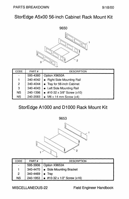
PARTS BREAKDOWN 9/18/00
StorEdge A5x00 56-inch Cabinet Rack Mount Kit
9650
CODE PART# DESCRIPTION
- 595-4360 Option X9650A
1 340-4042 • Right Side Mounting Rail
2 340-4044 • Tray for 56-inch Cabinet
3 340-4043 • Left Side Mounting Rail
NS 240-1396 • #10-32 x 3/8" Screw (x10)
f\!S 240-2083 .a f\.A~ v 1 A mm Cl""lor-ruu { ... ,A\ - IVIV A I-,. 111111 VVI t:iVV A..,. \ I
StorEdge A 1000 and 01000 Rack Mount Kit
9653
CODE PART# DESCRIPTION
- 595-3906 Option X9653A
1 340-4470 • Side Mounting Bracket
2 340-4469 • Tray NS 240-1953 • #10-32 x 1 /2" Screw (x16)
MISCELLANEOUS-22 Field Engineer Handbook
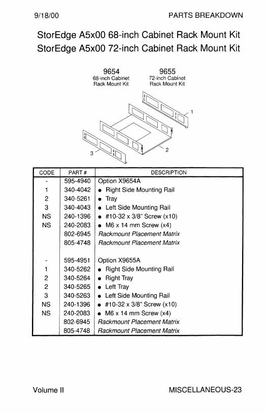
9/18/00 PARTS BREAKDOWN
StorEdge A5x00 68-inch Cabinet Rack Mount Kit StorEdge A5x00 72-inch Cabinet Rack Mount Kit
CODE PART#
- 595-4940
1 340-4042
2 340-5261
3 340-4043
NS 240-1396
NS 240-2083
802-6945
805-4748
- 595-4951
1 340-5262
2 340-5264
2 340-5265
3 340-5263
NS 240-1396
NS 240-2083 802-6945
805-4748
Volume II
9654 68-inch Cabinet Rack Mount Kit
Option X9654A
9655 72-inch Cabinet Rack Mount Kit
DESCRIPTION
• Right Side Mounting Rail
• Tray • Left Side Mounting Rail
• #10-32 x 3/8" Screw (x10)
• M6 x 14 mm Screw (x4) Rackmount Placement Matrix
Rackmount Placement Matrix
Option X9655A
• Right Side Mounting Rail
• Right Tray
• Left Tray • Left Side Mounting Rail
• #10-32 x 3/8" Screw (x10)
• M6 x 14 mm Screw (x4) Rackmount Placement Matrix
Rackmount Placement Matrix
MISCELLANEOUS-23
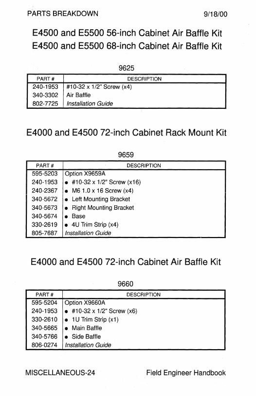
PARTS BREAKDOWN 9/18/00
E4500 and ESSOO 56-inch Cabinet Air Baffle Kit
E4500 and ESSOO 68-inch Cabinet Air Baffle Kit
9625 PART# DESCRIPTION
240-1953 #10-32 x 1 /2" Screw (x4)
340-3302 Air Baffle
802-7725 Installation Guide
E4000 and E4500 72-inch Cabinet Rack Mount Kit
9659 PART# DESCRIPTION
595-5203 Option X9659A
240-1953 • #10-32 x 1 /2" Screw (x16)
240-2367 • M61.0x16Screw(x4) 340-5672 • Left Mounting Bracket
340-5673 • Right Mounting Bracket
340-5674 • Base 330-2619 • 4U Trim Strip (x4) 805-7687 Installation Guide
E4000 and E4500 72-inch Cabinet Air Baffle Kit
9660 PART# DESCRIPTION
595-5204 Option X9660A 240-1953 • #10-32 x 1 /2" Screw (x6)
330-2610 • 1 U Trim Strip (x1) 340-5665 • Main Baffle
340-5766 • Side Baffle 806-0274 Installation Guide
MISCELLANEOUS-24 Field Engineer Handbook
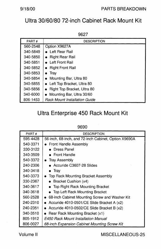
9/18/00 PARTS BREAKDOWN
Ultra 30/60/80 72-inch Cabinet Rack Mount Kit
9627 PART# DESCRIPTION
560-2548 Option X9627 A
340-5849 • Left Rear Rail
340-5850 • Right Rear Rail
340-5851 • Left Front Rail
340-5852 • Right Front Rail 340-5853 • Tray 340-5854 • Mounting Bar, Ultra 80
340-5855 • Left Top Bracket, Ultra 80
340-5856 • Right Top Bracket, Ultra 80 340-6000 • Mounting Bar, Ultra 30/60 806-1453 Rack Mount Installation Guide
Ultra Enterprise 450 Rack Mount Kit
9690 PART# DESCRIPTION
595-4428 56-inch, 68-inch, and 72-inch Cabinet, Option X9690A
540-3371 • Front Handle Assembly 330-3122 • Dress Panel 340-3509 • Front Handle 540-3372 • Tray Assembly 240-2306 • Accuride C3607-28 Slides 340-3418 • Tray 540-3373 • Top Rack Mounting Bracket Assembly
330-2367 • Bracket Cushion (x4) 340-3617 • Top Right Rack Mounting Bracket 340-3618 • Top Left Rack Mounting Bracket 560-2528 • 68-inch Cabinet Mounting Screw and Washer Kit
240-2310 • Accuride 4010-0501/CE Slide Bracket A (x2)
240-2351 • Accuride 4010-0502/CE Slide Bracket B (x2) 340-3510 • Rear Rack Mounting Bracket (x1) 805-1912 E450 Rack Mount Installation Manual 806-0027 68-inch Expansion Cabinet Mounting Screw Kit
Volume II MISCELLANEOUS-25
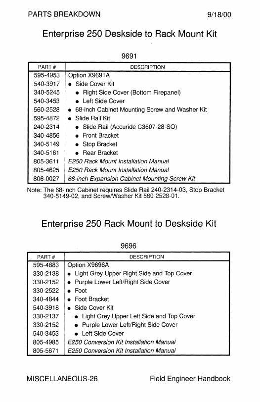
PARTS BREAKDOWN 9/18/00
Enterprise 250 Deskside to Rack Mount Kit
9691 PART# DESCRIPTION
595-4953 Option X9691 A
540-3917 • Side Cover Kit 340-5245 • Right Side Cover (Bottom Firepanel) 540-3453 • Left Side Cover 560-2528 • 68-inch Cabinet Mounting Screw and Washer Kit
595-4872 • Slide Rail Kit 240-2314 • Slide Rail (Accuride C3607-28-SO)
340-4856 • Front Bracket
340-5149 • Stop Bracket 340-5161 • Rear Bracket
805-3611 E250 Rack Mount Installation Manual
805-4625 E250 Rack Mount Installation Manual
806-0027 68-inch Expansion Cabinet Mounting Screw Kit
Note: The 68-inch Cabinet requires Slide Rail 240-2314-03, Stop Bracket 340-5149-02, and Scre'v'V/VVasher Kit 560-2528-01.
Enterprise 250 Rack Mount to Deskside Kit
9696 PART# DESCRIPTION
595-4883 Option X9696A
330-2138 • Light Grey Upper Right Side and Top Cover
330-2152 • Purple Lower Left/Right Side Cover
330-2522 • Foot 340-4844 • Foot Bracket 540-3918 • Side Cover Kit 330-2137 • Light Grey Upper Left Side and Top Cover
330-2152 • Purple Lower Left/Right Side Cover
540-3453 • Left Side Cover
805-4985 E250 Conversion Kit Installation Manual 805-5671 E250 Conversion Kit Installation Manual
MISCELLANEOUS-26 Field Engineer Handbook

9/18/00 PARTS BREAKDOWN
72-inch StorEdge Expansion Cabinet Front Door Kit
9818
PART# DESCRIPTION
595-4999 Option X9818A
370-3675 • Front Screen Door Kit None • Front Screen Door
None • Front Screen Door Key
None • 1/4-20 x 3/4" Bolt (x12)
None • Hinge Bracket with Plastic Sleeve (x2)
None • Latch Bracket without Plastic Sleeve (x2)
805-5992 StorEdge Expansion Cabinet Fan Tray Installation Guide
72-inch StorEdge Expansion Cabinet Cooling Kit
9819
PART# DESCRIPTION
595-4954 Option X9819A
540-3887 • Fan Tray Assembly (x2)
530-2236 • Cable, Fan Tray to J4 on AC Sequencer (x2)
340-5285 • Fan Tray Top Panel 805-5774 StorEdge Expansion Cabinet Front Door Installation Guide
Volume II MISCELLANEOUS-27
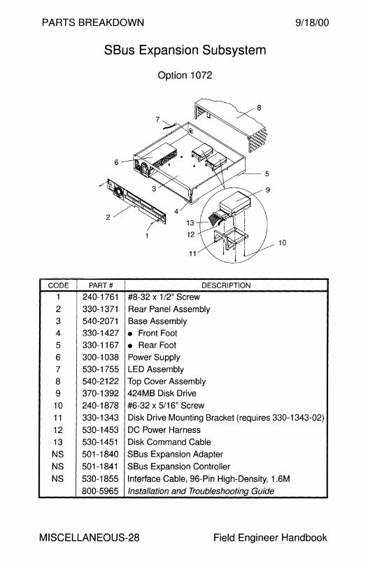
PARTS BREAKDOWN 9/18/00
SBus Expansion Subsystem
Option 1072
10
CODE PART# DESCRIPTION
1 240-1761 #8-32 x 1 /2" Screw
2 330-1371 Rear Panel Assembly
3 540-2071 Base Assembly 4 330-1427 • Front Foot
5 330-1167 • Rear Foot
6 300-1038 Power Supply
7 530-1755 LED Assembly
8 540-2122 Top Cover Assembly
9 370-1392 424MB Disk Drive
10 240-1878 #6-32 x 5/16" Screw
11 330-1343 Disk Drive Mounting Bracket (requires 330-1343-02)
12 530-1453 DC Power Harness
13 530-1451 Disk Command Cable
NS 501-1840 SBus Expansion Adapter
NS 501-1841 SBus Expansion Controller
NS 530-1855 Interface Cable, 96-Pin High-Density, 1.6M
800-5965 Installation and Troubleshooting Guide
MISCELLANEOUS-28 Field Engineer Handbook

9/18/00 PARTS BREAKDOWN
This page intentionally left blank.
Volume II MISCELLANEOUS-29

PARTS BREAKDOWN 9/18/00
Sunscreen SPF-100
SS5 with Sunscreen Administration Station
CODE PART# DESCRIPTION
- - Order Number SCREEN-100
1 603-2362 SPARCstation 5 Model 110
NS 501-2062 • Quad Ethernet, Option 1058
NS 501-2367 • PCMCIA Adapter, Option 1030
NS 530-2239 • 1 OBASE-T Crossover Cable
- - Order Number SCREEN-110
2 600-3886 486DX2 Administration Station
NS 370-2294 • NEC SCREEN-110 Mouse FRU
2 370-2295 • NEC SCREEN-110 Administration Station FRU
2 370-2385 • Dell SCREEN-110 Administration Station FRU
3 370-2296 • SCREEN-110/11 OG 14" Monitor FRU
NS 370-2297 • NEC SCREEN-110 Keyboard FRU
NS 370-2383 • Dell SCREEN-110/11 OG Mouse FRU
NS 370-2384 • Dell SCREEN-110/11 OG Keyboard FRU
- - Order Number SCREEN-120
NS 600-3886 486DX2 Administration Station
1 603-2362 SPARCstation 5 Model 110
- - Order Number SCREEN-130
NS 600-3886 486DX2 Administration Station
1 603-2362 SPARCstation 5 Model 110 (x2)
MISCELLANEOUS-30 Field Engineer Handbook

9/18/00 PARTS BREAKDOWN
Sunscreen SPF-1 OOG
SSS with Sunscreen Administration Station
CODE PART# DESCRIPTION
- - Order Number SCREEN-100-G
1 603-2531 SPARCstation 5 Model 110
NS 501-2062 • Quad Ethernet, Option 1 058
NS 530-2239 • 1 OBASE-T Crossover Cable
- - Order Number SCREEN-110-G
2 603-2555 SCREEN-11 OG Administration Station
2 370-2382 • Dell SCREEN-110/11 OG Admin Station FRU
2 370-2386 • NEC 11 OG Administration Station FRU
3 370-2296 • SCREEN-110/11 OG 14" Monitor FRU
NS 370-2383 • Dell SCREEN-110/11 OG Mouse FRU
NS 370-2384 • Dell SCREEN-110/11 OG Keyboard FRU
Volume II MISCELLANEOUS-31

PARTS BREAKDOWN 9/18/00
7
CODE
-
-
-
-
-
1
2 --
3 -
-4
5
6
7
8
JavaStation JJ-8 JJ-16 JJ-32 JJ-40 JJ-64
Logic Enclosure
PART#
600-4251
600-4252
600-4253
600-4254
600-4255
540-1982
540-2959
540-2890 540-2865
540-2866
300-1282
370-1986
240-2281
540-2865
530-2300
501-3141
540-2454
/1 ~
DESCRIPTION
JJ-8 JavaStation Assembly, 8MB Memory 1
JJ-16 JavaStation Assembly, 16MB Memory 1
JJ-32 JavaStation Assembly, 32MB Memory 1
JJ-40 JavaStation Assembly, 40MB Memory 1
JJ-64 JavaStation Assembly, 64MB Memory 1
Lockbox
Top Cover and Empty Base Assembly/FRU
• Top Cover • Base Assembly Power Supply Assembly/FRU
• 30 Watt Power Supply
• Fan #4-40 Jackscrew
Base Assembly
LED Cable Assembly/FRU
OMB CPU FRU
Speaker Assembly/FRU
1 Whole unit replacements are available as FRUs in some geographies.
MISCELLANEOUS-32 Field Engineer Handbook

9/18/00
CODE
--
-
-
-
-
-
-
-
1 -
-
-
2
3
4
5
6
7
Volume II
PARTS BREAKDOWN
JavaStation JK-xx-16 JK-xx-32 JK-xx-64
Logic Enclosure
3~/--- ---cr-
4 @-_____ 6
PART# DESCRIPTION
595-4513 JavaStation FRU, 16MB Memory and OMB Flash
595-4514 JavaStation FRU, 16MB Memory and 4MB Flash
595-4515 JavaStation FRU, 16MB Memory and 8MB Flash
595-4516 JavaStation FRU, 32MB Memory and OMB Flash
595-4517 JavaStation FRU, 32MB Memory and 4MB Flash 595-4518 JavaStation FRU, 32MB Memory and 8MB Flash
595-4519 JavaStation FRU, 64MB Memory and OMB Flash
595-4520 JavaStation FRU, 64MB Memory and 4MB Flash
595-4521 JavaStation FRU, 64MB Memory and 8MB Flash 540-2998 Chassis Assembly
540-3384 • Left Cover Assembly
330-2212 • Foot 540-3385 • Right Cover 530-2300 LED Cable Assembly
540-3486 Speaker Assembly/FRU
330-2200 Left Shroud
300-1329 Power Supply
540-3347 Lockbox
330-2201 Right Shroud
MISCELLANEOUS-33
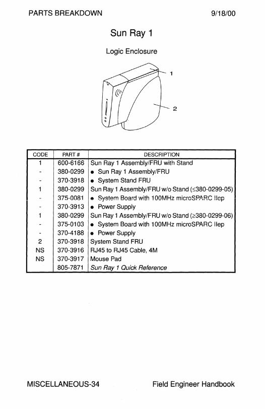
PARTS BREAKDOWN 9/18/00
Sun Ray 1
Logic Enclosure
1
2
CODE PART# DESCRIPTION
1 600-6166 Sun Ray 1 Assembly/FRU with Stand - 380-0299 • Sun Ray 1 Assembly/FRU - 370-3918 • System Stand FRU 1 380-0299 Sun Ray 1 Assembly/FRU w/o Stand (:::;380-0299-05)
- 375-0081 • System Board with 1 OOMHz microSPARC !!ep - 370-3913 • Power Supply 1 380-0299 Sun Ray 1 Assembly/FRU w/o Stand (2380-0299-06) - 375-0103 • System Board with 100MHz microSPARC llep - 370-4188 • Power Supply 2 370-3918 System Stand FRU
NS 370-3916 RJ45 to RJ45 Cable, 4M
NS 370-3917 Mouse Pad
805-7871 Sun Ray 1 Quick Reference
MISCELLANEOUS-34 Field Engineer Handbook
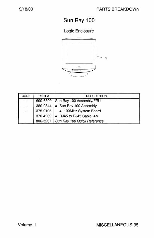
9/18/00 PARTS BREAKDOWN
Sun Ray 100
Logic Enclosure
[-I
CODE PART# DESCRIPTION
1 600-6809 Sun Ray 100 Assembly/FRU - 380-0344 • Sun Ray 100 Assembly - 375-0105 • 1 OOMHz System Board
370-4232 • RJ45 to RJ45 Cable, 4M 806-5237 Sun Ray 1 DO Quick Reference
Volume II MISCELLANEOUS-35
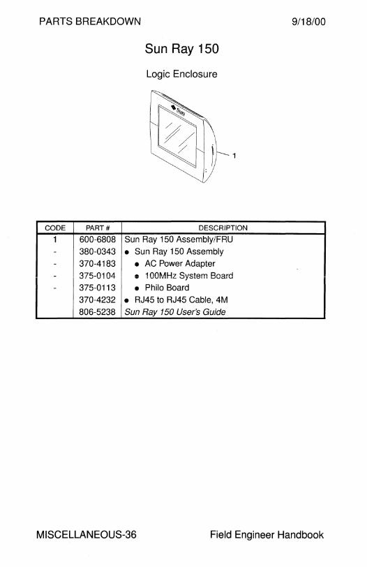
PARTS BREAKDOWN 9/18/00
Sun Ray 150
Logic Enclosure
1
CODE PART# DESCRIPTION
1 600-6808 Sun Ray 150 Assembly/FRU
- 380-0343 • Sun Ray 150 Assembly - 370-4183 • AC Power Adapter - 375-0104 e 1 OOMHz System Board - 375-0113 • Philo Board
370-4232 • RJ45 to RJ45 Cable, 4M
806-5238 Sun Ray 150 User's Guide
MISCELLANEOUS-36 Field Engineer Handbook

PARTS BREAKDOWN
PROM

9/18/00 PARTS BREAKDOWN
PROM
IDPROM ............................................................................... 2
Boot PROM Sun-4m ............................................................................. . microSPARC llep ............................................................. . Sun-4d .............................................................................. .
5 7 8
Sun-4u ............................................................................... 10
Firmware SPARCstorage Array ........................................................ 21 Enterprise Network Array A5000 . . . . . . . . . . . . . . . . . . . . . . . . . . . . . . . . . . . . . . . 25 StorEdge A5000/5100/5200 .............................................. 25 Ultra Enterprise 3000-6000 1/0 Boards . . ... .. .. .. .. .. .. .. . . . . . .. ... 26 Ultra Enterprise 3500-6500 1/0 Boards ............................. 26
Flash PROM Update Sun-4u Flash Update . . . . . . . . . . . . . . . . . . . . . . . . . . . . . . . . . . . . . . . . . . . . . . . . . . . . . . . . 28
Field Engineer Handbook - Volume II
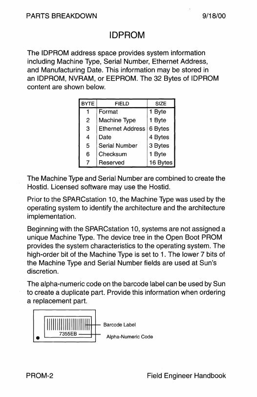
PARTS BREAKDOWN 9/18/00
ID PROM
The IDPROM address space provides system information including Machine Type, Serial Number, Ethernet Address, and Manufacturing Date. This information may be stored in an IDPROM, NVRAM, or EEPROM. The 32 Bytes of IDPROM content are shown below.
BYTE FIELD SIZE
1 Format 1 Byte
2 Machine Type 1 Byte
3 Ethernet Address 6 Bytes
4 Date 4 Bytes
5 Serial Number 3 Bytes
6 Checksum 1 Byte
7 Reserved 16 Bytes
The Machine Type and Serial Number are combined to create the Hostid. Licensed software may use the Hostid.
Prior to the SPARCstation 10, the Machine Type was used by the operating system to identify the architecture and the architecture implementation.
Beginning with the SPARCstation 10, systems are not assigned a unique Machine Type. The device tree in the Open Boot PROM provides the system characteristics to the operating system. The high-order bit of the Machine Type is set to 1. The lower 7 bits of the Machine Type and Serial Number fields are used at Sun's discretion.
The alpha-numeric code on the barcode label can be used by Sun to create a duplicate part. Provide this information when ordering a replacement part.
11111111111111111111* t-+- Barcode Label
7355EB • Alpha-Numeric Code
PROM-2 Field Engineer Handbook
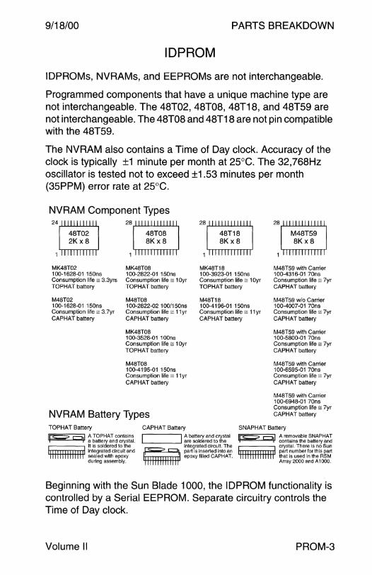
9/18/00 PARTS BREAKDOWN
ID PROM
IDPROMs, NVRAMs, and EEPROMs are not interchangeable.
Programmed components that have a unique machine type are not interchangeable. The 48T02, 48T08, 48T18, and 48T59 are not interchangeable. The 48T08 and 48T18 are not pin compatible with the 48T59.
The NVRAM also contains a Time of Day clock. Accuracy of the clock is typically ±1 minute per month at 25°C. The 32,768Hz oscillator is tested not to exceed ±1.53 minutes per month (35PPM) error rate at 25°C.
NVRAM Component Types
MK48T02 100-1628-01 150ns Consumption life = 3.3yrs TOPHAT battery
M48T02 100-1628-01 150ns Consumption life = 3. ?yr CAPHAT battery
MK48T08 100-2822-01 150ns Consumption life = 1 Oyr TOPHAT battery
M48T08 100-2822-02 100/150ns Consumption life = 11 yr CAPHAT battery
MK48T08 100-3528-01 1 OOns Consumption life = 1 Oyr TOPHAT battery
M48T08 100-4195-01 150ns Consumption life = 11 yr CAPHAT battery
NVRAM Battery Types
MK48T18 100-3923-01 150ns Consumption life = 1 Oyr TOPHAT battery
M48T18 100-4196-01 150ns Consumption life = 11 yr CAPHAT battery
M48T59 with Carrier 100-4316-01 70ns Consumption life = ?yr CAPHAT battery
M48T59 w/o Carrier 100-4007-01 70ns Consumption life = ?yr CAPHA T battery
M48T59 with Carrier 100-5800-01 70ns Consumption life = ?yr CAPHA T battery
M48T59 with Carrier 100-6595-01 70ns Consumption life = ?yr CAPHAT battery
M48T59 with Carrier 100-6948-01 70ns Consumption life = ?yr CAPHAT battery
TOPHAT Battery CAPHAT Battery SNAPHAT Battery
'F? 91 ~ J3ie~Ain~o~~~~~-lt is soldered to the
1111111111111111 integrated circuit and sealed with epoxy during assembly.
I :r~~~rcfur~~dt~fuis~al '-----------' integrated circuit. The p? g part is inserted into an lnnnm iHitl epoxy filled CAPHAT.
Ip? ~I ~d~t~~~~~~ ~~:~~~~ crystal. There is no Sun
1111111111111111 part numberforthis part that 1s used in the RSM Array 2000 and A 1000.
Beginning with the Sun Blade 1000, the ID PROM functionality is controlled by a Serial EEPROM. Separate circuitry controls the Time of Day clock.
Volume II PROM-3
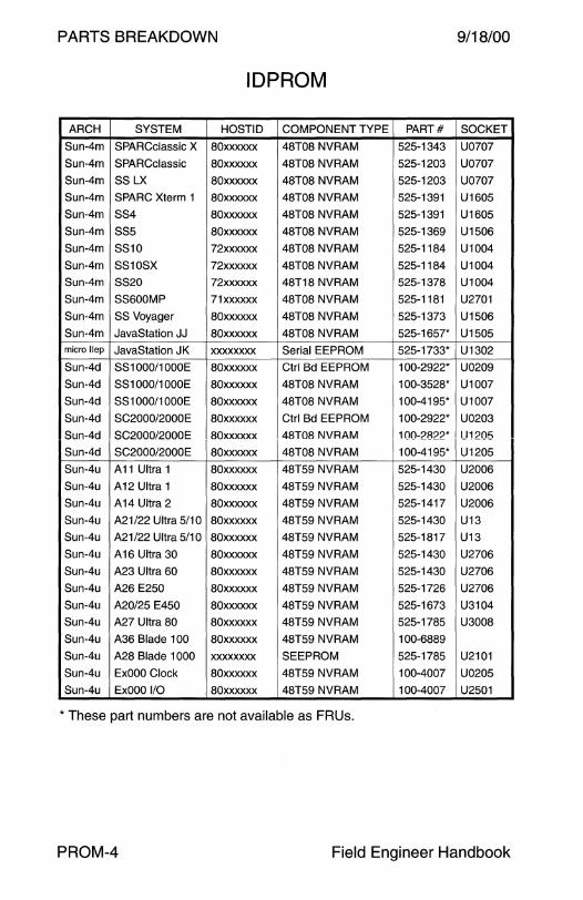
PARTS BREAKDOWN 9/18/00
ID PROM
ARCH SYSTEM HOSTID COMPONENT TYPE PART# SOCKET
Sun-4m SPARCclassic X 80xxxxxx 48T08 NVRAM 525-1343 U0707
Sun-4m SPARCclassic 80xxxxxx 48T08 NVRAM 525-1203 U0707
Sun-4m SSLX 80xxxxxx 48T08 NVRAM 525-1203 U0707
Sun-4m SPARC Xterm 1 80xxxxxx 48T08 NVRAM 525-1391 U1605
Sun-4m SS4 80xxxxxx 48T08 NVRAM 525-1391 U1605
Sun-4m SSS 80xxxxxx 48T08 NVRAM 525-1369 U1506
Sun-4m SS10 72xxxxxx 48T08 NVRAM 525-1184 U1004
Sun-4m SS10SX 72xxxxxx 48T08 NVRAM 525-1184 U1004
Sun-4m SS20 72xxxxxx 48T18 NVRAM 525-1378 U1004
Sun-4m SS600MP 71xxxxxx 48T08 NVRAM 525-1181 U2701
Sun-4m SS Voyager 80xxxxxx 48T08 NVRAM 525-1373 U1506
Sun-4m JavaStation JJ 80xxxxxx 48T08 NVRAM 525-1657* U1505 micro llep JavaStation JK xxxxxxxx Serial EEPROM 525-1733* U1302
Sun-4d SS1000/1000E 80xxxxxx Ctrl Bd EEPROM 100-2922* U0209
Sun-4d SS 1000/1 OOOE 80xxxxxx 48T08 NVRAM 100-3528* U1007
Sun-4d SS 1000/1 OOOE 80xxxxxx 48T08 NVRAM 100-4195* U1007
Sun-4d SC2000/2000E 80xxxxxx Ctrl Bd EEPROM 100-2922* U0203
Sun-4d SC2000/2000E 80xxxxxx 48T08 NVRAM 100-2822* U1205
Sun-4d SC2000/2000E 80xxxxxx 48T08 NVRAM 100-4195* U1205
Sun-4u A11Ultra1 80xxxxxx 48T59 NVRAM 525-1430 U2006
Sun-4u A12 Ultra 1 80xxxxxx 48T59 NVRAM 525-1430 U2006
Sun-4u A14 Ultra 2 80xxxxxx 48T59 NVRAM 525-1417 U2006
Sun-4u A21/22 Ultra 5/1 O 80xxxxxx 48T59 NVRAM 525-1430 U13
Sun-4u A21/22 Ultra 5/1 O 80xxxxxx 48T59 NVRAM 525-1817 U13
Sun-4u A16 Ultra 30 80xxxxxx 48T59 NVRAM 525-1430 U2706
Sun-4u A23 Ultra 60 80xxxxxx 48T59 NVRAM 525-1430 U2706
Sun-4u A26 E250 80xxxxxx 48T59 NVRAM 525-1726 U2706
Sun-4u A20/25 E450 80xxxxxx 48T59 NVRAM 525-1673 U3104
Sun-4u A27 Ultra 80 80xxxxxx 48T59 NVRAM 525-1785 U3008
Sun-4u A36 Blade 100 80xxxxxx 48T59 NVRAM 100-6889
Sun-4u A28 Blade 1000 xxxxxxxx SEEPROM 525-1785 U2101
Sun-4u ExOOO Clock 80xxxxxx 48T59 NVRAM 100-4007 U0205
Sun-4u ExOOO 1/0 80xxxxxx 48T59 NVRAM 100-4007 U2501
* These part numbers are not available as FRUs.
PROM-4 Field Engineer Handbook
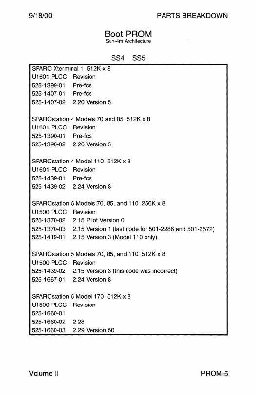
9/18/00 PARTS BREAKDOWN
Boot PROM Sun-4m Architecture
SPARC Xterminal 1 512K x 8
U1601 PLCC Revision 525-1399-01 Pre-fcs 525-1407-01 Pre-fcs
525-1407-02 2.20 Version 5
884 885
SPARCstation 4 Models 70 and 85 512K x 8 U1601 PLCC Revision 525-1390-01 Pre-fcs
525-1390-02 2.20 Version 5
SPARCstation 4 Model 110 512K x 8 U1601 PLCC Revision
525-1439-01 Pre-fcs
525-1439-02 2.24 Version 8
SPARCstation 5 Models 70, 85, and 11 O 256K x 8 U1500 PLCC Revision
525-1370-02 2.15 Pilot Version O
525-1370-03 2.15 Version 1 {last code for 501-2286 and 501-2572) 525-1419-01 2.15 Version 3 (Model 110 only)
SPARCstation 5 Models 70, 85, and 110 512K x 8 U1500 PLCC Revision 525-1439-02 2.15 Version 3 (this code was incorrect)
525-1667-01 2.24 Version 8
SPARCstation 5 Model 170 512K x 8 U1500 PLCC Revision
525-1660-01
525-1660-02 2.28 525-1660-03 2.29 Version 50
Volume II PROM-5

PARTS BREAKDOWN
Boot PROM Sun-4m Architecture
SPARCstation 20
U1005 525-1377-01 Pre-fcs 525-1377-02 Pre-fcs
525-1377-03 Pre-fcs 525-1377-04 2.15a Version 3
525-1377-05 2.15 Version 7
8820
9/18/00
525-1377-06 2.19 Version 3 (adds hyperSPARC support) 525-1377-07 2.22 Version 1 (adds SuperSPARC II support)
525-1377-08 2.25 Version O (adds 150MHz hyperSPARC support)
560-2048 Boot PROM Upgrade Kit
PROM-6 Field Engineer Handbook

9/18/00 PARTS BREAKDOWN
Boot PROM Sun-4m Architecture
JavaStation JJ
JavaStation JJ 512K x 8 U1603 Flash PROM Revision 525-1663-01
525-1663-02 525-1663-03 2.28 Version 1 (JavaStation 1 banner) 525-1663-04 2.30 Version O (JavaStation banner)
Boot PROM microSPARC llep Architecture
JavaStation JK
JavaStation JK 512K x 8
U 1203 Flash PROM Revision
525-1732-01 525-1732-02 525-1732-03
525-1732-04 525-1732-05 525-1732-06 Revision unknown, Engineering Release 525-1732-07 Revision unknown, ECOW0_11774
525-1732-10 OBP 3.12.FW12 +POST 3.2
Volume II PROM-7
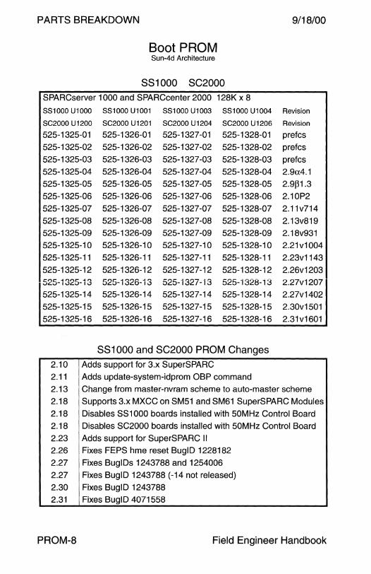
PARTS BREAKDOWN 9/18/00
Boot PROM 8un-4d Architecture
881000 SC2000 SPARCserver 1000 and SPARCcenter 2000 128K x 8
881000 U1000 881000 U1001 881000 U1003 881000 U1004 Revision
8C2000 U 1200 8C2000 U1201 8C2000 U1204 8C2000 U1206 Revision
525-1325-01 525-1326-01 525-1327-01 525-1328-01 pref cs
525-1325-02 525-1326-02 525-1327 -02 525-1328-02 prefcs
525-1325-03 525-1326-03 525-1327 -03 525-1328-03 prefcs
525-1325-04 525-1326-04 525-1327-04 525-1328-04 2.9a4.1
525-1325-05 525-1326-05 525-1327-05 525-1328-05 2.9~1.3
525-1325-06 525-1326-06 525-1327 -06 525-1328-06 2.10P2
525-1325-07 525-1326-07 525-1327-07 525-1328-07 2.11v714
525-1325-08 525-1326-08 525-1327 -08 525-1328-08 2.13v819
525-1325-09 525-1326-09 525-1327 -09 525-1328-09 2.18v931
525-1325-1 0 525-1326-1 0 525-1327-10 525-1328-10 2.21v1004
525-1325-11 525-1326-11 525-1327-11 525-1328-11 2.23v1143
525-1325-12 525-1326-12 525-1327-12 525-1328-12 2.26v1203 t::l")t:: -t l')l"\I::' -I,.., r::-nr- -1 ru·"'lln. ... n 525-1327 -13 525- i 328- i 3 2.27v1207 .,JC..,r I VC.;J- I V 0<::.0- I .JL.O- I .)
525-1325-14 525-1326-14 525-1327-14 525-1328-14 2.27v1402
525-1325-15 525-1326-15 525-1327-15 525-1328-15 2.30v1501
525-1325-16 525-1326-16 525-1327-16 525-1328-16 2.31v1601
881000 and SC2000 PROM Changes 2.10 Adds support for 3.x SuperSPARC
2.11 Adds update-system-idprom OBP command
2.13 Change from master-nvram scheme to auto-master scheme
2.18 Supports 3.x MXCC on SM51 and SM61 SuperSPARC Modules
2.18 Disables SS1000 boards installed with 50MHz Control Board
2.18 Disables SC2000 boards installed with 50MHz Control Board
2.23 Adds support for SuperSPARC II
2.26 Fixes FEPS hme reset BuglD 1228182
2.27 Fixes BuglDs 1243788 and 1254006
2.27 Fixes BuglD 1243788 (-14 not released)
2.30 Fixes BuglD 1243788
2.31 Fixes BuglD 4071558
PROM-8 Field Engineer Handbook
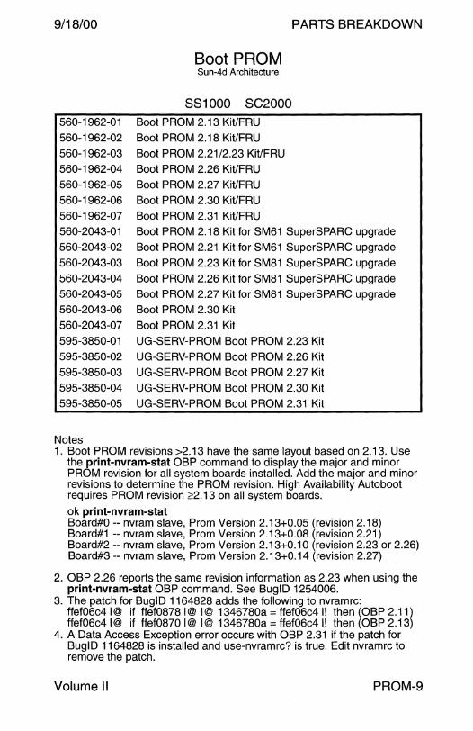
9/18/00
560-1962-01 560-1962-02
560-1962-03 560-1962-04 560-1962-05
560-1962-06 560-1962-07 560-2043-01
560-2043-02 560-2043-03
560-2043-04 560-2043-05 560-2043-06
560-2043-07
595-3850-01 595-3850-02 595-3850-03
595-3850-04 595-3850-05
Notes
Boot PROM Sun-4d Architecture
SS 1000 SC2000 Boot PROM 2.13 Kit/FRU Boot PROM 2.18 Kit/FRU
Boot PROM 2.21/2.23 Kit/FRU Boot PROM 2.26 Kit/FRU
Boot PROM 2.27 Kit/FRU Boot PROM 2.30 Kit/FRU
Boot PROM 2.31 Kit/FRU
PARTS BREAKDOWN
Boot PROM 2.18 Kit for SM61 SuperSPARC upgrade Boot PROM 2.21 Kit for SM61 SuperSPARC upgrade
Boot PROM 2.23 Kit for SM81 SuperSPARC upgrade
Boot PROM 2.26 Kit for SM81 SuperSPARC upgrade Boot PROM 2.27 Kit for SM81 SuperSPARC upgrade
Boot PROM 2.30 Kit
Boot PROM 2.31 Kit UG-SERV-PROM Boot PROM 2.23 Kit
UG-SERV-PROM Boot PROM 2.26 Kit UG-SERV-PROM Boot PROM 2.27 Kit UG-SERV-PROM Boot PROM 2.30 Kit
UG-SERV-PROM Boot PROM 2.31 Kit
1. Boot PROM revisions >2.13 have the same layout based on 2.13. Use the print-nvram-stat OBP command to display the major and minor PROM revision for all system boards installed. Add the major and minor revisions to determine the PROM revision. High Availability Autoboot requires PROM revision ~2.13 on all system boards.
ok print-nvram-stat Board#O -- nvram slave, Prom Version 2.13+0.05 (revision 2.18) Board#1 -- nvram slave, Prom Version 2.13+0.08 (revision 2.21) Board#2 -- nvram slave, Prom Version 2.13+0.1 O (revision 2.23 or 2.26) Board#3 -- nvram slave, Prom Version 2.13+0.14 (revision 2.27)
2. OBP 2.26 reports the same revision information as 2.23 when using the print-nvram-stat OBP command. See BuglD 1254006.
3. The patch for BuglD 1164828 adds the following to nvramrc: ffef06c4 I@ if ffef0878 I@ I@ 1346780a == ffef06c4 I! then (OBP 2.11) ffef06c4 I@ if ffef0870 I@ I@ 1346780a == ffef06c4 I! then (OBP 2.13)
4. A Data Access Exception error occurs with OBP 2.31 if the patch for Bug ID 1164828 is installed and use-nvramrc? is true. Edit nvramrc to remove the patch.
Volume II PROM-9
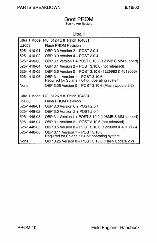
PARTS BREAKDOWN 9/18/00
Boot PROM Sun-4u Architecture
Ultra 1
Ultra 1 Model 140 512K x 8 Patch 104881
U2003 Flash PROM Revision 525-1410-01 OBP 3.0 Version 2 + POST 2.0.4 525-1410-02 OBP 3.0 Version 4 +POST 2.0.4
525-1410-03 OBP 3.1 Version 1 + POST 3.10.2 (128MB SIMM support) 525-1410-04 OBP 3.1 Version 2 + POST 3.10.6 (not released)
525-1410-05 OBP 3.5 Version 0 +POST 3.10.6 {1229983 & 4018056) 525-1410-06 OBP 3.11 Version 1 + POST 3.10.6
Required for Solaris 7 64-bit operating system
None OBP 3.25 Version O + POST 3.10.6 (Flash Update 2.2)
Ultra 1 Model 170 512K x 8 Patch 104881 U2003 Flash PROM Revision 525-1448-01 OBP 3.0 Version 0 +POST 2.0.4
525-1448-02 OBP 3.0 Version 2 +POST 2.0.4 525-1448-03 OBP 3.1 Version 1 + POST 3.10.2 (128MB SIMM support) 525-1448-04 OBP 3.1Version2 +POST 3.10.6 (not released)
525-1448-05 OBP 3.5 Version 0 +POST 3.10.6 (1229983 & 4018056) 525-1448-06 OBP 3.11 Version 1 + POST 3.10.6
Required for Solaris 7 64-bit operating system None OBP 3.25 Version O + POST 3.10.6 (Flash Update 2.2)
PROM-10 Field Engineer Handbook

9/18/00 PARTS BREAKDOWN
Boot PROM Sun-4u Architecture
Ultra 1
Ultra 1 Model 140E 512K x 8 Patch 104288 U2003 Flash PROM Revision 525-1681-01
525-1681-02 OBP 3.3 Version 3 +POST 3.10.6 525-1681-03 Not released
525-1681-04 OBP 3.5 Version 1 + POST 3.10.6 (not released) 525-1681-05 OBP 3.7 Version 1 + POST 3.11.4 (supports Rev3 PHY) 525-1681-06 OBP 3.11 Version 1 + POST 3.11.4
Required for Solaris 7 64-bit operating system None OBP 3.25 Version O + POST 3.11.4 (Flash Update 2.2)
Ultra 1 Model 170E 512K x 8 Patch 104288 U2003 Flash PROM Revision 525-1411-01
525-1411-01 525-1411-02 525-1411-03
525-1411-04 525-1411-05
None 525-1411-06 525-1411-07
None
OBP 3.0 Beta3 Version 3 OBP 3.0 Beta4 Version o OBP 3.0 Version 4 + POST 2.0.6 OBP 3.1 Version 2 + POST 3.10.2 Not released
OBP 3.5 Version 1 + POST 3.10.6 (not released) OBP 3.5 Version 2 + POST 3.10.6 (on Flash Update 1.5) OBP 3. 7 Version 1 + POST 3.11.4 (supports Rev3 PHY)
OBP 3.11 Version 1 + POST 3.11.4 Required for Solaris 7 64-bit operating system
OBP 3.25 Version 0 + POST 3.11.4 (Flash Update 2.2)
Ultra 1 Model 200E 512K x 8 Patch 104288
U2003 Flash PROM Revision 525-1662-01 OBP 3.3 Alpha1Version0 +POST 3.10.2 (PO build)
525-1662-02 OBP 3.3 Alpha2 Version 2 + POST 3.10.3 (P2 build) 525-1662-03 OBP 3.3 Version 2 + POST 3.10.3 (FCS build)
525-1662-04 Not released
525-1662-05 OBP 3.5 Version 1 + POST 3.10.6 (not released) 525-1662-06 OBP 3.7 Version 1 + POST 3.11.4 (supports Rev3 PHY)
525-1662-07 OBP 3.11 Version 1 + POST 3.11.4 Required for Solaris 7 64-Bit operating system
None OBP 3.25 Version O + POST 3.11.4 (Flash Update 2.2)
Volume 11 PROM-11

PARTS BREAKDOWN
Boot PROM Sun-4u Architecture
Ultra 2 Flash PROM Revision 512K x 8 Patch 104169
OBP 3.0 Beta4 Version 4 (P1 .2 build)
OBP 3.0 Alpha1 Version 1 (P1 .3 build)
9/18/00
U2003
525-1414-01
525-1414-01 525-1414-01
525-1414-02
525-1414-03
525-1414-04
525-1414-05
525-1414-06
525-1414-07
OBP 3.1 Alpha 1 Version 2 + POST 1.1.9 (P1 .4 /P2.0 build)
OBP 3.1 Beta 1 Version O + POST 2.1.1 (200MHz support)
OBP 3.1 Version 2 + POST 3.1.3 or 3.1 .4
None
525-1414-08
525-1414-09
525-1414-1 0
525-1414-11
525-1414-12
525-1414-13
None
OBP 3.1.3 Version 3 + POST 3.1.4
OBP 3.1.3 Version 3 + POST 3.1.5 (not released)
OBP 3.1.4 Version 4 + POST 3.1.5 (not released)
OBP 3.1.5 Version 5 + POST 3.1.5 (Flash Update 1.3)
OBP 3.1 Version 6 + POST 3.1.5
OBP 3.5 Version 2 + POST 3.1.5 (not released)
OBP 3.7 Version 0 +POST 3.2.1
OBP 3.11 Version 2 + POST 3.3.5 (not structured)
OBP 3.11 Version 2 + POST 3.3. 7
OBP 3.11 Version 2 + POST 3,3,8
OBP 3.19 Version 0 + POST 3.3.8
OBP 3.25 Version 0 + POST 3.3.8 (Flash Update 2.2)
Ultra 2 PROM Changes -02 Adds support for 200MHz UltraSPARC
-04 Previous OBP versions set the UPA speed to 148MHz when 2.2 and 4.0 UltraSPARC processors are mixed.
-07 Fixes wrong SIMM pair error reporting Bug ID 1262941. Reports memory errors as a single SIMM. Available in Flash Update 1.3 and Patch 104169-03.
-09 Fixes BuglDs 1229983 and 4018056. Adds support for 300MHz UltraSPARC II. Power down if mixed modules are installed.
-10 Not structured because of POST external cache ram crosstalk test BuglDs 4115766 and 4116867. Included on Flash Update 1.7. Required for Solaris 7 64-bit operating system.
-11 Removed external cache ram crosstalk test.
-12 Adds support for 400MHz UltraSPARC II
-13 Fixes BuglDs 4004140, 4129194, 4145990, and 4203848
-13 Adds tape drive boot support and UXFL support
PROM-12 Field Engineer Handbook

9/18/00 PARTS BREAKDOWN
Boot PROM Sun-4u Architecture
Ultra 5 Ultra 10 U2703 375-0009 Flash PROM Revision 1M x 8 Patch 106121
370-3202-01 OBP 3.11 Version 2 + POST 2.2.2 + OBDIAG 2.2 370-3202-02 OBP 3.11 Version 5 + POST 2.2.2 + OBDIAG 2.2 370-3202-03 OBP 3.11 Version 6 + POST 2.2.8 + OBDIAG 2.5
370-3202-04 OBP 3.11 Version 7 + POST 2.2.8 + OBDIAG 2.6 370-3202-05 OBP 3.11 Version 9 + POST 2.2.9 + OBDIAG 2.6
370-3202-06 OBP 3.11 Version 12 + POST 2.2.9 + OBDIAG 2.6 370-3886-03 OBP 3.19 Version 4 +POST 3.0.7 + OBDIAG 2.8 370-3886-06 OBP 3.25 Version 3 + POST 3.0.9 + OBDIAG 2.8
U2703 375-0066 Flash PROM Revision 1 M x 8 Patch 106121 370-3697-02 OBP 3.15 Version 2
370-3886-03 OBP 3.19 Version 4 + POST 3.0.7 + OBDIAG 2.8 370-3886-04 OBP 3.25 Version 1 + POST 3.0.8 + OBDIAG 2.8
370-3886-06 OBP 3.25 Version 3 + POST 3.0.9 + OBDIAG 2.8
U2703 375-0079 Flash PROM Revision 1 M x 8 Patch 106121 370-3886-01 OBP 3.19 Version 0
370-3886-02 OBP 3.19 Version 2 + POST 3.0.5
370-3886-03 OBP 3.19 Version 4 +POST 3.0.7 + OBDIAG 2.8 370-3886-04 OBP 3.25 Version 1 + POST 3.0.8 + OBDIAG 2.8
370-3886-05 OBP 3.25 Version 2 + POST 3.0.9 + OBDIAG 2.8 370-3886-05 OBP 3.25 Version 3 + POST 3.0.9 + OBDIAG 2.8
370-3886-06 OBP 3.25 Version 3 + POST 3.0.9 + OBDIAG 2.8
U2703 375-0115 Flash PROM Revision 1 M x 8 Patch 106121 370-3886-04 OBP 3.25 Version 1 + POST 3.0.8 + OBDIAG 2.8
370-3886-05 OBP 3.25 Version 2 + POST 3.0.9 + OBDIAG 2.8 370-3886-06 OBP 3.25 Version 3 + POST 3.0.9 + OBDIAG 2.8
Ultra 5 and Ultra 10 PROM Changes
3886-03 DRAM timing change for 333/360/440MHz Sapphire Red 3886-04 DRAM timing change for 400MHz Sapphire Red 3886-05 DRAM timing change for 440MHz Sapphire Red
3886-06 Micron memory timeing change for 360/400/440MHz
Volume II PROM-13

PARTS BREAKDOWN 9/18/00
Boot PROM Sun-4u Architecture
Ultra 30
U2003 Flash PROM Revision 1 M x 8 Patch 105930
525-1669-01 Pre-FCS 525-1669-02 OBP 3.5.3 Pre-FCS 525-1669-03 OBP 3.5.0 Pre-FCS
525-1669-04 OBP 3.5.5 Pre-FCS 525-1669-05 OBP 3.5.10 Pre-FCS
525-1669-06 OBP 3.5.0 Pre-FCS 525-1669-07 OBP 3.5 P2.0 Version 16 1
525-1669-08 OBP 3.5 Version 17
525-1669-09 OBP 3.5 Version 17
525-1669-10 OBP 3.9 Version 4 +POST 1.1.1 + OBDIAG 2.1.1 525-1669-11 OBP 3.9 Version 5 +POST 1.1.1 + OBDIAG 2.1.1 525-1669-12 OBP 3.11 Version 1 +POST 1.1.1 + OBDIAG 2.1.1 2
525-1669-13 OBP 3.11 Version 1 + POST 1.1.1 + OBDIAG 2.2 3
525-1669-14 OBP 3.11 Version 2 + POST 1.1.1 + OBDIAG 2.2
None OBP 3.25 Version 0 + POST 1.1.1 + OBD!AG 2.2
Ultra 30 PROM Changes
-14 Fixes Symbios SCSI controller booting BuglD 4114784
-14 Changed pci-page mask from 4K to 8K BuglD 4119734 -14 Fixes hex parsing of IP address BuglD 4129194
1 Add the following lines to nvramrc if a serial console is used with OBP 3.5 P2.0. Refer to BuglDs 4023405 and 4030675.
' false f0036644 f003a5e0 (patch ' false f0036650 f003a5e0 (patch
2 Checksum A282FAO. Not released. On Flash Update 1.8. 3 Checksum A2B2CA3. W0_ 12833 cancelled. Shipped by W0_ 12559.
PROM-14 Field Engineer Handbook

9/18/00 PARTS BREAKDOWN
Boot PROM Sun-4u Architecture
Ultra 60
U2703 Flash PROM Revision 1 M x 8 Patch 106455 525-1701-01 P1.0
525-1701-02 P1.0B 525-1701-03 OBP 3.11 Version 15
525-1701-04 OBP 3.11 Version 18 525-1701-05 OBP 3.11 Version 18
525-1701-06 OBP 3.11 Version 19 525-1701-07 OBP 3.11Version24 525-1701-08 OBP 3.11 Version 25 + POST 1.0.8 1
525-1701-09 OBP 3.11 Version 26 + POST 2.0.0 + OBDIAG 1.3 525-1701-10 OBP3.11 Version272 525-1701-11 OBP 3.13 Version 1 +POST 2.0.1 + OBDIAG 1.3 3
525-1701-12 OBP 3.17 Version 0 + POST 2.0.2 + OBDIAG 1.3 525-1701-13 OBP 3.23 Version 1+POST2.0.2 + OBDIAG 1.3
None OBP 3.25 Version 0 + POST 2.0.2 + OBDIAG 1.3
Ultra 60 PROM Changes
-09 Fixes Symbios SCSI controller booting BuglD 4114784
-09 Adds 400:100, 440:110, 480:120, and 500:125 +4 modes -09 Supports mixing 360MHz UltraSPARC mask# <80 and 80
-09 Changed pci-page mask from 4K to 8K Bug ID 4119734 -09 Fixes hex parsing of IP address BuglD 4129194
-10 Adds tape drive boot support -12 Adds 450:112 +4 mode. Fix max memory hang during POST. -13 Adds NVRAM variables for the Enterprise 220R
1 Parts labeled 525-1701-08 with an arrow symbol are not write enabled. Trying to flash update a 525-1701-08 with an arrow symbol will fail.
2 Not used. Not ECO released. Not structured. 3 Not ECO released. Not structured to the board. On Flash Update 1.10.
Volume II PROM-15

PARTS BREAKDOWN
Boot PROM Sun-4u Architecture
Ultra 80 U3007 Flash PROM Revision 1 M x 8 Patch 109082 525-1780-01 Pre-FCS
525-1780-02 Pre-FCS 525-1780-03 Pre-FCS
525-1780-04 Pre-FCS 525-1780-05 Pre-FCS
525-1780-06 OBP 3.23 Version 0 + POST 1.2. 7 + OBDIAG 1.0 109082-01 OBP 3.25 Version 0 +POST 1.2.7 + OBDIAG 1.0
Uxxxx 370-4116
Sun Blade 100 Flash PROM Revision Unknown
Sun Blade 1000 I U2103 F!ash PROM Revlslon 2M x 8 525-1807-01 Pre-FCS 525-1807-01to525-1807-07
525-1807-08 Unknown
9/18/00
PROM-16 Field Engineer Handbook

9/18/00 PARTS BREAKDOWN
Boot PROM Sun-4u Architecture
Enterprise 250
U2703 Boot Flash PROM Revision 1 M x 8 Patch 106503 525-1718-05 OBP 3.7 Version 1 525-1718-06 OBP 3.7 Version 2
525-1718-07 OBP 3.7 Version 3 +POST 6.0.2 + OBDIAG 3.17.1 525-1718-08 OBP 3.7 Version 7 +POST 6.0.4 + OBDIAG 3.19.1
525-1718-09 OBP 3.12 Version 10 +POST 6.0.8 + OBDIAG 4.5.1 525-1718-10 OBP 3.12 Version 11 + POST 6.0.8 + OBDIAG 4.5.1 525-1718-11 OBP 3.12 Version 12 + POST 6.0.8 + OBDIAG 4.5.1
525-1718-13 OBP 3.16 Version 1 +POST 6.0.9 + OBDIAG 4.5.1
U4401 Remote System Control Flash PROM Revision 1 M x 8 525-1724-04 RSC main b0.22 525-1724-05 RSC main b0.22 m0.25
525-1724-06 RSC main b0.22 m0.28 525-1724-07 RSC main b1 .1 m1 .12 (not released) 525-1724-08 RSC main b1.3 m1.14
Enterprise 250 Boot PROM Changes
-09 Adds 400MHz support - Not used
-10 Adds 400MHz support
-11 Fixes SCMP timing problem with 400MHz BuglD 4212155
-13 Adds 501-5440 support. Adds 5: 1 clock ratio support.
-08
Volume II
Enterprise 250 RSC PROM Changes
Required if System Board has 64MB DRAM at U4405. The 501-4681-09 and 501-5440-01 use 64MB DRAM.
PROM-17

PARTS BREAKDOWN 9/18/00
Boot PROM Sun-4u Architecture
Ultra 450 Ultra Enterprise 450 Enterprise 450 U3101
U3101 525-1672-01 525-1672-04 525-1672-05
525-1672-08
501-2996 Flash PROM Revision 1 M x 8 Patch 106122
501-5028 Flash PROM Revision 1 M x 8 Patch 106122 Pre-FCS (525-1672-01, 525-1672-02, and 525-1672-03) P1 .4 P2 (525-1672-05, 525-1672-06, and 525-1672-07)
OBP 3.5 Version 105 + POST 4.0.6
525-1672-09 Not used 525-1672-10 OBP 3.7 Version 107 +POST 5.0.8 + OBDIAG 3.9.2
Required for Solaris 7 64-Bit operating system
Enterprise 450 U3101 501-5270 Flash PROM Revision 1 M x 8 Patch 106122
525-1776-01 OBP 3.12 Version 1 + POST 6.0.6 + OBDIAG 525-1776-02 OBP 3.12 Version 2 +POST+ OBDIAG
525-1776-03 OBP 3.12 Version 3 + POST + OBDIAG 525-1776-04 OBP 3.14 Version 1+POST6.0.9 + OBDIAG 4.4.1 525-1776-05 OBP 3.16 Version 2 +POST 6.0.9 + OBDIAG 4.4.1
Enterprise 450 U3101 501-5672 Flash PROM Revision 1 M x 8 Patch 106122
U3101 501-5673 Flash PROM Revision 1M x 8 Patch 106122 525-1776-05 OBP 3.16 Version 2 + POST 6.0.9 + OBDIAG 4.4.1
525-1776-06 OBP 3.18 Version 0 + POST 6.1.0 + OBDIAG 4.4.1
525-1776 PROM Changes -03 Fixes CPU2 timeout error during POST BuglD 4195116 -05 Enable slave CPU error reporting BuglD 4302752 -06 Adds support for 480MHz UltraSPARC II
PROM-18 Field Engineer Handbook
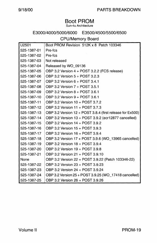
9/18/00 PARTS BREAKDOWN
Boot PROM Sun-4u Architecture
E3000/ 4000/5000/6000 E3500/4500/5500/6500
CPU/Memory Board
U2501 Boot PROM Revision 512K x 8 Patch 103346 525-1387-01 Pre-fcs 525-1387-02 Pre-fcs
525-1387-03 Not released 525-1387-04 Released by W0_09136
525-1387-05 OBP 3.2 Version 4 +POST 3.2.2 (FCS release) 525-1387-06 OBP 3.2 Version 5 +POST 3.2.3 525-1387-07 OBP 3.2 Version 6 + POST 3.4.1
525-1387-08 OBP 3.2 Version 7 +POST 3.5.1
525-1387-09 OBP 3.2 Version 8 +POST 3.6.1 525-1387-10 OBP 3.2 Version 9 +POST 3.6.1
525-1387-11 OBP 3.2 Version 10 +POST 3.7.2
525-1387-12 OBP3.2Version 11 + POST3.7.3 525-1387-13 OBP 3.2 Version 12 + POST 3.8.4 (first release for Ex500)
525-1387-14 OBP 3.2 Version 13 +POST 3.9.2 (ecr12877 cancelled) 525-1387-15 OBP 3.2 Version 14 +POST 3.9.2 525-1387-16 OBP 3.2 Version 15 +POST 3.9.3
525-1387-17 OBP 3.2 Version 16 +POST 3.9.4 525-1387-18 OBP 3.2 Version 17 +POST 3.9.6(W0_13965 cancelled) 525-1387-19 OBP 3.2 Version 18 +POST 3.9.4
525-1387-20 OBP 3.2 Version 19 +POST 3.9.8 525-1387-21 OBP 3.2 Version 21+POST3.9.10
None OBP 3.2 Version 22 + POST 3.9.22 (Patch 103346-22) 525-1387-22 OBP 3.2 Version 23 +POST 3.9.23 525-1387-23 OBP 3.2 Version 24 +POST 3.9.24 525-1387-24 OBP 3.2 Version 25 +POST 3.9.25(W0_17418 cancelled)
525-1387-25 OBP 3.2 Version 26 +POST 3.9.26
Volume II PROM-19
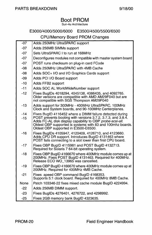
PARTS BREAKDOWN 9/18/00
Boot PROM Sun-4u Architecture
E3000/4000/5000/6000 E3500/4500/5500/6500
CPU/Memory Board PROM Changes -07 Adds 250MHz UltraSPARC support -07 Adds 256MB SIMMs support -07 Sets UltraSPARC I to run at 168MHz -07 Deconfigures modules not compatible with master system board
-07 POST runs checksum on plug-in card FCode
-08 Adds 250MHz UltraSPARC with 4MB Cache -08 Adds SOC+ 1/0 and 1/0 Graphics Cards support -09 Adds PCI 1/0 Board support -1 O Adds FFB2 support
-11 Adds SOC AL WorldWideNumber support -12 Fixes BuglDs 4018294, 4045138, 4086435, and 4092765.
Older versions are compatible with AMO AM29F040 but are not compatible with SGS Thompson AM29F040
-13 Adds support for 300MHz - 400MHz UltraSPARC, 1 OOMHz Clock and System boards, and 90-1 OOMHz Centerplanes.
-14 Fixes Bug!D 4116452 where a D!MM failure detected during -15 POST prevents booting with versions 3.7.2, 3.7.3, and 3.8.4.
Adds FC-AL disk display capability to OBP probe-scsi-all. Oldest OBP supported is systems with 83 and 1 OOmhz boards. Oldest OBP supported in E3500-E6500.
-16 Fixes BuglDs 4105947, 4120409, 4126710, and 4123660. Adds CPU DR support. Introduces BuglD 4131463 where POST fails connecting to a slot lower than first CPU board.
-17 Fixes OBP BuglD 4115981 and POST BuglD 4132713. Required for Solaris 7 64-bit operating system.
-18 Fixes OBP BuglD 4166670 where 400MHz module comes up at 200MHz. Fixes POST BuglD 4131463. Required for 400MHz. Release ECO W0_ 13965 was cancelled.
-19 Fixes OBP BuglD 4166670 where 400MHz module comes up at 200MHz. Required for 400MHz 4MB Cache.
-21 Fixes .speed OBP command BuglD 4168353. Supports 5:1 clock board. Required for 400MHz 8MB Cache.
None Patch 103346-22 fixes mixed cache module BuglD 4224994. -22 Adds 256MB DIMM support.
-23 Fixes BuglDs 4276401, 4276722, and 4298992. -25 Fixes 2GB memory bank BuglD 4323635.
PROM-20 Field Engineer Handbook
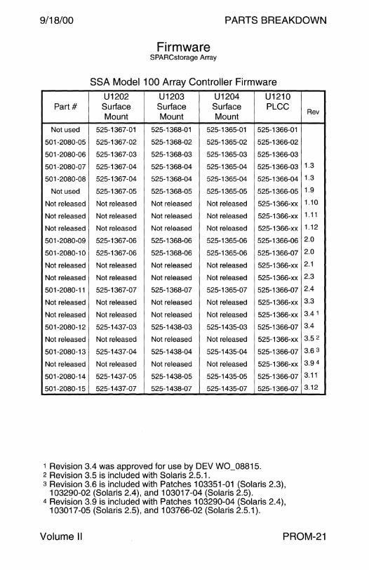
9/18/00 PARTS BREAKDOWN
Firmware SPARCstorage Array
SSA Model 100 Array Controller Firmware
U1202 U1203 U1204 U1210 Part# Surface Surface Surface PLCC
Mount Mount Mount
Not used 525-1367-01 525-1368-01 525-1365-01 525-1366-01
501-2080-05 525-1367-02 525-1368-02 525-1365-02 525-1366-02
501-2080-06 525-1367-03 525-1368-03 525-1365-03 525-1366-03
501-2080-07 525-1367-04 525-1368-04 525-1365-04 525-1366-03
501-2080-08 525-1367-04 525-1368-04 525-1365-04 525-1366-04
Not used 525-1367-05 525-1368-05 525-1365-05 525-1366-05
Not released Not released Not released Not released 525-1366-xx
Not released Not released Not released Not released 525-1366-xx
Not released Not released Not released Not released 525-1366-xx
501-2080-09 525-1367-06 525-1368-06 525-1365-06 525-1366-06
501-2080-10 525-1367-06 525-1368-06 525-1365-06 525-1366-07
Not released Not released Not released Not released 525-1366-xx
Not released Not released Not released Not released 525-1366-xx
501-2080-11 525-1367-07 525-1368-07 525-1365-07 525-1366-07
Not released Not released Not released Not released 525-1366-xx
Not released Not released Not released Not released 525-1366-xx
501-2080-12 525-1437-03 525-1438-03 525-1435-03 525-1366-07
Not released Not released Not released Not released 525-1366-xx
501-2080-13 525-1437-04 525-1438-04 525-1435-04 525-1366-07
Not released Not released Not released Not released 525-1366-xx
501-2080-14 525-1437-05 525-1438-05 525-1435-05 525-1366-07
501-2080-15 525-1437-07 525-1438-07 525-1435-07 525-1366-07
1 Revision 3.4 was approved for use by DEV W0_08815. 2 Revision 3.5 is included with Solaris 2.5.1. s Revision 3.6 is included with Patches 103351-01 (Solaris 2.3),
103290-02 (Solaris 2.4), and 103017-04 (Solaris 2.5). 4 Revision 3.9 is included with Patches 103290-04 (Solaris 2.4),
103017-05 (Solaris 2.5), and 103766-02 (Solaris 2.5.1 ).
Rev
1.3
1.3
1.9
1.10
1.11
1.12
2.0
2.0
2.1
2.3
2.4
3.3
3.4 1
3.4
3.5 2
3.6 3
3.94
3.11
3.12
Volume II PROM-21

PARTS BREAKDOWN 9/18/00
Firmware SPARCstorage Array
SSA Model 112 Array Controller Firmware
U1202 U1203 U1204 U1210 Part# Suriace Suriace Suriace PLCC
Mount Mount Mount
501-2872-02 525-1437-01 525-1438-01 525-1435-01 525-1436-01
501-2872-02 Not released Not released Not released 525-1436-xx
501-2872-02 Not released Not released Not released 525-1436-xx
501-2872-03 525-1437-03 525-1438-03 525-1435-03 525-1436-02
Not released Not released Not released Not released 525-1436-xx
501-2872-04 525-1437-04 525-1438-04 525-1435-04 525-1436-02
501-4271-01 525-1437-04 525-1438-04 525-1435-04 525-1436-02
Not released Not released Not released Not released 525-1436-xx
501-2872-05 525-1437-05 525-1438-05 525-1435-05 525-1436-02
501 -4271 -02 525-1437-05 525-1438-05 525-1435-05 525-1436-02
501-2872-06 525-1437-07 525-1438-07 525-1435-07 525-1436-03
501-4271-03 525-1437-07 525-1438-07 525-1435-07 525-1436-03
1 Revision 3.3 was approved for use by DEV W0_08658. 2 Revision 3.4 was approved for use by DEV W0_08815€. 3 Revision 3.5 is included with Safaris 2.5.1. 4 Revision 3.6 is included with Patches 103351-01 (Safaris 2.3),
103290-02 (Safaris 2.4), and 103017-04 (Safaris 2.5). 5 Revision 3.9 is included with Patches 103290-04 (Safaris 2.4),
103017-05 (Safaris 2.5), and 103766-02 (Safaris 2.5.1).
Rev
3.31
3.4 2
3.4
3.5 3
3.64
3.64
3.9 5
3.11
3.11
3.12
3.12
PROM-22 Field Engineer Handbook
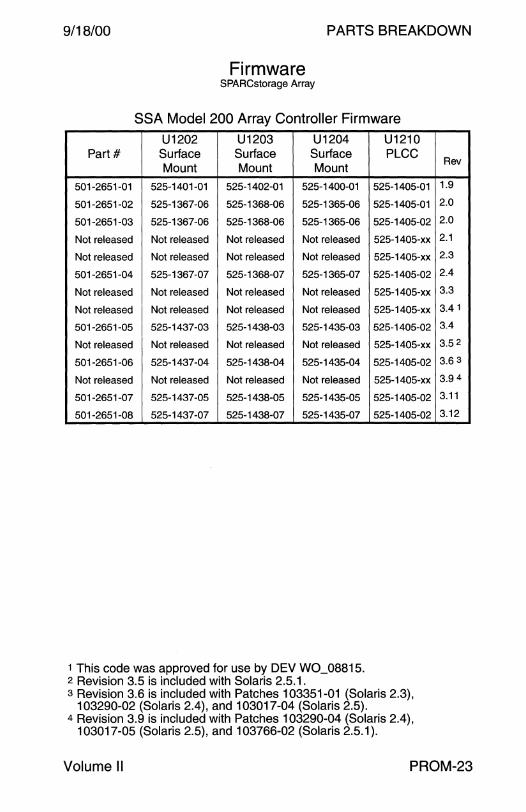
9/18/00 PARTS BREAKDOWN
Firmware SPARCstorage Array
SSA Model 200 Array Controller Firmware
U1202 U1203 U1204 Part# Surface Surface Surface
Mount Mount Mount
501-2651-01 525-1401-01 525-1402-01 525-1400-01
501-2651-02 525-1367-06 525-1368-06 525-1365-06
501-2651-03 525-1367-06 525-1368-06 525-1365-06
Not released Not released Not released Not released
Not released Not released Not released Not released
501-2651-04 525-1367-07 525-1368-07 525-1365-07
Not released Not released Not released Not released
Not released Not released Not released Not released
501-2651-05 525-1437-03 525-1438-03 525-1435-03
Not released Not released Not released Not released
501-2651-06 525-1437-04 525-1438-04 525-1435-04
Not released Not released Not released Not released
501-2651-07 525-1437-05 525-1438-05 525-1435-05
501-2651-08 525-1437-07 525-1438-07 525-1435-07
1 This code was approved for use by DEV W0_08815. 2 Revision 3.5 is included with Solaris 2.5.1.
U1210 PLCC
525-1405-01
525-1405-01
525-1405-02
525-1405-xx
525-1405-xx
525-1405-02
525-1405-xx
525-1405-xx
525-1405-02
525-1405-xx
525-1405-02
525-1405-xx
525-1405-02
525-1405-02
3 Revision 3.6 is included with Patches 103351-01 (Solaris 2.3), 103290-02 (Solaris 2.4), and 103017-04 (Solaris 2.5).
4 Revision 3.9 is included with Patches 103290-04 (Solaris 2.4), 103017-05 (Solaris 2.5), and 103766-02 (Solaris 2.5.1 ).
Rev
1.9
2.0
2.0
2.1
2.3
2.4
3.3
3.4 1
3.4
3.52
3.63
3.94
3.11
3.12
Volume II PROM-23
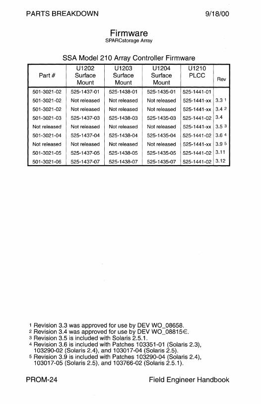
PARTS BREAKDOWN 9/18/00
Firmware SPARCstorage Array
SSA Model 210 Array Controller Firmware
U1202 U1203 U1204 U1210 Part# Surface Surface Surface PLCC
Mount Mount Mount
501-3021-02 525-1437-01 525-1438-01 525-1435-01 525-1441-01
501-3021-02 Not released Not released Not released 525-1441-xx
501-3021-02 Not released Not released Not released 525-1441-xx
501-3021-03 525-1437-03 525-1438-03 525-1435-03 525-1441-02
Not released Not released Not released Not released 525-1441-xx
501-3021-04 525-1437-04 525-1438-04 525-1435-04 525-1441-02
Not released Not released Not released Not released 525-1441-xx
501-3021-05 525-1437-05 525-1438-05 525-1435-05 525-1441-02
501-3021-06 525-1437-07 525-1438-07 525-1435-07 525-1441-02
1 Revision 3.3 was approved for use by DEV W0_08658. 2 Revision 3.4 was approved for use by DEV W0_08815€. 3 Revision 3.5 is included with Solaris 2.5.1. 4 Revision 3.6 is included with Patches 103351-01 (Solaris 2.3),
103290-02 (Solaris 2.4), and 103017-04 (Solaris 2.5). 5 Revision 3.9 is included with Patches 103290-04 (Solaris 2.4),
103017-05 (Solaris 2.5), and 103766-02 (Solaris 2.5.1).
Rev
3.3 1
3.4 2
3.4
3.5 3
3.6 4
3.9 5
3.11
3.12
PROM-24 Field Engineer Handbook

9/18/00 PARTS BREAKDOWN
Firmware Enterprise Network Array A5000
StorEdge A5000 StorEdge A5100 StorEdge A5200
FC100/S FC-AL Host Adapter Firmware Assy Part# Part# U0202 PLCC Revision
540-2989-01 501-3060-02 525-1690-01 Pre-release
540-2989-01 501-3060-03 525-1690-01 Pre-release
540-2989-02 501-3060-04 525-1690-02 Unknown
Not used Not used 525-1690-03 Not used
540-2989-03 501-3060-05 525-1690-04 Unknown
540-2989-04 501-5202-01 525-1690-04 Unknown
540-2989-04 501-5202-02 525-1690-04 Unknown
540-2989-05 501-5266-01 525-1690-04 Unknown
None None None 1.10 1
540-2989-06 501-5266-02 525-1690-05 1.11 2
Interface Board Firmware Assy Part# Part# U0602 PLCC Revision
None 501-2951-04 525-1689-04 Pre-release
540-2988-01 501-2951-04 525-1689-05 Pre-release
540-2988-02 501-2951-05 525-1689-06 Unknown
540-2988-03 501-2951-06 525-1689-07 Unknown
Unknown Unknown Unknown 1.01
None None None 1.03 1
540-2988-04 501-2951-09 525-1689-08 1.05
540-2988-04 501-2951-10 525-1689-08 1.05
540-2988-05 501-2951-11 525-1689-09 1.07
540-2988-06 501-2951-12 525-1689-10 1.08
540-4033-01 501-5217-02 525-1689-10 1.08
540-2988-07 501-2951-13 525-1689-11 1.09
540-4033-02 501-5217-03 525-1689-11 1.09
Interconnect Board Firmware Assy Part# Part# U0704 PLCC Revision
540-2864-04 501-2948-06 525-1691-02 Pre-release
540-2864-05 501-2948-07 525-1691-03 Unknown
540-2864-06 501-2948-08 525-1691-04 Unknown
540-2864-08 501-2948-09 525-1691-05 1.05
540-2864-09 501-2948-10 525-1691-06 1.07
540-2864-1 0 501-2948-11 525-1691-07 1.08
540-2864-11 501-2948-12 525-1691 -08 1.09
Volume II PROM-25
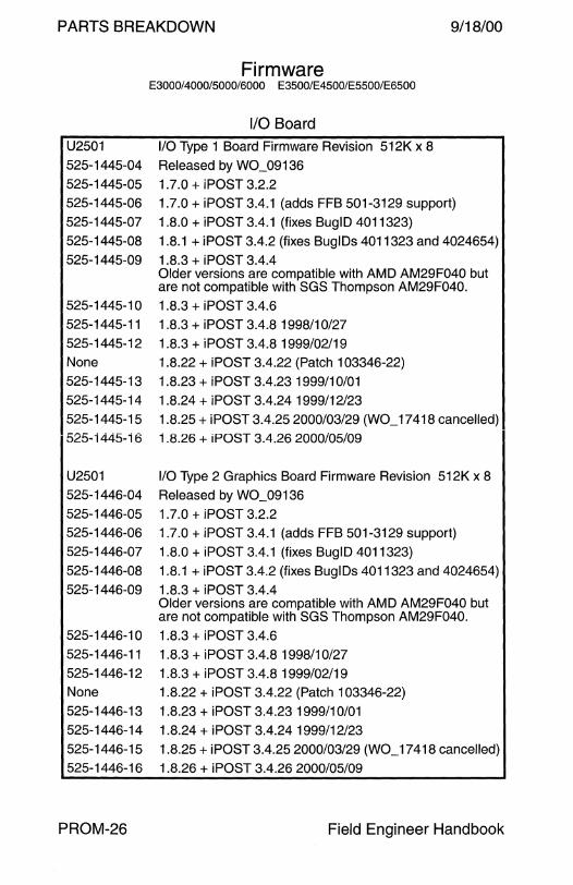
PARTS BREAKDOWN
Firmware E3000/4000/5000/6000 E3500/E4500/E5500/E6500
1/0 Board U2501 1/0 Type 1 Board Firmware Revision 512K x 8 525-1445-04 Released by W0_09136
525-1445-05 1.7.0 + iPOST 3.2.2
9/18/00
525-1445-06 1.7.0 + iPOST 3.4.1 (adds FFB 501-3129 support)
525-1445-07 1.8.0 + iPOST 3.4.1 {fixes BuglD 4011323) 525-1445-08 1.8.1 + iPOST 3.4.2 (fixes BuglDs 4011323 and 4024654)
525-1445-09 1.8.3 + i POST 3.4.4 Older versions are compatible with AMO AM29F040 but are not compatible with SGS Thompson AM29F040.
525-1445-10 1.8.3 + iPOST 3.4.6
525-1445-11 1.8.3 + iPOST 3.4.8 1998/10/27
525-1445-12 1.8.3 + iPOST 3.4.8 1999/02/19 None 1.8.22 + iPOST 3.4.22 (Patch 103346-22) 525-1445-13 1.8.23 + iPOST 3.4.23 1999/10/01
525-1445-14 1.8.24 + iPOST 3.4.241999/12/23 525-1445-15 1.8.25 + iPOST 3.4.25 2000/03/29(W0_17418 cancelled) 525-i445-i 6 i .8.26 + iPOST 3.4.26 2000/05/09
U2501 1/0 Type 2 Graphics Board Firmware Revision 512K x 8 525-1446-04 Released by W0_09136
525-1446-05 1.7.0 + iPOST 3.2.2 525-1446-06 525-1446-07
525-1446-08 525-1446-09
525-1446-1 0
525-1446-11 525-1446-12 None
525-1446-13
1.7.0 + iPOST 3.4.1 (adds FFB 501-3129 support) 1.8.0 + iPOST 3.4.1 (fixes BuglO 4011323)
1.8.1 + iPOST 3.4.2 {fixes BuglDs 4011323 and 4024654)
1.8.3 + iPOST 3.4.4 Older versions are compatible with AMO AM29F040 but are not compatible with SGS Thompson AM29F040. 1.8.3 + iPOST 3.4.6
1.8.3 + iPOST 3.4.8 1998/10/27
1.8.3 + iPOST 3.4.8 1999/02/19 1.8.22 + iPOST 3.4.22 (Patch 103346-22)
1.8.23 + iPOST 3.4.23 1999/10/01 525-1446-14 1.8.24 + iPOST 3.4.24 1999/12/23
525-1446-15 1.8.25 + iPOST 3.4.25 2000/03/29(W0_17418 cancelled) 525-1446-16 1.8.26 + iPOST 3.4.26 2000/05/09
PROM-26 Field Engineer Handbook

9/18/00 PARTS BREAKDOWN
Firmware E3000/4000/5000/6000 E3500/E4500/E5500/E6500
1/0 Board - Continued
U2501 PCI 1/0 Type 3 Board Firmware Revision 512K x 8 525-1680-01 1.8.7 + iPOST 3.0.2 ·
525-1680-02 1.8. 7 + iPOST 3.0.3 None 1.8.22 + iPOST 3.0.22 (Patch 103346-22)
525-1680-03 1.8.23 + iPOST 3.0.23 1999/10/01 525-1680-04 1.8.24 + iPOST 3.0.24 1999/12/23 525-1680-05 1.8.25 + iPOST 3.0.25 2000/03/29(W0_17418 cancelled}
525-1680-06 1.8.26 + iPOST 3.0.26 2000/05/09
U2501 1/0 Type 4 Board Firmware Revision 512K x 8
525-1757-01 1.8.6 + iPOST 3.4.4 525-1757-02 1.8.7 + iPOST unknown 525-1757-03 1.8.7 + iPOST 3.4.6
525-1757-04 1.8. 7 + iPOST 3.4.8 1998/10/27
525-1757-05 1.8. 7 + iPOST 3.4.8 1999/02/19 None 1.8.22 + iPOST 3.4.22 (Patch 103346-22) 525-1757-06 1.8.23 + iPOST 3.4.231999/10/01
525-1757-07 1.8.24 + iPOST 3.4.241999/12/23 525-1757-08 1.8.25 + iPOST 3.4.25 2000/03/29(W0_17418 cancelled)
525-1757-09 1.8.26 + iPOST 3.4.26 2000/05/09
U2501 1/0 Graphics Type 5 Board Firmware Revision 512K x 8 525-1760-01 Unknown
525-1760-02 Unknown 525-1760-03 1.8.7 + iPOST 3.4.6
525-1760-04 1.8.7 + iPOST 3.4.81998/10/27 525-1760-05 1.8.7 + iPOST 3.4.8 1999/02/19
None 1.8.22 + iPOST 3.4.22 (Patch 103346-22) 525-1760-06 1.8.23 + iPOST 3.4.23 1999/10/01 525-1760-07 1.8.24 + iPOST 3.4.24 1999/12/23
525-1760-08 1.8.25 + iPOST 3.4.25 2000/03/29(W0_17418 cancelled}
525-1760-09 1.8.26 + iPOST 3.4.26 2000/05/09
Volume II PROM-27
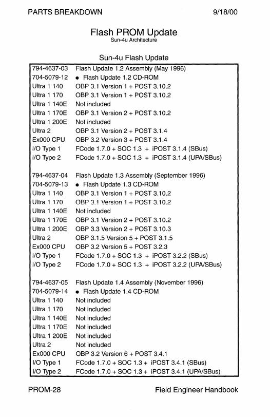
PARTS BREAKDOWN
Flash PROM Update Sun-4u Architecture
Sun-4u Flash Update 794-4637-03 Flash Update 1.2 Assembly (May 1996)
704-5079-12 • Flash Update 1.2 CD-ROM
Ultra 1 140 OBP 3.1 Version 1 + POST 3.10.2
OBP 3.1 Version 1 + POST 3.10.2
Not included
OBP 3.1 Version 2 + POST 3.10.2
Not included
OBP 3.1 Version 2 + POST 3.1.4
OBP 3.2 Version 3 + POST 3.1.4
9/18/00
Ultra 1 170
Ultra 1 140E
Ultra 1 170E
Ultra 1 200E
Ultra 2
ExOOO CPU
110 Type 1
110 Type 2
FCode 1.7.0 +SOC 1.3 + iPOST 3.1.4 (SBus)
FCode 1.7.0 +SOC 1.3 + iPOST 3.1.4 (UPA/SBus)
794-4637-04 Flash Update 1.3 Assembly (September 1996)
704-5079-13 • Flash Update 1.3 CD-ROM
Ultra 1 140
Ultra 1 170
Ultra 1 140E
Ultra 1 170E
Ultra 1 200E
Ultra 2
ExOOO CPU
110 Type 1
110 Type 2
OBP 3.1 Version 1 + POST 3.10.2
OBP 3.1 Version 1 + POST 3.10.2
Not included
OBP 3.1 Version 2 + POST 3.10.2
OBP 3.3 Version 2 + POST 3.10.3
OBP 3.1.5 Version 5 + POST 3.1.5
OBP 3.2 Version 5 + POST 3.2.3
FCode 1.7.0 +SOC 1.3 + iPOST 3.2.2 (SBus)
FCode 1.7.0 +SOC 1.3 + iPOST 3.2.2 (UPA/SBus)
794-4637-05 Flash Update 1.4 Assembly (November 1996)
704-5079-14 • Flash Update 1.4 CD-ROM
Ultra 1 140
Ultra 1 170
Ultra 1 140E
Ultra 1 170E
Ultra 1 200E
Ultra 2
ExOOO CPU
110 Type 1
110 Type 2
PROM-28
Not included
Not included
Not included
Not included
Not included
Not included
OBP 3.2 Version 6 + POST 3.4.1
FCode 1.7.0 +SOC 1.3 + iPOST 3.4.1 (SBus)
FCode 1.7.0 +SOC 1.3 + iPOST 3.4.1 (UPA/SBus)
Field Engineer Handbook
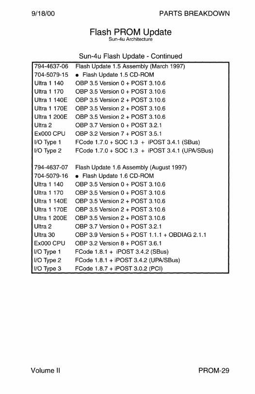
9/18/00 PARTS BREAKDOWN
Flash PROM Update Sun-4u Architecture
Sun-4u Flash Update - Continued
794-4637-06 Flash Update 1.5 Assembly (March 1997)
704-5079-15 • Flash Update 1.5 CD-ROM
Ultra 1 140
Ultra 1 170
Ultra 1 140E
Ultra 1 170E
Ultra 1 200E
Ultra 2
ExOOO CPU
1/0 Type 1
1/0 Type 2
OBP 3.5 Version 0 + POST 3.10.6
OBP 3.5 Version 0 + POST 3.10.6
OBP 3.5 Version 2 + POST 3.10.6
OBP 3.5 Version 2 + POST 3.10.6
OBP 3.5 Version 2 + POST 3.10.6
OBP 3.7 Version 0 +POST 3.2.1
OBP 3.2 Version 7 + POST 3.5.1
FCode 1.7.0 +SOC 1.3 + iPOST 3.4.1 (SBus)
FCode 1.7.0 +SOC 1.3 + iPOST 3.4.1 (UPA/SBus)
794-4637-07 Flash Update 1.6 Assembly (August 1997)
704-5079-16 • Flash Update 1.6 CD-ROM
Ultra 1 140
Ultra 1 170
Ultra 1 140E
Ultra 1 170E
Ultra 1 200E
Ultra 2
Ultra 30
ExOOO CPU
1/0 Type 1
1/0 Type 2
1/0 Type 3
Volume II
OBP 3.5 Version 0 + POST 3.10.6
OBP 3.5 Version 0 + POST 3.10.6
OBP 3.5 Version 2 + POST 3.10.6
OBP 3.5 Version 2 + POST 3.10.6
OBP 3.5 Version 2 + POST 3.10.6
OBP 3.7 Version 0 +POST 3.2.1
OBP 3.9 Version 5 + POST 1.1.1 + OBDIAG 2.1.1
OBP 3.2 Version 8 + POST 3.6.1
FCode 1.8.1 + iPOST 3.4.2 (SBus)
FCode 1.8.1 + iPOST 3.4.2 (UPA/SBus)
FCode 1.8.7 + iPOST 3.0.2 (PCI)
PROM-29

PARTS BREAKDOWN 9/18/00
Flash PROM Update Sun-4u Architecture
Sun-4u Flash Update - Continued
794-4637-08 Flash Update 1. 7 Assembly (October 1997)
704-5079-17 • Flash Update 1.7 CD-ROM
Ultra 1 140 OBP 3.5 Version 0 + POST 3.10.6 Ultra 1 170
Ultra 1 140E
Ultra 1 170E
Ultra 1 200E Ultra 2
Ultra 30
ExOOO CPU
1/0 Type 1
1/0 Type 2
1/0 Type 3
1/0 Type 4
1/0 Type 5
OBP 3.5 Version 0 + POST 3.10.6
OBP 3.5 Version 2 + POST 3.10.6
OBP 3.5 Version 2 + POST 3.10.6
OBP 3.5 Version 2 + POST 3.10.6
OBP 3.7 Version 0 +POST 3.2.1
OBP 3.9 Version 5 + POST 1.1.1 + OBDIAG 2.1.1
OBP 3.2 Version 10 + POST 3.7.2
FCode 1.8.1 + SOC 1.3 + iPOST 3.4.2 (SBus)
FCode 1.8.1 +SOC 1.3 + iPOST 3.4.2 (UPA/SBus)
FCode 1.8. 7 + iPOST 3.0.2 (PCI)
FCode 1.8.6 + SOC+ 1.10 + iPOST 3.0.2 (SBus)
FCode 1.8.6 + SOC+ 1.10 + iPOST 3.4.4 (UPA/SBus)
794-4637-09 Flash Update 1.8 Assembly (February 1998)
704-5079-18 • Flash Update 1.8 CD-ROM
Ultra 1 140
Ultra 1 170
Ultra 1 140E
Ultra 1 170E
Ultra 1 200E
Ultra 2
Ultra 5/10
Ultra 30
Ultra 60
Ultra 450
ExOOO CPU
1/0 Type 1
1/0 Type 2
1/0 Type 3
1/0 Type 4
1/0 Type 5
PROM-30
OBP 3.11 Version 1 + POST 3.10.6
OBP 3.11 Version 1 + POST 3.10.6
OBP 3.11 Version 1 + POST 3.11.4
OBP 3.11 Version 1 + POST 3.11.4
OBP 3.11 Version 1 + POST 3.11.4
OBP 3.11 Version 2 + POST 3.3.5
OBP 3.11 Version 7 + POST 2.2.8
OBP 3.11 Version 1 +POST 1.1.1 + OBDIAG 2.1.1
OBP 3.11 Version 25 + POST 1.0.8 + OBDIAG 2.1.1
OBP 3.7 Version 107 + POST 5.0.8
OBP 3.2 Version 12 + POST 3.8.4
FCode 1.8.3 + iPOST 3.4.4 (SBus)
FCode 1.8.3 + iPOST 3.4.4 (UPA/SBus)
FCode 1.8.7 + iPOST 3.0.2 (Type 3 Dual-PCI)
FCode 1.8.7 + iPOST 3.4.4 (Type 4 Dual-SBus SOC+)
FCode 1.8.7 + iPOST 3.4.4 (Type 5 UPA-SBus SOC+)
Field Engineer Handbook
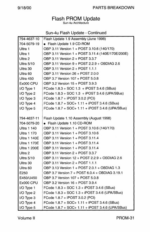
9/18/00
794-4637-10
704-5079-19
Ultra 1
Ultra 1
Ultra 2
Ultra 5/10
Ultra 30
Ultra 60
Ultra 450
ExOOO CPU
1/0 Type 1
1/0 Type 2
1/0 Type 3
1/0 Type 4
1/0 Type 5
794-4637 -11
704-5079-20
Ultra 1 140
Ultra 1 170
Ultra 1 140E
Ultra 1 170E
Ultra 1 200E
Ultra 2
Ultra 5/10
Ultra 30
Ultra 60
E250
E450/U450
ExOOO CPU
1/0 Type 1
1/0 Type 2
1/0 Type 3
1/0 Type 4
1/0 Type 5
Volume II
PARTS BREAKDOWN
Flash PROM Update Sun-4u Architecture
Sun-4u Flash Update - Continued
Flash Update 1.9 Assembly (June 1998)
• Flash Update 1.9 CD-ROM
OBP 3.11 Version 1 + POST 3.10.6 (140/170)
OBP 3.11 Version 1 + POST 3.11.4 (140E/170E/200E)
OBP 3.11 Version 2 + POST 3.3. 7
OBP 3.11 Version 9 + POST 2.2.9 + OBDIAG 2.6
OBP 3.11 Version 2 + POST 1.1.1
OBP 3.11 Version 26 + POST 2.0.0
OBP 3.7 Version 107 +POST 5.0.8
OBP 3.2 Version 15 + POST 3.9.3
FCode 1.8.3 + SOC 1.3 + iPOST 3.4.6 (SBus)
FCode 1.8.3 +SOC 1.3 + iPOST 3.4.6 (UPA/SBus)
FCode 1.8.7 + iPOST 3.0.2 (PCI)
FCode 1.8.7 + SOC+ 1.11 + iPOST 3.4.6 (SBus)
FCode 1.8.7 + SOC+ 1.11 + iPOST 3.4.6 (UPA/SBus)
Flash Update 1.1 O Assembly (August 1998)
• Flash Update 1 .10 CD-ROM
OBP 3.11 Version 1 + POST 3.10.6 (140/170)
OBP 3.11 Version 1 + POST 3.10.6
OBP 3.11 Version 1 + POST 3.11.4
OBP 3.11 Version 1 + POST 3.11.4
OBP 3.11 Version 1 + POST 3.11.4
OBP 3.11 Version 2 +POST 3.3.7
OBP 3.11 Version 12 + POST 2.2.9 + OBDIAG 2.6
OBP 3.11 Version 2 + POST 1.1.1
OBP 3.13 Version 1 + POST 2.0.1 + OBDIAG 1.3
OBP 3.7 Version 7 + POST 6.0.4 + OBDIAG 3.19.1
OBP 3.7 Version 107 + POST 5.0.8
OBP 3.2 Version 16 + POST 3.9.4
FCode 1.8.3 + SOC 1.3 + iPOST 3.4.6 (SBus)
FCode 1.8.3 + SOC 1.3 + iPOST 3.4.6 (UPA/SBus)
FCode 1.8.7 + iPOST 3.0.2 (PCI)
FCode 1.8.7 +SOC+ 1.11 + iPOST 3.4.6 (SBus)
FCode 1.8.7 +SOC+ 1.11 + iPOST 3.4.6 (UPA/SBus)
PROM-31
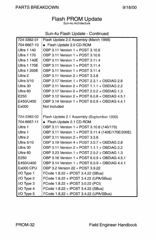
PARTS BREAKDOWN 9/18/00
Flash PROM Update Sun-4u Architecture
Sun-4u Flash Update - Continued
724-3382-01 Flash Update 2.0 Assembly (March 1999)
704-6667-10 • Flash Update 2.0 CD-ROM
Ultra 1 140 OBP 3.11 Version 1 + POST 3.10.6
Ultra 1 170
Ultra 1 140E
Ultra 1 170E
Ultra 1 200E
Ultra 2
Ultra 5/1 O
Ultra 30
Ultra 60
E250
E450/U450
ExOOO
724-3382-02
704-6667-11
Ultra 1
Ultra 1
Ultra 2
Ultra 5/10
Ultra 30
Ultra 60
E250
E450/U450
ExOOO CPU
1/0 Type 1
1/0 Type 2
1/0 Type 3
1/0 Type 4
1/0 Type 5
PROM-32
OBP 3.11 Version 1 + POST 3.10.6
OBP 3.11 Version 1 + POST 3.11.4
OBP 3.11 Version 1 + POST 3.11.4
OBP 3.11 Version 1 + POST 3.11.4
OBP 3.11 Version 2 + POST 3.3.8
OBP 3.17 Version 1 + POST 2.3.1 + OBDIAG 2.8
OBP 3.11 Version 2 + POST 1.1.1 + OBDIAG 2.2
OBP 3.17 Version 0 + POST 2.0.2 + OBDIAG 1.3
OBP 3.12 Version 2 + POST 6.0.8 + OBDIAG 4.5.1
OBP 3.14 Version 1+POST6.0.9 + OBDIAG 4.4.1
Not Included
F!ash Update 2.1 ,A,ssembly {September 1999) • Flash Update 2.1 CD-ROM
OBP 3.11 Version 1 + POST 3.10.6 (140/170)
OBP 3.11 Version 1 + POST 3.11.4 (140E/170E/200E)
OBP 3.11 Version 2 + POST 3.3.8
OBP 3.19 Version 4 +POST 3.0.7 + OBDIAG 2.8
OBP 3.11 Version 2 + POST 1.1.1 + OBDIAG 2.2
OBP 3.23 Version 1 + POST 2.0.2 + OBDIAG 1.3
OBP 3.16 Version 1 + POST 6.0.9 + OBDIAG 4.5.1
OBP 3.14 Version 1 + POST 6.0.9 + OBDIAG 4.4.1
OBP 3.2 Version 22 + POST 3.9.22
FCode 1.8.22 + iPOST 3.4.22 (SBus)
FCode 1.8.22 + iPOST 3.4.22 (UPA/SBus)
FCode 1.8.22 + iPOST 3.0.22 (PCI)
FCode 1.8.22 + iPOST 3.4.22 (SBus)
FCode 1.8.22 + iPOST 3.4.22 (UPA/SBus)
Field Engineer Handbook
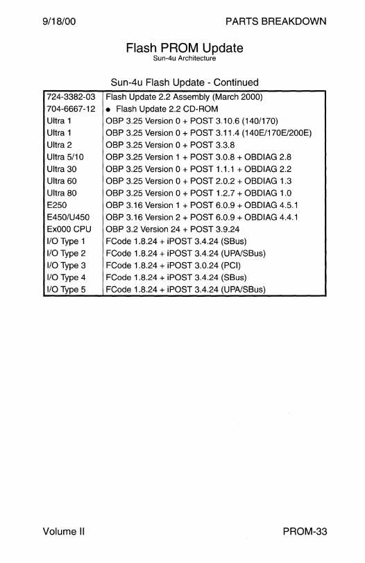
9/18/00
724-3382-03
704-6667-12
Ultra 1
Ultra 1
Ultra 2
Ultra 5/10
Ultra 30
Ultra 60
Ultra 80
E250
E450/U450
ExOOO CPU
1/0 Type 1
1/0 Type 2
1/0 Type 3
1/0 Type 4
1/0 Type 5
Volume II
PARTS BREAKDOWN
Flash PROM Update Sun-4u Architecture
Sun-4u Flash Update - Continued
Flash Update 2.2 Assembly (March 2000)
• Flash Update 2.2 CD-ROM
OBP 3.25 Version 0 +POST 3.10.6 (140/170)
OBP 3.25 Version 0 + POST 3.11.4 (140E/170E/200E)
OBP 3.25 Version 0 + POST 3.3.8
OBP 3.25 Version 1 + POST 3.0.8 + OBDIAG 2.8
OBP 3.25 Version 0 + POST 1.1.1 + OBDIAG 2.2
OBP 3.25 Version 0 + POST 2.0.2 + OBDIAG 1.3
OBP 3.25 Version 0 +POST 1.2.7 + OBDIAG 1.0
OBP 3.16 Version 1 + POST 6.0.9 + OBDIAG 4.5.1
OBP 3.16 Version 2 + POST 6.0.9 + OBDIAG 4.4.1
OBP 3.2 Version 24 + POST 3.9.24
FCode 1.8.24 + iPOST 3.4.24 (SBus)
FCode 1.8.24 + iPOST 3.4.24 (UPA/SBus)
FCode 1.8.24 + iPOST 3.0.24 (PCI)
FCode 1.8.24 + iPOST 3.4.24 (SBus)
FCode 1.8.24 + iPOST 3.4.24 (UPA/SBus)
PROM-33

This page intentionally left blank.
PARTS BREAKDOWN
BOARD

9/18/00 PARTS BREAKDOWN
Board
CPU Sun-4m Architecture ......................................................... . microSPARC llep ............................................................. . Sun-4d Architecture .......................................................... .
3 7 8
Sun-4u Architecture .. .. .. .... .. .. .. .. .. ... .. . .. .. . .... ... .. . .. .. .. ... .. .. ..... 12 Sun-4u1 Architecture ........................................................ . 25
Graphics ZX TZX Expert 3D . . . . . . . . . . . . . . . . . . . . . . . . . . . . . . . . . . . . . . . . . . . . . . . . . . . . . . . 26 Cables ............................................................................... 27
SCSI SBus .................................................................................. 28 PCI .................................................................................... 29 XDbus SCSI Disk Cards . .. .. .. .. .... ... ..... .. .. . .... .. .. . . .. . .. .. .. . . .. ... 30 Gigaplane SCSI Disk Card................................................ 31 RSM Array 2000 . . . . . . . . . . . . . . . . . . . . . . . . . . . . . . . . . . . . . . . . . . . . . . . . . . . . . . . . . . . . . . . . 32 StorEdge A3000 . . . . . . . . . . . . . . . . . . . . . . . . . . . . . . . . . . . . . . . . . . . . . . . . . . . . . . . . . . . . . . . . 32 StorEdge A3500 . . . . . . . . . . . . . . . . . . . . . . . . . . . . . . . . . . . . . . . . . . . . . . . . . . . . . . . . . . . . . . . . 32 StorEdge A3500FC ........................................................... 32 StorEdge A 1000 . . . . . . . . . . . . . . . . . . . . . . . . . . . . . . . . . . . . . . . . . . . . . . . . . . . . . . . . . . . . . . . . 32 StorEdge D1000 ................................................................ 32 External Single-Ended 8-Bit Narrow SCSI Cables . .. ...... ... 33 External Differential and 16-Bit Wide SCSI Cables ..... ... ... 34 Terminators . .. .. .. .. .. ... . .. .. .. .. .. .. .. .. .. . .. . ... . .. .. ..... ... .. .. .. .. . . . . .. .. .. 35
Fibre Channel SPARCstorage Array Model 100 ....................................... 36 SPARCstorage Array Model 112 ....................................... 37 SPARCstorage Array Model 200 ....................................... 38 SPARCstorage Array Model 210 ....................................... 39 Enterprise Network Array A5000 . . . . . . . . . . . . . . . . . . . . . . . . . . . . . . . . . . . . . . . 40 StorEdge A5000/51 00/5200 . . . . . . . . . . . . . . . . . . . . . . . . . . . . . . . . . . . . . . . . . . . . . . 40
Field Engineer Handbook - Volume II
PARTS BREAKDOWN 9/18/00
Board - Continued
Ethernet Accessories . . . . . . . . . . . . . . . . . . . . . . . . . . . . . . . . . . . . . . . . . . . . . . . . . . . . . . . . . . . . . . . . . . . . . . . 41 SBus .................................................................................. 42 PCI .................................................................................... 44
Communication SBus .................................................................................. 45 PCI .................................................................................... 49
Miscellaneous Board Hardware ................................................................ 51
BOARD-2 Field Engineer Handbook
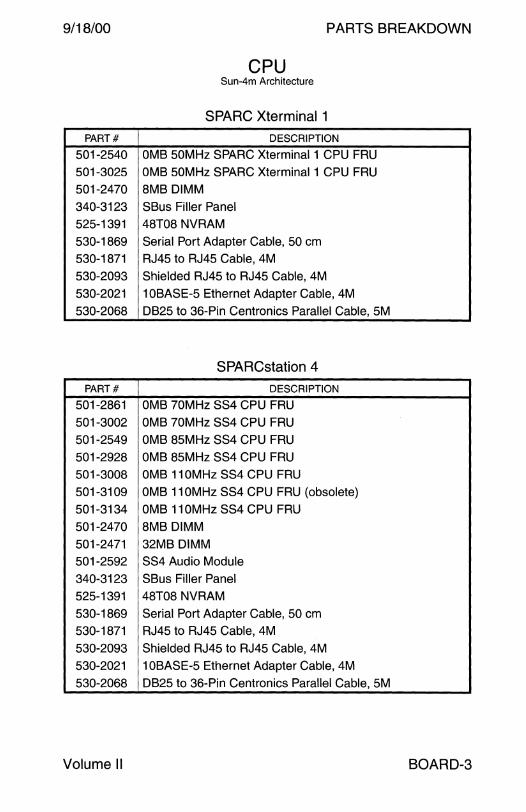
9/18/00 PARTS BREAKDOWN
CPU Sun-4m Architecture
SPARC Xterminal 1
PART# DESCRIPTION
501-2540 OM8 50MHz SPARC Xterminal 1 CPU FRU 501-3025 OM8 50MHz SPARC Xterminal 1 CPU FRU
501-2470 8M8 OIMM
340-3123 S8us Filler Panel
525-1391 48T08 NVRAM
530-1869 Serial Port Adapter Cable, 50 cm
530-1871 RJ45 to RJ45 Cable, 4M
530-2093 Shielded RJ45 to RJ45 Cable, 4M
530-2021 108ASE-5 Ethernet Adapter Cable, 4M
530-2068 0825 to 36-Pin Centronics Parallel Cable, 5M
SPARCstation 4
PART# DESCRIPTION
501-2861 OM870MHzSS4CPUFRU
501-3002 OM8 70MHz SS4 CPU FRU
501-2549 OM8 85MHz SS4 CPU FRU
501-2928 OM8 85MHz SS4 CPU FRU
501-3008 OM8 11 OM Hz SS4 CPU FRU
501-3109 OM8 110MHz SS4 CPU FRU (obsolete)
501-3134 OM8 11 OM Hz SS4 CPU FRU
501-2470 8M8 OIMM
501-2471 32M8 DIMM
501-2592 SS4 Audio Module
340-3123 S8us Filler Panel
525-1391 48T08 NVRAM
530-1869 Serial Port Adapter Cable, 50 cm 530-1871 RJ45 to RJ45 Cable, 4M
530-2093 Shielded RJ45 to RJ45 Cable, 4M
530-2021 108ASE-5 Ethernet Adapter Cable, 4M
530-2068 0825 to 36-Pin Centronics Parallel Cable, 5M
Volume II BOARD-3

PARTS BREAKDOWN 9/18/00
CPU Sun-4m Architecture
SPARCstation 5
PART# DESCRIPTION
S01-2286 OMB 70MHz SSS CPU FRU
S01-2798 OMB 70MHz SSS CPU FRU
S01-2S72 OMB 8SMHz SSS CPU FRU
S01-2799 OMB 8SMHz SSS CPU FRU
S01-281S OMB 8SMHz SSS CPU FRU
S01-2778 OMB 11 OM Hz SSS CPU FRU
S01-30S9 OMB 170MHz SSS CPU FRU
S01-2470 8MB DIMM
S01-2471 32MB DIMM
240-2101 M3 Machine Screw
2S0-1200 Spring for M3 Machine Screw
340-1763 SBus Filler Panel
S2S-1369 48T08 NVRAM
S30-2021 1 OBASE-S Ethernet Adapter Cable, 2S cm
530-1857 HD26 to 36=Pin Centronics Paiallel Port Cable, 5ivi S30-1861 HD26 to DB2S IBM Parallel Port Cable, SM
S30-1869 Serial Port Adapter Cable, SO cm
S30-1871 RJ4S to RJ4S Cable, 4M
S30-2093 Shielded RJ4S to RJ4S Cable, 4M
BOARD-4 Field Engineer Handbook

9/18/00 PARTS BREAKDOWN
CPU Sun-4m Architecture
SPARCstation 20
PART# DESCRIPTION
501-2324 OMB SS20 CPU FRU 501-2924 OMB SS20 CPU FRU
501-2961 OMB SS20 CPU FRU
501-2479 16MB DIMM
501-2622 32MB DIMM
501-2480 64MB DIMM 501-2771 64MB DIMM (internal use only)
501-2481 4MB VSIMM
501-2482 8MB VSIMM
501-2528 SM50 SuperSPARC Module 3.5
501-2568 SM50 SuperSPARC Module 5.x
501-2708 SM50 SuperSPARC Module 5.x
501-2712 SM50 SuperSPARC Module 5.x
501-2562 SM51 SuperSPARC Module 3.5 501-2607 SM51 SuperSPARC Module 3.5
501-2617 SM51 SuperSPARC Module 5.x
501-2707 SM51 SuperSPARC Module 5.x 501-2754 SM51 SuperSPARC Module 5.2
501-2780 SM52X SuperSPARC Module 3.5 501-2756 SM52X SuperSPARC Module 5.2
501-2613 SM61 SuperSPARC Module 5.x
501-2519 SM61 SuperSPARC Module 5.x
501-2769 SM61 SuperSPARC Module 5.x 501-2752 SM61 SuperSPARC Module 5.2
501-2825 SM61 SuperSPARC Module 5.2
501-2520 75MHz SuperSPARC Module 1.6
501-2904 75MHz SuperSPARC Module 2.3
501-2925 75MHz SuperSPARC Module 2.4.5
501-2940 75MHz SuperSPARC Module 2.4
501-3001 75MHz SuperSPARC Module 2.4.3
501-4130 75MHz SuperSPARC Module 2.4.5
Volume II BOARD-5
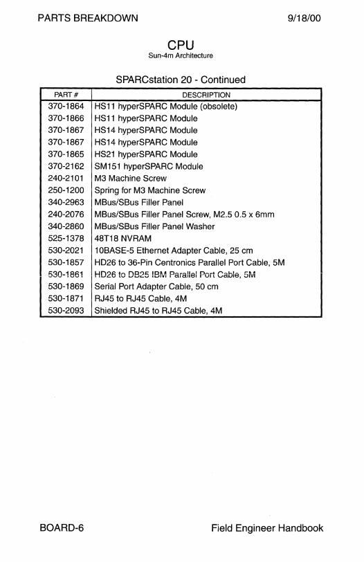
PARTS BREAKDOWN 9/18/00
CPU Sun-4m Architecture
SPARCstation 20 - Continued
PART# DESCRIPTION
370-1864 HS11 hyperSPARC Module (obsolete)
370-1866 HS11 hyperSPARC Module 370-1867 HS14 hyperSPARC Module 370-1867 HS14 hyperSPARC Module
370-1865 HS21 hyperSPARC Module 370-2162 SM151 hyperSPARC Module 240-2101 M3 Machine Screw
250-1200 Spring for M3 Machine Screw 340-2963 MBus/SBus Filler Panel
240-2076 MBus/SBus Filler Panel Screw, M2.5 0.5 x 6mm 340-2860 MBus/SBus Filler Panel Washer 525-1378 48T18 NVRAM
530-2021 1 OBASE-5 Ethernet Adapter Cable, 25 cm 530-1857 HD26 to 36-Pin Centronics Parallel Port Cable, SM
530-1861 HD26 to DB25 IB~v1 Parallel Poit Cable, 5rv1 530-1869 Serial Port Adapter Cable, 50 cm 530-1871 RJ45 to RJ45 Cable, 4M
530-2093 Shielded RJ45 to RJ45 Cable, 4M
BOARD-6 Field Engineer Handbook
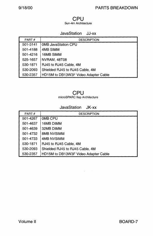
9/18/00 PARTS BREAKDOWN
CPU Sun-4m Architecture
JavaStation JJ-xx
PART# DESCRIPTION
501-3141 OMB JavaStation CPU 501-4188 4MB SIMM 501-4216 16MB SIMM
525-1657 NVRAM, 48T08
530-1871 RJ45 to RJ45 Cable, 4M 530-2093 Shielded RJ45 to RJ45 Cable, 4M 530-2357 HD15M to DB13W3F Video Adapter Cable
CPU microSPARC llep Architecture
JavaStation JK-xx PART# DESCRIPTION
501-4267 OMB CPU
501-4637 16MB DIMM 501-4639 32MB DIMM
501-4732 8MB NVSIMM 501-4733 4MB NVSIMM 530-1871 RJ45 to RJ45 Cable, 4M
530-2093 Shielded RJ45 to RJ45 Cable, 4M
530-2357 HD15M to DB13W3F Video Adapter Cable
Volume II BOARD-7
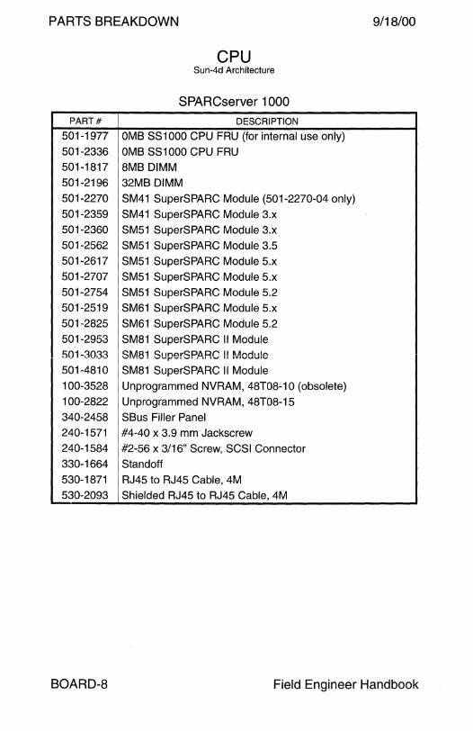
PARTS BREAKDOWN 9/18/00
CPU Sun-4d Architecture
SPARCserver 1000
PART# DESCRIPTION
501-1977 OMB SS1000 CPU FRU (for internal use only)
501-2336 OMB SS1000 CPU FRU 501-1817 8MB DIMM
501-2196 32MB DIMM
501-2270 SM41 SuperSPARC Module (501-2270-04 only) 501-2359 SM41 SuperSPARC Module 3.x
501-2360 SM51 SuperSPARC Module 3.x
501-2562 SM51 SuperSPARC Module 3.5
501-2617 SM51 SuperSPARC Module 5.x
501-2707 SM51 SuperSPARC Module 5.x 501-2754 SM51 SuperSPARC Module 5.2
501-2519 SM61 SuperSPARC Module 5.x
501-2825 SM61 SuperSPARC Module 5.2
501-2953 SM81 SuperSPARC II Module
501-3033 SM81 SuperSPARC !! Module
501-4810 SM81 SuperSPARC II Module
100-3528 Unprogrammed NVRAM, 48T08-10 (obsolete)
100-2822 Unprogrammed NVRAM, 48T08-15
340-2458 SBus Filler Panel 240-1571 #4-40 x 3.9 mm Jackscrew
240-1584 #2-56 x 3/16" Screw, SCSI Connector
330-1664 Standoff
530-1871 RJ45 to RJ45 Cable, 4M
530-2093 Shielded RJ45 to RJ45 Cable, 4M
BOARD-8 Field Engineer Handbook

9/18/00 PARTS BREAKDOWN
CPU Sun-4d Architecture
SPARCserver 1 OOOE
PART# DESCRIPTION
501-2668 OMB SS1000E CPU FRU
501-1817 8MB DIMM
501-2196 32MB DIMM
501-2519 SM61 SuperSPARC Module 5.x
501-2825 SM61 SuperSPARC Module 5.2
501-2953 SM81 SuperSPARC II Module
501-3033 SM81 SuperSPARC II Module
501-4810 SM81 SuperSPARC II Module
100-3528 Unprogrammed NVRAM, 48T08-10
340-2458 SBus Filler Panel 530-1871 RJ45 to RJ45 Cable, 4M
530-2093 Shielded RJ45 to RJ45 Cable, 4M
Volume II BOARD-9

PARTS BREAKDOWN 9/18/00
CPU Sun-4d Architecture
SPARCcenter 2000
PART# DESCRIPTION
SPARCcenter 2000
501-1866 OMB SC2000 CPU FRU
501-2334 OMB SC2000 CPU FRU
501-1817 8MB DIMM
501-2196 32MB DIMM
501-2197 1MB NVSIMM
501-2318 SM41 SuperSPARC Module 3.x (pre-fcs)
501-2270 SM41 SuperSPARC Module 3.x (501-2270-04 only)
501-2359 SM41 SuperSPARC Module 3.x
501-2353 SM51-2 SuperSPARC Module 3.x
501-2601 SM51-2 SuperSPARC Module 3.5
501-2618 SM51-2 SuperSPARC Module 5.x
501-2755 SM51-2 SuperSPARC Module 5.2
501-2543 SM61-2 SuperSPARC Module 5.x
501-2757 S~.~61-2 SuperSPl\RC ~1odule 5.2 501-3022 SM81-2 SuperSPARC II Module
501-3098 SM81-2 SuperSPARC II Module
501-4780 SM81-2 SuperSPARC II Module
501-5056 SM81-2 SuperSPARC II Module
100-2822 Unprogrammed NVRAM, 48T08-15
330-1664 SBus and SPARC Module Standoff
340-2528 SBus Filler Panel
530-1871 RJ45 to RJ45 Cable, 4M
530-2093 Shielded RJ45 to RJ45 Cable, 4M
BOARD-10 Field Engineer Handbook
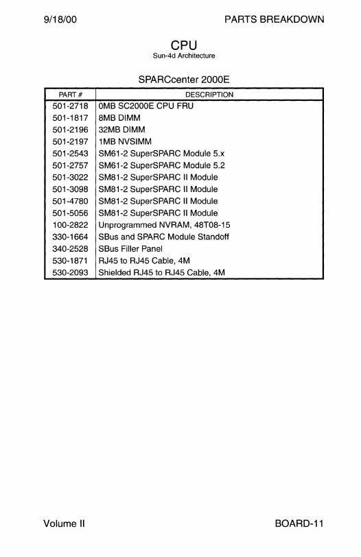
9/18/00 PARTS BREAKDOWN
CPU Sun-4d Architecture
SPARCcenter 2000E
PART# DESCRIPTION
501-2718 OMB SC2000E CPU FRU
501-1817 8MB DIMM 501-2196 32MB DIMM
501-2197 1MB NVSIMM
501-2543 SM61-2 SuperSPARC Module 5.x
501-2757 SM61-2 SuperSPARC Module 5.2
501-3022 SM81-2 SuperSPARC II Module
501-3098 SM81-2 SuperSPARC II Module
501-4780 SM81-2 SuperSPARC II Module
501-5056 SM81-2 SuperSPARC II Module
100-2822 Unprogrammed NVRAM, 48T08-15
330-1664 SBus and SPARC Module Standoff
340-2528 SBus Filler Panel
530-1871 RJ45 to RJ45 Cable, 4M
530-2093 Shielded RJ45 to RJ45 Cable, 4M
Volume II BOARD-11

PARTS BREAKDOWN 9/18/00
CPU Sun-4u Architecture
Ultra 1 Models 140 and 170
PART# DESCRIPTION
Ultra 1 Model 140 (A 11)
501-2836 OMS CPU FRU
540-2761 • UltraSPARC Fan Assembly {discontinued 5/97 - 6/97)
501-2479 16MB DIMM
501-2622 32MB DIMM
501-2480 64MB DIMM
501-5691 64MB DIMM
501-3136 128MB DIMM
525-1430 NVRAM, 48T59
340-3187 SBus Filler Panel
530-2068 0825 to 36-Pin Centronics Parallel Cable, 5M
530-1871 RJ45 to RJ45 Cable, 4M
530-2093 Shielded RJ45 to RJ45 Cable, 4M
595-3780 Mil to AUi Converter (requires AC power)
Ultra 1 Model 170 (A 11)
501-3082 OMB CPU FRU
501-5139 OMB CPU FRU
540-2761 • UltraSPARC Fan Assembly (discontinued 5/97 - 6/97)
501-2479 16MB DIMM
501-2622 32MB DIMM
501-2480 64MB DIMM
501-5691 64MB DIMM
501-3136 128MB DIMM
525-1430 NVRAM, 48T59
340-3187 SBus Filler Panel
530-2068 0825 to 36-Pin Centronics Parallel Cable, 5M
530-1871 RJ45 to RJ45 Cable, 4M
530-2093 Shielded RJ45 to RJ45 Cable, 4M
595-3780 Mil to AUi Converter (requires AC power)
BOARD-12 Field Engineer Handbook
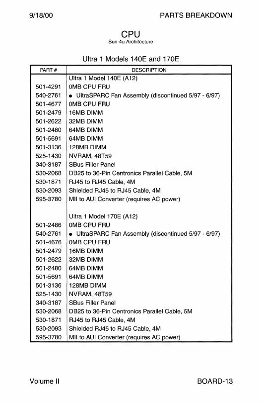
9/18/00 PARTS BREAKDOWN
CPU Sun-4u Architecture
Ultra 1 Models 140E and 170E
PART# DESCRIPTION
Ultra 1 Model 140E (A 12) 501-4291 OM8 CPU FRU 540-2761 • UltraSPARC Fan Assembly (discontinued 5/97 - 6/97) 501-4677 OM8 CPU FRU 501-2479 16M8 DIMM
501-2622 32M8 DIMM 501-2480 64M8 DIMM 501-5691 64M8 OIMM
501-3136 128M8 OIMM 525-1430 NVRAM, 48T59 340-3187 S8us Filler Panel 530-2068 0825 to 36-Pin Centronics Parallel Cable, 5M
530-1871 RJ45 to RJ45 Cable, 4M 530-2093 Shielded RJ45 to RJ45 Cable, 4M 595-3780 Mii to AUi Converter (requires AC power)
Ultra 1 Model 170E (A12) 501-2486 OM8 CPU FRU 540-2761 • UltraSPARC Fan Assembly (discontinued 5/97 - 6/97) 501-4676 OM8 CPU FRU 501-2479 ~6M8 DIMM 501-2622 32M8 DIMM
501-2480 64M8 DIMM 501-5691 64M8 OIMM
501-3136 128M8 OIMM 525-1430 NVRAM, 48T59
340-3187 S8us Filler Panel 530-2068 0825 to 36-Pin Centronics Parallel Cable, 5M
530-1871 RJ45 to RJ45 Cable, 4M 530-2093 Shielded RJ45 to RJ45 Cable, 4M 595-3780 Mii to AUi Converter (requires AC power)
Volume II BOARD-13
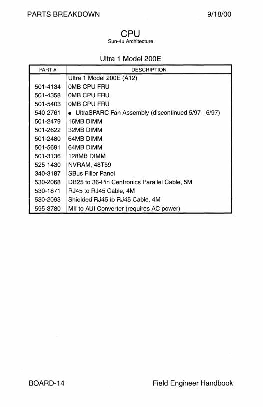
PARTS BREAKDOWN 9/18/00
CPU Sun-4u Architecture
Ultra 1 Model 200E
PART# DESCRIPTION
Ultra 1 Model 200E (A 12)
501-4134 OMB CPU FRU 501-4358 OMB CPU FRU
501-5403 OMB CPU FRU
540-2761 • UltraSPARC Fan Assembly (discontinued 5/97 - 6/97)
501-2479 16MB DIMM
501-2622 32MB DIMM
501-2480 64MB DIMM
501-5691 64MB DIMM
501-3136 128MB DIMM
525-1430 NVRAM, 48T59
340-3187 SBus Filler Panel
530-2068 0825 to 36-Pin Centronics Parallel Cable, SM
530-1871 RJ45 to RJ45 Cable, 4M
530-2093 Shieided RJ45 to RJ45 Gabie, 4ivi
595-3780 Mii to AUi Converter (requires AC power)
BOARD-14 Field Engineer Handbook
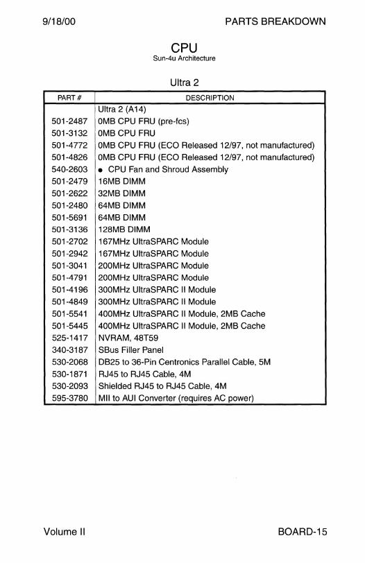
9/18/00 PARTS BREAKDOWN
CPU Sun-4u Architecture
Ultra 2
PART# DESCRIPTION
Ultra 2 (A14) 501-2487 OMB CPU FRU (pre-fcs)
501-3132 OMB CPU FRU
501-4772 OMB CPU FRU (ECO Released 12/97, not manufactured)
501-4826 OMB CPU FRU (ECO Released 12/97, not manufactured)
540-2603 • CPU Fan and Shroud Assembly 501-2479 16MB DIMM
501-2622 32MB DIMM
501-2480 64MB DIMM
501-5691 64MB DIMM
501-3136 128MB DIMM
501-2702 167MHz UltraSPARC Module
501-2942 167MHz UltraSPARC Module
501-3041 200MHz UltraSPARC Module
501-4791 200MHz UltraSPARC Module
501-4196 300MHz UltraSPARC II Module
501-4849 300MHz UltraSPARC II Module
501-5541 400MHz UltraSPARC II Module, 2MB Cache
501-5445 400MHz UltraSPARC II Module, 2MB Cache 525-1417 NVRAM, 48T59
340-3187 SBus Filler Panel
530-2068 0825 to 36-Pin Centronics Parallel Cable, 5M
530-1871 RJ45 to RJ45 Cable, 4M
530-2093 Shielded RJ45 to RJ45 Cable, 4M
595-3780 Mii to AUi Converter (requires AC power)
Volume II BOARD-15
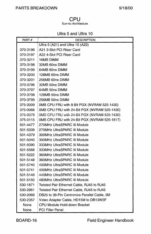
PARTS BREAKDOWN 9/18/00
CPU Sun-4u Architecture
Ultra 5 and Ultra 1 O
PART# DESCRIPTION
Ultra 5 (A21) and Ultra 10 (A22)
370-3196 A21 3-Slot PCI Riser Card
370-3197 A22 4-Slot PCI Riser Card
370-3211 16MB DIMM
370-3198 32MB 60ns DIMM
370-3199 64MB 60ns DIMM
370-3200 128MB 60ns DIMM
370-3201 256MB 60ns DIMM
370-3796 32MB 50ns DIMM
370-3797 64MB 50ns DIMM 370-3798 128MB 50ns DIMM
370-3799 256MB 50ns DIMM
375-0009 OMB CPU FRU with 8-Bit PGX (NVRAM 525-1430)
375-0066 OMB CPU FRU with 24-Bit PGX (NVRAM 525-1430) t:>'"7r::- rt.n7n V/\..rUU/ \:J
l\l lln ,.....n1 1 rn1 1 ... :.1.1_ ,..,. A n!.1. '"'"''' 1111. n ""'"'A 1. .111 ,...,...,.. ..... ,...,....,
VIVID vru rnu Wllll <:::'t-Dll r-uA ll'IVH/-\IVI 0<:::0-14.lUJ
375-0115 OMB CPU FRU with 24-Bit PGX (NVRAM 525-1817)
501-4477 270MHz UltraSPARC Iii Module
501-5039 270MHz UltraSPARC Iii Module
501-4379 300MHz UltraSPARC Iii Module
501-5040 300MHz UltraSPARC Iii Module
501-5090 333MHz UltraSPARC Iii Module
501-5568 333MHz UltraSPARC Iii Module
501-5222 360MHz UltraSPARC Iii Module 501-5148 360MHz UltraSPARC Iii Module
501-5740 400MHz UltraSPARC Iii Module
501-5741 400MHz UltraSPARC Iii Module
501-5149 440MHz UltraSPARC Iii Module
501-5150 480MHz UltraSPARC Iii Module
530-1871 Twisted Pair Ethernet Cable, RJ45 to RJ45
530-2961 Twisted Pair Ethernet Cable, RJ45 to RJ45
530-2068 0825 to 36-Pin Centronics Parallel Cable, 5M
530-2357 Video Adapter Cable, HD15M to DB13W3F
None CPU Module Hold-down Bracket
None PCI Filler Panel
BOARD-16 Field Engineer Handbook
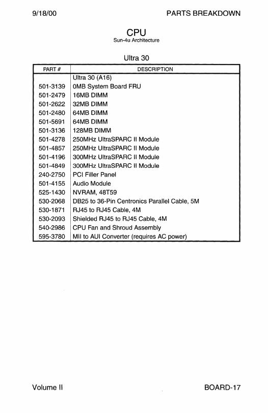
9/18/00 PARTS BREAKDOWN
CPU Sun-4u Architecture
Ultra 30
PART# DESCRIPTION
Ultra 30 (A 16)
501-3139 OMB System Board FRU
501-2479 16MB DIMM
501-2622 32MB DIMM
501-2480 64MB DIMM
501-5691 64MB DIMM
501-3136 128MB DIMM
501-4278 250MHz UltraSPARC II Module
501-4857 250MHz UltraSPARC II Module
501-4196 300MHz UltraSPARC II Module
501-4849 300MHz UltraSPARC II Module
240-2750 PCI Filler Panel
501-4155 Audio Module
525-1430 NVRAM, 48T59
530-2068 DB25 to 36-Pin Centronics Parallel Cable, 5M
530-1871 RJ45 to RJ45 Cable, 4M
530-2093 Shielded RJ45 to RJ45 Cable, 4M
540-2986 CPU Fan and Shroud Assembly
595-3780 Mii to AUi Converter (requires AC power)
Volume II BOARD-17
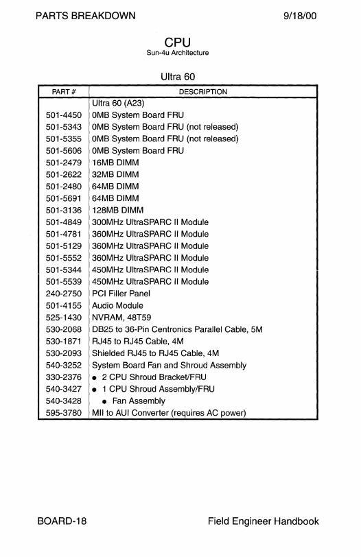
PARTS BREAKDOWN 9/18/00
CPU Sun-4u Architecture
Ultra 60
PART# DESCRIPTION
Ultra 60 (A23)
501-4450 OMB System Board FRU
501 -5343 OMB System Board FRU (not released)
501-5355 OMB System Board FRU (not released)
501 -5606 OMB System Board FRU
501 -2479 16MB DIMM
501 -2622 32MB DIMM
501-2480 64MB DIMM
501-5691 64MB DIMM
501-3136 128MB DIMM
501-4849 300MHz UltraSPARC Module
501 -4781 360MHz UltraSPARC Module
501-5129 360MHz UltraSPARC Module
501 -5552 360MHz UltraSPARC Module
501 -5344 450MHz UltraSPARC Module
501 -5539 450MHz UltraSPARC Module
240-2750 PCI Filler Panel
501-4155 Audio Module
525-1430 NVRAM, 48T59
530-2068 DB25 to 36-Pin Centronics Parallel Cable, SM
530-1871 RJ45 to RJ45 Cable, 4M
530-2093 Shielded RJ45 to RJ45 Cable, 4M
540-3252 System Board Fan and Shroud Assembly
330-2376 • 2 CPU Shroud Bracket/FRU
540-3427 • 1 CPU Shroud Assembly/FRU 540-3428 • Fan Assembly 595-3780 Mii to AUi Converter (requires AC power)
BOARD-18 Field Engineer Handbook
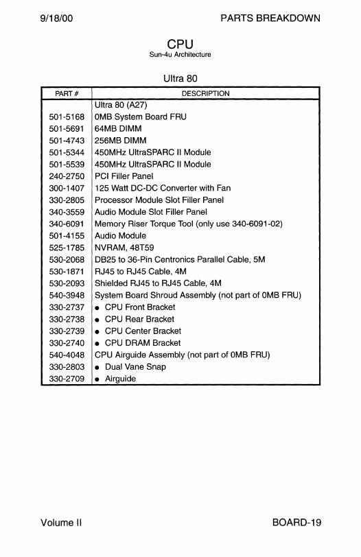
9/18/00 PARTS BREAKDOWN
CPU Sun-4u Architecture
Ultra 80
PART# DESCRIPTION
Ultra 80 {A27)
501-5168 OMB System Board FRU
501-5691 64MB DIMM
501-4743 256MB DIMM
501-5344 450MHz UltraSPARC II Module
501-5539 450MHz UltraSPARC II Module
240-2750 PCI Filler Panel
300-1407 125 Watt DC-DC Converter with Fan
330-2805 Processor Module Slot Filler Panel
340-3559 Audio Module Slot Filler Panel
340-6091 Memory Riser Torque Tool (only use 340-6091-02)
501-4155 Audio Module
525-1785 NVRAM, 48T59
530-2068 DB25 to 36-Pin Centronics Parallel Cable, 5M
530-1871 RJ45 to RJ45 Cable, 4M
530-2093 Shielded RJ45 to RJ45 Cable, 4M
540-3948 System Board Shroud Assembly (not part of OMB FRU)
330-2737 • CPU Front Bracket
330-2738 • CPU Rear Bracket 330-2739 • CPU Center Bracket
330-2740 • CPU DRAM Bracket
540-4048 CPU Airguide Assembly (not part of OMB FRU)
330-2803 • Dual Vane Snap 330-2709 • Airguide
Volume II BOARD-19
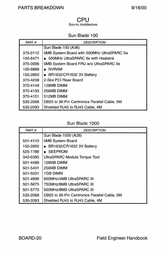
PARTS BREAKDOWN 9/18/00
CPU Sun-4u Architecture
Sun Blade 100
PART# DESCRIPTION
Sun Blade 100 (A36)
37S-0112 OMB System Board with SOOMHz UltraSPARC lie
100-6471 • SOOMHz UltraSPARC lie with Heatsink
37S-0096 OMB System Board FRU w/o UltraSPARC lie
100-6889 • NVRAM 1S0-28SO • BR1632/CR1632 3V Battery
370-4208 2-Slot PCI Riser Board
370-4149 128MB DIMM
370-41SO 2S6MB DIMM
370-41 S1 S12MB DIMM
S30-2068 DB2S to 36-Pin Centronics Parallel Cable, SM
S30-2093 Shielded RJ4S to RJ4S Cable, 4M
C:::11n Rl<:>rlo 1 ()()() '-"Ull L..llUUV IVVV
PART# DESCRIPTION
Sun Blade 1000 (A28)
S01-4143 OMB System Board
1S0-28SO • BR1632/CR1632 3V Battery
S2S-1788 • SEEPROM
340-639S UltraSPARC Module Torque Tool
S01-4489 128MB DIMM
S01-S401 2S6MB DIMM
S01-S031 1GB DIMM
S01-4999 600MHz/4MB UltraSPARC Ill
S01-S67S 7SOMHz/8MB UltraSPARC Ill
S01-S770 900MHz/8MB UltraSPARC Ill
S30-2068 DB2S to 36-Pin Centronics Parallel Cable, SM
S30-2093 Shielded RJ4S to RJ4S Cable, 4M
BOARD-20 Field Engineer Handbook
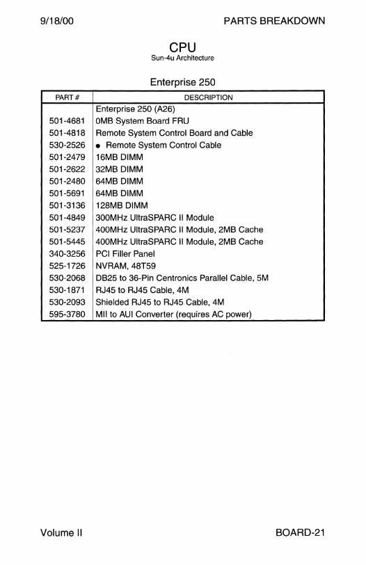
9/18/00 PARTS BREAKDOWN
CPU Sun-4u Architecture
Enterprise 250
PART# DESCRIPTION
Enterprise 250 (A26)
501-4681 OMB System Board FRU
501-4818 Remote System Control Board and Cable
530-2526 • Remote System Control Cable 501-2479 16MB DIMM
501-2622 32MB DIMM
501-2480 64MB DIMM
501-5691 64MB DIMM
501-3136 128MB DIMM
501-4849 300MHz UltraSPARC II Module 501-5237 400MHz UltraSPARC II Module, 2MB Cache
501-5445 400MHz UltraSPARC II Module, 2MB Cache
340-3256 PCI Filler Panel
525-1726 NVRAM, 48T59
530-2068 DB25 to 36-Pin Centronics Parallel Cable, 5M
530-1871 RJ45 to RJ45 Cable, 4M
530-2093 Shielded RJ45 to RJ45 Cable, 4M
595-3780 Mii to AUi Converter (requires AC power)
Volume II BOARD-21

PARTS BREAKDOWN 9/18/00
CPU Sun-4u Architecture
Ultra 450 Ultra Enterprise 450 PART# DESCRIPTION
Ultra 450 (A20) and Ultra Enterprise 450 (A25)
300-1322 45 Watt DC-DC Converter 330-2781 Slot CPU-A 1 Air Baffle for 400MHz Module
330-3102 Empty CPU Slot Filler Panel for 480MHz Systems
330-3127 Empty Slot CPU-A 1 Cover for 480MHz Systems
501-5028 OMB System Board FRU (A20 only) 501-2996 OMB System Board FRU (A25 only)
501-5270 OMB System Board FRU (A25 only)
501-5672 OMB System Board FRU (A25 only)
501-5673 OMB System Board FRU (A25 only)
501-2622 32MB DIMM 501-2480 64MB DIMM
501-5691 64MB DIMM 501-3136 128MB DIMM
501-4743 256iviB Diiviivi 501-5896 256MB DIMM with Gate Array Logic
501-4278 250MHz UltraSPARC Module 501-4857 250MHz UltraSPARC Module
501-4196 300MHz UltraSPARC Module 501-4849 300MHz UltraSPARC Module 501-5239 400MHz UltraSPARC Module, 4MB Cache
501-5446 400MHz UltraSPARC Module, 4MB Cache 501-5449 480MHz UltraSPARC Module, 4MB Cache 525-1673 NVRAM, 48T59
340-3256 PCI Filler Panel
501-2592 Audio Module
530-1869 Serial Port Adapter Cable, 50 cm 530-1871 RJ45 to RJ45 Cable, 4M 530-2068 DB25 to 36-Pin Centronics Parallel Cable, 5M
530-2093 Shielded RJ45 to RJ45 Cable, 4M 540-4597 Airduct Assembly/FRU for 480MHz Module
595-3780 Mii to AUi Converter (requires AC power)
BOARD-22 Field Engineer Handbook

9/18/00 PARTS BREAKDOWN
CPU Sun-4u Architecture
Ultra Enterprise 3000/4000/5000/6000
PART# DESCRIPTION
Ultra Enterprise 3000/4000/5000/6000 501-2557 CPU/Memory (not released - seen during flash update)
501-2976 OMB CPU/Memory FRU (2MB cache support)
501-4312 OMB CPU/Memory FRU (8MB cache support)
100-4007 • CPU/Memory Board NVRAM
501-2511 Clock Board (not released - seen during flash update)
501-2975 83MHz Clock Board ( +2 clock ratio)
501-4286 83MHz Clock Board (+2 and +3 clock ratios)
525-1665 • Clock Board NVRAM, 48T59 501-2941 167MHz UltraSPARC Module, 1/2MB Cache 501-2959 167MHz UltraSPARC Module, 1 MB Cache
501-4178 250MHz UltraSPARC II Module, 1 MB Cache
501-4249 250MHz UltraSPARC II Module, 4MB Cache
501-4836 250MHz UltraSPARC II Module, 4MB Cache
501-2652 8MB DIMM
501-2653 32MB DIMM
501-2654 128MB DIMM
501-5658 256MB DIMM
501-2558 1/0 Board (not released - seen during flash update)
501-2977 83MHz 1/0 Board with SOC
501-4287 83MHz 1/0 Board with SOC
501-4266 83MHz 1/0 Board with SOC+
501-2749 83MHz 1/0 Graphics Board with SOC 501-4288 83MHz 110 Graphics Board with SOC
501-4325 83MHz PCI 1/0 Board FRU with 2x 5V Risers
530-1871 RJ45 to RJ45 Cable, 4M
530-2093 Shielded RJ45 to RJ45 Cable, 4M
595-3780 Mii to AUi Converter (requires AC power)
Notes 1. The ExOOO CPU/Memory and 1/0 boards may be used in the Ex500. 2. The minimum OS for the ExOOO is 2.5.1. 3. The minimum OS for the Ex500 is 2.5.1 HW: 11 /97 or 2.6 HW: 3/98. 4. The minimum OBP for the Ex500 is 3.2 Version 14.
Volume II BOARD-23
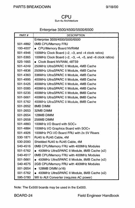
PARTS BREAKDOWN 9/18/00
CPU Sun-4u Architecture
Enterprise 3500/4500/5500/6500
PART# DESCRIPTION
Enterprise 3500/4500/5500/6500
501-4882 OMB CPU/Memory FRU
100-4007 • CPU/Memory Board NVRAM
501-4946 1 OOMHz Clock Board (+2, +3, and +4 clock ratios)
501-5365 100MHz Clock Board (+2, +3, +4, +5, and +6 clock ratios)
525-1665 • Clock Board NVRAM, 48T59
501-4249 250MHz UltraSPARC Module, 4MB Cache
501-4836 250MHz UltraSPARC Module, 4MB Cache
501-4363 336MHz UltraSPARC Module, 4MB Cache
501-4995 400MHz UltraSPARC Module, 4MB Cache
501-5425 400MHz UltraSPARC Module, 4MB Cache
501-5585 400MHz UltraSPARC Module, 4MB Cache
501-5235 400MHz UltraSPARC Module, 8MB Cache
501-5661 400MHz UltraSPARC Module, 8MB Cache C:fH 1:7&>"' vv 1-v1u.c..
Af\f'\ft.JILI-. I llJ. .. -("'t.nA nl""'\ .. vv1v1nL u1u ct.::>r-Mnv Module, 8ivi8 Cache
501-2652 8MB DIMM
501-2653 32MB DIMM
501-2654 128MB DIMM
501-2658 256MB DIMM
501-4883 1 OOMHz 1/0 Board with SOC+
501-4884 1 OOMHz 1/0 Graphics Board with SOC+
501-4926 1 OOMHz PCI 1/0 Board FRU with 2x 5V Risers
530-1871 RJ45 to RJ45 Cable, 4M
530-2093 Shielded RJ45 to RJ45 Cable, 4M
540-4516 OMB CPU/Memory FRU with 400MHz Modules
501-5762 • 400MHz UltraSPARC II Module, 8MB Cache (x2)
540-4517 OMB CPU/Memory FRU with 400MHz Modules
501-5661 • 400MHz UltraSPARC II Module, 8MB Cache (x2)
540-4575 2GB CPU/Memory FRU with 400MHz Modules
501-2654 • 128MB DIMM {x16)
501-5762 • 400MHz UltraSPARC II Module, 8MB Cache (x2)
595-3780 Mii to AUi Converter (requires AC power)
Note: The Ex500 boards may be used in the ExOOO.
BOARD-24 Field Engineer Handbook
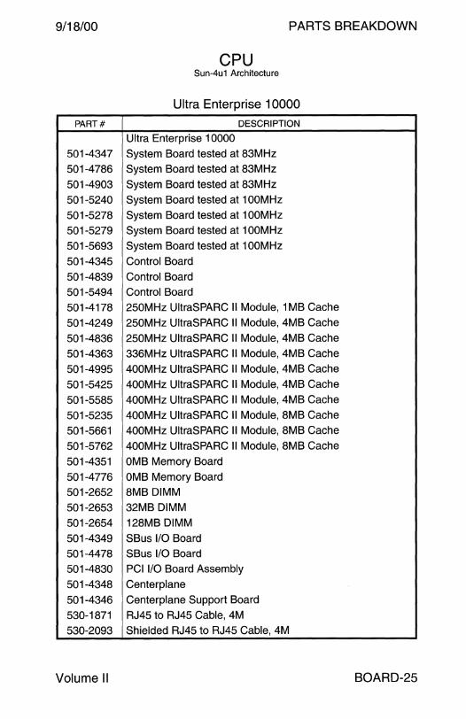
9/18/00 PARTS BREAKDOWN
CPU Sun-4u1 Architecture
Ultra Enterprise 10000
PART# DESCRIPTION
Ultra Enterprise 10000
501-4347 System Board tested at 83MHz
501-4786 System Board tested at 83MHz
501-4903 System Board tested at 83MHz
501-5240 System Board tested at 100MHz
501-5278 System Board tested at 1 OOMHz
501-5279 System Board tested at 1 OOMHz
501-5693 System Board tested at 100MHz
501-4345 Control Board
501-4839 Control Board
501-5494 Control Board
501-4178 250MHz UltraSPARC Module, 1 MB Cache
501-4249 250MHz UltraSPARC Module, 4MB Cache
501-4836 250MHz UltraSPARC Module, 4MB Cache
501-4363 336MHz UltraSPARC Module, 4MB Cache
501-4995 400MHz UltraSPARC Module, 4MB Cache
501-5425 400MHz UltraSPARC Module, 4MB Cache
501-5585 400MHz UltraSPARC Module, 4MB Cache
501-5235 400MHz UltraSPARC Module, 8MB Cache
501-5661 400MHz UltraSPARC Module, 8MB Cache
501-5762 400MHz UltraSPARC Module, 8MB Cache
501-4351 OMB Memory Board
501-4776 OMB Memory Board
501-2652 8MB DIMM
501-2653 32MB DIMM
501-2654 128MB DIMM
501-4349 SBus 1/0 Board
501-4478 SBus 1/0 Board
501-4830 PCI 1/0 Board Assembly
501-4348 Centerplane
501-4346 Centerplane Support Board
530-1871 RJ45 to RJ45 Cable, 4M
530-2093 Shielded RJ45 to RJ45 Cable, 4M
Volume II BOARD-25
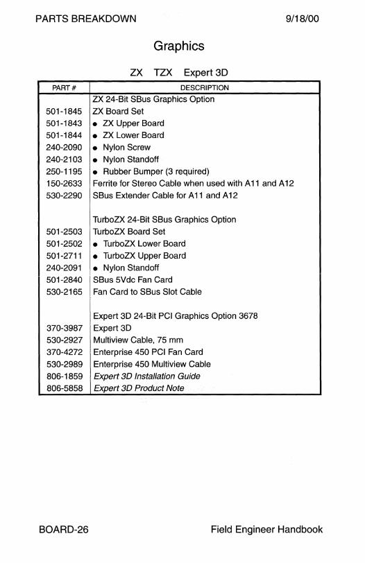
PARTS BREAKDOWN 9/18/00
Graphics
ZX TZX Expert 30
PART# DESCRIPTION
ZX 24-Bit SBus Graphics Option
501-1845 ZX Board Set
501-1843 • ZX Upper Board
501-1844 • ZX Lower Board
240-2090 • Nylon Screw 240-2103 • Nylon Standoff
250-1195 • Rubber Bumper (3 required)
150-2633 Ferrite for Stereo Cable when used with A 11 and A 12
530-2290 SB us Extender Cable for A 11 and A 12
TurboZX 24-Bit SBus Graphics Option
501-2503 TurboZX Board Set
501-2502 • TurboZX Lower Board
501-2711 • TurboZX Upper Board
240-2091 • Nylon Standoff 501-2840 SBus 5Vdc Fan Card
530-2165 Fan Card to SBus Slot Cable
Expert 30 24-Bit PCI Graphics Option 3678
370-3987 Expert 30
530-2927 Multiview Cable, 75 mm
370-4272 Enterprise 450 PCI Fan Card
530-2989 Enterprise 450 Multiview Cable
806-1859 Expert 30 Installation Guide
806-5858 Expert 30 Product Note
BOARD-26 Field Engineer Handbook
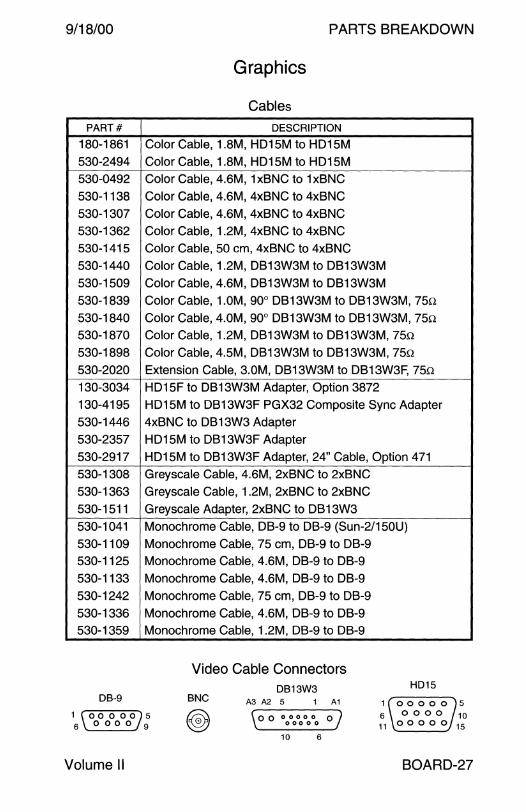
9/18/00 PARTS BREAKDOWN
Graphics
Cables
PART# DESCRIPTION
180-1861 Color Cable, 1.8M, H01 SM to H01 SM S30-24g4 Color Cable, 1.8M, H01 SM to H01 SM 530-04g2 Color Cable, 4.6M, 1x8NC to 1x8NC
S30-1138 Color Cable, 4.6M, 4x8NC to 4x8NC S30-1307 Color Cable, 4.6M, 4x8NC to 4x8NC S30-1362 Color Cable, 1.2M, 4x8NC to 4x8NC 530-1415 Color Cable, SO cm, 4x8NC to 4x8NC S30-1440 Color Cable, 1.2M, 0813W3M to 0813W3M S30-1sog Color Cable, 4.6M, 0813W3M to 0813W3M S30-183g Color Cable, 1.0M, go0 0813W3M to 0813W3M, 7Sn
530-1840 Color Cable, 4.0M, go0 0813W3M to 0813W3M, 7Sn S30-1870 Color Cable, 1.2M, 0813W3M to 0813W3M, 7Sn S30-18g8 Color Cable, 4.SM, 0813W3M to 0813W3M, 7Sn
530-2020 Extension Cable, 3.0M, 0813W3M to 0813W3F, 7Sn 130-3034 H01SF to 0813W3M Adapter, Option 3872 130-41gs H015M to 0813W3F PGX32 Composite Sync Adapter
S30-1446 4x8NC to 0813W3 Adapter S30-23S7 H01 SM to 0813W3F Adapter S30-2g17 H01SM to 0813W3F Adapter, 24" Cable, Option 471 S30-1308 Greyscale Cable, 4.6M, 2x8NC to 2x8NC S30-1363 Greyscale Cable, 1.2M, 2x8NC to 2x8NC
S30-1 S11 Greyscale Adapter, 2x8NC to 0813W3
530-1041 Monochrome Cable, 08-g to 08-g (Sun-2/1 SOU) S30-11og Monochrome Cable, 7S cm, 08-g to 08-g S30-112S Monochrome Cable, 4.6M, 08-g to 08-g
S30-1133 Monochrome Cable, 4.6M, 08-g to 08-g
S30-1242 Monochrome Cable, 7S cm, 08-g to 08-g
S30-1336 Monochrome Cable, 4.6M, 08-g to 08-g S30-13Sg Monochrome Cable, 1.2M, 08-g to 08-g
Video Cable Connectors DB13W3 HD15
DB-9 BNC A3 A2 5 1 A1
1 (ooooo}s 6 \0000 9
( 0 o 00000 oj \ 00000 .
1 00000 5 6 0 0 0 0 10 11 0 0 0 0 0 15
10 6
Volume II BOARD-27

PARTS BREAKDOWN
SCSI
SB us
PART# DESCRIPTION
501-1869 SCSI Host Adapter and Buffered Ethernet SBE/S
130-2031 • Adapter, RJ45F to RJ45F 340-2573 • SCSI Connector Screw, #2-56 x 1/4" 530-1812 • 10Base5 Adapter Cable, DB-15, 70 mm
530-1813 • 10Base-T Adapter Cable, RJ-45, 40 mm
9/18/00
501-2015 Fast SCSI Host Adapter and Buffered Ethernet FSBE/S
340-2573 • SCSI Connector Screw, #2-56 x 1/4"
501-1902 Differential SCSI Host and Buffered Ethernet DSBE/S
340-2573 • SCSI Connector Screw, #2-56 x 1/4" 240-1911 • SCSI Connector Standoff, #2-56M - #2-56F (obsolete)
240-2110 • SCSI Connector Standoff, #2-56M - #2-56F, Slotted
501-2739 SunSwift SBus SCSI/Ethernet 530-1871 [ RJ45 to RJ45 Cable, 4M
BOARD-28 Field Engineer Handbook

9/18/00 PARTS BREAKDOWN
SCSI
PCI
PART# DESCRIPTION
501-2741 SunSwift PCI SCSI/Ethernet 501-5656 SunSwift PCI SCSI/Ethernet 530-1871 RJ45 to RJ45 Cable, 4M
375-0005 Dual Single-Ended Ultra SCSI without FCode 375-0013 Dual Single-Ended Ultra SCSI with FCode 530-2366 E450 Internal A-Port and B-Port Cable 530-2452 External HD68 to VHDCl68 Cable, 80 cm 530-2453 External HD68 to VHDCl68 Cable, 2M
375-0006 Dual Differential Ultra SCSI without FCode 375-0014 Dual Differential Ultra SCSI with FCode 530-2366 E450 Internal A-Port and B-Port Cable 530-2452 External HD68 to VHDCl68 Cable, 80 cm 530-2453 External HD68 to VHDCl68 Cable, 2M
375-0078 SCSI RAID Controller SRC/P None • DPT PM3755U2B SmartRAID Millennium None • DPT DM4050-64 64MB DIMM
375-0082 • DPT BB4050 Battery Backup Module None • DPT BP-0001-001 2.4V Battery None • DPT SX4055U2-2 SCSI Expansion Module
530-2733 External HD68 to VHDCl68 Cable, 2M (obsolete) 530-2453 External HD68 to VHDCl68 Cable, 2M * (-02 required) 530-2744 E450 Internal 8-Disk Backplane Cable
* Two 530-2452-01 or 530-2453-01 cables are not usable at the same time on the A and B ports due to thickness of the connector shell. The shell thickness was reduced on cables 530-2452-02 and 530-2453-02.
Volume II BOARD-29
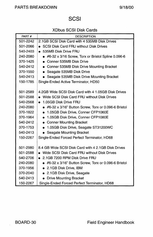
PARTS BREAKDOWN 9/18/00
SCSI
XDbus SCSI Disk Cards
PART# DESCRIPTION
501-2242 2.1 GB SCSI Disk Card with 4 535MB Disk Drives
501-2066 • SCSI Disk Card FRU without Disk Drives 540-2403 • 535MB Disk Drive FRU 240-2080 • #6-32 x 3/16 Screw, Torx or Bristol Spline 0.096-6 370-1425 • Conner 535MB Disk Drive 540-2412 • Conner 535MB Disk Drive Mounting Bracket
370-1550 • Seagate 535MB Disk Drive 540-2413 • Seagate 535MB Disk Drive Mounting Bracket 150-1785 Single-Ended Active Terminator, HD50
501-2589 4.2GB Wide SCSI Disk Card with 4 1.05GB Disk Drives 501-2588 • Wide SCSI Disk Card FRU without Disk Drives
540-2568 • 1.05GB Disk Drive FRU 240-2080 • #6-32 x 3/16" Button Screw, Torx or 0.096-6 Bristol
370-1822 • 1.05GB Disk Drive, Conner CFP1060E 370-1964 • 1.05GB Disk Drive, Conner CFP1080E
540-2412 • Conner Mounting Bracket
370-1753 • 1.05GB Disk Drive, Seagate ST31200WC 540-2413 • Seagate Mounting Bracket
150-2267 Single-Ended Forced Perfect Terminator, HD68
501-2980 8.4 GB Wide SCSI Disk Card with 4 2.1 GB Disk Drives
501-2588 • Wide SCSI Disk Card FRU without Disk Drives 540-2706 • 2.1 GB 7200 RPM Disk Drive FRU 240-2080 • #6-32 x 3/16" Button Screw, Torx or 0.096-6 Bristol
370-1956 • 2.1 GB Disk Drive, IBM 370-2040 • 2.1 GB Disk Drive, Seagate 540-2413 • Drive Mounting Bracket 150-2267 Single-Ended Forced Perfect Terminator, HD68
BOARD-30 Field Engineer Handbook

9/18/00 PARTS BREAKDOWN
SCSI
Gigaplane SCSI Disk Card
PART# DESCRIPTION
501-4168 4.2 GB Wide SCSI Disk Card with 2 2.1 GB Disk Drives
501-3113 • Wide SCSI Disk Card FRU without Disk Drives
540-2730 • 2.1 GB 7200 RPM Disk Drive FRU
370-2040 • 2.1 GB Disk Drive, Seagate ST32550WC
370-1956 • 2.1GB Disk Drive, IBM DFHS-32160
540-2936 • 2.1 GB 7200 RPM Disk Drive FRU
370-2365 • 2.1GB Disk Drive, Seagate ST32171WC
370-1808 • 2.1 GB Disk Drive, Quantum VK22J05
501-5137 8.4 GB Wide SCSI Disk Card with 2 4.2GB Disk Drives
501-3113 • Wide SCSI Disk Card FRU without Disk Drives 540-2938 • 4.2GB 7200 RPM Disk Drive FRU
370-2367 • 4.2GB Disk Drive, Seagate ST34371WC
370-2809 • 4.2GB Disk Drive, Quantum VK45J05
370-3403 • 4.2GB Disk Drive, IBM DDRS-34560 370-3412 • 4.2GB Disk Drive, Fujitsu MAB3045SC
501-5584 18.2 GB Wide SCSI Disk Card with 2 9.1 GB Disk Drives
501-3113 • Wide SCSI Disk Card FRU without Disk Drives 540-3704 • 9.1 GB 7200 RPM Disk Drive FRU 370-3404 • 9.1 GB Disk Drive, IBM DDRS-39130
370-3413 • 9.1GB Disk Drive, Fujitsu MAB3091SC
370-3595 • 9.1 GB Disk Drive, Seagate ST39173WC
390-0004 • 9.1 GB Disk Drive, Fujitsu MAE3091 LC 390-0007 • 9.1GB Disk Drive, IBM DNES-309170
501-5584 36.4 GB Wide SCSI Disk Card with 2 18.2GB Disk Drives
501-3113 • Wide SCSI Disk Card FRU without Disk Drives 540-4177 • 18.2GB 10000 RPM Disk Drive FRU 390-0002 • 18.2GB Disk Drive, Seagate ST318203LC
390-0006 • 18.2GB Disk Drive, Fujitsu MAG3182LC
390-0038 • 18.2GB Disk Drive, Seagate ST318404LC 390-0043 • 18.2GB Disk Drive, Fujitsu MAJ3182WC
Volume II BOARD-31
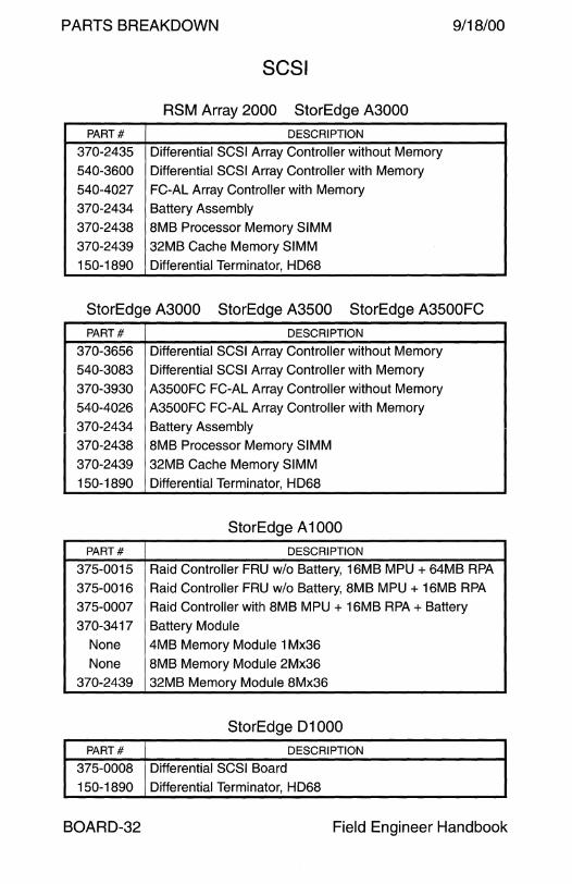
PARTS BREAKDOWN 9/18/00
SCSI
RSM Array 2000 StorEdge A3000
PART# DESCRIPTION
370-2435 Differential SCSI Array Controller without Memory
540-3600 Differential SCSI Array Controller with Memory
540-4027 FC-AL Array Controller with Memory
370-2434 Battery Assembly
370-2438 8MB Processor Memory SIMM
370-2439 32MB Cache Memory SIMM
150-1890 Differential Terminator, HD68
StorEdge A3000 StorEdge A3500 StorEdge A3500FC PART# DESCRIPTION
370-3656 Differential SCSI Array Controller without Memory
540-3083 Differential SCSI Array Controller with Memory
370-3930 A3500FC FC-AL Array Controller without Memory
540-4026 A3500FC FC-AL Array Controller with Memory
370-2434 Battery Assembly
370-2438 8MB Processor Memory SIMM
370-2439 32MB Cache Memory SIMM
150-1890 Differential Terminator, HD68
StorEdge A 1 000
PART# DESCRIPTION
375-0015 Raid Controller FRU w/o Battery, 16MB MPU + 64MB RPA
375-0016 Raid Controller FRU w/o Battery, 8MB MPU + 16MB RPA
375-0007 Raid Controller with 8MB MPU + 16MB RPA + Battery
370-3417 Battery Module
None 4MB Memory Module 1 Mx36
None 8MB Memory Module 2Mx36
370-2439 32MB Memory Module 8Mx36
StorEdge 01000
PART# DESCRIPTION
375-0008 Differential SCSI Board
150-1890 Differential Terminator, HD68
BOARD-32 Field Engineer Handbook
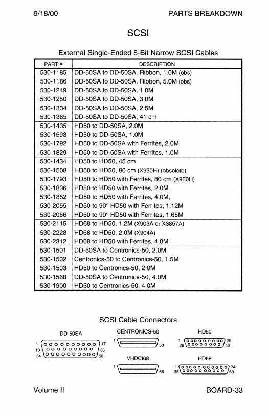
9/18/00 PARTS BREAKDOWN
SCSI
External Single-Ended 8-Bit Narrow SCSI Cables
PART# DESCRIPTION
530-1185 DD-50SA to DD-50SA, Ribbon, 1.0M (obs)
530-1186 DD-50SA to DD-50SA, Ribbon, 5.0M (obs) 530-124g DD-50SA to DD-50SA, 1.0M
530-1250 DD-50SA to DD-50SA, 3.0M
530-1334 DD-50SA to DD-50SA, 2.5M
530-1365 DD-50SA to DD-50SA, 41 cm
530-1435 HD50 to DD-50SA, 2.0M 530-15g3 HD50 to DD-50SA, 1.0M 530-17g2 HD50 to DD-50SA with Ferrites, 2.0M 530-182g HD50 to DD-50SA with Ferrites, 1.0M
530-1434 HD50 to HD50, 45 cm
530-1508 HD50 to HD50, 80 cm (X930H) (obsolete) 530-17g3 HD50 to HD50 with Ferrites, 80 cm (X930H)
530-1836 HD50 to HD50 with Ferrites, 2.0M
530-1852 HD50 to HD50 with Ferrites, 4.0M,
530-2055 HD50 to go0 HD50 with Ferrites, 1.12M
530-2056 HD50 to go0 HD50 with Ferrites, 1.65M
530-2115 HD68 to HD50, 1.2M (X903A or X3857 A)
530-2228 HD68 to HD50, 2.0M (X904A)
530-2312 HD68 to HD50 with Ferrites, 4.0M
530-1501 DD-50SA to Centronics-50, 2.0M
530-1502 Centronics-50 to Centronics-50, 1.5M
530-1503 HD50 to Centronics-50, 2.0M
530-1568 DD-50SA to Centronics-50, 4.0M 530-1goo HD50 to Centronics-50, 4.0M
SCSI Cable Connectors
DD-SOSA CENTRONICS-50 HDSO
1 o o o o o o o o o o 17 1 ~====150 18 0 0 0 0 0 0 0 0 0 33 34 0000000000 50
VHDCl68
1 ~====168
Volume II
1 0 00 0 0 0 0 00 25 26 0 00 0 0 0 0 0 50
HD68
1 00000 000000 34 35 0 00 0 0 0 0 0 0 0 68
BOARD-33

PARTS BREAKDOWN 9/18/00
SCSI
External Differential and 16-Bit Wide SCSI Cables
PART# DESCRIPTION
370-3427 HD68M to 2x HD68F, 30 cm (Y-Cable X3851A)
530-1883 HD68 to HD68, 20 cm
530-1884 HD68 to HD68 with Ferrites, 80 cm
530-1885 HD68 to HD68 with Ferrites, 2M
530-1886 HD68 to HD68, 12.0M (X979A)
530-2022 HD68 to HD68, 1.0M (X905A)
530-2057 HD68 to HD68, 25 cm (X977A)
530-2224 HD68 to HD68 with Ferrites, 1 M
530-2352 HD68 to HD68 with Ferrites, 4M (X3810A)
530-2375 HD68 to HD68 with Ferrites, 12M
530-2383 HD68 to HD68 with Ferrites, 80 cm* (X3856A)
530-2384 HD68 to HD68 with Ferrites, 2M *
530-2452 HD68 to VHDCl68 with Ferrites, 80 cm *
530-2453 HD68 to VHDCl68 with Ferrites, 2M *
530-2454 HD68 to VHDCl68 with Ferrites, 4M (X3830A)
530-2455 HD68 to VHDCi68 wiih Ferrites, i OM (X3831A)
530-2574 HD68 to HD68 with Ferrites, 6M (X3838A)
530-2575 HD68 to HD68 with Ferrites, 8M (X3839A)
530-272g Left go0 HD68 to VHDCl68, 2M (X992A) *
530-2735 go0 HD68 to go0 HD68, 16 cm (X991A) *
530-2751 Left go0 HD68 to VHDCl68, 4M (X993A)
530-27go go0 HD68 to VHDCl68, .3M (X6917A)
530-2846 Right go0 HD68 to VHDCl68, 2M (X959A) *
530-2847 Right go0 HD68 to VHDCl68, 4M (X947A)
530-2go5 go0 HD68 to VHDCl68, .SM
370-3545 L 1000 go0 HD68 to go0 HD68, 18 cm
370-3546 L 1000 go0 HD68 to go0 HD68, 36 cm
* These cables support Single-Ended Ultra/Wide SCSI transfer rates.
BOARD-34 Field Engineer Handbook

9/18/00 PARTS BREAKDOWN
SCSI
Terminators
PART# DESCRIPTION
150-1346 Single-Ended Passive Terminator, HD50
150-1407 Single-Ended Passive Terminator, 50-Pin Centronics
150-1785 Single-Ended Active Terminator, HD50
150-2283 Single-Ended Forced Perfect Terminator, HD50
530-1381 Single-Ended Passive Terminator, DD-50SA
150-1890 Differential Terminator, HD68 with LED
150-2267 Single-Ended Forced Perfect Terminator, HD68
370-3549 Differential Terminator, HD68 without LED (StorEdge L280)
370-3712 Differential Terminator, HD68, Low Profile (StorEdge L3500)
Volume II BOARD-35

PARTS BREAKDOWN 9/18/00
Fibre Channel
SPARCstorage Array Model 100
PART# DESCRIPTION
501-2552 Configured Array Controller
340-2666 • Filler Panel 370-1426 • Fibre Channel Optical Module 501-2028 • Battery Module (obsolete, removed from 501-2552-05) 501-2857 • Battery Module 501-2080 • Array Controller (40MHz microSPARC II)
501-2553 Configured SBus Optical Channel Host Adapter 340-2895 • Filler Panel 370-1426 • Fibre Channel Optical Module 501-2069 • SBus Optical Channel Host Adapter SOCHA or FC25/S
537-1004 SC Duplex 50/125 Multimode Fibre Optical Cable, 2M 537-1020 SC Duplex 50/125 Multimode Fibre Optical Cable, SM
537-1006 SC Duplex 50/125 Multimode Fibre Optical Cable, 15M
SBus Optical Channel Host Adapter FCode
SOCHA PART# FCode PART# FCode REVISION
501-2069-05 525-1386-02 1.18 501-2069-07 525-1386-03 1.33
501-2069-09 525-1386-04 1.52
BOARD-36 Field Engineer Handbook
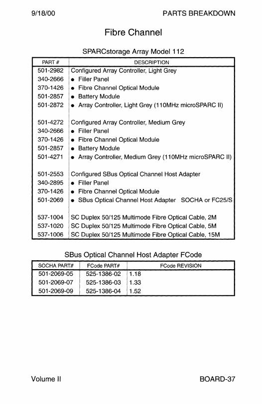
9/18/00 PARTS BREAKDOWN
Fibre Channel
SPARCstorage Array Model 112
PART# DESCRIPTION
501-2982 Configured Array Controller, Light Grey
340-2666 • Filler Panel 370-1426 • Fibre Channel Optical Module 501-2857 • Battery Module 501-2872 • Array Controller, Light Grey (110MHz microSPARC II)
501-4272 Configured Array Controller, Medium Grey 340-2666 • Filler Panel 370-1426 • Fibre Channel Optical Module 501-2857 • Battery Module 501-4271 • Array Controller, Medium Grey (110MHz microSPARC II)
501-2553 Configured SBus Optical Channel Host Adapter 340-2895 • Filler Panel 370-1426 • Fibre Channel Optical Module 501-2069 • SBus Optical Channel Host Adapter SOCHA or FC25/S
537-1004 SC Duplex 50/125 Multimode Fibre Optical Cable, 2M 537-1020 SC Duplex 50/125 Multimode Fibre Optical Cable, 5M 537-1006 SC Duplex 50/125 Multimode Fibre Optical Cable, 15M
SBus Optical Channel Host Adapter FCode
SOCHA PART# FCode PART# FCode REVISION
501-2069-05 525-1386-02 1.18
501-2069-07 525-1386-03 1.33 501-2069-09 525-1386-04 1.52
Volume II BOARD-37

PARTS BREAKDOWN 9/18/00
Fibre Channel
SPARCstorage Array Model 200
PART# DESCRIPTION
501-2786 Configured Array Controller
340-2666 • Filler Panel 370-1426 • Fibre Channel Optical Module 501-2857 • Battery Module 501-2651 • Differential Array Controller (40MHz microSPARC II)
501-2553 Configured SBus Optical Channel Host Adapter 340-2895 • Filler Panel 370-1426 • Fibre Channel Optical Module 501-2069 • SBus Optical Channel Host Adapter SOCHA or FC25/S
501-2670 Differential SCSI to Fibre Channel Adapter
537-1004 SC Duplex 50/125 Multimode Fibre Optical Cable, 2M
537-1020 SC Duplex 50/125 Multimode Fibre Optical Cable, SM
537-1006 SC Duplex 50/125 Multimode Fibre Optical Cable, 1 SM
SBus Optical Channel Host Adapter FCode
SOCHA PART# FCode PART# FCode REVISION
501-2069-05 525-1386-02 1.18
501-2069-07 525-1386-03 1.33
501-2069-09 525-1386-04 1.52
BOARD-38 Field Engineer Handbook
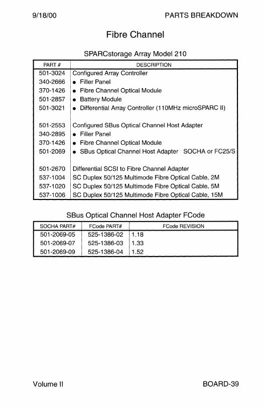
9/18/00 PARTS BREAKDOWN
Fibre Channel
SPARCstorage Array Model 21 O
PART# DESCRIPTION
501-3024 Configured Array Controller
340-2666 • Filler Panel 370-1426 • Fibre Channel Optical Module
501-2857 • Battery Module 501-3021 • Differential Array Controller (11 OMHz microSPARC 11)
501-2553 Configured SBus Optical Channel Host Adapter
340-2895 • Filler Panel 370-1426 • Fibre Channel Optical Module
501-2069 • SBus Optical Channel Host Adapter SOCHA or FC25/S
501-2670 Differential SCSI to Fibre Channel Adapter
537-1004 SC Duplex 50/125 Multimode Fibre Optical Cable, 2M
537-1020 SC Duplex 50/125 Multimode Fibre Optical Cable, 5M
537-1006 SC Duplex 50/125 Multimode Fibre Optical Cable, 15M
SBus Optical Channel Host Adapter FCode
SOCHA PART# FCode PART# FCode REVISION
501-2069-05 525-1386-02 1.18
501-2069-07 525-1386-03 1.33
501-2069-09 525-1386-04 1.52
Volume II BOARD-39

PARTS BREAKDOWN 9/18/00
Fibre Channel
Enterprise Network Array A5000 StorEdge A5000/5100/5200
PART# DESCRIPTION
540-2989 Configured FC-AL Host Adapter :<;501-2989-03
370-2303 • FC-AL GBIC Optical Module 501-3060 • FC-AL Host Adapter
540-2989 Configured FC-AL Host Adapter 501-2989-04 370-2303 • FC-AL GBIC Optical Module 501-5202 • FC-AL Host Adapter
540-2989 Configured FC-AL Host Adapter 2501-2989-05
370-2303 • FC-AL GBIC Optical Module 501-5266 • FC-AL Host Adapter
540-2988 Configured Interface Board
370-2303 • FC-AL GBIC Optical Module 501-2951 • Interface Board
540-4033 Configured Interface Board (Not manufactured) 370-2303 • FC-AL GBIC Optical Module 501-5217 • Interface Board (Not manufactured)
540-2864 Interconnect Board Assembly
501-2947 • Vertical Interconnect Board 501-2948 • Horizontal Interconnect Board
370-3722 Long Wave GBIC Optical Module 537-1014 SC Duplex 9/125 Singlemode Fibre Optical Cable, 15M
501-4158 11-Slot FC-AL Disk Backplane 501-4372 7-Slot FC-AL Disk Backplane
501-5316 7-Slot FC-AL Disk Backplane (Not manufactured)
537-1004 SC Duplex 50/125 Multimode Fibre Optical Cable, 2M 537-1020 SC Duplex 50/125 Multimode Fibre Optical Cable, 5M 537-1006 SC Duplex 50/125 Multimode Fibre Optical Cable, 15M
BOARD-40 Field Engineer Handbook

9/18/00 PARTS BREAKDOWN
Ethernet
Accessories
PART# DESCRIPTION
Twisted Pair Ethernet Cables
530-1871 530-1871-xx, Category 3, RJ45 to RJ45, 4M
530-1871 530-1871-04, Category 5, RJ45 to RJ45, 4M
530-2093 Shielded RJ45 to RJ45, 4M
530-2149 Category 5, Back-to-Back, RJ45 to RJ45, 1.0M
530-2150 Category 5, Back-to-Back, RJ45 to RJ45, 5.0M
540-3584 TP4 Hub Assembly/FRU
150-2974 • UK Adapter, 3COM 3C167417, BS1363 Plug
150-2975 • European Adapter, 3COM 3C167427, CEE 7/16 Plug
150-2976 • Japanese Adapter, 3COM 3C167437, JIS 8303 Plug
150-2977 • Australian Adapter, 3COM 3C167447, AS3112 Plug
150-2978 • S. African Adapter, 3COM 3C167457, BS546 Plug
370-3325 • OfficeConnect Hub TP4, 3COM 3C16704-US
None • US Adapter, 3Com 3C167407, NEMA 1-15 Plug
370-3795 Hub Assembly/FRU (replaced 540-3584)
380-0001 SunSwitch Gigabit Ethernet Switch
537-1004 SC Duplex 50/125 Multimode Fibre Optical Cable, 2M
537-1020 SC Duplex 50/125 Multimode Fibre Optical Cable, 5M
537-1006 SC Duplex 50/125 Multimode Fibre Optical Cable, 15M
A31 Technical Compute Farm
370-4114 RJ45 Cable, CPl-IWF1 PE
370-4115 RJ45 Cable, CPl-IWF2PE
370-4169 Cisco AS2511-RJ Access Server
370-4170 Cisco WS-C3524-XL-EN 24-Port Gigabit Ethernet Switch
370-4189 Cisco WS-C3508G-XL-EN 8-Port Gigabit Ethernet Switch
370-4190 Cisco WS-G5484 1 OOOBASE-SX Multimode GBIC
370-4228 Serial Port Adapter
370-4229 Arcom NX-7T 10BASE-T AUi Transceiver
370-4231 Arcom PX88BK-10 Ethernet Cable
Volume II BOARD-41

PARTS BREAKDOWN
Ethernet SB us
Ethernet Controllers
PART# DESCRIPTION
501-1450 Ethernet Controller 501-1881 Ethernet Controller 530-1871 RJ45 to RJ45 Cable, 4M
530-2093 Shielded RJ45 to RJ45 Cable, 4M
501-2062 Quad Ethernet QEC/S 501-4302 Quad FastEthernet 1.0 QFE/S 501-4837 Quad FastEthernet 2.0 QFE/S
501-5443 Quad FastEthernet 2.0 QFE/S 530-1871 RJ45 to RJ45 Cable, 4M 530-2093 Shielded RJ45 to RJ45 Cable, 4M
375-0003 GigabitEthernet 1.0
501-4375 GigabitEthernet 2.0
9/18/00
537-1004 SC Dupiex 50/125 iviuiiimode Fibre Opiicai Gabie, 2ivi 537-1020 SC Duplex 50/125 Multimode Fibre Optical Cable, SM
537-1006 SC Duplex 50/125 Multimode Fibre Optical Cable, 15M
501-2655 SunFastEthernet 1.0/1.1 Assembly/FRU
501-2450 • SunFastEthernet 1.0/1 .1 SBus Card 501-2646 • SunFastEthernet Transceiver Card 530-1871 RJ45 to RJ45 Cable, 4M
530-2093 Shielded RJ45 to RJ45 Cable, 4M 595-3780 Mii to AUi Converter (requires AC power)
501-2919 SunFastEthernet 2.0
530-1871 RJ45 to RJ45 Cable, 4M 530-2093 Shielded RJ45 to RJ45 Cable, 4M
595-3780 Mii to AUi Converter (requires AC power)
BOARD-42 Field Engineer Handbook
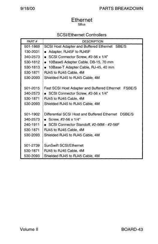
9/18/00 PARTS BREAKDOWN
Ethernet SB us
SCSI/Ethernet Controllers
PART# DESCRIPTION
501-1869 SCSI Host Adapter and Buffered Ethernet SBE/S
130-2031 • Adapter, RJ45F to RJ45F
340-2573 • SCSI Connector Screw, #2-56 x 1/4"
530-1812 • 10Base5 Adapter Cable, DB-15, 70 mm
530-1813 • 10Base-T Adapter Cable, RJ-45, 40 mm
530-1871 RJ45 to RJ45 Cable, 4M
530-2093 Shielded RJ45 to RJ45 Cable, 4M
501-2015 Fast SCSI Host Adapter and Buffered Ethernet FSBE/S
340-2573 • SCSI Connector Screw, #2-56 x 1/4" 530-1871 RJ45 to RJ45 Cable, 4M
530-2093 Shielded RJ45 to RJ45 Cable, 4M
501-1902 Differential SCSI Host and Buffered Ethernet DSBE/S 340-2573 • Screw, #2-56 x 1/4"
240-1911 • SCSI Connector Standoff, #2-56M - #2-56F 530-1871 RJ45 to RJ45 Cable, 4M
530-2093 Shielded RJ45 to RJ45 Cable, 4M
501-2739 SunSwift SCSI/Ethernet
530-1871 RJ45 to RJ45 Cable, 4M
530-2093 Shielded RJ45 to RJ45 Cable, 4M
Volume II BOARD-43
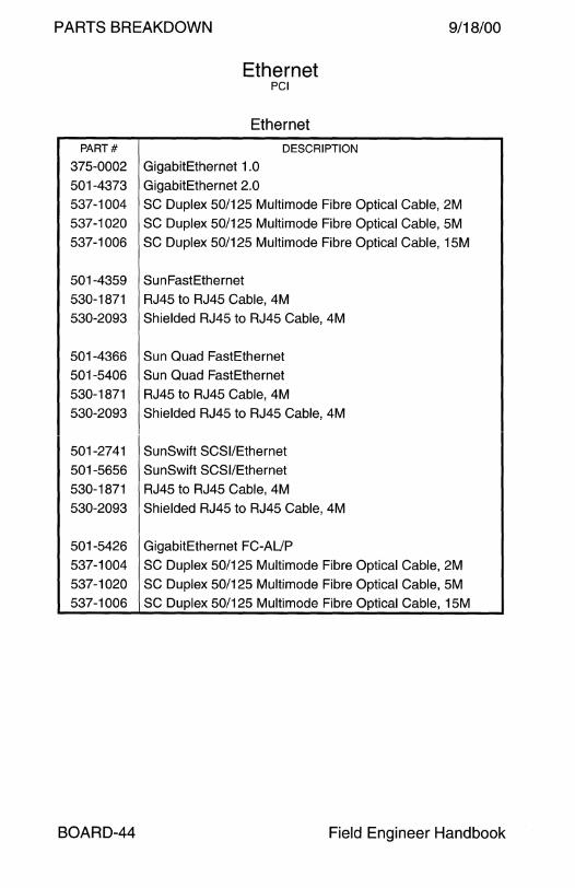
PARTS BREAKDOWN 9/18/00
Ethernet PCI
Ethernet PART# DESCRIPTION
37S-0002 GigabitEthernet 1.0 S01-4373 GigabitEthernet 2.0 S37-1004 SC Duplex S0/12S Multimode Fibre Optical Cable, 2M
S37-1020 SC Duplex S0/12S Multimode Fibre Optical Cable, SM
S37-1006 SC Duplex S0/12S Multimode Fibre Optical Cable, 1SM
501-4359 SunFastEthernet 530-1871 RJ45 to RJ45 Cable, 4M
530-2093 Shielded RJ4S to RJ45 Cable, 4M
501-4366 Sun Quad FastEthernet 501-5406 Sun Quad FastEthernet
530-1871 RJ45 to RJ45 Cable, 4M
530-2093 Shielded RJ45 to RJ45 Cable, 4M
S01-27 41 Sun Swift SCSI/Ethernet
S01-56S6 SunSwift SCSI/Ethernet 530-1871 RJ45 to RJ45 Cable, 4M
S30-2093 Shielded RJ45 to RJ4S Cable, 4M
501-5426 GigabitEthernet FC-AUP
S37-1004 SC Duplex 50/125 Multimode Fibre Optical Cable, 2M S37-1020 SC Duplex 50/12S Multimode Fibre Optical Cable, SM S37-1006 SC Duplex 50/125 Multimode Fibre Optical Cable, 1SM
BOARD-44 Field Engineer Handbook
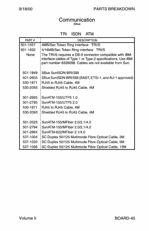
9/18/00 PARTS BREAKDOWN
Communication SB us
TRI ISDN ATM
PART# DESCRIPTION
501-1557 4MB/Sec Token Ring Interface TRl/S
501-1932 4/16MB/Sec Token Ring Interface TRl/S
None The TRl/S requires a DB-9 connector compatible with IBM interface cables of Type-1 or Type-2 specifications. Use IBM part number 6339098. Cables are not available from Sun.
501-1849 SBus SunlSDN-BRl/SBI
501-2603 SBus SunlSDN-BRl/SBI (BABT, ETSl-1, and AU-1 approved)
530-1871 RJ45 to RJ45 Cable, 4M
530-2093 Shielded RJ45 to RJ45 Cable, 4M
501-2665 SunATM-155/UTP5 1.0
501-2795 SunATM-155/UTP5 2.0
530-1871 RJ45 to RJ45 Cable, 4M
530-2093 Shielded RJ45 to RJ45 Cable, 4M
501-2523 SunATM-155/MFiber 2.0/2.1 /4.0
501-2794 SunATM-155/MFiber 2.0/2.1 /4.0
501-2864 SunATM-622/MFiber 2.1/4.0
537-1004 SC Duplex 50/125 Multimode Fibre Optical Cable, 2M
537-1020 SC Duplex 50/125 Multimode Fibre Optical Cable, 5M
537-1006 SC Duplex 50/125 Multimode Fibre Optical Cable, 15M
Volume II BOARD-45
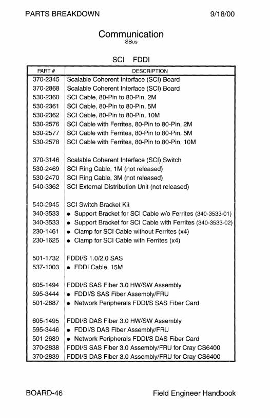
PARTS BREAKDOWN 9/18/00
Communication SBus
SCI FDDI PART# DESCRIPTION
370-234S Scalable Coherent Interface (SCI) Board
370-2868 Scalable Coherent Interface (SCI) Board
S30-2360 SCI Cable, 80-Pin to 80-Pin, 2M
S30-2361 SCI Cable, 80-Pin to 80-Pin, SM
S30-2362 SCI Cable, 80-Pin to 80-Pin, 1 OM
S30-2S76 SCI Cable with Ferrites, 80-Pin to 80-Pin, 2M
S30-2S77 SCI Cable with Ferrites, 80-Pin to 80-Pin, SM
S30-2S78 SCI Cable with Ferrites, 80-Pin to 80-Pin, 1 OM
370-3146 Scalable Coherent Interface (SCI) Switch
S30-2469 SCI Ring Cable, 1 M (not released)
S30-2470 SCI Ring Cable, 3M (not released)
S40-3362 SCI External Distribution Unit (not released)
C:.Af'\ 1")0111:: V""t'V-LV'-t..J SCI Svv·itch Bracket Kit 340-3S33 • Support Bracket for SCI Cable w/o Ferrites (340-3533-01)
340-3S33 • Support Bracket for SCI Cable with Ferrites (340-3533-02)
230-1461 • Clamp for SCI Cable without Ferrites (x4)
230-162S • Clamp for SCI Cable with Ferrites (x4)
S01-1732 FDDl/S 1.0/2.0 SAS
S37-1003 • FDDI Cable, 1 SM
60S-1494 FDDl/S SAS Fiber 3.0 HW/SW Assembly
S9S-3444 • FDDl/S SAS Fiber Assembly/FRU
S01-2687 • Network Peripherals FDDl/S SAS Fiber Card
60S-149S FDDl/S DAS Fiber 3.0 HW/SW Assembly
S9S-3446 • FDDl/S DAS Fiber Assembly/FRU
S01-2689 • Network Peripherals FDDl/S DAS Fiber Card
370-2838 FDDl/S SAS Fiber 3.0 Assembly/FRU for Cray CS6400
370-2839 FDDl/S DAS Fiber 3.0 Assembly/FRU for Cray CS6400
BOARD-46 Field Engineer Handbook

9/18/00 PARTS BREAKDOWN
Communication SB us
FDDI
PART# DESCRIPTION
605-1559 FDDl/S SAS 4.0 HW/SW Assembly
605-1564 FDDl/S SAS 4.0 HW/SW Assembly
370-2238 • Network Peripherals FDDl/S SAS Fiber Card
370-2715 • Network Peripherals FDDl/S SAS Fiber Card
605-1560 FDDl/S DAS 4.0 HW/SW Assembly
605-1565 FDDl/S DAS 4.0 HW/SW Assembly
370-2239 • Network Peripherals FDDl/S DAS Fiber Card
370-2716 • Network Peripherals FDDl/S DAS Fiber Card
605-1571 FDDl/S SAS 5.0 HW/SW Assembly
605-1610 FDDl/S SAS 6.0 HW/SW Assembly
370-2339 • Network Peripherals FDDl/S SAS Fiber Card (obs)
370-3142 • Network Peripherals FDDl/S SAS Fiber Card
537-1009 • Cable Assembly 130-3122 • MIC to MIC Coupler
180-1737 • 3 Meter FDDI Cable, SC Duplex to MIC
605-1572 FDDl/S DAS 5.0 HW/SW Assembly
605-1609 FDDl/S DAS 6.0 HW/SW Assembly
370-2340 • Network Peripherals FDDl/S DAS Fiber Card (obs)
370-3143 • Network Peripherals FDDl/S DAS Fiber Card
180-1737 • 3 Meter FDDI Cable, SC Duplex to MIC (obs) 537-1009 • Cable Assembly 130-3122 • MIC to MIC Coupler 180-1737 • 3 Meter FDDI Cable, SC Duplex to MIC
Enterprise Services FDDl/S 5.0 FRU
370-4045 Network Peripherals FDDl/S SAS Fiber Card 1
370-4046 Network Peripherals FDDl/S DAS Fiber Card 2
1 The 370-4045-01 is the same as 370-3142-02. 2 The 370-4046-01 is the same as 370-3143-02.
Volume II BOARD-47

PARTS BREAKDOWN 9/18/00
PART#
501-1511
501-1931 340-2342
340-2361
340-2460
340-2898
540-2007
540-1558
370-1366
530-1685
501-1725
530-1685
340-2342
340-2361
340-2460
340-2898
370-1381
370-1383
530-1430
540-2030
501-1746
540-2191
501-1880
BOARD-48
Communication SBus
SPC HSI
DESCRIPTION
SBus Serial Parallel Controller SPC/S
SBus Serial Parallel Controller SPC/S
• 19" Wide Rack Mounting Bracket
• Wall Mounting Bracket
• Sun 56" Rack Mounting Bracket
• SBus Mounting Screw Adapter Bracket
• 8-Channel Interface Panel
• RS-232 Loopback Test Plug, 25-Pin
• SPC/S Loopback Test Plug, 96-Pin High-Density
• Interface Cable, SBus Card to Interface Panel, 2.0M
SBus High Speed Serial Interface HSl/S
Interface Cable, SBus Card to Interface Panel, 2.0M
• 19" Wide Rack Mounting Bracket
• Wall Mounting Bracket • Sun 56" Rack Mounting Bracket
• SBus Mounting Screw Adapter Bracket
• HSl/S Loopback Test Plug, 96-Pin High-Density
• RS-530 Loopback Test Plug, 25-Pin (obsolete)
• RS-449 Loopback Test Plug, 37-Pin
• 4-Channel RS-530 Interface Panel (obsolete)
• RS-530 Interface Panel PCB
• 4-Channel RS-449 Interface Panel
• RS-449 Interface Panel PCB
Field Engineer Handbook
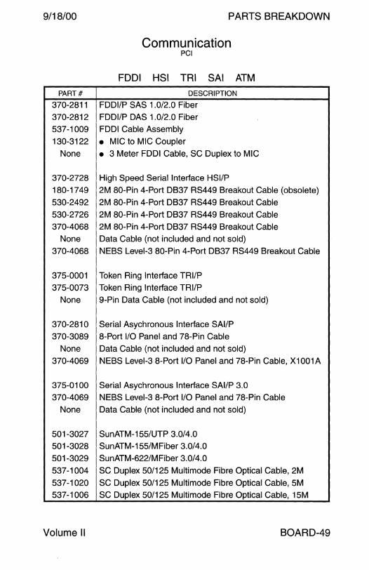
9/18/00
PART#
370-2811
370-2812
537-1009
130-3122
None
370-2728
180-1749
530-2492
530-2726
370-4068
None
370-4068
375-0001
375-0073
None
370-2810
370-3089
None
370-4069
375-0100
370-4069
None
501-3027
501-3028
501-3029
537-1004
537-1020
537-1006
Volume II
PARTS BREAKDOWN
Communication PCI
FDDI HSI TRI SAi ATM
DESCRIPTION
FDDl/P SAS 1.0/2.0 Fiber
FDDl/P DAS 1.0/2.0 Fiber
FDDI Cable Assembly
• MIC to MIC Coupler
• 3 Meter FDDI Cable, SC Duplex to MIC
High Speed Serial Interface HSl/P
2M 80-Pin 4-Port DB37 RS449 Breakout Cable (obsolete)
2M 80-Pin 4-Port DB37 RS449 Breakout Cable
2M 80-Pin 4-Port DB37 RS449 Breakout Cable
2M 80-Pin 4-Port DB37 RS449 Breakout Cable
Data Cable (not included and not sold)
NEBS Level-3 80-Pin 4-Port DB37 RS449 Breakout Cable
Token Ring Interface TRl/P
Token Ring Interface TRl/P
9-Pin Data Cable (not included and not sold)
Serial Asychronous Interface SAl/P
8-Port 1/0 Panel and 78-Pin Cable
Data Cable (not included and not sold)
NEBS Level-3 8-Port 1/0 Panel and 78-Pin Cable, X1001A
Serial Asychronous Interface SAl/P 3.0
NEBS Level-3 8-Port 1/0 Panel and 78-Pin Cable
Data Cable (not included and not sold)
SunATM-155/UTP 3.0/4.0
SunATM-155/MFiber 3.0/4.0
SunATM-622/MFiber 3.0/4.0
SC Duplex 50/125 Multimode Fibre Optical Cable, 2M
SC Duplex 50/125 Multimode Fibre Optical Cable, 5M
SC Duplex 50/125 Multimode Fibre Optical Cable, 15M
BOARD-49

PARTS BREAKDOWN 9/18/00
PART#
370-3878
370-3879 537-1004
537-1020
537-1006
595-5149
370-3868
595-5191
370-3922
330-2000
340-5929
340-6177
340-6178
340-5957
530-2869
530-2870
530-2871
Communication PCI
HIPPI SCI
DESCRIPTION
HIPPl/P 1.0/1.1
SC Duplex 50/125 Multimode Fibre Optical Cable, 15M
SC Duplex 50/125 MM Cable, 2M (alternate for 370-3879)
SC Duplex 50/125 Multimode Fibre Optical Cable, 5M
SC Duplex 50/125 MM Cable, 15M (alternate for 370-3879)
Option X1074A
• SCl/P, Dolphin PCl-64 Model D320
Option X3895A
• SCI Switch, Dolphin Model D515
• Bracket • Right Cable Bracket
• Left Cable Bracket
• Cable Clamp
• Chassis Foot SCI Cable, Option X3901 A, 2M
SCI Cable, Option X3902A, 5M
SCI Cable, Option X3903A, 7.5M
BOARD-50 Field Engineer Handbook
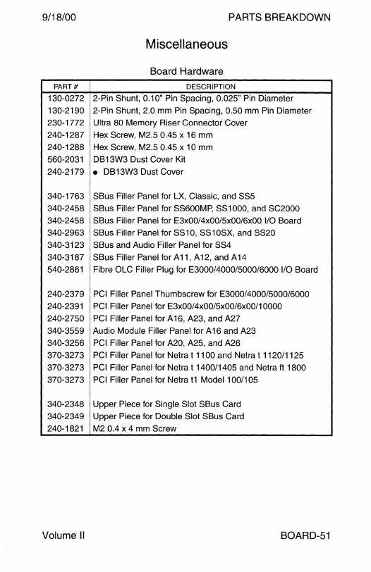
9/18/00 PARTS BREAKDOWN
Miscellaneous
Board Hardware
PART# DESCRIPTION
130-0272 2-Pin Shunt, 0.1 O" Pin Spacing, 0.025" Pin Diameter
130-2190 2-Pin Shunt, 2.0 mm Pin Spacing, 0.50 mm Pin Diameter
230-1772 Ultra 80 Memory Riser Connector Cover
240-1287 Hex Screw, M2.5 0.45 x 16 mm
240-1288 Hex Screw, M2.5 0.45 x 10 mm
560-2031 DB13W3 Dust Cover Kit
240-2179 • DB13W3 Dust Cover
340-1763 SBus Filler Panel for LX, Classic, and SS5
340-2458 SBus Filler Panel for SS600MP, SS1000, and SC2000
340-2458 SBus Filler Panel for E3x00/4x00/5x00/6xOO 1/0 Board
340-2963 SBus Filler Panel for SS10, SS10SX, and SS20
340-3123 SBus and Audio Filler Panel for SS4
340-3187 SBus Filler Panel for A 11, A 12, and A 14
540-2861 Fibre OLC Filler Plug for E3000/4000/5000/6000 1/0 Board
240-2379 PCI Filler Panel Thumbscrew for E3000/4000/5000/6000
240-2391 PCI Filler Panel for E3x00/4x00/5x00/6x00/10000
240-2750 PCI Filler Panel for A 16, A23, and A27
340-3559 Audio Module Filler Panel for A 16 and A23
340-3256 PCI Filler Panel for A20, A25, and A26
370-3273 PCI Filler Panel for Netra t 1100 and Netra t 1120/1125
370-3273 PCI Filler Panel for Netra t 1400/1405 and Netra ft 1800
370-3273 PCI Filler Panel for Netra t1 Model 100/105
340-2348 Upper Piece for Single Slot SBus Card
340-2349 Upper Piece for Double Slot SBus Card
240-1821 M2 0.4 x 4 mm Screw
Volume II BOARD-51

This page intentionally left blank.
PARTS BREAKDOWN
INPUT DEVICE
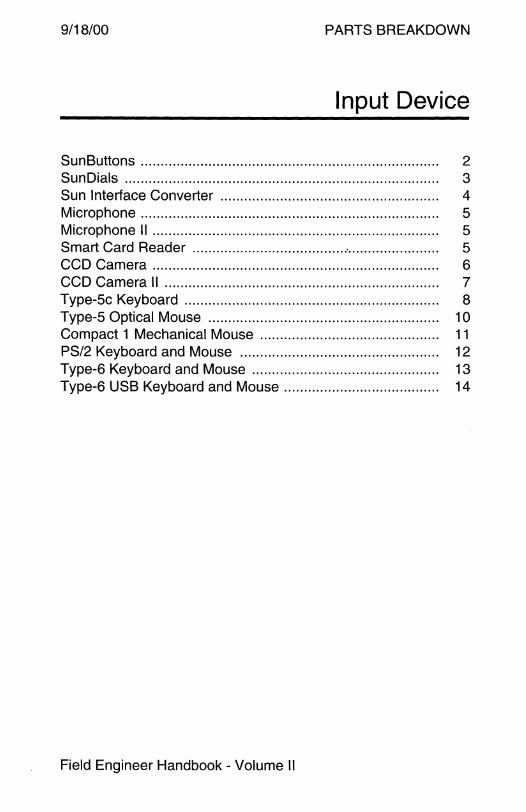
9/18/00 PARTS BREAKDOWN
Input Device
Sun Buttons . .. . . .. .... .. . .. .. .. ... .. .. . . .. .. .. .. .. .. .. . . .. . .. . .. .. .. .. .. . ... . . . .. . . . . . 2 Sun Dials ............................................................................... 3 Sun Interface Converter ... .. . .. . .. .. . ... .. .. .. .. .. . ... .. .. .. . . .. . .. .. .. .. .. . . . 4 Microphone........................................................................... 5 Microphone II ........................................................................ 5 Smart Card Reader ....................................... ·....................... 5 CCD Camera . . . . . . . . . . . . . . . . . . . . . . . . . . . . . . . . . . . . . . . . . . . . . . . . . . . . . . . . . . . . . . . . . . . . . . . . 6 CCD Camera 11 . . . . . . . . . . • . . . . . . . . . . . . . . . . . . • . . • . • . • . . . . • . . • . . • . . . . . . . • . . • . . . . • . . . • . 7 Type-5c Keyboard . .. . .. .. . .. .. .. .. .. . . .. .. . . . . . .. .. .. . ... .... ... . ... .. .. . . .. .. . .. 8 Type-5 Optical Mouse ....... .. .. ... ... . . . .. .. .. .. .. . ... .... .. .. .. .. . . .. . . .. .... 1 O Compact 1 Mechanical Mouse . . . . . . . . . . . . . . . . . . . . . . . . . . . . . . . . . . . . . . . . . . . . . 11 PS/2 Keyboard and Mouse . . . . . . . . . . . . . . . . . . . . . . . . . . . . . . . . . . . . . . . . . . . . . . . . . . 12 Type-6 Keyboard and Mouse .. .. .. .. .. .. . . . .. . . .. .. .. .. . .. .. .. . .. .. .. .. .. .. 13 Type-6 USB Keyboard and Mouse .. . . . .... .. . ... . ... .. .. .. . .. . ... . ... . . . 14
Field Engineer Handbook - Volume II
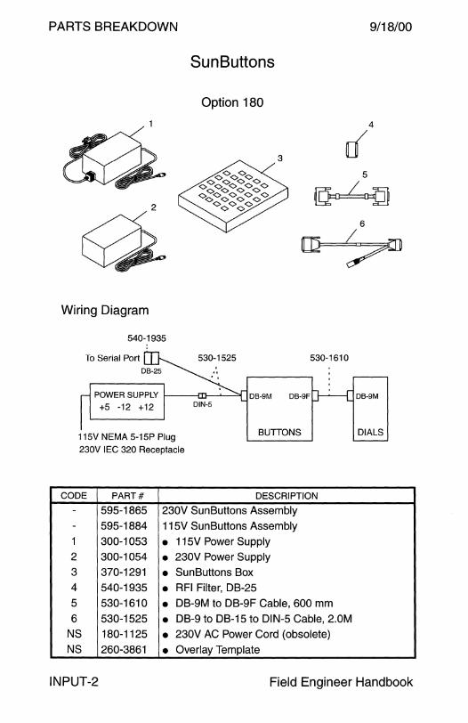
PARTS BREAKDOWN 9/18/00
Sun Buttons
Option 180
4
0 5
2 ~ 6
~ Wiring Diagram
540-1935 ..........
To Serial Port 530-1525 530-1610
POWERSUPPLY 1--~~11f---'~~ DB-SM
+5 -12 +12
115V NEMA 5-15P Plug 230V IEC 320 Receptacle
BUTTONS
CODE PART# DESCRIPTION
- 595-1865 230V SunButtons Assembly
- 595-1884 115V SunButtons Assembly
1 300-1053 • 115V Power Supply 2 300-1054 • 230V Power Supply 3 370-1291 • SunButtons Box 4 540-1935 • RFI Filter, DB-25
5 530-1610 • DB-9M to DB-9F Cable, 600 mm
6 530-1525 • DB-9 to DB-15 to DIN-5 Cable, 2.0M NS 180-1125 • 230V AC Power Cord (obsolete) NS 260-3861 • Overlay Template
DIALS
INPUT-2 Field Engineer Handbook

9/18/00
Sun Dials
Option 190
2
Wiring Diagram
540-1935
To Serial Port 530-1525
POWER SUPPLY t----ill-~---"I +5 -12 +12
DB-9M
115V NEMA 5-15P Plug
230V IEC 320 Receptacle
DIALS
PARTS BREAKDOWN
4
[{ 5
~ 6
~
PART# DESCRIPTION
- 595-1737 115V SunDials Assembly
- 595-1773 230V SunDials Assembly
1 300-1053 • 115V Power Supply 2 300-1054 • 230V Power Supply
3 370-1223 • Dialbox and Bale 4 540-1935 • RFI Filter, DB-25
5 530-1610 • DB-9M to DB-9F Cable, 600 mm
6 530-1525 • DB-9 to DB-15 to DIN-5 Cable, 2.0M NS 180-1125 • 230V AC Power Cord (obsolete)
NS 260-3257 • Overlay Template
Volume II INPUT-3

PARTS BREAKDOWN
Top View
End View
~ . .
PART#
595-3692
370-2068
802-3847
Sun Interface Converter
Option 465
~ . .
SUN
fOOal ID D DI ~--,
® . .
0
OFF ON
1~ 2 EJ 3 EJ
() ,-Switch Settings
ON m OFF ~ ~ ~
1 2 3 us AT-101
ON m OFF ~ ~ ~
1 2 3 Germany AT-102
DESCRIPTION
Sun Interface Converter Assembly/FRU
• Sun Interface Converter
• Installation Manual
9/18/00
Bottom View
0
n -1
ON m OFF ~ ~ ~
1 2 3 UK AT-102
ON m OFF ~ ~ ~
1 2 3 DOS/V
INPUT-4 Field Engineer Handbook

9/18/00 PARTS BREAKDOWN
Microphone
PART# DESCRIPTION
370-1414 Microphone
370-1439 Microphone without Sun Logo
None • Pocket Clip None • Adhesive Clip
None • Panasonic CR2032 Battery
Microphone 11
PART# DESCRIPTION
370-1678 Microphone II
370-1750 Microphone II without Sun Logo
530-2112 Microphone II adapterforSS10, SS10SX, SPARCstation LX,
SPARCclassic, and Speakerbox
Smart Card Reader
PART# DESCRIPTION
595-5242 Smart Card Reader, Option 3681
370-4002 Smart Card Reader
None • Smart Card Reader Base
Volume II INPUT-5

PARTS BREAKDOWN
Front View
CCD Camera 485
Camera 487
Sun Video SBus Kit
I\ 5.6 mm f/2.8
~ ~ ~ ~ 0 · · · · · 1 /60 - 1 /15000 sec
\'L._ _ __1==="1/ 4 7° H x 37° V
Right Side View
PART# I
DESCRIPTION
595-3211 c_;amera Assembly, United States
370-1804 • Camera 370-1813 • AC-DC Power Adapter
530-2132 • Video Cable
595-3279 Camera Assembly, Europe
370-1805 • Camera 370-1816 • AC-DC Power Adapter 530-2132 • Video Cable
595-3301 Camera Assembly, United Kingdom
370-1806 • Camera 370-1815 • AC-DC Power Adapter
530-2132 • Video Cable
595-3386 Camera Assembly, Japan
370-1807 • Camera 370-1814 • AC-DC Power Adapter
530-2132 • Video Cable
9/18/00
Rear View
INPUT-6 Field Engineer Handbook
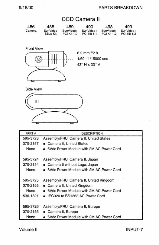
9/18/00 PARTS BREAKDOWN
CCD Camera II 486 488 489 490 498 499
Camera SunVideo SunVideo+ SunVideo+ SunVideo+ SunVideo+ SBus Kit PCI Kit 1.0 PCI Kit 1.1 PCI Kit 1.2 PCI Kit 1.3
Front View
@----1-1-1-1-··--6.2 mm f/2.8
1 /60 - 1 /15000 sec
43° H x 33° V
Side View
PART# DESCRIPTION
595-3723 Assembly/FRU, Camera II, United States
370-2157 • Camera II, United States None • 6Vdc Power Module with 2M AC Power Cord
595-3724 Assembly/FRU, Camera II, Japan
370-2154 • Camera II without Logo, Japan None • 6Vdc Power Module with 2M AC Power Cord
595-3725 Assembly/FRU, Camera II, United Kingdom
370-2155 • Camera II, United Kingdom None • 6Vdc Power Module with 2M AC Power Cord
530-1821 • IEC320 to BS1363 AC Power Cord
595-3726 Assembly/FRU, Camera II, Europe 370-2155 • Camera II, Europe
None • 6Vdc Power Module with 2M AC Power Cord
Volume II INPUT-7

PARTS BREAKDOWN 9/18/00
Type-Sc Keyboard
Control Card
Mouse Connector = ==O Flex Cable Connectors
12345 00000 Dip Switch or 00000 Wire Jumpers 00000
C=::J Keyboard Cable Connector
L=:J
Underside of Keyboard
TOP [ Mouse Connector
[g] 0 Control Card Access Cover [g]
~
Captive Keyboard Cable
WIRE JUMPER HEX
DESCRiPTiON JSi JS2 JS3 JS4 JS5 CODE
us - - - - In 21
US/Unix - - - In - 22
Japanese In - - - In 31
DIP SWITCH HEX
DESCRIPTION 1 2 3 4 5 CODE
French - - - On On 23
Danish - - On - - 24
German - - On - On 25
Italian - - On On - 26
Dutch - - On On On 27
Norwegian - On - - - 28
Portuguese - On - - On 29
Spanish - On - On - 2a
Swedish/Finnish - On - On On 2b
Swiss/French - On On - - 2c
Swiss/German - On On - On 2d
UK - On On On - 2e
Korean - On On On On 21
Taiwanese On - - - - 30
French Canadian On On On On On 31
INPUT-8 Field Engineer Handbook
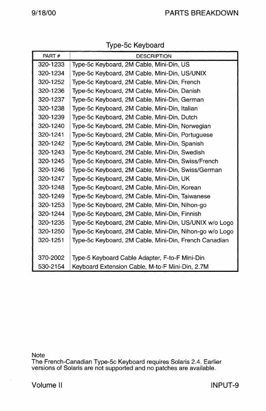
9/18/00 PARTS BREAKDOWN
Type-5c Keyboard
PART# DESCRIPTION
320-1233 Type-5c Keyboard, 2M Cable, Mini-Din, US
320-1234 Type-5c Keyboard, 2M Cable, Mini-Din, US/UNIX
320-1252 Type-5c Keyboard, 2M Cable, Mini-Din, French 320-1236 Type-5c Keyboard, 2M Cable, Mini-Din, Danish 320-1237 Type-5c Keyboard, 2M Cable, Mini-Din, German
320-1238 Type-5c Keyboard, 2M Cable, Mini-Din, Italian
320-1239 Type-5c Keyboard, 2M Cable, Mini-Din, Dutch
320-1240 Type-5c Keyboard, 2M Cable, Mini-Din, Norwegian
320-1241 Type-5c Keyboard, 2M Cable, Mini-Din, Portuguese 320-1242 Type-5c Keyboard, 2M Cable, Mini-Din, Spanish
320-1243 Type-5c Keyboard, 2M Cable, Mini-Din, Swedish 320-1245 Type-5c Keyboard, 2M Cable, Mini-Din, Swiss/French 320-1246 Type-5c Keyboard, 2M Cable, Mini-Din, Swiss/German
320-1247 Type-5c Keyboard, 2M Cable, Mini-Din, UK 320-1248 Type-5c Keyboard, 2M Cable, Mini-Din, Korean
320-1249 Type-5c Keyboard, 2M Cable, Mini-Din, Taiwanese
320-1253 Type-5c Keyboard, 2M Cable, Mini-Din, Nihon-go
320-1244 Type-5c Keyboard, 2M Cable, Mini-Din, Finnish
320-1235 Type-5c Keyboard, 2M Cable, Mini-Din, US/UNIX w/o Logo 320-1250 Type-5c Keyboard, 2M Cable, Mini-Din, Nihon-go w/o Logo 320-1251 Type-5c Keyboard, 2M Cable, Mini-Din, French Canadian
370-2002 Type-5 Keyboard Cable Adapter, F-to-F Mini-Din
530-2154 Keyboard Extension Cable, M-to-F Mini-Din, 2.7M
Note The French-Canadian Type-5c Keyboard requires Solaris 2.4. Earlier versions of Solaris are not supported and no patches are available.
Volume II INPUT-9

PARTS BREAKDOWN 9/18/00
Type-5 Optical Mouse
PART# DESCRIPTION
f370-1398 Type-5 Mouse and Pad, Mini-Din
370-1398 • Type-5 Mouse, 300 CPI, Mini-Din
370-1399 • Type-5 Mouse Pad, 300 CPI, 196.6 x 178.0 mm 370-1664 Type-5 Mouse without Sun Logo, 300 CPI, Mini-Din
370-1663 Type-5 Mouse Pad without Sun Logo, 300 CPI
Notes 1. The Type-5 Mouse replaced the Type-4 Mouse in October 1993. 2. The Compact 1 Mouse replaced the Type-5 Mouse in August 1995.
INPUT-10 Field Engineer Handbook

9/18/00 PARTS BREAKDOWN
Compact 1 Mechanical Mouse
Option 494
4800 Baud Circuit Board 1200 Baud Circuit Board
R20Q R2 Not Installed
D ~ =300 0 0 ~:.~-Jo 0
PART# DESCRIPTION
370-1586-01 Compact 1 Mouse, 4800 Baud, 760 mm Cable
370-1586-02 Compact 1 Mouse, 1200 Baud, 760 mm Cable
370-1586-03 Compact 1 Mouse, 1200 Baud, 1000 mm Cable 370-1587-01 Compact 1 Mouse w/o Logo, 4800 Baud, 760 mm Cable 370-1587-02 Compact 1 Mouse w/o Logo, 1200 Baud, 760 mm Cable
370-1587-03 Compact 1 Mouse w/o Logo, 1200 Baud, 1000 mm Cable 370-2037-01 Foam Pad without Logo
370-2038-01 Foam Pad
Note The 4800 baud mouse was only shipped with the SPARCstation Voyager. Solaris 2.3 is required if the 4800 Baud mouse is used on other systems.
Volume II INPUT-11

PARTS BREAKDOWN 9/18/00
PS/2 Keyboard and Mouse
PART# DESCRIPTION
370-2308 PS/2 Mouse, Mini-Din-6, 1.8M Cable
370-2405 • Mouse Pad
370-2404 PS/2 Mouse without Logo, Mini-Din-6, 1.8M Cable
370-2405 • Mouse Pad
320-1256 PS/2 Keyboard, Mini-Din-6, 1.8M Cable, US
320-1257 PS/2 Keyboard, Mini-Din-6, 1.8M Cable, UK
320-1258 PS/2 Keyboard, Mini-Din-6, 1.8M Cable, Swedish
320-1259 PS/2 Keyboard, Mini-Din-6, 1.8M Cable, Japanese w/o Logo
320-1260 PS/2 Keyboard, Mini-Din-6, 1.8M Cable, German
320-1261 PS/2 Keyboard, Mini-Din-6, 1.8M Cable, without Logo
320-1262 PS/2 Keyboard, Mini-Din-6, 1.8M Cable, French
320-1263 PS/2 Keyboard, Mini-Din-6, 1.8M Cable, Italian
320-1264 PS/2 Keyboard, ~Jlini-Din~6, 1.8~v1 Cable, Taivvanese 320-1265 PS/2 Keyboard, Mini-Din-6, 1.8M Cable, Spanish
320-1266 PS/2 Keyboard, Mini-Din-6, 1.8M Cable, Korean
320-1267 PS/2 Keyboard, Mini-Din-6, 1.8M Cable, Japanese
INPUT-12 Field Engineer Handbook
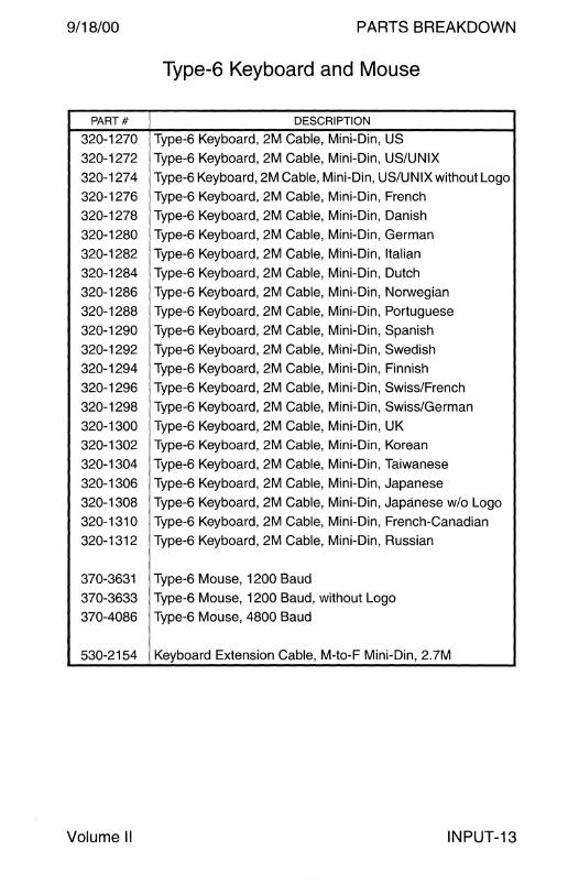
9/18/00 PARTS BREAKDOWN
Type-6 Keyboard and Mouse
PART# DESCRIPTION
320-1270 Type-6 Keyboard, 2M Cable, Mini-Din, US
320-1272 Type-6 Keyboard, 2M Cable, Mini-Din, US/UNIX
320-1274 Type-6 Keyboard, 2M Cable, Mini-Din, US/UNIX without Logo
320-1276 Type-6 Keyboard, 2M Cable, Mini-Din, French
320-1278 Type-6 Keyboard, 2M Cable, Mini-Din, Danish
320-1280 Type-6 Keyboard, 2M Cable, Mini-Din, German
320-1282 Type-6 Keyboard, 2M Cable, Mini-Din, Italian
320-1284 Type-6 Keyboard, 2M Cable, Mini-Din, Dutch
320-1286 Type-6 Keyboard, 2M Cable, Mini-Din, Norwegian
320-1288 Type-6 Keyboard, 2M Cable, Mini-Din, Portuguese
320-1290 Type-6 Keyboard, 2M Cable, Mini-Din, Spanish
320-1292 Type-6 Keyboard, 2M Cable, Mini-Din, Swedish
320-1294 Type-6 Keyboard, 2M Cable, Mini-Din, Finnish
320-1296 Type-6 Keyboard, 2M Cable, Mini-Din, Swiss/French
320-1298 Type-6 Keyboard, 2M Cable, Mini-Din, Swiss/German
320-1300 Type-6 Keyboard, 2M Cable, Mini-Din, UK
320-1302 Type-6 Keyboard, 2M Cable, Mini-Din, Korean
320-1304 Type-6 Keyboard, 2M Cable, Mini-Din, Taiwanese
320-1306 Type-6 Keyboard, 2M Cable, Mini-Din, Japanese
320-1308 Type-6 Keyboard, 2M Cable, Mini-Din, Japanese w/o Logo
320-1310 Type-6 Keyboard, 2M Cable, Mini-Din, French-Canadian
320-1312 Type-6 Keyboard, 2M Cable, Mini-Din, Russian
370-3631 Type-6 Mouse, 1200 Baud
370-3633 Type-6 Mouse, 1200 Baud, without Logo
370-4086 Type-6 Mouse, 4800 Baud
530-2154 Keyboard Extension Cable, M-to-F Mini-Din, 2.7M
Volume II INPUT-13

PARTS BREAKDOWN 9/18/00
Type-6 USB Keyboard and Mouse
PART# DESCRIPTION
320-1271 Type-6 Keyboard, 2M Cable, USB, US
320-1273 Type-6 Keyboard, 2M Cable, USB, US/UNIX
320-1275 Type-6 Keyboard, 2M Cable, USB, US/UNIX without Logo
320-1277 Type-6 Keyboard, 2M Cable, USB, French
320-1279 Type-6 Keyboard, 2M Cable, USB, Danish
320-1281 Type-6 Keyboard, 2M Cable, USB, German
320-1283 Type-6 Keyboard, 2M Cable, USB, Italian
320-1285 Type-6 Keyboard, 2M Cable, USB, Dutch
320-1287 Type-6 Keyboard, 2M Cable, USB, Norwegian
320-1289 Type-6 Keyboard, 2M Cable, USB, Portuguese
320-1291 Type-6 Keyboard, 2M Cable, USB, Spanish
320-1293 Type-6 Keyboard, 2M Cable, USB, Swedish
320-1295 Type-6 Keyboard, 2M Cable, USB, Finnish
320-1297 Type-6 Keyboard, 2M Cable, USB, Swiss/French
320-1299 Type-6 Keyboard, 2M Cable, USB, Swiss/German
320-1301 Type-6 Keyboard, 2M Cable, USB, UK
320-i303 Type-6 Keyboard, 2M Cable, USB, Korean
320-1305 Type-6 Keyboard, 2M Cable, USB, Taiwanese
320-1307 Type-6 Keyboard, 2M Cable, USB, Japanese
320-1309 Type-6 Keyboard, 2M Cable, USB, Japanese without Logo
320-1313 Type-6 Keyboard, 2M Cable, USB, Russian
370-3632 Type-6 USB Mouse
370-3634 Type-6 USB Mouse without Logo
530-2154 Keyboard Extension Cable, M-to-F Mini-Din, 2.7M
INPUT-14 Field Engineer Handbook

PARTS BREAKDOWN
MONITOR

9/18/00 PARTS BREAKDOWN
Monitor
Monitor and Image Size . .. .. .. .. ... ... .. . .. .. .. .. . . ... . . . . .. . . . . . .. .. .. .. .. . . . 2 Connector Pinouts . . . . . . . . . . . . . . . . . . . . . . . . . . . . . . . . . . . . . . . . . . . . . . . . . . . . . . . . . . . . . . . . 3 Video Cables . . . . . . . . . . . . . . . . . . . . . . . . . . . . . . . . . . . . . . . . . . . . . . . . . . . . . . . . . . . . . . . . . . . . . . . . 4
LCD 18-inch Color LCD . .. . . . . . .. .. .. . .. . .. . .. .. .. . .. .. . . .. .. .. .. .. .. .. .. . . . .. . . . .. . 5
Greyscale 17-inch Greyscale CRT ..................................................... 6 19-inch Greyscale CRT ..................................................... 8 19-inch Greyscale CRT with OCLI ..... .. . . .. .. .. .. .. .. .. . . . .. ..... .. . 1 O 20-inch Premium Greyscale CRT . . .. .. .. .. .. .. .... .. .. .. .. ... . .. .. .. . . 11
Color 14-inch Entry-Level Color CRT . . . . . . . .. .. .. .. .. .. .. .. .. .. . . . .. . .. .. .. .. 12 15-inch Color CRT . . . . . . . . . . . . . . . . . . . . . . . . . . . . . . . . . . . . . . . . . . . . . . . . . . . . . . . . . . . . . 14 16-inch Color CRT . .. . .. .. .. .. .. .. . ... . . . .. .. .. .. .. . . .. .. .. .. .. .. . . . ..... .. .. .. 15 16-inch Mid-Range Color CRT .. . .. . . .. . . . . .. . .. . . .. . . . .. . . .. .. .. .. . . . .. 17 16-inch Premium Color CRT . . . . . . . . . . . . . . . . . . . . . . . . . . . . . . . . . . . . . . . . . . . . . 18 17-inch Entry-Level Color CRT .. . .. . . .. . . . . .. . . . . . . . . . . .. . . .. . . .. . . .. . .. 19 17-inch Premium Color CRT ............................................. 23 19-inch Color CRT . . .. . . . . . . . .. . . . . .. ... .. . . ... . . . .. . . . .. . . . . . .. .. .. .. .. . . .. . .. 25 19-inch Premium Color CRT . . .. .. . .. .. .. .. .. .. .. .. .. .. .. .. .. . . . ... .. .. .. 27 19-inch Premium Flat Screen Color CRT . . . . . . . . . . . . . . . . . . . . . . . . . . 28 20-inch Premium Color CRT . . .. .. . .. .. .. .. .. .. .. .. .. .. . ... . . . . . ... .. .. .. 29 21-inch Color CRT .. . . .. . . . . . . .. . . . .. . .. .. .. ...... ... . .. . . .. .. .. .. .. .. .... .. . . . 32 21-inch Premium Flat Screen Color CRT .. .. ..... ... . . . . . ... .. .. . . 34 24-inch Premium Color CRT . . . . . . . . . . . . . . . . . . . . . . . . . . . . . . . . . . . . . . . . . . . . . 35
Field Engineer Handbook - Volume II

PARTS BREAKDOWN 9/18/00
Monitor and Image Size
Monitor size is the diagonal dimension of the CRT or the diagonal dimension of the CRT phosphor coating.
The image size of monitors may not be reflected in the monitor size listed in sales documents or price lists.
Image size is the horizontal and vertical dimension of the active display. The image size, or active display, is smaller than the CRT, Bezel, and Margin.
Sun Monitor Engineering Specifications define the horizontal and vertical dimensions of the nominal image size listed in this section. The diagonal dimensions listed in this section are calculated from the horizontal and vertical dimensions and do not take CRT curvature into account.
The dimensions of the 19" Premium Color CRT are:
CRT Size: 20-inch diagonal (19" Phosphor Coating) Bezel Size: 360 mm H x 283 mm V x 457 mm (17.99") D Nominal Image Size: 350 mm H x 270 mm V x 442 mm (17.40") D
I\ /I
Image Size
Margin
- Bezel
IL "II
1 ~ L
MONITOR-2 Field Engineer Handbook

9/18/00 PARTS BREAKDOWN
Connector Pinouts
Color CRT DB13W3 Connector
PIN SIGNAL PIN SIGNAL A1 A2 A3
1 Monitor specific 8 SENSE1
2 Monitor specific 9 SENSED
3 SENSE2 10 CRTN 6 10
4 SRTN A1 Red
5 CSYNC A2 Green
6 Monitor specific A3 Blue
7 Monitor specific
Pins 1, 2, 6, and 7 are GND on the SBus GX+. Pin-2 is VSYNC and Pin-6 is HSYNC on the SBus CG3.
Greyscale CRT DB13W3
PIN SIGNAL PIN SIGNAL
1 Monitor specific 8 SENSE1
2 Monitor specific 9 SENSED
3 SENSE2 1D CRTN
4 SRTN A1 Not used
5 CSYNC A2 Green
6 Monitor specific A3 Not used
7 Monitor specific
Color CRT HD15
PIN SIGNAL PIN SIGNAL
1 Red 9 Not used
2 Green 10 Sync Gnd
3 Blue 11 Monitor specific
4 Monitor specific 12 DOC Data
5 Sgnd 13 Hsync
6 Red Gnd 14 Vsync
7 Green Gnd 15 DOC Clock
8 Blue Gnd
Pin-13 accepts Composite Sync if VSync is not present on Pin-14.
Volume II
A1 Connector
A2 A3
5
6 10
Connector
5 00000 1 10 0 0 0 0 0 6 15 0 0 0 0 0 11
MONITOR-3
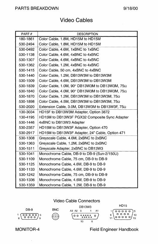
PARTS BREAKDOWN 9/18/00
Video Cables
PART# DESCRIPTION
180-1861 Color Cable, 1.8M, H015M to H015M 530-24g4 Color Cable, 1.8M, H015M to H015M 530-04g2 Color Cable, 4.6M, 1x8NC to 1x8NC 530-1138 Color Cable, 4.6M, 4x8NC to 4x8NC 530-1307 Color Cable, 4.6M, 4x8NC to 4x8NC
530-1362 Color Cable, 1.2M, 4x8NC to 4x8NC 530-1415 Color Cable, 50 cm, 4x8NC to 4x8NC 530-1440 Color Cable, 1.2M, 0813W3M to 0813W3M 530-150g Color Cable, 4.6M, 0813W3M to 0813W3M 530-183g Color Cable, 1.0M, go0 0813W3M to 0813W3M, 750
530-1840 Color Cable, 4.0M, go0 0813W3M to 0813W3M, 750 530-1870 Color Cable, 1.2M, 0813W3M to 0813W3M, 750 530-18g8 Color Cable, 4.5M, 0813W3M to 0813W3M, 750
530-2020 Extension Cable, 3.0M, 0813W3M to 0813W3F, 750 130-3034 H015F to 0813W3M Adapter, Option 3872 130-41g5 H015M to 0813W3F PGX32 Composite Sync Adapter 530-1446 4x8NC to 0813W3 Adapter 530-2357 H015M to 0813W3F Adapter, Option 470 530-2g17 H015M to 0813W3F Adapter, 24" Cable, Option 471 530-1308 Greyscale Cable, 4.6M, 2x8NC to 2x8NC 530-1363 Greyscale Cable, 1.2M, 2x8NC to 2x8NC
530-1511 Greyscale Adapter, 2x8NC to 0813W3 530-1041 Monochrome Cable, 08-g to 08-g (Sun-2/150U) 530-110g Monochrome Cable, 75 cm, 08-g to 08-g
530-1125 Monochrome Cable, 4.6M, 08-g to 08-g 530-1133 Monochrome Cable, 4.6M, 08-g to 08-g
530-1242 Monochrome Cable, 75 cm, 08-g to 08-g
530-1336 Monochrome Cable, 4.6M, 08-g to 08-g
530-135g Monochrome Cable, 1.2M, 08-g to 08-g
Video Cable Connectors DB13W3 HD15
DB-9 BNC A3 A2 5 1 A1
1 \00 0 00)5 6_0000_9 \oo 00000 oj
. 00000 .
1 00000 5 6 0 0 0 0 10 11 0 0 0 0 0 15
10 6
MONITOR-4 Field Engineer Handbook
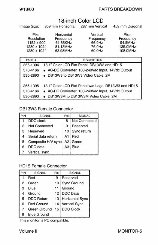
9/18/00 PARTS BREAKDOWN
18-inch Color LCD Image Size: 359 mm Horizontal 287 mm Vertical 459 mm Diagonal
Pixel Resolution 1152 x 900
1280 x 1024 1280 x 1024
PART#
Horizontal Frequency 61.85KHz 81.13MHz 63.98MHz
Vertical Frequency
66.0Hz 76.0Hz 60.0Hz
DESCRIPTION
Pixel Frequency 94.5MHz 135.0MHz 108.0MHz
365-1394 18.1" Color LCD Flat Panel, DB13W3 and HD15
370-4166 • AC-DC Converter, 100-240Vac Input, 14Vdc Output 530-2893 • DB13W3 to DB13W3 Video Cable, 2M
365-1395 18.1" Color LCD Flat Panel w/o Logo, DB13W3 and HD15
370-4166 • AC-DC Converter, 100-240Vac Input, 14Vdc Output
530-2893 • DB13W3M to DB13W3M Video Cable, 2M
DB13W3 Female Connector
PIN SIGNAL PIN SIGNAL
1 DDC clock 8 Not Connected
2 Not Connected 9 Reserved
3 Reserved 10 Sync return
4 Serial data return A1 Red
5 Composite HN sync A2 Green 6 DDC data A3 Blue 7 Vertical sync
HD15 Female Connector
PIN SIGNAL PIN SIGNAL
1 Red 9 Reserved
2 Green 10 Sync Ground 3 Blue 11 Ground
4 Ground 12 DDC Data
5 DDC Return 13 Horizontal Sync
6 Red Ground 14 Vertical Sync 7 Green Ground 15 DDC Clock 8 Blue Ground
This monitor is PC compatible.
Volume II MONITOR-5
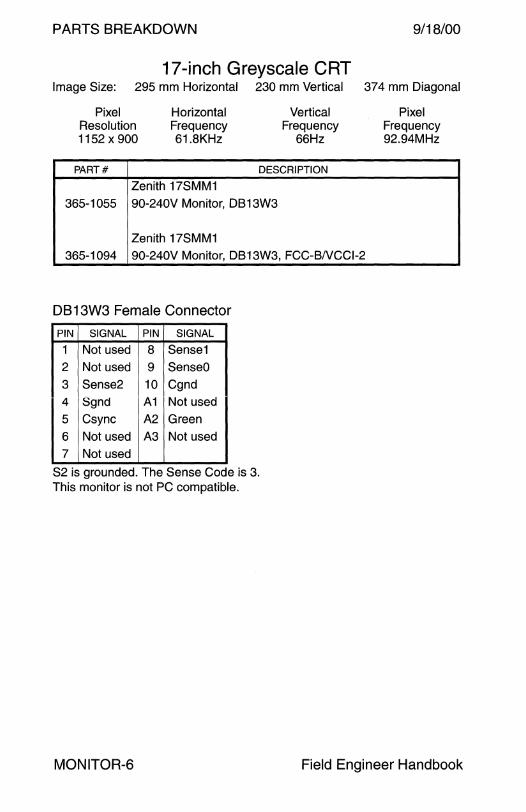
PARTS BREAKDOWN 9/18/00
17-inch Greyscale CRT Image Size: 295 mm Horizontal 230 mm Vertical 374 mm Diagonal
Pixel Resolution 1152 x 900
Horizontal Frequency 61.8KHz
Vertical Frequency
66Hz
PART# DESCRIPTION
Zenith 17SMM1
365-1055 90-240V Monitor, DB13W3
Zenith 17SMM1 365-1094 90-240V Monitor, DB13W3, FCC-BNCCl-2
DB 13W3 Female Connector
PIN SIGNAL PIN SIGNAL
1 Not used 8 Sense1 2 Not used 9 SenseO 3 Sense2 10 Cgnd 4 Sgnd A1 Not used
5 Csync A2 Green
6 Not used A3 Not used 7 Not used
S2 is grounded. The Sense Code is 3. This monitor is not PC compatible.
Pixel Frequency 92.94MHz
MONITOR-6 Field Engineer Handbook

9/18/00 PARTS BREAKDOWN
17-inch Greyscale CRT Image Size:
Pixel Resolution 914x690
1024 x 780 1024 x 800 1152 x 900
PART#
295 mm Horizontal
Horizontal Frequency 70.8KHz 71.7KHz 70.8KHz 71.7KHz
Zenith 17SMM4-A
230 mm Vertical
Vertical Frequency
84.0Hz 76.0Hz 84.0Hz 76.0Hz
DESCRIPTION
374 mm Diagonal
Pixel Frequency 92.94MHz* 105.5MHzt 92.94MHz 105.5MHz
365-1100 115V/240V Monitor, DB13W3, FCC-BNCCl-2
Zenith 17SMM4-B
365-1109 115V/240V OEM Monitor, DB13W3, FCC-BNCCl-2
Zenith 17SMM4-A
365-1157 115V/240V Monitor, DB13W3, FCC-BNCCl-2, with Video Cable 530-1870
*The Mode Ill (1024 x 800@ 84) Overscan Mode user area is 914 x 690. t The Mode II (1152 x 900 @ 76) Overscan Mode user area is 1024 x 780.
DB13W3 Female Connector
PIN SIGNAL PIN SIGNAL
1 Not used 8 Sense1 2 Not used 9 SenseO 3 Sense2 10 Cgnd 4 Sgnd A1 Not used 5 Csync A2 Green
6 Not used A3 Not used 7 Not used
S2 is grounded. The Sense Code is 3. This monitor is not PC compatible.
Volume II MONITOR-7
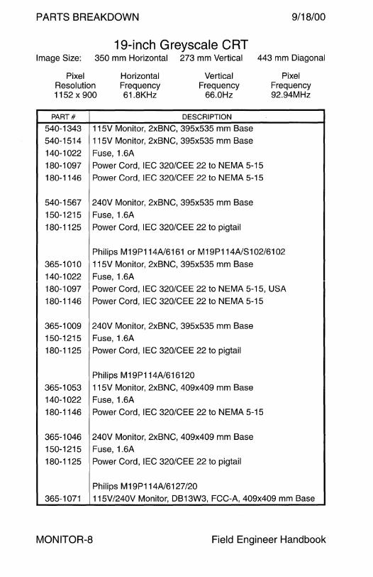
PARTS BREAKDOWN 9/18/00
19-inch Greyscale CRT Image Size: 350 mm Horizontal 273 mm Vertical 443 mm Diagonal
Pixel Resolution 1152 x 900
Horizontal Frequency 61.8KHz
Vertical Frequency
66.0Hz
Pixel Frequency 92.94MHz
PART# DESCRIPTION
540-1343 115V Monitor, 2xBNC, 395x535 mm Base 540-1514 115V Monitor, 2xBNC, 395x535 mm Base
140-1022 Fuse, 1.6A 180-1097 Power Cord, IEC 320/CEE 22 to NEMA 5-15 180-1146 Power Cord, IEC 320/CEE 22 to NEMA 5-15
540-1567 240V Monitor, 2xBNC, 395x535 mm Base
150-1215 Fuse, 1.6A 180-1125 Power Cord, IEC 320/CEE 22 to pigtail
Philips M19P114A/6161 or M19P114A/S102/6102
365-1010 115V Monitor, 2xBNC, 395x535 mm Base 140-1022 Fuse, 1.6A 180-1097 Power Cord, IEC 320/CEE 22 to NEMA 5-15, USA
180-1146 Power Cord, IEC 320/CEE 22 to NEMA 5-15
365-1009 240V Monitor, 2xBNC, 395x535 mm Base 150-1215 Fuse, 1.6A
180-1125 Power Cord, IEC 320/CEE 22 to pigtail
Philips M19P114A/616120 365-1053 115V Monitor, 2xBNC, 409x409 mm Base 140-1022 Fuse, 1.6A
180-1146 Power Cord, IEC 320/CEE 22 to NEMA 5-15
365-1046 240V Monitor, 2xBNC, 409x409 mm Base 150-1215 Fuse, 1.6A 180-1125 Power Cord, IEC 320/CEE 22 to pigtail
Philips M19P114A/6127/20 365-1071 115V/240V Monitor, DB13W3, FCC-A, 409x409 mm Base
MONITOR-8 Field Engineer Handbook
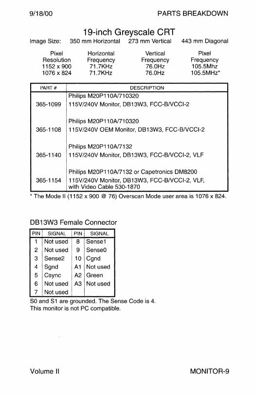
9/18/00 PARTS BREAKDOWN
19-inch Greyscale CRT Image Size: 350 mm Horizontal 273 mm Vertical 443 mm Diagonal
Pixel Resolution 1152 x 900 1076 x 824
Horizontal Frequency 71.7KHz 71.7KHz
Vertical Frequency
76.0Hz 76.0Hz
PART# DESCRIPTION
Philips M20P11OA/710320
365-1099 115V/240V Monitor, DB13W3, FCC-BNCCl-2
Philips M20P11OA/710320
Pixel Frequency 105.5Mhz 105.5MHz*
365-1108 115V /240V OEM Monitor, DB 13W3, FCC-BNCCl-2
Philips M20P11 OA/7132 365-1140 115V /240V Monitor, DB 13W3, FCC-BNCCl-2, VLF
Philips M20P11 OA/7132 or Capetronics DM8200 365-1154 115V/240V Monitor, DB13W3, FCC-BNCCl-2, VLF,
with Video Cable 530-1870
*The Mode II (1152 x 900 @ 76) Overscan Mode user area is 1076 x 824.
DB13W3 Female Connector
PIN SIGNAL PIN SIGNAL
1 Not used 8 Sense1 2 Not used 9 SenseO
3 Sense2 10 Cgnd 4 Sgnd A1 Not used
5 Csync A2 Green
6 Not used A3 Not used 7 Not used
SO and S1 are grounded. The Sense Code is 4. This monitor is not PC compatible.
Volume II MONITOR-9

PARTS BREAKDOWN 9/18/00
19-inch Greyscale CRT with OCLI Image Size: 350 mm Horizontal 273 mm Vertical 443 mm Diagonal
Pixel Resolution 1152 x 900
Horizontal Frequency 61.8KHz
Vertical Frequency
66.0Hz
PART# DESCRIPTION
Philips M19P114T/6103 365-1008 240V Monitor, 2xBNC, 395x535 mm Base 150-1051 Fusecarrier 150-1215 Fuse, 1.6A 180-1125 Power Cord, IEC 320/CEE 22 to pigtail
365-1052 240V Monitor, 2xBNC, 409x409 mm Base 150-1051 Fusecarrier
150-1215 Fuse, 1.6A 180-1125 Power Cord, IEC 320/CEE 22 to pigtail
BNC Adapter 530-1511 DB13W3 Female Connector
PIN SIGNAL PIN SIGNAL
1 Not used 8 Sense1 2 Not used 9 SenseO 3 Sense2 10 Cgnd 4 Sgnd A1 Not used
5 Csync A2 Green
6 Not used A3 Not used 7 Not used
S2 is grounded in Adapter 530-1511. The Sense Code is 3. This monitor is not PC compatible.
Pixel Frequency 92.94MHz
MONITOR-10 Field Engineer Handbook

9/18/00 PARTS BREAKDOWN
20-inch Premium Greyscale CRT Image Size: 350 mm Horizontal 273 mm Vertical 443 mm Diagonal
Pixel Resolution 1152 x 900
1280 x 1024
PART#
Horizontal Frequency 71.8KHz 81.1 KHz
Zenith 20S5
Vertical Frequency
76.0Hz 76.0Hz
DESCRIPTION
Pixel Frequency 105.5MHz 135.0MHz
365-1168 115V/240V Monitor, DB13W3, FCC-BNCCl-2, MPR 1990: 10 with non-removable 1.2M Video Cable
Zenith 20S5
365-1320 115V/240V Southern Hemisphere Monitor, DB13W3, FCC-BNCCl-2, MPR 1990:10 with non-removable
DB13W3 Male Connector
PIN SIGNAL PIN SIGNAL
1 Not used 8 Sense1
2 Not used 9 SenseO
3 Sense2 10 Cgnd
4 Sgnd A1 Not used
5 Csync A2 Green
6 Not used A3 Not used
7 Not used
S1 and S2 are grounded. The Sense Code is 6. This monitor is not PC compatible.
Volume II MONITOR-11

PARTS BREAKDOWN 9/18/00
14-inch Entry-Level Color CRT Image Size: 255 mm Horizontal 191 mm Vertical 319 mm Diagonal
Default Resolution 800 x 600 1024 x 768
PART#
Horizontal Frequency 46.875KHz 48.363KHz
Vertical Frequency 75.000Hz 60.004Hz
DESCRIPTION
Samsung CQB4157L, .28 mm Dot-Pitch 365-1350 115V/240V Monitor, SVGA, HD-15
365-1351 115V/240V OEM Monitor, SVGA, HD-15
HD15 Male Connector
PIN SIGNAL PIN SIGNAL
1 Red 9 Not used
2 Green 10 Sync Gnd
3 Blue 11 Gnd 4 t--Jot used 1 ') nnf"' n;or, .......
OL.. LJLIV LIQLQ
5 Not used 13 Hsync
6 Red Gnd 14 Vsync
7 Green Gnd 15 DOC Clock
8 Blue Gnd
This monitor is PC compatible.
Pixel Frequency 49.50MHz 65.00MHz
MONITOR-12 Field Engineer Handbook

9/18/00 PARTS BREAKDOWN
14-inch Entry-Level Color CRT Image Size: 255 mm Horizontal 191 mm Vertical 319 mm Diagonal
Default Resolution 800 x 600 1024 x 768
PART#
Horizontal Frequency 46.875KHz 48.363KHz
Vertical Frequency 75.000Hz 60.004Hz
DESCRIPTION
Samsung, .28 mm Dot-Pitch
365-1388 115V/240V Monitor, SVGA, HD-15
365-1389 115V/240V OEM Monitor, SVGA, HD-15
HD15 Male Connector
PIN SIGNAL PIN SIGNAL
1 Red 9 Reserved
2 Green 10 Sync Gnd
3 Blue 11 Gnd 4 Not used 12 DOC Data
5 Data gnd 13 Hsync
6 Red Gnd 14 Vsync
7 Green Gnd 15 DOC Clock
8 Blue Gnd
This monitor is PC compatible.
Volume II
Pixel Frequency 49.50MHz 65.00MHz
MONITOR-13
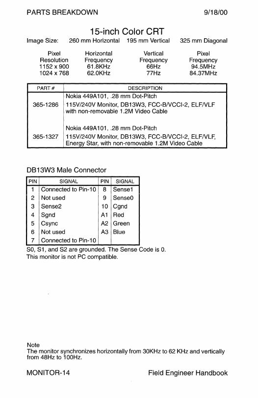
PARTS BREAKDOWN
15-inch Color CRT Image Size:
Pixel Resolution 1152 x 900 1024 x 768
PART#
260 mm Horizontal
Horizontal Frequency 61.8KHz 62.0KHz
195 mm Vertical
Vertical Frequency
66Hz 77Hz
DESCRIPTION
Nokia 449A 101, .28 mm Dot-Pitch
9/18/00
325 mm Diagonal
Pixel Frequency 94.5MHz
84.37MHz
365-1286 115V /240V Monitor, DB 13W3, FCC-BNCCl-2, ELFNLF with non-removable 1 .2M Video Cable
Nokia 449A 101, .28 mm Dot-Pitch
365-1327 115V/240V Monitor, DB13W3, FCC-BNCCl-2, ELFNLF, Energy Star, with non-removable 1.2M Video Cable
DB13W3 Male Connector
PIN SIGNAL PIN SIGNAL
1 Connected to Pin-1 O 8 Sense1
2 Not used 9 SenseO
3 Sense2 10 Cgnd
4 Sgnd A1 Red
5 Csync A2 Green
6 Not used A3 Blue
7 Connected to Pin-1 O
SO, S1, and S2 are grounded. The Sense Code is 0. This monitor is not PC compatible.
Note The monitor synchronizes horizontally from 30KHz to 62 KHz and vertically from 48Hz to 1 OOHz.
MONITOR-14 Field Engineer Handbook
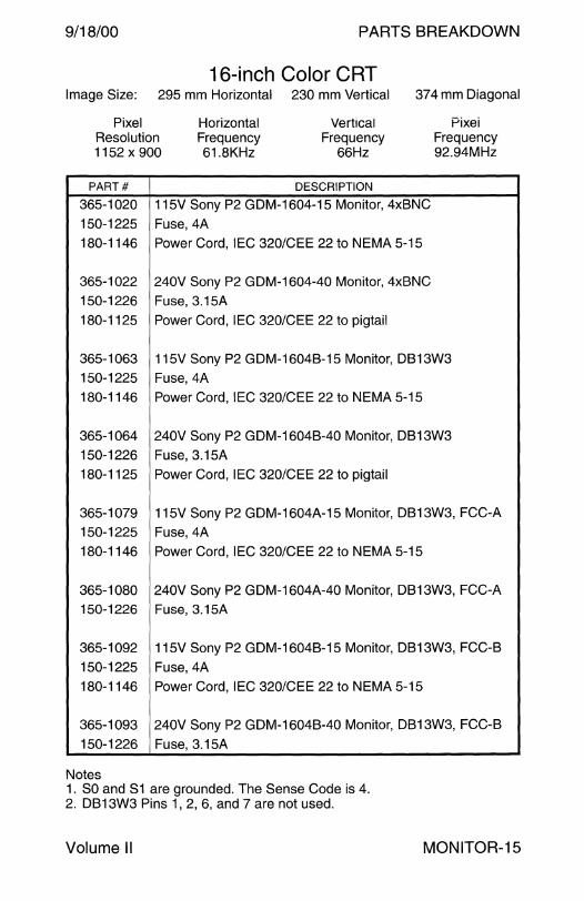
9/18/00 PARTS BREAKDOWN
16-inch Color CRT Image Size: 295 mm Horizontal 230 mm Vertical 374 mm Diagonal
Pixel Resolution 1152 x 900
Horizontal Frequency 61.8KHz
Vertical Frequency
66Hz
Pixei Frequency 92.94MHz
PART# DESCRIPTION
365-1020 115V Sony P2 GDM-1604-15 Monitor, 4xBNC
150-1225 Fuse, 4A 180-1146 Power Cord, IEC 320/CEE 22 to NEMA 5-15
365-1022 240V Sony P2 GDM-1604-40 Monitor, 4xBNC 150-1226 Fuse, 3.15A 180-1125 Power Cord, IEC 320/CEE 22 to pigtail
365-1063 115V Sony P2 GDM-1604B-15 Monitor, DB13W3 150-1225 Fuse,4A 180-1146 Power Cord, IEC 320/CEE 22 to NEMA 5-15
365-1064 240V Sony P2 GDM-1604B-40 Monitor, DB13W3 150-1226 Fuse, 3.15A 180-1125 Power Cord, IEC 320/CEE 22 to pigtail
365-1079 115V Sony P2 GDM-1604A-15 Monitor, DB 13W3, FCC-A 150-1225 Fuse,4A 180-1146 Power Cord, IEC 320/CEE 22 to NEMA 5-15
365-1080 240V Sony P2 GDM-1604A-40 Monitor, DB13W3, FCC-A 150-1226 Fuse, 3.15A
365-1092 115V Sony P2 GDM-1604B-15 Monitor, DB 13W3, FCC-B
150-1225 Fuse,4A 180-1146 Power Cord, IEC 320/CEE 22 to NEMA 5-15
365-1093 240V Sony P2 GDM-1604B-40 Monitor, DB13W3, FCC-B
150-1226 Fuse, 3.15A
Notes 1. SO and S1 are grounded. The Sense Code is 4. 2. DB13W3 Pins 1, 2, 6, and 7 are not used.
Volume II MONITOR-15
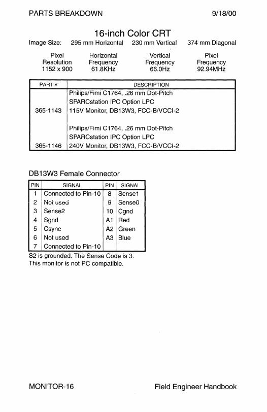
PARTS BREAKDOWN 9/18/00
16-inch Color CRT Image Size: 295 mm Horizontal 230 mm Vertical 374 mm Diagonal
Pixel Resolution 1152 x 900
PART#
Horizontal Frequency 61.BKHz
Vertical Frequency
66.0Hz
DESCRIPTION
Philips/Fi mi C1764, .26 mm Dot-Pitch
SPARCstation IPC Option LPC 365-1143 115V Monitor, DB 13W3, FCC-BNCCl-2
Philips/Fimi C1764, .26 mm Dot-Pitch
SPARCstation IPC Option LPC
365-1146 240V Monitor, DB13W3, FCC-BNCCl-2
DB 13W3 Female Connector
PIN SIGNAL PIN SIGNAL
1 Connected to Pin-1 O 8 Sense1 ,.,
t'1ot used 9 SenseO t:.
3 Sense2 10 Cgnd
4 Sgnd A1 Red
5 Csync A2 Green
6 Not used A3 Blue 7 Connected to Pin-1 O
S2 is grounded. The Sense Code is 3. This monitor is not PC compatible.
Pixel Frequency 92.94MHz
MONITOR-16 Field Engineer Handbook

9/18/00 PARTS BREAKDOWN
16-inch Mid-Range Color CRT Image Size: 95 mm Horizontal 226 mm Vertical 371 mm Diagonal
Pixel Resolution 1152 x 900 1024 x 768
PART#
Horizontai Frequency 61.8KHz 62.0KHz
Veriicai Frequency
66.0Hz 77.0Hz
DESCRIPTION
Sony CPD-1790, .26 mm Dot-Pitch 365-1151 115V /240V Monitor, DB 13W3, FCC-BNCCl-2,
with non-removable 1.2M Video Cable
365-1164 115V/240V S. Hemisphere Monitor, DB13W3,
r"\: •• -1 r111.t:::1
Frequency 92.94MHz 84.37MHz
FCC-BNCCl-2, with non-removable 1.2M Video Cable
365-1165 115V/240V European Monitor, DB13W3, FCC-BNCCl-2, Swedish MPR-2, with non-removable 1.2M Video Cable
365-1166 115V/240V OEM Monitor, DB13W3, FCC-BNCCl-2, with non-removable 1.2M Video Cable.
DB 13W3 Male Connector SSS Compatibility Matrix 1
PIN SIGNAL PIN SIGNAL MODEL PART# COMPATIBILE
1 Not used 8 Sense1 Xterm 1 2501-2540-03 Yes 2 Not used 9 SenseO Xterm 1 2501-3025-02 Yes
3 Sense2 10 Cgnd 70MHz 2501-2861-02 Yes 4 Sgnd A1 Red 70MHz 2501-3002-02 Yes
5 Csync A2 Green 85MHz 2501-2549-03 Yes
6 Not used A3 Blue 85MHz 2501-2928-02 Yes 7 Not used 110MHz 2501-3008-03 Yes
S2 is grounded. 110MHz 501-3109-xx Yes 2
The Sense Code is 3. 110MHz 501-3134-xx Yes 2
Not a PC compatible monitor.
1 If the SPARCstation 4 tcx frame buffer outputs sync on green, the board is not compatible with the 16-inch monitor. The monitor cannot remove sync from the green output. Sync on green causes a higher than normal green output level. Refer to BuglD 1218690.
2 Jumper J0501 on the SS4 CPU enables or disables sync on green.
Volume II MONITOR-17

PARTS BREAKDOWN 9/18/00
16-inch Premium Color CRT Image Size: 295 mm Horizontal 230 mm Vertical 37 4 mm Diagonal
Pixel Horizontal Vertical Pixel Resolution Frequency Frequency Frequency* 944 x 736 70.8KHz 84.0Hz 92.94MHz 1076 x 824 71.7KHz 76.0Hz 105.5MHzt 1152 x 900 61.8KHz 66.0Hz 92.94MHz 1152 x 900 71.7KHz 76.0Hz 105.5MHz
PART# DESCRIPTION
Sony P3 GDM-1662, .31 mm Dot-Pitch
365-1096 115V/240V Monitor, DB13W3, FCC-A/VCCl-1 (not used)
Sony P3 GDM-1662 or GDM-1662B, .31 mm Dot-Pitch
365-1107 115V /240V OEM Monitor, DB 13W3, FCC-BNCCl-2
365-1113 115V/240V Monitor, DB13W3, FCC-BNCCl-2
Sony P3 GDM-1662B, .31 mm Dot-Pitch
365-1130 115V/240V Monitor, DB13W3, FCC-BNCCl-2, VLF 365-1147 115V/240V Southern Hemisphere Monitor, DB13W3, VLF
Sony P3 GDM-1662B, .31 mm Dot-Pitch with Video Cable 530-1870
365-1159 115V/240V Monitor, DB13W3, FCC-BNCCl-2, VLF,
365-1161 115V /240V S. Hemisphere Monitor, DB 13W3, VLF,
365-1289 115V /240V OEM Monitor, DB 13W3, VLF,
*The Mode Ill (1024 x 800@ 84) Overscan Mode user area is 944 x 736. t The Mode II (1152 x 900@ 76) Overscan Mode user area is 1076 x 824.
Notes 1. SO is grounded. The Sense Code is 6. 2. DB13W3 Pins 1, 2, 6, and 7 are not used. 3. This monitor is not PC compatible. 4. The overscan mode is not supported at 66Hz vertical refresh. 5. The Frame Buffer revisions listed below do not decode the monitor
sense code. Video is not displayed upon power-up until the video cable is removed and reconnected.
P4 CG6, 501-1505-03 and below P4 CG6, 501-1532-09 and below SBus CG6, 501-1481-04 and below SBus CG6 501-1645-03 and below.
MONITOR-18 Field Engineer Handbook
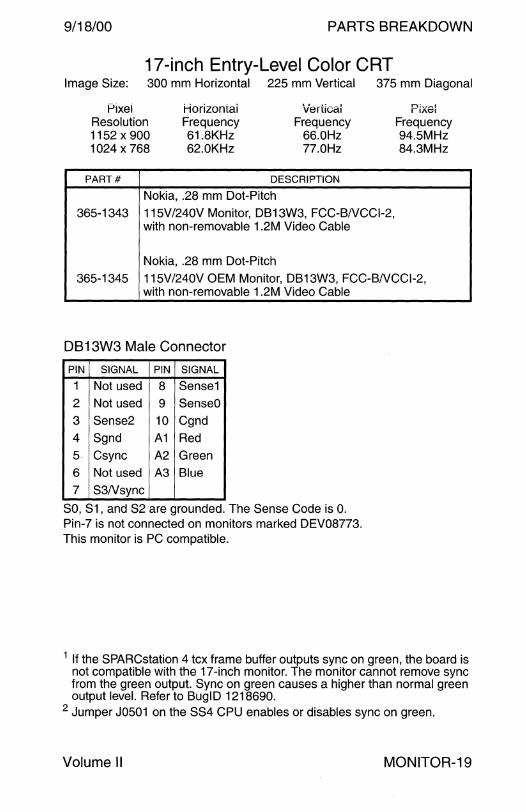
9/18/00 PARTS BREAKDOWN
17-inch Entry-Level Color CRT Image Size: 300 mm Horizontal 225 mm Vertical 375 mm Diagonal
Pixel Resolution 1152 x 900 1024 x 768
PART#
Horizontai Frequency 61.8KHz 62.0KHz
Veriicai Frequency
66.0Hz 77.0Hz
DESCRIPTION
Nokia, .28 mm Dot-Pitch
n:~,.-1
r1At:::I
Frequency 94.5MHz 84.3MHz
365-1343 115V/240V Monitor, DB13W3, FCC-BNCCl-2, with non-removable 1.2M Video Cable
Nokia, .28 mm Dot-Pitch
365-1345 115V/240V OEM Monitor, DB13W3, FCC-BNCCl-2, with non-removable 1 .2M Video Cable
DB13W3 Male Connector
PIN SIGNAL PIN SIGNAL
1 Not used 8 Sense1
2 Not used 9 SenseO
3 Sense2 10 Cgnd
4 Sgnd A1 Red
5 Csync A2 Green
6 Not used A3 Blue
7 S3Nsync
SO, S1, and S2 are grounded. The Sense Code is 0. Pin-7 is not connected on monitors marked DEV08773. This monitor is PC compatible.
1 If the SPARCstation 4 tcx frame buffer outputs sync on green, the board is not compatible with the 17-inch monitor. The monitor cannot remove sync from the green output. Sync on green causes a higher than normal green output level. Refer to BuglD 1218690.
2 Jumper J0501 on the SS4 CPU enables or disables sync on green.
Volume II MONITOR-19

PARTS BREAKDOWN 9/18/00
17-inch Entry-Level Color CRT Image Size: 300 mm Horizontal 225 mm Vertical 375 mm Diagonal
Pixel Horizontal Vertical Pixel Resolution Frequency Frequency Frequency 800 x 600 46.8KHz 75.0Hz 49.5MHz 1152 x 900 61.8KHz 66.0Hz 94.5MHz 1152 x 900 71.8KHz 76.0Hz 108.0MHz 1024 x 768 62.0KHz 77.0Hz 84.3MHz 1024 x 768 60.0KHz 75.0Hz 78.7MHz
PART# DESCRIPTION
Nokia, .27 mm Dot-Pitch
365-1354 115V/240V Monitor, HD15, FCC-BNCCl-2, with non-removable 1.5M Video Cable
Nokia, .27 mm Dot-Pitch
365-1355 115V/240V OEM Monitor, HD15, FCC-BNCCl-2, with non-removable 1.5M Video Cable
130-3034 HD15F to DB13W3M Adapter
HD15 Male Connector
PIN SIGNAL PIN SIGNAL
1 Red 9 Not used
2 Green 10 Sync Gnd
3 Blue 11 Gnd
4 Gnd 12 DOC Data
5 Sgnd 13 Hsync
6 Red Gnd 14 Vsync
7 Green Gnd 15 DOC Clock
8 Blue Gnd
Pin-13 accepts Composite Sync if Vsync is not present on Pin-14. This monitor is PC compatible.
MONITOR-20 Field Engineer Handbook
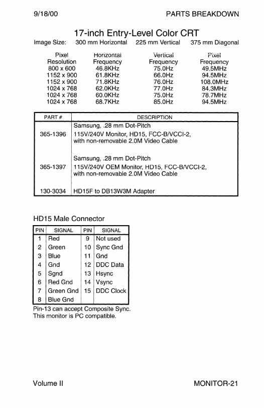
9/18/00 PARTS BREAKDOWN
17-inch Entry-Level Color CRT Image Size: 300 mm Horizontal 225 mm Vertical 375 mm Diagonal
Pixel Honzontai Verticai n:.,-.1 rt.At::1
Resolution Frequency Frequency Frequency 800 x 600 46.8KHz 75.0Hz 49.5MHz 1152 x 900 61.8KHz 66.0Hz 94.5MHz 1152 x 900 71.8KHz 76.0Hz 108.0MHz 1024 x 768 62.0KHz 77.0Hz 84.3MHz 1024 x 768 60.0KHz 75.0Hz 78.7MHz 1024 x 768 68.7KHz 85.0Hz 94.5MHz
PART# DESCRIPTION
Samsung, .28 mm Dot-Pitch
365-1396 115V/240V Monitor, HD15, FCC-BNCCl-2, with non-removable 2.0M Video Cable
Samsung, .28 mm Dot-Pitch
365-1397 115V/240V OEM Monitor, HD15, FCC-BNCCl-2, with non-removable 2.0M Video Cable
130-3034 HD15F to DB13W3M Adapter
HD15 Male Connector
PIN SIGNAL PIN SIGNAL
1 Red 9 Not used
2 Green 10 Sync Gnd
3 Blue 11 Gnd
4 Gnd 12 DOC Data
5 Sgnd 13 Hsync
6 Red Gnd 14 Vsync
7 Green Gnd 15 DOC Clock
8 Blue Gnd
Pin-13 can accept Composite Sync. This monitor is PC compatible.
Volume II MONITOR-21
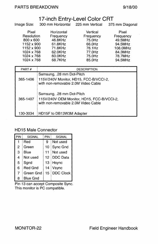
PARTS BREAKDOWN 9/18/00
17-inch Entry-Level Color CRT Image Size: 300 mm Horizontal 225 mm Vertical 375 mm Diagonal
Pixel Horizontal Vertical Pixel Resolution Frequency Frequency Frequency 800 x 600 46.8KHz 75.0Hz 49.SMHz 1152 x 900 61.8KHz 66.0Hz 94.SMHz 1152 x 900 71.8KHz 76.1Hz 108.0MHz 1024 x 768 62.0KHz 77.0Hz 84.3MHz 1024 x 768 60.0KHz 75.0Hz 78.7MHz 1024 x 768 68.7KHz 85.0Hz 94.SMHz
PART# DESCRIPTION
Samsung, .28 mm Dot-Pitch 365-1406 115V/240V Monitor, HD15, FCC-BNCCl-2,
with non-removable 2.0M Video Cable
Samsung, .28 mm Dot-Pitch 365-1407 11 SV /240V OEM Monitor, HD15, FCC-BNCCl-2,
with non-removable 2.0M Video Cable
130-3034 HD1 SF to DB13W3M Adapter
HD15 Male Connector
PIN SIGNAL PIN SIGNAL
1 Red 9 Not used 2 Green 10 Sync Gnd
3 Blue 11 Not used 4 Not used 12 DOC Data
5 Sgnd 13 Hsync 6 Red Gnd 14 Vsync
7 Green Gnd 15 DOC Clock
8 Blue Gnd
Pin-13 can accept Composite Sync. This monitor is PC compatible.
MONITOR-22 Field Engineer Handbook

9/18/00 PARTS BREAKDOWN
17-inch Premium Color CRT Image Size: 300 mm Horizontal 234 mm Vertical 380 mm Diagonal
Pixel Resolution 1152 x 900
1280 x 1024
PART#
Horizontal Frequency 71.81KHz 81.13KHz
Vertical Frequency 76.14Hz 76.11Hz
DESCRIPTION
Sony N1 GDM-17E10, .26 mm Dot-Pitch
Pixel Frequency 108.0MHz 135.0MHz
365-1316 115V /240V Monitor, DB 13W3, FCC-BNCCl-2, with non-removable 1.2M Video Cable
Sony N1 GDM-17E10
365-1319 115V/240V OEM Monitor, DB13W3, FCC-BNCC1-2 with non-removable 1.2 Video Cable
Sony N1 GDM-17E10
365-1321 115V/240V Southern Hemisphere Monitor, DB13W3, FCC-BNCC1 -2 with non-removable 1.2 Video Cable
DB 13W3 Male Connector
PIN SIGNAL PIN SIGNAL
1 RS232 clock input 8 Sense1 2 RS232 data in 9 SenseO
3 Sense2 10 Cgnd 4 Sgnd A1 Red
5 Csync A2 Green
6 RS232 data out A3 Blue 7 Not used
SO is grounded. The Sense Code is 5. This monitor is not PC compatible.
Volume II MONITOR-23

PARTS BREAKDOWN 9/18/00
17-inch Premium Color CRT Image Size: 300 mm Horizontal 234 mm Vertical 380 mm Diagonal Image Size: 293 mm Horizontal 234 mm Vertical 375 mm Diagonal
Pixel Horizontal Vertical Pixel Resolution Frequency Frequency Frequency 1152 x 900 71.81KHz 76.14Hz 108.0MHz 1280 x 1024 81.13KHz 76.11 Hz 135.0MHz 960 x 680 81.13KHz 112.37Hz 101.0MHz
PART# DESCRIPTION
Sony N2 GDM17E20, .26 mm Dot-Pitch 365-1338 115V/240V Monitor, DB13W3, FCC-BNCCl-2,
with non-removable 1 .2M Video Cable
Sony N2 GDM17E20, .26 mm Dot-Pitch
365-1339 115V/240V OEM Monitor, DB13W3, FCC-BNCC1-2 with non-removable 1.2 Video Cable
Sony N2 GDM17E20, .26 mm Dot-Pitch 365-1341 115V /240V Southern Hemisphere Monitor, DB 13W3,
FCC-BNCC1-2 with non-removable 1.2 Video Cable
DB13W3 Male Connector
PIN SIGNAL PIN SIGNAL
1 SCL clock input for DDC1/2B 8 Sense1
2 +5Vdc from DOC framebuffer 9 SenseO
3 Sense2 10 Cgnd 4 Sgnd A1 Red
5 Csync A2 Green
6 SDA bi-directional serial data A3 Blue
7 Sense3Nsync
SO and S3 are grounded. The Sense Code is 6. Pin-5 is Hsync if Vsync is present on Pin-7. This monitor is PC compatible with internal rework.
MONITOR-24 Field Engineer Handbook

9/18/00 PARTS BREAKDOWN
19-inch Color CRT Image Size: 350 mm Horizontal 273 mm Vertical 443 mm Diagonal
Pixel Resolution 1152 x 900
Horizontal Frequency 61.8KHz
Vertical Frequency
66.0Hz
PART# DESCRIPTION
Sony P2 GDM-1955A15, .31 mm Dot-Pitch 365-1038 115V Monitor, 4xBNC
150-1225 Fuse,4A 180-1146 Power Cord, IEC 320/CEE 22 to NEMA 5-15
Sony P2 GDM-1955A40, .31 mm Dot-Pitch
365-1039 240V Monitor, 4xBNC
150-1226 Fuse, 3.15A 180-1125 Power Cord, IEC 320/CEE 22 to pigtail
Sony P2 GDM-1955A15, .31 mm Dot-Pitch
365-1065 115V Monitor, DB13W3 150-1225 Fuse,4A
Sony P2 GDM-1955A40, .31 mm Dot-Pitch
365-1066 240V Monitor, DB13W3
150-1226 Fuse, 3.15A
Sony P2 GDM-1955A15, .31 mm Dot-Pitch
365-1081 115V Monitor, DB13W3, FCC-A/VCCl-1
150-1225 Fuse,4A
Sony P2 GDM-1955A40, .31 mm Dot-Pitch 365-1082 240V Monitor, DB13W3, FCC-A/VCCl-1
150-1226 Fuse, 3.15A
Notes 1. S2 is grounded. The Sense Code is 3. 2. DB13W3 Pins 1, 2, 6, and 7 are not used. 3. This monitor is not PC compatible.
Volume II
Pixel Frequency 92.94MHz
MONITOR-25
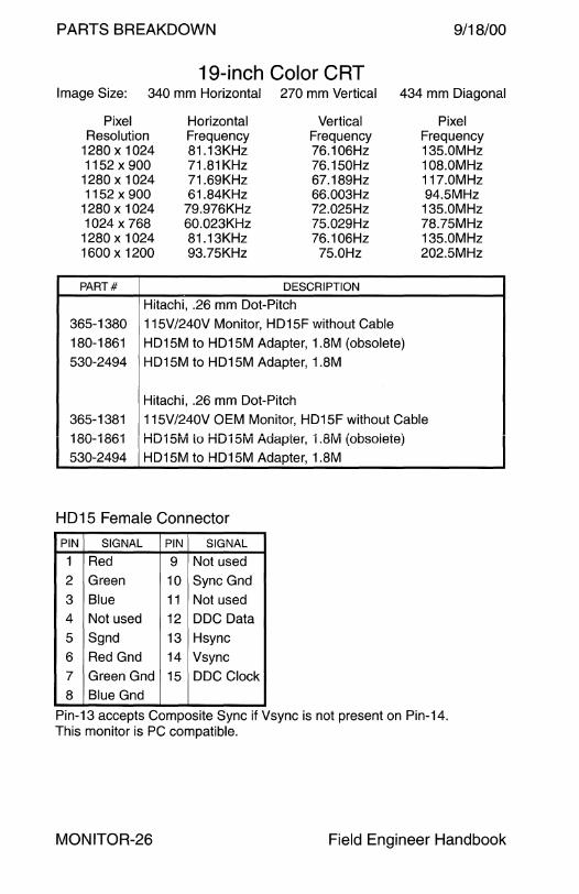
PARTS BREAKDOWN 9/18/00
19-inch Color CRT Image Size: 340 mm Horizontal 270 mm Vertical 434 mm Diagonal
Pixel Horizontal Vertical Pixel Resolution Frequency Frequency Frequency
1280 x 1024 81.13KHz 76.106Hz 13S.OMHz 11S2 x 900 71.81KHz 76.1SOHz 108.0MHz
1280 x 1024 71.69KHz 67.189Hz 117.0MHz 11S2 x 900 61.84KHz 66.003Hz 94.SMHz
1280 x 1024 79.976KHz 72.02SHz 13S.OMHz 1024 x 768 60.023KHz 7S.029Hz 78.7SMHz
1280 x 1024 81.13KHz 76.106Hz 13S.OMHz 1600 x 1200 93.7SKHz 7S.0Hz 202.SMHz
PART# DESCRIPTION
Hitachi, .26 mm Dot-Pitch
36S-1380 11 SV/240V Monitor, HD1SF without Cable
180-1861 HD1 SM to HD1 SM Adapter, 1.8M (obsolete)
S30-2494 HD1SM to HD1SM Adapter, 1.8M
Hitachi, .26 mm Dot-Pitch
36S-1381 11SV/240V OEM Monitor, HD1SF without Cable
180-1861 HD15ivi to HD15ivi Adapter, 1.8ivi (obsoiete)
S30-2494 HD1 SM to HD1 SM Adapter, 1.8M
HD15 Female Connector
PIN SIGNAL PIN SIGNAL
1 Red 9 Not used
2 Green 10 Sync Gnd
3 Blue 11 Not used
4 Not used 12 DOC Data
s Sgnd 13 Hsync
6 Red Gnd 14 Vsync
7 Green Gnd 1S DOC Clock
8 Blue Gnd
Pin-13 accepts Composite Sync if Vsync is not present on Pin-14. This monitor is PC compatible.
MONITOR-26 Field Engineer Handbook

9/18/00 PARTS BREAKDOWN
19-inch Premium Color CRT Image Size: 350 mm Horizontal 270 mm Vertical 442 mm Diagonal
.Pixel Horizontal Vertical P1xe1 Resolution Frequency Frequency Frequency 1076 x 824 71.7KHz 76.0Hz 105.5MHz* 1152 x 900 61.8KHz 66.0Hz 92.94MHz 1152 x 900 71.7KHz 76.0Hz 105.5MHz
1280 x 1024 71.7KHz 67.0Hz 117.0MHz
PART# DESCRIPTION
Sony P3 GDM-1962, .31 mm Dot-Pitch
365-1095 115V/240V Monitor, DB13W3, FCC-ANCCl-1
365-1106 115V/240V OEM Monitor, DB13W3, FCC-ANCCl-1 (obs)
Sony P3 GDM-1962B, .31 mm Dot-Pitch
365-1112 115V /240V Monitor, DB 13W3, FCC-BNCCl-2, VLF
Sony P3 GDM-1962B, .31 mm Dot-Pitch
365-1148 115V/240V Southern Hemisphere Monitor, DB13W3, VLF
Sony P3 GDM-1962B, .31 mm Dot-Pitch
365-1153 115V /240V European Monitor, DB 13W3, FCC-BNCCl-2, Swedish MPR-2, with Video Cable 530-1870
Sony P3 GDM-1962B with Video Cable 530-1870
365-1160 115V/240V Monitor, DB13W3, VLF
Sony P3 GDM-1962B with Video Cable 530-1870
365-1162 115V/240V S. Hemisphere Monitor, DB13W3, VLF,
Sony P3 GDM-1962B with Video Cable 530-1870
365-1288 115V /240V OEM Monitor, DB 13W3, FCC-BNCCl-2, VLF,
*The Mode II (1152 x 900@ 76) Overscan Mode user area is 1076 x 824.
Notes 1. SO and S1 are grounded. The Sense Code is 4. 2. DB13W3 Pins 1, 2, 6, and 7 are not used. 3. This monitor is not PC compatible. 4. CG6 s501-1505-03, s501-1532-09, s501-1481-04 or s501-1645-03
do not decode the monitor sense code. No video is displayed when power is applied until the video cable is removed and reconnected.
Volume II MONITOR-27
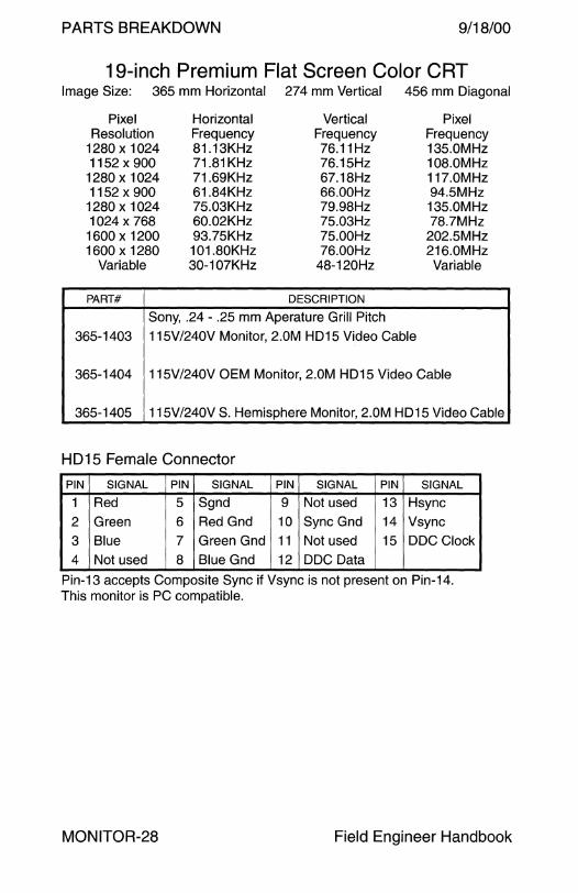
PARTS BREAKDOWN 9/18/00
19-inch Premium Flat Screen Color CRT Image Size: 365 mm Horizontal 274 mm Vertical 456 mm Diagonal
Pixel Resolution
1280 x 1024 1152 x 900
1280 x 1024 1152 x 900
1280 x 1024 1024 x 768 1600 x 1200 1600x1280
Variable
PART#
Horizontal Frequency 81.13KHz 71.81KHz 71.69KHz 61.84KHz 75.03KHz 60.02KHz 93.75KHz 101.80KHz 30-107KHz
Vertical Frequency 76.11 Hz 76.15Hz 67.18Hz 66.00Hz 79.98Hz 75.03Hz 75.00Hz 76.00Hz
48-120Hz
DESCRIPTION
Pixel Frequency 135.0MHz 108.0MHz 117.0MHz 94.5MHz 135.0MHz 78.7MHz
202.5MHz 216.0MHz Variable
Sony, .24 - .25 mm Aperature Grill Pitch
365-1403 115V/240V Monitor, 2.0M HD15 Video Cable
365-1404 115V/240V OEM Monitor, 2.0M HD15 Video Cable
365-1405 115V/240V S. Hemisphere Monitor, 2.0M HD15 Video Cable
HD15 Female Connector
PIN SIGNAL PIN SIGNAL PIN SIGNAL PIN SIGNAL
1 Red 5 Sgnd 9 Not used 13 Hsync
2 Green 6 Red Gnd 10 Sync Gnd 14 Vsync
3 Blue 7 Green Gnd 11 Not used 15 DOC Clock
4 Not used 8 Blue Gnd 12 DOC Data
Pin-13 accepts Composite Sync if Vsync is not present on Pin-14. This monitor is PC compatible.
MONITOR-28 Field Engineer Handbook

9/18/00 PARTS BREAKDOWN
20-inch Premium Color CRT Image Size: 350 mm Horizontal 270 mm Vertical 442 mm Diagonal
Pixel Horizontal Vertical Pixei Resolution Frequency Frequency Frequency 1076 x 824 71.7KHz 76.0Hz 108.0MHz* 1196 x 938 81.1 KHz 76.0Hz 135.0MHzt 1152 x 900 61.8KHz 66.0Hz 94.5MHz 1152 x 900 71.8KHz 76.0Hz 108.0MHz 1280 x 1024 71.8KHz 67.0Hz 118.0MHz 1280 x 1024 81.1KHz 76.0Hz 135.0MHz
PART# DESCRIPTION
Sony P4 GDM-20D10, .31 mm Dot-Pitch
365-1167 115V/240V Monitor, DB13W3, FCC-BNCCl-2, MPR 1990: 1 O with non-removable 1.2M Video Cable
365-1313 115V/240V OEM Monitor, DB13W3, FCC-BNCCl-2, MPR 1990:10 with non-removable 1.2M Video Cable
365-1317 115V /240V Southern Hemisphere Monitor, DB 13W3, FCC-BNCC1-2, MPR 1990:10 with 1.2M Video Cable
365-1330 115V/240V Monitor, DB13W3, FCC-BNCCl-2, MPR 1990:10 with non-removable 1.2M Video Cable
370-1576 Remote Control
370-1705 Remote Control without Logo
None CR2025 3V Battery, 20 mm diameter x 2.5 mm height
*The Mode II (1152 x 900@ 76) Overscan Mode user area is 1076 x 824. t The Mode I (1280 x 1024 @ 135) Overscan Mode user area is 1196 x 938.
DB 13W3 Male Connector PIN SIGNAL PIN SIGNAL PIN
1 RS232 clock in 5 Csync 10
2 RS232 data in 6 RS232 data out A1
3 Sense2 8 Sense1 A2
4 Sgnd 9 SenseO A3
SO and S1 are grounded. The Sense Code is 4. Pin-7 is not used. This monitor is not PC compatible.
Volume II
SIGNAL
Cgnd
Red
Green
Blue
MONITOR-29

PARTS BREAKDOWN 9/18/00
20-inch Premium Color CRT Image Size: 350 mm Horizontal 270 mm Vertical 442 mm Diagonal
Pixel Horizontal Vertical Pixel Resolution Frequency Frequency Frequency 1076 x 824 71.7KHz 76.0Hz 108.0MHz* 1196 x 938 81.1 KHz 76.0Hz 135.0MHzt 1152 x 900 61.8KHz 66.0Hz 94.5MHz 1152 x 900 71.8KHz 76.0Hz 108.0MHz
1280 x 1024 71.8KHz 67.0Hz 118.0MHz 1280 x 1024 81.1KHz 76.0Hz 135.0MHz
PART# DESCRIPTION
Sony P4 GDM-20D10, .31 mm Dot-Pitch
365-1322 115V/240V Sony P4 Korean Monitor, DB13W3, Energy Star, with non-removable 1.2M Video Cable
365-1324 115V/240V Sony P4 Monitor, DB13W3, Energy Star, with non-removable 1 .2M Video Cable
365-1325 115V/240V Sony P4 S. Hemisphere Monitor, DB13W3, Energy Star, with non-removable 1 .2M Video Cable
365-1326 115V/240V Sony P4 OEM Monitor, DB13W3, Energy Star, with non-removable 1 .2M Video Cable
370-1576 Remote Control
370-1705 Remote Control without Logo
None CR2025 3V Battery, 20 mm diameter x 2.5 mm height
* The Mode II (1152 x 900 @ 76) Overscan Mode user area is 1076 x 824. t The Mode I (1280 x 1024 @ 135) Overscan Mode user area is 1196 x 938.
DB13W3 Male Connector PIN SIGNAL PIN SIGNAL PIN
1 RS232 clock in 5 Csync 9
2 RS232 data in 6 RS232 data out A1
3 Sense2 5 Csync A2
4 Sgnd 8 Sense1 A3
SO and S1 are grounded. The Sense Code is 4. Pin-7 is not used. This monitor is not PC compatible.
SIGNAL
SenseO
Red
Green
Blue
MONITOR-30 Field Engineer Handbook

9/18/00 PARTS BREAKDOWN
20-inch Premium Color CRT Image Size: 350 mm Horizontal 270 mm Vertical 442 mm Diagonal
Pixel Horizontal Verticai Pixei Resolution Frequency Frequency Frequency 960 x 680 81.13KHz 112.37Hz 101.0MHz 1152 x 900 71.81KHz 76.14Hz 108.0MHz 1152 x 900 61.84KHz 66.00Hz 94.5MHz 1280 x 1024 81.13KHz 76.11 Hz 135.0MHz 1280 x 1024 71.67KHz 66.67Hz 118.0MHz
PART# DESCRIPTION
Sony N2 GDM-20E20, .31 mm Dot-Pitch
365-1335 115V /240V Monitor, DB 13W3, FCC-B, Energy Star with non-removable 1.2M Video Cable
365-1337 115V /240V OEM Monitor, DB 13W3, FCC-B, Energy Star with non-removable 1.2M Video Cable
365-1340 115V /240V Southern Hemisphere Monitor, DB 13W3, FCC-B, Energy Star with non-removable 1.2M Video Cable
365-1342 115V /240V Korean Monitor, DB 13W3, FCC-B, Energy Star with non-removable 1.2M Video Cable
DB13W3 Male Connector
PIN SIGNAL PIN SIGNAL
1 SCL DOC clock input 8 Sense1
2 Not used 9 SenseO
3 Sense2 10 Cgnd
4 Sgnd A1 Red
5 Csync A2 Green
6 SDA DOC data 1/0 A3 Blue
7 Vsync
SO and 81 are grounded. The Sense Code is 4. Pin-5 is Hsync if Vsync is present on Pin-7. This monitor is PC compatible.
Volume II MONITOR-31

PARTS BREAKDOWN 9/18/00
21-inch Color CRT Image Size: 369 mm Horizontal 295 mm Vertical 472 mm Diagonal
Pixel Resolution
1280 x 1024
PART#
Horizontal Frequency 81.1 KHz
Toshiba P21 CU80
Vertical Frequency
76.0Hz
DESCRIPTION
365-1068 115V/240V Monitor, DB13W3, FCC-A/VCCl-1
Toshiba P21 CU80
Pixel Frequency 135.0MHz
365-1110 115V/240V OEM Monitor, DB13W3, FCC-A/VCCl-1
DB13W3 Female Connector
PIN SIGNAL PIN SIGNAL
1 Not used 8 Sense1 2 Not used 9 SenseO 3 Sense2 10 Cgnd 11 Sgnd A• n _ _, .,. /"\ I n~u
5 Csync A2 Green 6 Not used A3 Blue 7 Not used
SO and S2 are grounded. The Sense Code is 2. This monitor is not PC compatible.
MONITOR-32 Field Engineer Handbook

9/18/00 PARTS BREAKDOWN
21-inch Color CRT Image Size: 350 mm Horizontal 270 mm Vertical 442 mm Diagonal
Pixel Horizontal Verticai Pixei Resolution Frequency Frequency Frequency
1280 x 1024 81.13KHz 76.11 Hz 135.0MHz 1152 x 900 71.81KHz 76.14Hz 108.0MHz 1600 x 1200 93.75KHz 75.00Hz 202.5MHz 1152 x 900 61.84KHz 66.00Hz 94.5MHz
1280 x 1024 71.69KHz 67.18Hz 117.0MHz 960 x 680 81.13KHz 112.37Hz 101.2MHz
PART# DESCRIPTION
Sony N3 GDM-501 OPT, .26 mm Dot-Pitch
365-1383 115V/240V Monitor, DB13W3 and HD15 with non-removable 2.0M Video Cable
365-1384 115V/240V OEM Monitor, DB13W3 and HD15 with non-removable 2.0M Video Cable
365-1386 115V/240V Korean Monitor, DB13W3 and HD15 with non-removable 2.0M Video Cable
DB13W3 Male Connector
PIN SIGNAL PIN SIGNAL
1 SCL DOC clock input 6 SDA DOC data 1/0
2 +5 from Framebuffer 7 Vsync
3 Sense2 8 Sense1
4 Sgnd 9 SenseO
5 Csync 10 Cgnd
SO and S1 are grounded. The Sense Code is 4. This monitor is PC compatible.
HD15 Female Connector
PIN SIGNAL PIN SIGNAL PIN SIGNAL
1 Red 5 Sgnd 9 Not used
2 Green 6 Red Gnd 10 Sync Gnd
3 Blue 7 Green Gnd 11 Not used
4 Not used 8 Blue Gnd 12 DOC Data
PIN SIGNAL
A1 Red
A2 Green
A3 Blue
PIN SIGNAL
13 Hsync
14 Vsync
15 DOC Clock
Pin-13 accepts Composite Sync if Vsync is not present on Pin-14. This monitor is PC compatible.
Volume II MONITOR-33

PARTS BREAKDOWN 9/18/00
21-inch Premium Flat Screen Color CRT Mode I Size: 364 mm Horizontal 291 mm Vertical 466 mm Diagonal Mode II Size: 388 mm Horizontal 291 mm Vertical 485 mm Diagonal
Pixel Resolution
1280 x 1024 1152 x 900 1280 x 1024 1280 x 1024 1152 x 900 1024 x 768 1600 x 1200 1280 x 1024
Variable
PART#
Horizontal Frequency 81.13KHz 71.81KHz 79.97KHz 71.69KHz 61.84KHz 60.02KHz 93.75KHz 120.94KHz 30-121KHz
Vertical Frequency 76.11Hz 76.15Hz 75.02Hz 67.19Hz 66.00Hz 75.03Hz 75.00Hz 111.98Hz 48-160Hz
DESCRIPTION
Pixel Frequency 135.0MHz 108.0MHz 135.0MHz 117.0MHz 94.5MHz 78.7MHz
202.5MHz 216.0MHz Variable
Sony GDM-5410, .24 mm Aperature Grill Pitch 365-1399 115V/240V Monitor, 2.0M 13W3 Video Cable 370-4064 Rear Cover
365-1400 115V/240V OEM Monitor, 2.0M 13W3 Video Cable 370-4065 Rear Cover
365-1401 115V/240V S. Hemisphere Monitor, 2.0M 13W3 Video Cable
DB13W3 Male Connector
PIN SIGNAL PIN SIGNAL PIN SIGNAL
1 DOC clock input 6 DOC data 1/0 A1 Red
2 +5 from Framebuffer 7 Vsync A2 Green
3 Sense2 8 Sense1 A3 Blue
4 Sgnd 9 SenseO 5 Csync 10 Cgnd
SO and S1 are grounded. The Sense Code is 4.
HD15 Female Connector
PIN SIGNAL PIN SIGNAL PIN SIGNAL PIN SIGNAL
1 Red 5 Sgnd 9 Not used 13 Hsync
2 Green 6 Red Gnd 10 Sync Gnd 14 Vsync
3 Blue 7 Green Gnd 11 Not used 15 DOC Clock
4 Not used 8 Blue Gnd 12 DOC Data
Pin-13 accepts Composite Sync if Vsync is not present on Pin-14. This monitor is PC compatible.
MONITOR-34 Field Engineer Handbook
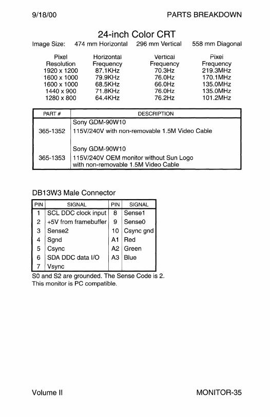
9/18/00 PARTS BREAKDOWN
24-inch Color CRT Image Size: 474 mm Horizontal 296 mm Vertical 558 mm Diagonal
Pixel Horizontal Verticai Pixei Resolution Frequency Frequency Frequency
1920 x 1200 87.1KHz 70.3Hz 219.3MHz 1600 x 1000 79.9KHz 76.0Hz 170.1MHz 1600 x 1000 68.5KHz 66.0Hz 135.0MHz 1440 x 900 71.8KHz 76.0Hz 135.0MHz 1280 x 800 64.4KHz 76.2Hz 101.2MHz
PART# DESCRIPTION
Sony GDM-90W10
365-1352 115V /240V with non-removable 1.5M Video Cable
Sony GDM-90W10
365-1353 115V /240V OEM monitor without Sun Logo with non-removable 1.5M Video Cable
DB13W3 Male Connector
PIN SIGNAL PIN SIGNAL
1 SCL DDC clock input 8 Sense1
2 +5V from framebuffer 9 SenseO
3 Sense2 10 Csync gnd
4 Sgnd A1 Red
5 Csync A2 Green
6 SDA DOC data 1/0 A3 Blue
7 Vsync
SO and S2 are grounded. The Sense Code is 2. This monitor is PC compatible.
Volume II MONITOR-35

This page intentionally left blank.

PARTS BREAKDOWN
TROUBLESHOOTING
9/18/00 TROUBLESHOOTING
CPU Power-On Self Test Keyboard Error Codes ...................... 3
E3x00 E4x00 E5x00 E6x00 Front Panel LEDs Clock Board LEDs .. . . . . . . . . . . . . . . . . . . . . . . . . . . . 6 CPU/Memory LEDs 1/0 LEDs Disk Board LEDs . . . . . . . . . 6
E10000 System Board LEDs Control Board LEDs .. .. . .. . . .. .. ... .. . . .. 7 Centerplane Support Board LEDs Fan Tray LEDs .. .. . . . .. 8
SCSI Disk Drives Single-ended 8-bit SCSI Pinouts ................. ................... ... 9 Single-ended 16-bit SCSI Pinouts ............... ........ ........... ... 10 Single Connector SCSI Pinouts .. .. . . . . . . . . .. .. .. .. . . . . .. ... . . . . . . .. ... 11 Differential 8-bit SCSI Pinouts .. .. .. .. . . . . . . . .. .. .. .. . . . . .. . . .. .. . .. .. .. . 12 Differential 16-bit SCSI Pinouts .. .. .. . .. . . . . .. .. .. .. . . . . .. . .. . . . . .. .. .. . 13 Media Defect Management . . . .. .. .. .. . . . . . . . . .. .. .. .. . . . . .. .. .. .. . . . . . .. . 14 SCSI Option Bit .. .. .. . . .. .. .. .. ... . . .. .. .. .. .. . . . . .... .. .. .. . . . . .. .. .. .. .. . .. .. . 15 SCSI Controllers .. .. . .. .. . .. .. .. . . . . .. .. .. . . . .. . . . . .. .. . .. . .. . . . .. . .. . .. .. . . . . . . 16 SCSI Sense Keys .. . . . .. .. . . .. .. . .. .. .. .. .. .. . . . . . ... .. .. .. . . . . .. .. . . .. .. . . . . . . 17 SCSI Sense Codes . . .. .. . . .. .. . . . .. .. .. . . .. . . . . .... .. .. .. . . . . .. .. .. .. .. .. .. .. 19
Removable Media 5GB 4 mm DDS-1 ............................................................. 25 4-8GB 4 mm DDS-2 .... ..... ........... ......... ............ ......... ........ 26 20-40GB 4 mm DDS-4 . . . .. .. . . . .. .. . . . . .. . . . . . .. . . . . . . . . .. .. . . .. . .. . .. .. . . . 26 Quantum DLT 4700 ........................................................... 27
Communication Electrical Characteristics .. .. . . . .. .. . . . . .. .. .. . .. . . . . . . . . . . ... . .. .. .. . .. .. . . 28 RS-232 Signals .. .. . . . . .. . .. .. .. .. . .. .. .. . . .. .. .. . . .. . . . . . .. . . . . .. . .. .. . . . . . . .. . 30 RS-449 Signals ................................................................. 31 Ethernet Controllers . .... .. . . .. .. .. . .. .. .. . . . . . . . .. . . .. .. . .. . . . . . . . . . .. . . . . . .. 32
Field Engineer Handbook - Volume II
TROUBLESHOOTING 9/18/00
Troubleshooting - Continued
Communication Pin Assignments CPU Serial Ports . .. ... .. . .. ... . . .. .. . . . .. .. .. .. .. . . .. .. . .. . .. .. ... ... ... ... .. .. 33 CPU Keyboard and Mouse . .. ... . . .. .. .. .. .. .. .. .. . .. . .. .. ... ... ... ... . . .. 33 USB Port ........................................................................... 35 IEEE-1394 Port ................................................................. 35 CPU Parallel Port . . . . . . . . . . . . . . . . . . . . . . . . . . . . . . . . . . . . . . . . . . . . . . . . . . . . . . . . . . . . . . 36 SSS SS20 AUi Port ........................................................ 38 Sun Microphone II ............................................................. 38 SSS SS4 Audio Module Audio Jacks . . .. .. . .. . .. .. . .. ... . .. . ..... 39 SS20 Audio Jacks . . . . . . . . . . . . . . . . . . . . . . . . . . . . . . . . . . . . . . . . . . . . . . . . . . . . . . . . . . . . . 40 A11 A12 A14 Audio Jacks............................................ 41 Ethernet . . . . . . . . . . . . . . . . . . . . . . . . . . . . . . . . . . . . . . . . . . . . . . . . . . . . . . . . . . . . . . . . . . . . . . . . . . . . . 42 Sun Link ISDN .................................................................... 42 SBE/S Ethernet . .. .. ... .. . .. ... . . .. .. .. . .. . . .. . . . .. .. . . .. . . .. .. . .. . .. ... ... . .. .. 43 Fast Ethernet . . . . . . . . . . . . . . . . . . . . . . . . . . . . . . . . . . . . . . . . . . . . . . . . . . . . . . . . . . . . . . . . . . . . . 44 SPC/S HSl/S .. .. .. . . . .. ... .. ... . . .. .. . . . .. .. .. . . . .. .. . . . . .. .. .. . .. . .. . .. .... .. . 45
Network Terminal Server LEDs ............................................ 46
TROUBLESHOOTING-2 Field Engineer Handbook
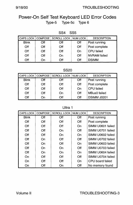
9/18/00 TROUBLESHOOTING
Power-On Self Test Keyboard LED Error Codes Type-5 Type-Sc Type 6
SS4 SS5
CAPS LOCK COMPOSE SCROLL LOCK NUM LOCK DESCRIPTION
Blink Off Off Off Post running
Off Off Off Off Post complete
Off Off Off On CPU failed
Off Off On Off NVRAM failed
Off On Off Off DSIMM
8820 CAPS LOCK COMPOSE SCROLL LOCK NUM LOCK DESCRIPTION
Blink Off Off Off Post running
Off Off Off Off Post complete
Off Off Off On CPU failed
Off Off On Off MBusO failed
Off On Off Off DSIMM J0201
Ultra 1
CAPS LOCK COMPOSE SCROLL LOCK NUM LOCK DESCRIPTION
Blink Off Off Off Post running
Off Off Off Off Post complete
Off Off Off On SIMM U0601 failed
Off Off On Off SIMM U0701 failed
Off Off On On SIMM U0602 failed
Off On Off Off SIMM U0702 failed
Off On Off On SIMM U0603 failed
Off On On Off SIMM U0703 failed
Off On On On SIMM U0604 failed
On Off Off Off SIMM U0704 failed
On Off Off On CPU board failed
On Off On Off No memory found
Volume II TROUBLESHOOTING-3
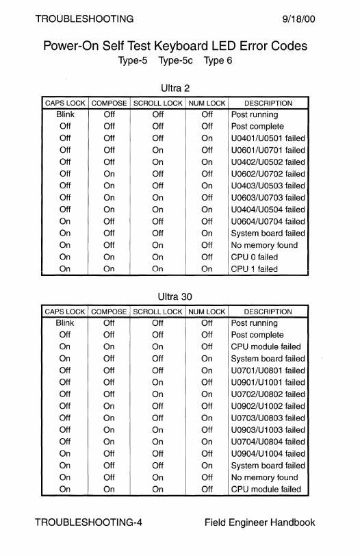
TROUBLESHOOTING 9/18/00
Power-On Self Test Keyboard LED Error Codes Type-5 Type-Sc Type 6
Ultra 2
CAPS LOCK COMPOSE SCROLL LOCK NUM LOCK DESCRIPTION
Blink Off Off Off Post running
Off Off Off Off Post complete
Off Off Off On U0401/U0501 failed
Off Off On Off U0601/U0701 failed
Off Off On On U0402/U0502 failed
Off On Off Off U0602/U0702 failed
Off On Off On U0403/U0503 failed
Off On On Off U0603/U0703 failed
Off On On On U0404/U0504 failed
On Off Off Off U0604/U0704 failed
On Off Off On System board failed
On Off On Off No memory found
On On On Off CPU 0 failed
On On On On CPIJ 1 failed
Ultra 30
CAPS LOCK COMPOSE SCROLL LOCK NUM LOCK DESCRIPTION
Blink Off Off Off Post running
Off Off Off Off Post complete
On On On Off CPU module failed
On Off Off On System board failed
Off Off Off On U0701/U0801 failed
Off Off On Off U0901/U1001 failed
Off Off On On U0702/U0802 failed
Off On Off Off U0902/U1002 failed
Off On Off On U0703/U0803 failed
Off On On Off U0903/U 1003 failed
Off On On On U0704/U0804 failed
On Off Off Off U0904/U1004 failed
On Off Off On System board failed
On Off On Off No memory found
On On On Off CPU module failed
TROU BLESHOOTI NG-4 Field Engineer Handbook

9/18/00 TROUBLESHOOTING
Power-On Self Test Keyboard LED Error Codes Type-5 Type-5c Type 6
Ultra 5 Ultra 10
CAPS LOCK COMPOSE SCROLL LOCK NUM LOCK DESCRIPTION
Blink Off Off Off Post running
Off Off Off Off Post complete
On On On Off Reserved
On Off Off On System board failed
On Off On Off No memory found
On On On Off CPU module failed
Enterprise 250 Ultra 450 Ultra Enterprise 450
CAPS LOCK COMPOSE SCROLL LOCK NUM LOCK DESCRIPTION
Blink Off Off Off Post running
Off Off Off Off Post complete
On Off Off Off System board failed
Off On Off Off CPU 0 failed
Off On Off On CPU 1 failed
Off On On Off CPU 2 failed
Off On On On CPU 3failed
On Off Off On No memory found
On On Off Off Bank 0 failed
On On Off On Bank 1 failed
On On On Off Bank 2 failed
On On On On Bank 3 failed
Off Off Off On NVRAM failed
Volume II TROUBLESHOOTING-5

TROUBLESHOOTING 9/18/00
E3000 E4000 E5000 E6000 E3500 E4500 E5500 E6500
Front Panel LEDs Clock Board LEDs
POWER SERVICE CYCLING DESCRIPTION
Off Off Off No power or key is in Off position
Off On Off Failure - system has electrical power
Off Off On Failure - system has electrical power
Off On On Failure - system has electrical power
On Off Off Hung in POST, OBP, or OS
On Off On Hung in OS
On On Off Hung in POST, OBP, or OS with a failed component
On On On Hung in POST, OBP, or OS with a failed component
On Off Flashing OS running and system operating normally
On On Flashing OS running with a failed component
On Flashing Off Slow flash = POST Fast flash = OBP
On Flashing On OBP or OS error
CPU/Memory LEDs 1/0 LEDs Disk Board LEDs
POWER SERVICE CYCLING DESCRIPTION
Off Off Off No power or key is in Off position
Off On Off Low power mode - board can be unplugged
Off Off Flashing Undefined error code
Off On Flashing Undefined error code
On Off Off Hung in POST, OBP, or OS
On Off On Hung in OS
On On Off Hung in POST, OBP, or OS with a failed component
On On On Hung in POST, OBP, or OS with a failed component
On Off Flashing OS running and system operating normally
On On Flashing OS running with a failed component
On Flashing Off Slow flash = POST Fast flash = OBP.
On Flashing On OBP or OS error
Disk Board LED Notes 1. The normal LED pattern is On-Off-On prior to Solaris 2.6 HW 5/98. 2. The normal LED pattern is Off-On-Off in Solaris ~2.6 HW 5/98.
TROUBLESHOOTING-6 Field Engineer Handbook

9/18/00 TROUBLESHOOTING
E10000
System Board LEDs
LABEL COLOR DESCRIPTION
3.3VDC Yellow 3.3VDC is present on the System board
The System Board is NOT safe to service
5VDC Yellow 5VDC is present on the System board
The System Board is NOT safe to service
voe CORE Yellow VDC Core is present on the System board
The System Board is NOT safe to service
5VDC HK Green 5.0VDC Housekeeping power is present
3.3VDC HK Green 3.3VDC Housekeeping power is present
HKS/W Green Displays the state of a designated bit position on the power control JTAG ring
S/W 7- S/W 0 Green Programmable LEDs that can be read and written by JTAG or software
Control Board LEDs
LABEL COLOR DESCRIPTION
HKS/W Green State of bit 8 on the power control JTAG ring
S/W 0- S/W 7 Green Programmable bits that indicate the state of an 8-bit register in the SPARClite address space
S/W 0- S/W 6 Green Displays a walking 1 s pattern when the Control Board Executive is operating normally
S/W7 Green Indicates the network is operational
PORT CLAIM Green JTAG System Controller is active
TRANSMIT Green Ethernet transmit status
RECEIVE Green Ethernet receive status
LINK Green Ethernet link status
COLLISION Green Ethernet collision status
5VDC HK Green 5.0VDC Housekeeping power is present 3.3VDC HK Green 3.3VDC Housekeeping power is present
5VDC Yellow 5VDC is present on the Control board
The Control Board is NOT safe to service
5VDC FAN Green 5VDC Fan Control power is present
5VDC PER Yellow Peripheral Cabinet power control is present
Volume II TROUBLESHOOT! NG-7
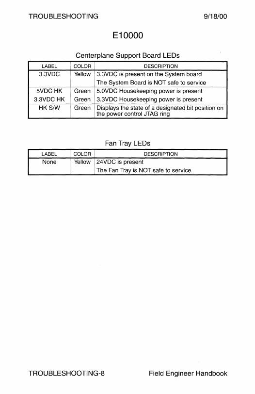
TROUBLESHOOTING 9/18/00
E10000
Centerplane Support Board LEDs
LABEL COLOR DESCRIPTION
3.3VDC Yellow 3.3VDC is present on the System board
The System Board is NOT safe to service 5VDC HK Green 5.0VDC Housekeeping power is present
3.3VDC HK Green 3.3VDC Housekeeping power is present
HKS/W Green Displays the state of a designated bit position on the power control JTAG ring
Fan Tray LEDs
LABEL COLOR DESCRIPTION
None Yellow 24VDC is present
The Fan Tray is NOT safe to service
TROUBLESHOOTING-8 Field Engineer Handbook

9/18/00 TROUBLESHOOTING
Single-ended 8-bit SCSI Pinouts
SIGNAL DD-SOP HD-SO DD-SOSA HD-68 SIGNAL DD-SOP HD-SO DD-SOSA HD-68
-DB(O) 2 26
-DB(1) 4 27
-DB(2) 6 28
-DB(3) 8 29
-DB(4) 10 30
-DB(S) 12 31
-DB(6) 14 32
-DB(?) 16 33
-DB(P) 18 34
GND 20 3S
GND 22 36
GND 24 37 Res
TPWR 26 38
GND 28 39 Res
GND 30 40
-ATN 32 41
GND 34 42
BSY 36 43
-ACK 38 44
-RST 40 4S
-MSG 42 46
-SEL 44 47
-CID 46 48
-REQ 48 49
-1/0 so so
DD-50P
49 000000000000 1 50 000000000000 2
50-Pin Male
Notes
34
2
19
36
4
21
38
6
23
40
8
2S
42
10
27
44
12
29
46
14
31
48
16
33
so
40 GND 1
41 GND 3
42 GND s
43 GND 7
44 GND 9
4S GND 11
46 GND 13
47 GND 1S
48 GND 17
49 GND 19
so GND 21
S1 Opn GND 23
S2 GND 2S
S3 GND 27
S4 GND 29
SS GND 31
S6 GND 33
S7 GND 3S
S8 GND 37
S9 GND 39
60 GND 41
61 GND 43
62 GND 4S
63 GND 47
64 GND 49
Connector Types
HD-50
2S 0 00 0 0 0 0 00 1 so 0 00 0 0 0 0 0 26
50-Pin Female
1 1 6
2 18 7
3 3S 8
4 3 9
s 20 10
6 37 11
7 s 12
8 22 13
9 39 14
10 7 1S
11 24 16
12 Res 41 17 Opn
13 Opn 9 18 Opn
14 Res 26 19
1S 43 20
16 11 21
17 28 22
18 4S 23
19 13 24
20 30 2S
21 47 26
22 1S 27
23 32 28
24 49 29
2S 17 30
DD-50SA
17 0 0 0 0 0 0 0 0 0 0 1 33 0 0 0 0 0 0 0 0 0 18 so 0000000000 34
50-Pin Female
1. On HD50 cables, Pins 12, 14, 37, and 39 are reserved and Pin 13 is open.
2. On HD50 to HD68 cables, Pins 1, 2, 3, 4, 5, 17, 18, 31, 32, 33, 34, 35, 36, 37, 38, 39, 51, 65, 66, 67, and 68 are open.
Volume II TROUBLESHOOTING-9
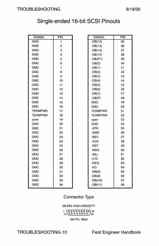
TROUBLESHOOTING
Single-ended 16-bit SCSI Pinouts
SIGNAL
GND
GND
GND
GND
GND
GND
GND
GND
GND
GND
GND
GND
GND
GND
GND
GND
TERMPWR
TERMPWR open
GND
GND
GND
GND
GND
GND
GND
GND
GND
GND
GND
GND
GND
GND
GND
PIN SIGNAL
1 -DB(12)
2 -DB(13)
3 -DB(14)
4 -DB(15)
5 -DB(P1)
6 -DB(O)
7 -DB(1)
8 -DB(2)
9 -DB(3)
10 -DB(4)
11 -DB(5)
12 -DB(6)
13 -DB(?)
14 -DB(P)
15 GND
16 GND
17 TERMPWR
18 TERMPWR
19 nne:i.n ................
20 GND
21 -ATN
22 -GND
23 -BSY
24 -ACK
25 -AST
26 -MSG
27 -SEL
28 -CID
29 -REQ
30 -1/0
31 -DB(8)
32 -DB(9)
33 -DB(10)
34 -DB(11)
Connector Type
68-PIN HIGH-DENSITY
1 \000000000734 35 00000000 68
68-Pin, Male
9/18/00
PIN
35
36
37
38
39
40
41
42
43
44
45
46
47
48
49
50
51
52
53 54
55
56
57
58
59
60
61
62
63 64
65
66
67
68
TROU BLESHOOTI NG-10 Field Engineer Handbook
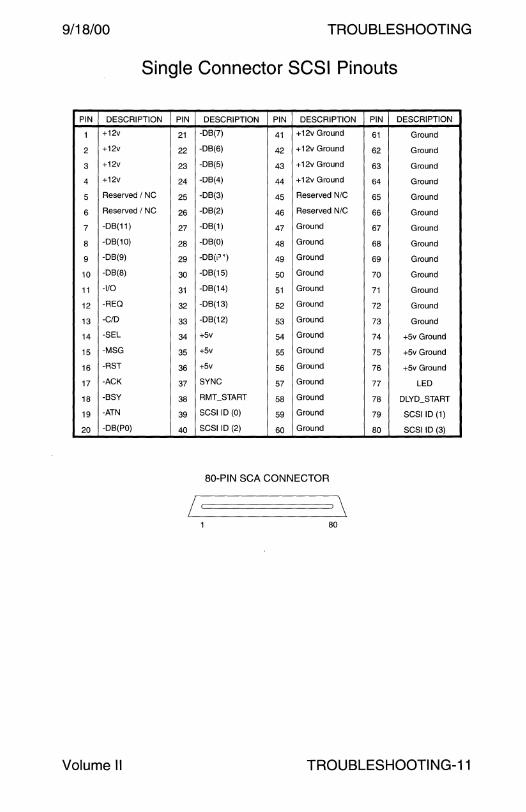
9/18/00 TROUBLESHOOTING
Single Connector SCSI Pinouts
PIN DESCRIPTION PIN DESCRIPTION PIN DESCRIPTION PIN DESCRIPTION
1 +12v 21 -DB(?) 41 +12v Ground 61 Ground
2 +12v 22 -DB(6) 42 +12v Ground 62 Ground
3 +12v 23 -DB(5} 43 +12v Ground 63 Ground
4 +12v 24 -DB(4) 44 +12v Ground 64 Ground
5 Reserved I NC 25 -DB(3) 45 Reserved N/C 65 Ground
6 Reserved I NC 26 -DB(2) 46 Reserved N/C 66 Ground
7 -DB(11) 27 -DB(1) 47 Ground 67 Ground
8 -DB(10) 28 -DB(O) 48 Ground 68 Ground
9 -DB(9) 29 -DB(1") 49 Ground 69 Ground
10 -DB(8) 30 -DB(15) 50 Ground 70 Ground
11 -1/0 31 -DB(14) 51 Ground 71 Ground
12 -REQ 32 -DB(13) 52 Ground 72 Ground
13 -C/D 33 -DB(12) 53 Ground 73 Ground
14 -SEL 34 +5v 54 Ground 74 +5v Ground
15 -MSG 35 +5v 55 Ground 75 +5v Ground
16 -RST 36 +5v 56 Ground 76 +5v Ground
17 -ACK 37 SYNC 57 Ground 77 LED
18 -BSY 38 RMT_START 58 Ground 78 DLYD_START
19 -ATN 39 SCSI ID (0) 59 Ground 79 SCSI ID(1)
20 -DB(PO) 40 SCSI ID (2) 60 Ground 80 SCSI ID (3)
80-PIN SCA CONNECTOR
80
Volume II TROUBLESHOOTING-11

TROUBLESHOOTING
Differential 8-bit SCSI Pinouts
SIGNAL 50 68 SIGNAL 50 68 NAME PIN PIN NAME PIN PIN
None - 1 None - 35 None - 2 None - 36 None - 3 None - 37 None - 4 None - 38 None - 5 None - 39 GND 1 6 GND 2 40 +DB(O) 3 7 -DB(O) 4 41 +DB(1) 5 8 -DB(1) 6 42 +DB(2) 7 9 -DB(2) 8 43 +DB(3) 9 10 -DB(3) 10 44 +DB(4) 11 11 -DB(4) 12 45 +DB(5) 13 12 -DB(5) 14 46 +DB(6) 15 13 -DB(6) 16 47 +DB(?) 17 14 -DB(?) 18 48 +DB(P) 19 15 -DB(P) 20 49 DIFFSENS 21 16 GND 22 50
TERMPWR 23 171 TERMPWR 24 51 1
TERMPWR 25 18 TERMPWR 26 52 Gf\!D 27 19 GND 28 53 +ATN 29 20 -ATN 30 54 GND 31 21 GND 32 55 +BSY 33 22 -BSY 34 56 +ACK 35 23 -ACK 36 57 +RST 37 24 -RST 38 58 +MSG 39 25 -MSG 40 59 +SEL 41 26 -SEL 42 60 +CID 43 27 -CID 44 61 +REQ 45 28 -REQ 46 62 +110 47 29 -110 48 63 GND 49 30 GND 50 64 None - 31 None - 65 None - 32 None - 66 None - 33 None - 67 None - 34 None - 68
Connector Types 50-PIN DD-50
1 000000000000 49 2 000000000000 50
50-Pin, Female
68-PIN HIGH-DENSITY
1 \.000000000734 35 00000000 68
68-Pin, Male
9/18/00
1 50-Pin Connector Pins 17 and 51 are not used on the Differential SCSI Tray Internal Cable 530-1904-xx.
TROUBLESHOOTING-12 Field Engineer Handbook

9/18/00 TROUBLESHOOTING
Differential 16-bit SCSI Pinouts
SIGNAL +DB(12)
+DB(13)
+DB(14)
+DB(15) +DB(P1)
GND
+DB(O) +DB(1)
+DB(2)
+DB(3) +DB(4)
+DB(5)
+DB(6)
+DB(7) +DB(P)
DIFFSENS
TERMPWR
TERMPWR
GND
+ATN GND
+BSY
+ACK
+RST +MSG
+SEL
+CID +REQ
+110 GND
+DB(8)
+DB(9) +DB(10)
+DB(11)
PIN SIGNAL
1 -DB(12)
2 -DB(13)
3 -DB(14)
4 -DB(15)
5 -DB(P1)
6 GND
7 -DB(O)
8 -DB(1)
9 -DB(2)
10 -DB(3)
11 -DB(4)
12 -DB(5)
13 -DB(6)
14 -DB(7)
15 -DB(P)
16 GND
171 TERMPWR
18 TERMPWR
19 GND
20 -ATN
21 GND
22 -BSY
23 -ACK
24 -RST
25 -MSG
26 -SEL
27 -CID 28 -REQ
29 -110 30 GND
31 -DB(8)
32 -DB(9)
33 -DB(10)
34 -DB(11)
Connector Type
68-PIN HIGH-DENSITY
1 000000000 34 35 00000000 68
68-Pin, Male
-·---"· PIN
35
36
37
38 39
40
41 42
43
44 45
46
47
48 49
50
51 1
52
53 54
55
56
57
58
59
60 61
62
63
64 65
66 67
68
1 Pins 17 and 51 are used on the Differential SCSI Tray Internal Cable 530-2096-xx.
Volume II TROUBLESHOOTING-13

TROUBLESHOOTING 9/18/00
Media Defect Management
Embedded SCSI Disk Drives
The FORMAT UNIT command formats the media so that all data blocks can be accessed. The following lists are used during the defect management process.
Primary, or Manufacturer's, Defect List (P list)
The P list supplied by the manufacturer is resident on the disk drive. The initiator can reference this list with the READ DEFECT DATA command. The initiator cannot change or erase the Primary list.
Certification Defect List (C list)
The C list is the position information of defective data blocks detected during data block verification after initialization when the FORMAT UNIT command is issued. These defects are added to the Grown list.
Data Defect List (D list)
The D list is the defect position information transferred from the initiator upon execution of the FORMAT UNIT command. These defects are added to the Grown list.
Grown Defect List (G list)
The G list includes defects identified to, or by, the drive. It does not include the P list. These defects are classified as flaws appearing after the media is formatted. The initiator may request that the current G list be used during formatting, or that the current G list be erased and a new list begun. Entries to the G list include:
1. Defects provided to the drive in D lists during previous FORMAT UNIT commands.
2. Drive C list defects detected during previous FORMAT UNIT commands.
3. Defects appended by successful completion of the REASSIGN BLOCKS command.
TROUBLESHOOTING-14 Field Engineer Handbook
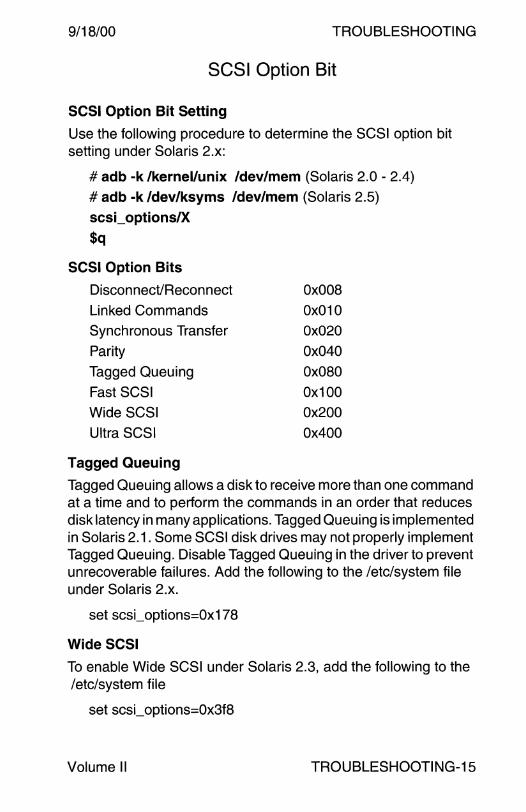
9/18/00 TROUBLESHOOTING
SCSI Option Bit
SCSI Option Bit Setting
Use the following procedure to determine the SCSI option bit setting under Solaris 2.x:
# adb -k /kernel/unix /dev/mem (Solaris 2.0 - 2.4)
# adb -k /dev/ksyms /dev/mem (Solaris 2.5)
scsi_options/X
$q
SCSI Option Bits
DisconnecVReconnect
Linked Commands
Synchronous Transfer
Parity
Tagged Queuing
Fast SCSI
Wide SCSI
Ultra SCSI
Tagged Queuing
Ox008
Ox010
Ox020
Ox040
Ox080
Ox100
Ox200
Ox400
Tagged Queuing allows a disk to receive more than one command at a time and to perform the commands in an order that reduces disk latency in many applications. Tagged Queuing is implemented in Solaris 2.1. Some SCSI disk drives may not properly implement Tagged Queuing. Disable Tagged Queuing in the driver to prevent unrecoverable failures. Add the following to the /etc/system file under Solaris 2.x.
set scsi_options=Ox178
Wide SCSI
To enable Wide SCSI under Solaris 2.3, add the following to the /etc/system file
set scsi_options=Ox3f8
Volume II TROU BLESHOOTI NG-15

TROUBLESHOOTING 9/18/00
SCSI Controllers
esp isp fas glm
ESP236 ISP1000
53C875 53C90 53C90A
53C96 FAS101 FAS236 MACIO ISP1000U' FEPS
53C876' ISP1040t
4/20 4/75 SBE/S SS10 SS1000 4/15 SWIS/S A12 RSM2000
4/25 4/40 SS600 SS600 FSBE/S 4/30 DWIS/S A14 A16
4/40 4150 DSBE/S SS5 UDWIS/S' X1018 A20 A25
4/60 X1055 SS10SX X1032'f0€ X1059 CP1500
4/65 SS20 X2630'f0€ X2610 A23' A26'
A11 X2620 A27' A28'
X6540'
X6541'
MACIO (NCR 59C100) {STP2000)
The MACIO ASIC provides three special purpose SBus OMA channels: Ethernet, SCSI, and Parallel Port. The SCSI block is based on the Emulex FAS101 macrocell which is a superset of (and backwards compatible with) the ESP1 OOA.
FEPS (STP2002)
The FEPS ASIC is a Fast Ethernet, Parallel Port, and Fast Wide SCSI Controller. The SCSI Channel consists of SCSI DVMA and FAS366.
ESP esp(7D)
The esp driver supports the Emulex family of esp SCSI chips (esp100, esp1 OOA, esp236, fas101, fas236).
FAS fas(7D)
The fas driver supports the Qlogic FAS366 SCSI chip.
ISP (isp7D)
The isp driver supports the Qlogic ISP1000 SCSI chip on SBus and the ISP1040B SCSI chip on PCI bus.
GLM (glm7D)
The glm driver supports the Symbios 53c875 SCSI chip.
TROUBLESHOOTING-16 Field Engineer Handbook

9/18/00 TROUBLESHOOTING
SCSI Sense Keys
KEY DESCRIPTION
0 NO SENSE
There is no specific sense key information to be reported for the designated logical unit. This would be the case for a successful command or a command that received CHECK CONDITION or COMMAND TERMINATED status because one of the filemark, EOM, or Ill bits is set to one.
1 RECOVERED DATA
The last command completed successfully with some recovery action performed by the target. Details may be determined by examining the additional sense bytes and the information field.
2 NOT READY
The logical unit addressed cannot be accessed. Operator intervention may be required to correct this condition.
3 MEDIUM ERROR
The command terminated with a non-recovered error condition that was probably caused by a flaw in the medium or an error in the recorded data. This sense key may also be returned if the target is unable to distinguish between a flaw in the medium and a specific hardware failure (sense key 4)
4 HARDWARE ERROR
The target detected a non-recoverable hardware failure while performing the command or during self test.
5 ILLEGAL REQUEST
There was an illegal parameter in the command descriptor block or in the additional parameters supplied as data for some commands. If the target detects an invalid parameter in the command descriptor block, then it shall terminate the command without altering the medium. If the target detects an invalid parameter in the additional parameters supplied as data, then the target may have already altered the medium. This sense key may also indicate that an invalid IDENTIFY message was received.
6 UNIT ATTENTION
The removable medium may have been changed or the target has been reset.
Volume II TROUBLESHOOTING-17

TROUBLESHOOTING 9/18/00
SCSI Sense Keys -Continued
KEY DESCRIPTION
7 DATA PROTECT
A command that reads or writes the medium was attempted on a block that is protected from this operation.
8 BLANK CHECK
A write-once device or a sequential-access device encountered blank medium or format-defined end-of-data indication while reading or a write-once device encountered
9 Vendor Specific
This key is available for reporting vendor specific conditions.
a COPY ABORTED
A COPY, COMPARE, or COPY AND VERIFY command was aborted due to an error condition on the source device, the destination device, or both.
b ABORTED COMMAND
The target aborted the command. The initiator may be able to recover by trying the command again.
c HARDWARE ERROR
The target detected a non-recoverable hardware failure while performing the command or during self test.
d VOLUME OVERFLOW
A buffered peripheral device has reached the end-of-partition and data may remain in the buffer that has not been written to the medium.
e MISCOMPARE
The source data did not match the data read from the medium.
f Reserved
TROUBLESHOOTING-18 Field Engineer Handbook
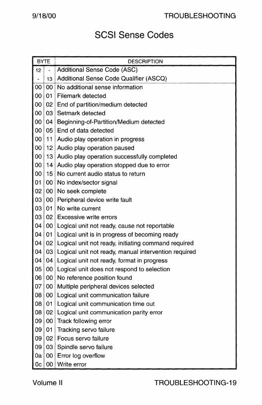
9/18/00 TROUBLESHOOTING
SCSI Sense Codes
BYTE DESCRIPTION
12 - Additional Sense Code (ASC)
- 13 Additional Sense Code Qualifier (ASCQ)
00 00 No additional sense information
00 01 Filemark detected
00 02 End of partition/medium detected
00 03 Setmark detected
00 04 Beginning-of-Partition/Medium detected
00 05 End of data detected
00 11 Audio play operation in progress
00 12 Audio play operation paused
00 13 Audio play operation successfully completed
00 14 Audio play operation stopped due to error
00 15 No current audio status to return
01 00 No index/sector signal
02 00 No seek complete
03 00 Peripheral device write fault
03 01 No write current
03 02 Excessive write errors
04 00 Logical unit not ready, cause not reportable
04 01 Logical unit is in progress of becoming ready
04 02 Logical unit not ready, initiating command required
04 03 Logical unit not ready, manual intervention required
04 04 Logical unit not ready, format in progress
05 00 Logical unit does not respond to selection
06 00 No reference position found
07 00 Multiple peripheral devices selected
08 00 Logical unit communication failure
08 01 Logical unit communication time out
08 02 Logical unit communication parity error
09 00 Track following error
09 01 Tracking servo failure
09 02 Focus servo failure
09 03 Spindle servo failure
Oa 00 Error log overflow
Oc 00 Write error
Volume II TROUBLESHOOTING-19

TROUBLESHOOTING 9/18/00
SCSI Sense Codes - Continued
BYTE DESCRIPTION
12 - Additional Sense Code (ASC)
- 13 Additional Sense Code Qualifier (ASCQ) Oc 01 Write error recovered with auto reallocation Oc 02 Write error - auto reallocation failed 10 00 ID CRC or ECG error
11 00 Unrecovered read error
11 01 Read retries exhausted 11 02 Error log too long to correct
11 03 Multiple read errors
11 04 Unrecovered read error - auto reallocate failed
11 05 L-EC uncorrectable error
11 06 CIRC unrecovered error
11 07 Data resynchronization error
11 08 Incomplete block read
11 09 No gap found
11 Oa Miscorrected error 12 00 Address mark not found for ID field
13 00 Address mark not found for data field
14 00 Recorded entity not found
14 01 Record not found
15 00 Random positioning error
15 01 Mechanical positioning error
15 02 Positioning error detected by read of medium
16 00 Data synchronization mark error
17 00 Recovered data with no error correction applied
17 01 Recovered data with retries
17 02 Recovered data with positive head offset
17 03 Recovered data with negative head offset
17 04 Recovered data with retries and/or CIRC applied 17 05 Recovered data using previous sector
17 06 Recovered data without ECG - Data auto-reallocated
18 00 Recovered data with error correction applied
18 01 Recovered data with error correction & retries applied
18 02 Recovered data with ECG and/or retries
18 03 Recovered data with CIRC
TROU BLESHOOTI NG-20 Field Engineer Handbook

9/18/00 TROUBLESHOOTING
SCSI Sense Codes - Continued
BYTE DESCRIPTION
12 - Additional Sense Code (ASC)
- 13 Additional Sense Code Qualifier (ASCQ)
18 04 Recovered data with LEG
19 00 Defect list error
19 01 Defect list not available
19 02 Defect list error in primary list
19 03 Defect list error in grown list
1a 00 Parameter list length error
1b 00 Synchronous data transfer error
1c 00 Defect list not found
1c 01 Primary defect list not found
1c 02 Grown defect list not found
1d 00 Miscompare during verify operation
1e 00 Recovered ID with ECG correction
20 00 Invalid command operation code
21 00 Logical block address out of range
21 01 Invalid element address
22 00 Illegal function for device type
24 00 Invalid field in COB
25 00 Logical unit not supported
26 00 Invalid field in parameter list
26 01 Parameter not supported
26 02 Parameter value invalid
26 03 Threshold parameters not supported
27 00 Write protected
28 00 Not ready to ready transition
28 01 Import I Export element accessed
29 00 Power-On, reset, or bus device reset occurred
2a 00 Parameters changed
2a 01 Mode parameters changed
2a 02 Log parameters changed
2b 00 Copy cannot execute since host cannot disconnect
2c 00 Command sequence error
2c 01 Too many windows specified
2c 02 Invalid combination of windows specified
Volume II TROUBLESHOOTING-21
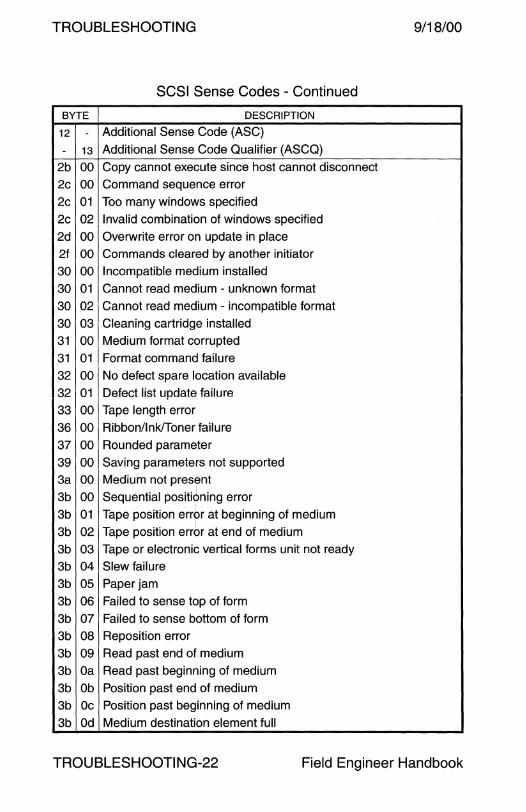
TROUBLESHOOTING 9/18/00
SCSI Sense Codes - Continued
BYTE DESCRIPTION
12 - Additional Sense Code (ASC)
- 13 Additional Sense Code Qualifier (ASCQ)
2b 00 Copy cannot execute since host cannot disconnect
2c 00 Command sequence error
2c 01 Too many windows specified
2c 02 Invalid combination of windows specified
2d 00 Overwrite error on update in place
2f 00 Commands cleared by another initiator
30 00 Incompatible medium installed
30 01 Cannot read medium - unknown format
30 02 Cannot read medium - incompatible format
30 03 Cleaning cartridge installed
31 00 Medium format corrupted
31 01 Format command failure
32 00 No defect spare location available
32 01 Defect list update failure
33 00 Tape length error
36 00 Ribbon/Ink/Toner failure
37 00 Rounded parameter
39 00 Saving parameters not supported
3a 00 Medium not present
3b 00 Sequential positid>ning error
3b 01 Tape position error at beginning of medium
3b 02 Tape position errbr at end of medium
3b 03 Tape or electronic vertical forms unit not ready
3b 04 Slew failure
3b 05 Paper jam
3b 06 Failed to sense top of form
3b 07 Failed to sense bottom of form
3b 08 Reposition error
3b 09 Read past end of medium
3b Oa Read past beginning of medium
3b Ob Position past end of medium
3b Oc Position past beginning of medium
3b Od Medium destination element full
TROU BLESHOOTI NG-22 Field Engineer Handbook

9/18/00 TROUBLESHOOTING
SCSI Sense Codes - Continued
BYTE DESCRIPTION
12 - Additional Sense Code (ASC)
- 13 Additional Sense Code Qualifier (ASCQ)
3b Oe Medium source element empty
3d 00 Invalid bits in identify message
3e 00 Logical unit has not self configured yet
3f 00 Target operating conditions have changed
3f 01 Microcode has been changed
3f 02 Changed operating definition
3f 03 Inquiry data has changed
40 nn Diagnostic failure on component nn (80h-ffh)
41 00 Data path failure
42 00 Power-On or Self-Test failure
43 00 Message error
44 00 Internal target failure
45 00 Select/Reselect failure
46 00 Unsuccessful soft reset
47 00 SCSI parity error
48 00 Initiator detected error message received
49 00 Invalid message error
4a 00 Command phase error
4b 00 Data phase error
4c 00 Logical unit failed self configuration
4e 00 Overlapped commands attempted
50 00 Write append error
50 01 Write append position error
50 02 Position error related to timing
51 00 Erase failure
52 00 Cartridge fault
53 00 Media load/eject failed
53 01 Unload tape failure
53 02 Medium removal prevented
54 00 SCSI to host system interface failure
55 00 System resource failure
57 00 Unable to recover table-of-contents
58 00 Generation does not exist
Volume II TROUBLESHOOTING-23

TROUBLESHOOTING 9/18/00
SCSI Sense Codes - Continued
BYTE DESCRIPTION
12 - Additional Sense Code (ASC)
- 13 Additional Sense Code Qualifier (ASCQ)
59 00 Updated block read
5a 00 Operator request or state change input
5a 01 Operator medium removal request
5a 02 Operator selected write protect
5a 03 Operator selected write permit
5b 00 Log exception
5b 01 Threshold condition met
5b 02 Log counter at maximum
5b 03 Log list codes exhausted
5c 00 RPL status change
5c 01 Spindles synchronized
5c 02 Spindles not synchronized
60 00 Lamp failure
61 01 I ln"'.)hln +n .,,...,... •• i""""" lf;,.J,...,... \.JI n ... U.Jl\J LV 0.V'-tUll V VIUVV
61 02 Out of focus
62 00 Scan head positioning error
63 00 End of user area encountered on this track
64 00 Illegal mode for this track
80 80 Vendor unique ASC and ASCQ through
ff l ff Vendor unique ASC and ASCQ
TROU BLESHOOTI NG-24 Field Engineer Handbook
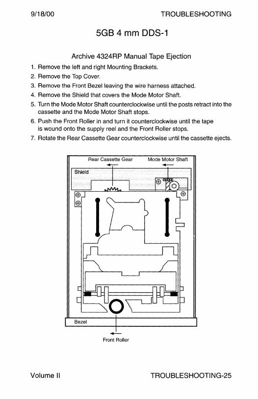
9/18/00 TROUBLESHOOTING
SGS 4 mm DDS-1
Archive 4324RP Manual Tape Ejection
1. Remove the left and right Mounting Brackets.
2. Remove the Top Cover.
3. Remove the Front Bezel leaving the wire harness attached.
4. Remove the Shield that covers the Mode Motor Shaft.
5. Turn the Mode Motor Shaft counterclockwise until the posts retract into the cassette and the Mode Motor Shaft stops.
6. Push the Front Roller in and turn it counterclockwise until the tape is wound onto the supply reel and the Front Roller stops.
7. Rotate the Rear Cassette Gear counterclockwise until the cassette ejects.
Bezel
Volume II
Rear Cassette Gear -
-Front Roller
Mode Motor Shaft -
TROU BLESHOOTI NG-25
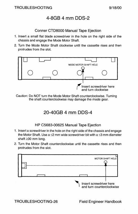
TROUBLESHOOTING 9/18/00
4-8GB 4 mm DDS-2
Conner CTD8000 Manual Tape Ejection
1. Insert a small flat blade screwdriver in the hole on the right side of the chassis and engage the Mode Motor Shaft.
2. Turn the Mode Motor Shaft clockwise until the cassette rises and then protrudes from the slot.
0 0 MODE MOTOR SHAFT HOLE
0
(insert screwdriver here and turn clockwise
Caution: Do NOT turn the Mode Motor Shaft counterclockwise. Turning the shaft counterclockwise may damage the mode gear.
20-40GB 4 mm DDS-4
HP C5683-00625 Manual Tape Ejection
1. Insert a screwdriver in the hole on the right side of the chassis and engage the Motor Shaft. Use a :::;2 mm wide screwdriver bit with a :::;3 mm diameter shaft ;:>:30 mm long.
2. Turn the Motor Shaft counterclockwise until the cassette rises and then protrudes from the slot.
TROUBLESHOOTING-26
MOTOR SHAFT HOLE
Insert screwdriver here and turn counterclockwise
Field Engineer Handbook

9/18/00 TROUBLESHOOTING
Quantum DLT 4700
Manual Magazine Ejection
1. Remove the top cover. 2. Depress the roller located 16 cm from the rear on the top left side. 3. Slide the drive forward approximately 22 cm. 4. Press in on the top of the front door to release tension. 5. Push the Release Lever on the right side 2-3 mm towards the rear. 6. Release the front door and remove the Magazine.
Cautions 1. Do NOT turn the Aluminum Shaft. 2. Pliers and similar tools will damage the soft metal Aluminum Shaft. 3. Over rotation of the Aluminum Shaft may cause the Front Door locking
clips to spring off the shaft.
Right Side of DLT4700 Receiver
Press in on the top of the Front Door
0 Aluminum Shaft
Push the Release Lever 2-3 mm ~f • \ \ 11 ] to release the Front Door l - -. . .
Volume II
Release Lever rotation point
TROU BLESHOOTI NG-27

TROUBLESHOOTING 9/18/00
Electrical Characteristics
EIA RS-232-C Section 2.3
For data interchange circuits, the signal shall be considered in the marking condition when the voltage (V1) interchange circuit
measured at the interface point, is more negative than minus three volts with respect to Circuit AB (Signal Ground). The signal shall be considered in the spacing condition when the voltage (V 1) is
more positive than plus three volts with respect to circuit AB. The signal state in not uniquely defined when the voltage (V 1) is in this transition region.
EIA RS-232-D Section 2.1.3
For data interchange circuits, the signal shall be considered in the marking condition when the voltage (V 1) on the
interchange circuit, measured at the interface point, is more negative than minus three volts with respect to Circuit AB (Signal Ground). The signal shall be considered in the spacing condition when the voitage (V 1) is more positive than plus three volts with respect to circuit AB. The region between plus three volts and minus three volts is defined as the transition region. The signal state in not uniquely defined when the voltage (V 1) is in this transition region.
During the transmission of data, the marking condition shall be used to denote the binary state ONE and the spacing condition shall be used to denote state ZERO.
EIA RS-422-A Section 4.1.1
For either binary state, the magnitude of the differential voltage (V 0) measured between the two generator output terminals shall
not be less than 6.0 volts; nor shall the magnitude of V 0a and
V0bmeasured between the two generator output terminals and
generator circuit ground be more than 6.0 volts.
TROUBLESHOOTING-28 Field Engineer Handbook
9/18/00 TROUBLESHOOTING
Electrical Characteristics - Continued
EIA RS-423-A Section 4.1.1
For either binary state, the magnitude of the voltage (V 0) measured between the generator output terminal and generator circuit ground shall not be less than 4.0 volts nor more than 6.0 volts. For the opposite binary state, the polarity of V 0 shall be reversed.
EIA RS-449-A Section 2.1.1
The following circuits are classified as Category I circuits: SD, RD, TT, ST, RT, RS, CS, RR, TR, and OM.
For applications where the signaling rate on the data interchange circuits (Circuits SD and RD) is 20,000 bits per second or less, the individual Category I circuits shall use either the balanced electrical characteristics of RS-423, without the cable termination resistance (Rt), or the unbalanced electrical characteristics of RS-422-A. Two leads shall be brought out to the interface connector for each Category I circuit. Each interchange circuit consists of a pair of wires interconnecting a balanced or unbalanced generator and a differential receiver.
For applications where the signaling rate on the data interchange circuits (Circuits SD and RD) is above 20,000 bits per second, all Category I circuits shall use the balanced electrical characteristics of RS-422. Use of optional cable termination resistance (Rt)
permitted. Each interchange circuit consists of a pair of wires interconnecting a balanced generator and a differential receiver.
EIA RS-449-A Section 2.1.2
All other circuits are classified as Category II circuits. For all applications, Category II circuits shall use the unbalanced electrical characteristics of RS-423. Each Category 11 interchange circuit consists of one wire interconnecting an unbalanced generator and a differential receiver.
Volume II TROUBLESHOOTING-29

TROUBLESHOOTING 9/18/00
RS-232 Signals
PIN SIGNAL SIGNAL NAME FLOW DESCRIPTION
2 BA Transmit Data Output Data transmitted to the data
14 or communications equipment.
TD
3 BB Receive Data Input Data received from the data
16 or communications equipment.
RD
4 CA Request to Send Output Signal sent to the data communica-
19 or lions equipment, asking if it is
RTS ready to start accepting data.
5 CB Clear to Send Input Ready to accept data signal from the
13 or data communications equipment.
CTS
6 cc Data Set Ready Input Data communications equipment
or indicates the status of the local data set.
DSR
7 AB Signal Ground None Signal Ground provides a reference
or level for the signal voltages.
SG 8 CF Data Carrier Detect Input Data communications equipment
12 or detected "carrier." Example: a modem senses tones sent to it
DCD by another modem over phone lines.
15 DB Transmit Clock Input Transmit clock from the modem.
or from DCE Usually not used for asynchronous
TC devices (terminals, printers, and modems, etc).
17 DD Receive Clock Input Receive clock from the modem.
or from DCE Usually not used for asynchronous
RC devices (terminals, printers and, modems, etc).
20 CD Data Terminal Output The DTE is powered on and
or Ready ready to communicate as the "local data terminal" with the
DTR data communication equipment. For example, the modem.
24 DA Transmit Clock Output Provides transmit clock from the
or from DTE DTE. Usually not used for
TCO asynchronous devices, (terminals, printers, and modems, etc).
TROU BLESHOOTI NG-30 Field Engineer Handbook

9/18/00 TROUBLESHOOTING
RS-449 Signals
PIN SIGNAL SIGNAL NAME FLOW DESCRIPTION
4 SD Transmit Data Output Data transmitted to the data
22 or communications equipment.
TD
6 RD Receive Data Input Data received from the data
24 communications equipment.
7 RS Request to Send Output Signal sent to the data communica-
25 or lions equipment, asking if it is
RTS ready to start accepting data.
9 cs Clear to Send Input Ready to accept data signal from the
27 or data communications equipment.
CTS
11 OM Data Set Ready Input Data communications equipment
29 or indicates the status of the local data set.
DSR
19 SG Signal Ground None Signal Ground provides a reference level for the signal voltages.
13 RR Data Carrier Detect Input Data communications equipment
31 or detected "carrier." Example: a modem senses tones sent to it
DCD by another modem over phone lines.
5 ST Transmit Clock Input Transmit clock from the modem.
23 or from DCE Usually not used for asynchronous devices (terminals, printers, and
TC modems, etc).
8 RT Receive Clock Input Receive clock from the modem.
26 or from DCE Usually not used for asynchronous
RC devices (terminals, printers, and modems, etc).
12 TR Data Terminal Output The DTE is powered on and
30 or Ready ready to communicate as the "local data terminal" with the
DTR data communication equipment. For example, the modem.
17 TT Transmit Clock Output Provides transmit clock from the
35 or from DTE DTE. Usually not used for
TCO asynchronous devices, (terminals, printers, and modems, etc).
Volume II TROUBLESHOOTING-31
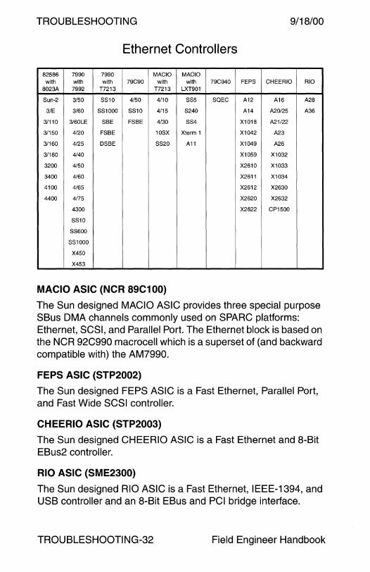
TROUBLESHOOTING 9/18/00
Ethernet Controllers
82586 7990 7990 MACIO MACIO with with with 79C90 with with 79C940 FEPS CHEERIO RIO
8023A 7992 T7213 T7213 LXT901
Sun-2 3/50 SS10 4/50 4/10 SSS SQEC A12 A16 A28
3/E 3/60 SS1000 SS10 4/15 S240 A14 A20/25 A36
3/110 3/60LE SBE FSBE 4/30 SS4 X1018 A21/22
3/150 4/20 FSBE 10SX Xterm 1 X1042 A23
3/160 4/25 DSBE SS20 A11 X1049 A26
3/180 4/40 X1059 X1032
3200 4150 X2610 X1033
3400 4/60 X2611 X1034
4100 4/65 X2612 X2630
4400 4/75 X2620 X2632
4300 X2622 CP1500
SS10
SS600
SS1000
X450
X453
MACIO ASIC (NCR 89C100)
The Sun designed MACIO ASIC provides three special purpose SBus OMA channels commonly used on SPARC platforms: Ethernet, SCSI, and Parallel Port. The Ethernet block is based on the NCR 92C990 macrocell which is a superset of (and backward compatible with) the AM7990.
FEPS ASIC (STP2002)
The Sun designed FEPS ASIC is a Fast Ethernet, Parallel Port, and Fast Wide SCSI controller.
CHEERIO ASIC (STP2003)
The Sun designed CHEERIO ASIC is a Fast Ethernet and 8-Bit EBus2 controller.
RIO ASIC (SME2300)
The Sun designed RIO ASIC is a Fast Ethernet, IEEE-1394, and USB controller and an 8-Bit EBus and PCI bridge interface.
TROUBLESHOOTING-32 Field Engineer Handbook
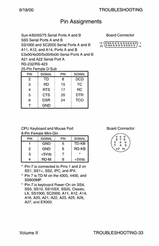
9/18/00 TROUBLESHOOTING
Pin Assignments
Sun-4/60/6S/7S Serial Ports A and B SSS Serial Ports A and B SS1000 and SC2000 Serial Ports A and B A11, A12, and A14, Ports A and B E3x00/4x00/Sx00/6x00 Serial Ports A and B A21 and A22 Serial Port A RS-232/RS-423 2S-Pin Female D-Sub
PIN SIGNAL PIN
2 TD 8
3 RD 1S
4 RTS 17
s CTS 20
6 DSR 24
7 GND
CPU Keyboard and Mouse Port 8-Pin Female Mini-Din
PIN SIGNAL PIN
1 GND s 2 GND 6
3 +SVdc 7
4 RD-M 8
SIGNAL
DCD
TC
RC
DTR
TCO
SIGNAL
TD-KB
RD-KB *
+SVdc
* Pin-7 is connected to Pins 1 and 2 on SS1, SS1+, SS2, IPC, and IPX.
* Pin 7 is TD-M on the 4300, 4400, and SS600MP.
* Pin-7 is keyboard Power-On on SS4, SSS, SS10, SS10SX, SS20, Classic, LX, SS1000, SC2000, A11, A12, A14, A 16, A20, A21, A22, A23, A2S, A26, A27, and EXOOO.
Volume II
Board Connector
13 0000000000000 1 25 000000000000 14
Board Connector
TROUBLESHOOTING-33

TROUBLESHOOTING
Sun-4/15/30, SS10, SS20, A20, A25, A26, and A27 Adapter 530-1869 Serial Port A 25-Pin Female D-Sub
PIN SIGNAL PIN SIGNAL
2 TD 8 DCD
3 RD 15 TC
4 RTS 17 RC
5 CTS 20 DTR
6 DSR 24 TCO 7 GND
Sun-4/15/30, SS10, SS20*, A20 A25, A26, and A27 Adapter 530-1869 Serial Port B 25-Pin Female D-Sub
I PIN I Sl~~AL I PIN I SIGNAL I 2 8 DCD 3 RD 15 TC
4 RTS 20 DTR
5 CTS 24 TCO
7 GND Port B is asynchronous only. * A jumper setting change and an
adapter cable is required to use the SS20 Port B in synchronous mode. Pin-9 is dsr and Pin-10 is rtxc.
Netra t1 Model 100/105 Serial Port 8-Pin RJ45
PIN SIGNAL PIN SIGNAL
1 RTS 5 GND
2 DTR 6 RXD
3 TXD 7 DSR
4 GND 8 CTS
TROUBLESHOOTING-34
9/18/00
Adapter Connector
13 0000000000000 1 25 000000000000 14
Adapter Connector
13 0000000000000 1 25 000000000000 14
Board Connector
0
Field Engineer Handbook
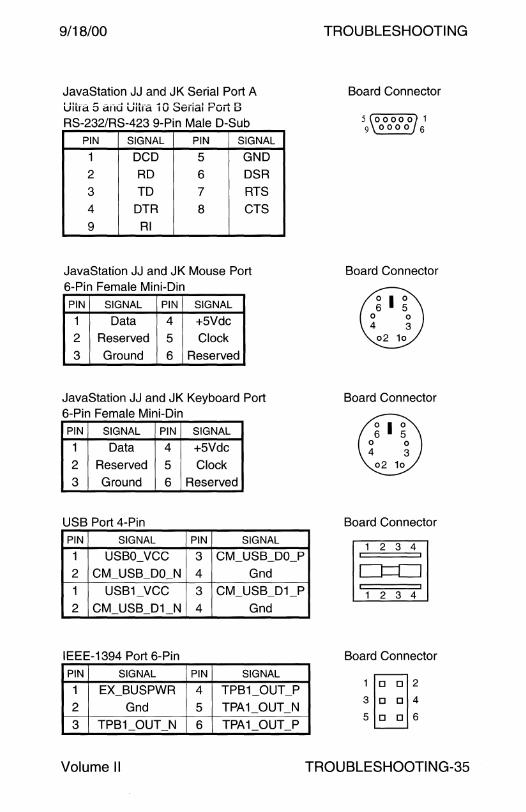
9/18/00
JavaStation JJ and JK Serial Port A Uitra 5 and Ultra 1 O Serlal Port 8 RS-232/RS-423 9-Pin Male D-Sub
PIN SIGNAL PIN SIGNAL
1 DCD 5 GND
2 RD 6 DSR
3 TD 7 RTS
4 DTR 8 CTS
9 RI
JavaStation JJ and JK Mouse Port 6-Pin Female Mini-Din
PIN SIGNAL PIN SIGNAL
1 Data 4 +5Vdc 2 Reserved 5 Clock
3 Ground 6 Reserved
JavaStation JJ and JK Keyboard Port 6-Pin Female Mini-Din
PIN SIGNAL PIN SIGNAL
1 Data 4 +5Vdc 2 Reserved 5 Clock
3 Ground 6 Reserved
USB Port 4-Pin
PIN SIGNAL PIN SIGNAL
1 USBO_VCC 3 CM_USB_DO_P
2 CM_USB_DO_N 4 Gnd
1 USB1_VCC 3 CM_USB_D1 _P
2 CM_USB_D1_N 4 Gnd
IEEE-1394 Port 6-Pin PIN SIGNAL PIN SIGNAL
1 EX_BUSPWR 4 TPB1_0UT_P
2 Gnd 5 TPA1_0UT_N
3 TPB1_0UT_N 6 TPA1_0UT_P
Volume II
TROUBLESHOOTING
Board Connector
5 00000 1 9 0000 6
Board Connector
Board Connector
Board Connector
1 2 3 4
1 2 3 4
Board Connector
1 []D 2 3 D D 4
5 D D 6
TROUBLESHOOTING-35
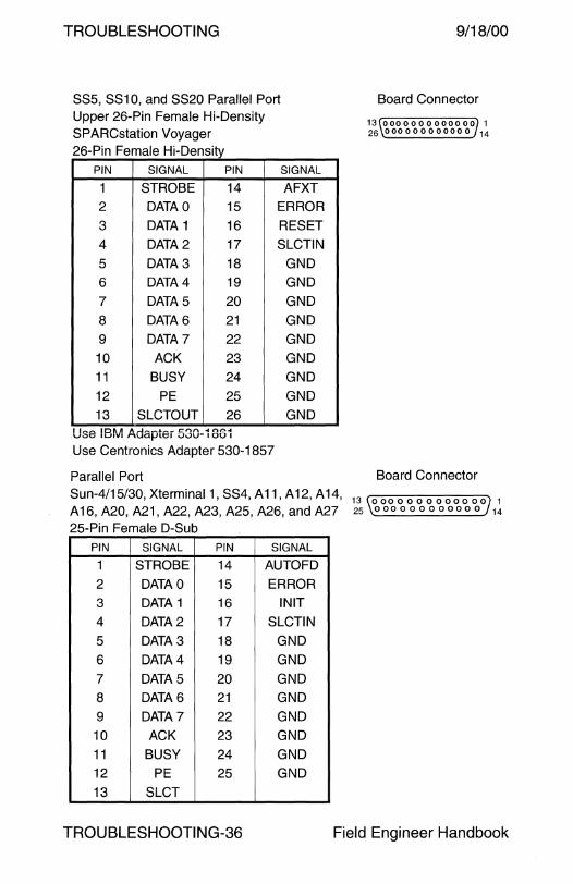
TROUBLESHOOTING
SS5, SS10, and SS20 Parallel Port Upper 26-Pin Female Hi-Density SPARCstation Voyager 26-Pin Female Hi-Density
PIN SIGNAL PIN SIGNAL
1 STROBE 14 AFXT
2 DATAO 15 ERROR
3 DATA 1 16 RESET
4 DATA2 17 SLCTIN
5 DATA3 18 GND
6 DATA4 19 GND
7 DATA5 20 GND
8 DATA6 21 GND
9 DATA 7 22 GND
10 ACK 23 GND
11 BUSY 24 GND
12 PE 25 GND
13 SLCTOUT 26 GND Use 18fv1 Adaptei 530-1861 Use Centronics Adapter 530-1857
Parallel Port
9/18/00
Board Connector
13 0000000000000 1 26 000000000000 14
Board Connector
Sun-4/15/30, Xterminal 1, SS4, A 11, A 12, A 14, 13 r-0-0--:-0--:-0-0--=-0--=-0--=-0--=-0--=-0--=-0 --=-0~0 1
A16, A20, A21, A22, A23, A25, A26, and A27 2s o 00 o o o o 0 oo o o 14
25-Pin Female D-Sub PIN SIGNAL PIN SIGNAL
1 STROBE 14 AUTO FD
2 DATAO 15 ERROR
3 DATA 1 16 INIT
4 DATA2 17 SLCTIN
5 DATA3 18 GND
6 DATA4 19 GND
7 DATA5 20 GND
8 DATA6 21 GND
9 DATA 7 22 GND
10 ACK 23 GND
11 BUSY 24 GND
12 PE 25 GND
13 SLCT
TROUBLESHOOTING-36 Field Engineer Handbook

9/18/00
SS5, SS10, SS20, and SS Voyager Centron!cs Para!!e! Port Adapter 530-1857 26-Pin Hi-Density to 36-Pin Centronics
PIN SIGNAL PIN SIGNAL
1 STROBE 15 SLCTIN
2 DATAO 20 GND
3 DATA 1 21 GND
4 DATA2 22 GND
5 DATA3 23 GND
6 DATA4 24 GND
7 DATA5 25 GND
8 DATA6 26 GND
9 DATA? 27 GND
10 ACK 28 GND
11 BUSY 31 RESET
12 PE 32 ERROR
13 SLCTOUT 36 SLCTIN
14 AFXT
SS5, SS10, SS20, and SS Voyager IBM Parallel Port Adapter 530-1861 26-Pin Hi-Density to 25-Pin D-Sub
PIN SIGNAL PIN SIGNAL
1 STROBE 14 AFXT
2 DATAO 15 ERROR
3 DATA 1 16 RESET
4 DATA2 17 SLCTIN
5 DATA3 18 GND
6 DATA4 19 GND
7 DATA5 20 GND
8 DATA6 21 GND
9 DATA 7 22 GND
10 ACK 23 GND
11 BUSY 24 GND
12 PE 25 GND
13 SLCTOUT
Volume II
TROUBLESHOOTING
Cable Connector
Cable Connector
1 0000000000000 13 14 000000000000 25
TROUBLESHOOTING-37
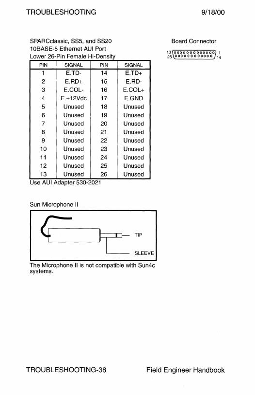
TROUBLESHOOTING
SPARCclassic, SSS, and SS20 10BASE-5 Ethernet AUi Port Lower 26-Pin Female Hi-Density
PIN SIGNAL PIN
1 E.TD- 14
2 E.RD+ 15 3 E.COL- 16 4 E.+12Vdc 17
5 Unused 18
6 Unused 19 7 Unused 20
8 Unused 21
9 Unused 22 10 Unused 23 11 Unused 24 12 Unused 25 13 Unused 26
Use AUi Adapter 530-2021
Sun Microphone II
SIGNAL
E.TD+ E.RD-
E.COL+ E.GND Unused
Unused Unused
Unused Unused
Unused Unused Unused
Unused
4-~~ ~I f- TIP
~SLEEVE
The Microphone II is not compatible with Sun4c systems.
9/18/00
Board Connector
13 0000000000000 1 26 000000000000 14
TROU BLESHOOTI NG-38 Field Engineer Handbook
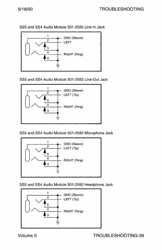
9/18/00 TROUBLESHOOTING
SS5 and SS4 Audio Module 501-2592 Line-In Jack
.-------- GND (Sleeve) ~-2---+-- LEFT
5 4 '------.-----+-- RIGHT (Ring) 3
SS5 and SS4 Audio Module 501-2592 Line-Out Jack
1 GND (Sleeve)
2 LEFT (Tip)
5 4
RIGHT (Ring) 3
SS5 and SS4 Audio Module 501-2592 Microphone Jack
2 GND (Sleeve)
LEFT (Tip)
5 4
RIGHT (Ring) 3
SS5 and SS4 Audio Module 501-2592 Headphone Jack
5
4 '------.-----+-- RIGHT (Ring) 3
Volume II TROU BLESHOOTI NG-39
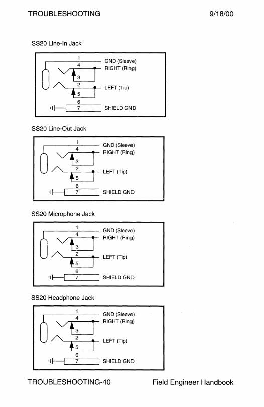
TROUBLESHOOTING
SS20 Line-In Jack
----1--- GND (Sleeve) A vb RIGHT (Ring)
u A •: r LEFT(Tip)
6 11~ SHIELDGND
SS20 Line-Out Jack
----1--- GND (Sleeve) A vb RIGHT (Ring)
u A .: j LEFT(Tlp)
6 11 H 7 SHIELD GND
SS20 Microphone Jack
----1--- GND (Sleeve) A vb RIGHT (Ring)
u A ~: j LEFT(T;p)
6 11~ SHIELDGND
SS20 Headphone Jack
----1--- GND .(Sleeve) A vb RIGHT (Ring)
u A ~ : j LEFT (T;p)
6 ii H 7 SHIELD GND
TROUBLESHOOTING-40
9/18/00
Field Engineer Handbook

9/18/00
A11, A12, and A14 Line-In Jack
1 ~------ GND (Sleeve) A V +~: ___ RIGHT (Ring)
u A----.~4--- LEFT (Tip) .3 6
•I~ SHIELDGND
A11, A12, and A14 Line-Out Jack
1 GND (Sleeve) A ~ RIGHT (Ring)
u A t: LEFT(Tip)
6 ii~ SHIELDGND
A 11, A 12, and A 14 Microphone Jack
1 GND (Sleeve) A ~ RIGHT(Ring)
u A • : LEFT (T;p)
6 •I~ SHIELDGND
A 11 , A 12, and A 14 Headphone Jack
1 GND (Sleeve) A ~ RIGHT (Ring)
u A • : LEFT (T;p)
6 •I H 7 SHIELD GND
Volume II
TROUBLESHOOTING
TROUBLESHOOTING-41

TROUBLESHOOTING
1 OBASE-5 Ethernet 8-Pin Female Mini-Din)
PIN SIGNAL
2 COL+
3 TD+
5 RD+ 6 GND
10BASE-T Ethernet 8-Pin RJ45
PIN SIGNAL
1 TPO+
2 TPO-
3 TPI+
4 Unused
Sunlink ISDN
PIN
9 10
12
13
PIN
5
6
7
8
SIGNAL
COL-
TD-
RD-
+12Vdc
SIGNAL
Unused TPI-
Unused
Unused
SUPPORTED Sunlink ISDN CARRIERS
British Telecom
Deuische Bundepost Telekom
France Telecom Numeris
Nippon Telegraph and Telephone
AT&T 5ESS 5e5 conformant US carriers
ISDN Network Termination NT 8-Pin RJ45
PIN SIGNAL PIN
1 PS3+ 5 2 PS3- 6
3 RD+ 7 4 TD+ 8
ISDN Terminal Endpoint TE 8-Pin RJ45
PIN SIGNAL PIN
1 PS3+ 5 2 PS3- 6
3 TD+ 7 4 RD+ 8
TROUBLESHOOTING-42
SIGNAL
TD-
RD-
PS2-
PS2+
SIGNAL
RD--
TD--
PS2-
PS2+
9/18/00
Board Connector
s <\o o o o o o o o} 1 15 0 0 0 0 0 0 0 9
Board Connector
0
SPECIFICATION
ISDN2
iTR6
VN2
INS-Net 64
AT&T 5ESS 5e5
Board Connector
0
Board Connector
0
Field Engineer Handbook
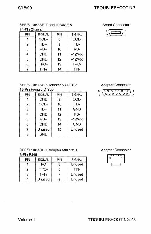
9/18/00
SBE/S 10BASE-T and 10BASE-5 1 Ll.-Pin r.h::.mn ...... -··-···r-
PIN SIGNAL PIN SIGNAL
1 COL+ 8 COL-2 TD+ 9 TD-
3 RD+ 10 RD-4 GND 11 +12Vdc 5 GND 12 +12Vdc 6 TPO+ 13 TPO-7 TPI+ 14 TPI-
SBE/S 10BASE-5 Adapter 530-1812 15-Pin Female D-Sub
PIN SIGNAL PIN SIGNAL
1 GND 9 COL-
2 COL+ 10 TD-
3 TD+ 11 GND 4 GND 12 RD-
5 RD+ 13 +12Vdc
6 GND 14 GND 7 Unused 15 Unused
8 GND
SBE/S 10BASE-T Adapter 530-1813 8-Pin RJ45
PIN SIGNAL PIN SIGNAL
1 TPO+ 5 Unused
2 TPO- 6 TPI-
3 TPI+ 7 Unused 4 Unused 8 Unused
Volume II
TROUBLESHOOTING
Board Connector
7 \ J 1 14 9
Adapter Connector
8 ro 0 0 0 0 0 0 OJ 1 15 \ 0 0 0 0 0 0 0. 9
Adapter Connector
0
TROU BLESHOOTI NG-43
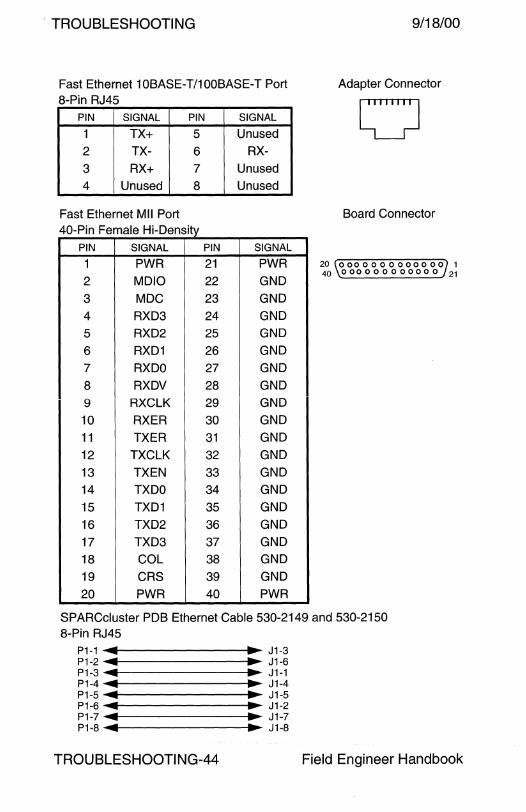
. TROUBLESHOOTING
Fast Ethernet 1 OBASE-T/1 OOBASE-T Port 8-Pin RJ45
PIN SIGNAL PIN
1 TX+ 5
2 TX- 6
3 RX+ 7
4 Unused 8
Fast Ethernet Mii Port 40-Pin Female Hi-Density
PIN SIGNAL
1 PWR
2 MDIO
3 MDC
4 RXD3
5 RXD2
6 RXD1
7 RXDO
8 RXDV g RXCLK
10 RXER
11 TXER
12 TXCLK
13 TXEN
14 TXDO
15 TXD1
16 TXD2
17 TXD3
18 COL
19 CRS
20 PWR
PIN
21
22
23
24
25
26
27
28
29
30
31
32
33 34
35
36
37
38
39
40
SIGNAL
Unused
RX-
Unused Unused
SIGNAL
PWR
GND
GND
GND
GND
GND
GND
GND
GND
GND
GND
GND
GND
GND
GND
GND
GND
GND
GND
PWR
9/18/00
Adapter Connector
0 Board Connector
20 0 00 0 0 0 0 0 0 0 0 0 0 1 40 0 0 0 0 0 0 0 0 0 0 0 0 21
SPARCcluster PDB Ethernet Cable 530-2149 and 530-2150 8-Pin RJ45
P1-1 ...... --------....... ~ J1-3 P1-2 ... ... J1-6 P1-3 ... ... J1-1 P1-4 ... ... J1-4 P1-5 ... ... J1-5 P1-6 ... ... J1-2 P1-7 ... ... J1-7 P1-8 ... ... J1-8
TROU BLESHOOTI NG-44 Field Engineer Handbook
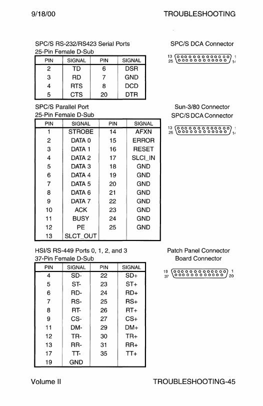
9/18/00
SPC/S RS-232/RS423 Serial Ports 25-Pin Female D-Sub
PIN SIGNAL
2 TD
3 RD
4 RTS
5 CTS
SPC/S Parallel Port 25-Pin Female D-Sub
PIN SIGNAL
1 STROBE
2 DATAO
3 DATA 1
4 DATA2
5 DATA3
6 DATA4
7 DATA5
8 DATA6
9 DATA 7
10 ACK
11 BUSY
12 PE
13 SLCT_OUT
PIN SIGNAL
6 DSR
7 GND
8 DCD
20 DTR
PIN SIGNAL
14 AFXN
15 ERROR
16 RESET
17 SLCl_IN
18 GND
19 GND
20 GND
21 GND
22 GND
23 GND
24 GND
25 GND
HSl/S RS-449 Ports 0, 1, 2, and 3 37-Pin Female D-Sub
PIN SIGNAL PIN SIGNAL
4 SD- 22 SD+
5 ST- 23 ST+
6 RD- 24 RD+ 7 RS- 25 RS+
8 RT- 26 RT+
9 CS- 27 CS+ 11 DM- 29 DM+ 12 TR- 30 TR+
13 RR- 31 RR+ 17 TT- 35 TT+
19 GND
TROUBLESHOOTING
SPC/S DCA Connector
13 0000000000000 1 25 000000000000 1'
Sun-3/80 Connector
SPC/S DCA Connector
13 0000000000000 1 25 000000000000 1'
Patch Panel Connector Board Connector
19 0000000000000 1 ~ 000000000000 w
Volume II TROUBLESHOOTING-45
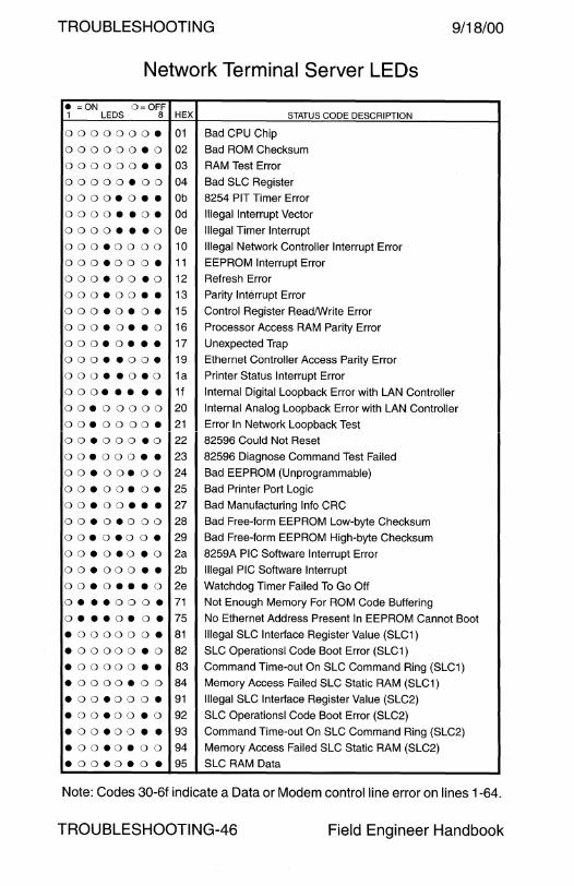
TROUBLESHOOTING 9/18/00
Network Terminal Server LEDs
e =ON O=OFF 1 LEDS 8 HEX STATUS CODE DESCRIPTION
0000000• 01 Bad CPU Chip
000000•0 02 Bad ROM Checksum
000000•• 03 RAM Test Error
oooooeoo 04 Bad SLC Register
0000•0•• Ob 8254 PIT Timer Error
0000••0• Od Illegal Interrupt Vector
0000•••0 Oe Illegal Timer Interrupt
oooeoooo 10 Illegal Network Controller Interrupt Error
oooeoooe 11 EEPROM Interrupt Error
oooeooeo 12 Refresh Error
oooeoo•• 13 Parity Interrupt Error
oooeo•o• 15 Control Register Read/Write Error
oooeoeeo 16 Processor Access RAM Parity Error
oooeo••• 17 Unexpected Trap
oooeeooe 19 Ethernet Controller Access Parity Error
oooeeoeo 1a Printer Status Interrupt Error
o o oe • • • • 1f Internal Digital Loopback Error with LAN Controller
ooeooooo 20 Internal Analog Loopback Error with LAN Controller
ooeooooe 21 Error In Network Loopback Test
ooeoooeo 22 82596 Could Not Reset
ooeooo•• 23 82596 Diagnose Command Test Failed
ooeooeoo 24 Bad EEPROM (Unprogrammable)
ooeooeoe 25 Bad Printer Port Logic
ooeoo••• 27 Bad Manufacturing Info CRC
ooeoeooo 28 Bad Free-form EEPROM Low-byte Checksum ooeoeooe 29 Bad Free-form EEPROM High-byte Checksum
ooeoeoeo 2a 8259A PIG Software Interrupt Error
ooeoooee 2b Illegal PIG Software Interrupt
ooeo•••o 2e Watchdog Timer Failed To Go Off
oeeeoooe 71 Not Enough Memory For ROM Code Buffering
o•••o•o• 75 No Ethernet Address Present In EEPROM Cannot Boot
•000000• 81 Illegal SLC Interface Register Value (SLC1)
eoooooeo 82 SLC Operations! Code Boot Error (SLC1)
eoooooee 83 Command Time-out On SLC Command Ring (SLC1)
eooooeoo 84 Memory Access Failed SLC Static RAM (SLC1)
eooeoooe 91 Illegal SLC Interface Register Value (SLC2)
eooeooeo 92 SLC Operations! Code Boot Error (SLC2)
eooeooee 93 Command Time-out On SLC Command Ring (SLC2)
eooeoeoo 94 Memory Access Failed SLC Static RAM (SLC2)
eooeoeoe 95 SLC RAM Data
Note: Codes 30-6f indicate a Data or Modem control line error on lines 1-64.
TROUBLESHOOTING-46 Field Engineer Handbook

PARTS BREAKDOWN
POWER

9/18/00 POWER
Power
AC Power Cords . . . . . . . . . . . . . . . . . . . . . . . . .. . . . . . . . . . . . . . . . . . . . . . . . . .. .. .. .. .. .. .. .. . 2 StorEdge A7000 AC Power Cords ....................................... 5 AC Power Plugs . .. . .. . .. .. . .. .. .. . .. .. .. . . .. .. . .. .. .. . .. . .. .. .. .. .. .. . . . .. . . . . . .. . 5 Fuses.................................................................................... 6 Keys ..................................................................................... 11
Wiring Diagrams SPARCcenter 2000 and 2000E .. .. .. .... .. .... .. .. .. .. .. ... .. .. ...... .. 12 SPARCcenter 2000E .. . .. .. ... .. .. . . .. .. . . . . . . .. . ... .. . . . . . . .. ... .. .. . .... . .. 13 Netra nfs 150 .. .. .. . . .. . .. .. .. .. . .. . .. .. . .. .. .. . . .. . .. . . . . . .. .. . .. . .. . .. .. .. .. . .. . 14 Ultra Enterprise 150 and Netra i 150 . .. . .. .. .. ... .. . .... .. .. ...... .. . 15 Enterprise 220R . . .. . .. ... .. .. . . . .. ... . .. .. . .. .. . . . . ... . . . . ... . .. . .. .. ... .. .. . .. 16 Enterprise 420R . . .. ... ... .. .. .. . .. .. .. .. .. .. .. . . . . . ... .. .. .. . .. . . . ... ... . . .. .. . 17 Enterprise 250 . . . .. .. .. . .. . . . .. .. . . . .. .. .. . . .. . . .. . .. . . .. .. . . . . .. . .. .. . . . .. .. . .. . 18 Ultra Enterprise 450 ... .. .. ... .. ... .. . .. ... . . . .. . . . . .. .. . . . . .. ... .. . . ... .. . . . . 19
Ultra Enterprise 3000 .. . .. .. .. . .. .. .. .. .. .. . . .. . .. .. . .. .. .. . . .. .. . .. .. .. . .. .. 20 Ultra Enterprise 4000 ........................................................ 21 Ultra Enterprise 5000 .. .. .. . .. .. .. .. .. .. . .. .. . .. . .. . .. . . . . . . .. . . . .. .. . . . .. . .. 22 Ultra Enterprise 6000 ........................................................ 23 56-inch Enterprise Expansion Cabinet .. .. .. .. .. .. .. .. .. .. .. .. .. .. .. 24
Enterprise 3500 . . .. .. .. . .. . . .. . .. .. .. .. .. .. . . .. . . . .. .. . .. .. .. . . .. . . .. . .. . .. .. .. . 25 Enterprise 4500 .. .. .. .. . .. .. .. . .. .. .. .. .. .. . . .. .. . .. .. . . . .. .. . .. . .. .. . .. .. . .. .. . 26 Enterprise 5500 .. . . .. .. . .... .. . .. .. .. .. .. .. .. .. . . . .. .. .. . .. . . . .. ... .. . . . .. ... .. . 27 Enterprise 6500 ................................................................. 28 68-inch Enterprise Expansion Cabinet .... .. .. .. .... ..... .. . .. .. .... 29
StorEdge A7000 AC Input ................................................. 30
Field Engineer Handbook - Volume II

POWER 19/18/00
AC Power Cords
PART# DESCRIPTION USAGE
180-1010 IEC 320 - Reverse IEC 320, Coiled (obs) Ace Pwr
180-1117 IEC 320 - Reverse IEC 320 Ace Pwr
180-1 og7 IEC 320 - NEMA 5-15, 15A/125V USA
180-1125 IEC 320 - pigtail, 6A/250V Ace Pwr
180-1126 IEC 320 - NEMA 6-15, 10A/250V (obs) V3 Sequencer
180-1142 IEC 320 - NEMA 5-15, 15A/125V USA
180-1146 IEC 320 - NEMA 5-15, 10A/125V USA
180-1176 IEC 320 - BS 1363, 1 OA/250V (obs) UK
180-1177 IEC 320 - CEE 7/7, 1 OA/250V (obs) France
180-1177 IEC 320 - CEE 7/7, 1 OA/250V (obs) Germany
180-1177 IEC 320 - CEE 7/7, 10A/250V (obs) Sweden
180-1178 IEC 320 - SEV 1011, 1 OA/250V (obs) France
180-1178 IEC 320 - SEV 1011, 1 OA/250V (obs) Germany
180-1178 IEC 320 - SEV 1011, 10A/250V (obs) Switzerland
180-117g IEC 320 - NEMA 5-15, 10A/250V USA
180-1179 !EC 320 - f'JE~v~l\ 5-15, 10A/250\/ Japan
180-1183 Y IEC 320 - NEMA 6-15, 10A/250V V3 Sequencer
180-1184 Y IEC 320 - Reverse IEC 320, 1 OA/250V V4 Sequencer
180-118g IEC 320 - NEMA 6-15, 10A/250V V3 Sequencer
180-11 go IEC 320 - Reverse IEC 320, 10A/250V V4 Sequencer
180-1234 IEC 320 - 107/10-1g73, 10A/250V (obs) Denmark
180-1235 IEC 320 - CEI 23-16Nll, 10A/250V (obs) Italy
180-1236 IEC 320 - AS 3112, 10A/250V (obs) Australia
180-1662 IEC 320 - no description available Korea
180-1683 IEC 320 - Reverse IEC 320, 10A/250V, 1.5M V4 Sequencer
180-1688 IEC 320 - Reverse IEC 320, 10A/250V, 2.5M V4 Sequencer
180-1732 go0 IEC 320 - go0 Reverse IEC 320, .75M E150 Internal
180-1g43 Han 6HsB to NEMA L6-30P, Option 3800 E5x00/E6x00
180-1g44 Han 6HsB to Blue 32A IEC30g, Option 3848 E5x00/E6x00
370-372g IEC 320-C1g - NEMA 5-20P L11000
370-3g41 go 0 IEC 320 - SEV 1011 Sun Ray 1
370-3g42 go 0 IEC 320 - NEMA 5-15 Sun Ray 1
~ Warning - The Schuko CEE 7/7 plug is not grounded if used ffi with the Danish Afsnit 107 electrical outlet.
POWER-2 Field Engineer Handbook

9/18/00 POWER
AC Power Cords - Continued
PART# DESCRIPTION USAGE
370-3g43 go 0 IEC 320 - CEI 23-16Nll Sun Ray 1 370-3g44 go0 IEC 320 - CEE 7/7 Sun Ray 1 370-3g45 go 0 IEC 320 - BS 1363 Sun Ray 1 370-3g45 go0 IEC 320 - no description available, Korea Sun Ray 1 370-3g48 go0 IEC 320 - 107/10-1g73 Sun Ray 1 370-3g4g go0 IEC 320 - AS 3112 Sun Ray 1
370-4011 go0 IEC 320 - no description available, Japan Sun Ray 1 530-1343 IEC 320 - Reverse IEC 320, 10A/250V V4 Sequencer 530-1351 IEC 320 - NEMA 6-15, 10A/250V V3 Sequencer 530-1370 IEC 320 - NEMA 5-15, 15A/125V, Grey USA
530-1371 IEC 320 - Reverse IEC 320, 15A/125V, Grey PBox Ace Pwr 530-1410 IEC 320 - CEE 7/7, 6A/250V, Grey Europe 530-1411 IEC 320 - BS 1363, Grey UK
530-1583 IEC 320 - SEV 1011, 1 OA/250V, Grey Switzerland 530-1584 IEC 320 - CEI 23-16Nll, 10A/250V, Grey Italy
530-1585 IEC 320 - 107/10-1g73, 10A/250V, Grey Denmark 530-1586 IEC 320 - AS 3112, 10A/250V, Grey Australia
530-1604 IEC 320 - CEE 7/7, 1 OA/250V, Grey S. America 530-1657 90° IEC 320 - NEMA 5-15, 10A/125V, Grey USA
530-1663 go0 IEC 320 - CEE 7/7, 10A/250V, Grey France 530-1663 go0 IEC 320 - CEE 7/7, 10A/250V, Grey Germany 530-1664 go0 IEC 320 - SEV 1011, 1 OA/250V, Grey France
530-1664 go0 IEC 320 - SEV 1011, 1 OA/250V, Grey Germany 530-1664 go0 IEC 320 - SEV 1011, 1 OA/250V, Grey Switzerland 530-1665 go0 IEC 320- CEI 23-16Nll, 10A/250V, Grey Italy 530-1666 go0 IEC 320 - 107/10-1g73, 10A/250V, Grey Denmark
530-1667 go0 IEC 320 - AS 3112, 1 OA/250V, Grey Australia
530-1668 go0 IEC 320 - CEE 7/7, 10A/250V, Grey S. America 530-1671 go0 IEC 320 - BS 1363, 6A/250V, Grey UK 530-1817 IEC 320 - CEE 7/7, 10A/250V France 530-1817 IEC 320 - CEE 7/7, 1 OA/250V Germany
530-1817 IEC 320 - CEE 7/7, 10A/250V Sweden
~ Warning - The Schuko CEE 7/7 plug is not grounded if used ffi with the Danish Afsnit 107 electrical outlet.
Volume II POWER-3
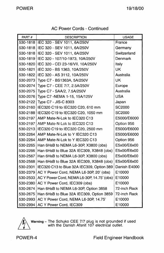
POWER 19/18/00
AC Power Cords - Continued
PART# DESCRIPTION USAGE
530-1818 IEC 320 - SEV 1011, 6A/250V France
530-1818 IEC 320 - SEV 1011, 6A/250V Germany
530-1818 IEC 320 - SEV 1011, 6A/250V Switzerland
530-1819 IEC 320 - 107/10-1973, 10A/250V Denmark
530-1820 IEC 320 - CEI 23-16Nll, 10A/250V Italy
530-1821 IEC 320 - BS 1363, 10A/250V UK
530-1822 IEC 320 -AS 3112, 10A/250V Australia
530-2073 Type C7 - BS 1363A, 5A/250V UK
530-2074 Type C7 - CEE 7/7, 2.5A/250V Europe
530-2075 Type C7 - SAA/2, 7.5A/250V Australia
530-2076 Type C7 -NEMA 1-15, 15A/125V USA
530-2122 Type C7 - JIS-C 8303 Japan
530-2160 IEC320 C19 to IEC320 C20, 610 mm SC2000
530-2188 IEC320 C19 to IEC320 C20, 1050 mm SC2000
530-2197 AMP Mate-N-Lok to IEC320 C13 E5000/E6000
530-2197 /HAD Un+,..._f\U ,....1, +r. IC:f"''::!'>n f""'-1 '::! I UVll 1Vll.4LV .... -1-vn. LV IL..VVi:..v v Iv Option 956
530-2213 IEC320 C19 to IEC320 C20, 2500 mm E5000/E6000
530-2264 AMP Mate-N-Lok to Y IEC320 C13 E5000/E6000
530-2264 AMP Mate-N-Lok to Y IEC320 C13 Option 956
530-2265 Han 6HsB to NEMA L6-30P, X3800 (obs) E5x00/E6x00
530-2266 Han 6HsB to Blue 32A IEC309, X3848 (obs) E5x00/E6x00
530-2567 Han 6HsB to NEMA L6-30P, X3800 (obs) E5x00/E6x00
530-2568 Han 6HsB to Blue 32A IEC309, X3848 (obs) E5xOO/E6xOO
530-2301 IEC320 C13 to Blue 32A IEC309, Option 389 Danish E4000
530-2379 ACY Power Cord, NEMA L6-30P, 20' (obs) E10000
530-2503 ACY Power Cord, NEMAL6-30P, 14.75' (obs) E10000
530-2380 ACY Power Cord, IEC309 (obs) E10000
530-2674 Han 6HsB to NEMA L6-30P, Option 3858 72-inch Rack
530-2675 Han 6HsB to Blue 32A IEC309, Option 3859 72-inch Rack
530-2993 ACY Power Cord, NEMA L6-30P, 14.75' E10000
530-2994 ACY Power Cord, IEC309 E10000
/;). Warning - The Schuko CEE 7/7 plug is not grounded if used ffi with the Danish Afsnit 107 electrical outlet.
POWER-4 Field Engineer Handbook
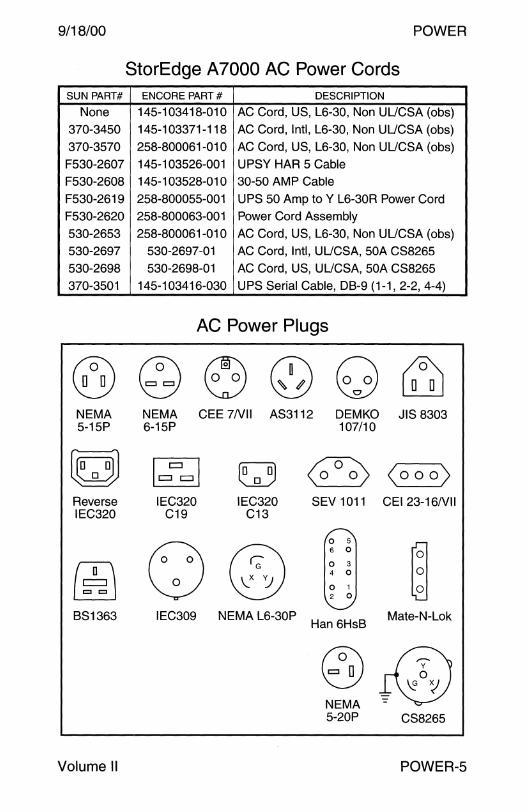
9/18/00 POWER
StorEdge A 7000 AC Power Cords SUN PART# ENCORE PART# DESCRIPTION
None 145-103418-010 AC Cord, US, L6-30, Non UUCSA (obs)
370-3450 145-103371-118 AC Cord, Intl, L6-30, Non UUCSA (obs)
370-3570 258-800061-010 AC Cord, US, L6-30, Non UUCSA (obs)
F530-2607 145-103526-001 UPSY HAR 5 Cable
F530-2608 145-1 03528-01 0 30-50 AMP Cable
F530-2619 258-800055-001 UPS 50 Amp to Y L6-30R Power Cord
F530-2620 258-800063-001 Power Cord Assembly
530-2653 258-800061-010 AC Cord, US, L6-30, Non UUCSA (obs)
530-2697 530-2697-01 AC Cord, Intl, UUCSA, 50A CS8265
530-2698 530-2698-01 AC Cord, US, UUCSA, 50A CS8265
370-3501 145-1 03416-030 UPS Serial Cable, DB-9 (1-1, 2-2, 4-4)
AC Power Plugs
@ ~ ~ 0 8 ~ NEMA NEMA CEE ?NII AS3112 DEMKO JIS 8303 5-15P 6-15P 107/10
~ ~ M ~ <o o o) Reverse IEC320 IEC320 SEV 1011 CEI 23-16Nll IEC320 C19 C13
() 0 5
~ ® 6 0
(~j 0 3 4 0
'J 0 1 2 0
BS1363 IEC309 NEMA L6-30P Han 6HsB
Mate-N-Lok
@ +® NEMA 5-20P CS8265
Volume II POWER-5

POWER 19/18/00
Fuses
Fuseholder and Fusecarrier
Follow these instructions to avoid electrical shock hazard when wiring the type of fuseholder illustrated below.
1. Connect the AC Input to the Terminal on the end of the Fuse holder.
2. Connect the Terminal on the side of the Fuseholder to the AC Line Filter or AC Switch.
FUSECARRIER
FUSE
lIJJ
I DESCRiPTiON
Carrier, Domestic
Carrier, International Holder, In Line 22-14AWG Holder, In Line 22-14AWG Holder, UUCSA/VDE
Holder, R/A for PIG-TAIL Holder, R/A for PIG-TAIL
Holder, 20A,250V,UL Microfuse Holder Microfuse Holder
Holder Holder, Faston Type
Holder, Faston Type Holder, Quick Connect Holder, Quick Connect
Field Engineers Fuse Kit
POWER-6
FUSEHOLDER
~erminal to ON/OFF Switch ~ on AC Line Filter
Terminal to AC Input
I SUN PART# I I
VENDOR PART#
150-1042 Schurter FEK 031.1666 150-1051 Schurter 031.1663
140-1023 AMP 552844-1 140-1023 Littelfuse 155 020U 150-1041 Schurter FEU 031.1693
150-1163 Littelfuse 281 007 150-1163 Pwr Dynamic 19557 150-1177 Schurter FEU031.1673 150-1179 Littelfuse 282 002 150-1179 Littelfuse 282 008
150-1024 Littelfuse 345 001 150-1026 Littelfuse 571 007 150-1026 Bussman HPF
150-1029 Bussman HTA-HH 150-1029 Littelfuse 342 858 555-1126 Sun 555-1126
I
Field Engineer Handbook
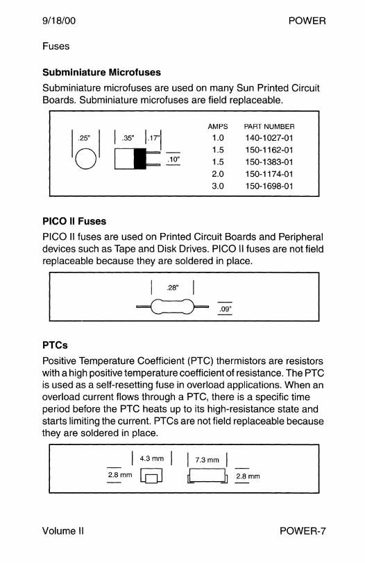
9/18/00 POWER
Fuses
Subminiature Microfuses
Subminiature microfuses are used on many Sun Printed Circuit Boards. Subminiature microfuses are field replaceable.
AMPS PART NUMBER
1.25" I I .35" 1.17"1 1.0 140-1027-01
LI= .10" 1.5 150-1162-01
0 1.5 150-1383-01
2.0 150-1174-01
3.0 150-1698-01
PICO II Fuses
PICO II fuses are used on Printed Circuit Boards and Peripheral devices such as Tape and Disk Drives. PICO II fuses are not field replaceable because they are soldered in place.
PT Cs
Positive Temperature Coefficient (PTC) thermistors are resistors with a high positive temperature coefficient of resistance. The PTC is used as a self-resetting fuse in overload applications. When an overload current flows through a PTC, there is a specific time period before the PTC heats up to its high-resistance state and starts limiting the current. PTCs are not field replaceable because they are soldered in place.
Volume II
4.3mm
2.Bmm [DJ I 7.3mm I [ ~ 2.Bmm
POWER-7

POWER 19/18/00
Fuses
FUSE SIZE SUN PART# VENDOR PART#
1/16A .25x1.25" 140-1004 Littelfuse 312.062
1/16A .25 x 1.25" 140-1004 Bussman AGC 1/16
1/8A .25 x 1.25" 140-1003 Littelfuse 312.125 1/8A .25 x 1.25" 140-1003 Bussman AGC 1/8
1/2A .25 x 1.25" 140-1012 Littelfuse 313.500
3/4A PICO II 140-1024 Littelfuse 255.750
3/4A .145x.30" 140-1024 Bussman GFA 3/4 3/4A .25 x 1.25" 140-1044 Littelfuse 312.750
1A .25 x 1.25" 140-1040 Littelfuse 313 001 1A Microfuse 140-1027 Littelfuse 273 001
1A .25 x 1.25" 140-1040 Littelfuse 313 001
1A .25 x 1.25" 140-8500 Bussman AGC-1
1A .25 x 1.25" 140-8500 Littelfuse 314 001
1.5A Microfuse 150-1162 Littelfuse 273 01.5
1.5A Microfuse 150-1383 Littelfuse 273 01.5
1.5A 5 x20mm 150-1208 soc MT4-1-51
1.5A .25 x 1.25" 140-1042 Littelfuse 313 01.5
1.6A .25 x 1.25" 140-1022 Littelfuse 312 01.6
1.6A .25 x 1.25" 140-1022 BEL 3AG1.6 1.6A .25 x 1.25" 140-1022 Pwr Dynamics 19340 1.6A
1.6A .25 x 1.25" 140-1022 Bussman AGC 1.6A
1.6A 5 x 20mm 150-1215 Schurter 034.3119
1.6A 5x 20mm 150-1215 Littelfuse 218 01.6
2A .25 x 1.25" 140-1005 Littelfuse 312 002 2A .25x1.25" 140-1005 Bussman AGC2 2A PICOll 140-1028 Littelfuse 252 002
2A 5 x20mm 140-1034 Bussman GDC-2
2A 5x20mm 140-1034 Littelfuse 218 002
2A Microfuse 150-1174 Littelfuse 273 002 2A .25 x 1.25" 150-1191 MGC MGC 0002 2A .25 x 1.25" 150-1191 Littelfuse 312 002
2A .25 x 1.25" 140-1048 Littelfuse 313 002 2A .25 x 1.25" 140-1048 Bussman MDA2
2.5A .25 x 1.25" 140-1000 Littelfuse 313 02.5
2.5A .25 x 1.25" 140-1000 Bussman MDA 21/2
POWER-8 Field Engineer Handbook
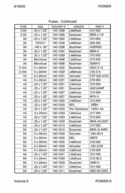
9/18/00 POWER
Fuses - Continued
FUSE SIZE SUN PART# VENDOR PART#
2.5A .25 x 1.25" 140-1008 Littelfuse 313 003
2.5A .25 x 1.25" 140-1008 Bussman MDA 21/2
3A .25 x 1.25" 150-1034 Littelfuse 313 003 3A PICOll 140-1038 Littelfuse 252 003 3A .145 x .30" 140-1038 Bussman A3XRAD
3A .25 x 1.25" 150-1034 Bussman MDA-3
3A .25 x 1.25" 140-1039 Littelfuse 312 003 3A Microfuse 150-1698 Littelfuse 273 003
3A Microfuse 150-1698 Bussman GMW-3
3.15A 5 x 20mm 140-1002 Bussman GDC 3.15
3.15A 5 x20mm 140-1002 Littelfuse 218 315
4A 5 x 20mm 140-1031 Schurter FST 034.3123 4A 5 x20mm 140-1031 Littelfuse 218 004
4A .25 x 1.25" 140-1001 Littelfuse 318 004
4A .25 x 1.25" 140-1001 Bussman AGC4AMP
4A .25 x 1.25" 140-1007 Littelfuse 312 004 4A .25 x 1.25" 140-1007 Bussman MTH4
4A .25 x 1.25" 140-1020 Littelfuse 313 004
4A .25 x 1.25" 140-1020 BEL 3SB4
4A .25 x 1.25" 140-1020 Pwr Dynamics 19341-4A
4A .5 x20mm 140-1043 Littelfuse 217 004
4A .25x1.25" 150-1033 Littelfuse 313 004
4A .25 x 1.25" 150-1033 Bussman MDA4A,250V
5A .25 x 1.25" 140-1010 Littelfuse 313 005
5A .25 x 1.25" 140-1010 Bussman MDA (5 AMP)
5A 5 x 20mm 140-1025 Schurter 034.3914
5A 5 x20mm 140-1025 BEL 5MT5
5A 5 x 20mm 140-1025 Littelfuse 218 005 5A 5 x20mm 140-1029 Schurter 034.3124 5A 5 x 20mm 140-1029 Littelfuse 218 005
5A .25 x 1.25" 140-1041 Littelfuse 312 005
6A 5 x 20mm 140-1009 Littelfuse 212 06.3
6A 5 x20mm 140-1009 Bussman GMA6 6A .25 x 1.25" 140-1011 Littelfuse 314 006 6A .25 x 1.25" 140-1011 Bussman ABC 6A250V
Volume II POWER-9

POWER 19/18/00
Fuses - Continued
FUSE SIZE SUN PART# VENDOR PART#
6A .25 x 1.25" 140-1021 Littelfuse 312 006
6A .25 x 1.25" 140-1021 Bussman MTH-6A
6A .25 x 1.25" 140-1021 Pwr Dynamics 19340-6A 6A .25 x 1.25" 140-1026 Bussman 250(MSL)
6A 5 x20mm 150-0473 Pnl Compnt 341524
6A 5 x20mm 150-0473 Littelfuse 213 006 6.3A 5 x 20mm 140-1030 Schurter FST 034.3125 6.3A 5 x20mm 140-1030 Littelfuse 21B 063
7A .25 x 1.25" 150-125B Littelfuse 313 007 7A .25 x 1.25" 150-125B Bussman MDQ-7
BA .25 x 1.25" 140-1006 Littelfuse 314 OOB BA .25 x 1.25" 140-1006 Bussman MTH B BA 5 x 20mm 150-2246 Littelfuse 217 OOB BA 5x 20mm 150-2246 Schurter 034.1525
10A .25 x 1.25" 140-1017 Littelfuse 326 010 10A .25 x 1.25" 140-1017 Pwr Dynamics 19341-1 OA 10A .25 x 1.25" 140-1051 Littelfuse 314 010 10A .25 x 1.25" 140-1051 Bussman ABC-10A
10A 0.46 x 1.5" 140-1152 Littelfuse KLK-R 10A
10A 0.46 x 1.5" 150-xxxx Littelfuse CCMR 10A 12A .25 x 1.25" 140-BOOO Bussman ABC-12 12A .25 x 1.25" 140-BOOO Littelfuse 314.012
15A .25 x 1.25" 140-1019 Littelfuse 314 015 15A .25 x 1.25" 140-1019 Bussman ABC-15A 15A .25 x 1.25" 140-1035 Littelfuse 314 015 15A .25 x 1.25" 140-1035 Bussman ABC-15A 15A 0.46 x 1.5" 140-1154 Littelfuse CCM-R 15A 15A 0.46 x 1.5" 140-1154 Bussman LP-CC-15
15A Nano2 150-2330 Littelfuse 451 015 15A PICOll 150-239B Littelfuse 251 015 15A 0.46 x 1.5" 150-xxxx Littelfuse CCMR 15A
30A Autofuse None Littelfuse 257030
POWER-10 Field Engineer Handbook
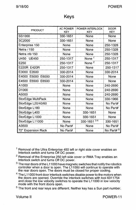
9/18/00 POWER
Keys
PRODUCT AC POWER POWER INTERLOCK DOOR
KEY KEY KEY
881000 330-1651 None None SC2000 330-1651 None None Enterprise 150 None None 250-1328 Netra i 150 None None 250-1328 Netra nfs 150 None None 250-1328 U450 UE450 250-1317 None 1 250-1317 E250 250-1317 None 2 250-1317 E220R E420R 250-1317 None 250-1317 E3000 E3500 330-2014 None 330-2014 E4000 E5000 E6000 330-2014 None None E4500 E5500 E6500 330-2014 None None A1000 None None 240-2690 D1000 None None 240-2690 A5000 None None 240-2690 StorEdge MultiPack None None 330-1966 StorEdge L20/40/60 None None No Part# StorEdge L 180 None None No Part# StorEdge L400 None 330-1651 None StorEdge L 1000 None 330-1651 None StorEdge L 11000 None 330-1651 34 330-1651 A3500 No Part# None No Part# 72" Expansion Rack No Part# None No Part# 5
1 Removal of the Ultra Enterprise 450 left or right side cover enables an Interlock switch and turns Off DC power.
2 Removal of the Enterprise 250 left side cover or RMA Tray enables an Interlock switch and turns Off DC power.
3 The rear doors of the L 11000 have magnetic switches that notify the robotics controller when a door is open. The L 11000 will continue to operate with the rear doors open. The doors must be closed for proper cooling.
4 The L 11000 front door interlock switches disable power to the motors when the doors are opened. Override the interlock switches with tool 6311754 and close the low velocity switches to operate the L 11000 in low velocity mode with the front doors open.
5 The front and rear keys are different. Neither key has a Sun part number.
Volume II POWER-11
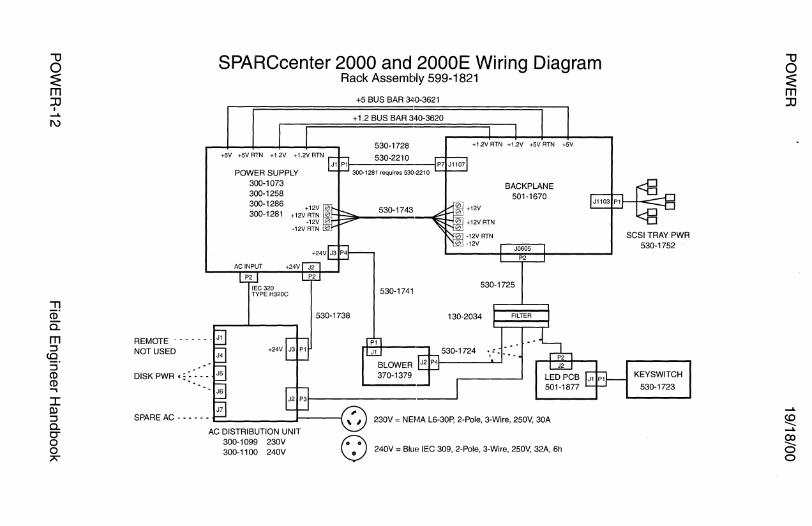
""U 0 ~ m :JJ
I ...... I\)
:I: ll> :J a. co 0
"'"
SPARCcenter 2000 and 2000E Wiring Diagram Rack Assembly 599-1821
+SV +5VRTN +1.2V +1.2VRTN
POWER SUPPLY 300-1073 300-1258 300-1286 300-1281
+5 BUS BAR 34-0-3621
+ 1.2 BUS BAR 340-3620
530-1728
530-2210
530-1743
530-1741
+ 12V RTN + 1.2V +5V RTN +5V
BACKPLANE 501-1670
J0605
P2
530-1725
130-2034 FILTER
REMOTE _______ J,
NOT USED 530-1724
DISKPWR ,,:·. - ---
230V = NEMA L6-30P, 2-Pole, 3-Wire, 250V, 30A
~.· \..!.) 240V = BIUE! IEC 309, 2-Pole, 3-Wire, 250V, 32A, 6h
SCSI TRAY PWR 530-1752
KEYSWITCH
530-1723
""U 0 ~ m :JJ
...... se ......
~ 0

< 0 c 3 CD
"'U 0 ~ m JJ
I __. VJ
+5 I + 1.2 BUS BAR 340-3136
POWER SUPPLY 2 Lower 300-1281
540-2648 IEC 320 TYPE H320C AC Receptacles
Captive AC Cord
REMOTE NOT USED
DISKPWR • :- -
SPARE AC
SPARCcenter 2000E Wiring Diagram Rack Assemblies 599-2027 and 599-2031
+5V
POWER SUPPLY 1 Upper300-1281
530-2162
530-2164
300-1099 230V 300-1100 240V
+5 BUS BAR 340-3621
+ 1.2 BUS BAR 340-3620
530-2162 530-2163 + 1.2V RTN + 1.2V +SV RTN +5V
+12V
+12V RTN
-12V RTN -12V
BACKPLANE 501-1670
J0605
P2
530-1725
130-2034
530-2161
230V = NEMA L6-30P, 2-Pole, 3-Wire, 250V, 30A
~.· \.:_} 240V = Blue IEC 309, 2-Pole, 3-Wire, 250V, 32A, 6h
SCSI TRAY PWR 530-1752
KEYSWITCH
530-1723
co -__.
~ 0
""O 0 ~ m JJ
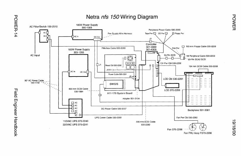
"'U 0 ~ m :D
I ...... +:>.
AC Filter/Switch 150-2510
AC Input
Netra nfs 150 Wiring Diagram 180W Power Supply
300-1308 Peripheral Power Cable 530-2255
185W Power Supply 300-1283
AC In DC Out
800 mm SCSI Cable 530-1884
J1
Pwr .. ~upply Wire Harness
Filterbox Cable 530-2260
A11-170 System Board
Adapter 501-3104
LCD Cbl 530-2261
LCD 370-2259
190 mm Floppy Cable 530-2258
1 M Peripheral Cable 530-2253
- - 80-Pin SCA2 SCSI
194 mm SCSI Cable 530-2268
OAC AC
'--------------+-~--------+----t--t-;-1,, " " " " "
DC Power Cable 530-2257
AC IHI--------------·-----~
11 OVAC UPS 370-2240
220VAC UPS 370-2241
UPS Comm Cable 530-2259
590 mm SCSI Cable
530-2282
Backplane 501-3081
Fan Pwr Cbl 530-2262
Fan 370-2266
Fan FRU Assy F370-2266
"'U 0 ~ m :D

< 0 c 3 CD
-u 0 ~ m JJ
I ...... CJl
Ultra Enterprise 150 and Netra i 150 Wiring Diagram 90° AC Power Cable 180-1732
AC Filter/Switch 150-251 O ,::
AC Input
180W Power Supply 300-1308
185W Power Supply 300-1283
AC In DC Out
800 mm SCSI Cable 530-1884
Powe~ Supply Wire Harness
Filterbox Cable 530-2260
J1
Power Cable 530-2281 J3
Sun Swift
A 11-170 System Board
Adapter 501-3104
Peripheral Power Cable 530-2255
Tape Pwr Floppy Pwr
190 mm Floppy Cable 530-2258
B _ 1 M Peripheral Cable 530-2253
· 80-Pin SCA2 SCSI
194 mm SCSI Cable 530-2268
'--------------~--------+---+--t7!,, " " " " "
DC Power Cable 530-2257
590 mm SCSI Cable 530-2282
Backplane 501-3081
Fan Pwr Cbl 530-2262
Fan 370-2266
Fan FRU Assy F370-2266
-u 0 ~ m JJ

""U 0 ~ m ::D
I ...... O')
I Q) ::::i 0.. CT 0 0
"
c D =====:Jc DD~~a
D D
Ultra 60 System Board
AC Power Cable 530-2819
Enterprise 220R Wiring Diagram
Cable 530-2828
Cable 530-2829
DC-DC 300-1455
Cable 530-2824
AC Receptacle 540-4232
Power Supply #1 300-1449
AC Receptacle 540-4232
Power Supply #0 300-1449
LED
On/Off Button
Keyswitch c=()
Key 250-1317
Fan Tray
540-4431
DC Distribution ~~-------<--i----n DC Power Cable 530-2864
501-5506
AC Input/Filter I +-----------j--------------------' 370-4099
AC Input/Filter 370-4099
AC Ground Cable 530-2861
AC Power Cable 530-2819
AC Ground Cable 530-2861
Terminator
530 mm SCSI Cable 530-2827
""U 0 ~ m ::D

< 0 c 3 CD
Enterprise 420R Wiring Diagram
DC-DC 300-1407
===
===
D
======
Cable 530-2822
Cable 530-2821
Cable 530-2824
AC Receptacle 540-4232
Power Supply #1 300-1449
AC Receptacle 540-4232
Power Supply #0 300-1449
LED
On/Off Button
Keyswitch ~
Key250-1317
Ultra 80 System Board Fan Tray
540-4431
DC Distribution '-1-+--~~---r,....--n DC Power Cable 530-2864
501-5506 AC Power Cable 530-2819
AC lnpuUFilter I t------------t--------------------' 370-4099
AC Input/Filter 370-4099
AC Ground Cable 530-2861
AC Power Cable 530-2819
AC Ground Cable 530-2861 530 mm SCSI Cable 530-2827
Terminator -0 0 ~ m JJ

""O 0 :E m ::D
I ...... CXl
.,, (ii" a. m ::l
CQ. ::l CD CD ..... J: Dl ::l a. O" 0 0
"
Enterprise 250 Wiring Diagram
Interlock Switch/Cable 530-2482
.,; @
'ii -!!.! 0 0
~ :::-@ ·a c.
"' "' ~ 6 0
"' ~ g. en
j .c "' ,!;! "' "' 3: 6 en -" 0
~ "' ~ ~ c.
" ~
en
j 0 () .. 32 en
'!l
D DD
4-Pin Power Cable 530-2444
6-Pin Power Cable 530-2441
D D
Sense Cable 530-2481
Sense/12C Cbl 530-2480
a
System Board 501-4681
RMA Tray Interlock Switch Cb w Key 250-1317
Keyswitch/ _EDA2C Cable 530-2525
® ®
~
~ u c: "' ;:!:
; >.
~ c: if
Floppy Cable 530-2439
LED/Cable 370-3324
~ o~ o~ ~
"' <Xl
Backplane Rear View
~ o~ o~ Fan Power Cable 530-2685 DC Power Cable 530-2443
UCM Board w Cable 501-4818 25 mm SCSI/Floppy Data Cable 530-2446
pci@11,4000/scsi@3 and pci@11,4000/ebus@1/fdthree@14
""O 0 :E m ::D
...... se ......
~ 0
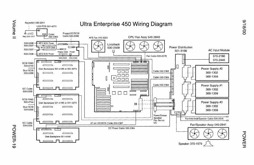
< 0 c: 3 CD
"1J 0 :2: m JJ
I ....... <D
Keyswitch 530-2314
LED PCB 501-4270
=
Floppy/12C/SCSI Cable 530-2368
= = = =
= = =
= Disk Backplane 501-4148
= =
Ultra Enterprise 450 Wiring Diagram
AFB Fan 540-3023 CPU Fan Assy 540-2840
D
Loop back 530-2509
a~ DOD 0000
DOD
==a~ DOD
Cl
67 cm 12C/SCSI Cable 530-2367
~ ~ = = = =
DC Power Cable 530-2364
Power Distribution 501-3100 AC Input Module
370-2160 370-2440
Power Supply #2 300-1302 300-1359
Power Supply #1 300-1302
300-1359
Power Supply #0 300-1302 300-1359
Fan/Speaker Assy 540-2841
Speaker 370-1579
-u 0 :2: m JJ

"'U 0 ~ m JJ
I I\) 0
I ll> ::::l 0.. C" 0 0 ;;>\'"
Ultra Enterprise 3000 Wiring Diagram
935 mm SCSI Cable 530-2381
Term
68-Pin
50-Pin
50-Pin
501-2599
530-2226
Keyswitch 530-2148
_ .---.·scs1PowerCbl530-2221
~ . - ~. - ~. - ~ .. I I I I I I I I
I I I I I I I I
I I I I I I I I
I I I I I I I I
::~,,~,,~,,~,, ~ ~ I I I I I I I I I I
I I I I I I I I I I
l I I I I I I I l l
Front View
Fan 370-2158 --1 (j) (j) @l Fan Tray FRU Assy 540-2756
Aux Fan FRU Assy 540-2757 Centerplane
Either an Aux Fan Assy or a Power/Cooling Module is required above the AC Peripheral Power Supply
4-Slot Backplane 501-2939
PSS PS3 PS1
DD-AC PPS PPS;:
Rear View
One AC Peripheral Power Supply is required and only one is supported. A Peripheral Power Supply in the PPS slot is optional.
---n ·~
Peripheral Power Supply 300-1301 AC Peripheral Power Supply 300-1307 Danish AC Peripheral PS 300-1317
Centerplane
AC Input 300-1307 and 300-1317 only
A terminated 1/0 board is required in Slot 1 to access the internal SCSI bus.
"'U 0 :z: m :D

< 0 c: 3 CD
Ultra Enterprise 4000 Wiring Diagram AC Input/Fan Tray FRU Assy 370-1811
Danish AC Input/Fan FRU Assy 370-2364
530-2202 - ~
501-2810. -
530-2203. -
Centerplane
> Fan370-1911
- - - . 530-2204
CJI .__ __ PP_s ___ ~
G G
. - - - - - - - -- - - - . ·------------·
·------------· ·------------·
Rear View
A terminated 1/0 board is required in Slot 1 to access the internal SCSI bus.
SCSI Tray FRU Assy 540-2587
533 mm SCSI Cbl 530-2119
50-Pin 50-Pin Terminator
~-~ID ·------------·
·------------· ·------------·
Front View
B G
Keyswitch FRU Assy 370-1810
8-Slot Backplane 501-2978
-u
~ m JJ
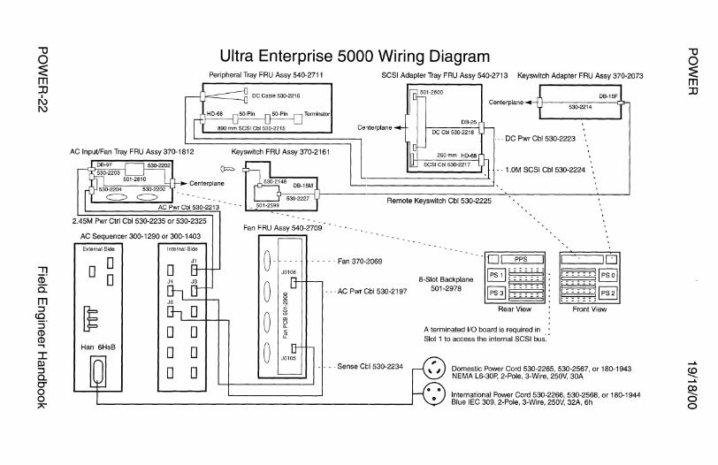
"'O 0 :E m JJ
I I\) I\)
"TI Ci)" a. m :J
CQ. :J CD CD ...... I Pl :J a. O'" 0 0 7'
AC Input/Fan Tray FRU Assy 370-1812
2.45M Pwr Ctrl Cbl 530-2235 or 530-2325
AC Sequencer 300-1290 or 300-1403
External Side
D D D
~ Han 6HsB
Internal Side
D D D
J1
D D
Ultra Enterprise 5000 Wiring Diagram Peripheral Tray FRU Assy 540-2711 SCSI Adapter Tray FRU Assy 540-2713 Keyswitch Adapter FRU Assy 370-2073
DB·15F Centerplane
530-2214 Terminator
Ce'lterplane
. - . DC Pwr Cbl 530-2223
Keyswitch FRU Assy 370-2161
- · 1.0M SCSI Cbl 530-2224
Remote Keyswitch Cbl 530-2225
0 0 0
- - - - · Fan 370-2069
- - ·AC Pwr Cbl 530-2197
- - - . Sense Ctl 530-2234
8-Slot Backplane 501-2978
--01 PPS
:::::inin~ 1 =. Rear View
A terminated 1/0 board is required in Slot 1 to access the internal SCSI bus:·
l'----'10 ~Ipso!
~§] Front View
Domestic Power Cord 530-2265, 530-2567, or 180-1943 NEMA L6-30P, 2-Pole, 3-Wire, 250V, 30A
International Power Cord 530-2266, 530-2568, or 180-1944 Blue IEC 309, 2-Pole, 3-Wire, 250V, 32A, Sh
"'U 0 :E m JJ
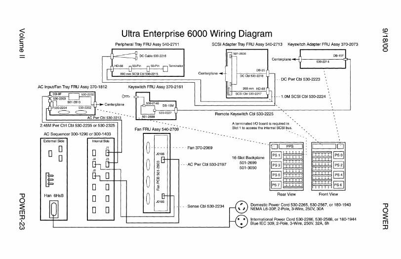
~ c:: 3 CD
""CJ 0 :E m :II
I I\) w
AC Input/Fan Tray FRU Assy 370-1812
2.45M Pwr Ctrl Cbl 530-2235 or 530-2325
AC Sequencer 300-1290 or 300-1403
External Side
0 0 0
Han 6HsB
Internal Side
J1
0 0 0 0 0 0
Ultra Enterprise 6000 Wiring Diagram Peripheral Tray FRU Assy 540-2711 SCSI Adapter Tray FRU Assy 540-2713 Keyswitch Adapter FRU Assy 370-2073
DB-15F Centerplane
530-2214
Terminator
Centerplane
- - - DC Pwr Cbl 530-2223
Keyswitch FRU Assy 370-2161
1.0M SCSI Cbl 530-2224
Remote Keyswitch Cbl 530-2225
0-0 0 0
---
- - - - - Fan 370-2069
- - -AC Pwr Cbl 530-2197
- - - . Sense Cbl 530-2234
A terminated l/O board is required in Slot 1 to access the internal SCSI bus.
16-Slot Backplane 501-2699 501-3050
Rear View
·~-~JD ~IPsol ~
i::::: i ::::: ~~
Front View
Domestic Power Cord 530-2265, 530-2567, or 180-1943 NEMA L6-30P, 2-Pole, 3-Wire, 250V, 30A
International Power Cord 530-2266, 530-2568, or 180-1944 Blue IEC 309, 2-Pole, 3-Wire, 250V, 32A, Sh
""CJ 0 :E m :II
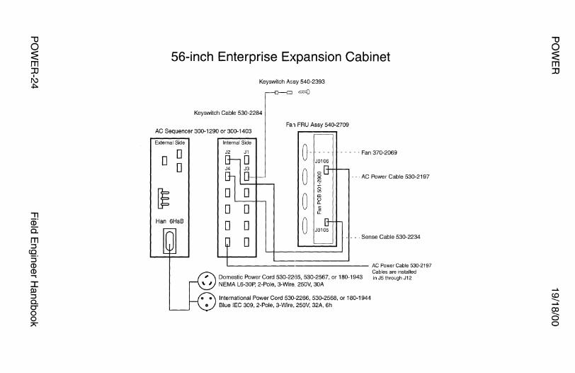
-u 0 ~ m :0
I I\) .,i::..
..,, Ci)" 0:: m :::J co
:::J CD CD ., I OJ :::J a. O" 0 0 ;;>;""
56-inch Enterprise Expansion Cabinet
Keyswitch A'sy 540-2393
=OJ
Keyswitch Cable 530-2284
Fa.1 FRU Assy 540-2709 AC Sequencer 300-1290 or 300-1403
External Side
D D D
Han 6HsB
Internal Side
D D D D
D
0-0 0 0
J0106
- · Fan 370-2069
- - ·AC Power Cable 530-2197
- - - . Sense Cable 530-2234
~--------·--------- AC Power Cable 530-2197 Cables are installed
Domestic Power Cord 530-22135, 530-2567, or 180-1943 in JS through J12 NEMA L6-30P, 2-Pole, 3-Wire 250V, 30A
International Power Cord 530-2266, 530-2568, or 180-1944 Blue IEC 309, 2-Pole, 3-Wire, 250V, 32A, 6h
-u 0 :E m :0
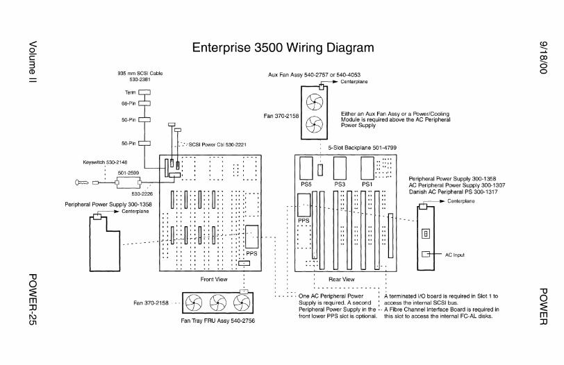
< 0 c: 3 CD
""U 0 :E m :D
I I\) CJ1
Enterprise 3500 Wiring Diagram
935 mm SCSI Cable 530-2381
Keyswitch_ 530-2148
530-2226
Peripheral Power Supply 300-1358 Centerplane
__ .:.·SCSI Power Cbl 530-2221
~ .. ~ .. ~. - ~. -I I I I I I I I
I I I I I I I I
I I I I I I I I
I I I I I I I I
I II II
I II 1'
I 11 11 ..... I 11 1••••
I I I I I I I I I I 1 11 I .......... .... D ---------~ ~ ~~J ~ ~ ~ ~ ! ~~ ~ --~T ~ -..
'' '' '' '' : :: : PPS
::ci Front View
Fan 370-2158 -- ·I GJ (fl ©] Fan Tray FRU Assy 540-2756
Aux Fan Assy 540-2757 or 540-4053
Fan 370-2158
Centerplane
Either an Aux Fan Assy or a Power/Cooling Module is required above the AC Peripheral Power Supply
5-Slot Backplane 501-4799
D DD ...... D .:::·.:: ·--··· Peripheral Power Supply 300-1358
PS5 PS3
D PS1 AC Peripheral Power Supply 300-1307
Danish AC Peripheral PS 300-1317
Centerplane
PPS .-.n "~
AC Input
Rear View
: - - : : ·. One AC Peripheral Power A terminated 1/0 board is required in Slot 1 to Supply is required. A second , access the internal SCSI bus. Peripheral Power Supply in the •. A Fibre Channel Interface Board is required in front lower PPS slot is optional. this slot to access the internal FC-AL disks.
"U 0 :E m :D
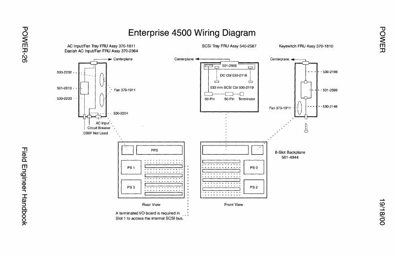
"U
~ m :D
I I\) O>
J: ll> ::::i c. C'" 0 0 7""
Enterprise 4500 Wiring Diagram AC lnpuVFan Tray FRU Assy 370-1811
Danish AC lnpuVFan FRU Assy 370-2364
530-2202 - <
501-2810 -
530-2203 -
CJ ._I __ PP_s ___ _.
B B
·------------· ·------------· ·------------·
·------------·
Rear View
A terminated 1/0 board is required in Slot 1 to access the internal SCSI bus.
SCSI Tray FRU Assy 540-2587
533 mm SCSI Cbl 530-2119
50-Pin 50-Pin Terminator
.____ _ __.I D ·------------· ·------------· ·------------·
Front View
B B
Keyswitch FRU Assy 370-1810
8-Slot Backplane 501-4944
"U 0 :E m :D
...... ~ ...... 00 0 0
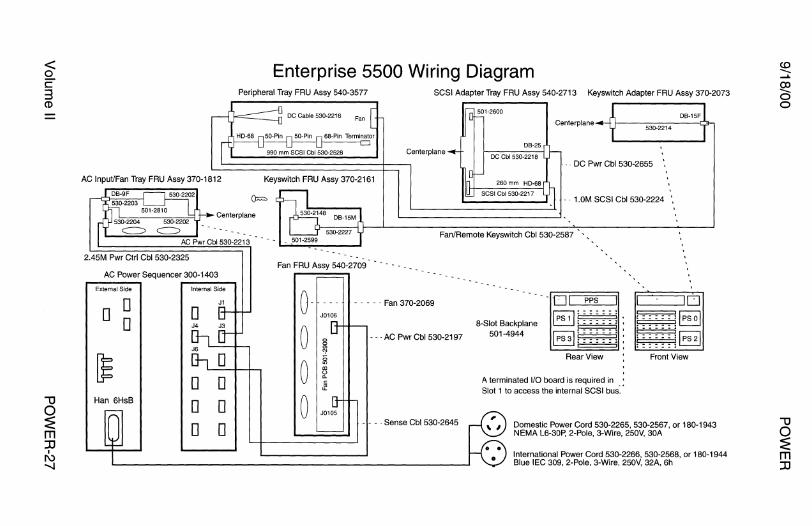
< 0 c 3 Cl>
""U 0 :E m :a
I I\) -...J
AC lnpuVFan Tray FRU Assy 370-1812
2.45M Pwr Ctrl Cbl 530-2325
AC Power Sequencer 300-1403
External Side
D D D
Han 6HsB
Internal Side
J1
D D D D D D
Enterprise 5500 Wiring Diagram Peripheral Tray FRU Assy 540-3577
Keyswitch FRU Assy 370-2161
SCSI Adapter Tray FRU Assy 540-2713 Keyswitch Adapter FRU Assy 370-2073
DB-15F Centerplane
530·2214
DB·25 Centerplane
. - . DC Pwr Cbl 530-2655
- - 1.0M SCSI Cbl 530-2224
Fan/Remote Keyswitch Cbl 530-2587
· Fan 370-2069
· AC Pwr Cbl 530-2197
8-Slot Backplane 501-4944
--01 PPS
~-~:~1~~~~~: = ~~
Rear View
A terminated 1/0 board is required in Slot 1 to access the internal SCSI bus:·
l1C~ _ _,JD ~IPsol ~
~~ Front View
- - - - Sense Cbl 530-2645 Domestic Power Cord 530-2265, 530-2567, or 180-1943 NEMA L6-30P, 2-Pole, 3-Wire, 250V, 30A
International Power Cord 530-2266, 530-2568, or 180-1944 Blue IEC 309, 2-Pole, 3-Wire, 250V, 32A, 6h
"'U 0 ~ m JJ

""U
~ m JJ
I I\) CXl
"Tl (i)" Q._
m :J co :J CP CP ..... I !).) :J Q._
0-0 0 ;:>\
AC Input/Fan Tray FRU Assy 370-1812
2.45M Pwr Ctrl Cbl 530-2325
AC Power Sequencer 300-1403
External Side
D D D
~ Han 6HsB
Internal Side
J1
D D D D D D
Enterprise 6500 Wiring Diagram Peripheral Tray FRU Assy 540-3577 SCSI Adapter Tray FRU Assy 540-2713 Keyswitch Adapter FRU Assy 370-2073
Centerplane 530-2214
Centerplane
... DC Pwr Cbl 530-2655
Keyswitch FRU Assy 370-2161
1.0M SCSI Cbl 530-2224
Remote Keyswitch Cbl 530-2587
Fan FRU Assy 540-2709
0 0 0 0
J0106
· Fan 370-2069
- - · AC Pwr Cbl 530-2197
- - - . Sense C:bl 530-2645
A terminated 1/0 board is required in Slot 1 to access the internal SCSJ bus.
16-Slot Backplane 501-5010
Rear View
l,L~-~JD
Domestic Power Cord 530-2265, 530-2567, or 180-1943 NEMA L6-30P, 2-Pole, 3-Wire, 250V, 30A
International Power Cord 530-2266, 530-2568, or 180-1944 Blue IEC 309, 2-Pole, 3-Wire, 250V, 32A, 6h
...... ~ ......
~ 0
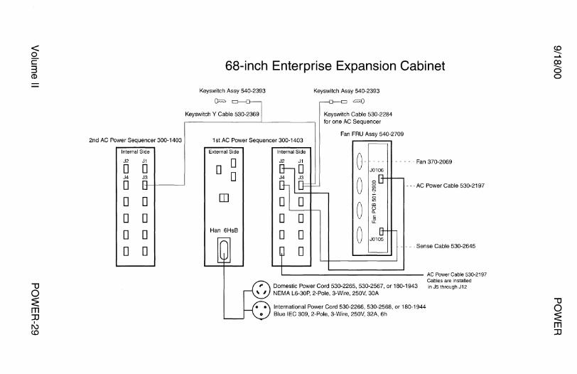
< 0 c 3 CD
""U 0 :E m JJ
I I\) c.o
2nd AC Power Sequencer 300-1403
Internal Side
J2 J1
D D J4 J3
D D D D D D D D D
68-inch Enterprise Expansion Cabinet
Keyswitch Assy 540-2393
O=>
Keyswitch Y Cable 530-2369
Keyswitch Assy 540-2393
"""° Keyswitch Cable 530-2284 for one AC Sequencer
Fan FRU Assy 540-2709 1st AC Power Sequencer 300-1403
External Side
D D D
rn
Han 6Hs8
Internal Side
J2 - - - - - Fan 370-2069
0 - - -AC Power Cable 530-2197
D D 0 D D 0
D - - - -Sense Cable 530-2645
'-------------------- AC Power Cable 530-2197 Cables are installed
Domestic Power Cord 530-2265, 530-2567, or 180-1943 in JS through J12 NEMA L6-30P, 2-Pole, 3-Wire, 250V, 30A
International Power Cord 530-2266, 530-2568, or 180-1944 Blue IEC 309, 2-Pole, 3-Wire, 250V, 32A, Sh
""U 0 :E m JJ

POWER 19/18/00
StorEdge A 7000 AC Input
A7000 Rear View
D D D D
D D D D
Serial Cable 370-3501
L6-30P - L6-30R
8KVA UPS F300-1381-01
: - - - - - - · CS8269 Receptacle
NEMA 5-20R
0 0
[[]0
- - '. - - - - Knock-outs for AC Input power cable 200 -240VAC 60 - 50A
1----~ ACY Cable F530-2619
International AC Cord 370-3450 to L6-30 Plug Domestic AC Cord 370-3570 to L6-30 Plug Domestic AC Cord 530-2653 to L6-30 Plug Hardwired inside rear of A7000 cabinet
A7000 Rear View
D D D D
D D D D
Serial Cable 370-3501
International AC Cord 530-2697 to CS8265 Plug Domestic AC Cord 530-2698 to CS8265 Plug Hardwired inside rear of A7000 cabinet
POWER-30
2x L6-30R to CS8265 Plug
8KVA UPS F300-1381-02
: - - - - - - · CS8269 Receptacle
CS8269 Receptacle
- - - Knock-outs for AC Input power cable 200 -240VAC 60- 50A
Field Engineer Handbook

PARTS BREAKDOWN
AC POWER

9/18/00
AC Power
AC Power Sequencer Remote and Local Bus Connectors . . . . . . . . . . . . . . . . . . . . . . . . . . . . . . . . . . . 3 Power Requirements .. .. .. . . .. ... . . . .. . .. .. .. . . . . .. . ........ .. . . . . . ... .. ..... 4 370-1027 Pulizzi Engineering 230V . . . ... .. . .. . . 5 370-1155 Pulizzi Engineering 230V . .. ... ... .. . . 5 370-1126 Pulizzi Engineering 240V .. .. .. . . . . ... 6 370-1156 Pulizzi Engineering 240V . . . . .. . . . . .. . 6 370-1155-02 Sherwood Enterprises 230V . . . . . . . . . . . . . 7 300-1263 Sherwood Enterprises 230V . . . . . . . . . . . . . 8 370-1156-03 Sherwood Enterprises 240V . . . . . . . . . . . . . 9 300-1264 Sherwood Enterprises 240V . . . . . . . . . . . . . 1 O
Option 964 AC Power Sequencer Operation . .. . . . .. . . . ... .. . .. .. . .. .. .. .. .. . .. . ... 11 300-1216 Sherwood Enterprises 230V . . . . . . . . . . . . . 12 300-1217 Sherwood Enterprises 240V . . . . . .. .. .. .. 13
SC2000 SC2000E AC Distribution Unit Power Requirements ........................ 14 300-1099 Sherwood Enterprises 230V . . . . . . . . . . . . . 15 300-1100 Sherwood Enterprises 240V . . . . . . . . . . . . . 16
E4000 E5000 E6000 E4500 E5500 E6500 E10000 AC Power Sequencer Power Requirements ..................... 17 300-1290 AC Power Sequencer 240V . .. ... . . . .. . . 18 300-1403 AC Power Sequencer 240V . .. .. . . . . .. . . 20
E4000 E5000 E6000 E4500 E5500 E6500 370-1811 AC Input/Fan Assy 110/230V ............. 22 370-1812 AC Input/Fan Assy 230V ............. 23 370-2364 AC Input/Fan Assy 230V ............. 24
Field Engineer Handbook - Volume II
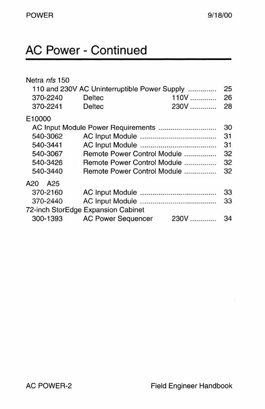
POWER 9/18/00
AC Power - Continued
Netra nfs 150 11 O and 230V AC Uninterruptible Power Supply .. . .. ... .. .. . . 25 370-2240 Del tee 11 OV . . . . . . . . . . . . . 26 370-2241 Deltec 230V . . . . . . . . . . . . . 28
E10000 AC Input Module Power Requirements ............................. 30 540-3062 AC Input Module .. . . .. .. .. . . .. . . .. ... ... . . .. .. .. .. .. .. 31 540-3441 AC Input Module ...................................... 31 540-3067 Remote Power Control Module .. .. .. .. .. .. .. .. 32 540-3426 Remote Power Control Module . ... . . . ... ... . . . 32 540-3440 Remote Power Control Module . . .. .. .. .. .. .. . . 32
A20 A25 370-2160 AC Input Module .. . . .. .. .. .. .. . ... ... ... .. .. .. .. .. .. .. 33 370-2440 AC input ivioduie . . . . .. .. .. . . .. .. .. . .. .... .. . .. .. .. .. .. 33
72-inch StorEdge Expansion Cabinet 300-1393 AC Power Sequencer 230V ............. 34
AC POWER-2 Field Engineer Handbook
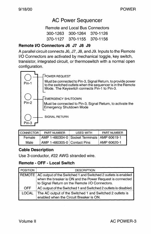
9/18/00
AC Power Sequencer Remote and Local Bus Connectors 300-1263 300-1264 370-1126
370-1127 370-1155 370-1156
POWER
Remote 1/0 Connectors J6 J7 JS J9 A parallel circuit connects J6, J7, JS, and J9. Inputs to the Remote 1/0 Connectors are activated by mechanical toggle, key switch, transistor, integrated circuit, or thermoswitch with a normal open configuration.
0 Pin-1
0 Pin-2
0 Pin-3
POWER REQUEST
Must be connected to Pin-3, Signal Return, to provide power to the switched outlets when the sequencer is in the Remote Mode. The Keyswitch connects Pin-1 to Pin-3.
EMERGENCY SHUTDOWN
Must be connected to Pin-3, Signal Return, to activate the Emergency Shutdown Mode
SIGNAL RETURN
CONNECTOR PART NUMBER USED WITH PART NUMBER
Female AMP 1-480304-0 Socket Terminals AMP 60619-1
Male AMP 1-480305-0 Contact Pins AMP 60620-1
Cable Description Use 3-conductor, #22 AWG stranded wire.
Remote - OFF - Local Switch
POSITION DESCRIPTION
REMOTE AC output of the Switched 1 and Switched 2 outlets is enabled when the breaker is ON and the Power Request is connected to Signal Return on the Remote 1/0 Connectors.
OFF AC output of the Switched 1 and Switched 2 outlets is disabled.
LOCAL The AC output of the Switched 1 and Switched 2 outlets is enabled when the Circuit Breaker is ON.
Volume II AC POWER-3
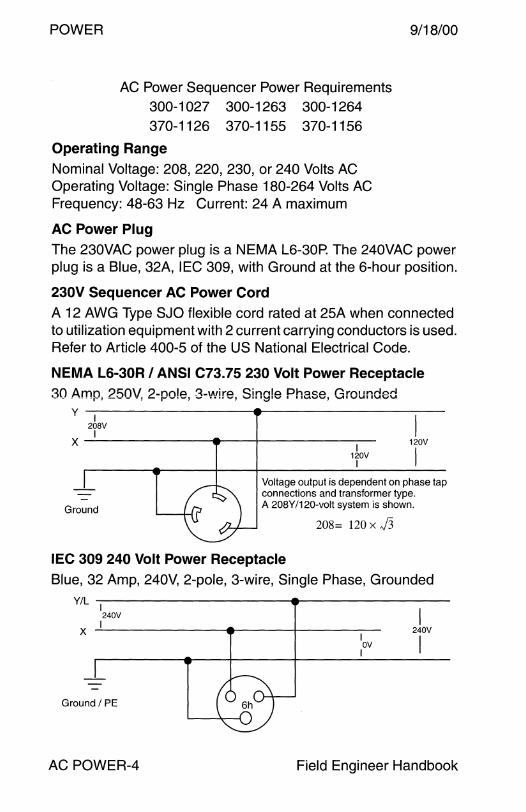
POWER
AC Power Sequencer Power Requirements 300-1 027 300-1263 300-1264 370-1126 370-1155 370-1156
Operating Range
Nominal Voltage: 208, 220, 230, or 240 Volts AC Operating Voltage: Single Phase 180-264 Volts AC Frequency: 48-63 Hz Current: 24 A maximum
AC Power Plug
9/18/00
The 230VAC power plug is a NEMA L6-30P. The 240VAC power plug is a Blue, 32A, IEC 309, with Ground at the 6-hour position.
230V Sequencer AC Power Cord
A 12 AWG Type SJO flexible cord rated at 25A when connected to utilization equipment with 2 current carrying conductors is used. Refer to Article 400-5 of the US National Electrical Code.
NEMA L6-30R I ANSI C73.75 230 Volt Power Receptacle
30 Amp; 250V, 2-po!e, 3-wire, Single Phase, Grounded y I
208V I X ~~~~~~~--~----'f--~~~~~I~
120V I
I 120V
I Voltage output is dependent on phase tap connections and transformer type.
Ground A 208Y/120-volt system is shown.
208= 120 x J3
IEC 309 240 Volt Power Receptacle
Blue, 32 Amp, 240V, 2-pole, 3-wire, Single Phase, Grounded
Y/L I 240V
x _!~~~~~~~---~~~+-~~~~ I OV I
I 240V
I
Ground I PE
AC POWER-4 Field Engineer Handbook

9/18/00
Outlet Side
230 Volt AC Power Sequencer 300-1027
Pulizzi Engineering PC874
370-1155 Pulizzi Engineering
PC874
POWER
J6~ J7~ NEMA6-15R-E:J f;J f;Jf;J c33JtJ GJCJ Js D
c31JtJ UNSWITCHED
250V/15A SWITCHED 1
250V/15A SWITCHED2
250V/15A
Control Side
ONe I REMOTE POWER CONTROL BUS
COVER
Notes
ON G) Q (j) OFF l!:::::!!:::!l
SWITCHED
•• 1 2
MAIN POWER OFF
J8
REMOTE CD LOCAL
30A/250V NEMA L6-30P plug
1. Requires AC outlet NEMA L6-30R, 30A, 250V.
J9
2. Any conversion to the Data Center Cabinet, including replacement of the AC Power Plug or AC Power Sequencer, voids all safety agency approvals.
3. The Switched 2 output of 370-1127 comes on after a 5-second delay. 4. The Switched 2 output of 370-1155 comes on after a 20-second delay.
References 1. Sun Full-Height Rack System Installation Manual, 800-1677. 2. Sun Rackmountable Fileservers Installation Manual, 800-1676. 3. Sun 900 Mbyte Disk Drive Installation Manual, 800-1036. 4. Sun 56-inch Data Center Cabinet and Data Center Expansion
Cabinet Installation Manual, 800-3242. 5. Sun 56-inch Expansion Cabinet Installation Manual, 800-5936-18. 6. Sun 56-inch Expansion Cabinet Service Manual, 800-6371-17.
Volume II AC POWER-5
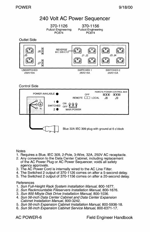
POWER
Outlet Side
240 Volt AC Power Sequencer 370-1126
Pulizzi Engineering PC874
370-1156 Pulizzi Engineering
PC874
9/18/00
~ J6~ REVERSE I~ ~ IEC320C13~ ~ ~~
J5
~ J7~ UNSWITCHED
250V/15A
Control Side
J1 J2
~~ SWITCHED 1
250V/15A
J3 J4
~~ SWITCHED2
250V/15A
REMOTE POWER CONTROL BUS POWER AVAILABLE • OFF
REMOTE CD LOCAL [U:!J ~
J8 J9
1 • ON Q (i) (i) SWITCHED OFF l!:::::!!:=:!l
2 • MAIN POWER
Blue 32A IEC 309 plug with ground at 6 o'clock
Notes 1. Requires a Blue, IEC 309, 2-Pole, 3-Wire, 32A, 250V AC receptacle. 2. Any conversion to the Data Center Cabinet, including replacement
of the AC Power Plug or AC Power Sequencer, voids all safety agency approvals.
3. The AC Power Cord is internally wired to the AC Line Filter. 4. The Switched 2 output of 370-1126 comes on after a 5-second delay. 5. The Switched 2 output of 370-1156 comes on after a 20-second delay.
References 1. Sun Full-Height Rack System Installation Manual, 800-1677. 2. Sun Rackmountable Fileservers Installation Manual, 800-1676. 3. Sun 900 Mbyte Disk Drive Installation Manual, 800-1036. 4. Sun 56-inch Data Center Cabinet and Data Center Expansion
Cabinet Installation Manual, 800-3242. 5. Sun 56-inch Expansion Cabinet Installation Manual, 800-5936-18. 6. Sun 56-inch Expansion Cabinet Service Manual, 800-6371-17.
AC POWER-6 Field Engineer Handbook
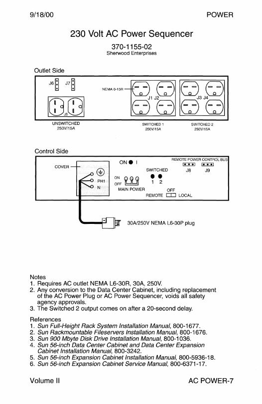
9/18/00
Outlet Side
230 Volt AC Power Sequencer 370-1155-02
Sherwood Enterprises
J6~ J7~
G3J5GJ
POWER
UNSWITCHED 250V/15A
SWITCHED 1 250V/15A
SWITCHED 2 250V/15A
Control Side
ONe I REMOTE POWER CONTROL BUS
COVER
Notes
ON G) (j) (j) OFF I!::::!!:::!]
SWITCHED
•• 1 2
MAIN POWER OFF
JS
REMOTE CJ:] LOCAL
30N250V NEMA L6-30P plug
1. Requires AC outlet NEMA L6-30R, 30A, 250V.
J9
2. Any conversion to the Data Center Cabinet, including replacement of the AC Power Plug or AC Power Sequencer, voids all safety agency approvals.
3. The Switched 2 output comes on after a 20-second delay.
References 1. Sun Full-Height Rack System Installation Manual, 800-1677. 2. Sun Rackmountable Fileservers Installation Manual, 800-1676. 3. Sun 900 Mbyte Disk Drive Installation Manual, 800-1036. 4. Sun 56-inch Data Center Cabinet and Data Center Expansion
Cabinet Installation Manual, 800-3242. 5. Sun 56-inch Expansion Cabinet Installation Manual, 800-5936-18. 6. Sun 56-inch Expansion Cabinet Service Manual, 800-6371-17.
Volume II AC POWER-7
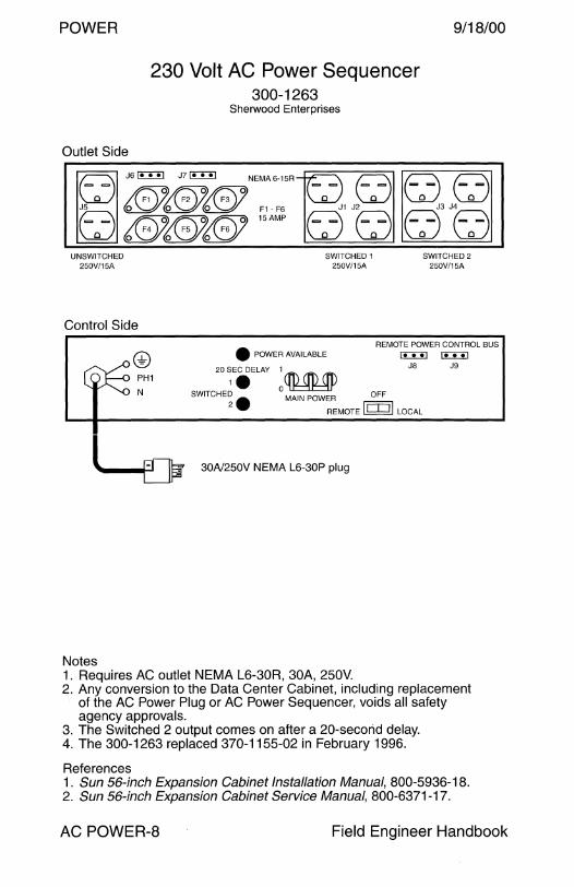
POWER
Outlet Side
230 Volt AC Power Sequencer 300-1263
Sherwood Enterprises
9/18/00
F2 F3 @ee ~ ""l!I!l "'"""' '"~"'°' rw. E:J c:Jt:J 0 0 F1 - F6
{@J{G)J{GJ 1sAMP fj1JtJ fj3JtJ
UNSWITCHED 250V/15A
Control Side
Notes
SWITCHED 1 250V/15A
• POWER AVAILABLE
20 SEC DELAY 1 1.
SWITCHED2 250V/15A
REMOTE POWER CONTROL BUS
~ J8 ~
J9
SWITCHED 2. oCfMM'.P MAIN POWER OFF
REMOTE I 1 I ii LOCAL
30N250V NEMA L6-30P plug
1. Requires AC outlet NEMA L6-30R, 30A, 250V. 2. Any conversion to the Data Center Cabinet, including replacement
of the AC Power Plug or AC Power Sequencer, voids all safety agency approvals.
3. The Switched 2 output comes on after a 20-secorid delay. 4. The 300-1263 replaced 370-1155-02 in February 1996.
References 1. Sun 56-inch Expansion Cabinet Installation Manual, 800-5936-18. 2. Sun 56-inch Expansion Cabinet Service Manual, 800-6371-17.
AC POWER-8 Field Engineer Handbook

9/18/00
Outlet Side
240 Volt AC Power Sequencer 370-1156-03
Sherwood Enterprises
POWER
rffi'i [£ITJ
~ J6 ~
J7 ~~ ~~ J5
~+ REVERSE IEC 320 C13
UNSWITCHED 250V/15A
Control Side
POWER AVAILABLE •
L
@ N
1• SWITCHED 2•
J1 J2
~~ SWITCHED 1
250V/15A
J3 J4
~~ SWITCHED2
250V/15A
REMOTE POWER CONTROL BUS OFF
REMOTE o::J LOCAL
ON G) (j) (j) OFF l!:::::!!:::!i
MAIN POWER
~ in:::!J JS J9
Blue 32A IEC 309 plug with ground at 6 o'clock
Notes 1. Requires a Blue, IEC 309, 2-Pole, 3-Wire, 32A, 250V AC receptacle. 2. Any conversion to the Data Center Cabinet, including replacement
of the AC Power Plug or AC Power Sequencer, voids all safety agency approvals.
3. The AC Power Cord is internally wired to the AC Line Filter. 4. The Switched 2 output comes on after a 20-second delay.
References 1. Sun Fu/I-Height Rack System Installation Manual, 800-1677. 2. Sun Rackmountable Fileservers Installation Manual, 800-1676. 3. Sun 900 Mbyte Disk Drive Installation Manual, 800-1036. 4. Sun 56-inch Data Center Cabinet and Data Center Expansion
Cabinet Installation Manual, 800-3242. 5. Sun 56-inch Expansion Cabinet Installation Manual, 800-5936-18. 6. Sun 56-inch Expansion Cabinet Service Manual, 800-6371-17.
Volume II AC POWER-9
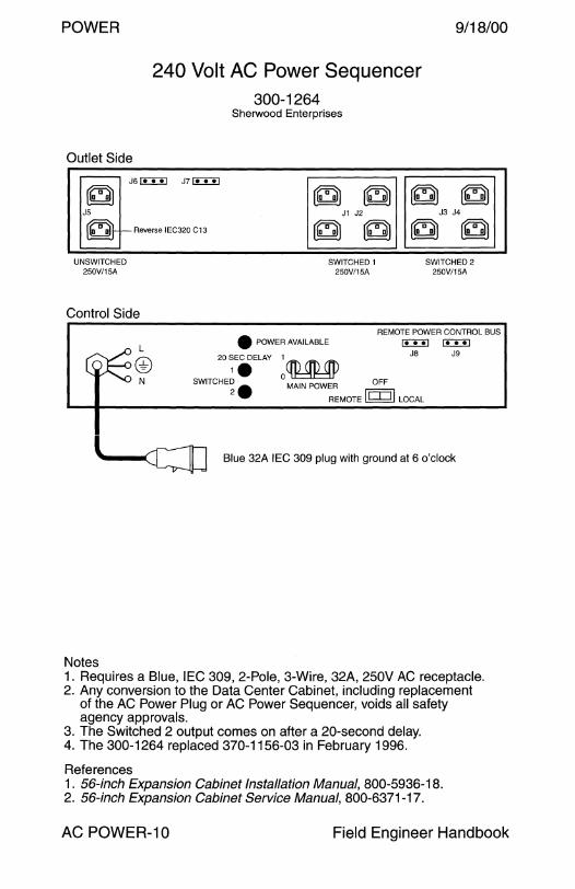
POWER
Outlet Side
240 Volt AC Power Sequencer 300-1264
Sherwood Enterprises
.------ J6 I:!:!:!:] J? C!::::!:!J
~ ~ ~ ~
9/18/00
~ JS J1 J2 J3 J4
~ f--Reverse IEC320 C13 ~ ~ ~ ~ UNSWITCHED
250V/15A SWITCHED 1
250V/15A SWITCHED2
250V/15A
Control Side REMOTE POWER CONTROL BUS
L
@ N
• POWER AVAILABLE l:!::TI] JS 20 SEC DELAY ,.
SWITCHED 2. 1
oCIMMP MAIN POWER OFF
REMOTE I! I lj LOCAL
~ J9
~ Blue 32A IEC 309 plug with ground at 6 o'clock
Notes 1. Requires a Blue, IEC 309, 2-Pole, 3-Wire, 32A, 250V AC receptacle. 2. Any conversion to the Data Center Cabinet, including replacement
of the AC Power Plug or AC Power Sequencer, voids all safety agency approvals.
3. The Switched 2 output comes on after a 20-second delay. 4. The 300-1264 replaced 370-1156-03 in February 1996.
References 1 . 56-inch Expansion Cabinet Installation Manual, 800-5936-18. 2. 56-inch Expansion Cabinet Service Manual, 800-6371-17.
AC POWER-10 Field Engineer Handbook

9/18/00 POWER
Option 964 AC Power Sequencer Operation
~nn A1v B2w B1w nn B4 ~ B2 ~
NEMA6-15R
Switch SW1
SS1000
~ SW3
SS10
1 2 3 4
sw1Q 3 1 2
sw2Q
IN
D D
OUT
Use SW1 to set the Slave Outputs when SW2 is set to 1.
Switch SW2
Use SW2 to set Switched=1, Remote=2, or Unswitched=3.
Switch SW3 Use SW3 to set the AC current detection level used when SW2 is set to Switched mode. Slave outputs are enabled when the AC current exceeds 200ma in the SS1 O position or 600ma in the SS1000 position.
SW1 SW2 MASTER-1 MASTER-2 SLAVE-1 SLAVE-2
LOAD LOAD OUTPUT OUTPUT
1 1 On x On On 1 1 Off x Off Off 2 1 On Off On Off 2 1 On On On On 2 1 Off On Off On 2 1 Off Off Off Off 3 1 On x On On 3 1 Off On On On 3 1 Off Off Off Off 4 1 On x On On 4 1 Off On Off On 4 1 Off Off Off Off
1234 2 N/A N/A x x 1234 3 N/A N/A On On
Volume II AC POWER-11
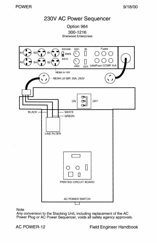
POWER
230V AC Power Sequencer Option 964 300-1216
Sherwood Enterprises
A1C8 B2~ B1~ ~s::~ 0 IN
D Fuses
000 000 A2~ B4~ B2~ SS
10 0
SW2 D
OUT LittelFuse CCMR 15A
BLACK
Note
NEMA 6-15R
NEMA L6-30P, 30A, 250V
WHITE
..J_....c:::r-- GREEN
LJ LINE FILTER
0 0 0 D D
PRINTED CIRCUIT BOARD
AC POWER SWITCH
9/18/00
Any conversion to the Stacking Unit, including replacement of the AC Power Plug or AC Power Sequencer, voids all safety agency approvals.
AC POWER-12 Field Engineer Handbook
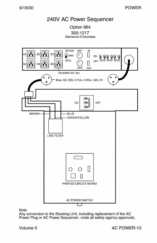
9/18/00
BROWN
Note
240V AC Power Sequencer Option 964 300-1217
Sherwood Enterprises
SW1 IN
0 DON~~~ 0 D OFF
SW2 OUT
REVERSE IEC 320
Blue, IEC 309, 2-Pole, 3-Wire, 32A, 6h
LINE FILTER
BLUE
GREEN/YELLOW
o o 0 D D
PRINTED CIRCUIT BOARD
AC POWER SWITCH
POWER
Any conversion to the Stacking Unit, including replacement of the AC Power Plug or AC Power Sequencer, voids all safety agency approvals.
Volume II AC POWER-13

POWER 9/18/00
AC Distribution Unit Power Requirements
Operating Range
SC2000 300-1099
SC2000E 300-1100
Nominal Voltage: 208, 220, 230, or 240 Volts AC Operating Voltage: Single Phase 180-264 Volts AC Frequency: 48-63 Hz Current: 24 A maximum
AC Power Plug
The 230VAC power plug is a NEMA L6-30P. The 240VAC power plug is a Blue, 32A, IEC 309, with Ground at the 6-hour position.
AC Power Cord
The 230VAC Power Sequencer uses a 12 AWG Type SJO flexible cord rated at 25A when connected to utilization equipment with 2 current carrying conductors. Refer to Article 400-5 of the US National Electrical Code.
NEMA L6-30R I ANSI C73.75 230 Volt Power Receptacle
30 Amp, 250V, 2-pole, 3-wire, Single Phase, Grounded
v ---·~----------------' I
208V
x-1------------+------~ I 120V
I
I 120V
Ground
I Voltage output is dependent on phase tap connections and transformer type.
A 208Y/120-volt system is shown.
208= 120 x J3
IEC 309 240 Volt Power Receptacle
32 Amp, 240V, 2-pole, 3-wire, Single Phase, Grounded
Y/L-1-------------------~ 240V I
X _I ---------1a-----;------ 240V
~v I
Ground I PE
AC POWER-14 Field Engineer Handbook
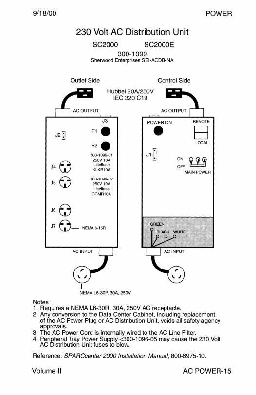
9/18/00 POWER
230 Volt AC Distribution Unit SC2000 SC2000E
300-1099 Sherwood Enterprises SEl-ACDB-NA
Outlet Side Control Side
Notes
J2~
J4 CJ J5 ~
J6 n \!.)
Hubbel 20N250V IEC 320 C19
J3 POWER ON
F1 • • F2 • 300-1099-01 J1 ~ 250V 10A Litteltuse KLKR10A
300-1099-02 250V 10A Litteltuse
CCMR10A
J7 ~- NEMA6-15R
NEMA L6-30P, 30A, 250V
REMOTE
B LOCAL
ON w OFF MAIN POWER
1. Requires a NEMA L6-30R, 30A, 250V AC receptacle. 2. Any conversion to the Data Center Cabinet, including replacement
of the AC Power Plug or AC Distribution Unit, voids all safety agency approvals.
3. The AC Power Cord is internally wired to the AC Line Filter. 4. Peripheral Tray Power Supply <300-1096-05 may cause the 230 Volt
AC Distribution Unit fuses to blow.
Reference: SPARCcenter 2000 Installation Manual, 800-6975-10.
Volume II AC POWER-15
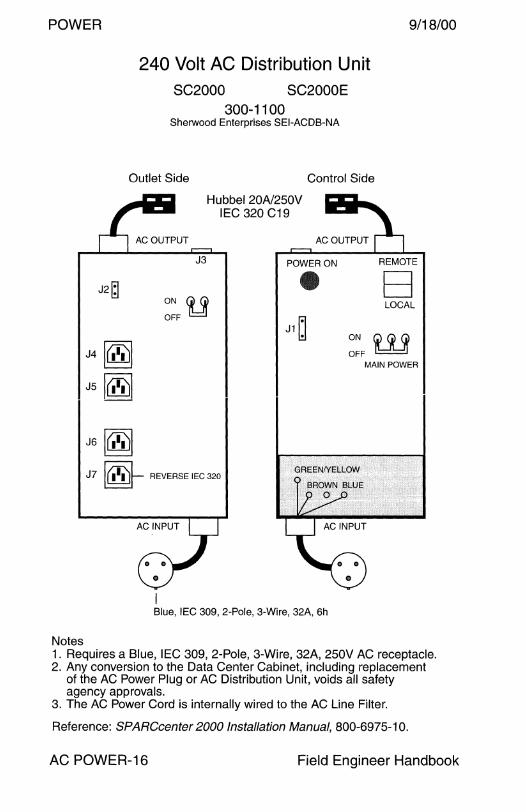
POWER 9/18/00
Notes
240 Volt AC Distribution Unit SC2000 SC2000E
300-1100 Sherwood Enterprises SEl-ACDB-NA
Outlet Side Control Side
J2~
J4 l(iii')I J5 l(DJI
J6 l(iii')I
Hubbel 20A/250V IEC 320 C19
J3
ON (j) (j) OFF I!::!]
POWER ON
J1 ~
J7 [@]--- REVERSE IEC 320
Blue, IEC 309, 2-Pole, 3-Wire, 32A, 6h
REMOTE
B LOCAL
ON w OFF MAIN POWER
1. Requires a Blue, IEC 309, 2-Pole, 3-Wire, 32A, 250V AC receptacle. 2. Any conversion to the Data Center Cabinet, including replacement
of the AC Power Plug or AC Distribution Unit, voids all safety agency approvals.
3. The AC Power Cord is internally wired to the AC Line Filter.
Reference: SPARCcenter 2000 Installation Manual, 800-6975-10.
AC POWER-16 Field Engineer Handbook

9/18/00 POWER
AC Power Sequencer Power Requirements E5000 E6000 E5500 E6500 E10000 Options 956 6513
300-1290 300-1403
Operating Range
Nominal Voltage: 208, 220, 230, or 240 Volts AC Operating Voltage: Single Phase 180-264 Volts AC Frequency: 48-63 Hz Current: 24 A maximum
AC Input Power Plug
U.S. power cord 530-2197 uses a NEMA L6-30P plug. International power cord 530-2266 uses a Blue, IEC 309, 2-Pole, 3-Wire, 32 Amp plug, with Ground at the 6-hour position.
AC Output Connectors
Connector J1 has an IEC 320 C19 receptacle. Connectors J2 and J5 - J12 have 3-circuit AMP Mate-N-Lok receptacles.
NEMA L6-30R I ANSI C73.75 230 Volt Power Receptacle
30 Amp, 250V, 2-pole, 3-wire, Single Phase, Grounded
y I 208V
x~I~~~~~~--~-+-~~~~~~ I
120V I
I 120V
I
Ground Voltage output is dependent on phase tap connections and transformer type. A 208Y/120-volt system is shown.
208= 120 x J3
IEC 309 240 Volt Power Receptacle
32 Amp, 240V, 2-pole, 3-wire, Single Phase, Grounded
Y/L 1 240V
x ~l~~~~~~----<a-~~-+~~~~-1
OV I
Ground I PE
I 240V
I
Volume II AC POWER-17
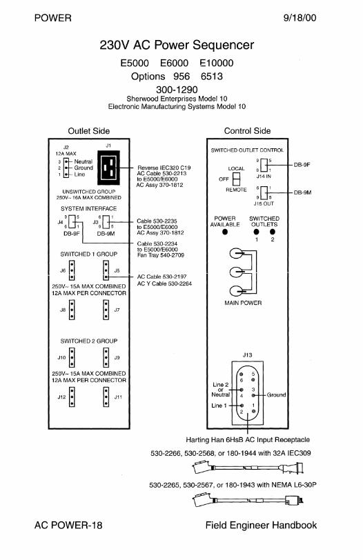
POWER 9/18/00
230V AC Power Sequencer E5000 E6000 E10000
Options 956 6513 300-1290
Sherwood Enterprises Model 1 O Electronic Manufacturing Systems Model 10
Outlet Side
J2 12A MAX
s ~Neutral 2 Ground 1 Line
J1
UNSWITCHED GROUP 250V- 16A MAX COMBINED
SYSTEM INTERFACE
9 J4
6
6 J3
9
DB-9M
Reverse IEC320 C19 AC Cable 530-2213 to E5000/E6000 AC Assy 370-1812
Cable 530-2235 to E5000/E6000 AC Assy 370-1812
~----1- Cable 530-2234
SWITCHED 1 GROUP to E5000/E6000 Fan Tray 540-2709
J6 ~ ~ J5 l!J ---+- AC Cable 530-2197
250V- 15A MAX COMBINED ACY Cable 530-2264
12A MAX PER CONNECTOR
SWITCHED 2 GROUP
J10 ~ ~ J9
250V-15A MAX COMBINED 12A MAX PER CONNECTOR
J12 ~ ~ J11
Control Side
SWITCHED OUTLET CONTROL
LOCAL
OFF B REMOTE
POWER AVAILABLE
•
+----+- DB-9F 6 1
J14 IN
-+---+-DB-9M 9 5
J15 OUT
SWITCHED OUTLETS • • 2
MAIN POWER
J13
@
6 @
Line 2 or
Neutral Ground
Line 1 <ID
Harting Han 6HsB AC Input Receptacle
530-2266, 530-2568, or 180-1944 with 32A IEC309
~ 530-2265, 530-2567, or 180-1943 with NEMA L6-30P
AC POWER-18 Field Engineer Handbook

9/18/00 POWER
300-1290
J3 Remote Power Control J4 Rack Fan Interface
PIN DESCRIPTION PIN DESCRIPTION
1 Expansion Rack Fan Fail 1 Rack Fan Fail
2 Expansion Rack Fan Fail 2 Ground Return 3 Expansion Rack Fan Fail
3 +5V Power On Control 4 Not used 4 Remote In+ 5 Not used
Keyswitch Closure+
5 Remote In Keyswitch 6 Expansion Rack Fan Fail
Return Closure- 7 Not used
6 EPO+ Switch Closure+ 8 Not used 7 Not used
8 +5V Return 9 Expansion Rack Present In
9 EPO- Switch Closure-
J14 Remote In J15 Remote Out
PIN DESCRIPTION PIN DESCRIPTION
1 Not used 1 Not used
2 Not used 2 Not used
3 Expansion Rack Fan Fail 3 Expansion Rack Fan Fail In Out to Master from Slave
4 Remote In+ Used as Slave 4 Relay N.O. Remote Out
5 Remote In- 5 Relay Com. Remote Out
6 Expansion Rack Fan Fail 6 Expansion Rack Fan Fail Return Return
7 Not used 7 Not used
8 Not used 8 Not used
9 Expansion Rack Present 9 Expansion Rack Present In Out Connected to Pin-6
Volume II AC POWER-19

POWER
230V AC Power Sequencer E5000 E6000 E5500 E6500 E10000 Options 956 6513 9610 9615 9620
300-1403 Electronic Manufacturing Systems Model 10
Outlet Side Control Side
J2 12A MAX
J1 SWITCHED OUTLET CONTROL
9/18/00
2 Ground a~ Neutral
Reverse IEC320 C19 AC Cable 530-2213 to E5000/E6000
LOCAL
OFF E3 REMOTE
-t---t-DB-9F
1 Line
UNSWITCHED GROUP 250V-16A MAX COMBINED
SYSTEM INTERFACE 9
J4 6
6 J3
9
DB-9M
AC Assy 370-1812
Cable 530-2235 to E5000/E6000 AC Assy 370-1812
'------I- Cable 530-2234
SWITCHED 1 GROUP
J6~ ~JS
to E5000/E6000 Fan Tray 540-2709
l!J 1*---11- AC Cable 530-2197
250V- 15A MAX COMBINED ACY Cable 530-2264
12A MAX PER CONNECTOR
JS~ ~ J7
SWITCHED 2 GROUP
J10 ~ ~ J9
250V- 15A MAX COMBINED 12A MAX PER CONNECTOR
J12 ~ ~ J11
POWER AVAILABLE
•
6 1
J14 IN
+---o-DB-9M 9 5
J15 OUT
SWITCHED OUTLETS • • 2
rn MAIN POWER
J13
® 6 ®
Line 2 or
Neutral 4 Ground
Line 1 2 ®
Harting Han 6HsB AC Input Receptacle
530-2568 or 180-1944 with 32A IEC309
530-2567or180-1943 with NEMA L6-30P
AC POWER-20 Field Engineer Handbook

9/18/00 POWER
300-1403
J3 Remote Power Control J4 Rack Fan Interface
PIN DESCRIPTION PIN DESCRIPTION
1 Expansion Rack Fan Fail 1 Rack Fan Fail
2 Expansion Rack Fan Fail 2 Ground Return 3 Expansion Rack Fan Fail
3 +5V Power On Control 4 Not used 4 Remote In+ 5 Not used
Keyswitch Closure+
5 Remote In Keyswitch 6 Expansion Rack Fan Fail
Return Closure- 7 Not used
6 EPO+ Switch Closure+ 8 Not used 7 Not used
8 +5V Return 9 Expansion Rack Present In
9 EPO- Switch Closure-
J14 Remote In J 15 Remote Out
PIN DESCRIPTION PIN DESCRIPTION
1 Not used 1 Not used
2 Not used 2 Not used
3 Expansion Rack Fan Fail 3 Expansion Rack Fan Fail In Out to Master from Slave
4 Remote In+ Used as Slave 4 Relay N.O. Remote Out
5 Remote In- 5 Relay Com. Remote Out
6 Expansion Rack Fan Fail 6 Expansion Rack Fan Fail Return Return
7 Not used 7 Not used
8 Not used 8 Not used
9 Expansion Rack Present 9 Expansion Rack Present In Out Connected to Pin-6
Notes 1. Option 9626 is required when a second AC Power Sequencer, Option
9620, is installed in the front of the E5500 and E6500 cabinet. 2. Option 9626 includes mounting bracket 340-5205.
Volume II AC POWER-21

POWER
110/230V AC Input/Fan Assembly E4000 E4500
370-1811
Front View
IEC320 C14 DB-9F
--1--4-----ll-- Remote Power Control '------' Not used by E4000
= =
=
Rear View
@@
Left Side View
9/18/00
AC POWER-22 Field Engineer Handbook

9/18/00
Front View
230V AC Input/Fan Assembly E5000 E6000 E5500 E6500
370-1812
DB-9F
--+-~----If-- Remote Power Control 8 l-c:..:=-' Cable 530-2213 to AC ,:":,, :, Lill] Powec Soq"'oooc
Rear View
© ©
Left Side View
POWER
Volume II AC POWER-23

POWER
Danish 230V AC Input/Fan Assembly E4000V5 E4500V5
370-2364
Front View
DB-9F IEC320 C14
-++----1~ Remote Power Control + L__.::;:.___J Not used by E4000V5
= =
=
Rear View
© ©
Left Side View
Notes 1. Use AC Power cord 530-2301, Option X389L. 2. Power cord 530-2301 requires a 16A IEC309 receptacle.
9/18/00
AC POWER-24 Field Engineer Handbook

9/18/00 POWER
110 and 230V AC Uninterruptible Power Supply Netra nfs 150
370-2240 370-2241
Front Panel Display
I- Red LEDs
0- Green LEDs
Line Input High Overload
100% Load 1------t------ Battery Level LEDs
Line OK 75% Load LEDs turn Off from
Line Input Low
,-(}
50% Load
<25% Load
~--- Low Battery
®@@
top to bottom when battery is discharging
LEDs turn On from bottom to top when battery is charging
Site warning Ground fault or reversed neutral
RS-232 Activity '"----+------ Potential battery
failure detected Alarm
----~---.
Silence/Reset Switch .... - -- - - - - -- - ..
Backup Life 1. Approximately 5 to 10 minutes of backup is available at full load. 2. Approximately 10 to 30 minutes of backup is available at partial load.
Battery Recharging 1. Automatic recharging occurs after a power failure when the On/Off switch
is in the ON position. 2. Complete recharging can take up to 24 hours when the battery is used
for a long period of time. 3. Most charging takes less than 8 hours.
Storing 1. Turn the On/Off switch to the OFF position. 2. Recharge the battery every 6 months. 3. Charging takes 8 to 12 hours.
Volume II AC POWER-25

POWER 9/18/00
11 OVolt AC Un interruptible Power Supply Netra nfs 150
Front View
ON
0
0 0 0 0 0
0 0 0 0 0
0 0 0 r(J: t3 ~
®@@ 0 0
:::~::
AC POWER-26
370-2240 Deltec PRA600a-SM
Rear View
AC Outputs
Reverse IEC320 C13
B Input 120VAC 5.5A 60Hz
Output 120VAC 5.0A 60Hz
600VA/520W
B B On Bl
UPS
B Off 0
AC Input 18 IEC320-C14
l~I ~~1 Off On
D Fuse+ Spare Comm Port
Field Engineer Handbook

9/18/00
SWITCH SETTING
1 Off
2 Off
1 On
2 Off
1 Off
2 On
1 On*
2 On*
3 On*
3 Off
4 On
4 Off*
5 On
5 Off*
6 On
6 Off*
7 On*
7 Off
8 On
8 Off*
Notes
370-2240
Switch Settings
DESCRIPTION
UPS configuration 120V nominal +/-20%
UPS configuration 127V nominal +/-20%
UPS configuration 11 OV nominal +/-20%
UPS configuration 120V nominal +/-25% extended voltage range
Disable site warning alarm
Enable site warning alarm
Approximately 5 minutes backup before low battery alarm
Approximately 2 minutes backup after low battery alarm
Enable <5% load auto shutdown
Enable <5% load auto shutdown after 5 minutes on battery
Conditional shutdown delay 180 sec
Conditional shutdown delay 5 sec
Disable AC input failure alarm
Enable AC input failure alarm
Frequency selection 50Hz
Frequency selection 60Hz
1. The Sun default switch settings are indicated by the * symbol.
POWER
2. The manufacturer's default switch settings are all switches OFF. 3. Switch setting changes made while the UPS is running, do not
take effect until the UPS power is cycled.
Volume II AC POWER-27

POWER 9/18/00
230Volt AC Uninterruptible Power Supply Netra nfs 150
Front View
ON
0
0 0 0 0 0
0 0 0 0 0
0 0 0 ,(]: 0 g
®@@ 0 0 0 ---~---.
, __ '<:_::'?'. __ '
AC POWER-28
370-2241 Deltec PRA600i-SM
Rear View
AC Outputs
Reverse IEC320 C13 ~----~
[Input 230VAC 50Hz
Output 230VAC 2.6A 50Hz 600VA/520W
On D~PS ortOo
AC Input 18 IEC320-C14 ;
ii (.D)i~I 1~1 ~ Offl!:!!J6n
ll63A250VJI D Fuse Jspare
Comm Port
Field Engineer Handbook
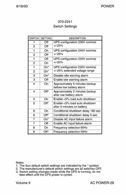
9/18/00
SWITCH SETTING
1 Off
2 Off
1 On
2 Off
1 Off
2 On
1 On*
2 On*
3 On*
3 Off
4 On
4 Off*
5 On
5 Off*
6 On
6 Off*
7 On*
7 Off
8 On
8 Off*
Notes
370-2241
Switch Settings
DESCRIPTION
UPS configuration 230V nominal +/-20%
UPS configuration 240V nominal +/-20%
UPS configuration 220V nominal +/-20%
UPS configuration 230V nominal +/-25% extended voltage range
Disable site warning alarm
Enable site warning alarm
Approximately 5 minutes backup before low battery alarm
Approximately 2 minutes backup after low battery alarm
Enable <5% load auto shutdown
Enable <5% load auto shutdown after 5 minutes on battery
Conditional shutdown delay 180 sec
Conditional shutdown delay 5 sec
Disable AC input failure alarm
Enable AC input failure alarm
Frequency selection 60Hz
Frequency selection 50Hz
1. The Sun default switch settings are indicated by the * symbol.
POWER
2. The manufacturer's default switch settings are all switches OFF. 3. Switch setting changes made while the UPS is running, do not
take effect until the UPS power is cycled.
Volume II AC POWER-29
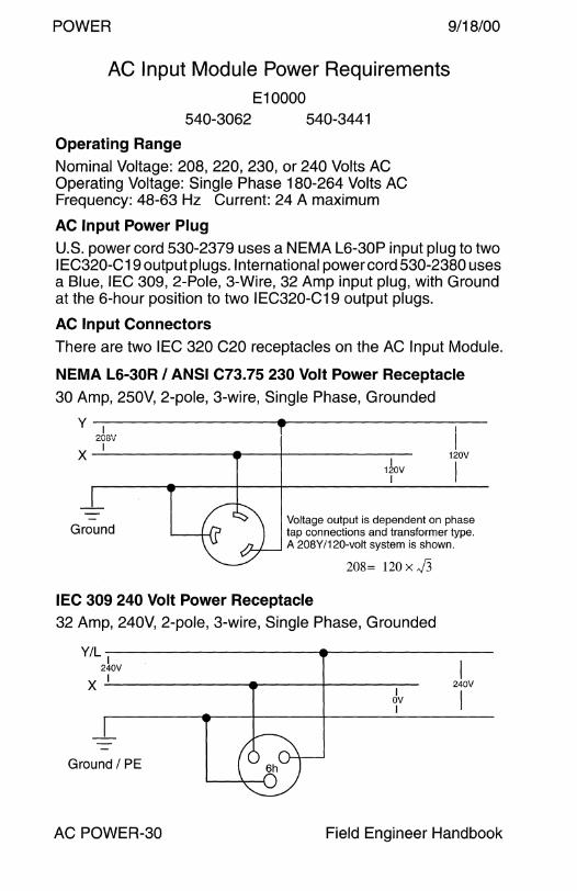
POWER 9/18/00
AC Input Module Power Requirements E10000
540-3062 540-3441
Operating Range Nominal Voltage: 208, 220, 230, or 240 Volts AC Operating Voltage: Single Phase 180-264 Volts AC Frequency: 48-63 Hz Current: 24 A maximum
AC Input Power Plug U.S. power cord 530-2379 uses a NEMA L6-30P input plug to two IEC320-C19 output plugs. International power cord 530-2380 uses a Blue, IEC 309, 2-Pole, 3-Wire, 32 Amp input plug, with Ground at the 6-hour position to two IEC320-C19 output plugs.
AC Input Connectors
There are two IEC 320 C20 receptacles on the AC Input Module.
NEMA L6-30R I ANSI C73.75 230 Volt Power Receptacle 30 Amp, 250V, 2-pole, 3-wire, Single Phase, Grounded
y I 208V
I
x-' ------------+---~--~ I
120V I
I 120V
Ground
I
Voltage output is dependent on phase tap connections and transformer type. A 208Y/120-volt system is shown.
208= 120 x J3
IEC 309 240 Volt Power Receptacle 32 Amp, 240V, 2-pole, 3-wire, Single Phase, Grounded
Y/L-1 -------------------~ 240V I
X -'-I-----------<----+----- 240V
~v I
Ground I PE
AC POWER-30 Field Engineer Handbook
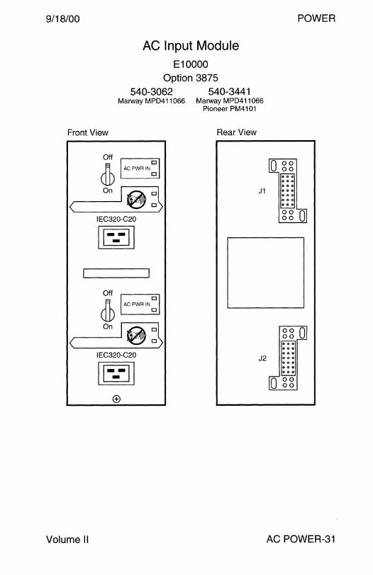
9/18/00
AC Input Module E10000
Option 3875 540-3062 540-3441
Marway MPD411066 Marway MPD411066 Pioneer PM4101
Front View Rear View
Volume II
Off D Ji ACPWRIN
(jJ) ~D
IEC320-C20
[0
Off
@ D
ACPWR IN D
IEC320-C20
[0
J1
J2
0 0 0 0 0 0
POWER
AC POWER-31
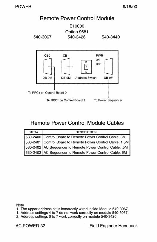
POWER 9/18/00
Note
Remote Power Control Module E10000
540-3067 Option 9681
540-3426 540-3440
CBO ,-----+--
.___ DB-9M
PWR CB1 .---1
OFF ON 0 DB-9M Address Switch DB-9F
To RPCx on Control Board 0
To RPCx on Control Board 1 To Power Sequencer
Remote Power Control Module Cables
PART# DESCRIPTION
530-2400 Control Board to Remote Power Control Cable, 3M
530-2401 Control Board to Remote Power Control Cable, 1.5M
530-2402 AC Sequencer to Remote Power Control Cable, .SM
530-2403 AC Sequencer to Remote Power Control Cable, 6M
1. The upper address bit is incorrectly wired inside Module 540-3067. 1. Address settings 4 to 7 do not work correctly on module 540-3067. 2. Address settings O to 7 work correctly on module 540-3426.
AC POWER-32 Field Engineer Handbook
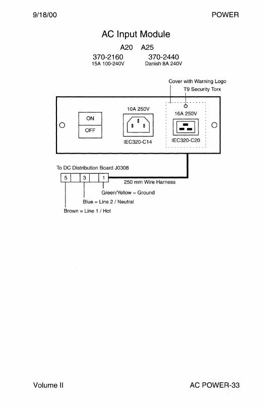
9/18/00
0
AC Input Module A20 A25
370-2160 370-2440 15A 100-240V Danish 8A 240V
POWER
Cover with Warning Logo
0 ~
10A 250V
IEC320-C14
J lg Security Torx
J --i-----: 16A 250V :
~jo IEC320-C20
To DC Distribution Board J0308
[ 5 I } 3 I } 1 250 mm Wire Harness
I breenNellow = Ground
Blue = Line 2 I Neutral
Brown = Line 1 I Hot
Volume II AC POWER-33
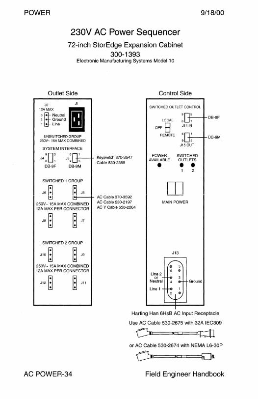
POWER 9/18/00
230V AC Power Sequencer 72-inch StorEdge Expansion Cabinet
300-1393 Electronic Manufacturing Systems Model 1 O
Outlet Side
J2 J1
1 !A~MAXNeutral I 2 Ground 1 Line
UNSWITCHED GROUP 250V-16A MAX COMBINED
SYSTEM INTERFACE
905 J4 6 1
DB-9F
6 J3
9
DB-9M
SWITCHED 1 GROUP
J6 ~ ~ J5
Keyswitch 370-3547 Cable 530-2369
l!J __ __,_ AC Cable 370-3592
250V-15A MAX COMBINED AC Cable 530-2197 12A MAX PER CONNECTOR ACY Cable 530-2264
JS~ ~ J?
SWITCHED 2 GROUP
J10 ~ ~ J9
250V-15A MAX COMBINED 12A MAX PER CONNECTOR
J12 ~ ~ J11
Control Side
SWITCHED OUTLET CONTROL
LOCAL
OFF B REMOTE
POWER AVAILABLE •
+-----+- DB-9F 6 1
J14 IN
+---+-DB-9M 9 5
J15 OUT
SWITCHED OUTLETS • • 2
m MAIN POWER
J13
@
6 @
Line 2 or
Neutral Ground
Line 1 1 411
Harting Han 6HsB AC Input Receptacle
Use AC Cable 530-2675 with 32A IEC309
or AC Cable 530-2674 with NEMA L6-30P
AC POWER-34 Field Engineer Handbook
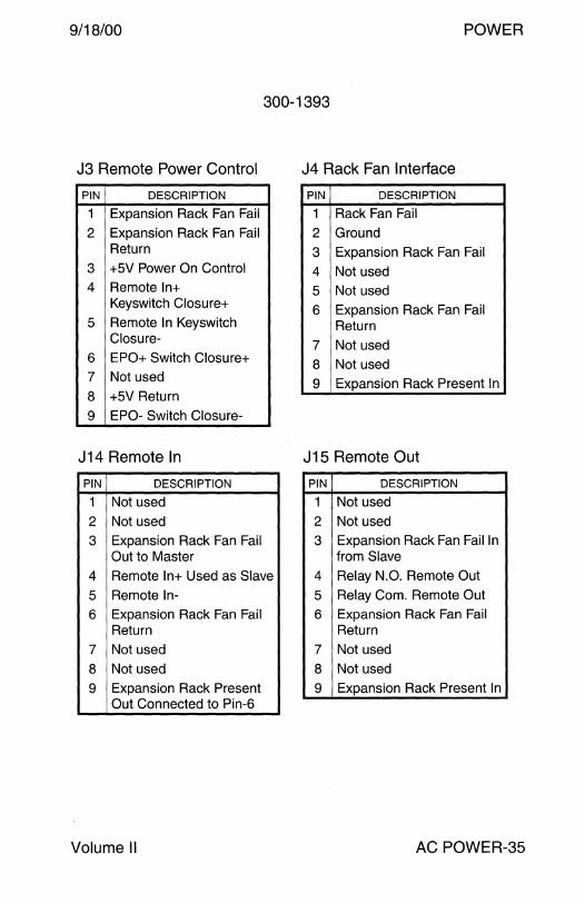
9/18/00 POWER
300-1393
J3 Remote Power Control J4 Rack Fan Interface
PIN DESCRIPTION PIN DESCRIPTION
1 Expansion Rack Fan Fail 1 Rack Fan Fail
2 Expansion Rack Fan Fail 2 Ground Return 3 Expansion Rack Fan Fail
3 +5V Power On Control 4 Not used 4 Remote In+ 5 Not used
Keyswitch Closure+
5 Remote In Keyswitch 6 Expansion Rack Fan Fail
Return Closure- 7 Not used
6 EPO+ Switch Closure+ 8 Not used 7 Not used
8 +5V Return 9 Expansion Rack Present In
9 EPO- Switch Closure-
J14 Remote In J 15 Remote Out
PIN DESCRIPTION PIN DESCRIPTION
1 Not used 1 Not used
2 Not used 2 Not used
3 Expansion Rack Fan Fail 3 Expansion Rack Fan Fail In Out to Master from Slave
4 Remote In+ Used as Slave 4 Relay N.O. Remote Out
5 Remote In- 5 Relay Com. Remote Out
6 Expansion Rack Fan Fail 6 Expansion Rack Fan Fail Return Return
7 Not used 7 Not used
8 Not used 8 Not used
9 Expansion Rack Present 9 Expansion Rack Present In Out Connected to Pin-6
Volume II AC POWER-35

This page intentionally left blank.

PARTS BREAKDOWN
DC POWER

9/18/00
DC Power
Power Supplies 300-1037 Sony 35Watts ............... 4 300-1073 Fuji 2410Watts ............... 5 300-1080 Sony 60Watts ............... 6 300-1090 Sony 35Watts ............... 7 300-1096 Zytec 269Watts ............... 8 300-1312 Zytec 269Watts ............... 8 300-1098 Zytec 440Watts ............... 9 540-2465 Zytec 440Watts ............... 9 540-2981 Zytec 440Watts ............... 9 300-1103 Zytec 650Watts ............... 10 300-1105 Sony 44Watts ............... 11 300-1215 FOK 150Watts ............... 12 300-1279 FOK 150Watts ............... 12 300-1257 Sony 50Watts ............... 13 300-1258 Fuji 2410Watts ............... 14 300-1260 FOK 300Watts ............... 15 300-1444 FOK 300Watts ............... 15 300-1281 Fuji 2410Watts ............... 16 300-1282 FOK 30Watts ............... 17 540-2674 FOK 30Watts ............... 17 540-2694 FOK 30Watts ............... 17 540-2866 FOK 30Watts ............... 17 540-3004 FOK 30Watts ............... 17 300-1283 Sony 185Watts ............... 18 300-1286 Fuji 2410Watts ............... 19 300-1295 Zytec 310Watts ............... 20 300-1301 FOK 184Watts ............... 21 300-1302 Zytec 560Watts ............... 22 300-1307 FOK 184Watts ............... 23 300-1400 FOK 184Watts ............... 23 300-1248 Sony 180Watts ............... 24 300-1308 Sony 180Watts ............... 24
Field Engineer Handbook - Volume II
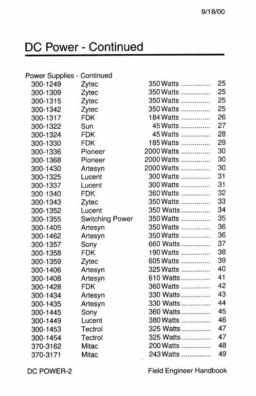
9/18/00
DC Power - Continued
Power Supplies - Continued 300-1249 Zytec 350Watts ............... 25 300-1309 Zytec 350Watts ............... 25 300-1315 Zytec 350Watts ............... 25 300-1342 Zytec 350Watts ............... 25 300-1317 FOK 184 Watts ............... 26 300-1322 Sun 45Watts ............... 27 300-1324 FOK 45Watts ............... 28 300-1330 FOK 185Watts ............... 29 300-1336 Pioneer 2000Watts ............... 30 300-1368 Pioneer 2000Watts ............... 30 300-1430 Arte syn 2000Watts ............... 30 300-1325 Lucent 300Watts ............... 31 300-1337 Lucent 300Watts ............... 31 ~()(\_ 1 ~A() FDK l)C.n 1111~ .. ~ ,...,., VVV IV""TV ..ivv v v au;:, ............... .:JC.
300-1343 Zytec 350Watts ............... 33 300-1352 Lucent 350 Watts ............... 34 300-1355 Switching Power 350Watts ............... 35 300-1405 Artesyn 350Watts ............... 36 300-1462 Artesyn 350Watts ............... 36 300-1357 Sony 660 Watts ............... 37
300-1358 FOK 190Watts ............... 38
300-1359 Zytec 605Watts ............... 39 300-1406 Artesyn 325Watts ............... 40
300-1408 Artesyn 610 Watts ............... 41
300-1428 FOK 360Watts ............... 42
300-1434 Arte syn 330 Watts ............... 43 300-1435 Arte syn 330 Watts ............... 44
300-1445 Sony 360 Watts ............... 45 300-1449 Lucent 380Watts ............... 46
300-1453 Tectrol 325 Watts ............... 47
300-1454 Tectrol 325 Watts ............... 47 370-3162 Mitac 200Watts ............... 48 370-3171 Mitac 243Watts ............... 49
DC POWER-2 Field Engineer Handbook
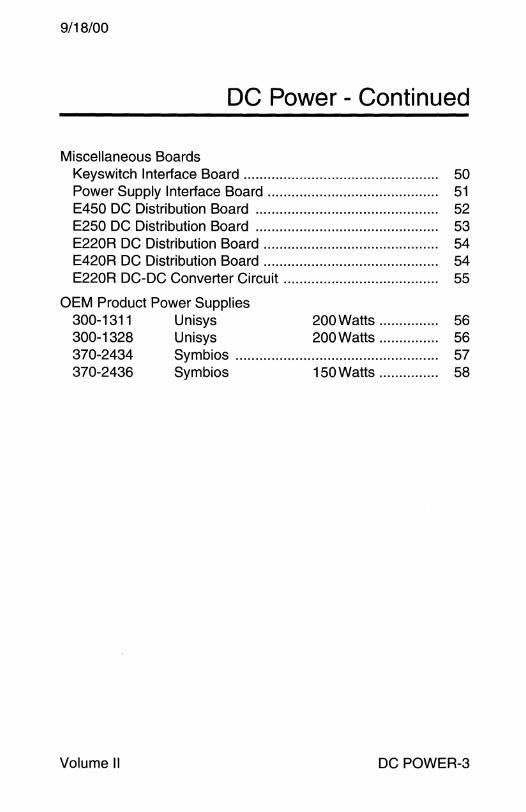
9/18/00
DC Power - Continued
Miscellaneous Boards Key switch Interface Board . . . . . . . . . . . . . . . . . . . . . . . . . . . . . . . . . . . . . . . . . . . . . . . . . 50 Power Supply Interface Board........................................... 51 E450 DC Distribution Board . . . . . . . . . . . . . . . . . . . . . . . . . . . . . . . . . . . . . . . . . . . . . . 52 E250 DC Distribution Board . . . . . . . . . . . . . . . . . . . . . . . . . . . . . . . . . . . . . . . . . . . . . . 53 E220R DC Distribution Board . . . . . . . . . . . . . . . . . . . . . . . . . . . . . . . . . . . . . . . . . . . . 54 E420R DC Distribution Board . . . . . . . . . . . . . . . . . . . . . . . . . . . . . . . . . . . . . . . . . . . . 54 E220R DC-DC Converter Circuit . .. .. .. .. . .. ... ........ ... .. .. .. .. .. ... 55
OEM Product Power Supplies 300-1311 Unisys 200Watts ............... 56 300-1328 Unisys 200 Watts . .. .. .. .. ...... 56 370-2434 Symbios . . . . . . . . . . . . . . . . . . . . . . . . . . . . . . . . . . . . . . . . . . . . . . . . . . . 57 370-2436 Symbios 150 Watts . . . . . . . . . . . . . . . 58
Volume II DC POWER-3
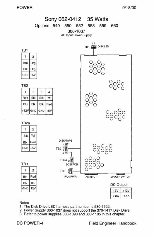
POWER 9/18/00
TB1
1
Brn
Blk
GND
TB2
1
Red
Blu
+12V
TB2a
1
Blk
Blk
GND
TB3
1
Blk
Blk
GND
Notes
Sony 062-0412 35 Watts Options 540 550 552 558 559 660
2
Org
Org
+5V
2 3
Blk Blk
Blk Blk
GND GND
2
Yel
Red
+5V
2
Red
Blu
12V
4
Yel
Red
+5V
300-1037 AC Input Power Supply
DISK!TAPE
1
TB2 2 ~ 1----1 3 4
TB2a ~ m SCSI PCB
TB3 1 IQJ] 21Qlj
FAN PWR AC INPUT
DISK LED
ON/OFF SWITCH
DC Output
+5V +12V
2.0A 1.5A
1. The Disk Drive LED harness part number is 530-1522. 2. Power Supply 300-1037 does not support the 370-1417 Disk Drive. 3. Refer to power supplies 300-1090 and 300-1105 in this chapter.
DC POWER-4 Field Engineer Handbook
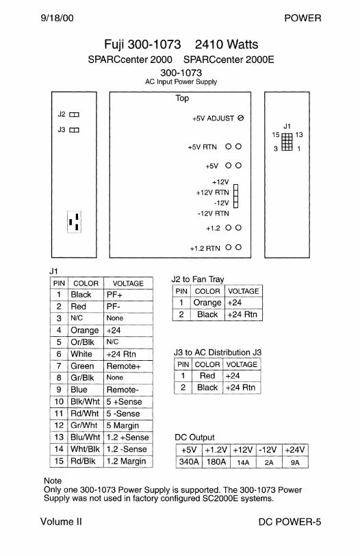
9/18/00 POWER
Fuji 300-1073 241 O Watts SPARCcenter 2000 SPARCcenter 2000E
300-1073
J2 rn
J3 rn
J1 PIN
1
2
3 4
5 6 7 8
9 10 11 12 13
14
15
Note
I. •I L!J
COLOR
Black Red N/C
Orange Or/Blk
White Green Gr/Blk Blue
Blk/Wht
Rd/Wht Gr/Wht
Blu/Wht Wht/Blk
Rd/Blk
AC Input Power Supply
VOLTAGE
PF+ PF-None
+24 N/C
+24 Rtn
Remote+ None
Remote-
5 +Sense 5 -Sense 5 Margin
1.2 +Sense 1.2 -Sense
1.2 Margin
Top
+5V ADJUST 0
+5V RTN 0 0
+5V 0 0
+12V
+12V RTN B -12V B
-12V RTN
+1.2 0 0
+1.2 RTN 0 0
J2 to Fan Tray PIN COLOR VOLTAGE
1 Orange +24 2 Black +24 Rtn
J3 to AC Distribution J3 PIN COLOR VOLTAGE
1 Red +24 2 Black +24 Rtn
DC Output
J1 151E3 13
3 t1jj 1
+5V +1.2V +12V -12V +24V
340A 180A 14A 2A 9A
Only one 300-1073 Power Supply is supported. The 300-1073 Power Supply was not used in factory configured SC2000E systems.
Volume II DC POWER-5
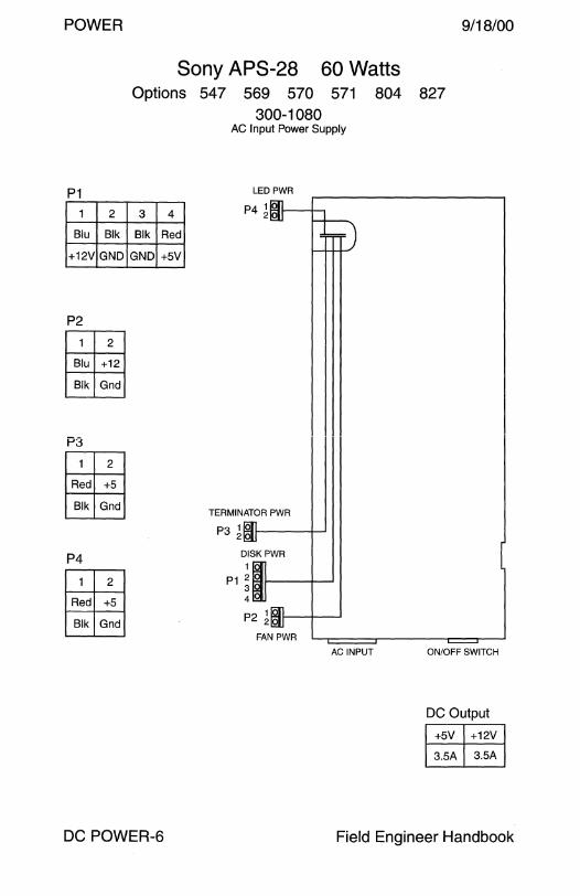
POWER 9/18/00
P1
1 2
Blu Blk
+12V GND
P2
1 2
Blu +12
Blk Gnd
P3
1 2
Red +5
Blk Gnd
P4
1 2
Red +5
Blk Gnd
Sony APS-28 60 Watts Options 547 569 570 571 804 827
300-1080
3 4
Blk Red
GND +5V
AC Input Power Supply
LED PWR
P41
TERMINATOR PWR
P3 1 o l------1-J
DISKPWR
1
P1 2 3 4
P2 1~ol1----1--.J
FAN PWR
AC INPUT ON/OFF SWITCH
DC Output
+5V +12V
3.5A 3.5A
DC POWER-6 Field Engineer Handbook

9/18/00
TB1
1 2
Blk Org
GND +5V
TB2
1 2
Blu Blk
+12V GND
TB2a
1 2
Blk Red
GND +5V
TB3
1 2
Blk Blu
GND 12V
Notes
POWER
Sony 062-0412 35 Watts Options
3 4
Blk Red
GND +5V
540 550 552 558 300-1090
AC Input Power Supply
DISK/TAPE
1
TB2 2 3 4
TB2a 1 Ii! SCSI PCB
TB3 11§11 FAN PWR
1 2
TB1
AC INPUT
559 660
DISK LED
ON/OFF SWITCH
DC Output
+5V +12V
2.0A 1.5A
1. The Disk Drive LED harness part number is 530-1522. 2. Disk Drive 370-1417 requires Power Supply 300-1090-02.
Volume II DC POWER-7
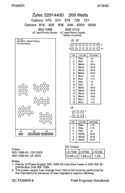
POWER 9/18/00
Zytec 22914400 269 Watts Options 573 57 4 576 726 727
Options 816 826 836 846 6054 6056 300-1096 300-1312
AC Input Power Supply AC Input Power Supply Nordic Countries
~UT RECEPTACLE IEC320/CEE22
J4 J3 J2 833 11111111111111111111
Fuses 300-1096-04, 1 OA 250V 300-1096-05, 5A 250V
Notes
J2 J3
1 00000000 8
9 0 0 0 0 0 0 0 0 16
PIN COLOR VOLTAGE
1 Red +5 2 Red +5 3 Black Gnd 4 Black Gnd 5 Black Gnd 6 Black Gnd 7 Blue +12 8 Blue +12 9 Red +5 10 Red +5 11 Black Gnd 12 Black Gnd 13 Black Gnd 14 Black Gnd 15 Blue +12 16 Blue +12
J4
110 0 013 4 0 0 0 6
PIN COLOR VOLTAGE
1 Blue +12 2 Blue +12 3 Red +5 4 Black Gnd 5 Black Gnd 6 Black Gnd
DC Output
+5.1Vdc +12Vdc +12Vdc
10.0A x 2 7.0A x 2 1.5A
1. Failure of Power Supply 300-1096-03 may blow fuses in 230 Volt AC Distribution Unit 300-1099.
2. The power supply fuse change from 1 OA to 5A must be performed by the manufacturer because of new regulatory agency labeling.
DC POWER-8 Field Engineer Handbook

9/18/00 POWER
Zytec 22917800 440 Watts SPARCstorage Array
300-1098 540-2465 540-2981 AC Input Power Supply Light Grey FRU Medium Grey FRU
0 CAPTIVE FASTENER (Q) IEC 320 AC RECEPTACLE
[:§ INSTALLATION/REMOVAL LEVER
0
0
[::!§ 180-Pin Connector
0 Io'\_ Joi _n,
DC Output
POWER SWITCH
0 0 l I
DC STATUS LED
AC STATUS LED
0
le:J 0
.,.._
+5 +12 A +12 B +2.85 +5PC +12PC 34.0A 20.0A 2.0A 7.0A 4.5A 3.0A
Note Power Supply 2'.300-1098-04 or 2'.540-2465-03 is required if more than seven 2.1 GB Disk Drives are installed in a disk tray.
Volume II DC POWER-9

POWER 9/18/00
Zytec 22917100 650 Watts SPARCserver 1000
300-1103 AC Input Power Supply
Front View
ON
STANDBY (S) DIAG
SECURE
Fuse: BUSS ABC 12A 250V
LED
Left Middle
Right
STATUS
On On Off On Off On Off
GREEN YELLOW
GREEN
DESCRIPTION
Power Supply receiving AC power Self-tests running (first 60 sec of AC power) No hardware failures (after self-tests end) Hardware failure (after self-tests end) Self-tests running (first 60 sec of AC power) System running (after self-tests end) Hardware failure (after self-tests end)
Rear View
PIN COLOR
8 Orange 9 White 10 N/C 11 N/C 12 GnNel 13 Brown 14 Blue
DC Output
Connector J3 Internal Wiring
VOLTAGE
+12 Rtn Fan Fail N/C N/C ACGnd AC In AC In
8 0 0 1
00 00 00 00 00
14 0 0 7
PIN
1 2 3 4 5 6 7
COLOR VOLTAGE
Red +12 Black + 12 Rtn N/C N/C N/C N/C GnNel ACGnd Brown AC In Blue AC In
+5.1Vdc +1.2Vdc +12Vdc -12Vdc +12 Motor 1 OOA 40A 2.25A 0.25A 7.5A/12A 25sec
DC POWER-10 Field Engineer Handbook
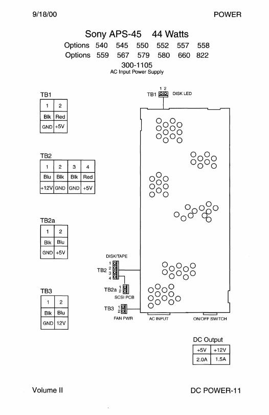
9/18/00 POWER
Sony APS-45 44 Watts Options Options
TB1
1 2
Blk Red
GND +5V
TB2
1 2 3 4
Blu Blk Blk Red
+12V GND GND +5V
TB2a
1 2
Blk Blu
GND +5V
TB3
1 2
Blk Blu
GND 12V
Volume II
540 545 550 552 559 567 579 580
300-1105 AC Input Power Supply
DISK!TAPE
1
TB2 2 3 4
TB2a ~~ SCSI PCB
TB3 1 IQll 21Qlj
FAN PWR
1 2
TB1
AC INPUT
557 660
DISK LED
558 822
ON/OFF SWITCH
DC Output
+5V +12V
2.0A 1.5A
DC POWER-11

POWER 9/18/00
FOK PEX668-31 150 Watts SS4 SSS SS20
300-1215 300-1279 AC Input Power Supply AC Input Power Supply
Rear View
m lwl 'COOWITT
ON/OFF SWITCH rr.=ill @ ACINPUT
J1
1 2 3 4 5 6 7
Blu Brn Red Red Red Red Red
+12 -12 +5 +5 +5 +5 +5
J2
1 2 3 4 5 6
Red Blk Blk Red Blk Blu
+5 GND GND +5 GND +12
Notes
Front View
1 10
._foJg ~J1
8
~ ~ 9 18
9
Red Gry
+5 Poff
J2
PERIPHERAL POWER ~
10-15 16 17 18
Blk Grn Vio Yel
GND Mon Fan Pon
DC Output +5V +12V -12V
25A 2.3A 0.25A
1. The SS20 requires the 300-1215-03 or 300-1279-01 power supply. 2. Part number 300-1279 is used in SS4 1.05GB disk drive Server
configurations because the 150 Watt power supply supports the power state memory feature. SS4 Workstation configurations, regardless of disk capacity, use 50 Watt power supply 300-1257.
DC POWER-12 Field Engineer Handbook

9/18/00 POWER
Rear View
Sony SPS-50 50 Watts SPARC Xterminal 1 SPARCstation 4
300-1257 AC Input Power Supply
Front View
m I c•.•J 1 ·couoe"' ON/OFF SWITCH ~
~ ACINPUT
J1
1 2 3 4 5-6 7 8
Blu Brn Red Red N/C Red Red
+12 -12 +5 +5 - +5 +5
J2
1 2 3 4 5 6
Red Blk Blk Red Blk Blu
+5 GND GND +5 GND +12
Notes
1 10
[gi8 ~J1 ~ &.Q 9 18
J2
PERIPHERAL POWER ~
9 10-11 12-13 14-15 16 17 18
Gry Blk N/C
Poff GND -
Blk N/C Vio Yel
GND - Fan Pon
DC Output
+5V +12V -12V
SA 1.8A 0.2A
1. Part number 300-1279 is used in 1.05GB disk drive Server configurations because the 150 Watt power supply supports the power state memory feature. Workstation configurations, regardless of disk capacity, used 50 Watt power supply 300-1257.
2. The On/Off switch does not control the AC accessory outlet.
Volume II DC POWER-13
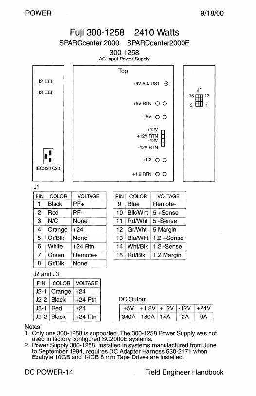
POWER 9/18/00
Fuji 300-1258 241 O Watts SPARCcenter 2000 SPARCcenter2000E
300-1258
J2 CD
J3 CD
I· :I IEC320 C20
J1
PIN COLOR
1 Black
2 Red
3 N/C 4 Orange 5 Or/Blk
6 White
7 Green
8 Gr/Blk
J2 and J3
PIN COLOR
J2-1 Orange J2-2 Black J3-1 Red J2-2 Black
Notes
AC Input Power Supply
VOLTAGE
PF+ PF-
None
+24 None
+24 Rtn
Remote+ None
VOLTAGE
+24 +24 Rtn
+24 +24 Rtn
Top
PIN
9 10 11
12 13 14
15
+5VADJUST 0
+5VRTN 0 0
+5V 0 0
+12V ~ +12V RTN
-12V
-12V RTN
+1.2 0 0
+1.2 RTN 0 0
COLOR VOLTAGE
Blue Remote-Blk/Wht 5 +Sense Rd/Wht 5 -Sense
Gr/Wht 5 Margin Blu/Wht 1.2 +Sense WhVBlk 1.2 -Sense
Rd/Blk 1.2 Margin
DC Output
J1 15 llE 13
3 l:m 1
+5V +1.2V +12V -12V +24V 340A 180A 14A 2A 9A
1. Only one 300-1258 is supported. The 300-1258 Power Supply was not used in factory configured SC2000E systems.
2. Power Supply 300-1258, installed in systems manufactured from June to September 1994, requires DC Adapter Harness 530-2171 when Exabyte 10GB and 14GB 8 mm Tape Drives are installed.
DC POWER-14 Field Engineer Handbook
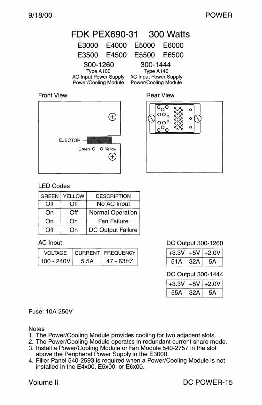
9/18/00
Front View
FOK PEX690-31 300 Watts E3000 E4000 E5000 E6000 E3500 E4500 E5500 E6500
300-1260 300-1444 Type A106 Type A146
AC Input Power Supply AC Input Power Supply Power/Cooling Module Power/Cooling Module
Rear View
~ 000 0000
00 0 0000 0000
00° 0000 r 0000
o0 o 0000
0
0 V\) N
0
POWER
EJECTOR --1•• Green 0 0 Yellow
LED Codes
GREEN YELLOW DESCRIPTION
Off Off No AC Input
On Off Normal Operation
On On Fan Failure
Off On DC Output Failure
AC Input
VOLTAGE CURRENT FREQUENCY
100 - 240V 5.5A 47 - 63HZ
Fuse: 1 OA 250V
Notes
DC Output 300-1260
+3.3V +5V +2.0V 51A 32A 5A
DC Output 300-1444
+3.3V +5V +2.0V 55A 32A 5A
1. The Power/Cooling Module provides cooling for two adjacent slots. 2. The Power/Cooling Module operates in redundant current share mode. 3. Install a Power/Cooling Module or Fan Module 540-2757 in the slot
above the Peripheral Power Supply in the E3000. 4. Filler Panel 540-2593 is required when a Power/Cooling Module is not
installed in the E4x00, E5x00, or E6x00.
Volume II DC POWER-15
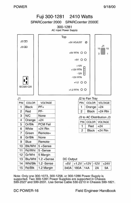
POWER 9/18/00
Fuji 300-1281 2410 Watts SPARCcenter 2000 SPARCcenter 2000E
300-1281 AC input Power Supply
J2ITJ
J3ITJ
I· :I IEC320 C20
J1 PIN COLOR VOLTAGE
1 Black PF+
2 Red PF-
3 N/C None
4 Orange +24
5 Or/Blk PCM Fail
6 White +24 Rtn
7 Green Remote+
8 Gr/Blk None
9 Blue Remote-
10 Blk/Wht 5 +Sense
11 Rd/Wht 5 -Sense
12 Gr/Wht 5 Margin
13 Blu/Wht 1.2 +Sense
14 Wht/Blk 1.2 -Sense
15 Rd/Blk 1.2 Margin
Top
+5VADJUST 0
+5V RTN 0 0
+5V 0 0
+12V
+12V RTN B -12V B
-12V RTN
+1.2 0 0
+1.2 RTN 0 0
. I? tn F:m Trmt -- ~- . -·· ··-J PIN COLOR
1 Orange
2 Black
J1 15 s:E 13
3 l:tE 1
VOLTAGE
+24
+24 Rtn
J3 to AC Distribution J3
PIN COLOR VOLTAGE
1 Red +24
2 Black +24 Rtn
DC Output
+5V +1.2V +12V -12V +24V
340A 180A 14A 2A 9A
Note: Only one 300-1073, 300-1258, or 300-1286 Power Supply is supported. Two 300-1281 Power Supplies are supported in Chassis 599-2027 and 599-2031. Use Sense Cable 530-221 O in Chassis 599-1821.
DC POWER-16 Field Engineer Handbook

9/18/00 POWER
FOK PEX698-30 30 Watts JavaStation JJ SPARCstorage UniPack StorEdge UniPack
300-1282 Type A103
AC Input Power Supply
540-2674 540-2694 540-2866 540-3004 Tape UniPack FRU Disk UniPack FRU JavaStation FRU Tape Unipack FRU Narrow SCSI 1/0 Wide SCSI 1/0
Top View
J1
ON/OFF SWITCH
0
AC INPUT
PIN VOLTAGE
1 +12
2 Gnd
3 Gnd
4 +5
Volume II
DC Output 300-1282-01 300-1282-02
+5V +12V
3.4A 1.8A
Wide SCSI 1/0
J1 ~
DC Output 300-1282-03
+5V +12V
4.5A 1.8A
DC POWER-17
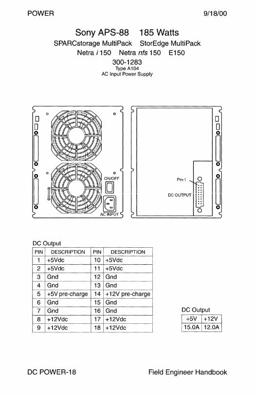
POWER 9/18/00
Sony APS-88 185 Watts SPARCstorage MultiPack StorEdge MultiPack
Netra i 150 Netra nfs 150 E150 300-1283
0
0 0 0
~ 0
0 o~
n n LJ u 0
DC Output PIN DESCRIPTION PIN
1 +5Vdc 10
2 +5Vdc 11
3 Gnd 12
4 Gnd 13
5 +5V pre-charge 14
6 Gnd 15
7 Gnd 16
8 +12Vdc 17
9 +12Vdc 18
DC POWER-18
Type A104 AC Input Power Supply
0
~I
DESCRIPTION
+5Vdc
+5Vdc
Gnd
Gnd
+ 12V pre-charge
Gnd
Gnd
+12Vdc
+12Vdc
0 0 0
~ 0
0 0 Pin-1 n ..
ocouoeool ~ I~
DC Output
+5V +12V 15.0A 12.0A
Field Engineer Handbook
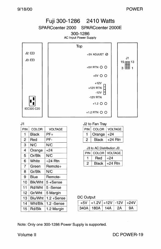
9/18/00 POWER
Fuji 300-1286 2410 Watts SPARCcenter 2000 SPARCcenter 2000E
300-1286
J2 [I]
J3 [I]
I· :I IEC320 C20
J1 PIN COLOR
1 Black 2 Red 3 N/C 4 Orange
5 Or/Blk 6 White 7 Green 8 Gr/Blk 9 Blue
10 Blk/Wht 11 Rd/Wht 12 Gr/Wht 13 Blu/Wht 14 WhVBlk 15 Rd/Blk
AC Input Power Supply
VOLTAGE
PF+ PF-
N/C
+24 N/C
+24 Rtn Remote+ N/C Remote-
5 +Sense 5 -Sense 5 Margin
1.2 +Sense 1.2 -Sense 1.2 Margin
Top
+5VADJUST 0
+5VRTN 0 0
+5V 0 0
+12V
+12V RTN B -12V B
-12V RTN
+1.2 0 0
+1.2 RTN 0 0
J2 to Fan Tray
J1 15s:E13
3 l±E 1
PIN COLOR VOLTAGE
1 Orange +24 2 Black +24 Rtn
J3 to AC Distribution J3
PIN COLOR VOLTAGE
1 Red +24 2 Black +24 Rtn
DC Output
+SV +1.2V +12V -12V +24V 340A 180A 14A 2A 9A
Note: Only one 300-1286 Power Supply is supported.
Volume II DC POWER-19

POWER 9/18/00
Zytec EP071265 31 O Watts Enterprise Network Array A500
StorEdge A5000 StorEdge A5100 StorEdge A5200 Option 9687
Front View
300-1295 Type A108
AC Input Power Supply
Yellow 0 0
Green
EJECTOR
Rear View
(000000) \
AC Input
VOLTAGE CURRENT FREQUENCY 100 - 240V 5A 47 - 63HZ
DC Output
OUTPUT PRECHARGE MAXIMUM
+3.3VI +5V I +12V +3.3V I +5V I +12V 310 Watts
26.0A l 21.0A l 21.0A 1.0A l 2.0A l 1.0A
DC POWER-20 Field Engineer Handbook

9/18/00 POWER
ID Yellow \V 0 0
Green
FOK PEX705-30 184 Watts E3000 E4000 E5000 E6000
E4500 E5500 E6500 300-1301
Type A105 AC Input Power Supply
AC Input
EJECTOR
VOLTAGE CURRENT FREQUENCY
100 - 240V 3A 47 - 63HZ
DC Output
+5V +5V +12V +12V MAXIMUM CONTINUOUS
20A SA 13A 1.5A 195 Watts
Notes 1. One 300-1301 Power Supply is supported per system. 2. AC Input/Fan Assembly 370-1811 or 370-1812 provides cooling for
the 184W Power/Cooling Module in the E4000/E4500, E5000/E5500, and E6000/E6500.
3. Fan Tray 540-2757 or 300 Watt Power/Cooling Module 300-1260 provides cooling for the 184 Watt Power Supply in the E3000.
4. The 184 Watt Power Supply provides the following functions: +5Vdc and + 12Vdc peripheral tray power +5Vdc and + 12Vdc drive precharge (non redundant) +3.3Vdc and +5Vdc system precharge (non redundant) +5Vdc redundant system power + 12Vdc redundant power for PCM fans + 12Vdc redundant power for E3000/E3500 Auxiliary Fan Module +5Vdc auxiliary power for Clock Board remote console serial port E4000/E4500 Keyswitch Assembly fan power E5000/E5500 and E6000/E6500 AC Input Box fan power
Volume II DC POWER-21

POWER 9/18/00
Note
Zytec 300-1302 560 Watts Ultra 450 Ultra Enterprise 450
Option 9682 300-1302
AC Input Power Supply
Front View
Rear View
r-fl 0 0 0 - -- -- -- -- -~
0 0 0
0 0 0
0 0 0
0 0 0
0-AC Input
100-240 VAC
47-63Hz
BA
000 6. ~ r-J-
DC Output +3.3V +5.0V +12.0V -12.0V +5.0V Standby
47.0A 64.0A 16.0A 1.0A 2.4A
A memory latch remembers the power supply's last power On/Off state. When a power supply that was Off is installed in a system that is On, the supply will remain Off. To turn on the power supply, rotate the front panel keyswitch from the Power-On position to the Diagnostic position, then back to the Power-On position, or press the keyboard Power-On key.
DC POWER-22 Field Engineer Handbook

9/18/00 POWER
FOK PEX705-40 184 Watts E3000 E3500
300-1307 300-1400 Type A109 Type A109
AC Input Power Supply AC Input Power Supply
C'I Yellow \!:) 0 0
Green l~I Ac INPUT <±) IEC 320 C14
EJECTOR
000 ~o~o 0
~ 00 0 o~o~ 0 Lr\)
~ 00° 0000 N 0000
o0 o 0000 0
AC Input
VOLTAGE CURRENT FREQUENCY
100 - 240V 12A 47 - 63HZ
DC Output
+5V +5V +12V +12V MAXIMUM CONTINUOUS
20A 5A 13A 1.5A 195 Watts
Notes 1. One 300-1307 or 300-1400 per system is supported. 2. Use 300-1301 as the redundant Peripheral Power Supply in the E3000. 3. Use 300-1358 as the redundant Peripheral Power Supply in the E3500. 4. Use Filler Panel 540-2593 when 300-1301 or 300-1400 is not installed. 5. Use Filler Panel 540-3815 when 300-1358 is not installed. 6. Fan Tray 540-2757 or 300 Watt Power/Cooling Module 300-1260
provides cooling for the 184 Watt Power Supply. 7. The 184 Watt Power Supply provides the following functions:
AC Input power +5Vdc and + 12Vdc peripheral tray power +5Vdc and + 12Vdc drive precharge (non redundant) +3.3Vdc and +5Vdc system precharge (non redundant) +5Vdc redundant system power +12Vdc redundant power for PCM fans + 12Vdc redundant power for E3000/E3500 Auxiliary Fan Module +5Vdc auxiliary power for Clock Board remote console serial port
Volume II DC POWER-23

POWER 9/18/00
Sony APS-72 180 Watts A11 A12 Netrai150 Netranfs150 E150
300-1248 300-1308 Early Production FCS
Type A101 Type A101 AC Input Power Supply AC Input Power Supply
Top
0
0 0 0
J3 J1 J2
J3 to System Board
PIN FUNCTION PIN FUNCTION
1 +12Vdc 9 Thermal Sensor
2 Return .. " -t t")\ / ,.J,... IV - IC..VUV
3 Power On 11 Power Off
4 +5 Sense 12 +5 Sense Rtn
5 +3.3 Sense* 13 +3.3 Sense Rtn*
6 +3.0 Sense* 14 +3.0 Sense Rtn* 7 +3.0 +V Programing 15 Thermal Sensor
8 +3.0 +OVP Programing 16 Power On Reset
* Pins 5, 6, 13, and 14 are not used.
J1 to System Board J2 to Peripheral Harness
PIN FUNCTION PIN FUNCTION PIN FUNCTION PIN FUNCTION
1 +5Vdc 10 +5 Rtn 1 +5Vdc 4 +5Vdc 2 +5Vdc 11 +5 Rtn 2 +5 Rtn 5 +5 Rtn
3 +5Vdc 12 +5 Rtn 3 +12 Rtn 6 +12Vdc 4 +3.3Vdc 13 +3.3 Rtn
5 +3.3Vdc 14 +3.3 Rtn DC Output
6 +3.3Vdc 15 +3.3 Rtn 1 2 3 4 5*
7 +3.0Vdc 16 +3.0 Rtn +3.3V +5V +12V -12V +3.0V 8 +3.0Vdc 17 +3.0 Rtn 12A 18A 5.1A 0.3A 12A 9 +3.0Vdc 18 +3.0 Rtn * Output 5 is adjusted to 3.3Vdc.
DC POWER-24 Field Engineer Handbook

9/18/00 POWER
Zytec EP071235-C1 Ultra 2
350 Watts
300-1249 #6-32 Screws
Early production Type A102
AC Input Power
300-1309 #6-32 Screws P1 Production
Type A102 AC Input Power
300-1315 M3 Screws
Pilot Production Type A102
AC Input Power
2-Pin
24-Pin
4-Pin
Removed from 300-1315
300-1342 M3 Screws May 1997 Type A102
AC Input Power
~ 12-Pin 6-Wire
~ 8-Pin 4-Wire
--{] 4-Pin 2-Wire
Power to System Board 24-Pin Connector to System Board J3206 PIN COLOR FUNCTION
1 -6 Black +3. 3 Rtn to J3205
7-12 Yellow +3.3 to J3205
1 -2 Black +5 Rtn to J3204
3-4 Red +5 to J3204
5-6 Black +3.0B Rtn to J3204
7-8 Blue +3.0B to J3204
1 -2 Black +3.0A Rtn to J3203
3-4 Green +3.0A to J3203
Floppy Drive Power PIN COLOR FUNCTION
1 Red +5V
2 Black +5 Rtn
3 N/C N/C
4 N/C N/C
Removable Media Power PIN COLOR FUNCTION
1 Brown +12
2 Black +12 Rtn
3 Black +5 Rtn
4 Red +5
Volume II
PIN COLOR FUNCTION PIN COLOR FUNCTION
1 Green +3A Sense 13 Red +3A-Sense
2 Grn/Wht +3A Vprog 14 Red/Wht +3A OVP Prag
3 Prpl/Wht +3B Sense 15 Brown +3B -Sense
4 Pnk/Wht +3B Vprog 16 Black +3B OVP Prag
5 Blue Fan Speed 17 Brown PwrOn Reset
6 Blu/Wht +3.3 Sense 18 Black +3.3 -Sense
7 Gry/Wht +5 Sense 19 Grey +5 -Sense
8 Blk/Wht +12 20 Red/Ye I Return
9 Brn/Wht +12 21 Purple Return
10 White -12 22 Orange Interlock
11 Yellow On 23 Pink Off
12 Yel/Wht Tmp Sense 24 Pink Tmp Sense
Note: Outputs 3.0A and 3.0B are programmable from 2.5V to 3.5V. They provide the core voltage to UPAO and UPA1 respectively when a module is installed.
DC Output V1 V2 V3 V4 V5 V6
+3.3V +5.0V +12.0V -12.0V +3.0V +3.0V
55.0A 25.0A 6.5A 0.4A 12.0A 12.0A
DC POWER-25

POWER 9/18/00
FOK PEX705-40 Danish 184 Watts E3000V5 E3500V5
300-1317 Type A115
AC Input Power Supply
Q.. Yellow '9 0 0
Green l~I ACINPuT <±) IEC 320 C14
EJECTOR
~ 000 0000 0
00 0 0000
H 0000 r 00° 0000 o~ 0000
o0 o 0000 0
AC Input
I VOLTAGE lcuRRENTIFREOUENcvl 1100 - 240V I 12A I 47 - 63HZ I
DC Output
+5V +5V +12V +12V MAXIMUM CONTINUOUS
15A OA 8.5A 1.5A 195 Watts
Notes 1. Use AC power cord 530-2301, Option X389L. 2. Power cord 530-2301 requires a 16A IEC309 receptacle. 3. One 300-1317 Power Supply is supported per system. 4. Use 300-1301 as the redundant Peripheral Power Supply. 5. Use Filler Panel 540-2593 when 300-1301 is not installed. 6. Fan Tray 540-2757 or 300 Watt Power/Cooling Module 300-1260
provides cooling for the 184 Watt Power Supply. 7. The 184 Watt Power Supply provides the following functions:
AC Input power +5Vdc and + 12Vdc peripheral tray power +5Vdc and + 12Vdc drive precharge (non redundant) +3.3Vdc and +5Vdc system precharge (non redundant) +5Vdc redundant system power + 12Vdc redundant power for PCM fans + 12Vdc redundant power for E3000 Auxiliary Fan Module +5Vdc auxiliary power for Clock Board remote console serial port
DC POWER-26 Field Engineer Handbook
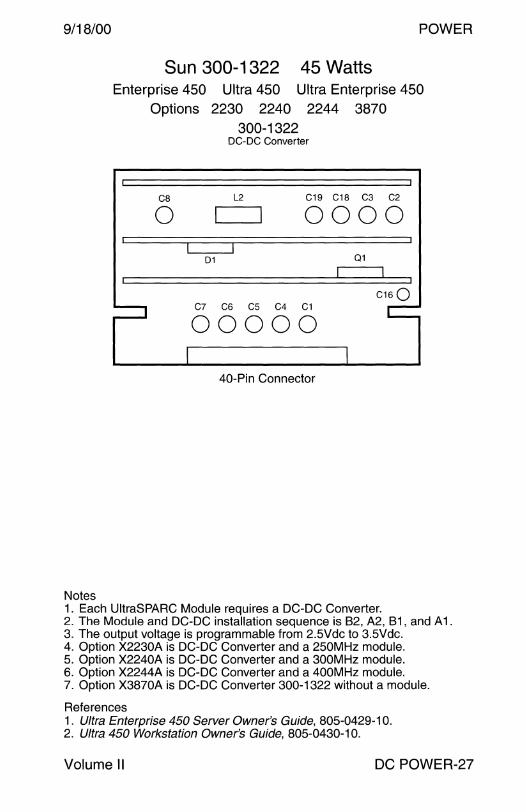
9/18/00 POWER
Notes
Sun 300-1322 45 Watts Enterprise 450 Ultra 450 Ultra Enterprise 450
Options 2230 2240 2244 3870 300-1322
DC-DC Converter
CB L2 C19 C18 C3 C2
0 0000
01 Q1
C16Q C7 C6 C5 C4 C1
00000
40-Pin Connector
1. Each UltraSPARC Module requires a DC-DC Converter. 2. The Module and DC-DC installation sequence is B2, A2, B1, and A1. 3. The output voltage is programmable from 2.5Vdc to 3.5Vdc. 4. Option X2230A is DC-DC Converter and a 250MHz module. 5. Option X2240A is DC-DC Converter and a 300MHz module. 6. Option X2244A is DC-DC Converter and a 400MHz module. 7. Option X3870A is DC-DC Converter 300-1322 without a module.
References 1. Ultra Enterprise 450 Server Owner's Guide, 805-0429-10. 2. Ultra 450 Workstation Owner's Guide, 805-0430-10.
Volume II DC POWER-27

POWER 9/18/00
FOK PEX726-30 45 Watts SPARCstorage FlexiPack StorEdge FlexiPack
300-1324
ON/OFF SWITCH
[g
I c•.•J I AC INPUT
RECEPTACLE
SCSI Adapter Power PIN COLOR FUNCTION
1 N/C N/C
2 N/C N/C
3 Black +SV Rtn
4 Red +SV
Peripheral Power PIN COLOR FUNCTION
1 Blue +12V
2 Black +12V Rtn
3 Black +SV Rtn
4 Red +SV
DC POWER-28
Type A120 AC Input Power Supply
4
SCSI ADAPTER PERIPHERAL PERIPHERAL POWER POWER POWER
AC Input VOLTAGE CURRENT FREQUENCY
100 - 240V 1.2A 47 - 63Hz
DC Output V2 V3
+5.0V +12.0V
4.SA 2.7A
Field Engineer Handbook
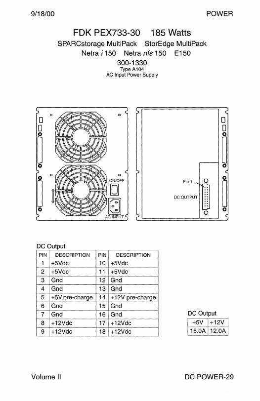
9/18/00 POWER
0
0 0 0
~ 0
0 0
~ 0
FOK PEX733-30 185 Watts SPARCstorage MultiPack StorEdge MultiPack
Netra i 150 Netra nfs 150 E150 300-1330
Type A104 AC Input Power Supply
~
.-----1
Pin-1 ~ g N ..
DC OUTPUT ..
(_ 0
~ 0 0 0
~ 0
0
~ 0 _5
DC Output
PIN DESCRIPTION
1 +5Vdc
2 +5Vdc
3 Gnd
4 Gnd
5 +5V pre-charge
6 Gnd
7 Gnd
8 +12Vdc
9 +12Vdc
Volume II
PIN
10 11
12
13
14
15
16
17
18
DESCRIPTION
+5Vdc
+5Vdc
Gnd
Gnd
+ 12V pre-charge
Gnd
Gnd
+12Vdc
+12Vdc
DC Output
+5V +12V
15.0A 12.0A
DC POWER-29
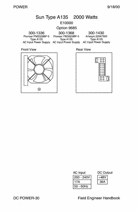
POWER 9/18/00
Sun Type A 135 2000 Watts E10000
300-1336 Option 9685 300-1368 300-1430
Pioneer PM3329BP-5 Pioneer PM3329BP-5 Artesyn 22947500 Type A135 Type A135 Type A135
AC Input Power Supply AC Input Power Supply AC Input Power Supply
Front View
DC POWER-30
Rear View
AC Input
200 - 240V
17A
50 - 60Hz
0 0 0
0 0 0
0 0 0
0 0 0
DC Output
~ ~
Field Engineer Handbook
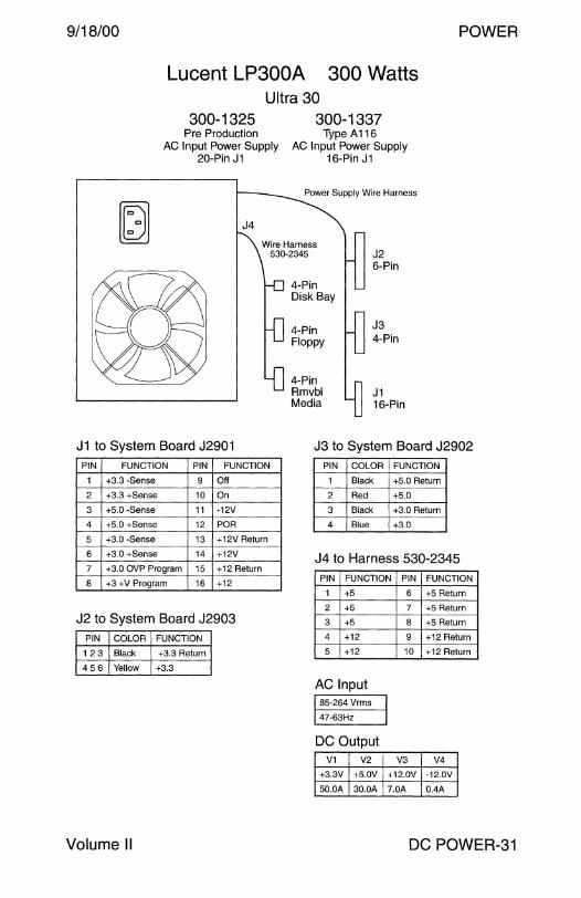
9/18/00 POWER
Lucent LP300A 300 Watts Ultra 30
300-1325 300-1337 Pre Production Type A 116
AC Input Power Supply AC Input Power Supply 20-Pin J1 16-Pin J1
Power Supply Wire Harness
J4
Wire Harness 530-2345
4-Pin Disk Bay
4-Pin Floppy
4-Pin Rmvbl Media
J2 6-Pin
J3 4-Pin
J1 16-Pin
J1 to System Board J2901 J3 to System Board J2902 PIN FUNCTION PIN FUNCTION
1 +3.3 -Sense 9 Off
2 +3.3 +Sense 10 On
3 +5.0 -Sense 11 -12V
4 +5.0 +Sense 12 POR
5 +3.0 -Sense 13 +12V Return
6 +3.0 +Sense 14 +12V
7 +3.0 OVP Program 15 +12 Return
8 +3 +V Program 16 +12
J2 to System Board J2903 PIN COLOR FUNCTION
123 Black +3.3 Return
456 Yellow +3.3
Volume II
PIN COLOR FUNCTION
1 Black +5.0 Return
2 Red +5.0
3 Black +3.0 Return
4 Blue +3.0
J4 to Harness 530-2345 PIN FUNCTION PIN FUNCTION
1 +5
2 +5
3 +5
4 +12
5 +12
AC Input 85-264 Vrms
47-63Hz
DC Output V1 V2
+3.3V +5.0V
50.0A 30.0A
6 +5 Return
7 +5 Return
8 +5 Return
9 +12 Return
10 +12 Return
V3 V4
+12.0V -12.0V
7.0A 0.4A
DC POWER-31
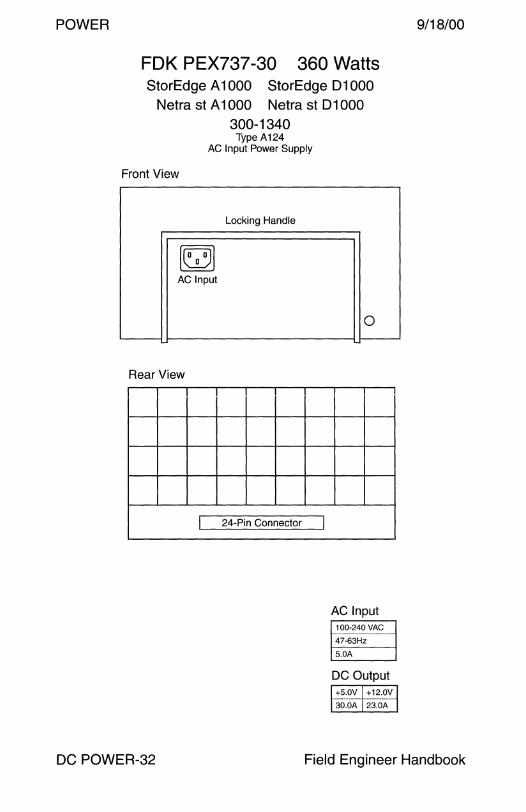
POWER 9/18/00
FOK PEX737-30 360 Watts StorEdge A 1000 StorEdge 01000
Netra st A 1000 Netra st 01000 300-1340
Type A124 AC Input Power Supply
Front View
Locking Handle
~ AC Input
Rear View
I 24-Pin Connector
DC POWER-32
I
0
AC Input 100-240VAC
47-63Hz
5.0A
DC Output +5.0V +12.0V
30.0A 23.0A
Field Engineer Handbook
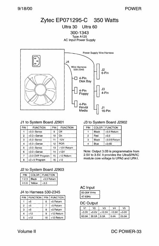
9/18/00 POWER
Zytec EP071295-C 350 Watts Ultra 30 Ultra 60
300-1343 Type A125
AC Input Power Supply
Power Supply Wire Harness
J4
Wire Harness 530-2345
4-Pin Disk Bay
4-Pin Floppy
4-Pin Rmvbl Media
~ ~
J2 6-Pin
J3 4-Pin
J1 16-Pin
J1 to System Board J2901 J3 to System Board J2902 PIN FUNCTION PIN FUNCTION
1 +3.3 -Sense 9 Off
2 +3.3 +Sense 10 On
3 +5.0 -Sense 11 -12V
4 +5.0 +Sense 12 POR
5 +3.0 -Sense 13 +12V Return
6 +3.0 +Sense 14 +12V
7 +3.0 OVP Program 15 +12 Return
8 +3 +V Program 16 +12
J2 to System Board J2903 PIN COLOR FUNCTION
123 Black +3.3 Return
456 Yellow +3.3
J4 to Harness 530-2345 PIN FUNCTION PIN FUNCTION
1 +5 6 +5 Return
2 +5 7 +5 Return
3 +5 8 +5 Return
4 +12 9 +12 Return
5 +12 10 +12 Return
Volume II
PIN COLOR FUNCTION
1 Black +5.0 Return
2 Red +5.0
3 Black +3.0 B Return
4 Blue +3.0B
Note: Output 3.0B is programmable from 2.5V to 3.5V. It provides the UltraSPARC module core voltage to UPAO and UPA 1.
AC Input 85-264 Vrms
47-63Hz
DC Output V1 V2
+3.3V +5.0V
60.0A 30.0A
V3 V4 V5
+12.0V -12.0V +3.0V
6.0A 0.4A 25.0A
DC POWER-33

POWER 9/18/00
ffi
ffi
Lucent LP360A 360 Watts Enterprise 250
~
Option 9683 300-1352
Type A127 AC Input Power Supply
AC Input 100-240V
47-63Hz
6A
DC Output
OD DO DO DO DO DO DO OD DO DO DO DO
DO DO DO DO DO DO DO DO DO DO DO ~
+2.5V +3.3V +5.0V + 12.0V -12.0V +5.0V
27.0A 34.0A 30.0A 10.0A 0.5A 1.0A
DC POWER-34 Field Engineer Handbook

9/18/00 POWER
Switching Power Inc Sun-450 350 Watts Netra t 1100 Netra t 1120
300-1355 DC Input Power Supply
AMP Connectors Used Before 5/99
RTN fOl -48V [.Q_j
Input A
f0l -48V
[.Q_j RTN
Input B
Logic OV
M50.8--B
M50.8--E)
J1 to System Board J2901 PIN FUNCTION PIN FUNCTION
+3.3 -Sense 9 Off
2 +3.3 +Sense 10 On
3 +5.0 -Sense 11 -12V
4 +5.0 +Sense 12 POR
5 +3.0 -Sense 13 +12V Return
6 +3.0 +Sense 14 +12V
7 +3.0 OVP Program 15 +12 Return
8 +3 +V Program 16 +12
J3 to System Board J2902 PIN COLOR FUNCTION
Black +5.0 Return
2 Red +5.0
3 Black +3.0
4 Blue +3.0 Return
J2 to System Board J2903 PIN COLOR FUNCTION
123 Black +3.3 Return
456 Yellow +3.3
Notes
DC Input
~ ~ DC Output
V1 V2
+3.3V +5.0V
50.0A 35.0A
V3
+12.0V
6.0A
J2 6-Pin
~ J3 4-Pin
J1 16-Pin
V4 V5
-12.0V -2.5V
1.0A 28.0A
1. Three banks of memory can be installed in the Ultra 60 System Board if the power supply is ~300-1355-03.
2. Four banks of memory can be installed in the Ultra 60 System Board if the power supply is ~300-1355-04.
3. AMP connectors require two #14AWG wires to the circuit breaker.
Volume II DC POWER-35

POWER 9/18/00
Artesyn EP071332 350 Watts Netra t 1120
300-1405 300-1462 Type D119 Type D119
DC Input Power Supply DC Input Power Supply AMP Connectors Wago Connectors
Used From 5/99 to 11 /99 Used After 11 /99
300-1462 is Shown Wago DC Connectors
Input A loooi
M50.8--{)
-48v Gnd Rtn
Input B ioooi Rtn Gnd -48v
Logic OV
M50.8-B
J1 to System Board J2901 PIN FUNCTION PIN
+3.3 -Sense 9
2 +3.3 +Sense 10
3 +5.0 -Sense 11
4 +5.0 +Sense 12
5 +3.0 -Sense 13
6 +3.0 +Sense 14
7 +3.0 OVP Program 15
8 +3 +V Program 16
FUNCTION
Off
On
-12V
POR
+12V Return
+12V
+12 Return
+12
4-Pin Disk Bay
~n 4-Pin
CD-ROM
8-Pin Alarm Card
J2 6-Pin
J3 4-Pin
J3 to System Board J2902 PIN COLOR FUNCTION
J1 16-Pin
Black +5.0 Return
2 Red +5.0
3 Black +3.0
4 Blue +3.0 Return
J2 to System Board J2903 PIN COLOR FUNCTION
123 Black +3.3 Return
456 Yellow +3.3
Notes
DC Input
~ ~ DC Output
V1 V2
+3.3V +5.0V
50.0A 35.0A
V3 V4 V5
+12.0V -12.0V -2.5V
6.0A 1.0A 28.0A
1. Four banks of memory can be installed in the Ultra 60 System Board if the power supply is 300-1405 or 300-1462.
2. The 300-1405 and 300-1462 are not qualified in the Netra t 1100. 3. AMP connectors require two #14AWG wires to the circuit breaker. 4. Wago connectors require three #12AWG wires to the circuit breaker.
DC POWER-36 Field Engineer Handbook

9/18/00
Sony APS-112 Ultra 80
300-1357 Type A119
660 Watts
AC Input Power Supply
00000 000000 000000 000000
00000
Rear View
0000000 0000000
0000000 0000000
J1 to System Board J4107 PIN FUNCTION PIN FUNCTION
00000 00000 00000 00000 00000
c:S J2 14-Pin
J1 14-Pin
POWER
1/2 +3.3V 15/16 +3.3V Return Molex 43980 3/4 +3.3V 17/18 +3.3V Return
5/6 +3.3V 19/20 +3.3V Return
7/8 +3.3V 21/22 +3.3V Return
9/10 +5.0V 23/24 +5V Return
11/12 +5.0V 25/26 +5V Return
13/14 +5.0V 27/28 +5V Return
J2 to System Board J4106 PIN FUNCTION PIN FUNCTION AC Input
1 POWERON_L 8 POWER_ OK 100-120V 200-140V
2 -12V 9 PS_FAN 9A 4A
3 Ground 10 +5.0
4 Ground 11 +3.3 DC Output 5 Ground 12 +12V V1 V2 V3 V4 V5
6 Ground 13 +12V +3.3V +5.0V +12.0V -12.0V +5SB
7 Spare 14 +5 Standby 90.0A 70.0A 7.0A 0.4A 0.02A
Volume II DC POWER-37
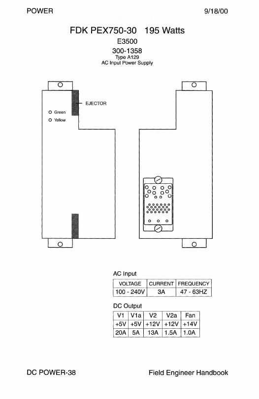
POWER 9/18/00
l 0
0 Green
0 Yellow
1 0
FOK PEX750-30 195 Watts E3500
300-1358 Type A129
AC Input Power Supply
I- EJECTOR
AC Input
VOLTAGE
100 - 240V
DC Output
V1 V1a
+5V +5V
20A SA
0 0 0 0 _oo oo_ u 00 u 000000
000000 000000
000000
0 0 0
/
0
0
CURRENT FREQUENCY
3A 47- 63HZ
V2 V2a Fan
+12V +12V +14V
13A 1.5A 1.0A
DC POWER-38 Field Engineer Handbook
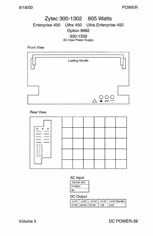
9/18/00 POWER
Zytec 300-1302 605 Watts Enterprise 450 Ultra 450 Ultra Enterprise 450
Option 9682
Front View
Rear View
r-fl 0 0 0 - -- -- -- -- -'o07
0 0 0
0 0 0
0 0 0
0 0 0
~
Volume II
300-1359 AC Input Power Supply
Locking Handle
AC Input 100-240 VAC
47-63Hz
BA
DC Output
000 6. ._ r.J -
+3.3V +5.0V +12.0V -12.0V +5.0V Standby
47.0A 64.0A 20.0A 1.0A 2.4A
DC POWER-39

POWER 9/18/00
Artesyn EP071332 Netra t 1125
300-1406 Type A136
325 Watts
AC Input Power Supply
MS0.8--0
J1 to System Board J2901 PIN FUNCTION PIN FUNCTION
+3.3 -Sense 9 Off
2 +3.3 +Sense 10 On
3 +5.0 -Sense 11 -12V
4 +5.0 +Sense 12 POR
5 +3.0 -Sense 13 +12V Return
6 +3.0 +Sense 14 +12V
7 +3.0 OVP Program 15 + 12 Return
8 +3 +V Program 16 +12
J3 to System Board J2902 PIN FUNCTION
1 +5.0 Return
2 +5.0
3 +3.0
4 +3.0 Return
J2 to System Board J2903 PIN FUNCTION
123 +3.3 Return
456 +3.3
DC POWER-40
LOGICOV
M50.8B
4-Pin I LJ CD-ROM
L[J 8-Pin Alarm Card
DC Output V1 V2 V3
+3.3V +5.0V +12.0V
50.0A 30.0A 6.0A
J2 6-Pin
J3 4-Pin
J1 16-Pin
V4 VS
-12.0V 2.5-3.SV
0.4A 25.0A
Field Engineer Handbook
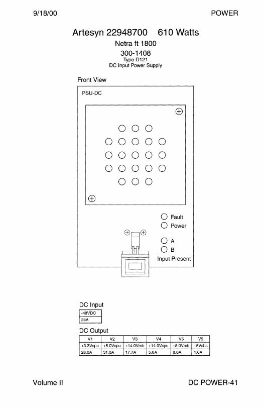
9/18/00 POWER
Volume II
Artesyn 22948700 61 O Watts Netra ft 1800
300-1408 Type 0121
DC Input Power Supply
Front View
PSU-DC
000 00000 00000 00000
000
0 Fault
0 Power
OA df-. 0 B
Input Present
'------- § f----------'
DC Input
~ §::.:___]
DC Output V1 V2
+3.3Vcpu +5.0Vcpu
28.0A 31.0A
V3 V4 vs +14.0Vmb +14.0Vcpu +5.0Vmb
17.?A 5.0A 8.0A
V5
+5Vsbs
1.0A
DC POWER-41
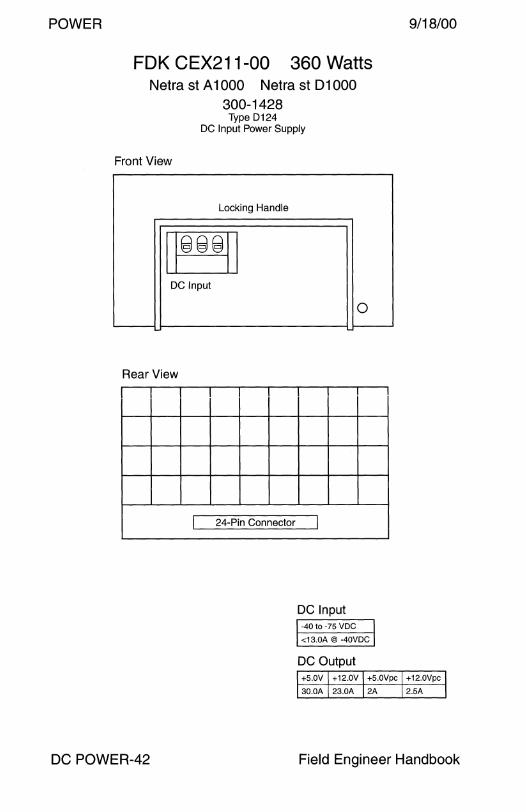
POWER 9/18/00
FOK CEX211-00 360 Watts Netra st A 1000 Netra st 01000
300-1428 Type D124
DC Input Power Supply
Front View
Locking Handle
11999
1 I
DC Input
Rear View
I 24-Pin Connector
DC POWER-42
0
I
DC Input -40 to -75 VDC
<13.0A@ -40VDC
DC Output +5.0V +12.0V +5.0Vpc +12.0Vpc
30.0A 23.0A 2A 2.5A
Field Engineer Handbook
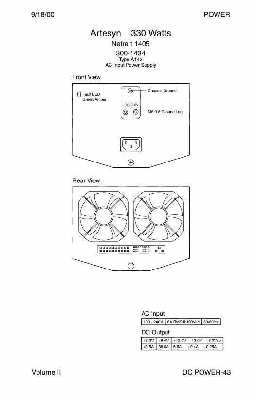
9/18/00
Volume II
POWER
Artesyn 330 Watts Netra t 1405
300-1434 Type A142
AC Input Power Supply
Front View
Q Fault LED Green/ Amber
Rear View
0
Chassis Ground
MS 0.8 Ground Lug
AC Input I 100 - 240V I 6A RMS@ 1 OOVac I 50/60Hz I DC Output +3.3V +5.0V +12.0V -12.0V +5.0Vsb
49.5A 38.SA 6.6A 0.4A 0.25A
DC POWER-43

POWER
Artesyn EP071359 Netra t 1400
300-1435 Type 0129
330 Watts
DC Input Power Supply
Front View
Q Fault LED Green/Amber
Chassis Ground
M5 0.8 Ground Lug
Wago DC Connectors
loool ioool -48v Gnd Rtn -48v Gnd Rtn
Rear View
0
DC Input 1-40 to -75Vdc I 15A I DC Output
9/18/00
+3.3V +5.0V +12.0V -12.0V +5.0Vsb
49.5A 38.5A 6.6A 0.4A 0.25A
DC POWER-44 Field Engineer Handbook

9/18/00 POWER
Sony DPS-62 360 Watts Netra ct 400 Netra ct 800
300-1445 Type D128
DC Input Power Supply
Front View Rear View
LEDs
Green
Yellow
Notes
DDDDDDD DDDDDDD DDDDDDD DDDDDDD
DODD© DDDDD DDDDD DDDDD DDDDD
0 DDDDD o DDDDD
©DODD _j_
Unlock
Lock
l © © J L_ Air Filter
DC Input -48V 13.0A
-60V 8.5A
DC Output 1 2
+5.0V +3.3V
30.0A 20.0A
3
+12.0V
10.5A
D
D
4 5
-12.0V +5.0Vsb
1.0A 2.0A
6 7
+5Vpc +12Vpc
3.0A pk 3.0A pk
1. Replace the power supply air filter every three to six months. 2. Power supply air filter 250-1594-01 is available as Option 7182.
Reference: Netra ct Server Service Manual, 806-3296.
Volume II DC POWER-45
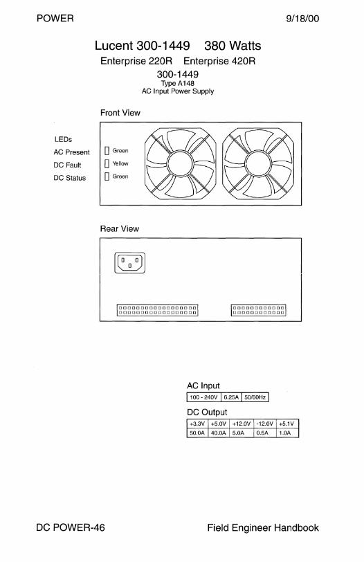
POWER 9/18/00
LEDs
Lucent 300-1449 380 Watts Enterprise 220R Enterprise 420R
300-1449 Type A148
AC Input Power Supply
Front View
AC Present D Green
DC Fault D Yellow
DC Status D Green
Rear View
DDDDDDDDDDDDDDDDDD DDODDDDDDDDDDDDDDD
DDDDDDDDDDDD DODDDODDDDOD
DC POWER-46
AC Input I 100 - 240V I 6.25A I 50/60Hz I DC Output +3.3V +5.0V +12.0V -12.0V +5.1V
50.0A 40.0A 5.0A 0.5A 1.0A
Field Engineer Handbook
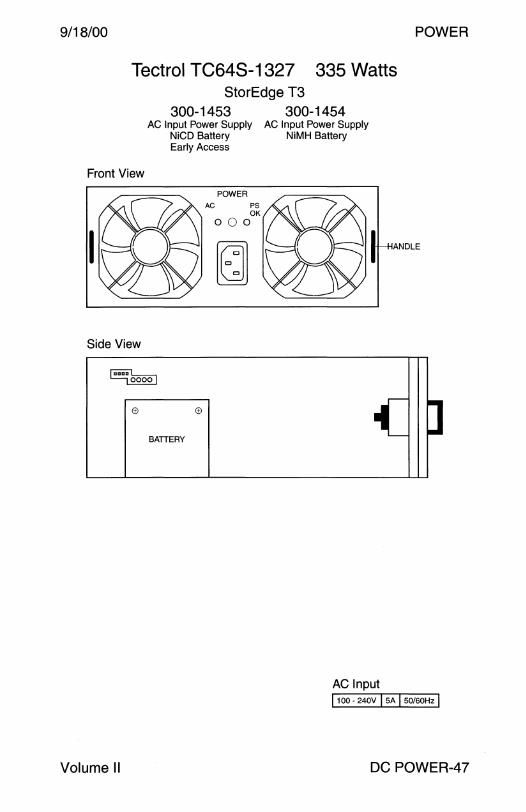
9/18/00 POWER
Tectrol TC64S-1327 335 Watts StorEdge T3
300-1453 300-1454 AC Input Power Supply AC Input Power Supply
NiCD Battery NiMH Battery Early Access
Front View
Side View
[OoDoL__., ~
(fl (fl
BATIE RY
POWER
AC PS OK
ooo
~
AC Input i 100 - 240V I sA I sotsoHz I
Volume II DC POWER-47
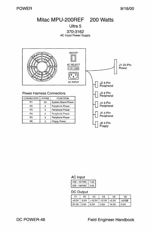
POWER
Mitac MPU-200REF Ultra 5
370-3162
200 Watts
AC Input Power Supply
ON/OFF
[] AC SELECT
l11s 123ol
AC INPUT J2 4-Pin Peripheral
Power Harness Connectors J3 4-Pin Peripheral
CONNECTOR #PINS
P1 20
P2 4
P3 4
P4 4
PS 4
P6 4
FUNCTION
System Board Power J4 4-Pin Peripheral Peripheral Power
Peripheral Power
Per:pheral Powei
Peripheral Power
Floppy Power
n .I<; LL-Pin
~ P~riph~~al
J6 4-Pin Floppy
AC Input 100 - 127VAC 7.0A
200 - 240VAC 3.SA
DC Output V1 V2 V3
+S.OV -5.0V +12.0V
22.0A O.SA 6.0A
V4 VS
-12.0V +3.3V
O.BA 14.0A
9/18/00
J1 20-Pin Power
V6
+5VSB
0.2A
DC POWER-48 Field Engineer Handbook

9/18/00
Mitac MPU-250REF Ultra 10
370-3171
243 Watts
AC Input Power Supply
ON/OFF
[] AC SELECT
111512301
AC INPUT J2 4-Pin Peripheral
Power Harness Connectors J3 4-Pin Peripheral
CONNECTOR #PINS FUNCTION
P1 20 System Board Power
P2 4 Peripheral Power
P3 4 Peripheral Power
P4 4 Peripheral Power
P5 4 Peripheral Power
P6 4 Floppy Power
P7 6 System Board Power
AC Input
J4 4-Pin Peripheral
JS 4-Pin Peripheral
J6 4-Pin Floppy
100 -127VAC 8.0A
200 - 240VAC 4.0A
DC Output V1 V2 V3 V4
+5.0V +3.3V +12.0V -12.0V
22.0A 21.0A 5.0A 0.3A
POWER
J1 20-Pin Power
J7 6-Pin Power
V5
+5VSB
0.2A
Volume II DC POWER-49
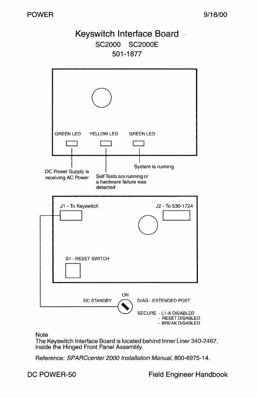
POWER
Keyswitch Interface Board SC2000 SC2000E
501-1877
0 GREEN LED YELLOW LED GREEN LED
CJ CJ l I
System is running DC Power Supply is receiving AC Power Self Tests are running or
a hardware failure was detected
J1 - To Keyswitch J2 -To 530-1724
.----1---<{ J
Sl - RESET SWITCH
D ON
DC STANDBY DIAG - EXTENDED POST
~------1, SECURE - L 1-A DISABLED
- RESET DISABLED - BREAK DISABLED
Note
9/18/00
The Keyswitch Interface Board is located behind Inner Liner 340-2467, inside the Hinged Front Panel Assembly.
Reference: SPARCcenter 2000 Installation Manual, 800-6975-14.
DC POWER-50 Field Engineer Handbook
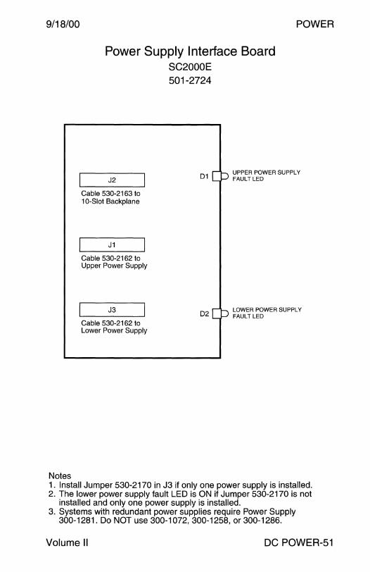
9/18/00
Notes
POWER
Power Supply Interface Board SC2000E
J2
Cable 530-2163 to 10-Slot Backplane
J1
Cable 530-2162 to Upper Power Supply
J3
Cable 530-2162 to Lower Power Supply
501-2724
01
02
UPPER POWER SUPPLY FAULT LED
LOWER POWER SUPPLY FAULT LED
1. Install Jumper 530-2170 in J3 if only one power supply is installed. 2. The lower power supply fault LED is ON if Jumper 530-2170 is not
installed and only one power supply is installed. 3. Systems with redundant power supplies require Power Supply
300-1281. Do NOT use 300-1072, 300-1258, or 300-1286.
Volume II DC POWER-51
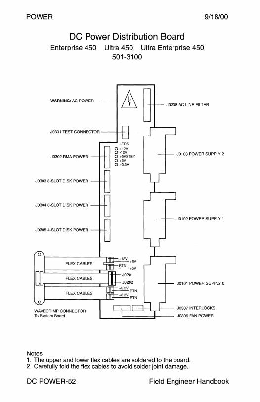
POWER 9/18/00
DC Power Distribution Board Enterprise 450 Ultra 450 Ultra Enterprise 450
501-3100
WARNING: AC POWER
J0302 AMA POWER
J0303 8-SLOT DISK POWER
J0304 8-SLOT DISK POWER
J0305 4-SLOT DISK POWER
FLEX CABLES
FLEX CABLES
FLEX CABLES
0
WAVECRIMP CONNECTOR To System Board
Notes
0 +12V 0 -12V 0 +5VSTBY 0 +5V 0 +3.3V
J0308 AC LINE FILTER
J0103 POWER SUPPLY 2
J0102 POWER SUPPLY 1
J0101 POWER SUPPLY 0
J0307 INTERLOCKS
L--====~i--- J0306 FAN POWER
1. The upper and lower flex cables are soldered to the board. 2. Carefully fold the flex cables to avoid solder joint damage.
DC POWER-52 Field Engineer Handbook
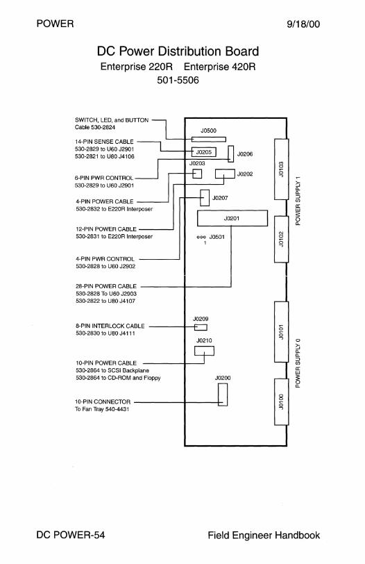
POWER
DC Power Distribution Board Enterprise 220R Enterprise 420R
501-5506
SWITCH, LED, and BUTTON Cable 530-2S24
J0500
14-PIN SENSE CABLE 530-2S29 to U60 J2901 530-2S21 to USO J4106 J0206
6-PIN PWR CONTROL J0202
530-2S29 to U60 J2901
4-PIN POWER CABLE 530-2S32 to E220R Interposer
12-PIN POWER CABLE 530-2S31 to E220R Interposer 000 J0501
1
4-PIN PWR CONTROL 530-2S2S to U60 J2902
28-PIN POWER CABLE 530-2S2S To U60 J2903 530-2S22 to USO J4107
J0209 S-PIN INTERLOCK CABLE 530-2S30 to USO J4111
J0210
10-PIN POWER CABLE 530-2S64 to SCSI Backplane 530-2S64 to CD-ROM and Floppy J0200
10-PIN CONNECTOR To Fan Tray 540-4431
9/18/00
C'l 0
Sj ~ [L [L
:::> Cf)
a: w :s: 0 [L
C\J 0
0 -,
0 0 -,
0
~ [L [L
:::> Cf)
a: w
5 [L
DC POWER-54 Field Engineer Handbook
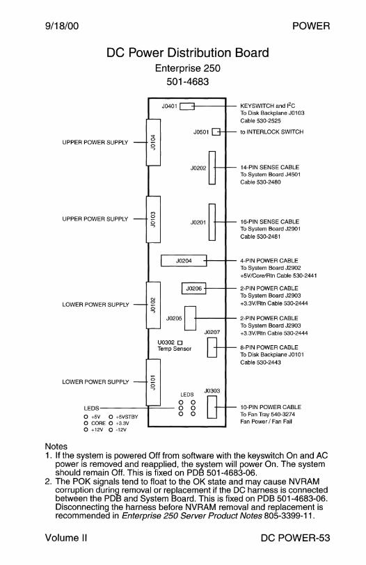
9/18/00 POWER
DC Power Distribution Board Enterprise 250
UPPER POWER SUPPLY
UPPER POWER SUPPLY
Notes
" 0
0 ....,
C') 0
0 ....,
501-4683
J0401 -1---4-- KEYSWITCH and 12C
J0501
To Disk Backplane J0103 Cable 530-2525
to INTERLOCK SWITCH
J0202 14-PIN SENSE CABLE To System Board J4501 Cable 530-2480
J0201 16-PIN SENSE CABLE To System Board J2901 Cable 530-2481
J0204 -+---+-- 4-PIN POWER CABLE ~---~ To System Board J2902
+5V/Core/Rtn Cable 530-2441
-+---+-- 2-PIN POWER CABLE To System Board J2903 +3.3V/Rtn Cable 530-2444
+----+-- 2-PIN POWER CABLE To System Board J2903 +3.3V/Rtn Cable 530-2444
8-PIN POWER CABLE To Disk Backplane J0101 Cable 530-2443
10-PIN POWER CABLE To Fan Tray 540-3274 Fan Power I Fan Fail
1 . If the system is powered Off from software with the keyswitch On and AC power is removed and reapplied, the system will power On. The system should remain Off. This is fixed on PDB 501-4683-06.
2. The POK signals tend to float to the OK state and may cause NVRAM corruption during removal or replacement if the DC harness is connected between the PDB and System Board. This is fixed on PDB 501-4683-06. Disconnecting the harness before NVRAM removal and replacement is recommended in Enterprise 250 Server Product Notes 805-3399-11.
Volume II DC POWER-53

9/18/00
Note
DC-DC Converter Circuit Enterprise 220R
300-1455 375-0094 DC-DC Converter Interposer Board
Interposer Board 375-0094
J0102 J0103 12-PIN CABLE 530-2831 --t--+to DC Distribution J0202
4-PIN CABLE 530-2832 to DC Distribution J0203 0
0 00
J0101i '-----------'
DC-DC Converter 300-1455
1 _n
~ ~F1 D 00 ooo
oo 0 ooo 0 0
POWER
Replace 375-0094-01 with 375-0094-01 DEV W0_ 17041 or 375-0094-02.
Volume II DC POWER-55

POWER 9/18/00
Unisys 200 Watts SPARCstorage RSM
300-1311 300-1328 Lambda VAOSM231 Tectrol
AC Input Power Supply AC Input Power Supply
RELEASE LEVER
DC Output
CH1 CH2
+12V +5V
12A 14A
CH3
+5V
1.5A
DC POWER-56 Field Engineer Handbook

9/18/00 POWER
Symbios Redundant Battery Backup Module RSM Array 2000
StorEdge A3000 StorEdge A3500 StorEdge A3500FC 370-2434
Top View with Cover Removed
J4
Notes
Eagle Picher HE6V7.7FR 6 Volt 7.7Ah (20Hr) Sealed Rechargeable Lead Acid Battery Nonspillable
CIRCUIT A
: 0J5AandDln=>15Ah
: c::::=J J6 A and D In= >15 Ah
+
+
1. Charging a new battery can take up to 12 hours.
Full Charge A LED Off = Not Fully Charged Green= Full Charge
Fault A LED Off= Normal Amber = Fault
Full Charge B LED Off = Not Fully Charged Green = Full Charge
Fault BLED Off= Normal Amber= Fault
2. Write caching is disabled if the battery is weak or has lost its charge. 3. Replace the battery every 2 years as indicated on the label. 4. The maximum battery shelf life is 12 months at 25C. 5. Four LEDs were added to the front panel in July 1998.
Volume II DC POWER-57

POWER 9/18/00
Symbios 150 Watts RSM Array 2000
StorEdge A3000 StorEdge A3500 StorEdge A3500FC 370-2436
Top View
Power Switch PSSP-150-21RS AC Input Power Supply
End View
DC OUTPUT CONNECTOR
DC POWER-58
AC Input
100 - 240V 2.8 - 0.8A
50 - 60Hz
DC Output
+12V +SV 4A 20A
Field Engineer Handbook
Copyright © 2022 FDOKUMEN

