


Bahasa
Halaman
Hukum

639
ESCAPADE : A Flexible Software System for Device Simulation
C Greenough, C J Hunt and R D Mount
Rutherford Appleton Laboratory
C J Fitzsimons
Trinity College, Dublin
Summary
Over the past few years many programs have appeared simulating the behaviour of semiconductor devices [1,2,3,4]. In general each program has adopted its own peculiar strategy for solving the three partial differential equations governing the system. Initialisations of the numerical process have also been diverse, not to mention the variety of the linearisations and the linear algebra employed. This richness in techniques has led to an art, if not alchemy, in the solution of semiconductor problems.
In this paper is described yet another simulation package for modelling semiconductor devices, using yet another solution procedure adding to the many already available. However, this system has one major software engineering difference; its' own internal virtual machine with an application specific instruction set. This will enable those who wish to engage in algorithmic alchemy to do so within a relatively stable enviroment.
1 Introduction
ESCAPADE, a European Semiconductor Algorithms Package for the Analysis of DEvices has been designed and written as part of a pre-ESPRIT research program in device simulation. The main goal of the project was to design and implement efficient numerical solutions for silicon devices. This has clearly led to research into basic discretisation techniques, physical models, linearisation and linear algebra, to name a few areas. Each partner has taken part in the development and testing of these techniques in their. own in-house computer programs. However, during the later part of the
640
project it was agreed that a software system should be written capable of implementing and testing the many new algorithmic ideas coming to light. This has resulted in the design and implementation of ESCAPADE-I.
Currently the majority of simulators are two dimensional but in years to come extensions into three dimensional analysis would be desirable. Although this first version of ESCAPADE performs only a two dimensional analysis, it has been designed with three dimensional problems in mind.
2 The Structure of ESCAPADE
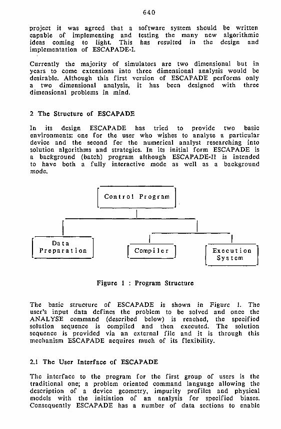
In its design ESCAPADE has tried to provide two basic environments: one for the user who wishes to analyse a particular device and the second for the numerical analyst researching into solution algorithms and strategies. In its initial form ESCAPADE is a background (batch) program although ESCAPADE-II is intended to have both a fully interactive mode as well as a background mode.
Control Program
Data Preparation Compiler Execu t i on
Sys tern
Figure 1 : Program Structure
The basic structure of ESCAPADE is shown in Figure 1. The user's input data defines the problem to be solved and once the ANALYSE command (described below) is reached, the specified solution sequence is compiled and then executed. The solution sequence is provided via an external file and it is through this mechanism ESCAPADE acquires much of its flexibility.
2.1 The User Interface of ESCAPADE
The interface to the program for the first group of users is the traditional one; a problem oriented command language allowing the description of a device geometry, impurity profiles and physical models with the initiation of an analysis for specified biases. Consequently ESCAPADE has a number of data sections to enable
641
this problem description. These include:
problem identification
program option selection
the description in the device geometry
physical, model and material definitions
impurity profile specifications
specification of contact potentials
mesh control instructions
output control
selection of type of analysis
These data sections contain a large number of subcommands and options which are described in the User's Manual [5]. Throughout the design of the user interface simplicity and flexibility have been considered very important. It is thought that the current structure in ESCAPADE exhibits these qualities. Where necessary some of these commands will be described.
2.2 The Solver Sequence Machine
The second purpose of ESCAPADE is to provide a software enviroment for those who are concerned with algorithmic development. This enviroment has been provided in terms of ESCAPADE'S own vitrnal machine, the Solver Sequence Machine (SSM). The main characteristics of the SSM are:
* A high level programming language with control structures and application specific instructions.
* A compiler and execution system.
The basic instruction set of the SSM comprise major algorithmic steps such as Solve Poisson's Equation, or Solve a fully coupled system of equations, and as one would expect there are elementary instructions to control the flow of execution within the machine, to manipulate the internal registers of the machine, and to make logical and arithmetic tests.
This interface to ESCAPADE, through the SSM, is intended for use only by specialists in semiconductor device modelling who wish to use a non-standard solution sequence. They have available to them a simple structure language to control all the elements of a solution sequence. For example mesh generation and adaption, physical model selection and coupled or uncoupled equation solutions.
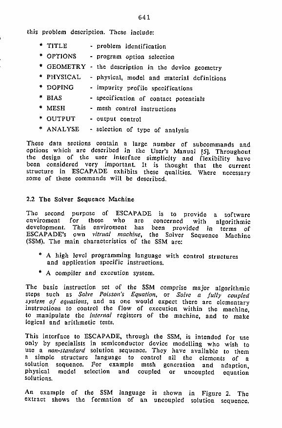
An example of the SSM language is shown in Figure 2. The extract shows the formation of an uncoupled solution sequence.
* TITLE
* OPTIONS
* GEOMETRY -
* PHYSICAL -
* DOPING
* BIAS
* MESH
* OUTPUT
* ANALYSE
642
Two carrier equations are used with the Poisson equation.
ANALYSE FROM * $ $ Example SSM algorithm $
INITIALISE BIAS FIX_N FIX_P PUT_INS SLV_POISS FREE_N FREE_P PUT_SEM SLV_INN SLV_INP UPD_VARS SLVJPOISS
$ $ Loops to balance the electron and hole concctrations
sequence
initialise the SSM Machine select next bias point fix n-quasi fermi potentials fix p-quasi fermi potentials put bias on insulator contacts solve Poisson's equation free n-quasi fermi potentials free p-quasi fermi potentials put bias on semiconductor contacts solve modified n-continuity equation solve modified p-continuity equation update of all dependent variables resolve Poisson's equation
CNVGD_OPT 4 l.D-6 -REPEAT
SLV_N SLV_P
UNTIL CONVERGED -
select convergence test and tolerance start of repeat block solve n-continuity equation solve p-continuity equation test convergence
Gummel loops for low injection problems
CNVGD_OPT 4 1.0D-5 RECOMB 1 REPEAT
CAL_REC SLV_N SLV_P SLV_POISS
UNTIL CNVGD OUTPUT
STOP
select convergence test and tolerance select SRH recombination start of repeat block calculate recombination solve n-continuity equation solve p-continuity equation solve Poisson's equation test convergence produce output file
- SSM sequence completed
Figure 2 : SSM Instructions
The flow of an algorithm can be controlled by a number of simple structures: a REPEAT-UNTIL, a DO-NEXT, and a IF-THEN-ELSE. The basic structure of these is illustrated in Figure 2. The SSM Machine also contains a number of registers which can be assigned by the program and used by the SSM instructions. Details on the use of these is given in the User's Manual [5],
643
3 The Basic Equations
The electrical behaviour of semiconductor devices is governed by Poisson's equation
e^2tf = -q [p - n + N+ .- Nf] (1)
and the continuity equations for electrons and holes
| H = + I V . J - U (2 ) d t q n n v '
£ £ = . I ^ . J - U (3 ) St q * p p ^
where ^ is the electric potential and n and p are the electron and hole densities. From a special case of Fermi-Dirac statistics, J n and Jp in (2) and (3) can be written as functions of the electrostatic potential and the electron and hole concentrations, n and p.
Jn - q/*nEn + Q'V7 1 1 (4 )
Jp = q/*pEp " QDp^P (5 )
where nn and / i p are the electron and hole mobilities and D n and Dp are the electron and hole diffusivities. If the effects of band-gap narrowing are assumed small, and assuming Boltzmann carrier statistics, the electric fields due to the electron and hole densities can be written as
E n = E p - E = " ^ (6 )
U n and Up in (2) and (3) represent the net rates of recombination and generation of electrons and holes. N a and N^ are the ionized impurity concentrations.
4 Mobility Models
The carrier mobilities nn and Up account for scattering mechanisms in the transport equations. ESCAPADE currently only contains two simple models. The simplest alternative is to choose constant mobilities for holes and electrons throughout the device. The effect of impurity scattering is also included by using local low-field mobilities which are characterised by the total impurity concentrations [6,7],
The most complex mobility model currently available in ESCAPADE is a field-dependent model. The model used is [6]
644
/ t (E) = 1 * I4*! l"
1/0
Mo (7>
where vs is the saturation velocity, |3 is a constant (usually 1 or 2) and fi0 is the low-field mobility. For Si [8] the saturation velocity is given by
2 . 4 x l 0 7
vs(T) = T V T (8) s 1 + °-8 [*ro]
5 Recombination and Generation
Currently only the basic Shockely-Rcad-Hall and Auger recombination models have been implemented in ESCAPADE [9]. These are given by the following expressions
n+n . I + T p + n . i[ I e J n [ H I C J
2 pn - n .
USRH - - r - i ^> T
P
where r p and r n are the hole and electron lifetimes which may be concentration dependent, and
UAUG = ( n i c " n P H c " - n + c P - P ) ( 1 0 )
where C n and CP are specified constants dependent on the physics of the semiconductor material.
In these equations n j c is the effective intrinsic concentration and is taken to be a function of the impurity doping [10]. The spatial variation of nj e to accommodate band-gap narrowing effects will also modify the electric field terms in the transport equations. The constants n j c can include this field dependence. Hence E n and E p
become
E n
E P
kT = - T7 "
V - " ln " i c ] <12>
6 Numerical Methods
ESCAPADE-I sets out to solve the steady state form to the semiconductor equations. The basic technique used to approximate the equations is the control region approximation as proposed by McCartin [11,12,13]. The major reasons for this choice are those
645
given in [11]. The approximation should:
1) be applicable to arbitrary geometries
2) be conservative
3) adequately treat the continuity equations
4) allow adaptive development of the discretisation.
The control region approximation provides for all of these requirements and is capable of efficient implementation in software. The starting point of the control region approximation is the conservative forms of the three governing equations.
f e | £ ds - JJ" (Nj-Na+n-p) dA = 0 (13) S " A
| ( D n | ? - « n n f £ ) ds - JJ Rn dA - 0 (14) J S A
IS<DP I f + "PP £ > dS • l I AR P d A = ° (15)
The control region approximation is applicable to many general conservation laws and consists of performing discrete flux balances over control region boundaries.
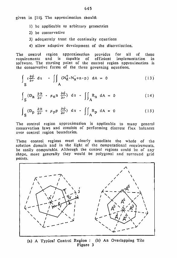
These control regions must clearly tesscllatc the whole of the solution domain and in the light of the computational requirements, be easily computable. Although the control regions could be of any shape, more generally they would be polygonal and surround grid points.
(a) A Typical Control Region : (b) An Overlapping Tile Figure 3
646
The control regions currently used in ESCAPADE are formed by using the Delaunay triangulation of the grid points [14]. The control regions arc constructed by using the perpendicular bisectors of the edges of the Delaunay triangularisation. The regions formed arc the Dirichlet regions [15] of the space and are dual to the Delaunay triangulation.
To illustrate the control region approximation it will be applied to the Poisson equation for the electrostatic scalar potential. The detail of this approximation can be found in [11] and [12], The treatment here differs only in the approximation of the charge terms. In order to approximate
ev2f = -qfp - n + N* - N^l (16)
the equation is recast in its divergence form, as in (13). A is any simply-connected region and s(.v) is a coordinate in the direction normal to the boundary of A (S). The first integral is approximated about a point p0, using straightforward finite differences for., the derivative of ^, along each edge of the control region. This leads to the expression
m
I •If'" -5«i[*Lii iT-i <"> b i = l
where q is the value of permittivity on the edge, TJ and hj arc characteristic lengths of the edge. r\ is the length of the edge and hj is the length of the perpendicular bisector of the z'th edge. These lengths are described in Figure 3a.
In the control region approximation the charge terms are in general assumed to be constant over the whole Dirichlet tile. This is similar to the technique of nodal lumping used in the finite clement and finite difference methods. The major difference is the area associated with the node and the types of permissible triangles. However, if the impurity distributions are step functions the charge approximation is modified. The charge term is broken into two parts
JJ p dA - JJ (p-n) dA + JJ (N d -N a ) dA (18)
The first integral is approximated by
JJ (p-n) dA = [ p ( X i , y i ) - n ( x i , y i ) ] . A i (19)
where (xj.yj) are the coordinates of the node enclosed by A and Aj is the area of this region. In the case of a step function impurity profile the second integral is approximated by
647
m
ff (Nd-Na) dA « ]> (Nj- N J ) . A * (20) A i = l
where NJJ and Njjj are the values of N^ and N a respectively on the kth part of the tile. The area of the fcth part of the tile is denoted by A}\ Over each subarea the impurity profile is assumed to be constant and special care is taken when subareas overlap the boundaries of underlying triangular mesh (as shown in Figure 3b)
The linearisation of the final equation formed from these approximations is
m
- S - ' p n T r H ' i + ( n o - p o - N o ) A » i = l
where n£, p£ and i/<£ denote the present estimates of these variables, and 5 is the difference between i/-k and the exact solution \p.
In most device simulators special discretisation schemes arc used for the carrier continuity equations. In general the scheme proposed by Scharfettcr and Gummel [16] is most often used. It is possible to extend the control region approximation to the continuity equations and introduce the Scharfetter-Gummel quite naturally. This is described in [11] and [12] in detail and will not be repeated here.
7 Mesh Generation
ESCAPADE is equipped to generate meshes for irregular, polygonal device geometry definitions. Given a geometric description of an arbitrary device, ESCAPADE will automatically generate a coarse mesh of triangles within the bounds of the device. This fully automatic mesh generation is sufficient to produce discretisations of a device based entirely on its geometric definition.
However for many device structures it is essential that the mesh be fine in certain regions. The refinement of a discretisation has been accommodated to two ways: by user interaction and by the use of automatic, program-driven refinement based on error estimates.
648
7.1 The Nature of the Triangular Mesh
The essential feature of the mesh generated by ESCAPADE is that the connectivity of the nodes is on a nearest neighbour basis. This ensures that the control regions associated with the nodes donot overlap. This is important since it will ensure that the discretisation of the electron and hole continuity equations is consistent throughout the device. In addition the nearest neighbour connectivity results in a mesh where most triangles do not contain obtuse angles. Since triangles with high aspect ratios are recognised as sources of discretisation error this choice of connectivity has considerable advantages.
7.2 Mesh Generation and Refinement
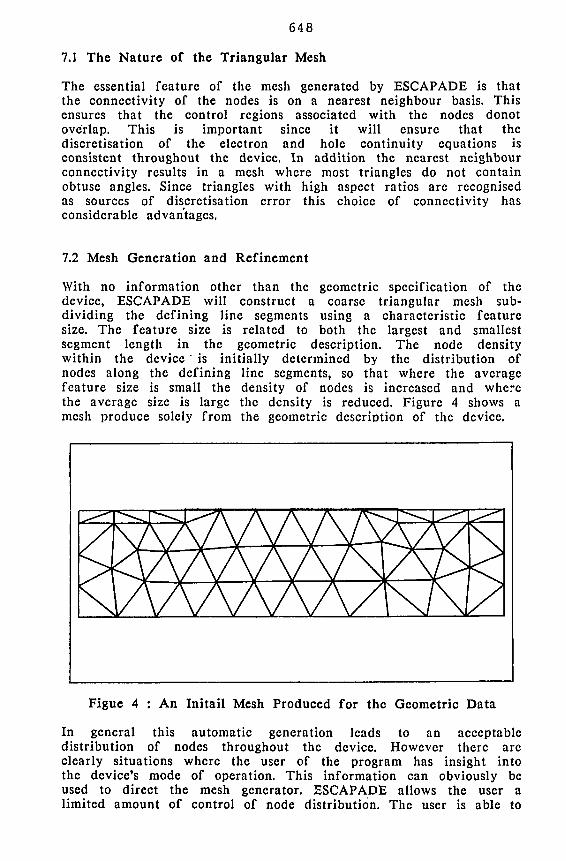
With no information other than the geometric specification of the device, ESCAPADE will construct a coarse triangular mesh subdividing the defining line segments using a characteristic feature size. The feature size is related to both the largest and smallest segment length in the geometric description. The node density within the device is initially determined by the distribution of nodes along the defining line segments, so that where the average feature size is small the density of nodes is increased and where the average size is large the density is reduced. Figure 4 shows a mesh produce solely from the geometric description of the device.
Figue 4 : An Initail Mesh Produced for the Geometric Data
In general this automatic generation leads to an acceptable distribution of nodes throughout the device. However there are clearly situations where the user of the program has insight into the device's mode of operation. This information can obviously be used to direct the mesh generator. ESCAPADE allows the user a limited amount of control of node distribution. The user is able to
649
specify the number of nodes generated on a particular defining line segment and bias the distribution to either end of the segment. A global element size can be specified which overrides that estimated within the program. The user can also add segments to the geometric definition or direct the generation of nodes. With these mesh control facilities it is thought that an experienced user can influence the mesh generation to advantage.
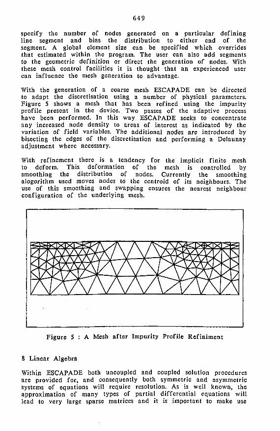
With the generation of a coarse mesh ESCAPADE can be directed to adapt the discretisation using a number of physical parameters. Figure 5 shows a mesh that has been refined using the impurity profile present in the device. Two passes of the adaptive process have been performed. In this way ESCAPADE seeks to concentrate any increased node density to areas of interest as indicated by the variation of field variables. The additional nodes arc introduced by bisecting the edges of the discretisation and performing a Delaunay adjustment where necessary.
With refinement there is a tendency for the implicit finite mesh to deform. This deformation of the mesh is controlled by smoothing the distribution of nodes. Currently the smoothing alogorithm used moves nodes to the centroid of its neighbours. The use of this smoothing and swapping ensures the nearest neighbour configuration of the underlying mesh.
Figure 5 : A Mesh after Impurity Profile Refiniment
8 Linear Algebra
Within ESCAPADE both uncoupled and coupled solution procedures are provided for, and consequently both symmetric and asymmetric systems of equations will require resolution. As is well known, the approximation of many types of partial differential equations will lead to very large sparse matrices and it is important to make use
650
of the sparsity of these systems. ESCAPADE takes into account this sparsity its solution procedures and takes use of disk files to maintain sparsity patterns and system information.
ESCAPADE contains two linear solvers currently: firstly an incomplete Choleski conjugate gradient solver for the uncoupled Poisson equations and the equations arising from the initial guess strategy, and secondly a fully sparse direct Gaussian decomposition for any asymmetric matrices arising from the uncoupled and coupled solution.
The ICCG solver ,is the classical conjugate gradient algorithm using a prcconditioner derived from the work of Gusstafson [17] and Meijerink and van der Vorst [18]. This method of solution is well recognised as being the most efficient for symmetric positive definite matrices.
The matrices arising from the continuity equations and the fully coupled system are asymetric and are currently solved using a variant of the sparse direct Gaussian reduction in the Harwell Subroutine Library [19] (Subroutine MA28, Duff [20]). This is provide a robust and efficient whilst research continues for an effective asymmetric iterative solver using one of the derivatives of the conjugate gradient method, such conjugate gradients squared (CGS, Sonnevcld [21]).
9 Conclusions
ESCAPADE is now in testing and is showing promising levels of performance on a number of simple benchmark problems. Over the next few months there will be a full evaluation of the current solver sequences implemented and an extension of the physical models contained in the program. It is hoped to report some of these at forth comming conferences.
Experience so far indicates that the virtual machine approach the algorithmic design and evaluation will become very important in many areas of mathematical physics, not only in semiconductor device simulation and there are already initial plans to use the approach in software for electromagnetics.
10 Acknowledgments
The authors wish to acknowledge the assistances of all those who have been involved in ESCAPADE for short periods during its development, particularly Dr P Bettes, Dr M Towers and D Byrne of University College Swansea, S Mulligan and N Ferguson of Trinity College Dublin, T K Patel of the Rutherford Appleton Laboratory and Dr P Mole of the GEC Hirst Research Laboratories.
651
11 References
1. Selberherr, S., Schutz, A. and Potzl, H.W. "MINIMOS - A Two-Dimensional MOS Transistor Analyzer" IEEE Trans. Electron Devices. ED-27, pp.1540-1550, 1980
2. Arnborg, T. and Bjorkqvist, K. "HALVFEM - a Computer Program for Two-Dimensional Finite Element Analysis of Semiconductor Devices" Int. J. Electronics, Vol.50, No.l, p.15-26, 1981.
3. Baccarani, G., Guerricri, R., Ciampolini, P., and Rudan, M. "HFIELDS: a Highly Flexible 2-D Semiconductor-Device Analysis Program" In: Proc. of the NASECODE IV Conf. (Ed.J.J.H.Miller), Boole Press, p.l, 1985.
4. Pinto, M.R., Raffcrty, C.S. and Dutton, R.W. "PISCES TI: Poisson and Continuity Equation Solver" Stanford University,. Stanford, CA 94305, September 1984
5. Greenough, C, Hunt, C.J., Fitzsimons, C.J. and Patel, T.K. "ESCAPADE User's Manual" Rutherford Appleton Laboratory Report, To be Published
6. Caughey, D.M. and Thomas, R.E. "Carries Mobilities in Silicon Empirically related to Doping and Field" Proc. IEEE. Vol.55, pp.2192-2193, 1967.
7. Selberherr, S. "Process and Device Modelling for VLSI" Microelectrn. Reliab., Vol.24, No.2, pp.225-257, 1984.
8. Sze, S.M. "Phvsics of Semiconductor Devices" 2nd. ed., John Wiley and Sons, New York, 1982.
9. Selberherr, S. "Analysis and Simulation of Semiconductor Devices" Springer-Verlag, Wien-Ncw York, 1984.
10. Roulston, D.J., Arora, N.D. and Chamberlain, S.G. "Modeling and Measurement of Minority-Carrier Lifetime Versus Doping in Diffused Layers of n+-p Silicon Diodes" IEEE Trans, nn Electron Devices. ED-29, pp.284-291, 1982
11. McCartin, B.J. "Discretization of the Semiconductor Device Equations", In: Proc.
of the Short Course held at NASECODE IV Conf. (Ed.J.J.H.Miller), Boole Press, p.72, 1985.
652
12. McCartin, B.J., Hobbs, R.H., LaBarre, R.E. and Kirschncr, P.E "Solution of the Discrete Semiconductor Devices Equations", In: Proc. of the NASECODE IV Conf. (Ed.J.J.H.Miller), Boole Press, p.411, 1985.
13. McCartin, B.J., Hobbs, R.H., LaBarre, R.E., Kirschner, P.E and Peterson, G.A. "Control Area Approximation on Dirichlet Regions Applied to Semiconductor Device Simulation" Submitted to IEEE Proceedings.
14. Delaunay, B. "Sur la Sphere Vide" Bull. Acad. Sci. USSR (VIIV. Classe Sci., Mat. Nat., pp.793-800, 1934.
15. Dirichlet, G.L. "Uber die Reduction dcr Postitiven Quadratischen Formen mit drei Unbcstimmten Ganzcn Zahlcn" Z.Reine Angew. Math.. Vol.40, No.3, pp.209-227, 1850.
16. Scharfetter, D.L. and Gummel, H.K. "Large-Signal Analysis of a Silicon Read Diode Oscillator" IEEE Trans. Electron Devices. ED-16, pp.64-77, 1969.
17. Gustafsson, I. "A Class of First Order Factorization Methods" BIT. 18, pp.142-156, 1978.
18. Meijerink, J.A. and van der Vorst, H.A. "An Iterative Solution Method for Linear Systems of which the Coefficient Matrix is a Symmetric M-matrix" Math, of Comp.. 13, pp.148-162, 1977.
19. Hopper, M.J. "Harwell Subroutine Library: A Catalogue of Subroutines" AERE Harwell, Report R-9185, HMSO, London, 1984.
20. Duff, I.S. "MA28 - A Set of Fortran Subroutines for Sparse Unsvmmetric Linear Equations" AERE Harwell, Report R-8730, HMSO, London, 1977.
21. Sonneveld, P. "CGS. a Fast Lanczos-tvpe Solver for Nonsvmmetric Linear Systems" Department od Mathematics and Informatics, Delft University of Technology, Report 84-16, 1984.
Top Related
Copyright © 2022 FDOKUMEN

