


Bahasa
Halaman
Hukum

WM2011 Conference, February 27-March 3, 2011, Phoenix, AZ
Disposal of Spent Fuel from German Nuclear Power Plants:
The Third Option - Disposal of Transport and Storage Casks (Status) – 11517
Wolfgang. Filbert*, Marion Tholen*, Hans-Joachim Engelhardt*
R. Graf, K.-J. Brammer**
*DBE TECHNOLOGY GmbH, Peine, Germany
**GNS - Gesellschaft für Nuklear-Service mbH, Essen, Germany
ABSTRACT
In Germany, the reference concept for the disposal of high-level radioactive waste (HLW) and spent fuel
(SF) [1] proposes geological disposal in a rock salt formation. While HLW canisters (mainly canisters
with vitrified waste from reprocessing) are to be disposed of in vertical boreholes, SF is to be placed in
heavy, self-shielding containers (POLLUX
®
, weight 65 t) which are to be emplaced in horizontal disposal
drifts. For the disposal of SF, an alternative concept – the so-called "BSK 3 concept" – has been
developed which relies on a vertical borehole emplacement technology. (Note: BSK 3 is the German
acronym for fuel rod canister). As a third option, the feasibility of direct disposal of transport and storage
casks – the so-called "DIREGT" concept – is being investigated. It offers the possibility to avoid the
feasible but quite complex conditioning of fuel assemblies, thus reducing radiation exposure to the
personnel and reducing arisings of operational wastes. Studies carried out so far are promising and
support further investigations and development work.
Taking into account the progress in shaft hoisting technology, the principles of shaft transport of large
transport and storage casks (TSC) with masses of up to 160 t (e.g. CASTOR
®
type casks prepared for
disposal) are being investigated. A pre-feasibility study on corresponding options for shaft hoisting, drift
transport, and emplacement systems was carried out. The concepts for drift and borehole disposal of these
casks were compared by means of numerical calculations of the heat input and heat transfer into the host
rock. The calculation results showed that borehole disposal requires a considerably shorter interim storage
time (40 a) to reduce the heat input than drift disposal (70 a). A draft layout of an emplacement field was
designed based on thermal calculations. A further comparison of vertical and horizontal borehole disposal
showed that the latter has a clear advantage as regards operational safety of the repository. Further issues
being investigated are questions regarding subcriticality of TSCs and the measures required to ensure
subcriticality in the hypothetical case that fluid enters the casks.
INTRODUCTION
Since the late seventies, the Federal Ministry of Education and Research has been researching the disposal
of high-level radioactive waste (HLW) and spent fuel (SF) in a rock salt formation. Simultaneously, the
German utilities, currently represented by GNS - Gesellschaft für Nuklear-Service mbH, has supported
this research with the development of casks for the transport of disposal packages and casks for final
disposal. Until 1994, the Atomic Energy Act (AtG) stipulated that the only way for the German utilities to
dispose of irradiated fuel assemblies was the reprocessing of SF assemblies.
Although the initial disposal concept thus only considered the disposal of waste from reprocessing,
research work on the disposal of waste from reprocessing in boreholes and the disposal of final disposal
cask with spent fuel in horizontal drifts already started in the late seventies. As an alternative to SF
reprocessing and disposal of vitrified HLW, the direct disposal of SF was developed further. The
feasibility was assessed, the disposal equipment built and tested, and all safety aspects were evaluated.
The results of the R&D project “Direct Disposal of Spent Fuel” [2] lead to an amendment of the Atomic
Energy Act in 1994 which then allowed the direct disposal of SF without prior reprocessing. After a

WM2011 Conference, February 27-March 3, 2011, Phoenix, AZ
change of government, reprocessing of SF ceased on June 30, 2005. Today, direct disposal is thus the
only way SF can be disposed of in Germany.
THE FIRST OPTION – DISPOSAL OF POLLUX
®
CASKS IN DRIFTS
The German reference concept for the disposal of HLW and SF proposes geological disposal in a salt
formation. The POLLUX
®
concept anticipates the emplacement of heavy (65 t), self-shielding casks
(Fig. 1) containing the fuel rods of disassembled LWR spent fuel elements in horizontal drifts of a
repository mine at a depth of approximately 870 m. The void drift space around the casks will be
backfilled with crushed salt shortly after disposal.
Fig. 1. POLLUX
®
cask.
A first equipment demonstration program in the early nineties concentrated on the direct disposal of SF.
The concept anticipates the packaging of fuel rods of up to 10 spent PWR fuel assemblies (about 5 tHM)
or 30 BWR spent fuel elements into a POLLUX
®
cask with a gross weight of approximately 65 metric
tons. Together with the weight of the transport cart and the ancillary equipment, this requires a shaft
hoisting system for a payload of 85 metric tons. One core aspect of the first equipment demonstration
program therefore was to convincingly show that the shaft hoisting of such payloads is feasible and can
be realized in compliance with nuclear safety requirements. However, the other relevant handling
procedures and the equipment needed for the direct disposal of SF were also included in the
demonstration program. Equipment relevant to safety that was not state of the art was constructed and the
handling procedures were tested in full-scale surface test facilities (Fig. 2).

WM2011 Conference, February 27-March 3, 2011, Phoenix, AZ
Fig. 2. Shaft transport and emplacement tests.
In order to optimize the reference concept, all operational steps were reviewed for possible improvements.
The review process initiated the development of a second option for the direct disposal of SF, the BSK 3
concept.
THE SECOND OPTION – DISPOSAL OF FUEL ROD CANISTERS IN VERTICAL
BOREHOLES
At the end of the 1990s, the development of a second concept, called "BSK 3" concept (in accordance
with the acronym for the German word for fuel rod canister), was started. In contrast to the POLLUX
®
concept, this supplementary concept relies on a vertical borehole emplacement technology and was
investigated further as it promised advantages regarding operational simplifications and long-term safety.
The BSK 3 concept also relies on the separation of fuel rods from the structural parts of the fuel
assemblies but – unlike in the POLLUX
®
reference concept – the fuel rods are packed into a BSK 3
canister (43 cm diameter, 5 m length, 5.2 t weight) which has the same diameter as a canister with
vitrified HLW (43 cm diameter, 1.3 m length, 0.5 t weight) [3]. The new canister may contain the rods of
3 PWR or 9 BWR fuel assemblies [4].
The corresponding BSK 3 disposal concept was jointly developed by GNS and DBE TECHNOLOGY
GmbH, funded by the German utilities, represented by GNS, and by the German Ministry of Economics
and the European Commission.
Like vitrified HLW and other waste from reprocessing, the BSK 3 is to be disposed of in up to 300-m-
deep, unlined, vertical boreholes with a diameter of 60 cm which are drilled from the repository drifts
(Fig. 3). The diameter of the boreholes is slightly larger than the diameter of the waste canisters (43 cm).
The main advantages expected to be gained from the implementation of the BSK 3 concept are:
• almost direct heat transfer to the host rock,
• improvement of long-term safety: enclosure of the waste will be completed within only a few months
due to the small void space around the BSK 3 canisters in the borehole,
• reduced spatial extension of the repository due to three-dimensional utilization of the host rock,
• reduction of potential gas problems due to significantly reduced amount of metal,
• reduction of the various canister and cask systems required due to the fact that the BSK 3 canister has
the same external diameter as the vitrified HLW canister, and

WM2011 Conference, February 27-March 3, 2011, Phoenix, AZ
• reduction of the quantity of disposal operations by constructing an overpack for 3 vitrified waste
canisters which has the same total length as a BSK 3.
Fig. 3. Outline of the BSK 3 disposal system and full-scale test stand.
THE THIRD OPTION – DISPOSAL OF TRANSPORT AND STORAGE CASKS (TSCs)
As a third option, the feasibility of direct disposal of SF and waste from reprocessing (HLW) in transport
and storage casks (TSCs), the "DIREGT concept", is being investigated.
Concerning SF, the implementation of the third option would avoid the necessity to separate fuel rods
from structural parts and to procure custom-made final disposal casks. Furthermore, canisters containing
waste from reprocessing would not have to be transferred from a TSC onto a transfer cask for transport
and disposal operations. After the German Government decided at the end of 2010 to extend the lifetime
of the German nuclear power plants, a total of about 1600 TSCs with spent fuel need to be considered,
based on the estimated quantities of heavy metal (HM). In addition to this, 300 TSCs for reprocessing
residues are stored in interim storage facilities. If the first or second option is implemented, 1900 TSCs
will have to be scrapped.
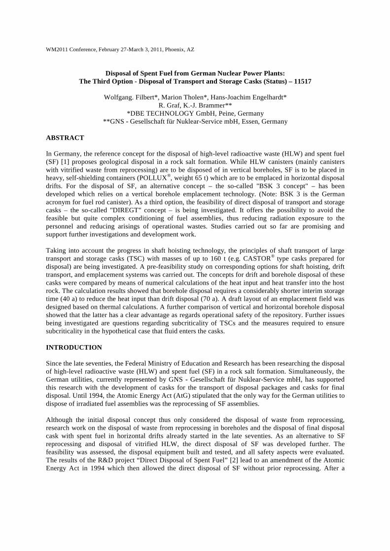
Transport and Storage Casks
In the following text, the CASTOR
®
V/19 and CASTOR
®
HAW28M transport and storage casks are
briefly described (Fig. 4). The CASTOR
®
V/19 is a TSC for PWR fuel assemblies while the CASTOR
®
HAW28M is a TSC for 28 HLW canisters. Both casks have a thick-walled cylindrical body made of
WM2011 Conference, February 27-March 3, 2011, Phoenix, AZ
ductile cast iron. For neutron shielding, axial boreholes are drilled into the cask walls and filled with
moderator rods made of polyethylene. In addition to this, there are shielding elements in the baskets,
moderator plates at the bottom, and multi-part moderator plates at the top. The casks are sealed with a
primary lid. When the casks are in interim storage, a secondary lid is tightly secured on top of the primary
lid ("storage configuration"). Radial cooling fins are mounted to the outside walls to improve the heat
transfer to the environment. Four trunnions are used for handling and to transfer the casks onto transport
equipment.
Fig. 4. CASTOR
®
V/19 and CASTOR
®
HAW28M (source: GNS).

WM2011 Conference, February 27-March 3, 2011, Phoenix, AZ
Adjustments of TSCs for Disposal
The "DIREGT" project also concentrates on investigating whether the TSCs need to be adjusted for final
disposal. Concerning SF, adjustments of the reference casks (CASTOR
®
V/19) may result from the
necessity to demonstrate subcriticality and sufficient cask integrity in repository conditions. The studies
so far do not conclusively demonstrate subcriticality and cask integrity for direct disposal. To maintain
subcriticality, it is recommended to fill the void space in the cask with depleted UO2 or other non-
moderating material such as magnetite. These measures would increase the total weight of the TSCs to
approximately 160 t. Reliable data on cask integrity are not yet available. Effects of surface corrosion of
the TSC material have been estimated and have to be supplemented by effects of local corrosion, based on
realistic assumptions on the existence of corrosive media, if any. Furthermore, requirements on the
tightness of the screwed or welded joints between cask body and primary and secondary lids under
repository conditions still need to be derived, and the tightness has to be demonstrated.
Thermal Calculations for TSC Disposal
Using numerical calculations of the heat input and heat transfer into the host rock, two TSC concepts
were compared:
• disposal in drifts as in the reference concept
• disposal in boreholes
The calculations took into account the requirement that the temperature in the salt formation does not rise
above 200° C at any time. This temperature is the accepted design criterion for the disposal of heat-
generating waste in salt. The calculation results showed that borehole disposal requires a considerably
shorter interim storage time (40 a) to reduce the heat input than drift disposal (70 a). A further comparison
of vertical and horizontal borehole disposal showed that the latter has a clear advantage as regards
operational safety of the repository.
Shaft Transport
In the POLLUX® reference concept, a payload of approximately 85 t (cask and transport cart) needs to be
hoisted from the surface to the repository level. After detailed design studies that identified all systems
and components that were not state-of-the-art at the time, a hoisting system for such heavy payloads was
developed. With a redesign of the Koepe shaft hoisting system (cage and counterweight system with
balance rope), it should be possible to increase the payload to 160 t. Corresponding investigations are
ongoing.
Underground Transport and Disposal
When arriving underground, the TSC is loaded on a combination transport cart/emplacement device. For
safety reasons, a rail-bound transportation was selected. A battery powered mining locomotive pushes the
transport cart/emplacement device to the emplacement field. There, the device is positioned on a turntable
in front of the horizontal emplacement borehole (Fig. 5). After the device has been fixated, the TSC is
pushed on sliding elements into the borehole. Subsequently, the void space around the TSC is backfilled
with crushed rock salt.

WM2011 Conference, February 27-March 3, 2011, Phoenix, AZ
Fig. 5. TSC emplacement in a horizontal borehole.
Fig. 6 shows a complete emplacement field for 70 TSCs based on the calculated minimum TSC-to-TSC
distances.
Fig. 6. Emplacement field for 70 TSCs.

WM2011 Conference, February 27-March 3, 2011, Phoenix, AZ
CONCLUSION AND OUTLOOK
The reliability and safety of the disposal technologies for the direct disposal of SF have been
demonstrated for the first option (POLLUX
®
concept) and for the second option (BSK 3 concept). The
third option (disposal of TSCs) would allow the disposal of all kinds of SF and HLW without the need to
reload the waste into custom-made final disposal casks and to disassemble spent fuel assemblies. The
ongoing research recommends that the void space in the TSCs be filled with non-moderating material,
such as depleted UO2 or magnetite. These measures would increase the total weight of a TSC to 160 t.
Further investigations are needed regarding mechanical integrity under repository conditions.
The equipment for hoisting payloads of up to 160 t is not state-of-the-art. Currently, the Koepe shaft
hoisting system which is part of the POLLUX
®
reference concept is being redesigned. Thermal
calculations show that the emplacement of TSCs in horizontal boreholes would be possible after interim
storage times of 40 years. A comparison of vertical and horizontal borehole disposal showed that the
latter has a clear advantage as regards operational safety of the repository. The underground transport is
intended to be rail-bound. The transport device could be a combination of a transport cart and an
emplacement device. All investigations and studies carried out so far showed no critical aspects that
would impede the disposal of TSCs.
Fig. 7 shows the current state of developments. The work will continue.
Fig. 7. Current state of developments.

WM2011 Conference, February 27-March 3, 2011, Phoenix, AZ
REFERENCES
1. Aktualisierung des Konzepts “Endlager Gorleben”, Abschlussbericht, 13.02.1998, BfS,
unveröffentlicht.
2. H.-J. ENGELMANN et al., “Systemanalyse Endlagerkonzepte, Abschlussbericht, Hauptband”,
(System Analysis Repository Concepts. Final Report. Main Volume.), DEAB T 59 (1995).
3. W. FILBERT et al., “Resultate der Arbeiten zum Endlagerkonzept Direkte Endlagerung abgebrannter
Brennstäbe in Brennstabkokillen”, KTG Conference, May 2010, Berlin.
4. H. SPILKER, “Status of the Development of Final Disposal Casks and Prospects in Germany”,
DISTEC '98, International Conference on Radioactive Waste Disposal, September 9-11, 1998,
Hamburg.
Top Related
Copyright © 2022 FDOKUMEN

