Development of Spent Fuel Remote Handling Technology
248
KR0000089 KAERI/RR-1924/98 5| #^I1 Development of Spent Fuel Remote Handling Technology Development of Swing and Shock Free Crane A 31/ 30
-
Upload
khangminh22 -
Category
Documents
-
view
0 -
download
0
Transcript of Development of Spent Fuel Remote Handling Technology

KR0000089
KAERI/RR-1924/98
5| #^I1
Development of Spent Fuel Remote Handling Technology
Development of Swing and Shock Free Crane
A
3 1 / 30
KAERI/RR-1924/98
Development of Spent Fuel Remote Handling Technology
^ a all elDevelopment of Swing and Shock Free Crane
7}
7|
1999. 4.
04
HI-
0| g #
0| ^ s
- 1 -
NEXT PAGE(S)left BLANK
O Ol:
II. 51
7)
in.
sa
- iii -
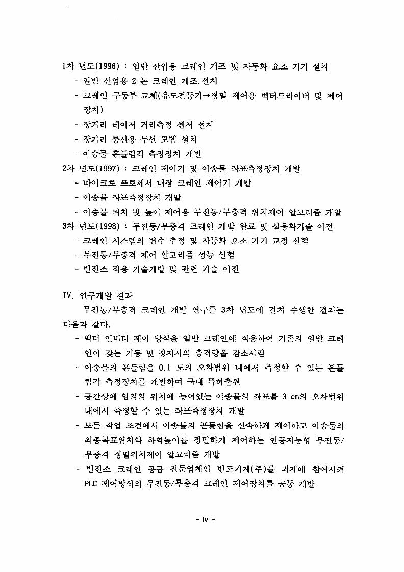
\1JE(1996) : <*m #<g-§- 3 4 * ! 7\2, % *}^£f jg.^ 7] 7]
2 * 3 4 * !
: 34*!
34*!
34*! ?fl
- 34*! ^1^^^ ^ r ^ ^ ii ^^Sf A i 7171
IV. 9 ^ ^
34*!
3 4 * ! ^ ^-§-*H 71 31 ^^J: 3 4
*!<>1 4 ^ 71* ^ ^
0.1
b 3 4 « ! g-g- %APLC aHHH^l -f-^*/"?"^^ 3 4 « !
- iv -

fe 55 ^ c.
V.
- v -
NEXT PAGE(S)left BLANK
S U M M A R Y
I. Project Title
Development of Swing and Shock Free Crane
II. Objective and Importance of the Project
Cranes are widely used for handling radioactive heavy materials
in nuclear facilities. They are typically used to exchange the fuels
in PWR reactor, transport and store spent fuels in spent fuel
storage rack, and load and unload radioactive waste drums in the
radioactive waste storage. These kinds of works require the
capability of the precise transportation of material as well as the
remote controllability to provide safety measure and to reduce the
radiation dose to the crane operators. Since these capabilities are
not provided in conventional crane, the concept of automatized crane
is introduced to enhance the safety measure in the loading/unloading
operation of the radioactive waste drums at the nuclear power
plants. Thus, the presented R&D effort is aimed at providing the
relevant technology to realize this concept and developing the swing
and shock free crane.
III. Scope and Contents of the project
To develop the automatized crane and its relevant technology,
this project began in 1996 as a 3 year project. The R&D scope of
each year is as follows;
Year 1(1996) '• setup the hardwares of the swing and shock free crane
- fabrication of industrial crane of 2 ton capacity
- replace manual control scheme by computer-controlled scheme
- install a laser displacement sensor which precisely measures
- vii -
the travel distance over 500 meter
- install radio communication modems to provide wireless
communication
- develop a swing angle measuring device
Year 2(1997) : develop the control systems and a laser localizer
- design on-board crane controller embedded with /i-processor
- develop a laser localizer which measures location and
orientation of the arbitrarily located objects
- develop the swing and shock free control algorithm
Year 3(1998) : develop the prototype of swing and shock free crane
and technology transfer
- identify system parameters
- verify the performance of the developed components
- investigate the control characteristics of the crane
- technology transfer to a industrial sector
IV. Results of Project
3 years R&D results can be summarized as;
- By adopting Vector-Invertor Control, the degree of shock can be
greatly reduced particularly at start and stop position
- The swing angle measuring device has been developed which
measures the swing angle of transported object with accuracy of 0.1
degree. Also its design has been submitted for domestic patent
application.
- The laser localizer has been developed which measures the
location and orientation of the arbitrarily oriented objects with
accuracy of 3 cm.
- The swing and shock free control algorithm has been developed,
which rapidly reduces the swinging of the transported object and
precisely controls the object position in any case.
- viii -

- The PLC based crane controller has been jointly designed with
Bando Machinery Co. LTD. which can be directly applicable to the
nuclear power plants.
- The drum grapple device, which remotely grasps a 55 gallon waste
drum, has been developed.
- The crane supervisory program has been developed which commands
a crane, and monitors the crane operation in a remote environment
- The swing and shock free crane and its relevant technology
developed up to date has been transferred to Bando Machinery Co.
LTD.
V. Proposal for Application
Bando Machinery Co. LTD. contracted the project of installation
of the solid radioactive waste-handling crane in the Youngkwang NPP
units 5 and 6 by October 2000. Currently it is designing the
concepts of this crane by adopting the transferred technology.
- ix -
NEXT PAGE(S)left BLANK

C O N T E N T S
Chapter 1. Introduction 1
Chapter 2. State of art of swing and shock free crane 5
Section 1. Introduction 5
Section 2. Foreign research status 5
Section 3. Domestic research status 6
Chapter 3. Contents and results of research 9
Section 1. Design and fabrication of swing and shock free crane 9
1. Modification of industrial crane 10
2. Sensors 15
3. Swing angle measuring device 19
4. Laser localizer 24
5. Crane controller 28
Section 2. Mathematical modelling of overhead crane 38
Section 3. Control algorithms 42
1. Swing free control 42
2. Swing free control by velocity tracking algorithm 42
3. Position control using hybrid genetic algorithm and fuzzy
theory 43
4. Fuzzy learning control 45
5. Algorithm for object localization 53
Section 4. Simulation of control algorithms 58
1. Crane control using genetic algorithm 58
2. Fuzzy rule generation by fuzzy learning 63
Section 5. Preliminary experiments of swing and shock free crane 69
1. Operation method of vector inverter 69
2. Parameters setup for vector inverter 70
3. Identification and calibration of crane system parameters 73
4. Performance test of crane 93
5. Performance test of laser local izer 113
Section 6. Performance test of swing and shock free crane 123
- xi -

1. Open-loop control 123
2. Closed-loop control 128
Section 7. Applicable technology for nuclear power plant 132
1. PLC control system 132
2. Remote grapple device of waste drum 150
3. Crane operation program 163
Chapter 4. Conclusions 185
References 189
Appendices 193
- XII -
1 ^ ^ f 1
4 i ^ M"i 55
^ ¥&&^^ }d # ^ ^ W 64 3 # t&^m -HM-S- 51 ^ 9
4 1 ^r^/^f-l^ 3. 1<a A]>^^ ^ ^ 91. 3.HM *£%] 102. -SH ^1 153. ^r^-i- ^§^1 4.5^H8#*1 194. o l ^ # 3^S - ^ ^ 1 245. 3.$]<& 4 < H ^ 1 28
j 3842
42
2. ^S^II^ ^ ^ ^ § ^ 4 ^<^ 42
3. &&<&3.B\&3\ ^*}°}^-§r ^ ^ * > ^^1-?-^ *\]°] 43
4. 2 ] ^ ] ^ ^ * M 455. oj^-i- 2|-^4^ ^ 2 | f 53
58
m & % i ] 582. ^^ ]^^of l 3)*} z\x\^-*\ Ag^ 63
^1 ] ^ ^ 69^ \ \ \ 4^ ^ ^ 69
2. £ B ] ^ ^ ^ u 7 0
3. £131 o J - M ^ ^ ^ ^ ^ % 3.^ 734. £2.efl<a ^ ^ A | ^ 93
5. ^Usfffi ^-^g ^ ^ 113
123
123
- XIII -

2. spqs *W ^ 1287 | - ¥ -#^ /^3 3.ej]<a ^ £ 1 - 7l# 7g^ 1321. ^ ^ A ? " ! ^ ^^1^1 PLC ^IH ^ ] ^ ^ 7fl*}; 1322. 3^l7)# S . ^ ^^3r}>c]^) 7lyJ: 1503. ^•^^•/^•^^ 3.^]<H ^r-§- 5 S 2 ^ 163
4 ^ 4. ۥ 185-*i 189
193
- xiv -

S. 1 3.^}<d 7}£M<g 12a 2 -§^yo^]-§- ^ ^ \ &M *\<$ 16a 3 4°W #7^1 ^m A}<$ 17Jt 4 - M i ^ A}<£ 18
a 5 4 - £ ^ 1 2.31-§• 22SL 6 LADAR 2D-50S} *}<$ 27
a 7 ^ o i ^ B | A}<g 29
3£ 8 3.$}<>A ^1«H7)^ A}6ot 32
A 9 3.$]<& z\]o\7}<$ nflael -7-S 34
5 : 10 CPU^ INT.PENTil- 1NT_M,ASK 36
S 11 CPU£| I0C1 37
S 12 *R>5.AH *H-Q ^ 59S. 13 ^^i^-3.el#<Hl *}&# ^ ^ 59
s 14 -^^jie i## *y%-n zmn % *\x]^ 6oa 15 3.T5\ ^ ^ :& 72
a 16 ^ ^ ^ ^ ^ ^ ^ ^ 74S 17 X, Y, m o]^7]e] -y^^3i} 75
S 18 8 ^ - 5q#<*f.& ^ ^ ^ ^ f 77
S 19 ^ ^ Hi-fi 51^1^-S ^ - ^ ^ ^ f 78fi 20 =g^f Hj-fl Sl^i^-£ ^ - ^ ^ ^ 79a 21 atH>M»fl 6J^ ^ i^ ^ # ^]*t ^ ^ ^t soa 22 4 s ^ - ^ 7 i ^ - ^ ^ ^ ^^i- 103a 23 #zH ^^g^^ ^ ^ in
a 24 i ^ ^ i q A*f 121a 25 *>:£7]7M 10^- 3.^1^1 A><g= 134a 26 PLC f i . -^-^- 136a 27 ^ ^ ^bJ5. ^ - ^ 144a 28 # ^ ^ja. ^ ^ - s ^ 145a 29 Ml-?- i H o ] Jf^. 146S 30 JE.^ *1 A}6OV 154
S 31 AC A]^.a.E.# -8-^31 4<g 155
- xv -
a 32 tsffojBlHfloJ-t 4<H e l ^ S . 165&. 33 - b ^ 3x>< e j^M 166
3SE 34 COMMINI.INI FILESJ ^-2i 167S 35 REFEINI.INI FILES] ^2. 1683£ 36 3.31 1 4cH7]7f ^ ] ^ ^ PCS Jiiflfe- <&$. 170S 37 3.^|«1 5L7JS}- ^ ^ 171S 38 Jog Control^] Start ^ ^ 172S 39 ^#5c) A|?> ^^g tg^ 173
fi 40 Path Control^] Start*g*g 174
- xvi -

=3 —i
1 2-E-2 ^&&^$ } HJ3 -?-^3M ^ 4 ^ 3 #*1 7fl IE. 214 S # e | ^^cM - f ^ ^ 2*}# 4JE.<3HS!#*] 23
5 zte-SHS-MT1-^ 236 o]^u§ s | - a ^ ^ 7jJ^JE 25
7 t^iMl ^-^^1 268 #^2f^ ^ - ^ ^ 1 ^ *H7}1^ 269 3.^161 4<^7l ^ ^ ^ ^ - 7 ) J ^ i £ 30
10 ^ ^ 1 ^ / ^ - ^ ^ ^^1°J 4 < H ^ 1 3111 3.eH<y af|<H7l 32
12 ^]oi7l ^ - ^ ^ 7j)^i 34
13 s s a ^ 7H 4 3514 3.^1 <?i l 3*HI ^ ^ 3815 S-pattern <%£ ^ | ^ 4316 3 | ^ | ^ ^ . ^)<^ <y>LBl^. 45
17 7]^^7|15.A-| 2}X] ^)o]7l 46
18 ^ ^ ^ ^ ^:3E 46
19 4 7 1 ^ ^ ^TJli] M} - 9 -^ 4820 £L31<?1 ^r^i^- ^*> ^l<H7l^ # ^ - ^ i £ 5121 ^ ^ o)^§ 54
22 -^^7]- ^ ^ ^ 1 ^ ^ o l ^ ^ - 55
23 ^l^-^^I ^ 3 <^1^# 5724 3Ja|3f ^ 3 | ^ ] ^ . 4 | ^ o|-g.*V 3.^}6l o)-§. ^A>j iA f 61
25 a i ^ ^ f ^ a j ^ l ^ . ^ ^ . o]-g-*> 3.^)^1 <>]%• &&5S} 62
26 5|x|*ra. 4<H7H ^ ^ n]-#<H^ 3^J9J ^ £ f l | ^ 6627 3.5)1*1 # ^ ^#*§] 6628 3.3]<>1^ o | ^ ^ ^ ] 67
29 # ^ o ] 5 ] ^5f 6730 3. 1 1 #*] ^i-iy 68
- xvii -

31 a.^1^1 o)^. * j 68
32 AS^HJ ^ \ 71
33 5 L O | ^ E . S.^O] T&Q6\] icf^ z | s . 4 ^ 7 l ty°]°\$) ?1°] *LS*
82
34 4 ^ 4 ^ 7] Sj-S 83
35 Z j - J ^ H M ^ 5:7] #*] 87
36 SS^oJ £SH *W 4-£^-^7] ^.7]^ -$ 91
37 x^3if y4<s1 *1^1^ 93
38 -3.31*1 3 ^ - § - ^ ^ ^ 7 f f^£ 9539 ^ * ^ ^ sK* - § - ^ ^ ^ ^ ^ 9640 ^ ! ^ ^ - ^ 4 ^ r - § - ^ ^ ^ ^ 97
41 3 L O | ^ ; E ^ ^ 2 } ^ - § - ^ ^ ^ ^3\ 98
42 ^ g ^ - 4 ^ - § - ^ ^ ^ ^21- 99
43 ^ * 5 ^ ^ l ^ - § - ^ ^ ^ ^ ^ " 10044 ^l^l>iS.^- ^]^>-§-^^^ ^2f 100
45 4 s ^ - ^ 7 l Al^5> ^ ^ ] S . ^ 102
46 4iE.^-^7l Al^»> *o»vCS.^ 10347 :to]2:A}3: ^ 1 T 1 # )*> ^ s f -f-3q-^B| 104
48 o ] ^ ^ - ^ § ^ 1 < % ^ ^ ^ ^ ^ 105
49 ##*l-gr^ 10650 H^7\ $Xt= 7 1 ^ ^ 107
51 ¥3.2) ^}^M 14-g. i f l« l^ ^Sf 112
52 ^^1/^4 ^ . ^ ^ iL^ 113
53 LADAR 2D-50-§- 4-§"t> #^11 ^ ^ 115
54 S . ^ # x ^ «ov*o*-^- ^ ? ^ t> 1° ]^ 116
55 S . ^ ^ «>i]^l^# 117
56 x - y ^ # oj-g-*]: H ^ ^ j <Hl^^-i- 118
57 3.Q2] ^l^l^-i-(3Sl >r^) 119
58 S < ^ ^ ^^^J- 119
59 ^ ^ o m ^ ofl*l^#(3S] ^ ? J ) 12060 fi3]om<q ^|^| ^ . ( 7 ^ >.?ifl) 12261 A}c}e] ^ - i ^ H 123
62 ^ - ^ ^ 4 4 ol^rl"^ ^#^] 126
- xvili -

63 <y<q<4 ^ s ^ s - l - 3-§-*f2ia- 4 o)^*] g 12764 £) <q <^S. i£S. £#*}&# 4 o]^ iq £ ^ 129
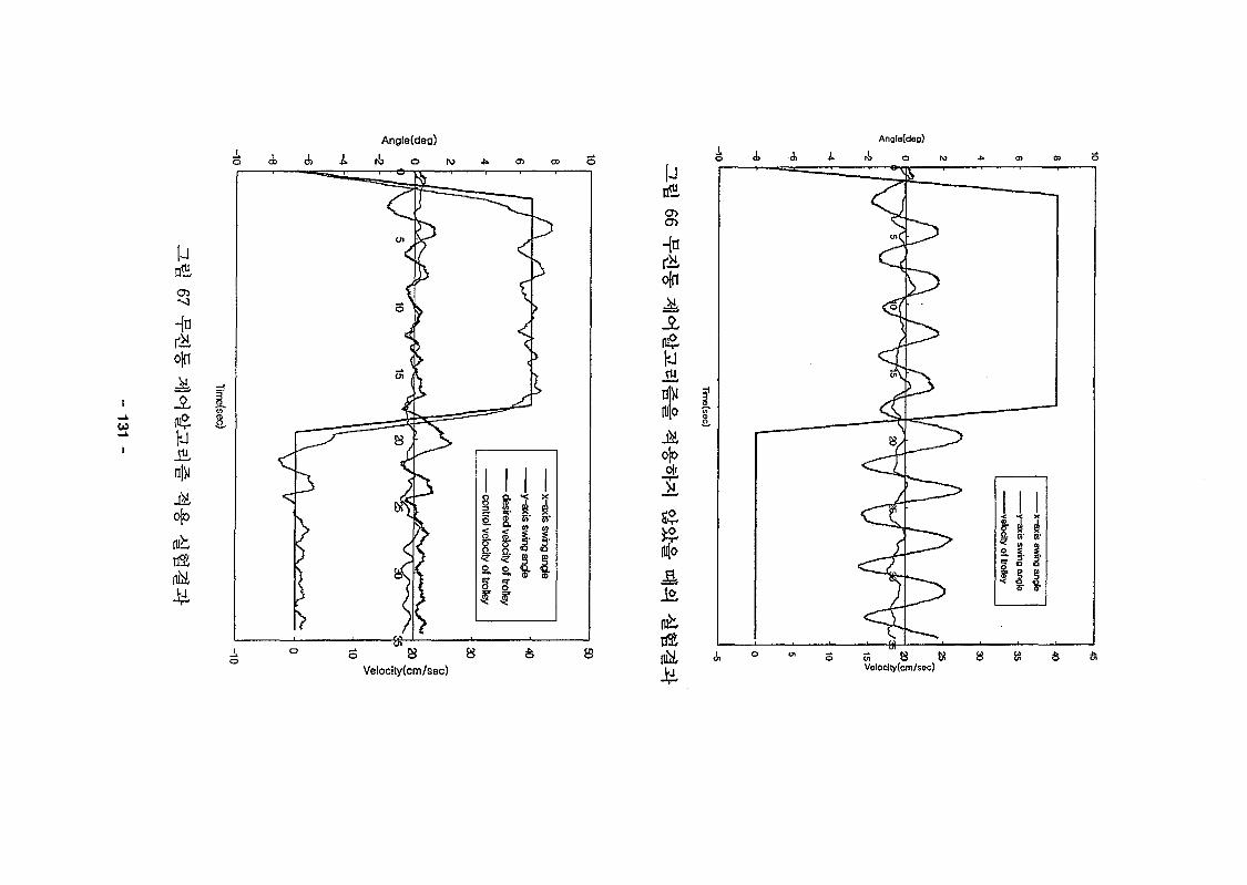
65 ai^s] 4 ^ 5 ^ -*H a- W •=«**&& 4 °l^-i^ #^ • 130
66 ^ ^ ^l<H^3.5l## 3-§-*}*l & & # 4 3 ^ ^ ^ 2 f 13167 ^ ^ 1 - ^ ^ H ^ ^ - e l ^ - ^j-§- ^ ^ 2 f 131
68 10^. j a . ^ ] ^ / ^ . ^ ^ a.e)|«sl PLC ]«H A l ^ 7H^JE. 133
69 3.$}<>\ ^ H # t > PLCif ^ 7 | 7 l tiff^S. 135
70 ^ 1 - ^ 3.$]<& ^ H # t > PLC S # 9-^-£. 138
71 PLC HSZL^ 7H^: ^A-lS 142
72 PLC ^^.ZLsJIU &*\5. 143
73 <^^ 4 5]^-£ I 147
74 «y^ Sl^-S. II 148
75 # ^ ^ - 51S.S. 149
76 JE.^ * H M ^ 9-3: S . ^ H v -5.^ 150
77 3 ^ ^^}/^3g>i] S .^ ^ ^ 3 i f ^ l ^ | 151
78 4 ^ ^ ^ i ^ H ^ ^ 1 ^ 2 > ^ 1 ^ | 152
79 £. 4^1^^ ^ " ^ -tlsl 15380 £.^4^)^]^ 7} -n H S.1^ 156
81 S. sfxj^l 4o]^)6] ^^.i 160
82 S . ^ 3 > ^ 1 ^ 1 ^ -f-^^l-i-S. 161
83 3.$)<& r § -S5-m3 ^*f^ 17784 Other t^]^f ^ A] 177
85 ^ i sfSfnjEf ^^§ cHSHtf^ - • 17886 Initialization QS-^h 179
87 ^S.H.^ ^ ^ ^ t ^ tH^f^-^V 180
88 3.5)1 <>i ^ - ^ 5.7] 5f 181
89 <^1^#^ ^ [ ^ 181
90 Jog Control 4 ^ l-£-f 182
91 Path Control ^<^ S - f 183
- xix -
1 3- M
71
S\7}
- 1 -
3f ZL
20cm
x 20m x
- 2 -
CCD
80196 CPU7f
safe
2000^1
435. 31 45- WS.
- 3 -

., 2% , 3
- 4 -
3\
ORNL, > ^ M ABB,
1.5 ~ 2.0
^ 100K
Kokan hot
t:f.
Brown Boveri)[215} n ] - ^ SNL/ORNL[1]#
ABB(ASEA
Hj-
ORNLo]
- 5 -

37} DC
ACJS.B]
AC
3.
AC
7)
'90 ~ '91
}. o)
'92 id<^fe
safe
one board
- 6 -

AC
AC
- 7 -
NEXT PAGE(S)left BLANK
MI
1 0 0 * AC
ON/OFF
AC
DC A S . ^ ^ M ^ ^ ^ f -n -^W AC
safe
^ ( O N / O F F )
Safe ^1H ^ 1 # 7>S. ^ 4 / 4 ^ 1 - ^ ^ . '97\iS.^lfe 80196 CPU7]-
fe 34*1*
AC
34*1 ^ ^ * * 2fs^>7i §n ^c^^i# ^ i ^ ^ safe
ON/OFF
- 9 -

7m, ^- 17m,
A] >^^(GIRDER SYSTEM)
S-i-B] A j ^ ^ o ) ^ o ^ ^ ) ^ A ) ^ ^ ^ ^ . 27fl^ 4^(SADDLE)
2f 2711*1 A S ^ - ^ s m , 4 4 ^ 4 n ^°1 3550mm, ^- 220mm, ^o]
360mm 3 7 ] S ^ 4 * f S i ^ . ¥ H ^ 4 W
^t> ^°1 17m I ^-711^ JS.1- 950mm
(1)
^ ^ - S . ^ H.T
7}
GEARED AC ^ ^ J£B | (3^ 220V, 1.5kw, &$*]: 1/8.52 X
- 10 -

15/57) B| *r line drive
aU 1 2S
Pan/Tilt CCD Camera
\.Angle Da
- 11 -

TYPE m*\)
RATED LOAD ( jzj *>#)
TESTING LOAD <*1 W ^ )
SPAN(^ RAIL -g^TJBl)
LIFT (<#^)
GIRDER (*§*})
SPEED
BRAKE
HOISTING ( ^)
TRAVERSING (%^)
TRAVELLING (^^)
HOISTING ( J-)
TRAVERSING ( ^ )
TRAVELLING (^^g)
iM^JE(MAX. )
POWERSOURCE(£«)
POWER (^^)
CONTROL (2:^-)
CONTROL METHOD (£3py-*J)
BUFFER TYPE
WIRE ROPE Hf
RAIL
POWERSYSTEM
TRAVERSING {^*J)
TRAVELLING (^g)
TRAVERSING ( gtg)
TRAVELLING ( * )
RATING (3}20
2TON X SPAN16M935 HOIST^
^ [ ^ CRANE
2 TON
2.5 TON
16M935
6.83 M
BOX TYPE
10 M/MIN
34 M/MIN
42 M/MIN
3.7 KW X 4P
1.5 KW X 4P
1.5 KW X 4P
D. C MAGNET DISC BRAKE
D. C MAGNET DISC BRAKE
D. C MAGNET DISC BRAKE
40 °C
AC. 3$ 220V 60Hz
AC. 1$ 110V 60Hz
BY PENDANT P. B. S/W
RUBBER
(6 X 19) $8 X 4FALLS
15 KG/M
22 KG/M (7]^- LINE)
FESTOON TYPE
FESTOON TYPE
30 MIN
- 12 -
(2) S.
1/800 o)*}7\
^J^-(HOIST) ^ l ^ S-f-B] (TROLLEY)
(1)
DRUM2f DRUM CASES. T ^ S M DRUM ^j^(232mm)^r WIRE ROPE
(7f)
: l / 64 .3825)#
HIGH STARTS. 7 ) ^ 5 ^ HOIST
AC J2.Bl(3# 220V, 3.7KW)# ^f§-*}^ 7 ^ £ 3 . g o } it
fe line drive
^ H D.C MAGNET DISC
BRAKES 4 4 > l K ^ )
A.C J E L 3 H 3 . £ J 1/60
- 13 -

15(Wt| 0)^0]
SHEAVE, CROSS HEAD, SHEAVE COVER & HOOICS.
CROSS HEAD ofl-fe BEARING (THRUST)-§- - g * l * H HOOK# * ] * | *
(2)
AC ^ % SB|(3^ 220V,
1.5kw)# Afg-*fSic>. 2.^4$ ^oflfe ag*]*!- •^•^K^-^H}: 17/47X
l/8.52)# -f^f^-$.^ «.5)Io|a. f^^fe line drive
(2048p/rev)#
- 14 -

2.
7\. elnje A
©I 3.7% n]
Ate el<>lte
- 15 -

ra W - 'o o
- •• GAIN. 1
GAIN. 2.
Hysteresis^,.;
Gl, G2"
t^4 • -(Gl, G2.&<&)
( ^ . ^ PANEL)
(^^g PANEL)
V§- « l ^ ^
KPS-P300S
AC 100 ~ 110V, AC 200 ~ 220V(50/60Hz)
^ U : * DIODE(«1^)
PHOTO DIODE
0 . 5 - 5m ^tfKGAIN VOLUME 7 > ^ )
GAIN 1 7]B\£\ 30 ~ 80%(GAIN VOLUME 7)-*l)
> g ^ 7 ] e ] ^ 20% o]z>}
<$ 2 . 5 VA
NPN TRANSISTOR OPEN COLLECTOR # ^
5]t|J 1,-ff- i 80 mA
^I^U ^«y- : 7QV DC ^ l ^ X ^ ^ l ON ^^-)
RELAY ^ ^ ( < y^"^l ON ^ - i - )
AC 250 V, 2A(*|%ML-SW)
80 ms «>|^}-
«y^-A] ON ^§ -4 (DARK OFF)
W l ^ ^ l ON ^ ^ (DARK ON)
GAIN 1
GAIN 2%?m LED ^ ^
GAIN 1 ^ - 4 LED
GAIN 2 ^ H LED
DIP SWITCHS. 4 ^ ^ - ^ d ^ 7 } ^
-10 - +50T3<3nM $*] ^fe ^M^\)
<$ ' 470g, ^ ^ l l ^ M : ABS RESIN
2 m
- 16 -

i RangeGrade Foil
IBEO Prism
-;Accuracy
Data Output Rate
•f Measuring Beam Source
i.Wayeierigth
^ Divergency •
V- Beam Diameter
; Temperature
-_-• R a n g e •,
- Power Supply
Operating
Storage
Voltage
Current
Interface
Weight
Laser-Classification
1 ~ 300m
1 ~ 500m
2mm
69 Measurements/sec
Laser Diode
905nm
lmrad
at Lens : 4cm
14 cm at 100m
-10TC + 45*C
-20T: + 70°C
5 VDC
1.5A, 3A at power up
RS 232C, configurable via
keyboard
1.7kg
Class 1(IEC 825)
- 17 -

^ 4 - ?\ -&]•:!•; '
A f § - ^ 4 1 ^ . ^ '••''> \>^ TlJ St?
^ ^ii ^S. tp ,
*l •¥• 3 ^ .
^f§- ^ ^ ^rS-
1-8- ^ £ ^ £ •Af-g- ^^i s i
L.U ^1 T*
^ %• 3 ••
^ ^ *] 41
S0T-VS1501A/B
0 ~ 150m
DC12/24V
DC10 ~ 30V
3W MAX
DC ~ 19200bps
"5"^-^l ^Qi'Q diode
Photo diode
FSK
RS232C
^• t i 3P, < y # ^ 25P
-10 ~ + 50*C
40 ~ 80%RH
4000Lx o}*}
10 ~ 55Hz X • Y • Z 4 W 2A|^>
500m/Sz X • Y • Z 4 ^ * ^ 3S|
80(W) X 110(D) X 40(H)
^ 250g
- 18 -
3.
CCD
n|
4s.#
- 19 -

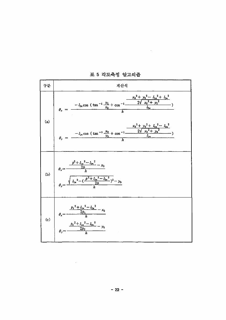
(a)2Li:Hr
(a),
fe (b)
- 20 -

- 21 -
(a)
hn
Ox =• /2ncos ( t an —• + cos
xo— I 2f
0V =-Aacos ( t an 1 — 7 + cos l
yO2+ An 2 " hn2
xo2+ V
(b)
(c)ex=-
It
2b - ) 2 -
2PX
2p2
~xo
- 22 -
ROTARY POTENT!J3«!ETER
BALANCING^WEKS'Ht
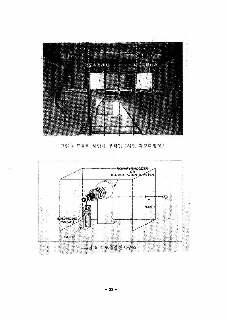
- 23 -
4.
n| , 3.7}
o|
, y
image processing)!-
(grasp device), H
5m
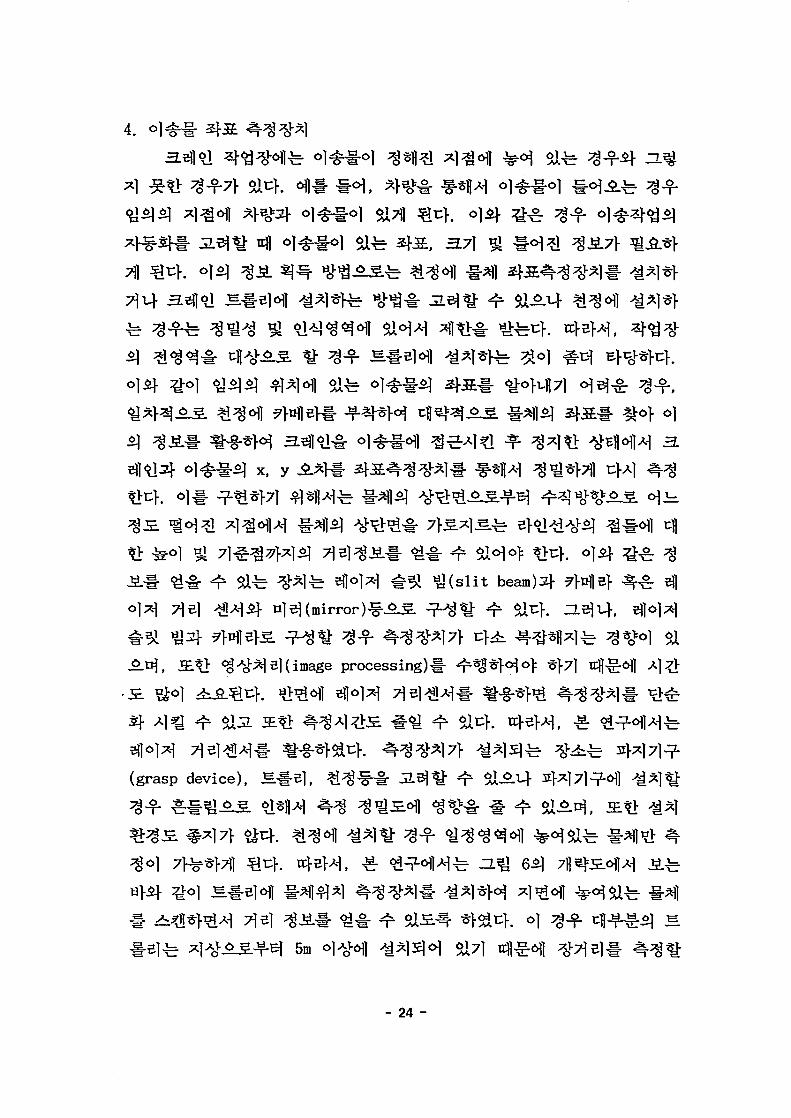
- 24 -
LADAR
360°
> 3.Q 73}
^ 6,630mm
RS422 7>H
37]
PC
4s alA
. LADAR 2D-50
T800 ^s£^^B] ( t r anspu te r ) ! : t f l ^ }
^ s - 7 }X]^ RS422
^ } jfl 50m
, 0.56°^ ^ 4 - ^ ^ - *}cj| 270°#
- 25 -

3600*1
0.02197°(360V214)
LADARS] aq
6 %3i) 25
Trolley
Ground
8
- 26 -

6 LADAR
Light source
Wave length
Angle sensor
Accuracy distance
Minimum Angle step
Angular resolution
Measurement rate
Scan angle
Scan speed
Scan density
Distance
range
white wall
dark wall
Return value
Laser diode
905nm
incremental encoder
±30mm(single shot)
0.56°
214increments on 360°
3600/s
270° max.
8 rev./s
1.25Pulse/degree
1.0m~50m
1.5m~15m
(/, a)
- 27 -

5.
S O S *
7}.
(2) ^I^is.
ON/OFF
AC ^71 4§ofl AC
S.3L
(1)
- 28 -

la [o [[a (jt"<!ra"Er | s ' a j^-igl^'§"o
th-B' '"fe lo^^OOO'l 'lT3FZHS9--0T (O9'0)Ks/ui6'9HH%06~02/a09~0T-
| a (#4^ |5: • fo^r^ 'n" -fol*T-{2r '•{=>-1*:-{IT
lalolta^Tflil^b 'taHazr^^iQ
( i& B'&T i Iv' 8/'XjLsi^-3i^v' c *\ p i pi. L / l«— C*—/ C " Q C C*-
AOI-O 'A9~o oa 'k-fek^-l^s^s-JscxBMZ
(ZHT)i^to%09T
i5:-&l '%OST
ZHOSAHTO'O : ^ r l ' - i i l ^ b(aOT+92)%rO+ ^lvrir^^-1^
'%I0'0+ ^l^r-^lirb -^fe1 ib^-feriiTt?ZHOf^-1*0
tv-fft I^IMd lafeaii-SrVZ
(•%-fa lb-R>^^^)A0£2~00Z -R'-R'OZZ-002 (p*-S)-&-fi-
F6£"8SS
dT990-00Sf
T-gr-8-lY
taloltalif^^lirb
taloHalE"5"^kb•E"5"S-§:IY, ,
(V) ik&'WM&fkk:
A022 ;A00Z
. . . . AiS-Vsr

J300-055LF/J-FB(Xaxis)
r> n r> n no
J300-055LF/J-FB(Yaxis)
r» r> n r» n n
J30(M)55LF/J-FB(Zaxis)
1/0 ENCODER(x) D/A(x) I/O ENCODER(y) D/A(y) I/O ENCODER(z) D/A(z)(UMIT.RELAY) (POSITON) (SPEED) (UMIT.REALY) (POSITON) (SPEED) (UMIT.REIAY) (POSITON) (SPEED)
CRANE CONTROLLER ( 80-196 KC )
ANGLE DETECTION f)x, 8y)
A/D A/D
COM-PC COM1 COM2 COM3
RS-232 RS-232 RS-232 RS-232
Potentiometer
AA DC5V
Potentiometer
AA DC5V
Ladar 1D-X
II'1
Vfr,Ladar 1D-Y
COM1( RS-232)
EXECUTABLE PROGRAM DOWN LOADCOMMANDCRANE STATE DISPLAY
8
- 30 -
• « . - . . . . ••'.: i £ j Jj.. "
• * • '
(2)
CPUfe Intel*\
8O196KC#
cf. CPU
3711
S#5|(micro controller)
CPU *}*H7>
-D Radar)
- 31 -

8
CPU
A/D
D/A
I/OOutput
Input
Counter
Serial
- 80196KC, 20MHz, 16bit(Embedded Microcontroller)
- 64KB Memory
- 8CH, 12bit Resolution
- ti^^ltf : +iov ~ -lov- Differential, single ended ^j- Filter : 2Hz- Amplifier : ^ ^ 1 ~ 5wfl- 4CH, 12bit Resolution- #^^ 6J- : +10V 10V
- 8CH, Relay output
- 16CH, TR input
- 32bit Counter, 4CH- Line Driver <ys)
- RS 232C, 4CH- 19.200BPS
f-H£££jV£Hte£?
ail n
- 32 -
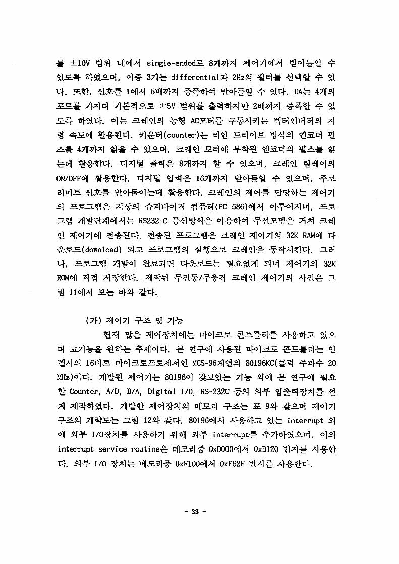
±10V
ON/OFF^]
o]
ROM<H1
single-endedS.
^. differential 2}
±5V
^}^^(counter)
RS232-C
32K
32K
20
«> Counter, A/D, D/A, Digital I/O, RS-232C
interrupt service routine^
I/O
fJL alfe interrupt ^
i n t e r rup t* ^ 7 f * > ^ ^ . ^ , 0]$]
OxDOOCMH 0xD120
0xF62F ^ ] * A
- 33 -
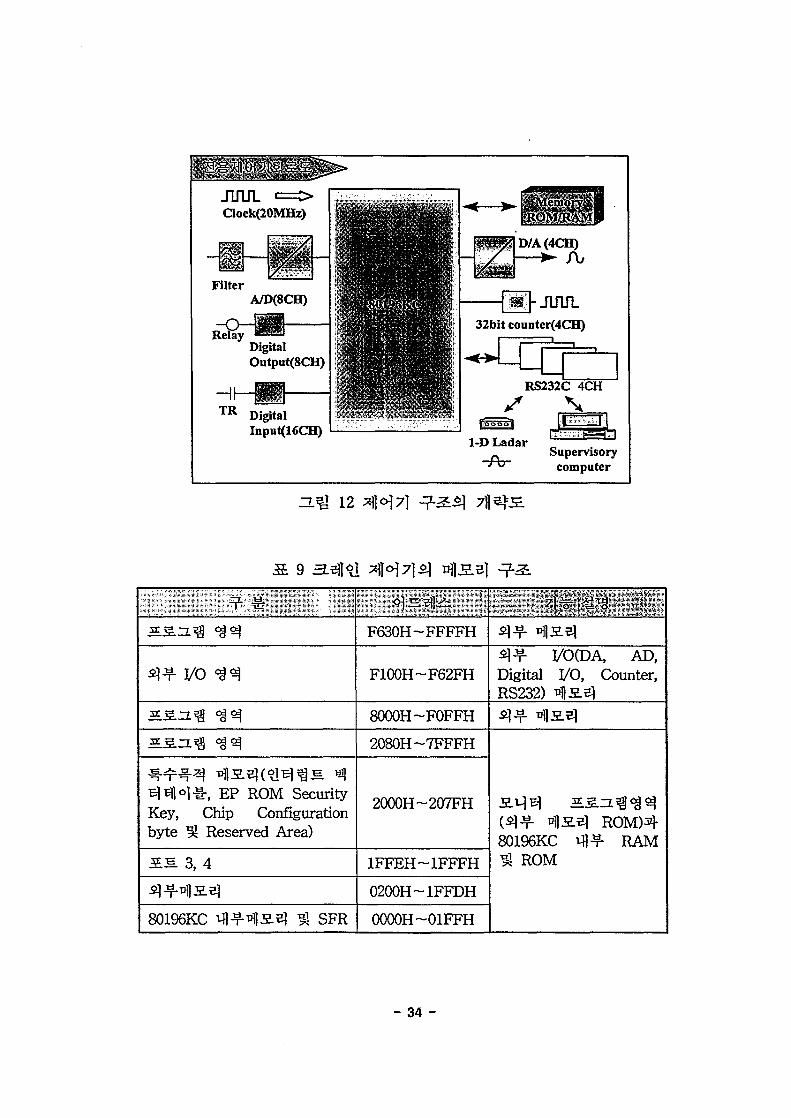
JUUL <=OClock(20MHz)
FilterA/D(8CH)
DigitalOutput(SCH)
HIT R Digital
Input(16CH)
Supervisorycomputer
12
B^til^lr, EP ROM SecurityKey, Chip Configurationbyte ^ Reserved Area)
I S 3, 4
80196KC tfl-^-^sel ^ SFR
•in
F630H-FFFFH
F100H-F62FH
8000H-F0FFH
2080H-7FFFH
2000H-207FH
1FFEH-1FFFH
0200H-1FFDH
0000H-01FFH
q^ pfl2.e|
S ] ^ 1/OCDA, AD,Digital I/O, Counter,RS232) TflS-Sl
(5]^- *H5.el R0M)480196KC tfl^- RAM3J ROM
- 34 -

START
PC POWER ON &CONTROLLER POWER OK
EXECUTE THE IARCCOMPILER UNDER
THE WINDOWENVIORNMENT
C PROGRAMMING &MAKE PROJECT FILE
SETUP THECOMPILER OPTIONS& LINKER OPTIONS
COMPILE & LINKOR
MAKEOR
BUILD ALL
MODIFY THE CPROGRAM
EXECUTE 'PROCOMM1 &PUSH THE RESETSWITCH, THEN
DOWNLOAD
RUN THE PROGRAM
NO
END
13
- 35 -

RS232-C
RS232-C
Register)^ ^ B
*1l "fe S 10, S
INT_PEND1 SFR-i- ^
6\] wri te
I/0
PROCOMM
32K
32K ROM
CPU^ SFR( Special Function
80196 o l ^ ^ ^ # ll *>7l ^
10C1, INT_MASK, INT_MASK1, INTT_PEND,
^r C W H s J - S } iol96_kc.h^] ^
-rrA/D
3L 10 INTJ*ENT£J- INT_MASK
•'""''BITS ' ^
INTJPEND,INTJVLASK
INTJ'ENDl,INT3IASK1
!<i.
EXTINT
NMI
6 -
SerialPort
FIFOFull
5
SoftTimer
EXTINT1
" 4
HIS.Opin
T2Overflow
HSO pin
T2Capture
HISdata
HISFIFOFull
t 1
A/Ddone
RI
0
TimerOverflow
TI
A/D
8259
7]
function^- A/D
A/D
. D/A
0xF400, 0xF420, 0xF440,
A/D
A/D
- 36 -
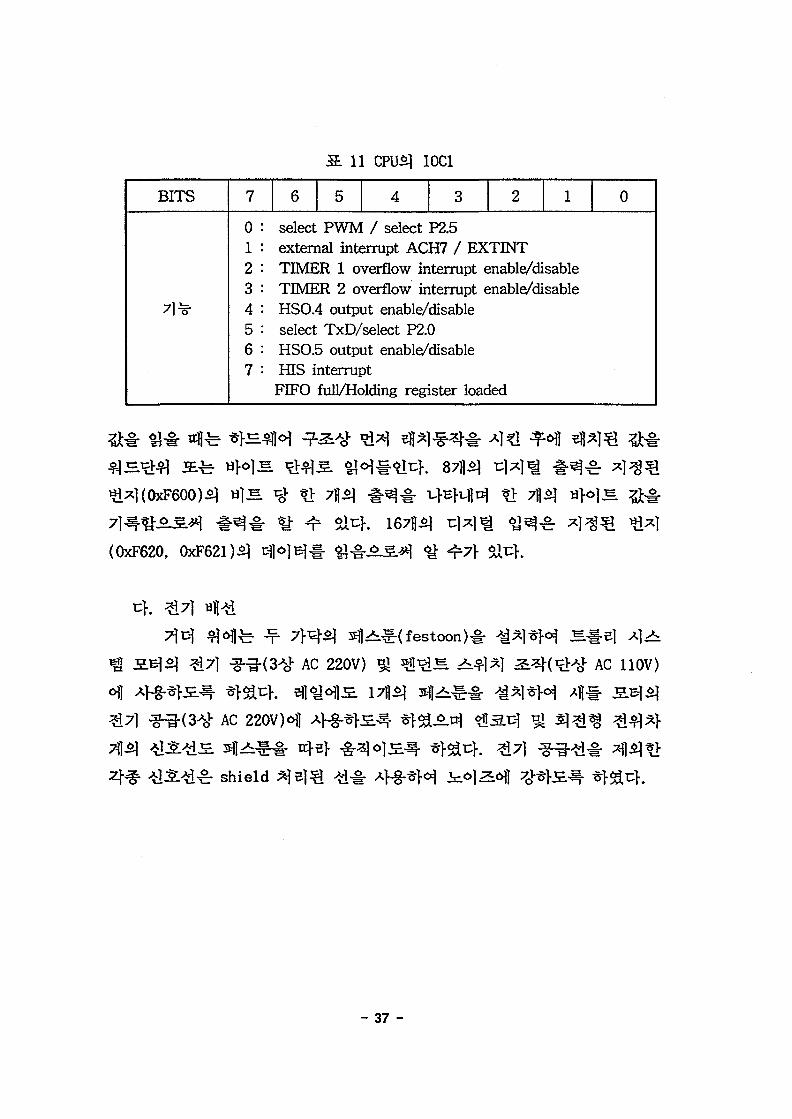
11 CPU£| I0C1
BITS
*
7
0
2345
67
6 5 4 3 2 1 0
. select PWM / select P2.5external interrupt ACH7 / EXTINTTIMER 1 overflow interrupt enable/disableTIMER 2 overflow interrupt enable/disableHSO.4 output enable/disableselect TxD/select P2.0HSO.5 output enable/disableHIS interruptFIFO full/Holding register loaded
(0xF620, 4-7}
>i^-( festoon )«
^7] AC 220V) AC 110V)
AC
^r shield
- 37 -

B,
05.
14
- 38 -

7A — (x+ x1)i+(y+yi)j+z1k (1)
^ ^ f (2)
where, X\ = /sintfsi
= Icosd
equations)^
Usecond order differential equations)^..^.
X
- 39 -

TG= \ mGx2 (4)
X ^ Y
T r = (5)
(6)
/2 <}>
x + ^ mT^ x
/2 ^
*1
2
+ 21 x ^ s i n0cos0+ /2 02 sin2 6+2 lysind cos<j>
+ 21 y 6 cosd cos<p-21 y I2 B2
(7)
(8)
- 40 -

V=-Mglcosd (9)
HMH(*I (10)), ^ # e l ^ ^r^«o^^(^ (ID),(12)), ol^#^l « 1 M H ( * 1 (13)) "£
Ml2 s in20 "& + 2MI I '$ s in 2 0+2M/ 2 '<j> 8 s in^ cos«5
= — Mix sind cosfi+Mly sin# si
( mG+ mT+ M) x+Mlcos ^sin 4> 6+M/sin ^cos <£
+ Msin^sin^/+2ikf/&cos^sin0+2M/^sin^cos?i (10)
+ 2Mcos 0cos <t> d '<f> - MK B1 + ^2)sin ^sin <j> = Fx
y+ Mlcos 6cos <f> ~d—M!sin 8sin 4> $
+ MsinOcos$'l+2M'l '6cos6cos4>-2MI '<j>sin0sin4> (11)
-2Ml'0'4>cos0sin4>-Ml{ 82 + j>2)sin$cos4> = Fy
( mH+M) l+Mx sin# sin^ + Afj; sin^(12)
- Ml d2- Ml j>2 s in26-Mgcosd= -FH
Ml2~d+2Mlie-MI2 j>2 sin6 cos6+ Mglski6(13)
= —Mix cos6 svo.<f>—Mly cos8 cos4>
- 41 -

&S.th 3.
(13)3*
(15)
x = kd6 (16)
2.
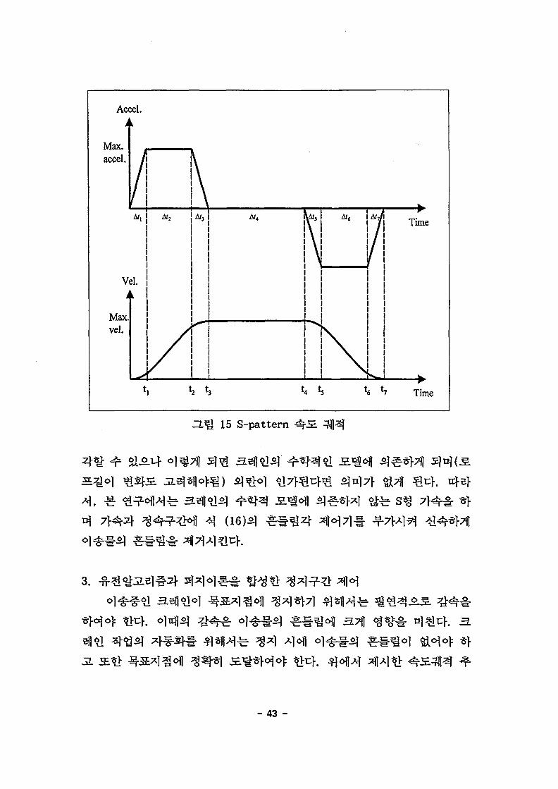
15
$171
- 42 -
Aa
Max.accel.
:el.
/
Vi
Max.vel.
L,Af,
3l.k
Af2
/
/
t, 1
\
\
\
A/.
\
Time
2 *3 *4 *s {6 h Time
3.Q 15 S-pattern
(16)51
3.
3.
- 43 -

control)
IF ~ ~ SLS.
(Genetic algorithm)^
5:(Population)#
(Mutation),
rossover),
NB(Negative Big), ZE(ZEro), PB(Positive
cj|*> ig t t^^HMembership function)
sub-min
^(34=81) romosome)
b& 0(NB), . 2(PB)
Runge-Kutta
- 44 -
4.
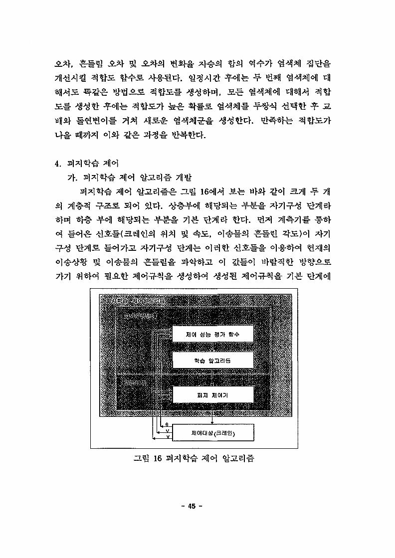
3.7\] ^ 7)1
SI CM CH ( 3 2 1 1 2 ! )
ZL^J 16
- 45 -
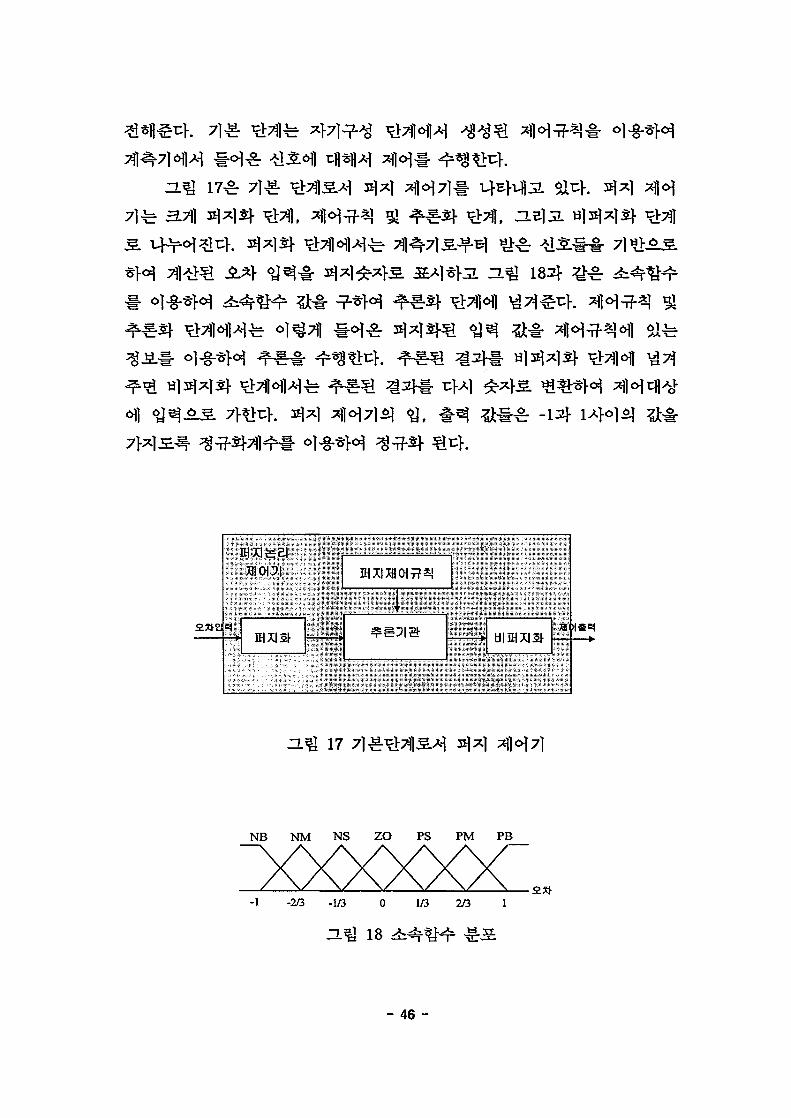
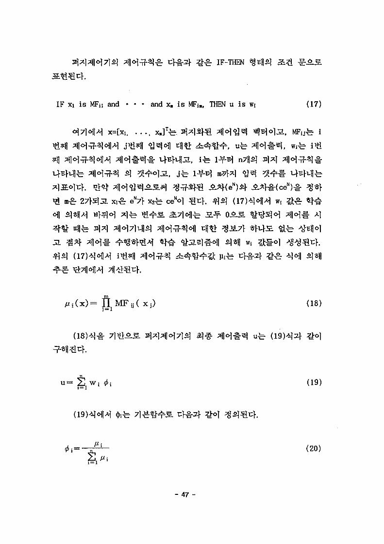
3.7\)
182}
=L% 17
NB NM NS ZO PS PM PB
-1 -2/3 -1/3 0 1/3 2/3 1
-L^U 1 8
- 46 -
IF-THEN
IF xi i s MFii and • • • and x» i s MFiB> THEN u i s (17)
x=[xi. . . . . x»JT
rg: eN7f w,6\]
(18)
(19)
(20)
- 47 -

J(t) = -l-{eN(t)2+XceN(t)2} (21)
ge
, tfe
11aoi a* m st+
J(t)
Wi(t+1)
^ . ^ 19
- 48 -

W i(22)
t|«M . ( 22 )^^
(23)
an*.
3(e(t)-e(t-D) ... ge(t) gy(t)~ 3u(t) ~ 9u(t) " 5u(t)
(25)
- 49 -
S ceee
N(t)kt) *,J
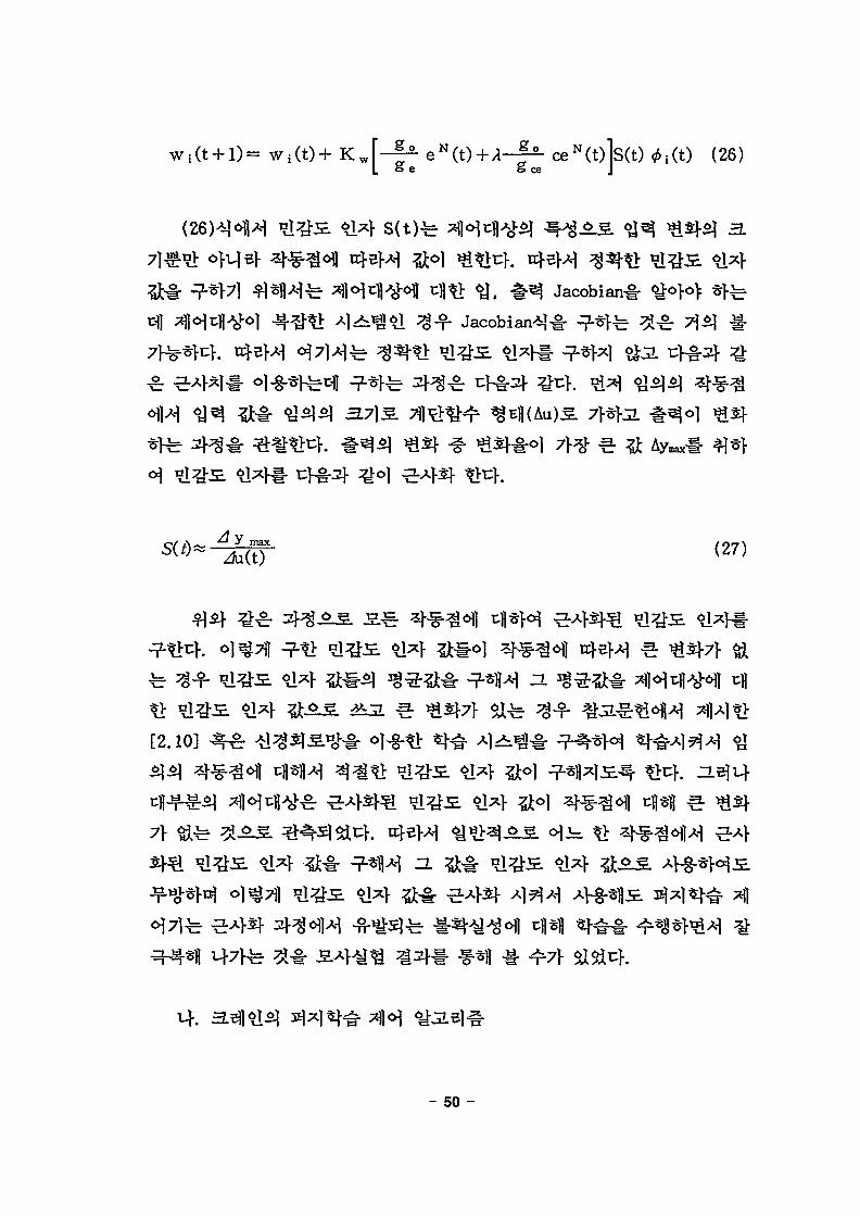
(26)
Jacobianl-
( 2 7 )
[2.10]
7> §ife
- 50 -

Tl-" v .
HI
3 s©• o
1SSH
ZL^ 20
4
- 51 -
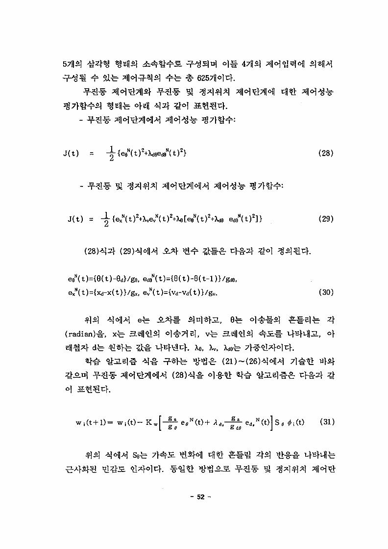
6257JMT}.
- 52 -
J(t) = -if {eQ"(t)2+U>eAt)2} (28)
J ( t ) = ^-{e^D^Xvev^t^+XeCee^t^Xde ed9N(t)2]} (29)
eeN(t)={e(t)-8d}/g8, ed9N(t)={8(t)-e(t-l)}/gd8)
exN(t)={xd-x(t)}/gx, ev
N(t)={vd-Vd(t)}/gv. (30)
(radian)^, xfe
e,N(t)+ *A.—^- ed,N(t)l S e ^:(t) (31)& d^ J

+ K w J J - f * e ?(t) + * a*--1- e S(t)| S , # i (t) (32)
5.
(33),
3.7)
(0, 0, z0
SfS) X,
D, E) 7}*
n|
x,
- 53 -

Line 1
E(0,y.)
^ 21
(35)5+
xc =
r =
H=hg-z0
(33)
(34)
(35)
(36)
O (0, 0, Zo)
b,
4
(37),
, y
- 2abcosO (37)
- 54 -
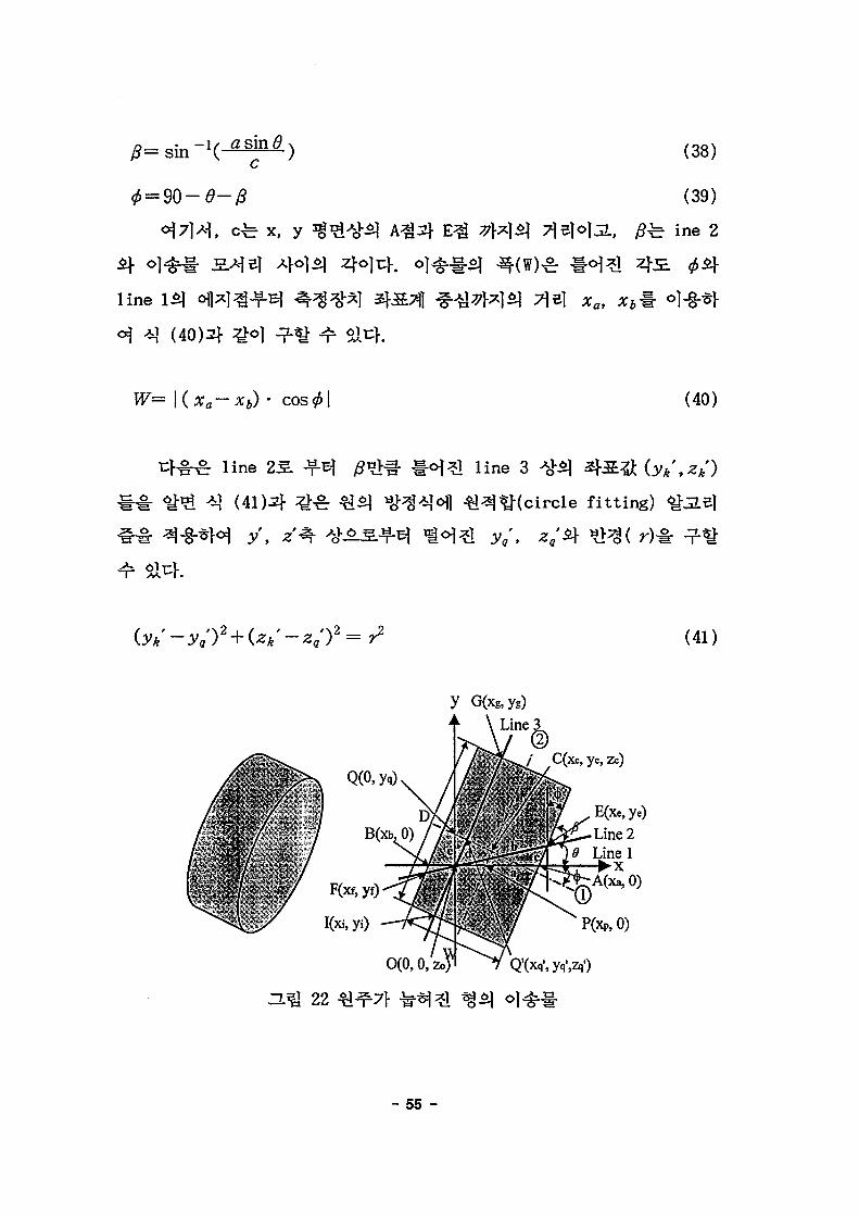
(38)
, y
line
(40)2}
(39)
7\ii\<>}5L, #fc ine 2
cos (40)
line 2$.
(41)2f
l i n e 3
fitting)
(41)
G(xg,yg)
yc,zc)
E(Xe, ye)
Line 2
A(Xa,O)
P(xP,O)
Q'CXq'.yq'.Zq1)
3.% 22
- 55 -

x =
y = — x+yQ
line 3
^ ^ (42), (43)
(42)
(43)
(46)4
(48)4(49)4
^ c = cos 2 ^ ( ^ + ^ tan «4)
yc= cos2<f>(yQ-xptcin<f>)
(44)
(45)
(42)
(41)
(46)
(47)
- 56 -

H=2r
(48)
(49)
3]
(40)
1/2
^ (37), (38), (39)
line 3 ^ o f ^ ] ^ G f I
^ y c f e *? (42)J?-Bl
line
G(xg,yB)
line 3
r C(xc, yc, zc)
E(Xe,ye)
Line 2
O.^ 23
- 57 -
441 3.31*1
AC
12,
. o]
- 58 -

cm/s
0.5 cm
12
ol^T^Kn,)
7}^Al^(s)i
S^o | ( m )
^(deg.)
10
0.4
4
1.5
0.15
1.2
1.2
6
0.5
0.3
13
20 81 0.9 0.01 100 roulettewheel
3.n
^^
- 59 -

14
NB
ZE
ZE
v.
NB
ZE
PB
NB
ZE
PB
NB
ZE
PB
NB
NB
ZE
ZE
ZE
NB
ZE
NB
NB
ZE
ZE
ZE
NB
PB
ZE
NB
PB
ZE
ZE
NB
PB
PB
ZE
ZE
PB
PB
NB
ZE
ZE
NB
ZE
ZE" '
NB
NB
NB
NB
NB
PB
ZE
NB
PB
PB
ZE
ZE
ZE
NB
NB
ZE
ZE
ZE
NB
NB
PB
ZE
PB
ZE
NB
NB
NB
NB
ZE
ZE
'PB
NB
PB
NB
ZE
ZE
NB
NB
ZE
ZE
ZE
,ZE
ZE
ZE
NB
ZE
NB
NB
PB
NB
NB
PB.
ZE
NB
PB
ZE
ZE
ZE
ZE
NB
ZE
- 60 -

1111
— crane• • • rcpe
_) 1
11 1
U—+—•Yi • • • * 1
Tmne(s)
(a) Acceleration
Time(s)
(b)Vfetocity
1 -
= L *
i-i _
-2
V
10
angle• • • angiiarvel.
20 30
Tims®
-f
40
(d) Angle and Angular Velocity
SO
ZL% 24
- 61 -

a .., _J 1 , ^ .__,
: i i -__Ly^
0 -^-—I 1 \ \I
111111
.. 1• • 1
VI1
1111
1—
argeangdarud.
• X'-A - !
r iI |• i
i ii ii i
_ j 1
\ . II ,
0 -v-
-1 -
10 20 30 40 SO
Trre(s)
(d) Ac&e and AigJarVfelociV
ZL^ 25
- 62 -

2.
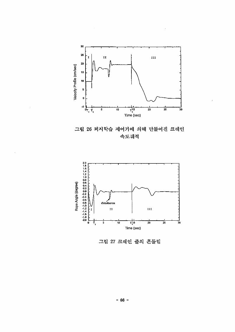
4. ^ 266| 4 4 4
OS. Ti
lOcm/secS.
66.678cm/sec2oli;f. o|
^2.^ 26, 27, 28,
27^1 -1 4
ga=6.0, ge=1.2,
- 63 -
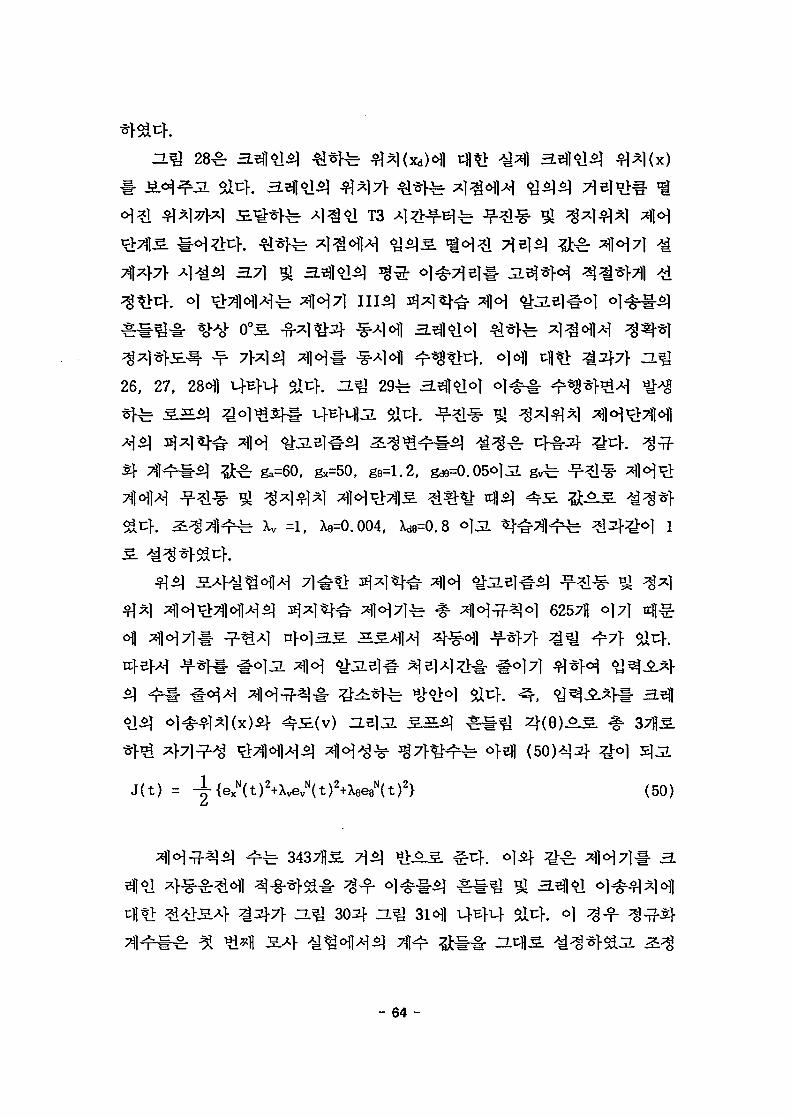
T 3
26, 27, 28<H1 ZL^ 29
0, gx=50, g9=1.2,
1, X8=0.004,
62571 ol71
J(t) =
37l|S.
(50)
3437US 7]$]
ra-§- ^ - f <>" L ^ 302}- ZL
^ ^|o|7]t
- 64 -

Xv =0.9, Xe=0.00085.
30 9| ZlQ
4,27 «£ ZL^l 28
- 65 -
10 T15 20
Time (sec)
25 30
26
£O)CD
.2
0)
Time (sec)
27
- 66 -

Iffile
S£L
8
sta
Q
300
250
200
150
100
50
0
•50
1 ' 1
• TSet point
1 . 1
1 • t ' 1
\ :
\
N
Crane position
-
-
I . I . I .
10 15 20
Time (sec)
25 30
28
10 15 20
Time (sec)
25 30
DJ& 29
- 67 -

a>
Disturbance Applied (-0.5°)
10 15 20
Time (sec)
25 30
ZU£ 30
le (c
m]
I
stan
ce
350
300
250
200
150
100
50
-50
Desired PosiSon ICrane Traveling Position 1
-
10 15 20
Time (sec)
25 30
31
- 68 -

7>.
(1) MCCB
(2)
LED I POWER \y\
I d 1 0
(4)
(5)
(6)
(7) 0-
(8)
FUNC
63J ^ e | I F
1 03 |(Blt
9
4SJ ^ e l I d I 0 [g.
FW-CM1
FW-CMI
(-. | FUNC
( 1 ) MCCB-!
- 69 -

LED 1 POWER |7>
(2)
(3)
(4) I FUNC
el LJLL2J7}
(5)
F 4
71 *FUNC
(6) I RUN
] £ 5^ fee] I F I 2
FUNC
F
(7) STOP/RESET
FUNC
r
2.
sensor vector *cW-§-ol
vector
^ V/F
V/F
7\.
(1)
(2)
A I 621. I A I 63
, sensorless vector
sensorless - - r sensor
, sensor
- 70 -

(3)
(4)
(5)
: I A I 2
: I A I 4
Afg-
i ^ s - A54
3.
(1) J2
(2) 3)
(3) 7)
(S
(4) 71
(2
(4-1)
SB^4
4^ S ^ ' a ' f i H ON (A 54)
4^ S * ] ^ ON
4.-f-x| .^-^§(S.B]fe S|^*M 1
t < 50 & ••50 £ t < 100 SL "
100 ^ t < 300 ^ . ••
4
4flo l-A} -ti^(A 0)
jg.B)iij|o)B) ^ ^ ( A 54)
4
a = 40
a = 20
' a = 10
H^ 32
- 71 -
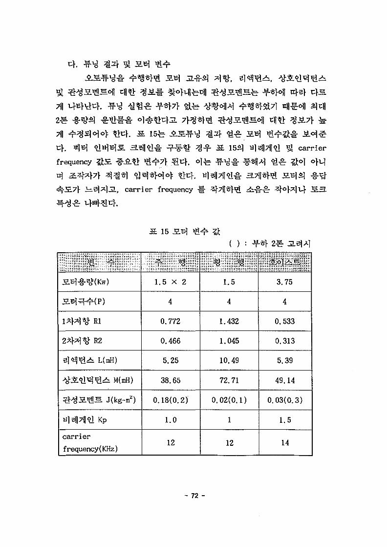
7)1
15-b
carrier
frequency
, carrier frequency
^o]
15
( ) :
l*M*c}- Rl
2^W%V R2
e H ^ L(mH)
^•31*1^^>b M(mH)
^ : ^ S ^ [ S Jikg-m2)
til^lTll^l Kp
carrierfrequency(KHz)
1.5 x 2
4
0.772
0.466
5.25
38.65
0.18(0.2)
1.0
12
1.5
4
1.432
1.045
10.49
72.71
0.02(0.1)
1
12
3.75
4
0.533
0.313
5.39
49.14
0.03(0.3)
1.5
14
- 72 -

3.
fg- JjL
4
x,
7\.
W}^(wheel)
4
TfcanflBK tachometer)S.
- 73 -
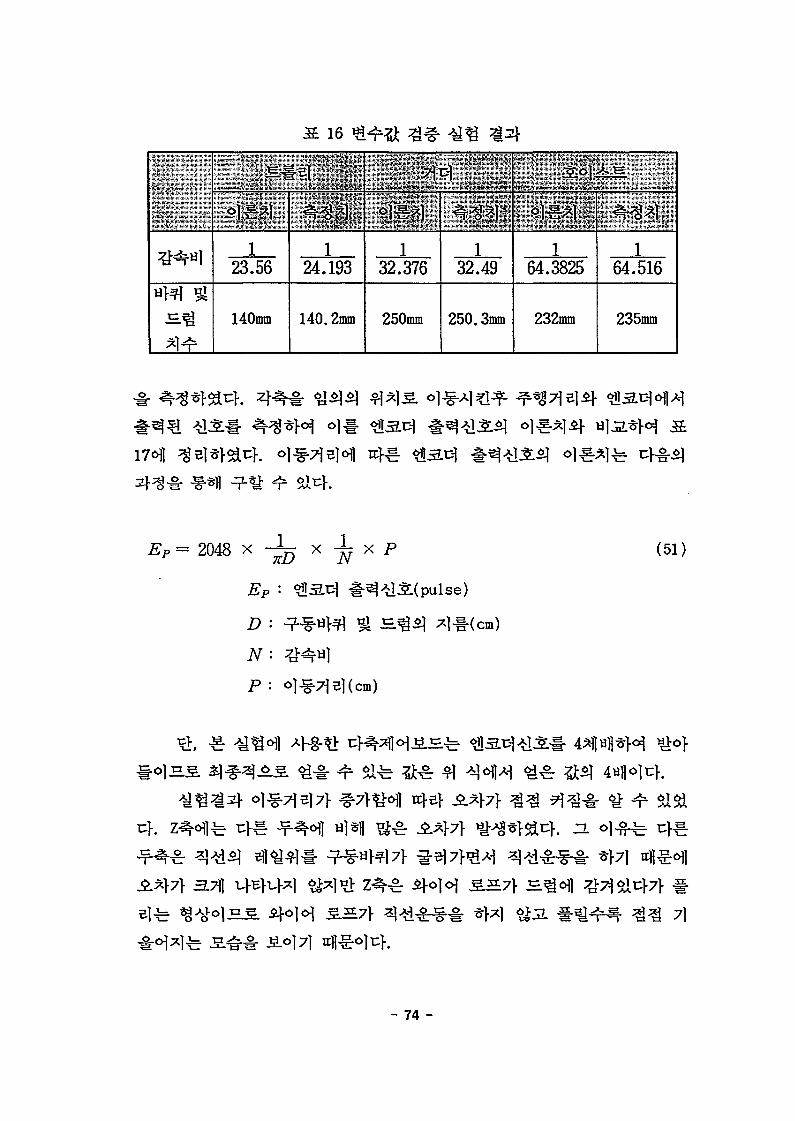
16
-
123.56
140mm
124.193
140.2mm
132.376
250mm
132.49
250.3mm
64.3825
232mm
. ***
164.516
235mm
= 2048 xTCD N
EP-
N •
P :
se)
cm)
(51)
.7\]
7]
- 74 -

17 . X, Y,
*
(cm)
142.5
291.8
495.5
1039.3
85.15
306
498.5
1012.3
101
318
442.6
633.5
(pulse),.^
478205
978112
1660342
3495358
370461
1333190
2173693
4420150
1454209
4186076
5988759
8727540
ol^^l(pulse)
481212.7245
985388.5825
1673269.509
3509644.804
373600.8901
1342593.921
2187199.574
4441296.867
1461742.895
4602319.213
6405617.873
9168456.671
(cm)
0.89
2.15
3.83
4.23
0.71
2.14
3.07
3.82
1.04
57.52
57.6
60.93
s/W
(52), (53), (54)5?-
fit t ing)«M
[Pulse]
EPi>=4359.3Py [Pulse]
EPz= 13630 Pz [Pulse]
(52)
(53)
(54)
- 75 -

±10V ^ 10V
60Hz7>
RPM
(cm/sec)# 2048pulse/rev(51 ) #
(1)
15/57 X
[cm/sec] (55)
= rpm x52"X 57"
fitting)*}^
(56)
VEX=3374.4^ [ Pfe/se/ sec ] (57)
- 76 -

is
rpm cm/sec pulse/sec rpni cm/sec pulse/sec
5.53 7.2443 6111.203 5.69 7.4539 6288.019
11.07 14.5017 12233.46 11.45 14.9995 12653.4
t51*'>*516.63 21.7853 18377.81 17.22 22.5582 19029.82
22.15 29.0165 24477.97 22.98 30.1038 25395.2
27.7 36.287 30611.28 28.7 37.597 31716.37
33.2 43.492 36689.33 34.54 45.2474 38170.15
38.8 50.828 42877.83 40.47 53.0157 44723.4
44.3 58.033 48955.93 46.1 60.391 50945.11
49.8 65.238 55033.98 51.8 67.858 57244.18
601 55.4 72.574 61222.55 W05 55.4 72.574 61222.54
vix= 7.4694 Fx [cm/sec] (58)
(2)
17/47 X 1/8.52*1
^ - S 19 ^ ^ . ^
(59)#
fe 43.
[cm/sec] (59)
- 77 -

=z rpmx
204860
1 .. 178.52 47
= 804.02* rpm [Pulse/ sec] (6
fitting)*}^
=4405.6 vy [ Puke/ sec ] (61)
% = 5.6792 Fy [cm/sec] (62)
(3)
19
rpni cm/sec pulse/sec rpm cm/sec pulse/sec
7.61 5.5553 6118.59 7.77 5.6721 6247.235|12! 15.27 11.1471 12277.39 15.68 11.4464 12607.03
22.9 16.717 18412.06 23.6 17.228 18974.87•21] 30.5 22.265 24522.61 31.5 22.995 25326.6330 38.14 27.8422 30665.32 39.37 28.7401 31654.27ffl.45.7 33.361 36743.71 47.3 34.529 38030.15
53.37 38.9601 42910.55 55.2 40.296 44381.9m 60.9 44.457 48964.82 63.2 46.136 50814.06
68.5 50.005 55075.37 71.4 52.122 57407.0373.4 53.582 59015.07 o 74.4 54.312 59813.1
1/64.3825^1
72.88cmo]i:}.
- 78 -

(63)
20^1- 20^1^1
vx= rpmx
x
/sec]
^?64.3825
fitting)*}^
(63)
(64)
= 14410 vz [ Pulse/ sec ] (65)
viz= 1.7562 V* [cm/ sec] (66)
20
lhz>
U'6-612.18/
^2'P:
.3642 s
-,48Vi54j-,60;
rpm
-
5.68.411.213.9816.7819.5722.3825.1827.95
cm/sec
-
3.4165.1246.8328.527810.235811.937713.651815.359817.0495
pulse/sec
-
12306.518459.7624613.0130722.3136875.5643006.8449182.0655335.3261422.64
:t"'l' '
Us*??-5 6
fr9-^?10^
rpm
-
5.78.7111.614.5617.4720.423.326.227.9
cm/sec
-
3.4775.31317.076
8.881610.656712.44414.21315.98217.019
pulse/sec
-
12526.2619141.0125492.0431996.9138391.944830.8451203.8557576.8661312.76
- 79 -

•
A/D '*?%7) '
• > :
•'-• • ' " : •
_•
3 } ^ ^6i(ADN)
3 ) 4 «y-(ADM)
^SiHsKbit)
^l*ol oi J£j j^i. S i / nrr \
c^j^- 3-|EJJ ^^.ejz)-(EMA)
5)db ^ g - ^ ^-^(MNAD)
(6m a.^^o))
0 V
+5 V
12
1 turn(350° )
4 cm
41.5 cm
±5°
0.1 cm
600 cm
e h
7]
*£
^o), i57jo|
A/D
A/D
A/D
5V7} ^ c > . O.B1JL, A/D
0.00122V/bit(ADVM/212
5/4096)71-
360
35051
- 80 -
12.22cm(±6.11cm)o]t:K
; ±8.385.
± 5 5 . o]H3. o}v$S>\ S^nfl^£)tfl*l$l(PEMD)ir 7.16cm(±
3.63cm = tan(EMA) -h = tan(±5) •41.5)7}- u}-.
0.0818 x[V/cm]( AT/PMD = A:/12.22 = 0.0818*
0.594A;[V](PEMD X VD= 7.16 x 0.
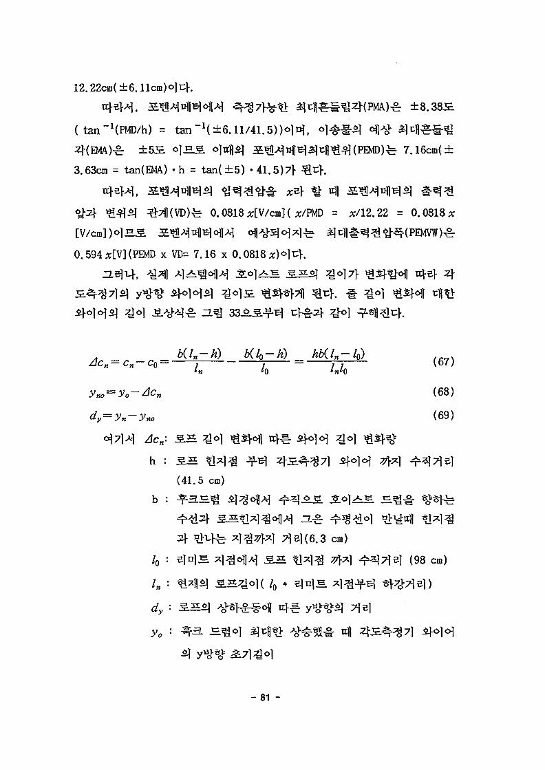
b(ln-h) Kk-h) hb{ln-k) . . . .= 1 ^ = J-J (67)
n o 0 n (68)
dy=yn-yn0 (69)
h : 5 ^ *1^1^ -f-B](41.5 cm)
b : ^
7}e}(6.3 cm)
/0 : e}u}je x}^ofl^ 1 5 ^ ] ^ 7 | .X | ^3}7}e} (98 cm)
71 BI
- 81 -

71
yn
(70)
- 82 -
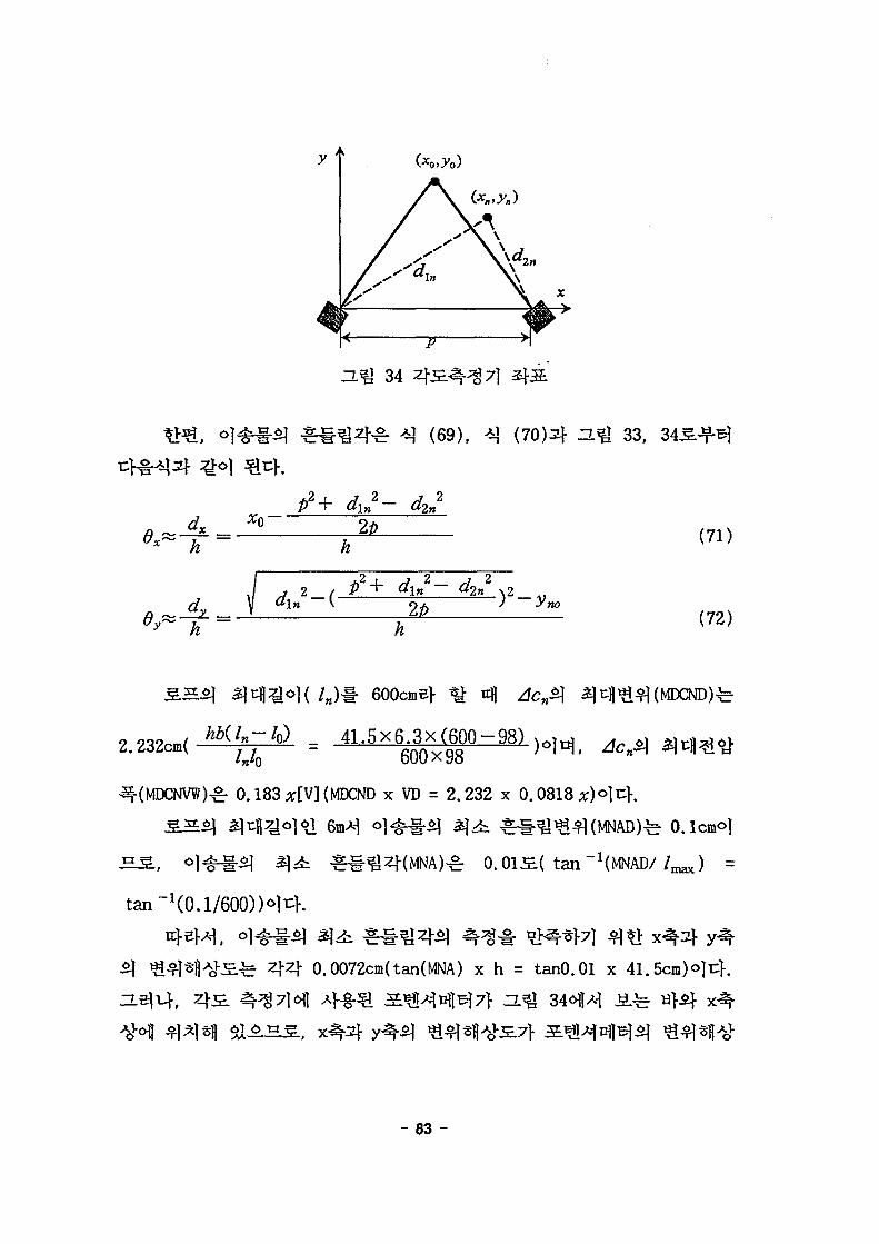
2.
(69), 33,
P2+ dln2- d,2»
h
- ( —y no
h
600cmef ^ 4
_ 41.5x6.3x(600-98)
^r 0.183 A:[V](MDCND X VD = 2.232 X 0.0818 x)°]
0.013E.( tan~1(MNAD/
(71)
(72)
4 4 0.0072cm(tan(MNA) x h = tanO.Ol x 41.5cm) ^ i ; } .
- 83 -
=27.3cm,
13.5cm, ^^=7.9cm, dw= 15.6cm, ^ = 1 5 . 9 c m ) # *} (71), ( 7 2 H
^ ] 0
0.00721- cH<a*H ^ (71)2f (72)51 ^ ^
1 : PVR > ADVB = x > 4.07V
2 : ADVM>PEMVW => x < 8.42V
••• 4.07V< x < 8.42V
^r A/D
(PVR)fe 0.0003x[V] (VD x PDR = 0.0818 x 0.0036)7]-
S ^ ^ t ^ ] ^ ^ 6 « ^ ^ ^ ^ ^ ^ ( A : [ V ] ) Sna^S: A/D
(ADVB)7f S ^ ^ ^ | B ] ^ ^^^^«1|^JE(PVR)JB.C} ^ J L , A/D
PBOV = (ADM+MDCNV)/2 = ( 5 + 0.183 x 5 ) / 2 = 2.9575 V
fe 2.444[cm/V](PMD/
x = 12.22/ *[cm/V] = 2.
- 84 -

dml-=tan~\(ADM-PBOV) • DV/h) = 7.14S.
A/D
10V, ^ f e o ] 12bit^l
o]JL, A/D ^%7]*1
10/4096 = 0.00244V/bit)<>H,
OV,
. °1 4 ^ ^ ^ ( A D V M ) ^ 10V
0.00244V/bit(AVB = ADVM/2" =
^ : ±5S.
(PEMD)^ ±3.63cm7l-
0.594x[V]o]t;]-.
(DCNPEMVW) r 0.766x[V]oli:]-.
^ ^ ^ S - ( P D R ) ^ 0.0036cmoH,
) ^ 0.0003x[V]o|t:K
A/D
7}
(ADVM)o)
, A/D
PVR > AVB
ADVM>DCNPEMVW
8.14V< x < 13.06V
x > 8.14V
x < 13.06V
^: A/D
- 85 -

PBOV = (ADM+MDCNV)/2 = 6.03V
°M. 3 ^ * N ^ < q t ^ ^ o f l ^ t> ^^(DV)fe 1.018[cm/V](DV =
PMD/x = 12.22/x[cm/V] = 1. ^
A/D
i = tan ~*( (ADM- PBO V) • Z)VM) = 5.565.
(2)
35Hz(10cm/sec)# «y7>*H 5L<5)^i^t> ^ ^ 7Hz#
<% 0.6co ^
7} -i^sia^. tB > *jth 01
(3)
- 86 -

(a)
(b)
35
- 87 -

P = 27.3cm
^o = 7.9cm
/«, = 15.6cm (AA
/ « = 15.9cm (CC
AT= 13.5cm (CC
= 41.5cm
= 6.3cm ( S S
/0 = 98cm
(4)
= 2783.317 mV
Vcco = 2950.525 mV
(5)
(7\)
2cm/ sec
4cm
5V,
350° o]uf. 5V*]
- 88 -

= 4?r X 36(r~ = 12-2173cm
lcm 409.256mV
AA, CCl-
10cm
A/D
: 57.54569mV ~ 3979.526mV (Ocm ~ 10cm)
VCC : 32.64559mV ~ 3967.831mV (Ocm ~ 10cm)
0.16V
20m
v / = 392.198031 mV/cm
CCvl= 393.518541 mVl cm
+
- 89 -
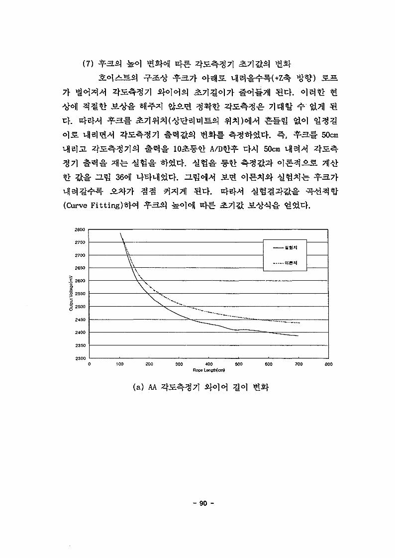
(7)
7}
(Curve Fitting)*M
50cm
50cm
45/%
2800
2750
2700
2650
.§ 2600<D
3
g 2550
§2500
2450
2400
2350
2300
\
o|S*l
100 200 300 400 500Rope Lengthfcm)
600 700 800
(a) AA zjo)
- 90 -

3000
2900
2800
18 2600
2500
240O
ois*l
100 200 300 400 500 600 700 800
(b)
7.5
«0to<r
O
sr
5.5
\
\
-•V sV
o|5*|
" — • .
100 200 300 400Ftope length(cm)
500 600 700
(c)
ZL% 36 3.
- 91 -
= 2.30845xi0~13x /M6-6.14745xHr10x /n
5 + 6.62142 x 10 " 7 x lnA
-3.70455x 10⁻⁴x /M3 + 0.11488x ln
2-19.38486x /„+3910.61
2.53149x 10~13x /«6-6.80303xl0"10x /B5+7.43036x 10"7x ln
4
-4.22247xl0~4x /w3 + 0.13244x /n
2-22.32439x/„+4243
/, : t l ^ i ^ - ^ *3&A ^ ^ ^ 1 ^ 7 (cm)
6.7353X10"16 /M6 - 1.8746x 10"12 /«5 +2.12997xl0~ 9 lj
- 1 . 2 7 1 7 x l O " 6 ln3 +4.2753X10"4 Q -0.08029/„ + 12.8487
(cm)
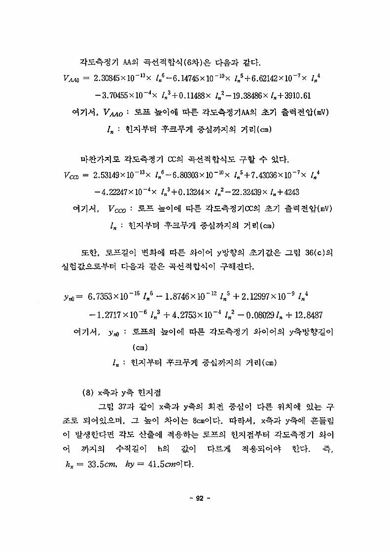
(8)
6\ 77}*]$!)
Ax = 33.5c?w, hy
- 92 -

Y-axisrotation
8cm
Wirerope
37
4.
remote
.7)7}
-7) "A
2.v*$]
- 93 -
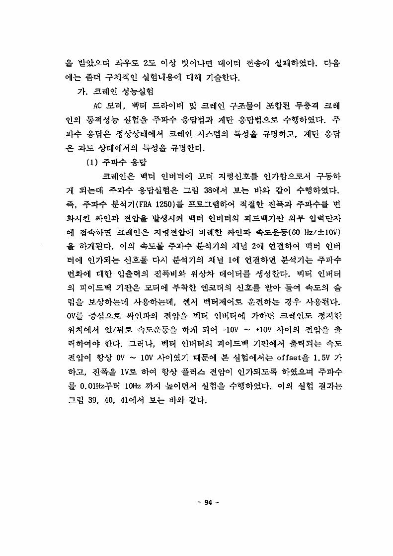
2S.
AC
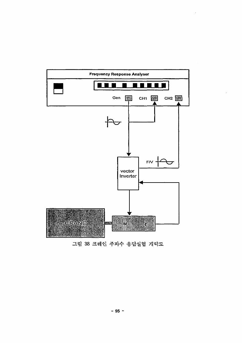
(l)
1250)1- S£IL
Hz/±10V)
-10V ~ +10V
~ 10V offset^- 1.5V 7>
O.OlHz-f-B] lOHz
Q 39, 40,
- 94 -
Frequency Response Analyser
Gen CH1 CH2
vectorInverter
M
38
- 95 -

Travel motor (FRA->curve-fit)
10 10Frequency (rad/sec)
(a )
Travel motor (FRA->curve-fit)
10" 10° 101
Frequency (rad/sec)
(b)
102
H ^ 39
- 96 -

10Traverse motor (FRA->curve-fit)
'co(5
-5
-1010"
U1JJJJ-- - - -
10° 102
Frequency (rad/sec)
(a)
50
0<
o> -50•o
(0
£-100
-150
Traverse motor (FRA->curve-fit)
-200
.... "i
1
1•
. . .
s
...
s
-•••
-j
4
• • {
t
j
ko
i
i
\
....\—
..
• •
•f
-1
ri
j -
s-
4 -J-
J10-1 10°
Frequency (rad/sec)
(b)
102
Z L ^ 40
- 97 -
15Hoist motor (FRA->curve-fit)
10
CD
c'COO
10'1 10°Frequency (rad/sec)
(a )
102
50
0<
o> -50
"°CO
£-100
-150
....
^,
...
» •
. . .
Hoist motor (FRA->curve-fit)
= • •
• * •
: l i i i
. . . .
;
. . . - -
"!"fj
t^Ni :!
•4-5-i
! : :
; ; ;
; ; ;i 11
S
......
. . .
••••!•
. . .
:
V s
»i
Iti'; i
| ;: !:
14-VI
mit t I t t 1 I !
10° 102
Frequency (rad/sec)
(b) 4W
a^ 41
- 98 -

(2)
7f
0.1, 1,
o]
lsec
43,
overshoot
overshoot^
0.01,
H^l 42,
1.4
0.4
0.2
Filtered Signal
Curve Fitting Linew v^
Time(sec)
42
- 99 -

1.4
CDCD
1.2
1
0.8
0.6
0.4
0.2
0
, Filtered Signal
^s*—-—~^^
. / Curve Fitting Line
\1II
-
--
0.2 0.4
HQ 43
0.6 0.8
Time(sec)
1.2 1.4
1.4
1.2
Filtered Signal
Curve Fitting Line
0.5 1 1.5 2 2.5 3 3.5 4
Time(sec)
-7 at 44 - r o| >t. E J
- 100 -

Fi t t ing )^
= T : = 7T
7\]
o)
(71), (72)3}- ^ ^ r
(1)
H ^ 482]- 16.346°
71
.fe s 221.54SKS.
- 101 -
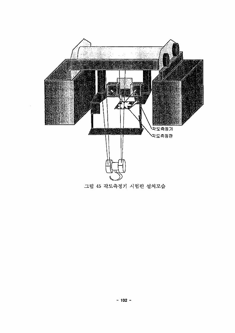
45
- 102 -
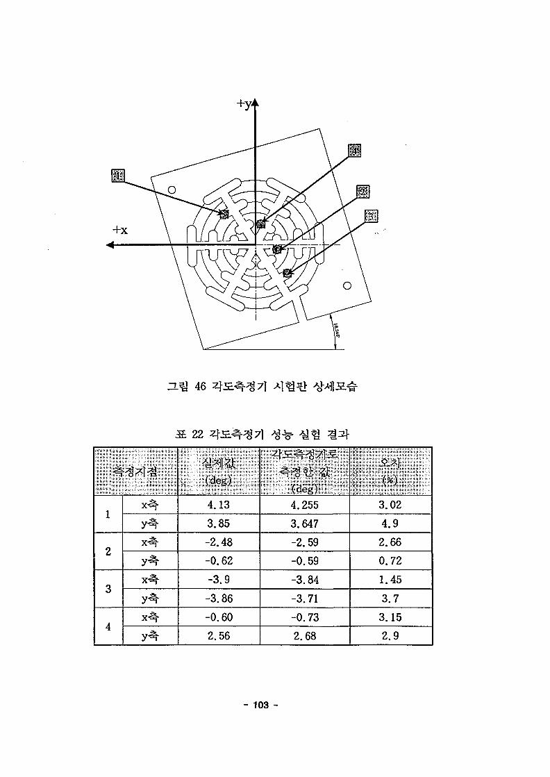
46
22 45.^7)
1
2
3
4
x ^
y ^
y^-
x ^
y ^
-H*1l*Jt.- (deg)
4.13
3.85
-2.48
-0.62
-3.9
-3.86
-0.60
2.56
(deg).4.255
3.647
-2.59
-0.59
-3.84
-3.71
-0.73
2.68
\ ^
3.02
4.9
2.66
0.72
1.45
3.7
3.15
2.9
- 103 -
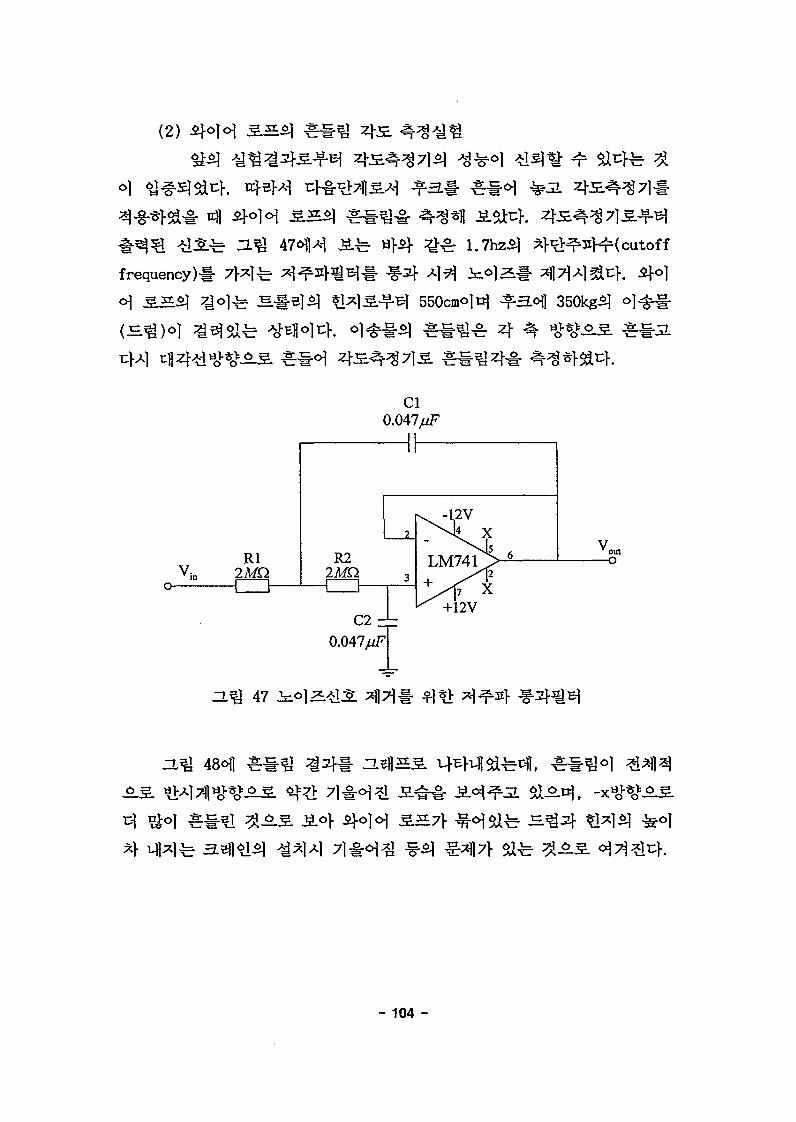
(2)
frequency)
Rl2JWD
R22MQ
Cl0.047/^
—II—
0.047/zF
ZL l 47 i ^ o ) ^
VoutO
- 104 -

H U 48 <>]<
}. 3^71
•(1)15 i
^r *1 (73)3f
(rad)
8= (9.8m/sec2)
(73)
- 105 -
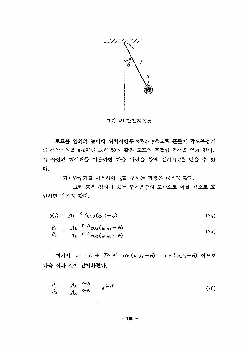
49
do
02 Ae = e
(74)
(75)
(76)
- 106 -
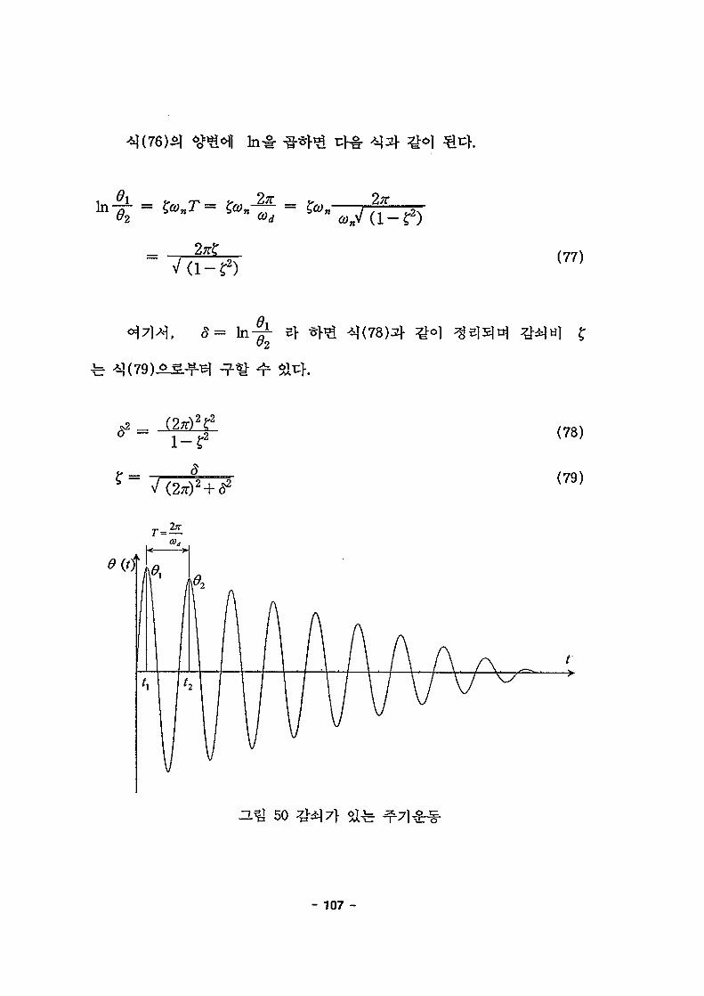
(77)
= In
1 - r 2
c*
(78)
(79)
ZL^ 50
- 107 -

"2 t/3
(81)
(82)
°}7H, 8= I. in/ Vj+l
(2)
(83)
- 108 -
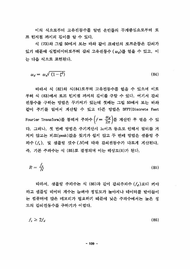
44
(84)
(82)4
^r H>v^^r DFFT(Discrete Fast
Fourier Trans form ) # (/=
7?
(85)
(86)4
fs ^ 2/rf (86)
- 109 -

(3)
0
Q)n)7\ 7\
- 110 -
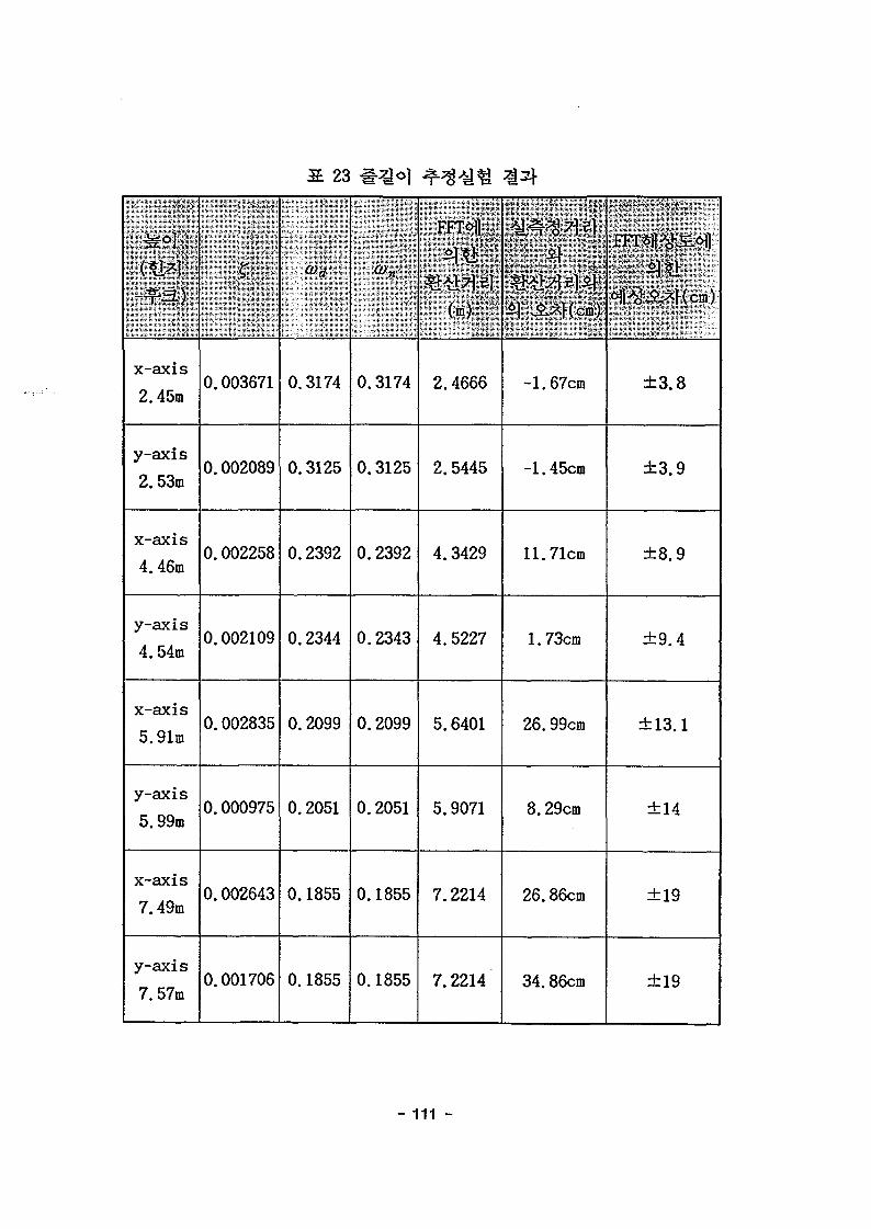
23
•s°f
x-axis
2.45m
y-axis
2.53m
x-axis
4.46m
y-axis
4.54m
x-axis
5.91m
y-axis
5.99m
x-axis
7.49m
y-axis
7.57m
K
0.003671
0.002089
0.002258
0.002109
0.002835
0.000975
0.002643
0.001706
0>d
0.3174
0.3125
0.2392
0.2344
0.2099
0.2051
0.1855
0.1855
0.3174
0.3125
0.2392
0.2343
0.2099
0.2051
0.1855
0.1855
FFTsfl
(•)
2.4666
2.5445
4.3429
4.5227
5.6401
5.9071
7.2214
7.2214
«1 A*|<c.)
-1.67cm
-1.45cm
11.71cm
1.73cm
26.99cm
8.29cm
26.86cm
34.86cm
±3.8
±3.9
±8.9
±9.4
±13.1
±14
±19
±19
-111 -

x-axis
0.0038
0.0036
0.002S
0.002
0.0015
0.001
0.0005 •
(a) X-axis
y-axis
(b) Y-axis
51
- 112 -

5.
(calibration)
LADAR
ZLe)7|] LADAR7]-
(a) Center Error
52
(b) Slant Error
- 113 -
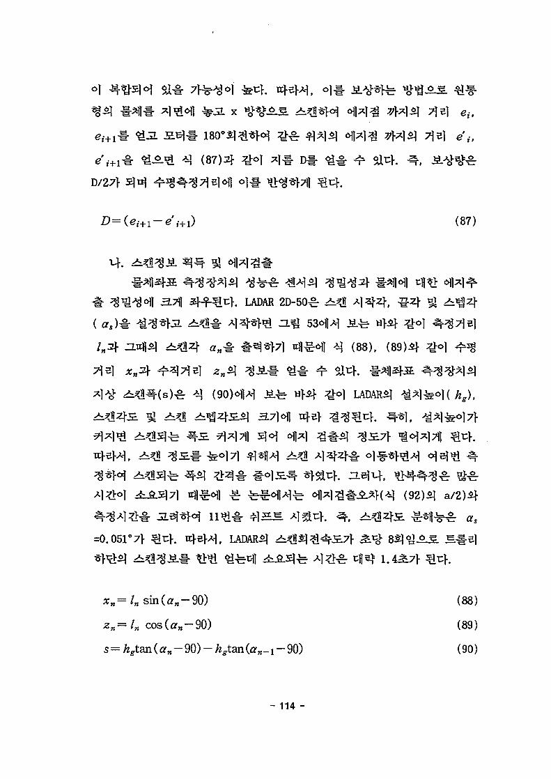
x
D/27>
e'it
(87)
. LADAR 2D-50^r
(88),
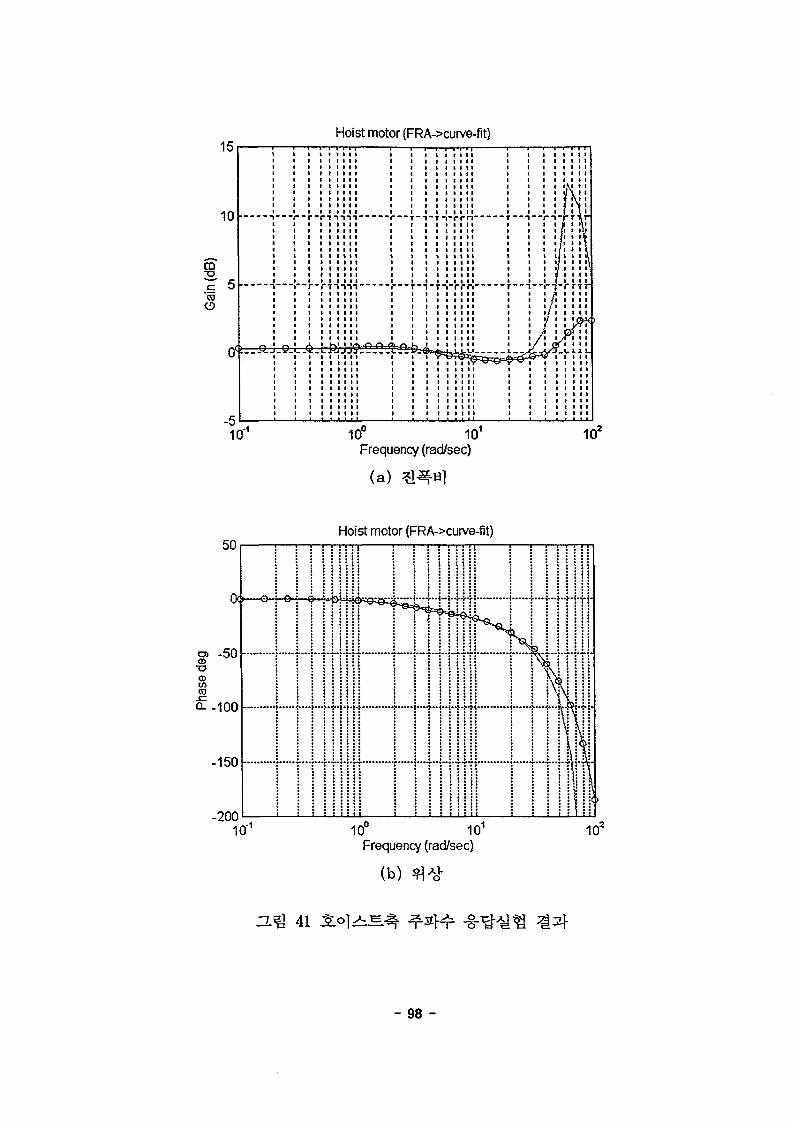
=0.051o7>
hg),
= ln cos(an — 90)
(88)
(89)
(90)
- 114 -
Odeg.LADAR2D
180 deg.
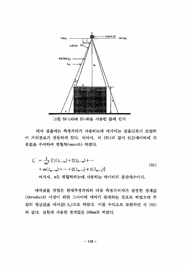
3.Q 53 LADAR 2D-50-§-
7}
1m'
2 [!(/!_J+2(/2_J +(91)
(threshold)
(92)
- 115 -
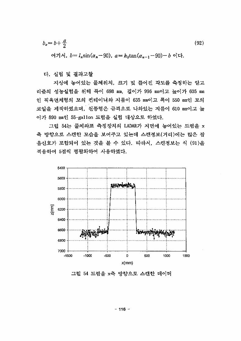
2 (92)
698 mm, zJo]7> 996
} 635 ]
\ 605 mm
550 mm I
610 mmolJL
o]7\ 890 55-gallon S .
LADAR7} fe ^-^# x
5400
5600-
5800-
6000 -
| 6200 -N
6400-
6600-
6800
7000
-1500 -1000 -500 0
x(mm)
500 1000 1500
D.Q 54
- 116 -

554
LADAR
(-50, -60)
Drum Test(D=610, H=890, , -60))
400
300-
200-
100-
i •-100-
-200
-300-
-400
•
t{\\
—•—•
\
— First E<•• Secorx— DramF
"w\
t/f
IgeiEdga'osition
-400 -300 -200 -100 0 100 200 300 400
y(mm)
55 s.
(-50, -60)
LADAR#
(36)
(-47, -59, 5738), 622mm, £. 892mm
- 117 -

Drum Test(D=610, H=890, Center(-50, -60))
300-
200-
100-
I o-X
-100-
-200-
-300-
-400-
iV
•
-9
X
\jf.
i - First Edge
•— Drum Position
t"7
/ ....
•400 -300 -200 -100 0 100 200 300 400
y(mm)
zr% 56 x-
(39)
(-100, -100)
LADAR#
1 0 . 9 2 ° ^
£(61.08°)
y* 91 * * # ^^ r ^ ^ (41)* *
(least square method)^ ^|~§-*M Q^^"(circle fitting)*}
- 118 -

Coil Test(Rotated Angle=11.31deg., Center(-100,-100))600
400
-400
-600•600 600
57
(48) (-109, -126, 5985)^. Til
• Measured Datao Circle Fitted Data
6700-800 -700 -600 -500 -400 -300 -200 -100 0 100 200 300 400
Yk'(mm)
zmi 58
- 119 -

(-100, -150) &JL 10.41
LADA&
(39)
12.3°
Container Test(Rotated Angle=10.41deg., Center(-100,-150))800
6 0 0 - -
400
200
-200
- 6 0 0 - -
-800
I
T".] J_
1tt
4• 3"*1 1 1
-400 't T
fT"
T"
T"
1 2
IFirst EdgeSecond EdgeBox Position
I
1
1M
-800 -600 -400 -200 0
y(mm)
H^ 59
• 1
•T—r 1
200 400 600 800
(48) (-111. -154, 6034)5.
, 3.7]
A l
- 120 -
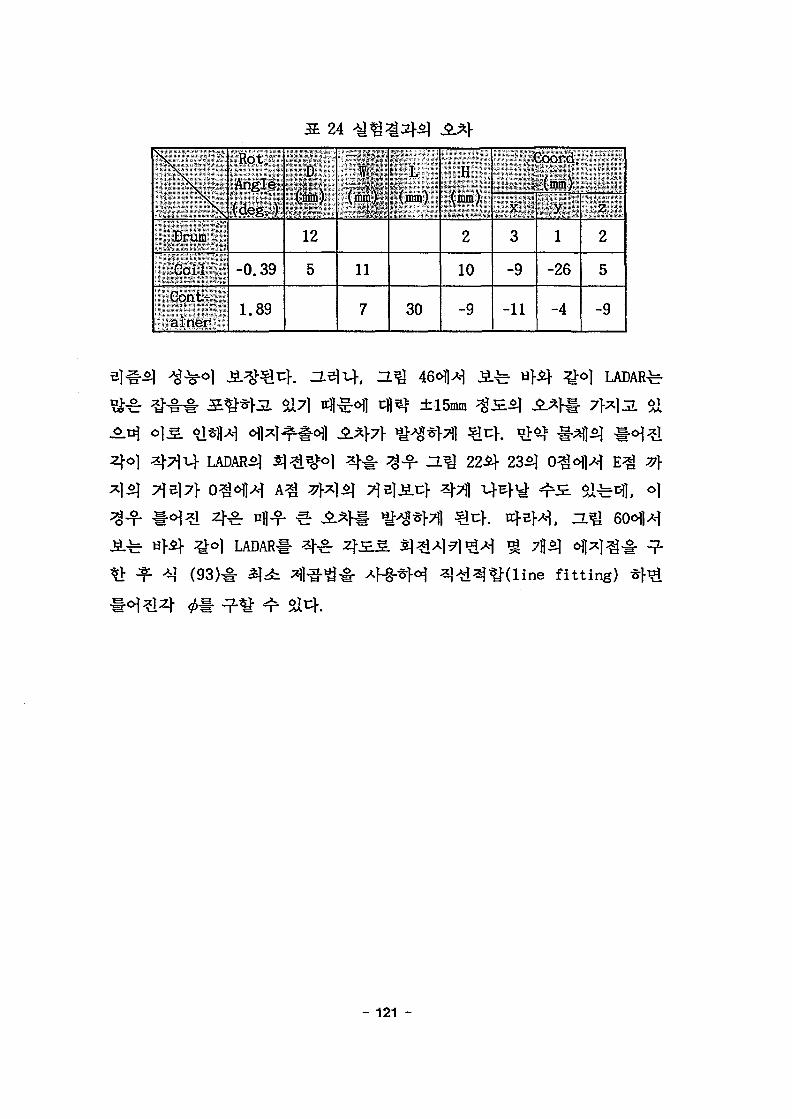
24
\
Drum
Coil
Cont-
ainer
Rot.
Angle
(deg.)
-0.39
1.89
D
(mm)
12
5
:.W
(mm)
11
7
L
(mm)
30
H
(mm)
2
10
-9
Coord.
. (mm)
X
3
-9
-11
y
1
-26
-4
z
2
5
-9
Zj-o]
7l5]7f
±15mm
4711
LADAR^
Ife^l, o]
LADAR#
ine fitting)
- 121 -

800
600 • -
400
200
-400
-600
-800
First EdgeSecond EdgeBox Position
-200 VI 1 1
r _i i
T 'I
4-
TI
-4--800 -600 -400 -200 0 200
y(mm)
400 600 800
60
(93)
- 122 -

/& + gd = - i (15)
a
max
61
->
- 123 -
omogeneous
Solution)^- (94)-$+ OT-.(94)
C2 :
o]*H (Particular Solution)^
= C3
V
7
6(0) = 0, 6(0) =
77 (96)
6(t) = -¥-;(coscot-l) (97)
§' 1 S
^ ^ 7 } sacf.
, t = T =
(9(T) = 0
& ^ a ) T ) = 0
^ ( 9 7 ) ^
- 124 -

t = TS.
t7\
A
(2)
61cm/sec, S
4 4 718cm, 613cm
afif ±2° *] ^
(3)
- 125 -

- x-axis swing ancle
- y-sx'e swing ancle
Tme{sec)
(a)
10
8
6
4
2
H 0-a
I' AA A
' I
! •
A
-
<
-4
-6
-8
-10
-12
, f , ,30! •
ii i' • \
' V V !
' ' '
I; \
x-axis swing angle
y-axis swkig angle
Time(sec)
(b) S
62
- 126 -

y-axis swing an^e
velocity of grcter
tirefeec)
(a)
-10
-1
-2
-3
-4
H^ 63
-x-axis swing angle
-y-axis swing angle j
-velocity of trolley !
time(sec)
(b) S
-10
- 127 -

4.06sec,
(4)
2.
7}.
- 128 -
Angletdeg
to
S « 8Velocity(cm/sec)
8 8 £Velocity(cm/sec)
8 8

x-axte swing angle
y-axis swino angle
velocity of girder
velocity of troftey
Time (sec)
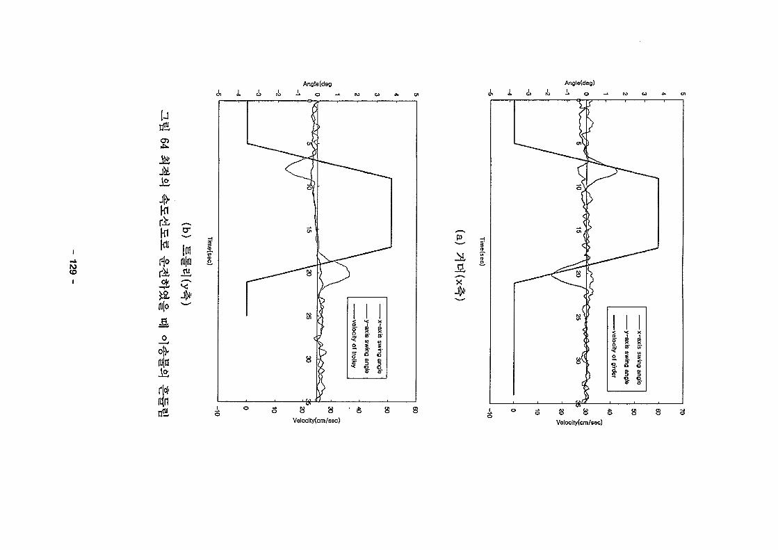
65 -?-§•**&§•
*H<>>
3.5S.
o]
7fx]jL
40cm/sec, 700cm, ZLB)3.
0.05sec5-
fe H^l 662]- ZL
- 130 -
Angle(deo) Angle(deo)
i
w
i
u
ofrl
o s
ojo
I
Velocity(cm/sec)
•* —* h5 l\5 <i>O Ol O tfi O
Ve!ocity(cm/sec)$ ft
^-§-3*
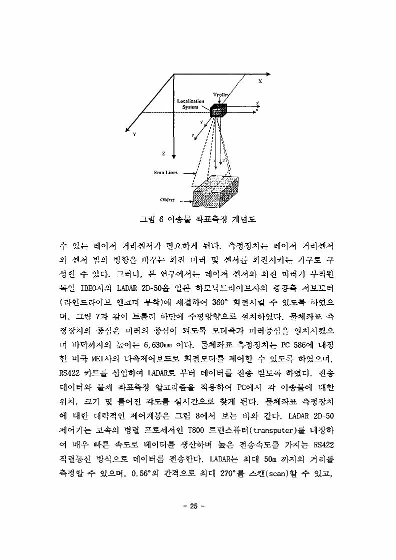
3.31*1 PLCa.mi PLC
331*1
PLC(Programmable Logic
Control ler)l-
PLC#
100% AC
PLC
PLC
$14. -g-
PLC5]
4. PLC
- 132 -

AC
ON/OFF
. 7)
71 PLC
RadioModem
Supervisor Computer
O.^ 68 10 PLC^H ^ 1 ^
- 133 -

^(Traverse
PLC
m x 15m x 6m)-§- 3.7\]
7]
25
' '•'• ^"SPECilFibivrioN ' "*"
.Hoisting Load
Span* ,";•
Travel ling'Length ;-;;
•Hoisting Length
Motor
Main.Hoist
Creep Ho.ist !
Aux- Hoisti
Creep-Hoist
Traversing
Travelling
Power Source
Control Method
Remark
10,000kg
15.625m
40m
6m
9kWX8P - 1
l.lkWX8P - 1
0.75kWX4P - 1
lkWX6P - 1
AC3p 220V-60Hz
By Pendent S/W
- 134 -

pL C
PLC
PLC
-r
fe 7]
69:4 ^Ani,
|3<(G3Q-RY4A)
/ / / / / / /
as siws gj«S = CPU (G3I-
(G3M (GM2 D24A)-PA1A) -CPUA)
A/D
as(G3F-AD4A)
(G3L-CUEA)
asS3
(G3L-PA1A)
POTENTIOMETER(DC10V)
- 135 -

26 PLC
# :& S. #
.^U<>l-g- CPU
Base J±J=
•
S.-E-
A/D
D/A
Po*er AC 110V » J ^ ,
-1-el DC 5V -6A,
DC 24-1.5A
£]cfl: I/O^^r 4096,
tH|S.Bl : 128K
<y-^^ S . # 87j| ^-«1-
Digital * J ^ 3 2 ^
12 / 24V
Relay -§-3 3 2 ^
12/24V
16 CH
*i<y-gH3 16 CH
J24}. ?f-Sre](2 CH)
RS-232 / RS-422-§-
PC^^H
^ «
1 EA
1 EA
1 EA
1 EA
1 EA
1 EA
1 EA
2 EA
1 EA
1 EA
•T?- A
GM3-PA1A
GM2-CPUA
GM2-B0S4
G3I-D24A
G3Q-RY4A
G3F-AD4A
G3F-DA4V
G3F-HSCA
G3L-CUEA
GMWIN
"• H] if
.Pendent P/B(7)
-Hs : UP/DOWN
Tr : EAST/WEST
Tv : SOUTH/NORTH
.Fielde sensor(3)
- Hs L/S
- Tr L/S
- Tv L/S
.SERVO BRAKE(3)
.al^^^l (1)
. t N ^ on/off
. S . O ] ^ - - E Up/Down-§-(2)
(2 CH4-8-)v V^t. AI ti3 T*7
X.Y.Z ^ -
PLC-PC^ ^ *
- 136 -

7) 7
^?> PLC CPU^fe LG<HW ^§#5]JL alfe GLOFA GM s e r i e s ^ PLC 3.
GM2-CPUA1- Sfil^SsUL. o | ^ ^ ^ ^ § ^ <%;§£ 71
if 4 ^ A l ^ ^ D i g i t a l
±10V ^ ^ ^ ^ ] A - | ^ i ^ . 6flr:lJE. (Single-ended)S.
PLC S#(G3F-AD4V)# ^H^
D/A ^ % PLCS#(G3F-DA4V)^r ±10V
PLC # (
n-col lector)
I/O PLC S#(G3I-D24A/G3a-RY4A)^r Bln]S. JSLA]- ^ l^ iS . P/B
^1. -LejJL, ^*$, ^^^ ojHiBl ON/OFF 4 ^ § " , ^ o l ^ S &S.
UP/DOWN A } ^ | ^
586HWRS232-C f-
PLC
PLC
°l-g-*H
- 137 -
D/A,
PLC CPU(GM2-CPUA)^- A/D,
PLC
(2) PLC
PLC
PLC
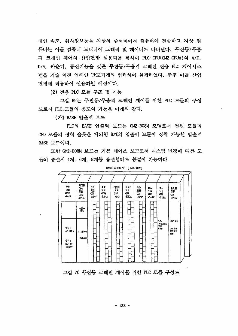
^ BASE « y # ^
PLC5] BASE GM2-B08M
CPU
BASE
GM2-B08M J i S .
67ft,
BASE Sg§? a£(GM2-B0SM)
aaG3M-PAIA
ACUOV
DC 5VDC 24V
HCHSCPUSiGM2
-CPUA
%
5l2Kb)te
12SKstq>
SiC3I-D24V
-
-
SiG3Q-RY4A
-
SiO3F-HSCA
--
SiC3F•HSCA
-
-
A/DSiG3F-AD4A
-
D/ASiC3F-DA4V
-
Si!SiG3L-CUEA
PIC-SPERVISERF C 3
26O3F-PAIA
±UVS2
aasgSi
H^ 70
- 138 -

fit
PLC.2} * 1 ^ fi#^r GM3-PAlAS.'iS>| AC 110V
DC 5V-6A£} DC 24-1.5A1- #« | .£3 .* fe JS.#3>1, «W>i J iE^S] 4
CPU
PLC5} *H«g
Ethernet MlS^3.7]- 7 ^ ^ t ^ , ^ ^ - n>o]HS
0.12 [xslstepQ 3A- cIMEjaleM- ^ ^ a l a , IL( Instruction
List), LD(Ladder Diagram), SFC(Sequential Function Chart)
512 Kbyte(128 Kstep),
8-64 Kbyte,
446 Kbyte#
PLC JSL#^r «^^f i#o) G3I-D24A, # ^ f i # o ]
G3Q-RY4A o]c}. ^ ^ S # ^ r ^ ^ ^ ^ # # 12/24V<>Hf Digital 6 j ^ 32
<§.§. 6 t ^ ^ ^ S *>i:K "lelJl , 32^^1 Digital <^^ ^ ^ - ^ ^ I ^ S . P/B
6\] S U ^ £ | ^ ^ r ^ / ^ f i - P/B, 3.6] >iS. UP/DOWN P/B, S # e ] EAST/WEST
P/B, 71 Dj SOUTH/NORTH P/B^ S . S ^i^g ^ ^ - ^ ^ ^>-§-*}3L, Field
L/S, ^*$ °]&Wk L/S, ^*5 o)^^*> L/S,
SERVO BRAKES
Relay # ^ 3 2 ^ # # ^ ^ ^ r S . tb^f. ON/OFF
ON/OFF 4 -g-, SL^I^S -S^^7l^j UP/DOWN #
(nf) ?}^^ PLC fi#
fi#^r G3F-HSCAS.A-I 5 ~
16,1777,215^
- 139 -
A/D PLC £ . #
A/D # ^
*}JLf <^2]tf l ^ H ^ s g ; 1.22mV(20/2uH
43s.
D/A PLC J5.-H
D/A 2 . # ^ G3F-DA4VS.>M 1 S.#«ifi 16*11 3 } °
, ±iov)#
G3F-PA1A
G3L-CUEA S # ^ & Cnet
RS-232C/ RS-422 4 1
G3F-PA1A S . # ^ D/A l ^g-S | fe ^-f- ^ 4 ^ " ^ - ^ ^ ±15V
- 140 -
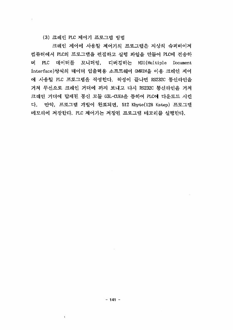
(3) a.i!j|$i PLC
t^ PLC tflolBll- J2.i-jB|ig, i : l» i^t - fe MDKMultiple Document
Interface)^^$] ^ ] ° ] ^ ^ # ^ - § - 4i^S^[]<H GMWIN# o)-g-
PLC 5 S a ^ f 4 ^ ^ K 4^°1 ^M- i RS232Cxl ^.i4|3L CM RS232C
G3L-CUEA# ^f-^oi PLC
^-o) ^ ^ . 5 ] ^ , 512 Kbyte(128 Kstep)
K PLC 1 ^ ] ) #
- 141 -

fe nil 712f KM 7M£
START
PC POWER ON &PLC POWER ON
RUN THE PLC
SOFTWARE PACKAGE
( GMWIN )
IN THE PC
2) PLC PROGRAMMING
PLC PROGRAM
DOWNLOAD
SETUP PLC PROGRAM
IN THE PLC CPU
RUN THE PLC PROGRAM
END
71 PLC
MODIFY THE PLC
PROGRAM
NO
^.^. 7m
- 142 -
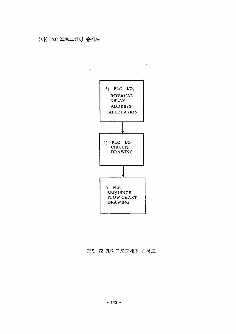
(tf)
3) PLC I/O,
INTERNALRELAYADDRESS
ALLOCATION
4) PLC I/OCIRCUITDRAWING
5) PLCSEQUENCEFLOW CHARTDRAWING
D.Q 72 PLC
- 143 -

PLC I/O
PLC
27
-
Pendent P/B
Field L/S
1 SERVO BRAKE
ENCODER RESET
POWER ON/OFF P / B
U1^HN P/B
^T^i-/^}^- ^ ^ P/B
5 1 O | ^ E up P / B
J t o ] ^ S . DOWN P/B
S i - e l EAST P/B
s#e l WEST P/B
7 | ^ SOUTH P/B
Tit-) NORTH P/B
S.o]>iH UPPER L / s
S # e ] EAST L/S
si-el WEST L/s7}ti) SOUTH L/S
7lt5| NORTH L/S
^ . o l ^ i H OVER LOAD
5 l o ] ^ E E 0 C R TRJP
Jg.#el EOCR TRIP
S # e l VWF FAULT
S # e l BRAKE OPEN
7\tf EOCR TRIP
7]C-] VWF FAULT
7]tf BRAKE OPEN
3 > ] ^ ; e ENCODER RESET
S I - e l ENCODER RESET
7 j D | ENCODER RESET
%* CPU*i^ ^ - t
X001
X002
X003
X004
X005
X006
X007
X008
X009
X010
X011
X012
X013
X014
X020
X021
X022
X023
X024
X025
X026
X027
X030
X031
X032
- 144 -
-
-
•
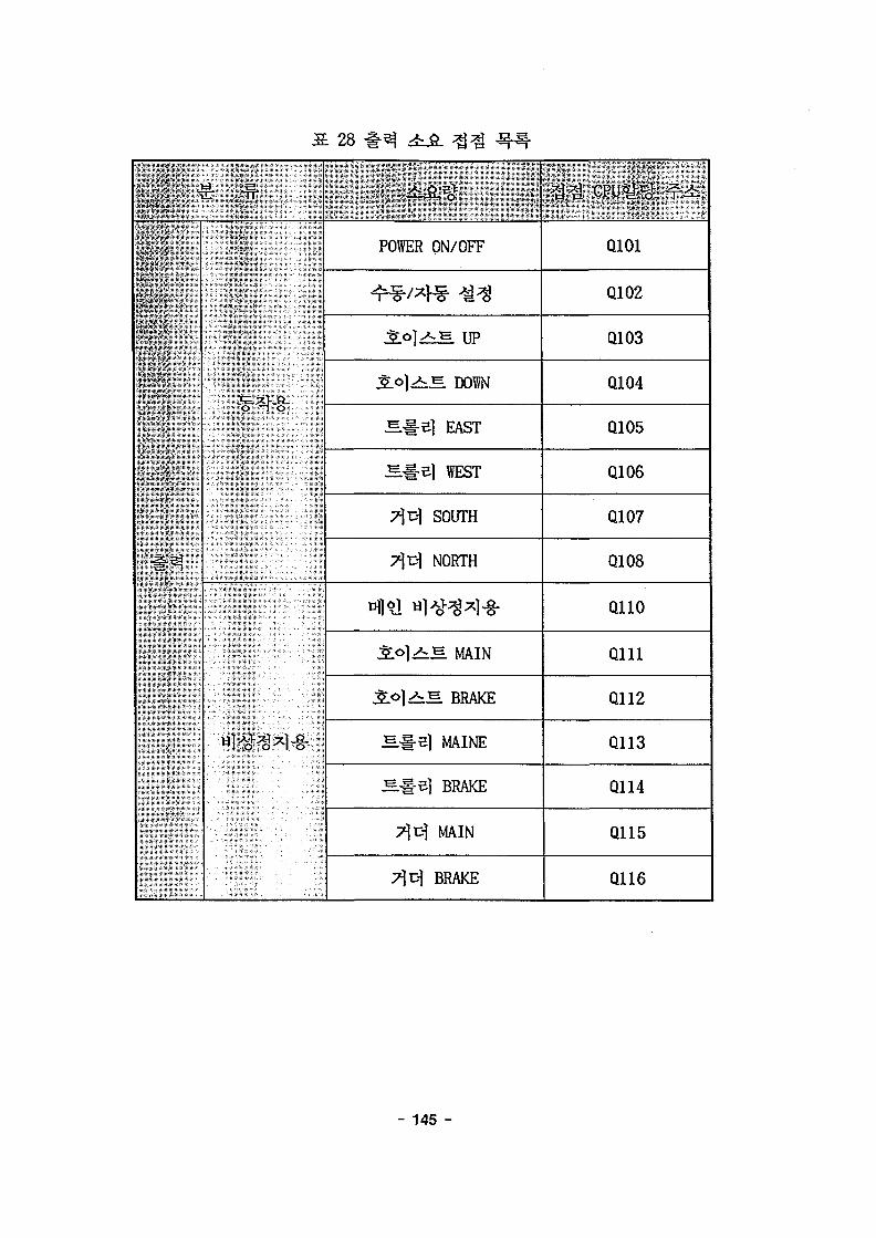
: 28 #^ ifi. 3$ -if -
POSER ON/OEF
+*/>» *«"ero]^*»'E IIP
SL°]^ DOW
S.#e] EAST
J^.#e] WEST
7^D| SOUTH
7 ^ NORTH
S L o j ^ S MAIN
Jto].>*-E BRAKE
H # e | MAINE
M # e ] BRAKE
7)1^ MAIN
T^D) BRAKE
Q101
Q102
Q103
Q104
Q105
Q106
G107
Q108
QUO
Q l l l
Q112
Q113
Q114
Q115
Q116
- 145 -
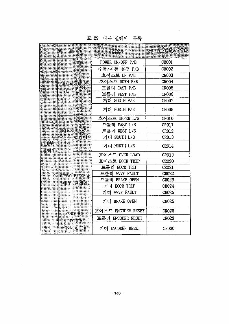
29
&' ,•* -
•Si
- •
s
,Pendent P/B-g-
-r 's
F i e l d L/S-g-
SERVO BRAKE-g-
-", . ENCODER
--' RESET-g-
. ^ % >
POWER ON/OFF P/B
4^?/*H§- ^ ^ P/B^ O | > ^ E up p/B
^o|>. t= DOWN P/BS # e | EAST P/BS-i-el WEST P/BT C-1 SOUTH P/B
7}cl NORTH P/B
SLOJ-AJS UPPER L/S
S . # e l EAST L/S
s .#e | WEST L/s7^1^ SOUTH L/S
7 ^ NORTH L/S
^ o ] ^ e OVER LOAD
S l o l A . ^ EOCR TRIP
S # S l EOCR TRIP
S . # e l WVF FAULT
S # S l BRAKE OPEN
TjcJ EOCR TRIP
T X I VWF FAULT
7|D| BRAKE OPEN
• ^ O T - ^ E ENCODER RFSET
S # 5 | ENCODER RESET
7]-c] ENCODER RESET
«« CPUW ^
CR0O1
CR002
CR003
CR004
CR005
CR006
CR007
CR0O8
CR010
CR011
CR012
CR013
CR014
CR019
CR020
CR021
CR022
CR023
CR024
CR025
CR025
CR028
CR029
CR030
- 146 -

(Ef)
P24[V] N24[V]
- •
•V
- •
X001
X002
X003
X004
X005
X006
X007
X008
X009
XO1O
XOO1
X002
XOO3
X004
X005
X006
X007
XOO8
X009
XO1O
XO11
X012
XO13
X014
X020
POWER ON/OFF
S 01 £ DOWN
S S E I EAST
S S E I WEST
0\ CH SOUTH
>1 EH NORTH
SOI ^ ^ UPPER
S S £ | EAST
MSE| WEST
^CH SOUTH
^ Cl NORTH
S01 i § OVERLOAD
73
- 147 -
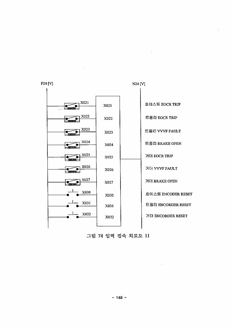
P24[V] N24[V]
,X021
X022
X023
X024
X025mmmm
X026
|XO27
X030
X031
X032
X021
X022
X023
X024
X025
X026
X027
X030
X031
X032
^ U 74
MSEIEOCRTRIP
^ S E I V W F FAULT
SSS.I BRAKE OPEN
^CHEOCRTRIP
IflCH V W F FAULT
71 C| BRAKE OPEN
s O I ^ M ENCODER RESET
M»e.l ENCORDER RESET
D\ a ENCORDER RESET
II
- 148 -
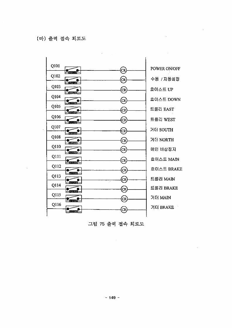
(n\)
Q101
Q102
Q1O3
Q104
Q105
Q106
Q107
Q1O8
QUO
Q l l l
Q116
POWER ON/OFF
^ e up
MM&I EAST
M £ | WEST
1CH SOUTH
^ Ci NORTH
die! UI#§XI
SOI^M MAIN
S O I ^ ^ BRAKE
SM£| MAIN
M l £ | BRAKE
71CHMAIN
BRAKE
75
- 149 -

2.
A.
3.^^1(2000^ 10^
55 ^-(gallon)
iiiiiiiiniiiiiiiiiiiiiiiiiiiiiinii
ZL^l 76
- 150 -

3 ^ 1
^ 7)
774
7]
(a)
HU 77 3^
- 151 -

(1)
Arm)ol ^(Support
H ^ 78,
CCTV
- 152 -

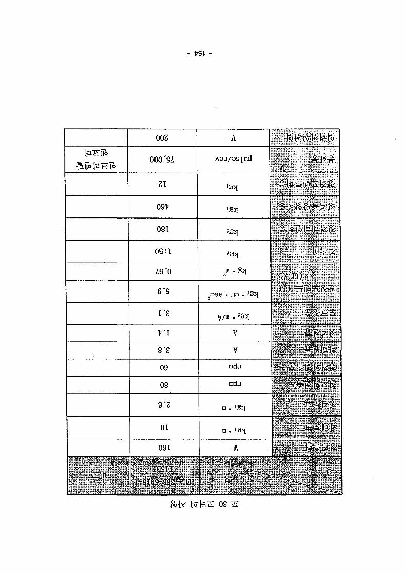
3. 30,
10mm, 7Hwl(n) 1/1.5,
| 25.
60 rpnh§-
25.51mm4 3.83sec7}
7.66sec7}
fe AC
Screw
Support Arm
Grapple Arm
n^ 79 ^ ^ 4*1
- 153 -
002
000'SZ
21
09*
081
0G:I
Z9*0
6'9
re
n8'e
09
08
9 "2
01
091
: ; • • ' ; • " • ' . - : • • :
.- • 0SI3
-ST09TaS2-VHJ'
A
J231
7oas . rao . JSij
V/ni. f3>i
V
V
radj
rada
ra . 'Sit
(T) "aia'Sgrg:
•• " 4%\^
••-• ^ # f e &
OS

31 AC
V AC100-230V50/60Hz
A(rms) 1.4A(rms) 3.8
^ 3.(GDV4)
18
kg 1.8PWM Z\]o\
: 16.7KHz): IPM
U.V.W
mm W60XH180XD150
A B
1 : 1000
0.
DC 0~±10V 33.Q)
, ccw^
TxD.RxD.GND 13
- 155 -

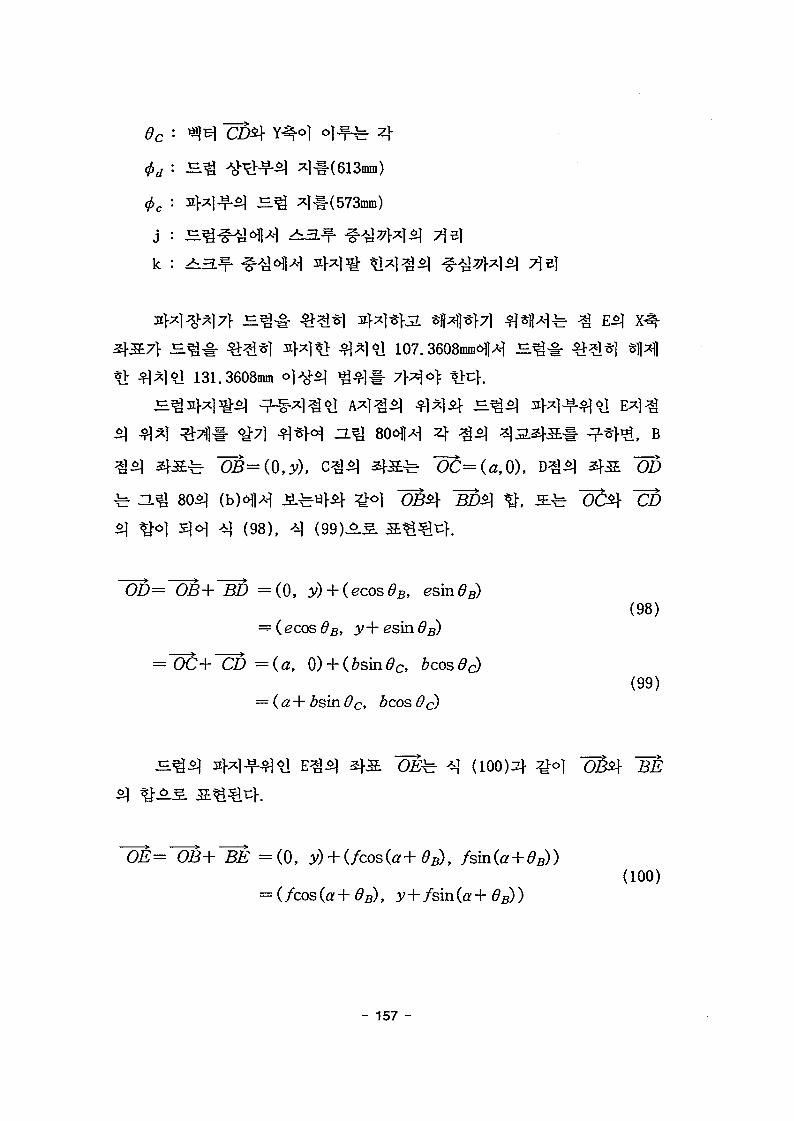
D.Q 80 -5.
(2)
a
b
c
d
e
f
0C$\ ^<>1 (86.3608mm)
7A°]{ 170mm)
<\A] Y ^ H H E ^ 7}x]*1 ^7]el(107.3608mm)
^ o ] (156.96mm)
~BE7\ o)if4=* 4(28.843°
o)-f^ 4
- 156 -
4
mm)
k :
# ] 1 107.
131.3608mm ] > ^ ^ ]
, B
80^ (bHW A^w} i f ^-o] QBii]- BD$] ^t s . ^ "ocitf CDA] ( 9 8 ) ( A]
BD = ( 0 , 3>) +(98)
bcos 6c)(99)
(100)4 ^o] OB$\ BE
0E= OB+ BE =(0, y) + (/cos(ff+^B), fsm(a+dB))(100)
- 157 -
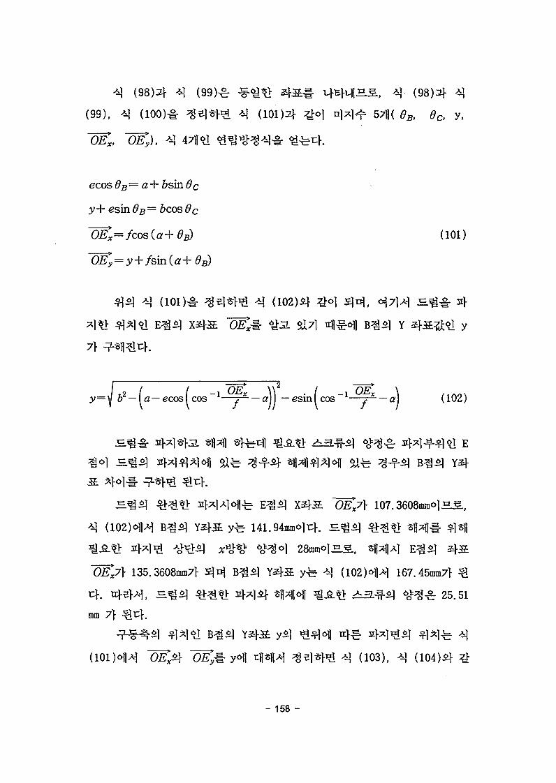
S , *}• (98)2}- *]
(99), 4) (100)# ^Bi*M ^ (101 )2f ^ o | njx)^ 57l( 0B, $c, y,
~OEX, ~OEy), ^ 47lj*l ^ ^ « o ^ ^ # ^fet:>.
ecos 6B=a+ bsin 6 c
y+ esin ^ B = fecos c
~OKc=fcos(a+6B) (101)
^ (lOl)-i- ^e]*l-^ ^ (102)*} £°] S|o|(
^ l ^ i E ^ ^ X3j-a ~OEM <&3. $X7] n^6\] B ^ ^ Y
7}
= y 62 — la— ecosf cos 1—j2- — a)\ - e s i n f cos 1—j*- — a)
^©i : E L ^ = W ^ * H safe ^-f^- *iwm*H safe
^ > 107.
141.94mm©li:K
(102)
135.3608mm7]- S | ^ B ^ ^ Y2|-a yfe -i] (102)©H^ 167.45mm7} ^
s ^ ^ ^^[*> afxlij- *||;<H ^^.*> 3 . ^ - ^ 6 o ^ ^ 25.51
mm 7}
- 158 -

f / / t a n ) (103)
^ * ^ ) (104)
(3)
Hll 4*1**13
(Control Box)£}
tfl
. 4*1 **H JHm AC
^ ^ ^ AC
4*1 €3 ^£# *M W. AC A^^^# -DC 0-+10 V
FWD, REV,
FWD# 3 l
R E V # ^ ^ }
1 (DGD, Drum Grapple D e v i c e ) ^
- 159 -

81
- 160 -

Auto Hand
Move crane tounloading position(by Pendant S/W)
82 JE
- 161 -

LED7>
PLC
n]s ^^^1 C7>
is. ^ 4 B7]-
LED7f
4^5] S. - *>$it:>. s)n]S ^ 4 Cfe S ^ 4 4
- 162 -

| A}
je ^ * ) C7}
3=3
C71-
A7}
7}. *S~LQ
$1^.^, ^^f W 8 4 f e ^-8-4^3. Slli:}.safe
LED!-34*
4*1 (Clamp) ^H*H^(Push Button)^
A7} ^ 1 S
^ ^ # ^1^ * M ^ 3 ^ - 4*1*M €4.^ H * l B7}
- 163 -

6\]
Display*}-^,
Databasel- ^ M ) 1 ^ ^ ^ 1
C++BuilderS. Windows
Data^^l,
Display, Database ^-^ i£ Load, Plot, Print, Save
= 1 ^ 3.7)} 37}*}$.
RS-232C
331
*.cpp
6J ^ S 34i} 3E 354} ^
- 164 -

32
FILE NAME
Current. DB
GetData. DB
ListFi le .DB
Test . DB
TempDB. DB
c:\crane\dborg
c:\crane\dborg
c:\crane\dborg
c:\crane\dborg
c:\crane
c:\crane\dbfiles
Jog, Path Control M Start Button^-±f£.r& 7\S.7\ ^ ^ S | f e DB
Table ^ * ? > ^ . ^ * } J L $X^ DB =5?-7
^ ^ 1 ^ 4 r DB FileS. ^ - ^ ^-A} >
Open< W i l ^ ^ l ^ } S # ^-A}S| £_#*}
fe DB
^f-il TestoJI^ %&*£ DB
£ S 2 ^ ^ ^ A | Jog, Path control^Start button^ J f S ^ | $^8r ?g-f <Q^
Saveoi] ^§U ^ H ^ Files
- 165 -

3E 33'•'a'" ;'••' "
SOURCE1. ,
BitMath.cpp
ChartMk. cpp
Commlni.cpp
DmudlCl.cpp
Initial, cpp
JogCtrl. cpp
ListDB.cpp
PathCtrl.cpp
Main.cpp
Refe.cpp
RptList.cpp
SrTest.cpp
« *
". J H E A D E R • •
BitMath.h
ChartMk.h
Commlni.h
DmudlCl.h
Initial.h
JonCtrl.h
ListDB.h
PathCtrl. h
Main.h
Refe.h
RptList. h
SrTest. h
CtrlCode.h
/ "FORM1. . •:
FrmChart
FrmComm
DmdulC
Frmlni t
FrmJog
FrmList
FrmPath
FrmMain
FrmRefe
FrmQrList
FrmSrTest
« *
sin, cos-j*-'5'}7| t File-^-^f.
Chart He]7l( plot )
•T§"£l Parameter J^.7% ^.7]Si-
File Open, File Save
Crane controller ^.7|S]-
Jog Control
Open^ File List
Path control
List^i File Print (Sf^ ^<Hl
date view)
5 S H | •§-/il Simulation
Jja-X|o)] ^-^^ >i)|o] J c (FTY ^-
- 166 -

X 34 COMMINI.INI FILE3]
FILE -tJI-g-
[Options]SPEED = 2
PARITY = 2
DATABIT = 3
COMMPORT = 0
-
0 :1 '2345
012
012Q
0123
4800 BPS9600 BPS19200 BPS38400 BPS56000 BPS57600 BPS
EVENODENONE
5BITS6BITS7BITS8BITS
COM1COM2COM3COM4
- 167 -
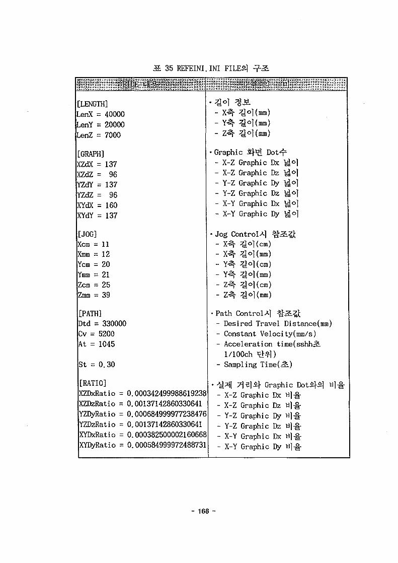
3EE. 35 REFEINI.
' ' FILE vfl g- • '
[LENGTH]LenX = 40000LenY = 20000LenZ = 7000
[GRAPH]XZdX = 137XZdZ = 96YZdY = 137YZdZ = 96XYdX = 160XYdY = 137
[JOG]Xcm = 11Xmm = 12Ycm = 20Ymm = 21Zcm = 25Zmm = 39
[PATH]Dtd = 330000Cv = 5200At = 1045
St = 0.30
[RATIO]XZDxRatio =XZDzRatio =YZDyRatio =YZDzRatio =XYDxRatio =XYDyRatio =
0.0.0.0.0.0.
0003424999886192380013714286033064100068499997723847600137142860330641000382500002160668000584999972488731
INI FILES} ^-3L
- X^- ^o](imn)— Y^i" | I (HUB)
— Z"^Y ^y 1 v VL\S1 )
• Graphic Sj- Ji Dot- 2-- X-Z Graphic Dx ^Jo]- X-Z Graphic Dz ,°]- Y-Z Graphic Dy ^o]- Y-Z Graphic Dz ^ o |- X-Y Graphic Dx ^Jo]- X-Y Graphic Dy ^Jo|
• Jog Control A] ^-^.^- x-^ ^cl(cm)- X^- ^o](mm)- Y^- ^o|(cm)- Y^- ^o|(mm)- Z^- ^o](cm)
- m- oKmm)
• Path Control A] % 2 L Q- Desired Travel Distance(mm)- Constant Velocity(mm/s)- Acceleration time(sshhr£.l/100ch ^>^|)
- Sampling Time(i2.)
• ^ ] 7]s]if Graphic DotS}5} H|^-- X-Z Graphic Dx «]•§•- X-Z Graphic Dz «]•§•- Y-Z Graphic Dy «]-§•- Y-Z Graphic Dz a]^-- X-Y Graphic Dx a|-§-- X-Y Graphic Dy ti]-§-
- 168 -

(l)
(7» S^OL^-i- 41^*1*1 ^ S ^ o ] S$J$ % ttfl COMMINI.INI,
REFEINI.INI FILEoJW g5..-T^ofl s g ^ ^ ^ . ^ |H#*Il=K
Main a ^ o ] Active ^ tcfl ^-^1 P0RT# Ji7]Sf A)^lt:l-. o]vc%
7fe*M Sm #<>lJ2.fe ^}&fe TempDB.DB ) ^^SjJL Jog,
Initial, PathSf^o] 5 l # ^ ^ l ^o\^. ^}^.^o| Display^}.
( t » Jog Control JE-fe Path Control < M Start Button^- ^fS.^.
Control l e rS ^-Ml^^ °14-f-^ #°1^-fe *}3-^ Current. DB
Stop Button^
TempDB.DBofl ^H v€^}.
(n» 3< ]A-| x-j -51 Current. DB
T&, LIST# # ^ S f 3 ^ Save
(2) ^tl Telecommunication Protocol)
(Initialization)^:^ Jog Control *$*%, Path Control
(71-)
(byte)S
'0x02'
- 169 -
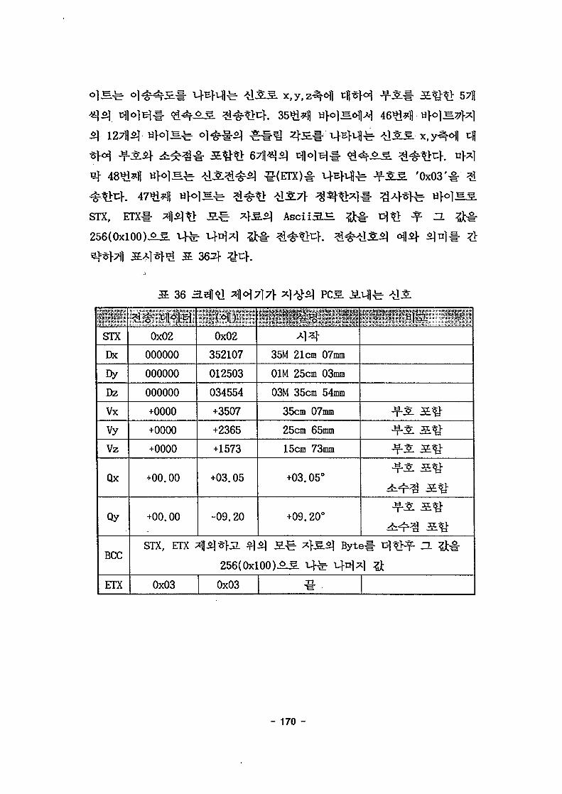
STX, ETX-1-
256(0x100)-^^
362}
57fl
^ l A i 46*1*11
AsciiSS
'0x03'
36
STX
Dx
DyDz
Vx
vyVz
Qx
Qy
BCC
ETX
0x02
000000
000000
000000
+0000
+0000
+0000
+00.00
+00.00
STX, ETX -
0x03
*•*•>• v C ^ i | J
0x02
352107
012503
034554
+3507
+2365
+1573
+03.05
-09.20
35M 21cm 07mm
01M 25cm 03mm
03M 35cm 54mm
35cm 07mm
25cm 65mm
15cm 73mm
+03.05°
+09.20°
Jf-SL a #
^ ^
lil*}jL $\$) 3.^=: x}&$) Byte# T%$}ft- H &§r
256(0x100)^5. i-fe M-4^1 ^
0x03
- 170 -
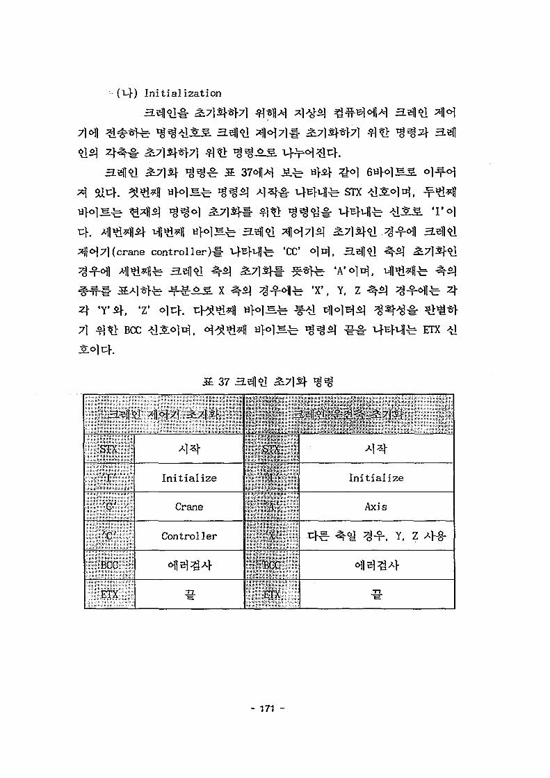
(i-}) Initialization
STX
crane controller)#
X
'CC O)B},
^ t r f e 'A'o]n},
fe 'X', Y, Z
7) BCC
37
fe 4
fe ETX
a. M ^M7l ^71^
STX
'I'
' C
f.C'
•BCC ,
ETX
Initialize
Crane
Controller
a-eff*]. ^ ^ 3L7\$\
STX
'I'
'A'
'X'
BCC
ETX
Initialize
Axis
4 ^ ^ ^-f, Y, Z Af§-
- 171 -

(~c\) Jog Control
Jog Controls
h£r Start
Jog Controls
-M41 *H
start
S ^ 1171S}
Start *_
•fe- Jog Control-g
>1 Start-!- 5]ti
»Y' 'V' ' 7 'A . I . / .
38 Jog Control^ Start
STX
• 'J'v
" 's<t'': 'X^i-;,; •'+',; ,
:f: BCC ""
r:ETXv
JogStart
cr€- -^ -f, Y, Z 4-§-
00 cm 00mm (4 *}B1)
Stop
STX
U]-o]
BCC
STX
BCC
vfl^ ETX'T', '0', 'P', BCC, ETX#
. ^, STX, 'S',
STX S T 0 P BCC ETX
- 172 -

(ef) Path Control
Path Control6\)*\ 3.3*1 & § • *\)°\*}7]
STX
C o n t r o l ^
*i*j| w H S
39
^ r Path
STX
'P'' 'S'
BCC
ETX
A}4
Path
Sampling time
102 1.02^.
Start
S. 40 1 >H , 7}
STXif ETXojc}.
] E ^ Path control^.
'Y', 'Z'
- 173 -

BCC
mm/s
Stop
40 Path Control^}
STX
'PP'
'X' "
' + '
<^£(4)
BCC
ETX
Path
t*E ^ ^-f. Y, z 4-§-
00 M 00cm 00mm
0000 mm/s
1234 12.34^:
-fe 1 ^ Jog Control^ ^ ^
STX S T 0 P BCC ETX
- 174 -
(1)
C:\Crane # T ^ # ^>#3. S 33£] Source file2]- header file
- C:\Del3comp # H - § - ?fifvjL CommuDrv32.pas, TransBtn.pas, Led.pas
Borland C++ Builder^] 4 ^ . ^ : Component#
1. Borland C++Builder# launch*]?!^}.
2. Borald C++ Builder^ ComponenttH)-rr< |A-| install Component
3. Unit f i le name(Install Component)#
- Browser button^ T ^ - ^ C:\Del3Comp\Lib\CommDrv32.pas-i-
-^ File Type^r Pascal uni t(#.pas)# -ti
4. 3313} ^ ^ ^ ^ S . ^ ^ c l^ jSe l vHl 61 TransBtn. pas,
Led.pas# ° l ^
o] £3= ^t*i\T& Package f i l e # Update
1. f i le menuoJH Open# -*i -cr]-o^ C++ Builder Package f i le( f i le
name : dclusr35.bpk)-i- £ c h (C++Builder7>
2. o}2fl£j- ^ - ^ dclusr35.bpk^
- 175 -

;/
#include <vcl.h>
#pragma hdrstop
USERES("DCLUSR35.res");
USEPACKAGE("vcl35.bpi");
USEUNIT("..\..\..V.\Del3Comp\Ub\ComDrv32.pas");
USERES("..V.\..V.\Del3Comp\Lib\ComDrv32.dcr"); —> Mgr*m ^StypeSllo^Ffe code
USEUNIT("..\..\..V.\Del3Comp\Lib\TransBtn.pas");
USERES("..V.V.V.\Del3Comp\Lib\TransBtn.dcr);
#pragma package(smart_init)
// Package source.
int WINAPI DIIEntryPoint(HINSTANCE hinst, unsigned long reason, void*)
{
return 1;
}
II
3. ^r^% dclusr35.bpk 3i]-^# Builder}
BitCtrl 3
(2)
crane #I>|^1 $X^ crane.exe
Initialization
Jog Control nfl>*f£|- Path Control nfl«%f, r§- S . H ^ ^ 3L7]?ti-
^ f e Other nfi-f ^ S Z L ^ # ^SM^ct End
- 176 -
CRANE MASTER; CONTROL.
a
i| , [mil
j THE: *
V Ltll
M1.J
J *»\ tri•i
** it
1 u
Olhc
i ml
ili/atiun
"ontrtil
C ( ntr A
L t i l l
^ iiitn
uilr
mi s\i
r
* j
J I M
ikr U I
• f II K l ~
lfH_ I'flll I
-«'
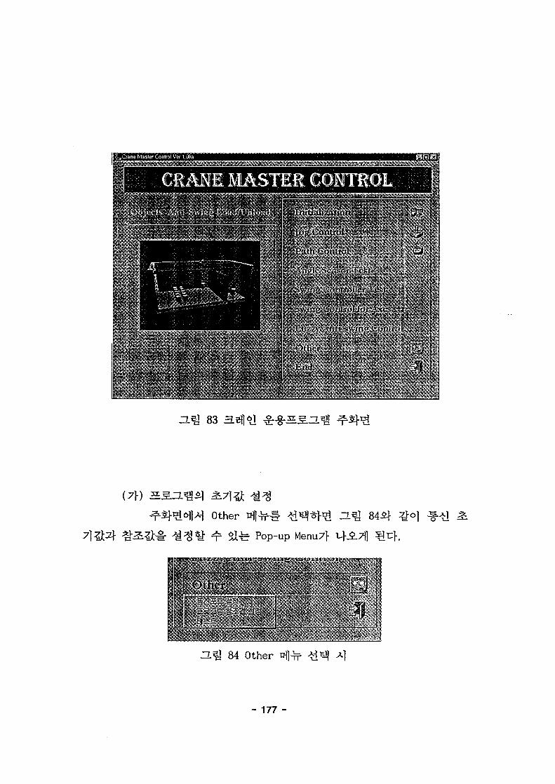
83 rg-SS-IL^ ^Sf1^
(7\) 5S2
Other nfl-THi"
i ^ Pop-up Menu7}
ZL^l 84 Other nfl^f
- 177 -

1 t: PARITY BIT JNONE ~
l> "DATA^BIT*1" JSBITS ^ y]«
'' ''COMM PORT ICOM l" ' ^ l " ' " i l O '
n.^ 85
' S P E E D ' ^
4800bps^-B] 57600bps*}*]
'Crane
mmo]u}.
4 -LSH^^I. 'Jog ControUl
4
r ^ Jog Control
'Path Control*] 4 ^
Path Control^ afl
- 178 -

Control c f e Path Control
W Initialization tHl f 3Mr Jog
Dx, Dy, Dzfe J f l * ] # Vx, Vy, Vzfe
OPEN,
,? < InitiaJi^a'ion > *i t • . . • • • s . . j n i i . . .
86 Initialization
- 179 -

= £313 &2SSS
H Bflo|Bj
PRINTS
-L^ 87 S.S.0.^
SAVE, ZL fe PLOT,
CONTROL MENUS
Initialization t ^ H ^d^^}1^ H^I 86^} ^
H.2]l l ^7|2} 4<^ ^1^-ffe 'Crane
controller initialization'^ 'Select any axis(X,Y,Z)', 'Select of
mass*it) 37}x] ^ ^ ^ S ^-^5]<>| Sir}.
Crane controller initialization ^ - S :
Select any axis(X,Y,Z) §
Select any axis(X.Y.Z) ^
, X,Y,Z
Select of mass
- 180 -

Select of mass
895} ^ ^
SISIM ^ 865]
(Bf) Jog Control
Jog Control n
. Jog Control^
'Select any axis'
fe STOP
Simulation Start/Stop
• . • > . • : • • . . ' i t v :, . - r - . | - : ; . . • • • - - ;p j .=?•" - .
s ' si1 •••';< Initialization > i
! Qare'coriisilstinilializaticii ' •
•hi-
r• • ' • • - I
X J
. • • T T ; T , ; . V , . - : : I -
J-.'.yf-. . |
,'f ' • ' " ' • ; : • *
-.J „: :1
S(Pendent)S
Start
^-2]- 'INC tf[^-#
^^Initialization >.L:.SJj.u:- -i. ;:
•';!' Qane:coniroCe» Wiafcafion
!«•••';jvKJ..J: . T L T U ^ P "
i • . Scfcclof mass '".
.;:-J:.9.l •'.- ••• i
a^J 89
- 181 -

i iJog Control
n ^ 90 Jog Control
Path Control
Path Control
f. Path Control^:
Profile
912f
«'Enter desired travel distance(mm)' -£}
"&}^- 'Enter constant velocity(mm/s)',
'fci i Kir 'Enter acceleration time(sec)',
'Enter sampling time(sec)'.£} ^ ^ ^ o ] ^ ^ ^-§- l^l^fe 'Select any
axis' t§^, o|"cr J; ^ " S " d ^ ^ } ^ 'Select any direction' v§^§, 3.sf|
l-fe5- Start ttl-c-il- 3^(1 $1^1 3fti# -f-^l^l-fe1 STOP
- 182 -
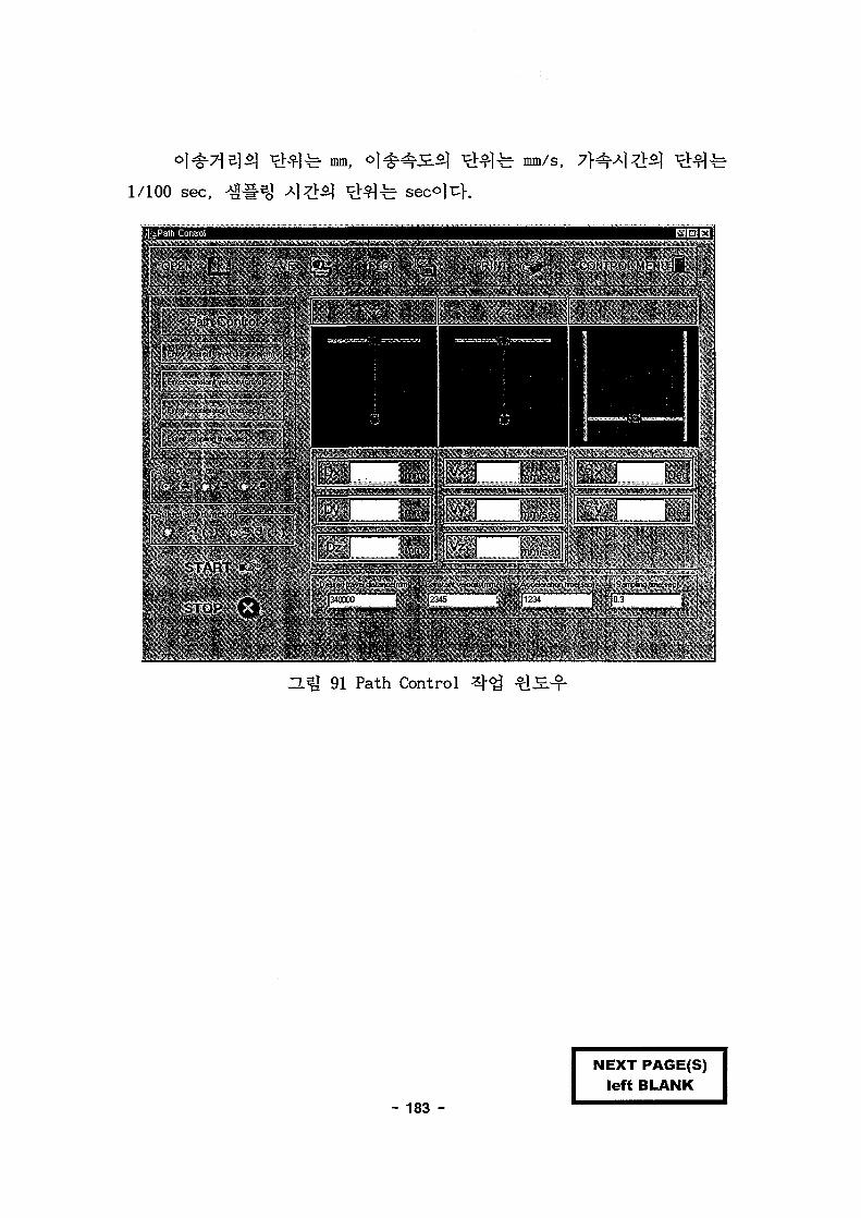
- b mm, 2=. mm/s,
1/100 sec,
fcPath Control•V • T »
S L ^ L S •'iii^l '••" ":?'*•]>'•' <Pai l\Coitol
« J_ _ .
' * r J - 1 ¥»l 1 J*"*
< m w * > • - W » H I P T » I «• ^
1 I" > * I C T
START »-'
STOP Q
JL
f 3 1 p/1 .."/1 f' y ] „ ;j;Dz i
• " ' ! 1
^n • 1 *
. i - - ^ T 'j ' , ^ - .
•-. i
91 Path Control
- 183 -
NEXT PAGE(S)left BLANK
1- ©1
7171
51-OH51
- 185 -
x, y - SI*] o] 4 ^tflsfl x,
45.(0.
ON/OFF
30 mm
shield AC 3 ^ 220V ^ ^ o f l v-o)
100%
- 186 -

- 187 -
NEXT PAGE(S)left BLANK
[1] T. Tsukui, "Automated Yard Systems at the Ohgishima Hot
Strip Mill", Nippon Kohan Technical Reports Overseas, 1980.
[2] E. Alzinger AND V. Brozovic, "Brown Boveri Automation and
Control System for Grab Cranes", Brown Boveri Review, vol.70,
no.9-10, pp.351-356, 1983.
[3] J. Werner, et al., Swing-free Movement of Simple Suspended
Objects Employing Parameter Estimation, SAND 89-2511, Sandia Natn'l
Lab., 1989.
[4] M.W. Knokes, et al., "Implementation of Damped-Oscillation
Crane Control for Existing AC Induction Motor Driven Cranes", Proc.
of ANS 5th Top. Meeting on Robotics and Remote Systems, American
Nuclear Society, Knoxville, TN, pp.479-485, 1993.
[5] •&*]$, »A^*\, °1*M, "Mmm'89 KACC, vol.1, pp.260-265, 1989.
, '90 KACC, vol.1, pp.292-297, 1990.
, pp. 409-414, 1993.
[8]
", ^mm^iS. th^- 17481, n|-S»- 19291, ^ ^ 94-11736,
P4402787.7, 5:^94-54827, ^^1^9400211-0, l ^ S 940542, 1994.
[9] &X1-3, ^^, o } ^ , ti|^^( "3.^}^]$] MB S&lfcl- ^ ^ ^
W® HW. ^)&m?$.S- ^m 6026, n|^ 246337, ^^! 9401560-9,
1994.
[10] J.S. Yoon, et al., "Fuzzy Anti-swing Crane", '94 ANS Winter Annual
Meeting, Washington D.C., Nov, 1994.
[11] -n-tl^-2], "Fuzzy Logic Control of a Roof Crane with Conflicting
- 189 -

Rules", 5th IFSA, pp.1370-1373, 1993.
[12] *]SJ, "tl^WM £3.3]^ S.^^ *H<4 # # <& -," '95KACC pp. 606-612, 1995.
[13] A. F. Moustafa and G. Abou-el-yazid, "Load Sway Control of
Overhead Cranes with Load Hoisting via Stability Analysis", JSME,
series C, vol. 39, no. 1, pp. 34-40, 1996.
[14] David E. Goldberg, "Genetic Algorithms in Search, Optimization,
and Machine Learning", Addison-Wesley Publishing Company, Inc.,
1989.
[15] E. Ohnishi, et al. , "Automatic Control of an Overhead
Crane", '84 IFAC, no. 66.3, pp. XIV-37- XIV-42, 1984.
[16] J. S. Yoon, B. S. Park, J. S. Lee, and H. S. Park, " Fuzzy
Anti-Swing Crane", ANS, vol. 2, pp.35-43, 1994.
[17] J. S. Yoon, B. S. Park, J. S. Lee, and H. S. Park, "Various
Control Schemes for Implementation of the Anti-Swing Crane", ANS,
vol. 2, pp. 472-479, 1995.
[18] Yamada, S h i n - i c h i , e t a l . , "Fuzzy Control of t h e Roof
Crane", IECON Proceed ings , vo l . 4, pp. 709-714, 1989.
[19] Torbi t t , A.J. , e t a l . , "Development of Deployment Results of
the Tethered Remote Operating Device", Proceedings of ANS 6th
Topical Meeting on Robotics and Remote System, Vol. 1, pp. 62-69,
1995.
[20] B. S. Park, S. H. Kim, D. A. Kwon, J. S. Yoon, "A Study on
Automation of Crane Operation", KACC Proceedings, vol. 12, pp.
1871-1875, 1997.
[21] B. S. Park, D. A. Kwon & J. S. Yoon, "Development of Object
Localization Algorithms for Crane Automation", KSME, Part A, vol.
23, no. 5, pp. 829-838, 1999.
[22] H. R. Lee, J. H. Kim, "Spreader and Container Recognition
Method for Unmanned Container Stack", KACC Proceedings, vol. 9, pp.
- 190 -
1155-1160, 1994.
[23] G. Y. Park and P. H. Seong, "Towards Increasing the Learning
Speed of Gradient Descent Method in Fuzzy Systems", Fuzzy Sets and
Systems, vol.77, pp.299-313, 1996.
[24] Ho-Hoon Lee and Sung-Kun Cho, "Position and Load-Swing Control
of a 2-Dimensional Overhead Crane", KSME, vol. 21, no. 10, pp.
1683-1693, 1997.
[25] Ji-Sup Yoon and E. Suck Kang, "A Study on the Anti-Swing and
Position Controller for the Overhead Cranes", KSME, vol. 19, no. 6,
pp. 1391-1401, 1995.
[26] Itsuo Murata, Satoshi Kunimitsu, "Development of Coil Position
Detection Apparatus by the Light Projection Method and Application
to Automatic Crane", Mitsubishi Heavy Industries, Ltd., 1991 vol.
28, no. 6, pp. 618-622, 1991.
[27] Itsuo Murata, Hirofumi Yoshikawa, et. al., "Position Detection
of Object Hanging from a Crane by Image-Processing Method", The
Japan Society of Mechanical Engineers, Part C, vol. 60, no. 569, pp.
198-203, 1994.
[28] K. Sugiyama and Y. Nabeshima, "Rationalization of Container
Handling with Automatic Operation of Crane", Ship Operation
Automation, III. Proc. of the 3rd IFIP/IFAC Symposium, pp. 209-216,
1980.
- 191 -
NEXT PAGE(S)left BLANK
- 193 -
NEXT PAGE(S)left BLANK

CO
en
PROXIMITY SWITCH
VFCTVFCT 3 , 5 « q cVFCT 2tqx12cx3FC-3PMCT-9S 2Bq
IQXIMITY SWITCHCW2aqx3c
SPECIFICATION
HOISTING LOAD
SPAN
TRAVELLING LENGTH
O
3
MAIN HOIST
CREEP HOIST
AUX. HOIST
CREEP HOST
TRAVERSING
TRAVELLING
POWER SOURCE
CONTROL UETHOO
RCMARK
10000 KG
15.«25 U
U
9KW x 8P - 1
1.1KW K 8 P - 1
0.75KW x 4P - 1
tKW K 6P - 2
AC 3 * 220 V 60 Hz
BY PENDENT SWITCH
A
<|> BANDO MACHINERY CO., LTD.
ELECTRICAL ARRANGEMENT ORAWNGJ
BANDODRAW1HC NO.
•£3- TMK} AMCU PHJtONM
MV-Mk. »CE1

14 I 15 I 16 I 17 | 18 | 19
CREEPHOISTING
OC.MAG MOTORBRAKE 1.IKW x 8P
(0-0HOISTING
DC.MAG MOTORBRAKE 9KW x 8P ENCODER
DC.MAG DC.MAGBRAKE BRAKE ENCODER
• 1 1\L|j
D/O 0/0 H/COUNT D/O D/O D/l 0 /A H/COUNT
PROGRAMABLE C0NTR0LLER(GL0FA-GM2-CPUA)
D/O
A/0 A /0 D/l 0/1- --D/I
D/O D/l D/A H/COUNT
RS-232
DC SV DC 5V
POTENTIONMETER 1
POTENTIONMETER 2
(X) (V)
ANGLE DETECTOR
FIELD SENSORL/S OR PHOTO
I
A'MK
R E V I S I O N S
DRAWING
T l T L E
rnvnSYSTEM CONRGRATION
DRAWING APPROVED
( § ) BANDO MACHINERY CO., LTD. DWG. NO
ORDER NO.
PW-0649-01

I 16 I JT '8 I '9 T
NFB1(100AF/1OOAT)
OC. 24V TO : DC CONTROLDC. 12VTO: OC CONTROL
AC. 110V TO : AC. CONTROL
DC.±15V T 0 . D C C O N T R O L
-L- M300T ( S M C - 2 0 P )
- 1 - M1O1 J - MIO2• • • * * * • "'IV* • » • • » ! | 4 | | f
(SMC- I25P)T (SMC-125P) - r (SMC-20P) T ( S u c _ 2 0 p )
RF100(SR-60)
EOCR-110 —
LOAO-LIUITER —
NOISE FILTER ZZ
RF100(SR-30) INV 300
J300-0S5LF
ENCODER HOISTINGMOTOR
9KW x 8P
A 1 i / u \ i I t
U/ \Jy U/DCMAG CREEP HOISTING DC.MAGBRAKE MOTOR
1.1KWx8P
M301(SMC-20P)
RF300(SR-20)
- L M400- " (SMC-20P)
REACTOR
, I NOISE FILTER
INV 400J300-O55LF
EOCR400-S
<$
TO: PIC
-L M401" " (SMC-20P)
RF400 |(SR-30) |
i
0 Q-fr-Q D)TRAVERSING
MOTOR0.75KW x 4P
ENCODER DC.MAGBRAKE
TRAVELUNGMOTOR
1KW x 6P x 2
ENCODER DC.MAG8RAKE
DC.MAGBRAKE
AA"AA'MK " R E V I S I O N S
DRAWING
T I T L E
SINGLE LINE DIAGRAM
( g ) BANDO MACHINERY CO., LTD. DWG. NO PW-0649-02

a
I
. 1 2 1 3 1 4 1 » 1 5 1 7 1 8 1 9 I 10 11 1 12 1 13
POWER CIRCUIT
1 14 | 15 1 16 1 17 | IB 1 19
TRAVELLING POWER SUPPLY SYSTEM
T
AAMK DATE R E V I S I O N S
>D
E
V
CHK. APP
R
V
c
s
v(A2/OS)^
TRAVELLING POWERSUPPLY SYSTEM
T81(TR0LLEY BAR)2 0 0 * x 4UNE
|
K 1"\\\
COLLECTORC0L1
90A x 4EA!
H"~LI.
i
CV 22sq x 4c j
1V1
\\
T7 N O T E S
051 1. MARKED OWNER SCOPE2. MARKEO CRANE MAKER SCOPE
- CUSTOMER
ORAWNG
T 1 T L •
mm
MAIN POWER CIRCUIT 1
DIAGRAM
DRAWING
? • - "
! lT| | CV 22sq x 4c
! ' iR 's (T
-L-l— I
r/f r/ Y | N F S " 203(125A)
1 1 11 1 1
1 I I CV 22sq X 4c
1 1 11 1 i
\ • 2 so POWEI;^ . AC it
\ {RO 60HZ
^ ^ . ? E
OESICN
•
CHECKED APPROVED
(g)BANDO MACHINERY CO., LTD.
20
AOR'S NO.
Al
SOURCE220V
SCALE
NONE
DWG. NO
DATE
1999. 01.20
ORDER NO.
PW-0649-03

~ r I 9 I 10 I IIPOWER CIRCUIT
12 1 13 | U | 15 I '7
COMMON PROTECTION
POWER SUPPLYSPS1
MAIN INCOMINGSWTCHNF81
ABS-IOJ(IOOA)
to
TO : PLC CONTROL
TO : POTENIION METER
TO: AC CONTROL
TO : PLC CONTROL(OVOI) (G3F-DA4V)
TOiTRAVERSINCPOWER
TO: TRAVELLINGPOWER
A.'A.A'
R E V I S I O N S
DRAWING
T I T L E
wivn
MAIN POWER CIRCUIT 2
DIAGRAM
DRAWING DESIGN CHECKED APPROVEO
BANDO MACHINERY CO., LTD. DWG. NO PW-0649-04
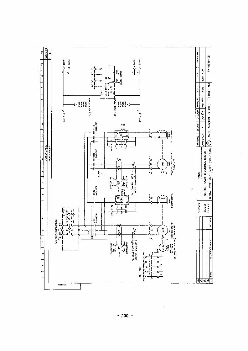
I i
Sis
I1
I!
- 200 -

O
1 I 2 I 3 I 4 8 I 9 | 10 | II | 12 | U | H | 15 | 16 | 17 | IB | 19 2O_
TRAVERSING MOTION
POWER CIRCUIT
r
IM10 EN300TRAVERSING MOTOR TRAVERSING
0.75 KW « 4P ENCODER(E4OH1O-1O24-.3-2)
0830OC.MAG.BRAKE
A
R E V I S I O N S
DRAWING
Tl T L E
irmi
TRAVERSING POWER CIRCUIT
DIAGRAM BANDO MACHINERY CO., LTD.DWG. NO PW-0649-06

tooto
• I 2 I T 9 1 10 | 11 1 12 | 13 | 14 | 15 [ 16 [ 17 | IB | 19
TRAVELLING MOTION
POWER CIRCUIT
(A2/0«)(A2/W)(A2/0»X»2/M)7 7V
FROM:PLCDA CONVERTER
Si-1-CR -J- CR (C-T40I-T402
40IA +02A I
O i A -
BRAKE OPEN INVERTER FAULT
(^aii rw M
INV400J3OO-O55LF
DA CONVERTERFROM:PLC
TO: PLC
- - • &
IM41 IM42TRAVELLING MOTOR
1 K W I C 6 P x 2
EN400TRAVELLING
ENCODER(E4OH1O-1O24-3-2)
M4O1 'SMC-20P !
llil
' 4 , !'
- ? / i
< RF400!SR-30
I
DB41, 42OC.MAG.BRAKE
AR E V I S I O N S
DRAWING
T I T L E
TRAVELLING POWER CIRCUIT
DIAGRAM ( g ) BANDO MACHINERY CO., LTD.DWG. NO PW-0649-07

• I 2 I ~ | S | B 1 7 Is I 9 [ 10 1 I I | 12 | 13 I 14 | 13 | 16 | 17 | 18
PLC CONFIGURATION ADR'S NO.
toou
C3M-PA1AGM2-CPIM
5 >( N O
A/D MODULE D/A MODULE
Q5HN
A
R E V I S I O N S
DRAWING
T I T L E
PLC CONFIGURATION DIAGRAM
DRAWING
BANDO MACHINERY CO., LTD. DWG. NO PW-0649-08

- 3-I
>oI
SJ
o
o
e
V7
POWER ON/OFF
AUTO ON/OFF
UPPER LIMIT S/W 1
T/S LIMIT S/W (EAST)
T/S LIMIT S/W(WEST)
T/L LIMIT S/W(SOUTH)
T A LIMIT S/«V(NORTH)
ANTI-SWAY ALGORISM
i 5 > £<?
! Ti
O 5 —
V
I
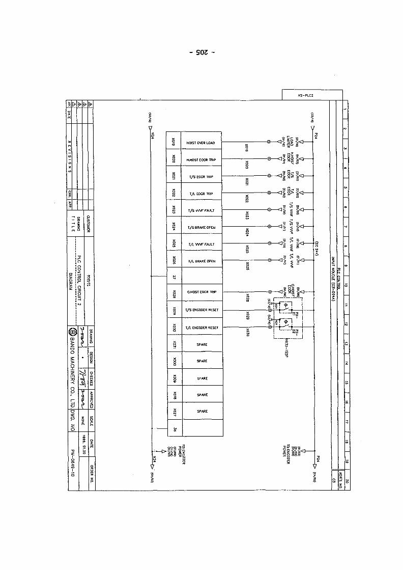
- S03 -
oo
V2
Bi
HOIST OVER LOAD
H.HOST EOCR TRIP
T/S EOCR TRIP
TA EOCR TRIP
T/S VWF FAULT
T/S BRAKE OPEN
TA VWF FAUU
T/L BRAKE OPEN
C.HOST EOCR TRIP
T/S ENCODER RESET
T A ENCOOER RESET
3 Si
-@—<3<
-@—<3-
Vs

8
8
i 1 2 1 3 1 * 6 7 8 1 9 1 10 1 11 1 12 1 13 14 1 15 | 16 I 17 | 18 | 19
PIC CONTROL
AMK DATE
to""
(81/01)
1
y3
V
X20I
1
>
X2O4
X20*
R E V I S I O N S
HOISTENCODER
(ai/0!)
<
s*?
X205
CHK.
7
>
X208
CO
M
X208
H.S
(DC 21V)
(Bl/0!)
<
&
X209
APP.
CUSTOMER
DRAWING
T I T L E
7
>
X212
°
XJ12 17
COUNTER (OJF-HSCA)
>
18
a«(
X221
V
X222
/
/ /
i 1i,
iiaait
n1 /X232
i -
X233
/
PLC CONTROL CIRCUIT 3
DIAGRAM
DRAWING
NP
X234
1!i /
ititua
nit
+
37
/ /
DESIGN
<g)BANDO
•
CHECKEO APPROVED
MACHINERY CO.. LTD.
P24
20
ADR'S NO.
G4
>
°
38
N24 K- '
SCALE
NONE
DWG. NO
DATE
1999. 01.20
OROER NO.
PW-0649-
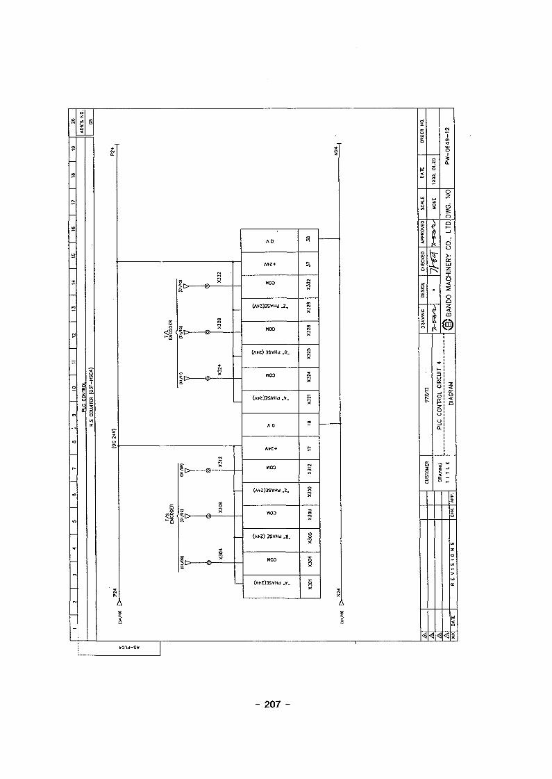
o
en
oo
_
to
—
_
—
—
—
o
en
CO
r*-
»o
m
^.
_
il
J
ooa
i
i
3or
*
IT)
i £8
Q.
As5
•D1d-SV
s S
3
^[> @—!!—
s.
T/S
EN
CO
DE
S
p i^ *
| i> ®
lt> © - ^ —
°R X;>L = iy/S
AO
A*Z+
WOO
(A«)3SVHd . 2 .
H00
(AtZ) 3SVHd .8 .
noo
C*«)3SVHd.V.
A 0
A»Z+
noo
(A^Z)3SVHd 2
H00
(A«) SSVHd . 8 .
noo
(A«)3SVHd .V.
S
%
s
S
a
X
CO
j .
5
SS
Bs
iX
z
A
s
1
d
5
1
<o
SC
AL
E
o
| A
PP
F
z
jj•
O
O
oi>61
I
1
\v
«
s
<
3o:
NTR
OL
Cl
o
a
CM
|
ssa.
O
DW
G.
N
c
VorLJ
zT
ACI-
oczm
!i
I
<\
1 -K —o >_
<
HP.
<
[CH
KJ
tnzQ
>
a:
D
- 207 -

OCO
AS
-PLC
5
-
1 2 1 3 1 4 | 5 6 7 1 8 1 9 1 10 1 11 1 12 1 13 14 IS | 16 1 17 1 18 19
PLC CONTROI
AD CONVERTER (G3F-A04A)
A
AAAMK
(AI/17) I> 1
1OC12VINPUT
(A2/17) [ > '
DATE
+12V)
=OTENTION METERX *
(OV)
«
(OUT)
X401
)
""""
o
s
X401
t
r—<3 (A2/17)(+12V)
POTENTION METERY i
(OUT)
X402
i «
g
X402
X403
)
5
X403
R E V 1 S 1 0 N S
(OV)
(
DC12VINPUT
X404
)
5
X404
CHK.
5
X405
APP.
5
X406
CUSTOMER
ORAWMG
T T L E
5
X407
5
X4O8
Xu
X409
X
X4I0
5
X411
PLC CONTROL CIRCUIT 5
DIAGRAM
/
jJ1 I1 1
ii1 1
II-II—II
/ ;
u.
5
X431
DRAWING
I i .
5
X432
DESIGN
•
(g/BANDO
/ /
/ . '
/ /
1 J
J J/ /
-II—II
CHECKED
36
APPROVED
MACHINERY CO., LTD
o
37
1
J8
SCALE
NONE
DWG. NO
DATE
1999. 01.20
20
AOR'S NO.
G6
OROER NO.
PW-0649- 3
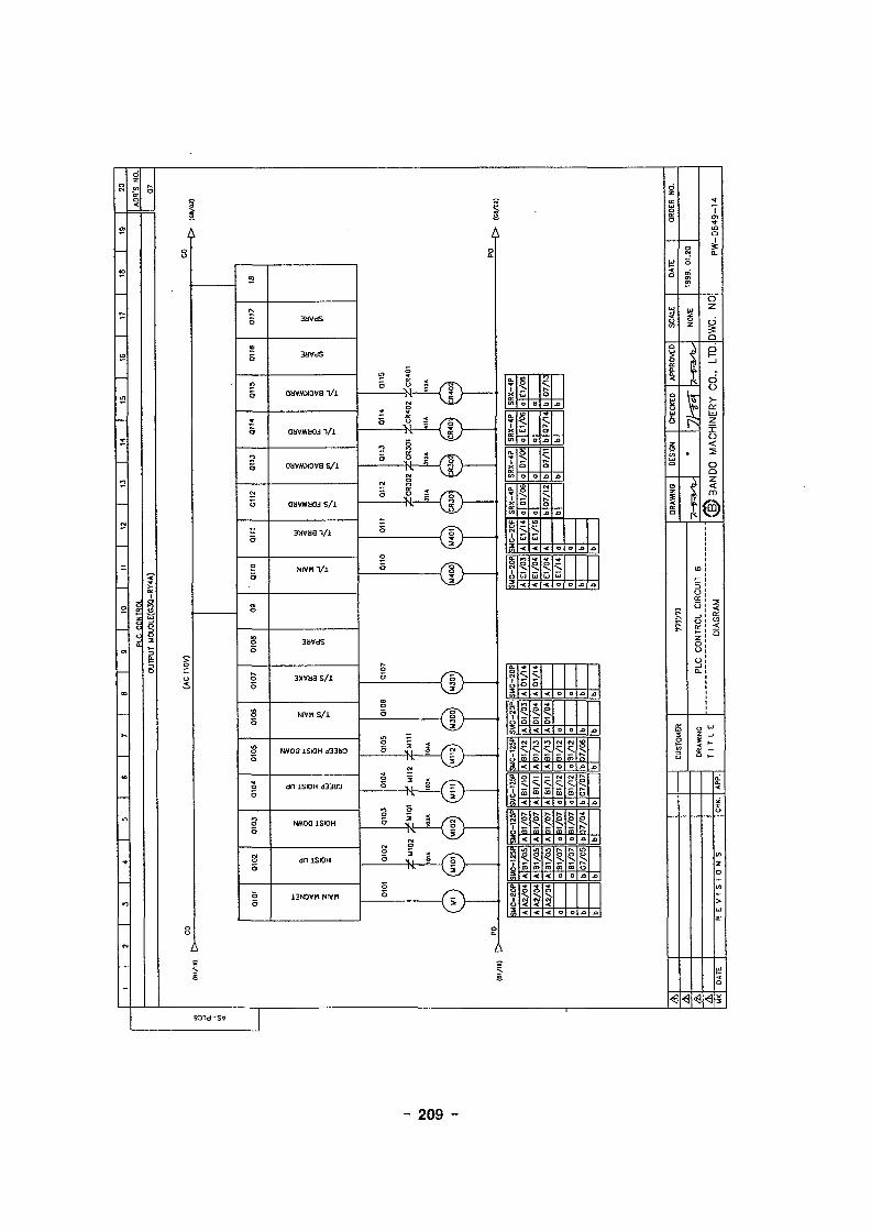
c !
ii
0MVMX3V8 V i
j Vi
oavM>tova s / i
sxvaa V i
NIVH V i
3XVU8 S/i
Nivn sA
NMOO 1SIOH d33SO
dfi 1SIOH d33!K)
S SR
X-4
P
X
1M
C-2
0P
|1
El/06
o
E1/
06
o
30/10
oCD
3o
LJ
A|E
1/0
3||
>
D
D
D
a
Sl/I3
|>
A|E
1/O
4||J
1
•o
o.a
LJ
•D
J l
- O
J3
5uj
1(J
^C
-20P
LSQJ
so
sA
<J
A
1
/-4
5• <
01/0
3
CO
'01
/
CD
eg
5
;A|A
2/0
4||
J
/14
5• <
|D1/
O4
5.m
Cfl
K B
l/!A
|A2
/04
||J
• <
o
CD
I
£
iA|A
2/04
||>
D
^ .CD
CO
?.9?
CO
o
?.CD
m
eg
5
• »
IB
.s
• o
- 209 -

' I 2 I 3 I 4 I 5 I 6 I T I 9 I 10 I 11 I 12 I 13 I 14 | 15 I 16 I 17 | 18 | 19
PLC CONTROL ADR'S NO.
OUTPUT MOUDLE(C30-RV4A)
^ CO
0119
ARE
0120
ARE
a
0121
ARE
a
0122
ARE
Si
0123
ARE
a
0124
ARE
a
(AC 110V)
0125
ARE
a
0126
ARE
a
27 0128
ARE
0129
ARE
a
0130
ARE
a
0131
ARE
a
Q100
ARE
a
0109
ARE
a
0118
ARE
a
0127
ARE
a
CO
36
JkA.
R E V I S I O N S
DRAWING
T I T L E
<mvnPLC CONTROL CIRCUIT 7
DIAGRAM (g )BAND0 MACHINERY CO., LTD. DWG. NO
ORDER NO.
PW-0S49-15

• I 2 I 3 I 4 I ~ 10 II
PLC CONTROL
DA CONV£RTER(C3F-0A4V)
13 | 14 | 15 I 16
ADR'S NO.
(«/») >
0501
._ OV
Q502 0503
o
5
\
0504
o
5
0503
7(Dl/OJ)
\
O505
.-5
0504
7(DI/DS)
TO : T/S INVERTER
\
C+isv)
0506
5
0505
7(EIAM)
\
Q507
5
0506
7 \
0507
7(El/O») (0l/0>)
Q508
5
\
0508
7(01/M)
TO : T A INVERTER TO : T/S INVERTER
(0V)
N15
Q509
6
\
0509
7(El/OS)
0510
HI
5
\
051C
7(tl/M)
TO : T A INVERTER
nIIjjIIiiIIII
ijII
0531
Ui
5
0532
Id
5
Q533
u.I
053+
u.
5
P15
36
S
37
u
38
S
-15V)
OV .
N15 |
A
R E V I S I O N S
DRAWING
T I T L E
1W/11
PLC CONTROL CIRCUIT
DIAGRAM
CHECKED APPROVED
( g ) BANDO MACHINERY CO., LTD. DWG. NO
ORDER NO.
PW-0649-16
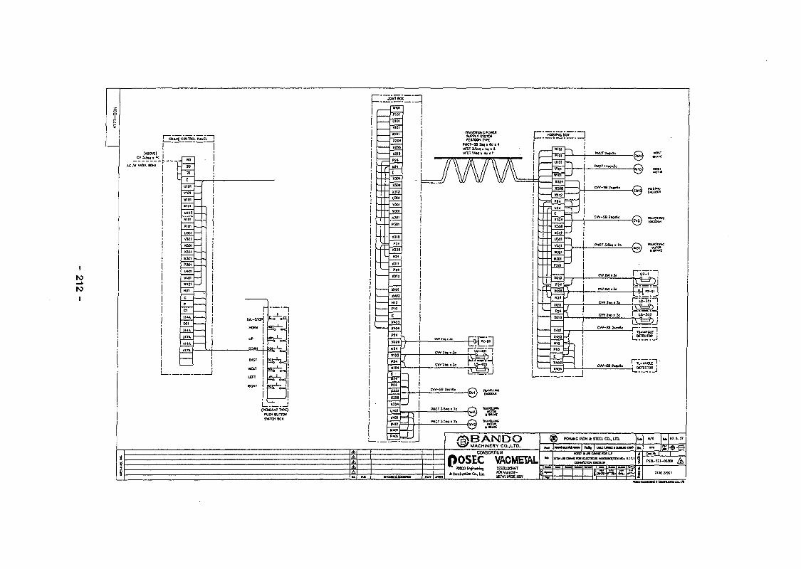
toto

A
A
R E V I S I O N S
DRAWING
T I T L E
CONNECTION DIAGRAM
APPROVED SCALE
(B)BANDO MACHINERY CO., LTD. DWG. NO:

©I!
f i g
Hir
- 214 -

3 I 4 I 5 I 6 I T 9 I 10
I
N>
iAiili OTWHI?.* Si. eMtli?Uiq.
•.MAIN POWER : AC 3<t 220V
•.CONTROL POWER : AC 1B 110V
NU.
1
2
3
4
5
6
7
8
9
10
11
12
13
14
15
16
17
18
19
20
21
22
23
24
25
26
27
SYMBOL
NFB1
NF83
Ml
M101.M102
M300.M301M400.M401
UI11.MII2
CR401.402CR301.302
E0CR100
E0CR110,300,400
RF100
RF110.300,400
PLC
INV300.400
RE300
RE400
NF1
NF300
NF4OO
SPS1
SPS2
TR2
F1
REPI.2
TGS1
DLS-1
FL-01
-
DESCRIPTION
NO-FUSE BREAKER
NO-FUSE BREAKER
MAGNETIC CONTACTOR
MAGNETIC CONTACTOR
MAGNETIC CONTACTOR
MAGNETIC CONTACTOR
AUX. RELAY
E O C R
E O C R
RECTIFIER
RECTIFIER
P.L.C
INVERTER
REACTOR
REACTOR
NOISE FILTER
NOISE FILTER
NOISE FILTER
POWER SUPPLY
POWER SUPPLY
TRANSFORMER
FUSE
RECEPTACLE
RECEPTACLE
DOOR UWIT SW.
PANEL FL. LAMP
TERMINAL BLOCK
SPECIFICATION
ABS-103(100A)
ABS-32(1OA)
SMC-BOP
SMC-126P
SMC-2OP
SMC-20P
SRX-4P
SS-SO
SS-30
SR-60
SR-30
GLOFA GM2
J300-055LF
220V, 1.5KW
220V, 3.7KW
110V, 10A 1F>h
220V. 10A 3Ph
220V. 20A 3Ph
AC110V/DC24V, 12V
AC110V/0C 35V, 5V
220V/110V, IPh
10A
220V.110V
22OV.11OV
KH-9015-PB(L)
10W
OTY
1
1
1
2
4
2
4
1
3
1
3
1
1
1
1
1
1
1
1
1
1
1
2
2
1
1
UNIT
EA
EA
EA
EA
EA
EA
EA
EA
EA
EA
EA
SET
SET
EA
EA
EA
EA
EA
EA
EA
EA
EA
EA
EA
EA
EA
MAKER
LG
LG
LG
LG
LG
LG
LG
SAMWHA
SAUWHA
BANDO
BANDO
LG
HYUNDAI
PUR.
PUR.
PUR.
PUR.
PUR.
PUR.
PUR.
PUR.
PUR.
PUR.
PUR.
KUNHUNG
ILKWANG
REMARK
A
R E V I S I O N S
DRAWING
T I T L E
CONTROL PANEL EQUIP. ARRANG.
APPROVED
( § } BANDO MACHINERY CO., LTD.
NONE
DWG. NO

1 I 2 I 3 I « I T 10 | 11 U | 15
O>
NT^LTTC—-—£2!£! !^CEANE CONTROL PANEL
W
1200
K
1600
0
400
B
250
O'TY
1 SET
N O T E S
1 PAINTING COLOR (WUNSELL NO.)
INSIDE : 7.5 BG 6/1.5
OUTSIDE : 7.5 BG 6/1.5
2. PAINTING THICKNESS : ABOVE BOum
3. TYPE : DUST PROOF
4. PANEL MAT! : 2.3T STEEL PLATE
5. NAME PLATE MATX : ALUMINIUM USE BOLTING
6. PANEL INSIDE WIRE : POWER ; HIV BLACK COLOR
CONTRL : HIV YELLOW COLOR
7. PANEL INSIDE TERMINAL TUBE COLOR : "R- PHASE : RED
"S" PHASE : WHITE
"T" PHASE : BLUE8. twiAtKi .<Xe i t 'el«U i?Mtq.
•.MAIN POWER : AC 30 220V•.CONTROL POWER : AC 1« 110V
A'A'MK " R E V I S I O N S
ORAWING
T I T L E
CRANE CONTROL PANEL
APPROVED
\ B ) BANDO MACHINERY CO., LTD. DWG. NO

n(Drum
- 217 -
NEXT PAGE(S)left BLANK

I
+—!—i——1=
HOOK PART PLAN
Actuator
Driving panel
1 0 OClamp Undamp
0 ©POM/- fmer.
CONTROL PANEL
NO. Oaacription
1/8
Uottr io l Q'ty Surfoca Rumor*
A3

0
E3 3
roo 0
s
Daign
M/2
Motonol Q'ty Surfac«
K A E R I
A3
Dwg, No
0A£ SHIN ENGINEERING CO.>& 0A£ SHIN DJCIK

- 221 -

- 222 -
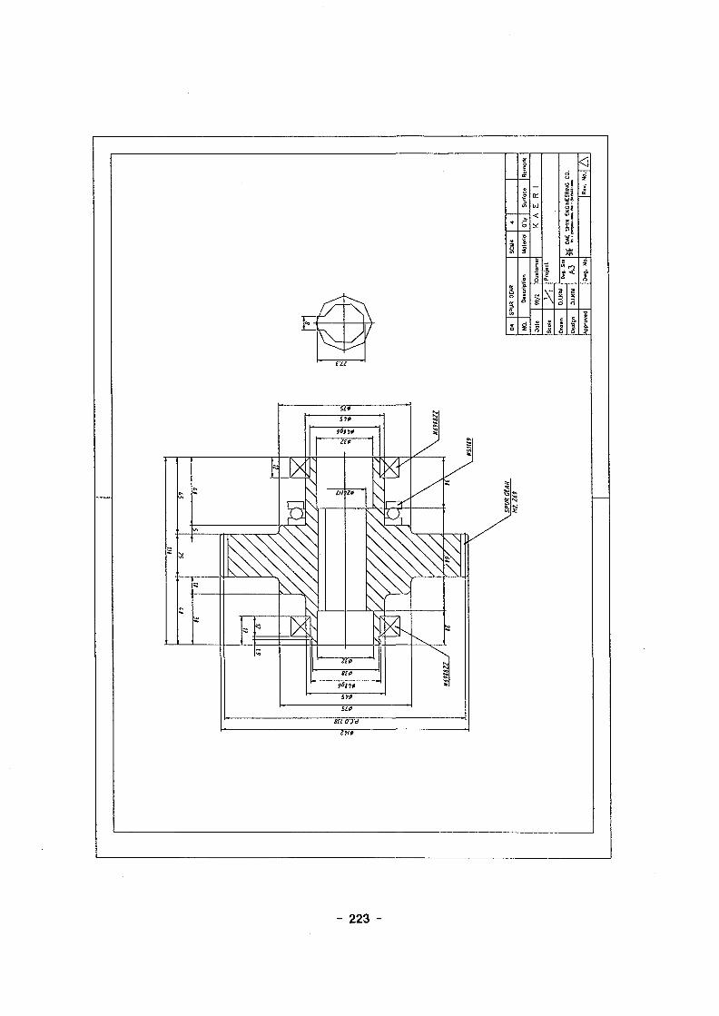
- 223 -

roro
gk gk
S<5C
NO. Description
M/2
Moteriol Q'ty Surfoce R<
K A E R I
Proj.ct
A3 5
Dwg, No,

- 225 -
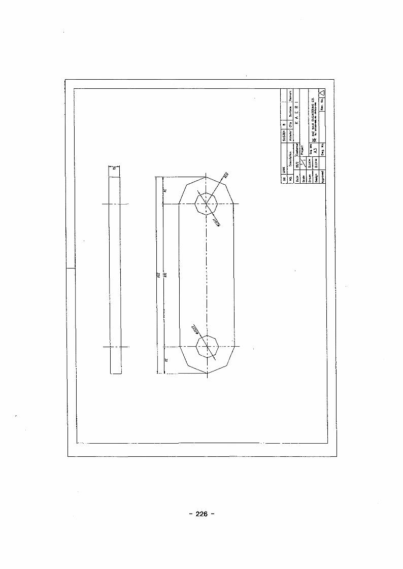
- 226 -

to
I
Dnlgn
89/1
Moterlol O'ty SurToc* Rgmartc
K A E R I
D*g. Sin
A3
0 « j . No.
, DAE SHIN ENGINEERING CO.

U2
SPUR 0EARIM2, Zi6l
8-06.6 DRILLH17 C'BORE DP 7
12 SPUR GEAR
NO. Description
Scole
Drown
Design
Approved
99/2 Customer
D.I.KIM
D.I.KIM
SCM4
Moteriol O'ty Surface Remark
K A E R 1Project
DRUM f ' i l l ! * ! ^JAJji0»g. S!i
Dwg. No
DAE SHIN ENGINEERING CO.
Rev.• • W A
- 228 -
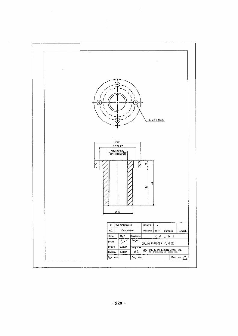
i-06.5 DRILL
061
p.cna
<
TM25xP5x2(PITCH10x2§j
038
/
I
11 TM SCREWNUT
NO. Description
Dote
Scole
Drawn
Design
Approved
99/2 Customer
D.I.KIM
D.I.KIM
BRASS
Material Q'ty Surface Remark
K A E R 1Project
* ! -y-M!^
Dwg. No,
DAE SHIN ENGINEERING CO.
Rev. Nol / \
- 229 -
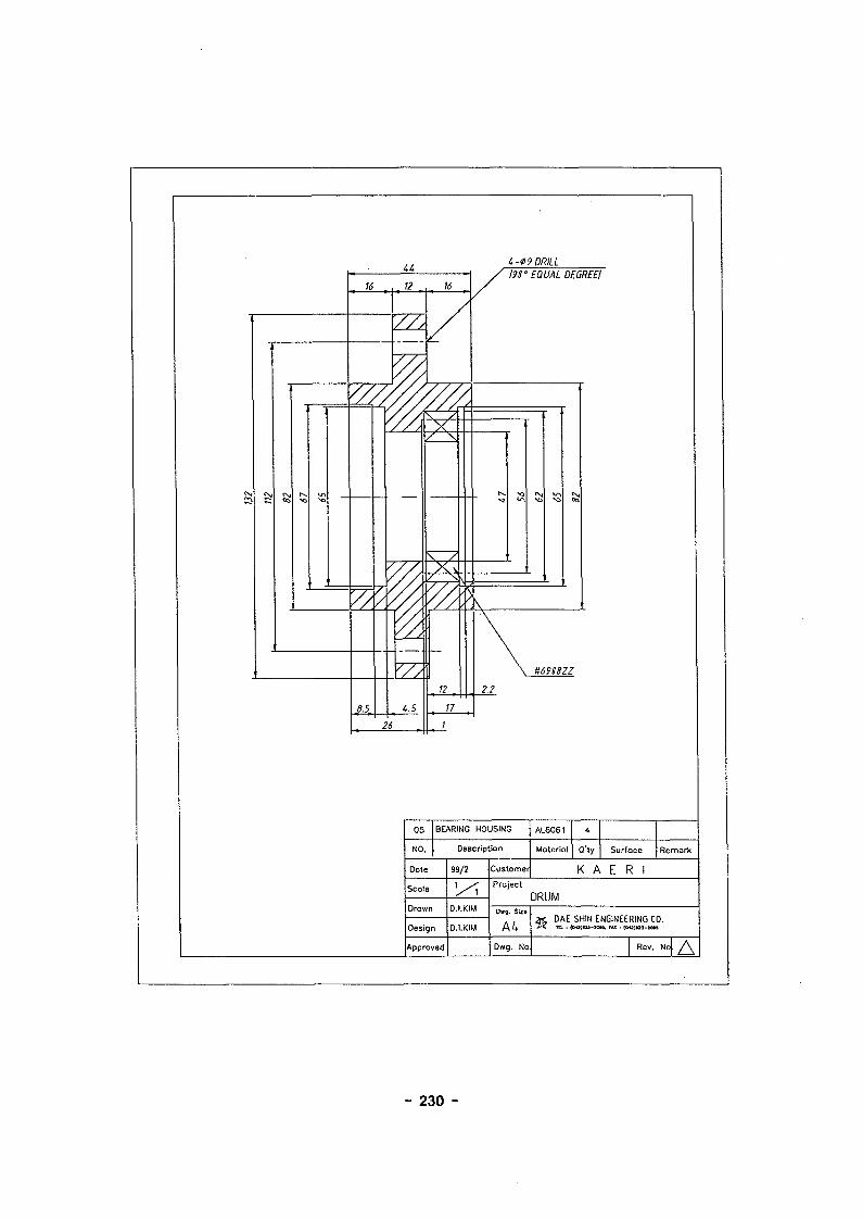
a1,-09 DRILL
12
4.5
26
12
n
19!' EQUAL DECREE!
H69S8ZZ
05 BEARING HOUSING
NO. Description
Dole
Scoe
Orawn
Design
Approved
99/2
D.I.KIM
Customer
AL6061
Material Q'ty Surface Remark
K A E R 1Project
DRUMDwg. Site
Dwg. No
XC. DAE7< m. :
DAE SHIN ENGINEERING CO.
Rev••"4Z\
- 230 -

68
52
4-07 DRILL 12
06 COVER
NO. Description
Date
Scole
Drown
Design
Approved
99/2 Customer
1
D.I.KIM
D.I.KIM
AL6061
Material Q'ty Surface Remork
K A E R I
ProjectDRUM
Owg.
Dwg. No
DAE SHIN ENGINEERING CO.
Re' '• N o A
- 231 -

- 232 -

- 233 -

- 234 -

A
INIS ^A\SE
KAERI/RR-1924/98
" ),
1999. 4
p. 248 H 7] 30 Cm.
v ), ),
(15-20
?1?!, I 3-
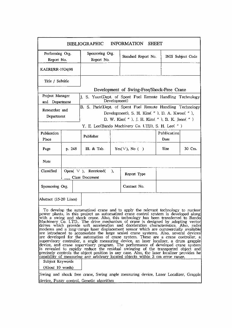
BIBLIOGRAPHIC INFORMATION SHEET
Performing Org.
Report No.
Sponsoring Org.
Report No.Standard Report No. INIS Subject Code
KAERI/RR-1924/98
Title / Subtitle
Development of Swing-Free/Shock-Free CraneProject Manager
and DepartmentJ. S. Yoon(Dept. of Spent Fuel Remote Handling Technology
Development)
Researcher and
Department
B. S. Park(Dept. of Spent Fuel Remote Handling Technology
Development), S. H. Kim( " ), D. A. Kwon( " ),
D. W. Kim( " ), .T. H. Kim( " ), B. K. Jeon( " )
Y. E. Leeffiando Machinery Co. LTD), S. H. Lee( " )
Publication
PlacePublisher
Publication
Date
Page p. 248 111. & Tab. Yes(V), No ( ) Size 30 Cm.
Note
Classified Open( V ), Restricted ),
Class DocumentReport Type
Sponsoring Org. Contract No.
Abstract (15-20 Lines)
To develop the automatized crane and to apply the relevant technology to nuclearpower plants, in this project an automatized crane control system is developed alongwith a swing and shock crane. Also, this technology has been transferred to BandoMachinery Co. LTD.. The drive mechanism of crane is designed by adopting vectordrives which provide soft acceleration and deceleration characteristics. Also, radiomodems and a long-range laser displacement sensor which are commercially availableare introduced to accomodate the large scaled crane systems. Also, several devicesare developed for the automation of crane system. These are a crane controller, asupervisory controller, a angle measuring device, an laser localizer, a drum grappledevice, and crane supervisory program. The performance of developed crane systemis revealed to rapidly reduce the residual swinging of the transported object andprecisely controls the object position in any case. Also, the laser localizer provides hecapability of measuring any arbitrary located objects within 3 cm error range.
Subject Keywords
(About 10 words)
Swing and shock free crane, Swing angle measuring device, Laser Localizer, Grapple
device. Fuzzy control. Genetic algorithm