


Bahasa
Halaman
Hukum


[Aainawala, 3(7): July, 2014] ISSN: 2277-9655 Scientific Journal Impact Factor: 3.449
(ISRA), Impact Factor: 1.852
http: // www.ijesrt.com (C)International Journal of Engineering Sciences & Research Technology
[498-510]
IJESRT INTERNATIONAL JOURNAL OF ENGINEERING SCIENCES & RESEARCH
TECHNOLOGY Design of Multistoried R.C.C. Buildings with and without Shear Walls
M. S. Aainawala 1, Dr. P. S. Pajgade 2 1Assistant Professor, Department of Civil engineering, Prof. Ram Meghe Institute of Technology and
Research Badnera, Amravati, Maharashtra 444701 India 2Professor, Department of Civil engineering, Prof. Ram Meghe Institute of Technology and Research
Badnera, Amravati, Maharashtra 444701 India
Abstract From the past records of earthquake, there is increase in the demand of earthquake resisting building which
can be fulfilled by providing the shear wall systems in the buildings. Static Analysis is performed for regular buildings
up to 90m height in zone II and III, Dynamic Analysis should be performed for regular buildings in zone IV and V
above 40 m. Reinforced cement concrete (RCC) framed structures combined with shear walls has been widely used
to resist lateral forces during earthquakes in tall buildings. Shear walls are generally provided for full height of the
frame. Shear wall systems are one of the most commonly used lateral-load resisting systems in high-rise buildings.
Shear walls have very high in-plane stiffness and strength, which can be used to simultaneously resist large horizontal
loads and support gravity loads, making them quite advantageous in many structural engineering applications. An
earthquake load is applied to a building for G+12, G+25, G+38 located in zone II, zone III, zone IV and zone V for
different cases of shear wall position. An analysis is performed using ETAB v 9.0.7 software. Lateral displacement
and story drift are calculated in all the cases. It was observed that Multistoried R.C.C. Buildings with shear wall is
economical as compared to without shear wall.
Keyword: ETAB v 9.0.7, framed structure, Seismic analysis, Dynamic analysis, Shear wall.
Introduction RC Multi-Storey Buildings are adequate for
resisting both the vertical and horizontal load. When
such building is designed without shear wall, the beam
and column sizes are quite heavy, steel quantity is also
required in large amount thus there is lot of congestion
at these joint and it is difficult to place and vibrate
concrete at these places and displacement is quite
heavy which induces heavy forces in member. Shear
wall may become imperative from the point of view of
economy and control of lateral deflection. In RC
multi-storey building R.C.C. lift well or shear wall are
usual requirement. Centre of mass and stiffness of the
building must coincide. However, on many occasions
the design has to be based on the off centre position of
lift and stair case wall with respect to centre of mass
which results into an excessive forces in most of the
structural members, unwanted torsion moment and
deflection. Generally shear wall can be defined as
structural vertical member that is able to resist
combination of shear, moment and axial load induced
by lateral load and gravity load transfer to the wall
from other structural member. Reinforced concrete
walls, which include lift wells or shear walls, are the
usual requirements of Multi Storey Buildings. Design
by coinciding center of mass and stiffness of the
building is the ideal for a Structure. Providing of shear
wall represents a structurally efficient solution to
stiffen a building structural system because the main
function of a shear wall is to increase the rigidity for
lateral load resistance. The use of shear wall structure
has gained popularity in high rise building structure,
especially in the construction of service apartment or
office, commercial tower. It is very important to note
that shear walls meant to resist earthquake should be
designed for ductility.
Forces acting on shear wall
Shear walls resist two types of forces: Shear forces and
Uplift forces.
Shear forces are generated in stationary buildings
by accelerations resulting from ground movement
and by external forces like wind and waves. This
action creates shear forces throughout the height of

[Aainawala, 3(7): July, 2014] ISSN: 2277-9655 Scientific Journal Impact Factor: 3.449
(ISRA), Impact Factor: 1.852
http: // www.ijesrt.com (C)International Journal of Engineering Sciences & Research Technology
[498-510]
the wall between the top and bottom shear wall
connections.
Uplift forces exist on shear walls because the
horizontal forces are applied to the top of the wall.
These uplift forces try to lift up one end of the wall
and push the other end down. In some cases, the
uplift force is large enough to tip the wall over.
Uplift forces are greater on tall short walls and less
on low long walls. Bearing walls have less uplift
than non-bearing walls because gravity loads on
shear walls help them resist uplift. Shear walls need
hold down devices at each end when the gravity
loads cannot resist all of the uplift. The hold down
device then provides the necessary uplift resistance.
To form an effective box structure, equal length
shear walls should be placed symmetrically on all
four exterior walls of the building. Shear walls
should be added to the building interior when the
exterior walls cannot provide sufficient strength
and stiffness.
Figure 1. Failure of shear wall
Behaviour of shear wall
The behavior of shear walls, with particular
reference to their typical mode of failure is, as in the
case of beams, influenced by their proportions as
well as their support conditions. Low shear walls also
known as squat walls, characterized by relatively
small height-to length ratios, may be expected to fail
in shear just like deep beams. Shear walls occurring
in high-rise buildings, on the other hand, generally
behaves vertical cantilever beams with their strength
controlled by flexure and than by shear. Such walls
are subjected to bending moments and shear
originating from lateral loads, and to axial
compression caused by gravity.
Geometry and description Details of structures
For this study, a G+12, G+25, G+38 building with 3.5
meters height for each storey, regular in plan is
modeled. This building consists of four spans of 5
meter, 3 meter, 3 meter and 5 meter in X direction and
in Y direction as shown in figure 2. The square plan of
all buildings measures 16m x 16m. Shear walls were
modeled using three different positions. These
buildings were designed in compliance to the Indian
Code of Practice for Seismic Resistant Design of
Buildings .The buildings are assumed to be fixed at the
base and the floors acts as rigid diaphragms. The
sections of structural elements are square and their
dimensions are changed for different building. Storey
heights of buildings are assumed to be constant
including the ground storey.
The buildings are modeled using software ETAB
Nonlinear v 9.0.7 four different models were studied
with different positioning of shear wall in different
zones and for various heights to find out the best
location of shear wall in buildings. Models are studied
and dynamic analysis is performed for G+ 38 models
in all the four zones comparing the lateral
displacement, storey drift, concrete quantity required,
steel and total cost required in all the zones.
The plan of the building model are given below
Model 1 – Floor plan of the bare framed structure.
Model 2 – Floor plan of the dual system with shear
wall one on each side.
Model 3 - Floor plan of the dual system with shear wall
on corner with L = 5 m.
Model 4 – Floor plan of the dual system with shear
wall in middle (core) with L = 6m.

[Aainawala, 3(7): July, 2014] ISSN: 2277-9655 Scientific Journal Impact Factor: 3.449
(ISRA), Impact Factor: 1.852
http: // www.ijesrt.com (C)International Journal of Engineering Sciences & Research Technology
[498-510]
Figure 2. Model 1
Figure 3. Model 2

[Aainawala, 3(7): July, 2014] ISSN: 2277-9655 Scientific Journal Impact Factor: 3.449
(ISRA), Impact Factor: 1.852
http: // www.ijesrt.com (C)International Journal of Engineering Sciences & Research Technology
[498-510]
Figure 4. Model 3
Figure 5. Model 4

[Aainawala, 3(7): July, 2014] ISSN: 2277-9655 Scientific Journal Impact Factor: 3.449
(ISRA), Impact Factor: 1.852
http: // www.ijesrt.com (C)International Journal of Engineering Sciences & Research Technology
[498-510]
Table 1. Preliminary data
Sr.
No. Data For 13 storey For 26 storey For 39 storey
1 No. of Stories 13 (G + 12) 26 (G + 25) 39 (G + 38)
2 Grade of Concrete and Steel M25 and Fe415 M25 and Fe415 M25 and Fe415
3 Floor to Floor Height 3.5 m 3.5 m 3.5 m
4 Beam size
*300x300 mm² *300x450 mm² *300x450mm² B1: outer beam
B2: inner beam
5 Column size *450x450 mm² *500x500 mm² *600x600 mm²
C1,C2,C3,C4,C5,C6
6 Thickness of slab 150 mm 150 mm 150 mm
7 Thickness of Shear Wall 200 mm 200 mm 200 mm
8 Thickness of External Wall 230 mm 230 mm 230 mm
9 Thickness of Internal Wall 115 mm 115 mm 115mm
10 Live load 3 kN/m² 3 kN/m² 3 kN/m²
Note:
* = sizes are changed according to requirement.
For Model 1 : Column notations are C1, C2, C3, C4, C5, C6.
For Model 2, 3, 4 : Column notations are C1, C2, C3.

[Aainawala, 3(7): July, 2014] ISSN: 2277-9655 Scientific Journal Impact Factor: 3.449
(ISRA), Impact Factor: 1.852
http: // www.ijesrt.com (C)International Journal of Engineering Sciences & Research Technology
[498-510]
Results for G+12, G+25, G+38 story buildings
Lateral displacement for G+12
Figure 6. Displacement curve for Zone II Figure 7. Displacement curve for Zone III
Figure 8. Displacement curve for Zone IV Figure 9. Displacement curve for Zone V
From results it is observed that the displacement of all models for G+12 in Zone II, III, IV and V is minimum for
model 3.
[Aainawala, 3(7): July, 2014] ISSN: 2277-9655 Scientific Journal Impact Factor: 3.449
(ISRA), Impact Factor: 1.852
http: // www.ijesrt.com (C)International Journal of Engineering Sciences & Research Technology
[498-510]
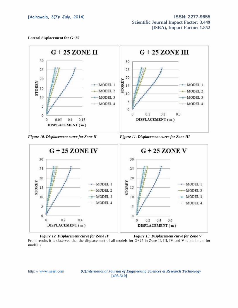
Lateral displacement for G+25
Figure 10. Displacement curve for Zone II Figure 11. Displacement curve for Zone III
Figure 12. Displacement curve for Zone IV Figure 13. Displacement curve for Zone V
From results it is observed that the displacement of all models for G+25 in Zone II, III, IV and V is minimum for
model 3.

[Aainawala, 3(7): July, 2014] ISSN: 2277-9655 Scientific Journal Impact Factor: 3.449
(ISRA), Impact Factor: 1.852
http: // www.ijesrt.com (C)International Journal of Engineering Sciences & Research Technology
[498-510]
Lateral displacement for g+38
Figure 14. Displacement curve for Zone II Figure 15. Displacement curve for Zone III
Figure 16. Displacement curve for Zone IV Figure 17. Displacement curve for Zone V
From results it is observed that the displacement of all models for G+38 in Zone II, III, IV and V is minimum for
model 3.

[Aainawala, 3(7): July, 2014] ISSN: 2277-9655 Scientific Journal Impact Factor: 3.449
(ISRA), Impact Factor: 1.852
http: // www.ijesrt.com (C)International Journal of Engineering Sciences & Research Technology
[498-510]
Design of multistoried building After the analysis of various models it is cleared that by using shear wall at Corner location (Model 3) gives
minimum displacement and drift. Hence design is done for corner location and for maximum height i.e. for G+38, so
that dynamic analysis is applied for all zones and then comparison is done between Model 1 and Model 3 to find the
steel and concrete quantity required for various zones.
For Model 1: Up to 14 storey column notation: C5, C6 = 700 mm x 700 mm.
15 to 27 storey column notation: C3, C4 = 600 mm x 600 mm.
Above 28 storey column notation: C1, C2 = 450 mm x 450 mm.
For Model 3: Up to 14 storey column notation: C3 = 650 mm x 650 mm.
15 to 27 storey column notation: C2 = 550 mm x 550 mm.
Above 28 storey column notation: C1 = 450 mm x 450 mm.
Methods of seismic analysis of structures Various methods of differing complexity have been developed for the seismic analysis of structures. They
can be classified as follows.
1. Static Analysis
2. Dynamic Analysis.
Methods of Static Analysis:
The method of static analysis used here is Equivalent Static Method.
According to clause 6.3.1.2 of IS 1893(Part1): 2000
Load combination used:
1) 1.5 ( DL + LL)
2) 1.2 (DL + IL + EL)
3) 1.5 (DL + EL)
4) 0.9DL + 1.5EL
Methods of Dynamic Analysis:
The method of dynamic analysis used here is Response Spectrum Method.
The word spectrum in seismic engineering conveys the idea that the response of buildings having a broad
range of periods is summarized in a single graph. For a given earthquake motion and a percentage of critical damping,
a typical response spectrum gives a plot of earthquake-related responses such as acceleration, velocity, and deflection
for a complete range, or spectrum, of building periods. Thus, a response spectrum may be visualized as a graphical
representation of the dynamic response of a series of progressively longer cantilever pendulums with increasing natural
periods subjected to a common lateral seismic motion of the base.
Dynamic analysis is performed by Response Spectrum Method. In this method the design base shear VB is compared
with a base shear VB1 calculated using a fundamental period Ta. Where VB is less than VB1, all the response quantity
i.e. member force, displacements, storey forces, storey shears, base reactions are multiplied by VB1 / VB.

[Aainawala, 3(7): July, 2014] ISSN: 2277-9655 Scientific Journal Impact Factor: 3.449
(ISRA), Impact Factor: 1.852
http: // www.ijesrt.com (C)International Journal of Engineering Sciences & Research Technology
[498-510]
Results for model 1 and 3 for G+38 Displacement and drift comparison for model 1 and 3
Figure 18. Displacement curve for Model 1 Figure 19. Displacement curve for Model 3
Figure 20. Storey Drift curve for Model 1 Figure 21. Storey Drift curve for Model 3

[Aainawala, 3(7): July, 2014] ISSN: 2277-9655 Scientific Journal Impact Factor: 3.449
(ISRA), Impact Factor: 1.852
http: // www.ijesrt.com (C)International Journal of Engineering Sciences & Research Technology
[498-510]
Steel quantity and concrete quantity for model 1 and 3
Figure 22. Steel quantity for Model 1 and Model 3. Figure 23. Concrete quantity for Model 1 and Model 3.
Cost comparison for model 1 and 3
Figure 24. Cost for Model 1 and Model 3.
Discussion Table 2. Displacement (m) for G+38 at the 39 storey
Model 1 Model 3
ZONE II 0.3325 0.1262
ZONE III 0.4834 0.1857
ZONE IV 0.4454 0.2549
ZONE V 0.5252 0.3585
ZONE II ZONE III ZONE IV ZONE V
MODEL 1 40721083 42803886 51891825 56813944
MODEL 3 36008203 38799652 42165426 44240884
0
10000000
20000000
30000000
40000000
50000000
60000000
CO
ST
( R
s )
TOTAL COST

[Aainawala, 3(7): July, 2014] ISSN: 2277-9655 Scientific Journal Impact Factor: 3.449
(ISRA), Impact Factor: 1.852
http: // www.ijesrt.com (C)International Journal of Engineering Sciences & Research Technology
[498-510]
% = Model 1− Model 3
Model 1∗ 100
From the above result it is seen that,
The displacement in Zone II for Model 1 is 62% greater than Model 3.
The displacement in Zone III for Model 1 is 61.58% greater than Model 3.
The displacement in Zone IV for Model 1 is 42% greater than Model 3.
The displacement in Zone V for Model 1 is 31.74% greater than Model 3.
The storey drift for model 1 (fig.20) shows the discontinuity of curve this is due to column size variation.
The storey drift for all zones for model 1 is maximum up to 0.005 and that for Model 3 is maximum up to
0.0035.
Fig.21 shows that by using shear wall with various sizes of column does not affect the storey drift. However
fig.20 shows that the storey drift is affected where the column sizes are changing.
According to clause 7.11.1 of IS 1893 (Part 1): 2000;
Storey Drift Limitation:
The storey drift in any storey due to the minimum specified design lateral force, with partial load factor of
1.0, shall not exceed 0.004 times the storey height, hence this clause is satisfied in this G+38 Building.
Maximum displacement according to clause 7.11.1 of IS 1893 (Part 1): 2000;
= 0.004*136.5 (total height)
= 0.546 m
= 546 mm
Here maximum displacement is 0.5252 m for model 1.
Maximum drift according to clause 7.11.1 of IS 1893 (Part 1): 2000;
= 0.004*3.5 (floor to floor height)
= 0.014
Here maximum drift is 0.005 for Model 1.
Fig. 22.
Steel required for shear wall is less in Model 3 as compared to Model 1 for all Zones
o For Zone II, 28.49 % of steel increases in Model 1 as compared to Model 3
o For Zone III, 17.24 % of steel increases in Model 1 as compared to Model 3.
o For Zone IV, 24.94 % of steel increases in Model 1 as compared to Model 3.
o For Zone V, 17.47 % of steel increases in Model 1 as compared to Model 3.
Fig. 23.
o For Zone II, 8.14% of concrete increases in Model 3 as compared to Model 1, because of quantity
of concrete increases in shear wall for this zone.
o For Zone III, 0.52% of concrete increases in Model 1 as compared to Model 3, because quantity of
column and beam sections are large.
o For Zone IV, 10.93% of concrete increases in Model 1 as compared to Model 3, because quantity
of column and beam sections are large.
o For Zone V, 26.93 % of concrete increases in Model 1 as compared to Model 3, because quantity of
column and beam sections are very large.
Fig. 24.
o For Zone II, 11.57 % of Cost increases in Model 1 as compared to Model 3.
o For Zone III, 9.35 % of Cost increases in Model 1 as compared to Model 3.
o For Zone IV, 18.74 % of Cost increases in Model 1 as compared to Model 3.
o For Zone V, 22.13 % of Cost increases in Model 1 as compared to Model 3.
o

[Aainawala, 3(7): July, 2014] ISSN: 2277-9655 Scientific Journal Impact Factor: 3.449
(ISRA), Impact Factor: 1.852
http: // www.ijesrt.com (C)International Journal of Engineering Sciences & Research Technology
[498-510]
Conclusion From above analysis, it is observed that in
G+12, G+25, G+38 Storey building,
constructing building with shear wall at
corner (Model 3) location gives minimum
drift and minimum displacement.
From all the above analysis and design, it is
observed that in G+38 Storey building,
constructing building with shear wall at
corner (Model 3) is economical as compared
with bare frame structure (Model 1).
Size of members like column can be reduced
economically in case of structure with shear
wall as compared to the same structure
without shear wall.
Variation in column size at different floors in
Model 1 affects the storey drift while in case
of Model 3 it does not affect the storey drift
due to the presence of shear wall.
More carpet area will be available in the
building as the sizes of columns are reduced
when shear wall is provided.
Less obstruction will be there because of
reduced size of column and provision of
shear wall.
As per analysis, it is concluded that
displacement at different level in multistoried
building with shear wall is comparatively
lesser as compared to R.C.C. building
Without Shear Wall.
It is concluded that building with shear wall
is constructed in lower cost as compared to
structure without shear wall.
For Zone II, 11.57 % of Cost increases for
Model 1 as compared to Model 3.
For Zone III, 9.35 % of Cost increases for
Model 1 as compared to Model 3.
For Zone IV, 18.74 % of Cost increases for
Model 1 as compared to Model 3.
For Zone V, 22.13 % of Cost increases for
Model 1 as compared to Model 3.
References 1. Anuj Chandiwala, "Earthquake analysis of
building configuration with different position
of shear wall" ISSN 2250-2459, ISO
9001:2008 certified journal, volume 2, issue
12, December 2012.
2. Ashish S. Agrawal and S.D. Charkha, “Study
of Optimizing Configuration of Multi-Storey
Building Subjected to Lateral Loads by
Changing Shear Wall Location" proceedings
of international conference on advances in
architecture and civil engineering (aarcv
2012), 21st – 23rd june 2012 287 paper id
sam137, vol. 1
3. Romy Mohan, “Dynamic Analysis of RCC
Buildings with Shear Wall” International
Journal of Earth Sciences and Engineering
ISSN 0974-5904, Volume 04, No 06 SPL,
October 2011, pp 659-662.
4. Himalee Rahangdale, S.R. Satone, " Design
And Analysis Of Multistoried Building With
Effect Of Shear Wall" International Journal
of Engineering Research and Applications
(IJERA) ISSN: 2248-9622, Vol. 3, Issue 3,
May-Jun 2013, pp.223-232.
5. YUN, hyun-do, CHOI, Chang-sik and LEE,
li-hyung, “Earthquake performance of high-
strength concrete structural walls with
boundary elements” 13th World Conference
on Earthquake Engineering, Vancouver,
B.C., Canada August 1-6, 2004, Paper No.
1182.
6. Anshuman. S, Dipendu Bhunia, Bhavin
Ramjiyani, “Solution of Shear Wall Location
in Multi-Storey Building” international
journal of civil and structural engineering,
volume 2, no 2, 2011.
7. Priya Chandurkar, Dr. P. S. Pajgade,
“Seismic analysis of RCC building with and
without shear wall” International Journal of
Modern Engineering Research (IJMER), Vol.
3, Issue. 3, May - June 2013 pp-1805-1810
8. Varsha R. Harne, “Comparative study of
strength of RC Shear wall at different
location on multistoried residential
building” International Journal of Civil
Engineering Research. ISSN 2278-3652
Volume 5, Number 4 (2014), pp. 391-400
Top Related
Copyright © 2022 FDOKUMEN

