


Bahasa
Halaman
Hukum


WHEATLAND COUNTY DESIGN AND CONSTRUCTION STANDARDS MANUAL
OCTOBER 2016

1 of 207
CONTENTS
Part 1 – Urban Service Area Design Standards
1000 – General...............................................................................................................................................6
2000 – Roads ................................................................................................................................................7
3000 – Sanitary Sewer System ......................................................................................................................13
4000 – Water Distribution System ...............................................................................................................17
5000 – Stormwater Management System ....................................................................................................21
Part 2 – Rural Service Area Design Standards
1000 – General............................................................................................................................................ 28
2000 – Rural Transportation ....................................................................................................................... 29
3000 – Rural Sanitary Sewer ....................................................................................................................... 76
4000 – Rural Water Distribution ................................................................................................................. 77
5000 – Rural Stormwater Management .....................................................................................................78
Part 3 – Construction Standards
1000 – General............................................................................................................................................82
2000 – Roads ..............................................................................................................................................83
3000 – Sanitary & Storm Sewer ..................................................................................................................107
4000 – Waterworks………………………………………………………………………………………………………………………………143
Part 4 – Standard Drawings
2 of 207

WHEATLAND COUNTY URBAN SERVICE AREA DESIGN STANDARDS
OCTOBER 2016
3 of 207

4 of 207
CONTENTS 1000 General ......................................................................................................................................................6
1100 Survey Control Markers and Legal Pins .................................................................................................6
2000 Roads .........................................................................................................................................................7
2100 Traffic Impact Analysis ...........................................................................................................................7
2200 General ..................................................................................................................................................8
2300 Street Classification ...............................................................................................................................8
2400 Vertical Alignment .................................................................................................................................8
2500 Horizontal Alignment .............................................................................................................................9
2600 General Requirements ...........................................................................................................................9
2700 Roadway Lighting...................................................................................................................................12
3000 Sanitary Sewer System ..............................................................................................................................13
3100 System Design ........................................................................................................................................13
4000 Water Distribution System ...................................................................................................................... 17
4100 General ................................................................................................................................................ 17
4200 System Design ...................................................................................................................................... 17
5000 Stormwater Management System .......................................................................................................... 21
5100 System Design ...................................................................................................................................... 21
5 of 207
WHEATLAND COUNTY URBAN SERVICE AREA STANDARDS JULY 2016
1000 GENERAL These standards are provided to set guidelines and establish requirements regarding design and construction of
municipal infrastructure within Wheatland County. Its objective is to ensure that all municipal infrastructure work
in Wheatland County is constructed to a consistent, sustainable standard. Construction of municipal infrastructure
must adhere to these standards.
The County retains the ability to refer to other applicable regional municipality Design Guidelines, Standards and
Policies where the County deems it appropriate on a case by case basis.
1100 SURVEY CONTROL MARKERS AND LEGAL PINS
EXISTING CONTROL
.1 The Developer or their Consultant shall make every effort to protect existing markers.
.2 Markers which are destroyed or disturbed shall be replaced by the Developer at their sole
expense.
LEGAL POSTS
.1 Legal posts shall be placed subsequent to the installation of all utilities.
.2 All legal posts in the subdivision area shall be located within 60 days prior to application for Final
Acceptance of the surface improvements.
.3 The Developer shall instruct the legal surveying consultant to replace any missing or disturbed
posts as required by the Wheatland County Representative. All costs are to be borne by the
Developer.
6 of 207
Roads
2000 ROADS The road design guidelines herein generally follow the most recent editions of Transportation Association of
Canada (TAC) (Various Guidelines) and Alberta Transportation (AT) Highway Geometric Design Guide. It is the
Developer’s responsibility to ensure that the design, construction and performance of all infrastructure
constructed under the Development Agreement or Access and Work Agreement meets or exceeds these
standards/guidelines. Good engineering practice and design is required for all road construction situations.
The County may consider alternate road design variations from this section to accommodate unique site
circumstances, provided that public safety and the County are not at risk. Any and all variations are to be brought
to the County’s attention and requested on a case by case basis.
The applicant shall enter into an “Access and Work Agreement” with the County to perform the road construction.
Applications must be submitted in writing with applicable design drawings to the Manager of Transportation and
Utilities for road construction on statutory local road allowances and shall be subject to approval by the Manager
of Transportation and Utilities. For Provincial roads applications must also be submitted to the Ministry of
Transportation and shall be subject to approval by the Ministry and the County.
2100 TRAFFIC IMPACT ANALYSIS
PURPOSE OF THE TRAFFIC IMPACT ASSESSMENT
The purpose of the Traffic Impact Assessment (TIA) is to review and evaluate operational conditions within the
analyzed area and to assess impact of the proposed development and/or changes to the transportation network.
EXTENT OF THE ANALYSIS
2102.1 STUDY AREA
The study area will be defined by the County on a case by case basis and will include area adjacent to
the proposed development. This may involve all the proposed access points as well as selected
intersections within the study area designated by the Wheatland County Representative. This
includes intersections external as well as internal to the development.
2102.2 ANALYZED HORIZONS
The analysis should be carried out for:
(i) Current conditions using the current traffic volumes;
(ii) Opening day – showing conditions at the opening day; and
(iii) 5, 10, 15, and 25 year horizons or horizons as determined by the Wheatland County
Representative.
7 of 207
Roads
2200 GENERAL
Individual street classification is to be based on functional use as shown in Table 1 and verified by
Wheatland County Engineering.
The Developer and the Developer’s Consultant are responsible to ensure that the infrastructure is
designed and constructed to achieve design life expectations consistent with good design and
construction practice.
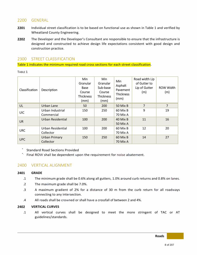
2300 STREET CLASSIFICATION Table 1 indicates the minimum required road cross sections for each street classification.
TABLE 1
Classification Description
Min Granular Base Course
Thickness (mm)
Min Granular Sub‐base Course
Thickness (mm)
Min Asphalt Pavement Thickness (mm)
Road width Lip of Gutter to Lip of Gutter
(m) ROW Width
(m)
UL Urban Lane 50 200 50 Mix B 7 7
UIC Urban Industrial Commercial
150 250 60 Mix B 70 Mix A
9 19
UR Urban Residential 100 200 40 Mix B
50 Mix A 11 16
URC Urban Residential Collector
100 200 60 Mix B 70 Mix A
12 20
UPC Urban Primary Collector
150 250 60 Mix B 70 Mix A
14 27
* Standard Road Sections Provided *. Final ROW shall be dependent upon the requirement for noise abatement.
2400 VERTICAL ALIGNMENT
GRADE
.1 The minimum grade shall be 0.6% along all gutters, 1.0% around curb returns and 0.8% on lanes.
.2 The maximum grade shall be 7.0%.
.3 A maximum gradient of 2% for a distance of 30 m from the curb return for all roadways
connecting to any intersection.
.4 All roads shall be crowned or shall have a crossfall of between 2 and 4%.
VERTICAL CURVES
.1 All vertical curves shall be designed to meet the more stringent of TAC or AT
guidelines/standards.
8 of 207
Roads
2500 HORIZONTAL ALIGNMENT
CURVES
.1 The minimum degree of curvature of the centerline of the carriage way is dependent on the road
classification and its design speed.
.2 All horizontal curves shall be designed to meet the more stringent of TAC or AT
guidelines/standards.
2600 GENERAL REQUIREMENTS
PAVEMENT STRUCTURE
.1 The Geotechnical Report for the proposed project shall be submitted to the Wheatland County
Representative for review as part of the overall submission.
.2 The Geotechnical Report must include specific recommendations for pavement structure
construction based on insitu conditions and projected traffic volume. The more conservative of
the 20 year structure recommended by the Geotechnical Consultant and the structure shown in
Table 1 shall be used.
.3 Table 1 indicates the minimum thicknesses of granular and asphaltic concrete materials required
for each street classification.
.4 The Final Acceptance Certificate (FAC) for roads excluding surface course asphalt shall be issued,
subject to all deficiencies being rectified, two years after the issuance of the Construction
Completion Certificate (CCC) for roads.
.5 If an interim or temporary entrance is necessary to provide access to a new subdivision, cul‐de‐
sac or other residential street the pavement structure must be designed to accommodate the
projected traffic for the life of the facility.
SIDEWALKS AND WALKWAYS
.1 Separate sidewalks shall be a minimum width of 1.5 m. Separate sidewalks shall be constructed
where indicated on the standard road cross sections.
.2 Monolithic 1.5 m sidewalk and gutter with rolled curb shall be constructed where indicated on
the standard road cross sections.
.3 Monolithic sidewalk and gutter with standard curb shall be constructed where indicated on the
standard road cross sections.
.4 All Collector and Arterial streets shall have sidewalks on both sides except where the adjacent
lands are industrial where sidewalk is then only required on one side. Local roads shall have
sidewalks on both sides where the adjacent lands are commercial or high density residential,
otherwise local roads shall have sidewalk on one side.
.5 Wheelchair ramps are to be used at all curbed intersections and shall be constructed
monolithically or securely dowelled.
.6 All sidewalks shall be imprinted with the Contractor's stamp showing company name and year of
construction. Frequency of stamps shall be one per residential block or every 200 m whichever
is less.
9 of 207
Roads
.7 Sidewalks shall be imprinted with a "CC" to identify all Curb Cock locations.
.8 The design of the subdivision should consider pedestrian needs and allow for walkways through
cul‐de‐sacs and other appropriate locations.
CONCRETE CURB AND GUTTER
.1 Concrete curb and gutter shall be constructed on all streets in accordance with this standard.
.2 Standard curb and gutter shall be used on all collector (minor and major) and arterial roads. All
roads fronting parks, PUL's, and walkways shall also require standard curb and gutter unless
another means of preventing vehicular access onto these public lands is provided.
.3 Curb returns on residential street intersections shall be constructed with a minimum radius of
10.0 m.
.4 Curb returns in industrial/commercial areas shall be constructed with a minimum radius of 15.0
m to accommodate truck turning movements.
DRIVEWAYS
.1 Residential subdivision lot layout shall be such that driveways shall not access directly onto
arterial roadways. In addition, no driveways shall be permitted direct access onto those major
collector roads or portions thereof which have an estimated traffic volume of 4,000 vpd or
greater.
.2 No driveways or any portion thereof shall be permitted to access an abutting road through a curb
return area.
.3 For corner lots the driveway zone must be indicated for the street of lesser traffic only.
BERMING, FENCING AND LANDSCAPING
.1 Consistent noise attenuation fencing shall be required on all lots that back or side onto arterial
roads. Berming and fencing shall be required to separate residential developments from high
volume arterial traffic. Roadways through residential areas which require berming and adjacent
fencing include all arterial roads as well as adjacent highways.
.2 Residential development adjacent to arterial roadways, may require a Noise Impact Assessment
(NIA) to be submitted during the development approval process. The NIA is to meet the intent of
regional municipal policy and standards.
.3 Fencing proposals are to be reviewed for acceptance by the County. Fencing along arterial roads
and utility lots shall be of a close boarded type and extend to ground level. Fencing is required
along parks, schools and other public open space and shall be 1.5 m high. All fences shall be
constructed on private property.
10 of 207
Roads
CUL‐DE‐SACS
.1 The normal maximum length of a cul‐de‐sac is 120 m from the street curb line to the start of the
bulb. Cul‐de‐sacs in excess of 120 m and less than 170 m will require an additional hydrant. Water
main looping will be required for cul‐de‐sacs in excess of 120m. Where cul‐de‐sacs in excess of
170 m are proposed, provision must be made for a 6.0 m wide PUL for emergency vehicle access
and water service looping.
.2 Cul‐de‐sacs with steep grades are to be avoided. If cul‐de‐sacs cannot be graded to drain towards
the intersection then an outlet for the overland flow must be provided by way of a PUL.
.3 The minimum radius of cul‐de‐sac bulbs is 10.5m to lip of gutter for residential and 14.75m for
all others.
.4 Cul‐de‐sac road surface is to be crowned except the bulb portion which may be crossfall.
INTERSECTIONS
Intersections include the crossing of two public roadways or the connection of a public access to a roadway.
.1 The minimum angle of intersection for two roadways shall be 75°.
.2 Intersection design is to meet the more stringent of AT and TAC guidelines/standards.
.3 Acceptance of intersection design, driveway locations and fencing shall be subject to review of
available sight distances and other safety considerations. Tapering of berms at intersections may
be required to provide for the necessary sight distances. Acceptance shall be granted on a case
by case basis.
.4 The Developer shall provide confirmation that sight distances, and horizontal and vertical
visibility constraints at the access to arterial roadways, Range Roads and Township Roads meet
the applicable stopping sight distances.
.5 Minimum centerline to centerline spacing of intersections shall be 60 m along local and collector
roadways. Under normal circumstances (i.e., on the 1.6 km or 3.2 km sections of grid roads)
access to arterial roads may be permitted as follows:
(i.) Signalized where warranted but potentially signalized intersections spaced and
capacity designed for minimum arterial impact.
(ii.) Where traffic volumes or existing conditions make the above standards inappropriate
the more stringent of AT and TAC guidelines/standards are to be applied.
.6 At the intersection of arterial roads and where the traffic volume at entrance roads indicates a
need for acceleration/deceleration turning lanes the Developer shall provide an additional 3.7 m
for widening of the arterial ROW.
.7 Standard 6m x 6m corner cutoffs will be required at all intersections unless otherwise directed
by the County.
11 of 207
Roads
LANEWAYS
.1 All laneways shall be a minimum of 7.0 m in width.
.2 If paved, laneways shall be paved over their full width.
.3 An inverted cross‐section shall be used for laneway construction with a minimum longitudinal
grade of 0.8%.
TRAFFIC CONTROL AND STREET NAME SIGNS
.1 Traffic control and street name signs are to be as per regionally accepted standards unless
otherwise stated in this section and as per the Rural Address Sign standard drawing.
.2 Street name signs at intersections shall consist of white lettering on a green metal plate. Lettering
sizes shall be as follows:
(i.) Arterial Roadways: 250 mm (10") on a 300 mm (12") blade.
(ii.) Major Collector Roadways: 250 mm (10") on a 300 mm (12") blade.
(iii.) Minor Collector and Local Roadways: 100 mm (4") on a 150 mm (6") blade.
.3 100 mm (4") white address numbering on a green metal plate will be required on all cul‐de‐sacs
in addition to the street name signage.
.4 Developers may be permitted to install additional decorative street name signage or signage
support when adequate maintenance funding provisions have been approved by the Wheatland
County Representative.
2700 ROADWAY LIGHTING
DESIGN CRITERIA
.1 The illumination of roadways in urban areas shall be designed to the TAC Guide for the Design of
Roadway Lighting.
12 of 207
Sanitary Sewer System
3000 SANITARY SEWER SYSTEM
3100 SYSTEM DESIGN
GENERAL
The sanitary sewer system shall be of sufficient capacity to carry peak flows plus an inflow and infiltration
allowance. The flows and factors outlined in the following sections shall be used in the design of sanitary
sewer systems.
The Developer and the Developer's Consultant are responsible to meet the requirements of Alberta Environment
& Parks when connecting to existing municipal systems or utilities.
The Developer and the Developer's Consultant are responsible to ensure that the infrastructure is designed and
constructed to achieve design life expectations consistent with good design and construction practice.
ESTIMATING AVERAGE SEWAGE FLOWS
.1 Residential: 300 L/person/day.
.2 Commercial/Industrial: Since these flows vary greatly with the type of development, each case
must be considered on an individual basis. For preliminary planning purposes, 18.0 m3/ha/day
may be used for Commercial/Light Industrial.
.3 In determining residential flows a minimum of 3.0 persons per household shall be used.
PEAKING FACTOR
.1 The peaking factor for residential development shall be calculated using the Harmon Formula.
The minimum peaking factor shall be 4.0. Peaking Factor = 1 + (14 / (4 + (P/1000)0.5)), where P =
the design contributing population in thousands.
.2 The peaking factor must reflect the projected population of the subdivision being designed.
.3 The peaking factor for commercial/industrial development varies greatly with the type of
development. Each case must be considered on an individual basis.
ESTIMATING EXTRANEOUS FLOW ALLOWANCES
.1 A general infiltration allowance of 0.28 L/sec/ha shall be added to the above flow.
.2 In addition, a separate allowance of 0.4 L/sec shall be added for each manhole located in a street
sag with some degree of water inflow control in place.
13 of 207
Sanitary Sewer System
PIPE SIZING
3105.1 MINIMUM PIPE SIZE:
(i.) Commercial / Industrial / Institutional: 250 mm
(ii.) Residential: 200 mm (150mm may be permitted on request for sewers servicing 6 or
less units)
3105.2 PIPE SIZING SHALL BE DETERMINED BY UTILIZING THE MANNING'S FORMULA USING A MINIMUM "N" VALUE
(ROUGHNESS COEFFICIENT) OF 0.013.
Q =AR2/3S1/2
n
With calculation of the estimated design flow from the Manning’s formula the pipe capacity shall
then be determined with the following formula:
Required Sewer Capacity = Estimated Design Flow
0.86
3105.3 MINIMUM FLOW VELOCITY
0.60 m/sec. Maximum flow velocity = 3.0 m/sec. Minimum flow velocity in first upstream leg to
be 0.90 m/sec.
WEEPING TILES (FOUNDATION DRAINS)
.1 For any development (residential, commercial, industrial, etc.), weeping tiles, roof leaders
(downspouts), sump pumps and similar appurtenances that handle storm water or ground water
are not permitted to discharge into sanitary sewers.
SANITARY SEWER MAIN ALIGNMENTS AND LOCATIONS
.1 Standard road sections provide line assignments for mains. A reduction from 3.0 m to 2.5 m
separation distance between water and sanitary sewer mains may be considered upon request.
.2 Connection manholes and service mains to property line are required for a multi‐family site as
part of the overall subdivision site servicing. The Developer's Consultant must address the size
and depth requirements of the service stub to ensure all of the multi‐family lot can be adequately
serviced.
.3 Mains shall be at a depth adequate to provide a minimum 2.5 m cover for silt and clay soils and
2.8m cover for granular soils from finished grade to top of pipe and the required minimum depth
of cover over service connections. Insulation will be required for any main that is installed with
less than the minimum cover.
.4 Curved sewers shall be permitted with the following restrictions:
(i.) The curve shall run parallel to the curb or street centerline.
(ii.) The minimum grade for sewers on a curve shall be 50% greater than the minimum
grade required for a straight run of sewer.
(iii.) Manholes shall be located at the beginning and end of each curve. Joint deflection
shall not exceed pipe manufacturers' specifications.
14 of 207
Sanitary Sewer System
.5 At water main crossings of sanitary and storm sewers, the following shall apply:
(i.) Under normal conditions, water mains shall cross above sewers with a sufficient
vertical separation to allow for proper bedding and structural support of the water
and sewer mains.
(ii.) Where it is necessary for the water main to cross below the sewer, the water main
shall be protected by providing:
a.) A vertical separation of at least 0.5 m from water main crown to sewer invert;
b.) Structural support of the sewer to prevent excessive joint deflection and settling; and
c.) A centering of the length of water main at the point of crossing so that the joints
are equidistant from the sewer.
MANHOLES
.1 The maximum spacing between manholes shall be 185 m. Lesser spacing distance is encouraged
for maintenance purposes.
.2 Manholes are also required at all transitions in size, grade, or direction, and at junctions and the
ends of mains. Change in flow direction shall not exceed 90 degrees. They should be located to
avoid driveway conflicts.
.3 At manholes where pipe size changes occur, the crowns (obverts) of the incoming mains shall be
designed to match or be higher than the outgoing main. This requirement could be relaxed if a
hydraulic flow analysis proves flows are not negatively impacted.
.4 Inverts in manholes shall have a minimum 30 mm drop for straight run sewer manholes. At
changes in direction, manholes shall have at least 60 mm fall across the manhole in the direction
of flow from inlet to outlet elevation and 150mm for bends greater than 90o if permitted by the
Wheatland County Representative. The intention is to maintain the HGL considering entrance
and exit losses such that the above minimums shall be increased as necessary.
.5 Drop sections are required for invert grade differences greater than 300 mm in sanitary sewer
manholes. For 200 mm and 250 mm mains, internal drops may be used. Benching is required for
invert grade differences 300 mm or less.
SERVICE CONNECTIONS
.1 Each lot or multi‐family unit shall have its own separate sanitary service connection.
.2 The minimum size of a sanitary sewer service connection shall be 100 mm inside diameter.
.3 Non‐residential and multi‐family service connections shall be sized according to anticipated user
requirements. These service connections would normally be installed at the time that the
subdivision is developed. Commercial/Industrial service connections may be deferred until the
lots develop provided there will be no disturbance to the roadway while making the connection
to the sewer main.
.4 The minimum grade on the service line shall be 2.0%.
.5 In the case of single family lots, the minimum depth of cover shall be 2.6 m to the top of pipe
from finished grade at a point 0.15 m from the back (house side) of the property easement/right‐
of‐way.
15 of 207
Sanitary Sewer System
.6 For non‐residential and multi‐family service connections, the Developer's Consultant must
address the depth requirements for servicing of these lots in the establishment of the design
depth for the sanitary sewer main on the abutting street.
.7 Services shall be located such that they do not conflict with driveway locations.
.8 In‐line Tees or Wyes are required for all residential service connections.
.9 Services require an inspection chamber at property line.
.10 Commercial/industrial connections 200 mm or larger require a manhole connection. Where a
manhole connection is provided an inspection chamber is not required.
16 of 207
²ŀǘŜNJ 5ƛǎǘNJƛōdzǘƛƻƴ {ȅǎǘŜƳ
4000 WATER DISTRIBUTION SYSTEM
4100 GENERAL The Developer and the Developer's Consultant are responsible to meet the requirements of Alberta Environment
& Parks when connecting to existing municipal systems or utilities.
The Developer and the Developer's Consultant are responsible to ensure that the infrastructure is designed and
constructed to achieve design life expectations consistent with good design and construction practice.
4200 SYSTEM DESIGN
HYDRAULIC NETWORK ANALYSIS
.1 The Developer shall perform hydraulic network analyses for all developments.
.2 The criteria for network analysis shall be as follows:
.1 The normal operating range for residential pressure shall be between 350 kPa to 700
kPa with a maximum velocity of 3.0 m/sec.
.2 Design population shall be the ultimate population for the area under construction.
.3 Design consumption:
Average Day Minimum Demand ............ 360 L/person/day
Maximum Day Demand .......................... 720 L/person/day
Peak Hour Demand ............................. 1,440 L/person/day
.4 The maximum value of "C" in the Hazen‐ Williams formula shall be 120 regardless of
pipe material.
.5 An analysis shall be made for peak hour demand and the mains shall be sized such
that there shall be a minimum residual pressure of 350 kPa at ground level at any
node in the network.
.6 Analysis to be performed on system for maximum day demand plus a fire flow of:
50 L/s fire flow for country residential
100 L/s fire flow for residential
166 L/s fire flow for multi‐family
250 L/s for all other high density, industrial, commercial or institutional
The minimum residual pressure at any node in the system shall be 140 kPa at ground
level under this situation.
.7 Fire flow conditions shall also be analyzed using the criteria contained in the most
recent edition of "Water Supply For Public Fire Protection, A Guide to Recommended
Practice" as published by Fire Underwriters Survey. The analysis must take into
consideration the various factors which may impact on the fire flow requirements.
.8 In commercial/industrial areas, a separate analysis shall also be made to determine
what system configurations and sizes would be required to provide direct flow to
sprinkler systems in combination with hydrant flows in accordance with National Fire
Protection and Fire Underwriter's Survey standards.
17 of 207
Water Distribution System
.9 All calculations, schematic diagrams, computer printouts, etc. shall be submitted.
WATER MAINS
.1 In residential, commercial and industrial subdivisions the water main alignments and hydrant
locations shall be as per the standard road cross sections.
.2 A reduction from 3.0 m to 2.5 m separation distance between water and sanitary sewer mains
may be considered.
.3 The installation of a water main service to property line for a multi‐family site development
would normally be completed at the time of initial subdivision development.
.4 The water distribution system in new subdivisions shall be looped. For the initial purely
residential stages of a large development area the Wheatland County Representative, at its sole
discretion, may temporarily waive this requirement provided that the developer can
demonstrate that the necessary fire flows can be delivered via the single water feed. In any event,
a maximum of 50 lots may be serviced temporarily without looping of the system. Looping must
be provided within one year of temporarily servicing without looping.
In the case of residential cul‐de‐sacs, distribution lines must all be looped except those serving
single cul‐de‐sacs of less than 120 m as measured from the street curb line to the start of the
bulb. In the case of industrial/commercial subdivisions, all distribution mains must be looped.
.5 At street intersections, a minimum clearance of 1.5 m horizontally shall be maintained between
water mains and any catch basins or storm manholes.
.6 Mains shall be at a depth adequate to provide a minimum 3.0 m cover in silt and clay soils and
3.3 m cover in granular soils from finished grade to top of pipe and the same depth of cover over
service line goosenecks (in the case of single family dwelling services).
.7 The minimum diameter for distribution mains shall be 150 mm for a residential development
unless one or more hydrants are located on the line in which case the minimum diameter shall
be 200 mm. For commercial/industrial development, the minimum water main size shall be 300
mm.
.8 At water main crossings of sanitary and storm sewers, the following shall apply:
.1 Under normal conditions, water mains shall cross above sewers with a sufficient
vertical separation to allow for proper bedding and structural support of water and
sewer mains.
.2 Where it is necessary for the water main to cross below the sewer, the water main
shall be protected by providing:
a.) A vertical separation of at least 0.5 m from water main crown to sewer invert;
b.) Structural support of the sewer to prevent excessive joint deflection and settling; or
c.) A centering of the length of water main at the point of crossing so that the joints
are equidistant from the sewer.
.9 In the vicinity where a change in elevation greater than two pipe diameters between the obvert
of the lower pipe and the invert of the upper pipe where no service line exists, a blow‐off or
similar device must be added for the removal of trapped air.
18 of 207

²ŀǘŜNJ 5ƛǎǘNJƛōdzǘƛƻƴ {ȅǎǘŜƳ
.10 Any water main installed made of PVC, HDPE or similar non‐conductive material is to have tracer
wire installed. The tracer wire shall have connection points exposed at every opportunity (all
valves, blow‐offs and hydrants).
.11 Tracer wire used must be a minimum of 14 gauge coated copper wire complete with sacrificial 5
lb anodes spaced every 1000 l/m.
HYDRANTS
.1 Maximum allowable spacing between fire hydrants shall be 150 m in single family residential
areas and 90 m in multiple family residential, school or industrial/commercial areas. Variances
may be considered if it can be demonstrated that the alternative hydrant location provides more
efficient connection and response time. Wheatland County Fire and Disaster Services should be
included for input into any variance request.
.2 They shall be located at the beginning of the curve of the curb return at the corners of
intersections or at the extension of property lines.
.3 In cul‐de‐sacs of 75 m in length or less, the hydrant shall be installed at or near the intersection
of the intersecting street.
.4 Hydrants are to be set to ensure that the pumper port faces the street. If non‐standard alignment
locations are accepted for either the main or the hydrant, the hydrant valve must not be installed
directly in front of the pumper port.
VALVES
.1 Distribution main valves shall be located as follows:
(i.) On the projection of property lines at mid‐block, at the beginning of curb return at
road intersections.
.2 Distribution main valves shall be located such that in the event of a shutdown:
(i.) No more than two hydrants are taken out of service,
(ii.) No more than 25 single family units are involved in a shutdown.
.3 Maximum length of a dead end line in a residential neighbourhood is 120 m. A blow off valve
must be installed at the end of dead end line. Blow off valves need to be sized to achieve a
minimum flushing flow of 0.6 m/sec.
.4 Valves on hydrant leads are to be located in the boulevard area. All hydrants must be separated
from the distribution system by a valve. Valves shall be spaced far enough away from the hydrant
body to allow for easy operation.
.5 Valves shall be the same size as the main they are installed on.
19 of 207

Water Distribution System
SERVICE CONNECTIONS
.1 Each lot or multi‐family unit shall have its own separate water service connection. Any sprinkler
dwellings are to have a minimum 38mm service and be sized as per the demands.
Services to single family dwellings or multi‐family units shall be a minimum 20 mm diameter
unless the length of the service, measured from the main to the property line or unit, is greater
than 20 m in which case 25 mm diameter shall be used.
Multi‐family and industrial/commercial service connections shall be sized according to
anticipated user requirements. These service connections would normally be installed at the time
that the subdivision is being developed. Commercial/Industrial service connections may be
deferred until the individual lots develop provided there will not be a disturbance to the roadway
while making the connection to the water main. A shut‐off valve must be installed at property
line when the lot is serviced.
.2 In the case of single family lots, the minimum depth of cover shall be 3.0 m for silt and clay soils
and 3.3m for granular soils from finished grade over a vertical gooseneck and to the top of pipe
at a point 0.15 m from the back of (house side) of the easement required along the front of all
lots.
.3 Curb stops locations shall be located such that they do not conflict with driveway locations or
sidewalks.
.4 Parks may require a water service. The size, type and requirement will be determined in
consultation with the Wheatland County Representative.
20 of 207

Stormwater Management System
5000 STORMWATER MANAGEMENT SYSTEM
5100 SYSTEM DESIGN
GENERAL
.1 The concept of a major and minor storm drainage system has three purposes:
.1 The control of storm water to minimize inconvenience or disruption of activity as a
result of runoff from more frequent but less intense storms, and
.2 Control of storm water runoff to prevent or minimize damage to property, physical
injury and loss of life which may occur during or after an infrequent or unusual storm;
and
.3 Provide improved water quality by filtering contaminants prior to entering receiving
downstream water courses.
.2 When the minor system capacity is exceeded the major system must provide a continuous
overland flow route for runoff water to follow. Generally major system routing shall utilize
roadways and open channels with carefully designed and controlled lot grading and building
elevations.
.3 Storm sewers shall be designed as a separate sewer system. Effluent from sanitary sewers or any
potentially contaminated drainage from industrial, agricultural, or commercial operations shall
not be discharged to storm sewers.
.4 The Developer and their Engineering Consultant must adhere to the guidelines presented in the
latest edition of the publication "Stormwater Management Guidelines for the Province of
Alberta" prepared by AEP.
MINOR SYSTEM
5102.1 DESIGN CRITERIA
.1 The Minor System must be designed to accommodate the runoff generated by a 1:5
year storm event.
.2 The Rational Method. For most developments, the Rational Method is not an
acceptable form of stormwater analysis in Wheatland County. However, in some
cases for single lot developments less than 2.0 ha exceptions may be provided. Such
exceptions will require written approval obtained from the Wheatland County
Representative. All other cases will require the use of computer modeling.
.3 Computer modelling shall be required by the County for the design of stormwater
systems for all areas not specifically approved in the previous section.
21 of 207
Stormwater Management System
5102.2 DESIGN CRITERIA
.1 Minimum Pipe Size:
Storm Sewer ..................... 300 mm
Catch Basin Lead ............... 250 mm
Double Catch Basin Lead .. 300 mm
.2 Pipe sizing shall be determined by utilizing the Manning's Formula using a minimum
"n" value of 0.013.
.3 Minimum flow velocity = 0.60 m/sec. Maximum flow velocity = 3.0 m/sec.
.4 The minimum grade of catch basin leads shall not be less than 1.0%.
.5 Minimum slopes determined by velocity shall be increased by 50% on all curves.
5102.3 STORM SEWER MAIN ALIGNMENTS AND LOCATIONS
.1 Alignments are provided in the standard road cross sections.
.2 The installation of a main into a multi‐family site development would normally be
completed at the time the site develops. However, the Developer's Consultant must
address the depth requirements for servicing the site in the establishment of the
design depth for the main located on the abutting street.
.3 Storm sewer service must be provided to all commercial and industrial lots.
.4 Storm sewers must be located at least 3.0 m horizontally from any water main.
.5 PUL widths shall be a minimum of 4.0 m for a single utility and 6.0 m for one
containing two utilities. A 1.0 m easement is required on the lots on each side of a
PUL.
.6 Mains shall have a minimum depth of cover of 1.2 m to top of pipe.
.7 Curved sewers shall be permitted with the following restrictions:
a.) The curve shall run parallel to the curb or street centreline.
b.) The minimum grade for sewers on a curve shall be 50% greater than the minimum
grade required for a straight run of sewer.
c.) Manholes shall be located at the beginning and end of each curve and
intermediate locations as required.
.8 At water main crossings of sanitary and storm sewers, the following shall apply:
a.) Under normal conditions, water mains shall cross above sewers with a sufficient
vertical separation to allow for proper bedding and structural support of the
water and sewer mains.
b.) Where it is necessary for the water main to cross below the sewer, the water
main shall be protected by providing:
A vertical separation of at least 0.5 m from water main crown to sewer
invert;
Structural support of the sewer to prevent excessive joint deflection and
settling; or
A centering of the length of water main at the point of crossing so that
the joints are equidistant from the sewer.
22 of 207
Stormwater Management System
5102.4 MANHOLES
.1 The maximum spacing between manholes shall be 185 m.
.2 Manholes are also required at all transitions in size, grade, or direction, and at
junctions and the ends of mains. They should be located to avoid driveway conflicts.
.3 At manholes where size changes occur, the crowns (obverts) of the mains shall be
designed to match.
.4 Inverts in manholes shall have a minimum 30 mm drop for straight run sewer
manholes. At changes in direction, manholes shall have at least 60 mm fall across the
manhole in the direction of flow from inlet to outlet elevation and 150mm for bends
greater than 90o. The intention is to maintain the HGL considering entrance and exit
losses such that the above minimums shall be increased as necessary.
5102.5 CATCH BASINS
.1 See standard drawings for catch basin types.
.2 The maximum run between catch basins shall be 150 m with minimum grades.
.3 Spacing and capacity of catch basins shall be such that ponding shall not occur during
a 1:5 year storm.
.4 The minimum sump depth in catch basins shall be 600 mm.
.5 Catch basins shall be installed to intercept all overland flows, including back lanes,
prior to crossing walkways. At curb returns, catch basins shall be installed to intercept
runoff on the uphill side of cross walks.
.6 Concrete swales crossing roadways will be permitted with written approval of the
Wheatland County Representative.
5102.6 CATCH BASIN LEADS
.1 The minimum size of catch basin leads shall be 250 mm inside diameter.
.2 The maximum length of a catch basin lead shall be 30 m. A catch basin manhole shall
be required at the upper end if the lead exceeds 30 m.
.3 The minimum grade on a catch basin lead shall be 1.0%.
.4 Minimum depth of cover shall be 1.2 m to top of pipe.
.5 All leads shall be connected to a main line manhole or a catch basin manhole.
5102.7 STORM SEWER SERVICE CONNECTIONS
.1 Single family Residential Service connections shall be minimum 150 mm inside
diameter.
.2 Medium/high density residential and non‐residential site service connections shall be
sized according to anticipated site requirements.
.3 Services shall be located such that they do not conflict with driveway locations.
23 of 207
Stormwater Management System
MAJOR SYSTEM AND STORM WATER MANAGEMENT FACILITIES (SWMF)
5103.1 GENERAL
.1 The overall major drainage system for the Urban Services Area must be designed to
provide continuous overland flow routes with minimum depths of ponding in
roadway sags and to provide overflow routes at all SWMF. The development of the
major drainage system framework shall be a key component of the Master Drainage
Plan to be developed by the Developer's Engineering Consultant for new drainage
basins (watersheds).
.2 The major system shall accommodate a 1:100 year storm.
5103.2 LOT GRADING
.1 Carefully designed and controlled lot grading is an important component of the Major
System.
.2 Lots shall be designed to drain from back to front except under extreme cases where
the Developer can satisfy the Wheatland County Representative that back to front
drainage is not technically feasible. If an alternate system is required it must be
designed so that surface water crosses the fewest lots possible in its path to the
street. No more than two lots shall be crossed. In extreme cases the Wheatland
County Representative, may permit more than two lots to be crossed provided a
concrete drainage swale and easement are established. The potential problem areas
shall be identified in the Design Brief.
.3 Minimum and maximum slopes on landscaped areas to be 2% and 10% respectively.
An initial minimum grade of 10% over a distance of 1.5 m is to be provided around all
buildings. Driveway slopes must be no less than 2% and no greater than 8%.
5103.3 STORM WATER MANAGEMENT FACILITIES
.1 Stormwater Management Facilities shall be as per AEP "Stormwater Management
Guidelines for the Province of Alberta.
24 of 207

WHEATLAND COUNTY RURAL SERVICE AREA DESIGN STANDARDS
OCTOBER 2016
25 of 207

26 of 207
CONTENTS 1000 General .................................................................................................................................................28 1100 Survey Control Markers and Legal Pins ................................................................................................28
2000 Rural Transportation ............................................................................................................................29
3000 Rural Sanitary Sewer.............................................................................................................................76 3100 System Design Overview .....................................................................................................................76
4000 Rural Water Distribution ......................................................................................................................77 4100 System Design Overview .....................................................................................................................77
5000 Rural Stormwater Management...........................................................................................................78 5100 General .................................................................................................................................................78
27 of 207
WHEATLAND COUNTY RURAL SERVICE AREA STANDARDS JULY 2016
1000 GENERAL These standards are provided to set guidelines and establish requirements regarding design and construction of
municipal infrastructure within Wheatland County. Its objective is to ensure that all municipal infrastructure work
in Wheatland County is constructed to a consistent, sustainable standard. Construction of municipal infrastructure
must adhere to these standards.
The County retains the ability to refer to other applicable regional municipality Design Guidelines, Standards
and Policies where the County deems it appropriate on a case by case basis.
1100 SURVEY CONTROL MARKERS AND LEGAL PINS
Existing Control
.1 The Developer or their Consultant shall make every effort to protect existing markers.
.2 Markers which are destroyed or disturbed shall be replaced by the Developer at their sole expense.
Legal Posts
.1 Legal posts shall be placed subsequent to the installation of all utilities.
.2 All legal posts in the subdivision area shall be located within 60 days prior to application for Final
Acceptance of the surface improvements.
.3 The Developer shall instruct the legal surveying consultant to replace any missing or disturbed posts
as required by the Wheatland County Representative. All costs are to be borne by the Developer.
20
28 of 207
2000 RURAL TRANSPORTATION 2000 Roadway Requirements and Standards .............................................................................................................................33
2100 Design Classifications and Criteria .......................................................................................................................33
2101 Local Roads ......................................................................................................................................................33
2102 Collectors (RCU) ..............................................................................................................................................35
2103 Major Collectors (RLU) ....................................................................................................................................35
2104 Arterial Roads (RAU) .......................................................................................................................................36
2200 Road Design Guidelines .........................................................................................................................................36
2201 Traffic Impact Assessments ..............................................................................................................................37
2202 Dedicated Road Widening and Additional ROW Requirements .......................................................................37
2203 Setbacks ..........................................................................................................................................................39
2204 Intersections ...................................................................................................................................................39
2205 Approaches .....................................................................................................................................................40
2206 Cul‐de‐Sacs .....................................................................................................................................................42
2207 Walkways / Pathways .....................................................................................................................................42
2208 Fences .............................................................................................................................................................42
2209 Topsoil and Seeding ........................................................................................................................................42
2210 Rock Ditch Checks .............................................................................................................................................43
2211 Postal Box Turnout ...........................................................................................................................................43
2212 Road Signs and Painting ....................................................................................................................................43
2213 Obstructions on Road ROW / Road Allowance .................................................................................................43
2214 Guardrail ...........................................................................................................................................................43
2300 Geometric Design ..................................................................................................................................................44
2301 Vertical Alignment ..........................................................................................................................................44
2302 Horizontal Alignment ......................................................................................................................................45
2400 Surfacing Structure Design and Construction ........................................................................................................45
2401 Subgrade and Grading .....................................................................................................................................45
2402 Granular Base Course .....................................................................................................................................47
2403 Asphalt Concrete Pavement ............................................................................................................................48
2404 Material Testing ..............................................................................................................................................49
2500 Shallow and Overhead Utilities ..............................................................................................................................52
2501 Utility Corridors ...............................................................................................................................................11
2502 Shallow Utility Systems ...................................................................................................................................53
2503 Gas, Power, Telephone and Cable Television Standards .................................................................................53
2504 Electric System/Lighting ..................................................................................................................................53
2600 General Construction Requirements.....................................................................................................................54
Schedule 2000‐1: Subgrade Proof‐Rolling Inspections ..............................................................................................55
Schedule A‐2: Standard Road Drawings .....................................................................................................................56
29 of 207
LIST OF TABLES Table 2000‐1: Road Classifications and Sub‐classifications .......................................................33
Table 2000‐2: Minimum Corner Cut‐off Requirements at Intersections ...................................38
Table 2000‐3: Minimum Setback Distances..............................................................................39
Table 2000‐4: Geometric Requirements at Intersections .........................................................40
Table 2000‐5: Geometric and Design Requirements for Approaches .......................................41
Table 2000‐6: Minimum "K" Values for Vertical Curves ...........................................................44
Table 2000‐7: Horizontal Alignment Requirements..................................................................45
Table 2000‐8: Minimum ACP Depth Requirements ..................................................................48
Table 2000‐9: Material Testing Requirements ..........................................................................49
Table 2000‐10: Specifications for Aggregate .............................................................................51
Table 2000‐11: Deflection Testing Requirements .....................................................................52
30 of 207
LIST OF DRAWINGS Figure A‐1.1 Typical Road Cross Section on a 20.12m ROW with 8.6m Top Width & 3.0m Ditch Width
Figure A‐1.2 Typical Road Cross Section on a 30.00m ROW with 8.6m Top Width & 3.0m Ditch Width
Figure A‐1.3 Typical Road Cross Section on a 30.00m ROW with 10.0m Top Width & 3.0m Ditch Width
Figure A‐1.4 Country Residential Road Paved
Figure A‐1.5 Country Residential Road Double Seal Coat
Figure A‐2 Internal Subdivision
Figure A‐3 Local Road – Low Volume
Figure A‐4 Road Allowance / Service Road Paved
Figure A‐5 Collector Road Industrial / Commercial Road
Figure A‐6 Major Collector Road Gravel Standard
Figure A‐7 Major Collector Road Paved Standard
Figure A‐9 Typical Road Approach
Figure A‐9.1 Maximum Approach Grades to Local and Collector Roads
Figure A‐10 Minimum Cul‐de‐sac Dimensions for a 30m Right Of Way
Figure A‐11 Temporary Cul‐de‐sac
Figure A‐12 Typical Postal Box Turnout (20.0m ROW)
Figure A‐13 Typical Postal Box Turnout (30.0m ROW)
Figure A‐14 Typical Installation of Municipal Road Name Signs
Figure A‐15 Typical Rock Ditch Check
31 of 207
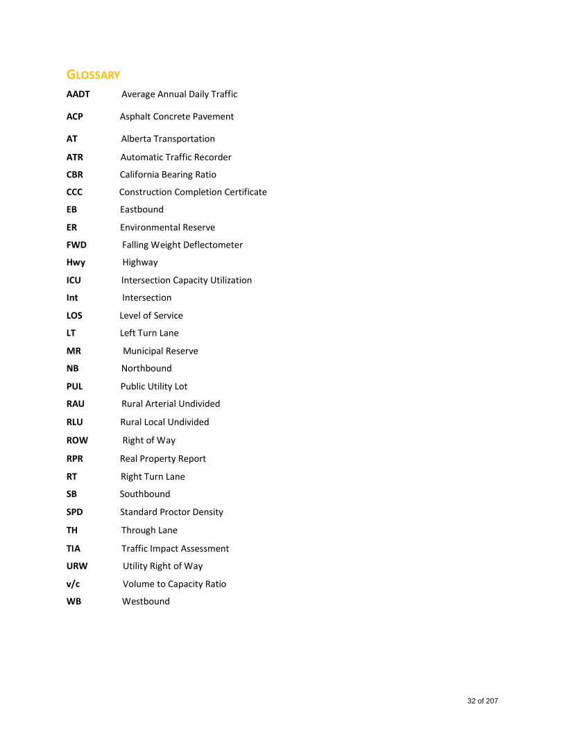
GLOSSARY AADT Average Annual Daily Traffic
ACP Asphalt Concrete Pavement
AT Alberta Transportation
ATR Automatic Traffic Recorder
CBR California Bearing Ratio
CCC Construction Completion Certificate
EB Eastbound
ER Environmental Reserve
FWD Falling Weight Deflectometer
Hwy Highway
ICU Intersection Capacity Utilization
Int Intersection
LOS Level of Service
LT Left Turn Lane
MR Municipal Reserve
NB Northbound
PUL Public Utility Lot
RAU Rural Arterial Undivided
RLU Rural Local Undivided
ROW Right of Way
RPR Real Property Report
RT Right Turn Lane
SB Southbound
SPD Standard Proctor Density
TH Through Lane
TIA Traffic Impact Assessment
URW Utility Right of Way
v/c Volume to Capacity Ratio
WB Westbound
32 of 207
2000RoadwayRequirementsandStandards
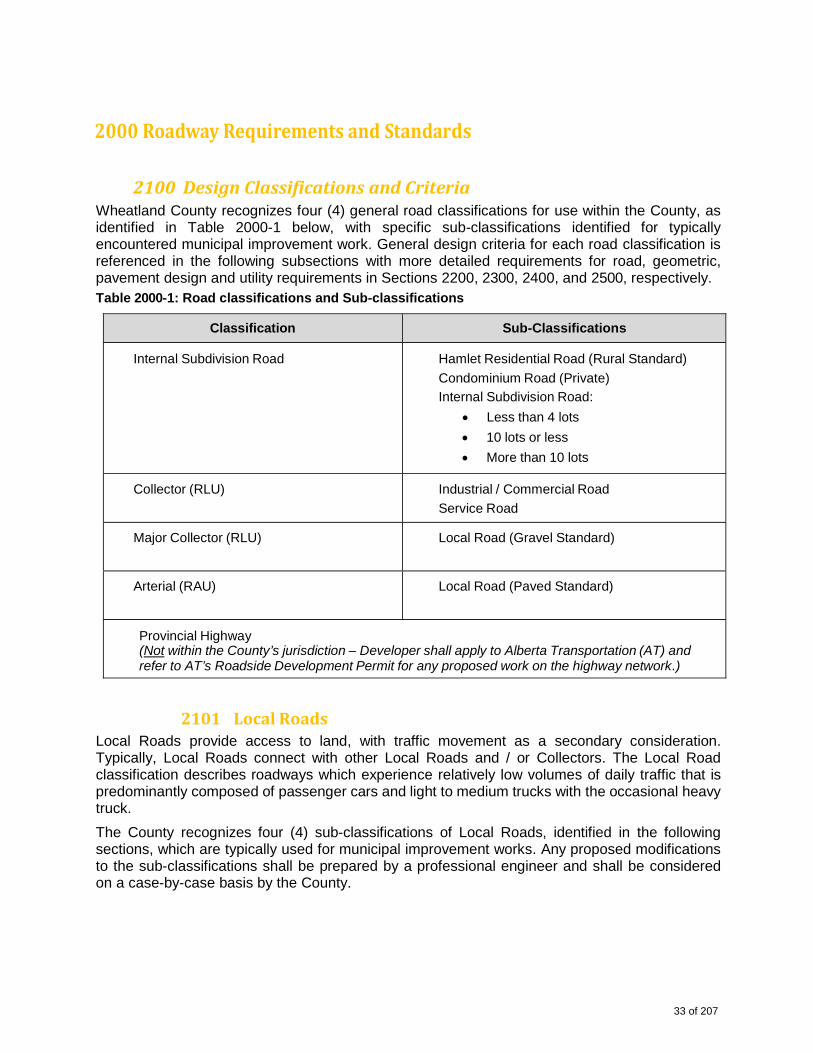
2100DesignClassificationsandCriteriaWheatland County recognizes four (4) general road classifications for use within the County, as identified in Table 2000-1 below, with specific sub-classifications identified for typically encountered municipal improvement work. General design criteria for each road classification is referenced in the following subsections with more detailed requirements for road, geometric, pavement design and utility requirements in Sections 2200, 2300, 2400, and 2500, respectively. Table 2000-1: Road classifications and Sub-classifications
Classification Sub-Classifications
Internal Subdivision Road Hamlet Residential Road (Rural Standard)
Condominium Road (Private)
Internal Subdivision Road:
Less than 4 lots
10 lots or less
More than 10 lots
Collector (RLU) Industrial / Commercial Road
Service Road
Major Collector (RLU) Local Road (Gravel Standard)
Arterial (RAU) Local Road (Paved Standard)
Provincial Highway (Not within the County’s jurisdiction – Developer shall apply to Alberta Transportation (AT) and refer to AT’s Roadside Development Permit for any proposed work on the highway network.)
2101LocalRoadsLocal Roads provide access to land, with traffic movement as a secondary consideration. Typically, Local Roads connect with other Local Roads and / or Collectors. The Local Road classification describes roadways which experience relatively low volumes of daily traffic that is predominantly composed of passenger cars and light to medium trucks with the occasional heavy truck.
The County recognizes four (4) sub-classifications of Local Roads, identified in the following sections, which are typically used for municipal improvement works. Any proposed modifications to the sub-classifications shall be prepared by a professional engineer and shall be considered on a case-by-case basis by the County.
33 of 207
2101.1 Residential Road (Rural Standard) The Residential Road (Rural Standard) sub-classification provides access to land in rural residential settings. This type of road may also incorporate stormwater drainage, water and wastewater infrastructure, and / or other utilities within its cross-section, as required.
The design speed for a Residential Road (Rural Standard) is 60 km/h with a maximum posted speed limit of 50 km/h or lower.
The basic ROW for a Residential Road (Rural Standard) is 30 m with ditches incorporated into the cross-section.
A typical cross-section and general design guidelines for Residential Roads (Rural Standard) are presented in Drawings A-1.1 to A-1.5 included in Schedule A-2: Standard Road Drawings.
2101.2 Condominium Road A Condominium Road is designed to be privately-owned and maintained by a condominium association in perpetuity; however, essential services and emergency response vehicles, such as fire and ambulance, require access to such developments with little or no disruption. As such, the design of Condominium Roads shall be in accordance with the requirements for Residential Roads (Urban or Rural Standard); alternate designs may be considered by the County, if and as necessary.
2101.3 Internal Subdivision Road The Internal Subdivision Road sub-classification provides access to country residential parcels. The basic design for an Internal Subdivision Road provides a paved 7.6 m road surface with 4:1 sideslopes and 3 m ditches within a 30 m basic ROW.
The design speed for an Internal Subdivision Road is 60 km/h with a maximum posted speed limit of 50 km/h or lower.
A typical cross-section and general design guidelines for Internal Subdivision Roads are presented in Drawing Figure A-2 – Internal Subdivision, included in Schedule A-2: Standard Road Drawings.
2101.4 Low Volume Road The Low Volume Road sub-classification provides access to land in rural settings and provides links between various road classifications. Low volume roads shall be considered where a maximum of four (4) residential lots and/or dwelling units are proposed, traffic generation is not anticipated to exceed 50 VPD and future development is restricted by topography or other factors. This type of road may also incorporate stormwater drainage, water and wastewater infrastructure, and / or other utilities, as required.
The design speed for a Low Volume Road is 60 km/h with a maximum posted speed limit of 50 km/h or lower.
Right-of-way and cross-section requirements for the Low Volume Road sub-classification may vary and are subject to the discretion of the County.
34 of 207
2102Collectors(RCU)Collectors provide access to land and provide a higher level of traffic movement than local roads. Collector roadways collect traffic from local roads and channel it to higher classified roadways. The Collector classification applies for roadways with moderate volumes of daily traffic, composed of passenger cars, and light, medium and heavy trucks.
The County recognizes two (2) sub-classifications of Collectors, identified in the following sections, which are typically used for municipal improvement works. Any proposed modifications to the sub-classifications shall be prepared by a professional engineer and shall be considered on a case-by-case basis by the County.
2102.1 Service Road The Service Road sub-classification provides local access to properties (residential, business, or otherwise) adjacent to a road designation with access limitations such as an arterial, expressway or freeway.
The design speed for a Service Road is 60 km/h with a maximum posted speed limit of 50 km/h or less.
A typical cross-section and general design guidelines for Service Roads are presented in Drawing A-4 included in Schedule A-2: Standard Road Drawings.
2102.2 Industrial / Commercial Road The Industrial / Commercial Road sub-classification provides local access to industrial businesses with a design that accommodates a higher percentage of truck traffic compared to other road designations. This roadway designation provides a wider roadway top width of 9.0 m within a 30 m ROW, greater horizontal curve parameters, increased surfacing structure, and greater stopping sight distances for larger vehicles.
The design speed for an Industrial / Commercial Road is 60 km/h with a maximum posted speed limit of 50 km/h or less.
A typical cross-section and general design guidelines for Industrial / Commercial Roads are presented in Drawing A-5, included in Schedule A-2: Standard Road Drawings.
2103MajorCollectors(RLU)Major Collectors provide access to land and provide a higher level of traffic movement than Collector roadways. Major Collectors collect traffic from Collectors and Local Roads and channel it to higher classified roadways. The Major Collector classification applies for roadways with higher volumes of daily traffic, composed of passenger cars, and light, medium and heavy trucks.
The County recognizes two (2) sub-classifications of Major Collectors, identified in the following sections, which are typically used for municipal improvement works. Any proposed modifications to the sub-classifications presented below shall be prepared by a professional engineer and may be considered on a case-by-case basis by the County.
35 of 207
2103.1 Municipal Road (Gravel Standard) The Road Allowance (Gravel Standard) sub-classification is a roadway within an existing government road allowance, whether it be new construction or re-construction of an existing road to current standards. The minimum basic ROW for this road designation is 20 – 30 m.
A Developer who constructs a road allowance extension to provide access to a municipal improvement is responsible for surfacing the road with gravel prior to acceptance by the County.
Construction within road allowances, either undeveloped or developed, shall be carried out in accordance with the County’s standards as well as the conditions of approval for the municipal improvement. The Developer shall submit the detailed design and related drawings, prepared by a Professional Engineer, for Municipal approval. A Development Agreement, signed by the Developer, a letter of credit and proof of liability insurance is required prior to Municipal approval for construction within any road allowance.
The design speed for the Municipal Road (Gravel Standard) sub-classification is 90 km/h with a maximum posted speed limit of 80 km/h or less.
A typical cross-section and general design guidelines for the Municipal Road (Gravel Standard) designation are presented in Drawing A-6, included in Schedule A-2: Standard Road Drawings.
2104ArterialRoads(RAU)Any proposed construction or upgrades on an existing road to an arterial designation shall be considered on a case-by-case basis by the County. Proposed designs for arterial roads shall be prepared by a Professional Engineer and shall incorporate access management.
2104.1 Road Allowance (Paved Standard)
The Municipal Road (Paved Standard) sub-classification is a roadway within an existing government road allowance, whether it be new construction or re-construction of an existing road to current standards. The Municipal Road (Paved Standard) is typically constructed with a wider subgrade to support a paved surfacing structure (granular base course and asphalt concrete pavement). The minimum basic ROW for this road designation is 30 m.
A Developer who constructs a road allowance extension to provide access to a municipal improvement is responsible for surfacing the road in accordance with the proposed design prior to acceptance by the County.
Construction within road allowances, either undeveloped or developed, shall be carried out in accordance with the County’s standards as well as the conditions of approval for the municipal improvement. The Developer shall submit the detailed design and related drawings, prepared by a Professional Engineer, for Municipal approval. A Development Agreement, signed by the Developer, a letter of credit and proof of liability insurance shall be required prior to Municipal approval for construction within any road allowance.
The design speed for the Municipal Road (Paved Standard) sub-classification is 110 km/h with a maximum posted speed limit of 100 km/h or less.
A typical cross-section and general design guidelines for the Municipal Road (Paved Standard) designation are presented in Drawing A-7, included in Schedule A-2: Standard Road Drawings.
2200RoadDesignGuidelinesThe following road design guidelines present the County’s general requirements for proposed roadway design and construction projects. In addition to the requirements presented herein, the
36 of 207
most recent version of the following guidelines and supporting documents are to be used in preparation of road designs for the County:
(1) Geometric Design Guide for Canadian Roads, Transportation Association of Canada (TAC);
(2) Highway Geometric Design Guide, Alberta Transportation (AT);
(3) Traffic Impact Assessment Guideline, Alberta Transportation (AT);
(4) Manual of Uniform Traffic Control Devices for Canada, Transportation Association of Canada (TAC);
(5) Rural Approach Standards Policy, Wheatland County;
(6) Roadside Design Guide, Alberta Transportation (AT);
(7) Standard Specifications for Highway Construction, Alberta Transportation (AT).
The County may consider innovative design variations from the guidelines presented herein to accommodate site-specific variances, provided that public safety and the County are not at risk and that the Consulting Engineer provides sufficient reasoning and justification for any proposed variations.
2201TrafficImpactAssessmentsA Traffic Impact Assessment (TIA) is required for all proposed subdivision developments with ten (10) or more lots and for all proposed industrial / commercial developments. The County may also require a TIA for subdivision developments which propose to use existing Municipal roads or for developments with less than ten (10) lots at the County’s discretion.
TIAs shall be prepared and authenticated by a professional engineer and shall be conducted in accordance with the requirements set forth in AT’s Traffic Impact Assessment Guideline. All items required within this guideline shall be identified and provided as part of the County’s requirements. Because this guideline cannot feasibly cover all situations which may arise, it is recommended that the Developer / Consulting Engineer contact the County to identify and determine site-specific components of the study. Some details, such as growth rates, shall be established on a case-by- case basis in conjunction with the County as they can vary depending upon the location of the proposed improvement.
Minimum requirements for intersection improvements shall be based on AT’s Highway Geometric Design Guide. The intersection review and assessment shall include a detailed individual turning movement analysis The cost of any additional ROW required to accommodate intersection improvements is the sole responsibility of the Developer.
Trip generation rates shall be based on information included within the Institute of Transportation Engineers’ (ITE’s) Trip Generation Tables.
The minimum Level of Service (LOS) acceptable to the County is “C” in all rural areas. A lower LOS may be considered in urban or urban / rural fringe areas at the discretion of the County.
2202DedicatedRoadWideningandAdditionalROWRequirementsAs part of the land subdivision process outlined in Division 8, Section 661 and 662 of the Municipal Government Act, the County may require land to be provided for the purposes of future road widening and /or road upgrading. Compensation may not be provided to the Developer for such land nor for improvements (such as gates, fences, trees, shelterbelts, etc.) on such land.
The following items pertain to the County’s requirements for dedicated road widening and additional ROW requirements:
37 of 207
(1) For proposed improvements of undeveloped road allowances, ROW for future road widening shall be taken adjacent to the road allowance unless the County agrees, in writing, that there is sufficient ROW available for future road improvements or the road has no likelihood of future improvements.
(2) Additional ROW may be required in areas where there are abnormal embankments, large fill / cut areas, or existing substandard road conditions. In these circumstances, the County shall endeavor to protect, at a minimum, the ROW required for minimum 4:1 sideslopes and 3:1 backslopes with a 3 m ditch bottom, as required.
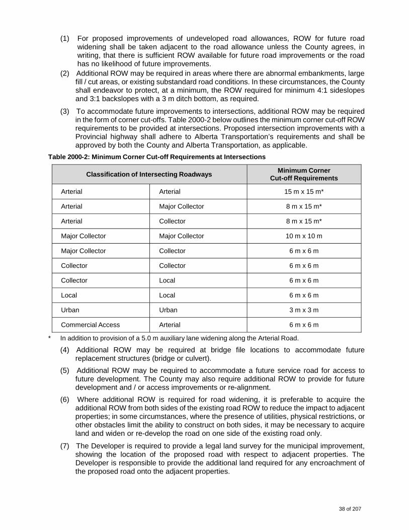
(3) To accommodate future improvements to intersections, additional ROW may be required in the form of corner cut-offs. Table 2000-2 below outlines the minimum corner cut-off ROW requirements to be provided at intersections. Proposed intersection improvements with a Provincial highway shall adhere to Alberta Transportation’s requirements and shall be approved by both the County and Alberta Transportation, as applicable.
Table 2000-2: Minimum Corner Cut-off Requirements at Intersections
Classification of Intersecting Roadways
Minimum Corner Cut-off Requirements
Arterial
Arterial 15 m x 15 m*
Arterial Major Collector 8 m x 15 m*
Arterial Collector 8 m x 15 m*
Major Collector Major Collector 10 m x 10 m
Major Collector Collector 6 m x 6 m
Collector Collector 6 m x 6 m
Collector Local 6 m x 6 m
Local Local 6 m x 6 m
Urban Urban 3 m x 3 m
Commercial Access Arterial 6 m x 6 m
* In addition to provision of a 5.0 m auxiliary lane widening along the Arterial Road.
(4) Additional ROW may be required at bridge file locations to accommodate future replacement structures (bridge or culvert).
(5) Additional ROW may be required to accommodate a future service road for access to future development. The County may also require additional ROW to provide for future development and / or access improvements or re-alignment.
(6) Where additional ROW is required for road widening, it is preferable to acquire the additional ROW from both sides of the existing road ROW to reduce the impact to adjacent properties; in some circumstances, where the presence of utilities, physical restrictions, or other obstacles limit the ability to construct on both sides, it may be necessary to acquire land and widen or re-develop the road on one side of the existing road only.
(7) The Developer is required to provide a legal land survey for the municipal improvement, showing the location of the proposed road with respect to adjacent properties. The Developer is responsible to provide the additional land required for any encroachment of the proposed road onto the adjacent properties.
38 of 207

(8) The Developer is responsible for all expenses related to surveying and development of a road plan for the municipal improvement including movement of existing fences as well as all costs associated with legal survey and land titles registration.
2203SetbacksTable 2000-3 below identifies the minimum setback distances required for all proposed municipal improvements and developments.
Table 2000-3: Minimum Setback Distances
Min. Setback Distance from Road Centreline
Local Roads and Collectors
Major Collectors and Arterials
Berm 20 m 25 m
Stormwater Pond 20 m 25 m
Dugout 20 m 25 m
Note: All measurements shall be taken from the outside toe of slope of the berm or berm for stormwater pond/dugout (where the sideslope of the berm intersects with the natural ground surface); berm sideslopes shall not be steeper than 3H:1V. If no berm exists, a minimum 6 meter to be added to the above setbacks.
2204IntersectionsThe following criteria apply to roadway intersection designs for all proposed municipal improvements:
(1) The desirable angle of intersection for any two roadways shall be 90°. Alternate angles of intersection for some intersection, driveway, access and fencing locations may be accepted by the County subject to evidence of acceptable sight distances and other safety factors by the Consulting Engineer.
(2) The Consulting Engineer shall provide evidence that sight distances and horizontal / vertical visibility at all accesses, including driveways, along a road meet the applicable requirements for intersection stopping and approaching sight distance as outlined in TAC’s Geometric Design Guide for Canadian Roads.
(3) The minimum spacing between any two intersections along local or collector roads shall be 150 m, measured from center of intersection to center of intersection. A lesser intersection spacing may be acceptable at the discretion of the County.
(4) Where existing or future traffic volumes warrant acceleration and / or deceleration lanes for a turning movement, the Developer shall provide an additional 5.0 m of ROW for road widening, as a minimum and at the County’s discretion.
(5) Any proposed intersection with a provincial highway shall require an AT Development Permit.
Table 2000-4 below identifies the typical intersection geometric requirements. These requirements are also illustrated in Drawing A-8, included in Schedule A-2: Standard Road Drawings.
39 of 207
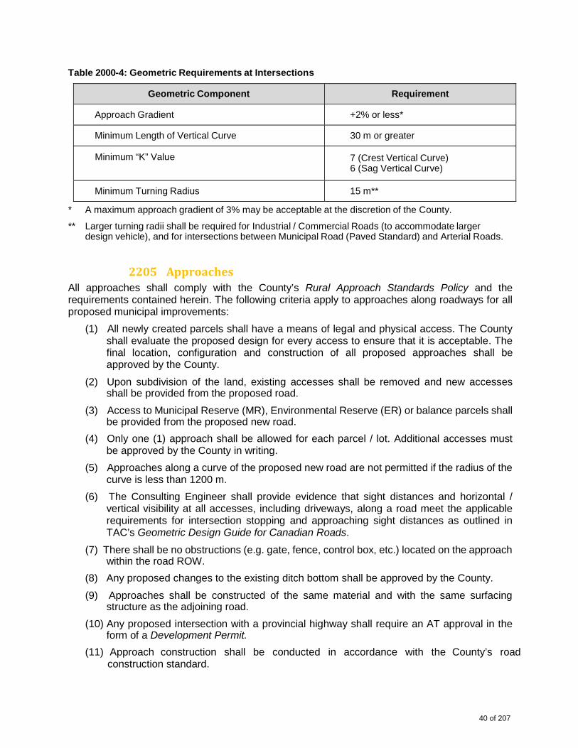
Table 2000-4: Geometric Requirements at Intersections
Geometric Component Requirement
Approach Gradient +2% or less*
Minimum Length of Vertical Curve 30 m or greater
Minimum “K” Value 7 (Crest Vertical Curve) 6 (Sag Vertical Curve)
Minimum Turning Radius 15 m**
* A maximum approach gradient of 3% may be acceptable at the discretion of the County.
** Larger turning radii shall be required for Industrial / Commercial Roads (to accommodate larger design vehicle), and for intersections between Municipal Road (Paved Standard) and Arterial Roads.
2205ApproachesAll approaches shall comply with the County’s Rural Approach Standards Policy and the requirements contained herein. The following criteria apply to approaches along roadways for all proposed municipal improvements:
(1) All newly created parcels shall have a means of legal and physical access. The County shall evaluate the proposed design for every access to ensure that it is acceptable. The final location, configuration and construction of all proposed approaches shall be approved by the County.
(2) Upon subdivision of the land, existing accesses shall be removed and new accesses shall be provided from the proposed road.
(3) Access to Municipal Reserve (MR), Environmental Reserve (ER) or balance parcels shall be provided from the proposed new road.
(4) Only one (1) approach shall be allowed for each parcel / lot. Additional accesses must be approved by the County in writing.
(5) Approaches along a curve of the proposed new road are not permitted if the radius of the curve is less than 1200 m.
(6) The Consulting Engineer shall provide evidence that sight distances and horizontal / vertical visibility at all accesses, including driveways, along a road meet the applicable requirements for intersection stopping and approaching sight distances as outlined in TAC’s Geometric Design Guide for Canadian Roads.
(7) There shall be no obstructions (e.g. gate, fence, control box, etc.) located on the approach within the road ROW.
(8) Any proposed changes to the existing ditch bottom shall be approved by the County.
(9) Approaches shall be constructed of the same material and with the same surfacing structure as the adjoining road.
(10) Any proposed intersection with a provincial highway shall require an AT approval in the form of a Development Permit.
(11) Approach construction shall be conducted in accordance with the County’s road construction standard.
40 of 207
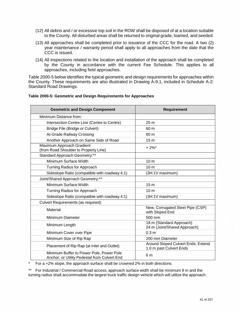
(12) All debris and / or excessive top soil in the ROW shall be disposed of at a location suitable to the County. All disturbed areas shall be returned to original grade, loamed, and seeded.
(13) All approaches shall be completed prior to issuance of the CCC for the road. A two (2) year maintenance / warranty period shall apply to all approaches from the date that the CCC is issued.
(14) All inspections related to the location and installation of the approach shall be completed by the County in accordance with the current Fee Schedule. This applies to all approaches, including field approaches.
Table 2000-5 below identifies the typical geometric and design requirements for approaches within the County. These requirements are also illustrated in Drawing A-9.1, included in Schedule A-2: Standard Road Drawings. Table 2000-5: Geometric and Design Requirements for Approaches
Geometric and Design Component Requirement
Minimum Distance from:
Intersection Centre Line (Centre to Centre) 25 m
Bridge File (Bridge or Culvert) 60 m
At-Grade Railway Crossing 60 m
Another Approach on Same Side of Road 15 m Maximum Approach Gradient (from Road Shoulder to Property Line)
+ 2%*
Standard Approach Geometry:**
Minimum Surface Width 10 m
Turning Radius for Approach 10 m
Sideslope Ratio (compatible with roadway 4:1) (3H:1V maximum)
Joint/Shared Approach Geometry:**
Minimum Surface Width 15 m
Turning Radius for Approach 10 m
Sideslope Ratio (compatible with roadway 4:1) (3H:1V maximum)
Culvert Requirements (as required):
Material New, Corrugated Steel Pipe (CSP)with Sloped End
Minimum Diameter 500 mm
Minimum Length 18 m (Standard Approach) 24 m (Joint/Shared Approach)
Minimum Cover over Pipe 0.3 m
Minimum Size of Rip Rap 200 mm Diameter
Placement of Rip Rap (at Inlet and Outlet) Around Sloped Culvert Ends; Extend1.0 m past Culvert Ends
Minimum Buffer to Power Pole, Power PoleAnchor, or Utility Pedestal from Culvert End
6 m
* For a +2% slope, the approach surface shall be crowned 2% in both directions.
** For Industrial / Commercial Road access, approach surface width shall be minimum 9 m and the turning radius shall accommodate the largest truck traffic design vehicle which will utilize the approach.
41 of 207
2206Cul‐de‐SacsProposed municipal improvements shall include a cul-de-sac for roads which dead-end.
The minimum radius of cul-de-sac bulbs shall be 15.8 m to the edge of pavement or face of curb. A maximum 2% grade is allowed. Drawing E-10 and E-11, included in Schedule A-2: Standard Road Drawings, provide minimum cul-de-sac dimensions for various ROW widths.
A temporary cul-de-sac shall be provided when there is a likelihood of extending the road to adjacent properties or as part of a multi-phase subdivision plan. ROW required for the temporary cul-de-sac shall be provided as a temporary easement, pending forward extension of the road. Drawing A-10 and A-11, included in Schedule A-2: Standard Road Drawings, illustrates the typical requirements for a temporary cul-de-sac.
2207Walkways/PathwaysIn a country residential and rural setting, walkways and pathways shall be gravel surfaced and compacted to 98% of Standard Proctor Density (SPD).
In a hamlet or cluster residential setting, walkways and pathways shall be asphalt concrete or cement concrete surfaced at the discretion of the County. Surface types for walkways and pathways in other locations shall be approved by the County on a case-by-case basis.
The minimum width for walkway and pathways shall be 1.2 m.
2208FencesThe Developer is responsible for fencing of all property lines along the road ROW, including areas where road widening has been surveyed out or where there is a caveat in place, in accordance with the County’s standard. If the County removes and reconstructs a fence that was built in the improper location, the Developer shall be invoiced for all expenses related to the fence removal and reconstruction. If a Developer removes fencing along an existing road ROW, it is the responsibility of the Developer to replace the fence with a new fence in accordance with the Land Use Bylaw, using the same materials as was previously used, at the Developer’s expense.
A Temporary Fence – Standard Class B fence to be utilized (3 wire with 10 m post spacing)
2209TopsoilandSeedingTopsoil shall be stripped from the construction site and stockpiled for redistribution on the sideslopes, ditches, and backslopes following construction or for landscaping use.
All topsoil spread on road sideslopes, ditches, and backslopes shall be free of rocks, boulders, gravels, or other deleterious materials. Any visible stones, rocks, or boulders shall be removed from site prior to topsoil placement.
The thickness of the topsoil placed shall not be less than 150 mm. The topsoil surface shall be graded and smoothed to the approved design grade and lines.
Upon completion of topsoil placement, the surface shall be lightly compacted and seeded with a seed mix specification approved by the County.
All work associated with topsoil and seeding shall comply with the Land Use Bylaw.
42 of 207
2210RockDitchChecksRock ditch checks and / or erosion control blankets, at the County’s discretion, shall be required for a drainage channel or road ditch with a grade more than 4.0% and with velocities that warrant protection to prevent scour and erosion.
If the Developer fails to provide adequate studies and analysis regarding erosion control, it shall be the responsibility of the Developer, at the Developer’s expense, to mitigate and repair erosion damage.
2211PostalBoxTurnoutResidential, Condominium, Internal Subdivision, and Industrial / Commercial Roads shall have a Postal Box Turnout in accordance with Drawing A-12 and Drawing A-13 (for 20 m and 30 m ROW, respectively), included in Schedule A-2: Standard Road Drawings. Sightline requirements, in accordance with TAC’s Geometric Design Guide for Canadian Roads, shall be maintained at all times.
The Postal Box Turnout shall be located a minimum distance of 50 m along the road from the edge of pavement on an intersecting road or cul-de-sac and shall be located on the right-hand side. The final location shall be approved by the County and Canada Post.
2212RoadSignsandPaintingMunicipal road names shall be approved by the County.
A typical plan for the installation of a Municipal Road Name sign is included as Drawing A-13, in Schedule A-2: Standard Road Drawings. Signs are to be located in the northeast quadrant of the intersection, approximately 2.0 m from the adjacent property lines. The sign shall be installed such that the bottom edge of the sign is 2.4 m above the edge of pavement on the adjacent roadway, with a minimum bury depth of 0.75 m for the sign post.
All other traffic control devices and paint required for paved roads shall be installed in accordance with TAC’s Manual of Uniform Traffic Control Devices for Canada.
Road ban signs are required on all paved roads.
2213ObstructionsonRoadROW/RoadAllowanceThe Developer shall not erect any gates, walls, monuments, signs, billboards or any other form of obstruction, either temporarily or permanently, within the road ROW or road allowance without prior approval of the County. The County shall not accept a CCC until all unauthorized obstructions are removed.
2214GuardrailGuardrail shall be considered in accordance with AT’s Highway Geometric Design Guide and Roadside Design Guide.
43 of 207

2300GeometricDesign
2301VerticalAlignmentThe following criteria outline the minimum requirements with respect to vertical alignment for proposed municipal improvements on roadways. AT’s Alberta Highway Geometric Design Guide shall be used for design requirements not referenced below:
(1) Minimum gradient shall be 0.60% for ditch drainage;
(2) Maximum gradient shall be 7% at the discretion of the County, a steeper grade may be considered; and,
(3) Maximum gradient of +2% for a minimum distance of 30 m from the shoulder of an intersecting road.
All vertical curves shall be designed to meet the minimum “K” values as shown in Table 2000-6 below. The minimum length of vertical curve, in metres, shall be greater than or equal to the design speed of the road, in kilometres per hour. Table 2000-6: Minimum “k” Values for Vertical Curves
Design Speed km/h
Minimum “ K” Value
Sag Vertical Curve Crest Vertical Curve
50 12 10
60 20 15
70 25 25
80 35 35
90 40 55
100 50 75
44 of 207
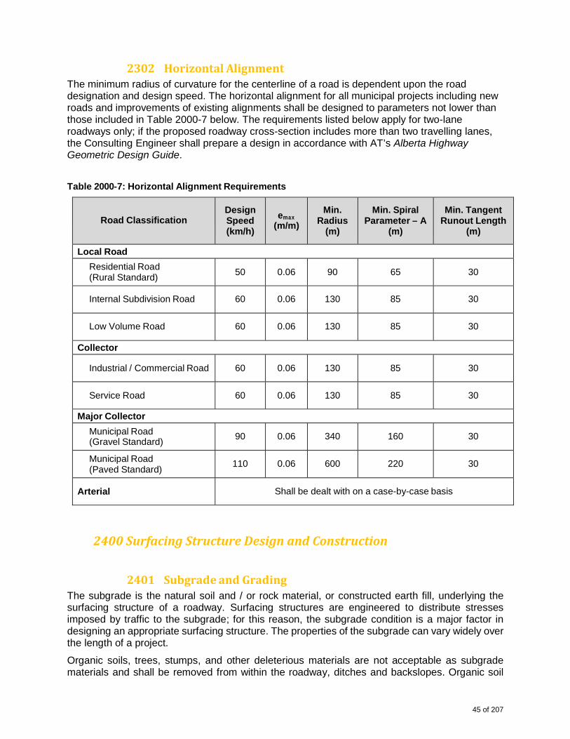
2302HorizontalAlignmentThe minimum radius of curvature for the centerline of a road is dependent upon the road designation and design speed. The horizontal alignment for all municipal projects including new roads and improvements of existing alignments shall be designed to parameters not lower than those included in Table 2000-7 below. The requirements listed below apply for two-lane roadways only; if the proposed roadway cross-section includes more than two travelling lanes, the Consulting Engineer shall prepare a design in accordance with AT’s Alberta Highway Geometric Design Guide.
Table 2000-7: Horizontal Alignment Requirements
Road Classification
Design Speed (km/h)
emax (m/m)
Min. Radius
(m)
Min. Spiral Parameter – A
(m)
Min. Tangent Runout Length
(m)
Local Road
Residential Road (Rural Standard)
50 0.06 90 65
30
Internal Subdivision Road
60 0.06 130 85
30
Low Volume Road
60 0.06 130 85
30
Collector
Industrial / Commercial Road
60 0.06 130 85
30
Service Road
60 0.06 130 85
30
Major Collector
Municipal Road (Gravel Standard)
90 0.06 340 160
30
Municipal Road (Paved Standard)
110 0.06 600 220
30
Arterial
Shall be dealt with on a case-by-case basis
2400SurfacingStructureDesignandConstruction
2401SubgradeandGradingThe subgrade is the natural soil and / or rock material, or constructed earth fill, underlying the surfacing structure of a roadway. Surfacing structures are engineered to distribute stresses imposed by traffic to the subgrade; for this reason, the subgrade condition is a major factor in designing an appropriate surfacing structure. The properties of the subgrade can vary widely over the length of a project.
Organic soils, trees, stumps, and other deleterious materials are not acceptable as subgrade materials and shall be removed from within the roadway, ditches and backslopes. Organic soil
45 of 207
shall be stockpiled and used as loam on the roadway side-slopes and ditches for reclamation of disturbed areas after roadway construction.
The following criteria outline the County’s requirements for subgrade and grading design and construction:
(1) The road subgrade shall be constructed in accordance with the neat lines, grades, and sections shown on the plans approved by the County.
(2) Prior to fill being placed for the surfacing structure, the exposed subgrade surface shall be scarified and re-worked to a depth of 300 mm and re-compacted to 100% of SPD.
a. I t is responsibility of the Developer and Consulting Engineer to ensure that the
existing subgrade has adequate strength to carry the predicted traffic loads over the entire design life of the road. The Consulting Engineer shall perform California Bearing Ratio (CBR) tests on soil samples to assess the in-situ condition of the subgrade and determine the required surfacing structure.
b. I f testing indicates an expansive or low-strength subgrade (i.e. with a liquid limit greater than 40), the Consulting Engineer may propose the following engineering or construction method alternatives to the County for consideration:
i. Treating expansive soil with lime or other additives;
ii. Replacing expansive soil with non-expansive materials; and, iii. Use of geotextile fabric to limit water infiltration of the subgrade.
Alternatives shall be recommended by a professional geotechnical engineer and all costs shall be borne by the Developer.
Geotextile fabric shall be stored and placed as per the manufacturer’s guidelines.
The area to be covered by geotextile fabric shall be graded to a smooth, uniform condition, free of ruts, holes, and protruding objects such as rocks or sticks, prior to placement of the geotextile.
Geotextile fabric damaged during placement shall be repaired as per manufacturer’s guidelines.
(3) All rocks greater than 100 mm in diameter shall be removed from the subgrade surface prior to compaction.
(4) All backfill materials shall be compacted to 95% of SPD in lifts not exceeding 150 mm. The final 300 mm of backfill material shall be placed in two (2) equal layers and compacted to 100% of SPD.
(5) Moisture and density tests shall be taken separately for each lift placed; in addition to the test results, materials testing reports shall note the date that the material was placed, the date that the test was completed, and the horizontal and vertical locations of the tests.
(6) The Developer shall have the Consulting Engineer certify true and submit copies of all field test results to the County. All associated costs shall be borne by the Developer.
(7) Upon completion of subgrade construction, the Consulting Engineer shall request a joint Proof-Roll Inspection with the County to be conducted in accordance with Schedule A-1: Subgrade Proof-Rolling Inspections, contained herein.
The Developer shall not be allowed to move excavated materials out of the municipal improvement site or to haul subgrade materials from other locations into the municipal improvement site without written approval from the County. Where it is necessary to haul material in or out of site, the Developer shall submit a written request to the County and shall include detailed information including, but not limited to, the type and quantity of materials to be moved, the origin and destination of the materials, the intention for use of such materials, and a written consent from
46 of 207
landowners receiving / supplying the materials. A Lot Grading Permit, Quality Test, Road Use Agreement, and / or Natural Resources Extraction Permit may also be required.
The subgrade and grading design shall consider the existing surface drainage patterns and shall be an integral part of the stormwater management plan, addressing any drainage work and / or diversions as approved in writing by Alberta Environmental and the County. The subgrade and grading design shall also address the location and construction of lot approaches. Approaches shall be designed and located in accordance with Section A.2.5 above. Approaches, once finalized, shall not be relocated, reconstructed, or otherwise altered without prior written approval from the County.
2402GranularBaseCourseThe following criteria outline the County’s requirements for granular base course (GBC) design and construction:
(1) The minimum depth of GBC material required by the County is:
a. 200 mm for Residential roadways; and,
b. 300 mm for Industrial / Commercial roadways, including Municipal Road, Road Allowances, and Service Roads.
These depths are based on a soaked CBR value for the subgrade of 3.0 or greater. It is the responsibility of the Developer’s Consulting Engineer to confirm the soaked CBR values of the in-situ or other materials used and to provide recommendations for GBC thicknesses for soils with a CBR value less than 3.0.
(2) The minimum depth of GBC material required for Arterial class roads will be determined on a case-by-case basis. Designation 2, Class 20 or Designation 2, Class 25 crushed granular shall be used for all GBC material in road construction. Specifications for this material shall be in accordance with the Specifications for Aggregate included in AT’s Standard Specifications for Highway Construction.
(3) Prime coat shall be applied to the finished GBC surface prior to placement of asphalt concrete pavement.
(4) GBC shall be placed in accordance with the lines, grades, and sections shown on the plans approved by the County.
(5) GBC shall be uniformly compacted to 100% of SPD in lifts not exceeding 150 mm.
(6) Density tests shall be taken separately for each lift placed; in addition to the test results, testing reports shall note the date that the material was placed, the date that the test was completed, and the horizontal and vertical locations of the tests.
(7) All material tests shall be undertaken in accordance with the requirements set forth in Section A.4.4 of this document.
(8) Excessive watering during compaction shall be avoided to protect from wash-out of fine materials.
(9) All segregated materials shall be mixed thoroughly prior to compaction.
(10) Upon completion of GBC placement and compaction, the Developer shall repair any and all damages to the shoulders, sideslopes, and ditches resulting from the work; the road shall be left neatly trimmed in accordance with the cross-sections approved by the County.
(11) The Developer shall remove all excess gravel from the road shoulder, sideslopes and ditches. All disturbed areas shall be free from gravel and other deleterious materials and shall be topsoiled and seeded in accordance with Section A.2.9 above.
47 of 207
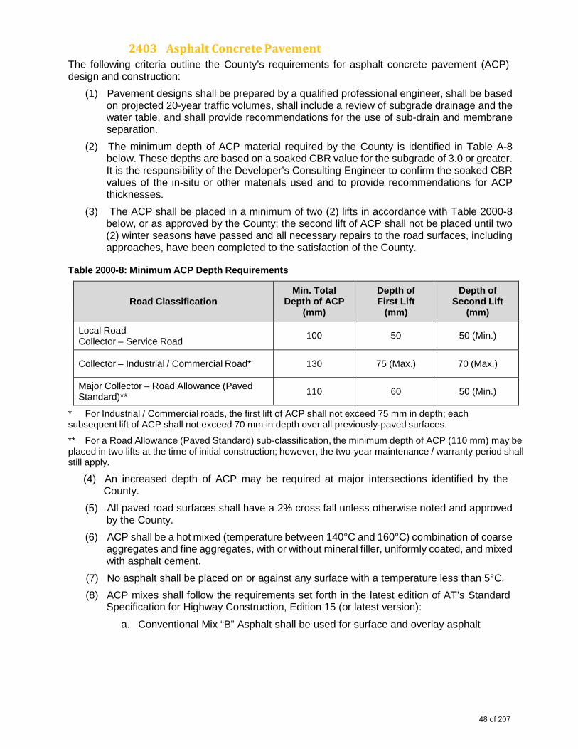
2403AsphaltConcretePavementThe following criteria outline the County’s requirements for asphalt concrete pavement (ACP) design and construction:
(1) Pavement designs shall be prepared by a qualified professional engineer, shall be based on projected 20-year traffic volumes, shall include a review of subgrade drainage and the water table, and shall provide recommendations for the use of sub-drain and membrane separation.
(2) The minimum depth of ACP material required by the County is identified in Table A-8 below. These depths are based on a soaked CBR value for the subgrade of 3.0 or greater. It is the responsibility of the Developer’s Consulting Engineer to confirm the soaked CBR values of the in-situ or other materials used and to provide recommendations for ACP thicknesses.
(3) The ACP shall be placed in a minimum of two (2) lifts in accordance with Table 2000-8 below, or as approved by the County; the second lift of ACP shall not be placed until two (2) winter seasons have passed and all necessary repairs to the road surfaces, including approaches, have been completed to the satisfaction of the County.
Table 2000-8: Minimum ACP Depth Requirements
Road Classification
Min. Total Depth of ACP
(mm)
Depth of First Lift
(mm)
Depth of Second Lift
(mm)
Local Road Collector – Service Road
100 50
50 (Min.)
Collector – Industrial / Commercial Road* 130 75 (Max.)
70 (Max.)
Major Collector – Road Allowance (Paved Standard)**
110 60
50 (Min.)
* For Industrial / Commercial roads, the first lift of ACP shall not exceed 75 mm in depth; each subsequent lift of ACP shall not exceed 70 mm in depth over all previously-paved surfaces.
** For a Road Allowance (Paved Standard) sub-classification, the minimum depth of ACP (110 mm) may be placed in two lifts at the time of initial construction; however, the two-year maintenance / warranty period shall still apply.
(4) An increased depth of ACP may be required at major intersections identified by the County.
(5) All paved road surfaces shall have a 2% cross fall unless otherwise noted and approved by the County.
(6) ACP shall be a hot mixed (temperature between 140°C and 160°C) combination of coarse aggregates and fine aggregates, with or without mineral filler, uniformly coated, and mixed with asphalt cement.
(7) No asphalt shall be placed on or against any surface with a temperature less than 5°C.
(8) ACP mixes shall follow the requirements set forth in the latest edition of AT’s Standard Specification for Highway Construction, Edition 15 (or latest version):
a. Conventional Mix “B” Asphalt shall be used for surface and overlay asphalt
48 of 207
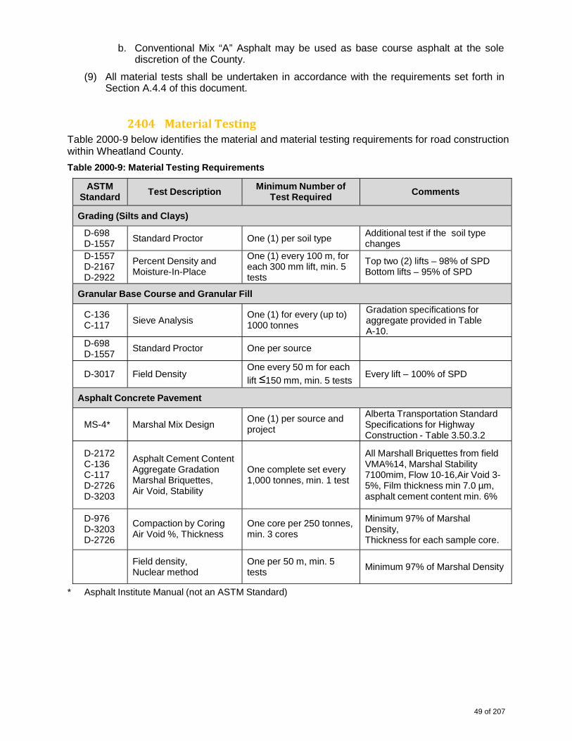
b. Conventional Mix “A” Asphalt may be used as base course asphalt at the sole discretion of the County.
(9) All material tests shall be undertaken in accordance with the requirements set forth in Section A.4.4 of this document.
2404MaterialTestingTable 2000-9 below identifies the material and material testing requirements for road construction within Wheatland County.
Table 2000-9: Material Testing Requirements
ASTM Standard
Test Description
Minimum Number of Test Required
Comments
Grading (Silts and Clays)
D-698 D-1557
Standard Proctor One (1) per soil type Additional test if the soil type changes
D-1557 D-2167 D-2922
Percent Density and Moisture-In-Place
One (1) every 100 m, foreach 300 mm lift, min. 5 tests
Top two (2) lifts – 98% of SPD Bottom lifts – 95% of SPD
Granular Base Course and Granular Fill
C-136 C-117
Sieve Analysis
One (1) for every (up to) 1000 tonnes
Gradation specifications for aggregate provided in Table A-10.
D-698 D-1557
Standard Proctor One per source
D-3017
Field Density
One every 50 m for each
lift ≤150 mm, min. 5 tests Every lift – 100% of SPD
Asphalt Concrete Pavement
MS-4*
Marshal Mix Design
One (1) per source and project
Alberta Transportation Standard Specifications for Highway Construction - Table 3.50.3.2
D-2172 C-136 C-117 D-2726 D-3203
Asphalt Cement Content Aggregate Gradation Marshal Briquettes, Air Void, Stability
One complete set every 1,000 tonnes, min. 1 test
All Marshall Briquettes from field VMA%14, Marshal Stability 7100mim, Flow 10-16,Air Void 3- 5%, Film thickness min 7.0 µm, asphalt cement content min. 6%
D-976 D-3203 D-2726
Compaction by Coring Air Void %, Thickness
One core per 250 tonnes, min. 3 cores
Minimum 97% of Marshal Density, Thickness for each sample core.
Field density, Nuclear method
One per 50 m, min. 5 tests
Minimum 97% of Marshal Density
* Asphalt Institute Manual (not an ASTM Standard)
49 of 207
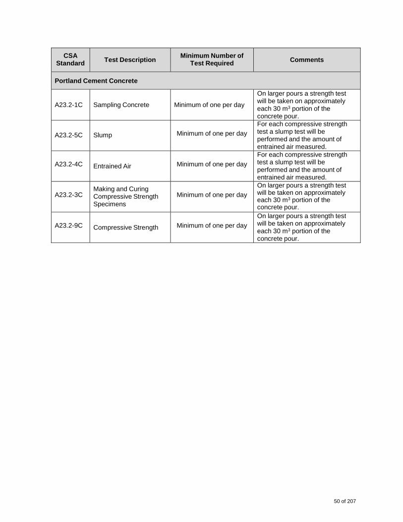
CSA Standard
Test Description
Minimum Number of Test Required Comments
Portland Cement Concrete
A23.2-1C
Sampling Concrete
Minimum of one per day
On larger pours a strength test will be taken on approximately each 30 m3 portion of the concrete pour.
A23.2-5C
Slump Minimum of one per day
For each compressive strengthtest a slump test will be performed and the amount of entrained air measured.
A23.2-4C
Entrained Air Minimum of one per day
For each compressive strengthtest a slump test will be performed and the amount of entrained air measured.
A23.2-3C
Making and Curing Compressive Strength Specimens
Minimum of one per day
On larger pours a strength test will be taken on approximately each 30 m3 portion of the concrete pour.
A23.2-9C
Compressive Strength Minimum of one per day
On larger pours a strength testwill be taken on approximately each 30 m3 portion of the concrete pour.
50 of 207
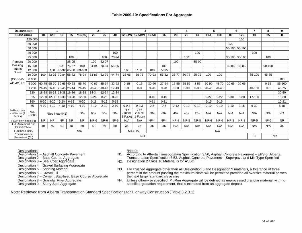
Table 2000-10: Specifications For Aggregate
Designations: Designation 1 – Asphalt Concrete Pavement Designation 2 – Base Course Aggregate Designation 3 – Seal Coat Aggregate
N1.
N2.
*Notes: According to Alberta Transportation Specification 3.50, Asphalt Concrete Pavement – EPS or Alberta Transportation Specification 3.53, Asphalt Concrete Pavement – Superpave and Mix Type Specified Designation 2 Class 16 Material is for ASBC
Designation 4 – Gravel Surfacing Aggregate Designation 5 – Sanding Material N3. For crushed aggregate other than all Designation 5 and Designation 9 materials, a tolerance of three Designation 6 – Gravel Fill Designation 7 – Cement Stabilized Base Course Aggregate
percent in the amount passing the maximum sieve will be permitted provided all oversize material passes the next larger standard sieve size
Designation 8 – Granular Filter Aggregate Designation 9 – Slurry Seal Aggregate
N4. Unless otherwise specified, Pit-Run Aggregate will be defined as unprocessed granular material, with no specified gradation requirement, that is extracted from an aggregate deposit.
Note: Retrieved from Alberta Transportation Standard Specifications for Highway Construction (Table 3.2.3.1)
DESIGNATION 1 2 3 4 5 6 7 8 9 Class (mm) 10 12.5 16 25 *16(N2) 20 25 40 12.5AW 12.5BW 12.5C 16 20 25 40 10A 10B 80 125 40 25 8
Percent Passing Metric Sieve
(CGSB 8-
GP-2M) : m
125 000 100
80 000 100
50 000 55-100 55-100
40 000 100 100 100
25 000 100 100 70-94 100 38-100 38-100 100
20 000 85-95 100 82-97 100 55-90
16 000 100 75-87 100 84-94 70-94 55-85 100 32-85 32-85 90-100
12 500 100 80-92 65-80 89-100 100 100 100 72-95 10 000 100 83-92 70-84 58-72 78-94 63-86 52-79 44-74 35-65 55-75 70-93 53-82 35-77 30-77 25-72 100 100 85-100 45-75
8 000 100
5 000 60-75 55-70 50-65 40-58 55-70 40-67 35-64 32-62 0-15 0-15 30-60 27-54 15-55 15-55 8-55 70-90 45-70 20-65 20-65 0-15 85-100
1 250 26-45 26-45 26-45 25-44 26-45 20-43 18-43 17-43 0-3 0-3 9-28 9-28 0-30 0-30 0-30 20-45 20-45 40-100 0-5 45-75
630 18-38 18-38 18-38 16-36 18-38 14-34 12-34 12-34 30-50
315 12-30 12-30 12-30 10-28 12-30 9-26 8-26 8-26 0-15 0-15 9-22 9-22 6-30 6-30 17-100 18-30
160 8-20 8-20 8-20 6-18 8-20 5-18 5-18 5-18 0-11 0-11 5-15 5-15 10-21
80 4-10 4-10 4-10 4-10 4-10 2-10 2-10 2-10 0-0.3 0-0.3 0-8 0-8 0-12 0-12 0-12 0-10 0-10 2-10 2-15 6-30 5-15
% FRACTURE
BY WEIGHT (2 FACES)
ALL
+5000
*See Note (N1)
60+
60+ 60+ 50+
75+(100%1 Face)
75+(100% 1 Face)
60+ 60+ 40+
40+ 25+ N/A N/A N/A N/A N/A N/A N/A
PLASTICITY INDEX (PI) NP NP NP NP NP NP-6 NP-6 NP-6 N/A N/A NP-4 NP-4 NP-8 NP-8 NP-8 NP-6 NP-6 NP-8 NP-8 NP-5 NP-5 NP L.A. ABRASION LOSS
PERCENT MAX. 40 40 40 40 50 50 50 50 35 35 35 35 N/A N/A N/A N/A N/A N/A N/A N/A N/A 35
FLAKINESS INDEX N/A MAX 15 N/ACOEFFICIENT OF
UNIFORMITY (CU) N/A 3+ N/A
51 of 207

Notes
1. A deviation of a single value for asphalt pavement thickness or density shall be acceptable within ± 5% of the targeted range; the average value shall meet the design requirements.
2. An average density value of less than 92% or an average asphalt cement content more than 5% below the design requirement shall require removal of the material unless otherwise specified by the County.
At the discretion of the County, the Developer shall provide deflection testing to ensure results are in accordance with Table 2000-11 below. The tested average deflections shall be based on a minimum of 10 Benkelman Beam Tests and a testing interval of 50 m or less.
Note: If the Falling Weight Deflectometer is used, a formula for converting FWD deflections to Benkelman Beam equivalents is required.
Table 2000-11: Deflection Testing Requirements
Road Classification
Maximum Average Deflection (mm)
Local Roads 50
Collectors 35
Major Collectors 25
Arterial Roads 25
2500ShallowandOverheadUtilitiesAs part of the proposed municipal improvement work the Developer shall submit a Shallow / Overhead Utilities Plan. This plan shall include plan and profile views, identifying any and all existing and proposed shallow / overhead utilities, and shall be submitted with the other drawings for review and approval by the County.
All shallow / overhead utilities shall have a separate, designated utility ROW located outside of the road ROW, unless otherwise mutually agreed to in a joint Utility Right-of-Way (URW) agreement with the County.
All shallow utilities, either new or existing, crossing a roadway shall be located at a minimum depth of 1.20 m below the finished ditch bottom. Transformers, pedestals, or other utility furniture shall not be placed within or on a drainage course nor within the road ROW.
The Developer shall be responsible to relocate all shallow / overhead utilities as may be required to meet the requirements; this relocation shall be performed at the Developer’s expense.
2501UtilityCorridorsFor development servicing, corridors may be required for routing of utility mains, secondary emergency access, walkways, and / or major drainage outside of the road ROW. Where the corridor is used for access, walkways, and / or major drainage, a Public Utility Lot (PUL) shall be provided. The PUL is generally 6.0 m wide with a 2.0 m easement on each side of the PUL for a total ROW width of 10.0 m.
52 of 207
Where the corridor is only required for routing of utility mains, it shall be contained within an easement. The easement is generally 10 m wide with 8.0 m located on one lot and 2.0 m on an
adjacent lot. The following conditions shall apply, as well as any further conditions as set forth by the applicable Utility Company, to any easement containing deep utilities:
(1) The property owner shall not be permitted to use the easement area for any purpose other than for lawn and / or garden purposes;
(2) The property owner shall not be permitted to place, erect, or build any concrete or asphalt driveways, pads or paths, rock garden, building, or structure whatsoever within the boundaries of the easement;
(3) The property owner shall not be permitted to plant any tree, hedge, or other vegetation which in any way prevents or hinders the County’s rights to maintain all utilities under such lands;
(4) If the area is to be fenced, the property owner shall be required to install 7.0 m gates to allow for maintenance vehicle access; and,
(5) The property owner shall be permitted to park private cars, trucks, and / or recreation vehicles upon such land.
The preceding conditions shall be included in the information package provided to the prospective lot purchaser.
2502ShallowUtilitySystemsThe purpose of the Utilities Plan is to establish the proposed system requirements. Temporary facilities (e.g. overhead power or telecommunication lines), if required due to the proposed subdivision phasing, shall be shown on the plan along with the proposed permanent facilities.
The shallow utility companies shall be provided with a copy of the applicable plans indicating the proposed locations of deep utilities and road layouts to assist them in locating surface features such as transformers, switch gear, telephone switching cabinets, etc.
2503Gas,Power,TelephoneandCableTelevisionStandardsThe Developer is required to prepare a detailed Utility Plan for each proposed phase of development. The Developer shall make arrangements for the provision of natural gas, power, telephone, and cable television service for each phase of development, as applicable / available.
Power, telephone and cable television services are generally installed in a common trench; however, each utility company shall be contacted to review their alignments and prepare their design.
The Developer is responsible for coordinating the location of the power, gas, telephone and cable television, including obtaining alignment approvals, as applicable / available.
The Developer is responsible for any and all expenses related to the provision of power, gas, telephone and cable television to service a municipal improvement, including the cost of installing ducts for road crossings.
2504ElectricSystem/LightingAs detailed in the Development Agreement, the Developer shall arrange for the installation of street / walkway lighting and power distribution in accordance with the following:
53 of 207
(1) An Electrical Consulting Engineer shall prepare the design in accordance with these guidelines and a qualified contractor shall complete all electrical installations in accordance with the Power Distributor’s Construction Specifications;
(2) The design of the power system shall be approved by the current Power Distributor prior
to installation;
(3) The installation shall be inspected by the current Power Distributor; and,
(4) Energization of the system shall be done by the current Power Distributor once they have accepted the system.
The electrical servicing plan shall conform to the current Power Distributor’s standards. The electrical layout plan shall be in accordance with the requirements set forth in the distributors standards.
2600GeneralConstructionRequirementsThe following general construction requirements and policies shall be adhered to:
(1) The Developer shall enter into a Development Agreement with the County and shall supply an irrevocable Letter of Credit for 125 % of the approved cost estimate prior to commencement of construction. This amount shall be returned to the Developer when the CCC is issued by the County with an amount retained (25 %) to cover a two (2) year maintenance / warranty period and any outstanding deficiencies as noted on the approved CCC.
(2) The County assigns Prime Contractor responsibilities, as specified in the Occupational Health and Safety Act, to all parties with which it enters into contracts and agreements. The Developer shall familiarize itself, its staff and its Contractor(s) / Subcontractor(s) with the terms of the Occupational Health and Safety Act and Regulations thereunder to ensure complete understanding respecting the responsibilities given and compliance required. The Developer acknowledges that it is and assumes all of the responsibilities and duties of the Prime Contractor as defined by the Occupational Health and Safety Act, and that it shall, as a condition of the Contract / Agreement, comply with the Occupation Health and Safety Act and the Regulations thereunder.
(3) A site meeting shall be held prior to the start of construction; the Contractor(s), the Developer, the County and the Consulting Engineer shall be in attendance.
(4) The Developer shall be responsible for obtaining all required approvals for road closures, utility crossings, railway crossings, or other impacts requiring approval from applicable stakeholders.
(5) All phases of construction shall conform to good engineering practice and be in a manner considered acceptable by the County.
(6) A qualified geotechnical consulting company shall complete quality control material testing throughout all phases of construction in accordance with Table A-9 above.
(7) The Developer is responsible for locating all underground utilities within the proposed improvement area as well as any offsite locations that may be impacted. Prior to and during construction, the Developer is responsible for protecting any such utilities until the project is completed and accepted by the County.
(8) Any road-related construction item not specifically mentioned in this Guidelines and Standards document shall meet the requirements as set forth in AT’s Standard Specifications for Highway Construction, or as otherwise indicated by the County.
54 of 207
Schedule2000‐1:SubgradeProof‐RollingInspections The primary purpose of proof-rolling the subgrade is to locate yielding subgrade. Soft subgrade areas that are located shall be corrected with the intent to secure a uniform subgrade, of adequate supporting capability.
Proof-rolling shall be done immediately after regular compaction, before the subgrade becomes too dry or wet for effective rolling inspection. For maximum effectiveness, proof-rolling shall be completed when the moisture content of the subgrade soils is near optimum or at the moisture content at which compaction was achieved. All roadways and approaches shall be proof-rolled at the same time.
When unsuitable material is encountered it shall be excavated to a depth deemed sufficient by the Developer’s Engineer.
Ruts and soft spots shall be repaired with the appropriate borrow materials and shall be inspected by the Developer’s Engineer prior to request for re-inspection.
The subgrade shall have no visible movement or deflection and shall be at optimum moisture content in order to pass the proof-roll inspection. Scaling or movement in the subgrade top shall be considered unacceptable by the County and shall result in a failed proof-roll inspection.
The following requirements shall apply to all Subgrade Proof-Rolling Inspections:
1. Single axle or approved tandem axle vehicle shall be allowed;
2. The total payload shall be a minimum of 15 tonnes for proof-rolling; a current weight ticket shall be provided to the County;
3. The tire pressure of the truck shall be between 100 and 120 psi;
4. Operation of the equipment shall be at a speed between 4 and 5 km/h;
5. The external temperature shall be above zero degrees Celsius and the proof-roll inspection shall be completed prior to ground freezing; in the event that temperatures fall below zero degrees Celsius overnight, the proof–roll inspection shall be re-scheduled;
6. The subgrade surface shall be smooth, with proper grades, and free of any loose or organic materials. Rocks shall be at least 150 mm below the subgrade surface; visible rocks or loose material on the subgrade surface shall result in an automatic fail of the proof–roll inspection and re-inspection shall be required, with all applicable fees;
7. All conduit crossings shall be completed prior to the proof–roll inspection;
8. Gravel or other granular layers shall not be applied to a subgrade surface prior to receiving an approved proof- roll inspection;
9. Approved gravel or other granular material shall be placed within 24 hours of an approved proof–roll inspection;
10. If the project receives significant rainfall, the proof–roll inspection shall be re-scheduled;
11. If the proof-roll inspection fails, a re-inspection fee shall apply for each trip, to be paid by the Developer prior to each inspection as per the current Fee Schedule;
12. Advanced notice of 48 hours is required for all inspections; and
13. The County has the final decision for approval / acceptance on all proof-roll inspections.
55 of 207

ScheduleA‐2:StandardRoadDrawings
Figure A-1.1 Typical Road Cross Section on a 20.12m ROW with 8.6m Top Width & 3.0m Ditch Width
Figure A-1.2 Typical Road Cross Section on a 30.00m ROW with 8.6m Top Width & 3.0m Ditch Width
Figure A-1.3 Typical Road Cross Section on a 30.00m ROW with 10.0m Top Width & 3.0m Ditch Width
Figure A-1.4 Country Residential Road Paved
Figure A-1.5 Country Residential Road Double Seal Coat
Figure A-2 Internal Subdivision
Figure A-3 Local Road – Low Volume
Figure A-4 Road Allowance / Service Road Paved
Figure A-5 Collector Road Industrial / Commercial Road
Figure A-6 Major Collector Road Gravel Standard
Figure A-7 Major Collector Road Paved Standard
Figure A-9 Typical Road Approach
Figure A-9.1 Maximum Approach Grades to Local and Collector Roads
Figure A-10 Minimum Cul-de-sac Dimensions for a 30m Right Of Way
Figure A-11 Temporary Cul-de-sac
Figure A-12 Typical Postal Box Turnout (20.0m ROW)
Figure A-13 Typical Postal Box Turnout (30.0m ROW)
Figure A-14 Typical Installation of Municipal Road Name Signs
Figure A-15 Typical Rock Ditch Check
56 of 207
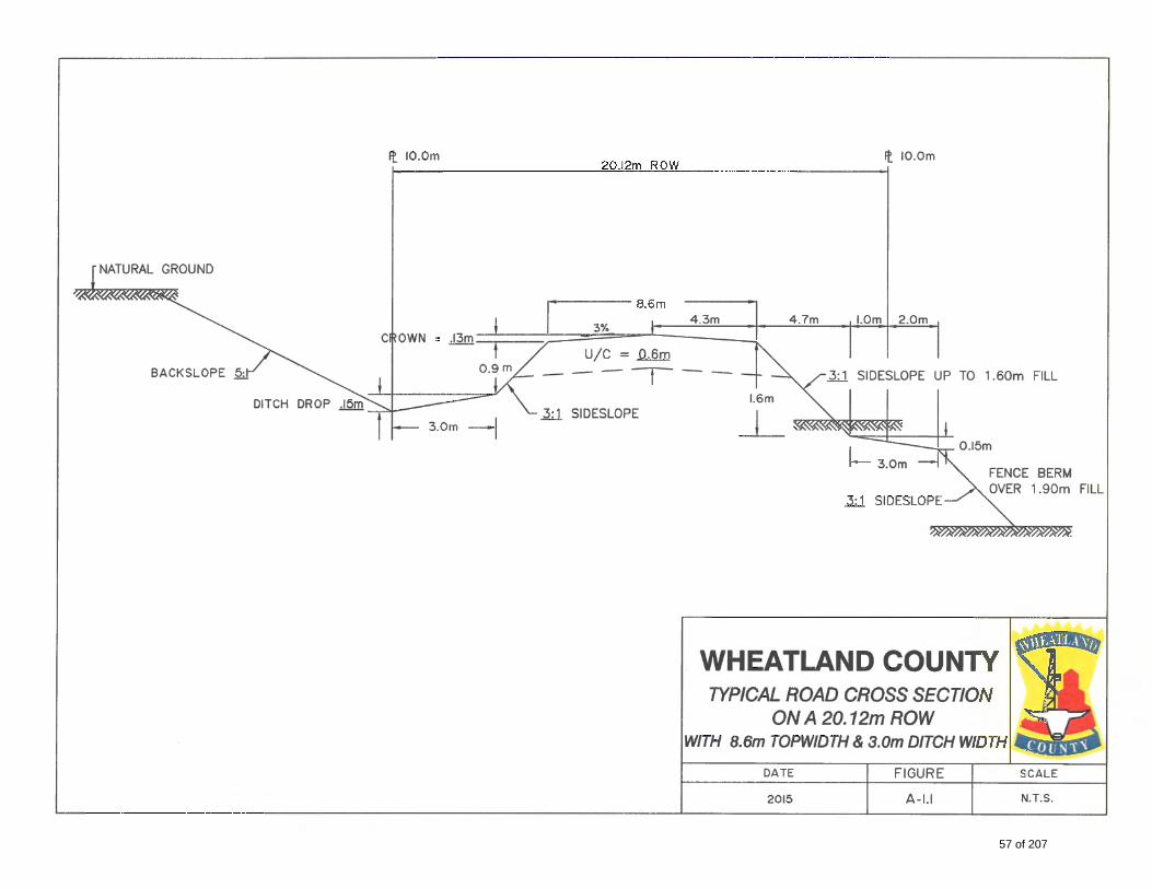
57 of 207
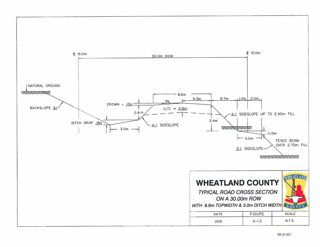
58 of 207
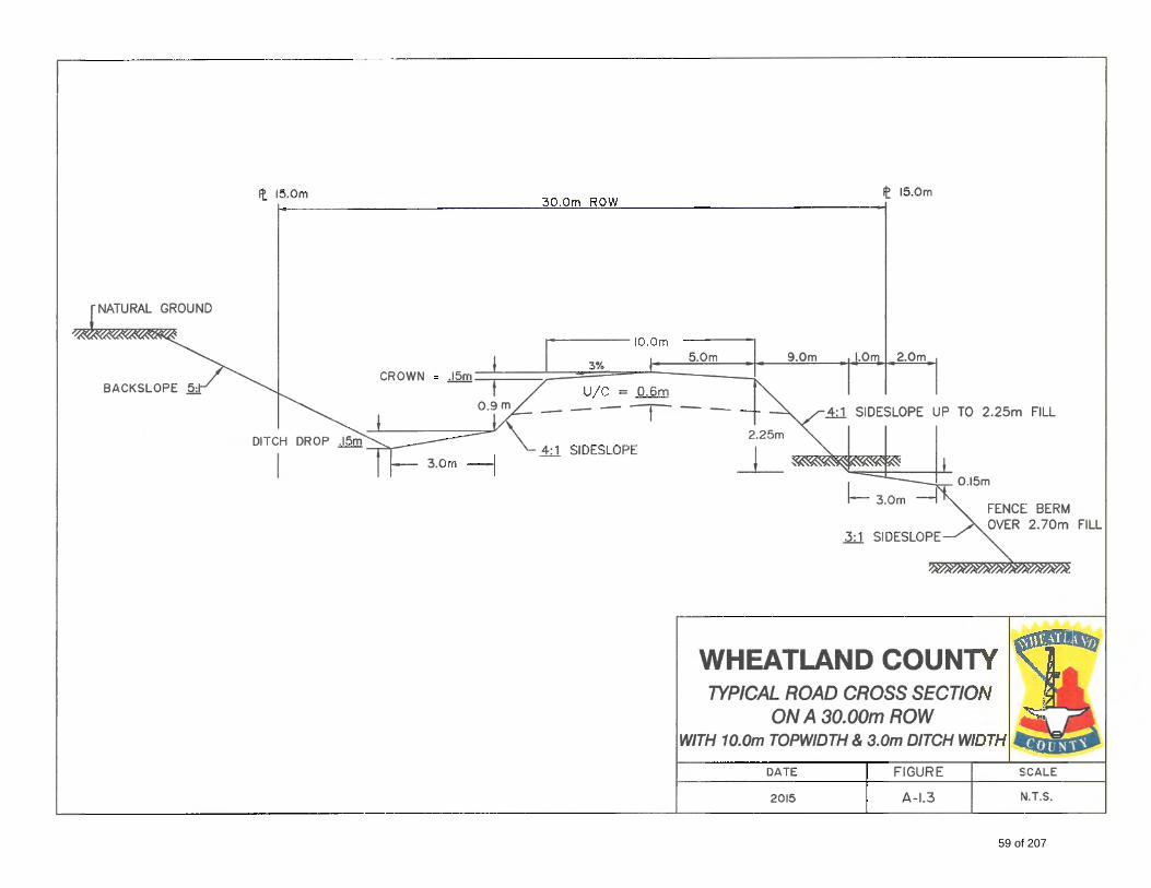
59 of 207
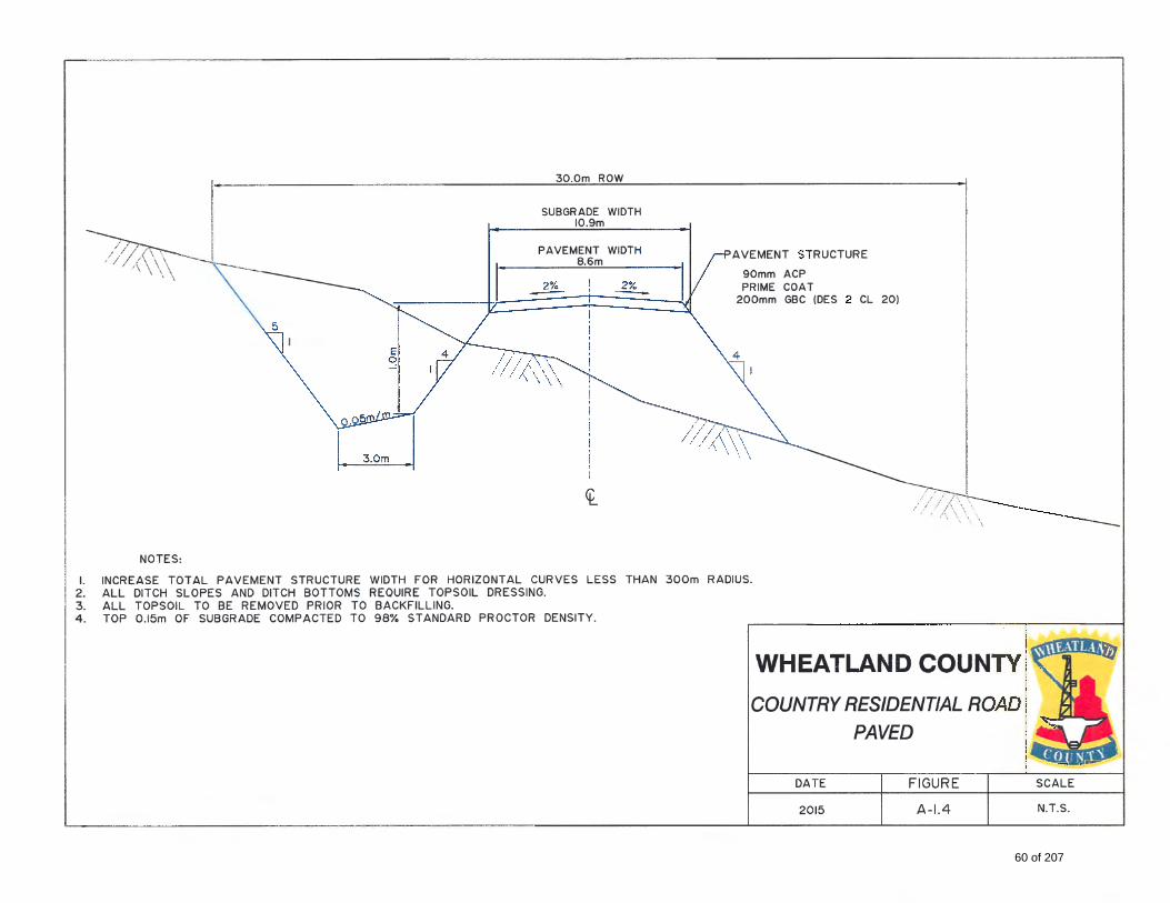
60 of 207
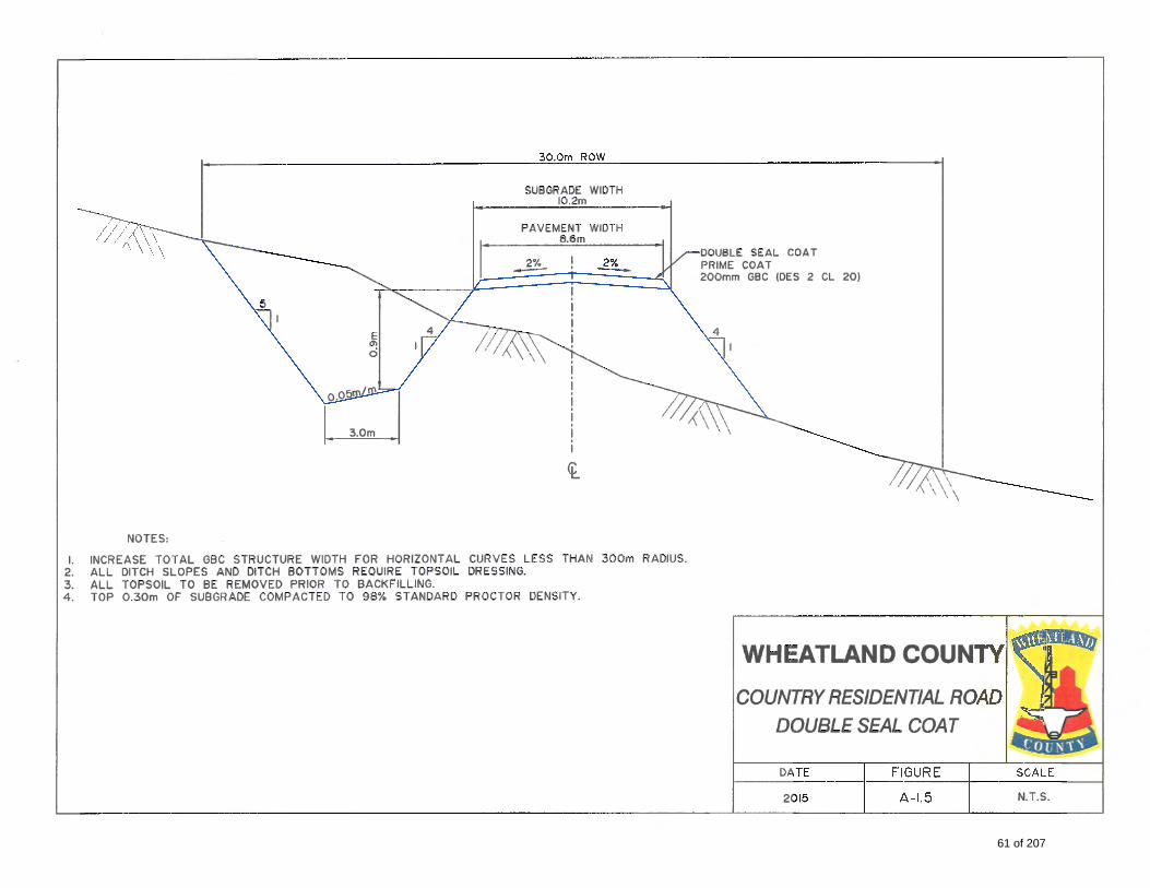
61 of 207
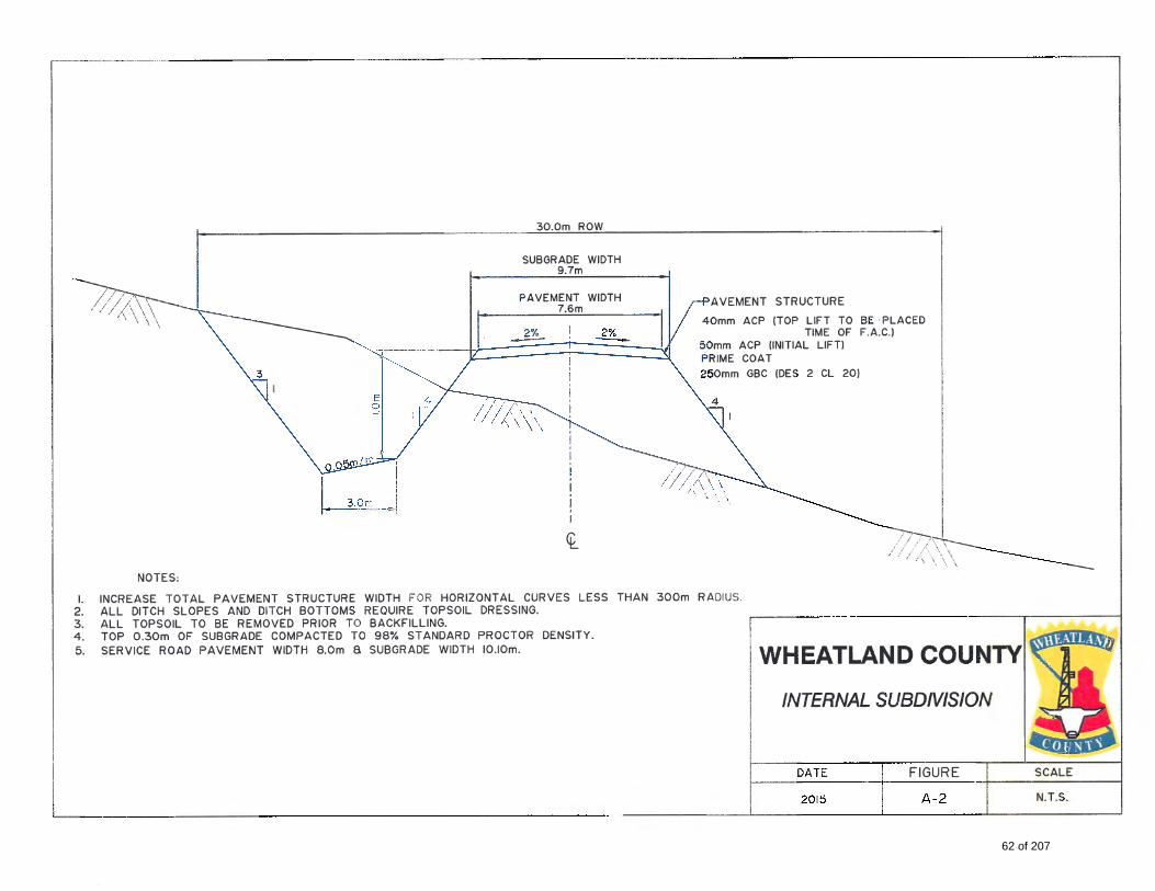
62 of 207
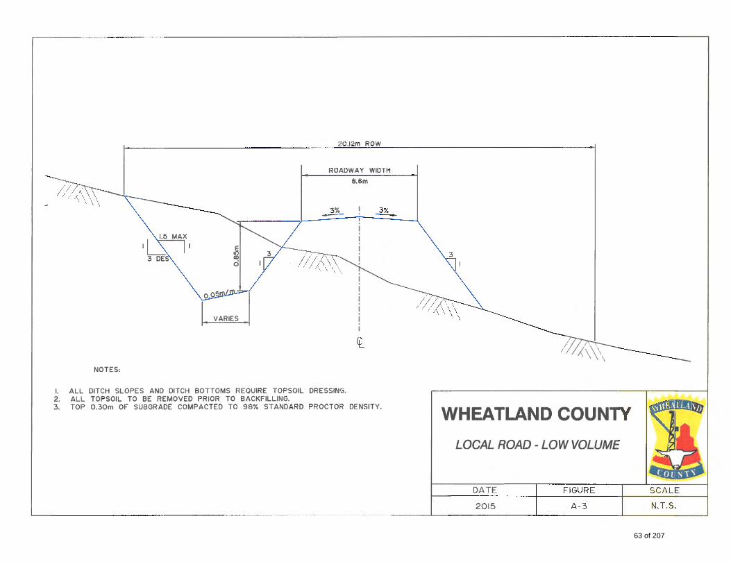
63 of 207

64 of 207
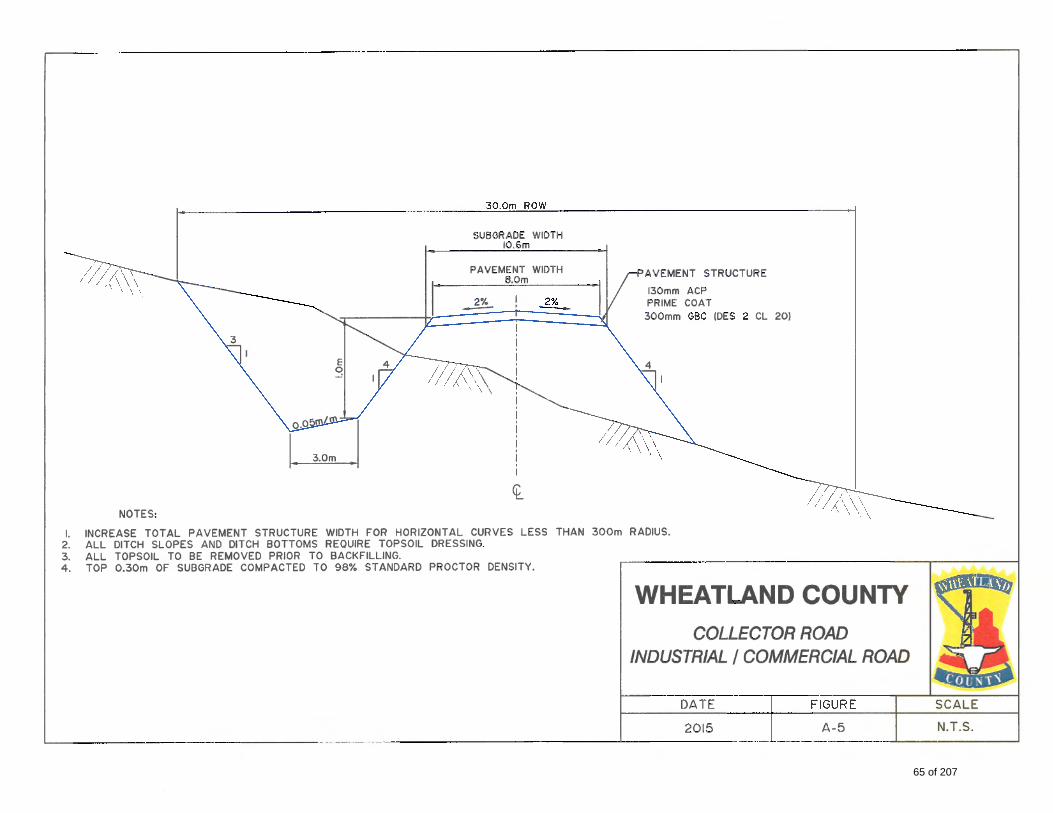
65 of 207
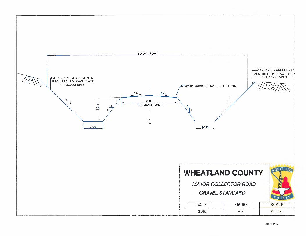
66 of 207
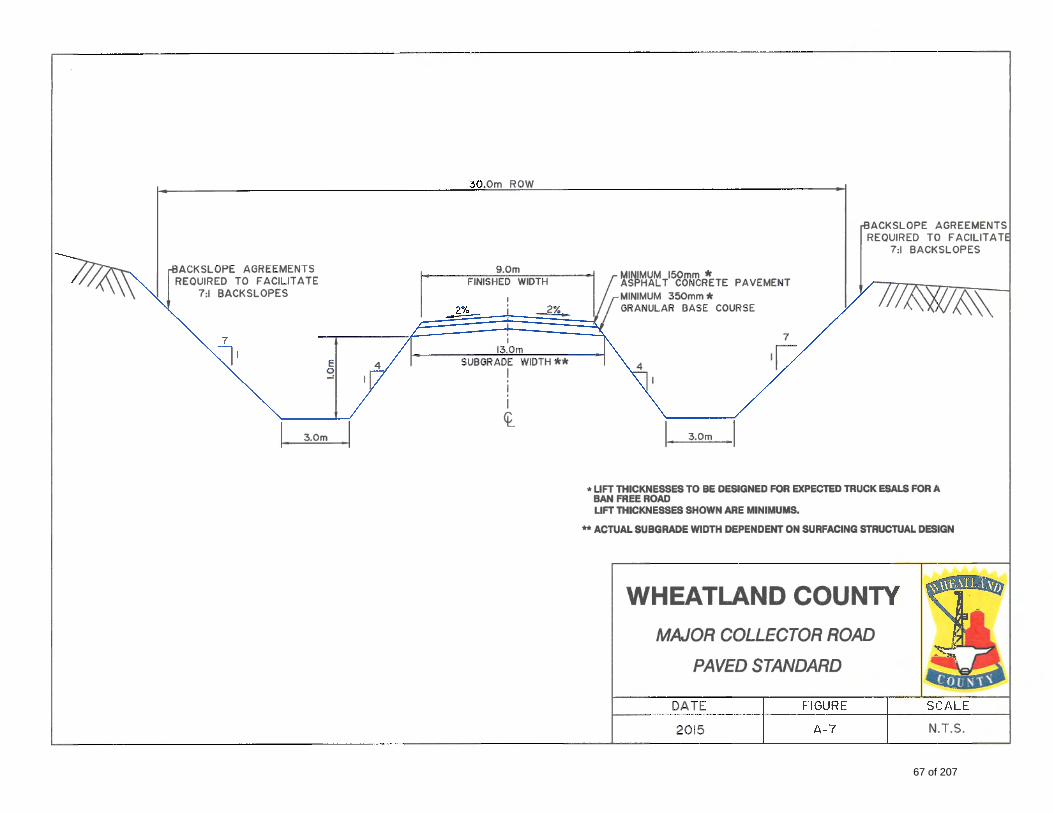
67 of 207
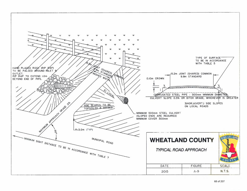
68 of 207
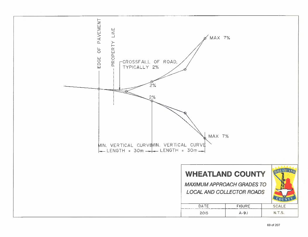
69 of 207
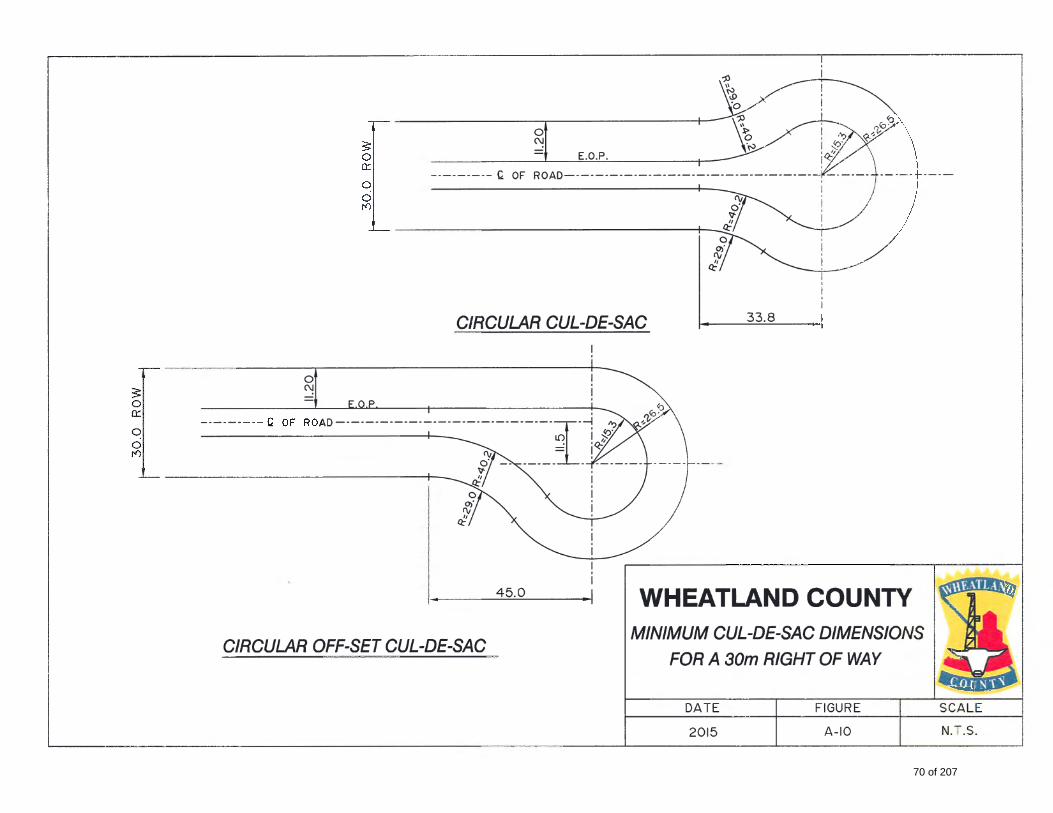
70 of 207
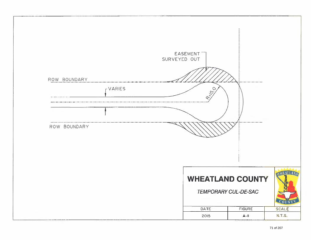
71 of 207
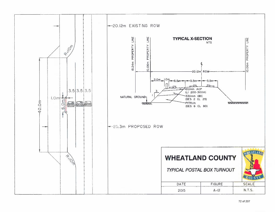
72 of 207
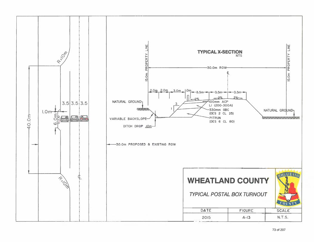
73 of 207
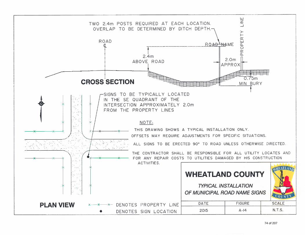
74 of 207
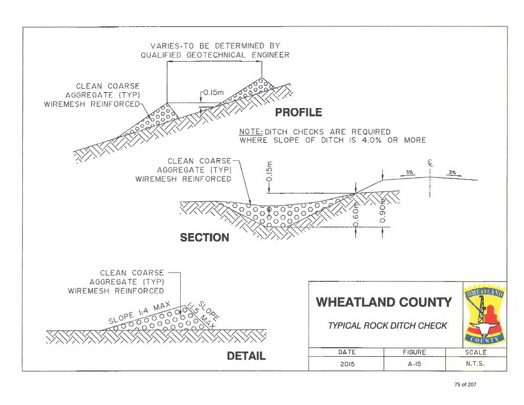
75 of 207
3000 RURAL SANITARY SEWER
3100 SYSTEM DESIGN OVERVIEW
The sanitary sewer system shall be of sufficient capacity to service the ultimate population proj ection of the
development area.
Wheatland County Planning Policy Section 7.3 outlines the requirements for Private Sewage Disposal
Systems including the Alberta Environment 2009 Private Sewage System Standard of Practice and The Model
Process for Subdivision Approval and Private Sewage. In accordance with the Municipal Development Plan,
all subdivision or development proposa l s that would result in a total of six (6) or more lots per quarter
section, outside of an urban area, shall provide access to piped servicing, at the developers expense.
Where a municipal system or utility is available and connection is supported by the County the urban
standards for sewer design are to be adhered to.
The Developer and the Developer 's Consultant are responsible to ensure that the infrastructure is
designed and constructed to achieve manufacturers ' design life expectations consistent with good design
and construction practice. System proposals must identify disposal means in accordance with Alberta
Environment regulations and guidelines. Plan‐profile drawings, specifications and a letter report shall be
prepared by a qualified Professional Engineer and be submitted to the County and Alberta Environment
and Parks for review and approval prior to construct ion.
22
76 of 207
4000 RURAL WATER DISTRIBUTION
4100 SYSTEM DESIGN OVERVIEW
Consideration of the water distribution and transm ission systems shall be in accordance to the County
standards.
In accordance with the Municipal Development Plan, all subdivision or development proposals that would result
in a total of six (6) or more lots per quarter section, outside of an urban area, shall provide access to piped
servicing, at the developers expense.
Where a municipal system or utility is available and connection is supported by the County the urban
standards for potable water design are to be adhered to.
Where there are less than 6 lots per quarter section onsite wells will be considered. The design and
construction of wells must adhere to the AEP standards and guidelines.
23
77 of 207

5000 RURAL STORMWATER MANAGEMENT
5100 GENERAL The Developer and his Engineering Consultant must adhere to the guidelines presented in the latest edition
of the publication "Stormwater Management Guidelines for the Province of Alberta" prepared by AEP.
The standards provided in the urban section are also to be adhered to except the minor system where there is no
minor system required by the development.
When developing land in a rural setting i t i s i m p o r t a n t t o r e c o g n i z e t h a t drainage leaving a development
typically flows into adjacent ditch networks and/or natural drainage courses across private property.
In addition, the engineering consultant needs to recognize that a drainage system for stormwater runoff always
exists, and virtually any modification of an existing drainage system will modify the runoff characteristics of the
system. Any adverse impacts resulting from this modification must be accounted for and rectified through the
design of the stormwater management system.
24
78 of 207

WHEATLAND COUNTY CONSTRUCTION STANDARDS
OCTOBER 2016
79 of 207

80 of 207
CONTENTS 1000 General ....................................................................................................................................................82
1100 Survey Control Markers .......................................................................................................................82
2000 Roads .......................................................................................................................................................83
2100 Granular Material ................................................................................................................................83
2200 Base Stabilization .................................................................................................................................86
2300 Asphalt Concrete .................................................................................................................................87
2400 Stone Matrix Asphalt ...........................................................................................................................91
2500 Portland Cement Concrete ..................................................................................................................92
2600 Portland Cement Pavement ................................................................................................................98
2700 Fencing .................................................................................................................................................99
2800 Guardrails ............................................................................................................................................101
2900 Geotextiles and Geomembranes .........................................................................................................106
3000 Sanitary & Storm Sewer ...........................................................................................................................107
3100 General ................................................................................................................................................107
3200 Materials ..............................................................................................................................................108
4000 Waterworks .............................................................................................................................................143
4100 Scope ...................................................................................................................................................143
4200 Inspection ............................................................................................................................................143
81 of 207

General
WHEATLAND COUNTY CONSTRUCTION STANDARDS JULY 2016
1000 GENERAL For approved materials and material testing standards the current edition of these standards are to be adhered
to unless otherwise provided; should a conflict arise between reference materials, the Engineer shall decide which
takes precedence.
These standards are provided to set guidelines and establish requirements regarding construction of municipal
infrastructure within Wheatland County. Its objective is to ensure that all municipal infrastructure work in
Wheatland County is constructed to a consistent, sustainable standard. Construction of municipal infrastructure
must adhere to these standards.
The County retains the ability to refer to other applicable regional municipality Construction Guidelines, Standards
and Policies where the County deems it appropriate on a case by case basis.
1100 SURVEY CONTROL MARKERS
EXISTING CONTROL
.1 The Developer or their Consultant shall make every effort to protect existing markers.
.2 Markers which are destroyed or disturbed shall be replaced by the Developer at their sole expense.
LEGAL POSTS
.1 Legal posts shall be placed subsequent to the installation of all utilities.
.2 All legal posts in the subdivision area shall be located within 60 days prior to application for Final
Acceptance of the surface improvements.
.3 The Developer shall instruct the legal surveying consultant to replace any missing or disturbed posts
as required by the Wheatland County Representative. All costs are to be borne by the Developer.
82 of 207
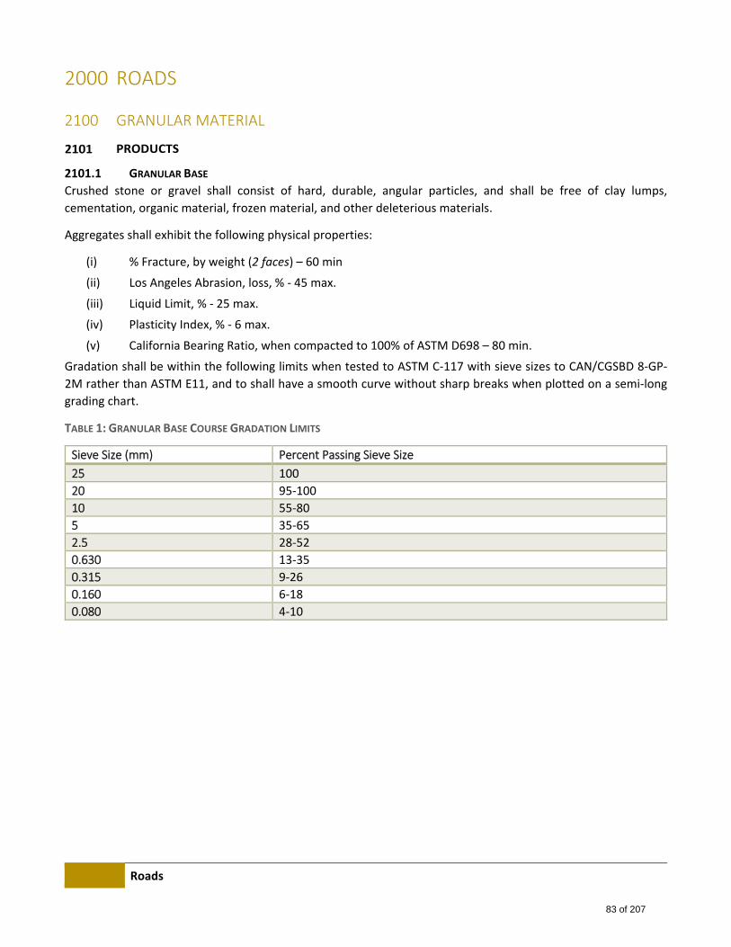
Roads
2000 ROADS
2100 GRANULAR MATERIAL
PRODUCTS
2101.1 GRANULAR BASE
Crushed stone or gravel shall consist of hard, durable, angular particles, and shall be free of clay lumps,
cementation, organic material, frozen material, and other deleterious materials.
Aggregates shall exhibit the following physical properties:
(i) % Fracture, by weight (2 faces) – 60 min
(ii) Los Angeles Abrasion, loss, % ‐ 45 max.
(iii) Liquid Limit, % ‐ 25 max.
(iv) Plasticity Index, % ‐ 6 max.
(v) California Bearing Ratio, when compacted to 100% of ASTM D698 – 80 min.
Gradation shall be within the following limits when tested to ASTM C‐117 with sieve sizes to CAN/CGSBD 8‐GP‐
2M rather than ASTM E11, and to shall have a smooth curve without sharp breaks when plotted on a semi‐long
grading chart.
TABLE 1: GRANULAR BASE COURSE GRADATION LIMITS
Sieve Size (mm) Percent Passing Sieve Size
25 100
20 95‐100
10 55‐80
5 35‐65
2.5 28‐52
0.630 13‐35
0.315 9‐26
0.160 6‐18
0.080 4‐10
83 of 207
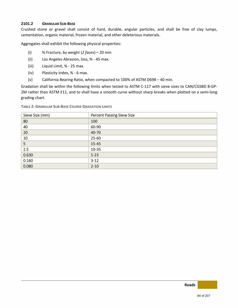
Roads
2101.2 GRANULAR SUB‐BASE
Crushed stone or gravel shall consist of hard, durable, angular particles, and shall be free of clay lumps,
cementation, organic material, frozen material, and other deleterious materials.
Aggregates shall exhibit the following physical properties:
(i) % Fracture, by weight (2 faces) – 20 min
(ii) Los Angeles Abrasion, loss, % ‐ 45 max.
(iii) Liquid Limit, % ‐ 25 max.
(iv) Plasticity Index, % ‐ 6 max.
(v) California Bearing Ratio, when compacted to 100% of ASTM D698 – 40 min.
Gradation shall be within the following limits when tested to ASTM C‐117 with sieve sizes to CAN/CGSBD 8‐GP‐
2M rather than ASTM E11, and to shall have a smooth curve without sharp breaks when plotted on a semi‐long
grading chart.
TABLE 2: GRANULAR SUB‐BASE COURSE GRADATION LIMITS
Sieve Size (mm) Percent Passing Sieve Size
80 100
40 60‐90
20 40‐70
10 25‐60
5 15‐45
2.5 10‐35
0.630 5‐23
0.160 3‐12
0.080 2‐10
84 of 207
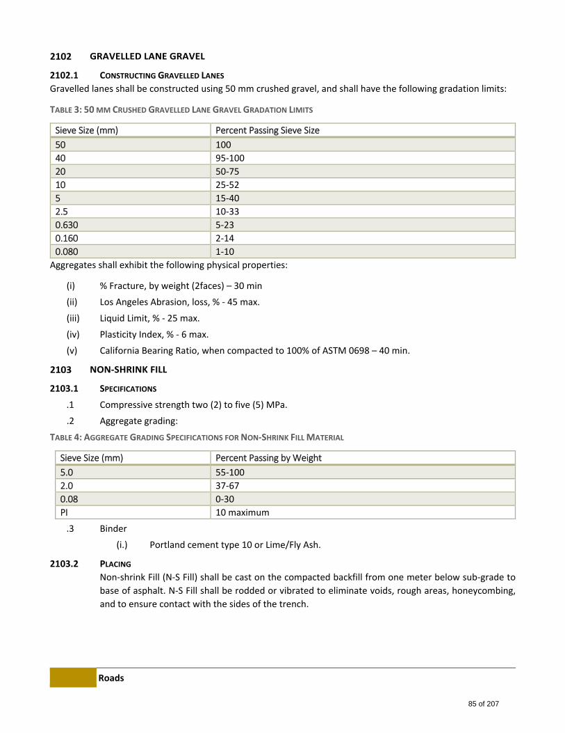
Roads
GRAVELLED LANE GRAVEL
2102.1 CONSTRUCTING GRAVELLED LANES
Gravelled lanes shall be constructed using 50 mm crushed gravel, and shall have the following gradation limits:
TABLE 3: 50 MM CRUSHED GRAVELLED LANE GRAVEL GRADATION LIMITS
Sieve Size (mm) Percent Passing Sieve Size
50 100
40 95‐100
20 50‐75
10 25‐52
5 15‐40
2.5 10‐33
0.630 5‐23
0.160 2‐14
0.080 1‐10
Aggregates shall exhibit the following physical properties:
(i) % Fracture, by weight (2faces) – 30 min
(ii) Los Angeles Abrasion, loss, % ‐ 45 max.
(iii) Liquid Limit, % ‐ 25 max.
(iv) Plasticity Index, % ‐ 6 max.
(v) California Bearing Ratio, when compacted to 100% of ASTM 0698 – 40 min.
NON‐SHRINK FILL
2103.1 SPECIFICATIONS
.1 Compressive strength two (2) to five (5) MPa.
.2 Aggregate grading:
TABLE 4: AGGREGATE GRADING SPECIFICATIONS FOR NON‐SHRINK FILL MATERIAL
Sieve Size (mm) Percent Passing by Weight
5.0 55‐100
2.0 37‐67
0.08 0‐30
PI 10 maximum
.3 Binder
(i.) Portland cement type 10 or Lime/Fly Ash.
2103.2 PLACING
Non‐shrink Fill (N‐S Fill) shall be cast on the compacted backfill from one meter below sub‐grade to
base of asphalt. N‐S Fill shall be rodded or vibrated to eliminate voids, rough areas, honeycombing,
and to ensure contact with the sides of the trench.
85 of 207
Roads
CONTROL DENSITY FILL
2104.1 GENERAL
A flowable fill with self‐levelling properties for trench backfill consisting of fine aggregate, sand, and
cementitious content, the control density fill shall be resistant to settlement after hydration.
2200 BASE STABILIZATION
SOIL CEMENT BASE COURSE
2201.1 DESCRIPTION
Soil cement base course consists of soil and Portland Cement uniformly mixed, moistened, compacted, finished,
and cured in accordance with these Specifications, and it conforms to lines, grades, thickness, and typical cross‐
section shown or as directed by the Engineer.
2201.2 MATERIALS
2201.2.1 Portland Cement Portland Cement shall meet the requirements of CAN3‐A5‐M77.
2201.2.2 Water Water shall be free from substances deleterious to the hardening of soil cement, and be subject
to the approval of the Engineer.
2201.2.3 Curling Seal Curling seal shall be an emulsified asphalt, type RS‐1H or RC‐70.
2201.2.4 Soil Soil consists of the material existing in the street to be paved, in an approved borrow pit, or a
combination of these materials in a definite controlled proportion. The soil shall not contain
gravel or stone retained on a 50 mm sieve or more than 45 percent retained on a 5.0 mm sieve.
ASPHALT STABILIZATION
2202.1 DESCRIPTION
Asphalt stabilized base course consists of soil, crushed aggregate and emulsified asphalt uniformly mixed,
moistened, compacted and finished in accordance with these Specifications, and it conforms to line, grade,
thickness and typical cross‐section shown or as directed by the Engineer.
2202.2 MATERIALS
2202.2.1 Emulsified Asphalt SS‐1 emulsified asphalt shall conform to the requirements of the Canadian Specification Board
Specification for Emulsified Asphalt (16‐GP‐2).
2202.2.2 Water Water shall be free from substances deleterious to the hardening of soil cement, and be subject
to the approval of the Engineer.
2202.2.3 Soil Soil consists of the material existing in the street to be paved, in an approved borrow pit, or a
combination of these materials in a definite controlled proportion. The soil shall not contain
gravel or stone retained on a 50 mm sieve or more than 45 percent retained on a 5.0 mm sieve.
86 of 207
Roads
2202.2.4 Aggregates Aggregates shall conform to the gradation specified in section 2100 – Granular Material.
2202.3 MIX DESIGN
The amount of emulsified asphalt and soil/aggregate blends shall be established by the following tests:
ASTM Designation D915 Method of Testing Soil Bituminous Mixtures.
ASTM Designation D1560 Resistance to Deformation and Cohesion of Bituminous Mixtures by Means of Hveem
Apparatus
ASTM Designation D1561 Preparation of Test Specimens of Bituminous Mixtures by Means of California Kneading
Compactor.
2202.4 EQUIPMENT
Mixing and spreading shall be accomplished through the use of a rotary type mixer with transverse shafts that mix
emulsified asphalt and soil/aggregate by revolving tines under a hood, preferably with an internal spray system
which applies the emulsified asphalt while mixing. All equipment necessary for the proper construction of the
base course shall be on the project and in satisfactory condition before construction begins.
2300 ASPHALT CONCRETE
DESCRIPTION
Asphalt concrete consists of a hot mixed coarse aggregate and fine aggregate, with or without mineral
filter, uniformly coated and mixed with asphalt cement in an approved mixing plant.
PREPARATION FOR PAVING
2302.1 GENERAL
The hot asphalt mixture shall be laid upon a dry firm base, true to grade and cross‐section and free from all
screenings or other loose or foreign material. No hot mix shall be spread while the granular base or sub‐base is
wet or when other conditions prevent proper spreading, finishing, or compaction.
Existing asphalt surfaces and gutter areas shall be thoroughly cleaned of all loose or deleterious materials or
objects prior to commencing either the levelling course or top lift paving operations.
Cleaning prior to paving shall be considered as incidental to the Unit Rate for asphalt concrete.
Granular materials and/or asphalt shall not be used as fill under full‐depth asphaltic concrete paving unless
positive drainage is provided. If extra material is required in order to bring the subgrade to the proper grade, the
material shall be obtained from a suitable earth borrow area.
87 of 207
Roads
2302.2 PROCEDURE FOR PRIME COAT
Upon a uniformly damp base course, a prime coat of diluted SS‐1 emulsified asphalt shall be uniformly applied as
follows:
(i) Dilution rate: 2 parts SS‐1 emulsion to 1 part water.
(ii) Distribution rate: 2.0 litres per square meter.
(iii) Emulsion temperature: 20°C to 50°C.
(iv) Ambient air temperature: shall be greater than 4°C.
(v) Curing time: a minimum of two hours. If weather or other conditions have been such that the prime
coat has not fully cured at the end of two hours, the Engineer may extend the curing period as he/she
deems necessary.
2302.3 PROCEDURE FOR TACK COAT
Tack coat shall be applied between successive lifts of asphaltic concrete, only after the surface has been cleaned
of all loose or deleterious materials or objects, and as follows:
(i) Type: SS‐1H emulsion
(ii) Distribution rate: not greater than 0.5 litres per square meter;
(iii) Emulsion temperature: 20°C to 50°C.
(iv) Ambient air temperature: shall be greater than 4°C.
MANHOLES, VALVES, AND APPURTENANCES
The Contractor shall bring all manholes, water valves boxes and other appurtenance to the finished grade of the
road or median strip at no cost to the County. This work shall be done in each individual block no later than one
week after final paving operations have been completed in that block. The cost of repairing or replacing water
valves, manholes and other appurtenances damaged as a result of the Contractors operation shall be borne by
him. The final surface shall not vary more than 10 mm when checked with a 3 m straight edge. However, the
County does not allow any tolerance for vertical drop of the finished surface in the vicinity of any utility
appurtenance. The Contractor shall be responsible for correcting any irregularities in the final surface around ant
utility appurtenance, at his expense and within the time specified by the Engineer.
Raising or lowering of manhole rims shall be done using precast collars, conforming to ASTM Designation C‐139
along with an approved cement mortar. The completed work shall be in accordance with the Standard
Specifications Sewer Construction. All work shall be subject to inspection and approval by the Engineer before it
shall be considered complete.
Adjustment or sewer manholes shall be done in accordance with the following:
.1 All manhole adjustments shall be in accordance with the Standard Specification Wastewater
Construction.
.2 Top lift paving shall not commence until all necessary manhole rebuilding has been done.
88 of 207
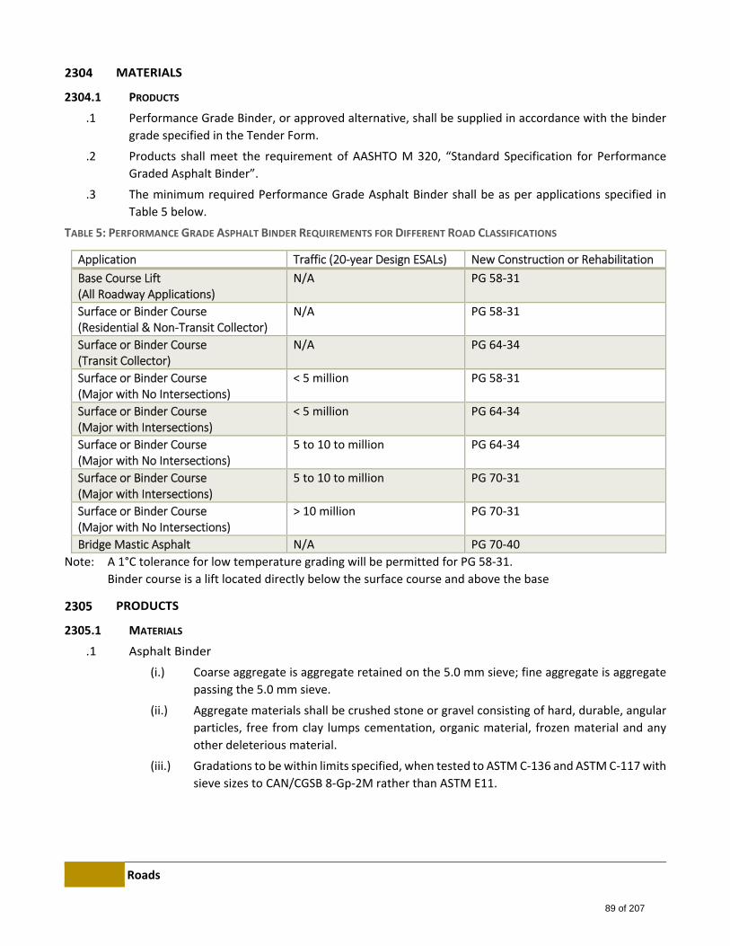
Roads
MATERIALS
2304.1 PRODUCTS
.1 Performance Grade Binder, or approved alternative, shall be supplied in accordance with the binder
grade specified in the Tender Form.
.2 Products shall meet the requirement of AASHTO M 320, “Standard Specification for Performance
Graded Asphalt Binder”.
.3 The minimum required Performance Grade Asphalt Binder shall be as per applications specified in
Table 5 below.
TABLE 5: PERFORMANCE GRADE ASPHALT BINDER REQUIREMENTS FOR DIFFERENT ROAD CLASSIFICATIONS
Application Traffic (20‐year Design ESALs) New Construction or Rehabilitation
Base Course Lift (All Roadway Applications)
N/A PG 58‐31
Surface or Binder Course (Residential & Non‐Transit Collector)
N/A PG 58‐31
Surface or Binder Course (Transit Collector)
N/A PG 64‐34
Surface or Binder Course (Major with No Intersections)
< 5 million PG 58‐31
Surface or Binder Course (Major with Intersections)
< 5 million PG 64‐34
Surface or Binder Course (Major with No Intersections)
5 to 10 to million PG 64‐34
Surface or Binder Course (Major with Intersections)
5 to 10 to million PG 70‐31
Surface or Binder Course (Major with No Intersections)
> 10 million PG 70‐31
Bridge Mastic Asphalt N/A PG 70‐40
Note: A 1°C tolerance for low temperature grading will be permitted for PG 58‐31.
Binder course is a lift located directly below the surface course and above the base
PRODUCTS
2305.1 MATERIALS
.1 Asphalt Binder
(i.) Coarse aggregate is aggregate retained on the 5.0 mm sieve; fine aggregate is aggregate
passing the 5.0 mm sieve.
(ii.) Aggregate materials shall be crushed stone or gravel consisting of hard, durable, angular
particles, free from clay lumps cementation, organic material, frozen material and any
other deleterious material.
(iii.) Gradations to be within limits specified, when tested to ASTM C‐136 and ASTM C‐117 with
sieve sizes to CAN/CGSB 8‐Gp‐2M rather than ASTM E11.
89 of 207
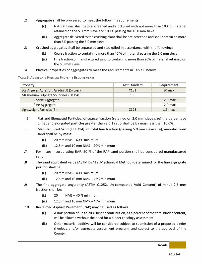
Roads
.2 Aggregate shall be processed to meet the following requirements:
(i.) Natural fines shall be pre‐screened and stockpiled with not more than 10% of material
retained on the 5.0 mm sieve and 100 % passing the 10.0 mm sieve.
(ii.) Aggregate delivered to the crushing plant shall be pre‐screened and shall contain no more
than 5% passing the 5.0 mm sieve.
.3 Crushed aggregates shall be separated and stockpiled in accordance with the following:
(i.) Coarse fraction to contain no more than 40 % of material passing the 5.0 mm sieve.
(ii.) Fine fraction or manufactured sand to contain no more than 20% of material retained on
the 5.0 mm sieve.
.4 Physical properties of aggregates to meet the requirements in Table 6 below.
TABLE 6: AGGREGATE PHYSICAL PROPERTY REQUIREMENTS
Property Test Standard Requirement
Los Angeles Abrasion, Grading B (% Loss) C131 30 max
Magnesium Sulphate Soundness (% loss) C88
Coarse Aggregate 12.0 max
Fine Aggregate 12.0 max
Lightweight Particles (5) C123 1.5 max
.5 Flat and Elongated Particles: of coarse fraction (retained on 5.0 mm sieve size) the percentage
of flat and elongated particles greater than a 5:1 ratio shall be by mass less than 10.0%
.6 Manufactured Sand (TLT 314): of total fine fraction (passing 5.0 mm sieve size), manufactured
sand shall be by mass:
(i.) 20 mm NMS – 60 % minimum
(ii.) 12.5 m and 10 mm NMS – 70% minimum
.7 For mixes incorporating RAP, 50 % of the RAP sand portion shall be considered manufactured
sand.
.8 The sand equivalent value (ASTM D2419, Mechanical Method) determined for the fine aggregate
portion shall be:
(i.) 20 mm NMS – 40 % minimum
(ii.) 12.5 m and 10 mm NMS – 45% minimum
.9 The fine aggregate angularity (ASTM C1252, Un‐compacted Void Content) of minus 2.5 mm
fraction shall be:
(i.) 20 mm NMS – 40 % minimum
(ii.) 12.5 m and 10 mm NMS – 45% minimum
.10 Reclaimed Asphalt Pavement (RAP) may be used as follows:
(i.) A RAP portion of up to 20 % binder contribution, as a percent of the total binder content,
will be allowed without the need for a binder rheology assessment.
(ii.) Other material additive will be considered subject to submission of a proposed binder
rheology and/or aggregate assessment program, and subject to the approval of the
County.
90 of 207
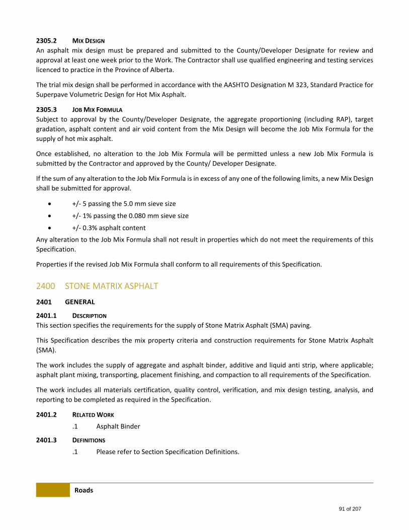
Roads
2305.2 MIX DESIGN
An asphalt mix design must be prepared and submitted to the County/Developer Designate for review and
approval at least one week prior to the Work. The Contractor shall use qualified engineering and testing services
licenced to practice in the Province of Alberta.
The trial mix design shall be performed in accordance with the AASHTO Designation M 323, Standard Practice for
Superpave Volumetric Design for Hot Mix Asphalt.
2305.3 JOB MIX FORMULA
Subject to approval by the County/Developer Designate, the aggregate proportioning (including RAP), target
gradation, asphalt content and air void content from the Mix Design will become the Job Mix Formula for the
supply of hot mix asphalt.
Once established, no alteration to the Job Mix Formula will be permitted unless a new Job Mix Formula is
submitted by the Contractor and approved by the County/ Developer Designate.
If the sum of any alteration to the Job Mix Formula is in excess of any one of the following limits, a new Mix Design
shall be submitted for approval.
+/‐ 5 passing the 5.0 mm sieve size
+/‐ 1% passing the 0.080 mm sieve size
+/‐ 0.3% asphalt content
Any alteration to the Job Mix Formula shall not result in properties which do not meet the requirements of this
Specification.
Properties if the revised Job Mix Formula shall conform to all requirements of this Specification.
2400 STONE MATRIX ASPHALT
GENERAL
2401.1 DESCRIPTION
This section specifies the requirements for the supply of Stone Matrix Asphalt (SMA) paving.
This Specification describes the mix property criteria and construction requirements for Stone Matrix Asphalt
(SMA).
The work includes the supply of aggregate and asphalt binder, additive and liquid anti strip, where applicable;
asphalt plant mixing, transporting, placement finishing, and compaction to all requirements of the Specification.
The work includes all materials certification, quality control, verification, and mix design testing, analysis, and
reporting to be completed as required in the Specification.
2401.2 RELATED WORK
.1 Asphalt Binder
2401.3 DEFINITIONS
.1 Please refer to Section Specification Definitions.
91 of 207
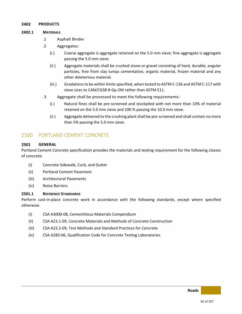
Roads
PRODUCTS
2402.1 MATERIALS
.1 Asphalt Binder
.2 Aggregates:
(i.) Coarse aggregate is aggregate retained on the 5.0 mm sieve; fine aggregate is aggregate
passing the 5.0 mm sieve.
(ii.) Aggregate materials shall be crushed stone or gravel consisting of hard, durable, angular
particles, free from clay lumps cementation, organic material, frozen material and any
other deleterious material.
(iii.) Gradations to be within limits specified, when tested to ASTM C‐136 and ASTM C‐117 with
sieve sizes to CAN/CGSB 8‐Gp‐2M rather than ASTM E11.
.3 Aggregate shall be processed to meet the following requirements:
(i.) Natural fines shall be pre‐screened and stockpiled with not more than 10% of material
retained on the 5.0 mm sieve and 100 % passing the 10.0 mm sieve.
(ii.) Aggregate delivered to the crushing plant shall be pre‐screened and shall contain no more
than 5% passing the 5.0 mm sieve.
2500 PORTLAND CEMENT CONCRETE
GENERAL
Portland Cement Concrete specification provides the materials and testing requirement for the following classes
of concrete:
(i) Concrete Sidewalk, Curb, and Gutter
(ii) Portland Cement Pavement
(iii) Architectural Pavements
(iv) Noise Barriers
2501.1 REFERENCE STANDARDS
Perform cast‐in‐place concrete work in accordance with the following standards, except where specified
otherwise.
(i) CSA A3000‐08, Cementitious Materials Compendium
(ii) CSA A23.1‐09, Concrete Materials and Methods of Concrete Construction
(iii) CSA A23.2‐09, Test Methods and Standard Practices for Concrete
(iv) CSA A283‐06, Qualification Code for Concrete Testing Laboratories
92 of 207
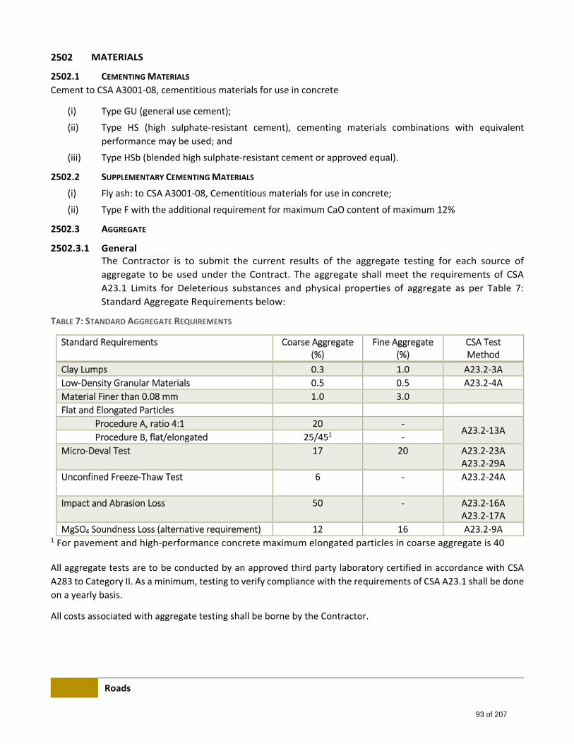
Roads
MATERIALS
2502.1 CEMENTING MATERIALS
Cement to CSA A3001‐08, cementitious materials for use in concrete
(i) Type GU (general use cement);
(ii) Type HS (high sulphate‐resistant cement), cementing materials combinations with equivalent
performance may be used; and
(iii) Type HSb (blended high sulphate‐resistant cement or approved equal).
2502.2 SUPPLEMENTARY CEMENTING MATERIALS
(i) Fly ash: to CSA A3001‐08, Cementitious materials for use in concrete;
(ii) Type F with the additional requirement for maximum CaO content of maximum 12%
2502.3 AGGREGATE
2502.3.1 General The Contractor is to submit the current results of the aggregate testing for each source of
aggregate to be used under the Contract. The aggregate shall meet the requirements of CSA
A23.1 Limits for Deleterious substances and physical properties of aggregate as per Table 7:
Standard Aggregate Requirements below:
TABLE 7: STANDARD AGGREGATE REQUIREMENTS
Standard Requirements Coarse Aggregate (%)
Fine Aggregate (%)
CSA Test Method
Clay Lumps 0.3 1.0 A23.2‐3A
Low‐Density Granular Materials 0.5 0.5 A23.2‐4A
Material Finer than 0.08 mm 1.0 3.0
Flat and Elongated Particles
Procedure A, ratio 4:1 20 ‐ A23.2‐13A
Procedure B, flat/elongated 25/451 ‐
Micro‐Deval Test 17 20 A23.2‐23A A23.2‐29A
Unconfined Freeze‐Thaw Test 6 ‐ A23.2‐24A
Impact and Abrasion Loss 50 ‐ A23.2‐16A A23.2‐17A
MgSO4 Soundness Loss (alternative requirement) 12 16 A23.2‐9A 1 For pavement and high‐performance concrete maximum elongated particles in coarse aggregate is 40
All aggregate tests are to be conducted by an approved third party laboratory certified in accordance with CSA
A283 to Category II. As a minimum, testing to verify compliance with the requirements of CSA A23.1 shall be done
on a yearly basis.
All costs associated with aggregate testing shall be borne by the Contractor.
93 of 207
Roads
2502.3.2 Fine Aggregates Normal density fine aggregate shall consist of natural sand, manufactured sand, or a combination
of thereof.
Fine aggregate shall be graded to limits specified in CSA A23.1 Grading Limits for Fine Aggregate,
Group FA1.
Fine aggregate tested in accordance with CSA A23.2‐7A, test for organic impurities in fine
aggregates for concrete, is to produce a color not darker than the standard color (organic Plate
Number 3). Aggregate producing a color darker than the standard color will be rejected. The
provision of CSA A23.1, Section 4.2.3.3.3.2 shall not apply.
2502.3.3 Coarse Aggregates Normal density coarse aggregate shall consist of crushed stone, gravel, or a combination of these
materials.
The sizes of coarse aggregate shall be selected from the standard sizes given in CSA A23.1,
Grading Requirements for Concrete Aggregate, Group 1. The standard size of the coarse
aggregate is 20 mm to 5 mm, except where specified otherwise.
2502.4 WATER
Water for concrete production and curing is to be clean and free from excessive amounts of oil, acid, alkali, soluble
chlorides, organic matter, or sediment.
Any potable water is suitable for use in the concrete production. Water deemed not potable may be used in the
concrete production provided that a satisfactory history of strength and durability of concrete made with the
water has been demonstrated.
2502.5 ADMIXTURES
(i) Air entraining admixtures shall conform to the requirements of ASTM C‐206
(ii) Water reducing admixtures and high range water reducing admixtures (superplasticizers) shall
conform to the requirements of ASTM C‐494.
(iii) Calcium chloride shall not be used as it promotes steel corrosion, if present, and reduces long‐term
sulphate resistance of concrete. Set accelerating admixtures shall only be used if approved by the
County.
2502.6 FIBRES
2502.6.1 Synthetic Fibre Synthetic fibre reinforcement shall meet the requirement of ASTM C‐1116, 4.1.3, Type III, and shall be olefin macro
fibres.
Macro synthetic fibre content shall be in the range of 1 kg/m3 to 2 kg/m3 for plastic shrinkage control and improved
mechanical properties. Higher fibre volumes reduce workability and have a propensity to ball during mixing. When
higher fibre content is required for a particular application, tests are necessary to verify that concrete with the
desired amount of fibre can be properly mixed and placed.
Macro synthetic fibre length shall be between 38 mm and 50 mm.
94 of 207
Roads
2502.6.2 Steel Fibre Steel Fibre reinforcement shall meet the requirements of ASTM C‐1116, 4.1.1, Type I and shall
be carbon steel.
Steel fibre content shall be a minimum 35 kg/m3. Higher fibre volumes reduce workability and
have a propensity to ball during mixing. When higher fibre content is required for a particular
application, tests are necessary to verify that concrete with the desired amount of fibre can be
properly mixed and placed.
Steel fibre length shall be between 38 mm and 50 mm and be continuously deformed or have
ends mechanically deformed.
2502.7 CURING MEMBRANE
Liquid membrane forming curing compound to ASTM C‐309.
(i) Type 1 – Clear translucent without dye; and
(ii) Type 2 – White pigmented.
Liquid curing membrane shall be applied to the concrete as soon as reasonable after the completion of and/or
texturing activities. The time of the application shall not exceed 30 minutes after finishing.
SUBMITTALS
(i) Submit the proposed mix design for all concrete mix types to the Engineer for approval four (4) weeks
prior to the commencement of the Contract. Mix design documentation shall include all components
of the mix and quantities of the materials used.
(ii) Submit copies of mill certificate test reports of cement and fly ash.
(iii) Submit the test results for each source of the aggregate to be used for compliance with the Aggregate
section.
(iv) Submit data on all proposed concrete admixtures.
CONCRETE SIDEWALK, CURB, AND GUTTER
2504.1 GENERAL
Portland concrete sidewalk, curb, and gutter, medians, traffic islands, gores, driveway crossings, and aprons shall
be constructed in accordance with these Specification and the Standard Drawings. The type of construction used
and the location shall be as shown on the construction plans, or as directed by the Engineer, and be in accordance
with the provisions of this section.
Standard face curb shall be required around school and at bus stops.
Wheelchair ramps are compulsory at all intersection, where sidewalks cross wither curb and gutter or curb and at
community mailbox locations.
95 of 207
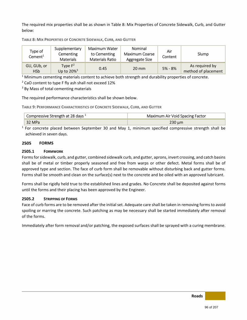
Roads
The required mix properties shall be as shown in Table 8: Mix Properties of Concrete Sidewalk, Curb, and Gutter
below:
TABLE 8: MIX PROPERTIES OF CONCRETE SIDEWALK, CURB, AND GUTTER
Type of Cement1
Supplementary Cementing Materials
Maximum Water to Cementing Materials Ratio
Nominal Maximum Coarse Aggregate Size
Air Content
Slump
GU, GUb, or HSb
Type F2
Up to 20%3 0.45 20 mm 5% ‐ 8%
As required by method of placement
1 Minimum cementing materials content to achieve both strength and durability properties of concrete. 2 CaO content to type F fly ash shall not exceed 12% 3 By Mass of total cementing materials
The required performance characteristics shall be shown below.
TABLE 9: PERFORMANCE CHARACTERISTICS OF CONCRETE SIDEWALK, CURB, AND GUTTER
Compressive Strength at 28 days 1 Maximum Air Void Spacing Factor
32 MPa 230 μm 1 For concrete placed between September 30 and May 1, minimum specified compressive strength shall be
achieved in seven days.
FORMS
2505.1 FORMWORK
Forms for sidewalk, curb, and gutter, combined sidewalk curb, and gutter, aprons, invert crossing, and catch basins
shall be of metal or timber properly seasoned and free from warps or other defect. Metal forms shall be of
approved type and section. The face of curb form shall be removable without disturbing back and gutter forms.
Forms shall be smooth and clean on the surface(s) next to the concrete and be oiled with an approved lubricant.
Forms shall be rigidly held true to the established lines and grades. No Concrete shall be deposited against forms
until the forms and their placing has been approved by the Engineer.
2505.2 STRIPPING OF FORMS
Face of curb forms are to be removed after the initial set. Adequate care shall be taken in removing forms to avoid
spoiling or marring the concrete. Such patching as may be necessary shall be started immediately after removal
of the forms.
Immediately after form removal and/or patching, the exposed surfaces shall be sprayed with a curing membrane.
96 of 207
Roads
REINFORCING
2506.1 GENERAL
When required by the Engineer, structure shall be reinforced in accordance with the drawings provided.
Cold drawn steel wire shall meet the requirement of ASTM designation A 82.
Wire mesh shall meet the requirements of ASTM designation A 185. Overlapping of wire mesh reinforcing shall
be a minimum of 300 mm and be wired together.
Bar reinforcing shall meet ASTM Designation A 184 and ADTM Designation A 304 intermediate grade new billet
deformed steel. Overlapping of bar reinforcing shall be 30 bar diameters and be wired together.
The mesh and/or bar reinforcing shall be supported above the compacted gravel base to ensure a minimum 50
mm cover of concrete. The manner of supporting the reinforcing shall be approved by the Engineer. Concrete with
mesh wire position at the bottom of the concrete element shall be deemed unacceptable.
2506.2 WIRE MESH
A single layer of 150 mm by 150 mm No. 10 by 10 gauge wire mesh shall be installed in private residential driveway
crossings and commercial sidewalks.
A double layer of 150 mm 150 mm, No. 10 by 10 gauge wire mesh shall be installed in public lanes and commercial
driveway crossings.
The mesh shall extend the full width of the crossing. In aprons, the mesh shall extend to the full width, special
attention being made that the mesh extends into the corners of the apron. All acute angle apron corners shall be
constructed and reinforces as shown in the Standard Drawing section.
Reinforcing mesh shall be rolled or otherwise straightened to make a perfectly flat surface before placing.
2506.3 REINFORCING BARS
A 10 m reinforcing bar shall be installed, as shown in the drawings, in separate curb and gutter at all crossings.
2506.4 SYNTHETIC FIBRE CONCRETE
The Engineer may specify that synthetic fibre concrete be used instead of steel reinforces concrete.
2506.5 BULL NOSES ON MEDIAN
Where bull noses are to be constructed at the ends of medians, reinforcing bars may be left extending from the
median in order to tie into the bull nose.
CONCRETE PLACING
2507.1 GENERAL
The Contractor shall notify the Materials and Research dispatcher of ROADS of his intention to place concrete by
15:00 hours (3:00 pm) of the prior working day to permit arrangements to be made for the inspection and testing
of the concrete. Contractor notification directly to a testing agency shall not relieve his obligation in this regard.
Advice as to work or the later than the following working day, except in the case of weekends, shall be taken as
advice only and shall not constitute notification as required under this section.
97 of 207
Roads
2600 PORTLAND CEMENT PAVEMENT
GENERAL
This specification covers the requirements for the construction of Portland Cement Concrete Pavement (PCC) for
roadway applications to dimensions, line grades, and typical cross‐sections as shown on the drawings.
2601.1 REFERENCE STANDARDS
(i) CSA A3000‐08, Cementitious Materials Compendium
(ii) CSA A23.1‐09, Concrete Materials and Methods of Concrete Construction
(iii) CSA A23.2‐09, Test Methods and Standard Practices for Concrete
(iv) CSA A283‐06, Qualification Code for Concrete Testing Laboratories
(v) Related Sections: Standard Specifications Roads Construction, Portland Cement Concrete.
2601.2 SUBMITTALS
(i) Submit the proposed mix design for PCC mix to the Engineer for approval four (4) weeks prior to the
commencement of the Contract. Mix design documentation shall include all components of the mix
and quantities of the materials used.
(ii) Submit copies of mill certificate test reports of cement and fly ash.
(iii) Submit the test results for each source of the aggregate to be used for compliance with the Aggregate
section.
(iv) Submit data on all proposed concrete admixtures.
(v) Submit data on proposed fibres.
(vi) Submit the results of trial batch testing for each type of concrete for compliance with concrete
properties specified in relevant sections of this Specification. Any change in the materials and/or
quantities shall require a new trail batch test.
MATERIALS
2602.1 CEMENTING MATERIALS
Cementing materials shall meet the requirements of Section 2502.1 ‐ Cementing Materials.
2602.2 SUPPLEMENTARY CEMENTING MATERIALS
Supplementary cementing materials shall meet the requirement of Section 2502.2 Supplementary Cementing
Materials.
2602.3 AGGREGATE
Aggregates shall meet the requirements of Section 2502.3 Aggregate.
2602.4 WATER
Water shall meet the requirements of Section 2502.4 Water.
2602.5 ADMIXTURES
(i) Admixtures shall meet the requirements of Section 2502.4 Admixtures. Admixtures containing
calcium chloride shall not be used.
(ii) Calcium Chloride shall not be used in concrete pavement applications.
98 of 207
Roads
2602.6 FIBRES
Fibres shall meet the requirement of Section 2502.6 Fibres.
2602.7 CURING MEMBRANE
Curing membrane shall meet the requirement of Section 2502.7 Curing Membrane.
The application and dosage of the curing membrane shall follow the manufacturers recommendation for the
product.
2602.8 JOINT MATERIALS
2602.8.1 Preformed Sealant Preformed sealant shall conform to requirements of ASTM Designation D‐1751
2602.8.2 Hot Pour Sealant Hot poured sealants are asphalt‐latex compounds conforming to the requirements of ASTM D‐
1190.
2602.9 REINFORCING
(i) Dowels and tie‐bars shall conform to CSA G40.21.
(ii) Epoxy coated bars shall conform to ASTM A‐775.
(iii) Smooth dowels shall be corrosion resistant, clean, straight, and epoxy coated steel bars, grade 300.
2700 FENCING
GENERAL
Fencing shall be supplied and erected in accordance with the following Specifications and to line grade established
by the Engineer. The Contactor shall be responsible for determining the location of all underground utilities prior
to digging post holes.
Fencing shall be paid for at the Unit Rate measured in its erect position.
BARBED WIRE FENCING
2702.1 MATERIALS
Fencing wire shall be “Four Point” 122 gauge galvanized strands. Diagonal bracing shall be 6 gauge soft galvanized
wire. This bracing wire shall be doubled for all installations. Staples are 30 mm long galvanized steel.
Posts and braces shall be of pressure treated wood, with a minimum diameter of 100 mm. Posts and braces shall
be two meters longs. Gate droppers shall be 1.4 long and shall be a minimum of 50 mm in diameter. Dressed
lumber with nominal dimensions of 50 mm by 100 mm may also be used for gate droppers.
2702.2 INSTALLATION
Posts shall be installed a maximum of four meters apart, with the bottoms of the posts 750 mm below the finished
grade line. The posts shall be shall be set and temped in a plumb and firm position.
Adjacent to each end gate, in each direction from a change in direction or an intersection of fences, a bracing
panel two meters long shall be installed. If a tangent length of fencing exceeds 300 mm or a curved length of
fencing exceeds 150 m, a bracing panel shall be installed.
99 of 207
Roads
Bracing panels shall have one brace post installed horizontally 150 mm from the top of the two fence posts.
Bracing wire shall be run diagonally in both diagonals from the top of one post to the bottom of the other. Bracing
shall be stretched.
Four strands of barbed wire are strung, with the wires located 150 mm, 450 mm, 750 mm and 1 m below the top
of each post. Each wire shall be stretched and stapled to each post on the opposite side of the post to the roadway
right‐of‐way.
Gates shall have barbed wire spacing the same as the rest of the fence. Droppers are spaced at a maximum of 2.5
m apart. At the hinge post, no dropper is required, as the wire may be connected directly to the gate post. At the
fastening end of the gate the end dropper shall be connected to the gate post by the use of two wire loops, one
at the bottom of the gate and one at the top.
2702.3 MAINTENANCE
The County shall not hold the Contractor responsible for damages resulting from traffic or malice following the
issuance of the Construction Completion Certificate.
2702.4 ENDS, GATES, CORNERS, AND BRACES
Unless otherwise specified, end, gate, corner, and other bracing panels or gates, shall be included in the Unit Rate
for fencing and no additional compensation shall be paid.
CHAIN LINK FENCING
Materials Fence fabric shall conform to CGSB Standard CAN/CGSB‐138.1‐M, unless otherwise specified in the
Contract Documents. If green, olive green, brown, or black colored vinyl‐coated wire is specified, colors shall
conform to ASTM Standard F‐934.
Gates and gate hardware shall be as specified in CGSB Standard CAN/CGSB‐138.4‐M. Gate frames, in addition to
meeting the minimum requirements of CGSB Standard shall be designed such that the outer member will not sag
in excess of one percent of the gate leaf width or 50 mm, whichever is less. Gates shall be assembled with fabric
mounted on the outside. Gate heights shall match fence heights unless otherwise specified. Gate sections three
meters of more in width shall have three hinges per section.
All posts and rails shall be of Type “A” or Type “B” at the discretion of the Contractor.
The inner surface of Type “B” posts and rails shall have either a zinc coating as per ASTM F‐1234, Type B, applied
at an average rate of 305 g/m2 and a minimum rate of 275 g/m2 or an ASTM F‐1234, Type D coating with a
minimum zinc powder loading of 91% by weight and a minimum thickness of 0.075 mm. The inner coating shall
have the ability to resist 650 hours of exposure to salt fog with a maximum 5% red rust when tested in accordance
with ASTM B‐117.
Fittings shall be constructed of aluminum or steel, as specified by ASTM Standard F‐626. Fittings shall be of
adequate strength for the intended purpose. Steel fittings shall be hot‐dipped galvanized to achieve the same zinc
coating at that required for Type “a” posts and rails.
100 of 207
Roads
2703.1 END, GATE, CORNER, AND STRAIN POSTS
Unless otherwise specified, end, gate, corner, and strain posts are paid for at the Unit Rate for the respective class
of post, which shall include excavation and pouring of footings, supply and installation of posts, post tops, and
braces.
Gates are paid for at the Unit Rate, which includes the supply and installation of the gate complete with hinges,
latch, fabric, and miscellaneous material necessary for its completion. Gate terminal posts are paid for as gate
posts.
FENCE REMOVAL
Fencing shall be removed with care, avoiding damage to fence components. All salvageable material, as
designated by the Engineer, shall be transported to a County storage area designated by the Engineer.
FENCE REMOVAL AND RELOCATION
All fence designated for relocation shall be disassembled in a careful workmanlike manner. If required, the
Contractor shall provide safe storage of the fence components. Any damaged or otherwise defective materials
shall be replaces by the Contractor.
The fence shall be reassembled at the lines and grades established by the Engineer, to a standard similar to that
of the fence removed. Any excess salvageable materials shall be transported to a County storage are designated
by the Engineer.
2800 GUARDRAILS
GENERAL
Guardrails shall be installed at locations as shown on the drawings, or as directed by the Engineer.
All terminal sections and approach end treatments are formed form the same material as rail elements.
Installation at each location shall conform to the Standard Drawings.
Guardrails shall be paid for at the Unit Rate measured in tis erect position.
Unless otherwise specified, each “Approach/End Treatment” or “Attachment to Structures” shall be paid for ass
a separate item of specified length.
STEEL W‐BEAM ON WOODEN POSTS
2802.1 MATERIALS
2802.1.1 General Guardrail parts are standardized and are interchangeable with parts produced by guardrail
manufacturers. Dimensions and details are shown on Standard Drawings.
2802.1.2 Rail Rail elements are formed from open hearth or electric furnace steel and shall meet the following
requirements:
(i) Gauge: 12 minimum
(ii) Tensile Strength: 550 MPa minimum
(iii) Elongation (ASTM): 12% minimum
(iv) DES: (E‐8: 50 mm gauge length
101 of 207

Roads
The load shall be applied through a 75 mm flat surface at the centre of a freely supported 3.65
clear span and when the joint is tested it shall be at the centre of the span.
Max Deflection Load Traffic Face Up Load Traffic Face Down
70 mm 680 kg 550 kg
140 mm 900 kg 1,180 kg
Rail elements shall be galvanized to conform to the requirements for the Coating Class 2.50 of
the current ASTM Designation A‐525.
2802.1.3 Bolts Bolts, nuts, and washers shall be galvanized to meet the requirements of ASTM Designation A‐
153. The post connection shall withstand a 2,250 kg side pull in either direction.
2802.1.4 Posts and Blocks The wood posts and blocks shall be constructed with pine, and conform to No. 1 Structural Grade
for posts and timbers as classified and defined by NGLA 1970, Standard Grading Rules for
Canadian Lumber.
All posts and block shall be incised and pressure treated with Chromate Copper arsenate (CCA)
to a minimum net retention of 6.4 kg/m3 of wood (3.5 kg/m3 for block), in accordance with CSA
Standard 0.80.14: Pressure Preserved Wood for Highway Construction.
2802.1.5 Recycled Plastic The use of recycled plastic posts and blocks shall be subject to the prior written approval of the
Engineer.
2802.2 INSTALLATION
Posts shall be spaced on 1.9 m centres measured along the centerline of the rail. The rail elements shall be erected
to produce a smooth continuous rail paralleling the line and grade of the highway surface or as shown on the
plans. The rails elements shall be lapped in the direction of traffic. Terminal sections are attached to the ends of
each installation.
2802.3 ATTACHMENT TO CONCRETE STRUCTURES
The rail elements are bolted to concrete structures as shown on the Standard Drawings for Steel W‐Beams. In the
vicinity of the structures the guardrail shall be strengthen by the addition of a 150 mm x 3.7 kg channel bolted to
the wooden posts below the W‐Bea, for aa distance of 7.6 m. This 150 mm x 3.7 kg channels shall be galvanized
or metalized as specified below the steel box beam guard.
STEEL BOX BEAM ON STEEL POSTS
Details of this guardrail are shown on the Standard Drawing for steel box beams.
2803.1 MATERIALS
There are three (3) types of materials as follows:
2803.1.1 Corten Grade “A” Steel Corten Grade “A” Steel shall be in accordance with CSA. G‐40.11 Grade A. Bolts for the connection
of the steel to the structures shall be painted to match the matured Corten A color, the color of
“Stelcoloy Weathering Steel – Halifax Rural” or approved equal.
102 of 207
Roads
2803.1.2 Metalized Steel Metalized Steel shall be in accordance with Stelco 50 or approved equal, and with a minimum
yield strength of 350 MPa.
Steel shall be field or shop metalized to provide a deposition of not less than 0.15 mm thickness
of zinc on all surfaces 0.92 kg/m2.
Work shall be in accordance with the requirements of the American Welding Society C2.2
“Recommended Practices for Metalizing, Part 1B – Application of Aluminum and Zinc for
Protection of Iron and Steel,” New York, 1952.
Surfaces to be metalized shall be cleaned by a dry blast process in accordance with the latest
edition of CGSB Schedule 31‐P‐404, Classification 2.1.2 “Commercial Blast Cleaning”.
Blast cleaning shall be carried out as such a rate that blast cleaned metal is not exposed for more
than one hour prior to application of the spray metal coating.
The zinc coating shall be applied by wire or powder process and shall be of first class commercial
quality, free from surface blemishes, breaks, etc. and of uniform thickness.
A thickness gauge shall be kept on hand at all times and coating thickness shall be checked as
often as necessary to ensure uniformity Immediately after completion of a section of the railing
the entire area shall be spot‐checked with a magnetic thickness gauge and if thin spots are found
additional metal shall be applied immediately.
2803.1.3 Galvanized Steel Galvanized Steel shall be in accordance with Stelco 50 or approved equal, and with minimum
yield strength of 350 MPs. Galvanizing of the box beam and posts shall conform to the
requirements for the coating Class 0.6 liters per square meter of the current ASTM Designation
A‐525. Galvanizing of the bolts, nuts, and washes shall conform to the requirements of ASTM
Designation A‐153.
2803.2 INSTALLATION
Posts shall be spaced on 1.8 m centres measured along the centerline of the beam. In the vicinity of structures
spacing can be closer as shown on the Standard Drawings for post installation. The beams are erected to produce
a smooth continuous rail paralleling the line and grade of the highway surface or as shown on the plans.
PRE‐CAST CONCRETE GUARDRAIL
Details of this guardrail are shown on the Standard Drawings for standard concrete barrier.
2804.1 MATERIALS
2804.1.1 Concrete
(i) Concrete shall be a minimum of 35 MPa compressive strength at 28 days.
(ii) Cement shall be Type 30 Portland Cement meeting the requirements of CAN3‐A5‐
M77.
(iii) Aggregate gradation shall conform to the requirements of ASTM Designation C33 –
Fine Aggregate, Clause 3.
(iv) Coarse aggregate Size 67.
(v) Maximum water‐cement ratio shall be 0.43
(vi) Slump shall be 75 mm maximum
103 of 207

Roads
(vii) Air entrainment shall be 6% minimum
(viii) Concrete shall also comply with Section 2500 ‐ Portland Cement Concrete of the
Specifications regarding entrained air spacing factor.
(ix) No calcium chloride shall be used
2804.1.2 Reinforcing Steel Reinforcing steel shall be intermediate grade deformed bars meeting the requirements of ASTM
Designation A‐615, Grade 40.
2804.1.3 Miscellaneous Metals Miscellaneous metals shall conform to the requirements of ASTM Designation A‐36 or better.
2804.1.4 Air Entraining Agents Air entraining agents shall conform to the requirements of ASTM Designation C‐260.
2804.2 MIX DESIGN
Prior to any casting of guardrail, the proposed mix design including source of proposed aggregates shall be
submitted to the Engineer for approval.
2804.3 TESTING
The manufacturer shall notify the Engineer of casting times in order that arrangements for concrete testing and/or
inspection, at the expense of the County can be made. For this purpose, the supplier shall allow the Engineer free
access to those portions of his plant where the guardrails are being produced and stored.
Concrete cylinders are tested in accordance with the following current ASTM standards:
(i) Moulding: ASTM Designation C‐192
(ii) Curing: ASTM Designation C‐31
(iii) Test for compressive strength: ASTM Designation C‐39
2804.4 FORMS
Forms shall be true to shape, lines, and dimension as called for on the drawings. They shall be substantial and
tight to prevent leakage of moisture. Maximum tolerance for final dimensions shall be +/‐ 5 mm.
2804.5 INSERTS
All inserts shall be paced accurately and securely in position by templates prior to concrete placement.
2804.6 CONCRETE COMPACTION
Concrete shall be thoroughly compacted by mechanical vibrators during casting. It shall be worked around
reinforcement, embedded fixtures and into the corners of the forms. Vibrators are internal and/or form vibrators
at the manufacturer’s option.
2804.7 CURING
2804.7.1 Moist Curing The surfaces of fresh concrete shall be kept continuously moist for a period of at least 7 days and
are protected against the harmful effects of sunshine, drying winds, cold running water, surface
water and mechanical shock. The temperature of the concrete shall be kept at 20°C for not less
than 7 days.
104 of 207

Roads
2804.7.2 Steam Curing If steam curing is used to maintain a doily cycle of casting, the following criteria for curing shall
be adhered to:
(i) There shall be a minimum of 4 hours delay after final placing of the concrete prior to
the application of steam
(ii) The maximum rate of temperature rise of the concrete shall be 20°C per hour.
(iii) The maximum temperature to which the concrete shall be raised is 70°C.
(iv) The maximum rate of cooling shall be 20°C per hour.
Immediately after stripping of forms, the members shall be moist or steam cured for an additional five days
at a temperature of not less than 65°C.
After completion of moist or steam curing, the member are stored and allowed to dry out for a further period
of 30 days prior to being put into service.
2804.8 PROTECTIVE COATINGS FOR METAL
Connector‐lifting coupling inserts and threaded caps shall be completely galvanized.
2804.9 HANDLING, STORAGE, AND DELIVERY
Care shall be taken in the handling, storage, and delivery of completed pre‐cast units to avoid damage. Damage
to units prior to acceptance by the County at the point of delivery shall be rectified by the supplier at no extra cost
to the County.
The units are delivered to the site of work as directed by the Engineer, and are unloaded and stacked at a specified
location.
2804.10 INSTALLATION
Backfilled behind the guardrail shall be placed and compacted prior to placing pavement against the face of the
guardrail.
Concrete slabs between the curb and the guardrail on guardrail taper sections shall be constructed as shown on
the plans, and shall conform to the Specification for concrete sidewalk, concrete curb and gutter.
CONCRETE GUARDRAIL
Concrete guardrail shall have a cross‐section as shown on Standard Drawings.
Unless otherwise specified, the concrete levelling slab between the asphalt and the concrete guardrail (if required)
shall not be considered incidental to the Unit Rate of concrete guardrail.
2805.1 MATERIALS
2805.1.1 Concrete Concrete shall be Class “A” conforming to all Specifications for Portland Cement Concrete, found
in Section 2500 ‐ Portland Cement Concrete.
2805.1.2 Reinforcing Steel Reinforcing Steel shall conform to ASTM Designation A‐432, with deformations conforming to
ASTM Designation A‐305.
105 of 207
Roads
2805.1.3 Crushed Gravel 25 mm crushed gravel (see Section 2100 ‐ Granular Material) shall be used to trim the sub‐grade
to the design line and grade.
2805.2 CAST IN‐PLACE CONCRETE GUARDRAIL
2805.2.1 Length Guardrail sections shall not exceed six meters in length.
2805.2.2 Joints Joints between sections shall have joint filler and dowels installed as shown on the plans.
2900 GEOTEXTILES AND GEOMEMBRANES
FILTER FABRICS
2901.1 GENERAL
Filter fabrics are divided into separation membranes and drainage membranes.
2901.1.1 Separation Membranes Separation membranes shall be used to separate native soils from construction materials.
The fabric shall be woven polymer fibre having the following minimum properties:
Grab Tensile Strength 890 N
Puncture Strength 420 N
Mullen Burst Strength 2,900 kPa
Trapezoidal Tear Strength 400 N
2901.1.2 Drainage Membranes Drainage membranes shall be used to filter excess water entering the drainage gravel and/or sub‐
drain from the sub‐grade.
The fabric shall be non‐woven polymer having the following properties:
Grab Tensile Strength 890 N
Mullen Burst Strength 2,000 kPa
Trapezoidal Tear Strength 270 N
Permeability K 0.1 cm/sec
2901.2 JOINTS
All fabric joints shall be sewn using a thread having equal or greater tensile strength than the fabric. Seams (joints)
shall be double stitched using the “j” seam with interlocking stiches. The strength of the finished joint shall meet
the same Specifications required for the fabric.
106 of 207
Sanitary ϧ {ǘƻNJƳ {ŜǿŜNJ
3000 SANITARY & STORM SEWER
3100 GENERAL The following regulations and standards are referred to within these Specifications. In all cases, the most recent
edition of these documents will govern.
Materials must conform to standards set out in these Specifications: Sanitary & Storm Sewer. Materials not listed
may be acceptable on a product by product basis, however, prior to approval by the County will be required.
Upon request by a County representative, evidence shall be provided that material complies with these standard
specifications.
Access to manufacturing facilities for inspection purposes shall also be provided if requested by a County
representative.
REGULATIONS
(i) Canadian Plumbing Code
(ii) Explosives Act (Canada)
(iii) Occupation Health and Safety Act, Regulation, and Code
(iv) Alberta Fire Code
MATERIAL AND INSTALLATION STANDARDS
Canadian Standards Association (CSA): A23.1 Concrete Materials and Methods of Concrete Construction A23.2 Methods of Test for Concrete CAN/CSA A257.3 Joints for Circular Concrete Sewer and Culvert Pipe, Manhole Sections, and Fittings Using
Rubber Gaskets CAN/CSA A257.4 Precast Reinforced Circular Concrete Manhole Sections, Catch Basins, and Fittings A3001 Cementous Materials for Use in Concrete B182.1 Plastic Drain and Sewer Pipe and Pipe Fittings B182.2 PVC Sewer Pipe and Fittings (PSM Type) B182.4 Profile PVC Sewer Pipe and Fittings B182.6 Profile Polyethylene Sewer Pipe and Fittings for Leak‐Proof Sewer Applications
107 of 207

Sanitary & Storm Sewer
3200 MATERIALS
APPROVED PRODUCT LIST
3201.1 PIPE
3201.1.1 Non‐Reinforced Concrete Pipe Approved Products:
Nominal Inside Pipe Diameter (mm) Manufacturer/Supplier
Inland Lafarge
300 Yes No
375 Yes No
450 Yes No
525 Yes No
600 Yes No
675 No No
750 No No
900 No No
3201.1.2 Reinforced Concrete Pipe Approved Products:
Nominal Inside Pipe Diameter (mm) Manufacturer/Supplier
Inland Lafarge
300 Yes Yes
375 Yes Yes
450 Yes Yes
525 Yes Yes
600 Yes Yes
675 Yes Yes
750 Yes Yes
900 Yes Yes
1050 Yes Yes
1200 Yes Yes
1350 Yes Yes
1500 Yes Yes
1650 Yes Yes
1800 Yes Yes
1950 Yes Yes
2100 Yes Yes
2400 Yes Yes
2700 Yes Yes
3000 Yes Yes
108 of 207
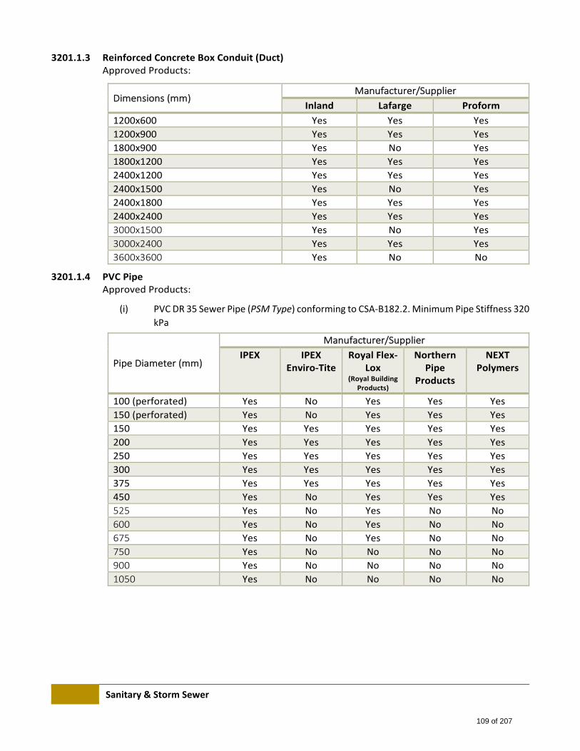
Sanitary & Storm Sewer
3201.1.3 Reinforced Concrete Box Conduit (Duct) Approved Products:
Dimensions (mm) Manufacturer/Supplier
Inland Lafarge Proform
1200x600 Yes Yes Yes
1200x900 Yes Yes Yes
1800x900 Yes No Yes
1800x1200 Yes Yes Yes
2400x1200 Yes Yes Yes
2400x1500 Yes No Yes
2400x1800 Yes Yes Yes
2400x2400 Yes Yes Yes
3000x1500 Yes No Yes
3000x2400 Yes Yes Yes
3600x3600 Yes No No
3201.1.4 PVC Pipe Approved Products:
(i) PVC DR 35 Sewer Pipe (PSM Type) conforming to CSA‐B182.2. Minimum Pipe Stiffness 320
kPa
Pipe Diameter (mm)
Manufacturer/Supplier
IPEX IPEX Enviro‐Tite
Royal Flex‐Lox
(Royal Building Products)
Northern Pipe
Products
NEXT Polymers
100 (perforated) Yes No Yes Yes Yes
150 (perforated) Yes No Yes Yes Yes
150 Yes Yes Yes Yes Yes
200 Yes Yes Yes Yes Yes
250 Yes Yes Yes Yes Yes
300 Yes Yes Yes Yes Yes
375 Yes Yes Yes Yes Yes
450 Yes No Yes Yes Yes
525 Yes No Yes No No
600 Yes No Yes No No
675 Yes No Yes No No
750 Yes No No No No
900 Yes No No No No
1050 Yes No No No No
109 of 207
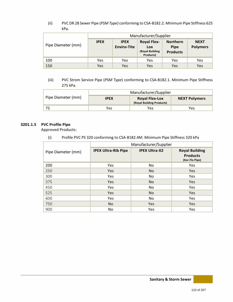
Sanitary & Storm Sewer
(ii) PVC DR 28 Sewer Pipe (PSM Type) conforming to CSA‐B182.2. Minimum Pipe Stiffness 625
kPa.
Pipe Diameter (mm)
Manufacturer/Supplier
IPEX IPEX Enviro‐Tite
Royal Flex‐Lox
(Royal Building Products)
Northern Pipe
Products
NEXT Polymers
100 Yes Yes Yes Yes Yes
150 Yes Yes Yes Yes Yes
(iii) PVC Strom Service Pipe (PSM Type) conforming to CSA‐B182.1. Minimum Pipe Stiffness
275 kPa.
Pipe Diameter (mm) Manufacturer/Supplier
IPEX Royal Flex‐Lox (Royal Building Products)
NEXT Polymers
75 Yes Yes Yes
3201.1.5 PVC Profile Pipe Approved Products:
(i) Profile PVC PS 320 conforming to CSA‐B182.4M. Minimum Pipe Stiffness 320 kPa
Pipe Diameter (mm)
Manufacturer/Supplier
IPEX Ultra‐Rib Pipe IPEX Ultra‐X2 Royal Building Products (Kor‐Flo Pipe)
200 Yes No Yes
250 Yes No Yes
300 Yes No Yes
375 Yes No Yes
450 Yes No Yes
525 Yes No Yes
600 Yes No Yes
750 No Yes Yes
900 No Yes Yes
110 of 207
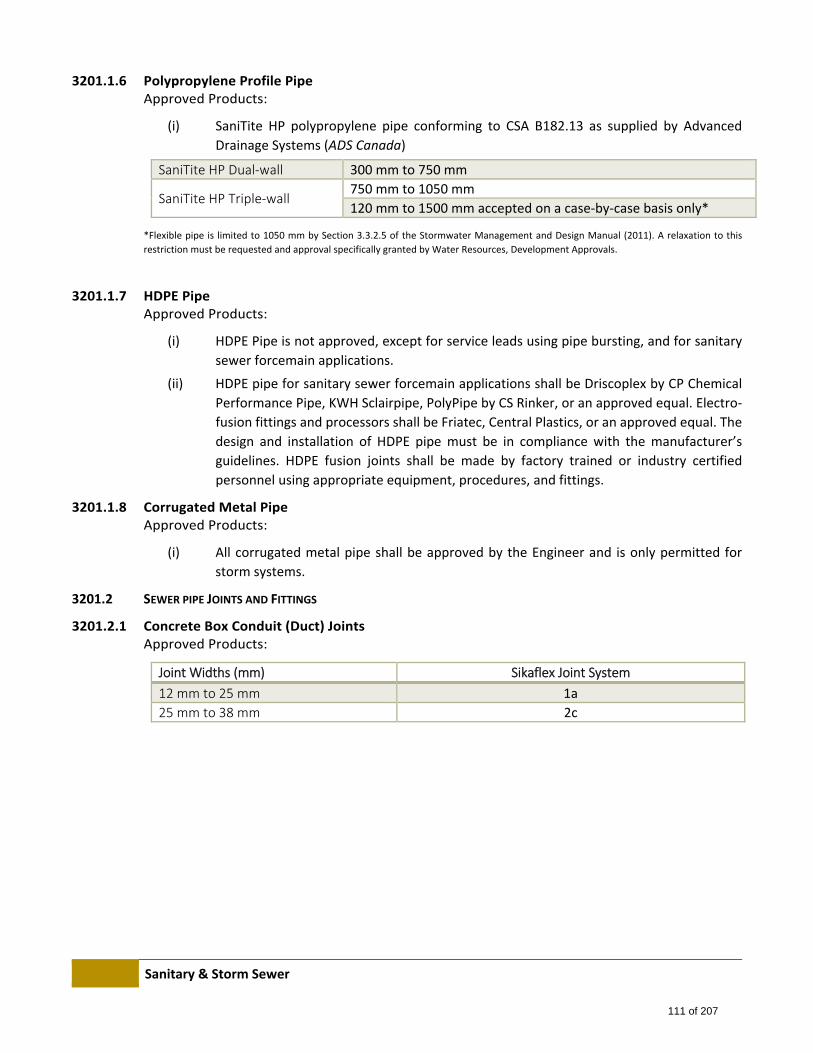
Sanitary & Storm Sewer
3201.1.6 Polypropylene Profile Pipe Approved Products:
(i) SaniTite HP polypropylene pipe conforming to CSA B182.13 as supplied by Advanced
Drainage Systems (ADS Canada)
SaniTite HP Dual‐wall 300 mm to 750 mm
SaniTite HP Triple‐wall 750 mm to 1050 mm
120 mm to 1500 mm accepted on a case‐by‐case basis only*
*Flexible pipe is limited to 1050 mm by Section 3.3.2.5 of the Stormwater Management and Design Manual (2011). A relaxation to this
restriction must be requested and approval specifically granted by Water Resources, Development Approvals.
3201.1.7 HDPE Pipe Approved Products:
(i) HDPE Pipe is not approved, except for service leads using pipe bursting, and for sanitary
sewer forcemain applications.
(ii) HDPE pipe for sanitary sewer forcemain applications shall be Driscoplex by CP Chemical
Performance Pipe, KWH Sclairpipe, PolyPipe by CS Rinker, or an approved equal. Electro‐
fusion fittings and processors shall be Friatec, Central Plastics, or an approved equal. The
design and installation of HDPE pipe must be in compliance with the manufacturer’s
guidelines. HDPE fusion joints shall be made by factory trained or industry certified
personnel using appropriate equipment, procedures, and fittings.
3201.1.8 Corrugated Metal Pipe Approved Products:
(i) All corrugated metal pipe shall be approved by the Engineer and is only permitted for
storm systems.
3201.2 SEWER PIPE JOINTS AND FITTINGS
3201.2.1 Concrete Box Conduit (Duct) Joints Approved Products:
Joint Widths (mm) Sikaflex Joint System
12 mm to 25 mm 1a
25 mm to 38 mm 2c
111 of 207
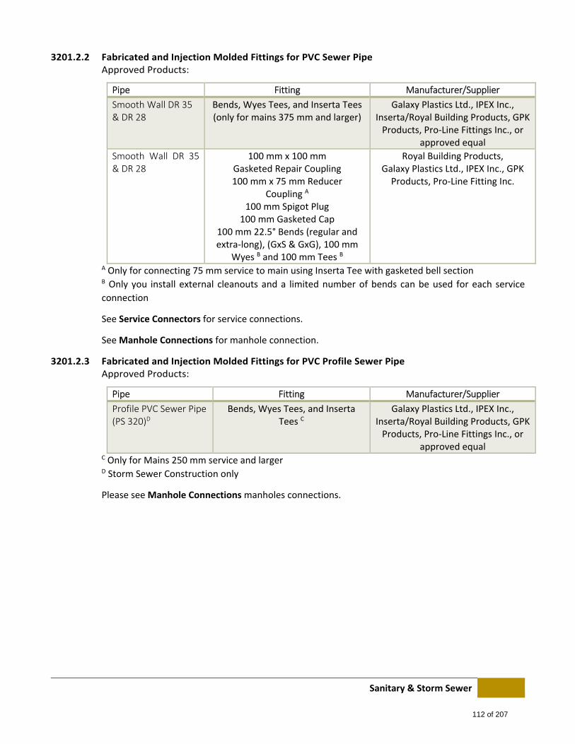
Sanitary & Storm Sewer
3201.2.2 Fabricated and Injection Molded Fittings for PVC Sewer Pipe Approved Products:
Pipe Fitting Manufacturer/Supplier
Smooth Wall DR 35 & DR 28
Bends, Wyes Tees, and Inserta Tees (only for mains 375 mm and larger)
Galaxy Plastics Ltd., IPEX Inc., Inserta/Royal Building Products, GPK Products, Pro‐Line Fittings Inc., or
approved equal
Smooth Wall DR 35 & DR 28
100 mm x 100 mm Gasketed Repair Coupling 100 mm x 75 mm Reducer
Coupling A 100 mm Spigot Plug
100 mm Gasketed Cap 100 mm 22.5° Bends (regular and extra‐long), (GxS & GxG), 100 mm
Wyes B and 100 mm Tees B
Royal Building Products, Galaxy Plastics Ltd., IPEX Inc., GPK Products, Pro‐Line Fitting Inc.
A Only for connecting 75 mm service to main using Inserta Tee with gasketed bell section B Only you install external cleanouts and a limited number of bends can be used for each service
connection
See Service Connectors for service connections.
See Manhole Connections for manhole connection.
3201.2.3 Fabricated and Injection Molded Fittings for PVC Profile Sewer Pipe Approved Products:
Pipe Fitting Manufacturer/Supplier
Profile PVC Sewer Pipe (PS 320)D
Bends, Wyes Tees, and Inserta Tees C
Galaxy Plastics Ltd., IPEX Inc., Inserta/Royal Building Products, GPK Products, Pro‐Line Fittings Inc., or
approved equal C Only for Mains 250 mm service and larger D Storm Sewer Construction only
Please see Manhole Connections manholes connections.
112 of 207
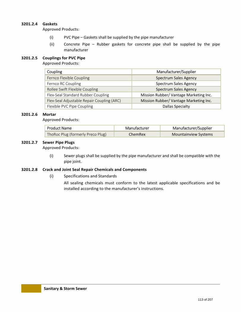
Sanitary & Storm Sewer
3201.2.4 Gaskets Approved Products:
(i) PVC Pipe – Gaskets shall be supplied by the pipe manufacturer
(ii) Concrete Pipe – Rubber gaskets for concrete pipe shall be supplied by the pipe
manufacturer
3201.2.5 Couplings for PVC Pipe Approved Products:
Coupling Manufacturer/Supplier
Fernco Flexible Coupling Spectrum Sales Agency
Fernco RC Coupling Spectrum Sales Agency
Rollee Swift Flexible Coupling Spectrum Sales Agency
Flex‐Seal Standard Rubber Coupling Mission Rubber/ Vantage Marketing Inc.
Flex‐Seal Adjustable Repair Coupling (ARC) Mission Rubber/ Vantage Marketing Inc.
Flexible PVC Pipe Coupling Dallas Specialty
3201.2.6 Mortar Approved Products:
Product Name Manufacturer Manufacturer/Supplier
ThoRoc Plug (formerly Preco Plug) ChemRex Mountainview Systems
3201.2.7 Sewer Pipe Plugs Approved Products:
(i) Sewer plugs shall be supplied by the pipe manufacturer and shall be compatible with the
pipe joint.
3201.2.8 Crack and Joint Seal Repair Chemicals and Components
(i) Specifications and Standards
All sealing chemicals must conform to the latest applicable specifications and be
installed according to the manufacturer’s instructions.
113 of 207
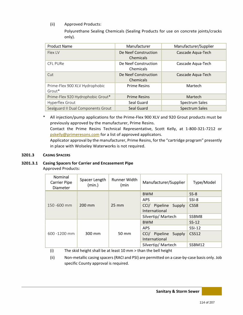
Sanitary & Storm Sewer
(ii) Approved Products:
Polyurethane Sealing Chemicals (Sealing Products for use on concrete joints/cracks
only).
Product Name Manufacturer Manufacturer/Supplier
Flex LV De Neef Construction Chemicals
Cascade Aqua‐Tech
CFL PURe De Neef Construction Chemicals
Cascade Aqua‐Tech
Cut De Neef Construction Chemicals
Cascade Aqua‐Tech
Prime‐Flex 900 XLV Hydrophobic Grout*
Prime Resins Martech
Prime‐Flex 920 Hydrophobic Grout* Prime Resins Martech
Hyperflex Grout Seal Guard Spectrum Sales
Sealguard II Dual Components Grout Seal Guard Spectrum Sales
* All injection/pump applications for the Prime‐Flex 900 XLV and 920 Grout products must be
previously approved by the manufacturer, Prime Resins.
Contact the Prime Resins Technical Representative, Scott Kelly, at 1‐800‐321‐7212 or
[email protected] for a list of approved applicators.
Applicator approval by the manufacturer, Prime Resins, for the “cartridge program” presently
in place with Wolseley Waterworks is not required.
3201.3 CASING SPACERS
3201.3.1 Casing Spacers for Carrier and Encasement Pipe Approved Products:
Nominal Carrier Pipe Diameter
Spacer Length (min.)
Runner Width (min
Manufacturer/Supplier Type/Model
150 ‐600 mm 200 mm 25 mm
BWM SS‐8
APS SSI‐8
CCI/ Pipeline Supply International
CSS8
Silvertip/ Martech SSBM8
600 ‐1200 mm 300 mm 50 mm
BWM SS‐12
APS SSI‐12
CCI/ Pipeline Supply International
CSS12
Silvertip/ Martech SSBM12
(i) The skid height shall be at least 10 mm > than the bell height
(ii) Non‐metallic casing spacers (RACI and PSI) are permitted on a case‐by‐case basis only. Job
specific County approval is required.
114 of 207
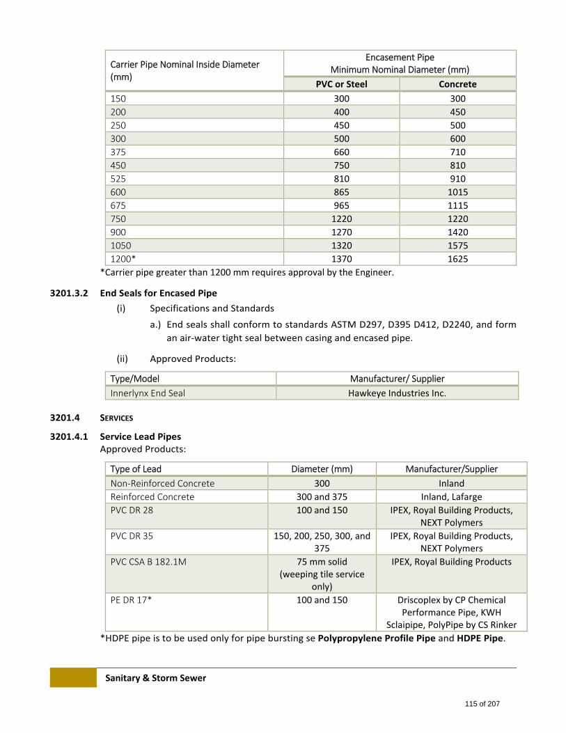
Sanitary & Storm Sewer
Carrier Pipe Nominal Inside Diameter (mm)
Encasement Pipe Minimum Nominal Diameter (mm)
PVC or Steel Concrete
150 300 300
200 400 450
250 450 500
300 500 600
375 660 710
450 750 810
525 810 910
600 865 1015
675 965 1115
750 1220 1220
900 1270 1420
1050 1320 1575
1200* 1370 1625
*Carrier pipe greater than 1200 mm requires approval by the Engineer.
3201.3.2 End Seals for Encased Pipe
(i) Specifications and Standards
a.) End seals shall conform to standards ASTM D297, D395 D412, D2240, and form
an air‐water tight seal between casing and encased pipe.
(ii) Approved Products:
Type/Model Manufacturer/ Supplier
Innerlynx End Seal Hawkeye Industries Inc.
3201.4 SERVICES
3201.4.1 Service Lead Pipes Approved Products:
Type of Lead Diameter (mm) Manufacturer/Supplier
Non‐Reinforced Concrete 300 Inland
Reinforced Concrete 300 and 375 Inland, Lafarge
PVC DR 28 100 and 150 IPEX, Royal Building Products, NEXT Polymers
PVC DR 35 150, 200, 250, 300, and 375
IPEX, Royal Building Products, NEXT Polymers
PVC CSA B 182.1M 75 mm solid (weeping tile service
only)
IPEX, Royal Building Products
PE DR 17* 100 and 150 Driscoplex by CP Chemical Performance Pipe, KWH
Sclaipipe, PolyPipe by CS Rinker
*HDPE pipe is to be used only for pipe bursting se Polypropylene Profile Pipe and HDPE Pipe.
115 of 207
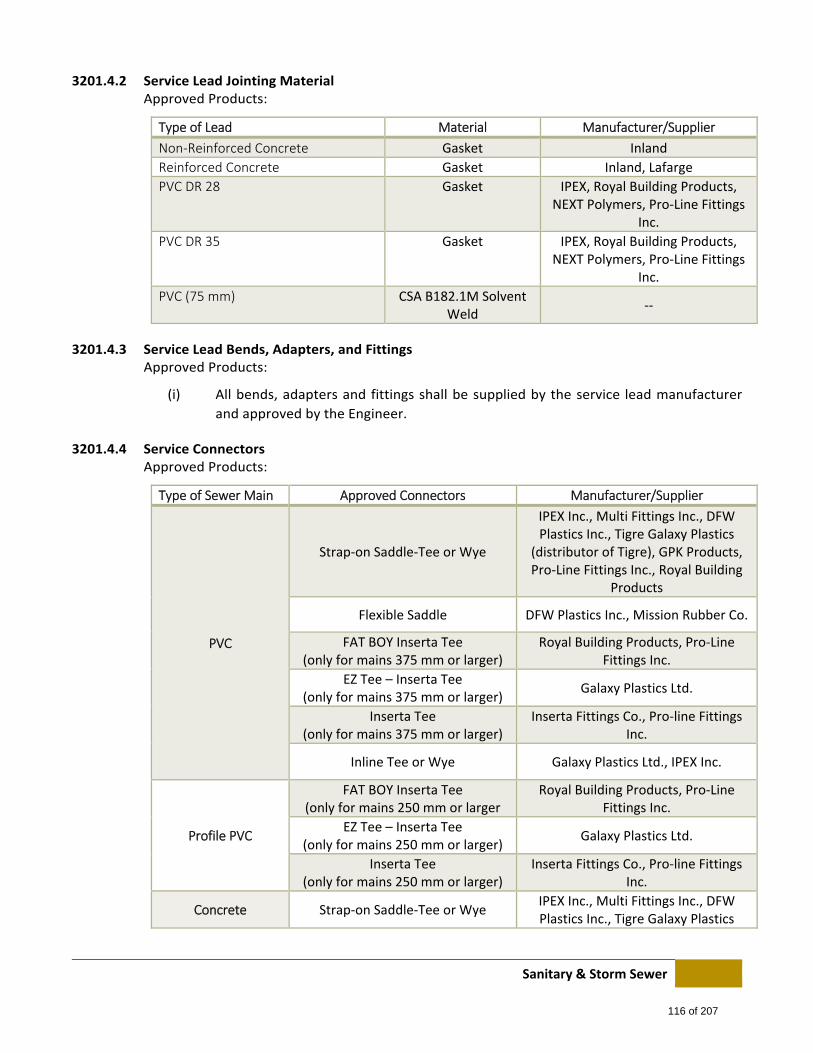
Sanitary & Storm Sewer
3201.4.2 Service Lead Jointing Material Approved Products:
Type of Lead Material Manufacturer/Supplier
Non‐Reinforced Concrete Gasket Inland
Reinforced Concrete Gasket Inland, Lafarge
PVC DR 28 Gasket IPEX, Royal Building Products, NEXT Polymers, Pro‐Line Fittings
Inc.
PVC DR 35 Gasket IPEX, Royal Building Products, NEXT Polymers, Pro‐Line Fittings
Inc.
PVC (75 mm) CSA B182.1M Solvent Weld
‐‐
3201.4.3 Service Lead Bends, Adapters, and Fittings Approved Products:
(i) All bends, adapters and fittings shall be supplied by the service lead manufacturer
and approved by the Engineer.
3201.4.4 Service Connectors Approved Products:
Type of Sewer Main Approved Connectors Manufacturer/Supplier
PVC
Strap‐on Saddle‐Tee or Wye
IPEX Inc., Multi Fittings Inc., DFW Plastics Inc., Tigre Galaxy Plastics
(distributor of Tigre), GPK Products, Pro‐Line Fittings Inc., Royal Building
Products
Flexible Saddle DFW Plastics Inc., Mission Rubber Co.
FAT BOY Inserta Tee (only for mains 375 mm or larger)
Royal Building Products, Pro‐Line Fittings Inc.
EZ Tee – Inserta Tee (only for mains 375 mm or larger)
Galaxy Plastics Ltd.
Inserta Tee (only for mains 375 mm or larger)
Inserta Fittings Co., Pro‐line Fittings Inc.
Inline Tee or Wye Galaxy Plastics Ltd., IPEX Inc.
Profile PVC
FAT BOY Inserta Tee (only for mains 250 mm or larger
Royal Building Products, Pro‐Line Fittings Inc.
EZ Tee – Inserta Tee (only for mains 250 mm or larger)
Galaxy Plastics Ltd.
Inserta Tee (only for mains 250 mm or larger)
Inserta Fittings Co., Pro‐line Fittings Inc.
Concrete Strap‐on Saddle‐Tee or Wye IPEX Inc., Multi Fittings Inc., DFW Plastics Inc., Tigre Galaxy Plastics
116 of 207
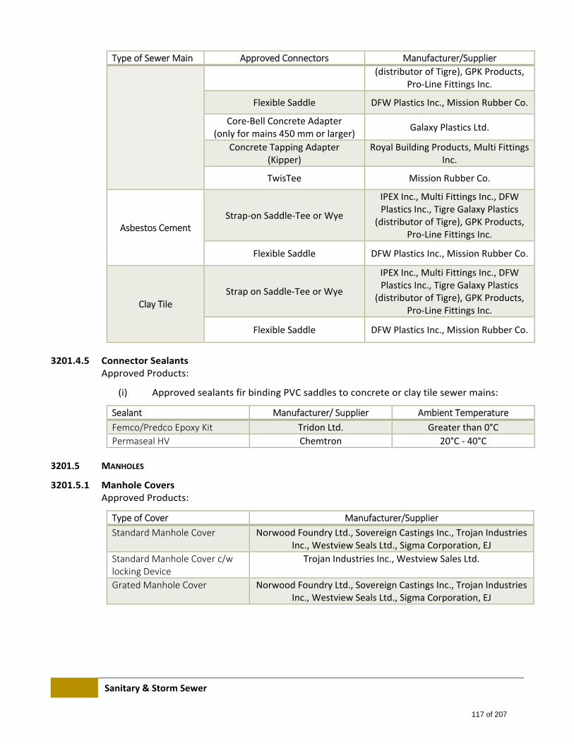
Sanitary & Storm Sewer
Type of Sewer Main Approved Connectors Manufacturer/Supplier
(distributor of Tigre), GPK Products, Pro‐Line Fittings Inc.
Flexible Saddle DFW Plastics Inc., Mission Rubber Co.
Core‐Bell Concrete Adapter (only for mains 450 mm or larger)
Galaxy Plastics Ltd.
Concrete Tapping Adapter (Kipper)
Royal Building Products, Multi Fittings Inc.
TwisTee Mission Rubber Co.
Asbestos Cement Strap‐on Saddle‐Tee or Wye
IPEX Inc., Multi Fittings Inc., DFW Plastics Inc., Tigre Galaxy Plastics
(distributor of Tigre), GPK Products, Pro‐Line Fittings Inc.
Flexible Saddle DFW Plastics Inc., Mission Rubber Co.
Clay Tile Strap on Saddle‐Tee or Wye
IPEX Inc., Multi Fittings Inc., DFW Plastics Inc., Tigre Galaxy Plastics
(distributor of Tigre), GPK Products, Pro‐Line Fittings Inc.
Flexible Saddle DFW Plastics Inc., Mission Rubber Co.
3201.4.5 Connector Sealants Approved Products:
(i) Approved sealants fir binding PVC saddles to concrete or clay tile sewer mains:
Sealant Manufacturer/ Supplier Ambient Temperature
Femco/Predco Epoxy Kit Tridon Ltd. Greater than 0°C
Permaseal HV Chemtron 20°C ‐ 40°C
3201.5 MANHOLES
3201.5.1 Manhole Covers Approved Products:
Type of Cover Manufacturer/Supplier
Standard Manhole Cover Norwood Foundry Ltd., Sovereign Castings Inc., Trojan Industries Inc., Westview Seals Ltd., Sigma Corporation, EJ
Standard Manhole Cover c/w locking Device
Trojan Industries Inc., Westview Sales Ltd.
Grated Manhole Cover Norwood Foundry Ltd., Sovereign Castings Inc., Trojan Industries Inc., Westview Seals Ltd., Sigma Corporation, EJ
117 of 207
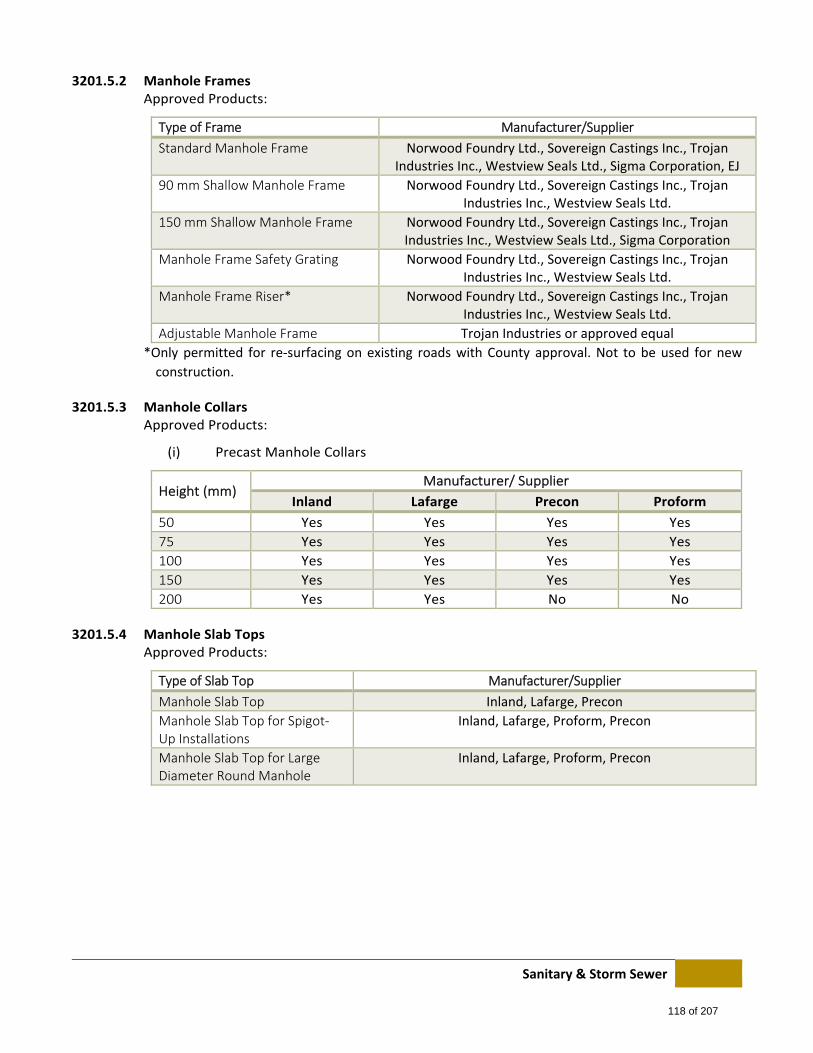
Sanitary & Storm Sewer
3201.5.2 Manhole Frames Approved Products:
Type of Frame Manufacturer/Supplier
Standard Manhole Frame Norwood Foundry Ltd., Sovereign Castings Inc., Trojan Industries Inc., Westview Seals Ltd., Sigma Corporation, EJ
90 mm Shallow Manhole Frame Norwood Foundry Ltd., Sovereign Castings Inc., Trojan Industries Inc., Westview Seals Ltd.
150 mm Shallow Manhole Frame Norwood Foundry Ltd., Sovereign Castings Inc., Trojan Industries Inc., Westview Seals Ltd., Sigma Corporation
Manhole Frame Safety Grating Norwood Foundry Ltd., Sovereign Castings Inc., Trojan Industries Inc., Westview Seals Ltd.
Manhole Frame Riser* Norwood Foundry Ltd., Sovereign Castings Inc., Trojan Industries Inc., Westview Seals Ltd.
Adjustable Manhole Frame Trojan Industries or approved equal
*Only permitted for re‐surfacing on existing roads with County approval. Not to be used for new
construction.
3201.5.3 Manhole Collars Approved Products:
(i) Precast Manhole Collars
Height (mm) Manufacturer/ Supplier
Inland Lafarge Precon Proform
50 Yes Yes Yes Yes
75 Yes Yes Yes Yes
100 Yes Yes Yes Yes
150 Yes Yes Yes Yes
200 Yes Yes No No
3201.5.4 Manhole Slab Tops Approved Products:
Type of Slab Top Manufacturer/Supplier
Manhole Slab Top Inland, Lafarge, Precon
Manhole Slab Top for Spigot‐Up Installations
Inland, Lafarge, Proform, Precon
Manhole Slab Top for Large Diameter Round Manhole
Inland, Lafarge, Proform, Precon
118 of 207
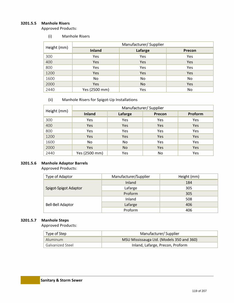
Sanitary & Storm Sewer
3201.5.5 Manhole Risers Approved Products:
(i) Manhole Risers
Height (mm) Manufacturer/ Supplier
Inland Lafarge Precon
300 Yes Yes Yes
400 Yes Yes Yes
800 Yes Yes Yes
1200 Yes Yes Yes
1600 No No No
2000 Yes No Yes
2440 Yes (2500 mm) Yes No
(ii) Manhole Risers for Spigot‐Up Installations
Height (mm) Manufacturer/ Supplier
Inland Lafarge Precon Proform
300 Yes Yes Yes Yes
400 Yes Yes Yes Yes
800 Yes Yes Yes Yes
1200 Yes Yes Yes Yes
1600 No No Yes Yes
2000 Yes No Yes Yes
2440 Yes (2500 mm) Yes No Yes
3201.5.6 Manhole Adaptor Barrels Approved Products:
Type of Adaptor Manufacturer/Supplier Height (mm)
Spigot‐Spigot Adaptor
Inland 184
Lafarge 305
Proform 305
Bell‐Bell Adaptor
Inland 508
Lafarge 406
Proform 406
3201.5.7 Manhole Steps Approved Products:
Type of Step Manufacturer/ Supplier
Aluminum MSU Mississauga Ltd. (Models 350 and 360)
Galvanized Steel Inland, Lafarge, Precon, Proform
119 of 207
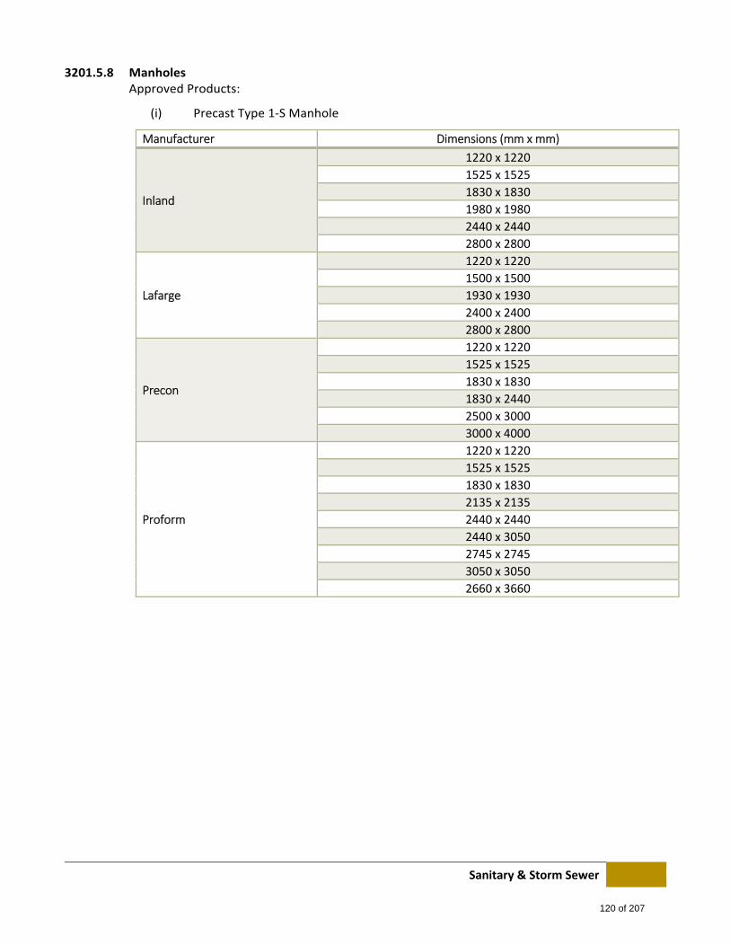
Sanitary & Storm Sewer
3201.5.8 Manholes Approved Products:
(i) Precast Type 1‐S Manhole
Manufacturer Dimensions (mm x mm)
Inland
1220 x 1220
1525 x 1525
1830 x 1830
1980 x 1980
2440 x 2440
2800 x 2800
Lafarge
1220 x 1220
1500 x 1500
1930 x 1930
2400 x 2400
2800 x 2800
Precon
1220 x 1220
1525 x 1525
1830 x 1830
1830 x 2440
2500 x 3000
3000 x 4000
Proform
1220 x 1220
1525 x 1525
1830 x 1830
2135 x 2135
2440 x 2440
2440 x 3050
2745 x 2745
3050 x 3050
2660 x 3660
120 of 207
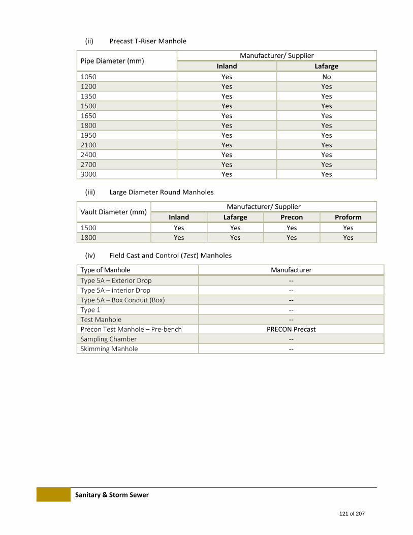
Sanitary & Storm Sewer
(ii) Precast T‐Riser Manhole
Pipe Diameter (mm) Manufacturer/ Supplier
Inland Lafarge
1050 Yes No
1200 Yes Yes
1350 Yes Yes
1500 Yes Yes
1650 Yes Yes
1800 Yes Yes
1950 Yes Yes
2100 Yes Yes
2400 Yes Yes
2700 Yes Yes
3000 Yes Yes
(iii) Large Diameter Round Manholes
Vault Diameter (mm) Manufacturer/ Supplier
Inland Lafarge Precon Proform
1500 Yes Yes Yes Yes
1800 Yes Yes Yes Yes
(iv) Field Cast and Control (Test) Manholes
Type of Manhole Manufacturer
Type 5A – Exterior Drop ‐‐
Type 5A – interior Drop ‐‐
Type 5A – Box Conduit (Box) ‐‐
Type 1 ‐‐
Test Manhole ‐‐
Precon Test Manhole – Pre‐bench PRECON Precast
Sampling Chamber ‐‐
Skimming Manhole ‐‐
121 of 207
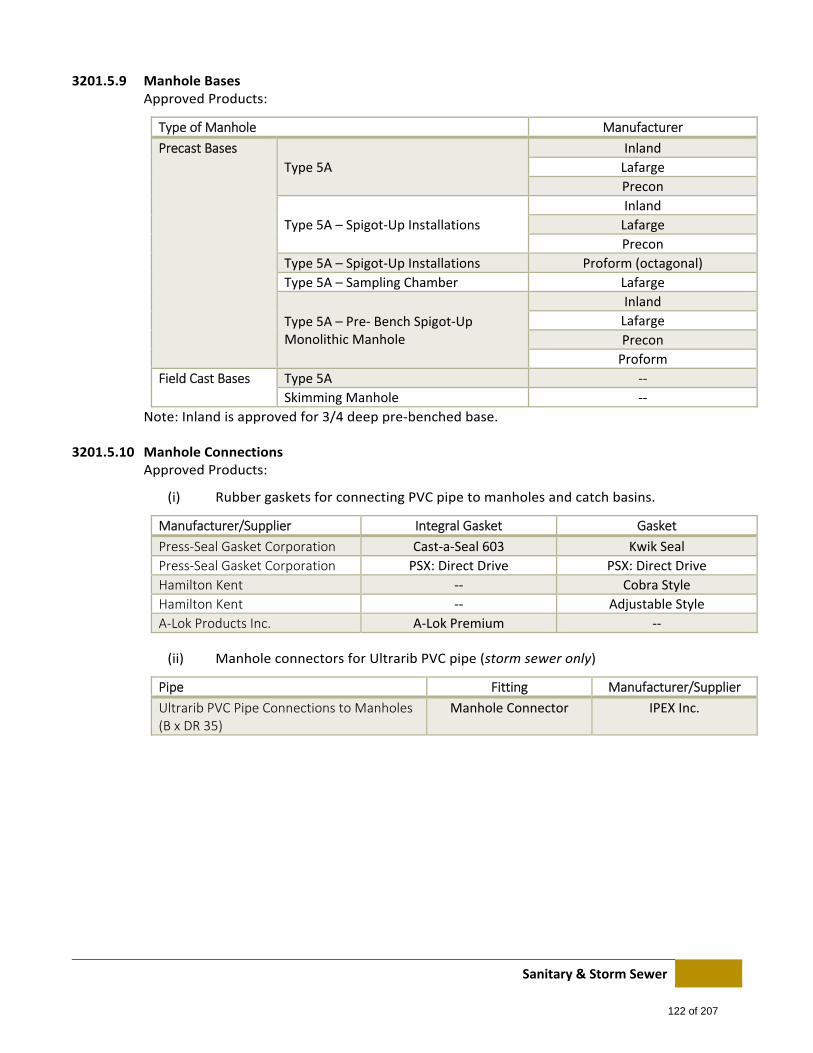
Sanitary & Storm Sewer
3201.5.9 Manhole Bases Approved Products:
Type of Manhole Manufacturer
Precast Bases
Type 5A
Inland
Lafarge
Precon
Type 5A – Spigot‐Up Installations
Inland
Lafarge
Precon
Type 5A – Spigot‐Up Installations Proform (octagonal)
Type 5A – Sampling Chamber Lafarge
Type 5A – Pre‐ Bench Spigot‐Up Monolithic Manhole
Inland
Lafarge
Precon
Proform
Field Cast Bases Type 5A ‐‐
Skimming Manhole ‐‐
Note: Inland is approved for 3/4 deep pre‐benched base.
3201.5.10 Manhole Connections Approved Products:
(i) Rubber gaskets for connecting PVC pipe to manholes and catch basins.
Manufacturer/Supplier Integral Gasket Gasket
Press‐Seal Gasket Corporation Cast‐a‐Seal 603 Kwik Seal
Press‐Seal Gasket Corporation PSX: Direct Drive PSX: Direct Drive
Hamilton Kent ‐‐ Cobra Style
Hamilton Kent ‐‐ Adjustable Style
A‐Lok Products Inc. A‐Lok Premium ‐‐
(ii) Manhole connectors for Ultrarib PVC pipe (storm sewer only)
Pipe Fitting Manufacturer/Supplier
Ultrarib PVC Pipe Connections to Manholes (B x DR 35)
Manhole Connector IPEX Inc.
122 of 207
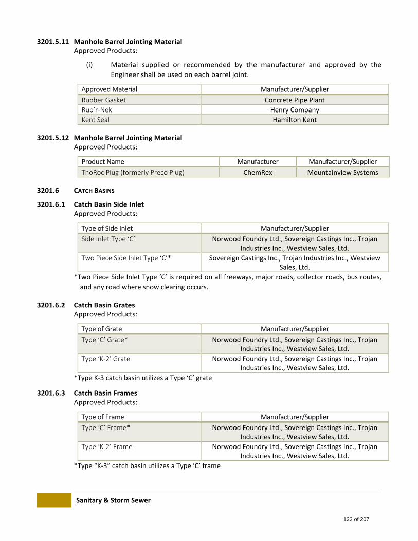
Sanitary & Storm Sewer
3201.5.11 Manhole Barrel Jointing Material Approved Products:
(i) Material supplied or recommended by the manufacturer and approved by the
Engineer shall be used on each barrel joint.
Approved Material Manufacturer/Supplier
Rubber Gasket Concrete Pipe Plant
Rub’r‐Nek Henry Company
Kent Seal Hamilton Kent
3201.5.12 Manhole Barrel Jointing Material Approved Products:
Product Name Manufacturer Manufacturer/Supplier
ThoRoc Plug (formerly Preco Plug) ChemRex Mountainview Systems
3201.6 CATCH BASINS
3201.6.1 Catch Basin Side Inlet Approved Products:
Type of Side Inlet Manufacturer/Supplier
Side Inlet Type ‘C’ Norwood Foundry Ltd., Sovereign Castings Inc., Trojan Industries Inc., Westview Sales, Ltd.
Two Piece Side Inlet Type ‘C’* Sovereign Castings Inc., Trojan Industries Inc., Westview Sales, Ltd.
*Two Piece Side Inlet Type ‘C’ is required on all freeways, major roads, collector roads, bus routes,
and any road where snow clearing occurs.
3201.6.2 Catch Basin Grates Approved Products:
Type of Grate Manufacturer/Supplier
Type ‘C’ Grate* Norwood Foundry Ltd., Sovereign Castings Inc., Trojan Industries Inc., Westview Sales, Ltd.
Type ‘K‐2’ Grate Norwood Foundry Ltd., Sovereign Castings Inc., Trojan Industries Inc., Westview Sales, Ltd.
*Type K‐3 catch basin utilizes a Type ‘C’ grate
3201.6.3 Catch Basin Frames Approved Products:
Type of Frame Manufacturer/Supplier
Type ‘C’ Frame* Norwood Foundry Ltd., Sovereign Castings Inc., Trojan Industries Inc., Westview Sales, Ltd.
Type ‘K‐2’ Frame Norwood Foundry Ltd., Sovereign Castings Inc., Trojan Industries Inc., Westview Sales, Ltd.
*Type “K‐3” catch basin utilizes a Type ‘C’ frame
123 of 207
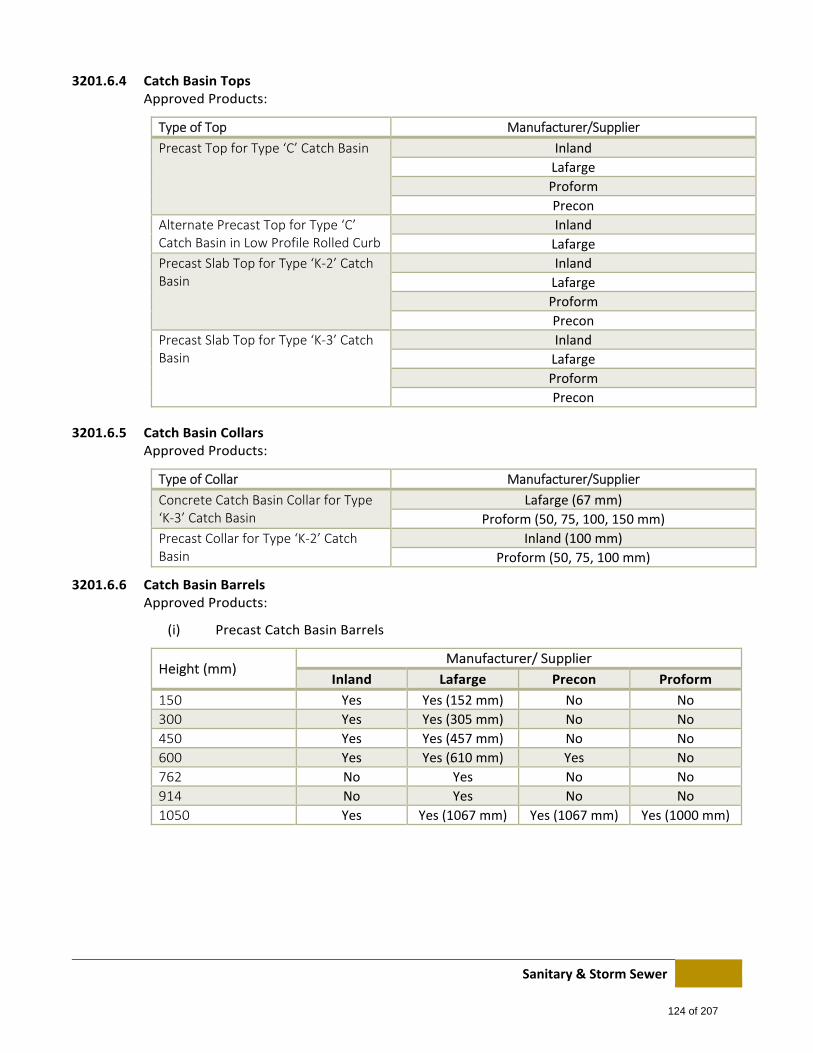
Sanitary & Storm Sewer
3201.6.4 Catch Basin Tops Approved Products:
Type of Top Manufacturer/Supplier
Precast Top for Type ‘C’ Catch Basin Inland
Lafarge
Proform
Precon
Alternate Precast Top for Type ‘C’ Catch Basin in Low Profile Rolled Curb
Inland
Lafarge
Precast Slab Top for Type ‘K‐2’ Catch Basin
Inland
Lafarge
Proform
Precon
Precast Slab Top for Type ‘K‐3’ Catch Basin
Inland
Lafarge
Proform
Precon
3201.6.5 Catch Basin Collars Approved Products:
Type of Collar Manufacturer/Supplier
Concrete Catch Basin Collar for Type ‘K‐3’ Catch Basin
Lafarge (67 mm)
Proform (50, 75, 100, 150 mm)
Precast Collar for Type ‘K‐2’ Catch Basin
Inland (100 mm)
Proform (50, 75, 100 mm)
3201.6.6 Catch Basin Barrels Approved Products:
(i) Precast Catch Basin Barrels
Height (mm) Manufacturer/ Supplier
Inland Lafarge Precon Proform
150 Yes Yes (152 mm) No No
300 Yes Yes (305 mm) No No
450 Yes Yes (457 mm) No No
600 Yes Yes (610 mm) Yes No
762 No Yes No No
914 No Yes No No
1050 Yes Yes (1067 mm) Yes (1067 mm) Yes (1000 mm)
124 of 207
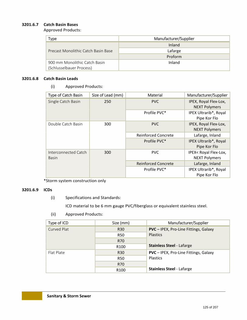
Sanitary & Storm Sewer
3201.6.7 Catch Basin Bases Approved Products:
Type Manufacturer/Supplier
Precast Monolithic Catch Basin Base
Inland
Lafarge
Proform
900 mm Monolithic Catch Basin (Schlusselbauer Process)
Inland
3201.6.8 Catch Basin Leads
(i) Approved Products:
Type of Catch Basin Size of Lead (mm) Material Manufacturer/Supplier
Single Catch Basin 250 PVC IPEX, Royal Flex‐Lox, NEXT Polymers
Profile PVC* IPEX Ultrarib*, Royal Pipe Kor Flo
Double Catch Basin 300 PVC IPEX, Royal Flex‐Lox, NEXT Polymers
Reinforced Concrete Lafarge, Inland
Profile PVC* IPEX Ultrarib*, Royal Pipe Kor Flo
Interconnected Catch Basin
300 PVC IPEX< Royal Flex‐Lox, NEXT Polymers
Reinforced Concrete Lafarge, Inland
Profile PVC* IPEX Ultrarib*, Royal Pipe Kor Flo
*Storm system construction only
3201.6.9 ICDs
(i) Specifications and Standards:
ICD material to be 6 mm gauge PVC/fiberglass or equivalent stainless steel.
(ii) Approved Products:
Type of ICD Size (mm) Manufacturer/Supplier
Curved Plat R30 PVC – IPEX, Pro‐Line Fittings, Galaxy Plastics Stainless Steel ‐ Lafarge
R50
R70
R100
Flat Plate R30 PVC – IPEX, Pro‐Line Fittings, Galaxy Plastics Stainless Steel ‐ Lafarge
R50
R70
R100
125 of 207
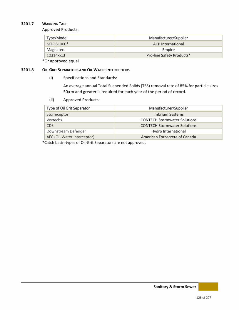
Sanitary & Storm Sewer
3201.7 WARNING TAPE
Approved Products:
Type/Model Manufacturer/Supplier
MTP 61000* ACP International
Magnatec Empire
10314xxx3 Pro‐line Safety Products*
*Or approved equal
3201.8 OIL‐GRIT SEPARATORS AND OIL WATER INTERCEPTORS
(i) Specifications and Standards:
An average annual Total Suspended Solids (TSS) removal rate of 85% for particle sizes
50m and greater is required for each year of the period of record.
(ii) Approved Products:
Type of Oil Grit Separator Manufacturer/Supplier
Stormceptor Imbrium Systems
Vortechs CONTECH Stormwater Solutions
CDS CONTECH Stormwater Solutions
Downstream Defender Hydro International
AFC (Oil‐Water Interceptor) American Forcecrete of Canada
*Catch basin‐types of Oil‐Grit Separators are not approved.
126 of 207
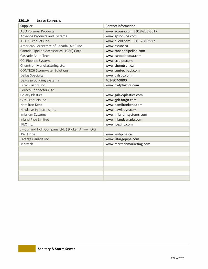
Sanitary & Storm Sewer
3201.9 LIST OF SUPPLIERS
Supplier Contact Information
ACO Polymer Products www.acousa.com | 918‐258‐3517
Advance Products and Systems www.apsonline.com
A‐LOK Products Inc. www.a‐lokl.com | 918‐258‐3517
American Forcecrete of Canada (APS) Inc. www.ascinc.ca
Canada Pipeline Accessories (1986) Corp. www.canadapipeline.com
Cascade Aqua‐Tech www.cascadeaqua.com
CCI Pipeline Systems www.ccipipe.com
Chemtron Manufacturing Ltd. www.chemtron.ca
CONTECH Stormwater Solutions www.contech‐cpi.com
Dallas Specialty www.dalspc.com
Degussa Building Systems 403‐807‐9800
DFW Plastics Inc. www.dwfplastics.com
Fernco Connectors Ltd.
Galaxy Plastics www.galaxyplastics.com
GPK Products Inc. www.gpk‐fargo.com
Hamilton Kent www.hamiltonkent.com
Hawkeye Industries Inc. www.hawk‐eye.com
Imbrium Systems www.imbriumsystems.com
Inland Pipe Limited www.inlandcanada.com
IPEX Inc. www.ipexinc.com
J‐Four and Hoff Company Ltd. ( Broken Arrow, OK)
KWH Pipe www.kwhpipe.ca
Lafarge Canada Inc. www.lafargepipe.com
Martech www.martechmarketing.com
127 of 207
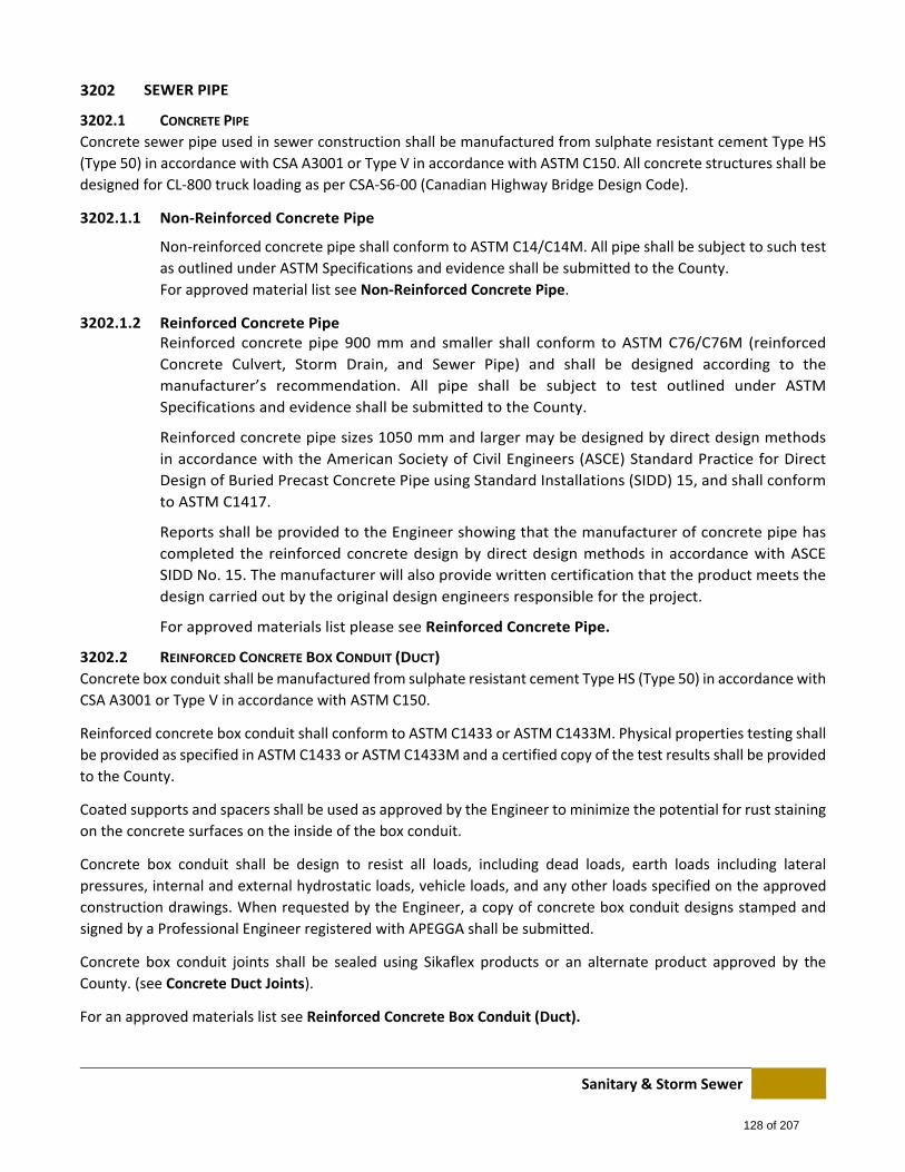
Sanitary & Storm Sewer
SEWER PIPE
3202.1 CONCRETE PIPE
Concrete sewer pipe used in sewer construction shall be manufactured from sulphate resistant cement Type HS
(Type 50) in accordance with CSA A3001 or Type V in accordance with ASTM C150. All concrete structures shall be
designed for CL‐800 truck loading as per CSA‐S6‐00 (Canadian Highway Bridge Design Code).
3202.1.1 Non‐Reinforced Concrete Pipe
Non‐reinforced concrete pipe shall conform to ASTM C14/C14M. All pipe shall be subject to such test
as outlined under ASTM Specifications and evidence shall be submitted to the County.
For approved material list see Non‐Reinforced Concrete Pipe.
3202.1.2 Reinforced Concrete Pipe Reinforced concrete pipe 900 mm and smaller shall conform to ASTM C76/C76M (reinforced
Concrete Culvert, Storm Drain, and Sewer Pipe) and shall be designed according to the
manufacturer’s recommendation. All pipe shall be subject to test outlined under ASTM
Specifications and evidence shall be submitted to the County.
Reinforced concrete pipe sizes 1050 mm and larger may be designed by direct design methods
in accordance with the American Society of Civil Engineers (ASCE) Standard Practice for Direct
Design of Buried Precast Concrete Pipe using Standard Installations (SIDD) 15, and shall conform
to ASTM C1417.
Reports shall be provided to the Engineer showing that the manufacturer of concrete pipe has
completed the reinforced concrete design by direct design methods in accordance with ASCE
SIDD No. 15. The manufacturer will also provide written certification that the product meets the
design carried out by the original design engineers responsible for the project.
For approved materials list please see Reinforced Concrete Pipe.
3202.2 REINFORCED CONCRETE BOX CONDUIT (DUCT)
Concrete box conduit shall be manufactured from sulphate resistant cement Type HS (Type 50) in accordance with
CSA A3001 or Type V in accordance with ASTM C150.
Reinforced concrete box conduit shall conform to ASTM C1433 or ASTM C1433M. Physical properties testing shall
be provided as specified in ASTM C1433 or ASTM C1433M and a certified copy of the test results shall be provided
to the County.
Coated supports and spacers shall be used as approved by the Engineer to minimize the potential for rust staining
on the concrete surfaces on the inside of the box conduit.
Concrete box conduit shall be design to resist all loads, including dead loads, earth loads including lateral
pressures, internal and external hydrostatic loads, vehicle loads, and any other loads specified on the approved
construction drawings. When requested by the Engineer, a copy of concrete box conduit designs stamped and
signed by a Professional Engineer registered with APEGGA shall be submitted.
Concrete box conduit joints shall be sealed using Sikaflex products or an alternate product approved by the
County. (see Concrete Duct Joints).
For an approved materials list see Reinforced Concrete Box Conduit (Duct).
128 of 207
Sanitary & Storm Sewer
3202.3 PVC PIPE
All PVC pipe shall be CSA approved. Materials used for pipe shall come from a single compound manufacturer and
have a cell classification of 12454‐B, 12454‐C, or 12364‐C as defined in ASTM D1784 (Rigid PVC Compounds and
CPVC Compounds).
All PVC pipe shall meet the physical requirements given in CSA B182.1M (Plastic Drain and Sewer Pipe and Pipe
Fittings), CSA B182.2M (PVC Sewer Pipe and Fittings). All pipe shall be subject to such teste as required in the CSA
standards and results for specific pipe data shall be submitted to the County if requested.
PVC Shall be installed according to ASTM D2321 (Underground Installation of Flexible Thermo‐Plastic Sewer Pipe).
For an approved materials list see PVC Pipe.
3202.4 CORRUGATED METAL PIPE
All materials shall conform to the CSA G401 and shall be subject to such tests as outlined in that standard.
Corrugated metal pipe shall only be used for storm sewer mains to which there are no direct connections from
catch basins or house services (weeping tile drains), and only where specifically approved for use by the County.
3202.4.1 Materials
(i.) Pipe
Pipe shall have helical corrugated lock seams with ends re‐corrugated to provide annular
corrugations for couplers. Riveted pipe is not accepted.
(ii.) Couplers
Couplers shall be of sufficient length so as to extend over a minimum of 2 complete
corrugation crests and valleys on each pipe end, and shall be capable of providing a water
tight joint when installed with gaskets in accordance with the manufacturer’s
recommendations.
The coupler shall have a sufficient number of closure bolts such that when the coupler is
drawn closed all parts of the coupler have uniform tension and there is no wrapping or
distortion on any part of the coupler
Couplers must be supplied by the pipe manufacturer.
(iii.) Gaskets
Gaskets shall be one‐piece sleeve or wrap‐around strip type, supplied by the pipe
manufacturer, or sufficient thickness to fill the annular space between the pipe and
coupler to provide an effective water tight joint.
3202.5 PROFILE PIPE
3202.5.1 PVC Profile Pipe Profile PVC storm sewer pipe shall be CSA certified and shall conform to CSA B182.4 (Profile PVC
pipe and Fittings), and shall be subject to such tests as outlined under the standard. Materials
used for pipe and fittings shall come from a single compound manufacturer and have a cell
classification of 12454‐B, 12454‐C, or 12364‐C as defined in ASTM D1784 (Rigid PVC Compounds
and CPVC Compounds).
129 of 207
Sanitary & Storm Sewer
Profile PVC pipe shall conform to ASTM F794 (Standard Specification for Poly Vinyl Chloride (PVC)
Profile Gravity Sewer Pipe and Fittings Based on Controlled Inside Diameter).
PVC Profile Pipe is to be used in storm system construction only.
For approved materials list see PVC Profile Pipe.
3202.5.2 Polypropylene Profile Pipe Profile Polypropylene Pipe shall conform to CSA B182.13 and shall be subject to such tests as
outlined under the standard. Materials used for pipe and fittings shall come from a single
compound manufacturer.
Polypropylene Profile Pipe is to be used in storm sewer system construction only.
SaniTite HP shall be dual‐wall for sizes 300 to 750 mm, and triple‐wall for sizes 750 to 1500 mm.
Polypropylene Profile Pipe requires a maximum aggregate size of 20 mm for pipe embedment of
all sizes of dual‐wall pipe up to the maximum pipe size of 750 mm. 120 mm to 1500 mm pipe
sizes are permitted only with approval on a case by case basis.
For an approved materials list see Polypropylene Profile Pipe.
3202.6 HDPE PIPE
HDPE Pipe products are not approved for use except for service leads using pipe bursting. (see HDPE Pipe Bursting
Procedure for Replacing Sanitary Services), and for sanitary sewer forcemain applications.
For service lead applications using pipe bursting, HDPE materials for pipe and fittings shall come from a single
compound manufacturer and conform to ASTM D3350. Closed and open profile pipe products and fittings shall
conform to sections 4 and 5 of CSA B182.6 and CSA 182.8 for manufactured quality and dimensional tolerances.
Resin compounds shall be tested for slow creak growth resistance as per Appendix SP‐NCTL in ASTM D5397 as
modified in Clause 8.8 of CSA B182.8.
For sanitary sewer forcemain application, HDPE pipe and fittings shall conform to the AWWA C906‐99 Standard
and shall be PE 32408 with a dimension ratio (DR) 11 and working pressure rating (WPR) 160 psi, unless otherwise
approved.
For sanitary sewer forcemain applications, please refer to the Standard Specifications: Waterworks Construction.
The following exception to the Waterworks Specification shall apply: HDPE pipe for sanitary sewer forcemain use
must be identified by green longitudinal printing, striping, or a green outer shell.
The outside diameter (OD) shall conform to ductile iron (DIPS) unless otherwise approved by the Engineer. HDPE
project design shall conform to the design principals outlines by AWWA M55 Design Manual.
Operator certification for each fusing method employed on a project shall be presented for inspection and shall
have a date no more than one calendar year previous to be considered valid. All butt and electro‐fusion shall be
performed in the presence of the Engineer unless otherwise approved. Microprocessor fusing logs shall be
submitted to the Engineer for every butt fuse made, and for each electro‐fuse fitting where used. Butt fusing shall
bot commence onsite until the Fusing Operator has successfully completed a “Bent Strap” test (as per the Plastics
Pipe Institute Handbook) to the satisfaction of the Engineer.
130 of 207
Sanitary & Storm Sewer
SEWER PIPE JOINTS, FITTINGS, AND CASING SPACERS
3203.1 GASKETS
3203.1.1 Gaskets for PVC Pipe Gaskets shall be supplied by the manufacturer. All gaskets shall conform to ASTM F477
(Elastomeric Seals (Gaskets) for Joining Plastic Pipe) and shall be subject to such test as outlined
under the ASTM Specifications.
3203.1.2 Gaskets for Concrete Pipe All gaskets shall conform to CSA A257‐3 (Joints for Circular Concrete Sewer and Culvert Pipe,
Manhole Section, and Fitting Using Rubber Gaskets) of ASTM C443 (Joints for Circular Concrete
Sewer and Culvert Pipe (Using Rubber Gaskets)), and shall be subject to such test as outlined
under the Specifications.
3203.2 MORTAR
Mortar, if specifically required and approved for pipe joints, shall consist of one part sulphate resistant cement
Type HS (Type 50) in accordance with CSA A3001 or Type V in accordance with ASTM C150 to two parts of clear
sharp sand.
3203.3 SEWER PIPE PLUGS
Manufactured plugs shall be supplied by the pipe manufacturer or shall conform to the following and shall be as
watertight as possible:
.1 For 100 mm – 600 mm diameter pipe, an 18 mm plywood plug cut to fit the inside of the pipe’s bell.
.2 For pipe diameter greater than 600 mm all plugs to be approved by the Engineer.
3203.4 CONCRETE DUCT JOINTS
Joints shall be sealed using Sikaflex products and joint systems or an alternate product approved by the County
on a site specific basis.
Sikaflex products shall adhere to the following ASTM Specifications.
C 679 Standard Test Method for Tack‐Free Time of Elastomeric Sealants
C 719 Standard Test Method for Adhesion and Cohesion of Elastomeric Joint Sealants Under Cyclic Movement (Hockamn Cycle)
D 412 Standard Test Methods for Vulcanized Rubber and Thermoplastic Elastomers
D 624 Standard Test Method for Tear Strength of Conventional Vulcanized Rubber and Thermoplastic Elastomers
D 2240 Standard Test Method for Rubber Property – Durometer Hardness
Sikaflex products and systems must be installed by an applicator approved by Sikaflex Canada. Contact and Sika
Canada Technical Representative (Sean Coghlan) at 403‐861‐3456 (cell) of [email protected], or 403‐995‐
3540 (local office) or 1‐800‐933‐7452 (National Office) for a list of approved applicators.
For joint widths 12 mm to 25 mm, use a Sikaflex 1a joint system. For joint widths 25 mm to 38 mm, use a Sikaflex
2c joint system.
For joint widths less than 12 mm or exceeding 38 mm, or for unusual or special conditions, contact manufacturer
for recommendation on materials and practices. Note: these products are not intended to prevent moisture
penetration through the joint due to outside hydrostatic pressure.
131 of 207
Sanitary & Storm Sewer
Minimum joint width shall be 12 mm and maximum joint width shall be 30 mm.
Prevent three‐sided adhesion by using ethafoam rod (backing rod) at a 25% larger diameter than the joint width,
or for shallow, wide joints use a bond breaker tape that covers the entire bottom of the joint.
Follow all installation procedures recommended by the manufacturer.
All joints shall be completely cleaned of all debris and moisture in accordance with the sealant manufacturer’s
recommendations prior to applying primer. Sealant shall not be installed is any moisture is evident on the
application surface.
Apply primer to surfaces to receive sealant in accordance with the manufacture’s recommendations.
To ensure optimal binding conditions, install joint sealant a minimum of 28 days after the date of fabrication
stamped on the concrete duct and, in all cases, within 28 days of duct installation.
3203.5 FABRICATED AND INJECTION MOLDED FITTINGS AND COUPLINGS FOR PVC SEWER PIPE
All fittings shall have a CSA sticker and be approved under CSA B182.2 (PVC Sewer Pipe and Fittings PSM Type_ or
CSA B182.4 (Profile OVC Sewer Pipe and Fittings). Materials used for molded fittings shall come from a single
compound manufacturer and have a cell classification of 12364‐C, 12454‐B, 12454‐C, or 13343‐C as defined in
ASTM D1784 (Rigid PVC Compounds and CPVC Compounds).
Locations proposed for Fabricated Fittings must be shown on the Construction Drawings and approved by the
Engineer.
All couplings must be CSA approved and conform to ASTM C1173‐06, D5926‐04, and shall be subject to such tests
as outlined under the ASTM specifications.
3203.6 CASING SPACERS FOR CARRIER AND ENCASEMENT PIPE
Skid height shall be such that there is a maximum space for 25 mm between the skid and casing pipe. If space is
greater than 25 mm the void must be filled with sand or grout.
3203.6.1 Encasement Pipe See Encasement Pipe for specification and sizing information.
3203.6.2 Carrier Pipe See Carrier Pipe for information.
SERVICES
3204.1 SERVICE LEADS
All pipe materials shall conform to the material specification set forward within Sewer Pipe.
The pipe diameter for service leads shall be limited to the sizes for the type of pipe shown in Service Lead Pipes.
For polyethylene pipe bursting requirements for service line replacements, refer to the pipe bursting procedures
for replacing sanitary services detailed in HDPE Pipe Bursting Procedures for Replacing Sanitary Services.
3204.2 SERVICE LEAD JOINTING MATERIAL
All service lead joints shall be made watertight and root proof with jointing materials supplied by the
manufacturer. All jointing materials shall be approved by the Engineer prior to use.
For approved materials see Service Lead Jointing Material.
132 of 207
Sanitary & Storm Sewer
3204.3 SERVICE LEAD BENDS, ADAPTORS, FITTINGS, AND CONNECTORS
All bends, adaptors and fittings shall be supplied by the service lead manufacturer and approved by the Engineer.
Bends consisting of a 22.5° deflection shall be used when required as per the Canadian Plumbing Code.
All service lead bends, adaptors, and fitting shall conform to the material specifications set forward within Sewer
Pipe Joints, Fittings, and Casing Spacers.
All service connectors shall conform to the material specifications set forward within PVC Pipe.
3204.4 CONNECTOR SEALANTS
All sealants used for bonding service saddles to sewer mains shall be approved by the Engineer. For approved
materials see Approved Products: Connector sealants.
MANHOLES
3205.1 MANHOLES – GENERAL
All concrete used in the construction of manholes shall be manufactured from sulphate resistant cement Type HS
(Type 50) in accordance with CSA A3001 or Type V in accordance with ASTM C150. All concrete structures shall be
designed for CL‐800 truck loading as per CSA‐S6‐00 (Canadian Highway Bridge Design Code_. All precast reinforced
concrete manhole sections shall conform to ASTM C478.
Concrete compressive strength shall be 3 0 MPa (35 35 MPa for Box Conduit) at 28 days and air content shall be
4 to 7% except where no slump concrete is used. Concrete cover shall be a minimum of 25 mm.
All cast iron, cast steel, and ductile iron manhole components shall be un‐coated except as specifically required
by the engineer and approved by the County.
Standard Manhole Cover: Gray cast iron shall conform to ASTM A48 (Gray Iron castings) Class 20.
Grated Manhole Cover: Cast steel shall conform to ASTM A148 (High Strength Steel Castings for Structural
purposes) Grade 90‐60 or ductile iron shall conform to ASTM A536 (Ductile Iron Castings) Grade 60‐40‐18.
If specified and approved, the coating for cast components shall be asphalt varnish.
90 mm Shallow Manhole Frame and Manhole Frame Rise: Ductile iron shall conform to ASTM A536 (Ductile Iron
Castings) Grade 60‐40‐18. Shallow manhole frames (90 mm and 150 mm) are not to be used in gravel lanes without
prior approval from the County.
All precast reinforced concrete manhole barrels, bases, slab tops, adaptors, and risers shall conform to ASTM C478
(Precast Reinforce concrete Manhole Sections) and CSA 257.4 (Precast Reinforced Concrete Manhole Sections).
All precast sanitary manhole bases shall be constructed with rubber gaskets or an approved equivalent sealant
material.
Benching concrete compressive strength shall be 30 MPa at 28 days according to these Specifications.
Reinforcing steel shall conform to CSA G30.18M (Billet Steel Bars for Concrete Reinforcement) and shall be
intermediate grade with yield strength of deformed bars equal to 400 MPa.
Welded wire reinforcement shall conform to ASTM A185 (Steel Welded Steel Reinforcement, Plain for Concrete)
and shall have yield strength of 450 MPa.
133 of 207
Sanitary & Storm Sewer
For Type 5A Interior Drop Manhole, PVC pipe shall be DR 35 in accordance with CSA B182.2 (PVC Sewer Pipe and
Fittings (PSM Type)).
Openings for connections into the manhole barrel shall, when possible, be pre‐formed at the manufacturing plant.
Pre‐formed openings shall be provided with sleeves to accommodate a ‘boot’ connection or cast‐in place gaskets
(approved) for use with the intended pipe size and material. Limitations are the availability of gaskets for the
intended size.
Openings for connection made in the field shall not be greater than the outer diameter of the pipe by more than
50 mm in any direction and shall be cored or cut. Remediation in excess of 50 mm shall be subject to approval by
the County.
Acceptable Pipe Protrusion – large Diameter Round Manhole: Where the pipe enters a large diameter manhole
(1500 and 1800 mm diameter), the pipe shall be flush with the inside manhole wall at the spring‐line. Pipe
protrusions at invert and obvert shall be mortared smoothly to avoid gaps and cracks, and to provide water
tightness. It is recommended that the mortar be applied at approximately 45 to 75 degrees to the protruded pipe.
For large Diameter (1500 and 1800 mm) Round Manholes, only concrete pipe is permitted for connecting.
Acceptable pipe protrusion – 1S Manhole: Where the pipe enter the manhole the pipe shall be made flush with
the inside of the manhole and the opening shall be mortared flush with the pipe and inside manhole wall.
For approved materials see Manholes.
3205.2 MANHOLE BARREL JOINTING MATERIAL
All gaskets shall conform to CSA A257.3 (joints for Circular Concrete Sewer and Culverts Pipe, Manhole Sections,
and Fittings Using Rubber Gaskets) or ASTM C443 (Joints for Circular Concrete Sewer and Culvert Pipe (Using
Rubber Gaskets)), and shall be subject to such test as outlined under the Specifications
Material supplied or recommended by the manufacturer and approved by the Engineer shall be sued in each
barrel joint.
If pipe penetration occurs right at a joint between two manhole barrels, use mortar as described in Mortar. Mortar
shall be placed on the exterior of the barrel joint.
3205.3 MANHOLE STEPS
Aluminum manholes steps shall conform to CSA CAN3‐S157 (Strength Design in Aluminium).
Steel manhole steps shall conform to ASTM A36 (Carbon Structural Steel) and shall have a yield strength of 240
MPa. The steps shall be hot dipped galvanized according to ASTM A123 (Zinc (Hot‐Dipped Galvanized) Coatings
on Iron and Steel Products).
3205.4 MORTAR
Mortar used for sealing pipe penetrations shall consist of one part cement to two parts of clear sharp sand.
Cement shall be sulphate resistant Portland Cement Type HS (Type 50) in accordance with CSA A3001 or Type V
in accordance with ASTM C150.
134 of 207
Sanitary & Storm Sewer
CATCH BASINS
3206.1 CATCH BASINS – GENERAL
Ductile iron shall conform to and be test as outlines in ASTM A536 (Ductile Iron Castings) Grade 60‐40‐18. Cast
steel shall conform to and be tested as outlined is ASTM A148 (High Strength Steel Castings for Structural Purposes
Grade 90‐60.
For Type ‘C’ Catch Basin Frame gray cast iron shall conform to and be tested as outlined in ASTM A48 (Gray Iron
Castings) Class 20. For Type ‘K‐2’ Catch Basin Frame gray cast iron shall conform to and be tested as outlined in
ASTM A48 (Gray Iron Castings) Class 40.
Bearing surfaces between cast frames and grates shall be attached to prevent rocking.
All castings shall be true in form and dimensions, free from faults, sponginess, cracks, blow holes, and other
defects affecting their strength.
All cast iron, cast steel and ductile iron catch basin components shall be un‐coated except as specifically required
by the Engineer and approved by the County.
If specified and approved, the coating for cast components shall be asphalt varnish.
All catch basin slab tops, collars, barrels, and bases shall conform to ASTM C478 (Precast Reinforced Concrete
Manholes Sections) and CSA A257.4 (Precast Reinforced Circular Concrete Manhole Sections, Catch Basins, and
Fittings). All concrete used in the construction of catch basins shall be manufactured from sulphate‐resistant
cement Type HS (Type 50) in accordance with CSA A3001 or Type V in accordance with ASTM C150.
Concrete compressive strength shall be 30 MPa at 28 days and air content shall be 4 – 7% except where no slump
concrete is used. Concrete cover shall be 30 mm minimum.
Reinforcing steel shall conform to CSA G30.18M (Billet Steel Bars for Concrete Reinforcement) and shall be
intermediates grade with yield strength of deformed bars equal to 400 MPa.
All concrete structures shall be designed for CL‐800 truck loading as per CSA‐S6‐00) Canadian Highway Bridge
Design Code).
For approved material list see Catch Basins.
3206.2 SUMP CATCH BASINS
Sump catch basins shall be installed on a case‐by‐case basis where approved. A detailed drawing of the catch basin
installation including the dimensions of the sump shall be included with the construction drawings submitted for
approval.
3206.3 TESTS
All catch basin frames, grates, and side inlets shall be tested as outlines under their appropriate ASTM
Specification.
STANDARD DRAINAGE SWALE
All standard drainage swales shall be constructed according to the dimensions and material specifications on a
case‐by‐case basis.
Concrete Finishing shall conform to the Specifications outline in Concrete Finishes.
135 of 207
Sanitary & Storm Sewer
CAST IN PLACE CONCRETE
3208.1 CONCRETE FORM WORK
3208.1.1 Design by the Contractor The Contractor shall design formwork and shoring to safely support all vertical and lateral loads,
so that all concrete members will be of the correct dimension, shape, alignment, elevation, and
position, and have the specified finish.
In general, formwork and soring shall be designed in accordance with the applicable
requirements of CSA S269.1, CSA 269.3, ACI 347, CSA O86, and CAN/CSA S16.
All concrete structures shall be designed for CL‐800truck loading as per CSA‐S6‐00 (Canadian
Highway Bridge Design Code).
All applicable codes and regulations shall be complied with, respecting safety in the design and
construction of formwork and shoring, where required by regulatory requirements, formwork
and shoring shall be stamped by Professional Engineer registered with APEGGA.
3208.1.2 Materials Forms shall be either wood or steel unless specified otherwise.
For all permanently exposed concrete surface (i.e. concrete surfaces that will not be covered by
backfill or concrete), high‐density overlaid plywood forms or steel panels made of clean, smooth
material, free from holes, surface markings, and defect shall be used. Use similar forming
material for each element to produce similar textures, color, and appearance.
False work materials shall conform to CSA S269.1, Table 1. Materials bearing grade marks or
accompanied with certificates, test reports, or other proof of conformity shall be provided.
Removable or snap‐off metal form ties shall be provided which are fixed or adjustable in length,
free from devices leaving holes larger than 25 mm diameter in concrete and that break off no
closer than 25 mm to the concrete surface.
Provide a release agent that will not stain the concrete. Release agents to be approved by the
Engineer.
An approved sealer or form liner to prevent absorption of moisture from the concrete shall be
used.
3208.2 CONCRETE REINFORCEMENT
Shop drawings shall be submitted for concrete reinforcement prior to fabrication.
Certified mill test reports shall be submitted for concrete reinforcement when requested by the Engineer.
Cold bend bars strictly to approved shop drawings. Bars shall be furnished in lengths indicated.
.1 Reinforcing Bars
Reinforcing bars shall be billet‐steel deformed bars conforming to CSA G.30.18, Grade 400.
.2 Epoxy Coated Reinforcing Bars
Epoxy coated reinforcing bars shall conform to ASTM A775/A775M and CSA G30.18, Grade 400.
136 of 207
Sanitary & Storm Sewer
.3 Steel Wire Fabric
Steel welded wire reinforcement shall be in accordance with ASTM A185. Deformed steel welded
wire reinforcement shall be in accordance with ASTM A497/A497M.
.4 Wire Ties
Plain, cold drawn, annealed steel sire conforming to CSA G30.3 shall be used.
.5 Accessories
Bar supports, bolster, chairs, and spacers shall conform to ACI 315 (Manual of Standard Practice
for Detailing Reinforced Concrete Structure”. Chairs made of non‐ferrous metal or other
approved non‐staining material in slabs where the underside will be exposed to view shall be
used.
3208.3 STRUCTURAL CONCRETE
3208.3.1 Structural Concrete ‐ General Concrete shall be furnished which shall develop a compressive strength no less than that shown
on the construction plans. Forms shall be either wood or steel unless specified otherwise.
3208.3.2 Aggregate All sources of aggregate used shall meet the requirements of these Specification. Lightweight
aggregate shall meet the requirements of ASTM C33 for lightweight aggregate for structural
concrete.
(i.) Fine Aggregate
Fine aggregate shall meet the requirements of ASTM C33 except as modified by the
following paragraphs:
Fine aggregate shall be natural sand, washed clean, having hard, strong, sharp,
durable, uncoated grains and shall be free from injurious amounts of dust, lumps, soft
or flaky particles, mica, shale, alkali, organic matter, loam, or other deleterious
substances.
Should the necessity for frequent rejection occur, no further sand will be accepted
from the sources and another approved source will be required.
(ii.) Coarse Aggregate
Coarse aggregate shall conform to the requirements of ASTM C33 except as modified
by the following paragraphs:
Coarse aggregate shall consist of gravel or broken stone composed of strong, hard,
durable, uncoated pebbles, or rock fragments washed clean and free from injurious
amounts of shale, coal, clay, lumps, soft fragments, dirt, glass and organic or other
deleterious substances.
137 of 207
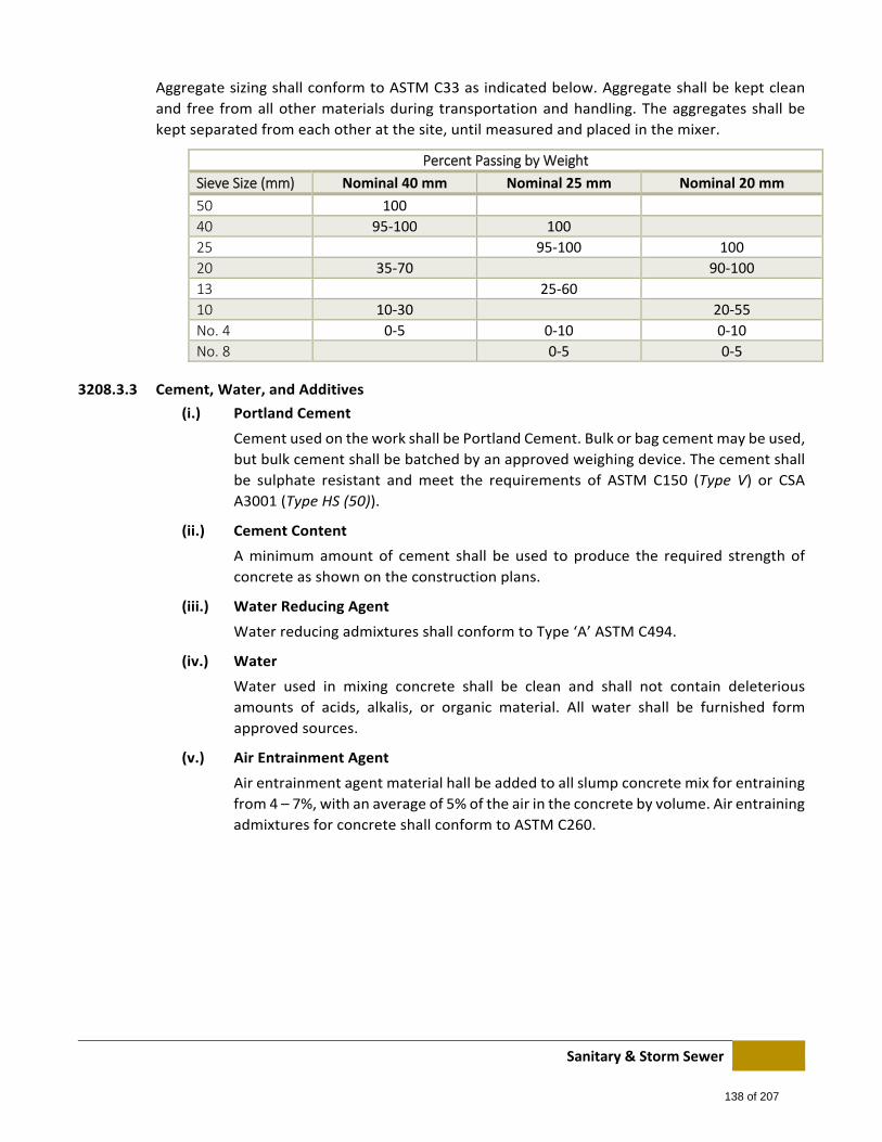
Sanitary & Storm Sewer
Aggregate sizing shall conform to ASTM C33 as indicated below. Aggregate shall be kept clean
and free from all other materials during transportation and handling. The aggregates shall be
kept separated from each other at the site, until measured and placed in the mixer.
Percent Passing by Weight
Sieve Size (mm) Nominal 40 mm Nominal 25 mm Nominal 20 mm
50 100
40 95‐100 100
25 95‐100 100
20 35‐70 90‐100
13 25‐60
10 10‐30 20‐55
No. 4 0‐5 0‐10 0‐10
No. 8 0‐5 0‐5
3208.3.3 Cement, Water, and Additives
(i.) Portland Cement
Cement used on the work shall be Portland Cement. Bulk or bag cement may be used,
but bulk cement shall be batched by an approved weighing device. The cement shall
be sulphate resistant and meet the requirements of ASTM C150 (Type V) or CSA
A3001 (Type HS (50)).
(ii.) Cement Content
A minimum amount of cement shall be used to produce the required strength of
concrete as shown on the construction plans.
(iii.) Water Reducing Agent
Water reducing admixtures shall conform to Type ‘A’ ASTM C494.
(iv.) Water
Water used in mixing concrete shall be clean and shall not contain deleterious
amounts of acids, alkalis, or organic material. All water shall be furnished form
approved sources.
(v.) Air Entrainment Agent
Air entrainment agent material hall be added to all slump concrete mix for entraining
from 4 – 7%, with an average of 5% of the air in the concrete by volume. Air entraining
admixtures for concrete shall conform to ASTM C260.
138 of 207
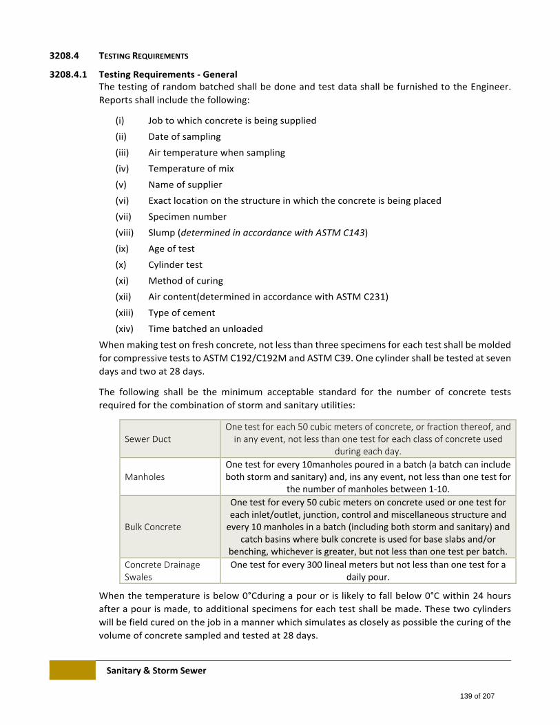
Sanitary & Storm Sewer
3208.4 TESTING REQUIREMENTS
3208.4.1 Testing Requirements ‐ General The testing of random batched shall be done and test data shall be furnished to the Engineer.
Reports shall include the following:
(i) Job to which concrete is being supplied
(ii) Date of sampling
(iii) Air temperature when sampling
(iv) Temperature of mix
(v) Name of supplier
(vi) Exact location on the structure in which the concrete is being placed
(vii) Specimen number
(viii) Slump (determined in accordance with ASTM C143)
(ix) Age of test
(x) Cylinder test
(xi) Method of curing
(xii) Air content(determined in accordance with ASTM C231)
(xiii) Type of cement
(xiv) Time batched an unloaded
When making test on fresh concrete, not less than three specimens for each test shall be molded
for compressive tests to ASTM C192/C192M and ASTM C39. One cylinder shall be tested at seven
days and two at 28 days.
The following shall be the minimum acceptable standard for the number of concrete tests
required for the combination of storm and sanitary utilities:
Sewer Duct One test for each 50 cubic meters of concrete, or fraction thereof, and in any event, not less than one test for each class of concrete used
during each day.
Manholes One test for every 10manholes poured in a batch (a batch can include both storm and sanitary) and, ins any event, not less than one test for
the number of manholes between 1‐10.
Bulk Concrete
One test for every 50 cubic meters on concrete used or one test for each inlet/outlet, junction, control and miscellaneous structure and every 10 manholes in a batch (including both storm and sanitary) and
catch basins where bulk concrete is used for base slabs and/or benching, whichever is greater, but not less than one test per batch.
Concrete Drainage Swales
One test for every 300 lineal meters but not less than one test for a daily pour.
When the temperature is below 0°Cduring a pour or is likely to fall below 0°C within 24 hours
after a pour is made, to additional specimens for each test shall be made. These two cylinders
will be field cured on the job in a manner which simulates as closely as possible the curing of the
volume of concrete sampled and tested at 28 days.
139 of 207
Sanitary & Storm Sewer
In the event that testing indicated substandard materials and workmanship, further testing shall
be completed.
3208.4.2 Test Cylinders Test cylinders shall be made and stored in accordance with ASTM C31 and will be tested in
accordance with ASTM C39. In hot weather, correct storage temperatures may be maintained by
ventilation from sand or burlap, and in cold weather by using heating devices.
When heating is impractical at the site it should be noted that cylinders are not to be transported
any considerable distance immediately after molding.
It is preferable to transport the sample of concrete to the molding and curing site, so that the
freshly molded specimens will be moved only a few feet by hand.
The cylinders should always be handled in a manner which provides the teste results with
adequate protection against damage and ensures that the test results will provide a sound basis
for evaluation of concrete quality.
3208.4.3 Strength Requirements To conform to the strength requirements the average of all tests shall exceed the specified strength.
When five or more tests of the same class of concrete are available, the average of any five
consecutive tests shall be equal to, or greater than the specified strength. No three consecutive tests
shall fall below the specified strength. Where those criteria are not met, the Engineer shall have the
right to require one or more of the following:
(i) Changes in mix portions for the reminder of the work.
(ii) The additional curing on those portions of the structure represented by the test
specimen which failed.
(iii) That cores be drilled from the portion of the structure in question and tested in
accordance with CSA A23.2. The result of this test will help ascertain whether or not
the specimens previously tested were truly representative of the concrete place.
If, after carrying out the requirements mentioned above, the Engineer is not satisfied that the
concrete in the structure is of the specified quality, he/she may demand a strengthening or
replacement of those portions which failed to develop the required strength.
3208.5 MIX DESIGN
All concrete shall be proportioned according to mix designs prepared by a Professional Engineer employed by an
independent engineering material testing laboratory for the classes of concrete and nominal maximum size of
coarse aggregate specified except where the concrete is to be supplied by a ready‐mix plant. Where there
Engineer so permits, mix designs mat be prepared by a Professional Engineer who is in the employ of the plant.
Concrete shall be designed to produce minimum cement content for each class of concrete shown on the
construction plans. The concrete mix shall be so designed that the material will not segregate and excessive
bleeding will not occur. A copy of the mix design shall be made available to the Engineer upon request.
140 of 207
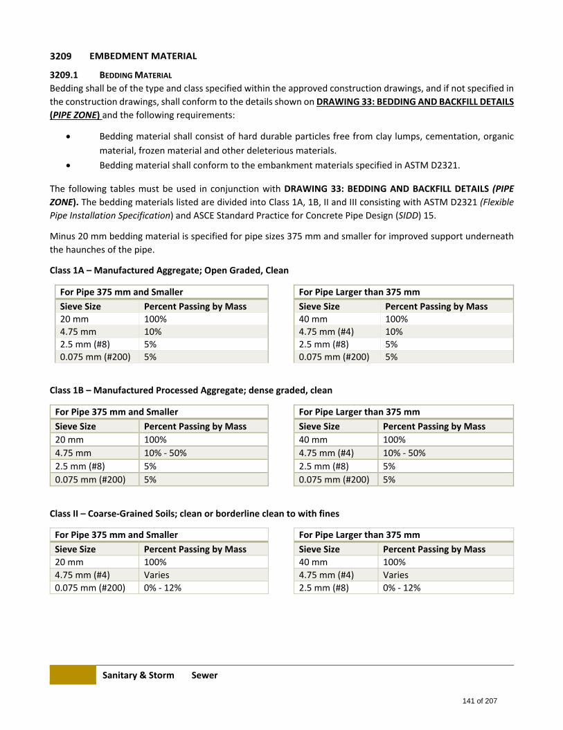
Sanitary & Storm Sewer
EMBEDMENT MATERIAL
3209.1 BEDDING MATERIAL
Bedding shall be of the type and class specified within the approved construction drawings, and if not specified in
the construction drawings, shall conform to the details shown on DRAWING 33: BEDDING AND BACKFILL DETAILS
(PIPE ZONE) and the following requirements:
Bedding material shall consist of hard durable particles free from clay lumps, cementation, organic
material, frozen material and other deleterious materials.
Bedding material shall conform to the embankment materials specified in ASTM D2321.
The following tables must be used in conjunction with DRAWING 33: BEDDING AND BACKFILL DETAILS (PIPE
ZONE). The bedding materials listed are divided into Class 1A, 1B, II and III consisting with ASTM D2321 (Flexible
Pipe Installation Specification) and ASCE Standard Practice for Concrete Pipe Design (SIDD) 15.
Minus 20 mm bedding material is specified for pipe sizes 375 mm and smaller for improved support underneath
the haunches of the pipe.
Class 1A – Manufactured Aggregate; Open Graded, Clean
For Pipe 375 mm and Smaller For Pipe Larger than 375 mm
Sieve Size Percent Passing by Mass Sieve Size Percent Passing by Mass 20 mm 100% 40 mm 100% 4.75 mm 10% 4.75 mm (#4) 10% 2.5 mm (#8) 5% 2.5 mm (#8) 5% 0.075 mm (#200) 5% 0.075 mm (#200) 5%
Class 1B – Manufactured Processed Aggregate; dense graded, clean
For Pipe 375 mm and Smaller For Pipe Larger than 375 mm
Sieve Size Percent Passing by Mass Sieve Size Percent Passing by Mass
20 mm 100% 40 mm 100%
4.75 mm 10% ‐ 50% 4.75 mm (#4) 10% ‐ 50%
2.5 mm (#8) 5% 2.5 mm (#8) 5%
0.075 mm (#200) 5% 0.075 mm (#200) 5%
Class II – Coarse‐Grained Soils; clean or borderline clean to with fines
For Pipe 375 mm and Smaller For Pipe Larger than 375 mm
Sieve Size Percent Passing by Mass Sieve Size Percent Passing by Mass
20 mm 100% 40 mm 100%
4.75 mm (#4) Varies 4.75 mm (#4) Varies
0.075 mm (#200) 0% ‐ 12% 2.5 mm (#8) 0% ‐ 12%
141 of 207
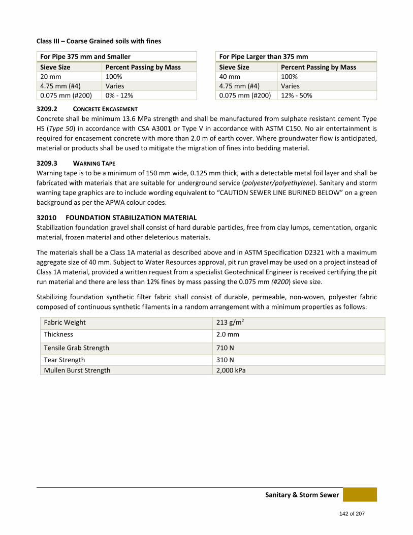
Sanitary & Storm Sewer
Class III – Coarse Grained soils with fines
For Pipe 375 mm and Smaller For Pipe Larger than 375 mm
Sieve Size Percent Passing by Mass Sieve Size Percent Passing by Mass
20 mm 100% 40 mm 100%
4.75 mm (#4) Varies 4.75 mm (#4) Varies
0.075 mm (#200) 0% ‐ 12% 0.075 mm (#200) 12% ‐ 50%
3209.2 CONCRETE ENCASEMENT
Concrete shall be minimum 13.6 MPa strength and shall be manufactured from sulphate resistant cement Type
HS (Type 50) in accordance with CSA A3001 or Type V in accordance with ASTM C150. No air entertainment is
required for encasement concrete with more than 2.0 m of earth cover. Where groundwater flow is anticipated,
material or products shall be used to mitigate the migration of fines into bedding material.
3209.3 WARNING TAPE
Warning tape is to be a minimum of 150 mm wide, 0.125 mm thick, with a detectable metal foil layer and shall be
fabricated with materials that are suitable for underground service (polyester/polyethylene). Sanitary and storm
warning tape graphics are to include wording equivalent to “CAUTION SEWER LINE BURINED BELOW” on a green
background as per the APWA colour codes.
FOUNDATION STABILIZATION MATERIAL
Stabilization foundation gravel shall consist of hard durable particles, free from clay lumps, cementation, organic
material, frozen material and other deleterious materials.
The materials shall be a Class 1A material as described above and in ASTM Specification D2321 with a maximum
aggregate size of 40 mm. Subject to Water Resources approval, pit run gravel may be used on a project instead of
Class 1A material, provided a written request from a specialist Geotechnical Engineer is received certifying the pit
run material and there are less than 12% fines by mass passing the 0.075 mm (#200) sieve size.
Stabilizing foundation synthetic filter fabric shall consist of durable, permeable, non‐woven, polyester fabric
composed of continuous synthetic filaments in a random arrangement with a minimum properties as follows:
Fabric Weight 213 g/m2
Thickness 2.0 mm
Tensile Grab Strength 710 N
Tear Strength 310 N
Mullen Burst Strength 2,000 kPa
142 of 207

Waterworks
4000 WATERWORKS
4100 SCOPE These Specifications form part of the Contract Documents for the installation of: distribution main, feeder main,
and water and sewer service connections. Distribution mains are generally defined as main 400 mm in diameter
and smaller and feeder mains are generally defined as mains larger than 400 mm in diameter.
All work performed on existing and new water systems shall be carried out in accordance with the latest issue of
the Wheatland County Design and Construction Standards and the Manufacturer’s Specifications. In case of any
inconsistency or conflict between these documents the provision of documents shall govern in the following
order:
1. Wheatland County Design and Construction Standards
2. The Manufacturer’s Specifications
Unless otherwise specified, the Contractor shall furnish all material, equipment, tools and labour necessary to do
the work.
In these Specifications, the term “Engineer” shall denote the Wheatland County Representative, or his authorized
representative. All deviations from these Specifications and the approved Construction Drawings shall have the
written approval of the Engineer.
4200 INSPECTION
GENERAL
The Engineer shall have free and uninterrupted access to work areas for the purpose of carrying out inspections.
The Contractor shall provide, at no cost to the County, such labour and access as may be required to enable the
Engineer to carry out a complete inspection of all installation and materials. The Contractor shall provide
adequate samples of materials for testing purposes.
The Engineer has the authority to stop work and order the re‐excavation and removal of any or all installations if
any material or installation method employed does not conform to these Specifications.
All material found during the progress of the work with cracks, flaws or other defects shall be rejected by the
Engineer. All rejected materials shall be promptly removed from the work site by the Contractor.
The Contractor shall give 48 hour’s notice to the Inspection Section of his intention to commence construction all
new installations and prior to commencing of the following repair work:
Repair of mains and service connections.
Repair of cathodic protection systems.
Repair of valves, hydrants and pressure‐reducing valves.
Construction or maintenance work for other utilities which require the exposure of a watermain.
It is the Contractor’s responsibility to ensure that all work is inspected by the Professional Engineer prior to back‐
filling. The Final Acceptance Certificate will not be issued if inspection of new construction and/or maintenance
work was not requested.
143 of 207
Waterworks
4201.1 INSPECTION OF SITE PRIOR TO CONSTRUCTION
Prior to construction, the Contractor shall carry out an inspection of the work sites to identify any damage or
deficiencies that might exist on, or adjacent to the work area. The Contractor shall notify the Engineer in writing
of all such deficiencies or damage prior to construction. Any deficiencies or damage not identified by the
Contractor prior to construction shall be corrected or repaired by the Contractor at no expense to the County.
4201.2 INSPECTION OF SACRIFICIAL ANODES AND TEST POINTS
All installations of sacrificial anodes, test points and related wiring shall be inspected by the Engineer prior to back‐
filling. It shall be the Contractor’s responsibility to notify the Engineer and request inspection of each cathodic
protection installation. Where back‐filling over anodes and test wires has been carried out prior to inspection,
the Contractor shall, when requested by the Engineer, re‐excavate and expose all anodes and test wires, at no
cost to the County, for the purpose of inspection.
4201.3 DAILY PROGRESS REPORT
These “daily progress reports’ will be used for the preparation of progress payments on County administered
contractors. Progress reports shall be made out in quadruplicate by the on‐site Inspector of each day’s work.
These reports will include all work done by the Contractor each day as broken down in the schedule of quantities
and in addition, will provide a detailed list of all equipment, materials and labour supplied on force account
including the force account rates. The Contractor shall also provide a copy of all utility location slips as part of the
daily report.
An authorized representative of the Contractor shall sign each “daily progress report” within 24 hours after the
completion of each day of work, acknowledging that he has carefully examined the quantities of the work
performed as indicated on the “daily progress report” for that day and agrees as to its accuracy. Should any
dispute result with respect to the quantity of any work performed on that day, it shall be brought immediately to
the Engineer’s attention by the Contractor.
If the dispute is not resolved immediately, the Contractor shall place on file with the Engineer a written report
clearly stating his position and quantities of work for which he feels should be paid. Failure to file such written
notice within 28 hours of advising the Engineer shall result in the use of the quantities indicated on the disputed
“daily progress report” in the preparation of progress payments without further recourse by the Contractor even
if he has not signed the “daily progress report”.
Should an error in quantities be discovered on any “daily progress report” after it is signed, it may be corrected
providing both parties mutually agree to the change. If the quantities can be readily measured, the re‐measured
quantity shall be used for payment.
The Contractor shall give advance notice to the inspector of his intention to perform force account work. The
amount of force account work and force account rates shall be mutually agreed to by both parties prior to
performing the work.
The Contractor will be provided with two (2) copies of each signed “daily progress report” for his file.
144 of 207
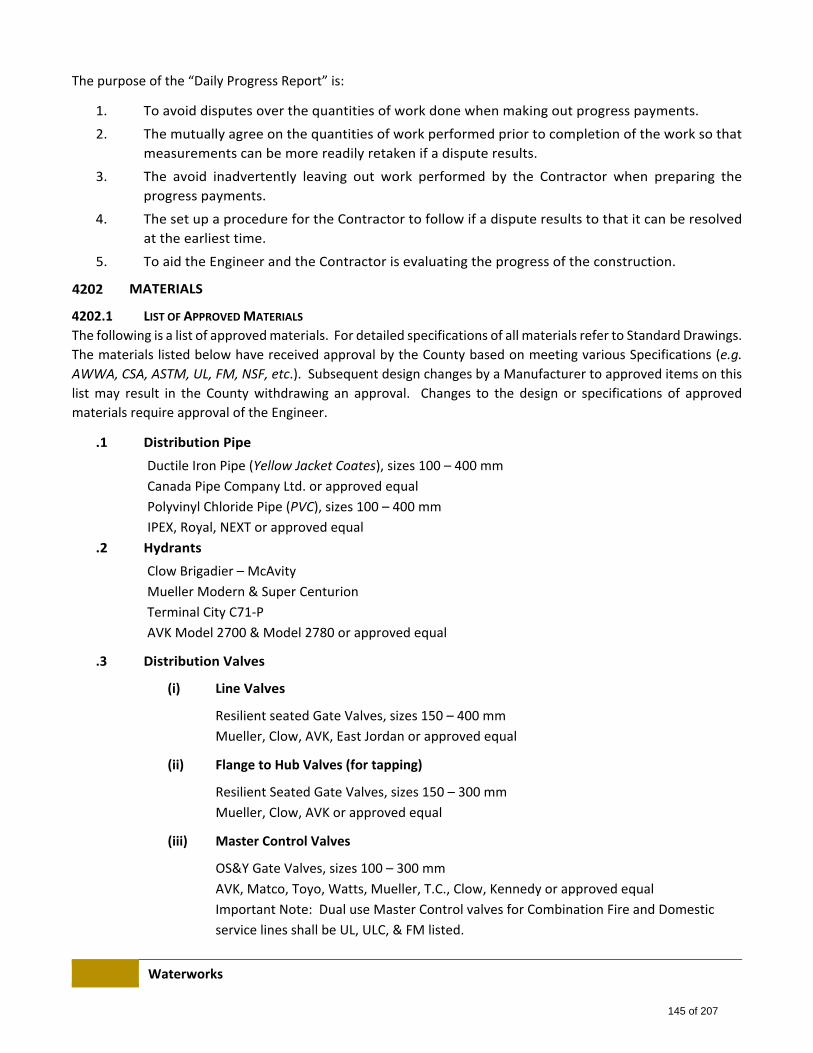
Waterworks
The purpose of the “Daily Progress Report” is:
1. To avoid disputes over the quantities of work done when making out progress payments.
2. The mutually agree on the quantities of work performed prior to completion of the work so that
measurements can be more readily retaken if a dispute results.
3. The avoid inadvertently leaving out work performed by the Contractor when preparing the
progress payments.
4. The set up a procedure for the Contractor to follow if a dispute results to that it can be resolved
at the earliest time.
5. To aid the Engineer and the Contractor is evaluating the progress of the construction.
MATERIALS
4202.1 LIST OF APPROVED MATERIALS
The following is a list of approved materials. For detailed specifications of all materials refer to Standard Drawings.
The materials listed below have received approval by the County based on meeting various Specifications (e.g.
AWWA, CSA, ASTM, UL, FM, NSF, etc.). Subsequent design changes by a Manufacturer to approved items on this
list may result in the County withdrawing an approval. Changes to the design or specifications of approved
materials require approval of the Engineer.
.1 Distribution Pipe
Ductile Iron Pipe (Yellow Jacket Coates), sizes 100 – 400 mm
Canada Pipe Company Ltd. or approved equal
Polyvinyl Chloride Pipe (PVC), sizes 100 – 400 mm
IPEX, Royal, NEXT or approved equal
.2 Hydrants
Clow Brigadier – McAvity
Mueller Modern & Super Centurion
Terminal City C71‐P
AVK Model 2700 & Model 2780 or approved equal
.3 Distribution Valves
(i) Line Valves
Resilient seated Gate Valves, sizes 150 – 400 mm
Mueller, Clow, AVK, East Jordan or approved equal
(ii) Flange to Hub Valves (for tapping)
Resilient Seated Gate Valves, sizes 150 – 300 mm
Mueller, Clow, AVK or approved equal
(iii) Master Control Valves
OS&Y Gate Valves, sizes 100 – 300 mm
AVK, Matco, Toyo, Watts, Mueller, T.C., Clow, Kennedy or approved equal
Important Note: Dual use Master Control valves for Combination Fire and Domestic
service lines shall be UL, ULC, & FM listed.
145 of 207
Waterworks
.4 Pressure Reducing Valves, sizes 75 – 300 mm
(i) Clayton:
Model 90‐01DSY (sizes 75 mm and smaller)*
Model 90‐01BSY (sizes 100 mm and larger)*
(ii) Singer
Model 106 – PR‐C (sizes 100 mm and larger)*
4202.2 MATERIAL SPECIFICATIONS
4202.2.1 Material Approval Procedure The County requires that the prior written approval of the Engineer be received for all products
to be incorporated in the distribution system. The Engineer reserves the right to withdraw the
approval of any product if in his opinion the product does not perform satisfactorily.
Manufacturers whose products conform to these Specifications are encouraged to submit to the
County a written request for product approval together with detailed product Specifications and
sufficient samples to conduct field evaluations, preference will be given to products
manufactured in an ISO 9000 certified production facility. The product evaluation process may
exceed a period of one year. Only a complete product line will be considered.
4202.2.2 Surface Quality of Castings All casting for fittings, valve bodies, hydrants barrels, valve bottom and top boxes, valve lids and
any other castings which are to be incorporated in the distribution system shall be free from
injurious defects. Surfaces of castings shall be free of burned‐in sand and shall be reasonably
smooth. Sharp edges shall be rounded to a minimum radius of 3 mm. Runners, risers, fins and
other useless cast‐on pieces shall be removed by the Manufacturer prior to the delivery of the
casting to the coating applicator. All castings shall have the Manufacturer’s name (identification
marks) distinctly cast upon them and such other information as requested throughout these
Specifications. The County Engineer may reject any casting at the Manufacturer’s yard or at the
coating applicator’s yard, which in his opinion does not conform to these requirements.
4202.2.3 Ductile Iron Pipe Ductile iron pipe shall conform to the AWWA C151‐02 Standard, and shall be cement mortar lined
in accordance with AWWA C104‐03. Where seal coat is applied to the mortar lining, the coating
shall be NSF61 listed. Ductile iron pipe shall be minimum Pressure Class 350. Unless otherwise
specified the pipe shall be supplied with bell & spigot ends complete with continuous, molded
rubber‐ring NBR (Nitrile) gaskets and conforming to the AWWA C111‐00 Standard. Ductile iron
pipe shall be supplied with copper conductivity strips “Conductoflex” welded to the bell and
spigot c/w jumper strip, nuts and bolts.
Where conductivity strips are not supplied with the pipe, continuity across joints may be
provided in the field with a #6 TW cable thermite welded to the bell & spigot. Ductile iron pipe
shall be eternally coated as specified in Sec. 4606.
The pipe Manufacturer, Distributor and Installer shall ensure that the bell and spigot end of each
pipe length remain sealed in a manner acceptance to the Engineer to prevent contaminants from
entering the interior of the pipe from the time of manufacture to the time of installation.
146 of 207
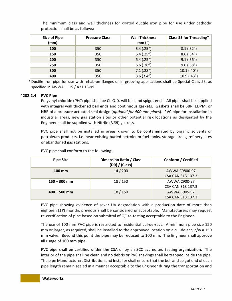
Waterworks
The minimum class and wall thickness for coated ductile iron pipe for use under cathodic
protection shall be as follows:
Size of Pipe (mm)
Pressure Class Wall Thickness mm (“)
Class 53 for Threading*
100 350 6.4 (.25”) 8.1 (.32”)
150 350 6.4 (.25”) 8.6 (.34”)
200 350 6.4 (.25”) 9.1 (.36”)
250 350 6.6 (.26”) 9.6 (.38”)
300 350 7.1 (.28”) 10.1 (.40”)
400 350 8.6 (3.4”) 10.9 (.43”)
* Ductile iron pipe for use with rehab‐on flanges or in grooving applications shall be Special Class 53, as
specified in AWWA C115 / A21.15‐99
4202.2.4 PVC Pipe Polyvinyl chloride (PVC) pipe shall be CI. O.D. will bell and spigot ends. All pipes shall be supplied
with integral wall thickened bell ends and continuous gaskets. Gaskets shall be SBR, EDPM, or
NBR of a pressure actuated seal design (optional for 400 mm pipes). PVC pipe for installation in
industrial areas, new gas station sites or other potential risk locations as designated by the
Engineer shall be supplied with Nitrile (NBR) gaskets.
PVC pipe shall not be installed in areas known to be contaminated by organic solvents or
petroleum products, i.e. near existing buried petroleum fuel tanks, storage areas, refinery sites
or abandoned gas stations.
PVC pipe shall conform to the following:
Pipe Size Dimension Ratio / Class (DR) / (Class)
Conform / Certified
100 mm 14 / 200 AWWA C9800‐97 CSA CAN 313 137.3
150 – 300 mm 18 / 150 AWWA C900‐97 CSA CAN 313 137.3
400 – 500 mm 18 / 150 AWWA C905‐97 CSA CAN 313 137.3
PVC pipe showing evidence of sever UV degradation with a production date of more than
eighteen (18) months previous shall be considered unacceptable. Manufacturers may request
re‐certification of pipe based on submittal of QC re‐testing acceptable to the Engineer.
The use of 100 mm PVC pipe is restricted to residential cul‐de‐sacs. A minimum pipe size 150
mm or larger, as required, shall be installed to the appro0ved location on a cul‐de‐sac, c/w a 150
mm valve. Beyond this point the pipe may be reduced to 100 mm. The Engineer shall approve
all usage of 100 mm pipe.
PVC pipe shall be certified under the CSA or by an SCC accredited testing organization. The
interior of the pipe shall be clean and no debris or PVC shavings shall be trapped inside the pipe.
The pipe Manufacturer, Distribution and Installer shall ensure that the bell and spigot end of each
pipe length remain sealed in a manner acceptable to the Engineer during the transportation and
147 of 207
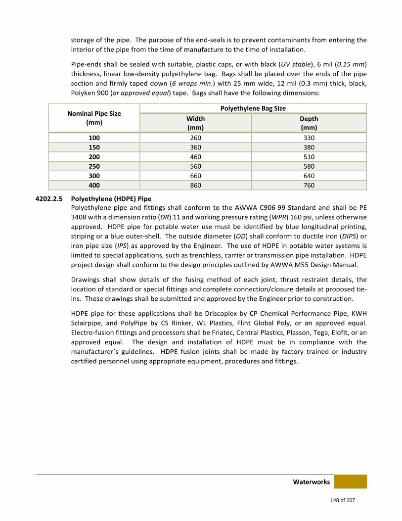
Waterworks
storage of the pipe. The purpose of the end‐seals is to prevent contaminants from entering the
interior of the pipe from the time of manufacture to the time of installation.
Pipe‐ends shall be sealed with suitable, plastic caps, or with black (UV stable), 6 mil (0.15 mm)
thickness, linear low‐density polyethylene bag. Bags shall be placed over the ends of the pipe
section and firmly taped down (6 wraps min.) with 25 mm wide, 12 mil (0.3 mm) thick, black,
Polyken 900 (or approved equal) tape. Bags shall have the following dimensions:
Nominal Pipe Size (mm)
Polyethylene Bag Size
Width (mm)
Depth (mm)
100 260 330
150 360 380
200 460 510
250 560 580
300 660 640
400 860 760
4202.2.5 Polyethylene (HDPE) Pipe Polyethylene pipe and fittings shall conform to the AWWA C906‐99 Standard and shall be PE
3408 with a dimension ratio (DR) 11 and working pressure rating (WPR) 160 psi, unless otherwise
approved. HDPE pipe for potable water use must be identified by blue longitudinal printing,
striping or a blue outer‐shell. The outside diameter (OD) shall conform to ductile iron (DIPS) or
iron pipe size (IPS) as approved by the Engineer. The use of HDPE in potable water systems is
limited to special applications, such as trenchless, carrier or transmission pipe installation. HDPE
project design shall conform to the design principles outlined by AWWA M55 Design Manual.
Drawings shall show details of the fusing method of each joint, thrust restraint details, the
location of standard or special fittings and complete connection/closure details at proposed tie‐
ins. These drawings shall be submitted and approved by the Engineer prior to construction.
HDPE pipe for these applications shall be Driscoplex by CP Chemical Performance Pipe, KWH
Sclairpipe, and PolyPipe by CS Rinker, WL Plastics, Flint Global Poly, or an approved equal.
Electro‐fusion fittings and processors shall be Friatec, Central Plastics, Plasson, Tega, Elofit, or an
approved equal. The design and installation of HDPE must be in compliance with the
manufacturer’s guidelines. HDPE fusion joints shall be made by factory trained or industry
certified personnel using appropriate equipment, procedures and fittings.
148 of 207
Waterworks
Operator certifications for each fusing method employed on a project shall be presented for
inspection and shall have a date no more than one calendar year previous to be considered valid.
All butt and electro‐fusion shall be performed in the presence of the Engineer unless otherwise
approved. Microprocessor fusing logs shall be submitted to the Engineer for every butt fuse
made and for each electro‐fuse fitting where used. Butt fusing shall not commence on site until
the Fusing Operator has successfully completed a “Bent Strap” test (as per the Plastics Pipe
Institute Handbook) to the satisfaction of the Engineer.
The pipe Manufacturer, Distributor and Installer shall ensure that the bell and spigot end of each
pipe length remain sealed in a manner acceptance to the Engineer during the transportation and
storage of the pipe. HDPE pipe shall not be installed in areas contaminated or potentially
contaminated with volatile organic compounds (organic solvents or petroleum products).
4202.2.6 Steel Pipe Steel pipe for bypass or alteration piping shall conform to ASTM Specification A53, standard wall,
with an approved end preparation of field welding. Fittings shall be standard weight seamless or
welded with beveled ends for butt welding. Flanges shall be 150 lb. forged ASA type. Steel pipe
shall be coated and lined to the following Specifications:
Lining: Cement mortar conforming to AWWA C205‐00 Type A internal coating or a NSF61
listed 100% solids epoxy as approved by the Engineer.
Coating: Yellow Jacket No. 1 extruded polyethylene, Type “A” coating system a NSF61 listed
100% solids epoxy, P.E. tape or other coating system as approved by the Engineer.
The pipe Manufacturer, Distributor and Installer shall ensure that the bell and spigot end of each
pipe length remain sealed in a manner acceptable to the Engineer during the transportation and
storage of the pipe.
4202.2.7 Hydrants Hydrants shall be ULC (Underwriter Laboratories of Canada), UL (Underwriter Laboratories, US)
or FM (Factory Mutual Fire Insurance Company) approved and shall also conform to the AWWA
C502‐94 Standard. Hydrants shall be dry‐barrel compression type supplied with an inlet elbow
bell‐end sized for 150 mm cast iron pipe O.D. Hydrants shall be supplied with a frangible (break‐
away) connection at the grade line flanges. Unless otherwise specified, hydrants shall be
supplied with continuous, molded rubber‐ring gaskets confirming to the AWWA C11‐00
Standard.
NBR (Nitrile) gaskets shall be supplied for hydrants which will be installed in areas contaminated
or potentially contaminated with volatile organic solvents or petroleum products, i.e. near buried
petroleum fueled tanks, abandoned gas stations, petro storage areas or petro refinery sites.
Hydrants shall be of the “Dry‐Top” design with a totally enclosed chamber for the operating
mechanism, sealed with O‐rings. Packing glands and stuffing box designs are not acceptable. The
operating housing shall be grease lubricated.
149 of 207

Waterworks
Outlet nozzles shall be fastened into the barrel by a threaded or approved bayonet connection.
The drain valve shall close as the compression valve starts to open. The interface between the
removable parts of the main valve assembly and the hydrant body shall be bronze to bronze. The
operating nut shall be 32 mm² (1 ¼ in²) and shall turn counter‐clockwise (left) to open.
All hydrants shall have two (2) hose connections 57 mm (2 ½”) in size at 180 degrees with Alberta
Mutual Thread and 114 mm (4 ½”) pumper connection to the following thread detail:
4 threads per 25.4 mm
154 mm O.D.
Root 145 mm with 0.51 mm flat top and bottom
The hose connection outlets shall be supplied with cast iron caps, factory lubricated for ease of
removal. The caps shall not be secured to the hydrant body with chains or cables.
Hydrants shall be supplied with a single 150 – 600 mm barrel and stem extension located
immediately below the grade‐line flange except where approved by the Engineer and shall have
a minimum of one stem guide (spider) if the cross‐sectional area of the operating stem is less
than 1000 mm ² (1.5 in²). The dimension from the grade line flange to the center‐line of the
lowest outlet nozzle shall be a minimum of 400 mm.
The exterior of the hydrant above and 300 mm below the grade line flange shall be coated in
accordance with Section 4605 (Type C) in the following colours:
Bright Green Body: C.I.L. #3486, Valspar 20‐G‐684, Cloverdale Hydrant Yellow base
#11104, ICI 634‐2017, or approved equal.
Hydrants on non‐potable and reclaimed water systems shall be painted purpose
(Pantone 522 C) with black caps.
Black Caps and Top: Cloverdale #11107, or approved equal.
The exterior of the remaining buried hydrant barrel shall be coated in accordance with Section
4604 (Type B).
The Coating Applicator shall ensure that all threads, including those on outlet nozzles, are
protected from the sandblasting and coating procedures. After the coating application the
Coating Applicator shall remove all sand from threads and restore the lubricants on all nozzles
and cap threads. Electrical continuity shall be maintained between all exterior parts of the
hydrant.
The depth of bury shall be defined as a distance from the invert of the suction elbow to 500 mm
below the underside of the grade line flange.
150 of 207
Waterworks
4202.2.8 Distribution Valves
(i) General
All distribution valves shall be resilient seat unless otherwise approved. Valves shall be
equipped with a 50 mm square operating nut and shall turn clockwise (right) to open unless
otherwise specified. Working pressure shall be 1380 kPa (200 psi) for valves 300 mm and
smaller, and 1030 kPa (150 psi) for valve 400 mm and larger. The stem seal shall be of an O‐
ring or other pressure actuated seal design.
All resilient seated line and tapping valves shall be ULC, UL or FM approved and shall also
conform to the AWWA C509‐01 or AWWA C515‐09 Standard. Valves shall be either cast or
ductile iron body, resilient rubber seated disc style with non‐rising stem. The interior (ferrous
parts) of the valve shall be factory coated with epoxy coating to conform to AWWA C550‐01.
All valves shall be supplied with a circular bottom box guide plate. Metallic type guide plates
shall be coated in accordance with Section 4603 (Type A). The guide plate shall be located
below the operating nut and shall be designed to center the operating nut inside the
designated bottom box. Unless otherwise specified, valves shall be supplied with continuous,
molded rubber‐ring gaskets conforming to the AWWA C111‐00 Standard. The exterior of all
buried distribution valves shall be factory coated in accordance with Section 4604 (Type B) or
as approved by the Engineer.
NBR (Nitrile) gaskets shall be supplied for valves which will be installed in areas contaminated
or potentially contaminated with volatile organic compounds (organic solvents or petroleum
products), i.e. near buried petroleum fuel tanks, abandoned gas stations, petro storage areas
or petro refinery sites.
(ii) Line Valves
Unless otherwise approved by the Engineer, line valve ends shall be bell type suitable for
push on single rubber gasket joints. The gaskets shall be supplied with the valve and the cost
of the gaskets shall be included in the cost of the valve. Line valves shall be approved resilient
seated gate valves, conforming to the AWWA C509‐01 Standard and these Specifications.
Valves shall be epoxy coated externally in accordance to AWWA Standard C550‐01 and
coated internally with an approved NSF 61 listed epoxy coating.
(iii) Flanged and Tapping Valves
Unless otherwise approved by the Engineer, flanged and tapping valves shall be supplied with
a flat face flange (without a spigot alignment rings) conforming in dimensions and drillings to
ANSI B16.1 class 125 or AWWA C110‐03 Standards, and where specified, a bell type end
suitable for push on single rubber gasket joints. Bell‐end gaskets shall be supplied with the
valve and the cost of the gaskets shall be included in the cost of the valve. Non isolating
flange gaskets shall be an EDPM or Nitrile, NSF61 listed rubber compound, full‐faced, multiple
integral o‐ring style, 3.18 mm thick. Isolating flange kits, where required, shall be as listed on
in section 4202.2.26.
151 of 207
Waterworks
4202.2.9 Distribution Valve Operating Assembly For 100 to 400 mm valves, the valve rod, top box, valve box adapters, valve lids, casing and
bottom box shall conform to the standard drawings.
4202.2.10 Pressure Reducing Valves Pressure reducing valves shall maintain a constant downstream pressure regardless of varying
inlet pressure. Pressure reducing valves shall be cast or ductile iron body with flat face flanges
conforming in dimensions and drillings to ANSI B16.1 and class 125 or AWWA C110‐03 Standards
equipped with a hydraulically operated, diaphragm‐actuated, globe valve assembly. They shall
include stainless steel trim seats, an external position indicator, and 6 mm pet‐cocks on the inlet
and outlet side of the valve. A separate pet‐cock shall be supplied on the inlet and outlet side of
the valve to accommodate pressure gauges. The pilot control system shall have an external
strainer and direct acting, adjustable, spring loaded, normally open diaphragm valve with an all
stainless steel or brass body, c/w stainless steel or brass bolts. Pressure reducing valves with
optional flow monitoring capability shall be preferred.
4202.2.11 Check Valves All check valves shall conform to the AWWA C508‐01 Standard. They shall be iron‐body bronzed
mounted swing check valves. Disc hanger pins shall be stainless steel, and voer nuts and bolts
shall be stainless steel or zinc plated. Check valves located between two pressure zones shall be
supplied with an outside lever and weight. Check valves on private sites shall not be equipped
with lever and weight.
4202.2.12 Fittings
(i) Cast and Ductile Iron Fittings
Cast and ductile iron full body fittings for use in chambers or direct bury (i.e. tees, crosses,
bends and reducers) sizes 100 mm to 400 mm shall have bell‐ends conforming to the AWWA
C110‐03 Standard. Flanges, where approved, shall conform in dimensions and drillings to
ANSI B16‐1 class 125 or AWWA C110‐03 Standards.
Compact ductile iron fittings conforming to AWWA C‐153‐00 shall be permitted for direct
bury use only. Flanges, where approved, shall conform in dimensions and drillings to ANSI
B16‐1 class 125 or AWWA C110‐03 Standards. Non isolating flange gaskets shall be an EDPM
or Nitrile, NSF61 listed rubber compound, full‐faced, multiple integral o‐ring style, 3.18 mm
thick.
The exterior and interior of all fittings shall be fusion bond epoxy coated in the factory of by
an approved third party coating facility in accordance with AWWA C‐16‐03 and Section 4603
(Type A) of these Specifications.
Unless otherwise specified, all fittings shall be supplied with continuous, molded rubber‐ring
gaskets conforming to the AWWA C111‐00 Standards.
NBR (Nitrile) gaskets shall be used where fittings are to be installed in areas contaminated or
potentially contaminated with volatile organic compounds (organic solvents or petroleum
products), i.e. near buried petroleum fuel tanks, abandoned gas stations, petro storage areas
or petro refinery sites.
152 of 207
Waterworks
(ii) Polyvinyl Chloride (PVC) Fittings
PVC injection‐molded fittings, i.e. tees, elbows, tapped couplings (AWWA thread), sizes 100
– 300 mm, line and repair couplings, reducers and plugs, sizes 100 – 300 mm shall be Class
150 conforming to UNI‐BELL B‐12‐87 Standard and AWWA C907‐91 Standards.
Tees, elbows, tapped (AWWA thread) couplings and reducers sizes 100 – 200 mm shall also
conform to CSA CAN/CSA – B137.2‐M 93. Fittings shall be supplied with continuous (jointless)
elastomeric gaskets. All gaskets for PVC fittings shall be of a pressure actuated seal design.
PVC extruded fittings, i.e. long body 5° elbows, sizes 100 – 400 mm shall be Class 150, DR 18,
conforming to AWWA C900‐97. PVC fittings shall not be installed in areas contaminated or
potentially contaminated with volatile organic compounds (organic solvents or petroleum
products), i.e. near buried petroleum fuel tanks, abandoned gas stations, petro storage areas
and petro refinery sites.
4202.2.13 Tapping Sleeves
(i) General
Tapping sleeves shall be either a mild steel split body type, or a stainless steel full wrap gasket
style with integral flat face flanges (without spigot alignment groove), conforming in
dimensions and drillings to ANSI B16.1 class 125, or AWWA C110‐03 Standards. They must
be available for all nominal pipe sizes between 100 mm and 400 mm and shall accommodate
PVC, Cast Iron, Rough Barrel Asbestos Cement Class 150, and Standard Steel pipe.
They shall have a 20 mm (3/4”) NPT test plug for pressure testing; have permanent
identification marking identifying the Manufacturer’s name, nominal size & O.D. range and
shall be packaged as a complete unit (i.e. sleeves, gaskets, nuts and bolts). The tapping sleeve
Manufacturer shall supply complete installation information including bolt torques.
The tapping sleeve installer shall follow the installation and bolt torque procedure as outlined
in the product installation guide and shall demonstrate the proper bolt installation torque
with a torque wrench at the Engineer’s request.
NBR (Nitrile) gaskets shall be supplied for tapping sleeves which will be installed in areas
contaminated or potentially contaminated with volatile organic solvents or petroleum
products, i.e. near buried petroleum fuel tanks, abandoned gas stations, petro storage areas
or petro refinery sites.
(ii) Stainless Steel Tapping Sleeves
All metallic parts of the stainless steel tapping sleeve shall be fabricated from 18 – 8 Stainless
Steel, Type 304 or Type 304L. All surfaces including weld areas shall be thoroughly cleaned
of scale, grease (oil) and other contaminants. Sensitized stainless steel is not acceptable.
Bolts shall be 16 mm (5/8”) SS with hex‐nuts, NC rolled threads, lubricated (coated) to
prevent falling. These sleeves are approved for use on all pipe materials for all taps up to 400
mm including “size on size” taps (branch size same as main). For “size on size” taps on
Asbestos Concrete, Cast Iron, or PVC pipe, a 12.5 mm undersized cutter must be used. For
“size on size” taps on 400 mm PVC pipe, a 350 mm cutter shall be used.
(iii) Mild Steel Tapping Sleeves
153 of 207
Waterworks
The mild steel tapping sleeve shall be supplied with 20 mm (3/4”) mild steel or stainless steel
bolts, NC heavy‐hex nuts. The tapping sleeve, including nuts & bolts (stainless accepted) shall
be coated in accordance with Section 4603 (Type A). Coated flange faces shall be supplied
with EDPM or Nitrile, NSF61 listed rubber compound, full‐faced, multiple integral o‐ring style
gaskets, 3.18 mm thick. These sleeves are approved for use on metallic main for taps up to
400 mm, excluding “size on size” taps on Cast Iron. These sleeves may be used on PVC main
up to 300 mm in diameter provided that the outlet size is a full pipe size less than the main
(i.e. 250 mm).
Size on size tapping with this type of sleeve on PVC main is not permitted. Tapping of AC
pipe with this type of sleeve is not permitted.
4202.2.14 Couplings
(i) General
Product Specifications:
The Manufacturer shall supply complete cataloging of couplings including product
Specifications and selection charts. The selection chart shall provide detailed information on
the selection of end‐plates, gaskets and boots relative to various pipe OD’s
Coating:
The body sleeve, end plates and bolts, (except flange faces and stainless steel nuts & bolts)
shall be factory coating in accordance with Section. 4603 (Type A). or as approved by the
Engineer. Electrical conductivity must be provided between all metallic parts of the coupling.
Electrical conductivity between bolts and end plates shall be provided by removing the
coating from the bolt nut, bolt head and end‐plate bearing area. Alternate electrical
conductivity designs must be approved by the Engineer. Refer to Section 4607 for field
coating requirements.
Couplings shall be available for all nominal pipe sizes, i.e. 100 mm to 400 mm inclusive to
accommodate: Cast Iron; Rough Barrel Asbestos Cement Class 150 and Standard Steel Pipe.
End‐plates shall be designed to provide the best possible back up support for the gaskets.
(ii) Flange Coupling Adapters
Material:
The body and end plates shall be made of ductile iron conforming to ASTM A536. Bolts shall
be 304 stainless steel with; hex‐nuts, NC rolled threads, lubricated (coated) to prevent galling.
Bolt diameter shall be 16 mm (5/8”) for 100 mm (4”) couplings, 20 mm (3/4”) for 150 & 200
mm (6” & 8”) couplings and 22 mm (7/8”) for 250 & 300 mm (10” & 12”) couplings unless
otherwise approved by the Engineer. Coated flange faces shall be supplied with EDPM or
Nitrile, NSF61 listed rubber compound, full‐faced, multiple integral o‐ring style gaskets, 3.18
mm thick.
154 of 207
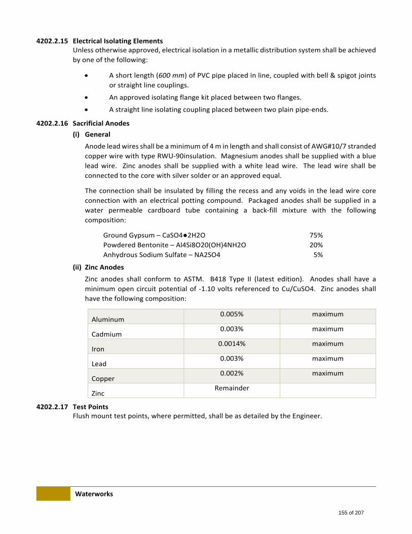
Waterworks
4202.2.15 Electrical Isolating Elements Unless otherwise approved, electrical isolation in a metallic distribution system shall be achieved
by one of the following:
A short length (600 mm) of PVC pipe placed in line, coupled with bell & spigot joints
or straight line couplings.
An approved isolating flange kit placed between two flanges.
A straight line isolating coupling placed between two plain pipe‐ends.
4202.2.16 Sacrificial Anodes
(i) General
Anode lead wires shall be a minimum of 4 m in length and shall consist of AWG#10/7 stranded
copper wire with type RWU‐90insulation. Magnesium anodes shall be supplied with a blue
lead wire. Zinc anodes shall be supplied with a white lead wire. The lead wire shall be
connected to the core with silver solder or an approved equal.
The connection shall be insulated by filling the recess and any voids in the lead wire core
connection with an electrical potting compound. Packaged anodes shall be supplied in a
water permeable cardboard tube containing a back‐fill mixture with the following
composition:
Ground Gypsum – CaSO4●2H2O 75%
Powdered Bentonite – Al4Si8O20(OH)4NH2O 20%
Anhydrous Sodium Sulfate – NA2SO4 5%
(ii) Zinc Anodes
Zinc anodes shall conform to ASTM. B418 Type II (latest edition). Anodes shall have a
minimum open circuit potential of ‐1.10 volts referenced to Cu/CuSO4. Zinc anodes shall
have the following composition:
Aluminum 0.005% maximum
Cadmium 0.003% maximum
Iron 0.0014% maximum
Lead 0.003% maximum
Copper 0.002% maximum
Zinc Remainder
4202.2.17 Test Points Flush mount test points, where permitted, shall be as detailed by the Engineer.
155 of 207

Waterworks
4202.2.18 Water Service Pipe All new water services shall be sized to meet the current minimum water service size
requirements of The Canadian Plumbing Code Division B. Water service pipe shall be one of the
following:
(i) Copper Pipe: sizes 20 – 50 mm
Copper pipe shall be Type K, soft copper conforming to ANSI/AWWA C800‐01 Standard and
ASTM B88. All copper pipe shall be third party certified (TPC).
(ii) PEX Pipe (Cross‐linked Polyethylene Pipe): sizes 20 – 50 mm
PEX pipe shall be manufactured in accordance with CSA B137.5 and ASTM F876 and shall
comply with NSF 14 & 61 (PW). The degree of cross‐linking for PEX pipe shall be not less than
70% when tested according to ASTM D2765, Method B. PEX pipe shall meet CSA / NSF
approved pressure rating:
160 psi @ 23°C / 73.4°F
100 psi @ 82°C / 180°F
80 psi @ 93°C / 200°F
The outside diameter of the pipe shall be copper tube size (CTS) and must have a standard
dimension ratio (SDR) of 9. PEX pipe shall be manufactured in natural colour of in sky Blue
(RAL 5015) and shall carry the following marks every five (5) feet (minimum): manufactures’
name, nominal size, ASTM, CSA & NSF designations, SDR (standard dimension ratio), pressure
/ temperature rating, potable tubing, manufacturing date & machine number and footage
mark. The pipe shall have consecutive footage marks every five (5) feet (minimum) starting
with zero (0) at the beginning of each coil. The pipe shall be shipped in protective cardboard
boxes marked with the product name and size.
4202.2.19 Water Service Saddles
(i) Materials:
Service saddles shall be constructed of stainless steel, bronze or a combination of both.
Stainless steel components shall be Type 304 or 304L. All surfaces including weld areas shall
be thoroughly cleaned of scale, grease (oil) or other contaminants. Welding must be
performed to prevent sensitization. Sensitized stainless steel is not acceptable.
Bronze saddle components shall be Waterworks Bronze (85‐5‐5‐5) and conform to the ASTM
standard B62 or A40B. Service saddles shall be available for nominal pipe sizes 100 m to 400
mm and adaptable to the following pipe types and respective OD ranges:
Non‐Isolating Saddles shall be suitable for PVC with CI OD and Rough Barrel Asbestos
Cement Class 150 Pipe.
Isolating Saddles shall be suitable for steel, cast iron and ductile iron pipe.
Service saddles shall be a stainless one piece or a two component (body and strap) design
with fastening devices on each side of the outlet. The body shall be heavy cast stainless steel
or cast bronze tapped with AWWA taper (CC) threads; stainless steel straps with 13 mm
stainless steel bolts & nuts with NC rolled threads lubricated to prevent galling.
156 of 207

Waterworks
Gaskets shall be adequately secured to metal components to resist shifting. Non‐isolating
gaskets shall be neoprene for water services. Isolating gaskets shall be SBR isolating
compound of high dielectric strength and low water absorption and shall prevent the metallic
saddle components from contacting the pipe. NBR (Nitrile) gaskets shall be supplied for
saddles to be installed in areas contaminated or potentially contaminated with organic
solvents or petroleum products, i.e. near buried petroleum fuel tanks, abandoned gas
stations, petro storage areas or petro refinery sites.
The opening in the gaskets shall be the same as the nominal diameter of the saddle outlet.
Gaskets shall extend 6 mm minimum beyond the saddle components edge. Service saddles
shall conform to the following table:
Nominal Pipe (mm)
Nominal Outlet (mm)
Strap Type
Non Isolating Isolating
100, 150 20 D, SW SW
100, 150 25 D, SW SW
100 40, 50 D, SW SW
150 40, 50 D, SW SW
200 20, 25, 40, 50 D, SW SW
250, 300, 400 20, 25, 40, 50 D, SW SW
(ii) Where:
S Single strap minimum width 45 mm with two (2) fastening devices, one on each side of the outlet.
D Double strap, (two single straps) minimum width of 45 mm each, complete with four (4) fastening devices, two (2) on each side of the outlet.
SW Single wide strap, minimum width of 100 mm c/w four (4) fastening devices, two (2) on each side of the outlet for two component bronze and stainless saddles. All stainless one‐piece saddles shall use a minimum of two fasteners on pipe up to 200 mm and a minimum of four fasteners for 250 mm and above pipe.
(iii) Markings:
The following permanent identification markings shall be provided:
Manufacturer’s Name
OD Range
Type (Isolating or Non‐Isolating).
4202.2.20 Main Stops Main stops shall be of brass construction (brass or stainless steel ball type) listed under the NSF
61 Standard, and conforming to AWWA C800‐01 Standards with AWWA (Mueller) threads on the
inlet and compression type connection on the outlet end.
The compression ends shall be designed with a “limited travel” compression nut to prevent over‐
stressing (necking down) the service pipe. Main stops shall be isolating where directly tapped to
metallic pipe and non‐isolating type where connecting to a non‐metallic pipe or isolating service
saddle.
157 of 207
Waterworks
4202.2.21 Service Valves Service valves 50 mm and smaller shall be of brass construction listed under the NSF 61 Standard,
and conforming to AWWA C800‐01 Standards. Unless otherwise specified by the Engineer
service valves shall be the non‐draining type.
The service valve shall be a “full port” ball design supplied with a suitably coated brass or stainless
steel ball with compression type ends. The operator shall have a minimum thickness of 9.6 mm
with a hole diameter of 7 mm centered 8 mm from the base.
The compression ends shall be designed with a “limited travel” compression nut to prevent over‐
stressing (necking down) of the service pipe.
4202.2.22 Service Valve Operating Assembly The operating rod shall be supplied as a single unit. The Manufacturer’s name shall be embossed
onto the clevis. The cotter pin shall be slightly bent to prevent it from falling out during transport.
For 20 mm & 25 mm service valves the Type A operating rod shall be used and for 40 mm & 50
mm service valves the Type B operating rod shall be used.
4202.2.23 Sewer Service Pipe All pipe materials shall conform to the material specifications.
4202.2.24 Sewer Service Pipe Jointing Material All pipe‐jointing materials shall conform to the material specifications.
4202.2.25 Sewer Service Pipe Elbows, Adapters and Fittings All elbows, adapters and fittings shall be supplied by the service Pipe Manufacturer and approved
by the Engineer. Bends consisting of 22.5° deflection shall be used when required as per the
Canadian Plumbing Code.
4202.2.26 Sewer Service Saddles All sewer service saddles shall conform to the material specifications.
4202.2.27 Isolating Flange Kit Isolating flange kits shall be designed to fit flat face flanges conforming in dimensions and drillings
to ANSI B16.1 class 125 or AWWA C110‐03 Standards. Gaskets shall be Type ‘E’, G‐10, 3 mm
thick, epoxy glass, c/w NBR O‐rings or seal rings imbedded on opposite sides of the gasket, or full
faced NBR or neoprene sealing surfaces. Where supplied, the O‐ring placement shall be
compatible with the flanges used. The kit shall include sleeves of G‐10 epoxy glass material c/w
two G10 washers and two zine plated steel washers per sleeve, sized to permit clear passage of
the bolt sleeves through the washer bore.
4202.2.28 Joint Restraints Concrete thrust blocks shall be provided for all tees, bends, plugs reducers and hydrants as
detailed on the Standard Drawings and where specified throughout these Specifications. When
approved by the Engineer, approved joint restraints may be used in addition to thrust blocks in
high traffic areas where time is of the essence and back‐filling has to be carried out immediately
in order to restore traffic. Under no circumstances shall the joint restrainer be used as an
alternate to thrust blocks. Each joint restraint bolt shall be protected by an approved zinc anode
cap meeting ASTM B418. Anode caps shall be 6 oz. for up to and including on inch bolts and shall
be 14 oz. for bolts above one inch in diameter. All non‐coated threads and bolting surfaces on
158 of 207
Waterworks
joint restraints, excepting anode caps, shall be wrapped with an approved petrolatum paste and
tape as listed in section 4607 of the Specifications.
4202.2.29 Handling and Storing of Materials
(i) General
Pipe, fittings, valves, hydrants and accessories shall be loaded, unloaded and lowered into
the trench using adequate lifting and rigging equipment satisfactory to the Engineer. Under
no circumstances shall such material be dropped, piled or rolled in such a way as to cause
excessive impact. The handling and moving of all materials shall be kept to a minimum.
Damaged coating or lining shall be repaired to the satisfaction of the Engineer at no cost to
the City. Yellow‐jacketed pipe and Polyvinyl Chloride (PVC) pipe shall not be stored in a
manner that exposes the pipe to direct sunlight for a period in excess of twelve (12) month.
PEX pipe shall be shipped and stored in protective cardboard boxes. PEX shall not be stored
in such a manner as to cause exposure to direct sunlight for periods in excess of three (3)
months. If it is necessary to store the pipe in excess of this period, the Contractor shall at no
cost to the County, provide a suitable cover (canvas or other opaque material) to protect the
pipe from the sun. A minimum of 75 mm of air space shall be provided between the pipe
surface and the cover to prevent heat buildup.
(ii) Ductile Iron and Steel Pipe
Coated ductile iron and steel pipe shall be handled and placed using wide slings and padded
cradles of canvas, leather or other suitable material to prevent damage to pipe and coating.
The use of bare metal cables, chains, hooks or other equipment that may cause damage to
coating will not be permitted. Coated pipe shall be supported on sandbags or suitable
wooden blocks. When it is necessary to walk on coated pipe, soft‐soled shoes shall be used.
(iii) Concrete Pipe
This clause pertains to high‐pressure concrete cylinder pipe manufactured in accordance with
AWWA C301‐99 and AWWA C303‐02 Standards as supplied by Hyprescon, Ameron or others.
Concrete pipe may not be placed directly on the ground. Suitable support such as sand bags,
tires or timber shall be used. Timber blocking may be required when the pipe is placed on
soft or sloping ground and in locations where local activity or vandalism could be a problem.
Stacking of concrete pipe will not be permitted. Interior pipe bracing shall not be removed
until after the pipe has bene placed in the trench and back‐filled.
Joint gaskets which form part of the pipe shipment shall be stored flat in an area which is
clean and dry, free from dirt, oil, grease, solvents and not exposed to sunlight.
159 of 207

WHEATLAND COUNTY STANDARD DRAWINGS
OCTOBER 2016
160 of 207

161 of 207
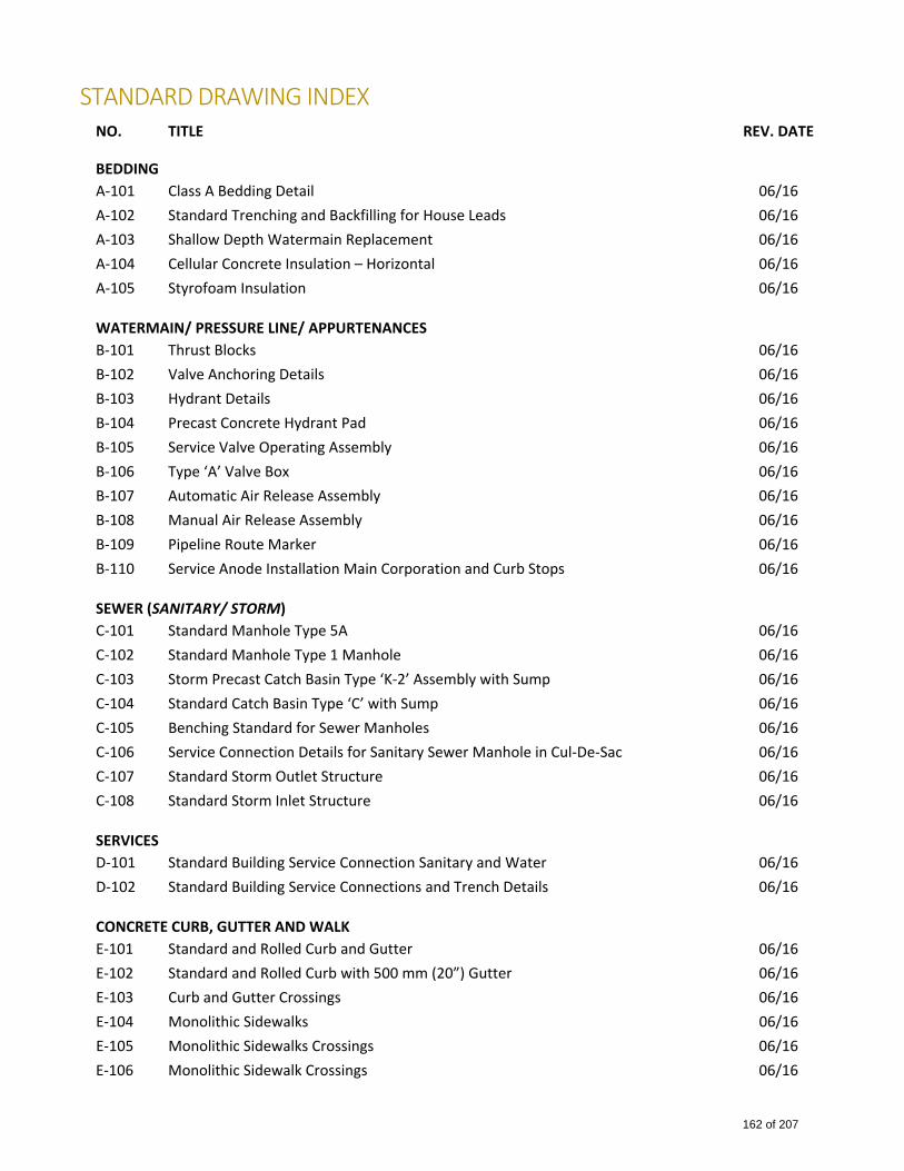
STANDARD DRAWING INDEX NO. TITLE REV. DATE
BEDDING
A‐101 Class A Bedding Detail 06/16
A‐102 Standard Trenching and Backfilling for House Leads 06/16
A‐103 Shallow Depth Watermain Replacement 06/16
A‐104 Cellular Concrete Insulation – Horizontal 06/16
A‐105 Styrofoam Insulation 06/16
WATERMAIN/ PRESSURE LINE/ APPURTENANCES
B‐101 Thrust Blocks 06/16
B‐102 Valve Anchoring Details 06/16
B‐103 Hydrant Details 06/16
B‐104 Precast Concrete Hydrant Pad 06/16
B‐105 Service Valve Operating Assembly 06/16
B‐106 Type ‘A’ Valve Box 06/16
B‐107 Automatic Air Release Assembly 06/16
B‐108 Manual Air Release Assembly 06/16
B‐109 Pipeline Route Marker 06/16
B‐110 Service Anode Installation Main Corporation and Curb Stops 06/16
SEWER (SANITARY/ STORM)
C‐101 Standard Manhole Type 5A 06/16
C‐102 Standard Manhole Type 1 Manhole 06/16
C‐103 Storm Precast Catch Basin Type ‘K‐2’ Assembly with Sump 06/16
C‐104 Standard Catch Basin Type ‘C’ with Sump 06/16
C‐105 Benching Standard for Sewer Manholes 06/16
C‐106 Service Connection Details for Sanitary Sewer Manhole in Cul‐De‐Sac 06/16
C‐107 Standard Storm Outlet Structure 06/16
C‐108 Standard Storm Inlet Structure 06/16
SERVICES
D‐101 Standard Building Service Connection Sanitary and Water 06/16
D‐102 Standard Building Service Connections and Trench Details 06/16
CONCRETE CURB, GUTTER AND WALK
E‐101 Standard and Rolled Curb and Gutter 06/16
E‐102 Standard and Rolled Curb with 500 mm (20”) Gutter 06/16
E‐103 Curb and Gutter Crossings 06/16
E‐104 Monolithic Sidewalks 06/16
E‐105 Monolithic Sidewalks Crossings 06/16
E‐106 Monolithic Sidewalk Crossings 06/16
162 of 207
NO. TITLE REV. DATE
E‐107 Separate Sidewalk Details 06/16
E‐108 Crossing for Separate Sidewalk 06/16
E‐109 Standard Monolithic Commercial Sidewalk 06/16
E‐110 Standard Wheelchair Ramp for Separate Sidewalk with Sidewalk Widening 06/16
E‐111 Standard Wheelchair Ramp for Separate Sidewalk 06/16
E‐112 Standard Wheelchair Ramp for Monolithic Sidewalk 06/16
E‐113 Concrete Swale 06/16
E‐114 Asphalt Walkway & Bicycle Pathway 06/16
ROADWORK
H‐101 Gravelled Lanes 6.10m to 10 m Right‐Of‐Way 06/16
FENCING AND LANDSCAPING
L‐101 Barbed Wire Fence Details 06/16
L‐102 Standard Chain Link Fence 06/16
163 of 207
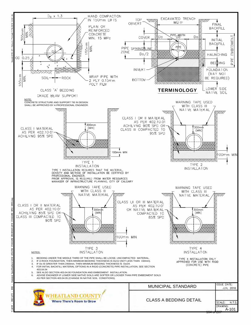
TERMINOLOGY
NOTE: CONCRETE STRUCTURE AND SUPPORT TIE IN DESIGN SHALL BE APPROVED BY A PROFESSIONAL ENGINEER.
NOTES:
1. BEDDING UNDER THE MIDDLE THIRD OF THE PIPE SHALL BE LOOSE, UNCOMPACTED MATERIAL. 2. IF A ROCK FOUNDATION, THEN MINIMUM BEDDING THICKNESS IS Do/12 (NOT LESS THAN 150mm). 3. IF Do IS GREATER THAN 2400mm, THEN MINIMUM BEDDING THICKNESS IS Do/24. 4. FOR INITIAL BACKFILL MATERIAL OPTIONS IN A RIGID (CONCRETE) PIPE INSTALLATION, SEE SECTION
403.04.04 5. SEE ALSO SECTION 403.04.00 FOUNDATION AND EMBEDMENT INSTALLATION. 6. ADVISE ENGINEER IF LOWER SIDE NATIVE SOILS ARE SOFTER OR LOOSER THAN PIPE EMBEDMENT SOILS
AS PER SECTION 403.04.05 (CHANGE IN NATIVE SOIL CONDITIONS).
MUNICIPAL STANDARD
CLASS A BEDDING DETAIL
A-101 164 of 207
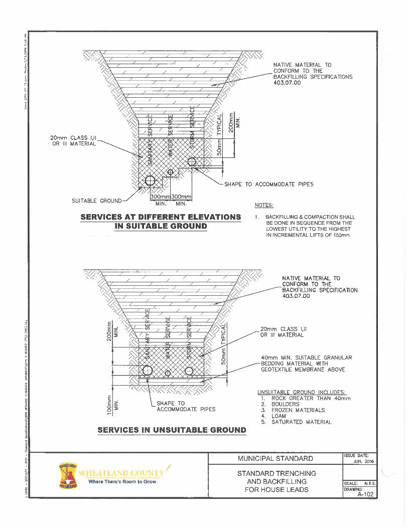
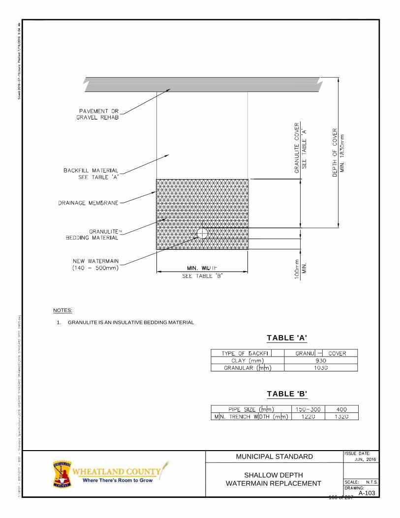
NOTES:
1. GRANULITE IS AN INSULATIVE BEDDING MATERIAL
TABLE 'A'
TABLE 'B'
MUNICIPAL STANDARD
SHALLOW DEPTH WATERMAIN REPLACEMENT
A-103 166 of 207
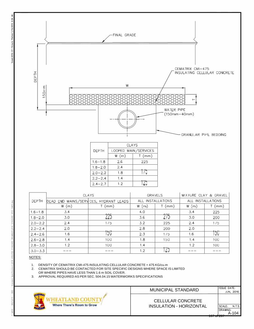
NOTES:
1. DENSITY OF CEMATRIX CMI-475 INSULATING CELLULAR CONCRETE = 475 KG/cu.m 2. CEMATRIX SHOULD BE CONTACTED FOR SITE SPECIFIC DESIGNS WHERE SPACE IS LIMITED
OR WHERE PIPES HAVE LESS THAN 1.6 m SOIL COVER. 3. APPROVAL REQUIRED AS PER SEC. 504.04.15 WATERWORKS SPECIFICATIONS
MUNICIPAL STANDARD
CELLULAR CONCRETE INSULATION - HORIZONTAL
A-104 167 of 207
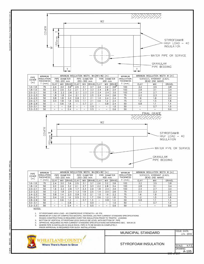
®
®
NOTES:
1. STYROFOAM® HIGH LOAD - 40 COMPRESSIVE STRENGTH = 40 PSI 2. MINIMUM OF 0.25m OF COMPACTED BACKFILL MATERIAL (AS PER CURRENT STANDARD SPECIFICATIONS
ROADS CONSTRUCTION) IS REQUIRED OVER THE INSULATION PRIOR TO TRAFFIC LOADING 3. BOTTOM OF VERTICAL STYROFOAM LEGS SHOULD BE LEVEL WITH BOTTOM OF PIPE 4. APPROVAL REQUIRED AS PER CURRENT STANDARD SPECIFICATIONS WATERWORKS SEC. 504.04.15 5. WHERE PIPE IS INSTALLED IN SOLID ROCK, PIPE IS TO BE BOXED IN COMPLETELY.
PRIOR APPROVAL IS REQUIRED FOR SUCH INSTALLATIONS.
MUNICIPAL STANDARD
STYROFOAM INSULATION
A-105 168 of 207
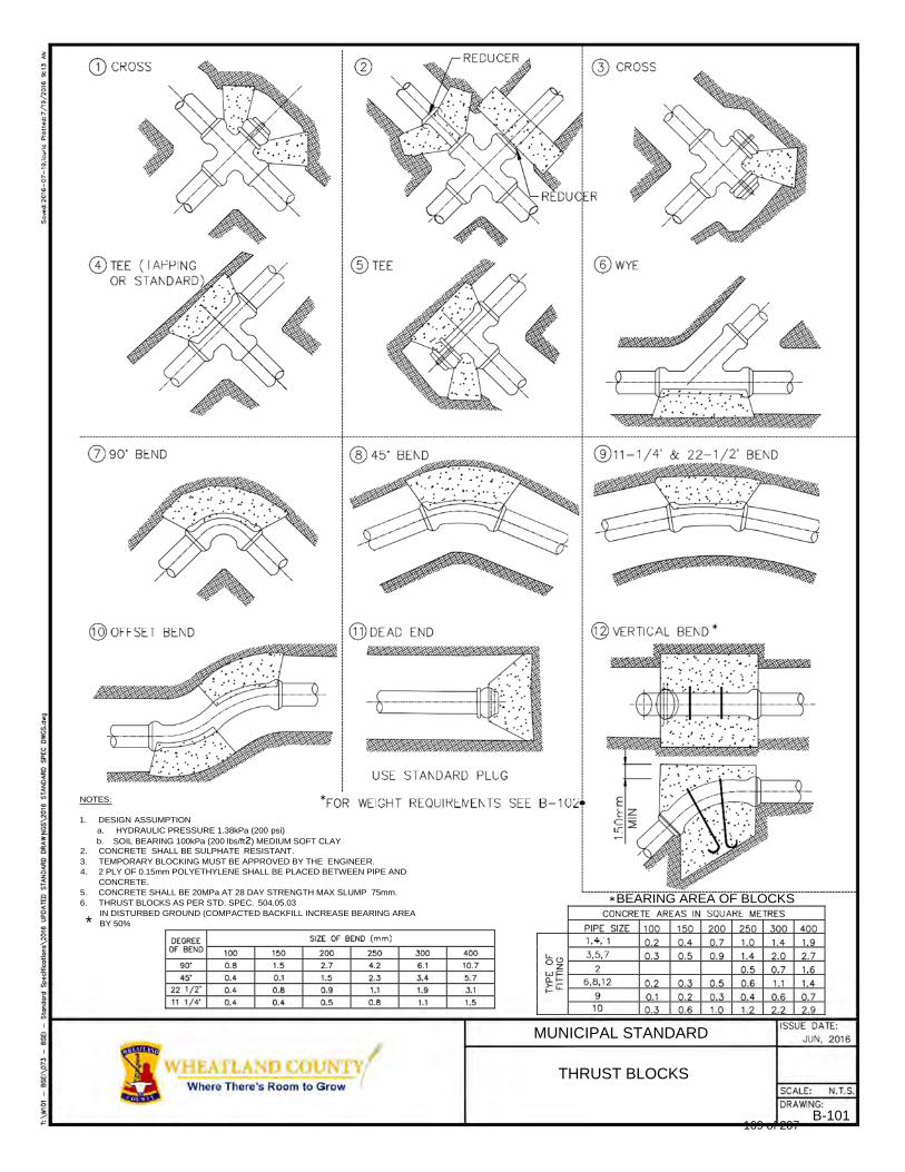
NOTES:
1. DESIGN ASSUMPTION a. HYDRAULIC PRESSURE 1.38kPa (200 psi)
b. SOIL BEARING 100kPa (200 lbs/ft2) MEDIUM SOFT CLAY 2. CONCRETE SHALL BE SULPHATE RESISTANT. 3. TEMPORARY BLOCKING MUST BE APPROVED BY THE ENGINEER. 4. 2 PLY OF 0.15mm POLYETHYLENE SHALL BE PLACED BETWEEN PIPE AND
CONCRETE. 5. CONCRETE SHALL BE 20MPa AT 28 DAY STRENGTH MAX SLUMP 75mm. 6. THRUST BLOCKS AS PER STD. SPEC. 504.05.03
IN DISTURBED GROUND (COMPACTED BACKFILL INCREASE BEARING AREA BY 50%
BEARING AREA OF BLOCKS
MUNICIPAL STANDARD
THRUST BLOCKS
B-101
*
169 of 207
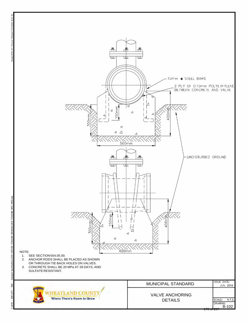
¢
NOTE:
1. SEE SECTION 504.05.00. 2. ANCHOR RODS SHALL BE PLACED AS SHOWN
OR THROUGH TIE BACK HOLES ON VALVES. 3. CONCRETE SHALL BE 20 MPa AT 28 DAYS, AND
SULFATE RESISTANT.
MUNICIPAL STANDARD
VALVE ANCHORING DETAILS
B-102 170 of 207
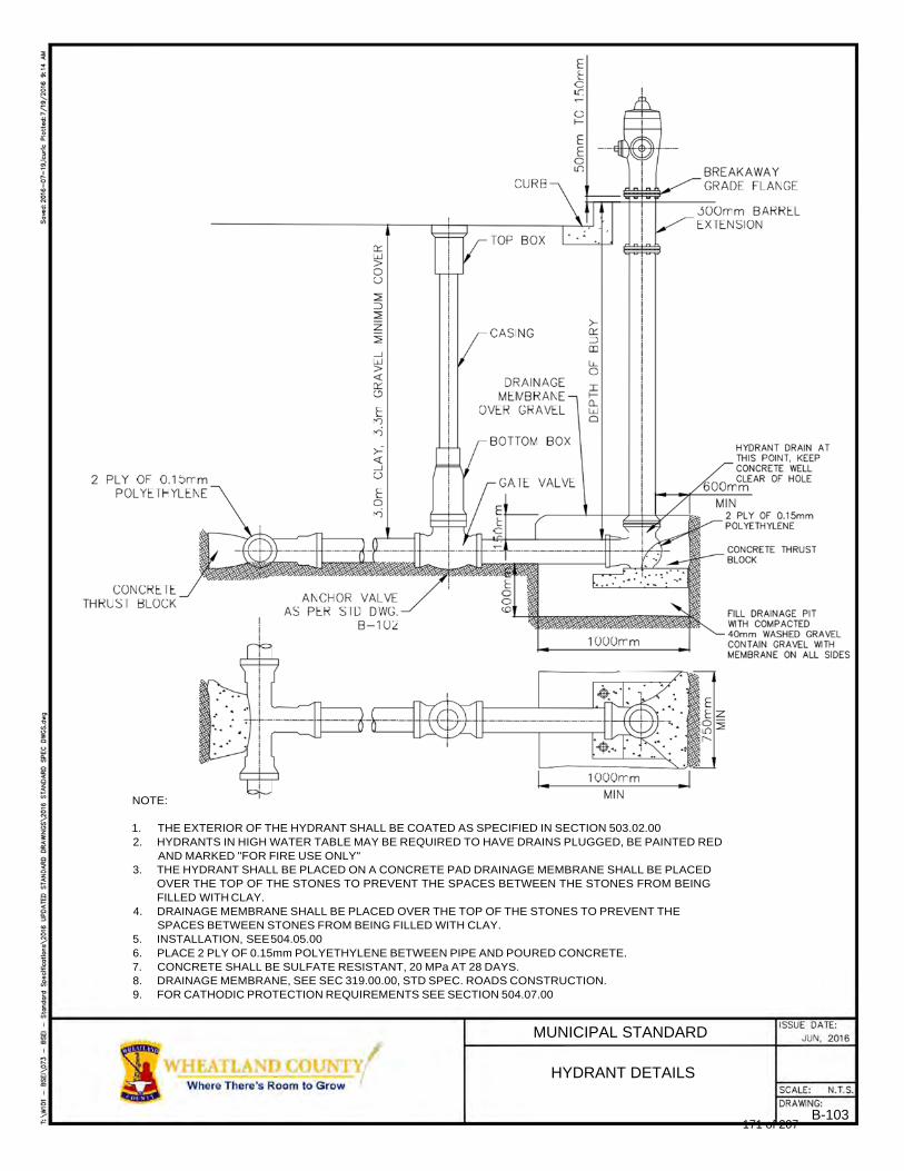
NOTE:
1. THE EXTERIOR OF THE HYDRANT SHALL BE COATED AS SPECIFIED IN SECTION 503.02.00 2. HYDRANTS IN HIGH WATER TABLE MAY BE REQUIRED TO HAVE DRAINS PLUGGED, BE PAINTED RED
AND MARKED "FOR FIRE USE ONLY" 3. THE HYDRANT SHALL BE PLACED ON A CONCRETE PAD DRAINAGE MEMBRANE SHALL BE PLACED
OVER THE TOP OF THE STONES TO PREVENT THE SPACES BETWEEN THE STONES FROM BEING FILLED WITH CLAY.
4. DRAINAGE MEMBRANE SHALL BE PLACED OVER THE TOP OF THE STONES TO PREVENT THE SPACES BETWEEN STONES FROM BEING FILLED WITH CLAY.
5. INSTALLATION, SEE 504.05.00 6. PLACE 2 PLY OF 0.15mm POLYETHYLENE BETWEEN PIPE AND POURED CONCRETE. 7. CONCRETE SHALL BE SULFATE RESISTANT, 20 MPa AT 28 DAYS. 8. DRAINAGE MEMBRANE, SEE SEC 319.00.00, STD SPEC. ROADS CONSTRUCTION. 9. FOR CATHODIC PROTECTION REQUIREMENTS SEE SECTION 504.07.00
MUNICIPAL STANDARD
HYDRANT DETAILS
B-103 171 of 207
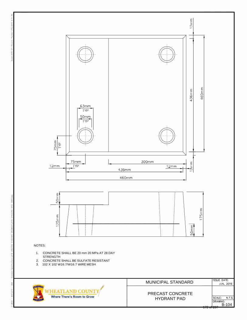
NOTES:
1. CONCRETE SHALL BE 20 mm 20 MPa AT 28 DAY
STRENGTH 2. CONCRETE SHALL BE SULFATE RESISTANT 3. 102 X 102 W16.7/W16.7 WIRE MESH
MUNICIPAL STANDARD
PRECAST CONCRETE HYDRANT PAD
B-104 172 of 207
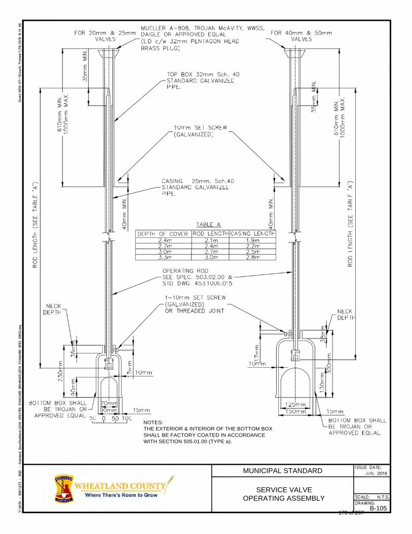
NOTES: THE EXTERIOR & INTERIOR OF THE BOTTOM BOX SHALL BE FACTORY COATED IN ACCORDANCE WITH SECTION 505.01.00 (TYPE a).
MUNICIPAL STANDARD
SERVICE VALVE OPERATING ASSEMBLY
B-105 173 of 207
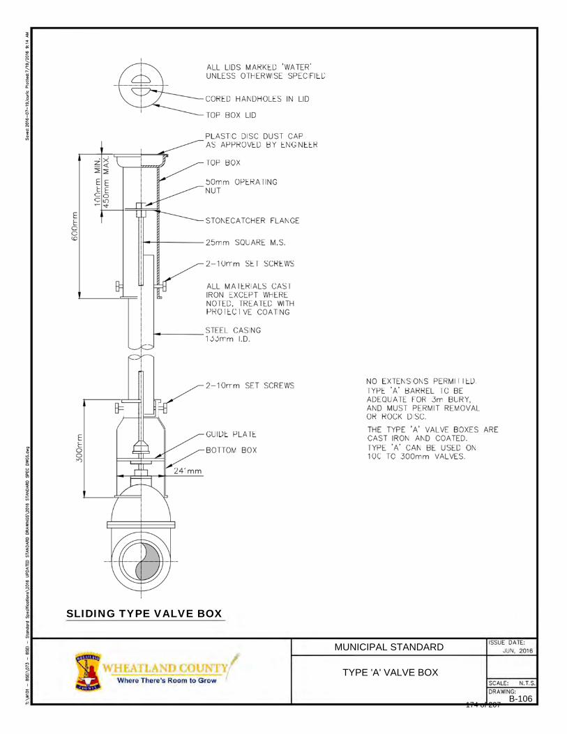
SLIDING TYPE VALVE BOX
MUNICIPAL STANDARD
TYPE 'A' VALVE BOX
B-106 174 of 207
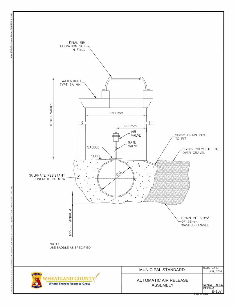
NOTE: USE SADDLE AS SPECIFIED
MUNICIPAL STANDARD
AUTOMATIC AIR RELEASE ASSEMBLY
B-107 175 of 207
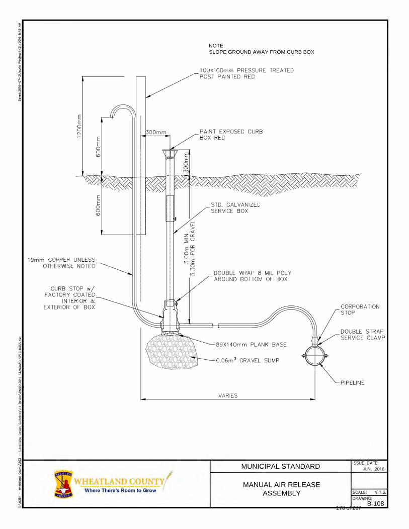
NOTE: SLOPE GROUND AWAY FROM CURB BOX
MUNICIPAL STANDARD
MANUAL AIR RELEASE ASSEMBLY
B-108 176 of 207

NOTE:
1. CONTRACTOR IS TO SUBMIT ONE MARKER COMPLETE FOR APPROVAL BY THE ENGINEER PRIOR TO INSTALLATION 2. ALL LETTERING AND COLORINGS SHALL BE BAKED ENAMEL FINISH PAINT OR A VINYL MATERIAL WITH VINYL INK FOR
LETTERING SUCH AS 3M SCOTCHCAL, FASCON OR APPROVED EQUAL 3. SIGNS WILL BE INSTALLED AT ROAD CROSSINGS AND BURIED MANHOLES. THE ACTUAL LOCATION WILL BE
DESIGNATED BY THE ENGINEER.
MUNICIPAL STANDARD
PIPELINE ROUTE MARKER
B-109 177 of 207
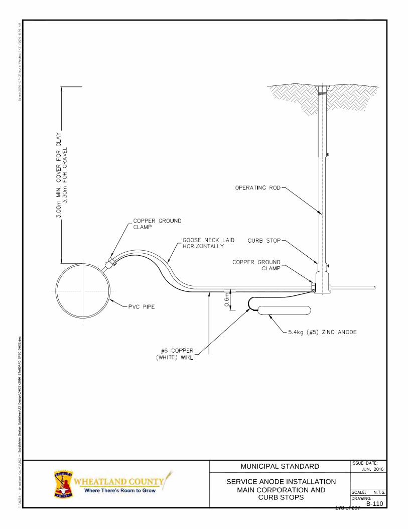
MUNICIPAL STANDARD
SERVICE ANODE INSTALLATION MAIN CORPORATION AND
CURB STOPS B-110
178 of 207
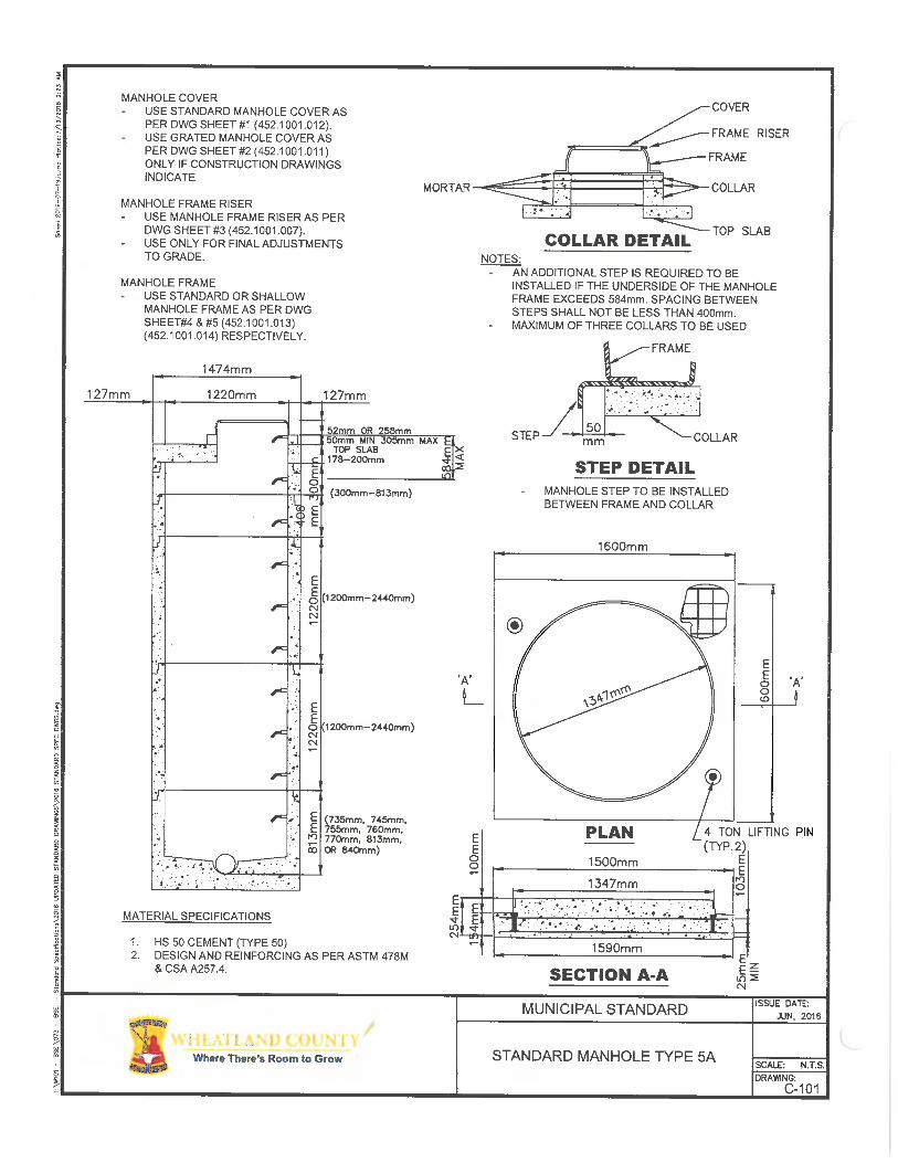
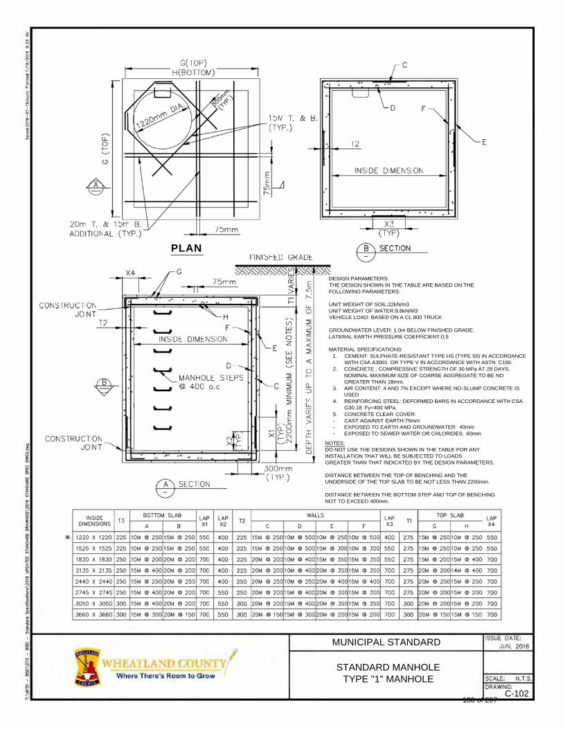
PLAN
DESIGN PARAMETERS: THE DESIGN SHOWN IN THE TABLE ARE BASED ON THE FOLLOWING PARAMETERS:
UNIT WEIGHT OF SOIL:22kN/m3 UNIT WEIGHT OF WATER:9.8kN/M3 VEHICLE LOAD: BASED ON A CL 800 TRUCK
GROUNDWATER LEVER: 1.0m BELOW FINISHED GRADE. LATERAL EARTH PRESSURE COEFFICIENT:0.5
MATERIAL SPECIFICATIONS:
1. CEMENT: SULPHATE-RESISTANT TYPE HS (TYPE 50) IN ACCORDANCE WITH CSA A3001 OR TYPE V IN ACCORDANCE WITH ASTN C150.
2. CONCRETE : COMPRESSIVE STRENGTH OF 30 MPa AT 28 DAYS. NOMINAL MAXIMUM SIZE OF COARSE AGGREGATE TO BE NO GREATER THAN 28mm.
3. AIR CONTENT: 4 AND 7% EXCEPT WHERE NO-SLUMP CONCRETE IS USED
4. REINFORCING STEEL: DEFORMED BARS IN ACCORDANCE WITH CSA G30.18. Fy=400 MPa.
5. CONCRETE CLEAR COVER: - CAST AGAINST EARTH:75mm - EXPOSED TO EARTH AND GROUNDWATER: 40mm - EXPOSED TO SEWER WATER OR CHLORIDES: 60mm
NOTES: DO NOT USE THE DESIGNS SHOWN IN THE TABLE FOR ANY INSTALLATION THAT WILL BE SUBJECTED TO LOADS GREATER THAN THAT INDICATED BY THE DESIGN PARAMETERS.
DISTANCE BETWEEN THE TOP OF BENCHING AND THE UNDERSIDE OF THE TOP SLAB TO BE NOT LESS THAN 2200mm.
DISTANCE BETWEEN THE BOTTOM STEP AND TOP OF BENCHING NOT TO EXCEED 400mm.
MUNICIPAL STANDARD
STANDARD MANHOLE TYPE "1" MANHOLE
C-102 180 of 207
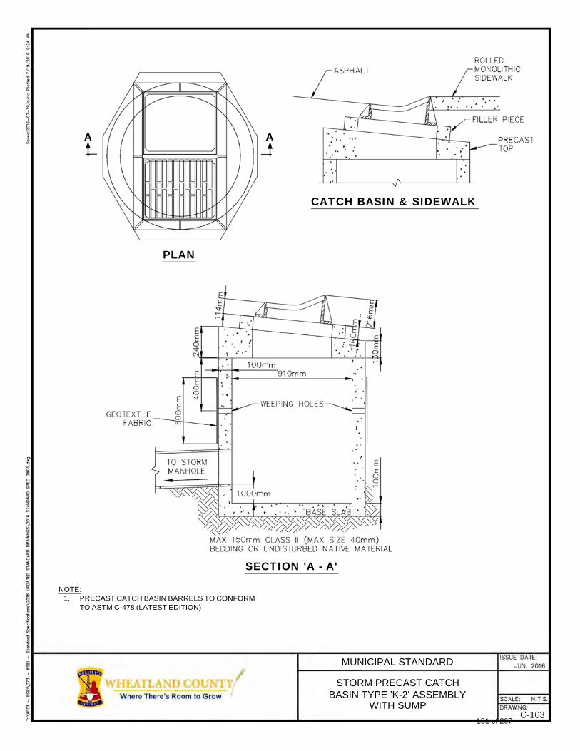
A A
CATCH BASIN & SIDEWALK
PLAN
SECTION 'A - A'
NOTE: 1. PRECAST CATCH BASIN BARRELS TO CONFORM
TO ASTM C-478 (LATEST EDITION)
MUNICIPAL STANDARD
STORM PRECAST CATCH BASIN TYPE 'K-2' ASSEMBLY
WITH SUMP C-103
181 of 207
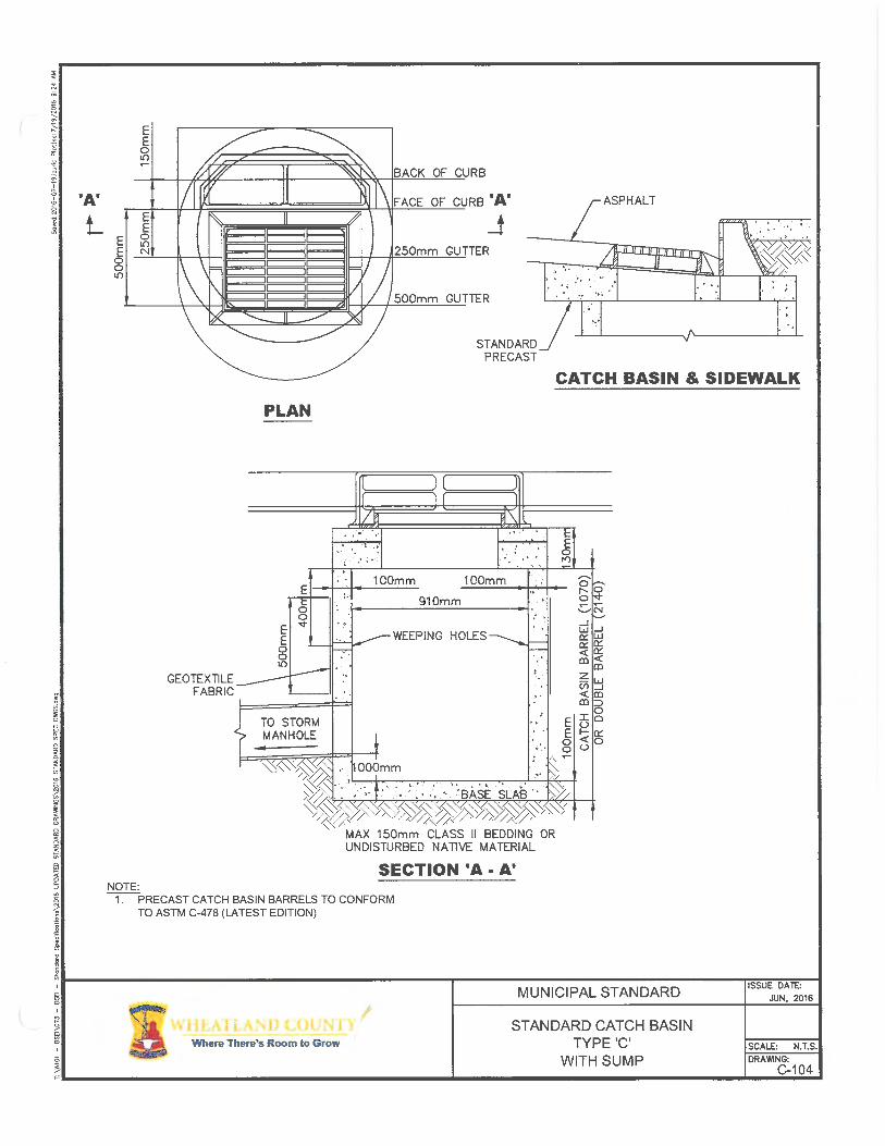
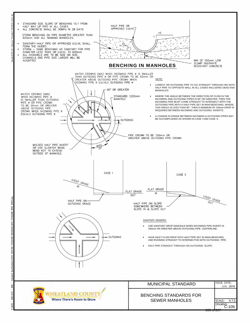
BENCHING IN MANHOLES
NOTE:
LOWEST OR OUTGOING PIPE TO GO STRAIGHT THROUGH MH WITH HALF PIPE TO OPPOSITE WALL IN ALL CASES INCLUDING DEAD END MANHOLES.
WHERE THE ANGLE BETWEEN THE DIRECTION OF FLOW IN THE INCOMING AND OUTGOING PIPES IS 90° OR GREATER, THEN THE INCOMING PIPE MUST COME STRAIGHT TO INTERSECT WITH THE OUTGOING PIPE WITH A HALF PIPE SET IN MAIN BENCHING, WHERE THIS ANGLE IS LESS THAN 90°. THEN A MINIMUM OF 150mm DROP IS REQUIRED BETWEEN INCOMING AND OUTGOING INVERTS.
A CHANGE IN GRADE BETWEEN INCOMING & OUTGOING PIPES MAY BE ACCOMPLISHED AS SHOWN IN CASE I AND CASE II.
SANITARY SEWERS:
USE SANITARY DROP MANHOLE WHEN INCOMING PIPE INVERT IS 760mm OR GREATER ABOVE OUTGOING PIPE CENTERLINE.
HAVE INLET FLOW DROP INTO HALF PIPE SET IN MAIN BENCHING AND RUNNING STRAIGHT TO INTERSECTON WITH OUTGOING PIPE.
HALF PIPE STRAIGHT THROUGH ON OUTGOING SLOPE.
MUNICIPAL STANDARD
BENCHING STANDARDS FOR SEWER MANHOLES
C-105 183 of 207
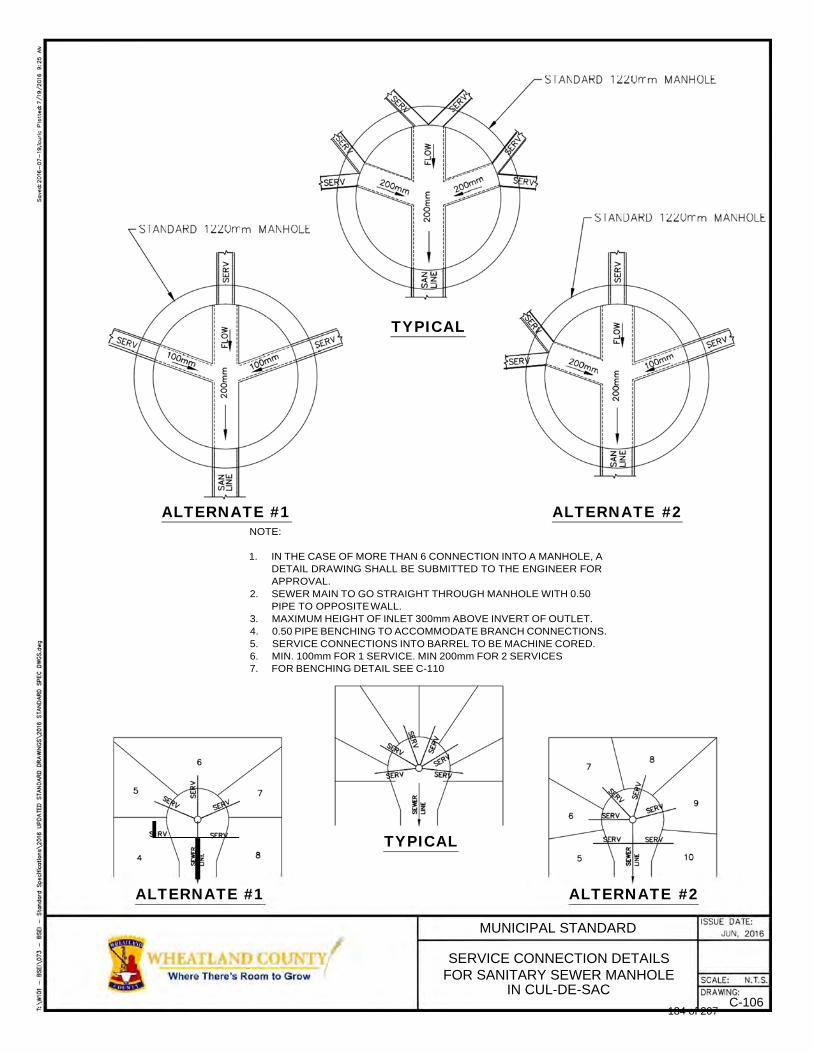
TYPICAL
ALTERNATE #1 ALTERNATE #2
NOTE:
1. IN THE CASE OF MORE THAN 6 CONNECTION INTO A MANHOLE, A DETAIL DRAWING SHALL BE SUBMITTED TO THE ENGINEER FOR APPROVAL.
2. SEWER MAIN TO GO STRAIGHT THROUGH MANHOLE WITH 0.50 PIPE TO OPPOSITE WALL.
3. MAXIMUM HEIGHT OF INLET 300mm ABOVE INVERT OF OUTLET. 4. 0.50 PIPE BENCHING TO ACCOMMODATE BRANCH CONNECTIONS. 5. SERVICE CONNECTIONS INTO BARREL TO BE MACHINE CORED. 6. MIN. 100mm FOR 1 SERVICE. MIN 200mm FOR 2 SERVICES 7. FOR BENCHING DETAIL SEE C-110
TYPICAL
ALTERNATE #1 ALTERNATE #2
MUNICIPAL STANDARD
SERVICE CONNECTION DETAILS FOR SANITARY SEWER MANHOLE
IN CUL-DE-SAC C-106
184 of 207
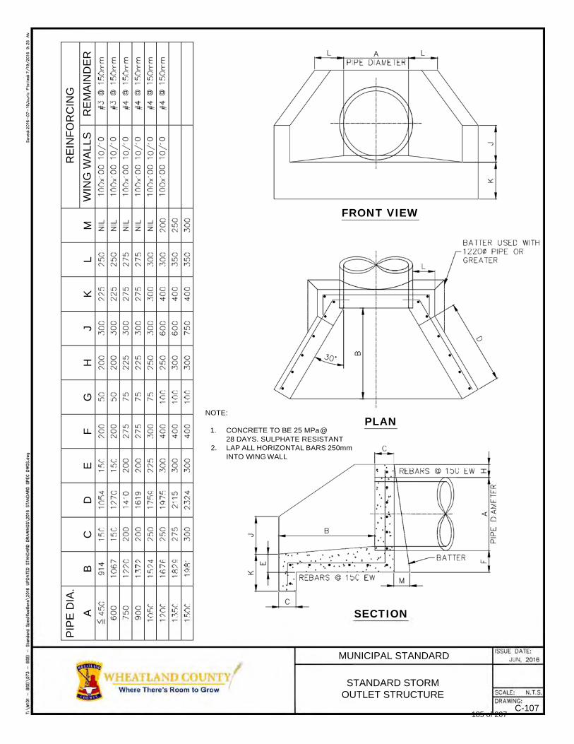
FRONT VIEW
NOTE:
1. CONCRETE TO BE 25 MPa @ 28 DAYS. SULPHATE RESISTANT
2. LAP ALL HORIZONTAL BARS 250mm INTO WING WALL
PLAN
SECTION
MUNICIPAL STANDARD
STANDARD STORM OUTLET STRUCTURE
C-107
RE
INF
OR
CIN
G
RE
MA
IND
ER
WIN
G W
AL
LS
M
L
K
J
H
G
F
E
D
C
B
PIP
E D
IA.
A
185 of 207
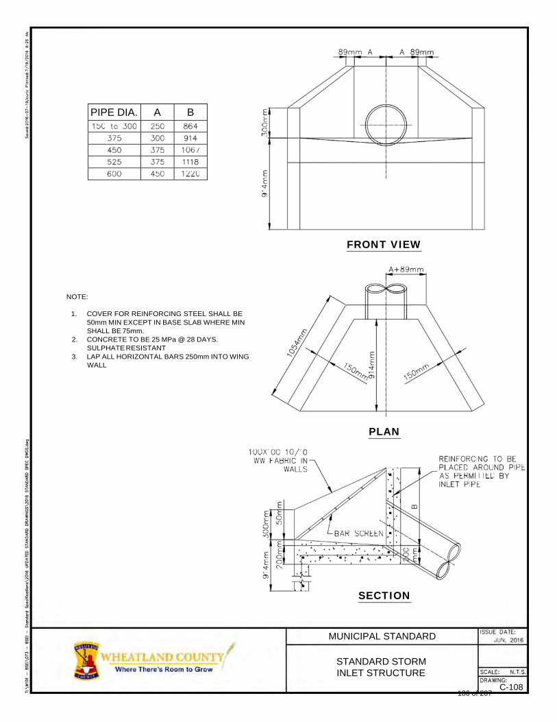
PIPE DIA. A B
FRONT VIEW
NOTE:
1. COVER FOR REINFORCING STEEL SHALL BE 50mm MIN EXCEPT IN BASE SLAB WHERE MIN SHALL BE 75mm.
2. CONCRETE TO BE 25 MPa @ 28 DAYS. SULPHATE RESISTANT
3. LAP ALL HORIZONTAL BARS 250mm INTO WING WALL
PLAN
SECTION
MUNICIPAL STANDARD
STANDARD STORM INLET STRUCTURE
C-108 186 of 207
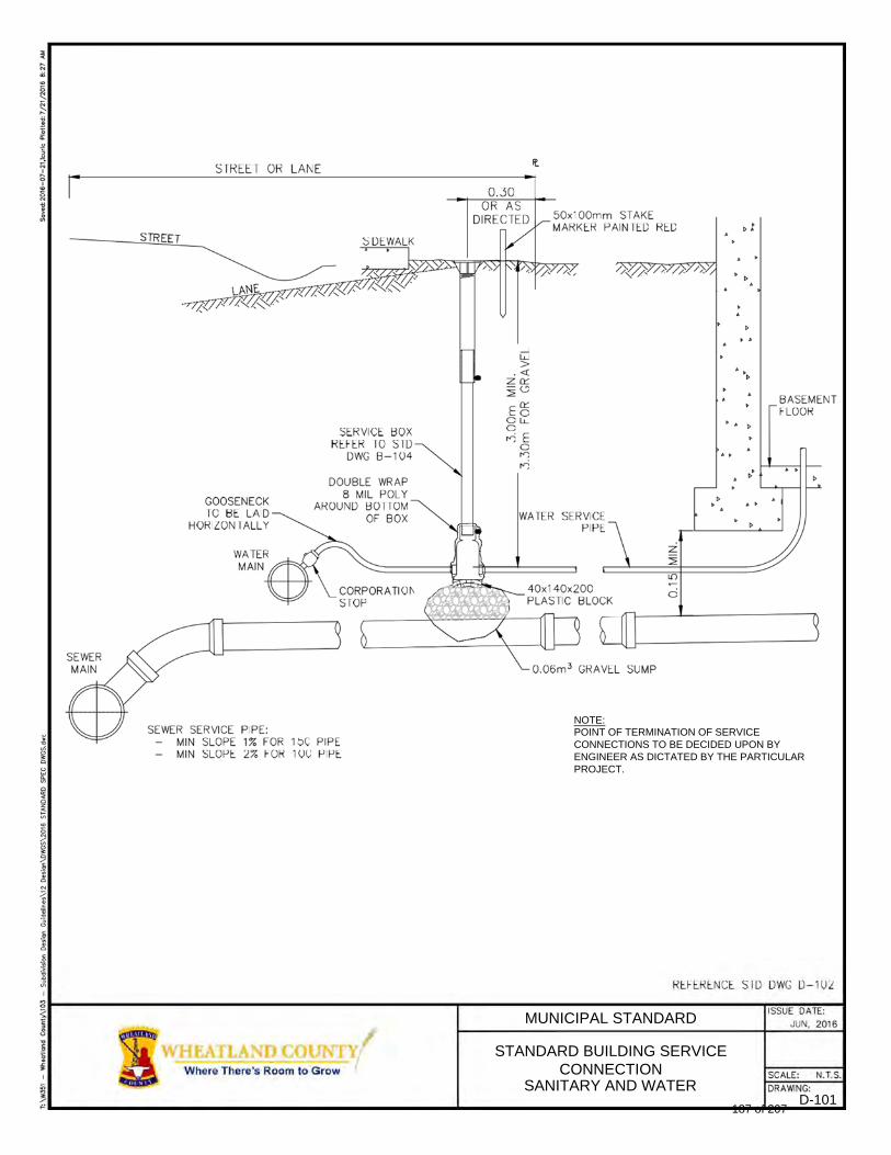
NOTE: POINT OF TERMINATION OF SERVICE CONNECTIONS TO BE DECIDED UPON BY ENGINEER AS DICTATED BY THE PARTICULAR PROJECT.
MUNICIPAL STANDARD
STANDARD BUILDING SERVICE CONNECTION
SANITARY AND WATER D-101
187 of 207
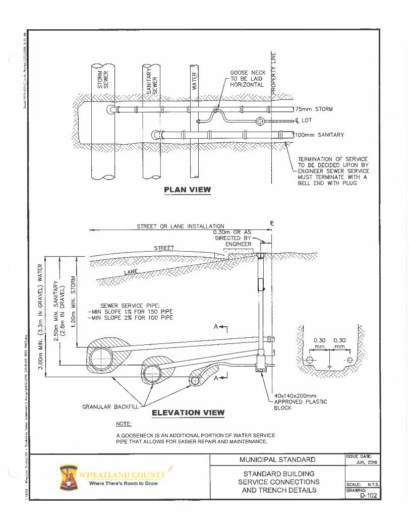
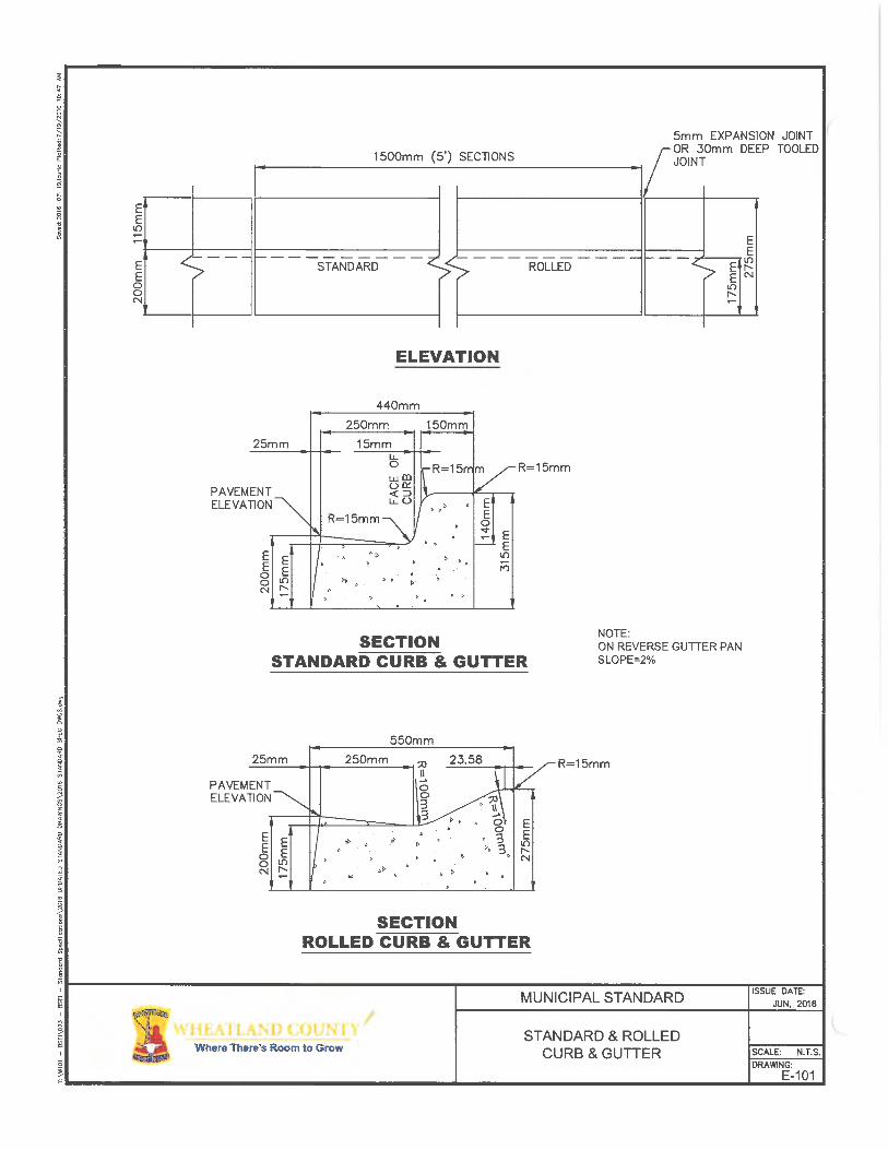
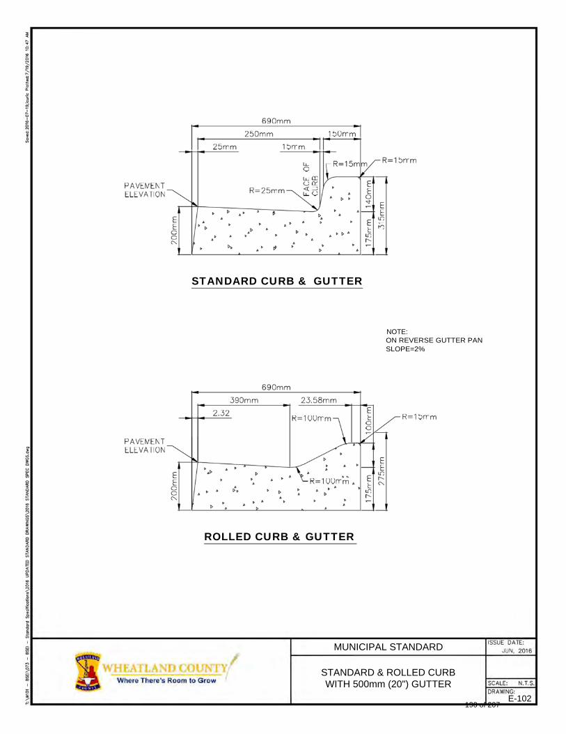
STANDARD CURB & GUTTER
NOTE: ON REVERSE GUTTER PAN SLOPE=2%
ROLLED CURB & GUTTER
MUNICIPAL STANDARD
STANDARD & ROLLED CURB WITH 500mm (20") GUTTER
E-102 190 of 207
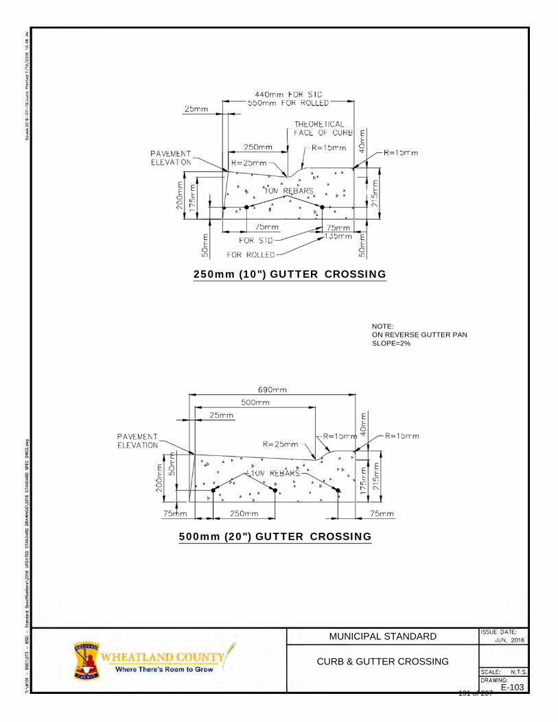
250mm (10") GUTTER CROSSING
NOTE: ON REVERSE GUTTER PAN SLOPE=2%
500mm (20") GUTTER CROSSING
MUNICIPAL STANDARD
CURB & GUTTER CROSSING
E-103 191 of 207
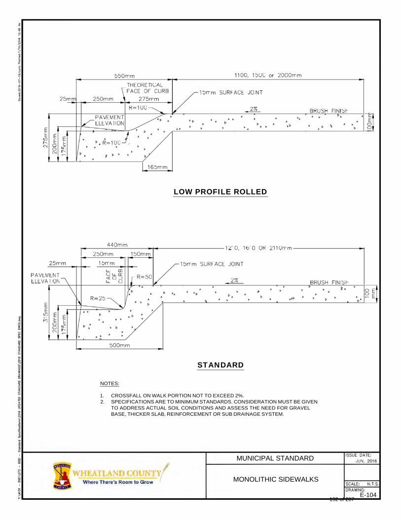
LOW PROFILE ROLLED
STANDARD
NOTES:
1. CROSSFALL ON WALK PORTION NOT TO EXCEED 2%. 2. SPECIFICATIONS ARE TO MINIMUM STANDARDS. CONSIDERATION MUST BE GIVEN
TO ADDRESS ACTUAL SOIL CONDITIONS AND ASSESS THE NEED FOR GRAVEL BASE, THICKER SLAB, REINFORCEMENT OR SUB DRAINAGE SYSTEM.
MUNICIPAL STANDARD
MONOLITHIC SIDEWALKS
E-104 192 of 207
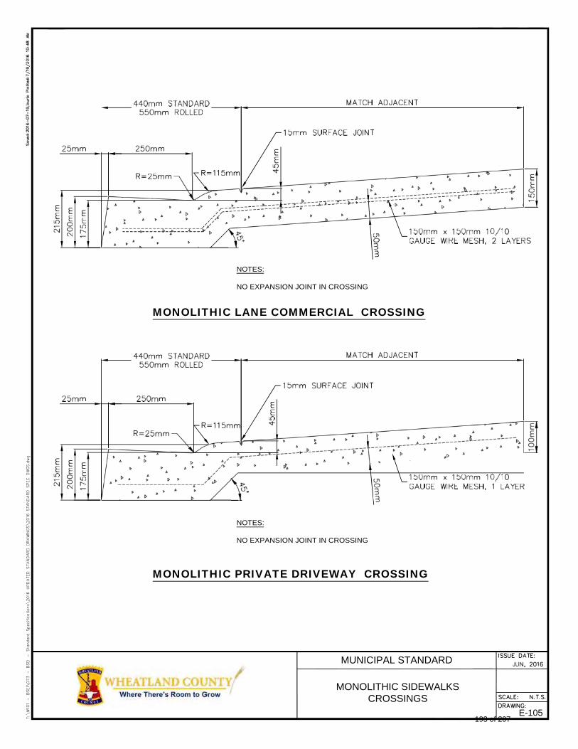
NOTES:
NO EXPANSION JOINT IN CROSSING
MONOLITHIC LANE COMMERCIAL CROSSING
NOTES:
NO EXPANSION JOINT IN CROSSING
MONOLITHIC PRIVATE DRIVEWAY CROSSING
MUNICIPAL STANDARD
MONOLITHIC SIDEWALKS CROSSINGS
E-105 193 of 207
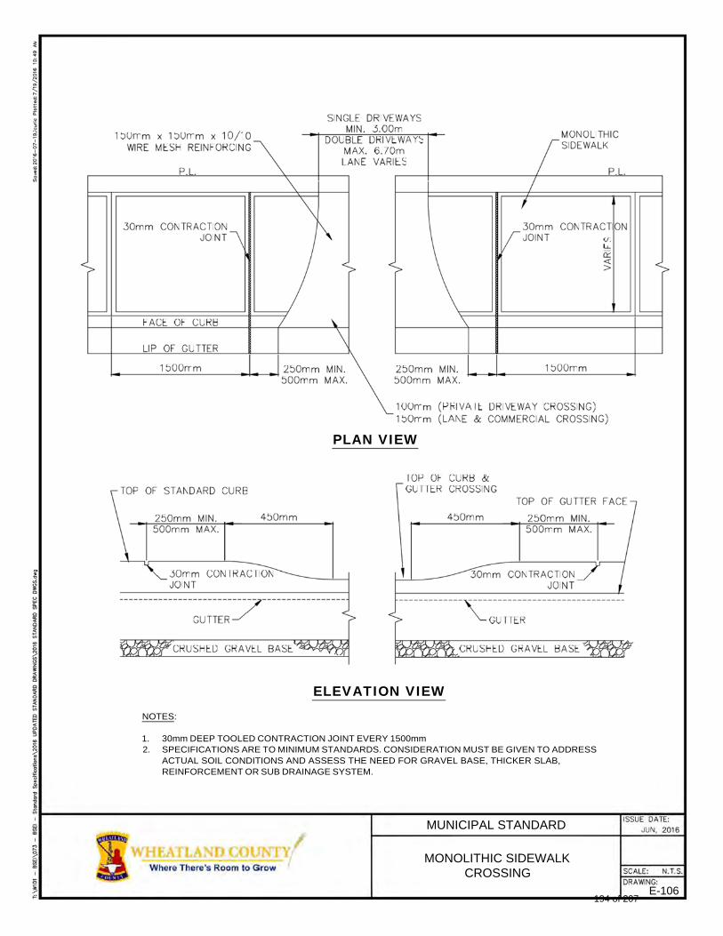
PLAN VIEW
ELEVATION VIEW
NOTES:
1. 30mm DEEP TOOLED CONTRACTION JOINT EVERY 1500mm 2. SPECIFICATIONS ARE TO MINIMUM STANDARDS. CONSIDERATION MUST BE GIVEN TO ADDRESS
ACTUAL SOIL CONDITIONS AND ASSESS THE NEED FOR GRAVEL BASE, THICKER SLAB, REINFORCEMENT OR SUB DRAINAGE SYSTEM.
MUNICIPAL STANDARD
MONOLITHIC SIDEWALK CROSSING
E-106 194 of 207

PLAN
SECTION
NOTES:
1. FOR DISHED SIDEWALK SLOPE 2% TO CENTRE 2. SPECIFICATIONS ARE TO MINIMUM STANDARDS. CONSIDERATION MUST BE GIVEN TO ADDRESS
ACTUAL SOIL CONDITIONS AND ASSESS THE NEED FOR GRAVEL BASE, THICKER SLAB, REINFORCEMENT OR SUB DRAINAGE SYSTEM.
MUNICIPAL STANDARD
SEPARATE SIDEWALKS DETAILS
E-107 195 of 207
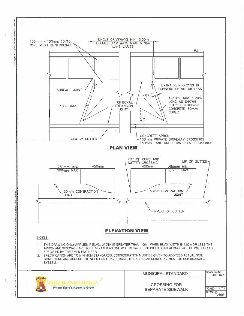
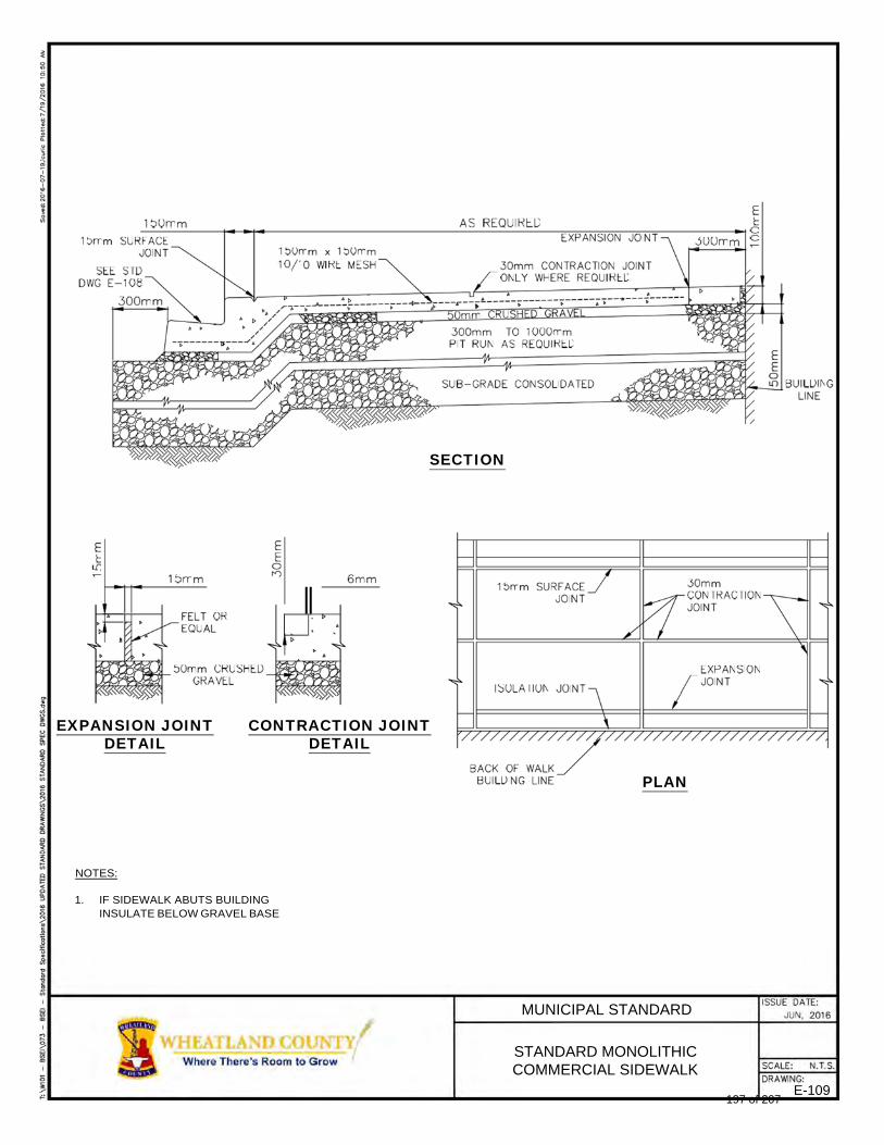
SECTION
EXPANSION JOINT
DETAIL CONTRACTION JOINT
DETAIL PLAN
NOTES:
1. IF SIDEWALK ABUTS BUILDING
INSULATE BELOW GRAVEL BASE
MUNICIPAL STANDARD
STANDARD MONOLITHIC COMMERCIAL SIDEWALK
E-109 197 of 207
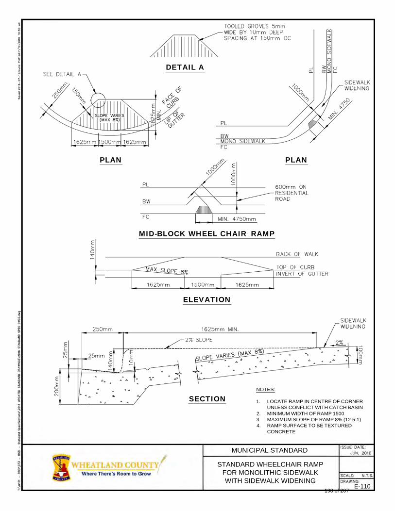
DETAIL A
PLAN PLAN
MID-BLOCK WHEEL CHAIR RAMP
ELEVATION
SECTION
NOTES:
1. LOCATE RAMP IN CENTRE OF CORNER UNLESS CONFLICT WITH CATCH BASIN
2. MINIMUM WIDTH OF RAMP 1500 3. MAXIMUM SLOPE OF RAMP 8% (12.5:1) 4. RAMP SURFACE TO BE TEXTURED
CONCRETE
MUNICIPAL STANDARD
STANDARD WHEELCHAIR RAMP FOR MONOLITHIC SIDEWALK WITH SIDEWALK WIDENING
E-110 198 of 207
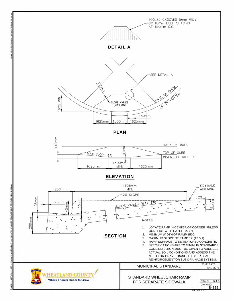
DETAIL A
PLAN
ELEVATION
NOTES:
SECTION
1. LOCATE RAMP IN CENTER OF CORNER UNLESS CONFLICT WITH CATCH BASIN
2. MINIMUM WIDTH OF RAMP 1500 3. MAXIMUM SLOPE OF RAMP 8% (12.5:1) 4. RAMP SURFACE TO BE TEXTURED CONCRETE. 5. SPECIFICATIONS ARE TO MINIMUM STANDARDS.
CONSIDERATION MUST BE GIVEN TO ADDRESS ACTUAL SOIL CONDITIONS AND ASSESS THE NEED FOR GRAVEL BASE, THICKER SLAB, REINFORCEMENT OR SUB DRAINAGE SYSTEM.
MUNICIPAL STANDARD
STANDARD WHEELCHAIR RAMP FOR SEPARATE SIDEWALK
E-111 199 of 207
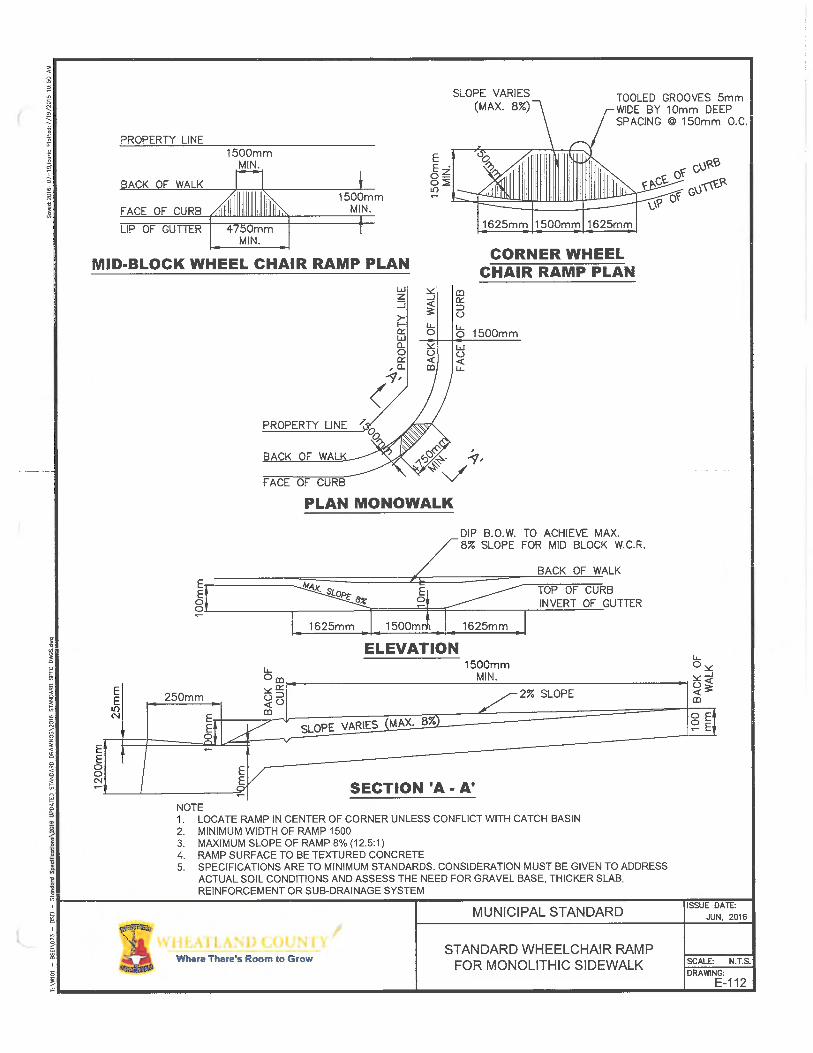
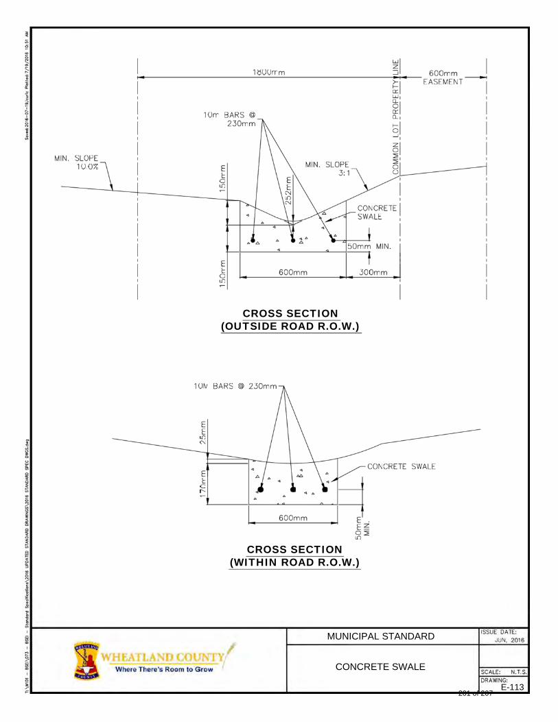
CROSS SECTION (OUTSIDE ROAD R.O.W.)
CROSS SECTION (WITHIN ROAD R.O.W.)
MUNICIPAL STANDARD
CONCRETE SWALE
E-113 201 of 207
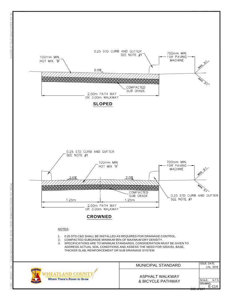
SLOPED
CROWNED
NOTES:
1. 0.25 STD C&G SHALL BE INSTALLED AS REQUIRED FOR DRAINAGE CONTROL. 2. COMPACTED SUBGRADE MINIMUM 95% OF MAXIMUM DRY DENSITY. 3. SPECIFICATIONS ARE TO MINIMUM STANDARDS. CONSIDERATION MUST BE GIVEN TO
ADDRESS ACTUAL SOIL CONDITIONS AND ASSESS THE NEED FOR GRAVEL BASE, THICKER SLAB, REINFORCEMENT OR SUB DRAINAGE SYSTEM.
MUNICIPAL STANDARD
ASPHALT WALKWAY & BICYCLE PATHWAY
E-114 202 of 207
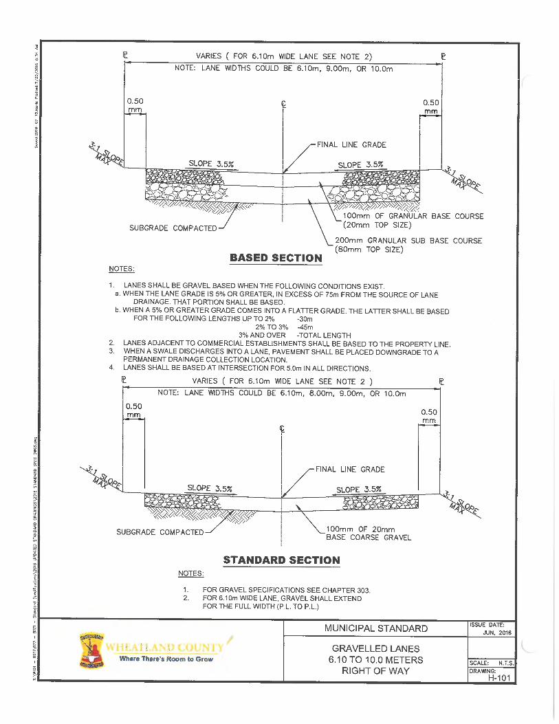
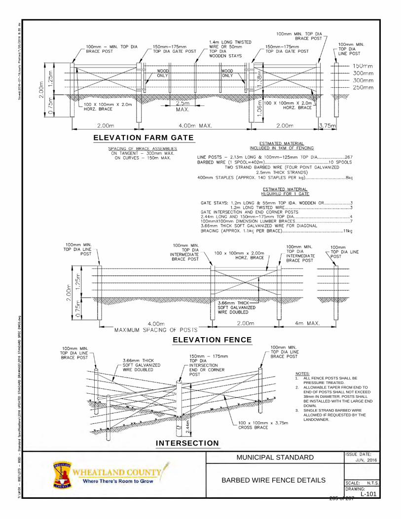
ELEVATION FARM GATE
ELEVATION FENCE
NOTES: 1. ALL FENCE POSTS SHALL BE
PRESSURE TREATED. 2. ALLOWABLE TAPER FROM END TO
END OF POSTS SHALL NOT EXCEED 38mm IN DIAMETER. POSTS SHALL BE INSTALLED WITH THE LARGE END DOWN.
3. SINGLE STRAND BARBED WIRE ALLOWED IF REQUESTED BY THE LANDOWNER.
INTERSECTION
MUNICIPAL STANDARD
BARBED WIRE FENCE DETAILS
L-101 205 of 207
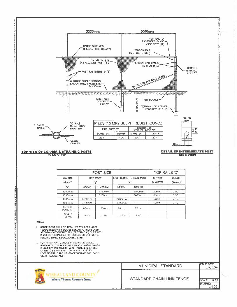

207 of 207
Top Related
Copyright © 2022 FDOKUMEN

