Construction Standards - Town of Bargersville, Indiana
322
TOWN OF BARGERSVILLE, INDIANA CONSTRUCTION STANDARDS SPECIFICATIONS AND DETAILS ---- JANUARY 2 ND , 2019 ----
-
Upload
khangminh22 -
Category
Documents
-
view
1 -
download
0
Transcript of Construction Standards - Town of Bargersville, Indiana

TOWN OF BARGERSVILLE, INDIANA
CONSTRUCTION STANDARDS
SPECIFICATIONS AND DETAILS
---- JANUARY 2ND, 2019 ----
TOWN OF BARGERSVILLE CONSTRUCTION STANDARDS ADOPTED JANURAY 2ND, 2019 3
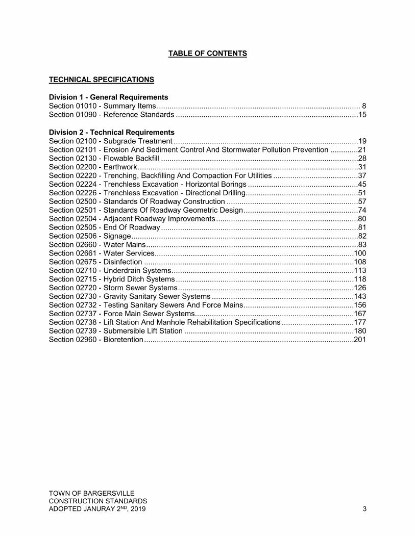
TABLE OF CONTENTS TECHNICAL SPECIFICATIONS Division 1 - General Requirements Section 01010 - Summary Items ................................................................................................ 8 Section 01090 - Reference Standards ......................................................................................15 Division 2 - Technical Requirements Section 02100 - Subgrade Treatment .......................................................................................19 Section 02101 - Erosion And Sediment Control And Stormwater Pollution Prevention .............21 Section 02130 - Flowable Backfill .............................................................................................28 Section 02200 - Earthwork ........................................................................................................31 Section 02220 - Trenching, Backfilling And Compaction For Utilities ........................................37 Section 02224 - Trenchless Excavation - Horizontal Borings ....................................................45 Section 02226 - Trenchless Excavation - Directional Drilling .....................................................51 Section 02500 - Standards Of Roadway Construction ..............................................................57 Section 02501 - Standards Of Roadway Geometric Design ......................................................74 Section 02504 - Adjacent Roadway Improvements ...................................................................80 Section 02505 - End Of Roadway .............................................................................................81 Section 02506 - Signage ...........................................................................................................82 Section 02660 - Water Mains ....................................................................................................83 Section 02661 - Water Services .............................................................................................. 100 Section 02675 - Disinfection ................................................................................................... 108 Section 02710 - Underdrain Systems ...................................................................................... 113 Section 02715 - Hybrid Ditch Systems .................................................................................... 118 Section 02720 - Storm Sewer Systems ................................................................................... 126 Section 02730 - Gravity Sanitary Sewer Systems ................................................................... 143 Section 02732 - Testing Sanitary Sewers And Force Mains .................................................... 156 Section 02737 - Force Main Sewer Systems ........................................................................... 167 Section 02738 - Lift Station And Manhole Rehabilitation Specifications .................................. 177 Section 02739 - Submersible Lift Station ................................................................................ 180 Section 02960 - Bioretention ................................................................................................... 201
TOWN OF BARGERSVILLE CONSTRUCTION STANDARDS ADOPTED JANURAY 2ND, 2019 4
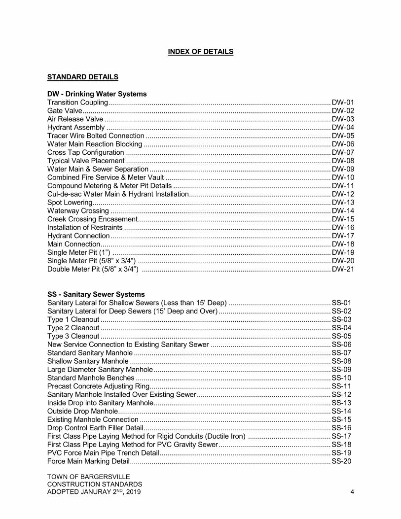
INDEX OF DETAILS STANDARD DETAILS DW - Drinking Water Systems Transition Coupling ................................................................................................................. DW-01 Gate Valve .............................................................................................................................. DW-02 Air Release Valve ................................................................................................................... DW-03 Hydrant Assembly .................................................................................................................. DW-04 Tracer Wire Bolted Connection .............................................................................................. DW-05 Water Main Reaction Blocking ............................................................................................... DW-06 Cross Tap Configuration ........................................................................................................ DW-07 Typical Valve Placement ........................................................................................................ DW-08 Water Main & Sewer Separation ............................................................................................ DW-09 Combined Fire Service & Meter Vault .................................................................................... DW-10 Compound Metering & Meter Pit Details ................................................................................ DW-11 Cul-de-sac Water Main & Hydrant Installation ........................................................................ DW-12 Spot Lowering ......................................................................................................................... DW-13 Waterway Crossing ................................................................................................................ DW-14 Creek Crossing Encasement .................................................................................................. DW-15 Installation of Restraints ......................................................................................................... DW-16 Hydrant Connection ................................................................................................................ DW-17 Main Connection ..................................................................................................................... DW-18 Single Meter Pit (1”) ............................................................................................................... DW-19 Single Meter Pit (5/8” x 3/4”) .................................................................................................. DW-20 Double Meter Pit (5/8” x 3/4”) ................................................................................................ DW-21 SS - Sanitary Sewer Systems Sanitary Lateral for Shallow Sewers (Less than 15’ Deep) .................................................... SS-01 Sanitary Lateral for Deep Sewers (15’ Deep and Over) ......................................................... SS-02 Type 1 Cleanout ..................................................................................................................... SS-03 Type 2 Cleanout ..................................................................................................................... SS-04 Type 3 Cleanout ..................................................................................................................... SS-05 New Service Connection to Existing Sanitary Sewer ............................................................. SS-06 Standard Sanitary Manhole .................................................................................................... SS-07 Shallow Sanitary Manhole ...................................................................................................... SS-08 Large Diameter Sanitary Manhole .......................................................................................... SS-09 Standard Manhole Benches ................................................................................................... SS-10 Precast Concrete Adjusting Ring............................................................................................ SS-11 Sanitary Manhole Installed Over Existing Sewer .................................................................... SS-12 Inside Drop into Sanitary Manhole .......................................................................................... SS-13 Outside Drop Manhole ............................................................................................................ SS-14 Existing Manhole Connection ................................................................................................. SS-15 Drop Control Earth Filler Detail ............................................................................................... SS-16 First Class Pipe Laying Method for Rigid Conduits (Ductile Iron) .......................................... SS-17 First Class Pipe Laying Method for PVC Gravity Sewer ......................................................... SS-18 PVC Force Main Pipe Trench Detail ....................................................................................... SS-19 Force Main Marking Detail ...................................................................................................... SS-20

TOWN OF BARGERSVILLE CONSTRUCTION STANDARDS ADOPTED JANURAY 2ND, 2019 5
Air/Vacuum Release Valve & Vault Detail .............................................................................. SS-21 Valve & Box Detail .................................................................................................................. SS-22 Thrust Blocking Details for Pressure Main ............................................................................. SS-23 SS - Sanitary Sewer Systems (continued) Railroad Pipe Crossing Detail ................................................................................................. SS-24 State Highway Boring/Casing Detail ....................................................................................... SS-25 Sanitary Sewer Stream Crossing Detail ................................................................................. SS-26 Typical Lift Station Plan .......................................................................................................... SS-27 Typical Lift Station Section ..................................................................................................... SS-28 Typical Pump Station Electrical and Pump Control Mounting Detail ...................................... SS-29 Typical Pump Station Service Pole for Pump Station Services .............................................. SS-30 Typical Pump Station Power Distribution Diagram ................................................................. SS-31 Bypass Pump Quick Connection Detail .................................................................................. SS-32 Grease Trap Detail ................................................................................................................. SS-33 Blow Off Valve Detail for Traffic Bearing Areas ...................................................................... SS-34 Blow Off Valve Detail for Non-Traffic Bearing Areas .............................................................. SS-35 Lift Station Enclosure .............................................................................................................. SS-36 Low Pressure Service Connection ......................................................................................... SS-37 SW - Storm Water Systems Gravity Sewer Repair ............................................................................................................ SW-01 Silt Fence ............................................................................................................................... SW-02 Turf Armored Ditch ................................................................................................................ SW-03 Hard Armored Ditch ............................................................................................................... SW-04 Detention/Retention Ponds .................................................................................................... SW-05 Rigid (RCP, DI) Pipe Trench ................................................................................................. SW-06 Flexible (HDPE, PVC) Pipe Trench ....................................................................................... SW-07 Gravity Pipe Crossing Waterway ........................................................................................... SW-08 Gravity Pipe Crossing Roadway/Railroad .............................................................................. SW-09 Drainage Swale with Underdrain ........................................................................................... SW-10 Drainage Lateral in Rear of Lot ............................................................................................. SW-11 Not Used................................................................................................................................ SW-12 Precast Concrete End Section .............................................................................................. SW-13 Trash Guard .......................................................................................................................... SW-14 Standard Storm Manhole ....................................................................................................... SW-15 Large Diameter Storm Manhole ............................................................................................ SW-16 Inlet Type A ........................................................................................................................... SW-17 Yard Inlet ............................................................................................................................... SW-18 RS - Roadway Sections Principal Arterial A1 ................................................................................................................ RS-01 Principal Arterial B1 ................................................................................................................ RS-02 Principal Arterial C1 ................................................................................................................ RS-03 Minor Arterial 1 ....................................................................................................................... RS-04 Major Collector 1 .................................................................................................................... RS-05 Minor Collector 1 .................................................................................................................... RS-06 Local 1 and Local 2 (High Density) ......................................................................................... RS-07 Local Rural with Shoulders ..................................................................................................... RS-08

TOWN OF BARGERSVILLE CONSTRUCTION STANDARDS ADOPTED JANURAY 2ND, 2019 6
County Road 144/Old Plank Road with Curb 1 ...................................................................... RS-09 County Road 144/Old Plank Road with Ditch 2 ...................................................................... RS-10 Typical Trail Cross Section ..................................................................................................... RS-11 Existing Roadway Intersection Reconstruction ....................................................................... RS-12 TR - Transportation Concrete Chair Back Curb & Gutter ....................................................................................... TR-01 Concrete Roll Curb & Gutter ................................................................................................... TR-02 Driveway Curb Cut ................................................................................................................. TR-03 Curb Inlet Detail ...................................................................................................................... TR-04 Concrete Center Curb ............................................................................................................ TR-05 Underdrain Pipe Detail Chair Back Curb ................................................................................ TR-06 Underdrain Pipe Detail Roll Curb ............................................................................................ TR-07 Connection to Existing Streets ............................................................................................... TR-08 Widening Detail ...................................................................................................................... TR-09 HMA Pavement Trench Repair Detail .................................................................................... TR-10 Major Commercial and Subdivision Entrance Requirements ................................................. TR-11 Commercial & Industrial Cul-de-sac Turnarounds .................................................................. TR-12 Local Cul-de-sac Turnarounds Street Class 1 ........................................................................ TR-13 Temporary Cul-de-sac Street Class 1 .................................................................................... TR-14 End of Road Detail ................................................................................................................. TR-15 Standard Barricade ................................................................................................................. TR-16 Concrete Apron at Sewer Structures .................................................................................... TR-17 Local Street with Roadside Ditch .......................................................................................... TR-18 Concrete Sidewalk Detail....................................................................................................... TR-19 Rolled Curb Ramp Detail ....................................................................................................... TR-20 Sidewalk and Curb Ramp Notes ........................................................................................... TR-21 Street Sign ............................................................................................................................. TR-22 Sign Post ................................................................................................................................ TR-23

TOWN OF BARGERSVILLE CONSTRUCTION STANDARDS ADOPTED JANURAY 2ND, 2019 7
TECHNICAL SPECIFICATIONS
DIVISION 1 GENERAL REQUIREMENTS
SUMMARY ITEMS SECTION 01010
TOWN OF BARGERSVILLE CONSTRUCTION STANDARDS ADOPTED JANURAY 2ND, 2019 8
SECTION 01010 - SUMMARY ITEMS
PART 1 - GENERAL
1.01 General Items
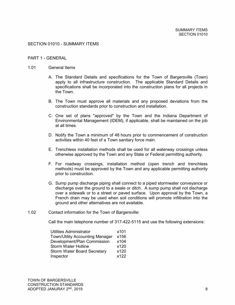
A. The Standard Details and specifications for the Town of Bargersville (Town) apply to all infrastructure construction. The applicable Standard Details and specifications shall be incorporated into the construction plans for all projects in the Town.
B. The Town must approve all materials and any proposed deviations from the construction standards prior to construction and installation.
C. One set of plans "approved" by the Town and the Indiana Department of Environmental Management (IDEM), if applicable, shall be maintained on the job at all times.
D. Notify the Town a minimum of 48 hours prior to commencement of construction activities within 40 feet of a Town sanitary force main.
E. Trenchless installation methods shall be used for all waterway crossings unless otherwise approved by the Town and any State or Federal permitting authority.
F. For roadway crossings, installation method (open trench and trenchless methods) must be approved by the Town and any applicable permitting authority prior to construction.
G. Sump pump discharge piping shall connect to a piped stormwater conveyance or discharge over the ground to a swale or ditch. A sump pump shall not discharge over a sidewalk or to a street or paved surface. Upon approval by the Town, a French drain may be used when soil conditions will promote infiltration into the ground and other alternatives are not available.
1.02 Contact information for the Town of Bargersville:
Call the main telephone number of 317-422-5115 and use the following extensions: Utilities Administrator x101 Town/Utility Accounting Manager x156 Development/Plan Commission x104 Storm Water Hotline x120 Storm Water Board Secretary x120 Inspector x122
SUMMARY ITEMS SECTION 01010
TOWN OF BARGERSVILLE CONSTRUCTION STANDARDS ADOPTED JANURAY 2ND, 2019 9
1.03 Meetings
A. A pre-construction conference must be scheduled with the Town a minimum two (2) business days prior to commencement of construction.
B. Pre-construction conference shall be scheduled through the permitting office at 317-422-5115 x106.
C. No work shall begin prior to pre-construction meeting with the Town.
1.04 Submittals
A. Final Design Drawings
1. Submit final design drawings to the Town for review. Review fees are as required by the Town’s Development Plan Permit.
2. Once the final design drawings have been reviewed, a plan review letter from the Town will be provided to the applicant.
3. Revise the design drawings based on review comments and resubmit. 4. Reviewed and approved design drawings are required prior to construction.
All other requirements as listed in this Specification must be met prior to construction.
5. Prior to scheduling a Pre-Construction conference, the Owner shall provide three (3) sets of marked “Final Approved Plans”. At the pre-construction meeting the drawings will be stamped and one (1) copy should be available onsite at all times.
B. Construction Schedules
1. Progress schedules are to be submitted by the Contractor to the Town prior to construction.
2. Provide complete sequence of construction by activity showing dates for beginning and completion of each element of construction.
C. Products and Materials
1. All materials furnished by the Contractor to be incorporated in the work shall be subject to inspection and approved by the Town prior to installation.
2. Product data shall be submitted to the Town for all utility pipe, utility structures, precast concrete structure coatings and sealants, manhole and catch basin frames and covers, hydrants, valves, casing pipe, all lift station equipment, concrete, asphalt and all associated materials necessary for a complete installation. Such data shall be of sufficient detail to enable the Town to identify the particular product in question and determine its conformance to the Town's requirements. Mark each copy to identify applicable products, models and options to be supplied.
SUMMARY ITEMS SECTION 01010
TOWN OF BARGERSVILLE CONSTRUCTION STANDARDS ADOPTED JANURAY 2ND, 2019 10
3. Provide sufficient number of copies of each submittal to the Town such that there is sufficient quantity for the Town to retain 3 copies.
D. As-Built Drawings
1. Provide "as-built" drawings at the completion of the utility construction. Submittal of as-built drawings is required prior to acceptance and placement in service of new utility items.
2. Provide (1) PDF digital copy, (1) CAD digital copy (.dwg format version 2004 or higher) or other file type compatible with the Town’s GIS software, (1) mylar copy, and (1) hard copy set of as-built drawings in accordance with these Standards. a. The names for the files should allow someone unfamiliar with the consulting firms naming conventions to determine the content of the file. b. The .dwg files will used the NAD83, Indiana State Plane Coordinate System, East Zone projection using U.S. Survey feet. The vertical datum for the files will be NAVD 88. c. All pertinent drawing elements will reside in the primary drawing file. There shall be no cells, nodes, blocks, or reference files (x-refs) attached to the drawing.
3. Include all installed utility lines, structures, and all existing gas and electric utility locations on as-built drawings.
4. Include any changes to the design drawings, including dimensions and revisions of details.
5. Provide offset measurements to all fittings, valves, blow-off assemblies, hydrants, and other appurtenances. Measure the offset from the centerline of the nearest street running parallel to the installed utility line. Record a second measurement from another permanent structure to the fittings, valves, blow-off assemblies, hydrants, or other appurtenances.
6. Final vertical elevations shall be established and recorded. 7. Record all pipe sizes, lengths along the centerline of the pipe, manufacturer
of each of the materials used in construction, and all easement locations, types, and dimensions.
1.05 Coordination
A. Give the Town’s Utilities Administrator and Development Department a minimum of two (2) working days notice prior to commencement of any construction activities.
B. No water or sewer system construction may begin until approval from IDEM has been received by the Town.
C. Advise the Town of who the Contractor will be prior to the pre-construction conference. The Town reserves the right to reject the Contractor.

SUMMARY ITEMS SECTION 01010
TOWN OF BARGERSVILLE CONSTRUCTION STANDARDS ADOPTED JANURAY 2ND, 2019 11
D. Coordinate work with other Contractors and the Town. Select order of work and establish schedule or working hours for construction and submit to the Town. The Town reserves the right to assure orderly and expeditious progress of work.
E. Maintain existing services affected by Contractors' operations under the contract. Schedule construction to minimize interruptions to existing services and inconvenience to others.
F. Locate all existing utilities prior to commencement of construction. Call Indiana811 at 811 or 1-800-382-5544.
G. Street closures must be approved by the Town prior to beginning work.
H. Notify the Town immediately upon the event of damage to any public street during the course of the work and requiring closure thereof. Contractor shall be responsible for repair and costs as determined by the Town.
I. Notify the Town immediately upon event of damage to any utility line. Contractor shall be responsible for repair and costs as determined by the Town. A representative from the Town must be on-site to inspect repair prior to backfill.
J. Provide bonds as required by the Subdivision Control Ordinance.
K. Notify the Town one (1) working day prior to working on weekends. There will be an additional cost for inspection on weekends to compensate for overtime.
1.06 Quality Control
A. All materials and each part or detail of the work shall be subject to inspection by the Town at all times. The Town shall be allowed access to all parts of the work and shall be furnished with such information and assistance by the Contractor as is required to make a complete and detailed inspection.
B. Provide quality-control services specified as required.
1. Where services are indicated as Contractor's responsibility, engage a qualified testing agency to perform these quality-control services.
2. Where quality-control services are indicated as Contractor's responsibility, submit a certified written report, in duplicate, of each quality-control service.
1.07 Temporary Facilities
A. Provide the following temporary facilities:
1. Sanitary facilities 2. Trash Containers 3. Barricades and enclosures 4. Bulletin Board (for required notices and postings)

SUMMARY ITEMS SECTION 01010
TOWN OF BARGERSVILLE CONSTRUCTION STANDARDS ADOPTED JANURAY 2ND, 2019 12
B. Sanitary Facilities
1. Provide sanitary facilities for use of all construction personnel including those of other contractors for the duration of the project as follows: a. Chemical units complete with weathertight enclosure adequately
ventilated and equipped with latching door. b. Maintain chemical units weekly or at lesser periods if determined
necessary. Chemical units shall be in accordance with all applicable rules and regulations.
c. Furnish toilet paper and hand sanitizer for the chemical units and replenish supply whenever required.
C. Trash Containers
1. Provide a trash container for the disposal of packaging materials, pieces of broken pipe, rubbish, trash and other debris.
2. Empty trash containers as often as necessary to prevent overflowing, but not less than one time per week.
D. Barricades
1. Provide, erect and maintain all necessary barricades, suitable and sufficient danger signals and signs.
2. Take all necessary precautions for the protection and safety of the public, workmen, structures and equipment. Roads closed to traffic shall be protected by effective barricades. Obstructions shall be illuminated during hours of darkness.
3. Erect warning signs in advance of any location on the project where operations may interfere with the use of the road by traffic and at all intermediate points where the new work crosses or coincides with the existing road. Construct and erect warning signs in accordance with the Federal Highway Administration’s Manual on Uniform Traffic Control Devices (MUTCD) and the Indiana Supplement, latest editions.
1.08 Rights of Access
A. Representatives of the Town, Environmental Protection Agency and the State of Indiana shall have access to the work wherever it is in preparation or progress and that the Contractor will provide facilities for such access and inspection.
1.09 Safety and Health Regulations for Construction
A. The Contractor shall be solely responsible for all obligations prescribed as employer obligations under Chapter XVII of Title 29, Code of Federal Regulations, Part 1926, otherwise known as "Safety and Health Regulations for Construction and CFR Part 1910.46 Permit Required for Confined Space".

SUMMARY ITEMS SECTION 01010
TOWN OF BARGERSVILLE CONSTRUCTION STANDARDS ADOPTED JANURAY 2ND, 2019 13
B. Upon request, provide the Town with the name of the Contractor's Safety Officer, plus the on-site Safety Representative, if other than the Superintendent.
C. Safety must be kept at all times but the Town is not responsible for overseeing these requirements.
1.10 Operations within Right-of-Way
A. In public thoroughfares, all operations of the Contractor, including those of temporary nature, must be confined within the applicable right-of-way limits.
B. If the methods of the construction are such as to require the use of land beyond the public thoroughfares, Contractor shall make his own arrangements with the property owners affected for the use of such additional land. Such additional agreements will not include any liability for the Town.
C. Perform all construction in existing roadways between the hours of 9:00 am and 2:00 pm. Road closures shall be coordinated with the Town prior to construction.
D. Prior to construction activity and if access will be through an existing roadway system (subdivision), the Contractor shall video the route and provide a copy to the Town.
1.11 Permits
A. The Developer shall obtain all permits which are related to the design and construction of the completed facilities including providing copies to the Town. Permits to be obtained by the Developer include, but are not limited to, permits from the following:
1. Town of Bargersville 2. Johnson County 3. Indiana Department of Environmental Management 4. Indiana Department of Homeland Security Fire and Building and Safety
Division 5. Indiana Department of Natural Resources 6. U.S. Army Corps of Engineers
B. The construction shall be performed in full accordance with any and all permit
requirements.
PART 2 - PRODUCTS
Not Used.
SUMMARY ITEMS SECTION 01010
TOWN OF BARGERSVILLE CONSTRUCTION STANDARDS ADOPTED JANURAY 2ND, 2019 14
PART 3 - EXECUTION
3.01 Site Maintenance
A. The working area shall be kept free, at all time, of tools, materials, and equipment not essential to the work in progress. Debris, waste materials, and rubbish shall not be allowed to accumulate and shall properly be disposed. On site burning of trash and debris is prohibited. On-site burial of trash and debris is prohibited.
B. If the site owner should fail to maintain the project site, the Town shall make the necessary arrangements to clean up the site at the owner's expense. If such action becomes necessary, in the opinion of the Town, the Town shall not be responsible for the inadvertent removal of materials which the owner would not have disposed of had he affected the required clean up.
C. Where material or debris has washed, flowed, blown, or been purposely deposited into watercourses, drains, ditches, inlets, or elsewhere as a result of the construction operation, such material or debris shall be entirely removed and satisfactorily disposed of immediately upon identification.
D. The site owner shall be responsible to restore or replace any public or private property damaged by operations, equipment, or employees to a condition at least equal to that existing immediately prior to beginning the project.
E. The site owner shall be responsible for the repair of any drainage tile broken or damaged during construction. The replacement pipe shall be installed with pea gravel or any other suitable granular backfill from the bottom of the trench to six inches above the top of the replacement pipe. The repair of the drainage tile shall be installed to the satisfaction of the property owner.
F. Repair all parking lots and drives to their original state of usefulness. Streets and side ditches shall be left in neat and operable condition.
G. Restore the grades to the original contours and condition.
H. The site owner shall be responsible to maintain and mow property, including all easements, right-of-ways, and common areas. If the site owner should fail to maintain the project site, the Town of Bargersville shall make the necessary arrangements to mow the site at the site owner's expense.
END OF SECTION 01010
REFERENCE STANDARDS SECTION 01090
TOWN OF BARGERSVILLE CONSTRUCTION STANDARDS ADOPTED JANURAY 2ND, 2019 15
SECTION 01090 - REFERENCE STANDARDS
PART 1 - GENERAL
1.01 Summary
A. Section Includes
1. General reference standards, rules and regulations that govern construction work, alterations, repairs, mechanical installations and appliances connected therewith
2. Abbreviations used in these Specifications
1.02 Quality Assurance
A. Regulatory Requirements: Work shall comply with the following:
1. Occupational Safety and Health Act 2. Indiana State Construction Industry Safety Code 3. State Building rules and regulations of the Indiana Department of Homeland
Security Fire and Building Safety Division 4. Indiana State Fire Marshal 5. Indiana Department of Environmental Management 6. Indiana Department of Natural Resources 7. Army Corps of Engineers 8. National Electric Code 9. National Electric Safety Code 10. Uniform Building Code 11. Life Safety Code 12. Utility regulations 13. Local ordinances, state, and federal rules and regulations pertaining to the
Work
B. Such rules, regulations and ordinances are to be considered part of these Specifications.
C. Fees for licenses shall be paid by the Contractor.
REFERENCE STANDARDS SECTION 01090
TOWN OF BARGERSVILLE CONSTRUCTION STANDARDS ADOPTED JANURAY 2ND, 2019 16
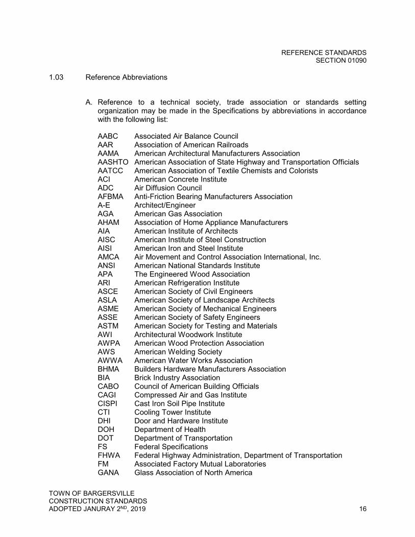
1.03 Reference Abbreviations
A. Reference to a technical society, trade association or standards setting organization may be made in the Specifications by abbreviations in accordance with the following list:
AABC Associated Air Balance Council AAR Association of American Railroads AAMA American Architectural Manufacturers Association AASHTO American Association of State Highway and Transportation Officials AATCC American Association of Textile Chemists and Colorists ACI American Concrete Institute ADC Air Diffusion Council AFBMA Anti-Friction Bearing Manufacturers Association A-E Architect/Engineer AGA American Gas Association AHAM Association of Home Appliance Manufacturers AIA American Institute of Architects AISC American Institute of Steel Construction AISI American Iron and Steel Institute AMCA Air Movement and Control Association International, Inc. ANSI American National Standards Institute APA The Engineered Wood Association ARI American Refrigeration Institute ASCE American Society of Civil Engineers ASLA American Society of Landscape Architects ASME American Society of Mechanical Engineers ASSE American Society of Safety Engineers ASTM American Society for Testing and Materials AWI Architectural Woodwork Institute AWPA American Wood Protection Association AWS American Welding Society AWWA American Water Works Association BHMA Builders Hardware Manufacturers Association BIA Brick Industry Association CABO Council of American Building Officials CAGI Compressed Air and Gas Institute CISPI Cast Iron Soil Pipe Institute CTI Cooling Tower Institute DHI Door and Hardware Institute DOH Department of Health DOT Department of Transportation FS Federal Specifications FHWA Federal Highway Administration, Department of Transportation FM Associated Factory Mutual Laboratories GANA Glass Association of North America
REFERENCE STANDARDS SECTION 01090
TOWN OF BARGERSVILLE CONSTRUCTION STANDARDS ADOPTED JANURAY 2ND, 2019 17
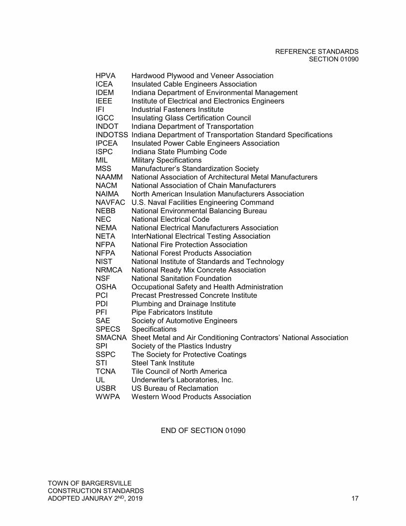
HPVA Hardwood Plywood and Veneer Association ICEA Insulated Cable Engineers Association IDEM Indiana Department of Environmental Management IEEE Institute of Electrical and Electronics Engineers IFI Industrial Fasteners Institute IGCC Insulating Glass Certification Council INDOT Indiana Department of Transportation INDOTSS Indiana Department of Transportation Standard Specifications IPCEA Insulated Power Cable Engineers Association ISPC Indiana State Plumbing Code MIL Military Specifications MSS Manufacturer’s Standardization Society NAAMM National Association of Architectural Metal Manufacturers NACM National Association of Chain Manufacturers NAIMA North American Insulation Manufacturers Association NAVFAC U.S. Naval Facilities Engineering Command NEBB National Environmental Balancing Bureau NEC National Electrical Code NEMA National Electrical Manufacturers Association NETA InterNational Electrical Testing Association NFPA National Fire Protection Association NFPA National Forest Products Association NIST National Institute of Standards and Technology NRMCA National Ready Mix Concrete Association NSF National Sanitation Foundation OSHA Occupational Safety and Health Administration PCI Precast Prestressed Concrete Institute PDI Plumbing and Drainage Institute PFI Pipe Fabricators Institute SAE Society of Automotive Engineers SPECS Specifications SMACNA Sheet Metal and Air Conditioning Contractors’ National Association SPI Society of the Plastics Industry SSPC The Society for Protective Coatings STI Steel Tank Institute TCNA Tile Council of North America UL Underwriter's Laboratories, Inc. USBR US Bureau of Reclamation WWPA Western Wood Products Association
END OF SECTION 01090
TOWN OF BARGERSVILLE CONSTRUCTION STANDARDS ADOPTED JANURAY 2ND, 2019 18
TECHNICAL SPECIFICATIONS
DIVISION 2 TECHNICAL REQUIREMENTS

SUBGRADE TREATMENT SECTION 02100
TOWN OF BARGERSVILLE CONSTRUCTION STANDARDS ADOPTED JANURAY 2ND, 2019 19
SECTION 02100 – SUBGRADE TREATMENT
PART 1 - GENERAL
1.01 General Items
A. This specification applies to all pavement types receiving subgrade treatment, including, but not limited to, roads, drives, trails, paths, sidewalks, parking areas, or any other facility designed to carry pedestrian or vehicular traffic.
B. Codes, specifications, and standards referred to by number or title shall form a part of this specification to the extent required by the reference thereto. Except as specifically modified in this specification, operations, materials and testing will comply with the most current revisions of applicable sections per the latest version of the Indiana Department of Transportation Standard Specifications (INDOTSS).
C. Soils must be tested to determine suitability for subgrade treatment, and if suitable, the method for treating the subgrade. Soils containing greater than 3% by dry weight calcium, magnesium carbonate or organic material, or with a maximum dry density of less than 100 lb/cu ft, or with liquid limit of greater than 50, will not be permitted within the specified thickness of the subgrade treatment in cut sections and will not be permitted within 24 in. of the finished subgrade elevation in fill sections. Density shall be determined in accordance with AASHTO T 99 and loss of ignition shall be determined in accordance with AASHTO T 267. Liquid limits shall be determined in accordance with AASHTO T89.
D. All rock greater than 6 in. shall be removed or broken off at least 6 in. below the subgrade surface. Holes or depressions resulting from the removal of unsuitable material shall be filled with an acceptable material and compacted to conform with the surrounding subgrade.
E. The subgrade shall be maintained in a well drained condition at all times during construction.
F. Even though the subgrade has been previously accepted, the condition of the subgrade at the time paving material is placed shall be in accordance with INDOTSS 105.03 and 207.04. Just prior to placing the base course on the subgrade, proofrolling in accordance with INDOTSS 203.26 shall be completed. If limits of the work make mechanical preparation of the subgrade impractical, appropriate hand methods may be used.
G. The subgrade treatment type shall be as specified on the plans and approved by the Town.
1. Type I. 24 in. of soil compacted to density and moisture requirements

SUBGRADE TREATMENT SECTION 02100
TOWN OF BARGERSVILLE CONSTRUCTION STANDARDS ADOPTED JANURAY 2ND, 2019 20
2. Type IB. 14 in. chemical soil modification 3. Type IC. 12 in. of the subgrade excavated and replaced with coarse
aggregate No. 53 4. Type II. 6 in. of the subgrade excavated and replaced with coarse aggregate
No. 53 5. Type IIA. 8 in. chemical soil modification 6. Type III. 6 in. of soil compacted to the density and moisture requirements 7. Type IV. 12 in. of the subgrade excavated and replaced with coarse
aggregate No. 53 on geogrid (type as approved by the Town) 8. Type V. 3 in. of subgrade excavated and replaced with coarse aggregate
No. 53
H. If soils different than used for the design are encountered, a third party testing laboratory shall be engaged at the Contractor’s expense to test the soils encountered and specify the treatment type necessary to comply with the design.
I. Chemical soil modification materials and methods shall be specified by an independent testing laboratory, as designed, or at the contractor’s expense.
J. Where the density and moisture control option is used, compaction of embankment areas shall be in accordance with INDOTSS 203.23. In cut and transition areas, the top lifts shall be removed, and the bottom 6 in. compacted in-place to comply with the specified density and moisture requirements. The excavated material shall then be replaced and compacted in 6 in. lifts to comply with the specified density and moisture requirements. Removal of the lifts may be waived and only the upper 6 in. treated in accordance with INDOTSS 207.03 when it is determined, through testing in accordance with INDOTSS 203.24, that the lower lifts comply with the specified density and moisture requirements.
K. Any areas not passing a proofroll after stabilization shall be repaired by methods acceptable to the Town, at the contractor’s expense, until it passes a proofroll immediately prior to paving.
L. The subgrade condition must be approved by the Town before any stone base or pavement is placed. The final subgrade and stone base shall pass a proofroll test as directed by the Town.
PART 2 - PRODUCTS
Not Used.
PART 3 - EXECUTION
Not Used.
END OF SECTION 02100
EROSION AND SEDIMENT CONTROL SECTION 02101
TOWN OF BARGERSVILLE CONSTRUCTION STANDARDS ADOPTED JANURAY 2ND, 2019 21
SECTION 02101 - EROSION AND SEDIMENT CONTROL AND STORMWATER POLLUTION PREVENTION
PART 1 - GENERAL
1.01 Summary
A. Section Includes: Furnishing, installing, and maintaining all temporary and permanent control measures as shown on the Drawings, required by permits, and ordered by the Town during the land disturbing activity.
1.02 References
A. Indiana Administrative Code (IAC), latest edition
B. Indiana Department of Transportation (INDOT) Standard Specifications, latest editions
1. Section 904 - Aggregates 2. Section 918 - Soil Fabrics
1.03 Definitions
A. Stabilized Areas: Disturbed areas which have established a minimum 70 percent uniform density of perennial vegetation coverage.
1.04 Submittals
A. Design Plans
1. Include a note on the design plans stating, "The Town of Bargersville reserves the right to require additional onsite controls as deemed necessary to maintain compliance with 327 IAC 15-5 (Rule 5) and the Town’s Stormwater Management Ordinance. All erosion and sediment controls, best management practices and pollution prevention measures must be installed and maintained in accordance with the Indiana Stormwater Quality Manual.”
B. Design Calculations
1. Turf Reinforcement Mat: Provide design calculations (i.e. flow velocity and shear stress) to demonstrate that the selected product is appropriate for the site conditions.
EROSION AND SEDIMENT CONTROL SECTION 02101
TOWN OF BARGERSVILLE CONSTRUCTION STANDARDS ADOPTED JANURAY 2ND, 2019 22
PART 2 - PRODUCTS
2.01 Products
A. Silt Fence
1. Posts shall be either 2-inch diameter wood or equivalent metal posts with a minimum length of 3.5 feet. Metal posts shall have projections for fastening wire to them.
2. Anchor stakes shall be 1-inch by 2-inch wood stakes or equivalent metal stakes with a minimum length of 1.5 feet.
3. Provide wire fence reinforcement for silt fences using standard strength filter cloth. Wire fence reinforcement shall be a minimum of 42 inches in height, be a minimum of 14 gauge, and have a maximum mesh spacing of 6 inches.
4. The fabric shall be purchased in a continuous roll, cut to the length of the barrier, to avoid the use of joints. When joints are necessary, splice filter fabric together only at a support post, wrap filter fabric around post to join, and seal securely.
5. Filter tubes or filter socks may be substituted for silt fence.
B. Filter Tubes or Filter Socks
1. Filter tubes or filter socks are used to filter sediment-laden runoff for sheet flow areas and may also be used across a swale as a check-dam.
2. Specify the tube/sock size on the plans based on anticipated flow and site conditions.
3. Provide a product that is made of a permeable netting filled with aggregate, compost or wood fibers.
4. Straw bales are not allowed for erosion control measures.
C. Topsoil
1. Use material for topsoil that is natural, organic, fertile soil and capable of sustaining vigorous plant and lawn growth.
2. Topsoil must be free of stones, lumps, clods, sticks larger than one inch, sod, live plants and roots, and other extraneous matter.
D. Erosion Control Blanket
1. Use an erosion control blanket product that is made of natural mulch materials and has a quickly degrading net material (less than 12 months degrading time).
EROSION AND SEDIMENT CONTROL SECTION 02101
TOWN OF BARGERSVILLE CONSTRUCTION STANDARDS ADOPTED JANURAY 2ND, 2019 23
E. Turf Reinforcement Mat
1. Turf reinforcement mat is a three-dimensional matrix of polypropylene, nylon or other non-degradable material used to reinforce plant rooting system and the underlying soil material.
2. The use of turf reinforcement mat is preferred (as opposed to riprap or other
hard armoring) to reinforce vegetation and prevent erosion and scouring in areas of concentrated flow, on interior pond slopes, at storm sewer outfalls and on steep slopes.
F. Riprap
1. Provide Revetment, Class 1, or Class 2 riprap in accordance with INDOT Standard Specification Section 904.
2. All riprap placed for pipe and outfall protection shall be extended a minimum of 10 feet.
G. Geotextile for Use under Riprap
1. Provide non-woven needle-punched or heat bonded geotextile consisting of strong, rot-resistant, chemically stable long-chain synthetic polymer materials which are dimensionally stable relative to each other.
2. Furnish geotextile which meets or exceeds INDOT Standard Specification Section 918.
PART 3 - EXECUTION
3.01 General
A. The site owner as identified in the stormwater permit shall be responsible for maintenance of soil erosion and sediment control measures throughout all phases of construction, and until final build-out of project is entirely complete, and no other land disturbing activities will occur (per 327 IAC-5-7.5). The site owner shall be responsible to ensure that individual lot owners, subcontractors, developers and any other entities performing land disturbing activities comply with the approved construction plan. The project site owner shall maintain overall responsibility and shall be the point of contact regarding Rule 5 compliance issues until the notice of termination is filed with IDEM.
B. Submit notice of termination (NOT) inspection request to the Town ten (10) days prior to filing NOT with IDEM.
C. The Town will not perform building site inspections if erosion and sediment control plans are not adequately implemented.
EROSION AND SEDIMENT CONTROL SECTION 02101
TOWN OF BARGERSVILLE CONSTRUCTION STANDARDS ADOPTED JANURAY 2ND, 2019 24
3.02 Individual Building Lots
A. The individual lot operator, whether owning or acting as the agent, shall be responsible for erosion and sediment control requirement associated with activities on individual lots.
B. Divert stormwater runoff away from the building by grading the lawn to provide at least 6 inches of vertical fall in the first 10 feet in horizontal distance.
C. Install and maintain stable construction entrance in the proposed driveway location by using No. 2 washed stone. Maintain by adding fresh stone.
D. Clean up sediment that is tracked or washed onto roads daily. Flushing roads with water is not acceptable. Cleared sediment shall be redistributed or disposed of in a manner that is in compliance with all applicable statutes and rules.
E. Adjacent lots disturbed by an individual lot operator shall be repaired and stabilized with permanent surface stabilization. Side yard swales shall be graded as specified in the plans.
F. Final stabilization is met when all land disturbing activities have been completed and a uniform perennial vegetative cover with a density of 70 percent or greater has been established on all unpaved areas and areas not covered by permanent structures, or equivalent permanent stabilization measures have been employed.
G. Rear yard swales are not to be disturbed following final grading of swale. Install erosion control blanket over seed to reestablish vegetation in disturbed swales.
H. Place perimeter protection inside drainage easement lines.
3.03 Installation and Maintenance
A. Silt Fence
1. The static slicing method is the preferred method for installing silt fence. 2. When trenching is implemented, place excavated material on the upslope
side. In no instance is excavated material to be placed on the downslope side.
3. When standard strength filter fabric is used with a wire mesh support fence, fasten the filter fabric securely to the upslope side of the posts using heavy duty 1-inch wire staples, tie wires, or hog rings. The wire mesh and filter fabric shall extend into the trench a minimum of 2 inches and shall not extend more than 36 inches above the original ground surface.
4. When standard strength filter fabric is used without a wire mesh support fence, fasten the filter fabric securely to the upslope side of the posts using heavy duty 1-inch wire staples, tie wires, or hog rings. The filter fabric shall

EROSION AND SEDIMENT CONTROL SECTION 02101
TOWN OF BARGERSVILLE CONSTRUCTION STANDARDS ADOPTED JANURAY 2ND, 2019 25
extend into the trench a minimum of 8 inches and shall not extend more than 36 inches above the original ground surface.
5. Do not staple filter fabric to existing trees. 6. Backfill the trench and compact the soil over the filter fabric on the upslope
side. 7. Turn the ends of each silt fence segment in the uphill direction to collect
sediment. This is commonly called "J-hook installation" or "hooking". 8. Remove silt fences when they have served their useful purpose, but not
before the upslope area has been permanently stabilized. 9. Silt fence shall not be used as a diversion and shall not be installed across a
pipe opening, stream, channel, ditch, swale, or other waterway. 10. Inspect silt fence barriers after each rainfall and at least daily during
prolonged rainfall. Make any required repairs immediately. 11. Should the fabric decompose or become ineffective prior to the end of the
expected usable life and the barrier is still necessary, replace the fabric promptly.
12. Inspect for sediment deposits after each storm event. Remove sediment deposits when the deposits reach approximately half the height of the barrier.
13. Any sediment deposits remaining in place after the silt fence is no longer required shall be dressed to conform to the finished grade.
B. Filter Tubes or Filter Socks
1. If more than one tube/sock is used in a row, the ends must overlap. 2. Hold tube/socks in place by driving post through the center. 3. If a trench must be dug for installation of the tube/sock, excavated material
must be placed on the upslope side. In no instance is excavated material to be placed on the downslope side.
4. Install product according to manufacturer’s instructions
C. Inlet Protection
1. Install inlet protection at all stormwater inlets within the construction area, or in areas that receive runoff from disturbed areas, to prevent sediments, construction debris, and other potential stormwater pollutants from entering storm sewer inlets and catch basins.
2. For inlets within a road or driving lane inlet protection must be installed below the grate and be equipped with an overflow or bypass so that ponding water does not cause unsafe driving conditions.
3. After every rain event, inspect all inlet protection and remove accumulated sediment and debris collected by inlet protection practices and dispose of properly.
4. When cleaning or removing inlet protection, do not place sediment and debris in a ditch, stream, wetland, waterway or stormwater conveyance.
5. Inlet protection is to remain until land disturbing activities are complete and the upstream drainage areas are stabilized.
EROSION AND SEDIMENT CONTROL SECTION 02101
TOWN OF BARGERSVILLE CONSTRUCTION STANDARDS ADOPTED JANURAY 2ND, 2019 26
D. Top Soil
1. All lawn and grass areas damaged by construction shall be final graded after settlement with six inches of topsoil.
2. Fertilize and seed the damaged area with grass seed of the same type or mixture as is existing in the field or lawn near the damaged area.
E. Erosion Control Blanket
1. Where construction disturbs slopes equal or steeper than 3 to 1 or within areas of concentrated flow, protect bare slopes with an erosion control blanket to prevent soil erosion.
2. When vegetation is to be established, follow requirements of Article 3.05. Place erosion control blanket over the seed. Anchor the blanket according to manufacturer’s instructions to prevent the seed from washing away.
3. Use erosion control blanket in all back yard swales. 4. Install erosion control blanket in swales or ditches from top of bank to top of
bank according to manufacturer’s instructions. Overlap ends of adjacent blankets and trench or slice ends into the soil.
F. Turf Reinforcement Mat
1. Install product according to manufacturer’s instructions.
G. Riprap Gabion Baskets
1. Place riprap gabion baskets over geotextile in accordance with these Specifications and in conformance with the lines, grades, and locations indicated on the Drawings.
2. Assemble and install gabion baskets in accordance with manufacturer’s instructions.
3. Install continuous lacing wire for full length of basket. 4. Any riprap gabion basket damaged during installation shall be replaced.
3.04 Managing Stockpiles
A. Manage soil stockpiles for wind erosion, stormwater erosion and sediment control.
B. Temporarily or permanently stabilize stockpiled soil that is scheduled or likely to be left inactive for 15 days or more with measures appropriate for the season in order to minimize erosion potential.
C. Position stockpiles away from any ditch, stream, wetland, or stormwater conveyance.

EROSION AND SEDIMENT CONTROL SECTION 02101
TOWN OF BARGERSVILLE CONSTRUCTION STANDARDS ADOPTED JANURAY 2ND, 2019 27
D. Install a stable construction drive (if necessary) to prevent tracking of soil onto roadways, if tracking of soil occurs continuous brooming of the roadway shall be required.
3.05 Establishing Vegetation
A. Stabilize all unpaved surfaces and areas not covered by permanent structures with permanent perennial vegetation.
B. Prior to seeding, disturbed areas must be graded to final grade and receive a minimum of 4 inches of topsoil.
C. Scarify the planting area to a minimum depth of 6 inches. Mix soil amendments such as fertilizer and lime if required, in the top 2 to 4 inches of topsoil with a disk or rake operated across the slope.
D. Apply seed uniformly and cover newly seeded areas with mulch or erosion control blanket. Mulch shall be anchored, crimped or applied with tackifiers to hold the mulch in place. Hydroseeding is an acceptable alternative method.
E. Keep seeded and fertilized areas adequately watered until germination of seed is completed and uniform grass cover is accomplished at a minimum of 70 percent density of vegetation coverage.
END OF SECTION 02101
FLOWABLE BACKFILL SECTION 02130
TOWN OF BARGERSVILLE CONSTRUCTION STANDARDS ADOPTED JANURAY 2ND, 2019 28
SECTION 02130 – FLOWABLE BACKFILL
PART 1 - GENERAL
1.01 Summary
A. Flowable backfill shall be “removable” in accordance with INDOTSS 213, as amended herein.
1.02 Description
A. This work shall consist of placing a flowable, self-leveling, controlled low strength, cementitious backfill material in trenches for pipe structures, culverts, utility cuts, other work extending under pavement locations, cavities beneath slopewalls and other locations in accordance with INDOTSS 105.03. The material shall have an unconfined compressive strength between 50 and 100 psi.
1.03 Flowable Materials
A. Materials shall be in accordance with the following INDOT specification sections:
Concrete Admixtures* 912.03 Fine Aggregate 904.02(a) Portland Cement 901.01(b) Water 913.01 * Other admixtures that increase flowability may be used as approved by the Town of Bargersville.
B. The supplier may elect to use nominal size No. 23 and No. 24 gradations in
accordance with INDOTSS 904.02(h) or may propose the use of alternate gradations. The alternate gradation and proposed tolerances of material passing each sieve shall be included in the flowable backfill mix design.
1.04 Flowable Backfill Mix Design
A. The Contractor shall submit a flowable backfill mix design (FBMD) to the Town a minimum of 7 days prior to use. The FBMD will be accepted in accordance with INDOTSS 213.04. The FBMD shall be submitted in a format acceptable to the Town and shall include the following:
1. a list of all ingredients the source of all materials 2. the gradation of the aggregates 3. the batch weight (mass) with the aggregates at the SSD condition 4. the names of all admixtures 5. the admixture dosage rates and manufacturer’s recommended range
FLOWABLE BACKFILL SECTION 02130
TOWN OF BARGERSVILLE CONSTRUCTION STANDARDS ADOPTED JANURAY 2ND, 2019 29
B. A FBMD in accordance with these specifications, which has been approved for
use on a previous contract, may be submitted to the Town for approval. The submittal shall include copies of test results in accordance with INDOTSS 213.04 and 213.05. Changes in the FBMD will not be allowed except for adjustments to compensate for routine moisture fluctuations or a change in sand source in accordance with INDOTSS 213.05 based on the dry flow determined from the trial batch testing. All other changes will require a new FBMD.
1.05 Flowable Backfill Mix Criteria
A. The FBMD shall produce a workable mixture with the following properties:
1. Flow Consistency a. Flow consistency will be measured in accordance with ASTM D 6103.
The diameter of the spread shall be at least 8 in. (200 mm). 2. Lightweight Dynamic Cone Penetration Blow Count Number
a. A lightweight dynamic cone penetration test will be performed in accordance with ITM 216 after the flowable backfill mix has cured for 3 days. The average penetration resistance blow count number for removable flowable backfill shall not be less than 12 nor greater than 30.
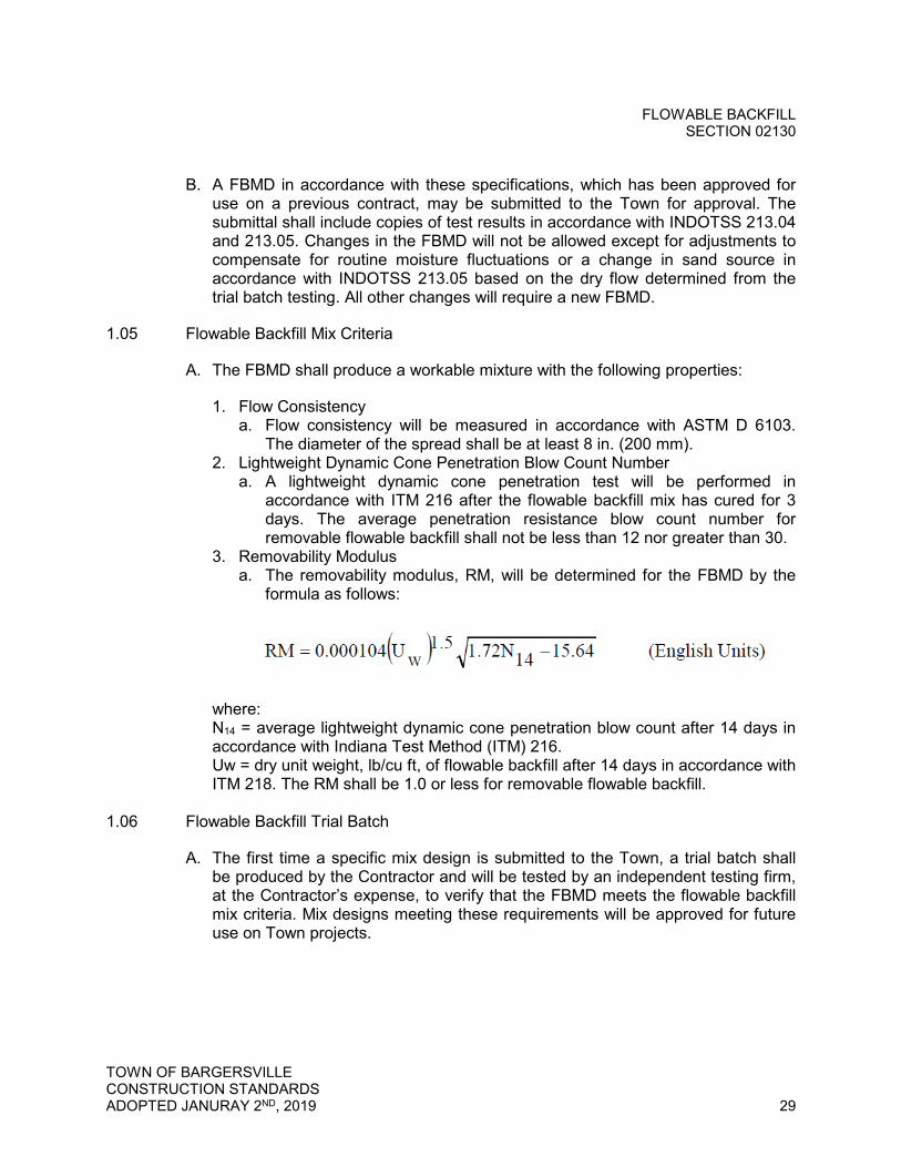
3. Removability Modulus a. The removability modulus, RM, will be determined for the FBMD by the
formula as follows:
where: N14 = average lightweight dynamic cone penetration blow count after 14 days in accordance with Indiana Test Method (ITM) 216. Uw = dry unit weight, lb/cu ft, of flowable backfill after 14 days in accordance with ITM 218. The RM shall be 1.0 or less for removable flowable backfill.
1.06 Flowable Backfill Trial Batch
A. The first time a specific mix design is submitted to the Town, a trial batch shall be produced by the Contractor and will be tested by an independent testing firm, at the Contractor’s expense, to verify that the FBMD meets the flowable backfill mix criteria. Mix designs meeting these requirements will be approved for future use on Town projects.

FLOWABLE BACKFILL SECTION 02130
TOWN OF BARGERSVILLE CONSTRUCTION STANDARDS ADOPTED JANURAY 2ND, 2019 30
PART 2 - PRODUCTS
Not Used.
PART 3 - EXECUTION
3.01 Placement
A. The flowable backfill shall not be placed on frozen ground. Flowable backfill shall be protected from freezing for 72 hours. Flowable backfill shall not be placed into or through standing water unless approved by the Town of Bargersville in writing. The diameter of the flowable backfill spread shall be at least 8 in. at time of placement. Water may be adjusted from the FBMD 120 to meet the minimum spread requirement if the initial measured spread is between 7 and 8 in.
B. The flowable backfill shall be brought up uniformly to the fill line as shown on the plans or as directed. When used as structure backfill, flowable backfill shall be placed uniformly so as not to induce unbalanced loading on any part of a structure. The flowable backfill shall not be subjected to load nor disturbed by construction activities until a lightweight dynamic cone penetration test has produced a blow count of seven (7) or greater.
END OF SECTION 02130

EARTHWORK SECTION 02200
TOWN OF BARGERSVILLE CONSTRUCTION STANDARDS ADOPTED JANURAY 2ND, 2019 31
SECTION 02200 - EARTHWORK
PART 1 - GENERAL
1.01 Summary
A. Section Includes: Stripping, storage and redistribution of topsoil, cut and fill operations, rough and finish grading and construction of drainage swales as applicable in conformity with the lines and grades and slopes as shown on the Drawings.
B. Related Sections
1. Section 02101 - Erosion and Sediment Control and Stormwater Pollution Prevention
1.02 References
A. American Society for Testing and Materials (ASTM), latest editions
1. ASTM D698 - Standard Test Methods for Laboratory Compaction Characteristics of Soil Using Standard Effort (12,400 ft-lbf/ft3 (600 kN-m/m3))
1.03 Submittals
A. Design Data
1. Velocity and scour calculations for drainage swales and ditch lining
B. Test Results
1. Compaction testing results 1.04 Warranty
A. Refill and restore to the original grade settlement in the backfill which takes place within the warranty period at no additional cost to the Town. Restore the surface area where settlement has occurred, including, but not limited to seeding, fertilizing, erosion control and restoration of streets, drives, yards, and sidewalks.
B. Guarantee all disturbed and replaced trees and shrubs during the warranty period.
EARTHWORK SECTION 02200
TOWN OF BARGERSVILLE CONSTRUCTION STANDARDS ADOPTED JANURAY 2ND, 2019 32
PART 2 - PRODUCTS
2.01 Materials
A. Excavated Material
1. Suitable earth removed from the excavation, free of rocks, boulders, stones larger than 2 inches in diameter, and other debris.
2. Topsoil and soil containing decomposed organic materials shall be considered suitable for topsoil fill material only.
3. Aeration of some backfill may be required for compaction.
B. Granular Fill
1. Clean granular material including sand and pit run gravel. 2. Granular fill material shall contain a maximum 2 percent, by weight, passing
a No. 220 sieve and 100 percent passing a 3/4-inch sieve.
C. Topsoil
1. Topsoil shall meet the requirements of Section 02101 - Erosion and Sediment Control and Stormwater Pollution Prevention.
D. Drainage Swale and Ditch Lining
1. Provide turf reinforcement mat or other vegetative products, where possible. Furnish material in accordance with Section 02101 - Erosion and Sediment Control and Stormwater Pollution Prevention.
2. Provide riprap or other hard armoring where approved by the Town. Furnish material in accordance with Section 02101 - Erosion and Sediment Control and Stormwater Pollution Prevention.
2.02 Excavation Classification
A. This work shall consist of excavation, hauling, disposal, or compaction of all materials encountered within the limits of the work. All excavation will be classified as hereafter described.
1. Common Excavation: Common excavation shall consist of all excavation not included as rock excavation or excavation which is otherwise classified.
2. Rock Excavation: Rock excavation shall consist of igneous, metamorphic, and sedimentary rock which cannot be excavated without blasting, or the use of a modern power shovel of no less than one cubic yard capacity, properly used, having adequate power and in good running condition, or the use of other equivalent power equipment. It shall also include all boulders or detached stones each having a volume of one half (1/2) cubic yard or more.

EARTHWORK SECTION 02200
TOWN OF BARGERSVILLE CONSTRUCTION STANDARDS ADOPTED JANURAY 2ND, 2019 33
3. Unclassified Excavation: Unclassified excavation shall consist of the excavation and disposal of all materials of whatever character encountered in the work.
4. Borrow: Borrow shall consist of approved material required for the construction of embankments or for other portions of the work and shall be obtained from offsite and in accordance with all local, state, and federal regulations. Unless otherwise designated in the contract, the Contractor shall make his own arrangements for obtaining borrow and shall pay all costs involved. All Contractor operations including erosion and sediment control shall be conducted in accordance with all local, state, and federal regulations.
PART 3 - EXECUTION
3.01 Preparation
A. Remove all topsoil at construction areas. Stockpile topsoil for use in finish grading operation. Do not use topsoil for fill.
B. No fill materials shall be placed until the subgrade and construction has been inspected and approved by the Town.
3.02 Excavation
A. Keep open excavations free of water, both surface and subterranean by use of pumps and earth damming around such excavations to drain surface water away from the excavations.
B. Provide and maintain adequate dewatering equipment to remove and dispose of surface and ground water entering excavations. Use diversion ditches, dikes or other suitable means to prevent surface water from entering the excavation and to provide adequate drainage of the area adjacent to the excavation. Filter the water from dewatering operations to remove sediment before discharge.
C. Protect open excavations by roping areas off, or with barricades or railings to prevent injury to personnel. Contractor shall be responsible to comply with any and all applicable Occupational Safety and Health Administration (OSHA) regulations.
D. Excavate true to line and grade, and level at bottom of the excavation. Excavate to undisturbed, structurally stable subsoil. Contractor shall notify the Town where excavation, in order to reach such subsoil, must continue deeper than required by the elevations indicated on the Drawings.
E. Excavations shall be of the dimensions indicated for new construction plus sufficient space as applicable to permit erection of forms, shoring, masonry, foundations, structure installations, and excavation inspections.

EARTHWORK SECTION 02200
TOWN OF BARGERSVILLE CONSTRUCTION STANDARDS ADOPTED JANURAY 2ND, 2019 34
F. Excavation below structures shall be sufficient to permit placement of subbase material.
G. Foundations and Paved Areas
1. If suitable bearing subsoil is not encountered at the depth indicated on Drawings for valve vault, wet well, or other structure, immediately notify the Town. Do not proceed further until instructions are given by the Town and required tests are completed.
2. Structures shall not be placed on soft earth; if soft earth is encountered remove soft pockets. Backfill with lean concrete or compacted granular fill as specified in Article 3.04.
H. Provide shoring or piling as required to protect excavation bank.
3.03 Filling and Backfilling
A. All material entering the fill shall be free of organic matter such as leaves, grass, roots, and other objectionable material.
B. Suspend earthwork operations when satisfactory results cannot be obtained because of rain, freezing weather or other unsatisfactory conditions in the field.
C. Material in layers shall be of the proper moisture content before compaction. Should the material be too wet to permit proper compaction, all work on all portions thus affected shall be delayed until the material has dried to the required moisture content.
D. In the construction of filled areas, place starting layers in the deepest portion of the fill. As placement progresses, layers shall be constructed approximately parallel to the finished grade line.
E. Boulders, if encountered, must be disposed of outside of the construction area.
3.04 Compaction
A. Fill areas shall be compacted using equipment capable of compacting each lift its full depth. Moisture during compaction operations shall be maintained at optimum content.
B. Compacting equipment shall be approved equipment of such design, weight and quantity to obtain the required density in accordance with soil compaction requirements. Under no circumstances shall a bulldozer or similar tracked vehicle be used as compacting equipment.
C. Water distribution equipped with a suitable sprinkling devices shall be used to add moisture to the soil if required.

EARTHWORK SECTION 02200
TOWN OF BARGERSVILLE CONSTRUCTION STANDARDS ADOPTED JANURAY 2ND, 2019 35
D. For fill areas around new structures: Continue compaction operations until the fill is compacted to not less than 95 percent Standard Proctor of the maximum dry density as determined in accordance with ASTM D698.
E. For paved areas and within 5 feet of paved areas: Place fill in 8-inch maximum balanced lifts and compact each layer to 95 percent of Standard Proctor dry density in accordance with ASTM D698, up to the top 12 inches of fill.
F. For all other areas: Continue compaction until the fill is compacted to not less than 95 percent Standard Proctor of the maximum dry density, as determined in accordance with ASTM D698. Unless otherwise specified herein, fills shall be placed in successive horizontal layers of approximately 12 inches in loose depth for the full width of the section.
G. Areas inaccessible to roller shall be consolidated and compacted by mechanical tampers. The equipment shall be operated in such manner that hardpan, cemented gravel, clay, or other chunky soil material are broken up into small particles and become incorporated with the material in the layer.
H. Compaction by flooding is not acceptable.
3.05 Proof Rolling
A. Proof rolling shall be performed with a triaxle loaded with a minimum of 20 tons of stone with load ticket verification. Proof rolling shall be from curb line to curb line. Correct any and all roller marks, irregularities, and failures.
B. Proof roll subgrades below paved areas with heavy equipment prior to filling, consisting of one coverage of an earthmover.
C. After completion of filling and compaction operation, proof roll area with smooth wheel vehicle to leave a smooth surface sealed to shed all water.
3.06 Grading
A. Furnish, operate, and maintain equipment necessary to control uniform layers, section, and smoothness of grade for maximum compaction and drainage.
B. Rough Grading
1. Evenly grade to elevations 6 inches below the finish grade elevations indicated.
2. Protect all constructed items during grading operations, and repair if damaged.
3. All areas in the project including excavated and filled sections and adjacent transition areas shall be reasonably smooth, compacted, and free from irregular surface changes.
EARTHWORK SECTION 02200
TOWN OF BARGERSVILLE CONSTRUCTION STANDARDS ADOPTED JANURAY 2ND, 2019 36
4. The degree of finish shall be that ordinarily obtainable from either blade-grader or scraper operations, except as otherwise specified.
5. The finished subgrade surface generally shall be not more than 0.3 feet above or below the established grade or approved cross-section, with due allowance for topsoil and seeding or sod as applicable.
6. The tolerance for areas within 10 feet of buildings shall not exceed 0.15 feet above or below the established subgrade.
7. All ditches, swales and gutters as applicable shall be finished to drain readily. 8. The subgrade shall be evenly sloped to provide drainage away from
structures and building walls in all directions at a grade not less than 1/2 inches per foot.
9. Provide grade rounding at top and bottom of banks and at other breaks in grade.
C. Protection
1. Protect newly graded areas from the action of the elements. 2. Settlement or washing that occurs prior to acceptance of the work shall be
repaired, and grades re-established to the required elevations and slopes. 3. Fill to required subgrade levels any areas where settlement occurs.
D. Finish Grading
1. Proceed to finish elevations shown on the Drawings with a tolerance of +/-0.04 feet (1/2 inch).
2. Rake subsoil clean of stones and debris. Scarify to depth of 3 inches. 3. Spread stockpiled topsoil over prepared subgrade to a minimum depth of
6 inches, and roll until suitable for seeding or placement of sod as applicable. 4. Maintain surfaces and replace additional topsoil necessary to repair erosion.
END OF SECTION 02200

TRENCHING, BACKFILLING AND COMPACTION FOR UTILITIES
SECTION 02220
TOWN OF BARGERSVILLE CONSTRUCTION STANDARDS ADOPTED JANURAY 2ND, 2019 37
SECTION 02220 - TRENCHING, BACKFILLING AND COMPACTION FOR UTILITIES
PART 1 - GENERAL
1.01 Summary
A. Section Includes: Performing all excavation work as required for the installation of water mains, valves, hydrants, storm sewers, gravity sanitary sewers, force mains, structures, and appurtenances including necessary clearing, grubbing, excavation, trenching, bedding, backfilling, and other related work.
B. Related Sections
1. Section 02660 - Water Mains 2. Section 02720 - Storm Sewer Systems 3. Section 02730 - Gravity Sanitary Sewer Systems 4. Section 02737 - Force Main Sewer Systems
1.02 References
A. American Society for Testing and Materials (ASTM), latest editions
1. ASTM D698 - Standard Test Methods for Laboratory Compaction Characteristics of Soil Using Standard Effort (12,400 ft-lbf/ft3 (600 kN-m/m3))
B. Indiana Department of Transportation (INDOT) Standard Specifications, latest
edition
1. Section 904 - Aggregates 1.03 Definitions
A. Pavement Loading Zone: The area within 5 feet of any edge of pavement, curb, gutter, or similar structure.
1.04 Submittals
A. Test Results
1. Testing results for flowable fill 2. Compaction testing results for trench bedding 3. Compaction testing results for trench backfill
TRENCHING, BACKFILLING AND COMPACTION FOR UTILITIES
SECTION 02220
TOWN OF BARGERSVILLE CONSTRUCTION STANDARDS ADOPTED JANURAY 2ND, 2019 38
1.05 Warranty
A. Refill and restore to the original grade settlement in the backfill which takes place within the warranty period at no additional cost to the Town. Restore the surface area where settlement has occurred, including, but not limited to seeding, fertilizing, erosion control and restoration of streets, drives, yards, and sidewalks.
B. Guarantee all disturbed and replaced trees and shrubs during the warranty period.
PART 2 - PRODUCTS
2.01 Bedding and Backfill Material Classes
A. Class I - Angular, 6 to 40 millimeters (1/4 to 1-1/2 inches) unwashed, graded stone such as crushed stone. INDOT Classification No. 5, No. 8, and No. 9 are all considered acceptable Class I materials. A No. 8 gravel possessing a minimum 50 percent mechanical crush count, and meeting the following nominal sizes and percentage passing will be considered an equivalent Class I material:
1. 100 percent passing 1-inch sieve 2. 75-95 percent passing 3/4-inch sieve 3. 40-70 percent passing 1/2-inch sieve 4. 0-15 percent passing No. 4 sieve
B. Class II (Granular Backfill) - Coarse sands and gravel-sand mixtures with a
maximum particle size of 40 millimeters (1-1/2 inches), including variously graded sands and gravels containing small percentages of fines, generally granular and non-cohesive, either wet or dry. Soil types GW, GP, SW and SP are included in this class. Class II material shall comply with Classification for Structure Backfill as defined in INDOT Standard Specification Section 904.
C. Excavated Material - Excavated material suitable for use as trench backfill as specified must be clean and free of: rocks and other debris larger than 4 inches, frozen soil lumps, wood, or other extraneous material. No excavated material shall be allowed within five feet of road crossings.
D. Flowable Fill - As described in Section 02130 – Flowable Backfill
2.02 Sheeting and Bracing
A. Sheeting and Bracing, where required, shall be capable of sustaining the lateral forces of the trench banks. Comply with all applicable Occupational Safety and Health Act (OSHA) requirements.
TRENCHING, BACKFILLING AND COMPACTION FOR UTILITIES
SECTION 02220
TOWN OF BARGERSVILLE CONSTRUCTION STANDARDS ADOPTED JANURAY 2ND, 2019 39
PART 3 - EXECUTION
3.01 Bedding and Backfill Locations
A. Refer to the Standard Details for an illustration of the placement of bedding and backfill materials required for each pipe material class.
3.02 Site Preparation
A. Before any excavation is started, provide adequate protection for all lawns, trees, landscape work, shrubs, fences, hydrants, sidewalks, utility poles, and other objects that are to remain in place. Maintain such protection for as long as necessary to prevent damage from the Contractor operations.
B. Movable items such as mail boxes and roadway signs may be temporarily relocated during construction. Place movable items in their original location immediately after backfilling is complete. Replace movable items damaged during construction with new items at the Contractor's expense.
C. Strip topsoil and vegetation from the excavated areas. Clean topsoil may be stockpiled for reuse as the upper 6-inches of fill. Do not mix grass, weeds, roots, brush, and stones larger than 1-inch in diameter with stockpiled topsoil. Dispose of root contaminated topsoil.
D. Clear and remove logs, stumps, brush, vegetation, rubbish and other perishable matter from the job site as required for construction.
E. Remove existing pavement and walks from the excavated areas. The width of pavement to be removed shall not exceed the width of the trench by more than 12 inches on each side of the trench.
3.03 Material Disposal
A. All existing utility infrastructure and appurtenances (piping, structures, etc.) that are to be replaced or removed to allow for new construction are the responsibility of the Contractor unless otherwise designated. As these appurtenances are removed during the excavation, remove them from the job site and dispose of them in accordance with applicable local, state and federal rules and regulations.
3.04 Existing Facilities
A. Determine the exact location of and the means of protection for existing utility facilities and structures. Support and maintain operation of these facilities during construction.
B. Proceed with caution in the excavation and preparation of trenches so that the exact location of underground utilities and structures, both known and unknown
TRENCHING, BACKFILLING AND COMPACTION FOR UTILITIES
SECTION 02220
TOWN OF BARGERSVILLE CONSTRUCTION STANDARDS ADOPTED JANURAY 2ND, 2019 40
may be determined. The Contractor shall be responsible for the repair of existing utilities and structures when broken or otherwise damaged by operations. Immediately bring to the attention of the Town any unforeseen conflicts with existing utilities encountered during excavation and preparation of trenches. If it is determined that the proposed utility cannot be installed at locations as shown, make adjustments in its alignment or relocation of the existing utilities as approved by the Town.
3.05 Excavating
A. Store excavated materials suitable and necessary for backfilling in a neat pile adjacent to the excavation in a manner so as to interfere as little as possible with traffic. Do not place such materials with sufficient height or proximity to excavation so as to endanger such openings due to earth slides or cave-ins. Do not stockpile excavated material closer than 2 feet from the top edge of the trench wall at ground surface.
B. Remove excavated material not suitable for backfilling and excess suitable material from the job site and dispose of in a spoil area secured by the Contractor in accordance with all local, state, and federal regulations.
C. Provide and maintain adequate dewatering equipment to remove and dispose of surface and ground water entering excavations. Use diversion ditches, dikes or other suitable means to prevent surface water from entering the excavation and to provide adequate drainage of the area adjacent to the excavation. Filter the water from dewatering operations to remove sediment before discharge.
3.06 Trenching
A. Excavate trenches to a depth and width as required for the proper installation of the pipe and appurtenances. Fill excavations below the required grade with compacted bedding material.
B. Make trenches as narrow as possible. Keep sides of trenches as near vertical as possible and properly sheet and/or brace, if required. Perform open cut excavation except where noted otherwise. Provide a clearance of not less than 8 inches or more than 12 inches on each side of the pipe for the width of the trench.
C. Provide a continuous, uniform bearing support for the pipe on solid undisturbed soil or compacted granular backfill within trench dished to provide circumferential support to the lower third of each pipe. Dig out holes to receive pipe bells.
D. Remove rock and soft material encountered in the trench which, in the opinion of the Town is incapable of providing adequate bearing to support the pipe, to a depth of 4 inches below the required elevation and fill with compacted granular
TRENCHING, BACKFILLING AND COMPACTION FOR UTILITIES
SECTION 02220
TOWN OF BARGERSVILLE CONSTRUCTION STANDARDS ADOPTED JANURAY 2ND, 2019 41
backfill material. Field measure these locations where additional granular backfill is required, prior to backfilling.
E. Do not open more than 50 feet of trench in advance of the installed pipe, unless otherwise directed or permitted by the Town. Excavate the trench within 6 inches of full depth for a distance of at least 30 feet in advance of the pipe installation, unless otherwise directed or permitted.
F. Maintain one lane of traffic at all streets and service drives during construction. Streets and drives may be closed and traffic detoured if prior permission is obtained by the Contractor from the State, Town, County or Local Business having jurisdiction.
G. Support all sewer, gas, water or other pipes or conduits crossing the trench without damage and without interrupting service. The manner of supporting such pipes or conduits will be subject to the approval of the Town.
H. Provide adequate sheeting and bracing in open cut trenches to protect life, property and the work.
I. Place, renew, and maintain all sheeting, planking, timbering, shoring, bracing, and bridging, and do not remove until sufficient backfill has been placed to protect the pipe. Sheeting, shoring and/or bracing is not a pay item unless the Contractor is directed by the Town to leave same in place. Be accountable and responsible for all sheeting and bracing used, and for damages to persons or property resulting from the improper quality, strength, placing, maintenance and removal of the sheeting and bracing, including damage to trees, shrubs, walkways and other similar property during the trenching, backfilling and pipe laying operations. Ensure all sheeting and bracing complies with applicable OSHA regulations.
J. Where rock is encountered during trenching operations, Contractor must remove the rock by mechanical means. The use of a rock trencher which produces excavated material commensurate to "granular backfill" is preferred. Materials suitable for granular backfill excavated by a rock trencher may be used as bedding for pipe in areas of rock excavation. Blasting is not permitted.
K. Where water mains are to be installed under existing asphalt or concrete driveways, roads, or streets, install the main by boring a hole and inserting the main in the bore hole unless otherwise permitted.
L. Do not cut fences when gates are available within a reasonable distance to move equipment from one field to another. Comply with applicable easements or obtain property access permission prior to accessing or traversing fields.
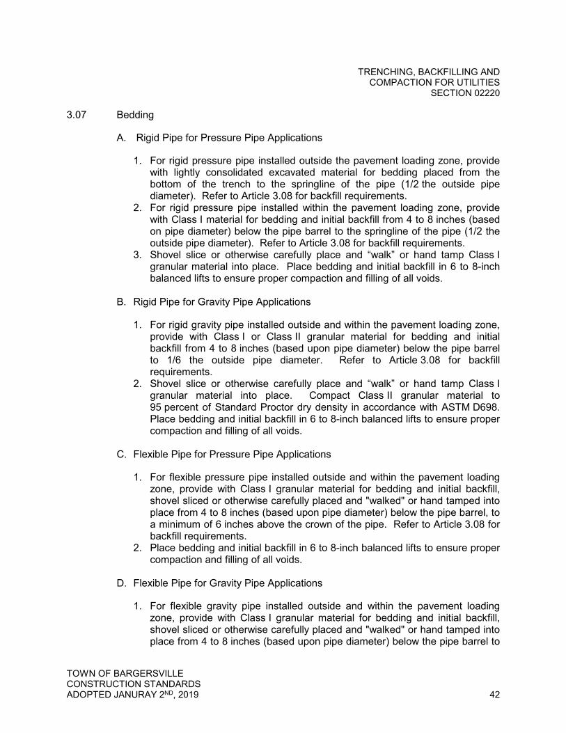
TRENCHING, BACKFILLING AND COMPACTION FOR UTILITIES
SECTION 02220
TOWN OF BARGERSVILLE CONSTRUCTION STANDARDS ADOPTED JANURAY 2ND, 2019 42
3.07 Bedding
A. Rigid Pipe for Pressure Pipe Applications
1. For rigid pressure pipe installed outside the pavement loading zone, provide with lightly consolidated excavated material for bedding placed from the bottom of the trench to the springline of the pipe (1/2 the outside pipe diameter). Refer to Article 3.08 for backfill requirements.
2. For rigid pressure pipe installed within the pavement loading zone, provide with Class I material for bedding and initial backfill from 4 to 8 inches (based on pipe diameter) below the pipe barrel to the springline of the pipe (1/2 the outside pipe diameter). Refer to Article 3.08 for backfill requirements.
3. Shovel slice or otherwise carefully place and “walk” or hand tamp Class I granular material into place. Place bedding and initial backfill in 6 to 8-inch balanced lifts to ensure proper compaction and filling of all voids.
B. Rigid Pipe for Gravity Pipe Applications
1. For rigid gravity pipe installed outside and within the pavement loading zone, provide with Class I or Class II granular material for bedding and initial backfill from 4 to 8 inches (based upon pipe diameter) below the pipe barrel to 1/6 the outside pipe diameter. Refer to Article 3.08 for backfill requirements.
2. Shovel slice or otherwise carefully place and “walk” or hand tamp Class I granular material into place. Compact Class II granular material to 95 percent of Standard Proctor dry density in accordance with ASTM D698. Place bedding and initial backfill in 6 to 8-inch balanced lifts to ensure proper compaction and filling of all voids.
C. Flexible Pipe for Pressure Pipe Applications
1. For flexible pressure pipe installed outside and within the pavement loading zone, provide with Class I granular material for bedding and initial backfill, shovel sliced or otherwise carefully placed and "walked" or hand tamped into place from 4 to 8 inches (based upon pipe diameter) below the pipe barrel, to a minimum of 6 inches above the crown of the pipe. Refer to Article 3.08 for backfill requirements.
2. Place bedding and initial backfill in 6 to 8-inch balanced lifts to ensure proper compaction and filling of all voids.
D. Flexible Pipe for Gravity Pipe Applications
1. For flexible gravity pipe installed outside and within the pavement loading zone, provide with Class I granular material for bedding and initial backfill, shovel sliced or otherwise carefully placed and "walked" or hand tamped into place from 4 to 8 inches (based upon pipe diameter) below the pipe barrel to
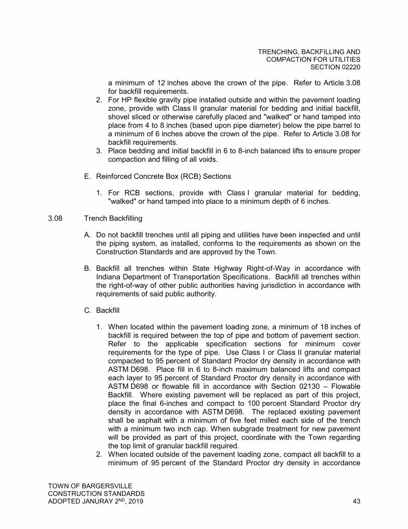
TRENCHING, BACKFILLING AND COMPACTION FOR UTILITIES
SECTION 02220
TOWN OF BARGERSVILLE CONSTRUCTION STANDARDS ADOPTED JANURAY 2ND, 2019 43
a minimum of 12 inches above the crown of the pipe. Refer to Article 3.08 for backfill requirements.
2. For HP flexible gravity pipe installed outside and within the pavement loading zone, provide with Class II granular material for bedding and initial backfill, shovel sliced or otherwise carefully placed and "walked" or hand tamped into place from 4 to 8 inches (based upon pipe diameter) below the pipe barrel to a minimum of 6 inches above the crown of the pipe. Refer to Article 3.08 for backfill requirements.
3. Place bedding and initial backfill in 6 to 8-inch balanced lifts to ensure proper compaction and filling of all voids.
E. Reinforced Concrete Box (RCB) Sections
1. For RCB sections, provide with Class I granular material for bedding, "walked" or hand tamped into place to a minimum depth of 6 inches.
3.08 Trench Backfilling
A. Do not backfill trenches until all piping and utilities have been inspected and until the piping system, as installed, conforms to the requirements as shown on the Construction Standards and are approved by the Town.
B. Backfill all trenches within State Highway Right-of-Way in accordance with Indiana Department of Transportation Specifications. Backfill all trenches within the right-of-way of other public authorities having jurisdiction in accordance with requirements of said public authority.
C. Backfill
1. When located within the pavement loading zone, a minimum of 18 inches of backfill is required between the top of pipe and bottom of pavement section. Refer to the applicable specification sections for minimum cover requirements for the type of pipe. Use Class I or Class II granular material compacted to 95 percent of Standard Proctor dry density in accordance with ASTM D698. Place fill in 6 to 8-inch maximum balanced lifts and compact each layer to 95 percent of Standard Proctor dry density in accordance with ASTM D698 or flowable fill in accordance with Section 02130 – Flowable Backfill. Where existing pavement will be replaced as part of this project, place the final 6-inches and compact to 100 percent Standard Proctor dry density in accordance with ASTM D698. The replaced existing pavement shall be asphalt with a minimum of five feet milled each side of the trench with a minimum two inch cap. When subgrade treatment for new pavement will be provided as part of this project, coordinate with the Town regarding the top limit of granular backfill required.
2. When located outside of the pavement loading zone, compact all backfill to a minimum of 95 percent of the Standard Proctor dry density in accordance

TRENCHING, BACKFILLING AND COMPACTION FOR UTILITIES
SECTION 02220
TOWN OF BARGERSVILLE CONSTRUCTION STANDARDS ADOPTED JANURAY 2ND, 2019 44
with ASTM D698. Additional compaction efforts may be required to minimize settling. Excavated materials are suitable for backfilling outside the pavement loading zone. Place backfill in maximum 12-inch balanced lifts unless specified otherwise below. Make proper allowances for topsoil as applicable. Limited mounding of backfill above finish grade may be performed to compensate for settlement. Place 6 inches of topsoil over the area to be seeded.
3. Backfill trenches at unpaved driveways and alleys with Class II granular material up to the last 12 inches, then replace the last 12 inches with the same material as the original surface. Place backfill in 8-inch balanced lifts and compact to 95 percent Standard Proctor dry density in accordance with ASTM D698.
D. Compact backfill by using hand tamping or approved mechanical tamping
device. Prepare upper portion of trench for pavement replacement as applicable.
E. Maintain backfilled trenches in a smooth and uniform condition until paving or seeding operations are completed. Refill and restore to the original grade any settlement in the backfill which takes place within the warranty period at no additional cost.
3.09 Field Quality Control
A. Compaction Testing
1. Class II Compaction Tests: Perform compaction tests for Class II trench backfill material in accordance with ASTM D698 and as follows: a. At each road crossing: vertically at 2-foot intervals in the trench b. At every 1,000 feet longitudinally in roadways along the pipe alignment
and vertically at 2-foot intervals in the trench c. Notify the Town one working day prior to the tests so they may be
present for the compaction tests. d. Provide a copy of all test results to the Town. e. No additional payment will be made for compaction tests. Compaction
tests are considered incidental to the Work.
END OF SECTION 02220
TRENCHLESS EXCAVATION HORIZONTAL BORINGS
SECTION 02224
TOWN OF BARGERSVILLE CONSTRUCTION STANDARDS ADOPTED JANURAY 2ND, 2019 45
SECTION 02224 – TRENCHLESS EXCAVATION – HORIZONTAL BORINGS
PART 1 - GENERAL
1.01 Summary
A. Section Includes: Furnishing and installing casing pipes beneath waterways, highways, railroads, and other locations as shown on the Drawings and performing all related work necessary to complete work shown and specified.
B. Products Installed but not Supplied Under this Section
1. Carrier pipe
C. Related Sections
1. Section 02660 - Water Mains 2. Section 02720 - Storm Sewer Systems 3. Section 02730 - Gravity Sanitary Sewer Systems 4. Section 02737 - Force Main Sewer Systems
1.02 References
A. American Society for Testing and Materials (ASTM), latest editions
1. ASTM A139 - Standard Specification for Electric-Fusion (Arc)-Welded Steel Pipe (NPS 4 and Over)
1.03 Submittals
A. Quality Control Submittals: Before beginning any work, submit the following items to the Town. Do not proceed with the work until such documents have been reviewed by the Town. The review by the Town of any plan or method shall not relieve the Contractor of his responsibility in any way.
1. Manufacturer’s Certificate of Compliance certifying compliance with the referenced specifications and standards.
2. Certified copies of reports of factory tests specified in this Section and required by the referenced standards.
3. Details of equipment and written procedure with working drawings describing in detail the proposed method and the entire operation to be used.
4. Documentation of experience as required by Article 1.04A.

TRENCHLESS EXCAVATION HORIZONTAL BORINGS
SECTION 02224
TOWN OF BARGERSVILLE CONSTRUCTION STANDARDS ADOPTED JANURAY 2ND, 2019 46
1.04 Quality Assurance
A. Qualifications
1. Demonstrate experience and expertise in trenchless excavation methods by providing a list of 6 references for whom similar work has been performed. Include a name and telephone number for each contact.
2. Provide documentation showing successful completion of at least 10,000 linear feet of horizontal bore installation of piping, or obtain the services of an experienced subcontractor meeting the experience requirements of this section to supervise the installation. Conventional trenching is not considered as applicable experience.
3. Adequately train all supervisory personnel and ensure they have at least 4 years of experience in this trenchless installation method. Submit the names and resumes of all supervisory field personnel for review by the Town.
B. Regulatory Requirements
1. Perform all horizontal boring work in accordance with all applicable laws, permits, requirements and regulations.
2. Secure acceptance of the crossing from the railroad company in writing before the Town will assume ownership.
C. General Procedures
1. Attend all meetings and provide all necessary data, reports, information, details, and construction schedules as requested by the governing officials.
2. Notify the Town when each individual boring and receiving pit has been staked in the field. Provide a survey crew to obtain profiles along the length of each individual boring location. Do not proceed with the work until the survey information is obtained for the respective boring location and is approved by the Town.
3. The Town or proper officials will review and modify as necessary the scheduling of any and all construction activities for the crossing in order to prevent interruption to traffic and stream flow. No additional compensation will be made on account of such procedures.
4. Notify the proper officials before beginning the installation of casing pipe on each individual boring.
5. Complete all work in a careful, workmanlike manner to the satisfaction of the proper officials, as well as the Town.

TRENCHLESS EXCAVATION HORIZONTAL BORINGS
SECTION 02224
TOWN OF BARGERSVILLE CONSTRUCTION STANDARDS ADOPTED JANURAY 2ND, 2019 47
PART 2 - PRODUCTS
2.01 HDPE Casing
A. HDPE Casing Pipe
1. Pipe material: conforming to AWWA C901 and C906, manufactured from high density, extra high molecular weight polyethylene and conforming to PE Standard Code PE 4710. Pipe shall have a minimum cell classification of 445574C per the requirements of ASTM D3350.
2. Furnish HDPE casing pipe designed and manufactured in iron pipe size and to a minimum pressure class of 200 psi. Provide Dimension Ratio 11 (DR-11) HDPE casing pipe conforming to all applicable regulatory requirements. Supply pipe designed to withstand crushing, buckling and deformation resulting in ovality at a depth of bury as indicated on the Drawings.
3. Deflection: Do not deflect pipe, unless approved by the Town. In no instance shall the casing pipe deflect on a radius of less than 50 times the pipe diameter, less than the manufacturer’s recommendation or in a manner that prohibits removal and installation of the carrier pipe. If an HDPE fitting, flange or mechanical joint is present within the length of pipe to be deflected, do not deflect on a radius of less than 100 times the pipe diameter.
B. Furnish HDPE casing pipe sizes as listed in the following table:
Nominal Diameter of Carrier Pipe
Nominal Diameter of HDPE Casing Pipe
3” 12” 4” 14” 6” 18” 8” 22”
10” 26” 12” 28” 14” 32” 16” 34” 18” 36”
2.02 Steel Casing
A. Provide casing pipe and joints of steel construction. Provide casing pipe and joints capable of withstanding the load of traffic or the load of pavement, subgrade, and traffic, as applicable. Assemble the casing pipe and joints to prevent leakage of any matter from the casing or carrier pipe throughout its entire length including the ends of the casing pipe.
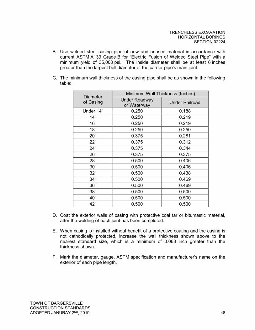
TRENCHLESS EXCAVATION HORIZONTAL BORINGS
SECTION 02224
TOWN OF BARGERSVILLE CONSTRUCTION STANDARDS ADOPTED JANURAY 2ND, 2019 48
B. Use welded steel casing pipe of new and unused material in accordance with current ASTM A139 Grade B for “Electric Fusion of Welded Steel Pipe” with a minimum yield of 35,000 psi. The inside diameter shall be at least 6 inches greater than the largest bell diameter of the carrier pipe’s main joint.
C. The minimum wall thickness of the casing pipe shall be as shown in the following table:
Diameter of Casing
Minimum Wall Thickness (Inches) Under Roadway
or Waterway Under Railroad
Under 14" 0.250 0.188 14" 0.250 0.219 16" 0.250 0.219 18" 0.250 0.250 20" 0.375 0.281 22" 0.375 0.312 24" 0.375 0.344 26" 0.375 0.375 28" 0.500 0.406 30" 0.500 0.406 32" 0.500 0.438 34" 0.500 0.469 36" 0.500 0.469 38" 0.500 0.500 40" 0.500 0.500 42" 0.500 0.500
D. Coat the exterior walls of casing with protective coal tar or bitumastic material,
after the welding of each joint has been completed.
E. When casing is installed without benefit of a protective coating and the casing is not cathodically protected, increase the wall thickness shown above to the nearest standard size, which is a minimum of 0.063 inch greater than the thickness shown.
F. Mark the diameter, gauge, ASTM specification and manufacturer's name on the exterior of each pipe length.

TRENCHLESS EXCAVATION HORIZONTAL BORINGS
SECTION 02224
TOWN OF BARGERSVILLE CONSTRUCTION STANDARDS ADOPTED JANURAY 2ND, 2019 49
2.03 Casing Spacers
A. Provide casing spacers with stainless steel bands and risers, plastic liner and runners as manufactured by Cascade Waterworks Manufacturing Company or approved equal.
PART 3 - EXECUTION
3.01 Installation of Casing Pipe
A. Install casing pipe as shown and specified, in accordance with approved jacking and boring methods. Maintain the lines and grades, as shown on the construction Drawings, for the entire length of the casing.
B. Proceed with installing the casing operation from a pit, excavated at a minimum of 30 feet from the edge of pavement or top of bank, as applicable. Construct bore pit without interruption to traffic or stream flow. Contact the applicable authority before entering property to do work.
C. Sheet excavation pits as necessary, in accordance with all applicable Occupational Safety and Health Act (OSHA) requirements. Ensure excavation and backfill is as specified in Section 02220 - Trenching, Backfilling, and Compaction for Utilities.
D. Set casing under railroads as shown on Drawings with top not less than 5-1/2 feet below base of the rails. Make casing a minimum of 99 feet long, centered under the track and measured at normal angle to centerline of track.
E. Measure and locate each end of the casing pipe to a minimum of 2 permanent reference points for Record Drawing purposes.
F. The use of water or other liquids to facilitate casing emplacement and sand removal is prohibited.
3.02 Construction of Casing Pipe by Methods Other Than Jacking or Boring
A. If the casing pipe is installed by methods other than the jacking method, perform it in a manner which meets with prior approval of the authorities.
B. Be responsible for any expense incurred in connection with the construction of the crossing, and any removal, replacement or maintenance resulting from the construction of the casing pipe and the carrier pipe.

TRENCHLESS EXCAVATION HORIZONTAL BORINGS
SECTION 02224
TOWN OF BARGERSVILLE CONSTRUCTION STANDARDS ADOPTED JANURAY 2ND, 2019 50
3.03 Installation of Carrier Pipe
A. The carrier pipe designated on the Drawings shall be as specified in other Sections for the type of pipe, whether water main, gravity sanitary sewer, storm sewer, force main, or other utility conduit.
B. Jointing of the carrier pipe is as specified in other Sections for the type of utility, pipe material, and joint fittings.
C. Place the carrier pipe into and through the steel casing at locations shown on Drawings. Employ suitable methods to maintain tight joints, to the satisfaction of the Town.
D. Install casing spacers to provide uniform support throughout the entire length of the casing. Install a minimum of three evenly spaced casing spacers per stick of pipe. Casing spacers shall be installed at a maximum of 3 feet from both pipe ends.
E. Block up ends of casing pipe in such a way as to prevent the entrance of foreign material, but do not tightly seal. Grouting of the void space between the casing and the carrier pipe is not required.
F. Furnish and install a gate valve for all water main installations meeting the requirements listed in Specification 02660 on the carrier pipe on both ends of the casing.
END OF SECTION 02224
TRENCHLESS EXCAVATION DIRECTIONAL DRILLING
SECTION 02226
TOWN OF BARGERSVILLE CONSTRUCTION STANDARDS ADOPTED JANURAY 2ND, 2019 51
SECTION 02226 - TRENCHLESS EXCAVATION - DIRECTIONAL DRILLING
PART 1 - GENERAL
1.01 Summary
A. Section Includes: Installation of water mains, storm sewers, sanitary sewers, and force mains by the directional drilling method and performing all related work necessary to complete work shown and specified.
B. Related Sections
1. Section 02660 - Water Mains 2. Section 02720 - Storm Sewer Systems 3. Section 02730 - Sanitary Sewer Systems 4. Section 02737 - Force Main Sewer Systems
1.02 References
A. American Society for Testing and Materials (ASTM), latest editions
1. ASTM D1248 – Standard Specification for Polyethylene Plastics Extrusion Materials for Wire and Cable
1.03 Submittals
A. Quality Control Submittals: Before beginning any work, submit the following items to the Town. Do not proceed with the work until such documents have been reviewed by the Town. The review by the Town of any plan or method shall not relieve the Contractor of his responsibility in any way
1. Manufacturer's Certificate of Compliance certifying compliance with the referenced specifications and standards.
2. Certified copies of reports of factory tests specified in this Section and required by the referenced standards.
3. Details of equipment and written procedure with working drawings describing in detail the proposed directional drilling method and the entire operation to be used.
4. Documentation of experience as required by Article 1.04A.

TRENCHLESS EXCAVATION DIRECTIONAL DRILLING
SECTION 02226
TOWN OF BARGERSVILLE CONSTRUCTION STANDARDS ADOPTED JANURAY 2ND, 2019 52
1.04 Quality Assurance
A. Qualifications
1. Demonstrate experience and expertise in trenchless excavation methods by providing a list of 6 references for whom similar work has been performed. Include a name and telephone number for each contact.
2. Provide documentation showing successful completion of at least 50,000 linear feet of directional drilling, or obtain the services of an experienced directional drilling subcontractor meeting the experience requirements of this section to supervise the installation. Conventional trenching is not considered as applicable experience.
3. Adequately train all supervisory personnel and ensure they have at least 4 years of experience in directional drilling installation method. Submit the names and resumes of all supervisory field personnel for review by the Town.
B. Regulatory Requirements
1. Perform all directional drilling work in accordance with all applicable laws, permits, requirements and regulations.
C. General Procedures
1. Attend all meetings and provide all necessary data, reports, information, details and construction schedules as requested by the governing officials.
2. Complete all work in a careful, workmanlike manner to the satisfaction of the proper officials, as well as the Town.
PART 2 - PRODUCTS
2.01 Pipe
A. Water main pipe shall meet the requirements as specified in Section 02660 - Water Mains.
B. Storm sewer pipe shall meet the requirements as specified in Section 02720 – Storm Sewer Systems.
C. Sanitary sewer pipe shall meet the requirements as specified in Section 02730– Sanitary Sewer Systems.
D. Force main pipe shall meet the requirements as specified in Section 02737 – Force Main Sewer Systems.
TRENCHLESS EXCAVATION DIRECTIONAL DRILLING
SECTION 02226
TOWN OF BARGERSVILLE CONSTRUCTION STANDARDS ADOPTED JANURAY 2ND, 2019 53
PART 3 - EXECUTION
3.01 Examination
A. Verify the location and depth of all known and unknown utilities and structures by drilling test holes prior to any boring or drilling. These utilities and structures may include, but are not limited to:
1. Underground utilities such as, but not limited to: a. Cable television lines b. Electric cables c. Fiber optic lines d. Field drain tiles e. Gas lines f. Sewer lines and septic systems g. Storm lines h. Telephone lines i. Water mains j. Wells
2. Above-ground utilities and other obstructions such as, but not limited to: a. Buildings b. Electric and telephone poles c. Road signs d. Trees
B. The Contractor is responsible for inspecting the site, for conducting
investigations, surveys and tests, including subsurface investigations and tests that are necessary for the complete execution of all the work.
3.02 Installation
A. General
1. Notify the Town 48 hours in advance of starting directional drilling work. Do not begin the directional drilling until the Town, or his authorized representative, is present at the job site and agrees that proper preparations for the operation have been made. The Town’s approval for beginning the installation shall in no way relieve the Contractor of the ultimate responsibility for the satisfactory completion of the work.
2. Open cut disturbance of waterway, roadway, or railroad to retrieve any lost boring appurtenances or equipment is prohibited.
3. Maintain a log of drilling operations, including vertical depths of the pipe at established 25-foot horizontal intervals.
B. Equipment
1. The directional drilling system to be used must have the following features:

TRENCHLESS EXCAVATION DIRECTIONAL DRILLING
SECTION 02226
TOWN OF BARGERSVILLE CONSTRUCTION STANDARDS ADOPTED JANURAY 2ND, 2019 54
a. The system shall be remotely steerable and permit electronic monitoring of tunnel depth and location. The system shall be able to control the depth and direction of the pipe and must be accurate to a window of +/-2 inches.
b. The system shall utilize a fluid-cutting process, using a liquid clay such as bentonite. This clay shall be totally inert and contain no risk to the environment.
c. The liquid clay shall remain in the tunnel to increase the stability of the tunnel and to provide a lubricant to reduce frictional drag when the pipe is installed.
d. Recover spoils by use of a vacuum system mounted on a vehicle. Do not discharge spoils into waterways, water bodies, sewers or storm drains. Properly dispose of all spoil material.
e. Equipment shall be fitted with a permanent alarm system capable of detecting an electrical current. The system will have an audible alarm to warn the operator when the drill head nears electrified cables within a safe operating distance. Refer to paragraph 3.02C for additional safety requirements.
C. Safety
1. Mechanical, pneumatic or water-jetting methods are not acceptable due to the risk of surface subsidence and damage.
2. Upon completion of drilling and pipe installation, remove all spoils from all starting and termination pits. Restore pits to their original condition.
3. Where manholes or grinder pumps are to be installed, use adequate protection in the form of steel plates in traffic areas and timber shutters in other areas until such times as the manhole or grinder pump is installed and the pit is backfilled and stabilized. The Contractor shall be responsible for maintaining these areas.
4. Because directional drilling may be performed while existing buried electrical cable is energized, meet the following safety requirements: a. Include a permanent, inherent alarm system capable of detecting an
electrical current on all drilling equipment. Equip the ground system with an audible alarm to warn the operator when the drill head nears electrified cable within a safe operating distance.
b. Provide all crews with grounded safety mats, heavy gauge ground cables with connectors, hot boots and gloves.
c. Adequately train all supervisor personnel. All supervisor personnel shall have direct supervisory experience in directional drilling.
D. Drilling Procedure
1. Place erosion and sediment control for perimeter protection necessary to contain any hydraulic or drilling fluid spills, including berms, liners, turbidity curtains and other erosion control measures. Adhere to all applicable

TRENCHLESS EXCAVATION DIRECTIONAL DRILLING
SECTION 02226
TOWN OF BARGERSVILLE CONSTRUCTION STANDARDS ADOPTED JANURAY 2ND, 2019 55
environmental regulations. Do not store fuel and oil in bulk containers within 200 feet of any water-body or wetland.
2. Grade or fill the work site to provide a level working area. Make no alterations beyond what is required for operations. Confine all activities to the designated work areas and construction limits.
3. Accurately survey the entire drill path and place entry and exit stakes in the appropriate locations within the areas indicated on the drawings. If the Contractor is using a magnetic guidance system, survey the drill path for any surface geo-magnetic variations or anomalies.
4. Place pipe resting on paved or hardened surfaces (i.e., sidewalks, asphalt, concrete, gravel, etc.) on pipe rollers before being pulled into the drill hole, with rollers spaced close enough to prevent excessive sagging and dragging of the pipe upon rough surfaces which could scar the pipe.
5. Calibrate the directional drilling head locator at the start of each day and at each new directional drilling operation. Keep a daily calibration log for the Town’s review.
6. Ensure the directional drilling operator has full control of the direction of the drilling tool at all times. Abandon and fill shallow, misdirected or other unsuccessful drills at the direction of the Town and at own expense.
7. The maximum drill angle shall be 15 degrees measured perpendicular from existing grade to the design depth elevation.
8. Drill a pilot hole on the drill path with no deviations greater than 5 percent of depth over a length of 100 feet. In the event that the pilot hole does deviate from the drill path more than 5 percent of depth in 100 feet, notify the Town. The Town may require pull back and re-drill from a location along the drill path before the deviation.
9. In the event of a drilling fluid fracture, inadvertent returns or returns loss occurs during pilot hole drilling operations, cease drilling, wait at least 30 minutes, inject a quantity of drilling fluid with a viscosity exceeding 120 seconds as measured by a Marsh funnel and then wait another 30 minutes. If mud fracture or returns loss continues, cease operations and notify the Town. The Town and Contractor will discuss additional options and work will then proceed accordingly.
10. Upon successful completion of the pilot hole, ream the drill hole to a minimum of 25 percent greater than the outside diameter of the pipe using the appropriate tools. Do not attempt to ream at one time more than the drilling equipment and mud system are designed to safely handle.
11. After successfully reaming the drill hole to the required diameter, pull the pipe through the drill hole. Provide a swiveling mandrel in front of the pipe. Once pull-back operations have commenced, operations must continue without interruption until the pipe is completely pulled into the drill hole. Do not apply more than the maximum safe pipe pull pressure at any time during pull-back operations.
12. Pull back tracer wire with the pipe as specified in the applicable specification for the type of pipe.

TRENCHLESS EXCAVATION DIRECTIONAL DRILLING
SECTION 02226
TOWN OF BARGERSVILLE CONSTRUCTION STANDARDS ADOPTED JANURAY 2ND, 2019 56
13. In the event the pipe becomes stuck during pull-back, cease pulling operations to allow any potential hydro-lock to subside and then commence pulling operations. If the pipe remains stuck, notify the Town. The Town and the Contractor will discuss options and then work will proceed accordingly.
14. At all drill pits and directional drilling entrances and exits to the surface, use a backhoe or equivalent to gradually return the bore depth to the prescribed depth.
15. Backfill and compact all drill pits and directional drilling entrances and exits to the surface as specified in Section 02220 - Trenching, Backfilling and Compaction for Utilities.
3.03 Field Quality Control
A. Line and Grade
1. Maintain a daily calibration log of the directional drilling head locator. Provide completed forms or computer generated output to the Town on a daily basis for checking line and grade of the drilling operation.
2. Dig test/pressure relief holes (potholes) every 50 feet along the bore route to confirm alignment and grade, and to relieve subsurface pressure.
3. Allowable deviation in pressure pipe line shall be a maximum of 12 inches in any 100-foot section.
4. Allowable deviation in gravity pipe grade, as measured from the upstream manhole, shall be a maximum of 4 inches for the 100-foot length of gravity sewer. At no point in the gravity sewer shall the slope be less than 0.40%.
5. Perform a post CCTV inspection of all gravity pipes. A belly in the pipe that, in the opinion of the Town, exceeds 0.5 inch is not acceptable.
6. Replace sections of pipe that do not meet the above requirements at no additional cost to the Town. If the new installed pipe does not meet the above requirements, either grout and abandon the pipe in place, or remove the pipe and fill the void as directed by the Town at no additional cost to the Town.
B. Additional Testing
1. Perform all testing as required in other sections for the type of utility pipe installed.
END OF SECTION 02226
STANDARDS OF ROADWAY CONSTRUCTION SECTION 02500
TOWN OF BARGERSVILLE CONSTRUCTION STANDARDS ADOPTED JANURAY 2ND, 2019 57
SECTION 02500 – STANDARDS OF ROADWAY CONSTRUCTION
PART 1 - GENERAL
1.01 Related Sections: Related Work Specified in the following Section
A. Section 02100 Subgrade Treatment B. Section 02200 Earthwork
1.02 Road construction shall conform to the following requirements and standards:
A. Streets, General
1. Streets and alleys shall be graded, surfaced, and improved to the dimensions required by the cross-sections and the work shall be performed in the manner prescribed herein and the Indiana Department of Transportation (INDOT) Standard Specifications. Whenever a conflict between the two specifications arises, the greater standard shall apply.
2. Prior to placing the street and alley surfaces, adequate subsurface drainage (underdrains) for the street shall be provided by the subdivider.
3. Before any bond covering a street installation is released, the Town or duly authorized representative may request that core borings of the street be provided, at the subdivider’s expense, for thickness and/or compaction determination.
4. Prior to the acceptance of asphalt streets, the subdivider shall employ and pay for the services of an independent testing laboratory to take cores at selected locations and perform Marshall stability, flow and density test, and percent of compaction determination on completed asphalt work if so directed by the Town or duly authorized representative.
5. Prior to acceptance of concrete streets, subdividers must provide satisfactory test results from an independent testing laboratory to the Town or duly authorized representative.
6. The developer shall be required to submit a separate performance bond to cover the cost of the installation of the surface layer of asphalt and curbing.
7. All traffic control devices shall comply with guidelines and requirements of the current edition of the Indiana Manual on Uniform Traffic Control Devices.
B. Pavement Section - Typical pavement sections shall conform to the cross
section shown in the Standard Details. The use of alternative cross sections shall be approved by the Town.
C. Curbs and Gutters
1. Curb & gutter sections shall comply with the Standard Details. As an alternate, curb sections which comply with INDOT Standard Details will be permitted upon approval the Town.

STANDARDS OF ROADWAY CONSTRUCTION SECTION 02500
TOWN OF BARGERSVILLE CONSTRUCTION STANDARDS ADOPTED JANURAY 2ND, 2019 58
D. Sidewalks and Multi-Use Trails
1. Pedestrian facilities shall be constructed in accordance with the Proposed Accessibility Guidelines for Pedestrian Facilities in the Public Right-of-Way (PROWAG).
2. Sidewalks in public right-of-way shall be at least 5 feet wide at all locations. Expansion joints shall be located every 50 feet and control joints every 5 feet.
3. Curb ramps shall comply with the most current INDOT and ADA requirements. Refer to the INDOT Standard Drawings for general curb ramp types and configurations.
4. Multi-Use Trails, other than sidewalks, shall conform to sidewalk standards. Asphalt trails shall comply with the section as shown in the Standard Details.
5. All Multi-Use Trails shall be placed on properly prepared and compacted subgrades.
6. When sidewalks or trails cross major street intersections within or adjacent to a subdivision, necessary traffic control devices such as painted crosswalks and signs shall be installed at the subdivider’s expense at the discretion of the Town.
7. When bike lanes are located on streets, they should be constructed to the same standards as the roadway on which they are located.
8. If not located within the public right-of-way, easements shall be provided for sidewalks and trails.
E. Plans - Construction plans for improvements to be installed shall be furnished in accordance with the specifications of the Town and/or, when appropriate, to the Johnson County Highway Department. Such plans must receive all appropriate approvals before improvements are installed. Upon completion of street and alley improvements, as-built plans shall be filed with the Town and when appropriate, to the proper governing body of Johnson County. All construction plans shall include the following:
1. Horizontal geometry of each proposed street, with centerline and curb radii shown.
2. The profile of each proposed street, with grades indicated, and lengths of vertical curves.
3. The cross-section of each proposed street, showing the width of pavement, the location and width of sidewalks, and the location and size of utility mains.
F. Inspection - Prior to starting any construction, arrangements shall be made for
inspection of work to ensure compliance with plans and specifications approved by the Town or, when appropriate, the Johnson County Highway Department.
G. All construction must be approved by the Town and notice of construction must be given to the Town or duly authorized representative, two working days (not including holidays or weekends) prior to beginning work.
STANDARDS OF ROADWAY CONSTRUCTION SECTION 02500
TOWN OF BARGERSVILLE CONSTRUCTION STANDARDS ADOPTED JANURAY 2ND, 2019 59
H. Allowable Modifications - Where unusual or exceptional factors or conditions exist, the Town may allow minor modifications of any provision of this Section. When such modifications are allowed, a detailed written statement of the reasons for such modifications shall be attached to all copies of construction plans.
1.03 References
A. Codes, specifications, and standards referred to by number or title shall form a part of this specification to the extent required by the reference thereto. Except as specifically modified in this specification, paving and surfacing operations, materials and testing will comply with the most current revisions of applicable sections per the latest version of the Indiana Department of Transportation Standard Specifications (INDOTSS).
1.04 Definitions
A. Subgrade: The prepared and compacted soil immediately below the pavement or sidewalk system and extending to such depth as will affect the structural design.
B. Subbase: The layer of specified or selected material of designed thickness placed on a subgrade to support a base course and surface course.
C. Base Course: The layer of specified or selected material of designed thickness placed on a subbase to support an intermediate course or surface course.
D. Intermediate Course: The layer of specified or selected material of designed thickness placed on a subbase or base course to support a surface course.
E. Surface Course: The layer of specified or selected material of designed thickness placed on a subbase, base course or intermediate course to support the traffic load.
1.05 Quality Assurance and Tolerances
A. The Developer/Contractor shall employ and pay for the services of an independent testing laboratory to perform specific services and necessary field density tests in accordance with the requirements herein. The Developer/Contractor shall demonstrate to the Town or designee that proper compaction has been obtained and proper asphalt and concrete mix designs are in compliance with the specifications.
B. Mixing Plant: Prior to placing any hot mix asphalt (HMA) pavement or Portland cement concrete pavement (PCCP), the Contractor shall provide the Town or designee the name and location of the HMA or concrete mixing plant and the type and composition of mixes the Contractor proposes to use in the work.

STANDARDS OF ROADWAY CONSTRUCTION SECTION 02500
TOWN OF BARGERSVILLE CONSTRUCTION STANDARDS ADOPTED JANURAY 2ND, 2019 60
C. Paving and surfacing shall comply with the tolerances specified in INDOTSS 402 and 502.
1. Subgrade and subbase shall be within 1/2 inch of dimensions indicated on drawings.
2. HMA base shall not vary more than 1/4 inch from a 10-foot straightedge. HMA and PCCP surfaces shall not vary more than 1/8 inch from a 10-foot straightedge.
3. Finished surface shall be within 1/4 inch of dimensions indicated on drawings.
D. HMA and PCC pavement shall be installed by a contractor whose prime
business is HMA or PCCP paving.
1.06 Project Conditions and Weather Limitations
A. Paving and surfacing materials shall not be placed on a wet surface, pumping subbase or when weather conditions would prevent the proper construction of paving and surfacing.
B. Aggregates shall not be placed on frozen subgrade or subbase. Aggregates shall not be placed when ambient air temperature is below 32°F.
C. Asphalt materials are to be placed in accordance with INDOTSS 402 and 406.05.
D. Asphalt materials shall not be placed when the ambient air temperature is below 40°F.
E. Paving and surfacing materials shall not be placed when natural light is not sufficient to properly observe work or operations.
1.07 Grade Adjustments of Existing Structures
A. When paving over existing manhole frames, covers, gratings, valve boxes, etc., temporarily place 1/8” inch thick material over casting prior to paving over.
1.08 Contractor’s Organization
A. The Contractor shall be a firm whose prime business is HMA or PCCP paving. The Contractor shall have a competent supervisor on the site during the progress of the work, acting for the Contractor in all matters concerning the work. He shall have the authority to receive directions and act upon them for the Town or designee.
B. The Contractor shall keep a set of approved Plans and Specifications available on the site and in good condition.
STANDARDS OF ROADWAY CONSTRUCTION SECTION 02500
TOWN OF BARGERSVILLE CONSTRUCTION STANDARDS ADOPTED JANURAY 2ND, 2019 61
1.09 Traffic Control
A. The Developer’s Engineer shall plan construction operations so that existing local traffic access can be maintained. During the construction, the Contractor will also maintain appropriate use of barricades, lights, flagmen and other protective devices, whether specified for the project or required by the local governing authority. Traffic control devices used for maintenance of traffic shall comply with the latest version of the Indiana Manual on Uniform Traffic Control Devices.
PART 2 - PRODUCTS
2.01 Aggregate
A. Coarse aggregates shall comply with INDOTSS 904.03. Fine aggregates shall comply with INDOTSS 904.02.
2.02 Asphalt Materials
A. Asphalt materials for binder shall consist of: 1. PG Binder, minimum grade PG 64-22. 2. Materials shall conform to INDOTSS 902.01.
B. Asphalt materials for tack coat shall consist of:
1. Asphalt emulsion - AE-T. 2. Materials shall conform to INDOTSS 902.01.
C. Asphalt materials for seal coat shall consist of 1. Asphalt emulsion - RS-2, AE-90, AE-150, HFRS-2. 2. Materials shall conform to INDOTSS 902.01.
2.03 Hot Mix Asphalt (HMA)
A. Hot mix asphalt (HMA) shall consist of an intimate mixture of coarse aggregate, fine aggregate (including mineral filler if required), and asphalt binder or emulsion combined in proportions specified in INDOTSS 402.
B. When the use of one type or source of aggregate or binder is started, the use of that same type or source shall be continued for the entire lift being constructed, unless otherwise directed by the Town.
C. Preparation of HMA mixtures shall comply with the requirements of INDOTSS 402.
STANDARDS OF ROADWAY CONSTRUCTION SECTION 02500
TOWN OF BARGERSVILLE CONSTRUCTION STANDARDS ADOPTED JANURAY 2ND, 2019 62
D. At a minimum, HMA Type B shall be utilized for all Local and Collector roadways, and HMA Type C shall be utilized for all Arterials, unless a higher category type is required per INDOTSS 402.04, or otherwise determined by an approved pavement design.
2.04 Portland Cement Concrete (PCC)
A. Cement shall be Portland cement and shall meet the requirements of ASTM Specification C 150, ACI 301, and ACI 318. Cement shall be Type 1 for normal use, Type 1A where air entrainment is desired, or Type III or Type IIIA where high early strength is required by the Town. Blended hydraulic cements which meet the requirements of ASTM Specification C 595 Type 1P Portland pozzolan cement may be used where a more watertight concrete is required. Cement shall meet requirements specified in INDOTSS 901.
B. Regular fine and coarse aggregates shall meet the requirements of ASTM Specification C 33. Aggregate shall be crushed limestone with a maximum size of 3/4 inch, except in mass concrete the maximum size may be 1-1/2 inches.
1. Lightweight fine and coarse aggregates shall meet the requirements of ASTM Specification C 330.
2. Insulating fine and coarse aggregates shall meet the requirements of ASTM Specification C 332.
C. Water shall be potable, clean, and free from injurious amounts of oils, acids,
alkalis, salts, organic materials, or other substances that may be deleterious to concrete or steel.
D. Air entraining admixtures shall meet the requirements of ASTM Specification C 260.
1. Water reducing and retarding admixtures shall meet the requirements of ASTM C494, Type A or Type D; however, they shall contain no chlorides, be nontoxic after 30 days and compatible with the air entraining admixtures. The amount of admixture added to the concrete shall be in accordance with the manufacturer's requirements. Furnish a compliance statement that the admixture used satisfies all requirements of this specification. Evidence that the admixture is included in the approved list of the INDOT Division of Materials and Tests, in accordance with INDOTSS 912.03, will satisfy the requirement for a compliance statement.
2. Fly ash shall meet the chemical and physical requirements of ASTM C 618 for mineral admixture Class F, except loss on ignition shall not exceed 3%. Fly ash shall be sampled and tested in accordance with ASTM C 311 prior to use.
STANDARDS OF ROADWAY CONSTRUCTION SECTION 02500
TOWN OF BARGERSVILLE CONSTRUCTION STANDARDS ADOPTED JANURAY 2ND, 2019 63
E. Reinforcing steel shall meet the requirements of ASTM Specification A 615, Grade 60.
1. Welded wire fabric or wire mesh shall meet the requirements of ASTM A 185.
2. Reinforcing steel and appurtenances shall follow INDOTSS 910.01.
F. Preformed expansion joint filler shall meet the requirements of ASTM Specification D 1752, Type III.
1. Flexible foam expansion joint filler will not be allowed. Prior written approval must be obtained before this material can be used. If used without written approval from the Town, the concrete shall be removed and replaced with expansion joint material approved by the Town.
2. Hot-poured elastic joint filler shall meet the requirements of ASTM Specification D 1190.
3. Waterproof expansion joint filler shall meet the requirements of ASTM Specification D 1850.
4. Joint materials specified in INDOTSS 906 may be used.
G. Concrete pavement shall be wet cured by using burlap, waterproof blankets, or ponding; or by using a membrane compound. If the membrane method is used, the compound shall be Type 2, complying with AASHTO M148 for white pigmented compound. A pressure sprayer capable of applying a continuous uniform film to the pavement surfaces will be required.
H. Concrete for drives shall be within ¼ inch of the thickness specified, and have tooled control joints at 12’ maximum spacing. Tooled control joints shall be 1/8 inch wide and ¼ of the concrete depth.
I. Dowel bars and assemblies shall conform to the requirements of INDOTSS 503.04. Dowel bars shall be smooth, round bars of plain billet steel conforming to ASTM A615, Grade 40, and free of any deformation or foreign material that would restrict slippage in concrete. Dowel bars shall be coated as required by INDOTSS. For expansion joints, each bar shall be provided with a metal cap, or approved plastic cap, on one end that will provide for ample movement of the slabs.
J. Concrete base shall meet the requirements of INDOTSS 305.
K. Reinforced concrete pavement shall meet the requirements of INDOTSS 502.
L. Reinforced concrete for sidewalks and steps shall meet the requirements of INDOTSS 604.
M. Reinforced concrete for curbing shall meet the requirements of INDOTSS 605.
STANDARDS OF ROADWAY CONSTRUCTION SECTION 02500
TOWN OF BARGERSVILLE CONSTRUCTION STANDARDS ADOPTED JANURAY 2ND, 2019 64
2.05 Underdrains
A. Refer to Section 02710 - Underdrain Systems.
2.06 Guardrail
A. Steel guardrail shall conform to INDOT standards and specifications.
PART 3 - EXECUTION
3.01 General
A. The Contractor is responsible to provide equipment, workmanship and materials required to achieve a finished product that meets these specifications.
B. Use compaction equipment suitable to the material being placed. Compacting equipment shall include at least one piece of equipment capable of providing a smooth even surface on the pavement surface course.
C. Prior to placing paving and surfacing materials, shape subgrade as required to produce finished pavement grades and cross-sections shown on drawings.
D. Do not place paving and surfacing material before subgrade is reviewed (proof roll) and accepted by the Town or designee. Do not place paving and surfacing materials on a frozen or muddy subgrade.
E. Compact the top 6 inches of the subgrade to not less than 100% of its maximum density as determined in accordance with AASHTO T99.
F. Provide adequate drainage at all times to prevent water from standing on subgrade, pavement or sidewalks.
G. The Owner or Contractor shall provide the Town core samples of the existing pavement section prior to the design and construction of a connection to an existing public roadway with the exception of a residential private drive. This information will be used by the Town to determine additional paving requirements.
H. Additional improvements may be required depending on field conditions and as determined by the Town.
3.02 Subgrade
A. The subgrade material and testing shall comply with INDOTSS 207, before placement of subbase.
B. Subgrade Preparation
STANDARDS OF ROADWAY CONSTRUCTION SECTION 02500
TOWN OF BARGERSVILLE CONSTRUCTION STANDARDS ADOPTED JANURAY 2ND, 2019 65
1. After all earth work is substantially complete and all drains installed, the subgrade shall be brought to the lines and grades shown on the plans.
2. Unless otherwise provided, the upper six (6) inches of all subgrade shall be uniformly compacted to at least 95 percent standard density as determined by the provisions of AASHTO, T99, "Compaction and Density of Soils". During subgrade preparation and after its completion, adequate drainage shall be provided at all times to prevent water from standing on the subgrade. Subgrades shall be so constructed that it will have uniform density throughout. Proof rolling shall be performed with a triaxle loaded with a minimum of 20 tons of stone with load ticket verification. Proof rolling shall be from curb line to curb line. Correct any and all roller marks, irregularities, and failures.
3. For areas not accessible to the roller, the required compaction shall be obtained by using mechanical tampers.
4. All soft yielding or otherwise unsuitable material which will not compact properly shall be removed. All rock encountered shall either be removed or broken off to conform with required cross sections. Any holes or depressions resulting from the removal of such unsuitable material shall be filled with approved material and compacted to conform with the surrounding subgrade surface. No placement of pavement shall be permitted on uninspected or unapproved subgrade and, at no time, when the subgrade is frozen or muddy. No hauling shall be done nor equipment moved over the subgrade when its condition is such that undue distortion results. If these conditions are present, the subgrade shall be protected with adequate plank runways, mats, or other satisfactory means if hauling is to be done thereon.
5. The subgrade shall be prepared sufficiently in advance to facilitate proper inspection of final elevations and compactions by the Town or duly authorized representative.
6. All utility and drainage excavations under pavement shall be backfilled with compacted granular backfill and/or flowable fill, as specified in Section 02220 – Trenching, Backfilling and Compaction for Utilities. These locations shall be illustrated on construction drawings submitted to the Town.
3.03 Subbase Preparation
A. Provide crushed aggregate subbase in locations where pavement is to be placed on a material other than Structure Backfill. Subbase shall meet the requirements of INDOTSS 302. Pea gravel, or rounded aggregate is not an approved material for subbase or base material.
3.04 Aggregate Base, Surface or Shoulders
A. Aggregate base, surface, or shoulders shall consist of crushed aggregate. The aggregate type shall be suitable for the area in which the project is located. The aggregate thickness shall be as shown on the drawings and as specified herein.
STANDARDS OF ROADWAY CONSTRUCTION SECTION 02500
TOWN OF BARGERSVILLE CONSTRUCTION STANDARDS ADOPTED JANURAY 2ND, 2019 66
B. Compacted aggregate materials and construction shall conform to INDOTSS 303.
C. If the required thickness of the aggregate exceeds 4 inches, the material shall be placed and compacted in separate lifts, no more than 6 inches of compacted depth.
D. If spreading devices are used which will ensure proper depth and alignment, forms will not be required; otherwise, forms shall be required. Forms shall be of wood or steel, adequate in depth, straight, of uniform dimensions and equipped with positive means for holding the form ends rigidly together and in line. Segregation of material shall be avoided by any spreading method used. No payment will be made for aggregate placed beyond the dimensions shown on the drawings.
E. Compact material in each lift after material is spread and shaped. Compact material to not less than 100% of maximum dry density as determined by AASHTO T99. Use construction procedures, including sufficient wetting and number of passes, to ensure specified density is attained.
F. The Contractor shall employ an independent testing laboratory to perform field density tests to demonstrate proper compaction of aggregate.
G. Unless otherwise shown on the drawings, the minimum concrete section shall be: 6 inches of 4,000 psi concrete, over 6 inches of compacted aggregate No. 53, over treated subgrade.
H. Unless otherwise shown on the drawings, for a street with a concrete base and an asphalt surface, the replacement section shall be a new concrete base, not less than 6 inches thick with a minimum 6 inch HMA base to within 2 inches of the existing grade and then 2 inches of HMA surface.
I. Unless otherwise shown on the drawings, aggregate pavement shall be replaced with 6 inches of compacted aggregate No. 53.
3.05 Asphalt Milling
A. Milling shall produce the line and grade necessary to provide a uniform platform and required elevation for subsequent HMA courses. Prior to milling, areas for patching shall be marked and repaired to within 2 inches of the new surface elevation.
3.06 Hot Mix Asphalt (HMA)
A. This work shall consist of constructing one or more courses of HMA base, intermediate, wedge leveling, and/or surface mixtures on a prepared foundation in accordance with these specifications and in reasonably close conformance
STANDARDS OF ROADWAY CONSTRUCTION SECTION 02500
TOWN OF BARGERSVILLE CONSTRUCTION STANDARDS ADOPTED JANURAY 2ND, 2019 67
with the lines, grades, thicknesses, and typical cross sections shown on the plans or established by the Town.
1. If the required finished depth of any course is to exceed four times the top size of the aggregate used as shown by actual screen analysis, the course shall be constructed in multiple lifts, as directed.
2. Mix type shall be as indicated on the drawings, without exception, unless otherwise approved in writing by the Town. a. Job mix formulas shall be prepared and submitted for approval in
accordance with INDOTSS 402. The job mix formula shall include standard asphalt mixture information including, but not limited to, aggregate gradation, binder content, maximum specific gravity, and air voids.
3. Materials and construction requirements shall comply with the requirements of INDOTSS 402.
B. Place and spread HMA with proper paving equipment. In areas inaccessible to a
paving machine, place and spread HMA by other acceptable mechanical or hand methods.
C. Tack coat shall be placed on ALL horizontal and vertical existing asphalt or concrete surfaces before a new lift of HMA material is added. Apply tack coat uniformly at a rate of 0.06 gallon per square yard (0.000252 ton per square yard), resulting in a minimum of 90% coverage. If spray bar does not provide complete coverage, the tack coat operation shall be stopped until the equipment can produce the required coverage. If the equipment cannot produce the required coverage in a single pass, a second pass may be allowed or required, at the discretion of the Town. The tack coat shall be allowed to cure over approximately 90% of the surface area before paving operations can begin.
1. Patch and clean existing surface. The surface shall be free of irregularities and provide a reasonably smooth and uniform surface to receive the tack coat. Remove and replace unstable corrugated areas with suitable patching materials.
2. Tack coat shall be placed in accordance with INDOTSS 406.
D. Placement and compaction of HMA shall conform to INDOTSS 402.
E. Place HMA used for wedging or leveling, approaches, and/or feathering by mechanical methods or acceptable hand methods for placing and spreading in accordance with INDOTSS 610.
F. HMA Surface shall be 9.5mm surface mix unless approved in writing by the Town.
STANDARDS OF ROADWAY CONSTRUCTION SECTION 02500
TOWN OF BARGERSVILLE CONSTRUCTION STANDARDS ADOPTED JANURAY 2ND, 2019 68
3.07 Seal Coat and Covering Aggregate (Chip and Seal)
A. Seal coat and covering aggregate shall conform to INDOTSS 404.
3.08 Portland Cement Concrete Pavement
A. Portland cement concrete pavement shall consist of a coarse aggregate base and a reinforced or unreinforced Portland cement concrete surface, as shown on the drawings.
1. Compacted aggregate No. 53 shall be used for subbase, unless otherwise shown or specified.
2. Pavement cross-section shall be as shown on drawings.
B. Portland cement concrete pavement operations and materials shall comply with INDOTSS 502 unless otherwise specified by the Town.
1. Alternate equipment to that specified in INDOTSS 502 shall be allowed provided that line, grade, surface, smoothness and other requirements of the specifications are met. The concrete pavement material shall be 6,000 psi (6 bag concrete).
2. Expansion and contraction joints shall be installed as indicated on the drawings or as required by INDOT standards. Expansion joints shall be required whenever new concrete abuts fixed objects or existing concrete surfaces, whether or not shown on the drawings.
3. Keyway construction, load transfer devices, tie bars and slab and ear reinforcement shall be installed as indicated on the drawings.
4. When concrete is placed, the subgrade shall be properly dampened. 5. Unless otherwise shown on the drawings, finishing and curing the concrete
pavement shall conform to INDOTSS 504. 6. The Contractor shall always have materials available to protect the surface of
concrete against rain. These materials shall consist of burlap, curing paper or plastic sheeting.
7. New concrete pavement shall be protected by the Contractor until opening to traffic is approved by the Town. It shall not be opened to traffic until the field-cured concrete has attained a flexural strength of 550 psi, or a compressive strength of 6,000 psi. If such tests are not conducted, the pavement shall not be opened to traffic until 3 days after the concrete was placed. Before opening to traffic, the pavement shall be cleaned and permanent lane markings applied to the pavement.
3.09 Sidewalks
A. Sidewalks shall consist of a concrete pavement on compacted subgrade. Concrete shall be Class "A", 4,000 psi concrete conforming to INDOTSS 702.
STANDARDS OF ROADWAY CONSTRUCTION SECTION 02500
TOWN OF BARGERSVILLE CONSTRUCTION STANDARDS ADOPTED JANURAY 2ND, 2019 69
B. Concrete shall be 4 inches thick, unless crossing driveways, where the concrete will be the same thickness of the adjacent concrete drive, a thickness equivalent to the existing HMA drive, or 6 inches thick, whichever is greater.
C. Compact base to not less than 95% of maximum dry density, as determined in accordance with AASHTO T99.
D. Proportion, mix, and place concrete as specified in INDOTSS 604 and 702. Sidewalk surfaces shall have a coarse broom finish. Edge all outside edges of sidewalk with a ¼ inch radius.
E. Unless otherwise shown on the drawings, sidewalks shall be divided into sections not more than six feet in length by grooved joints formed by a jointing tool with a ¼ inch radius.
F. Form construction joints around all abutting structures and appurtenances such as manhole, utility poles, hatches, and hydrants. Install ½ inch preformed expansion joint filler in construction joints. Expansion joint material shall extend for the full depth of the sidewalk.
G. If existing sidewalk is to be removed and replaced with new sidewalk or new sidewalk extended from existing sidewalk, the existing sidewalk shall be saw-cut full depth and removed at the nearest joint of suitable quality or as directed by the Town.
H. Ramps shall meet the requirements of INDOT standard drawings and Public Right-of-Way Accessibility Guidelines.
3.10 Curbs
A. The construction of curbs, combination curb & gutter, and integral curb & gutter shall be in accordance with these specifications and as shown on the plans and shall be in conformance with the lines and grades shown on the plans.
B. Excavation for curbs shall be made to the required depth, and the subgrade or base upon which the curb is constructed shall be compacted to a firm, even surface to not less than 95% of maximum dry density as determined in accordance with AASHTO T99.
C. Concrete for curbs shall be Class A, 4,000 psi conforming to INDOTSS 702.
D. The curbs shall be constructed by the use of wood or metal forms; or the curb may be constructed using a curb slipform machine. Forms, if used, shall be straight, free from warped or bent sections, and shall extend for the entire depth of the curb and shall be securely held in place so that no deviation from alignment and grade will occur during placement of concrete. The concrete shall be consolidated by vibration or other acceptable methods. The top of the curb shall be floated smooth and the top outer corner rounded to a ¼ inch radius.

STANDARDS OF ROADWAY CONSTRUCTION SECTION 02500
TOWN OF BARGERSVILLE CONSTRUCTION STANDARDS ADOPTED JANURAY 2ND, 2019 70
E. The face, top, and gutter of curbs shall not have deviations or irregularities of more than ¼ inch when checked with a 10-foot straightedge. Curb inlets shall be placed ¼ inch lower than the adjacent gutter elevation.
F. Joints shall be placed at 10-foot intervals, unless otherwise shown or directed by the Town. The joint shall be saw cut with uniform width, and to a depth of approximately 2.5 inches. Expansion joints shall be formed with ¼ inch preformed joint material. Expansion joints shall be filled with joint sealant. Expansion joints shall be formed around all abutting structures such as inlets.
G. If existing curb is to be removed and replaced with new curb or new curb extended from existing curb, the existing curb shall be saw-cut full depth and removed to the nearest joint. New curb shall be doweled to the existing using an approved doweling system.
H. During the placement of new concrete curb, utility marking shall be embossed into the top of the curb. The marking shall be a 2” high letter stamped into the concrete before the concrete sets up. The letters shall be located perpendicular from the utility feature that is being marked.
1. The letters shall be as follows: G = Gas C = Conduit SS = Sewer Service Lateral MH = Manhole Behind Curb W = Water V = Water Valve SD = Subsurface Drain ST = Storm
3.11 Lane Striping
A. Lane striping is to be in accordance with all applicable standards of INDOTSS 808 and the construction plans.
B. Material for pavement markings shall be standard on HMA pavement or multi-component on Concrete pavement.
C. Contractor will clean the new pavement surface to remove all dust, dirt, mud and debris prior to striping.
3.12 Testing for Hot Mix Asphalt (HMA)
A. The Developer/Contractor shall employ and pay for the services of a competent independent testing laboratory to take cores at selected locations and perform described tests. Compaction requirements for HMA mixtures placed in accordance with INDOTSS 402 shall be controlled by in place density determined from cores cut from the compacted pavement. A minimum of two

STANDARDS OF ROADWAY CONSTRUCTION SECTION 02500
TOWN OF BARGERSVILLE CONSTRUCTION STANDARDS ADOPTED JANURAY 2ND, 2019 71
cores per section shall be cut for each course of each material or as directed by the Town. Sections are defined as a maximum of 1041 tons of HMA base or intermediate or 624 Tons of HMA surface. The transverse core location shall be located so that the edge of the core will be no closer than 3 inches from a confined edge or 6 inches from a non-confined edge of the course being placed.
B. For compaction of HMA mixtures with quantities less than 104 tons per day, acceptance may be visual as determined by the Town.
C. The Contractor along with their independent testing lab representative shall obtain cores in the presence of the Town with a device that shall produce a uniform 6 inches in diameter pavement sample. Each HMA course shall be cored within one workday of placement. Damaged core(s) shall be discarded and replaced with a core from a nearby location as selected by the Town.
D. The Contractor, in the presence of the Town, shall mark the core to define the course to be tested. If the defined area is less than 1.5 times the maximum particle size, the core will be discarded and a core from a new random location will be selected for testing as determined by the Town. Within one work day of coring operations the Contractor shall clean, dry, refill and compact the core holes with suitable material approved by the Town.
E. The Contractor’s testing lab representative shall take immediate possession of the cores. If the cores are subsequently damaged, additional coring within the specific section(s) will be required at locations to be determined by the Town.
F. Each core shall be tested within one work day of coring operation to determine thickness, bulk specific gravity, aggregate gradation and binder content. Test results shall then be transmitted either verbally or by other means to both the Contractor and the Town for verification before each subsequent HMA lift is placed.
1. Average thickness of the cores shall not vary from the plan thickness more than 0.5 inches for HMA base and intermediate course(s) and 0.25 inches for HMA surface course(s) for acceptance in accordance with INDOTSS 105.03.
2. The bulk specific gravity shall be determined in accordance with AASHTO T166 or AASHTO T 275. The in place density of a section for a mixture shall be expressed as:
Density % = (BSG/MSG) * 100
Where: BSG = bulk specific gravity as determined from independent testing laboratory MSG = maximum specific gravity as reported on job mix formula.
STANDARDS OF ROADWAY CONSTRUCTION SECTION 02500
TOWN OF BARGERSVILLE CONSTRUCTION STANDARDS ADOPTED JANURAY 2ND, 2019 72
3. The calculated density of the cores shall not be less than 90% nor more than 96% as set out above. Test results which are outside stated limits shall be considered and adjudicated as a failed material in accordance with INDOTSS 105.03.
G. The Contractor’s independent testing laboratory representative shall determine
the aggregate gradation and binder content of the core samples in accordance with ITM 571. Aggregate gradation shall be within tolerances set forth in INDOTSS 402.04 and binder content shall be within ±0.5 percent from the job mix formula. Test results which are outside the stated limits shall be considered and adjudicated as a failed material in accordance with INDOTSS 105.03.
H. A copy of all core test results shall be submitted to the Town for verification of specification compliance within one calendar week of core testing.
3.13 Testing for Concrete
A. The Contractor shall make the following tests at their cost and they shall be as specified in this Article. Perform tests in accordance with the following ASTM Specifications:
Test ASTM Specification Slump C143 Air Content C173 Test Cylinders C31 or C513 Core Samples C42
1. Measure slump each time test beams or cylinders are to be made and at any
other time requested by the Town. The slump shall be as specified in INDOTSS 502, or as otherwise specified herein, unless specifically excepted by the Town.
2. Measure air content each time test beams or cylinders are to be made and at any other time requested by the Town. The field test may be omitted if the air content is known prior to taking samples. The field test may not be omitted if fly ash is used in the mix.
3. Concrete paving mixes shall comply with guidelines of INDOTSS 502 and shall meet the testing requirements of INDOTSS 502. However, in lieu of forming test beams as described in INDOTSS 502, the Contractor may substitute cylinder tests as follows: a. Make test cylinders in sets of four. Field cure one cylinder and break at
seven days. Laboratory cure the remaining three cylinders and break at 28 days. The Contractor shall be responsible for handling and transportation of cylinders.
b. If fly ash is used in the mix, a total set of seven cylinders shall be taken. The additional three cylinders shall be laboratory cured and broken at 56 days, if the 28-day strength does not meet specifications.
STANDARDS OF ROADWAY CONSTRUCTION SECTION 02500
TOWN OF BARGERSVILLE CONSTRUCTION STANDARDS ADOPTED JANURAY 2ND, 2019 73
c. Make one set of test cylinders for each 100 cubic yards, or fraction of 100 cubic yards, of concrete placed; or at other times requested by the Town.
d. Unless otherwise specified, concrete shall have a 28-day compressive strength of 4,000 psi, as demonstrated by laboratory tests of cylinders.
3.14 Protection
A. Maintain compacted aggregate base and surface true to line and grade and required density. Maintain base until pavement is placed. Maintain surface until job is complete.
B. Do not permit vehicular traffic of any kind on any HMA course until the HMA has hardened sufficiently not to be distorted beyond specified tolerances. Remove any foreign material which is on the surface of any course before the course is rolled or any subsequent course is placed.
C. Do not permit traffic on concrete pavement or walks until concrete has developed sufficient strength not to be marked or damaged. Do not permit vehicular traffic on concrete for at least 3 days.
D. Repair or replace damaged pavement and walks to the satisfaction of the Town or designee.
3.15 Cleanup
A. Clean up the job site following pavement and surfacing restoration. Remove all rubbish, excess materials, temporary structures, and equipment. Leave the work in a neat and presentable condition.
END OF SECTION 02500

STANDARDS OF ROADWAY GEOMETRIC DESIGN SECTION 02501
TOWN OF BARGERSVILLE CONSTRUCTION STANDARDS ADOPTED JANURAY 2ND, 2019 74
SECTION 02501 – STANDARDS OF ROADWAY GEOMETRIC DESIGN
PART 1 - GENERAL
1.01 Construction Plans shall conform to the following requirements and standards:
A. Minimum Pavement Width
1. Minimum pavement widths, to be installed at the subdivider’s expense, shall comply with the roadway sections as shown in Details RS-01 through RS-11 for the following: a. Principal Arterials b. Minor Arterials c. Major Collectors d. Minor Collectors e. Local Streets f. Multi-Use Trail
B. Developers shall provide curbs with gutters on each side of the street in a proposed development. Curb & gutter sections placed on Arterials or Collectors shall be of the barrier type, unless prohibited by design speed and otherwise approved. Rolled curb & gutter sections will be permitted for Local Streets.
C. Cul-de-sac design
1. A cul-de-sac should not exceed eight hundred (800) feet in length, measured from the entrance to the center of the turnaround, and if more than one hundred fifty (150) feet in length, shall be provided with a turnaround having radii as depicted in Standard Detail TR-12 for residential applications. For non-residential (commercial, business, and industrial) cul-de-sacs, the turnaround radius at the property line shall be increased as shown in Standard Detail TR-13. The entire turnaround of the cul-de-sac shall be paved.
2. There shall be no obstructions within the radius of a residential cul-de-sac unless specifically approved by the Town of Bargersville. Neither shall the radius of any non-residential cul-de-sac be obstructed, except for the placement of "no parking" signs which shall be required along all commercial and industrial streets within business parks, in accordance with the Municipal Code, as amended.
3. Mailbox assemblies shall be installed per the United States Postal Service requirements.
D. Street Grades, Curves, and Sight Distances
1. All streets shall be designated and posted for a minimum 25 mph speed limit. 2. The minimum vertical grade for all streets shall be 0.5%.

STANDARDS OF ROADWAY GEOMETRIC DESIGN SECTION 02501
TOWN OF BARGERSVILLE CONSTRUCTION STANDARDS ADOPTED JANURAY 2ND, 2019 75
3. Maximum Vertical Grades a. The maximum vertical grade for Principal Arterials shall be 5.0% and
Minor Arterials shall be 7.0%. b. The maximum vertical grade for Collectors shall be 7.5%. c. The maximum vertical grade for Local Streets shall be 10.0%. d. Where adjacent sidewalks are going to be installed, the maximum vertical
grade shall be 5.0%. 4. Vertical curves shall be designed to meet or exceed INDOT Standards for
sag and crest vertical curves. a. Local Streets shall have a design speed of 25 mph. b. Collectors shall have a design speed of 30 mph. c. Principal Arterials and Minor Arterials shall have a minimum design speed
of 40 mph or the posted speed limit, whichever is less. 5. Horizontal centerline curve radius shall correspond to the following:
a. Local Streets shall have a 200-foot minimum centerline radius. b. Collectors shall have a 333-foot minimum centerline radius. c. Principal Arterials and Minor Arterials shall have a 762-foot minimum
centerline radius. d. Tangent distance between reverse curves shall be 100 feet.
6. Multi-use trails shall be constructed with a maximum grade of 5%. Trails shall be constructed with an ADA compliant surface, either asphalt or concrete.
E. Intersections
1. Street curbs shall be rounded by radii of sufficient length to permit the smooth flow of traffic, but in no case shall curb radii be less than twenty-five (25) feet for local or cul-de-sac streets, or twenty-five (25) feet for collector streets, or forty (40) feet for nonresidential streets. Minimum radii for arterials shall be as approved by the Town.
2. Street intersections shall be as nearly at right angles as is possible, and no intersection shall be at an angle of less than sixty degrees (60º).
3. Street intersections shall be designed to avoid the simultaneous intersection or more than two (2) streets carrying traffic from more than four (4) directions.
4. Street intersections shall not be closer than one hundred eighty-five (185) feet from centerline to centerline.
5. Sight distance at intersections. The following paragraphs shall be required as a provision of the covenants of all secondary plats: a. No fence, wall, hedge, tree, shrub, planting or other similar item which
obstructs sight lines at elevation between two and one-half (2½) and nine (9) feet above the crown of a street shall be permitted to remain on any corner lot within the triangular area formed by the street right-of-way lines and a line connecting points twenty-five (25) feet from the intersection of the street right-of way lines; or in the case of a rounded property corner, from the intersection of the street right-of-way lines extended.
STANDARDS OF ROADWAY GEOMETRIC DESIGN SECTION 02501
TOWN OF BARGERSVILLE CONSTRUCTION STANDARDS ADOPTED JANURAY 2ND, 2019 76
b. The same sight line limitations shall apply to any lot within ten (10) feet from the intersection of a street right-of-way line with the edge of a driveway pavement or alley line. For corner lots, no driveway shall be located within seventy (70) feet of the intersection of two (2) street centerlines.
6. At the intersection of any proposed Local Street with a Principal Arterial, Minor Arterial, or Collector, acceleration and deceleration lanes, passing blisters or left turn lanes shall be provided on the Principal Arterial, Minor Arterial, or Collector.
F. Easements
1. Where alleys are not provided, easements for utilities shall be provided. Such easements shall have minimum widths of 15 feet, and where located along lot lines, one-half the width shall be taken from each lot as determined by the Town.
2. Whenever possible, easements for poles or underground conduits for electrical power, or telephone lines shall be provided along rear lot lines.
3. Where a subdivision is traversed by a watercourse, drainage ditch, channel, or stream, adequate areas for storm water or drainage easements shall be allocated for the purpose of widening, deepening, sloping, improving or protecting said watercourses in accordance with the requirements of the Johnson County Drainage Board and/or the Town.
4. The subdivider shall be encouraged to design for the placement of utility lines underground, following the required standards and specifications established by each utility company. The location of each underground utility system shall be shown by appropriate easement lines on the proposed plat.
G. Clear Zone (New Roadways and streets)
1. See INDOT Indiana Design Manual (IDM) Chapter 49
H. Obstruction Free Zones (Existing Roads)
1. The obstruction free zone (OFZ) is defined as the roadside area next to the travelway which should be free from hazards and obstructions. Obstacles within the obstruction free zone limits should be removed, made breakaway, or shielded with guardrail. The obstruction free zone values given below are minimums and should be extended where accident experience indicates a wider zone would further enhance safety. The following obstruction free zones apply to roadway projects:
2. Arterial Streets with Shoulders. Where the design speed is 50 mph or greater and the design ADT is over 1500, the minimum obstruction free zone is 20 feet from the edge of the through traffic lanes or to the right-of-way line, whichever is less. For roadways where the design speed is less than 50 mph, and the design ADT is less than 1500, the minimum obstruction free zone
STANDARDS OF ROADWAY GEOMETRIC DESIGN SECTION 02501
TOWN OF BARGERSVILLE CONSTRUCTION STANDARDS ADOPTED JANURAY 2ND, 2019 77
from the edge of through traffic lanes is 10 feet plus the usable shoulder width provided, or to the right-of-way line, whichever is less.
3. Collector Streets with Shoulders. Where the design speed is 50 mph or greater and the design ADT is over 1500, the minimum obstruction free zone from the edge of the through traffic lanes is 10 feet plus the usable shoulder width provided, or to the right-of-way line, whichever is less. For roadways where the design speed is less than 50 mph and design ADT is less than 1500, the minimum obstruction free zone from the edge of through traffic lanes is 6.5 feet, plus the usable shoulder width provided, or to the right-of-way line, whichever is less.
4. Local Streets with Shoulders. The minimum obstruction free zone from the edge of the through traffic lane is 6.5 feet plus the usable shoulder width provided, or to the right-of-way line, whichever is less.
5. Usable Shoulder Width. As defined by IDM Chapter 55. 6. Curbed Roadways. Where the posted speed limit is less than 45 mph, the
minimum obstruction free zone from the face of the curb should be 6.5 feet except for mail boxes, street lighting, and street signs. However, for traffic signal supports the minimum obstruction free zone should be 2.5 feet. Where the curbs are less than 6 inches in height or the posted speed limit is 50 mph or greater regardless of curb height, the minimum obstruction free zone will be the same as defined in Items 2, 3, or 4 above.
7. Appurtenance-Free Area. Roadways for all functional classifications should have a 6.5 feet appurtenance-free area from the face of curb or from the edge of the travel lane if there is no curb. For traffic signal supports, a 2.5 feet clearance should be provided. The appurtenance free area is defined as a space in which nothing, including breakaway safety appurtenances, should protrude above the paved or earth surface. The objective is to provide a clear area adjacent to the roadway in which nothing will interfere with extended side-mirrors on trucks, with the opening of vehicular doors, etc.
8. On-Street Parking. The following obstruction-free zone requirements will apply to facilities with on-street parking. a. Continuous 24-Hour Parking. No obstruction-free zone is required on
facilities where there is continuous 24-hour parking, except that the appurtenance-free area should be provided from the face of the curb or edge of the parking lane if there is no curb.
b. Parking Lane Used as a Travel Lane. The obstruction free zone should be determined assuming the edge of the parking lane as the right edge of the farthest right travel lane.
9. Application a. The designer should eliminate or modify the following hazards, according
to the above treatments, if they are within the obstruction free zone: 1) Tree Removal. Trees shall not be allowed in any and all public
right-of-way. 2) Obstructions. Obstructions within the obstruction free zone, such as
rough rock cuts, boulders, headwalls, foundations, etc., with projections that extend more than 4 inches above the ground line should be removed, relocated, made breakaway or shielded with
STANDARDS OF ROADWAY GEOMETRIC DESIGN SECTION 02501
TOWN OF BARGERSVILLE CONSTRUCTION STANDARDS ADOPTED JANURAY 2ND, 2019 78
guardrail as appropriate. A rough rock cut is one that presents a potential vehicular snagging problem.
3) Sign and Light Supports. Sign posts and light poles to remain within the obstruction free zone will be made breakaway. In urban areas where pedestrian traffic is prevalent, breakaway light supports should not be used. However, these supports should, as a minimum, be offset beyond the obstruction free zone or desirably behind the sidewalk. In other areas where pedestrian traffic is prevalent, the use of breakaway supports will be considered on a case-by-case basis by the Town.
4) Traffic Signals. Traffic signal supports should be placed to provide the obstruction-free zone through the area where the traffic signal supports are located. However, the following exceptions will apply:
5) Channelized Islands. Installation of signal supports in channelizing islands should be avoided, if practical. However, if a signal support must be located in a channelizing island, a minimum clearance of 30 feet should be provided from all travel lanes (including turn lanes) in rural areas and in urban areas where the posted speed is greater than 45 mph. In urban areas where the island is bordered by a barrier curb and the posted speed is 45 mph or less, a minimum clearance of 10 feet should be provided from all travel lanes (including turn lanes).
6) Non-Curbed Facilities (Posted Speeds ≥ 50 mph and ADT > 1500). Where conflicts exist such that the placement of the signal supports outside of the obstruction-free zone is impractical (e.g., conflicts with buried or utility cables), the signal supports should be located at least 10 feet beyond the outside edge of the shoulder.
7) Non-Curbed Facilities (Posted Speeds < 50 mph or ADT ≤ 1500). Where conflicts exist such that the placement of the signal supports outside of the obstruction-free zone is impractical (e.g., conflicts with buried or utility cables), the signal supports should be located at least 6.5 feet beyond the outside edge of the shoulder.
8) Ditches. Traversable ditches shall be required within the OFZ. A ditch is considered to be within the OFZ if the toe of the foreslope is within the OFZ. Traversable slopes are considered to be 4:1 or flatter.
9) Culverts. Culvert ends are considered to be within the OFZ if the point at which the top of the culvert protrudes from the slope is within the OFZ. Culvert end protection shall comply with INDOT IDM standards.
10) Transverse Slopes on Side Roads and Private Drives. Steep transverse slopes on side roads and private entrances should be considered for flattening, if practical. Desirably these slopes should be 6:1 or flatter, but in no case should they be steeper than 4:1. Transverse slopes on median crossovers will be 10:1 or flatter.
11) Curbs. Curbs should generally be removed on rural highways where posted speeds are greater than 45 mph. The proper placement of traffic control devices must be considered in reviewing the removal of corner island curbs where such devices are located. This item is not intended to cover divisional (channelizing) islands separating two-way
STANDARDS OF ROADWAY GEOMETRIC DESIGN SECTION 02501
TOWN OF BARGERSVILLE CONSTRUCTION STANDARDS ADOPTED JANURAY 2ND, 2019 79
traffic or curbs at the edge of shoulder for drainage. In the latter two cases, sloping curbs should be used on highways with posted speeds greater than 45 mph. Curbs higher than 4 inches should not be used in conjunction with guardrail. The face of curbs, used in conjunction with guardrail, should desirably be behind the face of the rail. If this cannot be achieved, the face of the curb may be located flush with the face of the rail.
12) Utility Poles. Utility poles within the obstruction free zone which are not owned by the Town or INDOT often constitute a significant hazard and should be removed or relocated. Utility companies should be requested to relocate utility poles that are located in high vulnerability areas such as channelizing islands, or where the accident history indicates there has been a utility pole accident problem. The Town, based on their judgment, will determine where such work is warranted.
13) Non-Traversable Hazards. Fill slopes steeper than 2:1 with a height greater than 2 feet within the obstruction free zone should be flattened to the extent practical. If any part of a drainage ditch appears within the obstruction-free zone, it should be relocated.
14) Guardrail. An engineer registered in the State of Indiana shall determine if a crash tested system is required and designed appropriately for proposed locations.
PART 2 - PRODUCTS
Not Used.
PART 3 - EXECUTION
Not Used.
END OF SECTION 02501
ADJACENT ROADWAY IMPROVEMENTS SECTION 02504
TOWN OF BARGERSVILLE CONSTRUCTION STANDARDS ADOPTED JANURAY 2ND, 2019 80
SECTION 02504 – ADJACENT ROADWAY IMPROVEMENTS
PART 1 - GENERAL
1.01 Roadways adjacent to proposed developments shall conform to the following requirements and standards:
A. Adjacent Roadway Improvements
1. Developers shall be responsible for improvements to the existing roadway(s) that front their property. These improvements shall include, but are not limited to, the following items: a. Construction of acceleration lanes, deceleration lanes, and passing
blisters for each entrance or street intersection as indicated in the Standard Details.
b. In order to construct adequate acceleration lanes, deceleration lanes, and passing blisters, right-of-way shall be obtained which has a width consistent with the most current accepted Thoroughfare Plan.
PART 2 - PRODUCTS
Not Used.
PART 3 - EXECUTION
Not Used.
END OF SECTION 02504

END OF ROADWAY SECTION 02505
TOWN OF BARGERSVILLE CONSTRUCTION STANDARDS ADOPTED JANURAY 2ND, 2019 81
SECTION 02505 – END OF ROADWAY
PART 1 - GENERAL
1.01 Roadways terminated for future extension and development shall conform to the following requirements and standards:
A. Temporary Cul-de-Sac
1. Developers shall be responsible for constructing a temporary cul-de-sac on all streets with temporary termination as determined by the local fire department and the Town street department.
2. Temporary cul-de-sacs must provide appropriate drainage to prevent ponding. Street underdrains shall be extended the full length of temporary cul-de-sac.
B. Stubbed Streets
1. Streets stubbed out within 100 feet of an intersection shall be provided with a Standard Barricade in lieu of a temporary cul-de-sac.
2. With approval of the Town, developer may provide End of Roadway Signage in lieu of a standard barricade.
PART 2 - PRODUCTS
Not Used.
PART 3 - EXECUTION
Not Used.
END OF SECTION 02505
SIGNAGE SECTION 02506
TOWN OF BARGERSVILLE CONSTRUCTION STANDARDS ADOPTED JANURAY 2ND, 2019 82
SECTION 02506 – SIGNAGE
PART 1 - GENERAL
1.01 Uniform traffic signage is required throughout the Town. All traffic signage in the Town shall conform to current Manual of Uniform Traffic Control Devices (M.U.T.C.D.), Indiana Supplements and INDOTSS 802.
1.02 Posting of one speed limit sign shall be required within 200 feet of each entrance into a subdivision, with a supplemental plaque R2-5bP “Neighborhood” included.
1.03 Street signage to be accepted and maintained by the Town shall comply with the following specifications:
1.04 Street signage to be owned and maintained by the developer, HOA or other entity shall comply with Section 1.01.
PART 2 - PRODUCTS
Not Used.
PART 3 - EXECUTION
Not Used.
END OF SECTION 02506

WATER MAINS SECTION 02660
TOWN OF BARGERSVILLE CONSTRUCTION STANDARDS ADOPTED JANURAY 2ND, 2019 83
SECTION 02660 - WATER MAINS
PART 1 - GENERAL
1.01 Summary
A. Section Includes: Furnishing and installing all water mains, fittings, valves, hydrants, casings and appurtenances as required for completing the work as shown on the Drawings and as specified herein.
B. Related Sections
1. Section 02220 - Trenching, Backfilling and Compaction for Utilities 2. Section 02224 - Trenchless Excavation – Horizontal Borings 3. Section 02226 - Trenchless Excavation – Directional Drilling 4. Section 02661 - Water Services 5. Section 02675 - Disinfection
1.02 References
A. American Society of Mechanical Engineers (ASME), latest editions
1. ASME B16 - Standards of Pipes and Fittings 2. ASME B18 - Hex Cap Screw, Hex Bolt, Machine Bolt fasteners 3. ASME B31 - Standards of Pressure Piping
B. American Society for Testing and Materials (ASTM), latest editions
1. ASTM A194 - Carbon and Alloy Steel Nuts for Bolts for High Pressure or High Temperature Service, or Both
2. ASTM A307 - Carbon Steel Bolts and Studs, 60,000 psi Tensile Strength 3. ASTM C94 - Standard Specification for Ready-Mixed Concrete 4. ASTM D1330 - Rubber Sheet Gaskets 5. ASTM D1784 - Rigid Poly(Vinyl Chloride) (PVC) Compounds and Chlorinated
Poly(Vinyl Chloride) (CPVC) Compounds 6. ASTM D2241 - Poly(Vinyl Chloride) (PVC) Pressure-Rated Pipe (SDR
Series) 7. ASTM D3139 - Plastic Pressure Pipes Using Flexible Elastomeric Seals 8. ASTM D3261 - Butt Heat Fusion Polyethylene (PE) Plastic Fittings for
Polyethylene (PE) Plastic Pipe and Tubing 9. ASTM D3350 - Polyethylene Plastics Pipe and Fittings Materials 10. ASTM F477 - Elastomeric Seals (Gaskets) for Joining Plastic Pipe
C. American Water Works Association (AWWA) Standards, latest editions
1. AWWA C104 - Cement Mortar Lining for Ductile Iron Pipe and Fittings 2. AWWA C110 - Ductile Iron and Gray Pipe Fittings
WATER MAINS SECTION 02660
TOWN OF BARGERSVILLE CONSTRUCTION STANDARDS ADOPTED JANURAY 2ND, 2019 84
3. AWWA C111 - Rubber Gasket Joints for Ductile Iron Pressure Pipe and Fittings
4. AWWA C151 - Ductile Iron Pipe, Centrifugally Cast 5. AWWA C153 - Ductile Iron Compact Fittings for Water Service (3-inch
through 64-inch) 6. AWWA C207 - Steel Pipe Flanges for Waterworks Service (4-inch through
144-inch) 7. AWWA C502 - Dry Barrel Hydrants 8. AWWA C509 - Resilient-Seated Gate Valves for Water Supply Service 9. AWWA C600 - Installation of Ductile-Iron Water Mains and their
Appurtenances 10. AWWA C605 - Underground Installation of PVC Pressure Pipe and Fittings
for Water 11. AWWA C651 - Disinfecting Water Mains 12. AWWA C900 - PVC Pipe and Fabricated Fittings (4-inch through 12-inch) for
Water Transmission and Distribution 13. AWWA C905 - PVC Pipe and Fabricated Fittings (14-inch through 48-inch)
for Water Transmission and Distribution 14. AWWA C906 - Polyethylene (PE) Pressure Pipe and Fittings, (4-inch through
63-inch), for Water Distribution and Transmission
D. Indiana Department of Environmental Management (IDEM) Regulations in 327 of the Indiana Administrative Code (IAC), latest edition
E. Indiana Plumbing Code, latest edition
1.03 Submittals
A. Product Data
1. Pipe 2. Valves 3. Casing Pipe 4. Fittings 5. Air relief valves 6. Joint restraints 7. Hydrants 8. Concrete 9. Other related items and appurtenances
B. Test Results
1. Hydrostatic test 2. Continuity test 3. Fusion joint log (HDPE Pipe)
C. Other Items
WATER MAINS SECTION 02660
TOWN OF BARGERSVILLE CONSTRUCTION STANDARDS ADOPTED JANURAY 2ND, 2019 85
1. HDPE bonding qualifications 1.04 Quality Assurance
A. HDPE Pipe: Bonders and bonding operators shall be qualified in the use of the written bonding procedure specification (BPS) as required by ASME B31.3, Chapter VII, paragraph A-328. Qualification records certifying that bonders and bonding operators employed to perform the fusion bonding are qualified in the BPS shall be submitted prior to the commencement of fusion bonding work. Bonders and bonding operators shall be qualified for the specific fusion bonding equipment utilized in the fusion bonding work.
1.05 Delivery, Storage, and Handling
A. Acceptance at Site
1. Deliver, store and handle all materials in accordance with manufacturer's recommendations.
2. Load and unload all pipe, fittings, valves, hydrants, and appurtenances by hoists. Do not drop materials. Do not skid or roll materials on or against each other. Use padded slings, hooks and pipe tongs to handle materials in a manner to prevent damage.
3. Pipe possessing defects including, but not limited to, the following will be rejected for installation: a. Variations from straight centerline b. Elliptical shape in round pipe c. Lack of rigidity d. Illegible markings as required herein e. Bruised, broken, or otherwise damaged metallic or bituminous coating or
liner, as applicable f. Deep or excessive gouges, dents, bends, or scratches on the pipe wall g. Fractures, punctures, or cracks passing through the pipe wall h. Damaged or cracked ends where such damage would prevent making a
satisfactory joint 4. All materials deemed damaged by the Town will not be accepted.
B. Storage and Protection
1. Store materials in an area safe from damage and deterioration. Keep the interior of pipe, fittings, valves, hydrants and appurtenances free from dirt and foreign matter. Drain and store valves and hydrants in a manner to prevent damage from freezing. Store gaskets in a cool location out of direct sunlight, and free from contact with petroleum products.
2. Do not stack any pipe higher than recommended by manufacturer. Do not stack fittings, valves, and hydrants.
WATER MAINS SECTION 02660
TOWN OF BARGERSVILLE CONSTRUCTION STANDARDS ADOPTED JANURAY 2ND, 2019 86
1.06 Warranty
A. Locate and repair leaks that occur within the warranty period on any and all installed water mains at no cost to the Town.
PART 2 - PRODUCTS
2.01 General
A. All pipes, fittings, valves, hydrants, and appurtenances shall be new and unused.
2.02 Ductile Iron (DI) and Polyvinyl Chloride (PVC) Water Main Pipe and Fittings
A. Ductile Iron (DI) Pipe
1. Provide pipe centrifugally cast in metal or sand-lined molds and conforming to AWWA C151. Provide pipe with a minimum of: a. 350 PSI rated water working pressure for 12-inch diameter and smaller
pipe b. 250 PSI rated water working pressure for 14-inch diameter and larger
pipe 2. Provide DI pipe in 18-foot nominal laying lengths. 3. Provide ductile iron pipe as manufactured by U.S. Pipe, Clow Water Systems
Company, American Cast Iron Pipe Company, or approved equal. B. Polyvinyl Chloride (PVC) Pipe (Iron Pipe Size O.D.)
1. Provide PVC pipe conforming to ASTM D2241. Supply PVC Pipe Class shown on the Drawings.
2. Pipe materials: conforming to ASTM D1784, Type 1, Grade 1, 2,000 psi design stress.
3. Pipe joint and gasket: conforming to ASTM D3139 for joints; single gasket bell and spigot type, the bells being formed integrally with the pipe; bell consisting of a factory-installed solid cross section elastomeric gasket which meets the requirements of ASTM F477.
4. Provide PVC pipe as manufactured by JM Eagle, North American Pipe Corporation, National Pipe and Plastics, Inc., or approved equal.
C. Polyvinyl Chloride (PVC) Pipe C900 or C905 (Ductile Iron O.D.)
1. Provide PVC pipe conforming to AWWA C900 or C905 as applicable and having Dimension Ratio of DR 18.
2. Pipe materials: conform to ASTM D1784, Class 12454-A or Class 12454-B virgin compounds with hydrostatic design basis of 4,000 psi.
3. Pipe joint and gasket: conforming to ASTM D3139 for joints; single gasket bell and spigot type, the bells being formed integrally with the pipe; bell consisting of a factory-installed solid cross section elastomeric gasket which meets the requirements of ASTM F477.

WATER MAINS SECTION 02660
TOWN OF BARGERSVILLE CONSTRUCTION STANDARDS ADOPTED JANURAY 2ND, 2019 87
4. Furnish PVC pipe as manufactured by J-M Eagle, North American Pipe Corporation, National Pipe and Plastics, Inc., or approved equal.
D. Ductile Iron Fittings
1. Provide mechanical joint DI fittings conforming to AWWA C153 and AWWA C110.
2. Gaskets: conforming to AWWA C111. 3. Provide fittings as manufactured by Clow Water Systems Company, Tyler
Union, or approved equal.
E. Fitting Restraints
1. Series 1100 Megalug by EBAA Iron for DI pipe (3- to 48-inch diameter) 2. Series 2000 PV Megalug by EBAA Iron for C900, C905, or IPS PVC pipe (3-
to 36-inch diameter)
F. Joints
1. Supply the pipe with push-on type joints conforming to AWWA C111 unless otherwise noted.
2. Restrain pipe joints as specified in Part 3 of this section.
G. Joint Restraint
1. Series 1500/1600 Bell Restraint Harness by EBAA Iron for C900 PVC pipe (4- to 12-inch diameter)
2. Series 6500 Bell restraint Harness by EBAA Iron for IPS PVC pipe (4- to 12-inch diameter)
3. Series 2800 Megalug Restraint Harness by EBAA Iron for C905 PVC pipe (14- to 48-inch diameter)
4. Series 1700 Megalug Restraint Harness by EBAA Iron for DI pipe (4- to 48-inch diameter)
5. Grip Ring Series 600 Pipe Restraining System manufactured by ROMAC Industries, Inc. for DI pipe and PVC pipe (4- to 12-inch diameter)
6. Ford Meter Box Uni-Flange Series 1390 Joint Restrainer for C900 or C905 PVC pipe (black body) or IPS PVC pipe (gray body) (4- to 36-inch diameter)
7. Ford Meter Box Uni-Flange Series 1390 Joint Restrainer for DI pipe (black body) (4- to 16-inch diameter)
H. Pipe Markings
1. Each length of pipe shall be clearly marked with the following information at a minimum, conforming to AWWA C151: a. Manufacturer's name or trade mark b. Pipe class c. Year of manufacture

WATER MAINS SECTION 02660
TOWN OF BARGERSVILLE CONSTRUCTION STANDARDS ADOPTED JANURAY 2ND, 2019 88
I. Pipe Joint Restraints in Casing Pipe
1. Provide restrained joints for all pipe installed in steel casing. 2. IPS PVC Pipe
a. Certalok Yelomine Restrained Joint Pipe as manufactured by Certainteed b. Approved equal
J. Coatings - Furnish DI pipe and fittings which have a standard thickness cement
mortar lining as specified in AWWA C104 and a bituminous seal outside coating as specified in AWWA C151.
K. Nuts and Bolts
1. Furnish high-strength, heat treated cast iron nuts and bolts conforming to AWWA C111. Nuts shall be hexagon and bolts shall be tee head.
2. Nuts and bolts for tapping sleeves shall be stainless steel. 2.03 High Density Polyethylene (HDPE) Water Main
A. Use of HDPE water main requires pre-approval by Town and shall only be considered for Horizontal Directional Drilling installations.
B. Pipe
1. Provide HDPE pipe conforming to AWWA C906. Supply HDPE pipe manufactured from high density, extra high molecular weight polyethylene and conforming to PE Standard Code PE 4710. Polyethylene pipe shall have a minimum cell classification of 445574C per the requirements of ASTM D3350.
2. Supply minimum DR-9 HDPE pipe designed and manufactured to pressure class 250. Supply HDPE pipe designed to withstand crushing, buckling and deformation resulting in ovality at a depth of bury indicated. Furnish HDPE pipe designed and manufactured in ductile iron pipe size.
3. Do not deflect HDPE pipe on a radius of less than 50 times the pipe diameter or less than the manufacturer’s recommendation. If an HDPE fitting, flange or mechanical joint is present within the length of pipe to be deflected, do not deflect on a radius of less than 100 times the pipe diameter.
4. Provide HDPE pipe which has a blue shell or blue permanent striping and the AWWA specification stamp embedment or permanent blue-line print clearly and continuously marked longitudinally along the outside pipe wall.
C. Fittings
1. Provide HDPE fittings manufactured from high density, extra high molecular weight polyethylene conforming to PE Standard Code PE 4710. All HDPE fittings shall have a minimum cell classification of 445574C per the requirements of ASTM D3350.
WATER MAINS SECTION 02660
TOWN OF BARGERSVILLE CONSTRUCTION STANDARDS ADOPTED JANURAY 2ND, 2019 89
2. Furnish fabricated polyethylene fittings designed and manufactured for one pressure class rating higher than the pressure class rating of the pipe specified in this section.
3. Provide HDPE fittings manufactured per the requirements of ASTM D3261 and which are injection molded or fabricated using a combination of extrusion and machining. Provide HDPE fittings manufactured from HDPE pipe specified in this section. Supply HDPE fittings manufactured or fabricated in facilities designed for that purpose. Field fabricated HDPE fittings will not be allowed.
4. Provide HDPE fittings which have a blue shell or permanent blue striping and the AWWA pipe specification stamp embedment or permanent blue-line print clearly and continuously marked longitudinally along the outside wall.
D. Flange Backup Rings and Gaskets
1. Provide flange backup rings conforming to AWWA C207. Supply ring type Class D with bolting dimensions conforming to ASTM B16.5.
2. Furnish flange backup rings having fusion-bonded epoxy coating applied to all exterior and interior exposed surfaces with a minimum dry film thickness of 4 mil.
3. Provide flange gaskets which are synthetic red rubber (SBR) hardness (Shore A) 80 +/- 5, ring or full face, 1/8-inch thick and conforming to ASTM D1330 grades I and II. Asbestos gaskets will not be allowed.
4. Supply flange to flange connection bolts which are carbon steel, ASTM A307 grade B for Class D flanges. Supply nuts conforming to ASTM A194 grade 2H. Furnish bolts and nuts having regular unfinished hexagonal dimensions in accordance with ASTM B18.2.1 for wrench head bolts and nuts and wrench openings. Minimum bolt lengths shall be the sum of the mating flange maximum thicknesses, the gasket and the depth of nut plus 1/8-inch minimum before torqueing.
E. Mechanical Joints
1. Use polyethylene mechanical joint adaptors when making connections to mechanical joint fittings and when connecting to dissimilar pipe materials (e.g., ductile iron). Supply polyethylene mechanical joint adaptors complying with the specifications contained herein for HDPE fittings. Connect polyethylene mechanical joint adaptor to mechanical joint fitting by means of a mechanical joint gland and gasket in accordance with the specifications regarding mechanical joint ductile iron fittings contained herein and in accordance with AWWA C110, AWWA C111 and AWWA C153. Meg-A-Lugs and Field-Lok gaskets will not be allowed for use with polyethylene mechanical joint adaptors.
2. Provide “Harvey” style polyethylene mechanical joint adaptors (transition coupling) which include a stainless steel stiffener inserted into the inside of the mechanical seal end of the adaptor to provide additional axial strength and prevent pipe diameter reduction at the seal. Provide transition coupling

WATER MAINS SECTION 02660
TOWN OF BARGERSVILLE CONSTRUCTION STANDARDS ADOPTED JANURAY 2ND, 2019 90
as a kit complete with gasket, mechanical gland, bolts and nuts per this section.
F. Pipe Markings
1. Each length of pipe shall be clearly marked with the following information at a minimum, conforming to AWWA C906: a. Nominal size and diameter base b. Dimension ratio (DR-9) c. Manufacturer's name or trademark d. Material designation code (PE 4710) e. Pressure class (PC 250) f. AWWA designation number (AWWA C906) g. Manufacturer's production (lot) code h. Date of manufacture i. Seal or mark of testing agency certifying tubing for potable water service
2.04 Valves
A. Gate Valves - Provide resilient seated gate valves with mechanical joint ends conforming to AWWA C509 as manufactured by Mueller Company. Valves shall be iron body with bronze stem nuts, glands and bushings, and shall be non-rising stem type with O-ring packing. Valves shall open counterclockwise (left) and have a 2-inch operating nut.
B. Tapping Valves - Provide iron body, non-rising stem gate valves conforming to AWWA C509. Supply valve gates, gate rings and body-seat rings which are oversized to permit entry and exit of tapping machine cutters. A valve end connecting to a tapping sleeve shall have a flange for bolting to the sleeve. The flange shall have a tongue which fits a recess in the tapping sleeve. Mechanical joint tapping sleeves are not allowed. A valve end connecting to the plain end of water main pipe or adapter shall be mechanical joint. Provide valves which open counterclockwise (left) and have a 2-inch operating nut. Provide stainless steel tapping sleeves for tapping valves with a coated carbon steel or stainless steel flange end branch connection. Supply tapping sleeve with oversized branch connection with inside diameter to permit entry and exit of tapping machine cutters. Flange end shall have a recess to center the tapping valve. Provide Smith Blair Style 315 tapping saddles. Contact the Town for the tapping saddle inventory numbers.
C. Insertion Valves – Provide insertion valve as approved by the Town.
D. Air Release Valves – Provide air release valve with cast iron body, cover and baffle; stainless steel float brass water diffuser; and Buna-N seat.
E. Butterfly valves will not be allowed.

WATER MAINS SECTION 02660
TOWN OF BARGERSVILLE CONSTRUCTION STANDARDS ADOPTED JANURAY 2ND, 2019 91
2.05 Valve Boxes
A. Supply all buried valves with a special utility 5-1/4” cast iron valve box, lid, and solid 4” diameter PVC riser with a minimum thickness of 3/16” and centered of the valve, constructed so that the removable cover will not be thrown out by travel over it.
B. Provide all valves boxes with a posi-cap or equivalent item for valve box stabilization and centering.
C. Covers for valve boxes on water service valves shall be marked "WATER".
2.06 Hydrant Assemblies
A. Standard Fire Hydrants - Provide dry barrel, compression shutoff, traffic model hydrants conforming to AWWA C502 as manufactured by Mueller Company. Supply hydrants with 5-1/4-inch main valve opening, 6-inch mechanical joint inlets, two 2-1/2-inch hose nozzles with national standard threads, and one 4-1/2-inch pumper nozzle with a 5-inch Storz connection. Supply hydrants with nozzle threads and operating directions consistent with existing hydrants in the Town’s distribution system. Remove chains from hydrant caps.
B. Auxiliary Gate Valves - Install 6-inch auxiliary gate valve with each hydrant.
C. Provide each hydrant with a 2-component exterior grade full gloss polyurethane exterior enamel topcoat. Touch-up painting for field repairs shall be in accordance with Manufacturer's recommendations. Provide hydrant colors as follows:
1. Public hydrant: safety yellow-4 with gloss black caps 2. Private hydrant: safety red
2.07 Polyethylene Encasement
A. Provide high-density, cross laminated polyethylene film with a minimum thickness of 4 mils conforming to ANSI/AWWA C105/A21.5.
2.08 Tracer Wire
A. Furnish tracer wire with all pipe.
B. For pipe installed by open excavation or within a casing pipe, provide one strand of solid 12-gauge AWG copper wire taped at 10-foot intervals to the top of the pipe for the entire length of pipe.
C. Provide a two pound anode soldered to the tracer wire every 500 feet.

WATER MAINS SECTION 02660
TOWN OF BARGERSVILLE CONSTRUCTION STANDARDS ADOPTED JANURAY 2ND, 2019 92
D. For pipe installed by horizontal directional drilling, provide 2 strands of 12-gauge solid, steel core hard drawn extra high strength copper tracer wire for the entire length of pipe. Supply Copperhead Direct Burial tracer wire, or approved equal.
E. Solder all splices and provide splice kits suitable for underground installation for splices and branch connections. Seal connection with epoxy contained in splice kit and wrap with waterproof tape.
2.09 Meter Pits
A. Provide meter pits, and related items as indicated on the Standard Details and in accordance with Section 02661 - Water Services.
2.10 Additional Items
A. Cast-in-Place Concrete - Provide ready-mixed concrete meeting the requirements of ASTM C94. Each cubic yard of concrete shall have:
1. Cement - minimum 6 bags 2. Air Content - 5 to 7 percent 3. Coarse Aggregate Size - maximum 1-1/2 inches 4. Slump - 3 to 5 inches 5. Compressive Strength - 4,000 psi unless noted otherwise
B. Cross Connection Control
1. When existing water mains are used to supply test water, they should be protected from backflow contamination by temporarily installing a double check valve assembly between the test and supply main or by other means approved by the Town. Prior to pressure and leakage testing, remove the temporary backflow prevention and isolate the main under test from the existing supply main.
PART 3 - EXECUTION
3.01 General
A. Inspect water mains, fittings, valves, hydrants, and appurtenances prior to installation and promptly remove damaged or unsuitable materials from the job site. Replace damaged or unsuitable materials with new and unused materials.
B. Install all water mains, fittings, valves, hydrants, casing and appurtenances as shown on the Standard Details and as specified in this Section. Do not install pipe when, in the opinion of the Town, trench conditions are unsuitable.
C. Follow manufacturer's installation procedures when installing water mains, fittings, valves, hydrants and appurtenances.

WATER MAINS SECTION 02660
TOWN OF BARGERSVILLE CONSTRUCTION STANDARDS ADOPTED JANURAY 2ND, 2019 93
3.02 Installation of Water Mains
A. Install water mains to the lines shown, except as specified in this Section.
B. Install all DI water mains and accessories in accordance with AWWA C600.
C. Water mains installed parallel to existing sanitary sewers, sewage force mains, or storm sewers shall have a minimum horizontal separation of 10 feet measured from edge of pipe to edge of pipe. Where local conditions prevent this separation, water mains shall be installed with the bottom of the water main at least 18 inches above the top of the sewer.
D. Water mains crossing sanitary sewers, sewage force mains, or storm sewers shall have a minimum vertical separation of 18 inches measured from edge of pipe to edge of pipe. This separation shall apply whether the water main is above or below the sewer or force main. Install water mains so that a full length of pipe is centered on the sewer or force main. No water main shall pass through or come in contact with any part of a sanitary sewer manhole.
E. Install water mains with a minimum of 54 inches of cover.
F. Do not install water mains under roadways or curbs unless crossing the roadway at 90 degrees or specifically approved by the Town.
G. Along property lines, only ductile iron pipe is allowed unless otherwise approved by the Town.
H. Installed piping systems shall be temporarily plugged at the end of each day’s work or other interruption of progress on a given line. Plugging shall be installed in a manner satisfactory to the Town, and it shall be adequate to prevent entry of animals into the pipe or the entrance or insertion of deleterious materials.
I. Follow manufacturer's installation procedures when installing water mains, fittings, valves, hydrants and appurtenances.
J. Excavate trenches to widths which provide adequate working space for proper pipe installation, jointing and embedment. Shape the bottom of trench to give uniform circumferential support to the lower quarter of each pipe. Lay pipe with bell ends facing in the direction of laying.
K. Lower pipe, fittings, valves and hydrants into trench by hand, by means of hoists or ropes, or by other suitable tools or equipment which will not damage materials, coatings or linings. Do not drop or dump pipe, fittings, valves or hydrants into trench.
L. As each length of pipe is installed, join the pipe to the previously installed pipe. Bring the pipe to the correct line and grade and secure in place with bedding tamped under and around each side of the pipe. Deposit and compact backfill
WATER MAINS SECTION 02660
TOWN OF BARGERSVILLE CONSTRUCTION STANDARDS ADOPTED JANURAY 2ND, 2019 94
material uniformly and simultaneously on each side of the pipe to prevent lateral displacement.
M. Wherever it is necessary to deflect pipe from a straight line in either a vertical or horizontal plane, the amount of deflection allowed shall not exceed that allowed by the pipe manufacturer’s specifications or two inches. If the alignment requires joint deflections in excess of the allowable, furnish and install fittings or a sufficient number of shorter lengths of pipe.
N. Where crossing under ditches or streams, the standard depth of the trench required shall be maintained. Standard special fittings shall be used if required to depress the pipe, but in no case shall the approach to the crossing be laid at an angle greater than forty-five degrees with the horizontal plane.
O. Unless otherwise approved by the Town, approach ditches with a gradual slope in the water main as to avoid the use of special construction methods or fittings.
P. Cut pipe in a neat and workmanlike manner without damage to the cement lining of DI pipe. Use a cutting machine so as to leave smooth ends at right angles to the axis of the pipe. Flame cutting with an oxyacetylene torch shall not be allowed on DI pipe. For bell and spigot joint installation, bevel the edges of all field-cut pipe after cutting. For mechanical joint installation do not bevel the pipe end. Remove all burs that form as a result of field cutting the pipe, whether the pipe end is beveled or not.
Q. Fusion Bonding Procedure for HDPE Pipe
1. The method of joining polyethylene pipe to polyethylene pipe or polyethylene fitting, other than those shown as flanged or otherwise mechanically connected, shall be by means of butt-fusion or sidewall fusion in accordance with the polyethylene pipe manufacturer's written bonding procedure specifications (BPS) and conforming to ASME B31.3, Chapter VII, paragraph A-328. BPS shall include, but not be limited to, cutting and facing requirements and shall utilize a data logger, such as the “Datalogger” manufactured by McElroy Manufacturing, Inc., to monitor and record the assembly of each butt-fusion or sidewall fusion joint.
2. Materials to be butt-fused or sidewall fused shall be from Standard Code PE 4710 and 445574C cell classification. Mechanical sleeves and saddles will not be allowed for branch or service connections.
3. Fusion bonding equipment specified in the BPS shall be clean and in proper operating condition capable of meeting all conditions and requirements of the pipe and bonding equipment manufacturer, including temperature, alignment and fusion pressure. Equipment heater performance shall be tested and certified prior to use for fusion bonding each day at start up and at one other time each day, no sooner than 4 hours after start up. A data logger for quality control shall electronically log each fusion joint, except as noted above. Logged fusion joints shall be stored in the data logger unit such that
WATER MAINS SECTION 02660
TOWN OF BARGERSVILLE CONSTRUCTION STANDARDS ADOPTED JANURAY 2ND, 2019 95
it can be downloaded. Logged fusion joints shall be printed weekly and submitted within 2 days of the completion of last fusion joint to the Town for review. One fusion joint for every 5 days of fusing bonding work will be removed and forwarded to a certified lab for testing. Testing shall include bend back tests of the fused joint per AWWA C906.
R. Allow HDPE pipe to reach ambient temperature for the installed condition before
final cutting, installation of concrete restraint system, or connection of transition couplings.
3.03 Connections to Existing Water Mains
A. Locate the existing water mains vertically and horizontally, and verify their exact size in advance of making connections.
B. Perform any new connection that may cause loss of service to an existing customer after 10:00 pm and before 6:00 am.
3.04 Installation of Fittings, Valves, Hydrants, and Appurtenances
A. General
1. Clean the interiors of all fittings, valves and hydrants of foreign matter prior to installation. Inspect valves and hydrants in open and closed positions to ensure all parts are in working condition.
2. Wrap all fittings in polyethylene encasement. 3. Provide adequate poured concrete and thrust restraint for all hydrants, valves
and fittings such as bends, tees and plugs as shown on the Standard Details or a minimum of one full length of pipe on each side of all valves and fittings, whichever is more stringent.
4. Provide thrust restraint as shown on the Standard Details or a minimum of one full length of pipe on each side of all valves and fittings, whichever is more stringent.
5. Where poured concrete is used, place concrete between fitting and solid trench wall where shown on the Standard Details. Poured concrete shall be quick set with a minimum of 2,000 psi compressive strength. Form concrete thrust block in place and do not cover bolted glands. Place a sheet of polyethylene plastic wrap between the main or fitting and poured concrete prior to placement of the concrete.
B. Valves
1. Place valves vertically on solid concrete block as shown on the Standard Details and bed them solidly. The valve box shall rest on the valve bonnet and be centered over the valve, and the top of the section shall be approximately on line with nut at top of valve stem. The entire assembly shall be plumb.

WATER MAINS SECTION 02660
TOWN OF BARGERSVILLE CONSTRUCTION STANDARDS ADOPTED JANURAY 2ND, 2019 96
2. Place and compact backfill in lifts around valve box so valve box remains plumb. Tamp backfill on all sides of each valve box to the undisturbed trench face.
3. Adjust valve box covers so they are flush with finished grade. Re-adjust covers as necessary so that they remain flush with the finished grade after final paving and grading work is complete.
4. Isolation valves shall be required to provide zonal isolation. Maximum valve spacing shall be 800 feet or one per block, whichever is less. No valves shall be installed in the street, unless pre-approved by the Town.
5. Install air release valves in meter pits as shown on the Standard Details in locations as directed by the Town.
C. Hydrants
1. All hydrants shall be installed with a minimum bury not less than that required for the water mains. Check the hydrant locations and determine whether the hydrant requires a deeper bury depth.
2. Set hydrants plumb with the pumper nozzle facing toward the street or drive surface. Set hydrants so the centerline of hydrant outlet nozzles are not less than 18 inches nor more than 20 inches above finish grade. Provide hydrant extensions where required to obtain proper elevation. Install hydrants as shown on the Standard Details. Provide washed coarse gravel at hydrant shoe to ensure proper drainage of hydrant barrel. Place and compact backfill around hydrant to finish grade so that hydrant remains plumb. Furnish and install an auxiliary gate valve and valve box on each hydrant branch connection.
3. All hydrant installations must be inspected by the Town prior to backfilling. 4. At locations where a new hydrant assembly is to be installed on an existing
water main, install new tee in the existing main to connect the new lead to the new hydrant assembly.
5. At locations where an existing hydrant is on a water main 6” or larger and is to be replaced with a new hydrant assembly and existing hydrant lead is smaller than required for the new hydrant, remove the existing tee, lead, valve, and hydrant. Install a new tee in the existing main with a new lead to the new hydrant assembly. Damage to hydrant coating shall be field repaired in accordance with the hydrant manufacturer’s recommendations or the hydrant shall be replaced at no additional cost to the Town.
6. A standard fire hydrant with auxiliary gate valve is required at all dead end water mains. No blow-offs are allowed.
7. The maximum spacing between fire hydrants in residential neighborhoods and residentially zoned areas shall be 500 feet.
8. The maximum spacing between fire hydrants in commercial and industrial zoned areas shall be 300 feet.
D. Tracer Wire
WATER MAINS SECTION 02660
TOWN OF BARGERSVILLE CONSTRUCTION STANDARDS ADOPTED JANURAY 2ND, 2019 97
1. Install tracer wire by taping to pipe in 15- to 20-foot intervals. Do not wrap wire around pipe. Install tracer wire on inside of all valve boxes with enough wire to extend 2 feet above the box. Seal splices and branch connections with epoxy and wrap with tape. Install one pound anodes every mile or less.
2. Assemble tracer wire splices and branch connections with 12 AWG splice kits suitable for underground installation. Remove 1/2 inch of insulation from wire. Tie together wires using an overhand knot to prevent pull apart and use a split bolt connector or solder to connect for electrical continuity. Seal connection with epoxy contained in splice kit and wrap with tape.
3.05 Field Quality Control
A. Filling and Disinfection
1. Fill and sterilize all new water mains, services, leads and appurtenances in accordance with AWWA C651 and Section 02675 - Disinfection.
B. Continuity Test
1. Conduct continuity test on all tracer wire. All tracer wire found not to be continuous after testing shall be repaired or replaced at no additional cost to the Town.

WATER MAINS SECTION 02660
TOWN OF BARGERSVILLE CONSTRUCTION STANDARDS ADOPTED JANURAY 2ND, 2019 98
C. Valve Assembly Pressure Test
1. After a tapping cross or sleeve or a cut in tee and valve are properly supported and installed, perform a hydrostatic pressure test of the entire assembly to a pressure of 150 psi for 10 minutes. If any leaks are present, repair the assembly at no additional cost to the Town.
D. Hydrostatic Leakage Test
1. Hydrostatically test all water mains installed. Perform leakage test under a hydrostatic pressure in accordance with AWWA C600 and these specifications. The hydrostatic pressure shall be 150 psi or 1-1/2 times the working pressure at the point of testing, whichever is greater, but shall not exceed 150 psi at the lowest point in elevation of the system being tested. Allow the pipeline to stabilize at the test pressure before conducting the hydrostatic test.
2. The hydrostatic test shall be at least 2 hours in duration. Maintain the test pressure within +/-5 psi during the test period by adding makeup water using a test pump. At the end of the test duration, return the line pressure to the original test pressure by adding makeup water. Accurately measure the total amount of makeup water added during and at the end of the test duration, or leakage, in gallons by means of a water meter installed on the supply side of the pressure pump.
3. The pipe installation will not be accepted if the leakage is greater than that determined by the following formula in which L is the allowable leakage, in gallons per hour; S is the length of pipeline tested, in feet; D is the nominal diameter of the pipe, in inches; and P is the average test pressure during the leakage test, in pounds per square inch gage.: a. Ductile Iron L=0.0000068SD(P)1/2 See Table 3.05-1 b. Polyvinyl Chloride L=0.0000068SD(P)1/2 See Table 3.05-2 c. Polyethylene See Table 3.05-3
4. Where the leakage rate exceeds the permissible maximum, locate and repair the leak or leaks. Repeat the leakage test until the test results are acceptable.
5. Repair all leaks discovered within the warranty period and retest the repaired segments to confirm leaks have been stopped.
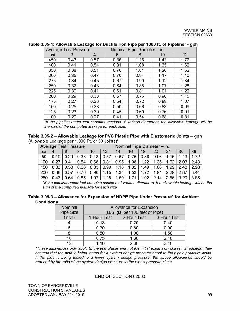
WATER MAINS SECTION 02660
TOWN OF BARGERSVILLE CONSTRUCTION STANDARDS ADOPTED JANURAY 2ND, 2019 99
Table 3.05-1: Allowable Leakage for Ductile Iron Pipe per 1000 ft. of Pipeline* - gph Average Test Pressure Nominal Pipe Diameter – in.
psi 3 4 6 8 10 12 450 0.43 0.57 0.86 1.15 1.43 1.72 400 0.41 0.54 0.81 1.08 1.35 1.62 350 0.38 0.51 0.76 1.01 1.26 1.52 300 0.35 0.47 0.70 0.94 1.17 1.40 275 0.34 0.45 0.67 0.90 1.12 1.34 250 0.32 0.43 0.64 0.85 1.07 1.28 225 0.30 0.41 0.61 0.81 1.01 1.22 200 0.29 0.38 0.57 0.76 0.96 1.15 175 0.27 0.36 0.54 0.72 0.89 1.07 150 0.25 0.33 0.50 0.66 0.83 0.99 125 0.23 0.30 0.45 0.60 0.76 0.91 100 0.20 0.27 0.41 0.54 0.68 0.81
*If the pipeline under test contains sections of various diameters, the allowable leakage will be the sum of the computed leakage for each size.
Table 3.05-2 – Allowable Leakage for PVC Plastic Pipe with Elastomeric Joints – gph (Allowable Leakage per 1,000 Ft. or 50 Joints)*
Average Test Pressure Nominal Pipe Diameter – in. psi 4 6 8 10 12 14 16 18 20 24 30 36 50 0.19 0.29 0.38 0.48 0.57 0.67 0.76 0.86 0.96 1.15 1.43 1.72 100 0.27 0.41 0.54 0.68 0.81 0.95 1.08 1.22 1.35 1.62 2.03 2.43 150 0.33 0.50 0.66 0.83 0.99 1.16 1.32 1.49 1.66 1.99 2.48 2.98 200 0.38 0.57 0.76 0.96 1.15 1.34 1.53 1.72 1.91 2.29 2.87 3.44 250 0.43 0.64 0.85 1.07 1.28 1.50 1.71 1.92 2.14 2.56 3.20 3.85 *If the pipeline under test contains sections of various diameters, the allowable leakage will be the sum of the computed leakage for each size.
Table 3.05-3 – Allowance for Expansion of HDPE Pipe Under Pressure* for Ambient Conditions
Nominal Pipe Size
Allowance for Expansion (U.S. gal per 100 feet of Pipe)
(inch) 1-Hour Test 2-Hour Test 3-Hour Test 4 0.13 0.25 0.40 6 0.30 0.60 0.90 8 0.50 1.00 1.50 10 0.75 1.30 2.10 12 1.10 2.30 3.40
*These allowances only apply to the test phase and not the initial expansion phase. In addition, they assume that the pipe is being tested for a system design pressure equal to the pipe's pressure class. If the pipe is being tested to a lower system design pressure, the above allowances should be reduced by the ratio of the system design pressure to the pipe's pressure class.
END OF SECTION 02660
WATER SERVICES SECTION 02661
TOWN OF BARGERSVILLE CONSTRUCTION STANDARDS ADOPTED JANURAY 2ND, 2019 100
SECTION 02661 - WATER SERVICES
PART 1 - GENERAL
1.01 Summary
A. Section Includes: Developer shall furnish and install all water service connections to Town water mains, including service taps, service lines, meter pits and appurtenances as required for completing the work shown or specified.
B. Related Sections
1. Section 02220 - Trenching, Backfilling and Compaction for Utilities 2. Section 02660 - Water Mains 3. Section 02675 - Disinfection
1.02 References
A. American Society for Testing and Materials (ASTM), latest editions
1. ASTM D2239 - Polyethylene (PE) Plastic Pipe (SIDR-PR) Based on Controlled Inside Diameter
2. ASTM D3350 - Polyethylene Plastics Pipe and Fittings Materials
B. American Water Works Association (AWWA), latest editions
1. AWWA C651 - Disinfecting Water Mains 2. AWWA C800 - Underground Service Line Valves and Fittings 3. AWWA C901 - Polyethylene (PE) Pressure Pipe and Tubing (1/2-inch
through 3-inch) for Water Service
C. Indiana Department of Environmental Management (IDEM) Regulations in 327 of the Indiana Administrative Code (IAC), latest edition
D. Indiana Plumbing Code, latest edition
E. NSF Standard 14 – Plastic Pipe System Components
1.03 Submittals
A. Product Data
1. Service Lines 2. Meter Pits 3. Fittings 4. Other related items and appurtenances
WATER SERVICES SECTION 02661
TOWN OF BARGERSVILLE CONSTRUCTION STANDARDS ADOPTED JANURAY 2ND, 2019 101
B. Test Results
1. Continuity test 1.04 Delivery, Storage, and Handling
A. Acceptance at Site
1. Deliver, store and handle all materials in accordance with manufacturer's recommendations.
2. Load and unload all tubing, fittings, meter pits, and appurtenances by hoists. Do not drop materials. Do not skid or roll materials on or against each other. Use padded slings, hooks and pipe tongs to handle materials in a manner to prevent damage.
3. All meter pits, brass fittings, and lids/rings shall be delivered to the job site and be the Developers/Contractors responsibility.
4. All materials deemed damaged by the Town will not be accepted.
B. Storage and Protection
1. Store materials in an area safe from damage and deterioration. Keep the interior of tubing, fittings, and appurtenances free from dirt and foreign matter. Drain and store materials in a manner to prevent damage from freezing. Store gaskets in a cool location out of direct sunlight and free from contact with petroleum products.
1.05 Items to Be Provided By the Town
A. The Town will supply the meter. All other items required for the complete installation shall be provided by the Contractor.
PART 2 - PRODUCTS
2.01 General
A. All services lines, meter pits, and appurtenances shall be new and unused.
B. All service lines shall be 1” and larger.
C. All service lines shall be in schedule 40 conduit under streets.
D. Provide products that meet the Reduction of Lead in Drinking Water Act.
2.02 Service Saddles
A. Provide single strap, ductile iron body service saddle with TaperSealTM fully bonded gasket and wraparound 304 SS strap for added corrosion resistance.

WATER SERVICES SECTION 02661
TOWN OF BARGERSVILLE CONSTRUCTION STANDARDS ADOPTED JANURAY 2ND, 2019 102
1. Service saddle shall meet the applicable requirements of AWWA C800 2. Designed for use on PVC, steel, ductile iron, cast iron, and asbestos cement
water main. Spring washers are required when used on HDPE water main. 3. Outlet shall be 1” diameter, AWWA CC threads. 4. Closed lug hinge strap design 5. Designed for working pressures up to 200 psi 6. Wide skirt and heavy tapping boss design
B. Provide 315 Smith-Blair service saddles suitable for the intended water main diameter and material type.
2.03 Corporation Stops
A. Provide Mueller Company Model H-15008-330N.
2.04 Service Line Tubing
A. Copper Service Line Tubing
1. Provide Type "K" copper service line tubing. 2. All service lines shall be in schedule 40 conduit under streets.
B. High Density Polyethylene (HDPE)
1. Provide DR-9 HDPE tubing in accordance with AWWA C901, ASTM 3350, ASTM D2239, and NSF 14. Supply HDPE pipe manufactured from high density, extra high molecular weight polyethylene and conforming to PE Standard Code PE 4710. Polyethylene pipe shall have a minimum cell classification of 445574C per the requirements of ASTM D3350.
2. Provide stainless steel stiffeners for HDPE service line. 3. Each length of pipe shall be clearly marked with the following information at a
minimum, in conformance with AWWA C901: a. Nominal size and diameter base b. Dimension ratio or minimum wall thickness (DR-9) c. Manufacturer's name or trademark d. Material designation code (PE 4710) e. Pressure class (PC 250) f. AWWA designation number (AWWA C901) g. Manufacturer's production (lot) code h. Date of manufacture i. Seal or mark of testing agency certifying tubing for potable water service
2.05 Tracer Wire
A. Furnish tracer wire with all service lines.

WATER SERVICES SECTION 02661
TOWN OF BARGERSVILLE CONSTRUCTION STANDARDS ADOPTED JANURAY 2ND, 2019 103
B. For service line tubing installed by open excavation or within a casing pipe, provide one strand of solid 12-gauge AWG copper wire taped to the top of the pipe at 10-foot intervals for the entire length of service.
C. For service line tubing installed by horizontal directional drilling, provide 1 strand of 12-gauge solid, steel core hard drawn extra high strength copper tracer wire for the entire length of service. Supply Copperhead Direct Burial tracer wire, or approved equal.
D. Solder all splices and provide splice kits suitable for underground installation for splices and branch connections. Seal connection with epoxy contained in splice kit and wrap with waterproof tape.
2.06 Meter Pits
A. Meter Pit Assembly Complete
1. Single Meter Pit (1”) – Mueller Part No. 330RS2140RVBNN 2. Single Meter Pit (5/8” x 3/4”) – Mueller Part No. 203RD2140RVBNN 3. Double Meter Pit (5/8” x 3/4”) – Mueller Part No. 203RS2140RVB
B. Individual Meter Pit Components
1. Y Branch a. Provide Mueller Company Model H-15363.
2. Ball Valves a. For 5/8” x 3/4" x 3/4" ball valves, provide Mueller Company Model B-
24265-4. For 1” ball valves, provide Mueller Company Model B-24258-R. 3. Check Valves
a. For 5/8” x 3/4" x 3/4" check valves, provide Mueller Company Model H-14269. For 1” check valves, provide Mueller Company Model H-14244
4. Service Line Reducer a. For 5/8” x 3/4" x 3/4" thread to compression reducers, provide Mueller
Company Model H-15428. For 1” thread to compression reducers, provide Mueller Company Model H-15088.
5. Insulation Pad a. Provide 4” thick, 21” diameter insulation pad by Mueller, Part No. 790119.
6. Meter (Provided by Town) a. Provide radio read meter as manufactured by Neptune Technology
Group and approved by the Town. 7. Master Meters (By Others)
a. Provide HP Protectus III master meter as manufactured by Neptune Technology Group.
8. Meter Pits (By Others) a. For service lines up to 1”, provide 40-inch deep pre-fabricated meter pits
with 21” diameter meter pit tile as manufactured by Mueller.

WATER SERVICES SECTION 02661
TOWN OF BARGERSVILLE CONSTRUCTION STANDARDS ADOPTED JANURAY 2ND, 2019 104
b. Provide cast iron meter pit lid frames, 21” outside diameter with 18” lid opening. Mueller Part No. 700098.
c. Provide cast iron side locking meter pit lid. Mueller Part No. 282925. d. For service line sizes larger than 2-inch, provide pre-cast concrete meter
vaults unless meter is installed inside building. 9. Building Meters
a. Provide building meter settings with by-pass shut off.
2.07 Additional Items
A. All fitting connections shall be compression. No solder of any type will be accepted.
B. Service Line Fitting Adapters
1. ¾” CTS to FIP adapter – Provide Mueller Company Model H-15451-330N. 2. 1” CTS to FIP adapter – Provide Mueller Company Model H-15451-250N.
C. Concrete Blocking - Provide minimum 2,000 psi compressive strength concrete
blocking where indicated. Do not use packaged concrete (Quikrete, etc.).
PART 3 - EXECUTION
3.01 General
A. Request for water service shall be directed through the Town Controller, (317) 422-5115. At no time should service be requested through the Water Field Office.
B. The Town requires a minimum of 24 hours advance notice for all water taps and meter sets. No water taps or meter sets shall be made without a written work order issued from the Town Office.
C. When setting water meter pits or installing water main taps all specifications below shall be followed and enforced. Any alterations to these specifications must be approved by the Town.
D. Service line length and placement must be approved by the Town. No taps will be permitted under driveways.
E. A total count of the meter pits is required as soon as the Town approves the construction drawings.
F. Trenching and backfilling shall be in accordance with Section 02220 - Trenching, Backfilling, and Compaction for Utilities.

WATER SERVICES SECTION 02661
TOWN OF BARGERSVILLE CONSTRUCTION STANDARDS ADOPTED JANURAY 2ND, 2019 105
G. Inspect water services, fittings, meter pits and appurtenances prior to installation and promptly remove damaged or unsuitable materials from the job site. Replace damaged or unsuitable materials with new and unused materials.
H. Install all water services, fittings, meter pits and appurtenances as shown on the Standard Details and as specified in this Section. Do not install items when, in the opinion of the Town, trench conditions are unsuitable.
I. Absolutely no electrical boxes, transformers, or telephone boxes are to be installed between the water meter pit location and the proposed building structure.
J. Direct taps will be made on a Monday, Tuesday, or Wednesday, unless otherwise instructed by the Town.
3.02 Items to Be Installed By the Town
A. The Town will install the meter. All other installation is the responsibility of the Contractor.
3.03 Installation of Water Services (By Others)
A. Follow manufacturer's installation procedures for installation.
B. All service lines shall be buried to a minimum of 12 inches below the frost line.
C. All services greater than 100 feet in length shall be minimum 1-inch diameter and sized per the Indiana Plumbing Code.
D. Separate service lines shall be provided for each unit served.
E. Install all service lines in accordance with AWWA C800.
F. Expose the water main (at least a 4-foot by 4-foot hole is required), and provide a safe and dry working area with safe and easy access into and out of the excavation. Town may, at their discretion, refuse to work in an unsafe hole or trench.
G. Where new meters are installed on opposite sides of road from new mains, push services under road to connect to meters. No open cutting of road surfaces will be allowed for service lines.
H. Excavate trenches to widths which provide adequate working space for proper pipe installation, jointing and embedment.
I. Cut pipe in a neat and workmanlike manner. Use a cutting machine so as to leave smooth ends at right angles to the axis of the pipe. Remove all burs that form as a result of field cutting the pipe, whether the pipe end is beveled or not.
WATER SERVICES SECTION 02661
TOWN OF BARGERSVILLE CONSTRUCTION STANDARDS ADOPTED JANURAY 2ND, 2019 106
J. No joints will be allowed in service lines.
K. Fusion Bonding Procedure for HDPE Tubing
1. The method of joining polyethylene pipe to polyethylene fitting, other than those shown as flanged or otherwise mechanically connected, shall be by means of butt-fusion or sidewall fusion in accordance with the polyethylene pipe manufacturer's written bonding procedure specifications (BPS) and conforming to ASME B31.3, Chapter VII, paragraph A-328. BPS shall include, but not be limited to, cutting and facing requirements and shall utilize a data logger, such as the “Datalogger” manufactured by McElroy Manufacturing, Inc., to monitor and record the assembly of each butt-fusion or sidewall fusion joint, except when making small diameter service connections (2-inch or smaller).
2. Materials to be butt-fused or sidewall fused shall be from Standard Code PE 4710 and 445574C cell classification. Mechanical sleeves and saddles will not be allowed for branch or service connections.
3. Fusion bonding equipment specified in the BPS shall be clean and in proper operating condition capable of meeting all conditions and requirements of the pipe and bonding equipment manufacturer, including temperature, alignment and fusion pressure. Equipment heater performance shall be tested and certified prior to use for fusion bonding each day at start up and at one other time each day, no sooner than 4 hours after start up. A data logger for quality control shall electronically log each fusion joint, except as noted above. Logged fusion joints shall be stored in the data logger unit such that it can be downloaded. Logged fusion joints shall be printed weekly and submitted within 2 days of the completion of last fusion joint to the Town for review. One fusion joint for every 5 days of fusing bonding work will be removed and forwarded to a certified lab for testing. Testing shall include bend back tests of the fused joint per AWWA C906.
L. When using HDPE tubing, attach a tracer wire to the pipe at 3-foot intervals and
terminate inside the pit. HDPE tubing may only be used between the building and water meter pit.
M. Do not cut or drill meter pits.
N. Allow HDPE pipe to reach ambient temperature for the installed condition before final cutting, installation of concrete restraint system, or connection of transition couplings.
3.04 Installation of Meter Pits
A. Follow manufacturer's installation procedures for installation.
B. Be responsible for laying all service lines to meter pit location and setting meter pit.
WATER SERVICES SECTION 02661
TOWN OF BARGERSVILLE CONSTRUCTION STANDARDS ADOPTED JANURAY 2ND, 2019 107
C. Be responsible for setting meter pit and finished grade of pit. If meter pit must be raised or lowered at a later date it is the installing Contractor's responsibility. No brick or block will be approved. The meter pit must be excavated and reset in order to raise or lower pit.
D. Mark meter pipe and valve boxes with a 4-foot by 4-foot post painted Safety Blue for visibility.
3.05 Installation of Building Meters
A. Any water meter to be installed inside a building must be first approved by the Town.
B. Water meters to be installed inside a building must be equipped with a remote reading device approved by the Town and paid for by the Contractor. Be responsible for installing the appropriate water meter setters inside the building before the meter is to be set.
3.06 Field Quality Control
A. Install, flush, and perform leakage test on service lines in accordance with the Indiana Plumbing Code.
B. Conduct continuity test on all tracer wire. All tracer wire found not to be continuous after testing shall be repaired or replaced at no cost to the Town.
END OF SECTION 02661
DISINFECTION SECTION 02675
TOWN OF BARGERSVILLE CONSTRUCTION STANDARDS ADOPTED JANURAY 2ND, 2019 108
SECTION 02675 - DISINFECTION
PART 4 - GENERAL
4.01 Summary
A. Section Includes: Disinfection of all potable water lines, valves, hydrants, service connections, and all other appurtenances which are to store, handle or carry potable water. Furnish all labor, water, chemical and equipment, including taps, corporation stops, temporary pumps and other items necessary to perform the Work, unless noted otherwise.
B. Related Sections
1. Section 02660 – Water Mains 4.02 References
A. All disinfection work shall be acceptable to the Indiana Department of Environmental Management. If any requirements of this section are in conflict with requirements of the authority of disinfection, those of the authority shall govern.
B. American Water Works Association (AWWA), latest editions
1. AWWA C651 – Disinfecting Water Mains
C. Indiana Plumbing Code
4.03 Submittals
A. Quality Control Submittals
1. Prior to starting any disinfection work, furnish for the Town’s review a detailed outline of the proposed sequence of operation, disinfection method to be used, manner of filling and flushing units, source and quality of water to be used, and disposal of heavily chlorinated water.
B. Test Results
1. Submit copies of all bacteriological and chlorine residual test results to the Town.
4.04 Quality Assurance
A. Perform all work for and in connection with disinfection under the direction of an experienced supervisor.
DISINFECTION SECTION 02675
TOWN OF BARGERSVILLE CONSTRUCTION STANDARDS ADOPTED JANURAY 2ND, 2019 109
B. All equipment used in disinfection work shall be in proper working condition, and shall be adequate for the specified work.
PART 5 - PRODUCTS
5.01 Materials
A. Liquid chlorine, sodium hypochlorite solution, and calcium hypochlorite granules or tablets, as identified by AWWA as acceptable disinfection materials.
PART 6 - EXECUTION
6.01 Preparation
A. Perform pressure and leakage tests prior to disinfection when specified in related sections.
B. Fill and sterilize all new water mains, services, leads and appurtenances in accordance with AWWA C651 and this section.
C. Each section of water main shall be complete and concrete thrust blocking shall have been in place for not less than 10 days prior to being filled and disinfected.
D. The source of potable water shall be flushed prior to use to ensure that contaminants or debris are not introduced into the new pipes. Flush all water mains and fire hydrants to remove foreign material prior to disinfection. Flush mains with a flushing velocity of at least 2.5 feet per second. Flush water mains and hydrants until the water discharged is clear.
E. Fill the new mains with water from the Town’s distribution system. All air shall be expelled from the mains as they are filled. Tap the water main at high points, if necessary, to assure removal of all air. Provide necessary corporation cocks and vent piping in the event that complete venting cannot be accomplished through available outlets.
F. Prevent admission of contaminated water into previously disinfected units.
6.02 Application
A. Disinfection Procedures for Water Mains, Valves, Fittings, and Appurtenances
1. Disinfect by one of the two following methods as described in AWWA C651: tablet or continuous feed. The slug method is not allowed. a. Tablet Method
1) Perform in accordance with AWWA C651.
DISINFECTION SECTION 02675
TOWN OF BARGERSVILLE CONSTRUCTION STANDARDS ADOPTED JANURAY 2ND, 2019 110
2) Do not use calcium hypochlorite on solvent-weld plastic or screwed-joint steel pipe due to the danger of fire or explosion.
3) Keep pipe and appurtenances clean and dry during construction. 4) Place calcium hypochlorite granules or tablets to give an average
chlorine dose of 25 mg/L as follows: a) During construction, place calcium hypochlorite granules at the
upstream end of the first section of pipe, at the upstream end of each branch, and at 500-foot intervals.
b) During construction, place 5 gram calcium hypochlorite tables in each section of pipe. Also, place 1 tablet in each hydrant, hydrant branch, and other appurtenances. Attach tablets using a food grade adhesive.
5) After installation is complete, fill the water main slowly and ensure that all air pockets are eliminated.
6) The chlorinated water shall remain in the pipe for at least 24 hours. If the water temperature is less that 41 degrees Fahrenheit, the chlorinated water shall remain in the pipe for at least 48 hours. Operate valves and hydrants during this time to ensure disinfection of appurtenances.
7) At the end of the retention period, the chlorine residual shall not be less than 10 mg/L.
b. Continuous-Feed Method 1) Perform in accordance with AWWA C651. 2) Perform a preliminary flushing of the water main to eliminate air
pockets and remove particulates. The flushing velocity shall be not less than 2.5 feet per second.
3) Provide a water supply through a temporary connection from a backflow protected source at a constant, measured rate.
4) Chlorine Solution shall be prepared based on a chlorine gas-water solution or 1 percent chlorine solution prepared with calcium hypochlorite-water or sodium hypochlorite-water mixture.
5) Direct-feed chlorinators, which operate from the gas pressure in the chlorine cylinder, shall not be used for the application of liquid chlorine. Apply liquid chlorine with a solution feed, vacuum operated chlorinator and booster pump.
6) Hypochlorite solutions may be fed using a powered chemical feed pump designed for feeding chlorine solution.
7) At a point not more than 10 feet downstream from the beginning of the new main, feed the new water main with a dose of chlorine at a constant rate such that the feed water will have not less than 25 mg/L free chlorine.
8) Chlorine application shall not cease until the entire main is filled with heavily chlorinated water.
9) The chlorinated water shall remain in the pipe for at least 24 hours. 10) Operate valves and hydrants during this time to ensure disinfection of
appurtenances.
DISINFECTION SECTION 02675
TOWN OF BARGERSVILLE CONSTRUCTION STANDARDS ADOPTED JANURAY 2ND, 2019 111
11) At the end of the retention period, the chlorine residual shall not be less than 10 mg/L.
2. To prevent damage, the heavily chlorinated water shall be flushed from the system as quickly as possible following the applicable retention period. The piping system shall be flushed until the water is found to be comparable to that of the Town or not less than 1 mg/L.
3. Do not permit flushing water to discharge into existing water mains.
B. Disinfection of Items to be Immediately Returned to Service
1. Perform in accordance with AWWA C651. 2. Apply liberal quantities of hypochlorite to open trench areas when an existing
water main or service connection is opened and the excavation is wet. 3. Disinfect pipe, fittings or appurtenances by thoroughly flushing and swabbing
with a 5 percent solution of calcium hypochlorite immediately prior to assembly.
4. Following swabbing, flush the unit until replacement water in the system is proven to be comparable in quality to the water which will enter that unit or system. Flush toward the work location from both directions. Flushing shall be started as soon as the repairs are complete and shall be continued until discolored water is eliminated.
5. After appropriate procedures of disinfection and flushing have been completed, the existing main may be returned to service prior to completion of verification of disinfection in order to minimize the time customers are without water.
C. Disinfection of Service Lines and Accessories
1. Perform in accordance with the Indiana Plumbing Code. 2. Flush the piping with clean, potable water until only potable water appears at
the points of outlet. 3. Disinfect the system according to one of the following procedures:
a. Fill the system with a water – chlorine solution containing at least 50 mg/L of free chlorine. Retain the heavily chlorinated water in the system for at least 24 hours.
b. Fill the system with a water – chlorine solution containing at least 300 mg/L of free chlorine. Retain the heavily chlorinated water in the system for at least 3 hours.
4. Following disinfection, flush the system with clean, potable water until the chlorine in the water coming from the system does not exceed the chlorine residual in the flushing water.
5. Verification of disinfection for service lines is not required. 6.03 Verification of Disinfection and Disposal of Waste
A. After application of disinfection is complete, perform final flushing of heavily chlorinated water, unless specified otherwise.

DISINFECTION SECTION 02675
TOWN OF BARGERSVILLE CONSTRUCTION STANDARDS ADOPTED JANURAY 2ND, 2019 112
B. Properly dispose of all heavily chlorinated water by neutralization and in accordance with the regulations of the local health department, Indiana Department of Environmental Management, and AWWA C651, Appendix C.
C. Obtain written authorization from Town sewer department before discharging heavily chlorinated water to sanitary sewer system.
D. Before the system, structure or well is placed in service, obtain 2 successive water samples 24 hours apart and have them tested for bacteriological analysis by a State-approved laboratory. Samples shall be drawn in accordance with the State’s procedure.
E. If samples do not prove satisfactory, the system, structure or well shall be re-chlorinated and re-sampled until 2 successive water samples taken 24 hours apart have tested satisfactory.
F. Assume the expense of taking and testing additional samples until satisfactory samples are obtained.
G. Assume the expense of all water for subsequent fillings of the pipelines, basins, tanks and equipment.
END OF SECTION 02675
UNDERDRAIN SYSTEMS SECTION 02710
TOWN OF BARGERSVILLE CONSTRUCTION STANDARDS ADOPTED JANURAY 2ND, 2019 113
SECTION 02710 - UNDERDRAIN SYSTEMS
PART 1 - GENERAL
1.01 Summary
A. Section Includes: Furnishing and installing all underdrains, French drains, fittings, appurtenances, and other materials as shown on the Drawings and specified herein.
B. Related Sections
1. Section 02220 - Trenching, Backfilling and Compaction for Utilities 1.02 References
A. American Association of State Highway and Transportation Officials (AASHTO), latest editions
1. AASHTO M252 - Standard Specification for Corrugated Polyethylene Drainage Pipe
2. AASHTO M294 - Standard Specification for Corrugated Polyethylene Pipe 300- to 1500-mm (12- to 60-in.) Diameter
B. American Society for Testing and Materials (ASTM), latest editions
1. ASTM C94 - Standard Specification for Ready-Mixed Concrete 2. ASTM D4355 - Standard Test Method for Deterioration of Geotextiles by
Exposure to Light, Moisture and Heat in a Xenon Arc Type Apparatus 3. ASTM D4491 - Standard Test Methods for Water Permeability of Geotextiles
by Permittivity 4. ASTM D4533 - Standard Test Method for Trapezoid Tearing Strength of
Geotextiles 5. ASTM D4632 - Standard Test Method for Grab Breaking Load and
Elongation of Geotextiles 6. ASTM D4751 - Standard Test Method for Determining Apparent Opening
Size of a Geotextile 7. ASTM D4833 - Standard Test Method for Index Puncture Resistance of
Geomembranes and Related Products
C. Indiana Department of Transportation (INDOT) Standard Specifications, latest edition
1. Section 715 - Pipe Culverts, and Storm and Sanitary Sewers 2. Section 904 - Aggregates

UNDERDRAIN SYSTEMS SECTION 02710
TOWN OF BARGERSVILLE CONSTRUCTION STANDARDS ADOPTED JANURAY 2ND, 2019 114
1.03 Submittals
A. Product Data
1. Pipe 2. Outlet Protectors 3. Geotextile 4. Concrete Mix Design for Concrete Collars
1.04 Delivery, Storage, and Handling
A. Acceptance at Site
1. Load and unload all pipe, fittings, appurtenances, and other materials in a manner to avoid shock and damage. Do not drop materials. Lift by hoists or skids when hand lifting is not feasible. Never allow pipe handled on skidways to skid or roll against pipe already on the ground.
2. Replace damaged or defective pipe, appurtenances, and other materials at no additional cost.
3. Pipe possessing defects including, but not limited to the following, will be rejected for installation: a. Variations from straight centerline b. Elliptical shape in round pipe c. Lack of rigidity d. Illegible markings as required herein e. Deep or excessive gouges, dents, bends, or scratches on the pipe wall f. Fractures, punctures, or cracks passing through the pipe wall g. Damaged or cracked ends where such damage would prevent making a
satisfactory joint 4. Geotextile possessing defects including, but not limited to the following, will
be rejected for installation: a. Rips or punctures passing through the material b. Deterioration from light, temperature, or other unsatisfactory conditions
B. Storage and Protection
1. Store materials in an area safe from damage and deterioration. 2. Protect plastic pipes from extreme temperatures and ultraviolet radiation. 3. Keep interior of pipe, fittings, manhole sections, and appurtenances free from
dirt and foreign matter. 4. Store gaskets in a cool location out of direct sunlight and free from contact
with petroleum products. 5. Store and handle geotextiles in accordance with the manufacturer's
recommendations. Do not expose geotextile to direct sunlight, ultraviolet rays, temperatures greater than 140 degrees Fahrenheit, mud, dirt, dust, or debris to the extent that its strength, toughness, or permeability requirements are diminished.
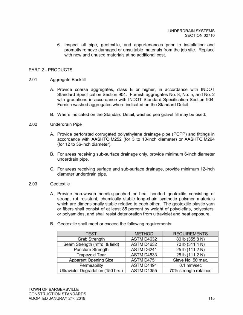
UNDERDRAIN SYSTEMS SECTION 02710
TOWN OF BARGERSVILLE CONSTRUCTION STANDARDS ADOPTED JANURAY 2ND, 2019 115
6. Inspect all pipe, geotextile, and appurtenances prior to installation and promptly remove damaged or unsuitable materials from the job site. Replace with new and unused materials at no additional cost.
PART 2 - PRODUCTS
2.01 Aggregate Backfill
A. Provide coarse aggregates, class E or higher, in accordance with INDOT Standard Specification Section 904. Furnish aggregates No. 8, No. 5, and No. 2 with gradations in accordance with INDOT Standard Specification Section 904. Furnish washed aggregates where indicated on the Standard Detail.
B. Where indicated on the Standard Detail, washed pea gravel fill may be used.
2.02 Underdrain Pipe
A. Provide perforated corrugated polyethylene drainage pipe (PCPP) and fittings in accordance with AASHTO M252 (for 3 to 10-inch diameter) or AASHTO M294 (for 12 to 36-inch diameter).
B. For areas receiving sub-surface drainage only, provide minimum 6-inch diameter underdrain pipe.
C. For areas receiving surface and sub-surface drainage, provide minimum 12-inch diameter underdrain pipe.
2.03 Geotextile
A. Provide non-woven needle-punched or heat bonded geotextile consisting of strong, rot resistant, chemically stable long-chain synthetic polymer materials which are dimensionally stable relative to each other. The geotextile plastic yarn or fibers shall consist of at least 85 percent by weight of polyolefins, polyesters, or polyamides, and shall resist deterioration from ultraviolet and heat exposure.
B. Geotextile shall meet or exceed the following requirements:
TEST METHOD REQUIREMENTS Grab Strength ASTM D4632 80 lb (355.8 N)
Seam Strength (mfrd. & field) ASTM D4632 70 lb (311.4 N) Puncture Strength ASTM D6241 25 lb (111.2 N)
Trapezoid Tear ASTM D4533 25 lb (111.2 N) Apparent Opening Size ASTM D4751 Sieve No. 50 max.
Permeability ASTM D4491 0.1 mm/sec Ultraviolet Degradation (150 hrs.) ASTM D4355 70% strength retained
UNDERDRAIN SYSTEMS SECTION 02710
TOWN OF BARGERSVILLE CONSTRUCTION STANDARDS ADOPTED JANURAY 2ND, 2019 116
2.04 Concrete Collar
A. Provide ready-mixed concrete which meets the requirements of ASTM C94. Each cubic yard of concrete shall contain the following:
1. Cement: 6 bag minimum 2. Air content: 5 to 7 percent 3. Coarse aggregate size: 1-1/2 inches maximum 4. Slump: 3 to 5 inches 5. Compressive strength: 4,000 psi
PART 3 - EXECUTION
3.01 General
A. Provide all tools, labor and equipment necessary for the safe and expeditious installation of all underdrains and French drains, risers, and appurtenances as shown on the Drawings and specified herein.
B. Perform all clearing, grubbing, excavation, trenching, bedding, and backfilling required in accordance with Section 02220 - Trenching, Backfilling and Compaction for Utilities.
3.02 Trenching
A. Trenches shall be excavated to the dimensions and grade required by the plans or as directed in the field by the Town.
B. Provide a minimum clearance of 4 inches on each side of the pipe for the width of the trench.
C. Excavate to design grade to provide a smooth, graded surface free of debris, large cavities, and exposed rocks greater than 3 inches in diameter.
3.03 Installation
A. After excavating to design grade, cut geotextile to a width sufficient to provide for non-tight placement in trenches and overlaps of the ends of adjacent rolls.
B. Avoid contamination of the geotextile during construction. If it becomes contaminated, remove and replace geotextile with new material.
C. Place the geotextile with the machine direction in the direction of water flow in the drainage system. It shall be placed loosely, but with no wrinkles or folds.
D. Overlap the ends and edges of subsequent rolls and parallel rolls of geotextile a minimum of 1 foot. The upstream geotextile shall always be overlapped over the

UNDERDRAIN SYSTEMS SECTION 02710
TOWN OF BARGERSVILLE CONSTRUCTION STANDARDS ADOPTED JANURAY 2ND, 2019 117
downstream geotextile. Join seams which are required in the longitudinal direction by means of either sewing or overlapping. Overlapped seams shall have a minimum overlap equal to the width of the trench.
E. Place perforated pipe with the perforations facing down and securely join the pipe sections with the appropriate coupling, fitting or bands. Non-perforated pipe shall be laid with the bell end upgrade and with open joints wrapped with suitable material to permit entry of water, or unwrapped as shown on the Drawings.
F. Take necessary precautions to protect pipe and tile. All damaged sections shall be replaced by the Contractor for no additional payment.
G. Where required by the Drawings or where directed in the field, furnish and construct stub-tee connections in accordance with INDOT Standard Specification Section 715.
H. Provide cleanout or riser structure at a maximum spacing of 500 feet.
3.04 Backfilling
A. Placement of drainage aggregate shall proceed immediately following placement of the geotextile and underdrain.
B. Place aggregate in a manner which minimizes contamination of the underdrain pipe.
END OF SECTION 02710
HYBRID DITCH SYSTEMS SECTION 02715
TOWN OF BARGERSVILLE CONSTRUCTION STANDARDS ADOPTED JANURAY 2ND, 2019 118
SECTION 02715 - HYBRID DITCH SYSTEMS
PART 1 - GENERAL
1.01 Summary
A. Section Includes: Furnishing and installing all hybrid ditch pipes, drain basins, and appurtenances as shown on the Drawings and as specified herein.
B. Related Sections
1. Section 02220 - Trenching, Backfilling and Compaction for Utilities 1.02 References
A. American Association of State Highway and Transportation Officials (AASHTO), latest editions
1. AASHTO M252 - Standard Specification for Corrugated Polyethylene Drainage Pipe
2. AASHTO M294 - Standard Specification for Corrugated Polyethylene Pipe 300- to 1500-mm (12- to 60-in.) Diameter
B. American Society for Testing and Materials (ASTM), latest editions
1. ASTM D698 - Standard Test Methods for Laboratory Compaction Characteristics of Soil Using Standard Effort (12,400 ft-lbf/ft3 (600 kN-m/m3))
2. ASTM D1784 - Standard Specification for Rigid Poly(Vinyl Chloride) (PVC) Compounds and Chlorinated Poly(Vinyl Chloride) (CPVC) Compounds
3. ASTM D3212 - Standard Specification for Joints for Drain and Sewer Plastic Pipes Using Flexible Elastomeric Seals
4. ASTM D3350 - Standard Specification for Polyethylene Plastics Pipe and Fittings Materials
5. ASTM D4355 - Standard Test Method for Deterioration of Geotextiles by Exposure to Light, Moisture and Heat in a Xenon Arc Type Apparatus
6. ASTM D4491 - Standard Test Methods for Water Permeability of Geotextiles by Permittivity
7. ASTM D4533 - Standard Test Method for Trapezoid Tearing Strength of Geotextiles
8. ASTM D4632 - Standard Test Method for Grab Breaking Load and Elongation of Geotextiles
9. ASTM D4751 - Standard Test Method for Determining Apparent Opening Size of a Geotextile
10. ASTM D4833 - Standard Test Method for Index Puncture Resistance of Geomembranes and Related Products
11. ASTM F477 - Standard Specification for Elastomeric Seals (Gaskets) for Joining Plastic Pipe
HYBRID DITCH SYSTEMS SECTION 02715
TOWN OF BARGERSVILLE CONSTRUCTION STANDARDS ADOPTED JANURAY 2ND, 2019 119
C. Indiana Department of Transportation (INDOT) Standard Specifications, latest
edition
1. Section 904 - Aggregates 2. Section 907 - Concrete, Clay, and Plastic Drainage Components 3. Section 918 - Soil Fabrics
1.03 Submittals
A. Product Data
1. Pipe 2. Structures 3. Castings 4. Geotextile
1.04 Delivery, Storage, and Handling
A. Acceptance at Site
1. Load and unload all pipe, fittings, structure sections, and appurtenances in a manner to avoid shock and damage. Do not drop materials. Lift by hoists or skids when hand lifting is not feasible. Never allow pipe handled on skidways to skid or roll against pipe already on the ground.
2. Replace damaged or defective pipe and appurtenances at no additional cost. 3. Pipe possessing defects including, but not limited to the following, will be
rejected for installation: a. Variations from straight centerline b. Elliptical shape in round pipe c. Lack of rigidity d. Illegible markings as required herein e. Deep or excessive gouges, dents, bends, or scratches on the pipe wall f. Fractures, punctures, or cracks passing through the pipe wall g. Damaged or cracked ends where such damage would prevent making a
satisfactory joint 4. Geotextile possessing defects including, but not limited to the following, will
be rejected for installation: a. Rips or punctures passing through the material b. Deterioration from light, temperature, or other unsatisfactory conditions
B. Storage and Protection
1. Store materials in an area safe from damage and deterioration. 2. Protect plastic pipes from extreme temperatures and ultraviolet radiation. 3. Keep interior of pipe, fittings, manhole sections, and appurtenances free from
dirt and foreign matter.
HYBRID DITCH SYSTEMS SECTION 02715
TOWN OF BARGERSVILLE CONSTRUCTION STANDARDS ADOPTED JANURAY 2ND, 2019 120
4. Store gaskets in a cool location out of direct sunlight and free from contact with petroleum products.
5. Store and handle geotextiles in accordance with the manufacturer's recommendations. Do not expose geotextile to direct sunlight, ultraviolet rays, temperatures greater than 140 degrees Fahrenheit, mud, dirt, dust, or debris to the extent that its strength, toughness, or permeability requirements are diminished.
6. Inspect all pipe, structures, geotextile, and appurtenances prior to installation and promptly remove damaged or unsuitable materials from the job site. Replace with new and unused materials at no additional cost.
PART 2 - PRODUCTS
2.01 Aggregate Backfill
A. Provide washed coarse aggregate No. 8, class E or higher, in accordance with INDOT Standard Specification Section 904.
B. Provide fine aggregate No. 23 sand, in accordance with INDOT Standard Specification Section 904.
2.02 High Density Polyethylene (HDPE) Pipe
A. Pipe Material
1. Provide dual wall corrugated HDPE pipe and fittings, consisting of an annular outer corrugated pipe wall and a smooth inner wall, in accordance with ASTM F2648 and INDOT Standard Specification Section 907.
2. Provide perforated corrugated polyethylene drainage pipe (PCPP) and fittings in accordance with AASHTO M252 (for 3- to 10-inch diameter) or AASHTO M294 (for 12- to 36-inch diameter), ASTM F2648, and INDOT Standard Specification Section 907. Perforations shall be AASHTO Class II.
3. HDPE pipe and fittings material shall be either: a. Virgin high density polyethylene with a minimum cell class of 424420C for
4- to 10-inch diameter pipe or 435400C for 12- to 36-inch diameter, as defined in ASTM D3350
b. Engineered compound of virgin and recycled high density polyethylene with a minimum cell class of 424420C for 4- to 10-inch diameter pipe or 435420C for 12- to 36-inch diameter, as defined in ASTM D3350
4. The flexibility factor of HDPE pipe shall not exceed 0.095.
B. Joints
1. Furnish HDPE pipe with bell and spigot joints in conformance with ASTM F2648.
2. Gasket material shall conform to ASTM F477.
HYBRID DITCH SYSTEMS SECTION 02715
TOWN OF BARGERSVILLE CONSTRUCTION STANDARDS ADOPTED JANURAY 2ND, 2019 121
C. Fittings
1. Provide fittings of the same manufacturer for each type of HDPE pipe. 2. Manufactured fittings such as wyes, tees, elbows, or adaptors will not be
accepted for use in place of drain basins unless otherwise indicated on the Drawings.
D. Pipe Markings
1. Each length of HDPE pipe shall be clearly marked with the following information at a minimum: a. Name of manufacturer or identification symbol b. Nominal pipe size c. Product/extrusion code
2.03 Pipe Accessories
A. Pipe to Structure Connections
1. Pipe penetration holes shall be either pre-formed by manufacturer or core drilled in the field.
2. Provide flexible neoprene molded boot or resilient seal which conforms to ASTM C923. Provide Kor-N-Seal boot as manufactured by National Pollution Control Systems, Inc. or approved equal. Provide resilient seal as manufactured by A-Lok or approved equal.
2.04 Drain Basins and Accessories
A. Structures
1. Provide PVC drain basins which are manufactured from PVC pipe stock, utilizing a thermo-molding process to re-form the pipe stock to the furnished configuration. Drainage pipe connection stubs shall be manufactured from PVC pipe stock and formed to provide a watertight connection with the specified type of pipe. The raw material shall conform to ASTM D1784 cell class 12454.
2. PVC structure joints shall conform to ASTM D3212. Flexible elastomeric seals shall conform to ASTM F477.
3. Provide Nyloplast drain basins as manufactured by Advanced Drainage Systems, Inc. or approved equal.
B. Castings
1. Furnish cast iron or ductile iron frames and covers to match the diameter of the drain basin installed. Road and highway grates shall meet minimum H-20 load rating.

HYBRID DITCH SYSTEMS SECTION 02715
TOWN OF BARGERSVILLE CONSTRUCTION STANDARDS ADOPTED JANURAY 2ND, 2019 122
2.05 Geotextile
A. Provide non-woven needle punched or heat bonded geotextile consisting of strong, rot-resistant, chemically stable long-chain synthetic polymer materials which are dimensionally stable relative to each other including selvedges.
B. Furnish geotextile which meets or exceeds INDOT Standard Specification Section 918 and the following requirements:
TEST METHOD REQUIREMENT Grab Strength ASTM D4632 80 lb (355.8 N)
Seam Strength (mfrd. & field) ASTM D4632 70 lb (311.4 N) Puncture Strength ASTM D4833 25 lb (111.2 N)
Trapezoid Tear ASTM D4533 25 lb (111.2 N) Apparent Opening Size ASTM D4751 Sieve No. 50 max.
Permeability ASTM D4491 0.1 mm/sec Ultraviolet Degradation (150 hrs.) ASTM D4355 70% strength retained
PART 3 - EXECUTION
3.01 Examination
A. Verification of Conditions
1. Before installing piping, verify location, depth, type of joint needed, and size of pipe to which connection is proposed.
2. Assure that lines can be run as proposed. Notify the Town immediately for approval of any necessary deviation before lines are run.
3. Work all lengths of pipe into place without forcing. 3.02 Installation
A. General
1. Provide all tools, labor and equipment necessary for the safe and expeditious installation of all hybrid ditches, drain basins, and appurtenances as shown on the Drawings and specified herein.
2. Perform all clearing, grubbing, excavation, trenching, bedding, and backfilling required in accordance with Section 02220 - Trenching, Backfilling and Compaction for Utilities.
B. Bedding and Backfill
1. Place aggregate in a manner which minimizes contamination of the hybrid ditch pipe.
HYBRID DITCH SYSTEMS SECTION 02715
TOWN OF BARGERSVILLE CONSTRUCTION STANDARDS ADOPTED JANURAY 2ND, 2019 123
2. Place coarse aggregate bedding and backfill material in 6 to 8-inch balanced lifts to ensure proper compaction and filling of all voids. Hand tamp or "walk" aggregate into place.
3. Place fine aggregate backfill material in maximum 12-inch balanced lifts to ensure proper compaction. Compact each lift to 95 percent of Standard Proctor dry density in accordance with ASTM D698.
C. Pipe and Accessories
1. Lay hybrid ditch pipe uniformly to line and grade so that finished pipe will present a uniform conduit.
2. Set line and grade by means of laser beam and target for alignment and grade.
3. Lay pipe progressively upgrade in a manner to form close, concentric joints with smooth bottom inverts.
4. Maintain 18 inches of vertical separation and 10 feet of horizontal separation between new hybrid ditch pipe and new or existing water mains unless otherwise directed. Notify the Town immediately of all instances where separation cannot be maintained.
5. After joint is made, place sufficient bedding material along each side of the pipe to prevent conditions that might tend to move the pipe off line or grade.
6. Temporarily plug installed piping systems at end of each day’s work or other interruption of progress on a given line. Plug shall be adequate to prevent entry of animals and entrance or insertion of deleterious materials and shall be installed in a manner satisfactory to the Town.
7. Securely attach fabricated branches for wyes and tees to wall of pipe in such a manner as to not restrict or otherwise interfere with flow characteristics of the pipe.
8. Install boot and saddle connectors for all taps to concrete and RCP pipe. 9. Ensure smooth trench bottom free from large exposed rocks greater than
3 inches in diameter, and cover trench bottom with geotextile as specified herein and No. 8 washed gravel. Install pipe with perforations facing downward at a minimum grade of 0.10 percent and 2 feet minimum to 4 feet maximum cover. Cover PCPP with No. 8 washed gravel to a minimum of 12 inches above the pipe crown. Fold geotextile around gravel and backfill as specified and as shown on the Drawings.
10. If any existing drainage tile systems are encountered during construction, reconstruct the tile to its original conditions or connect tile to the new storm drainage system as approved by the Town.
D. Drain Basins and Accessories
1. Join pipe bell spigot to the structure body by use of a swage mechanical joint.
2. Bed and backfill drain basins as specified for PVC pipe in Section 02200 - Trenching, Backfilling and Compaction for Utilities.
3. Install drain basins so axis of structure is vertical.
HYBRID DITCH SYSTEMS SECTION 02715
TOWN OF BARGERSVILLE CONSTRUCTION STANDARDS ADOPTED JANURAY 2ND, 2019 124
4. Unless otherwise indicated, set castings for all structures at finish grade level. Inline drain and drain basin bodies shall be cut to final grade. No brick, stone, or concrete block will be permitted to set the casting to the finish grade level. Adjust castings to the satisfaction of the Town, at Contractor’s expense.
5. For H-20 load rate installations, pour a concrete ring under and around the grate and frame per the manufacturer’s recommendations.
6. Remove all debris and excess soil from structures after installation and prior to flushing the storm sewer pipes, to the satisfaction of the Town.
E. Connection to Existing Structures
1. Core drill new pipe penetration at the proper location where the pipe enters the structure.
2. Install flexible neoprene molded boot or resilient seal to secure the pipe in the structure wall as noted in Article 2.03A.2 of this Section.
3.03 Field Quality Control
A. Tests
1. Deflection Test for Flexible Pipes a. Pipe materials considered flexible include the following:
1) HDPE 2) PCPP
b. Perform testing in presence of Town. c. Perform deflection testing on all flexible pipes after the final backfill has
been in place for at least 30 days. d. Perform deflection test using a mandrel pulled by hand. The mandrel
(go/no-go) device shall be cylindrical in shape and constructed with 9 or 10 evenly spaced arms or prongs.
e. No pipe shall exceed a vertical deflection of 5 percent. Uncover, replace, and retest any pipe not passing the deflection test until a satisfactory result is achieved.
B. Inspection
1. Television Inspection a. Televise all pipe segments in excess of 40 feet in length. b. Perform all television inspection in presence of the Town. c. Clean all new pipe segments by “flooding” prior to television inspection.
The image shall be clear so the interior condition of the pipe is easily evaluated.
d. Correct all unacceptable conditions found during the television inspection and re-televise until no unacceptable conditions are found.

HYBRID DITCH SYSTEMS SECTION 02715
TOWN OF BARGERSVILLE CONSTRUCTION STANDARDS ADOPTED JANURAY 2ND, 2019 125
e. Unacceptable conditions are conditions that adversely affect the ability of the system to function as designed or to be properly maintained and may include, but are not limited to, the following: 1) Protruding taps 2) Cracked or faulty pipe 3) Misaligned or deformed pipe 4) Debris in line 5) Excessive gaps at joints 6) Bellies or sags with a depth greater than or equal to 10 percent of the
pipe diameter (maximum of 3 inches) or a length greater than 25 feet f. Submit copy of the televising recording (DVD format) within 14 calendar
days of the inspection. 3.04 Cleaning
A. Clean all new pipe segments with high pressure water jet after installation and before testing.
END OF SECTION 02715
STORM SEWER SYSTEMS SECTION 02720
TOWN OF BARGERSVILLE CONSTRUCTION STANDARDS ADOPTED JANURAY 2ND, 2019 126
SECTION 02720 - STORM SEWER SYSTEMS
PART 1 - GENERAL
1.01 Summary
A. Section Includes: Furnishing and installing all culverts, storm sewers, end sections, inlets, manholes, and appurtenances as shown on the Drawings and as specified herein.
B. Related Sections
1. Section 02101 - Erosion and Sediment Control and Stormwater Pollution Prevention
2. Section 02220 - Trenching, Backfilling and Compaction for Utilities 1.02 References
A. American Association of State Highway and Transportation Officials (AASHTO), latest editions
1. AASHTO M36 - Standard Specification for Corrugated Steel Pipe, Metallic-Coated for Sewers and Drains
2. AASHTO M170 - Standard Specification for Reinforced Concrete Culvert, Storm Drain, and Sewer Pipe
3. AASHTO M207 - Standard Specification for Reinforced Concrete Elliptical Culvert, Storm Drain, and Sewer Pipe
B. American Society for Testing and Materials (ASTM), latest editions
1. ASTM A48 - Standard Specification for Gray Iron Castings 2. ASTM A615 - Standard Specification for Deformed and Plain Carbon-Steel
Bars for Concrete Reinforcement 3. ASTM C76 - Standard Specification for Reinforced Concrete Culvert, Storm
Drain, and Sewer Pipe 4. ASTM C443 - Standard Specification for Joints for Concrete Pipe and
Manholes, Using Rubber Gaskets 5. ASTM C478 - Standard Specification for Precast Reinforced Concrete
Manhole Sections 6. ASTM C507 - Standard Specification for Reinforced Concrete Elliptical
Culvert, Storm Drain, and Sewer Pipe 7. ASTM C928 - Standard Specification for Packaged, Dry, Rapid-Hardening
Cementitious Materials for Concrete Repairs 8. ASTM C1433 - Standard Specification for Precast Reinforced Concrete
Monolithic Box Sections for Culverts, Storm Drains, and Sewers

STORM SEWER SYSTEMS SECTION 02720
TOWN OF BARGERSVILLE CONSTRUCTION STANDARDS ADOPTED JANURAY 2ND, 2019 127
9. ASTM C1577 - Standard Specification for Precast Reinforced Concrete Monolithic Box Sections for Culverts, Storm Drains, and Sewers Design According to AASHTO LRFD
10. ASTM D1784 - Standard Specification for Rigid Poly(Vinyl Chloride) (PVC) Compounds and Chlorinated Poly(Vinyl Chloride) (CPVC) Compounds
11. ASTM D2412 - Standard Test Method for Determination of External Loading Characteristics of Plastic Pipe by Parallel-Plate Loading
12. ASTM D3034 - Standard Specification for Type PSM Poly(Vinyl Chloride) (PVC) Sewer Pipe and Fittings
13. ASTM D3212 - Standard Specification for Joints for Drain and Sewer Plastic Pipes Using Flexible Elastomeric Seals
14. ASTM D3350 - Standard Specification for Polyethylene Plastics Pipe and Fittings Materials
15. ASTM D4101 - Standard Specification for Polypropylene Injection and Extrusion Materials
16. ASTM F477 - Standard Specification for Elastomeric Seals (Gaskets) for Joining Plastic Pipe
17. ASTM F679 - Standard Specification for Poly(Vinyl Chloride) (PVC) Large-Diameter Plastic Gravity Sewer Pipe and Fittings
18. ASTM F714 - Standard Specification for Polyethylene (PE) Plastic Pipe (SDR-PR) Based on Outside Diameter
19. ASTM F894 - Standard Specification for Polyethylene (PE) Large Diameter Profile Wall Sewer and Drain Pipe
20. ASTM F949 - Standard Specification for Poly(Vinyl Chloride) (PVC) Corrugated Sewer Pipe With a Smooth Interior and Fittings
21. ASTM F1055 - Standard Specification for Electrofusion Type Polyethylene Fittings for Outside Diameter Controlled Polyethylene and Crosslinked Polyethylene (PEX) Pipe and Tubing
22. ASTM F1803 - Standard Specification for Poly(Vinyl Chloride) (PVC) Closed Profile Gravity Pipe and Fittings Based on Controlled Inside Diameter
23. ASTM F2648 - Standard Specification for 2 to 60 inch [50 to 1500 mm] Annular Corrugated Profile Wall Polyethylene (PE) Pipe and Fittings for Land Drainage Applications
C. Indiana Department of Transportation (INDOT) Standard Specifications, latest
edition
1. Section 901 - PCC Materials 2. Section 904 - Aggregates 3. Section 907 - Concrete, Clay, and Plastic Drainage Components 4. Section 908 - Metal Pipe 5. Section 910 - Metal Materials
D. Town of Bargersville Storm Water Manual, latest edition

STORM SEWER SYSTEMS SECTION 02720
TOWN OF BARGERSVILLE CONSTRUCTION STANDARDS ADOPTED JANURAY 2ND, 2019 128
1.03 Submittals
A. Product Data, as applicable
1. Pipe 2. Fittings 3. End Sections 4. Trash Guards 5. Structures 6. Castings 7. Manhole Steps
1.04 Delivery, Storage, and Handling
A. Acceptance at Site
1. Load and unload all pipe, fittings, structure sections, and appurtenances in a manner to avoid shock and damage. Do not drop materials. Lift by hoists or skids when hand lifting is not feasible. Never allow pipe handled on skidways to skid or roll against pipe already on the ground.
2. Replace damaged or defective pipe and appurtenances at no additional cost. 3. Pipe possessing defects including, but not limited to the following, will be
rejected for installation: a. Variations from straight centerline b. Elliptical shape in round pipe c. Lack of rigidity d. Illegible markings as required herein e. Bruised, broken, or otherwise damaged metallic or bituminous coating or
liner, as applicable f. Deep or excessive gouges, dents, bends, or scratches on the pipe wall g. Fractures, punctures, or cracks passing through the pipe wall h. Damaged or cracked ends where such damage would prevent making a
satisfactory joint 4. Concrete pipe and structures possessing defects including, but not limited to
the following, will be rejected for installation: a. Fractures or cracks passing through the wall b. Honeycombed or open texture which would adversely affect the function
of the box sections c. Ends of sections not normal to the walls and centerline of the section
5. Geotextile possessing defects including, but not limited to the following, will be rejected for installation: a. Rips or punctures passing through the material b. Deterioration from light, temperature, or other unsatisfactory conditions
B. Storage and Protection
1. Store materials in an area safe from damage and deterioration.

STORM SEWER SYSTEMS SECTION 02720
TOWN OF BARGERSVILLE CONSTRUCTION STANDARDS ADOPTED JANURAY 2ND, 2019 129
2. Protect plastic pipes from extreme temperatures and ultraviolet radiation. 3. Keep interior of pipe, fittings, manhole sections, and appurtenances free from
dirt and foreign matter. 4. Store gaskets in a cool location out of direct sunlight and free from contact
with petroleum products. 5. Inspect all pipe, structures, and appurtenances prior to installation and
promptly remove damaged or unsuitable materials from site. Replace with new and unused materials.
PART 2 - PRODUCTS
2.01 Acceptable Material Use
A. All public storm sewers located within road or street right-of-ways, including storm sewers to be maintained by a Home Owners Association (HOA), and storm sewers to be dedicated to the Town shall be gasket type, reinforced concrete pipe (RCP) meeting the requirements of this specification.
B. All public storm sewers located within drainage and utility easements (D&UE) other utility or drainage easements, including storm sewers to be maintained by a Home Owners Association (HOA), and storm sewers to be dedicated to the Town shall be gasket type, reinforced concrete pipe (RCP) meeting the requirements of this specification. If however, the storm sewers in this sub-section are provided with a minimum of 32 inches of cover (measured from the top of pipe to the finished ground elevation), high-performance polypropylene (HP) pipe meeting the requirements of this specification may also be utilized.
C. Storm sewers that are not considered public, shall be considered private and may be RCP, polyvinyl chloride (PVC), or high-density polyethylene (HDPE) meeting the requirements of this specification.
D. All equivalents shall be approved by the Town of Bargersville prior to installation.
2.02 High Density Polyethylene (HDPE) Pipe
A. Pipe Material
1. Provide HDPE pipe for culverts and storm sewers which are 12 to 24 inches in diameter. HDPE pipe shall not be used for culverts and storm sewers over 24 inches in diameter.
2. Provide Type D dual wall corrugated HDPE pipe and fittings, consisting of an annular outer corrugated pipe wall and a smooth inner wall braced circumferentially with circular ribs joined to a smooth outer wall, in accordance with AASHTO M294 Type S.
3. HDPE pipe and fittings material shall be either: a. Virgin high density polyethylene with a minimum cell class as defined in
ASTM D3350
STORM SEWER SYSTEMS SECTION 02720
TOWN OF BARGERSVILLE CONSTRUCTION STANDARDS ADOPTED JANURAY 2ND, 2019 130
b. Engineered compound of virgin and recycled high density polyethylene with a minimum cell class as defined in ASTM D3350
4. The flexibility factor of HDPE pipe shall not exceed 0.095. 5. Provide Sure-Lok as manufactured by Hancor, Inc., N-12 Soil-Tight as
manufactured by ADS, or approved equal.
B. Joints
1. Furnish HDPE pipe with bell and spigot gasketed joints in conformance with ASTM F2648 and ASTM D3212.
2. Gasket material shall conform to ASTM F477.
C. Fittings
1. Provide fittings of the same manufacturer for each type of HDPE pipe. 2. Manufactured fittings such as wyes, tees, elbows, or adaptors will not be
accepted for use in place of storm sewer manholes or inlets, unless otherwise indicated on the Drawings.
D. Pipe Markings
1. Each length of HDPE pipe shall be clearly marked with the following information at a minimum: a. Name of manufacturer or identification symbol b. Nominal pipe size c. Product/extrusion code
2.03 High Performance Polypropylene (HP) Pipe
A. Pipe Material
1. This specification describes 12-inch through 60-inch ADS (or equivalent) HP Storm pipe for use in gravity-flow storm drainage applications. 12-inch through 60-inch pipe shall have a smooth interior and annular exterior corrugations and meet or exceed ASTM F2881 and AASHTO M330.
2. Polypropylene compound for pipe and fitting production shall be impact modified copolymer meeting the material requirements of ASTM F2881, Section 5 and AASHTO M330, Section 6.1.
3. Manning’s “n” value for use in design shall be 0.012.
B. Joints
1. Pipe shall be joined with a gasketed integral bell & spigot joint meeting the requirements of F2881. 12-inch through 60-inch shall be watertight according to the requirements of ASTM D3212. Spigots shall have gaskets meeting the requirements of ASTM F477.
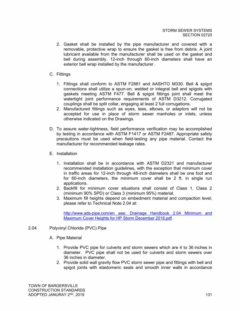
STORM SEWER SYSTEMS SECTION 02720
TOWN OF BARGERSVILLE CONSTRUCTION STANDARDS ADOPTED JANURAY 2ND, 2019 131
2. Gasket shall be installed by the pipe manufacturer and covered with a removable, protective wrap to ensure the gasket is free from debris. A joint lubricant available from the manufacturer shall be used on the gasket and bell during assembly. 12-inch through 60-inch diameters shall have an exterior bell wrap installed by the manufacturer.
C. Fittings
1. Fittings shall conform to ASTM F2881 and AASHTO M330. Bell & spigot connections shall utilize a spun-on, welded or integral bell and spigots with gaskets meeting ASTM F477. Bell & spigot fittings joint shall meet the watertight joint performance requirements of ASTM D3212. Corrugated couplings shall be split collar, engaging at least 2 full corrugations.
2. Manufactured fittings such as wyes, tees, elbows, or adaptors will not be accepted for use in place of storm sewer manholes or inlets, unless otherwise indicated on the Drawings.
D. To assure water-tightness, field performance verification may be accomplished
by testing in accordance with ASTM F1417 or ASTM F2487. Appropriate safety precautions must be used when field-testing any pipe material. Contact the manufacturer for recommended leakage rates.
E. Installation
1. Installation shall be in accordance with ASTM D2321 and manufacturer recommended installation guidelines, with the exception that minimum cover in traffic areas for 12-inch through 48-inch diameters shall be one foot and for 60-inch diameters, the minimum cover shall be 2 ft. in single run applications.
2. Backfill for minimum cover situations shall consist of Class 1, Class 2 (minimum 90% SPD) or Class 3 (minimum 95%) material.
3. Maximum fill heights depend on embedment material and compaction level; please refer to Technical Note 2.04 at:
http://www.ads-pipe.com/en see: Drainage Handbook 2.04 Minimum and Maximum Cover Heights for HP Storm December 2016.pdf.
2.04 Polyvinyl Chloride (PVC) Pipe
A. Pipe Material
1. Provide PVC pipe for culverts and storm sewers which are 4 to 36 inches in diameter. PVC pipe shall not be used for culverts and storm sewers over 36 inches in diameter.
2. Provide solid wall gravity flow PVC storm sewer pipe and fittings with bell and spigot joints with elastomeric seals and smooth inner walls in accordance
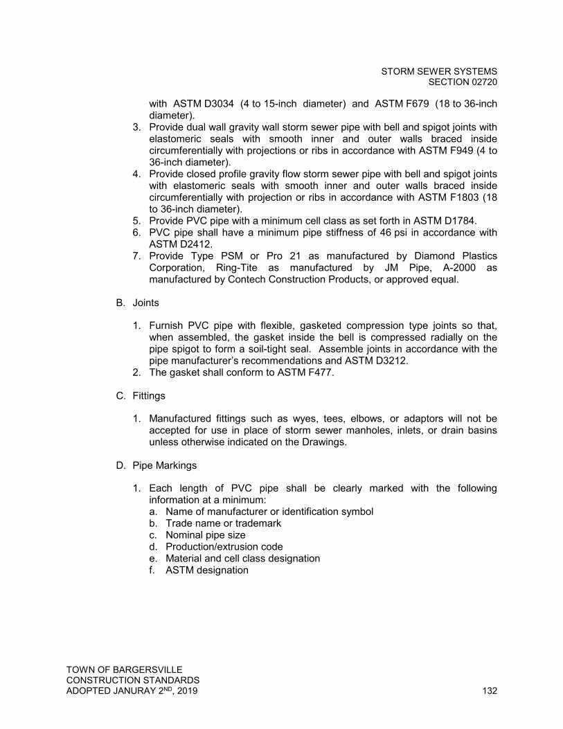
STORM SEWER SYSTEMS SECTION 02720
TOWN OF BARGERSVILLE CONSTRUCTION STANDARDS ADOPTED JANURAY 2ND, 2019 132
with ASTM D3034 (4 to 15-inch diameter) and ASTM F679 (18 to 36-inch diameter).
3. Provide dual wall gravity wall storm sewer pipe with bell and spigot joints with elastomeric seals with smooth inner and outer walls braced inside circumferentially with projections or ribs in accordance with ASTM F949 (4 to 36-inch diameter).
4. Provide closed profile gravity flow storm sewer pipe with bell and spigot joints with elastomeric seals with smooth inner and outer walls braced inside circumferentially with projection or ribs in accordance with ASTM F1803 (18 to 36-inch diameter).
5. Provide PVC pipe with a minimum cell class as set forth in ASTM D1784. 6. PVC pipe shall have a minimum pipe stiffness of 46 psi in accordance with
ASTM D2412. 7. Provide Type PSM or Pro 21 as manufactured by Diamond Plastics
Corporation, Ring-Tite as manufactured by JM Pipe, A-2000 as manufactured by Contech Construction Products, or approved equal.
B. Joints
1. Furnish PVC pipe with flexible, gasketed compression type joints so that, when assembled, the gasket inside the bell is compressed radially on the pipe spigot to form a soil-tight seal. Assemble joints in accordance with the pipe manufacturer’s recommendations and ASTM D3212.
2. The gasket shall conform to ASTM F477.
C. Fittings
1. Manufactured fittings such as wyes, tees, elbows, or adaptors will not be accepted for use in place of storm sewer manholes, inlets, or drain basins unless otherwise indicated on the Drawings.
D. Pipe Markings
1. Each length of PVC pipe shall be clearly marked with the following information at a minimum: a. Name of manufacturer or identification symbol b. Trade name or trademark c. Nominal pipe size d. Production/extrusion code e. Material and cell class designation f. ASTM designation
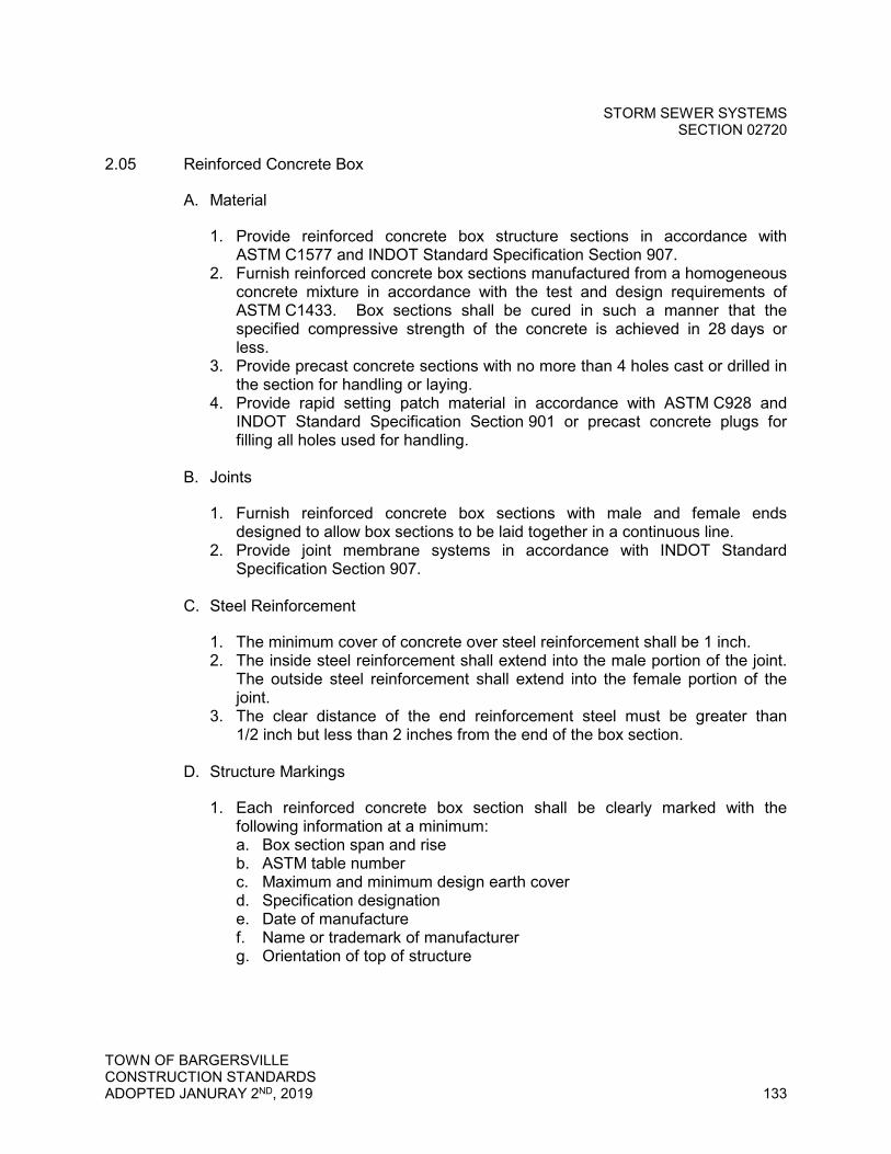
STORM SEWER SYSTEMS SECTION 02720
TOWN OF BARGERSVILLE CONSTRUCTION STANDARDS ADOPTED JANURAY 2ND, 2019 133
2.05 Reinforced Concrete Box
A. Material
1. Provide reinforced concrete box structure sections in accordance with ASTM C1577 and INDOT Standard Specification Section 907.
2. Furnish reinforced concrete box sections manufactured from a homogeneous concrete mixture in accordance with the test and design requirements of ASTM C1433. Box sections shall be cured in such a manner that the specified compressive strength of the concrete is achieved in 28 days or less.
3. Provide precast concrete sections with no more than 4 holes cast or drilled in the section for handling or laying.
4. Provide rapid setting patch material in accordance with ASTM C928 and INDOT Standard Specification Section 901 or precast concrete plugs for filling all holes used for handling.
B. Joints
1. Furnish reinforced concrete box sections with male and female ends designed to allow box sections to be laid together in a continuous line.
2. Provide joint membrane systems in accordance with INDOT Standard Specification Section 907.
C. Steel Reinforcement
1. The minimum cover of concrete over steel reinforcement shall be 1 inch. 2. The inside steel reinforcement shall extend into the male portion of the joint.
The outside steel reinforcement shall extend into the female portion of the joint.
3. The clear distance of the end reinforcement steel must be greater than 1/2 inch but less than 2 inches from the end of the box section.
D. Structure Markings
1. Each reinforced concrete box section shall be clearly marked with the following information at a minimum: a. Box section span and rise b. ASTM table number c. Maximum and minimum design earth cover d. Specification designation e. Date of manufacture f. Name or trademark of manufacturer g. Orientation of top of structure

STORM SEWER SYSTEMS SECTION 02720
TOWN OF BARGERSVILLE CONSTRUCTION STANDARDS ADOPTED JANURAY 2ND, 2019 134
2.06 Reinforced Concrete Pipe (RCP)
A. Pipe Material
1. Provide Class III, IV, or V Wall B type RCP conforming to ASTM C76 and AASHTO M170.
2. Provide elliptical RCP which conforms to ASTM C507 and AASHTO M207. 3. Lift holes are not permitted for pipes less than 36-inch diameter. A maximum
of 2 lift holes will be permitted for pipes 36-inch diameter and larger.
B. Joints
1. Furnish RCP with tongue and groove joints with compression type rubber gasket which conforms to ASTM C443.
C. Fittings
1. Supply fabricated wye and tee branches.
D. Pipe Markings
1. Each length of RCP shall be clearly marked with the following information at a minimum: a. Nominal pipe size b. Date of manufacture c. Name or trademark of manufacturer
2.07 Pipe Accessories
A. Concrete End Sections
1. Provide concrete end sections in accordance with INDOT Standard Specification Section 907 for all pipe types.
2. Concrete end sections shall be the same grade and strength as specified for RCP, ASTM C76, Class III.
3. Reinforcement in the non-tapered portion of the end section shall be the same as specified for RCP, ASTM C76, Class III for the size of connecting pipe.
4. Reinforcement in the tapered portion of the end section shall have a cross sectional area equal to that of one layer of steel in the non-tapered portion.
5. Provide concrete pipe toe anchors on all concrete end sections. 6. Furnish 3/4-inch coarse thread hook bolts and nuts in accordance with
ASTM A307. Hook bolts and nuts shall be galvanized in accordance with ASTM A153.
7. Furnish trash guard for all end sections which are 18 inches in diameter and larger. Trash guards shall have a maximum clear opening of 6 inches and be removable.

STORM SEWER SYSTEMS SECTION 02720
TOWN OF BARGERSVILLE CONSTRUCTION STANDARDS ADOPTED JANURAY 2ND, 2019 135
B. Outfall Protection
1. Provide hard armoring material as required for outfall protection. Refer to Section 02101 - Erosion and Sediment Control and Stormwater Pollution Prevention.
2.08 Precast Concrete Manholes, Inlets, and Accessories
A. General
1. Provide precast concrete sections with no more than 3 holes cast or drilled in the section for handling.
2. Provide rapid setting patch material in accordance with ASTM C928 or precast concrete plugs for filling all holes used for handling.
B. Precast Concrete Manholes
1. Supply a minimum of 1 adjusting ring for each manhole. Adjusting rings shall be a minimum of 1 inches and maximum of 12 inches in height as shown on the Standard Detail. Supply precast concrete riser sections for adjustment greater than 12 inches in height.
2. Provide precast concrete eccentric cone section which conforms to ASTM C478. Where indicated on the Drawings, provide flat top section which conforms to ASTM C478. Cone and flat top sections shall have a 24-inch opening.
3. Provide precast concrete manhole risers/barrels which conform to ASTM C478, AASHTO M199, INDOT Standard Specification Section 907, and as indicated on Drawings.
4. Provide precast concrete manhole bases which conforms to ASTM C478, AASHTO M199, and INDOT Standard Specification Section 907.
5. Provide precast concrete floor or form with Class A concrete. Floor shall be sloped to the sewer invert.
6. Provide 2 rows of 1/2-inch diameter flexible butyl rubber joint gaskets conforming to ASTM C443 and AASHTO M198 for all manhole section joints. Provide Kent Seal or approved equal.
7. Sumps are not permitted in manhole structures.
C. Precast Concrete Inlets and Catch Basins
1. Provide precast concrete inlets to the dimensions as shown on the Drawings or in accordance with INDOT Standard Drawings.
2. Provide RCP Class II, Wall B for yard inlet structures. 3. All inlets and catch basins shall be in accordance with INDOT Standard
Specifications. 4. Sumps are not permitted in inlet structures.
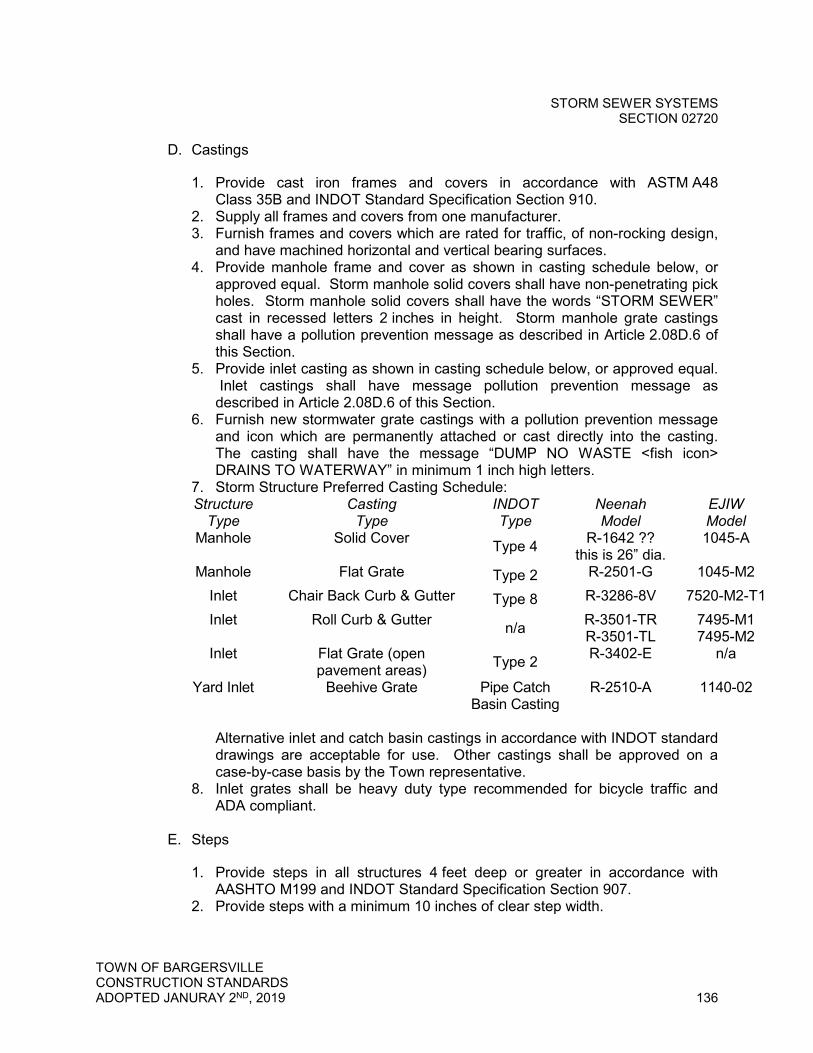
STORM SEWER SYSTEMS SECTION 02720
TOWN OF BARGERSVILLE CONSTRUCTION STANDARDS ADOPTED JANURAY 2ND, 2019 136
D. Castings
1. Provide cast iron frames and covers in accordance with ASTM A48 Class 35B and INDOT Standard Specification Section 910.
2. Supply all frames and covers from one manufacturer. 3. Furnish frames and covers which are rated for traffic, of non-rocking design,
and have machined horizontal and vertical bearing surfaces. 4. Provide manhole frame and cover as shown in casting schedule below, or
approved equal. Storm manhole solid covers shall have non-penetrating pick holes. Storm manhole solid covers shall have the words “STORM SEWER” cast in recessed letters 2 inches in height. Storm manhole grate castings shall have a pollution prevention message as described in Article 2.08D.6 of this Section.
5. Provide inlet casting as shown in casting schedule below, or approved equal. Inlet castings shall have message pollution prevention message as described in Article 2.08D.6 of this Section.
6. Furnish new stormwater grate castings with a pollution prevention message and icon which are permanently attached or cast directly into the casting. The casting shall have the message “DUMP NO WASTE <fish icon> DRAINS TO WATERWAY” in minimum 1 inch high letters.
7. Storm Structure Preferred Casting Schedule: Structure
Type Casting
Type INDOT Type
Neenah Model
EJIW Model
Manhole Solid Cover Type 4 R-1642 ?? this is 26” dia.
1045-A
Manhole Flat Grate Type 2 R-2501-G 1045-M2 Inlet Chair Back Curb & Gutter Type 8 R-3286-8V 7520-M2-T1 Inlet Roll Curb & Gutter n/a R-3501-TR
R-3501-TL 7495-M1 7495-M2
Inlet Flat Grate (open pavement areas) Type 2 R-3402-E n/a
Yard Inlet Beehive Grate Pipe Catch Basin Casting
R-2510-A 1140-02
Alternative inlet and catch basin castings in accordance with INDOT standard drawings are acceptable for use. Other castings shall be approved on a case-by-case basis by the Town representative.
8. Inlet grates shall be heavy duty type recommended for bicycle traffic and ADA compliant.
E. Steps
1. Provide steps in all structures 4 feet deep or greater in accordance with AASHTO M199 and INDOT Standard Specification Section 907.
2. Provide steps with a minimum 10 inches of clear step width.

STORM SEWER SYSTEMS SECTION 02720
TOWN OF BARGERSVILLE CONSTRUCTION STANDARDS ADOPTED JANURAY 2ND, 2019 137
3. Furnish copolymer polypropylene coated steel steps or approved non-corrosive fiberglass steps.
4. Copolymer polypropylene shall meet the requirements of ASTM D4101 reinforced with deformed 1/2-inch minimum diameter reinforcing steel in accordance with ASTM A615, Grade 60.
5. Non-coated cast iron steps will not be accepted.
F. Pipe to Structure Connections
1. Pipe penetration holes shall be either pre-formed by manufacturer or core drilled in the field.
2. For RCP and HP, provide non-shrink grout mixture of 2 parts No. 23 fine aggregate in accordance with INDOT Standard Specification Section 904 and 1 part Portland cement.
3. For HDPE and PVC pipe, provide flexible neoprene molded boot or resilient seal which conforms to ASTM C923. Provide Kor-N-Seal boot as manufactured by National Pollution Control Systems, Inc. or approved equal. Provide resilient seal as manufactured by A-Lok or approved equal.
PART 3 - EXECUTION
3.01 General
A. Inspect pipe, fittings, structures, and appurtenances prior to installation and promptly remove damaged or unsuitable materials from the job site. Replace damaged or unsuitable materials with new and unused materials.
B. Install all pipes, fittings, structures, and appurtenances as shown on the Standard Details and as specified in this Section. Do not install pipe when, in the opinion of the Town, trench conditions are unsuitable.
C. Follow manufacturer's installation procedures when installing pipe, fittings, structures, and appurtenances.
3.02 Examination
A. Verification of Conditions
1. Before installing piping, verify location, depth, type of joint needed, and size of pipe to which connection is proposed.
2. Assure that lines can be run as proposed. Notify the Town immediately for approval of any necessary deviation before lines are run.
3. Work all lengths of pipe into place without forcing.

STORM SEWER SYSTEMS SECTION 02720
TOWN OF BARGERSVILLE CONSTRUCTION STANDARDS ADOPTED JANURAY 2ND, 2019 138
3.03 Installation
A. Culvert Pipe, Storm Sewer Pipe, and Accessories
1. Maintain 18 inches of vertical separation and 10 feet of horizontal separation between new storm sewer and new or existing water mains unless otherwise directed. Notify the Town immediately of all instances where separation cannot be maintained.
2. Lay culvert pipe and storm sewer pipe uniformly to line and grade so that finished culvert or storm sewer will present a uniform conduit.
3. Minimum allowable cover shall be 24 inches over the top of culvert and storm sewer pipes in all locations. Shallower depth of cover may be considered by the Town under conditions where engineering design will alleviate concern for surface loadings and frost heave.
4. Set line and grade by means of laser beam and target for alignment and grade.
5. Lay culvert pipe and storm sewer pipe progressively upgrade in a manner to form close, concentric joints (maximum allowable gap shall not exceed one half (1/2) inch) with smooth bottom inverts.
6. After joint is made, place sufficient bedding material along each side of the pipe to prevent conditions that might tend to move the pipe off line or grade.
7. Repair any lift holes in a clean, workmanlike manner using a conical shaped precast concrete plug. Properly seal into place using non-shrink cement grout. Mastic sealer shall not be used.
8. Temporarily plug installed piping systems at end of each day’s work or other interruption of progress on a given line. Plug shall be adequate to prevent entry of animals and entrance or insertion of deleterious materials and shall be installed in a manner satisfactory to the Town.
9. Securely attach fabricated branches for wyes and tees to wall of pipe in such a manner as to not restrict or otherwise interfere with flow characteristics of the pipe.
10. Install boot and saddle connectors for all taps to concrete and RCP pipe. 11. Complete all field-cutting of PVC pipe in a neat, trim manner using a hand or
power saw. Field cutting of closed profile pipe requires any exposed channels be sealed in accordance with the manufacturer’s recommendation.
12. Place the end of the connecting pipe in a concrete end section so that flow lines are flush. Fill the joint completely with mortar.
13. Transition from the slope of an end section to the specified fill slope to create a smooth transition approximately 10 feet in length.
14. Install trash guards on all pipe end sections 18 inches and larger in diameter.
15. If any existing drainage tile systems are encountered during construction, reconstruct the tile to its original conditions or connect tile to the new storm drainage system as approved by the Town.
STORM SEWER SYSTEMS SECTION 02720
TOWN OF BARGERSVILLE CONSTRUCTION STANDARDS ADOPTED JANURAY 2ND, 2019 139
B. Precast Concrete Manholes, Inlets, and Accessories
1. Install storm structures to provide a maximum structure spacing of 500 feet. 2. For new storm sewer construction, install storm manhole at locations where
there is a change in storm sewer alignment, slope, size, or material. 3. Unless otherwise indicated, provide 0.1 foot sewer invert drop through
manholes. 4. Keep structure excavations free from water during construction. 5. Fill all areas excavated below the depth required for the structure's base with
No. 8 crushed stone at Contractor’s expense. 6. Install precast concrete risers and adjusting rings in such combination that
the manhole frame will be at the proper elevation. Structures shall be completely constructed to proper finished grade before curbs, asphalt, or other pavement may be installed. Patching and filling under frames will not be permitted.
7. Install manhole frame to grade and centered. 8. Install steps beginning at approximately 8 inches below the top of the cone
section (maximum 21 inches from top of casting). Install steps at 12 inches on center minimum to 16 inches on center maximum, continuous and spaced uniformly.
9. Install steps with minimum 3-inch wall embedment and minimum 4-inch clear distance projection from the wall as measured from the point of embedment.
10. Install precast concrete base, risers, cone, and flat top sections so that the axis of the manhole is vertical.
11. Install precast concrete inlets so that the axis of the structure is vertical. 12. Install gaskets for joints in accordance with the manufacturer’s
recommendations. Wrap riser joints with external joint seals in accordance with manufacturer’s recommendations. Install external seal from 6 inches above joint to 6 inches below.
13. Prior to backfilling, fill all holes used for handling with rapid setting patch material or with precast concrete plugs secured with Portland cement mortar.
14. Unless otherwise indicated, set castings for all structures at finish grade level. Adjust castings to the satisfaction of the Town, at Contractor’s expense.
15. No mortar or grout may be installed inside manhole, except for sealing annular space around pipe penetrations.
16. Storm sewer structures and castings must be inspected by the Town. Proper casting elevation will be verified. Adjustment and repairs shall be made prior to maintenance and final bond releases.
C. Pipe to Structure Connections
1. Core drill new pipe penetration into existing structure at the proper location where the pipe enters the structure.
2. For RCP and HP, fill the annular space between the pipe and structure interior and exterior walls with grout as noted in Article 2.08F.2 of this Section.
STORM SEWER SYSTEMS SECTION 02720
TOWN OF BARGERSVILLE CONSTRUCTION STANDARDS ADOPTED JANURAY 2ND, 2019 140
3. For HDPE and PVC pipe, install flexible neoprene molded boot or resilient seal to secure the pipe in the structure wall as noted in Article 2.08F.3 of this Section.
D. Connection to Existing Sewer
1. Install new service connection to existing storm sewer as shown on the Drawings and as specified for new service connections to existing sanitary sewers.
3.04 Field Quality Control
A. General
1. Provide all necessary equipment and instrumentation required for proper completion of the testing of manholes and piping systems.
2. All tests shall be made in the presence of the Town. Preliminary tests made by the Contractor without being observed by the Town will not be accepted. Notify the Town at least two working days (not including holidays or weekends) before any work is to be inspected or tested.
3. All defects in piping systems shall be repaired and/or replaced and retested until acceptable to the Town. Repairs shall be made to the standard of quality specified for the entire system.
4. Sections of the system may be tested separately, but any defect which may develop in a section previously tested and accepted shall be promptly corrected and retested at no additional cost to the Town.
5. All manholes and piping systems shall be tested in accordance with these test methods in addition to any test required by Indiana Department of Environmental Management (IDEM), State or Local plumbing codes and/or building authorities.
B. Tests
1. Deflection Test for Flexible Pipes a. Pipe materials considered flexible include the following:
1) HP 2) HDPE 3) PVC
b. Perform testing in presence of Town at no cost to the Town. c. Perform deflection testing on all flexible pipes after the final backfill has
been in place for at least 30 days. d. Perform deflection test using a mandrel pulled by hand. The mandrel
(go/no-go) device shall be cylindrical in shape and constructed with 9 or 10 evenly spaced arms or prongs. Provide proving rings to check the mandrel. The mandrel diameter dimension shall carry a minimum tolerance of 0.01 inches.
STORM SEWER SYSTEMS SECTION 02720
TOWN OF BARGERSVILLE CONSTRUCTION STANDARDS ADOPTED JANURAY 2ND, 2019 141
e. No pipe shall exceed a vertical deflection of seven and one-half (7-1/2) percent. Uncover, replace, and retest any pipe not passing the deflection test until a satisfactory result is achieved. Complete any required additional testing at no additional cost to the Town.
f. For HP pipe, mandrel testing per Sub-sections b. through e. above shall be performed on a minimum of 10% of the installed length as well as any areas exhibiting visual deflection. At the discretion of the Town representative, additional testing shall be performed as directed at no cost to the Town.
C. Inspection
1. Pipe Inspections a. Televise all storm sewer pipe (HP, HDPE, PVC and RCP) in the presence
of the Town at no cost to the Town. Visual inspections are unacceptable. Identify problems such as excessive sedimentation, joint failures, joint gaps, structural defects, misalignments, sags, or other defects that have the potential of affecting the hydraulic performance, durability, or structural integrity of the pipe segment.
2. Television Inspection mandatory for all public and private storm sewer systems installed in the Town. a. Perform all television inspection in presence of Town at no cost to the
Town. b. Clean all new storm sewers by “flooding” prior to television inspection.
The image shall be clear so the interior condition of the pipe is easily evaluated.
c. Correct all unacceptable conditions found during the television inspection and re-televise until no unacceptable conditions are found.
d. Unacceptable conditions are conditions that adversely affect the ability of the system to function as designed or to be properly maintained and may include, but are not limited to, the following: 1) Protruding taps 2) Cracked or faulty pipe 3) Misaligned or deformed pipe 4) Debris in line 5) Infiltration/exfiltration 6) Excessive gaps at joints (maximum allowable gap shall not exceed
one half (1/2) inch). 7) Bellies or sags with a depth greater than or equal to 10 percent of the
pipe diameter (maximum of two (2) inches or a length greater than 25 feet
e. Submit copy of the televising recording (DVD format) prior to final inspection and acceptance.
3. Structure Inspection a. Visually check each manhole and box inlet structure for excessive
leakage, backfill infiltration, or improper workmanship and materials in the presence of the Town. Repair or replace all structures that fail to meet
STORM SEWER SYSTEMS SECTION 02720
TOWN OF BARGERSVILLE CONSTRUCTION STANDARDS ADOPTED JANURAY 2ND, 2019 142
minimum construction standards at no cost to the Town. Re-inspect all repaired and replaced structures in the presence of the Town.
3.05 Cleaning
A. Provide all necessary equipment required for proper completion of the flushing of manholes and piping systems. Source, quality, and disposal of water shall be approved by the Town.
B. Remove all debris and excess soil from structures after installation and prior to flushing the storm sewer pipes, to the satisfaction of the Town.
C. Clean all new storm sewers with high pressure water jet after installation and before testing and televising at no cost to the Town. All pipe interiors shall be kept clean until acceptance. Any foreign material discovered in the pipe during inspection shall be removed at the Contractor's expense.
END OF SECTION 02720

GRAVITY SANITARY SEWER SYSTEMS SECTION 02730
TOWN OF BARGERSVILLE CONSTRUCTION STANDARDS ADOPTED JANURAY 2ND, 2019 143
SECTION 02730 – GRAVITY SANITARY SEWER SYSTEMS
PART 1 - GENERAL
1.01 Summary
A. Section Includes: Furnishing and installing and gravity sanitary sewers, services, manholes, and appurtenances as shown on the Drawings and as specified herein.
B. Related Work Specified Elsewhere
1. Section 02220 - Trenching, Backfilling and Compacting for Utilities 2. Section 02732 - Testing Sanitary Sewers and Force Mains 3. Section 02737 - Force Main Sewer Systems
1.02 Easements
When easements are required, they shall be exclusive Sanitary Sewer Easements and shall be dedicated and recorded solely for the benefit of the Town. Exclusive sanitary sewer easements shall not overlap other easements. Easement boundaries shall be shown on the plans, specifications, and plats as “Sanitary Sewer Easement” in lieu of “Utility Easement.” Common utility easements are prohibited for sanitary sewer facilities. The minimum permanent easement widths to be dedicated to the Town are as follows: 1. For sanitary sewers less than twenty-four (24) inches in diameter:
Depth of Sewer Minimum
Width, feet
Up to and including 10 feet 20
Greater than 10 feet to and including 20 feet 30
Greater than 20 feet 40
All sanitary sewers shall be centered in the easement. For those sanitary sewers constructed in the public right-of-way, the easement shall extend the distance outside the right-of-way necessary to provide the required easement width. If the sewer is located outside, but within five (5) feet of the public right-of-way and is fifteen (15) inches or less in diameter, the exclusive easement is only required to be ten (10) feet wide. The remainder of the required easement width may be shown as a Drainage, Utility and Sanitary Sewer Easement. For
GRAVITY SANITARY SEWER SYSTEMS SECTION 02730
TOWN OF BARGERSVILLE CONSTRUCTION STANDARDS ADOPTED JANURAY 2ND, 2019 144
sewers greater than fifteen (15) inches in diameter, the exclusive easement width shall be shown in the above table.
2. For sanitary sewers twenty-four (24) inches and larger:
The easement width will be determined on a case-by-case basis, but shall not be less than a minimum of fifty (50) feet in width.
3. Lift Stations:
The easements for lift stations may, at the discretion of the Town, be modified on a case-by-case basis, if justified. At a minimum, the easement requirements for lift stations are as follows:
a. From the base slab – twenty (20) feet in all directions; b. From the access drive – ten (10) feet in all directions.
The lift station easement shall not overlap any other easement. Except for perpendicular crossings, utility companies are not allowed to use the sewer easements for the installation of their utility lines without the expressed written permission of the Town. If permission is granted, utilities shall agree to relocate or support their respective facilities, at no expense to the Town, if the Town requires access to maintain or repair the sanitary sewer facility. All site development and plan/profile sheets shall clearly identify the sanitary sewer easement and the location of all existing and proposed utilities, on both plan and profile sections, proposed to cross the sanitary sewer easement.
1.03 SCADA
A. Developer to coordinate SCADA with the Town.
1.04 References
A. American Association of State Highway and Transportation Officials (AASHTO), latest editions
1. AASHTO M198 - Standard Specification for Joints for Concrete Pipe, Manholes, and Precast Box Sections Using Preformed Flexible Joint Sealants
2. AASHTO M199 - Standard Specification for Precast Reinforced Concrete Manhole Sections
B. American National Standards Institute (ANSI), latest editions
1. ANSI A21.4 - Cement-Mortar Lining for Ductile-Iron Pipe and Fittings for Water
GRAVITY SANITARY SEWER SYSTEMS SECTION 02730
TOWN OF BARGERSVILLE CONSTRUCTION STANDARDS ADOPTED JANURAY 2ND, 2019 145
2. ANSI A21.11 - Rubber-Gasket Joints for Ductile-Iron Pressure Pipe and Fittings
3. ANSI A21.51 - Ductile-Iron Pipe, Centrifugally Cast, for Water
C. American Society for Testing and Materials (ASTM), latest editions
1. ASTM A48 - Standard Specification for Gray Iron Castings 2. ASTM A615 - Standard Specification for Deformed and Plain Carbon-Steel
Bars for Concrete Reinforcement 3. ASTM A746 - Standard Specification for Ductile Iron Gravity Sewer Pipe 4. ASTM C76 - Standard Specification for Reinforced Concrete Culvert, Storm
Drain, and Sewer Pipe 5. ASTM C361 - Standard Specification for Reinforced Concrete Low-Head
Pressure Pipe 6. ASTM C443 - Standard Specification for Joints for Concrete Pipe and
Manholes, Using Rubber Gaskets 7. ASTM C478 - Standard Specification for Precast Reinforced Concrete
Manhole Sections 8. ASTM C923 - Standard Specification for Resilient Connectors Between
Reinforced Concrete Manhole Structures, Pipes, and Laterals 9. ASTM C928 - Standard Specification for Packaged, Dry, Rapid-Hardening
Cementitious Materials for Concrete Repairs 10. ASTM D3034 - Standard Specification for Type PSM Poly(Vinyl Chloride)
(PVC) Sewer Pipe and Fittings 11. ASTM D3212 - Standard Specification for Joints for Drain and Sewer Plastic
Pipes Using Flexible Elastomeric Seals 12. ASTM D4101 - Standard Specification for Polypropylene Injection and
Extrusion Materials 13. ASTM F477 - Standard Specification for Elastomeric Seals (Gaskets) for
Joining Plastic Pipe 14. ASTM F679 - Standard Specification for Poly(Vinyl Chloride) (PVC) Large-
Diameter Plastic Gravity Sewer Pipe and Fittings 15. ASTM F714 - Standard Specification for Polyethylene (PE) Plastic Pipe
(SDR-PR) Based on Outside Diameter 16. ASTM F894 - Standard Specification for Polyethylene (PE) Large Diameter
Profile Wall Sewer and Drain Pipe 17. ASTM F949 - Standard Specification for Poly(Vinyl Chloride) (PVC)
Corrugated Sewer Pipe With a Smooth Interior and Fittings 18. ASTM F1055 - Standard Specification for Electrofusion Type Polyethylene
Fittings for Outside Diameter Controlled Polyethylene and Crosslinked Polyethylene (PEX) Pipe and Tubing
19. ASTM F1803 - Standard Specification for Poly(Vinyl Chloride) (PVC) Closed Profile Gravity Pipe and Fittings Based on Controlled Inside Diameter
20. ASTM F2648 - Standard Specification for 2 to 60 inch [50 to 1500 mm] Annular Corrugated Profile Wall Polyethylene (PE) Pipe and Fittings for Land Drainage Applications
GRAVITY SANITARY SEWER SYSTEMS SECTION 02730
TOWN OF BARGERSVILLE CONSTRUCTION STANDARDS ADOPTED JANURAY 2ND, 2019 146
D. American Water Works Association (AWWA) Standards, latest editions
1. AWWA C104 - Cement Mortar Lining for Ductile Iron Pipe and Fittings 2. AWWA C110 - Ductile Iron and Gray Pipe Fittings 3. AWWA C151 - Ductile Iron Pipe, Centrifugally Cast
E. Indiana Department of Transportation (INDOT) Standard Specifications, latest
edition
1. Section 901 - PCC Materials 2. Section 907 - Concrete, Clay, and Plastic Drainage Components 3. Section 910 - Metal Materials
1.05 Submittals
A. Product Data, as applicable
1. Pipe 2. Fittings 3. Structures 4. Castings 5. Manhole Steps
1.06 Delivery, Storage, and Handling
A. Acceptance at Site
1. Load and unload all pipe, fittings, structure sections, and appurtenances in a manner to avoid shock and damage. Do not drop materials. Lift by hoists or skids when hand lifting is not feasible. Never allow pipe handled on skidways to skid or roll against pipe already on the ground.
2. Replace damaged or defective pipe and appurtenances at no additional cost. 3. Pipe possessing defects including, but not limited to the following, will be
rejected for installation: a. Variations from straight centerline b. Elliptical shape in round pipe c. Lack of rigidity d. Illegible markings as required herein e. Bruised, broken, or otherwise damaged metallic or bituminous coating or
liner, as applicable f. Deep or excessive gouges, dents, bends, or scratches on the pipe wall g. Fractures, punctures, or cracks passing through the pipe wall h. Damaged or cracked ends where such damage would prevent making a
satisfactory joint 4. Concrete structures possessing defects including, but not limited to the
following, will be rejected for installation: a. Fractures or cracks passing through the wall

GRAVITY SANITARY SEWER SYSTEMS SECTION 02730
TOWN OF BARGERSVILLE CONSTRUCTION STANDARDS ADOPTED JANURAY 2ND, 2019 147
b. Honeycombed or open texture which would adversely affect the function of the box sections
c. Ends of sections are not normal to the walls and centerline of the section
B. Storage and Protection
1. Store materials in an area safe from damage and deterioration. 2. Protect plastic pipes from extreme temperatures and ultraviolet radiation. 3. Keep interior of pipe, fittings, manhole sections, and appurtenances free from
dirt and foreign matter. 4. Store gaskets in a cool location out of direct sunlight and free from contact
with petroleum products. 5. Inspect all pipe, structures, and appurtenances prior to installation and
promptly remove damaged or unsuitable materials. Replace with new and unused materials.
PART 2 - PRODUCTS
2.01 Polyvinyl Chloride (PVC) Pipe
A. Pipe Material
1. Provide PVC pipe for sanitary sewers which are 8 to 48 inches in diameter for installations up to 25 feet deep. Provide solid wall PVC gravity sewer pipe. a. For pipe sizes 15-inch and less which are less than 15 feet deep, provide
SDR-35 PVC conforming to ASTM D3034. b. For pipe sizes 15-inch and less which are 15 to 25 feet deep, provide
SDR-26 PVC conforming to ASTM D3034. c. For pipe sizes 15-inch and less which are within 10 feet or a water main
or 50 feet of a water well, regardless of depth, provide SDR-21 PVC conforming to ASTM D3034.
d. For pipe sizes 18-inch to 48-inch, regardless of depth, provide PVC conforming to ASTM F679.
B. Joints
1. Joints shall be bell and spigot type with elastomeric seals per ASTM D3212, with gaskets conforming to ASTM F477.
C. Fittings
1. Provide fittings such as wyes, tees, and bends made in such a manner as to provide strength and water tightness at least equal to the class of the adjacent main line pipe to which they are jointed.
GRAVITY SANITARY SEWER SYSTEMS SECTION 02730
TOWN OF BARGERSVILLE CONSTRUCTION STANDARDS ADOPTED JANURAY 2ND, 2019 148
2. Fittings shall conform to all other requirements specified for corresponding pipe class and internal diameter. Joints shall be of the same type as used on the adjoining pipe.
3. Fabricated branches for wyes and tees shall be securely attached to the wall of the pipe in a watertight manner and shall be flush with the inside surface of the pipe.
D. Service Laterals
1. Building service laterals shall be a minimum of 4-inch diameter PVC for residential connections and 6-inch diameter PVC for all other connections, and of the same class as the adjacent sanitary sewer main, conforming to ASTM D3034. Each lateral connection shall have a minimum of one (1) cleanout installed three (3) feet from the structure projecting a minimum of four (4) inches above finished grade.
E. Pipe Markings
1. Each length of PVC pipe shall be clearly marked with the following information at a minimum: a. Name of manufacturer or identification symbol b. Trade name or trademark c. Nominal pipe size d. Production/extrusion code e. Material and cell class designation f. ASTM designation
2.02 Ductile Iron (DI) Pipe
A. Pipe and Fitting Material
1. Provide DI pipe for sanitary sewers which are 8 to 60 inches in diameter. 2. Provide DI pipe and fittings in conformance with the requirements of
ANSI/AWWA A21.51/C151 and ASTM A746. 3. Furnish Pressure Class 350 DI pipe for sizes 8-12 inches. 14-12 inches shall
be Class 250. 20 inches and larger shall be Class 150.
B. Pipe Coating and Lining
1. Outside surfaces of the pipe and fittings shall be bituminous-coated complying with ANSI/AWWA A21.51/C151 and ANSI/AWWA A21.10/C110.
2. Inside surfaces of all pipes, fittings and adapters shall be lined with cement mortar and a bituminous seal coat. Cement mortar lining and bituminous seal coat shall meet the requirements of ANSI/AWWA A21.4/C104.
C. Joints
GRAVITY SANITARY SEWER SYSTEMS SECTION 02730
TOWN OF BARGERSVILLE CONSTRUCTION STANDARDS ADOPTED JANURAY 2ND, 2019 149
1. Supply pipe with push-on type joints conforming to ANSI A21.11 (AWWA C111).
2. Supply fittings with push-on or mechanical joints rated for 150 psi working pressure, or match the designed pipe thickness, whichever is greater.
D. Pipe Markings
1. Each length of pipe shall be clearly marked with the following information at a minimum: a. Manufacturer's name or trade mark b. Pipe class c. Year of manufacture
2.03 Manhole and Accessories
A. General
1. Provide precast concrete sections with no more than 3 holes cast or drilled in the section for handling.
2. Provide rapid setting patch material in accordance with ASTM C928 and INDOT Standard Specification Section 901 or precast concrete plugs for filling all holes used for handling.
3. Monolithic, or cast-in-place, manholes shall be allowed if pre-approved by the Town.
B. Precast Concrete Manholes
1. Supply a minimum of 1 adjusting ring for each manhole. Adjusting rings shall be a minimum of 4 inches and maximum of 12 inches in height for new manholes. Supply precast concrete riser sections for adjustment greater than 12 inches in height. Existing standard allows for no adjusting rings where feasible.
2. Provide precast concrete eccentric cone section which conforms to ASTM C478. Where preapproved by the Town, provide flat top section which conforms to ASTM C478. Cone and flat top sections shall have a 24-inch opening.
3. Provide precast concrete manhole risers/barrels which conform to ASTM C478, AASHTO M199, INDOT Standard Specification Section 907, and as indicated on Drawings.
4. Provide precast concrete manhole bases which conforms to ASTM C478, AASHTO M199, and INDOT Standard Specification Section 907. Base sections shall be a minimum 6 inches thick for 48-inch diameter manholes and a minimum 8 inches thick for manholes greater than 48-inch diameter. Base floor shall be sloped to the sewer invert.
5. For doghouse manhole base, provide precast concrete base with "doghouse" openings.
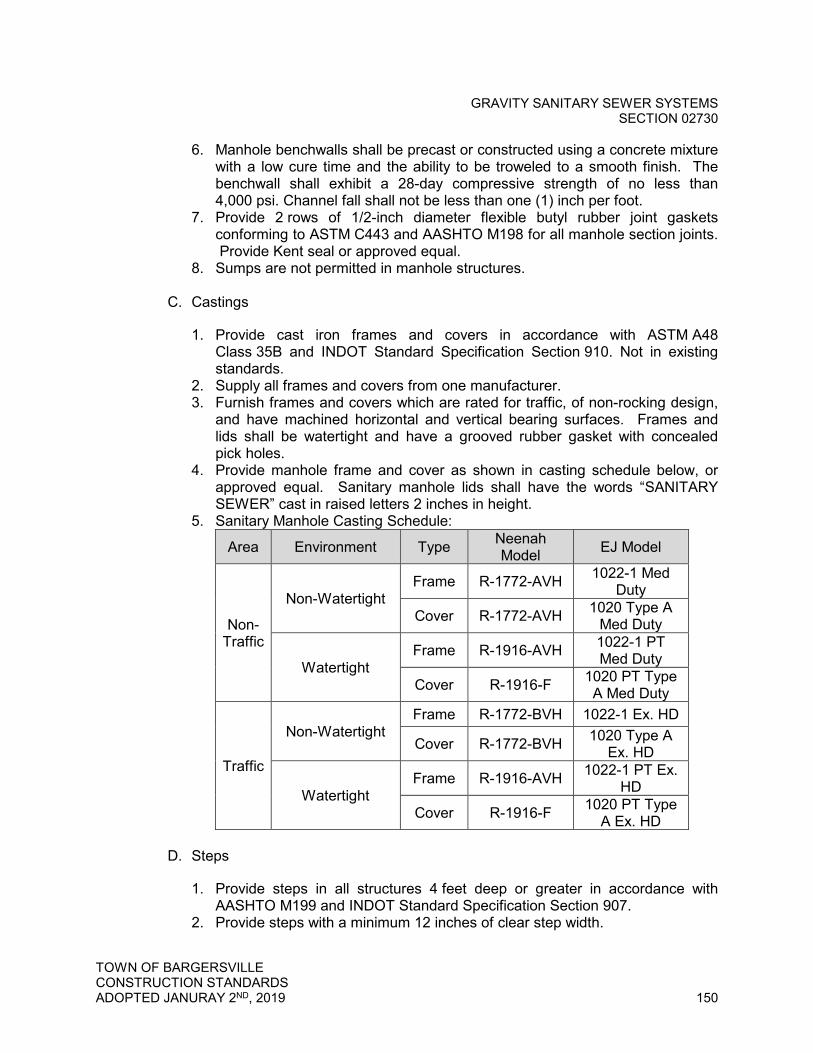
GRAVITY SANITARY SEWER SYSTEMS SECTION 02730
TOWN OF BARGERSVILLE CONSTRUCTION STANDARDS ADOPTED JANURAY 2ND, 2019 150
6. Manhole benchwalls shall be precast or constructed using a concrete mixture with a low cure time and the ability to be troweled to a smooth finish. The benchwall shall exhibit a 28-day compressive strength of no less than 4,000 psi. Channel fall shall not be less than one (1) inch per foot.
7. Provide 2 rows of 1/2-inch diameter flexible butyl rubber joint gaskets conforming to ASTM C443 and AASHTO M198 for all manhole section joints. Provide Kent seal or approved equal.
8. Sumps are not permitted in manhole structures.
C. Castings
1. Provide cast iron frames and covers in accordance with ASTM A48 Class 35B and INDOT Standard Specification Section 910. Not in existing standards.
2. Supply all frames and covers from one manufacturer. 3. Furnish frames and covers which are rated for traffic, of non-rocking design,
and have machined horizontal and vertical bearing surfaces. Frames and lids shall be watertight and have a grooved rubber gasket with concealed pick holes.
4. Provide manhole frame and cover as shown in casting schedule below, or approved equal. Sanitary manhole lids shall have the words “SANITARY SEWER” cast in raised letters 2 inches in height.
5. Sanitary Manhole Casting Schedule:
Area Environment Type Neenah Model EJ Model
Non-Traffic
Non-Watertight Frame R-1772-AVH 1022-1 Med
Duty
Cover R-1772-AVH 1020 Type A Med Duty
Watertight Frame R-1916-AVH 1022-1 PT
Med Duty
Cover R-1916-F 1020 PT Type A Med Duty
Traffic
Non-Watertight Frame R-1772-BVH 1022-1 Ex. HD
Cover R-1772-BVH 1020 Type A Ex. HD
Watertight Frame R-1916-AVH 1022-1 PT Ex.
HD
Cover R-1916-F 1020 PT Type A Ex. HD
D. Steps
1. Provide steps in all structures 4 feet deep or greater in accordance with AASHTO M199 and INDOT Standard Specification Section 907.
2. Provide steps with a minimum 12 inches of clear step width.
GRAVITY SANITARY SEWER SYSTEMS SECTION 02730
TOWN OF BARGERSVILLE CONSTRUCTION STANDARDS ADOPTED JANURAY 2ND, 2019 151
3. Furnish approved non-corrosive fiberglass steps. 4. Non-coated cast iron steps will not be accepted.
E. Pipe to Structure Connections
1. Pipe penetration holes shall be either pre-formed by manufacturer or core drilled in the field.
2. Provide flexible neoprene molded boot or resilient seal which conforms to ASTM C923. Provide Kor-N-Seal boot as manufactured by National Pollution Control Systems, Inc., Quik-Lok as manufactured by A-Lok Products, Inc., or approved equal.
2.04 Tracer Wire
A. Furnish tracer wire for service laterals.
B. For pipe installed by open excavation or within a casing, provide one strand of solid 12-gauge AWG copper wire for the entire length of pipe.
C. For pipe installed by horizontal directional drilling, provide 2 strands of 10-gauge solid, steel core hard drawn extra high strength copper tracer wire for the entire length of pipe. Supply Copperhead Direct Burial tracer wire, or approved equal.
D. Provide splice kits suitable for underground installation for splices and branch connections. Seal connection with epoxy contained in splice kit and wrap with waterproof tape.
E. Tracer wire coating shall be minimum 30 mil thick high-density polyethylene, color green.
PART 3 - EXECUTION
3.01 General
A. Inspect pipe, fittings, structures, and appurtenances prior to installation and promptly remove damaged or unsuitable materials from job site. Replace damaged or unsuitable materials with new and unused materials.
B. Install all pipes, fittings, structures, and appurtenances as shown on the Standard Details and as specified in this Section. Do not install pipe when, in the opinion of the Town, trench conditions are unsuitable.
C. Follow manufacturer's installation procedures when installing pipe, fittings, structures, and appurtenances.
GRAVITY SANITARY SEWER SYSTEMS SECTION 02730
TOWN OF BARGERSVILLE CONSTRUCTION STANDARDS ADOPTED JANURAY 2ND, 2019 152
3.02 Examination
A. Verification of Conditions
1. Before installing piping, verify location, depth, type of joint needed, and size of pipe to which connection is proposed.
2. Assure that lines can be run as proposed. Notify Town immediately for approval of any necessary deviation before lines are run.
3. Work all lengths of pipe into place without forcing. 3.03 Installation
A. Gravity Sanitary Sewer Pipe, Service Lateral, and Accessories
1. All lengths of pipe shall be dimensioned accurately to measurements established at the site and shall be worked into place without forcing. Cut sections of pipe shall be cut using proper equipment such as a chop saw to provide a beveled end.
2. Alternate sewer pipe materials consisting of ductile iron, concrete encased pipe, or SDR-21 PVC pipe must be used when one or more of the following conditions apply: a. Where sewers or laterals must cross under existing water mains and
cannot achieve or maintain 18 inches of clearance, use alternate pipe materials for at least one full pipe length centered under the crossing.
b. Where sewers or laterals must be routed horizontally with less than 10 feet of clearance from existing water mains, use alternative pipe materials for entire length.
3. Lay sewer pipe uniformly to line and grade so that the finished sewer will present a uniform conduit.
4. Minimum allowable cover shall be 36 inches over the top of sanitary sewer pipes and services in all locations. Shallower depth of cover may be considered by the Town under conditions where engineering design will alleviate concern for surface loadings and frost heave.
5. Set line and grade by means of laser beam and target for alignment and grade.
6. Lay sewer pipe progressively upgrade with bell upstream in a manner to form close, concentric joints with smooth bottom inverts.
7. After joint is made, place sufficient bedding material along each side of the pipe to prevent conditions that might tend to move the pipe off line or grade.
8. Temporarily plug installed piping systems at end of each day's work, or other interruption of progress on a given line. Plug shall be adequate to prevent entry of animals and entrance or insertion of deleterious materials and shall be installed in a manner satisfactory to the Town.
9. Securely attach fabricated branches for wyes and tees to wall of pipe in such a manner as to not restrict or otherwise interfere with flow characteristics of the pipe.

GRAVITY SANITARY SEWER SYSTEMS SECTION 02730
TOWN OF BARGERSVILLE CONSTRUCTION STANDARDS ADOPTED JANURAY 2ND, 2019 153
10. Where applicable, install laterals at a normal slope of 1/4-inch per foot. Minimum slope shall be 1/8-inch per foot.
11. Install a mechanical plug at the end of each lateral and at the end of all sewer stubs. Install the lateral at a depth of approximately 5 feet to allow each customer to connect to the end of the lateral.
12. Install a metal T-fencepost at the end of each sewer lateral for marking. It shall be the responsibility of the Contractor to protect these markers and to verify that all laterals have been properly marked.
13. Tracer Wire a. Install tracer wire on service lines, taped to pipe in 15 to 20-foot intervals.
Do not wrap wire around pipe. b. Install tracer wire from sanitary sewer main to cleanout and from cleanout
to building. c. Secure terminus of tracer wire to top of pipe
B. Manholes
1. Install sanitary structures to provide a maximum structure spacing of 500 feet.
2. For new sanitary sewer construction, install sanitary manhole at locations where there is a change in sanitary sewer alignment, slope, size, or material.
3. Unless otherwise indicated, provide 0.1 foot sewer invert drop through manholes.
4. Keep structure excavations free from water during construction. 5. Fill all areas excavated below the depth required for the structure's base with
No. 8 crushed stone at Contractor’s expense. 6. Set top of casting at elevation to prevent surface water infiltration in areas of
flooding or ponding. Install precast concrete risers and adjusting rings in such combination that the manhole frame will be at the proper elevation. Structures shall be completely constructed to proper finished grade before curbs, asphalt, or other pavement may be installed. Patching and filling under frames will not be permitted.
7. Install manhole frame to grade and centered. 8. Install steps beginning at approximately 8 inches below the top of the cone
section (maximum 21 inches from top of casting). Install steps at 12 inches on center minimum to 16 inches on center maximum, continuous and spaced uniformly.
9. Install steps with minimum 3-inch wall embedment and minimum 4-inch clear distance projection from the wall as measured from the point of embedment.
10. Install precast concrete base, risers, cone, and flat top sections so that the axis of the manhole is vertical.
11. Install gaskets for joints in accordance with the manufacturer’s recommendations.
12. Apply a trowelable grade butyl rubber base exterior backplaster material 1/4-inch minimum thickness (when dry) on the exterior of the manhole at each joint, extending 6 inches above and 6 inches below the joint. Wrap joints with 80 gauge stretch wrap.
GRAVITY SANITARY SEWER SYSTEMS SECTION 02730
TOWN OF BARGERSVILLE CONSTRUCTION STANDARDS ADOPTED JANURAY 2ND, 2019 154
13. Apply a trowelable grade butyl rubber base exterior backplaster material 1/4-inch minimum thickness (when dry) on the exterior of the chimney section from 2 inches below the bottom adjusting ring to, and covering, the base of the casting.
14. Prior to backfilling, fill all holes used for handling with rapid setting patch material or with precast concrete plugs secured with Portland cement mortar.
15. Unless otherwise indicated, set castings for all structures at 2” above grade level. Adjust castings to the satisfaction of the Town, at Contractor’s expense.
16. No mortar or grout may be installed inside manhole, except for sealing annular space around pipe penetrations.
17. Benchwalls shall have a minimum 1/2-inch per foot slope starting at the manhole wall/benchwall interface and then slope towards the top of the trough. The trough shall have a minimum depth equal to the diameter of the incoming and exiting sewers.
18. Manhole frames located in pavement shall be wrapped in minimum 3/8” preformed joint filler. The joint filler shall extend from the top to the bottom of the frame.
19. Sanitary sewer structures and castings must be inspected by the Town. Proper casting elevation will be verified. Adjustment and repairs shall be made prior to maintenance and final bond releases.
C. Doghouse Manholes
1. Doghouse manholes shall meet the requirements listed above. 2. Excavate sufficiently below existing pipe where doghouse manhole is to be
placed, in order to allow for placement of crushed stone bedding and concrete blocks.
3. Use forms for pouring concrete base; do not use earth trench in lieu of forms. Pour concrete base as shown in the Standard Details. Pour concrete around existing pipe.
4. Sawcut cleanly and remove the top half of existing pipe after manhole is constructed.
D. Pipe to Structure Connections
1. Core drill new pipe penetration into existing structure at the proper location where the pipe enters the structure.
2. Install flexible neoprene molded boot or resilient seal to secure the pipe in the structure wall as noted in Article 2.08F.3 of this Section.
E. Connection to Existing Sewer
1. Install new service connection to existing sanitary sewer as shown on the Standard Details.
GRAVITY SANITARY SEWER SYSTEMS SECTION 02730
TOWN OF BARGERSVILLE CONSTRUCTION STANDARDS ADOPTED JANURAY 2ND, 2019 155
3.04 Field Quality Control
A. Test all sanitary sewer systems installed in accordance with Section 02732 - Testing Sanitary Sewers and Force Mains.
3.05 Cleaning
A. Provide all necessary equipment required for proper completion of the jetting and vacuuming of manholes and piping systems. Source, quality, and disposal of water shall be approved by the Town.
B. Remove all debris and excess soil from manhole after construction and prior to jetting the sewer pipes, to the satisfaction of the Town.
C. Remove all debris and excess soil from all pipe installed under this Contract by jetting and vacuuming with clean water. If flushing is not adequate to clean the pipes, the Contractor shall clean the pipes by jetting. It shall be the Contractor's responsibility to obtain necessary water and equipment to flush the pipes to the satisfaction of the Town.
END OF SECTION 02730

TESTING SANITARY SEWERS AND FORCE MAINS
SECTION 02732
TOWN OF BARGERSVILLE CONSTRUCTION STANDARDS ADOPTED JANURAY 2ND, 2019 156
SECTION 02732 - TESTING SANITARY SEWERS AND FORCE MAINS
PART 1 - GENERAL
1.01 Summary
A. Section Includes: Testing of the gravity sewers, force mains, and structures installed as applicable.
B. Related Sections
1. Section 02730 - Sanitary Sewer Systems 2. Section 02737 - Force Main Sewer Systems
1.02 References
A. American Society for Testing and Materials (ASTM), latest editions
1. ASTM F1417, Standard Practice for Installation Acceptance of Plastic Non-Pressure Sewer Lines Using Low Pressure Air
1.03 Submittals
A. Documentation
1. Prior to dedication and acceptance of facilities, the following items shall be completed and on file at the Town: a. Copies of all testing reports and data; b. Final payment for inspection services; c. As-built drawings; d. Daily inspection reports; e. Copy of final recorded easements executed by the property owner(s), if
easements are required; f. A written statement of facilities present on those lands, including:
1) Identification of the type and nature of facilities present; 2) Dimensions of the facilities present; 3) Totals for each type of facility present (ex: 1,000 ft of roadway, 1,000
ft of sanitary sewer, 1,000 ft of residential curbing, etc.) 4) Statement of actual cost of construction, breaking out the cost of
easements and cost of facilities.
B. Dedication
1. The Town’s engineering representative shall review all required completion documents and prepare a document stating that the work has been completed, the requirements have been met, and all items are in proper

TESTING SANITARY SEWERS AND FORCE MAINS
SECTION 02732
TOWN OF BARGERSVILLE CONSTRUCTION STANDARDS ADOPTED JANURAY 2ND, 2019 157
form. The Town’s engineering representative shall also include a recommendation on acceptance/denial of the facilities and may also include comments regarding the project. The representative shall present to the Town its findings in a public meeting for consideration.
C. Acceptance
1. The Town will assume responsibility of the sanitary sewer when construction is fully completed in accordance with the plans and standards, and when all requirements in these standards are met.
2. The Town shall receive the recommendation from the Town’s engineering representative, and upon review by the Town Attorney, Wastewater Superintendent, and Town Inspector, shall make a determination as to acceptance of the facilities. A majority approval of the Council members present at the meeting is required for acceptance.
D. Test Results
1. Gravity pipe televising recording 2. Gravity pipe air test 3. Gravity pipe joint test 4. Gravity pipe infiltration test 5. Gravity pipe exfiltration test 6. Gravity pipe deflection test 7. Force main hydrostatic test 8. Force main leakage test 9. Tracer wire continuity test 10. Manhole vacuum test
PART 2 - PRODUCTS
Not Used.
PART 3 - EXECUTION
3.01 General
A. Provide all necessary equipment and instrumentation required for proper completion of the testing of manholes and piping systems.
B. All tests shall be made in the presence of the Town. Preliminary tests made by the Contractor without being observed by the Town will not be accepted. Notify the Town at least 48 hours (not including holidays or weekends) before any work is to be inspected or tested for the following items:
1. Daily work schedule, including any changes in work schedule;

TESTING SANITARY SEWERS AND FORCE MAINS
SECTION 02732
TOWN OF BARGERSVILLE CONSTRUCTION STANDARDS ADOPTED JANURAY 2ND, 2019 158
2. Prior notification if work is to be performed on weekends and/or holidays; 3. Date tests are to be performed; and, 4. Date as-built verification is to be performed.
C. Contractor and/or Owner shall provide notice to the Town of the planned
commencement of construction thirty (30) days prior to such commencement.
D. All defects in piping systems shall be repaired and/or replaced and retested until acceptable to the Town. Repairs shall be made to the standard of quality specified for the entire system.
E. Sections of the system may be tested separately, but any defect which may develop in a section previously tested and accepted shall be promptly corrected and retested at no additional cost to the Town.
F. All manholes and piping systems shall be tested in accordance with these test methods in addition to any test required by Indiana Department of Environmental Management (IDEM), State or Local plumbing codes and/or building authorities.
G. Sanitary lateral inspections shall be visually conducted prior to backfilling.
H. All testing required shall be paid for by the Contractor.
3.02 Gravity Sewer Television Inspection
A. Televise all new sanitary sewers.
B. Perform all television inspection in presence of Town.
C. Clean all new sanitary sewers by jetting and vacuuming prior to television inspection. The image shall be clear so the interior condition of the pipe is easily evaluated.
D. Correct all unacceptable conditions found during the television inspection and re-televise until no unacceptable conditions are found.
E. Unacceptable conditions are conditions that adversely affect the ability of the system to function as designed or to be properly maintained and may include, but are not limited to, the following:
1. Protruding taps 2. Cracked or faulty pipe 3. Misaligned or deformed pipe 4. Debris in line 5. Infiltration/exfiltration 6. Excessive gaps at joints
TESTING SANITARY SEWERS AND FORCE MAINS
SECTION 02732
TOWN OF BARGERSVILLE CONSTRUCTION STANDARDS ADOPTED JANURAY 2ND, 2019 159
7. Bellies or sags with a depth greater than or equal to 10 percent of the pipe diameter (maximum of 3 inches) or a length greater than 25 feet
F. Submit copy of the televising recording (DVD and USB flash drive format) prior
to acceptance.
3.03 Gravity Sewer Testing
A. Unless otherwise directed by the Town, all underground sewer system piping for gravity flow shall be subjected to an air test rather than an infiltration or exfiltration tests, however, infiltration and exfiltration test methods may be requested by the Town during construction. No extra compensation will be allowed if such tests are required. When leakage occurs in excess of the specified limits, defective pipe or joints shall be located and repaired. The Contractor, at his own expense, shall remove and reconstruct, along with retesting, as much of the original work as necessary to obtain a sewer test within the allowable leakage limits.
1. Air Test a. Test all sanitary sewer lines (36-inch diameter and smaller) in increments
between manholes in accordance with ASTM F1417. Seal the line shall be sealed at each end. The seal at one end shall have an orifice through which to pass air into the pipe. Connect an air supply to the orifice at one end of the line. The air supply line shall contain an on-off gas valve and a pressure gauge having a range of 0 to 5 psi. The gauge shall have minimum divisions of 0.10 psi and shall have an accuracy of ± 0.04 psi. 1) The pipe line under test shall be pressurized to 4 psig. Allow the line
to stabilize between 4 psig and 3.5 psig for a period of no less than 5 minutes. If necessary, add air to the line to maintain the pressure above 3.5 psig. After the stabilization period, close the gas valve. When the line pressure stabilizes above 3.5 psig, commence timing with a stop watch. The stop watch shall be allowed to run until such time as the line pressure drops 1.0 psig or the allowable time in Table 1 is exceeded.
2) If the pipe line to be tested is beneath the ground water level, the test pressure shall be increased 0.433 psi for each foot the ground water level is above the crown of the pipe.
3) Allowable time shall be as shown in Table 1.

TESTING SANITARY SEWERS AND FORCE MAINS
SECTION 02732
TOWN OF BARGERSVILLE CONSTRUCTION STANDARDS ADOPTED JANURAY 2ND, 2019 160
Table 1: Minimum Specified Time Required for a 1.0 psig Pressure Drop For Size and Length of Pipe Indicated, Q=0.0015 cu. ft. per min. per sq. ft. Pipe Dia., In.
Minimum Time, min:s
Length for Minimum Time, ft.
Time for Longer
Length, s Specification Time for Length(L) Shown, min:s
100 ft 150 ft 200 ft 250 ft 300 ft 350 ft 400 ft 450 ft 4 3:46 597 0.380 L 3:46 3:46 3:46 3:46 3:46 3:46 3:46 3:46 6 5:40 398 0.864 L 5:40 5:40 5:40 5:40 5:40 5:40 5:42 6:24 8 7:34 298 1.520 L 7:34 7:34 7:34 7:34 7:36 8:52 10:08 11:24
10 9:26 239 2.374 L 9:26 9:26 9:26 9:53 11:52 13:51 15:49 17:48 12 11:20 189 3.418 L 11:20 11:20 11:20 14:15 17:05 19:56 22:47 25:38 15 14:10 159 5.342 L 14:10 14:10 17:48 22:15 26:42 31:09 35:36 40:04 18 17:00 133 7.692 L 17:00 19:13 25:38 32:03 38:27 44:52 51:16 57:41 21 19:50 114 10.470 L 19:50 26:10 34:54 43:37 52:21 61:00 69:48 78:31 24 22:40 99 13.674 L 22:47 34:11 45:34 56:58 66:22 79:45 91:10 102:33 27 25:30 88 17.306 L 28:51 43:16 57:41 72:07 86:32 100:57 115:22 129:48 30 28:20 80 21.366 L 35:37 53:25 71:13 89:02 106.50 124:38 142:26 60:15 33 31:10 72 26.852 L 43:06 64:38 86:10 107:48 129:16 150:43 172:21 193:53 36 34:00 66 30.768 L 51:17 76:55 102:34 128:12 153:50 179:29 205:07 230:46
4) If the time lapse is greater than that specified, the section undergoing tests will have passed. If the time lapse is less than that specified, the line has not passed the test and the Contractor shall be required to make all repairs and retest.
5) The Contractor shall furnish all equipment and personnel required to make all tests including pipe stoppers, air compressor, air storage tank, pressure regulating valves, pressure gauges, stopwatch, etc. Contractor shall take precautions necessary, including blocking of stoppers or plugs, to protect the safety of property and personnel.
6) Building sewers may be allowed to be installed during the construction of the main line sewer only upon writing request and writing response by the Town. This request shall be clearly delineated on the design plans and standards submitted for approval. If Building sewers are approved for construction by the Town as part of the main line sewer, they shall be included in the test and their lengths may be ignored for computing the required test times.
2. Joint Test a. Test all joints in sanitary sewer lines over 36-inch diameter. Perform joint
test using air or water under low pressure in accordance with ASTM C1103 and this specification.
b. Perform the joint test after final backfill is placed. c. Use equipment made specifically for joint testing of pipelines. d. Joint Test Apparatus Installation
1) Clean the joint and interior joint surfaces. 2) Move the joint test apparatus into the sewer line to the joint to be
tested and position over the joint. Make sure the end element sealing tubes straddle both sides of the joint and the hoses are attached. For the water test, the bleed-off petcock must be located at dead center.

TESTING SANITARY SEWERS AND FORCE MAINS
SECTION 02732
TOWN OF BARGERSVILLE CONSTRUCTION STANDARDS ADOPTED JANURAY 2ND, 2019 161
3) Inflate end element sealing tubes with air in accordance with equipment and manufacturer's instructions.
4) Test Pressure Adjustment Due to Groundwater a) The air pressure adjustment for groundwater shall be determined
by the following: Adjustment = Depth of Groundwater x 0.43, where
Adjustment = adjustment added to the starting pressure of the low-pressure air test, measured in psig. The maximum adjustment shall be 2.0 psig.
Depth of Groundwater = depth of groundwater as measured above the top of pipe, measured in feet
b) The depth of groundwater shall be determined using groundwater monitoring wells. If more than one well is installed, take the average depth of the nearest downstream and nearest upstream monitoring locations. If monitoring wells were not installed, the adjustment shall be 2.0 psig.
e. Joint Air Test 1) Pressurize the void volume with air to 3.5 psi plus the necessary
adjustment for groundwater above the top of pipe (maximum 2.0 psi adjustment for a 5.5 psi maximum total). Allow the air pressure and temperature to stabilize before shutting off the air supply. Start the timing of the test.
2) Measure the pressure drop for 5 seconds. 3) After the joint test is completed, exhaust void volume, then exhaust
end element tubes prior to removal of the testing apparatus. f. Joint Water Test
1) Introduce water into the void volume until water flows evenly from open petcock. Close the petcock and pressurize with water to 3.5 psi plus the necessary adjustment for groundwater above the top of pipe (maximum 2.0 psi adjustment for a 5.5 psi maximum total). Shut off the water supply and start test timing.
2) Measure the pressure drop for 5 seconds. 3) After the joint test is completed, exhaust end element tubes which will
automatically release the water from the void volume, prior to removal of the testing apparatus.
g. Determination of Line Acceptance 1) If the pressure holds or drops less than 1.0 psi for the 5-second test
time, the joint shall have passed the test. 2) If the pressure drops 1.0 psi or more during the 5-second test time,
the joint shall have failed the test. Repair and retest as necessary until the joint passes. The method of repair shall be approved by the Town. Grouting is not an acceptable method of repair.
3. Infiltration Tests (If required) a. When the groundwater level is at or above a point 4 feet above the top of
the sewer, the infiltration test will consist of sealing off a length of sewer and measuring the depth of flow over a measuring weir, or by pumping
TESTING SANITARY SEWERS AND FORCE MAINS
SECTION 02732
TOWN OF BARGERSVILLE CONSTRUCTION STANDARDS ADOPTED JANURAY 2ND, 2019 162
the infiltrated water into containers for measurement. Tests shall be conducted for a minimum of 4 hours. Infiltration leakage shall not exceed 200 gallons per 24 hours per inch diameter per mile of sewer.
4. Exfiltration Tests (If required) a. When the groundwater level is below a point 4 feet above the top of the
sewer, the exfiltration test shall consist of isolating the particular section and filling the water to a point 4 feet above the ground water level in the upper manhole and allowing it to stand not less than 4 hours. The section shall then be refilled with water up to the original point and after 2 hours the drop in water surface shall be measured. The computed leakage shall not exceed 200 gallons per 24 hours per inch diameter per mile of sewer.
5. Deflection/Mandrel Test for Flexible Pipes a. Pipe materials considered flexible include the following:
1) HDPE 2) PP 3) PVC
b. Each pipe material/type required to be mandrel tested shall be tested with a mandrel approved by the pipe manufacturer and meeting the requirements of this section.
c. Perform testing in presence of Town. The Contractor shall provide proving rings to check the mandrel. Drawings of mandrels with complete dimensions shall be furnished to the Town upon request for each diameter and standard type.
d. Perform deflection/mandrel testing on all flexible pipes after the final backfill has been in place at least 30 days.
e. Perform deflection test using a mandrel pulled by hand. The mandrel (go/no-go) device shall be cylindrical in shape and constructed with 9 or 10 evenly spaced arms or prongs.
f. No pipe shall exceed a vertical deflection of 5 percent. Uncover, replace, and retest any pipe not passing the deflection test until a satisfactory result is achieved.
3.04 Force Main Testing
A. Tests for exposed piping shall be made before covering and insulation is placed and prior to concealment within the building construction.
B. The pressure and leakage tests for buried piping shall be made after all jointing operations and backfilling are completed, and concrete reaction blocks and restraints have cured at least 14 days. Piping tested before backfill is in place shall be retested after compacted backfill is placed.
C. Sections of piping between valves, and other short sections of line may be isolated for testing. If shorter sections are tested, test plugs or bulkheads required at the ends of the test section shall be furnished and installed by the

TESTING SANITARY SEWERS AND FORCE MAINS
SECTION 02732
TOWN OF BARGERSVILLE CONSTRUCTION STANDARDS ADOPTED JANURAY 2ND, 2019 163
Contractor, together with all anchors, braces, and other devices required to withstand the test pressure without imposing any thrust on the pipe line. The Contractor shall be solely responsible for any damage which may result from the failure of test plugs or supports.
D. Hydrostatic Test
1. All sewage force mains shall pass a hydrostatic pressure test as specified. 2. Slowly fill the piping system with water and expel all air from the pipe. Care
shall be taken that all air release valves are installed and open in the section being filled, and that the rate of filling does not exceed the venting capacity of the air release valves.
3. After the section of line to be tested has been filled with water, the specified test pressure shall be applied and maintained for a minimum period of 2 hours and for such additional period necessary for the Town to complete the inspection of the line under test.
4. If defects are noted, repairs shall be made and the test repeated until all parts of the line withstand the test pressure.
5. Hydrostatic test pressure shall be 150 percent of design pressure, but not less than 100 psi. Test duration shall be 2 hours.
E. Leakage Test
1. All buried piping with slip-type or mechanical joints shall pass a leakage test. No leakage is allowed in exposed piping or buried piping with flanged, threaded, welded or mechanical joints.
2. After the specified hydrostatic test has been completed, the line shall be subjected to leakage test under a hydrostatic pressure the same as the pressure specified for the hydrostatic test.
3. The pressure shall be maintained within a maximum variation of 5 percent during the entire leakage test. Leakage measurements shall not be started until a constant test pressure has been established. The line leakage shall be measured by means of a water meter installed on the supply side of the pressure pump, or method as approved by the Town. a. The tested section will not be accepted if it has a leakage rate in excess
of that rate determined by the formula: L = 0.000135 ND(P)1/2 in which;
L = Maximum permissible leakage rate, in gallons per hour, throughout the entire length of line being tested.
N = Number of gasketed joints (two for each flexible coupling joint) in the line under test.
D = Nominal internal diameter (in inches) of the pipe. P = The actual pressure in psig on all joints in the tested portion of the
line. This actual pressure shall be determined by finding the difference between the average elevation of all tested pipe joints
TESTING SANITARY SEWERS AND FORCE MAINS
SECTION 02732
TOWN OF BARGERSVILLE CONSTRUCTION STANDARDS ADOPTED JANURAY 2ND, 2019 164
and the elevation of the pressure gauge and adding the difference in elevation head to the required pressure.
b. Where the leakage rate exceeds the permissible maximum, the Contractor shall locate and repair leaking joints to the extent required to reduce the total leakage to the required amount.
c. All leaks discovered within 1 year from the date of final acceptance of the work shall be located, repaired and retested by the Contractor, regardless of the total line leakage rate.
3.05 Tracer Wire Continuity Testing
A. Conduct continuity test on all tracer wire. All tracer wire found not to be continuous after testing shall be repaired or replaced.
3.06 Manhole Vacuum Testing
A. A vacuum test shall be conducted by the Contractor on all manholes to ensure water tightness and manhole integrity.
B. The equipment required to conduct a vacuum test on manholes includes inflatable pipe plugs, test head, vacuum pump, flexible air hose and a vacuum gage. The test equipment shall be capable of drawing a vacuum of 10 inches of mercury (in-Hg). The equipment shall be designed specifically for the purpose of testing manholes and as approved by the Town.
C. The procedure for conducting an air test on manholes shall be in accordance with the following:
1. All pipes entering the manhole shall be securely plugged and adequately braced against the inside of the manhole to prevent being drawn out of the pipe.
2. Place the test head on the inside of the cone section and seal with an inflatable seal.
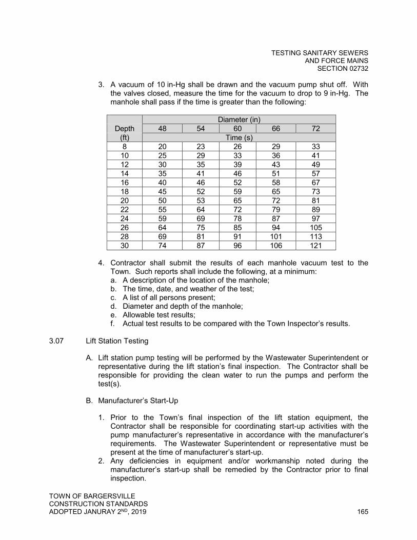
TESTING SANITARY SEWERS AND FORCE MAINS
SECTION 02732
TOWN OF BARGERSVILLE CONSTRUCTION STANDARDS ADOPTED JANURAY 2ND, 2019 165
3. A vacuum of 10 in-Hg shall be drawn and the vacuum pump shut off. With the valves closed, measure the time for the vacuum to drop to 9 in-Hg. The manhole shall pass if the time is greater than the following:
Diameter (in)
Depth 48 54 60 66 72 (ft) Time (s) 8 20 23 26 29 33 10 25 29 33 36 41 12 30 35 39 43 49 14 35 41 46 51 57 16 40 46 52 58 67 18 45 52 59 65 73 20 50 53 65 72 81 22 55 64 72 79 89 24 59 69 78 87 97 26 64 75 85 94 105 28 69 81 91 101 113 30 74 87 96 106 121
4. Contractor shall submit the results of each manhole vacuum test to the Town. Such reports shall include the following, at a minimum: a. A description of the location of the manhole; b. The time, date, and weather of the test; c. A list of all persons present; d. Diameter and depth of the manhole; e. Allowable test results; f. Actual test results to be compared with the Town Inspector’s results.
3.07 Lift Station Testing
A. Lift station pump testing will be performed by the Wastewater Superintendent or representative during the lift station’s final inspection. The Contractor shall be responsible for providing the clean water to run the pumps and perform the test(s).
B. Manufacturer’s Start-Up
1. Prior to the Town’s final inspection of the lift station equipment, the Contractor shall be responsible for coordinating start-up activities with the pump manufacturer’s representative in accordance with the manufacturer’s requirements. The Wastewater Superintendent or representative must be present at the time of manufacturer’s start-up.
2. Any deficiencies in equipment and/or workmanship noted during the manufacturer’s start-up shall be remedied by the Contractor prior to final inspection.
TESTING SANITARY SEWERS AND FORCE MAINS
SECTION 02732
TOWN OF BARGERSVILLE CONSTRUCTION STANDARDS ADOPTED JANURAY 2ND, 2019 166
3. Upon successful completion of the manufacturer’s start-up, the manufacturer
shall deliver to the Contractor: a. Three (3) copies of a letter certifying that all pumping and electrical
equipment has been installed and is operating in accordance with manufacturer’s requirements;
b. Two (2) sets of Operation and Maintenance Manuals; and c. One (1) complete set of spare parts.
C. Final Inspection
1. The Contractor shall provide the following pump test equipment and materials: a. Water to conduct test; b. Amp/volt meter; c. Stop watch; d. Calibrated test gauge to measure operating head. The gauge shall be
calibrated in feet of water from 0 to 100 feet in one foot increments; and e. Manufacturer’s pump performance curves.
2. The Wastewater Superintendent or representative attending the final inspection shall re-check any deficiencies. The Town’s Inspector shall then complete a cursory final inspection checklist and perform pump down tests, which shall include the following: a. Manual check of all level ON-OFF operation, alarm, and run lights; b. Determination of inflow rate; c. Determination of pump capacity for each pump individual and both/all
pumps simultaneously; d. Determination of pump capacity with force main full. Verification of full
force main shall be determined by pressure gauge provided by Contractor. Force main shall be considered full when the line pressure stabilizes; and
e. Plot performance of each pump or pump curves provided by Contractor. 3. The Contractor shall provide all water necessary to conduct the pumping
tests, and shall provide a connection for the test gauge on the blind-flanged tee in the valve vault. The stem connection shall be equipped with a plug valve to close the connection after testing is complete. The connection shall be left in place and shall be suitable for use as an air bleed off.
4. The pumping test results must meet or exceed the design pumping criteria approved by the Town to successfully pass the final inspection. Any deficiencies noted during the final inspection shall be repaired/replaced by the Contractor to the satisfaction of the Town and re-inspected/re-tested prior to final acceptance.
END OF SECTION 02732
FORCE MAIN SEWER SYSTEMS SECTION 02737
TOWN OF BARGERSVILLE CONSTRUCTION STANDARDS ADOPTED JANURAY 2ND, 2019 167
SECTION 02737 – FORCE MAIN SEWER SYSTEMS
PART 1 - GENERAL
1.01 Summary
A. Section Includes: Furnishing and installing all force mains, fittings, air release valves, and appurtenances as required for completing the work as shown on the Drawings and as specified herein.
B. Related Sections
1. Section 02220 - Trenching, Backfilling and Compaction for Utilities 2. Section 02224 - Trenchless Excavation – Horizontal Borings 3. Section 02226 - Trenchless Excavation – Directional Drilling 4. Section 02732 - Testing Sanitary Sewers and Force Mains
1.02 References
A. American National Standards Institute (ANSI), latest editions
1. ANSI A21.4 - Cement-Mortar Lining for Ductile-Iron Pipe and Fittings for Water
2. ANSI A21.10 - Ductile-Iron and Gray-Iron Fittings for Water 3. ANSI A21.11 - Rubber-Gasket Joints for Ductile-Iron Pressure Pipe and
Fittings 4. ANSI A21.51 - Ductile-Iron Pipe, Centrifugally Cast, for Water 5. ANSI B16.5 - Pipe Flanges and Flanged Fittings
B. American Society for Testing and Materials (ASTM), latest editions
1. ASTM A48 - Standard Specification for Gray Iron Castings 2. ASTM A536 - Standard Specification for Ductile Iron Castings 3. ASTM C890 - Standard Practice for Minimum Structural Design Loading for
Monolithic or Sectional Precast Concrete Water and Wastewater Structures 4. ASTM C913 - Standard Specification for Precast Concrete Water and
Wastewater Structures 5. ASTM C928 - Standard Specification for Packaged, Dry, Rapid-Hardening
Cementitious Materials for Concrete Repairs 6. ASTM D1784 - Standard Specification for Rigid Poly(Vinyl Chloride) (PVC)
Compounds and Chlorinated Poly(Vinyl Chloride) (CPVC) Compounds 7. ASTM D2241 - Standard Specification for Poly(Vinyl Chloride) (PVC)
Pressure-Rated Pipe (SDR Series) 8. ASTM D3035 - Standard Specification for Polyethylene (PE) Plastic Pipe
(DR-PR) Based on Controlled Outside Diameter 9. ASTM D3261 - Butt Heat Fusion Polyethylene (PE) Plastic Fittings for
Polyethylene (PE) Plastic Pipe and Tubing

FORCE MAIN SEWER SYSTEMS SECTION 02737
TOWN OF BARGERSVILLE CONSTRUCTION STANDARDS ADOPTED JANURAY 2ND, 2019 168
10. ASTM D3350 - Polyethylene Plastics Pipe and Fittings Materials 11. ASTM F714 - Standard Specification for Polyethylene (PE) Plastic Pipe
(SDR-PR) Based on Outside Diameter
C. American Water Works Association (AWWA) Standards, latest editions
1. AWWA C104 - Cement Mortar Lining for Ductile Iron Pipe and Fittings 2. AWWA C110 - Ductile Iron and Gray Pipe Fittings 3. AWWA C111 - AWWA C111 - Rubber Gasket Joints for Ductile Iron
Pressure Pipe and Fittings 4. AWWA C151 - Ductile Iron Pipe, Centrifugally Cast
D. Indiana Department of Transportation (INDOT) Standard Specifications, latest
edition
1. Section 901 - PCC Materials 2. Section 910 - Metal Materials
1.03 Submittals
A. Product Data
1. Pipe 2. Valves 3. Casing Pipe 4. Fittings 5. Air release valves 6. Joint restraints 7. Hydrants 8. Concrete 9. Certification and training records (for HDPE fusion equipment operators) 10. Other related items and appurtenances
B. Test Results
1. Fusion joint log (HDPE pipe) 1.04 Quality Assurance
A. HDPE Pipe: Bonders and bonding operators shall be qualified in the use of the written bonding procedure specification (BPS) as required by ASME B31.3, Chapter VII, paragraph A-328. Qualification records certifying that bonders and bonding operators employed to perform the fusion bonding are qualified in the BPS shall be submitted prior to the commencement of fusion bonding work. Bonders and bonding operators shall be qualified for the specific fusion bonding equipment utilized in the fusion bonding work.

FORCE MAIN SEWER SYSTEMS SECTION 02737
TOWN OF BARGERSVILLE CONSTRUCTION STANDARDS ADOPTED JANURAY 2ND, 2019 169
1.05 Delivery, Storage, and Handling
A. Acceptance at Site
1. Deliver, store and handle all materials in accordance with manufacturer's recommendations.
2. Load and unload all pipe, fittings, valves, hydrants, and appurtenances by hoists. Do not drop materials. Do not skid or roll materials on or against each other. Use padded slings, hooks and pipe tongs to handle materials in a manner to prevent damage.
3. Pipe possessing defects including, but not limited to, the following will be rejected for installation: a. Variations from straight centerline b. Elliptical shape in round pipe c. Lack of rigidity d. Illegible markings as required herein e. Bruised, broken, or otherwise damaged metallic or bituminous coating or
liner, as applicable f. Deep or excessive gouges, dents, bends, or scratches on the pipe wall g. Fractures, punctures, or cracks passing through the pipe wall h. Damaged or cracked ends where such damage would prevent making a
satisfactory joint 4. All materials deemed damaged by the Town will not be accepted.
B. Storage and Protection
1. Store materials in an area safe from damage and deterioration. Keep the interior of pipe, fittings, valves, hydrants and appurtenances free from dirt and foreign matter. Drain and store valves and hydrants in a manner to prevent damage from freezing. Store gaskets in a cool location out of direct sunlight and free from contact with petroleum products.
2. Do not stack any pipe higher than recommended by manufacturer. Do not stack fittings, valves, and hydrants.
PART 2 - PRODUCTS
2.01 Ductile Iron (DI) Force Main
A. Pipe and Fittings
1. Provide ductile iron pipe centrifugally cast in metal or sandlined molds and conforming to ANSI A21.51/AWWA C151. Minimum thickness class shall be Class 50 for all sizes.
2. Provide mechanical joint ductile iron fittings conforming to ANSI A21.10/ AWWA C110 and ANSI A21.11/AWWA C111.
FORCE MAIN SEWER SYSTEMS SECTION 02737
TOWN OF BARGERSVILLE CONSTRUCTION STANDARDS ADOPTED JANURAY 2ND, 2019 170
3. Furnish DI pipe and fittings which have a standard thickness cement mortar lining as specified in ANSI A21.4/AWWA C104 and an outside coating as specified in ANSI A21.51/AWWA C151.
4. Furnish gaskets for mechanical joints fittings and DI pipe push-on joints which conform to ANSI A.21.11/AWWA C111.
B. Joints and Joint Restraint
1. Supply the pipe with push-on type joints conforming to ANSI A21.11/ AWWA C111.
2. Joint restraint shall be Megalug by EBAA Iron, Inc., or pre-approved domestic manufactured equal.
3. Provide restrained joints for all pipe installed in steel casing. 4. Restrain pipe joints as specified in Part 3 of this section.
C. Pipe Markings
1. Each length of pipe shall be marked with the following information at a minimum: a. Manufacturer’s name or trademark b. Pipe class c. Year of manufacture
2.02 High Density Polyethylene (HDPE) Force Main
A. Pipe
1. Provide HDPE pipe manufactured from extra high molecular weight, high density PE 3408 polyethylene resin. Polyethylene pipe shall meet the requirements of ASTM D3035 and ASTM F714. Cell classification shall be 345444C per the requirements of ASTM D3350.
2. Furnish pipe which is suitable for a working pressure of 150 psi or greater, surge pressure of 200 psi or greater, and a depth of cover of minimum 54 inches.
3. Supply minimum DR-21 polyethylene pipe and a nominal IPS (Iron Pipe Size) outside diameter.
B. Fittings
1. Provide HDPE fittings manufactured from extra high molecular weight, high density PE 3408 polyethylene resin in accordance with ASTM D3261. Fittings shall be manufactured by injection molding.
2. Provide HDPE fittings manufactured by the same manufacturer as the pipe to which fusion bonding is intended, using identical materials.
3. Fittings shall be manufactured to meet the same pressure rating as the pipe with an included 2:1 safety factor. The pipe DR (Dimension Ratio) shall be used to determine the fitting pressure rating requirements.

FORCE MAIN SEWER SYSTEMS SECTION 02737
TOWN OF BARGERSVILLE CONSTRUCTION STANDARDS ADOPTED JANURAY 2ND, 2019 171
4. Fitting shall be manufactured in facilities designed for that purpose. Field-fabricated fitting shall not be allowed.
5. Provide branch saddle reducing tees to connect air release valves to the force mains. Saddles shall be main line size by 4 inches, with a 4-inch flange adapter and back-up ring, and 4-inch by 2-inch NPT companion flange.
C. Flange Backup Rings and Gaskets
1. Provide DI convoluted type backup rings, fabricated from ductile iron per ASTM A536, grade range 60/40/18 to 65/45/12. Ductile iron flange backup ring bolting dimension shall conform to ANSI B16.5 Class 150.
2. Backup rings shall be finished as cast with flash removed from all edges and bolt holes to the specified dimensions. Additionally backup rings shall be epoxy coated, with Bitumastic 300M High Build Coal Tar Epoxy per manufacturer's recommendations.
3. Gasket materials shall be compatible with the service of the piping system. Asbestos gaskets will not be allowed.
D. Allow HDPE pipe to reach ambient temperature for the installed condition before
final cutting, installation of concrete restraint system, or connection of transition couplings.
2.03 Polyvinyl Chloride (PVC) Force Main
A. Pipe and Fittings
1. Provide PVC pipe conforming to ASTM D2241, SDR-26 (pressure class 160 minimum) or AWWA C900/905, DR-25 (pressure class 165 minimum).
2. Pipe materials shall conform to ASTM D1784, Class 12454-B (PVC 1120). 3. Fittings shall be mechanical joint iron or ductile iron conforming to ANSI
A21.10/AWWA C110 and ANSI A21.11/AWWA C111. Restrained joints and shall be mechanical wedge-action type as approved by the Town
4. PVC fittings are allowable for sizes two (2) inches and smaller.
B. Joints and Joint Restraint
1. Pipe joints shall be single gasket bell and spigot type, the bells being formed integrally with the pipe.
2. Pipe and couplings shall be made of unplasticized PVC compounds, minimum cell classification of 12454, as defined in ASTM D1784.
3. The PVC restrained joint pipe system shall be SDR-17 and conform to ASTM D2241, including pressure test requirements.
4. PVC restrained joint pipe system shall be Yellowmine Integral Bell or Certa-Lok Yelomine pipe with couplings as manufactured by CertainTeed Corporation, or approved equal.

FORCE MAIN SEWER SYSTEMS SECTION 02737
TOWN OF BARGERSVILLE CONSTRUCTION STANDARDS ADOPTED JANURAY 2ND, 2019 172
C. Pipe Markings
1. Each length of PVC pipe shall be clearly marked with the following information at a minimum: a. Name of manufacturer or identification symbol b. Trade name or trademark c. Nominal pipe size d. Production/extrusion code e. Material and cell class designation f. ASTM designation
2.04 Plug Valves and Boxes
A. Valve
1. Provide eccentric plug valves for wastewater service which are non-lubricated with a resilient seating surface.
2. Buried valves shall have mechanical joint ends conforming to ANSI/AWWA C110 requirements.
3. Port areas shall be 100 percent of full pipe area. 4. Valves shall have permanently lubricated stainless steel slave-type bearings,
or other lubricated type bearings, in the upper and lower stem journals. 5. Valve seats shall be corrosion resistant with a high nickel content. 6. Bonnet shaft seals shall be capable of being replaced while force main and
valve remain in service, thereby eliminating the need to take pumping station out of service.
7. All exposed nuts, bolts, springs and washers shall be zinc-coated steel. 8. Buried valves, 8 inches and larger, shall have worm-gear actuators. Buried
valves smaller than 8 inch shall have totally enclosed and sealed operators with a 2 inch square AWWA operating nut.
9. Plug valves shall be capable of providing drip-tight shutoff with flow in either direction up to the valve’s rated operating pressure.
10. The plug face material shall be nitrile-butadiene, Neoprene or as approved by the Town.
11. Valves and actuators for buried service shall have seals on all shafts and gaskets on valve and actuator covers to prevent the entry of fluid.
12. Actuator shall be capable of fully seating and unseating the valve and have a maximum torque of 50 foot-pounds on operating nuts.
13. Valves shall be DeZurik, Mueller, or equal.
B. Valve Box
1. All buried valves shall have an extension stem, cast or ductile iron valve box and cover, and tee-wrench.

FORCE MAIN SEWER SYSTEMS SECTION 02737
TOWN OF BARGERSVILLE CONSTRUCTION STANDARDS ADOPTED JANURAY 2ND, 2019 173
2.05 Sewage Air and Vacuum Valves
A. Sewage Air Release and Air Vacuum Valve shall have cast iron body and cover with a 2-inch N.P.T. inlet and 1-inch N.P.T. outlet with a stainless steel float and float guide.
B. Provide valve as manufactured by Crispin Valve, Series “S”, or approved equal.
2.06 Valve Vault
A. Structure
1. Provide precast concrete sections with no more than 3 holes cast or drilled in the section for handling.
2. Provide rapid setting patch material in accordance with ASTM C928 and INDOT Standard Specification Section 901 or precast concrete plugs for filling all holes used for handling.
3. Provide square precast concrete vaults which conform to ASTM C913 and C890 and as indicated on Drawings.
B. Casting
1. Provide cast iron frames and covers in accordance with ASTM A48 Class 35B and INDOT Standard Specification Section 910.
2. Supply all frames and covers from one manufacturer. 3. Furnish frames and covers which are rated for traffic, of non-rocking design,
and have machined horizontal and vertical bearing surfaces. Frames and lids shall be watertight and have a grooved rubber gasket with concealed pick holes.
4. Provide frame and cover as shown on Standard Detail, or approved equal. 2.07 Tracer Wire
A. Furnish tracer wire for all pipe.
B. For pipe installed by open excavation or within a casing, provide one strand of solid 12-gauge AWG copper wire for the entire length of pipe.
C. For pipe installed by horizontal directional drilling, provide 2 strands of 10-gauge solid, steel core hard drawn extra high strength copper tracer wire for the entire length of pipe. Supply Copperhead Direct Burial tracer wire, or approved equal.
D. Provide splice kits suitable for underground installation for splices and branch connections. Seal connection with epoxy contained in splice kit and wrap with waterproof tape.
FORCE MAIN SEWER SYSTEMS SECTION 02737
TOWN OF BARGERSVILLE CONSTRUCTION STANDARDS ADOPTED JANURAY 2ND, 2019 174
2.08 Location Material
A. Location material shall be metallic type tape such as Terra Tape Detectable as manufactured by Reef Industries, Inc. or approved equal. Location material shall be marked with “Caution Sewer Line Buried Below” and installed 12” to 24” above force main.
2.09 Force Main Marker Post
A. Provide model PMP 7CE with lid C2 as manufactured by Handley Industries, or approved equal.
B. One (1) marker post shall be installed every 500 feet of force main installed, and at any major deflection in the pipeline.
C. The following information shall be clearly printed on force main marker post:
1. Bargersville Utilities 2. Sanitary Sewer Line Buried Below 3. Emergency Contact 317-422-5115 4. Caution Sewer Pipeline
PART 3 - EXECUTION
3.01 General
A. Inspect force mains, fittings, valves, and appurtenances prior to installation and promptly remove damaged or unsuitable materials from the job site. Replace damaged or unsuitable materials with new and unused materials.
B. Install all force mains, fittings, valves, and appurtenances as shown on the Standard Details and as specified in this Section. Do not install pipe when, in the opinion of the Town, trench conditions are unsuitable.
C. Follow manufacturer's installation procedures when installing force mains, fittings, valves, and appurtenances.
3.02 Installation of Force Mains
A. Before installing piping, the Contractor shall carefully verify location, depth, type of joint needed and size of pipe to which connection is proposed. He shall assure himself that the lines can be run as contemplated. Any necessary deviation shall be referred to the Town for final approval before lines are run.
B. All lengths of pipe shall be dimensioned accurately to measurements established at the site, and shall be worked into place without forcing. Cut sections of pipe shall be cut using pipe cutters to provide a square end.

FORCE MAIN SEWER SYSTEMS SECTION 02737
TOWN OF BARGERSVILLE CONSTRUCTION STANDARDS ADOPTED JANURAY 2ND, 2019 175
C. Lay force main pipe uniformly to line and grade so that the finished sewer will present a uniform conduit. The Contractor, at his own expense, shall set force main alignment and grade for the minimum depth of cover of 54 inches.
D. Contractor shall take precautions to avoid constructing "high points" in the force main other than those already shown on the Drawings. The Contractor shall be responsible for installing at his own costs any additional Sewage Air Release Valves necessary in these areas to vent accumulated air and gases trapped at these "high points".
E. Tracer Wire
1. Install tracer wire on HDPE and PVC pipe and service lines, taped to pipe in 15 to 20-foot intervals. Do not wrap wire around pipe.
2. Install tracer wire boxes at intervals not to exceed 1,000 feet. Seal splices and branch connections with epoxy and wrap with tape. Install one pound anodes every mile or less.
F. Install length of extension stems on valve boxes so that plug valve operating nut
is 9 to 12 inches below the ground surface.
G. Temporarily plug installed piping systems at the end of each day's work, or other interruption of progress on a given line. Plug shall be adequate to prevent entry of animals and entrance or insertion of deleterious materials and shall be installed in a manner satisfactory to the Town.
H. HDPE Pipe Fusion Bonding Procedure
1. Piping joints other than those shown as flanged or otherwise mechanically connected shall be butt fusion bonded in accordance with a written bonding procedure specification (BPS) as required by ANSI/ASME B31.3, Chapter VII, paragraph A-328. BPS shall include cutting and facing requirements and shall utilize a data logger.
2. Materials to be fusion bonded shall be from the same manufacturer. 3. Bonders and bonding operators shall be qualified in the use of the BPS as
required by ANSI/ASME B31.3, Chapter VII, paragraph A-328. Qualification records certifying that borders and bonding operators employed to complete fusion bonding are qualified in the BPS shall be submitted prior to commencement of fusion bonding work.
4. Bonding equipment specified in the BPS shall be in proper operating condition. Equipment heater performance shall be tested and certified prior to use for fusion bonding. Bonders and bonding operators shall be qualified for the specific bonding equipment utilized in the fusion bonding work.
5. The joining method shall be performed in strict accordance with the pipe manufacturer's requirements. The butt fusion equipment used in the jointing procedure shall be capable of meeting all conditions required by the pipe manufacturer, including temperature, alignment and fusion pressure. Heat
FORCE MAIN SEWER SYSTEMS SECTION 02737
TOWN OF BARGERSVILLE CONSTRUCTION STANDARDS ADOPTED JANURAY 2ND, 2019 176
fusion joining shall be 100 percent efficient offering a joint weld strength at least equal to the tensile strength of the pipe. Each butt fusion joint shall be logged electronically by the butt fusion unit, for quality control, by such equipment as The Data Logger manufactured by McElroy Manufacturing, Inc. Logged fusion joints shall be stored in the Data Logger unit, such that it can be downloaded and printed weekly for submittal to the Town.
I. HDPE pipe installed by open cut shall be butt fusion bonded at grade level and
lowered into the trench using nylon slings to avoid damage to the pipe. Chains or cable type chokers must be avoided when lifting sections of pipe.
J. PVC pipe installed by open cut shall be joined at grade level and lowered into the trench using nylon slings to avoid damage to the pipe. Chains or cable type chokers must be avoided when lifting sections of pipe.
K. Horizontal directional drilling of HDPE and PVC pipe shall be as specified in Section 02226 – Trenchless Excavation – Directional Drilling.
L. Install location material above force main between 18 to 24 inches deep.
3.03 Sewage Air and Vacuum Valves
A. Keep structure excavations free from water during construction.
B. Fill all areas excavated below the depth required for the structure's base with No. 8 crushed stone at Contractor’s expense.
C. Install vault sections so that the axis of the structure is vertical.
D. Prior to backfilling, fill all holes used for handling with rapid setting patch material or with precast concrete plugs secured with Portland cement mortar.
3.04 Cleaning
A. Provide all necessary equipment required for proper completion of the flushing of structures and piping systems. Source, quality, and disposal of water shall be approved by the Town.
B. Remove all debris and excess soil from all pipe installed under this Contract by cleaning with clean water. It shall be the Contractor's responsibility to obtain necessary water and equipment to flush the pipes to the satisfaction of the Town.
C. Water used for cleaning is not to enter existing sanitary sewer system.
END OF SECTION 02737

LIFT STATION AND MANHOLE REHABILITATION SPECIFICATIONS
SECTION 02738
TOWN OF BARGERSVILLE CONSTRUCTION STANDARDS ADOPTED JANURAY 2ND, 2019 177
SECTION 02738 – LIFT STATION AND MANHOLE REHABILITATION SPECIFICATIONS
PART 1 - GENERAL
1.01 Summary
A. The rehabilitation of wastewater structures shall be accomplished with any number of systems/products so long as it ensures a final monolithic application from the top of the invert to include the bench, wall, cone, chimney and frame seal areas. The lining shall be designed for use in high hydrogen sulfide environments to protect the substrate from exposure, eliminate groundwater infiltration and rebuild structural integrity. Spectra Shield preferred.
B. The work to include all labor, material, and equipment necessary for resurfacing and coating of manhole interiors. This is to include any preparation work involving cleaning, step removal, leak stoppage, and filling of voids or cavities prior to application of the lining materials.
1.02 Quality Assurance
A. The contractor shall provide documentation that the applicator is an approved installer and licensed by the coating system manufacturer. The installer must have at least five (5) years of experience with a list of at least five (5) past clients, including names and telephone numbers to verify previous satisfactory performance on the projects of similar or greater size.
B. The Manufacturer shall warrant the product for a period of ten (10) years and show documentation of test results indicating a fifty (50) year plus service life. A date stamp of application shall be integral to the lining or affixed in a permanent manner near the top chimney area of the structure for ease of identification.
C. All materials and installation thereof shall be furnished and coordinated with/by one supplier/applicator who turnkeys the work and assumes full responsibility for the entire operation.
1.03 References
A. ASTM D4541 – Adhesion
B. ASTM D412 – Tensile Strength
C. ASTM D412 – Elongation
D. ASTM D624 – Tear Strength
E. ASTM D2210 – Hardness

LIFT STATION AND MANHOLE REHABILITATION SPECIFICATIONS
SECTION 02738
TOWN OF BARGERSVILLE CONSTRUCTION STANDARDS ADOPTED JANURAY 2ND, 2019 178
F. ASTM D522 – Flexibility
G. ASTM D4060 – Taber Abrasion
H. AASHTO H20 load rating
I. Independent 3rd Party Test Results from an industry affiliated testing agency such as CIGMAT, CUIRE, LA Tech, LA County, etc…
PART 2 - PRODUCTS
2.01 Lining Materials
A. The lining materials shall be polymer based with a minimum thickness of 500mil in one or more layers/applications. Where cement/mortar is used for resurfacing it will be considered incidental to the lining thickness as indicated.
B. The lining material shall be sprayable, solvent free, two-component polymeric, moisture/chemical barrier specifically developed for the corrosive wastewater environment.
C. The lining materials shall withstand a minimum head pressure of 15 psi, or 35 vertical feet, as verified by 3rd party results.
PART 3 - EXECUTION
3.01 Surface Preparation
A. Prior to conducting any work, perform inspection of structure to determine need for flow control or diversion. Submit plan as needed to the Town for approval prior to any work.
B. Surface preparation methods may include high pressure water cleaning, hydro blasting, abrasive blasting, grinding, detergent water cleaning and shall be suited to provide a surface compatible for installation of the liner system.
C. Surface prep method shall produce a cleaned, abraded and sound surface with no evidence of laitance, loose concrete, brick or mortar, contaminants or debris, and shall display a surface profile suitable for application of the liner system.
D. Surface prep program to include monitoring of atmosphere for hydrogen sulfide, methane, low oxygen or other gases with appropriate documentation to confined space entry permit requirements.
LIFT STATION AND MANHOLE REHABILITATION SPECIFICATIONS
SECTION 02738
TOWN OF BARGERSVILLE CONSTRUCTION STANDARDS ADOPTED JANURAY 2ND, 2019 179
E. After completion of surface prep, perform check list to identify and remediate any leaks. Repair all leaks with a chemical or hydraulic sealant designed for use in the field sealing of ground water. Non shrink grouts may also be utilized to fill larger voids/cavities prior to application.
3.02 Material Installation
A. Application procedures shall conform to the recommendations of the Manufacturer including material handling, mixing, environmental controls during application, safety and spray equipment.
B. Equipment shall be specifically designed to accurately ratio and apply the liner system using hand held plural component spray technologies.
C. Provide pre and post application photo of structure in final report to the Town. The photo should be taken from the outflow, to be identified as the 6:00 position of the manhole per NASSCO guidelines.
D. New cement structures shall have cured a minimum of 28 days prior to commencing installation of the liner system.
3.03 Inspection
A. Applicator shall take appropriate action to comply with all local, state and federal regulations including those set forth by OSHA, EPA, the Town and any other applicable authorities.
B. Final liner system shall be completely free of pinholes or voids by visual inspection and holiday “spark” test methods whereby an electric charge is introduced to the interior of the structure. Any deficiencies of the finished liner shall be marked and repaired according to the procedures set forth by the Manufacturer.
C. The sewer system shall be returned to full operational service as soon as the final inspection takes place.
END OF SECTION 02738
SUBMERSIBLE LIFT STATION SECTION 02739
TOWN OF BARGERSVILLE CONSTRUCTION STANDARDS ADOPTED JANURAY 2ND, 2019 180
SECTION 02739 - SUBMERSIBLE LIFT STATION
PART 1 - GENERAL
1.01 Summary
A. Section includes: The installation of submersible lift station with non-clog centrifugal pumps as shown in the Standard Details including pumps, motor, base elbow, hatches with safety grating, slide rails, wet well and valve vault, controls, piping and valves, and other appurtenances.
B. Developer or Contractor shall be responsible for all costs associated with abandonment or relocation of an existing lift station.
1.02 General and Design Requirements
A. This section pertains to the requirement for sanitary sewer lift stations designed and constructed by a Developer or Contractor.
B. The Developer must show that it is not physically possible or economically feasible to provide gravity service into a public sewer. No lift station shall be approved for a project unless a 50-year life cycle analysis is submitted to the Town to demonstrate that it will be more cost effective for the Town in lieu of constructing a deeper gravity sewer.
C. All sewage lift stations that are connected to the Town of Bargersville collection system must be approved by the Indiana Department of Environmental Management (IDEM) and by the Town of Bargersville. The lift station must meet the requirements of this Section and the Standard Details.
D. Any exceptions to this Standard or associated approved Plans shall be submitted in writing and clearly stated. The exceptions must be approved by the Town prior to proceeding with the work.
E. All components of the lift station that are exposed to weather shall be constructed of material that is resistant to corrosion and will not require surface protection throughout the expected life of the lift station. In general, these materials are stainless steel, aluminum, fiberglass reinforced polyester (FRP) and ultraviolet stabilized PVC.
F. Inlet piping shall be located such that the sewage discharging into the wet well does not fall directly onto one or both of the submersible pumps.
G. All lift stations shall be designed and constructed in accordance with IDEM and Ten States Standards. All design criteria and calculations shall be submitted to the Town for approval.
SUBMERSIBLE LIFT STATION SECTION 02739
TOWN OF BARGERSVILLE CONSTRUCTION STANDARDS ADOPTED JANURAY 2ND, 2019 181
H. Lift Station pumps shall be provided to accommodate peak hourly flow with the largest pump out of service. A minimum of two (2) pumps shall be provided at each lift station.
I. Force mains shall be designed to maintain a minimum of 2 feet per second in order to avoid solids deposition in the pipe. Minimum force main size shall be 4-inches in diameter unless specifically authorized by the Town.
J. Service and replacement parts for all components of the lift station must be readily available in the local Indianapolis area within 40 miles of the Town of Bargersville.
K. The wet well is a Class 1, Division 1, Groups C and D environment. All components installed in the wet well shall be rated accordingly.
L. Lift Station Location
1. Locate the lift station in such a manner that it is accessible by means of a paved surface (street grade) with parking area for 2 service vehicles without obstructing any adjacent sidewalks or streets. Drive shall provide adequate access for a vacuum truck. Layout must be approved at Tech Review.
2. Landscaping/fencing may be required in locations where visual qualities are a consideration or for safety and equipment protection. Guidelines for landscaping around lift stations are available from the Town. A landscaping plan shall be submitted to the Town at Tech Review.
3. Provide access in the area surrounding the lift station for possible future maintenance purposes and the future addition of a second wet well. Provide a minimum area of 1,200 square feet. Future additional wet well should be able to be installed without interruption of original wet well. Site layout shall include site of future wet well. Show utility easements on the Plans.
4. The lift station site shall be located above the 100-year flood elevation as established by IDEM and DNR.
M. Lift Station Design
1. Lift stations shall be wet well/valve vault design utilizing submersible pumps in the wet well with a separate valve vault. Provisions for draining the valve vault into the wet well shall be made.
2. Provisions shall be made for connection to the Town’s portable generators in the event of a power failure.
N. Lift Station Enclosure
1. A lift station enclosure shall be designed to protect the controls against inclement weather and be designed not to conflict with the maintenance of the wet well/valve vault. The design shall be approved by the Town’s Wastewater Superintendent and Utility Coordinator.
SUBMERSIBLE LIFT STATION SECTION 02739
TOWN OF BARGERSVILLE CONSTRUCTION STANDARDS ADOPTED JANURAY 2ND, 2019 182
O. Wet Well Sizing Criteria
1. The wet well storage below the lowest inlet shall be a minimum of 5’-0” and shall also meet the following criteria: a. OFF level to be set at the pump manufacturer’s recommended level but
no less than 1’-0” from the bottom of the wet well. b. The distance between the OFF level and the lead pump ON level shall be
set to provide storage capacity in gallons equal to:
15 x Rated Pump GPM (i.e. 15 minute cycle minimum) 4
c. The lag pump ON level shall be set a minimum of 6 inches above the lead pump ON level. Lag pump shall have a time delay relay, adjustable from 0 to 60 seconds.
d. The high water alarm shall be set a minimum of 6 inches above the lag pump ON level.
e. All level settings shall be set a minimum of 6 inches below the lowest invert elevation into the wet well.
f. All multitrode level set points shall be set below the lowest inlet into the wet well.
1.03 Quality Assurance
A. Standardization - All equipment shall be of the latest and most modern design. All similar components shall be manufactured and furnished by one manufacturer unless specifically allowed otherwise in writing by the Town.
B. Provide manufacturer's warranty as specified in this Section.
C. Provide field test results in Start-Up Certification Report as specified in this section.
D. The pumping equipment, controls, and accessories shall be an integral package supplied by a pump supplier with local representation so as to provide undivided responsibility.
1.04 Submittals
A. Submit the following to the Town for review:
1. Certified copies of factory tests and reports, if specified in this Section or required by the referenced standards.
2. Descriptive information including catalogue cuts and manufacturer’s specifications for all components.
3. Copy of manufacturer's standard warranty for each type of equipment provided.
SUBMERSIBLE LIFT STATION SECTION 02739
TOWN OF BARGERSVILLE CONSTRUCTION STANDARDS ADOPTED JANURAY 2ND, 2019 183
4. Shop drawings with performance data, descriptive literature, weights and dimensions, and other physical characteristics verifying compliance with this Section including certified pump curves, motor starting and full-load amps, and motor horsepower and data, and other specific pump information. When numerous options and sizes are shown, the shop drawings shall be marked to clearly indicate the size and types specific to this Section and project.
5. Electrical: a. Submit all electrical requirements for each piece of equipment including
voltage, phase, and load data. b. Provide wiring diagrams for each piece of equipment. For example,
submitting one diagram for all pumps is not acceptable. c. “Typical” diagrams are not acceptable. Manufacturer’s standard
diagrams may be submitted if they are made specific for this project by: 1) Showing all included options, special items, etc. 2) Unused options or features shall be crossed out or deleted. 3) Identify the drawing with project name, equipment name, and tag
number, e.g., “Bargersville, “XXX” Lift Station Pump No. 1” d. Telemetry plan
6. A material list indicating items to be furnished by the equipment manufacturer.
7. List of which components and materials shall be shipped preassembled and parts list for the other components and materials. Weights and physical dimensions shall be indicated for each part, assembly, and/or package to be shipped.
8. Manufacturer's installation instructions and recommended testing procedures.
9. Material Safety Data Sheets (MSDS) for any and all oils or chemicals utilized for lift station operation and maintenance.
10. Provide start-up certification report specified in this Section. 11. Operation and Maintenance Manuals
a. Three (3) hard-copy Operation and Maintenance Manuals, and three (3) book-marked, pdf copies on CD or DVD, for all components of the lift station.
b. Manuals shall include, at a minimum: 1) Operation Instructions 2) Maintenance Instructions and Schedule 3) Recommended Spare Parts List 4) Lubrication Schedules 5) Structural Diagrams 6) As-built Wiring Diagrams 7) Bill of Materials
1.05 Warranty
A. Equipment and installation warranties shall comply with the warranty requirements specified in the General Conditions.
SUBMERSIBLE LIFT STATION SECTION 02739
TOWN OF BARGERSVILLE CONSTRUCTION STANDARDS ADOPTED JANURAY 2ND, 2019 184
B. The manufacturer of the equipment furnished under this Section shall be responsible for the proper operation of the system when installed according to his instructions.
C. Pump warranty shall be provided by the pump manufacturer and shall warrant the units being supplied to the Town against defects in workmanship and materials for a period of five (5) years prorated from the start-up date. The warranty shall be in printed form and apply to all similar units. A copy of the warranty statement shall be submitted with the shop drawings.
D. All Work shall be warranted by the Developer and Contractor to be free from defective material and workmanship for a period of one year from the date of acceptance of the lift station by the Town. Replace defective materials, components, and workmanship during this time, including but not limited to all materials, labor, shipping, and transportation, at no cost to the Town. Warranty work performed during this one year period shall also be warranted to be free from defective material or workmanship for a period of one year from the date the warranty work is completed and shall be addressed in the same manner at no additional cost to the Town.
1.06 Spare Parts and Special Tools
A. The manufacturer shall furnish one set of all special tools necessary for normal operation, maintenance and calibration.
B. Provide all manufacturer's recommended spare parts for each unit, as well as any spare parts identified in this specification section or the special requirements. As a minimum, a spare O-Ring Kit package shall be supplied with each pump.
1.07 Product Delivery, Storage and Handling
A. The Contractor shall be responsible for the delivery, storage, and handling of products. Store products in accordance with the manufacturer's recommended procedures.
B. Load and unload all pumps, motors, and appurtenances by hoists or skidding. Do no drop products. Do not skid or roll products on or against other products. Attach slings and hooks in such a manner to prevent damage to products.
C. The pumps furnished shall be packaged in such a manner as to provide ample protection from damage during handling, shipment, and outdoor storage at the station site. All openings shall be capped with dustproof closures and all edges sealed or taped to provide a dust-tight closure.
D. Promptly remove damaged products from the job site. Replace damaged products with undamaged products.
SUBMERSIBLE LIFT STATION SECTION 02739
TOWN OF BARGERSVILLE CONSTRUCTION STANDARDS ADOPTED JANURAY 2ND, 2019 185
PART 2 - PRODUCTS
2.01 Submersible Non-Clog Pumps
A. Requirements
1. Provide two (2) identical centrifugal, submersible, solids handling, non-clog design pumps capable of handling 3-inch sphere solids, fibrous materials, sludge, and other typical solids. The pumps shall have the characteristics indicated on the Data Sheet. Pumps shall meet the requirements of HI Standards.
2. Pumps shall be manufactured by Hydromatic Pump Company or Fairbanks Morse. All other pump manufacturers require preapproval by the Town.
3. Pumps shall be equipped with submersible cable suitable for submersible pump applications of length necessary from each pump to its respective remote control panel (RCP). The power cable shall be sized according to NEC and ICEA standards.
4. The pumps shall be supplied with mating cast iron discharge connections as indicated on the Data Sheet.
B. Pump Design
1. Pumps shall be capable of passing raw unscreened sewage and three (3) inch spherical solids.
2. The pumps shall be automatically and firmly connected to the discharge connection, guided by no less than two guide rails or one fiberglass I-beam extending from the top of the station to the discharge connection. There shall be no need for personnel to enter the wet-well.
3. No portion of the pump shall bear directly on the sump floor. 4. Each pump shall be fitted with a solid lifting ring permanently affixed to the
pump and a stainless steel lifting chain or stainless steel cable of adequate strength and length to permit raising and lowering of the pump to be removed in one continuous motion, without intermediate hooking.
C. Pump Construction
1. Each pump shall be a centrifugal, non-clog, solids handling, submersible, wastewater type. The pump volute, motor and seal housing shall be high quality gray cast iron, ASTM A-48, Class 30 or 35B. The pump discharge shall be fitted with an ASA 125 lb. flange, faced and drilled of a size listed in the Data Sheet. All external mating parts shall be machined and Buna N Rubber O-ring sealed on a beveled edge. All fasteners exposed to the pumped liquids shall be 300 series stainless steel.

SUBMERSIBLE LIFT STATION SECTION 02739
TOWN OF BARGERSVILLE CONSTRUCTION STANDARDS ADOPTED JANURAY 2ND, 2019 186
D. Electrical Power Cord
1. Electrical power cord shall be SOOW, water resistant 600V, 90ºC., UL and CSA approved and applied dependent on amp draw for size, of sufficient length to extend from the pumps to the remote control panel (RCP) without splices.
2. The cable seal design shall include specific torque requirements to ensure a watertight and submersible seal.
3. The cable entry shall consist of a single cylindrical elastomer grommet, flanked by washers, all having a close tolerance fit against the cable outside diameter and the entry inside diameter and compressed by the body containing a strain relief function separate from the function of sealing the cable.
4. The cable entry junction chamber and motor shall be separated by a stator lead sealing gland or terminal board, which shall isolate the interior from foreign material gaining access through the pump top. Epoxies, silicones, or other secondary sealing systems shall not be considered acceptable.
E. Motor
1. Provide 460 volt, 3-phase electric motors of premium efficiency. Electric motors shall operate with a service factor of 1.15.
2. Provide solid state motor starters designed for both soft start and soft stop capability for motors over 10 horsepower.
3. The stator, rotor and bearings shall be mounted in a sealed submersible type housing. The stator windings and stator leads shall have Class F insulation (155°C) and a dielectric oil filled or air-filled motor, NEMA B design. Further protection shall be provided by on winding thermal sensors. The pump and motor shall be specifically designed so that they may be operated partially or completely submerged in the liquid being pumped. The pump shall not require cooling water jackets. Water jackets for supplemental cooling are not acceptable.
4. Stators shall be securely held in place with a removable end ring and threaded fasteners so they may be easily removed in the field without the use of heat or a press. Stator held by a heat shrink fit are not acceptable. Stators must be capable of being repaired or rewound by a local motor service station. Units which require service only by the factory shall not be acceptable. No special tools shall be required for pump and motor disassembly.
5. Pump shall be equipped with two heat sensors. The heat sensors shall be a low resistance, bi-metal discs that are temperature sensitive. They shall be mounted directly in the stator windings and sized to open at 125ºC and automatically reset at 30-35ºC differential. The sensors shall be connected in series with the motor starter coil so that the starter is tripped if a heat sensor opens. The motor starter shall be equipped with 3 leg overload heaters so all normal overloads are protected by external heater block.
SUBMERSIBLE LIFT STATION SECTION 02739
TOWN OF BARGERSVILLE CONSTRUCTION STANDARDS ADOPTED JANURAY 2ND, 2019 187
F. Bearings and Shaft
1. An upper radial bearing and a lower thrust bearing shall be required. The upper radial bearing shall have minimum B-10 life at the specified condition of 10,000 hours and the lower thrust bearing shall have a minimum B-10 life at the specified condition of 10,000 hours. Bearings shall be locally available.
2. The shaft shall be 431 stainless steel and be a design which is of large diameter with minimum overhang to reduce shaft deflection and prolong bearing life.
G. Seals
1. Pumps shall have single mechanical shaft seals with carbon washer and stainless steel housing parts and springs. Pumps for water below 150 degrees F shall have mechanical seals with ceramic or Ni-Resist stationary seat and BUNA elastomer. Pumps for water to 220 degrees F shall have mechanical seals with carbon stationary seat and Viton elastomer.
H. Impeller
1. Impeller shall be of the two or more vanes, enclosed non-clogging design (wherever possible) and have pump-out vanes on the front and backside of the impeller to prevent grit and other materials from collecting in the seal area. Single vane design impellers which cannot be easily trimmed and which do not maintain balance with wear causing shaft deflections and reducing seal and bearing life are not acceptable.
2. Impellers shall be statically and dynamically balanced. The tolerance values shall be listed below according to the International Standard Organization grade 6.3 for rotors in rigid frames. The tolerance is to be split equally between the two balance planes which are the two impeller shrouds.
RPM Tolerance 1750 .02 in. – oz./lb. of impeller weight 1150 .026 in. – oz./lb. of impeller weight 870 .03 in. – oz./lb. of impeller weight
3. The impeller shall be threaded shaft or tapered shaft and key driven.
I. Casing
1. The casing shall be of the end suction volute type having sufficient strength and thickness to withstand all stress and strain from service at full operating pressure and load. The casing shall be of the centerline discharge type equipped with an automatic pipe coupling arrangement for ease of installation and piping alignment. The design shall be such that the pumps will be automatically connected to the discharge piping when lowered into
SUBMERSIBLE LIFT STATION SECTION 02739
TOWN OF BARGERSVILLE CONSTRUCTION STANDARDS ADOPTED JANURAY 2ND, 2019 188
position with the guide rails. The casing shall be accurately machined and bored for register fits with the suction and casing covers.
2. A volute case wearing ring shall be provided to minimize impeller wear. The wear ring shall be alloy 230 brass ASTM B43, Teflon, or nitrile rubber coated steel. The wear ring shall be easily replaceable in the field. Wear rings of any other material are not acceptable.
J. Serviceability
The complete rotating assembly shall be capable of being removed from the volute without disturbing the suction piping, discharge piping and volute. The motor housing, seal housing with seal plate and impeller still attached to the shaft shall be capable of being lifted out of the volute case from the top as one assembly.
K. Spare Parts
1. Provide one complete set of spare parts including multitrode unit, electrical relays, timers, lights, and other electrical components as provided by pump manufacturer.
2.02 Concrete Wet Well and Valve Vault
A. The Contractor shall furnish and install a monolithic concrete or precast manhole type wet well as indicated on the Details. Pump and related equipment shall be installed and/or mounted as shown.
B. A concrete vault shall be furnished and installed to house the valves and appurtenances. Provide an aluminum access ladder in the valve vault as shown on the Details. Square valve vault structures shall conform to requirements of ASTM Specification C913 and C890. Valve vault shall be constructed same as described for manholes in specification Section 02730.
C. Circular precast wet well structures shall conform to requirements of ASTM Specification C478. Wet well shall be constructed same as described for manholes in specification Section 02730. Wet well shall be vacuum tested per specification Section 02732.
D. All pipe penetrations into wet well and valve vault shall be core drilled. Seal all pipe penetrations with link seal for a watertight connection.
E. Provide suitable ballast to prevent floatation in the event of high water tables.
F. Provide 2-inch diameter PVC drain from valve vault to wet well. Furnish with 2-inch flapper valve inside wet well to prevent drain back of wastewater into the valve vault.
G. Furnish valve vault with aluminum ladder.
SUBMERSIBLE LIFT STATION SECTION 02739
TOWN OF BARGERSVILLE CONSTRUCTION STANDARDS ADOPTED JANURAY 2ND, 2019 189
H. The wet well interior walls and cover shall be coated to protect against infiltration and hydrogen sulfide corrosion. Provide the following materials:
1. Mainstay ML-72 microsilica cement mortar 2. Mainstay DS-5 epoxy coating
2.03 Pump Discharge Piping
A. Pump discharge piping within the wet well and valve vault shall be flanged ductile iron pipe conforming to the following requirements:
1. Pipe - ANSI A21.51 and AWWA C151 Class 350 per 02732 or 250 depending on size.
2. Fittings - ANSI A21.1 and AWWA C110 Class 250. 3. Flanges - ANSI A21.15 with 1/8" thick neoprene gaskets 4. Coatings - Piping shall meet AWWA 21.4A and receive one coat bituminous
paint inside and out, except exposed exterior surfaces which shall receive the following exterior coating system: a. Prime Coat – Organic Zinc-Rich Urethane, 1 coat, 2.5-3.5 mils DFT b. Finish Coat - Aliphatic Acrylic Polyurethane, 2 coats, 2.0-5.0 mils DFT –
Color to be determined by the Town. 5. Nuts - ANSI B18.2 6. Bolts - ASTM A307
B. Buried pump discharge piping shall conform to Specification Section 02731 –
Force Main Sewer Systems.
C. Gate Valves
1. Provide resilient seated gate valves with mechanical joint ends conforming to AWWA C509 or AWWA C515. Valves shall be iron body with bronze stem nuts, glands and bushings, and shall be non-rising stem type with O-ring packing. Valves shall open counterclockwise (left) and have a 2-inch operating nut.
2. Provide buried valves with adjustable 5-inch diameter valve boxes with a minimum thickness of 3/16 inch, constructed so that the removable cover will not be thrown out by travel over it.
3. Provide cast iron, extension type valve boxes with slide or screw type adjustment to permit movement of the top section without transmitting forces onto the valve body.
4. Provide all valves boxes with a posi-cap or equivalent item for valve box stabilization and centering.
5. Covers for valve boxes on sewer service valves shall be marked "SEWER". 6. Valves shall be Mueller, or equal.
SUBMERSIBLE LIFT STATION SECTION 02739
TOWN OF BARGERSVILLE CONSTRUCTION STANDARDS ADOPTED JANURAY 2ND, 2019 190
D. Plug Valves
1. Eccentric Plug Valves for wastewater service shall be non-lubricated with a resilient sealing surface. Valves located in the valve vault shall have flanged ends conforming to ANSI/AWWA C110 requirements. Port areas shall be at least 80% of full pipe area. Valves shall have permanently lubricated stainless steel slave-type bearings, or other lubricated type bearings, in the upper and lower stem journals. Valve seats shall be corrosion resistant, having a high nickel content.
2. Bonnet shaft seals shall be capable of being replaced while line and valve remain in service, thereby eliminating the need to take pumping station out of service. All exposed nuts, bolts, springs and washers shall be stainless steel. Means of actuation shall be by handwheel and geared actuator.
3. The valves shall be capable of providing drip-tight shutoff with flow in either direction up to the valve’s rated operating pressure. Flanged valves shall be faced and drilled to ANSI B.16.1, Class 125 standard. Flanges of valves shall have face-to-face dimensions of ANSI/AWWA standard gate valves.
4. The plug face material shall be nitrile-butadiene, Neoprene or as approved by the Town.
5. Each actuator shall be capable of seating and unseating the valve and have a maximum torque 50 foot-pounds.
6. Valves shall be DeZurik; Mueller; or equal.
E. Check Valves
1. Check valves for wastewater service in sizes 4 inches and larger shall be the single disc, swing check design, outside weight and lever, non-slam, cast iron ASTM A-126, Class B body and bonnet, bronze seat ring and disk plate, bolted cover, flanged ends, 175 psig working pressure. Valves of 4-inch diameter shall have bronze disk. Valves larger than 4 inches shall have ductile iron or cast iron disk in accordance with ASTM B536 or ASTM A126 Class B. Hinge pin shall be 316 stainless steel. Check valves shall meet or exceed ANSI/AWWA C508 and be suitable for use in a horizontal position. Flanges shall conform in dimensions and drilling to ANSI B16.1. Check valves shall be Mueller, or equal.
2.04 Accessories
A. Aluminum Hatches
1. Frame shall be 1/4-inch extruded aluminum with built-in neoprene cushion and with strap anchors bolted to exterior. Cover leaf shall be 1/4-inch aluminum reinforced with aluminum stiffeners as required. Stainless steel hinges shall be bolted to underside and pivot on all stainless bolts and hardware shall be used. The cover shall open to 90 degrees and lock automatically in that position. A vinyl grip handle shall be provided to release and close the cover with one hand. Covers shall be built to withstand a live

SUBMERSIBLE LIFT STATION SECTION 02739
TOWN OF BARGERSVILLE CONSTRUCTION STANDARDS ADOPTED JANURAY 2ND, 2019 191
load of 300 pounds per square foot, and equipped with a snap lock and removable handle. When closed, covers shall not protrude above the operating surface in which they are installed. Factory finish shall be aluminum lacquer. Surface contacting concrete shall have bituminous coating. Covers shall be diamond pattern plate. Aluminum hatches shall be Bilco, USEMCO, USF, Halliday, or approved equal.
2. Provide wet well and valve vault hatch doors which are aluminum single leaf access hatches with locking hasp. Hatch doors shall have lifting handles, safety latch, hasp for padlock, and nonskid surface finish. All hatch doors shall have spring-assist and anti-slam device.
3. Wet well hatches shall be sized and provided by the pump manufacturer specifically for the submersible pumps provided, and shall not contain intermediate support bars across the clear opening.
4. When flush mounted covers are furnished, provide two wrenches at each lift station for opening covers.
5. Safety Grating a. Safety grating shall be furnished integral with the hatch for the wet well to
prevent falling into the pit when the hatch lids are opened. The wet well access hatch shall be equipped with a safety grating panel under each hatch leaf. Each safety grating panel shall be molded in one piece. The grating shall be designed to withstand a minimum live load of 300 psf. Deflection shall not exceed 1/150th of the span.
b. Grate openings shall allow for visual inspection, limited maintenance, and float adjustments while the safety grate is closed. The design of the hatch must assure that the grate is closed prior to the hatch doors being closed.
c. Each grate shall be equipped with torsion rod lift assistance for ease of operation and a hold open arm shall be included which will lock the grate in the 90° position once opened. Hold open arm shall be aluminum with a stainless steel release handle. All other hardware included shall be Type 316 stainless steel. The grate shall be coated with a high visibility safety color coating.
d. Design of the system must assure fall-through protection is in place after the door has been closed, thereby protecting the next operator.
e. The opening arm shall be equipped with a controlled confined space entry locking device that will prevent unauthorized entry to the confined space.
f. The safety grating shall be furnished by the same manufacturer as the aluminum hatch to assure compatibility.
B. Slide Rail System
1. A fiberglass fabricated I-beam section rail system shall be provided for easy removal of the pump and motor assembly for inspection and service. The system shall not require a man to enter the wet well to remove the pump and motor assembly.

SUBMERSIBLE LIFT STATION SECTION 02739
TOWN OF BARGERSVILLE CONSTRUCTION STANDARDS ADOPTED JANURAY 2ND, 2019 192
2. Two (2) beams shall be provided for each pump. The guide beams shall be positioned and supported by the pump mounting base. The guide beams shall be aligned vertically and supported at the top by attachment to the access hatch frame.
3. Stainless steel pipe sections may be provided in lieu of fabricated fiberglass I-beam sections if economics or physical constraints dictate.
4. One (1) intermediate guide rail support is required for each ten (10) feet of guide rail length for stainless steel pipe.
5. The pumps shall be equipped with sliding brackets or rail guides. To insure easy removal of the pumps, the rail guides attached to each pump shall not encircle the rails.
6. The rails and the rail guides shall function to allow the complete weight of the pumping unit to be lifted on dead center without binding and stressing the pump housing. The rail system shall function to automatically align the pumping unit to the discharge connection by a simple downward movement of the pump. No twisting or angle approach will be considered acceptable.
C. Portable Hoist
1. Furnish and install for each pump station (1) portable hoist along with a winch, cable, and hook capable of lifting one pump. The hoist and associated lifting equipment shall have a minimum capacity of 120% of the weight of one pump. One (1) hoist shall be provided to be used for all pumps provided.
2. Provide stainless steel lift chains which shall allow removal of the pump(s) without entering the wet well.
3. A surface-mounted socket shall be provided and anchored into the top of the concrete slab over the wet well for each pump as shown on the Drawings. Any additionally reinforcing and appurtenances required to install the socket assembly shall be provided by the manufacturer or Contractor.
4. The hoist shall be provided with a pump lift gripper as a means to easily connect the hook, hoist the pump and disconnect the hook without needless intermediate reconnecting.
D. Cable Holder
1. Provide a stainless steel cable and chain holder to be mounted inside the hatch opening of the top slab of the wet well to support the pump power and control cables and lifting cable.
E. Safety
1. Provide safety device for confined space entry. Device shall be Unihoist Floor Mount model US100 and Unihoist Sleeve Cap model US106, or approved equal.
F. Hydrant

SUBMERSIBLE LIFT STATION SECTION 02739
TOWN OF BARGERSVILLE CONSTRUCTION STANDARDS ADOPTED JANURAY 2ND, 2019 193
1. Provide 2-inch post type water hydrant with backflow prevention for potable water supply. Provide hydrant model Mueller A41/42 or approved equal.
2.05 Electrical and Controls
A. All conduit from the wet well to control panels shall have conduits sealed where they enter the control panels to prevent gases from entering from the wet well The classification of the wet well is Class 1 Division 1 Group D.
B. Provide PVC Schedule 80 rigid conduit 18-inches above to 18-inches below grade, with PVC Schedule 40 conduit up to the all enclosures.
C. Include link type seals where conduits enter the wet well. Link Seal model #S-316 or equal.
D. Power conductors shall be type THWN-THHN: For dry and wet locations; max dry location operating temperature 90 Deg. C. Insulation shall be flame-retardant, moisture-resistant and heat-resistant thermoplastic; outer covering shall be nylon jacket. All conductors shall be copper.
E. All terminals shall be rated for copper conductors. Dual rated lugs shall be acceptable.
F. Provide a solidly grounded service ground electrode system. Include an equipment grounding conductor for all circuits.
G. Provide stainless steel Kellems-type grips to support all cables from the cable holder in the wet well.
H. Provide post mounted dusk to dawn electric light to provide light to entire wet well, valve vault, and parking area. Depending upon location, a motion detector type light may be used if preapproved by the Town. Provide flip switch for light inside control panel.
I. Provide NEMA 4X stainless steel enclosure for enclosing electrical controls. Access door shall be capable of being secured shut and shall have an automatic heavy-duty hold-open with release handle to keep door open while maintenance is performed.
J. The manufacturer of the control systems shall be a UL listed shop for industrial control systems and shall provide evidence of such on request from the Town. All electrical and control components shall be domestically manufactured.
K. A circuit breaker and NEMA rated magnetic starter with three (3) leg overload protection and manual reset shall be provided for each pump. Motors 10 Hp and larger shall have Reduced Voltage Solid State Starters (soft starts). Starters shall have auxiliary contacts to operate both pumps on override condition. A separate circuit breaker shall be supplied for power to the control circuit. The

SUBMERSIBLE LIFT STATION SECTION 02739
TOWN OF BARGERSVILLE CONSTRUCTION STANDARDS ADOPTED JANURAY 2ND, 2019 194
control center shall include an extra circuit breaker of adequate size to provide 115 volt, single (1) phase to be used for all control functions. A green run light and H-O-A switch shall be provided for each pump. A terminal strip shall be provided to make field connections of pump power leads, float switches, seal sensor leads, heat sensor leads, and remote monitor panel interconnections.
L. Provide the following electrical and control components:
1. Separate elapsed time meters for each pump 2. Individual breaker for each pump in the control panel (lock-out/tag-out) 3. Pump moisture seal probe alarm 4. Telemetering interface connection capability 5. Thermostatically controlled electric strip heater for moisture control 6. Loss of phase monitor on each motor 7. Lightning surge protection 8. Duplex 110 volt, GFI, electric receptacle inside panel 9. Alternator selector switch 10. Heat sensor to indicate clogged pumps - connection shall disconnect starter
upon high temperature signal and will automatically reconnect when condition has been corrected
M. Provide moisture and temperature sensing relays for all pumps and motors
installed in the pump control enclosures. Provide wiring diagrams and directions on how the relays are to be connected to protect the pump and motor per the warranty requirements.
N. Provide audible and visual alarms with external silencer.
O. Provide Sigma 6100 level transducer unit in the wet well.
P. Provide engraved nameplates for all major devices and equipment. Include detailed instructions on the connection and transferring over to a portable generator. Identify and label all conductors with Brady style labels.
Q. Final as-built drawings shall be attached to the inside of the front panel door. A list of all legends shall be included.
R. All component parts in the control panel shall be permanently marked and identified as they are indicated on the drawings. Marking shall be on the back plate adjacent to the component. All control conductors shall be identified with wire markers at each end as close as practical to the end of conductor.
S. All panels shall be tested to the power requirements as shown on the plans to assure proper operation of all the components. Each control function shall be activated to check for proper indication.
T. Furnish all hazard identifications such as "Confined Space" and "High Voltage - Authorized Personnel Only" posted signs.

SUBMERSIBLE LIFT STATION SECTION 02739
TOWN OF BARGERSVILLE CONSTRUCTION STANDARDS ADOPTED JANURAY 2ND, 2019 195
U. All control equipment shall be guaranteed for a period of three (3) years from the date shipment. The guarantee is effective against all defects in workmanship and/or defective component. The warranty is limited to replacement or repair of the defective equipment.
2.06 Emergency Generator Connection
A. Furnish and install a manual transfer switch as shown on the Drawings and as specified herein. The manual transfer switch shall be Westinghouse MTSS, or approved equal, 2-pole, double throw, 100 amp, 600 volt, A.C., 60 hertz, NEMA 4X enclosure, with lockable devices (key lock), positive mechanical interlocking by means of a walking beam interlock, common load bus, solid neutral bar, auxiliary contact normal source, auxiliary contact for emergency source, indicating lights for each position.
B. Furnish and install emergency generator receptacle to match Hubbell connectors as shown and described on the Drawings.
2.07 Identification Sign
A. Provide red plastic engraved identification sign that is 8-1/2 inches wide by 6 inches tall. Sign text shall be white in color and minimum 1/2-inch high letters in Arial Black font. Coordinate sign text and lift station name with the Town, e.g. "Town of Bargersville Sewer Utility, ____ Lift Station, In Case of Emergency Call 317-422-5115", including “No Public Access” sign per ADA code.
2.08 Fencing
A. Provide a vinyl coated 6'-0" chain link fence with a #9 tension wire at the bottom of the fence.
B. Provide a 3'-0" pedestrian gate.
C. Provide a double gate for maintenance access. Size to be determined by Sanitary Sewer Supervisor or Utilities Administrator.
PART 3 - EXECUTION
3.01 Installation
A. All equipment shall be installed in accordance with the manufacturer's published instructions, and in accordance with all state and local codes, ordinances and regulations.
SUBMERSIBLE LIFT STATION SECTION 02739
TOWN OF BARGERSVILLE CONSTRUCTION STANDARDS ADOPTED JANURAY 2ND, 2019 196
B. Install safety base on the concrete pad approximately 12 inches from the edge of the wet well hatch.
C. Terminate force main tracer wire in a manufactured test station box, Handley Industries model T4 or approved equal. Locate test station adjacent to lift station concrete pad.
D. Do not pour concrete pad until all conduits are installed.
E. Install multitrode unit so that it is easily accessible and removable from the wet well hatch.
F. Prepare wet well surface for coating and install coatings per manufacturer's recommendations. Coat wet well walls and inside of cover entirely.
G. Coordinate with the Town to determine antenna placement location. Bury all cables for antenna in rigid conduit.
H. Secure seal failure cable to power cord with wire ties to keep together from the pump into the conduit to the control panel.
I. The Contractor shall adjust, lubricate and leave the pumping system in proper working condition. Wrap excess cable in a neat, orderly fashion within the wet well.
J. Contractor shall provide spare parts to the Town as described herein.
3.02 Backfill & Compaction
A. Backfill around wet well and around and under valve vault shall be compacted. Place fill in 6” to 8” maximum balanced lifts and compact each layer to 95% of Modified Proctor dry density in accordance with ASTM D-1557. Compaction of backfill shall be by hand tamping or approved mechanical tamping device. Perform compaction tests every two vertical feet and for every 100 square feet. Notify the Town twenty-four (24) hours prior to the tests so they may be present for the compaction tests. Employ and pay for the services of an independent testing laboratory to perform field density tests to ensure that proper compaction is obtained. Submit compaction test results to the Town.
3.03 Abandonment of Existing Lift Station
A. Remove all equipment, cap all piping, and remove structure and concrete pad to a minimum of 2 feet below finished grade.
B. Complete clean all structures. The Town shall inspect all structures prior to backfill.
C. Return all equipment to the Town.
SUBMERSIBLE LIFT STATION SECTION 02739
TOWN OF BARGERSVILLE CONSTRUCTION STANDARDS ADOPTED JANURAY 2ND, 2019 197
3.04 Cleaning Up
A. Upon completion of work, the Contractor shall remove all construction equipment and temporary materials, and he shall also dispose of all rubbish and other unsightly debris caused by operations and shall leave the premises in as good or better condition than found.
B. Clean wet well via Vac-Truck prior to final inspection and acceptance by the Town.
C. Clean lift station and all sewer lines of mud and gravel before testing of the lift station is performed.
3.05 Field Testing
A. Perform exfiltration testing for lift station wet well.
1. Plug all inlet lines before starting presoak period. 2. Presoak period shall be at least 4 hours. 3. Following presoak period, fill structure to a depth of 6 inches below the top
structure joint. 4. Test period shall be 2 hours. A detectable leakage shall be corrected and
retesting accomplished.
B. The manufacturer's representative shall perform a pumping test (utilizing water) of each new pump as soon as practical after the pumping equipment is installed. The Contractor is responsible for coordinating the testing of the pumps. The pumping test shall determine the capacity, discharge pressure, horsepower draw, and efficiency of each pumping unit under actual operating conditions. The duration of each pump test shall be at least ten (10) minutes of continuous operation. Include all as-installed test data and pump curves in Start-Up Certification Report.
C. Flow meters and pressure gauges installed as a part of the project shall be used to determine the pumping rates and pressures. The Contractor will not be required to install temporary flow meters and gauges for pump testing. Where flow meters are not provided, a wet-well draw down test shall be performed to verify pump performance.
D. Field testing shall be performed after discharge piping is installed and shall include the following:
1. The pump shall be visually inspected to confirm that it is built in accordance with specification as to horsepower, voltage, phase and hertz.
2. The motor seal and housing chambers shall be meggered for infinity to test for moisture content and/or insulation defects.
3. Pump shall be allowed to run dry to check for proper rotation.

SUBMERSIBLE LIFT STATION SECTION 02739
TOWN OF BARGERSVILLE CONSTRUCTION STANDARDS ADOPTED JANURAY 2ND, 2019 198
4. Discharge piping shall be attached, the pump submerged in water, and amp readings shall be taken in each leg to check for an imbalanced stator winding. If there is a significant difference in readings, the stator windings shall be checked with a bridge to determine if an unbalanced resistance exists. If so, the stator shall be replaced.
5. The pump shall be removed from the water, meggered again, dried and the motor housing filled with dielectric oil.
E. Defects in the new equipment or failure to meet the specified performance shall
be corrected by the Contractor. The Town reserves the right to reject the pump if the Contractor fails or refuses to make the corrections required to meet the specified performance; or the improved pumping units, when tested, fail to meet the specified performance.
3.06 Manufacturer's Service and Start-Up Certification Report
A. Notify the Town a 72 hours in advance (not including weekends or holidays) of start-up operation.
B. The Contractor shall provide the services of a qualified representative of the pump manufacturer for a minimum of one day per pump station to perform the following tasks:
1. Inspect the installation of the equipment. 2. Place the equipment in operation and make any necessary adjustments. 3. Perform Field Tests specified above. 4. Perform tests specified in this Section and recommended by the equipment
manufacturer. 5. Instruct the Town 's personnel in the proper operation and maintenance
(O&M) of the equipment (8 hours of training).
C. If equipment is not completed for proper start-up and training procedures, the representative shall reschedule another visit at no additional cost to the Town. Training will not be permitted without proper start-up and testing tasks. An abstract or outline of the start-up, testing, and training procedures shall be provided to the Town at least 5 days prior to the scheduled visit. Manufacturer's operation and maintenance manuals and materials shall be incorporated in the training procedures, with emphasis on items or materials of greatest importance.
D. A typed, bound report covering the manufacturer's representative's findings shall be submitted to the Wastewater Superintendent of the Town of Bargersville for review and approval. The report shall (1) describe the start-up procedures taken; (2) include any inspections performed; (3) outline in detail any deficiencies observed along with the corrective measures taken; and (4) include the results of all field tests, including necessary graphs, charts, tables, etc., specified in this Section or required by the referenced standards. The report shall certify that the equipment is properly installed and functioning for the purpose intended. The
SUBMERSIBLE LIFT STATION SECTION 02739
TOWN OF BARGERSVILLE CONSTRUCTION STANDARDS ADOPTED JANURAY 2ND, 2019 199
report must be received and reviewed by the Town prior to the equipment being put into permanent operation.
E. The Contractor shall bear all expenses associated with the start-up, testing, and training procedures and report described above, including labor, transportation, lodging, and material costs.
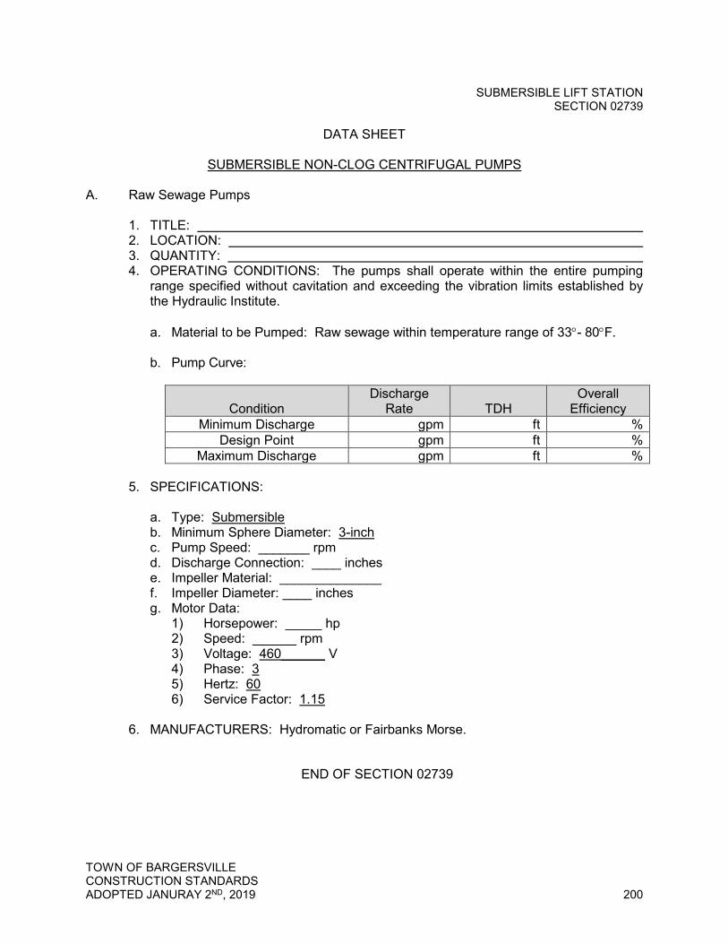
SUBMERSIBLE LIFT STATION SECTION 02739
TOWN OF BARGERSVILLE CONSTRUCTION STANDARDS ADOPTED JANURAY 2ND, 2019 200
DATA SHEET
SUBMERSIBLE NON-CLOG CENTRIFUGAL PUMPS
A. Raw Sewage Pumps 1. TITLE: 2. LOCATION: 3. QUANTITY: 4. OPERATING CONDITIONS: The pumps shall operate within the entire pumping
range specified without cavitation and exceeding the vibration limits established by the Hydraulic Institute.
a. Material to be Pumped: Raw sewage within temperature range of 33°- 80°F. b. Pump Curve:
Condition
Discharge Rate
TDH
Overall Efficiency
Minimum Discharge gpm ft % Design Point gpm ft %
Maximum Discharge gpm ft % 5. SPECIFICATIONS: a. Type: Submersible b. Minimum Sphere Diameter: 3-inch c. Pump Speed: _______ rpm d. Discharge Connection: ____ inches e. Impeller Material: ______________ f. Impeller Diameter: ____ inches g. Motor Data: 1) Horsepower: _____ hp 2) Speed: ______ rpm 3) Voltage: 460______ V 4) Phase: 3 5) Hertz: 60 6) Service Factor: 1.15 6. MANUFACTURERS: Hydromatic or Fairbanks Morse.
END OF SECTION 02739
BIORETENTION SECTION 02960
TOWN OF BARGERSVILLE CONSTRUCTION STANDARDS ADOPTED FEBRUARY 27, 2018 201
SECTION 02960 - BIORETENTION
PART 1 - GENERAL
1.01 Summary
A. Section Includes: Furnishing and installing all stone, soil mixtures, plants, mulch, structures, and pipe required for bioretention area facilities as shown on the Drawings and as specified.
B. Related Sections
1. Section 02101 - Erosion and Sediment Control and Stormwater Pollution Prevention
2. Section 02220 - Trenching, Backfilling, & Compaction 3. Section 02720 - Storm Sewer Systems
1.02 References
A. American National Standards Institute (ANSI), latest editions
1. ANSI Z60.1 - American Standard for Nursery Stock
B. American Society for Testing and Materials (ASTM), latest editions
1. ASTM C76 - Standard Specification for Reinforced Concrete Culvert, Storm Drain, and Sewer Pipe
2. ASTM D422 - Standard Test Method for Particle-Size Analysis of Soils
C. Indiana Department of Transportation (INDOT) Standard Specifications, latest edition
1. Section 904 - Aggregates 2. Section 907 - Concrete, Clay, and Plastic Drainage Components
1.03 Submittals
A. Product Data
1. Gradation analysis of stone from supplier for each type of gravel and riprap 2. Plant list stating botanical and common name 3. Yard inlet 4. Overflow pipe
BIORETENTION SECTION 02960
TOWN OF BARGERSVILLE CONSTRUCTION STANDARDS ADOPTED FEBRUARY 27, 2018 202
B. Soil Testing
1. Soil mixtures shall be tested prior to installation. No material shall be added to the planting soil stockpile after the soil has been tested.
2. Provide sieve analysis, PH test results, and organic matter test results for each bioretention area.
3. All testing shall be performed at the same testing facility. Provide testing facility name, address, contact person, phone number, and email address.
1.04 Quality Assurance
A. Provide plants grown in a recognized nursery in accordance with good horticultural practice. Provide healthy, vigorous stock free of disease, insects, eggs, larvae, and defects such as sun-scald, injuries, abrasions, or disfigurement.
B. Provide plants of sizes shown or specified. Plants of larger size may be used if sizes of roots or balls are increased proportionately.
C. The Town reserves right to inspect trees and shrubs either at place of growth or at site before planting, for compliance with requirements for name, variety, size, and quality.
1.05 Delivery, Storage, and Handling
A. Acceptance at Site
1. Damaged plants and materials will not be accepted. Promptly remove damaged plants and materials from the job site. Replace damaged plants and materials with undamaged items at no additional cost to the Town.
B. Storage and Protection
1. Protect soil to be used in bioretention area from all sources of additional moisture during conveyance and at the project site until incorporated into the Work.
2. Keep root stock of plant material moist during transport and storage. 3. Protect plants and materials from damage and deterioration during delivery
and storage at the site.
1.06 Sequencing
A. Complete site elevation grading and stabilize all disturbed soils within the drainage areas of the proposed bioretention areas. Do not perform bioretention area excavation and construction until the drainage area is fully stabilized.

BIORETENTION SECTION 02960
TOWN OF BARGERSVILLE CONSTRUCTION STANDARDS ADOPTED FEBRUARY 27, 2018 203
1.07 Warranty
A. Refill and restore to the original grade any settlement in the bioretention area soil medium which takes place within one year at no additional cost to the Town. Restore the surface area where settlement has occurred including, but not limited to, installing seed, mulch, and erosion control measures.
B. A 3-year maintenance agreement is required. The Owner shall be responsible for landscaping maintenance including removal of trash, debris, dead vegetation, and sediments; watering; weeding; and mulching.
C. Remove and replace any plantings which have been damaged or destroyed within the 3-year maintenance period at no additional cost to the Town.
PART 2 - PRODUCTS
2.01 Gravel Dry Well
A. No. 8 Washed Gravel
1. Provide well graded INDOT classification No. 8 washed gravel with a maximum diameter of 1 inch.
B. Pea Gravel
1. Provide washed, river-run, round diameter pea gravel with a maximum diameter of 1/2 inch.
2.02 Soil Medium
A. Soil medium shall be a uniform mix, free of brush, seeds, noxious weeds, stones, stumps, roots, or other material over 1-inch diameter. No materials or substances shall be mixed or dumped within the bioretention area that may be harmful to plant growth or prove a hindrance to the planting or maintenance operations.
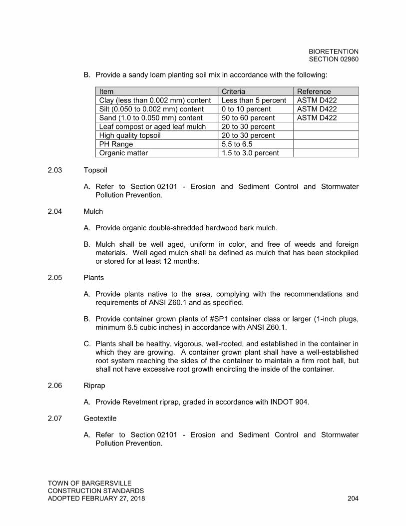
BIORETENTION SECTION 02960
TOWN OF BARGERSVILLE CONSTRUCTION STANDARDS ADOPTED FEBRUARY 27, 2018 204
B. Provide a sandy loam planting soil mix in accordance with the following:
Item Criteria Reference Clay (less than 0.002 mm) content Less than 5 percent ASTM D422 Silt (0.050 to 0.002 mm) content 0 to 10 percent ASTM D422 Sand (1.0 to 0.050 mm) content 50 to 60 percent ASTM D422 Leaf compost or aged leaf mulch 20 to 30 percent High quality topsoil 20 to 30 percent PH Range 5.5 to 6.5 Organic matter 1.5 to 3.0 percent
2.03 Topsoil
A. Refer to Section 02101 - Erosion and Sediment Control and Stormwater Pollution Prevention.
2.04 Mulch
A. Provide organic double-shredded hardwood bark mulch.
B. Mulch shall be well aged, uniform in color, and free of weeds and foreign materials. Well aged mulch shall be defined as mulch that has been stockpiled or stored for at least 12 months.
2.05 Plants
A. Provide plants native to the area, complying with the recommendations and requirements of ANSI Z60.1 and as specified.
B. Provide container grown plants of #SP1 container class or larger (1-inch plugs, minimum 6.5 cubic inches) in accordance with ANSI Z60.1.
C. Plants shall be healthy, vigorous, well-rooted, and established in the container in which they are growing. A container grown plant shall have a well-established root system reaching the sides of the container to maintain a firm root ball, but shall not have excessive root growth encircling the inside of the container.
2.06 Riprap
A. Provide Revetment riprap, graded in accordance with INDOT 904.
2.07 Geotextile
A. Refer to Section 02101 - Erosion and Sediment Control and Stormwater Pollution Prevention.
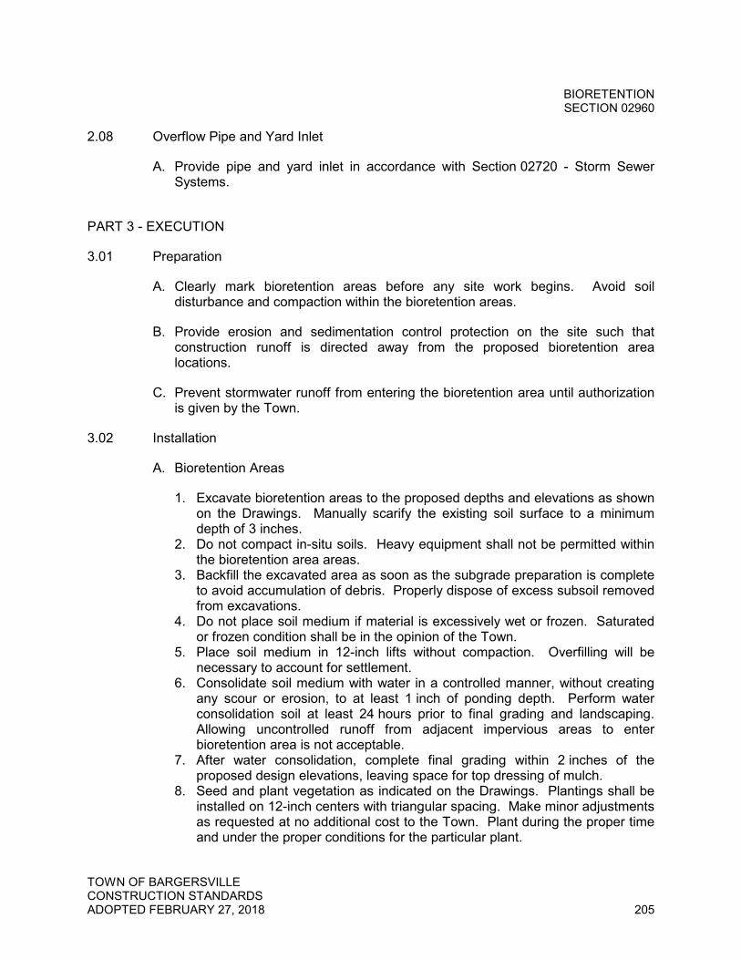
BIORETENTION SECTION 02960
TOWN OF BARGERSVILLE CONSTRUCTION STANDARDS ADOPTED FEBRUARY 27, 2018 205
2.08 Overflow Pipe and Yard Inlet
A. Provide pipe and yard inlet in accordance with Section 02720 - Storm Sewer Systems.
PART 3 - EXECUTION
3.01 Preparation
A. Clearly mark bioretention areas before any site work begins. Avoid soil disturbance and compaction within the bioretention areas.
B. Provide erosion and sedimentation control protection on the site such that construction runoff is directed away from the proposed bioretention area locations.
C. Prevent stormwater runoff from entering the bioretention area until authorization is given by the Town.
3.02 Installation
A. Bioretention Areas
1. Excavate bioretention areas to the proposed depths and elevations as shown on the Drawings. Manually scarify the existing soil surface to a minimum depth of 3 inches.
2. Do not compact in-situ soils. Heavy equipment shall not be permitted within the bioretention area areas.
3. Backfill the excavated area as soon as the subgrade preparation is complete to avoid accumulation of debris. Properly dispose of excess subsoil removed from excavations.
4. Do not place soil medium if material is excessively wet or frozen. Saturated or frozen condition shall be in the opinion of the Town.
5. Place soil medium in 12-inch lifts without compaction. Overfilling will be necessary to account for settlement.
6. Consolidate soil medium with water in a controlled manner, without creating any scour or erosion, to at least 1 inch of ponding depth. Perform water consolidation soil at least 24 hours prior to final grading and landscaping. Allowing uncontrolled runoff from adjacent impervious areas to enter bioretention area is not acceptable.
7. After water consolidation, complete final grading within 2 inches of the proposed design elevations, leaving space for top dressing of mulch.
8. Seed and plant vegetation as indicated on the Drawings. Plantings shall be installed on 12-inch centers with triangular spacing. Make minor adjustments as requested at no additional cost to the Town. Plant during the proper time and under the proper conditions for the particular plant.
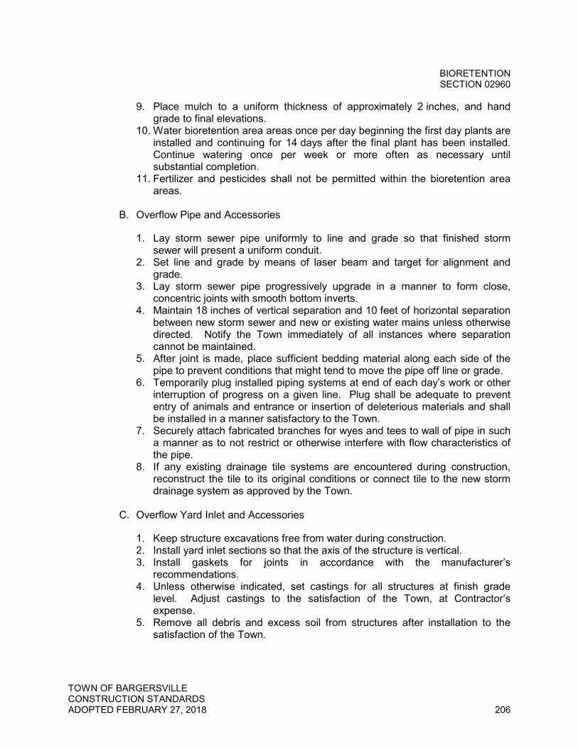
BIORETENTION SECTION 02960
TOWN OF BARGERSVILLE CONSTRUCTION STANDARDS ADOPTED FEBRUARY 27, 2018 206
9. Place mulch to a uniform thickness of approximately 2 inches, and hand grade to final elevations.
10. Water bioretention area areas once per day beginning the first day plants are installed and continuing for 14 days after the final plant has been installed. Continue watering once per week or more often as necessary until substantial completion.
11. Fertilizer and pesticides shall not be permitted within the bioretention area areas.
B. Overflow Pipe and Accessories
1. Lay storm sewer pipe uniformly to line and grade so that finished storm sewer will present a uniform conduit.
2. Set line and grade by means of laser beam and target for alignment and grade.
3. Lay storm sewer pipe progressively upgrade in a manner to form close, concentric joints with smooth bottom inverts.
4. Maintain 18 inches of vertical separation and 10 feet of horizontal separation between new storm sewer and new or existing water mains unless otherwise directed. Notify the Town immediately of all instances where separation cannot be maintained.
5. After joint is made, place sufficient bedding material along each side of the pipe to prevent conditions that might tend to move the pipe off line or grade.
6. Temporarily plug installed piping systems at end of each day’s work or other interruption of progress on a given line. Plug shall be adequate to prevent entry of animals and entrance or insertion of deleterious materials and shall be installed in a manner satisfactory to the Town.
7. Securely attach fabricated branches for wyes and tees to wall of pipe in such a manner as to not restrict or otherwise interfere with flow characteristics of the pipe.
8. If any existing drainage tile systems are encountered during construction, reconstruct the tile to its original conditions or connect tile to the new storm drainage system as approved by the Town.
C. Overflow Yard Inlet and Accessories
1. Keep structure excavations free from water during construction. 2. Install yard inlet sections so that the axis of the structure is vertical. 3. Install gaskets for joints in accordance with the manufacturer’s
recommendations. 4. Unless otherwise indicated, set castings for all structures at finish grade
level. Adjust castings to the satisfaction of the Town, at Contractor’s expense.
5. Remove all debris and excess soil from structures after installation to the satisfaction of the Town.
BIORETENTION SECTION 02960
TOWN OF BARGERSVILLE CONSTRUCTION STANDARDS ADOPTED FEBRUARY 27, 2018 207
3.03 Maintenance and Protection
A. Provide protection against traffic and construction operations by erecting barricades and warning signs immediately after bioretention area landscaping is completed.
B. If bioretention area areas are damaged or destroyed, the affected area shall be repaired or replaced to the satisfaction of the Town.
END OF SECTION 02960
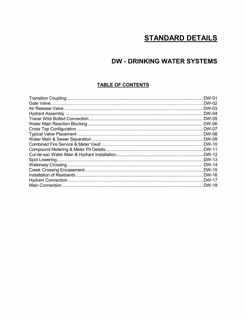
STANDARD DETAILS
DW - DRINKING WATER SYSTEMS
TABLE OF CONTENTS Transition Coupling ................................................................................................................. DW-01 Gate Valve .............................................................................................................................. DW-02 Air Release Valve ................................................................................................................... DW-03 Hydrant Assembly .................................................................................................................. DW-04 Tracer Wire Bolted Connection .............................................................................................. DW-05 Water Main Reaction Blocking ............................................................................................... DW-06 Cross Tap Configuration ........................................................................................................ DW-07 Typical Valve Placement ........................................................................................................ DW-08 Water Main & Sewer Separation ............................................................................................ DW-09 Combined Fire Service & Meter Vault .................................................................................... DW-10 Compound Metering & Meter Pit Details ................................................................................ DW-11 Cul-de-sac Water Main & Hydrant Installation ........................................................................ DW-12 Spot Lowering ......................................................................................................................... DW-13 Waterway Crossing ................................................................................................................ DW-14 Creek Crossing Encasement .................................................................................................. DW-15 Installation of Restraints ......................................................................................................... DW-16 Hydrant Connection ................................................................................................................ DW-17 Main Connection ..................................................................................................................... DW-18

STANDARD DETAILS
SS - SANITARY SEWER SYSTEMS
TABLE OF CONTENTS Sanitary Lateral for Shallow Sewers (Less than 15’ Deep) .................................................... SS-01 Sanitary Lateral for Deep Sewers (15’ Deep and Over) ......................................................... SS-02 Type 1 Cleanout ..................................................................................................................... SS-03 Type 2 Cleanout ..................................................................................................................... SS-04 Type 3 Cleanout ..................................................................................................................... SS-05 New Service Connection to Existing Sanitary Sewer ............................................................. SS-06 Standard Sanitary Manhole .................................................................................................... SS-07 Shallow Sanitary Manhole ...................................................................................................... SS-08 Large Diameter Sanitary Manhole .......................................................................................... SS-09 Standard Manhole Benches ................................................................................................... SS-10 Precast Concrete Adjusting Ring............................................................................................ SS-11 Sanitary Manhole Installed Over Existing Sewer .................................................................... SS-12 Inside Drop into Sanitary Manhole .......................................................................................... SS-13 Outside Drop Manhole ............................................................................................................ SS-14 Existing Manhole Connection ................................................................................................. SS-15 Drop Control Earth Filler Detail ............................................................................................... SS-16 First Class Pipe Laying Method for Rigid Conduits (Ductile Iron) .......................................... SS-17 First Class Pipe Laying Method for PVC Gravity Sewer ......................................................... SS-18 PVC Force Main Pipe Trench Detail ....................................................................................... SS-19 Force Main Marking Detail ...................................................................................................... SS-20 Air/Vacuum Release Valve & Vault Detail .............................................................................. SS-21 Valve & Box Detail .................................................................................................................. SS-22 Thrust Blocking Details for Pressure Main ............................................................................. SS-23 Railroad Pipe Crossing Detail ................................................................................................. SS-24 State Highway Boring/Casing Detail ....................................................................................... SS-25 Sanitary Sewer Stream Crossing Detail ................................................................................. SS-26 Typical Lift Station Plan .......................................................................................................... SS-27 Typical Lift Station Section ..................................................................................................... SS-28 Typical Pump Station Electrical and Pump Control Mounting Detail ...................................... SS-29 Typical Pump Station Service Pole for Pump Station Services .............................................. SS-30 Typical Pump Station Power Distribution Diagram ................................................................. SS-31 Bypass Pump Quick Connection Detail .................................................................................. SS-32 Grease Trap Detail ................................................................................................................. SS-33 Blow Off Valve Detail for Traffic Bearing Areas ...................................................................... SS-34 Blow Off Valve Detail for Non-Traffic Bearing Areas .............................................................. SS-35 Lift Station Enclosure .............................................................................................................. SS-36 Low Pressure Service Connection ......................................................................................... SS-37

STANDARD DETAILS
SW - STORM WATER SYSTEMS
TABLE OF CONTENTS Gravity Sewer Repair ............................................................................................................ SW-01 Silt Fence ............................................................................................................................... SW-02 Turf Armored Ditch ................................................................................................................ SW-03 Hard Armored Ditch ............................................................................................................... SW-04 Detention/Retention Ponds .................................................................................................... SW-05 Rigid (RCP, DI) Pipe Trench ................................................................................................. SW-06 Flexible (HDPE, PVC) Pipe Trench ....................................................................................... SW-07 Gravity Pipe Crossing Waterway ........................................................................................... SW-08 Gravity Pipe Crossing Roadway/Railroad .............................................................................. SW-09 Drainage Swale with Underdrain ........................................................................................... SW-10 Drainage Lateral in Rear of Lot ............................................................................................. SW-11 Not Used................................................................................................................................ SW-12 Precast Concrete End Section .............................................................................................. SW-13 Trash Guard .......................................................................................................................... SW-14 Standard Storm Manhole ....................................................................................................... SW-15 Large Diameter Storm Manhole ............................................................................................ SW-16 Inlet Type A ........................................................................................................................... SW-17 Yard Inlet ............................................................................................................................... SW-18
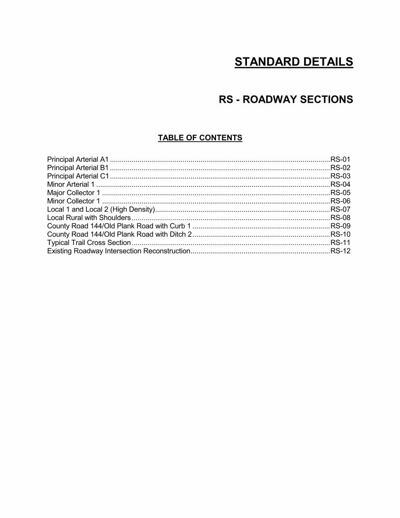
STANDARD DETAILS
RS - ROADWAY SECTIONS
TABLE OF CONTENTS Principal Arterial A1 ................................................................................................................ RS-01 Principal Arterial B1 ................................................................................................................ RS-02 Principal Arterial C1 ................................................................................................................ RS-03 Minor Arterial 1 ....................................................................................................................... RS-04 Major Collector 1 .................................................................................................................... RS-05 Minor Collector 1 .................................................................................................................... RS-06 Local 1 and Local 2 (High Density) ......................................................................................... RS-07 Local Rural with Shoulders ..................................................................................................... RS-08 County Road 144/Old Plank Road with Curb 1 ...................................................................... RS-09 County Road 144/Old Plank Road with Ditch 2 ...................................................................... RS-10 Typical Trail Cross Section ..................................................................................................... RS-11 Existing Roadway Intersection Reconstruction ....................................................................... RS-12

STANDARD DETAILS
TR - TRANSPORTATION
TABLE OF CONTENTS Concrete Chair Back Curb & Gutter ....................................................................................... TR-01 Concrete Roll Curb & Gutter ................................................................................................... TR-02 Driveway Curb Cut ................................................................................................................. TR-03 Curb Inlet Detail ...................................................................................................................... TR-04 Concrete Center Curb ............................................................................................................ TR-05 Underdrain Pipe Detail Chair Back Curb ................................................................................ TR-06 Underdrain Pipe Detail Roll Curb ............................................................................................ TR-07 Connection to Existing Streets ............................................................................................... TR-08 Widening Detail ...................................................................................................................... TR-09 HMA Pavement Trench Repair Detail .................................................................................... TR-10 Major Commercial and Subdivision Entrance Requirements ................................................. TR-11 Commercial & Industrial Cul-de-sac Turnarounds .................................................................. TR-12 Local Cul-de-sac Turnarounds Street Class 1 ........................................................................ TR-13 Temporary Cul-de-sac Street Class 1 .................................................................................... TR-14 End of Road Detail ................................................................................................................. TR-15 Standard Barricade ................................................................................................................. TR-16 Concrete Apron at Sewer Structures .................................................................................... TR-17 Local Street with Roadside Ditch .......................................................................................... TR-18 Concrete Sidewalk Detail....................................................................................................... TR-19 Rolled Curb Ramp Detail ....................................................................................................... TR-20 Sidewalk and Curb Ramp Notes ........................................................................................... TR-21 Street Sign ............................................................................................................................. TR-22 Sign Post ................................................................................................................................ TR-23
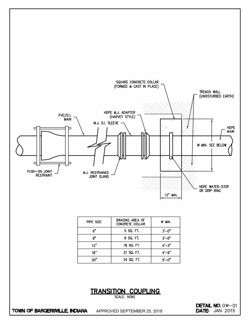
APPROVED SEPTEMBER 25, 2018
AutoCAD SHX Text
SQUARE CONCRETE COLLAR (FORMED & CAST IN PLACE)
AutoCAD SHX Text
PVC/D.I. MAIN
AutoCAD SHX Text
M.J. D.I. SLEEVE
AutoCAD SHX Text
HDPE M.J. ADAPTER (HARVEY STYLE)
AutoCAD SHX Text
M.J. RESTRAINED JOINT GLAND
AutoCAD SHX Text
PUSH-ON JOINT RESTRAINT
AutoCAD SHX Text
TRENCH WALL (UNDISTURBED EARTH)
AutoCAD SHX Text
HDPE MAIN
AutoCAD SHX Text
HDPE WATER-STOP OR GRIP RING
AutoCAD SHX Text
BRACING AREA OF CONCRETE COLLAR
AutoCAD SHX Text
W MIN.
AutoCAD SHX Text
5 SQ. FT.
AutoCAD SHX Text
PIPE SIZE
AutoCAD SHX Text
6"
AutoCAD SHX Text
3'-0"
AutoCAD SHX Text
3'-6"
AutoCAD SHX Text
9 SQ. FT.
AutoCAD SHX Text
8"
AutoCAD SHX Text
4'-3"
AutoCAD SHX Text
18 SQ. FT.
AutoCAD SHX Text
12"
AutoCAD SHX Text
4'-9"
AutoCAD SHX Text
21 SQ. FT.
AutoCAD SHX Text
16"
AutoCAD SHX Text
5'-0"
AutoCAD SHX Text
24 SQ. FT.
AutoCAD SHX Text
20"
AutoCAD SHX Text
TOWN OF BARGERSVILLE, INDIANA
AutoCAD SHX Text
DATE:
AutoCAD SHX Text
DETAIL NO.
AutoCAD SHX Text
SCALE: NONE
AutoCAD SHX Text
DW-
AutoCAD SHX Text
TRANSITION COUPLING
AutoCAD SHX Text
01
AutoCAD SHX Text
JAN 2015

APPROVED SEPTEMBER 25, 2018
AutoCAD SHX Text
CONCRETE SUPPORT BLOCKING (16"x16"x6")
AutoCAD SHX Text
NEW MAIN
AutoCAD SHX Text
HAND COMPACTED SOIL
AutoCAD SHX Text
GATE VALVE
AutoCAD SHX Text
FINISHED GRADE
AutoCAD SHX Text
8" C.I. VALVE BOX LID MARKED "WATER"
AutoCAD SHX Text
FLUSH WITH GRADE
AutoCAD SHX Text
TRACER WIRE BRANCH CONNECTION
AutoCAD SHX Text
TRACER WIRE
AutoCAD SHX Text
C.I. VALVE BOX
AutoCAD SHX Text
INSTALL 3" "S" HOOKS
AutoCAD SHX Text
2" VALVE OPERATING NUT
AutoCAD SHX Text
14" DRILLED HOLE
AutoCAD SHX Text
TOWN OF BARGERSVILLE, INDIANA
AutoCAD SHX Text
DATE:
AutoCAD SHX Text
DETAIL NO.
AutoCAD SHX Text
SCALE: NONE
AutoCAD SHX Text
DW-
AutoCAD SHX Text
GATE VALVE
AutoCAD SHX Text
02
AutoCAD SHX Text
JAN 2015
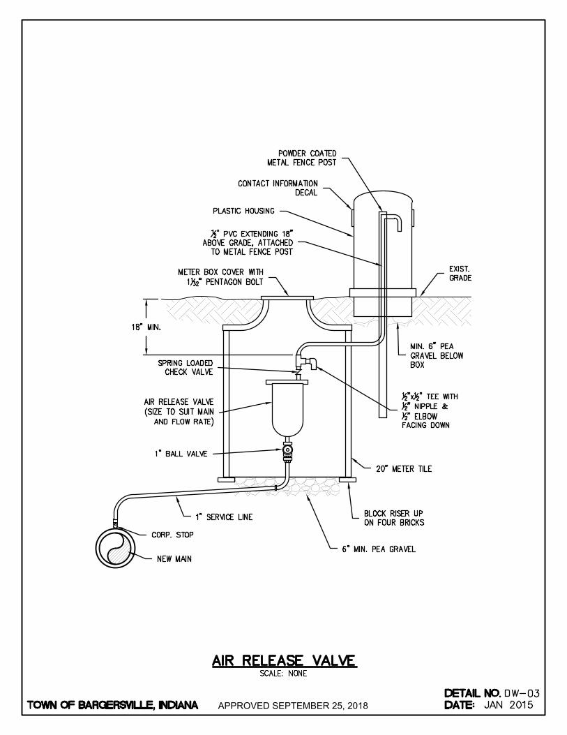
APPROVED SEPTEMBER 25, 2018
AutoCAD SHX Text
METER BOX COVER WITH 1 " PENTAGON BOLT132" PENTAGON BOLT
AutoCAD SHX Text
POWDER COATED METAL FENCE POST
AutoCAD SHX Text
12" PVC EXTENDING 18" ABOVE GRADE, ATTACHED TO METAL FENCE POST
AutoCAD SHX Text
20" METER TILE
AutoCAD SHX Text
AIR RELEASE VALVE (SIZE TO SUIT MAIN AND FLOW RATE)
AutoCAD SHX Text
BLOCK RISER UP ON FOUR BRICKS
AutoCAD SHX Text
1" SERVICE LINE
AutoCAD SHX Text
NEW MAIN
AutoCAD SHX Text
CORP. STOP
AutoCAD SHX Text
1" BALL VALVE
AutoCAD SHX Text
CONTACT INFORMATION DECAL
AutoCAD SHX Text
MIN. 6" PEA GRAVEL BELOW BOX
AutoCAD SHX Text
6" MIN. PEA GRAVEL
AutoCAD SHX Text
12"x " TEE WITH x " TEE WITH 12" TEE WITH 12" NIPPLE & 12" ELBOW FACING DOWN
AutoCAD SHX Text
EXIST. GRADE
AutoCAD SHX Text
SPRING LOADED CHECK VALVE
AutoCAD SHX Text
PLASTIC HOUSING
AutoCAD SHX Text
TOWN OF BARGERSVILLE, INDIANA
AutoCAD SHX Text
DATE:
AutoCAD SHX Text
DETAIL NO.
AutoCAD SHX Text
SCALE: NONE
AutoCAD SHX Text
DW-
AutoCAD SHX Text
AIR RELEASE VALVE
AutoCAD SHX Text
03
AutoCAD SHX Text
JAN 2015
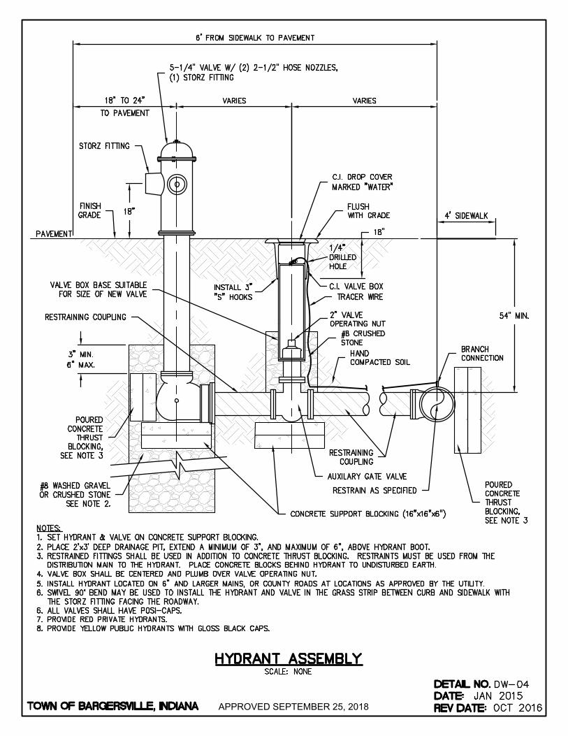
APPROVED SEPTEMBER 25, 2018
AutoCAD SHX Text
NOTES: 1. SET HYDRANT & VALVE ON CONCRETE SUPPORT BLOCKING. SET HYDRANT & VALVE ON CONCRETE SUPPORT BLOCKING. 2. PLACE 2'x3' DEEP DRAINAGE PIT, EXTEND A MINIMUM OF 3", AND MAXIMUM OF 6", ABOVE HYDRANT BOOT. PLACE 2'x3' DEEP DRAINAGE PIT, EXTEND A MINIMUM OF 3", AND MAXIMUM OF 6", ABOVE HYDRANT BOOT. 3. RESTRAINED FITTINGS SHALL BE USED IN ADDITION TO CONCRETE THRUST BLOCKING. RESTRAINTS MUST BE USED FROM THE RESTRAINED FITTINGS SHALL BE USED IN ADDITION TO CONCRETE THRUST BLOCKING. RESTRAINTS MUST BE USED FROM THE DISTRIBUTION MAIN TO THE HYDRANT. PLACE CONCRETE BLOCKS BEHIND HYDRANT TO UNDISTURBED EARTH. 4. VALVE BOX SHALL BE CENTERED AND PLUMB OVER VALVE OPERATING NUT. VALVE BOX SHALL BE CENTERED AND PLUMB OVER VALVE OPERATING NUT. 5. INSTALL HYDRANT LOCATED ON 6" AND LARGER MAINS, OR COUNTY ROADS AT LOCATIONS AS APPROVED BY THE UTILITY. INSTALL HYDRANT LOCATED ON 6" AND LARGER MAINS, OR COUNTY ROADS AT LOCATIONS AS APPROVED BY THE UTILITY. 6. SWIVEL 90° BEND MAY BE USED TO INSTALL THE HYDRANT AND VALVE IN THE GRASS STRIP BETWEEN CURB AND SIDEWALK WITHTHE STORZ FITTING FACING THE ROADWAY. 6. ALL VALVES SHALL HAVE POSI-CAPS. ALL VALVES SHALL HAVE POSI-CAPS. 7. PROVIDE RED PRIVATE HYDRANTS. PROVIDE RED PRIVATE HYDRANTS. 8. PROVIDE YELLOW PUBLIC HYDRANTS WITH GLOSS BLACK CAPS.PROVIDE YELLOW PUBLIC HYDRANTS WITH GLOSS BLACK CAPS.
AutoCAD SHX Text
HAND COMPACTED SOIL
AutoCAD SHX Text
#8 WASHED GRAVEL OR CRUSHED STONE SEE NOTE 2.
AutoCAD SHX Text
FLUSH WITH GRADE
AutoCAD SHX Text
C.I. DROP COVER MARKED "WATER"
AutoCAD SHX Text
FINISH GRADE
AutoCAD SHX Text
5-1/4" VALVE W/ (2) 2-1/2" HOSE NOZZLES, (1) STORZ FITTING
AutoCAD SHX Text
TRACER WIRE
AutoCAD SHX Text
BRANCH CONNECTION
AutoCAD SHX Text
POURED CONCRETE THRUST BLOCKING, SEE NOTE 3
AutoCAD SHX Text
#8 CRUSHED STONE
AutoCAD SHX Text
C.I. VALVE BOX
AutoCAD SHX Text
INSTALL 3" "S" HOOKS
AutoCAD SHX Text
2" VALVE OPERATING NUT
AutoCAD SHX Text
18" TO 24"
AutoCAD SHX Text
18" TO 24"
AutoCAD SHX Text
PAVEMENT
AutoCAD SHX Text
1/4" DRILLED HOLE
AutoCAD SHX Text
POURED CONCRETE THRUST BLOCKING, SEE NOTE 3
AutoCAD SHX Text
RESTRAINING COUPLING
AutoCAD SHX Text
STORZ FITTING
AutoCAD SHX Text
VALVE BOX BASE SUITABLE FOR SIZE OF NEW VALVE
AutoCAD SHX Text
RESTRAIN AS SPECIFIED
AutoCAD SHX Text
AUXILARY GATE VALVE
AutoCAD SHX Text
CONCRETE SUPPORT BLOCKING (16"x16"x6")
AutoCAD SHX Text
RESTRAINING COUPLING
AutoCAD SHX Text
TOWN OF BARGERSVILLE, INDIANA
AutoCAD SHX Text
DATE:
AutoCAD SHX Text
DETAIL NO.
AutoCAD SHX Text
DW-04
AutoCAD SHX Text
REV DATE:
AutoCAD SHX Text
JAN 2015
AutoCAD SHX Text
OCT 2016
AutoCAD SHX Text
SCALE: NONE
AutoCAD SHX Text
HYDRANT ASSEMBLY
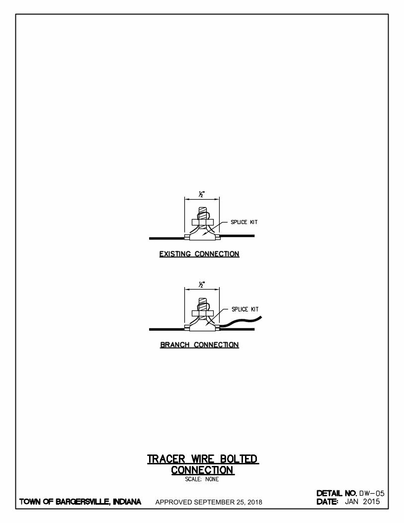
APPROVED SEPTEMBER 25, 2018
AutoCAD SHX Text
%%UEXISTING CONNECTION
AutoCAD SHX Text
%%UBRANCH CONNECTION
AutoCAD SHX Text
SPLICE KIT
AutoCAD SHX Text
SPLICE KIT
AutoCAD SHX Text
TOWN OF BARGERSVILLE, INDIANA
AutoCAD SHX Text
DATE:
AutoCAD SHX Text
DETAIL NO.
AutoCAD SHX Text
SCALE: NONE
AutoCAD SHX Text
DW-
AutoCAD SHX Text
TRACER WIRE BOLTED CONNECTION
AutoCAD SHX Text
05
AutoCAD SHX Text
JAN 2015
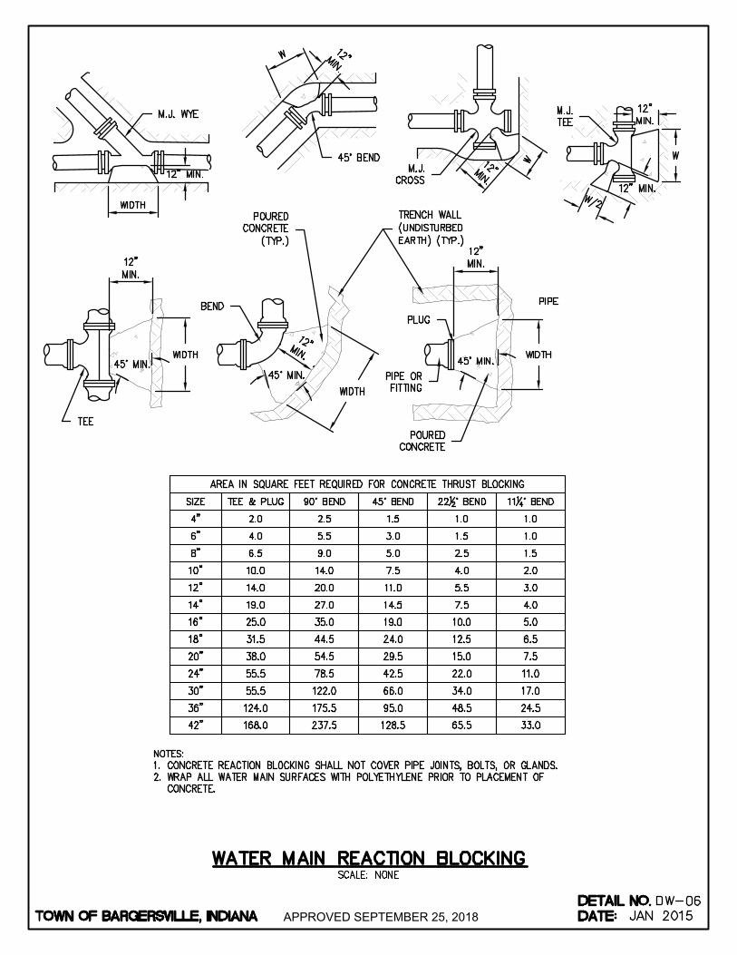
APPROVED SEPTEMBER 25, 2018
AutoCAD SHX Text
NOTES: 1. CONCRETE REACTION BLOCKING SHALL NOT COVER PIPE JOINTS, BOLTS, OR GLANDS. CONCRETE REACTION BLOCKING SHALL NOT COVER PIPE JOINTS, BOLTS, OR GLANDS. 2. WRAP ALL WATER MAIN SURFACES WITH POLYETHYLENE PRIOR TO PLACEMENT OF WRAP ALL WATER MAIN SURFACES WITH POLYETHYLENE PRIOR TO PLACEMENT OF CONCRETE.
AutoCAD SHX Text
PIPE
AutoCAD SHX Text
POURED CONCRETE
AutoCAD SHX Text
PIPE OR FITTING
AutoCAD SHX Text
PLUG
AutoCAD SHX Text
POURED CONCRETE (TYP.)
AutoCAD SHX Text
BEND
AutoCAD SHX Text
TEE
AutoCAD SHX Text
TRENCH WALL (UNDISTURBED EARTH) (TYP.)
AutoCAD SHX Text
4"
AutoCAD SHX Text
6"
AutoCAD SHX Text
8"
AutoCAD SHX Text
10"
AutoCAD SHX Text
12"
AutoCAD SHX Text
TEE & PLUG
AutoCAD SHX Text
22 ° BEND12° BEND
AutoCAD SHX Text
45° BEND
AutoCAD SHX Text
90° BEND
AutoCAD SHX Text
SIZE
AutoCAD SHX Text
M.J. TEE
AutoCAD SHX Text
M.J. CROSS
AutoCAD SHX Text
45° BEND
AutoCAD SHX Text
M.J. WYE
AutoCAD SHX Text
AREA IN SQUARE FEET REQUIRED FOR CONCRETE THRUST BLOCKING
AutoCAD SHX Text
11 ° BEND14° BEND
AutoCAD SHX Text
2.0
AutoCAD SHX Text
1.5
AutoCAD SHX Text
2.5
AutoCAD SHX Text
4.0
AutoCAD SHX Text
3.0
AutoCAD SHX Text
5.5
AutoCAD SHX Text
6.5
AutoCAD SHX Text
5.0
AutoCAD SHX Text
9.0
AutoCAD SHX Text
10.0
AutoCAD SHX Text
7.5
AutoCAD SHX Text
14.0
AutoCAD SHX Text
14.0
AutoCAD SHX Text
11.0
AutoCAD SHX Text
20.0
AutoCAD SHX Text
14"
AutoCAD SHX Text
19.0
AutoCAD SHX Text
14.5
AutoCAD SHX Text
27.0
AutoCAD SHX Text
16"
AutoCAD SHX Text
25.0
AutoCAD SHX Text
19.0
AutoCAD SHX Text
35.0
AutoCAD SHX Text
18"
AutoCAD SHX Text
31.5
AutoCAD SHX Text
24.0
AutoCAD SHX Text
44.5
AutoCAD SHX Text
20"
AutoCAD SHX Text
38.0
AutoCAD SHX Text
29.5
AutoCAD SHX Text
54.5
AutoCAD SHX Text
24"
AutoCAD SHX Text
55.5
AutoCAD SHX Text
42.5
AutoCAD SHX Text
78.5
AutoCAD SHX Text
30"
AutoCAD SHX Text
55.5
AutoCAD SHX Text
66.0
AutoCAD SHX Text
122.0
AutoCAD SHX Text
36"
AutoCAD SHX Text
124.0
AutoCAD SHX Text
95.0
AutoCAD SHX Text
175.5
AutoCAD SHX Text
42"
AutoCAD SHX Text
168.0
AutoCAD SHX Text
128.5
AutoCAD SHX Text
237.5
AutoCAD SHX Text
7.5
AutoCAD SHX Text
10.0
AutoCAD SHX Text
12.5
AutoCAD SHX Text
15.0
AutoCAD SHX Text
22.0
AutoCAD SHX Text
34.0
AutoCAD SHX Text
48.5
AutoCAD SHX Text
65.5
AutoCAD SHX Text
4.0
AutoCAD SHX Text
5.0
AutoCAD SHX Text
6.5
AutoCAD SHX Text
7.5
AutoCAD SHX Text
11.0
AutoCAD SHX Text
17.0
AutoCAD SHX Text
24.5
AutoCAD SHX Text
33.0
AutoCAD SHX Text
1.0
AutoCAD SHX Text
1.5
AutoCAD SHX Text
2.5
AutoCAD SHX Text
4.0
AutoCAD SHX Text
5.5
AutoCAD SHX Text
1.0
AutoCAD SHX Text
1.0
AutoCAD SHX Text
1.5
AutoCAD SHX Text
2.0
AutoCAD SHX Text
3.0
AutoCAD SHX Text
TOWN OF BARGERSVILLE, INDIANA
AutoCAD SHX Text
DATE:
AutoCAD SHX Text
DETAIL NO.
AutoCAD SHX Text
SCALE: NONE
AutoCAD SHX Text
DW-
AutoCAD SHX Text
WATER MAIN REACTION BLOCKING
AutoCAD SHX Text
06
AutoCAD SHX Text
JAN 2015
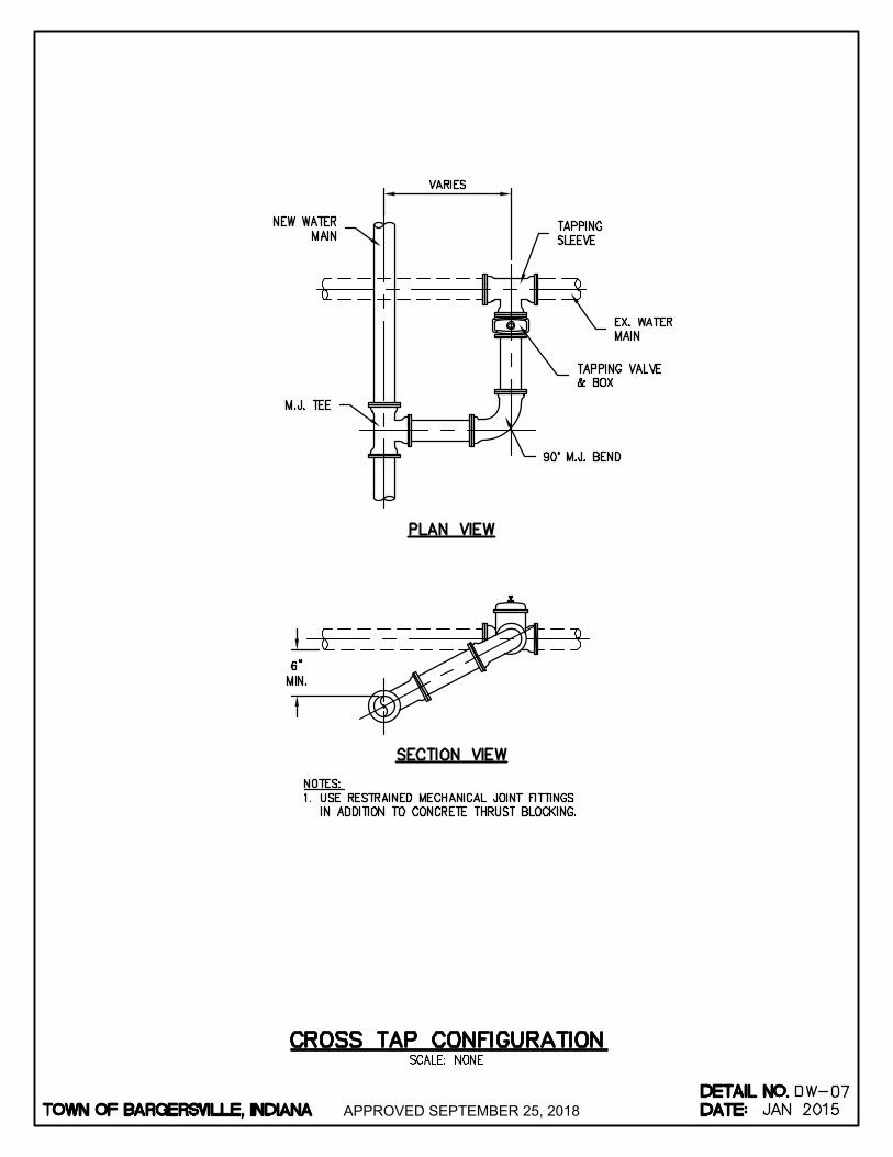
APPROVED SEPTEMBER 25, 2018
AutoCAD SHX Text
%%UPLAN VIEW
AutoCAD SHX Text
%%USECTION VIEW
AutoCAD SHX Text
M.J. TEE
AutoCAD SHX Text
90° M.J. BEND
AutoCAD SHX Text
TAPPING VALVE & BOX
AutoCAD SHX Text
EX. WATER MAIN
AutoCAD SHX Text
TAPPING SLEEVE
AutoCAD SHX Text
NEW WATER MAIN
AutoCAD SHX Text
NOTES: 1. USE RESTRAINED MECHANICAL JOINT FITTINGS USE RESTRAINED MECHANICAL JOINT FITTINGS IN ADDITION TO CONCRETE THRUST BLOCKING.
AutoCAD SHX Text
TOWN OF BARGERSVILLE, INDIANA
AutoCAD SHX Text
DATE:
AutoCAD SHX Text
DETAIL NO.
AutoCAD SHX Text
SCALE: NONE
AutoCAD SHX Text
DW-
AutoCAD SHX Text
CROSS TAP CONFIGURATION
AutoCAD SHX Text
07
AutoCAD SHX Text
JAN 2015

APPROVED SEPTEMBER 25, 2018
AutoCAD SHX Text
CONTINUOUS RUNS VALVE SEPARATION: 6" THROUGH 12" VALVES, INSTALLATION EVERY 1000' TO 1200' 6" THROUGH 12" VALVES, INSTALLATION EVERY 1000' TO 1200' 16" THROUGH 18" VALVES, INSTALLATION EVERY 1200' TO 1800' FOR LARGER MAINS THE VALVE SEPARATION MAY BE REDUCED WITHIN A DEVELOPMENT, AS APPROVED BY THE TOWN OF BARGERSVILLE. VALVES ON ALL 4 CORNERS AND ON ALL THREE SIDES OF T ROAD.
AutoCAD SHX Text
%%UPLAN VIEWS
AutoCAD SHX Text
VALVE DESIGN AT TEE INTERSECTION
AutoCAD SHX Text
R/W
AutoCAD SHX Text
SIDEWALK
AutoCAD SHX Text
R/W
AutoCAD SHX Text
R/W
AutoCAD SHX Text
SIDEWALK
AutoCAD SHX Text
B.O.
AutoCAD SHX Text
NEW WATER MAIN (TYP.)
AutoCAD SHX Text
EX. WATER MAIN
AutoCAD SHX Text
WALK
AutoCAD SHX Text
H
AutoCAD SHX Text
Y
AutoCAD SHX Text
D
AutoCAD SHX Text
WV
AutoCAD SHX Text
EX. VALVE
AutoCAD SHX Text
EX. HYDRANT
AutoCAD SHX Text
NEW M.J. SLEEVE
AutoCAD SHX Text
R/W
AutoCAD SHX Text
VALVE DESIGN AT INTERSECTION
AutoCAD SHX Text
R/W
AutoCAD SHX Text
R/W
AutoCAD SHX Text
WV
AutoCAD SHX Text
WV
AutoCAD SHX Text
R/W
AutoCAD SHX Text
SIDEWALK
AutoCAD SHX Text
NEW WATER MAIN (TYP.)
AutoCAD SHX Text
B.O.
AutoCAD SHX Text
WV
AutoCAD SHX Text
WV
AutoCAD SHX Text
SIDEWALK
AutoCAD SHX Text
CURB
AutoCAD SHX Text
BARRIER
AutoCAD SHX Text
WV
AutoCAD SHX Text
WV
AutoCAD SHX Text
NEW VALVE
AutoCAD SHX Text
H
AutoCAD SHX Text
Y
AutoCAD SHX Text
D
AutoCAD SHX Text
WV
AutoCAD SHX Text
H
AutoCAD SHX Text
Y
AutoCAD SHX Text
D
AutoCAD SHX Text
CURB
AutoCAD SHX Text
NEW HYDRANT
AutoCAD SHX Text
NEW VALVE
AutoCAD SHX Text
%%UPLAN VIEWS
AutoCAD SHX Text
NOTE: ALL VALVES ARE TO BE INSTALLED WITHIN 10' OF AN INTERSECTION OR NEAR A FIRE HYDRANT.
AutoCAD SHX Text
WV
AutoCAD SHX Text
WV
AutoCAD SHX Text
TOWN OF BARGERSVILLE, INDIANA
AutoCAD SHX Text
DATE:
AutoCAD SHX Text
DETAIL NO.
AutoCAD SHX Text
SCALE: NONE
AutoCAD SHX Text
DW-
AutoCAD SHX Text
TYPICAL VALVE PLACEMENT
AutoCAD SHX Text
08
AutoCAD SHX Text
JAN 2015
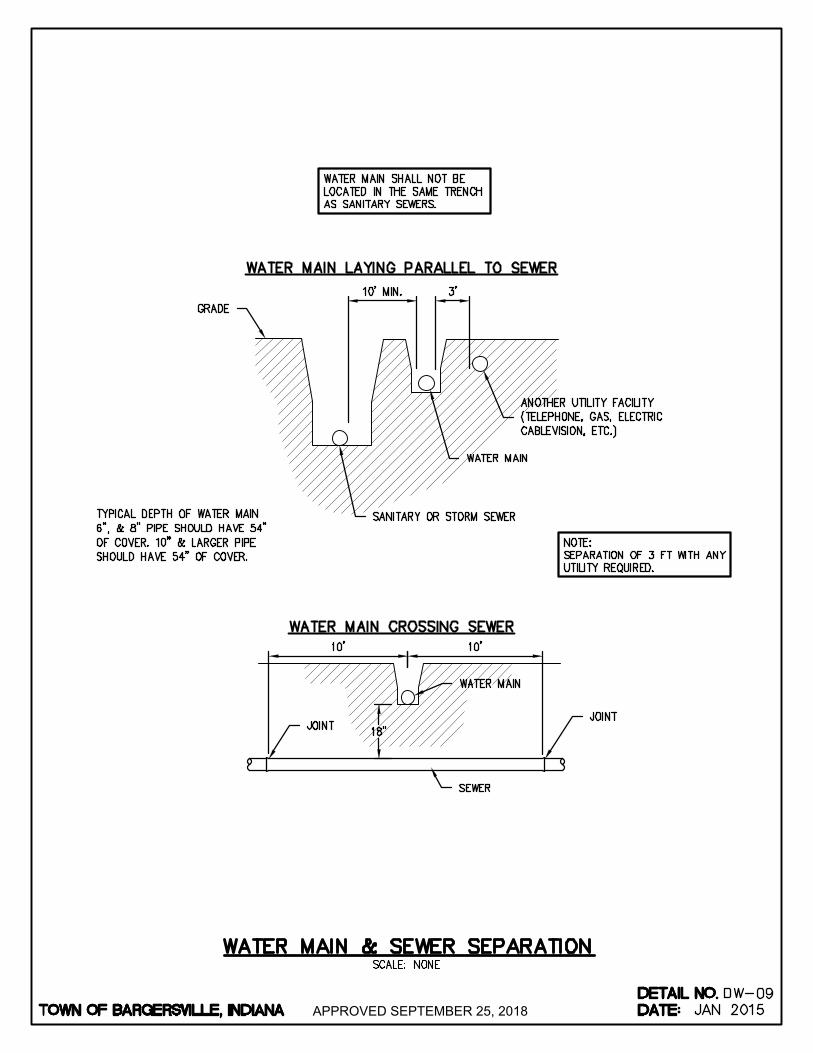
APPROVED SEPTEMBER 25, 2018
AutoCAD SHX Text
GRADE
AutoCAD SHX Text
JOINT
AutoCAD SHX Text
JOINT
AutoCAD SHX Text
%%UWATER MAIN CROSSING SEWER
AutoCAD SHX Text
WATER MAIN
AutoCAD SHX Text
%%UWATER MAIN LAYING PARALLEL TO SEWER
AutoCAD SHX Text
WATER MAIN
AutoCAD SHX Text
ANOTHER UTILITY FACILITY (TELEPHONE, GAS, ELECTRIC CABLEVISION, ETC.)
AutoCAD SHX Text
SANITARY OR STORM SEWER
AutoCAD SHX Text
NOTE: SEPARATION OF 3 FT WITH ANY UTILITY REQUIRED.
AutoCAD SHX Text
WATER MAIN SHALL NOT BE LOCATED IN THE SAME TRENCH AS SANITARY SEWERS.
AutoCAD SHX Text
TYPICAL DEPTH OF WATER MAIN 6", & 8" PIPE SHOULD HAVE 54" OF COVER. 10" & LARGER PIPE SHOULD HAVE 54" OF COVER.
AutoCAD SHX Text
SEWER
AutoCAD SHX Text
TOWN OF BARGERSVILLE, INDIANA
AutoCAD SHX Text
DATE:
AutoCAD SHX Text
DETAIL NO.
AutoCAD SHX Text
SCALE: NONE
AutoCAD SHX Text
DW-
AutoCAD SHX Text
WATER MAIN & SEWER SEPARATION
AutoCAD SHX Text
09
AutoCAD SHX Text
JAN 2015

APPROVED JANUARY 2, 2019
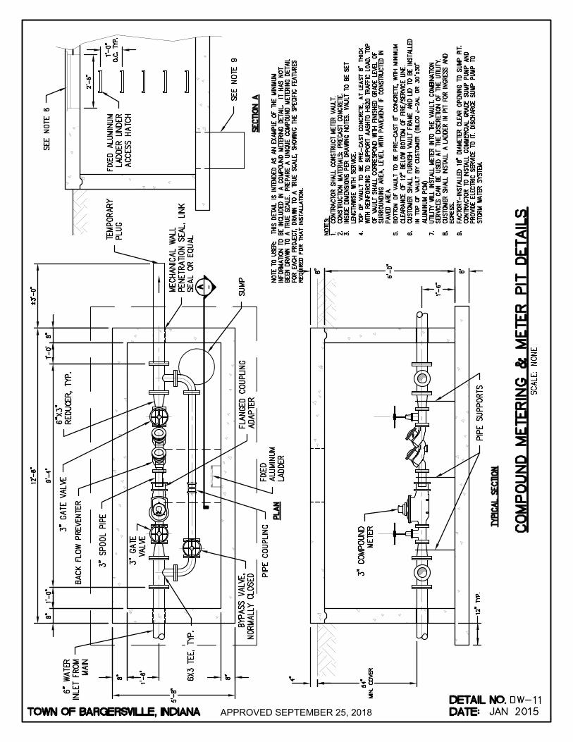
APPROVED SEPTEMBER 25, 2018
AutoCAD SHX Text
%%UTYPICAL SECTION
AutoCAD SHX Text
%%UPLAN
AutoCAD SHX Text
3" COMPOUND METER
AutoCAD SHX Text
SEE NOTE 6
AutoCAD SHX Text
6X3 TEE, TYP.
AutoCAD SHX Text
BYPASS VALVE, NORMALLY CLOSED
AutoCAD SHX Text
FLANGED COUPLING ADAPTER
AutoCAD SHX Text
SUMP
AutoCAD SHX Text
MECHANICAL WALL PENETRATION SEAL, LINK SEAL OR EQUAL
AutoCAD SHX Text
FIXED ALUMINUM LADDER UNDER ACCESS HATCH
AutoCAD SHX Text
NOTE TO USER: THIS DETAIL IS INTENDED AS AN EXAMPLE OF THE MINIMUM INFORMATION TO BE INCLUDED IN A COMPOUND METERING DETAIL. IT HAS NOT BEEN DRAWN TO A TRUE SCALE. PREPARE A UNIQUE COMPOUND METERING DETAIL FOR EACH PROJECT, DRAWN TO A TRUE SCALE, SHOWING THE SPECIFIC FEATURES REQUIRED FOR THAT INSTALLATION.
AutoCAD SHX Text
NOTES: 1. CONTRACTOR SHALL CONSTRUCT METER VAULT. CONTRACTOR SHALL CONSTRUCT METER VAULT. 2. CONSTRUCTION MATERIALS: PRECAST CONCRETE. CONSTRUCTION MATERIALS: PRECAST CONCRETE. 3. INSIDE DIMENSIONS PER DRAWING NOTES. VAULT TO BE SET INSIDE DIMENSIONS PER DRAWING NOTES. VAULT TO BE SET LENGTHWISE WITH SERVICE. 4. TOP OF VAULT TO BE PRE-CAST CONCRETE, AT LEAST 8" THICK TOP OF VAULT TO BE PRE-CAST CONCRETE, AT LEAST 8" THICK WITH REINFORCING TO SUPPORT AASHTO HS20 TRAFFIC LOAD. TOP OF VAULT SHALL CORRESPOND WITH FINISHED GRADE LEVEL OF SURROUNDING AREA, LEVEL WITH PAVEMENT IF CONSTRUCTED IN PAVED AREA. 5. BOTTOM OF VAULT TO BE PRE-CAST 8" CONCRETE, WITH MINIMUM BOTTOM OF VAULT TO BE PRE-CAST 8" CONCRETE, WITH MINIMUM CLEARANCE OF 12" BELOW BOTTOM OF FIRE/SERVICE LINE. 6. CUSTOMER SHALL FURNISH VAULT FRAME AND LID TO BE INSTALLED CUSTOMER SHALL FURNISH VAULT FRAME AND LID TO BE INSTALLED IN TOP OF VAULT BY CUSTOMER (BILCO J-2AL OR 30"x30" ALUMINUM PCM) 7. UTILITY WILL INSTALL METER INTO THE VAULT. COMBINATION UTILITY WILL INSTALL METER INTO THE VAULT. COMBINATION SERVICES CAN BE USED AT THE DISCRETION OF THE UTILITY. 8. CUSTOMER SHALL INSTALL A LADDER IN PIT FOR INGRESS AND CUSTOMER SHALL INSTALL A LADDER IN PIT FOR INGRESS AND EGRESS. 9. FACTORY-INSTALLED 18" DIAMETER CLEAR OPENING TO SUMP PIT. FACTORY-INSTALLED 18" DIAMETER CLEAR OPENING TO SUMP PIT. CONTRACTOR TO INSTALL COMMERCIAL GRADE SUMP PUMP AND PROVIDE ELECTRIC SERVICE TO IT. DISCHARGE SUMP PUMP TO STORM WATER SYSTEM.
AutoCAD SHX Text
%%USECTION A
AutoCAD SHX Text
TEMPORARY PLUG
AutoCAD SHX Text
A
AutoCAD SHX Text
-
AutoCAD SHX Text
3" GATE VALVE
AutoCAD SHX Text
3" SPOOL PIPE
AutoCAD SHX Text
BACK FLOW PREVENTER
AutoCAD SHX Text
6"X3" REDUCER, TYP.
AutoCAD SHX Text
6" WATER INLET FROM MAIN
AutoCAD SHX Text
FIXED ALUMINUM LADDER
AutoCAD SHX Text
PIPE SUPPORTS
AutoCAD SHX Text
SEE NOTE 9
AutoCAD SHX Text
PIPE COUPLING
AutoCAD SHX Text
3" GATE VALVE
AutoCAD SHX Text
TOWN OF BARGERSVILLE, INDIANA
AutoCAD SHX Text
DATE:
AutoCAD SHX Text
DETAIL NO.
AutoCAD SHX Text
SCALE: NONE
AutoCAD SHX Text
DW-
AutoCAD SHX Text
JAN 2015
AutoCAD SHX Text
11
AutoCAD SHX Text
COMPOUND METERING & METER PIT DETAILS
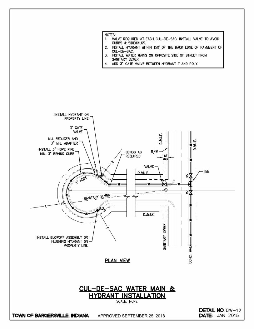
APPROVED SEPTEMBER 25, 2018
AutoCAD SHX Text
S
AutoCAD SHX Text
S
AutoCAD SHX Text
NOTES: 1. VALVE REQUIRED AT EACH CUL-DE-SAC. INSTALL VALVE TO AVOID VALVE REQUIRED AT EACH CUL-DE-SAC. INSTALL VALVE TO AVOID CURBS & SIDEWALKS. 2. INSTALL HYDRANT WITHIN 150' OF THE BACK EDGE OF PAVEMENT OF INSTALL HYDRANT WITHIN 150' OF THE BACK EDGE OF PAVEMENT OF CUL-DE-SAC. 3. INSTALL WATER MAINS ON OPPOSITE SIDE OF STREET FROM INSTALL WATER MAINS ON OPPOSITE SIDE OF STREET FROM SANITARY SEWER. 4. ADD 3" GATE VALVE BETWEEN HYDRANT T AND POLY.ADD 3" GATE VALVE BETWEEN HYDRANT T AND POLY.
AutoCAD SHX Text
INSTALL HYDRANT ON PROPERTY LINE
AutoCAD SHX Text
M.J. REDUCER AND 3" M.J. ADAPTER
AutoCAD SHX Text
INSTALL 3" HDPE PIPE MIN. 3" BEHIND CURB
AutoCAD SHX Text
3" HDPE
AutoCAD SHX Text
D.&U.E.
AutoCAD SHX Text
D.&U.E.
AutoCAD SHX Text
SANITARY SEWER
AutoCAD SHX Text
VALVE
AutoCAD SHX Text
R/W
AutoCAD SHX Text
D.&U.E.
AutoCAD SHX Text
D.&U.E.
AutoCAD SHX Text
CONC. WALK
AutoCAD SHX Text
SANITARY SEWER
AutoCAD SHX Text
TEE
AutoCAD SHX Text
%%UPLAN VIEW
AutoCAD SHX Text
B.O.
AutoCAD SHX Text
WV
AutoCAD SHX Text
H
AutoCAD SHX Text
Y
AutoCAD SHX Text
D
AutoCAD SHX Text
BENDS AS REQUIRED
AutoCAD SHX Text
INSTALL BLOWOFF ASSEMBLY OR FLUSHING HYDRANT ON PROPERTY LINE
AutoCAD SHX Text
WV
AutoCAD SHX Text
WV
AutoCAD SHX Text
3" GATE VALVE
AutoCAD SHX Text
TOWN OF BARGERSVILLE, INDIANA
AutoCAD SHX Text
DATE:
AutoCAD SHX Text
DETAIL NO.
AutoCAD SHX Text
SCALE: NONE
AutoCAD SHX Text
DW-
AutoCAD SHX Text
CUL-DE-SAC WATER MAIN & HYDRANT INSTALLATION
AutoCAD SHX Text
12
AutoCAD SHX Text
JAN 2015

APPROVED SEPTEMBER 25, 2018
AutoCAD SHX Text
TOP OF PIPE
AutoCAD SHX Text
EX. WATER MAIN
AutoCAD SHX Text
EX. GRADE
AutoCAD SHX Text
RESTRAIN A MINIUMUM OF 2 JOINTS PAST BEND.
AutoCAD SHX Text
RESTRAIN A MINIUMUM OF 2 JOINTS PAST BEND.
AutoCAD SHX Text
NOTE: 1. DUCTILE ONLY.DUCTILE ONLY.
AutoCAD SHX Text
TOWN OF BARGERSVILLE, INDIANA
AutoCAD SHX Text
DATE:
AutoCAD SHX Text
DETAIL NO.
AutoCAD SHX Text
SCALE: NONE
AutoCAD SHX Text
DW-
AutoCAD SHX Text
SPOT LOWERING
AutoCAD SHX Text
13
AutoCAD SHX Text
JAN 2015
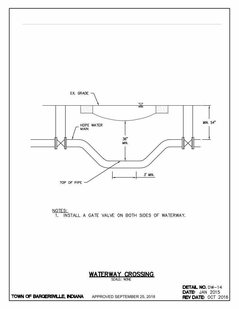
APPROVED SEPTEMBER 25, 2018
AutoCAD SHX Text
TOP OF PIPE
AutoCAD SHX Text
HDPE WATER MAIN
AutoCAD SHX Text
EX. GRADE
AutoCAD SHX Text
TOWN OF BARGERSVILLE, INDIANA
AutoCAD SHX Text
NOTES: 1. INSTALL A GATE VALVE ON BOTH SIDES OF WATERWAY.INSTALL A GATE VALVE ON BOTH SIDES OF WATERWAY.
AutoCAD SHX Text
DATE:
AutoCAD SHX Text
DETAIL NO.
AutoCAD SHX Text
DW-14
AutoCAD SHX Text
REV DATE:
AutoCAD SHX Text
JAN 2015
AutoCAD SHX Text
OCT 2016
AutoCAD SHX Text
SCALE: NONE
AutoCAD SHX Text
WATERWAY CROSSING
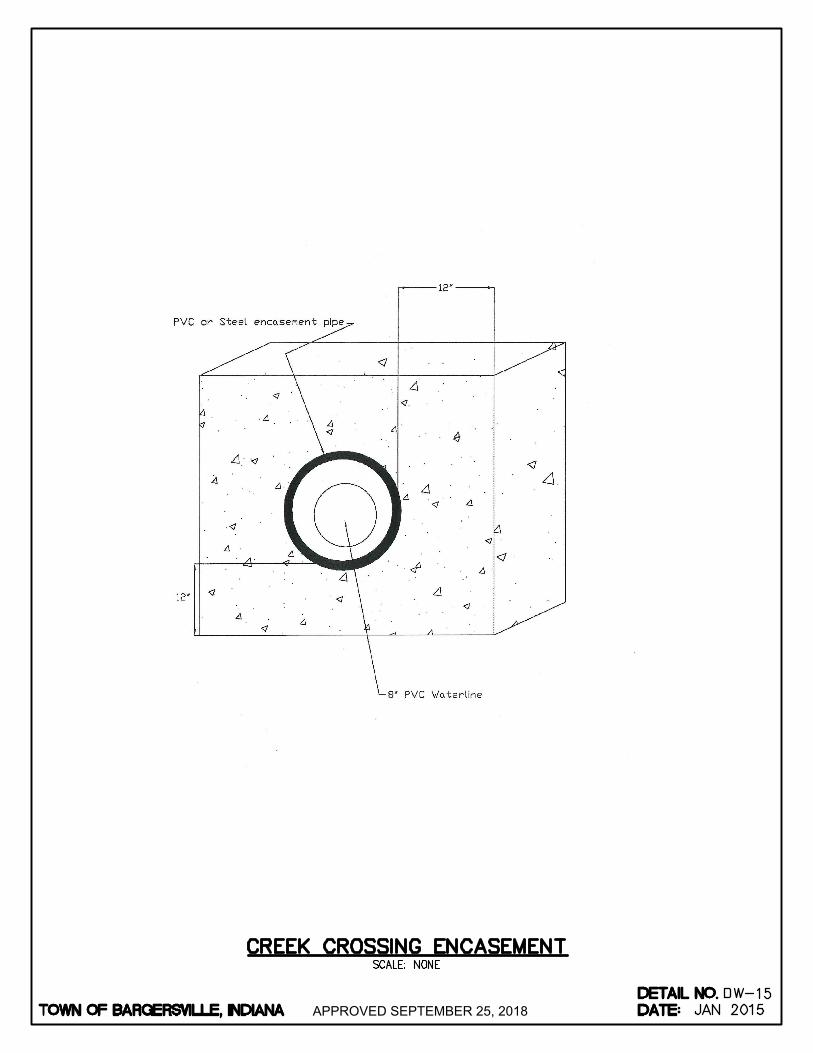
APPROVED SEPTEMBER 25, 2018
AutoCAD SHX Text
TOWN OF BARGERSVILLE, INDIANA
AutoCAD SHX Text
DATE:
AutoCAD SHX Text
DETAIL NO.
AutoCAD SHX Text
SCALE: NONE
AutoCAD SHX Text
DW-
AutoCAD SHX Text
CREEK CROSSING ENCASEMENT
AutoCAD SHX Text
15
AutoCAD SHX Text
JAN 2015

APPROVED SEPTEMBER 25, 2018
AutoCAD SHX Text
%%UMAIN LINE REDUCER
AutoCAD SHX Text
REDUCERS CAN ONLY BE USED AT A INTERSECTION
AutoCAD SHX Text
REDUCERS ON 6" AND 8" USE 1 GRIP RING AND 1 JOINT RESTRAINER ON EACH SIDE OF THE REDUCER 20 FEET MINIMUM.
AutoCAD SHX Text
JT
AutoCAD SHX Text
MJ
AutoCAD SHX Text
MJ
AutoCAD SHX Text
JT
AutoCAD SHX Text
%%UALL BENDS REQUIRE RESTRAINERS
AutoCAD SHX Text
ALL BENDS ARE DUCTILE IRON AND REQUIRE (1) GRIP RING ON EACH SIDE OF THE FITTING. 22 " BENDS REQUIRE ONLY GRIP RINGS IN ALL 12" BENDS REQUIRE ONLY GRIP RINGS IN ALL SIZES. 45" BENDS REQUIRE GRIP RINGS OR A BELL RESTRAINT HARNESS ON EACH SIDE OF THE FITTING ONE JOINT AWAY.
AutoCAD SHX Text
%%UTHRUST BLOCK REQUIRED ON ALL BENDS.
AutoCAD SHX Text
REDUCERS ON 10" AND LARGER USE 2 JOINT RESTRAINERS ON THE LARGER SIDE AND 1 GRIP RING. USE 1 GRIP RING AND 1 JOINT RESTRAINER ON THE SMALL SIDE 20 FEET MINIMUM.
AutoCAD SHX Text
JT
AutoCAD SHX Text
MJ
AutoCAD SHX Text
MJ
AutoCAD SHX Text
JT
AutoCAD SHX Text
JT
AutoCAD SHX Text
%%UPOLY REDUCER DETAIL
AutoCAD SHX Text
(SPIGOT BY MECHANICAL)
AutoCAD SHX Text
%%UJOINT RESTRAINT DETAIL
AutoCAD SHX Text
MJ RING WITH TRANSITION GASKET ASSESSORY SET WITH RODS AND NUTS
AutoCAD SHX Text
PVC PIPE
AutoCAD SHX Text
PVC PIPE
AutoCAD SHX Text
HYDRANT TEE
AutoCAD SHX Text
BELL RESTRAINT HARNESS
AutoCAD SHX Text
ALL THREAD RODS WITH NUTS
AutoCAD SHX Text
GATE VALVE SEE HYDRANT ASSEMBLY DETAIL
AutoCAD SHX Text
(2) EXTRA SINGLE BANDS WITH FEET FILED DOWN TO ALLOW FOR BETTER FIT ON ANGLED SECTION OF THE REDUCER.
AutoCAD SHX Text
%%UBEND RESTRAINT
AutoCAD SHX Text
RESTRAINT
AutoCAD SHX Text
GRIP RING WITH NO RODS OR BELL RESTRAINT HARNESSBELL RESTRAINT HARNESS
AutoCAD SHX Text
TOWN OF BARGERSVILLE, INDIANA
AutoCAD SHX Text
DATE:
AutoCAD SHX Text
DETAIL NO.
AutoCAD SHX Text
DW-16
AutoCAD SHX Text
REV DATE:
AutoCAD SHX Text
JAN 2015
AutoCAD SHX Text
OCT 2016
AutoCAD SHX Text
SCALE: NONE
AutoCAD SHX Text
INSTALLATION OF RESTRAINTS

APPROVED SEPTEMBER 25, 2018
AutoCAD SHX Text
%%UINSTALLATION PARALLEL TO MAIN
AutoCAD SHX Text
90° ELBOWANCHORING COUPLING
AutoCAD SHX Text
STANDARD TEE
AutoCAD SHX Text
NOTE: 1. ALL TEES MUST HAVE POURED THRUST BLOCKS. ALL TEES MUST HAVE POURED THRUST BLOCKS. (SEE APPLICABLE DETAILS).
AutoCAD SHX Text
6" GATE VALVE
AutoCAD SHX Text
HYDRANT
AutoCAD SHX Text
6" GATE VALVE
AutoCAD SHX Text
HYDRANT
AutoCAD SHX Text
%%UINSTALLATION PERPENDICULAR TO MAIN
AutoCAD SHX Text
STANDARD TEE
AutoCAD SHX Text
TOWN OF BARGERSVILLE, INDIANA
AutoCAD SHX Text
DATE:
AutoCAD SHX Text
DETAIL NO.
AutoCAD SHX Text
SCALE: NONE
AutoCAD SHX Text
DW-
AutoCAD SHX Text
HYDRANT CONNECTION
AutoCAD SHX Text
17
AutoCAD SHX Text
JAN 2015
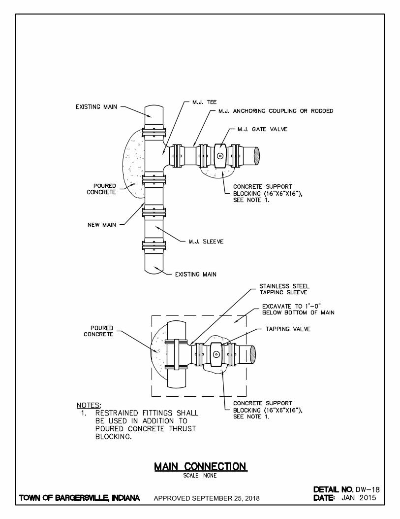
APPROVED SEPTEMBER 25, 2018
AutoCAD SHX Text
EXISTING MAIN
AutoCAD SHX Text
POURED CONCRETE
AutoCAD SHX Text
POURED CONCRETE
AutoCAD SHX Text
TAPPING VALVE
AutoCAD SHX Text
EXCAVATE TO 1'-0" BELOW BOTTOM OF MAIN
AutoCAD SHX Text
STAINLESS STEEL TAPPING SLEEVE
AutoCAD SHX Text
EXISTING MAIN
AutoCAD SHX Text
M.J. SLEEVE
AutoCAD SHX Text
CONCRETE SUPPORT BLOCKING (16"X6"X16"), SEE NOTE 1.
AutoCAD SHX Text
M.J. GATE VALVE
AutoCAD SHX Text
M.J. ANCHORING COUPLING OR RODDED
AutoCAD SHX Text
M.J. TEE
AutoCAD SHX Text
NEW MAIN
AutoCAD SHX Text
CONCRETE SUPPORT BLOCKING (16"X6"X16"), SEE NOTE 1.
AutoCAD SHX Text
TOWN OF BARGERSVILLE, INDIANA
AutoCAD SHX Text
DATE:
AutoCAD SHX Text
DETAIL NO.
AutoCAD SHX Text
SCALE: NONE
AutoCAD SHX Text
DW-
AutoCAD SHX Text
MAIN CONNECTION
AutoCAD SHX Text
18
AutoCAD SHX Text
JAN 2015
AutoCAD SHX Text
NOTES: : 1. RESTRAINED FITTINGS SHALL RESTRAINED FITTINGS SHALL BE USED IN ADDITION TO POURED CONCRETE THRUST BLOCKING.
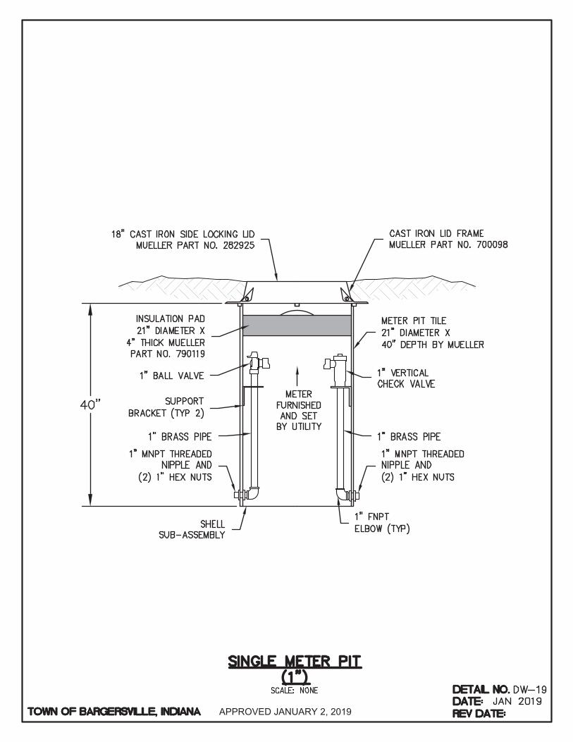
APPROVED JANUARY 2, 2019
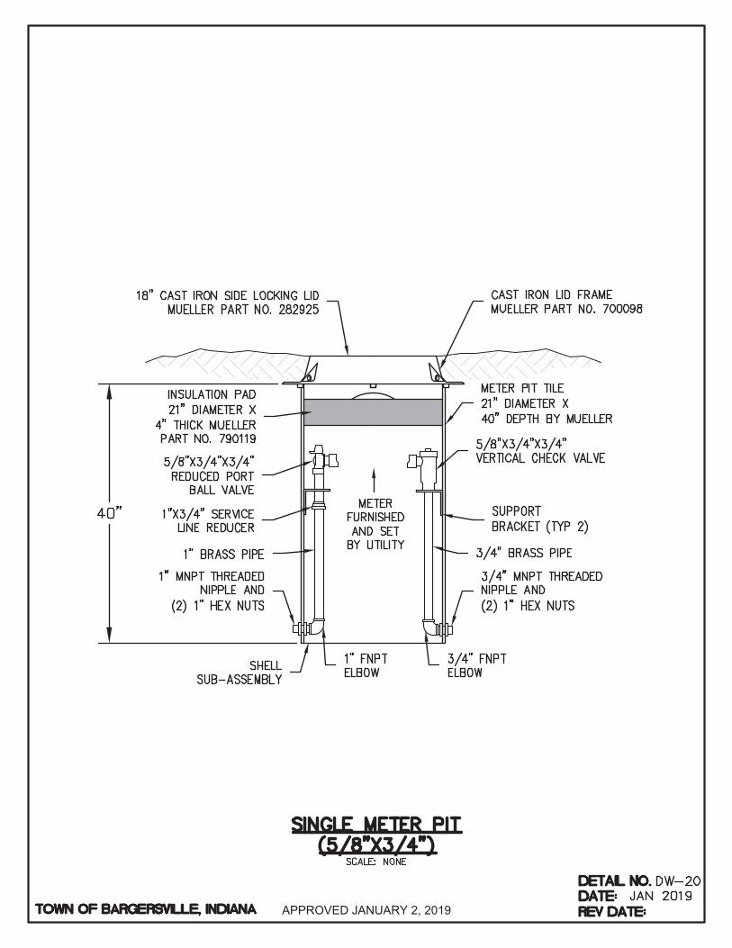
APPROVED JANUARY 2, 2019

APPROVED JANUARY 2, 2019

APPROVED SEPTEMBER 25, 2018
AutoCAD SHX Text
TOWN OF BARGERSVILLE, INDIANA
AutoCAD SHX Text
DATE:
AutoCAD SHX Text
DETAIL NO.
AutoCAD SHX Text
%%uELEVATION
AutoCAD SHX Text
%%uPLAN VIEW
AutoCAD SHX Text
30°-60°
AutoCAD SHX Text
MIN. SLOPE: 1.04% OR 18" PER FOOT
AutoCAD SHX Text
5' OUTSIDE DRAINAGE AND UTILITY EASEMENT LINE
AutoCAD SHX Text
4'-0" LONG 2"X4" WOOD PAINTED GREEN
AutoCAD SHX Text
TRACER WIRE
AutoCAD SHX Text
BELL HOLES SHALL BE PROVIDED UNDER PIPE
AutoCAD SHX Text
FACTORY-INSTALLED SERVICE WYE NO TEE
AutoCAD SHX Text
USE APPROPRIATE NUMBER OF ELBOWS FOR TRUE ALIGNMENT (2 ELBOWS MAX.)
AutoCAD SHX Text
TYPE 1, TYPE 2, OR TYPE 3 CLEANOUT
AutoCAD SHX Text
5' OUTSIDE DRAINAGE AND UTILITY EASEMENT LINE
AutoCAD SHX Text
LATERAL MINIMUM SIZE = 6"
AutoCAD SHX Text
MAIN SEWER LINE
AutoCAD SHX Text
NOTES: 1. WYE BRANCHES SHALL BE INSTALLED WHERE INDICATED. THEY SHALL BE EXTENDED TO PROPERTY LINES OR TO WYE BRANCHES SHALL BE INSTALLED WHERE INDICATED. THEY SHALL BE EXTENDED TO PROPERTY LINES OR TO DISTANCES AS SHOWN ON THE DRAWINGS, AND SHALL BE OF 6" PIPE UNLESS OTHERWISE SHOWN. 2. THE DEPTH OF THE LATERAL SHALL BE APPROXIMATELY 5'-0" UNLESS SEWER DEPTH IS LESS, IN WHICH EVENT A THE DEPTH OF THE LATERAL SHALL BE APPROXIMATELY 5'-0" UNLESS SEWER DEPTH IS LESS, IN WHICH EVENT A MINIMUM SLOPE OF 1/8" PER 1'-0" SHALL BE USED. THE DEPTH OF THE LATERAL SHALL BE NO LESS THAN 4'-0". 3. COMPACTION OF BEDDING AND BACKFILL IS CRITICAL UNDER WYE AND BEND. IF PROPER COMPACTION CANNOT BE COMPACTION OF BEDDING AND BACKFILL IS CRITICAL UNDER WYE AND BEND. IF PROPER COMPACTION CANNOT BE ACHIEVED, PLACE A MIN. OF 6" OF CLASS B CONCRETE AROUND BEND.18 BEND.
AutoCAD SHX Text
CONNECT TO EXISTING SERVICE OR SEAL WITH WATERTIGHT PLUG FOR FUTURE CONNECTION.
AutoCAD SHX Text
WRAP TRACER WIRE AROUND END OF LATERAL PIPE/CAP
AutoCAD SHX Text
SCALE: NONE
AutoCAD SHX Text
SS-
AutoCAD SHX Text
SANITARY LATERAL FOR SHALLOW SEWERS (LESS THAN 15' DEEP)
AutoCAD SHX Text
01
AutoCAD SHX Text
JAN 2015
AutoCAD SHX Text
SINGLE FAMILY BUILDING LATERAL MINIMUM SIZE = 4"
AutoCAD SHX Text
ROUNDED CAP
AutoCAD SHX Text
#8 CRUSHED STONE ENCASEMENT TO R/W

APPROVED SEPTEMBER 25, 2018
AutoCAD SHX Text
TOWN OF BARGERSVILLE, INDIANA
AutoCAD SHX Text
DATE:
AutoCAD SHX Text
DETAIL NO.
AutoCAD SHX Text
SCALE: NONE
AutoCAD SHX Text
SS-
AutoCAD SHX Text
SANITARY LATERAL FOR DEEP SEWERS (15' DEEP AND OVER)
AutoCAD SHX Text
02
AutoCAD SHX Text
JAN 2015
AutoCAD SHX Text
%%uELEVATION
AutoCAD SHX Text
%%uPLAN
AutoCAD SHX Text
UNDISTURBED SOIL
AutoCAD SHX Text
TEES
AutoCAD SHX Text
MAIN SEWER LINE
AutoCAD SHX Text
45° -60° (UNLESSOTHERWISE DIRECTED)
AutoCAD SHX Text
4" CONCRETE ENCASEMENT (MIN. 2500 PSI)
AutoCAD SHX Text
CONTROL SETTLEMENT (SLP) JOINT
AutoCAD SHX Text
TRACER WIRE
AutoCAD SHX Text
4'0" LONG 2X4 WOOD PAINTED GREEN
AutoCAD SHX Text
CONNECT TO EXISTING SERVICE OR SEAL WITH WATERTIGHT PLUG FOR FUTURE CONNECTION
AutoCAD SHX Text
5' OUTSIDE DRAINAGE AND UTILITY EASEMENT LINE
AutoCAD SHX Text
6" LATERAL
AutoCAD SHX Text
MINIMUM 4" CONCRETE ENCASEMENT (MIN. CONC. STRENGTH OF 2500 PSI)
AutoCAD SHX Text
TYPE 1, TYPE 2, OR TYPE 3 CLEANOUT
AutoCAD SHX Text
MAIN SEWER LINE
AutoCAD SHX Text
4" HOUSE LATERAL MIN. SLOPE: 2.08% OR " PER FOOT. 14" PER FOOT. OTHER BUILDING LATERALS 6" DIA. MIN.
AutoCAD SHX Text
NOTES: 1. WYE BRANCHES SHALL BE INSTALLED WHERE INDICATED. THEY SHALL BE EXTENDED TO WYE BRANCHES SHALL BE INSTALLED WHERE INDICATED. THEY SHALL BE EXTENDED TO PROPERTY LINES OR TO DISTANCES AS SHOWN ON THE DRAWINGS, AND SHALL BE OF 6" PIPE UNLESS OTHERWISE SHOWN. 2. THE DEPTH OF THE LATERAL SHALL BE APPROXIMATELY 5'-0". THE DEPTH OF THE LATERAL SHALL BE APPROXIMATELY 5'-0".
AutoCAD SHX Text
COMPACTED CLASS II BACKFILL
AutoCAD SHX Text
WRAP TRACER WIRE AROUND END OF LATERAL PIPE/CAP
AutoCAD SHX Text
#8 CRUSHED STONE BEDDING TO UNDISTURBED SOIL
AutoCAD SHX Text
5' OUTSIDE DRAINAGE AND UTILITY EASEMENT LINE
AutoCAD SHX Text
FACTORY INSTALLED SERVICE WYE
AutoCAD SHX Text
ROUNDED CAP

APPROVED SEPTEMBER 25, 2018
AutoCAD SHX Text
TOWN OF BARGERSVILLE, INDIANA
AutoCAD SHX Text
DATE:
AutoCAD SHX Text
DETAIL NO.
AutoCAD SHX Text
SCALE: NONE
AutoCAD SHX Text
SS-
AutoCAD SHX Text
TYPE 1 CLEANOUT
AutoCAD SHX Text
03
AutoCAD SHX Text
JAN 2015
AutoCAD SHX Text
FINISHED GRADE
AutoCAD SHX Text
6" PVCRISER
AutoCAD SHX Text
CONTINUE MAIN SEWER OR PLUG AT TERMINUS
AutoCAD SHX Text
45° BEND
AutoCAD SHX Text
6"X6"X6" PVC WYE
AutoCAD SHX Text
3 CUBIC FT. CONC. CRADLE
AutoCAD SHX Text
NOTES: 1. FOR USE IN LAWN OR LANDSCAPED SURFACES FOR USE IN LAWN OR LANDSCAPED SURFACES (LESS THAN 3' FROM HOUSE OR BUILDING).
AutoCAD SHX Text
TO MAIN SEWER
AutoCAD SHX Text
FROM HOUSE OR BUILDING
AutoCAD SHX Text
TRACER WIRE
AutoCAD SHX Text
ROUNDED CAP
AutoCAD SHX Text
FOUNDATION (FOOTER)
AutoCAD SHX Text
CONSTRUCTED OR GLUED JOINT W/ PURPLE PRIMER
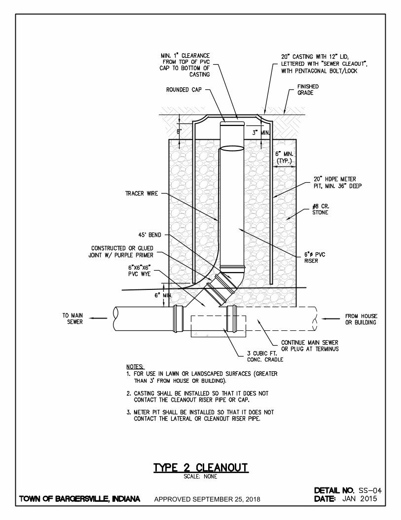
APPROVED SEPTEMBER 25, 2018
AutoCAD SHX Text
TOWN OF BARGERSVILLE, INDIANA
AutoCAD SHX Text
DATE:
AutoCAD SHX Text
DETAIL NO.
AutoCAD SHX Text
SCALE: NONE
AutoCAD SHX Text
SS-
AutoCAD SHX Text
TYPE 2 CLEANOUT
AutoCAD SHX Text
04
AutoCAD SHX Text
JAN 2015
AutoCAD SHX Text
FINISHED GRADE
AutoCAD SHX Text
6" PVCRISER
AutoCAD SHX Text
CONTINUE MAIN SEWER OR PLUG AT TERMINUS
AutoCAD SHX Text
45° BEND
AutoCAD SHX Text
6"X6"X6" PVC WYE
AutoCAD SHX Text
3 CUBIC FT. CONC. CRADLE
AutoCAD SHX Text
NOTES: 1. FOR USE IN LAWN OR LANDSCAPED SURFACES (GREATER FOR USE IN LAWN OR LANDSCAPED SURFACES (GREATER THAN 3' FROM HOUSE OR BUILDING). 2. CASTING SHALL BE INSTALLED SO THAT IT DOES NOT CASTING SHALL BE INSTALLED SO THAT IT DOES NOT CONTACT THE CLEANOUT RISER PIPE OR CAP. 3. METER PIT SHALL BE INSTALLED SO THAT IT DOES NOT METER PIT SHALL BE INSTALLED SO THAT IT DOES NOT CONTACT THE LATERAL OR CLEANOUT RISER PIPE.
AutoCAD SHX Text
TO MAIN SEWER
AutoCAD SHX Text
FROM HOUSE OR BUILDING
AutoCAD SHX Text
TRACER WIRE
AutoCAD SHX Text
ROUNDED CAP
AutoCAD SHX Text
20" CASTING WITH 12" LID, LETTERED WITH "SEWER CLEAOUT", WITH PENTAGONAL BOLT/LOCK
AutoCAD SHX Text
#8 CR. STONE
AutoCAD SHX Text
20" HDPE METER PIT, MIN. 36" DEEP
AutoCAD SHX Text
CONSTRUCTED OR GLUED JOINT W/ PURPLE PRIMER
AutoCAD SHX Text
MIN. 1" CLEARANCE FROM TOP OF PVC CAP TO BOTTOM OF CASTING
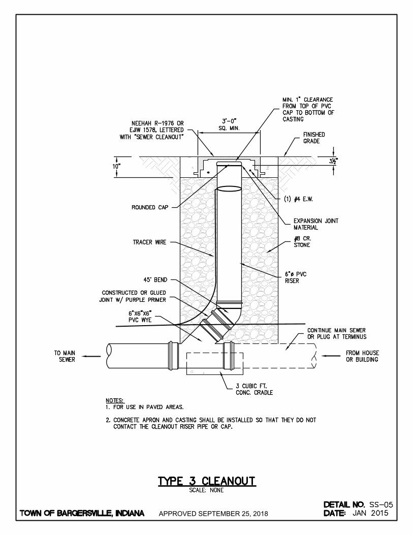
APPROVED SEPTEMBER 25, 2018
AutoCAD SHX Text
TOWN OF BARGERSVILLE, INDIANA
AutoCAD SHX Text
DATE:
AutoCAD SHX Text
DETAIL NO.
AutoCAD SHX Text
SCALE: NONE
AutoCAD SHX Text
SS-
AutoCAD SHX Text
TYPE 3 CLEANOUT
AutoCAD SHX Text
05
AutoCAD SHX Text
JAN 2015
AutoCAD SHX Text
FINISHED GRADE
AutoCAD SHX Text
NEEHAH R-1976 OR EJIW 1578, LETTERED WITH "SEWER CLEANOUT"
AutoCAD SHX Text
(1) #4 E.W.
AutoCAD SHX Text
EXPANSION JOINT MATERIAL
AutoCAD SHX Text
6" PVCRISER
AutoCAD SHX Text
CONTINUE MAIN SEWER OR PLUG AT TERMINUS
AutoCAD SHX Text
ROUNDED CAP
AutoCAD SHX Text
45° BEND
AutoCAD SHX Text
6"X6"X6" PVC WYE
AutoCAD SHX Text
3 CUBIC FT. CONC. CRADLE
AutoCAD SHX Text
NOTES: 1. FOR USE IN PAVED AREAS. FOR USE IN PAVED AREAS. 2. CONCRETE APRON AND CASTING SHALL BE INSTALLED SO THAT THEY DO NOT CONCRETE APRON AND CASTING SHALL BE INSTALLED SO THAT THEY DO NOT CONTACT THE CLEANOUT RISER PIPE OR CAP.
AutoCAD SHX Text
TO MAIN SEWER
AutoCAD SHX Text
FROM HOUSE OR BUILDING
AutoCAD SHX Text
TRACER WIRE
AutoCAD SHX Text
#8 CR. STONE
AutoCAD SHX Text
MIN. 1" CLEARANCE FROM TOP OF PVC CAP TO BOTTOM OF CASTING
AutoCAD SHX Text
CONSTRUCTED OR GLUED JOINT W/ PURPLE PRIMER

APPROVED SEPTEMBER 25, 2018
AutoCAD SHX Text
TOWN OF BARGERSVILLE, INDIANA
AutoCAD SHX Text
DATE:
AutoCAD SHX Text
DETAIL NO.
AutoCAD SHX Text
SCALE: NONE
AutoCAD SHX Text
SS-
AutoCAD SHX Text
NEW SERVICE CONNECTION TO EXISTING SANITARY SEWER
AutoCAD SHX Text
06
AutoCAD SHX Text
JAN 2015
AutoCAD SHX Text
4"X4"X4" OR 6"X6"X6" PVC WYE
AutoCAD SHX Text
4" OR 6" PVC SANITARY SEWER LATERAL
AutoCAD SHX Text
NEW PVC INSERTA TEE (OR CUT IN TEE)
AutoCAD SHX Text
EX. SANITARY SEWER
AutoCAD SHX Text
TYPE 2 OR TYPE 3 CLEANOUT SEE DETAIL
AutoCAD SHX Text
FROM HOUSE OR BUILDING
AutoCAD SHX Text
4" OR 6" PVC SANITARY SEWER LATERAL
AutoCAD SHX Text
CORE DRILL HOLE TO PROVIDE SMOOTH TRANSITION

APPROVED SEPTEMBER 25, 2018
AutoCAD SHX Text
TOWN OF BARGERSVILLE, INDIANA
AutoCAD SHX Text
FINISHED GRADE
AutoCAD SHX Text
NEENAH FOUNDRY R1772 (7" RISE) AND R1712 (9" RISE) FRAME AND COVER W/ "SELF-SEALING" APPL. OR EQUAL
AutoCAD SHX Text
ADJUSTING RINGS PER DETAIL 1111
AutoCAD SHX Text
ECCENTRIC CONE SECTION
AutoCAD SHX Text
O-RING GASKET BETWEEN ALL RISER AND CONE SECTIONS, PLUS 2 ROWS OF " 12" EXTRUDABLE GASKETS
AutoCAD SHX Text
MIN. 1" PER FOOT SLOPE
AutoCAD SHX Text
FLEXIBLE RUBBER BOOT FOR ALL PIPES AND LATERALS PER ASTM C-923
AutoCAD SHX Text
#8 CR. STONE TO UNDISTURBED SOIL
AutoCAD SHX Text
PRECAST CONCRETE BARREL SECTIONS
AutoCAD SHX Text
REINFORCING STEEL PER ASTM C478
AutoCAD SHX Text
MONOLITHIC BASE & BARREL (ONE UNIT)
AutoCAD SHX Text
BUTYL RUBBER 6" ABOVE & 6" BELOW EACH OUTSIDE JOINT, " MIN. THICKNESS WITH 80 14" MIN. THICKNESS WITH 80 GAUGE STRETCH WRAP
AutoCAD SHX Text
NOTES: 1. FOR NEW CONSTRUCTION 8" MAX. CHIMNEY HEIGHT. FOR EXISTING MANHOLES, 12" MAX. CHIMNEY HEIGHT. FOR NEW CONSTRUCTION 8" MAX. CHIMNEY HEIGHT. FOR EXISTING MANHOLES, 12" MAX. CHIMNEY HEIGHT. 2. FOR ALL MANHOLES 6'-0" OR LESS IN DEPTH - PROVIDE RISER WITH FLAT TOP IN LIEU OF ECCENTRIC FOR ALL MANHOLES 6'-0" OR LESS IN DEPTH - PROVIDE RISER WITH FLAT TOP IN LIEU OF ECCENTRIC CONE IN ACCORDANCE WITH ASTM C-478 3. THE CROWN OF THE INFLUENT PIPE SHALL BE AT OR ABOVE THE CROWN OF THE OUTLET PIPE. THE CROWN OF THE INFLUENT PIPE SHALL BE AT OR ABOVE THE CROWN OF THE OUTLET PIPE. 4. DROP MANHOLES SHALL BE USED WHENEVER THE DISTANCE FROM THE INVERT OF THE INCOMING LINE DROP MANHOLES SHALL BE USED WHENEVER THE DISTANCE FROM THE INVERT OF THE INCOMING LINE AND BOTTOM OF MANHOLE IS GREATER THAN TWO FEET.
AutoCAD SHX Text
UNDISTURBED SOIL
AutoCAD SHX Text
INTERNAL CHIMNEY SEAL
AutoCAD SHX Text
BUTYL RUBBER BASE EXTERIOR BACKPLASTER MATERIAL. " MIN. 14" MIN. THICKNESS FROM 2" BELOW BOTTOM ADJUSTING RING TO COVERING THE BASE OF CASTING.
AutoCAD SHX Text
COAT EXTERIOR SURFACE WITH COAL TAR EPOXY
AutoCAD SHX Text
REINFORCED NON-METALLIC MANHOLE STEPS @ 16" O-C (TYP.)
AutoCAD SHX Text
DATE:
AutoCAD SHX Text
DETAIL NO.
AutoCAD SHX Text
SS-07
AutoCAD SHX Text
REV DATE:
AutoCAD SHX Text
JAN 2015
AutoCAD SHX Text
OCT 2016
AutoCAD SHX Text
SCALE: NONE
AutoCAD SHX Text
STANDARD SANITARY MANHOLE

APPROVED SEPTEMBER 25, 2018
AutoCAD SHX Text
TOWN OF BARGERSVILLE, INDIANA
AutoCAD SHX Text
DATE:
AutoCAD SHX Text
DETAIL NO.
AutoCAD SHX Text
SCALE: NONE
AutoCAD SHX Text
SS-
AutoCAD SHX Text
SHALLOW SANITARY MANHOLE
AutoCAD SHX Text
08
AutoCAD SHX Text
JAN 2015
AutoCAD SHX Text
O-RING GASKET BETWEEN RISER AND SECTIONS, PLUS FLAT TOP 2 ROWS OF " 12" EXTRUDABLE GASKETS
AutoCAD SHX Text
MIN. 1" PER FOOT SLOPE SEE DETAIL NO. SS-10
AutoCAD SHX Text
FLEXIBLE RUBBER BOOT FOR ALL PIPES AND LATERALS PER ASTM C-923
AutoCAD SHX Text
#8 CR. STONE TO UNDISTURBED SOIL
AutoCAD SHX Text
REINFORCING STEEL PER ASTM C478
AutoCAD SHX Text
MONOLITHIC BASE AND BARREL (ONE UNIT)
AutoCAD SHX Text
NOTES: 1. REQUIRES PRE-APPROVAL BY TOWN OF BARGERSVILLE. REQUIRES PRE-APPROVAL BY TOWN OF BARGERSVILLE. 2. NEW MANHOLE CONSTRUCTION AND ACCESSORIES SAME AS SHOWN FOR STANDARD NEW MANHOLE CONSTRUCTION AND ACCESSORIES SAME AS SHOWN FOR STANDARD SANITARY MANHOLE. 3. MANHOLE STEPS REQUIRED FOR ALL MANHOLES 4 FEET DEEP OR GREATER.MANHOLE STEPS REQUIRED FOR ALL MANHOLES 4 FEET DEEP OR GREATER.
AutoCAD SHX Text
UNDISTURBED SOIL
AutoCAD SHX Text
BUTYL RUBBER 6" ABOVE & 6" BELOW EACH OUTSIDE JOINT, " MIN. WITH 80 14" MIN. WITH 80 GAUGE STRETCH WRAP
AutoCAD SHX Text
PRECAST CONCRETE FLAT TOP SECTION (TRAFFIC BEARING)
AutoCAD SHX Text
COAT EXTERIOR SURFACE WITH COAL TAR EPOXY
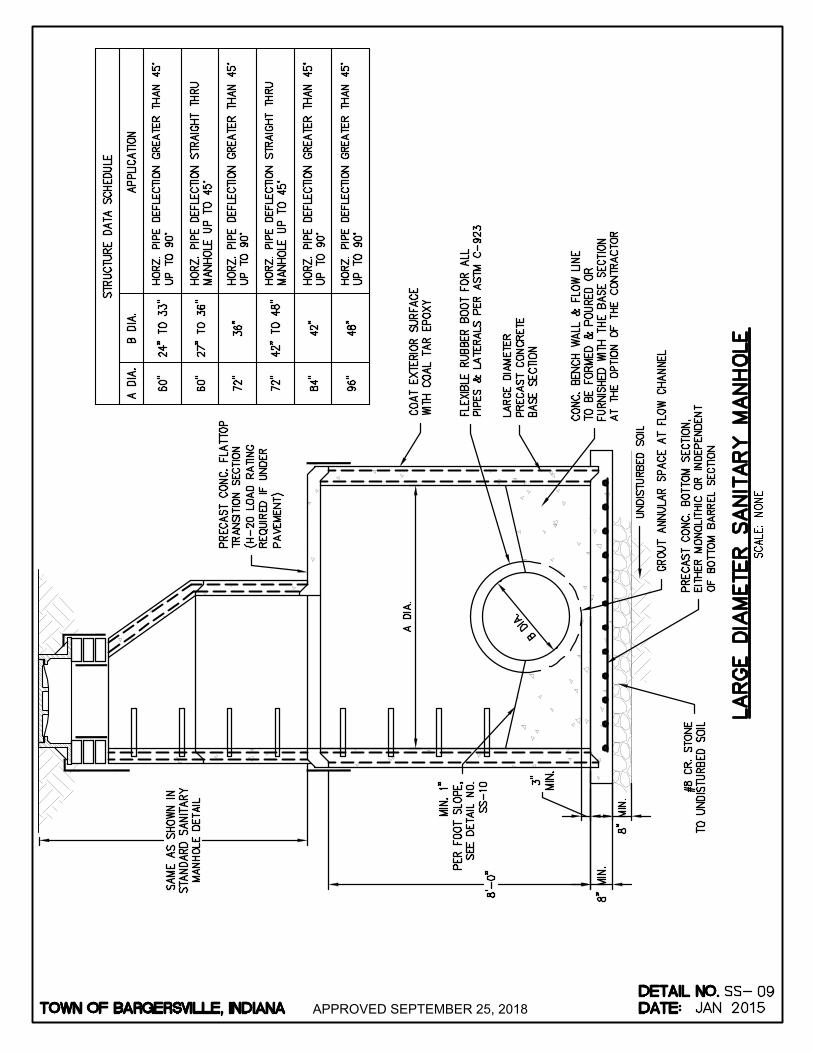
APPROVED SEPTEMBER 25, 2018
AutoCAD SHX Text
TOWN OF BARGERSVILLE, INDIANA
AutoCAD SHX Text
DATE:
AutoCAD SHX Text
DETAIL NO.
AutoCAD SHX Text
PRECAST CONC. FLATTOP TRANSITION SECTION (H-20 LOAD RATING REQUIRED IF UNDER PAVEMENT)
AutoCAD SHX Text
FLEXIBLE RUBBER BOOT FOR ALL PIPES & LATERALS PER ASTM C-923
AutoCAD SHX Text
LARGE DIAMETER PRECAST CONCRETE BASE SECTION
AutoCAD SHX Text
CONC. BENCH WALL & FLOW LINE TO BE FORMED & POURED OR FURNISHED WITH THE BASE SECTION AT THE OPTION OF THE CONTRACTOR
AutoCAD SHX Text
PRECAST CONC. BOTTOM SECTION, EITHER MONOLITHIC OR INDEPENDENT OF BOTTOM BARREL SECTION
AutoCAD SHX Text
#8 CR. STONE TO UNDISTURBED SOIL
AutoCAD SHX Text
MIN. 1" PER FOOT SLOPE, SEE DETAIL NO. SS-10
AutoCAD SHX Text
UNDISTURBED SOIL
AutoCAD SHX Text
GROUT ANNULAR SPACE AT FLOW CHANNEL
AutoCAD SHX Text
STRUCTURE DATA SCHEDULE
AutoCAD SHX Text
APPLICATION
AutoCAD SHX Text
B DIA.
AutoCAD SHX Text
A DIA.
AutoCAD SHX Text
HORZ. PIPE DEFLECTION STRAIGHT THRU MANHOLE UP TO 45°
AutoCAD SHX Text
96"
AutoCAD SHX Text
48"
AutoCAD SHX Text
HORZ. PIPE DEFLECTION GREATER THAN 45° UP TO 90°
AutoCAD SHX Text
84"
AutoCAD SHX Text
42"
AutoCAD SHX Text
HORZ. PIPE DEFLECTION GREATER THAN 45° UP TO 90°
AutoCAD SHX Text
72"
AutoCAD SHX Text
42" TO 48"
AutoCAD SHX Text
72"
AutoCAD SHX Text
36"
AutoCAD SHX Text
HORZ. PIPE DEFLECTION GREATER THAN 45° UP TO 90°
AutoCAD SHX Text
60"
AutoCAD SHX Text
27" TO 36"
AutoCAD SHX Text
HORZ. PIPE DEFLECTION STRAIGHT THRU MANHOLE UP TO 45°
AutoCAD SHX Text
HORZ. PIPE DEFLECTION GREATER THAN 45° UP TO 90°
AutoCAD SHX Text
24" TO 33"
AutoCAD SHX Text
60"
AutoCAD SHX Text
COAT EXTERIOR SURFACE WITH COAL TAR EPOXY
AutoCAD SHX Text
SCALE: NONE
AutoCAD SHX Text
SS-
AutoCAD SHX Text
JAN 2015
AutoCAD SHX Text
09
AutoCAD SHX Text
LARGE DIAMETER SANITARY MANHOLE
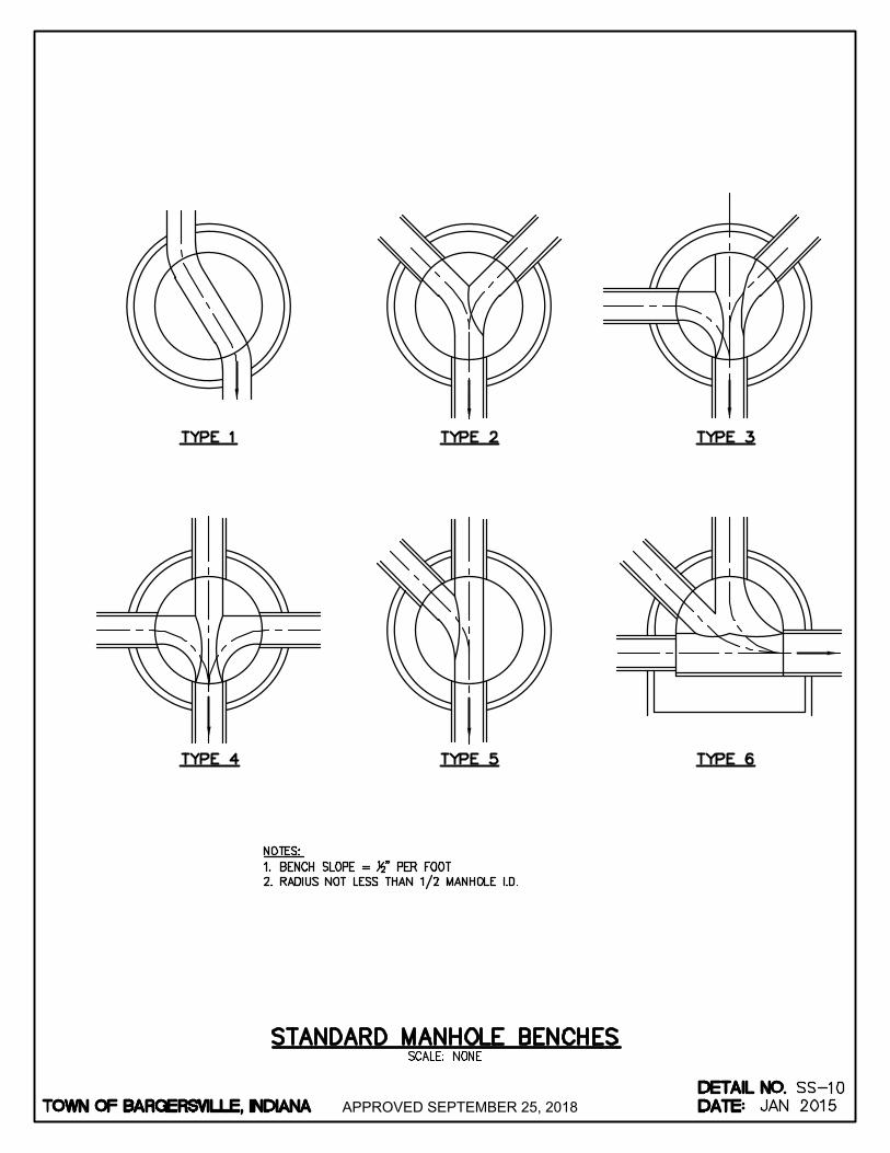
APPROVED SEPTEMBER 25, 2018
AutoCAD SHX Text
TOWN OF BARGERSVILLE, INDIANA
AutoCAD SHX Text
DATE:
AutoCAD SHX Text
DETAIL NO.
AutoCAD SHX Text
SCALE: NONE
AutoCAD SHX Text
SS-
AutoCAD SHX Text
STANDARD MANHOLE BENCHES
AutoCAD SHX Text
10
AutoCAD SHX Text
JAN 2015
AutoCAD SHX Text
NOTES: 1. BENCH SLOPE = " PER FOOT BENCH SLOPE = " PER FOOT 12" PER FOOT 2. RADIUS NOT LESS THAN 1/2 MANHOLE I.D.RADIUS NOT LESS THAN 1/2 MANHOLE I.D.
AutoCAD SHX Text
%%UTYPE 1
AutoCAD SHX Text
%%UTYPE 2
AutoCAD SHX Text
%%UTYPE 3
AutoCAD SHX Text
%%UTYPE 4
AutoCAD SHX Text
%%UTYPE 5
AutoCAD SHX Text
%%UTYPE 6

APPROVED SEPTEMBER 25, 2018
AutoCAD SHX Text
TOWN OF BARGERSVILLE, INDIANA
AutoCAD SHX Text
DATE:
AutoCAD SHX Text
DETAIL NO.
AutoCAD SHX Text
SCALE: NONE
AutoCAD SHX Text
SS-
AutoCAD SHX Text
PRECAST CONCRETE ADJUSTING RING
AutoCAD SHX Text
11
AutoCAD SHX Text
JAN 2015
AutoCAD SHX Text
A
AutoCAD SHX Text
A
AutoCAD SHX Text
PRECAST CONCRETE ADJUSTING RING OR FLANGE OF CASTING
AutoCAD SHX Text
NOMINAL " BUTYL RUBBER BASE 12" BUTYL RUBBER BASE EXTRUDABLE PREFORMED GASKET MATERIAL IN KEYWAY AND BETWEEN SECTIONS PER MANUFACTURER RECOMMENDATIONS.
AutoCAD SHX Text
PLACE " BUTYL RUBBER 12" BUTYL RUBBER BASE EXTRUDABLE PREFORMED GASKET MATERIAL PER MANUFACTURER'S RECOMMENDATIONS
AutoCAD SHX Text
%%UPLAN VIEW
AutoCAD SHX Text
%%UGASKET DETAIL
AutoCAD SHX Text
%%USECTION A-A
AutoCAD SHX Text
NOTES: 1. PRECAST CONCRETE ADJUSTING RINGS SHALL HAVE PRECAST CONCRETE ADJUSTING RINGS SHALL HAVE KEYWAY/CHANNEL CONSTRUCTION. "SMOOTH" ADJUSTING RINGS SHALL NOT BE PERMITTED. 2. FOR F/C LOCATED IN HARD SURFACES USE EJIW FOR F/C LOCATED IN HARD SURFACES USE EJIW INFRA-RISER, MIN. 1".

APPROVED SEPTEMBER 25, 2018
AutoCAD SHX Text
TOWN OF BARGERSVILLE, INDIANA
AutoCAD SHX Text
DATE:
AutoCAD SHX Text
DETAIL NO.
AutoCAD SHX Text
SCALE: NONE
AutoCAD SHX Text
SS-
AutoCAD SHX Text
SANITARY MANHOLE INSTALLED OVER EXISTING SEWER
AutoCAD SHX Text
12
AutoCAD SHX Text
JAN 2015
AutoCAD SHX Text
SET DOGHOUSE BASE ON CONCRETE BLOCKS
AutoCAD SHX Text
DOGHOUSE OPENING SHALL BE PREFORMED BY MANUFACTURER TO FIT PIPE OUTSIDE DIAMETER PLUS 6"
AutoCAD SHX Text
8"X8"X16" AND 4"X8"X16" SOLID CONCRETE BLOCKS CENTER W/RISER WALL MIN. (4 EACH)
AutoCAD SHX Text
EXISTING SANITARY SEWER PIPE
AutoCAD SHX Text
MIN. 12" CLEARANCE BETWEEN EXISTING PIPE AND STONE BEDDING
AutoCAD SHX Text
NEW SANITARY SEWER PIPE, SEE NOTE 4
AutoCAD SHX Text
%%UDOGHOUSE MANHOLE BASE
AutoCAD SHX Text
6" MIN. NO. 8 CRUSHED STONE BEDDING TO UNDISTURBED SOIL
AutoCAD SHX Text
NOTES: 1. REQUIRES PRE-APPROVAL BY TOWN OF BARGERSVILLE. REQUIRES PRE-APPROVAL BY TOWN OF BARGERSVILLE. 2. MANHOLE CONSTRUCTION AND ACCESSORIES ABOVE BASE SAME AS SHOWN FOR STANDARD SANITARY MANHOLE. MANHOLE CONSTRUCTION AND ACCESSORIES ABOVE BASE SAME AS SHOWN FOR STANDARD SANITARY MANHOLE. 3. CONSTRUCT A FORMED INVERT FROM NEW SEWER LINE TO ALLOW FLOW TO THE EXISTING PIPE. CONSTRUCT A FORMED INVERT FROM NEW SEWER LINE TO ALLOW FLOW TO THE EXISTING PIPE. 4. CUT AND REMOVE THE TOP HALF OF EXISTING PIPE TO WITHIN 6" OF THE MANHOLE WALLS AFTER THE INVERT AND SHELF CUT AND REMOVE THE TOP HALF OF EXISTING PIPE TO WITHIN 6" OF THE MANHOLE WALLS AFTER THE INVERT AND SHELF HAVE BEEN FORMED AND THE MANHOLE HAS BEEN FULLY TESTED IN ACCORDANCE WITH THESE SPECIFICATIONS. 5. PROVIDE ADEQUATE PIPE SUPPORT DURING CONSTRUCTION TO PREVENT PIPE DAMAGE. PROVIDE ADEQUATE PIPE SUPPORT DURING CONSTRUCTION TO PREVENT PIPE DAMAGE.
AutoCAD SHX Text
ALLOW CONCRETE TO FLOW A MIN. 1'-0" BEYOND BASE OF STRUCTURE
AutoCAD SHX Text
12" MIN. CAST-IN PLACE 3000 PSI CONCRETE BASE
AutoCAD SHX Text
SEAL JOINT BETWEEN BENCH AND EXISTING PIPE WITH FLEXIBLE EPOXY
AutoCAD SHX Text
FORM CONCRETE BENCHWALL PRIOR TO REMOVING EXISTING SEWER PIPE CROWN, SLOPE 1" PER FOOT TO WALL
AutoCAD SHX Text
%%UFOUNDATION SECTION VIEW
AutoCAD SHX Text
WRAP EXISTING PIPE WITH NEOPRENE GASKET MATERIAL BEFORE FILLING THE OPENING
AutoCAD SHX Text
FILL DOGHOUSE OPENING AROUND EXISTING PIPE WITH NON-SHRINKING GROUT

APPROVED SEPTEMBER 25, 2018
AutoCAD SHX Text
TOWN OF BARGERSVILLE, INDIANA
AutoCAD SHX Text
DATE:
AutoCAD SHX Text
DETAIL NO.
AutoCAD SHX Text
SCALE: NONE
AutoCAD SHX Text
SS-
AutoCAD SHX Text
INSIDE DROP INTO SANITARY MANHOLE
AutoCAD SHX Text
13
AutoCAD SHX Text
JAN 2015
AutoCAD SHX Text
NOTES: 1. INSIDE DROP ACCEPTABLE FOR 2" AND SMALLER FORCE MAIN ONLY. INSIDE DROP ACCEPTABLE FOR 2" AND SMALLER FORCE MAIN ONLY. 2. INSIDE DROPS REQUIRE A SPRAY ON LINE.INSIDE DROPS REQUIRE A SPRAY ON LINE.
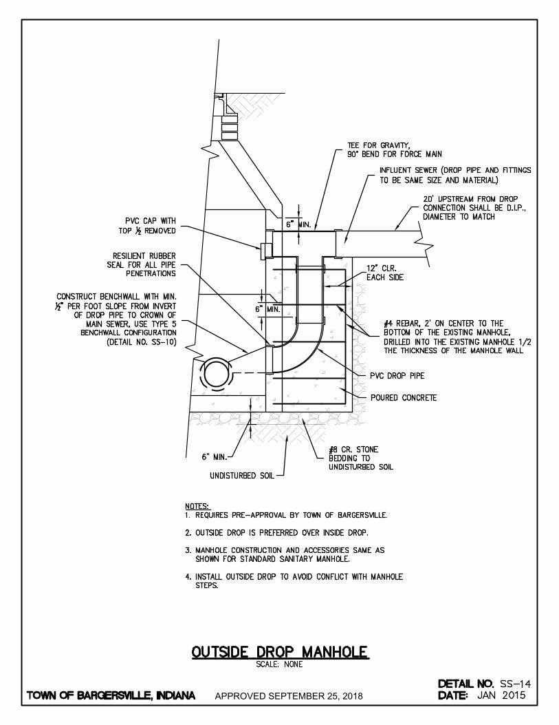
APPROVED SEPTEMBER 25, 2018
AutoCAD SHX Text
TOWN OF BARGERSVILLE, INDIANA
AutoCAD SHX Text
DATE:
AutoCAD SHX Text
DETAIL NO.
AutoCAD SHX Text
SCALE: NONE
AutoCAD SHX Text
SS-
AutoCAD SHX Text
OUTSIDE DROP MANHOLE
AutoCAD SHX Text
14
AutoCAD SHX Text
JAN 2015
AutoCAD SHX Text
INFLUENT SEWER (DROP PIPE AND FITTINGS TO BE SAME SIZE AND MATERIAL)
AutoCAD SHX Text
PVC DROP PIPE
AutoCAD SHX Text
#8 CR. STONE BEDDING TO UNDISTURBED SOIL
AutoCAD SHX Text
CONSTRUCT BENCHWALL WITH MIN. 12" PER FOOT SLOPE FROM INVERT OF DROP PIPE TO CROWN OF MAIN SEWER, USE TYPE 5 BENCHWALL CONFIGURATION (DETAIL NO. SS-10)
AutoCAD SHX Text
RESILIENT RUBBER SEAL FOR ALL PIPE PENETRATIONS
AutoCAD SHX Text
POURED CONCRETE
AutoCAD SHX Text
PVC CAP WITH TOP REMOVED12 REMOVED
AutoCAD SHX Text
NOTES: 1. REQUIRES PRE-APPROVAL BY TOWN OF BARGERSVILLE. REQUIRES PRE-APPROVAL BY TOWN OF BARGERSVILLE. 2. OUTSIDE DROP IS PREFERRED OVER INSIDE DROP. OUTSIDE DROP IS PREFERRED OVER INSIDE DROP. 3. MANHOLE CONSTRUCTION AND ACCESSORIES SAME AS MANHOLE CONSTRUCTION AND ACCESSORIES SAME AS SHOWN FOR STANDARD SANITARY MANHOLE. 4. INSTALL OUTSIDE DROP TO AVOID CONFLICT WITH MANHOLE INSTALL OUTSIDE DROP TO AVOID CONFLICT WITH MANHOLE STEPS.
AutoCAD SHX Text
UNDISTURBED SOIL
AutoCAD SHX Text
6" MIN.
AutoCAD SHX Text
TEE FOR GRAVITY, 90° BEND FOR FORCE MAIN
AutoCAD SHX Text
20' UPSTREAM FROM DROP CONNECTION SHALL BE D.I.P., DIAMETER TO MATCH
AutoCAD SHX Text
#4 REBAR, 2' ON CENTER TO THE BOTTOM OF THE EXISTING MANHOLE, DRILLED INTO THE EXISTING MANHOLE 1/2 THE THICKNESS OF THE MANHOLE WALL
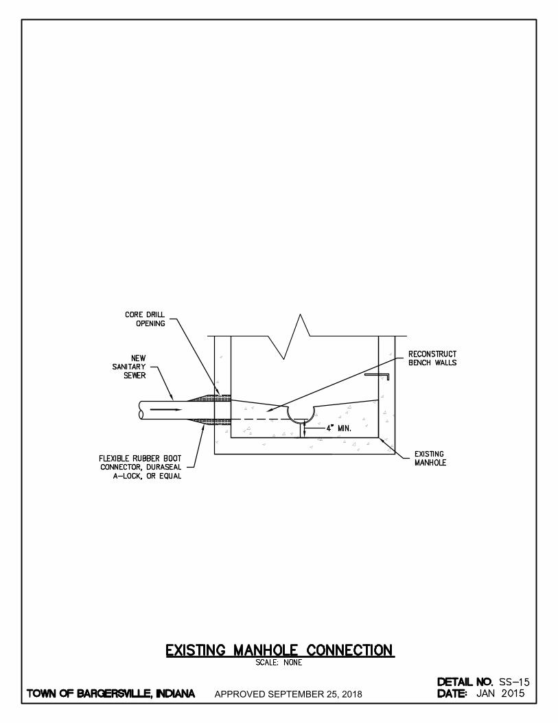
APPROVED SEPTEMBER 25, 2018
AutoCAD SHX Text
TOWN OF BARGERSVILLE, INDIANA
AutoCAD SHX Text
DATE:
AutoCAD SHX Text
DETAIL NO.
AutoCAD SHX Text
SCALE: NONE
AutoCAD SHX Text
SS-
AutoCAD SHX Text
EXISTING MANHOLE CONNECTION
AutoCAD SHX Text
15
AutoCAD SHX Text
JAN 2015
AutoCAD SHX Text
EXISTING MANHOLE
AutoCAD SHX Text
RECONSTRUCT BENCH WALLS
AutoCAD SHX Text
CORE DRILL OPENING
AutoCAD SHX Text
NEW SANITARY SEWER
AutoCAD SHX Text
FLEXIBLE RUBBER BOOT CONNECTOR, DURASEAL A-LOCK, OR EQUAL
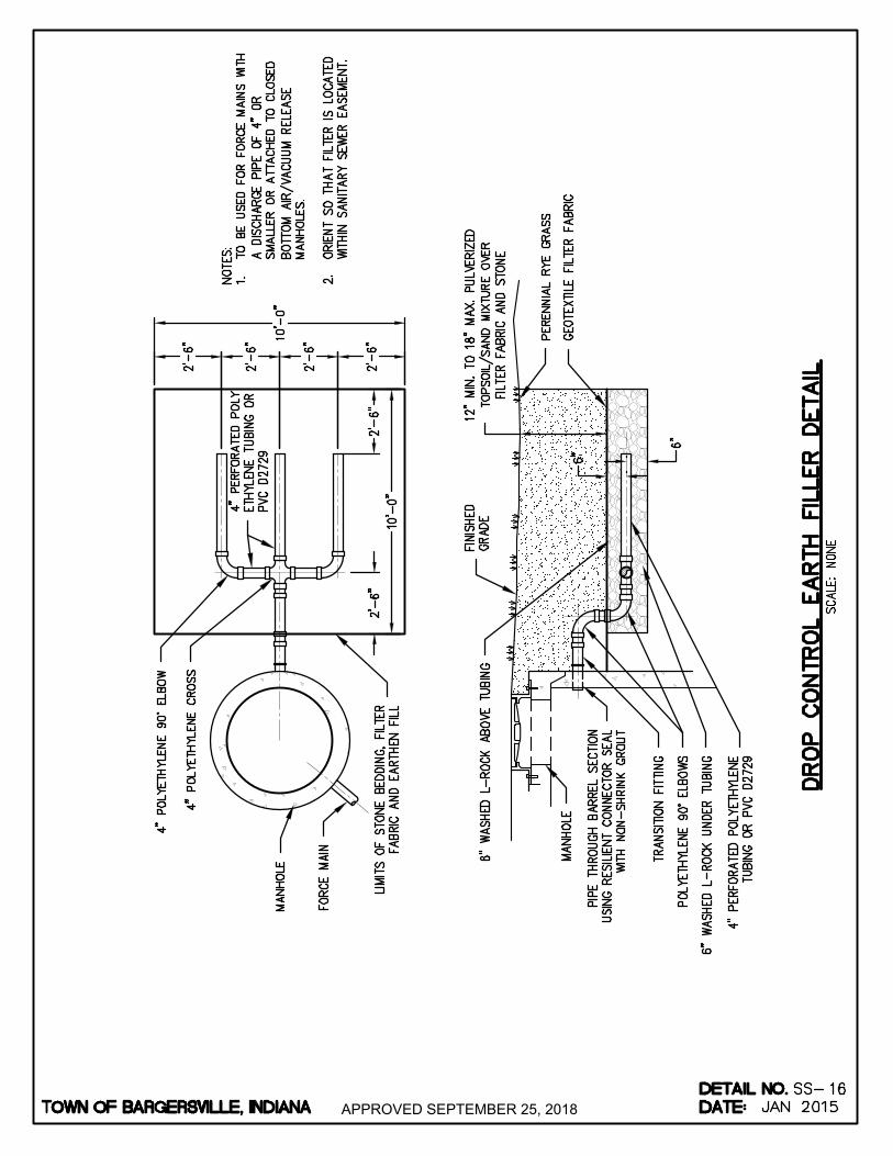
APPROVED SEPTEMBER 25, 2018
AutoCAD SHX Text
TOWN OF BARGERSVILLE, INDIANA
AutoCAD SHX Text
DATE:
AutoCAD SHX Text
DETAIL NO.
AutoCAD SHX Text
4" PERFORATED POLY ETHYLENE TUBING OR PVC D2729
AutoCAD SHX Text
4" POLYETHYLENE 90° ELBOW
AutoCAD SHX Text
4" POLYETHYLENE CROSS
AutoCAD SHX Text
MANHOLE
AutoCAD SHX Text
FORCE MAIN
AutoCAD SHX Text
LIMITS OF STONE BEDDING, FILTER FABRIC AND EARTHEN FILL
AutoCAD SHX Text
NOTES: 1. TO BE USED FOR FORCE MAINS WITH TO BE USED FOR FORCE MAINS WITH A DISCHARGE PIPE OF 4" OR SMALLER OR ATTACHED TO CLOSED BOTTOM AIR/VACUUM RELEASE MANHOLES. 2. ORIENT SO THAT FILTER IS LOCATED ORIENT SO THAT FILTER IS LOCATED WITHIN SANITARY SEWER EASEMENT.
AutoCAD SHX Text
FINISHED GRADE
AutoCAD SHX Text
6" WASHED L-ROCK ABOVE TUBING
AutoCAD SHX Text
PERENNIAL RYE GRASS
AutoCAD SHX Text
GEOTEXTILE FILTER FABRIC
AutoCAD SHX Text
MANHOLE
AutoCAD SHX Text
PIPE THROUGH BARREL SECTION USING RESILIENT CONNECTOR SEAL WITH NON-SHRINK GROUT
AutoCAD SHX Text
TRANSITION FITTING
AutoCAD SHX Text
POLYETHYLENE 90° ELBOWS
AutoCAD SHX Text
6" WASHED L-ROCK UNDER TUBING
AutoCAD SHX Text
4" PERFORATED POLYETHYLENE TUBING OR PVC D2729
AutoCAD SHX Text
SCALE: NONE
AutoCAD SHX Text
SS-
AutoCAD SHX Text
JAN 2015
AutoCAD SHX Text
16
AutoCAD SHX Text
DROP CONTROL EARTH FILLER DETAIL
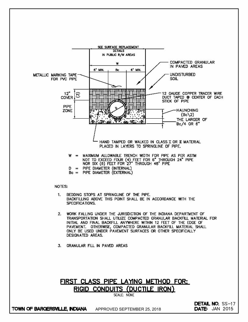
APPROVED SEPTEMBER 25, 2018
AutoCAD SHX Text
TOWN OF BARGERSVILLE, INDIANA
AutoCAD SHX Text
DATE:
AutoCAD SHX Text
DETAIL NO.
AutoCAD SHX Text
SCALE: NONE
AutoCAD SHX Text
SS-
AutoCAD SHX Text
FIRST CLASS PIPE LAYING METHOD FOR: RIGID CONDUITS (DUCTILE IRON)
AutoCAD SHX Text
17
AutoCAD SHX Text
JAN 2015
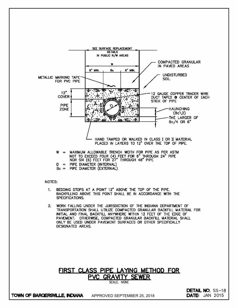
APPROVED SEPTEMBER 25, 2018
AutoCAD SHX Text
TOWN OF BARGERSVILLE, INDIANA
AutoCAD SHX Text
DATE:
AutoCAD SHX Text
DETAIL NO.
AutoCAD SHX Text
SCALE: NONE
AutoCAD SHX Text
SS-
AutoCAD SHX Text
FIRST CLASS PIPE LAYING METHOD FOR PVC GRAVITY SEWER
AutoCAD SHX Text
18
AutoCAD SHX Text
JAN 2015

APPROVED SEPTEMBER 25, 2018
AutoCAD SHX Text
TOWN OF BARGERSVILLE, INDIANA
AutoCAD SHX Text
DATE:
AutoCAD SHX Text
DETAIL NO.
AutoCAD SHX Text
SCALE: NONE
AutoCAD SHX Text
SS-
AutoCAD SHX Text
PVC FORCE MAIN PIPE TRENCH DETAIL
AutoCAD SHX Text
19
AutoCAD SHX Text
JAN 2015
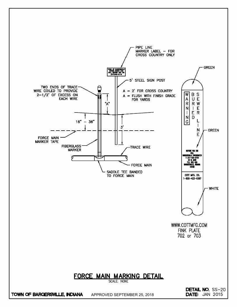
APPROVED SEPTEMBER 25, 2018
AutoCAD SHX Text
TOWN OF BARGERSVILLE, INDIANA
AutoCAD SHX Text
DATE:
AutoCAD SHX Text
DETAIL NO.
AutoCAD SHX Text
SCALE: NONE
AutoCAD SHX Text
SS-
AutoCAD SHX Text
FORCE MAIN MARKING DETAIL
AutoCAD SHX Text
20
AutoCAD SHX Text
JAN 2015
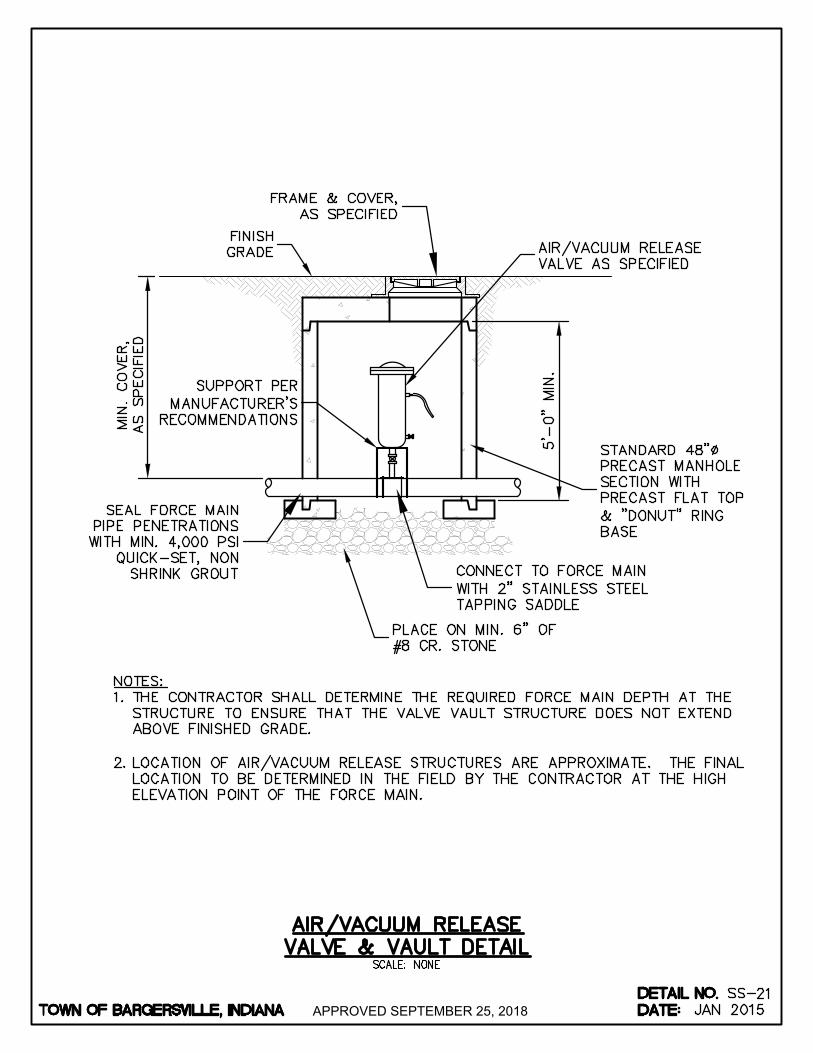
APPROVED SEPTEMBER 25, 2018
AutoCAD SHX Text
TOWN OF BARGERSVILLE, INDIANA
AutoCAD SHX Text
DATE:
AutoCAD SHX Text
DETAIL NO.
AutoCAD SHX Text
SCALE: NONE
AutoCAD SHX Text
SS-
AutoCAD SHX Text
AIR/VACUUM RELEASE VALVE & VAULT DETAIL
AutoCAD SHX Text
21
AutoCAD SHX Text
JAN 2015
AutoCAD SHX Text
NOTES: 1. THE CONTRACTOR SHALL DETERMINE THE REQUIRED FORCE MAIN DEPTH AT THE THE CONTRACTOR SHALL DETERMINE THE REQUIRED FORCE MAIN DEPTH AT THE STRUCTURE TO ENSURE THAT THE VALVE VAULT STRUCTURE DOES NOT EXTEND ABOVE FINISHED GRADE. 2. LOCATION OF AIR/VACUUM RELEASE STRUCTURES ARE APPROXIMATE. THE FINAL LOCATION OF AIR/VACUUM RELEASE STRUCTURES ARE APPROXIMATE. THE FINAL LOCATION TO BE DETERMINED IN THE FIELD BY THE CONTRACTOR AT THE HIGH ELEVATION POINT OF THE FORCE MAIN.
AutoCAD SHX Text
PLACE ON MIN. 6" OF #8 CR. STONE
AutoCAD SHX Text
FINISH GRADE
AutoCAD SHX Text
STANDARD 48" PRECAST MANHOLE SECTION WITH PRECAST FLAT TOP & "DONUT" RING BASE
AutoCAD SHX Text
AIR/VACUUM RELEASE VALVE AS SPECIFIED
AutoCAD SHX Text
SEAL FORCE MAIN PIPE PENETRATIONS WITH MIN. 4,000 PSI QUICK-SET, NON SHRINK GROUT
AutoCAD SHX Text
CONNECT TO FORCE MAIN WITH 2" STAINLESS STEEL TAPPING SADDLE
AutoCAD SHX Text
FRAME & COVER, AS SPECIFIED
AutoCAD SHX Text
SUPPORT PER MANUFACTURER'S RECOMMENDATIONS

APPROVED SEPTEMBER 25, 2018
AutoCAD SHX Text
TOWN OF BARGERSVILLE, INDIANA
AutoCAD SHX Text
DATE:
AutoCAD SHX Text
DETAIL NO.
AutoCAD SHX Text
SCALE: NONE
AutoCAD SHX Text
SS-
AutoCAD SHX Text
VALVE & BOX DETAIL
AutoCAD SHX Text
22
AutoCAD SHX Text
JAN 2015
AutoCAD SHX Text
NOTE: DETAIL APPLIES TO PLUG, GATE AND BUTTERFLY VALVES.
AutoCAD SHX Text
FINISHED GRADE
AutoCAD SHX Text
(1) #4 E.W.
AutoCAD SHX Text
EXPANSION JOINT MATERIAL
AutoCAD SHX Text
SET TOP CASTING & CONC. COLLAR FLUSH WITH FIN. GRADE
AutoCAD SHX Text
ADJUSTABLE VALVE BOX, BASE SIZE TO BE SUITABLE TO NEW VALVE
AutoCAD SHX Text
NEW VALVE AS IDENTIFIED ON PLANS, SEE SPECIFICATION SECTION 15080
AutoCAD SHX Text
NEW PIPING, SIZE & PROCESS AS IDENTIFIED ON PLANS
AutoCAD SHX Text
CONC. SUPPORT BLOCKING

APPROVED SEPTEMBER 25, 2018
AutoCAD SHX Text
TOWN OF BARGERSVILLE, INDIANA
AutoCAD SHX Text
DATE:
AutoCAD SHX Text
DETAIL NO.
AutoCAD SHX Text
SCALE: NONE
AutoCAD SHX Text
SS-
AutoCAD SHX Text
THRUST BLOCKING DETAILS FOR PRESSURE MAIN
AutoCAD SHX Text
23
AutoCAD SHX Text
JAN 2015
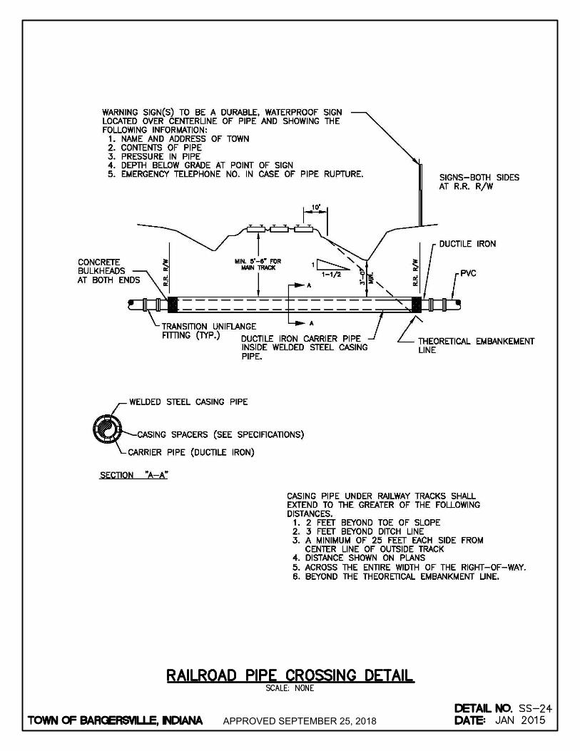
APPROVED SEPTEMBER 25, 2018
AutoCAD SHX Text
TOWN OF BARGERSVILLE, INDIANA
AutoCAD SHX Text
DATE:
AutoCAD SHX Text
DETAIL NO.
AutoCAD SHX Text
SCALE: NONE
AutoCAD SHX Text
SS-
AutoCAD SHX Text
RAILROAD PIPE CROSSING DETAIL
AutoCAD SHX Text
24
AutoCAD SHX Text
JAN 2015

APPROVED SEPTEMBER 25, 2018
AutoCAD SHX Text
TOWN OF BARGERSVILLE, INDIANA
AutoCAD SHX Text
DATE:
AutoCAD SHX Text
DETAIL NO.
AutoCAD SHX Text
SCALE: NONE
AutoCAD SHX Text
SS-
AutoCAD SHX Text
JAN 2015
AutoCAD SHX Text
25
AutoCAD SHX Text
STATE HIGHWAY BORING/CASING DETAIL
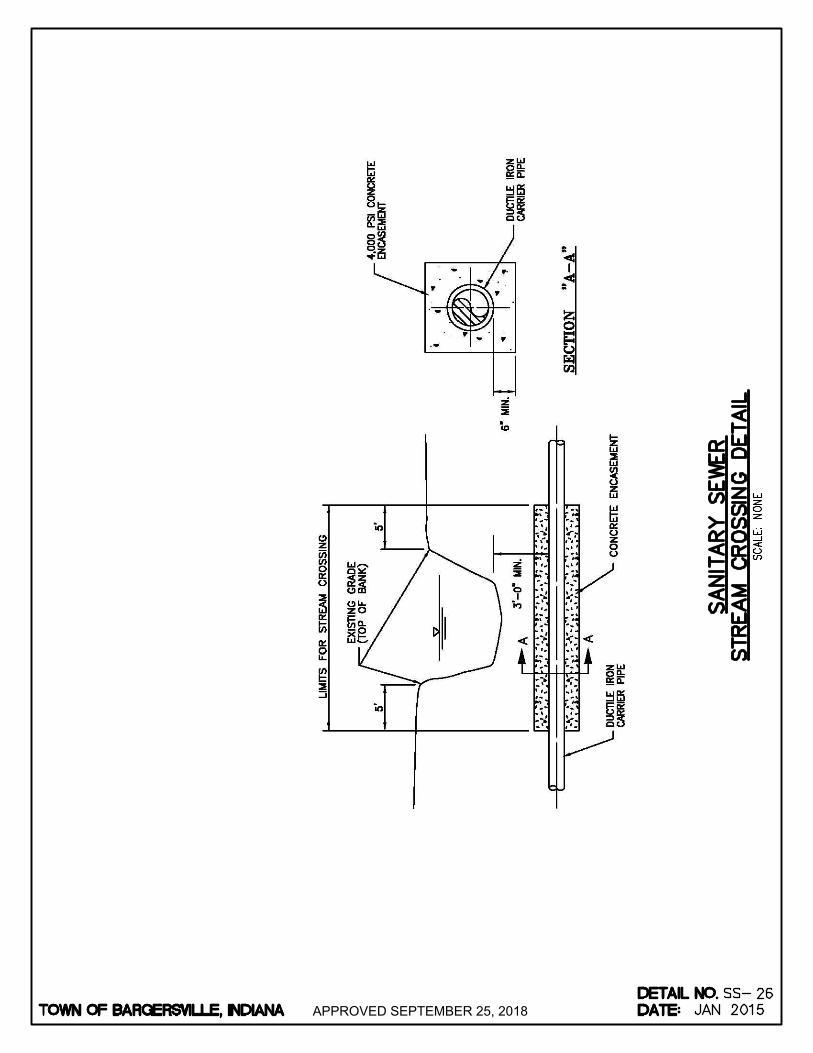
APPROVED SEPTEMBER 25, 2018
AutoCAD SHX Text
TOWN OF BARGERSVILLE, INDIANA
AutoCAD SHX Text
DATE:
AutoCAD SHX Text
DETAIL NO.
AutoCAD SHX Text
SCALE: NONE
AutoCAD SHX Text
SS-
AutoCAD SHX Text
JAN 2015
AutoCAD SHX Text
26
AutoCAD SHX Text
SANITARY SEWER STREAM CROSSING DETAIL
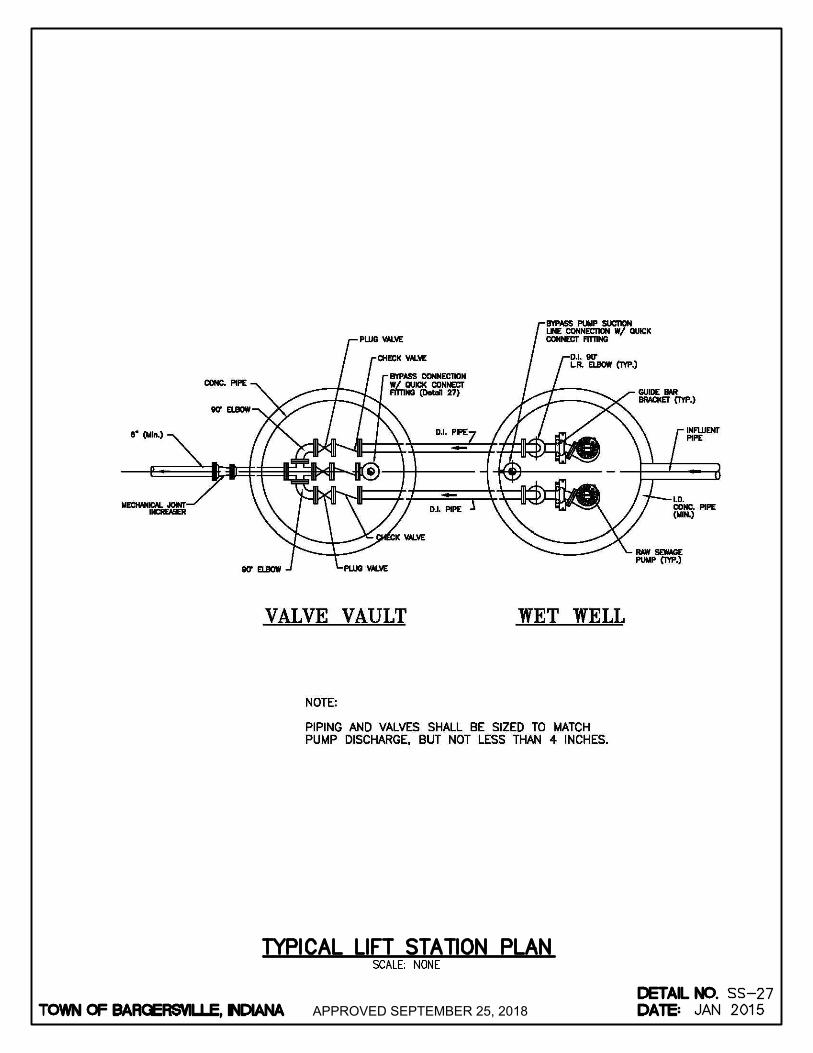
APPROVED SEPTEMBER 25, 2018
AutoCAD SHX Text
TOWN OF BARGERSVILLE, INDIANA
AutoCAD SHX Text
DATE:
AutoCAD SHX Text
DETAIL NO.
AutoCAD SHX Text
SCALE: NONE
AutoCAD SHX Text
SS-
AutoCAD SHX Text
TYPICAL LIFT STATION PLAN
AutoCAD SHX Text
27
AutoCAD SHX Text
JAN 2015

APPROVED SEPTEMBER 25, 2018
AutoCAD SHX Text
TOWN OF BARGERSVILLE, INDIANA
AutoCAD SHX Text
DATE:
AutoCAD SHX Text
DETAIL NO.
AutoCAD SHX Text
SS-28
AutoCAD SHX Text
REV DATE:
AutoCAD SHX Text
JAN 2015
AutoCAD SHX Text
OCT 2016
AutoCAD SHX Text
SCALE: NONE
AutoCAD SHX Text
TYPICAL LIFT STATION SECTION
AutoCAD SHX Text
8'-0" MIN.
AutoCAD SHX Text
WET WELL DIA. MIN. 10'-0"
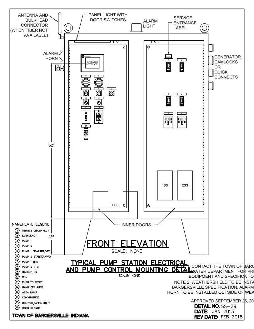
INNER DOORS
4
12
3
12
3
10
G
1SS
7 8
43
1 2
2SS
ESC ENT
5
ESC ENT
6
OFF
ON
OFF
ON
15
UPS
ALARM
LIGHT
Quality
A-B
Allen-Bradley
OPERATOR
INTERFACE
ALARM
HORN
13
RESET
TEST
TEST MONTHLY
PUSH TO RESET
SEE INSTRUCTIONS
14
4
10
G
9
11
R
SUITABLE FOR USE AS
SERVICE EQUIPMENT
INDUSTRIAL CONTROL PANEL
SERVICE
ENTRANCE
LABEL
16
GENERATOR
CAMLOCKS
OR
QUICK
CONNECTS
ANTENNA AND
BULKHEAD
CONNECTOR
(WHEN FIBER NOT
AVAILABLE)
PANEL LIGHT WITH
DOOR SWITCHES
NOTE 1: CONTACT THE TOWN OF BARGERSVILLE WASTEWATER DEPARTMENT FOR PREFERRED
EQUIPMENT AND SPECIFICATIONS.
NOTE 2: WEATHERSHIELD TO BE INSTALLED PER BARGERSVILLE SPECIFICATION. ALARM LIGHT AND
HORN TO BE INSTALLED OUTSIDE OF WEATHERSHIELD.
APPROVED SEPTEMBER 25, 2018

APPROVED SEPTEMBER 25, 2018
AutoCAD SHX Text
TOWN OF BARGERSVILLE, INDIANA
AutoCAD SHX Text
DATE:
AutoCAD SHX Text
DETAIL NO.
AutoCAD SHX Text
SCALE: NONE
AutoCAD SHX Text
SS-
AutoCAD SHX Text
TYPICAL PUMP STATION SERVICE POLE FOR PUMP STATION SERVICES
AutoCAD SHX Text
30
AutoCAD SHX Text
JAN 2015
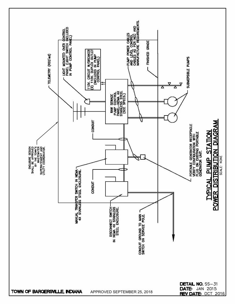
APPROVED SEPTEMBER 25, 2018
AutoCAD SHX Text
TOWN OF BARGERSVILLE, INDIANA
AutoCAD SHX Text
DATE:
AutoCAD SHX Text
DETAIL NO.
AutoCAD SHX Text
SS-31
AutoCAD SHX Text
REV DATE:
AutoCAD SHX Text
JAN 2015
AutoCAD SHX Text
OCT 2016
AutoCAD SHX Text
SCALE: NONE
AutoCAD SHX Text
TYPICAL PUMP STATION POWER DISTRIBUTION DIAGRAM
AutoCAD SHX Text
ENCLOSURE DESIGN DESIGN SHALL BE APPROVED BY THE TOWN'S WASTEWATER SUPERINTENDENT AND UTILITY COORDINATOR.
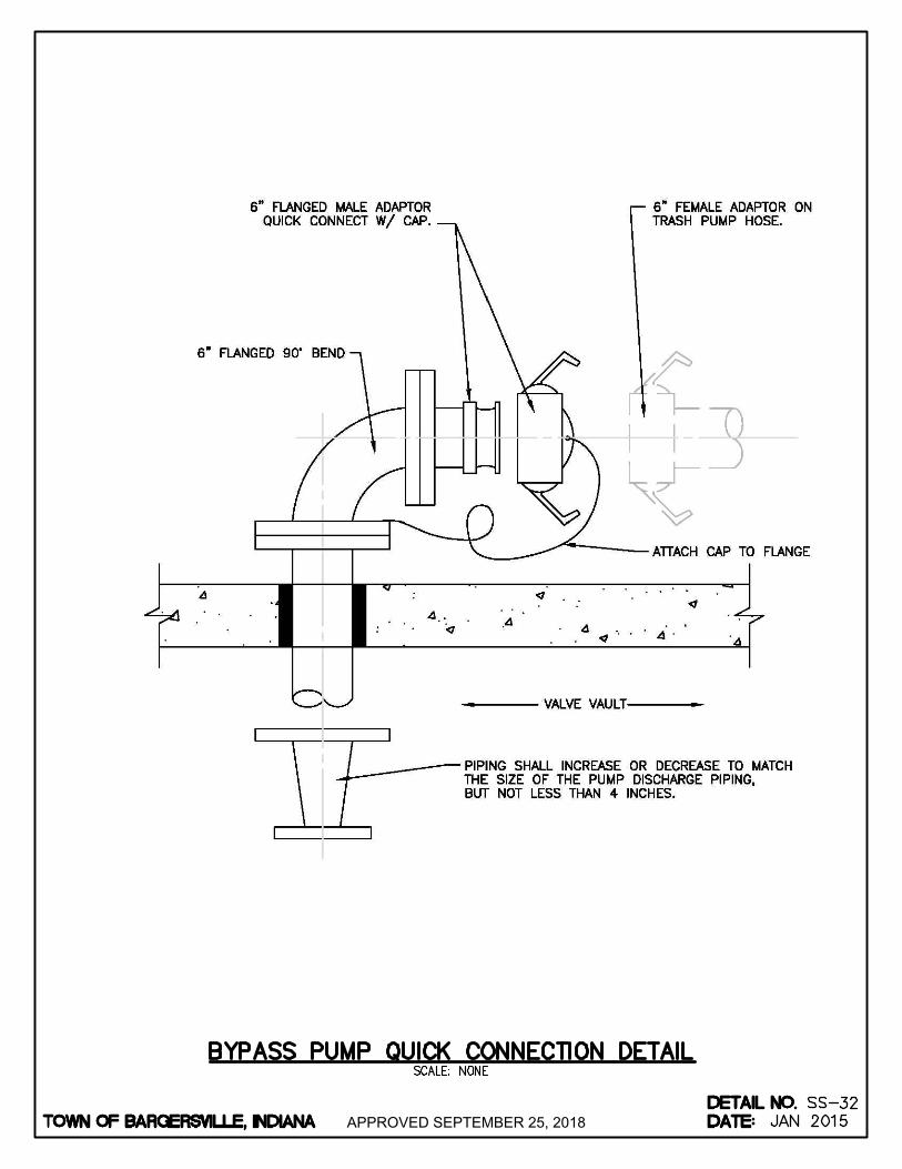
APPROVED SEPTEMBER 25, 2018
AutoCAD SHX Text
TOWN OF BARGERSVILLE, INDIANA
AutoCAD SHX Text
DATE:
AutoCAD SHX Text
DETAIL NO.
AutoCAD SHX Text
SCALE: NONE
AutoCAD SHX Text
SS-
AutoCAD SHX Text
BYPASS PUMP QUICK CONNECTION DETAIL
AutoCAD SHX Text
32
AutoCAD SHX Text
JAN 2015
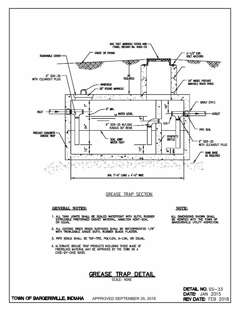
APPROVED SEPTEMBER 25, 2018
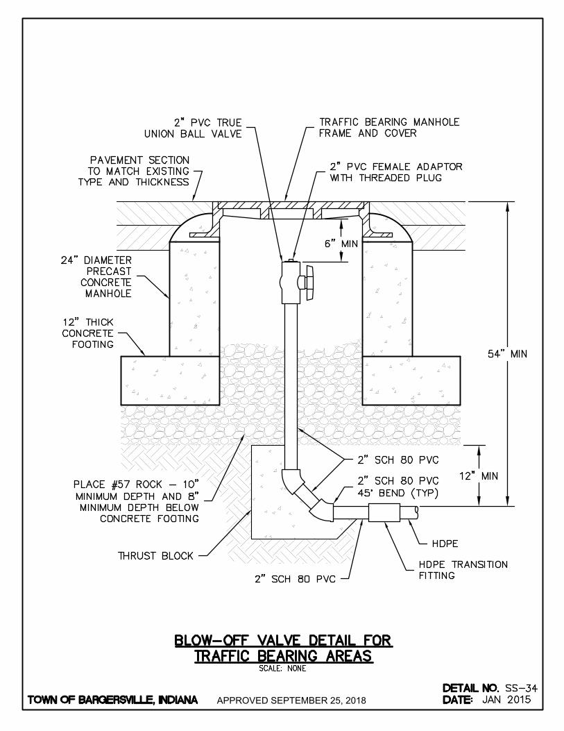
APPROVED SEPTEMBER 25, 2018
AutoCAD SHX Text
TOWN OF BARGERSVILLE, INDIANA
AutoCAD SHX Text
DATE:
AutoCAD SHX Text
DETAIL NO.
AutoCAD SHX Text
SCALE: NONE
AutoCAD SHX Text
SS-
AutoCAD SHX Text
BLOW-OFF VALVE DETAIL FOR TRAFFIC BEARING AREAS
AutoCAD SHX Text
34
AutoCAD SHX Text
JAN 2015
AutoCAD SHX Text
24" DIAMETER PRECAST CONCRETE MANHOLE
AutoCAD SHX Text
2" SCH 80 PVC 45° BEND (TYP)
AutoCAD SHX Text
2" SCH 80 PVC
AutoCAD SHX Text
HDPE
AutoCAD SHX Text
HDPE TRANSITION FITTING
AutoCAD SHX Text
2" SCH 80 PVC
AutoCAD SHX Text
PLACE #57 ROCK - 10" MINIMUM DEPTH AND 8" MINIMUM DEPTH BELOW CONCRETE FOOTING
AutoCAD SHX Text
12" THICK CONCRETE FOOTING
AutoCAD SHX Text
2" PVC FEMALE ADAPTOR WITH THREADED PLUG
AutoCAD SHX Text
TRAFFIC BEARING MANHOLE FRAME AND COVER
AutoCAD SHX Text
2" PVC TRUE UNION BALL VALVE
AutoCAD SHX Text
PAVEMENT SECTION TO MATCH EXISTING TYPE AND THICKNESS
AutoCAD SHX Text
THRUST BLOCK

APPROVED SEPTEMBER 25, 2018
AutoCAD SHX Text
TOWN OF BARGERSVILLE, INDIANA
AutoCAD SHX Text
DATE:
AutoCAD SHX Text
DETAIL NO.
AutoCAD SHX Text
SCALE: NONE
AutoCAD SHX Text
SS-
AutoCAD SHX Text
BLOW-OFF VALVE DETAIL FOR NON-TRAFFIC BEARING AREAS
AutoCAD SHX Text
35
AutoCAD SHX Text
JAN 2015
AutoCAD SHX Text
2" SCH 80 PVC 45° BEND (TYP)
AutoCAD SHX Text
2" SCH 80 PVC
AutoCAD SHX Text
HDPE
AutoCAD SHX Text
HDPE TRANSITION FITTING
AutoCAD SHX Text
2" SCH 80 PVC
AutoCAD SHX Text
PLACE #57 ROCK - 10" MINIMUM DEPTH: ON OUTSIDE OF BOX, PLACE 6" BELOW AND 4" ABOVE BOX BOTTOM
AutoCAD SHX Text
2" PVC FEMALE ADAPTOR WITH THREADED PLUG
AutoCAD SHX Text
CAST IRON MANHOLE COVER AS APPROVED BY THE TOWN
AutoCAD SHX Text
2" PVC TRUE UNION BALL VALVE
AutoCAD SHX Text
FINISHED GRADE
AutoCAD SHX Text
THRUST BLOCK
AutoCAD SHX Text
24" DIAMETER POLYETHYLENE PIT

APPROVED SEPTEMBER 25, 2018
AutoCAD SHX Text
TOWN OF BARGERSVILLE, INDIANA
AutoCAD SHX Text
FRONT
AutoCAD SHX Text
SIDE VIEW
AutoCAD SHX Text
WEATHER SHIELD
AutoCAD SHX Text
SS-36
AutoCAD SHX Text
OCT 2016
AutoCAD SHX Text
SCALE: NONE
AutoCAD SHX Text
LIFT STATION ENCLOSURE
AutoCAD SHX Text
NOTE: 1. DESIGN SHALL BE APPROVED DESIGN SHALL BE APPROVED BY THE TOWN'S WASTEWATER SUPERINTENDENT AND UTILITY COORDINATOR.
AutoCAD SHX Text
TOWN OF BARGERSVILLE, INDIANA
AutoCAD SHX Text
DATE:
AutoCAD SHX Text
DETAIL NO.

APPROVED SEPTEMBER 25, 2018

APPROVED SEPTEMBER 25, 2018
AutoCAD SHX Text
SAW CUT (TYP.)
AutoCAD SHX Text
1/4" MAX. SPA. (TYP)
AutoCAD SHX Text
TRANSITION COUPLING, SEE NOTE 2
AutoCAD SHX Text
EXISTING PIPE
AutoCAD SHX Text
NOTES: 1. PIPE BEDDING AND BACKFILL SHALL BE AS SHOWN IN PIPE TRENCH DETAILS FOR THE PIPE MATERIAL AND SIZE. PIPE BEDDING AND BACKFILL SHALL BE AS SHOWN IN PIPE TRENCH DETAILS FOR THE PIPE MATERIAL AND SIZE. 2. TRANSITION COUPLING FOR PVC TO PVC REPAIRS SHALL BE PVC REPAIR SLEEVE. TRANSITION COUPLING FOR ALL TRANSITION COUPLING FOR PVC TO PVC REPAIRS SHALL BE PVC REPAIR SLEEVE. TRANSITION COUPLING FOR ALL OTHER PIPE REPAIRS SHALL BE "FERNCO" COUPLING, OR APPROVED EQUAL, WITH STAINLESS STEEL BANDS.
AutoCAD SHX Text
TOWN OF BARGERSVILLE, INDIANA
AutoCAD SHX Text
DATE:
AutoCAD SHX Text
DETAIL NO.
AutoCAD SHX Text
SCALE: NONE
AutoCAD SHX Text
SW-
AutoCAD SHX Text
GRAVITY SEWER REPAIR
AutoCAD SHX Text
01
AutoCAD SHX Text
JAN 2015

APPROVED SEPTEMBER 25, 2018
AutoCAD SHX Text
FLOW
AutoCAD SHX Text
%%UPLAN
AutoCAD SHX Text
%%UELEVATION
AutoCAD SHX Text
NOTES: 1. THE HEIGHT OF THE BARRIER SHALL BE A MINIMUM OF 18" AND A MAXIMUM OF 30". THE HEIGHT OF THE BARRIER SHALL BE A MINIMUM OF 18" AND A MAXIMUM OF 30". 2. POSTS SHALL BE SPACED A MAXIMUM OF 6 FEET APART AT THE BARRIER LOCATION AND DRIVEN POSTS SHALL BE SPACED A MAXIMUM OF 6 FEET APART AT THE BARRIER LOCATION AND DRIVEN SECURELY INTO THE GROUND (MINIMUM OF 18 INCHES). WHEN STANDARD STRENGTH FABRIC IS USED WITH THE WIRE SUPPORT FENCE, POST SPACING SHALL NOT EXCEED 8 FEET.
AutoCAD SHX Text
FILTER FABRIC
AutoCAD SHX Text
MIN. 8" TRENCH (UPSLOPE) BACKFILL OVER SILT FENCE
AutoCAD SHX Text
STAPLE OR FASTEN FABRIC TO POSTS
AutoCAD SHX Text
METAL OR WOOD SUPPORT POSTS
AutoCAD SHX Text
FLOW
AutoCAD SHX Text
FLOW
AutoCAD SHX Text
TIEBACK
AutoCAD SHX Text
%%UPOST AND FABRIC
AutoCAD SHX Text
%%UEMBEDMENT
AutoCAD SHX Text
%%UPOST
AutoCAD SHX Text
%%UTIEBACK
AutoCAD SHX Text
NOTE: THE SPACING OF TIEBACKS SHALL EQUAL THE SPACING OF THE POSTS. ADDITIONAL POST DEPTH OR TIEBACKS MAY BE REQUIRED IN UNSTABLE SOILS
AutoCAD SHX Text
GEOTEXTILE FABRIC, EXTEND FULL DEPTH INTO TRENCH AND ACROSS BOTTOM
AutoCAD SHX Text
FABRIC EMBEDMENT TRENCH WITH COMPACTED SOIL BACKFILL ON UPSLOPE SIDE ONLY
AutoCAD SHX Text
FLOW
AutoCAD SHX Text
FLOW
AutoCAD SHX Text
ANCHOR STAKE MIN. LENGTH 1'-6"
AutoCAD SHX Text
TIEBACK BETWEEN FENCE POST AND ANCHOR
AutoCAD SHX Text
DOWNSLOPE
AutoCAD SHX Text
UPSLOPE
AutoCAD SHX Text
TOWN OF BARGERSVILLE, INDIANA
AutoCAD SHX Text
DATE:
AutoCAD SHX Text
DETAIL NO.
AutoCAD SHX Text
SCALE: NONE
AutoCAD SHX Text
SW-
AutoCAD SHX Text
SILT FENCE
AutoCAD SHX Text
02
AutoCAD SHX Text
JAN 2015
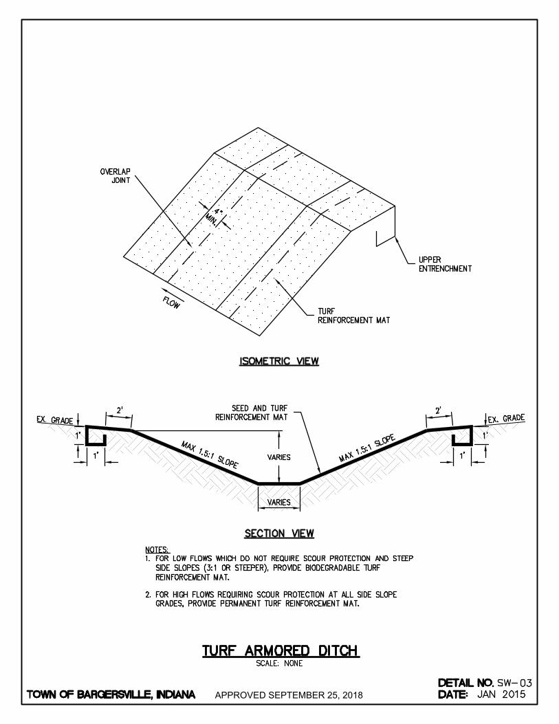
APPROVED SEPTEMBER 25, 2018
AutoCAD SHX Text
MAX 1.5:1 SLOPE
AutoCAD SHX Text
EX. GRADE
AutoCAD SHX Text
MAX 1.5:1 SLOPE
AutoCAD SHX Text
SEED AND TURF REINFORCEMENT MAT
AutoCAD SHX Text
NOTES: 1. FOR LOW FLOWS WHICH DO NOT REQUIRE SCOUR PROTECTION AND STEEP FOR LOW FLOWS WHICH DO NOT REQUIRE SCOUR PROTECTION AND STEEP SIDE SLOPES (3:1 OR STEEPER), PROVIDE BIODEGRADABLE TURF REINFORCEMENT MAT. 2. FOR HIGH FLOWS REQUIRING SCOUR PROTECTION AT ALL SIDE SLOPE FOR HIGH FLOWS REQUIRING SCOUR PROTECTION AT ALL SIDE SLOPE GRADES, PROVIDE PERMANENT TURF REINFORCEMENT MAT.
AutoCAD SHX Text
%%USECTION VIEW
AutoCAD SHX Text
EX. GRADE
AutoCAD SHX Text
%%UISOMETRIC VIEW
AutoCAD SHX Text
FLOW
AutoCAD SHX Text
TURF REINFORCEMENT MAT
AutoCAD SHX Text
UPPER ENTRENCHMENT
AutoCAD SHX Text
OVERLAP JOINT
AutoCAD SHX Text
TOWN OF BARGERSVILLE, INDIANA
AutoCAD SHX Text
DATE:
AutoCAD SHX Text
DETAIL NO.
AutoCAD SHX Text
SCALE: NONE
AutoCAD SHX Text
SW-
AutoCAD SHX Text
TURF ARMORED DITCH
AutoCAD SHX Text
03
AutoCAD SHX Text
JAN 2015

APPROVED SEPTEMBER 25, 2018
AutoCAD SHX Text
EX. GRADE
AutoCAD SHX Text
MAX 1.5:1 SLOPE
AutoCAD SHX Text
EX. GRADE
AutoCAD SHX Text
HARD ARMORING MATERIAL
AutoCAD SHX Text
MAX 1.5:1 SLOPE
AutoCAD SHX Text
GEOTEXTILE
AutoCAD SHX Text
NOTES: 1. TURF ARMORING IS PREFFERED METHOD OF SCOUR PROTECTION AND BANK TURF ARMORING IS PREFFERED METHOD OF SCOUR PROTECTION AND BANK STABILIZATION, WHERE APPLICABLE. 2. PROVIDE RIPRAP (REVETMENT, CLASS I, OR CLASS II GRADATION PER INDOT) PROVIDE RIPRAP (REVETMENT, CLASS I, OR CLASS II GRADATION PER INDOT) OR ARMORFLEX HARD ARMOR.
AutoCAD SHX Text
TOWN OF BARGERSVILLE, INDIANA
AutoCAD SHX Text
DATE:
AutoCAD SHX Text
DETAIL NO.
AutoCAD SHX Text
SCALE: NONE
AutoCAD SHX Text
SW-
AutoCAD SHX Text
HARD ARMORED DITCH
AutoCAD SHX Text
04
AutoCAD SHX Text
JAN 2015
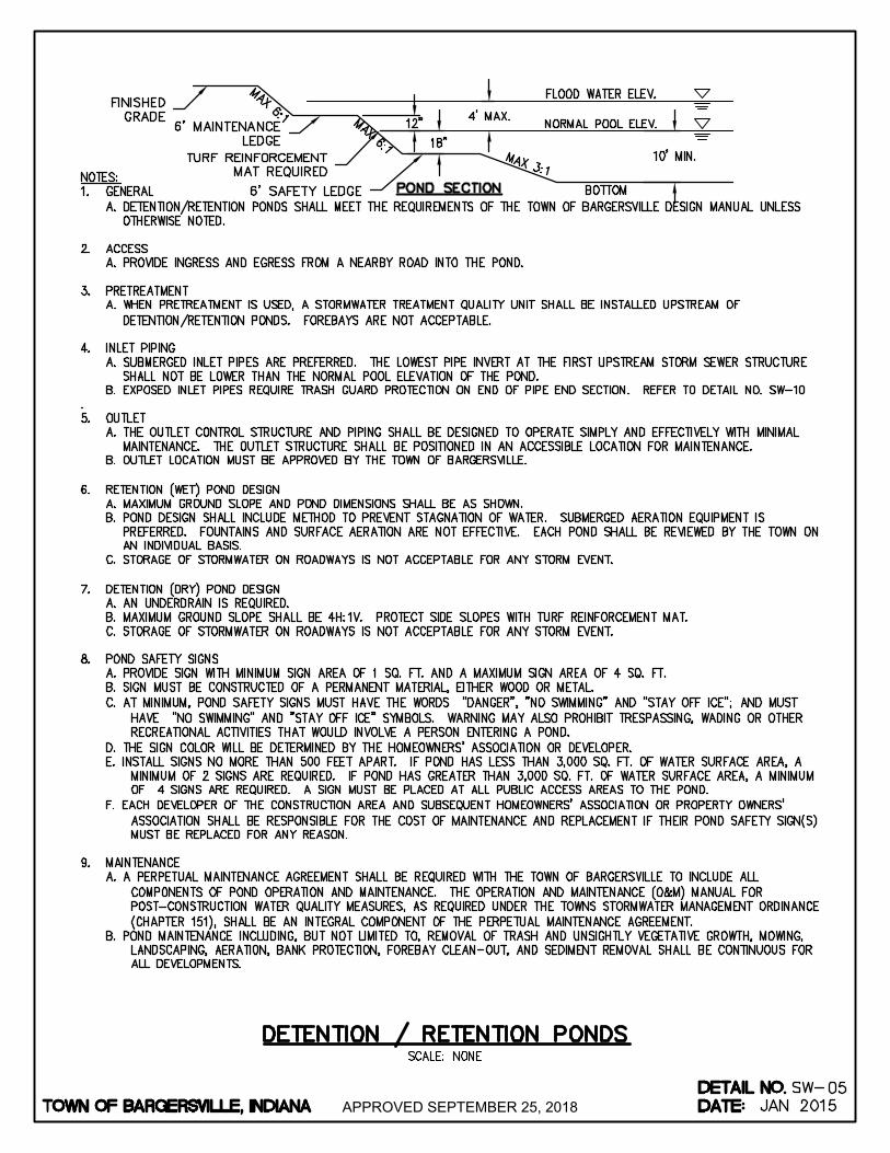
APPROVED SEPTEMBER 25, 2018
AutoCAD SHX Text
%%UPOND SECTION
AutoCAD SHX Text
FINISHED GRADE
AutoCAD SHX Text
MAX 6:1
AutoCAD SHX Text
MAX 6:1
AutoCAD SHX Text
MAX 3:1
AutoCAD SHX Text
BOTTOM
AutoCAD SHX Text
NORMAL POOL ELEV.
AutoCAD SHX Text
FLOOD WATER ELEV.
AutoCAD SHX Text
6' MAINTENANCE LEDGE
AutoCAD SHX Text
TURF REINFORCEMENT MAT REQUIRED
AutoCAD SHX Text
6' SAFETY LEDGE
AutoCAD SHX Text
NOTES: 1. GENERAL GENERAL A. DETENTION/RETENTION PONDS SHALL MEET THE REQUIREMENTS OF THE TOWN OF BARGERSVILLE DESIGN MANUAL UNLESS OTHERWISE NOTED. 2. ACCESS ACCESS A. PROVIDE INGRESS AND EGRESS FROM A NEARBY ROAD INTO THE POND. 3. PRETREATMENT PRETREATMENT A. WHEN PRETREATMENT IS USED, A STORMWATER TREATMENT QUALITY UNIT SHALL BE INSTALLED UPSTREAM OF DETENTION/RETENTION PONDS. FOREBAYS ARE NOT ACCEPTABLE. 4. INLET PIPING INLET PIPING A. SUBMERGED INLET PIPES ARE PREFERRED. THE LOWEST PIPE INVERT AT THE FIRST UPSTREAM STORM SEWER STRUCTURE SHALL NOT BE LOWER THAN THE NORMAL POOL ELEVATION OF THE POND. B. EXPOSED INLET PIPES REQUIRE TRASH GUARD PROTECTION ON END OF PIPE END SECTION. REFER TO DETAIL NO. SW-10 . 5. OUTLET OUTLET A. THE OUTLET CONTROL STRUCTURE AND PIPING SHALL BE DESIGNED TO OPERATE SIMPLY AND EFFECTIVELY WITH MINIMAL MAINTENANCE. THE OUTLET STRUCTURE SHALL BE POSITIONED IN AN ACCESSIBLE LOCATION FOR MAINTENANCE. B. OUTLET LOCATION MUST BE APPROVED BY THE TOWN OF BARGERSVILLE. 6. RETENTION (WET) POND DESIGN RETENTION (WET) POND DESIGN A. MAXIMUM GROUND SLOPE AND POND DIMENSIONS SHALL BE AS SHOWN. B. POND DESIGN SHALL INCLUDE METHOD TO PREVENT STAGNATION OF WATER. SUBMERGED AERATION EQUIPMENT IS PREFERRED. FOUNTAINS AND SURFACE AERATION ARE NOT EFFECTIVE. EACH POND SHALL BE REVIEWED BY THE TOWN ON AN INDIVIDUAL BASIS. C. STORAGE OF STORMWATER ON ROADWAYS IS NOT ACCEPTABLE FOR ANY STORM EVENT. 7. DETENTION (DRY) POND DESIGN DETENTION (DRY) POND DESIGN A. AN UNDERDRAIN IS REQUIRED. B. MAXIMUM GROUND SLOPE SHALL BE 4H:1V. PROTECT SIDE SLOPES WITH TURF REINFORCEMENT MAT. C. STORAGE OF STORMWATER ON ROADWAYS IS NOT ACCEPTABLE FOR ANY STORM EVENT. 8. POND SAFETY SIGNS POND SAFETY SIGNS A. PROVIDE SIGN WITH MINIMUM SIGN AREA OF 1 SQ. FT. AND A MAXIMUM SIGN AREA OF 4 SQ. FT. B. SIGN MUST BE CONSTRUCTED OF A PERMANENT MATERIAL, EITHER WOOD OR METAL. C. AT MINIMUM, POND SAFETY SIGNS MUST HAVE THE WORDS "DANGER", "NO SWIMMING" AND "STAY OFF ICE"; AND MUST HAVE "NO SWIMMING" AND "STAY OFF ICE" SYMBOLS. WARNING MAY ALSO PROHIBIT TRESPASSING, WADING OR OTHER RECREATIONAL ACTIVITIES THAT WOULD INVOLVE A PERSON ENTERING A POND. D. THE SIGN COLOR WILL BE DETERMINED BY THE HOMEOWNERS' ASSOCIATION OR DEVELOPER. E. INSTALL SIGNS NO MORE THAN 500 FEET APART. IF POND HAS LESS THAN 3,000 SQ. FT. OF WATER SURFACE AREA, A MINIMUM OF 2 SIGNS ARE REQUIRED. IF POND HAS GREATER THAN 3,000 SQ. FT. OF WATER SURFACE AREA, A MINIMUM OF 4 SIGNS ARE REQUIRED. A SIGN MUST BE PLACED AT ALL PUBLIC ACCESS AREAS TO THE POND. F. EACH DEVELOPER OF THE CONSTRUCTION AREA AND SUBSEQUENT HOMEOWNERS' ASSOCIATION OR PROPERTY OWNERS' ASSOCIATION SHALL BE RESPONSIBLE FOR THE COST OF MAINTENANCE AND REPLACEMENT IF THEIR POND SAFETY SIGN(S) MUST BE REPLACED FOR ANY REASON. 9. MAINTENANCE MAINTENANCE A. A PERPETUAL MAINTENANCE AGREEMENT SHALL BE REQUIRED WITH THE TOWN OF BARGERSVILLE TO INCLUDE ALL COMPONENTS OF POND OPERATION AND MAINTENANCE. THE OPERATION AND MAINTENANCE (O&M) MANUAL FOR POST-CONSTRUCTION WATER QUALITY MEASURES, AS REQUIRED UNDER THE TOWNS STORMWATER MANAGEMENT ORDINANCE (CHAPTER 151), SHALL BE AN INTEGRAL COMPONENT OF THE PERPETUAL MAINTENANCE AGREEMENT. B. POND MAINTENANCE INCLUDING, BUT NOT LIMITED TO, REMOVAL OF TRASH AND UNSIGHTLY VEGETATIVE GROWTH, MOWING, LANDSCAPING, AERATION, BANK PROTECTION, FOREBAY CLEAN-OUT, AND SEDIMENT REMOVAL SHALL BE CONTINUOUS FOR ALL DEVELOPMENTS.
AutoCAD SHX Text
TOWN OF BARGERSVILLE, INDIANA
AutoCAD SHX Text
DATE:
AutoCAD SHX Text
DETAIL NO.
AutoCAD SHX Text
SCALE: NONE
AutoCAD SHX Text
SW-
AutoCAD SHX Text
DETENTION / RETENTION PONDS
AutoCAD SHX Text
05
AutoCAD SHX Text
JAN 2015

APPROVED SEPTEMBER 25, 2018
AutoCAD SHX Text
BEDDING & 1/6 OD HAUNCHING AREA CLASS I OR CLASS II MATERIAL
AutoCAD SHX Text
HAUNCHING & INITIAL & FINAL BACKFILL EXCAVATED MATERIAL OUTSIDE PAVEMENT LOADING ZONE, CLASS I OR CLASS II MATERIAL INSIDE PAVEMENT LOADING ZONE
AutoCAD SHX Text
BEDDING BELOW THE PIPE BARREL
AutoCAD SHX Text
BEDDING BELOW THE PIPE BARREL
AutoCAD SHX Text
SOIL FOUNDATION
AutoCAD SHX Text
ROCK FOUNDATION
AutoCAD SHX Text
OD / 24 MIN = 3"
AutoCAD SHX Text
OD / 12 MIN = 6"
AutoCAD SHX Text
EX GRADE
AutoCAD SHX Text
SURFACE RESTORATION
AutoCAD SHX Text
UNDISTURBED EARTH
AutoCAD SHX Text
TOWN OF BARGERSVILLE, INDIANA
AutoCAD SHX Text
DATE:
AutoCAD SHX Text
DETAIL NO.
AutoCAD SHX Text
SCALE: NONE
AutoCAD SHX Text
SW-
AutoCAD SHX Text
RIGID (RCP, DI) PIPE TRENCH
AutoCAD SHX Text
06
AutoCAD SHX Text
JAN 2015

APPROVED SEPTEMBER 25, 2018
AutoCAD SHX Text
BEDDING, HAUNCHING, & INITIAL BACKFILL CLASS I MATERIAL
AutoCAD SHX Text
TRACER WIRE
AutoCAD SHX Text
PIPE SIZE
AutoCAD SHX Text
BEDDING BELOW THE PIPE BARREL
AutoCAD SHX Text
3" TO 15"
AutoCAD SHX Text
18" TO 30"
AutoCAD SHX Text
4"
AutoCAD SHX Text
OD / 4
AutoCAD SHX Text
EX GRADE
AutoCAD SHX Text
SURFACE RESTORATION
AutoCAD SHX Text
UNDISTURBED EARTH
AutoCAD SHX Text
FINAL BACKFILL EXCAVATED MATERIAL OUTSIDE PAVEMENT LOADING ZONE, CLASS I OR CLASS II MATERIAL INSIDE PAVEMENT LOADING ZONE
AutoCAD SHX Text
33" AND OVER
AutoCAD SHX Text
8"
AutoCAD SHX Text
TOWN OF BARGERSVILLE, INDIANA
AutoCAD SHX Text
DATE:
AutoCAD SHX Text
DETAIL NO.
AutoCAD SHX Text
SCALE: NONE
AutoCAD SHX Text
SW-
AutoCAD SHX Text
FLEXIBLE (HDPE PVC) PIPE TRENCH
AutoCAD SHX Text
07
AutoCAD SHX Text
JAN 2015
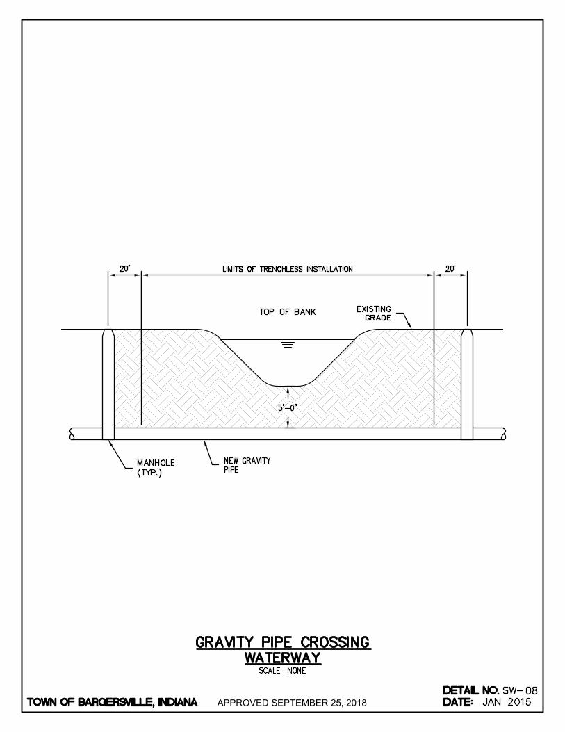
APPROVED SEPTEMBER 25, 2018
AutoCAD SHX Text
NEW GRAVITY PIPE
AutoCAD SHX Text
EXISTING GRADE
AutoCAD SHX Text
TOP OF BANK
AutoCAD SHX Text
MANHOLE (TYP.)
AutoCAD SHX Text
TOWN OF BARGERSVILLE, INDIANA
AutoCAD SHX Text
DATE:
AutoCAD SHX Text
DETAIL NO.
AutoCAD SHX Text
SCALE: NONE
AutoCAD SHX Text
SW-
AutoCAD SHX Text
GRAVITY PIPE CROSSING WATERWAY
AutoCAD SHX Text
08
AutoCAD SHX Text
JAN 2015
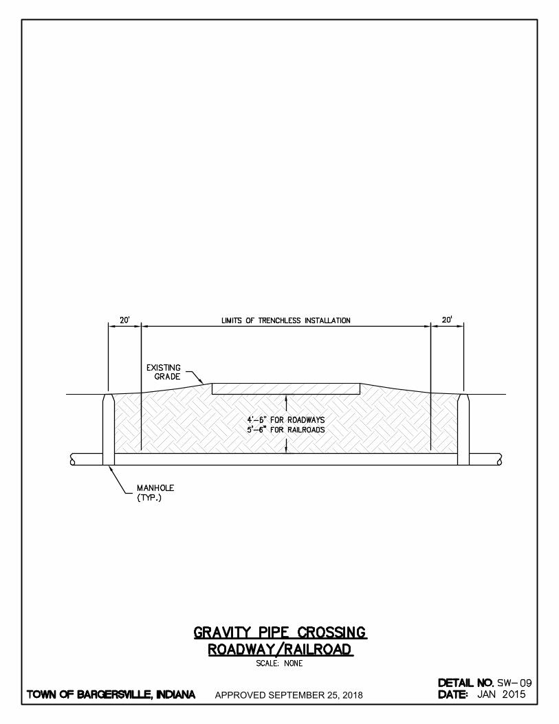
APPROVED SEPTEMBER 25, 2018
AutoCAD SHX Text
MANHOLE (TYP.)
AutoCAD SHX Text
EXISTING GRADE
AutoCAD SHX Text
TOWN OF BARGERSVILLE, INDIANA
AutoCAD SHX Text
DATE:
AutoCAD SHX Text
DETAIL NO.
AutoCAD SHX Text
SCALE: NONE
AutoCAD SHX Text
SW-
AutoCAD SHX Text
GRAVITY PIPE CROSSING ROADWAY/RAILROAD
AutoCAD SHX Text
09
AutoCAD SHX Text
JAN 2015

APPROVED SEPTEMBER 25, 2018
AutoCAD SHX Text
NO. 8 WASHED STONE
AutoCAD SHX Text
6" PERFORATED UNDERDRAIN PIPE
AutoCAD SHX Text
NO. 8 WASHED STONE OR WASHED PEA GRAVEL
AutoCAD SHX Text
EX. GRADE
AutoCAD SHX Text
6" TOPSOIL, SEED AND EROSION CONTROL BLANKET OR SOD
AutoCAD SHX Text
MAX 3:1 SLOPE
AutoCAD SHX Text
EX. GRADE
AutoCAD SHX Text
MAX 3:1 SLOPE
AutoCAD SHX Text
NOTES: 1. PIPE MATERIAL SHALL BE PERFORATED CORRUGATED PIPE MATERIAL SHALL BE PERFORATED CORRUGATED POLYETHYLENE, AS SPECIFIED. 2. UNDERDRAIN CLEANOUT/RISERS REQUIRED EVERY 500 FEET.UNDERDRAIN CLEANOUT/RISERS REQUIRED EVERY 500 FEET.
AutoCAD SHX Text
TOWN OF BARGERSVILLE, INDIANA
AutoCAD SHX Text
DATE:
AutoCAD SHX Text
DETAIL NO.
AutoCAD SHX Text
SW-10
AutoCAD SHX Text
REV DATE:
AutoCAD SHX Text
JAN 2015
AutoCAD SHX Text
OCT 2016
AutoCAD SHX Text
SCALE: NONE
AutoCAD SHX Text
DRAINAGE SWALE WITH UNDERDRAIN

APPROVED SEPTEMBER 25, 2018
AutoCAD SHX Text
6" HDPE PERFORATED CORRUGATED SINGLE-WALL UNDERDRAIN PIPE
AutoCAD SHX Text
4" PLUG
AutoCAD SHX Text
4" PLUG
AutoCAD SHX Text
4"X4"X6" HDPE WYE
AutoCAD SHX Text
PROPERTY LINE
AutoCAD SHX Text
PROPERTY LINE
AutoCAD SHX Text
4" HDPE SOLID WALL DRAINAGE LATERAL
AutoCAD SHX Text
4" HDPE SOLID WALL DRAINAGE LATERAL
AutoCAD SHX Text
4" PLUG
AutoCAD SHX Text
4"X4"X6" HDPE WYE
AutoCAD SHX Text
CONNECTION DETAIL TO SUB-DRAIN
AutoCAD SHX Text
6" HDPE PERFORATED CORRUGATED SINGLE-WALL UNDERDRAIN PIPE
AutoCAD SHX Text
4" HDPE SOLID WALL STORM LATERAL
AutoCAD SHX Text
METAL T-FENCE POST
AutoCAD SHX Text
NOTES: 1. ROUTE ALL DRAINAGE LATERALS TO REAR YARD SWALES WHEN POSSIBLE. ROUTE ALL DRAINAGE LATERALS TO REAR YARD SWALES WHEN POSSIBLE. 2. IF CONNECTING SUMP PUMP DISCHARGE TO STORM SEWER SYSTEM, THE SYSTEM MUST IF CONNECTING SUMP PUMP DISCHARGE TO STORM SEWER SYSTEM, THE SYSTEM MUST CONTAIN A CHECK VALVE INSIDE THE DWELLING. THE SUMP PUMP DISCHARGE PIPE MAY THEN BE CONNECTED TO LATERAL WITH AN APPROPRIATE FITTING. IF NO CHECK VALVE IS PRESENT, THE SUMP PUMP AND SYSTEM SHALL NOT HAVE A HARD CONNECTION. 3. LATERAL LOCATIONS SHALL BE NOTED ON AS-BUILTS.LATERAL LOCATIONS SHALL BE NOTED ON AS-BUILTS.
AutoCAD SHX Text
6"X6" HDPE TEE
AutoCAD SHX Text
DRAINAGE EASEMENT
AutoCAD SHX Text
TOWN OF BARGERSVILLE, INDIANA
AutoCAD SHX Text
DATE:
AutoCAD SHX Text
DETAIL NO.
AutoCAD SHX Text
SCALE: NONE
AutoCAD SHX Text
SW-
AutoCAD SHX Text
DRAINAGE LATERAL IN REAR OF LOT
AutoCAD SHX Text
11
AutoCAD SHX Text
JAN 2015

APPROVED SEPTEMBER 25, 2018
AutoCAD SHX Text
%%uCONCRETE PIPE TOE ANCHOR
AutoCAD SHX Text
%%uSECTION A-A
AutoCAD SHX Text
%%uPLAN VIEW
AutoCAD SHX Text
%%ULONGITUDINAL SECTION
AutoCAD SHX Text
A
AutoCAD SHX Text
A
AutoCAD SHX Text
3:1 FILL SLOPE
AutoCAD SHX Text
12"
AutoCAD SHX Text
2"
AutoCAD SHX Text
5"
AutoCAD SHX Text
51"
AutoCAD SHX Text
74"
AutoCAD SHX Text
24"
AutoCAD SHX Text
10.125"
AutoCAD SHX Text
9"
AutoCAD SHX Text
800
AutoCAD SHX Text
1100
AutoCAD SHX Text
11"
AutoCAD SHX Text
12.5"
AutoCAD SHX Text
30"
AutoCAD SHX Text
75"
AutoCAD SHX Text
48"
AutoCAD SHX Text
7"
AutoCAD SHX Text
2.25"
AutoCAD SHX Text
15"
AutoCAD SHX Text
1300
AutoCAD SHX Text
12"
AutoCAD SHX Text
15.5"
AutoCAD SHX Text
36"
AutoCAD SHX Text
74"
AutoCAD SHX Text
49"
AutoCAD SHX Text
11"
AutoCAD SHX Text
2.5"
AutoCAD SHX Text
18"
AutoCAD SHX Text
1500
AutoCAD SHX Text
13"
AutoCAD SHX Text
16.125"
AutoCAD SHX Text
42"
AutoCAD SHX Text
75"
AutoCAD SHX Text
42"
AutoCAD SHX Text
11"
AutoCAD SHX Text
2.75"
AutoCAD SHX Text
21"
AutoCAD SHX Text
1800
AutoCAD SHX Text
14"
AutoCAD SHX Text
16.375"
AutoCAD SHX Text
48"
AutoCAD SHX Text
75"
AutoCAD SHX Text
32"
AutoCAD SHX Text
12"
AutoCAD SHX Text
3"
AutoCAD SHX Text
24"
AutoCAD SHX Text
2100
AutoCAD SHX Text
14.5"
AutoCAD SHX Text
18.563"
AutoCAD SHX Text
54"
AutoCAD SHX Text
75"
AutoCAD SHX Text
29"
AutoCAD SHX Text
13"
AutoCAD SHX Text
3.25"
AutoCAD SHX Text
27"
AutoCAD SHX Text
2400
AutoCAD SHX Text
15"
AutoCAD SHX Text
18.5"
AutoCAD SHX Text
60"
AutoCAD SHX Text
75"
AutoCAD SHX Text
22"
AutoCAD SHX Text
14"
AutoCAD SHX Text
3.5"
AutoCAD SHX Text
30"
AutoCAD SHX Text
4100
AutoCAD SHX Text
17.5"
AutoCAD SHX Text
23.75"
AutoCAD SHX Text
66"
AutoCAD SHX Text
99"
AutoCAD SHX Text
42"
AutoCAD SHX Text
15"
AutoCAD SHX Text
3.75"
AutoCAD SHX Text
33"
AutoCAD SHX Text
4200
AutoCAD SHX Text
20"
AutoCAD SHX Text
24.625"
AutoCAD SHX Text
72"
AutoCAD SHX Text
99"
AutoCAD SHX Text
37"
AutoCAD SHX Text
17"
AutoCAD SHX Text
4"
AutoCAD SHX Text
36"
AutoCAD SHX Text
* TOLERANCE %%P
AutoCAD SHX Text
DIA.
AutoCAD SHX Text
T (MIN.)
AutoCAD SHX Text
A*
AutoCAD SHX Text
C*
AutoCAD SHX Text
D*
AutoCAD SHX Text
E*
AutoCAD SHX Text
R11
AutoCAD SHX Text
R22
AutoCAD SHX Text
APPROX. WEIGHT
AutoCAD SHX Text
4000 PSI CONCRETE
AutoCAD SHX Text
GROOVE (OR TONGUE) TO BE THE SAME AS ON STANDARD REINFORCED CONCRETE PIPE ASTM DESIGNATION C76
AutoCAD SHX Text
GROOVED END ON OUTLET END TONGUE END ON INLET END
AutoCAD SHX Text
4:1 FILL SLOPE
AutoCAD SHX Text
4" COMPACTED CLASS I BEDDING
AutoCAD SHX Text
UNDISTURBED SOIL
AutoCAD SHX Text
4000 PSI CONCRETE
AutoCAD SHX Text
TOWN OF BARGERSVILLE, INDIANA
AutoCAD SHX Text
DATE:
AutoCAD SHX Text
DETAIL NO.
AutoCAD SHX Text
SW-13
AutoCAD SHX Text
REV DATE:
AutoCAD SHX Text
JAN 2015
AutoCAD SHX Text
OCT 2016
AutoCAD SHX Text
SCALE: NONE
AutoCAD SHX Text
PRECAST CONCRETE END SECTION
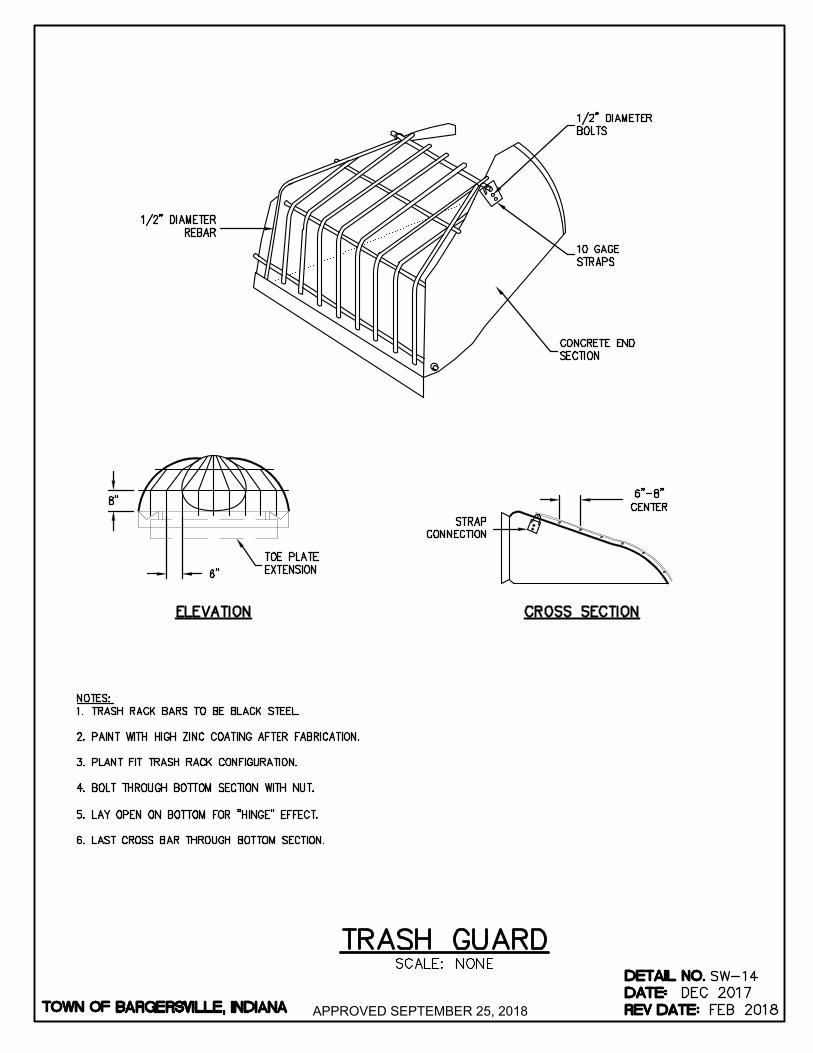
APPROVED SEPTEMBER 25, 2018
AutoCAD SHX Text
%%UCROSS SECTION
AutoCAD SHX Text
%%UELEVATION
AutoCAD SHX Text
NOTES: 1. TRASH RACK BARS TO BE BLACK STEEL. TRASH RACK BARS TO BE BLACK STEEL. 2. PAINT WITH HIGH ZINC COATING AFTER FABRICATION. PAINT WITH HIGH ZINC COATING AFTER FABRICATION. 3. PLANT FIT TRASH RACK CONFIGURATION. PLANT FIT TRASH RACK CONFIGURATION. 4. BOLT THROUGH BOTTOM SECTION WITH NUT. BOLT THROUGH BOTTOM SECTION WITH NUT. 5. LAY OPEN ON BOTTOM FOR "HINGE" EFFECT. LAY OPEN ON BOTTOM FOR "HINGE" EFFECT. 6. LAST CROSS BAR THROUGH BOTTOM SECTION.LAST CROSS BAR THROUGH BOTTOM SECTION.
AutoCAD SHX Text
STRAP CONNECTION
AutoCAD SHX Text
1/2" DIAMETER REBAR
AutoCAD SHX Text
TOE PLATE EXTENSION
AutoCAD SHX Text
REINFORCED EDGE
AutoCAD SHX Text
1/2" DIAMETER BOLTS
AutoCAD SHX Text
10 GAGE STRAPS
AutoCAD SHX Text
TOWN OF BARGERSVILLE, INDIANA
AutoCAD SHX Text
DATE:
AutoCAD SHX Text
DETAIL NO.
AutoCAD SHX Text
SCALE: NONE
AutoCAD SHX Text
SW-
AutoCAD SHX Text
TRASH GUARD
AutoCAD SHX Text
14
AutoCAD SHX Text
JAN 2015
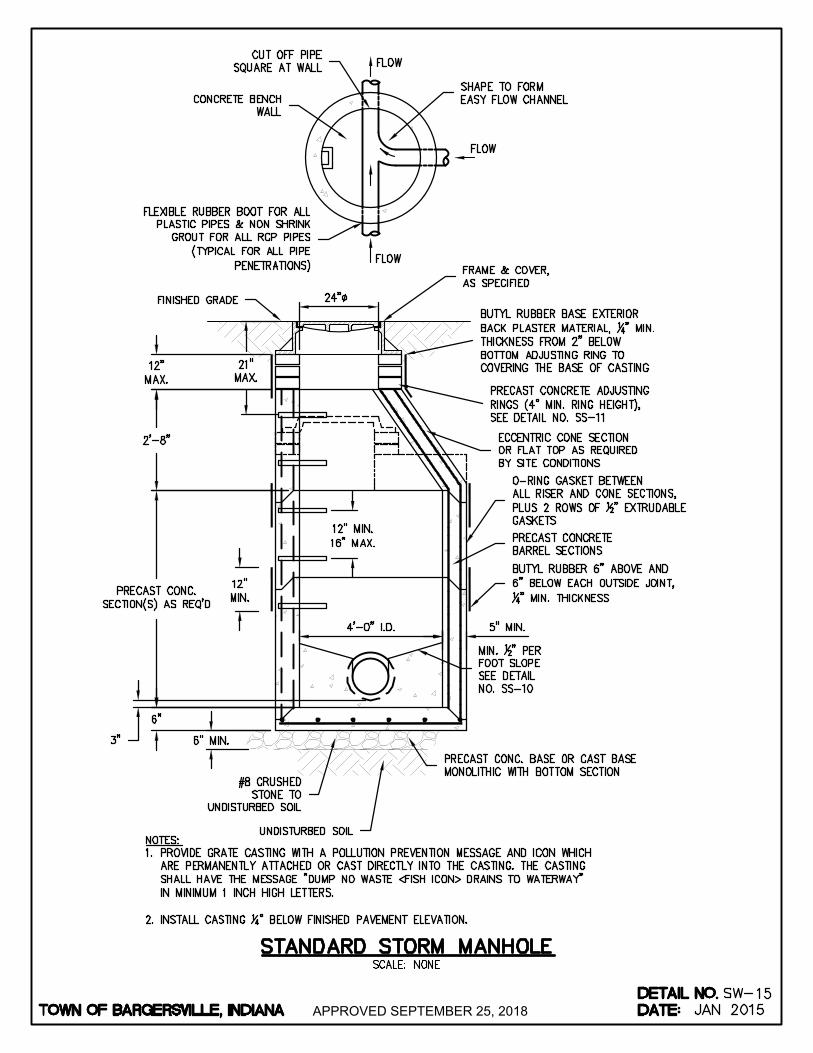
APPROVED SEPTEMBER 25, 2018
AutoCAD SHX Text
FINISHED GRADE
AutoCAD SHX Text
PRECAST CONCRETE ADJUSTING RINGS (4" MIN. RING HEIGHT), SEE DETAIL NO. SS-11
AutoCAD SHX Text
ECCENTRIC CONE SECTION OR FLAT TOP AS REQUIRED BY SITE CONDITIONS
AutoCAD SHX Text
MIN. " PER 12" PER FOOT SLOPE SEE DETAIL NO. SS-10
AutoCAD SHX Text
FLEXIBLE RUBBER BOOT FOR ALL PLASTIC PIPES & NON SHRINK GROUT FOR ALL RCP PIPES (TYPICAL FOR ALL PIPE PENETRATIONS)
AutoCAD SHX Text
#8 CRUSHED STONE TO UNDISTURBED SOIL
AutoCAD SHX Text
PRECAST CONCRETE BARREL SECTIONS
AutoCAD SHX Text
PRECAST CONC. BASE OR CAST BASE MONOLITHIC WITH BOTTOM SECTION
AutoCAD SHX Text
BUTYL RUBBER BASE EXTERIOR BACK PLASTER MATERIAL, " MIN. 14" MIN. THICKNESS FROM 2" BELOW BOTTOM ADJUSTING RING TO COVERING THE BASE OF CASTING
AutoCAD SHX Text
O-RING GASKET BETWEEN ALL RISER AND CONE SECTIONS, PLUS 2 ROWS OF " EXTRUDABLE 12" EXTRUDABLE GASKETS
AutoCAD SHX Text
FRAME & COVER, AS SPECIFIED
AutoCAD SHX Text
SHAPE TO FORM EASY FLOW CHANNEL
AutoCAD SHX Text
CUT OFF PIPE SQUARE AT WALL
AutoCAD SHX Text
CONCRETE BENCH WALL
AutoCAD SHX Text
FLOW
AutoCAD SHX Text
FLOW
AutoCAD SHX Text
FLOW
AutoCAD SHX Text
UNDISTURBED SOIL
AutoCAD SHX Text
NOTES: 1. PROVIDE GRATE CASTING WITH A POLLUTION PREVENTION MESSAGE AND ICON WHICH PROVIDE GRATE CASTING WITH A POLLUTION PREVENTION MESSAGE AND ICON WHICH ARE PERMANENTLY ATTACHED OR CAST DIRECTLY INTO THE CASTING. THE CASTING SHALL HAVE THE MESSAGE "DUMP NO WASTE <FISH ICON> DRAINS TO WATERWAY" IN MINIMUM 1 INCH HIGH LETTERS. 2. INSTALL CASTING " BELOW FINISHED PAVEMENT ELEVATION. INSTALL CASTING " BELOW FINISHED PAVEMENT ELEVATION. 14" BELOW FINISHED PAVEMENT ELEVATION.
AutoCAD SHX Text
BUTYL RUBBER 6" ABOVE AND 6" BELOW EACH OUTSIDE JOINT, 14" MIN. THICKNESS
AutoCAD SHX Text
TOWN OF BARGERSVILLE, INDIANA
AutoCAD SHX Text
DATE:
AutoCAD SHX Text
DETAIL NO.
AutoCAD SHX Text
SCALE: NONE
AutoCAD SHX Text
SW-
AutoCAD SHX Text
STANDARD STORM MANHOLE
AutoCAD SHX Text
15
AutoCAD SHX Text
JAN 2015

APPROVED SEPTEMBER 25, 2018
AutoCAD SHX Text
STD. 48" BARREL SECTIONS
AutoCAD SHX Text
PRECAST CONC. FLATTOP TRANSITION SECTION AS REQ'D.
AutoCAD SHX Text
FLEXIBLE RUBBER BOOT FOR ALL PIPES & LATERALS
AutoCAD SHX Text
LARGE DIAMETER PRECAST CONCRETE BASE SECTION
AutoCAD SHX Text
CONC. BENCH WALL & FLOW LINE TO BE FORMED & POURED OR FURNISHED WITH THE BASE SECTION AT THE OPTION OF THE CONTRACTOR
AutoCAD SHX Text
PRECAST CONC. BOTTOM SECTION, EITHER MONOLITHIC OR INDEPENDENT OF BOTTOM BARREL SECTION
AutoCAD SHX Text
#8 CR. STONE TO UNDISTURBED SOIL
AutoCAD SHX Text
MIN. " 12" PER FOOT SLOPE, SEE DETAIL NO. SS-10
AutoCAD SHX Text
UNDISTURBED SOIL
AutoCAD SHX Text
GROUT ANNULAR SPACE AT FLOW CHANNEL
AutoCAD SHX Text
STRUCTURE DATA SCHEDULE
AutoCAD SHX Text
APPLICATION
AutoCAD SHX Text
B DIA.
AutoCAD SHX Text
A DIA.
AutoCAD SHX Text
HORZ. PIPE DEFLECTION STRAIGHT THRU MANHOLE UP TO 45°
AutoCAD SHX Text
96"
AutoCAD SHX Text
48"
AutoCAD SHX Text
HORZ. PIPE DEFLECTION GREATER THAN 45° UP TO 90°
AutoCAD SHX Text
84"
AutoCAD SHX Text
42"
AutoCAD SHX Text
HORZ. PIPE DEFLECTION GREATER THAN 45° UP TO 90°
AutoCAD SHX Text
72"
AutoCAD SHX Text
42" TO 48"
AutoCAD SHX Text
72"
AutoCAD SHX Text
36"
AutoCAD SHX Text
HORZ. PIPE DEFLECTION GREATER THAN 45° UP TO 90°
AutoCAD SHX Text
60"
AutoCAD SHX Text
27" TO 36"
AutoCAD SHX Text
HORZ. PIPE DEFLECTION STRAIGHT THRU MANHOLE UP TO 45°
AutoCAD SHX Text
HORZ. PIPE DEFLECTION GREATER THAN 45° UP TO 90°
AutoCAD SHX Text
24" TO 33"
AutoCAD SHX Text
60"
AutoCAD SHX Text
SCALE: NONE
AutoCAD SHX Text
SW-
AutoCAD SHX Text
JAN 2015
AutoCAD SHX Text
16
AutoCAD SHX Text
LARGE DIAMTER STORM MANHOLE
AutoCAD SHX Text
TOWN OF BARGERSVILLE, INDIANA
AutoCAD SHX Text
DATE:
AutoCAD SHX Text
DETAIL NO.
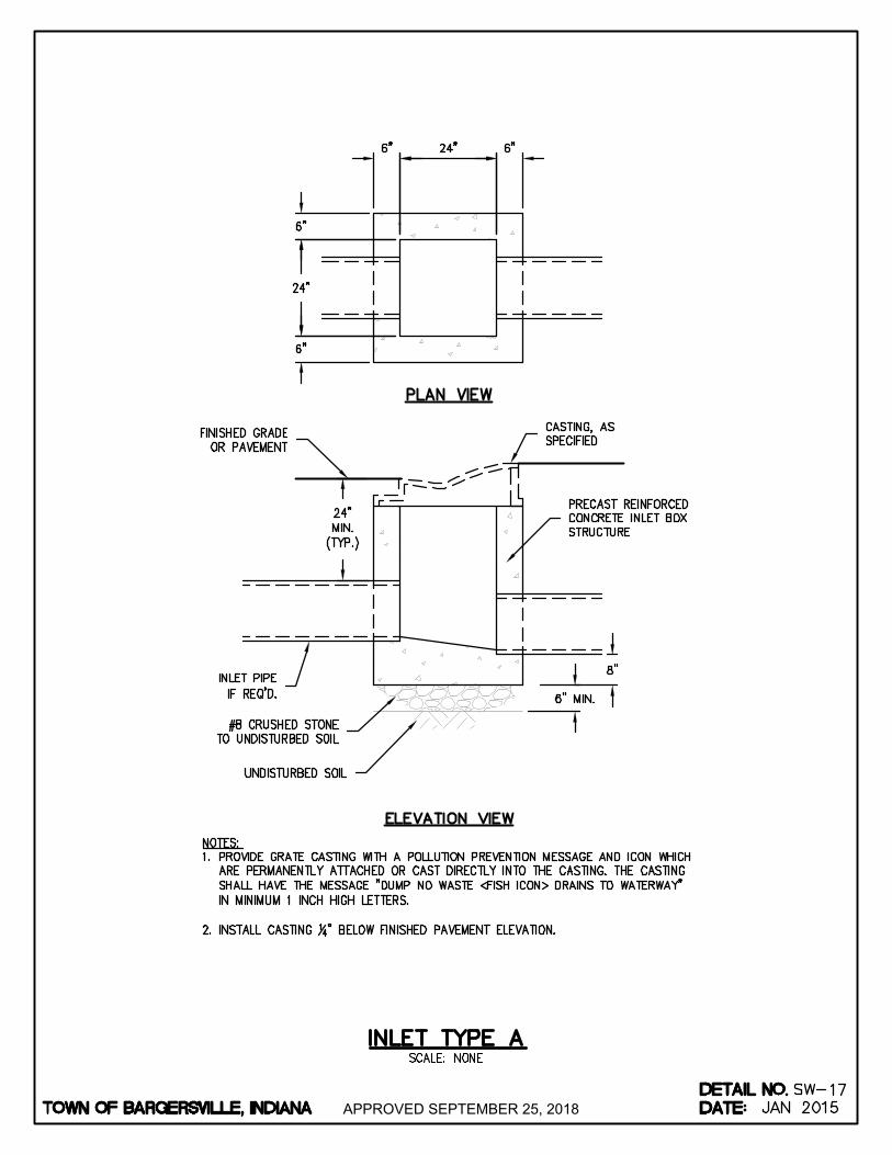
APPROVED SEPTEMBER 25, 2018
AutoCAD SHX Text
%%UPLAN VIEW
AutoCAD SHX Text
%%UELEVATION VIEW
AutoCAD SHX Text
INLET PIPE IF REQ'D.
AutoCAD SHX Text
CASTING, AS SPECIFIED
AutoCAD SHX Text
PRECAST REINFORCED CONCRETE INLET BOX STRUCTURE
AutoCAD SHX Text
#8 CRUSHED STONE TO UNDISTURBED SOIL
AutoCAD SHX Text
UNDISTURBED SOIL
AutoCAD SHX Text
NOTES: 1. PROVIDE GRATE CASTING WITH A POLLUTION PREVENTION MESSAGE AND ICON WHICH PROVIDE GRATE CASTING WITH A POLLUTION PREVENTION MESSAGE AND ICON WHICH ARE PERMANENTLY ATTACHED OR CAST DIRECTLY INTO THE CASTING. THE CASTING SHALL HAVE THE MESSAGE "DUMP NO WASTE <FISH ICON> DRAINS TO WATERWAY" IN MINIMUM 1 INCH HIGH LETTERS. 2. INSTALL CASTING " BELOW FINISHED PAVEMENT ELEVATION. INSTALL CASTING " BELOW FINISHED PAVEMENT ELEVATION. 14" BELOW FINISHED PAVEMENT ELEVATION.
AutoCAD SHX Text
FINISHED GRADE OR PAVEMENT
AutoCAD SHX Text
TOWN OF BARGERSVILLE, INDIANA
AutoCAD SHX Text
DATE:
AutoCAD SHX Text
DETAIL NO.
AutoCAD SHX Text
SCALE: NONE
AutoCAD SHX Text
SW-
AutoCAD SHX Text
INLET TYPE A
AutoCAD SHX Text
17
AutoCAD SHX Text
JAN 2015
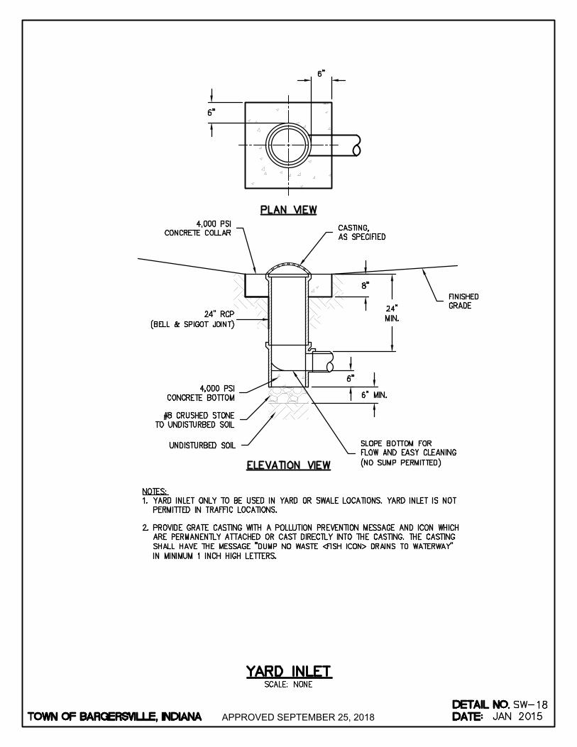
APPROVED SEPTEMBER 25, 2018
AutoCAD SHX Text
4,000 PSI CONCRETE COLLAR
AutoCAD SHX Text
24" RCP (BELL & SPIGOT JOINT)
AutoCAD SHX Text
4,000 PSI CONCRETE BOTTOM
AutoCAD SHX Text
%%UPLAN VIEW
AutoCAD SHX Text
%%UELEVATION VIEW
AutoCAD SHX Text
CASTING, AS SPECIFIED
AutoCAD SHX Text
FINISHED GRADE
AutoCAD SHX Text
UNDISTURBED SOIL
AutoCAD SHX Text
#8 CRUSHED STONE TO UNDISTURBED SOIL
AutoCAD SHX Text
SLOPE BOTTOM FOR FLOW AND EASY CLEANING (NO SUMP PERMITTED)
AutoCAD SHX Text
NOTES: 1. YARD INLET ONLY TO BE USED IN YARD OR SWALE LOCATIONS. YARD INLET IS NOT YARD INLET ONLY TO BE USED IN YARD OR SWALE LOCATIONS. YARD INLET IS NOT PERMITTED IN TRAFFIC LOCATIONS. 2. PROVIDE GRATE CASTING WITH A POLLUTION PREVENTION MESSAGE AND ICON WHICH PROVIDE GRATE CASTING WITH A POLLUTION PREVENTION MESSAGE AND ICON WHICH ARE PERMANENTLY ATTACHED OR CAST DIRECTLY INTO THE CASTING. THE CASTING SHALL HAVE THE MESSAGE "DUMP NO WASTE <FISH ICON> DRAINS TO WATERWAY" IN MINIMUM 1 INCH HIGH LETTERS.
AutoCAD SHX Text
TOWN OF BARGERSVILLE, INDIANA
AutoCAD SHX Text
DATE:
AutoCAD SHX Text
DETAIL NO.
AutoCAD SHX Text
SCALE: NONE
AutoCAD SHX Text
SW-
AutoCAD SHX Text
YARD INLET
AutoCAD SHX Text
18
AutoCAD SHX Text
JAN 2015
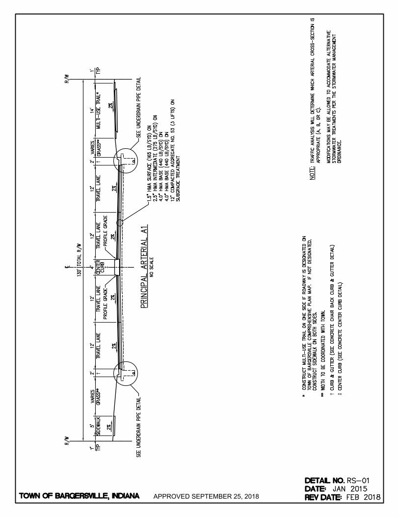
†
†
†
‡
‡
APPROVED SEPTEMBER 25, 2018
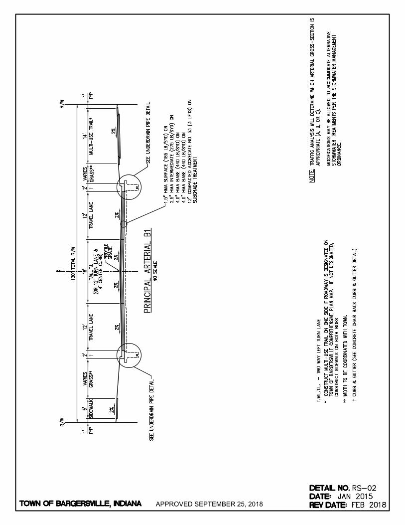
††
†
APPROVED SEPTEMBER 25, 2018

†
†
†
APPROVED SEPTEMBER 25, 2018
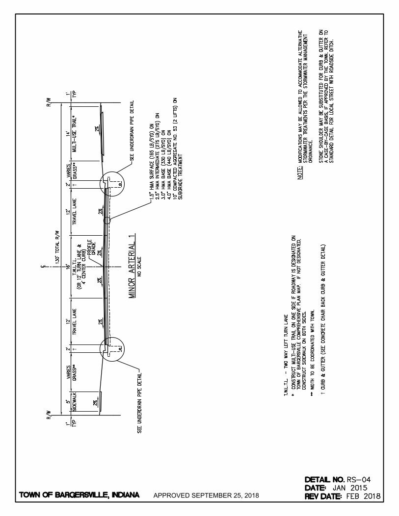
†
††
APPROVED SEPTEMBER 25, 2018
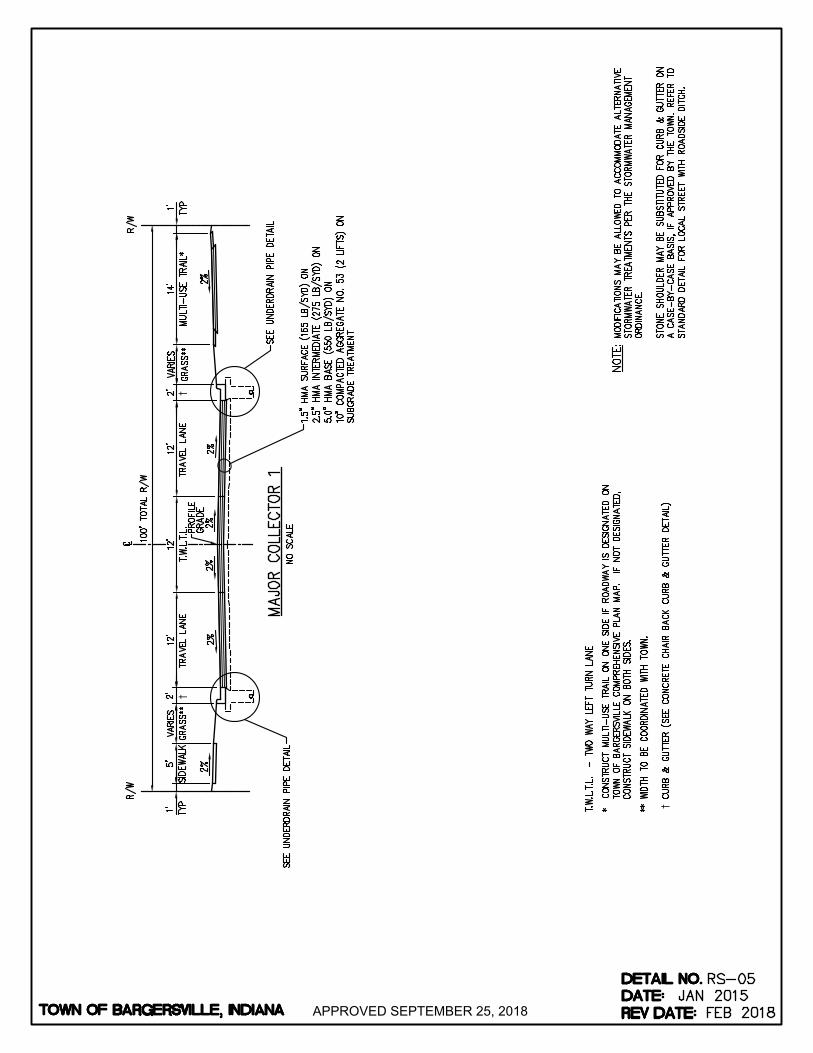
†
††
APPROVED SEPTEMBER 25, 2018

††
††
††
APPROVED SEPTEMBER 25, 2018
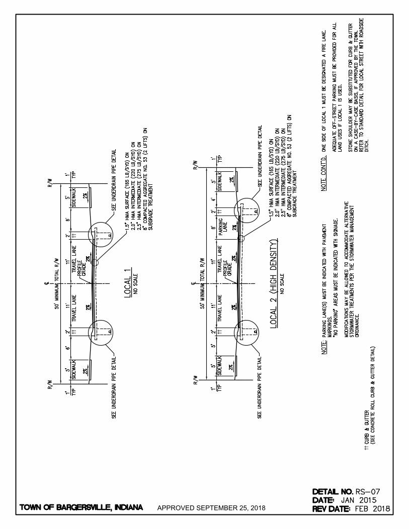
††
††
††
††
††
APPROVED SEPTEMBER 25, 2018

APPROVED SEPTEMBER 25, 2018

††
†
APPROVED SEPTEMBER 25, 2018

APPROVED SEPTEMBER 25, 2018

APPROVED SEPTEMBER 25, 2018

APPROVED SEPTEMBER 25, 2018

APPROVED SEPTEMBER 25, 2018
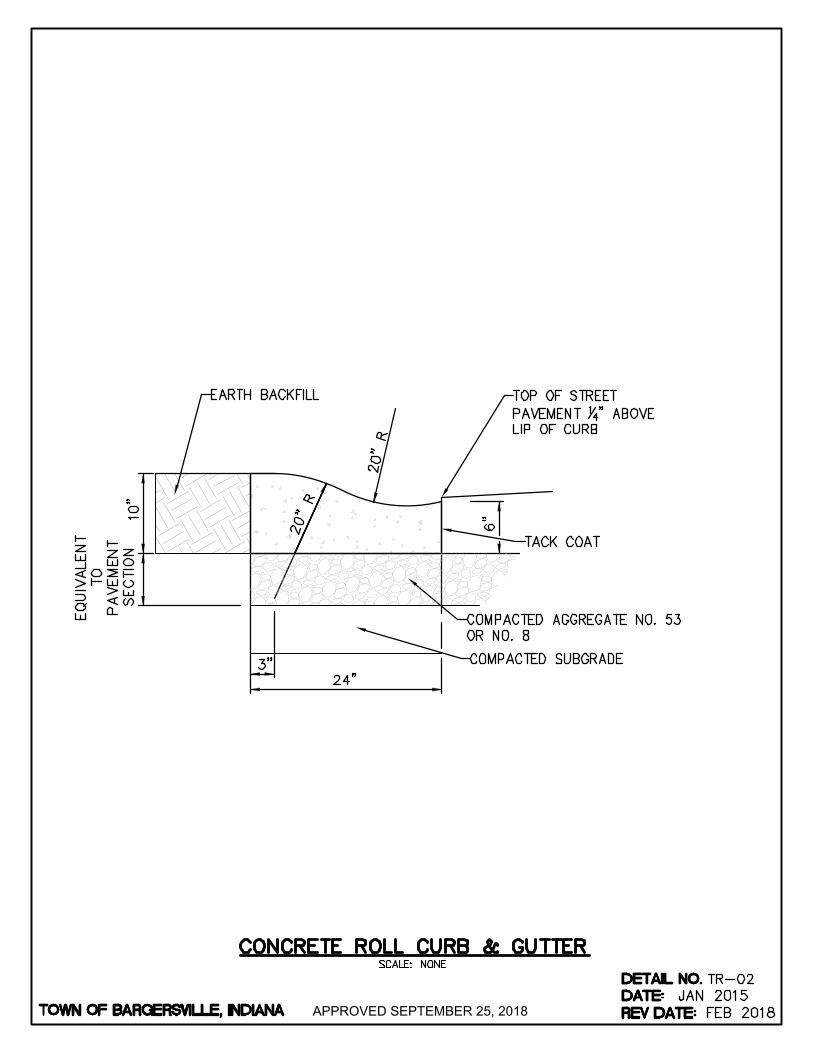
APPROVED SEPTEMBER 25, 2018
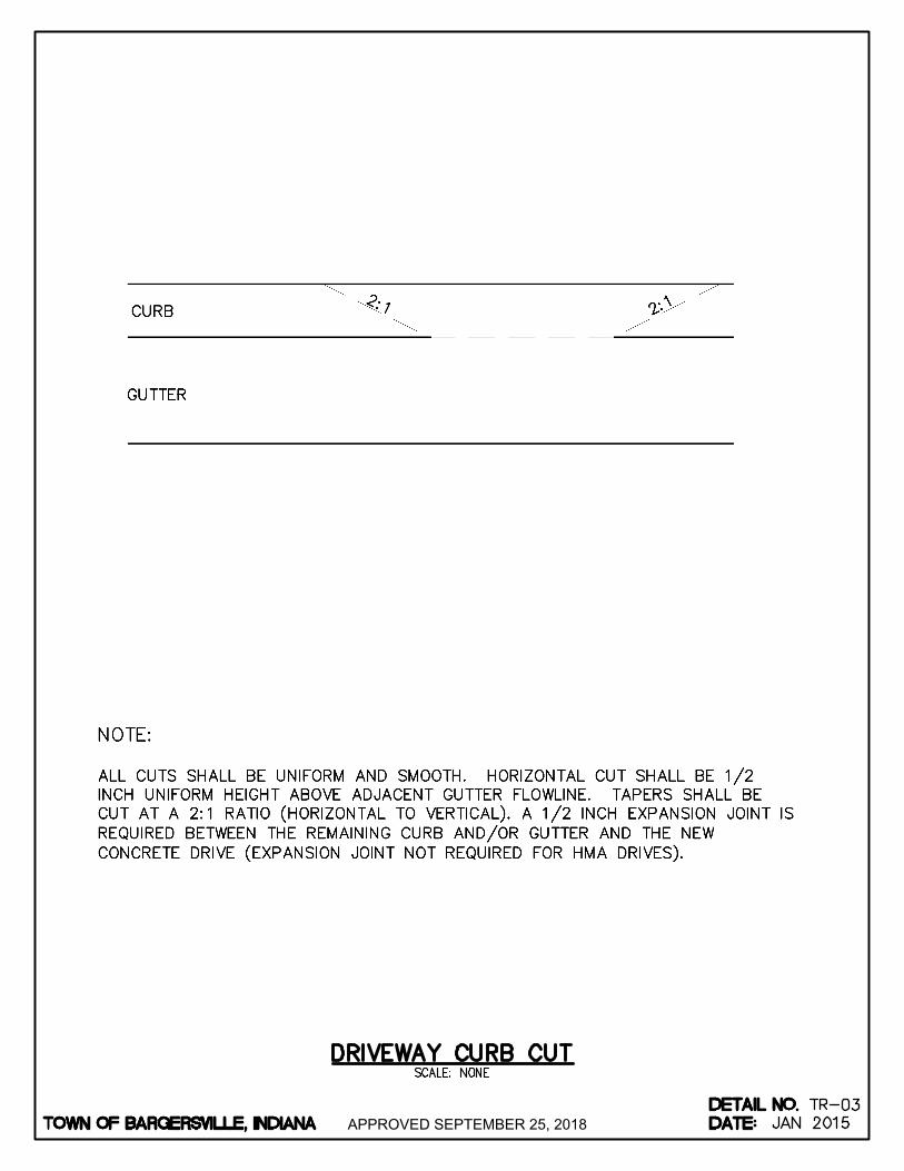
APPROVED SEPTEMBER 25, 2018
AutoCAD SHX Text
TOWN OF BARGERSVILLE, INDIANA
AutoCAD SHX Text
DATE:
AutoCAD SHX Text
DETAIL NO.
AutoCAD SHX Text
SCALE: NONE
AutoCAD SHX Text
TR-
AutoCAD SHX Text
DRIVEWAY CURB CUT
AutoCAD SHX Text
03
AutoCAD SHX Text
JAN 2015

APPROVED SEPTEMBER 25, 2018
AutoCAD SHX Text
TOWN OF BARGERSVILLE, INDIANA
AutoCAD SHX Text
DATE:
AutoCAD SHX Text
DETAIL NO.
AutoCAD SHX Text
TR-04
AutoCAD SHX Text
REV DATE:
AutoCAD SHX Text
JAN 2015
AutoCAD SHX Text
OCT 2016
AutoCAD SHX Text
SCALE: NONE
AutoCAD SHX Text
CURB INLET DETAIL
AutoCAD SHX Text
NOTE: INLET FLOW LINE SHALL BE INSTALLED 1/4 IN. BELOW ADJACENT GUTTER FLOWLINES.
AutoCAD SHX Text
CURB
AutoCAD SHX Text
GUTTER
AutoCAD SHX Text
1/4"
AutoCAD SHX Text
12" EXPANSION JOINT
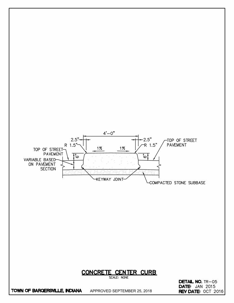
APPROVED SEPTEMBER 25, 2018
AutoCAD SHX Text
TOWN OF BARGERSVILLE, INDIANA
AutoCAD SHX Text
DATE:
AutoCAD SHX Text
DETAIL NO.
AutoCAD SHX Text
TR-05
AutoCAD SHX Text
REV DATE:
AutoCAD SHX Text
JAN 2015
AutoCAD SHX Text
OCT 2016
AutoCAD SHX Text
SCALE: NONE
AutoCAD SHX Text
CONCRETE CENTER CURB
AutoCAD SHX Text
R 1.5"
AutoCAD SHX Text
TOP OF STREET PAVEMENT
AutoCAD SHX Text
6"
AutoCAD SHX Text
R 1.5"
AutoCAD SHX Text
6"
AutoCAD SHX Text
TOP OF STREET PAVEMENT
AutoCAD SHX Text
KEYWAY JOINT
AutoCAD SHX Text
4'-0"
AutoCAD SHX Text
1%%%
AutoCAD SHX Text
1%%%
AutoCAD SHX Text
COMPACTED STONE SUBBASE
AutoCAD SHX Text
2.5"
AutoCAD SHX Text
2.5"
AutoCAD SHX Text
VARIABLE BASED ON PAVEMENT SECTION

APPROVED SEPTEMBER 25, 2018
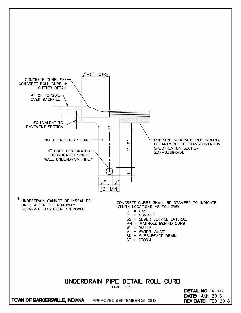
APPROVED SEPTEMBER 25, 2018
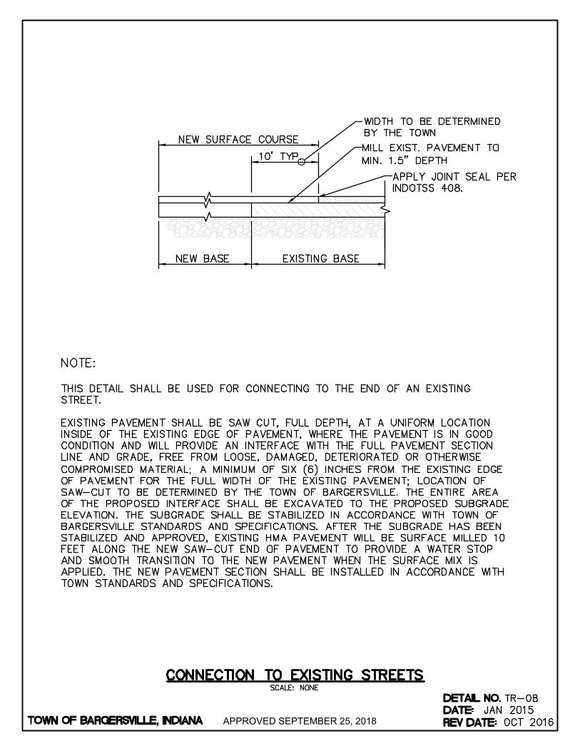
APPROVED SEPTEMBER 25, 2018
AutoCAD SHX Text
TOWN OF BARGERSVILLE, INDIANA
AutoCAD SHX Text
DATE:
AutoCAD SHX Text
DETAIL NO.
AutoCAD SHX Text
TR-08
AutoCAD SHX Text
REV DATE:
AutoCAD SHX Text
JAN 2015
AutoCAD SHX Text
OCT 2016
AutoCAD SHX Text
SCALE: NONE
AutoCAD SHX Text
CONNECTION TO EXISTING STREETS
AutoCAD SHX Text
NEW BASE
AutoCAD SHX Text
EXISTING BASE
AutoCAD SHX Text
NEW SURFACE COURSE
AutoCAD SHX Text
10' TYP.
AutoCAD SHX Text
NOTE: THIS DETAIL SHALL BE USED FOR CONNECTING TO THE END OF AN EXISTING STREET. EXISTING PAVEMENT SHALL BE SAW CUT, FULL DEPTH, AT A UNIFORM LOCATION INSIDE OF THE EXISTING EDGE OF PAVEMENT, WHERE THE PAVEMENT IS IN GOOD CONDITION AND WILL PROVIDE AN INTERFACE WITH THE FULL PAVEMENT SECTION LINE AND GRADE, FREE FROM LOOSE, DAMAGED, DETERIORATED OR OTHERWISE COMPROMISED MATERIAL; A MINIMUM OF SIX (6) INCHES FROM THE EXISTING EDGE OF PAVEMENT FOR THE FULL WIDTH OF THE EXISTING PAVEMENT; LOCATION OF SAW-CUT TO BE DETERMINED BY THE TOWN OF BARGERSVILLE. THE ENTIRE AREA OF THE PROPOSED INTERFACE SHALL BE EXCAVATED TO THE PROPOSED SUBGRADE ELEVATION. THE SUBGRADE SHALL BE STABILIZED IN ACCORDANCE WITH TOWN OF BARGERSVILLE STANDARDS AND SPECIFICATIONS. AFTER THE SUBGRADE HAS BEEN STABILIZED AND APPROVED, EXISTING HMA PAVEMENT WILL BE SURFACE MILLED 10 FEET ALONG THE NEW SAW-CUT END OF PAVEMENT TO PROVIDE A WATER STOP AND SMOOTH TRANSITION TO THE NEW PAVEMENT WHEN THE SURFACE MIX IS APPLIED. THE NEW PAVEMENT SECTION SHALL BE INSTALLED IN ACCORDANCE WITH TOWN STANDARDS AND SPECIFICATIONS.
AutoCAD SHX Text
MILL EXIST. PAVEMENT TO MIN. 1.5" DEPTH
AutoCAD SHX Text
WIDTH TO BE DETERMINED BY THE TOWN
AutoCAD SHX Text
APPLY JOINT SEAL PER INDOTSS 408.

APPROVED SEPTEMBER 25, 2018

APPROVED SEPTEMBER 25, 2018
AutoCAD SHX Text
TOWN OF BARGERSVILLE, INDIANA
AutoCAD SHX Text
DATE:
AutoCAD SHX Text
DETAIL NO.
AutoCAD SHX Text
TR-10
AutoCAD SHX Text
REV DATE:
AutoCAD SHX Text
JAN 2015
AutoCAD SHX Text
OCT 2016
AutoCAD SHX Text
SCALE: NONE
AutoCAD SHX Text
HMA PAVEMENT TRENCH REPAIR DETAIL
AutoCAD SHX Text
NOTE: TRENCH SHALL BE SAW-CUT FULL DEPTH THROUGH PAVEMENT SECTION FOR THE ENTIRE LENGTH OF THE TRENCH, ON ALL SIDES WITHIN THE PAVEMENT. IF EDGES OF THE EXISTING PAVEMENT ARE CHIPPED OR DAMAGED AS A RESULT OF THE TRENCH PROJECT, GREATER THAN THE 12 INCH MILLING AREA FOR THE WATER STOP, THE DAMAGED PAVEMENT SHALL BE MILLED OR FULL DEPTH SAW-CUT AND REMOVED BEYOND THE DAMAGED EDGE FOR THE ENTIRE LENGTH OF THE TRENCH, TO THE SATISFACTION OF THE TOWN OR THE TOWN'S ENGINEER. FLOWABLE BACKFILL, PER THE TOWN'S SPECIFICATION, SHALL BE USED TO BACKFILL THE TRENCH TO THE BOTTOM OF THE PAVEMENT SECTION. 5 INCHES ON ALL SIDES OF THE TRENCH SHALL BE SURFACE MILLED 1.5 INCHES DEEP TO CREATE A WATER STOP. ALL SURFACES TO RECEIVE HMA SHALL BE TACK COATED. A PAVEMENT SECTION APPROVED BY THE TOWN SHALL BE INSTALLED TO TOWN STANDARDS AND SPECIFICATIONS.
AutoCAD SHX Text
FLOWABLE BACKFILL
AutoCAD SHX Text
EXISTING HMA
AutoCAD SHX Text
EXISTING HMA
AutoCAD SHX Text
TRENCH WIDTH
AutoCAD SHX Text
NEW HMA LAYERS
AutoCAD SHX Text
TACK COAT
AutoCAD SHX Text
MILLED WATER STOP
AutoCAD SHX Text
1.5 IN.
AutoCAD SHX Text
SAWCUT FULL DEPTH
AutoCAD SHX Text
SAWCUT FULL DEPTH
AutoCAD SHX Text
1.5 IN.
AutoCAD SHX Text
APPLY JOINT SEAL PER INDOTSS 408
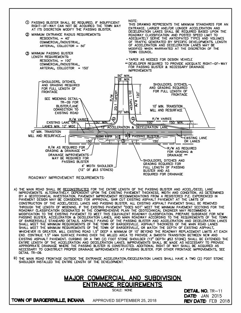
APPROVED SEPTEMBER 25, 2018
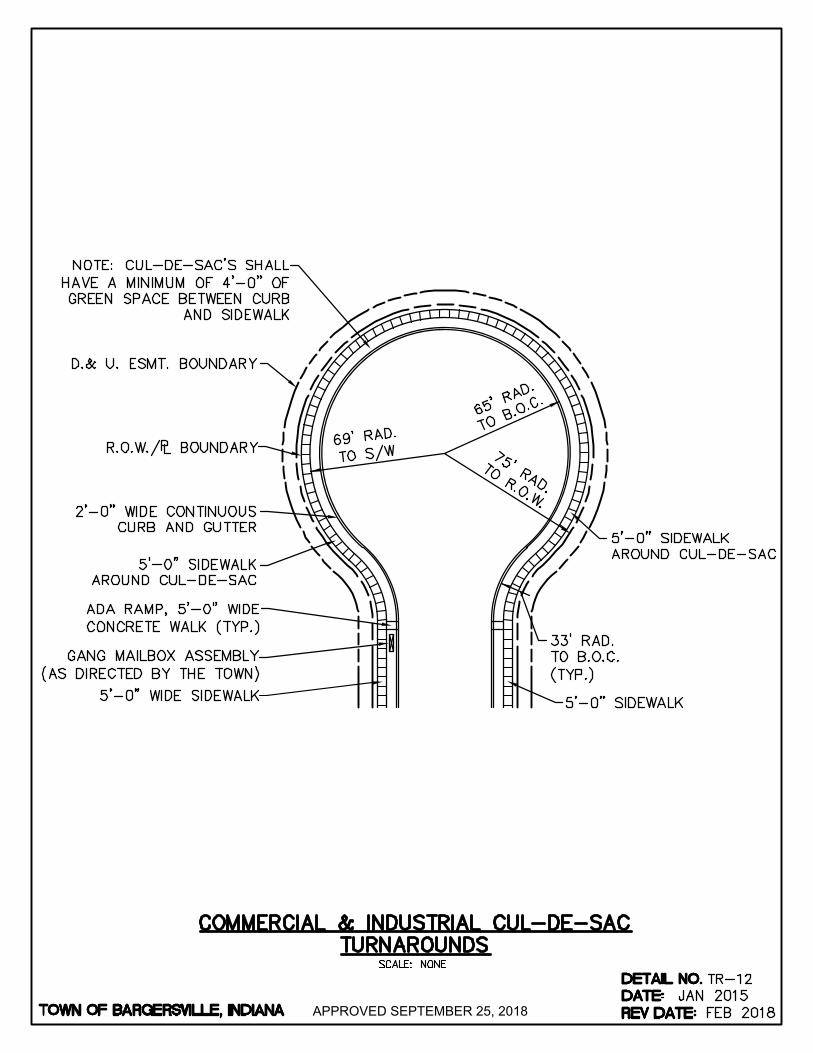
APPROVED SEPTEMBER 25, 2018

APPROVED SEPTEMBER 25, 2018
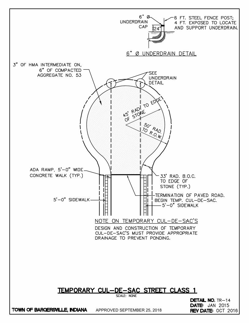
APPROVED SEPTEMBER 25, 2018
AutoCAD SHX Text
TOWN OF BARGERSVILLE, INDIANA
AutoCAD SHX Text
DATE:
AutoCAD SHX Text
DETAIL NO.
AutoCAD SHX Text
TR-14
AutoCAD SHX Text
REV DATE:
AutoCAD SHX Text
JAN 2015
AutoCAD SHX Text
OCT 2016
AutoCAD SHX Text
SCALE: NONE
AutoCAD SHX Text
TEMPORARY CUL-DE-SAC STREET CLASS 1
AutoCAD SHX Text
45' RAD. TO EDGE
AutoCAD SHX Text
OF STONE
AutoCAD SHX Text
5'-0" SIDEWALK
AutoCAD SHX Text
%%UNOTE ON TEMPORARY CUL-DE-SAC'S
AutoCAD SHX Text
:
AutoCAD SHX Text
DESIGN AND CONSTRUCTION OF TEMPORARY
AutoCAD SHX Text
CUL-DE-SAC'S MUST PROVIDE APPROPRIATE
AutoCAD SHX Text
DRAINAGE TO PREVENT PONDING.
AutoCAD SHX Text
50' RAD.
AutoCAD SHX Text
TO R.O.W.
AutoCAD SHX Text
SEE
AutoCAD SHX Text
UNDERDRAIN
AutoCAD SHX Text
DETAIL
AutoCAD SHX Text
5'-0" SIDEWALK
AutoCAD SHX Text
33' RAD. B.O.C.
AutoCAD SHX Text
TO EDGE OF
AutoCAD SHX Text
STONE (TYP.)
AutoCAD SHX Text
TERMINATION OF PAVED ROAD.
AutoCAD SHX Text
BEGIN TEMP. CUL-DE-SAC.
AutoCAD SHX Text
24"
AutoCAD SHX Text
%%U6" Ø UNDERDRAIN DETAIL
AutoCAD SHX Text
6" Ø
AutoCAD SHX Text
UNDERDRAIN
AutoCAD SHX Text
CAP
AutoCAD SHX Text
6 FT. STEEL FENCE POST;
AutoCAD SHX Text
4 FT. EXPOSED TO LOCATE
AutoCAD SHX Text
AND SUPPORT UNDERDRAIN.
AutoCAD SHX Text
ADA RAMP, 5'-0" WIDE
AutoCAD SHX Text
CONCRETE WALK (TYP.)
AutoCAD SHX Text
3" OF HMA INTERMEDIATE ON, 6" OF COMPACTED AGGREGATE NO. 53
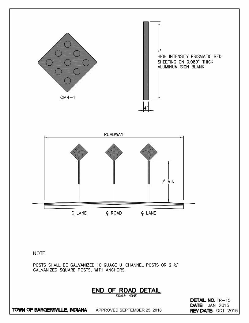
APPROVED SEPTEMBER 25, 2018
AutoCAD SHX Text
TOWN OF BARGERSVILLE, INDIANA
AutoCAD SHX Text
DATE:
AutoCAD SHX Text
DETAIL NO.
AutoCAD SHX Text
TR-15
AutoCAD SHX Text
REV DATE:
AutoCAD SHX Text
JAN 2015
AutoCAD SHX Text
OCT 2016
AutoCAD SHX Text
SCALE: NONE
AutoCAD SHX Text
END OF ROAD DETAIL
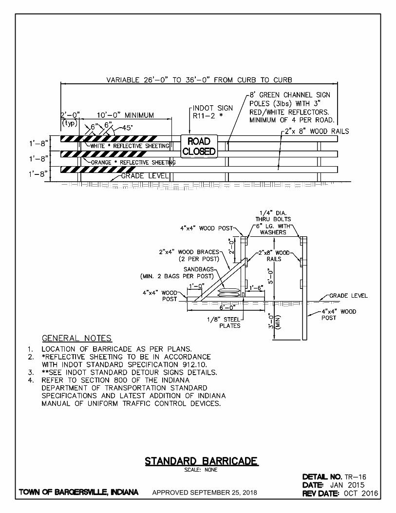
APPROVED SEPTEMBER 25, 2018
AutoCAD SHX Text
TOWN OF BARGERSVILLE, INDIANA
AutoCAD SHX Text
DATE:
AutoCAD SHX Text
DETAIL NO.
AutoCAD SHX Text
TR-16
AutoCAD SHX Text
REV DATE:
AutoCAD SHX Text
JAN 2015
AutoCAD SHX Text
OCT 2016
AutoCAD SHX Text
SCALE: NONE
AutoCAD SHX Text
STANDARD BARRICADE
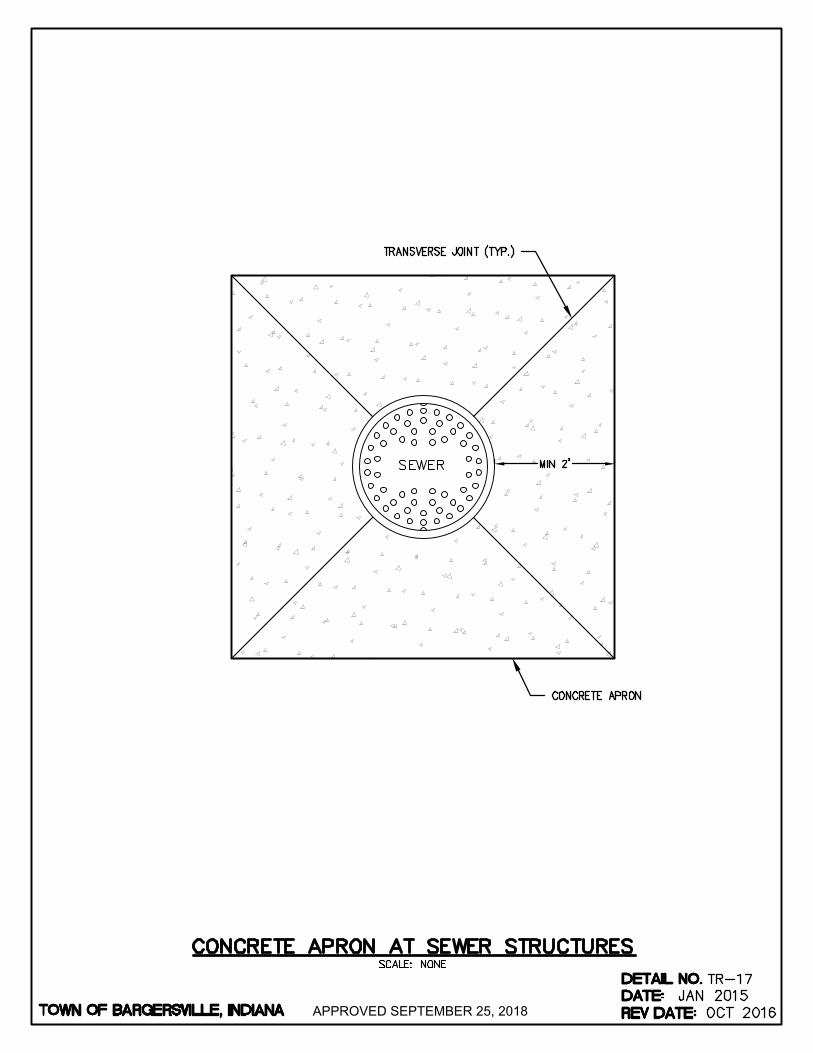
APPROVED SEPTEMBER 25, 2018
AutoCAD SHX Text
TOWN OF BARGERSVILLE, INDIANA
AutoCAD SHX Text
SEWER
AutoCAD SHX Text
CONCRETE APRON
AutoCAD SHX Text
TRANSVERSE JOINT (TYP.)
AutoCAD SHX Text
DATE:
AutoCAD SHX Text
DETAIL NO.
AutoCAD SHX Text
TR-17
AutoCAD SHX Text
REV DATE:
AutoCAD SHX Text
JAN 2015
AutoCAD SHX Text
OCT 2016
AutoCAD SHX Text
SCALE: NONE
AutoCAD SHX Text
CONCRETE APRON AT SEWER STRUCTURES
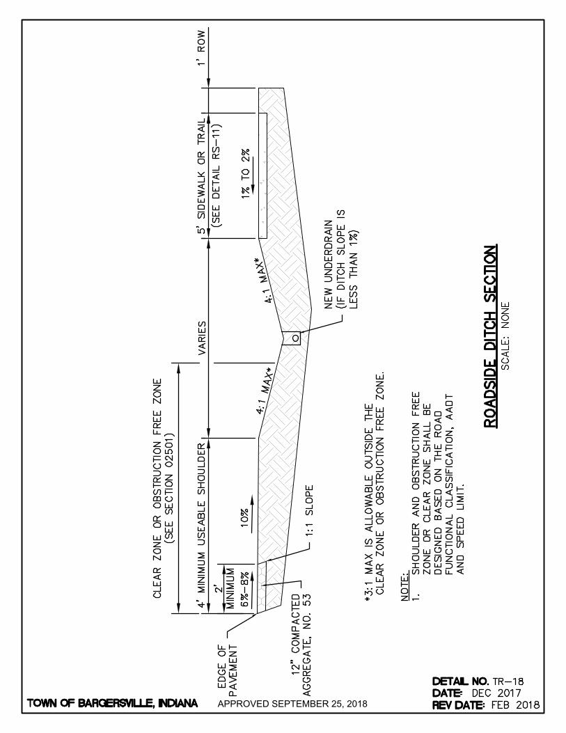
APPROVED SEPTEMBER 25, 2018
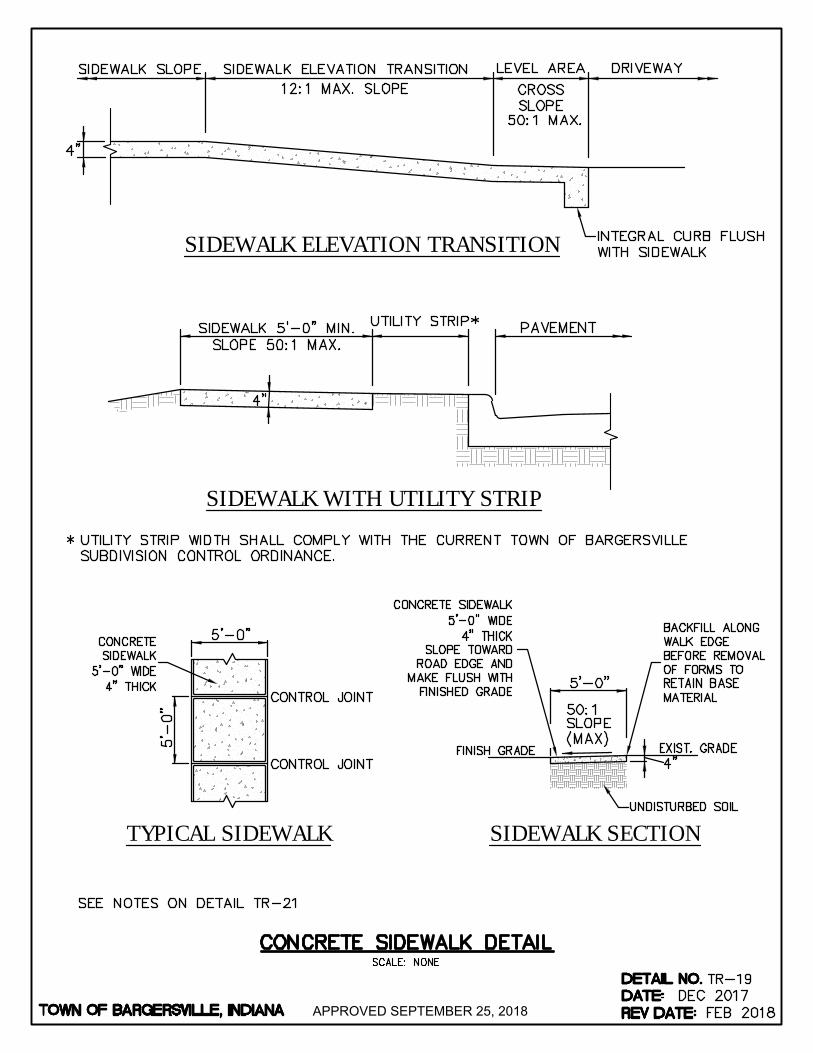
SIDEWALK WITH UTILITY STRIP
SIDEWALK ELEVATION TRANSITION
SIDEWALK SECTIONTYPICAL SIDEWALK
APPROVED SEPTEMBER 25, 2018
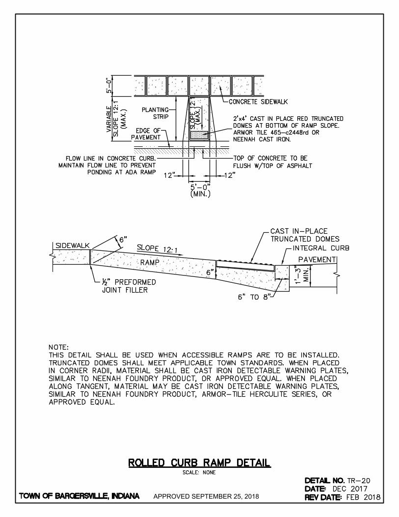
APPROVED SEPTEMBER 25, 2018
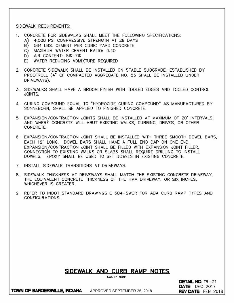
APPROVED SEPTEMBER 25, 2018
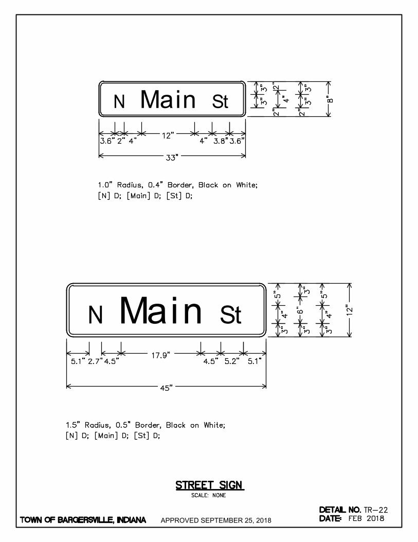
N StMain
StMainN
APPROVED SEPTEMBER 25, 2018
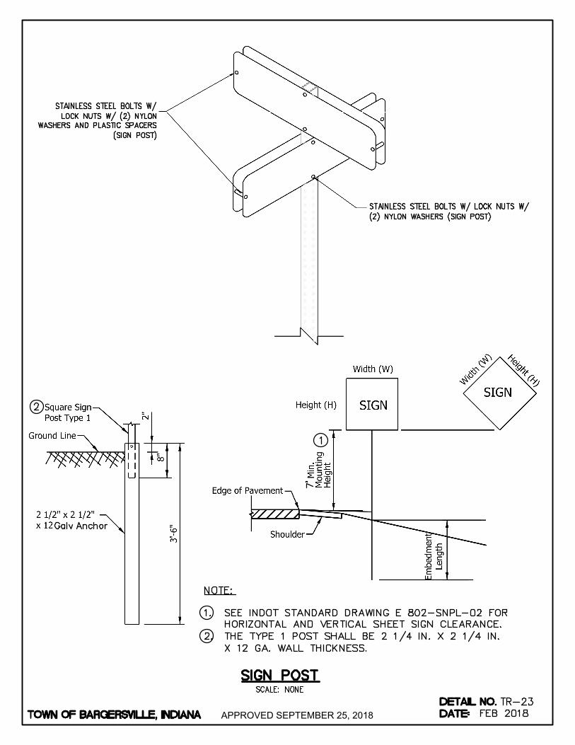
APPROVED SEPTEMBER 25, 2018