


Bahasa
Halaman
Hukum

Building and Environment 36 (2001) 701–709www.elsevier.com/locate/buildenv
Indoor climate design based on CFDCoupled simulation of convection, radiation, and HVAC control for
attaining a given PMV valueShuzo Murakami, Shinsuke Kato ∗, Taeyeon Kim
Institute of Industrial Science, University of Tokyo, 4-6-1 Komaba Meguro-ku, Tokyo 153, Japan
Abstract
A new computational 3uid dynamics (CFD) simulation for designing indoor climates is presented in this study. It is coupled with aradiative heat transfer simulation and heating, ventilating, and air-conditioning (HVAC) control system in a room. This new method canfeed back the outputs of the CFD to the input conditions for controlling the HVAC system, and includes a human model to evaluate thethermal environment. It can be used to analyze the conditions of the HVAC system (e.g. temperature of supply air, surface temperature ofradiation panel, etc.) and the heating=cooling loads of di5erent HVAC systems under the condition of the same human thermal sensation(e.g. PMV, operative temperature, etc.) To examine the performance of the new method, a thermal environment within a semi-enclosedspace which opens into an atrium space is analyzed under the steady-state conditions during the summer season. Using this method, themost energy e8cient HVAC system can be chosen under the same PMV value. In this paper, two types of HVAC system are compared:one is a radiation-panel system and the other is an all-air cooling system. The radiation-panel system is found to be more energy e8cientfor cooling the semi-enclosed space in this study. c© 2001 Elsevier Science Ltd. All rights reserved.
Keywords: CFD; HVAC Control; Coupled simulation; PMV
1. Introduction
This paper presents a new CFD method coupled with aradiative heat transfer simulation and HVAC control in aroom. It can provide precise information about the condi-tions of the HVAC system and heating=cooling loads whichtake into account the temperature distribution, etc. In thesimulation, the conditions of the HVAC system (e.g., sup-ply air temperature, supply air volume, etc.) are modi<edby changing the input boundary conditions (BCs) using afeedback system of the HVAC control. These modi<cationsare determined based on the simulations with modi<ed in-put BCs to maintain the predicted mean vote (PMV) value[1,2] of a human model at the target value.
To examine the performance of the new CFD method,the thermal environment in a semi-enclosed space, whichopens into an atrium space, is analyzed. Using this CFDsimulation method with a feedback system, the conditionsof the HVAC system and cooling loads required for at-
∗ Corresponding author.E-mail address: [email protected] (S. Kato).
taining the same thermal sensation are quantitatively esti-mated.
2. Four levels of indoor thermal environment analyses
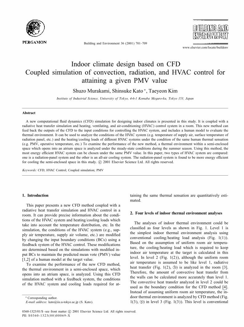
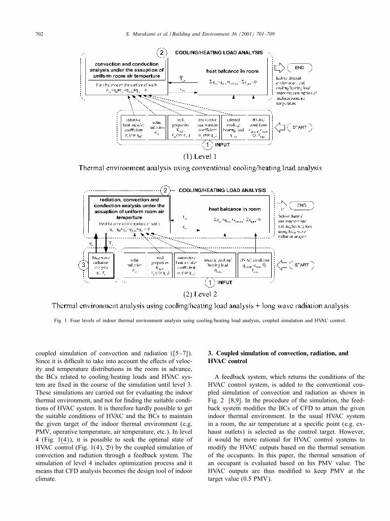
The analyses of indoor thermal environment could beclassi<ed as four levels as shown in Fig. 1. Level 1 isthe simplest indoor thermal environment analysis usingconventional cooling=heating load analysis (Fig. 1(1)).Based on the assumption of uniform room air tempera-ture, the cooling=heating load which is required to keepindoor air temperature at the target is calculated in thislevel. In level 2 (Fig. 1(2)), although the uniform roomair temperature is assumed to be like level 1, radiativeheat transfer (Fig. 1(2), ) is analyzed in the room [3].Therefore, the amount of convective heat transfer fromthe walls can be calculated more accurately than level 1.The convective heat transfer analyzed in level 2 could beused as the boundary condition for the CFD method [4].Instead of assuming uniform room air temperature, the in-door thermal environment is analyzed by CFD method (Fig.1(3), ) in level 3 (Fig. 1(3)). This level is conventional
0360-1323/01/$ - see front matter c© 2001 Elsevier Science Ltd. All rights reserved.PII: S 0360 -1323(00)00069 -X
702 S. Murakami et al. / Building and Environment 36 (2001) 701–709
Fig. 1. Four levels of indoor thermal environment analysis using cooling=heating load analysis, coupled simulation and HVAC control.
coupled simulation of convection and radiation ([5–7]).Since it is di8cult to take into account the e5ects of veloc-ity and temperature distributions in the room in advance,the BCs related to cooling=heating loads and HVAC sys-tem are <xed in the course of the simulation until level 3.These simulations are carried out for evaluating the indoorthermal environment, and not for <nding the suitable condi-tions of HVAC system. It is therefore hardly possible to getthe suitable conditions of HVAC and the BCs to maintainthe given target of the indoor thermal environment (e.g.PMV, operative temperature, air temperature, etc.). In level4 (Fig. 1(4)), it is possible to seek the optimal state ofHVAC control (Fig. 1(4), ) by the coupled simulation ofconvection and radiation through a feedback system. Thesimulation of level 4 includes optimization process and itmeans that CFD analysis becomes the design tool of indoorclimate.
3. Coupled simulation of convection, radiation, andHVAC control
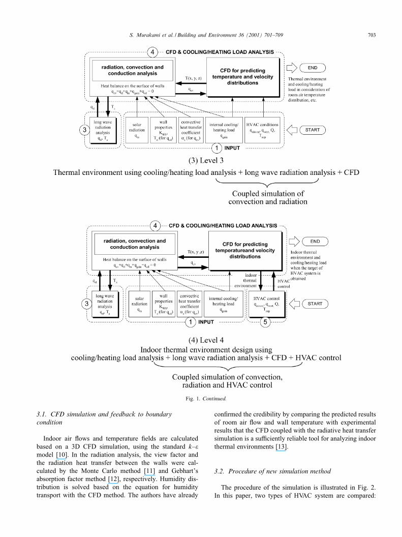
A feedback system, which returns the conditions of theHVAC control system, is added to the conventional cou-pled simulation of convection and radiation as shown inFig. 2 [8,9]. In the procedure of the simulation, the feed-back system modi<es the BCs of CFD to attain the givenindoor thermal environment. In the usual HVAC systemin a room, the air temperature at a speci<c point (e.g. ex-haust outlets) is selected as the control target. However,it would be more rational for HVAC control systems tomodify the HVAC outputs based on the thermal sensationof the occupants. In this paper, the thermal sensation ofan occupant is evaluated based on his PMV value. TheHVAC outputs are thus modi<ed to keep PMV at thetarget value (0.5 PMV).
S. Murakami et al. / Building and Environment 36 (2001) 701–709 703
Fig. 1. Continued.
3.1. CFD simulation and feedback to boundarycondition
Indoor air 3ows and temperature <elds are calculatedbased on a 3D CFD simulation, using the standard k–�model [10]. In the radiation analysis, the view factor andthe radiation heat transfer between the walls were cal-culated by the Monte Carlo method [11] and Gebhart’sabsorption factor method [12], respectively. Humidity dis-tribution is solved based on the equation for humiditytransport with the CFD method. The authors have already
con<rmed the credibility by comparing the predicted resultsof room air 3ow and wall temperature with experimentalresults that the CFD coupled with the radiative heat transfersimulation is a su8ciently reliable tool for analyzing indoorthermal environments [13].
3.2. Procedure of new simulation method
The procedure of the simulation is illustrated in Fig. 2.In this paper, two types of HVAC system are compared:
704 S. Murakami et al. / Building and Environment 36 (2001) 701–709
Fig. 2. Procedure of simulation including HVAC system control.
one is a radiation-panel system and the other is an all-aircooling system. In the case of radiation-panel system,the heat 3ux at the surface of the radiation-panel ismodi<ed, while the temperature of the supply outletsis modi<ed in the case of all-air cooling system duringthe simulation. The cooling loads of the HVAC systemsneeded to achieve the target PMV of the human model(0.5 PMV) can be given through these simulations. Thefeedback system is stopped when this target PMV isachieved.
4. Optimal design based on CFD feedback mechanism
In this paper, only the BC of the heat 3ux of theradiation-panel and the air temperature of the supply outletare modi<ed in the simulation. However, with this method,other BCs (e.g., locations of supply outlets, number ofsupply outlets, etc.) can be modi<ed so as to control theindoor climate at the target temperature. Through thesesimulations, the optimal design of the HVAC system canbe achieved. It would be a very useful tool for environ-mental design. Although the description concerns coolingsystem control, the same control could be also applied toa heating system.
5. Semi-enclosed space
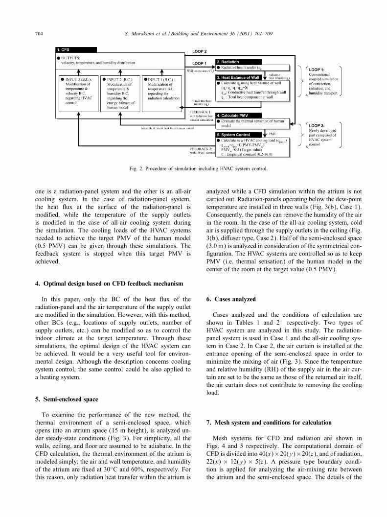
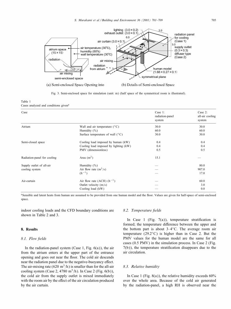
To examine the performance of the new method, thethermal environment of a semi-enclosed space, whichopens into an atrium space (15 m height), is analyzed un-der steady-state conditions (Fig. 3). For simplicity, all thewalls, ceiling, and 3oor are assumed to be adiabatic. In theCFD calculation, the thermal environment of the atrium ismodeled simply; the air and wall temperature, and humidityof the atrium are <xed at 30◦C and 60%, respectively. Forthis reason, only radiation heat transfer within the atrium is
analyzed while a CFD simulation within the atrium is notcarried out. Radiation-panels operating below the dew-pointtemperature are installed in three walls (Fig. 3(b), Case 1).Consequently, the panels can remove the humidity of the airin the room. In the case of the all-air cooling system, coldair is supplied through the supply outlets in the ceiling (Fig.3(b), di5user type, Case 2). Half of the semi-enclosed space(3.0 m) is analyzed in consideration of the symmetrical con-<guration. The HVAC systems are controlled so as to keepPMV (i.e. thermal sensation) of the human model in thecenter of the room at the target value (0.5 PMV).
6. Cases analyzed
Cases analyzed and the conditions of calculation areshown in Tables 1 and 2 respectively. Two types ofHVAC system are analyzed in this study. The radiation-panel system is used in Case 1 and the all-air cooling sys-tem in Case 2. In Case 2, the air curtain is installed at theentrance opening of the semi-enclosed space in order tominimize the mixing of air (Fig. 3). Since the temperatureand relative humidity (RH) of the supply air in the air cur-tain are set to be the same as those of the returned air itself,the air curtain does not contribute to removing the coolingload.
7. Mesh system and conditions for calculation
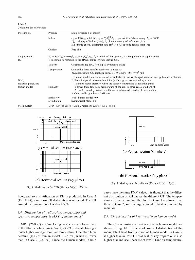
Mesh systems for CFD and radiation are shown inFigs. 4 and 5 respectively. The computational domain ofCFD is divided into 40(x)×20(y)×20(z), and of radiation,22(x) × 12(y) × 5(z). A pressure type boundary condi-tion is applied for analyzing the air-mixing rate betweenthe atrium and the semi-enclosed space. The details of the
S. Murakami et al. / Building and Environment 36 (2001) 701–709 705
Fig. 3. Semi-enclosed space for simulation (unit: m) (half space of the symmetrical room is illustrated).
Table 1Cases analyzed and conditions givena
Case Case 1: Case 2:radiation-panel all-air coolingsystem system
Atrium Wall and air temperature (◦C) 30.0 30.0Humidity (%) 60.0 60.0Surface temperature of wall (◦C) 30.0 30.0
Semi-closed space Cooling load imposed by human (kW) 0.4 0.4Cooling load imposed by lighting (kW) 0.4 0.4PMV (dimensionless) 0.5 0.5
Radiation-panel for cooling Area (m2) 15.1 —
Supply outlet of all-air Humidity (%) — 80.0cooling system Air 3ow rate (m3=s) — 907.0
(h−1) — 17.0
Air-curtain Air 3ow rate (ACH) (h−1) — 60.0Outlet velocity (m=s) — 3.0Cooling load (kW) — 0.0
aSensible and latent heats from human are assumed to be provided from one human model and the 3oor. Values are given for half-space of semi-enclosedspace.
indoor cooling loads and the CFD boundary conditions areshown in Table 2 and 3.
8. Results
8.1. Flow 6elds
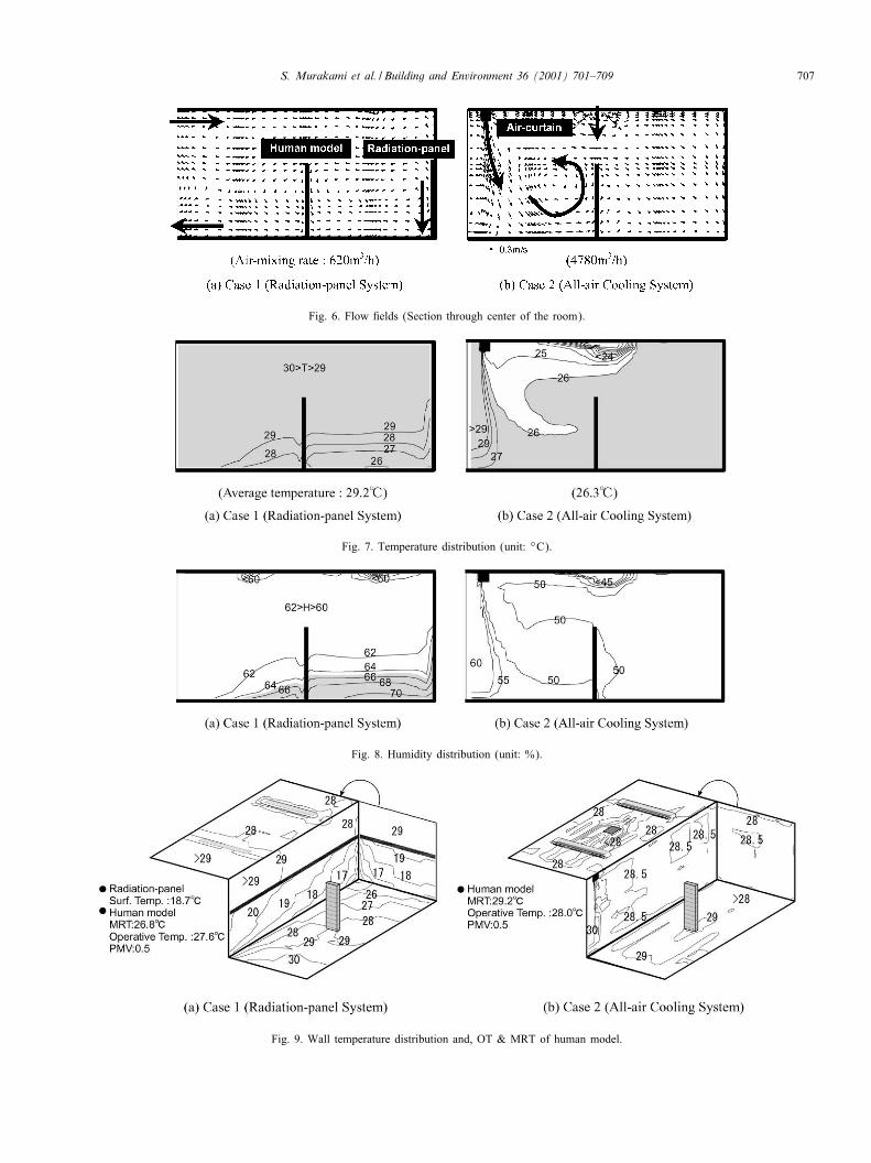
In the radiation-panel system (Case 1, Fig. 6(a)), the airfrom the atrium enters at the upper part of the entranceopening and goes out near the 3oor. The cold air descendsnear the radiation panel due to the negative-buoyancy e5ect.The air-mixing rate (620 m3=h) is smaller than for the all-aircooling system (Case 2, 4780 m3=h). In Case 2 (Fig. 6(b)),the cold air from the supply outlet is mixed immediatelywith the room air by the e5ect of the air circulation producedby the air curtain.
8.2. Temperature 6elds
In Case 1 (Fig. 7(a)), temperature strati<cation isformed; the temperature di5erence between the upper andthe bottom part is about 3–4◦C. The average room airtemperature (29:2◦C) is higher than in Case 2. But thePMV values for the human model are the same for allcases (0.5 PMV) in the simulation process. In Case 2 (Fig.7(b)), the temperature strati<cation disappears due to theair circulation.
8.3. Relative humidity
In Case 1 (Fig. 8(a)), the relative humidity exceeds 60%over the whole area. Because of the cold air generatedby the radiation-panel, a high RH is observed near the
706 S. Murakami et al. / Building and Environment 36 (2001) 701–709
Table 2Conditions for calculation
Pressure BC Pressure Static pressure 0 at atrium
In3ow kin = 3=2(Uin × 0:05)2; �in = C�k3=2in =lin ; lin= width of the opening, Tin = 30◦C,
Uin: velocity of in3ow (m=s), kin: kinetic energy of in3ow (m2=s2),�in: kinetic energy dissipation rate (m2=s3); lin: speci<c length scale (m)
Out3ow Free slip
Supply outlet kin = 3=2(Uin × 0:05)2; �in = C�k3=2in =lin ; lin= width of the opening, Air temperature of supply outlet
BC is modi<ed in response to the HVAC control system during CFD
Velocity Generalized log-law, free slip at symmetric plane
Temperature Convective heat transfer coe8cient is <xed as:Radiation-panel: 5.5, adiabatic surface: 3.0, others: 4:0 (W=m2 ◦C)
1. Human model: emission rate of sensible=latent heat is changed based on energy balance of human.Wall, 2. Radiation-panel: absolute humidity (AH) is given corresponding to theradiation-panel, and saturated vapor pressure, when the surface temperature of radiation-panelhuman model Humidity is lower than dew point temperature of the air. In other cases, gradient of
AH = 0. Humidity transfer coe8cient is calculated based on Lewis relation.3. Other walls: gradient of AH = 0.
Emissivity Wall, human model: 0.9of radiation Symmetrical plane: 0.0
Mesh system CFD: 40(x) × 20(y) × 20(z), radiation: 22(x) × 12(y) × 5(z)
Fig. 4. Mesh system for CFD (40(x) × 20(y) × 20(z)).
3oor, and so a strati<cation of RH is produced. In Case 2(Fig. 8(b)), a uniform RH distribution is observed. The RHaround the human model is about 50%.
8.4. Distribution of wall surface temperature and,operative temperature & MRT of human model
MRT (26:8◦C) in Case 1 (Fig. 9(a)) is much lower thanin the all-air cooling case (Case 2, 29:2◦C), despite having amuch higher average room air temperature. Operative tem-perature (OT) of human model is 27:6◦C, which is lowerthan in Case 2 (28:0◦C). Since the human models in both
Fig. 5. Mesh system for radiation (22(x) × 12(y) × 5(z)).
cases have the same PMV value, it is thought that the di5er-ent distribution of RH causes the di5erent OT. The temper-atures of the ceiling and the 3oor in Case 1 are lower thanthose in Case 2, since a large amount of heat is removed byradiation.
8.5. Characteristics of heat transfer in human model
The Characteristics of heat transfer in human model areshown in Fig. 10. Because of low RH distribution of theroom, latent heat from surface of human model in Case 2is higher than in Case 1. Total heat loss by respiration is alsohigher than in Case 1 because of low RH and air temperature.
S. Murakami et al. / Building and Environment 36 (2001) 701–709 707
Fig. 6. Flow <elds (Section through center of the room).
Fig. 7. Temperature distribution (unit: ◦C).
Fig. 8. Humidity distribution (unit: %).
Fig. 9. Wall temperature distribution and, OT & MRT of human model.

708 S. Murakami et al. / Building and Environment 36 (2001) 701–709
Table 3Predicted results of cooling loadsa
Case Case 1: Case 2:radiation-panel all-air coolingsystem system
Semi-enclosed space Sensible cooling load due to air-mixing (kW) 0.6 2.3Latent cooling load due to air-mixing (kW) 0.3 5.6Sensible cooling load due to radiation (kW) 0.1 0.0Air-mixing rate (m3=h) 620.0 4780.0Average room air temperature (◦C) 29.2 26.3
Radiation-panel for cooling Sensible cooling load (kW) 1.4 —Latent cooling load (kW) 0.4 —Surface temperature (◦C) 18.7 —
Supply outlet of all-air Temperature (◦C) — 16.1cooling system Sensible cooling load (kW) — 3.0
Latent cooling load (kW) — 5.7
aValues are given for half of the semi-enclosed space.
Fig. 10. Characteristics of heat transfer in human model.
Consequently, sensible heat (convection + radiation) fromhuman model of Case 1 (84.0 W) is higher than that ofCase 2 (79.5 W). In Case 1, the amount of heat transfer byradiation from the human body is about 2 times larger thanthat by convection. But in Case 2, heat by radiation is almostthe same as by convection.
8.6. Condition of the HVAC system and cooling loads inthe semi-enclosed space
Cooling loads in the semi-enclose space are shown inTable 3. Since the all-air cooling system (Case 2) has alarge air-mixing rate between the semi-enclosed space andthe atrium, the sensible cooling load in Case 2 is larger thanfor the radiation-panel system (Case 1). The latent coolingloads in Case 2 are also larger than in Case 1. Since MRTin Case 2 is higher than in Case 1, the cooling load dueto radiation exchange becomes lower. The temperatures of
the radiation-panel surface in Case 1 and the supplied airin Case 2 become 18.7 and 16:1◦C, respectively when theconverged solution is obtained.
9. Conclusions
1. A new CFD technique, coupled with a radiative heattransfer simulation and HVAC control system, wasproposed. With this new method, the conditions ofthe HVAC system and the required cooling loads forattaining the same thermal sensation for occupants(0.5 PMV) were quantitatively evaluated for di5erentHVAC systems.
2. In order to control the thermal environment of thesemi-enclosed space which opened into an atrium, theradiation-panel system was evaluated as very energye8cient in this study.
3. The analyses showed that the CFD method coupled withthe feedback system for HVAC control is a very usefultool for environmental design.
Acknowledgements
This study was supported by the Japan Science and Tech-nology Corporation (JST), Japan.
References
[1] Fanger PO. Thermal comfort. Danishi Technical Press, 1970.[2] ASHRAE. ASHRAE handbook - fundamentals. American Society of
Heating, Refrigerating and Air-Conditioning Engineers, Inc., 1993.[3] Omori T, Murakami S, Kato K. Numerical simulation of solar heat
absorption within indoor space by means of composite grid method.ASHRAE Transactions 1997;103(1):164–71.
[4] Kato S, Murakami S, Shoya S, Hanyu S, Zeng J. CFD Analysis of3ow and temperature <elds in atrium with ceiling height of 130 m.ASHRAE Transaction 1995;101(2):1144–57.
S. Murakami et al. / Building and Environment 36 (2001) 701–709 709
[5] Kim T, Kato S, Murakami S. Study on indoor thermalenvironment controlled by panel cooling system with condensation(Part 6), 3-D coupled simulation of radiation, convection, heatconduction and humidity transport within gymnasium. Summaryof Technical Paper of Architectural Institute of Japan, 1997[in Japanese].
[6] Murakami S, Kato S, Zeng J. Combined simulation of air3ow,radiation and moisture transport for heat release from humanbody. Sixth International Conference on Air Distribution in Rooms,ROOMVENT ’98, 1998.
[7] Jiang Z, Chen Q, Moser A. Indoor air 3ow with coolingpanel and radiative=convective heat source. ASHRAE Transactions1992;98(1):33–42.
[8] Kato S. Application of CFD for analyzing the indoor environment(Part 7), The Society of Heating, Air-Conditioning and SanitaryEngineers of Japan, January 1998 [in Japanese].
[9] Murakami S, Kato S, Kim T. Indoor climate design based on feedbackcontrol of HVAC, Coupled simulation of convection, radiation,and HVAC control for attaining given operative temperature. SixthInternational IBPSA Conference, Building Simulation ’99, 1999.
[10] Launder BE, Spalding DB. The numerical computation of turbulent3ows. Computer Methods in Applied Mechanics and Engineering1974;3:269–89.
[11] Omori T, Taniguchi H, Kudo K. Monte Carlo simulation of indoorradiant environment. International Journal of Numerical Methods inEngineering 1990;30(4):615–28.
[12] Gebhart B. A new method for calculating radiant exchanges.ASHRAE Transactions 1959;65:321–32.
[13] Murakami S, Kato S, Nakagawa H. Numerical prediction ofhorizontal nonisothermal 3-D jet in room based on the k-e model.ASHRAE Transactions 1991;97(1):38–48.
Top Related
Copyright © 2022 FDOKUMEN

