


Bahasa
Halaman
Hukum

IEEE TRANSACTIONS ON CIRCUITS AND SYSTEMS—I: REGULAR PAPERS, VOL. 57, NO. 8, AUGUST 2010 1865
Control of MEMS Vibration Modes With PulsedDigital Oscillators: Part I—Theory
Elena Blokhina, Member, IEEE, Joan Pons, Jordi Ricart, Orla Feely, Fellow, IEEE, andManuel Dominguez Pumar, Member, IEEE
Abstract—The aim of this paper is to show that it is possibleto excite selectively different mechanical resonant modes of aMEMS structure using pulsed digital oscillators (PDOs). Thiscan be done by simply changing the working parameters of theoscillator, namely its sampling frequency or its feedback filter. Aset of iterative maps is formulated to describe the evolution of thespatial modes between two sampling events in PDOs. With thislumped model, it is established that under some circumstancesPDO bitstreams related to only one of the resonances can beobtained, and that in the anti-oscillation regions of the PDOthe mechanical energy is absorbed into the electrical domain onaverage. The possibility of selecting for a given resonant frequencythe oscillation and anti-oscillation behavior allows one to obtainoscillations at any given resonant mode of the MEMS structure.
Index Terms—Energy efficiency, microelectromechanical sys-tems (MEMS), microresonators, multimode control, oscillators,sigma-delta modulation.
LIST OF SYMBOLS
Modulus .
Largest integer less or equal to .
Complex conjugate of .
Real part of .
Imaginary part of .
Greater common divider, .
I. INTRODUCTION
T HERE is a large set of applications based on MEMSworking in resonance, such as the sensing of accelera-
tion, pressure, mass change, etc. These resonant sensors oftendetect shifts of the resonant frequency or amplitude changes ofMEMS structures put in resonance in response to an externalstimulus [1]–[4]. In most cases, resonant MEMS exploit struc-tures such as beams [3]–[6] or plates [2], [7] with additionalsupporting elements (springs, arms, etc.) that are excited in oneof their mechanical modes.
Manuscript received June 22, 2009; revised September 25, 2009; acceptedNovember 22, 2009. Date of publication February 05, 2010; date of currentversion August 11, 2010. This work was supported by the Spanish Governmentthrough the TEC2007-67951/MIC (FEDER) project and by Science FoundationIreland. This paper was recommended by Associate Editor Z. Galias.
E. Blokhina and O. Feely are with the School of Electrical, Electronic andMechanical Engineering, University College Dublin, Belfield, Dublin 4, Ireland.
J. Pons, J. Ricart, and M. Dominguez are with the Micro and Nano Tech-nologies Group, Universitat Politécnica de Catalunya, Barcelona 08034, Spain(email: [email protected]).
Digital Object Identifier 10.1109/TCSI.2009.2038541
Fig. 1. General single feedback topology of the pulsed digital oscillator. In thispaper G(z) is a delay filter ����� � � �.
With the development of the MEMS technology, a lot of ef-forts have been made to improve the sensitivity of resonant sen-sors (see [8] and papers cited there). In most cases, the sensi-tivity of such sensors depends on the resonant frequency of theMEMS structure, which is usually excited in one of its mechan-ical resonant modes. Most of the methods that have been pro-posed to improve the sensitivity of gravimetric (or mass change)resonant sensors are based on increasing their operating fre-quency. For instance, parametric resonance amplification is anexample of an efficient technique [9]–[12] that allows the ex-citation of the same mechanical structure at a higher frequencyto improve sensitivity. In gravimetric sensors, the use of higherorder modes generally serves to increase the sensitivity to masschanges, whereas it is desired in gyroscopes to avoid the activa-tion of certain resonant modes of the inertial mass [13]. More-over, the activation of higher vibration modes to increase perfor-mance has been also reported in atomic force microscopes [14],[15] and in piezoelectric sensors and actuators [16], where elec-trodes have been specifically designed to activate certain modes.
Thus, depending on the specific application, the selective ac-tivation of different spatial vibration modes of a mechanicalresonator can be one way to improve performance for a largenumber of MEMS sensors [17]. The purpose of this paper isto show that pulsed digital oscillators (PDOs) [18], [19], maybe a tool to selectively excite self-sustained resonant modes inMEMS structures.
PDOs are simple circuits that allow linear resonatorsto maintain self-sustained oscillations. The PDO generalsingle-feedback topology is depicted in Fig. 1. The circuittopology consists of a resonator, a 1-bit quantizer ( func-tion), and a simple digital feedback filter, . The positionof the MEMS resonator is evaluated at each sampling time, andshort pulses of force are applied to the resonator. These circuitsallow changes in the resonant frequency of the resonator to bemonitored simply by processing the binary sequence generatedat their output [20], [21]. The use of a pulsed actuation withconstant amplitude and simplified position/velocity sensing
1549-8328/$26.00 © 2010 IEEE
1866 IEEE TRANSACTIONS ON CIRCUITS AND SYSTEMS—I: REGULAR PAPERS, VOL. 57, NO. 8, AUGUST 2010
requirements overcomes some of the nonlinearities usuallyfound in MEMS with standard actuation techniques. This isclearly the case for the example of thermoelectric actuation,where the applied force is proportional to the square of theapplied voltage or current. The same approach can also beused to the electrostatic actuation case, if the variation of theelectrode gap is negligible (small signal displacement).
In order to analyze the dynamics of PDOs working withMEMS resonators with more than one resonance it is conve-nient to obtain the iterative map of the dynamical system, usinga lumped model for the MEMS structure. The dynamics ofMEMS structures that display predominately one-dimensionalbehavior, such as cantilevers or beams, are described through1D partial differential equations (PDEs) [22]. A commonstrategy is to reduce distributed systems in the form of PDEs tolumped systems in the form of ordinary differential equations(ODEs) [23]. This way, instead of using a PDE, this devicecan be described by a set of mass-spring-damper coupled dif-ferential equations, the typical and yet effective way to modelthe dynamics of a variety of MEMS [7], [19], [20], [24]–[27].This is an important result that will allow us to link the MEMSgeometry with the iterative map of the PDO working withthe resonator. We start with the partial differential equation(Section II) that describes the transversal deflections of a beam[22], [28]. Then a system of ordinary differential equations,coupled via the external driving, is obtained. Based on thepulsed nature of the actuation, in Section III a set of iterativemaps is obtained to describe the evolution of the spatial modesbetween two sampling events.
Once the lumped model has been obtained, the iterative mapof the PDO working with a resonator with several resonances isfound in Section III. The objective of Section IV is to show thatunder some circumstances the PDO is able to excite only one ofthe resonances of the resonator. In this case the bitstream at theoutput of the oscillator is related exclusively to that resonance.It will be shown that this behavior may depend on the initialcondition of the resonator. This implies that in order to selecta given resonance another mechanism is needed. In [25] it wasshown that under some circumstances the actuation of PDOson linear resonators may, on average, extract energy out of theresonator. This mechanism is for the first time analyzed andcharacterized in a general way in Section V. It will be used asa tool to generate selective oscillation in MEMS resonators inpart II of the paper.
II. ANALYSIS OF THE VIBRATION MODES OF ELASTIC BEAMS
In order to obtain a suitable lumped model to generate theiterative map of PDOs actuating resonators with more than oneresonance, it is necessary to analyze the mechanical resonancesof the structure. The general problem of transversal vibrationson elastic beams has been considered, for instance, in books[28], [22], including direct applications to MEMS in the latterbook. A number of papers have studied beam vibrations in thecontext of MEMS [23], [29]–[33].
The aim of this section is to derive a reduced-order model of aspecific MEMS cantilever with the given external driving usingone of the techniques described in review [23] and successfullyapplied to MEMS in the above-mentioned papers. This is a re-quired step in order to obtain the lumped model, which later
Fig. 2. Schematic drawing of the clamped-free beam in the PDO.
will allow the generation of the PDO iterative map actuating theMEMS resonator variables. We will start from a general PDEthat describes transversal deflections of a cantilever and applya strategy based on discretizing the initial distributed system bymeans of a set of spatial eigenmode functions , whichin the general case is infinite. As a result, we will obtain a setof ordinary differential equations that represent the dynamics ofeach spatial mode as the mass-spring-damper equation with ap-propriate parameters.
Let us emphasize that in contrast to [30]–[32] that examineMEMS devices with electrostatic actuation, we will focus on asystem that is subjected to a different type of excitation (drivingby short pulses) and discuss the impact of such type of drivingon mechanical modes generated in beams.
According to this, we assume that the MEMS cantilever is aclamped-free beam shown in Fig. 2 that is excited by the externalforce . The dimensionless equation and the boundaryconditions that describe the transverse vibrations of the beamare as follows [28]:
(1)
and (2)
where is the transverse displacement at the positionand time . In (1), the dimensionless coordinate along the beamaxis , time and the dissipation parameter due to viscousdamping are defined through the dimensional ones , and
(3)
where is the Young’s modulus, is the moment of inertiaof the cross-section (for beams with a rectangular cross-section
), is the density, is the area of the cross section,is the dissipation coefficient, is the length of the beam, is
its width and is its thickness.Next, the continuous equation (1) is discretized using the
truncated set of linear mode shapes [23], [34]
(4)
where are time-dependent functions and are the spa-tial mode shapes. For a clamped-free beam, these functions are[28]:
(5)
where , and arethe roots of the equation
(6)
BLOKHINA et al.: CONTROL OF MEMS VIBRATION MODES WITH PULSED DIGITAL OSCILLATORS—I 1867
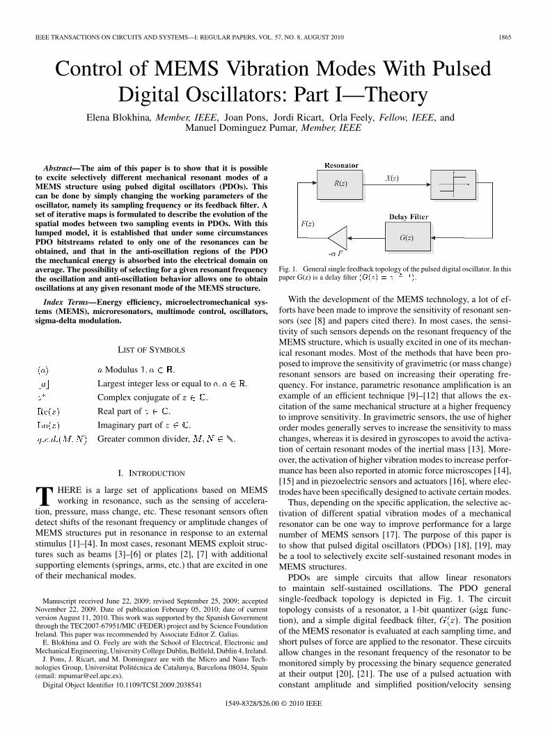
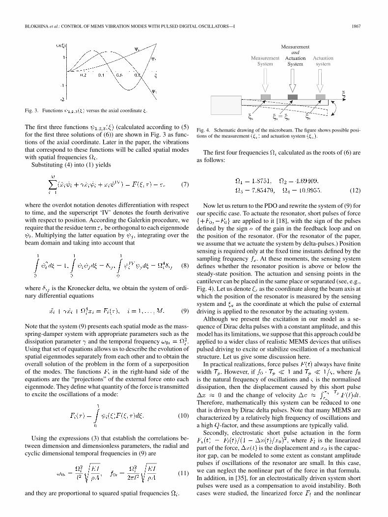
Fig. 3. Functions � ��� versus the axial coordinate �.
The first three functions (calculated according to (5)for the first three solutions of (6)) are shown in Fig. 3 as func-tions of the axial coordinate. Later in the paper, the vibrationsthat correspond to these functions will be called spatial modeswith spatial frequencies .
Substituting (4) into (1) yields
(7)
where the overdot notation denotes differentiation with respectto time, and the superscript ‘IV’ denotes the fourth derivativewith respect to position. According the Galerkin procedure, werequire that the residue term be orthogonal to each eigenmode
. Multiplying the latter equation by , integrating over thebeam domain and taking into account that
(8)
where is the Kronecker delta, we obtain the system of ordi-nary differential equations
(9)
Note that the system (9) presents each spatial mode as the mass-spring-damper system with appropriate parameters such as thedissipation parameter and the temporal frequency .Using that set of equations allows us to describe the evolution ofspatial eigenmodes separately from each other and to obtain theoverall solution of the problem in the form of a superpositionof the modes. The functions in the right-hand side of theequations are the “projections” of the external force onto eacheigenmode. They define what quantity of the force is transmittedto excite the oscillations of a mode:
(10)
Using the expressions (3) that establish the correlations be-tween dimension and dimensionless parameters, the radial andcyclic dimensional temporal frequencies in (9) are
(11)
and they are proportional to squared spatial frequencies .
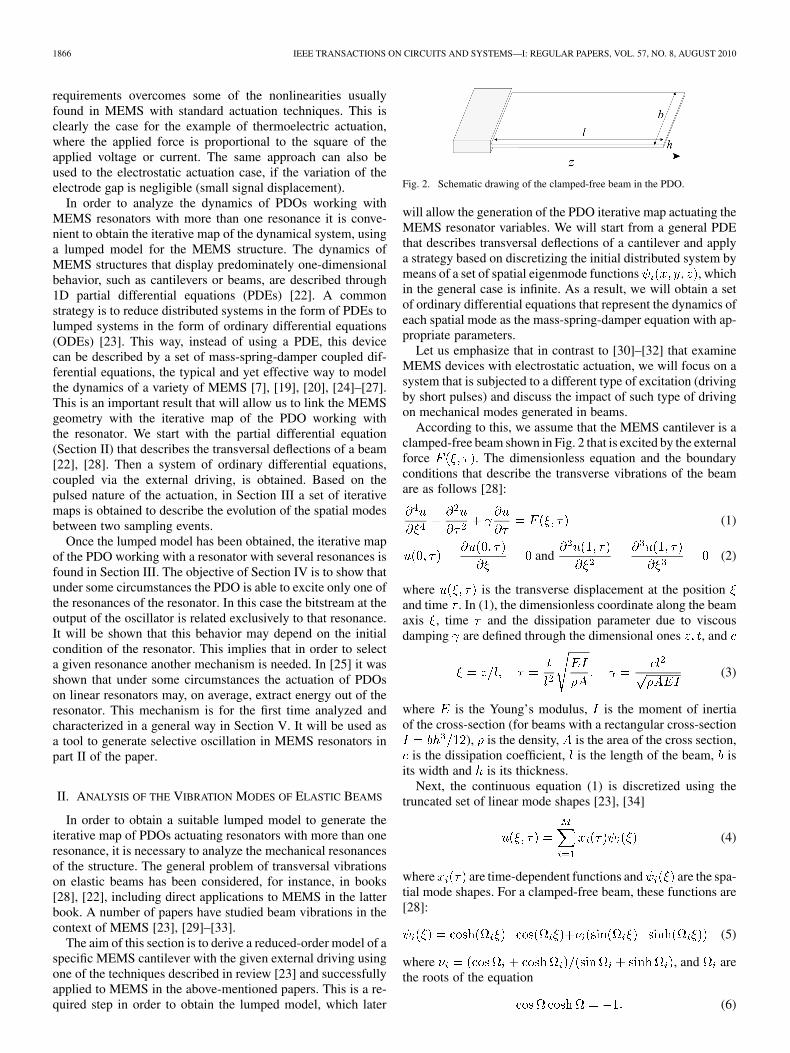
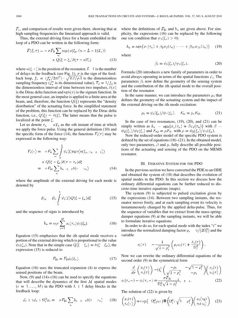
Fig. 4. Schematic drawing of the microbeam. The figure shows possible posi-tions of the measurement �� � and actuation system �� �.
The first four frequencies calculated as the roots of (6) areas follows:
(12)
Now let us return to the PDO and rewrite the system of (9) forour specific case. To actuate the resonator, short pulses of force
are applied to it [18], with the sign of the pulsesdefined by the sign of the gain in the feedback loop and onthe position of the resonator. (For the resonator of the paper,we assume that we actuate the system by delta-pulses.) Positionsensing is required only at the fixed time instants defined by thesampling frequency . At these moments, the sensing systemdefines whether the resonator position is above or below thesteady-state position. The actuation and sensing points in thecantilever can be placed in the same place or separated (see, e.g.,Fig. 4). Let us denote as the coordinate along the beam axis atwhich the position of the resonator is measured by the sensingsystem and as the coordinate at which the pulse of externaldriving is applied to the resonator by the actuating system.
Although we present the excitation in our model as a se-quence of Dirac delta pulses with a constant amplitude, and thismodel has its limitations, we suppose that this approach could beapplied to a wider class of realistic MEMS devices that utilisespulsed driving to excite or stabilize oscillation of a mechanicalstructure. Let us give some discussion here.
In practical realizations, force pulses always have finitewidth . However, if and , whereis the natural frequency of oscillations and is the normaliseddissipation, then the displacement caused by this short pulse
and the change of velocity .Therefore, mathematically this system can be reduced to onethat is driven by Dirac delta pulses. Note that many MEMS arecharacterized by a relatively high frequency of oscillations anda high -factor, and these assumptions are typically valid.
Secondly, electrostatic short pulse actuation in the form, where is the linearized
part of the force, is the displacement and is the capac-itor gap, can be modeled to some extent as constant amplitudepulses if oscillations of the resonator are small. In this case,we can neglect the nonlinear part of the force in that formula.In addition, in [35], for an electrostatically driven system shortpulses were used as a compensation to avoid instability. Bothcases were studied, the linearized force and the nonlinear
1868 IEEE TRANSACTIONS ON CIRCUITS AND SYSTEMS—I: REGULAR PAPERS, VOL. 57, NO. 8, AUGUST 2010
, and comparison of results were given there, showing that athigh sampling frequencies the linearized approach is valid.
Thus, the external driving force for a beam embedded in theloop of a PDO can be written in the following form:
(13)
where is the position of the resonator, is the numberof delays in the feedback (see Fig. 1), is the sign of the feed-back loop, is the dimensionlesssampling frequency ( is its dimensional value), isthe dimensionless interval of time between two impulses,is the Dirac delta function and is the signum function. Inthe most general case, an impulse is applied to a finite area at thebeam, and, therefore, the function represents the “densitydistribution” of the actuating force. In the simplified statementof the problem, this function can be replaced by the Dirac deltafunction, i.e., . The latter means that the pulse islocalized at the point .
Let us denote as the th instant of time at whichwe apply the force pulse. Using the general definition (10) andthe specific form of the force (14), the functions may beexpressed in the following way:
(14)
where the amplitude of the external driving for each mode isdenoted by
(15)
and the sequence of signs is introduced by
(16)
Equation (15) emphasises that the th spatial mode receives aportion of the external driving which is proportional to the value
. Note that in the simple case , theexpression (15) is reduced to
(17)
Equation (16) uses the truncated expansion (4) to express thesensed positions of the beam.
Now, (9) and (14)–(16) can be used to specify the equationsthat will describe the dynamics of the first spatial modes
in the PDO with delay blocks in thefeedback loop:
(18)
where the definitions of and are given above. For sim-plicity, the expressions (16) can be replaced by the followingone (on condition that ):
(19)
where
(20)
Formula (20) introduces a new family of parameters in order toavoid always operating in terms of the spatial functions . Theparameters now define the geometry of the sensing systemand the contribution of the th spatial mode to the overall posi-tion of the resonator.
In the same manner, we can introduce the parameters thatdefines the geometry of the actuating system and the impact ofthe external driving on the th mode excitation:
(21)
In the case of two resonances, (19), (20), and (21) can besimply written as with
and with .Now the reduced-order model of the specific PDO system is
defined by the set of equations (18)–(21). In the obtained model,only two parameters, and , fully describe all possible posi-tions of the actuating and sensing of the PDO on the MEMSresonator.
III. ITERATIVE SYSTEM FOR THE PDO
In the previous section we have converted the PDE to an ODEand obtained the system of (18) that describes the evolution ofspatial modes in the PDO. In this section we discuss how theordinary differential equations can be further reduced to dis-crete-time iterative equations (maps).
The system (9) is subjected to pulsed excitation given bythe expressions (14). Between two sampling instants, the res-onator moves freely, and at each sampling event its velocity isinstantaneously changed by the applied delta-pulse. Thus, forthe sequence of variables that we extract from the mass-spring-damper equations (9) at the sampling instants, we will be ableto formulate iterative equations.
In order to do so, for each spatial mode with the index “ ” weintroduce the normalized damping factor and thevariable
Now we can rewrite the ordinary differential equations of thesecond order (9) in the symmetrical form
(22)
The solution of (22) is given by
(23)
BLOKHINA et al.: CONTROL OF MEMS VIBRATION MODES WITH PULSED DIGITAL OSCILLATORS—I 1869
where is the rotation matrix
by the angle . If we define the sequenceas the extracted values of and at
the sampling instants , the set of iterative equations will havethe following form:
(24)
for . Note that the values are defined by(16). In the set (24), we introduce the following dimensionlessparameters:
(25)
where is the dimensionless damping parameter, is the nor-malized sample ratio in terms of the paper [26] (or normalizedfrequency in terms of the paper [20], both terms will be usedthroughout the paper), is the normalized increment (note thatit depends on the sign of the feedback loop) and is the con-traction factor. In (24), the first letter of the index, i.e., , refersto the number of a spatial mode, and the second letter, i.e., ,refers to the iteration number.
In a similar way to the previous section, we draw attentionto the particular case of the first two spatial modes. It is veryconvenient to establish the correlation between the parametersthat refer to the first and the second modes in explicit form.Therefore, we introduce the ratio of the spatial frequencies ofthe modes as follows:
(26)
and apply it to connect the set of parameters for the modes:
(27)
Note that from the onset, our theory has included suchparameters as the frequencies of the eigenmodes. As a con-sequence, the parameters used for formulation of the iterativesystem cannot be considered as independent ones, i.e., thevalues of controlling parameters have to be changed accordingthe expressions (27). For instance, in the experimental set thesampling frequency is measured with respect to the frequencyof the fundamental mode (i.e., the first spatial mode with thelowest frequency), and so the sampling ratio is given as a“basic” parameter. The value of can be obtained simply byrecalculating with the ratio .
Equations (24) introduce the iterative system as a set of 2Diterative maps and operate with variables such as the position
of the resonator and the variable proportional to the ve-locity of the resonator. Results presented in these variables areeasier to understand since and have an obvious physicalinterpretation. However, it is convenient to work on the com-plex plane with appropriate normalization and introduce a setof complex 1-D maps instead of 2-D maps written in real vari-ables. By defining the following complex variable
the evolution of the system is described now by the complexmap
(28)
where , and for definition of andsee (25).
The system (24) contains two coupled subsets—iterativeequations that describe the first spatial mode component bythe variables and and the second spatial mode by thevariables and . Later in the paper, dynamics that aredisplayed by the first subset of (24) will be referred as the “firstspatial mode” (or the first mode, eigenmode or resonance),and dynamics that are displayed by the second subset will bereferred as the “second spatial mode” (or the second mode).Note that the real position of the system is defined by the super-position of these two components according to the formula (4).
IV. CONTROL OF RESONANT MODES WITH PDOS
The objective of this section is to study the behavior of PDOsworking with resonators with more than one resonance. Nowthat we have established the possibility of extracting a lumpedmodel of the PDE governing a given MEMS structure, it is pos-sible to continue the line of work introduced in [20] to study thedynamics of PDOs. The first result will show that under someconditions, depending on the initial condition of the resonator,it is possible to obtain bitstreams at the output of the oscillatorrelated only to one of the resonant frequencies of the resonator.It will be shown later that, at least in some cases, the oscillationfrequency may generally depend on the initial condition of theresonator.
On the other hand, it has already been shown in [36] that,given a resonator with one resonance and a configuration ofthe oscillator, either the oscillator induces self-sustained oscil-lations on it, or, on the contrary, tends to cancel any oscillationby extracting energy until some limit cycle is reached near theorigin. This behavior will be used to selectively activate one ofthe resonances of a resonator with more than one resonance. Theobjective of Section V will be the study of this “anti-oscillation”behavior.
A. Iterative Map With Two Resonances
Let us focus on the case with two resonances. We will assumethat the feedback filter is of the form . Using thegeneral complex formula (28) to formulate the iterative equa-tions we obtain the following equations:
(29)
(30)
(31)
1870 IEEE TRANSACTIONS ON CIRCUITS AND SYSTEMS—I: REGULAR PAPERS, VOL. 57, NO. 8, AUGUST 2010
where are normalized forces (25),and depends on the MEMS geometry.
In the case of a cantilever it would be defined as in (20).The dynamical system associated with these equations may
be defined in the following way:
(32)
where . For
(33)
Now, following a similar approach to [20], we define:Definition 1: The projections
and are de-fined as , and
.We will consider that , is the identity
and that is the result of applications of the functionto . In order to simplify notation we further define:
Definition 2: The function isdefined as .
Definition 3: The function is defined as.
Definition 4: In the case , the functionsare defined as . If
is defined as .If the feedback loop of the oscillator ensures that
. Ifthen .
Now, for a given binary sequence we may define the se-quence as:
(34)
with , and test for the admissibility of thatbinary sequence:
Lemma 1: Given a sequence and, if
then.
Proof: It is obvious since in this case:
(35)
and , for all .This is an important result because it is the mechanism we
will use to prove that a given bitstream can be present at the
output of a PDO. A similar result has been previously used in[20] to prove that under some circumstances the bitstream of aPDO, working with a resonator with only one resonance, is an
sequence at the resonant frequency of the resonator.Due to the presence of two different resonances in the res-
onator, one might expect a bitstream related to a mixture ofboth frequencies, most probably rendering the bitstream use-less, from the point of view of obtaining at least one of the reso-nant frequencies directly from it. However, it will be proved thatunder some conditions, the bitstream at the output of the PDOwith two resonances may be related only to one of them.
We will principally focus on a certain group of frequencies,called ‘tuned’ frequencies which were first found in [20]. Themain reason to focus on these frequencies is that the oscillatorwith low or no losses presents a regularity pattern that simplifiesthe analysis of its dynamics.
B. Lossless Resonator Case
Now, we will obtain sufficient conditions for oscillation at oneof the resonant frequencies of the resonator. This result will bevalid for frequencies and ,with g.c.d. , and g.c.d. . Further-more, we will assume that frequency is ‘tuned’ [20], i.e., for
:
even
(36)
In the case , the former conditions are
(37)
Under the above conditions it has been proved, [20], thatif , with being a tuned frequency and
, for , then
(38)
for , which is a result greatly simplifying the use ofLemma 1 for sequences of the form of . Now, we may statethe following theorem:
Theorem 1: If an oscillator with two lossless resonances,, and
, with g.c.d. , is tuned to ,and are such that
, then
. (The proof is given in Appendix I.)This last result shows us that under some circumstances it is
possible to obtain a bitstream at the output of the PDO relatedto only one of the resonances of the resonator. Among the con-ditions needed to ensure this oscillation we find the initial con-dition in both resonators.
BLOKHINA et al.: CONTROL OF MEMS VIBRATION MODES WITH PULSED DIGITAL OSCILLATORS—I 1871
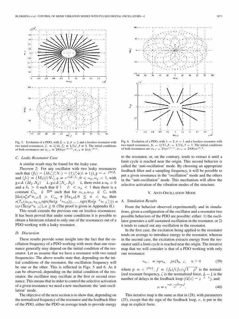
Fig. 5. Evolution of a PDO, with � � �� � � � and a lossless resonator withtwo tuned resonances, � � ����� � � ������ � �. The initial conditionsof both resonances are � � ����� � � � ��� .
C. Leaky Resonator Case
A similar result may be found for the leaky case.Theorem 2: For any oscillator with two leaky resonances
such thatand , withg.c.d. g.c.d , there exist aand a such that if then there is aconstant such that for , with
, then
. (The proof is given in Appendix II.)This result extends the previous one on lossless resonances.
It has been proved that under some conditions it is possible toobtain a bitstream related to only one of the resonances out of aPDO working with a leaky resonator.
D. Discussion
These results provide some insight into the fact that the os-cillation frequency of a PDO working with more than one reso-nance generally may depend on the initial condition of the res-onator. Let us assume that we have a resonator with two tunedfrequencies. The above results state that, depending on the ini-tial conditions of the resonator, the oscillation frequency willbe one or the other. This is reflected in Figs. 5 and 6. As itcan be observed, depending on the initial condition of the res-onator, the oscillator may oscillate at the first or second reso-nance. This means that in order to control the selective activationof a given resonance we need a new mechanism: the ‘anti-oscil-lation’ mode.
The objective of the next section is to show that, depending onthe normalized frequency of the resonator and the feedback filterof the PDO, either the PDO on average tends to provide energy
Fig. 6. Evolution of a PDO, with � � �� � � � and a lossless resonator withtwo tuned resonances, � � ����� � � ������ � �. The initial conditionsof both resonances are � � ��� � � � ����� .
to the resonator, or, on the contrary, tends to extract it until alimit cycle is reached near the origin. This second behavior iscalled the ‘anti-oscillation’ mode. By choosing an appropriatefeedback filter and a sampling frequency, it will be possible toput a given resonance in the “oscillation” mode and the othersin the “anti-oscillation” mode. This mechanism will allow theselective activation of the vibration modes of the structure.
V. ANTI-OSCILLATION MODE
A. Simulation Results
From the behavior observed experimentally and in simula-tions, given a configuration of the oscillator and a resonator twopossible behaviors of the PDO are possible: either: 1) the oscil-lator generates a self-sustained oscillation in the resonator, or 2)it tends to cancel out any oscillation in the resonator.
In the first case, the excitation being applied to the resonatortends on average to introduce energy to the resonator, whereasin the second case, the excitation extracts energy from the res-onator until a limit cycle is reached near the origin. The iterativemap that we will consider is that of a PDO working with onlyone resonance:
(39)
where is the normal-ized resonant frequency, is the normalized force, is thenumber of delays in the feedback loop , and:
(40)
This iterative map is the same as that in (28), with parameters(25), except that the sign of the feedback loop, , is put in themap in explicit form.
1872 IEEE TRANSACTIONS ON CIRCUITS AND SYSTEMS—I: REGULAR PAPERS, VOL. 57, NO. 8, AUGUST 2010
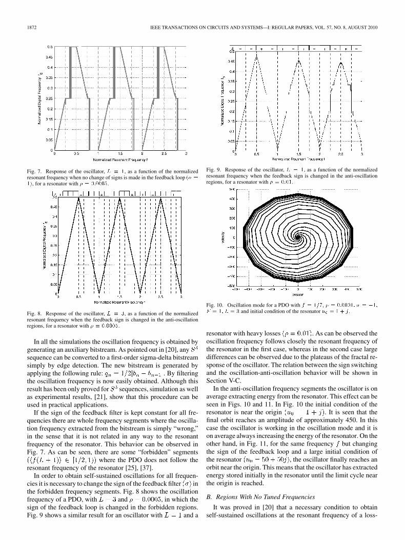
Fig. 7. Response of the oscillator, � � �, as a function of the normalizedresonant frequency when no change of signs is made in the feedback loop �� ���, for a resonator with � � ������.
Fig. 8. Response of the oscillator, � � �, as a function of the normalizedresonant frequency when the feedback sign is changed in the anti-oscillationregions, for a resonator with � � ������.
In all the simulations the oscillation frequency is obtained bygenerating an auxiliary bitstream. As pointed out in [20], anysequence can be converted to a first-order sigma-delta bitstreamsimply by edge detection. The new bitstream is generated byapplying the following rule: . By filteringthe oscillation frequency is now easily obtained. Although thisresult has been only proved for sequences, simulation as wellas experimental results, [21], show that this procedure can beused in practical applications.
If the sign of the feedback filter is kept constant for all fre-quencies there are whole frequency segments where the oscilla-tion frequency extracted from the bitstream is simply “wrong,”in the sense that it is not related in any way to the resonantfrequency of the resonator. This behavior can be observed inFig. 7. As can be seen, there are some “forbidden” segments
where the PDO does not follow theresonant frequency of the resonator [25], [37].
In order to obtain self-sustained oscillations for all frequen-cies it is necessary to change the sign of the feedback filter inthe forbidden frequency segments. Fig. 8 shows the oscillationfrequency of a PDO, with and , in which thesign of the feedback loop is changed in the forbidden regions.Fig. 9 shows a similar result for an oscillator with and a
Fig. 9. Response of the oscillator, � � �, as a function of the normalizedresonant frequency when the feedback sign is changed in the anti-oscillationregions, for a resonator with � � ����.
Fig. 10. Oscillation mode for a PDO with � � ���� � � ������� � � ���� � �� � � � and initial condition of the resonator � � .
resonator with heavy losses . As can be observed theoscillation frequency follows closely the resonant frequency ofthe resonator in the first case, whereas in the second case largedifferences can be observed due to the plateaus of the fractal re-sponse of the oscillator. The relation between the sign switchingand the oscillation-anti-oscillation behavior will be shown inSection V-C.
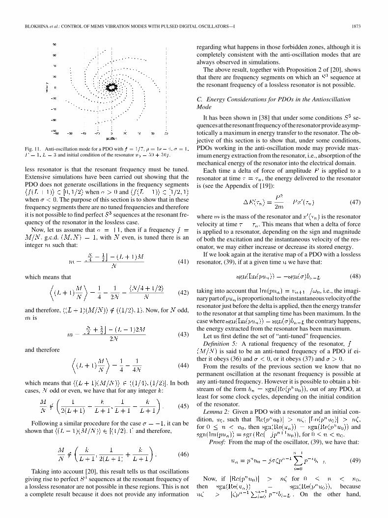
In the anti-oscillation frequency segments the oscillator is onaverage extracting energy from the resonator. This effect can beseen in Figs. 10 and 11. In Fig. 10 the initial condition of theresonator is near the origin . It is seen that thefinal orbit reaches an amplitude of approximately 450. In thiscase the oscillator is working in the oscillation mode and it ison average always increasing the energy of the resonator. On theother hand, in Fig. 11, for the same frequency but changingthe sign of the feedback loop and a large initial condition ofthe resonator , the oscillator finally reaches anorbit near the origin. This means that the oscillator has extractedenergy stored initially in the resonator until the limit cycle nearthe origin is reached.
B. Regions With No Tuned Frequencies
It was proved in [20] that a necessary condition to obtainself-sustained oscillations at the resonant frequency of a loss-
BLOKHINA et al.: CONTROL OF MEMS VIBRATION MODES WITH PULSED DIGITAL OSCILLATORS—I 1873
Fig. 11. Anti-oscillation mode for a PDO with � � ���� � � ��� �� � � ��� � �� � � � and initial condition of the resonator � �� � �� .
less resonator is that the resonant frequency must be tuned.Extensive simulations have been carried out showing that thePDO does not generate oscillations in the frequency segments
when andwhen . The purpose of this section is to show that in thesefrequency segments there are no tuned frequencies and thereforeit is not possible to find perfect sequences at the resonant fre-quency of the resonator in the lossless case.
Now, let us assume that , then if a frequencyg.c.d. , with even, is tuned there is an
integer such that:
(41)
which means that
(42)
and therefore, . Now, for odd,is
(43)
and therefore
(44)
which means that . In bothcases, odd or even, we have that for any integer :
(45)
Following a similar procedure for the case , it can beshown that and therefore,
(46)
Taking into account [20], this result tells us that oscillationsgiving rise to perfect sequences at the resonant frequency ofa lossless resonator are not possible in these regions. This is nota complete result because it does not provide any information
regarding what happens in those forbidden zones, although it iscompletely consistent with the anti-oscillation modes that arealways observed in simulations.
The above result, together with Proposition 2 of [20], showsthat there are frequency segments on which an sequence atthe resonant frequency of a lossless resonator is not possible.
C. Energy Considerations for PDOs in the AntioscillationMode
It has been shown in [38] that under some conditions se-quencesat theresonantfrequencyoftheresonatorprovideasymp-totically a maximum in energy transfer to the resonator. The ob-jective of this section is to show that, under some conditions,PDOs working in the anti-oscillation mode may provide max-imum energy extraction from the resonator, i.e., absorption of themechanical energy of the resonator into the electrical domain.
Each time a delta of force of amplitude is applied to aresonator at time , the energy delivered to the resonatoris (see the Appendix of [19]):
(47)
where is the mass of the resonator and is the resonatorvelocity at time . This means that when a delta of forceis applied to a resonator, depending on the sign and magnitudeof both the excitation and the instantaneous velocity of the res-onator, we may either increase or decrease its stored energy.
If we look again at the iterative map of a PDO with a losslessresonator, (39), if at a given time we have that:
(48)
taking into account that , i.e., the imagi-narypartof isproportional totheinstantaneousvelocityoftheresonator just before the delta is applied, then the energy transferto the resonator at that sampling time has been maximum. In thecase where the contrary happens,the energy extracted from the resonator has been maximum.
Let us first define the set of “anti-tuned” frequencies.Definition 5: A rational frequency of the resonator,
is said to be an anti-tuned frequency of a PDO if ei-ther it obeys (36) and , or it obeys (37) and .
From the results of the previous section we know that nopermanent oscillation at the resonant frequency is possible atany anti-tuned frequency. However it is possible to obtain a bit-stream of the form , out of any PDO, atleast for some clock cycles, depending on the initial conditionof the resonator.
Lemma 2: Given a PDO with a resonator and an initial con-dition, , such that ,for , then and
, for .Proof: From the map of the oscillator, (39), we have that:
(49)
Now, if for ,then , because
. On the other hand,
1874 IEEE TRANSACTIONS ON CIRCUITS AND SYSTEMS—I: REGULAR PAPERS, VOL. 57, NO. 8, AUGUST 2010
from (49), it is easy to see that if , for, then .
This last result, means that for an unbounded set of initialconditions of the resonator, regardless of the configuration ofthe oscillator, the bitstream is dominated at least for some timedirectly by the initial condition of the resonator. Under thesecircumstances it is possible to study the energy efficiency of thePDO actuation while actuating the resonator, i.e., the numberof times the sign of the delta of force applied to the resonatorcoincided with the sign of its velocity.
Definition 6: The energy efficiency, , of a given finite-timepulsed actuation with amplitudes on a linearresonator with initial condition is defined as
(50)
where is the velocity of the resonator at time whenthe resonator is actuated with deltas with amplitudes
, and the initial condition of the resonator is .We will now analyze the energy efficiency of PDOs in anti-
tuned frequencies.Theorem 3: Given a PDO with a lossless resonator with an
anti-tuned frequency, , if the initial condition, ,is such that , for
, then the energy efficiency of the actuation of the PDOfrom time to on the resonator is
a) for even either or ;b) for odd, either or .
Proof: The actuation the oscillator feeds into the res-onator is . From Lemma 2, it follows that
and. If ,
then .We may distinguish three different cases:a) : in this case ,
and therefore. This means the
the energy efficiency of this actuation is ;b) : then .
In this case,. Now, if
, where is defined as, then
, and therefore . Onthe other hand, if , wewill see that the difference between the sequences
and isof two bits each bits, and therefore .
The sequence may be ex-pressed in the following form:
(51)
Now, if the collection of sets is defined, we may further define a function as
(52)
which allows us to rewrite the sequence as:
(53)
Then, for any if , andotherwise. On the other hand, the sequence
may be written as:
(54)
It is clear that if then both bitstreamsare identical. If then:
(55)
and therefore 2 in each bits change from the sequencewith regard to , which means that .
odd: then , and therefore. Now, if
then andtherefore the energy efficiency is .
Now, the sequence may beexpressed in the following form:
(56)
Following a similar procedure as before, we may defineas
(57)
BLOKHINA et al.: CONTROL OF MEMS VIBRATION MODES WITH PULSED DIGITAL OSCILLATORS—I 1875
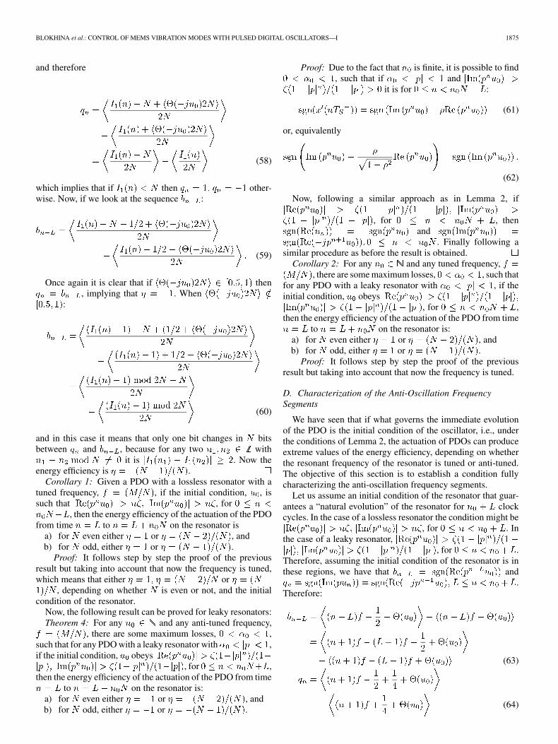
and therefore
(58)
which implies that if then other-wise. Now, if we look at the sequence :
(59)
Once again it is clear that if then, implying that . When
:
(60)
and in this case it means that only one bit changes in bitsbetween and , because for any two with
it is . Now theenergy efficiency is .
Corollary 1: Given a PDO with a lossless resonator with atuned frequency, , if the initial condition, , issuch that , for
, then the energy efficiency of the actuation of the PDOfrom time to on the resonator is
a) for even either or , andb) for odd, either or .
Proof: It follows step by step the proof of the previousresult but taking into account that now the frequency is tuned,which means that either or
, depending on whether is even or not, and the initialcondition of the resonator.
Now, the following result can be proved for leaky resonators:Theorem 4: For any and any anti-tuned frequency,
, there are some maximum losses, ,such that for any PDO with a leaky resonator with ,if the initial condition, obeys
, for ,then the energy efficiency of the actuation of the PDO from time
to on the resonator is:a) for even either or , andb) for odd, either or .
Proof: Due to the fact that is finite, it is possible to find, such that if and
it is for :
(61)
or, equivalently
(62)
Now, following a similar approach as in Lemma 2, if
, for , thenand
. Finally following asimilar procedure as before the result is obtained.
Corollary 2: For any and any tuned frequency,, there are some maximum losses, , such that
for any PDO with a leaky resonator with , if theinitial condition, obeys
, for ,then the energy efficiency of the actuation of the PDO from time
to on the resonator is:a) for even either or , andb) for odd, either or .
Proof: It follows step by step the proof of the previousresult but taking into account that now the frequency is tuned.
D. Characterization of the Anti-Oscillation FrequencySegments
We have seen that if what governs the immediate evolutionof the PDO is the initial condition of the oscillator, i.e., underthe conditions of Lemma 2, the actuation of PDOs can produceextreme values of the energy efficiency, depending on whetherthe resonant frequency of the resonator is tuned or anti-tuned.The objective of this section is to establish a condition fullycharacterizing the anti-oscillation frequency segments.
Let us assume an initial condition of the resonator that guar-antees a “natural evolution” of the resonator for clockcycles. In the case of a lossless resonator the condition might be
, for . Inthe case of a leaky resonator,
, for .Therefore, assuming the initial condition of the resonator is inthese regions, we have that and
.Therefore:
(63)
(64)
1876 IEEE TRANSACTIONS ON CIRCUITS AND SYSTEMS—I: REGULAR PAPERS, VOL. 57, NO. 8, AUGUST 2010
Now, considering that , for large, in order to have, on average for all initial conditions, it must be
, which means that:
(65)
and these are precisely the frequency segments where the anti-oscillation behavior is found (for ). In case then
.
VI. CONCLUSION
The dynamics of PDOs working with MEMS resonatorswith more than one resonance were analyzed. We started witha lumped model of coupled ordinary differential equationsobtained for clamped-free beams. Each ODE is related toone of the resonances of the beam, which result from thedecomposition in eigenmodes of the solution to the partial dif-ferential equation governing the motion of the beam. From thislumped model a set of iterative maps has obtained that serveto describe the dynamics of a PDO working with resonatorwith more than one resonance. It has been proved that undersome circumstances PDOs can activate one of the resonancesof the MEMS structure, but that this fact can depend on theinitial condition of the resonator. In order to achieve an activecontrol on the activation of the resonances another mechanismis necessary: the anti-oscillation mode. This mode has beenanalyzed and it has been shown that the energy efficiency of theactuation in the anti-oscillation frequency segments is negative.This mechanism will be used later in part II to actuate differentresonant modes on a MEMS cantilever.
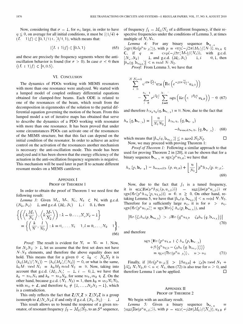
APPENDIX IPROOF OF THEOREM 1
In order to obtain the proof of Theorem 1 we need first thefollowing result:
Lemma 3: Given , with g.c.d., and g.c.d. , then
(66)
Proof: The result is evident for . Now,for , let us assume that the first set does not have
elements, and therefore the above equality does nothold. This means that for a given it is
, or what is the same,. Now, taking into
account that g.c.d. , we have thatand , for some . On the
other hand, because g.c.d. , then ,with , and therefore , whichis a contradiction.
This only reflects the fact that is a groupisomorph to if and only if g.c.d. .
This result allows us to bound the response of a given res-onator, of resonant frequency , to an sequence,
of frequency of a different frequency, if their re-spective frequencies under the conditions of Lemma 3, at timesmultiple of .
Lemma 4: For any binary sequence, with
, if , with g.c.d., and g.c.d. , then
.Proof: From Lemma 3, we have that
(67)
and therefore . Now, due to the fact that
(68)
which means that .Now, we may proceed with proving Theorem 1:
Proof of Theorem 1: Following a similar approach to thatused for proving Theorem 2 in [20], it can be shown that for abinary sequence we have that
(69)
Now, due to the fact that is a tuned frequency,it is or
. On other hand, re-taking Lemma 5, we have that .Therefore for a sufficiently large , it is for
, and
(70)
and therefore
(71)
Finally, if, then (72) is also true for , and
therefore Lemma 1 can be applied.
APPENDIX IIPROOF OF THEOREM 2
We begin with an auxiliary result.Lemma 5: Given a binary sequence
, with
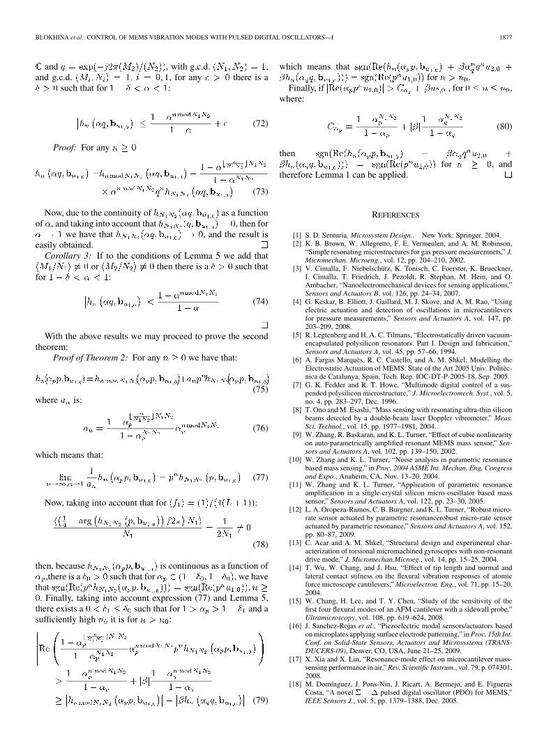
BLOKHINA et al.: CONTROL OF MEMS VIBRATION MODES WITH PULSED DIGITAL OSCILLATORS—I 1877
and , with g.c.d. ,and g.c.d. , for any there is a
such that for :
(72)
Proof: For any
(73)
Now, due to the continuity of as a functionof , and taking into account that , then for
we have that , and the result iseasily obtained.
Corollary 3: If to the conditions of Lemma 5 we add thator then there is a such that
for :
(74)
With the above results we may proceed to prove the secondtheorem:
Proof of Theorem 2: For any we have that:
(75)where is:
(76)
which means that:
(77)
Now, taking into account that for :
(78)
then, because is continuous as a function of,there is a such that for , we have
that. Finally, taking into account expression (77) and Lemma 5,
there exists a such that for and asufficiently high it is for :
(79)
which means thatfor .
Finally, if , for ,where:
(80)
thenfor , and
therefore Lemma 1 can be applied.
REFERENCES
[1] S. D. Senturia, Microsystem Design.. New York: Springer, 2004.[2] K. B. Brown, W. Allegretto, F. E. Vermeulen, and A. M. Robinson,
“Simple resonating microstructures for gas pressure measuremnets,” J.Micromechan. Microeng., vol. 12, pp. 204–210, 2002.
[3] V. Cimalla, F. Niebelschütz, K. Tonisch, C. Foerster, K. Brueckner,I. Cimalla, T. Friedrich, J. Pezoldt, R. Stephan, M. Hein, and O.Ambacher, “Nanoelectromechanical devices for sensing applications,”Sensors and Actuators B, vol. 126, pp. 24–34, 2007.
[4] G. Keskar, B. Elliott, J. Gaillard, M. J. Skove, and A. M. Rao, “Usingelectric actuation and detection of oscillations in microcantileversfor pressure measurements,” Sensors and Actuators A, vol. 147, pp.203–209, 2008.
[5] R. Legtenberg and H. A. C. Tilmans, “Electrostatically driven vacuum-encapsulated polysilicon resonators. Part I. Design and fabrication,”Sensors and Actuators A, vol. 45, pp. 57–66, 1994.
[6] A. Fargas Marquès, R. C. Castello, and A. M. Shkel, Modelling theElectrostatic Actuation of MEMS: State of the Art 2005 Univ. Politèc-nica de Catalunya, Spain, Tech. Rep. IOC-DT-P-2005-18, Sep. 2005.
[7] G. K. Fedder and R. T. Howe, “Multimode digital control of a sus-pended polysilicon microstructure,” J. Microelectromech. Syst., vol. 5,no. 4, pp. 283–297, Dec. 1996.
[8] T. Ono and M. Esashi, “Mass sensing with resonating ultra-thin siliconbeams detected by a double-beam laser Doppler vibrometer,” Meas.Sci. Technol., vol. 15, pp. 1977–1981, 2004.
[9] W. Zhang, R. Baskaran, and K. L. Turner, “Effect of cubic nonlinearityon auto-parametrically amplified resonant MEMS mass sensor,” Sen-sors and Actuators A, vol. 102, pp. 139–150, 2002.
[10] W. Zhang and K. L. Turner, “Noise analysis in parametric resonancebased mass sensing,” in Proc. 2004 ASME Int. Mechan, Eng, Congressand Expo., Anaheim, CA, Nov. 13–20, 2004.
[11] W. Zhang and K. L. Turner, “Application of parametric resonanceamplification in a single-crystal silicon micro-oscillator based masssensor,” Sensors and Actuators A, vol. 122, pp. 23–30, 2005.
[12] L. A. Oropeza-Ramos, C. B. Burgner, and K. L. Turner, “Robust micro-rate sensor actuated by parametric resonancerobust micro-rate sensoractuated by parametric resonance,” Sensors and Actuators A, vol. 152,pp. 80–87, 2009.
[13] C. Acar and A. M. Shkel, “Structural design and experimental char-acterization of torsional micromachined gyroscopes with non-resonantdrive mode,” J. Micromechan.Microeg., vol. 14, pp. 15–25, 2004.
[14] T. Wu, W. Chang, and J. Hsu, “Effect of tip length and normal andlateral contact stifness on the flexural vibration responses of atomicforce microscope cantilevers,” Microelectron. Eng., vol. 71, pp. 15–20,2004.
[15] W. Chang, H. Lee, and T. Y. Chen, “Study of the sensitivity of thefirst four flexural modes of an AFM cantilever with a sidewall probe,”Ultramicroscopy, vol. 108, pp. 619–624, 2008.
[16] J. Sanchez-Rojas et al., “Piezoelectric modal sensors/actuators basedon microplates applying surface electrode patterning,” in Proc. 15th Int.Conf. on Solid-State Sensors, Actuators and Microsystems (TRANS-DUCERS-09), Denver, CO, USA, June 21–25, 2009.
[17] X. Xia and X. Lin, “Resonance-mode effect on microcantilever mass-sensing performance in air,” Rev. Scientific Instrum., vol. 79, p. 074301,2008.
[18] M. Domínguez, J. Pons-Nin, J. Ricart, A. Bermejo, and E. FiguerasCosta, “A novel � � � pulsed digital oscillator (PDO) for MEMS,”IEEE Sensors J., vol. 5, pp. 1379–1388, Dec. 2005.
1878 IEEE TRANSACTIONS ON CIRCUITS AND SYSTEMS—I: REGULAR PAPERS, VOL. 57, NO. 8, AUGUST 2010
[19] M. Domínguez, J. Pons-Nin, J. Ricart, A. Bermejo, E. Figueras Costa,and M. Morata, “Analysis of the � � � pulsed digital oscillator forMEMS,” IEEE Trans. Circuits Syst. I, Regular Papers, vol. 52, no. 11,pp. 2286–2297, Nov. 2005.
[20] M. Domínguez, J. Pons-Nin, and J. Ricart, “General dynamics ofpulsed digital oscillators,” IEEE Trans. Circuits Syst. I, Reg. Papers,vol. 55, no. , pp. 2038–2050, 2008.
[21] J. Ricart, J. Pons, M. Domínguez, A. Rodríguez, E. Figueras, M. C. H.J. Gutiérrez, and I. Sayago, “Application of pulsed digital oscillatorsto volatile organic compounds sensing,” Sensors and Actuators B, vol.134, pp. 773–779, 2008.
[22] J. A. Pelesko and D. H. Bernstein, Modeling of MEMS and NEMS.London, U.K.: Chapman&Hall, 2003.
[23] A. H. Nayfeh, M. I. Younis, and E. M. Abdel-Rahman, “Reduced-ordermodels for MEMS applications,” Nonlinear Dyn., vol. 41, pp. 211–236,2005.
[24] J. Wu and L. R. Carley, “Electromechanical �� modulation withhigh-Q micromechanical accelerometers and pulse density modulatedforce feedback,” IEEE Trans. Circuits Syst. I, Reg. Papers, vol. 53, no.3, pp. 274–287, Mar. 2006.
[25] M. Domínguez, J. Pons-Nin, and J. Ricart, “Application of pulsed dig-ital oscillators in ‘reverse mode’ to eliminate undesired vibrations inhigh-Q MEMS resonators,” in Proc. IEEE International Symposiumon Circuits and Systems 2007, New Orleans, USA, May 27–30, 2007,pp. 925–928.
[26] A. Teplinsky and O. Feely, “Limit cycles in a MEMS oscillator,” IEEETrans. Circuits Syst. II, Expr. Briefs, vol. 55, no. 9, pp. 882–886, Sep.2008.
[27] E. Blokhina and O. Feely, “A kicked oscillator as a model of a pulsedMEMS system,” Int. J. Bifurc. Chaos, vol. 19, no. 1, pp. 187–202, 2009.
[28] K. Graff, Wave Motion in Elastic Solids. New York: Dover, 1975.[29] H. A. C. Tilmans and R. Legtenberg, “Electrostatically driven vacuum-
encapsulated polysilicon resonators. Part II. Theory and performance,”Sensors and Actuators A, vol. 45, pp. 67–84, 1994.
[30] E. M. Abdel-Rahman, M. I. Younis, and A. H. Nayfeh, “Characteriza-tion of the mechanical behavior of an electrically actuated microbeam,”J. Micromechan. Microeng., vol. 12, pp. 759–766, 2002.
[31] M. I. Younis and A. H. Nayfeh, “A study of the nonlinear response of aresonant microbeam to an electric actuation,” Nonlinear Dyn., vol. 31,pp. 91–117, 2003.
[32] M. I. Younis, E. M. Abdel-Rahman, and A. Nayfeh, “A reduced-ordermodel for electrically actuated microbeam-based MEMS,” J. Micro-electromech. Syst., vol. 12, no. 5, pp. 672–680, Oct. 2003.
[33] W. C. Xie, H. P. Lee, and S. P. Lim, “Nonlinear dynamic analysis ofMEMS switches by nonlinear modal analysis,” Nonlinear Dynamics,vol. 31, pp. 243–256, 2003.
[34] Y. C. Liang, W. Z. Lin, H. P. Lee, S. P. Lim, K. H. Lee, and H. Sun,“Proper orthogonal decomposition and its applications—Part II: Modelreduction for MEMS dynamical analysis,” J. Sound Vibration, vol. 256,pp. 515–532, 2002.
[35] G. K. Fedder, “Simulation of microelectromechanical systems,” Ph.D.dissertation, Univ. California, Berkeley, 1994.
[36] M. Domínguez, J. Pons-Nin, J. Ricart, and E. Figueras, “The MEMSpulsed digital oscillator (PDO) below the Nyquist limit,” Sensors andActuators A, vol. 136, pp. 690–696, 2007.
[37] E. Blokhina, O. Feely, and M. Dominguez, “Dynamics of the MEMSpulsed digital oscillator with multiple delays in the feedback loop,” inProc. of IEEE Int. Symp. on Circuits and Systems (ISCAS) 2009, pp.1903–1906.
[38] M. Domínguez, “Energy efficiency of pulsed actuations on linear res-onators,” IEEE Trans. Circuits Syst. I, vol. 56, no. 12, pp. 2678–2688,Dec. 2009.
Elena Blokhina (S’05–M’06) received the M.S. andPh.D. degrees in physics from Saratov State Univer-sity, Russia, in 2002 and 2005, respectively.
From 2005 to 2007 she was a research scientist inSaratov State University where her project concernednonlinear dynamics and chaos in microwave electrondevices. She is currently a postdoctoral researcher inthe Circuit and Systems Research Group at Univer-sity College Dublin. Her research interests includenonlinear dynamics and oscillation theory and theirapplication to the vibration analysis of MEMS.
Joan Pons-Nin received the M.Sc. and Ph.D. de-grees in electronic engineering from the UniversitatPolitècnica de Catalunya, Barcelona, Spain, in 1985and 1995, respectively.
He is an Associate Professor with the Departmentof Electronic Engineering at the Telecommunica-tions Engineering School of Barcelona, Spain. .He is currently working on oscillators for MEMSresonators. He worked also on emitter characteriza-tion and optimization for advanced bipolar devicesand polysilicon contacted silicon solar cells. Other
research topics of his interest are semiconductor devices simulation and digitalcontrol circuitry.
Jordi Ricart received the M.Sc. degree in IngenieríaElectrónica from the Universitat Politécnica deCatalunya (UPC), Barcelona, Spain, in 2004. Hejoined the Micro and Nano Technologies ResearchGroup of the UPC both as a Research Assistant andas a Ph.D. degree student.
He is actively working in sensors for space applica-tions and nonlinear circuits for MEMS applications,such as oscillators.
Orla Feely (S’85–M’86–SM’87–F’09) received theB.E. degree in electronic engineering from UniversityCollege Dublin in 1986, and the M.S. and Ph.D. de-grees in electrical engineering from the University ofCalifornia, Berkeley, in 1990 and 1992, respectively.
She is currently a Professor in the School of Elec-trical, Electronic and Mechanical Engineering, Uni-versity College Dublin. Her research interests lie inthe area of nonlinear dynamics of electronic circuits.
Prof. Feely received the Best Paper Award of theInternational Journal of Circuit Theory and Applica-
tions in 2007, and the Best Paper Award of the European Conference on Cir-cuit Theory and Design in 1997. Her Ph.D. thesis on sigma-delta modulationwon the D. J. Sakrison Memorial Prize for outstanding and innovative research,awarded annually by the Department of Electrical Engineering and ComputerSciences at U. C. Berkeley. She has served as Associate Editor of the IEEETRANSACTIONS ON CIRCUITS AND SYSTEMS PART I: FUNDAMENTAL THEORY
AND APPLICATIONS, and is a member of the Editorial Board of the InternationalJournal of Circuit Theory and Applications.
Manuel Dominguez Pumar (M’99) received theM.Sc. and Ph.D. degrees in electronic engineeringfrom the Universitat Politècnica de Catalunya (UPC),Barcelona, Spain, in 1994 and 1997, respectively,and a Degree in mathematics from the UniversidadNacional de Educación a Distancia (UNED), Madrid,Spain, with honors., in 2005.
He has been with the UPC Department of Elec-tronic Engineering since 1994, where he is nowAssociate Professor. He was visiting scholar at theCourant Institute of Mathematical Sciences from
September 2006 to August 2007. His research areas include the design anddevelopment of oscillators, MEMS sensors and actuators, sensors for spaceapplications, sigma-delta modulation applied to MEMS and non-linear circuitsin general.
Top Related
Copyright © 2022 FDOKUMEN

