


Bahasa
Halaman
Hukum

ARTICLE IN PRESS
0030-3992/$ - se
doi:10.1016/j.op
�CorrespondE-mail addr
a_l_dawar@yah
(P.M.V. Subba
Optics & Laser Technology 40 (2008) 64–75
www.elsevier.com/locate/optlastec
Computation of streamwise vorticity in a compressible flow of awinglet nozzle-based COIL device
Gaurav Singhala, A.L. Dawara,�, P.M.V. Subbaraob, M. Endoc
aLaser Science and Technology Center, Metcalfe House, Delhi 110054, IndiabIndian Institute of Technology, Delhi 110016, India
cDepartment of Physics, Tokai University, Hiratsuka City, Japan
Received 30 December 2006; received in revised form 22 March 2007; accepted 22 March 2007
Available online 18 May 2007
Abstract
Chemical oxygen iodine laser (COIL) is a high-power laser with potential applications in both military as well as in the industry. COIL
is the only chemical laser based on electronic transition with a wavelength of 1.315 mm, which falls in the near-infrared (IR) range. Thus,
COIL beam can also be transported via optical fibers for remote applications such as dismantling of nuclear reactors. The efficiency of a
supersonic COIL is essentially a function of mixing specially in systems employing cross-stream injection of the secondary lasing (I2) flow
in supersonic regime into the primary pumping (O21Dg) flow. Streamwise vorticity has been proven to be among the most effective manner
of enhancing mixing and has been utilized in jet engines for thrust augmentation, noise reduction, supersonic combustion, etc. Therefore,
a computational study of the generation of streamwise vorticity in the supersonic flow field of a COIL device employing a winglet nozzle
with various delta wing angles of 51, 101, and 22.51 has been carried out. The study predicts a typical Mach number of approximately
1.75 for all the winglet geometries. The analysis also confirms that the winglet geometry doubles up both as a nozzle and as a vortex
generator. The region of maximum turbulence and fully developed streamwise vortices is observed to occur close to the exit, at x/l of 0.5,of the winglets making it the most suitable region for secondary flow injection for achieving efficient mixing. The predicted length scale of
the scalloped mixer formed by the winglet nozzle is 4l. Also, the winglet nozzle with 101 lobe angle is most suitable from the point of view
of mixing developing cross-stream velocity of 120m/s with acceptable pressure drop of 0.7 Torr. The winglet geometry with 51 lobe angle
is associated with a low cross-stream velocity of 60m/s, whereas the one with 22.51 lobe angle is associated with a large static and total
pressure drop of 1.87 and 9.37Torr, respectively, making both the geometries unsuitable for COIL systems. The experimental validation
shows a close agreement with the computationally predicted values. The studies for the most suitable 101 lobe angle geometry show
an observed Mach number of 1.72 with an improved mixing efficiency of 74% due to the occurrence of predicted streamwise vortices in
the flow.
r 2007 Elsevier Ltd. All rights reserved.
Keywords: COIL; Winglet nozzle; Streamwise vortex
1. Introduction
A chemical oxygen iodine laser (COIL) is a potentialhigh-power laser capable of being employed for variousindustrial and defense applications. COIL is essentially achemical laser based on electronic transition in iodineatoms from an excited state of I(2P1/2) to ground state of
e front matter r 2007 Elsevier Ltd. All rights reserved.
tlastec.2007.03.011
ing author.
esses: [email protected] (G. Singhal),
oo.com (A.L. Dawar), [email protected]
rao), [email protected] (M. Endo).
I(2P3/2) emitting at a wavelength of 1.315 mm. Chemicalpumping of iodine atoms to the excited state is achieved bya near resonant energy transfer with singlet oxygenmolecules which are produced in a generator. Inside thegenerator a two-phase chemical reaction occurs betweenbasic hydrogen peroxide (BHP), passed in form of liquidjets, and chlorine gas for producing singlet delta oxygen(O2
1Dg). The generator works best under low-pressureconditions of approximately 30Torr [1,2] for achievingmaximum chlorine utilization and singlet oxygen yield. Theoperating temperature for the generator is 300K. Theexit of the generator is throttled in order to transport
ARTICLE IN PRESS
Nomenclature
A area at the exit of the winglets (m2)A* area at the apexes of the winglet (m2)a sonic velocity (m/s)B nozzle shroud width (mm)E internal energy of the flow (J)H nozzle shroud height (mm)k turbulence kinetic energy (J)L length of the delta wing (mm)M Mach number (ratio of stream velocity to local
velocity of sound)P pressure (Pa)R characteristic gas constant (J/kg/K)r vortex radius (mm)
T temperature (K)U average velocity of flow over the winglets (m/s)u velocity of the flow (m/s)x Cartesian coordinatea lobe angle (1)k turbulence kinetic energy (m2/s2)e kinetic energy dissipation rate (m2/s3)G magnitude of shed circulation (m2/s)l lobe wavelength (mm)r density (kg/m3)x blockage ratio defined as the ratio of the apex
height of the winglet to the shroud height abovethe nozzle center line
O shed streamwise vorticity (s�1)
G. Singhal et al. / Optics & Laser Technology 40 (2008) 64–75 65
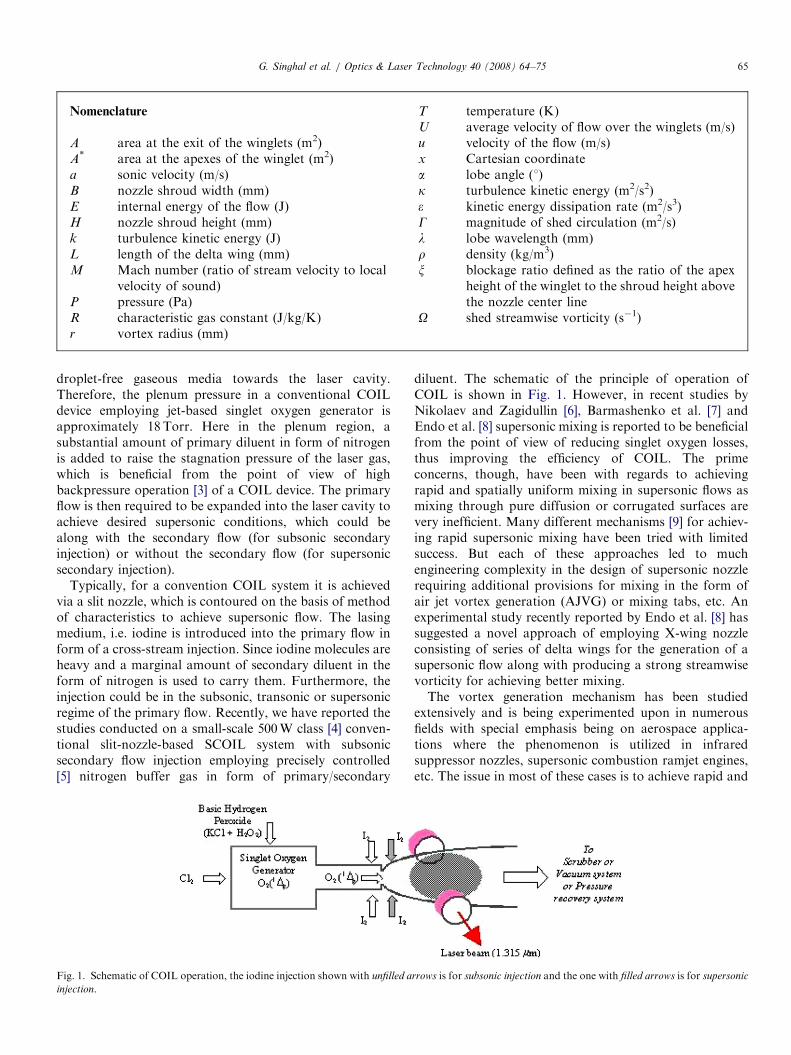
droplet-free gaseous media towards the laser cavity.Therefore, the plenum pressure in a conventional COILdevice employing jet-based singlet oxygen generator isapproximately 18Torr. Here in the plenum region, asubstantial amount of primary diluent in form of nitrogenis added to raise the stagnation pressure of the laser gas,which is beneficial from the point of view of highbackpressure operation [3] of a COIL device. The primaryflow is then required to be expanded into the laser cavity toachieve desired supersonic conditions, which could bealong with the secondary flow (for subsonic secondaryinjection) or without the secondary flow (for supersonicsecondary injection).
Typically, for a convention COIL system it is achievedvia a slit nozzle, which is contoured on the basis of methodof characteristics to achieve supersonic flow. The lasingmedium, i.e. iodine is introduced into the primary flow inform of a cross-stream injection. Since iodine molecules areheavy and a marginal amount of secondary diluent in theform of nitrogen is used to carry them. Furthermore, theinjection could be in the subsonic, transonic or supersonicregime of the primary flow. Recently, we have reported thestudies conducted on a small-scale 500W class [4] conven-tional slit-nozzle-based SCOIL system with subsonicsecondary flow injection employing precisely controlled[5] nitrogen buffer gas in form of primary/secondary
Fig. 1. Schematic of COIL operation, the iodine injection shown with unfilled a
injection.
diluent. The schematic of the principle of operation ofCOIL is shown in Fig. 1. However, in recent studies byNikolaev and Zagidullin [6], Barmashenko et al. [7] andEndo et al. [8] supersonic mixing is reported to be beneficialfrom the point of view of reducing singlet oxygen losses,thus improving the efficiency of COIL. The primeconcerns, though, have been with regards to achievingrapid and spatially uniform mixing in supersonic flows asmixing through pure diffusion or corrugated surfaces arevery inefficient. Many different mechanisms [9] for achiev-ing rapid supersonic mixing have been tried with limitedsuccess. But each of these approaches led to muchengineering complexity in the design of supersonic nozzlerequiring additional provisions for mixing in the form ofair jet vortex generation (AJVG) or mixing tabs, etc. Anexperimental study recently reported by Endo et al. [8] hassuggested a novel approach of employing X-wing nozzleconsisting of series of delta wings for the generation of asupersonic flow along with producing a strong streamwisevorticity for achieving better mixing.The vortex generation mechanism has been studied
extensively and is being experimented upon in numerousfields with special emphasis being on aerospace applica-tions where the phenomenon is utilized in infraredsuppressor nozzles, supersonic combustion ramjet engines,etc. The issue in most of these cases is to achieve rapid and
rrows is for subsonic injection and the one with filled arrows is for supersonic
ARTICLE IN PRESSG. Singhal et al. / Optics & Laser Technology 40 (2008) 64–7566
efficient momentum transfer process or mixing between co-flowing fluid media in order to improve the efficiency of thedevice. It has been well established by the various reportedworks [10–12] that one of the most powerful mechanism forenhancing mixing is the introduction of strong streamwisevortices. In this regard, lobed mixers have emerged to beone of the most suitable devices for introducing thesevortices. Also a related concept of scalloped lobed mixershas also been introduced which showed more rapiddevelopment of streamwise vorticity along with rapidsubsequent decay [13] as compared to a lobed mixer. Ascalloped mixer is essentially a lobed mixer with a portionof end walls having been removed. Although, immenseamount of research is being carried out with the develop-ment and optimization of such mixing mechanisms, butmost of the reported computational and experimentalworks are attributed to the cases of incompressible flows orfor subsonic compressible flows.
In the present study, the aim is to computationallydetermine the effect of employing a winglet mixer employ-ing delta wings in a compressible flow field of a COILdevice. The present paper also deals with study of theevolution of streamwise vorticity, ascertaining the scale ofthese vortices, the extent of circulation, an estimation ofthe magnitude of the cross-stream velocities in variouswinglet nozzle geometries designed for a 500W class COILdevice. Also, an experimental validation of the predictedconditions has been carried out and also a comparativeassessment of the mixing efficiency of the winglet nozzlewith a slit nozzle has also been made.
2. Geometry and streamwise vorticity
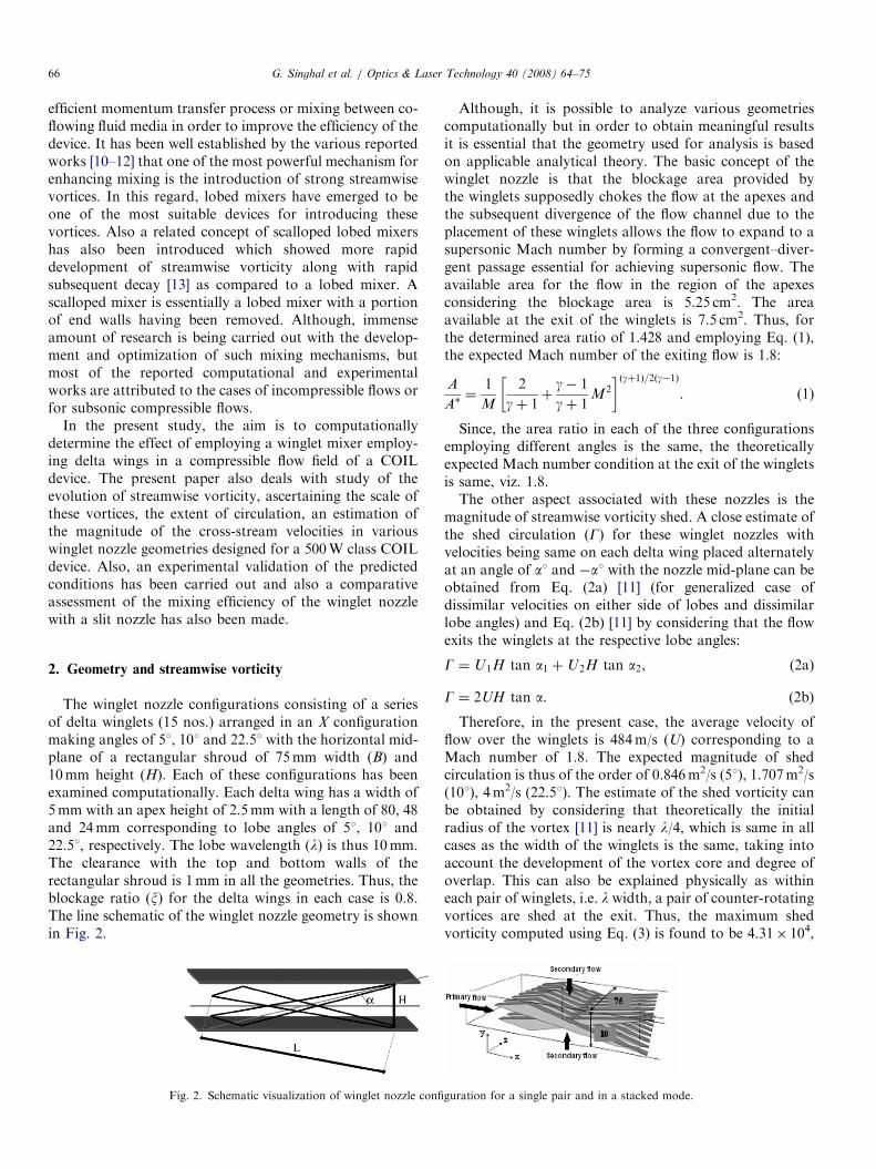
The winglet nozzle configurations consisting of a seriesof delta winglets (15 nos.) arranged in an X configurationmaking angles of 51, 101 and 22.51 with the horizontal mid-plane of a rectangular shroud of 75mm width (B) and10mm height (H). Each of these configurations has beenexamined computationally. Each delta wing has a width of5mm with an apex height of 2.5mm with a length of 80, 48and 24mm corresponding to lobe angles of 51, 101 and22.51, respectively. The lobe wavelength (l) is thus 10mm.The clearance with the top and bottom walls of therectangular shroud is 1mm in all the geometries. Thus, theblockage ratio (x) for the delta wings in each case is 0.8.The line schematic of the winglet nozzle geometry is shownin Fig. 2.
Fig. 2. Schematic visualization of winglet nozzle confi
Although, it is possible to analyze various geometriescomputationally but in order to obtain meaningful resultsit is essential that the geometry used for analysis is basedon applicable analytical theory. The basic concept of thewinglet nozzle is that the blockage area provided bythe winglets supposedly chokes the flow at the apexes andthe subsequent divergence of the flow channel due to theplacement of these winglets allows the flow to expand to asupersonic Mach number by forming a convergent–diver-gent passage essential for achieving supersonic flow. Theavailable area for the flow in the region of the apexesconsidering the blockage area is 5.25 cm2. The areaavailable at the exit of the winglets is 7.5 cm2. Thus, forthe determined area ratio of 1.428 and employing Eq. (1),the expected Mach number of the exiting flow is 1.8:
A
A�¼
1
M
2
gþ 1þ
g� 1
gþ 1M2
� �ðgþ1Þ=2ðg�1Þ. (1)
Since, the area ratio in each of the three configurationsemploying different angles is the same, the theoreticallyexpected Mach number condition at the exit of the wingletsis same, viz. 1.8.The other aspect associated with these nozzles is the
magnitude of streamwise vorticity shed. A close estimate ofthe shed circulation (G) for these winglet nozzles withvelocities being same on each delta wing placed alternatelyat an angle of a1 and �a1 with the nozzle mid-plane can beobtained from Eq. (2a) [11] (for generalized case ofdissimilar velocities on either side of lobes and dissimilarlobe angles) and Eq. (2b) [11] by considering that the flowexits the winglets at the respective lobe angles:
G ¼ U1H tan a1 þU2H tan a2, (2a)
G ¼ 2UH tan a. (2b)
Therefore, in the present case, the average velocity offlow over the winglets is 484m/s (U) corresponding to aMach number of 1.8. The expected magnitude of shedcirculation is thus of the order of 0.846m2/s (51), 1.707m2/s(101), 4m2/s (22.51). The estimate of the shed vorticity canbe obtained by considering that theoretically the initialradius of the vortex [11] is nearly l/4, which is same in allcases as the width of the winglets is the same, taking intoaccount the development of the vortex core and degree ofoverlap. This can also be explained physically as withineach pair of winglets, i.e. l width, a pair of counter-rotatingvortices are shed at the exit. Thus, the maximum shedvorticity computed using Eq. (3) is found to be 4.31� 104,
guration for a single pair and in a stacked mode.
ARTICLE IN PRESS
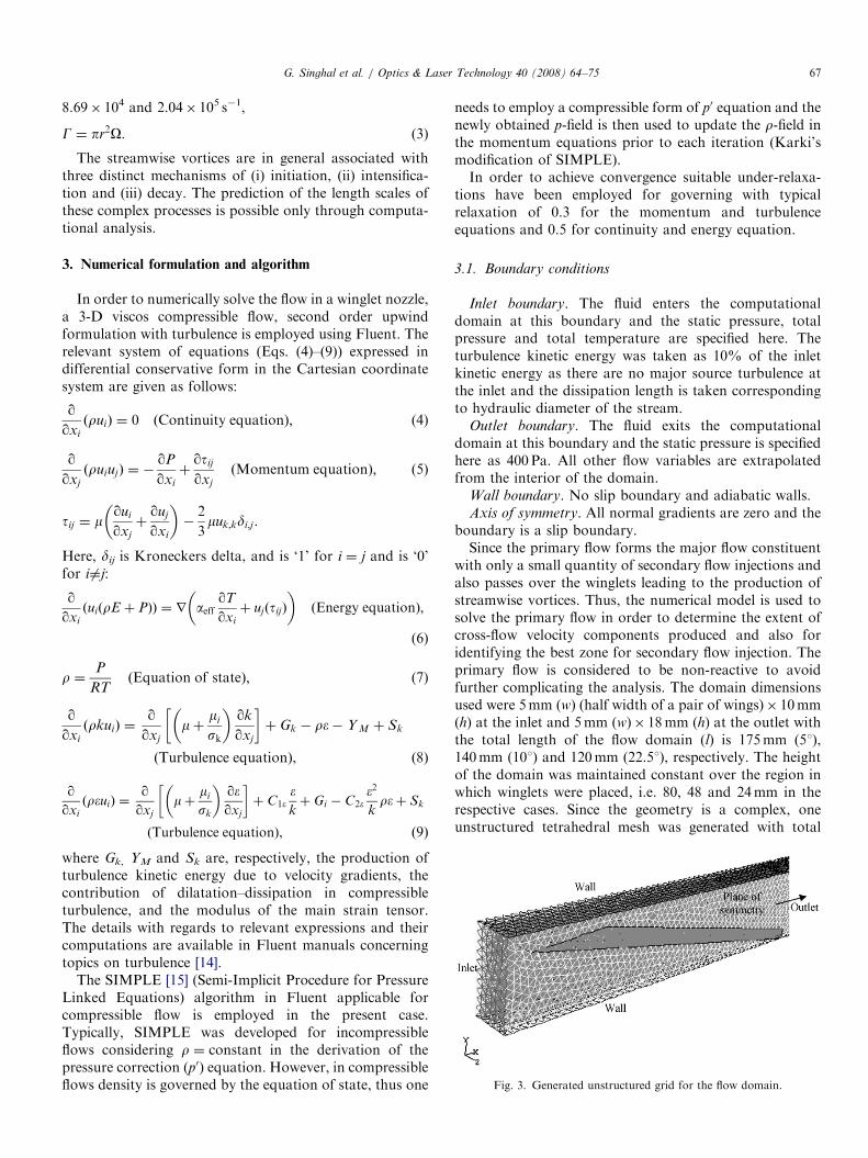
Fig. 3. Generated unstructured grid for the flow domain.
G. Singhal et al. / Optics & Laser Technology 40 (2008) 64–75 67
8.69� 104 and 2.04� 105 s�1,
G ¼ pr2O. (3)
The streamwise vortices are in general associated withthree distinct mechanisms of (i) initiation, (ii) intensifica-tion and (iii) decay. The prediction of the length scales ofthese complex processes is possible only through computa-tional analysis.
3. Numerical formulation and algorithm
In order to numerically solve the flow in a winglet nozzle,a 3-D viscos compressible flow, second order upwindformulation with turbulence is employed using Fluent. Therelevant system of equations (Eqs. (4)–(9)) expressed indifferential conservative form in the Cartesian coordinatesystem are given as follows:
qqxi
ðruiÞ ¼ 0 ðContinuity equationÞ; (4)
qqxj
ðruiujÞ ¼ �qP
qxi
þqtij
qxj
ðMomentum equationÞ; (5)
tij ¼ mqui
qxj
þquj
qxi
� ��
2
3muk;kdi;j.
Here, dij is Kroneckers delta, and is ‘1’ for i ¼ j and is ‘0’for i 6¼j:
qqxi
ðuiðrE þ PÞÞ ¼ r aeffqT
qxi
þ ujðtijÞ
� �ðEnergy equationÞ;
(6)
r ¼P
RTðEquation of stateÞ; (7)
qqxi
ðrkuiÞ ¼qqxj
mþmi
sk
� �qk
qxj
� �þ Gk � r�� Y M þ Sk
ðTurbulence equationÞ, ð8Þ
qqxi
ðr�uiÞ ¼qqxj
mþmi
sk
� �q�qxj
� �þ C1�
�
kþ Gi � C2�
�2
kr�þ Sk
ðTurbulence equationÞ, ð9Þ
where Gk, YM and Sk are, respectively, the production ofturbulence kinetic energy due to velocity gradients, thecontribution of dilatation–dissipation in compressibleturbulence, and the modulus of the main strain tensor.The details with regards to relevant expressions and theircomputations are available in Fluent manuals concerningtopics on turbulence [14].
The SIMPLE [15] (Semi-Implicit Procedure for PressureLinked Equations) algorithm in Fluent applicable forcompressible flow is employed in the present case.Typically, SIMPLE was developed for incompressibleflows considering r ¼ constant in the derivation of thepressure correction (p0) equation. However, in compressibleflows density is governed by the equation of state, thus one
needs to employ a compressible form of p0 equation and thenewly obtained p-field is then used to update the r-field inthe momentum equations prior to each iteration (Karki’smodification of SIMPLE).In order to achieve convergence suitable under-relaxa-
tions have been employed for governing with typicalrelaxation of 0.3 for the momentum and turbulenceequations and 0.5 for continuity and energy equation.
3.1. Boundary conditions
Inlet boundary. The fluid enters the computationaldomain at this boundary and the static pressure, totalpressure and total temperature are specified here. Theturbulence kinetic energy was taken as 10% of the inletkinetic energy as there are no major source turbulence atthe inlet and the dissipation length is taken correspondingto hydraulic diameter of the stream.
Outlet boundary. The fluid exits the computationaldomain at this boundary and the static pressure is specifiedhere as 400 Pa. All other flow variables are extrapolatedfrom the interior of the domain.
Wall boundary. No slip boundary and adiabatic walls.Axis of symmetry. All normal gradients are zero and the
boundary is a slip boundary.Since the primary flow forms the major flow constituent
with only a small quantity of secondary flow injections andalso passes over the winglets leading to the production ofstreamwise vortices. Thus, the numerical model is used tosolve the primary flow in order to determine the extent ofcross-flow velocity components produced and also foridentifying the best zone for secondary flow injection. Theprimary flow is considered to be non-reactive to avoidfurther complicating the analysis. The domain dimensionsused were 5mm (w) (half width of a pair of wings)� 10mm(h) at the inlet and 5mm (w)� 18mm (h) at the outlet withthe total length of the flow domain (l) is 175mm (51),140mm (101) and 120mm (22.51), respectively. The heightof the domain was maintained constant over the region inwhich winglets were placed, i.e. 80, 48 and 24mm in therespective cases. Since the geometry is a complex, oneunstructured tetrahedral mesh was generated with total
ARTICLE IN PRESSG. Singhal et al. / Optics & Laser Technology 40 (2008) 64–7568
number of elements being 60158, 55045 and 50325. Since afine grid was employed at the outset thus further gridadaptation was not required. The domain was solved usingsecond-order upwind scheme considered to be moreaccurate for compressible flows (Fig. 3).
4. Results and discussions
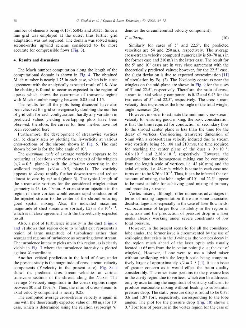
The Mach number computation along the length of thecomputational domain is shown in Fig. 4. The obtainedMach number is nearly 1.75 in each case, which is in closeagreement with the analytically expected result of 1.8. Alsothe choking is found to occur as expected in the region ofapexes which shows the occurrence of transonic regimewith Mach number ranging between 0.85 and 1.15.
The results for all the plots being discussed have alsobeen checked for grid convergence by doubling the numberof grid cells for each configuration, hardly any variation inpredicted values yielding overlapping plots have beenobserved; therefore, the curves for finer meshes have notbeen recounted here.
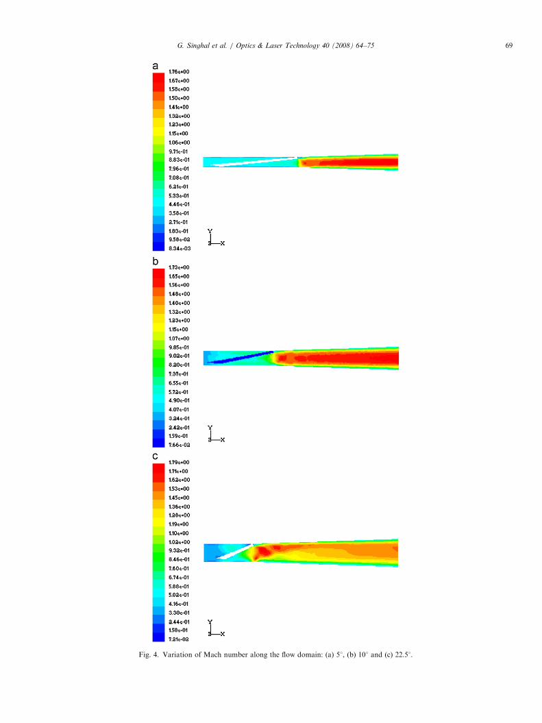
Furthermore, the development of streamwise vorticescan be clearly seen by plotting the X-vorticity at variouscross-sections of the shroud shown in Fig. 5. The caseshown below is for the lobe angle of 101.
The maximum scale of average vorticity appears to beoccurring at locations very close to the exit of the winglets(x/l ¼ 0.5, plane-2) with the initiation occurring in thescalloped region (x/l ¼ �0.5, plane-1). The vorticityappears to decay rapidly further downstream and reducealmost to zero by x/l ¼ 4 (plane 3). The typical length ofthe streamwise vortices for the considered winglet mixergeometry is 4l, i.e. 40mm. A cross-stream injection in theregion of these vortices would ensure rapid conduction ofthe injected stream to the center of the shroud ensuringgood spatial mixing. Also, the indicated maximummagnitude of shed streamwise vorticity (O) is 8� 104 s�1,which is in close agreement with the theoretically expectedresult.
Also, a plot of turbulence intensity in the duct (Figs. 6and 7) shows that region close to winglet exit represents aregion of large magnitude of turbulence rather thansegregated regions of turbulence as occurring down stream.The turbulence intensity picks up in this region, as is clearlyvisible in Fig. 7 where the turbulence intensity is plottedagainst X-coordinate.
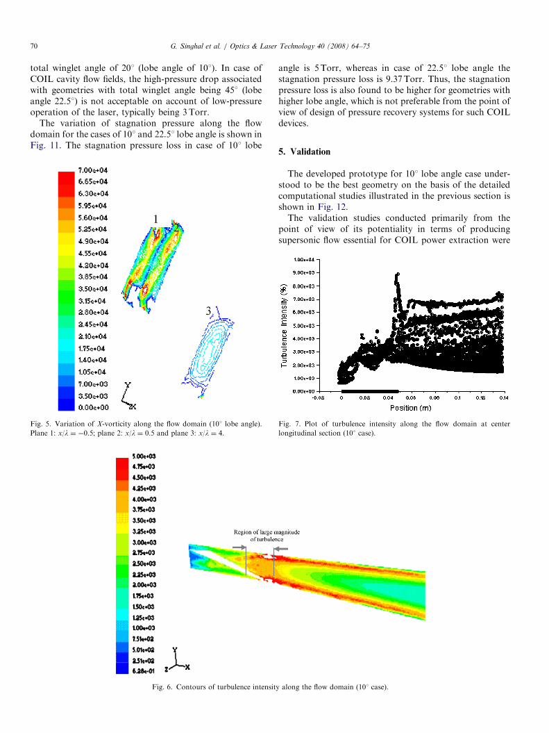
Another, critical prediction in the kind of flows underthe present study is the magnitude of cross-stream velocitycomponents (Y-velocity in the present case). Fig. 8a–cshows the predicted cross-stream velocities at varioustransverse sections of the shroud along the X-axis. Theaverage Y-velocity magnitude in the vortex regions rangesbetween 80 and 120m/s. Thus, the ratio of cross-stream toaxial velocity component is nearly 0.25.
The computed average cross-stream velocity is again inline with the theoretically expected value of 108m/s for 101case, which is determined using the relation (subscript ‘y’
denotes the circumferential velocity component),
G ¼ 2pruy. (10)
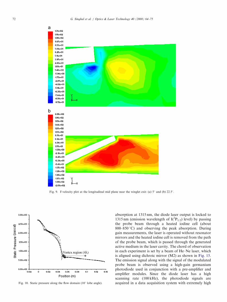
Similarly for cases of 51 and 22.51, the predictedvelocities are 54 and 250m/s, respectively. The averagecross-stream velocity computed numerically is 50–70m/s inthe former case and 210m/s in the latter case. The result forthe 51 and 101 cases are in very close agreement with thetheoretically predicted values; however, for the 22.51 case,the slight deviation is due to expected overestimation [11]of circulation by Eq. (2). The Y-velocity contours near thewinglets on the mid-plane are shown in Fig. 9 for the casesof 51 and 22.51, respectively. Therefore, the ratio of cross-stream to axial velocity component is 0.12 and 0.43 for thetwo cases of 51 and 22.51, respectively. The cross-streamvelocity thus increases as the lobe angle or the total wingletangle increases (2a).However, in order to estimate the minimum cross-stream
velocity for ensuring good mixing, the basic considerationis that the time required for conduction of secondary flowto the shroud center plane is less than the time for thedecay of vortices. Considering, transverse dimension of5mm with a cross-stream velocity induced due to streamwise vorticity being 55, 108 and 210m/s, the time requiredfor reaching the center plane of the duct is 9� 10�5,4.6� 10�5 and 2.38� 10�5, respectively. However, theavailable time for homogenous mixing can be computedfrom the length scale of vortices, i.e. 4l (40mm) and theaxial velocity, i.e. 484m/s, which is same in each case andturns out to be 8.26� 10�5. Thus, it can be inferred that onaccount of mixing, the lobe angles of 101 and 22.51 appearto be most suitable for achieving good mixing of primaryand secondary streams.Vortex mixers, although, offer numerous advantages in
terms of mixing augmentation there are some associateddisadvantages also especially in the case of laser flow fields,viz. occurrence of larger flow instability in the region ofoptic axis and the production of pressure drop in a lasermedia already working under severe constraints of lowtotal pressure.However, in the present scenario for all the considered
lobe angles, the former issue is circumvented by the use ofscalloping that exists in the X-wing as the vortices decay inthe region much ahead of the laser optic axis usuallylocated at 65mm from the injection point (i.e. at the exit ofwinglets). However, if one were to use a lobed mixerwithout scalloping with the length scale being compara-tively larger of approximately x/l ¼ 7–8 [11], it is an issueof greater concern as it would effect the beam qualityconsiderably. The other issue pertains to the pressure lossin the cavity region due to vortices, which can be addressedonly by ascertaining the magnitude of vorticity sufficient toproduce reasonable mixing without leading to substantialpressure drop. The static pressure drop is found to be 0.37,0.6 and 1.87Torr, respectively, corresponding to the lobeangles. The plot for the pressure drop (Fig. 10) shows a0.7 Torr loss of pressure in the vortex region for the case of
ARTICLE IN PRESS
Fig. 4. Variation of Mach number along the flow domain: (a) 51, (b) 101 and (c) 22.51.
G. Singhal et al. / Optics & Laser Technology 40 (2008) 64–75 69
ARTICLE IN PRESSG. Singhal et al. / Optics & Laser Technology 40 (2008) 64–7570
total winglet angle of 201 (lobe angle of 101). In case ofCOIL cavity flow fields, the high-pressure drop associatedwith geometries with total winglet angle being 451 (lobeangle 22.51) is not acceptable on account of low-pressureoperation of the laser, typically being 3Torr.
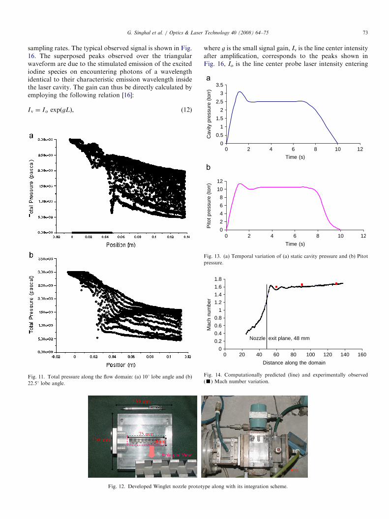
The variation of stagnation pressure along the flowdomain for the cases of 101 and 22.51 lobe angle is shown inFig. 11. The stagnation pressure loss in case of 101 lobe
Fig. 5. Variation of X-vorticity along the flow domain (101 lobe angle).
Plane 1: x/l ¼ �0.5; plane 2: x/l ¼ 0.5 and plane 3: x/l ¼ 4.
Fig. 6. Contours of turbulence intensity
angle is 5 Torr, whereas in case of 22.51 lobe angle thestagnation pressure loss is 9.37 Torr. Thus, the stagnationpressure loss is also found to be higher for geometries withhigher lobe angle, which is not preferable from the point ofview of design of pressure recovery systems for such COILdevices.
5. Validation
The developed prototype for 101 lobe angle case under-stood to be the best geometry on the basis of the detailedcomputational studies illustrated in the previous section isshown in Fig. 12.The validation studies conducted primarily from the
point of view of its potentiality in terms of producingsupersonic flow essential for COIL power extraction were
along the flow domain (101 case).
Fig. 7. Plot of turbulence intensity along the flow domain at center
longitudinal section (101 case).
ARTICLE IN PRESS
Fig. 8. Variation of cross-stream velocity, i.e. Y-velocity along the flow domain (101 lobe angle): (a) x/l ¼ �0.5, (b) x/l ¼ 0.5 and (c) x/l ¼ 4.
G. Singhal et al. / Optics & Laser Technology 40 (2008) 64–75 71
carried out. The experimentally observed values of cavityand Pitot pressure during winglet nozzle testing for theobtained Mach number conditions inside the laser cavityare shown in Fig. 13a and b.
Thus, the observed cavity static pressure (Pcavity) of2.5 Torr and a Pitot pressure (PPitot) of 14.5 Torr corre-spond to a Mach number (M) of 1.72 which is calculatedby employing the simplified Rankine–Hugoniot relationexpressed in Eq. (11), true for a specific heat ratio of 1.4:
PPitot
Pcavity¼
166:9M7
ð7M2 � 1Þ2:5. (11)
The observed Mach number for various dilution ratios(typical 1:3 and 1:5) varies from 1.72 to 1.75. The graphsdepicted above are for a typical dilution of 1:3 used inconventional systems. The Mach number predicted nu-merically along the line formed by the intersection of themid-planes along and across the flow channel is shown inFig. 14 along with the corresponding experimental values
of the same obtained from corresponding static and Pitotpressure measurements at 10, 40 and 60mm (near optic axis
location) from the nozzle exit.Furthermore, the mixing efficiency of the nozzle is
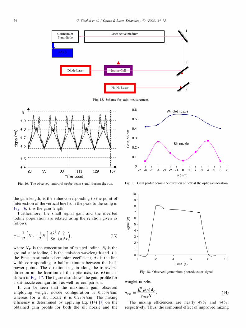
characterized by measuring the small signal gain of themedium along various transverse chords (Y-direction) at agiven location downstream of the winglet exit (X-direc-tion). The small signal gain is proportional to thepopulation inversion existing in the medium, i.e. theconcentration of the excited species [I(2P1/2)] and is thusthe true representation of the extractable laser power in thesystem. Probe beam measurement technique has been usedfor estimation of the small signal gain. The technique isbased on Lambert–Beer’s law in which the change in beamintensity is governed is proportional to the number densityof the excited atoms or the population inversion. Theschematic for the same is shown in Fig. 15.The approach consists of employing a tunable diode
laser having a peak wavelength around 1310 nm with abandwidth of 20 nm. Since the iodine atoms also have peak
ARTICLE IN PRESS
Fig. 9. Y-velocity plot at the longitudinal mid plane near the winglet exit: (a) 51 and (b) 22.51.
Fig. 10. Static pressure along the flow domain (101 lobe angle).
G. Singhal et al. / Optics & Laser Technology 40 (2008) 64–7572
absorption at 1315 nm, the diode laser output is locked to1315 nm (emission wavelength of I(2P1/2) level) by passingthe probe beam through a heated iodine cell (about800–850 1C) and observing the peak absorption. Duringgain measurements, the laser is operated without resonatormirrors and the heated iodine cell is removed from the pathof the probe beam, which is passed through the generatedactive medium in the laser cavity. The chord of observationin each experiment is set by a beam of He–Ne laser, whichis aligned using dichroic mirror (M2) as shown in Fig. 15.The emission signal along with the signal of the modulatedprobe beam is observed using a high-gain germaniumphotodiode used in conjunction with a pre-amplifier andamplifier modules. Since the diode laser has a highscanning rate (100 kHz), the photodiode signals areacquired in a data acquisition system with extremely high
ARTICLE IN PRESS
2
2.5
3
3.5
ssure
(to
rr)
G. Singhal et al. / Optics & Laser Technology 40 (2008) 64–75 73
sampling rates. The typical observed signal is shown in Fig.16. The superposed peaks observed over the triangularwaveform are due to the stimulated emission of the excitediodine species on encountering photons of a wavelengthidentical to their characteristic emission wavelength insidethe laser cavity. The gain can thus be directly calculated byemploying the following relation [16]:
Iv ¼ Io expðgLÞ, (12)
Fig. 11. Total pressure along the flow domain: (a) 101 lobe angle and (b)
22.51 lobe angle.
Fig. 12. Developed Winglet nozzle protot
where g is the small signal gain, Iv is the line center intensityafter amplification, corresponds to the peaks shown inFig. 16, Io is the line center probe laser intensity entering
ype along with its integration scheme.
0
0.5
1
1.5
Cavity p
re
0
2
4
6
8
10
12
Pitot
pre
ssure
(to
rr)
0 8 10 12
Time (s)
2 4 6
0 8 10 12
Time (s)
2 4 6
Fig. 13. (a) Temporal variation of (a) static cavity pressure and (b) Pitot
pressure.
0
0.2
0.4
0.6
0.8
1
1.2
1.4
1.6
1.8
0 20 40 60 80 100 120 140 160
Distance along the domain
Mach n
um
ber
Nozzle exit plane, 48 mm
Fig. 14. Computationally predicted (line) and experimentally observed
(’) Mach number variation.
ARTICLE IN PRESS
Laser active medium
Diode Laser Iodine Cell
He-Ne Laser
Germanium
Photodiode
1
2
3
DACS
Fig. 15. Scheme for gain measurement.
Fig. 16. The observed temporal probe beam signal during the run.
0
0.1
0.2
0.3
0.4
0.5
0.6
-7 -6 -5 -4 -3 -2 -1 0 1 2 3 4 5 6 7
y (mm)
Gain
, %
/cm
Slit nozzle
Winglet nozzle
Fig. 17. Gain profile across the direction of flow at the optic axis location.
0
1
2
3
4
5
6
7
8
9
10
0 4 8 10
Time (s)
Sig
nal (V
)
2 6
Fig. 18. Observed germanium photodetector signal.
G. Singhal et al. / Optics & Laser Technology 40 (2008) 64–7574
the gain length, is the value corresponding to the point ofintersection of the vertical line from the peak to the ramp inFig. 16, L is the gain length.
Furthermore, the small signal gain and the invertediodine population are related using the relation given asfollows:
g ¼7
12NI� �
1
2NI
� �Al2
8p2
pDn
� �, (13)
where NI� is the concentration of excited iodine, NI is theground state iodine, l is the emission wavelength and A isthe Einstein stimulated emission coefficient, Dn is the linewidth corresponding to half-maximum between the half-power points. The variation in gain along the transversedirection at the location of the optic axis, i.e. 65mm isshown in Fig. 17. The figure also shows the gain profile fora slit-nozzle configuration as well for comparison.
It can be seen that the maximum gain observedemploying winglet nozzle configuration is 0.55%/cm,whereas for a slit nozzle it is 0.27%/cm. The mixingefficiency is determined by applying Eq. (14) [7] on theobtained gain profile for both the slit nozzle and the
winglet nozzle:
Zmix ¼
RH
0 gðxÞdy
gmaxH. (14)
The mixing efficiencies are nearly 49% and 74%,respectively. Thus, the combined effect of improved mixing
ARTICLE IN PRESSG. Singhal et al. / Optics & Laser Technology 40 (2008) 64–75 75
efficiency and the corresponding reduction in dissociationlosses account for the substantial gain increase observed incase of winglet nozzle. As emphasized earlier, the observedgain is a direct representation of the expected power fromthe COIL device and the temporal variation of the powerpulse observed employing the germanium photodetectorplaced at the rear mirror side is shown in Fig. 18.
6. Conclusion
A computational analysis of winglet nozzle serving as ascalloped lobed mixer has been carried out for threedifferent lobe angles of 51, 101 and 22.51 in a compressibleflow field of a COIL device. The length scale of predictedstreamwise vorticity is 40mm corresponding to x/l ¼ 4 inall the three cases. The computation shows that themaximum Y-velocity component increases with increasein the lobe angle. The optimum ratio of cross to axialvelocity components for achieving good mixing withminimum pressure drop is 0.25 and corresponds to thelobe angle of 101. Also, the optimum region for secondaryflow injection appears to be the exit of the winglets due tooccurrence of fully developed streamwise vorticity asregions ahead of the exit appear to show the vorticeswhich are still evolving and regions few lobe lengthsdownstream of the exit show onset of decay of vortices.The geometry with 101 is the most reasonable from thepoint of view of its applicability to COIL flow fields. Thevalidation studies carried out employing this optimumgeometry show close agreement with computational resultsin terms of the observed Mach number and its variation.Also, the maximum observed gain is 0.55%/cm signifi-
cantly higher than for the slit-nozzle configuration.Furthermore, the computed mixing efficiency is nearly50% higher at 75% for the new nozzle configuration ascompared to 49% for slit-nozzle case.
References
[1] Tyagi RK, Rajesh R, Singhal G, Mainuddin, Dawar AL, Endo M.
SPIE 2003;4971–02.
[2] Rajesh R, Hussain M, Zaidi ZH, Tyagi RK, Singhal G, Mainuddin,
et al. Int J Infrared Millimeter Waves 2004;25(9):1361.
[3] Singhal G, Rajesh R, Mainuddin, Dawar AL, Subbarao PMV, Endo
M. Exp Therm Fluid Sci 2006;30:145.
[4] Tyagi RK, Rajesh R, Singhal G, Mainuddin, Dawar AL, Endo M.
Infrared Phys Technol 2003;44:271.
[5] Mainuddin, Beg MT, Moinuddin, Tyagi RK, Rajesh R, Singhal G, et
al. Int J Infrared Millimeter Waves 2005;1:91.
[6] Nikolaev VD, Zagidullin MV. AIAA Paper 2000;2427.
[7] Barmashenko BD, Bruins E, Furman D, Rybalkin V, Rosenwaks S.
SPIE 2002;4631:74.
[8] Endo M, Osaka T, Takeda S. Appl Phys Lett 2004;84(16):2983–5.
[9] Yang TT, Dickerson RA, Moon LF, Hsia YC. In: AIAA 30th plasma
dynamics and lasers conference; 2000. p. 2425.
[10] Greitzer EM, Tan CS, Graf MB. Internal flow concepts and
applications. Cambridge: Cambridge University Press; 2004 [chapter
9].
[11] Waitz IA, Qui YJ, Manning TA, Fung AKS, Illiot JK, Kerwin JM, et
al. Prog Aerospace Sci 1997;33:323.
[12] Majamaki AH, Smith OI, Karagozian AR. AIAA J 2003;41(4):623.
[13] Hu H, Kobayashi T, Saga T, Taniguchi N, Liu H, Wu S. Transcripts
Jpn Soc Aerospace Sci 1999;41(34):187.
[14] FLUENT Users’ manuals, version 5.1. Fluent India; 2003.
[15] Patankar SV. Numerical heat transfer and fluid flow. New York:
Hemisphere; 1980 [chapter 6].
[16] Kodymova J, Spalek O. SPIE 2002;4631:86.
Top Related
Copyright © 2022 FDOKUMEN

