


Bahasa
Halaman
Hukum


BoWI Project Body World Interac/on
10/2012-‐ 2016
Lab-‐STICC: J-‐Ph.Diguet (CNRS), C.Roland, F.Poirier, C.Person, C.Langlais (TB) IRISA: O.SenAeys (INRIA), P.Scalart, O.Berder, A.Carer, A. Courtay (ENSSAT/UR1)
IETR: R.Sauleau (UR1) Designer: C. Gault (UBS) Engineer: M. Le GenAl (ENSSAT/UR1)
PhD students: A. Alery (UBS/UR1), R. Massod (TB/UR1), Z.Zheng (UR1/UBS), V-‐H.Nguyen (UR1,TB)
Journées Ouest IRT / Labex CominLabs
Rennes, Dec. 2013

2
Outline
1. Project overview 2. Recent progresses
§ Usage § Radio § Algorithms § Architecture § Network
3. PerspecAves

3
• Digital Environment for the CiMzen + Energy Efficiency in ICT • New Wireless Body Area Network for Gesture / Posture recogniAon - In-‐ or out-‐door, everyday environment without addiMonal equipment - UlAmate low power: no baZery but energy harvesAng
1- Overview: Labex Challenges
€
xyz
"
#
$ $ $
%
&
' ' '
€
xyz
"
#
$ $ $
%
&
' ' '
Centralized Device (e.g. Smartphone)
Body Coordinates System WLAN Connexion
Inter-nodes communications
Node Geo-localisation
CompuAng Control
RF Front End
InerAal MEMS
Energy HarvesAng 200µW

4
Cross-‐layer approach taking advantage of diversity and redundancy. 1. Accurate short-‐range geolocalizaMon based on distributed mulAple
sensor fusion: IMU + Radio. 2. Self-‐powered and self-‐adapMve compuMng plaXorm 3. Channel propagaMon modeling and adapMve antennas 4. Dynamic protocols, cooperaMve communicaMons and coding 5. New body-‐world interfaces exploiMng the BoWI concept for digital
ciAzens.
1- Overview: Technical Challenges

5
• VICON • Camera set + Reflectors • Accurate • Equipped environment
• Xsense MOVEN
• 9 DoF IMU (MTX) + Standard Embedded processor • Xbus / PC: BT connecAon • 17 MTX @350mW • 3 orders of magnitude over Energy HarvesMng
1- Overview: Current GAP
BT Radio Link

6
1- Overview: Project organization
Usage (Designer 12months, 2013)
Inertial Sensors
Dynamic Cooperative Communication Protocol
Wake-Up Radio
Archi. HW/SW Self-adaptivity for Power
Optimisation
Channel Models + Antennas Radio
Available Soon BoWI Research Scope Post BoWI timeline
mm-Waves Front End
BAN (eg Zigbee or upcoming UWB
802.15.4a)
PhD2 PhD3
PhD1
Geolocalisation based on multi-sensors and Distributed Algorithms
New UWB ?
HW/SW/COM Node Architecture Network Protocol-Coding
Pro
toty
pe
(Eng
inee
r, 20
13)
PhD4
Sho
rt-R
ange
Geo
loca
tion
+ M
ulti-
Sen
sor
7
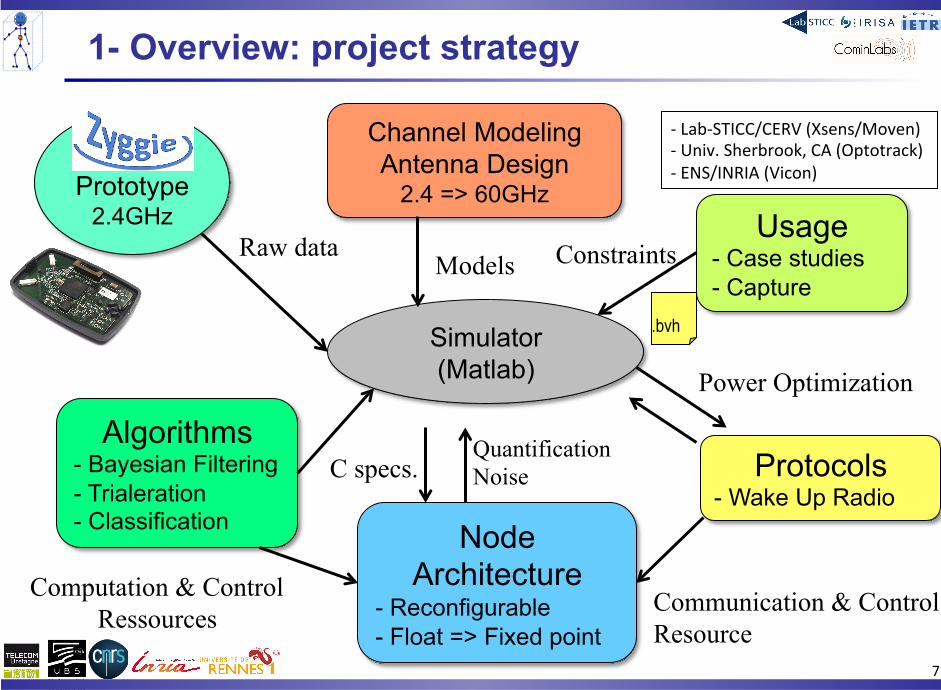
1- Overview: project strategy
Zyggie Prototype
2.4GHz
Simulator (Matlab)
Algorithms - Bayesian Filtering - Trialeration - Classification
Usage - Case studies - Capture
Node Architecture
- Reconfigurable - Float => Fixed point
Channel Modeling Antenna Design
2.4 => 60GHz
Protocols - Wake Up Radio
Raw data Models
Quantification Noise
Computation & Control Ressources
Constraints
Power Optimization
Communication & Control Resource
C specs.
.bvh
-‐ Lab-‐STICC/CERV (Xsens/Moven) -‐ Univ. Sherbrook, CA (Optotrack) -‐ ENS/INRIA (Vicon)

8
2- Recent progress

9
2.1- Usage

10
2.1- Usage: Combinatorial alphabet
• Original Idea: Propose the first standard combinatorial alphabet of gestures
-‐ Head, Arm, Back, Legs > 2000 postures -‐ Testbench for BoWI -‐ No specific meaning but thousands of combinaAons for various applicaAons cases
e.g. Lel and Right Arms: 16 possibiliAes

11
2.1- Usage / 1st Test Scenario: Imitation Game
• Technological demonstrator • “Simon”-‐inspired Simple and
Playful Game • Popularize the alphabet

12
2.1- Usage / 1nd prospective scenario
• FuncMonal rehabilitaMon • Remote monitoring

13
2.1- Usage / 2nd prospective scenario
• Social Network • Gestures = CommunicaMon • Share Timed and localized
emoMons
2- Usage: 3nd prospective scenario
• Func%onal)rehabilita%on)• Remote)monitoring)"
Pleasant
Attraction Reject
Unpleasant
Posture Axis
Facial Axis
: Neutral : Primary : Secondary
Based on Schlosberg’s Emotion
Organization

14
2.2- Radio

15
2.2- Radio Channel
1. 2.4GHz Zyggie Antenna AdaptaMon, ISM band, Johanson Chip 2. On-‐body channel measurements:
§ Instability § Ongoing: Phantom Based measures + StaAsAcal Model (Wiserban project) § Diversity can offer advantages
M2 M1
Rx R2 R1
T1 T2 Tx
13 cm ~λ[email protected]
M1 M2

16
2.2- Radio Channel
3. Inter-‐BAN Channel Modeling -‐ LOS: Diversity interesAng -‐ NLOS: Poor, but acceptable channels
4. Short-‐term plan
§ POSER studio + CST integraAon: Radio channels for BoWI posture combinatorial alphabet
§ Scenario-‐based antenna design opAmized for BoWI postures (Ground plane, Size, RadiaAon paZern, PolarizaAon)
5. Long-‐term plan § Study of mm-‐waves channels (e.g. 60GHz)

17
2.3- Algorithms

18
2.3- Global Scheme
• Data Fusion and Redundancy
• AdaptaAon: § F1, F2: Algorithms, Type of used inputs, Input data rate, #iteraAons … § Choice / Use of Hardware resources done accordingly § Depending on: Accuracy constraints, Energy availability, MoAon, Node …
ni Central Manager
(smartphone) IMU IMU
IMU Position: Pi
(t)[]=F1( Mi[],{Dij[],Pj≠i[]}, Pi(t-1)[] )
Posture ID: Gi[]=F2( {Dij[],Pj[],Gj[]} )
Mi[]
Dij[], Pj[], Gj[]
E
E
E
Dij[], Pj[]
BoWI node

19
2.3- Architecture Schematic
Calibration Filter IMU fusion
LMS tracking
Iterative Position
Estimation
RX RF-FE
Canal estimation
Classification 1 (e.g. PCA)
Distance estimation
TX RF-FE MAC/Compression
MAC/Uncompress Equalization
Energy management
User configuration
Algo control
Radio control
Speed Position (x,y,z) Orientation
Position
Partial Gesture
Classification 2 FinalPGosture Decision
BoW
I Nod
e S
mar
tpho
ne
BAN Interface • Minimize CommunicaMons • Self-‐adaptaMon • Dedicated Node architecture

20
Sensors
Kalman
Acc Gyr Mag
Orientation
LMS
Speed Position (x,y,z)
IPE Position
Classif1
Posture projection
Node Algo
BVH Position
Comparison Position
Posture Posture
Comparison
Classif 2 Posture Decision
Posture
Smartphone
Position IMU synthesis
Calibration Filter
Noise model
Motion capture
Distance
Distance
Radio Model
2.3- Simulator

21
2-3 Iterative Position Estimation
• IPE EsAmaAon based on distances: § Compute [xi,yi,zi] from all Nj≠i[xj,yj,zj, Rj] § Minimize cumulated distance funcAon:
§ OpAmizaAon based on space dichotomy • 8 direcAon exploraAon • Dynamic step (/ 2k) • Some distances can be fixed
€
f (x,y,z) = (x − 1x )! + (y − 1y )! + (z − 1z )! − 1r ! λ1
+ (x − 2x )! + (y − 2y )! + (z − 2z )! − 2r ! λ2
+ (x − 3x )! + (y − 3y )! + (z − 3z )! − 3r ! λ3+

22
2.3 IPE Simulation • Average distance errors vs. σ_Distance and σ_Mems noise
10 nodes:
27 nodes:
Accuracy stop criterion : 10-‐2m 10-‐3m

23
2-3 Prediction § Quaternion (orientaAon), angular & linear acceleraAons based on Kalman-‐like filters
(EKF, UKF, Gradient, …) § Also used to improve iniMal posiMon with predicAon
Position image k+1 Position image k
Prediction (IMU)

24
2-3 Posture identification § Example of Principal Component Analysis-‐based idenAficaAon
• Case of 86 Postures from a conAnuous Capueira movement • Highly correlated Postures: only 3 eigen vectors enough (correlaAon > 90%)

25
2-3 PCA-based identification § Example of PCA-‐based idenAficaAon
• Case of 86 Postures from a conAnuous Capueira movement • Highly correlated Postures: only 3 eigen vectors enough (correlaAon > 90%)

26
2-3 PCA-based identification § Example of PCA-‐based idenAficaAon
• Case of 86 Postures from a conAnuous Capueira movement • Highly correlated Postures: only 3 eigen vectors enough (correlaAon > 90%)

27
2-3 PCA-based identification § Example of PCA-‐based idenAficaAon
• Case of 86 Postures from a conAnuous Capueira movement • Highly correlated Postures: only 3 eigen vectors enough (correlaAon > 90%)

28
2-3 PCA-based identification § Example of PCA-‐based idenAficaAon
• Case of 86 Postures from a conAnuous Capueira movement • Highly correlated Postures: only 3 eigen vectors enough (correlaAon > 90%)

29
• Experiment on RSSI measurements with Zyggie § 9 postures § 1min recording § Fixed posiAons § 3 environment (office, hall, park)
2-3 Towards Posture Signature
Right arm up Right arm middle
Right arm down
Left arm up 1 2 3 Left arm middle 4 5 6 Left arm down 7 8 9

30
• Experiment on RSSI measurements with Zyggie § Outdoor case
2-3 Towards Posture Signature
Transmitter number
Rece
iver n
umbe
r
Posture 1
2 4 6 8
1
2
3
4
5
6
7
8
9-100
-80
-60
-40
-20
0
Transmitter number
Rece
iver n
umbe
r
Posture 2
2 4 6 8
1
2
3
4
5
6
7
8
9-100
-80
-60
-40
-20
0
Transmitter number
Rece
iver n
umbe
r
Posture 3
2 4 6 8
1
2
3
4
5
6
7
8
9-100
-80
-60
-40
-20
0
Transmitter number
Rece
iver n
umbe
r
Posture 4
2 4 6 8
1
2
3
4
5
6
7
8
9-100
-80
-60
-40
-20
0
Transmitter number
Rece
iver n
umbe
r
Posture 5
2 4 6 8
1
2
3
4
5
6
7
8
9-100
-80
-60
-40
-20
0
Transmitter number
Rece
iver n
umbe
r
Posture 6
2 4 6 8
1
2
3
4
5
6
7
8
9-100
-80
-60
-40
-20
0
Transmitter number
Rece
iver n
umbe
r
Posture 7
2 4 6 8
1
2
3
4
5
6
7
8
9-100
-80
-60
-40
-20
0
Transmitter number
Rece
iver n
umbe
r
Posture 8
2 4 6 8
1
2
3
4
5
6
7
8
9-100
-80
-60
-40
-20
0
Transmitter number
Rece
iver n
umbe
r
Posture 9
2 4 6 8
1
2
3
4
5
6
7
8
9-100
-80
-60
-40
-20
0

31
• Promising results: Redundancy to compensate radio inaccuracy • Improve signature informaAon content with other parameters:
§ High Order staAsAcs § Gravity/Quaternion vectors § PredicAon (inter-‐posture correlaAon)
• Ongoing work on different learning & classificaAon methods: § Outlier eliminaAon § Principal Component Analysis, Support Vector Machine, Neuron Networks
• Distributed algorithms § Parallel implementaAon on nodes § Node / Smartphone parAAoning for communicaAon minimizaAon
2-3 Towards Posture Signature

32
2.4- Architecture

33
• AdapAve Hardware § Reconfigurable hardware specialized to Control/Compute/Store
§ Efficient dynamic reconfiguraAon § Fine-‐Grain Power Management
• Power gaAng • Body Bias
2-4 Towards Run-‐Time Fully AdapMve mulM core Architecture
Close to energy efficiency of fully specialized hardware but with much higher flexibility and hardware reuse.
Control
data-path
reg./mem.
Control
data-path
reg./mem.
Control
data-path
reg./mem.
Global Controller
Control
data-path
reg./mem.

34
2-4 Hardware / Algorithm adaptation
• ComputaAon requirements / algorithm parameters § Algorithm choices => huge impact on computaAons (so power) § Node Level adaptaAon is mandatory
!""#$%"&'
()*+,-'
(.#/0'
123'4$,+5"0'
123'67+%0,'
841'

35
2-4 Hardware design projection
• Very first “ulMmate bounds” esAmaAons § 28nm FDSOI, 1nJ/bit, 7.5pJ/MAC32, no PCA, 48b messages
• Case 1 (worst): 17 nodes, EKF: 50Hz, IPE: 50Hz, M=1, Precision 1cm • Case 2 : 17 nodes, EKF: 50Hz, IPE: 25Hz, M=2, Precision 1cm • Case 3 : 17 nodes, EKF: 50Hz, IPE: 10Hz, M=3, Precision 1cm
• Notes: § Big impact of communicaAon policy § MEMS not included: add 50μW without Gyrometer.
Ultimate Power Bounds Case 1 Case 2 Case 3 ComputaMon + Memory: 5.9 μW 5.2 μW 4.9 μW Radio: 22 μW 7.7 μW 2.7 μW

36
2.5- Network

37
2-5 MAC layer optimization
• IniAal MAC protocol: IEEE802.15.4 (low power Zigbee) § Frame divided in Ameslots § Each node listens in each Ame slot to get other node RSSI and send
data to the manager § Balise: Synchro by the manager § SuperTrame: 123ms @ 8Hz

38
2-5 MAC layer optimization on Zyggie
• Improve MAC protocol: IEEE802.15.4 (low power Zigbee) § SeparaAon of short RSSI and larger Data Frames

39
2-5 MAC layer optimization on Zyggie
• Improve MAC protocol: IEEE802.15.4 (low power Zigbee) § SeparaAon of short RSSI and larger Data Frames

40
3- Conclusion & Perspectives

41
• Challenging project: § RSSI Inaccuracy § Ultra Low power architecture : < 200µW from (Energy HarvesAng) § Distributed system with limited communicaAons (Power impact)
• OpportuniMes § AdaptaAon (moAon, correlaAon vs communicaAon cost, etc..) § Redundancy § OperaAonal Zyggie prototype for research (algorithms,
communicaAon, radio) § MulAdisciplinary team
3- Conclusion

42
• Short term § Node Architecture Design § ClassificaAon method and Node/Smartphone parAAoning § Channel modeling based on postures § MIMO (diversity, precoding, distributed)
• Long term § ASIC design § mm-‐waves front end
3- Perspectives

43
3- Perspectives
- Postures/Applications - Compilation Synthesis - Configuration Repositories
Monitoring information
- Decision Application - Management
Top Related
Copyright © 2022 FDOKUMEN

