


Bahasa
Halaman
Hukum

International Journal of Advanced Science and Technology
Vol.59, (2013), pp.97-112
http://dx.doi.org/10.14257/ijast.2013.59.08
ISSN: 2005-4238 IJAST
Copyright ⓒ 2013 SERSC
Behavioral Modeling and Simulation with Experimental Analysis of a Two Stroke Engine Using Nanosized Copper Coated Catalytic
Converter
Mukesh Thakur1 and N. K. Saikhedkar2
1Reader, Department of Mechanical Engineering, Rungta College of Engineering & Technology,
Raipur (C.G.), India 2Director and Professor, Department of Mechanical Engineering,
Raipur Institute of Technology, Raipur (C.G.), India
[email protected], [email protected]
Abstract The Automobile pollution is the major source of pollution. The majority of the
environmental pollution is from the two-wheeler automobiles due to their large number. A study on nano-particle reveals that the ratio of surface area of nano-particle to the volume of the nano-particle is inversely proportional to the radius of the nano-particle. So, on decreasing the radius, this ratio is increased leading to an increased rate of reaction and the concentration of the pollutants is decreased. To achieve this objective, an innovative design of catalytic converter for two-wheeler automobiles is proposed using nano-particle as a catalyst. This research paper basically deals with the behavioral modeling and simulation of two stroke engine with developed catalytic convertor. The basic idea of behavioral modeling starts from analyzing the practical behavior of two stroke engine with designed catalytic convertor, and then approximating obtained behavior in terms of mathematical equations. These obtained equations actually represent behavior of concern system. Once mathematical equations are obtained, next stage is to implementation of these equations in Simulink platform. The last process is the validation check by the simulation of developed model.
Keywords: Automobiles; catalytic converter; modeling; nano-particle; simulation 1. Introduction
Nanotechnology is one of the most emerging fields of science today due to its manifold applications and utility. Nano-particles are used for a variety of purposes from medical to scientific. Actually, when the size of a particle is reduced to the extent of about 10-9 m, it is called nano-particle. The small size of the particle makes it highly reactive Therefore; the nano-particles are also used to treat a variety of ailments and diseases like cancer. The major contributor of environmental pollution is the exhaust emissions from the tail pipe of automobiles. A complete re-design may not be as lucrative as the modification of the exhaust tailpipe arrangement. The exhaust emissions can be treated by nano-particles before ejecting them to atmosphere [1]. The exhaust emissions mainly contain carbon di-oxide which causes global warming and CO which is very harmful to human health and welfare [2]. Unburnt hydrocarbons are present in exhaust emission due to incomplete combustion. The level of unburned hydrocarbons is
International Journal of Advanced Science and Technology
Vol.59, (2013)
98 Copyright ⓒ 2013 SERSC
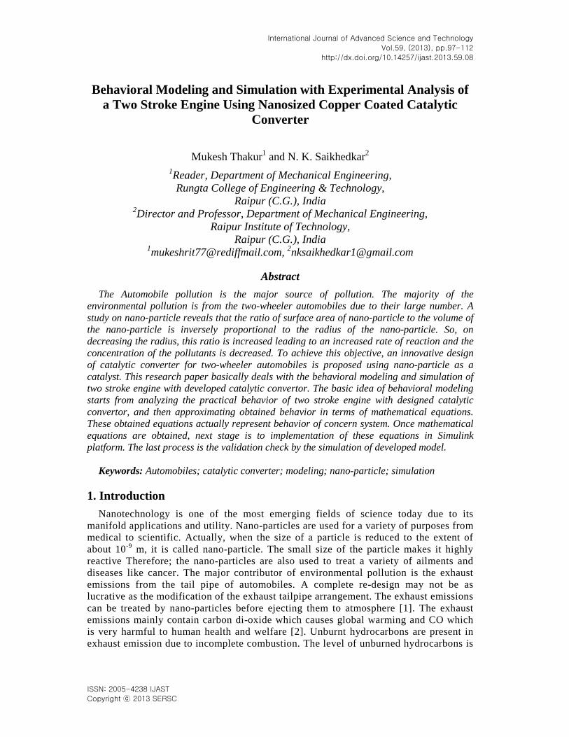
specified as parts per million (ppm) carbon atoms. The total hydrocarbon emissions are used as a measure of the combustion efficiency. Treatment of the exhaust gas means that some cleaning action must occur after the exhaust emissions leave the engine cylinder and exit from the tail pipe which enters in to atmosphere [3]. A comprehensive review on the application of nano-technology in automotive pollution control was covered. First, the essential aspects of environmental problems due to automotive industry were discussed and then the application of nanotechnology towards the prevention and control of these problems were suggested in detail [4]. The utility of the nano-particles towards automobile pollution control was explained in detail. The nano-particle coating on the catalytic converter of automobiles can be very helpful in the reduction of pollutant concentration and thus reduce the pollution level in atmosphere [5]. Amongst main metals like Au, Ag, Pd, Pt, towards which nanotechnology research is directed, copper and copper based compounds are the most important. The metallic Copper plays a significant role in modern electronics circuits due to its excellent electrical conductivity and low cost nanoparticles [6]. Copper based nano-particles are gaining wide popularity due to high reactivity and good conductivity [7]. The post pollution control method in two-wheeler automobiles using nano-particle as a catalyst was proposed. A study on nano-particle reveals that the ratio of surface area of nano-particle to the volume of the nano-particle is inversely proportional to the radius of the nano-particle. So, on decreasing the radius, this ratio is increased leading to an increased rate of reaction and the concentration of the pollutants is decreased [8]. It involves the use of copper nano-particle which is cheaper than the platinum, palladium and rhodium nano-particles used in automobiles [9]. A microprocessor based analyzer was used for measurement of CO and HC emissions [10]. To control the exhaust emissions from two stroke single cylinder spark ignition petrol engine having copper nano-particles coated on copper sieve as catalytic converter was used. AVL-422 Gas analyzer was used for the measurement and comparison for CO and unburned hydrocarbon in the exhaust of the engine at various speeds and loads [11]. The conversion efficiency of a catalytic converter mounted on a vehicle with spark ignition engine was evaluated under steady operating conditions [12]. Three way converters have been compared to understand the influence of the substrate on the exhaust gas conversions for different operating conditions of vehicle [13]. Various tests conducted on four stroke engine reveal that the copper coated engine showed a better performance than a normal engine [14]. On using copper powder, the catalytic efficiency was found to increase as the size of the powder decreased [15]. A nano catalytic converter was designed and manufactured to reduce the pollution in the environment [16]. Nano-coatings can be used to reduce surface roughness of engine components and to act as protective coating against wear of components. Experiments were conducted to improve the engine performance and reduce the emissions of HC and CO from vehicle. Some alterations and modifications have been designed so as to increase the retention period of exhaust gases to provide more time for its oxidation and thereby to reduce harmful emissions [17]. The Experimental Setup is as shown in Figure 1:
International Journal of Advanced Science and Technology
Vol.59, (2013)
Copyright ⓒ 2013 SERSC 99
Figure 1. Experimental Setup
This research paper basically deals with the behavioral modeling and simulation of two stroke engine with developed catalytic convertor.
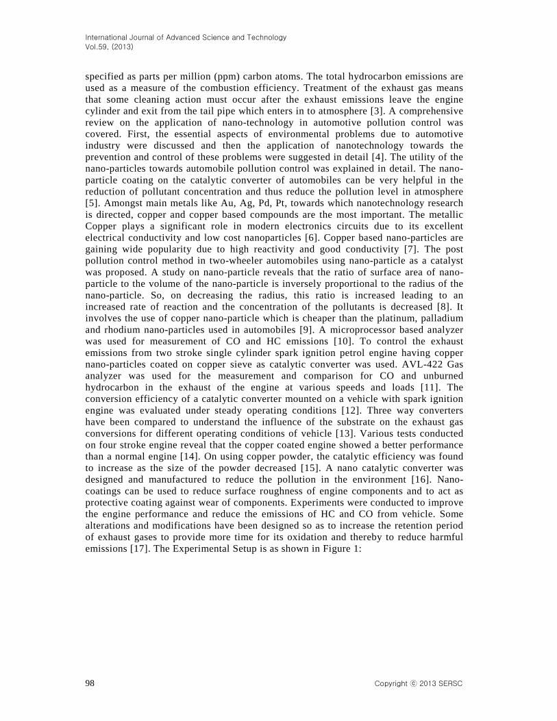
Figure 2 Different Three Dimensional Views of a Catalytic Converter
International Journal of Advanced Science and Technology
Vol.59, (2013)
100 Copyright ⓒ 2013 SERSC
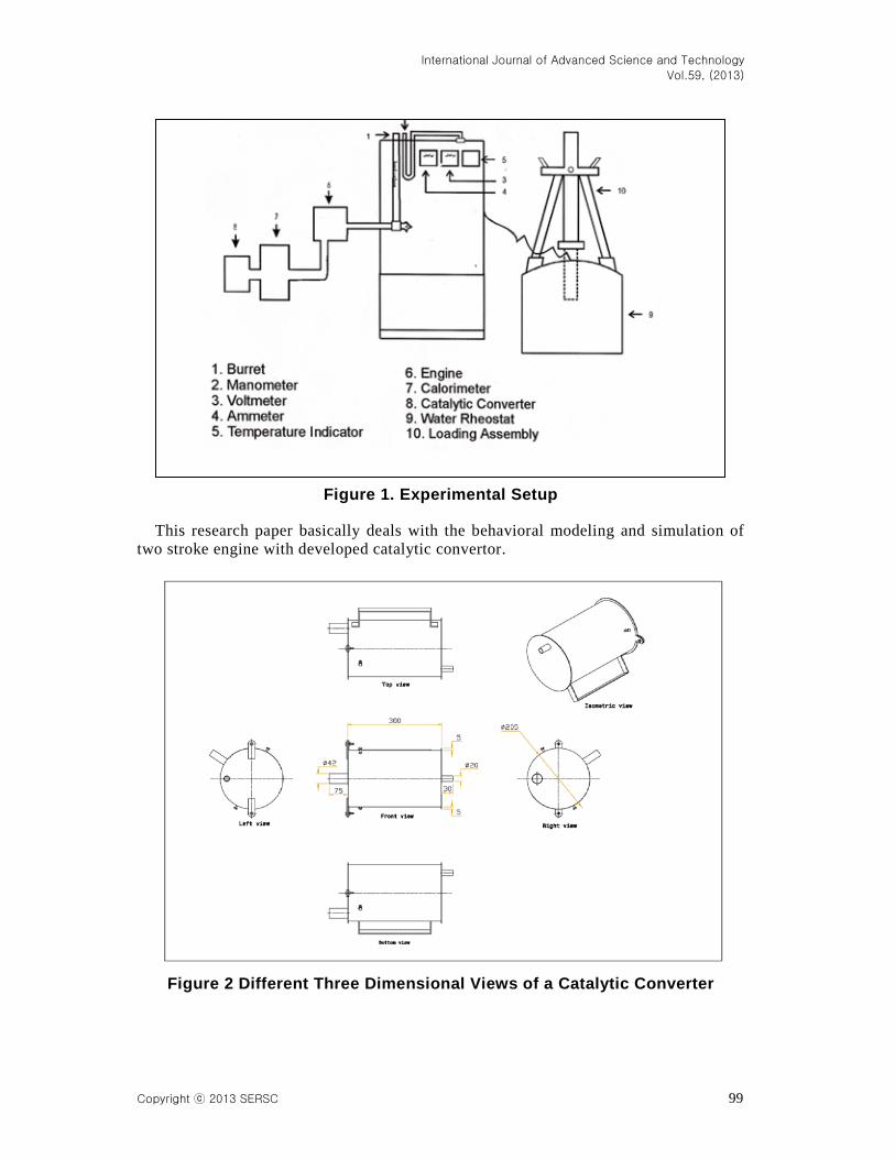
Figure 3. Cut Section Model of Designed Catalytic Converter
2. Behavioral Modeling and Simulation of Two Stroke Engine and Designed Catalytic Convertor
In behavioral science, system theory and dynamic system modeling, a behavioral model reproduces the required behavior of the original analyzed system, such as there is a one-to-one correspondence between the behavior of the original system and the simulated system. The behavioral approach is motivated by the aim of obtaining a framework for system analysis that respects the underlying physics. The behavior may be achieved in simulation with a mixture of ideal or otherwise physically unrealistic components if it successfully recapitulates the behavior of the system under analysis.
This section basically deals with the behavioral modeling and simulation of two stroke engine with developed catalytic convertor. The basic idea of behavioral modeling starts from analyzing the practical behavior of two stroke engine and designed catalytic convertor and then approximating obtained behavior in terms of mathematical equations. These obtained equations actually represent behavior of concern system. Once mathematical equations are obtained, next stage is to implementation of these equations in Simulink platform. The last process is the validation check by the simulation of developed model. 2.1. Behavioral Modeling of Two Stroke Engine
This subsection presents the complete behavioral modeling of two stroke engine, during modeling of engine following parameters are important and has to address during modeling.
i. Horse power of engine.
ii. Speed of engine in RPM.
iii. Applicable load during running condition.
These three important parameters are basically independent variable for modeling, and it is difficult to address simultaneously. However among these three, one can be assume constant, so for modeling of two stroke engine, in this paper horse power of
International Journal of Advanced Science and Technology
Vol.59, (2013)
Copyright ⓒ 2013 SERSC 101
engine is taken as constant, this leads the reduction of one independent variable from the list.
Now following steps provide complete idea of behavioral modeling of two stroke engine.
Step 1. Define the behavior of two stroke engine in terms of input and output variables. For modeling of this paper the input variables are:
i. Speed of engine in RPM.
ii. Applicable load during running condition.
Similarly the output variables for our work are
i. CO in percentage.
ii. HC in PPM.
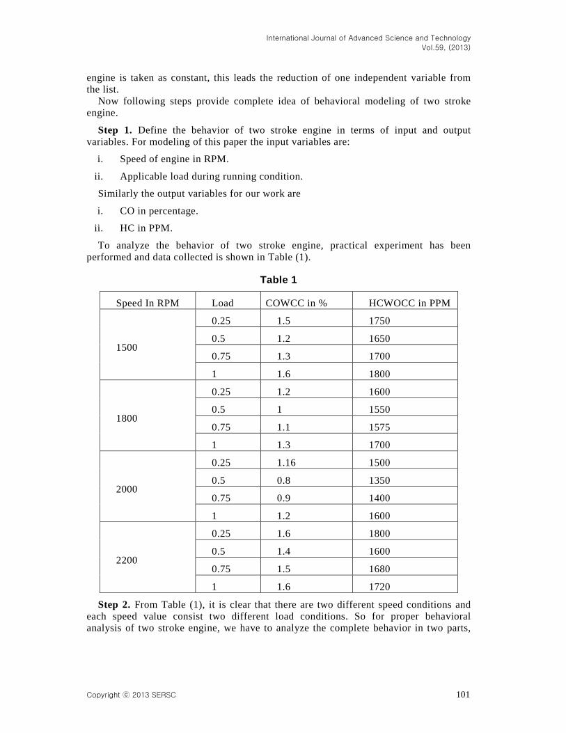
To analyze the behavior of two stroke engine, practical experiment has been performed and data collected is shown in Table (1).
Table 1
Speed In RPM Load COWCC in % HCWOCC in PPM
1500
0.25 1.5 1750
0.5 1.2 1650
0.75 1.3 1700
1 1.6 1800
1800
0.25 1.2 1600
0.5 1 1550
0.75 1.1 1575
1 1.3 1700
2000
0.25 1.16 1500
0.5 0.8 1350
0.75 0.9 1400
1 1.2 1600
2200
0.25 1.6 1800
0.5 1.4 1600
0.75 1.5 1680
1 1.6 1720
Step 2. From Table (1), it is clear that there are two different speed conditions and each speed value consist two different load conditions. So for proper behavioral analysis of two stroke engine, we have to analyze the complete behavior in two parts,
International Journal of Advanced Science and Technology
Vol.59, (2013)
102 Copyright ⓒ 2013 SERSC
i.e., based on different speed conditions. Hence the complete modeling is also divided in two parts.
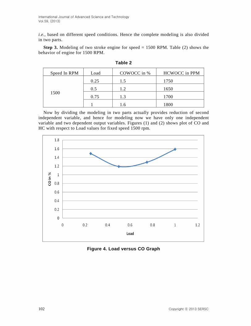
Step 3. Modeling of two stroke engine for speed = 1500 RPM. Table (2) shows the behavior of engine for 1500 RPM.
Table 2
Speed In RPM Load COWOCC in % HCWOCC in PPM
1500
0.25 1.5 1750
0.5 1.2 1650
0.75 1.3 1700
1 1.6 1800
Now by dividing the modeling in two parts actually provides reduction of second independent variable, and hence for modeling now we have only one independent variable and two dependent output variables. Figures (1) and (2) shows plot of CO and HC with respect to Load values for fixed speed 1500 rpm.
Figure 4. Load versus CO Graph
International Journal of Advanced Science and Technology
Vol.59, (2013)
Copyright ⓒ 2013 SERSC 103
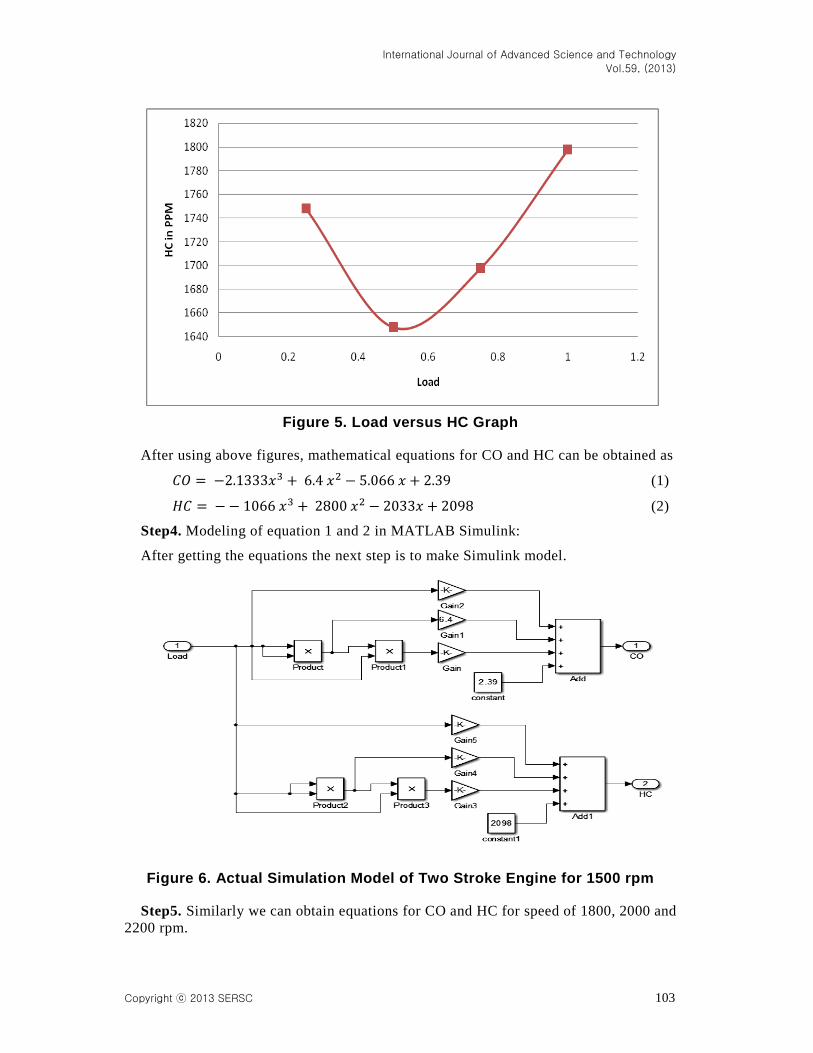
Figure 5. Load versus HC Graph
After using above figures, mathematical equations for CO and HC can be obtained as
𝐶𝑂 = −2.1333𝑥3 + 6.4 𝑥2 − 5.066 𝑥 + 2.39 (1)
𝐻𝐶 = −− 1066 𝑥3 + 2800 𝑥2 − 2033𝑥 + 2098 (2)
Step4. Modeling of equation 1 and 2 in MATLAB Simulink:
After getting the equations the next step is to make Simulink model.
Figure 6. Actual Simulation Model of Two Stroke Engine for 1500 rpm
Step5. Similarly we can obtain equations for CO and HC for speed of 1800, 2000 and 2200 rpm.
International Journal of Advanced Science and Technology
Vol.59, (2013)
104 Copyright ⓒ 2013 SERSC
The equations obtained are as follows:
i. For Speed = 1800 rpm.
𝐶𝑂 = −2.1333𝑥3 + 5.6 𝑥2 − 4.066𝑥 + 1.89 (3)
𝐻𝐶 = 266.6 𝑥3 + 200 𝑥2 − 466.6 𝑥 + 1698 (4)
ii. For Speed = 2000 rpm.
𝐶𝑂 = −2.773 𝑥3 + 7.84 𝑥2 − 6.106 𝑥 + 2.23 (5)
𝐻𝐶 = −533.3 𝑥3 + 2400 𝑥2 − 2166 𝑥 + 1898 (6)
iii. For Speed = 2200 rpm.
𝐶𝑂 = −4.266 + 9.6 𝑥2 − 6.533 𝑥 + 2.79 (7)
𝐻𝐶 = −2517 𝑥3 + 5792 𝑥2 − 4042 𝑥 + 2486 (8)
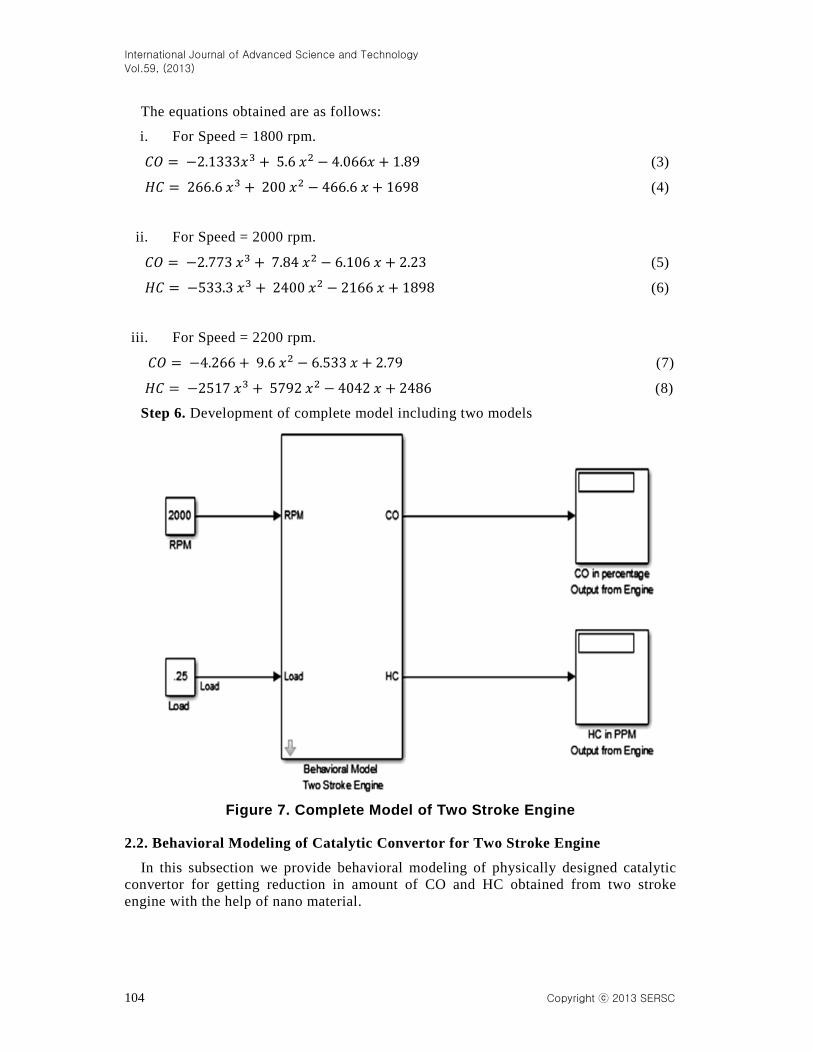
Step 6. Development of complete model including two models
Figure 7. Complete Model of Two Stroke Engine
2.2. Behavioral Modeling of Catalytic Convertor for Two Stroke Engine
In this subsection we provide behavioral modeling of physically designed catalytic convertor for getting reduction in amount of CO and HC obtained from two stroke engine with the help of nano material.
International Journal of Advanced Science and Technology
Vol.59, (2013)
Copyright ⓒ 2013 SERSC 105
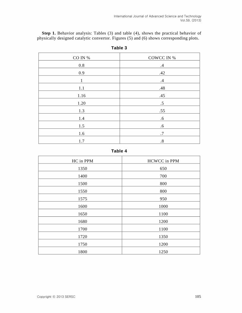
Step 1. Behavior analysis: Tables (3) and table (4), shows the practical behavior of physically designed catalytic convertor. Figures (5) and (6) shows corresponding plots.
Table 3
CO IN % COWCC IN %
0.8 .4
0.9 .42
1 .4
1.1 .48
1.16 .45
1.20 .5
1.3 .55
1.4 .6
1.5 .6
1.6 .7
1.7 .8
Table 4
HC in PPM HCWCC in PPM
1350 650
1400 700
1500 800
1550 800
1575 950
1600 1000
1650 1100
1680 1200
1700 1100
1720 1350
1750 1200
1800 1250
International Journal of Advanced Science and Technology
Vol.59, (2013)
106 Copyright ⓒ 2013 SERSC
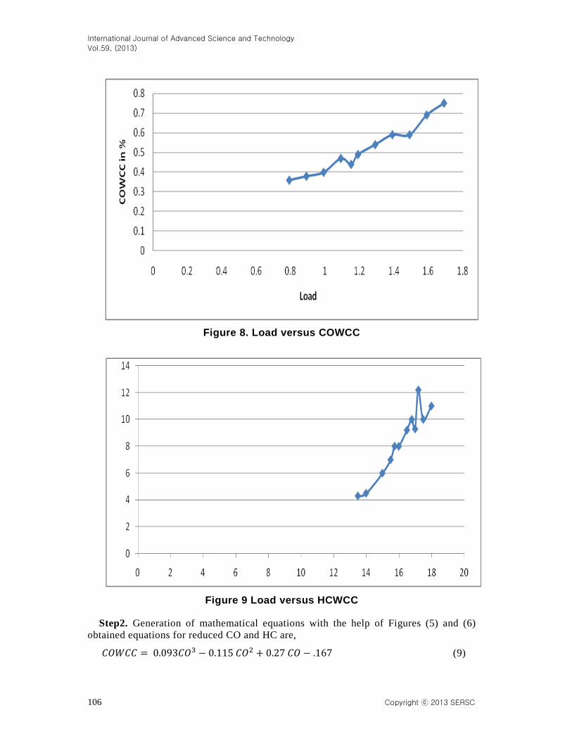
Figure 8. Load versus COWCC
Figure 9 Load versus HCWCC
Step2. Generation of mathematical equations with the help of Figures (5) and (6) obtained equations for reduced CO and HC are,
𝐶𝑂𝑊𝐶𝐶 = 0.093𝐶𝑂3 − 0.115 𝐶𝑂2 + 0.27 𝐶𝑂 − .167 (9)
International Journal of Advanced Science and Technology
Vol.59, (2013)
Copyright ⓒ 2013 SERSC 107
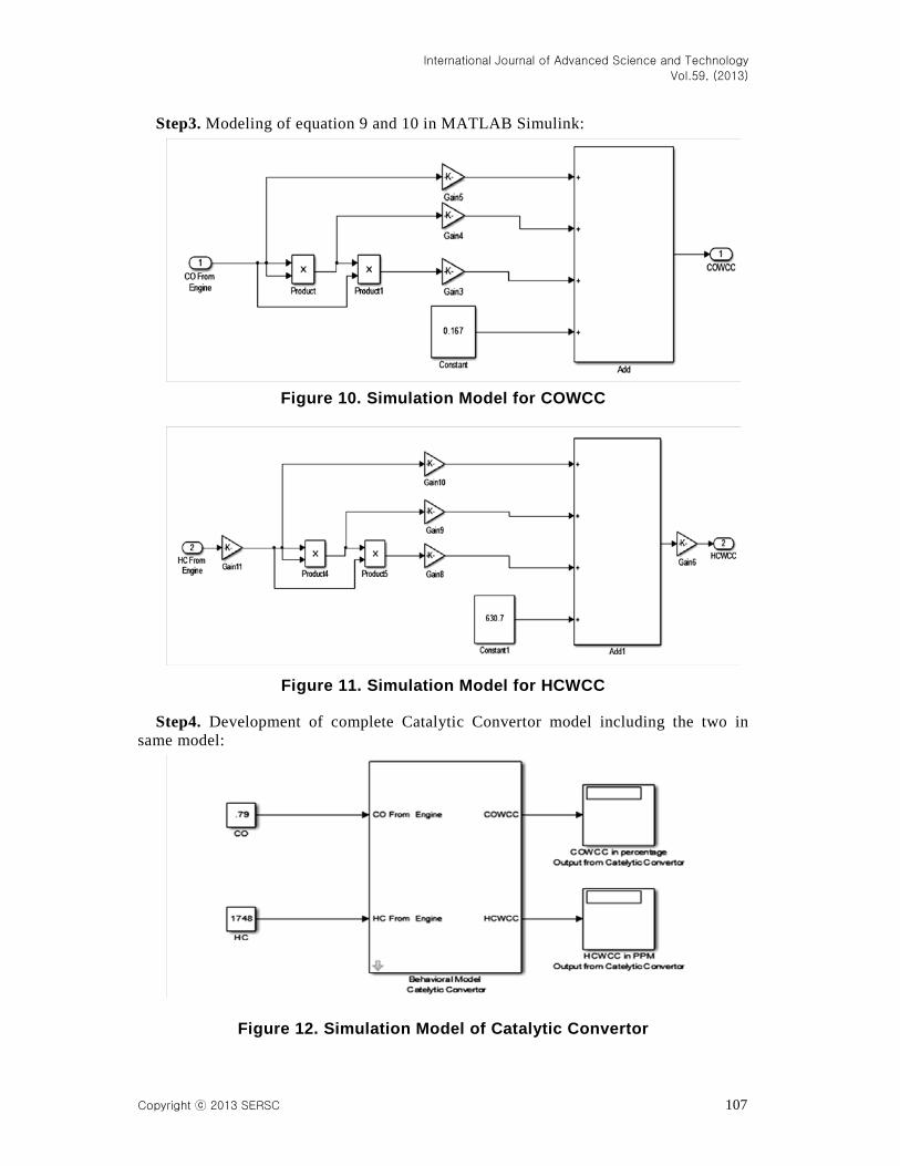
Step3. Modeling of equation 9 and 10 in MATLAB Simulink:
Figure 10. Simulation Model for COWCC
Figure 11. Simulation Model for HCWCC
Step4. Development of complete Catalytic Convertor model including the two in same model:
Figure 12. Simulation Model of Catalytic Convertor
International Journal of Advanced Science and Technology
Vol.59, (2013)
108 Copyright ⓒ 2013 SERSC
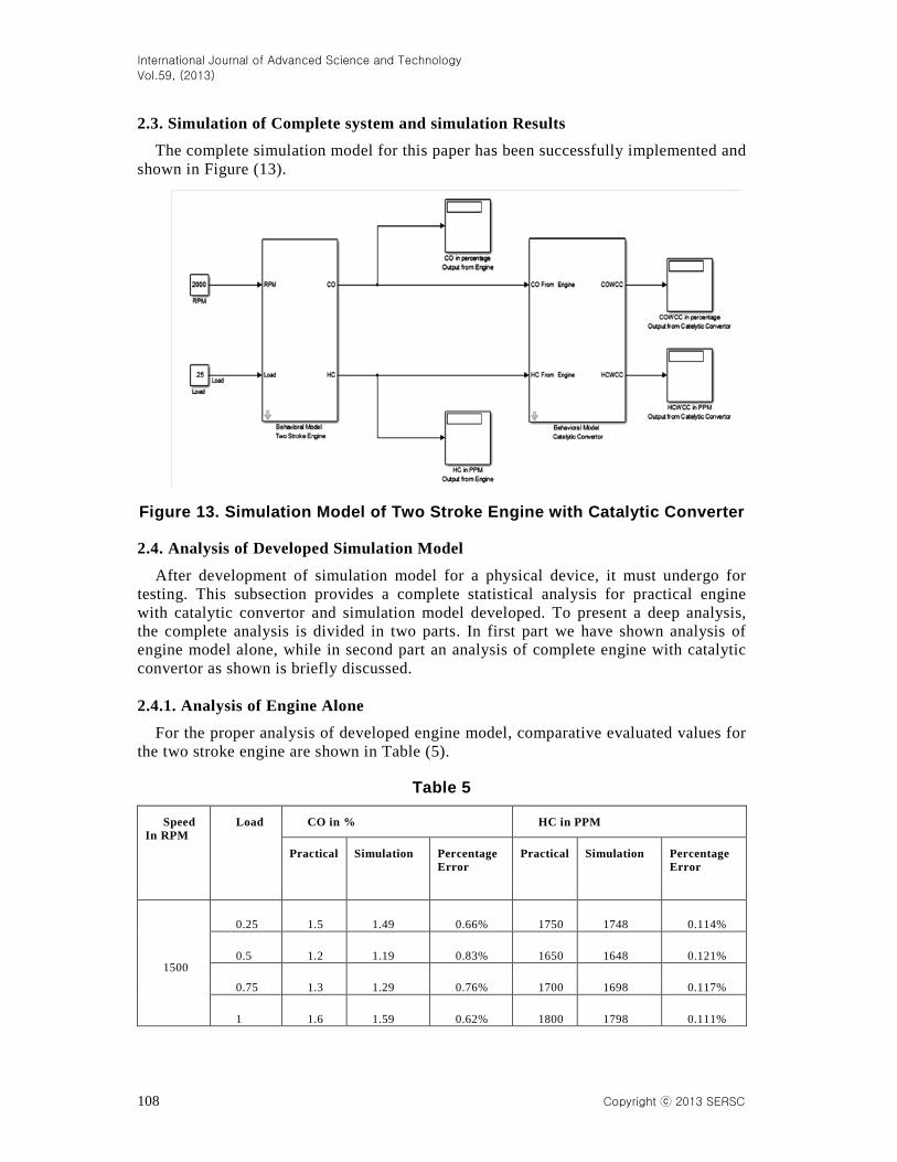
2.3. Simulation of Complete system and simulation Results
The complete simulation model for this paper has been successfully implemented and shown in Figure (13).
Figure 13. Simulation Model of Two Stroke Engine with Catalytic Converter
2.4. Analysis of Developed Simulation Model
After development of simulation model for a physical device, it must undergo for testing. This subsection provides a complete statistical analysis for practical engine with catalytic convertor and simulation model developed. To present a deep analysis, the complete analysis is divided in two parts. In first part we have shown analysis of engine model alone, while in second part an analysis of complete engine with catalytic convertor as shown is briefly discussed. 2.4.1. Analysis of Engine Alone
For the proper analysis of developed engine model, comparative evaluated values for the two stroke engine are shown in Table (5).
Table 5
Speed In RPM
Load CO in % HC in PPM
Practical Simulation Percentage Error
Practical Simulation Percentage Error
1500
0.25 1.5 1.49 0.66% 1750 1748 0.114%
0.5 1.2 1.19 0.83% 1650 1648 0.121%
0.75 1.3 1.29 0.76% 1700 1698 0.117%
1 1.6 1.59 0.62% 1800 1798 0.111%
International Journal of Advanced Science and Technology
Vol.59, (2013)
Copyright ⓒ 2013 SERSC 109
1800
0.25 1.2 1.19 0.83% 1600 1598 0.125%
0.5 1 0.99 1.00% 1550 1548 0.129%
0.75 1.1 1.09 0.90% 1575 1573 0.126%
1 1.3 1.29 0.76% 1700 1698 0.117%
2000
0.25 1.16 1.15 0.86% 1500 1498 0.133%
0.5 0.8 0.79 1.25% 1350 1348 0.148%
0.75 0.9 0.89 1.11% 1400 1398 0.142%
1 1.2 1.19 0.83% 1600 1598 0.125%
2200
0.25 1.6 1.69 0.62% 1800 1798 0.111%
0.5 1.4 1.39 0.71% 1600 1598 0.125%
0.75 1.5 1.49 0.66% 1680 1650 0.119%
1 1.6 1.59 0.62% 1720 1718 0.116%
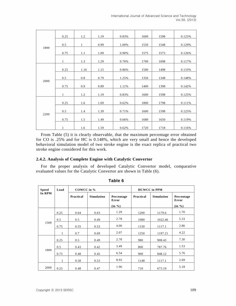
From Table (5) it is clearly observable, that the maximum percentage error obtained for CO is .25% and for HC is 0.148%, which are very small and hence the developed behavioral simulation model of two stroke engine is the exact replica of practical two stroke engine considered for this work. 2.4.2. Analysis of Complete Engine with Catalytic Convertor
For the proper analysis of developed Catalytic Convertor model, comparative evaluated values for the Catalytic Convertor are shown in Table (6).
Table 6
Speed In RPM
Load COWCC in % HCWCC in PPM
Practical Simulation Percentage Error
(in %)
Practical Simulation
Percentage Error
(in %)
1500
0.25 0.64 0.63 1.29 1200 1179.6 1.70
0.5 0.5 0.49 2.78 1080 1022.46 5.33
0.75 0.55 0.53 4.00 1150 1117.1 2.86
1 0.7 0.69 2.07 1250 1197.21 4.22
1800
0.25 0.5 0.49 2.78 980 908.43 7.30
0.5 0.43 0.42 3.49 800 787.76 1.53
0.75 0.48 0.45 6.54 900 848.12 5.76
1 0.58 0.53 8.93 1148 1117.1 2.69
2000 0.25 0.48 0.47 1.96 710 673.19 5.18
International Journal of Advanced Science and Technology
Vol.59, (2013)
110 Copyright ⓒ 2013 SERSC
0.5 0.38 0.36 6.05 520 493.67 5.06
0.75 0.4 0.38 3.85 700 650.4 7.09
1 0.5 0.49 2.78 850 820.43 3.48
2200
0.25 0.7 0.69 2.07 1300 1197.21 7.91
0.5 0.6 0.57 4.20 1000 908.43 9.16
0.75 0.65 0.63 3.52 1100 1026.7 6.66
1 0.71 0.69 3.45 1250 1146.67 8.27
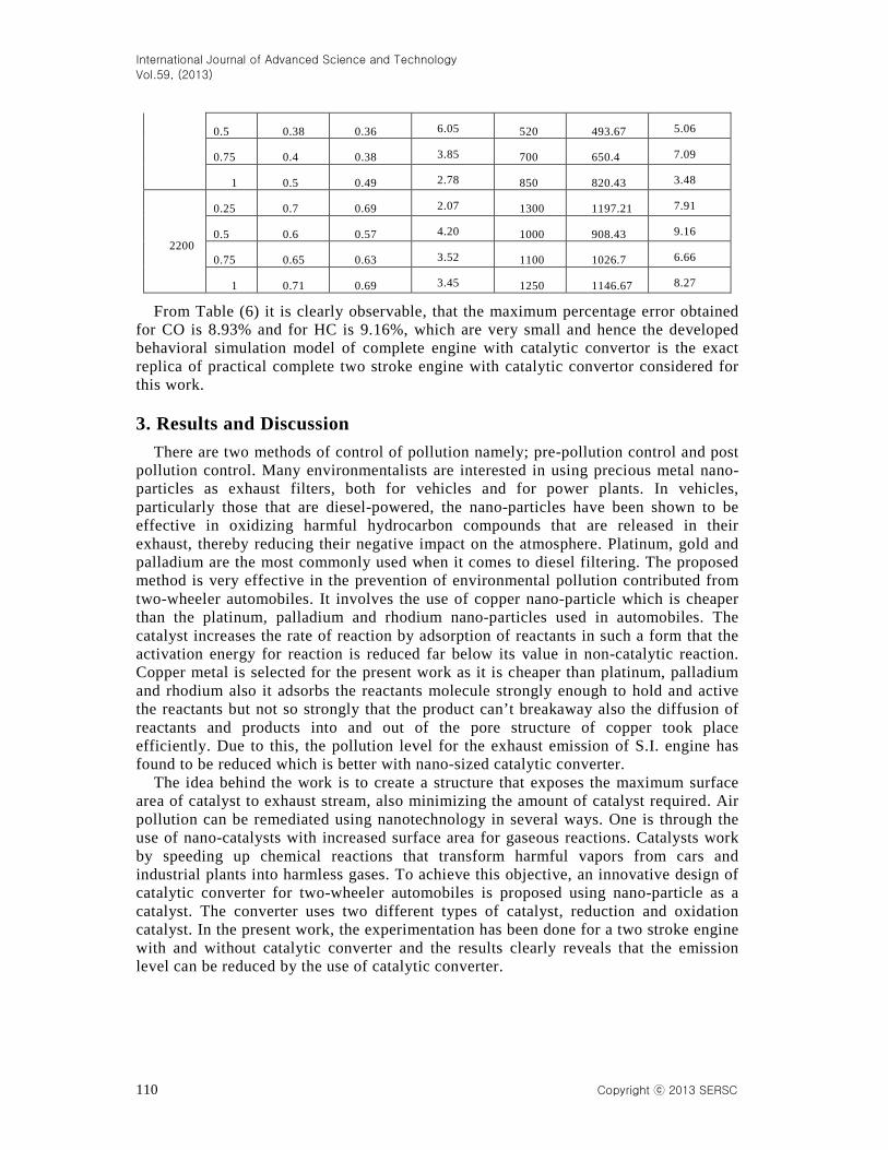
From Table (6) it is clearly observable, that the maximum percentage error obtained for CO is 8.93% and for HC is 9.16%, which are very small and hence the developed behavioral simulation model of complete engine with catalytic convertor is the exact replica of practical complete two stroke engine with catalytic convertor considered for this work. 3. Results and Discussion
There are two methods of control of pollution namely; pre-pollution control and post pollution control. Many environmentalists are interested in using precious metal nano-particles as exhaust filters, both for vehicles and for power plants. In vehicles, particularly those that are diesel-powered, the nano-particles have been shown to be effective in oxidizing harmful hydrocarbon compounds that are released in their exhaust, thereby reducing their negative impact on the atmosphere. Platinum, gold and palladium are the most commonly used when it comes to diesel filtering. The proposed method is very effective in the prevention of environmental pollution contributed from two-wheeler automobiles. It involves the use of copper nano-particle which is cheaper than the platinum, palladium and rhodium nano-particles used in automobiles. The catalyst increases the rate of reaction by adsorption of reactants in such a form that the activation energy for reaction is reduced far below its value in non-catalytic reaction. Copper metal is selected for the present work as it is cheaper than platinum, palladium and rhodium also it adsorbs the reactants molecule strongly enough to hold and active the reactants but not so strongly that the product can’t breakaway also the diffusion of reactants and products into and out of the pore structure of copper took place efficiently. Due to this, the pollution level for the exhaust emission of S.I. engine has found to be reduced which is better with nano-sized catalytic converter.
The idea behind the work is to create a structure that exposes the maximum surface area of catalyst to exhaust stream, also minimizing the amount of catalyst required. Air pollution can be remediated using nanotechnology in several ways. One is through the use of nano-catalysts with increased surface area for gaseous reactions. Catalysts work by speeding up chemical reactions that transform harmful vapors from cars and industrial plants into harmless gases. To achieve this objective, an innovative design of catalytic converter for two-wheeler automobiles is proposed using nano-particle as a catalyst. The converter uses two different types of catalyst, reduction and oxidation catalyst. In the present work, the experimentation has been done for a two stroke engine with and without catalytic converter and the results clearly reveals that the emission level can be reduced by the use of catalytic converter.
International Journal of Advanced Science and Technology
Vol.59, (2013)
Copyright ⓒ 2013 SERSC 111
4. Conclusion In the current scenario, the pollution control is a crucial area for research and
development. Lots of work has been done by the researchers in this connection but the area is still lacking for an efficient technique which can provide highly robust emission control for all the operating conditions of vehicles. The idea behind the work is to create a structure that exposes the maximum surface area of catalyst to exhaust stream, also minimizing the amount of catalyst required. The exhaust gases pass through a bed of catalyst and the catalytic action takes place at surface of copper which are porous and the higher catalytic activity towards the oxidation of CO and HC could be due to the higher catalytic surface area of small nanoparticles.
The proposed method is very effective in the prevention of environmental pollution contributed from two-wheeler automobiles. It involves the use of copper nano-particle which is cheaper than the platinum, palladium and rhodium nano-particles used in automobiles. This paper opens a gateway to study the changes in the concentration of exhaust emissions due to the nano-material copper coating. The modeling will help in understanding the mathematical nature of the process and simulation will help in predicting the results with ease. Nomenclature:
CO – Carbon Monoxide
CC – Catalytic Converter
HC – Hydrocarbon
COWCC – CO emission in % with catalytic converter
COWOCC – CO emission in % without catalytic converter
HCWCC – HC emission in PPM with catalytic converter
HCWOCC – HC emission in PPM without catalytic converter
x – Load References [1] P. S. Gilmour, A. Ziesenis, E. R. Morrison, M. A. Vickers, E. M. Drost and I. Ford, “Toxicological
Applications Pharmacology, vol. 195, (2004), pp. 35-44. [2] M. V. Twigg, “Roles of catalytic oxidation in control of vehicle exhaust emissions”, J. Catalysis Today, vol.
117, no. 4, (2006), pp. 407-418. [3] K. Kishore and M. V. S. Krishna, Journal of Scientific and Industrial Research, vol. 67, (2008), pp. 543-548. [4] M. Thakur and N. K. Saikhedkar, International Science Congress, Haridwar, (2012) December 8-9. [5] T. Mukesh and N. K. Saikhedkar, International Journal of Engineering Research and Applications, vol. 2, no.
5, (2012), pp. 1947-1952. [6] D. L. Feldheim and C. A. Foss, “Metal Nano-particles: Synthesis, Characterization and Applications”, Appl.
Phys. A Mater. Sci. Process, vol. 78, (2004), pp. 73-79. [7] A. K. Schaper, H. Hou, A. Greiner, R. Schneider and F. Philips, “One Pot Synthesis of Copper Nanoparticles
at Room Temperature and its Catalytic Activity”, Appl. Phys. A Mater. Sci. Process, vol. 78, (2004), pp. 85-99.
[8] T. Mukesh and N. K. Saikhedkar, Abhinav Journal, vol. 1, no. 11, (2012), pp. 32-38. [9] M. V. S. Murali Krishna, K. Kishor, P. V. K. Murthy, A. V. S. S. K. S. Gupta, S. Narsimha Kumar,
International Journal of Scientific and Technology Research, vol. 1, no. 2, (2012), pp. 85-90. [10] T. Mukesh, S. Shilpa and N. K. Saikhedkar, Abhinav Journal, vol. 3, no. 1, (2012), pp. 1-10.
International Journal of Advanced Science and Technology
Vol.59, (2013)
112 Copyright ⓒ 2013 SERSC
[11] C. M. Silva, M. Costa, T. L. Farias and H. Santos, “Energy Conversion and Management”, vol. 47, (2008), pp. 2281-2282.
[12] M. V. S. Murali Krishna and K. Kishor, “Performance of Copper Coated Spark Ignition Engine with Methanol Blended Gasoline with Catalytic Converter”, International Journal of Scientific and Technology Research, vol. 67, (2008), pp. 543-548.
[13] M. Samim, M. K. Kaushik and A. Maitra, Mater. Sci., vol. 30, no. 5, (2007), pp. 535-540. [14] A. Durairajan, T. Kavita, A. Rajendran and L. A. Kumarswamidas, Indian J. Innovations Dev., vol. 1, no. 5,
(2012), pp. 315-319. [15] S. Prabhu and B. K. Vinayagam, International Journal of Nanotechnology and Applications, vol. 3, no. 1,
(2009), pp. 17-28. [16] M. S. Shehata and Razak, Engineering Research Journal, vol. 120, (2008), pp. M33-M57. [17] T. Mukesh and N. K. Saikhedkar, “Control of Exhaust Emissions and Enhancement of Retention Time for
Four Stroke Engine Using Nano-sized Copper Metal Spray”, International Journal of Scientific & Engineering Research, vol. 4, no. 2, (2012), pp. 1-9.
Authors
Mukesh Thakur is a Research Scholar from Dr. C.V. Raman
University, Bilaspur. He is also working as a Reader in the Department of Mechanical Engineering of Rungta College of Engineering and Technology, Raipur. He has published his research papers in many national and international conferences and journals. He is also a life member of the Indian Science Congress Association and the Indian Society for Technical Education. He has won many awards for excellent teaching during his academic tenure and is like by one and all. He has also guided many undergraduate students in their project work.
Co-Author’s Name: N. K. Saikhedkar is presently working as a Director and professor in the department of Mechanical Engineering of Raipur Institute of Technology, Raipur. He has done his PhD in thermal engineering from IIT, Bombay. He has published his research papers in many national and international conferences and journals. He is also a life member of many national and international associations. He has vast experience in teaching and is considered as an ideal by many.
Top Related
Copyright © 2022 FDOKUMEN

