


Bahasa
Halaman
Hukum

www.tjprc.org [email protected]
AN APPROACH (PERFORMANCE SCORE) FOR EXPERIMENTAL AN ALYSIS OF
EXHAUST MANIFOLD OF MULTI-CYLINDER SI ENGINE TO DET ERMINE OPTIMUM
GEOMETRY FOR RECREATIONAL AND COMMERCIAL VEHICLES
K. S. UMESH1, V. K. PRAVIN 2 & K. RAJAGOPAL 3 1Department of Mechanical Engineering, Thadomal Shahani Engineering College, Bandra, Mumbai, Maharashtra, India
2Department of Mechanical Engineering, P. D. A. College of Engineering, Gulbarga, Karnataka, India 3Former Vice Chancellor JNT University, Hyderabad, Andhra Pradesh, India
ABSTRACT
Exhaust manifold is one of the most critical components of an IC Engine. The requirements to be met in an
exhaust system are: to be capable of speedy manufacture at low cost; designed for quick assembly on engine and chassis;
minimum interference with other components; low under bonnet temperature; durability; ruggedness; speeds. Preference
for any of this parameter varies as per designers needs. Usually fuel economy, emissions and power requirement are three
different thoughts considered for design of exhaust manifold. This work presents a new approach to exhaust manifold
design which helps in selection of best possible geometry for exhaust manifold depending upon applications.
The performance score method used in this work enables the engineer to select the best possible design experimentally
based upon the preferences. The performance score method gives the relative performance of exhaust manifold with
respect to each other for various performance parameters and helps in evaluation of designs which are dependent upon
multiple parameters rather than only few. The overall performance score of eight models are analyzed for two applications
viz. recreational purpose and commercial purpose. The best possible geometries selected for exhaust manifold are based on
highest overall performance score.
KEYWORDS: Exhaust Manifold, Backpressure, Exhaust Velocity, LBCE, LBSE, LBSER, LBCER, SBCE, SBSE,
SBCER, SBSER, Volumetric Efficiency, Thermal Efficiency, Mechanical Efficiency
INTRODUCTION
Exhaust manifold is connected downstream to engine. It’s a very important component of multi-cylinder engines.
In any automobile, an exhaust manifold of header receives the exhaust gases from multiple cylinders into single pipe. It is
attached downstream of the engine and is major relevance in multi-cylinder engines where there are multiple exhaust
streams that have to be collected into a single pipe.
When an engine starts its exhaust stroke, the piston moves up the cylinder bore, decreasing the total cylinder
volume. When the exhaust valve opens, the high pressure exhaust gas leaves into the exhaust manifold or header,
developing an exhaust pulse consisting three main parts: The high-pressure head is created by the large pressure difference
between the exhaust in the combustion chamber and the atmospheric pressure outside of the exhaust system. As the
exhaust gases equalize between the combustion chamber and the atmosphere, the difference in pressure decreases and the
exhaust velocity decreases. This forms the medium-pressure body component of the exhaust pulse. The remaining exhaust
International Journal of Automobile Engineering Research and Development (IJAuERD) ISSN(P): 2277-4785; ISSN(E): 2278–9413 Vol. 4, Issue 5, Oct 2014, 1-12 © TJPRC Pvt. Ltd.
2 K. S. Umesh, V. K. Pravin & K. Rajagopal
Impact Factor (JCC): 5.1066 Index Copernicus Value (ICV): 3.0
gas forms the low-pressure tail component. This tail component may initially match atmospheric pressure, but the
momentum of the high- and medium-pressure components decreases the pressure in the combustion chamber to a lower-
than-atmospheric level. This relatively low pressure helps to extract all the gases from the cylinder and induct the intake
charge during the overlap period when both intake and exhaust valves are partially open. The effect is known as
scavenging. Length, cross-sectional area, and shaping of the exhaust ports and pipe-works influences the degree of
scavenging effect, and the engine speed range over which scavenging occurs.
The magnitude of the exhaust scavenging effect is a direct function of the velocity of the high and medium
pressure components of the exhaust pulse. Performance headers work to increase the exhaust velocity as much as possible.
One technique is tuned-length primary tubes. This technique attempts to time the occurrence of each exhaust pulse then
serves to create a greater pressure difference between the high pressure head of the next exhaust pulse, thus increasing the
velocity of that exhaust pulse.
Exhaust streams coming out of various cylinders periodically (in accordance with firing order) is collected in
Header which directs it towards the catalytic converter and further through muffler to the atmosphere. It is usually casted
from cast steel or cast iron. The primary goal of exhaust manifold designing is to ensure un-obstructed flow of exhaust
gases downstream ensuring minimal back pressure and at the same time optimizing the performance of the catalytic
converter.
Exhaustive work has taken place already in this field. Scheeringa et al studied analysis of Liquid cooled exhaust
manifold using CFD. He to improve the fundamental understandings of manifold operation obtained detailed information
of flow property distributions and heat transfer. He to investigate the parametric effects of operating conditions and
geometry on the performance of manifolds performed a number of computations. Deger et al did CFD-FE-Analysis for the
Exhaust Manifold of a Diesel Engine aiming to determine specific temperature and pressure distributions. The fluid flow
and the heat transfer through the exhaust manifold were computed correspondingly by CFD analyses including the
conjugate heat transfer.
Kulal et al (2013) in his “CFD Analysis and Experimental Verification of Effect of Manifold Geometry on
Volumetric Efficiency and Backpressure for Multi-cylinder SI Engine” investigated optimal geometry for exhaust manifold
for maximum volumetric efficiency. Kulal et al (2013) in his “Experimental Analysis of Optimal Geometry for Exhaust
Manifold for Multi-cylinder SI Engine for Optimum Performance” investigated the effect of attaching a reducer to the
outlet of exhaust manifold.
For this analysis seven key engine performance parameters are analyzed for both the applications. For recreational
purpose volumetric efficiency should be high because power holds highest preference in this regard. Regarding other
parameters scavenging efficiency must be high to ensure good volumetric efficiency thus backpressure must be low and
exhaust velocity needs to be high. Obviously higher mechanical efficiency and thermal efficiency must be preferred
regardless of application. No matter what are the prices of fuel, the designer always prefers lower B.S.F.C. Now, regarding
A: F ratio stoichiometric, A: F ratio holds highest preference theoretically but practically slightly rich A: F ratio is
generally required. For commercial purpose or even domestic purpose the above explained preferences holds good except
A: F ratio. Usually designers prefer lower backpressure for commercial purpose due to lower B.S.F.C. and slightly lean
A: F ratio for economical operations. The power based approach and efficiency based approach are considered.
An Approach (Performance Score) for Experimental Analysis of Exhaust Manifold of Multi-Cylinder 3 SI Engine to Determine Optimum Geometry for Recreational and Commercial Vehicles
www.tjprc.org [email protected]
MODEL DESCRIPTION
The eight models of exhaust manifold considered for this work are:
• Short Bend Center Exit (SBCE)
• Short Bend Side Exit (SBSE)
• Long Bend Center Exit (LBCE)
• Long Bend Side Exit (LBSE)
• Short Bend Center Exit with Reducer (SBCER)
• Short Bend Side Exit with Reducer (SBSER)
• Long Bend Center Exit with Reducer (LBCER)
• Long Bend Side Exit with Reducer (LBSER)
Header length is 335 mm for all models. ID and OD are 52.48 mm and 60.3 mm respectively for the header. In
Short Bend models the bend radius is 48 mm. ID and OD of bend are 35.08 mm and 42.86 mm respectively. Long Bend
models have bend radius of 100 mm. ID and OD of outlet of exhaust are 52.48 mm and 60.3 mm respectively for all
models. Length of the outlet of exhaust manifold is kept at 220 mm and flange is attached at the end to connect it to
exhaust muffler.
For models with reducer the reducer length is kept 70 mm its inlet ID is 52.48 mm and outlet ID is 38 mm.
The total length of outlet of exhaust manifold is kept at 220 mm.
EXPERIMENTAL SET-UP
All the tests on Exhaust manifold are conducted on four-stroke four-cylinder Engine of Maruti-Suzuki Wagon-R.
Experimental set up consists of:
• The engine and dynamometer fitted together on common channel frame
• Fuel Consumption measuring unit and temperature measuring units
• Exhaust gas Calorimeter
• Orifice Meter
• Pressure measuring unit by using U-tube manometers
Temperatures are measured at:
• Exhaust Gas inlet to the calorimeter
• Exhaust gas outlet to calorimeter
• Water inlet to calorimeter
• Water outlet from Calorimeter
4 K. S. Umesh, V. K. Pravin & K. Rajagopal
Impact Factor (JCC): 5.1066 Index Copernicus Value (ICV): 3.0
• Water outlet from Engine
• Temperatures are measured in header at various points on the header where bends are attached
• At the inlet and outlet of manifold
Pressures are measured at:
• The inlet and outlet of manifold
• Various points on the header where bends are attached
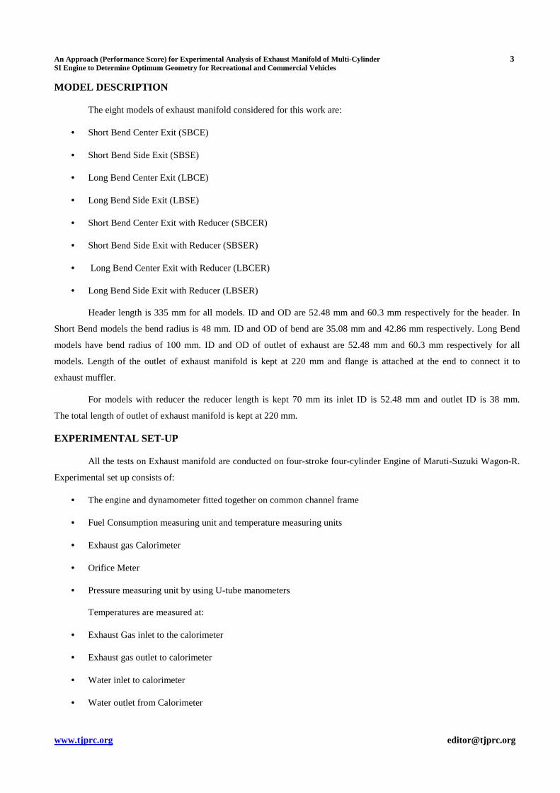
The block diagram of experimental set-up is shown below:
Figure 1: Block Diagram of Experimental Set-up
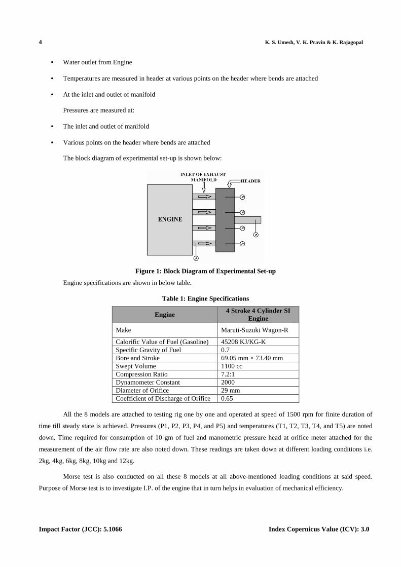
Engine specifications are shown in below table.
Table 1: Engine Specifications
Engine 4 Stroke 4 Cylinder SI
Engine
Make Maruti-Suzuki Wagon-R
Calorific Value of Fuel (Gasoline) 45208 KJ/KG-K Specific Gravity of Fuel 0.7 Bore and Stroke 69.05 mm × 73.40 mm Swept Volume 1100 cc Compression Ratio 7.2:1 Dynamometer Constant 2000 Diameter of Orifice 29 mm Coefficient of Discharge of Orifice 0.65
All the 8 models are attached to testing rig one by one and operated at speed of 1500 rpm for finite duration of
time till steady state is achieved. Pressures (P1, P2, P3, P4, and P5) and temperatures (T1, T2, T3, T4, and T5) are noted
down. Time required for consumption of 10 gm of fuel and manometric pressure head at orifice meter attached for the
measurement of the air flow rate are also noted down. These readings are taken down at different loading conditions i.e.
2kg, 4kg, 6kg, 8kg, 10kg and 12kg.
Morse test is also conducted on all these 8 models at all above-mentioned loading conditions at said speed.
Purpose of Morse test is to investigate I.P. of the engine that in turn helps in evaluation of mechanical efficiency.
An Approach (Performance Score) for Experimental Analysis of Exhaust Manifold of Multi-Cylinder 5 SI Engine to Determine Optimum Geometry for Recreational and Commercial Vehicles
www.tjprc.org [email protected]
Power Based Approach
The performance score is evaluated as follows:
(1)
The Stochiometric A:F ratio of 12.7 is considered for given fuel. Thus, considering 5% rich Mixture as ideal one,
12.065 is taken as ideal A:F ratio. And deviation of individual readings is found out.
The A: F ratio performance score is evaluated as follows:
(2)
Efficiency Based Approach
The performance score for all parameters remains same for all properties except A:F ratio. 5% lean Mixture is
considered as ideal one. 13.335 is taken as ideal A:F ratio. And deviation of individual readings is found out. The A:F ratio
performance score is evaluated as follows:
(3)
RESULTS AND DISCUSSIONS
Experiments are carried out at six different loads keeping speed constant. The backpressure and exhaust
temperatures are measured whereas all engine performance parameters such as exhaust velocity, volumetric efficiency,
B.S.F.C, Thermal efficiency, mechanical efficiency and A:F ratio are calculated for each model and performance score is
evaluated using the formulas discussed earlier. Later the best suited exhaust manifold designs from various view-points are
discussed.
• Backpressure
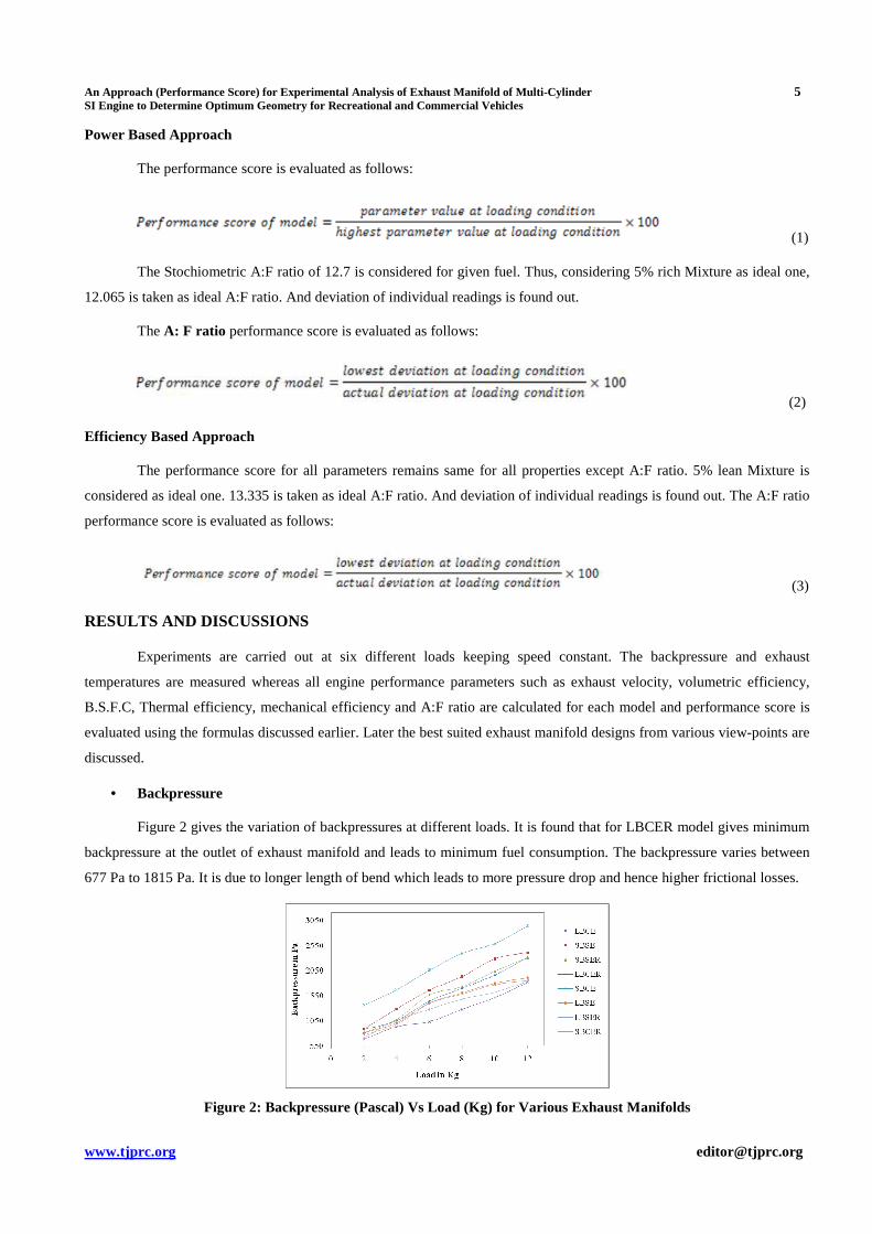
Figure 2 gives the variation of backpressures at different loads. It is found that for LBCER model gives minimum
backpressure at the outlet of exhaust manifold and leads to minimum fuel consumption. The backpressure varies between
677 Pa to 1815 Pa. It is due to longer length of bend which leads to more pressure drop and hence higher frictional losses.
Figure 2: Backpressure (Pascal) Vs Load (Kg) for Various Exhaust Manifolds
6 K. S. Umesh, V. K. Pravin & K. Rajagopal
Impact Factor (JCC): 5.1066 Index Copernicus Value (ICV): 3.0
It is observed that the backpressures are considerably reduced by designing the manifold using reducer at the
outlet, which resulted in a better design of exhaust manifold.
• Exhaust Velocity
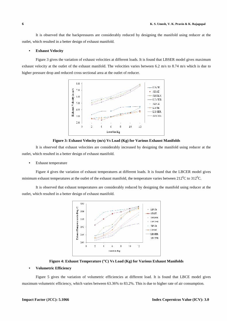
Figure 3 gives the variation of exhaust velocities at different loads. It is found that LBSER model gives maximum
exhaust velocity at the outlet of the exhaust manifold. The velocities varies between 6.2 m/s to 8.74 m/s which is due to
higher pressure drop and reduced cross sectional area at the outlet of reducer.
Figure 3: Exhaust Velocity (m/s) Vs Load (Kg) for Various Exhaust Manifolds
It is observed that exhaust velocities are considerably increased by designing the manifold using reducer at the
outlet, which resulted in a better design of exhaust manifold.
• Exhaust temperature
Figure 4 gives the variation of exhaust temperatures at different loads. It is found that the LBCER model gives
minimum exhaust temperatures at the outlet of the exhaust manifold, the temperature varies between 2120C to 3120C.
It is observed that exhaust temperatures are considerably reduced by designing the manifold using reducer at the
outlet, which resulted in a better design of exhaust manifold.
Figure 4: Exhaust Temperature (°C) Vs Load (Kg) for Various Exhaust Manifolds
• Volumetric Efficiency
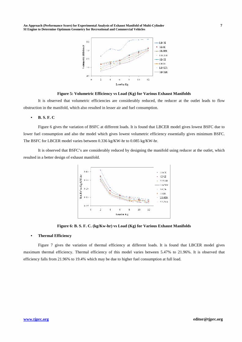
Figure 5 gives the variation of volumetric efficiencies at different load. It is found that LBCE model gives
maximum volumetric efficiency, which varies between 63.36% to 83.2%. This is due to higher rate of air consumption.
An Approach (Performance Score) for Experimental Analysis of Exhaust Manifold of Multi-Cylinder 7 SI Engine to Determine Optimum Geometry for Recreational and Commercial Vehicles
www.tjprc.org [email protected]
Figure 5: Volumetric Efficiency vs Load (Kg) for Various Exhaust Manifolds
It is observed that volumetric efficiencies are considerably reduced, the reducer at the outlet leads to flow
obstruction in the manifold, which also resulted in lesser air and fuel consumption.
• B. S. F. C
Figure 6 gives the variation of BSFC at different loads. It is found that LBCER model gives lowest BSFC due to
lower fuel consumption and also the model which gives lowest volumetric efficiency essentially gives minimum BSFC.
The BSFC for LBCER model varies between 0.336 kg/KW-hr to 0.085 kg/KW-hr.
It is observed that BSFC’s are considerably reduced by designing the manifold using reducer at the outlet, which
resulted in a better design of exhaust manifold.
Figure 6: B. S. F. C. (kg/Kw-hr) vs Load (Kg) for Various Exhaust Manifolds
• Thermal Efficiency
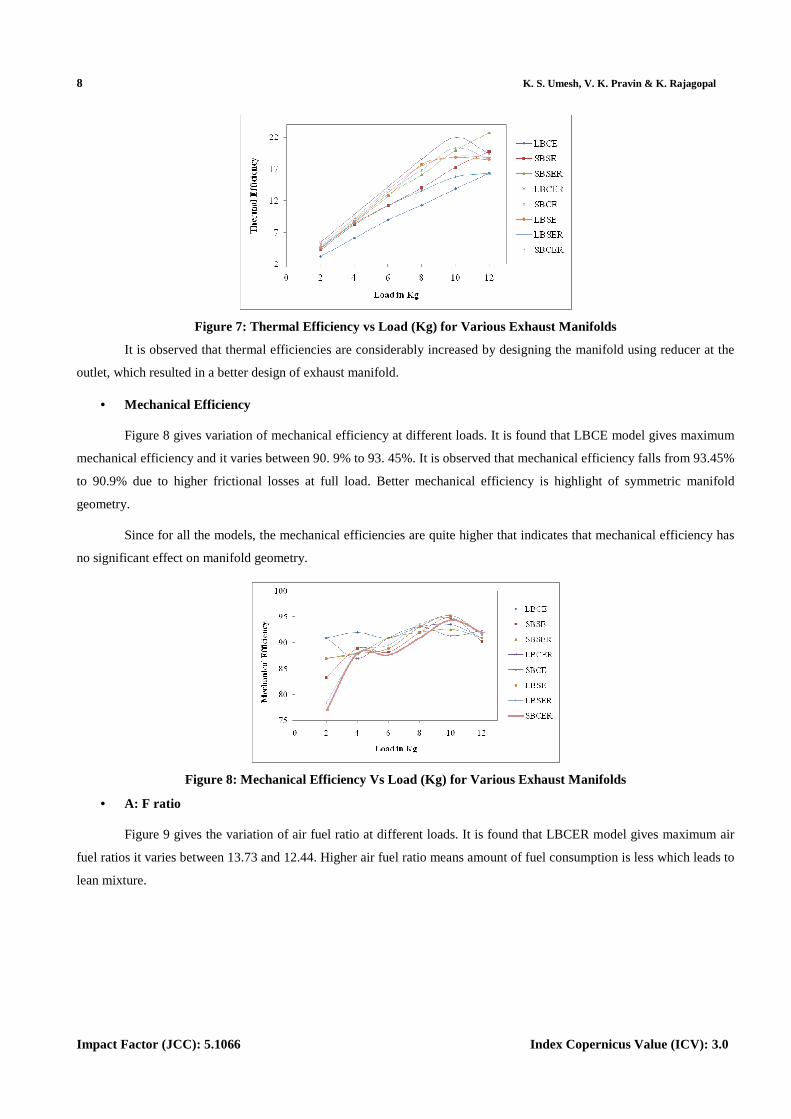
Figure 7 gives the variation of thermal efficiency at different loads. It is found that LBCER model gives
maximum thermal efficiency. Thermal efficiency of this model varies between 5.47% to 21.96%. It is observed that
efficiency falls from 21.96% to 19.4% which may be due to higher fuel consumption at full load.
8 K. S. Umesh, V. K. Pravin & K. Rajagopal
Impact Factor (JCC): 5.1066 Index Copernicus Value (ICV): 3.0
Figure 7: Thermal Efficiency vs Load (Kg) for Various Exhaust Manifolds
It is observed that thermal efficiencies are considerably increased by designing the manifold using reducer at the
outlet, which resulted in a better design of exhaust manifold.
• Mechanical Efficiency
Figure 8 gives variation of mechanical efficiency at different loads. It is found that LBCE model gives maximum
mechanical efficiency and it varies between 90. 9% to 93. 45%. It is observed that mechanical efficiency falls from 93.45%
to 90.9% due to higher frictional losses at full load. Better mechanical efficiency is highlight of symmetric manifold
geometry.
Since for all the models, the mechanical efficiencies are quite higher that indicates that mechanical efficiency has
no significant effect on manifold geometry.
Figure 8: Mechanical Efficiency Vs Load (Kg) for Various Exhaust Manifolds
• A: F ratio
Figure 9 gives the variation of air fuel ratio at different loads. It is found that LBCER model gives maximum air
fuel ratios it varies between 13.73 and 12.44. Higher air fuel ratio means amount of fuel consumption is less which leads to
lean mixture.
An Approach (Performance Score) for Experimental Analysis of Exhaust Manifold of Multi-Cylinder 9 SI Engine to Determine Optimum Geometry for Recreational and Commercial Vehicles
www.tjprc.org [email protected]
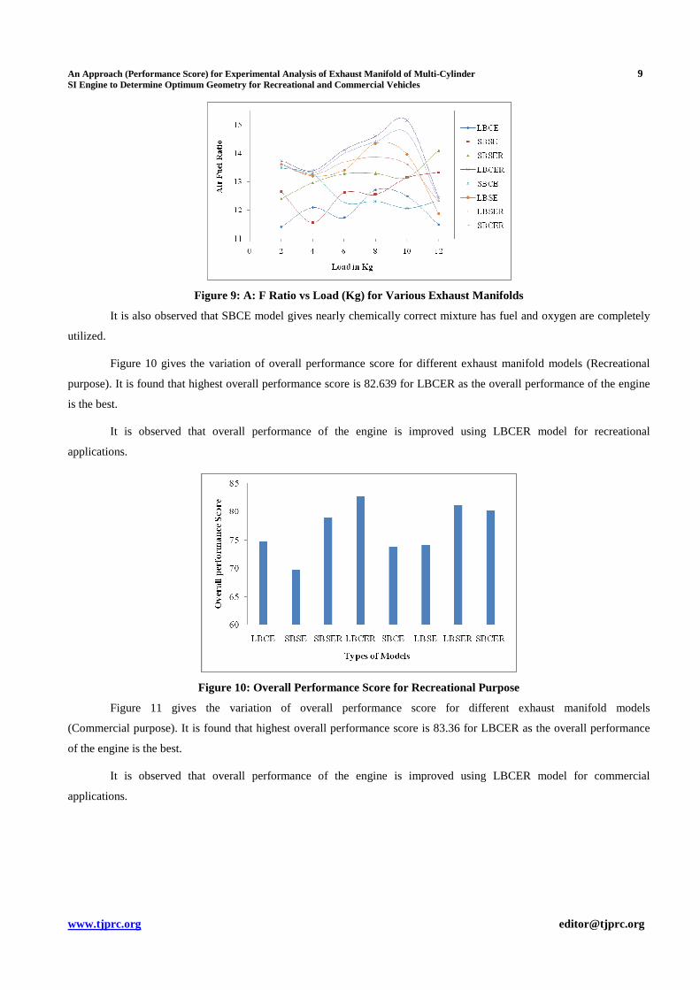
Figure 9: A: F Ratio vs Load (Kg) for Various Exhaust Manifolds
It is also observed that SBCE model gives nearly chemically correct mixture has fuel and oxygen are completely
utilized.
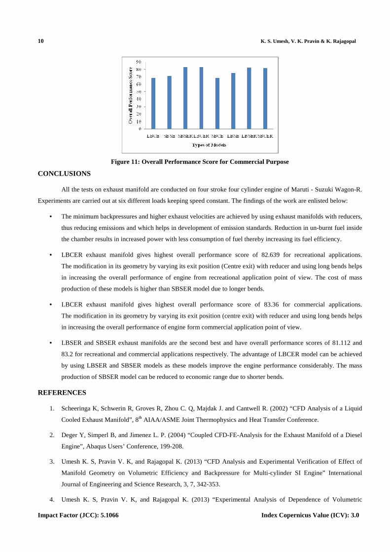
Figure 10 gives the variation of overall performance score for different exhaust manifold models (Recreational
purpose). It is found that highest overall performance score is 82.639 for LBCER as the overall performance of the engine
is the best.
It is observed that overall performance of the engine is improved using LBCER model for recreational
applications.
Figure 10: Overall Performance Score for Recreational Purpose
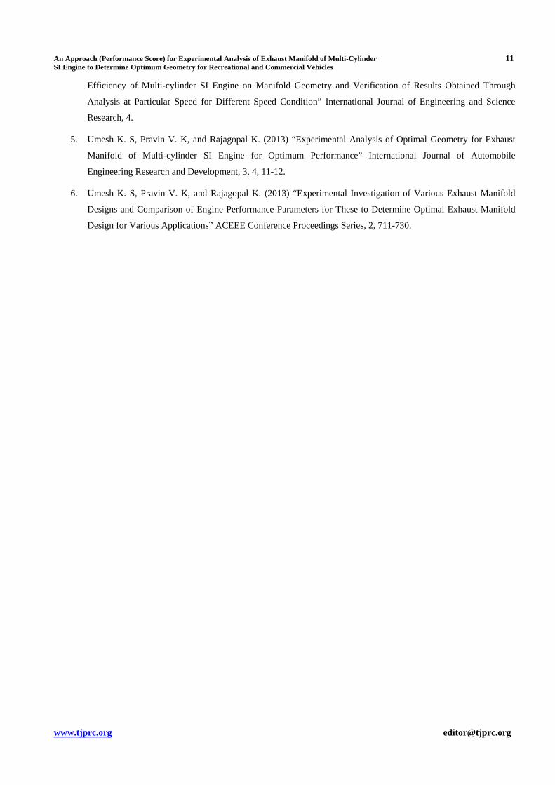
Figure 11 gives the variation of overall performance score for different exhaust manifold models
(Commercial purpose). It is found that highest overall performance score is 83.36 for LBCER as the overall performance
of the engine is the best.
It is observed that overall performance of the engine is improved using LBCER model for commercial
applications.
10 K. S. Umesh, V. K. Pravin & K. Rajagopal
Impact Factor (JCC): 5.1066 Index Copernicus Value (ICV): 3.0
Figure 11: Overall Performance Score for Commercial Purpose
CONCLUSIONS
All the tests on exhaust manifold are conducted on four stroke four cylinder engine of Maruti - Suzuki Wagon-R.
Experiments are carried out at six different loads keeping speed constant. The findings of the work are enlisted below:
• The minimum backpressures and higher exhaust velocities are achieved by using exhaust manifolds with reducers,
thus reducing emissions and which helps in development of emission standards. Reduction in un-burnt fuel inside
the chamber results in increased power with less consumption of fuel thereby increasing its fuel efficiency.
• LBCER exhaust manifold gives highest overall performance score of 82.639 for recreational applications.
The modification in its geometry by varying its exit position (Centre exit) with reducer and using long bends helps
in increasing the overall performance of engine from recreational application point of view. The cost of mass
production of these models is higher than SBSER model due to longer bends.
• LBCER exhaust manifold gives highest overall performance score of 83.36 for commercial applications.
The modification in its geometry by varying its exit position (centre exit) with reducer and using long bends helps
in increasing the overall performance of engine form commercial application point of view.
• LBSER and SBSER exhaust manifolds are the second best and have overall performance scores of 81.112 and
83.2 for recreational and commercial applications respectively. The advantage of LBCER model can be achieved
by using LBSER and SBSER models as these models improve the engine performance considerably. The mass
production of SBSER model can be reduced to economic range due to shorter bends.
REFERENCES
1. Scheeringa K, Schwerin R, Groves R, Zhou C. Q, Majdak J. and Cantwell R. (2002) “CFD Analysis of a Liquid
Cooled Exhaust Manifold”, 8th AIAA/ASME Joint Thermophysics and Heat Transfer Conference.
2. Deger Y, Simperl B, and Jimenez L. P. (2004) “Coupled CFD-FE-Analysis for the Exhaust Manifold of a Diesel
Engine”, Abaqus Users’ Conference, 199-208.
3. Umesh K. S, Pravin V. K, and Rajagopal K. (2013) “CFD Analysis and Experimental Verification of Effect of
Manifold Geometry on Volumetric Efficiency and Backpressure for Multi-cylinder SI Engine” International
Journal of Engineering and Science Research, 3, 7, 342-353.
4. Umesh K. S, Pravin V. K, and Rajagopal K. (2013) “Experimental Analysis of Dependence of Volumetric
An Approach (Performance Score) for Experimental Analysis of Exhaust Manifold of Multi-Cylinder 11 SI Engine to Determine Optimum Geometry for Recreational and Commercial Vehicles
www.tjprc.org [email protected]
Efficiency of Multi-cylinder SI Engine on Manifold Geometry and Verification of Results Obtained Through
Analysis at Particular Speed for Different Speed Condition” International Journal of Engineering and Science
Research, 4.
5. Umesh K. S, Pravin V. K, and Rajagopal K. (2013) “Experimental Analysis of Optimal Geometry for Exhaust
Manifold of Multi-cylinder SI Engine for Optimum Performance” International Journal of Automobile
Engineering Research and Development, 3, 4, 11-12.
6. Umesh K. S, Pravin V. K, and Rajagopal K. (2013) “Experimental Investigation of Various Exhaust Manifold
Designs and Comparison of Engine Performance Parameters for These to Determine Optimal Exhaust Manifold
Design for Various Applications” ACEEE Conference Proceedings Series, 2, 711-730.

Top Related
Copyright © 2022 FDOKUMEN

