ZM305 Standard - Avery Weigh-Tronix
86
ZM305 Standard Indicator User Instructions AWT35-501249 Issue AE
-
Upload
khangminh22 -
Category
Documents
-
view
0 -
download
0
Transcript of ZM305 Standard - Avery Weigh-Tronix

ZM305 StandardIndicator
User Instructions
AWT35-501249 Issue AE

ZM305_standard_u_en_501249.book
Avery Weigh-Tronix is a trademark of the Illinois Tool Works group of companies whose ultimate parent company is Illinois Tool Works Inc (“Illinois Tool Works”). Copyright © 2018 Illinois Tool Works. All rights reserved.
No part of this publication may be reproduced by making a facsimile copy, by the making of a copy in three dimensions of a two-dimensional work and the making of a copy in two dimensions of a three-dimensional work, stored in any medium by electronic means, or transmitted in any form or by any means, including electronic, mechanical, broadcasting, recording or otherwise without the prior written consent of the copyright owner, under license, or as permitted by law.
This publication was correct at the time of going to print, however Avery Weigh-Tronix reserves the right to alter without notice the specification, design, price or conditions of supply of any product or service at any time.

ZM305 Standard Indicator User Instructions 3
Table of Contents
page
Table of Contents ...................................................................................................................................... 3
Chapter 1 General information and warnings ......................................................................................... 5About this manual .............................................................................................................. 5
Text conventions ......................................................................................................... 5Special messages ....................................................................................................... 5
Installation .......................................................................................................................... 5Safe handling of equipment with batteries .................................................................. 6Wet conditions ............................................................................................................. 6
Routine maintenance ......................................................................................................... 6Cleaning the machine ........................................................................................................ 7Training .............................................................................................................................. 7Sharp objects ..................................................................................................................... 7FCC and EMC declarations of compliance ........................................................................ 8Declarations of Conformity ................................................................................................. 9
Chapter 2 Introduction ............................................................................................................................ 11Front panel ....................................................................................................................... 11
Annunciators ............................................................................................................. 13Powering up the ZM305 ................................................................................................... 14Entering a negative number ............................................................................................. 14
Chapter 3 Indicator applications ............................................................................................................ 15General weighing application ........................................................................................... 15
SELECT key default function .................................................................................... 15Gross weighing .......................................................................................................... 15Net weighing .............................................................................................................. 16Using setpoints .......................................................................................................... 18Printing ...................................................................................................................... 20ID Entry ..................................................................................................................... 20
Accumulator application ................................................................................................... 21SELECT key default function .................................................................................... 21Special key functions ................................................................................................. 21Accumulator operation .............................................................................................. 21
Counting application ........................................................................................................ 23SELECT key default function .................................................................................... 23Special key functions ................................................................................................. 23Sample operation ...................................................................................................... 23Dribble sampling ........................................................................................................ 23Bulk sampling ............................................................................................................ 24Piece weight entry ..................................................................................................... 25
Checkweighing application .............................................................................................. 26SELECT key default function .................................................................................... 26Special key functions ................................................................................................. 26Checkweigh operation ............................................................................................... 26Weighing a target object ............................................................................................ 27Setting upper and lower limits ................................................................................... 27Setpoint operation in the checkweighing application ................................................. 28
Batching application ......................................................................................................... 29SELECT key default function .................................................................................... 29Special key functions ................................................................................................. 29Batching operation .................................................................................................... 30

4 ZM305 Standard Indicator User Instructions
2-Speed filling ............................................................................................................ 30Ingredient filling ......................................................................................................... 30Independent setpoints ............................................................................................... 31Fill/Discharge ............................................................................................................. 31
Peak hold application ....................................................................................................... 32SELECT key default function .................................................................................... 32Special key functions ................................................................................................. 32Peak hold operation .................................................................................................. 32
Remote display application .............................................................................................. 33In-Motion application ........................................................................................................ 34
SELECT key operation .............................................................................................. 34
Chapter 4 Menus ...................................................................................................................................... 35Accessing the menus ....................................................................................................... 35Menu annunciators .......................................................................................................... 35Exiting the menus ............................................................................................................ 36USER level menus ........................................................................................................... 36User menu ....................................................................................................................... 37
Time .......................................................................................................................... 37Date ........................................................................................................................... 38Site ID ........................................................................................................................ 39Seal ........................................................................................................................... 39
About menu ...................................................................................................................... 40Boot ........................................................................................................................... 40Firm and App ............................................................................................................. 41Serial ......................................................................................................................... 41Option ........................................................................................................................ 41Enet ........................................................................................................................... 42Dload ......................................................................................................................... 43
Audit menu ....................................................................................................................... 44Counter ...................................................................................................................... 44Print ........................................................................................................................... 45
Chapter 5 Communications .................................................................................................................... 46Default print formats ......................................................................................................... 46
Chapter 6 Error messages ...................................................................................................................... 48
Chapter 7 Supervisor menu .................................................................................................................... 49General Weighing application supervisor menu .............................................................. 50
Setpoint ..................................................................................................................... 51Tare ........................................................................................................................... 54Battery ....................................................................................................................... 56
Accumulator application supervisor menu ....................................................................... 58Accumulator .............................................................................................................. 59
Counting application supervisor menu ............................................................................. 62Count ......................................................................................................................... 62
Checkweighing application supervisor menu ................................................................... 66Check ........................................................................................................................ 67
Batching application supervisor menu ............................................................................. 69Setpoint ..................................................................................................................... 69Batch ......................................................................................................................... 72Notes on batching ..................................................................................................... 75
Peak Hold application supervisor menu ........................................................................... 77Peak hold .................................................................................................................. 77
Remote Display application supervisor menu .................................................................. 79In-Motion application supervisor menu ............................................................................ 81
In-Motion ................................................................................................................... 82

ZM305 Standard Indicator User Instructions 5
1.1 About this manual
1 General information and warnings
1.1 About this manual
This manual is divided into chapters by the chapter number and the large text at the top of a page. Subsections are labeled as shown by the 1.1 and 1.1.1 headings. The names of the chapter and the next subsection level appear at the top of alternating pages of the manual to remind you of where you are in the manual. The manual name and page numbers appear at the bottom of the pages.
1.1.1 Text conventions
Key names are shown in bold and reflect the case of the key being described. If a key has a dual function it may be referred to by its alternate function.
Displayed messages appear in bold italic type and reflect the case of the displayed message.
Annunciator names appear as italic text and reflect the case of the annunciator.
1.1.2 Special messages
Examples of special messages you will see in this manual are defined below. The signal words have specific meanings to alert you to additional information or the relative level of hazard.
1.2 Installation
CAUTION!This is a Caution symbol.Cautions give information about procedures that, if not observed, could result in damage to equipment or corruption to and loss of data.
NOTE: This is a Note symbol. Notes give additional and important information, hints and tips that help you to use your product.
NO USER SERVICEABLE PARTS. REFER TO QUALIFIED SERVICE PERSONNEL FOR SERVICE.

6 ZM305 Standard Indicator User Instructions
General information and warnings
1.2.1 Safe handling of equipment with batteries
1.2.2 Wet conditions
Under wet conditions, the plug must be connected to the final branch circuit via an appropriate socket / receptacle designed for washdown use.
Installations within the USA should use a cover that meets NEMA 3R specifications as required by the National Electrical Code under section 410-57. This allows the unit to be plugged in with a rain tight cover fitted over the plug.
Installations within Europe must use a socket which provides a minimum of IP56 protection to the plug / cable assembly. Care must be taken to make sure that the degree of protection provided by the socket is suitable for the environment.
1.3 Routine maintenance
Always isolate the indicator from the power supply before starting any routine maintenance to avoid the possibility of electric shock.
CAUTION: Danger of explosion if battery is incorrectly replaced. Replace only with the same or equivalent type recommended by the manufacturer. Dispose of used batteries according to the manufacturer’s instructions.
ATTENTION: Il y a danger d'explosion s'il y a remplacement incorrect de la batterie, remplacer uniquement avec une batterie du même type ou d'un type équivalent recommandé par le constructeur. Mettre au rebut les batteries usagées conformément aux instructions du fabricant.
IMPORTANT: This equipment must be routinely checked for proper operation and calibration.Application and usage will determine the frequency of calibration required for safe operation.

ZM305 Standard Indicator User Instructions 7
1.4 Cleaning the machine
1.4 Cleaning the machine
1.5 Training
Do not attempt to operate or complete any procedure on a machine unless you have received the appropriate training or read the instruction books.
To avoid the risk of RSI (Repetitive Strain Injury), place the machine on a surface which is ergonomically satisfactory to the user. Take frequent breaks during prolonged usage.
1.6 Sharp objects
Do not use sharp objects such as screwdrivers or long fingernails to operate the keys.
Table 1.1 Cleaning DOs and DON’Ts
DO DO NOT
Wipe down the outside of standard products with a clean cloth, moistened with water and a small amount of mild detergent
Attempt to clean the inside of the machine
Use harsh abrasives, solvents, scouring cleaners or alkaline cleaning solutions
Spray the cloth when using a proprietary cleaning fluid
Spray any liquid directly on to the display windows

8 ZM305 Standard Indicator User Instructions
General information and warnings
1.7 FCC and EMC declarations of compliance
United States
Canada
European Countries
This equipment has been tested and found to comply with the limits for a Class A digital device, pursuant to Part 15 of the FCC Rules. These limits are designed to provide reasonable protection against harmful interference when the equipment is operated in a commercial environment. This equipment generates, uses, and can radiate radio frequency energy and, if not installed and used in accordance with the instruction manual, may cause harmful interference to radio communications. Operation of this equipment in a residential area is likely to cause harmful interference in which case the user will be required to correct the interference at his own expense.
This digital apparatus does not exceed the Class A limits for radio noise emissions from digital apparatus set out in the Radio Interference Regulations of the Canadian Department of Communications.
Le présent appareil numérique n’émet pas de bruits radioélectriques dépassant les limites applicables aux appareils numériques de la Classe A prescrites dans le Règlement sur le brouillage radioélectrique edicté par le ministère des Communications du Canada.
WARNING: This is a Class A product. In a domestic environment, this product may cause radio interference in which the user may be required to take adequate measures.

ZM305 Standard Indicator User Instructions 9
1.8 Declarations of Conformity
1.8 Declarations of Conformity
EN
EU
Decl
arat
ion
of
Conf
orm
ity
ZM3x
x / Z
Q37
5 Na
me
and
addr
ess
of th
e m
anuf
actu
rer:
Aver
y W
eigh
-Tro
nix1
Foun
dry
Lane
Sm
ethw
ick
W
est M
idla
nds
B66
2LP
EN
GLA
ND
This
dec
lara
tion
of c
onfo
rmity
is is
sued
und
er th
e so
le re
-sp
onsi
bilit
y of
the
man
ufac
ture
r O
bjec
t of t
he d
ecla
ratio
n:
ZM30
1-A
D* /
SD
* / S
P*
ZM30
3-A
D* /
SD
* / S
P*
ZM30
5-SD
1 / S
G1
ZQ37
5-SD
1 (*
=1/2
)
The
obje
ct o
f the
dec
lara
tion
desc
ribed
abo
ve is
in c
onfo
rmity
w
ith th
e re
leva
nt U
nion
har
mon
isat
ion
legi
slat
ion:
Appl
icab
le D
irect
ives
Har
mon
ised
st
anda
rds
or
oth
er te
chni
cal
spec
ifica
tions
2014
/30/
EU
Elec
trom
agne
tic C
ompa
tibilit
y EN
6100
0-6-
4:20
07
2014
/35/
EU
Elec
trical
equip
men
t des
igned
for u
se w
ithin
certa
in vo
ltage
limits
EN 6
0950
–1:2
006
+A11
:200
9 +A
1:20
10
+A12
:201
1
2011
/65/
EU
Rest
rictio
n of
the
use
of ce
rtain
haza
rdou
s su
bsta
nces
in e
lectric
al an
d ele
ctro
nic
equip
men
t
EN 5
0581
:201
2
2014
/31/
EU2
Non-
Auto
mati
c Weig
hing
Instru
men
ts
EN 4
5501
:201
5 W
ELM
EC 2
.1
The
notif
ied
body
NM
O, 0
126
perfo
rmed
the
appr
oval
for
mod
ule
B: E
U-ty
pe e
xam
inat
ion
(AN
NEX
II S
ectio
n 1
of
2014
/31/
EU) a
nd is
sued
the
certi
ficat
e:
UK
2923
Th
e no
tifie
d bo
dy S
GS
Uni
ted
Kin
gdom
Ltd
, 012
0 is
sued
th
e ap
prov
al fo
r mod
ule
D: C
onfo
rmity
to ty
pe b
ased
on
qual
ity a
ssur
ance
of t
he p
rodu
ctio
n pr
oces
s (A
NN
EX II
Se
ctio
n 2
of 2
014/
31/E
U) a
nd is
sued
the
certi
ficat
e:
GB
95/5
0915
Ad
ditio
nal i
nfor
mat
ion:
N
ote
IT
W L
td tr
adin
g as
Ave
ry W
eigh
-Tro
nix
Reg
. Offi
ce: N
exus
Hou
se, S
tatio
n R
oad,
Egh
am,
Sur
rey,
TW
20 9
LB, E
ngla
nd
Not
e
This
dec
lara
tion
is o
nly
valid
if th
e no
n-
auto
mat
ic w
eigh
ing
inst
rum
ent w
as v
erifi
ed b
y th
e m
anuf
actu
rer o
r with
a c
ertif
icat
e of
co
nfor
mity
issu
ed b
y a
notif
ied
body
.
Sign
ed fo
r and
on
beha
lf of
: A
very
Wei
gh-T
roni
x
at
1000
Arm
stro
ng D
rive,
Fai
rmon
t, M
N, 5
6031
-143
9,
USA
on
20
17-1
2-15
K
.Det
ert
Inno
vatio
ns/M
arke
ting
Dire
ctor
7650
1-50
6 Is
sue
DE
EU-
Konf
orm
itäts
erkl
ärun
g
ZM3x
x / Z
Q37
5Na
me
und
Ansc
hrift
des
Her
stel
lers
: Av
ery
Wei
gh-T
roni
x1 Fo
undr
y La
ne
Smet
hwic
k
Wes
t Mid
land
s B
66 2
LP
ENG
LAN
D
Die
alle
inig
e Ve
rant
wor
tung
für d
ie A
usst
ellu
ng d
iese
r Kon
-fo
rmitä
tser
klär
ung
trägt
der
Her
stel
ler.
G
egen
stan
d de
r Erk
läru
ng:
ZM30
1-A
D* /
SD
* / S
P*
ZM30
3-A
D* /
SD
* / S
P*
ZM30
5-SD
1 / S
G1
ZQ37
5-SD
1 (*
=1/2
)
Der
obe
n be
schr
iebe
ne G
egen
stan
d de
r Erk
läru
ng e
rfüllt
die
ei
nsch
lägi
gen
Har
mon
isie
rung
srec
htsv
orsc
hrift
en d
er U
nion
:
Ange
wan
dte
Ric
htlin
ien
Har
mon
isie
rte
Nor
men
ode
r so
nstig
en
tech
nisc
hen
Sp
ezifi
katio
nen
2014
/30/
EU
Elek
trom
agne
tisch
e Ve
rträg
lichk
eit
EN61
000-
6-4:
2007
2014
/35/
EU
Elek
trisc
her B
etrie
bsm
ittel
zur
Ve
rwen
dung
inne
rhal
b be
stim
mte
r S
panu
ngsg
renz
en
EN 6
0950
–1:2
006
+A11
:200
9 +A
1:20
10
+A12
:201
1
2011
/65/
EU
Besc
hrän
kung
der
Ver
wen
dung
be
stim
mte
r gef
ährli
cher
Sto
ffe in
El
ektro
- und
Ele
ktro
nikg
erät
en
EN 5
0581
:201
2
2014
/31/
EU2
Nich
tselbs
ttätig
er W
aage
n EN
455
01:2
015
WEL
MEC
2.1
Die
not
ifizi
erte
Ste
lle N
MO
, 012
6 ha
t die
Zul
assu
ng fü
r Mod
ul
B du
rchg
efüh
rt: E
U-B
aum
uste
rprü
fung
(AN
HAN
G II
Abs
chni
tt 1
2014
/31/
EU) u
nd fo
lgen
de B
esch
eini
gung
aus
gest
ellt:
U
K29
23
Die
not
ifizi
erte
Ste
lle S
GS
Uni
ted
Kin
gdom
Ltd
, 012
0 ha
t di
e Zu
lass
ung
für M
odul
D e
rteilt
: Kon
form
ität m
it de
r Bau
art
auf d
er G
rund
lage
der
Qua
lität
ssic
heru
ng b
ezog
en a
uf d
en
Prod
uktio
nspr
ozes
s (A
NH
ANG
II A
bsch
nitt
2 20
14/3
1/EU
) un
d fo
lgen
de B
esch
eini
gung
aus
gest
ellt:
GB
95/5
0915
Zu
satz
anga
ben:
A
nmer
kung
1 : IT
W L
td H
ande
l als
Ave
ry W
eigh
-Tro
nix
Sitz
: Nex
us H
ouse
, Sta
tion
Roa
d, E
gham
, S
urre
y, T
W20
9LB
, Eng
land
A
nmer
kung
2 : D
iese
Erk
läru
ng g
ilt n
ur, w
enn
die
nich
tsel
bsttä
tige
Waa
ge v
om H
erst
elle
r gee
icht
wur
de o
der i
n Ve
rbin
dung
mit
eine
r Kon
form
itäts
besc
hein
igun
g ei
ner
bena
nnte
n St
elle
.
Unt
erze
ichn
et fü
r und
im N
amen
von
: A
very
Wei
gh-T
roni
x
bei
1000
Arm
stro
ng D
rive,
Fai
rmon
t, M
N, 5
6031
-143
9,
USA
am
20
17-1
2-15
K
.Det
ert
Inno
vatio
nen
/ Mar
ketin
gdire
ktor
FR
Décl
ara�
on U
E de
Co
nfor
mité
ZM3x
x / Z
Q37
5 No
m e
t adr
esse
du
fabr
ican
t :
Aver
y W
eigh
-Tro
nix1
Foun
dry
Lane
Sm
ethw
ick
W
est M
idla
nds
B66
2LP
A
NG
LETE
RR
E
La p
rése
nte
décl
arat
ion
de c
onfo
rmité
est
éta
blie
sou
s la
se
ule
resp
onsa
bilit
é du
fabr
ican
t.
Obj
et d
e la
dec
lara
tion:
ZM30
1-A
D* /
SD
* / S
P*
ZM30
3-A
D* /
SD
* / S
P*
ZM30
5-SD
1 / S
G1
ZQ37
5-SD
1 (*
=1/2
)
L’ob
jet d
e la
déc
lara
tion
décr
it ci
-des
sus
est c
onfo
rme
à la
lé
gisl
atio
n d’
harm
onis
atio
n de
l’U
nion
app
licab
le:
Les
dire
ctive
s en
vig
ueur
Le
s no
rmes
ha
rmon
isée
s ou
d’
autre
s
spéc
ifica
tions
te
chni
ques
2014
/30/
UE
C
ompa
tibilit
é Él
ectro
mag
nétiq
ue
EN61
000-
6-4:
2007
2014
/35/
UE
Mat
érie
l éle
ctriq
ue d
estin
é à
être
em
ploy
é da
ns c
erta
ines
limite
s de
te
nsio
n EN
609
50–1
:200
6 +A
11:2
009
+A1:
2010
+A
12:2
011
2011
/65/
UE
La li
mita
tion
de l’
utilis
atio
n de
cer
tain
es
subs
tanc
es d
ange
reus
es d
ans
les
équi
pem
ents
éle
ctriq
ues
et
élec
troni
ques
EN 5
0581
:201
2
2014
/31/
UE2
Inst
rum
ents
de p
esag
e à
fonc
tionn
emen
t no
n au
tomat
ique
EN 4
5501
:201
5 W
ELM
EC 2
.1
L’or
gani
sme
notif
ié N
MO
, 012
6 a
effe
ctué
l'hom
olog
atio
n po
ur le
mod
ule
B: L
'exa
men
UE
de ty
pe (A
NN
EXE
II l'a
rticl
e 1
de 2
014/
31/U
E) e
t a é
tabl
i le
certi
ficat
:
UK
2923
L’
orga
nism
e no
tifié
SG
S U
nite
d K
ingd
om L
td, 0
120
déliv
ré
l'hom
olog
atio
n po
ur le
mod
ule
D: C
onfo
rmité
au
type
sur
la
base
de
l’ass
uran
ce d
e la
qua
lité
du p
roce
ssus
de
prod
uctio
n
(AN
NEX
E II
l'arti
cle
2 de
201
4/31
/UE)
et a
éta
bli l
e ce
rtific
at:
GB
95/5
0915
In
form
atio
ns c
ompl
émen
taire
s:
Not
a 1 :
ITW
Ltd
exe
rçan
t éga
lem
ent s
ous
le n
om d
e A
very
Wei
gh-
Tron
ix
Siè
ge s
ocia
l: Ne
xus
Hou
se, S
tatio
n Ro
ad,
Egha
m,
Sur
rey,
TW
20 9
LB, A
ngle
terre
N
ota
2 : C
ette
déc
lara
tion
est v
alid
e se
ulem
ent s
i l’i
nstru
men
t de
pesa
ge à
fonc
tionn
emen
t non
aut
oma-
tique
a é
té v
érifi
é pa
r le
fabr
ican
t ou
avec
une
atte
sta-
tion
de c
onfo
rmité
dél
ivrée
par
un
orga
nism
e no
tifié
.
Sign
é pa
r et a
u no
m d
e:
Ave
ry W
eigh
-Tro
nix
à 10
00 A
rmst
rong
Driv
e, F
airm
ont,
MN
, 560
31-1
439,
U
SA
le
2017
-12-
15
K.D
eter
t In
nova
tions
/ Di
rect
eur M
arke
ting
NL
EU-
Conf
orm
iteits
verk
lar-
ing
ZM3x
x / Z
Q37
5 Na
am e
n ad
res
van
de fa
brika
nt :
Aver
y W
eigh
-Tro
nix1
Foun
dry
Lane
Sm
ethw
ick
W
est M
idla
nds
B66
2LP
EN
GEL
AN
D
Dez
e co
nfor
mite
itsve
rkla
ring
wor
dt v
erst
rekt
ond
er v
olle
dige
ve
rant
woo
rdel
ijkhe
id v
an d
e fa
brik
ant.
Voor
wer
p va
n de
ver
klar
ing:
ZM30
1-A
D* /
SD
* / S
P*
ZM30
3-A
D* /
SD
* / S
P*
ZM30
5-SD
1 / S
G1
ZQ37
5-SD
1 (*
=1/2
)
Het
hie
rbov
en b
esch
reve
n vo
orw
erp
is in
ove
reen
stem
min
g m
et d
e de
sbet
reffe
nde
harm
onis
atie
wet
gevin
g va
n de
Uni
e:
Toep
asse
lijke
richt
lijnen
Geh
arm
onis
eerd
e st
anda
arde
n of
and
ere
te
chni
sche
sp
ecifi
catie
s
2014
/30/
EU
Elek
trom
agne
tisch
e com
patib
iliteit
EN
6100
0-6-
4:20
07
2014
/35/
EU
Elek
trisc
h m
ater
iaal
bes
tem
d vo
or
gebr
uik
binn
en b
epaa
lde
span
-ni
ngsg
renz
en
EN 6
0950
–1:2
006
+A11
:200
9 +A
1:20
10
+A12
:201
1
2011
/65/
EU
Bepe
rking
van
het g
ebru
ik va
n be
paald
e ge
vaar
lijke
stoffe
n in
elekt
risch
e en
el-
ektro
nisch
e ap
para
tuur
EN 5
0581
:201
2
2014
/31/
EU2
Nie
t-aut
omat
isch
e w
eegw
erkt
uige
n EN
455
01:2
015
WEL
MEC
2.1
De
aang
emel
de in
stan
tie N
MO
, 012
6 vo
erde
de
goed
keur
ing
voor
de
mod
ule
B : E
U -
type
onde
rzoe
k (B
IJLA
GE
II , s
ectie
1,
201
4/31
/ EU
en
het c
ertif
icaa
t ver
stre
kt:
UK
2923
D
e aa
ngem
elde
inst
antie
SG
S U
nite
d K
ingd
om L
td, 0
120
vers
trekt
e de
goe
dkeu
ring
voor
de
mod
ule
D :
conf
orm
iteit
met
het
type
op
basi
s va
n kw
alite
itsbo
rgin
g va
n he
t pr
oduc
tiepr
oces
(BIJ
LAG
E II
, sec
tie 2
van
201
4/31
/ EU
) en
vers
trekt
e he
t cer
tific
aat:
GB
95/5
0915
Aa
nvul
lend
e in
form
atie
: N
oot
IT
W L
td tr
adin
g al
s A
very
Wei
gh-T
roni
x Z
etel
: Nex
us H
ouse
, Sta
tion
Road
, Eg
ham
, S
urre
y, T
W20
9LB
, Eng
land
N
oot
D
eze
verk
larin
g is
alle
en g
eldi
g in
dien
het
wee
gwer
ktui
g do
or d
e fa
brik
ant i
s ge
verif
ieer
d, o
f m
et e
en V
erkl
arin
g va
n ov
eree
nste
mm
ing,
afg
egev
en
door
een
bev
oegd
e in
stan
tie.
Ond
erte
kend
voo
r en
nam
ens:
A
very
Wei
gh-T
roni
x
bij
1000
Arm
stro
ng D
rive,
Fai
rmon
t, M
N, 5
6031
-143
9,
VS
op
2017
-12-
15
K.D
eter
t
Inno
vatie
s / M
arke
ting
Dire
ctor
IT
Dic
hiar
azio
ne
di
Conf
orm
ità U
E
ZM3x
x / Z
Q37
5No
me
e in
diriz
zo d
el fa
bbric
ante
: Av
ery
Wei
gh-T
roni
x1 Fo
undr
y La
ne
Smet
hwic
k
Wes
t Mid
land
s B
66 2
LP
ING
HIL
TER
RA
La p
rese
nte
dich
iara
zion
e di
con
form
ità è
rila
scia
ta s
otto
la
resp
onsa
bilit
à es
clus
iva d
el fa
bbric
ante
. O
gget
to d
ella
dic
hiar
azio
ne:
ZM30
1-A
D* /
SD
* / S
P*
ZM30
3-A
D* /
SD
* / S
P*
ZM30
5-SD
1 / S
G1
ZQ37
5-SD
1 (*
=1/2
)
L’og
getto
del
la d
ichi
araz
ione
di c
ui s
opra
è c
onfo
rme
alla
pe
rtine
nte
norm
ativa
di a
rmon
izza
zion
e de
ll’U
nion
e:
Dire
ttive
app
licab
ili A
rmon
izza
to
stan
dard
o
altre
spe
cific
azio
ni
tecn
iche
2014
/30/
UE
Co
mpa
tibilit
à ele
ttrom
agne
tica
EN61
000-
6-4:
2007
2014
/35/
UE
Mat
eria
le e
lettr
ico
dest
inat
o a
esse
re
adop
erat
o en
tro ta
luni
limiti
di t
en-
sion
e EN
609
50–1
:200
6 +A
11:2
009
+A1:
2010
+A
12:2
011
2011
/65/
UE
Res
trizi
one
dell’
uso
di d
eter
min
ate
sost
anze
per
icol
ose
nelle
app
arec
chia
-tu
re e
lettr
iche
ed
elet
troni
che
EN 5
0581
:201
2
2014
/31/
UE2
Stru
men
ti per
pes
are
a fu
nzion
amen
to n
on
autom
atico
EN 4
5501
:201
5 W
ELM
EC 2
.1
L’en
te n
otifi
cato
NM
O, 0
126
ha d
ato
l'app
rova
zion
e de
l m
odul
o B
: l’e
sam
inaz
ione
tipo
UE
(AN
NESS
O II
, se
zion
e 1,
20
14/3
1/U
E) e
ha
rilas
ciat
o il
certi
ficat
o:
UK
2923
L’
ente
not
ifica
to S
GS
Uni
ted
Kin
gdom
Ltd
, 012
0 ha
rila
s-ci
ato
l'app
rova
zion
e pe
r il m
odul
o D
: C
onfo
rmità
al t
ipo
basa
ta s
ulla
gar
anzi
a de
lla q
ualit
à de
l pro
cess
o di
pr
oduz
ione
(ann
esso
II ,
punt
o 2
o 20
14/3
1 / U
E) e
ha
rilas
ciat
o il
certi
ficat
o:
GB
95/5
0915
In
form
azio
ni s
uppl
emen
tari:
Not
a 1 :
ITW
Ltd
trad
ing
com
e A
very
Wei
gh-T
roni
x S
ede
dell'u
ffici
o: N
exus
Hou
se, S
tatio
n R
oad,
Egh
am,
Sur
rey,
TW
20 9
LB, E
ngla
nd
Not
a 2 :
Que
sta
dich
iara
zion
e è
valid
a so
lam
ente
se
lo s
trum
en-
to d
i pes
atur
a no
n au
tom
atic
o è
stat
o ve
rific
ato
dal p
rodu
ttore
o p
rovv
isto
di u
n ce
rtific
ato
di
conf
orm
ità ri
lasc
iato
da
un e
nte
ricon
osci
uto.
Firm
ato
a no
me
e pe
r con
to d
i:
Ave
ry W
eigh
-Tro
nix
a 10
00 A
rmst
rong
Driv
e, F
airm
ont,
MN
, 560
31-1
439,
U
.S.A
. su
20
17-1
2-15
K
.Det
ert
Inno
vatio
ns /
Dire
ttore
Mar
ketin
g
ES
Decl
arac
ión
UE
de
Conf
orm
idad
ZM3x
x / Z
Q37
5 No
mbr
e y
dire
cció
n de
l fab
rican
te
Aver
y W
eigh
-Tro
nix1
Foun
dry
Lane
Sm
ethw
ick
W
est M
idla
nds
B66
2LP
IN
GLA
TER
RA
La p
rese
nte
decl
arac
ión
de c
onfo
rmid
ad s
e ex
pide
baj
o la
ex
clus
iva re
spon
sabi
lidad
del
fabr
ican
te.
Obj
eto
de la
dec
lara
ción
:
ZM30
1-A
D* /
SD
* / S
P*
ZM30
3-A
D* /
SD
* / S
P*
ZM30
5-SD
1 / S
G1
ZQ37
5-SD
1 (*
=1/2
)
El o
bjet
o de
la d
ecla
raci
ón d
escr
ita a
nter
iorm
ente
es
co
nfor
me
con
la le
gisl
ació
n de
arm
oniz
ació
n pe
rtine
nte
de la
U
nión
: D
irect
ivas
aplic
able
s N
orm
as
arm
oniz
adas
u
otra
s
espe
cific
acio
nes
técn
icas
2014
/30/
UE
C
ompa
tibilid
ad e
lect
rom
agné
tica
EN61
000-
6-4:
2007
2014
/35/
UE
Mat
eria
l elé
ctric
o de
stin
ado
a ut
iliz-
arse
con
det
erm
inad
os lí
mite
s de
te
nsió
n EN
609
50–1
:200
6 +A
11:2
009
+A1:
2010
+A
12:2
011
2011
/65/
UE
Res
tricc
ione
s a
la u
tiliz
ació
n de
det
er-
min
adas
sus
tanc
ias
pelig
rosa
s en
ap
arat
os e
léct
ricos
y e
lect
róni
cos
EN 5
0581
:201
2
2014
/31/
UE2
Inst
rum
ento
s de
pesa
je de
func
ionam
iento
no
aut
omáti
co
EN 4
5501
:201
5 W
ELM
EC 2
.1
El o
rgan
ismo
notif
icad
o N
MO
, 012
6 re
aliz
ó la
apr
obac
ión
para
el m
ódul
o B:
tipo
de
exam
en U
E (A
NEX
O II
Sec
ción
1
de 2
014/
31 /
UE)
y e
xpid
e el
cer
tific
ado:
UK
2923
El
org
anism
o no
tific
ado
SGS
Uni
ted
Kin
gdom
Ltd
, 012
0 ex
pidi
ó la
apr
obac
ión
para
el M
ódul
o D
: Con
form
idad
al t
ipo
se b
ase
en la
gar
antía
de
calid
ad d
el p
roce
so d
e pr
oduc
ción
(A
NEX
O II
, Sec
ción
2 o
201
4/31
/ U
E) y
exp
ide
el c
ertif
icad
o:
GB
95/5
0915
In
form
ació
n ad
icio
nal:
N
ota1 :
ITW
Ltd
trad
ing
as A
very
Wei
gh-T
roni
x O
ficin
a re
gist
rada
: Nex
us H
ouse
, Sta
tion
Roa
d, E
gham
, S
urre
y, T
W20
9LB
, Ang
lete
rre
Not
a2 : Es
ta d
ecla
raci
ón e
s vá
lida
sola
men
te s
i el e
quip
o de
pe
saje
no
auto
mát
ico
ha s
ido
verif
icad
o po
r el
fabr
ican
te o
con
cer
tific
ado
de c
onfo
rmid
ad e
miti
do p
or
un o
rgan
ism
o no
tific
ado.
Firm
ado
en n
ombr
e de
: A
very
Wei
gh-T
roni
x
en
1000
Arm
stro
ng D
rive,
Fai
rmon
t, M
N, 5
6031
-143
9,
EE.U
U
el
2017
-12-
15
K.D
eter
t In
nova
cion
es /
Dire
ctor
de
Mar
ketin
g

10 ZM305 Standard Indicator User Instructions
General information and warnings

ZM305 Standard Indicator User Instructions 11
2.1 Front panel
2 IntroductionThe ZM305, shown in Figure 2.1, is an easy to use weight indicator. The ZM305 comes in a stainless steel housing with an IBN display for high contrast visibility in all conditions. The indicator has a USB port, two serial COM ports and an Ethernet port. Available options are Analog Output, Current Loop/RS485/RS422, USB Device, Wireless Ethernet 802.11g internal module cards, STVS (Severe Transient Voltage Suppression) protection and external battery pack.
The indicator also has three logic level inputs with configurable functions and three setpoint outputs. See the Specification literature for a full list of specifications.
Figure 2.1 Front panel of the ZM305 indicator display
The ZM305 can connect to USB flash drives, printers, remote displays, computers and other peripheral devices via USB, ethernet and serial connections.
2.1 Front panel
The front panel, shown in Figure 2.1, consists of the keys and display.
ID
TARE SELECT
UNITS
1 2 3
4 5 6
7 8 9
C 0
ZM305
ZERO
START
SETUP
STOP
TARGET
GROSSNETTARECOUNTPRINT SP1 SP2 SP3 QTY
PTozgkglb
SAMPLE
F1
Never press a key with anything but your finger. Damage to the overlay may result if sharp or rough objects are used.

12 ZM305 Standard Indicator User Instructions
Introduction
The normal function of the keys on the front panel are listed below. Some keys will have special functions in certain applications. Details are provided in the individual application sections.
Press the TARE key to perform a tare function. Also prompts for a keyboard tare, if enabled. Acts as an up arrow key for menu navigation.Allows you to access minus and comma signs.Press the SELECT key to toggle between the active display values. Press and hold to enter the setpoint editor. Acts as a down arrow key for menu navigation.Allows you to access minus and comma signs.Press the PRINT to send information to a peripheral device through a configured communications port. Performs accumulator function, if enabled. Acts as a left arrow key for menu navigation.
Press the UNITS key to scroll through the available units of measure while in normal operating mode. Acts as a right arrow key for menu navigation.
Press the ZERO key to zero the display. Acts as an ENTER key to accept a displayed value or function.
Press the SAMPLE key to setup counting functions.
Press the START key to start or resume a batching specific action.
Press the STOP key to stop or pause a batching specific action.
Press ID to show the current ID value.Press and hold ID to enter a new ID value.
Press the F1 key to select application specific choices. Aborts a numeric entry and acts as an ESCAPE key in the menu navigation. Also used to display or enter an accumulator channel.
Press the SETUP key to access the setpoint editor. Press and hold to view the password entry screen for menu access.
Press the TARGET key setup checkweighing functions.
Use the numeric keypad to enter numbers in the appropriate screens. Press the C (CLEAR) key to clear the last entry.

ZM305 Standard Indicator User Instructions 13
2.1 Front panel
2.1.1 Annunciators
The annunciators on the display are shown and labeled in Figure 2.2.
Figure 2.2 Annunciators
These annunciators will light during operation to inform the user of the weighing mode, active unit of measure, etc.
GROSSNETTARECOUNTPRINT SP1 SP2 SP3 QTY
PTozgkglb
bargraphcenter-of-zero
motion
Gross weight
Net weight
Tare weight
Count
battery
setpoints See Table 2.1
quantity
preset tare
units of measure
Table 2.1 Circle Annunciator assignments
Annunciator Indicates
Circle 1 (left most) Network activity
Circle 2 Custom unit
Circle 3 Pieceweight
Circle 3 & 4 Minimum
Circle 4 & 5 Maximum
Circle 3, 4, & 5 + GROSS or NET
In Motion

14 ZM305 Standard Indicator User Instructions
Introduction
2.2 Powering up the ZM305
The indicator is always active as long as power is received. Power can be supplied by:
l AC power cord connected to a properly grounded outlet (100 VAC - 240 VAC, 50 or 60 Hz)
l ZM-BAT - Optional external non-charging battery pack with 4 D cellsl DC power source (12 to 36 VDC)
2.3 Entering a negative number
To enter a negative number, press the C key to clear the current value from the display. With only one digit displayed press SELECT. The first character will be the (-) negative sign. Enter the rest of the digits normally.

ZM305 Standard Indicator User Instructions 15
3.1 General weighing application
3 Indicator applicationsThis indicator has several weighing applications that can be enabled through a password protected menu. Only one application can be enabled at a time. The applications available are:
l General Weighing (explained on page 15)l Accumulator (explained on page 21)l Parts Counting (explained on page 23)l Checkweighing (explained on page 26)l Batching (explained on page 29)l Peak Hold (explained on page 32)l Remote Display (explained on page 33)l In-Motion (explained on page 34)
The indicator comes with the default application called General Weighing active.
3.1 General weighing application
This section applies if the General Weighing application is active. Features described here also apply to the other applications except where noted in those application instructions.
3.1.1 SELECT key default function
In the General Weighing application you can view the gross, net and tare display values by repeatedly pressing SELECT.
3.1.2 Gross weighing
To perform gross weighing, power up the unit and follow these steps:
1. Empty the scale and press ZERO to zero the display …
0 is displayed and the center-of-zero annunciator lights.
2. Place item to be weighed on the scale …
Weight is displayed.
3. Repeat steps 1 and 2.
To change unit of measure, press UNITS.

16 ZM305 Standard Indicator User Instructions
Indicator applications
3.1.3 Net weighing
Net weighing is available via three types of tare entry.
Pushbutton tare When enabled press TARE to tare the weight on the scale.
Entered tare When enabled key in a tare weight and press TARE to set.
Preset tare When enabled press TARE to recall a preset tare numbered 1-10.
There is an auto tare clear feature. If this is enabled, after a weighment, when the weight falls into the gross zero band, tare is cleared to zero.
The three types of tare are explained below.
Using Pushbutton Tare
To perform a net weighment using pushbutton tare, power up the unit and follow these steps:
1. Place item to be tared on the scale …
Weight is displayed.
2. Press TARE …
0 is displayed and the NET annunciator lights.
3. Place material to be weighed into or on the tared item on the scale …
Net weight of material is displayed.
4. Repeatedly press SELECT to view the gross, tare, and net values.
5. If repeated weighments use the same tared item, you do not need to establish a new tare value as described in step 1 and 2.
6. To clear a tare value, press and hold the TARE key until …
cLEArEd is displayed.
Using Entered Tare
To perform a net weighment using entered tare, the following steps describe a typical operation:
1. With no weight on the scale, if the display does not read 0 press ZERO …
0 is displayed and the center-of-zero annunciator lights.
Pushbutton and Entered Tares can be enabled simultaneously. If Preset Tare is enabled, Pushbutton and Entered Tares are automatically disabled.
Definition: Gross zero band - this is a configured value that defines a window around gross zero. This is used in several ways in different applications.

ZM305 Standard Indicator User Instructions 17
3.1 General weighing application
2. Key in the tare value of the container or box that will be used to hold the material that requires a net weight value, and press TARE …
Tare weight is displayed as a negative value and the NET annunciator lights.
3. Place the container or box and material to be weighed on the scale …
Net weight of material is displayed.
4. If repeated weighments use the same tared item, you do not need to establish a new tare value as described in step 2.
5. To remove the tare weight from the scale, enter 0, then press TARE …
The tare is cleared and the scale is in gross weigh mode.
Using Preset Tare
Preset tares are available if entered in a password protected menu by a supervisor. There can be up to 10 tares numbered 1-10. To perform a net weighment using one of the preset tares, follow these steps:
1. With no weight on the scale, if the display does not read 0 press ZERO …
0 is displayed and the center-of-zero annunciator lights.
2. Press TARE …
Tare number entry screen appears.
3. Key in the preset tare number and press ZERO …
Tare weight is displayed as a negative value and the NET annunciator lights.
4. Place container or box and material to be weighed on the scale …
Net weight of material is displayed.
5. Repeat step 4 until you are finished using that tare weight.
6. To clear a tare value, press and hold the TARE key until …
cLEArEd is displayed.
Tare is removed automatically if Auto Tare Clear is enabled.
If the active unit of measure is lb-oz then tare weights must be entered in the oz equivalent. To enter 2 lb 4.5 oz you would need to enter 36.5 oz (2 lb = 32 oz plus the 4.5)

18 ZM305 Standard Indicator User Instructions
Indicator applications
3.1.4 Using setpoints
Setpoints are values (weight) at which outputs are triggered automatically. Outputs can control relays connected to valves, lights, other machinery, etc. Setpoint outputs can be configured in the setpoint menu shown in Figure 3.1.
Figure 3.1 Setpoint menu
Follow these steps to configure the outputs:
1. Press SETUP …
out1 is displayed. This is the weight value for setpoint 1. You can access out2 or out3 by pressing the UNITS key. The following instructions apply to any of these three outputs.
2. Press SELECT …
Edit X is displayed. X being the number of output.
3. Press UNITS …
ModE X is displayed. This menu item sets the function of the output. Mode selection must be made before entering the Out value.
Out1 Out2 Out3
Edit X Mode X
Act Abv Act Bel Act In Act Out
Outx Lo Outx Hi
Setpnt
Key invalue
Key invalue
Press SETUP
Key invalue
Mode selection:Act Abv or Act Bel
Mode selection:Act In or Act Out
Default Setpoint operationMode = Active AboveOutputs must be enabled for setpoints to operate. See the Service Manual:
Below Configured Value:Outputs are OFFAnnunciators are OFF
Above Configured Value:Outputs are ONAnnunciators are ON
The setpoint outputs and setpoint annunciators logic state can be inverted from their default settings. Refer to details in the password protected menu settings in the section titled Setpoint on page 51.

ZM305 Standard Indicator User Instructions 19
3.1 General weighing application
4. Press SELECT …
The current Mode setting for the selected Output is displayed. The Mode settings are listed below:
Act AbV (default) The output is active when the weight is above the set value
Act bEL The output is active when the weight is below the set value
Act in The output is active when the weight is inside of the low and high set values
Act out The output is active when the weight is outside of the low and high set values
5. Press UNITS or PRINT to scroll through the choices shown above and then press ZERO to accept the displayed Mode …
ModE X is displayed.
6. Press UNITS …
Edit X is displayed. Set the value or values for the output under this menu item.
7. Press SELECT …
If you selected Mode Act AbV or Act bEL, a value entry screen is displayed. Go to step 8.
If you selected Mode Act in or Act out, outX Lo is displayed. This is one of two value entry screens under Edit X. Go to step 9.
8. Key in a value the you want the output to activate above or below and press ZERO to accept the value.
Edit X is displayed. Go to step 13.
9. Key in a value for outX Lo and press ZERO to accept …
outX Lo is displayed.
10. Press UNITS …
outX Hi is displayed.
11. Key in a value for outX Hi and press ZERO to accept …
outX Hi is displayed.
12. Press the TARE key …
Edit X is displayed.
13. Press the TARE key …
OutX is displayed.
14. Repeat steps 1 through 12 for out2 and out3.
15. Press TARE repeatedly to return to normal weighing mode with the setpoints active.

20 ZM305 Standard Indicator User Instructions
Indicator applications
3.1.5 Printing
To print the current weight information, press PRINT. The configured print format will be transmitted through the configured port to the connected peripheral device. The indicator can be configured to only allow one print for each weighing sequence. If PRINT is pressed more than once when so configured, then cAnt will appear instead of printing again.
Refer to Default print formats on page 46.
Printing any of the configured print formats is possible using the Numbered Print feature. Enter the print format number and then press the PRINT key. The selected print format will be transmitted out all ports that are configured to print.
3.1.6 ID Entry
A numeric ID can be entered for use with transmitted or printed transactions. Press and hold the ID key and the message id is displayed followed by the current ID value. Enter up to seven digits (numeric only) and press ZERO. To review press the ID key and the active ID will be displayed for a few seconds before returning to normal operation.

ZM305 Standard Indicator User Instructions 21
3.2 Accumulator application
3.2 Accumulator application
This section applies if the Accumulator application is active.
3.2.1 SELECT key default function
In the Accumulator application you can view the Gross, Net, Tare, Gross Total, Net Total and Transaction Count display values by repeatedly pressing SELECT.
When the Gross Total is displayed, both the GROSS and QTY annunciators will be lit. When the Net Total is displayed, both the NET and QTY annunciators will be lit. When the Transaction Count is displayed, the QTY annunciator is lit.
3.2.2 Special key functions
The following key has an extra function in this application:
F1 Press F1 and the active accumulator channel (chAn X) appears. Enter a value from 1 to 200 to select the active accumulator.
3.2.3 Accumulator operation
The accumulator application can be used to record totals of individual weighments.
Follow these steps:
1. Press ZERO to zero the scale, if necessary …
0 is displayed.
2. Place item on the scale …
Weight is displayed.
3. Press PRINT to add weight to the accumulator and to print the selected print format …
The PRINT annunciator lights and Acc is briefly displayed.
4. Remove weight from the scale. Weight must return to inside the gross zero band before another print and accumulation can be recorded.
5. Repeat steps 2 through 4 for each weighment you want to accumulate.
You can use gross or net weighing with the accumulator application as it stores both gross and net totals. You have 200 accumulator channels that can be used to store totals.
F1 accesses the different channels for accumulating data. Pushbutton tare is available for the current channel.
Each accumulator channel has it's own individual gross, tare and net totals, transaction counter and an ID, if entered.

22 ZM305 Standard Indicator User Instructions
Indicator applications
If enabled, press and hold PRINT for three seconds to print and/or clear the active accumulator values. These functions are enabled or disabled in the password protected menu.
The indicator can be configured to not allow printing or accumulating when the weight is inside the Gross Zero Band.

ZM305 Standard Indicator User Instructions 23
3.3 Counting application
3.3 Counting application
This section applies if Counting is active.
3.3.1 SELECT key default function
In the Counting application you can view the gross, net, tare, count total, transaction total, count and piece weight display values by repeatedly pressing SELECT.
3.3.2 Special key functions
The following keys have an extra function in this application:
SAMPLE Press SAMPLE to perform the sample operation as described below in the Dribble and Bulk sections.
Press and hold SAMPLE to perform the piece weight entry as described below.
F1 F1 works the same as the SAMPLE key when pressed.
3.3.3 Sample operation
There are two types of sampling to select from; bulk and dribble. Either type is selectable under a password protected menu. The default sample size for each is five but is selectable from 1-100,000.
Dribble sampling In this sampling method you can count out the specified number of items onto the scale and when you are ready, press the SAMPLE or F1 key and the scale starts to calculate piece weight and then shows the count.
Bulk sampling In this sampling method you place the specified number of items on the scale all at once (in bulk) and the scale automatically starts to calculate piece weight and then shows the count. This is the default sampling method.
Each method is described below.
3.3.4 Dribble sampling
With the dribble sampling method active, follow these steps to count.
1. Press ZERO to zero the scale, if necessary.
2. Use a tare method to tare a container, if necessary. See Net weighing on page 16.
3. Press SAMPLE or F1 …
ZEroing is briefly displayed. This means the indicator is zeroing itself.A numeric value (XX) is then displayed. This is the current sample size.

24 ZM305 Standard Indicator User Instructions
Indicator applications
4a. Accept the current sample size by pressing ZERO
OR
4b. Enter a new sample size and press ZERO …
Add is displayed. Count the number of sample items onto the scale and when ready press SAMPLE or F1 …
buSY is briefly displayed, followed by one of two possible outcomes:
a. If the sample met the minimum sample requirements and the weight is stable, the display will show the correct number of parts on the scale and COUNT is lit.
b If the sample size was not large enough or if the weight was unstable, Abort is briefly displayed and the display returns to gross weighing mode. Repeat steps 3 through 5 using a larger sample size.
5. Place the parts on the scale to be counted. To accumulate the count and number of transactions, press PRINT while in count mode.
6. If enabled, press and hold PRINT for three seconds to print and/or clear the active count total. These functions are enabled or disabled in a password protected menu.
3.3.5 Bulk sampling
With the counting application and the bulk sampling method active, follow these steps to count.
1. Press ZERO to zero the scale, if necessary.
2. Use a tare method to tare a container, if necessary. SeeNet weighing on page 16.
3. Press SAMPLE or F1 …
ZEroing is briefly displayed. This shows the indicator is zeroing itself. A numeric value (XX) is then displayed. This is the current sample size.
4a. Accept the current sample size by pressing ZERO
OR
4b. Enter a new sample size and press ZERO …
Add is then displayed.
5. Place the correct number of samples on the scale all at the same time.
buSY is briefly displayed, followed by one of two possible outcomes:
a. If the sample met the minimum sample requirements and the weight is stable, the display will show the correct number of parts on the scale and COUNT is lit.
Minimum sample weight is the gross zero band value. The initial sample count is 5 pieces. The maximum number of pieces that can be sampled is 100,000.

ZM305 Standard Indicator User Instructions 25
3.3 Counting application
b If the sample size was not large enough or if the weight was unstable, Abort is displayed and the display returns to gross weighing mode. Repeat steps 3 through 5 using a larger sample size.
6. Place the parts on the scale to be counted. To accumulate the count and number of transactions, press PRINT while in count mode.
7. If enabled, press and hold PRINT for three seconds to print and/or clear the active count total. These functions are enabled or disabled in a password protected menu.
3.3.6 Piece weight entry
Piece weight can be entered manually.
1. Press and hold SAMPLE.
The current piece weight is displayed.
2. Key in a new value and press ZERO to accept.
Minimum sample weight is the gross zero band value. The initial sample count is 5 pieces. The maximum number of pieces that can be sampled is 100,000.

26 ZM305 Standard Indicator User Instructions
Indicator applications
3.4 Checkweighing application
This section applies if your indicator has the Checkweighing application enabled.
3.4.1 SELECT key default function
In the Checkweighing application you can view the gross, net and tare display values by repeatedly pressing SELECT.
3.4.2 Special key functions
The following keys have an extra function in this application:
TARGET Press TARGET to set the target weight or upper and lower limits, as described below.
F1 F1 works the same as the TARGET key when pressed.
3.4.3 Checkweigh operation
Checkweighing allows a quick, visual check of the acceptability or unacceptability of an item’s weight. Figure 3.2 shows the checkweighing bargraph at the top of the display.
Figure 3.2 Checkweighing bargraph
There are two ways to set a target weight:
l Weigh the target object - If you use this method the acceptable weight will be the actual weight of the target sample ± a predefined range (default is ±1 division).
l Key in upper and lower weight limits - If you use this method the acceptable weight is any weight which falls between the upper and lower limits.
Each of these is explained below.
GROSSNETTARECOUNTPRINT SP1 SP2 SP3 QTY
PTozgkglb
Undertarget weight
Overtarget weight
Ontarget
The checkweighing annunciators are based off of net weight so if a tare is active only the net weight is considered for checkweighing. If there is no tare, gross weight is used as the basis for the annunciators.

ZM305 Standard Indicator User Instructions 27
3.4 Checkweighing application
3.4.4 Weighing a target object
With the indicator in checkweighing mode, follow these steps to set a target by weighing an object.
1. Press ZERO to zero the scale, if necessary.
2. Enter a tare if necessary. Refer to Net weighing on page 16 for instructions.
3. Place an object of the desired weight on the scale and press TARGET …
The weight is displayed and the middle bargraph segment lights as well as the SP2 annunciator.
4. Remove the object and replace with the next object to be checked.
The bargraph will show if the weight is under, over or within the target weight range. If the weight is under, SP1 annunciator and the UNDER bar segments will light. If the weight is over, SP3 annunciator and the OVER bar segments will light.
5. Repeat step 4 until you are finished weighing items.
The current target weight will be active until you repeat steps 1 through 3 with a new item of a different weight.
3.4.5 Setting upper and lower limits
With the indicator in checkweighing mode, follow these steps to set a target by setting upper and lower limits.
1. Press ZERO to zero the scale, if necessary.
2. Enter a tare if necessary. Refer to Net weighing on page 16 for instructions.
3. With weight inside the gross zero band, press TARGET …
Lo will be displayed briefly and then the current value for the lower accept weight.
4. Press ZERO to accept this or key in a new lower accept weight and press ZERO …
Hi is briefly displayed and then the current value for the upper accept weight.
5. Press ZERO to accept this or key in a new upper accept weight and press ZERO …
The display returns to normal weighing mode.
The acceptable target window is a range from Target Object weight ± a predefined range entered in a password protected menu.
The farther the weight is from the target weight, more over or under bargraph segments will light. The UNDER and OVER bargraph segments are fixed at 1 division each.

28 ZM305 Standard Indicator User Instructions
Indicator applications
6. Place a weight on the scale …
If the weight is below the lower accept weight, the left bargraph segments will light.
Any weight between the lower and upper acceptable weights will cause the middle bargraph segment to light to show the weight is within the target range.
If the weight is above the upper acceptable weight, the right bargraph segments will light.
7. Remove the item from the scale and repeat step 6 to check other items.
8. To set new upper and lower limits, repeat steps 1 through 5.
3.4.6 Setpoint operation in the checkweighing application
Inside the Gross Zero Band = All outputs and annunciators are off.
Under Target or Below Low Accept Weight = SP1 annunciator and Output 1 are on.
Inside Target = SP2 annunciator and Output 2 are on.
Over Target or Above Upper Accept Weight = SP3 annunciator and Output 3 are on.
Outputs can be set as latched or unlatched in a password protected menu.
If outputs are unlatched The annunciators and outputs follow the status of the bargraph except in gross zero band.
If outputs are latched The annunciators’ and outputs’ status is determined by where the first stable weight occurs after an item is placed on the scale. The latched annunciator and output is reset OFF only when weight returns inside the gross zero band.
Outputs have to be enabled (see Service manual).
Contact AWTX technical support for information about setpoint use with battery operated scales.

ZM305 Standard Indicator User Instructions 29
3.5 Batching application
3.5 Batching application
This section applies if your indicator has the Batching application active.
3.5.1 SELECT key default function
In the Batching application you can view the gross, net and tare display values by repeatedly pressing SELECT.
3.5.2 Special key functions
The following keys have an extra function in this application:
START Press START to start or resume a batch operation.
STOP Press STOP to pause a batch operation.Press STOP a second time in succession to abort the batch operation.
F1 F1 acts as a START and a STOP key on successive presses.
Setpoint or Preact values can be either positive or negative, up to or equal to scale capacity. See Entering a negative number on page 14 on how to enter negative values.
The Batch application has added selections for Preact values (1-3) in the Setpoint menu, shown below:
out1 out2 out3
Setpnt
Preact1 Preact2 Preact3
Press SETUP
Key insetpoint value
Key insetpoint value
Key insetpoint
value
Key inpreactvalue
Key inpreactvalue
Key inpreactvalue
PREACT definition - A preact is the amount of material in free fall.For example: You would like 1000 lbs of material added to a scale but when the supply valve closes you always end up with a final weight that is 120 lbs over the desired amount.
To correct this, set a preact of 120 lbs. This causes the setpoint controlling the material to stop sooner and allows the material in free fall to be accounted for in the final weight.
In Discharge or Negative fill applications using manual preact, the preact weight will typically be entered as a negative value.

30 ZM305 Standard Indicator User Instructions
Indicator applications
3.5.3 Batching operation
Batching allows the indicator to control up to three motors, timers, augers, gates, etc. using the three outputs for the purpose of making batches based on weight.
There are four types of batching operation:
l 2-speed single ingredientl Ingredient filling (up to three ingredients)l Independent setpoints fillingl Fill/discharge operation
Other parameters, that are set in a password protected menu, affect the batching operation.
3.5.4 2-Speed filling
2-Speed is for a single ingredient with a dual speed filling control (Fast/Slow), typically a valve or hopper gate that can be full open, partially open or closed. When the fill starts both SP1 and SP2 are turned on (outputs activated) which should set the dual speed control to full open (Fast speed). When the Out 1 value is reached SP1 and Output 1 are turned off and this should set the dual speed control to partial open condition (Slow speed). When Out 2 value is reached SP2 and Output 2 are turned off to close the control device and complete the fill. SP3 and Output 3 can be used as a Batch Cycle Active indicator.
1. Press SETUP or press and hold SELECT to access the setpoint editor.
2. Set Out1 to the fast fill value and Out 2 to the slow fill value.
3. To start or restart the 2-speed filling process, press START or F1.
4. To stop the filling process, press STOP or F1. (F1 toggles the process on and off.)
3.5.5 Ingredient filling
Ingredient filling is for batching up to 3 different ingredients controlled by Out 1, 2 and 3 values. If Out 2 value is 0 then it operates as a single ingredient filler. If Out 3 value is 0 then it operates as 2 ingredient batcher.
1. Press SETUP or press and hold SELECT to access the setpoint editor.
2. Set Out1 to the ingredient 1 value, Out 2 to the ingredient 2 value and Out 3 to the ingredient 3 value. See more details on Gross or Net weight batching in Notes on batching on page 75.
The bargraph will sequentially light up to show from 0 to 100% of the batch weight in all types of batching except the independent setpoints.
Example: To fill a product to 100 lb with the last 5 lb on slow fill: Out 1 should be set to 95 and Out 2 should be set to 100.

ZM305 Standard Indicator User Instructions 31
3.5 Batching application
3. To start or restart the batching process, press START or F1.
4. To stop the batching process, press STOP or F1. (F1 toggles the process on and off.)
3.5.6 Independent setpoints
Independent Setpoint works like the general weighing mode setpoints with the addition of start/stop controls. You can also do negative weight/discharge using this mode.
1. Press SETUP or press and hold SELECT to access the setpoint editor.
2. Set Out1, Out 2 and Out 3 values.
3. To start or restart the setpoints, press START or F1.
4. To stop the process, press STOP or F1. (F1 toggles the process on and off.)
3.5.7 Fill/Discharge
Fill/Discharge mode is typically used for applications that use negative filling to dispense a smaller amount of product from a large vessel, tank or hopper type scale. The vessel (tank or hopper) is filled to a set gross weight and then multiple operations of filling via negative amount of weight into bags or containers can be completed before the vessel (tank or hopper) requires a recharge or refill.
Fill Out 1 is assigned as the gross fill amount for the vessel (tank or hopper) and START or F1 key starts the fill. The fill is based only on gross weight. If you have Out 1 set to 2000 and the scale already has 500 lb remaining, the Output 1 will cutoff (and annunciator SP1 turns off) when the additional 1500 is added for a total gross of 2000 lb.
Discharge Out 2 is assigned as the discharge fill amount (negative weight) with the TARE key used to initiate the discharge cycle. The scale will tare prior to activating Output 2 (SP2 annunciator will light). An operator can perform multiple discharge operations. When the vessel gross weight is low, perform a refill.
1. Press SETUP or press and hold SELECT to access the setpoint editor.
2. Set Out1 to the gross fill weight in the vessel or container. Set Out 2 to the weight of the product to be discharged into smaller bags or containers.
3. To start or restart the large vessel fill process, press START or F1.
4. To stop the large vessel filling process, press STOP or F1.
5. Press TARE to start the bag filling process.
6. To stop bag filling process, press STOP or TARE.

32 ZM305 Standard Indicator User Instructions
Indicator applications
3.6 Peak hold application
This section applies if your indicator has the Peak Hold application active.
3.6.1 SELECT key default function
In the Peak Hold application you can view the gross, max and min display values by repeatedly pressing SELECT.
3.6.2 Special key functions
The following key has an extra function in this application:
F1 F1 resets the min and max peak weights to the current gross weight.
3.6.3 Peak hold operation
Only the highest weight applied to the scale is displayed when the peak weight value is selected to be displayed. Minimum weight is designated by a pair of green circle annunciators. Maximum weight is designated by a different pair of green circle annunciators. See Figure 3.3.
Figure 3.3 Min/Max annunciators
With the Peak application active, follow these steps to perform and view peak weighments.
1. Repeatedly press SELECT until the two green circle annunciators on the right light up. See Figure 3.3. This means you are now viewing the peak or maximum weight.
2. With no weight on the scale, press ZERO, if necessary press F1 to reset any previous peak value on the display.
3. Place weight on the scale and then remove it …
The display will show the peak weight recorded during the weighment.
4. To reset the peak, press F1 …
The minimum and maximums are reset to the current gross weight.
lb
These two annunciators light
for minimum weight
These two annunciators light
for maximum weight

ZM305 Standard Indicator User Instructions 33
3.7 Remote display application
5. Repeat the steps to perform another peak weighment.
Below is an example of the minimum weight display. Note the pair of circle annunciators that are lit.
Below is an example of the maximum weight display. Note that a different pair of circle annunciators are now lit.
3.7 Remote display application
This section applies if you have the Remote Display application active.
The indicator can be configured to work as a remote display with other compatible indicators or the GSE 350 IS and 355 IS.
To use a ZM indicator to operate as a Remote display for a Primary indicator you must configure settings in the Supervisor menu and in a separate password protected menu.
A remote indicator will display the same information as the primary indicator and pressing the main function keys (Tare, Select, Zero, Print, and Units) on the remote will function as if they were pressed on the primary indicator.
If the Remote indicator is connected to a GSE 35xIS Primary indicator, then additional features and options may be available for use from the remote such as setpoints, remote inputs, Com port communication forwarding to local devices and analog output option.
Contact your local Avery Weigh-Tronix representative for information on setting up the ZM indicator as a Remote or Primary indicator.
lb
lb
Numeric entries are non-functional from a remote display unit, or secondary indicator, such as numeric tare entry, numeric ID entry, etc.

34 ZM305 Standard Indicator User Instructions
Indicator applications
3.8 In-Motion application
This section applies if you have the In-Motion application active.
In-motion weighing involves items moving across a conveyor scale. When the item is completely past the beam of the entrance photo-eye the weight capture starts at the ADC rate of 80 samples per second. While weight is being captured the indicator will
show . When the item breaks the beam of the exit photo-eye the weight
capture stops and the average of all the weight readings is displayed for a configured length of time or until the next item breaks the beam of the entrance photo-eye.
A print of the averaged weight value will occur when the exit photo eye is tripped.
If the averaged weight timer expires before the next item arrives the display will show middle dashes.
3.8.1 SELECT key operation
Press the SELECT key to toggle between gross weight and the in-motion weight. The in-motion weight will have either the Net or Gross annunciator turned on depending on if Tare is active.
GROSSNET
lb
These three annunciators light during in-motion
weighing.
GROSS or NET annunciator will light
depending on if a Tare value is active.

ZM305 Standard Indicator User Instructions 35
4.1 Accessing the menus
4 MenusPassword protected menus are available to configure the indicator and/or view information.
4.1 Accessing the menus
Follow these steps to access the menus in the ZM305.
1. With the indicator powered up and in normal operating mode, press and hold F1 …
Pass is displayed, prompting you to enter the password.
2. Key in the password for the menu you want and press the ZERO key …
The first item in the top level of the menu you accessed is displayed.
3. Use the navigation keys, shown below, to navigate through the menu structure. The symbols in the chart appear on the bottom of the keys.
4.2 Menu annunciators
The menu structure is made up of menu items, parameters, value entry screens and lists from which you choose one item. To help you know where you are in the menu, the bargraph at the top of the display is on while the indicator is in the menus and will change appearance according to the following rules:
All segments flashing This means you are in the menu structure but not in any of the following screens.
Center flashing / others solid This means you are in a parameter prompt screen.
Center flashing / others off This means you are in a numeric entry screen. Enter a number and press ZERO to accept.
Right flashing / others off This means you are in a list. Scroll through the choices with the PRINT and UNITS keys and press ZERO to accept.
Press SELECT/ to move down in a menu
Press TARE/ to move up in a menu, except at the
bottom item in a menu, then use ZERO/ or F1
Press PRINT/ to move left in a menu
Press UNITS/ to move right in a menu
Press ZERO/ to accept a value or choice and move up in the menu.
Press F1 to escape and move up in the menu

36 ZM305 Standard Indicator User Instructions
Menus
4.3 Exiting the menus
1. If you are at the bottom item in a menu use ZERO to accept a choice or value and move up a level, or use F1 to escape and move up one level without accepting the choice or value. From that point, press TARE repeatedly until …
SAVE no is displayed. This means “Do not save changes.“
2. Press UNITS to scroll through the choices: SAVE no, SAVEYES and CAnCEL. Press ZERO to accept the displayed choice.
If you choose SAVE no or SAVEYES the indicator exits the menu and returns to normal weighing mode.
OR
If you choose CAnCEL, the indicator remains in the menu.
4.4 USER level menus
The USER level menus are available to the user. The other menu levels are for supervisors and technicians only.
The USER level (password 111) contains the User, About, and Audit menus arranged as shown in Figure 4.1.
Figure 4.1 USER level (password 111) menus
User About Audit
See page 37
See page 40
See page 44
NormalWeighing Mode
Press andhold F1 key
Enter 111& press ZERO
SELECT =
TARE =
PRINT =
UNITS =
ZERO =
F1 = Escape or

ZM305 Standard Indicator User Instructions 37
4.5 User menu
4.5 User menu
The User menu is shown in Figure 4.2.
Figure 4.2 User menu
Use this menu to set the time and date, to enter a site ID, and view the physical seal status. Each is explained below:
4.5.1 Time
User Time
1. Access the User menu (see Accessing the menus on page 35) and press SELECT …
tiME is displayed. Use this to set the time and clock style.
2. Press SELECT …
SEt is displayed.
3. Press SELECT …
h- x is displayed, with the x flashing. This is a numeric entry screen for the hour value.
User
Site ID SealTime Date
Set Style
h- m- s-
12hr 12hr-AP 24hr
Set Style
y- m- d-
MMDD4YMMDD2Y DDMM2Y DDMM4Y
EnterSite ID
View Seal
Status
SELECT =
TARE =
PRINT =
UNITS =
ZERO =
F1 = Escape or
The and symbols used in this section stand for direction moved in the menu. So User Time, shown above, illustrates that you move down from uSEr to tiME. This will help you keep track of where you are in the menu structure.

38 ZM305 Standard Indicator User Instructions
Menus
4. Key in the hour of the day using military (24 hr) time and press ZERO to accept …
M- x is displayed, with the x flashing. This is a numeric entry screen for the minute value.
5. Key in the minute value and press ZERO to accept …
S- x is displayed, with the x flashing. This is a numeric entry screen for the second value.
6. Key in the seconds value and press ZERO to accept …
SEt is displayed.
7. Press UNITS …
StYLE is displayed. Use this to set the style of clock for printouts. Choices are 12hr, 12hr-AP (AM/PM) and 24hr (military time).
8. Press SELECT …
12hr is displayed.
9. Press UNITS to scroll through the choices. Press ZERO to accept the displayed choice …
StYLE is displayed.
10. Press TARE …
tiME is displayed.
4.5.2 Date
User Time Date
1. From tiME, press UNITS …
dAtE is displayed.
2. Press SELECT …
SEt is displayed.
3. Press SELECT …
y- x is displayed, with the x flashing. This is a numeric entry screen for the year value.
4. Key in the year and press ZERO to accept …
M- x is displayed, with the x flashing. This is a numeric entry screen for the month.
5. Key in the month value and press ZERO to accept …
d- x is displayed, with the x flashing. This is a numeric entry screen for the day value.
6. Key in the day value and press ZERO to accept …
SEt is displayed.

ZM305 Standard Indicator User Instructions 39
4.5 User menu
7. Press UNITS …
StYLE is displayed. Use this to set the style of date for printouts. Choices are MMDD2Y, MMDD4Y, DDMM2Y and DDMM4Y.
8. Press SELECT …
MMDD2Y is displayed.
9. Press UNITS to scroll through the choices. Press ZERO when your choice is displayed …
The choice is made and StYLE is displayed.
10. Press TARE …
dAtE is displayed.
4.5.3 Site ID
User Time Date Site ID
1. From dAtE, press UNITS …
SitE id is displayed.
2. Press SELECT …
A numeric entry screen is displayed.
3. Key in a site ID number on the numeric keypad and press ZERO to accept …
SitE id is displayed.
4.5.4 Seal
User Time Date Site ID Seal
1. From SitE id, press UNITS …
SEAL is displayed.
2. Press SELECT …
unSEALE or SEALEd is displayed. This is the status of the physical seal inside the indicator. If the unit is sealed, no changes can be made to the configuration of the indicator.
3. Press F1 to return to the SEAL display.
4. To exit the menu, see Exiting the menus on page 36.
The Site ID is used to identify the information being transmitted or printed is provided from this specific device. ASCII characters 32-126 can be used.

40 ZM305 Standard Indicator User Instructions
Menus
4.6 About menu
The About menu is shown in Figure 4.3.
Figure 4.3 About menu
Use this menu to display information about the various items shown in Figure 4.3. Each is explained below:
4.6.1 Boot
About Boot
1. Access the About menu and press SELECT …
boot is displayed.
2. Press SELECT …
PArtno is displayed
3. Press SELECT …
The 1st half of the bootloader PN is displayed. Press UNITS to view the 2nd half.
4. Press ZERO to return to the PArtno display.
5. Press UNITS …
VErSion is displayed.
6. Press SELECT …
The version number of the bootloader is displayed.
Serial
About
App. EnetOptionFirmBoot
VersionPartno
IP GatewaySubnet
VersionPartno
VersionPartno
Version
Mac
Dload
Sserial Dserial
Type
Displays the bootloader
PN
Displays the bootloaderversion #
Displays the firmware
part number
Displays the firmware
version number
Displays the application
part number
Displays the application
version number
ViewSerial
Number
DisplaysIP address
DisplaysSubnet
info
DisplaysGateway
info
DisplaysMacinfo
SELECT =
TARE =
PRINT =
UNITS =
ZERO =
F1 = Escape or

ZM305 Standard Indicator User Instructions 41
4.6 About menu
7. Press ZERO to return to the VErSion display.
8. Press TARE to return to the boot display.
4.6.2 Firm and App
About Boot Firm and App
1. From boot, press UNITS …
FirM is displayed. This stands for firmware.
2. Repeat the same pattern of key presses in steps 2 through 7 to view the part number and version for the FirM. and APP menu items.
4.6.3 Serial
About Boot Firm App Serial
1. With APP displayed, press UNITS …
SEriAL is displayed.
2. Press SELECT …
The first four digits of the indicator serial number are displayed. Press UNITS to view the last five digits.
3. Press TARE to return to the SEriAL display.
4.6.4 Option
About Boot Firm App Serial Option
1. From SEriAL, press UNITS …
oPtion is displayed.
2. Press SELECT …
VErSion is displayed. This stands for the software version of the currently installed option card. This can be useful service information.
3. To view the version, press SELECT …
The software version number is shown.
4. Press ZERO …
oPtion is displayed.
5. Press UNITS …
tYPE is displayed. This stands for the type of option card installed. The four option cards are: Analog, 802.11g wireless, USB-d, and Current Loop/RS485/RS422.
6. Press SELECT …
The currently installed option card name is displayed.

42 ZM305 Standard Indicator User Instructions
Menus
7. Press ZERO …
tYPE is displayed.
8. Press TARE …
oPtion is displayed.
4.6.5 Enet
About Boot Firm App Serial Option Enet
1. From oPtion, press UNITS …
EnEt is displayed. Use this item to view the values for the IP, Subnet, Gateway and MAC addresses.
2. Press SELECT …
iP is displayed. Use this item to view the four part IP address.
3. Press SELECT …
1 XXX is displayed. This is first octet of the IP address
4. Press ZERO …
2 XXX is displayed. This is second octet of the IP address.
5. Press ZERO …
3 XXX is displayed. This is third octet of the IP address.
6. Press ZERO …
4 XXX is displayed. This is fourth octet of the IP address.
7. Press ZERO …
iP is displayed.
8. Press UNITS …
Subnet is displayed.
9. Repeat this sequence of key presses for the Subnet, Gateway and MAC addresses.
10. When finished press TARE …
EnEt is displayed.
If the indicator is connected to an ethernet network, the values displayed will be the current assigned addresses.

ZM305 Standard Indicator User Instructions 43
4.6 About menu
4.6.6 Dload
About Boot Firm App Serial Option Enet Dload
1. From EnEt, press UNITS …
dLoAd is displayed. This stands for download. Under SSEriAL you can view the serial number of the software application that created the configuration file. Under dSEriAL you can view the serial number of the software application that downloaded the configuration file. This is used for security and licensing purposes.
2. Press SELECT …
SSEriAL is displayed.
3. Press SELECT …
The 1st half of the serial number of the creating application of the configuration file is displayed.
4. Press ZERO to show the 2nd half.
5. Press F1 …
SSEriAL is displayed.
6. Press UNITS …
dSEriAL is displayed.
7. Press SELECT …
The 1st half of the serial number of the downloading application of the configuration file was downloaded to, is displayed.
8. Press ZERO to show the 2nd half.
9. Press F1 …
dSEriAL is displayed.
10. Press TARE until About is displayed.
11. To exit the menu, see Exiting the menus on page 36.

44 ZM305 Standard Indicator User Instructions
Menus
4.7 Audit menu
The Audit menu is shown in Figure 4.4.
Figure 4.4 Audit menu
Use this menu to display audit counters for configuration and calibration and to print this information. Each is explained below:
4.7.1 Counter
Audit Counter
1. Access the Audit menu and press SELECT …
countEr is displayed. This has two counters that tell you how many times the indicator has been configured and calibrated.
2. Press SELECT …
conFig is displayed.
3. Press SELECT again …
A number appears showing how many times the indicator has been configured.
4. Press ZERO …
conFig is displayed.
5. Press UNITS …
cALib is displayed.
6. Press SELECT …
A number appears showing how many times the indicator has been calibrated.
7. Press ZERO …
cALib is displayed.
8. Press TARE …
countEr is displayed.
Audit
PrintCounter
Config Calib
Port 1 Port 2 USB
SELECT =
TARE =
PRINT =
UNITS =
ZERO =
F1 = Escape or
Displaysnumber of
configurations
Displaysnumber of calibrations

ZM305 Standard Indicator User Instructions 45
4.7 Audit menu
4.7.2 Print
Audit Counter Print
1. From countEr, press UNITS …
Print is displayed.
2. Press SELECT …
Port1 is displayed. This is the first of three choices: Port 1, Port 2 or uSb. Use these to select which port to print the audit report through.
3. Press UNITS to scroll through the choices and press ZERO when your choice is displayed …
The audit log is printed through the chosen port and Print is displayed.
4. This completes the Audit menu. To exit the menu, see Exiting the menus on page 36.

46 ZM305 Standard Indicator User Instructions
Communications
5 CommunicationsThe ZM305 can communicate through these ports:
l Seriall Ethernetl USBl Wireless 802.11g
5.1 Default print formats
Below are examples of the default formats that are available:
General App. Default (Format #1)
Accumulate App. Default (Format #2)
Count App. Default (Format #3)
Checkweigh App. Default (Format #4)
Batch App. Default (Format #5)
Peak App. Default (Format #6)
Remote Display Output (Format #7)
Gross 3000 lb Tare 1000 lb Net 2000 lb
Acc # 1 Trans # 3 Gross 3000 lb Tare 1000 lb Net 2000 lb
(See Format #8 for Totals)

ZM305 Standard Indicator User Instructions 47
5.1 Default print formats
Acc. Totals App. Def. (Format #8)
In-Motion (Format #27)
The indicator can be configured for many other outputs to match the application.
Acc # 1 Trans # 3Gross Total 9000 lb Tare Total 2000 lb Net Total 7000 lb
G 5000 lb
(See Format #2 for printout)

48 ZM305 Standard Indicator User Instructions
Error messages
6 Error messagesThe following error messages may be displayed during use of the indicator:
Message Display
Overload
Can’t fit on display or load cell not properly connected
Underload
Can’t
Entry not in valid range
Password entry failed
Remote display not receiving data from the master indicator
Indicator did not reach a stable zero weight within time window set for
automated weighing process.
Indicates the battery is enabled and TMOUT value is set but the indicator is not operating with the proper battery
shutoff circuitry

ZM305 Standard Indicator User Instructions 49
7 Supervisor menuThis menu allows a supervisor to change those functions of an application that are configurable. Access the supervisor menu using the password 1793. Refer to Accessing the menus on page 35 for instructions.
The Supervisor menu changes based on the active application. Go to the appropriate section.
l General Weighing application supervisor menu on page 50
l Accumulator application supervisor menu on page 58
l Counting application supervisor menu on page 62
l Checkweighing application supervisor menu on page 66
l Batching application supervisor menu on page 69
l Peak Hold application supervisor menu on page 77
l Remote Display application supervisor menu on page 79
l In-Motion application supervisor menu on page 81
Wherever there is an option to print information in the any of the supervisor’s menus, the information will print out of Port 1, Port 2 or to USB, whichever is configured.
The menus are always explained in a sequential manner to cover all information in a logical fashion. You will probably never access all the menu items in this manner. You can navigate to the area of the menu that needs to be changed by using the navigation key chart shown with each menu.

50 ZM305 Standard Indicator User Instructions
Supervisor menu
7.1 General Weighing application supervisor menu
Figure 7.1 shows the Supervisor menu when you are in the General Weighing application.
Figure 7.1 Supervisor menu for the General Weighing application
Follow these steps to set the items in the Supervisor menu.
The Setpoint menu is the same for all the applications so will only be explained once here. Exceptions are noted in the text.
Super
Setpnt Tare
Edit Print Reset
No Yes
Tare 1 Tare 10
Battery
Enable Tmout
Off On
Port 1 Port 2 USB
Off On
Annun Out1 Out2 Out3
Edit Print Reset
Port 1 Port 2 USB No Yes
Edit X Mode X
Act Abv Act Bel Act In Act Out
Outx Lo Outx Hi
In1 In2 In3
Setup Under Over Accu PrntHld
Sample F1 Target Start Stop ID
None Print Units Select Tare Zero
Bold boxes and text denote defaults.
Appears only if Preset Tare is
enabled
SELECT =
TARE =
PRINT =
UNITS =
ZERO =
F1 = Escape
1-3600minutes
Key invalue
Key invalue
Key invalue
Mode selection:Act Abv or Act Bel
Mode selection:Act In or Act Out
Key invalue
Key invalue

ZM305 Standard Indicator User Instructions 51
7.1 General Weighing application supervisor menu
7.1.1 Setpoint
Super Setpoint
1. With the General Weighing application active, access the Supervisor menu. Refer to Accessing the menus on page 35 for instructions. From SuPEr, press SELECT …
SEtPnt is displayed. Use this to:
l set the function of the setpoint annunciatorsl enter up to three setpoint valuesl select inputs for up to three inputsl set the mode of setpoint operationl print the setpoint settingsl reset all setpoint settings to factory defaults.
Annunciators
Setpoint Edit Annun
2. Press SELECT …
Edit is displayed.
3. Press SELECT …
Annun is displayed.
This stands for annunciators, referring to the SP1, SP2 and SP3 setpoint annunciators. By default (oFF) these annunciators are ON when the selected mode of the setpoint is active or OFF when the selected mode of the setpoint is not active. If you select on, the annunciators work in the opposite fashion--OFF when the selected mode is active or ON when the selected mode is not active.
The and symbols used in this section stand for direction moved in the menu. So Super Setpoint, shown above, illustrates that you move down from SuPEr to SEtPnt. This will help you keep track of where you are in the menu structure.
If you are using a battery operated indicator with any application, setpoint output #3 can be configured for shutting down the battery for power saving. See the Service manual for information on setting up setpoint outputs and optional power saving circuitry you can create to shutdown power from a battery. The ZM-BAT (the optional D-cell battery pack) made for the ZM305 does not contain the power saving circuitry.
A setpoint value can be entered ranging from +/- scale capacity. See Entering a negative number on page 14 for the negative numeric entry process.
Turn off or disable any setpoints you are not using. See the Service manual for information on disabling or turning off setpoints.

52 ZM305 Standard Indicator User Instructions
Supervisor menu
4. Press SELECT …
The current setting is displayed (oFF or on).
5. Press UNITS to toggle between the choices and when your choice is displayed, press ZERO to accept …
Annun is displayed.
Outputs
Setpoint Edit Annun Out
6. Press UNITS …
out1 is displayed. This is the weight value for setpoint 1. You can access out2 or out3 by pressing the UNITS key. The following instructions apply to any of these three outputs.
7. Press SELECT …
Edit X is displayed. X being the number of output.
8. Press UNITS …
ModE X is displayed. This menu item sets the function of the output. Mode selection must be made before entering the Out value.
9. Press SELECT …
The current Mode setting for the selected Output is displayed. The Mode settings are listed below:
Act AbV (default) The output is active when the weight is above the set value
Act bEL The output is active when the weight is below the set value
Act in The output is active when the weight is inside of the low and high set values
Act out The output is active when the weight is outside of the low and high set values
10. Press UNITS or PRINT to scroll through the choices shown above and then press ZERO to accept the displayed Mode …
ModE X is displayed.
11. Press UNITS …
Edit X is displayed. Set the value or values for the output under this menu item.
12. Press SELECT …
If you selected Mode Act AbV or Act bEL, a value entry screen is displayed. Go to step 13.
If you selected Mode Act in or Act out, outX Lo is displayed. This is one of two value entry screens under Edit X. Go to step 14.

ZM305 Standard Indicator User Instructions 53
7.1 General Weighing application supervisor menu
13. Key in a value the you want the output to activate above or below and press ZERO to accept the value.
Edit X is displayed. Go to step 18.
14. Key in a value for outX Lo and press ZERO to accept …
outX Lo is displayed.
15. Press UNITS …
outX Hi is displayed.
16. Key in a value for outX Hi and press ZERO to accept …
outX Hi is displayed.
17. Press the TARE key …
Edit X is displayed.
18. Press the TARE key …
OutX is displayed.
19. Repeat steps 6 through 17 for out2 and out3.
Inputs
Setpoint Edit Annun Out In
20. Press UNITS when finished …
in1 is displayed. This stands for input 1. Use this to assign a function to input 1 when an external switch is tripped. Default choice is nonE. The choices are listed in Figure 7.1.
21. From in1, press SELECT …
The current choice is displayed.
22. Press UNITS to scroll through the choices and when your choice is displayed, press ZERO to accept …
in1 is displayed.
23. Press UNITS …
in2 is displayed.
24. Repeat steps 21 through 23 for in2 and in3.
25. Press TARE when finished …
Edit is displayed.
Inputs are enabled (ON) in a separate password protected menu. Some input choices will not apply in the application that is active.

54 ZM305 Standard Indicator User Instructions
Supervisor menu
Setpoint Edit Print
26. Press UNITS …
Print is displayed. Use this to print the settings under SEtPnt.
27. Press SELECT …
Port 1 is displayed.
28. Press IN/OUT to abort the print process or press UNITS to scroll to the desired port and press ZERO to print the information …
Print is displayed after either action.
Reset
Setpoint Edit Print Reset
29. Press UNITS …
rESEt is displayed. Use this to reset the settings under Edit to factory defaults.
30. Press SELECT …
no is displayed.
31. Press ZERO to abort the reset or press UNITS …
YES is displayed.
32. Press ZERO to reset the settings to factory defaults …
rESEt is displayed.
33. Press TARE …
SEtPnt is displayed.
7.1.2 Tare
Super Setpoint Tare
If Preset Tare is not enabled, skip to step 7. If it is enabled continue to the next step.
1. Press UNITS …
tArE is displayed.
Use this to:
l set values for up to 10 preset taresl print the values of the preset taresl reset all preset tares to factory defaults of 0
The following steps describe the procedures.

ZM305 Standard Indicator User Instructions 55
7.1 General Weighing application supervisor menu
Tare Register 1-10
Tare Edit Tare 1-10
2. Press SELECT …
Edit is displayed.
3. Press SELECT …
tArE 1 is displayed. This is the first of the 10 preset tare values you can set.
4. Press SELECT …
The current value is displayed with a flashing right digit.
5. Press ZERO to accept the displayed value or key in a new value and press ZERO to accept …
tArE 1 is displayed.
6. Press UNITS …
tArE 2 is displayed.
7. Repeat steps 4 through 6 for tArE 2 through tArE 10. Press TARE when finished …
Edit is displayed.
Printing
Tare Edit Print
8. Press UNITS …
Print is displayed. Use this to print the preset tare values.
9. Press SELECT …
Port 1 is displayed.
10. Press F1 to abort the print process or press UNITS to scroll to the desired port and press ZERO to print the information …
Print is displayed after either action.
Reset
Tare Edit Print Reset
11. Press UNITS …
rESEt is displayed. Use this to reset the all the preset tares to the factory default of 0.
If the active unit of measure is lb-oz then tare weights must be entered in the oz equivalent. To enter 2 lb 4.5 oz you would need to enter 36.5 oz (2 lb = 32 oz plus the 4.5)

56 ZM305 Standard Indicator User Instructions
Supervisor menu
12. Press SELECT …
no is displayed.
13. Press ZERO to abort the reset or press UNITS …
YES is displayed.
14. Press ZERO to reset the settings to factory defaults …
rESEt is displayed.
15. Press TARE …
tArE is displayed.
7.1.3 Battery
Super Setpoint Tare Battery
1. Press UNITS …
bAttErY is displayed. Use this to enable the battery and to set a timeout length (in minutes). If this time expires with no scale or keypad activity, setpoint #3 will change states so the battery will shut off if the proper external circuitry is provided. See the Service manual.
Enable
Battery Enable
2. Press SELECT …
EnAbLE is displayed. Choices are oFF and on. Choose oFF to disable battery usage. Choose on to enable battery usage.
3. Press UNITS to toggle between the choices and when your choice is displayed, press ZERO to accept …
EnAbLE is displayed.
Timeout
Battery Enable Timeout
4. Press UNITS …
tMout is displayed. This stands for timeout. Use this to set the length of time before inactivity of the scale and keypad cause battery power to be shutoff. Values between 1 and 3600 minutes are valid. This function only works if the battery has shutoff circuitry.
5. Press SELECT …
A numeric entry screen appears.
Only enable the battery and set the tMout value if the battery has the proper external shutoff circuitry. If battery use is enabled, setpoint output 3 cannot be used for setpoints in any application. It is used as a shutoff signal.

ZM305 Standard Indicator User Instructions 57
7.1 General Weighing application supervisor menu
6. Key in a value, in minutes and press ZERO to accept …
tMout is displayed.
7. This completes the Supervisor menu for General Weighing. Repeatedly press TARE until the indicator returns to normal weighing mode.
The current weight value is displayed.

58 ZM305 Standard Indicator User Instructions
Supervisor menu
7.2 Accumulator application supervisor menu
Figure 7.2 shows the Supervisor menu when you are in the Accumulator application:
Figure 7.2 Supervisor menu for the Accumulator application
Follow these steps to set the items in the Supervisor menu.
Super
Setpnt Tare
Edit Print Reset
No Yes
Tare 1 Tare 10
Accum
Prt Tot Tot Fmt Clr Tot Print Reset
On Off No Yes
Battery
Enable Tmout
Off On
Port 1 Port 2 USB
Port 1 Port 2 USB
Off On
Annun Out1 Out2 Out3
Edit Print Reset
Port 1 Port 2 USB No Yes
Edit X Mode X
Act Abv Act Bel Act In Act Out
Outx Lo Outx Hi
In1 In2 In3
Setup Under Over Accu PrntHld
Sample F1 Target Start Stop ID
None Print Units Select Tare Zero
On Off
Bold boxes and text denote defaults.
Enter Printformat # for Total operation
SELECT =
TARE =
PRINT =
UNITS =
ZERO =
F1 = Escape
Appears only if Preset Tare is
enabled
1-3600minutes
Key invalue
Key invalue
Key invalue
Mode selection:Act Abv or Act Bel
Mode selection:Act In or Act Out
Key invalue
Key invalue
The Setpnt, Tare and bAttErY submenus in Figure 7.2 are the same as described in General Weighing application supervisor menu on page 50. Go there for information on those submenus. The unique submenus to this application are described below.

ZM305 Standard Indicator User Instructions 59
7.2 Accumulator application supervisor menu
7.2.1 Accumulator
Super Setpoint Tare Accum
1. With the Accumulator application active, access the Supervisor menu using password 1793. Refer to Accessing the menus on page 35 for instructions. From SuPEr, press SELECT …
SEtPnt is displayed.
2. Press UNITS until …
AccuM is displayed. Use this to set the items relating to accumulation. Under AccuM you can do the following:
l Enable/Disable the ability to print the accumulated total (Prt tot).l Key in a print format number for printing the total accumulated weight
information (tot FMt).l Enable/Disable the ability to clear the total accumulation information
when the total is printed (clr tot). l Print the accumulation report for all 200 memory channels (Print).l Reset all 200 accumulator memory channel values to 0 (rESEt).
The following steps describe the procedure to set these items.
Print total
Accum Print Total
3. From AccuM, press SELECT …
Prt tot is displayed. This stands for print total.
4. Press SELECT …
oFF is displayed.
5. Press ZERO to keep the print total function disabled or press UNITS to toggle to on and press ZERO to enable printing of the accumulated total …
Prt tot is displayed.
If enabled, during normal operation the user can press and hold PRINT for three seconds and the selected total print format (see step 8 below) will be sent out any port that is set up to printed. The display will flash Prn-tot.
Total format
Accum Print Total Total Format
6. Press UNITS …
tot FMt is displayed. This stands for the total print format.
If the Print Return to Zero setting is OFF (in the password protected menu), press and holding the PRINT key will force a print to occur before printing of the totals. If the setting is ON then a print will not occur and the display will show cAnt and then the totals will print.

60 ZM305 Standard Indicator User Instructions
Supervisor menu
7. Press SELECT …
The current print format number is displayed with a flashing right-most digit. (Default is format 8)
8. Press ZERO to accept the existing setting or key in a new format number and press ZERO …
tot FMt is displayed.
Clear total
Accum Print Total Total Format Clear Total
9. Press UNITS …
cLr tot is displayed. This stands for clear total. Choose on to enable clearing the accumulated total when printed. Choose oFF to disable this function.
If enabled, the total is cleared if the user presses and holds the PRINT key for three seconds. The message cLr-tot will flash. The total is printed prior to clearing if this was enabled in step 5 above.
10. Press SELECT …
The current setting is displayed.
11. Press UNITS to toggle between the choices and when your choice is displayed, press ZERO to accept …
cLr tot is displayed.
Accum Print Total Total Format Clear Total Print
12. Press UNITS …
Print is displayed. This stands for print the accumulation report. Choose a port to print the accumulated totals report for all 200 memory channels.
13. Press SELECT …
Port 1 is displayed.
14. Press F1 to abort the print process or press UNITS to scroll to the desired port and press ZERO to print the information …
Print is displayed after either action.
Reset
Accum Print Total Total Format Clear Total Print Reset
15. Press UNITS …
rESEt is displayed. Use this to reset the all the items under AccuM to the factory defaults.

ZM305 Standard Indicator User Instructions 61
7.2 Accumulator application supervisor menu
16. Press SELECT …
no is displayed.
17. Press ZERO to abort the reset or press UNITS …
YES is displayed.
18. Press ZERO to reset the settings to factory defaults …
rESEt is displayed.
19. Press TARE …
AccuM is displayed.
20. Press UNITS …
bAttErY is displayed. The battery menu is identical in all the applications. Refer to step 1 on page 56 for information on setting up the battery.
21. This completes the Supervisor menu for the Accumulation application. Repeatedly press TARE until the indicator returns to normal weighing mode.
The current weight value is displayed.

62 ZM305 Standard Indicator User Instructions
Supervisor menu
7.3 Counting application supervisor menu
Figure 7.3 shows the Supervisor menu when you are in the Counting application:
Figure 7.3 Supervisor menu for the Count application
Follow these steps to set the items in the Supervisor menu.
7.3.1 Count
Super Setpoint Tare Count
1. With the Count application active, access the Supervisor menu using password 1793. Refer to Accessing the menus on page 35 for instructions. From SuPEr, press SELECT …
SEtPnt is displayed.
Count
Mode
Bulk Dribble
Super
Setpnt Tare
Edit Print Reset
No Yes
Tare 1 Tare 10
Battery
Enable Tmout
Off On
Prt Tot Tot Fmt Clr Tot
Port 1 Port 2 USB
Off On
Annun Out1 Out2 Out3
Edit Print Reset
Port 1 Port 2 USB No Yes
Edit X Mode X
Act Abv Act Bel Act In Act Out
Outx Lo Outx Hi
In1 In2 In3
Setup Under Over Accu PrntHld
Sample F1 Target Start Stop ID
None Print Units Select Tare Zero
Print Reset
No Yes
Port 1 Port 2 USB
On OffOn Off
Bold boxes and text denote defaults.
Enter Print format # for Total operation
SELECT =
TARE =
PRINT =
UNITS =
ZERO =
F1 = Escape
Appears only if Preset Tare is
enabled
1-3600minutes
Key invalue
Key invalue
Key invalue
Key invalue
Key invalue
Mode selection:Act Abv or Act Bel
Mode selection:Act In or Act Out
The Setpnt, Tare and bAttErY submenus in Figure 7.3 are the same as described in General Weighing application supervisor menu on page 50. Go there for information on those submenus. The unique submenus to this application are described below.

ZM305 Standard Indicator User Instructions 63
7.3 Counting application supervisor menu
2. Press UNITS twice …
count is displayed. Use this to set the items relating to counting:
l Select between bulk and dribble mode.l Enable/Disable the ability to print the count total (Prt tot).l Key in a print format number for printing the total count information
(tot FMt).l Enable/Disable the ability to clear the total count information when the
total is printed (clr tot).
The following steps describe the procedure to set these items.
Mode
Count Mode
3. Press SELECT …
ModE is displayed. There are two modes for sampling: buLK and dribbLE.
Bulk In bulk sampling you place the specified number of items on the scale all at once (in bulk) and the scale automatically starts to calculate piece weight when the weight stabilizes. The count is then displayed.
Dribble In dribble sampling method you count out the specified number of items onto the scale and when you are ready, press the SAMPLE key and the scale calculates piece weight and then shows the count.
4. With ModE displayed, press SELECT …
buLK is displayed.
5. Press UNITS to toggle between the choices and when your choice is displayed, press ZERO to accept …
ModE is displayed.
Print total
Count Mode Print Total
6. Press UNITS …
Prt tot is displayed. This stands for print total.
7. Press SELECT …
on or oFF is displayed. Default is on.

64 ZM305 Standard Indicator User Instructions
Supervisor menu
8. Press ZERO when on is displayed to enable printing of the count total or press UNITS to toggle to oFF and press ZERO to keep the print total function disabled …
Prt tot is displayed.
If enabled, during normal operation the user can press and hold PRINT for three seconds and the selected total print format (see step below) will be sent out any port that is set up to printed. The display will flash Prn-tot.
Total format
Count Mode Print Total Total Format
9. Press UNITS …
tot FMt is displayed. This stands for the total print format.
10. Press SELECT …
The current print format number is displayed with a flashing right-most digit. (Default is format 31)
11. Press ZERO to accept the existing setting or key in a new format number and press ZERO …
tot FMt is displayed.
Clear total
Count Mode Print Total Total Format Clear Total
12. Press UNITS …
cLr tot is displayed. This stands for clear total. Choose on to enable clearing the count total when printed. Choose oFF to disable this function.
If enabled, the total is cleared if the user presses and holds the PRINT key for three seconds. The message cLr-tot will flash. The total is printed prior to clearing if this was enabled in step 8 above.
13. Press SELECT …
The current setting is displayed.
14. Press UNITS to toggle between the choices and when your choice is displayed, press ZERO to accept …
cLr tot is displayed.
Count Mode Print Total Total Format Clear Total Print
15. Press UNITS …
Print is displayed. This stands for print the count totals report. Choose a port to print the count totals report.

ZM305 Standard Indicator User Instructions 65
7.3 Counting application supervisor menu
16. Press SELECT …
Port 1 is displayed.
17. Press F1 to abort the print process or press UNITS to scroll to the desired port and press ZERO to print the information …
Print is displayed after either action.
Reset
Count Mode Print Total Total Format Clear Total Print Reset
18. Press UNITS …
rESEt is displayed. Use this to reset the all the items under count to the factory defaults.
19. Press SELECT …
no is displayed.
20. Press ZERO to abort the reset or press UNITS …
YES is displayed.
21. Press ZERO to reset the settings to factory defaults …
rESEt is displayed.
22. Press TARE …
count is displayed.
23. Press UNITS …
bAttErY is displayed. The battery menu is identical in all the applications. Refer to step 1 on page 56 for information on setting up the battery.
24. This completes the Supervisor menu for the Count application. Repeatedly press TARE until the indicator returns to normal weighing mode.
The current weight value is displayed.

66 ZM305 Standard Indicator User Instructions
Supervisor menu
7.4 Checkweighing application supervisor menu
Figure 7.4 shows the Supervisor menu when you are in the Checkweighing application:
Figure 7.4 Supervisor menu for the Checkweighing application
Follow these steps to set the items in the Supervisor menu.
Undrdiv OverdivOutputs
Check
Latch Unlatch
Super
Setpnt
Off On
Tare
Edit Print Reset
Annun In1
No Yes
In2 In3
Edit Print Reset
No Yes
Tare 1 Tare 10
Reset
No Yes
Battery
Enable Tmout
Off On
Port 1 Port 2 USB
Port 1 Port 2 USB
Setup Under Over Accu PrntHld
Sample F1 Target Start Stop ID
None Print Units Select Tare Zero
0-1000-100
Bold boxes and text denote defaults.
Appears only if Preset Tare is enabled
1-3600 minutes
SELECT =
TARE =
PRINT =
UNITS =
ZERO =
F1 = Escape
Key invalue
Key invalue
The Setpnt, Tare and bAttErY submenus in Figure 7.4 are the same as described in General Weighing application supervisor menu on page 50. Go there for information on those submenus. The one exception is that out1, out2 and out3 are not in the Setpnt menu. They do not apply in the Checkweighing application. The unique submenus to this application are described below.
If Battery option is enabled (only necessary when the indicator is used with a battery shutdown circuit) in the check weighing application, Setpoint output #1 represents “Reject” (over & under conditions). Setpoint output #2 represents “Accept” (target). Setpoint output #3 is dedicated to battery shutoff circuitry. See the Service manual for information on setting up setpoint outputs.

ZM305 Standard Indicator User Instructions 67
7.4 Checkweighing application supervisor menu
7.4.1 Check
Super Setpoint Tare Check
1. With the Checkweighing application active, access the Supervisor menu using password 1793. Refer to Accessing the menus on page 35 for instructions. From SuPEr, press SELECT …
SEtPnt is displayed.
2. Press UNITS twice …
chEcK is displayed. This stands for checkweigher. Use this to set the items relating to checkweighing:
l Set conditions for using the outputs. (outPutS)l Set under divisions for acceptable target weight (undrdiv)l Set over divisions for acceptable target weight (oVErdiV)l Reset the target values to zero.(rESEt)
Outputs - Latch & Unlatch
Check Outputs Latch & Unlatch
3. Press SELECT …
outPutS is displayed. There are two choices for outputs, LAtch and unLAtch. If you choose LAtch, this means that the weight has to stabilize before the annunciator and output for the appropriate condition (Under, Accept or Over) is activated. If you choose unLAtch, the annunciator and output will change instantly as the weight changes checkweigh condition.
In latch mode, once activated the annunciator and output will remain unchanged until the item is removed and the gross weight returns to inside the gross zero band.
4. From outPutS, press SELECT …
LAtch is displayed.
5. Press UNITS to toggle between the choices and when your choice is displayed, press ZERO to accept …
outPutS is displayed.
Under divisions
Check Outputs Under divisions
6. Press UNITS …
undrdiv is displayed. Use this to set the number of divisions (0-100) below the target weight that is still within the accept window.
If the checkweigh mode is currently using the LO and HI limit values, viewing or entering the Under or Over division settings will change these Limit values accordingly.

68 ZM305 Standard Indicator User Instructions
Supervisor menu
7. Press SELECT …
The current value is shown with a flashing right-most digit.
8. Press ZERO to accept the current value or key in a new value and press ZERO to accept …
undrdiv is displayed.
Over divisions
Check Outputs Under divisions Over divisions
9. Press UNITS …
oVErdiV is displayed. Use this to set the number of divisions (0-100) above the target weight that is still within the accept window.
10. Press SELECT …
The current value is shown with a flashing right-most digit.
11. Press ZERO to accept the current value or key in a new value and press ZERO to accept …
oVErdiV is displayed.
Reset
Check Outputs Under divisions Over divisions Reset
12. Press UNITS …
rESEt is displayed. Use this to reset the all the checkweigher variables to the factory defaults.
13. Press SELECT …
no is displayed.
14. Press ZERO to abort the reset or press UNITS …
YES is displayed.
15. Press ZERO to reset the settings to factory defaults …
rESEt is displayed.
16. Press TARE …
chEcK is displayed.
17. Press UNITS …
bAttErY is displayed. The battery menu is identical in all the applications. Refer to step 1 on page 56 for information on setting up the battery.
18. This completes the Supervisor menu for the Checkweighing application. Repeatedly press TARE until the indicator returns to normal weighing mode.
The current weight value is displayed.
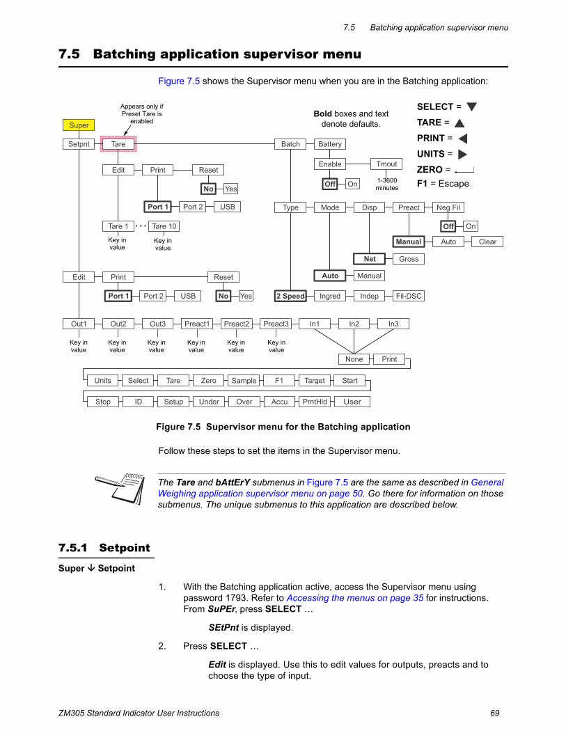
ZM305 Standard Indicator User Instructions 69
7.5 Batching application supervisor menu
7.5 Batching application supervisor menu
Figure 7.5 shows the Supervisor menu when you are in the Batching application:
Figure 7.5 Supervisor menu for the Batching application
Follow these steps to set the items in the Supervisor menu.
7.5.1 Setpoint
Super Setpoint
1. With the Batching application active, access the Supervisor menu using password 1793. Refer to Accessing the menus on page 35 for instructions. From SuPEr, press SELECT …
SEtPnt is displayed.
2. Press SELECT …
Edit is displayed. Use this to edit values for outputs, preacts and to choose the type of input.
Super
Setpnt Tare
Edit Print Reset
No Yes
Tare 1 Tare 10
Batch
Type Mode Disp Preact Neg Fil
Off On
AutoManual Clear
Net Gross
Auto Manual
2 Speed Ingred Indep Fil-DSC
Battery
Enable Tmout
Off On
Port 1 Port 2 USB
Out1 Out2 Out3
Edit Print Reset
Port 1 Port 2 USB No Yes
In1 In2 In3
Setup Under Over Accu PrntHld
Sample F1 Target Start
Stop ID
None Print
Units Select Tare Zero
Preact1 Preact2 Preact3
Bold boxes and text denote defaults.
SELECT =
TARE =
PRINT =
UNITS =
ZERO =
F1 = Escape
Appears only if Preset Tare is
enabled
1-3600minutes
Key invalue
Key invalue
Key invalue
Key invalue
Key invalue
Key invalue
Key invalue
Key invalue
The Tare and bAttErY submenus in Figure 7.5 are the same as described in General Weighing application supervisor menu on page 50. Go there for information on those submenus. The unique submenus to this application are described below.

70 ZM305 Standard Indicator User Instructions
Supervisor menu
Outputs
Setpoint Edit Out1
3. Press SELECT …
out1 is displayed. This is the weight value for setpoint 1.
4. Press SELECT …
The current value is displayed with a flashing right digit.
5. Press ZERO to accept the displayed value or key in a new value and press ZERO to accept …
out1 is displayed.
6. Press UNITS …
out2 is displayed.
7. Repeat steps 4 through 6 for out2 and out3. Press UNITS when finished …
PrEAct1 is displayed.
Preacts
Setpoint Edit Out Preact
Preacts can be used to compensate for product weight that continues to fill into a bag or container after the setpoint output turns off and before the final weight stabilizes. Key in values for these items if Preacts are set to Manual or Auto. The values you enter are used in either case but for Auto preacts the value is adjusted automatically by the indicator as it runs multiple batches. In other words it learns what the correct preact should be.
The actual cutoff weight will equal the entered setpoint value minus the preact value.
8. With PrEAct1 displayed, press SELECT …
The current value is displayed for preact 1 (which is associated with output 1).
9. Press ZERO to accept the displayed value or key in a new value and press ZERO to accept …
PrEAct1 is displayed.
10. Press UNITS …
PrEAct2 is displayed.
11. Repeat steps 8 through 10 for PrEAct2 and PrEAct3. Press UNITS when finished …
In1 is displayed.

ZM305 Standard Indicator User Instructions 71
7.5 Batching application supervisor menu
Inputs
Setpoint Edit Out Preact In
in1 stands for input 1. Use this to assign a function to input 1 when an external switch is tripped. Default choice is nonE. The choices are listed in Figure 7.5.
12. From in1, press SELECT …
The current choice is displayed.
13. Press UNITS to scroll through the choices and when your choice is displayed, press ZERO to accept …
in1 is displayed.
14. Press UNITS …
in2 is displayed.
15. Repeat steps 12 through 14 for in2 and in3.
16. Press TARE …
Edit is displayed.
Setpoint Edit Print
17. Press UNITS …
Print is displayed. Use this to print the settings under SEtPnt.
18. Press SELECT …
Port 1 is displayed.
19. Press IN/OUT to abort the print process or press UNITS to scroll to the desired port and press ZERO to print the information …
Print is displayed after either action.
Reset
Setpoint Edit Print Reset
20. Press UNITS …
rESEt is displayed. Use this to reset the settings under Edit to factory defaults.
21. Press SELECT …
no is displayed.
Inputs and Outputs must be enabled ON in a separate password protected menu. Some input choices will not apply in the application that is active.

72 ZM305 Standard Indicator User Instructions
Supervisor menu
22. Press ZERO to abort the reset or press UNITS …
YES is displayed.
23. Press ZERO to reset the settings to factory defaults …
rESEt is displayed.
24. Press TARE …
SEtPnt is displayed.
7.5.2 Batch
Super Setpoint Tare Batch
1. With the Batching application active, access the Supervisor menu using password 1793. Refer to Accessing the menus on page 35 for instructions. From SuPEr, press SELECT …
SEtPnt is displayed.
2. Press UNITS twice …
bAtch is displayed. Use this to set the items relating to batching:
l Set the type of batch operation. (tYPE)l Select auto or manual operation. (ModE)l Set gross or net display mode. (diSP)l Set the conditions for preact. (PrEAct)l Select negative filling operation.(nEG FiL)
Type
Batch Type
3. Press SELECT …
tYPE is displayed. There are 4 choices under Type: 2 SPEEd, iNGrEd, iNdEP and FiL-dSc. Each is explained below:
2 SPEEd Choose 2 speed when you have one ingredient with a speed control device.
iNGrEd Choose ingredient for sequential filling for up to 3 products at a single speed.
iNdEP Choose independent when the filling process is run based on the values set for the outputs.
FiL-dSc Choose fill-discharge when performing a fill operation (negative weight) from something like a hopper scale.
See Notes on batching on page 75 for information about settings for each of these types of batching.
4. Press SELECT …
The current setting is displayed.

ZM305 Standard Indicator User Instructions 73
7.5 Batching application supervisor menu
5. Press UNITS to scroll through the choices and when your choice is displayed, press ZERO to accept …
tYPE is displayed.
Mode
Batch Type Mode
6. Press UNITS …
ModE is displayed. Mode has two choices: Auto or MAnuAL. There is a detailed description for each type in the section titled Batching application on page 29
7. Press SELECT …
The current setting is displayed.
8. Press UNITS to toggle between the choices and when your choice is displayed, press ZERO to accept …
ModE is displayed.
Display
Batch Type Mode Display
9. Press UNITS …
diSP is displayed. Display has two choices: NEt or GroSS. Each is explained below:
NEt Choose Net to base batching on net weights.
GroSS Choose Gross to base batching on gross weights.
10. Press SELECT …
The current setting is displayed.
11. Press UNITS to toggle between the choices and when your choice is displayed, press ZERO to accept …
diSP is displayed.

74 ZM305 Standard Indicator User Instructions
Supervisor menu
Preact
Batch Type Mode Display Preact
12. Press UNITS …
PrEAct is displayed.
Preact can be used to compensate for product weight that continues to fill into the bag or container after the setpoint output turns off and before the final weight stabilizes. If a preact value is automatically calculated or manually entered, the actual cutoff weight will equal the entered setpoint value minus the preact value.
PrEAct has three choices: Manual, Auto, or cLEAr. Each is explained below:
Manual When Manual, the preact values entered in the SETPNT submenu for PREACT 1, 2 and 3 are used.
Auto When set to Auto, preact is automatically calculated. The amount of compensation is calculated based on the average variance between the entered setpoint value and the actual fill weights recorded during the most recent batch cycles. Auto Preact is only available in certain Batch Types as noted in their descriptions. Calculated Preact values can be viewed in the SETPNT submenu for PREACT 1, 2 and 3.
cLEAr When cLEAr is selected, the current preact values will be set to 0. If PrEAct was set to Auto, a new set of compensation values will be calculated on continuing batches. If preact was set to Manual, then preact will be disabled or new values can be manually entered in the setpoint menu.
13. Press SELECT …
The current setting is displayed.
14. Press UNITS to scroll through the choices and when your choice is displayed, press ZERO to accept …
PrEAct is displayed.
Negative fill
Batch Type Mode Display Preact Negative Fill
15. Press UNITS …
NEG FiL is displayed. This stands for negative fill. This has two choices: oFF or on. Each is explained below:
Choose oFF to disable negative fill. (default)
Choose on to enable negative fill. Operation varies depending on Type chosen. See Notes on batching on page 75.
16. Press SELECT …
The current setting is displayed.

ZM305 Standard Indicator User Instructions 75
7.5 Batching application supervisor menu
17. Press UNITS to scroll through the choices and when your choice is displayed, press ZERO to accept …
NEG FiL is displayed.
18. Press TARE …
bAtch is displayed.
19. Press UNITS …
bAttErY is displayed. The battery menu is identical in all the applications. Refer to step 1 on page 56 for information on setting up the battery.
20. This completes the Supervisor menu for the Batching application. Repeatedly press TARE until the indicator returns to normal weighing mode.
The current weight value is displayed.
7.5.3 Notes on batching
2 Speed
MODE setting does not apply to 2 SPEED.
If DISP is set to NET, an autotare will occur prior to the start of the fill.
If DISP is set to GROSS, no autotare will occur and the fill cutoffs are based on actual Gross weight.
PREACT, if used, only affects the cutoff value of Out 2. See details of PREACT below.
If NEG FILL is set to YES, then DISP should be set to NET so that an autotare occurs prior to start and the cutoffs will be based on negative entered values for Out 1 and Out 2.
SP3 and Output 3 are used as the Active Batch Cycle indicator in 2 Speed filling
Ingredient
If MODE is set to AUTO, the batch process will continue until the final ingredient is completed. Between each ingredient there will be a slight delay to allow for motion, final weight and preact calculations.
If MODE is set to MANUAL, this requires that you press F1 or START between each ingredient to complete the fill cycle.
If MODE is set to MANUAL and DISP is set to NET, then you must also press TARE between each ingredient before pressing START to fill the next ingredient.
If the START button is pressed during the batch cycle, the current ingredient fill will be terminated and the batch cycle will continue to the next ingredient fill.

76 ZM305 Standard Indicator User Instructions
Supervisor menu
If MODE is set to AUTO and DISP is set to NET, an autotare will occur prior to each ingredient and the Out 1, 2 and 3 fill weights will be based on Net weight.
If DISP is set to GROSS, no autotare will occur and the Out 1, 2 and 3 fill weights would be based on the Gross weight of the accumulated ingredients. If Ingredient 1 amount is 10, Ingredient 2 amount is 20 and ingredient 3 amount is 30 then you would enter Out 1 = 10, Out 2 = 30 (10 + 20) and Out 3 = 60 (10 + 20 + 30). Output cutoffs are based on the actual displayed Gross weight so if inaccurate amounts of ingredient are experienced during the batch then it may affect the amount of each subsequent ingredient that is added.
If PREACT is set to AUTO, then it will be calculated for each ingredient to adjust the cutoff weight accordingly.
If NEG FILL is set to YES, it will only operate for a single ingredient with OUT 1 used for discharge filling based on negative weight.
Independent Setpoints
Out 1, 2 and 3 values operate the Outputs independently. Press F1 or START for initial start.
MODE setting does not apply to INDEPENDENT setpoints.
If DISP is set to NET, this uses net weight and if DISP is set to GROSS, this uses gross weight for cutoff value
Auto PREACT is not available in INDEPENDENT filling.
If NEG FILL is set to YES, this allows operation of Out 1, 2 and 3 values in negative weight mode.
Fill/Discharge
MODE setting does not apply to Fill/Discharge
If DISP is set to NET, the display will remain in net weight mode after the discharge cycle.
If DISP is set to GROSS, the display will switch to gross weight mode after the discharge cycle.
If PREACT is set to AUTO it only applies during the Out 2 discharge cycle.
NEG FILL setting does not apply to Fill/Discharge

ZM305 Standard Indicator User Instructions 77
7.6 Peak Hold application supervisor menu
7.6 Peak Hold application supervisor menu
Figure 7.6 shows the Supervisor menu when you are in the Peak Hold application:
Figure 7.6 Supervisor menu for the Peak Hold application
7.6.1 Peak hold
Super Setpoint P-hold
1. With the Peak Hold application active, access the Supervisor menu using password 1793. Refer to Accessing the menus on page 35 for instructions. From SuPEr, press SELECT …
SEtPnt is displayed.
2. Press UNITS twice …
P-hoLd is displayed. Use this to reset the min/max peak. If the F1 key is disabled, which is the normal key to reset min/max, the supervisor needs an alternate method to reset these values.
Reset
P-hold Reset
3. Press SELECT …
rESEt is displayed.
The Setpnt and bAttErY submenus in Figure 7.6 are the same as described in General Weighing application supervisor menu on page 50. Go there for information on those submenus. The unique submenus to this application are described below.
Super
Setpnt Battery
Enable Tmout
Off On
P-hold
Reset
No Yes
Off On
Annun Out1 Out2 Out3
Edit Print Reset
Port 1 Port 2 USB No Yes
Edit X Mode X
Act Abv Act Bel Act In Act Out
Outx Lo Outx Hi
In1 In2 In3
Setup Under Over Accu PrntHld
Sample F1 Target Start Stop ID
None Print Units Select Tare Zero
Bold boxes and text denote defaults.
1-3600minutes
SELECT =
TARE =
PRINT =
UNITS =
ZERO =
F1 = Escape
Key invalue
Key invalue
Key invalue
Mode selection:Act Abv or Act Bel
Mode selection:Act In or Act Out

78 ZM305 Standard Indicator User Instructions
Supervisor menu
4. Press SELECT …
no is displayed.
5. Press UNITS to toggle between the no and YES choices. Press ZERO to accept…
The min/max are reset and rESEt is displayed.
6. Press TARE repeatedly to return to normal weighing operation.

ZM305 Standard Indicator User Instructions 79
7.7 Remote Display application supervisor menu
7.7 Remote Display application supervisor menu
To configure the indicator for remote display operation you must choose the mode of operation in the supervisor menu and configure the port. Configuring the port is done through a password protected menu. Contact your supervisor or your local Avery Weigh-Tronix representative for more information.
Figure 7.7 shows the Supervisor menu when you are in the Remote Display application:
Figure 7.7 Supervisor menu for the Remote Display application
1. With r-diSP displayed press SELECT …
EnAbLE is displayed. Use this to enable or disable the remote display function. Choices are OFF (disable) or on (enable).
2. Press SELECT …
The current setting is displayed.
3. Press UNITS to toggle between the choices and press ZERO to accept the displayed choice …
EnAbLE is displayed.
4. Press UNITS …
ModE is displayed. Choices are 350iS or rd4000. Choose which type of remote display protocol to receive.
The Setpnt and bAttErY submenus in Figure 7.7 are the same as described in General Weighing application supervisor menu on page 50. Go there for information on those submenus. The unique submenu to this application is described below.
Super
Setpnt R-disp
RD4000350iS
Mode
Off On
Enable
Battery
Enable Tmout
Off On
BindFwd
Port 1 Port 2 Enet 1 Enet 5
Off On
Annun Out1 Out2 Out3
Edit Print Reset
Port 1 Port 2 USB No Yes
Edit X Mode X
Act Abv Act Bel Act In Act Out
Outx Lo Outx Hi
In1 In2 In3
Setup Under Over Accu PrntHld
Sample F1 Target Start Stop ID
None Print Units Select Tare Zero
Bold boxes and text denote defaults.
1-3600minutes
SELECT =
TARE =
PRINT =
UNITS =
ZERO =
F1 = Escape
Key invalue
Key invalue
Key invalue
Mode selection:Act Abv or Act Bel
Mode selection:Act In or Act Out

80 ZM305 Standard Indicator User Instructions
Supervisor menu
5. Press SELECT …
The current setting is displayed.
6. Press UNITS to toggle between the choices and press ZERO to accept the displayed choice …
ModE is displayed.
7. Press UNITS …
bindFwd is displayed. Choose which port will be used for printing/communication forwarding from the Main indicator. Choices are Port 1, Port 2, Enet1 through Enet 5.
8. Press SELECT …
The current setting is displayed.
9. Press UNITS to scroll through the choices and press ZERO to accept the displayed choice …
bindFwd is displayed.
10. This completes the Supervisor menu for the Remote Display application. Repeatedly press TARE until the indicator returns to normal weighing mode.
The current weight value is displayed.
The indicator can be configured to work as a remote display with other compatible indicators or the GSE 350/355IS.
Settings in two password protected menus must be made to configure the indicator for remote display operation. Contact your local Avery Weigh-Tronix representative for information on setting up the Primary and Secondary indicator.
BindFwd only works when the unit is setup as a remote display with a GSE 350IS which is configured for forwarding Print information
Additional operation information can be found in Remote display application on page 33.

ZM305 Standard Indicator User Instructions 81
7.8 In-Motion application supervisor menu
7.8 In-Motion application supervisor menu
Figure 7.8 shows the Supervisor menu when you are in the In-Motion application:
Figure 7.8 Supervisor menu for the In-Motion application
Setpnt Tare In-Mo Battery
Super
Enable
Off On
Tmout
Off On
Annun Out1 Out2 Out3 In1 In2 In3
Edit Print Reset
Tare 1 Tare 10
Port 1 Port 2 USB No Yes
Edit Print Reset
Port 1 Port 2 USB No Yes
Edit X Mode X
Act Abv Act Bel Act In Act Out
Outx Lo Outx Hi
Enable StartIO
Off On
StopIO
-3 to 3 -3 to 3
Delay
Setup Under Over Accu PrntHld
Sample F1 Target Start Stop ID
None Print Units Select Tare Zero
Bold boxes and text denote defaults.
1-3600minutes
SELECT =
TARE =
PRINT =
UNITS =
ZERO =
F1 = Escape or 0-60seconds
Appears ifPreset Tare
enabled.
Key invalue
Key invalue
Key invalue
Key invalue
Key invalue
Mode selection:Act Abv or Act Bel
Mode selection:Act In or Act Out
The Setpnt, tArE and bAttErY submenus in Figure 7.8 are the same as described in General Weighing application supervisor menu on page 50. Go there for information on those submenus. The unique submenu to this application is described below.

82 ZM305 Standard Indicator User Instructions
Supervisor menu
7.8.1 In-Motion
Super Setpoint Tare In-Mo
1. With the In-Motion application active, access the Supervisor menu using password 1793. Refer to Accessing the menus on page 35 for instructions. From SuPEr, press SELECT …
SEtPnt is displayed.
2. Press UNITS twice …
in-Mo is displayed. This stands for in-motion. Use this to set the items relating to in-motion weighing.
3. Press SELECT …
EnAbLE is displayed. Use this item to enable or disable in-motion weighing. If enabled you must set the other parameters in this menu.
4. To enable or disable, press SELECT …
The current setting OFF (default) or on is displayed.
5. Press UNITS to toggle between the choices and press ZERO to accept the displayed choice …
EnAbLE is displayed.
6. Press UNITS …
StArtio is displayed. Use this item to setup the incoming or ‘start’ photo-eye so the weight averaging will begin to be captured by the indicator.
7. Press SELECT …
A value entry screen is displayed. You can key in values related to the input port that will be connected to the entrance photo eye circuit and whether it is a positive going transition (positive value) or negative going transition (negative value). This makes your choices: -3, -2, -1, 1, 2, or 3. The number you use is determined by the photo-eye you are using. Consult the photo-eye manual for the correct setting. To enter a negative value see Entering a negative number on page 14.
8. With the value displayed, press the ZERO key to accept …
StArtio is displayed.
Setpoints are based off of the In Motion averaged weight.
The second Photo Eye activates when the item being weighed is exiting the scale. This triggers the PRINT KEY FUNCTION at the firmware level. All Protocols using the Type selection set to PRINT will activate and send the print format data you have defined to the Ports they are Bind to.
Additional information on the photo-eye hardware and wiring is found in the following manual CVC_w_ZM_i_en_501403.pdf The ZM305 can also be used with Mono-Rails and Weigh-Legs for in-motion weighing applications.

ZM305 Standard Indicator User Instructions 83
7.8 In-Motion application supervisor menu
9. Press UNITS …
StoPio is displayed. Use this item to setup the outgoing or ‘stop’ photo-eye so the weight averaging will cease to be captured by the indicator.
10. Press SELECT …
A value entry screen is displayed. You can key in values related to the input port that will be connected to the exit photo eye circuit and whether it is a positive going transition or negative going transition. This makes your choices: -3, -2, -1, 1, 2, or 3. The number you use is determined by the photo-eye you are using. Consult the photo-eye manual for the correct setting. To enter a negative value see Entering a negative number on page 14.
11. When the value is displayed, press the ZERO key to accept …
StoPio is displayed.
12. Press UNITS …
dELAY is displayed. Use this item to enter the maximum time in seconds that the average weight is displayed after the item breaks the exit photo-eye. If another item breaks the entrance photo-eye before the time is up, the displayed weight is cleared early.
If zero is chosen, the weight is displayed until the next item breaks the entrance photo-eye beam.
This value is also used for how long the setpoint outputs will remain activated after the exit photo eye is tripped.
13. Press SELECT …
A value entry screen is displayed. Key in a delay time of 0-60 seconds. Zero means the indicator will wait until the next package or forever.
14. When the value is displayed, press the ZERO key to accept …
dELAY is displayed.
15. This completes the Supervisor menu for the In-motion application. Repeatedly press TARE until the indicator returns to normal weighing mode.
The current weight value is displayed.

84 ZM305 Standard Indicator User Instructions
Supervisor menu


Avery Weigh-Tronix USA1000 Armstrong Dr.Fairmont MN 56031 USATel:507-238-4461Fax:507-238-4195Email: [email protected]
Avery Weigh-Tronix UKFoundry Lane,Smethwick, West Midlands,England B66 2LPTel:+44 (0) 8453 66 77 88Fax:+44 (0)121 224 8183Email: [email protected]