Weigh Shark - Webflow
73
Weigh Shark GARLAND Conveyor Belt Scales Installation & Calibration Manual Sept 24, 2020
-
Upload
khangminh22 -
Category
Documents
-
view
2 -
download
0
Transcript of Weigh Shark - Webflow

Weigh Shark
GARLANDConveyor Belt Scales
Installation & Calibration Manual
Sept 24, 2020


Thank you for your purchase of our NEW Weigh Shark GARLAND conveyor belt scale. We have designed ourscale to be easy to install and calibrate with the very minimum of modifications to your conveyor. Our scale is designed for portable and tracked equipment.
* No Cutting of Conveyor Support or Frame
* No Welding
* No String lining of adjacent idlers
Sincerely,
Mark Humphreys
President
This is NOT a legal for trade scale.

Index Adendium: Pre-Installation and Installation Instructions.
Page 3: Calibration OverviewPage 4: Electrical WiringPage 5: Circuit Board Diagram
Page 6: Correct Circuit Board WiringPage 9 -10: Calibration - ZERO TEST
Page 11: Previous Feature
Page 12: SPAN TEST
Page 14: Material Test
Page 15: Load %
Page 16: Increasing Live Load Signal
Page 17: Real Time Performance
Page 18: Total’ s
Page 19: Analog Outputs (mA)
Page 20: Current Loop Examples
Page 21: Digital Inputs
Page 23: Digital Outputs
Page 23: Shaft Mounted Encoder
Page 26: Automatic Angle Compensator
Page 28 - 29: Ticket Printer (Option)
Page 30: Marquee Sign (Option)
Page 34: Internet Access & Ethernet Diagram Example
Page 35: Specifications - Mechanical & Integrator Data
Page 38: WARRANTY
Page 39: Belt Scale Maintenance
Page 40: Trouble Shooting Guide

Garland Idler Belt Scale Installation
The garland idler belt scale assembly is designed to be installed on a variety of conveyor styles. The instructions outlined below are for a generic style of conveyor. Your specific conveyor might be different and require some modifications so that the scale can be installed. Hopefully, the instructions below will provide sufficient guidance so that the installation can be modified accordingly for your specific style of conveyor. If there are any questions or concerns, please contact Weigh Shark Technical support for assistance.
Selecting an installation location If this is to be installed on portable equipment many of the following guidelines will not be able
to be met. Select the idler the best matches the guidelines.
The idler MUST NOT be in one of the following locations:o Directly before or after the head or tail pulleys.o Where material impacts the belt before or after the idler.
At least 3 idlers away from a material impact area. At least 2 idlers away from the head pulley. There should be a minimum of 1 idler before, and 1 idler after the scale idler, 3 idlers in a row.
Preferably there should be at least 5 in a row, 2 idlers before, 2 idlers after the scale idler. The scale idler, as well as those before and after should be in good working order, properly
aligned, and with all rollers turning when the belt is running empty.
If there are any questions regarding the installation location, please contact Weigh Shark Technical support.
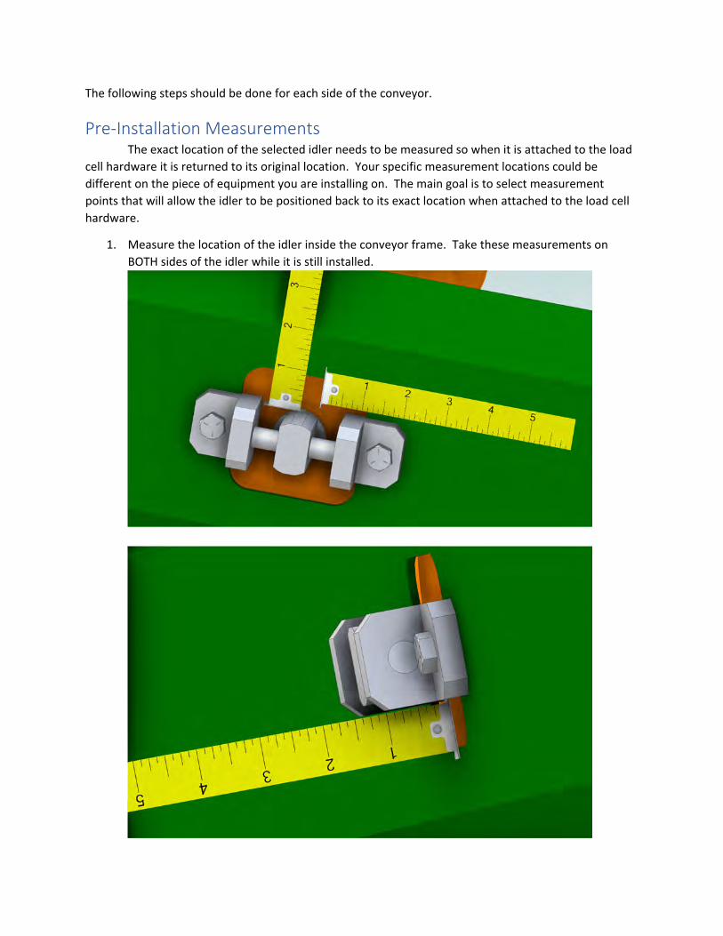
The following steps should be done for each side of the conveyor.
Pre‐Installation Measurements The exact location of the selected idler needs to be measured so when it is attached to the load
cell hardware it is returned to its original location. Your specific measurement locations could be different on the piece of equipment you are installing on. The main goal is to select measurement points that will allow the idler to be positioned back to its exact location when attached to the load cell hardware.
1. Measure the location of the idler inside the conveyor frame. Take these measurements onBOTH sides of the idler while it is still installed.

2. Measure the angle of the outside rollers with the provided Angle Finder. In most cases bothsides should be the same. To find the angle with the Angle Finder, attach it to the bottom sideof the roller, turn the white inner part until the bubble is between the 2 lines.
3. Set the angle of the load cell assembly to match the roller angle.a. Remove the cover from the load cell assembly. This will include the shipping bolt and
backet.
Cover Installed
Cover Removed
Shipping Bolt and Bracket
Pivot Lock Bolts

b. Temporarily clamp, or with assistance hold, the load cell assembly on the conveyorframe.
c. Place the angle finder on the side of the load cell assembly.
d. Loosen the Pivot Lock bolts slightly so the load cell can pivot.e. Adjust the angle so that it matches the pre‐set angle of the roller.f. Tighten the Pivot Lock Bolts to lock the angle.
Mount the Load Cell Assembly The exact mounting will most likely differ from what is shown below. Each piece of equipment is unique and might require additional fabrication or materials to mount the load cell assemblies.
1. Clamp or with assistance hold the load cell assembly parallel with the conveyor. Use the holethrough the load cell to align the assembly with the center of the idler roller.

2. Once the assembly is aligned, mark the locations that need to be drilled for bolts.
3. Once holes are drilled, securely bolt the assembly to the conveyor frame.
4. Install the threaded rod and Idler Hanger bracket to the roller.

5. Adjust the location of the idler to match the Pre‐Installation measurements. Use theadjustment bolts to move mounting accordingly to adjust idler to the correct location.
6. Once the assembly is properly aligned tighten all mounting and adjustment bolts.
Install overload/shipping assembly and cover. 1. Replace overload/shipping bracket and bolt.
The Shipping bolt should be REMOVED for normal operation. When conveyor is shipped theoverload bolt should be installed and tightened until the lever assembly is pushed away fromthe load cell.
2. Replace the cover and tighten the bolts. Make sure the load cell wiring is not interfering withthe load cell or lever assembly.
Install MagMount Speed Sensor The MagMount speed sensor should be preferably attached to the tail pulley. However, if the
tail pulley location is subject to debris or abuse the head pulley is acceptable. Make sure the end of the shaft is smooth and clean before attaching the MagMount.

Route Wires and Make Connections to the Integrator All wires should be routed away from any high voltage wiring. Wiring should be routed away from any pinch points where the wires could get damaged.
If the wires cross any conveyor pivot points be sure there is sufficient slack in the wires to pivotor fold with the conveyor.
For added protection install the provided Orange Flexible Conduit over the wires. This will addan extra level of protection and allow the wires to be easily identifiable.
Patent Pending
Load Cell Quick Connect Wiring:

A) Perform the Auto Zero (ZERO TEST) as instructed.
B) Start the SPAN TEST. Since the Garland idler is installed inside the conveyor frame it is not possible to install Calibration Weights during the SPAN TEST. You must confirm or EDIT and change the IDLER SPAN distance so we know the length of belt the scale idler supports. EXIT after you have confirmed or edited to save.
Preferred: Do a Material Test catching material andweighing it over a Truck Scale. Use the "Material Test" instructions on page 14 to manually set your correctSPAN.
Second Choice: This is the less preferred way since it is a crude way of setting your SPAN. After you have done the ZERO TEST you will stop the empty belt. Go to the Misc. screen and look at the line: "Scale Weight". It should be near 0 since we tarred off the load cell signal from the belt and idler. With belt stopped and empty... Place a known amount of weight DIRECTLY over the scale idler. Your "Scale Weight" should increase by the
Calibration Overview
3.

amount of weight you put on the belt. Use the formula on the "Material Test" page using your weigh value as the known (Truck Scale) and use the Belt Scale value of what you read. Change your SPAN number so that the scale shows the correct weight value you have on the scale.
Calibration is Complete.
ELECTRICAL WIRING
1. Route your load cell and speed sensor cables through the special 4 holecable grip. Locate the load cell terminals and connect. Wire the speedsensor cable to the indicated terminal also on the circuit board.
2. Route your power cable to the control box and run the cable though the 1hole cord grip.
3. Wire either 110 VAC or 220 VAC single phase or 12-24 VDC to theterminals indicated on the board. (Diagram below.).
When extending Speed Sensor or Load Cell Cables it is highly Recommended to use a Junction Box or Soldeing of Wires with Heat Shrink
Wrap. Wire Nuts or Butt Connectors are NEVER to be used.
4.

4. When all electrical connections are properly made, turn ON the unit at thePower Switch on the board.
Circuit Board Diagram
5.

* Junction Box Wiring Instructions *
6.
Correct Circuit Board Wiring

CALIBRATION
The calibration is divided into two categories. A) ZERO TestB) SPAN Test
The display will take you step by step through both processes and instruct you on what is taking place during the process and what to do next.
ZERO TEST
1. The first step of calibration is to weigh your Empty Belt and Idler and tareoff the weight of the belt and the idler so the scale only weighs material onthe belt.
2. Push the arrow key located under “Calib.” to select this calibration process.
3. The main calibration screen will appear. An arrow will point to “Zero Test –Press Enter”
4. Mark the belt or use the belt splice as your reference. Follow theinstructions on the display.
9.

5. Press the Arrow under START when your Empty Belt passes a referencepoint start to measure and weigh your belt. The display will show youinformation during this step. Watch your belt make one (1) revolution andpress the arrow under END after completion of this one revolution.
6. The screen will automatically change. It will show Belt Length (feet), OldZero Value and New Zero Value. It will instruct you to press the arrow underAPPLY. This will establish your Auto Zero value. The screen automaticallygoes back to the main calibration screen.
10.

PREVIOUS FEATURE
Once you have established a Zero Number you have also established a belt length for your conveyor. By using the PRV (previous) feature on the screen, it will allow you to start a zero test without having to wait for your splice or mark on the belt. Keep in mind that the belt MUST be empty and no calibration weights or bar applied.
This feature is only used for recalibrating your zero number with your existing belt length.
If you lose your settings for any reason, you will need to run a New Zero Test following the instructions beginning on page 9.
11.

Span Test 1. Use the ▼ arrow key located to the right of the display to move the
cursor arrow (>) down to the next line. “Span Test – Press Enter”.
2. Press ENTER
3. The screen will automatically change and instruct you to “PressSTART to perform a Span Calibration.
4. Press the arrow under START to start your process.
5. The screen will change and ask you to “Verify the Idler Span”. (Ifyour idlers are on 4 foot centers….. you have a “Span” of 8 feet)!
6. The screen will instruct you to Press NEXT to continue or Press EDIT to Change. The Idler Span value defaults to 8.00 feet. If you need to change this value, press the arrow under EDIT.
7. To EDIT, press the ◄ or ► Arrow keys to move the cursor to activate the cell you wish to change.
8. Use the + and - keys to change the value up or down if required.
9. Press the arrow under EXIT.
12.

You are going to run a material test to calibrate your scale…. See Next Page.
Press EXIT again to take you to the default screen.
13.

“MATERIAL TEST”
• We also suggest if possible that you verify the accuracy vs. alegal for trade truck scale. Catch material and write down theBelt Scale total and the Truck Scale total….then
a) Press ▲ under “Calib.”
b) Use ▼at right of display to bring the cursor down to the lineSPAN.
c) Press ENTER
d) You will want to Increase the SPAN if the scale was light andDecrease the SPAN if the scale was heavy.
(Known Weight) Divided By (Wt. On Screen)
New SPAN = (Truck Scale Wt. / Belt Scale Wt.) X Old SPAN
(Multiplier you use to calculate your new SPAN number)
IE: If you wish to make the SPAN larger by 12% …. You take your existing SPAN number x 1.12….. If you wish to make your SPAN smaller by 12%, you take your SPAN number x .88.
e) Press ▲under EDIT. A line will appear under the last numberin the New Span: line.
f) Use the + or – buttons to change the number. Use the ◄ tomove to the next number to the left and again use the + or –button to change that number. Continue until you haveentered in the complete number.
g) Press ▲under APPLY to accept your changes.
h) Press VIEW a couple times to go back to the default screen.
14.

Load % The default screen (View) shows your Load %. It is important that you have a reasonable load on the Weigh Shark scale to ensure the best opportunity for accuracy. Ideally we would like to see about 75% Load when you are running your normal rate. This will provide a good load cell signal and allow for additional rate. If you find you are running under 50%, we recommend you increase your ADC Gain. This will increase the amplification of the load cell signal to give us more load cell signal to represent weight. (Your ADC GAIN is set at the factory to 10). Steps to Change ADC GAIN: .
1) Go to SETUP
2) Arrow down to CALIBRATION SETUP
3) Press ENTER
4) Arrow up to ADC GAIN
5) Press ENTER
6) Press EDIT
7) Use the + button to increase your number to 15 or 20 Please Contact us to discuss your application.
8) Press APPLY
9) COMPLETED.You will need to Re-Calibrate your scale.
You must do both the ZERO Test and the SPAN Test.
15.

Increasing live load signal in light load applications
If the difference of your Load % when EMPTY and Load % LOADED is less than 20%, follow the instructions below to increase the signal from the live load.
(Requires Software Version 3.3.0 or higher)
1. Write down your LOAD % Empty2. Write down your LOAD % Under Full Load. If difference is less than 20% than
proceed.3. Go To Setup.
a. Arrow Down to Calibration Setup.b. Press ENTER.c. Arrow UP to Advanced Calibration.d. Change Advanced Calibration to ON by using the + or - key.e. Arrow Down to PGA.f. Press ENTER.g. Press EDIT.h. Press the + key to double your PGA number from 16 to 32. (If your EMPTY
Load % is approximately 50% this will double to approximately 100%. If youEMPTY Load % approximately 25% you will want to change your PGA to 64)
i. Press APPLY.4. With belt RUNNING EMPTY and NO calibration weights. Go to Calib Screen.
a. Arrow UP to OFFSET.b. Press ENTER.c. Press EDIT.d. Press SET, wait for test to complete.e. Press APPLY. (We have now lowered your load cell signal in the A/D
Converter Chip to tare off the excess dead load signal).5. Run a ZERO TEST (Make sure you have no calibration weighs on the scale.)6. Run a SPAN TEST (Entering in your scale application information and using your
calibration weights.)(We recommend you run the SPAN TEST 3 times since the first test will make a very large calibration change and the following tests will make fine changes.
We have lowered your LOAD % with the Empty belt and increased the resolution signal from the load cells to give us as much signal with your Live load as possible.
16.

Real Time Performance (RT Prfm%) Real Time Performance % is also shown on the default (View) screen. This shows you your performance RATE you are running based on the Standard Rate (your goal). The factory default setting is 350 TPH. You can change your Standard Rate to allow you to see what you are doing in relationship to your goal. This will give you instant information to allow you to understand your production. Steps to change your Standard Rate:
1) Go to SETUP
2) Arrow down to CALIBRATION SETUP
3) Press ENTER
4) Arrow down to STANDARD RATE
5) Press ENTER
6) Press EDIT
7) Use the + or – buttons to raise or lower the number.
8) Press APPLY
9) COMPLETED
You Do Not have to Recalibrate your Scale.
17.

TOTALS There are four (4) independent totals. Each can be viewed and cleared
separately. Each has its own Production Screen. It can be Viewed and
Printed (with optional ticker printer).
Daily Total: This total is displayed on the default screen. It shows your
accumulating total.
If you wish to clear off this total, press ENTER key while the cursor is
pointing to the "Daily Total". This will access your Production Screen.
Press Arrow Button below CLEAR to clear off this total. Press ESCAPE button or EXIT to go back to Default Screen Scroll Down (using on right of faceplate) 4 times to place the cursor in front of the “Weekly Total”. Weekly Total: This is also an accumulating total for you to use. You can view the weekly production screen by pressing ENTER. Monthly Total: This accumulating total is listed next and can be cleared by pressing ENTER to go to its production screen. Yearly Total: Located is located on the next screen, just press the down arrow key to move cursor to this line and Press ENTER.
Any of your totals can be printed while viewing the production screen. You can customize your ticket. (See Ticket Printer Pg. 28)
18.

Analog Outputs (Option) You may use the standard analog output (4-20 mA) for monitoring your production to a chart recorder, PLC or any device that accepts 4-20 mA. Press arrow located under I/O to access these setup screens. Press ENTER while the cursor (>) is next to Analog Output to go to the setup screen. Press the arrow under EDIT. The cursor (>) moves next to “Rate”. This cell is active and you can select your function. Press the + or – keys to view your options. The Current Loop configuration screen displays all the settings that pertain to the current loop.
Setting Description Function Function of the output (i.e. Rate, Belt Speed, Load%, etc.) Direction Direction of the output (Forward or Reverse). Minimum Minimum value for the output Maximum Maximum value for the output Averaging The number of samples to average (1 to 65000) Range 4-20mA or 0-20mA output
To make changes press the EDIT button. Use the ▲ and ▼ keys to move the cursor through the settings. To edit the number values use the ◄ and ► keys to move through the individual digits of the number. Use the + and – keys to change the values.
Press the ▼ arrow key to move your cursor to “Forward”. Use the + key to select Forward or Reverse.
Press the ▼ arrow key again to move your cursor next to “Minimum” Press the ► arrow key to move your cell line over to the location where you want to enter your TPH. The cell is active at the location of the short line. Use the + key to enter in the value for this cell.
(Example) If you wish to have your Minimum Rate (at 4 mA) be 100 TPH. Press the ► arrow key until the short line is directly left of the 0. Press the + key to select 0. Press the ◄ arrow key 1 time to move the short line to the left. Press the + key to place a 1 in that cell. You should now see 100 TPH.
Press the ▼ arrow key to move the cursor (>) next to “Maximum” Follow the same procedure to enter your desired Rate at 20 mA.
Current Loop Tips: • Increasing the Averaging value slows the response time of the output. For
blending or control applications the number should be lowered to increase theresponse time.
• When connecting to a PLC or Data Acquisition device, it might be helpful to outputa Total; this would allow the calculation of the Rate and Total.
• The 0-20mA and 4-20mA settings both have the same output resolution (16bit).
When you have selected your desired functions; press the arrow under APPLY or EXIT to leave without saving the changes.

To Isolate Current Loop Output Remove Jumpers J1 & J2
Current Loop Examples Output current Rate (TPH)
Desired output: 500tph = 20mA 10tph = 4mA Set the following:
Function: Rate Direction: Forward Minimum: 10 TPH Maximum: 500 TPH Range: 4 to 20mA
Output current Belt Speed (fpm) Desired output: 250fpm = 0mA 0fpm = 20mA Set the following:
Function: Belt Speed Direction: Reverse Minimum: 0 fpm Maximum: 250 fpm Range: 0 to 20mA
Output current Total 4 Desired output: 10,000tons = 20mA 0tph = 0mA Set the following:
Function: Total 4 Direction: Forward Minimum: 0 tons Maximum: 10000 tons Range: 0 to 20mA
20.

Digital Inputs
Press ENTER under I/O to access the Digital Inputs screen. You have 4 Inputs labeled Input 1, Input 2, Input 3 and Input 4.
1. Press the ▼ to place the cursor (>) next to Input 1.
2. Press ENTER to open the screen for entering your information.
3. Press EDIT to make your entries. You will see the > next to the wordFunction: This cell is active.
4. Use your + or – keys to scroll your options.
5. Press the ▼ to select if you want your Input to be ON or OFF
6. When you have selected your Function, press APPLY
7. Press EXIT to go back to your I/O screen.
8. If you wish to use more than 1 Input, you will use the ▼to move the cursordown to the next line (Input 2). Repeat the above procedure etc.
21.

Digital Outputs You have 4 Digital Outputs labeled Output 1 through Output 4. They are located on the same screen as the Inputs. You will use the ▼to move your cursor to the Output you wish.
1. Press ENTER to go to the setup screen.
2. Press the arrow under EDIT to make your entries. The cursor (>) willappear next to “Function:”
3. Use the + or – keys to scroll your options. (1 Ton Pulse, .1 Ton Pulse…..)
4. Press the ▼to move the cursor down one line to “Set point:” This cell isactive and this value may be changed. Press the + or – keys to change thevalue.
5. Press the ▼to move the cursor to the line “Action”: You can select ON orOFF.
6. Press the arrow under APPLY to set your changes.
Let’s say you want the scale to stop your conveyor when a certain weight is reached. You would select “Daily Total”, and enter you set point (15 tons). You would go to the normal screen. While the cursor (>) is pointing to “Daily Total” you would press ENTER to go to the screen to clear off this total and set it back to 0.
Press CLEAR to clear off your “Daily Total”, when you start running material the accumulation will show your production. When you reach your set point of 15 tons, Output 1 would turn ON to stop your conveyor. You can wire up a “remote clear” button to Input 1. Each time you would press your button your “Daily Total” would clear to 0.
22.

Magnetic Encoder - 80 Pulse
Wiring Specifications for Extended Cable
ENCODER EXTENDED CABLES CONTROL BOX Blue Wire White/Green GND(Blue) Red Wire Red +24 vdc(Brown) Gray Wire Black Speed In (Black)
NOTE: Do NOT use Pink, Green, Yellow, White or Brown wires directly from Encoder.
After Installing Encoder you will need to go to Control Box: Press SETUP button Press down arrow key to Calibration Setup Press ENTER Press down arrow to Wheel Dia. Press ENTER Press EDIT
23.

Use left arrow key to move the cursor to change to your pulley diameter (inches) Use the + or - buttons to set the pulses per revolution to 80 Press APPLY
Arrow down one line to Pulses per Revolution Verify you have 80 pulses If not Press ENTER and EDIT to change this number; Press APPLY
Changes are complete… Press EXIT to go to default screen.
24.

Automatic Angle Compensator An Automatic Angle Compensator because of possible conveyor elevationchanges. The Automatic Angle Compensator is bolted to your conveyor frame. It measures the angle incline changes. The scale automatically adjusts for the angle change and the scale remains in calibration.
1. Mount your Automatic Angle Compensator to the conveyor frame.2. Wire Automatic Angle Compensator to control box according to wiring
diagram.
3. Power ON the control box.4. Select I/O menu.5. Scroll down to SERIAL PORTS.6. Press ENTER.7. Select SERIAL PORT 2 (RS 485)8. Press ENTER.9. Press EDIT and use + - key to change FUNCTION to ANGLE SENSOR.
10. Press APPLY.
11. Turn OFF the belt scale and turn it back ON.
12. Calibrate the belt scale (Both ZERO and SPAN) as normal.
13. Angle Compensator information can be viewed under the CALIB. Menu byusing the ▲ or ▼ buttons on the right side of screen. Display will provideangle degree or error if there is a problem.
26.

Angle Information Displayed when Properly Set Up
ERROR Message Showing NOT properly set up.
27.

TICKET PRINTER - OptionA Ticket Printer may be purchased and used to record Production Data. The ticket printer comes mounted inside a NEMA 4x fiberglass enclosure with clear window and lockable latch. The ticket printer can be used to print Production Data for any of the four (4) independent totalizers of the scale.
1. Wire Ticket Printer according to diagram located in the back of the printer enclosure (RS 232)
2. Connect printer to 110 VAC power. (for 110 VAC models)3. Select I/O menu.4. Scroll down to line stating: SERIAL PORTS5. Press ENTER.6. Select Port 1 (RS 232)7. Press ENTER than Press EDIT8. Use + and _- to select Function: TICKET PRINTER9. Press the Down Arrow until cursor (>) points at Baud10. Press the + Button until the Baud shows 1920011. Press APPLY12. The Integrator will cycle power on its own.
MUST CHANGE TIME 1. Go to Setup Screen – Scroll to Time Setup – PRESS ENTER2. Use +/- Button to set time to 00:00 GMT time3. Exit Screen.4. Got to Miscellaneous Screen – PRESS ENTER – PRESS EDIT5. Enter In the Current Correct time at your location using the +/- buttons6. Press Apply to Recycle Power
28.

PRINTING TICKET
1. Select the TOTAL to be printed. Use ▲or ▲ keys to move the cursor to theTOTAL you wish to view and print.
2. Press ENTER (Here you will see Production Data information for yourcurrent TOTAL and the previous TOTAL).
3. Press PRINT to print ticket.
CUSTOMIZE TICKET 1. To add/edit the Scale Name and User Fields……. 2. Select SETUP Menu.3. Press ▲ or ▼ keys to select Scale Name or Use Fields.4. Press ENTER to edit. Press EDIT to display the cursor.5. Use + - keys to change the character in the active field.6. Use the ◄ or ► keys to move the cursor to the next field to make it active.(Note: Scale Name and User Field 1 print at the top of the ticket. And User
Field 2 and 2 print at the bottom of the ticket).7. Press: APPLY after you have entered in the information you wish printed.
You can turn ON or OFF information (CURRENT or PREVIOUS) that you wish printed.
1. Select TOTAL you wish to edit.2. Press ENTER3. Press SETUP4. Press EDIT5. Use any arrow keys to select item…. Then + or – to turn this item ON or
OFF. 6. Press: APPLY.
29.

WEIGH SHARK MARQUEE SIGN SETUP Applies to belt scale software version 3.1.8 or greater. Standard Wiring is RS 232The Marquee will display either 1 or 2 lines of selectable information from the belt scale. The Marquee is powered by 110/220 VAC, 12 VDC or 24VDC and communicates with the scale via RS 232. The RS 485 can be up to 1,000ft from the scale. If you desire to use the RS 485, follow the instructions below.
Setup:
• Connect 110/220 VAC, 12 VDC or 24 VDC to the sign based on what sign you purchased. When marquee is powered up it should display its default message.
• Connect sign to RS 485 serial plug in Weigh Shark scale. Refer to Wiring Diagram included.
o Go to I/O > Serial Ports (Press Enter) > RS 485 (Press ENTER)
o Press EDIT. Use the + / - keys to select sign Matko SBL
o Press-APPLY. Belt scale will automatically reset.
o After the scale resets, go to I/O > Marquee Setup (Press Enter).
o Use + / - keys to select # of lines (1 line displayed or 2 lines displayed).
o Arrow down and use + / - key to select what you want displayed:
30.

31.

32.

The default IP address for all scales is 192.168.000.100. This should be changed to a unique value.
If this will be on an existing network then refer to the network administrator for the proper ID address for this scale.
To change the IP address of a scale: • Press the key under I/O• Use the ▲ key to move the cursor up. This will move to the last item in the I/O menu which
is network.• Press Enter when the cursor is by Network.• The Network should display.• Press cursor should now be pointing at IP Address.• Press Enter to open the edit screen for the IP Address• Press the arrow key under Edit. This will display the cursor under the last group of Numbers.• Use the ◄ o ► keys to move the cursor Right or Left.• Use the + or – key to increase or decrease the number under the cursor.• When the correct I/P address is set ores the Arrow Key under apply. This will save the value
and return back to the Network Menu.• If an error is made during the edit process press default to return the IP addresses back to
default.• Pressing Exit during the edit process will exit the screen with no changes applied.
Set Subnet Mask, Gateway and Name Server in the Same Manner, ( If you are not sure which numbers to use refer to you Network Administrator.
2. Web ServerThe built in Web Server must also be enabled.
• Under the Network Scroll menu scroll down to Web Server (+/-)• Press + to change from Off to On.
3. Scale Name
Each scale should have a name that describes the scale. This will allow the scale to be easily identified on the Remote Display-2. If no scale name is given the RD-2 will show the scales IP address when viewing that scales information. The Scale Name can be up to 24 characters long with numbers letters and punctuation
To Change the scale name: • Press the key under Setup• The cursor should be on the first line pointing to Scale Name. If not use the ▼ ▲ keys to
move the cursor to Scale Name.• Press Enter when the cursor is next to Scale Name.• The Scale Name screen should now be displayed.• Press the key under Edit. This will display the cursor on the far right ofn New Name Line.• Use the ◄ o ► keys to move the Cursor Left and Right.• Use the +/- keys to change each character.• When the value correct name is set, press the Key under Apply. The will save the value
and return back to the setup menu.• Pressing Exit during the edit process will exit serene with no changes applied.
33.
1. IP Address
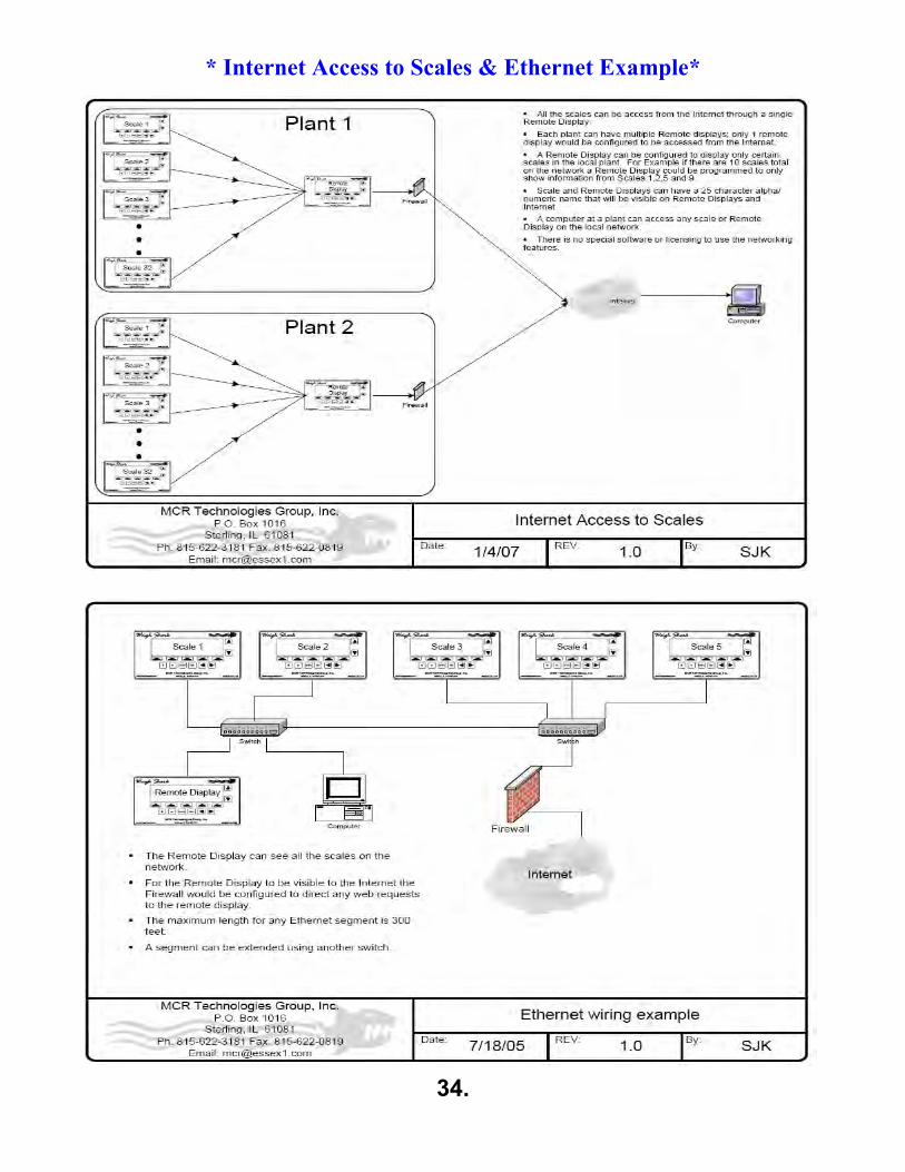
* Internet Access to Scales & Ethernet Example*
34.

Weigh Shark®
Modbus Serial and Ethernet Interface
Version 1.2.0 8/28/06 by Steven Keller

Weigh Shark®
Modbus Interface v1.2.0
Weigh Shark Modbus Interface 1.2.0 Table of Contents 1-1
1.0 Table of Contents
1.0 Table of Contents............................................................................................................................ 1-12.0 Technical Description ..................................................................................................................... 2-13.0 Port Setup ....................................................................................................................................... 3-1
3.1 RS-485 Setup. .......................................................................................................................... 3-13.1.1 Software Configuration ........................................................................................................ 3-13.1.2 Hardware Configuration ....................................................................................................... 3-1
3.1.2.1 RS-485 Port ................................................................................................................. 3-13.1.2.2 RS-485 Port Termination Resistor .............................................................................. 3-2
3.2 Ethernet Configuration ............................................................................................................. 3-33.2.1 Software Configuration ........................................................................................................ 3-3
3.2.1.1 Enable Modbus/IP ....................................................................................................... 3-33.2.1.2 Set IP Address ............................................................................................................ 3-3
3.2.2 Ethernet Hardware ............................................................................................................... 3-44.0 Modbus Registers ........................................................................................................................... 4-1
4.1 Input Registers ......................................................................................................................... 4-14.2 Output Registers ...................................................................................................................... 4-14.3 Input and Holding Registers ..................................................................................................... 4-2
5.0 Special Functions............................................................................................................................ 5-15.1 Performing an Zero Calibration ................................................................................................ 5-15.2 Current Loop Output ................................................................................................................. 5-15.3 Clearing Totals ......................................................................................................................... 5-2

Weigh Shark®
Modbus Interface v1.2.0
Weigh Shark Modbus Interface 1.2.0 Technical Description 2-1
2.0 Technical Description
The Weigh Shark Modbus Slave interface allows a PLC, Operator Interface, PC or other Modbus Master device to access scale data over a RS-485 or Ethernet network.
The Weigh Shark scale provides the Modbus Slave interface thru the RS-485 port (Port 2) or the 10/100 Base-T Ethernet network.
Both the serial port and Ethernet port interfaces use the same data tables and can operate at the same time.
The following operations can be performed using the Modbus interface:
• Totals can be read and cleared. Current totals, run times and average rates as well as previoustotal information can be read.
• Current Rate and Belt Speed.• Calibration Data can be read but NOT written. However a Zero Test can be performed thru the
interface.• Digital and Analog Inputs can be read and Outputs can be read and written.• Data registers for the Truck load out systems can read and written.• Scale name can be read and written. Total names can be read.

Weigh Shark®
Modbus Interface v1.2.0
Weigh Shark Modbus Interface 1.2.0 Port Setup 3-1
3.0 Port Setup This section covers the basic steps of the Modbus Slave port Configuration. Configuration should be performed by qualified personal.
3.1 RS-485 Setup.
3.1.1 Software Configuration
The RS-485 port is capable running the MODBUS RTU protocol at 9600baud, 8 bit, no parity, and 1 stop bit. To setup the RS-485 port for Modbus:
• Press the key under I/O. • Use the ▼ key to move the cursor to Serial Ports. • Press Enter. • Use the ▼ key to move the cursor to Port 2 (RS-485). • Press Enter. • Press the key under Edit. A cursor should display after the word Function. • Use the + key to change the function to MODBUS RTU. • Press the key under Apply. • The screen will change back to the previous screen. Line 3 shows Modbus/RTU
ID. • To change the Modbus/RTU ID use the ▼ key to move the cursor to line 3. Use
the +/- key to change the value. • Cycle the power on the scale for the serial port changes to take affect.
3.1.2 Hardware Configuration
3.1.2.1 RS-485 Port The RS-485 hardware port is a 3 pin terminal located at the top left side of the main circuit board. If the network cable is going to be run long distances it is recommended that it be isolated; contact factory for more details.
Figure 1

Weigh Shark®
Modbus Interface v1.2.0
Weigh Shark Modbus Interface 1.2.0 Port Setup 3-2
3.1.2.2 RS-485 Port Termination Resistor The RS-485 port comes standard with a 220Ω termination resistor installed. To change this 2 jumpers must be removed.
• Remove circuit board cover by removing the 4 screws (2 on each side of the cover). • Locate the two jumpers (JP1) below and to the right of the 3 pin RS-485 terminal.
Figure 2 - RS-485 Termination Jumpers ON
• Remove the 2 jumpers and place them on only 1 pin each for storage.
Figure 3 - RS-485 Termination Jumpers OFF

Weigh Shark®
Modbus Interface v1.2.0
Weigh Shark Modbus Interface 1.2.0 Port Setup 3-3
3.2 Ethernet Configuration
3.2.1 Software Configuration
3.2.1.1 Enable Modbus/IP To enable Modbus on the Ethernet port Modbus/IP must be turned ON.
• Press the key under I/O. • Use the ▲ key to move the cursor up. This will move to the last item in the I/O menu which is
Network. • Press ENTER when the cursor is by Network. • The Network menu should display. • Use the ▲ key to move the cursor up; this will switch to the last screen of the network
settings. • Continue pressing the ▲until the cursor is pointing to Modbus/IP (+/-). • Use the +/- keys to change the value to ON. • Press <<Back key to return to previous screen.
3.2.1.2 Set IP Address An IP address consists of 4 groups of numbers; each group can be a value between 0 and 254. An example of an IP address is: 192.168.000.001. In most simple networks the first 3 groups of numbers stay the same between all the scales and PLC’s; only the last group of numbers changes from scale to scale. For example if there were 5 scales on the network the numbering could be as follows:
Scale 1 192.168.000.001 Scale 2 192.168.000.002 Scale 3 192.168.000.003 Scale 4 192.168.000.004 Scale 5 192.168.000.005
The default IP address for all scales is 192.168.000.100. This should be changed on ALL the scales to a unique value.
To change the IP Address of a scale:
• Press the key under I/O. • Use the ▲ key to move the cursor up. This will move to the last item in the I/O
menu which is Network. • Press ENTER when the cursor is by Network. • The Network menu should display. • The cursor should now be pointing to IP Address. • Press ENTER to open the edit screen for the IP Address. • Press the arrow key under EDIT. This will display the cursor under the last group
of numbers. • Use the ◄► keys to move the cursor left or right. • Use the +/- keys to increase or decrease the number under the cursor. • When the correct IP Address is set, press the arrow key under Apply. The will save
the value and return back to the Network menu. • If an error is made during the edit process press Default to return the IP address
back to the factory default of 192.168.000.100. • Pressing EXIT during the edit process will exit the screen without making changes.
Repeat the process for setting the network mask, gateway and name server.

Weigh Shark®
Modbus Interface v1.2.0
Weigh Shark Modbus Interface 1.2.0 Port Setup 3-4
3.2.2 Ethernet Hardware The Weigh Shark Remote Display accepts standard RJ-12 10/100 Base-T Ethernet connection. The network port is located to the right of the 24Vdc power terminals. Figure 5 shows the empty port and the port with a network cable plugged in.
Figure 4

Weigh Shark®
Modbus Interface v1.2.0
Weigh Shark Modbus Interface 1.2.0 Modbus Registers 4-1
4.0 Modbus Registers The Modbus registers are the same regardless of the port (RS-485 or Ethernet) used to access them. All register addresses are listed as decimal numbers and are Base 1; registers are numbered starting at 1.
4.1 Input Registers Command: 0x02 Read Discrete Inputs Inputs can be read as individual bits or as a single 16bit register.
Address Function Holding Register
1 Digital Input 1 92:0 2 Digital Input 2 92:1 3 Digital Input 3 92:2 4 Digital Input 4 92:3 5 Current Loop status ( 1 = Loop closed; 0 = Loop Open) 92:4 6 Truck Output 92:5 7 Truck Input 92:6 8 Truck Ready 92:7 9 Truck Done 92:8
10 Truck at Cutoff 92:9 11 Ticket Printing Enabled 92:10
4.2 Output Registers Command: 0x01 Read Coils
0x05 Write Single Coil
Output values are Read/Write. For Digital outputs to be under Modbus control their function must be set to MODBUS. Outputs can be read/written as individual bits or in one of 2 16bit registers.
Address Function Holding Register
1 Digital Output 1 93:0 2 Digital Output 2 93:1 3 Digital Output 3 93:2 4 Digital Output 4 93:3 5 Clear Total 1 93:4 6 Clear Total 2 93:5 7 Clear Total 3 93:6 8 Clear Total 4 93:7 9 Clear All Totals 93:8
10 Print Total 1 Ticket 93:9 11 Print Total 2 Ticket 93:10 12 Print Total 3 Ticket 93:11 13 Print Total 4 Ticket 93:12 14 Truck Load Out Clear 93:13 15 Truck Load Out Start 93:14 16 Truck Load Out Stop 93:15 17 Clear Truck Total 94:0 18 Print Truck Ticket 94:1
Weigh Shark®
Modbus Interface v1.2.0
Weigh Shark Modbus Interface 1.2.0 Modbus Registers 4-2
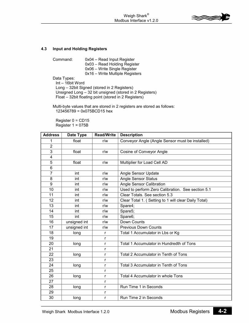
4.3 Input and Holding Registers Command: 0x04 – Read Input Register 0x03 – Read Holding Register 0x06 – Write Single Register 0x16 – Write Multiple Registers Data Types: Int – 16bit Word Long – 32bit Signed (stored in 2 Registers) Unsigned Long – 32 bit unsigned (stored in 2 Registers) Float – 32bit floating point (stored in 2 Registers) Multi-byte values that are stored in 2 registers are stored as follows: 123456789 = 0x075BCD15 hex Register 0 = CD15 Register 1 = 075B
Address Date Type Read/Write Description 1 float r/w Conveyor Angle (Angle Sensor must be installed) 2 3 float r/w Cosine of Conveyor Angle 4 5 float r/w Multiplier for Load Cell AD 6 7 int r/w Angle Sensor Update 8 int r/w Angle Sensor Status 9 int r/w Angle Sensor Calibration
10 int r/w Used to perform Zero Calibration. See section 5.1 11 int r/w Clear Totals. See section 5.3 12 int r/w Clear Total 1. ( Setting to 1 will clear Daily Total) 13 int r/w Spare4; 14 int r/w Spare5; 15 int r/w Spare6; 16 unsigned int r/w Down Counts 17 unsigned int r/w Previous Down Counts 18 long r Total 1 Accumulator in Lbs or Kg 19 r 20 long r Total 1 Accumulator in Hundredth of Tons 21 r 22 long r Total 2 Accumulator in Tenth of Tons 23 r 24 long r Total 3 Accumulator in Tenth of Tons 25 r 26 long r Total 4 Accumulator in whole Tons 27 r 28 long r Run Time 1 in Seconds 29 r 30 long r Run Time 2 in Seconds

Weigh Shark®
Modbus Interface v1.2.0
Weigh Shark Modbus Interface 1.2.0 Modbus Registers 4-3
31 r 32 long r Run Time 3 in Seconds 33 r 34 long r Run Time 4 in Seconds 35 r 36 long r Previous Total 1 in lbs 37 r 38 long r Previous Total 2 in Tenth of Tons 39 r 40 long r Previous Total 3 in Tenth of Tons 41 r 42 long r Previous Total 4 in Whole Tons 43 r 44 unsigned long r Total 1 Last Clear in Seconds since January 1, 1980. 45 r 46 unsigned long r Total 2 Last Clear in Seconds since January 1, 1980. 47 r 48 unsigned long r Total 3 Last Clear in Seconds since January 1, 1980. 49 r 50 unsigned long r Total 4 Last Clear in Seconds since January 1, 1980. 51 r 52 long r Previous Run Time 1 in Seconds 53 r 54 long r Previous Run Time 2 in Seconds 55 r 56 long r Previous Run Time 3 in Seconds 57 r 58 long r Previous Run Time 4 in Seconds 59 r 60 long r Unused 61 r 62 long r Average Rate in Hundredth of TPH 63 r 64 long r Unfiltered Belt speed in hundredth of FPM 65 r 66 long r Average Belt Speed in Hundredth of FPM 67 r 68 long r Percent Load in Hundredth of % 69 r 70 long r Unfiltered Load Cell AD value 71 r 72 long r Filtered Load Cell AD Value 73 r 74 long r Unused 75 r 76 long r Scale weight in Hundredth of Lbs. 77 r 78 long r/w Set point Value for Input 1 79 r/w 80 long r/w Set point Value for Input 2

Weigh Shark®
Modbus Interface v1.2.0
Weigh Shark Modbus Interface 1.2.0 Modbus Registers 4-4
81 r/w 82 long r/w Set point Value for Input 3 83 r/w 84 long r/w Set point Value for Input 4 85 r/w 86 unsigned long r Zero Calibration Value 87 r 88 long r Span Calibration Value 89 r 90 float r Belt Length in Feet 91 r 92 int r Inputs (See Section 4.1) 93 int r/w Outputs (See Section 4.2) 94 int r/w Outputs (See Section 4.2) 95 int r/w Current Loop Output (See section 5.2) 96 int r Load Cell ADC Gain 97 int r Day 98 int r Month 99 int r Year 100 int r hour 101 int r min 102 int r sec 103 int r units ( 0 = English; 1 = Metric) 104 unsigned long r Total Trucks Loaded 105 r 106 unsigned long r Total Tons loaded in Hundredth of tons 107 r 108 unsigned long r Total Fill Time in Seconds 109 r 110 float r Average Truck Weight 111 r 112 float r Average Truck Fill Time 113 r 114 float r Average Truck Fill Tons Per Hour 115 r 116 float r Average Difference between Truck Loads 117 r 118 float r Current Truck Percent Full 119 r 120 float r Current Truck Estimate seconds until full 121 r 122 float r Average Trucks per Hour 123 r 124 unsigned long r/w Truck Cutoff Weight in Hundredth of Tons 125 r/w 126 unsigned long r/w Truck Minimum Load in Hundredth of Tons 127 r/w 128 unsigned long r/w Truck Maximum Load in Hundredth of Tons 129 r/w 130 unsigned long r Current Truck Fill Time

Weigh Shark®
Modbus Interface v1.2.0
Weigh Shark Modbus Interface 1.2.0 Modbus Registers 4-5
131 r 132 unsigned long r/w Current Truck Target Weight in Hundredth of Tons 133 r/w 134 long r Current Truck Accumulator 135 r 136 long r Current Truck Difference of Actual from Target weight 137 r 138 int r Truck State 139 int r Truck Status 140 float r Idler Span in feet 141 r 142 unsigned long r Time and Date of Last Zero. (Seconds since January 1,
1980.) 143 r 144 unsigned long r Time and Date of Last Span. (Seconds since January 1,
1980.) 145 r 146 float r Zero Test Belt Length 147 r 148 unsigned long r New Zero Value 149 r 150 long r Run Time 1 in thousandths of hours 151 r 152 long r Average Rate in hundredth of tons based on Run Time 1. 153 r 154 unsigned int r Cutoff Value 155 unsigned Int r Standard Rate in tph 156 char r Total 1 Name (16 characters) 157 r 158 r 159 r 160 r 161 r 162 r 163 r 164 char r Total 2 Name (16 characters) 165 r 166 r 167 r 168 r 169 r 170 r 171 r 172 char r Total 3 Name (16 characters) 173 r 174 r 175 r 176 r 177 r 178 r

Weigh Shark®
Modbus Interface v1.2.0
Weigh Shark Modbus Interface 1.2.0 Modbus Registers 4-6
179 r 180 char r Total 4 Name (16 characters) 181 r 182 r 183 r 184 r 185 r 186 r 187 r 188 char r/w Scale Name (26 Characters) 189 r/w 190 r/w 191 r/w 192 r/w 193 r/w 194 r/w 195 r/w 196 r/w 197 r/w 198 r/w 199 r/w 200 r/w 201 char r/w Truck ID (20 characters) 202 r/w 203 r/w 204 r/w 205 r/w 206 r/w 207 r/w 208 r/w 209 r/w 210 r/w

Weigh Shark®
Modbus Interface v1.2.0
Weigh Shark Modbus Interface 1.2.0 Special Functions 5-1
5.0 Special Functions 5.1 Performing an Zero Calibration
Holding Registers Used: 10 – Read/Write Zero Calibration status 146 – Current Belt Length 148 – New Zero Value
A Zero Calibration can be performed at any time. However it is up to the user to be sure that the belt is empty during the test. There is nothing in the scale that will prevent a user from doing a Zero Calibration with a fully loaded belt.
The Zero Calibration is done using the stored belt length so it is not necessary to watch the belt for 1 complete revolution.
Values are Read and Written to Holding Register 10. The user will write values to the register and the scale will update the register with the current status of the Zero Test.
To start Zero Calibration: • Write 1 to holding register 10. The Zero Calibration will start.• Read register 10. During the Zero Calibration it will read 2.• While test is running register 146 will show how far the belt has traveled.• When test is done register 10 will read 3 and register 148 will contain the new Zero
Value.• Write 4 to register 10 to accept new Zero Value.• Writing any other value to register 10 will cancel the test with no changes made to the
calibration.
Register 10 0 r Zero Calibration not running 1 w Start Zero Calibration 2 r Zero Calibration Running 3 r Zero Calibration Complete 4 w Apply new Zero value 99 r/w Cancel Zero Calibration
5.2 Current Loop Output Holding Registers Used: 95 – Current Loop
Setting the Analog output function to Modbus will allow the current loop to be controlled directly by the Modbus master.
The current loop is a 16bit DAC. The value written to register 95 will directly output to the DAC.
The Analog Output settings, Action, Averaging and Range will still affect the output.

Weigh Shark®
Modbus Interface v1.2.0
Weigh Shark Modbus Interface 1.2.0 Special Functions 5-2
5.3 Clearing Totals There are 2 ways to clear scale totals. 1. Use Digital outputs addresses 5 – 9. (Or write to their corresponding Holding Registers)2. Write to Holding Register 11.
a. Normally Register 11 is read as -1.b. Writing the following values will clear the corresponding total.
0 Clear All Totals 1 Clear Total 1 2 Clear Total 2 3 Clear Total 3 4 Clear Total 4 5 Clear Truck Totals
c. After total is clear Register will read -1.
Totals can be cleared at any time.

35.

36.

37.

Weigh Shark Warranty MCR TECHNOLOGIES GROUP, INC. manufactures the Weigh Shark Conveyor belt Scale and the Weigh Shark SI Dry Solids Impact Flow Meter.
MCR TECHNOLOGIES GROUP, INC. offers a 2 Year Limited Warranty on parts against defective workmanship and failure. MCR TECHNOLOGIES GROUP, INC. will replace any defective part within 2 years of Purchase Date by either sending the replacement part to the customer or sending a complete assembly to be exchanged with the defective assembly. The Warranty does not cover Any Labor. MCR will pay Ground Freight expenses to the customer. It will be the responsibility of the customer to return their part to MCR TECHNOLOGIES GROUP, INC for testing.
If MCR TECHNOLOGIES GROUP, INC. determines that the returned part or assembly is not covered under the warranty due to neglect, abuse or misapplication, the customer will be charged to repair or replace the damaged part or assembly. If the customer fails to return their part or assembly, MCR TECHNOLOGIES GROUP, INC. may charge the customer.
This is not a Legal for Trade Scale.
38.

39.

40.

41.

42.

43.

Troubleshooting Tips if Scale is resetting to default values when powered on & off
It may be as simple as changing the battery as shown below.
If not please try the following steps:
1. Check Battery Cell Holder to see if it is larger than the battery, this maycause the battery to be loose and causing the default values to appear.
2. If loose remove battery from holder, raise the spring steel normally used fornegative contact. This should result in better battery contact.
3. If still having issues place a small coin (penny or dime) in between contactfor ground & the battery. It should reset 1 time after this is done.
4. If this does not work replace battery
5. If problem persists contact Weigh Shark Technical Support
▪ 815-622-3181 ext. 12
Battery Part Number: CR 2032
44.

NOTES Scale Model: ____________
Control Box #:_________________
Installation Date: _________________________
Scale Designation: Conveyor Name: ____________________
Product: ____________________________
Initial Settings: (after calibration is complete)
Belt Speed__________ ADC Gain:______________
Zero Reading________ Span Reading___________
Other Notes:
45.

BELT SCALE LOCATION
The scale should be installed within 50 feet of the loading point but not closer than 6m (20 ft) or 5 idler spaces to the end of the skirt board.
If there is a concave curve in the conveyor between the scale and the loading point, the scale shall be installed so that the belt is in contact with the idlers at all times for at least 6m (20 ft) or 5 idler spaces, whichever is greater, before and after the scale. A concave curve beyond the scale shall start no closer than 12m (40 ft) from the scale.

If installed on a conveyor with a concave curve, the scale must be installed in a section of the conveyor where the belt is straight (not necessarily horizontal) and in contact with at least 8 idlers to either side of the scale throughout the entire loading range (empty to full load)
Straight conveyors are preferable to curved conveyors. Convex curves are permissible at a distance of 20 feet or 5 idler spaces beyond the scale.
The scale should be installed within 50 feet of the loading point but not closer than 6m (20 ft) or 5 idler spaces to the end of the skirt board.
BELT SCALE ALIGNMENT

RECOMMENDED PRACTICES FOR CALIBRATING, TESTING, AND OPERATING BELT SCALES
Calibration and simulated load test methods
1. Calibration
a. Weighed Load Test
2. Simulated Load Testing
a. Roller Test Chain
b. Static Test Weights
c. Electronic Calibration
Material Test Using a Truck Scale as the Reference Scale
Material Test Using Static Hopper Scale

Weighed Load Test
Advantages
1. Only method which can establish traceable conveyor scale accuracy.
2. Readily permits testing at several feed rates to test linearity.
3. Test entire system, electronics, scale carriage, and conveyor effects.
Disadvantages
1. Requires availability of accurate static scale.
2. Requires accumulation, transportation to static scales, and static weighingof the test load material.
Chain Test
Roller Test Chains
Advantages
1. Simulates some conveyor belt effects.
2. Acceptable simulated test.
Disadvantages
1. Chains do not provide a traceable conveyor scale calibration standard.
2. Heavy chains are difficult to handle.
3. Conveyor belt must be stopped to apply and remove test chains.
4. Linearity test requires several chains.
5. Chains are costly.

Test Weights
Static Test Weights
Advantages
1. Simulates some conveyor belt effects.
2. Easy to apply.
3. Conveyor belt does not have to be stopped to apply weights.
4. Linearity test easy to perform.
5. Detects load cell failures, and applies force to the load cell.
6. Acceptable simulated test.
Disadvantages
1. Weights do not provide a traceable conveyor scale calibration standard.
2. Does not simulate conveyor belt effects.

MAJOR FACTORS AFFECTING FREQUENCY OF RE-ZEROING
1. Stability of the scale and associated integrating equipment to environmental changes and time.
2. The rate at which material collects on "weighed parts."
3. Uncontrollable conveyor parameters.
4. Conveyor maintenance.
5. Required accuracy.
MAJOR FACTORS AFFECTING FREQUENCY OF SPAN ADJUSTMENT
1. Stability of the scale and associated integrating equipment to environmental changes and time.
2. Mechanical wear.
a.. Leverage ratios.
b. Belt contact roll.
3. Material collected on speed sensor roll.
4. Uncontrollable conveyor parameters.
5. Conveyor maintenance.
6. Required accuracy.
7. Shifts in conveyor structure.
MATERIAL TESTING OF BELT SCALES FOR CERTIFICATION (NIST Handbook 44)
UR User Requirements
U.R.2.3 - Material Test - A belt conveyor scale shall be installed so that a material test can be conveniently conducted (non-retroactive as of January 1, 1981). Added 1980.
UR 3. - Use Requirements
U.R.3.1- Loading - The feed of material to the scale shall be controlled to assure that, during normal operation, the material flow is in accordance with manufacturer's recommendation for rated capacity.
NOTES
N.1.1- Official Test - An official test of a belt-conveyor scale shall be a materials test.
N.1.2. - Simulated Test - Simulated loading conditions as recommended by the manufacturer andapproved by the official with statutory authority may be used to properly monitor the system

operational performance between official test, but shall not be used for official certification (Amended 1991).
N.2 - A belt-conveyor scale shall be tested after it is installed on the conveyor system with whichit is to be used and under such environmental conditions as may normally be expected. It shallbe tested at normal use capacity and may be tested at any other rate of flow that may be used atthe installation.
Each test shall be conducted for:
(a) Not less than 1000 scale divisions,
(b) At least three revolutions of the belt, and
(c) At least 10 minutes of operations, or for a normal weighment. (Amended 1986)
N.3 Test Procedures
N.3.1 Zero Load Tests - The variation between the beginning and ending indication of the masterweight totalizer shall not be more than plus or minus 1 scale division when the instrument isoperated at no load for a period of time equivalent to that required to deliver the minimumtotalized load of 1000 scale divisions.
The zero-load test shall be conducted over a whole number of belt revolutions, but not less than three revolutions or 10 minutes of operations, whichever is greater.
During any portion of the zero-load test, the totalizer shall not change more than three scale divisions from its initial indication. (Amended 1989)
N.3.3. Material Tests - On initial verification, at least three individual tests shall be conducted. Onsubsequent verifications, at least two individual tests shall be conducted. The performance of theequipment is not to be determined by averaging the results of the individual tests. The results ofall of these tests shall be within the tolerance limits. (Amended 1986, 1989)
N.3.2.1. Accuracy of Material - The quantity of material comprising the material test shall beweighed statically to an accuracy of at least 0.1 percent.
N.3.3. Simulated Load Test - As required by the Official with Statutory authority, simulated loadtests as recommended by the manufacturer are to be conducted between material tests tomonitor the system's operational performance, but shall not be used for official certification.(Amended 1991)
A simulated load test consisting of at least three consecutive test runs shall be conducted as soon as possible, but not more than 12 hours after the completion of the material test, to establish the factor to relate the results of the simulated load tests to the results of the material tests. (Added 1990)
The results of the simulated load test shall repeat within 0.1 percent. (Added 1990) (Amended 1989 and 1990)
T.1 Tolerances Values - Maintenance and acceptance tolerance on material tests, relative to theweight of the material, shall be plus or minus 0.25 percent of the test load. (Amended 1993)
T.2 Tolerance Values, Repeatability Tests - The variation in the values obtained during theconduct of materials tests shall not be greater than 0.25 percent (1/400) Added 1993)