
Z-MAC: A Hybrid MAC for Wireless Sensor Networks
14
IEEE/ACM TRANSACTIONS ON NETWORKING, VOL. 16, NO. 3, JUNE 2008 511 Z-MAC: A Hybrid MAC for Wireless Sensor Networks Injong Rhee, Senior Member, IEEE, Ajit Warrier, Mahesh Aia, Jeongki Min, and Mihail L. Sichitiu, Member, IEEE Abstract—This paper presents the design, implementation and performance evaluation of a hybrid MAC protocol, called Z-MAC, for wireless sensor networks that combines the strengths of TDMA and CSMA while offsetting their weaknesses. Like CSMA, Z-MAC achieves high channel utilization and low latency under low con- tention and like TDMA, achieves high channel utilization under high contention and reduces collision among two-hop neighbors at a low cost. A distinctive feature of Z-MAC is that its perfor- mance is robust to synchronization errors, slot assignment failures, and time-varying channel conditions; in the worst case, its perfor- mance always falls back to that of CSMA. Z-MAC is implemented in TinyOS. Index Terms—CSMA, MAC, TDMA, wireless sensor networks. I. INTRODUCTION A RADIO CHANNEL cannot be accessed simultaneously by two or more nodes that are in a radio interference range—neighboring nodes may cause “conflict” or signal inter- ference at some nodes if transmitting at the same time on the same channel. In wireless sensor networks, controlling access to the channel, generally known as medium access control (MAC), plays a key role in determining channel utilization, network delays, and, more important, power consumption, also influencing congestion and fairness in channel usage. Sensor networks serve many diverse applications from low-data-rate event-driven monitoring applications to high-data-rate real-time industrial applications. Balakrishnan [1] reports that some high-data-rate applications can reach sensing rates of to Hz and consume from a few bytes per seconds up to 10 or 100 Mbps aggregate bandwidth; these applications require over five times improvement on the channel utilization of existing sensor networking technologies. Notwithstanding high channel utilization, traditional sensor network requirements such as power efficiency, scalability, robustness, and small footprints must also not be compromised. CSMA (carrier sense multiple access) is popular in wireless networks due to its simplicity, flexibility, and robustness. It does Manuscript received September 18, 2005; revised August 11, 2006, and Jan- uary 29, 2007; approved by IEEE/ACM TRANSACTIONS ON NETWORKING Ed- itor S. Das. This work was supported in part by the National Science Foundation under Grant NSF-NOSS 0435157. I. Rhee, A. Warrier, and J. Min are with the Computer Science Department, North Carolina State University, Raleigh, NC 27695 USA (e-mail: rhee@ncsu. edu; [email protected]; [email protected]). M. Aia was with North Carolina State University, and is now with TapRoot Systems, Inc., Morrisville, NC 27560 USA (e-mail: [email protected]). M. L. Sichitiu is with the Department of Electrical and Computer Engi- neering, North Carolina State University, Raleigh, NC 27695 USA (e-mail: [email protected]). Digital Object Identifier 10.1109/TNET.2007.900704 not require much infrastructure support: no clock synchroniza- tion and global topology information are required, and dynamic node joining and leaving are handled gracefully without extra operations. These advantages, however, come at the cost of trial and error—a trial may cost access collision where more than two “conflicting” nodes transmit at the same time, causing signal fidelity degradation at destinations. Collision can happen in any two-hop neighborhood of a node. While collision among one-hop neighbors can be greatly reduced by carrier sensing before transmission, carrier sensing does not work beyond one hop. This problem, called the hidden terminal problem, causes a serious throughput degradation especially in high-data-rate sensor applications. Although RTS/CTS can alleviate the hidden terminal problem, it incurs high overhead (40%–75% of the channel capacity in sensor networks [2], [3]) because data packets are typically very small in sensor networks. TDMA (time-division multiple access), on the other hand, can solve the hidden terminal problem without extra message overhead because it can schedule transmission times of neigh- boring nodes to occur at different times. However, TDMA has many other disadvantages as documented in [4]. First, finding an efficient time schedule in a scalable fashion is not trivial. It often requires a centralized node to find a collision-free schedule. Furthermore, developing an efficient schedule with a high degree of concurrency or channel reuse is very hard (the optimal solution is NP-hard [5]). Second, TDMA needs clock synchronization. Although clock synchronization is an essential feature of many sensor applications, tight syn- chronization incurs high energy overhead because it requires frequent message exchanges. Third, sensor networks may undergo frequent topology changes because of time-varying channel conditions, physical environmental changes, battery outage and node failures. Handling dynamic topology changes is expensive, possibly requiring a global change. Fourth, it is difficult to ascertain the interference relation among neigh- boring nodes because radio interference ranges are different from communication ranges, and some interfering nodes may not be in a direct communication range (this phenomenon is known as interference irregularity [6]). Therefore, any channel assignment that uses the communication ranges, in place of interference ranges, for building the conflict relations does not necessarily yield an interference-free schedule. Further- more, as interference ranges and channel conditions are highly time-varying, it is unlikely that one fixed schedule is sufficient to prevent collision all of the time. Fifth, during low contention, TDMA gives much lower channel utilization and higher delays than CSMA because in TDMA a node can transmit only during its scheduled time slots, whereas in CSMA nodes can transmit at any time as long as there is no contention. 1063-6692/$25.00 © 2008 IEEE
-
Upload
khangminh22 -
Category
Documents
-
view
1 -
download
0
Transcript of Z-MAC: A Hybrid MAC for Wireless Sensor Networks
IEEE/ACM TRANSACTIONS ON NETWORKING, VOL. 16, NO. 3, JUNE 2008 511
Z-MAC: A Hybrid MAC for WirelessSensor Networks
Injong Rhee, Senior Member, IEEE, Ajit Warrier, Mahesh Aia, Jeongki Min, and Mihail L. Sichitiu, Member, IEEE
Abstract—This paper presents the design, implementation andperformance evaluation of a hybrid MAC protocol, called Z-MAC,for wireless sensor networks that combines the strengths of TDMAand CSMA while offsetting their weaknesses. Like CSMA, Z-MACachieves high channel utilization and low latency under low con-tention and like TDMA, achieves high channel utilization underhigh contention and reduces collision among two-hop neighborsat a low cost. A distinctive feature of Z-MAC is that its perfor-mance is robust to synchronization errors, slot assignment failures,and time-varying channel conditions; in the worst case, its perfor-mance always falls back to that of CSMA. Z-MAC is implementedin TinyOS.
Index Terms—CSMA, MAC, TDMA, wireless sensor networks.
I. INTRODUCTION
ARADIO CHANNEL cannot be accessed simultaneouslyby two or more nodes that are in a radio interference
range—neighboring nodes may cause “conflict” or signal inter-ference at some nodes if transmitting at the same time on thesame channel. In wireless sensor networks, controlling accessto the channel, generally known as medium access control(MAC), plays a key role in determining channel utilization,network delays, and, more important, power consumption, alsoinfluencing congestion and fairness in channel usage.
Sensor networks serve many diverse applications fromlow-data-rate event-driven monitoring applications tohigh-data-rate real-time industrial applications. Balakrishnan[1] reports that some high-data-rate applications can reachsensing rates of to Hz and consume from a few bytesper seconds up to 10 or 100 Mbps aggregate bandwidth;these applications require over five times improvement on thechannel utilization of existing sensor networking technologies.Notwithstanding high channel utilization, traditional sensornetwork requirements such as power efficiency, scalability,robustness, and small footprints must also not be compromised.
CSMA (carrier sense multiple access) is popular in wirelessnetworks due to its simplicity, flexibility, and robustness. It does
Manuscript received September 18, 2005; revised August 11, 2006, and Jan-uary 29, 2007; approved by IEEE/ACM TRANSACTIONS ON NETWORKING Ed-itor S. Das. This work was supported in part by the National Science Foundationunder Grant NSF-NOSS 0435157.
I. Rhee, A. Warrier, and J. Min are with the Computer Science Department,North Carolina State University, Raleigh, NC 27695 USA (e-mail: [email protected]; [email protected]; [email protected]).
M. Aia was with North Carolina State University, and is now with TapRootSystems, Inc., Morrisville, NC 27560 USA (e-mail: [email protected]).
M. L. Sichitiu is with the Department of Electrical and Computer Engi-neering, North Carolina State University, Raleigh, NC 27695 USA (e-mail:[email protected]).
Digital Object Identifier 10.1109/TNET.2007.900704
not require much infrastructure support: no clock synchroniza-tion and global topology information are required, and dynamicnode joining and leaving are handled gracefully without extraoperations. These advantages, however, come at the cost oftrial and error—a trial may cost access collision where morethan two “conflicting” nodes transmit at the same time, causingsignal fidelity degradation at destinations. Collision can happenin any two-hop neighborhood of a node. While collision amongone-hop neighbors can be greatly reduced by carrier sensingbefore transmission, carrier sensing does not work beyond onehop. This problem, called the hidden terminal problem, causesa serious throughput degradation especially in high-data-ratesensor applications. Although RTS/CTS can alleviate thehidden terminal problem, it incurs high overhead (40%–75% ofthe channel capacity in sensor networks [2], [3]) because datapackets are typically very small in sensor networks.
TDMA (time-division multiple access), on the other hand,can solve the hidden terminal problem without extra messageoverhead because it can schedule transmission times of neigh-boring nodes to occur at different times. However, TDMA hasmany other disadvantages as documented in [4]. First, findingan efficient time schedule in a scalable fashion is not trivial.It often requires a centralized node to find a collision-freeschedule. Furthermore, developing an efficient schedule witha high degree of concurrency or channel reuse is very hard(the optimal solution is NP-hard [5]). Second, TDMA needsclock synchronization. Although clock synchronization isan essential feature of many sensor applications, tight syn-chronization incurs high energy overhead because it requiresfrequent message exchanges. Third, sensor networks mayundergo frequent topology changes because of time-varyingchannel conditions, physical environmental changes, batteryoutage and node failures. Handling dynamic topology changesis expensive, possibly requiring a global change. Fourth, it isdifficult to ascertain the interference relation among neigh-boring nodes because radio interference ranges are differentfrom communication ranges, and some interfering nodes maynot be in a direct communication range (this phenomenon isknown as interference irregularity [6]). Therefore, any channelassignment that uses the communication ranges, in place ofinterference ranges, for building the conflict relations doesnot necessarily yield an interference-free schedule. Further-more, as interference ranges and channel conditions are highlytime-varying, it is unlikely that one fixed schedule is sufficientto prevent collision all of the time. Fifth, during low contention,TDMA gives much lower channel utilization and higher delaysthan CSMA because in TDMA a node can transmit only duringits scheduled time slots, whereas in CSMA nodes can transmitat any time as long as there is no contention.
1063-6692/$25.00 © 2008 IEEE
512 IEEE/ACM TRANSACTIONS ON NETWORKING, VOL. 16, NO. 3, JUNE 2008
These difficulties with TDMA suggest that a stand-aloneTDMA scheme is not practical. Even if we have an effi-cient TDMA schedule, the other factors such as interferenceirregularity, time-varying channel conditions, and clock syn-chronization errors would diminish the benefits of TDMA.Nevertheless, we posit that the information provided by anefficient TDMA schedule, in particular, the independent sets ofnodes that can transmit concurrently can be used in curtailingoccurrences of collision especially under high contention. Thisposition greatly motivates our work.
In this paper, we present a new hybrid MAC scheme, calledZ-MAC (Zebra MAC), for sensor networks that combines thestrengths of TDMA and CSMA while offsetting their weak-nesses. The main feature of Z-MAC is its adaptability to thelevel of contention in the network—under low contention, it be-haves like CSMA, and under high contention, like TDMA. It isalso robust to dynamic topology changes and time synchroniza-tion failures commonly occurring in sensor networks.
Z-MAC uses CSMA as the baseline MAC scheme, but usesa TDMA schedule as a “hint” to enhance contention resolu-tion. In Z-MAC, a time slot assignment is performed at thetime of deployment—higher overhead is incurred at the begin-ning. Its design philosophy is that the high initial overhead isamortized over a long period of network operation, eventuallycompensated by improved throughput and energy efficiency.We use DRAND [7], an efficient scalable channel-schedulingalgorithm. DRAND is a distributed implementation of RAND[5], a centralized channel reuse scheduling algorithm. After theslot assignment, each node reuses its assigned slot periodicallyin every predetermined period, called frame. We call a nodeassigned to a time slot an owner of that slot and the othersthe nonowners of that slot. There can be more than one ownerper slot because DRAND allows any two nodes beyond theirtwo-hop neighborhoods to own the same slot.
Unlike TDMA, a node may transmit during any time slot inZ-MAC. Before a node transmits during a slot (not necessarily atthe beginning of the slot), it always performs carrier-sensing andtransmits a packet when the channel is clear. However, an ownerof that slot always has higher priority over its nonowners in ac-cessing the channel. The priority is implemented by adjustingthe initial contention window size in such a way that the ownersare always given earlier chances to transmit than nonowners.The goal is that, during the slots where owners have data totransmit, Z-MAC reduces the chance of collision since ownersare given earlier chances to transmit and their slots are sched-uled a priori to avoid collision, but when a slot is not in use by itsowners, nonowners can steal the slot. This priority scheme hasan effect of implicitly switching between CSMA and TDMA de-pending on the level of contention. An important feature of thispriority scheme is that the probability of owners accessing thechannel can be adjusted independently from that of nonowners.We show that this feature contributes to increasing the robust-ness of the protocol to synchronization and slot assignment fail-ures while enhancing its scalability to contention.
By mixing CSMA and TDMA, Z-MAC becomes more robustto timing failures, time-varying channel conditions, slot assign-ment failures and topology changes than a stand-alone TDMA;in the worst case, it always falls back to CSMA. Since Z-MAC
needs only local synchronization among senders in two-hopneighborhoods, we devise a simple local synchronizationscheme where each sending node adjusts its synchronizationfrequency based on its current data rate and resource budget.
In what follows, we describe the design, implementation, andperformance of Z-MAC in detail.
II. RELATED WORK
S-MAC [4] and T-MAC [8] are a hybrid of CSMA andTDMA in that they also maintain the synchronized timeslots, but, unlike TDMA, their slots can be much bigger thannormal TDMA slots and synchronization failures do not nec-essarily lead into communication failure because they employRTS/CTS. Nodes maintain periodic duty cycle to listen forchannel activities and transmit data. As these protocols useRTS/CTS, the overhead of the protocols is quite high becausemost data packets in sensor networks are small. T-MAC [8]improves the energy efficiency of S-MAC by forcing all of thetransmitting nodes to start transmission at the beginning ofeach active period.
B-MAC [3] is the default MAC for Mica2. B-MAC allows anapplication to implement its own MAC through a well-definedinterface. They also adopt LPL (low power listening) [9] andengineer the clear channel sensing (CCA) technique to improvechannel utilization. [10] uses the optimal probabilitydistribution in determining the channel access probability forCSMA when the number of senders is known. When isunknown, it provides suboptimal performance. Sift [11] adapts
[10] for a network where is unknown. The resultis high success probability for channel access and reduced colli-sion probability, thus achieving good throughput under both lowand high contention. However, the optimal probability distribu-tion works only when senders always have data to transmit andthey are synchronized for the channel access, and, thus, whendata arrivals to a node are highly random and senders cannotsense each other for data transmission (as in two-hops), its per-formance degenerates to the case of CSMA with the uniform ac-cess probability distribution. Sift relies on RTS/CTS to handlehidden terminals.
TDMA has long been dismissed as an impractical solution forwireless ad hoc networks for its lack of scalability and adapt-ability to changing environments. However, it provides a goodenergy efficiency and collision-freedom. Recently, several pro-posals [12], [13] are made for TDMA in sensor networks. How-ever, these protocols still fail to address the fundamental diffi-culties that stand-alone TDMA schemes face.
Seamlessly switching between TDMA and CSMA ac-cording to the level of contention was previously exploredby Ephremides and Mowafi [14] for a wireless LAN (orone-hop) environment using a scheme called ProbabilisticTDMA (PTDMA). As in TDMA, real time is slotted andby adjusting the access probability of owners (“a”) and thatof nonowners (“b”), PTDMA adapts the behavior of MACbetween TDMA and CSMA depending on contention. Theseprobabilities are adjusted by a function ,where is the number of senders. While PTDMA and Z-MACshare a common goal, PTDMA, being designed primarily for
RHEE et al.: Z-MAC: A HYBRID MAC FOR WIRELESS SENSOR NETWORKS 513
a one-hop wireless LAN environment, does not deal withmany difficulties that TDMA faces in ad hoc sensor networkssuch as time synchronization errors, interference irregularity,and topology changes. These failures can drastically reducethe performance of PTDMA. PTDMA also assumes bufferedsenders where all nodes experience the same statistical arrival.In a network where only a subset of nodes is active data sources(which is a common scenario in sensor networks), PTDMAexhibits very low channel utilization and does not behave likeCSMA. This is because “b” cannot be arbitrarily set to a highvalue without reducing “a” (reducing “a” also causes MAC notto behave like TDMA) due to the dependency between “a” and“b”. The effect of probability “a” is also not clear; it seems thatthe authors want to adjust “a” for different contention levels butthe paper does not mention how this can be achieved (Z-MACdoes not need to dynamically adjust its parameters to achievethe desired effect).
III. DESIGN OF Z-MAC
Z-MAC has a setup phase in which it runs the following op-erations in sequence: neighbor discovery, slot assignment, localframe exchange, and global time synchronization. These opera-tions run only once during the setup phase and do not run untila significant change in the network topology (such as physicalrelocation of sensors) occurs. The idea is that the initial upfrontcosts for running these operations are amortized by improvedthroughput and energy efficiency during data transmission. Inthis section, we first describe how we implement these setupphase operations and then discuss how they are integrated withtransmission control in Z-MAC.
A. Neighbor Discovery and Slot Assignment
As a node starts up, it first runs a simple neighbor discoveryprotocol where it periodically broadcasts a ping to its one-hopneighbors to gather its one-hop neighbor list. A ping messagecontains the current list of its one-hop neighbors. In our im-plementation, each node sends one ping message at a randomtime in each second for 30 s. Through this process, each nodegathers the information received from the pings from its one-hopneighbors, which essentially constitutes its two-hop neighborinformation.
The two-hop neighbor list is used as input to a time-slotassignment algorithm. The current implementation of Z-MACuses DRAND [7], a distributed implementation of RAND [5],to assign time slots to every node in the network. DRANDensures a broadcast schedule where no two nodes within atwo-hop communication neighborhood are assigned to thesame slot. This assignment guarantees that no transmissionby a node to any of its one-hop neighbors interferes with anytransmission by its two-hop neighbors. Note that a broadcastschedule can handle any routing changes among its one-hopneighbors.
The performance of DRAND is scalable because it does notdepend on the network size, but on the local neighborhoodsize of each node. The protocol produces a very efficient timeschedule where the slot number assigned to a node does notexceed the size of its local two-hop neighborhood —inmost cases, much less than that. The running time and message
complexity of DRAND is also bounded by . Thus, itsenergy cost is linearly proportional to the size of the localneighborhood. When only a small number of new nodes arejoined late, DRAND can also perform localized time slotassignment without modifying the time slots already assignedto the existing nodes. The detailed performance analysis ofDRAND can be found in [7].
B. Local Framing
Once a node picks a time slot, each node needs to decide onthe period in which it can use the time slot for transmission.This period is called the time frame of the node. The conven-tional wisdom is that all nodes must keep the same time framewhile all nodes synchronize to have their time slot 0 at the sametime. But this requires to propagate the maximum slot number(MSN) to the entire network and is also not adaptive to localtime slot changes. When new nodes are added to the network,DRAND can run local slot assignment while maintaining theexisting assignment. If this assignment causes the MSN to bechanged, that change must be propagated again to the entire net-work. This could incur high cost for adapting to a small changein the network topology. (Note that network topology changesby unstable radio channel conditions are handled by the inherentoperation of Z-MAC so it does not incur new assignment, butnew node joining or node redeployment can cause slot changes.)
We present a new scheme where each node maintains its ownlocal time frame that fits its local neighborhood size, but avoidsany conflict with its contending neighbors. The main idea is asfollows.
Time Frame Rule (TF Rule): Let a node be assigned to aslot according to DRAND and the MSN within its two-hopneighborhood be . We set ’s time frame to be wherea positive integer “a” is chosen to satisfy condition
, that is, uses the th slot in every time frame ( ’ slotsare , for all ). The right-hand-side (r.h.s.)of the inequality constrains the set of feasible values for toavoid conflict while the left-hand side (l.h.s.) of the inequalityforces us to pick the minimum of these feasible values. We nowprove why the r.h.s. of the inequality avoids conflict among con-tending neighbors.
Theorem 3.1: If every node uses only slots , forall , then no node in the two-hop neighborhoodof uses any slot that uses.
Proof: We can prove the theorem by contradiction. Let bea node that is in the two-hop neighborhood of , but it happens touse one of the slots that is used by . It does that at the -th timeframe of . By the TF rule, is assigned to by DRAND and’s time frame is for some . Then without loss of generality,
we assume that and . Note that, by DRAND,, and and are assigned to only one slot within
and , respectively. Then, because of the way that and arechosen by the TF rule, it is true that uses only one slot withina time frame, so does within a time frame. Then, for all
, . This means that, wheneverstarts its own frame, starts its time frame, and whenever endsits own frame, ends its time frame (i.e., no time frame of startsor ends in the middle of ’s). Because and are in conflict,must be less than or equal to . Because the beginning of ’s
514 IEEE/ACM TRANSACTIONS ON NETWORKING, VOL. 16, NO. 3, JUNE 2008
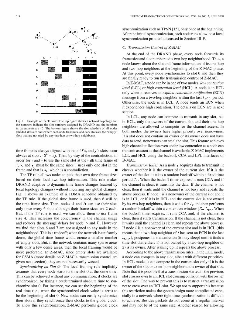
Fig. 1. Example of the TF rule. The top figure shows a network topology andthe numbers indicate the slot numbers assigned by DRAND and the numbersin parenthesis are � . The bottom figure shows the slot schedule of all nodes(shaded slots are ones where each node transmits, and dark slots are the “empty”slots that are not used by any one-hop or two-hop neighbors).
time frame is always aligned with that of ’s, and ’s slots occuralways at slots . Then, by way of the contradiction, inorder for and to use the same slot at the th time frame of, and must be the same since uses only one slot in the
frame and that is , which is a contradiction.The TF rule allows nodes to pick their own time frame sizes
based on their local two-hop information. This rule makesDRAND adaptive to dynamic time frame changes (caused bylocal topology changes) without incurring any global changes.Fig. 1 shows an example of a TDMA schedule obtained bythe TF rule. If the global time frame is used, then 6 will bethe time frame size. Then, nodes and can use their slotsonly once every 6 slots although their frame sizes are 2 each.But, if the TF rule is used, we can allow them to use framesize 4. This increases the concurrency in the channel usageand reduces the message delays for node and . However,we find that slots 6 and 7 are not assigned to any node in theneighborhood. This is a tradeoff; when the network is uniformlydense, the global time frame would create a smaller numberof empty slots. But, if the network contains many sparse areaswith only a few dense areas, then the local framing would bemore preferable. In Z-MAC, since empty slots are availablefor CSMA (more details on Z-MAC’s transmission control aregiven next section), they are not necessarily wasted.
Synchronizing on Slot 0: The local framing rule implicitlyassumes that every node starts its time slot 0 at the same time.This can be achieved without any communication, if clocks aresynchronized, by fixing a predetermined absolute time to syn-chronize slot 0. For instance, we can set the beginning of thereal time (i.e., when the synchronized clock value is zero) tobe the beginning of slot 0. New nodes can easily synchronizetheir slots if they synchronize their clocks to the global clock.To allow this synchronization, Z-MAC performs global clock
synchronization such as TPSN [15], only once at the beginning.After the initial synchronization, each node runs a low-cost localsynchronization protocol discussed in Section III-F.
C. Transmission Control of Z-MAC
At the end of the DRAND phase, every node forwards itsframe size and slot number to its two-hop neighborhood. Thus, anode knows about the slot and frame information of its one-hopand two-hop neighbors at the beginning of the Z-MAC phase.At this point, every node synchronizes to slot 0 and then theyare finally ready to run the transmission control of Z-MAC.
In Z-MAC, a node can be in one of two modes: low contentionlevel (LCL) or high contention level (HCL). A node is in HCLonly when it receives an explicit contention notification (ECN)message from a two-hop neighbor within the last period.Otherwise, the node is in LCL. A node sends an ECN whenit experiences high contention. The details on ECN are in nextsection.
In LCL, any node can compete to transmit in any slot, butin HCL, only the owners of the current slot and their one-hopneighbors are allowed to compete for the channel access. Inboth modes, the owners have higher priority over nonowners.If a slot does not contain an owner or its owner does not havedata to send, nonowners can steal the slot. This feature achieveshigh channel utilization even under low contention as a node cantransmit as soon as the channel is available. Z-MAC implementsLCL and HCL using the backoff, CCA and LPL interfaces ofB-MAC.
Transmission Rule: As a node acquires data to transmit, itchecks whether it is the owner of the current slot. If it is theowner of the slot, it takes a random backoff within a fixed timeperiod . When the backoff timer expires, it runs CCA and ifthe channel is clear, it transmits the data. If the channel is notclear, then it waits until the channel is not busy and repeats theabove process. If node is a nonowner of the current slot and itis in LCL, or if it is in HCL and the current slot is not ownedby its two-hop neighbors, then it waits for and then performsa random backoff within a contention window . Whenthe backoff timer expires, it runs CCA and, if the channel isclear, then it starts transmission. If the channel is not clear, thenit waits until the channel is clear, and repeats the above process.If node is a nonowner of the current slot and is in HCL (thismeans that a two-hop neighbor of has sent an ECN in the last
), postpones its transmission (it may sleep) until it finds atime slot that either: 1) is not owned by a two-hop neighbor or2) is its owner. After waking up, it repeats the above process.
According to the above transmission rules, in the LCL mode,a node can compete in any slot, albeit with different priorities.In HCL mode, it can compete in the current slot only if it is theowner of the slot or a one-hop neighbor to the owner of that slot.Note that it is possible that a transmission started in the previousslot crosses over to an HCL slot causing collision with the ownerof the slot. One way to prevent this is to restrict a transmissionnot to cross over an HCL slot. We opt not to support this becausethis restriction makes the system design more complicated espe-cially in a network where tight time synchronization is difficultto achieve. Besides packets do not come at a regular intervaland may not be of the same size. Another reason for allowing
RHEE et al.: Z-MAC: A HYBRID MAC FOR WIRELESS SENSOR NETWORKS 515
slot “crossing” is due to the following tradeoff in channel uti-lization. If such a crossing is not allowed, then even when thereis some remaining time in a slot, that time may be unused if apacket transmission by the owner cannot be finished within thattime slot. On the other hand, if we allow the crossing, then itis possible that a packet transmission by the next owner (whichcould act as a hidden terminal to the current owner) could causea collision, thus wasting the time for transmitting the packet.Now the tradeoff is whether we proactively prevent such a col-lision by not transmitting during that remaining time in the slotand thus wasting that time or we make the transmission duringthat time but possibly risking channel wastage due to a packetcollision at the next slot. Both cases waste some amount of slottime but in the first case, we always waste that time, but in thesecond case we waste the time only when a collision happens.Our initial test result is consistent with our intuition in that thesecond case results in more channel utilization.
Specific values of and have performance impact. Thechoice of determines the robustness of Z-MAC in the face oftime synchronization errors or slot assignment failures whichcause some slots to have more than one owner. If the synchro-nization error is no more than one TDMA slot size, then therecan be at most two to three conflicting owners at any time. Wecan analytically obtain the optimal size of to handle con-tention among two to three owners. Based on this, we set toeight contention window slots (also a power of 2 for efficientimplementation). We set to 32 slots (which is also the ini-tial contention window size in B-MAC).
Slot sizes also have a performance implication. If the slotsize is too small, clock synchronization errors will have higherperformance impact because it will allow more nodes tooverlap over slot boundaries. For slot size ms, as long asthe synchronization error is less than ms, a slot will haveno more than two conflicting owners. Another way to look atthe problem is that, since the effect of clock synchronizationerrors will likely occur around the boundaries of slots, as theslot size increases, the performance impact of such errorsasymptotically reduces (because within a unit time, the numberof boundaries gets smaller). On the other hand, increasing theslot size tends to increase the transmission delay because itincreases the frame size. If a node misses its time slot, it takesone frame size before it becomes an owner again. Therefore,the choice of the slot size should be a function of the accuracyof clock synchronization and also the desired network delay inthe network. In our system, the slot size is a system parametertunable depending on the application.
The transmission rule of Z-MAC is different from that ofPTDMA. Unlike PTDMA, the owner and non-owner accessprobabilities of Z-MAC (“a” and “b” in [14, eq. (1)]) are in-dependently adjusted by and since nonowners cannotcompete during . This enhances the ability to increase the ro-bustness of the protocol without affecting the general behaviorof the protocol. For instance, increasing does not changethe priority between owners and nonowners, thus preserving theperformance swing between TDMA and CSMA depending oncontention. In PTDMA, this is not possible due to dependencybetween “a” and “b.”
D. Explicit Contention Notification
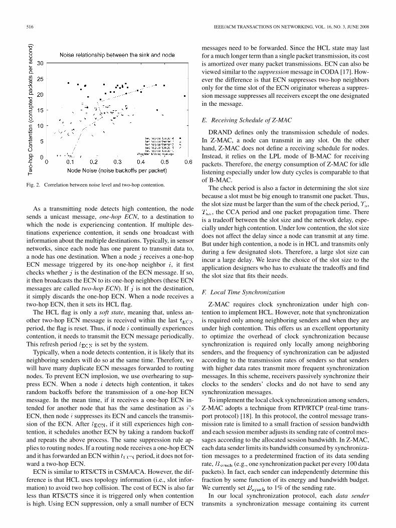
ECN messages notify two-hop neighbors not to act as hiddenterminals to the owner of each slot when contention is high.Each node makes a local decision to send an ECN messagebased on its local estimate of the contention level. There are twoways to estimate two-hop contention. One is to receive acknowl-edgment from the one-hop receiver and measure the packet lossrate. Since two-hop contention causes collision, it is highly re-lated to the loss rate. However this technique requires the re-ceiver to send feedback and incurs extra overhead. Unless theacknowledgment feature is enabled by the application, this over-head can unduly reduce the channel utilization. The other tech-nique is to measure the noise level of the channel. When highcontention occurs, it tends to increase the noise level. This tech-nique does not require any extra overhead as the noise level canbe measured passively at the time of data transmission. In orderto measure the noise level passively without actively samplingthe channel, we measure the average number of noise backoffsthat a sender takes before transmitting a packet. A noise backoffis the backoff taken by a transmitter when it senses the channelusing CCA before packet transmission (it transmits only whenthe channel is clear). When the noise level is higher than theCCA threshold, the node takes backoff. In order to see the cor-relation between the noise backoff and two-hop contention, wetook a Mica2 experiment where two clusters of nodes transmitto a common receiver called sink. The nodes in different clus-ters are in a two-hop distance to each other and the nodes in thesame cluster are one-hop away from each other. In one cluster,we fix one sender, called measurement node, and in the othercluster, we vary the number of senders. We measure the corre-lation between two-hop contention at the sink and the noise levelat the measurement node as we vary the number of senders inone cluster and their transmission rate. The two-hop contentionis measured by the number of times per second that the sinkleaves the idle state into the receiving state but fails to receivethe data because of corrupted data or high noise in sampled data(including loss of sync, CRC fail, and preamble fail).
Under low transmission rates, even if we increase the numberof senders, the average noise level and two-hop contention arevery low, below 0.1 per packet and 5 per second respectively.However, we increase the transmission rate to the full rate (allsenders always have data to send), the noise level increasesbeyond 0.2. Fig. 2 shows the correlation between the averagenoise level and two-hop contention under the full data rate. Thesimple correlation coefficient [16], the ratio of covariance ofthe two metrics over the product of the variances of individualmetrics, is 0.68 (1 and 1 indicate the maximum positive andnegative correlations and 0 indicates no correlation), indicatinghigh correlation. The exponentially moving average value (withweight 0.5) of the noise level when the two-hop contention ishigher than 20 per second increases beyond 0.3 backoffs/packet.We repeated the experiment many times and confirmed that av-erage 0.3 noise backoffs per packet consistently indicates hightwo-hop contention. However, this is only a conservative metricbecause even one-hop contention can cause high noise backoffsas well, but it is clear that low noise indicates low contention.
516 IEEE/ACM TRANSACTIONS ON NETWORKING, VOL. 16, NO. 3, JUNE 2008
Fig. 2. Correlation between noise level and two-hop contention.
As a transmitting node detects high contention, the nodesends a unicast message, one-hop ECN, to a destination towhich the node is experiencing contention. If multiple des-tinations experience contention, it sends one broadcast withinformation about the multiple destinations. Typically, in sensornetworks, since each node has one parent to transmit data to,a node has one destination. When a node receives a one-hopECN message triggered by its one-hop neighbor , it firstchecks whether is the destination of the ECN message. If so,it then broadcasts the ECN to its one-hop neighbors (these ECNmessages are called two-hop ECN). If is not the destination,it simply discards the one-hop ECN. When a node receives atwo-hop ECN, then it sets its HCL flag.
The HCL flag is only a soft state, meaning that, unless an-other two-hop ECN message is received within the lastperiod, the flag is reset. Thus, if node continually experiencescontention, it needs to transmit the ECN message periodically.This refresh period is set by the system.
Typically, when a node detects contention, it is likely that itsneighboring senders will do so at the same time. Therefore, wewill have many duplicate ECN messages forwarded to routingnodes. To prevent ECN implosion, we use overhearing to sup-press ECN. When a node detects high contention, it takesrandom backoffs before the transmission of a one-hop ECNmessage. In the mean time, if it receives a one-hop ECN in-tended for another node that has the same destination as ’sECN, then node suppresses its ECN and cancels the transmis-sion of the ECN. After , if it still experiences high con-tention, it schedules another ECN by taking a random backoffand repeats the above process. The same suppression rule ap-plies to routing nodes. If a routing node receives a one-hop ECNand it has forwarded an ECN within period, it does not for-ward a two-hop ECN.
ECN is similar to RTS/CTS in CSMA/CA. However, the dif-ference is that HCL uses topology information (i.e., slot infor-mation) to avoid two hop collision. The cost of ECN is also farless than RTS/CTS since it is triggered only when contentionis high. Using ECN suppression, only a small number of ECN
messages need to be forwarded. Since the HCL state may lastfor a much longer term than a single packet transmission, its costis amortized over many packet transmissions. ECN can also beviewed similar to the suppression message in CODA [17]. How-ever the difference is that ECN suppresses two-hop neighborsonly for the time slot of the ECN originator whereas a suppres-sion message suppresses all receivers except the one designatedin the message.
E. Receiving Schedule of Z-MAC
DRAND defines only the transmission schedule of nodes.In Z-MAC, a node can transmit in any slot. On the otherhand, Z-MAC does not define a receiving schedule for nodes.Instead, it relies on the LPL mode of B-MAC for receivingpackets. Therefore, the energy consumption of Z-MAC for idlelistening especially under low duty cycles is comparable to thatof B-MAC.
The check period is also a factor in determining the slot sizebecause a slot must be big enough to transmit one packet. Thus,the slot size must be larger than the sum of the check period, ,
, the CCA period and one packet propagation time. Thereis a tradeoff between the slot size and the network delay, espe-cially under high contention. Under low contention, the slot sizedoes not affect the delay since a node can transmit at any time.But under high contention, a node is in HCL and transmits onlyduring a few designated slots. Therefore, a large slot size canincur a large delay. We leave the choice of the slot size to theapplication designers who has to evaluate the tradeoffs and findthe slot size that fits their needs.
F. Local Time Synchronization
Z-MAC requires clock synchronization under high con-tention to implement HCL. However, note that synchronizationis required only among neighboring senders and when they areunder high contention. This offers us an excellent opportunityto optimize the overhead of clock synchronization becausesynchronization is required only locally among neighboringsenders, and the frequency of synchronization can be adjustedaccording to the transmission rates of senders so that senderswith higher data rates transmit more frequent synchronizationmessages. In this scheme, receivers passively synchronize theirclocks to the senders’ clocks and do not have to send anysynchronization messages.
To implement the local clock synchronization among senders,Z-MAC adopts a technique from RTP/RTCP (real-time trans-port protocol) [18]. In this protocol, the control message trans-mission rate is limited to a small fraction of session bandwidthand each session member adjusts its sending rate of control mes-sages according to the allocated session bandwidth. In Z-MAC,each data sender limits its bandwidth consumed by synchroniza-tion messages to a predetermined fraction of its data sendingrate, (e.g., one synchronization packet per every 100 datapackets). In fact, each sender can independently determine thisfraction by some function of its energy and bandwidth budget.We currently set to 1% of the sending rate.
In our local synchronization protocol, each data sendertransmits a synchronization message containing its current
RHEE et al.: Z-MAC: A HYBRID MAC FOR WIRELESS SENSOR NETWORKS 517
clock value periodically. When a node receives a synchroniza-tion message, it updates its clock value by taking a weightedmoving average of its current value and the newly receivedvalue. Because only senders transmit synchronization mes-sages, it is possible that some nodes located in a low trafficarea might have clock values drift far away from the othersynchronized nodes. When those nodes start transmission, theirclock values are unsynchronized (note that the maximum clockdrift rate of Mica2 is around 40 s [15] per second). Thus,their clock values must not be trusted. To avoid honoring clockvalues from unsynchronized senders, we adjust the averagingweight by applying a trust factor that reflects the frequencyof synchronizations of the message senders. is computedby the frequency of transmitted and received synchronizationmessages as below.
Let be the maximum clock drift rate of each sensor andbe the maximum acceptable clock error. Then
determines the minimum synchronization intervalrequired to achieve the maximum clock error or less. Let bethe average rate at which a node receives or sends synchro-nization messages, and be the maximum weight that ap-plies to the new clock value received. Then the of the nodecan be computed by . Theweighted moving average value of a clock can be com-puted by taking a weighted moving average of a newly receivedclock value and .
In Mica2, to maintain 1-ms clock accuracy with 40- s persecond maximum drift rate and one synchronization packet perevery hundred packets (packet size 49 bytes), a node needs tomaintain its sending and/or receiving data rate to 1.5 kbps orhigher. At that rate, the trust factor of the node becomes ,consuming only 1% of the sending rate, 150 bps (or 1/3 packetsper second with 49 byte packets), for synchronization. If the datarate (sum of sending and receiving rates) goes below this, thenthe trust factor of that node gets discounted. But this does notpose any threat to throughput because it is likely that the nodedoes not experience much contention below that data rate andCSMA works effectively under low contention.
In the above scheme, the nodes that send and receive syn-chronization messages more often tend to have a higher trustfactor and their values will be reflected more heavily in updatingclock values. Typically, these nodes on routing paths tend tohave higher trust factors because they tend to send more packetsthan the others. Similarly, source nodes that infrequently senddata have lower trust factors. When a source starts sending dataagain after a long hibernation, its clock could be drifted far apartfrom other more synchronized clocks. But as it increases its rateand its data being routed to the sink, its clock value will comecloser to the clock values of other routing nodes. In our experi-ment, we find that even if an island of 30 nodes is not synchro-nized, it resynchronizes with the rest of the network within 10synchronization messages.
IV. ANALYSIS OF CHANNEL UTILIZATION
Here, we formulate the closed-form expression of channelutilization for various existing MAC schemes for wirelesssensor networks, namely B-MAC, Sift, PTDMA, and Z-MAC
in a one-hop environment where all nodes can sense thetransmission of the other nodes. We do not analyze S-MACand T-MAC as [3] shows that these protocols perform muchworse than B-MAC. These expressions are validated in the nextsection by the simulation and experiment.
A. Model and Definitions
nodes are in the system and they are all in a radio range ofeach other, i.e., a transmission by a node can be sensed by allother nodes. out of nodes are sources and the remainingnodes do not send any packets. Sources always have packets tosend, i.e., applications are continually transmitting. We assumethat all packets are of the same size. As we increase , we varythe level of contention in the system. poses as the maximumpotential number of contenders in a neighborhood. We assumethat is the time taken to sense the radio. We call a con-tention slot. Assuming negligible propagation delay, collisionalways occur at the beginning of a packet transmission. Notethat under no delay, collision cannot occur in other times be-cause it can be sensed by all other transmitting nodes. Thus, thetime wasted because of collision is the same as the transmis-sion time of a packet which is denoted by . Out of , letthe time spent to transmit the payload of a packet excluding thetime taken to send its header. In our analysis, we measure theeffective channel utilization expended to transmit data payload,considering the header transmission to be overhead. We assumea slotted-time model where real time is divided in the unit of aslot time and all transmissions occur at the boundary of a slot.
B. B-MAC
We approximate the performance of B-MAC by slottedCSMA with one backoff window size. In this model, a nodetakes a random backoff time before a transmission. When thebackoff timer expires, it senses the channel. If the channel is notbusy, it starts transmission. If not, it waits until the transmissionis over and then take another backoff and repeat the aboveprocess. The backoff time value is randomly set in the unit ofslots within the backoff contention window. This scheme onlyapproximates B-MAC because B-MAC is implemented as anon-slotted CSMA protocol and also uses two different backoffwindows: the initial backoff before the transmission of a packetand the backoff after sensing the channel are taken from twodifferent window sizes. Despite these differences, we shall seethat our analysis is fairly close to its simulation result.
Nodes pick a random backoff uniformly over .Hence, the average window size observed by a node would be
. Now, consider a contention time slot .Since all nodes pause their backoff timer as soon as they detectthat the channel is busy, from the viewpoint of the nodes, theduration of an entire packet transmission (whether successfulor collided) is counted as a single contention slot. Seen thisway, contention slot can be in one of three states: Collision(s)occurred during , successful data transmission occurred during, or was idle. Let the probability that is in each of these
states be , , and , respectively. Hence,
(1)
518 IEEE/ACM TRANSACTIONS ON NETWORKING, VOL. 16, NO. 3, JUNE 2008
Given contending nodes, we can calculate utilizationachieved as follows:
(2)
The probability that a contention slot is idle is the probabilitythat none of the nodes selected that slot. Given contendingnodes, each with an average backoff window size of , theprobability of a node selecting a slot is . Hence,
(3)
Along the same lines, the probability of a contention slotbeing used for successful data transmission is the probabilityof a node selecting a contention slot, and all others choosingdifferent slots. Hence,
(4)
This system of equations can be solved for , , and toget the utilization .
C. Sift
Sift [11] is a slotted fixed window CSMA protocol. Backoffvalues are randomly chosen based on the following probabilitydistribution where is the contention slot number in range
, and is the probability that contention slot ischosen as a backoff value
(5)
Once the slot is chosen, the node transmits at that slot. Ifa node finds the channel busy, it waits till the channel is idleand tries again as before by choosing a new slot. This behavioris different from B-MAC where the backoff timers are pausedwhen the channel is found to be busy and later resumed againfrom the last values before the pause. This makes our analysisfor Sift a little different from that for B-MAC.
Let the probability of a successful transmission in a slot beas
(6)
which is the probability that any one node chooses slot , allother nodes do not select any slot from 1 to , and, sinceany of the nodes could be the winner, we multiply this prob-ability by to get the desired probability.
Let the probability of collision in slot be
(7)
Here, we are counting the probabilities of collisions occur-ring in slot . Thus, literally, the probability is that any nodesselect the same slot , and the remaining do not selectslots from 1 to . Since any out of the nodes can be the
nodes involved in the collision, we need to multiply this prob-ability by . Finally, we need to sum up probabilities due to
collisions, all occurring in slot .Let the total probability of success and collision for one trial
be and , respectively. Hence,
Let the expected lengths of successful and collided transmis-sions be and , respectively. Hence,
(8)
(9)
We can hence calculate the utilization as
(10)
D. PTDMA
Consider a TDMA time slot whose owner is . Note thatTDMA time slots are different from contention slots and inPTDMA, there is no contention slots and all transmissions aredone once at the beginning of each TDMA slot. It does not per-form any carrier sensing either. If is a source, then it transmitsin slot with probability while the remaining sourcestransmit in slot with probability . If more than two nodestransmit during the same slot, the TDMA slot is wasted withcollision.
Let and be the probabilities that successful packettransmission occurs in a slot of an active source and a nonsource,respectively, as
(11)
(12)
is calculated as the probability that the owner of the slotwins, all other sources lose, OR the owner of the slotloses, one of the nonowners of the slot wins, and all othersources lose (we multiply this by , since there can besuch winners. is obtained as the probability that one sourcewins with probability , and all other sources lose—weagain multiply by since there can be such winners. Giventhese probabilities, the utilization is
(13)
The factor accounts for the fraction of bandwidth lostdue to the header.

RHEE et al.: Z-MAC: A HYBRID MAC FOR WIRELESS SENSOR NETWORKS 519
E. Z-MAC
Owners of a slot pick a random backoff uniformly over, while nonowners do so within . Hence, the
average window size of owners and nonowners would beand , respectively.
Assuming strict time synchronization between nodes, the ownergrabs the channel every time because of its smaller backoffwindow. Hence, in slots out of slots, the correspondingowners will always succeed. Z-MAC behaves like a slotted,memory-less CSMA scheme with just one contender. We canapply the analysis in Section IV-C to this case, with one smallmodification—the probability of choosing a slot is governedby a uniform distribution, hence,
(14)
Let utilization obtained by owners be denoted by .In the remaining slots, all sources contend with afixed window of size . Z-MAC behaves like a slotted, fixed-window memory-less CSMA scheme with contenders. Ap-plying the analysis in Section IV-C again, with
(15)
We denote the utilization obtained in the slots as. Given and , the average utilization,
is a weighted average on the andslots, respectively, as
(16)
F. Discussion
Our goal for this analysis is to ascertain the best performanceachievable by a given protocol under idealized channel condi-tions when factors such as channel losses and noise are factoredout. We shall show in Section V-B and Figs. 6 and 7 that theanalysis closely follows the simulation results and that Z-MACperforms well compared to other protocols. With this valida-tion of our design, we proceed to implement Z-MAC in the realnetwork environment and present the corresponding results inSection V.
V. EXPERIMENTAL EVALUATION
Here, we validate the analytical results in the previous sectionexperimentally and test the performance of the MAC protocolsin more diverse but realistic environments.
A. Experimental Method
To evaluate the performance of Z-MAC, we implementedZ-MAC in both ns-2 and Mica2/TinyOS. We use ns-2 simula-tion to compare the performance with existing protocols whoseTinyOS implementation does not exist at the time of preparingthis work. We compare the performance of Z-MAC with that ofPTDMA (ns-2), Sift (ns-2), and B-MAC (ns-2 and TinyOS). Wedo not run S-MAC and T-MAC as [3] shows that these protocolsperform much worse than B-MAC. Although our performance
TABLE IDEFAULT SETTINGS OF Z-MAC PARAMETERS
evaluation does not cover all the available sensor MAC proto-cols, we believe that the evaluated protocols constitute a goodrepresentation of existing protocols.
Unless specified otherwise, we use the default settings ofB-MAC as described in [3]. Since Z-MAC is implementedon top of B-MAC, we use the same packet format as B-MAC(shown in [3, Table 4]). The default initial and congestionbackoff window sizes of B-MAC are 32 and 16 slots, respec-tively (each slot is 400 s). Except for the throughput testswhere we vary the backoff window sizes to see the impactof window sizes on channel utilization, we keep the defaultwindow sizes. The default values of Z-MAC parameters areshown in Table I.
We use three benchmark setups in our experiment: one-hop,two-hop, and multi-hop benchmarks.
One-Hop Benchmark: This benchmark is reproduced from[3]— nodes placed equidistant from a receiver in a circletransmit transmit as quickly as possible with full transmissionpower. Before each run, we ensured that all nodes are in aone-hop distance to each other so that there are no hiddenterminals. This benchmark is used to measure the achievablethroughput of different MAC protocols for different levelsof contention within a one-hop neighborhood. All nodes areplaced at least 2 feet apart and the distance to the receiver wasapproximately 2 m. The setup is placed in an open conferenceroom without any obstruction. ns-2 one-hop simulation followsthe same setup.
Two-Hop Benchmark: We create this benchmark to test theperformance of different protocols when hidden terminals arepresent. We organize nodes into two clusters where seven andeight sending nodes are located in each cluster respectively.The two clusters are placed approximately 5 m apart in a housewith drywall. A receiver node (or routing node) is placed in themiddle of the two clusters. Nodes within the same cluster areplaced about 2 feet apart. In this environment, we cannot get asharp boundary of interference but we ensure that all sendersfind the receiver as a one-hop neighbor and all nodes are reach-able by two-hop communications. We also reduce the transmis-sion power of senders to 1 dBm (1.3 mW) to control the numberof hidden terminals. Since the number of hidden terminals varieswith the transmission power, we get more hidden terminals witha low transmission power. On the other hand, ns-2 simulation of
520 IEEE/ACM TRANSACTIONS ON NETWORKING, VOL. 16, NO. 3, JUNE 2008
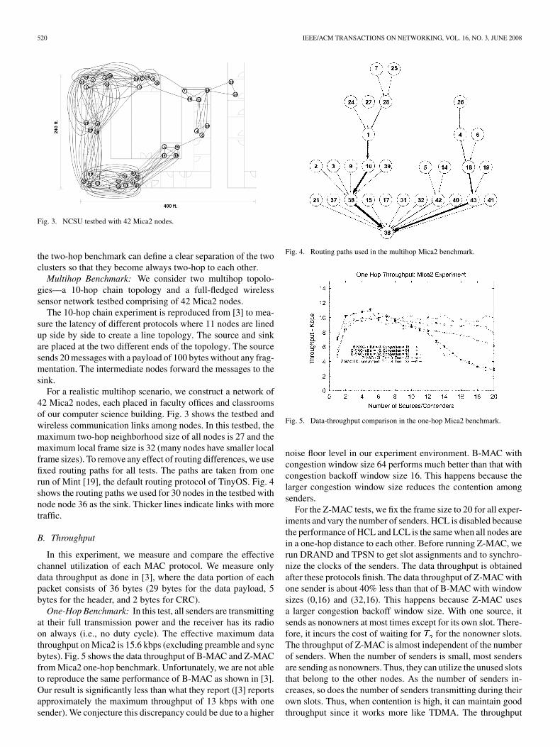
Fig. 3. NCSU testbed with 42 Mica2 nodes.
the two-hop benchmark can define a clear separation of the twoclusters so that they become always two-hop to each other.
Multihop Benchmark: We consider two multihop topolo-gies—a 10-hop chain topology and a full-fledged wirelesssensor network testbed comprising of 42 Mica2 nodes.
The 10-hop chain experiment is reproduced from [3] to mea-sure the latency of different protocols where 11 nodes are linedup side by side to create a line topology. The source and sinkare placed at the two different ends of the topology. The sourcesends 20 messages with a payload of 100 bytes without any frag-mentation. The intermediate nodes forward the messages to thesink.
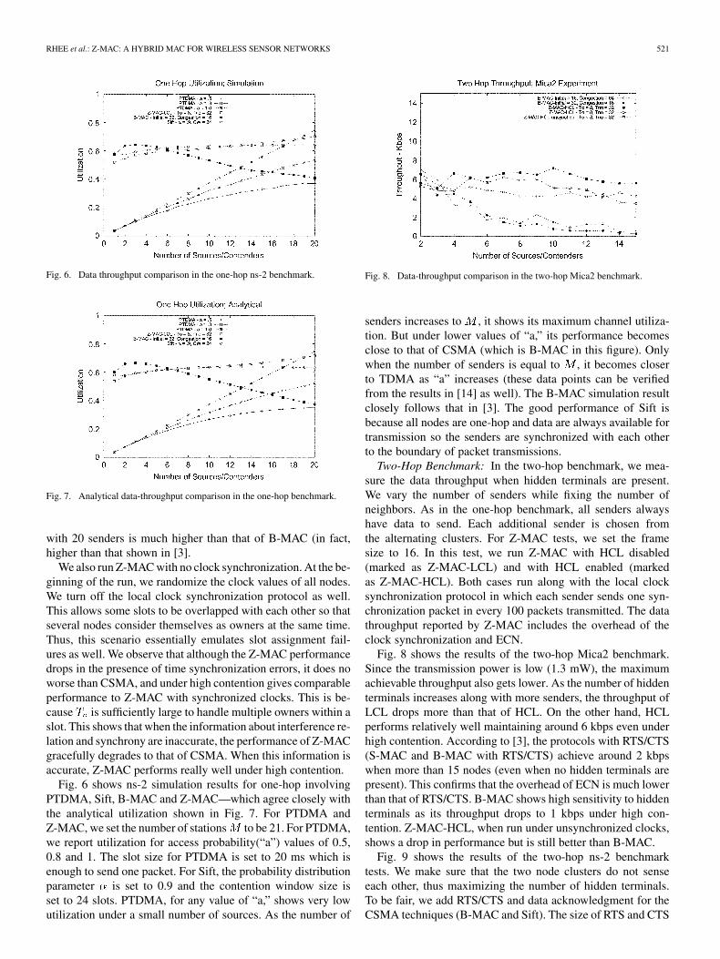
For a realistic multihop scenario, we construct a network of42 Mica2 nodes, each placed in faculty offices and classroomsof our computer science building. Fig. 3 shows the testbed andwireless communication links among nodes. In this testbed, themaximum two-hop neighborhood size of all nodes is 27 and themaximum local frame size is 32 (many nodes have smaller localframe sizes). To remove any effect of routing differences, we usefixed routing paths for all tests. The paths are taken from onerun of Mint [19], the default routing protocol of TinyOS. Fig. 4shows the routing paths we used for 30 nodes in the testbed withnode node 36 as the sink. Thicker lines indicate links with moretraffic.
B. Throughput
In this experiment, we measure and compare the effectivechannel utilization of each MAC protocol. We measure onlydata throughput as done in [3], where the data portion of eachpacket consists of 36 bytes (29 bytes for the data payload, 5bytes for the header, and 2 bytes for CRC).
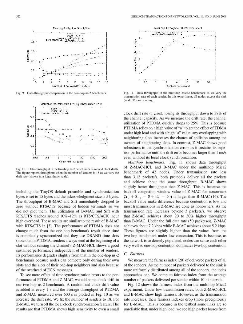
One-Hop Benchmark: In this test, all senders are transmittingat their full transmission power and the receiver has its radioon always (i.e., no duty cycle). The effective maximum datathroughput on Mica2 is 15.6 kbps (excluding preamble and syncbytes). Fig. 5 shows the data throughput of B-MAC and Z-MACfrom Mica2 one-hop benchmark. Unfortunately, we are not ableto reproduce the same performance of B-MAC as shown in [3].Our result is significantly less than what they report ([3] reportsapproximately the maximum throughput of 13 kbps with onesender). We conjecture this discrepancy could be due to a higher
Fig. 4. Routing paths used in the multihop Mica2 benchmark.
Fig. 5. Data-throughput comparison in the one-hop Mica2 benchmark.
noise floor level in our experiment environment. B-MAC withcongestion window size 64 performs much better than that withcongestion backoff window size 16. This happens because thelarger congestion window size reduces the contention amongsenders.
For the Z-MAC tests, we fix the frame size to 20 for all exper-iments and vary the number of senders. HCL is disabled becausethe performance of HCL and LCL is the same when all nodes arein a one-hop distance to each other. Before running Z-MAC, werun DRAND and TPSN to get slot assignments and to synchro-nize the clocks of the senders. The data throughput is obtainedafter these protocols finish. The data throughput of Z-MAC withone sender is about 40% less than that of B-MAC with windowsizes (0,16) and (32,16). This happens because Z-MAC usesa larger congestion backoff window size. With one source, itsends as nonowners at most times except for its own slot. There-fore, it incurs the cost of waiting for for the nonowner slots.The throughput of Z-MAC is almost independent of the numberof senders. When the number of senders is small, most sendersare sending as nonowners. Thus, they can utilize the unused slotsthat belong to the other nodes. As the number of senders in-creases, so does the number of senders transmitting during theirown slots. Thus, when contention is high, it can maintain goodthroughput since it works more like TDMA. The throughput
RHEE et al.: Z-MAC: A HYBRID MAC FOR WIRELESS SENSOR NETWORKS 521
Fig. 6. Data throughput comparison in the one-hop ns-2 benchmark.
Fig. 7. Analytical data-throughput comparison in the one-hop benchmark.
with 20 senders is much higher than that of B-MAC (in fact,higher than that shown in [3].
We also run Z-MAC with no clock synchronization. At the be-ginning of the run, we randomize the clock values of all nodes.We turn off the local clock synchronization protocol as well.This allows some slots to be overlapped with each other so thatseveral nodes consider themselves as owners at the same time.Thus, this scenario essentially emulates slot assignment fail-ures as well. We observe that although the Z-MAC performancedrops in the presence of time synchronization errors, it does noworse than CSMA, and under high contention gives comparableperformance to Z-MAC with synchronized clocks. This is be-cause is sufficiently large to handle multiple owners within aslot. This shows that when the information about interference re-lation and synchrony are inaccurate, the performance of Z-MACgracefully degrades to that of CSMA. When this information isaccurate, Z-MAC performs really well under high contention.
Fig. 6 shows ns-2 simulation results for one-hop involvingPTDMA, Sift, B-MAC and Z-MAC—which agree closely withthe analytical utilization shown in Fig. 7. For PTDMA andZ-MAC, we set the number of stations to be 21. For PTDMA,we report utilization for access probability(“a”) values of 0.5,0.8 and 1. The slot size for PTDMA is set to 20 ms which isenough to send one packet. For Sift, the probability distributionparameter is set to 0.9 and the contention window size isset to 24 slots. PTDMA, for any value of “a,” shows very lowutilization under a small number of sources. As the number of
Fig. 8. Data-throughput comparison in the two-hop Mica2 benchmark.
senders increases to , it shows its maximum channel utiliza-tion. But under lower values of “a,” its performance becomesclose to that of CSMA (which is B-MAC in this figure). Onlywhen the number of senders is equal to , it becomes closerto TDMA as “a” increases (these data points can be verifiedfrom the results in [14] as well). The B-MAC simulation resultclosely follows that in [3]. The good performance of Sift isbecause all nodes are one-hop and data are always available fortransmission so the senders are synchronized with each otherto the boundary of packet transmissions.
Two-Hop Benchmark: In the two-hop benchmark, we mea-sure the data throughput when hidden terminals are present.We vary the number of senders while fixing the number ofneighbors. As in the one-hop benchmark, all senders alwayshave data to send. Each additional sender is chosen fromthe alternating clusters. For Z-MAC tests, we set the framesize to 16. In this test, we run Z-MAC with HCL disabled(marked as Z-MAC-LCL) and with HCL enabled (markedas Z-MAC-HCL). Both cases run along with the local clocksynchronization protocol in which each sender sends one syn-chronization packet in every 100 packets transmitted. The datathroughput reported by Z-MAC includes the overhead of theclock synchronization and ECN.
Fig. 8 shows the results of the two-hop Mica2 benchmark.Since the transmission power is low (1.3 mW), the maximumachievable throughput also gets lower. As the number of hiddenterminals increases along with more senders, the throughput ofLCL drops more than that of HCL. On the other hand, HCLperforms relatively well maintaining around 6 kbps even underhigh contention. According to [3], the protocols with RTS/CTS(S-MAC and B-MAC with RTS/CTS) achieve around 2 kbpswhen more than 15 nodes (even when no hidden terminals arepresent). This confirms that the overhead of ECN is much lowerthan that of RTS/CTS. B-MAC shows high sensitivity to hiddenterminals as its throughput drops to 1 kbps under high con-tention. Z-MAC-HCL, when run under unsynchronized clocks,shows a drop in performance but is still better than B-MAC.
Fig. 9 shows the results of the two-hop ns-2 benchmarktests. We make sure that the two node clusters do not senseeach other, thus maximizing the number of hidden terminals.To be fair, we add RTS/CTS and data acknowledgment for theCSMA techniques (B-MAC and Sift). The size of RTS and CTS
522 IEEE/ACM TRANSACTIONS ON NETWORKING, VOL. 16, NO. 3, JUNE 2008
Fig. 9. Data-throughput comparison in the two-hop ns-2 benchmark.
Fig. 10. Data-throughput in the two-hop ns-2 benchmark as we add clock drifts.The figure reports throughput when the number of senders is 18 as we vary thedrift rate (shown in a logarithmic scale).
including the TinyOS default preamble and synchronizationbytes is set to 15 bytes and the acknowledgment size is 5 bytes.The throughput of B-MAC and Sift immediately dropped tozero without RTS/CTS because of hidden terminals so wedid not plot them. The utilization of B-MAC and Sift withRTS/CTS reaches around 10%–12% as RTS/CTS/ACK incurhigh overhead. These results are similar to the result of B-MACwith RTS/CTS in [3]. The performance of PTDMA does notchange much from the one-hop benchmark result since timeis completely synchronized and they use DRAND time slots(note that in PTDMA, senders always send at the beginning of aslot without sensing the channel). Z-MAC-HCL shows a goodsustained performance independent of the number of senders.Its performance degrades slightly from that in the one-hop ns-2benchmark because nodes can compete only during their ownslots and the slots of their one-hop neighbors and also becauseof the overhead of ECN messages.
To see more effect of time synchronization errors to the per-formance of PTDMA and Z-MAC, we add some clock drift inour two-hop ns-2 benchmark. A randomized clock drift valueis added at every 1 s and the average throughput of PTDMAand Z-MAC measured over 600 s is plotted in Fig. 10 as weincrease the drift rate. We fix the number of senders to 18. ForZ-MAC, we turn off the local clock synchronization feature. Theresults are that PTDMA shows high sensitivity to even a small
Fig. 11. Data throughput in the multihop Mica2 benchmark as we vary thetransmission rate of each sender. In this experiment, all nodes except the sink(node 36) are sending.
clock drift rate (1 s/s), losing its throughput down to 38% ofthe channel capacity. As we increase the drift rate, the channelutilization of PTDMA quickly drops to 25%. This is becausePTDMA relies on a high value of “a” to get the effect of TDMAunder high load and with a high “a” value, any overlapping withneighboring slots increases the chance of collision among theowners of neighboring slots. In contrast, Z-MAC shows goodrobustness to the synchronization errors as it sustains its supe-rior performance until the drift error becomes larger than 1 ms/seven without its local clock synchronization.
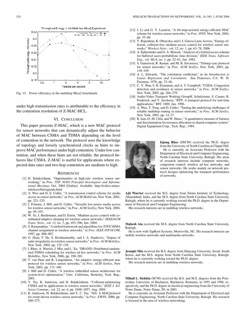
Multihop Benchmark: Fig. 11 shows data throughputof Z-MAC-HCL and B-MAC under the multihop Mica2benchmark of 42 nodes. Under transmission rate lessthan 3.12 packets/s, both protocols deliver all the packetsand achieve about the same throughput. B-MAC showsslightly better throughput than Z-MAC. This is because thebackoff congestion window value of Z-MAC for nonowners
is larger than B-MAC (16). Thebackoff value make difference because contention is low andmost transmissions in Z-MAC are done as nonowners. As thetransmission rate increases beyond 3 packets/s, we observethat Z-MAC achieves about 20 to 30% higher throughputthan B-MAC. Under the full data rate (50 packets/s), Z-MACachieves about 7.2 kbps while B-MAC achieves about 5.2 kbps.These figures are slightly higher than the values from thetwo-hop benchmark under low contention. This is because, asthe network is so densely populated, nodes can sense each othervery well so one-hop contention dominates two-hop contention.
C. Fairness
We measure the fairness index [20] of delivered packets of allof the senders. As the number of packets delivered to the sink ismore uniformly distributed among all of the senders, the indexapproaches one. We compute fairness index from the averagenumber of packets delivered per sender within 10-s intervals.
Fig. 12 shows the fairness index from the multihop Mica2experiment. Under low transmission rates, both Z-MAC-HCLand B-MAC show high fairness. However, as the transmissionrate increases, their fairness indexes drop (more precipitouslyfor B-MAC). This is because in the testbed some links are sounreliable that, under high load, we see high packet losses from

RHEE et al.: Z-MAC: A HYBRID MAC FOR WIRELESS SENSOR NETWORKS 523
Fig. 12. Fairness index from the multihop Mica2 benchmark.
Fig. 13. End-to-end latency on the 10-hop chain topology.
the links. Z-MAC still shows about 40% higher fairness indexthan B-MAC, under the full rate.
D. Latency
We replicate the same latency experiment in [3] using themultihop benchmark. Ref. [3] uses the sending rate of onepacket in every 10 s to measure the latency. We perform thesame experiment with Z-MAC with HCL enabled (but at thissource rate, ECN is never sent; the result is the same as Z-MACLCL). We run TPSN at the beginning to synchronize theclocks of all the nodes in the line topology and take the latencymeasurement of each packet using the timestamps taken at thesource and sink. Both B-MAC and Z-MAC are tested underLPL with 100-ms check interval and with full duty cycle.
Our result is very similar to that in [3]. Both protocols showvery similar latency in all tests. This indicates that the protocoloverhead of Z-MAC is quite comparable to B-MAC’s.
E. Energy Efficiency
Table II shows the itemized energy cost of the Z-MAC setupphase operations in the multihop benchmark. We run the setupphase for 30 times and report the average values and standarddeviations. Total 7.22 J/node on average is consumed for thesetup phase which constitutes about 0.03% of the total energyavailable per node with 2500 mAh and 3 V battery (the samebattery used in [3, Table 3]). Although DRAND and the other
TABLE IIAVERAGE ENERGY CONSUMPTION (IN JOULES) DURING THE SETUP
OPERATIONS IN THE MULTIHOP MICA2 TESTBED
Fig. 14. Power efficiency in low-data rate applications with low duty cycle.
operations are not optimized for energy saving, this is still asubstantial amount of energy consumption compared to the per-transmission energy cost. However, the idea is that this upfrontenergy cost is later compensated by increased energy efficiencyduring the regular transmission of Z-MAC. In this section, wesummarize our energy efficiency result from the Mica2-basedbenchmarks.
Z-MAC uses the CCA and LPL features of B-MAC. Thus, itsenergy efficiency is no better than B-MAC’s under low-data ap-plications. We run the same energy efficiency test described in[3, Sec. 6.2] using the one-hop Mica2 benchmark and plot theresults in Fig. 14. As we vary the transmission rate, we computethe optimal check interval for the traffic pattern. The power con-sumption of Z-MAC is slightly worse than that of B-MAC. Thisis because in Z-MAC: 1) nodes tend to wake up longer for trans-mission since their backoff window sizes are larger and 2) clocksynchronization messages are periodically sent. In this test, asdata rates are low, all nodes are in LCL and no overhead forECN is incurred.
We measure the energy efficiency of Z-MAC and B-MACin the multihop Mica2 benchmark. For each sending rates, wevary the duty cycle from 20% to 60% and measure the energyefficiency in terms of throughput over power. Fig. 15 presentsthe best ratio of throughput over power for a given sendingrate among all duty cycle runs. As we observe in the multihopthroughput test, under low data rates, B-MAC has slightlyhigher throughput. Also, we observe in the energy efficiencytest, that B-MAC also has slightly less power consumption (upto 10%) under low transmission rates. This is again because, asB-MAC has a smaller contention window size than Z-MAC, itsidle time is less under low transmission rates. However, as thetransmission rate increases beyond three packets per second,Z-MAC’s energy efficiency improves and beats that of B-MACby about 40% under the full rate. This higher energy efficiency
524 IEEE/ACM TRANSACTIONS ON NETWORKING, VOL. 16, NO. 3, JUNE 2008
Fig. 15. Power efficiency in the multihop Mica2 benchmark.
under high transmission rates is attributable to the efficiency inthe contention resolution of Z-MAC-HCL.
VI. CONCLUSION
This paper presents Z-MAC, which is a new MAC protocolfor sensor networks that can dynamically adjust the behaviorof MAC between CSMA and TDMA depending on the levelof contention in the network. The protocol uses the knowledgeof topology and loosely synchronized clocks as hints to im-prove MAC performance under high contention. Under low con-tention, and when these hints are not reliable, the protocol be-haves like CSMA. Z-MAC is useful for applications where ex-pected data rates and two-hop contention are medium to high.
REFERENCES
[1] H. Balakrishnan, “Opportunities in high-rate wireless sensor net-working,” in Proc. NSF NOSS Principal Investigator and Informa-tional Meetings, Oct. 2004 [Online]. Available: http://toilers.mines.edu/noss/Infoagenda.html
[2] A. Woo and D. E. Culler, “A transmission control scheme for mediaaccess in sensor networks,” in Proc. ACM MobiCom, New York, 2001,pp. 221–235.
[3] J. Polastre, J. Hill, and D. Culler, “Versatile low power media accessfor wireless sensor networks,” in Proc. ACM SenSys, New York, 2004,pp. 95–107.
[4] W. Ye, J. Heidemann, and D. Estrin, “Medium access control with co-ordinated adaptive sleeping for wireless sensor networks,” IEEE/ACMTrans. Netw., vol. 12, no. 3, pp. 493–506, Jun. 2004.
[5] S. Ramanathan, “A unified framework and algorithms for (T/F/C)DMAchannel assignment in wireless networks,” in Proc. IEEE INFOCOM,1997, pp. 900–907.
[6] G. Zhou, T. He, S. Krishnamurthy, and J. A. Stankovic, “Impact ofradio irregularity on wireless sensor networks,” in Proc. ACM MobiSys,New York, 2004, pp. 125–138.
[7] I. Rhee, A. Warrier, J. Min, and L. Xu, “DRAND: Distributed random-ized TDMA scheduling for wireless ad hoc networks,” in Proc. ACMMobiHoc, New York, 2006, pp. 190–201.
[8] T. van Dam and K. Langendoen, “An adaptive energy-efficient macprotocol for wireless sensor networks,” in Proc. ACM SenSys, NewYork, 2003, pp. 171–180.
[9] J. Hill and D. Culler, “A wireless embedded sensor architecture forsystem-level optimization,” Univ. California, Berkeley, Tech. Rep.,2001.
[10] Y. Tay, K. Jamieson, and H. Balakrishnan, “Collision-minimizingCSMA and its applications to wireless sensor networks,” IEEE J. Sel.Areas Commun., vol. 22, no. 6, pp. 1048–1057, Aug. 2004.
[11] K. Jamieson, H. Balakrishnan, and Y. C. Tay, “Sift: A MACprotocolfor event-driven wireless sensor networks,” in Proc. EWSN, 2006, pp.260–275.
[12] J. Li and G. Y. Lazarou, “A bit-map-assisted energy-efficient MACscheme for wireless sensor networks,” in Proc. IPSN, New York, 2004,pp. 55–60.
[13] V. Rajendran, K. Obraczka, and J. J. Garcia-Luna-Aceves, “Energy-ef-ficient, collision-free medium access control for wireless sensor net-works,” Wireless Netw., vol. 12, no. 1, pp. 63–78, 2006.
[14] A. Ephremides and O. A. Mowafi, “Analysis of a hybrid access schemefor buffered users-probabilistic time division,” IEEE Trans. SoftwareEng., vol. SE-8, no. 1, pp. 52–61, Jan. 1982.
[15] S. Ganeriwal, R. Kumar, and M. B. Srivastava, “Timing-sync protocolfor sensor networks,” in Proc. ACM SenSys, New York, 2003, pp.138–149.
[16] A. L. Edwards, “The correlation coefficient,” in An Introduction toLinear Regression and Correlation. San Francisco, CA: W. H.Freeman, 1976, pp. 33–46.
[17] C.-Y. Wan, S. B. Eisenman, and A. T. Campbell, “CODA: Congestiondetection and avoidance in sensor networks,” in Proc. ACM SenSys,New York, 2003, pp. 266–279.
[18] Audio-Video Transport Working GroupH. Schulzrinne, S. Casner, R.Frederick, and V. Jacobson, “RTP: A transport protocol for real-timeapplications,” RFC 1889, Jan. 1996.
[19] A. Woo, T. Tong, and D. Culler, “Taming the underlying challenges ofreliable multihop routing in sensor networks,” in Proc. ACM SenSys,New York, 2003, pp. 14–27.
[20] R. Jain, D.-M. Chiu, and W. Hawe, “A quantitative measure of fairnessand discrimination for resource allocation in shared computer system,”Digital Equipment Corp., Tech. Rep., 1984.
Injong Rhee (SM’89) received the Ph.D. degreefrom the University of North Carolina at Chapel Hill.
He is currently an Associate Professor with theDepartment of Electrical and Computer Engineering,North Carolina State University, Raleigh. His areasof research interests include computer networks,congestion control, wireless ad hoc networks, andsensor networks. He works mainly on network pro-tocol designs optimizing the transport performanceof networks.
Ajit Warrier received the B.E. degree from Nirma Institute of Technology,Ahmedabad, India, and the M.S. degree from North Carolina State University,Raleigh, where he is currently working toward the Ph.D. degree in the Depart-ment of Electrical and Computer Engineering.
His research interests are in multihop wireless networks.
Mahesh Aia received the M.S. degree from North Carolina State University,Raleigh.
He is now with TapRoot Systems, Morrisville, NC. His research interests aremobile wireless networks and multimedia networks.
Jeongki Min received the B.S. degree from Hanyang University, Seoul, SouthKorea, and the M.S. degree from North Carolina State University, Raleigh,where he is currently working toward the Ph.D. degree.
His research interests are in multihop wireless networks.
Mihail L. Sichitiu (M’98) received the B.S. and M.S. degrees from the Poly-technic University of Bucharest, Bucharest, Romania, in 1995 and 1996, re-spectively, and the Ph.D. degree in electrical engineering from the University ofNotre Dame, Notre Dame, IN, in 2001.
He is currently an Assistant Professor with the Department of Electrical andComputer Engineering, North Carolina State University, Raleigh. His researchis focused in the area of wireless networking.