
Your Electrical Solutions - Amazon S3
302
March 2001 MOLDED CASE CIRCUIT BREAKERS 4 PANELBOARDS 96 LOADCENTERS 110 METER CENTERS 112 SAFETY SWITCHES 113 DRY TYPE DISTRIBUTION TRANSFORMERS 114 BUSWAY (LOW VOLTAGE) 116 COMMUNICATIONS SYSTEMS 138 PROGRAMMABLE LOGIC CONTROLLERS (PLCs) 146 MOTOR CONTROL • CONTACTORS AND STARTERS 149 (LOW VOLTAGE, ELECTROMECHANICAL) DISTRIBUTION SWITCHBOARDS (LOW VOLTAGE) 223 HIGH RESISTANCE PULSING GROUND SYSTEM 231 SWITCHGEAR • LOW VOLTAGE 234 FUSES (MEDIUM VOLTAGE) 287 EXCITATION CONTROL EQUIPMENT 291 ADJUSTABLE FREQUENCY AC DRIVES MOTOR CONTROL CENTERS 208 • TRIP UNIT RETROFIT KITS 246 • SOLID-STATE LOW VOLTAGE 176 • SYNCHRONOUS 181 • STARTERS (MEDIUM VOLTAGE) 195 REDUCED VOLTAGE MOTOR STARTERS • MEDIUM VOLTAGE 275 • MEDIUM VOLTAGE LOAD INTERRUPTER 282 IQ PRODUCTS (METERING AND MOTOR PROTECTION) 131 DISTRIBUTION SYSTEM 2 Page A C D E F G H I J K M N O P Q R S T U V B L W Section
-
Upload
khangminh22 -
Category
Documents
-
view
1 -
download
0
Transcript of Your Electrical Solutions - Amazon S3
March 2001
MOLDED CASE CIRCUIT BREAKERS 4PANELBOARDS 96LOADCENTERS 110METER CENTERS 112SAFETY SWITCHES 113DRY TYPE DISTRIBUTION TRANSFORMERS 114BUSWAY (LOW VOLTAGE) 116
COMMUNICATIONS SYSTEMS 138PROGRAMMABLE LOGIC CONTROLLERS (PLCs) 146MOTOR CONTROL
• CONTACTORS AND STARTERS 149(LOW VOLTAGE, ELECTROMECHANICAL)
DISTRIBUTION SWITCHBOARDS (LOW VOLTAGE) 223HIGH RESISTANCE PULSING GROUND SYSTEM 231SWITCHGEAR
• LOW VOLTAGE 234
FUSES (MEDIUM VOLTAGE) 287EXCITATION CONTROL EQUIPMENT 291
ADJUSTABLE FREQUENCY AC DRIVES
MOTOR CONTROL CENTERS 208
• TRIP UNIT RETROFIT KITS 246
• SOLID-STATE LOW VOLTAGE 176
• SYNCHRONOUS 181• STARTERS (MEDIUM VOLTAGE) 195
REDUCED VOLTAGE MOTOR STARTERS
• MEDIUM VOLTAGE 275• MEDIUM VOLTAGE LOAD INTERRUPTER 282
IQ PRODUCTS (METERING AND MOTOR PROTECTION) 131
DISTRIBUTION SYSTEM 2
Page
A
CDEFGHIJ
K
MNOPQ
RSTUV
B
L
W
Section
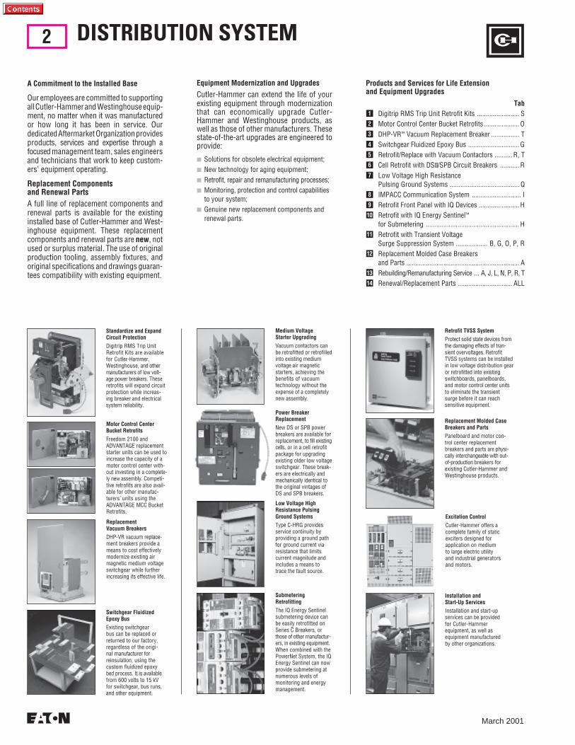
Equipment Modernization and UpgradesCutler-Hammer can extend the life of yourexisting equipment through modernizationthat can economically upgrade Cutler-Hammer and Westinghouse products, aswell as those of other manufacturers. Thesestate-of-the-art upgrades are engineered toprovide:
■ Solutions for obsolete electrical equipment;■ New technology for aging equipment;■ Retrofit, repair and remanufacturing processes;■ Monitoring, protection and control capabilities
to your system;■ Genuine new replacement components and
renewal parts.
Medium VoltageStarter UpgradingVacuum contactors canbe retrofitted or retrofilledinto existing mediumvoltage air magneticstarters, achieving thebenefits of vacuumtechnology without theexpense of a completelynew assembly.
Power BreakerReplacementNew DS or SPB powerbreakers are available forreplacement, to fill existingcells, or in a cell retrofitpackage for upgradingexisting older low voltageswitchgear. These break-ers are electrically andmechanically identical tothe original vintages ofDS and SPB breakers.
Low Voltage HighResistance PulsingGround SystemsType C-HRG providesservice continuity byproviding a ground pathfor ground current viaresistance that limitscurrent magnitude andincludes a means totrace the fault source.
Replacement Molded CaseBreakers and PartsPanelboard and motor con-trol center replacementbreakers and parts are physi-cally interchangeable with out-of-production breakers forexisting Cutler-Hammer andWestinghouse products.
SubmeteringRetrofittingThe IQ Energy Sentinelsubmetering device canbe easily retrofitted onSeries C Breakers, orthose of other manufactur-ers, in existing equipment.When combined with thePowerNet System, the IQEnergy Sentinel can nowprovide submetering atnumerous levels ofmonitoring and energymanagement.
Retrofit TVSS SystemProtect solid state devices fromthe damaging effects of tran-sient overvoltages. RetrofitTVSS systems can be installedin low voltage distribution gearor retrofitted into existingswitchboards, panelboards,and motor control center unitsto eliminate the transientsurge before it can reachsensitive equipment.
Installation andStart-Up ServicesInstallation and start-upservices can be providedfor Cutler-Hammerequipment, as well asequipment manufacturedby other organizations.
Excitation ControlCutler-Hammer offers acomplete family of staticexciters designed forapplication on mediumto large electric utilityand industrial generatorsand motors.
A Commitment to the Installed Base
Our employees are committed to supportingall Cutler-Hammer and Westinghouse equip-ment, no matter when it was manufacturedor how long it has been in service. Ourdedicated Aftermarket Organization providesproducts, services and expertise through afocused management team, sales engineersand technicians that work to keep custom-ers’ equipment operating.
Replacement Componentsand Renewal PartsA full line of replacement components andrenewal parts is available for the existinginstalled base of Cutler-Hammer and West-inghouse equipment. These replacementcomponents and renewal parts are new, notused or surplus material. The use of originalproduction tooling, assembly fixtures, andoriginal specifications and drawings guaran-tees compatibility with existing equipment.
DISTRIBUTION SYSTEM2
March 2001
Products and Services for Life Extensionand Equipment Upgrades
Tab1 Digitrip RMS Trip Unit Retrofit Kits ........................ S2 Motor Control Center Bucket Retrofits .................... O3 DHP-VR™ Vacuum Replacement Breaker ................ T4 Switchgear Fluidized Epoxy Bus ............................. G5 Retrofit/Replace with Vacuum Contactors .......... R, T6 Cell Retrofit with DSII/SPB Circuit Breakers ........... R7 Low Voltage High Resistance
Pulsing Ground Systems ....................................... Q8 IMPACC Communication System ............................ I9 Retrofit Front Panel with IQ Devices ....................... H10 Retrofit with IQ Energy Sentinel™
for Submetering ..................................................... H11 Retrofit with Transient Voltage
Surge Suppression System .................. B, G, O, P, R12 Replacement Molded Case Breakers
and Parts ................................................................ A13 Rebuilding/Remanufacturing Service ... A, J, L, N, P, R, T14 Renewal/Replacement Parts ............................... ALL
Standardize and ExpandCircuit ProtectionDigitrip RMS Trip UnitRetrofit Kits are availablefor Cutler-Hammer,Westinghouse, and othermanufacturers of low volt-age power breakers. Theseretrofits will expand circuitprotection while increas-ing breaker and electricalsystem reliability.
Motor Control CenterBucket RetrofitsFreedom 2100 andADVANTAGE replacementstarter units can be used toincrease the capacity of amotor control center with-out investing in a complete-ly new assembly. Competi-tive retrofits are also avail-able for other manufac-turers’ units using theADVANTAGE MCC BucketRetrofits.
ReplacementVacuum BreakersDHP-VR vacuum replace-ment breakers provide ameans to cost effectivelymodernize existing airmagnetic medium voltageswitchgear while furtherincreasing its effective life.
Switchgear FluidizedEpoxy BusExisting switchgearbus can be replaced orreturned to our factory,regardless of the origi-nal manufacturer forreinsulation, using thecustom fluidized epoxybed process. It is availablefrom 600 volts to 15 kVfor switchgear, bus runs,and other equipment.

DISTRIBUTION SYSTEM
March 2001
3
12111098
14
SECONDARYSPOT NETWORKWITH NETWORK PROTECTORS
8
12111098
14121110
8761
14
1413128
9 14
8
8 913
4 5314
1413
4
1498
MARGIN
ADJUSTABLEFREQUENCY CONTROL
ENCLOSEDCONTROL
REDUCED VOLTAGE STARTER
TRANSFORMER
TRANSFORMER
MEDIUM VOLTAGESWITCHGEAR
LOW VOLTAGESECONDARY UNITSUBSTATION
LOAD INTERRUPTERSWITCHGEAR
PROGRAMMABLELOGICCONTROLLER
MOTOR CONTROLCENTER
LOW VOLTAGE SWITCHBOARDINDIVIDUAL/GROUP MOUNTED
UP TO 300 HPUP TO 1500 HP
ARC RESISTANTSWITCHGEAR
UTILITY SYSTEM
EXCITATIONCONTROL
ON-SITE GENERATION
GROUNDING RESISTOR
HIGH CURRENT LOW VOLTAGEPROCESS
START STOP
COUNTCONTROL
PROXIMITY SENSOR
LIMITSWITCH
SELECTOR SWITCH
PHOTOELECTRIC SENSOR
SAFETYSWITCH
LIGHTING CONTROLPANELBOARD
OFFICE BUILDING
LIGHTINGPANELBOARD
LIGHTINGPANELBOARD
LIGHTINGPANELBOARD
LIGHTING CONTROLPANELBOARD
PROCESSRECTIFIERSYSTEM
DCDRIVE
SAFETYSWITCH
MEDIUM VOLTAGESTARTER
MEDIUM VOLTAGENON-SEGREGATED BUS
LOW VOLTAGE BUS
BUS PLUG
UP TO 700 HPUP TO 300 HP
DRY-TYPEDISTRIBUTIONTRANSFORMER
LOW VOLTAGE DISTRIBUTIONPANELBOARD
LOW VOLTAGE DISTRIBUTIONPANELBOARD
ELECTRICALOPERATORINTERFACE
BUS PLUG
MAGNETIC SHOEBREAK
MEDIUM VOLTAGE TRANSFER EQUIPMENTVACUUM BREAKERS OR LOAD BREAK FUSED SWITCHES
34.5 kVSWITCHGEAR
POWERTRANSFORMER
15 kVSWITCHGEAR
RECTIFIERAND EXCITER
SYNCHRONOUSMOTOR FIELDAPPLICATIONPANEL
GENERATOR
LOW VOLTAGE TRANSFER SWITCH
ADDITIONALUTILITY SOURCES
SAFETYSWITCH
MANUFACTURING FACILITY
SAFETYSWITCH
SYNCHRONOUSMOTOR
LOAD INTERRUPTERSWITCHGEAR
ENCLOSEDCONTROL
IMPACCINTEGRATEDMONITORINGPROTECTIONAND CONTROLCOMMUNICATIONSYSTEM
14
14
98
14
14 14
1414
914
5
138
14
6 713
4 5 8 9114
8 10 12 14
814
9
10128
149
112
14
14
14
81114
81114
12 148
14
814
814
141414141412 1410 1181481414149 14 88
4
March 2001
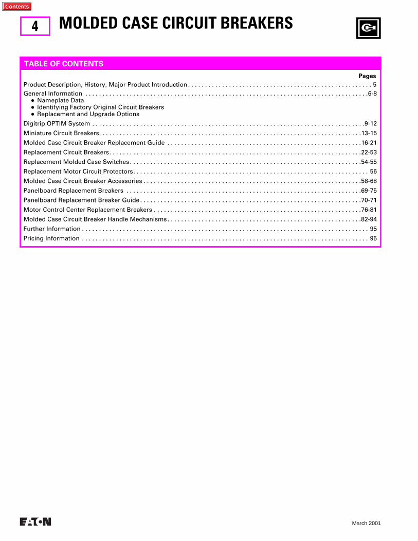
MOLDED CASE CIRCUIT BREAKERS
Pages
Product Description, History, Major Product Introduction . . . . . . . . . . . . . . . . . . . . . . . . . . . . . . . . . . . . . . . . . . . . . . . . . . . . . . 5General Information . . . . . . . . . . . . . . . . . . . . . . . . . . . . . . . . . . . . . . . . . . . . . . . . . . . . . . . . . . . . . . . . . . . . . . . . . . . . . . . . . . .6-8
●
Nameplate Data
●
Identifying Factory Original Circuit Breakers
●
Replacement and Upgrade Options
Digitrip OPTIM System . . . . . . . . . . . . . . . . . . . . . . . . . . . . . . . . . . . . . . . . . . . . . . . . . . . . . . . . . . . . . . . . . . . . . . . . . . . . . . . .9-12
Miniature Circuit Breakers. . . . . . . . . . . . . . . . . . . . . . . . . . . . . . . . . . . . . . . . . . . . . . . . . . . . . . . . . . . . . . . . . . . . . . . . . . . . .13-15
Molded Case Circuit Breaker Replacement Guide . . . . . . . . . . . . . . . . . . . . . . . . . . . . . . . . . . . . . . . . . . . . . . . . . . . . . . . . .16-21
Replacement Circuit Breakers. . . . . . . . . . . . . . . . . . . . . . . . . . . . . . . . . . . . . . . . . . . . . . . . . . . . . . . . . . . . . . . . . . . . . . . . . .22-53
Replacement Molded Case Switches . . . . . . . . . . . . . . . . . . . . . . . . . . . . . . . . . . . . . . . . . . . . . . . . . . . . . . . . . . . . . . . . . . . .54-55
Replacement Motor Circuit Protectors. . . . . . . . . . . . . . . . . . . . . . . . . . . . . . . . . . . . . . . . . . . . . . . . . . . . . . . . . . . . . . . . . . . . . 56
Molded Case Circuit Breaker Accessories . . . . . . . . . . . . . . . . . . . . . . . . . . . . . . . . . . . . . . . . . . . . . . . . . . . . . . . . . . . . . . . .58-68
Panelboard Replacement Breakers . . . . . . . . . . . . . . . . . . . . . . . . . . . . . . . . . . . . . . . . . . . . . . . . . . . . . . . . . . . . . . . . . . . . .69-75
Panelboard Replacement Breaker Guide . . . . . . . . . . . . . . . . . . . . . . . . . . . . . . . . . . . . . . . . . . . . . . . . . . . . . . . . . . . . . . . . .70-71
Motor Control Center Replacement Breakers . . . . . . . . . . . . . . . . . . . . . . . . . . . . . . . . . . . . . . . . . . . . . . . . . . . . . . . . . . . . .76-81
Molded Case Circuit Breaker Handle Mechanisms. . . . . . . . . . . . . . . . . . . . . . . . . . . . . . . . . . . . . . . . . . . . . . . . . . . . . . . . .82-94
Further Information . . . . . . . . . . . . . . . . . . . . . . . . . . . . . . . . . . . . . . . . . . . . . . . . . . . . . . . . . . . . . . . . . . . . . . . . . . . . . . . . . . . . 95
Pricing Information . . . . . . . . . . . . . . . . . . . . . . . . . . . . . . . . . . . . . . . . . . . . . . . . . . . . . . . . . . . . . . . . . . . . . . . . . . . . . . . . . . . . 95
TABLE OF CONTENTS
5
March 2001
A
Originally a Westinghouse Product
PRODUCT DESCRIPTION
PRODUCT HISTORY
MAJOR PRODUCT INTRODUCTION
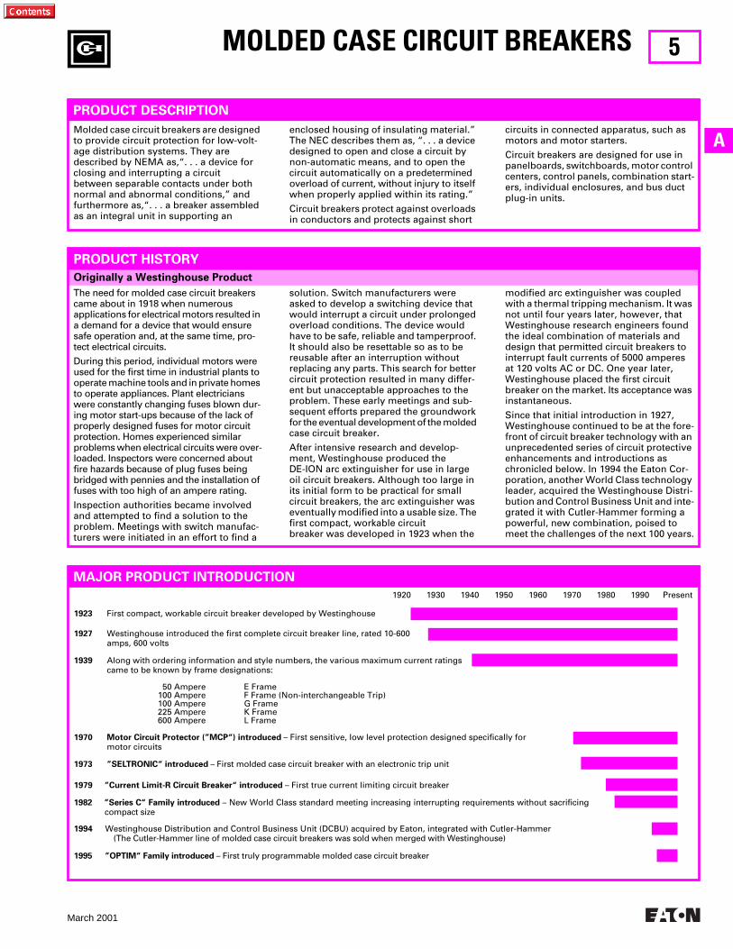
Molded case circuit breakers are designed to provide circuit protection for low-volt-age distribution systems. They are described by NEMA as,“. . . a device for closing and interrupting a circuit between separable contacts under both normal and abnormal conditions,” and furthermore as,“. . . a breaker assembled as an integral unit in supporting an
The need for molded case circuit breakers came about in 1918 when numerous applications for electrical motors resulted in a demand for a device that would ensure safe operation and, at the same time, pro-tect electrical circuits.
During this period, individual motors were used for the first time in industrial plants to operate machine tools and in private homes to operate appliances. Plant electricians were constantly changing fuses blown dur-ing motor start-ups because of the lack of properly designed fuses for motor circuit protection. Homes experienced similar problems when electrical circuits were over-loaded. Inspectors were concerned about fire hazards because of plug fuses being bridged with pennies and the installation of fuses with too high of an ampere rating.
Inspection authorities became involved and attempted to find a solution to the problem. Meetings with switch manufac-turers were initiated in an effort to find a
solution. Switch manufacturers were asked to develop a switching device that would interrupt a circuit under prolonged overload conditions. The device would have to be safe, reliable and tamperproof. It should also be resettable so as to be reusable after an interruption without replacing any parts. This search for better circuit protection resulted in many differ-ent but unacceptable approaches to the problem. These early meetings and sub-sequent efforts prepared the groundwork for the eventual development of the molded case circuit breaker.
After intensive research and develop-ment, Westinghouse produced the DE-ION arc extinguisher for use in large oil circuit breakers. Although too large in its initial form to be practical for small circuit breakers, the arc extinguisher was eventually modified into a usable size. The first compact, workable circuit breaker was developed in 1923 when the
enclosed housing of insulating material.” The NEC describes them as, “. . . a device designed to open and close a circuit by non-automatic means, and to open the circuit automatically on a predetermined overload of current, without injury to itself when properly applied within its rating.”
Circuit breakers protect against overloads in conductors and protects against short
circuits in connected apparatus, such as motors and motor starters.
Circuit breakers are designed for use in panelboards, switchboards, motor control centers, control panels, combination start-ers, individual enclosures, and bus duct plug-in units.
modified arc extinguisher was coupled with a thermal tripping mechanism. It was not until four years later, however, that Westinghouse research engineers found the ideal combination of materials and design that permitted circuit breakers to interrupt fault currents of 5000 amperes at 120 volts AC or DC. One year later, Westinghouse placed the first circuit breaker on the market. Its acceptance was instantaneous.
Since that initial introduction in 1927, Westinghouse continued to be at the fore-front of circuit breaker technology with an unprecedented series of circuit protective enhancements and introductions as chronicled below. In 1994 the Eaton Cor-poration, another World Class technology leader, acquired the Westinghouse Distri-bution and Control Business Unit and inte-grated it with Cutler-Hammer forming a powerful, new combination, poised to meet the challenges of the next 100 years.
1920 1930 1940 1950 1960 1970 1980 1990 Present
1923
First compact, workable circuit breaker developed by Westinghouse
1995 ”OPTIM“ Family introduced
– First truly programmable molded case circuit breaker
1927
Westinghouse introduced the first complete circuit breaker line, rated 10-600 amps, 600 volts
1939
Along with ordering information and style numbers, the various maximum current ratings came to be known by frame designations:
50 Ampere E Frame100 Ampere F Frame (Non-interchangeable Trip)100 Ampere G Frame225 Ampere K Frame600 Ampere L Frame
1970 Motor Circuit Protector (”MCP“) introduced
– First sensitive, low level protection designed specifically for motor circuits
1973 ”SELTRONIC“ introduced
– First molded case circuit breaker with an electronic trip unit
1979 ”Current Limit-R Circuit Breaker“ introduced
– First true current limiting circuit breaker
1982 ”Series C“ Family introduced
– New World Class standard meeting increasing interrupting requirements without sacrificingcompact size
1994
Westinghouse Distribution and Control Business Unit (DCBU) acquired by Eaton, integrated with Cutler-Hammer(The Cutler-Hammer line of molded case circuit breakers was sold when merged with Westinghouse)
MOLDED CASE CIRCUIT BREAKERS
6
March 2001
Nameplate Data
Accessories
MOLDED CASE CIRCUIT BREAKERS
General Information
BREAKER IDENTIFICATION
Most circuit breaker accessories are mounted internally and are not visible with a quick inspection.
However, since many accessories rely on or supply an external signal, there may be electrical leads exiting the circuit breaker case. Inspect for these leads when obtaining full descriptive information for circuit breaker replacement. Examples of common accessories:
Shunt Trip
Used to remotely trip the circuit breaker using an electrical signal. Typically two wires extend through the case.
Undervoltage Release (UVR)
Trips the circuit breaker when voltage drops below a specified percentage of coil voltage (typically 70%). Typically two wires extend through the case.
Auxiliary Switch
Provides remote indication of the circuit breaker status (open/closed). Typically three wires extend through case in a 1-pole 1A/1B application.
Alarm Lockout Switch
For remote indication of an automatic trip operation. Typically two or three wires extend through the case.
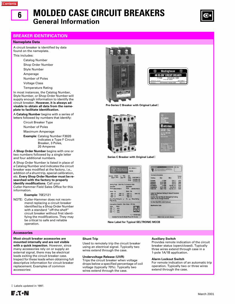
A circuit breaker is identified by data found on the nameplate.
This includes:
Catalog Number
Shop Order Number
Style Number
Amperage
Number of Poles
Voltage Class
Temperature Rating
In most instances, the Catalog Number, Style Number, or Shop Order Number will supply enough information to identify the circuit breaker.
However, it is always ad-visable to obtain all data from the name-plate to facilitate identification.
A
Catalog Number
begins with a series of letters followed by numbers that identify:
Circuit Breaker Type
Number of Poles
Maximum Amperage
Example:
Catalog Number F3020indicates a Type F CircuitBreaker, 3 Poles, 20 Amperes
A
Shop Order Number
begins with one or two numbers followed by a single letter and four additional numbers.
A Shop Order Number is listed in place of a Catalog Number and indicates the circuit breaker was modified at the factory, i.e., addition of a shunt trip, special calibration, etc.
Every Shop Order Number must be re-searched with the factory to properly identify modifications.
Call your Cutler-Hammer Field Sales Office for this information.
Example:
70E2121
NOTE: Cutler-Hammer does not recom-mend replacing a circuit breaker identified by a Shop Order Number with a standard ”off-the-shelf“ circuit breaker without first identi-fying the modifications. They may be critical to safe and reliable operation.
Pre-Series C Breaker with Original Label
➊
Series C Breaker with Original Label
➊
New Label for Typical SELTRONIC MCCB
➊
Labels updated in 1997.
7
March 2001
A
Identifying Genuine, Factory Original Westinghouse Circuit Breakers Manufactured by Cutler-Hammer
Why Insist on Only Genuine, New MCCBs Purchased Through Authorized Distributors?
MOLDED CASE CIRCUIT BREAKERS
General Information
FACTORY ORIGINAL CIRCUIT BREAKERS
Cutler-Hammer defines “New” product as that which has not yet been installed in an electrical circuit, purchased through authorized channels in factory original condition and packaged in unopened Cutler-Hammer cartons.
●
The only way to ensure safe and reliable operation of your system is to use genu-ine, new, Cutler-Hammer products exclusively. Since Cutler-Hammer does not resell the component parts for mold-
ed case circuit breakers, the only way for third party breaker refurbishers to get parts for the breakers that they are rebuilding is to cannibalize other used breakers or to use counterfeit compo-nents. Neither is a very good option for the end user.
●
In some cases, unauthorized resellers of molded case circuit breakers have been found to misrepresent used, rebuilt, or surplus products. Only
products purchased as ”new“ through authorized channels are covered under the Cutler-Hammer warranty policy.
●
There have been instances where third party refurbishers have rebuilt breakers using the wrong parts, with parts miss-ing or the factory lubrication removed in the cleaning process — any of which may result in devices that may not be depended upon to function properly to protect equipment and personnel.
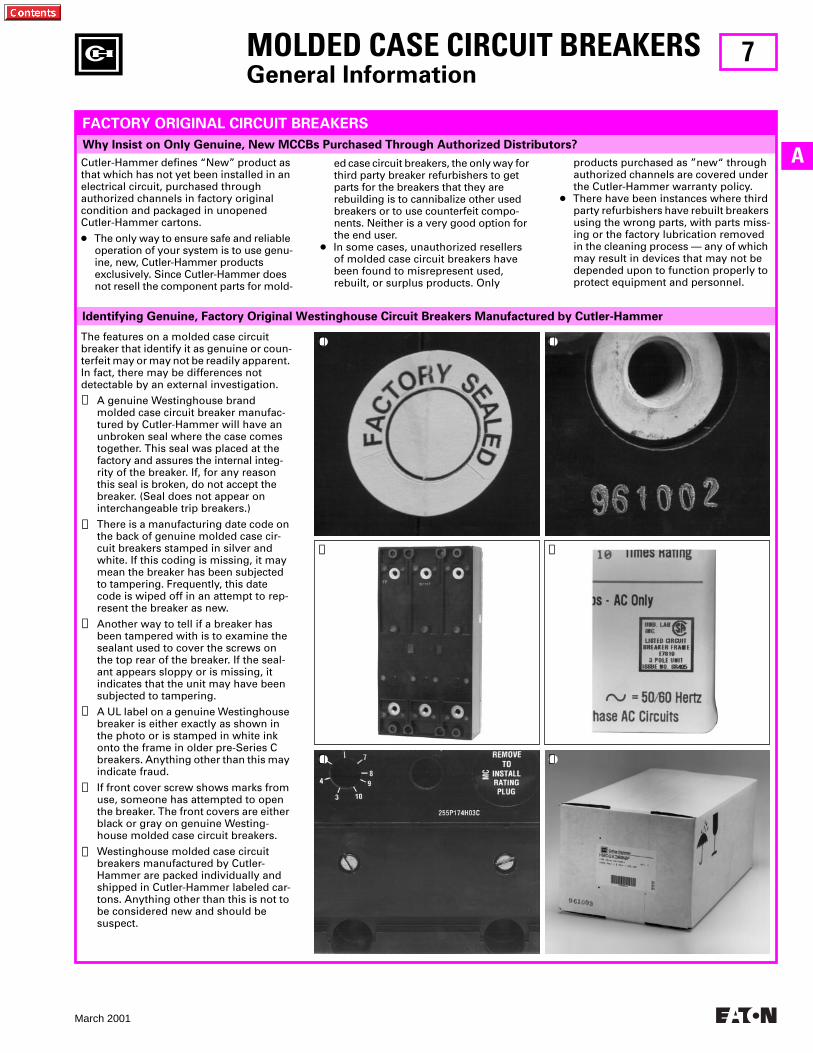
The features on a molded case circuit breaker that identify it as genuine or coun-terfeit may or may not be readily apparent. In fact, there may be differences not detectable by an external investigation.
1. A genuine Westinghouse brand molded case circuit breaker manufac-tured by Cutler-Hammer will have an unbroken seal where the case comes together. This seal was placed at the factory and assures the internal integ-rity of the breaker. If, for any reason this seal is broken, do not accept the breaker. (Seal does not appear on interchangeable trip breakers.)
2. There is a manufacturing date code on the back of genuine molded case cir-cuit breakers stamped in silver and white. If this coding is missing, it may mean the breaker has been subjected to tampering. Frequently, this date code is wiped off in an attempt to rep-resent the breaker as new.
3. Another way to tell if a breaker has been tampered with is to examine the sealant used to cover the screws on the top rear of the breaker. If the seal-ant appears sloppy or is missing, it indicates that the unit may have been subjected to tampering.
4. A UL label on a genuine Westinghouse breaker is either exactly as shown in the photo or is stamped in white ink onto the frame in older pre-Series C breakers. Anything other than this may indicate fraud.
5. If front cover screw shows marks from use, someone has attempted to open the breaker. The front covers are either black or gray on genuine Westing-house molded case circuit breakers.
6. Westinghouse molded case circuit breakers manufactured by Cutler-Hammer are packed individually and shipped in Cutler-Hammer labeled car-tons. Anything other than this is not to be considered new and should be suspect.
➀
➁
➂
➃
➄
➅
➀ ➁
➂ ➃
➄ ➅
8
March 2001
Replacement of Out-of-Production Panelboard or Motor Control Center Molded Case Circuit Breakers
Series C Molded Case Circuit Breakers
Factory Reconditioned Molded Case Circuit Breakers
Current Production Replacement Circuit Breakers
Service for Molded Case Circuit Breakers
MOLDED CASE CIRCUIT BREAKERS
When and Where to Use:
●
Generally a first choice wherever physically and electrically practical
●
Where communications, energy and power quality monitoring are desired
●
As a direct replacement or add-on to already installed Series C product
●
Where ampere rating flexibility is desired. (Interchangeable trip units are available.)
REPLACEMENT CAPABILITIES
Advantages:
●
Most current molded case circuit breaker technology
●
Higher interrupting capacities in each frame size
●
Smaller and lighter for a given frame size than other options
●
Generally less expensive than other replacement breaker options
●
Readily available throughout range / High levels of stock
●
Available from stock
●
One year warranty
When and Where to Use:
●
As a direct, one-for-one replacement of current production pre-Series C product
●
Where you know the catalog/style number but not the physical or electrical specifics about the application
Advantages:
●
Ease of selection and certainty of replacement
●
Guaranteed to be both a physical and electrical duplicate of original
●
Still in production
●
Newly manufactured
●
UL listed
●
Available from stock
●
One year warranty
When and Where to Use:
●
When replacing out-of-production circuit breakers in an existing Panelboard or MCC
Advantages:
●
Newly manufactured and tested to the latest applicable stan-dards
●
Both physically and electrically interchangeable with the circuit breakers that they are designed to replace
●
UL listed
●
Available from stock in most frame sizes
●
One year warranty
When and Where to Use:
●
Where Series C and other replacement breaker options are either not available or not workable
●
Where it is not feasible to modify or upgrade gear but there is a need to replace or add a circuit breaker
Advantages:
●
Though not UL listed, these breakers are reconditioned and tested by Cutler-Hammer at the factory according to the original manufacturing and engineering standards to which the breakers were built
●
Available for all styles of out-of-production circuit breakers (E, F, G, J, K, L, M, P)
●
Knowledge that these breakers are both safe and reliable
●
Labeled ”Reconditioned Circuit Breaker, Resold By Cutler-Hammer“
When and Where to Use:
●
Where circuit breaker has sustained minor physical damage to a handle, lug, etc., that otherwise would be fully functional
●
Large frame circuit breaker (600A and above) that has experi-enced some normal wear, but is in generally good condition, as an economically driven alternative to new
Advantages:
●
Prevents loss of circuit breakers due to minor damage
●
Reduces overall breaker costs
●
Prevents use of potentially unreliable third party refurbishers
●
Includes full one year Cutler-Hammer Warranty
●
Ensures reliability through dealing with the original manufactur-er with a long and well-recognized tradition of product safety, integrity and quality
●
Provides a simple and convenient solution
9
March 2001
A
MOLDED CASE CIRCUIT BREAKERS
Digitrip OPTIM System
NEW TECHNOLOGY
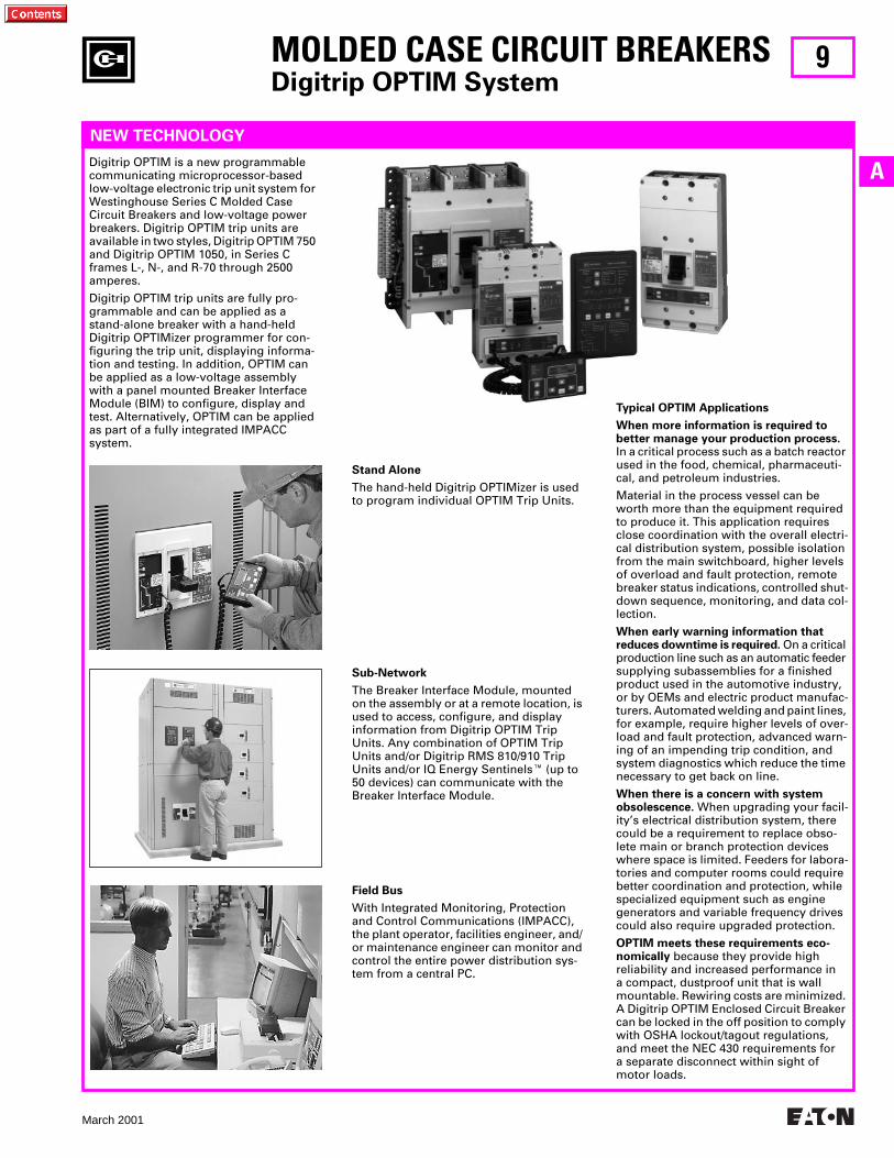
Digitrip OPTIM is a new programmable communicating microprocessor-based low-voltage electronic trip unit system for Westinghouse Series C Molded Case Circuit Breakers and low-voltage power breakers. Digitrip OPTIM trip units are available in two styles, Digitrip OPTIM 750 and Digitrip OPTIM 1050, in Series C frames L-, N-, and R-70 through 2500 amperes.
Digitrip OPTIM trip units are fully pro-grammable and can be applied as a stand-alone breaker with a hand-held Digitrip OPTIMizer programmer for con-figuring the trip unit, displaying informa-tion and testing. In addition, OPTIM can be applied as a low-voltage assembly with a panel mounted Breaker Interface Module (BIM) to configure, display and test. Alternatively, OPTIM can be applied as part of a fully integrated IMPACC system.
Stand Alone
The hand-held Digitrip OPTIMizer is used to program individual OPTIM Trip Units.
Sub-Network
The Breaker Interface Module, mounted on the assembly or at a remote location, is used to access, configure, and display information from Digitrip OPTIM Trip Units. Any combination of OPTIM Trip Units and/or Digitrip RMS 810/910 Trip Units and/or IQ Energy Sentinels
E
(up to 50 devices) can communicate with the Breaker Interface Module.
Field Bus
With Integrated Monitoring, Protection and Control Communications (IMPACC), the plant operator, facilities engineer, and/ or maintenance engineer can monitor and control the entire power distribution sys-tem from a central PC.
Typical OPTIM Applications
When more information is required to better manage your production process.
In a critical process such as a batch reactor used in the food, chemical, pharmaceuti-cal, and petroleum industries.
Material in the process vessel can be worth more than the equipment required to produce it. This application requires close coordination with the overall electri-cal distribution system, possible isolation from the main switchboard, higher levels of overload and fault protection, remote breaker status indications, controlled shut-down sequence, monitoring, and data col-lection.
When early warning information that reduces downtime is required.
On a critical production line such as an automatic feeder supplying subassemblies for a finished product used in the automotive industry, or by OEMs and electric product manufac-turers. Automated welding and paint lines, for example, require higher levels of over-load and fault protection, advanced warn-ing of an impending trip condition, and system diagnostics which reduce the time necessary to get back on line.
When there is a concern with system obsolescence.
When upgrading your facil-ity’s electrical distribution system, there could be a requirement to replace obso-lete main or branch protection devices where space is limited. Feeders for labora-tories and computer rooms could require better coordination and protection, while specialized equipment such as engine generators and variable frequency drives could also require upgraded protection.
OPTIM meets these requirements eco-nomically
because they provide highreliability and increased performance ina compact, dustproof unit that is wall mountable. Rewiring costs are minimized. A Digitrip OPTIM Enclosed Circuit Breaker can be locked in the off position to comply with OSHA lockout/tagout regulations, and meet the NEC 430 requirements fora separate disconnect within sight of motor loads.
10
March 2001
MOLDED CASE CIRCUIT BREAKERS
Digitrip OPTIM System
NEW TECHNOLOGY,
Continued
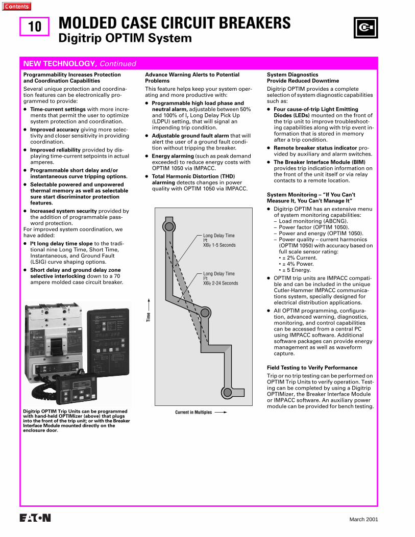
Programmability Increases Protection and Coordination Capabilities
Several unique protection and coordina-tion features can be electronically pro-grammed to provide:
●
Time-current settings
with more incre-ments that permit the user to optimize system protection and coordination.
●
Improved accuracy
giving more selec-tivity and closer sensitivity in providing coordination.
●
Improved reliability
provided by dis-playing time-current setpoints in actual amperes.
●
Programmable short delay and/or instantaneous curve tripping options.
●
Selectable powered and unpowered thermal memory as well as selectable sure start discriminator protection features.
●
Increased system security
provided by the addition of programmable pass-word protection.
For improved system coordination, we have added:
●
I
4
t long delay time slope
to the tradi-tional nine Long Time, Short Time, Instantaneous, and Ground Fault (LSIG) curve shaping options.
●
Short delay and ground delay zone selective interlocking
down to a 70 ampere molded case circuit breaker.
Advance Warning Alerts to Potential Problems
This feature helps keep your system oper-ating and more productive with:
●
Programmable high load phase and neutral alarm,
adjustable between 50% and 100% of I
r
Long Delay Pick Up(LDPU) setting, that will signal an impending trip condition.
●
Adjustable ground fault alarm
that will alert the user of a ground fault condi-tion without tripping the breaker.
●
Energy alarming
(such as peak demand exceeded) to reduce energy costs with OPTIM 1050 via IMPACC.
●
Total Harmonic Distortion (THD) alarming
detects changes in power quality with OPTIM 1050 via IMPACC.
System DiagnosticsProvide Reduced Downtime
Digitrip OPTIM provides a complete selection of system diagnostic capabilities such as:
●
Four cause-of-trip Light Emitting Diodes (LEDs)
mounted on the front of the trip unit to improve troubleshoot-ing capabilities along with trip event in-formation that is stored in memory after a trip condition.
●
Remote breaker status indicator
pro-vided by auxiliary and alarm switches.
●
The Breaker Interface Module (BIM) provides trip indication information on the front of the unit itself or via relay contacts to a remote location.
System Monitoring – “lf You Can’t Measure It, You Can’t Manage It”
● Digitrip OPTIM has an extensive menu of system monitoring capabilities:– Load monitoring (ABCNG).– Power factor (OPTIM 1050).– Power and energy (OPTIM 1050).– Power quality – current harmonics
(OPTIM 1050) with accuracy based on full scale sensor rating:• ± 2% Current.• ± 4% Power.• ± 5 Energy.
● OPTIM trip units are IMPACC compati-ble and can be included in the unique Cutler-Hammer IMPACC communica-tions system, specially designed for electrical distribution applications.
● All OPTIM programming, configura-tion, advanced warning, diagnostics, monitoring, and control capabilities can be accessed from a central PC using IMPACC software. Additional software packages can provide energy management as well as waveform capture.
Field Testing to Verify Performance
Trip or no trip testing can be performed on OPTIM Trip Units to verify operation. Test-ing can be completed by using a Digitrip OPTIMizer, the Breaker Interface Module or IMPACC software. An auxiliary power module can be provided for bench testing.
Digitrip OPTIM Trip Units can be programmed with hand-held OPTIMizer (above) that plugs into the front of the trip unit; or with the Breaker Interface Module mounted directly on the enclosure door.
11
March 2001
A
IMPACC Communications
Breaker Interface Module
Digitrip OPTIMizer
MOLDED CASE CIRCUIT BREAKERSDigitrip OPTIM System
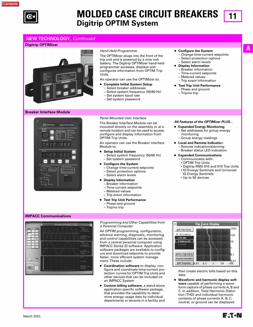
Hand-Held ProgrammerThe OPTIMizer plugs into the front of the trip unit and is powered by a nine-volt battery. The Digitrip OPTIMizer hand-held programmer accesses, displays and configures information from OPTIM Trip Units.
An operator can use the OPTIMizer to:
● Complete Initial System Setup– Select breaker addresses– Select system frequency (50/60 Hz)– Set system baud rate– Set system password
● Configure the System– Change time-current setpoints– Select protection options– Select alarm levels
● Display Information– Breaker information– Time-current setpoints– Metered values– Trip event information
● Test Trip Unit Performance– Phase and ground– Trip/no trip
Panel Mounted User InterfaceThe Breaker Interface Module can be mounted directly on the assembly or at a remote location and can be used to access, configure and display information from OPTIM Trip Units.
An operator can use the Breaker Interface Module to:
● Setup Initial System– Select system frequency (50/60 Hz)– Set system password
● Configure the System– Change time-current setpoints– Select protection options– Select alarm levels
● Display Information– Breaker information– Time-current setpoints– Metered values– Trip event information
● Test Trip Unit Performance– Phase and ground– Trip/no trip
All Features of the OPTIMizer PLUS...
● Expanded Energy Monitoring– Set addresses for group energy monitoring– Group energy readings
● Local and Remote Indication– Remote indication/alarming– Breaker status LED indication
● Expanded Communications– Communicates with:
• OPTIM Trip Units• Digitrip RMS 810 and 910 Trip Units• IQ Energy Sentinels and Universal IQ Energy Sentinels• Up to 50 devices
Programming and Other Capabilities from a Personal ComputerAll OPTIM programming, configuration, advance warning, diagnostic, monitoring and control capabilities can be accessed from a central personal computer using IMPACC Series III software. Application software packages are available to config-ure and download setpoints to provide faster, more efficient system manage-ment. These include:
● Coordination software to display, con-figure and coordinate time-current pro-tection curves for OPTIM Trip Units and other devices that can be included on an IMPACC System
● Custom billing software, a stand-alone application-specific software package, that provides the capability to deter-mine energy usage data by individual departments or tenants in a facility and
then create electric bills based on this data.
● Waveform and harmonic display soft-ware capable of performing a wave-form capture of phase currents A, B and C. In addition, Total Harmonic Distor-tion (THD) and individual harmonic contents of phase currents A, B, C, neutral, or ground can be displayed.
NEW TECHNOLOGY, Continued
12
March 2001
MOLDED CASE CIRCUIT BREAKERSDigitrip OPTIM Enclosed Circuit Breakers
THIS PAGE INTENTIONALLY LEFT BLANK
13
March 2001
A
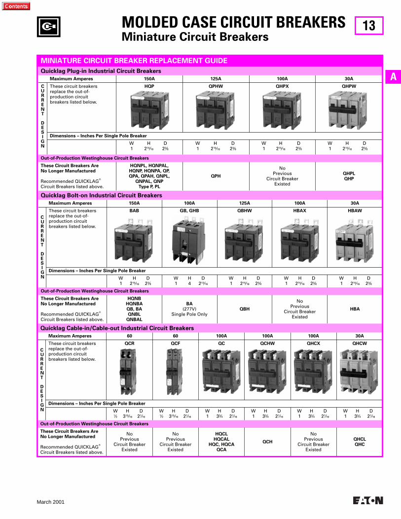
Maximum Amperes 150A 100A 125A 100A 30A
CURRENT
DESIGN
These circuit breakersreplace the out-of-production circuitbreakers listed below.
BAB GB, GHB QBHW HBAX HBAW
Dimensions – Inches Per Single Pole Breaker
W H D1 215⁄16 23⁄8
W H D1 4 213⁄16
W H D1 215⁄16 23⁄8
W H D1 215⁄16 23⁄8
W H D1 215⁄16 23⁄8
Out-of-Production Westinghouse Circuit Breakers
These Circuit Breakers AreNo Longer Manufactured
Recommended QUICKLAGT
Circuit Breakers listed above.
HQNBHQNBAQB, BAQNBL
QNBAL
BA(277V)
Single Pole OnlyQBH
NoPrevious
Circuit BreakerExisted
HBA
Quicklag Bolt-on Industrial Circuit Breakers
Maximum Amperes 60 60 100A 100A 100A 30A
CURRENT
DESIGN
These circuit breakersreplace the out-of-production circuitbreakers listed below.
QCR QCF QC QCHW QHCX QHCW
Dimensions – Inches Per Single Pole Breaker
W H D1⁄2 315⁄16 27⁄16
W H D1⁄2 315⁄16 27⁄16
W H D1 33⁄4 27⁄16
W H D1 33⁄4 27⁄16
W H D1 33⁄4 27⁄16
W H D1 33⁄4 27⁄16
Out-of-Production Westinghouse Circuit Breakers
These Circuit Breakers AreNo Longer Manufactured
Recommended QUICKLAGT
Circuit Breakers listed above.
No Previous
Circuit BreakerExisted
No Previous
Circuit BreakerExisted
HQCLHQCAL
HQC, HQCAQCA
QCH
No Previous
Circuit BreakerExisted
QHCLQHC
Maximum Amperes 150A 125A 100A 30A
CURRENT
DESIGN
These circuit breakersreplace the out-of-production circuitbreakers listed below.
HQP QPHW QHPX QHPW
Dimensions – Inches Per Single Pole Breaker
W H D1 215⁄16 23⁄8
W H D1 215⁄16 23⁄8
W H D1 215⁄16 23⁄8
W H D1 215⁄16 23⁄8
Out-of-Production Westinghouse Circuit Breakers
These Circuit Breakers AreNo Longer Manufactured
Recommended QUICKLAGT
Circuit Breakers listed above.
HQNPL, HQNPAL,HQNP, HQNPA, QP,QPA, QPAH, QNPL,
QNPAL, QNPType P, PL
QPH
No Previous
Circuit BreakerExisted
QHPLQHP
Quicklag Cable-in/Cable-out Industrial Circuit Breakers
Quicklag Plug-in Industrial Circuit Breakers
MOLDED CASE CIRCUIT BREAKERSMiniature Circuit Breakers
MINIATURE CIRCUIT BREAKER REPLACEMENT GUIDE
14
March 2001
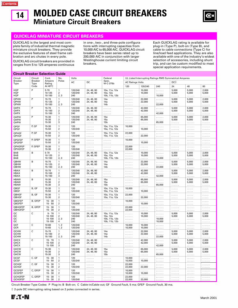
Circuit Breaker Selection Guide
Circuit Breaker Type Codes: P Plug-in; B Bolt-on; C Cable-in/Cable-out; GF Ground Fault, 5 ma; GFEP Ground Fault, 30 ma.
➊ 2-pole DC interrupting rating based on 2 poles connected in series.
CircuitBreakerType
Circuit Breaker Type Code
Cont.AmpereRatingAt 40°C
No.Poles
Volts FederalSpec.W-C-375b
UL Listed Interrupting Ratings RMS Symmetrical Amperes
AC DC AC Ratings Volts DC❶
120 120/240 240 24 48 80
HQPHQPHQP
P 5-7010-12510-100
122, 3
120/240120/240240
24, 48, 8024, 48, 80. . . . . .
10a, 11a, 12a10a, 12a10b, 11b, 12b
. . . . . .
. . . . . .
. . . . . .
10,00010,000. . . . . .
. . . . . .
. . . . . .10,000
5,0005,000. . . . . .
5,0005,000. . . . . .
2,0005,000. . . . . .
QPHWQPHWQPHW
P 15-7015-12515-100
122, 3
120/240120/240240
24, 48, 8024, 48, 80. . . . . .
14a14a 14b
. . . . . .
. . . . . .
. . . . . .
22,00022,000. . . . . .
. . . . . .
. . . . . .22,000
5,0005,000. . . . . .
5,0005,000
2,0005,000. . . . . .
QHPXQHPXQHPX
P 15-7015-10015-100
123
120/240120/240240
24, 48, 8024, 48, 80. . . . . .
. . . . . .
. . . . . .
. . . . . .
. . . . . .
. . . . . .
. . . . . .
42,00042,000. . . . . .
. . . . . .
. . . . . .42,000
5,0005,000. . . . . .
5,0005,000. . . . . .
2,0005,000. . . . . .
QHPWQHPWQHPW
P 15-3015-3015-30
123
120/240120/240240
24, 48, 8024, 48, 80. . . . . .
15a15a15b
. . . . . .
. . . . . .
. . . . . .
65,00065,000. . . . . .
. . . . . .
. . . . . .65,000
5,0005,000. . . . . .
5,0005,000. . . . . .
2,0005,000. . . . . .
QPGFQPGF
P, GF 15-3015-50
12
120120/240
. . . . . .
. . . . . .10a, 11a, 12a10a, 11a, 12a
10,000. . . . . .
. . . . . .10,000
. . . . . .
. . . . . .. . . . . .. . . . . .
. . . . . .
. . . . . .. . . . . .. . . . . .
QPHGFQPHGF
P, GF 15-3015-50
12
120120/240
. . . . . .
. . . . . .10a, 11a, 12a10a, 11a, 12a
22,000. . . . . .
. . . . . .22,000
. . . . . .
. . . . . .. . . . . .. . . . . .
. . . . . .
. . . . . .. . . . . .. . . . . .
QPGFEPQPGFEP
P, GFEP 15-3015-50
12
120120/240
. . . . . .
. . . . . .. . . . . .. . . . . .
10,000. . . . . .
. . . . . .10,000
. . . . . .
. . . . . .. . . . . .. . . . . .
. . . . . .
. . . . . .. . . . . .. . . . . .
QPHGFEPQPHGFEP
P, GFEP 15-3015-30
12
120120/240
. . . . . .
. . . . . .. . . . . .. . . . . .
22,00022,000
. . . . . .
. . . . . .. . . . . .. . . . . .
. . . . . .
. . . . . .. . . . . .. . . . . .
. . . . . .
. . . . . .
BABBABBAB
B 5-7010-12510-100
122, 3
120/240120/240240
24, 48, 8024, 48, 80. . . . . .
10a, 11a, 12a10a, 12a10b, 11b, 12b
. . . . . .
. . . . . .
. . . . . .
10,00010,000. . . . . .
. . . . . .
. . . . . .10,000
5,0005,000. . . . . .
5,0005,000. . . . . .
2,0005,000. . . . . .
QBHWQBHWQBHW
B 15-7015-12515-100
122, 3
120/240120/240240
24, 48, 8024, 48, 80. . . . . .
14a14a14b
. . . . . .
. . . . . .
. . . . . .
22,00022,000. . . . . .
. . . . . .
. . . . . .22,000
5,0005,000. . . . . .
5,0005,000. . . . . .
2,0005,000. . . . . .
HBAXHBAXHBAX
B 15-7015-10015-100
123
120/240120/240240
24, 48, 8024, 48, 80. . . . . .
. . . . . .
. . . . . .
. . . . . .
. . . . . .
. . . . . .
. . . . . .
42,00042,000. . . . . .
. . . . . .
. . . . . .42,000
5,0005,000. . . . . .
5,0005,000. . . . . .
2,0005,000. . . . . .
HBAWHBAWHBAW
B 15-3015-3015-30
123
120/240120/240240
24, 48, 8024, 48, 80. . . . . .
15a15a15b
. . . . . .
. . . . . .
. . . . . .
65,00065,000. . . . . .
. . . . . .
. . . . . .65,000
5,0005,000. . . . . .
5,0005,000. . . . . .
2,0005,000. . . . . .
QBGFQBGF
B, GF 15-3015-50
12
120120/240
. . . . . .
. . . . . .10a, 11a, 12a10a, 11a, 12a
10,000. . . . . .
. . . . . .10,000
. . . . . .
. . . . . .. . . . .. . . . .
. . . . .
. . . . .. . . . .. . . . .
QBHGFQBHGF
B, GF 15-3015-30
12
120120/240
. . . . . .
. . . . . .10a, 11a, 12a10a, 11a, 12a
22,000. . . . . .
. . . . . .22,000
. . . . . .
. . . . . .. . . . .. . . . .
. . . . .
. . . . .. . . . .. . . . .
QBGFEPQBGFEP
B, GFEP 15- 3015- 50
12
120120/240
. . . . . .
. . . . . .. . . . . .. . . . . .
10,000. . . . . .
. . . . . .10,000
. . . . . .
. . . . . .. . . . .. . . . .
. . . . .
. . . . .. . . . .. . . . .
QBHGFEPQBHGFEP
B, GFEP 15- 3015- 30
12
120120/240
. . . . . .
. . . . . .. . . . . .. . . . . .
22,00022,000
. . . . . .
. . . . . .. . . . . .. . . . . .
. . . . . .
. . . . . .. . . . . .. . . . . .
. . . . . .
. . . . . .
QCQCQCQC
C 5- 7010-10010-10015-100
122, 34
120/240120/240240240
24, 48, 8024, 48, 80. . . . . .. . . . . .
10a, 11a, 12a10a, 12a10b, 11b, 12b10b, 11b, 12b
. . . . . .
. . . . . .
. . . . . .
. . . . . .
10,00010,000. . . . . .. . . . . .
. . . . . .
. . . . . .10,00010,000
5,0005,000. . . . . .. . . . . .
5,0005,000. . . . . .. . . . . .
2,0005,000. . . . . .. . . . . .
QCFQCR
C 10-6010-60
1, 21, 2
120/240120/240
. . . . . .
. . . . . .. . . . . .. . . . . .
10,00010,000
10,00010,000
. . . . . .
. . . . . .. . . . . .. . . . . .
. . . . . .
. . . . . .. . . . . .. . . . . .
QCHWQCHWQCHW
C 15-7015-10015-100
122, 3
120/240120/240240
24, 48, 8024, 48, 80. . . . . .
14a14a14b
. . . . . .
. . . . . .
. . . . . .
22,00022,000. . . . . .
. . . . . .
. . . . . .22,000
5,0005,000. . . . . .
5,0005,000. . . . . .
2,0005,000. . . . . .
QHCXQHCXQHCX
C 15- 7015-10015-100
123
120/240120/240240
24, 48, 8024, 48, 80. . . . . .
. . . . . .
. . . . . .
. . . . . .
. . . . . .
. . . . . .
. . . . . .
42,00042,000. . . . . .
. . . . . .
. . . . . .42,000
5,0005,000. . . . . .
5,0005,000. . . . . .
2,0005,000. . . . . .
QHCWQHCWQHCW
C 15-3015-3015-30
123
120/240120/240240
24, 48, 8024, 48, 80. . . . . .
15a15a15b
. . . . . .
. . . . . .
. . . . . .
65,00065,000. . . . . .
. . . . . .
. . . . . .65,000
5,0005,000. . . . . .
5,0005,000. . . . . .
2,0005,000. . . . . .
QCGFQCGF
C. GF 15- 3015- 50
12
120120/240
. . . . . .
. . . . . .. . . . . .. . . . . .
10,00010,000
. . . . . .10,000
. . . . . .
. . . . . .. . . . . .. . . . . .
. . . . . .
. . . . . .. . . . . .. . . . . .
QCHGFQCHGF
C. GF 15- 3015- 30
12
120120/240
. . . . . .
. . . . . .. . . . . .. . . . . .
22,00022,000
. . . . . .22,000
. . . . . .
. . . . . .. . . . . .. . . . . .
. . . . . .
. . . . . .. . . . . .. . . . . .
QCGFEPQCGFEP
C, GFEP 15- 3015- 30
12
120120/240
. . . . . .
. . . . . .. . . . . .. . . . . .
10,00010,000
. . . . . .10,000
. . . . . .
. . . . . .. . . . . .. . . . . .
. . . . . .
. . . . . .. . . . . .. . . . . .
QCHGFEPQCHGFEP
C, GFEP 15- 3015- 30
12
120120/240
. . . . . .
. . . . . .. . . . . .. . . . . .
22,00022,000
. . . . . .22,000
. . . . . .
. . . . . .. . . . . .. . . . . .
. . . . . .
. . . . . .. . . . . .. . . . . .
MOLDED CASE CIRCUIT BREAKERSMiniature Circuit Breakers
QUICKLAG is the largest and most com-plete family of industrial thermal magnetic miniature circuit breakers. They provide the exclusive features of steel frame cali-bration and arc chutes in every pole.
QUICKLAG circuit breakers are provided in ranges from 5 to 125 amperes continuous
in one-, two-, and three-pole configura-tions with interrupting capacities from 10,000 AIC to 65,000 AIC. QUICKLAG circuit breakers have been series rated up to 200,000 AIC in conjunction with larger Westinghouse current limiting circuit breakers.
Each QUICKLAG rating is available for plug-in (Type P), bolt-on (Type B), and cable to cable connections (Type C) for line/load feed applications. They are also available with one of the industry’s widest selection of accessories, including shunt trip, and can be custom modified to meet special application requirements.
QUICKLAG MINIATURE CIRCUIT BREAKERS
15
March 2001
A
CHB Mounting Bases
Description CatalogNumber
Low Amp. 15-50A 1-pole . . . . . .2-pole . . . . . .3-pole . . . . . .
High Amp. 25-50A 1-pole . . . . .25-125A 2-pole . . . . .25-100A 3-pole . . . . .
CHB9L1CHB9L250CHB9L350
CHB9H1CHB9H2125CHB9H3100
MOLDED CASE CIRCUIT BREAKERSMiniature Circuit Breakers
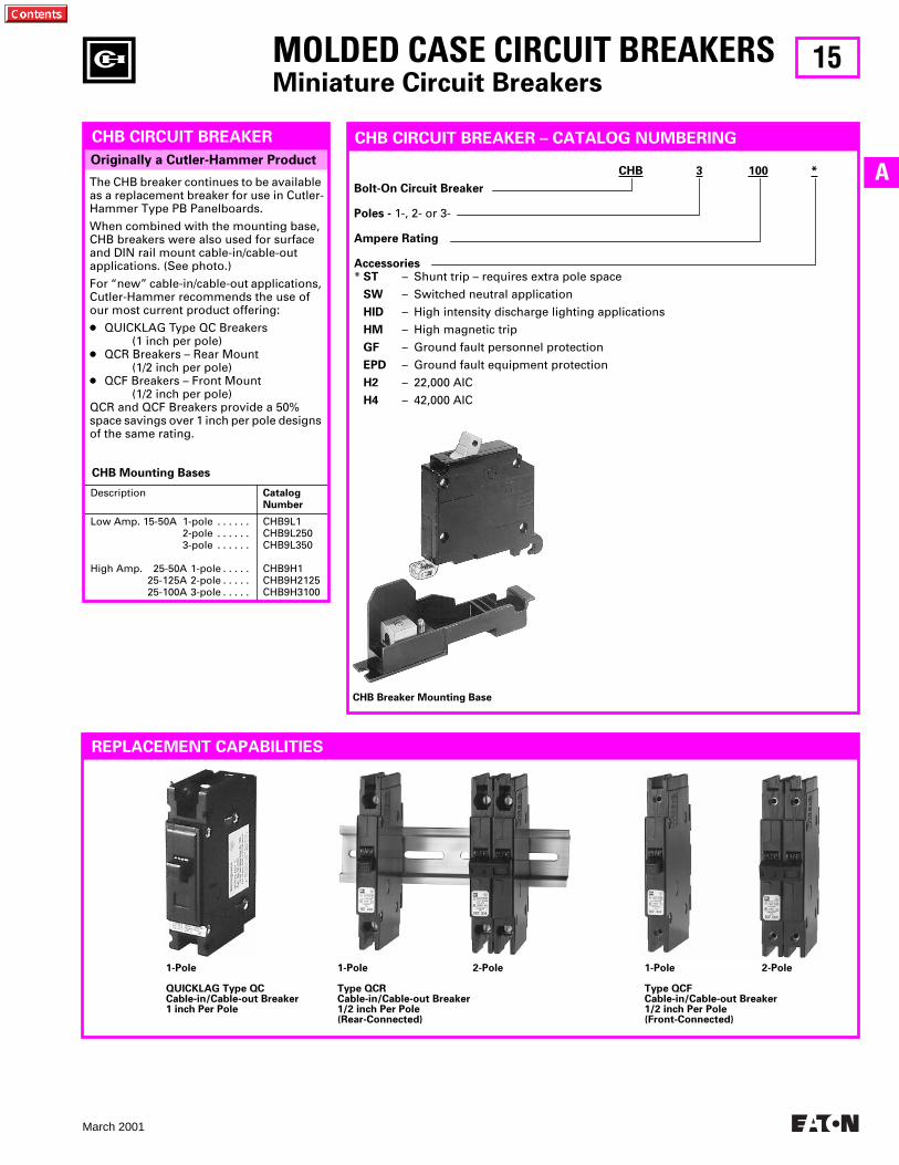
Originally a Cutler-Hammer Product
CHB CIRCUIT BREAKER
The CHB breaker continues to be available as a replacement breaker for use in Cutler-Hammer Type PB Panelboards.
When combined with the mounting base, CHB breakers were also used for surface and DIN rail mount cable-in/cable-out applications. (See photo.)
For “new” cable-in/cable-out applications, Cutler-Hammer recommends the use of our most current product offering:
● QUICKLAG Type QC Breakers(1 inch per pole)
● QCR Breakers – Rear Mount(1/2 inch per pole)
● QCF Breakers – Front Mount(1/2 inch per pole)
QCR and QCF Breakers provide a 50% space savings over 1 inch per pole designs of the same rating.
CHB Breaker Mounting Base
CHB CIRCUIT BREAKER – CATALOG NUMBERING
CHB 3 100 *
Bolt-On Circuit Breaker
Poles - 1-, 2- or 3-
Ampere Rating
Accessories* ST – Shunt trip – requires extra pole space
SW – Switched neutral application
HID – High intensity discharge lighting applications
HM – High magnetic trip
GF – Ground fault personnel protection
EPD – Ground fault equipment protection
H2 – 22,000 AIC
H4 – 42,000 AIC
REPLACEMENT CAPABILITIES
1-Pole
QUICKLAG Type QCCable-in/Cable-out Breaker1 inch Per Pole
1-Pole 2-Pole
Type QCRCable-in/Cable-out Breaker1/2 inch Per Pole(Rear-Connected)
1-Pole 2-Pole
Type QCFCable-in/Cable-out Breaker1/2 inch Per Pole(Front-Connected)
16
March 2001
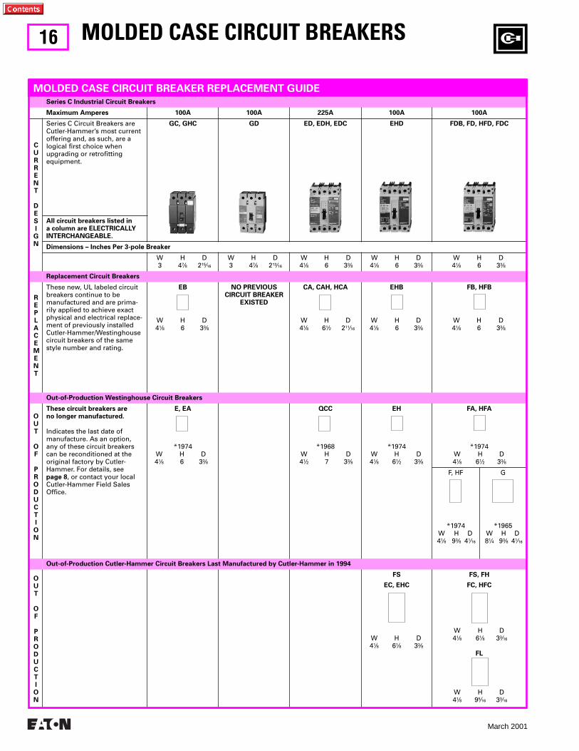
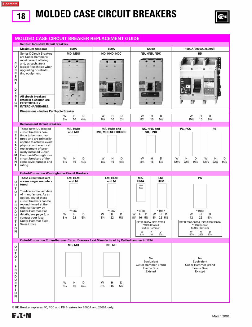
Series C Industrial Circuit Breakers
Maximum Amperes 100A 100A 225A 100A 100A
CURRENT
DESIGN
Series C Circuit Breakers are Cutler-Hammer’s most current offering and, as such, are a logical first choice when upgrading or retrofitting equipment.
GC, GHC GD ED, EDH, EDC EHD FDB, FD, HFD, FDC
All circuit breakers listed ina column are ELECTRICALLYINTERCHANGEABLE.
Dimensions – Inches Per 3-pole Breaker
W H D3 47⁄8 215⁄16
W H D3 47⁄8 213⁄16
W H D41⁄8 6 33⁄8
W H D41⁄8 6 33⁄8
W H D41⁄8 6 33⁄8
Replacement Circuit Breakers
REPLACEMENT
These new, UL labeled circuit breakers continue to be manufactured and are prima-rily applied to achieve exact physical and electrical replace-ment of previously installed Cutler-Hammer/Westinghouse circuit breakers of the same style number and rating.
EB
W H D41⁄8 6 33⁄8
NO PREVIOUSCIRCUIT BREAKER
EXISTED
CA, CAH, HCA
W H D41⁄8 61⁄2 211⁄16
EHB
W H D41⁄8 6 33⁄8
FB, HFB
W H D41⁄8 6 33⁄8
Out-of-Production Westinghouse Circuit Breakers
OUT
OF
PRODUCTION
These circuit breakers areno longer manufactured.
Indicates the last date of manufacture. As an option, any of these circuit breakers can be reconditioned at the original factory by Cutler-Hammer. For details, see page 8, or contact your local Cutler-Hammer Field Sales Office.
E, EA
*1974W H D41⁄8 6 33⁄8
QCC
*1968W H D41⁄2 7 33⁄8
EH
*1974W H D41⁄8 61⁄2 33⁄8
FA, HFA
*1974W H D41⁄8 61⁄2 33⁄8
F, HF
*1974W H D41⁄8 93⁄8 41⁄16
G
*1965W H D81⁄4 93⁄8 41⁄16
Out-of-Production Cutler-Hammer Circuit Breakers Last Manufactured by Cutler-Hammer in 1994
OUT
OF
PRODUCTION
FS
EC, EHC
W H D41⁄8 61⁄8 33⁄8
FS, FH
FC, HFC
W H D41⁄8 61⁄8 33⁄16
FL
W H D41⁄8 95⁄16 33⁄16
MOLDED CASE CIRCUIT BREAKER REPLACEMENT GUIDE
MOLDED CASE CIRCUIT BREAKERS
17
March 2001
A
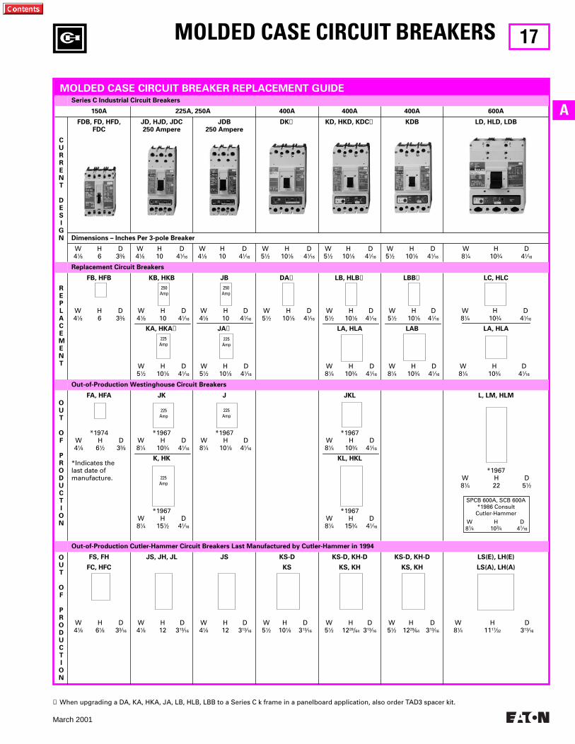
MOLDED CASE CIRCUIT BREAKER REPLACEMENT GUIDE
Series C Industrial Circuit Breakers
150A 225A, 250A 400A 400A 400A 600A
CURRENT
DESIGN
FDB, FD, HFD, FDC
JD, HJD, JDC250 Ampere
JDB 250 Ampere
DK
➊
KD, HKD, KDC
➊
KDB LD, HLD, LDB
Dimensions – Inches Per 3-pole Breaker
W H D4
1
⁄
8
6 3
3
⁄
8
W H D4
1
⁄
8
10 4
1
⁄
16
W H D4
1
⁄
8
10 4
1
⁄
16
W H D5
1
⁄
2
10
1
⁄
8
4
1
⁄
16
W H D5
1
⁄
2
10
1
⁄
8
4
1
⁄
16
W H D5
1
⁄
2
10
1
⁄
8
4
1
⁄
16
W H D8
1
⁄
4
10
3
⁄
4
4
1
⁄
16
Replacement Circuit Breakers
REPLACEMENT
FB, HFB
W H D4
1
⁄
8
6 3
3
⁄
8
KB, HKB
W H D4
1
⁄
8
10 4
1
⁄
16
KA, HKA
➊
W H D5
1
⁄
2
10
1
⁄
8
4
1
⁄
16
JB
W H D4
1
⁄
8
10 4
1
⁄
16
JA
➊
W H D5
1
⁄
2
10
1
⁄
8
4
1
⁄
16
DA
➊
W H D5
1
⁄
2
10
1
⁄
8
4
1
⁄
16
LB, HLB
➊
W H D5
1
⁄
2
10
1
⁄
8
4
1
⁄
16
LA, HLA
W H D8
1
⁄
4
10
3
⁄
4
4
1
⁄
16
LBB
➊
W H D5
1
⁄
2
10
1
⁄
8
4
1
⁄
16
LAB
W H D8
1
⁄
4
10
3
⁄
4
4
1
⁄
16
LC, HLC
W H D8
1
⁄
4
10
3
⁄
4
4
1
⁄
16
LA, HLA
W H D8
1
⁄
4
10
3
⁄
4
4
1
⁄
16
Out-of-Production Westinghouse Circuit Breakers
OUT
OF
PRODUCTION
FA, HFA
*1974W H D4
1
⁄
8
6
1
⁄
2
3
3
⁄
8
*Indicates the last date of manufacture.
JK
*1967W H D8
1
⁄
4
10
3
⁄
4
4
1
⁄
16
K, HK
*1967W H D8
1
⁄
4
15
1
⁄
2
4
1
⁄
16
J
*1967W H D8
1
⁄
4
10
1
⁄
8
4
1
⁄
16
JKL
*1967W H D8
1
⁄
4
10
3
⁄
4
4
1
⁄
16
KL, HKL
*1967W H D8
1
⁄
4
15
3
⁄
4
4
1
⁄
16
L, LM, HLM
*1967W H D8
1
⁄
4
22 5
1
⁄
2
SPCB 600A, SCB 600A*1986 Consult
Cutler-Hammer
W H D8
1
⁄
4
10
3
⁄
4
4
1
⁄
16
Out-of-Production Cutler-Hammer Circuit Breakers Last Manufactured by Cutler-Hammer in 1994
OUT
OF
PRODUCTION
FS, FH
FC, HFC
W H D4
1
⁄
8
6
1
⁄
8
3
3
⁄
16
JS, JH, JL
W H D4
1
⁄
8
12 3
13
⁄
16
JS
W H D4
1
⁄
8
12 3
13
⁄
16
KS-D
KS
W H D5
1
⁄
2
10
1
⁄
8
3
13
⁄
16
KS-D, KH-D
KS, KH
W H D5
1
⁄
2
12
29
/
64
3
13
⁄
16
KS-D, KH-D
KS, KH
W H D51⁄2 1229⁄64 313⁄16
LS(E), LH(E)
LS(A), LH(A)
W H D81⁄4 1117⁄32 313⁄16
MOLDED CASE CIRCUIT BREAKERS
250Amp
250Amp
225Amp
225Amp
225Amp
225Amp
225Amp
➊ When upgrading a DA, KA, HKA, JA, LB, HLB, LBB to a Series C k frame in a panelboard application, also order TAD3 spacer kit.
18
March 2001
Series C Industrial Circuit Breakers
Maximum Amperes 800A 800A 1200A 1600A/2000A/2500A
➊
CURRENT
DESIGN
Series C Circuit Breakers are Cutler-Hammer’s most current offering and, as such, are a logical first choice when upgrading or retrofit-ting equipment.
All circuit breakers listed in a column are ELECTRICALLYINTERCHANGEABLE.
MD, MDS ND, HND, NDC ND, HND, NDC RD
Dimensions – Inches Per 3-pole Breaker
W H D8
1
⁄
4
16 4
1
⁄
16
W H D8
1
⁄
4
16 5
1
⁄
2
W H D8
1
⁄
4
16 5
1
⁄
2
W H D15
1
⁄
2
16 9
3
⁄
4
Replacement Circuit Breakers
REPLACEMENT
These new, UL labeled circuit breakers con-tinue to be manufac-tured and are primarily applied to achieve exact physical and electrical replacement of previ-ously installed Cutler-Hammer/Westinghouse circuit breakers of the same style number and rating.
MA, HMAand MC
W H D8
1
⁄
4
16 4
1
⁄
16
MA, HMA andMC, MCC SELTRONIC
W H D8
1
⁄
4
16 4
1
⁄
16
NC, HNC andNB, HNB
W H D8
1
⁄
4
16 5
1
⁄
2
PC, PCC
W H D12
1
⁄
16
22
1
⁄
8
9
1
⁄
16
PB
W H D12
1
⁄
16
22
1
⁄
8
9
1
⁄
16
Out-of-Production Westinghouse Circuit Breakers
OUT OF
PRODUCTION
These circuit breakers are no longer manufac-tured.
* Indicates the last date of manufacture. As an option, any of these circuit breakers can be reconditioned at the original factory by Cutler-Hammer. For details, see
page 8
, or contact your local Cutler-Hammer Field Sales Office.
LM, HLMand M
*1967W H D8
1
⁄
4
22 5
1
⁄
2
LM, HLMand M
*1967W H D8
1
⁄
4
22 5
1
⁄
2
MA,HMA
*1968W H D8
1
⁄
4
16 5
1
⁄
2
LM,HLM
*1967W H D8
1
⁄
4
22 5
1
⁄
2
PA
*1968W H D12 22 9
1
⁄
16
SPCB 1200A, SCB 1200A*1986 Consult
Cutler-Hammer
W H D8
1
⁄
4
16 5
1
⁄
2
SPCB 2000-3000A, SCB 2000-3000A*1986 Consult
Cutler-Hammer
W H D12
1
⁄
16
22
1
⁄
8
9
1
⁄
16
Out-of-Production Cutler-Hammer Circuit Breakers Last Manufactured by Cutler-Hammer in 1994
OUT OF
PRODUCTION
MS, MH
W H D8
1
⁄
4
16 4
1
⁄
16
NS, NH
W H D8
1
⁄
4
16 5
1
⁄
2
NoEquivalent
Cutler-Hammer BrandFrame Size
Existed
NoEquivalent
Cutler-Hammer BrandFrame Size
Existed
MOLDED CASE CIRCUIT BREAKER REPLACEMENT GUIDE
MOLDED CASE CIRCUIT BREAKERS
1200Amp
➊
RD Breaker replaces PC, PCC and PB Breakers for 2000A and 2500A only.
19
March 2001
A
MOLDED CASE CIRCUIT BREAKERS
Protection to a Higher Power
For today’s sophisticated electrical systems, total protection means much more than just meeting your
minimum standards.
Cutler-Hammer has engineered an impressive new generation of Westinghouse circuit breakers, with
a range of intelligent features designed to achieve levels of performance beyond conventional protective
devices.
Dedicated and general purpose applications range from QUICKLAG miniature circuit breakers to Series C
high interrupting capacity molded case circuit breakers, and from thermal magnetic breakers to the
latest microprocessor-based Digitrip units featuring true RMS sensing, energy and status monitoring.
Additionally, Cutler-Hammer breakers communicate with the IMPACC monitoring and control system.
This family of circuit breakers works overtime to help anticipate, detect and pre-empt electrical problems
before they occur. So the next trip may not be necessary.
That is protection to the higher power — from the new Cutler-Hammer.
20
March 2001
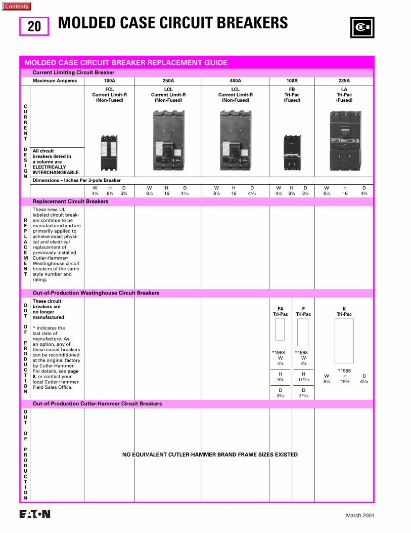
Current Limiting Circuit Breaker
Maximum Amperes 100A 250A 400A 100A 225A
CURRENT
DESIGN
FCLCurrent Limit-R
(Non-Fused)
LCLCurrent Limit-R
(Non-Fused)
LCLCurrent Limit-R
(Non-Fused)
FBTri-Pac(Fused)
LATri-Pac(Fused)
All circuitbreakers listed ina column areELECTRICALLYINTERCHANGEABLE.
Dimensions – Inches Per 3-pole Breaker
W H D41⁄8 83⁄4 33⁄8
W H D81⁄4 16 41⁄16
W H D81⁄4 16 41⁄16
W H D41⁄8 83⁄4 31⁄2
W H D81⁄4 16 43⁄4
Replacement Circuit Breakers
REPLACEMENT
These new, UL labeled circuit break-ers continue to be manufactured and are primarily applied to achieve exact physi-cal and electrical replacement of previously installed Cutler-Hammer/Westinghouse circuit breakers of the same style number and rating.
Out-of-Production Westinghouse Circuit Breakers
OUT
OF
PRODUCTION
These circuitbreakers areno longermanufactured
* Indicates the last date of manufacture. As an option, any of these circuit breakers can be reconditioned at the original factory by Cutler-Hammer. For details, see page 8, or contact your local Cutler-Hammer Field Sales Office.
FATri-Pac
*1968W41⁄8
H93⁄8
D33⁄16
FTri-Pac
*1968W45⁄8
H1113⁄16
D313⁄16
KTri-Pac
*1968W H D81⁄4 195⁄8 41⁄16
Out-of-Production Cutler-Hammer Circuit Breakers
OUT
OF
PRODUCTION
MOLDED CASE CIRCUIT BREAKER REPLACEMENT GUIDE
MOLDED CASE CIRCUIT BREAKERS
NO EQUIVALENT CUTLER-HAMMER BRAND FRAME SIZES EXISTED
21
March 2001
A
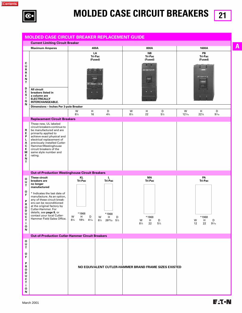
Current Limiting Circuit Breaker
Maximum Amperes 400A 800A 1600A
CURRENT
DESIGN
LATri-Pac(Fused)
NBTri-Pac(Fused)
PBTri-Pac(Fused)
All circuitbreakers listed ina column areELECTRICALLYINTERCHANGEABLE.
Dimensions – Inches Per 3-pole Breaker
W H D8
1
⁄
4
16 4
3
⁄
4
W H D8
1
⁄
4
22 5
1
⁄
2
W H D12
1
⁄
16
22
1
⁄
8
9
1
⁄
16
Replacement Circuit Breakers
REPLACEMENT
These new, UL labeled circuit breakers continue to be manufactured and are primarily applied to achieve exact physical and electrical replacement of previously installed Cutler-Hammer/Westinghouse circuit breakers of the same style number and rating.
Out-of-Production Westinghouse Circuit Breakers
OUT
OF
PRODUCTION
These circuitbreakers areno longermanufactured
* Indicates the last date of manufacture. As an option, any of these circuit break-ers can be reconditioned at the original factory by Cutler-Hammer. For details, see
page 8
, or contact your local Cutler-Hammer Field Sales Office.
KLTri-Pac
*1968W H D8
1
⁄
4
19
5
⁄
8
4
1
⁄
16
LTri-Pac
*1968W H D8
1
⁄
4
26
29
⁄
32
5
1
⁄
2
MATri-Pac
*1968W H D8
1
⁄
4
22 5
1
⁄
2
PATri-Pac
*1968W H D12 22 9
1
⁄
16
Out-of-Production Cutler-Hammer Circuit Breakers
OUT
OF
PRODUCTION
MOLDED CASE CIRCUIT BREAKER REPLACEMENT GUIDE
MOLDED CASE CIRCUIT BREAKERS
NO EQUIVALENT CUTLER-HAMMER BRAND FRAME SIZES EXISTED
22
March 2001
Underwriters’ Laboratories, Inc. Listed Interrupting Ratings
➑
Type EHB 1-, 2-, 3-Poles; 480 Volts AC Max.; Thermal Magnetic and Saf-T-Vue
T
(Includes Load Terminals Only)
Continuous AmpereRatingat 40°C
1-Pole, 277 Volts AC,125 Volts DC
➊
2-Pole, 480 Volts AC,250 Volts DC
➊
3-Pole480 Volts AC
Standard Standard Standard Saf-T-Vue
T
➋
Catalog Numbers
15 20 25 30 35 40 45 50 60 70 80 90100
EHB1015
➍
EHB1020
➍
EHB1025EHB1030EHB1035EHB1040EHB1045EHB1050EHB1060EHB1070EHB1080EHB1090EHB1100
EHB2015EHB2020EHB2025EHB2030EHB2035EHB2040EHB2045EHB2050EHB2060EHB2070EHB2080EHB2090EHB2100
EHB3015EHB3020EHB3025EHB3030EHB3035EHB3040EHB3045EHB3050EHB3060EHB3070EHB3080EHB3090EHB3100
EHB3015SEHB3020SEHB3025SEHB3030SEHB3035SEHB3040SEHB3045SEHB3050SEHB3060SEHB3070SEHB3080SEHB3090SEHB3100S
Approx. ship wt. 2 lbs. Approx. ship wt. 3 lbs. Approx. ship. wt. 4
1
⁄
2
lbs.
Type FB, HFB 1-, 2-, 3-, 4-Poles; 600 Volts AC Max.; Thermal Magnetic MARK 75
T
Saf-T-Vue
T
Type EB 1-, 2-, 3-Poles; 240 Volts AC Max.; Thermal Magnetic and Saf-T-Vue
T
(Includes Load Terminals Only)
Continuous AmpereRatingat 40°C
1-Pole277 Volts AC125 Volts DC
➊
2-Pole600 Volts AC250 Volts DC
➊
3-Pole600 Volts AC
4-Pole
➋➎
600 Volts AC
MARK 75
T
➏
Standard MARK 75
T
➐
Standard Saf-T-Vue
T
➋
MARK 75
T
Standard
Catalog Numbers
15 20 25 30 35 40 45 50 60 70 80 90100110125150
HFB1015
➍
HFB1020
➍
HFB1025HFB1030HFB1035HFB1040HFB1045HFB1050HFB1060HFB1070HFB1080HFB1090HFB1100 . . . . . . . . . . . . . . . . . . . . . . . . . . .
FB2015FB2020FB2025FB2030FB2035FB2040FB2045FB2050FB2060FB2070FB2080FB2090FB2100. . . . . . . . . . . . . . . . . .
HFB2015HFB2020HFB2025HFB2030HFB2035HFB2040HFB2045HFB2050HFB2060HFB2070HFB2080HFB2090HFB2100 . . . . . . . . . . . . . . . . . . . . . . . .
FB3015FB3020FB3025FB3030FB3035FB3040FB3045FB3050FB3060FB3070FB3080FB3090FB3100FB3110FB3125FB3150
FB3015SFB3020SFB3025SFB3030SFB3035SFB3040SFB3045SFB3050SFB3060SFB3070SFB3080SFB3090SFB3100SFB3110SFB3125SFB3150S
HFB3015HFB3020HFB3025HFB3030HFB3035HFB3040HFB3045HFB3050HFB3060HFB3070HFB3080HFB3090HFB3100HFB3110HFB3125HFB3150
FB4015FB4020FB4025FB4030FB4035FB4040FB4045FB4050FB4060FB4070FB4080FB4090FB4100 . . . . . . . . . . . . . . . . . .
(Includes Load Terminals Only)
Continuous AmpereRatingat 40°C
1-Pole, 120 Volts AC,125 Volts DC
➊
2-Pole, 240 Volts AC,125/250 Volts DC
➊
3-Pole, 240 Volts AC,125/250 Volts DC
➊
Standard Standard Standard Saf-T-Vue
T
➋
Catalog Numbers
15 20 25 30 35 40 45 50 60 70 80 90100
EB1015
➌
EB1020
➌
EB1025EB1030EB1035EB1040EB1045EB1050EB1060EB1070EB1080EB1090EB1100
EB2015EB2020EB2025EB2030EB2035EB2040EB2045EB2050EB2060EB2070EB2080EB2090EB2100
EB3015EB3020EB3025EB3030EB3035EB3040EB3045EB3050EB3060EB3070EB3080EB3090EB3100
EB3015SEB3020SEB3025SEB3030SEB3035SEB3040SEB3045SEB3050SEB3060SEB3070SEB3080SEB3090SEB3100S
Approx. ship. wt. 2 lbs. Approx. ship. wt. 3 lbs. Approx. ship. wt. 4
1
⁄
2
lbs.
Accessories and Modifications
MOLDED CASE CIRCUIT BREAKERS
Replacement Circuit Breakers
REPLACEMENT CAPABILITIES
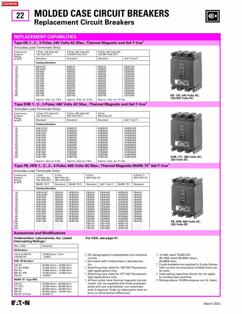
EB: 120, 240 Volts AC; 125/250 Volts DC
Max. Volts Amperes
EB Breakers
120 and 240 AC125/250 DC
10,000 Asym., Sym. 5,000
➊
EHB, FB Breakers
240 AC277 AC (EHB)480 AC600 AC (FB)250 DC
20,000 Asym., 18,000 Sym.15,000 Asym., 14,000 Sym.15,000 Asym., 14,000 Sym.15,000 Asym., 14,000 Sym.10,000
➊
MARK 75
T
Type HFB
240 AC277 AC
➏
480 AC600 AC250 DC (2-Pole)
75,000 Asym., 65,000 Sym.75,000 Asym., 65,000 Sym.30,000 Asym., 25,000 Sym.20,000 Asym., 18,000 Sym.20,000
➊➒
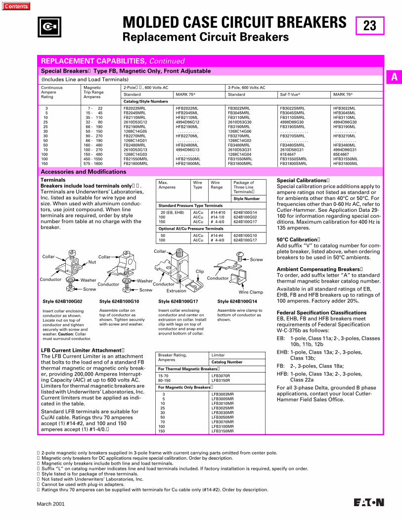
EHB: 277, 480 Volts AC; 250 Volts DC
FB, HFB: 600 Volts AC; 250 Volts DC
➊
DC ratings apply to substantially non-inductive circuits.
➋
Not listed with Underwriters’ Laboratories, Inc.
➌
Switching duty rated for 120 VAC fluorescent light applications only.
➍
Switching duty rated for 277 VAC fluorescent light applications only.
➎
All four poles have thermal magnetic trip ele-ments. Can be supplied with three protected poles and one unprotected, non-automatic pole if required. Order by description with no price or dimensional differences.
➏
15-30A rated 75,000 AIC. 40-100A rated 30,000A Asym.,25,000A Sym.
➐
2-pole breakers are supplied in 3-pole frames with current carrying parts omitted from cen-ter pole.
➑
Interrupting capacities shown do not apply to molded case switches.
➒
Ratings above 10,000 amperes not UL listed.
For CSA, see page 41.
23
March 2001
A
Accessories and Modifications
(Includes Line and Load Terminals)
ContinuousAmpereRating
MagneticTrip RangeAmperes
2-Pole
➊➋
, 600 Volts AC 3-Pole, 600 Volts AC
Standard MARK 75
T
Standard Saf-T-Vue
T
MARK 75
T
Catalog/Style Numbers
3 5 10 25 25 30 30 50 50 70100100150
7 - 22 15 - 45 35 - 110 32 - 80 66 - 190 50 - 150 90 - 270 66 - 190160 - 480100 - 270150 - 480450 - 1550575 - 1800
FB2022MRLFB2045MRLFB2110MRL2610D53G12FB2190MRL1268C14G05FB2270MRL1268C14G01FB2480MRL2610D53G131268C14G03FB21550MRLFB21800MRL
HFB2022MLHFB2045MLHFB2110ML4994D96G12HFB2190ML . . . . . . . . . .HFB2270ML . . . . . . . . . .HFB2480ML4994D96G13 . . . . . . . . . .HFB21550MLHFB21800ML
FB3022MRLFB3045MRLFB3110MRL2610D53G30FB3190MRL1268C14G06FB3270MRL1268C14G02FB3480MRL2610D53G311268C14G04FB31550MRLFB31800MRL
FB3022SMRLFB3045SMRLFB3110SMRL4998D89G30FB3190SMRL. . . . . . . . . . . . . FB3270SMRL. . . . . . . . . . . . . FB3480SMRL2610D58G3181E4647FB31550SMRLFB31800SMRL
HFB3022MLHFB3045MLHFB3110ML4994D96G30HFB3190ML . . . . . . . . . . HFB3270ML . . . . . . . . . . HFB3480ML4994D96G3165E4667HFB31550MLHFB31800ML
Special Breakers
➊
Type FB, Magnetic Only, Front Adjustable
MOLDED CASE CIRCUIT BREAKERS
Replacement Circuit Breakers
REPLACEMENT CAPABILITIES,
Continued
Screw
Wire Clamp
Conductor
Clip
Extrusion
ConductorConductorConductor
CollarCollarCollar
ScrewScrew
WasherWasher
Nut
TerminalsBreakers include load terminals only
➌➍
.Terminals are Underwriters’ Laboratories, Inc. listed as suitable for wire type and size. When used with aluminum conduc-tors, use joint compound. When line terminals are required, order by style number from table at no charge with the breaker.
Style 624B100G02
Insert collar enclosing conductor as shown. Locate nut on top of conductor and tighten securely with screw and washer.
Caution:
Collar must surround conductor.
Style 624B100G10
Assemble collar on top of conductor as shown. Tighten securely with screw and washer.
Style 624B100G17
Insert collar enclosing conductor and center on extrusion on collar. Install clip with legs on top of conductor and snap end around bottom of collar.
Style 624B100G14
Assemble wire clamp to bottom of conductor as shown.
LFB Current Limiter Attachment
➐
The LFB Current Limiter is an attachment that bolts to the load end of a standard FB thermal magnetic or magnetic only break-er, providing 200,000 Amperes Interrupt-ing Capacity (AIC) at up to 600 volts AC. Limiters for thermal magnetic breakers are listed with Underwriters’ Laboratories, Inc. Current limiters must be applied as indi-cated in the table.
Standard LFB terminals are suitable for Cu/AI cable. Ratings thru 70 amperes accept (1) #14-#2, and 100 and 150 amperes accept (1) #1-4/0.
➑
Special Calibrations
➏
Special calibration price additions apply to ampere ratings not listed as standard or for ambients other than 40°C or 50°C. For frequencies other than 0-60 Hz AC, refer to Cutler-Hammer. See Application Data 29-160 for information regarding special con-ditions. Maximum calibration for 400 Hz is 135 amperes.
50°C Calibration
➏
Add suffix “V” to catalog number for com-plete breaker, listed above, when ordering breakers to be used in 50°C ambients.
Ambient Compensating Breakers
➏
To order, add suffix letter “A” to standard thermal magnetic breaker catalog number.
Available in all standard ratings of EB, EHB, FB and HFB breakers up to ratings of 100 amperes. Factory adder 20%.
Federal Specification Classifications
EB, EHB, FB and HFB breakers meet requirements of Federal Specification W-C-375b as follows:
EB: 1-pole, Class 11a; 2-, 3-poles, Classes 10b, 11b, 12b
EHB: 1-pole, Class 13a; 2-, 3-poles, Class 13b;
FB: 2-, 3-poles, Class 18a;
HFB: 1-pole, Class 13a; 2-, 3-poles, Class 22a
For all 3-phase Delta, grounded B phase applications, contact your local Cutler-Hammer Field Sales Office.
Max.Amperes
WireType
WireRange
Package of Three LineTerminals
➎
Style Number
Standard Pressure Type Terminals
20 (EB, EHB)100150
Al/CuAl/CuAl/Cu
#14-#10#14-1/0# 4-4/0
624B100G14624B100G02624B100G17
Optional Al/Cu Pressure Terminals
50100
Al/CuAl/Cu
#14-#4# 4-4/0
624B100G10624B100G17
Breaker Rating,Amperes
Limiter
Catalog Number
For Thermal Magnetic Breakers
➑
15-7080-150
LFB3070RLFB3150R
For Magnetic Only Breakers
➑
3 5 10 25 30 50 70100150
LFB3003MRLFB3005MRLFB3010MRLFB3025MRLFB3030MRLFB3050MRLFB3070MRLFB3100MRLFB3150MR
➊
2-pole magnetic only breakers supplied in 3-pole frame with current carrying parts omitted from center pole.
➋
Magnetic only breakers for DC applications require special calibration. Order by description.
➌
Magnetic only breakers include both line and load terminals.
➍
Suffix “L” on catalog number indicates line and load terminals included. If factory installation is required, specify on order.
➎
Style listed is for package of three terminals.
➏
Not listed with Underwriters‘ Laboratories, Inc.
➐
Cannot be used with plug-in adapters.
➑
Ratings thru 70 amperes can be supplied with terminals for Cu cable only (#14-#2). Order by description.
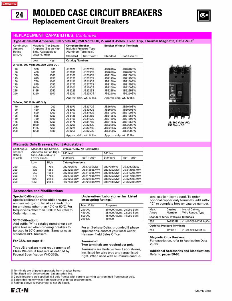
24
March 2001
ContinuousAmpereRatingat 40°C
Magnetic Trip Setting,Amperes (Set on HighSide, Adjustable toLower Limits)
Breaker Only, No Terminals
➍
2-Poles
➌
3-Poles
Standard Saf-T-Vue
T
Standard Saf-T-Vue
T
Low High
Catalog Numbers
250250250250250250
350 625 750 87511251250
70012501500175022502500
JB2700MWJB21250MWJB21500MWJB21750MWJB22250MWJB22500MW
JB2700SMWJB21250SMWJB21500SMWJB21750SMWJB22250SMWJB22500SMW
JB3700MWJB31250MWJB31500MWJB31750MWJB32250MWJB32500MW
JB3700SMWJB31250SMWJB31500SMWJB31750SMWJB32250SMWJB32500SMW
ContinuousAmpereRatingat 40°C
Magnetic Trip Setting,Amperes (Set on HighSide, Adjustable toLower Limits)
Complete Breaker
Includes Pressure Type Aluminum Terminals
➊
Breaker Without Terminals
Standard Saf-T-Vue
T
➋
Standard Saf-T-Vue
T
➋
Low High
Catalog Numbers
2-Poles, 600 Volts AC, 250 Volts DC
➌
70 90100125150175200225250
350 450 500 625 750 875100011251250
700 9001000125015001750200022502500
JB2070JB2090JB2100JB2125JB2150JB2175JB2200JB2225JB2250
JB2070SJB2090SJB2100SJB2125SJB2150SJB2175SJB2200SJB2225SJB2250S
JB2070WJB2090WJB2100WJB2125WJB2150WJB2175WJB2200WJB2225WJB2250W
JB2070SWJB2090SWJB2100SWJB2125SWJB2150SWJB2175SWJB2200SWJB2225SWJB2250SW
Approx. ship. wt. 12 lbs. Approx. ship. wt. 12 lbs.
3-Poles, 600 Volts AC Only
70 90100125150175200225250
350 450 500 625 750 875100011251250
700 9001000125015001750200022502500
JB3070JB3090JB3100JB3125JB3150JB3175JB3200JB3225JB3250
JB3070SJB3090SJB3100SJB3125SJB3150SJB3175SJB3200SJB3225SJB3250S
JB3070WJB3090WJB3100WJB3125WJB3150WJB3175WJB3200WJB3225WJB3250W
JB3070SWJB3090SWJB3100SWJB3125SWJB3150SWJB3175SWJB3200SWJB3225SWJB3250SW
Approx. ship. wt. 14 lbs. Approx. ship. wt. 12 lbs.
Type JB 90-250 Amperes, 600 Volts AC, 250 Volts DC, 2- and 3 -Poles, Fixed Trip, Thermal Magnetic, Saf-T-Vue
T
Magnetic Only Breakers, Front Adjustable
➋
Accessories and Modifications
MOLDED CASE CIRCUIT BREAKERS
Replacement Circuit Breakers
REPLACEMENT CAPABILITIES,
Continued
➊
Terminals are shipped separately from breaker frame.
➋
Not listed with Underwriters’ Laboratories, Inc.
➌
2-pole breakers are supplied in 3-pole frames with current carrying parts omitted from center pole.
➍
Select desired terminal from table and order as separate item.
➎
Ratings above 10,000 amperes not UL listed.
For all 3-phase Delta, grounded B phase applications, contact your local Cutler-Hammer Field Sales Office.
Terminals
➊
Two terminals are required per pole.
Terminals are Underwriters’ Laboratories, Inc. listed for wire type and range listed right. When used with aluminum conduc-
Underwriters’ Laboratories, Inc. Listed Interrupting Ratings
➎
Max. Volts Amperes
240 AC480 AC600 AC250 DC
30,000 Asym., 25,000 Sym.25,000 Asym., 22,000 Sym.15,000 Asym., 14,000 Sym.10,000
tors, use joint compound. To order optional copper only terminals, add suffix “C” to complete breaker catalog number.
Magnetic Only Breakers
For description, refer to Application Data 29-160.
Additional Accessories and Modifications
Refer to
pages 58-68.
Max.Amps
CatalogNumber
No. of Cables,Wire Range, Type
Standard Al/Cu Pressure Terminals
250 TA250KB (1) #4-350 MCM Al/Cu
Optional Pressure Terminals
250 T250KB (1) #4-350 MCM Cu
JB: 600 Volts AC; 250 Volts DC
Special Calibrations
➋
Special calibration price additions apply to ampere ratings not listed as standard or for ambients other than 40°C or 50°C. For frequencies other than 0-60 Hz AC, refer to Cutler-Hammer.
50°C Calibration
➋
Add suffix “V” to catalog number for com-plete breaker when ordering breakers to be used in 50°C ambients. Same price as standard 40°C breakers.
For CSA, see page 41.
Type JB breakers meet requirements of Class 19a circuit breakers as defined byFederal Specification W-C-375b.
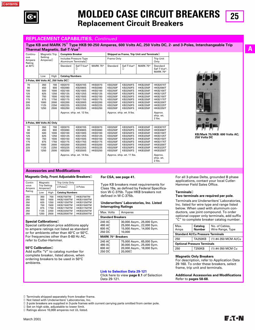
25
March 2001
A
Magnetic Only, Front Adjustable Breakers
➌
Contin-uousAmpereRating
Magnetic Trip SettingAmperes
➍
Trip Units Only
2-Poles
➌
3-Poles
Low High
Catalog Numbers
250250250250250250250
350 500 625 750 87511251250
700100012501500175022502500
HKB2700TMHKB21000TMHKB21250TMHKB21500TMHKB21750TMHKB22250TMHKB22500TM
HKB3700TMHKB31000TMHKB31250TMHKB31500TMHKB31750TMHKB32250TMHKB32500TM
➊
Terminals shipped separately from breaker frame.
➋
Not listed with Underwriters’ Laboratories, Inc.
➌
2-pole breakers are supplied in 3-pole frames with current carrying parts omitted from center pole.
➍
Set on high side, adjustable to lower limit.
➎ Ratings above 10,000 amperes not UL listed.
Continu-ousAmpereRatingat 40°C
Magnetic TripSettingAmperes➋
Complete Breaker Shipped as Frame, Trip Unit and Terminals➊
Includes Pressure Type Aluminum Terminals➋
Frame Only Trip Unit Only
Standard Saf-T-VueT➋
MARK 75T Standard Saf-T-VueT➌
MARK 75T StandardSaf-T-VueT,MARK 75T
Low High Catalog Numbers
2-Poles, 600 Volts AC, 250 Volts DC➌
70 90100125150175200225250
350 450 500 625 750 875100011251250
700 9001000125015001750200022502500
KB2070KB2090KB2100KB2125KB2150KB2175KB2200KB2225KB2250
KB2070SKB2090SKB2100SKB2125SKB2150SKB2175SKB2200SKB2225SKB2250S
HKB2070HKB2090HKB2100HKB2125HKB2150HKB2175HKB2200HKB2225HKB2250
KB2250FKB2250FKB2250FKB2250FKB2250FKB2250FKB2250FKB2250FKB2250F
KB2250FSKB2250FSKB2250FSKB2250FSKB2250FSKB2250FSKB2250FSKB2250FSKB2250FS
HKB2250FHKB2250FHKB2250FHKB2250FHKB2250FHKB2250FHKB2250FHKB2250FHKB2250F
HKB2070THKB2090THKB2100THKB2125THKB2150THKB2175THKB2200THKB2225THKB2250T
Approx. ship. wt. 12 lbs. Approx. ship. wt. 9 lbs. Approx. ship. wt. 2 lbs.
3-Poles, 600 Volts AC Only
70 90100125150175200225250
350 450 500 625 750 875100011251250
700 9001000125015001750200022502500
KB3070KB3090KB3100KB3125KB3150KB3175KB3200KB3225KB3250
KB3070SKB3090SKB3100SKB3125SKB3150SKB3175SKB3200SKB3225SKB3250S
HKB3070HKB3090HKB3100HKB3125HKB3150HKB3175HKB3200HKB3225HKB3250
KB3250FKB3250FKB3250FKB3250FKB3250FKB3250FKB3250FKB3250FKB3250F
KB3250FSKB3250FSKB3250FSKB3250FSKB3250FSKB3250FSKB3250FSKB3250FSKB3250FS
HKB3250FHKB3250FHKB3250FHKB3250FHKB3250FHKB3250FHKB3250FHKB3250FHKB3250F
HKB3070THKB3090THKB3100THKB3125THKB3150THKB3175THKB3200THKB3225THKB3250T
Approx. ship. wt. 14 lbs. Approx. ship. wt. 11 lbs. Approx. ship. wt. 2 lbs.
Type KB and MARK 75T Type HKB 90-250 Amperes, 600 Volts AC, 250 Volts DC, 2- and 3-Poles, Interchangeable Trip
Thermal Magnetic, Saf-T-VueT
MOLDED CASE CIRCUIT BREAKERSReplacement Circuit Breakers
Accessories and Modifications
REPLACEMENT CAPABILITIES, Continued
Special Calibrations➌Special calibration price additions apply to ampere ratings not listed as standard or for ambients other than 40°C or 50°C. For frequencies other than 0-60 Hz AC, refer to Cutler-Hammer.
50°C Calibration➌Add suffix “V” to catalog number for complete breaker, listed above, when ordering breakers to be used in 50°C ambients.
For CSA, see page 41.
Type KB breakers meet requirements for Class 19a, as defined by Federal Specifica-tion W-C-375b. Type HKB breakers not defined in W-C-375b.
Underwriters’ Laboratories, Inc. Listed Interrupting Ratings
Max. Volts Amperes
Standard Breakers
240 AC480 AC600 AC250 DC
30,000 Asym., 25,000 Sym.25,000 Asym., 22,000 Sym.15,000 Asym., 14,000 Sym.10,000
MARK 75T Breakers
240 AC480 AC600 AC250 DC
75,000 Asym., 65,000 Sym.30,000 Asym., 25,000 Sym.20,000 Asym., 18,000 Sym.20,000➎
For all 3-phase Delta, grounded B phase applications, contact your local Cutler-Hammer Field Sales Office.
Terminals➊Two terminals are required per pole.
Terminals are Underwriters’ Laboratories, Inc. listed for wire type and range listed below. When used with aluminum con-ductors, use joint compound. To order optional copper only terminals, add suffix “C” to complete breaker catalog number.
Magnetic Only BreakersFor description, refer to Application Data 29-160. To order these breakers, select frame, trip unit and terminals.
Additional Accessories and ModificationsRefer to pages 58-68.
Max.Amps
CatalogNumber
No. of Cables,Wire Range, Type
Standard Al/Cu Pressure Terminals
250 TA250KB (1) #4-350 MCM Al/Cu
Optional Pressure Terminals
250 T250KB (1) #4-350 MCM Cu
KB/Mark 75/HKB: 600 Volts AC; 250 Volts DC
Link to Selection Data 29-121Click here to view page 8.1 of Selection Data 29-121.
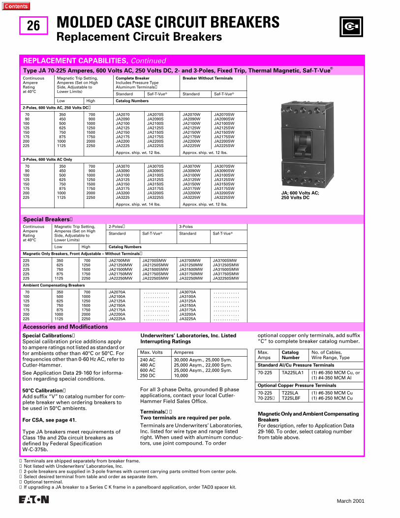
26
March 2001
ContinuousAmpereRatingat 40°C
Magnetic Trip Setting,Amperes (Set on HighSide, Adjustable toLower Limits)
Complete BreakerIncludes Pressure Type Aluminum Terminals➊
Breaker Without Terminals
Standard Saf-T-VueT Standard Saf-T-VueT
Low High Catalog Numbers
2-Poles, 600 Volts AC, 250 Volts DC➋
70 90100125150175200225
350 450 500 625 750 87510001125
700 900100012501500175020002250
JA2070JA2090JA2100JA2125JA2150JA2175JA2200JA2225
JA2070SJA2090SJA2100SJA2125SJA2150SJA2175SJA2200SJA2225S
JA2070WJA2090WJA2100WJA2125WJA2150WJA2175WJA2200WJA2225W
JA2070SWJA2090SWJA2100SWJA2125SWJA2150SWJA2175SWJA2200SWJA2225SW
Approx. ship. wt. 12 lbs. Approx. ship. wt. 12 lbs.
3-Poles, 600 Volts AC Only
70 90100125150175200225
350 450 500 625 750 87510001125
700 900100012501500175020002250
JA3070JA3090JA3100JA3125JA3150JA3175JA3200JA3225
JA3070SJA3090SJA3100SJA3125SJA3150SJA3175SJA3200SJA3225S
JA3070WJA3090WJA3100WJA3125WJA3150WJA3175WJA3200WJA3225W
JA3070SWJA3090SWJA3100SWJA3125SWJA3150SWJA3175SWJA3200SWJA3225SW
Approx. ship. wt. 14 lbs. Approx. ship. wt. 12 lbs.
Accessories and Modifications
ContinuousAmpereRatingat 40°C
Magnetic Trip Setting,Amperes (Set on HighSide, Adjustable toLower Limits)
2-Poles➌ 3-Poles
Standard Saf-T-VueT Standard Saf-T-VueT
Low High Catalog Numbers
Magnetic Only Breakers, Front Adjustable – Without Terminals➍
225225225225225
350 625 750 8751125
7001250150017502250
JA2700MWJA21250MWJA21500MWJA21750MWJA22250MW
JA2700SMWJA21250SMWJA21500SMWJA21750SMWJA22250SMW
JA3700MWJA31250MWJA31500MWJA31750MWJA32250MW
JA3700SMWJA31250SMWJA31500SMWJA31750SMWJA32250SMW
Ambient Compensating Breakers
70100125150175200225
350 500 625 750 87510001125
700100012501500175020002250
JA2070AJA2100AJA2125AJA2150AJA2175AJA2200AJA2225A
. . . . . . . . . . . . . . . . . . . . . . . . . . . . . . . . . . . . . . . . . . . . . . . . . . . . . . . . . . . . . . . . . . . . . . . . . . . . . . . . . . . .
JA3070AJA3100AJA3125AJA3150AJA3175AJA3200AJA3225A
. . . . . . . . . . . .
. . . . . . . . . . . .
. . . . . . . . . . . .
. . . . . . . . . . . .
. . . . . . . . . . . .
. . . . . . . . . . . .
. . . . . . . . . . . .
MOLDED CASE CIRCUIT BREAKERSReplacement Circuit Breakers
REPLACEMENT CAPABILITIES, ContinuedType JA 70-225 Amperes, 600 Volts AC, 250 Volts DC, 2- and 3-Poles, Fixed Trip, Thermal Magnetic, Saf-T-VueT
Special Breakers➌
➊ Terminals are shipped separately from breaker frame.➋ Not listed with Underwriters’ Laboratories, Inc.➌ 2-pole breakers are supplied in 3-pole frames with current carrying parts omitted from center pole.➍ Select desired terminal from table and order as separate item.➎ Optional terminal.➏ If upgrading a JA breaker to a Series C K frame in a panelboard application, order TAD3 spacer kit.
Magnetic Only and Ambient Compensating BreakersFor description, refer to Application Data 29-160. To order, select catalog number from table above.
Special Calibrations➋Special calibration price additions apply to ampere ratings not listed as standard or for ambients other than 40°C or 50°C. For frequencies other than 0-60 Hz AC, refer to Cutler-Hammer.
See Application Data 29-160 for informa-tion regarding special conditions.
50°C Calibration➋Add suffix “V” to catalog number for com-plete breaker when ordering breakers to be used in 50°C ambients.
For CSA, see page 41.
Type JA breakers meet requirements of Class 19a and 20a circuit breakers as defined by Federal Specification W-C-375b.
Underwriters’ Laboratories, Inc. Listed Interrupting Ratings
Max.Amps
CatalogNumber
No. of Cables,Wire Range, Type
Standard Al/Cu Pressure Terminals
70-225 TA225LA1 (1) #6-350 MCM Cu, or(1) #4-350 MCM Al
Optional Copper Pressure Terminals
70-22570-225➎
T225LAT225LBF
(1) #6-350 MCM Cu(1) #6-250 MCM Cu
JA; 600 Volts AC; 250 Volts DC
For all 3-phase Delta, grounded B phase applications, contact your local Cutler-Hammer Field Sales Office.
Terminals➊➏Two terminals are required per pole.
Terminals are Underwriters’ Laboratories, Inc. listed for wire type and range listed right. When used with aluminum conduc-tors, use joint compound. To order
Max. Volts Amperes
240 AC480 AC600 AC250 DC
30,000 Asym., 25,000 Sym.25,000 Asym., 22,000 Sym.25,000 Asym., 22,000 Sym.10,000
optional copper only terminals, add suffix “C” to complete breaker catalog number.
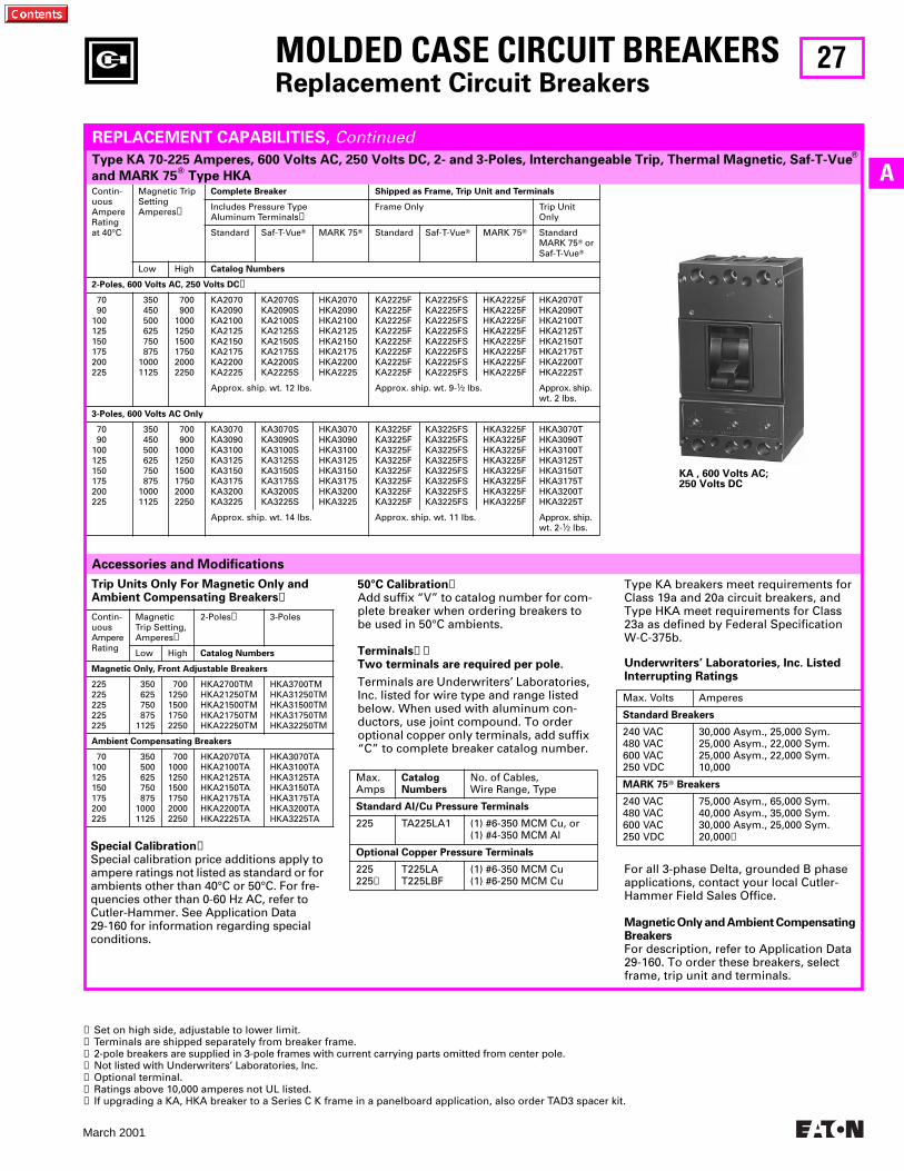
27
March 2001
AContin-uousAmpereRatingat 40°C
Magnetic Trip SettingAmperes➊
Complete Breaker Shipped as Frame, Trip Unit and Terminals
Includes Pressure Type Aluminum Terminals➋
Frame Only Trip Unit Only
Standard Saf-T-VueT MARK 75T Standard Saf-T-VueT MARK 75T Standard MARK 75T orSaf-T-VueT
Low High Catalog Numbers
2-Poles, 600 Volts AC, 250 Volts DC➌
70 90100125150175200225
350 450 500 625 750 87510001125
700 900100012501500175020002250
KA2070KA2090KA2100KA2125KA2150KA2175KA2200KA2225
KA2070SKA2090SKA2100SKA2125SKA2150SKA2175SKA2200SKA2225S
HKA2070HKA2090HKA2100HKA2125HKA2150HKA2175HKA2200HKA2225
KA2225FKA2225FKA2225FKA2225FKA2225FKA2225FKA2225FKA2225F
KA2225FSKA2225FSKA2225FSKA2225FSKA2225FSKA2225FSKA2225FSKA2225FS
HKA2225FHKA2225FHKA2225FHKA2225FHKA2225FHKA2225FHKA2225FHKA2225F
HKA2070THKA2090THKA2100THKA2125THKA2150THKA2175THKA2200THKA2225T
Approx. ship. wt. 12 lbs. Approx. ship. wt. 9-1⁄2 lbs. Approx. ship. wt. 2 lbs.
3-Poles, 600 Volts AC Only
70 90100125150175200225
350 450 500 625 750 87510001125
700 900100012501500175020002250
KA3070KA3090KA3100KA3125KA3150KA3175KA3200KA3225
KA3070SKA3090SKA3100SKA3125SKA3150SKA3175SKA3200SKA3225S
HKA3070HKA3090HKA3100HKA3125HKA3150HKA3175HKA3200HKA3225
KA3225FKA3225FKA3225FKA3225FKA3225FKA3225FKA3225FKA3225F
KA3225FSKA3225FSKA3225FSKA3225FSKA3225FSKA3225FSKA3225FSKA3225FS
HKA3225FHKA3225FHKA3225FHKA3225FHKA3225FHKA3225FHKA3225FHKA3225F
HKA3070THKA3090THKA3100THKA3125THKA3150THKA3175THKA3200THKA3225T
Approx. ship. wt. 14 lbs. Approx. ship. wt. 11 lbs. Approx. ship. wt. 2-1⁄2 lbs.
Accessories and Modifications
MOLDED CASE CIRCUIT BREAKERSReplacement Circuit Breakers
Type KA 70-225 Amperes, 600 Volts AC, 250 Volts DC, 2- and 3-Poles, Interchangeable Trip, Thermal Magnetic, Saf-T-VueT
and MARK 75T Type HKA
REPLACEMENT CAPABILITIES, Continued
➊ Set on high side, adjustable to lower limit.➋ Terminals are shipped separately from breaker frame.➌ 2-pole breakers are supplied in 3-pole frames with current carrying parts omitted from center pole.➍ Not listed with Underwriters’ Laboratories, Inc.➎ Optional terminal.➏ Ratings above 10,000 amperes not UL listed.➐ If upgrading a KA, HKA breaker to a Series C K frame in a panelboard application, also order TAD3 spacer kit.
Type KA breakers meet requirements for Class 19a and 20a circuit breakers, and Type HKA meet requirements for Class 23a as defined by Federal Specification W-C-375b.
For all 3-phase Delta, grounded B phase applications, contact your local Cutler-Hammer Field Sales Office.
Magnetic Only and Ambient Compensating BreakersFor description, refer to Application Data 29-160. To order these breakers, select frame, trip unit and terminals.
Underwriters’ Laboratories, Inc. Listed Interrupting Ratings
Max. Volts Amperes
Standard Breakers
240 VAC480 VAC600 VAC250 VDC
30,000 Asym., 25,000 Sym.25,000 Asym., 22,000 Sym.25,000 Asym., 22,000 Sym.10,000
MARK 75T Breakers
240 VAC480 VAC600 VAC250 VDC
75,000 Asym., 65,000 Sym.40,000 Asym., 35,000 Sym.30,000 Asym., 25,000 Sym.20,000➏
Trip Units Only For Magnetic Only and Ambient Compensating Breakers➍
Contin-uousAmpereRating
Magnetic Trip Setting,Amperes➊
2-Poles➌ 3-Poles
Low High Catalog Numbers
Magnetic Only, Front Adjustable Breakers
225225225225225
350 625 750 8751125
7001250150017502250
HKA2700TMHKA21250TMHKA21500TMHKA21750TMHKA22250TM
HKA3700TMHKA31250TMHKA31500TMHKA31750TMHKA32250TM
Ambient Compensating Breakers
70100125150175200225
350 500 625 750 87510001125
700100012501500175020002250
HKA2070TAHKA2100TAHKA2125TAHKA2150TAHKA2175TAHKA2200TAHKA2225TA
HKA3070TAHKA3100TAHKA3125TAHKA3150TAHKA3175TAHKA3200TAHKA3225TA
Special Calibration➍Special calibration price additions apply to ampere ratings not listed as standard or for ambients other than 40°C or 50°C. For fre-quencies other than 0-60 Hz AC, refer to Cutler-Hammer. See Application Data 29-160 for information regarding special conditions.
50°C Calibration➍Add suffix “V” to catalog number for com-plete breaker when ordering breakers to be used in 50°C ambients.
Terminals➋➐Two terminals are required per pole.
Terminals are Underwriters’ Laboratories, Inc. listed for wire type and range listed below. When used with aluminum con-ductors, use joint compound. To order optional copper only terminals, add suffix “C” to complete breaker catalog number.
Max.Amps
CatalogNumbers
No. of Cables,Wire Range, Type
Standard Al/Cu Pressure Terminals
225 TA225LA1 (1) #6-350 MCM Cu, or(1) #4-350 MCM Al
Optional Copper Pressure Terminals
225225➎
T225LAT225LBF
(1) #6-350 MCM Cu(1) #6-250 MCM Cu
KA , 600 Volts AC; 250 Volts DC
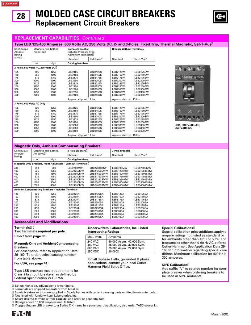
28
March 2001
Type LBB 125-400 Amperes, 600 Volts AC, 250 Volts DC, 2- and 3-Poles, Fixed Trip, Thermal Magnetic, Saf-T-VueT
ContinuousAmpereRatingat 40°C
Magnetic Trip Setting, Amperes➊
Complete Breaker
Includes Pressure Type Aluminum Terminals➋
Breaker Without Terminals
Standard Saf-T-VueT Standard Saf-T-VueT
Low High Catalog Numbers
2-Poles, 600 Volts AC, 250 Volts DC➌
125150175200225250300350400
625 750 875100011251250150017502000
125015001750200022502500300035004000
LBB2125LBB2150LBB2175LBB2200LBB2225LBB2250LBB2300LBB2350LBB2400
LBB2125SLBB2150SLBB2175SLBB2200SLBB2225SLBB2250SLBB2300SLBB2350SLBB2400S
LBB2125WLBB2150WLBB2175WLBB2200WLBB2225WLBB2250WLBB2300WLBB2350WLBB2400W
LBB2125SWLBB2150SWLBB2175SWLBB2200SWLBB2225SWLBB2250SWLBB2300SWLBB2350SWLBB2400SW
Approx. ship. wt. 13 lbs. Approx. ship. wt. 13 lbs.
3-Poles, 600 Volts AC Only
125150175200225250300350400
625 750 875100011251250150017502000
125015001750200022502500300035004000
LBB3125LBB3150LBB3175LBB3200LBB3225LBB3250LBB3300LBB3350LBB3400
LBB3125SLBB3150SLBB3175SLBB3200SLBB3225SLBB3250SLBB3300SLBB3350SLBB3400S
LBB3125WLBB3150WLBB3175WLBB3200WLBB3225WLBB3250WLBB3300WLBB3350WLBB3400W
LBB3125SWLBB3150SWLBB3175SWLBB3200SWLBB3225SWLBB3250SWLBB3300SWLBB3350SWLBB3400SW
Approx. ship. wt. 15 lbs. Approx. ship. wt. 15 lbs.
Magnetic Only, Ambient Compensating Breakers➍
MOLDED CASE CIRCUIT BREAKERSReplacement Circuit Breakers
Accessories and Modifications
REPLACEMENT CAPABILITIES, Continued
ContinuousAmpereRating
Magnetic Trip Setting,Amperes➊
2-Pole Breakers➌ 3-Pole Breakers
Standard Saf-T-VueT Standard Saf-T-VueT
Low High Catalog Numbers
Magnetic Only Breakers, Front Adjustable – Without Terminals➎
400400400400400400400
350 625 750 875112515002000
700125015001750225030004000
LBB2700MWLBB21250MWLBB21500MWLBB21750MWLBB22250MWLBB23000MWLBB24000MW
LBB2700SMWLBB21250SMWLBB21500SMWLBB21750SMWLBB22250SMWLBB23000SMWLBB24000SMW
LBB3700MWLBB31250MWLBB31500MWLBB31750MWLBB32250MWLBB33000MWLBB34000MW
LBB3700SMWLBB31250SMWLBB31500SMWLBB31750SMWLBB32250SMWLBB33000SMWLBB34000SMW
Ambient Compensating Breakers – Includes Terminals
125150175200225250300350400
625 750 875100011251250150017502000
125015001750200022502500300035004000
LBB2125ALBB2150ALBB2175ALBB2200ALBB2225ALBB2250ALBB2300ALBB2350ALBB2400A
LBB2125SALBB2150SALBB2175SALBB2200SALBB2225SALBB2250SALBB2300SALBB2350SALBB2400SA
LBB3125ALBB3150ALBB3175ALBB3200ALBB3225ALBB3250ALBB3300ALBB3350ALBB3400A
LBB3125SALBB3150SALBB3175SALBB3200SALBB3225SALBB3250SALBB3300SALBB3350SALBB3400SA
➊ Set on high side, adjustable to lower limits.➋ Terminals are shipped separately from breaker.➌ 2-pole breakers or trips are supplied in 3-pole frames with current carrying parts omitted from center pole.➍ Not listed with Underwriters’ Laboratories, Inc.➎ Select desired terminals from page 30, and order as separate item.➏ Ratings above 10,000 amperes not UL listed.➐ If upgrading an LBB breaker to a Series C K frame in a panelboard application, also order TAD3 spacer kit.
Special Calibrations➍Special calibration price additions apply to ampere ratings not listed as standard or for ambients other than 40°C or 50°C. For frequencies other than 0-60 Hz AC, refer to Cutler-Hammer. See Application Data 29-160 for information regarding special con-ditions. Maximum calibration for 400 Hz is 300 amperes.
50°C Calibration➍Add suffix “V” to catalog number for com-plete breaker when ordering breakers to be used in 50°C ambients.
On all 3-phase Delta, grounded B phase applications, contact your local Cutler-Hammer Field Sales Office.
Underwriters’ Laboratories, Inc. Listed Interrupting Ratings
Max. Volts Amperes
240 VAC480 VAC600 VAC250 VDC
50,000 Asym., 42,000 Sym.35,000 Asym., 30,000 Sym.25,000 Asym., 22,000 Sym.20,000➏
LBB, 600 Volts AC; 250 Volts DC
Terminals➋➐Two terminals required per pole.
Select from page 30.
Magnetic Only and Ambient Compensating BreakersFor description, refer to Application Data 29-160. To order, select catalog number from table above.
For CSA, see page 41.
Type LBB breakers meet requirements for Class 21a circuit breakers, as defined by Federal Specification W-C-375b.
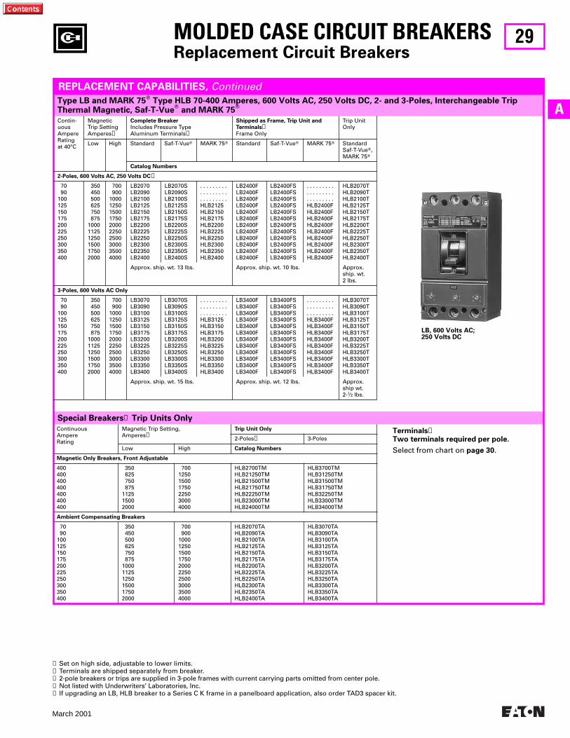
29
March 2001
A
Special Breakers➍ Trip Units Only
ContinuousAmpereRating
Magnetic Trip Setting,Amperes➊
Trip Unit Only
2-Poles➌ 3-Poles
Low High Catalog Numbers
Magnetic Only Breakers, Front Adjustable
400400400400400400400
350 625 750 875112515002000
700125015001750225030004000
HLB2700TMHLB21250TMHLB21500TMHLB21750TMHLB22250TMHLB23000TMHLB24000TM
HLB3700TMHLB31250TMHLB31500TMHLB31750TMHLB32250TMHLB33000TMHLB34000TM
Ambient Compensating Breakers
70 90100125150175200225250300350400
350 450 500 625 750 875100011251250150017502000
700 9001000125015001750200022502500300035004000
HLB2070TAHLB2090TAHLB2100TAHLB2125TAHLB2150TAHLB2175TAHLB2200TAHLB2225TAHLB2250TAHLB2300TAHLB2350TAHLB2400TA
HLB3070TAHLB3090TAHLB3100TAHLB3125TAHLB3150TAHLB3175TAHLB3200TAHLB3225TAHLB3250TAHLB3300TAHLB3350TAHLB3400TA
MOLDED CASE CIRCUIT BREAKERSReplacement Circuit Breakers
Type LB and MARK 75T Type HLB 70-400 Amperes, 600 Volts AC, 250 Volts DC, 2- and 3-Poles, Interchangeable Trip Thermal Magnetic, Saf-T-VueT and MARK 75T
REPLACEMENT CAPABILITIES, Continued
Contin-uousAmpereRatingat 40°C
Magnetic Trip SettingAmperes➊
Complete Breaker
Includes Pressure Type Aluminum Terminals➋
Shipped as Frame, Trip Unit and
Terminals➋Frame Only
Trip Unit Only
Low High Standard Saf-T-VueT MARK 75T Standard Saf-T-VueT MARK 75T StandardSaf-T-VueT,MARK 75T
Catalog Numbers
2-Poles, 600 Volts AC, 250 Volts DC➌
70 90100125150175200225250300350400
350 450 500 625 750 875100011251250150017502000
700 9001000125015001750200022502500300035004000
LB2070LB2090LB2100LB2125LB2150LB2175LB2200LB2225LB2250LB2300LB2350LB2400
LB2070SLB2090SLB2100SLB2125SLB2150SLB2175SLB2200SLB2225SLB2250SLB2300SLB2350SLB2400S
. . . . . . . . .
. . . . . . . . .
. . . . . . . . .HLB2125HLB2150HLB2175HLB2200HLB2225HLB2250HLB2300HLB2350HLB2400
LB2400FLB2400FLB2400FLB2400FLB2400FLB2400FLB2400FLB2400FLB2400FLB2400FLB2400FLB2400F
LB2400FSLB2400FSLB2400FSLB2400FSLB2400FSLB2400FSLB2400FSLB2400FSLB2400FSLB2400FSLB2400FSLB2400FS
. . . . . . . . .
. . . . . . . . .
. . . . . . . . .HLB2400FHLB2400FHLB2400FHLB2400FHLB2400FHLB2400FHLB2400FHLB2400FHLB2400F
HLB2070THLB2090THLB2100THLB2125THLB2150THLB2175THLB2200THLB2225THLB2250THLB2300THLB2350THLB2400T
Approx. ship. wt. 13 lbs. Approx. ship. wt. 10 lbs. Approx. ship. wt.2 lbs.
3-Poles, 600 Volts AC Only
70 90100125150175200225250300350400
350 450 500 625 750 875100011251250150017502000
700 9001000125015001750200022502500300035004000
LB3070LB3090LB3100LB3125LB3150LB3175LB3200LB3225LB3250LB3300LB3350LB3400
LB3070SLB3090SLB3100SLB3125SLB3150SLB3175SLB3200SLB3225SLB3250SLB3300SLB3350SLB3400S
. . . . . . . . .
. . . . . . . . .
. . . . . . . . .HLB3125HLB3150HLB3175HLB3200HLB3225HLB3250HLB3300HLB3350HLB3400
LB3400FLB3400FLB3400FLB3400FLB3400FLB3400FLB3400FLB3400FLB3400FLB3400FLB3400FLB3400F
LB3400FSLB3400FSLB3400FSLB3400FSLB3400FSLB3400FSLB3400FSLB3400FSLB3400FSLB3400FSLB3400FSLB3400FS
. . . . . . . . .
. . . . . . . . .
. . . . . . . . .HLB3400FHLB3400FHLB3400FHLB3400FHLB3400FHLB3400FHLB3400FHLB3400FHLB3400F
HLB3070THLB3090THLB3100THLB3125THLB3150THLB3175THLB3200THLB3225THLB3250THLB3300THLB3350THLB3400T
Approx. ship. wt. 15 lbs. Approx. ship. wt. 12 lbs. Approx. ship wt.2-1⁄2 lbs.
➊ Set on high side, adjustable to lower limits.➋ Terminals are shipped separately from breaker.➌ 2-pole breakers or trips are supplied in 3-pole frames with current carrying parts omitted from center pole.➍ Not listed with Underwriters’ Laboratories, Inc.➎ If upgrading an LB, HLB breaker to a Series C K frame in a panelboard application, also order TAD3 spacer kit.
LB, 600 Volts AC; 250 Volts DC
Terminals➎Two terminals required per pole.
Select from chart on page 30.
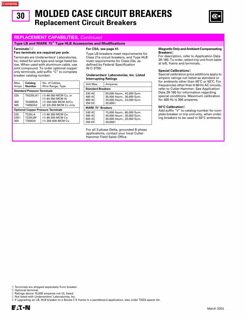
30
March 2001
Type LB and MARK 75T Type HLB Accessories and Modifications
MOLDED CASE CIRCUIT BREAKERSReplacement Circuit Breakers
REPLACEMENT CAPABILITIES, Continued
For CSA, see page 41.
Type LB breakers meet requirements for Class 21a circuit breakers, and Type HLB meet requirements for Class 23a, as defined by Federal Specification W-C-375b.
For all 3-phase Delta, grounded B phase applications, contact your local Cutler-Hammer Field Sales Office.
Underwriters’ Laboratories, Inc. Listed Interrupting Ratings
Volt Max. Amperes
Standard Breakers
240 AC480 AC600 AC250 DC
50,000 Asym., 42,000 Sym.35,000 Asym., 30,000 Sym.25,000 Asym., 22,000 Sym.20,000➌
MARK 75T Breakers
240 AC480 AC600 AC250 DC
75,000 Asym., 65,000 Sym.40,000 Asym., 35,000 Sym.30,000 Asym., 25,000 Sym.20,000➌
➊ Terminals are shipped separately from breaker.➋ Optional terminal.➌ Ratings above 10,000 amperes not UL listed.➍ Not listed with Underwriters’ Laboratories, Inc.➎ If upgrading an LB, HLB breaker to a Series C K frame in a panelboard application, also order TAD3 spacer kit.
Terminals➊➎Two terminals are required per pole.
Terminals are Underwriters’ Laboratories, Inc. listed for wire type and range listed be-low. When used with aluminum cable, use joint compound. To order optional copper only terminals, add suffix “C” to complete breaker catalog number.
Max.Amps
Catalog Number
No. of Cables,Wire Range, Type
Standard Pressure Terminals
225
350400
TA225LA1
TA350DAT400DA2
(1) #6-350 MCM Cu, or(1) #4-350 MCM Al(1) 250-500 MCM Al/Cu(2) 3/0-250 MCM Cu only
Optional Copper Pressure Terminals
225225➋350
T225LAT225LBFT350DA
(1) #6-350 MCM Cu(1) #6-250 MCM Cu(1) 250-500 MCM Cu
Magnetic Only and Ambient Compensating Breakers➍For description, refer to Application Data 29-160. To order, select trip unit from table at left, frame and terminals.
Special Calibrations➍Special calibration price additions apply to ampere ratings not listed as standard or for ambients other than 40°C or 50°C. For frequencies other than 0-60 Hz AC circuits, refer to Cutler-Hammer. See Application Data 29-160 for information regarding special conditions. Maximum calibration for 400 Hz is 300 amperes.
50°C Calibration➍Add suffix “V” to catalog number for com-plete breaker or trip unit only, when order-ing breakers to be used in 50°C ambients.
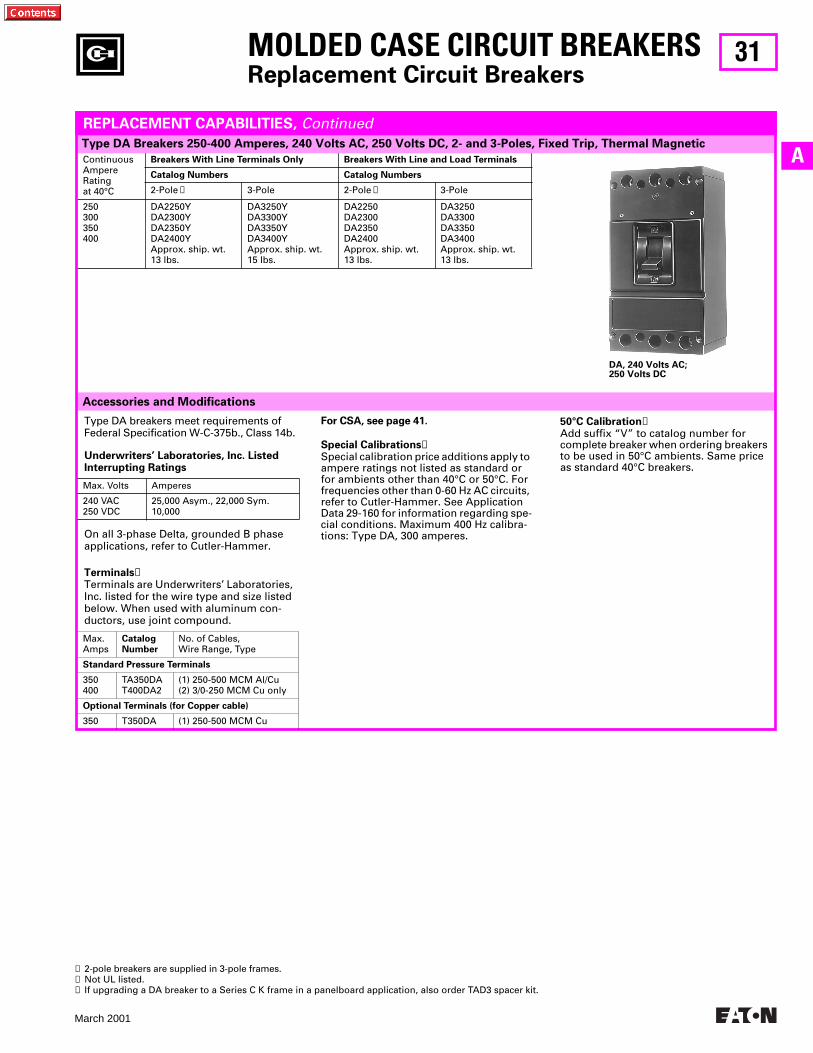
31
March 2001
A
Accessories and Modifications
ContinuousAmpereRatingat 40°C
Breakers With Line Terminals Only Breakers With Line and Load Terminals
Catalog Numbers Catalog Numbers
2-Pole ➊ 3-Pole 2-Pole ➊ 3-Pole
250300350400
DA2250YDA2300YDA2350YDA2400YApprox. ship. wt.13 lbs.
DA3250YDA3300YDA3350YDA3400YApprox. ship. wt.15 lbs.
DA2250DA2300DA2350DA2400Approx. ship. wt.13 lbs.
DA3250DA3300DA3350DA3400Approx. ship. wt.13 lbs.
MOLDED CASE CIRCUIT BREAKERSReplacement Circuit Breakers
Type DA Breakers 250-400 Amperes, 240 Volts AC, 250 Volts DC, 2- and 3-Poles, Fixed Trip, Thermal Magnetic
REPLACEMENT CAPABILITIES, Continued
Type DA breakers meet requirements of Federal Specification W-C-375b., Class 14b.
On all 3-phase Delta, grounded B phase applications, refer to Cutler-Hammer.
Terminals➌Terminals are Underwriters’ Laboratories, Inc. listed for the wire type and size listed below. When used with aluminum con-ductors, use joint compound.
Underwriters’ Laboratories, Inc. Listed Interrupting Ratings
Max. Volts Amperes
240 VAC250 VDC
25,000 Asym., 22,000 Sym.10,000
Max.Amps
CatalogNumber
No. of Cables,Wire Range, Type
Standard Pressure Terminals
350400
TA350DAT400DA2
(1) 250-500 MCM Al/Cu(2) 3/0-250 MCM Cu only
Optional Terminals (for Copper cable)
350 T350DA (1) 250-500 MCM Cu
For CSA, see page 41.
Special Calibrations➋Special calibration price additions apply to ampere ratings not listed as standard or for ambients other than 40°C or 50°C. For frequencies other than 0-60 Hz AC circuits, refer to Cutler-Hammer. See Application Data 29-160 for information regarding spe-cial conditions. Maximum 400 Hz calibra-tions: Type DA, 300 amperes.
➊ 2-pole breakers are supplied in 3-pole frames.➋ Not UL listed.➌ If upgrading a DA breaker to a Series C K frame in a panelboard application, also order TAD3 spacer kit.
DA, 240 Volts AC; 250 Volts DC
50°C Calibration➋Add suffix “V” to catalog number for complete breaker when ordering breakers to be used in 50°C ambients. Same price as standard 40°C breakers.
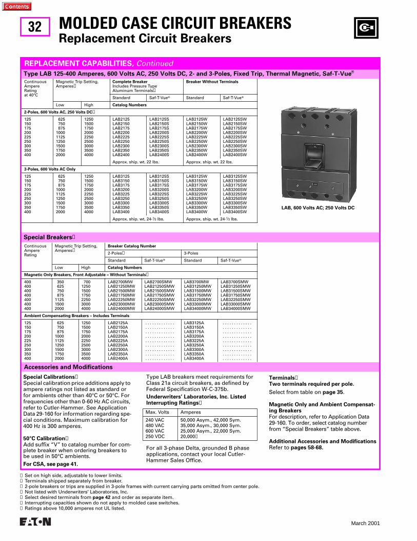
32
March 2001
ContinuousAmpereRatingat 40°C
Magnetic Trip Setting,Amperes➊
Complete BreakerIncludes Pressure Type Aluminum Terminals➋
Breaker Without Terminals
Standard Saf-T-VueT Standard Saf-T-VueT
Low High Catalog Numbers
2-Poles, 600 Volts AC, 250 Volts DC➌
125150175200225250300350400
625 750 875100011251250150017502000
125015001750200022502500300035004000
LAB2125LAB2150LAB2175LAB2200LAB2225LAB2250LAB2300LAB2350LAB2400
LAB2125SLAB2150SLAB2175SLAB2200SLAB2225SLAB2250SLAB2300SLAB2350SLAB2400S
LAB2125WLAB2150WLAB2175WLAB2200WLAB2225WLAB2250WLAB2300WLAB2350WLAB2400W
LAB2125SWLAB2150SWLAB2175SWLAB2200SWLAB2225SWLAB2250SWLAB2300SWLAB2350SWLAB2400SW
Approx. ship. wt. 22 lbs. Approx. ship. wt. 22 lbs.
3-Poles, 600 Volts AC Only
125150175200225250300350400
625 750 875100011251250150017502000
125015001750200022502500300035004000
LAB3125LAB3150LAB3175LAB3200LAB3225LAB3250LAB3300LAB3350LAB3400
LAB3125SLAB3150SLAB3175SLAB3200SLAB3225SLAB3250SLAB3300SLAB3350SLAB3400S
LAB3125WLAB3150WLAB3175WLAB3200WLAB3225WLAB3250WLAB3300WLAB3350WLAB3400W
LAB3125SWLAB3150SWLAB3175SWLAB3200SWLAB3225SWLAB3250SWLAB3300SWLAB3350SWLAB3400SW
Approx. ship. wt. 24-1⁄2 lbs. Approx. ship. wt. 24-1⁄2 lbs.
ContinuousAmpereRating
Magnetic Trip Setting,Amperes➊
Breaker Catalog Number
2-Poles➌ 3-Poles
Standard Saf-T-VueT Standard Saf-T-VueT
Low High Catalog Numbers
Magnetic Only Breakers, Front Adjustable – Without Terminals➎
400400400400400400400
350 625 750 875112515002000
700125015001750225030004000
LAB2700MWLAB21250MWLAB21500MWLAB21750MWLAB22250MWLAB23000MWLAB24000MW
LAB2700SMWLAB21250SMWLAB21500SMWLAB21750SMWLAB22250SMWLAB23000SMWLAB24000SMW
LAB3700MWLAB31250MWLAB31500MWLAB31750MWLAB32250MWLAB33000MWLAB34000MW
LAB3700SMWLAB31250SMWLAB31500SMWLAB31750SMWLAB32250SMWLAB33000SMWLAB34000SMW
Ambient Compensating Breakers – Includes Terminals
125150175200225250300350400
625 750 875100011251250150017502000
125015001750200022502500300035004000
LAB2125ALAB2150ALAB2175ALAB2200ALAB2225ALAB2250ALAB2300ALAB2350ALAB2400A
. . . . . . . . . . . . .
. . . . . . . . . . . . .
. . . . . . . . . . . . .
. . . . . . . . . . . . .
. . . . . . . . . . . . .
. . . . . . . . . . . . .
. . . . . . . . . . . . .
. . . . . . . . . . . . .
. . . . . . . . . . . . .
LAB3125ALAB3150ALAB3175ALAB3200ALAB3225ALAB3250ALAB3300ALAB3350ALAB3400A
. . . . . . . . . . . . . . . . . . . . . . . . . . . . . . . . . . . . . . . . . . . . . . . . . . . . . . . . . . . . . . . . . . . . . . . . . . . . . . . . . . . . . . . . . . . . . . . . . . . . . . . . . . . . . . . . . . . . .
MOLDED CASE CIRCUIT BREAKERSReplacement Circuit Breakers
Special Breakers➍
Accessories and Modifications
Type LAB 125-400 Amperes, 600 Volts AC, 250 Volts DC, 2- and 3-Poles, Fixed Trip, Thermal Magnetic, Saf-T-VueT
REPLACEMENT CAPABILITIES, Continued
Special Calibrations➍Special calibration price additions apply to ampere ratings not listed as standard or for ambients other than 40°C or 50°C. For frequencies other than 0-60 Hz AC circuits, refer to Cutler-Hammer. See Application Data 29-160 for information regarding spe-cial conditions. Maximum calibration for 400 Hz is 300 amperes.
50°C Calibration➍Add suffix “V” to catalog number for com-plete breaker when ordering breakers to be used in 50°C ambients.For CSA, see page 41.
Type LAB breakers meet requirements for Class 21a circuit breakers, as defined by Federal Specification W-C-375b.
For all 3-phase Delta, grounded B phase applications, contact your local Cutler-Hammer Sales Office.
Underwriters’ Laboratories, Inc. Listed Interrupting Ratings➏
Max. Volts Amperes
240 VAC480 VAC600 VAC250 VDC
50,000 Asym., 42,000 Sym.35,000 Asym., 30,000 Sym.25,000 Asym., 22,000 Sym.20,000➐
Terminals➋Two terminals required per pole.
Select from table on page 35.
Magnetic Only and Ambient Compensat-ing BreakersFor description, refer to Application Data 29-160. To order, select catalog number from “Special Breakers” table above.
Additional Accessories and ModificationsRefer to pages 58-68.
➊ Set on high side, adjustable to lower limits.➋ Terminals shipped separately from breaker.➌ 2-pole breakers or trips are supplied in 3-pole frames with current carrying parts omitted from center pole.➍ Not listed with Underwriters’ Laboratories, Inc.➎ Select desired terminals from page 42 and order as separate item.➏ Interrupting capacities shown do not apply to molded case switches.➐ Ratings above 10,000 amperes not UL listed.
LAB, 600 Volts AC; 250 Volts DC
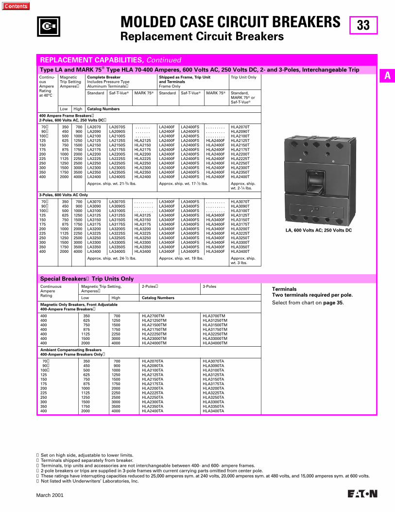
33
March 2001
AContinu-ousAmpereRatingat 40°C
Magnetic Trip SettingAmperes➊
Complete Breaker
Includes Pressure Type Aluminum Terminals➋
Shipped as Frame, Trip Unit
and Terminals
Frame Only
Trip Unit Only
Standard Saf-T-VueT MARK 75T Standard Saf-T-VueT MARK 75T Standard, MARK 75T or Saf-T-VueT
Low High Catalog Numbers
400 Ampere Frame Breakers➌2-Poles, 600 Volts AC, 250 Volts DC➍
70➎ 90➎100➎125150175200225250300350400
350 450 500 625 750 875100011251250150017502000
700 9001000125015001750200022502500300035004000
LA2070LA2090LA2100LA2125LA2150LA2175LA2200LA2225LA2250LA2300LA2350LA2400
LA2070SLA2090SLA2100SLA2125SLA2150SLA2175SLA2200SLA2225SLA2250SLA2300SLA2350SLA2400S
. . . . . . . . . . . . . . . . . . . . . HLA2125HLA2150HLA2175HLA2200HLA2225HLA2250HLA2300HLA2350HLA2400
LA2400FLA2400FLA2400FLA2400FLA2400FLA2400FLA2400FLA2400FLA2400FLA2400FLA2400FLA2400F
LA2400FSLA2400FSLA2400FSLA2400FSLA2400FSLA2400FSLA2400FSLA2400FSLA2400FSLA2400FSLA2400FSLA2400FS
. . . . . . . . .
. . . . . . . . .
. . . . . . . . .HLA2400FHLA2400FHLA2400FHLA2400FHLA2400FHLA2400FHLA2400FHLA2400FHLA2400F
HLA2070THLA2090THLA2100THLA2125THLA2150THLA2175THLA2200THLA2225THLA2250THLA2300THLA2350THLA2400T
Approx. ship. wt. 21-3⁄4 lbs. Approx. ship. wt. 17-1⁄2 lbs. Approx. ship. wt. 2-1⁄4 lbs.
3-Poles, 600 Volts AC Only
70➎ 90➎100➎125150175200225250300350400
350 450 500 625 750 875100011251250150017502000
700 9001000125015001750200022502500300035004000
LA3070LA3090LA3100LA3125LA3150LA3175LA3200LA3225LA3250LA3300LA3350LA3400
LA3070SLA3090SLA3100SLA3125SLA3150SLA3175SLA3200SLA3225SLA3250SLA3300SLA3350SLA3400S
. . . . . . . . .
. . . . . . . . .
. . . . . . . . .HLA3125HLA3150HLA3175HLA3200HLA3225HLA3250HLA3300HLA3350HLA3400
LA3400FLA3400FLA3400FLA3400FLA3400FLA3400FLA3400FLA3400FLA3400FLA3400FLA3400FLA3400F
LA3400FSLA3400FSLA3400FSLA3400FSLA3400FSLA3400FSLA3400FSLA3400FSLA3400FSLA3400FSLA3400FSLA3400FS
. . . . . . . . .
. . . . . . . . .
. . . . . . . . .HLA3400FHLA3400FHLA3400FHLA3400FHLA3400FHLA3400FHLA3400FHLA3400FHLA3400F
HLA3070THLA3090THLA3100THLA3125THLA3150THLA3175THLA3200THLA3225THLA3250THLA3300THLA3350THLA3400T
Approx. ship. wt. 24-1⁄2 lbs. Approx. ship. wt. 19 lbs. Approx. ship. wt. 3 lbs.
Type LA and MARK 75T Type HLA 70-400 Amperes, 600 Volts AC, 250 Volts DC, 2- and 3-Poles, Interchangeable Trip
Special Breakers➏ Trip Units Only
MOLDED CASE CIRCUIT BREAKERSReplacement Circuit Breakers
REPLACEMENT CAPABILITIES, Continued
➊ Set on high side, adjustable to lower limits.➋ Terminals shipped separately from breaker.➌ Terminals, trip units and accessories are not interchangeable between 400- and 600- ampere frames.➍ 2-pole breakers or trips are supplied in 3-pole frames with current carrying parts omitted from center pole.➎ These ratings have interrupting capacities reduced to 25,000 amperes sym. at 240 volts, 20,000 amperes sym. at 480 volts, and 15,000 amperes sym. at 600 volts.➏ Not listed with Underwriters’ Laboratories, Inc.
ContinuousAmpereRating
Magnetic Trip Setting,Amperes➊
2-Poles➍ 3-Poles
Low High Catalog Numbers
Magnetic Only Breakers, Front Adjustable
400-Ampere Frame Breakers➌
400400400400400400400
350 625 750 875112515002000
700125015001750225030004000
HLA2700TMHLA21250TMHLA21500TMHLA21750TMHLA22250TMHLA23000TMHLA24000TM
HLA3700TMHLA31250TMHLA31500TMHLA31750TMHLA32250TMHLA33000TMHLA34000TM
Ambient Compensating Breakers
400-Ampere Frame Breakers Only➌
70➎ 90➎100➎125150175200225250300350400
350 450 500 625 750 875100011251250150017502000
700 9001000125015001750200022502500300035004000
HLA2070TAHLA2090TAHLA2100TAHLA2125TAHLA2150TAHLA2175TAHLA2200TAHLA2225TAHLA2250TAHLA2300TAHLA2350TAHLA2400TA
HLA3070TAHLA3090TAHLA3100TAHLA3125TAHLA3150TAHLA3175TAHLA3200TAHLA3225TAHLA3250TAHLA3300TAHLA3350TAHLA3400TA
LA, 600 Volts AC; 250 Volts DC
TerminalsTwo terminals required per pole.
Select from chart on page 35.
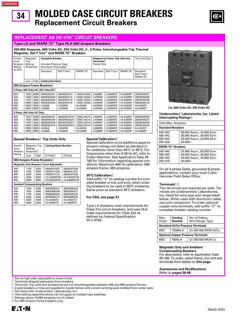
34
March 2001
MOLDED CASE CIRCUIT BREAKERSReplacement Circuit Breakers
Contin-uousAmpereRatingat 40°C
Magnetic Trip Setting,Amperes➊
Complete Breaker
Includes Pressure Type Aluminum Terminals➋
Shipped as Frame, Trip Unit and
Terminals➋Frame Only
Trip Unit Only
Standard Saf-T-VueT MARK 75T Standard Saf-T-VueT MARK 75T StandardSaf-T-VueTMARK 75T
Low High Catalog Numbers
600 Ampere Frame Breakers➌
2-Poles, 600 Volts AC, 250 Volts DC➍
250300350400500600
125015001750200025003000
250030003500400050006000
2603D50G012603D50G022603D50G032603D50G04LA2500LA2600
2603D50G132603D50G142603D50G152603D50G16LA2500SLA2600S
1256C10G021256C10G031256C10G041256C10G05HLA2500HLA2600
LA2600FLA2600FLA2600FLA2600FLA2600FLA2600F
LA2600FSLA2600FSLA2600FSLA2600FSLA2600FSLA2600FS
HLA2600FHLA2600FHLA2600FHLA2600FHLA2600FHLA2600F
2603D46G072603D46G082603D46G092603D46G10HLA2500THLA2600T
3-Poles, 600 Volts AC Only
250300350400500600
125015001750200025003000
250030003500400050006000
2603D50G072603D50G082603D50G092603D50G10LA3500LA3600
2603D50G0192603D50G0202603D50G0212603D50G022LA3500SLA3600S
1256C10G121256C10G131256C10G141256C10G15HLA3500HLA3600
LA3600FLA3600FLA3600FLA3600FLA3600FLA3600F
LA3600FSLA3600FSLA3600FSLA3600FSLA3600FSLA3600FS
HLA3600FHLA3600FHLA3600FHLA3600FHLA3600FHLA3600F
2603D46G262603D46G272603D46G282603D46G29HLA3500THLA3600T
Type LA and MARK 75T Type HLA 600 Ampere Breakers
REPLACEMENT AB DE-IONT CIRCUIT BREAKERS
250-600 Amperes, 600 Volts AC, 250 Volts DC, 2-, 3-Poles, Interchangeable Trip Thermal Magnetic, Saf-T-VueT and MARK 75T Breakers
➊ Set on high side, adjustable to lower limits.➋ Terminals shipped separately from breakers.➌ Terminals, trip units and accessories are not interchangeable between 400 and 600 ampere frames.➍ 2-pole breakers or trips are supplied in 3-pole frames with current carrying parts omitted from center pole.➎ Not listed with Underwriters’ Laboratories, Inc.➏ Interrupting capacities shown do not apply to molded case switches.➐ Ratings above 10,000 amperes not UL listed.➑ For 600 ampere frame breakers only.
Special Breakers➎ Trip Units Only
Contin-uousAmpereRating
Magnetic Trip Setting,Amperes➊
Catalog/Style Number
Low High 2-Poles➍ 3-Poles
600 Ampere Frame Breakers➌
Magnetic Only Breakers, Front Adjustable
600600600600600
11251500200025003000
22503000400050006000
2603D47G072603D47G082603D47G10HLA25000TMHLA26000TM
2603D47G262603D47G272603D47G29HLA35000TMHLA36000TM
Ambient Compensating Breakers
250300350400500600
125015001750200025003000
250030003500400050006000
5683D88G075683D88G085683D88G095683D88G10HLA2500TAHLA2600TA
5683D88G265683D88G275683D88G285683D88G29HLA3500TAHLA3600TA
Special Calibration➎Special calibration price additions apply to ampere ratings not listed as standard or for ambients other than 40°C or 50°C. For frequencies other than 0-60 Hz AC, refer to Cutler-Hammer. See Application Data 29-160 for information regarding special con-ditions. Maximum 400 Hz calibration: 600 ampere frame, 450 amperes.
50°C Calibration➎Add suffix “V” to catalog number for com-plete breaker or trip unit only, when order-ing breakers to be used in 50°C ambients. Same price as standard 40°C breakers.
For CSA, see page 41.
Type LA breakers meet requirements for Class 21a circuit breakers, and type HLA meet requirements for Class 23a as defined by Federal Specification W-C-375b.
On all 3-phase Delta, grounded B phase applications, contact your local Cutler-Hammer Field Sales Office.
Terminals➋➌Two terminals are required per pole. Ter-minals are Underwriters’ Laboratories, Inc. listed for wire type and range listed below. When used with aluminum cable, use joint compound. To order optional copper only terminals, add suffix “C” to complete breaker catalog number.
Magnetic Only and Ambient Compensating BreakersFor description, refer to Application Data 29-160. To order, select frame, trip unit and terminals from tables on this page.
Accessories and ModificationsRefer to pages 58-68.
Underwriters’ Laboratories, Inc. Listed Interrupting Ratings➏
Volts Max. Amperes
Standard Breakers
240 VAC480 VAC600 VAC250 VDC
50,000 Asym., 42,000 Sym.35,000 Asym., 30,000 Sym.25,000 Asym., 22,000 Sym.20,000➐
MARK 75T Breakers
240 VAC480 VAC600 VAC250 VDC
75,000 Asym., 65,000 Sym.40,000 Asym., 35,000 Sym.30,000 Asym., 25,000 Sym.20,000➐
Max.Amps
CatalogNumber
No. of Cables,Wire Range, Type
Standard Al/Cu Pressure Terminals
600➑ TA600LA (2) 250-500 MCM Al/Cu
Optional Copper Pressure Terminals
600➑ T600LA (2) 250-500 MCM Cu
LA, 600 Volts AC; 250 Volts DC
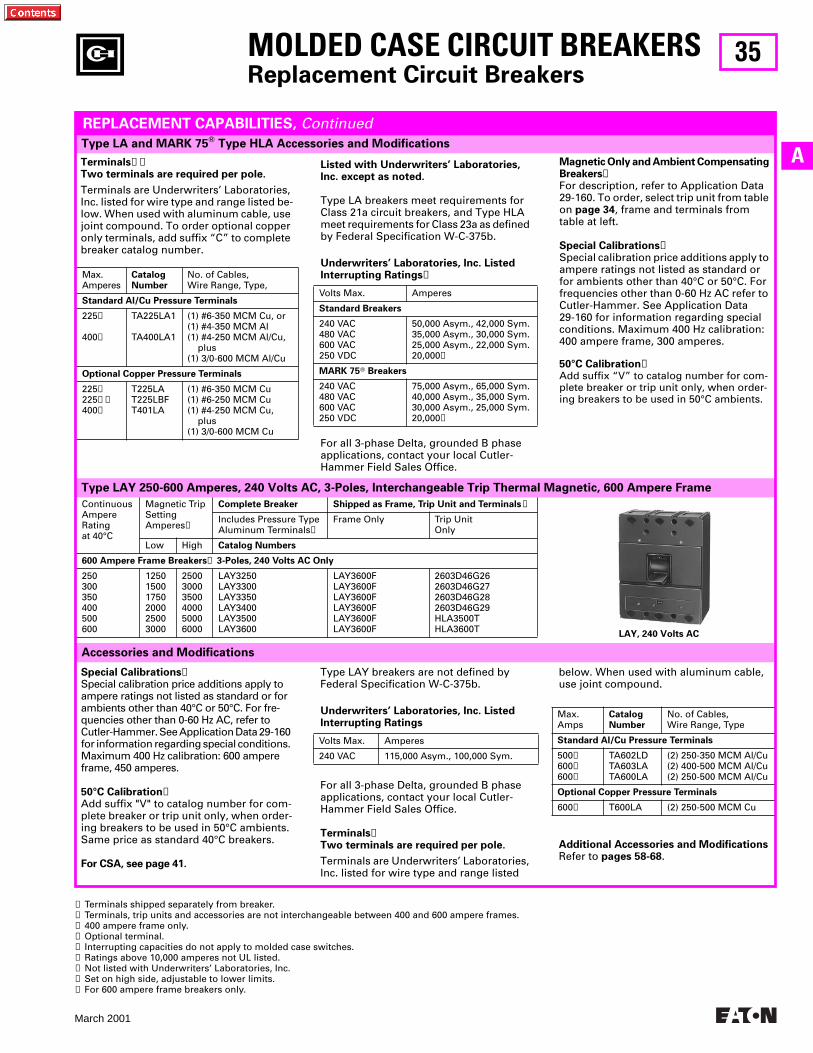
35
March 2001
A
ContinuousAmpereRatingat 40°C
Magnetic TripSettingAmperes➑
Complete Breaker Shipped as Frame, Trip Unit and Terminals➒
Includes Pressure TypeAluminum Terminals➊
Frame Only Trip UnitOnly
Low High Catalog Numbers
600 Ampere Frame Breakers➍ 3-Poles, 240 Volts AC Only
250300350400500600
125015001750200025003000
250030003500400050006000
LAY3250LAY3300LAY3350LAY3400LAY3500LAY3600
LAY3600FLAY3600FLAY3600FLAY3600FLAY3600FLAY3600F
2603D46G262603D46G272603D46G282603D46G29HLA3500THLA3600T
MOLDED CASE CIRCUIT BREAKERSReplacement Circuit Breakers
➊ Terminals shipped separately from breaker.➋ Terminals, trip units and accessories are not interchangeable between 400 and 600 ampere frames.➌ 400 ampere frame only.➍ Optional terminal.➎ Interrupting capacities do not apply to molded case switches.➏ Ratings above 10,000 amperes not UL listed.➐ Not listed with Underwriters’ Laboratories, Inc.➑ Set on high side, adjustable to lower limits.➒ For 600 ampere frame breakers only.
Listed with Underwriters’ Laboratories, Inc. except as noted.
Type LA breakers meet requirements for Class 21a circuit breakers, and Type HLA meet requirements for Class 23a as defined by Federal Specification W-C-375b.
For all 3-phase Delta, grounded B phase applications, contact your local Cutler-Hammer Field Sales Office.
Underwriters’ Laboratories, Inc. Listed Interrupting Ratings➎
Volts Max. Amperes
Standard Breakers
240 VAC480 VAC600 VAC250 VDC
50,000 Asym., 42,000 Sym.35,000 Asym., 30,000 Sym.25,000 Asym., 22,000 Sym.20,000➏
MARK 75T Breakers
240 VAC480 VAC600 VAC250 VDC
75,000 Asym., 65,000 Sym.40,000 Asym., 35,000 Sym.30,000 Asym., 25,000 Sym.20,000➏
Terminals➊➋Two terminals are required per pole.
Terminals are Underwriters’ Laboratories, Inc. listed for wire type and range listed be-low. When used with aluminum cable, use joint compound. To order optional copper only terminals, add suffix “C” to complete breaker catalog number.
Max.Amperes
CatalogNumber
No. of Cables,Wire Range, Type,
Standard Al/Cu Pressure Terminals
225➌
400➌
TA225LA1
TA400LA1
(1) #6-350 MCM Cu, or(1) #4-350 MCM Al(1) #4-250 MCM Al/Cu, plus(1) 3/0-600 MCM Al/Cu
Optional Copper Pressure Terminals
225➌225➌➍400➌
T225LAT225LBFT401LA
(1) #6-350 MCM Cu(1) #6-250 MCM Cu(1) #4-250 MCM Cu, plus(1) 3/0-600 MCM Cu
Type LA and MARK 75T Type HLA Accessories and Modifications
REPLACEMENT CAPABILITIES, Continued
Magnetic Only and Ambient Compensating Breakers➐For description, refer to Application Data 29-160. To order, select trip unit from table on page 34, frame and terminals from table at left.
Special Calibrations➐Special calibration price additions apply to ampere ratings not listed as standard or for ambients other than 40°C or 50°C. For frequencies other than 0-60 Hz AC refer to Cutler-Hammer. See Application Data 29-160 for information regarding special conditions. Maximum 400 Hz calibration: 400 ampere frame, 300 amperes.
50°C Calibration➐Add suffix “V” to catalog number for com-plete breaker or trip unit only, when order-ing breakers to be used in 50°C ambients.
Accessories and Modifications
Type LAY 250-600 Amperes, 240 Volts AC, 3-Poles, Interchangeable Trip Thermal Magnetic, 600 Ampere Frame
Special Calibrations➐Special calibration price additions apply to ampere ratings not listed as standard or for ambients other than 40°C or 50°C. For fre-quencies other than 0-60 Hz AC, refer to Cutler-Hammer. See Application Data 29-160 for information regarding special conditions. Maximum 400 Hz calibration: 600 ampere frame, 450 amperes.
50°C Calibration➐Add suffix "V" to catalog number for com-plete breaker or trip unit only, when order-ing breakers to be used in 50°C ambients. Same price as standard 40°C breakers.
For CSA, see page 41.
Type LAY breakers are not defined by Federal Specification W-C-375b.
For all 3-phase Delta, grounded B phase applications, contact your local Cutler-Hammer Field Sales Office.
Terminals➊Two terminals are required per pole.
Terminals are Underwriters’ Laboratories, Inc. listed for wire type and range listed
Underwriters’ Laboratories, Inc. ListedInterrupting Ratings
Volts Max. Amperes
240 VAC 115,000 Asym., 100,000 Sym.
below. When used with aluminum cable, use joint compound.
Additional Accessories and ModificationsRefer to pages 58-68.
Max.Amps
CatalogNumber
No. of Cables,Wire Range, Type
Standard Al/Cu Pressure Terminals
500➒600➒600➒
TA602LDTA603LATA600LA
(2) 250-350 MCM Al/Cu(2) 400-500 MCM Al/Cu(2) 250-500 MCM Al/Cu
Optional Copper Pressure Terminals
600➐ T600LA (2) 250-500 MCM Cu
LAY, 240 Volts AC
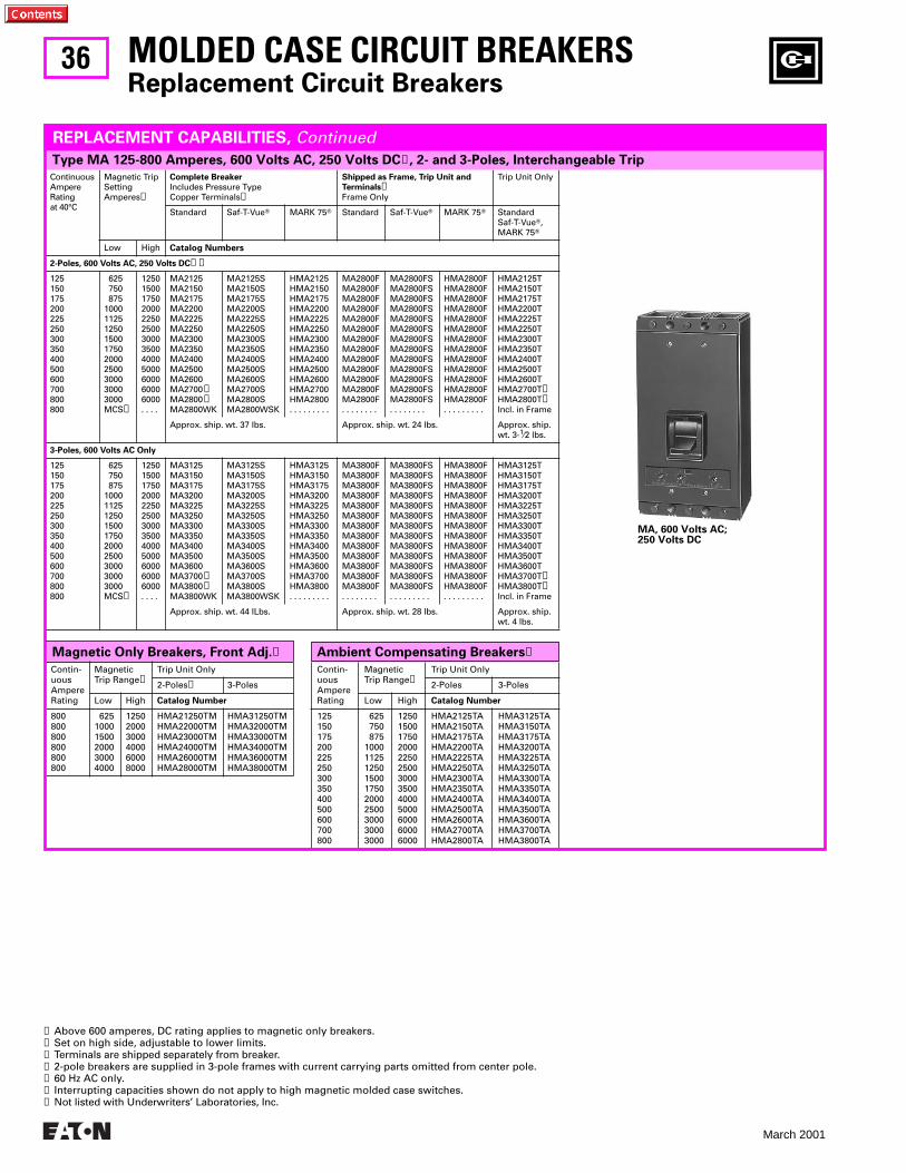
36
March 2001
Ambient Compensating Breakers➐Magnetic Only Breakers, Front Adj.➐
Contin-uousAmpereRating
Magnetic Trip Range➋
Trip Unit Only
2-Poles 3-Poles
Low High Catalog Number
125150175200225250300350400500600700800
625 750 8751000112512501500175020002500300030003000
1250150017502000225025003000350040005000600060006000
HMA2125TAHMA2150TAHMA2175TAHMA2200TAHMA2225TAHMA2250TAHMA2300TAHMA2350TAHMA2400TAHMA2500TAHMA2600TAHMA2700TAHMA2800TA
HMA3125TAHMA3150TAHMA3175TAHMA3200TAHMA3225TAHMA3250TAHMA3300TAHMA3350TAHMA3400TAHMA3500TAHMA3600TAHMA3700TAHMA3800TA
Contin-uousAmpereRating
MagneticTrip Range➋
Trip Unit Only
2-Poles➍ 3-Poles
Low High Catalog Number
800800800800800800
62510001500200030004000
125020003000400060008000
HMA21250TMHMA22000TMHMA23000TMHMA24000TMHMA26000TMHMA28000TM
HMA31250TMHMA32000TMHMA33000TMHMA34000TMHMA36000TMHMA38000TM
ContinuousAmpereRatingat 40°C
Magnetic TripSettingAmperes➋
Complete Breaker
Includes Pressure Type Copper Terminals➌
Shipped as Frame, Trip Unit and
Terminals➌Frame Only
Trip Unit Only
Standard Saf-T-VueT MARK 75T Standard Saf-T-VueT MARK 75T StandardSaf-T-VueT,MARK 75T
Low High Catalog Numbers
2-Poles, 600 Volts AC, 250 Volts DC➊➍
125150175200225250300350400500600700800800
625 750 8751000112512501500175020002500300030003000MCS➏
1250150017502000225025003000350040005000600060006000. . . .
MA2125MA2150MA2175MA2200MA2225MA2250MA2300MA2350MA2400MA2500MA2600MA2700➎MA2800➎MA2800WK
MA2125SMA2150SMA2175SMA2200SMA2225SMA2250SMA2300SMA2350SMA2400SMA2500SMA2600SMA2700SMA2800SMA2800WSK
HMA2125HMA2150HMA2175HMA2200HMA2225HMA2250HMA2300HMA2350HMA2400HMA2500HMA2600HMA2700HMA2800. . . . . . . . .
MA2800FMA2800FMA2800FMA2800FMA2800FMA2800FMA2800FMA2800FMA2800FMA2800FMA2800FMA2800FMA2800F. . . . . . . .
MA2800FSMA2800FSMA2800FSMA2800FSMA2800FSMA2800FSMA2800FSMA2800FSMA2800FSMA2800FSMA2800FSMA2800FSMA2800FS. . . . . . . .
HMA2800FHMA2800FHMA2800FHMA2800FHMA2800FHMA2800FHMA2800FHMA2800FHMA2800FHMA2800FHMA2800FHMA2800FHMA2800F. . . . . . . . .
HMA2125THMA2150THMA2175THMA2200THMA2225THMA2250THMA2300THMA2350THMA2400THMA2500THMA2600THMA2700T➎HMA2800T➎Incl. in Frame
Approx. ship. wt. 37 lbs. Approx. ship. wt. 24 lbs. Approx. ship.wt. 3-1⁄2 lbs.
3-Poles, 600 Volts AC Only
125150175200225250300350400500600700800800
625 750 8751000112512501500175020002500300030003000MCS➏
1250150017502000225025003000350040005000600060006000. . . .
MA3125MA3150MA3175MA3200MA3225MA3250MA3300MA3350MA3400MA3500MA3600MA3700➎MA3800➎MA3800WK
MA3125SMA3150SMA3175SMA3200SMA3225SMA3250SMA3300SMA3350SMA3400SMA3500SMA3600SMA3700SMA3800SMA3800WSK
HMA3125HMA3150HMA3175HMA3200HMA3225HMA3250HMA3300HMA3350HMA3400HMA3500HMA3600HMA3700HMA3800. . . . . . . . .
MA3800FMA3800FMA3800FMA3800FMA3800FMA3800FMA3800FMA3800FMA3800FMA3800FMA3800FMA3800FMA3800F. . . . . . . .
MA3800FSMA3800FSMA3800FSMA3800FSMA3800FSMA3800FSMA3800FSMA3800FSMA3800FSMA3800FSMA3800FSMA3800FSMA3800FS. . . . . . . . .
HMA3800FHMA3800FHMA3800FHMA3800FHMA3800FHMA3800FHMA3800FHMA3800FHMA3800FHMA3800FHMA3800FHMA3800FHMA3800F. . . . . . . . .
HMA3125THMA3150THMA3175THMA3200THMA3225THMA3250THMA3300THMA3350THMA3400THMA3500THMA3600THMA3700T➎HMA3800T➎Incl. in Frame
Approx. ship. wt. 44 lLbs. Approx. ship. wt. 28 lbs. Approx. ship.wt. 4 lbs.
Type MA 125-800 Amperes, 600 Volts AC, 250 Volts DC➊, 2- and 3-Poles, Interchangeable Trip
MOLDED CASE CIRCUIT BREAKERSReplacement Circuit Breakers
REPLACEMENT CAPABILITIES, Continued
➊ Above 600 amperes, DC rating applies to magnetic only breakers.➋ Set on high side, adjustable to lower limits.➌ Terminals are shipped separately from breaker.➍ 2-pole breakers are supplied in 3-pole frames with current carrying parts omitted from center pole.➎ 60 Hz AC only.➏ Interrupting capacities shown do not apply to high magnetic molded case switches.➐ Not listed with Underwriters’ Laboratories, Inc.
MA, 600 Volts AC; 250 Volts DC
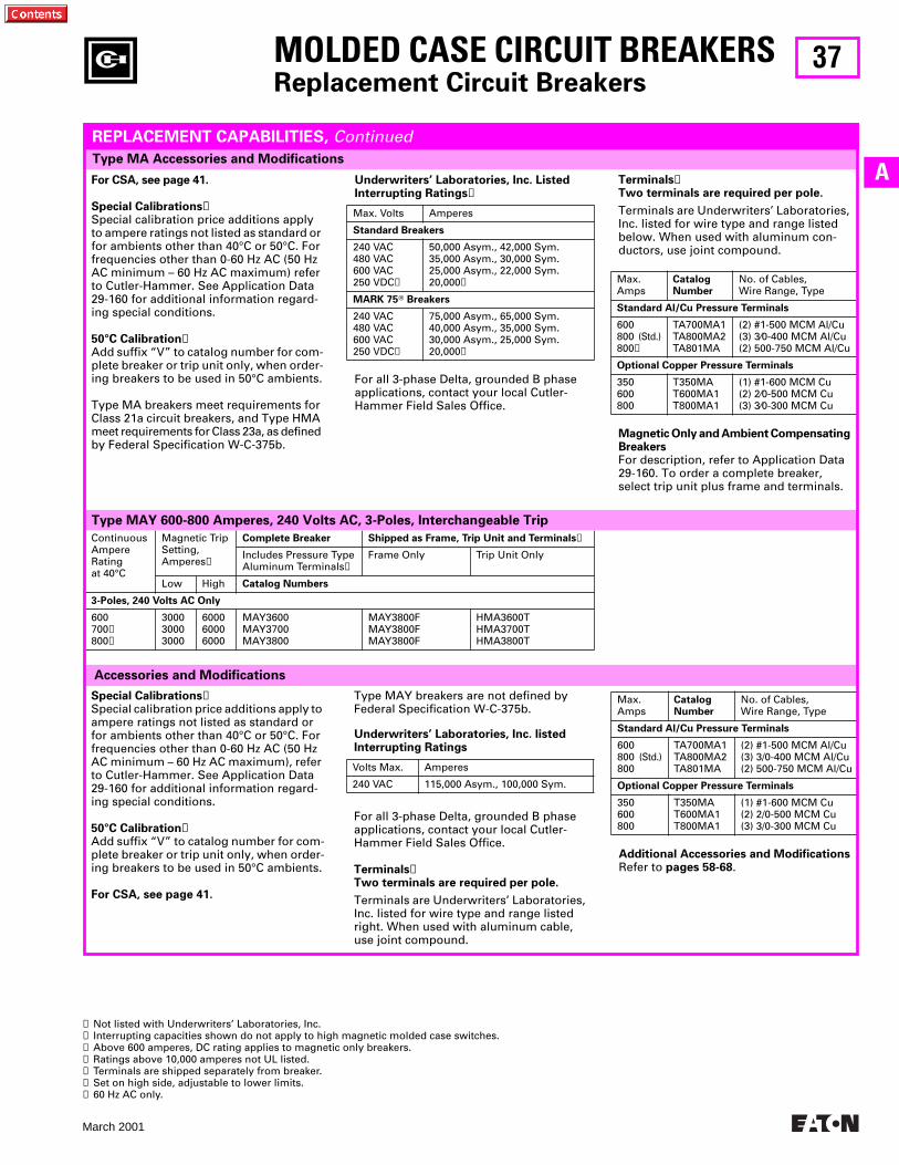
37
March 2001
A
MOLDED CASE CIRCUIT BREAKERSReplacement Circuit Breakers
Type MA Accessories and Modifications
ContinuousAmpereRatingat 40°C
Magnetic TripSetting,Amperes➏
Complete Breaker Shipped as Frame, Trip Unit and Terminals➎
Includes Pressure TypeAluminum Terminals➎
Frame Only Trip Unit Only
Low High Catalog Numbers
3-Poles, 240 Volts AC Only
600700➐800➐
300030003000
600060006000
MAY3600MAY3700MAY3800
MAY3800FMAY3800FMAY3800F
HMA3600THMA3700THMA3800T
Type MAY 600-800 Amperes, 240 Volts AC, 3-Poles, Interchangeable Trip
Accessories and Modifications
For CSA, see page 41.
Special Calibrations➊Special calibration price additions apply to ampere ratings not listed as standard or for ambients other than 40°C or 50°C. For frequencies other than 0-60 Hz AC (50 Hz AC minimum – 60 Hz AC maximum) refer to Cutler-Hammer. See Application Data 29-160 for additional information regard-ing special conditions.
50°C Calibration➊Add suffix “V” to catalog number for com-plete breaker or trip unit only, when order-ing breakers to be used in 50°C ambients.
Type MA breakers meet requirements for Class 21a circuit breakers, and Type HMA meet requirements for Class 23a, as defined by Federal Specification W-C-375b.
REPLACEMENT CAPABILITIES, Continued
For all 3-phase Delta, grounded B phase applications, contact your local Cutler-Hammer Field Sales Office.
Underwriters’ Laboratories, Inc. Listed Interrupting Ratings➋
Max. Volts Amperes
Standard Breakers
240 VAC480 VAC600 VAC250 VDC➌
50,000 Asym., 42,000 Sym.35,000 Asym., 30,000 Sym.25,000 Asym., 22,000 Sym.20,000➍
MARK 75T Breakers
240 VAC480 VAC600 VAC250 VDC➌
75,000 Asym., 65,000 Sym.40,000 Asym., 35,000 Sym.30,000 Asym., 25,000 Sym.20,000➍
Terminals➎Two terminals are required per pole.
Terminals are Underwriters’ Laboratories, Inc. listed for wire type and range listed below. When used with aluminum con-ductors, use joint compound.
Magnetic Only and Ambient Compensating BreakersFor description, refer to Application Data 29-160. To order a complete breaker, select trip unit plus frame and terminals.
Max.Amps
CatalogNumber
No. of Cables,Wire Range, Type
Standard Al/Cu Pressure Terminals
600800 (Std.)800➊
TA700MA1TA800MA2TA801MA
(2) #1-500 MCM Al/Cu(3) 3⁄0-400 MCM Al/Cu(2) 500-750 MCM Al/Cu
Optional Copper Pressure Terminals
350600800
T350MAT600MA1T800MA1
(1) #1-600 MCM Cu(2) 2⁄0-500 MCM Cu(3) 3⁄0-300 MCM Cu
Special Calibrations➊Special calibration price additions apply to ampere ratings not listed as standard or for ambients other than 40°C or 50°C. For frequencies other than 0-60 Hz AC (50 Hz AC minimum – 60 Hz AC maximum), refer to Cutler-Hammer. See Application Data 29-160 for additional information regard-ing special conditions.
50°C Calibration➊Add suffix “V” to catalog number for com-plete breaker or trip unit only, when order-ing breakers to be used in 50°C ambients.
For CSA, see page 41.
Type MAY breakers are not defined by Federal Specification W-C-375b.
For all 3-phase Delta, grounded B phase applications, contact your local Cutler-Hammer Field Sales Office.
Terminals➎Two terminals are required per pole.
Terminals are Underwriters’ Laboratories, Inc. listed for wire type and range listed right. When used with aluminum cable, use joint compound.
Underwriters’ Laboratories, Inc. listedInterrupting Ratings
Volts Max. Amperes
240 VAC 115,000 Asym., 100,000 Sym.
Additional Accessories and ModificationsRefer to pages 58-68.
Max.Amps
CatalogNumber
No. of Cables,Wire Range, Type
Standard Al/Cu Pressure Terminals
600800 (Std.)800
TA700MA1TA800MA2TA801MA
(2) #1-500 MCM Al/Cu(3) 3/0-400 MCM Al/Cu(2) 500-750 MCM Al/Cu
Optional Copper Pressure Terminals
350600800
T350MAT600MA1T800MA1
(1) #1-600 MCM Cu(2) 2/0-500 MCM Cu(3) 3/0-300 MCM Cu
➊ Not listed with Underwriters’ Laboratories, Inc.➋ Interrupting capacities shown do not apply to high magnetic molded case switches.➌ Above 600 amperes, DC rating applies to magnetic only breakers.➍ Ratings above 10,000 amperes not UL listed.➎ Terminals are shipped separately from breaker.➏ Set on high side, adjustable to lower limits.➐ 60 Hz AC only.
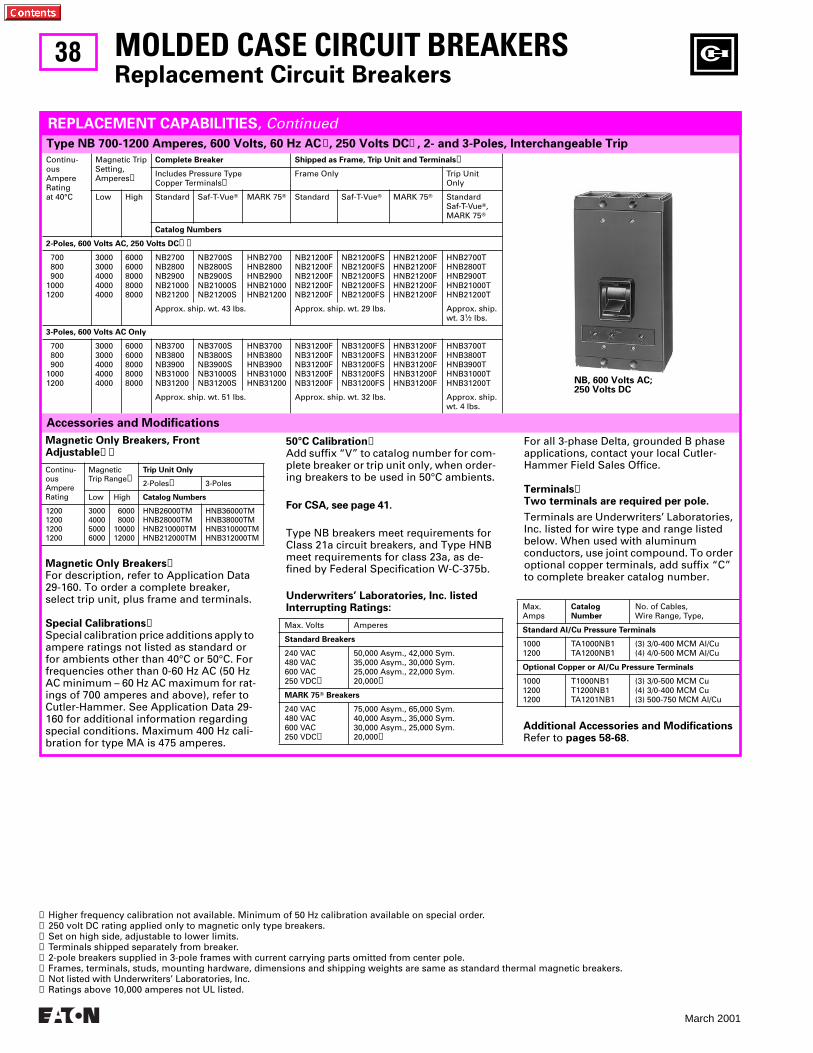
38
March 2001
MOLDED CASE CIRCUIT BREAKERSReplacement Circuit Breakers
Continu-ousAmpereRatingat 40°C
Magnetic TripSetting,Amperes➌
Complete Breaker Shipped as Frame, Trip Unit and Terminals➍
Includes Pressure TypeCopper Terminals➍
Frame Only Trip UnitOnly
Low High Standard Saf-T-VueT MARK 75T Standard Saf-T-VueT MARK 75T StandardSaf-T-VueT,MARK 75T
Catalog Numbers
2-Poles, 600 Volts AC, 250 Volts DC➋➎
700 800 90010001200
30003000400040004000
60006000800080008000
NB2700NB2800NB2900NB21000NB21200
NB2700SNB2800SNB2900SNB21000SNB21200S
HNB2700HNB2800HNB2900HNB21000HNB21200
NB21200FNB21200FNB21200FNB21200FNB21200F
NB21200FSNB21200FSNB21200FSNB21200FSNB21200FS
HNB21200FHNB21200FHNB21200FHNB21200FHNB21200F
HNB2700THNB2800THNB2900THNB21000THNB21200T
Approx. ship. wt. 43 lbs. Approx. ship. wt. 29 lbs. Approx. ship.wt. 31⁄2 lbs.
3-Poles, 600 Volts AC Only
700 800 90010001200
30003000400040004000
60006000800080008000
NB3700NB3800NB3900NB31000NB31200
NB3700SNB3800SNB3900SNB31000SNB31200S
HNB3700HNB3800HNB3900HNB31000HNB31200
NB31200FNB31200FNB31200FNB31200FNB31200F
NB31200FSNB31200FSNB31200FSNB31200FSNB31200FS
HNB31200FHNB31200FHNB31200FHNB31200FHNB31200F
HNB3700THNB3800THNB3900THNB31000THNB31200T
Approx. ship. wt. 51 lbs. Approx. ship. wt. 32 lbs. Approx. ship.wt. 4 lbs.
Accessories and Modifications
Type NB 700-1200 Amperes, 600 Volts, 60 Hz AC➊, 250 Volts DC➋, 2- and 3-Poles, Interchangeable Trip
REPLACEMENT CAPABILITIES, Continued
Magnetic Only Breakers➐For description, refer to Application Data 29-160. To order a complete breaker, select trip unit, plus frame and terminals.
Special Calibrations➐Special calibration price additions apply to ampere ratings not listed as standard or for ambients other than 40°C or 50°C. For frequencies other than 0-60 Hz AC (50 Hz AC minimum – 60 Hz AC maximum for rat-ings of 700 amperes and above), refer to Cutler-Hammer. See Application Data 29-160 for additional information regarding special conditions. Maximum 400 Hz cali-bration for type MA is 475 amperes.
Magnetic Only Breakers, FrontAdjustable➏➐
Continu-ousAmpereRating
MagneticTrip Range➌
Trip Unit Only
2-Poles➎ 3-Poles
Low High Catalog Numbers
1200120012001200
3000400050006000
6000 80001000012000
HNB26000TMHNB28000TMHNB210000TMHNB212000TM
HNB36000TMHNB38000TMHNB310000TMHNB312000TM
50°C Calibration➐Add suffix “V” to catalog number for com-plete breaker or trip unit only, when order-ing breakers to be used in 50°C ambients.
For CSA, see page 41.
Type NB breakers meet requirements for Class 21a circuit breakers, and Type HNB meet requirements for class 23a, as de-fined by Federal Specification W-C-375b.
Underwriters’ Laboratories, Inc. listedInterrupting Ratings:
Max. Volts Amperes
Standard Breakers
240 VAC480 VAC600 VAC250 VDC➍
50,000 Asym., 42,000 Sym.35,000 Asym., 30,000 Sym.25,000 Asym., 22,000 Sym.20,000➑
MARK 75T Breakers
240 VAC480 VAC600 VAC250 VDC➍
75,000 Asym., 65,000 Sym.40,000 Asym., 35,000 Sym.30,000 Asym., 25,000 Sym.20,000➑
For all 3-phase Delta, grounded B phase applications, contact your local Cutler-Hammer Field Sales Office.
Terminals➏Two terminals are required per pole.
Terminals are Underwriters’ Laboratories, Inc. listed for wire type and range listed below. When used with aluminum conductors, use joint compound. To order optional copper terminals, add suffix “C” to complete breaker catalog number.
Max.Amps
Catalog
Number
No. of Cables,Wire Range, Type,
Standard Al/Cu Pressure Terminals
10001200
TA1000NB1TA1200NB1
(3) 3/0-400 MCM Al/Cu(4) 4/0-500 MCM Al/Cu
Optional Copper or Al/Cu Pressure Terminals
100012001200
T1000NB1T1200NB1TA1201NB1
(3) 3/0-500 MCM Cu(4) 3/0-400 MCM Cu(3) 500-750 MCM Al/Cu
➊ Higher frequency calibration not available. Minimum of 50 Hz calibration available on special order.➋ 250 volt DC rating applied only to magnetic only type breakers.➌ Set on high side, adjustable to lower limits.➍ Terminals shipped separately from breaker.➎ 2-pole breakers supplied in 3-pole frames with current carrying parts omitted from center pole. ➏ Frames, terminals, studs, mounting hardware, dimensions and shipping weights are same as standard thermal magnetic breakers.➐ Not listed with Underwriters’ Laboratories, Inc.➑ Ratings above 10,000 amperes not UL listed.
NB, 600 Volts AC; 250 Volts DC
Additional Accessories and ModificationsRefer to pages 58-68.
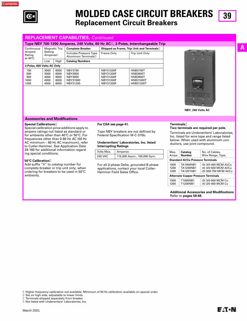
39
March 2001
AContinuousAmpereRatingat 40°C
Magnetic TripSettingAmperes➋
Complete Breaker Shipped as Frame, Trip Unit and Terminals➌
Includes Pressure TypeAluminum Terminals➌
Frame Only Trip Unit Only
Low High Catalog Numbers
3-Poles, 600 Volts AC Only
700 800 90010001200
30003000400040004000
60006000800080008000
NBY3700NBY3800NBY3900NBY31000NBY31200
NBY31200FNBY31200FNBY31200FNBY31200FNBY31200F
HNB3700THNB3800THNB3900THNB31000THNB31200T
Accessories and Modifications
MOLDED CASE CIRCUIT BREAKERSReplacement Circuit Breakers
Type NBY 700-1200 Amperes, 240 Volts, 60 Hz AC➊, 3-Poles, Interchangeable Trip
REPLACEMENT CAPABILITIES, Continued
Special Calibrations➍Special calibration price additions apply to ampere ratings not listed as standard or for ambients other than 40°C or 50°C. For frequencies other than 0-60 Hz AC (50 Hz AC minimum – 60 Hz AC maximum), refer to Cutler-Hammer. See Application Data 29-160 for additional information regard-ing special conditions.
50°C Calibration➍Add suffix “V” to catalog number for complete breaker or trip unit only, when ordering for breakers to be used in 50°C ambients.
For CSA see page 41.
Type NBY breakers are not defined byFederal Specification W-C-375b.
For all 3-phase Delta, grounded B phase applications, contact your local Cutler-Hammer Field Sales Office.
Underwriters’ Laboratories, Inc. listedInterrupting Ratings
Volts Max. Amperes
240 VAC 115,000 Asym., 100,000 Sym.
Terminals➌Two terminals are required per pole.
Terminals are Underwriters’ Laboratories, Inc. listed for wire type and range listed below. When used with aluminum con-ductors, use joint compound.
Max.Amps
CatalogNumber
No. of Cables,Wire Range, Type,
Standard Al/Cu Pressure Terminals
100012001200
TA1000NB1TA1200NB1TA1201NB1
(3) 3/0-400 MCM Al/Cu(4) 4/0-500 MCM Al/Cu(3) 500-750 MCM Al/Cu
Alternate Copper Pressure Terminals
10001200
T1000NB1T1200NB1
(3) 3/0-500 MCM Cu(4) 3/0-400 MCM Cu
➊ Higher frequency calibration not available. Minimum of 50 Hz calibration available on special order.➋ Set on high side, adjustable to lower limits.➌ Terminals shipped separately from breaker.➍ Not listed with Underwriters’ Laboratories, Inc.
NBY, 240 Volts AC
Additional Accessories and ModificationsRefer to pages 58-68.
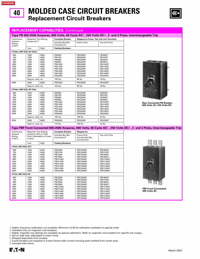
40
March 2001
ContinuousAmpereRatingat 40°C
Magnetic Trip Setting,Amperes➌➍
Complete Breaker Shipped as Frame, Trip Unit and Terminals
Includes Bus BarConnectors➎
Frame Only Trip Unit Only
Low High Catalog Numbers
2-Poles, 600 Volts AC Only➏
600 700 800 900100012001400160018002000
1500150015001500150020002500300030003000
5000500050005000500060007000800080008000
PB2600PB2700PB2800PB2900PB21000PB21200PB21400PB21600PB21800PB22000
PB22500FPB22500FPB22500FPB22500FPB22500FPB22500FPB22500FPB22500FPB22500FPB22500F
PB2600TPB2700TPB2800TPB2900TPB21000TPB21200TPB21400TPB21600TPB21800TPB22000T
Approx. ship. wt. 132 lbs. 98 lbs. 18 lbs.
2500 3000 8000 PB22500 PB22500F PB22500T
Approx. ship. wt. 144 lbs. 98 lbs. 18 lbs.
3-Poles, 600 Volts AC Only
600 700 800 900100012001400160018002000
1500150015001500150020002500300030003000
5000500050005000500060007000800080008000
PB3600PB3700PB3800PB3900PB31000PB31200PB31400PB31600PB31800PB32000
PB32500FPB32500FPB32500FPB32500FPB32500FPB32500FPB32500FPB32500FPB32500FPB32500F
PB3600TPB3700TPB3800TPB3900TPB31000TPB31200TPB31400TPB31600TPB31800TPB32000T
Approx. ship. wt. 155 lbs. 108 lbs. 23 lbs.
2500 3000 8000 PB32500 PB32500F PB32500T
Approx. ship. wt. 173 lbs. 108 lbs. 23 lbs.
MOLDED CASE CIRCUIT BREAKERSReplacement Circuit Breakers
Type PB 600-2500 Amperes, 600 Volts, 60 Cycle AC➊, 250 Volts DC➋, 2- and 3-Poles, Interchangeable Trip
REPLACEMENT CAPABILITIES, Continued
Rear Connected PB Breaker;600 Volts AC, 250 Volts DC
ContinuousAmpereRatingat 40°C
Magnetic Trip Setting,Amperes (Set on High Side, Adjustable to Lower Limits)
Complete Breaker Shipped As:
Includes Bus BarConnectors➐
Frame OnlyIncludes Bus BarConnectors➐
Trip Unit Only
Low High Catalog Numbers
2-Pole, 600 Volts AC➏
600 700 800 900100012001400160018002000
1500150015001500150020002500300030003000
5000500050005000500060007000800080008000
PBF2600PBF2700PBF2800PBF2900PBF21000PBF21200PBF21400PBF21600PBF21800PBF22000
PBF22000FPBF22000FPBF22000FPBF22000FPBF22000FPBF22000FPBF22000FPBF22000FPBF22000FPBF22000F
PBF2600TPBF2700TPBF2800TPBF2900TPBF21000TPBF21200TPBF21400TPBF21600TPBF21800TPBF22000T
3-Pole, 600 Volts AC
600 700 800 900100012001400160018002000
1500150015001500150020002500300030003000
5000500050005000500060007000800080008000
PBF3600PBF3700PBF3800PBF3900PBF31000PBF31200PBF31400PBF31600PBF31800PBF32000
PBF32000FPBF32000FPBF32000FPBF32000FPBF32000FPBF32000FPBF32000FPBF32000FPBF32000FPBF32000F
PBF3600TPBF3700TPBF3800TPBF3900TPBF31000TPBF31200TPBF31400TPBF31600TPBF31800TPBF32000T
➊ Higher frequency calibration not available. Minimum of 50 Hz calibration available on special order.➋ Available only on magnetic only breakers.➌ Higher magnetic trip settings are available as special calibration. Refer to magnetic only breakers for specific trip ranges.➍ Set on high side, adjustable to lower limits.➎ Shipped separately from breaker.➏ 2-pole breakers are supplied in 3-pole frames with current carrying parts omitted from center pole.➐ Included with frame.
PBF Front Connected; 600 Volts AC
Type PBF Front Connected 600-2000 Amperes, 600 Volts, 60 Cycle AC➊, 250 Volts DC➋, 2- and 3-Poles, Interchangeable Trip
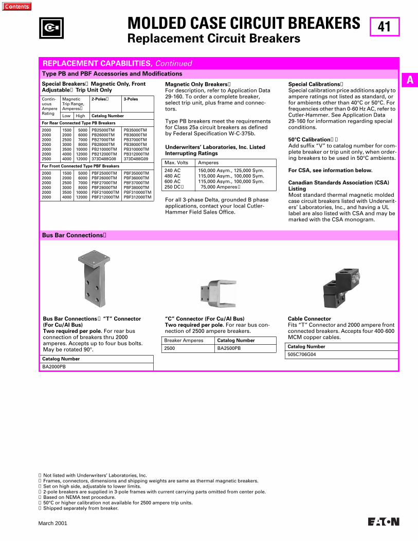
41
March 2001
A
MOLDED CASE CIRCUIT BREAKERSReplacement Circuit Breakers
Type PB and PBF Accessories and Modifications
REPLACEMENT CAPABILITIES, Continued
➊ Not listed with Underwriters’ Laboratories, Inc.➋ Frames, connectors, dimensions and shipping weights are same as thermal magnetic breakers.➌ Set on high side, adjustable to lower limits.➍ 2-pole breakers are supplied in 3-pole frames with current carrying parts omitted from center pole.➎ Based on NEMA test procedure.➏ 50°C or higher calibration not available for 2500 ampere trip units. ➐ Shipped separately from breaker.
Special Breakers➊ Magnetic Only, Front Adjustable➋ Trip Unit Only
Contin-uousAmpereRating
MagneticTrip Range,Amperes➌
2-Poles➍ 3-Poles
Low High Catalog Number
For Rear Connected Type PB Breakers
2000200020002000200020002500
1500200025003000350040004000
5000 6000 7000 8000100001200012000
PB25000TMPB26000TMPB27000TMPB28000TMPB210000TMPB212000TM373D488G08
PB35000TMPB36000TMPB37000TMPB38000TMPB310000TMPB312000TM373D488G09
For Front Connected Type PBF Breakers
200020002000200020002000
150020002500300035004000
5000 6000 7000 80001000012000
PBF25000TMPBF26000TMPBF27000TMPBF28000TMPBF210000TMPBF212000TM
PBF35000TMPBF36000TMPBF37000TMPBF38000TMPBF310000TMPBF312000TM
Special Calibrations➊Special calibration price additions apply to ampere ratings not listed as standard, or for ambients other than 40°C or 50°C. For frequencies other than 0-60 Hz AC, refer to Cutler-Hammer. See Application Data 29-160 for information regarding special conditions.
50°C Calibration➊➏Add suffix “V” to catalog number for com-plete breaker or trip unit only, when order-ing breakers to be used in 50°C ambients.
For CSA, see information below.
Canadian Standards Association (CSA)ListingMost standard thermal magnetic molded case circuit breakers listed with Underwrit-ers’ Laboratories, Inc., and having a UL label are also listed with CSA and may be marked with the CSA monogram.
Magnetic Only Breakers➊For description, refer to Application Data 29-160. To order a complete breaker, select trip unit, plus frame and connec-tors.
Type PB breakers meet the requirements for Class 25a circuit breakers as defined by Federal Specification W-C-375b.
For all 3-phase Delta, grounded B phase applications, contact your local Cutler-Hammer Field Sales Office.
Underwriters’ Laboratories, Inc. ListedInterrupting Ratings
Max. Volts Amperes
240 AC480 AC600 AC250 DC➊
150,000 Asym., 125,000 Sym.115,000 Asym., 100,000 Sym.115,000 Asym., 100,000 Sym. 75,000 Amperes➎
Bus Bar Connections➐ “T” Connector(For Cu/AI Bus)Two required per pole. For rear bus connection of breakers thru 2000 amperes. Accepts up to four bus bolts. May be rotated 90°.
Catalog Number
BA2000PB
“C” Connector (For Cu/AI Bus)Two required per pole. For rear bus con-nection of 2500 ampere breakers.
Breaker Amperes Catalog Number
2500 BA2500PB
Cable Connector Fits “T” Connector and 2000 ampere front connected breakers. Accepts four 400-600 MCM copper cables.
Catalog Number
505C706G04
Bus Bar Connections➐
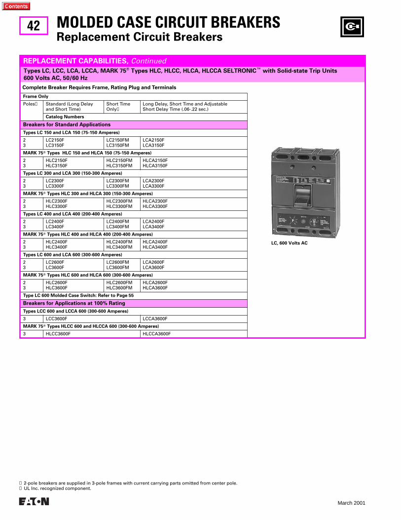
42
March 2001
Types LC, LCC, LCA, LCCA, MARK 75T Types HLC, HLCC, HLCA, HLCCA SELTRONICE with Solid-state Trip Units
600 Volts AC, 50/60 Hz
MOLDED CASE CIRCUIT BREAKERSReplacement Circuit Breakers
REPLACEMENT CAPABILITIES, Continued
Complete Breaker Requires Frame, Rating Plug and Terminals
Frame Only
Poles➊ Standard (Long Delayand Short Time)
Short TimeOnly➋
Long Delay, Short Time and AdjustableShort Delay Time (.06-.22 sec.)
Catalog Numbers
Breakers for Standard Applications
Types LC 150 and LCA 150 (75-150 Amperes)
23
LC2150FLC3150F
LC2150FMLC3150FM
LCA2150FLCA3150F
MARK 75T Types HLC 150 and HLCA 150 (75-150 Amperes)
23
HLC2150FHLC3150F
HLC2150FMHLC3150FM
HLCA2150FHLCA3150F
Types LC 300 and LCA 300 (150-300 Amperes)
23
LC2300FLC3300F
LC2300FMLC3300FM
LCA2300FLCA3300F
MARK 75T Types HLC 300 and HLCA 300 (150-300 Amperes)
23
HLC2300FHLC3300F
HLC2300FMHLC3300FM
HLCA2300FHLCA3300F
Types LC 400 and LCA 400 (200-400 Amperes)
23
LC2400FLC3400F
LC2400FMLC3400FM
LCA2400FLCA3400F
MARK 75T Types HLC 400 and HLCA 400 (200-400 Amperes)
23
HLC2400FHLC3400F
HLC2400FMHLC3400FM
HLCA2400FHLCA3400F
Types LC 600 and LCA 600 (300-600 Amperes)
23
LC2600FLC3600F
LC2600FMLC3600FM
LCA2600FLCA3600F
MARK 75T Types HLC 600 and HLCA 600 (300-600 Amperes)
23
HLC2600FHLC3600F
HLC2600FMHLC3600FM
HLCA2600FHLCA3600F
Type LC 600 Molded Case Switch: Refer to Page 55
Breakers for Applications at 100% Rating
Types LCC 600 and LCCA 600 (300-600 Amperes)
3 LCC3600F LCCA3600F
MARK 75T Types HLCC 600 and HLCCA 600 (300-600 Amperes)
3 HLCC3600F HLCCA3600F
➊ 2-pole breakers are supplied in 3-pole frames with current carrying parts omitted from center pole.➋ UL Inc. recognized component.
LC, 600 Volts AC
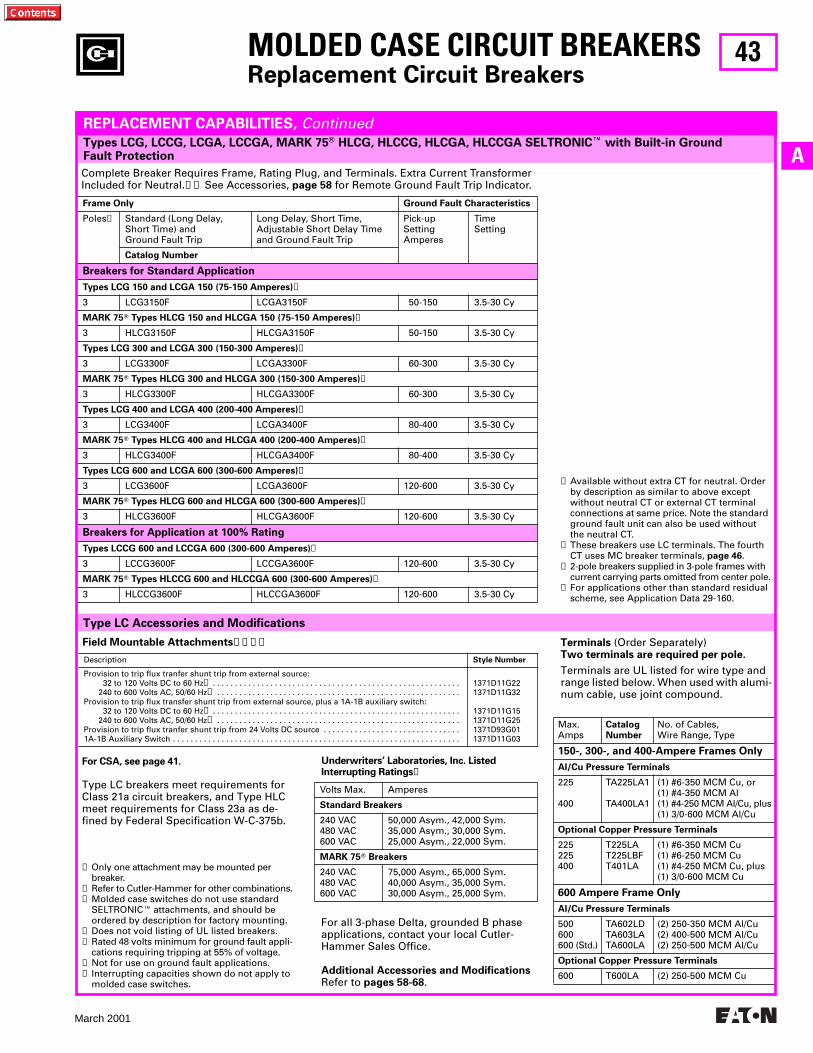
43
March 2001
A
For all 3-phase Delta, grounded B phase applications, contact your local Cutler-Hammer Sales Office.
Additional Accessories and ModificationsRefer to pages 58-68.
Underwriters’ Laboratories, Inc. ListedInterrupting Ratings➐
Volts Max. Amperes
Standard Breakers
240 VAC480 VAC600 VAC
50,000 Asym., 42,000 Sym.35,000 Asym., 30,000 Sym.25,000 Asym., 22,000 Sym.
MARK 75T Breakers
240 VAC480 VAC600 VAC
75,000 Asym., 65,000 Sym.40,000 Asym., 35,000 Sym.30,000 Asym., 25,000 Sym.
Types LCG, LCCG, LCGA, LCCGA, MARK 75T HLCG, HLCCG, HLCGA, HLCCGA SELTRONICE with Built-in Ground Fault Protection
MOLDED CASE CIRCUIT BREAKERSReplacement Circuit Breakers
REPLACEMENT CAPABILITIES, Continued
Complete Breaker Requires Frame, Rating Plug, and Terminals. Extra Current TransformerIncluded for Neutral.➊➋ See Accessories, page 58 for Remote Ground Fault Trip Indicator.
Frame Only Ground Fault Characteristics
Poles➌ Standard (Long Delay,Short Time) andGround Fault Trip
Long Delay, Short Time,Adjustable Short Delay Timeand Ground Fault Trip
Pick-upSettingAmperes
TimeSetting
Catalog Number
Breakers for Standard Application
Types LCG 150 and LCGA 150 (75-150 Amperes)➍
3 LCG3150F LCGA3150F 50-150 3.5-30 Cy
MARK 75T Types HLCG 150 and HLCGA 150 (75-150 Amperes)➍
3 HLCG3150F HLCGA3150F 50-150 3.5-30 Cy
Types LCG 300 and LCGA 300 (150-300 Amperes)➍
3 LCG3300F LCGA3300F 60-300 3.5-30 Cy
MARK 75T Types HLCG 300 and HLCGA 300 (150-300 Amperes)➍
3 HLCG3300F HLCGA3300F 60-300 3.5-30 Cy
Types LCG 400 and LCGA 400 (200-400 Amperes)➍
3 LCG3400F LCGA3400F 80-400 3.5-30 Cy
MARK 75T Types HLCG 400 and HLCGA 400 (200-400 Amperes)➍
3 HLCG3400F HLCGA3400F 80-400 3.5-30 Cy
Types LCG 600 and LCGA 600 (300-600 Amperes)➍
3 LCG3600F LCGA3600F 120-600 3.5-30 Cy
MARK 75T Types HLCG 600 and HLCGA 600 (300-600 Amperes)➍
3 HLCG3600F HLCGA3600F 120-600 3.5-30 Cy
Breakers for Application at 100% Rating
Types LCCG 600 and LCCGA 600 (300-600 Amperes)➍
3 LCCG3600F LCCGA3600F 120-600 3.5-30 Cy
MARK 75T Types HLCCG 600 and HLCCGA 600 (300-600 Amperes)➍
3 HLCCG3600F HLCCGA3600F 120-600 3.5-30 Cy
➊ Available without extra CT for neutral. Order by description as similar to above except without neutral CT or external CT terminal connections at same price. Note the standard ground fault unit can also be used without the neutral CT.
➋ These breakers use LC terminals. The fourth CT uses MC breaker terminals, page 46.
➌ 2-pole breakers supplied in 3-pole frames with current carrying parts omitted from center pole.
➍ For applications other than standard residual scheme, see Application Data 29-160.
Type LC Accessories and Modifications
Field Mountable Attachments➊➋➌➍
Description Style Number
Provision to trip flux tranfer shunt trip from external source: 32 to 120 Volts DC to 60 Hz➎ . . . . . . . . . . . . . . . . . . . . . . . . . . . . . . . . . . . . . . . . . . . . . . . . . . . . . . . . 240 to 600 Volts AC, 50/60 Hz➏ . . . . . . . . . . . . . . . . . . . . . . . . . . . . . . . . . . . . . . . . . . . . . . . . . . . . . . .
Provision to trip flux transfer shunt trip from external source, plus a 1A-1B auxiliary switch: 32 to 120 Volts DC to 60 Hz➎ . . . . . . . . . . . . . . . . . . . . . . . . . . . . . . . . . . . . . . . . . . . . . . . . . . . . . . . . 240 to 600 Volts AC, 50/60 Hz➏ . . . . . . . . . . . . . . . . . . . . . . . . . . . . . . . . . . . . . . . . . . . . . . . . . . . . . . .
Provision to trip flux tranfer shunt trip from 24 Volts DC source . . . . . . . . . . . . . . . . . . . . . . . . . . . . . . . 1A-1B Auxiliary Switch . . . . . . . . . . . . . . . . . . . . . . . . . . . . . . . . . . . . . . . . . . . . . . . . . . . . . . . . . . . . . . . . .
1371D11G221371D11G32
1371D11G151371D11G251371D93G011371D11G03
For CSA, see page 41.
Type LC breakers meet requirements for Class 21a circuit breakers, and Type HLC meet requirements for Class 23a as de-fined by Federal Specification W-C-375b.
➊ Only one attachment may be mounted per breaker.
➋ Refer to Cutler-Hammer for other combinations.➌ Molded case switches do not use standard
SELTRONICE attachments, and should be ordered by description for factory mounting.
➍ Does not void listing of UL listed breakers.➎ Rated 48 volts minimum for ground fault appli-
cations requiring tripping at 55% of voltage.➏ Not for use on ground fault applications.➐ Interrupting capacities shown do not apply to
molded case switches.
Terminals (Order Separately)Two terminals are required per pole.
Terminals are UL listed for wire type and range listed below. When used with alumi-num cable, use joint compound.
Max.Amps
CatalogNumber
No. of Cables,Wire Range, Type
150-, 300-, and 400-Ampere Frames Only
Al/Cu Pressure Terminals
225
400
TA225LA1
TA400LA1
(1) #6-350 MCM Cu, or(1) #4-350 MCM Al(1) #4-250 MCM Al/Cu, plus(1) 3/0-600 MCM Al/Cu
Optional Copper Pressure Terminals
225225400
T225LAT225LBFT401LA
(1) #6-350 MCM Cu(1) #6-250 MCM Cu(1) #4-250 MCM Cu, plus(1) 3/0-600 MCM Cu
600 Ampere Frame Only
Al/Cu Pressure Terminals
500600600 (Std.)
TA602LDTA603LATA600LA
(2) 250-350 MCM Al/Cu(2) 400-500 MCM Al/Cu(2) 250-500 MCM Al/Cu
Optional Copper Pressure Terminals
600 T600LA (2) 250-500 MCM Cu
44
March 2001
MOLDED CASE CIRCUIT BREAKERSReplacement Circuit Breakers
THIS PAGE INTENTIONALLY LEFT BLANK
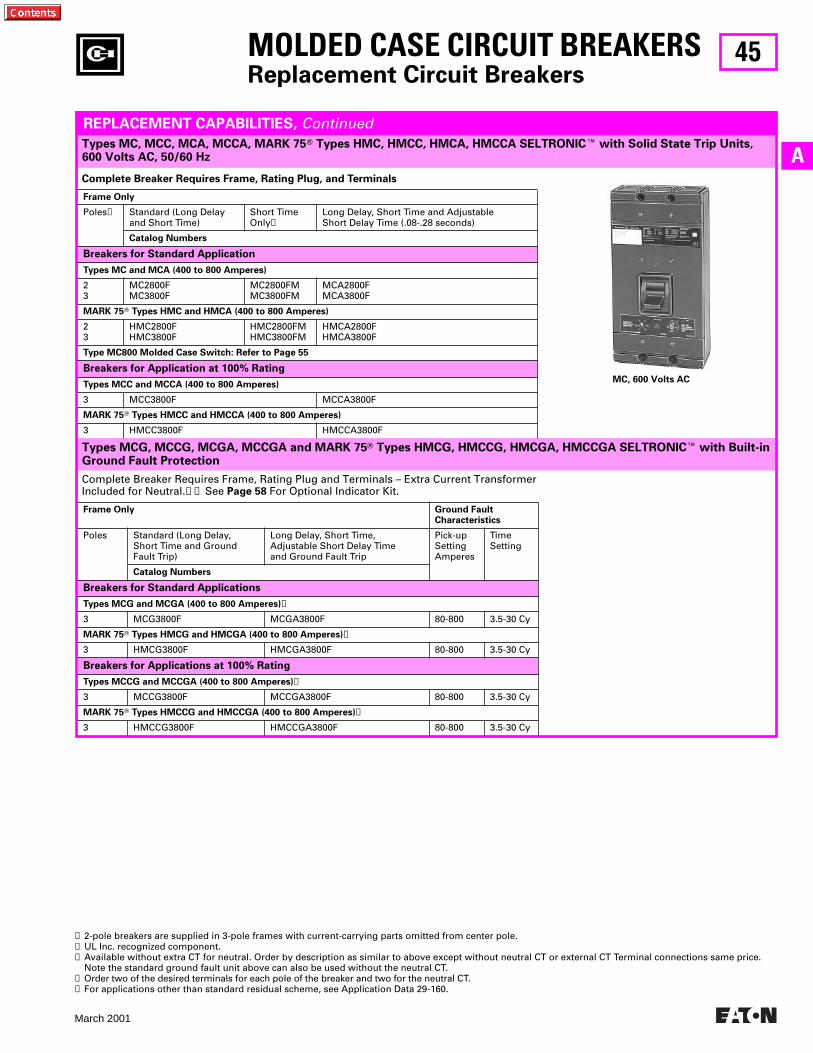
45
March 2001
ATypes MC, MCC, MCA, MCCA, MARK 75T Types HMC, HMCC, HMCA, HMCCA SELTRONICE with Solid State Trip Units,600 Volts AC, 50/60 Hz
Types MCG, MCCG, MCGA, MCCGA and MARK 75T Types HMCG, HMCCG, HMCGA, HMCCGA SELTRONICE with Built-in Ground Fault Protection
MOLDED CASE CIRCUIT BREAKERSReplacement Circuit Breakers
REPLACEMENT CAPABILITIES, Continued
Complete Breaker Requires Frame, Rating Plug, and Terminals
Frame Only
Poles➊ Standard (Long Delayand Short Time)
Short TimeOnly➋
Long Delay, Short Time and AdjustableShort Delay Time (.08-.28 seconds)
Catalog Numbers
Breakers for Standard Application
Types MC and MCA (400 to 800 Amperes)
23
MC2800FMC3800F
MC2800FMMC3800FM
MCA2800FMCA3800F
MARK 75T Types HMC and HMCA (400 to 800 Amperes)
23
HMC2800FHMC3800F
HMC2800FMHMC3800FM
HMCA2800FHMCA3800F
Type MC800 Molded Case Switch: Refer to Page 55
Breakers for Application at 100% Rating
Types MCC and MCCA (400 to 800 Amperes)
3 MCC3800F MCCA3800F
MARK 75T Types HMCC and HMCCA (400 to 800 Amperes)
3 HMCC3800F HMCCA3800F
Complete Breaker Requires Frame, Rating Plug and Terminals – Extra Current TransformerIncluded for Neutral.➌➍ See Page 58 For Optional Indicator Kit.
Frame Only Ground FaultCharacteristics
Poles Standard (Long Delay,Short Time and GroundFault Trip)
Long Delay, Short Time,Adjustable Short Delay Timeand Ground Fault Trip
Pick-upSettingAmperes
TimeSetting
Catalog Numbers
Breakers for Standard Applications
Types MCG and MCGA (400 to 800 Amperes)➎
3 MCG3800F MCGA3800F 80-800 3.5-30 Cy
MARK 75T Types HMCG and HMCGA (400 to 800 Amperes)➎
3 HMCG3800F HMCGA3800F 80-800 3.5-30 Cy
Breakers for Applications at 100% Rating
Types MCCG and MCCGA (400 to 800 Amperes)➎
3 MCCG3800F MCCGA3800F 80-800 3.5-30 Cy
MARK 75T Types HMCCG and HMCCGA (400 to 800 Amperes)➎
3 HMCCG3800F HMCCGA3800F 80-800 3.5-30 Cy
➊ 2-pole breakers are supplied in 3-pole frames with current-carrying parts omitted from center pole.➋ UL Inc. recognized component.➌ Available without extra CT for neutral. Order by description as similar to above except without neutral CT or external CT Terminal connections same price.
Note the standard ground fault unit above can also be used without the neutral CT.➍ Order two of the desired terminals for each pole of the breaker and two for the neutral CT.➎ For applications other than standard residual scheme, see Application Data 29-160.
MC, 600 Volts AC
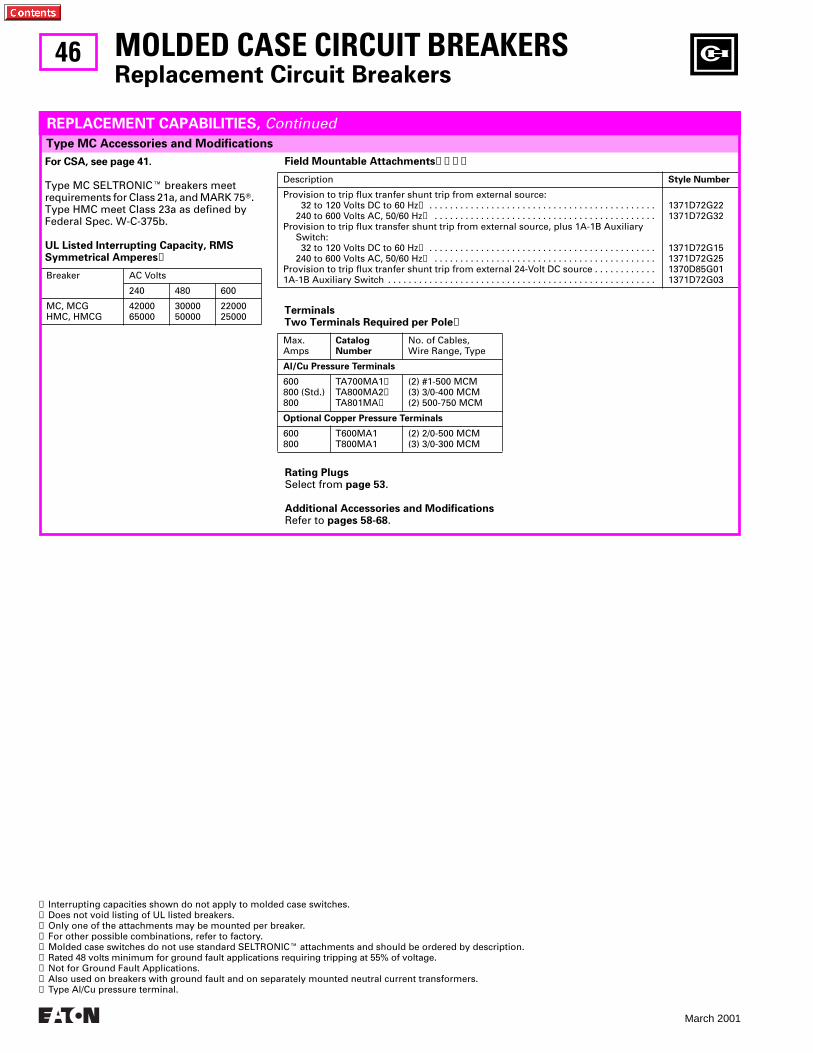
46
March 2001
Field Mountable Attachments➋➌➍➎
Description Style Number
Provision to trip flux tranfer shunt trip from external source: 32 to 120 Volts DC to 60 Hz➏ . . . . . . . . . . . . . . . . . . . . . . . . . . . . . . . . . . . . . . . . . . . .240 to 600 Volts AC, 50/60 Hz➐ . . . . . . . . . . . . . . . . . . . . . . . . . . . . . . . . . . . . . . . . . . .
Provision to trip flux transfer shunt trip from external source, plus 1A-1B AuxiliarySwitch: 32 to 120 Volts DC to 60 Hz➏ . . . . . . . . . . . . . . . . . . . . . . . . . . . . . . . . . . . . . . . . . . . .240 to 600 Volts AC, 50/60 Hz➐ . . . . . . . . . . . . . . . . . . . . . . . . . . . . . . . . . . . . . . . . . . .
Provision to trip flux tranfer shunt trip from external 24-Volt DC source . . . . . . . . . . . .1A-1B Auxiliary Switch . . . . . . . . . . . . . . . . . . . . . . . . . . . . . . . . . . . . . . . . . . . . . . . . . . . .
1371D72G221371D72G32
1371D72G151371D72G251370D85G011371D72G03
Terminals Two Terminals Required per Pole➑
Max.Amps
CatalogNumber
No. of Cables,Wire Range, Type
Al/Cu Pressure Terminals
600800 (Std.)800
TA700MA1➒TA800MA2➒TA801MA➒
(2) #1-500 MCM(3) 3/0-400 MCM(2) 500-750 MCM
Optional Copper Pressure Terminals
600800
T600MA1T800MA1
(2) 2/0-500 MCM(3) 3/0-300 MCM
MOLDED CASE CIRCUIT BREAKERSReplacement Circuit Breakers
For CSA, see page 41.
Type MC SELTRONICE breakers meet requirements for Class 21a, and MARK 75T. Type HMC meet Class 23a as defined by Federal Spec. W-C-375b.
UL Listed Interrupting Capacity, RMSSymmetrical Amperes➊
Breaker AC Volts
240 480 600
MC, MCGHMC, HMCG
4200065000
3000050000
2200025000
Type MC Accessories and Modifications
REPLACEMENT CAPABILITIES, Continued
➊ Interrupting capacities shown do not apply to molded case switches.➋ Does not void listing of UL listed breakers.➌ Only one of the attachments may be mounted per breaker.➍ For other possible combinations, refer to factory.➎ Molded case switches do not use standard SELTRONICE attachments and should be ordered by description.➏ Rated 48 volts minimum for ground fault applications requiring tripping at 55% of voltage.➐ Not for Ground Fault Applications.➑ Also used on breakers with ground fault and on separately mounted neutral current transformers.➒ Type Al/Cu pressure terminal.
Rating PlugsSelect from page 53.
Additional Accessories and ModificationsRefer to pages 58-68.
47
March 2001
A
MOLDED CASE CIRCUIT BREAKERSReplacement Circuit Breakers
THIS PAGE INTENTIONALLY LEFT BLANK
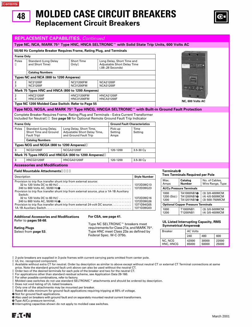
48
March 2001
Accessories and Modifications
Type NCG, NCGA, and MARK 75T Type HNCG, HNCGA SELTRONICE with Built-in Ground Fault Protection
MOLDED CASE CIRCUIT BREAKERSReplacement Circuit Breakers
Type NC, NCA, MARK 75T Type HNC, HNCA SELTRONICE with Solid State Trip Units, 600 Volts AC
REPLACEMENT CAPABILITIES, Continued
50/60 Hz Complete Breaker Requires Frame, Rating Plug, and Terminals
Frame Only
Poles➊
Standard (Long Delayand Short Time)
Short TimeOnly➋
Long Delay, Short Time andAdjustable Short Delay Time(.08-.28 Seconds)
Catalog Numbers
Types NC and NCA (800 to 1200 Amperes)
23
NC21200FNC31200F
NC21200FMNC31200FM
NCA21200FNCA31200F
Mark 75 Types HNC and HNCA (800 to 1200 Amperes)
23
HNC21200FHNC31200F
HNC21200FMHNC31200FM
HNCA21200FHNCA31200F
Type NC 1200 Molded Case Switch: Refer to Page 55
Complete Breaker Requires Frame, Rating Plug and Terminals – Extra Current Transformer Included for Neutral➌➍ See page 58 for Optional Remote Ground Fault Trip Indicator
Frame Only Ground Fault Characteristics
Poles Standard (Long Delay,Short Time and GroundFault Trip)
Long Delay, Short Time,Adjustable Short Delay Time,and Ground Fault Trip
Pick-upSettingAmps
TimeSetting
Catalog Numbers
Types NCG and NCGA (800 to 1200 Amperes)➎
3 NCG31200F NCGA31200F 120-1200 3.5-30 Cy
Mark 75 Types HNCG and HNCGA (800 to 1200 Amperes)➎
3 HNCG31200F HNCGA31200F 120-1200 3.5-30 Cy
Field Mountable Attachments➏➐➑➒
Description Style Number
Provision to trip flux transfer shunt trip from external source: 32 to 120 Volts DC to 60 Hz➓ . . . . . . . . . . . . . . . . . . . . . . . . . . . . . . . . . . . . . . . . . . . . .240 to 600 Volts AC, 50/60 HzK . . . . . . . . . . . . . . . . . . . . . . . . . . . . . . . . . . . . . . . . . . . .
Provision to trip flux transfer shunt trip from external source, plus a 1A-1B AuxiliarySwitch: 32 to 120 Volts DC to 60 Hz➓ . . . . . . . . . . . . . . . . . . . . . . . . . . . . . . . . . . . . . . . . . . . . .240 to 600 Volts AC, 50/60 HzK . . . . . . . . . . . . . . . . . . . . . . . . . . . . . . . . . . . . . . . . . . . .
Provision to trip flux transfer shunt trip from external 24-volt DC source . . . . . . . . . . . .1A-1B Auxiliary Switch . . . . . . . . . . . . . . . . . . . . . . . . . . . . . . . . . . . . . . . . . . . . . . . . . . . . .
1372D39G131372D39G23
1372D39G161372D39G261371D94G051371D39G03
➊ 2-pole breakers are supplied in 3-pole frames with current-carrying parts omitted from center pole.➋ UL Inc. recognized component.➌ Available without extra CT for neutral. Order by description as similar to above except without neutral CT or external CT Terminal connections at same
price. Note the standard ground fault unit above can also be used without the neutral CT.➍ Order two of the desired terminals for each pole of the breaker and two for the neutral CT.➎ For applications other than standard residual scheme, see Application Data 29-160.➏ For other possible combinations, refer to factory.➐ Molded case switches do not use standard SELTRONICE attachments and should be ordered by description.➑ Does not void listing of UL listed breakers.➒ Only one of the attachments may be mounted per breaker.➓ Rated 48 volts minimum for ground fault applications requiring tripping at 55% of voltage.K Not for ground fault applications.L Also used on breakers with ground fault and on separately mounted neutral current transformers.M Type Al/Cu pressure terminal.N Interrupting capacities shown do not apply to molded case switches.
UL Listed Interrupting Capacity, RMSSymmetrical AmperesN
Breaker AC Volts
240 480 600
NC, NCGHNC, HNCG
4200065000
3000050000
2200025000
Terminals L
Two Terminals Required per Pole
Max.Amps
CatalogNumber
No. of Cables,Wire Range, Type
Al/Cu Pressure Terminals
10001200 (Std.)1200
TA1000NB1M
TA1200NB1M
TA1201NB1M
(3) 3/0-400MCM(4) 4/0-500MCM(3) 500-750MCM
Optional Copper Pressure Terminals
10001200
T1000NB1T1200NB1
(3) 3/0-500MCM(4) 3/0-400MCM
NC, 600 Volts AC
For CSA, see page 41.
Type NC SELTRONICE breakers meetrequirements for Class 21a, and MARK 75T. Type HNC meet Class 23a as defined by Federal Spec. W-C-375b.
Additional Accessories and ModificationsRefer to pages 58-68.
Rating PlugsSelect from page 53.
49
March 2001
A
MOLDED CASE CIRCUIT BREAKERSReplacement Circuit Breakers
THIS PAGE INTENTIONALLY LEFT BLANK
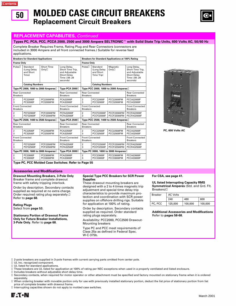
50
March 2001
Accessories and Modifications
MOLDED CASE CIRCUIT BREAKERSReplacement Circuit Breakers
Complete Breaker Requires Frame, Rating Plug and Rear Connectors (connectors are included in 3000 Ampere and all front connected frames.) Suitable for reverse feed applications.
Breakers for Standard Applications Breakers for Standard Applicationa at 100% Rating
Frame Only Frame Only
Poles➊ Standard(Long Delayand Short Time)
Short TimeOnly➋
Long Delay, Short Time Trip,and Adjustable Short DelayTime (.08-.28 seconds)
Poles➊ Standard(Long Delayand Short Time Trip)
MagneticOnly➋
Long Delay, Short Time Trip,and Adjustable Short Delay Time (.08-.28 seconds)
Catalog Numbers Catalog Numbers
Type PC 2000, 1000 to 2000 Amperes➌ Type PCA 2000➌ Type PCC 2000, 1000 to 2000 Amperes➍
Rear Connected Breakers
Rear ConnectedBreakers
Rear ConnectedBreakers
Rear ConnectedBreakers
23
PC22000FPC32000F
PC22000FMPC32000FM
PCA22000FPCA32000F
23
PCC22000FPCC32000F
PCC22000FMPCC32000FM
PCCA22000FPCCA32000F
Front Connected Breakers
Front ConnectedBreakers
Front ConnectedBreakers
Front ConnectedBreakers
23
PCF22000FPCF32000F
PCF22000FMPCF32000FM
PCFA22000FPCFA32000F
23
PCCF22000FPCCF32000F
PCCF22000FMPCCF32000FM
PCCFA22000FPCCFA32000F
Type PC 2500, 1400 to 2500 Amperes➌ Type PCA 2500➌ Type PCC 2500, 1400 to 2500 Amperes➍
Rear Connected Breakers
Rear ConnectedBreakers
Rear ConnectedBreakers
Rear ConnectedBreakers
23
PC22500FPC32500F
PC22500FMPC32500FM
PCA22500FPCA32500F
23
PCC22500FPCC32500F
PCC22500FMPCC32500FM
PCCA22500FPCCA32500F
Front Connected Breakers
Front ConnectedBreakers
Front ConnectedBreakers
Front ConnectedBreakers
23
PCF22500FPCF32500F
PCF22500FMPCF32500FM
PCFA22500FPCFA32500F
23
PCCF22500FPCCF32500F
PCCF22500FMPCCF32500FM
PCCFA22500FPCCFA32500F
Type PC 3000, 1600 to 3000 Amperes➌ Type PCA 3000➌ Type PC 3000, 1600 to 3000 Amperes➍
23
PC23000FPC33000F
PC23000FMPC33000FM
PCA23000FPCA33000F
23
PCC23000FPCC33000F
PCC23000FMPCC33000FM
PCCA23000FPCCA33000F
Drawout Mounting Breakers, 3-Pole OnlyBreaker frame and complete drawout frame with safety tripping interlock.
Order by description. Secondary contacts supplied as required at no extra charge. Order required rating plug separately.➎ Refer to page 68.
Rating PlugsSelect from page 53.
Special Type PCC Breakers for SCR PowerSupplies These drawout mounting breakers are designed with a 2 to 4 times magnetic trip adjustment and special time delay trip characteristics to provide maximum pro-tection and coordination with SCR power supplies on offshore drilling rigs. Suitable for application at 100% of rating.
Order by description. Secondary contacts supplied as required. Order standard rating plugs separately.
Availability: PCC2000, PCC2500 Drawout-Mounting breakers
Type PC and PCC meet requirements of Class 25a as defined in Federal Spec.W-C-375b.
Type PC, PCC Molded Case Switches: Refer to Page 55
For CSA, see page 41.
UL listed Interrupting Capacity RMSSymmetrical Amperes (Std. and Grd. Flt. Breakers)➑
Breaker AC Volts
240 480 600
PC, PCC 125,000 100,000 100,000
➊ 2-pole breakers are supplied in 3-pole frames with current carrying parts omitted from center pole.➋ UL Inc. recognized component.➌ UL listed for standard applications.➍ These breakers are UL listed for application at 100% of rating per NEC exceptions when used in a properly ventilated and listed enclosure.➎ Includes breakers without adjustable short delay time.➏ Secondary contacts, when required for motor operator or other attachment must be specified and factory mounted on stationary frame when it is ordered
separately.➐ When ordering breaker with movable portion only for use with previously installed stationary portion, deduct the list price of stationary portion from list
price of complete breaker with drawout frame.➑ Interrupting capacities shown do not apply to molded case switches.
Types PC, PCA, PCC, PCCA 2000, 2500 and 3000 Ampere SELTRONICE with Solid State Trip Units, 600 Volts AC, 50/60 Hz
REPLACEMENT CAPABILITIES, Continued
PC, 600 Volts AC
Stationary Portion of Drawout Frame Only for Future Breaker Installations,3-Pole Only. Refer to page 68.
Additional Accessories and ModificationsRefer to pages 58-68.
51
March 2001
A
MOLDED CASE CIRCUIT BREAKERSReplacement Circuit Breakers
Type PCG, PCGA, PCCG, PCCGA SELTRONICE with Built-in Ground Fault ProtectionIncludes Extra Current Transformer for Neutral➊ (Optional Remote Ground Fault Trip Indicator Kit, page 58)
REPLACEMENT CAPABILITIES, Continued
Breakers for Standard ApplicationComplete Breaker Requires Frame, Rating Plug and Rear Connectors (except Front Connected Frames and 3000 Ampere Frames Include Connectors)
Frames Only Ground Fault Characteristics
Poles Standard (Long Delay,Short Time and GroundFault Trip)
Long Delay, Short Time, GroundFault Trip, and Adjustable ShortDelay Time (.08-.28 Seconds)
Pick-upSetting
TimeSetting
Catalog Numbers
Type PCG 2000➋➌ Type PCGA 2000➋➌ 1000 to 2000 Amperes➌
Rear Connected Breakers
3 PCG32000F PCGA32000F 200-1200 3.5-30 Cycles
Front Connected Breakers
3 PCFG32000F PCFGA32000F 200-1200 3.5-30 Cycles
Type PCG 2500➋➌ Type PCGA 2500➋➌ 1400 to 2500 Amperes➌
Rear Connected Breakers
3 PCG32500F PCGA32500F 240-1200 3.5-30 Cycles
Front Connected Breakers
3 PCFG32500F PCFGA32500F 240-1200 3.5-30 Cycles
Type PCG 3000➋➌ Type PCGA 3000➋➌ 1600 to 3000 Amperes➌
3 PCG33000F PCGA33000F 300-1200 3.5-30 Cycles
Breakers for Application at 100% Rating
Frames Only Ground Fault Characteristics
Poles Standard (Long Delay,Short Time and GroundFault Trip)
Long Delay, Short Time, GroundFault Trip, and Adjustable ShortDelay Time (.08-.28 Seconds)
Pick-upSetting
TimeSetting
Catalog Numbers
Type PCCG 2000➍ Type PCCGA 2000➍ 1000 to 2000 Amperes➌
Rear Connected Breakers
3 PCCG32000F PCCGA32000F 200-1200 3.5-30 Cycles
Front Connected Breakers
3 PCCFG32000F PCCFGA32000F 200-1200 3.5-30 Cycles
Type PCCG 2500➍ Type PCCGA 2500➍ 1400 to 2500 Amperes➌
Rear Connected Breakers
3 PCCG32500F PCCGA32500F 240-1200 3.5-30 Cycles
Front Connected Breakers
3 PCCFG32500F PCCFGA32500F 240-1200 3.5-30 Cycles
Type PCCG 3000➍ Type PCCGA 3000➍ 1600 to 3000 Amperes➌
3 PCCG33000F PCCGA33000F 300-1200 3.5-30 Cycles
➊ Available without external CT for neutral. Order by description and specify similar to above except no neutral CT or terminal connections for neutral CT at same price. Note the standard ground fault unit listed above can also be used without the neutral CT.
➋ UL listed for standard applications.➌ For application other than standard residual schemes, refer to Application Data 29-160.➍ These breakers are UL listed for application at 100% of rating per NEC exceptions when used in a properly ventilated and listed enclosure.
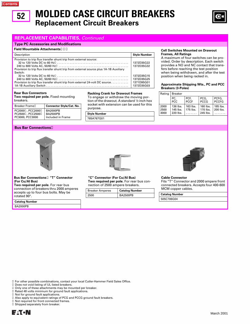
52
March 2001
Bus Bar Connections➑ “T” Connector(For Cu/AI Bus)Two required per pole. For rear bus connection of breakers thru 2000 amperes accepts up to four bus bolts. May be rotated 90°.
Catalog Number
BA2000PB
“C” Connector (For Cu/AI Bus)Two required per pole. For rear bus con-nection of 2500 ampere breakers.
Breaker Amperes Catalog Number
2500 BA2500PB
Cable Connector Fits “T” Connector and 2000 ampere front connected breakers. Accepts four 400-600 MCM copper cables.
Catalog Number
505C706G04
Bus Bar Connections➑
MOLDED CASE CIRCUIT BREAKERSReplacement Circuit Breakers
Type PC Accessories and Modifications
REPLACEMENT CAPABILITIES, Continued
Field Mountable Attachments➊➋➌
Description Style Number
Provision to trip flux transfer shunt trip from external source: 32 to 120 Volts DC to 60 Hz➍ . . . . . . . . . . . . . . . . . . . . . . . . . . . . . . . . . . . . . . . . . . . . . 240 to 600 Volts AC, 50/60 Hz➎ . . . . . . . . . . . . . . . . . . . . . . . . . . . . . . . . . . . . . . . . . . . .
Provision to trip flux transfer shunt trip from external source plus 1A-1B AuxiliarySwitch:
32 to 120 Volts DC to 60 Hz➍ . . . . . . . . . . . . . . . . . . . . . . . . . . . . . . . . . . . . . . . . . . . . . 240 to 600 Volts AC, 50/60 Hz➎ . . . . . . . . . . . . . . . . . . . . . . . . . . . . . . . . . . . . . . . . . . . .
Provision to trip flux transfer shunt trip from external 24-volt DC source . . . . . . . . . . . 1A-1B Auxiliary Switch . . . . . . . . . . . . . . . . . . . . . . . . . . . . . . . . . . . . . . . . . . . . . . . . . . . .
1372D35G221372D35G32
1372D35G151372D35G251371D95G011372D35G03
Rear Bus ConnectorsTwo required per pole. Fixed mounting breakers.
Breaker Frame➏ Connector Style/Cat. No.
PC2000➐, PCC2000➐PC2500➐, PCC2500➐PC3000, PCC3000
BA2000PBBA2500PBIncluded in Frame
➊ For other possible combinations, contact your local Cutler-Hammer Field Sales Office.➋ Does not void listing of UL listed breakers.➌ Only one of these attachments may be mounted per breaker.➍ Rated 48 volts minimum for ground fault applications.➎ Not for ground fault applications.➏ Also apply to equivalent ratings of PCG and PCCG ground fault breakers.➐ Not required for front connected frames.➑ Shipped separately from breaker.
Racking Crank for Drawout FramesTo engage or withdraw the moving por-tion of the drawout. A standard 1⁄2 inch hex socket with extension can be used for this purpose.
Style Number
765A767G01
Cell Switches Mounted on Drawout Frames, All RatingsA maximum of four switches can be pro-vided. Order by description. Each switch provides a NO and NC contact that trans-fers before reaching the test position when being withdrawn, and after the test position when being racked in.
Approximate Shipping Wts., PC and PCC Breakers (3-Poles)
Rating Breaker
PC,PCC
PCF,PCCF
PCG,PCCG
PCFG,PCCFG
200025003000
136 lbs.145 lbs.220 lbs.
163 lbs.175 lbs.. . . . . . .
160 lbs.170 lbs.245 lbs.
185 lbs.200 lbs.. . . . . . .
53
March 2001
A
MOLDED CASE CIRCUIT BREAKERSReplacement Circuit Breakers
Rating Plug Selection Data
REPLACEMENT CAPABILITIES, Continued
Rating Plugs Only (For 2- or 3-Pole Frames)
Continu-ousAmpereRating➊
Magnetic Trip Setting, Amperes
Fixed Rating Plugs Adjustable Rat-ing Plugs➋➌
Low High Catalog Number
For 150 Ampere Frames: LC, LCA, LCG, LCGA, HLC, HLCA, HLCG, HLCGA
75 90 100 125 150
225 270 300 375 450
750 900100012501500
1LC751LC901LC1001LC1251LC150
. . . . . . . . . . . . . . . . . . A1LC100➍A1LC125A1LC150➎
For 300 Ampere Frames: LC, LCA, LCG, LCGA, HLC, HLCA, HLCA, HLCG, HLCGA
150 175 200 225 250 275 300
450 525 600 675 750 825 900
1500175020002250250027503000
3LC1503LC1753LC2003LC2253LC2503LC2753LC300
. . . . . . . . . . . . . . . . . . . . . . . . . . .A3LC225A3LC250A3LC275A3LC300➎
For 400 Ampere Frames: LC, LCA, LCG, LCGA, HLC, HLCA, HLCG, HLCGA
200 225 250 300 350 400
600 675 750 90010501200
200022502500300035004000
4LC2004LC2254LC2504LC3004LC3504LC400
. . . . . . . . . . . . . . . . . . . . . . . . . . .A4LC300A4LC350A4LC400➎
For 600 Ampere Frames: LC, LCS, LCG, LCGA, HLC, HLCA, HLCG, HLCGA, LCC, LCCA, HLCC, HLCCA, LCCG, LCCGA, HLCCG, HLCCGA
300 350 400 450 500 600
90010501200135015001800
300035004000450050006000
6LC3006LC3506LC4006LC4506LC5006LC600
. . . . . . . . . . . . . . . . . .A6LC400➍A6LC450A6LC500A6LC600➎
For 800 Ampere Frames: MC, MCA, MCG, MCGA, HMC, HMCA, HMCG, HMCGA, MCC, MCCA, HMCC, HMCCA, MCCG, MCCGA, HMCCG, HMCCGA
400 500 600 700 800
12001500180021002400
40005000600070008000
8MC4008MC5008MC6008MC7008MC800
. . . . . . . . .A8MC500➏A8MC600A8MC700A8MC800➎
For 1200 Ampere Frames: NC, NCA, NCG, NCGA, HNC, HNCA, HNCG, HNCGA
800 90010001200
1600180020002400
6400720080009600
12NC80012NC90012NC100012NC1200
A12NC800➍A12NC900A12NC1000A12NC1200➎
➊ Ampere rating when used in magnetic only frames:LC-150: 150 Amperes MC-800: 800 Amperes PC-3000: 3000 AmperesLC-300: 300 Amperes NC-1200: 1200 Amperes LCL-250: 250 AmperesLC-400: 400 Amperes PC-2000: 2000 Amperes LCL-400: 400 AmperesLC-600: 600 Amperes PC-2500: 2500 Amperes
➋ Magnetic Trip range of adjustable rating plugs:LC, HLC, MC, HMC: 3 to 10 times ampere settingNC, HNC, PC, PCC, LCL-400: 2 to 8 times ampere settingLCL-250: 3 to 9 times ampere setting
➌ Adjustable 70 to 100% except as noted➍ Adjustable 75 to 100%➎ Adjustable 50 to 100%➏ Adjustable 80 to 100%
Rating Plugs Listed Below Are For Both Standard Breakers and Breakers with Built-in Ground Fault Protection
NOTE: Refer to your local Cutler-Hammer Field Sales Office for old style (three prong) ground fault rating plugs
Rating Plugs Only (For 2- or 3-Pole Frames)
ContinuousAmpereRating➊
Magnetic Trip Set-ting, Amperes
Fixed Rating Plugs
Adjustable Rating Plugs➋➌
Low High Catalog Numbers
For 2000 Ampere Frames: PC, PCA, PCC, PCCA, PCG, PCGA, PCCG, PCCGA
100012001400160018002000
200024002800320036004000
8000 960011200128001440016000
20PC100020PC120020PC140020PC160020PC180020PC2000
. . . . . . . . . . . . . . . . . . . . . . . . . . . . . . . . .A20PC1600A20PC1800A20PC2000➎
For 2500 Ampere Frames: PC, PCA, PCC, PCCA, PCG, PCGA, PCCG, PCCGA
14001600180020002500
28003200360040005000
1120012800144001600020000
25PC140025PC160025PC180025PC200025PC2500
. . . . . . . . . . . . . . . . . . . . . . A25PC1800A25PC2000A25PC2500➎
For 3000 Ampere Frames: PC, PCA, PCC, PCCA, PCG, PCGA, PCCG, PCCGA
16001800200025003000
32003600400050006000
1280014400160002000024000
30PC160030PC180030PC200030PC250030PC3000
. . . . . . . . . . . . . . . . . . . . . . . . . . . . . . . . . A30PC2500A30PC3000➎
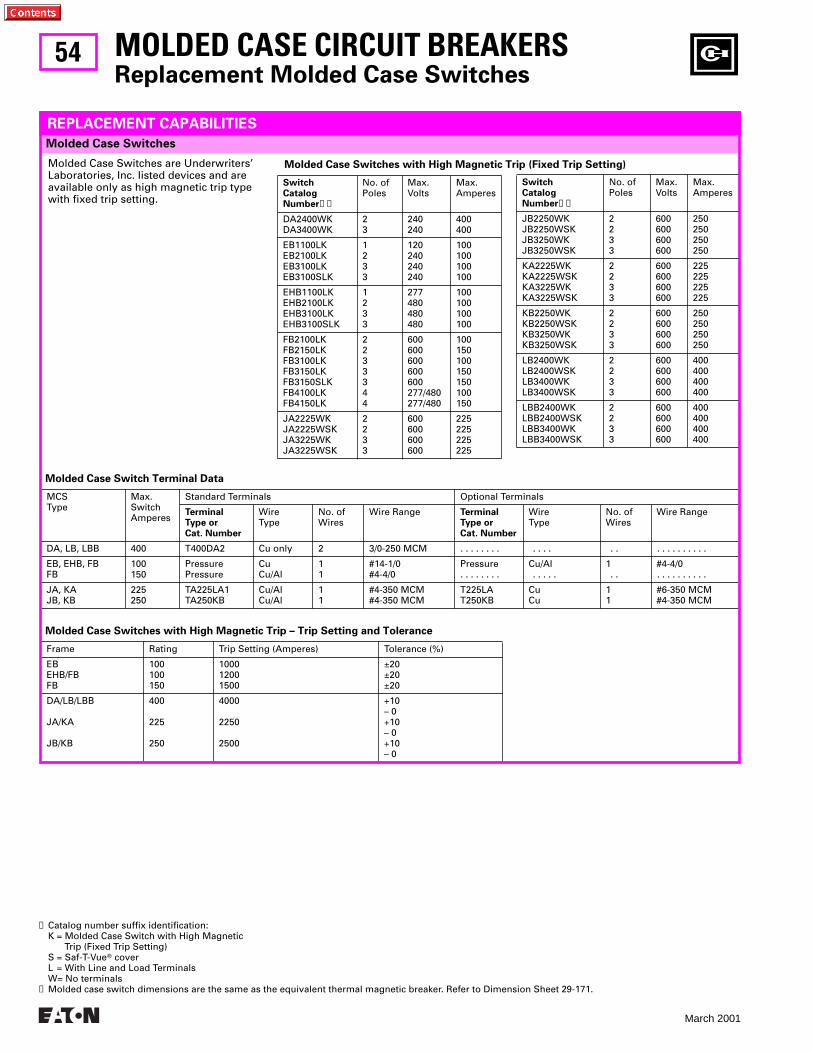
54
March 2001
Molded Case Switch Terminal Data
MCSType
Max.SwitchAmperes
Standard Terminals Optional Terminals
TerminalType orCat. Number
WireType
No. ofWires
Wire Range TerminalType orCat. Number
WireType
No. ofWires
Wire Range
DA, LB, LBB 400 T400DA2 Cu only 2 3/0-250 MCM . . . . . . . . . . . . . . . . . . . . . . . .
EB, EHB, FBFB
100150
PressurePressure
CuCu/Al
11
#14-1/0#4-4/0
Pressure. . . . . . . .
Cu/Al . . . . .
1 . .
#4-4/0. . . . . . . . . .
JA, KAJB, KB
225250
TA225LA1TA250KB
Cu/AlCu/Al
11
#4-350 MCM#4-350 MCM
T225LAT250KB
CuCu
11
#6-350 MCM#4-350 MCM
Molded Case Switches with High Magnetic Trip – Trip Setting and Tolerance
Frame Rating Trip Setting (Amperes) Tolerance (%)
EBEHB/FBFB
100100150
100012001500
±20±20±20
DA/LB/LBB
JA/KA
JB/KB
400
225
250
4000
2250
2500
+10– 0+10– 0+10– 0
MOLDED CASE CIRCUIT BREAKERSReplacement Molded Case Switches
Molded Case Switches
REPLACEMENT CAPABILITIES
Molded Case Switches are Underwriters’ Laboratories, Inc. Iisted devices and are available only as high magnetic trip type with fixed trip setting.
Molded Case Switches with High Magnetic Trip (Fixed Trip Setting)
SwitchCatalogNumber➊➋
No. ofPoles
Max.Volts
Max.Amperes
DA2400WKDA3400WK
23
240240
400400
EB1100LKEB2100LKEB3100LKEB3100SLK
1233
120240240240
100100100100
EHB1100LKEHB2100LKEHB3100LKEHB3100SLK
1233
277480480480
100100100100
FB2100LKFB2150LKFB3100LKFB3150LKFB3150SLKFB4100LKFB4150LK
2233344
600600600600600277/480277/480
100150100150150100150
JA2225WKJA2225WSKJA3225WKJA3225WSK
2233
600600600600
225225225225
SwitchCatalogNumber➊➋
No. ofPoles
Max.Volts
Max.Amperes
JB2250WKJB2250WSKJB3250WKJB3250WSK
2233
600600600600
250250250250
KA2225WKKA2225WSKKA3225WKKA3225WSK
2233
600600600600
225225225225
KB2250WKKB2250WSKKB3250WKKB3250WSK
2233
600600600600
250250250250
LB2400WKLB2400WSKLB3400WKLB3400WSK
2233
600600600600
400400400400
LBB2400WKLBB2400WSKLBB3400WKLBB3400WSK
2233
600600600600
400400400400
➊ Catalog number suffix identification:K = Molded Case Switch with High Magnetic
Trip (Fixed Trip Setting)S = Saf-T-VueT coverL = With Line and Load TerminalsW= No terminals
➋ Molded case switch dimensions are the same as the equivalent thermal magnetic breaker. Refer to Dimension Sheet 29-171.
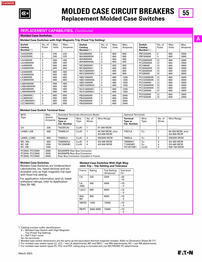
55
March 2001
A
MOLDED CASE CIRCUIT BREAKERSReplacement Molded Case Switches
Molded Case Switches
REPLACEMENT CAPABILITIES, Continued
Molded Case Switches with High Magnetic Trip (Fixed Trip Setting)
SwitchCatalogNumber➊➋
No. ofPoles
Max.Volts
Max.Amperes
CA2225WKCA3225WK
23
240240
225225
LA2400WKLA2400WSKLA2600WKLA2600WSK
2222
600600600600
400400600600
LA3400WKLA3400WSKLA3600WKLA3600WSK
3333
600600600600
400400600600
LAB2400WKLAB2400WSKLAB3400WKLAB3400WSK
2233
600600600600
400400400400
LC2600WK➌LC3600WK➌LCC2600WK➌LCC3600WK➌
2323
600600600600
600600600600
SwitchCatalogNumber➊➋
No. ofPoles
Max.Volts
Max.Amperes
MA2800WKMA2800WSKMA3800WKMA3800WSK
2233
600600600600
800800800800
MC2800WK➌MC3800WK➌MCC2800WK➌MCC3800WK➌
2323
600600600600
800800800800
NB21200WKNB21200WSKNB31200WKNB31200WSK
2233
600600600600
1200120012001200
NC21200WK➌NC31200WK➌
23
600600
12001200
PB22000WKPB22500WKPB32000WKPB32500WK
2233
600600600600
2000250020002500
SwitchCatalogNumber➊➋
No. ofPoles
Max.Volts
Max.Amperes
PBF22000KPBF32000K
23
600600
20002000
PC22000WK PC22500WK PC23000K PC32000WK PC32500WK PC33000K
2➍2➍2➍3➍3➍3➍
600600600600600600
200025003000200025003000
PCC22000WK PCC22500WK PCC23000K PCC32000WK PCC32500WK PCC33000K
2➍2➍2➍3➍3➍3➍
600600600600600600
200025003000200025003000
PCF22000K PCF32000K
2➍3➍
600600
20002000
Molded Case Switch Terminal Data
MCSType
Max.SwitchAmperes
Standard Terminals (Aluminum Body) Optional Terminals
TerminalType orCat. Number
WireType
No. ofWires
Wire Range TerminalType orCat. Number
WireType
No. ofWires
Wire Range
CA 225 TA225CA2 Cu/Al 1 #1-300 MCM . . . . . . . . . . . . . . . . . . . .
LA400, LAB 400 TA400LA1 Cu/Al 1 #4-250 MCM, plus3/0-600 MCM
T401LA Cu 1 #4-250 MCM, plus3/0-600 MCM
LA600, LC600 600 TA600LA Cu/Al 2 250/500 MCM T600LA Cu 2 250/500 MCM
MC, MANC, NBNC, NB
80012001200
TA800MA2TA1200NB1 . . . . . . . .
Cu/AlCu/Al . . . .
34 . .
3/0-400 MCM4/0-500 MCM . . . . . . . . . .
T800MA1T1200NB1TA1201NB1
CuCuCu/Al
343
3/0-300 MCM3/0-400 MCM500-750 MCM
PC2000, PCC2000PC2500, PCC2500PC3000, PCC3000
200025003000
BA2000PB Rear Bus ConnectorBA2500PB Rear Bus ConnectorRear Bus Connector Included in Frame
Molded Case SwitchesMolded Case Switches are Underwriters’ Laboratories, Inc. Iisted devices and are available only as high magnetic trip type with fixed trip setting.
For application information and UL Iisted withstand ratings, refer to Application Data 29-160.
Molded Case Switches With High Mag-netic Trip – Trip Setting and Tolerance
Frame Rating Trip Setting (Amperes)
Tolerance (%)
CA 225 2250 +20–10
LA (400)
400 4000 +10– 0
LA/LC 600 6000 +10– 0
MA/MC
800 8000 +10– 0
NB/NC 1200 12000 +10– 0
PB/PC 2000-3000 12000 +10– 0
➊ Catalog number suffix identification: K = Molded Case Switch with High Magnetic
Trip (Fixed Trip Setting)S = Saf-T-VueT coverW= No terminals
➋ Molded case switch dimensions are the same as the equivalent thermal magnetic breaker. Refer to Dimension Sheet 29-171.➌ For molded case switch types LC, LCC – use LA attachments; MC and MCC – use MA attachments; NC – use NB attachments.➍ For molded case switch types PC, PCC and PCF, rating plug is included and use SELTRONIC PC attachments.
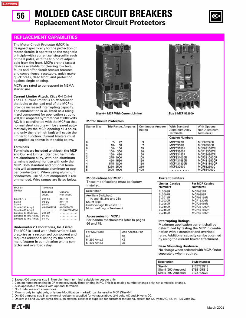
56
March 2001
MOLDED CASE CIRCUIT BREAKERS
Replacement Motor Circuit Protectors
REPLACEMENT CAPABILITIES
Motor Circuit Protectors
Starter Size Trip Range, Amperes Continuous Ampere Rating
With StandardAluminum AlloyTerminals
With OptionalNon-AluminumTerminals
➋
Catalog Numbers
0001234455
7- 22 18- 58 50- 150 100- 300 160- 480 275- 1000 450- 1550 575- 18001250- 25002000- 4000
3 7 15 30 50100150150250400
MCP0322RMCP0358RMCP03150RMCP13300RMCP23480RMCP331000RMCP431550RMCP431800RMCP532500 . . . . . . . . . . . .
MCP0322CRMCP0358CRMCP03150CRMCP13300CRMCP23480CRMCP331000CRMCP431550CRMCP431800CRMCP532500CMCP534000C
The Motor Circuit Protector (MCP) is designed specifically for the protection of motor circuits. It operates on the magnetic principle with a current sensing coil in each of the 3 poles, with the trip-point adjust-able from the front. MCPs are the fastest devices available for clearing low level faults and offer circuit breaker features and convenience, resettable, quick make-quick break, dead front, and protection against single phasing.
MCPs are rated to correspond to NEMA starter size
Current Limiter Attach.
(Size 0-4 Only)The EL current limiter is an attachment that bolts to the load end of the MCP to provide increased interrupting capacity. The combination is UL listed as a recog-nized component for application at up to 200,000 amperes symmetrical at 600 volts AC. It is coordinated with the MCP so that normal short circuits will be cleared auto-matically by the MCP, opening all 3 poles, and only the rare high fault will cause the limiter to function. Current limiters must be applied as shown in the table below.
TerminalsTerminals are included with both the MCP and Current Limiter.
Standard terminals are aluminum alloy, with non-aluminum terminals optional for use with only the MCP. Both standard and optional termi-nals will accommodate aluminum or cop-per conductors.
➊
When using aluminum conductors, use of joint compound is rec-ommended. Wire ranges are listed below.
Underwriters’ Laboratories, Inc. Listed
The MCP is listed with Underwriters’ Lab-oratories as a recognized component and requires additional listing by the control manufacturer in combination with a con-tactor and overload relay.
MCP orLimiter
Terminals
StandardAlum.
OptionalNon-Alum.
Size 0, 1, 2Size 3Size 4Size 5 (250 Amp.)Size 5 (400 Amp.)Limiters to 50 Amps.Limiters to 100 Amps.Limiters to 150 Amps.
#14-#4#6-3/0#4-4/0#4-350MCM . . . . . . . . . .#14-#2#1-4/0#1-4/0
#14-1/0#14-1/0#4-4/0#4-350MCM(2)-3/0-250MCM . . . . . . . . . . . . . . . . . . . . . . . . . . . . . . . . . . . . . . .
Size 0-4 MCP With Current Limiter Size 5 MCP 532500
➊
Except 400 amperes size 5. Non-aluminum terminal suitable for copper only.
➋
Catalog numbers ending in CR were previously listed ending in RC. This is a catalog number change only, not a material change.
➌
Also applicable to MCPs with optional terminals.
➍
Not Underwriters’ Laboratories.
➎
Mounts only in right pole; only one Modification marked
➎
can be used in MCP. (Size 0-4)
➏
On 400 amperes size 5, an external resistor is supplied for voltages above 240 volts AC and 24 volts DC.
➐
On size 0-4 and 250 amperes size 5, an external resistor is supplied for customer mounting, except for 120 volts AC, 12, 24, 125 volts DC.
Interrupting Ratings
Maximum application current shall be determined by testing the MCP in combi-nation with a contactor and overload relay. Additional capacity can be obtained by using the current limiter attachment.
Base Mounting Hardware
No charge when ordered with MCP. Order separately when required.
Description Style Number
Size 0-4Size 5 (250 Amperes)Size 5 (400 Amperes)
21C6782G18673B125G1221C6782G22
Accessories for MCP
➏
For handle mechanisms refer to pages 66 and 75.
Modifications for MCP
➍
These modifications must be factory installed.
Description
Auxiliary Switches
➎
1A and 1B, 2As and 2BsShunt Trip
➎
Undervoltage Release
➎➏➐
Moisture-Fungus Treatment
For MCP Size Use Access. For
0-45 (250 Amp.)5 (400 Amp.)
FBKBLB
Current Limiters
Limiter Catalog Numbers
For MCP Catalog Numbers
➌
EL3003REL3007REL3015REL3030REL3050REL3100REL3150REL3150R
MCP0322RMCP0358RMCP03150RMCP13300RMCP23480RMCP331000RMCP431550RMCP431800R
57
March 2001
A
MOLDED CASE CIRCUIT BREAKERS
Molded case circuit breakers are an integral part of today’s sophisticated electrical distribution systems. A Digitrip OPTIM circuit breaker provides new levels of power quality, protection and coordina-tion, energy monitoring, and communica-tions. These breakers can be installed in panelboards, switchboards and motor control centers in a wide variety of indus-trial applications.
To learn more about Digitrip OPTIM circuit breakers, turn to page 9.
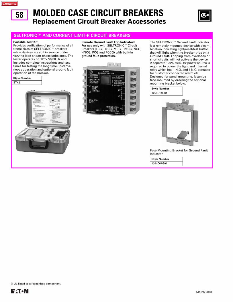
58
March 2001
MOLDED CASE CIRCUIT BREAKERS
Replacement Circuit Breaker Accessories
SELTRONIC™ AND CURRENT LIMIT-R CIRCUIT BREAKERS
Portable Test Kit
Provides verification of performance of all frame sizes of SELTRONIC
E
breakers while devices are still in service under varying load and/or phase unbalance. The tester operates on 120V 50/60 Hz and includes complete instructions and test times for testing the long time, instanta-neous operation and optional ground fault operation of the breaker.
Style Number
STK2
The SELTRONIC
E
Ground Fault indicator is a remotely mounted device with a com-bination indicating light/reset/test button that will light when the breaker trips on a Ground Fault. Tripping from overloads or short circuits will not activate the device. A separate 120V, 50/60 Hz power source is required to power the light and internal relay which has 1 N.O. and 1 N.C. contacts for customer connected alarm etc. Designed for panel mounting, it can be face-mounted by ordering the optional mounting bracket below.
Style Number
1259C14G01
Remote Ground Fault Trip Indicator
➊
For use only with SELTRONIC
E
Circuit Breakers (LCG, HLCG, MCG, HMCG, NCG, HNCG, PCG and PCCG) with built-in ground fault protection.
➊
UL listed as a recognized component.
Face Mounting Bracket for Ground FaultIndicator
Style Number
1264C67G01
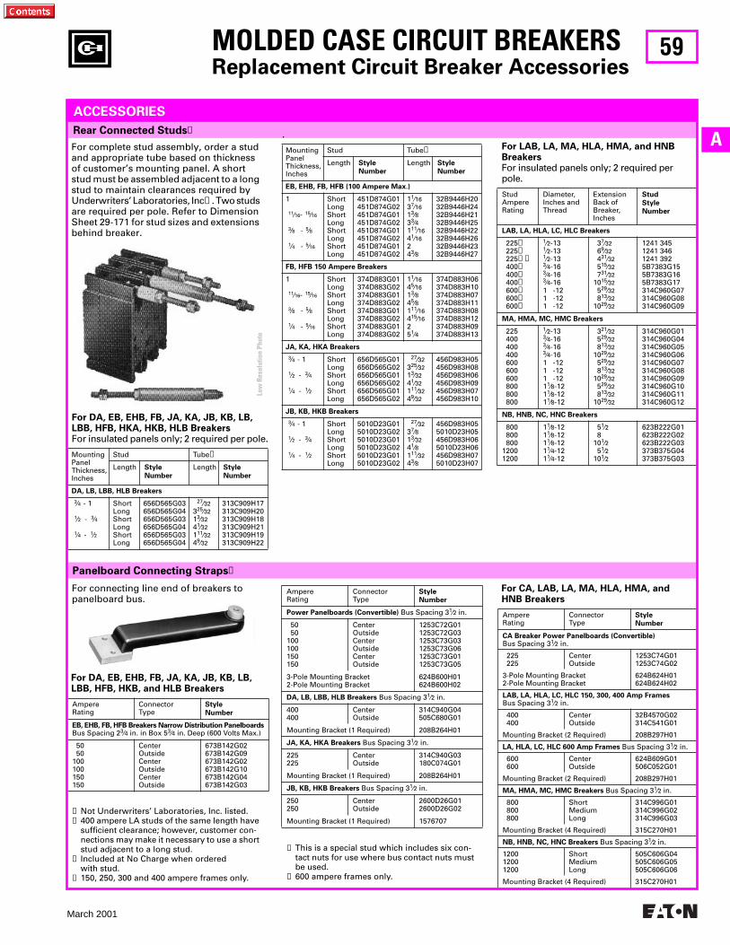
59
March 2001
A
AmpereRating
ConnectorType
Style
Number
Power Panelboards (Convertible)
Bus Spacing 3
1
⁄
2
in.
50 50100100150150
CenterOutsideCenterOutsideCenterOutside
1253C72G011253C72G031253C73G031253C73G061253C73G011253C73G05
3-Pole Mounting Bracket2-Pole Mounting Bracket
624B600H01624B600H02
DA, LB, LBB, HLB Breakers
Bus Spacing 3
1
⁄
2
in.
400400
CenterOutside
314C940G04505C680G01
Mounting Bracket (1 Required) 208B264H01
JA, KA, HKA Breakers
Bus Spacing 3
1
⁄
2
in.
225225
CenterOutside
314C940G03180C074G01
Mounting Bracket (1 Required) 208B264H01
JB, KB, HKB Breakers
Bus Spacing 3
1
⁄
2
in.
250250
CenterOutside
2600D26G012600D26G02
Mounting Bracket (1 Required) 1576707
Panelboard Connecting Straps
➊
Rear Connected Studs
➊
MOLDED CASE CIRCUIT BREAKERS
Replacement Circuit Breaker Accessories
ACCESSORIES
For complete stud assembly, order a stud and appropriate tube based on thickness of customer’s mounting panel. A short stud must be assembled adjacent to a long stud to maintain clearances required by Underwriters’ Laboratories, Inc
➋
. Two studs are required per pole. Refer to Dimension Sheet 29-171 for stud sizes and extensions behind breaker.
For DA, EB, EHB, FB, JA, KA, JB, KB, LB, LBB, HFB, HKA, HKB, HLB Breakers
For insulated panels only; 2 required per pole.
MountingPanelThickness,Inches
Stud Tube
➌
Length
Style
Number
Length
Style
Number
DA, LB, LBB, HLB Breakers
3
⁄
4
- 1
1
⁄
2
-
3
⁄
4
1
⁄
4
-
1
⁄
2
ShortLongShortLongShortLong
656D565G03656D565G04656D565G03656D565G04656D565G03656D565G04
27
⁄
32
3
25
⁄
32
1
3
⁄
32
4
1
⁄
32
1
11
⁄
32
4
9
⁄
32
313C909H17313C909H20313C909H18313C909H21313C909H19313C909H22
For LAB, LA, MA, HLA, HMA, and HNB Breakers
For insulated panels only; 2 required per pole.
StudAmpereRating
Diameter, Inches and Thread
Extension Back of Breaker, Inches
Stud
Style
Number
LAB, LA, HLA, LC, HLC Breakers
225
➍
225
➍
225
➍➎
400
➍
400
➍
400
➍
600
➏
600
➏
600
➏
1
⁄
2
-13
1
⁄
2
-13
1
⁄
2
-13
3
⁄
4
-16
3
⁄
4
-16
3
⁄
4
-161 -121 -121 -12
3
7
⁄
32
6
9
⁄
32
4
31
⁄
32
5
15
⁄
32
7
31
⁄
32
10
15
⁄
32
5
29
⁄
32
8
13
⁄
32
10
29
⁄
32
1241 3451241 3461241 3925B7383G155B7383G165B7383G17314C960G07314C960G08314C960G09
MA, HMA, MC, HMC Breakers
225 400 400 400 600 600 600 800 800 800
1
⁄
2
-13
3
⁄
4
-16
3
⁄
4
-16
3
⁄
4
-161 -121 -121 -121
1
⁄
8
-121
1
⁄
8
-121
1
⁄
8
-12
3
21
⁄
32
5
29
⁄
32
8
13
⁄
32
10
29
⁄
32
5
29
⁄
32
8
13
⁄
32
10
29
⁄
32
5
29
⁄
32
8
13
⁄
32
10
29
⁄
32
314C960G01314C960G04314C960G05314C960G06314C960G07314C960G08314C960G09314C960G10314C960G11314C960G12
NB, HNB, NC, HNC Breakers
800 800 80012001200
1
1
⁄
8
-121
1
⁄
8
-121
1
⁄
8
-121
1
⁄
4
-121
1
⁄
4
-12
5
1
⁄
2
810
1
⁄
2
5
1
⁄
2
10
1
⁄
2
623B222G01623B222G02623B222G03373B375G04373B375G03
➊
Not Underwriters’ Laboratories, Inc. listed.
➋
400 ampere LA studs of the same length have sufficient clearance; however, customer con-nections may make it necessary to use a short stud adjacent to a long stud.
➌
Included at No Charge when ordered with stud.
➍
150, 250, 300 and 400 ampere frames only.
For connecting line end of breakers to panelboard bus.
.
MountingPanelThickness,Inches
Stud Tube
➌
Length
Style
Number
Length
Style
Number
EB, EHB, FB, HFB (100 Ampere Max.)
1
11
⁄
16
-
15
⁄
16
3
⁄
8
-
5
⁄
8
1
⁄
4
-
5
⁄
16
ShortLongShortLongShortLongShortLong
451D874G01451D874G02451D874G01451D874G02451D874G01451D874G02451D874G01451D874G02
1
1
⁄
16
3
7
⁄
16
1
3
⁄
8
3
3
⁄
4
1
11
⁄
16
4
1
⁄
16
24
3
⁄
8
32B9446H2032B9446H2432B9446H2132B9446H2532B9446H2232B9446H2632B9446H2332B9446H27
FB, HFB 150 Ampere Breakers
1
11
⁄
16
-
15
⁄
16
3
⁄
8
-
5
⁄
8
1
⁄
4
-
5
⁄
16
ShortLongShortLongShortLongShortLong
374D883G01374D883G02374D883G01374D883G02374D883G01374D883G02374D883G01374D883G02
1
1
⁄
16
4
5
⁄
16
1
3
⁄
8
4
5
⁄
8
1
11
⁄
16
4
15
⁄
16
25
1
⁄
4
374D883H06374D883H10374D883H07374D883H11374D883H08374D883H12374D883H09374D883H13
JA, KA, HKA Breakers
3
⁄4 - 1
1⁄2 - 3⁄4
1⁄4 - 1⁄2
ShortLongShortLongShortLong
656D565G01656D565G02656D565G01656D565G02656D565G01656D565G02
27⁄32325⁄3213⁄3241⁄32111⁄3249⁄32
456D983H05456D983H08456D983H06456D983H09456D983H07456D983H10
JB, KB, HKB Breakers
3⁄4 - 1
1⁄2 - 3⁄4
1⁄4 - 1⁄2
ShortLongShortLongShortLong
5010D23G015010D23G025010D23G015010D23G025010D23G015010D23G02
27⁄3237⁄813⁄3241⁄8111⁄3243⁄8
456D983H055010D23H05456D983H065010D23H06456D983H075010D23H07
For CA, LAB, LA, MA, HLA, HMA, and HNB Breakers
AmpereRating
ConnectorType
Style
Number
CA Breaker Power Panelboards (Convertible)Bus Spacing 31⁄2 in.
225 225
CenterOutside
1253C74G011253C74G02
3-Pole Mounting Bracket2-Pole Mounting Bracket
624B624H01624B624H02
LAB, LA, HLA, LC, HLC 150, 300, 400 Amp FramesBus Spacing 31⁄2 in.
400 400
CenterOutside
32B4570G02314C541G01
Mounting Bracket (2 Required) 208B297H01
LA, HLA, LC, HLC 600 Amp Frames Bus Spacing 31⁄2 in.
600 600
CenterOutside
624B609G01506C052G01
Mounting Bracket (2 Required) 208B297H01
MA, HMA, MC, HMC Breakers Bus Spacing 31⁄2 in.
800 800 800
ShortMediumLong
314C996G01314C996G02314C996G03
Mounting Bracket (4 Required) 315C270H01
NB, HNB, NC, HNC Breakers Bus Spacing 31⁄2 in.
120012001200
ShortMediumLong
505C606G04505C606G05505C606G06
Mounting Bracket (4 Required) 315C270H01
For DA, EB, EHB, FB, JA, KA, JB, KB, LB, LBB, HFB, HKB, and HLB Breakers
AmpereRating
ConnectorType
Style
Number
EB, EHB, FB, HFB Breakers Narrow Distribution PanelboardsBus Spacing 23⁄4 in. in Box 53⁄4 in. Deep (600 Volts Max.)
50 50100100150150
CenterOutsideCenterOutsideCenterOutside
673B142G02673B142G09673B142G02673B142G10673B142G04673B142G03
➎ This is a special stud which includes six con-tact nuts for use where bus contact nuts must be used.
➏ 600 ampere frames only.
Low
Res
olut
ion
Phot
o
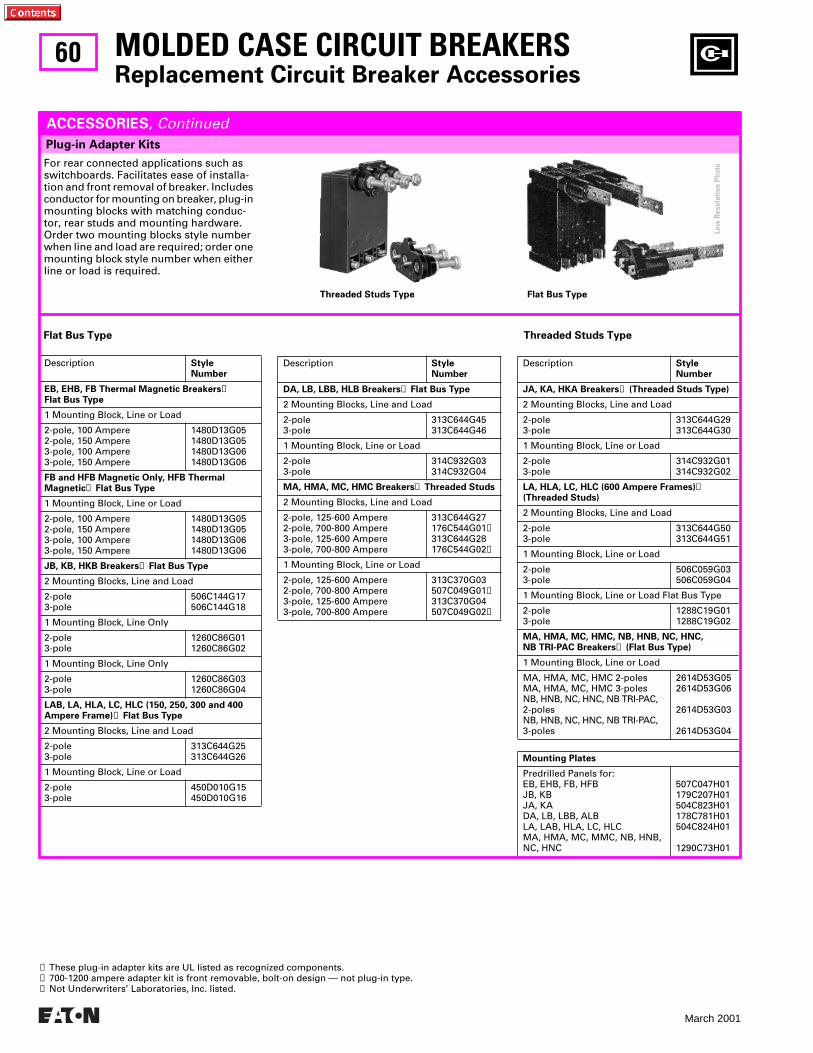
60
March 2001
Description
StyleNumber
JA, KA, HKA Breakers
➌
(Threaded Studs Type)
2 Mounting Blocks, Line and Load
2-pole3-pole
313C644G29313C644G30
1 Mounting Block, Line or Load
2-pole3-pole
314C932G01314C932G02
LA, HLA, LC, HLC (600 Ampere Frames)
➊
(Threaded Studs)
2 Mounting Blocks, Line and Load
2-pole3-pole
313C644G50313C644G51
1 Mounting Block, Line or Load
2-pole3-pole
506C059G03506C059G04
1 Mounting Block, Line or Load Flat Bus Type
2-pole3-pole
1288C19G011288C19G02
MA, HMA, MC, HMC, NB, HNB, NC, HNC, NB TRI-PAC Breakers
➌
(Flat Bus Type)
1 Mounting Block, Line or Load
MA, HMA, MC, HMC 2-polesMA, HMA, MC, HMC 3-polesNB, HNB, NC, HNC, NB TRI-PAC,2-polesNB, HNB, NC, HNC, NB TRI-PAC,3-poles
2614D53G052614D53G06
2614D53G03
2614D53G04
Mounting Plates
Predrilled Panels for:EB, EHB, FB, HFBJB, KBJA, KADA, LB, LBB, ALBLA, LAB, HLA, LC, HLCMA, HMA, MC, MMC, NB, HNB,NC, HNC
507C047H01179C207H01504C823H01178C781H01504C824H01
1290C73H01
Description
StyleNumber
EB, EHB, FB Thermal Magnetic Breakers
➊
Flat Bus Type
1 Mounting Block, Line or Load
2-pole, 100 Ampere2-pole, 150 Ampere3-pole, 100 Ampere3-pole, 150 Ampere
1480D13G051480D13G051480D13G061480D13G06
FB and HFB Magnetic Only, HFB Thermal Magnetic
➊
Flat Bus Type
1 Mounting Block, Line or Load
2-pole, 100 Ampere2-pole, 150 Ampere3-pole, 100 Ampere3-pole, 150 Ampere
1480D13G051480D13G051480D13G061480D13G06
JB, KB, HKB Breakers
➊
Flat Bus Type
2 Mounting Blocks, Line and Load
2-pole3-pole
506C144G17506C144G18
1 Mounting Block, Line Only
2-pole3-pole
1260C86G011260C86G02
1 Mounting Block, Line Only
2-pole3-pole
1260C86G031260C86G04
LAB, LA, HLA, LC, HLC (150, 250, 300 and 400 Ampere Frame)
➊
Flat Bus Type
2 Mounting Blocks, Line and Load
2-pole3-pole
313C644G25313C644G26
1 Mounting Block, Line or Load
2-pole3-pole
450D010G15450D010G16
MOLDED CASE CIRCUIT BREAKERS
Replacement Circuit Breaker Accessories
Plug-in Adapter Kits
ACCESSORIES,
Continued
For rear connected applications such as switchboards. Facilitates ease of installa-tion and front removal of breaker. Includes conductor for mounting on breaker, plug-in mounting blocks with matching conduc-tor, rear studs and mounting hardware. Order two mounting blocks style number when line and load are required; order one mounting block style number when either line or load is required.
Threaded Studs Type Flat Bus Type
Description
StyleNumber
DA, LB, LBB, HLB Breakers
➊
Flat Bus Type
2 Mounting Blocks, Line and Load
2-pole3-pole
313C644G45313C644G46
1 Mounting Block, Line or Load
2-pole3-pole
314C932G03314C932G04
MA, HMA, MC, HMC Breakers
➋
Threaded Studs
2 Mounting Blocks, Line and Load
2-pole, 125-600 Ampere2-pole, 700-800 Ampere3-pole, 125-600 Ampere3-pole, 700-800 Ampere
313C644G27176C544G01
➋
313C644G28176C544G02
➋
1 Mounting Block, Line or Load
2-pole, 125-600 Ampere2-pole, 700-800 Ampere3-pole, 125-600 Ampere3-pole, 700-800 Ampere
313C370G03507C049G01
➋
313C370G04507C049G02
➋
➊
These plug-in adapter kits are UL listed as recognized components.
➋
700-1200 ampere adapter kit is front removable, bolt-on design — not plug-in type.
➌
Not Underwriters’ Laboratories, Inc. listed.
Flat Bus Type Threaded Studs Type
Low
Res
olut
ion
Phot
o
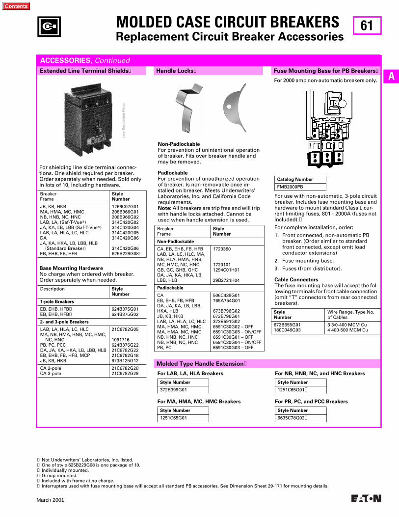
61
March 2001
A
Molded Type Handle Extension
➊
Handle Locks
➊
Fuse Mounting Base for PB Breakers
➊
MOLDED CASE CIRCUIT BREAKERS
Replacement Circuit Breaker Accessories
Extended Line Terminal Shields
➊
ACCESSORIES,
Continued
Base Mounting Hardware
No charge when ordered with breaker.Order separately when needed.
Description
StyleNumber
1-pole Breakers
EB, EHB, HFB
➌
EB, EHB, HFB
➍
624B375G01624B375G02
2- and 3-pole Breakers
LAB, LA, HLA, LC, HLCMA, NB, HMA, HNB, MC, HMC, NC, HNCPB, PC, PCCDA, JA, KA, HKA, LB, LBB, HLBEB, EHB, FB, HFB, MCPJB, KB, HKB
21C6782G05
1091716624B375G2221C6782G2221C6782G18673B125G12
CA 2-poleCA 3-pole
21C6782G2821C6782G29
For shielding line side terminal connec-tions. One shield required per breaker. Order separately when needed. Sold only in lots of 10, including hardware.
BreakerFrame
StyleNumber
JB, KB, HKBMA, HMA, MC, HMCNB, HNB, NC, HNCLAB, LA, (Saf-T-Vue
T
)JA, KA, LB, LBB (Saf-T-Vue
T
)LAB, LA, HLA, LC, HLCDAJA, KA, HKA, LB, LBB, HLB (Standard Breaker)EB, EHB, FB, HFB
1266C07G01208B966G01208B966G02314C420G02314C420G04314C420G05314C420G06
314C420G06625B229G08
➋
Non-Padlockable
For prevention of unintentional operation of breaker. Fits over breaker handle and may be removed.
Padlockable
For prevention of unauthorized operation of breaker. Is non-removable once in-stalled on breaker. Meets Underwriters’ Laboratories, Inc. and California Code requirements.
Note:
All breakers are trip free and will trip with handle locks attached. Cannot be used when handle extension is used.
BreakerFrame
StyleNumber
Non-Padlockable
CA, EB, EHB, FB, HFBLAB, LA, LC, HLC, MA, NB, HLA, HMA, HNB, MC, HMC, NC, HNCGB, GC, GHB, GHCDA, JA, KA, HKA, LB, LBB, HLB
1720360
17201011294C01H01
29B2721H04
Padlockable
CAEB, EHB, FB, HFBDA, JA, KA, LB, LBB, HKA, HLBJB, KB, HKBLAB, LA, HLA, LC, HLCMA, HMA, MC, HMCMA, HMA, MC, HMCNB, HNB, NC, HNCNB, HNB, NC, HNCPB, PC
506C438G01765A754G01
673B796G02673B796G01373B591G026591C30G02 – OFF6591C30G05 – ON/OFF6591C30G01 – OFF6591C30G04 – ON/OFF6591C30G03 – OFF
For LAB, LA, HLA Breakers
For MA, HMA, MC, HMC Breakers
Style Number
372B399G01
Style Number
1251C65G01
For 2000 amp non-automatic breakers only.
For use with non-automatic, 3-pole circuit breaker. Includes fuse mounting base and hardware to mount standard Class L cur-rent limiting fuses, 801 - 2000A (fuses not included).
➏
For complete installation, order:
1. Front connected, non-automatic PB breaker. (Order similar to standard front connected, except omit load conductor extensions)
2. Fuse mounting base.
3. Fuses (from distributor).
Cable Connectors
The fuse mounting base will accept the fol-lowing terminals for front cable connection (omit “T” connectors from rear connected breakers).
StyleNumber
Wire Range, Type No. of Cables
672B655G01180C046G03
3 3/0-400 MCM Cu4 400-500 MCM Cu
➊
Not Underwriters’ Laboratories, Inc. listed.
➋
One of style 625B229G08 is one package of 10.
➌
Individually mounted.
➍
Group mounted.
➎
Included with frame at no charge.
➏
Interrupters used with fuse mounting base will accept all standard PB accessories. See Dimension Sheet 29-171 for mounting details.
Catalog Number
FMB2000PB
For NB, HNB, NC, and HNC Breakers
For PB, PC, and PCC Breakers
Style Number
1251C65G01
➎
Style Number
6635C78G02
➎
Low
Res
olut
ion
Phot
o
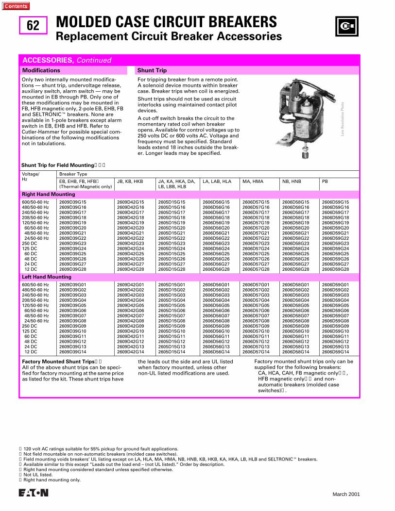
62
March 2001
Shunt Trip for Field Mounting
➊➋➌
Voltage/Hz
Breaker Type
EB, EHB, FB, HFB
➍
(Thermal-Magnetic only)JB, KB, HKB JA, KA, HKA, DA,
LB, LBB, HLBLA, LAB, HLA MA, HMA NB, HNB PB
Right Hand Mounting
600/50-60 Hz480/50-60 Hz240/50-60 Hz208/50-60 Hz120/50-60 Hz 60/50-60 Hz 48/50-60 Hz 24/50-60 Hz250 DC125 DC 60 DC 48 DC 24 DC 12 DC
2609D39G152609D39G162609D39G172609D39G182609D39G192609D39G202609D39G212609D39G222609D39G232609D39G242609D39G252609D39G262609D39G272609D39G28
2609D42G152609D42G162609D42G172609D42G182609D42G192609D42G202609D42G212609D42G222609D42G232609D42G242609D42G252609D42G262609D42G272609D42G28
2605D15G152605D15G162605D15G172605D15G182605D15G192605D15G202605D15G212605D15G222605D15G232605D15G242605D15G252605D15G262605D15G272605D15G28
2606D56G152606D56G162606D56G172606D56G182606D56G192606D56G202606D56G212606D56G222606D56G232606D56G242606D56G252606D56G262606D56G272606D56G28
2606D57G152606D57G162606D57G172606D57G182606D57G192606D57G202606D57G212606D57G222606D57G232606D57G242606D57G252606D57G262606D57G272606D57G28
2606D58G152606D58G162606D58G172606D58G182606D58G192606D58G202606D58G212606D58G222606D58G232606D58G242606D58G252606D58G262606D58G272606D58G28
2606D59G152606D59G162606D59G172606D59G182606D59G192606D59G202606D59G212606D59G222606D59G232606D59G242606D59G252606D59G262606D59G272606D59G28
Left Hand Mounting
600/50-60 Hz480/50-60 Hz240/50-60 Hz208/50-60 Hz120/50-60 Hz 60/50-60 Hz 48/50-60 Hz 24/50-60 Hz250 DC125 DC 60 DC 48 DC 24 DC 12 DC
2609D39G012609D39G022609D39G032609D39G042609D39G052609D39G062609D39G072609D39G082609D39G092609D39G102609D39G112609D39G122609D39G132609D39G14
2609D42G012609D42G022609D42G032609D42G042609D42G052609D42G062609D42G072609D42G082609D42G092609D42G102609D42G112609D42G122609D42G132609D42G14
2605D15G012605D15G022605D15G032605D15G042605D15G052605D15G062605D15G072605D15G082605D15G092605D15G102605D15G112605D15G122605D15G132605D15G14
2606D56G012606D56G022606D56G032606D56G042606D56G052606D56G062606D56G072606D56G082606D56G092606D56G102606D56G112606D56G122606D56G132606D56G14
2606D57G012606D57G022606D57G032606D57G042606D57G052606D57G062606D57G072606D57G082606D57G092606D57G102606D57G112606D57G122606D57G132606D57G14
2606D58G012606D58G022606D58G032606D58G042606D58G052606D58G062606D58G072606D58G082606D58G092606D58G102606D58G112606D58G122606D58G132606D58G14
2606D59G012606D59G022606D59G032606D59G042606D59G052606D59G062606D59G072606D59G082606D59G092606D59G102606D59G112606D59G122606D59G132606D59G14
Shunt Trip
MOLDED CASE CIRCUIT BREAKERS
Replacement Circuit Breaker Accessories
Modifications
ACCESSORIES,
Continued
Only two internally mounted modifica-tions — shunt trip, undervoltage release, auxiliary switch, alarm switch — may be mounted in EB through PB. Only one of these modifications may be mounted in FB, HFB magnetic only, 2-pole EB, EHB, FB and SELTRONIC
E
breakers. None are available in 1-pole breakers except alarm switch in EB, EHB and HFB. Refer to Cutler-Hammer for possible special com-binations of the following modifications not in tabulations.
For tripping breaker from a remote point. A solenoid device mounts within breaker case. Breaker trips when coil is energized.
Shunt trips should not be used as circuit interlocks using maintained contact pilot devices.
A cut-off switch breaks the circuit to the momentary rated coil when breaker opens. Available for control voltages up to 250 volts DC or 600 volts AC. Voltage and frequency must be specified. Standard leads extend 18 inches outside the break-er. Longer leads may be specified.
Factory Mounted Shunt Trips
➊➎
All of the above shunt trips can be speci-fied for factory mounting at the same price as listed for the kit. These shunt trips have
the leads out the side and are UL listed when factory mounted, unless other non-UL listed modifications are used.
➊
120 volt AC ratings suitable for 55% pickup for ground fault applications.
➋
Not field mountable on non-automatic breakers (molded case switches).
➌
Field mounting voids breakers’ UL listing except on LA, HLA, MA, HMA, NB, HNB, KB, HKB, KA, HKA, LB, HLB and SELTRONIC
E
breakers.
➍
Available similar to this except “Leads out the load end – (not UL listed).” Order by description.
➎
Right hand mounting considered standard unless specified otherwise.
➏
Not UL listed.
➐
Right hand mounting only.
Factory mounted shunt trips only can be supplied for the following breakers:
CA, HCA, CAH, FB magnetic only
➏➐
, HFB magnetic only
➏➐
and non-automatic breakers (molded case switches)
➋
.
Low
Res
olut
ion
Phot
o
63
March 2001
AProvision to trip flux transfer shunt trip from external32 to 120 volt (DC to 60 Hz) source.➊➋
Provision to trip flux transfer shunt trip from external240 to 600 volt AC, 50/60 Hz source.➋➌
MOLDED CASE CIRCUIT BREAKERSReplacement Circuit Breaker Accessories
Left Hand Mounting Kits For SELTRONIC™ Breakers
ACCESSORIES, Continued
MC, HMC Style 1371D72G32NC, HNC Style 1372D39G23PC, PCC Style 1372D35G32LC, HLC Style 1371D11G32
Shunt Trip Coil Data
Shunt TripVoltage Rating
For All Breakers Listed Above and onPrevious Page Except CA and SELTRONICE
SELTRONICE
Coil Inrush Coil Inrush
Amperes Volt-Amperes Amperes Volt-Amperes
600 AC480 AC240 AC208 AC120 AC 60 AC 48 AC 24 AC250 DC125 DC 60 DC 48 DC 24 DC (FB) 24 DC (KB) 24 DC (others) 12 DC
0.1050.0851.71.40.889.107.503.952.50.9750.5251.36.3.88.6.
63.0 40.8408.0291.2105.6546.0360.0 94.8625.0121.9 31.5 62.4144.0 91.2192. 72.
. . .
. . .
. . .
. . .15. . .. . .. . .. . .. . .. . .. . .. . .. . .. . .. . .
. . .
. . .
. . .
. . .18. . .. . .. . .. . .. . .. . .. . .. . .. . .. . .. . .
MC, HMC Style 1371D72G22NC, HNC Style 1372D39G13PC, PCC Style 1372D35G22LC, HLC Style 1371D11G22
➊ Rated 48 volts minimum for ground fault applications.➋ Also available factory mounted for 24 volts DC. Order by description.➌ Not for ground fault.
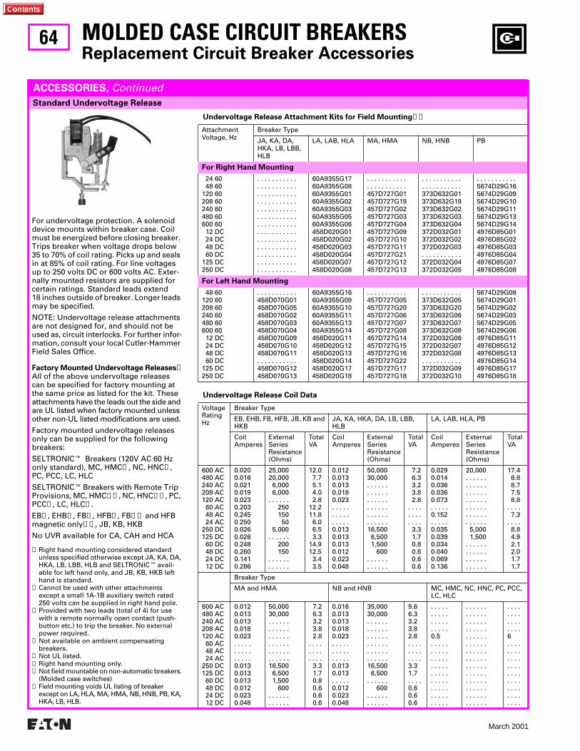
64
March 2001
Undervoltage Release Attachment Kits for Field Mounting➐➑
AttachmentVoltage, Hz
Breaker Type
JA, KA, DA, HKA, LB, LBB, HLB
LA, LAB, HLA MA, HMA NB, HNB PB
For Right Hand Mounting
24 60 48 60120 60208 60240 60480 60600 60 12 DC 24 DC 48 DC 60 DC125 DC250 DC
. . . . . . . . . . .
. . . . . . . . . . .
. . . . . . . . . . .
. . . . . . . . . . .
. . . . . . . . . . .
. . . . . . . . . . .
. . . . . . . . . . .
. . . . . . . . . . .
. . . . . . . . . . .
. . . . . . . . . . .
. . . . . . . . . . .
. . . . . . . . . . .
. . . . . . . . . . .
60A9355G1760A9355G0860A9355G0160A9355G0260A9355G0360A9355G0560A9355G06458D020G01458D020G02458D020G03458D020G04458D020G07458D020G08
. . . . . . . . . . .
. . . . . . . . . . .457D727G01457D727G19457D727G02457D727G03457D727G04457D727G09457D727G10457D727G11457D727G21457D727G12457D727G13
. . . . . . . . . . .
. . . . . . . . . . .373D632G01373D632G19373D632G02373D632G03373D632G04372D032G01372D032G02372D032G03. . . . . . . . . . .372D032G04372D032G05
. . . . . . . . . . .5674D29G165674D29G095674D29G105674D29G115674D29G135674D29G144976D85G014976D85G024976D85G034976D85G044976D85G074976D85G08
For Left Hand Mounting
48 60120 60208 60240 60480 60600 60 12 DC 24 DC 48 DC 60 DC125 DC250 DC
. . . . . . . . . . .458D070G01458D070G05458D070G02458D070G03458D070G04458D070G09458D070G10458D070G11. . . . . . . . . . .458D070G12458D070G13
60A9355G1660A9355G0960A9355G1060A9355G1160A9355G1360A9355G14458D020G11458D020G12458D020G13458D020G14458D020G17458D020G18
. . . . . . . . . . .457D727G05457D727G20457D727G06457D727G07457D727G08457D727G14457D727G15457D727G16457D727G22457D727G17457D727G18
. . . . . . . . . . .373D632G05373D632G20373D632G06373D632G07373D632G08372D032G06372D032G07372D032G08. . . . . . . . . . .372D032G09372D032G10
5674D29G085674D29G015674D29G025674D29G035674D29G055674D29G064976D85G114976D85G124976D85G134976D85G144976D85G174976D85G18
MOLDED CASE CIRCUIT BREAKERSReplacement Circuit Breaker Accessories
Standard Undervoltage Release
ACCESSORIES, Continued
For undervoltage protection. A solenoid device mounts within breaker case. Coil must be energized before closing breaker. Trips breaker when voltage drops below 35 to 70% of coil rating. Picks up and seals in at 85% of coil rating. For line voltages up to 250 volts DC or 600 volts AC. Exter-nally mounted resistors are supplied for certain ratings. Standard leads extend 18 inches outside of breaker. Longer leads may be specified.
NOTE: Undervoltage release attachments are not designed for, and should not be used as, circuit interlocks. For further infor-mation, consult your local Cutler-Hammer Field Sales Office.
Factory Mounted Undervoltage Releases➊All of the above undervoltage releases can be specified for factory mounting at the same price as listed for the kit. These attachments have the leads out the side and are UL listed when factory mounted unless other non-UL listed modifications are used.
Factory mounted undervoltage releases only can be supplied for the following breakers:
SELTRONICE Breakers (120V AC 60 Hz only standard), MC, HMC➋, NC, HNC➋, PC, PCC, LC, HLC
SELTRONICE Breakers with Remote Trip Provisions, MC, HMC➋➌, NC, HNC➋➌, PC, PCC➌, LC, HLC➌.
EB➍, EHB➍, FB➍, HFB➍, FB➎➏ and HFB magnetic only➎➏, JB, KB, HKB
No UVR available for CA, CAH and HCA
➊ Right hand mounting considered standard unless specified otherwise except JA, KA, DA, HKA, LB, LBB, HLB and SELTRONICE avail-able for left hand only, and JB, KB, HKB left hand is standard.
➋ Cannot be used with other attachments except a small 1A-1B auxiliary switch rated 250 volts can be supplied in right hand pole.
➌ Provided with two leads (total of 4) for use with a remote normally open contact (push-button etc.) to trip the breaker. No external power required.
➍ Not available on ambient compensating breakers.
➎ Not UL listed.➏ Right hand mounting only.➐ Not field mountable on non-automatic breakers.
(Molded case switches)➑ Field mounting voids UL listing of breaker
except on LA, HLA, MA, HMA, NB, HNB, PB, KA, HKA, LB, HLB.
Undervoltage Release Coil Data
VoltageRatingHz
Breaker Type
EB, EHB, FB, HFB, JB, KB and HKB
JA, KA, HKA, DA, LB, LBB, HLB
LA, LAB, HLA, PB
Coil Amperes
External SeriesResistance (Ohms)
TotalVA
Coil Amperes
External SeriesResistance (Ohms)
TotalVA
Coil Amperes
External SeriesResistance (Ohms)
TotalVA
600 AC480 AC240 AC208 AC120 AC 60 AC 48 AC 24 AC250 DC125 DC 60 DC 48 DC 24 DC 12 DC
0.0200.0160.0210.0190.0230.2030.2450.2500.0260.0260.2480.2600.1410.286
25,00020,000 6,000 6,000. . . . . . 250 150 50 5,000. . . . . . 200 150. . . . . .. . . . . .
12.0 7.7 5.1 4.0 2.812.211.8 6.0 6.5 3.314.912.5 3.4 3.5
0.0120.0130.0130.0180.023. . . . . . . . . .. . . . .0.0130.0130.0130.0120.0230.048
50,00030,000. . . . . .. . . . . .. . . . . .. . . . . .. . . . . .. . . . . .16,500 6,500 1,500 600. . . . . .. . . . . .
7.2 6.3 3.2 3.8 2.8. . . .. . . .. . . . 3.3 1.7 0.8 0.6 0.6 0.6
0.0290.0140.0360.0360.073. . . . .0.152. . . . .0.0350.0390.0340.0400.0690.136
20,000. . . . . .. . . . . .. . . . . .. . . . . .. . . . . .. . . . . .. . . . . . 5,000 1,500. . . . . .. . . . . .. . . . . .. . . . . .
17.4 6.8 8.7 7.5 8.8. . . . 7.3. . . . 8.8 4.9 2.1 2.0 1.7 1.7
Breaker Type
MA and HMA NB and HNB MC, HMC, NC, HNC, PC, PCC, LC, HLC
600 AC480 AC240 AC208 AC120 AC 60 AC 48 AC 24 AC250 DC125 DC 60 DC 48 DC 24 DC 12 DC
0.0120.0130.0130.0180.023. . . . .. . . . .. . . . .0.0130.0130.0130.0120.0230.048
50,00030,000. . . . . .. . . . . .. . . . . .. . . . . .. . . . . .. . . . . .16,500 6,500 1,500 600. . . . . .. . . . . .
7.26.33.23.82.8
. . . .
. . . .
. . . .3.31.70.80.60.60.6
0.0160.0130.0130.0180.023. . . . .. . . . .. . . . .0.0130.013. . . . .0.0120.0230.048
35,00030,000. . . . . .. . . . . .. . . . . .. . . . . .. . . . . .. . . . . .16,500 6,500. . . . . . 600. . . . . .. . . . . .
9.66.33.23.82.8. . . .. . . .. . . .3.31.7. . . .0.60.60.6
. . . . .
. . . . .
. . . . .
. . . . .0.5. . . . .. . . . .. . . . .. . . . .. . . . .. . . . .. . . . .. . . . .. . . . .
. . . . . .
. . . . . .
. . . . . .
. . . . . .
. . . . . .
. . . . . .
. . . . . .
. . . . . .
. . . . . .
. . . . . .
. . . . . .
. . . . . .
. . . . . .
. . . . . .
. . . .
. . . .
. . . .
. . . .6. . . .. . . .. . . .. . . .. . . .. . . .. . . .. . . .. . . .
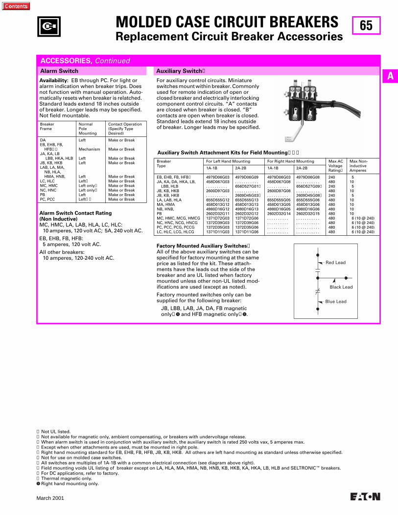
65
March 2001
AAvailability: EB through PC. For light or alarm indication when breaker trips. Does not function with manual operation. Auto-matically resets when breaker is relatched. Standard leads extend 18 inches outside of breaker. Longer leads may be specified. Not field mountable.
Alarm Switch Contact Rating (Non Inductive)MC, HMC, LA, LAB, HLA, LC, HLC:
10 amperes, 120 volt AC; 5A, 240 volt AC.
EB, EHB, FB, HFB:5 amperes, 120 volt AC.
All other breakers:10 amperes, 120-240 volt AC.
BreakerFrame
NormalPole Mounting
Contact Operation(Specify TypeDesired)
DAEB, EHB, FB, HFB➊➋JA, KA, LB LBB, HKA, HLBJB, KB, HKBLAB, LA, MA, NB, HLA, HMA, HNB,LC, HLCMC, HMCNC, HNCPBPC, PCC
Left
Mechanism
LeftLeft
LeftLeft➌Left only➌Left only➌LeftLeft➌➍
Make or Break
Make or Break
Make or BreakMake or Break
Make or BreakMake or BreakMake or BreakMake or BreakMake or BreakMake or Break
Auxiliary Switch Attachment Kits for Field Mounting➏➐➑
BreakerType
For Left Hand Mounting For Right Hand Mounting Max ACVoltageRating➒
Max Non-inductiveAmperes1A-1B 2A-2B 1A-1B 2A-2B
EB, EHB, FB, HFB➓JA, KA, DA, HKA, LB, LBB, HLBJB, KB, HKBJB, KB, HKBLA, LAB, HLAMA, HMANB, HNB,PBMC, HMC, MCG, HMCGNC, HNC, NCG, HNCGPC, PCC, PCG, PCCGLC, HLC, LCG, HLCG
4979D06G03458D067G03. . . . . . . . . .2600D97G03. . . . . . . . . .655D555G12458D013G124980D16G122602D32G111371D72G031372D39G031372D35G031371D11G03
4979D06G09. . . . . . . . . . .656D527G01➊. . . . . . . . . . .2609D45G03➊655D555G13458D013G134980D16G132602D32G121371D72G061372D39G061372D35G061371D11G06
4979D06G03458D067G08. . . . . . . . . .2600D97G08. . . . . . . . . .655D555G05458D013G054980D16G052602D32G14. . . . . . . . . .. . . . . . . . . .. . . . . . . . . .. . . . . . . . . .
4979D06G08. . . . . . . . . . .656D527G09➊. . . . . . . . . . .2609D45G08➊655D555G06458D013G064980D16G062602D32G15. . . . . . . . . . .. . . . . . . . . . .. . . . . . . . . . .. . . . . . . . . . .
240480240480240480480480480480480480480
510 510 510101010 6 (10 @ 240) 6 (10 @ 240) 6 (10 @ 240) 6 (10 @ 240)
Auxiliary Switch➎
MOLDED CASE CIRCUIT BREAKERSReplacement Circuit Breaker Accessories
Alarm Switch
ACCESSORIES, Continued
➊ Not UL listed.➋ Not available for magnetic only, ambient compensating, or breakers with undervoltage release.➌ When alarm switch is used in conjunction with auxiliary switch, the auxiliary switch is rated 250 volts vax, 5 amperes max.➍ Except when other attachments are used, must be mounted in right pole.➎ Right hand mounting standard for EB, EHB, FB, HFB, JB, KB, HKB. All others are left hand mounting as standard unless otherwise specified.➏ Not for use on molded case switches.➐ All switches are multiples of 1A-1B with a common electrical connection (see diagram above right).➑ Field mounting voids UL listing of breaker except on LA, HLA, MA, HMA, NB, HNB, KB, HKB, KA, HKA, LB, HLB and SELTRONICE breakers.➒ For DC applications, refer to factory.➓ Thermal magnetic only.K Right hand mounting only.
For auxiliary control circuits. Miniature switches mount within breaker. Commonly used for remote indication of open or closed breaker and electrically interlocking component control circuits. “A” contacts are closed when breaker is closed. “B” contacts are open when breaker is closed. Standard leads extend 18 inches outside of breaker. Longer leads may be specified.
Factory Mounted Auxiliary Switches➎All of the above auxiliary switches can be specified for factory mounting at the same price as listed for the kit. These attach-ments have the leads out the side of the breaker and are UL listed when factory mounted unless other non-UL listed mod-ifications are used (except as noted).
Factory mounted switches only can be supplied for the following breaker:
JB, LBB, LAB, JA, DA, FB magneticonly➊K and HFB magnetic only➊K.
Black Lead
Blue Lead
Red Lead
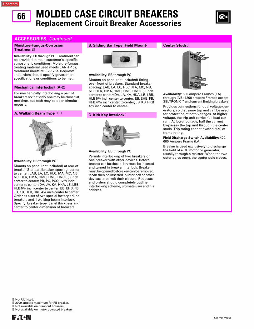
66
March 2001
Mechanical Interlocks
➊
(A-C)
A. Walking Beam Type
➊➋➌
MOLDED CASE CIRCUIT BREAKERS
Replacement Circuit Breaker Accessories
Center Studs
➊
B. Sliding Bar Type (Field Mount-Moisture-Fungus-Corrosion Treatment
➊
ACCESSORIES,
Continued
Availability:
EB through PC. Treatment can be provided to meet customer’s specific atmospheric conditions. Moisture-fungus treating material used meets JAN-T-152; treatment meets MIL-V-173a. Requests and orders should specify government specifications or conditions to be met.
Availability:
EB through PC
Mounts on panel (not included) at rear of breaker. Standard breaker spacing: center to center; LAB, LA, LC, HLC, MA, MC, NB, NC, HLA, HMA, HMC, HNB, HNC 8
1
/
2
inch center to center; PB, PC, PCC; 12
1
/
4
inch center to center; DA, JA, KA, HKA, LB, LBB, HLB 5
3
/
4
inch center to center; EB, EHB, FB, JB, KB, HFB, HKB 4
3
/
8
inch center to center. Order as a set of two special factory drilled breakers and 1 walking beam interlock. Specify breaker type, panel thickness and center to center dimension of breakers.
➊
Not UL listed.
➋
2000 ampere maximum for PB breaker.
➌
Not available on draw-out breakers.
➍
Not available on motor operated breakers.
Availability:
EB through PC
Mounts on panel (not included) fitting over front of breakers. Standard breaker spacing: LAB, LA, LC, HLC, MA, MC, NB, NC, HLA, HMA, HMC, HNB, HNC 8
1
/
2
inch center to center; DA, JA, KA, HKA, LB, LBB, HLB 5
3
/
4
inch center to center; EB, EHB, FB, HFB 4
3
/
16
inch center to center; JB, KB, HKB 4
3
/
8
inch center to center.
Availability:
EB through PC
Permits interlocking of two breakers or one breaker with other devices. Before breaker can be closed, key must be inserted and turned in breaker interlock. Breaker must be opened before key can be removed. It can then be inserted in interlock or other devices to permit their closure. Requests and orders should completely outline interlocking scheme, ultimate user and his address.
Availability:
600 ampere Frames (LA) through (NB) 1200 ampere Frames except SELTRONIC
E
and current limiting breakers.
Provides connections for dual voltage gen-erators, so that same trip unit can be used for protection at both voltages. At higher voltage, the trip unit carries full load cur-rent. At lower voltage, half the current by-passes the trip unit through the center studs. Trip rating cannot exceed 50% of frame rating.
Field Discharge Switch Availability:
400, 600 Ampere Frame (LA).
Breaker is used exclusively to discharge the field of a DC motor or generator, usually through a resistor. When the two outer poles open, the center pole closes.
For mechanically interlocking a pair of breakers so that only one may be closed at one time, but both may be open simulta-neously.
C. Kirk Key Interlock
➍
Low
Res
olut
ion
Phot
o
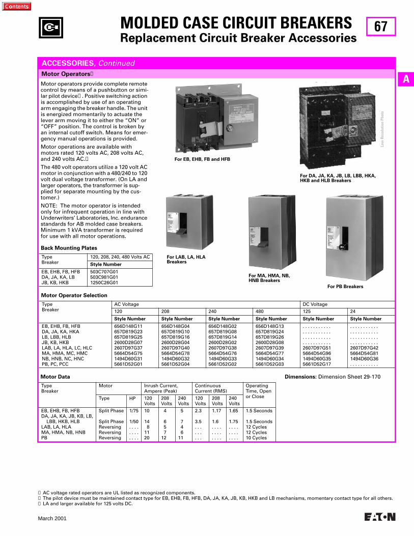
67
March 2001
A
MOLDED CASE CIRCUIT BREAKERS
Replacement Circuit Breaker Accessories
Motor Operators
➊
ACCESSORIES,
Continued
Motor operators provide complete remote control by means of a pushbutton or simi-lar pilot device
➋
. Positive switching action is accomplished by use of an operating arm engaging the breaker handle. The unit is energized momentarily to actuate the lever arm moving it to either the “ON” or “OFF” position. The control is broken by an internal cutoff switch. Means for emer-gency manual operations is provided.
Motor operations are available with motors rated 120 volts AC, 208 volts AC, and 240 volts AC.
➌
The 480 volt operators utilize a 120 volt AC motor in conjunction with a 480/240 to 120 volt dual voltage transformer. (On LA and larger operators, the transformer is sup-plied for separate mounting by the cus-tomer.)
NOTE: The motor operator is intended only for infrequent operation in line with Underwriters’ Laboratories, Inc. endurance standards for AB molded case breakers. Minimum 1 kVA transformer is required for use with all motor operations.
For LAB, LA, HLA Breakers
For MA, HMA, NB,HNB Breakers
Motor Operator Selection
TypeBreaker
AC Voltage DC Voltage
120 208 240 480 125 24
Style Number Style Number Style Number Style Number Style Number Style Number
EB, EHB, FB, HFBDA, JA, KA, HKALB, LBB, HLBJB, KB, HKBLAB, LA, HLA, LC, HLCMA, HMA, MC, HMCNB, HNB, NC, HNCPB, PC, PCC
656D148G11657D819G23657D819G252600D28G072607D97G375664D54G751494D60G315661D52G01
656D148G04657D819G10657D819G162600D28G042607D97G405664D54G781494D60G325661D52G04
656D148G02657D819G08657D819G142600D28G022607D97G385664D54G761494D60G335661D52G02
656D148G13657D819G24657D819G262600D28G082607D97G395664D54G771494D60G345661D52G03
. . . . . . . . . . .
. . . . . . . . . . .
. . . . . . . . . . .
. . . . . . . . . . .2607D97G515664D54G961494D60G355661D52G17
. . . . . . . . . . .
. . . . . . . . . . .
. . . . . . . . . . .
. . . . . . . . . . .2607D97G425664D54G811494D60G36. . . . . . . . . . .
➊
AC voltage rated operators are UL listed as recognized components.
➋
The pilot device must be maintained contact type for EB, EHB, FB, HFB, DA, JA, KA, JB, KB, HKB and LB mechanisms, momentary contact type for all others.
➌
LA and larger available for 125 volts DC.
Dimensions:
Dimension Sheet 29-170
Back Mounting Plates
TypeBreaker
120, 208, 240, 480 Volts AC
Style Number
EB, EHB, FB, HFBDA, JA, KA, LBJB, KB, HKB
503C707G01503C981G011250C26G01
For EB, EHB, FB and HFB
For DA, JA, KA, JB, LB, LBB, HKA,HKB and HLB Breakers
Motor Data
TypeBreaker
Motor Inrush Current,Ampere (Peak)
ContinuousCurrent (RMS)
OperatingTime, Openor CloseType HP 120
Volts208Volts
240Volts
120Volts
208Volts
240Volts
EB, EHB, FB, HFBDA, JA, KA, JB, KB, LB, LBB, HKB, HLBLAB, LA, HLAMA, HMA, NB, HNBPB
Split Phase
Split PhaseReversingReversingReversing
1/75
1/50. . . .. . . .. . . .
10
14 81120
4
6 5 712
5
7 4 611
2.3
3.5. . . . . .. . .
1.17
1.6. . . .. . . .. . . .
1.65
1.75. . . .. . . .. . . .
1.5 Seconds
1.5 Seconds12 Cycles12 Cycles10 Cycles
For PB Breakers
Low
Res
olut
ion
Phot
o
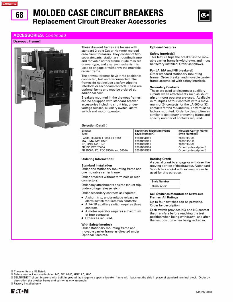
68
March 2001
Selection Data➋➌
BreakerType
Stationary Mounting FrameStyle Number➋
Movable Carrier FrameStyle Number➋
LA600, HLA600, LC600, HLC600MA, HMA, MC, HMCNB, HNB, NC, HNCPB, PC, PCC 2000APB 2500A, PC, PCC 2500A and 3000A
2603D84G012603D85G012603D85G012601D18G042601D18G05
2608D35G062608D35G102608D34G08Order by description➍Order by description➍
MOLDED CASE CIRCUIT BREAKERSReplacement Circuit Breaker Accessories
Drawout Frame➊
ACCESSORIES, Continued
These drawout frames are for use with standard 3-pole Cutler-Hammer molded case circuit breakers. They consist of two separate parts: stationary mounting frame and movable carrier frame. Slide rails are drawer-type, and a screw mechanism is used to engage or withdraw the movable carrier frame.
The drawout frames have three positions: connected, test and disconnected. The frames do not include a safety tripping interlock, or secondary contacts. These are optional items and may be ordered at additional cost.
Breakers mounted in the drawout frames can be equipped with standard breaker accessories including shunt trip, under-voltage release, auxiliary switch, alarm switch and motor operator.
➊ These units are UL listed.➋ Safety interlock not available on MC, NC, HMC, HNC, LC, HLC.➌ SELTRONICE circuit breakers with built-in ground fault require a special breaker frame with leads out the side in place of standard terminal block. Order by
descrption the breaker frame and carrier as one assembly.➍ Factory installed only.
Optional Features
Safety Interlock➋This feature trips the breaker as the mov-able carrier frame is withdrawn, and must be factory installed. Order as follows.
For LA, MA and NB breakers➋Order standard stationary mounting frame. Order breaker and movable carrier frame assembled with safety interlock.
Secondary ContactsThese are used to disconnect auxiliary circuits when attachments such as shunt trip or motor operator are used. Available in multiples of four contacts with a maxi-mum of 24 contacts for the LA 600 or 32 contacts for the MA and NB. They must be factory mounted. Order by description as similar to stationary or moving frame and specify number of contacts required.
Ordering Information➌
Standard InstallationOrder one stationary mounting frame and one movable carrier frame.
Order breakers without terminals or rear connectors.
Order any attachments desired (shunt trip, undervoltage release, etc.)
Order secondary contacts as required:
● A shunt trip, undervoltage release or alarm switch requires two contacts;
● A 1A-1B auxiliary switch requires three contacts;
● A motor operator requires a maximum of four contacts;
● Others as required.
With Safety InterlockOrder stationary mounting frame and movable carrier frame as directed under Optional Features.
Racking CrankA special crank to engage or withdraw the moving portion of the drawout. A standard 1/2 inch hex socket with extension can be used for this purpose.
Cell Switches Mounted on Draw-out Frames, All Ratings
Up to four switches can be provided. Order by description.
Each switch provides NO and NC contact that transfers before reaching the test position when being withdrawn, and after the test position when being racked in.
Style Number
765A767G01
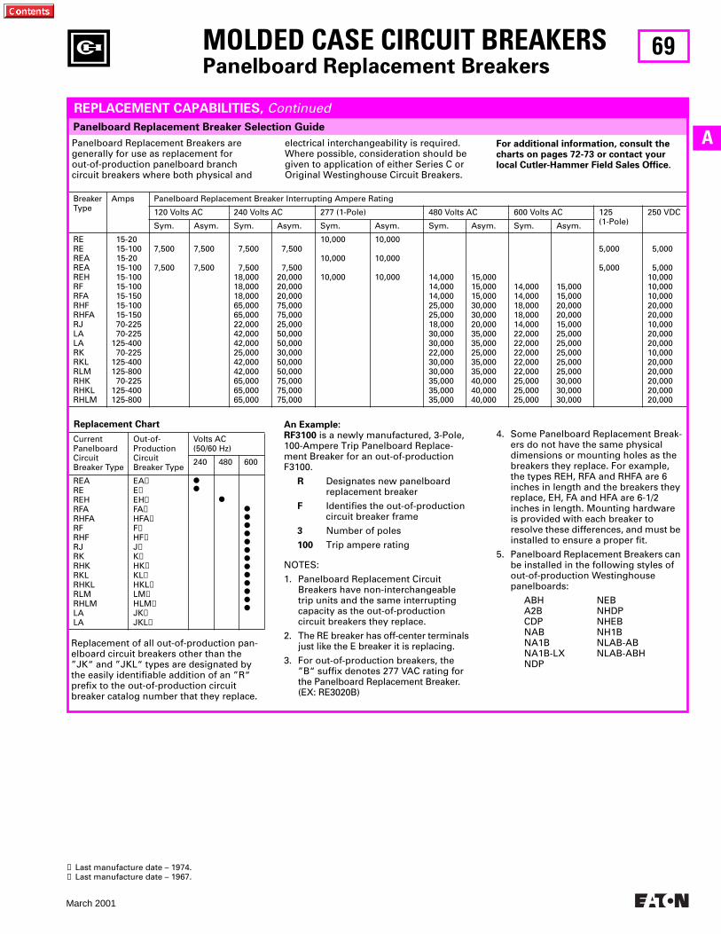
69
March 2001
A
MOLDED CASE CIRCUIT BREAKERS
Panelboard Replacement Breakers
REPLACEMENT CAPABILITIES,
Continued
Panelboard Replacement Breakers are generally for use as replacement for out-of-production panelboard branch circuit breakers where both physical and
An Example:RF3100
is a newly manufactured, 3-Pole, 100-Ampere Trip Panelboard Replace-ment Breaker for an out-of-production F3100.
R
Designates new panelboard replacement breaker
F
Identifies the out-of-production circuit breaker frame
3
Number of poles
100
Trip ampere rating
NOTES:
1. Panelboard Replacement Circuit Breakers have non-interchangeable trip units and the same interrupting capacity as the out-of-production circuit breakers they replace.
2. The RE breaker has off-center terminals just like the E breaker it is replacing.
3. For out-of-production breakers, the ”B“ suffix denotes 277 VAC rating for the Panelboard Replacement Breaker. (EX: RE3020B)
Panelboard Replacement Breaker Selection Guide
electrical interchangeability is required. Where possible, consideration should be given to application of either Series C or Original Westinghouse Circuit Breakers.
For additional information, consult the charts on pages 72-73 or contact your local Cutler-Hammer Field Sales Office.
BreakerType
Amps Panelboard Replacement Breaker Interrupting Ampere Rating
120 Volts AC 240 Volts AC 277 (1-Pole) 480 Volts AC 600 Volts AC 125 (1-Pole)
250 VDC
Sym. Asym. Sym. Asym. Sym. Asym. Sym. Asym. Sym. Asym.
REREREAREAREHRFRFARHFRHFARJLALARKRKLRLMRHKRHKLRHLM
15-20 15-100 15-20 15-100 15-100 15-100 15-150 15-100 15-150 70-225 70-225125-400 70-225125-400125-800 70-225125-400125-800
7,500
7,500
7,500
7,500
7,500
7,50018,00018,00018,00065,00065,00022,00042,00042,00025,00042,00042,00065,00065,00065,000
7,500
7,50020,00020,00020,00075,00075,00025,00050,00050,00030,00050,00050,00075,00075,00075,000
10,000
10,000
10,000
10,000
10,000
10,000 14,00014,00014,00025,00025,00018,00030,00030,00022,00030,00030,00035,00035,00035,000
15,00015,00015,00030,00030,00020,00035,00035,00025,00035,00035,00040,00040,00040,000
14,00014,00018,00018,00014,00022,00022,00022,00022,00022,00025,00025,00025,000
15,00015,00020,00020,00015,00025,00025,00025,00025,00025,00030,00030,00030,000
5,000
5,000
5,000
5,00010,00010,00010,00020,00020,00010,00020,00020,00010,00020,00020,00020,00020,00020,000
Replacement Chart
Current PanelboardCircuit Breaker Type
Out-of-ProductionCircuit Breaker Type
Volts AC(50/60 Hz)
240 480 600
REAREREHRFARHFARFRHFRJRKRHKRKLRHKLRLMRHLMLALA
EA
➊
E
➊
EH
➊
FA
➊
HFA
➊
F
➊
HF
➊
J
➋
K
➋
HK
➋
KL
➋
HKL
➋
LM
➋
HLM
➋
JK
➋
JKL
➋
●●
●
●●●●●●●●●●●●●
➊
Last manufacture date – 1974.
➋
Last manufacture date – 1967.
4. Some Panelboard Replacement Break-ers do not have the same physical dimensions or mounting holes as the breakers they replace. For example, the types REH, RFA and RHFA are 6 inches in length and the breakers they replace, EH, FA and HFA are 6-1/2 inches in length. Mounting hardware is provided with each breaker to resolve these differences, and must be installed to ensure a proper fit.
5. Panelboard Replacement Breakers can be installed in the following styles of out-of-production Westinghouse panelboards:
ABH NEBA2B NHDPCDP NHEBNAB NH1BNA1B NLAB-ABNA1B-LX NLAB-ABHNDP
Replacement of all out-of-production pan-elboard circuit breakers other than the ”JK“ and ”JKL“ types are designated by the easily identifiable addition of an ”R“ prefix to the out-of-production circuit breaker catalog number that they replace.
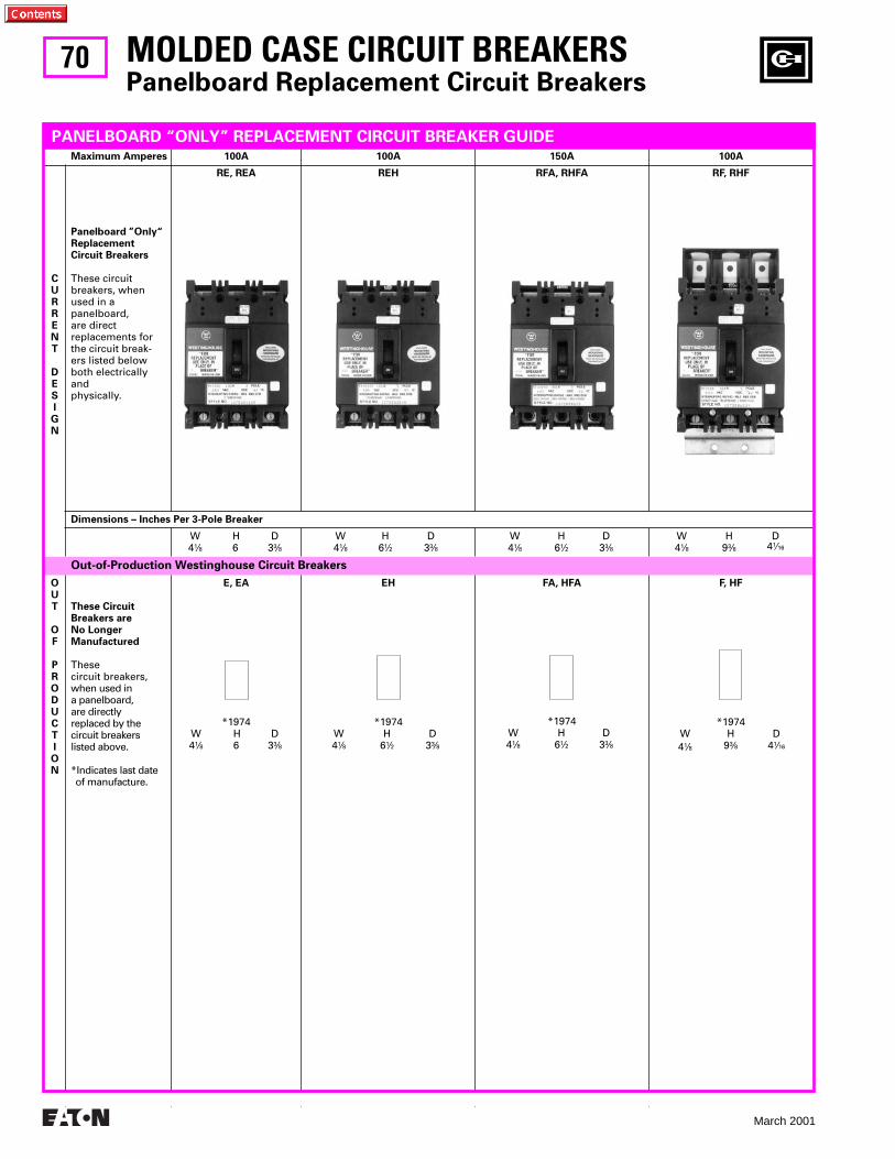
70
March 2001
MOLDED CASE CIRCUIT BREAKERS
Panelboard Replacement Circuit Breakers
Maximum Amperes 100A 100A 150A 100A
CURRENT
DESIGN
Panelboard ”Only“ Replacement Circuit Breakers
These circuit breakers, when used in a panelboard, are direct replacements for the circuit break-ers listed below both electrically and physically.
RE, REA REH RFA, RHFA RF, RHF
Dimensions – Inches Per 3-Pole Breaker
W H D4
1
⁄
8
6 3
3
⁄
8
W H D4
1
⁄
8
6
1
⁄
2
3
3
⁄
8
W H D4
1
⁄
8
6
1
⁄
2
3
3
⁄
8
W H D4
1
⁄
8
9
3
⁄
8
4
1
⁄
16
Out-of-Production Westinghouse Circuit Breakers
OUT
OF
PRODUCTION
These CircuitBreakers areNo LongerManufactured
Thesecircuit breakers,when used ina panelboard,are directlyreplaced by thecircuit breakerslisted above.
*Indicates last date of manufacture.
E, EA
*1974W H D4
1
⁄
8
6 3
3
⁄
8
EH
*1974W H D4
1
⁄
8
6
1
⁄
2
3
3
⁄
8
FA, HFA
*1974W H D4
1
⁄
8
6
1
⁄
2
3
3
⁄
8
F, HF
*1974W H D4
1
⁄
8
9
3
⁄
8
4
1
⁄
16
PANELBOARD “ONLY” REPLACEMENT CIRCUIT BREAKER GUIDE
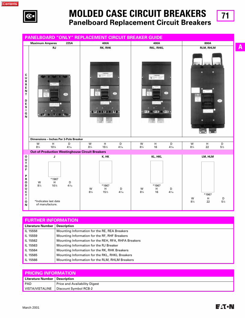
71
March 2001
A
Maximum Amperes 225A 400A 400A 800A
CURRENT
DESIGN
RJ RK, RHK RKL, RHKL RLM, RHLM
Dimensions – Inches Per 3-Pole Breaker
W H D8
1
⁄
4
10
1
⁄
8
4
1
⁄
16
W H D8
1
⁄
4
15
1
⁄
2
4
1
⁄
16
W H D8
1
⁄
4
16 4
1
⁄
16
W H D8
1
⁄
4
22 5
1
⁄
2
Out-of-Production Westinghouse Circuit Breakers
OUT OF
PRODUCTION
J
*1967W H D8
1
⁄
4
10
1
⁄
8
4
1
⁄
16
K, HK
*1967W H D8
1
⁄
4
15
1
⁄
2
4
1
⁄
16
KL, HKL
*1967W H D8
1
⁄
4
16 4
1
⁄
16
LM, HLM
*1967W H D8
1
⁄
4
22 5
1
⁄
2
Literature Number Description
IL 15558
IL 15559
IL 15562
IL 15563
IL 15564
IL 15565
IL 15566
Mounting Information for the RE, REA Breakers
Mounting Information for the RF, RHF Breakers
Mounting Information for the REH, RFA, RHFA Breakers
Mounting Information for the RJ Breaker
Mounting Information for the RK, RHK Breakers
Mounting Information for the RKL, RHKL Breakers
Mounting Information for the RLM, RHLM Breakers
FURTHER INFORMATION
MOLDED CASE CIRCUIT BREAKERS
Panelboard Replacement Circuit Breakers
PANELBOARD “ONLY” REPLACEMENT CIRCUIT BREAKER GUIDE
Literature Number Description
PAD
VISTA/VISTALINE
Price and Availability Digest
Discount Symbol RCB-2
PRICING INFORMATION
*Indicates last date of manufacture.
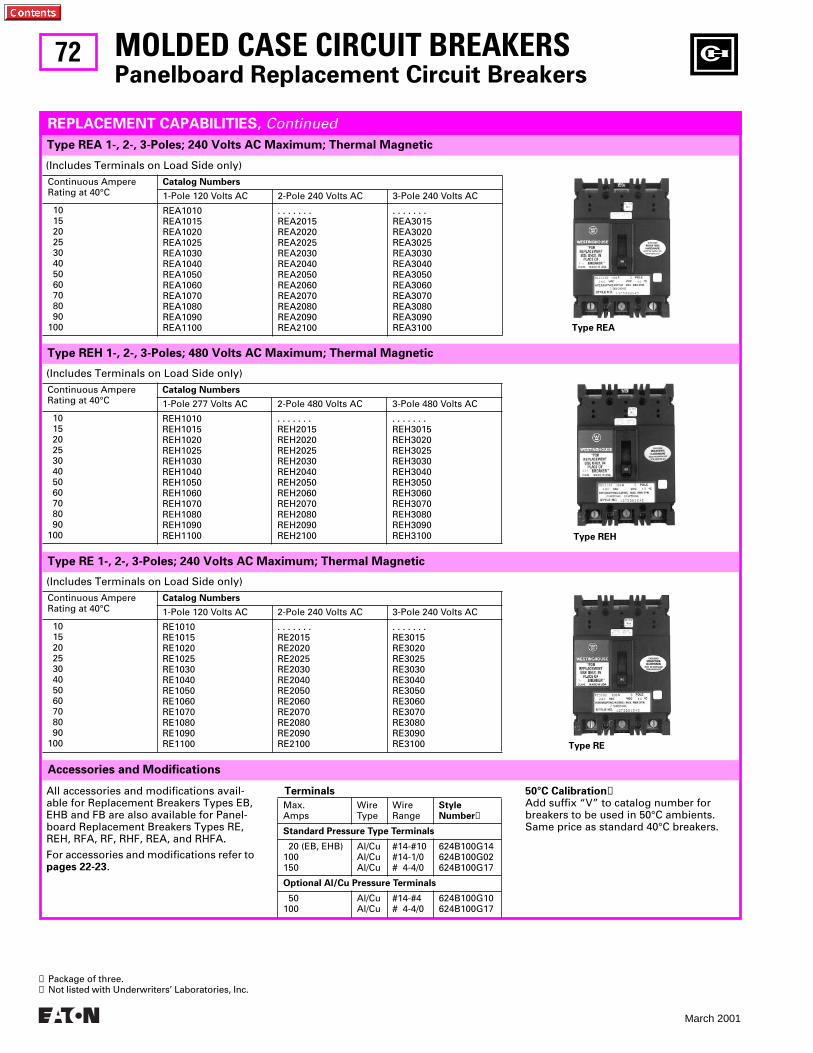
72
March 2001
50°C Calibration
➋
Add suffix “V” to catalog number for breakers to be used in 50°C ambients. Same price as standard 40°C breakers.
(Includes Terminals on Load Side only)
Continuous AmpereRating at 40°C
Catalog Numbers
1-Pole 120 Volts AC 2-Pole 240 Volts AC 3-Pole 240 Volts AC
10 15 20 25 30 40 50 60 70 80 90100
REA1010REA1015REA1020REA1025REA1030REA1040REA1050REA1060REA1070REA1080REA1090REA1100
. . . . . . .REA2015REA2020REA2025REA2030REA2040REA2050REA2060REA2070REA2080REA2090REA2100
. . . . . . .REA3015REA3020REA3025REA3030REA3040REA3050REA3060REA3070REA3080REA3090REA3100
Type REA 1-, 2-, 3-Poles; 240 Volts AC Maximum; Thermal Magnetic
MOLDED CASE CIRCUIT BREAKERS
Panelboard Replacement Circuit Breakers
REPLACEMENT CAPABILITIES,
Continued
(Includes Terminals on Load Side only)
Continuous AmpereRating at 40°C
Catalog Numbers
1-Pole 277 Volts AC 2-Pole 480 Volts AC 3-Pole 480 Volts AC
10 15 20 25 30 40 50 60 70 80 90100
REH1010REH1015REH1020REH1025REH1030REH1040REH1050REH1060REH1070REH1080REH1090REH1100
. . . . . . .REH2015REH2020REH2025REH2030REH2040REH2050REH2060REH2070REH2080REH2090REH2100
. . . . . . .REH3015REH3020REH3025REH3030REH3040REH3050REH3060REH3070REH3080REH3090REH3100
Type REH 1-, 2-, 3-Poles; 480 Volts AC Maximum; Thermal Magnetic
(Includes Terminals on Load Side only)
Continuous AmpereRating at 40°C
Catalog Numbers
1-Pole 120 Volts AC 2-Pole 240 Volts AC 3-Pole 240 Volts AC
10 15 20 25 30 40 50 60 70 80 90100
RE1010RE1015RE1020RE1025RE1030RE1040RE1050RE1060RE1070RE1080RE1090RE1100
. . . . . . .RE2015RE2020RE2025RE2030RE2040RE2050RE2060RE2070RE2080RE2090RE2100
. . . . . . .RE3015RE3020RE3025RE3030RE3040RE3050RE3060RE3070RE3080RE3090RE3100
Type RE 1-, 2-, 3-Poles; 240 Volts AC Maximum; Thermal Magnetic
Accessories and Modifications
All accessories and modifications avail-able for Replacement Breakers Types EB, EHB and FB are also available for Panel-board Replacement Breakers Types RE, REH, RFA, RF, RHF, REA, and RHFA.
For accessories and modifications refer to
pages 22-23
.
Terminals
Max.Amps
WireType
WireRange
Style Number
➊
Standard Pressure Type Terminals
20 (EB, EHB)100150
Al/CuAl/CuAl/Cu
#14-#10#14-1/0# 4-4/0
624B100G14624B100G02624B100G17
Optional Al/Cu Pressure Terminals
50100
Al/CuAl/Cu
#14-#4# 4-4/0
624B100G10624B100G17
➊
Package of three.
➋
Not listed with Underwriters’ Laboratories, Inc.
Type REA
Type REH
Type RE
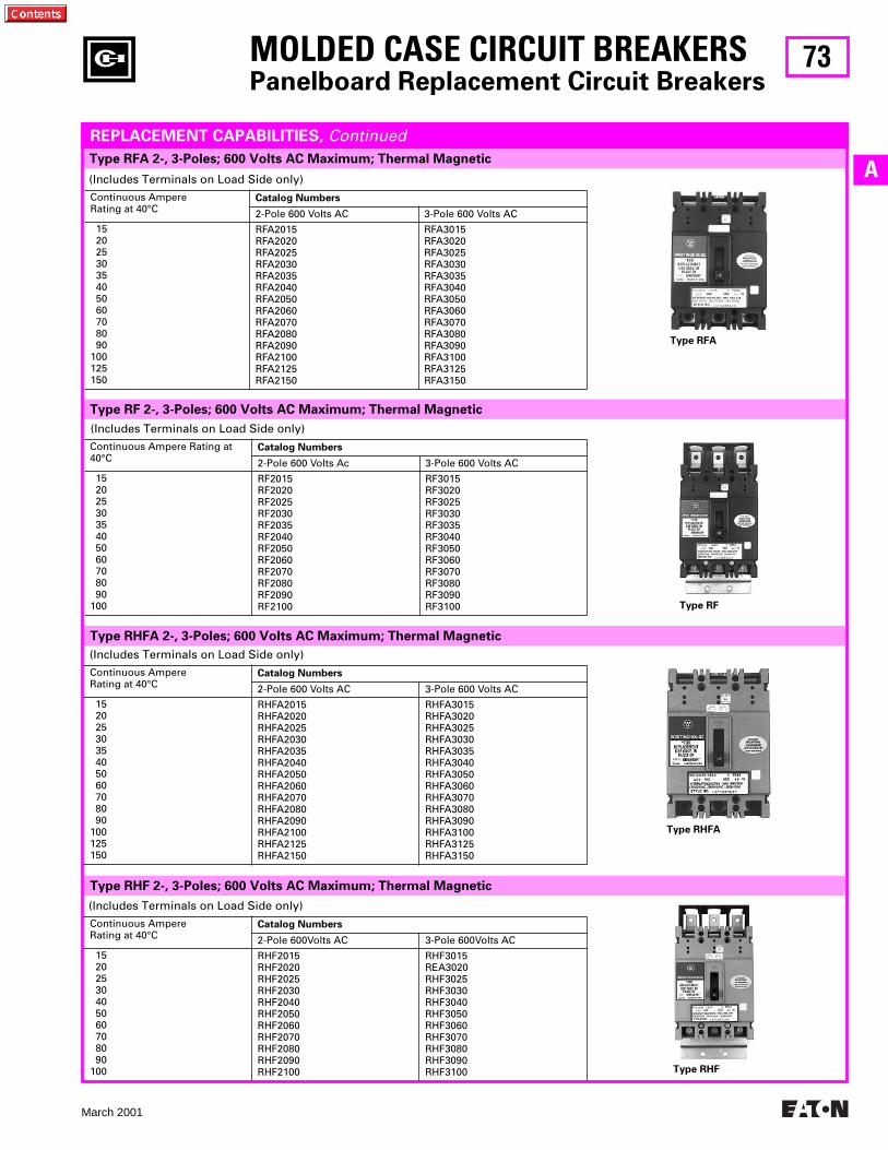
73
March 2001
A
(Includes Terminals on Load Side only)
Continuous Ampere Rating at 40°C
Catalog Numbers
2-Pole 600 Volts AC 3-Pole 600 Volts AC 15 20 25 30 35 40 50 60 70 80 90100125150
RFA2015RFA2020RFA2025RFA2030RFA2035RFA2040RFA2050RFA2060RFA2070RFA2080RFA2090RFA2100RFA2125RFA2150
RFA3015RFA3020RFA3025RFA3030RFA3035RFA3040RFA3050RFA3060RFA3070RFA3080RFA3090RFA3100RFA3125RFA3150
MOLDED CASE CIRCUIT BREAKERS
Panelboard Replacement Circuit Breakers
Type RFA 2-, 3-Poles; 600 Volts AC Maximum; Thermal Magnetic
REPLACEMENT CAPABILITIES, Continued
(Includes Terminals on Load Side only)Continuous Ampere Rating at 40°C
Catalog Numbers
2-Pole 600 Volts AC 3-Pole 600 Volts AC 15 20 25 30 35 40 50 60 70 80 90100125150
RHFA2015RHFA2020RHFA2025RHFA2030RHFA2035RHFA2040RHFA2050RHFA2060RHFA2070RHFA2080RHFA2090RHFA2100RHFA2125RHFA2150
RHFA3015RHFA3020RHFA3025RHFA3030RHFA3035RHFA3040RHFA3050RHFA3060RHFA3070RHFA3080RHFA3090RHFA3100RHFA3125RHFA3150
(Includes Terminals on Load Side only)Continuous Ampere Rating at 40°C
Catalog Numbers
2-Pole 600 Volts Ac 3-Pole 600 Volts AC 15 20 25 30 35 40 50 60 70 80 90100
RF2015RF2020RF2025RF2030RF2035RF2040RF2050RF2060RF2070RF2080RF2090RF2100
RF3015RF3020RF3025RF3030RF3035RF3040RF3050RF3060RF3070RF3080RF3090RF3100
(Includes Terminals on Load Side only)Continuous AmpereRating at 40°C
Catalog Numbers
2-Pole 600Volts AC 3-Pole 600Volts AC 15 20 25 30 40 50 60 70 80 90100
RHF2015RHF2020RHF2025RHF2030RHF2040RHF2050RHF2060RHF2070RHF2080RHF2090RHF2100
RHF3015REA3020RHF3025RHF3030RHF3040RHF3050RHF3060RHF3070RHF3080RHF3090RHF3100
Type RF 2-, 3-Poles; 600 Volts AC Maximum; Thermal Magnetic
Type RHFA 2-, 3-Poles; 600 Volts AC Maximum; Thermal Magnetic
Type RHF 2-, 3-Poles; 600 Volts AC Maximum; Thermal Magnetic
Type RFA
Type RF
Type RHFA
Type RHF
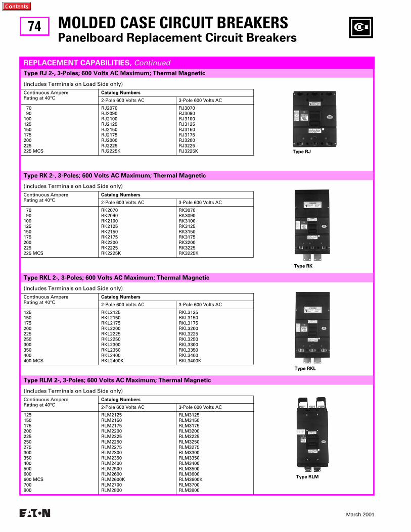
74
March 2001
Type RJ 2-, 3-Poles; 600 Volts AC Maximum; Thermal Magnetic
(Includes Terminals on Load Side only)
Continuous AmpereRating at 40°C
Catalog Numbers
2-Pole 600 Volts AC 3-Pole 600 Volts AC
70 90100125150175200225225 MCS
RJ2070RJ2090RJ2100RJ2125RJ2150RJ2175RJ2000RJ2225RJ2225K
RJ3070RJ3090RJ3100RJ3125RJ3150RJ3175RJ3200RJ3225RJ3225K
MOLDED CASE CIRCUIT BREAKERSPanelboard Replacement Circuit Breakers
REPLACEMENT CAPABILITIES, Continued
(Includes Terminals on Load Side only)
Continuous AmpereRating at 40°C
Catalog Numbers
2-Pole 600 Volts AC 3-Pole 600 Volts AC
125150175200225250300350400400 MCS
RKL2125RKL2150RKL2175RKL2200RKL2225RKL2250RKL2300RKL2350RKL2400RKL2400K
RKL3125RKL3150RKL3175RKL3200RKL3225RKL3250RKL3300RKL3350RKL3400RKL3400K
(Includes Terminals on Load Side only)
Continuous AmpereRating at 40°C
Catalog Numbers
2-Pole 600 Volts AC 3-Pole 600 Volts AC
70 90100125150175200225225 MCS
RK2070RK2090RK2100RK2125RK2150RK2175RK2200RK2225RK2225K
RK3070RK3090RK3100RK3125RK3150RK3175RK3200RK3225RK3225K
(Includes Terminals on Load Side only)
Continuous AmpereRating at 40°C
Catalog Numbers
2-Pole 600 Volts AC 3-Pole 600 Volts AC
125150175200225250275300350400500600600 MCS700800
RLM2125RLM2150RLM2175RLM2200RLM2225RLM2250RLM2275RLM2300RLM2350RLM2400RLM2500RLM2600RLM2600KRLM2700RLM2800
RLM3125RLM3150RLM3175RLM3200RLM3225RLM3250RLM3275RLM3300RLM3350RLM3400RLM3500RLM3600RLM3600KRLM3700RLM3800
Type RK 2-, 3-Poles; 600 Volts AC Maximum; Thermal Magnetic
Type RKL 2-, 3-Poles; 600 Volts AC Maximum; Thermal Magnetic
Type RLM 2-, 3-Poles; 600 Volts AC Maximum; Thermal Magnetic
Type RJ
Type RK
Type RKL
Type RLM

75
March 2001
AType RHK 2-, 3-Poles; 600 Volts AC Maximum; Thermal Magnetic
MOLDED CASE CIRCUIT BREAKERSPanelboard Replacement Circuit Breakers
REPLACEMENT CAPABILITIES, Continued
All accessories and modifications avail-able for replacement breakers types KA, LA and MA are also available for panel-board replacement breakers types RJ, RK, RKL, RLM, RHK, RHKL, and RHLM.
For additional accessories and modifica-tions refer to pages 35, 43 and 44.
Terminals
PanelboardCircuit Breakers
Terminals➊
RJRKRHKRKLRHKLRLMRHLM
TA225LA1TA225LA1TA225LA1TA400LA1TA400LA1TA700MA1 (for <600A)TA800MA1 (for 700-800A)
Special Breakers➋Magnetic only (includes load terminals). Available for all ampere ratings for 2- and 3-pole RJ, RK, RKL, RLM, RHK, RHKL, and RHLM.
High magnetic molded case switches (K suffix) are available to replace out-of-production non-automatic breakers (N suffix).
(Includes Terminals on Load Side only)Continuous AmpereRating at 40°C
Catalog Numbers
2-Pole 600 Volts AC 3-Pole 600 Volts AC 70 90100125150175200225225 MCS
RHK2070RHK2090RHK2100RHK2125RHK2150RHK2175RHK2200RHK2225RHK2225K
RHK3070RHK3090RHK3100RHK3125RHK3150RHK3175RHK3200RHK3225RHK3225K
} {
Type RHKL 2-, 3-Poles; 600 Volts AC Maximum; Thermal Magnetic
Type RHLM 2-, 3-Poles; 600 Volts AC Maximum; Thermal Magnetic
Accessories and Modifications
(Includes Terminals on Load Side only)Continuous AmpereRating at 40°C
Catalog Numbers
2-Pole 600 Volts AC 3-Pole 600 Volts AC125150175200225250275300325350400450500550600600 MCS700800
RHLM2125RHLM2150RHLM2175RHLM2200RHLM2225RHLM2250RHLM2275RHLM2300RHLM2325RHLM2350RHLM2400RHLM2450RHLM2500RHLM2550RHLM2600RHLM2600KRHLM2700RHLM2800
RHLM3125RHLM3150RHLM3175RHLM3200RHLM3225RHLM3250RHLM3275RHLM3300RHLM3325RHLM3350RHLM3400RHLM3450RHLM3500RHLM3550RHLM3600RHLM3600KRHLM3700RHLM3800
(Includes Terminals on Load Side only)Continuous AmpereRating at 40°C
Catalog Numbers
2-Pole 600 Volts AC 3-Pole 600 Volts AC125150175200225250300350400400 MCS
RHKL2125RHKL2150RHKL2175RHKL2200RHKL2225RHKL2250RHKL2300RHKL2350RHKL2400RHKL2400K
RHKL3125RHKL3150RHKL3175RHKL3200RHKL3225RHKL3250RHKL3300RHKL3350RHKL3400RHKL3400K
➊ Packaged individually.➋ Not listed with Underwriters’ Laboratories, Inc.
50°C Calibration➋Add suffix “V” to catalog number for breakers to be used in 50°C ambients. Same price as standard 40°C breakers.
Type RHK
Type RHKL
Type RHLM
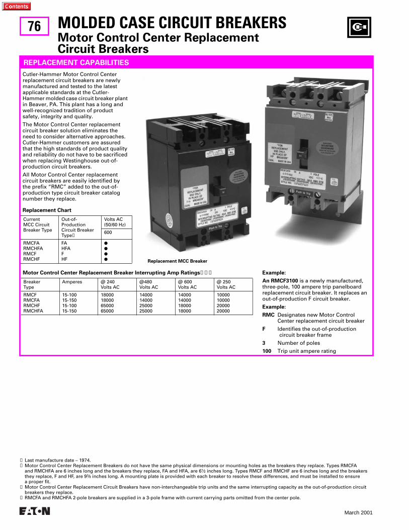
76
March 2001
MOLDED CASE CIRCUIT BREAKERSMotor Control Center Replacement Circuit Breakers
REPLACEMENT CAPABILITIES
Cutler-Hammer Motor Control Center replacement circuit breakers are newly manufactured and tested to the latest applicable standards at the Cutler-Hammer molded case circuit breaker plant in Beaver, PA. This plant has a long and well-recognized tradition of product safety, integrity and quality.
The Motor Control Center replacement circuit breaker solution eliminates the need to consider alternative approaches. Cutler-Hammer customers are assured that the high standards of product quality and reliability do not have to be sacrificed when replacing Westinghouse out-of-production circuit breakers.
All Motor Control Center replacement circuit breakers are easily identified by the prefix “RMC” added to the out-of-production type circuit breaker catalog number they replace.
Replacement Chart
CurrentMCC CircuitBreaker Type
Out-of-ProductionCircuit BreakerType➊
Volts AC(50/60 Hz)
600
RMCFARMCHFARMCFRMCHF
FAHFAFHF
●
●
●
●
Motor Control Center Replacement Breaker Interrupting Amp Ratings➋➌➍
BreakerType
Amperes @ 240Volts AC
@480Volts AC
@ 600Volts AC
@ 250Volts AC
RMCFRMCFARMCHFRMCHFA
15-10015-15015-10015-150
18000180006500065000
14000140002500025000
14000140001800018000
10000100002000020000
➊ Last manufacture date – 1974.➋ Motor Control Center Replacement Breakers do not have the same physical dimensions or mounting holes as the breakers they replace. Types RMCFA
and RMCHFA are 6 inches long and the breakers they replace, FA and HFA, are 61⁄2 inches long. Types RMCF and RMCHF are 6 inches long and the breakers they replace, F and HF, are 93⁄8 inches long. A mounting plate is provided with each breaker to resolve these differences, and must be installed to ensure a proper fit.
➌ Motor Control Center Replacement Circuit Breakers have non-interchangeable trip units and the same interrupting capacity as the out-of-production circuit breakers they replace.
➍ RMCFA and RMCHFA 2-pole breakers are supplied in a 3-pole frame with current carrying parts omitted from the center pole.
Example:
An RMCF3100 is a newly manufactured, three-pole, 100 ampere trip panelboard replacement circuit breaker. It replaces an out-of-production F circuit breaker.
Example:
RMC Designates new Motor Control Center replacement circuit breaker
F Identifies the out-of-production circuit breaker frame
3 Number of poles
100 Trip unit ampere rating
Replacement MCC Breaker
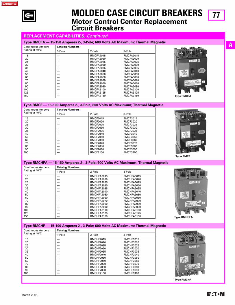
77
March 2001
A
Type RMCHF — 15-100 Amperes 2-, 3-Pole; 600 Volts AC Maximum; Thermal Magnetic
Type RMCHFA — 15-150 Amperes 2-, 3-Pole; 600 Volts AC Maximum; Thermal Magnetic
Type RMCF — 15-100 Amperes 2-, 3-Pole; 600 Volts AC Maximum; Thermal Magnetic
Continuous AmpereRating at 40°C
Catalog Numbers
1-Pole 2-Pole 3-Pole
15 20 25 30 35 40 50 60 70 80 90100125150
——————————————
RMCHFA2015RMCHFA2020RMCHFA2025RMCHFA2030RMCHFA2035RMCHFA2040RMCHFA2050RMCHFA2060RMCHFA2070RMCHFA2080RMCHFA2090RMCHFA2100RMCHFA2125RMCHFA2150
RMCHFA3015RMCHFA3020RMCHFA3025RMCHFA3030RMCHFA3035RMCHFA3040RMCHFA3050RMCHFA3060RMCHFA3070RMCHFA3080RMCHFA3090RMCHFA3100RMCHFA3125RMCHFA3150
Continuous AmpereRating at 40°C
Catalog Numbers
1-Pole 2-Pole 3-Pole
15 20 25 30 35 40 50 60 70 80 90100
————————————
RMCF2015RMCF2020RMCF2025RMCF2030RMCF2035RMCF2040RMCF2050RMCF2060RMCF2070RMCF2080RMCF2090RMCF2100
RMCF3015RMCF3020RMCF3025RMCF3030RMCF3035RMCF3040RMCF3050RMCF3060RMCF3070RMCF3080RMCF3090RMCF3100
MOLDED CASE CIRCUIT BREAKERSMotor Control Center Replacement Circuit Breakers
REPLACEMENT CAPABILITIES, ContinuedType RMCFA — 15-150 Amperes 2-, 3-Pole; 600 Volts AC Maximum; Thermal Magnetic
Continuous AmpereRating at 40°C
Catalog Numbers
1-Pole 2-Pole 3-Pole
15 20 25 30 35 40 50 60 70 80 90100125150
——————————————
RMCFA2015RMCFA2020RMCFA2025RMCFA2030RMCFA2035RMCFA2040RMCFA2050RMCFA2060RMCFA2070RMCFA2080RMCFA2090RMCFA2100RMCFA2125RMCFA2150
RMCFA3015RMCFA3020RMCFA3025RMCFA3030RMCFA3035RMCFA3040RMCFA3050RMCFA3060RMCFA3070RMCFA3080RMCFA3090RMCFA3100RMCFA3125RMCFA3150
Continuous AmpereRating at 40°C
Catalog Numbers
1-Pole 2-Pole 3-Pole
15 20 25 30 35 40 50 60 70 80 90100
————————————
RMCHF2015RMCHF2020RMCHF2025RMCHF2030RMCHF2035RMCHF2040RMCHF2050RMCHF2060RMCHF2070RMCHF2080RMCHF2090RMCHF2100
RMCHF3015RMCHF3020RMCHF3025RMCHF3030RMCHF3035RMCHF3040RMCHF3050RMCHF3060RMCHF3070RMCHF3080RMCHF3090RMCHF3100
Type RMCHF
Type RMCFA
Type RMCF
Type RMCHFA
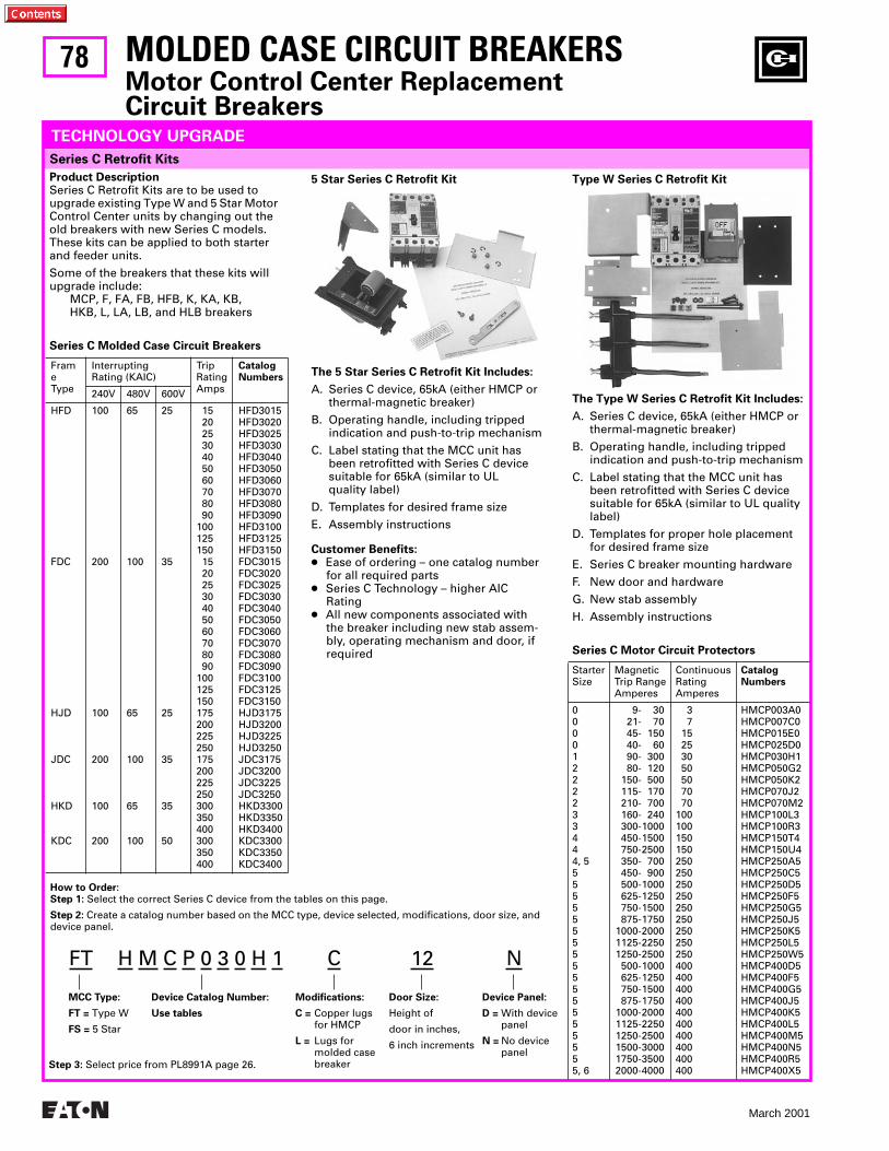
78
March 2001
MOLDED CASE CIRCUIT BREAKERSMotor Control Center Replacement Circuit Breakers
TECHNOLOGY UPGRADE
Series C Retrofit Kits
Product DescriptionSeries C Retrofit Kits are to be used to upgrade existing Type W and 5 Star Motor Control Center units by changing out the old breakers with new Series C models. These kits can be applied to both starter and feeder units.
Some of the breakers that these kits will upgrade include:
MCP, F, FA, FB, HFB, K, KA, KB,HKB, L, LA, LB, and HLB breakers
Series C Molded Case Circuit Breakers
FrameType
InterruptingRating (KAIC)
TripRatingAmps
CatalogNumbers
240V 480V 600V
HFD
FDC
HJD
JDC
HKD
KDC
100
200
100
200
100
200
65
100
65
100
65
100
25
35
25
35
35
50
15 20 25 30 40 50 60 70 80 90100125150 15 20 25 30 40 50 60 70 80 90100125150175200225250175200225250300350400300350400
HFD3015HFD3020HFD3025HFD3030HFD3040HFD3050HFD3060HFD3070HFD3080HFD3090HFD3100HFD3125HFD3150FDC3015FDC3020FDC3025FDC3030FDC3040FDC3050FDC3060FDC3070FDC3080FDC3090FDC3100FDC3125FDC3150HJD3175HJD3200HJD3225HJD3250JDC3175JDC3200JDC3225JDC3250HKD3300HKD3350HKD3400KDC3300KDC3350KDC3400
5 Star Series C Retrofit Kit
The 5 Star Series C Retrofit Kit Includes:
A. Series C device, 65kA (either HMCP or thermal-magnetic breaker)
B. Operating handle, including tripped indication and push-to-trip mechanism
C. Label stating that the MCC unit has been retrofitted with Series C device suitable for 65kA (similar to UL quality label)
D. Templates for desired frame size
E. Assembly instructions
Customer Benefits:● Ease of ordering – one catalog number
for all required parts● Series C Technology – higher AIC
Rating● All new components associated with
the breaker including new stab assem-bly, operating mechanism and door, if required
Type W Series C Retrofit Kit
The Type W Series C Retrofit Kit Includes:
A. Series C device, 65kA (either HMCP or thermal-magnetic breaker)
B. Operating handle, including tripped indication and push-to-trip mechanism
C. Label stating that the MCC unit has been retrofitted with Series C device suitable for 65kA (similar to UL quality label)
D. Templates for proper hole placement for desired frame size
E. Series C breaker mounting hardware
F. New door and hardware
G. New stab assembly
H. Assembly instructions
Series C Motor Circuit Protectors
StarterSize
MagneticTrip RangeAmperes
ContinuousRatingAmperes
CatalogNumbers
00001222233444, 5555555555555555555, 6
9- 3021- 7045- 15040- 6090- 30080- 120
150- 500115- 170210- 700160- 240300-1000450-1500750-2500350- 700450- 900500-1000625-1250750-1500875-1750
1000-20001125-22501250-2500500-1000625-1250750-1500875-1750
1000-20001125-22501250-25001500-30001750-35002000-4000
3 7 15 25 30 50 50 70 70100100150150250250250250250250250250250400400400400400400400400400400
HMCP003A0HMCP007C0HMCP015E0HMCP025D0HMCP030H1HMCP050G2HMCP050K2HMCP070J2HMCP070M2HMCP100L3HMCP100R3HMCP150T4HMCP150U4HMCP250A5HMCP250C5HMCP250D5HMCP250F5HMCP250G5HMCP250J5HMCP250K5HMCP250L5HMCP250W5HMCP400D5HMCP400F5HMCP400G5HMCP400J5HMCP400K5HMCP400L5HMCP400M5HMCP400N5HMCP400R5HMCP400X5
How to Order:Step 1: Select the correct Series C device from the tables on this page.
Step 2: Create a catalog number based on the MCC type, device selected, modifications, door size, and device panel.
FT H M C P 0 3 0 H 1 C 12 N
MCC Type:
FT = Type W
FS = 5 Star
Device Catalog Number:
Use tables
Modifications:
C = Copper lugsfor HMCP
L = Lugs formolded casebreaker
Door Size:
Height of
door in inches,
6 inch increments
Device Panel:
D = With devicepanel
N = No devicepanel
Step 3: Select price from PL8991A page 26.
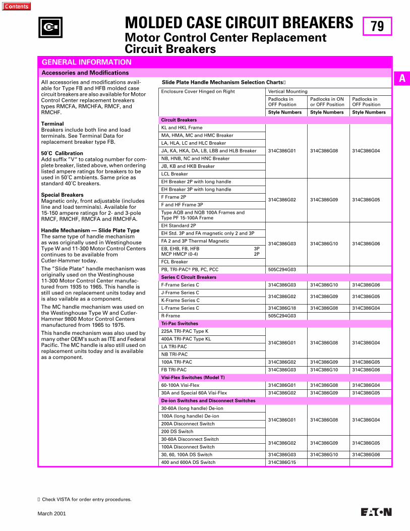
79
March 2001
A
MOLDED CASE CIRCUIT BREAKERSMotor Control Center Replacement Circuit Breakers
Accessories and Modifications
GENERAL INFORMATION
All accessories and modifications avail-able for Type FB and HFB molded case circuit breakers are also available for Motor Control Center replacement breakers types RMCFA, RMCHFA, RMCF, and RMCHF.
TerminalBreakers include both line and load terminals. See Terminal Data for replacement breaker type FB.
50˚C CalibrationAdd suffix ”V“ to catalog number for com-plete breaker, listed above, when ordering listed ampere ratings for breakers to be used in 50˚C ambients. Same price as standard 40˚C breakers.
Special BreakersMagnetic only, front adjustable (includes line and load terminals). Available for 15-150 ampere ratings for 2- and 3-pole RMCF, RMCHF, RMCFA and RMCHFA.
Handle Mechanism — Slide Plate Type The same type of handle mechanism as was originally used in Westinghouse Type W and 11-300 Motor Control Centers continues to be available from Cutler-Hammer today.
The ”Slide Plate“ handle mechanism was originally used on the Westinghouse 11-300 Motor Control Center manufac-tured from 1935 to 1965. This handle is still used on replacement units today and is also vailable as a component.
The MC handle mechanism was used on the Westinghouse Type W and Cutler-Hammer 9800 Motor Control Centers manufactured from 1965 to 1975.
This handle mechanism was also used by many other OEM‘s such as ITE and Federal Pacific. The MC handle is also still used on replacement units today and is available as a component.
Slide Plate Handle Mechanism Selection Charts➊
Enclosure Cover Hinged on Right Vertical Mounting
Padlocks in OFF Position
Padlocks in ONor OFF Position
Padlocks in OFF Position
Style Numbers Style Numbers Style Numbers
Circuit Breakers
KL and HKL Frame
314C386G01 314C386G08 314C386G04
MA, HMA, MC and HMC Breaker
LA, HLA, LC and HLC Breaker
JA, KA, HKA, DA, LB, LBB and HLB Breaker
NB, HNB, NC and HNC Breaker
JB, KB and HKB Breaker
LCL Breaker
EH Breaker 2P with long handle
314C386G02 314C386G09 314C386G05
EH Breaker 3P with long handle
F Frame 2P
F and HF Frame 3P
Type AQB and NQB 100A Frames andType PF 15-100A Frame
EH Standard 2P
314C386G03 314C386G10 314C386G06
EH Std. 3P and FA magnetic only 2 and 3P
FA 2 and 3P Thermal Magnetic
EB, EHB, FB, HFB 3PMCP HMCP (0-4) 2P
FCL Breaker
PB, TRI-PACT PB, PC, PCC 505C294G03
Series C Circuit Breakers
F-Frame Series C 314C386G03 314C386G10 314C386G06
J-Frame Series C314C386G02 314C386G09 314C386G05
K-Frame Series C
L-Frame Series C 314C386G18 314C386G08 314C386G04
R-Frame 505C294G03
Tri-Pac Switches
225A TRI-PAC Type K
314C386G01 314C386G08 314C386G04400A TRI-PAC Type KL
LA TRI-PAC
NB TRI-PAC
100A TRI-PAC 314C386G02 314C386G09 314C386G05
FB TRI-PAC 314C386G03 314C386G10 314C386G06
Visi-Flex Switches (Model T)
60-100A Visi-Flex 314C386G01 314C386G08 314C386G04
30A and Special 60A Visi-Flex 314C386G02 314C386G09 314C386G05
De-ion Switches and Disconnect Switches
30-60A (long handle) De-ion
314C386G01 314C386G08 314C386G04100A (long handle) De-ion
200A Disconnect Switch
200 DS Switch
30-60A Disconnect Switch314C386G02 314C386G09 314C386G05
100A Disconnect Switch
30, 60, 100A DS Switch 314C386G03 314C386G10 314C386G06
400 and 600A DS Switch 314C386G15
➊ Check VISTA for order entry procedures.
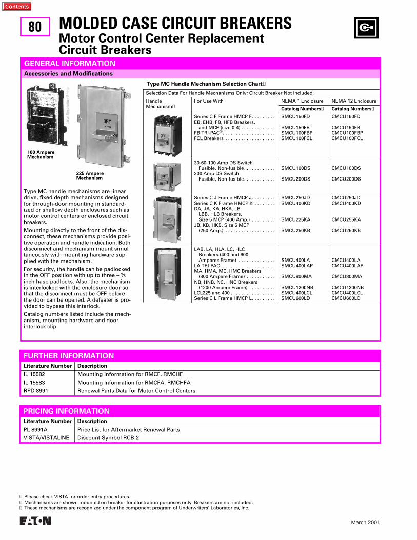
80
March 2001
Literature Number Description
IL 15582
IL 15583
RPD 8991
Mounting Information for RMCF, RMCHF
Mounting Information for RMCFA, RMCHFA
Renewal Parts Data for Motor Control Centers
Type MC Handle Mechanism Selection Chart➊
Selection Data For Handle Mechanisms Only; Circuit Breaker Not Included.
HandleMechanism➋
For Use With NEMA 1 Enclosure NEMA 12 Enclosure
Catalog Numbers➌ Catalog Numbers➌
Series C F Frame HMCP F. . . . . . . . .EB, EHB, FB, HFB Breakers,
and MCP (size 0-4) . . . . . . . . . . . . .FB TRI-PACw. . . . . . . . . . . . . . . . . . . .FCL Breakers . . . . . . . . . . . . . . . . . . .
SMCU150FD
SMCU150FBSMCU100FBPSMCU100FCL
CMCU150FD
CMCU150FBCMCU100FBPCMCU100FCL
30-60-100 Amp DS SwitchFusible, Non-fusible. . . . . . . . . . . .
200 Amp DS SwitchFusible, Non-fusible. . . . . . . . . . . .
SMCU100DS
SMCU200DS
CMCU100DS
CMCU200DS
Series C J Frame HMCP J. . . . . . . . .Series C K Frame HMCP K . . . . . . . .DA, JA, KA, HKA, LB,
LBB, HLB Breakers, Size 5 MCP (400 Amp.) . . . . . . . . .
JB, KB, HKB, Size 5 MCP(250 Amp.) . . . . . . . . . . . . . . . . . . .
SMCU250JDSMCU400KD
SMCU225KA
SMCU250KB
CMCU250JDCMCU400KD
CMCU255KA
CMCU250KB
LAB, LA, HLA, LC, HLCBreakers (400 and 600Amperes Frame) . . . . . . . . . . . . . .
LA TRI-PAC. . . . . . . . . . . . . . . . . . . . .MA, HMA, MC, HMC Breakers
(800 Ampere Frame) . . . . . . . . . . .NB, HNB, NC, HNC Breakers
(1200 Ampere Frame) . . . . . . . . . .LCL225 and 400 . . . . . . . . . . . . . . . . .Series C L Frame HMCP L. . . . . . . . .
SMCU400LASMCU400LAP
SMCU800MA
SMCU1200NBSMCU400LCLSMCU600LD
CMCU400LACMCU400LAP
CMCU800MA
CMCU1200NBCMCU400LCLCMCU600LD
Accessories and Modifications
MOLDED CASE CIRCUIT BREAKERSMotor Control Center Replacement Circuit Breakers
GENERAL INFORMATION
100 AmpereMechanism
225 AmpereMechanism
Type MC handle mechanisms are linear drive, fixed depth mechanisms designed for through-door mounting in standard-ized or shallow depth enclosures such as motor control centers or enclosed circuit breakers.
Mounting directly to the front of the dis-connect, these mechanisms provide posi-tive operation and handle indication. Both disconnect and mechanism mount simul-taneously with mounting hardware sup-plied with the mechanism.
For security, the handle can be padlocked in the OFF position with up to three – 3⁄8 inch hasp padlocks. Also, the mechanism is interlocked with the enclosure door so that the disconnect must be OFF before the door can be opened. A defeater is pro-vided to bypass this interlock.
Catalog numbers listed include the mech-anism, mounting hardware and door interlock clip.
FURTHER INFORMATION
Literature Number Description
PL 8991A
VISTA/VISTALINE
Price List for Aftermarket Renewal Parts
Discount Symbol RCB-2
PRICING INFORMATION
➊ Please check VISTA for order entry procedures.➋ Mechanisms are shown mounted on breaker for illustration purposes only. Breakers are not included. ➌ These mechanisms are recognized under the component program of Underwriters’ Laboratories, Inc.
Low
Res
olut
ion
Phot
o
81
March 2001
A
MOLDED CASE CIRCUIT BREAKERSMotor Control Center Replacement Breakers
For Motor Control Center Replacement Breakers, Call 1-800-OLD-UNIT
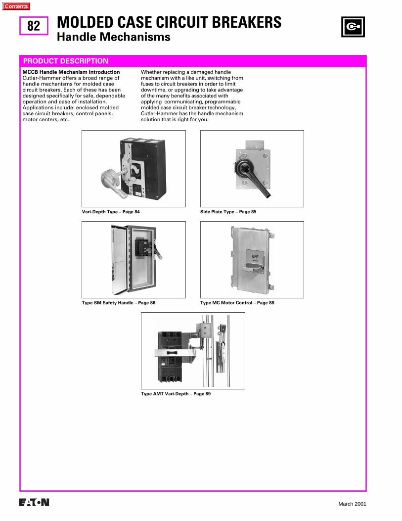
82
March 2001
MOLDED CASE CIRCUIT BREAKERS
Handle Mechanisms
PRODUCT DESCRIPTION
Vari-Depth Type – Page 84 Side Plate Type – Page 85
Type SM Safety Handle – Page 86 Type MC Motor Control – Page 88
Type AMT Vari-Depth – Page 89
MCCB Handle Mechanism Introduction
Cutler-Hammer offers a broad range of handle mechanisms for molded case circuit breakers. Each of these has been designed specifically for safe, dependable operation and ease of installation. Applications include: enclosed molded case circuit breakers, control panels, motor centers, etc.
Whether replacing a damaged handle mechanism with a like unit, switching from fuses to circuit breakers in order to limit downtime, or upgrading to take advantage of the many benefits associated with applying communicating, programmable molded case circuit breaker technology, Cutler-Hammer has the handle mechanism solution that is right for you.
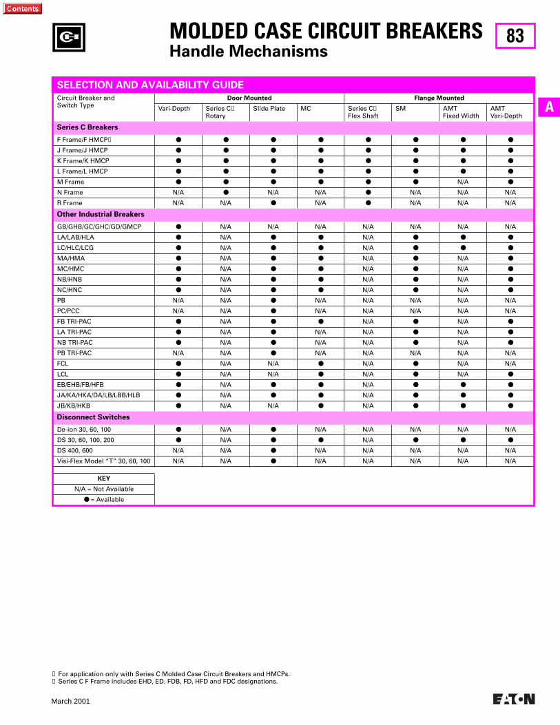
83
March 2001
A
GB/GHB/GC/GHC/GD/GMCP
●
N/A N/A N/A N/A N/A N/A N/A
LA/LAB/HLA
●
N/A
● ●
N/A
● ● ●
LC/HLC/LCG
●
N/A
● ●
N/A
● ● ●
MA/HMA
●
N/A
● ●
N/A
●
N/A
●
MC/HMC
●
N/A
● ●
N/A
●
N/A
●
NB/HNB
●
N/A
● ●
N/A
●
N/A
●
NC/HNC
●
N/A
● ●
N/A
●
N/A
●
PB N/A N/A
●
N/A N/A N/A N/A N/A
PC/PCC N/A N/A
●
N/A N/A N/A N/A N/A
FB TRI-PAC
●
N/A
● ●
N/A
●
N/A
●
LA TRI-PAC
●
N/A
●
N/A N/A
●
N/A
●
NB TRI-PAC
●
N/A
●
N/A N/A
●
N/A
●
PB TRI-PAC N/A N/A
●
N/A N/A N/A N/A N/A
FCL
●
N/A N/A
●
N/A
●
N/A N/A
LCL
●
N/A N/A
●
N/A
●
N/A
●
EB/EHB/FB/HFB
●
N/A
● ●
N/A
● ● ●
JA/KA/HKA/DA/LB/LBB/HLB
●
N/A
● ●
N/A
● ● ●
JB/KB/HKB
●
N/A N/A
●
N/A
● ● ●
Other Industrial Breakers
MOLDED CASE CIRCUIT BREAKERS
Handle Mechanisms
Circuit Breaker andSwitch Type
Door Mounted Flange Mounted
Vari-Depth Series C
➊
RotarySlide Plate MC Series C
➊
Flex ShaftSM AMT
Fixed WidthAMTVari-Depth
F Frame/F HMCP
➋ ● ● ● ● ● ● ● ●
J Frame/J HMCP
● ● ● ● ● ● ● ●
K Frame/K HMCP
● ● ● ● ● ● ● ●
L Frame/L HMCP
● ● ● ● ● ● ● ●
M Frame
● ● ● ● ● ●
N/A
●
N Frame N/A
●
N/A N/A
●
N/A N/A N/A
R Frame N/A N/A
●
N/A
●
N/A N/A N/A
Series C Breakers
De-ion 30, 60, 100
●
N/A
●
N/A N/A N/A N/A N/A
DS 30, 60, 100, 200
●
N/A
● ●
N/A
● ● ●
DS 400, 600 N/A N/A
●
N/A N/A N/A N/A N/A
Visi-Flex Model “T” 30, 60, 100 N/A N/A
●
N/A N/A N/A N/A N/A
KEY
N/A = Not Available
●
= Available
➊
For application only with Series C Molded Case Circuit Breakers and HMCPs.
➋
Series C F Frame includes EHD, ED, FDB, FD, HFD and FDC designations.
SELECTION AND AVAILABILITY GUIDE
Disconnect Switches
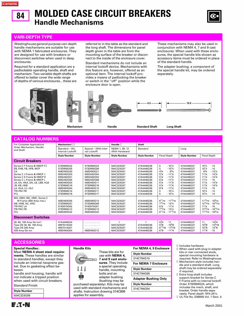
84
March 2001
Handle Kits
These kits are for use with
NEMA 4, 7 and 9 cast enclo-sures.
They include a special operating handle, mounting bolts and an adapter bushing (bushing may be
purchased separately). Kits may be used with standard mechanisms and shafts. Instruction drawing 314C809 applies for assembly.
Special Handles
❺
Meet
NEMA 4 sheet steel require-ments.
These handles are similar to standard handles, except they include an internal neoprene gas-ket. Due to gasketing effect be-tween handle and housing, handle will not indicate a tripped position when used with circuit breakers.
Standard Finish
Style Number
504C323G08
For NEMA 4, 9 Enclosure
For NEMA 7 Enclosure
Adapter Bushing Only
Style Number
314C794G10
Style Number
314C794G09
Style Number
314C794G04
Series C F Frame & HMCP F
➍
EB, EHB, FB, HFB, MCPCASeries C J Frame & HMCP JSeries C K Frame & HMCP KSeries C L Frame & HMCP LJA, KA, HKA, DA, LB, LBB, HLBJB, KB, HKBLA, HLA, LC, HLCTRI-PAC FBFCL
373D958G22373D958G05458D493G205092A62G035092A62G015092A62G05458D493G03373D958G18458D493G04373D958G10373D958G16
373D958G23373D958G06458D493G215092A62G045092A62G025092A62G06458D493G11373D958G19458D493G12373D958G11373D958G17
504C323G07504C323G07504C323G07504C323G07504C323G07504C323G07504C323G07504C323G07504C323G07504C323G07504C323G07
47A4446G3847A4446G3647A4446G3647A4446G3647A4446G3647A4446G3647A4446G3647A4446G3647A4446G3647A4446G3647A4446G36
5 - 10
1
⁄
4
5 - 10
1
⁄
4
4
3
⁄
4
- 9
3
⁄
4
5
7
⁄
8
- 11
1
⁄
8
5
7
⁄
8
- 11
1
⁄
8
6
1
⁄
8
- 11
1
⁄
4
5
7
⁄
8
- 11
1
⁄
8
5
7
⁄
8
- 11
1
⁄
8
6
1
⁄
8
- 11
1
⁄
4
5 - 10
1
⁄
4
5 - 10
1
⁄
4
47A4446G3747A4446G3747A4446G3747A4446G3747A4446G3747A4446G3747A4446G3747A4446G3747A4446G3747A4446G3747A4446G37
10
1
⁄
2
- 1410
1
⁄
2
- 14 9
3
⁄
4
- 13
1
⁄
2
11
1
⁄
8
- 14
7
⁄
8
11
1
⁄
8
- 14
7
⁄
8
11
1
⁄
4
- 1511
1
⁄
8
- 14
7
⁄
8
11
1
⁄
8
- 14
7
⁄
8
11
1
⁄
4
- 1510
1
⁄
4
- 1410
1
⁄
4
- 14
MA, HMA, MC, HMC, Series C M Frame (800 Amp max.)NB, HNB, NC, HNCTRI-PAC LATRI-PAC FBFCL
458D493G05373D958G07374D075G02373D958G12458D493G22
458D493G13373D958G08374D075G01373D958G13458D493G23
504C323G07504C323G07504C323G07504C323G07504C323G07
47A4446G3647A4446G3647A4446G3647A4446G3647A4446G36
611⁄16 - 1113⁄16715⁄16 - 131⁄461⁄8 - 111⁄4715⁄16 - 131⁄4611⁄16 - 1113⁄16
47A4446G3747A4446G3747A4446G3747A4446G3747A4446G37
1113⁄16 - 159⁄161215⁄16 - 1615⁄16111⁄4 - 151215⁄16 - 1615⁄161113⁄16 - 159⁄16
CATALOG NUMBERSFor Complete ApplicationsOrder Mechanism, Handleand Shaft
Mechanism➊➋ Handle ❺ Shaft
Standard – (No Internal Lockoff)
Special – (With Inter-nal Lockoff)
NEMA 1, 3R, 12 (With Hardware)
Standard Long
Style Number Style Number Style Number Style Number Panel Depth Style Number Panel Depth
MOLDED CASE CIRCUIT BREAKERSHandle Mechanisms
VARI-DEPTH TYPE
Westinghouse general purpose vari-depth handle mechanisms are suitable for use with NEMA 1 fabricated enclosures. They are designed for use with breakers or disconnect switches when used in deep enclosures.
Required for a standard application are a padlockable operating handle, shaft and mechanism. Two variable depth shafts are offered to better cover the wide range of depths of various enclosures... these are
referred to in the table as the standard and the long shaft. The dimensions for panel depth given in the table are from the mounting surface of the breaker or discon-nect to the inside of the enclosure cover.
Standard mechanisms do not include an internal lockoff device. Mechanisms with this feature are, however, offered as an optional item. The internal lockoff pro-vides a means of padlocking the breaker or switch in the “off” position while the enclosure door is open.
These mechanisms may also be used in conjunction with NEMA 4, 7 and 9 cast enclosures. When used with these enclo-sures, the special handle kits shown as accessory items must be ordered in place of the standard handle.
The adapter bushing, a component of the special handle kit, may be ordered separately.
Disconnect Switches
Circuit Breakers
30, 60, 100 Amp De-ion➌Type DS 30, 60, 100 AmpType DS 200 Amp200 Amp De-ion
47A4446G344987D14G024987D14G01458D493G04
. . . . . . . . . . . .
. . . . . . . . . . . .
. . . . . . . . . . . .458D493G12
➌504C323G07504C323G07504C323G07
➌47A4446G3647A4446G3647A4446G36
53⁄4 - 1153⁄8 - 105⁄8611⁄16 - 113⁄1661⁄8 - 111⁄4
47A4446G3747A4446G3747A4446G3747A4446G37
11 - 143⁄4103⁄8 - 145⁄16107⁄8 - 147⁄8111⁄4 - 15
➊ Includes hardware➋ When used with plug-in adapter
kits or rear connected studs, special mounting hardware is required. Refer to Westinghouse.
➌ Mechanism style includes han-dle and a standard shaft. Long shaft may be ordered separately if required.
➍ Extra long shaft includes support bracket for Series C F-Frame with no internal lockoff. Order 373D958G24, which includes the mech, shaft, and bracket. Order handle sepa-rately. Panel depth 163⁄8-241⁄4.
➎ UL File No. E56845 Vol. 1 Sect. 4.
Mechanism Handle Standard Shaft Long Shaft
ACCESSORIES
6.5 10.0
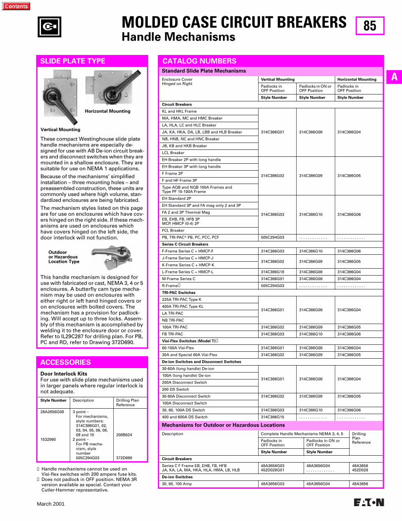
85
March 2001
AEnclosure CoverHinged on Right
Vertical Mounting Horizontal Mounting
Padlocks in OFF Position
Padlocks in ON or OFF Position
Padlocks in OFF Position
Style Number Style Number Style Number
Circuit Breakers
KL and HKL Frame
314C386G01 314C386G08 314C386G04
MA, HMA, MC and HMC Breaker
LA, HLA, LC and HLC Breaker
JA, KA, HKA, DA, LB, LBB and HLB Breaker
NB, HNB, NC and HNC Breaker
JB, KB and HKB Breaker
LCL Breaker
EH Breaker 2P with long handle
314C386G02 314C386G09 314C386G05
EH Breaker 3P with long handle
F Frame 2P
F and HF Frame 3P
Type AQB and NQB 100A Frames andType PF 15-100A Frame
EH Standard 2P
314C386G03 314C386G10 314C386G06
EH Standard 3P and FA mag only 2 and 3P
FA 2 and 3P Thermal Mag
EB, EHB, FB, HFB 3PMCP, HMCP (0-4) 2P
FCL Breaker
PB, TRI-PACT PB, PC, PCC, PCF 505C294G03 . . . . . . . . . . . . . . . . . . . . . . . . . .
Series C Circuit Breakers
F-Frame Series C + HMCP-F 314C386G03 314C386G10 314C386G06
J-Frame Series C + HMCP-J314C386G02 314C386G09 314C386G05
K-Frame Series C + HMCP-K
L-Frame Series C + HMCP-L 314C386G18 314C386G08 314C386G04
M-Frame Series C 314C386G01 314C386G08 314C386G04
R-Frame➋ 505C294G03 . . . . . . . . . . . . . . . . . . . . . . . . . .
TRI-PAC Switches
225A TRI-PAC Type K
314C386G01 314C386G08 314C386G04400A TRI-PAC Type KL
LA TRI-PAC
NB TRI-PAC
100A TRI-PAC 314C386G02 314C386G09 314C386G05
FB TRI-PAC 314C386G03 314C386G10 314C386G06
Visi-Flex Switches (Model T)➊
60-100A Visi-Flex 314C386G01 314C386G08 314C386G04
30A and Special 60A Visi-Flex 314C386G02 314C386G09 314C386G05
De-ion Switches and Disconnect Switches
30-60A (long handle) De-ion
314C386G01 314C386G08 314C386G04100A (long handle) De-ion
200A Disconnect Switch
200 DS Switch
30-60A Disconnect Switch 314C386G02 314C386G09 314C386G05
100A Disconnect Switch
30, 60, 100A DS Switch 314C386G03 314C386G10 314C386G06
400 and 600A DS Switch 314C386G15 . . . . . . . . . . . . . . . . . . . . . . . . . .
Standard Slide Plate Mechanisms
Door Interlock KitsFor use with slide plate mechanisms used in larger panels where regular interlock is not adequate.
Style Number Description Drilling Plan Reference
28A2656G08
1532990
3 point –For mechanisms,style numbers:314C386G01, 02,03, 04, 05, 06, 08,09 and 10
2 point –For PB mecha-nism, stylenumber505C294G03
208B624
372D690
MOLDED CASE CIRCUIT BREAKERSHandle Mechanisms
SLIDE PLATE TYPE
These compact Westinghouse slide plate handle mechanisms are especially de-signed for use with AB De-ion circuit break-ers and disconnect switches when they are mounted in a shallow enclosure. They are suitable for use on NEMA 1 applications.
Because of the mechanisms’ simplified installation – three mounting holes – and preassembled construction, these units are commonly used where high volume, stan-dardized enclosures are being fabricated.
The mechanism styles listed on this page are for use on enclosures which have cov-ers hinged on the right side. If these mech-anisms are used on enclosures which have covers hinged on the left side, the door interlock will not function.
This handle mechanism is designed for use with fabricated or cast, NEMA 3, 4 or 5 enclosures. A butterfly cam type mecha-nism may be used on enclosures with either right or left hand hinged covers or on enclosures with bolted covers. The mechanism has a provision for padlock-ing. Will accept up to three locks. Assem-bly of this mechanism is accomplished by welding it to the enclosure door or cover. Refer to IL29C287 for drilling plan. For PB, PC and RD, refer to Drawing 372D690.
ACCESSORIES
CATALOG NUMBERS
Description Complete Handle Mechanisms NEMA 3, 4, 5 Drilling Plan ReferencePadlocks in
OFF PositionPadlocks in ON or OFF Position
Style Number Style Number
Circuit Breakers
Series C F Frame EB, EHB, FB, HFBJA, KA, LA, MA, HKA, HLA, HMA, LB, HLB
48A3656G03452D028G01
48A3656G04. . . . . . . . . . . . .
48A3656452D028
De-ion Switches
30, 60, 100 Amp 48A3656G03 48A3656G04 48A3656
➊ Handle mechanisms cannot be used on Visi-flex switches with 200 ampere fuse kits.
➋ Does not padlock in OFF position. NEMA 3R version available as special. Contact your Cutler-Hammer representative.
Mechanisms for Outdoor or Hazardous Locations
Vertical Mounting
Horizontal Mounting
Outdooror HazardousLocation Type
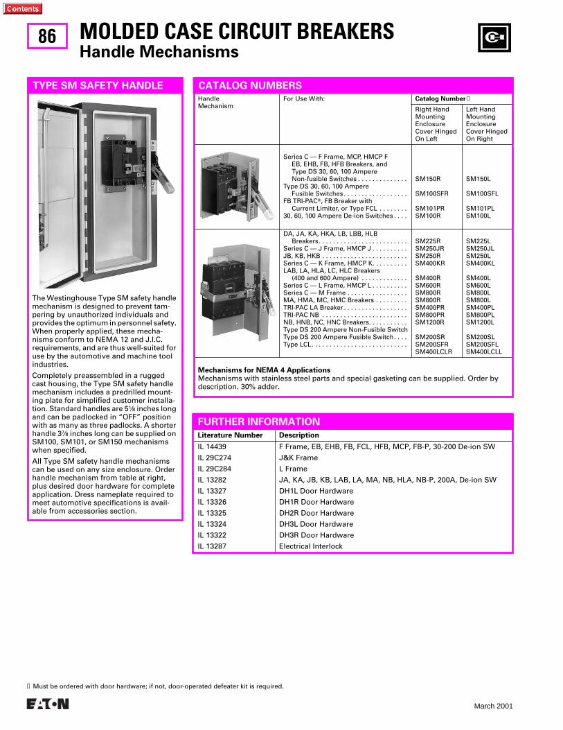
86
March 2001
Mechanisms for NEMA 4 ApplicationsMechanisms with stainless steel parts and special gasketing can be supplied. Order by description. 30% adder.
HandleMechanism
For Use With: Catalog Number➊
Right Hand Mounting Enclosure Cover Hinged On Left
Left Hand Mounting Enclosure Cover Hinged On Right
Series C — F Frame, MCP, HMCP FEB, EHB, FB, HFB Breakers, andType DS 30, 60, 100 Ampere Non-fusible Switches . . . . . . . . . . . . . .
Type DS 30, 60, 100 Ampere Fusible Switches . . . . . . . . . . . . . . . . . .
FB TRI-PACT, FB Breaker withCurrent Limiter, or Type FCL . . . . . . . .
30, 60, 100 Ampere De-ion Switches . . . .
SM150R
SM100SFR
SM101PRSM100R
SM150L
SM100SFL
SM101PLSM100L
DA, JA, KA, HKA, LB, LBB, HLBBreakers. . . . . . . . . . . . . . . . . . . . . . . . .
Series C — J Frame, HMCP J . . . . . . . . . .JB, KB, HKB . . . . . . . . . . . . . . . . . . . . . . . .Series C — K Frame, HMCP K. . . . . . . . . .LAB, LA, HLA, LC, HLC Breakers
(400 and 600 Ampere) . . . . . . . . . . . . .Series C — L Frame, HMCP L . . . . . . . . . .Series C — M Frame . . . . . . . . . . . . . . . . .MA, HMA, MC, HMC Breakers . . . . . . . . .TRI-PAC LA Breaker . . . . . . . . . . . . . . . . . .TRI-PAC NB . . . . . . . . . . . . . . . . . . . . . . . .NB, HNB, NC, HNC Breakers. . . . . . . . . . .Type DS 200 Ampere Non-Fusible SwitchType DS 200 Ampere Fusible Switch. . . .Type LCL. . . . . . . . . . . . . . . . . . . . . . . . . . .
SM225RSM250JRSM250RSM400KR
SM400RSM600RSM800RSM800RSM400PRSM800PRSM1200R
SM200SRSM200SFRSM400LCLR
SM225LSM250JLSM250LSM400KL
SM400LSM600LSM800LSM800LSM400PLSM800PLSM1200L
SM200SLSM200SFLSM400LCLL
MOLDED CASE CIRCUIT BREAKERSHandle Mechanisms
TYPE SM SAFETY HANDLE
The Westinghouse Type SM safety handle mechanism is designed to prevent tam-pering by unauthorized individuals and provides the optimum in personnel safety. When properly applied, these mecha-nisms conform to NEMA 12 and J.I.C. requirements, and are thus well-suited for use by the automotive and machine tool industries.
Completely preassembled in a rugged cast housing, the Type SM safety handle mechanism includes a predrilled mount-ing plate for simplified customer installa-tion. Standard handles are 51⁄8 inches long and can be padlocked in “OFF” position with as many as three padlocks. A shorter handle 37⁄8 inches long can be supplied on SM100, SM101, or SM150 mechanisms when specified.
All Type SM safety handle mechanisms can be used on any size enclosure. Order handle mechanism from table at right, plus desired door hardware for complete application. Dress nameplate required to meet automotive specifications is avail-able from accessories section.
CATALOG NUMBERS
➊ Must be ordered with door hardware; if not, door-operated defeater kit is required.
Literature Number Description
IL 14439
IL 29C274
IL 29C284
IL 13282
IL 13327
IL 13326
IL 13325
IL 13324
IL 13322
IL 13287
F Frame, EB, EHB, FB, FCL, HFB, MCP, FB-P, 30-200 De-ion SW
J&K Frame
L Frame
JA, KA, JB, KB, LAB, LA, MA, NB, HLA, NB-P, 200A, De-ion SW
DH1L Door Hardware
DH1R Door Hardware
DH2R Door Hardware
DH3L Door Hardware
DH3R Door Hardware
Electrical Interlock
FURTHER INFORMATION
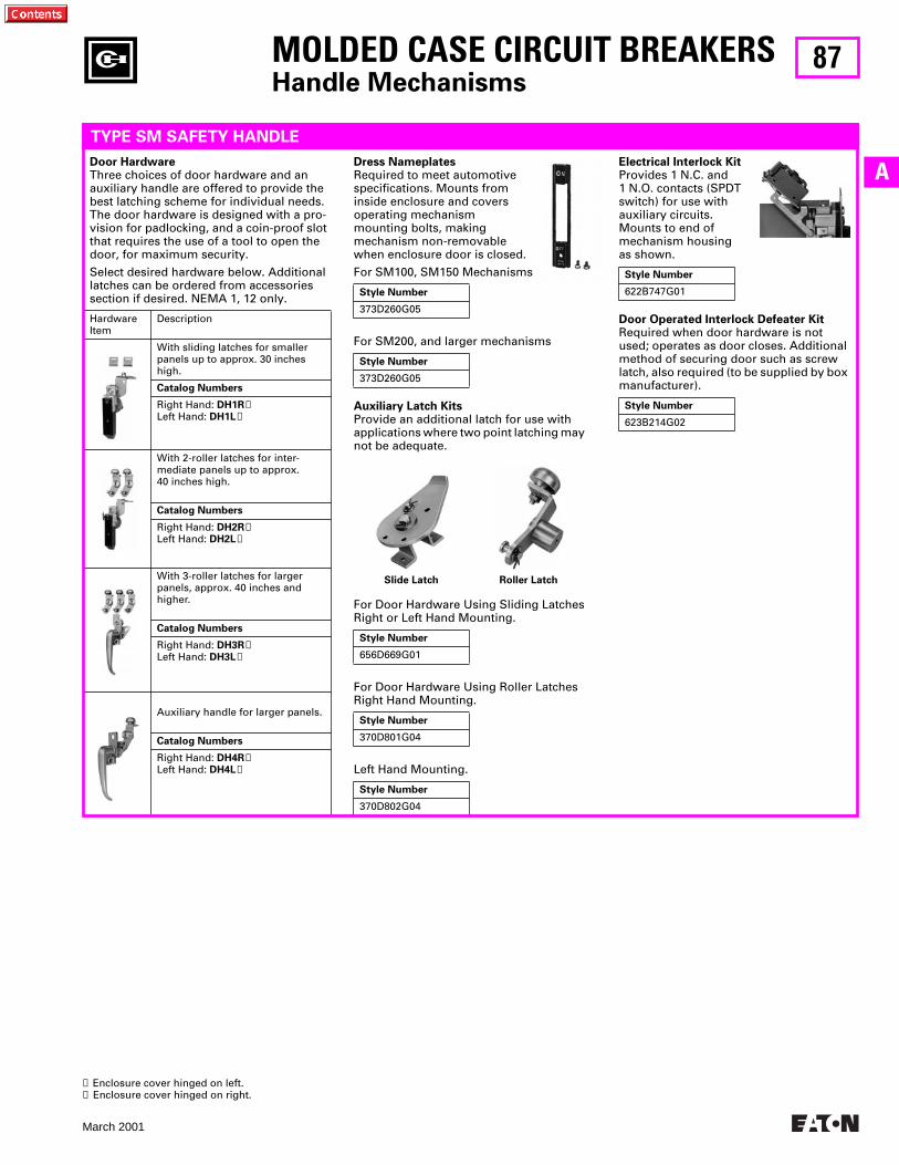
87
March 2001
AElectrical Interlock KitProvides 1 N.C. and1 N.O. contacts (SPDTswitch) for use with auxiliary circuits. Mounts to end of mechanism housing as shown.
Door Operated Interlock Defeater KitRequired when door hardware is not used; operates as door closes. Additional method of securing door such as screw latch, also required (to be supplied by box manufacturer).
Style Number
622B747G01
Style Number
623B214G02
Dress NameplatesRequired to meet automotive specifications. Mounts from inside enclosure and covers operating mechanism mounting bolts, making mechanism non-removable when enclosure door is closed.
For SM100, SM150 Mechanisms
For SM200, and larger mechanisms
Auxiliary Latch KitsProvide an additional latch for use with applications where two point latching may not be adequate.
Style Number
373D260G05
Style Number
373D260G05
MOLDED CASE CIRCUIT BREAKERSHandle Mechanisms
TYPE SM SAFETY HANDLE
Door HardwareThree choices of door hardware and an auxiliary handle are offered to provide the best latching scheme for individual needs. The door hardware is designed with a pro-vision for padlocking, and a coin-proof slot that requires the use of a tool to open the door, for maximum security.
Select desired hardware below. Additional latches can be ordered from accessories section if desired. NEMA 1, 12 only.
HardwareItem
Description
With sliding latches for smaller panels up to approx. 30 inches high.
Catalog Numbers
Right Hand: DH1R➊Left Hand: DH1L➋
With 2-roller latches for inter-mediate panels up to approx. 40 inches high.
Catalog Numbers
Right Hand: DH2R➊Left Hand: DH2L➋
With 3-roller latches for larger panels, approx. 40 inches and higher.
Catalog Numbers
Right Hand: DH3R➊Left Hand: DH3L➋
Auxiliary handle for larger panels.
Catalog Numbers
Right Hand: DH4R➊Left Hand: DH4L➋
Slide Latch Roller Latch
For Door Hardware Using Sliding Latches Right or Left Hand Mounting.
For Door Hardware Using Roller Latches Right Hand Mounting.
Left Hand Mounting.
Style Number
656D669G01
Style Number
370D801G04
Style Number
370D802G04
➊ Enclosure cover hinged on left.➋ Enclosure cover hinged on right.

88
March 2001
Selection Data for Handle Mechanism Only; Circuit Breaker Not Included
HandleMechanism➊
For Use With: NEMA 1 Enclosure NEMA 12 Enclosure
Catalog Number➋ Catalog Number➋
Series C F Frame HMCP F . . . . . . . . . . .EB, EHB, FB, HFB Breakers
and MCP (Size 0-4). . . . . . . . . . . . . . .FB TRI-PACT . . . . . . . . . . . . . . . . . . . . . .FCL Breakers . . . . . . . . . . . . . . . . . . . . . .
SMCU150FD
SMCU150FDSMCU100FBPSMCU100FCL
CMCU150FD
CMCU150FDCMCU100FBPCMCU100FCL
30-60-100 Ampere DS SwitchFusible, Non-fusible. . . . . . . . . . . . .
200 Ampere DS SwitchFusible, Non-fusible. . . . . . . . . . . . .
SMCU100DS
SMCU200DS
CMCU100DS
CMCU200DS
Series C J Frame HMCP J . . . . . . . . . .Series C K Frame HMCP K . . . . . . . . . .DA, JA, KA, HKA, LB,
LBB, HLB Breakers, Size5 MCP (400 Ampere) . . . . . . . . . . . .
JB, KB, HKB, Size 5 MCP(250 Ampere) . . . . . . . . . . . . . . . . . .
Series C L Frame HMCP L . . . . . . . . . .Series C M Frame . . . . . . . . . . . . . . . . .
SMCU250JDSMCU400KD
SMCU225KA
SMCU250KBSMCU600LDSMCU800MA
CMCU250JDCMCU400KD
CMCU225KA
CMCU250KBCMCU600LDCMCU800MA
LAB, LA, HLA, LC, HLC,Breakers (400 and 600Amperes Frame) . . . . . . . . . . . . . . .
LA TRI-PAC . . . . . . . . . . . . . . . . . . . . . .MA, HMA, MC, HMC Breakers
(800 Ampere Frame) . . . . . . . . . . . .NB, HNB, NC, HNC Breakers
(1200 Ampere Frame) . . . . . . . . . . .LCL225 and 400. . . . . . . . . . . . . . . . . . .Series C L Frame HMCP L . . . . . . . . . .
SMCU400LASMCU400LAP
SMCU800MA
SMCU1200NBSMCU400LCLSMCU600LD
SMCU400LASMCU400LAP
SMCU800MA
SMCU1200NBSMCU400LCLSMCU600LD
MOLDED CASE CIRCUIT BREAKERSHandle Mechanisms
TYPE MC MOTOR CONTROL
Type MC handle mechanisms are linear drive, fixed depth mechanisms designed for through-door mounting in standard-ized or shallow depth enclosures such as motor control centers or enclosed circuit breakers.
Mounting directly to the front of the dis-connect, these mechanisms provide posi-tive operation and handle indication. Both disconnect and mechanism mount simul-taneously with mounting hardware sup-plied with the mechanism.
For security, the handle can be padlocked in the OFF position with up to three 3⁄8 inch hasp padlocks. Also, the mechanism is interlocked with the enclosure door so that the disconnect must be “OFF” before the door can be opened. A defeater is provided to bypass this interlock.
Catalog numbers listed include the mechanism, mounting hardware and door interlock clip.
CATALOG NUMBERS
100 AmpereMechanism
225 AmpereMechanism
➊ Mechanisms are shown mounted on breaker for illustration purposes only. Breakers are not included.➋ These mechanisms are recognized under the component program of Underwriters’ Laboratories, Inc.
Literature Number Description
IL 14572
IL 29C273
IL 29C283
IL 14571
IL 14938
IL 14573
IL 14574
F Frame, EB, EHB, FB, MCP, HFB
J&K Frame
L Frame
FB-P
JB, KB
30, 60, 100A DS Switch
200A DS Switch
FURTHER INFORMATION
Low
Res
olut
ion
Phot
o
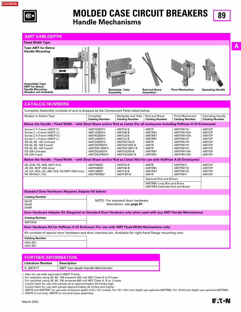
89
March 2001
A
CATALOG NUMBERS
Standard Door Hardware (Requires Adapter Kit below)
Fixed Width Type
EB, EHB, FB, HFB, MCP (0-4)JB, KB, MCP (250 Amp)JA, KA, HKA, LB, LBB, HLB, DA MCP (400 Amp)FB TRI-PACT, FCL
AMTFBBSFAMTKBBSFAMTLBBSFAMTFBPBSF
AMTFD-BAMTKB-BAMTLB-BAMTFBP-B
AMTRAMTRB1AMTRB1AMTR
AMTPM-FAMTPM-FSAMTPM-FSAMTPM-F
AMTOPAMTOPAMTOPAMTOP
Optional Rod and Brace➏
AMTRB2 Long Rod and BraceAMTRB3 Extended Rod and Brace
Below the Handle – Fixed Width – with Short Brace and/or Rod as Listed (Not for use with Hoffman A-25 Enclosures)
Series C F Frame HMCP F➊Series C J Frame HMCP J➊Series C K Frame HMCP K➊Series C L Frame HMCP L➊DS-30, 60, 100 UnfusedDS-30, 60, 100 Fused➌DS-30, 60, 100 Fused➋DS-200 UnfusedDS-200 Fused
AMTFDBSFHAMTJDBSFHAMTKDBSFHAMTLDBSFHAMTDSBSFHAMTDSFBSFHAMTDSF1BSFHAMTDS2BSFHAMTDS2FBSFH
AMTFD-BAMTKB-BAMTLB-BAMTLD-BAMTDS100-BAMTDS100F-BAMTDS100F1-BAMTDS200-BAMTDS200F-B
AMTRAMTRB1AMTRB1AMTRB1AMTRAMTRAMTRAMTRB1AMTRB1
AMTPM-FHAMTPM-FSHAMTPM-FSHAMTPM-FSAMTPM-FHAMTPM-FHAMTPM-FHAMTPM-FSHAMTPM-FSH
AMTOPAMTOPAMTOPAMTOPAMTOPAMTOPAMTOPAMTOPAMTOP
Complete Assembly consists of and is shipped as the Component Parts listed below.
Breaker or Switch Type CompleteCatalog Number
Backplate and YokeCatalog Number
Rod and BraceCatalog Number
Pivot MechanismCatalog Number
Operating HandleCatalog Number
Below the Handle – Fixed Width – with Short Brace and/or Rod as Listed (For all enclosures including Hoffman A-25 Enclosures)
MOLDED CASE CIRCUIT BREAKERSHandle Mechanisms
AMT VARI-DEPTH
Type AMT for Below Handle Mounting
Catalog Number
DH1RDH2RDH3R
Catalog Number
AMTDHA
Kit consists of special door hardware and door interlock pin. Available for right hand flange mounting only.
Catalog Number
HDH-2R➍HDH-3R➎
➊ Also for use with equivalent HMCP Frame.➋ For switches using 30, 60, 100 amperes 250 volt NEC Class H or R fuses.➌ For switches using 30, 60, 100 amperes 600 volt NEC Class H, R or J fuses.➍ 2 point latch for use with panels up to approximately 40 inches high.➎ 3 point latch for use with panels approximately 40 inches and higher.➏ AMTR and AMTRB1 for use with enclosure depth of 61⁄2-141⁄4 inches. For 121⁄4-181⁄4 inch depth use optional AMTRB2. For 18-24 inch depth use optional AMTRB3.➐ AMTR is rod only; AMTRI is rod and brace assembly.
Assembled TypeAMT for BelowHandle Mounting(Breaker not Included)
Backplate, YokeAssembly
Rod and BraceAssembly➐
Pivot Mechanism Operating Handle
NOTE: For standard door hardware description, see page 87.
Door Hardware Adapter Kit (Required on Standard Door Hardware only when used with any AMT Handle Mechanisms)
Door Hardware Kit for Hoffman A-25 Enclosure (For use with AMT Fixed Width Mechanisms only)
Literature Number Description
IL 29C277 AMT Vari-depth Handle Mechanism
FURTHER INFORMATION
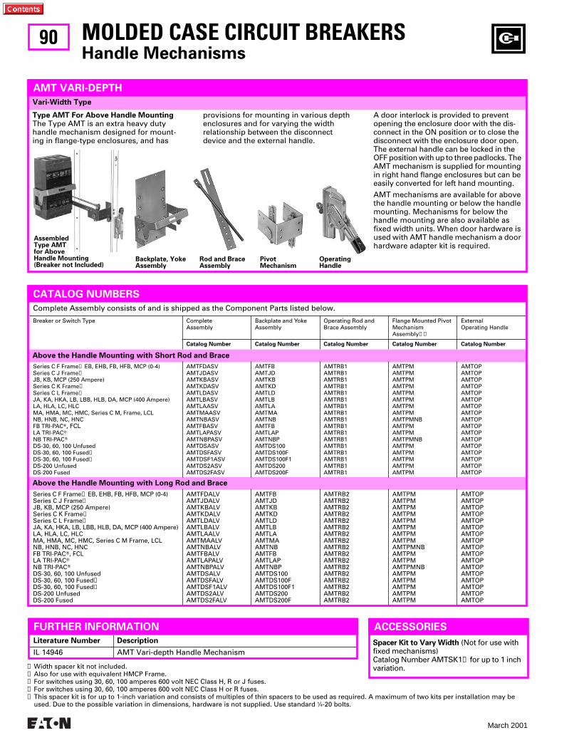
90
March 2001
Above the Handle Mounting with Long Rod and Brace
Above the Handle Mounting with Short Rod and Brace
A door interlock is provided to prevent opening the enclosure door with the dis-connect in the ON position or to close the disconnect with the enclosure door open. The external handle can be locked in the OFF position with up to three padlocks. The AMT mechanism is supplied for mounting in right hand flange enclosures but can be easily converted for left hand mounting.
AMT mechanisms are available for above the handle mounting or below the handle mounting. Mechanisms for below the handle mounting are also available as fixed width units. When door hardware is used with AMT handle mechanism a door hardware adapter kit is required.
Vari-Width Type
Series C F Frame➋ EB, EHB, FB, HFB, MCP (0-4)Series C J Frame➋JB, KB, MCP (250 Ampere)Series C K Frame➋Series C L Frame➋JA, KA, HKA, LB, LBB, HLB, DA, MCP (400 Ampere)LA, HLA, LC, HLCMA, HMA, MC, HMC, Series C M Frame, LCLNB, HNB, NC, HNCFB TRI-PACT, FCLLA TRI-PACTNB TRI-PACTDS-30, 60, 100 UnfusedDS-30, 60, 100 Fused➌DS-30, 60, 100 Fused➍DS-200 UnfusedDS-200 Fused
AMTFDALVAMTJDALVAMTKBALVAMTKDALVAMTLDALVAMTLBALVAMTLAALVAMTMAALVAMTNBALVAMTFBALVAMTLAPALVAMTNBPALVAMTDSALVAMTDSFALVAMTDSF1ALVAMTDS2ALVAMTDS2FALV
AMTFBAMTJDAMTKBAMTKDAMTLDAMTLBAMTLAAMTMAAMTNBAMTFBAMTLAPAMTNBPAMTDS100AMTDS100FAMTDS100F1AMTDS200AMTDS200F
AMTRB2AMTRB2AMTRB2AMTRB2AMTRB2AMTRB2AMTRB2AMTRB2AMTRB2AMTRB2AMTRB2AMTRB2AMTRB2AMTRB2AMTRB2AMTRB2AMTRB2
AMTPMAMTPMAMTPMAMTPMAMTPMAMTPMAMTPMAMTPMAMTPMNBAMTPMAMTPMAMTPMNBAMTPMAMTPMAMTPMAMTPMAMTPM
AMTOPAMTOPAMTOPAMTOPAMTOPAMTOPAMTOPAMTOPAMTOPAMTOPAMTOPAMTOPAMTOPAMTOPAMTOPAMTOPAMTOP
Series C F Frame➋ EB, EHB, FB, HFB, MCP (0-4)Series C J Frame➋JB, KB, MCP (250 Ampere)Series C K Frame➋Series C L Frame➋JA, KA, HKA, LB, LBB, HLB, DA, MCP (400 Ampere)LA, HLA, LC, HLCMA, HMA, MC, HMC, Series C M, Frame, LCLNB, HNB, NC, HNCFB TRI-PACT, FCLLA TRI-PACTNB TRI-PACTDS-30, 60, 100 UnfusedDS-30, 60, 100 Fused➌DS-30, 60, 100 Fused➍DS-200 UnfusedDS-200 Fused
AMTFDASVAMTJDASVAMTKBASVAMTKDASVAMTLDASVAMTLBASVAMTLAASVAMTMAASVAMTNBASVAMTFBASVAMTLAPASVAMTNBPASVAMTDSASVAMTDSFASVAMTDSF1ASVAMTDS2ASVAMTDS2FASV
AMTFBAMTJDAMTKBAMTKDAMTLDAMTLBAMTLAAMTMAAMTNBAMTFBAMTLAPAMTNBPAMTDS100AMTDS100FAMTDS100F1AMTDS200AMTDS200F
AMTRB1AMTRB1AMTRB1AMTRB1AMTRB1AMTRB1AMTRB1AMTRB1AMTRB1AMTRB1AMTRB1AMTRB1AMTRB1AMTRB1AMTRB1AMTRB1AMTRB1
AMTPMAMTPMAMTPMAMTPMAMTPMAMTPMAMTPMAMTPMAMTPMNBAMTPMAMTPMAMTPMNBAMTPMAMTPMAMTPMAMTPMAMTPM
AMTOPAMTOPAMTOPAMTOPAMTOPAMTOPAMTOPAMTOPAMTOPAMTOPAMTOPAMTOPAMTOPAMTOPAMTOPAMTOPAMTOP
MOLDED CASE CIRCUIT BREAKERSHandle Mechanisms
Complete Assembly consists of and is shipped as the Component Parts listed below.
Breaker or Switch Type CompleteAssembly
Backplate and YokeAssembly
Operating Rod and Brace Assembly
Flange Mounted Pivot MechanismAssembly➊➎
ExternalOperating Handle
Catalog Number Catalog Number Catalog Number Catalog Number Catalog Number
AMT VARI-DEPTH
CATALOG NUMBERS
Assembled Type AMTfor AboveHandle Mounting(Breaker not Included)
Backplate, YokeAssembly
Rod and BraceAssembly
Operating Handle
Type AMT For Above Handle MountingThe Type AMT is an extra heavy duty handle mechanism designed for mount-ing in flange-type enclosures, and has
provisions for mounting in various depth enclosures and for varying the width relationship between the disconnect device and the external handle.
➊ Width spacer kit not included.➋ Also for use with equivalent HMCP Frame.➌ For switches using 30, 60, 100 amperes 600 volt NEC Class H, R or J fuses.➍ For switches using 30, 60, 100 amperes 600 volt NEC Class H or R fuses.➎ This spacer kit is for up to 1-inch variation and consists of multiples of thin spacers to be used as required. A maximum of two kits per installation may be
used. Due to the possible variation in dimensions, hardware is not supplied. Use standard 1⁄4-20 bolts.
ACCESSORIES
Spacer Kit to Vary Width (Not for use with fixed mechanisms)Catalog Number AMTSK1➎ for up to 1 inch variation.
Pivot Mechanism
Literature Number Description
IL 14946 AMT Vari-depth Handle Mechanism
FURTHER INFORMATION
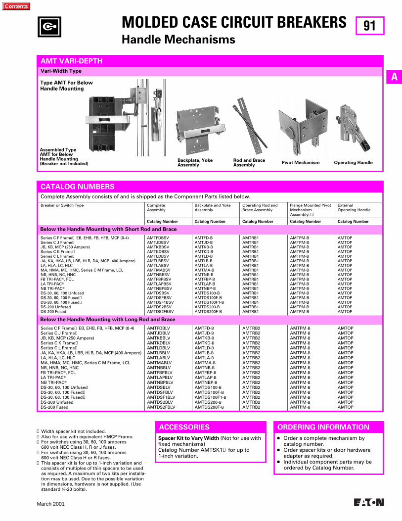
91
March 2001
A
MOLDED CASE CIRCUIT BREAKERSHandle Mechanisms
Vari-Width Type
➊ Width spacer kit not included.➋ Also for use with equivalent HMCP Frame.➌ For switches using 30, 60, 100 amperes
600 volt NEC Class H, R or J fuses.➍ For switches using 30, 60, 100 amperes
600 volt NEC Class H or R fuses.➎ This spacer kit is for up to 1-inch variation and
consists of multiples of thin spacers to be used as required. A maximum of two kits per installa-tion may be used. Due to the possible variation in dimensions, hardware is not supplied. (Use standard 1⁄4-20 bolts).
Series C F Frame➋ EB, EHB, FB, HFB, MCP (0-4)Series C J Frame➋JB, KB, MCP (250 Ampere)Series C K Frame➋Series C L Frame➋JA, KA, HKA, LB, LBB, HLB, DA, MCP (400 Ampere)LA, HLA, LC, HLCMA, HMA, MC, HMC, Series C M Frame, LCLNB, HNB, NC, HNCFB TRI-PACT, FCLLA TRI-PACTNB TRI-PACTDS-30, 60, 100 UnfusedDS-30, 60, 100 Fused➌DS-30, 60, 100 Fused➍DS-200 UnfusedDS-200 Fused
AMTFDBLVAMTJDBLVAMTKBBLVAMTKDBLVAMTLDBLVAMTLBBLVAMTLABLVAMTMABLVAMTNBBLVAMTFBPBLVAMTLAPBLVAMTNBPBLVAMTDSBLVAMTDSFBLVAMTDSF1BLVAMTDS2BLVAMTDS2FBLV
AMTFD-BAMTJD-BAMTKB-BAMTKD-BAMTLD-BAMTLB-BAMTLA-BAMTMA-BAMTNB-BAMTFBP-BAMTLAP-BAMTNBP-BAMTDS100-BAMTDS100F-BAMTDS100F1-BAMTDS200-BAMTDS200F-B
AMTRB2AMTRB2AMTRB2AMTRB2AMTRB2AMTRB2AMTRB2AMTRB2AMTRB2AMTRB2AMTRB2AMTRB2AMTRB2AMTRB2AMTRB2AMTRB2AMTRB2
AMTPM-BAMTPM-BAMTPM-BAMTPM-BAMTPM-BAMTPM-BAMTPM-BAMTPM-BAMTPM-BAMTPM-BAMTPM-BAMTPM-BAMTPM-BAMTPM-BAMTPM-BAMTPM-BAMTPM-B
AMTOPAMTOPAMTOPAMTOPAMTOPAMTOPAMTOPAMTOPAMTOPAMTOPAMTOPAMTOPAMTOPAMTOPAMTOPAMTOPAMTOP
Below the Handle Mounting with Long Rod and Brace
Series C F Frame➋ EB, EHB, FB, HFB, MCP (0-4)Series C J Frame➋JB, KB, MCP (250 Ampere)Series C K Frame➋Series C L Frame➋JA, KA, HKA, LB, LBB, HLB, DA, MCP (400 Ampere)LA, HLA, LC, HLCMA, HMA, MC, HMC, Series C M Frame, LCLNB, HNB, NC, HNCFB TRI-PACT, FCLLA TRI-PACTNB TRI-PACTDS-30, 60, 100 UnfusedDS-30, 60, 100 Fused➌DS-30, 60, 100 Fused➍DS-200 UnfusedDS-200 Fused
AMTFDBSVAMTJDBSVAMTKBBSVAMTKDBSVAMTLDBSVAMTLBBSVAMTLABSVAMTMABSVAMTNBBSVAMTFBPBSVAMTLAPBSVAMTNBPBSVAMTDSBSVAMTDSFBSVAMTDSF1BSVAMTDS2BSVAMTDS2FBSV
AMTFD-BAMTJD-BAMTKB-BAMTKD-BAMTLD-BAMTLB-BAMTLA-BAMTMA-BAMTNB-BAMTFBP-BAMTLAP-BAMTNBP-BAMTDS100-BAMTDS100F-BAMTDS100F1-BAMTDS200-BAMTDS200F-B
AMTRB1AMTRB1AMTRB1AMTRB1AMTRB1AMTRB1AMTRB1AMTRB1AMTRB1AMTRB1AMTRB1AMTRB1AMTRB1AMTRB1AMTRB1AMTRB1AMTRB1
AMTPM-BAMTPM-BAMTPM-BAMTPM-BAMTPM-BAMTPM-BAMTPM-BAMTPM-BAMTPM-BAMTPM-BAMTPM-BAMTPM-BAMTPM-BAMTPM-BAMTPM-BAMTPM-BAMTPM-B
AMTOPAMTOPAMTOPAMTOPAMTOPAMTOPAMTOPAMTOPAMTOPAMTOPAMTOPAMTOPAMTOPAMTOPAMTOPAMTOPAMTOP
Complete Assembly consists of and is shipped as the Component Parts listed below.
Breaker or Switch Type CompleteAssembly
Backplate and YokeAssembly
Operating Rod and Brace Assembly
Flange Mounted Pivot MechanismAssembly➊➎
ExternalOperating Handle
Catalog Number Catalog Number Catalog Number Catalog Number Catalog Number
AMT VARI-DEPTH
CATALOG NUMBERS
Assembled TypeAMT for BelowHandle Mounting(Breaker not Included)
Backplate, YokeAssembly
Rod and BraceAssembly
Pivot Mechanism Operating Handle
Type AMT For Below Handle Mounting
ACCESSORIES
Spacer Kit to Vary Width (Not for use with fixed mechanisms)Catalog Number AMTSK1➎ for up to 1-inch variation.
Below the Handle Mounting with Short Rod and Brace
ORDERING INFORMATION
● Order a complete mechanism by catalog number.
● Order spacer kits or door hardware adapter as required.
● Individual component parts may be ordered by Catalog Number.

92
March 2001
MOLDED CASE CIRCUIT BREAKERSHandle Mechanisms
THIS PAGE INTENTIONALLY LEFT BLANK
93
March 2001
A
MOLDED CASE CIRCUIT BREAKERSHandle Mechanisms
THIS PAGE INTENTIONALLY LEFT BLANK
94
March 2001
MOLDED CASE CIRCUIT BREAKERSHandle Mechanisms
THIS PAGE INTENTIONALLY LEFT BLANK
95
March 2001
A
MOLDED CASE CIRCUIT BREAKERS
THIS PAGE INTENTIONALLY LEFT BLANK
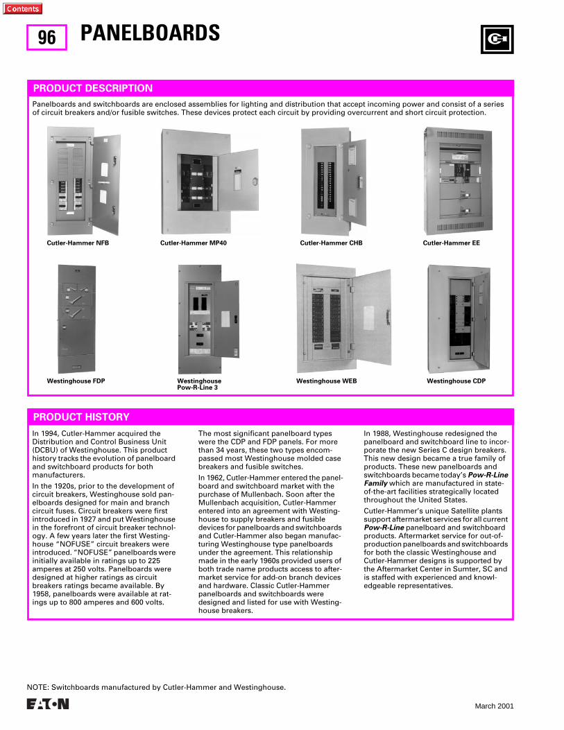
96
March 2001
PANELBOARDS
PRODUCT DESCRIPTION
Panelboards and switchboards are enclosed assemblies for lighting and distribution that accept incoming power and consist of a series of circuit breakers and/or fusible switches. These devices protect each circuit by providing overcurrent and short circuit protection.
PRODUCT HISTORY
Cutler-Hammer NFB Cutler-Hammer MP40 Cutler-Hammer CHB Cutler-Hammer EE
Westinghouse FDP Westinghouse Pow-R-Line 3
Westinghouse WEB Westinghouse CDP
In 1994, Cutler-Hammer acquired the Distribution and Control Business Unit (DCBU) of Westinghouse. This product history tracks the evolution of panelboard and switchboard products for both manufacturers.
In the 1920s, prior to the development of circuit breakers, Westinghouse sold pan-elboards designed for main and branch circuit fuses. Circuit breakers were first introduced in 1927 and put Westinghouse in the forefront of circuit breaker technol-ogy. A few years later the first Westing-house “NOFUSE” circuit breakers were introduced. “NOFUSE” panelboards were initially available in ratings up to 225 amperes at 250 volts. Panelboards were designed at higher ratings as circuit breakers ratings became available. By 1958, panelboards were available at rat-ings up to 800 amperes and 600 volts.
The most significant panelboard types were the CDP and FDP panels. For more than 34 years, these two types encom-passed most Westinghouse molded case breakers and fusible switches.
In 1962, Cutler-Hammer entered the panel-board and switchboard market with the purchase of Mullenbach. Soon after the Mullenbach acquisition, Cutler-Hammer entered into an agreement with Westing-house to supply breakers and fusible devices for panelboards and switchboards and Cutler-Hammer also began manufac-turing Westinghouse type panelboards under the agreement. This relationship made in the early 1960s provided users of both trade name products access to after-market service for add-on branch devices and hardware. Classic Cutler-Hammer panelboards and switchboards were designed and listed for use with Westing-house breakers.
In 1988, Westinghouse redesigned the panelboard and switchboard line to incor-porate the new Series C design breakers. This new design became a true family of products. These new panelboards and switchboards became today’s
Pow-R-Line Family
which are manufactured in state-of-the-art facilities strategically located throughout the United States.
Cutler-Hammer’s unique Satellite plants support aftermarket services for all current
Pow-R-Line
panelboard and switchboard products. Aftermarket service for out-of-production panelboards and switchboards for both the classic Westinghouse and Cutler-Hammer designs is supported by the Aftermarket Center in Sumter, SC and is staffed with experienced and knowl-edgeable representatives.
NOTE: Switchboards manufactured by Cutler-Hammer and Westinghouse.
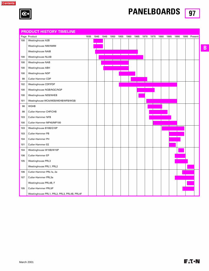
97
March 2001
B
Page Product 1935 1940 1945 1950 1955 1960 1965 1970 1975 1980 1985 1990 1995 Present
100
100
100
100
100
98
102
100
100
101
98
98
103
100
103
103
104
101
104
106
105
106
107
105
Westinghouse A2B
Westinghouse NM/NMM
Westinghouse NAIB
Westinghouse NLAB
Westinghouse NAB
Westinghouse ABH
Westinghouse NDP
Cutler-Hammer CDP
Westinghouse CDP/FDP
Westinghouse NQB/NQC/NQP
Westinghouse NEB/NHEB
Westinghouse WCA/WEB/WEHB/WFB/WGB/
WGHB
Cutler-Hammer CHP/CHB
Cutler-Hammer NFB
Cutler-Hammer MP40/MP100
Westinghouse B10B/Q10P
Cutler-Hammer PB
Cutler-Hammer PH
Cutler-Hammer EE
Westinghouse W10B/W10P
Cutler-Hammer EP
Westinghouse PRL3
Westinghouse PRL1, PRL2
Cutler-Hammer PRL1a, 2a
Cutler-Hammer PRL3a
Westinghouse PRL4B, F
Cutler-Hammer PRL5P
Westinghouse PRL1, PRL2, PRL3, PRL4B, PRL4F
PRODUCT HISTORY TIMELINE
PANELBOARDS
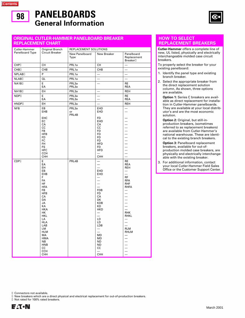
98
March 2001
ORIGINAL CUTLER-HAMMER PANELBOARD BREAKER REPLACEMENT CHART
Cutler-HammerPanelboard Type
Original BranchCircuit Breaker
REPLACEMENT SOLUTIONS
New PanelboardType
New Breaker PanelboardReplacementBreaker
➋
CHP
➊
CH PRL1a CH —
CHB
➊
CHB PRL1a CHB —
NPLAB
➊
P PRL1a — —
NLAB
➊
QL PRL1a — —
NA1B
➊
EEA
PRL3aPRL3a
— REREA
NH1B
➊
EH PRL3a — REH
NDP
➊
EEA
PRL3aPRL3a
——
REREA
HNDP
➊
EH PRL3a — REH
NFB EBEHB
EHCECCACCFBHFBFDFCFHFSHFCCCHCHH
PRL3aorPRL4B
EHDEHD
FDEHDCACCFDFDFDFDHFDFDHFD—CHH
——
—————————————
CDP
➌
EEAEHEBEHBFFAHFHFAFBHFBCADAJAKAHKAHKHKLLAHLALABLMHLMMAHMANBHNBCCCCHCHH
PRL4B ———EHDEHD————FDBFDCADKKDBKDHKD——LDLDLDB——MDMDNDNDCC—CHH
REREAREH——RFRFARHFRHFA———————RHKRHKL———RLMRHLM———————
PANELBOARDS
General Information
HOW TO SELECTREPLACEMENT BREAKERS
Cutler-Hammer
offers a complete line of new, UL listed, physically and electrically interchangeable molded case circuit breakers.
To properly select the breaker for your existing panelboard:
1. Identify the panel type and existing branch breaker.
2. Select the appropriate breaker from the direct replacement solution column. As shown, three options are available.
Option 1:
Series C breakers are avail-able as direct replacement for installa-tion in Cutler-Hammer panelboards. They are available at your local distrib-utor’s and are the most economic solution.
Option 2:
Original, but still-in-production breakers, (sometimes referred to as replacement breakers) are available from Cutler-Hammer’s national warehouse. These are identi-cal to the existing branch breakers.
Option 3:
Panelboard replacement breakers, available for out-of-production molded case breakers, are physically and electrically interchange-able with the existing breaker.
3. For additional information, contact your local Cutler-Hammer Field Sales Office or the Customer Support Center.
➊
Connectors not available.
➋
New breakers which are a direct physical and electrical replacement for out-of-production breakers.
➌
Not rated for 100% rated breakers.
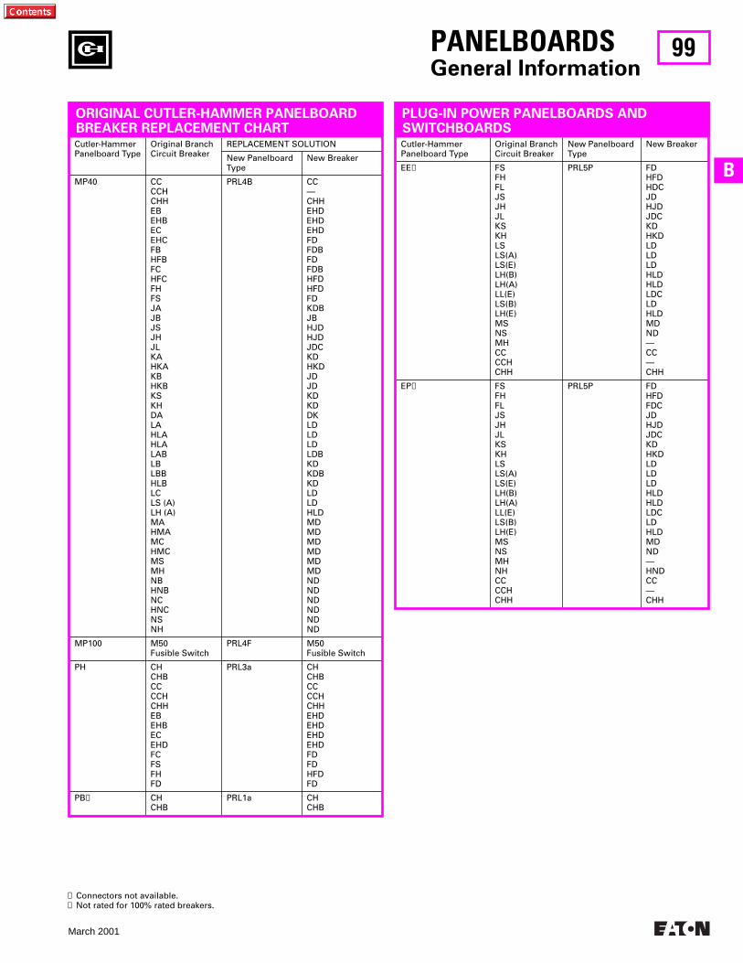
99
March 2001
B
Cutler-HammerPanelboard Type
Original BranchCircuit Breaker
New Panelboard Type
New Breaker
EE
➋
FSFHFLJSJHJLKSKHLSLS(A)LS(E)LH(B)LH(A)LL(E)LS(B)LH(E)MSNSMHCCCCHCHH
PRL5P FDHFDHDCJDHJDJDCKDHKDLDLDLDHLDHLDLDCLDHLDMDND—CC—CHH
EP
➋
FSFHFLJSJHJLKSKHLSLS(A)LS(E)LH(B)LH(A)LL(E)LS(B)LH(E)MSNSMHNHCCCCHCHH
PRL5P FDHFDFDCJDHJDJDCKDHKDLDLDLDHLDHLDLDCLDHLDMDND—HNDCC—CHH
Cutler-HammerPanelboard Type
Original BranchCircuit Breaker
REPLACEMENT SOLUTION
New Panelboard Type
New Breaker
MP40 CCCCHCHHEBEHBECEHCFBHFBFCHFCFHFSJAJBJSJHJLKAHKAKBHKBKSKHDALAHLAHLALABLBLBBHLBLCLS (A)LH (A)MAHMAMCHMCMSMHNBHNBNCHNCNSNH
PRL4B CC—CHHEHDEHDEHDFDFDBFDFDBHFDHFDFDKDBJBHJDHJDJDCKDHKDJDJDKDKDDKLDLDLDLDBKDKDBKDLDLDHLDMDMDMDMDMDMDNDNDNDNDNDND
MP100 M50Fusible Switch
PRL4F M50Fusible Switch
PH CHCHBCCCCHCHHEBEHBECEHDFCFSFHFD
PRL3a CHCHBCCCCHCHHEHDEHDEHDEHDFDFDHFDFD
PB
➊
CHCHB
PRL1a CHCHB
PANELBOARDS
General Information
ORIGINAL CUTLER-HAMMER PANELBOARD BREAKER REPLACEMENT CHART
PLUG-IN POWER PANELBOARDS ANDSWITCHBOARDS
➊
Connectors not available.
➋
Not rated for 100% rated breakers.
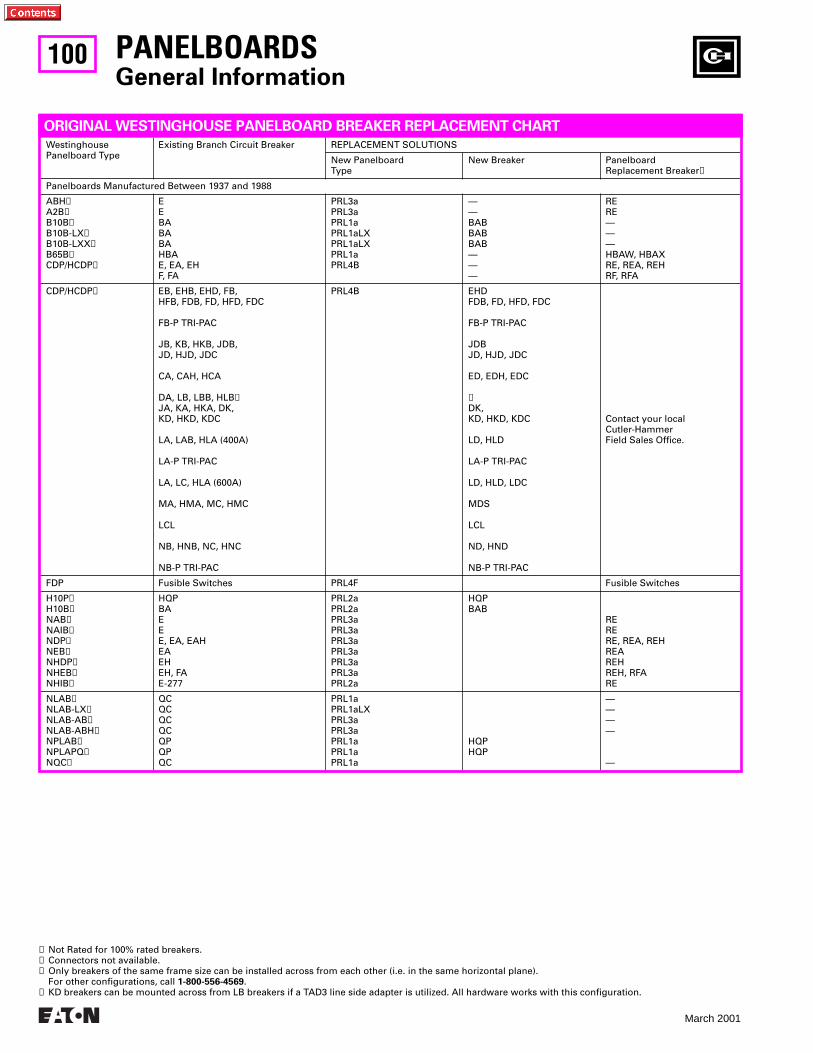
100
March 2001
PANELBOARDS
General Information
WestinghousePanelboard Type
Existing Branch Circuit Breaker REPLACEMENT SOLUTIONS
New PanelboardType
New Breaker PanelboardReplacement Breaker
➊
Panelboards Manufactured Between 1937 and 1988
ABH
➋
A2B
➋
B10B
➋
B10B-LX
➋
B10B-LXX
➋
B65B
➋
CDP/HCDP
➋
EEBABABAHBAE, EA, EHF, FA
PRL3aPRL3aPRL1aPRL1aLXPRL1aLXPRL1aPRL4B
——BABBABBAB———
RERE———HBAW, HBAXRE, REA, REHRF, RFA
CDP/HCDP
➌
EB, EHB, EHD, FB,HFB, FDB, FD, HFD, FDC
FB-P TRI-PAC
JB, KB, HKB, JDB, JD, HJD, JDC
CA, CAH, HCA
DA, LB, LBB, HLB
➍
JA, KA, HKA, DK, KD, HKD, KDC
LA, LAB, HLA (400A)
LA-P TRI-PAC
LA, LC, HLA (600A)
MA, HMA, MC, HMC
LCL
NB, HNB, NC, HNC
NB-P TRI-PAC
PRL4B EHDFDB, FD, HFD, FDC
FB-P TRI-PAC
JDBJD, HJD, JDC
ED, EDH, EDC
➍
DK,KD, HKD, KDC
LD, HLD
LA-P TRI-PAC
LD, HLD, LDC
MDS
LCL
ND, HND
NB-P TRI-PAC
Contact your local Cutler-Hammer Field Sales Office.
FDP Fusible Switches PRL4F Fusible Switches
H10P
➋
H10B
➋
NAB
➋
NAIB
➋
NDP
➋
NEB
➋
NHDP
➋
NHEB
➋
NHIB
➋
HQPBAEEE, EA, EAHEAEHEH, FAE-277
PRL2aPRL2aPRL3aPRL3aPRL3aPRL3aPRL3aPRL3aPRL2a
HQPBAB
RERERE, REA, REHREAREHREH, RFARE
NLAB
➋
NLAB-LX
➋
NLAB-AB
➋
NLAB-ABH
➋
NPLAB
➋
NPLAPQ
➋
NQC
➋
QCQCQCQCQPQPQC
PRL1aPRL1aLXPRL3aPRL3aPRL1aPRL1aPRL1a
HQPHQP
————
—
ORIGINAL WESTINGHOUSE PANELBOARD BREAKER REPLACEMENT CHART
➊
Not Rated for 100% rated breakers.
➋
Connectors not available.
➌
Only breakers of the same frame size can be installed across from each other (i.e. in the same horizontal plane). For other configurations, call
1-800-556-4569
.
➍
KD breakers can be mounted across from LB breakers if a TAD3 line side adapter is utilized. All hardware works with this configuration.
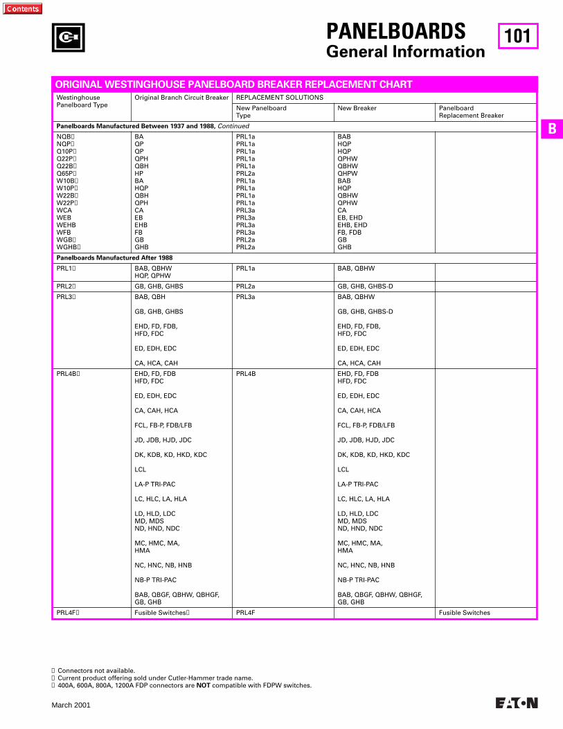
101
March 2001
B
WestinghousePanelboard Type
Original Branch Circuit Breaker REPLACEMENT SOLUTIONS
New PanelboardType
New Breaker PanelboardReplacement Breaker
Panelboards Manufactured Between 1937 and 1988,
Continued
NQB
➊
NQP
➊
Q10P
➊
Q22P
➊
Q22B
➊
Q65P
➊
W10B
➊
W10P
➊
W22B
➊
W22P
➊
WCAWEBWEHBWFBWGB
➊
WGHB
➊
BAQPQPQPHQBHHPBAHQPQBHQPHCAEBEHBFBGBGHB
PRL1aPRL1aPRL1aPRL1aPRL1aPRL2aPRL1aPRL1aPRL1aPRL1aPRL3aPRL3aPRL3aPRL3aPRL2aPRL2a
BABHQPHQPQPHWQBHWQHPWBABHQPQBHWQPHWCAEB, EHDEHB, EHDFB, FDBGBGHB
Panelboards Manufactured After 1988
PRL1
➋
BAB, QBHWHQP, QPHW
PRL1a BAB, QBHW
PRL2
➋
GB, GHB, GHBS PRL2a GB, GHB, GHBS-D
PRL3
➋
BAB, QBH
GB, GHB, GHBS
EHD, FD, FDB, HFD, FDC
ED, EDH, EDC
CA, HCA, CAH
PRL3a BAB, QBHW
GB, GHB, GHBS-D
EHD, FD, FDB, HFD, FDC
ED, EDH, EDC
CA, HCA, CAH
PRL4B
➋
EHD, FD, FDBHFD, FDC
ED, EDH, EDC
CA, CAH, HCA
FCL, FB-P, FDB/LFB
JD, JDB, HJD, JDC
DK, KDB, KD, HKD, KDC
LCL
LA-P TRI-PAC
LC, HLC, LA, HLA
LD, HLD, LDCMD, MDSND, HND, NDC
MC, HMC, MA,HMA
NC, HNC, NB, HNB
NB-P TRI-PAC
BAB, QBGF, QBHW, QBHGF, GB, GHB
PRL4B EHD, FD, FDBHFD, FDC
ED, EDH, EDC
CA, CAH, HCA
FCL, FB-P, FDB/LFB
JD, JDB, HJD, JDC
DK, KDB, KD, HKD, KDC
LCL
LA-P TRI-PAC
LC, HLC, LA, HLA
LD, HLD, LDCMD, MDSND, HND, NDC
MC, HMC, MA,HMA
NC, HNC, NB, HNB
NB-P TRI-PAC
BAB, QBGF, QBHW, QBHGF, GB, GHB
PRL4F
➋
Fusible Switches
➌
PRL4F Fusible Switches
PANELBOARDS
General Information
ORIGINAL WESTINGHOUSE PANELBOARD BREAKER REPLACEMENT CHART
➊
Connectors not available.
➋
Current product offering sold under Cutler-Hammer trade name.
➌
400A, 600A, 800A, 1200A FDP connectors are
NOT
compatible with FDPW switches.

102
March 2001
Originally a Westinghouse Product
PANELBOARDS
General Information
CDP/FDP
The panel layouts shown on this and the following pages will aid in determining the space available for the addition of molded case circuit breakers and fusible switches into your Cutler-Hammer panelboards.
●
Determine the amount of space available in the panelboard for adding circuit breakers.
●
1-3/8 inches of panel height = one X space
●
Determine the type of breaker needed for the required amp rating and number of poles.
●
Panel layouts shown aids in determining the space available for adding breakers to CDP/HCDP panels or fusible switches for FDP panelboards. First determine the available space for additions. Determine height of new device per layout. Order breaker hard-ware from RPD 31-480. Complete breaker retrofit kits are avail-able which include breaker, connectors and hardware from the Sumter, SC Aftermarket Center.
(1-800-556-4569)
Ratings: 1600A MaximumReplacement Devices: Breakers and Fusible Switches
Westinghouse CDP Westinghouse FDP
One X space = 1-3/8 inches.Blank fillers are required for unused x spaces.
7-1/2"
Solid Neutral Bar5X7X9X
13X13X
225A400A600A800A1200, 1600A
Thru-Feed Lugs225A250-400A600, 800A
10X13X17X
Total No. of Poles121824303642
13X15X17X19X21X23X
30"
Wid
e B
ox1X
2X
2X
3X
3X
3X
3X
4X
6X
6X
5" 5"
9" 9"
8" 8"
11" 11"
5X7X9X
12X
225A250-400A600A800, 1200, 1600A
7-1/2"
Main LugSection
2- or 3-PoleMC, HMC
LCLNC, HNC
2- or 3-PoleLC, HLC
LA
2- or 3-PoleLC, HLC
LA
2- or 3-PoleDA
LBB, LBHLB
2- or 3-PoleDA
LBB, LBHLB
2- or 3-PoleJB, KB, HKB
2- or 3-PoleJB, KB, HKB
3-PoleCA, CAH
3-PoleCA, CAH
2-PoleCA, CAH
2-PoleCA, CAH
2- and 3-PoleHFB
3-Pole EBEHB, FB
3-PoleEHB, FB
2-Pole EBEHB, FB
2-Pole EBEHB, FB
1-Pole EBEHB, HFB
1-Pole EBEHB, HFB➊
2- and 3-PoleHFB
30"
Wid
e B
ox
➋
48"
Wid
e B
ox
48"
Wid
e B
ox
Top Gutter
5X7X9X
13X13X
225A400A600A800A1200, 1600A
225A250-400A600A800, 1200, 1600A
5X8X9X
12X
7-1/2"
4X
4X
4X
SolidNeutralBar
5X
30A
60A
100A
30A
60A
100A
100A
2P, 3P240V AC
2P250V DC
Sid
e G
utt
ers
Tab
les
F an
d G
2P, 3P240V or600V AC
2P250V DC
6XMain or Branch
200A(Horizontal Mounted)
2P, 3P600V AC
30A
60A
30A
60A
100A 100A
2P, 3P240 or
600V AC2P
250V DC
Sid
e G
utt
ers
Tab
les
B a
nd
C
Main or Branch400 or 600A
(Horizontal Mounted)
Main or Branch800 or 1200A
(Horizontal Mounted)
Main or Branch800 or 1200A
(Vertical Mounted)
4X
4X
5X
11X
16X
21X
Main LugSection
Bottom Gutter7-1/2"
CDP Panel Layout FDP Panel Layout
➊
When only one EB, EHB, or HFB single pole breaker is required in conjunction with other frame size breakers, the single pole breaker space required changes from 1X to 2X.
➋
Must use 3-pole connector kit.
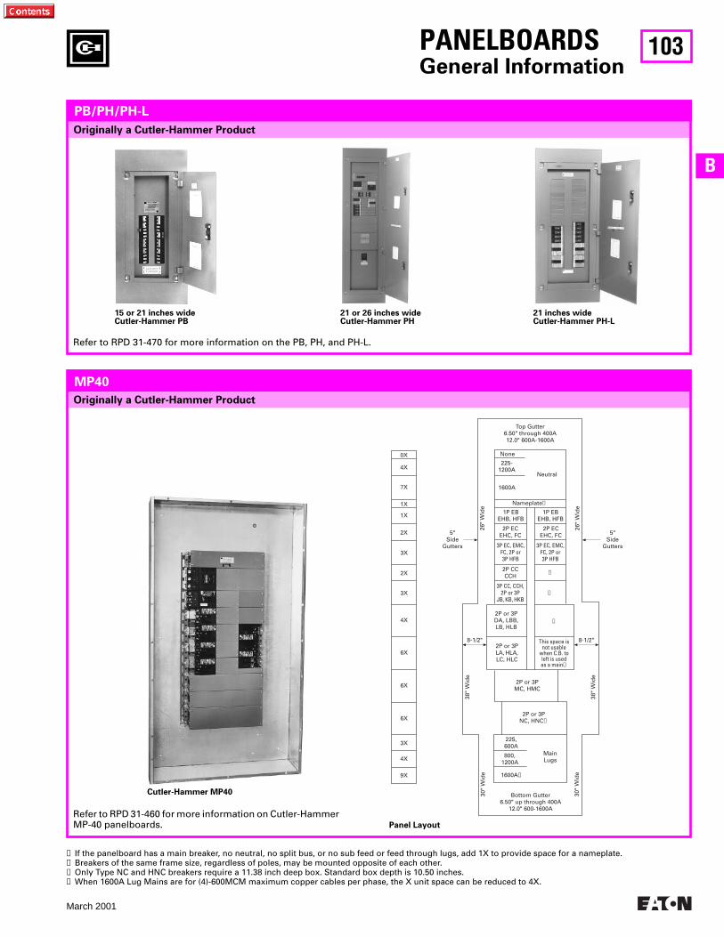
103
March 2001
B
Top Gutter6.50" through 400A12.0" 600A-1600A
None
225-1200A
1600A
Neutral
Nameplate➊
1P EBEHB, HFB
1P EBEHB, HFB
2P ECEHC, FC
2P ECEHC, FC
3P EC, EMC,FC, 2P or3P HFB
3P EC, EMC,FC, 2P or3P HFB
2P CCCCH
5"Side
Gutters
5"Side
Gutters
➋
➋
➋
3P CC, CCH,2P or 3P
JB, KB, HKB
2P or 3PDA, LBB,LB, HLB
2P or 3PLA, HLA,LC, HLC
This space isnot usable
when C.B. toleft is usedas a main➋
8-1/2" 8-1/2"
2P or 3PMC, HMC
2P or 3PNC, HNC➌
MainLugs
225,600A
800,1200A
1600A➍
Bottom Gutter6.50" up through 400A
12.0" 600-1600A
26"
Wid
e
9X
4X
3X
6X
6X
6X
4X
3X
3X
2X
2X
1X
7X
4X
0X
1X
26"
Wid
e
38"
Wid
e
38"
Wid
e
30"
Wid
e
30"
Wid
e
Originally a Cutler-Hammer Product
PANELBOARDS
General Information
PB/PH/PH-L
Refer to RPD 31-470 for more information on the PB, PH, and PH-L.
15 or 21 inches wideCutler-Hammer PB
21 or 26 inches wideCutler-Hammer PH
21 inches wideCutler-Hammer PH-L
MP40
Refer to RPD 31-460 for more information on Cutler-Hammer MP-40 panelboards.
Originally a Cutler-Hammer Product
➊
If the panelboard has a main breaker, no neutral, no split bus, or no sub feed or feed through lugs, add 1X to provide space for a nameplate.
➋
Breakers of the same frame size, regardless of poles, may be mounted opposite of each other.
➌
Only Type NC and HNC breakers require a 11.38 inch deep box. Standard box depth is 10.50 inches.
➍
When 1600A Lug Mains are for (4)-600MCM maximum copper cables per phase, the X unit space can be reduced to 4X.
Cutler-Hammer MP40
Panel Layout
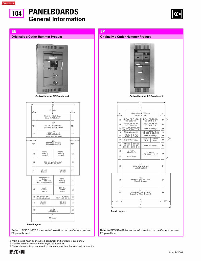
104
March 2001
PANELBOARDSGeneral Information
Originally a Cutler-Hammer Product
EE
Refer to RPD 31-470 for more information on the Cutler-Hammer EE panelboard.
Cutler-Hammer EE Panelboard
Panel Layout
Refer to RPD 31-470 for more information on the Cutler-Hammer EP panelboard.
Cutler-Hammer EP Panelboard
Panel Layout
Neutral — No X Space(May Be At Bottom)
48"
42"
7" 7"10" Gutter
10X 10X
20X
400-600A Main Switch➊400-600A Branch Switch
10X 10X
7X 7X
10"10"
14X1200A Lug Unit➊
200A Branch Switch(600V With R Fusing)
20X800A Main Switch➊800A Branch Switch
8X 8X
6X 6X
6X 6X
600A➋Branch
Lug Unit
600A➋Branch
Lug Unit
12XMS, MH Main Breaker➊
NS, NH Main Breaker
LS, LH➋Breaker
LS, LH➋Breaker
6X 6X
6X 5X
3X 3X
4X 4X
7X8X
200A Branch➋Switch
240V — R&T Fuse600V — T-Fuse Only
400A➋Branch
Lug Unit
100A➋BranchSwitch
KS, KH➋Breaker
KS, KH➋Breaker
30A, 60ABranchSwitch
CC, CCH, CHH➋FS, FH, JS, JH, JL
CC, CCH, CHH➋FS, FH, JS, JH, JL
12XMS, MH
Main Breaker
10" Gutter
Neutral — No X SpaceTop or Bottom
42"
2X
7"
10"
2X
2X 2X
2X 2X
3X 3X
2-Pole FS, FH, FL,CC, CCH, CHH
2-Pole FS, FH, FL,CC, CCH, CHH
3-Pole FS, FH, FL,CC, CCH, CHH
3-Pole FS, FH, FL,CC, CCH, CHH
2P FS, FH,CC, CCH
2P FS, FH,CC, CCH
2P FS, FH,CC, CCH
2P FS, FH,CC, CCH
Blank Wireway➌
Blank Wireway➌
Blank Wireway➌
Blank Wireway➌
Blank Wireway➌
2-PoleCHH
2-PoleCHH
3-PoleCHH
3-PoleCHH
3-PolesFS, FH,
CC, CHH
2X 2X
3X 3X
3X 3X
3X6X
3-PolesFS, FH,
CC, CHH
3 PolesJS, JH, JL 2-3 Pole
LSB, LHB, LLB, LC3X
6X6X12X
800A MS, MH, MCMain Breaker➊
Filler Plate
6X6X12X
800A MS, MH, MC, HMCBranch Breaker
6X6X12X
1200A NS, NH, NC, HNCBranch or Main Breaker➊
10" 10"10"
48"
➋
7"
➊ Main device must be mounted at neutral end of double-bus panel.➋ May be used in 30 inch wide single bus interiors.➌ Blank wireway fillers are required opposite any dual breaker unit or adapter.
Originally a Cutler-Hammer Product
EP
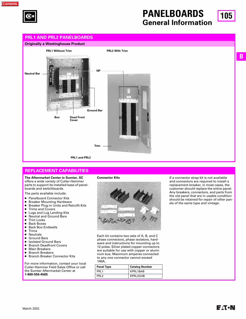
105
March 2001
B
PANELBOARDSGeneral Information
Originally a Westinghouse Product
PRL1 AND PRL2 PANELBOARDS
REPLACEMENT CAPABILITIES
Each kit contains two sets of A, B, and C phase connectors, phase isolators, hard-ware and instructions for mounting up to 12 poles. Silver plated copper connectors are suitable for use with copper or alumi-num bus. Maximum amperes connected to any one connector cannot exceed 140A.
Panel Type Catalog Number
PRL1 KPRL1BAB
PRL2 KPRL2GHB
The Aftermarket Center in Sumter, SC offers a wide variety of Cutler-Hammer parts to support its installed base of panel-boards and switchboards.
The parts available include:
● Panelboard Connector Kits● Breaker Mounting Hardware● Breaker Plug-in Units and Retrofit Kits● Trims and Covers● Lugs and Lug Landing Kits● Neutral and Ground Bars● Trim Locks● Back Boxes● Back Box Endwalls● Trims● Neutrals● Ground Bars● Isolated Ground Bars● Branch Deadfront Covers● Main Breakers● Branch Breakers● Branch Breaker Connector Kits
For more information, contact your local Cutler-Hammer Field Sales Office or call the Sumter Aftermarket Center at 1-800-556-4569.
If a connector strap kit is not available and connectors are required to install a replacement breaker, in most cases, the customer should replace the entire panel. Any breakers, connectors, and parts from the old panel that are in usable condition should be retained for repair of other pan-els of the same type and vintage.
PRL1 and PRL2
Neutral Bar
Box Dead Front Cover
Ground Bar
NP
Trim
Connector Kits
PRL1 Without Trim PRL2 With Trim
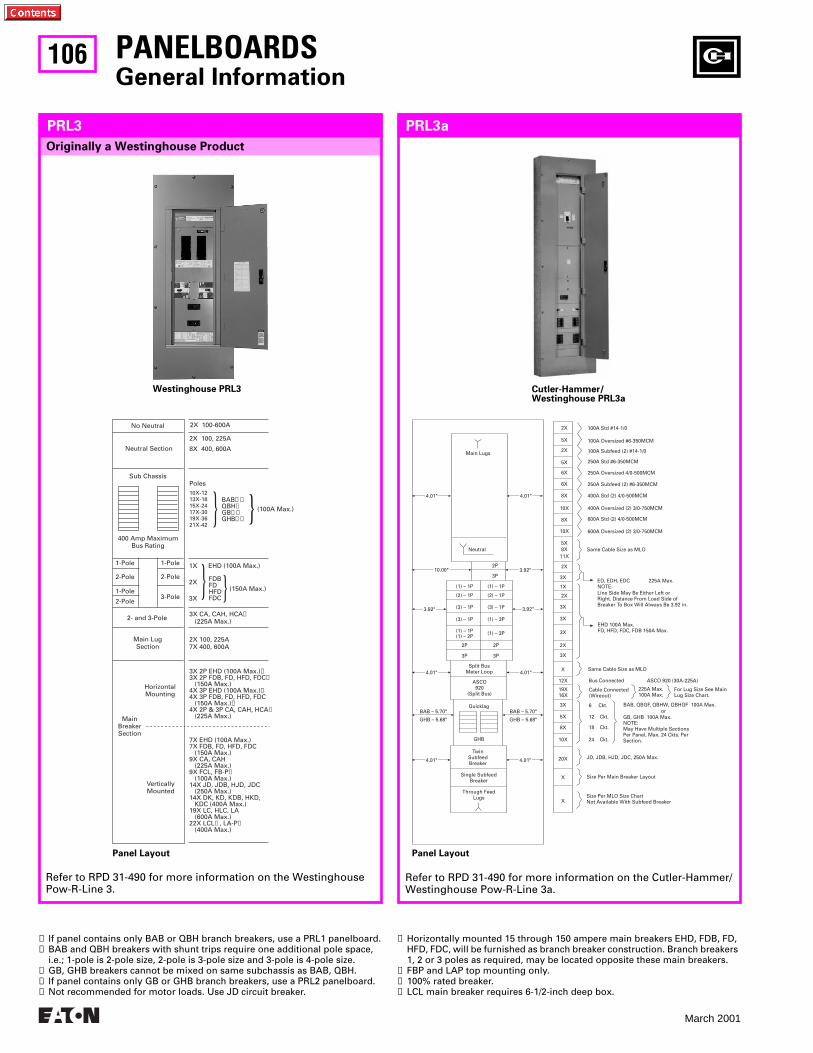
106
March 2001
No Neutral
Neutral Section
Sub Chassis
400 Amp MaximumBus Rating
2X 100-600A
2X 100, 225A
8X 400, 600A
Poles10X-1213X-1815X-2417X-3019X-3621X-42
BAB➊➋QBH➊GB➌➍GHB➌➍
(100A Max.)
1-Pole
1-Pole
1-Pole
2-Pole
2-Pole
2-Pole
3-Pole
2- and 3-Pole
Main LugSection
HorizontalMounting
MainBreakerSection
VerticallyMounted
FDBFDHFDFDC
EHD (100A Max.)1X
2X
3X
3X CA, CAH, HCA➎ (225A Max.)
2X 100, 225A7X 400, 600A
3X 2P EHD (100A Max.)➏3X 2P FDB, FD, HFD, FDC➏ (150A Max.)4X 3P EHD (100A Max.)➏4X 3P FDB, FD, HFD, FDC (150A Max.)➏4X 2P & 3P CA, CAH, HCA➏ (225A Max.)
7X EHD (100A Max.)7X FDB, FD, HFD, FDC (150A Max.)9X CA, CAH (225A Max.)9X FCL, FB-P➐ (100A Max.)14X JD, JDB, HJD, JDC (250A Max.)14X DK, KD, KDB, HKD, KDC (400A Max.)19X LC, HLC, LA (600A Max.)22X LCL➑, LA-P➒ (400A Max.)
(150A Max.)
PANELBOARDSGeneral Information
Refer to RPD 31-490 for more information on the Westinghouse Pow-R-Line 3.
Westinghouse PRL3
Panel Layout
Refer to RPD 31-490 for more information on the Cutler-Hammer/Westinghouse Pow-R-Line 3a.
Cutler-Hammer/Westinghouse PRL3a
Main Lugs
10.00" 3.92"
Neutral
2P
3P
2X
2X
2X
5X
5X
5X
6X
6X
8X
8X
8X
10X
10X
11X
3.92" 3.92"
(1) – 1P
(2) – 1P
(3) – 1P
(3) – 1P
(1) – 1P(1) – 2P
2P
3P
(1) – 1P
(2) – 1P
(3) – 1P
(1) – 3P
2P
3P
(1) – 3P
4.01" 4.01"
BAB – 5.70" BAB – 5.70"
GHB – 5.68" GHB – 5.68"
Split BusMeter Loop
ASCO920
(Split Bus)
Quicklag
GHB
TwinSubfeedBreaker
Single SubfeedBreaker
Through FeedLugs Size Per MLO Size Chart
Not Available With Subfeed Breaker
Size Per Main Breaker Layout
JD, JDB, HJD, JDC, 250A Max.
Same Cable Size as MLO
Bus Connected
6 Ckt.
12 Ckt.
18 Ckt.
24 Ckt.
BAB, QBGF, QBHW, QBHGF 100A Max.or
GB, GHB 100A Max.NOTE:May Have Multiple SectionsPer Panel, Max. 24 Ckts. PerSection.
225A Max.100A Max.
ASCO 920 (30A-225A)
For Lug Size See MainLug Size Chart.
X
X
20X
10X
8X
5X
3X
3X
3X
2X
X
12X
19X16X
3X
3X
3X
2X
1X
EHD 100A Max.FD, HFD, FDC, FDB 150A Max.
ED, EDH, EDCNOTE:
225A Max.
Line Side May Be Either Left orRight. Distance From Load Side ofBreaker To Box Will Always Be 3.92 in.
Same Cable Size as MLO
100A Std #14-1/0
250A Std #6-350MCM
400A Std (2) 4/0-500MCM
600A Std (2) 4/0-500MCM
100A Oversized #6-350MCM
250A Oversized 4/0-500MCM
400A Oversized (2) 3/0-750MCM
600A Oversized (2) 3/0-750MCM
100A Subfeed (2) #14-1/0
250A Subfeed (2) #6-350MCM
4.01" 4.01"
4.01" 4.01"
Cable Connected(Wireout)
Originally a Westinghouse Product
PRL3 PRL3a
Panel Layout
➊ If panel contains only BAB or QBH branch breakers, use a PRL1 panelboard.➋ BAB and QBH breakers with shunt trips require one additional pole space,
i.e.; 1-pole is 2-pole size, 2-pole is 3-pole size and 3-pole is 4-pole size.➌ GB, GHB breakers cannot be mixed on same subchassis as BAB, QBH.➍ If panel contains only GB or GHB branch breakers, use a PRL2 panelboard.➎ Not recommended for motor loads. Use JD circuit breaker.
➏ Horizontally mounted 15 through 150 ampere main breakers EHD, FDB, FD, HFD, FDC, will be furnished as branch breaker construction. Branch breakers 1, 2 or 3 poles as required, may be located opposite these main breakers.
➐ FBP and LAP top mounting only.➑ 100% rated breaker.➒ LCL main breaker requires 6-1/2-inch deep box.
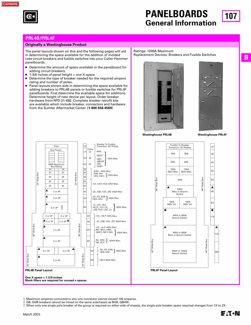
107
March 2001
BRatings: 1200A MaximumReplacement Devices: Breakers and Fusible Switches
Filler
Sub Panel➊
800A MaximumBus Rating
1P2P
3P
2P
3P
1P2P
3P
2P
3P
2 or 3P
2 or 3P
2 or 3P
2 or 3P
2 or 3P
2 or 3P
2 or 3P
2 or 3P
2 or 3P
Load
2 or 3P
2 or 3P 2 or 3P
44"
Wid
e B
ox
36"
Wid
e B
ox
6X
4X
6X
6X
3X
3X
24"
Wid
e B
ox
6X
3X
3X
3X
4X
2X
2X
1X
1X
11X
16X
20X
Poles18
30
42
Breaker To FusibleTransition, All Widths
BAB
QBGF
EHD➌ 100A Max.FDB, FD➌HFD, FDC➌
QBHQBHGFGB➋GHB➋
100A Max.
150A Max.
CA, CAH, HCA 225A Max.
JD, JDB, HJD, JDC 250A Max.
FCL, FB-P 100A Max.
LC, LCC, HLC,HLCC, LCY, LD,LDB, HLD, LDC, LA
DK, KD, KDBHKD, KDC 400A Max.
600A Max.
JD, JDB, HJD, JDC 250A Max.
LCL, LA-P, 400A Max.MC, MCC, HMC,HMCC, MCY, MA 800A Max.
NC, HNC,NB, NCY
1200A Max.
400A Max.
NB-P 800A Max.
DK, KD, KDB,HKD, KDC
24"
Wid
e B
ox
36"
Wid
e B
ox
44"
Wid
e B
ox
36"
Wid
e B
ox
44"
Wid
e B
ox
Fusible To BreakerTransition, All Widths
30A
60A
30A
60A
1X
4X
4X
4X
5X
100A250V Max.
100A250V Max.
100A
36"
Wid
e B
ox
6X200A
Main or BranchSwitch
5X
11X
11X
100A600V AC
100A600V AC
400A or 600ABranch Switch
400A or 600AMain or Branch Switch
44"
Wid
e B
ox
800A or 1200ABranch Switch
16X
PANELBOARDSGeneral Information
Originally a Westinghouse Product
PRL4B/PRL4F
The panel layouts shown on this and the following pages will aid in determining the space available for the addition of molded case circuit breakers and fusible switches into your Cutler-Hammer panelboards.
● Determine the amount of space available in the panelboard for adding circuit breakers.
● 1-3/8 inches of panel height = one X space● Determine the type of breaker needed for the required ampere
rating and number of poles.● Panel layouts shown aids in determining the space available for
adding breakers to PRL4B panels or fusible switches for PRL4F panelboards. First determine the available space for additions. Determine height of new device per layout. Order breaker hardware from RPD 31-490. Complete breaker retrofit kits are available which include breaker, connectors and hardware from the Sumter Aftermarket Center. (1-800-556-4569)
One X space = 1-3/8 inches.Blank fillers are required for unused x spaces.
Westinghouse PRL4B Westinghouse PRL4F
PRL4B Panel Layout PRL4F Panel Layout
➊ Maximum amperes connected to any one connector cannot exceed 140 amperes.➋ GB, GHB breakers cannot be mixed on the same subchassis as BAB, QBHW.➌ When only one single pole breaker of the group is required on either side of chassis, the single pole breaker space required changes from 1X to 2X.
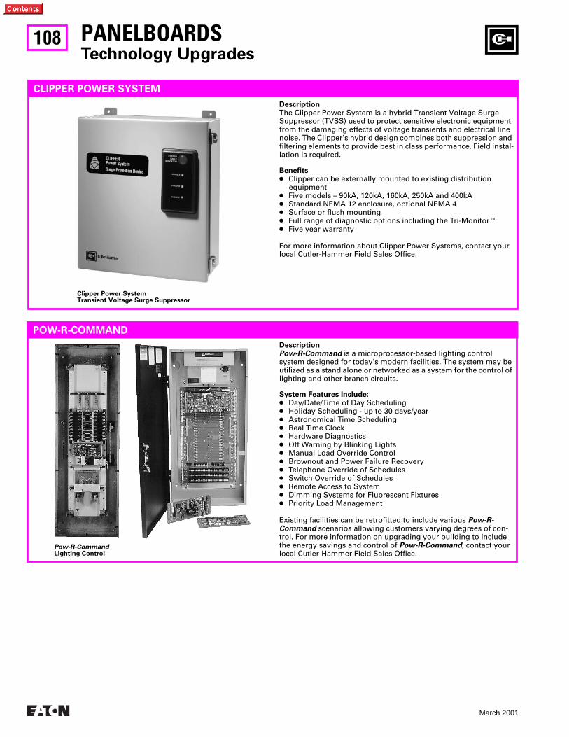
108
March 2001
PANELBOARDSTechnology Upgrades
CLIPPER POWER SYSTEM
Clipper Power SystemTransient Voltage Surge Suppressor
POW-R-COMMAND
Pow-R-CommandLighting Control
DescriptionThe Clipper Power System is a hybrid Transient Voltage Surge Suppressor (TVSS) used to protect sensitive electronic equipment from the damaging effects of voltage transients and electrical line noise. The Clipper’s hybrid design combines both suppression and filtering elements to provide best in class performance. Field instal-lation is required.
Benefits● Clipper can be externally mounted to existing distribution
equipment● Five models – 90kA, 120kA, 160kA, 250kA and 400kA● Standard NEMA 12 enclosure, optional NEMA 4● Surface or flush mounting● Full range of diagnostic options including the Tri-MonitorE● Five year warranty
For more information about Clipper Power Systems, contact your local Cutler-Hammer Field Sales Office.
DescriptionPow-R-Command is a microprocessor-based lighting control system designed for today’s modern facilities. The system may be utilized as a stand alone or networked as a system for the control of lighting and other branch circuits.
System Features Include:● Day/Date/Time of Day Scheduling● Holiday Scheduling - up to 30 days/year● Astronomical Time Scheduling● Real Time Clock● Hardware Diagnostics● Off Warning by Blinking Lights● Manual Load Override Control● Brownout and Power Failure Recovery● Telephone Override of Schedules● Switch Override of Schedules● Remote Access to System● Dimming Systems for Fluorescent Fixtures● Priority Load Management
Existing facilities can be retrofitted to include various Pow-R-Command scenarios allowing customers varying degrees of con-trol. For more information on upgrading your building to include the energy savings and control of Pow-R-Command, contact your local Cutler-Hammer Field Sales Office.
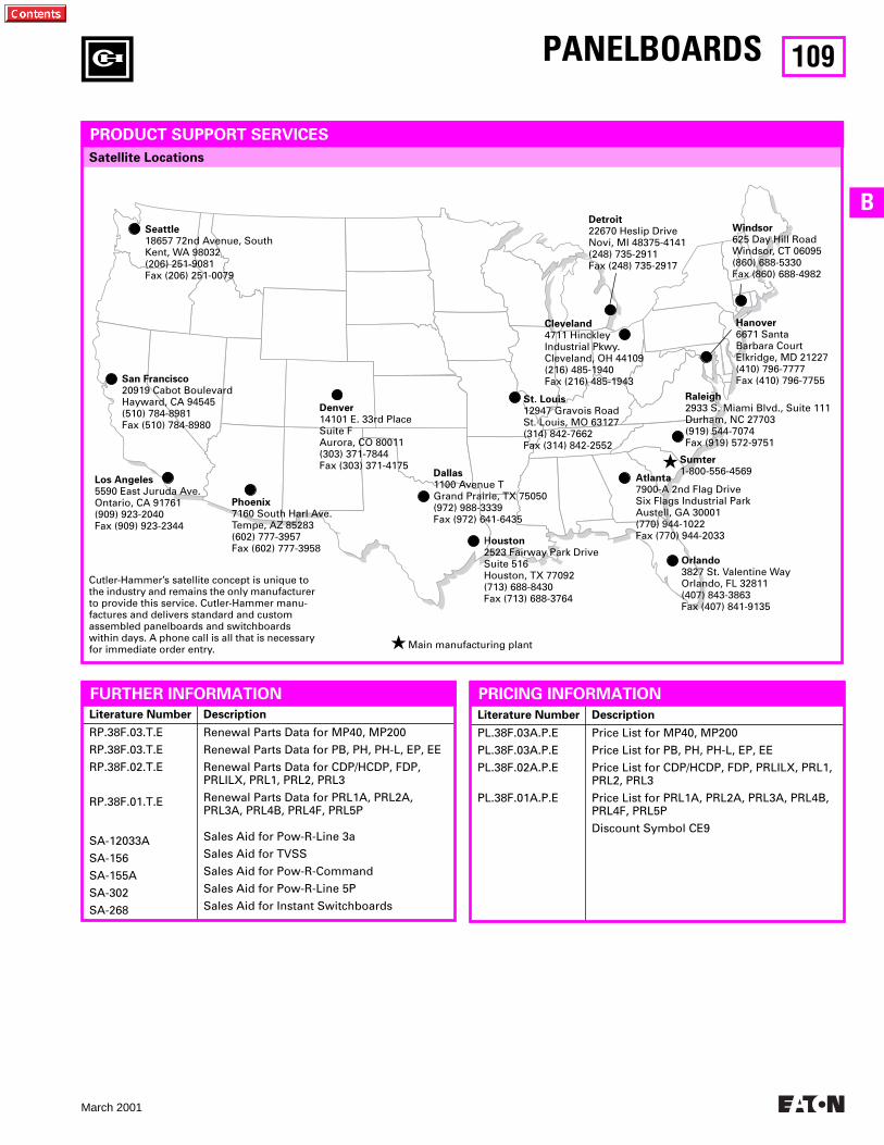
109
March 2001
B
Satellite Locations
Literature Number Description
RP.38F.03.T.E
RP.38F.03.T.E
RP.38F.02.T.E
RP.38F.01.T.E
SA-12033A
SA-156
SA-155A
SA-302
SA-268
Renewal Parts Data for MP40, MP200
Renewal Parts Data for PB, PH, PH-L, EP, EE
Renewal Parts Data for CDP/HCDP, FDP, PRLILX, PRL1, PRL2, PRL3
Renewal Parts Data for PRL1A, PRL2A, PRL3A, PRL4B, PRL4F, PRL5P
Sales Aid for Pow-R-Line 3a
Sales Aid for TVSS
Sales Aid for Pow-R-Command
Sales Aid for Pow-R-Line 5P
Sales Aid for Instant Switchboards
PANELBOARDS
PRODUCT SUPPORT SERVICES
FURTHER INFORMATION
Atlanta7900-A 2nd Flag DriveSix Flags Industrial ParkAustell, GA 30001(770) 944-1022Fax (770) 944-2033
Cleveland4711 Hinckley Industrial Pkwy.Cleveland, OH 44109(216) 485-1940Fax (216) 485-1943
Dallas1100 Avenue TGrand Prairie, TX 75050(972) 988-3339Fax (972) 641-6435
Denver14101 E. 33rd PlaceSuite FAurora, CO 80011(303) 371-7844Fax (303) 371-4175
Hanover6671 Santa Barbara CourtElkridge, MD 21227(410) 796-7777Fax (410) 796-7755
Houston2523 Fairway Park DriveSuite 516Houston, TX 77092(713) 688-8430Fax (713) 688-3764
Los Angeles5590 East Juruda Ave.Ontario, CA 91761(909) 923-2040Fax (909) 923-2344
Orlando3827 St. Valentine WayOrlando, FL 32811(407) 843-3863Fax (407) 841-9135
San Francisco20919 Cabot BoulevardHayward, CA 94545(510) 784-8981Fax (510) 784-8980
Seattle18657 72nd Avenue, SouthKent, WA 98032(206) 251-9081Fax (206) 251-0079
St. Louis12947 Gravois RoadSt. Louis, MO 63127(314) 842-7662Fax (314) 842-2552
Windsor625 Day Hill RoadWindsor, CT 06095(860) 688-5330Fax (860) 688-4982
Phoenix7160 South Harl Ave.Tempe, AZ 85283(602) 777-3957Fax (602) 777-3958
Literature Number Description
PL.38F.03A.P.E
PL.38F.03A.P.E
PL.38F.02A.P.E
PL.38F.01A.P.E
Price List for MP40, MP200
Price List for PB, PH, PH-L, EP, EE
Price List for CDP/HCDP, FDP, PRLILX, PRL1, PRL2, PRL3
Price List for PRL1A, PRL2A, PRL3A, PRL4B, PRL4F, PRL5P
Discount Symbol CE9
PRICING INFORMATION
★ Sumter1-800-556-4569
Cutler-Hammer’s satellite concept is unique to the industry and remains the only manufacturer to provide this service. Cutler-Hammer manu-factures and delivers standard and custom assembled panelboards and switchboards within days. A phone call is all that is necessary for immediate order entry. ★ Main manufacturing plant
Detroit22670 Heslip Drive Novi, MI 48375-4141(248) 735-2911Fax (248) 735-2917
Raleigh2933 S. Miami Blvd., Suite 111Durham, NC 27703(919) 544-7074Fax (919) 572-9751
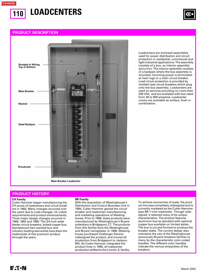
110
March 2001
LOADCENTERS
PRODUCT DESCRIPTION
Straight-in Wiring, Top or Bottom
Main Breaker
Neutral
Steel Backpan
Knockouts
PRODUCT HISTORY
CH Family
Cutler-Hammer began manufacturing the CH series of loadcenters and circuit break-ers in 1962. Many changes occurred over the years due to code changes, UL Listed requirements and product enhancements. Three major design changes occurred in 1969, 1982 and 1995. The 3/4-inch wide feeder circuit breakers, bolted copper bus, Sandalwood (tan) painted box and industry-leading warranties have been the trademarks of this premium product through the years.
BR Family
With the acquisition of Westinghouse’s Distribution and Control Business Unit in 1994, Cutler-Hammer gained the circuit breaker and loadcenter manufacturing and marketing operations of Westing-house. Prior to 1989, these products were manufactured by Westinghouse’s Bryant subsidiary in Bridgeport, CT. The products from this facility bore the Westinghouse and Bryant nameplates. In 1988, Westing-house purchased Challenger Electric, redesigned the product, and moved all production from Bridgeport to Jackson, MS. As Cutler-Hammer integrated the product lines in 1995, all loadcenter production shifted to the Lincoln, IL facility.
To achieve economies of scale, the prod-uct line was completely redesigned and is currently marketed as the Cutler-Hammer type BR 1-inch loadcenter. Though rede-signed, it retained many of its unique characteristics. The product features aluminum bus as standard with optional copper bus available on limited styles. The bus is cut and formed to produce the breaker stabs. The current design also maintains the use of the Westinghouse (previously Bryant) breakers familiar to many by the characteristic color-coded handles. The different color handles indicate the various ampacities of the breakers.
Loadcenters are enclosed assemblies used for power distribution and circuit protection in residential, commercial and light industrial applications. The assembly consists of a box, an interior assembly and a trim. The interior assembly consists of a backpan where the bus assembly is mounted. Incoming power is terminated at main lugs or a main circuit breaker. Load circuit protection is provided by molded case circuit breakers which plug onto the bus assembly. Loadcenters are used on services providing no more than 240 VAC, and are available with bus rated from 40 to 600 amperes. Loadcenter covers are available as surface, flush or combination.
Main Breaker Loadcenter
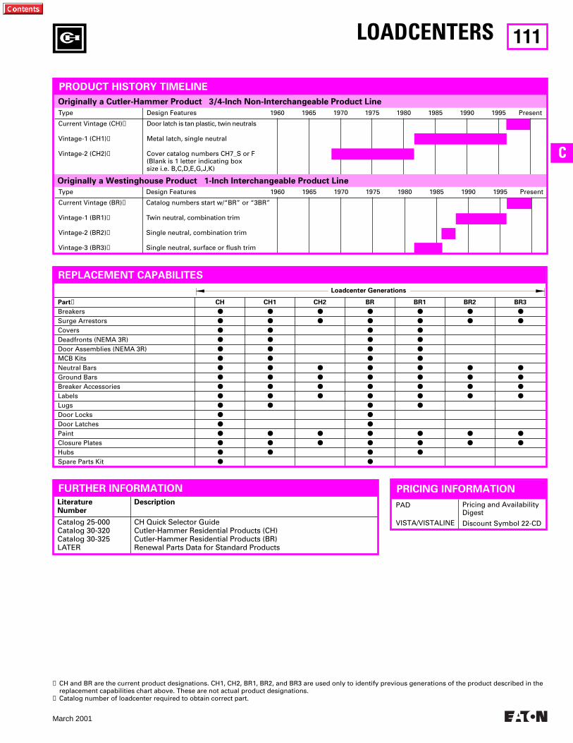
111
March 2001
C
Loadcenter Generations
Part
➋
CH CH1 CH2 BR BR1 BR2 BR3
Breakers
● ● ● ● ● ● ●
Surge Arrestors
● ● ● ● ● ● ●
Covers
● ● ● ●
Deadfronts (NEMA 3R)
● ● ● ●
Door Assemblies (NEMA 3R)
● ● ● ●
MCB Kits
● ● ● ●
Neutral Bars
● ● ● ● ● ● ●
Ground Bars
● ● ● ● ● ● ●
Breaker Accessories
● ● ● ● ● ● ●
Labels
● ● ● ● ● ● ●
Lugs
● ● ● ●
Door Locks
● ●
Door Latches
● ●
Paint
● ● ● ● ● ● ●
Closure Plates
● ● ● ● ● ● ●
Hubs
● ● ● ●
Spare Parts Kit
● ●
PAD
VISTA/VISTALINE
Pricing and Availability Digest
Discount Symbol 22-CD
LiteratureNumber
Description
Catalog 25-000Catalog 30-320Catalog 30-325LATER
CH Quick Selector GuideCutler-Hammer Residential Products (CH)Cutler-Hammer Residential Products (BR)Renewal Parts Data for Standard Products
LOADCENTERS
FURTHER INFORMATION
Type Design Features 1960 1965 1970 1975 1980 1985 1990 1995 Present
Current Vintage (CH)
➊
Vintage-1 (CH1)
➊
Vintage-2 (CH2)
➊
Door latch is tan plastic, twin neutrals
Metal latch, single neutral
Cover catalog numbers CH7_S or F (Blank is 1 letter indicating box size i.e. B,C,D,E,G,J,K)
Type Design Features 1960 1965 1970 1975 1980 1985 1990 1995 Present
Current Vintage (BR)
➊
Vintage-1 (BR1)
➊
Vintage-2 (BR2)
➊
Vintage-3 (BR3)
➊
Catalog numbers start w/“BR” or “3BR”
Twin neutral, combination trim
Single neutral, combination trim
Single neutral, surface or flush trim
Originally a Cutler-Hammer Product 3/4-Inch Non-Interchangeable Product Line
Originally a Westinghouse Product 1-Inch Interchangeable Product Line
PRODUCT HISTORY TIMELINE
➊
CH and BR are the current product designations. CH1, CH2, BR1, BR2, and BR3 are used only to identify previous generations of the product described in the replacement capabilities chart above. These are not actual product designations.
➋
Catalog number of loadcenter required to obtain correct part.
PRICING INFORMATION
REPLACEMENT CAPABILITES
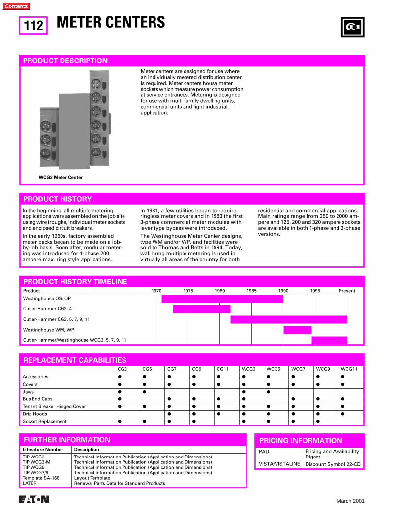
112
March 2001
CG3 CG5 CG7 CG9 CG11 WCG3 WCG5 WCG7 WCG9 WCG11
Accessories
P P P P P P P P P P
Covers
P P P P P P P P P P
Jaws
P P P P
Bus End Caps
P P P P P P P P
Tenant Breaker Hinged Cover
P P P P P P P P P P
Drip Hoods
P P P P P P P P
Socket Replacement
P P P P P P P P
Product 1970 1975 1980 1985 1990 1995 Present
Westinghouse QS, QP
Cutler-Hammer CG2, 4
Cutler-Hammer CG3, 5, 7, 9, 11
Westinghouse WM, WP
Cutler-Hammer/Westinghouse WCG3, 5, 7, 9, 11
METER CENTERS
PRODUCT HISTORY TIMELINE
PRODUCT DESCRIPTION
Meter centers are designed for use where an individually metered distribution center is required. Meter centers house meter sockets which measure power consumption at service entrances. Metering is designed for use with multi-family dwelling units, commercial units and light industrial application.
REPLACEMENT CAPABILITIES
FURTHER INFORMATION
PRODUCT HISTORY
In the beginning, all multiple metering applications were assembled on the job site using wire troughs, individual meter sockets and enclosed circuit breakers.
In the early 1960s, factory assembled meter packs began to be made on a job-by-job basis. Soon after, modular meter-ing was introduced for 1-phase 200 ampere max. ring style applications.
In 1981, a few utilities began to require ringless meter covers and in 1983 the first 3-phase commercial meter modules with lever type bypass were introduced.
The Westinghouse Meter Center designs, type WM and/or WP, and facilities were sold to Thomas and Betts in 1994. Today, wall hung multiple metering is used in virtually all areas of the country for both
residential and commercial applications. Main ratings range from 250 to 2000 am-pere and 125, 200 and 320 ampere sockets are available in both 1-phase and 3-phase versions.
Literature Number Description
TIP WCG3TIP WCG3-MTIP WCG5TIP WCG7/9Template SA-168LATER
Technical Information Publication (Application and Dimensions)Technical Information Publication (Application and Dimensions)Technical Information Publication (Application and Dimensions)Technical Information Publication (Application and Dimensions)Layout TemplateRenewal Parts Data for Standard Products
WCG3 Meter Center
PAD
VISTA/VISTALINE
Pricing and Availability Digest
Discount Symbol 22-CD
PRICING INFORMATION
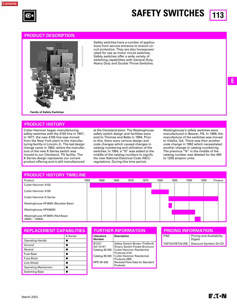
113
March 2001
E
LiteratureNumber
Description
B1227SA-12147Catalog 30-320
Catalog 30-325
RPD 30-326
Safety Switch Binder (Trafford)Rotary Switch Pocket BrochureCutler-Hammer Residential Products (CH)Cutler-Hammer Residential Products (BR)Renewal Parts Data for Standard Products
PAD
VISTA/VISTALINE
Pricing and Availability Digest
Discount Symbol 22-CD
K-Series
Operating Handle
P
Ground
P
Neutral
P
Fuse Base
P
Fuse Block
P
Line Shield
P
Operating Mechanism
P
Switching Base
P
Product 1955 1960 1965 1970 1975 1980 1985 1990 1995 Present
Cutler-Hammer 4103
Cutler-Hammer 4105
Cutler-Hammer K-Series
Westinghouse HF365N (Bacalyte Base)
Westinghouse HFN365N
Westinghouse HF365N (Red Base)(400A – 1200A)
SAFETY SWITCHES
PRODUCT HISTORY TIMELINE
PRODUCT DESCRIPTION
PRODUCT HISTORY
Safety switches have a number of applica-tions from service entrance to branch cir-cuit protection. They are also horsepower rated for use as motor circuit switches. Safety switches offer a wide variety of switching capabilities with General Duty, Heavy Duty and Double Throw Switches.
Cutler-Hammer began manufacturing safety switches with the 4103 line in 1957. In 1977, the new 4105 line was moved from the New York plant to the manufac-turing facility in Lincoln, IL. The last design change came in 1983, where the manufac-ture of the new K-Series switch was moved to our Cleveland, TN facility. The K-Series design represents our current product offering and is still manufactured
at the Cleveland plant. The Westinghouse safety switch design and facilities were sold to Thomas and Betts in 1994. Prior to this, there were various design and code changes which caused changes in catalog numbering and utilization of the switches. In 1984, a “N” was added to the middle of the catalog numbers to signify the new National Electrical Code (NEC) regulations. During this time period,
Westinghouse’s safety switches were manufactured in Beaver, PA. In 1989, the manufacture of the switches was moved to Vidalia, GA. There was then another code change in 1992 which necessitated another change in catalog numbering. The previous “N” in the middle of the catalog number was deleted for the 400 to 1200 ampere units.
PRICING INFORMATIONFURTHER INFORMATION
Family of Safety Switches
REPLACEMENT CAPABILITIES
Low
Res
olut
ion
Phot
o
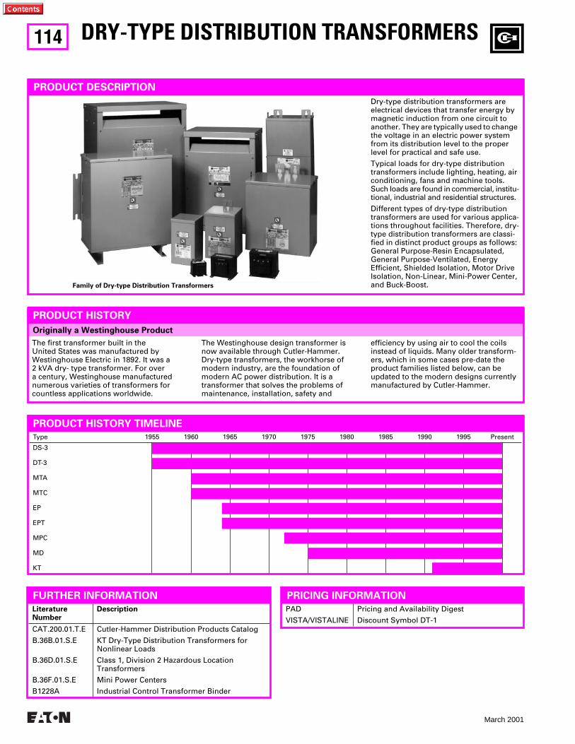
114
March 2001
LiteratureNumber
Description
CAT.200.01.T.E
B.36B.01.S.E
B.36D.01.S.E
B.36F.01.S.E
B1228A
Cutler-Hammer Distribution Products Catalog
KT Dry-Type Distribution Transformers forNonlinear Loads
Class 1, Division 2 Hazardous LocationTransformers
Mini Power Centers
Industrial Control Transformer Binder
Type 1955 1960 1965 1970 1975 1980 1985 1990 1995 Present
DS-3
DT-3
MTA
MTC
EP
EPT
MPC
MD
KT
Originally a Westinghouse Product
DRY-TYPE DISTRIBUTION TRANSFORMERS
PRODUCT DESCRIPTION
Dry-type distribution transformers are electrical devices that transfer energy by magnetic induction from one circuit to another. They are typically used to change the voltage in an electric power system from its distribution level to the proper level for practical and safe use.
Typical loads for dry-type distribution transformers include lighting, heating, air conditioning, fans and machine tools. Such loads are found in commercial, institu-tional, industrial and residential structures.
Different types of dry-type distribution transformers are used for various applica-tions throughout facilities. Therefore, dry-type distribution transformers are classi-fied in distinct product groups as follows: General Purpose-Resin Encapsulated, General Purpose-Ventilated, Energy Efficient, Shielded Isolation, Motor Drive Isolation, Non-Linear, Mini-Power Center, and Buck-Boost.
PRODUCT HISTORY
The first transformer built in the United States was manufactured by Westinghouse Electric in 1892. It was a 2 kVA dry- type transformer. For over a century, Westinghouse manufactured numerous varieties of transformers for countless applications worldwide.
The Westinghouse design transformer is now available through Cutler-Hammer. Dry-type transformers, the workhorse of modern industry, are the foundation of modern AC power distribution. It is a transformer that solves the problems of maintenance, installation, safety and
efficiency by using air to cool the coils instead of liquids. Many older transform-ers, which in some cases pre-date the product families listed below, can be updated to the modern designs currently manufactured by Cutler-Hammer.
FURTHER INFORMATION
PRODUCT HISTORY TIMELINE
PAD
VISTA/VISTALINE
Pricing and Availability Digest
Discount Symbol DT-1
PRICING INFORMATION
Family of Dry-type Distribution Transformers
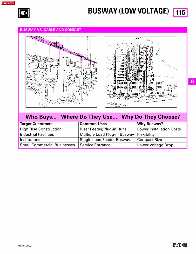
115
March 2001
G
Target Customers Common Uses Why Busway?
High Rise Construction Riser Feeder/Plug-in Runs Lower Installation CostsIndustrial Facilities Multiple Load Plug-in Busway FlexibilityInstitutions Single Load Feeder Busway Compact SizeSmall Commercial Businesses Service Entrance Lower Voltage Drop
BUSWAY (LOW VOLTAGE)
BUSWAY VS. CABLE AND CONDUIT
Who Buys... Where Do They Use... Why Do They Choose?
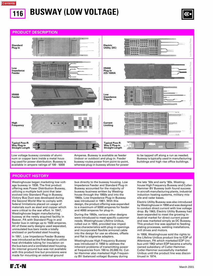
116
March 2001
Low voltage busway consists of alumi-num or copper bars inside a metal hous-ing used for power distribution. Busway is available in ampere ratings of 100 - 5000
Amperes. Busway is available as feeder (indoor or outdoor) and plug-in. Feeder busway routes power from point-to-point, whereas plug-in busway allows for power
to be tapped off along a run as needed. Busway is typically used in manufacturing buildings and high rise office buildings.
BUSWAY (LOW VOLTAGE)
PRODUCT DESCRIPTION
PRODUCT HISTORY
StandardPlug-in
LowImpedanceFeeder
H5000Feeder
HighFrequency
ElectricUtility (DC)
H5000Plug-in225-1000A
LowImpedance Plug-in
CurrentLimiting
Typical Pow-R-Way Plug-in Straight Length
Typical Pow-R-Way
II
Plug-in Straight Length
Westinghouse began marketing low volt-age busway in 1938. The first product offering was Power Distribution Busway, utilizing a multiple bolt joint that later evolved into Standard Plug-in Busway.Victory Bus Duct was developed during the Second World War to comply with federal limitations placed on usage of materials such as steel and copper which were critical to the war effort. In 1947, Westinghouse began manufacturing busway at the newly acquired facility in Beaver, PA with Standard Plug-in and feeder bus in ratings up to 1500 amperes. All of these early designs used separated, uninsulated bus bars inside a totally enclosed or perforated steel housing.
In 1951, Low Impedance Feeder Busway was introduced as the first design to utilize heat shrinkable tubing for insulation on the bus bars and a ventilated steel housing. An internal ground bus was not available with this product line but provisions were made for mounting an external ground
bus directly to the busway housing. Low Impedance Feeder and Standard Plug-in Busway accounted for the majority of busway business written by Westing-house through the 1950s and into the 1960s. Low Impedance Plug-in Busway was introduced in 1961. With this design, the product offering was expanded to a maximum of 5000 amperes for feeder and 4000 amperes for plug-in.
During the 1950s, various other designs were introduced to meet specific customer needs. Westinghouse Lifeline Unibus, rolled out in 1955, provided low imped-ance characteristics with plug-in openings and incorporated flexible armored cable into the design for use as elbows, offsets and flat to edgewise adapters.
Westinghouse High Frequency Busway was introduced in 1958 to address the inherent problems of transmitting power at frequencies from 180 to 20,000 Hz. Cut-ler-Hammer also marketed High Frequen-cy BV (balanced voltage) Busway during
the late ’50s and early ’60s. Westing- house High Frequency Busway and Cutler-Hammer BV Busway both found success in aircraft manufacturing plants, industrial induction heating systems, military mis-sile and radar bases.
Electric Utility Busway was also introduced by Westinghouse in 1958 and was designed to conduct direct current with low voltage drop. By 1963, Electric Utility Busway had been expanded to meet the growing in-dustrial market for direct current power and was marketed simply as DC Busway. This product line was applied to feeding plating processes, welding installations, mill drives and motors.
In 1958, Westinghouse sold the rights to the Lifeline Unibus product line to EDP of Allentown, PA which marketed EDP Uni-bus until 1962 when EDP became a wholly owned subsidiary of Cutler-Hammer. Cutler-Hammer successfully marketed Unibus until the product line was discon-tinued in 1974.
Low
Res
olut
ion
Phot
oLo
w R
esol
utio
n Ph
oto
Low
Res
olut
ion
Phot
oLo
w R
esol
utio
n Ph
oto
Low
Res
olut
ion
Phot
oLo
w R
esol
utio
n Ph
oto
Low
Res
olut
ion
Phot
oLo
w R
esol
utio
n Ph
oto
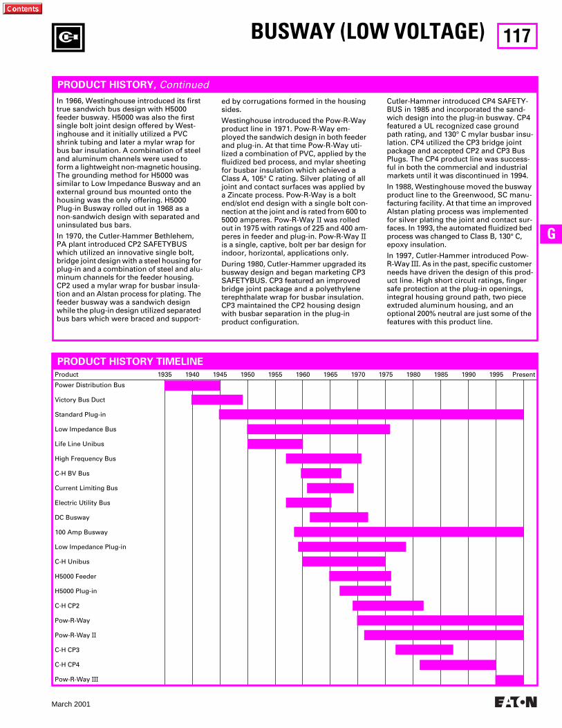
117
March 2001
G
Product 1935 1940 1945 1950 1955 1960 1965 1970 1975 1980 1985 1990 1995 Present
Power Distribution Bus
Victory Bus Duct
Standard Plug-in
Low Impedance Bus
Life Line Unibus
High Frequency Bus
C-H BV Bus
Current Limiting Bus
Electric Utility Bus
DC Busway
100 Amp Busway
Low Impedance Plug-in
C-H Unibus
H5000 Feeder
H5000 Plug-in
C-H CP2
Pow-R-Way
Pow-R-Way
II
C-H CP3
C-H CP4
Pow-R-Way
III
PRODUCT HISTORY,
Continued
In 1966, Westinghouse introduced its first true sandwich bus design with H5000 feeder busway. H5000 was also the first single bolt joint design offered by West-inghouse and it initially utilized a PVC shrink tubing and later a mylar wrap for bus bar insulation. A combination of steel and aluminum channels were used to form a lightweight non-magnetic housing. The grounding method for H5000 was similar to Low Impedance Busway and an external ground bus mounted onto the housing was the only offering. H5000 Plug-in Busway rolled out in 1968 as a non-sandwich design with separated and uninsulated bus bars.
In 1970, the Cutler-Hammer Bethlehem, PA plant introduced CP2 SAFETYBUS which utilized an innovative single bolt, bridge joint design with a steel housing for plug-in and a combination of steel and alu-minum channels for the feeder housing. CP2 used a mylar wrap for busbar insula-tion and an Alstan process for plating. The feeder busway was a sandwich design while the plug-in design utilized separated bus bars which were braced and support-
ed by corrugations formed in the housing sides.
Westinghouse introduced the Pow-R-Way product line in 1971. Pow-R-Way em-ployed the sandwich design in both feeder and plug-in. At that time Pow-R-Way uti-lized a combination of PVC, applied by the fluidized bed process, and mylar sheeting for busbar insulation which achieved a Class A, 105° C rating. Silver plating of all joint and contact surfaces was applied by a Zincate process. Pow-R-Way is a bolt end/slot end design with a single bolt con-nection at the joint and is rated from 600 to 5000 amperes. Pow-R-Way
II
was rolled out in 1975 with ratings of 225 and 400 am-peres in feeder and plug-in. Pow-R-Way
II
is a single, captive, bolt per bar design for indoor, horizontal, applications only.
During 1980, Cutler-Hammer upgraded its busway design and began marketing CP3 SAFETYBUS. CP3 featured an improved bridge joint package and a polyethylene terephthalate wrap for busbar insulation. CP3 maintained the CP2 housing design with busbar separation in the plug-in product configuration.
Cutler-Hammer introduced CP4 SAFETY-BUS in 1985 and incorporated the sand-wich design into the plug-in busway. CP4 featured a UL recognized case ground path rating, and 130° C mylar busbar insu-lation. CP4 utilized the CP3 bridge joint package and accepted CP2 and CP3 Bus Plugs. The CP4 product line was success-ful in both the commercial and industrial markets until it was discontinued in 1994.
In 1988, Westinghouse moved the busway product line to the Greenwood, SC manu-facturing facility. At that time an improved Alstan plating process was implemented for silver plating the joint and contact sur-faces. In 1993, the automated fluidized bed process was changed to Class B, 130° C, epoxy insulation.
In 1997, Cutler-Hammer introduced Pow-R-Way
III
. As in the past, specific customer needs have driven the design of this prod-uct line. High short circuit ratings, finger safe protection at the plug-in openings, integral housing ground path, two piece extruded aluminum housing, and an optional 200% neutral are just some of the features with this product line.
BUSWAY (LOW VOLTAGE)
PRODUCT HISTORY TIMELINE
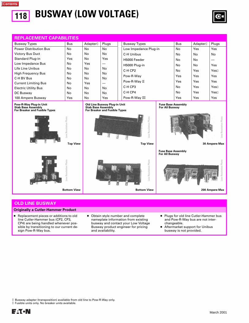
118
March 2001
Originally a Cutler-Hammer Product
BUSWAY (LOW VOLTAGE)
Top View
Pow-R-Way Plug-in UnitStab Base AssemblyFor Breaker and Fusible Types
Top View 30 Ampere Max
Bottom View Bottom View 200 Ampere Max
Old Line Busway Plug-in UnitStab Base AssemblyFor Breaker and Fusible Types
Fuse Base AssemblyFor All Busway
Fuse Base AssemblyFor All Busway
Busway Types Bus Adapter
➊
Plugs
Power Distribution Bus
Victory Bus Duct
Standard Plug-in
Low Impedance Bus
Life Line Unibus
High Frequency Bus
C-H BV Bus
Current Limiting Bus
Electric Utility Bus
DC Busway
100 Ampere Busway
No
No
Yes
No
No
No
No
No
No
No
Yes
No
No
No
Yes
No
No
No
Yes
No
No
No
No
No
Yes
—
No
No
No
—
No
No
Yes
Busway Types Bus Adapter
➊
Plugs
Low Impedance Plug-in
C-H Unibus
H5000 Feeder
H5000 Plug-in
C-H CP2
Pow-R-Way
Pow-R-Way
II
C-H CP3
C-H CP4
Pow-R-Way
III
No
No
No
No
No
Yes
Yes
No
No
Yes
Yes
No
No
No
Yes
Yes
Yes
Yes
Yes
Yes
Yes
No
—
Yes
Yes
➋
Yes
Yes
Yes
➋
Yes
➋
Yes
REPLACEMENT CAPABILITIES
OLD LINE BUSWAY
●
Replacement pieces or additions to old line Cutler-Hammer bus (CP2, CP3, CP4) are being handled whenever pos-sible by transitioning to our current de-sign Pow-R-Way bus.
●
Obtain style number and complete nameplate information from existing busway and contact your Low Voltage Busway product engineer for pricing and availability.
●
Plugs for old line Cutler-Hammer bus and Pow-R-Way bus are not inter-changeable.
●
Aftermarket support for Unibus busway is not provided.
➊
Busway adapter (transposition) available from old line to Pow-R-Way only.
➋
Fusible units only. No breaker units available.
Low
Res
olut
ion
Phot
oLo
w R
esol
utio
n Ph
oto
Low
Res
olut
ion
Phot
oLo
w R
esol
utio
n Ph
oto
Low
Res
olut
ion
Phot
oLo
w R
esol
utio
n Ph
oto
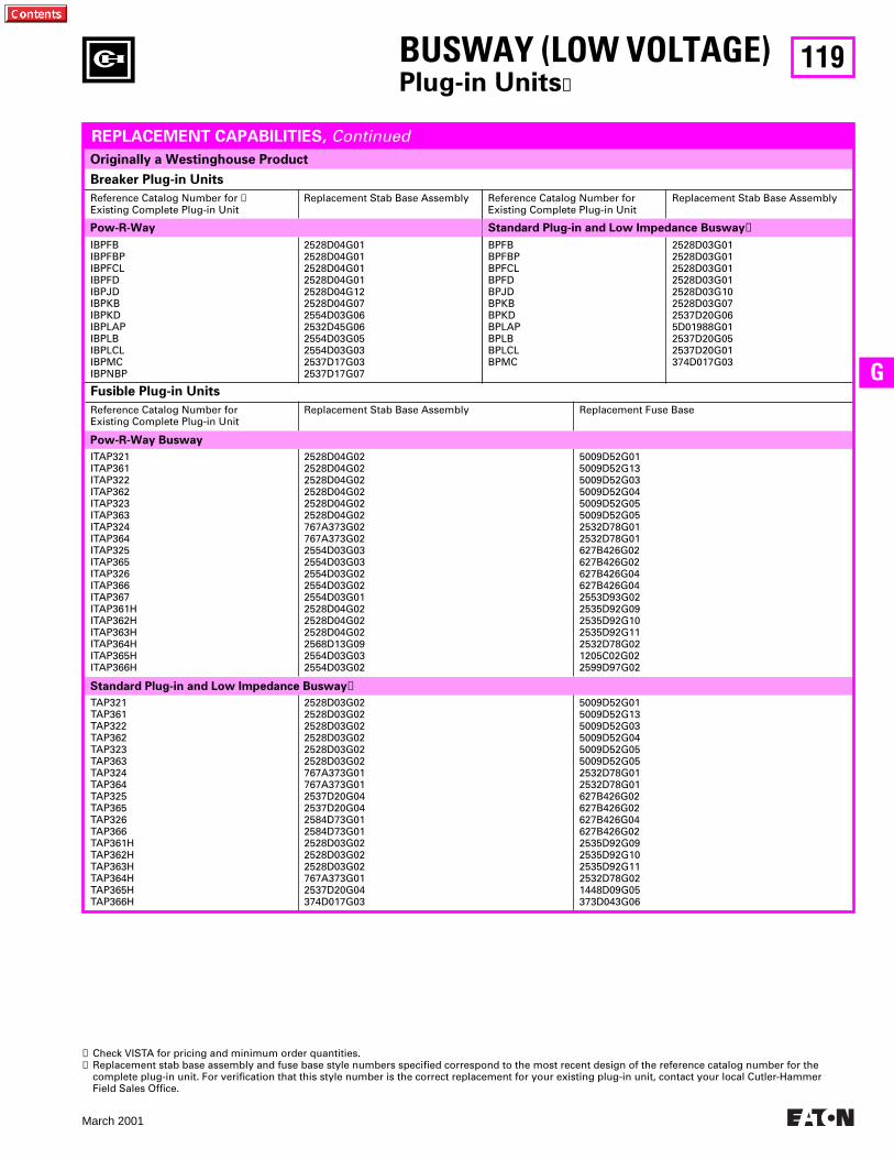
119
March 2001
G
Standard Plug-in and Low Impedance Busway
➋
Breaker Plug-in Units
Reference Catalog Number for
➊
Existing Complete Plug-in UnitReplacement Stab Base Assembly Reference Catalog Number for
Existing Complete Plug-in UnitReplacement Stab Base Assembly
IBPFBIBPFBPIBPFCLIBPFDIBPJDIBPKBIBPKDIBPLAPIBPLBIBPLCLIBPMCIBPNBP
2528D04G012528D04G012528D04G012528D04G012528D04G122528D04G072554D03G062532D45G062554D03G052554D03G032537D17G032537D17G07
BPFBBPFBPBPFCLBPFDBPJDBPKBBPKDBPLAPBPLBBPLCLBPMC
2528D03G012528D03G012528D03G012528D03G012528D03G102528D03G072537D20G065D01988G012537D20G052537D20G01374D017G03
Originally a Westinghouse Product
Pow-R-Way Standard Plug-in and Low Impedance Busway
➋
Fusible Plug-in Units
Reference Catalog Number for Existing Complete Plug-in Unit
Replacement Stab Base Assembly Replacement Fuse Base
ITAP321ITAP361ITAP322ITAP362ITAP323ITAP363ITAP324ITAP364ITAP325ITAP365ITAP326ITAP366ITAP367ITAP361HITAP362HITAP363HITAP364HITAP365HITAP366H
2528D04G022528D04G022528D04G022528D04G022528D04G022528D04G02767A373G02767A373G022554D03G032554D03G032554D03G022554D03G022554D03G012528D04G022528D04G022528D04G022568D13G092554D03G032554D03G02
5009D52G015009D52G135009D52G035009D52G045009D52G055009D52G052532D78G012532D78G01627B426G02627B426G02627B426G04627B426G042553D93G022535D92G092535D92G102535D92G112532D78G021205C02G022599D97G02
TAP321TAP361TAP322TAP362TAP323TAP363TAP324TAP364TAP325TAP365TAP326TAP366TAP361HTAP362HTAP363HTAP364HTAP365HTAP366H
2528D03G022528D03G022528D03G022528D03G022528D03G022528D03G02767A373G01767A373G012537D20G042537D20G042584D73G012584D73G012528D03G022528D03G022528D03G02767A373G012537D20G04374D017G03
5009D52G015009D52G135009D52G035009D52G045009D52G055009D52G052532D78G012532D78G01627B426G02627B426G02627B426G04627B426G022535D92G092535D92G102535D92G112532D78G021448D09G05373D043G06
BUSWAY (LOW VOLTAGE)
Plug-in Units
➊
REPLACEMENT CAPABILITIES,
Continued
➊
Check VISTA for pricing and minimum order quantities.
➋
Replacement stab base assembly and fuse base style numbers specified correspond to the most recent design of the reference catalog number for the complete plug-in unit. For verification that this style number is the correct replacement for your existing plug-in unit, contact your local Cutler-Hammer Field Sales Office.
Pow-R-Way Busway
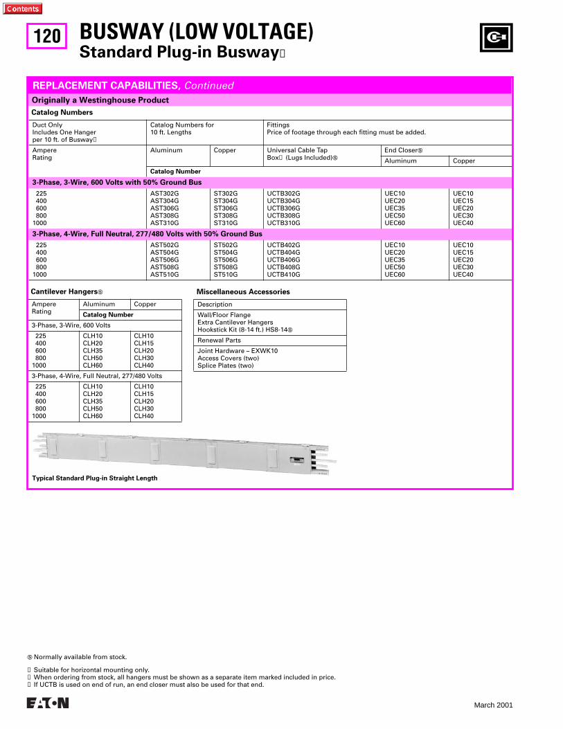
120
March 2001
Catalog Numbers
Duct OnlyIncludes One Hangerper 10 ft. of Busway
➋
Catalog Numbers for 10 ft. Lengths
FittingsPrice of footage through each fitting must be added.
AmpereRating
Aluminum Copper Universal Cable TapBox
➌
(Lugs Included)
S
End Closer
S
Aluminum Copper
Catalog Number
3-Phase, 3-Wire, 600 Volts with 50% Ground Bus
225 400 600 8001000
AST302GAST304GAST306GAST308GAST310G
ST302GST304GST306GST308GST310G
UCTB302GUCTB304GUCTB306GUCTB308GUCTB310G
UEC10UEC20UEC35UEC50UEC60
UEC10UEC15UEC20UEC30UEC40
3-Phase, 4-Wire, Full Neutral, 277/480 Volts with 50% Ground Bus
225 400 600 8001000
AST502GAST504GAST506GAST508GAST510G
ST502GST504GST506GST508GST510G
UCTB402GUCTB404GUCTB406GUCTB408GUCTB410G
UEC10UEC20UEC35UEC50UEC60
UEC10UEC15UEC20UEC30UEC40
BUSWAY (LOW VOLTAGE)
Standard Plug-in Busway
➊
Originally a Westinghouse Product
REPLACEMENT CAPABILITIES,
Continued
Cantilever Hangers
S
AmpereRating
Aluminum Copper
Catalog Number
3-Phase, 3-Wire, 600 Volts
225 400 600 8001000
CLH10CLH20CLH35CLH50CLH60
CLH10CLH15CLH20CLH30CLH40
3-Phase, 4-Wire, Full Neutral, 277/480 Volts
225 400 600 8001000
CLH10CLH20CLH35CLH50CLH60
CLH10CLH15CLH20CLH30CLH40
Miscellaneous Accessories
Description
Wall/Floor FlangeExtra Cantilever HangersHookstick Kit (8-14 ft.) HS8-14
S
Renewal Parts
Joint Hardware – EXWK10Access Covers (two)Splice Plates (two)
S
Normally available from stock.
➊
Suitable for horizontal mounting only.
➋
When ordering from stock, all hangers must be shown as a separate item marked included in price.
➌
If UCTB is used on end of run, an end closer must also be used for that end.
Typical Standard Plug-in Straight Length
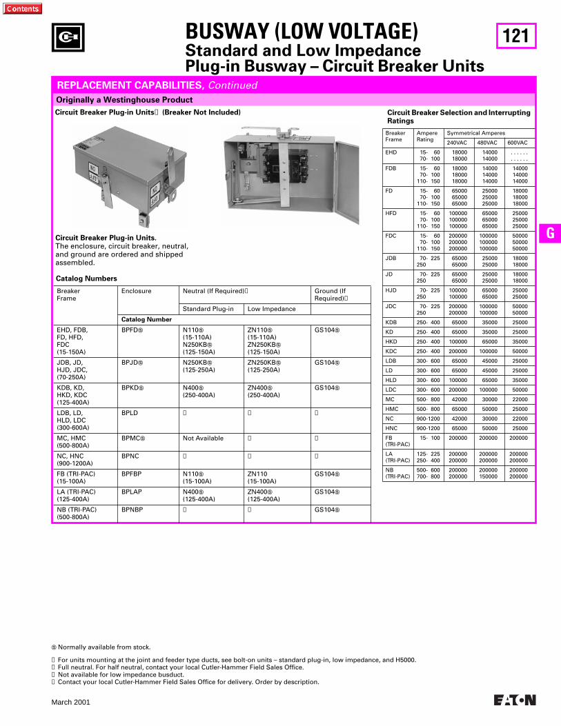
121
March 2001
G
BUSWAY (LOW VOLTAGE)
Standard and Low Impedance Plug-in Busway – Circuit Breaker Units
Originally a Westinghouse Product
REPLACEMENT CAPABILITIES,
Continued
Circuit Breaker Selection and Interrupting Ratings
BreakerFrame
AmpereRating
Symmetrical Amperes
240VAC 480VAC 600VAC
EHD 15- 60 70- 100
1800018000
1400014000
. . . . . .
. . . . . .
FDB 15- 60 70- 100110- 150
180001800018000
140001400014000
140001400014000
FD 15- 60 70- 100110- 150
650006500065000
250002500025000
180001800018000
HFD 15- 60 70- 100110- 150
100000100000100000
650006500065000
250002500025000
FDC 15- 60 70- 100110- 150
200000200000200000
100000100000100000
500005000050000
JDB 70- 225250
6500065000
2500025000
1800018000
JD 70- 225250
6500065000
2500025000
1800018000
HJD 70- 225250
100000100000
6500065000
2500025000
JDC 70- 225250
200000200000
100000100000
5000050000
KDB 250- 400 65000 35000 25000
KD 250- 400 65000 35000 25000
HKD 250- 400 100000 65000 35000
KDC 250- 400 200000 100000 50000
LDB 300- 600 65000 45000 25000
LD 300- 600 65000 45000 25000
HLD 300- 600 100000 65000 35000
LDC 300- 600 200000 100000 50000
MC 500- 800 42000 30000 22000
HMC 500- 800 65000 50000 25000
NC 900-1200 42000 30000 22000
HNC 900-1200 65000 50000 25000
FB(TRI-PAC)
15- 100 200000 200000 200000
LA(TRI-PAC)
125- 225250- 400
200000200000
200000200000
200000200000
NB(TRI-PAC)
500- 600700- 800
200000200000
200000150000
200000200000
Catalog Numbers
BreakerFrame
Enclosure Neutral (If Required)
➋
Ground (IfRequired)
➌
Standard Plug-in Low Impedance
Catalog Number
EHD, FDB, FD, HFD,FDC(15-150A)
BPFD
S
N110
S
(15-110A)N250KB
S
(125-150A)
ZN110
S
(15-110A)ZN250KB
S
(125-150A)
GS104
S
JDB, JD,HJD, JDC,(70-250A)
BPJD
S
N250KB
S
(125-250A)ZN250KB
S
(125-250A)GS104
S
KDB, KD,HKD, KDC(125-400A)
BPKD
S
N400
S
(250-400A)ZN400
S
(250-400A)GS104
S
LDB, LD,HLD, LDC(300-600A)
BPLD
➍ ➍ ➍
MC, HMC(500-800A)
BPMC
S
Not Available
➍ ➍
NC, HNC(900-1200A)
BPNC
➍ ➍ ➍
FB (TRI-PAC)(15-100A)
BPFBP N110
S
(15-100A)ZN110(15-100A)
GS104
S
LA (TRI-PAC)(125-400A)
BPLAP N400
S
(125-400A)ZN400
S
(125-400A)GS104
S
NB (TRI-PAC)(500-800A)
BPNBP
➍ ➍
GS104
S
S
Normally available from stock.
➊
For units mounting at the joint and feeder type ducts, see bolt-on units – standard plug-in, low impedance, and H5000.
➋
Full neutral. For half neutral, contact your local Cutler-Hammer Field Sales Office.
➌
Not available for low impedance busduct.
➍
Contact your local Cutler-Hammer Field Sales Office for delivery. Order by description.
Circuit Breaker Plug-in Units
➊
(Breaker Not Included)
Circuit Breaker Plug-in Units.
The enclosure, circuit breaker, neutral, and ground are ordered and shipped assembled.
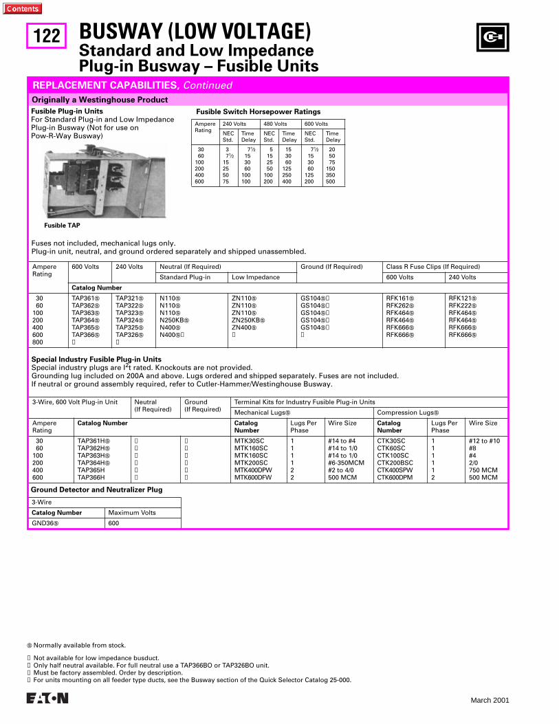
122
March 2001
Fuses not included, mechanical lugs only.Plug-in unit, neutral, and ground ordered separately and shipped unassembled.
BUSWAY (LOW VOLTAGE)
Standard and Low Impedance Plug-in Busway – Fusible Units
Originally a Westinghouse Product
REPLACEMENT CAPABILITIES,
Continued
Fusible Plug-in Units
For Standard Plug-in and Low Impedance Plug-in Busway (Not for use on Pow-R-Way Busway)
Fusible TAP
Fusible Switch Horsepower Ratings
AmpereRating
240 Volts 480 Volts 600 Volts
NECStd.
TimeDelay
NECStd.
TimeDelay
NECStd.
TimeDelay
30 60100200400600
3 7
1
⁄
2
15255075
7
1
⁄
2
15 30 60100100
5 15 25 50100200
15 30 60125250400
7
1
⁄
2
15 30 60125200
20 50 75150350500
Special Industry Fusible Plug-in Units
Special industry plugs are I
2
t rated. Knockouts are not provided. Grounding lug included on 200A and above. Lugs ordered and shipped separately. Fuses are not included.If neutral or ground assembly required, refer to Cutler-Hammer/Westinghouse Busway.
AmpereRating
600 Volts 240 Volts Neutral (If Required) Ground (If Required) Class R Fuse Clips (If Required)
Standard Plug-in Low Impedance 600 Volts 240 Volts
Catalog Number
30 60100200400600800
TAP361
S
TAP362
S
TAP363
S
TAP364
S
TAP365
S
TAP366
S
➍
TAP321
S
TAP322
S
TAP323
S
TAP324
S
TAP325
S
TAP326S
➍
N110S
N110S
N110S
N250KBS
N400S
N400S➋
ZN110S
ZN110S
ZN110S
ZN250KBS
ZN400S
➌
GS104S➊GS104S➊GS104S➊GS104S➊GS104S➊➌
RFK161S
RFK262S
RFK464S
RFK464S
RFK666S
RFK666S
RFK121S
RFK222S
RFK464S
RFK464S
RFK666S
RFK666S
3-Wire, 600 Volt Plug-in Unit Neutral(If Required)
Ground(If Required)
Terminal Kits for Industry Fusible Plug-in Units
Mechanical LugsS Compression LugsS
AmpereRating
Catalog Number CatalogNumber
Lugs PerPhase
Wire Size CatalogNumber
Lugs PerPhase
Wire Size
30 60100200400600
TAP361HS
TAP362HS
TAP363HS
TAP364HS
TAP365HTAP366H
➌➌➌➌➌➌
➌➌➌➌➌➌
MTK30SCMTK160SCMTK160SCMTK200SCMTK400DPWMTK600DFW
111122
#14 to #4#14 to 1/0#14 to 1/0#6-350MCM#2 to 4/0500 MCM
CTK30SCCTK60SCCTK100SCCTK200BSCCTK400SPWCTK600DPM
111112
#12 to #10#8#42/0750 MCM500 MCM
Ground Detector and Neutralizer Plug
3-Wire
Catalog Number Maximum Volts
GND36S 600
S Normally available from stock.
➊ Not available for low impedance busduct.➋ Only half neutral available. For full neutral use a TAP366BO or TAP326BO unit.➌ Must be factory assembled. Order by description.➍ For units mounting on all feeder type ducts, see the Busway section of the Quick Selector Catalog 25-000.
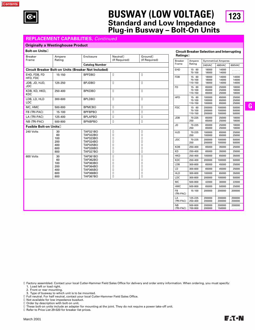
123
March 2001
G
Originally a Westinghouse Product
REPLACEMENT CAPABILITIES, Continued
Bolt-on Units➊
BreakerFrame
AmpereRating
Enclosure Neutral➋(If Required)
Ground➌(If Required)
Catalog Number
Circuit Breaker Bolt-on Units (Breaker Not Included)
EHD, FDB, FDHFD, FDC
15-150 BPFDBO ➍ ➍
JDB, JD, HJD,JDC
125-250 BPJDBO ➍ ➍
KDB, KD, HKD,KDC
250-400 BPKDBO ➍ ➍
LDB, LD, HLDLDC
300-600 BPLDBO ➍ ➍
MC, HMC 500-800 BPMCBO ➍ ➍
FB (TRI-PAC) 15-100 BPFBPBO ➍ ➍
LA (TRI-PAC) 125-400 BPLAPBO ➍ ➍
NB (TRI-PAC) 500-800 BPNBPBO ➍ ➍
Fusible Bolt-on Units➎
240 Volts 30 60100200400600800
TAP321BOTAP322BOTAP323BOTAP324BOTAP325BOTAP326BOTAP327BO
➍➍➍➍➍➍➍
➍➍➍➍➍➍➍
600 Volts 30 60100200400600800
TAP361BOTAP362BOTAP363BOTAP364BOTAP365BOTAP366BOTAP367BO
➍➍➍➍➍➍➍
➍➍➍➍➍➍➍
➊ Factory assembled. Contact your local Cutler-Hammer Field Sales Office for delivery and order entry information. When ordering, you must specify:1. Load left or load right.2. Front or rear mounting.3. Type of busway to which unit is to be mounted.
➋ Full neutral. For half neutral, contact your local Cutler-Hammer Field Sales Office.➌ Not available for low impedance busduct.➍ Order by description with bolt-on unit.➎ These bolt-on units include an adapter for mounting at the joint. They do not require a power take-off unit.➏ Refer to Price List 29-020 for breaker list prices.
Circuit Breaker Selection and Interrupting Ratings➏
BreakerFrame
AmpereRating
Symmetrical Amperes
240VAC 480VAC 600VAC
EHD 15- 60 70-100
1800018000
1400014000
. . . . . .
. . . . . .
FDB 15- 60 70-100110-150
180001800018000
140001400014000
140001400014000
FD 15- 60 70-100110-150
650006500065000
250002500025000
180001800018000
HFD 15- 60 70-100110-150
100000100000100000
650006500065000
250002500025000
FDC 15- 60 70-100110-150
200000200000200000
100000100000100000
500005000050000
JDB 70-225250
6500065000
2500025000
1800018000
JD 70-225250
6500065000
2500025000
1800018000
HJD 70-225250
100000100000
6500065000
2500025000
JDC 70-225250
200000200000
100000100000
5000050000
KDB 250-400 65000 35000 25000
KD 250-400 65000 35000 25000
HKD 250-400 100000 65000 35000
KDC 250-400 200000 100000 50000
LDB 300-600 65000 45000 25000
LD 300-600 65000 45000 25000
HLD 300-600 100000 65000 35000
LDC 300-600 200000 100000 50000
MC 500-800 42000 30000 22000
HMC 500-800 65000 50000 25000
FB(TRI-PAC)
15-100 200000 200000 200000
LA(TRI-PAC)
125-225250-400
200000200000
200000200000
200000200000
NB(TRI-PAC)
500-600700-800
200000200000
200000150000
200000. . . . . .
BUSWAY (LOW VOLTAGE)Standard and Low Impedance Plug-in Busway – Bolt-On Units
124
March 2001
BUSWAY (LOW VOLTAGE)Unibus Saf-Key Fusible Plugs➊
THIS PAGE INTENTIONALLY LEFT BLANK
125
March 2001
G
BUSWAY (LOW VOLTAGE)Unibus Saf-Key Circuit Breaker Plugs
THIS PAGE INTENTIONALLY LEFT BLANK
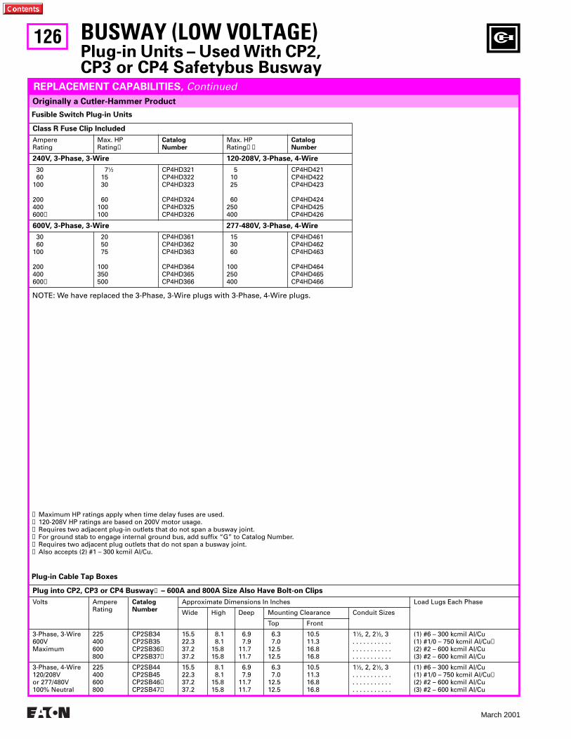
126
March 2001
BUSWAY (LOW VOLTAGE)Plug-in Units – Used With CP2, CP3 or CP4 Safetybus Busway
Originally a Cutler-Hammer Product
REPLACEMENT CAPABILITIES, Continued
Fusible Switch Plug-in Units
Class R Fuse Clip Included
AmpereRating
Max. HPRating➊
CatalogNumber
Max. HPRating➊➋
CatalogNumber
240V, 3-Phase, 3-Wire 120-208V, 3-Phase, 4-Wire
30 60100
200400600➌
71⁄2 15 30
60100100
CP4HD321CP4HD322CP4HD323
CP4HD324CP4HD325CP4HD326
5 10 25
60250400
CP4HD421CP4HD422CP4HD423
CP4HD424CP4HD425CP4HD426
600V, 3-Phase, 3-Wire 277-480V, 3-Phase, 4-Wire
30 60100
200400600➌
20 50 75
100350500
CP4HD361CP4HD362CP4HD363
CP4HD364CP4HD365CP4HD366
15 30 60
100250400
CP4HD461CP4HD462CP4HD463
CP4HD464CP4HD465CP4HD466
NOTE: We have replaced the 3-Phase, 3-Wire plugs with 3-Phase, 4-Wire plugs.
Plug-in Cable Tap Boxes
Plug into CP2, CP3 or CP4 Busway➍ – 600A and 800A Size Also Have Bolt-on Clips
Volts AmpereRating
CatalogNumber
Approximate Dimensions In Inches Load Lugs Each Phase
Wide High Deep Mounting Clearance Conduit Sizes
Top Front
3-Phase, 3-Wire600VMaximum
225400600800
CP2SB34CP2SB35CP2SB36➎CP2SB37➎
15.522.337.237.2
8.1 8.115.815.8
6.9 7.911.711.7
6.3 7.012.512.5
10.511.316.816.8
11⁄2, 2, 21⁄2, 3. . . . . . . . . . . . . . . . . . . . . . . . . . . . . . . . .
(1) #6 – 300 kcmil Al/Cu(1) #1/0 – 750 kcmil Al/Cu➏(2) #2 – 600 kcmil Al/Cu(3) #2 – 600 kcmil Al/Cu
3-Phase, 4-Wire120/208Vor 277/480V100% Neutral
225400600800
CP2SB44CP2SB45CP2SB46➎CP2SB47➎
15.522.337.237.2
8.1 8.115.815.8
6.9 7.911.711.7
6.3 7.012.512.5
10.511.316.816.8
11⁄2, 2, 21⁄2, 3. . . . . . . . . . . . . . . . . . . . . . . . . . . . . . . . .
(1) #6 – 300 kcmil Al/Cu(1) #1/0 – 750 kcmil Al/Cu➏(2) #2 – 600 kcmil Al/Cu(3) #2 – 600 kcmil Al/Cu
➊ Maximum HP ratings apply when time delay fuses are used.➋ 120-208V HP ratings are based on 200V motor usage.➌ Requires two adjacent plug-in outlets that do not span a busway joint.➍ For ground stab to engage internal ground bus, add suffix “G” to Catalog Number.➎ Requires two adjacent plug outlets that do not span a busway joint.➏ Also accepts (2) #1 – 300 kcmil Al/Cu.
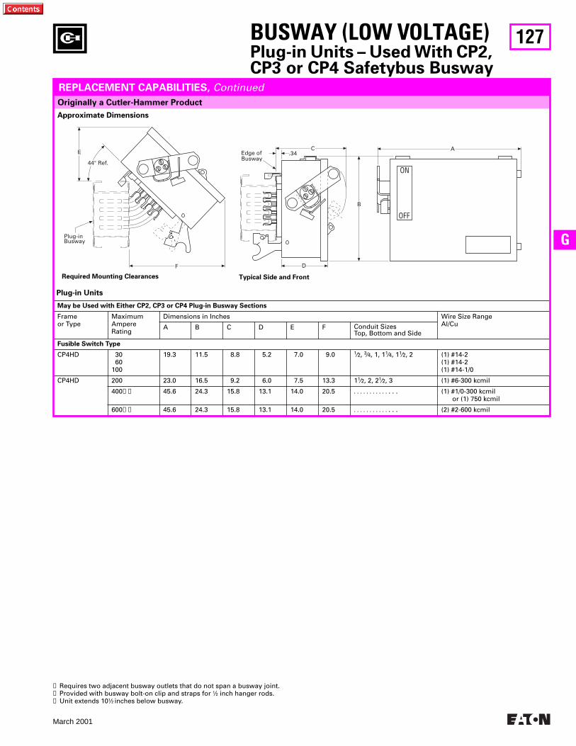
127
March 2001
G
BUSWAY (LOW VOLTAGE)Plug-in Units – Used With CP2, CP3 or CP4 Safetybus Busway
Originally a Cutler-Hammer Product
REPLACEMENT CAPABILITIES, Continued
Plug-in Units
May be Used with Either CP2, CP3 or CP4 Plug-in Busway Sections
Frameor Type
MaximumAmpere Rating
Dimensions in Inches Wire Size RangeAl/CuA B C D E F Conduit Sizes
Top, Bottom and Side
Fusible Switch Type
CP4HD 30 60100
19.3 11.5 8.8 5.2 7.0 9.0 1⁄2, 3⁄4, 1, 11⁄4, 11⁄2, 2 (1) #14-2(1) #14-2(1) #14-1/0
CP4HD 200 23.0 16.5 9.2 6.0 7.5 13.3 11⁄2, 2, 21⁄2, 3 (1) #6-300 kcmil
400➋➌ 45.6 24.3 15.8 13.1 14.0 20.5 . . . . . . . . . . . . . . (1) #1/0-300 kcmil or (1) 750 kcmil
600➋➌ 45.6 24.3 15.8 13.1 14.0 20.5 . . . . . . . . . . . . . . (2) #2-600 kcmil
➊ Requires two adjacent busway outlets that do not span a busway joint.➋ Provided with busway bolt-on clip and straps for 1⁄2 inch hanger rods.➌ Unit extends 101⁄2 inches below busway.
Required Mounting Clearances Typical Side and Front
Approximate Dimensions
OFF
ON
F
A
D
B
.34Edge ofBusway
CE
44° Ref.
Plug-inBusway

128
March 2001
CPS (TVSS) Bus Plug-in Units Performance Specification
Key Feature CPS-M CPS-H CPS-S2 CPS-S CPS-B
Surge current per phase Surge current mode: Line-Neutral Line-Ground Neutral-Ground Line-Line (Delta and ungrounded applications only)Protection modes: 3-phase wye system 3-phase delta systemFilter attenuation at 100 kHz(based on MIL-STD-22A)IEEE Cat B3 Ringwavesuppression (l-n mode; 6000V 500A)Surge Withstand capabilities IEEE C3 Wave (10kA)TVSS TRI-Monitor system 1. Overcurrent Protection 2. Infrared Detection 3. Thermal Detection
400kA
200kA200kA200kA200kA
76
55dB
<150V
>4000
YesYesYes
250kA
125kA125kA125kA125kA
76
55dB
<150V
>3500
YesYesYes
160kA
60kA60kA60kA60kA
76
55dB
<150V
>2500
YesYesYes
120kA
60kA60kA60kA60kA
76
55dB
<150V
>2500
YesYesYes
90kA
45kA45kA45kA45kA
76
55dB
<150V
>1500
YesOptionalOptional
Catalog Numbers for CPS Bus Plugs➊
TVSS Unit StandardPlug-in
LowImpedance
H5000Plug-in
CP2/CP3Plug-in
CP4Plug-in
Pow-R-WayPow-R-Way II
Pow-R-Way III
90kA
120kA
160kA
250kA
400kA
TAP-CPSB
TAP-CPSS
TAP-CPS2
TAP-CPSH
TAP-CPSM
ZTAP-CPSB
ZTAP-CPSS
ZTAP-CPS2
ZTAP-CPSH
ZTAP-CPSM
HTAP-CPSB
HTAP-CPSS
HTAP-CPS2
HTAP-CPSH
HTAP-CPSM
CP3-CPSB
CP3-CPSS
CP3-CPS2
CP3-CPSH
CP3-CPSM
CP4-CPSB
CP4-CPSS
CP4-CPS2
CP4-CPSH
CP4-CPSM
ITAP-CPSB
ITAP-CPSS
ITAP-CPS2
ITAP-CPSH
ITAP-CPSM
P3F-CPSB
P3F-CPSS
P3F-CPS2
P3F-CPSH
P3F-CPSM
BUSWAY (LOW VOLTAGE)Technology Upgrades
CLIPPER POWER SYSTEMS, BUSWAY TVSS PROTECTION
The Low Voltage Busway aftermarket product offering includes Transient Volt-age Surge Suppression (TVSS) which is ideal for busway fed distribution systems. Cutler-Hammer has developed the Clipper Power System (CPS) family of products to ensure that the quality power required to maximize productivity in today’s competi-tive environment is supplied to commer-cial, industrial, medical and institutional facilities. Without power protection devic-es, microprocessors and electronic based loads are not provided with the noise and disturbance-free power which they require. Since microprocessor loads are now
common in every facility, engineers must ensure the AC power supply is properly fil-tered. The CPS busway family of products consists of transient voltage surge sup-pression and filter components (TVSS filter) integrated into a bus plug with a fusible disconnect. TVSS bus plugs are available for the following types of plug-in busway:
Westinghouse Standard Plug-inWestinghouse Low Impedance Plug-inWestinghouse H5000 Plug-inCutler-Hammer CP2 Plug-inCutler-Hammer CP3 Plug-inCutler-Hammer CP4 Plug-in
Westinghouse Pow-R-WayWestinghouse Pow-R-Way IICutler-Hammer Pow-R-Way III
Significant performance advantages are achieved by integrating TVSS filters into busway systems. Since the TVSS unit is directly connected to the busway, the CPS minimizes let-through voltage, a signifi-cant performance advantage compared to cable-connected TVSS solutions. Due to the integrated design, the CPS bus plug also saves the user wall space and greatly reduces the installed project cost.
➊ CPS bus plugs are not stock items. Specify if ground and neutral stabs are required as they must be factory installed on CPS bus plugs.
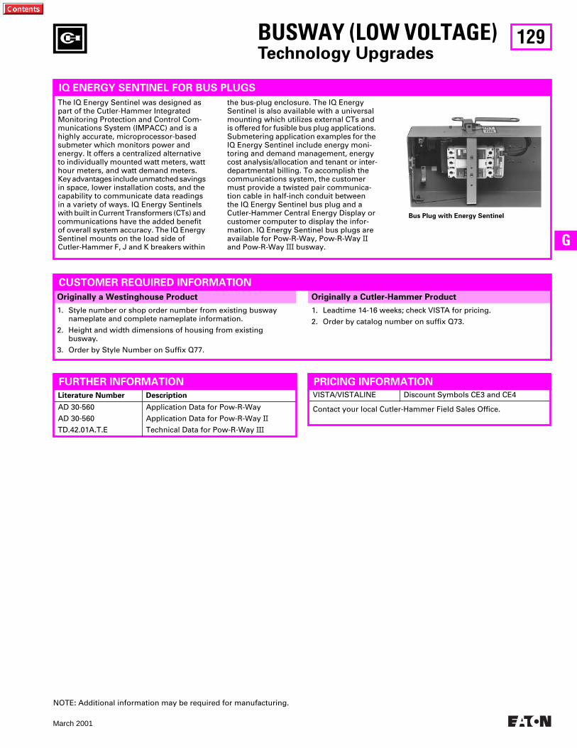
129
March 2001
G
BUSWAY (LOW VOLTAGE)Technology Upgrades
1. Leadtime 14-16 weeks; check VISTA for pricing.
2. Order by catalog number on suffix Q73.
IQ ENERGY SENTINEL FOR BUS PLUGS
Originally a Westinghouse Product Originally a Cutler-Hammer Product
1. Style number or shop order number from existing busway nameplate and complete nameplate information.
2. Height and width dimensions of housing from existing busway.
3. Order by Style Number on Suffix Q77.
CUSTOMER REQUIRED INFORMATION
Bus Plug with Energy Sentinel
The IQ Energy Sentinel was designed as part of the Cutler-Hammer Integrated Monitoring Protection and Control Com-munications System (IMPACC) and is a highly accurate, microprocessor-based submeter which monitors power and energy. It offers a centralized alternative to individually mounted watt meters, watt hour meters, and watt demand meters. Key advantages include unmatched savings in space, lower installation costs, and the capability to communicate data readings in a variety of ways. IQ Energy Sentinels with built in Current Transformers (CTs) and communications have the added benefit of overall system accuracy. The IQ Energy Sentinel mounts on the load side of Cutler-Hammer F, J and K breakers within
the bus-plug enclosure. The IQ Energy Sentinel is also available with a universal mounting which utilizes external CTs and is offered for fusible bus plug applications. Submetering application examples for the IQ Energy Sentinel include energy moni-toring and demand management, energy cost analysis/allocation and tenant or inter-departmental billing. To accomplish the communications system, the customer must provide a twisted pair communica-tion cable in half-inch conduit between the IQ Energy Sentinel bus plug and a Cutler-Hammer Central Energy Display or customer computer to display the infor-mation. IQ Energy Sentinel bus plugs are available for Pow-R-Way, Pow-R-Way II and Pow-R-Way III busway.
VISTA/VISTALINE Discount Symbols CE3 and CE4
FURTHER INFORMATION
Literature Number Description
AD 30-560
AD 30-560
TD.42.01A.T.E
Application Data for Pow-R-Way
Application Data for Pow-R-Way II
Technical Data for Pow-R-Way III
PRICING INFORMATION
Contact your local Cutler-Hammer Field Sales Office.
NOTE: Additional information may be required for manufacturing.
130
March 2001
IQ PRODUCTS
Please refer to Catalog 2001, Section 26 of the Distribution Volume pages 26-1 through 26-56 or
Section 56 of the Control Volume pages 56-1 through 56-56 for current IQ Products.
WEB Reference: Power Management Products onwww.ch.cutler-hammer.com
The IMPACC Series
III
is no longer available,but is supported. Please refer to Catalog 2001
pages 26-57 through 26-86 or pages 56-57 through 56-86 for the PowerNet Software
Suite and communications products.WEB Reference: Power Management Products on
www.ch.cutler-hammer.com
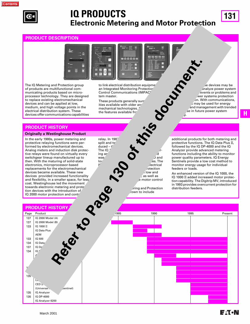
131
March 2001
H
Originally a Westinghouse Product
PRODUCT DESCRIPTION
The IQ Metering and Protection group of products are multifunctional com-municating products based on micro-processor technology. They are designed to replace existing electromechanicaldevices and can be applied at low,medium, and high voltage points in the electrical distribution system. Thesedevices offer communications capabilities
to link electrical distribution equipment to an Integrated Monitoring Protection and Control Communications (IMPACC) sys-tem master.
These products generally surpass capabil-ities available with older analog/electro-mechanical technologies. Depending on the features available from each device,
In the early 1980s, power metering and protective relaying functions were per-formed by electromechanical devices. Analog meters and induction disk protec-tive relays were found on virtually every switchgear lineup manufactured up to then. With the maturing of solid-state electronics, microprocessor-based replacements for the electromechanical devices became available. These newdevices provided increased functionality and flexibility, in a smaller space, for less cost. Westinghouse led the movement towards electronic metering and protec-tion devices with the introduction of the IQ 2000 motor protection and control
PRODUCT HISTORY
relay. In 1987, the IQ 2000 functions were split and two new products were intro-duced – the IQ 1000 and the IQ Data Plus. The IQ 1000 provided all current monitor-ing and motor protection functions and was developed for use on AMPGARD and low voltage motor control assemblies. The IQ Data Plus provided complete electrical metering and system voltage protection and was developed for use on low and medium voltage switchgear, as well as AMPGARD and low voltage motor control assemblies.
Since then, the IQ Metering and Protection product family has grown to include
additional products for both metering and protective functions. The IQ Data Plus
II
, followed by the IQ DP-4000 and the IQ AnaIyzer provide advanced meteringfunctions including the ability to monitor power quality parameters. IQ Energy Sentinels provide a low cost method to monitor energy usage for individual feeders or loads.
An enhanced version of the IQ 1000, the IQ 1000
II
added increased motor protec-tion capability. The Digitrip MV, introduced in 1993 provides overcurrent protection for distribution feeders.
information from these devices may be used to record and analyze power system and power quality events or problems and may improve power systems protection and coordination. With communications, these devices may be used for energy monitoring and management with trended data for use in future power system planning.
Page Product 1980 1985 1990 1995 Present
137137133
133134137134
136134135
135135
IQ 2000 Model (A)
IQ 2000 Model (B)
IQ 1000
II
IQ Data Plus
AEM
IQ 500
IQ Data
IQ Data Plus
II
IQ Generator
AR (Addressable Relay)
AEM
II
IQ 1000
II
AR
II
(Addressable Relay
II
)
lQES (IQ Energy Sentinel)
Digitrip MV
CED
CED
II
(Universal IQ Energy Sentinel)
IQ Analyzer
IQ DP-4000
IQ Analyzer 6200
PRODUCT HISTORY TIMELINE
IQ PRODUCTS
Electronic Metering and Motor Protection
Ref
er to P
age
130
of th
is d
ocu
men
t.
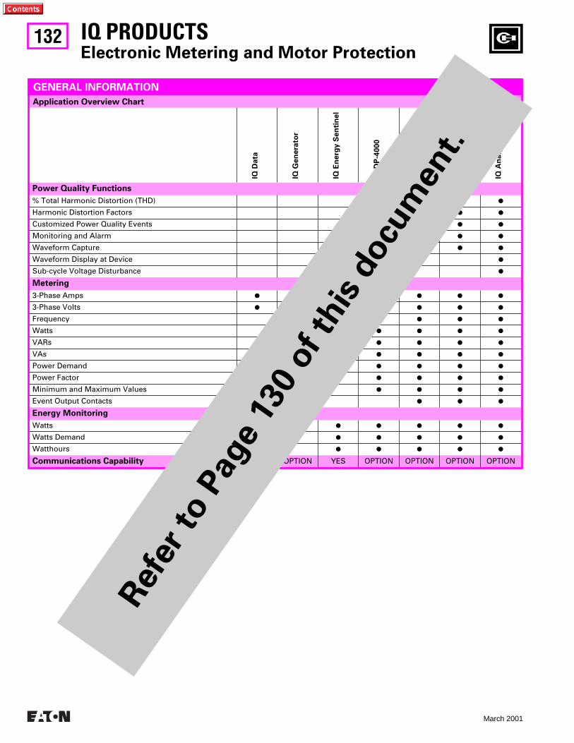
132
March 2001
IQ D
ata
IQ G
en
era
tor
IQ E
nerg
y S
en
tin
el
IQ D
P-4
000
IQ D
P-4
100
IQ A
naly
zer
6000
IQ A
naly
zer
6200
Power Quality Functions
% Total Harmonic Distortion (THD)
P P P P
Harmonic Distortion Factors
P P
Customized Power Quality Events
P P
Monitoring and Alarm
P P P
Waveform Capture
P P
Waveform Display at Device
P
Sub-cycle Voltage Disturbance
P
Metering
3-Phase Amps
P P P P P P
3-Phase Volts
P P P P P P
Frequency
P P P P P
Watts
P P P P
VARs
P P P P
VAs
P P P P
Power Demand
P P P P
Power Factor
P P P P
Minimum and Maximum Values
P P P P
Event Output Contacts
P P P
Energy Monitoring
Watts
P P P P P
Watts Demand
P P P P P
Watthours
P P P P P
Communications Capability
OPTION OPTION YES OPTION OPTION OPTION OPTION
GENERAL INFORMATION
IQ PRODUCTS
Electronic Metering and Motor Protection
Application Overview Chart
Ref
er to P
age
130
of th
is d
ocu
men
t.
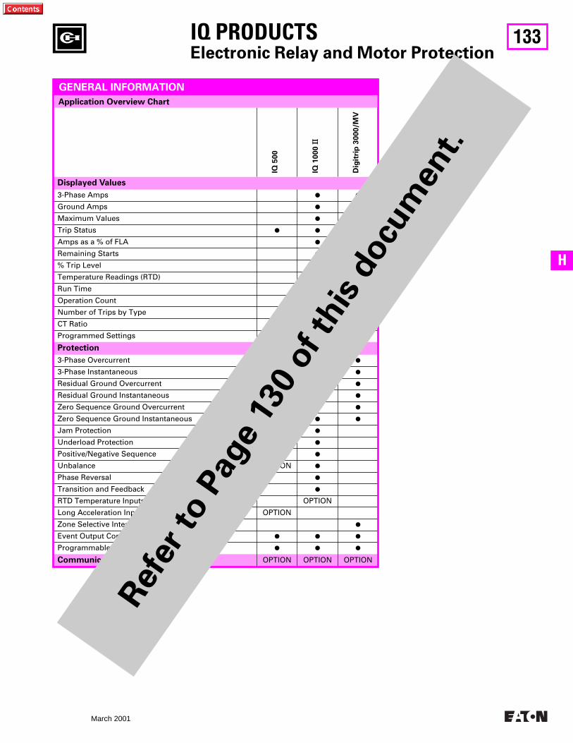
133
March 2001
H
IQ 5
00
IQ 1
000
II
Dig
itri
p 3
000/M
V
Displayed Values
3-Phase Amps
P P
Ground Amps
P P
Maximum Values
P P
Trip Status
P P P
Amps as a % of FLA
P
Remaining Starts
P
% Trip Level
P
Temperature Readings (RTD) OPTION
Run Time
P
Operation Count
P
Number of Trips by Type
P
CT Ratio
P P
Programmed Settings
P P
Protection
3-Phase Overcurrent
P P P
3-Phase Instantaneous
P P
Residual Ground Overcurrent
P P
Residual Ground Instantaneous
P
Zero Sequence Ground Overcurrent
P P
Zero Sequence Ground Instantaneous
P P
Jam Protection OPTION
P
Underload Protection OPTION
P
Positive/Negative Sequence
P
Unbalance OPTION
P
Phase Reversal
P
Transition and Feedback
P
RTD Temperature Inputs OPTION
Long Acceleration Input OPTION
Zone Selective Interlocking
P
Event Output Contacts
P P P
Programmable Settings for Trip Curve
P P P
Communications Capability
OPTION OPTION OPTION
GENERAL INFORMATION
IQ PRODUCTS
Electronic Relay and Motor Protection
Application Overview Chart
Ref
er to P
age
130
of th
is d
ocu
men
t.
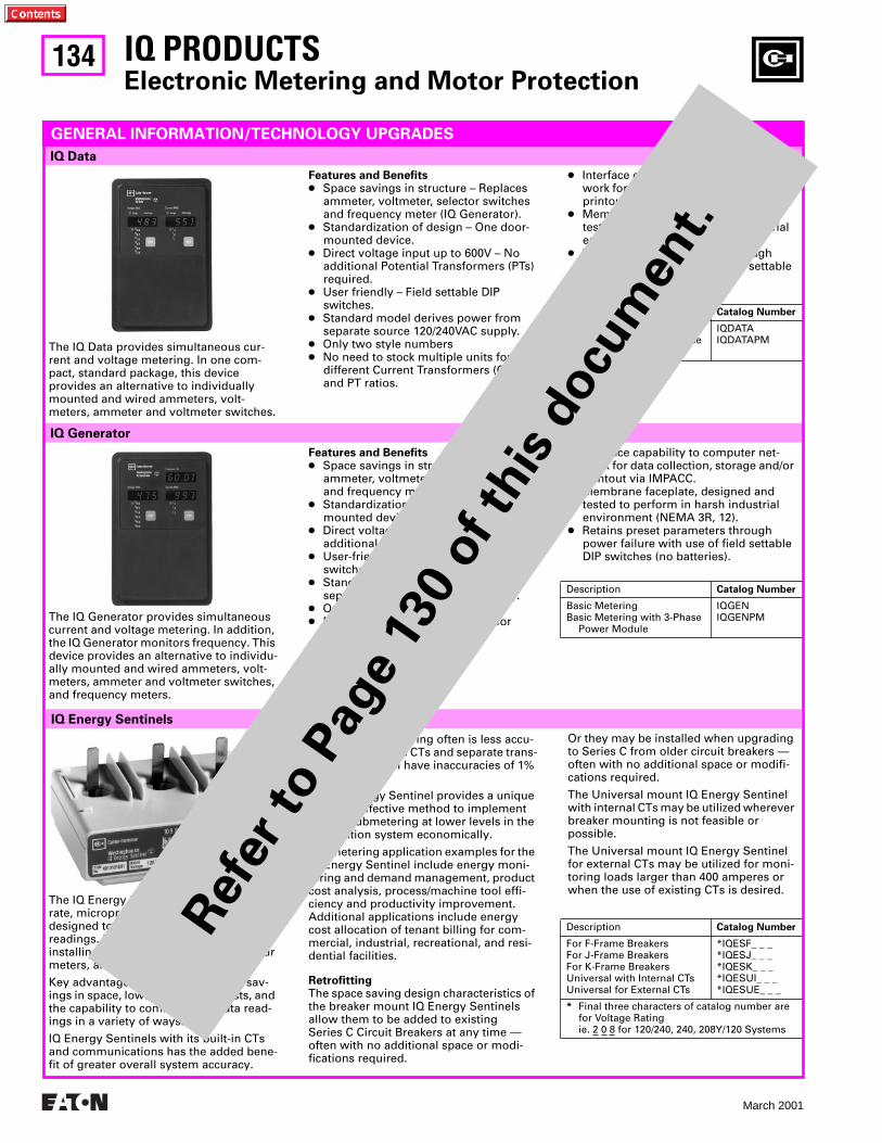
134
March 2001
IQ Generator
IQ Data
IQ PRODUCTS
Electronic Metering and Motor Protection
GENERAL INFORMATION/TECHNOLOGY UPGRADES
The IQ Data provides simultaneous cur-rent and voltage metering. In one com-pact, standard package, this device provides an alternative to individually mounted and wired ammeters, volt-meters, ammeter and voltmeter switches.
Features and Benefits
●
Space savings in structure – Replaces ammeter, voltmeter, selector switches and frequency meter (IQ Generator).
●
Standardization of design – One door- mounted device.
●
Direct voltage input up to 600V – No additional Potential Transformers (PTs) required.
●
User friendly – Field settable DIP switches.
●
Standard model derives power from separate source 120/240VAC supply.
●
Only two style numbers
●
No need to stock multiple units for different Current Transformers (CT) and PT ratios.
●
Interface capability to computer net-work for data collection, storage and/or printout via IMPACC.
●
Membrane faceplate, designed and tested to perform in a harsh industrial environment (NEMA 3R, 12).
●
Retains preset parameters through power failure with use of field settable DIP switches (no batteries).
Description
Catalog Number
Basic MeteringBasic Metering with 3-Phase
Power Module
IQDATAIQDATAPM
The IQ Generator provides simultaneous current and voltage metering. In addition, the IQ Generator monitors frequency. This device provides an alternative to individu-ally mounted and wired ammeters, volt-meters, ammeter and voltmeter switches, and frequency meters.
Features and Benefits
●
Space savings in structure – Replaces ammeter, voltmeter, selector switches and frequency meter (IQ Generator).
●
Standardization of design – One door- mounted device.
●
Direct voltage input up to 600V – No additional PTs required.
●
User-friendly – Field settable DIP switches.
●
Standard model derives power from separate source 120/240VAC supply.
●
Only two style numbers
●
No need to stock multiple units for different CT and PT ratios.
●
Interface capability to computer net-work for data collection, storage and/or printout via IMPACC.
●
Membrane faceplate, designed and tested to perform in harsh industrial environment (NEMA 3R, 12).
●
Retains preset parameters through power failure with use of field settable DIP switches (no batteries).
Description
Catalog Number
Basic MeteringBasic Metering with 3-Phase
Power Module
IQGENIQGENPM
IQ Energy Sentinels
The IQ Energy Sentinel is a highly accu-rate, microprocessor-based submeter designed to monitor power and energy readings. It represents an alternative to installing separate watt meters, watt-hour meters, and watt demand meters.
Key advantages include unmatched sav-ings in space, lower installation costs, and the capability to communicate data read-ings in a variety of ways.
IQ Energy Sentinels with its built-in CTs and communications has the added bene-fit of greater overall system accuracy.
Conventional metering often is less accu-rate since external CTs and separate trans-ducers may each have inaccuracies of 1% or more.
The IQ Energy Sentinel provides a unique and cost-effective method to implement energy submetering at lower levels in the distribution system economically.
Submetering application examples for the IQ Energy Sentinel include energy moni-toring and demand management, product cost analysis, process/machine tool effi-ciency and productivity improvement. Additional applications include energy cost allocation of tenant billing for com-mercial, industrial, recreational, and resi-dential facilities.
Retrofitting
The space saving design characteristics of the breaker mount IQ Energy Sentinels allow them to be added to existing Series C Circuit Breakers at any time — often with no additional space or modi-fications required.
Or they may be installed when upgrading to Series C from older circuit breakers — often with no additional space or modifi-cations required.
The Universal mount IQ Energy Sentinel with internal CTs may be utilized wherever breaker mounting is not feasible or possible.
The Universal mount IQ Energy Sentinel for external CTs may be utilized for moni-toring loads larger than 400 amperes or when the use of existing CTs is desired.
Description
Catalog Number
For F-Frame BreakersFor J-Frame BreakersFor K-Frame BreakersUniversal with Internal CTsUniversal for External CTs
*IQESF_ _ _*IQESJ_ _ _*IQESK_ _ _*IQESUI_ _ _*IQESUE_ _ _
*
Final three characters of catalog number are for Voltage Ratingie. 2 0 8 for 120/240, 240, 208Y/120 Systems
Ref
er to P
age
130
of th
is d
ocu
men
t.
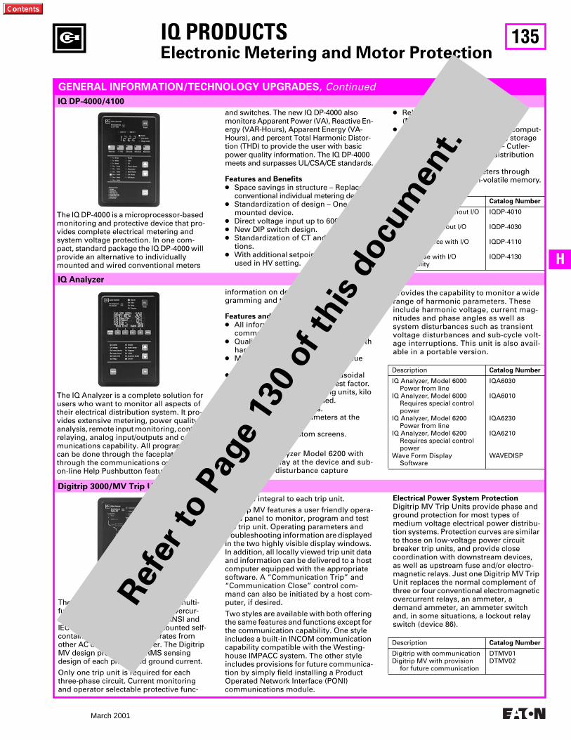
135
March 2001
H
Digitrip 3000/MV Trip Unit
IQ PRODUCTS
Electronic Metering and Motor Protection
IQ Analyzer
IQ DP-4000/4100
GENERAL INFORMATION/TECHNOLOGY UPGRADES,
Continued
The IQ DP-4000 is a microprocessor-based monitoring and protective device that pro-vides complete electrical metering and system voltage protection. In one com-pact, standard package the IQ DP-4000 will provide an alternative to individually mounted and wired conventional meters
and switches. The new IQ DP-4000 also monitors Apparent Power (VA), Reactive En-ergy (VAR-Hours), Apparent Energy (VA-Hours), and percent Total Harmonic Distor-tion (THD) to provide the user with basic power quality information. The IQ DP-4000 meets and surpasses UL/CSA/CE standards.
Features and Benefits
●
Space savings in structure – Replaces conventional individual metering devices.
●
Standardization of design – One door- mounted device.
● Direct voltage input up to 600V● New DIP switch design.● Standardization of CT and PT connec-
tions.● With additional setpoints, device can be
used in HV setting.
● Relaying included in I/O module(Model 4100).
● Optional interface capability to comput-er network for data collection, storage and/or printout via IMPACC – Cutler-Hammer’s leading power distribution monitoring network.
● Retains present parameters through power failure with non-volatile memory.
Description Catalog Number
Separate Source without I/O capability
Three-Phase without I/O capability
Separate Source with I/O capability
Three-Phase with I/O capability
IQDP-4010
IQDP-4030
IQDP-4110
IQDP-4130
The IQ Analyzer is a complete solution for users who want to monitor all aspects of their electrical distribution system. It pro-vides extensive metering, power quality analysis, remote input monitoring, control relaying, analog input/outputs and com-munications capability. All programming can be done through the faceplate or through the communications option. Its on-line Help Pushbutton feature displays
information on device operation, pro-gramming and troubleshooting.
Features and Benefits● All information accessible through
communications port.● Quality true RMS readings through 50th
harmonic.● Meets ANSI C12.16 class 10 revenue
metering spec.● Accurate readings for non-sinusoidal
wave forms with up to 3.0 crest factor.● Screens display auto ranging units, kilo
units, mega units as needed.● 10 Digit energy readings.● Displays multiple parameters at the
same time.● Programmable custom screens.
The new IQ Analyzer Model 6200 with waveform display at the device and sub-cycle voltage disturbance capture
provides the capability to monitor a wide range of harmonic parameters. These include harmonic voltage, current mag-nitudes and phase angles as well as system disturbances such as transient voltage disturbances and sub-cycle volt-age interruptions. This unit is also avail-able in a portable version.
Description Catalog Number
IQ Analyzer, Model 6000Power from line
IQ Analyzer, Model 6000Requires special control power
IQ Analyzer, Model 6200Power from line
IQ Analyzer, Model 6200Requires special control power
Wave Form DisplaySoftware
IQA6030
IQA6010
IQA6230
IQA6210
WAVEDISP
The Digitrip 3000/MV Trip Unit is a multi-function, microprocessor-based overcur-rent trip unit designed for both ANSI and IEC applications. It is a panel mounted self-contained trip unit which operates from other AC or DC control power. The Digitrip MV design provides true RMS sensing design of each phase and ground current.
Only one trip unit is required for each three-phase circuit. Current monitoring and operator selectable protective func-
tions are integral to each trip unit.
Digitrip MV features a user friendly opera-tions panel to monitor, program and test the trip unit. Operating parameters and troubleshooting information are displayed in the two highly visible display windows. In addition, all locally viewed trip unit data and information can be delivered to a host computer equipped with the appropriate software. A “Communication Trip” and “Communication Close” control com-mand can also be initiated by a host com-puter, if desired.
Two styles are available with both offering the same features and functions except for the communication capability. One style includes a built-in INCOM communication capability compatible with the Westing-house IMPACC system. The other style includes provisions for future communica-tion by simply field installing a Product Operated Network Interface (PONI) communications module.
Electrical Power System ProtectionDigitrip MV Trip Units provide phase and ground protection for most types of medium voltage electrical power distribu-tion systems. Protection curves are similar to those on low-voltage power circuit breaker trip units, and provide close coordination with downstream devices, as well as upstream fuse and/or electro-magnetic relays. Just one Digitrip MV Trip Unit replaces the normal complement of three or four conventional electromagnetic overcurrent relays, an ammeter, a demand ammeter, an ammeter switch and, in some situations, a lockout relay switch (device 86).
Description Catalog Number
Digitrip with communicationDigitrip MV with provision
for future communication
DTMV01DTMV02
Ref
er to P
age
130
of th
is d
ocu
men
t.
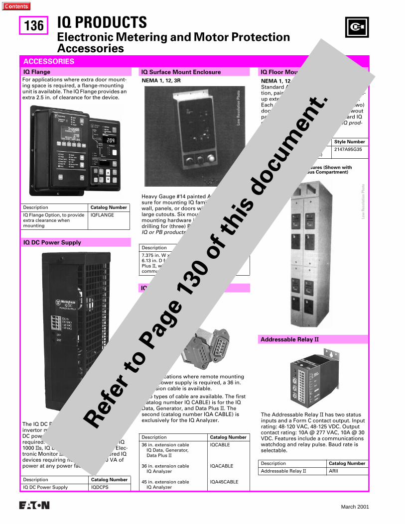
136
March 2001
NEMA 1, 12, 3RStandard AMPGARD© structure construc-tion, painted ASA-61. To be used as a line-up extension for mounting IQ products. Each 10 in. wide section comes with (two) doors with “works-in-a-drawer” drawout panel. Each door has (three) standard IQ cutouts with device panels. The IQ prod-ucts are not included.
Description Style Number
10 in. W x 30 in. D x 90 in. H (bus compartment optional)
2147A95G35
The Addressable Relay II has two status inputs and a Form C contact output. Input rating: 48-120 VAC, 48-125 VDC. Output contact rating: 10A @ 277 VAC, 10A @ 30 VDC. Features include a communications watchdog and relay pulse. Baud rate is selectable.
Description Catalog Number
Addressable Relay II ARII
IQ PRODUCTSElectronic Metering and Motor Protection Accessories
Two 10 in. Wide Enclosures (Shown with Optional 10 in. High Bus Compartment)
For applications where extra door mount-ing space is required, a flange-mounting unit is available. The IQ Flange provides an extra 2.5 in. of clearance for the device.
Description Catalog Number
IQ Flange Option, to provide extra clearance when mounting
IQFLANGE
The IQ DC Power Supply is a DC to AC invertor module intended for use where DC power is available, but some AC is required. The unit will operate several IQ 1000 IIs, IQ Data Plus IIs, Assemblies Elec-tronic Monitor IIs, or other AC powered IQ devices requiring no more than 30 VA of power at any power factor.
Description Catalog Number
IQ DC Power Supply IQDCPS
Heavy Gauge #14 painted ASA-61. Enclo-sure for mounting IQ family products on wall, panels, or doors without making large cutouts. Six mounting holes and mounting hardware included. Includes drilling for (three) PB1/PB2 devices. The IQ or PB products are not included.
Description Style Number
7.375 in. W x 16.25 in. H x 6.13 in. D for use with IQ Data Plus II, with or without communications.
2147A95G33
For applications where remote mounting of the power supply is required, a 36 in.extension cable is available.
Two types of cable are available. The first (catalog number IQ CABLE) is for the IQ Data, Generator, and Data Plus II. The second (catalog number IQA CABLE) is exclusively for the IQ Analyzer.
Description Catalog Number
36 in. extension cableIQ Data, Generator,Data Plus II
36 in. extension cableIQ Analyzer
45 in. extension cableIQ Analyzer
IQCABLE
IQACABLE
IQA45CABLE
ACCESSORIES
NEMA 1, 12, 3R
Addressable Relay II
IQ Cable
IQ DC Power Supply
IQ Flange IQ Surface Mount Enclosure IQ Floor Mounted Enclosure
Low
Res
olut
ion
Phot
o
Low
Res
olut
ion
Phot
o
Ref
er to P
age
130
of th
is d
ocu
men
t.
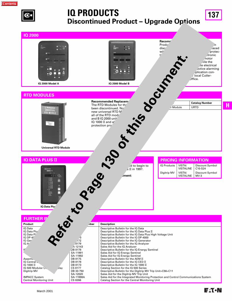
137
March 2001
H
IQ Products
Digitrip MV
VISTA/VISTALINE
VISTA/VISTALINE
Discount Symbol C10-S24
Discount Symbol MV-3
Product Literature Number Description
IQ DataIQ Data Plus IIIQ Data Plus II HVIQ DP-4000IQ GeneratorIQ Analyzer
IQ Energy Sentinel
Assemblies Electronic Monitor IIIQ Central Energy Display IIIQ 1000 IIIQ 500 Modular Overload RelayDigitrip MV
IMPACC SystemCentral Monitoring Unit
DB 8171DB 8170DB 8176DB 8170DB 8172DB 8179SA-12143DB 8178SA-11991SA-11992DB 8175DB 8178DB 8173CS 8177DB 33-750SA-12020SA-11998ACS 8266
Descriptive Bulletin for the IQ DataDescriptive Bulletin for the IQ Data Plus IIDescriptive Bulletin for the IQ Data Plus High Voltage UnitDescriptive Bulletin for the IQ DP-4000Descriptive Bulletin for the IQ GeneratorDescriptive Bulletin for the IQ AnalyzerSales Aid for the IQ AnalyzerDescriptive Bulletin for the IQ Energy SentinelSales Aid for IQ Energy SentinelSales Aid for IQ Energy SentinelDescriptive Bulletin for the AEM IIDescriptive Bulletin for the IQ CED IIDescriptive Bulletin for the IQ 1000 IICatalog Section for the IQ 500 SeriesDescriptive Bulletin for the Digitrip MV Trip Unit+C56+C11Sales Aid for the Digitrip MV Trip UnitSales Aid for the Integrated Monitoring Protection and Control Communications SystemCatalog Section for the Central Monitoring Unit
IQ PRODUCTSDiscontinued Product – Upgrade Options
IQ 2000
Recommended Replacement:Production of IQ 2000 devices has been discontinued. The IQ 2000 can be replaced with the IQ 1000 II electronic motor protec-tive relay and the IQ DP-4000 electronic meter. The IQ 1000 II provides motor current protective relaying, while the IQ DP-4000 provides complete electrical metering and voltage protective alarming functions. For specific application con-sideration, contact your local Cutler-Hammer Field Sales Office.
IQ 2000 Model A IQ 2000 Model B
RTD MODULES
Recommended Replacement:The RTD Modules for the IQ 2000 have been discontinued. Now available is the new universal RTD Module that replaces all of the RTD modules for the Model A and B IQ 2000 units, as well as the IQ 1000, IQ 1000 II and all current IQ metering and protection products.
Description Catalog Number
Universal Module URTD
Universal RTD Module
IQ DATA PLUS II
IQ Data Plus II
Cutler-Hammer is scheduled to begin to phaseout the IQ Data Plus II in 1997.
Recommeded Replacement:IQ DP-4000
FURTHER INFORMATION
PRICING INFORMATION
Ref
er to P
age
130
of th
is d
ocu
men
t.
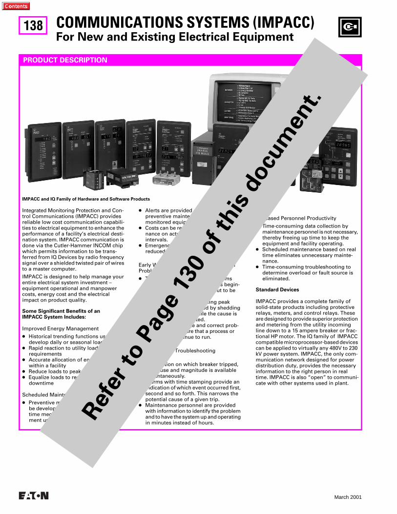
138
March 2001
COMMUNICATIONS SYSTEMS (IMPACC)
For New and Existing Electrical Equipment
PRODUCT DESCRIPTION
Integrated Monitoring Protection and Con-trol Communications (IMPACC) provides reliable low cost communication capabili-ties to electrical equipment to enhance the performance of a facility’s electrical desti-nation system. IMPACC communication is done via the Cutler-Hammer INCOM chip which permits information to be trans-ferred from IQ Devices by radio frequency signal over a shielded twisted pair of wires to a master computer.
IMPACC is designed to help manage your entire electrical system investment – equipment operational and manpower costs, energy cost and the electrical impact on product quality.
Some Significant Benefits of an IMPACC System Includes:
Improved Energy Management
●
Historical trending functions used to develop daily or seasonal load profiles
●
Rapid reaction to utility load shedding requirements
●
Accurate allocation of energy costs within a facility
●
Reduce loads to peak demand
●
Equalize loads to reduce potential downtime
Scheduled Maintenance Reduces Costs
●
Preventive maintenance schedules can be developed from the database of real time mechanical and electrical equip-ment usage.
●
Alerts are provided as a reminder that preventive maintenance is required on monitored equipment.
●
Costs can be reduced by basing mainte-nance on actual use instead of time intervals.
●
Emergencies can be dramatically reduced.
Early Warning Alarms Alert to PotentialProblems
●
The operator is alerted to problems before they occur (i.e., breakers begin-ning to time out or loads about to be exceeded).
●
Problems (such as exceeding peak demands) can be avoided by shedding or equalizing loads while the cause is identified and corrected.
●
The ability to isolate and correct prob-lems helps to insure that a process or facility will continue to run.
Instantaneous TroubleshootingInformation
●
Information on which breaker tripped, the cause and magnitude is available instantaneously.
●
Alarms with time stamping provide an indication of which event occurred first, second and so forth. This narrows the potential cause of a given trip.
●
Maintenance personnel are provided with information to identify the problem and to have the system up and operating in minutes instead of hours.
Increased Personnel Productivity
●
Time-consuming data collection by maintenance personnel is not necessary, thereby freeing up time to keep the equipment and facility operating.
●
Scheduled maintenance based on real time eliminates unnecessary mainte-nance.
●
Time-consuming troubleshooting to determine overload or fault source is eliminated.
Standard Devices
IMPACC provides a complete family of solid-state products including protective relays, meters, and control relays. These are designed to provide superior protection and metering from the utility incoming line down to a 15 ampere breaker or frac-tional HP motor. The IQ family of IMPACC compatible microprocessor-based devices can be applied to virtually any 480V to 230 kV power system. IMPACC, the only com-munication network designed for power distribution duty, provides the necessary information to the right person in real time. IMPACC is also “open” to communi-cate with other systems used in plant.
IMPACC and IQ Family of Hardware and Software Products
Ref
er to P
age
130
of th
is d
ocu
men
t.
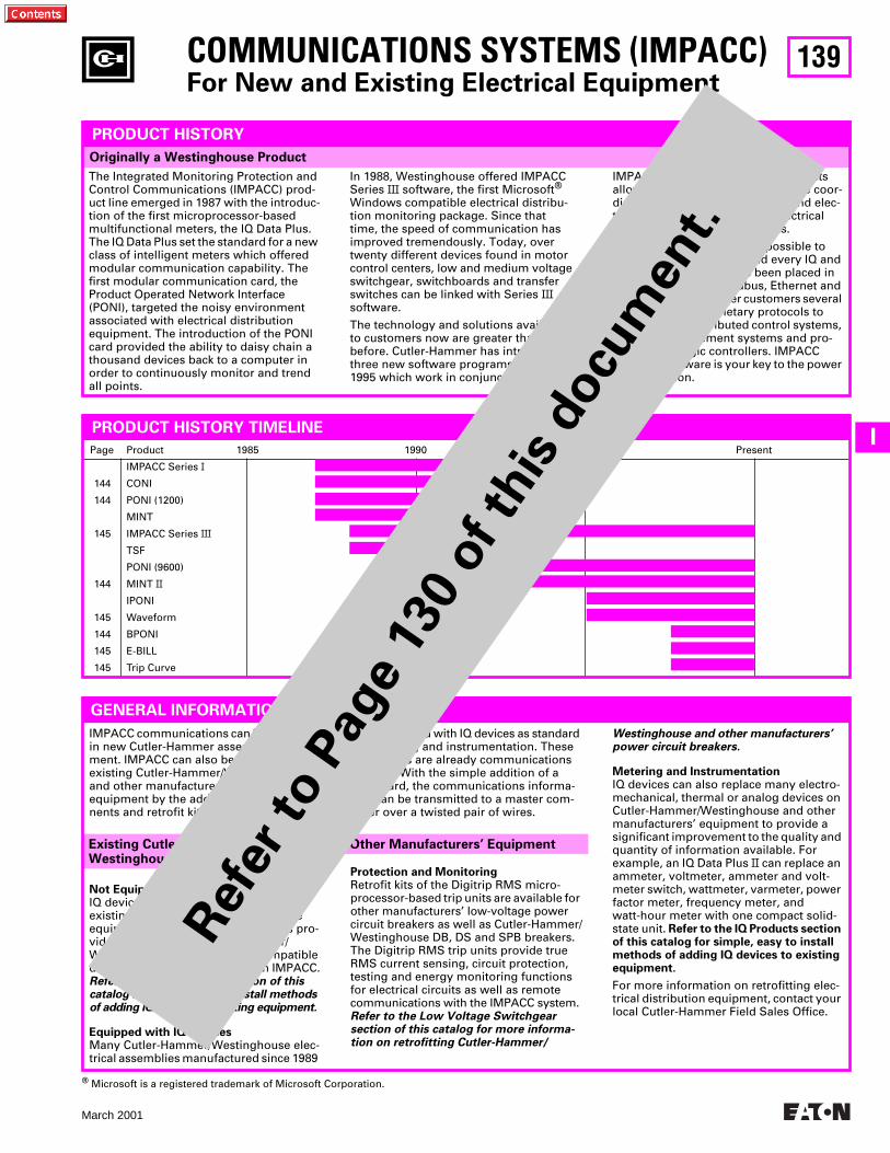
139
March 2001
I
COMMUNICATIONS SYSTEMS (IMPACC)
For New and Existing Electrical Equipment
Page Product 1985 1990 1995 Present
144
144
145
144
145
144
145
145
IMPACC Series
I
CONI
PONI (1200)
MINT
IMPACC Series
III
TSF
PONI (9600)
MINT
II
IPONI
Waveform
BPONI
E-BILL
Trip Curve
Originally a Westinghouse Product
PRODUCT HISTORY
The Integrated Monitoring Protection and Control Communications (IMPACC) prod-uct line emerged in 1987 with the introduc-tion of the first microprocessor-based multifunctional meters, the IQ Data Plus. The IQ Data Plus set the standard for a new class of intelligent meters which offered modular communication capability. The first modular communication card, the Product Operated Network Interface (PONI), targeted the noisy environment associated with electrical distribution equipment. The introduction of the PONI card provided the ability to daisy chain a thousand devices back to a computer in order to continuously monitor and trend all points.
In 1988, Westinghouse offered IMPACC Series
III
software, the first Microsoft
®
Windows compatible electrical distribu-tion monitoring package. Since that time, the speed of communication has improved tremendously. Today, over twenty different devices found in motor control centers, low and medium voltage switchgear, switchboards and transfer switches can be linked with Series
III
software.
The technology and solutions available to customers now are greater than ever before. Cutler-Hammer has introduced three new software programs since 1995 which work in conjunction with
IMPACC Series
III
. These new products allow analysis of harmonics, on-line coor-dination of electrical equipment and elec-tronic billing based on actual electrical usage and utility rate schedules.
Series
III
software makes it possible to communicate with each and every IQ and IMPACC product that has been placed in service since 1987. Modbus, Ethernet and IMPACC Gateways offer customers several standard, non-proprietary protocols to interface with distributed control systems, building management systems and pro-grammable logic controllers. IMPACC Series
III
software is your key to the power of information.
PRODUCT HISTORY TIMELINE
IMPACC communications can be provided in new Cutler-Hammer assembled equip-ment. IMPACC can also be retrofitted into existing Cutler-Hammer/Westinghouse and other manufacturers’ assembled equipment by the addition of IQ compo-nents and retrofit kits.
Not Equipped with IQ Devices
IQ devices can be easily retrofitted to existing Cutler-Hammer/Westinghouse equipment. The following four pages pro-vide an overview of Cutler-Hammer/Westinghouse assemblies and compatible devices for communications with IMPACC.
Refer to the IQ Products section of thiscatalog for simple, easy to install methodsof adding IQ devices to existing equipment.
Equipped with IQ Devices
Many Cutler-Hammer/Westinghouse elec-trical assemblies manufactured since 1989
Existing Cutler-Hammer/Westinghouse Equipment
GENERAL INFORMATION
were furnished with IQ devices as standard for metering and instrumentation. These assemblies are already communications capable. With the simple addition of a PONI card, the communications informa-tion can be transmitted to a master com-puter over a twisted pair of wires.
Protection and Monitoring
Retrofit kits of the Digitrip RMS micro-processor-based trip units are available for other manufacturers’ low-voltage power circuit breakers as well as Cutler-Hammer/Westinghouse DB, DS and SPB breakers. The Digitrip RMS trip units provide true RMS current sensing, circuit protection, testing and energy monitoring functions for electrical circuits as well as remote communications with the IMPACC system.
Refer to the Low Voltage Switchgearsection of this catalog for more informa-tion on retrofitting Cutler-Hammer/
Westinghouse and other manufacturers’power circuit breakers.
Metering and Instrumentation
IQ devices can also replace many electro-mechanical, thermal or analog devices on Cutler-Hammer/Westinghouse and other manufacturers’ equipment to provide a significant improvement to the quality and quantity of information available. For example, an IQ Data Plus
II
can replace an ammeter, voltmeter, ammeter and volt-meter switch, wattmeter, varmeter, power factor meter, frequency meter, and watt-hour meter with one compact solid-state unit.
Refer to the IQ Products section of this catalog for simple, easy to install methods of adding IQ devices to existing equipment.
For more information on retrofitting elec-trical distribution equipment, contact your local Cutler-Hammer Field Sales Office.
Other Manufacturers’ Equipment
®
Microsoft is a registered trademark of Microsoft Corporation.
Ref
er to P
age
130
of th
is d
ocu
men
t.
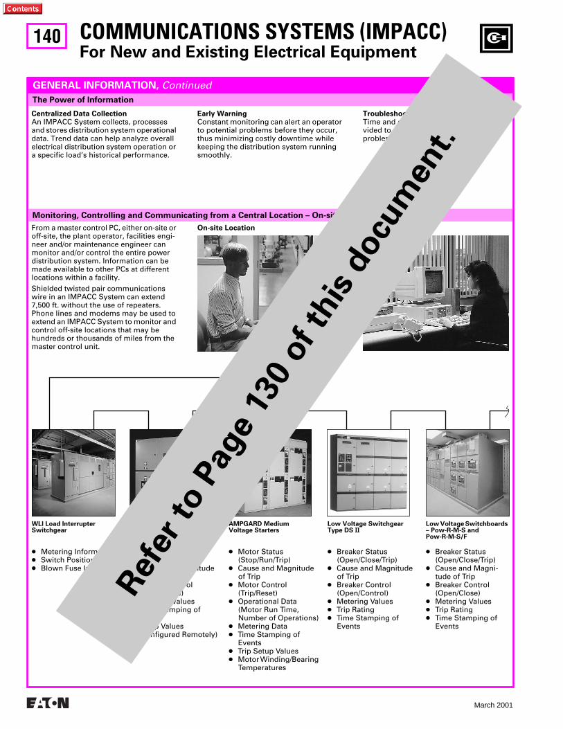
140
March 2001
COMMUNICATIONS SYSTEMS (IMPACC)
For New and Existing Electrical Equipment
Monitoring, Controlling and Communicating from a Central Location – On-site or Off-site
The Power of Information
GENERAL INFORMATION,
Continued
Centralized Data Collection
An IMPACC System collects, processes and stores distribution system operational data. Trend data can help analyze overall electrical distribution system operation or a specific load’s historical performance.
Early Warning
Constant monitoring can alert an operator to potential problems before they occur, thus minimizing costly downtime while keeping the distribution system running smoothly.
Troubleshooting
Time and date stamped event data is pro-vided to efficiently help troubleshoot problems within a distribution system.
From a master control PC, either on-site or off-site, the plant operator, facilities engi-neer and/or maintenance engineer can monitor and/or control the entire power distribution system. Information can be made available to other PCs at different locations within a facility.
Shielded twisted pair communications wire in an IMPACC System can extend 7,500 ft. without the use of repeaters. Phone lines and modems may be used to extend an IMPACC System to monitor and control off-site locations that may be hundreds or thousands of miles from the master control unit.
On-site Location Off-site Location
WLI Load InterrupterSwitchgear
●
Metering Information
●
Switch Position
●
Blown Fuse Indicator
Medium Voltage VacClad-WMetal-Clad Switchgear
●
Breaker Status(Open/Close/Trip)
●
Cause and Magnitudeof Trip
●
Breaker Control(Open/Close)
●
Metering Values
●
Time Stamping of Events
●
Setup Values(Configured Remotely)
AMPGARD MediumVoltage Starters
●
Motor Status(Stop/Run/Trip)
●
Cause and Magnitudeof Trip
●
Motor Control(Trip/Reset)
●
Operational Data(Motor Run Time,Number of Operations)
●
Metering Data
●
Time Stamping of Events
●
Trip Setup Values
●
Motor Winding/Bearing Temperatures
Low Voltage SwitchgearType DS
II
●
Breaker Status(Open/Close/Trip)
●
Cause and Magnitudeof Trip
●
Breaker Control(Open/Control)
●
Metering Values
●
Trip Rating
●
Time Stamping of Events
Low Voltage Switchboards – Pow-R-M-S and Pow-R-M-S/F
●
Breaker Status (Open/Close/Trip)
●
Cause and Magni-tude of Trip
●
Breaker Control (Open/Close)
●
Metering Values
●
Trip Rating
●
Time Stamping of Events
Ref
er to P
age
130
of th
is d
ocu
men
t.
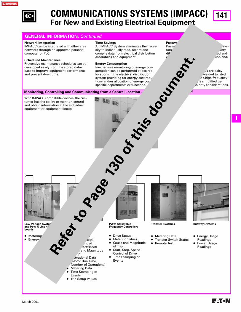
141
March 2001
I
COMMUNICATIONS SYSTEMS (IMPACC)
For New and Existing Electrical Equipment
Monitoring, Controlling and Communicating from a Central Location – On-site or Off-site,
continued
GENERAL INFORMATION,
Continued
Network Integration
IMPACC can be integrated with other area networks through an approved personal computer or PLC.
Scheduled Maintenance
Preventive maintenance schedules can be developed easily from the stored data- base to improve equipment performance and prevent downtime.
Time Savings
An IMPACC System eliminates the neces-sity to individually read, record and compile data from electrical distribution assemblies and equipment.
Energy Consumption
Inexpensive monitoring of energy con-sumption can be performed at desired locations in the electrical distribution system providing for energy cost reduc-tions and/or allocation of energy costs to specific departments or functions.
Password Protection
Password flexibility allows maximum sys-tem utilization and integrity. Up to thirty different passwords can be assigned and can be based on equipment function and/or location.
Ease of Installation
IMPACC compatible devices are daisy chain connected with a shielded twisted pair wire. Since INCOM is a high-frequency- based system, wiring is simplified be-cause there are no polarity considerations.
With IMPACC compatible devices, the cus-tomer has the ability to monitor, control and obtain information at the individual equipment or equipment lineup.
Low Voltage Switchboards and Pow-R-Line 4B/F Panel-boards
●
Metering Values
●
Energy Values
Motor Control Centers
●
Motor Status(Stop/Run/Trip)
●
Motor Control(Stop/Start/Reset)
●
Cause and Magnitude of Trip
●
Operational Data(Motor Run Time,Number of Operations)
●
Metering Data
●
Time Stamping of Events
●
Trip Setup Values
PWM AdjustableFrequency Controllers
●
Drive Status
●
Metering Values
●
Cause and Magnitude of Trip
●
Start, Stop, SpeedControl of Drive
●
Time Stamping of Events
Transfer Switches
●
Metering Data
●
Transfer Switch Status
●
Remote Test
Busway Systems
●
Energy Usage Readings
●
Power Usage Readings
Ref
er to P
age
130
of th
is d
ocu
men
t.
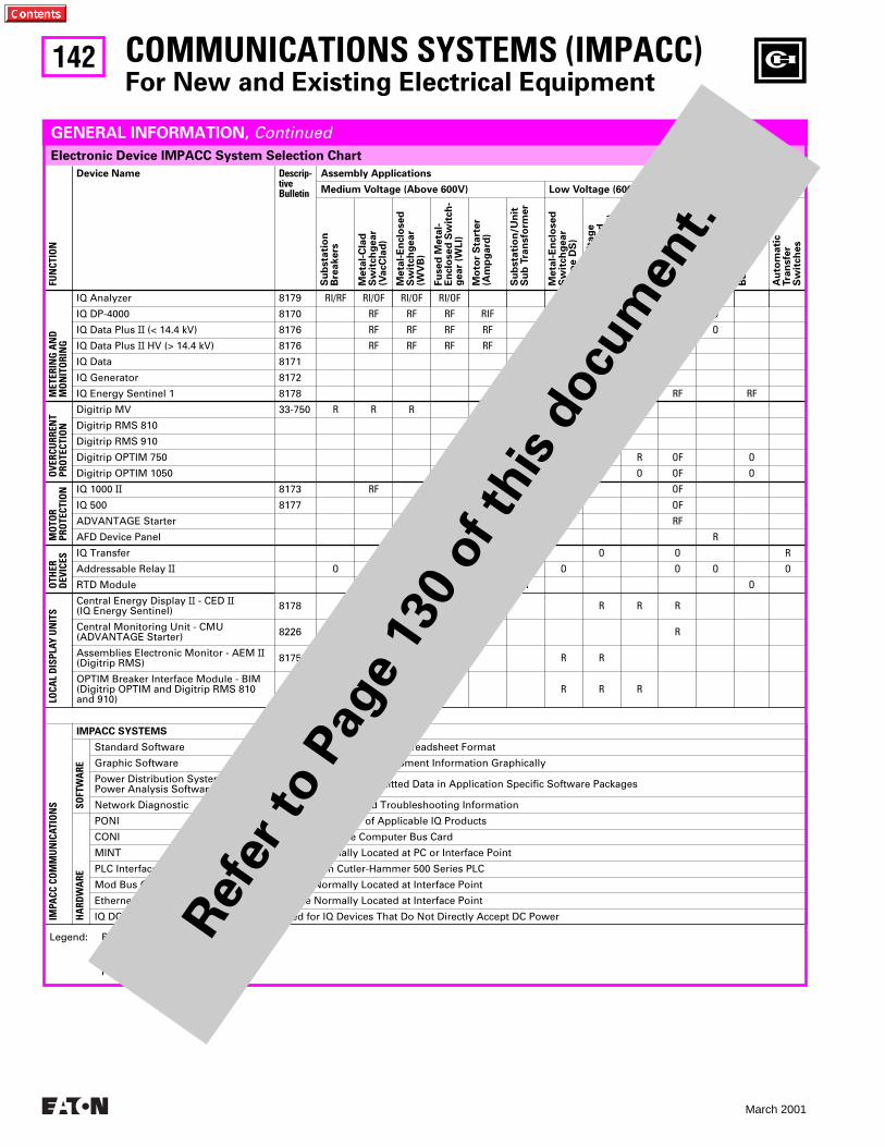
142
March 2001
Electronic Device IMPACC System Selection Chart
COMMUNICATIONS SYSTEMS (IMPACC)For New and Existing Electrical Equipment
FUN
CTIO
N
Device Name Descrip-tiveBulletin
Assembly Applications
Medium Voltage (Above 600V) Low Voltage (600V and Below)
Su
bsta
tio
nB
rea
ke
rs
Me
tal-
Cla
dS
wit
ch
ge
ar
(Va
cC
lad
)
Me
tal-
En
clo
se
dS
wit
ch
ge
ar
(WV
B)
Fu
se
d M
eta
l-E
nclo
se
d S
wit
ch
-g
ea
r (W
LI)
Mo
tor
Sta
rte
r(A
mp
ga
rd)
Su
bsta
tio
n/U
nit
S
ub
Tra
nsfo
rme
r
Me
tal-
En
clo
se
dS
wit
ch
ge
ar
(Ty
pe
DS
)
Lo
w-V
olt
ag
eS
wit
ch
bo
ard
(Po
w-R
-Lin
e C
)
Lo
w-V
olt
ag
eP
an
elb
oa
rd(P
ow
-R-L
ine
C)
Mo
tor
Co
ntr
ol
(Se
rie
s 2
10
0)
Ad
justa
ble
Fre
qu
en
cy
Dri
ve
s
Bu
sw
ay
Plu
gs
Au
tom
ati
cTra
nsfe
rS
wit
ch
es
MET
ERIN
G A
ND
MO
NIT
ORI
NG
IQ Analyzer 8179 RI/RF RI/OF RI/OF RI/OF RI RI RI O
IQ DP-4000 8170 RF RF RF RIF OI OI OI O
IQ Data Plus II (< 14.4 kV) 8176 RF RF RF RF OI OI OI O
IQ Data Plus II HV (> 14.4 kV) 8176 RF RF RF RF
IQ Data 8171 OI OI OI
IQ Generator 8172 OI
IQ Energy Sentinel 1 8178 RF RF RF RF
OVE
RCU
RREN
TPR
OTE
CTIO
N
Digitrip MV 33-750 R R R
Digitrip RMS 810 R RI
Digitrip RMS 910 O OI
Digitrip OPTIM 750 O R R OF O
Digitrip OPTIM 1050 O O O OF O
MO
TOR
PRO
TECT
ION IQ 1000 II 8173 RF RF OF
IQ 500 8177 OF OF
ADVANTAGE Starter RF
AFD Device Panel R
OTH
ERD
EVIC
ES
IQ Transfer O O R
Addressable Relay II O O O R R O O O O
RTD Module R R O
LOCA
L D
ISPL
AY U
NIT
S
Central Energy Display II - CED II(IQ Energy Sentinel) 8178 R R R
Central Monitoring Unit - CMU(ADVANTAGE Starter) 8226 R
Assemblies Electronic Monitor - AEM II(Digitrip RMS) 8175 R R
OPTIM Breaker Interface Module - BIM(Digitrip OPTIM and Digitrip RMS 810 and 910)
R R R
IMPA
CC C
OM
MU
NIC
ATIO
NS
IMPACC SYSTEMS
SOFT
WA
RE
Standard Software Presents System Data in Spreadsheet Format
Graphic Software Depicts System and Equipment Information Graphically
Power Distribution SystemPower Analysis Software Utilizes Device Transmitted Data in Application Specific Software Packages
Network Diagnostic System Start-up and Troubleshooting Information
HA
RDW
ARE
PONI Mounted on Rear of Applicable IQ Products
CONI IBM Compatible Computer Bus Card
MINT Device Normally Located at PC or Interface Point
PLC Interface Card Mounted in Cutler-Hammer 500 Series PLC
Mod Bus Gateway Device Normally Located at Interface Point
Ethernet Interface Bridge Device Normally Located at Interface Point
IQ DC Power Supply Used for IQ Devices That Do Not Directly Accept DC Power
Legend: R = Recommended ApplicationO = Optional ApplicationI = Incoming Main LineF = Feeder
GENERAL INFORMATION, Continued
Ref
er to P
age
130
of th
is d
ocu
men
t.
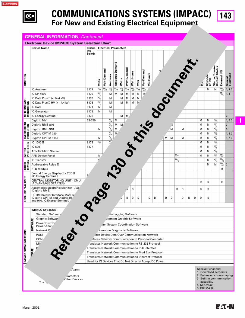
143
March 2001
I
Electronic Device IMPACC System Selection Chart
FUN
CTIO
N
Device Name Descrip-tiveBulletin
Electrical Parameters
Vo
lts
Vo
lt-D
em
an
d
Am
pe
res
Am
pe
res-D
em
an
d
Wa
tts
Wa
tt-D
em
an
d
Wa
tt-H
ou
rs
Va
rs
Va
r-D
em
an
d
Va
r-H
ou
rs
VA
VA
-De
ma
nd
VA
-Ho
urs
Po
we
r F
acto
r
He
rtz
To
tal H
arm
on
ic D
isto
rtio
n
Ha
rmo
nic
Dis
tort
ion
Fa
cto
rs
Min
/Ma
x V
alu
es
Ru
nti
me
Ev
en
t C
ou
nt
Ca
use
/Ma
gn
itu
de
of
Tri
p
Sta
rte
r/B
rea
ke
rC
on
tact
Sta
tus
Ex
tern
al I/
O
Sp
ecia
lF
un
cti
on
s
MET
ERIN
G A
ND
MO
NIT
ORI
NG
IQ Analyzer 8179 M⁄C M⁄C M⁄C M⁄C M⁄C M⁄C M⁄C M⁄C M⁄C M⁄C M⁄C M⁄C M⁄C M⁄C M⁄C M⁄C M M M M M⁄C 1, 4, 5
IQ DP-4000 8170 M⁄C M M M M M M M M M M M M M M M⁄C 1, 4
IQ Data Plus II (< 14.4 kV) 8176 M⁄C M M M M M M M
IQ Data Plus II HV (> 14.4 kV) 8176 M⁄C M M M M M M M
IQ Data 8171 M M
IQ Generator 8172 M M M
IQ Energy Sentinel 8178 M M M 3
OVE
RCU
RREN
TPR
OTE
CTIO
N
Digitrip MV 33-750 P⁄M M M M M⁄C 1, 2, 3
Digitrip RMS 810 P⁄M M M M M M M M M⁄C 3
Digitrip RMS 910 M P⁄M M M M M M M M M M⁄C 3
Digitrip OPTIM 750 P⁄M M M M M⁄T 1, 2, 3
Digitrip OPTIM 1050 M P⁄M M M M M M M M M M M M M M⁄T 1, 2, 3
MO
TOR
PRO
TECT
ION IQ 1000 II 8173 M⁄C P⁄M M M M⁄C
IQ 500 8177 P⁄M M M M⁄TADVANTAGE Starter P⁄M M M M⁄CAFD Device Panel M M M⁄C M M M⁄C M⁄C
OTH
ERD
EVIC
ES
IQ Transfer M⁄C M M⁄C M M⁄C M⁄CAddressable Relay II M M M⁄C 3
RTD Module M
LOCA
L D
ISPL
AY U
NIT
S
Central Energy Display II - CED II(IQ Energy Sentinel) 8178 D D D
CENTRAL MONITORING UNIT - CMU(ADVANTAGE STARTER) 8226 D D D D
Assemblies Electronic Monitor - AEM II(Digitrip RMS) 8175 D D D D D D D D D
OPTIM Breaker Interface Module - BIM(Digitrip OPTIM and Digitrip RMS 810 and 910, IQ Energy Sentinel)
D D D D D D D D D D D D D D D
IMPA
CC C
OM
MU
NIC
ATIO
NS
IMPACC SYSTEMS
SOFT
WA
RE
Standard Software Status/Control/Data Logging Software
Graphic Software Single Line/Equipment Graphic Software
Power Distribution SystemPower Analysis Software Power Quality, System Coordination Software
Network Diagnostic System Operation Diagnostic Software
HA
RDW
ARE
PONI Transmits Device Data Over Communication Network
CONI Interfaces Network Communication to Personal Computer
MINT Translates Network Communication to RS-232 Protocol
PLC Interface Card Translates Network Communication to PLC Interface
Mod Bus Gateway Translates Network Communication to Mod Bus Protocol
Ethernet Interface Bridge Translates Network Communication to Ethernet Protocol
IQ DC Power Supply Used for IQ Devices That Do Not Directly Accept DC Power
COMMUNICATIONS SYSTEMS (IMPACC)For New and Existing Electrical Equipment
Special Functions:1. Download setpoints2. Enhanced curve shaping3. Built-in communication
capability4. Min./Max.5. CBEMA (2)
Legend: M = MonitorC = Contact for Control/AlarmP = ProtectionD = Display Only, Parameters
Monitored by Other DevicesT = Trip Only
GENERAL INFORMATION, Continued
Ref
er to P
age
130
of th
is d
ocu
men
t.
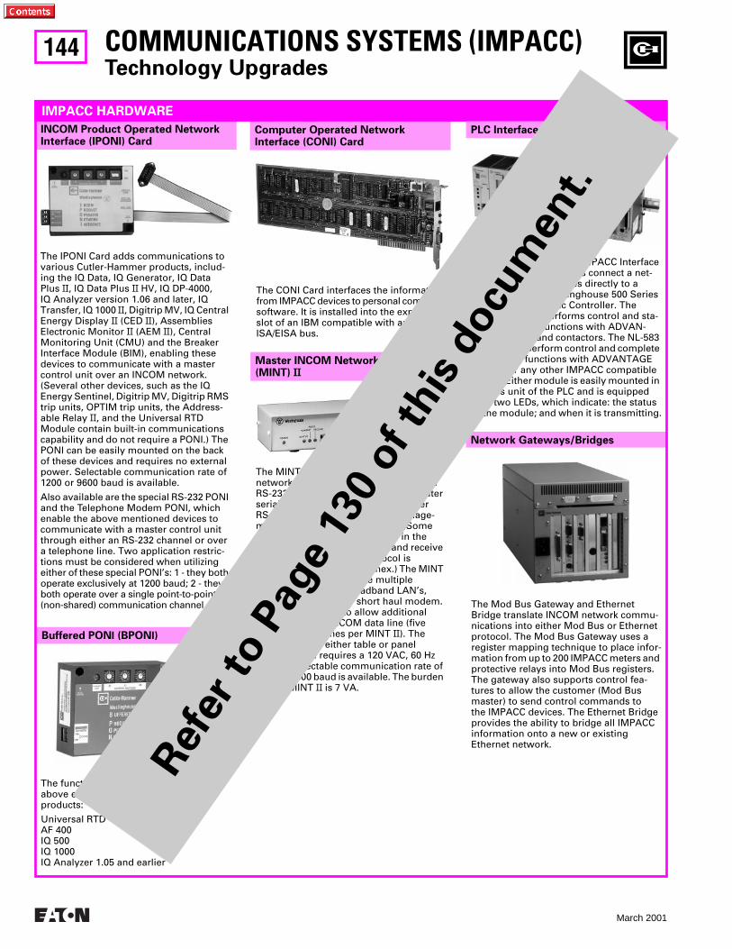
144
March 2001
Buffered PONI (BPONI)
COMMUNICATIONS SYSTEMS (IMPACC)Technology Upgrades
Network Gateways/Bridges
Master INCOM Network Translator(MINT) II
The MINT II interfaces the IMPACC network to a master control unit with anRS-232 port, such as a personal computer serial port, a programmable controllerRS-232 “smart card,” building manage-ment system interface card, etc. (Some software will have to be written in the master control unit to request and receive messages. The MINT II protocol is 10-character, ASC II coded hex.) The MINT II can be used to interface multiple IMPACC devices to Broadband LAN’s, telephone modem, or short haul modem. It can also be used to allow additional branches of the INCOM data line (five additional branches per MINT II). The MINT II can be either table or panel mounted and requires a 120 VAC, 60 Hz supply. Selectable communication rate of 1200 or 9600 baud is available. The burden for the MINT II is 7 VA.
INCOM Product Operated NetworkInterface (IPONI) Card
Computer Operated NetworkInterface (CONI) Card
The IPONI Card adds communications to various Cutler-Hammer products, includ-ing the IQ Data, IQ Generator, IQ Data Plus II, IQ Data Plus II HV, IQ DP-4000, IQ Analyzer version 1.06 and later, IQ Transfer, IQ 1000 II, Digitrip MV, IQ Central Energy Display II (CED II), Assemblies Electronic Monitor II (AEM II), Central Monitoring Unit (CMU) and the Breaker Interface Module (BIM), enabling these devices to communicate with a master control unit over an INCOM network. (Several other devices, such as the IQ Energy Sentinel, Digitrip MV, Digitrip RMS trip units, OPTIM trip units, the Address-able Relay II, and the Universal RTD Module contain built-in communications capability and do not require a PONI.) The PONI can be easily mounted on the back of these devices and requires no external power. Selectable communication rate of 1200 or 9600 baud is available.
Also available are the special RS-232 PONI and the Telephone Modem PONI, which enable the above mentioned devices to communicate with a master control unit through either an RS-232 channel or over a telephone line. Two application restric-tions must be considered when utilizingeither of these special PONI’s: 1 - they both operate exclusively at 1200 baud; 2 - they both operate over a single point-to-point (non-shared) communication channel.
IMPACC HARDWARE
The CONI Card interfaces the information from IMPACC devices to personal computer software. It is installed into the expansion slot of an IBM compatible with an ISA or ISA/EISA bus.
The NL-582 and NL-583 IMPACC Interface Communication Modules connect a net-work of IMPACC devices directly to aCutler-Hammer/Westinghouse 500 Series Programmable Logic Controller. The NL-582 module performs control and sta-tus monitoring functions with ADVAN-TAGE starters and contactors. The NL-583 module can perform control and complete monitoring functions with ADVANTAGE starters or any other IMPACC compatible device. Either module is easily mounted in the bus unit of the PLC and is equipped with two LEDs, which indicate: the status of the module; and when it is transmitting.
The Mod Bus Gateway and Ethernet Bridge translate INCOM network commu-nications into either Mod Bus or Ethernet protocol. The Mod Bus Gateway uses a register mapping technique to place infor-mation from up to 200 IMPACC meters and protective relays into Mod Bus registers. The gateway also supports control fea-tures to allow the customer (Mod Bus master) to send control commands to the IMPACC devices. The Ethernet Bridge provides the ability to bridge all IMPACC information onto a new or existing Ethernet network.
The functionality is identical to the IPONI above except for the list of supported products:
Universal RTD AF 400IQ 500IQ 1000IQ Analyzer 1.05 and earlier
PLC Interface Modules
Ref
er to P
age
130
of th
is d
ocu
men
t.
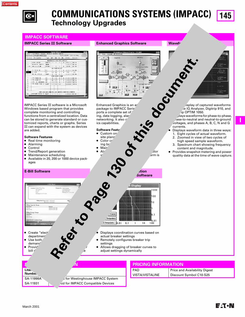
145
March 2001
I
COMMUNICATIONS SYSTEMS (IMPACC)Technology Upgrades
E-Bill Software
Waveform Display SoftwareEnhanced Graphics SoftwareIMPACC Series III Software
IMPACC SOFTWARE
IMPACC Series III software is a Microsoft Windows based program that provides complete monitoring and controlling functions from a centralized location. Data can be stored to generate standard or cus-tomized reports, charts or graphs. Series III can expand with the system as devices are added.
Software Features● Real time monitoring● Alarming● Control● Trend/Report generation● Maintenance scheduling● Available in 20, 200 or 1000 device pack-
ages
● Create “electric bills” for tenants or departments
● Use both energy consumption and demand to allocate bill amounts
● Provides trend data in .ODBC format for bill documentation and energy profile
Circuit Breaker Configurationand Trip Curve Display Software
● Displays coordination curves based on actual breaker settings
● Remotely configures breaker trip settings
● Allows dragging of breaker curves to adjust settings dynamically
Enhanced Graphics is an add-on software package to IMPACC Series III that sup-ports a complete set of functions – trend-ing, data logging, alarming, reporting and networking. It also offers powerful graph-ics capabilities.
Software Features● Custom one lines, elevation views and
site plans● Color coded one line symbols indicat-
ing breaker status or bus energized● Maintenance alarms● Alarm locator that shows the operator
where in the power system the alarm is occurring
● Allows display of captured waveforms from the IQ Analyzer, Digitrip 910, and Digitrip OPTIM 1050.
● Displays waveforms for phase-to-phase, phase-to-neutral and neutral-to-ground voltages, and phases A, B, C, N and G currents.
● Displays waveform data in three ways: 1. Eight cycles of actual waveform.2. Zoomed in view of two cycles of
high speed sample waveform.3. Spectrum chart showing frequency
content and magnitude.● Provides snapshot metering and power
quality data at the time of wave capture.
LiteratureNumber
Description
SA-11998A
SA-11931
Sales Aid for Westinghouse IMPACC System
Sales Aid for IMPACC Compatible Devices
FURTHER INFORMATION
PAD
VISTA/VISTALINE
Price and Availability Digest
Discount Symbol C10-S25
PRICING INFORMATION
Ref
er to P
age
130
of th
is d
ocu
men
t.
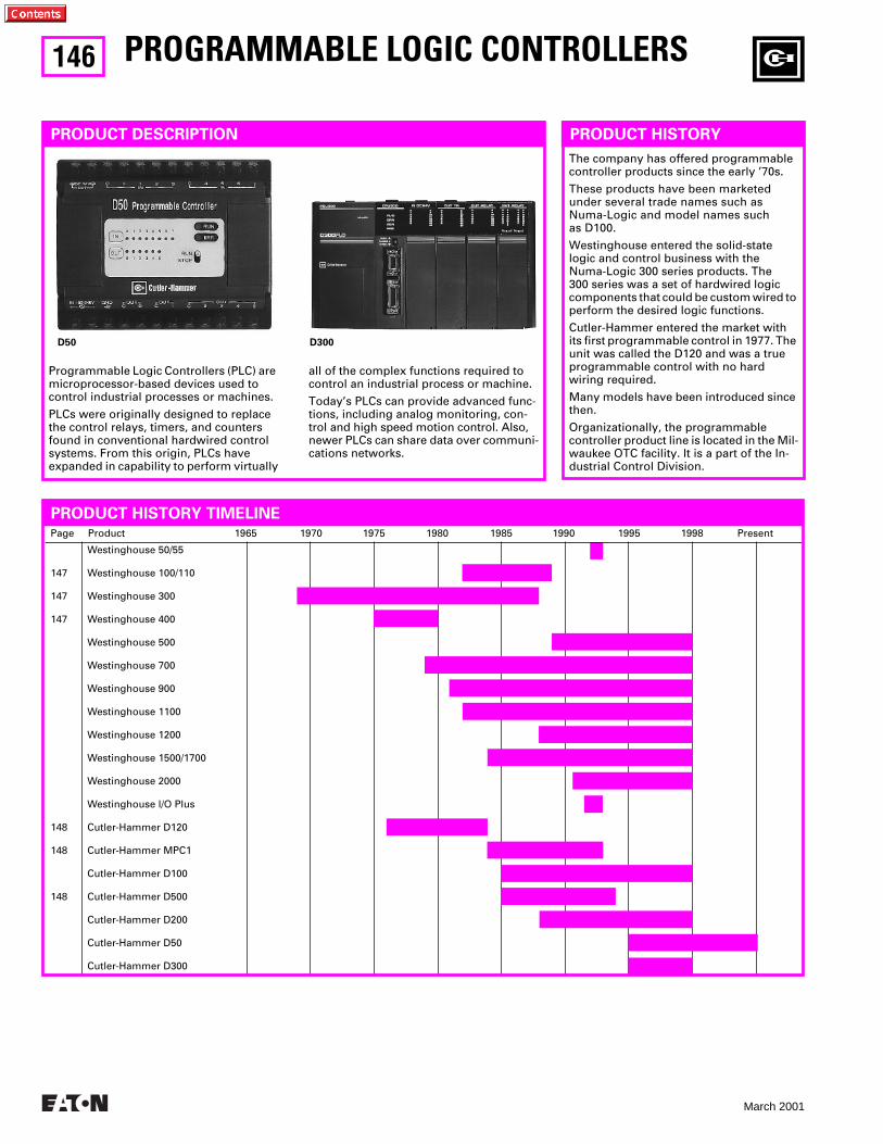
146
March 2001
Page Product 1965 1970 1975 1980 1985 1990 1995 1998 Present
147
147
147
148
148
148
Westinghouse 50/55
Westinghouse 100/110
Westinghouse 300
Westinghouse 400
Westinghouse 500
Westinghouse 700
Westinghouse 900
Westinghouse 1100
Westinghouse 1200
Westinghouse 1500/1700
Westinghouse 2000
Westinghouse l/O Plus
Cutler-Hammer D120
Cutler-Hammer MPC1
Cutler-Hammer D100
Cutler-Hammer D500
Cutler-Hammer D200
Cutler-Hammer D50
Cutler-Hammer D300
PROGRAMMABLE LOGIC CONTROLLERS
PRODUCT DESCRIPTION
PRODUCT HISTORY TIMELINE
Programmable Logic Controllers (PLC) are microprocessor-based devices used to control industrial processes or machines.
PLCs were originally designed to replace the control relays, timers, and counters found in conventional hardwired control systems. From this origin, PLCs have expanded in capability to perform virtually
all of the complex functions required to control an industrial process or machine.
Today’s PLCs can provide advanced func-tions, including analog monitoring, con-trol and high speed motion control. Also, newer PLCs can share data over communi-cations networks.
D50 D300
PRODUCT HISTORY
The company has offered programmable controller products since the early ’70s.
These products have been marketed under several trade names such as Numa-Logic and model names such as D100.
Westinghouse entered the solid-state logic and control business with the Numa-Logic 300 series products. The 300 series was a set of hardwired logic components that could be custom wired to perform the desired logic functions.
Cutler-Hammer entered the market with its first programmable control in 1977. The unit was called the D120 and was a true programmable control with no hard wiring required.
Many models have been introduced since then.
Organizationally, the programmable controller product line is located in the Mil-waukee OTC facility. It is a part of the In-dustrial Control Division.
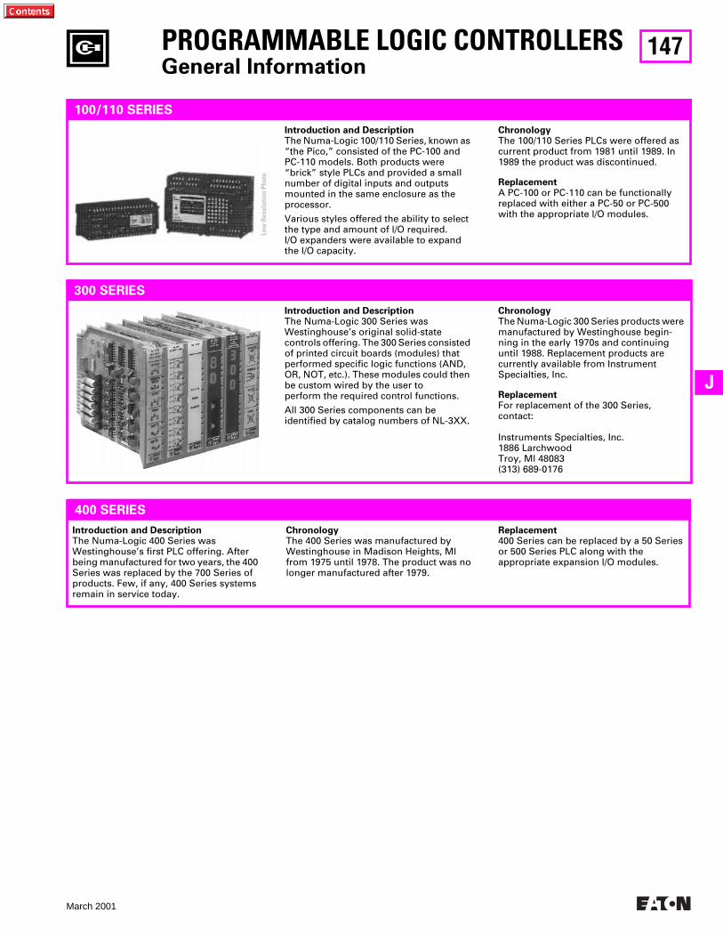
147
March 2001
J
PROGRAMMABLE LOGIC CONTROLLERS
General Information
100/110 SERIES
Introduction and Description
The Numa-Logic 100/110 Series, known as “the Pico,” consisted of the PC-100 and PC-110 models. Both products were “brick” style PLCs and provided a small number of digital inputs and outputs mounted in the same enclosure as the processor.
Various styles offered the ability to select the type and amount of l/O required. I/O expanders were available to expand the l/O capacity.
Chronology
The 100/110 Series PLCs were offered as current product from 1981 until 1989. In 1989 the product was discontinued.
Replacement
A PC-100 or PC-110 can be functionally replaced with either a PC-50 or PC-500 with the appropriate l/O modules.
300 SERIES
Introduction and Description
The Numa-Logic 300 Series wasWestinghouse’s original solid-state controls offering. The 300 Series consisted of printed circuit boards (modules) that performed specific logic functions (AND, OR, NOT, etc.). These modules could then be custom wired by the user to perform the required control functions.
All 300 Series components can be identified by catalog numbers of NL-3XX.
Chronology
The Numa-Logic 300 Series products were manufactured by Westinghouse begin-ning in the early 1970s and continuing until 1988. Replacement products are currently available from Instrument Specialties, Inc.
Replacement
For replacement of the 300 Series, contact:
Instruments Specialties, Inc.1886 LarchwoodTroy, Ml 48083(313) 689-0176
400 SERIES
Introduction and Description
The Numa-Logic 400 Series wasWestinghouse’s first PLC offering. After being manufactured for two years, the 400 Series was replaced by the 700 Series of products. Few, if any, 400 Series systems remain in service today.
Chronology
The 400 Series was manufactured by Westinghouse in Madison Heights, Ml from 1975 until 1978. The product was no longer manufactured after 1979.
Replacement
400 Series can be replaced by a 50 Series or 500 Series PLC along with the appropriate expansion l/O modules.
Low
Res
olut
ion
Phot
o
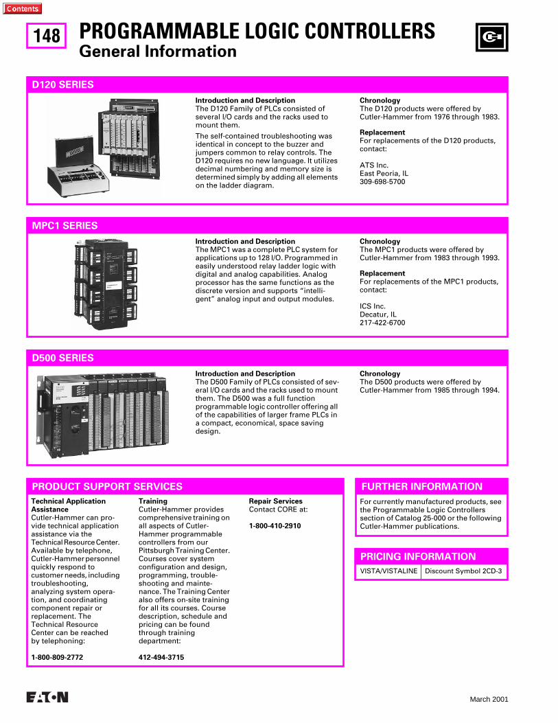
148
March 2001
For currently manufactured products, see the Programmable Logic Controllers section of Catalog 25-000 or the following Cutler-Hammer publications.
PROGRAMMABLE LOGIC CONTROLLERS
General Information
D120 SERIES
Introduction and Description
The D120 Family of PLCs consisted of several l/O cards and the racks used to mount them.
The self-contained troubleshooting was identical in concept to the buzzer and jumpers common to relay controls. The D120 requires no new language. It utilizes decimal numbering and memory size is determined simply by adding all elements on the ladder diagram.
Chronology
The D120 products were offered by Cutler-Hammer from 1976 through 1983.
Replacement
For replacements of the D120 products, contact:
ATS Inc.East Peoria, lL309-698-5700
MPC1 SERIES
Introduction and Description
The MPC1 was a complete PLC system for applications up to 128 I/O. Programmed in easily understood relay ladder logic with digital and analog capabilities. Analog processor has the same functions as the discrete version and supports “intelli-gent” analog input and output modules.
Chronology
The MPC1 products were offered byCutler-Hammer from 1983 through 1993.
Replacement
For replacements of the MPC1 products, contact:
ICS Inc.Decatur, lL217-422-6700
D500 SERIES
Introduction and Description
The D500 Family of PLCs consisted of sev-eral l/O cards and the racks used to mount them. The D500 was a full function programmable logic controller offering all of the capabilities of larger frame PLCs in a compact, economical, space saving design.
Chronology
The D500 products were offered by Cutler-Hammer from 1985 through 1994.
PRODUCT SUPPORT SERVICES
Technical ApplicationAssistance
Cutler-Hammer can pro-vide technical application assistance via the Technical Resource Center. Available by telephone, Cutler-Hammer personnel quickly respond to customer needs, including troubleshooting, analyzing system opera-tion, and coordinating component repair or replacement. The Technical Resource Center can be reached by telephoning:
1-800-809-2772
Training
Cutler-Hammer provides comprehensive training on all aspects of Cutler-Hammer programmable controllers from our Pittsburgh Training Center. Courses cover system configuration and design, programming, trouble-shooting and mainte-nance. The Training Center also offers on-site training for all its courses. Course description, schedule and pricing can be found through training department:
412-494-3715
Repair Services
Contact CORE at:
1-800-410-2910
FURTHER INFORMATION
VISTA/VISTALINE Discount Symbol 2CD-3
PRICING INFORMATION
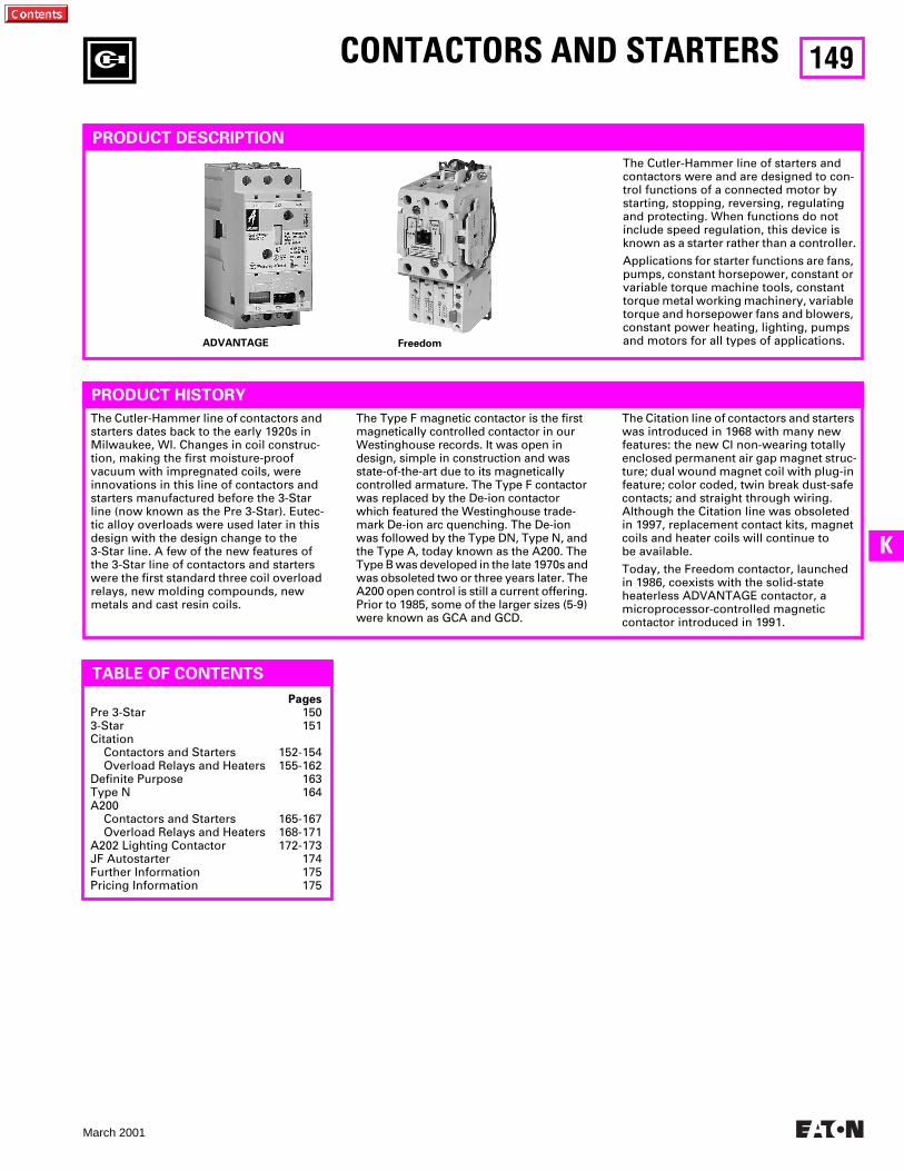
149
March 2001
K
CONTACTORS AND STARTERS
PRODUCT DESCRIPTION
The Cutler-Hammer line of contactors and starters dates back to the early 1920s in Milwaukee, WI. Changes in coil construc-tion, making the first moisture-proof vacuum with impregnated coils, were innovations in this line of contactors and starters manufactured before the 3-Star line (now known as the Pre 3-Star). Eutec-tic alloy overloads were used later in this design with the design change to the 3-Star line. A few of the new features of the 3-Star line of contactors and starters were the first standard three coil overload relays, new molding compounds, new metals and cast resin coils.
PRODUCT HISTORY
The Type F magnetic contactor is the first magnetically controlled contactor in our Westinghouse records. It was open in design, simple in construction and was state-of-the-art due to its magnetically controlled armature. The Type F contactor was replaced by the De-ion contactor which featured the Westinghouse trade-mark De-ion arc quenching. The De-ion was followed by the Type DN, Type N, and the Type A, today known as the A200. The Type B was developed in the late 1970s and was obsoleted two or three years later. The A200 open control is still a current offering. Prior to 1985, some of the larger sizes (5-9) were known as GCA and GCD.
TABLE OF CONTENTS
ADVANTAGE Freedom
Pages
Pre 3-Star 1503-Star 151Citation
Contactors and Starters 152-154Overload Relays and Heaters 155-162
Definite Purpose 163Type N 164A200
Contactors and Starters 165-167Overload Relays and Heaters 168-171
A202 Lighting Contactor 172-173JF Autostarter 174Further Information 175Pricing Information 175
The Cutler-Hammer line of starters and contactors were and are designed to con-trol functions of a connected motor by starting, stopping, reversing, regulating and protecting. When functions do not include speed regulation, this device is known as a starter rather than a controller.
Applications for starter functions are fans, pumps, constant horsepower, constant or variable torque machine tools, constant torque metal working machinery, variable torque and horsepower fans and blowers, constant power heating, lighting, pumps and motors for all types of applications.
The Citation line of contactors and starters was introduced in 1968 with many new features: the new CI non-wearing totally enclosed permanent air gap magnet struc-ture; dual wound magnet coil with plug-in feature; color coded, twin break dust-safe contacts; and straight through wiring. Although the Citation line was obsoleted in 1997, replacement contact kits, magnet coils and heater coils will continue to be available.
Today, the Freedom contactor, launched in 1986, coexists with the solid-state heaterless ADVANTAGE contactor, a microprocessor-controlled magnetic contactor introduced in 1991.
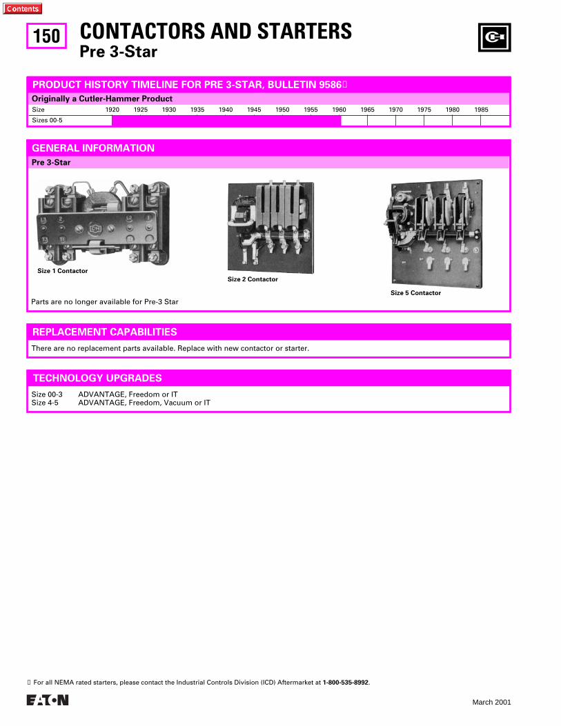
150
March 2001
Pre 3-Star
Size 1920 1925 1930 1935 1940 1945 1950 1955 1960 1965 1970 1975 1980 1985
Sizes 00-5
Originally a Cutler-Hammer Product
CONTACTORS AND STARTERS
Pre 3-Star
GENERAL INFORMATION
Size 2 Contactor
Size 1 Contactor
Size 5 Contactor
Parts are no longer available for Pre-3 Star
PRODUCT HISTORY TIMELINE FOR PRE 3-STAR, BULLETIN 9586
➊
REPLACEMENT CAPABILITIES
There are no replacement parts available. Replace with new contactor or starter.
TECHNOLOGY UPGRADES
Size 00-3 ADVANTAGE, Freedom or ITSize 4-5 ADVANTAGE, Freedom, Vacuum or IT
➊
For all NEMA rated starters, please contact the Industrial Controls Division (ICD) Aftermarket at
1-800-535-8992
.
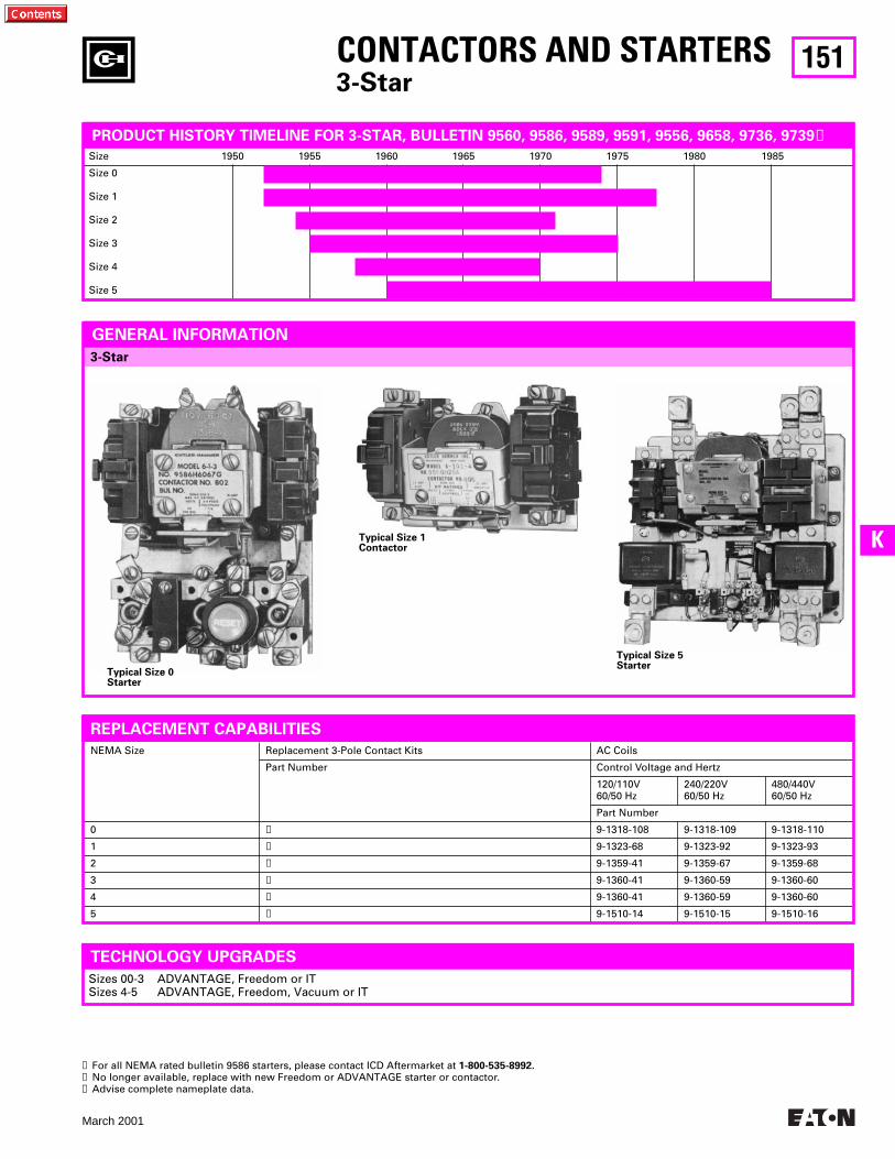
151
March 2001
K
Size 1950 1955 1960 1965 1970 1975 1980 1985
Size 0
Size 1
Size 2
Size 3
Size 4
Size 5
CONTACTORS AND STARTERS
3-Star
3-Star
Typical Size 1Contactor
Typical Size 5Starter
3-Star
GENERAL INFORMATION
Typical Size 0Starter
TECHNOLOGY UPGRADES
Sizes 00-3 ADVANTAGE, Freedom or ITSizes 4-5 ADVANTAGE, Freedom, Vacuum or IT
➊
For all NEMA rated bulletin 9586 starters, please contact ICD Aftermarket at
1-800-535-8992.
➋
No longer available, replace with new Freedom or ADVANTAGE starter or contactor.
➌
Advise complete nameplate data.
PRODUCT HISTORY TIMELINE FOR 3-STAR, BULLETIN 9560, 9586, 9589, 9591, 9556, 9658, 9736, 9739
➊
Typical Size 0Starter
NEMA Size Replacement 3-Pole Contact Kits AC Coils
Part Number Control Voltage and Hertz
120/110V60/50 Hz
240/220V60/50 Hz
480/440V60/50 Hz
Part Number
0
➋
9-1318-108 9-1318-109 9-1318-110
1
➋
9-1323-68 9-1323-92 9-1323-93
2
➋
9-1359-41 9-1359-67 9-1359-68
3
➋
9-1360-41 9-1360-59 9-1360-60
4
➋
9-1360-41 9-1360-59 9-1360-60
5
➌
9-1510-14 9-1510-15 9-1510-16
REPLACEMENT CAPABILITIES
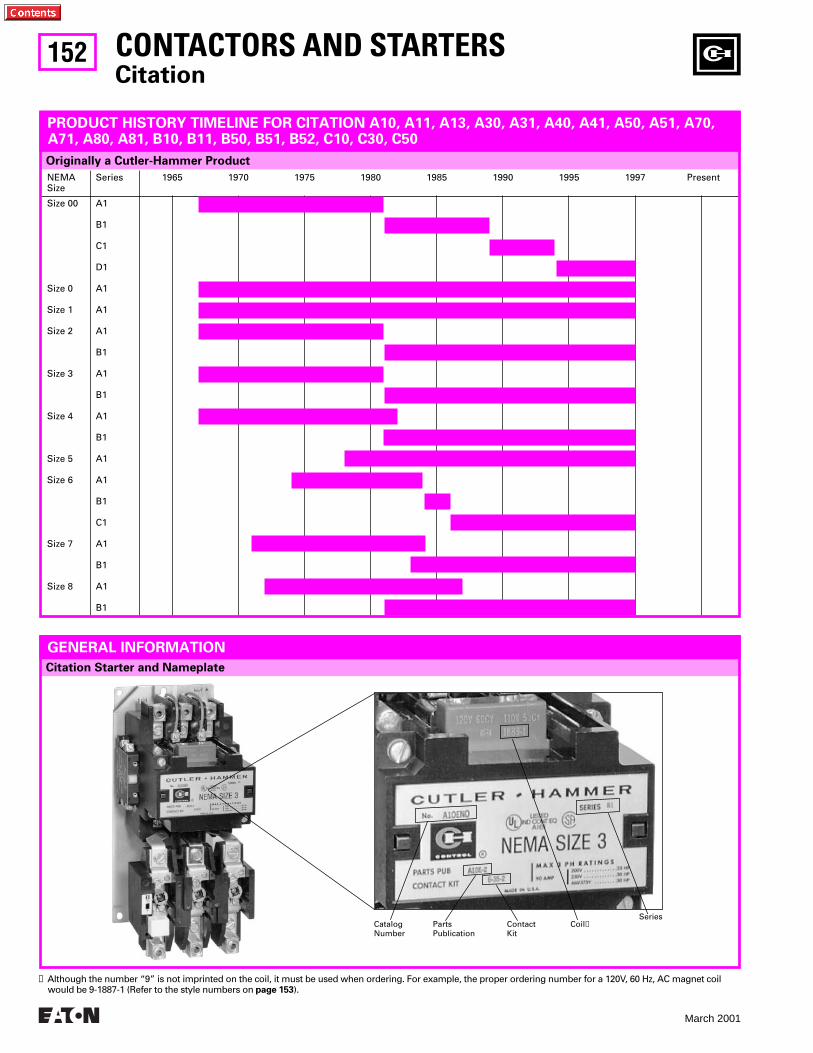
152
March 2001
Citation Starter and Nameplate
NEMASize
Series 1965 1970 1975 1980 1985 1990 1995 1997 Present
Size 00
Size 0
Size 1
Size 2
Size 3
Size 4
Size 5
Size 6
Size 7
Size 8
A1
B1
C1
D1
A1
A1
A1
B1
A1
B1
A1
B1
A1
A1
B1
C1
A1
B1
A1
B1
CONTACTORS AND STARTERS
Citation
Originally a Cutler-Hammer Product
PRODUCT HISTORY TIMELINE FOR CITATION A10, A11, A13, A30, A31, A40, A41, A50, A51, A70, A71, A80, A81, B10, B11, B50, B51, B52, C10, C30, C50
Catalog Number
Parts Publication
SeriesCoil
➊
Contact Kit
GENERAL INFORMATION
➊
Although the number “9” is not imprinted on the coil, it must be used when ordering. For example, the proper ordering number for a 120V, 60 Hz, AC magnet coil would be 9-1887-1 (Refer to the style numbers on
page 153
).

153
March 2001
K
Description Size 4 Size 5 Size 6 Size 7 Size 8
Series A1 Series B1 Series A1 Series B1 Series C1 Series A1 Series B1 Series A1 Series B1
Style and
Part
Numbers
Style and
Part
Numbers
Style and
Part
Numbers
Style and
Part
Numbers
Style and
Part
Numbers
Style and
Part
Numbers
Style and
Part
Numbers
Style and
Part
Numbers
Style and
Part
Numbers
Style and
Part
Numbers
CONTACT KITS
Part No. on Contactor or Starter Name Plate2-Pole without Interlock3-Pole without Interlock3-Pole with Interlock4-Pole without Interlock5-Pole without Interlock
6-266-26-2. . . . . .. . . . . .. . . . . .
6-36-36-36-4. . . . . .. . . . . .. . . . . .
6-276-27-2. . . . . .. . . . . .. . . . . .
6-286-28-2. . . . . .. . . . . .. . . . . .
. . . . . .6-570. . . . . .. . . . . .. . . . . .
6-601-26-601. . . . . .. . . . . .. . . . . .
6-286-28-2. . . . . .. . . . . .. . . . . .
. . . . . .6-570. . . . . .. . . . . .. . . . . .
. . . . . .646C829G05. . . . . .. . . . . .. . . . . .
. . . . . .6-571. . . . . .. . . . . .. . . . . .
MAGNET COILS
120V 60 Hz or 110V 50 Hz240V 60 Hz or 220V 50 Hz480V 60 Hz or 440V 50 Hz600V 60 Hz or 550V 50 Hz208V 60 Hz
24V 60 Hz380V 50 Hz120/240V 60 Hz or 110/220V 50 Hz240/480V 60 Hz or 220/440V 50 Hz277V 60 Hz
120V DC
➍
240V DC
➍
24V DC
➍
48V DC
➍
CoilSuffix
ABCDE
TLFGH
A1B1T1W1
9-1891-19-1891-29-1891-39-1891-49-1891-13
9-1891-159-1891-149-1892-19-1892-29-1891-26
9-2026-29-2026-19-2026-49-2026-3
9-1891-19-1891-29-1891-39-1891-49-1891-13
9-1891-159-1891-149-1892-19-1892-29-1891-26
9-2026-29-2026-19-2026-49-2026-3
9-1891-19-1891-29-1891-39-1891-49-1891-13
9-1891-159-1891-149-1892-19-1892-29-1891-26
9-2026-29-2026-19-2026-49-2026-3
9-1875-19-1875-29-1875-39-1875-49-1875-14
. . . . . . . .9-1875-19. . . . . . . .. . . . . . . .. . . . . . . .
. . . . . . . .
. . . . . . . .
. . . . . . . .
. . . . . . . .
9-26519-2651-29-2651-39-2651-49-2651-6
. . . . . . . .9-2651-5. . . . . . . .. . . . . . . .. . . . . . . .
. . . . . . . .
. . . . . . . .
. . . . . . . .
. . . . . . . .
9-26989-2698-29-2698-39-2698-49-2698-5
. . . . . . . .9-2698-6. . . . . . . .. . . . . . . .. . . . . . . .
. . . . . . . .
. . . . . . . .
. . . . . . . .
. . . . . . . .
9-1875-19-1875-29-1875-39-1875-49-1875-14
. . . . . . . .9-1875-19. . . . . . . .. . . . . . . .. . . . . . . .
. . . . . . . .
. . . . . . . .
. . . . . . . .
. . . . . . . .
9-26519-2651-29-2651-39-2651-49-2651-6
. . . . . . . .9-2651-5. . . . . . . .. . . . . . . .. . . . . . . .
. . . . . . . .
. . . . . . . .
. . . . . . . .
. . . . . . . .
438C805G12438C805G11438C805G10. . . . . . . . . . . .438C805G11
. . . . . . . . . . . .438C805G15. . . . . . . . . . . .. . . . . . . . . . . .. . . . . . . . . . . .
. . . . . . . . . . . .
. . . . . . . . . . . .
. . . . . . . . . . . .
. . . . . . . . . . . .
9-26549-2654-29-2654-39-2654-49-2654-6
. . . . . . . .9-2654-5. . . . . . . .. . . . . . . .. . . . . . . .
. . . . . . . .
. . . . . . . .
. . . . . . . .
. . . . . . . .
Description Size 00 Size 0 Size 1 Size 2 Size 3
Series A1
➊
Series B1 Series C1 Series D1 Series A1 Series B1 Series A1 Series B1
Style and
Part
Numbers
Style and
Part
Numbers
Style and
Part
Numbers
Style and
Part
Numbers
Style and
Part
Numbers
Style and
Part
Numbers
Style and
Part
Numbers
Style and
Part
Numbers
Style and
Part
Numbers
Style and
Part
Numbers
CONTACT KITS
Part No. on Contactor or Starter Name Plate2-Pole without Interlock3-Pole without Interlock3-Pole with Interlock4-Pole without Interlock5-Pole without Interlock
6-216-21-26-21-3. . . . . .. . . . . .
➋➋➋
. . .
. . .
➋➋➋
. . .
. . .
➋➋
. . .
. . .
6-226-22-2. . . . . .6-22-36-22-4
6-236-23-2. . . . . .6-23-36-23-4
6-246-24-2. . . . . .. . . . . .. . . . . .
6-346-34-2. . . . . .6-34-36-34-4
6-256-25-2. . . . . .. . . . . .. . . . . .
6-356-35-2. . . . . .. . . . . .. . . . . .
MAGNET COILS
120V 60 Hz or 110V 50 Hz240V 60 Hz or 220V 50 Hz480V 60 Hz or 440V 50 Hz600V 60 Hz or 550V 50 Hz208V 60 Hz
24V 60 Hz380V 50 Hz120/240V 60 Hz or 110/220V 50 Hz240/480V 60 Hz or 220/440V 50 Hz277V 60 Hz
120V DC
➍
240V DC
➍
24V DC
➍
48V DC
➍
Coil Suffix
ABCDE
TLFGH
A1B1T1W1
9-1945-19-1945-29-1945-39-1945-49-1945-5
9-1945-89-1945-6. . . . . . . .. . . . . . . .9-1945-16
. . . . . . . .
. . . . . . . .
. . . . . . . .
. . . . . . . .
9-2183-19-2183-29-2183-59-2183-199-2183-17
9-2183-169-2183-3. . . . . . . .. . . . . . . .9-2183-18
. . . . . . . .
. . . . . . . .
. . . . . . . .
. . . . . . . .
9-2650-19-2650-29-2650-39-2650-49-2650-5
9-2650-79-2650-6. . . . . . . .. . . . . . . .9-2650-13
. . . . . . . .
. . . . . . . .
. . . . . . . .
. . . . . . . .
9-2823-19-2823-29-2823-39-2823-49-2823-5
9-2823-189-2421-18
➌
. . . . . . . .
. . . . . . . .9-2823-129-2823-17. . . . . . . .. . . . . . . .. . . . . . . .. . . . . . . .
9-1887-19-1887-29-1887-39-1887-49-1887-5
9-1887-79-1887-89-1888-19-1888-29-1887-16
9-2024-29-2024-19-2024-49-2024-3
9-1887-19-1887-29-1887-39-1887-49-1887-5
9-1887-79-1887-89-1888-19-1888-29-1887-16
9-2024-29-2024-19-2024-49-2024-3
9-1889-19-1889-29-1889-39-1889-49-1889-13
9-1889-209-1889-149-1890-19-1890-29-1889-31
9-2025-29-2025-19-2025-49-2025-3
9-2526-19-2526-29-2526-39-2526-49-2526-5
9-2526-69-2526-79-2527-19-2527-29-2526-15
9-2626-29-2626-19-2626-49-2626-3
9-1891-19-1891-29-1891-39-1891-49-1891-13
9-1891-159-1891-149-1892-19-1892-29-1891-26
9-2026-29-2026-19-2026-49-2026-3
9-1889-19-1889-29-1889-39-1889-49-1889-13
9-1889-209-1889-149-1890-19-1890-29-1889-31
9-2025-29-2025-19-2025-49-2025-3
Contacts and Coils
REPLACEMENT CAPABILITIES
CONTACTORS AND STARTERS
Citation
➊
For non-reversing contactors and starters only.
➋
Replace complete contactor.
➌
Non-encapsulated coil.
➍
For use in existing DC operated devices. Not for conversion of existing AC operated devices to DC.
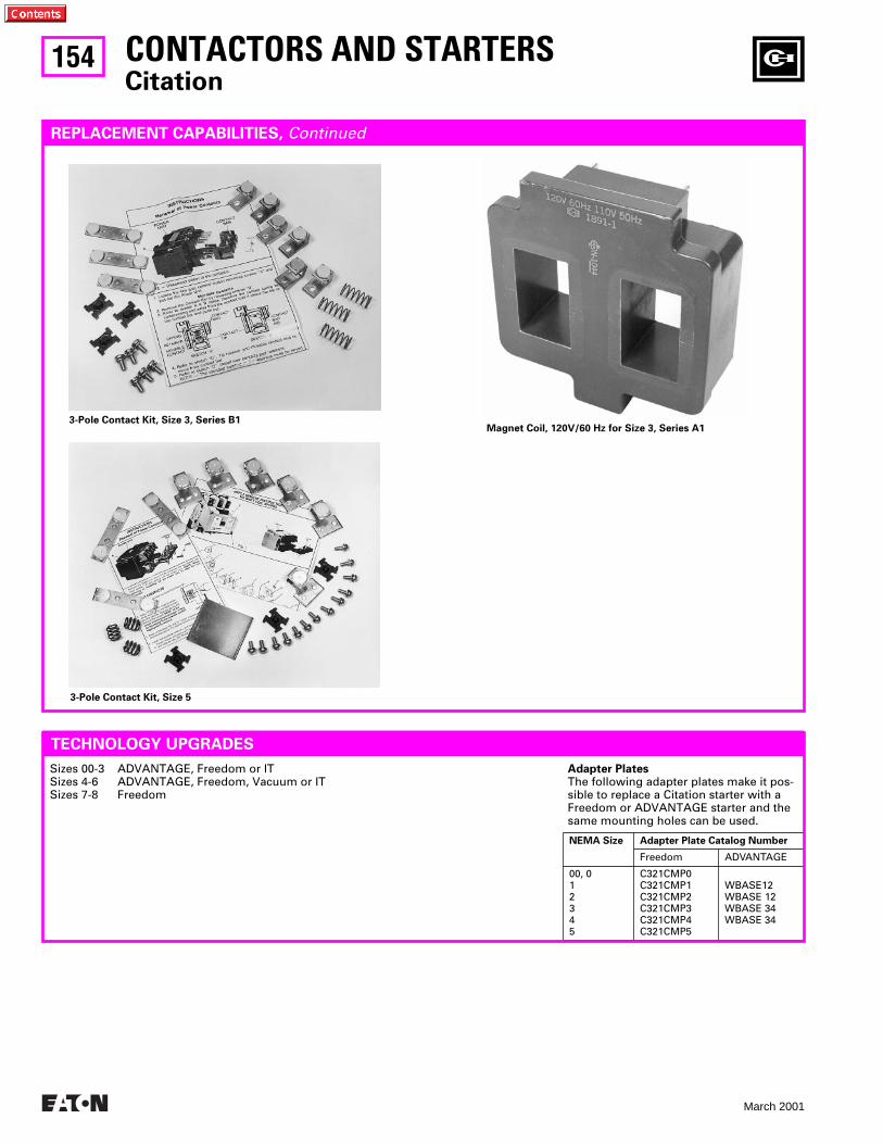
154
March 2001
Adapter Plates
The following adapter plates make it pos-sible to replace a Citation starter with a Freedom or ADVANTAGE starter and the same mounting holes can be used.
NEMA Size Adapter Plate Catalog Number
Freedom ADVANTAGE
00, 012345
C321CMP0C321CMP1C321CMP2C321CMP3C321CMP4C321CMP5
WBASE12WBASE 12WBASE 34WBASE 34
CONTACTORS AND STARTERS
Citation
3-Pole Contact Kit, Size 3, Series B1Magnet Coil, 120V/60 Hz for Size 3, Series A1
TECHNOLOGY UPGRADES
Sizes 00-3 ADVANTAGE, Freedom or ITSizes 4-6 ADVANTAGE, Freedom, Vacuum or ITSizes 7-8 Freedom
REPLACEMENT CAPABILITIES,
Continued
3-Pole Contact Kit, Size 5
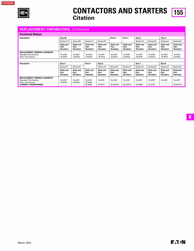
155
March 2001
K
Description Size 00 Size 0 Size 1 Size 2 Size 3
Series A1
➊
Series B1 Series C1 Series D1 Series A1 Series B1 Series A1 Series B1
Style and
Part
Numbers
Style and
Part
Numbers
Style and
Part
Numbers
Style and
Part
Numbers
Style and
Part
Numbers
Style and
Part
Numbers
Style and
Part
Numbers
Style and
Part
Numbers
Style and
Part
Numbers
Style and
Part
Numbers
REPLACEMENT THERMAL ELEMENTS
Standard Trip EutecticSlow Trip Eutectic
10-476710-5018
10-476710-5018
10-476710-5018
10-476710-5018
10-476710-5018
10-476710-5018
10-476710-5018
10-476710-5018
10-476710-5018
10-476710-5018
Overload Relays
Description Size 4 Size 5 Size 6 Size 7 Size 8
Series A1 Series B1 Series A1 Series B1 Series C1 Series A1 Series B1 Series A1 Series B1
Style and
Part
Numbers
Style and
Part
Numbers
Style and
Part
Numbers
Style and
Part
Numbers
Style and
Part
Numbers
Style and
Part
Numbers
Style and
Part
Numbers
Style and
Part
Numbers
Style and
Part
Numbers
Style and
Part
Numbers
REPLACEMENT THERMAL ELEMENTS
Standard Trip EutecticSlow Trip Eutectic
CURRENT TRANSFORMER
10-476710-5018. . . . . . . . .
10-476710-5018. . . . . . . . .
10-476710-501842-2807
10-4767. . . . . . . . . 9-1914-1
10-4767. . . . . . . . .42-3418-3
10-4767. . . . . . . . .42-3418-3
10-4767. . . . . . . . .42-2648
10-4767. . . . . . . . .42-3418
10-4767. . . . . . . . .. . . . . . . . .
10-4767. . . . . . . . . .42-3418-2
CONTACTORS AND STARTERS
Citation
REPLACEMENT CAPABILITIES,
Continued
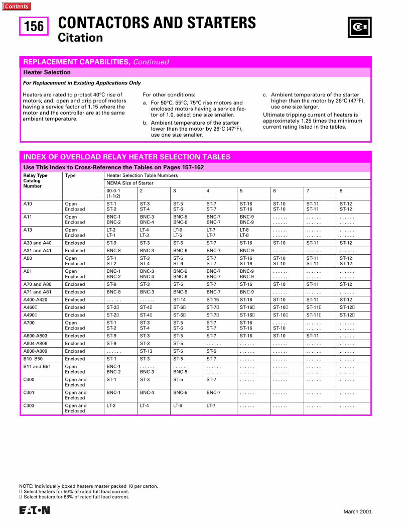
156
March 2001
Heater Selection
Relay TypeCatalog Number
Type Heater Selection Table Numbers
NEMA Size of Starter
00-0-1(1-1/2)
2 3 4 5 6 7 8
A10 OpenEnclosed
ST-1ST-2
ST-3ST-4
ST-5ST-6
ST-7ST-7
ST-16ST-16
ST-10ST-10
ST-11ST-11
ST-12ST-12
A11 OpenEnclosed
BNC-1BNC-2
BNC-3BNC-4
BNC-5BNC-6
BNC-7BNC-7
BNC-9BNC-9
. . . . . .
. . . . . .. . . . . .. . . . . .
. . . . . .
. . . . . .
A13 OpenEnclosed
LT-2LT-1
LT-4LT-3
LT-6LT-5
LT-7LT-7
LT-8LT-8
. . . . . .
. . . . . .. . . . . .. . . . . .
. . . . . .
. . . . . .
A30 and A40 Enclosed ST-9 ST-3 ST-6 ST-7 ST-16 ST-10 ST-11 ST-12
A31 and A41 Enclosed BNC-8 BNC-3 BNC-6 BNC-7 BNC-9 . . . . . . . . . . . . . . . . . .
A50 OpenEnclosed
ST-1ST-2
ST-3ST-4
ST-5ST-6
ST-7ST-7
ST-16ST-16
ST-10ST-10
ST-11ST-11
ST-12ST-12
A51 OpenEnclosed
BNC-1BNC-2
BNC-3BNC-4
BNC-5BNC-6
BNC-7BNC-7
BNC-9BNC-9
. . . . . .
. . . . . .. . . . . .. . . . . .
. . . . . .
. . . . . .
A70 and A80 Enclosed ST-9 ST-3 ST-6 ST-7 ST-16 ST-10 ST-11 ST-12
A71 and A81 Enclosed BNC-8 BNC-3 BNC-5 BNC-7 BNC-9 . . . . . . . . . . . . . . . . . .
A400-A420 Enclosed . . . . . . . . . . . . ST-14 ST-15 ST-16 ST-10 ST-11 ST-12
A460
➊
Enclosed ST-2
➊
ST-4
➊
ST-6
➊
ST-7
➊
ST-16
➊
ST-10
➊
ST-11
➊
ST-12
➊
A490
➋
Enclosed ST-2
➋
ST-4
➋
ST-6
➋
ST-7
➋
ST-16
➋
ST-10
➋
ST-11
➋
ST-12
➋
A700 OpenEnclosed
ST-1ST-2
ST-3ST-4
ST-5ST-6
ST-7ST-7
ST-16ST-16
. . . . . .ST-10
. . . . . .
. . . . . .. . . . . .. . . . . .
A800-A803 Enclosed ST-9 ST-3 ST-5 ST-7 ST-16 ST-10 ST-11 . . . . . .
A804-A806 Enclosed ST-9 ST-3 ST-5 . . . . . . . . . . . . . . . . . . . . . . . . . . . . . .
A808-A809 Enclosed . . . . . . ST-13 ST-5 ST-5 . . . . . . . . . . . . . . . . . . . . . . . .
B10 B50 Enclosed ST-1 ST-3 ST-5 ST-7 . . . . . . . . . . . . . . . . . . . . . . . .
B11 and B51 OpenEnclosed
BNC-1BNC-2
. . . . . .BNC-3
. . . . . .BNC-5
. . . . . .
. . . . . .. . . . . .. . . . . .
. . . . . .
. . . . . .. . . . . .. . . . . .
. . . . . .
. . . . . .
C300 Open and Enclosed
ST-1 ST-3 ST-5 ST-7 . . . . . . . . . . . . . . . . . . . . . . . .
C301 Open and Enclosed
BNC-1 BNC-4 BNC-5 BNC-7 . . . . . . . . . . . . . . . . . . . . . . . .
C303 Open and Enclosed
LT-2 LT-4 LT-6 LT-7 . . . . . . . . . . . . . . . . . . . . . . . .
CONTACTORS AND STARTERS
Citation
Use This Index to Cross-Reference the Tables on Pages 157-162
REPLACEMENT CAPABILITIES,
Continued
Heaters are rated to protect 40°C rise of motors; and, open and drip proof motors having a service factor of 1.15 where the motor and the controller are at the same ambient temperature.
For Replacement in Existing Applications Only
For other conditions:
a. For 50°C, 55°C, 75°C rise motors and enclosed motors having a service fac-tor of 1.0, select one size smaller.
b. Ambient temperature of the starter lower than the motor by 26°C (47°F), use one size smaller.
c. Ambient temperature of the starter higher than the motor by 26°C (47°F), use one size larger.
Ultimate tripping current of heaters is approximately 1.25 times the minimum current rating listed in the tables.
INDEX OF OVERLOAD RELAY HEATER SELECTION TABLES
NOTE: Individually boxed heaters master packed 10 per carton.
➊
Select heaters for 50% of rated full load current.
➋
Select heaters for 68% of rated full load current.
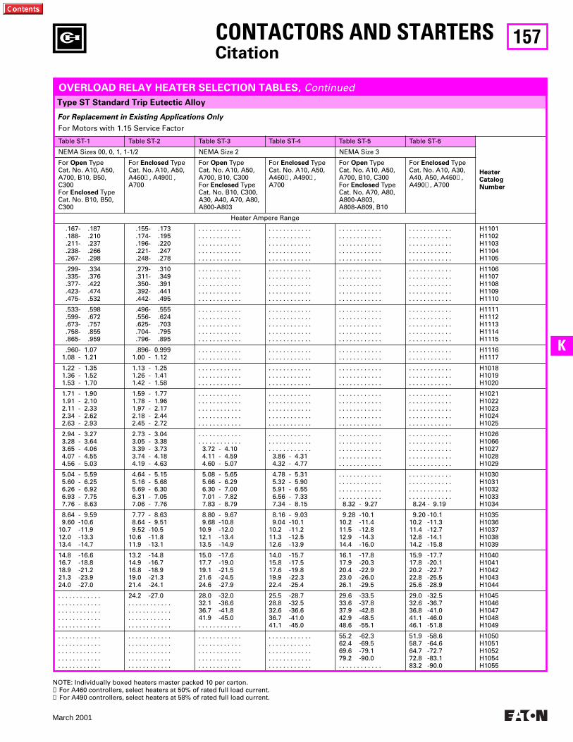
157
March 2001
K
Type ST Standard Trip Eutectic Alloy
CONTACTORS AND STARTERS
Citation
For Replacement in Existing Applications Only
OVERLOAD RELAY HEATER SELECTION TABLES,
Continued
For Motors with 1.15 Service Factor
Table ST-1 Table ST-2 Table ST-3 Table ST-4 Table ST-5 Table ST-6
Heater Catalog Number
NEMA Sizes 00, 0, 1, 1-1/2 NEMA Size 2 NEMA Size 3
For
Open
Type Cat. No. A10, A50, A700, B10, B50, C300For
Enclosed
TypeCat. No. B10, B50, C300
For
Enclosed
TypeCat. No. A10, A50, A460
➊
, A490
➋
, A700
For
Open
Type Cat. No. A10, A50, A700, B10, C300For
Enclosed
TypeCat. No. B10, C300, A30, A40, A70, A80, A800-A803
For Enclosed TypeCat. No. A10, A50, A460➊, A490➋, A700
For Open Type Cat. No. A10, A50, A700, B10, C300For Enclosed TypeCat. No. A70, A80, A800-A803, A808-A809, B10
For Enclosed TypeCat. No. A10, A30, A40, A50, A460➊, A490➋, A700
Heater Ampere Range
.167- .187 .188- .210 .211- .237 .238- .266 .267- .298
.155- .173 .174- .195 .196- .220 .221- .247 .248- .278
. . . . . . . . . . . .
. . . . . . . . . . . .
. . . . . . . . . . . .
. . . . . . . . . . . .
. . . . . . . . . . . .
. . . . . . . . . . . .
. . . . . . . . . . . .
. . . . . . . . . . . .
. . . . . . . . . . . .
. . . . . . . . . . . .
. . . . . . . . . . . .
. . . . . . . . . . . .
. . . . . . . . . . . .
. . . . . . . . . . . .
. . . . . . . . . . . .
. . . . . . . . . . . .
. . . . . . . . . . . .
. . . . . . . . . . . .
. . . . . . . . . . . .
. . . . . . . . . . . .
H1101H1102H1103H1104H1105
.299- .334 .335- .376 .377- .422 .423- .474 .475- .532
.279- .310 .311- .349 .350- .391 .392- .441 .442- .495
. . . . . . . . . . . .
. . . . . . . . . . . .
. . . . . . . . . . . .
. . . . . . . . . . . .
. . . . . . . . . . . .
. . . . . . . . . . . .
. . . . . . . . . . . .
. . . . . . . . . . . .
. . . . . . . . . . . .
. . . . . . . . . . . .
. . . . . . . . . . . .
. . . . . . . . . . . .
. . . . . . . . . . . .
. . . . . . . . . . . .
. . . . . . . . . . . .
. . . . . . . . . . . .
. . . . . . . . . . . .
. . . . . . . . . . . .
. . . . . . . . . . . .
. . . . . . . . . . . .
H1106H1107H1108H1109H1110
.533- .598 .599- .672 .673- .757 .758- .855 .865- .959
.496- .555 .556- .624 .625- .703 .704- .795 .796- .895
. . . . . . . . . . . .
. . . . . . . . . . . .
. . . . . . . . . . . .
. . . . . . . . . . . .
. . . . . . . . . . . .
. . . . . . . . . . . .
. . . . . . . . . . . .
. . . . . . . . . . . .
. . . . . . . . . . . .
. . . . . . . . . . . .
. . . . . . . . . . . .
. . . . . . . . . . . .
. . . . . . . . . . . .
. . . . . . . . . . . .
. . . . . . . . . . . .
. . . . . . . . . . . .
. . . . . . . . . . . .
. . . . . . . . . . . .
. . . . . . . . . . . .
. . . . . . . . . . . .
H1111H1112H1113H1114H1115
.960- 1.07 1.08 - 1.21
.896- 0.999 1.00 - 1.12
. . . . . . . . . . . .
. . . . . . . . . . . .. . . . . . . . . . . .. . . . . . . . . . . .
. . . . . . . . . . . .
. . . . . . . . . . . .. . . . . . . . . . . .. . . . . . . . . . . .
H1116H1117
1.22 - 1.35 1.36 - 1.52 1.53 - 1.70
1.13 - 1.25 1.26 - 1.41 1.42 - 1.58
. . . . . . . . . . . .
. . . . . . . . . . . .
. . . . . . . . . . . .
. . . . . . . . . . . .
. . . . . . . . . . . .
. . . . . . . . . . . .
. . . . . . . . . . . .
. . . . . . . . . . . .
. . . . . . . . . . . .
. . . . . . . . . . . .
. . . . . . . . . . . .
. . . . . . . . . . . .
H1018H1019H1020
1.71 - 1.90 1.91 - 2.10 2.11 - 2.33 2.34 - 2.62 2.63 - 2.93
1.59 - 1.77 1.78 - 1.96 1.97 - 2.17 2.18 - 2.44 2.45 - 2.72
. . . . . . . . . . . .
. . . . . . . . . . . .
. . . . . . . . . . . .
. . . . . . . . . . . .
. . . . . . . . . . . .
. . . . . . . . . . . .
. . . . . . . . . . . .
. . . . . . . . . . . .
. . . . . . . . . . . .
. . . . . . . . . . . .
. . . . . . . . . . . .
. . . . . . . . . . . .
. . . . . . . . . . . .
. . . . . . . . . . . .
. . . . . . . . . . . .
. . . . . . . . . . . .
. . . . . . . . . . . .
. . . . . . . . . . . .
. . . . . . . . . . . .
. . . . . . . . . . . .
H1021H1022H1023H1024H1025
2.94 - 3.27 3.28 - 3.64 3.65 - 4.06 4.07 - 4.55 4.56 - 5.03
2.73 - 3.04 3.05 - 3.38 3.39 - 3.73 3.74 - 4.18 4.19 - 4.63
. . . . . . . . . . . .
. . . . . . . . . . . . 3.72 - 4.10 4.11 - 4.59 4.60 - 5.07
. . . . . . . . . . . .
. . . . . . . . . . . .
. . . . . . . . . . . . 3.86 - 4.31 4.32 - 4.77
. . . . . . . . . . . .
. . . . . . . . . . . .
. . . . . . . . . . . .
. . . . . . . . . . . .
. . . . . . . . . . . .
. . . . . . . . . . . .
. . . . . . . . . . . .
. . . . . . . . . . . .
. . . . . . . . . . . .
. . . . . . . . . . . .
H1026H1066H1027H1028H1029
5.04 - 5.59 5.60 - 6.25 6.26 - 6.92 6.93 - 7.75 7.76 - 8.63
4.64 - 5.15 5.16 - 5.68 5.69 - 6.30 6.31 - 7.05 7.06 - 7.76
5.08 - 5.65 5.66 - 6.29 6.30 - 7.00 7.01 - 7.82 7.83 - 8.79
4.78 - 5.31 5.32 - 5.90 5.91 - 6.55 6.56 - 7.33 7.34 - 8.15
. . . . . . . . . . . .
. . . . . . . . . . . .
. . . . . . . . . . . .
. . . . . . . . . . . . 8.32 - 9.27
. . . . . . . . . . . .
. . . . . . . . . . . .
. . . . . . . . . . . .
. . . . . . . . . . . . 8.24 - 9.19
H1030H1031H1032H1033H1034
8.64 - 9.59 9.60 -10.610.7 -11.912.0 -13.313.4 -14.7
7.77 - 8.63 8.64 - 9.51 9.52 -10.510.6 -11.811.9 -13.1
8.80 - 9.67 9.68 -10.810.9 -12.012.1 -13.413.5 -14.9
8.16 - 9.03 9.04 -10.110.2 -11.211.3 -12.512.6 -13.9
9.28 -10.110.2 -11.411.5 -12.812.9 -14.314.4 -16.0
9.20 -10.110.2 -11.311.4 -12.712.8 -14.114.2 -15.8
H1035H1036H1037H1038H1039
14.8 -16.616.7 -18.818.9 -21.221.3 -23.924.0 -27.0
13.2 -14.814.9 -16.716.8 -18.919.0 -21.321.4 -24.1
15.0 -17.617.7 -19.019.1 -21.521.6 -24.524.6 -27.9
14.0 -15.715.8 -17.517.6 -19.819.9 -22.322.4 -25.4
16.1 -17.817.9 -20.320.4 -22.923.0 -26.026.1 -29.5
15.9 -17.717.8 -20.120.2 -22.722.8 -25.525.6 -28.9
H1040H1041H1042H1043H1044
. . . . . . . . . . . .
. . . . . . . . . . . .
. . . . . . . . . . . .
. . . . . . . . . . . .
. . . . . . . . . . . .
24.2 -27.0. . . . . . . . . . . .. . . . . . . . . . . .. . . . . . . . . . . .. . . . . . . . . . . .
28.0 -32.032.1 -36.636.7 -41.841.9 -45.0. . . . . . . . . . . .
25.5 -28.728.8 -32.532.6 -36.636.7 -41.041.1 -45.0
29.6 -33.533.6 -37.837.9 -42.842.9 -48.548.6 -55.1
29.0 -32.532.6 -36.736.8 -41.041.1 -46.046.1 -51.8
H1045H1046H1047H1048H1049
. . . . . . . . . . . .
. . . . . . . . . . . .
. . . . . . . . . . . .
. . . . . . . . . . . .
. . . . . . . . . . . .
. . . . . . . . . . . .
. . . . . . . . . . . .
. . . . . . . . . . . .
. . . . . . . . . . . .
. . . . . . . . . . . .
. . . . . . . . . . . .
. . . . . . . . . . . .
. . . . . . . . . . . .
. . . . . . . . . . . .
. . . . . . . . . . . .
. . . . . . . . . . . .
. . . . . . . . . . . .
. . . . . . . . . . . .
. . . . . . . . . . . .
. . . . . . . . . . . .
55.2 -62.362.4 -69.569.6 -79.179.2 -90.0. . . . . . . . . . . .
51.9 -58.658.7 -64.664.7 -72.772.8 -83.183.2 -90.0
H1050H1051H1052H1054H1055
NOTE: Individually boxed heaters master packed 10 per carton.➊ For A460 controllers, select heaters at 50% of rated full load current.➋ For A490 controllers, select heaters at 58% of rated full load current.
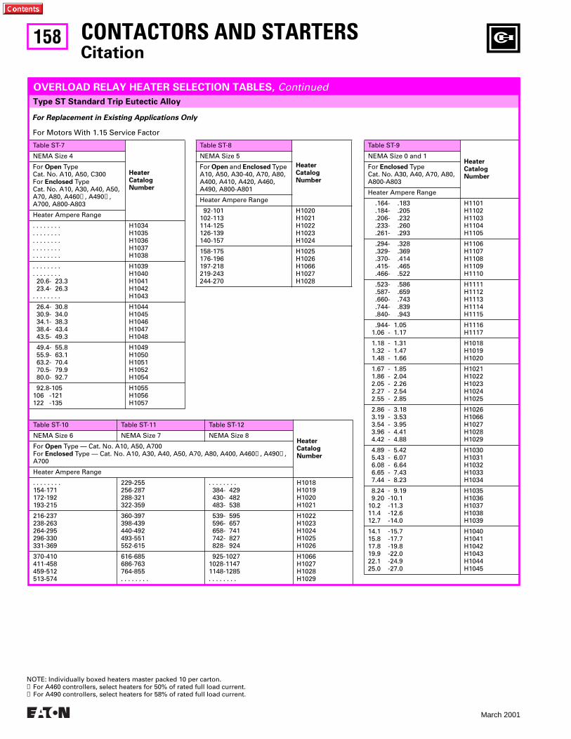
158
March 2001
Type ST Standard Trip Eutectic Alloy
CONTACTORS AND STARTERSCitation
For Replacement in Existing Applications Only
OVERLOAD RELAY HEATER SELECTION TABLES, Continued
For Motors With 1.15 Service Factor
Table ST-7
Heater Catalog Number
NEMA Size 4
For Open Type Cat. No. A10, A50, C300For Enclosed TypeCat. No. A10, A30, A40, A50, A70, A80, A460➊, A490➋, A700, A800-A803
Heater Ampere Range
. . . . . . . .
. . . . . . . .
. . . . . . . .
. . . . . . . .
. . . . . . . .
H1034H1035H1036H1037H1038
. . . . . . . .
. . . . . . . . 20.6- 23.3 23.4- 26.3. . . . . . . .
H1039H1040H1041H1042H1043
26.4- 30.8 30.9- 34.0 34.1- 38.3 38.4- 43.4 43.5- 49.3
H1044H1045H1046H1047H1048
49.4- 55.8 55.9- 63.1 63.2- 70.4 70.5- 79.9 80.0- 92.7
H1049H1050H1051H1052H1054
92.8-105106 -121122 -135
H1055H1056H1057
Table ST-8
Heater Catalog Number
NEMA Size 5
For Open and Enclosed Type A10, A50, A30-40, A70, A80, A400, A410, A420, A460, A490, A800-A801
Heater Ampere Range
92-101102-113114-125126-139140-157
H1020H1021H1022H1023H1024
158-175176-196197-218219-243244-270
H1025H1026H1066H1027H1028
Table ST-9
Heater Catalog Number
NEMA Size 0 and 1
For Enclosed TypeCat. No. A30, A40, A70, A80, A800-A803
Heater Ampere Range
.164- .183 .184- .205 .206- .232 .233- .260 .261- .293
H1101H1102H1103H1104H1105
.294- .328 .329- .369 .370- .414 .415- .465 .466- .522
H1106H1107H1108H1109H1110
.523- .586 .587- .659 .660- .743 .744- .839 .840- .943
H1111H1112H1113H1114H1115
.944- 1.05 1.06 - 1.17
H1116H1117
1.18 - 1.31 1.32 - 1.47 1.48 - 1.66
H1018H1019H1020
1.67 - 1.85 1.86 - 2.04 2.05 - 2.26 2.27 - 2.54 2.55 - 2.85
H1021H1022H1023H1024H1025
2.86 - 3.18 3.19 - 3.53 3.54 - 3.95 3.96 - 4.41 4.42 - 4.88
H1026H1066H1027H1028H1029
4.89 - 5.42 5.43 - 6.07 6.08 - 6.64 6.65 - 7.43 7.44 - 8.23
H1030H1031H1032H1033H1034
8.24 - 9.19 9.20 -10.110.2 -11.311.4 -12.612.7 -14.0
H1035H1036H1037H1038H1039
14.1 -15.715.8 -17.717.8 -19.819.9 -22.022.1 -24.925.0 -27.0
H1040H1041H1042H1043H1044H1045
Table ST-10 Table ST-11 Table ST-12
Heater Catalog Number
NEMA Size 6 NEMA Size 7 NEMA Size 8
For Open Type — Cat. No. A10, A50, A700For Enclosed Type — Cat. No. A10, A30, A40, A50, A70, A80, A400, A460➊, A490➋, A700
Heater Ampere Range
. . . . . . . .154-171172-192193-215
229-255256-287288-321322-359
. . . . . . . . 384- 429 430- 482 483- 538
H1018H1019H1020H1021
216-237238-263264-295296-330331-369
360-397398-439440-492493-551552-615
539- 595 596- 657 658- 741 742- 827 828- 924
H1022H1023H1024H1025H1026
370-410411-458459-512513-574
616-685686-763764-855. . . . . . . .
925-10271028-11471148-1285. . . . . . . .
H1066H1027H1028H1029
NOTE: Individually boxed heaters master packed 10 per carton.➊ For A460 controllers, select heaters for 50% of rated full load current.➋ For A490 controllers, select heaters for 58% of rated full load current.
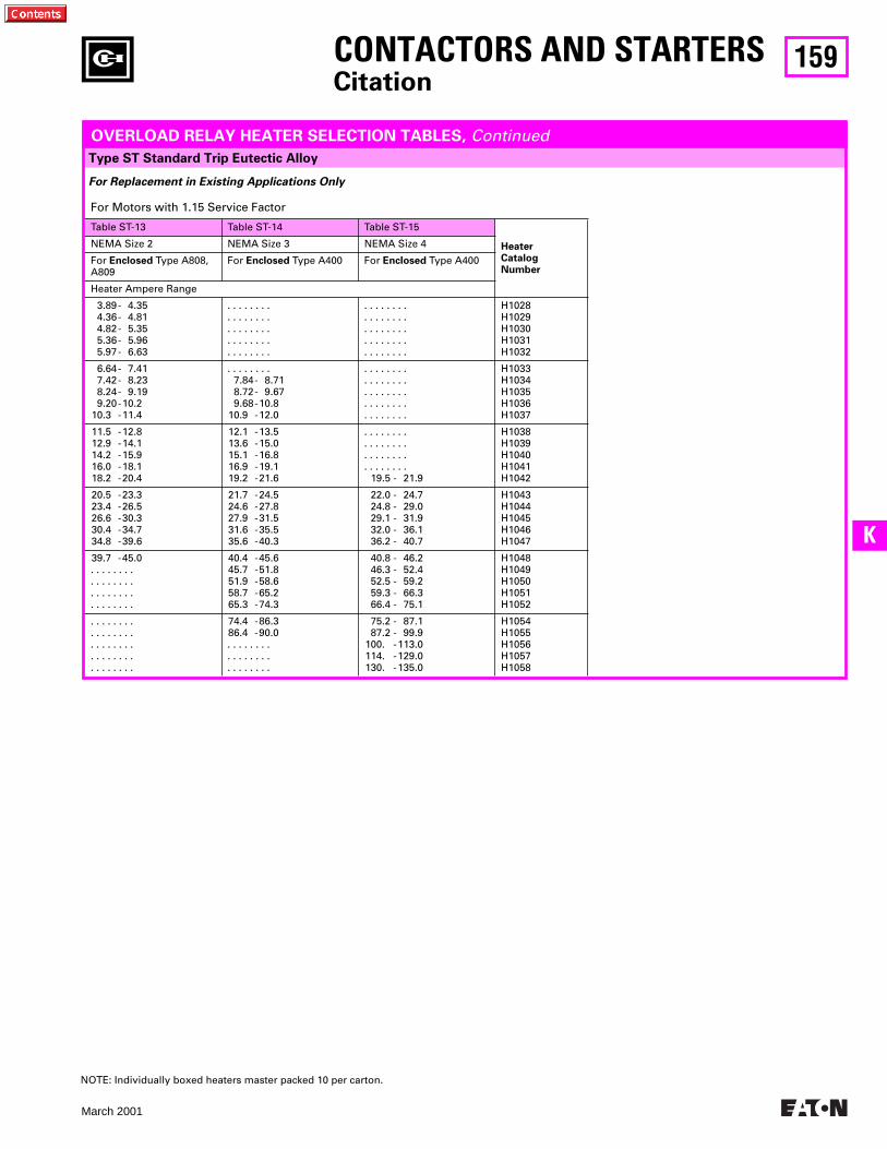
159
March 2001
K
Type ST Standard Trip Eutectic Alloy
CONTACTORS AND STARTERSCitation
For Replacement in Existing Applications Only
OVERLOAD RELAY HEATER SELECTION TABLES, Continued
For Motors with 1.15 Service Factor
Table ST-13 Table ST-14 Table ST-15
Heater Catalog Number
NEMA Size 2 NEMA Size 3 NEMA Size 4
For Enclosed Type A808, A809
For Enclosed Type A400 For Enclosed Type A400
Heater Ampere Range
3.89- 4.354.36- 4.814.82- 5.355.36- 5.965.97- 6.63
. . . . . . . .
. . . . . . . .
. . . . . . . .
. . . . . . . .
. . . . . . . .
. . . . . . . .
. . . . . . . .
. . . . . . . .
. . . . . . . .
. . . . . . . .
H1028H1029H1030H1031H1032
6.64- 7.417.42- 8.238.24- 9.199.20-10.2
10.3 -11.4
. . . . . . . .7.84- 8.718.72- 9.679.68-10.8
10.9 -12.0
. . . . . . . .
. . . . . . . .
. . . . . . . .
. . . . . . . .
. . . . . . . .
H1033H1034H1035H1036H1037
11.5 -12.812.9 -14.114.2 -15.916.0 -18.118.2 -20.4
12.1 -13.513.6 -15.015.1 -16.816.9 -19.119.2 -21.6
. . . . . . . .
. . . . . . . .
. . . . . . . .
. . . . . . . .19.5 - 21.9
H1038H1039H1040H1041H1042
20.5 -23.323.4 -26.526.6 -30.330.4 -34.734.8 -39.6
21.7 -24.524.6 -27.827.9 -31.531.6 -35.535.6 -40.3
22.0 - 24.724.8 - 29.029.1 - 31.932.0 - 36.136.2 - 40.7
H1043H1044H1045H1046H1047
39.7 -45.0. . . . . . . .. . . . . . . .. . . . . . . .. . . . . . . .
40.4 -45.645.7 -51.851.9 -58.658.7 -65.265.3 -74.3
40.8 - 46.246.3 - 52.452.5 - 59.259.3 - 66.366.4 - 75.1
H1048H1049H1050H1051H1052
. . . . . . . .
. . . . . . . .
. . . . . . . .
. . . . . . . .
. . . . . . . .
74.4 -86.386.4 -90.0. . . . . . . .. . . . . . . .. . . . . . . .
75.2 - 87.187.2 - 99.9
100. -113.0114. -129.0130. -135.0
H1054H1055H1056H1057H1058
NOTE: Individually boxed heaters master packed 10 per carton.
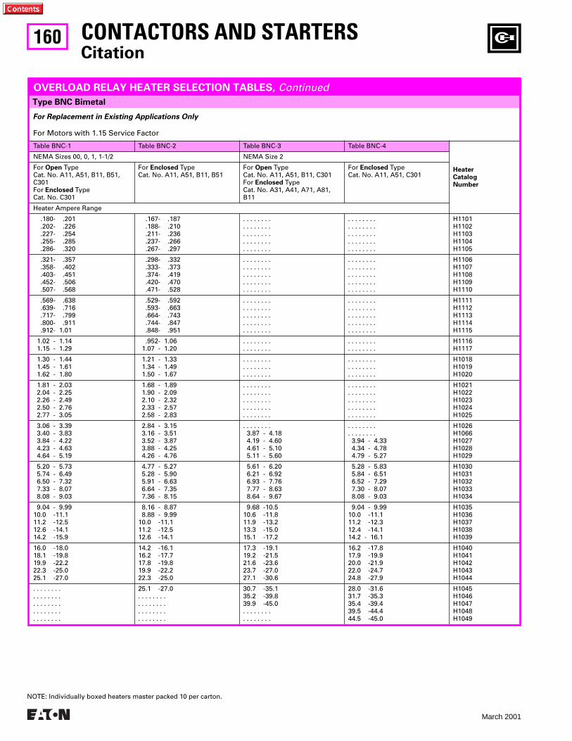
160
March 2001
For Replacement in Existing Applications Only
For Motors with 1.15 Service Factor
Table BNC-1 Table BNC-2 Table BNC-3 Table BNC-4
Heater Catalog Number
NEMA Sizes 00, 0, 1, 1-1/2 NEMA Size 2
For Open Type Cat. No. A11, A51, B11, B51, C301For Enclosed TypeCat. No. C301
For Enclosed TypeCat. No. A11, A51, B11, B51
For Open Type Cat. No. A11, A51, B11, C301For Enclosed TypeCat. No. A31, A41, A71, A81, B11
For Enclosed TypeCat. No. A11, A51, C301
Heater Ampere Range
.180- .201 .202- .226 .227- .254 .255- .285 .286- .320
.167- .187 .188- .210 .211- .236 .237- .266 .267- .297
. . . . . . . .
. . . . . . . .
. . . . . . . .
. . . . . . . .
. . . . . . . .
. . . . . . . .
. . . . . . . .
. . . . . . . .
. . . . . . . .
. . . . . . . .
H1101H1102H1103H1104H1105
.321- .357 .358- .402 .403- .451 .452- .506 .507- .568
.298- .332 .333- .373 .374- .419 .420- .470 .471- .528
. . . . . . . .
. . . . . . . .
. . . . . . . .
. . . . . . . .
. . . . . . . .
. . . . . . . .
. . . . . . . .
. . . . . . . .
. . . . . . . .
. . . . . . . .
H1106H1107H1108H1109H1110
.569- .638 .639- .716 .717- .799 .800- .911 .912- 1.01
.529- .592 .593- .663 .664- .743 .744- .847 .848- .951
. . . . . . . .
. . . . . . . .
. . . . . . . .
. . . . . . . .
. . . . . . . .
. . . . . . . .
. . . . . . . .
. . . . . . . .
. . . . . . . .
. . . . . . . .
H1111H1112H1113H1114H1115
1.02 - 1.14 1.15 - 1.29
.952- 1.06 1.07 - 1.20
. . . . . . . .
. . . . . . . .. . . . . . . .. . . . . . . .
H1116H1117
1.30 - 1.44 1.45 - 1.61 1.62 - 1.80
1.21 - 1.33 1.34 - 1.49 1.50 - 1.67
. . . . . . . .
. . . . . . . .
. . . . . . . .
. . . . . . . .
. . . . . . . .
. . . . . . . .
H1018H1019H1020
1.81 - 2.03 2.04 - 2.25 2.26 - 2.49 2.50 - 2.76 2.77 - 3.05
1.68 - 1.89 1.90 - 2.09 2.10 - 2.32 2.33 - 2.57 2.58 - 2.83
. . . . . . . .
. . . . . . . .
. . . . . . . .
. . . . . . . .
. . . . . . . .
. . . . . . . .
. . . . . . . .
. . . . . . . .
. . . . . . . .
. . . . . . . .
H1021H1022H1023H1024H1025
3.06 - 3.39 3.40 - 3.83 3.84 - 4.22 4.23 - 4.63 4.64 - 5.19
2.84 - 3.15 3.16 - 3.51 3.52 - 3.87 3.88 - 4.25 4.26 - 4.76
. . . . . . . . 3.87 - 4.18 4.19 - 4.60 4.61 - 5.10 5.11 - 5.60
. . . . . . . .
. . . . . . . . 3.94 - 4.33 4.34 - 4.78 4.79 - 5.27
H1026H1066H1027H1028H1029
5.20 - 5.73 5.74 - 6.49 6.50 - 7.32 7.33 - 8.07 8.08 - 9.03
4.77 - 5.27 5.28 - 5.90 5.91 - 6.63 6.64 - 7.35 7.36 - 8.15
5.61 - 6.20 6.21 - 6.92 6.93 - 7.76 7.77 - 8.63 8.64 - 9.67
5.28 - 5.83 5.84 - 6.51 6.52 - 7.29 7.30 - 8.07 8.08 - 9.03
H1030H1031H1032H1033H1034
9.04 - 9.9910.0 -11.111.2 -12.512.6 -14.114.2 -15.9
8.16 - 8.87 8.88 - 9.9910.0 -11.111.2 -12.512.6 -14.1
9.68 -10.510.6 -11.811.9 -13.213.3 -15.015.1 -17.2
9.04 - 9.9910.0 -11.111.2 -12.312.4 -14.114.2 - 16.1
H1035H1036H1037H1038H1039
16.0 -18.018.1 -19.819.9 -22.222.3 -25.025.1 -27.0
14.2 -16.116.2 -17.717.8 -19.819.9 -22.222.3 -25.0
17.3 -19.119.2 -21.521.6 -23.623.7 -27.027.1 -30.6
16.2 -17.817.9 -19.920.0 -21.922.0 -24.724.8 -27.9
H1040H1041H1042H1043H1044
. . . . . . . .
. . . . . . . .
. . . . . . . .
. . . . . . . .
. . . . . . . .
25.1 -27.0. . . . . . . .. . . . . . . .. . . . . . . .. . . . . . . .
30.7 -35.135.2 -39.839.9 -45.0. . . . . . . .. . . . . . . .
28.0 -31.631.7 -35.335.4 -39.439.5 -44.444.5 -45.0
H1045H1046H1047H1048H1049
Type BNC Bimetal
CONTACTORS AND STARTERSCitation
OVERLOAD RELAY HEATER SELECTION TABLES, Continued
NOTE: Individually boxed heaters master packed 10 per carton.
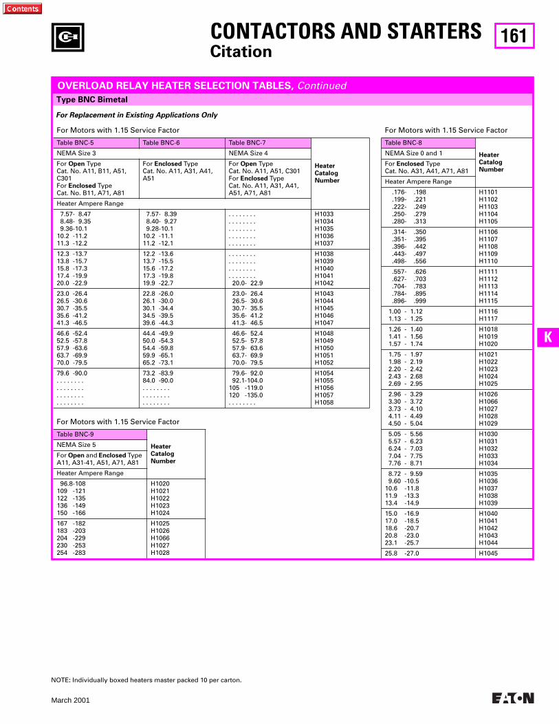
161
March 2001
K
Type BNC Bimetal
CONTACTORS AND STARTERSCitation
For Replacement in Existing Applications Only
OVERLOAD RELAY HEATER SELECTION TABLES, Continued
For Motors with 1.15 Service Factor
Table BNC-5 Table BNC-6 Table BNC-7
HeaterCatalog Number
NEMA Size 3 NEMA Size 4
For Open Type Cat. No. A11, B11, A51, C301For Enclosed TypeCat. No. B11, A71, A81
For Enclosed TypeCat. No. A11, A31, A41, A51
For Open Type Cat. No. A11, A51, C301For Enclosed TypeCat. No. A11, A31, A41, A51, A71, A81
Heater Ampere Range
7.57- 8.47 8.48- 9.35 9.36-10.110.2 -11.211.3 -12.2
7.57- 8.39 8.40- 9.27 9.28-10.110.2 -11.111.2 -12.1
. . . . . . . .
. . . . . . . .
. . . . . . . .
. . . . . . . .
. . . . . . . .
H1033H1034H1035H1036H1037
12.3 -13.713.8 -15.715.8 -17.317.4 -19.920.0 -22.9
12.2 -13.613.7 -15.515.6 -17.217.3 -19.819.9 -22.7
. . . . . . . .
. . . . . . . .
. . . . . . . .
. . . . . . . . 20.0- 22.9
H1038H1039H1040H1041H1042
23.0 -26.426.5 -30.630.7 -35.535.6 -41.241.3 -46.5
22.8 -26.026.1 -30.030.1 -34.434.5 -39.539.6 -44.3
23.0- 26.4 26.5- 30.6 30.7- 35.5 35.6- 41.2 41.3- 46.5
H1043H1044H1045H1046H1047
46.6 -52.452.5 -57.857.9 -63.663.7 -69.970.0 -79.5
44.4 -49.950.0 -54.354.4 -59.859.9 -65.165.2 -73.1
46.6- 52.4 52.5- 57.8 57.9- 63.6 63.7- 69.9 70.0- 79.5
H1048H1049H1050H1051H1052
79.6 -90.0. . . . . . . .. . . . . . . .. . . . . . . .. . . . . . . .
73.2 -83.984.0 -90.0. . . . . . . .. . . . . . . .. . . . . . . .
79.6- 92.0 92.1-104.0105 -119.0120 -135.0. . . . . . . .
H1054H1055H1056H1057H1058
For Motors with 1.15 Service Factor
Table BNC-9
Heater Catalog Number
NEMA Size 5
For Open and Enclosed Type A11, A31-41, A51, A71, A81
Heater Ampere Range
96.8-108109 -121122 -135136 -149150 -166
H1020H1021H1022H1023H1024
167 -182183 -203204 -229230 -253254 -283
H1025H1026H1066H1027H1028
For Motors with 1.15 Service Factor
Table BNC-8
Heater Catalog Number
NEMA Size 0 and 1
For Enclosed TypeCat. No. A31, A41, A71, A81
Heater Ampere Range
.176- .198 .199- .221 .222- .249 .250- .279 .280- .313
H1101H1102H1103H1104H1105
.314- .350 .351- .395 .396- .442 .443- .497 .498- .556
H1106H1107H1108H1109H1110
.557- .626 .627- .703 .704- .783 .784- .895 .896- .999
H1111H1112H1113H1114H1115
1.00 - 1.12 1.13 - 1.25
H1116H1117
1.26 - 1.40 1.41 - 1.56 1.57 - 1.74
H1018H1019H1020
1.75 - 1.97 1.98 - 2.19 2.20 - 2.42 2.43 - 2.68 2.69 - 2.95
H1021H1022H1023H1024H1025
2.96 - 3.29 3.30 - 3.72 3.73 - 4.10 4.11 - 4.49 4.50 - 5.04
H1026H1066H1027H1028H1029
5.05 - 5.56 5.57 - 6.23 6.24 - 7.03 7.04 - 7.75 7.76 - 8.71
H1030H1031H1032H1033H1034
8.72 - 9.59 9.60 -10.510.6 -11.811.9 -13.313.4 -14.9
H1035H1036H1037H1038H1039
15.0 -16.917.0 -18.518.6 -20.720.8 -23.023.1 -25.7
H1040H1041H1042H1043H1044
25.8 -27.0 H1045
NOTE: Individually boxed heaters master packed 10 per carton.
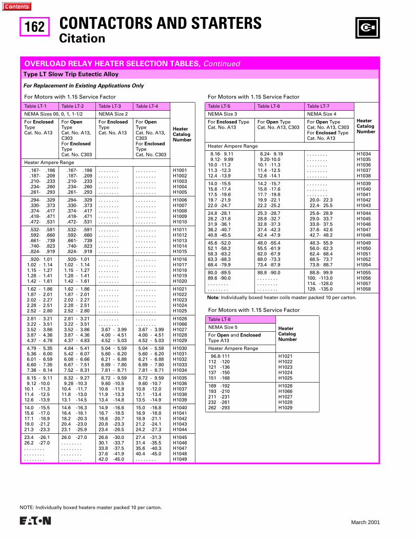
162
March 2001
Type LT Slow Trip Eutectic Alloy
CONTACTORS AND STARTERSCitation
For Replacement in Existing Applications Only
For Motors with 1.15 Service Factor
Table LT-1 Table LT-2 Table LT-3 Table LT-4
Heater Catalog Number
NEMA Sizes 00, 0, 1, 1-1/2 NEMA Size 2
For Enclosed TypeCat. No. A13
For Open Type Cat. No. A13, C303For Enclosed TypeCat. No. C303
For Enclosed TypeCat. No. A13
For Open Type Cat. No. A13, C303For Enclosed TypeCat. No. C303
Heater Ampere Range
.167- .186 .187- .209 .210- .233 .234- .260 .261- .293
.167- .186 .187- .209 .210- .233 .234- .260 .261- .293
. . . . . . . .
. . . . . . . .
. . . . . . . .
. . . . . . . .
. . . . . . . .
. . . . . . . .
. . . . . . . .
. . . . . . . .
. . . . . . . .
. . . . . . . .
H1001H1002H1003H1004H1005
.294- .329 .330- .373 .374- .417 .418- .471 .472- .531
.294- .329 .330- .373 .374- .417 .418- .471 .472- .531
. . . . . . . .
. . . . . . . .
. . . . . . . .
. . . . . . . .
. . . . . . . .
. . . . . . . .
. . . . . . . .
. . . . . . . .
. . . . . . . .
. . . . . . . .
H1006H1007H1008H1009H1010
.532- .591 .592- .660 .661- .739 .740- .823 .824- .919
.532- .591 .592- .660 .661- .739 .740- .823 .824- .919
. . . . . . . .
. . . . . . . .
. . . . . . . .
. . . . . . . .
. . . . . . . .
. . . . . . . .
. . . . . . . .
. . . . . . . .
. . . . . . . .
. . . . . . . .
H1011H1012H1013H1014H1015
.920- 1.01 1.02 - 1.14 1.15 - 1.27 1.28 - 1.41 1.42 - 1.61
.920- 1.01 1.02 - 1.14 1.15 - 1.27 1.28 - 1.41 1.42 - 1.61
. . . . . . . .
. . . . . . . .
. . . . . . . .
. . . . . . . .
. . . . . . . .
. . . . . . . .
. . . . . . . .
. . . . . . . .
. . . . . . . .
. . . . . . . .
H1016H1017H1018H1019H1020
1.62 - 1.86 1.87 - 2.01 2.02 - 2.27 2.28 - 2.51 2.52 - 2.80
1.62 - 1.86 1.87 - 2.01 2.02 - 2.27 2.28 - 2.51 2.52 - 2.80
. . . . . . . .
. . . . . . . .
. . . . . . . .
. . . . . . . .
. . . . . . . .
. . . . . . . .
. . . . . . . .
. . . . . . . .
. . . . . . . .
. . . . . . . .
H1021H1022H1023H1024H1025
2.81 - 3.21 3.22 - 3.51 3.52 - 3.86 3.87 - 4.36 4.37 - 4.78
2.81 - 3.21 3.22 - 3.51 3.52 - 3.86 3.87 - 4.36 4.37 - 4.83
. . . . . . . .
. . . . . . . . 3.67 - 3.99 4.00 - 4.51 4.52 - 5.03
. . . . . . . .
. . . . . . . . 3.67 - 3.99 4.00 - 4.51 4.52 - 5.03
H1026H1066H1027H1028H1029
4.79 - 5.35 5.36 - 6.00 6.01 - 6.59 6.60 - 7.35 7.36 - 8.14
4.84 - 5.41 5.42 - 6.07 6.08 - 6.66 6.67 - 7.51 7.52 - 8.31
5.04 - 5.59 5.60 - 6.20 6.21 - 6.88 6.89 - 7.80 7.81 - 8.71
5.04 - 5.59 5.60 - 6.20 6.21 - 6.88 6.89 - 7.80 7.81 - 8.71
H1030H1031H1032H1033H1034
8.15 - 9.11 9.12 -10.010.1 -11.311.4 -12.512.6 -13.9
8.32 - 9.27 9.28 -10.310.4 -11.711.8 -13.013.1 -14.5
8.72 - 9.59 9.60 -10.510.6 -11.811.9 -13.313.4 -14.8
8.72 - 9.59 9.60 -10.710.8 -12.012.1 -13.413.5 -14.9
H1035H1036H1037H1038H1039
14.0 -15.515.6 -17.017.1 -18.919.0 -21.221.3 -23.3
14.6 -16.316.4 -18.118.2 -20.320.4 -23.023.1 -25.9
14.9 -16.616.7 -18.518.6 -20.720.8 -23.323.4 -26.5
15.0 -16.816.9 -18.818.9 -21.121.2 -24.124.2 -27.3
H1040H1041H1042H1043H1044
23.4 -26.126.2 -27.0. . . . . . . .. . . . . . . .. . . . . . . .
26.0 -27.0. . . . . . . .. . . . . . . .. . . . . . . .. . . . . . . .
26.6 -30.030.1 -33.733.8 -37.537.6 -41.942.0 -45.0
27.4 -31.331.4 -35.535.6 -40.340.4 -45.0. . . . . . . .
H1045H1046H1047H1048H1049
For Motors with 1.15 Service Factor
Note: Individually boxed heater coils master packed 10 per carton.
Table LT-5 Table LT-6 Table LT-7
Heater Catalog Number
NEMA Size 3 NEMA Size 4
For Enclosed TypeCat. No. A13
For Open Type Cat. No. A13, C303
For Open Type Cat. No. A13, C303For Enclosed TypeCat. No. A13
Heater Ampere Range
8.16- 9.11 9.12- 9.9910.0 -11.211.3 -12.312.4 -13.9
8.24- 9.19 9.20-10.010.1 -11.311.4 -12.512.6 -14.1
. . . . . . . .
. . . . . . . .
. . . . . . . .
. . . . . . . .
. . . . . . . .
H1034H1035H1036H1037H1038
14.0 -15.515.6 -17.417.5 -19.619.7 -21.922.0 -24.7
14.2 -15.715.8 -17.617.7 -19.819.9 -22.122.2 -25.2
. . . . . . . .
. . . . . . . .
. . . . . . . . 20.0- 22.3 22.4- 25.5
H1039H1040H1041H1042H1043
24.8 -28.128.2 -31.831.9 -36.136.2 -40.740.8 -45.5
25.3 -28.728.8 -32.732.8 -37.337.4 -42.342.4 -47.9
25.6- 28.9 29.0- 33.7 33.8- 37.5 37.6- 42.6 42.7- 48.2
H1044H1045H1046H1047H1048
45.6 -52.052.1 -58.258.3 -63.263.3 -68.368.4 -79.9
48.0 -55.455.5 -61.962.0 -67.968.0 -73.373.4 -87.9
48.3- 55.9 56.0- 62.3 62.4- 68.4 68.5- 73.7 73.8- 88.7
H1049H1050H1051H1052H1054
80.0 -89.589.6 -90.0. . . . . . . .. . . . . . . .
88.8 -90.0. . . . . . . .. . . . . . . .. . . . . . . .
88.8- 99.9100. -113.0114. -128.0129. -135.0
H1055H1056H1057H1058
OVERLOAD RELAY HEATER SELECTION TABLES, Continued
For Motors with 1.15 Service Factor
Table LT-8
HeaterCatalog Number
NEMA Size 5
For Open and Enclosed Type A13
Heater Ampere Range
96.8-111112 -120121 -136137 -150151 -168
H1021H1022H1023H1024H1025
169 -192193 -210211 -231232 -261262 -293
H1026H1066H1027H1028H1029
NOTE: Individually boxed heaters master packed 10 per carton.
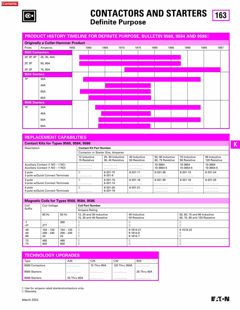
163
March 2001
K
Originally a Cutler-Hammer Product
Contact Kits for Types 9560, 9584, 9586
CONTACTORS AND STARTERSDefinite Purpose
Magnetic Coils for Types 9560, 9584, 9586
CoilSuffix
Coil Voltage Coil Part Number
Ampere Rating
60 Hz 50 Hz 12, 25 and 30 Inductive15, 30 and 40 Resistive
40 Inductive50 Resistive
50, 60, 75 and 90 Inductive60, 75, 90 and 120 Resistive
-7-47
. . . . 277
380. . . .
➋➋
➋➋
➋➋
-49-50-69
104 – 120208 – 24024
104 – 120208 – 24024
➋➋➋
9-1814-219-1814-89-1814-1
9-1518-22➋➋
-72-74
480600
480600
➋➋
➋➋
➋➋
Description Contact Kit Part Number
Contactor or Starter Size, Amperes
12 Inductive15 Resistive
25, 30 Inductive30, 40 Resistive
40 Inductive50 Resistive
50, 60 Inductive60, 75 Resistive
75 Inductive90 Resistive
90 Inductive120 Resistive
Auxiliary Contact (1 NO – 1 NC)Auxiliary Contact (1 NO – 1 NO)
. . . . . . . . .
. . . . . . . . .. . . . . . . . .. . . . . . . . .
. . . . . . . . .
. . . . . . . . .10-365410-3654-5
10-365410-3654-5
10-365410-3654-5
2-pole2-pole w/Quick Connect Terminals
➋. . . . . . . . .
6-331-106-331-9
6-331-11. . . . . . . . .
6-331-38. . . . . . . . .
6-331-13. . . . . . . . .
6-331-24. . . . . . . . .
3-pole3-pole w/Quick Connect Terminals
➋. . . . . . . . .
6-331-156-331-14
6-331-16. . . . . . . . .
6-331-39. . . . . . . . .
6-331-18. . . . . . . . .
6-331-25. . . . . . . . .
4-pole4-pole w/Quick Connect Terminals
➋. . . . . . . . .
6-331-206-331-19
6-331-21. . . . . . . . .
. . . . . . . . .
. . . . . . . . .. . . . . . . . .. . . . . . . . .
. . . . . . . . .
. . . . . . . . .
Type A25 C25 C32 B25
9560 Contactors
9584 Starters
9586 Starters
. . . . . . . . .
. . . . . . . . .
25 Thru 60A
15 Thru 90A
. . . . . . . . .
. . . . . . . . .
120 Thru 350A
. . . . . . . . .
. . . . . . . . .
. . . . . . . . .
25 Thru 40A
. . . . . . . . .
Poles Amperes 1955 1960 1965 1970 1975 1980 1985 1990 1995 1997
9560 Contactors
2P, 3P, 4P
2P, 3P
2P, 3P
25, 30, 40A
50, 60A
75, 90A
9584 Starters
1P 30A
40A
50A
60A
9586 Starters
1P 30A
40A
50A
60A
PRODUCT HISTORY TIMELINE FOR DEFINITE PURPOSE, BULLETIN 9560, 9584 AND 9586➊
REPLACEMENT CAPABILITIES
TECHNOLOGY UPGRADES
➊ Use for ampere rated starters/contactors only.➋ Obsolete.
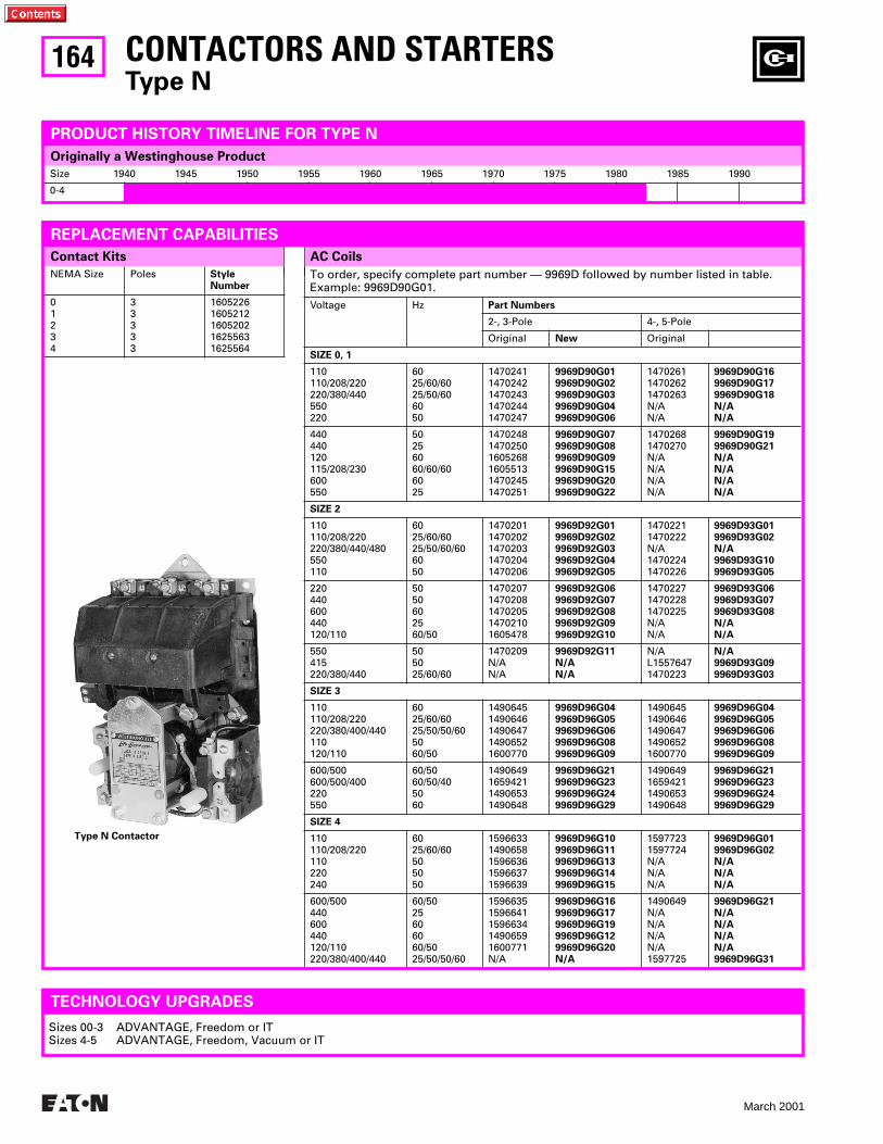
164
March 2001
To order, specify complete part number — 9969D followed by number listed in table. Example: 9969D90G01.Voltage Hz Part Numbers
2-, 3-Pole 4-, 5-Pole
Original New Original
SIZE 0, 1
110110/208/220220/380/440550220
6025/60/6025/50/606050
14702411470242147024314702441470247
9969D90G019969D90G029969D90G039969D90G049969D90G06
147026114702621470263N/AN/A
9969D90G169969D90G179969D90G18N/AN/A
440440120115/208/230600550
50256060/60/606025
147024814702501605268160551314702451470251
9969D90G079969D90G089969D90G099969D90G159969D90G209969D90G22
14702681470270N/AN/AN/AN/A
9969D90G199969D90G21N/AN/AN/AN/A
SIZE 2
110110/208/220220/380/440/480550110
6025/60/6025/50/60/606050
14702011470202147020314702041470206
9969D92G019969D92G029969D92G039969D92G049969D92G05
14702211470222N/A14702241470226
9969D93G019969D93G02N/A9969D93G109969D93G05
220440600440120/110
5050602560/50
14702071470208147020514702101605478
9969D92G069969D92G079969D92G089969D92G099969D92G10
147022714702281470225N/AN/A
9969D93G069969D93G079969D93G08N/AN/A
550415220/380/440
505025/60/60
1470209N/AN/A
9969D92G11N/AN/A
N/AL15576471470223
N/A9969D93G099969D93G03
SIZE 3
110110/208/220220/380/400/440110120/110
6025/60/6025/50/50/605060/50
14906451490646149064714906521600770
9969D96G049969D96G059969D96G069969D96G089969D96G09
14906451490646149064714906521600770
9969D96G049969D96G059969D96G069969D96G089969D96G09
600/500600/500/400220550
60/5060/50/405060
1490649165942114906531490648
9969D96G219969D96G239969D96G249969D96G29
1490649165942114906531490648
9969D96G219969D96G239969D96G249969D96G29
SIZE 4
110110/208/220110220240
6025/60/60505050
15966331490658159663615966371596639
9969D96G109969D96G119969D96G139969D96G149969D96G15
15977231597724N/AN/AN/A
9969D96G019969D96G02N/AN/AN/A
600/500440600440120/110220/380/400/440
60/5025606060/5025/50/50/60
15966351596641159663414906591600771N/A
9969D96G169969D96G179969D96G199969D96G129969D96G20N/A
1490649N/AN/AN/AN/A1597725
9969D96G21N/AN/AN/AN/A9969D96G31
Size 1940 1945 1950 1955 1960 1965 1970 1975 1980 1985 1990
0-4
AC CoilsContact Kits
NEMA Size Poles Style Number
01234
33333
16052261605212160520216255631625564
CONTACTORS AND STARTERSType N
PRODUCT HISTORY TIMELINE FOR TYPE N
REPLACEMENT CAPABILITIES
Originally a Westinghouse Product
Type N Contactor
TECHNOLOGY UPGRADES
Sizes 00-3 ADVANTAGE, Freedom or ITSizes 4-5 ADVANTAGE, Freedom, Vacuum or IT
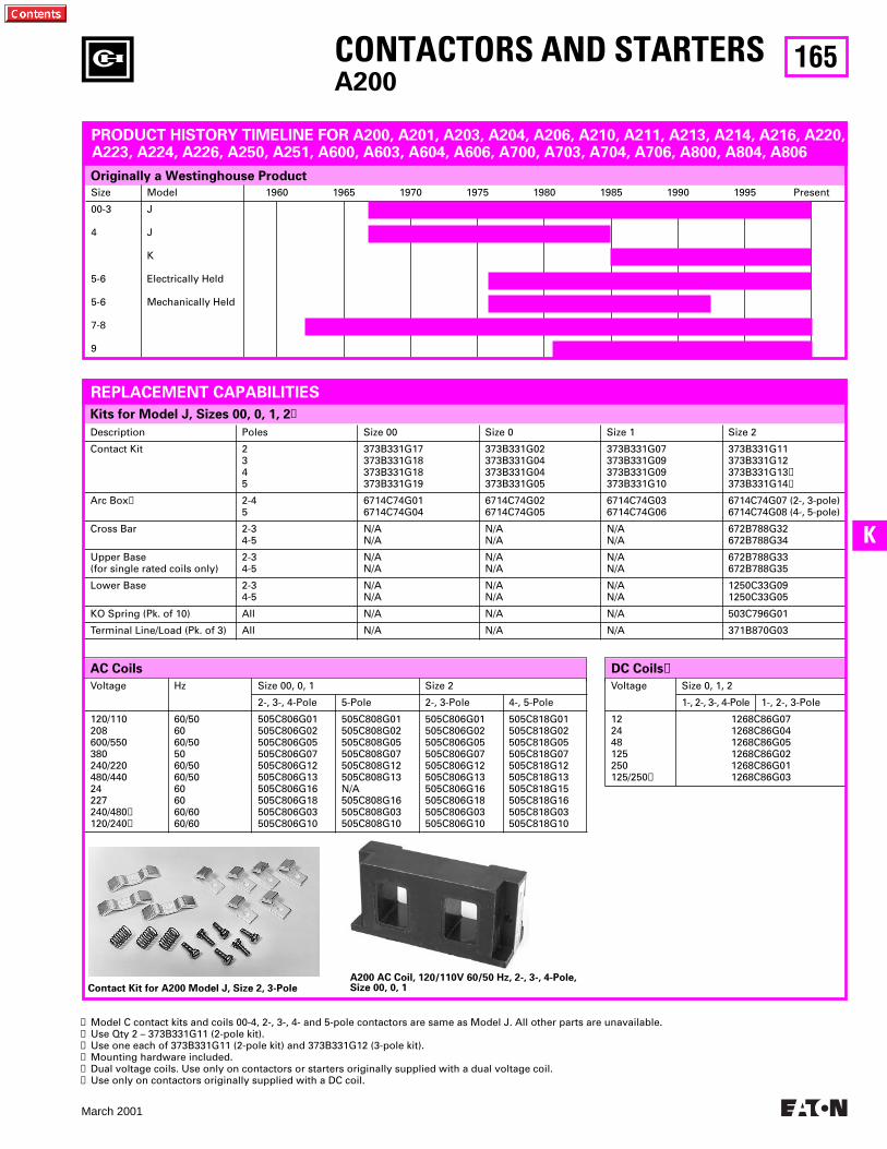
165
March 2001
K
Originally a Westinghouse Product
DC Coils➏AC Coils
Voltage Size 0, 1, 2
1-, 2-, 3-, 4-Pole 1-, 2-, 3-Pole
122448125250125/250➎
1268C86G071268C86G041268C86G051268C86G021268C86G011268C86G03
Description Poles Size 00 Size 0 Size 1 Size 2
Contact Kit 2345
373B331G17373B331G18373B331G18373B331G19
373B331G02373B331G04373B331G04373B331G05
373B331G07373B331G09373B331G09373B331G10
373B331G11373B331G12373B331G13➋373B331G14➌
Arc Box➍ 2-45
6714C74G016714C74G04
6714C74G026714C74G05
6714C74G036714C74G06
6714C74G07 (2-, 3-pole)6714C74G08 (4-, 5-pole)
Cross Bar 2-34-5
N/AN/A
N/AN/A
N/AN/A
672B788G32672B788G34
Upper Base(for single rated coils only)
2-34-5
N/AN/A
N/AN/A
N/AN/A
672B788G33672B788G35
Lower Base 2-34-5
N/AN/A
N/AN/A
N/AN/A
1250C33G091250C33G05
KO Spring (Pk. of 10) All N/A N/A N/A 503C796G01
Terminal Line/Load (Pk. of 3) All N/A N/A N/A 371B870G03
CONTACTORS AND STARTERSA200
Voltage Hz Size 00, 0, 1 Size 2
2-, 3-, 4-Pole 5-Pole 2-, 3-Pole 4-, 5-Pole
120/110208600/550380240/220480/44024227240/480➎120/240➎
60/506060/505060/5060/50606060/6060/60
505C806G01505C806G02505C806G05505C806G07505C806G12505C806G13505C806G16505C806G18505C806G03505C806G10
505C808G01505C808G02505C808G05505C808G07505C808G12505C808G13N/A505C808G16505C808G03505C808G10
505C806G01505C806G02505C806G05505C806G07505C806G12505C806G13505C806G16505C806G18505C806G03505C806G10
505C818G01505C818G02505C818G05505C818G07505C818G12505C818G13505C818G15505C818G16505C818G03505C818G10
Kits for Model J, Sizes 00, 0, 1, 2➊
Size Model 1960 1965 1970 1975 1980 1985 1990 1995 Present
00-3
4
5-6
5-6
7-8
9
J
J
K
Electrically Held
Mechanically Held
PRODUCT HISTORY TIMELINE FOR A200, A201, A203, A204, A206, A210, A211, A213, A214, A216, A220, A223, A224, A226, A250, A251, A600, A603, A604, A606, A700, A703, A704, A706, A800, A804, A806
REPLACEMENT CAPABILITIES
➊ Model C contact kits and coils 00-4, 2-, 3-, 4- and 5-pole contactors are same as Model J. All other parts are unavailable.➋ Use Qty 2 – 373B331G11 (2-pole kit).➌ Use one each of 373B331G11 (2-pole kit) and 373B331G12 (3-pole kit).➍ Mounting hardware included.➎ Dual voltage coils. Use only on contactors or starters originally supplied with a dual voltage coil.➏ Use only on contactors originally supplied with a DC coil.
Contact Kit for A200 Model J, Size 2, 3-PoleA200 AC Coil, 120/110V 60/50 Hz, 2-, 3-, 4-Pole, Size 00, 0, 1
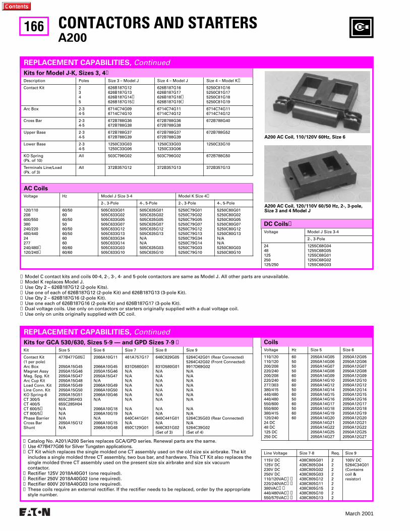
166
March 2001
Kits for GCA 530/630, Sizes 5-9 — and GPD Sizes 7-9 ➊ Coils
Kit Size 5 Size 6 Size 7 Size 8 Size 9
Contact Kit(1 per pole)Arc BoxMagnet AssyMag. Spg. KitArc Cup KitLoad Conn. KitLine Conn. KitKO Spring-6CT 300/5CT 400/5CT 600/5➌CT 800/5➌Phase BarrierCross BarShunt
477B477G05➋
2050A15G452050A15G462050A15G472050A15G482050A15G492050A15G502050A15G51655C285H03655C285H04N/AN/AN/A2050A15G12N/A
2066A10G11
2066A10G452050A15G462050A15G47N/A2066A10G492066A10G502066A10G46N/A
2066A10G182066A10G19N/A2066A10G152066A10G48
461A757G17
831D580G01N/AN/AN/AN/AN/AN/AN/A
N/AN/A640C441G01N/A650C129G01
646C829G05
831D580G01N/AN/AN/AN/AN/AN/AN/A
N/AN/A640C441G01N/A646C831G02(Set of 3)
5264C42G01 (Rear Connected)5264C42G02 (Front Connected)9917D69G02N/AN/AN/AN/AN/AN/AN/A
N/AN/A5264C35G03 (Rear Connected)N/A5264C39G02(Set of 4)
Voltage Hz Size 5 Size 6
110/120110/120200/208220/240200/208220/240277/303380/415440/480440/480550/600550/600380/415120/24024 DC48 DC125 DC250 DC
6050505060606050605060506060
2050A14G052050A14G062050A14G072050A14G082050A14G092050A14G102050A14G122050A14G142050A14G152050A14G162050A14G172050A14G182050A14G192050A14G202050A14G212050A14G222050A14G252050A14G27
2050A12G052050A12G062050A12G072050A12G082050A12G092050A12G102050A12G122050A12G142050A12G152050A12G162050A12G172050A12G182050A12G192050A12G202050A12G212050A12G222050A12G252050A12G27
Line Voltage Size 7-8 Req. Size 9
115V DC125V DC230V DC250V DC110/120VAC➍➐220/240VAC➎➐380VAC➏➐440/480VAC➏➐550/575VAC➏➐
438C805G01438C805G04438C805G02438C805G03438C805G12438C805G11438C805G15438C805G10438C805G13
222222222
100V DC5264C34G01(Contains coil & resistor)
➊ Catalog No. A201/A200 Series replaces GCA/GPD series. Renewal parts are the same.➋ Use 477B477G06 for Silver Tungsten applications.➌ CT Kit which replaces the single molded one CT assembly used on the old size six airbrake. The kit
includes a single molded three CT assembly, two bus bar, and hardware. This CT Kit also replaces the single molded three CT assembly used on the present size six airbrake and size six vacuum contactor.
➍ Rectifier 125V 2018A40G01 (one required).➎ Rectifier 250V 2018A40G02 (one required).➏ Rectifier 600V 2018A40G03 (one required).➐ These coils require an external rectifier. If the rectifier needs to be replaced, order by the appropriate
style number.
Voltage Model J Size 3-4
2-, 3-Pole
2448125250125/250
1255C68G041255C68G051255C68G011255C68G021255C68G03
DC Coils➑
Kits for Model J-K, Sizes 3, 4➊
CONTACTORS AND STARTERSA200
REPLACEMENT CAPABILITIES, Continued
Description Poles Size 3 – Model J Size 4 – Model J Size 4 – Model K➋
Contact Kit 2345
626B187G12626B187G13626B187G14➌626B187G15➍
626B187G16626B187G17626B187G18➎626B187G19➏
5250C81G165250C81G175250C81G185250C81G19
Arc Box 2-34-5
6714C74G096714C74G10
6714C74G116714C74G12
6714C74G116714C74G12
Cross Bar 2-34-5
672B788G36672B788G38
672B788G36672B788G38
672B788G40
Upper Base 2-34-5
672B788G37672B788G39
672B788G37672B788G39
672B788G52
Lower Base 2-34-5
1250C33G031250C33G06
1250C33G031250C33G06
1250C33G10
KO Spring (Pk. of 10)
All 503C796G02 503C796G02 672B788G50
Terminals Line/Load(Pk. of 3)
All 372B357G12 372B357G13 372B357G13
AC Coils
Voltage Hz Model J Size 3-4 Model K Size 4➋
2-, 3-Pole 4-, 5-Pole 2-, 3-Pole 4-, 5-Pole
120/110208600/550380240/220480/44024277240/480➐120/240➐
60/506060/505060/5060/50606060/6060/60
505C633G01505C633G02505C633G05505C633G07505C633G12505C633G13505C633G34505C633G14505C633G03505C633G10
505C635G01505C635G02505C635G05505C635G07505C635G12505C635G13N/AN/A505C635G03505C635G10
5250C79G015250C79G025250C79G055250C79G075250C79G125250C79G135250C79G345250C79G145250C79G035250C79G10
5250C80G015250C80G025250C80G055250C80G075250C80G125250C80G13N/AN/A5250C80G035250C80G10
A200 AC Coil, 110/120V 60Hz, Size 6
A200 AC Coil, 120/110V 60/50 Hz, 2-, 3-pole, Size 3 and 4 Model J
➊ Model C contact kits and coils 00-4, 2-, 3-, 4- and 5-pole contactors are same as Model J. All other parts are unavailable.➋ Model K replaces Model J.➌ Use Qty 2 – 626B187G12 (2-pole Kits).➍ Use one of each of 626B187G12 (2-pole Kit) and 626B187G13 (3-pole Kit).➎ Use Qty 2 – 626B187G16 (2-pole Kit).➏ Use one each of 626B187G16 (2-pole Kit) and 626B187G17 (3-pole Kit).➐ Dual voltage coils. Use only on contactors or starters originally supplied with a dual voltage coil.➑ Use only on units originally supplied with DC coil.
REPLACEMENT CAPABILITIES, Continued
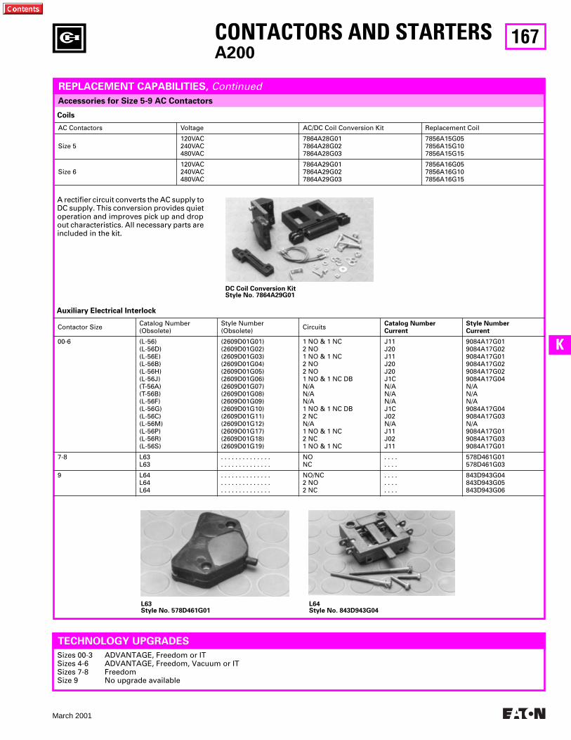
167
March 2001
K
Accessories for Size 5-9 AC Contactors
Coils
AC Contactors Voltage AC/DC Coil Conversion Kit Replacement Coil
Size 5120VAC240VAC480VAC
7864A28G017864A28G027864A28G03
7856A15G057856A15G107856A15G15
Size 6120VAC240VAC480VAC
7864A29G017864A29G027864A29G03
7856A16G057856A16G107856A16G15
CONTACTORS AND STARTERSA200
REPLACEMENT CAPABILITIES, Continued
A rectifier circuit converts the AC supply to DC supply. This conversion provides quiet operation and improves pick up and drop out characteristics. All necessary parts are included in the kit.
L63Style No. 578D461G01
L64Style No. 843D943G04
Auxiliary Electrical Interlock
Contactor Size Catalog Number(Obsolete)
Style Number(Obsolete) Circuits Catalog Number
CurrentStyle NumberCurrent
00-6 (L-56)(L-56D)(L-56E)(L-56B)(L-56H)(L-56J)(T-56A)(T-56B)(L-56F)(L-56G)(L-56C)(L-56M)(L-56P)(L-56R)(L-56S)
(2609D01G01)(2609D01G02)(2609D01G03)(2609D01G04)(2609D01G05)(2609D01G06)(2609D01G07)(2609D01G08)(2609D01G09)(2609D01G10)(2609D01G11)(2609D01G12)(2609D01G17)(2609D01G18)(2609D01G19)
1 NO & 1 NC2 NO1 NO & 1 NC2 NO2 NO1 NO & 1 NC DBN/AN/AN/A1 NO & 1 NC DB2 NCN/A1 NO & 1 NC2 NC1 NO & 1 NC
J11J20J11J20J20J1CN/AN/AN/AJ1CJ02N/AJ11J02J11
9084A17G019084A17G029084A17G019084A17G029084A17G029084A17G04N/AN/AN/A9084A17G049084A17G03N/A9084A17G019084A17G039084A17G01
7-8 L63L63
. . . . . . . . . . . . . .
. . . . . . . . . . . . . .NONC
. . . .
. . . .578D461G01578D461G03
9 L64L64L64
. . . . . . . . . . . . . .
. . . . . . . . . . . . . .
. . . . . . . . . . . . . .
NO/NC2 NO2 NC
. . . .
. . . .
. . . .
843D943G04843D943G05843D943G06
TECHNOLOGY UPGRADES
Sizes 00-3 ADVANTAGE, Freedom or ITSizes 4-6 ADVANTAGE, Freedom, Vacuum or ITSizes 7-8 FreedomSize 9 No upgrade available
DC Coil Conversion KitStyle No. 7864A29G01
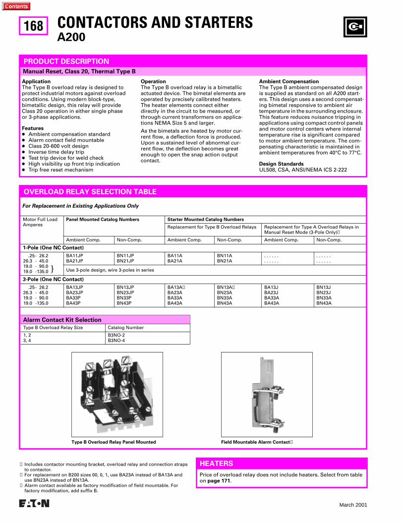
168
March 2001
Alarm Contact Kit Selection
Manual Reset, Class 20, Thermal Type B
CONTACTORS AND STARTERSA200
Motor Full Load Amperes
Panel Mounted Catalog Numbers Starter Mounted Catalog Numbers
Replacement for Type B Overload Relays Replacement for Type A Overload Relays in Manual Reset Mode (3-Pole Only)➊
Ambient Comp. Non-Comp. Ambient Comp. Non-Comp. Ambient Comp. Non-Comp.
1-Pole (One NC Contact)
.25- 26.226.3 - 45.019.0 - 90.019.0 -135.0
BA11JPBA21JP
BN11JPBN21JP
BA11ABA21A
BN11ABN21A
. . . . . .
. . . . . .. . . . . .. . . . . .
Use 3-pole design, wire 3-poles in series
3-Pole (One NC Contact)
.25- 26.226.3 - 45.019.0 - 90.019.0 -135.0
BA13JPBA23JPBA33PBA43P
BN13JPBN23JPBN33PBN43P
BA13A➋BA23ABA33ABA43A
BN13A➋BN23ABN33ABN43A
BA13JBA23JBA33ABA43A
BN13JBN23JBN33ABN43A
PRODUCT DESCRIPTION
ApplicationThe Type B overload relay is designed to protect industrial motors against overload conditions. Using modern block-type, bimetallic design, this relay will provideClass 20 operation in either single phase or 3-phase applications.
Features● Ambient compensation standard● Alarm contact field mountable● Class 20-600 volt design● Inverse time delay trip● Test trip device for weld check● High visibility up front trip indication● Trip free reset mechanism
OperationThe Type B overload relay is a bimetallic actuated device. The bimetal elements areoperated by precisely calibrated heaters.The heater elements connect either directly in the circuit to be measured, or through current transformers on applica-tions NEMA Size 5 and larger.
As the bimetals are heated by motor cur-rent flow, a deflection force is produced. Upon a sustained level of abnormal cur-rent flow, the deflection becomes great enough to open the snap action output contact.
Ambient CompensationThe Type B ambient compensated design is supplied as standard on all A200 start-ers. This design uses a second compensat-ing bimetal responsive to ambient air temperature in the surrounding enclosure. This feature reduces nuisance tripping in applications using compact control panels and motor control centers where internal temperature rise is significant compared to motor ambient temperature. The com-pensating characteristic is maintained in ambient temperatures from 40°C to 77°C.
Design StandardsUL508, CSA, ANSI/NEMA ICS 2-222
OVERLOAD RELAY SELECTION TABLE
}
Type B Overload Relay Size Catalog Number
1, 23, 4
B3NO-2B3NO-4
Type B Overload Relay Panel Mounted Field Mountable Alarm Contact➌
For Replacement in Existing Applications Only
HEATERS
Price of overload relay does not include heaters. Select from table on page 171.
➊ Includes contactor mounting bracket, overload relay and connection straps to contactor.
➋ For replacement on B200 sizes 00, 0, 1, use BA23A instead of BA13A and use BN23A instead of BN13A.
➌ Alarm contact available as factory modification of field mountable. For factory modification, add suffix B.
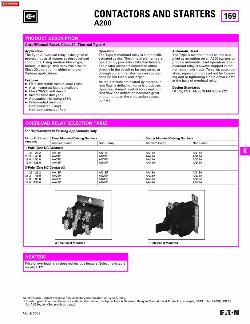
169
March 2001
K
Auto/Manual Reset, Class 20, Thermal Type A
CONTACTORS AND STARTERSA200
3-Pole Panel Mounted 1-Pole Panel Mounted
Motor Full Load Amperes
Panel Mounted Catalog Numbers Starter Mounted Catalog Numbers
Ambient Comp. Non-Comp. Ambient Comp. Non-Comp.
1-Pole (One NC Contact)
.25- 26.226.3 - 45.019.0 - 90.019.0 -135.0
AA11PAA21PAA31PAA41P
AN11PAN21PAN31PAN41P
AA11AAA21AAA31AAA41A
AN11AAN21AAN31AAN41A
3-Pole (One NC Contact)➊
.25- 26.226.3 - 45.019.0 - 90.019.0 -135.0
AA13PAA23PAA33PAA43P
AN13PAN23PAN33PAN43P
AA13AAA23AAA33AAA43A
AN13AAN23AAN33AAN43A
PRODUCT DESCRIPTION
ApplicationThe Type A overload relay is designed to protect industrial motors against overload conditions. Using modern block-type, bimetallic design, this relay will provide Class 20 operation in either single or 3-phase applications.
Features● Field selectable manual/auto reset● Alarm contract factory available● Class 20-600 volt design● Inverse time delay trip● Adjustable trip rating ±15%● Color-coded reset rod:
Compensated (Gray) Non-compensated (Red)
OperationThe Type A overload relay is a bimetallic actuated device. The bimetal elements are operated by precisely calibrated heaters. The heater elements connected either directly in the circuit to be measured, or through current transformers on applica-tions NEMA Size 5 and larger.
As the bimetals are heated by motor cur-rent flow, a deflection force is produced. Upon a sustained level of abnormal cur-rent flow, the deflection becomes great enough to open the snap action output contact.
Automatic ResetThe Type A overload relay can be sup-plied as an option on all A200 starters to provide automatic reset operation. The overload relay is always shipped in the non-automatic mode. To set up auto oper-ation, reposition the reset rod by loosen-ing and re-tightening a hold down clamp at the base of overload relay.
Design StandardsUL508, CSA, ANSI/NEMA ICS 2-222
OVERLOAD RELAY SELECTION TABLE
Price of overload relay does not include heaters. Select from table on page 171.
For Replacement in Existing Applications Only
HEATERS
NOTE: Alarm Contact available only as factory modification on Type A relay.➊ 3-pole Type B Overload Relay is a suitable alternative to a 3-pole Type A Overload Relay in Manual Reset Mode. For example, BA13JP for AA13P, BN23J
for AN23A, etc. (See previous page.)
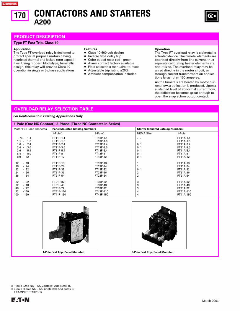
170
March 2001
1-Pole (One NC Contact); 3-Phase (Three NC Contacts in Series)
Motor Full Load Amperes Panel Mounted Catalog Numbers Starter Mounted Catalog Numbers➊
1-Pole➊ 3-Pole➋ NEMA Size 1-Pole
.76 - 1.11.1 - 1.61.6 - 2.42.4 - 3.63.6 - 5.45.4 - 8.08.0 - 12
12 - 1816 - 2422 - 3224 - 3636 - 54
22 - 3232 - 4848 - 7272 - 110
100 - 150
FT11P-1.1FT11P-1.6FT11P-2.4FT11P-3.6FT11P-5.4FT11P-8FT11P-12
FT11P-18FT11P-24FT11P-32FT21P-36FT21P-54
FT31P-32FT31P-48FT31P-72FT41P-110FT41P-150
FT13P-1.1FT13P-1.6FT13P-2.4FT13P-3.6FT13P-5.4FT13P-8FT13P-12
FT13P-18FT13P-24FT13P-32FT23P-36FT23P-54
FT33P-32FT33P-48FT33P-72FT43P-110FT43P-150
. . .
. . .0, 10, 10, 10, 10, 1
110, 122
33344
FT11A-1.1FT11A-1.6FT11A-2.4FT11A-3.6FT11A-5.4FT11A-8FT11A-12
FT11A-18FT11A-24FT11A-32FT21A-36FT21A-54
FT31A-32FT31A-48FT31A-72FT41A-110FT41A-150
CONTACTORS AND STARTERSA200
Type FT Fast Trip, Class 10
PRODUCT DESCRIPTION
ApplicationThe Type FT overload relay is designed to protect special purpose motors having restricted thermal and locked rotor capabil-ities. Using modern block-type, bimetallic design, this relay will provide Class 10 operation in single or 3-phase applications.
OVERLOAD RELAY SELECTION TABLE
1-Pole Fast Trip, Panel Mounted 3-Pole Fast Trip, Panel Mounted
For Replacement in Existing Applications Only
Features● Class 10-600 volt design● Inverse time delay trip● Color coded reset rod - green● Alarm contact factory available● Field selectable manual/auto reset● Adjustable trip rating ±20%● Ambient compensation included
OperationThe Type FT overload relay is a bimetallic actuated device. The bimetal elements are operated directly from line current, thus separate calibrating heater elements are not utilized. The overload relay may be wired directly in the motor circuit, or through current transformers on applica-tions larger than 150 amperes.
As the bimetals are heated by motor cur-rent flow, a deflection is produced. Upon a sustained level of abnormal current flow, the deflection becomes great enough to open the snap action output contact.
➊ 1-pole (One NO – NC Contact): Add suffix B.➋ 3-pole (Three NO – NC Contacts): Add suffix B.
EXAMPLE: FT13PB-12
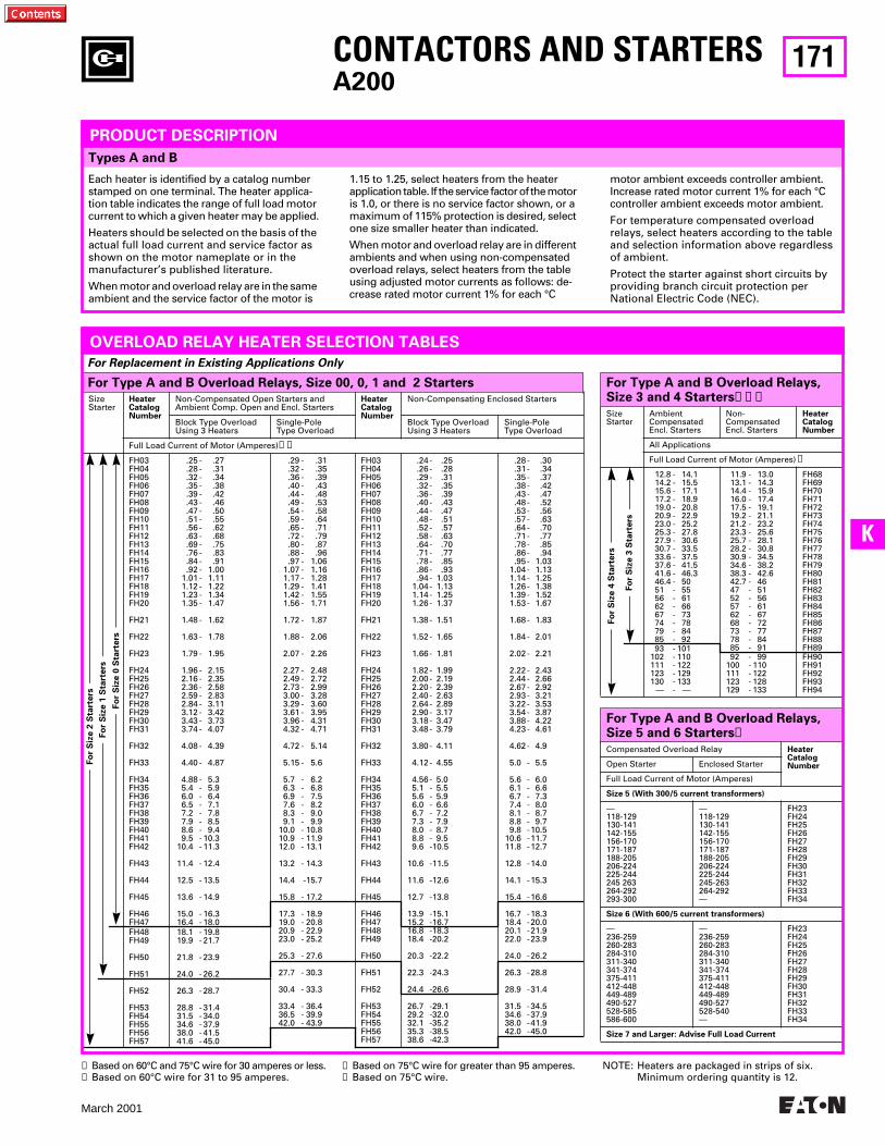
171
March 2001
K
Types A and B
CONTACTORS AND STARTERSA200
For Type A and B Overload Relays, Size 3 and 4 Starters➊➋➌SizeStarter
AmbientCompensatedEncl. Starters
Non-CompensatedEncl. Starters
HeaterCatalogNumber
All Applications
Full Load Current of Motor (Amperes)➊
12.8 - 14.114.2 - 15.515.6 - 17.117.2 - 18.919.0 - 20.820.9 - 22.923.0 - 25.225.3 - 27.827.9 - 30.630.7 - 33.533.6 - 37.537.6 - 41.541.6 - 46.346.4 - 5051 - 5556 - 6162 - 6667 - 7374 - 7879 - 8485 - 9293 - 101
102 - 110111 - 122123 - 129130 - 133
— - —
11.9 - 13.013.1 - 14.314.4 - 15.916.0 - 17.417.5 - 19.119.2 - 21.121.2 - 23.223.3 - 25.625.7 - 28.128.2 - 30.830.9 - 34.534.6 - 38.238.3 - 42.642.7 - 4647 - 5152 - 5657 - 6162 - 6768 - 7273 - 7778 - 8485 - 9192 - 99
100 - 110111 - 122123 - 128129 - 133
FH68FH69FH70FH71FH72FH73FH74FH75FH76FH77FH78FH79FH80FH81FH82FH83FH84FH85FH86FH87FH88FH89FH90FH91FH92FH93FH94
SizeStarter
HeaterCatalogNumber
Non-Compensated Open Starters andAmbient Comp. Open and Encl. Starters
HeaterCatalogNumber
Non-Compensating Enclosed Starters
Block Type OverloadUsing 3 Heaters
Single-PoleType Overload
Block Type OverloadUsing 3 Heaters
Single-PoleType Overload
Full Load Current of Motor (Amperes)➊➋
FH03FH04FH05FH06FH07FH08FH09FH10FH11FH12FH13FH14FH15FH16FH17FH18FH19FH20
FH21
FH22
FH23
FH24FH25FH26FH27FH28FH29FH30FH31
FH32
FH33
FH34FH35FH36FH37FH38FH39FH40FH41FH42
FH43
FH44
FH45
FH46FH47FH48FH49
FH50
FH51
FH52
FH53FH54FH55FH56FH57
.25 - .27
.28 - .31
.32 - .34
.35 - .38
.39 - .42
.43 - .46
.47 - .50
.51 - .55
.56 - .62
.63 - .68
.69 - .75
.76 - .83
.84 - .91
.92 - 1.001.01 - 1.111.12 - 1.221.23 - 1.341.35 - 1.47
1.48 - 1.62
1.63 - 1.78
1.79 - 1.95
1.96 - 2.152.16 - 2.352.36 - 2.582.59 - 2.832.84 - 3.113.12 - 3.423.43 - 3.733.74 - 4.07
4.08 - 4.39
4.40 - 4.87
4.88 - 5.35.4 - 5.96.0 - 6.46.5 - 7.17.2 - 7.87.9 - 8.58.6 - 9.49.5 - 10.3
10.4 - 11.3
11.4 - 12.4
12.5 - 13.5
13.6 - 14.9
15.0 - 16.316.4 - 18.018.1 - 19.819.9 - 21.7
21.8 - 23.9
24.0 - 26.2
26.3 - 28.7
28.8 - 31.431.5 - 34.034.6 - 37.938.0 - 41.541.6 - 45.0
.29 - .31
.32 - .35
.36 - .39
.40 - .43
.44 - .48
.49 - .53
.54 - .58
.59 - .64
.65 - .71
.72 - .79
.80 - .87
.88 - .96
.97 - 1.061.07 - 1.161.17 - 1.281.29 - 1.411.42 - 1.551.56 - 1.71
1.72 - 1.87
1.88 - 2.06
2.07 - 2.26
2.27 - 2.482.49 - 2.722.73 - 2.993.00 - 3.283.29 - 3.603.61 - 3.953.96 - 4.314.32 - 4.71
4.72 - 5.14
5.15 - 5.6
5.7 - 6.26.3 - 6.86.9 - 7.57.6 - 8.28.3 - 9.09.1 - 9.9
10.0 - 10.810.9 - 11.912.0 - 13.1
13.2 - 14.3
14.4 -15.7
15.8 - 17.2
17.3 - 18.919.0 - 20.820.9 - 22.923.0 - 25.2
25.3 - 27.6
27.7 - 30.3
30.4 - 33.3
33.4 - 36.436.5 - 39.942.0 - 43.9
FH03FH04FH05FH06FH07FH08FH09FH10FH11FH12FH13FH14FH15FH16FH17FH18FH19FH20
FH21
FH22
FH23
FH24FH25FH26FH27FH28FH29FH30FH31
FH32
FH33
FH34FH35FH36FH37FH38FH39FH40FH41FH42
FH43
FH44
FH45
FH46FH47FH48FH49
FH50
FH51
FH52
FH53FH54FH55FH56FH57
.24 - .25
.26 - .28
.29 - .31
.32 - .35
.36 - .39
.40 - .43
.44 - .47
.48 - .51
.52 - .57
.58 - .63
.64 - .70
.71 - .77
.78 - .85
.86 - .93
.94 - 1.031.04 - 1.131.14 - 1.251.26 - 1.37
1.38 - 1.51
1.52 - 1.65
1.66 - 1.81
1.82 - 1.992.00 - 2.192.20 - 2.392.40 - 2.632.64 - 2.892.90 - 3.173.18 - 3.473.48 - 3.79
3.80 - 4.11
4.12 - 4.55
4.56 - 5.05.1 - 5.55.6 - 5.96.0 - 6.66.7 - 7.27.3 - 7.98.0 - 8.78.8 - 9.59.6 -10.5
10.6 -11.5
11.6 -12.6
12.7 -13.8
13.9 -15.115.2 -16.716.8 -18.318.4 -20.2
20.3 -22.2
22.3 -24.3
24.4 -26.6
26.7 -29.129.2 -32.032.1 -35.235.3 -38.538.6 -42.3
.28 - .30
.31 - .34
.35 - .37
.38 - .42
.43 - .47
.48 - .52
.53 - .56
.57 - .63
.64 - .70
.71 - .77
.78 - .85
.86 - .94
.95 - 1.031.04 - 1.131.14 - 1.251.26 - 1.381.39 - 1.521.53 - 1.67
1.68 - 1.83
1.84 - 2.01
2.02 - 2.21
2.22 - 2.432.44 - 2.662.67 - 2.922.93 - 3.213.22 - 3.533.54 - 3.873.88 - 4.224.23 - 4.61
4.62 - 4.9
5.0 - 5.5
5.6 - 6.06.1 - 6.66.7 - 7.37.4 - 8.08.1 - 8.78.8 - 9.79.8 -10.5
10.6 -11.711.8 -12.7
12.8 -14.0
14.1 -15.3
15.4 -16.6
16.7 -18.318.4 -20.020.1 -21.922.0 -23.9
24.0 -26.2
26.3 -28.8
28.9 -31.4
31.5 -34.534.6 -37.938.0 -41.942.0 -45.0
For Type A and B Overload Relays, Size 00, 0, 1 and 2 Starters
PRODUCT DESCRIPTION
Each heater is identified by a catalog number stamped on one terminal. The heater applica-tion table indicates the range of full load motor current to which a given heater may be applied.
Heaters should be selected on the basis of the actual full load current and service factor as shown on the motor nameplate or in the manufacturer’s published literature.
When motor and overload relay are in the same ambient and the service factor of the motor is
1.15 to 1.25, select heaters from the heater application table. If the service factor of the motor is 1.0, or there is no service factor shown, or a maximum of 115% protection is desired, select one size smaller heater than indicated.
When motor and overload relay are in different ambients and when using non-compensated overload relays, select heaters from the table using adjusted motor currents as follows: de-crease rated motor current 1% for each °C
motor ambient exceeds controller ambient. Increase rated motor current 1% for each °C controller ambient exceeds motor ambient.
For temperature compensated overload relays, select heaters according to the table and selection information above regardless of ambient.
Protect the starter against short circuits by providing branch circuit protection per National Electric Code (NEC).
OVERLOAD RELAY HEATER SELECTION TABLES
For Replacement in Existing Applications Only
➊ Based on 60°C and 75°C wire for 30 amperes or less.➋ Based on 60°C wire for 31 to 95 amperes.
NOTE: Heaters are packaged in strips of six.Minimum ordering quantity is 12.
Fo
r S
ize 2
Sta
rters
Fo
r S
ize 1
Sta
rters
Fo
r S
ize 0
Sta
rters
Fo
r S
ize 4
Sta
rters
Fo
r S
ize 3
Sta
rters
For Type A and B Overload Relays, Size 5 and 6 Starters➍Compensated Overload Relay Heater
CatalogNumberOpen Starter Enclosed Starter
Full Load Current of Motor (Amperes)
Size 5 (With 300/5 current transformers)
—118-129130-141142-155156-170171-187188-205206-224225-244245 263264-292293-300
—118-129130-141 142-155 156-170 171-187 188-205 206-224 225-244 245-263 264-292—
FH23 FH24 FH25 FH26 FH27 FH28 FH29 FH30 FH31 FH32FH33 FH34
Size 6 (With 600/5 current transformers)
—236-259 260-283 284-310 311-340 341-374375-411412-448 449-489 490-527 528-585 586-600
—236-259260-283284-310311-340 341-374375-411412-448449-489490-527528-540—
FH23 FH24 FH25 FH26 FH27 FH28 FH29 FH30 FH31 FH32 FH33 FH34
Size 7 and Larger: Advise Full Load Current
➌ Based on 75°C wire for greater than 95 amperes.➍ Based on 75°C wire.
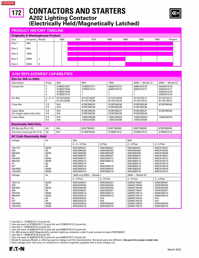
172
March 2001
AC Coils Electrically Held
Description Poles 30A 60A 100A 200A — Model J➎ 200A — Model K➑
Contact Kit 2345
373B331G07373B331G09373B331G09373B331G10
373B331G11373B331G12➊➋
626B187G12626B187G13➌➍
626B187G16626B187G17➏➐
5250C81G165250C81G175250C81G185250C81G19
Arc Box 2-, 3-, 45
6714C74G036714C74G06
6714C74G076714C74G08
6714C74G096714C74G10
6714C74G116714C74G12
6714C74G116714C74G12
Cross Bar 2-34-5
N/AN/A
672B788G32672B788G34
672B788G36672B788G38
672B788G36672B788G38
672B788G40
Upper Base(for single rated coils only)
2-34-5
N/AN/A
672B788G33672B788G35
672B788G37672B788G39
672B788G37672B788G39
672B788G52
Lower Base 2-34-5
N/AN/A
1250C33G091250C33G05
1250C33G031250C33G06
1250C33G031250C33G06
1250C33G10
Kits for 30A to 200A
Electrically Held Only
KO Spring (Pk of 10) All N/A 503C796G01 503C796G02 503C796G02 672B788G50
Terminal Line/Load (Pk of 3) All N/A 371B870G03 372B357G12 372B357G13 372B357G13
Voltage Hz 30A 60A
2-, 3-, 4-Pole 5-Pole 2-, 3-Pole 4-, 5-Pole
120/110208600/550380240/220480/44024227240/480➒120/240➒
60/506060/505060/5060/50606060/6060/60
505C806G01505C806G02505C806G05505C806G07505C806G12505C806G13505C806G16505C806G18505C806G03505C806G10
505C808G01505C808G02505C808G05505C808G07505C808G12505C808G13N/A505C808G16505C808G03505C808G10
505C806G01505C806G02505C806G05505C806G07505C806G12505C806G13505C806G16505C806G18505C806G03505C806G10
505C818G01505C818G02505C818G05505C818G07505C818G12505C818G13505C818G15505C818G16505C818G03505C818G10
Voltage Hz 100A and 200A — Model J 200A — Model K➑
2-, 3-Pole 4-, 5-Pole 2-, 3-Pole 4-, 5-Pole
120/110208600/550380240/220480/44024227240/480➒120/244➒
60/506060/505060/5060/50606060/6060/60
505C633G01505C633G02505C633G05505C633G07505C633G12505C633G13505C633G34505C633G14505C633G03505C633G10
505C635G01505C635G02505C635G05505C635G07505C635G12505C635G13N/AN/A505C635G03505C635G10
52050C79G0152050C79G0252050C79G0552050C79G0752050C79G1252050C79G1352050C79G3452050C79G1452050C79G0352050C79G10
5250C80G015250C80G025250C80G055250C80G075250C80G125250C80G13N/AN/A5250C80G035250C80G10
Size Amperes Model 1965 1970 1975 1980 1985 1990 1995 Present
Size 1
Size 2
Size 3
Size 4
Size 4
30A
60A
100A
200A
200A
J
K
Originally A Westinghouse Product
PRODUCT HISTORY TIMELINE
A202 REPLACEMENT CAPABILITIES
➊ Use Qty 2 – 373B331G11 (2-pole kit).➋ Use one each of 373B331G11 (2-pole kit) and 373B331G12 (3-pole kit).➌ Use Qty 2 – 626B187G12 (2-pole kit).➍ Use one each of 626B187G12 (2-pole kit) and 626B187G13 (3-pole kit).➎ For 200 ampere A202 Magnetically Latched Lighting contactors order 3-pole contact kit style 672B788G07.➏ Use Qty 2 – 626B187G16 (2-pole kit).➐ Use one each of 626B187G16 (2-pole kit) and 626B187G17 (3-pole kit).➑ Model K replaces Model J, offering superior design and life characteristics. Renewal parts are different. Use parts for proper model only.➒ Dual voltage coils. Use only on contactors or starters originally supplied with a dual voltage coil.
CONTACTORS AND STARTERSA202 Lighting Contactor(Electrically Held/Magnetically Latched)
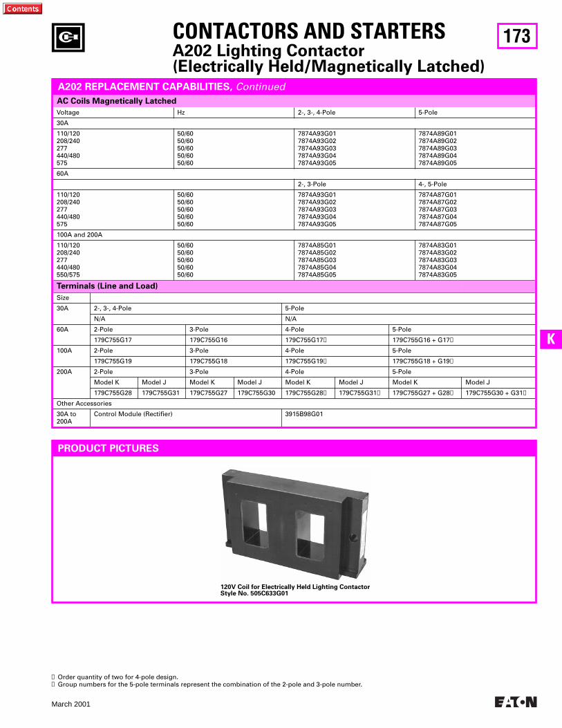
173
March 2001
K
120V Coil for Electrically Held Lighting ContactorStyle No. 505C633G01
Voltage Hz 2-, 3-, 4-Pole 5-Pole
30A
110/120208/240277440/480575
50/6050/6050/6050/6050/60
7874A93G017874A93G027874A93G037874A93G047874A93G05
7874A89G017874A89G027874A89G037874A89G047874A89G05
60A
2-, 3-Pole 4-, 5-Pole
110/120208/240277440/480575
50/6050/6050/6050/6050/60
7874A93G017874A93G027874A93G037874A93G047874A93G05
7874A87G017874A87G027874A87G037874A87G047874A87G05
100A and 200A
110/120208/240277440/480550/575
50/6050/6050/6050/6050/60
7874A85G017874A85G027874A85G037874A85G047874A85G05
7874A83G017874A83G027874A83G037874A83G047874A83G05
Terminals (Line and Load)
Size
30A 2-, 3-, 4-Pole 5-Pole
N/A N/A
60A 2-Pole 3-Pole 4-Pole 5-Pole
179C755G17 179C755G16 179C755G17➊ 179C755G16 + G17➋
100A 2-Pole 3-Pole 4-Pole 5-Pole
179C755G19 179C755G18 179C755G19➊ 179C755G18 + G19➋
200A 2-Pole 3-Pole 4-Pole 5-Pole
Model K Model J Model K Model J Model K Model J Model K Model J
179C755G28 179C755G31 179C755G27 179C755G30 179C755G28➊ 179C755G31➊ 179C755G27 + G28➋ 179C755G30 + G31➋
Other Accessories
30A to 200A
Control Module (Rectifier) 3915B98G01
AC Coils Magnetically Latched
A202 REPLACEMENT CAPABILITIES, Continued
PRODUCT PICTURES
➊ Order quantity of two for 4-pole design.➋ Group numbers for the 5-pole terminals represent the combination of the 2-pole and 3-pole number.
CONTACTORS AND STARTERSA202 Lighting Contactor(Electrically Held/Magnetically Latched)
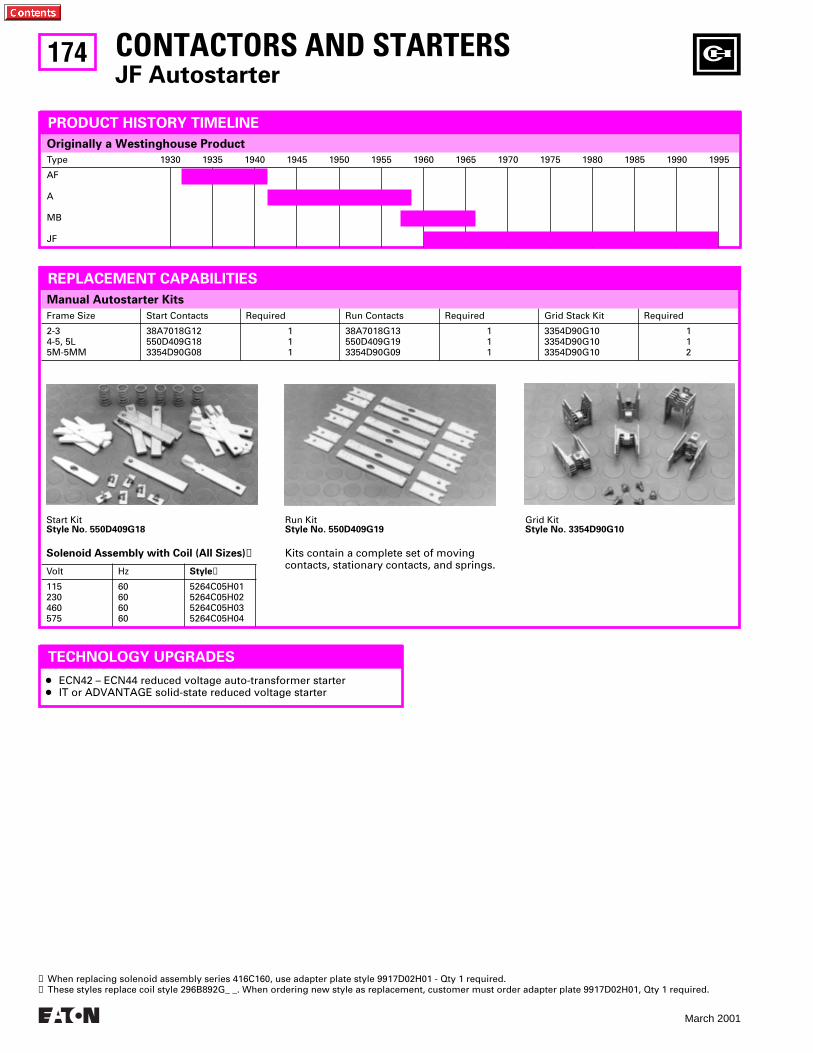
174
March 2001
Frame Size Start Contacts Required Run Contacts Required Grid Stack Kit Required
2-34-5, 5L5M-5MM
38A7018G12550D409G183354D90G08
111
38A7018G13550D409G193354D90G09
111
3354D90G103354D90G103354D90G10
112
Manual Autostarter Kits
Originally a Westinghouse Product
CONTACTORS AND STARTERSJF Autostarter
PRODUCT HISTORY TIMELINE
REPLACEMENT CAPABILITIES
Kits contain a complete set of moving contacts, stationary contacts, and springs.
Start KitStyle No. 550D409G18
Run KitStyle No. 550D409G19
Grid KitStyle No. 3354D90G10
Solenoid Assembly with Coil (All Sizes)➊
Volt Hz Style➋
115230460575
60606060
5264C05H015264C05H025264C05H035264C05H04
Type 1930 1935 1940 1945 1950 1955 1960 1965 1970 1975 1980 1985 1990 1995
AF
A
MB
JF
TECHNOLOGY UPGRADES
● ECN42 – ECN44 reduced voltage auto-transformer starter● IT or ADVANTAGE solid-state reduced voltage starter
➊ When replacing solenoid assembly series 416C160, use adapter plate style 9917D02H01 - Qty 1 required.➋ These styles replace coil style 296B892G_ _. When ordering new style as replacement, customer must order adapter plate 9917D02H01, Qty 1 required.
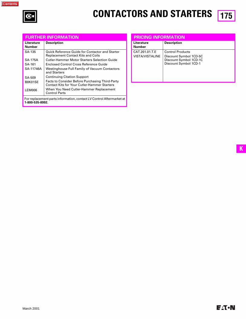
175
March 2001
K
For replacement parts information, contact LV Control Aftermarket at 1-800-535-8992.
Literature
Number
Description
SA-135
SA-175ASA-161SA-11746A
SA-509B8K01SE
LEM006
Quick Reference Guide for Contactor and StarterReplacement Contact Kits and CoilsCutler-Hammer Motor Starters Selection GuideEnclosed Control Cross Reference GuideWestinghouse Full Family of Vacuum Contactors and StartersContinuing Citation SupportFacts to Consider Before Purchasing Third-Party Contact Kits for Your Cutler-Hammer StartersWhen You Need Cutler-Hammer Replacement Control Parts
Literature
Number
Description
CAT.201.01.T.EVISTA/VISTALINE
Control ProductsDiscount Symbol 1CD-5CDiscount Symbol 1CD-1CDiscount Symbol 1CD-1
CONTACTORS AND STARTERS
FURTHER INFORMATION PRICING INFORMATION
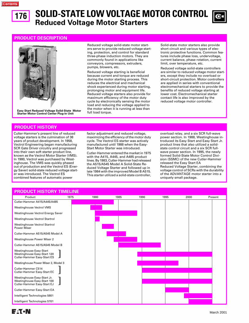
176
March 2001
Product 1975 1980 1985 1990 1995 2000 Present
Cutler-Hammer A415/A445/A485
Westinghouse Vectrol VMS
Westinghouse Vectrol Energy Saver
Westinghouse Vectrol Startrol
Westinghouse Vectrol StartrolPower Miser
Cutler-Hammer A515/A545 Model A
Westinghouse Power Miser 2
Cutler-Hammer A515/A545 Model B
Westinghouse Easy-StartWestinghouse Easy-Start 120Cutler-Hammer Easy-Start ES
Westinghouse Power Miser 2, Model 3
Cutler-Hammer C514Cutler-Hammer Easy-Start EC
Westinghouse Easy-Start Jr.Westinghouse Easy-Start 100Cutler-Hammer Easy-Start EJ
Cutler-Hammer Easy-Start EA
Intelligent Technologies 5801
Intelligent Technologies 5701
PRODUCT HISTORY TIMELINE
]
]]
SOLID-STATE LOW VOLTAGE MOTOR CONTROL
Reduced Voltage Motor Starters
PRODUCT DESCRIPTION
Reduced voltage solid-state motor start-ers serve to provide reduced voltage start-ing, protection, and control for standard three-phase induction motors. They are commonly found in applications like conveyors, compressors, extruders, pumps, blowers, etc.
Reduced voltage starting is beneficial because current and torque are reduced during the motor starting process. This reduces the electrical and mechanical shock experienced during motor starting, prolonging motor and equipment life. Reduced voltage starters also provide for maximum efficiency of the motor duty cycle by electronically sensing the motor load and reducing the voltage applied to the motor when it is running at less than full load torque.
Solid-state motor starters also provide short circuit and various types of elec-tronic protective functions. Common fea-tures include phase loss, undervoltage, current balance, phase rotation, current limit, over temperature, etc.
Reduced voltage solid-state controllers are similar to reduced voltage motor start-ers, except they include no overload or short-circuit protection. Motor controllers are applied in series with conventional electromechanical starters to provide the benefits of reduced voltage starting at lower cost. Electromechanical starter contact life is also improved by the reduced voltage motor controller.
Easy Start Reduced Voltage Solid-State MotorStarter Motor Control Center Plug-in Unit
PRODUCT HISTORY
Culter-Hammer’s present line of reduced voltage starters is the culmination of 38 years of product development. In 1958, Vectrol Engineering began manufacturing SCR Gate Driver circuitry and progressed into their own soft starter product line, known as the Vectrol Motor Starter (VMS). In 1980, Vectrol was purchased by West-inghouse. The VMS was quickly phased out of production and the Vectrol ES (Ener-gy Saver) solid-state reduced voltage start-er was introduced. The Vectrol ES combined features of automatic power
factor adjustment and reduced voltage, maximizing the efficiency of the motor duty cycle. The Vectrol ES starter was actively manufactured until 1988 when the Easy-Start Motor Starter was introduced.
Cutler-Hammer entered the market in 1975 with the A415, A445, and A485 product lines. By 1983, Cutler-Hammer had released the A515/A545 Model A Solid-State Re-duced Voltage Starter and followed up in late 1984 with the improved Model B A515. This starter utilized a solid-state controller,
overload relay, and a six SCR full-wave power section. In 1988, Westinghouse in-troduced its Easy Start and Easy Start Jr. product lines that also utilized a solid-state control circuit and a six SCR full-wave power section. In 1995, the newly formed Solid-State Motor Control Divi-sion (SSMC) of the new Cutler-Hammer released the Easy Start EAReduced Voltage Starter, combining the voltage control of SCRs with the durability of the ADVANTAGE motor starter into a uniquely small package.

177
March 2001
L
(See below for topic definitions)
PCBRepair
UpgradeKits
FactoryRepair
FieldService
TechnicalSupport
SpareParts
RecommendedReplacement
Cutler-Hammer Solid-State Reduced Voltage Starters
A415/A445/A485A515/A545 Model AA515/A545 Model BC514
●●●
●●●
●●●
●●●
●●●
Intelligent Technologies S801Intelligent Technologies S801Intelligent Technologies S801Intelligent Technologies S801
Westinghouse Solid-State Reduced Voltage Starters
Vectrol VMSVectrol Energy SaverEasy-Start/Easy-Start 120Easy-Start Jr./Easy-Start 100StartrolStartrol Power MiserPower Miser 2Power Miser 2, Model 3Easy-Start ADVANTAGE
●●●
●●●
●
●
●●●
●●●
●●
●●●
●●
●●●
●➊●●
●●●
Intelligent Technologies S801Intelligent Technologies S801Intelligent Technologies S801Intelligent Technologies S801Intelligent Technologies S801Intelligent Technologies S801Intelligent Technologies S801Intelligent Technologies S801Intelligent Technologies S801
SUPPORT CHART
Definitions
PCB Repair:
Printed circuit boards may be returned to the factory for repair. All PCBs are upgraded to the most current revision at the time of the repair.
Upgrade Kits:
Kits are available to upgrade the basic performance of certain vintage products.
Factory Repair:
Entire assemblies may be returned to the factory for repair, upgrade or refurbishment. A test-and-inspect fee applies to assemblies to evaluate the cost of repair.
Field Service:
Over 25 factory service employees nationwide provide first party service solely on SSMC products.
Technical Support:
Field service specialists located in major cities are prepared to offer on-site expertise.
Spare Parts:
Parts are available from factory stock.
SOLID-STATE LOW VOLTAGE MOTOR CONTROL
Reduced Voltage Motor Starters
➊
Original Printed Circuit Boards (PCB) are not available as spares. Please select the appropriate upgrade board for replacement.
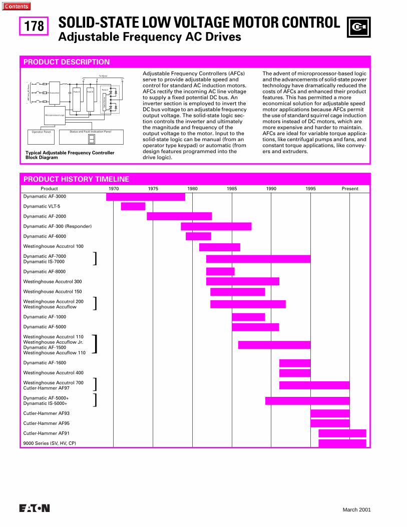
178
March 2001
To Motor
Pole A Pole BPole C
A B C
Gat
e D
rive
r
Converter
Microprocessor Logic
460
Volt
, 60
Her
tz
Operator Panel Status and Fault Indication Panel
SOLID-STATE LOW VOLTAGE MOTOR CONTROL
Adjustable Frequency AC Drives
PRODUCT DESCRIPTION
Adjustable Frequency Controllers (AFCs) serve to provide adjustable speed and control for standard AC induction motors. AFCs rectify the incoming AC line voltage to supply a fixed potential DC bus. An inverter section is employed to invert the DC bus voltage to an adjustable frequency output voltage. The solid-state logic sec-tion controls the inverter and ultimately the magnitude and frequency of the output voltage to the motor. Input to the solid-state logic can be manual (from an operator type keypad) or automatic (from design features programmed into the drive logic).
The advent of microprocessor-based logic and the advancements of solid-state power technology have dramatically reduced the costs of AFCs and enhanced their product features. This has permitted a more economical solution for adjustable speed motor applications because AFCs permit the use of standard squirrel cage induction motors instead of DC motors, which are more expensive and harder to maintain. AFCs are ideal for variable torque applica-tions, like centrifugal pumps and fans, and constant torque applications, like convey-ers and extruders.
Typical Adjustable Frequency Controller Block Diagram
Product 1970 1975 1980 1985 1990 1995 Present
Dynamatic AF-3000
Dynamatic VLT-5
Dynamatic AF-2000
Dynamatic AF-300 (Responder)
Dynamatic AF-6000
Westinghouse Accutrol 100
Dynamatic AF-7000Dynamatic IS-7000
Dynamatic AF-8000
Westinghouse Accutrol 300
Westinghouse Accutrol 150
Westinghouse Accutrol 200Westinghouse Accuflow
Dynamatic AF-1000
Dynamatic AF-5000
Westinghouse Accutrol 110Westinghouse Accuflow Jr.Dynamatic AF-1500Westinghouse Accuflow 110
Dynamatic AF-1600
Westinghouse Accutrol 400
Westinghouse Accutrol 700Cutler-Hammer AF97
Dynamatic AF-5000+Dynamatic IS-5000+
Cutler-Hammer AF93
Cutler-Hammer AF95
Cutler-Hammer AF91
9000 Series (SV, HV, CP)
]
]
]
]
]
PRODUCT HISTORY TIMELINE
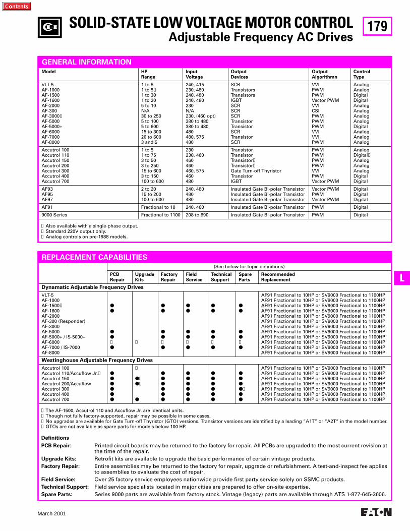
179
March 2001
L
➊
Also available with a single-phase output.
➋
Standard 220V output only.
➌
Analog controls on pre-1988 models.
Model HPRange
InputVoltage
OutputDevices
OutputAlgorithmn
ControlType
VLT-5AF-1000AF-1500AF-1600AF-2000AF-300AF-3000
➋
AF-5000AF-5000+AF-6000AF-7000AF-8000
1 to 51 to 5
➊
1 to 301 to 205 to 10N/A30 to 2505 to 1005 to 60015 to 30020 to 6003 and 5
240, 415230, 480240, 480240, 480230N/A230, (460 opt)380 to 480380 to 480480480, 575480
SCRTransistorsTransistorsIGBTSCRSCRSCRTransistorTransistorSCRTransistorSCR
VVIPWMPWMVector PWMVVICSIPWMPWMPWMVVIVVIPWM
AnalogAnalogDigitalDigitalAnalogAnalogAnalogAnalogDigitalAnalogAnalogAnalog
Accutrol 100Accutrol 110Accutrol 150Accutrol 200Accutrol 300Accutrol 400Accutrol 700
1 to 51 to 753 to 503 to 25015 to 6003 to 150100 to 600
230230, 460460460460, 575460480
TransistorTransistorTransistor
➍
Transistor
➍
Gate Turn-off ThyristorTransistorIGBT
PWMPWMPWMPWMVVIPWMVector PWM
AnalogDigital
➌
AnalogAnalogAnalogDigitalDigital
AF93AF95AF97
2 to 2015 to 200100 to 600
240, 480480480
Insulated Gate Bi-polar TransistorInsulated Gate Bi-polar TransistorInsulated Gate Bi-polar Transistor
Vector PWMPWMVector PWM
DigitalDigitalDigital
AF91 Fractional to 10 240, 460 Insulated Gate Bi-polar Transistor PWM Digital
9000 Series Fractional to 1100 208 to 690 Insulated Gate Bi-polar Transistor PWM Digital
SOLID-STATE LOW VOLTAGE MOTOR CONTROL
Adjustable Frequency AC Drives
GENERAL INFORMATION
➊
The AF-1500, Accutrol 110 and Accuflow Jr. are identical units.
➋
Though not fully factory-supported, repair may be possible in some cases.
➌
No upgrades are available for Gate Turn-off Thyristor (GTO) versions. Transistor versions are identified by a leading “A1T” or “A2T” in the model number.
➍
GTOs are not available as spare parts for models below 100 HP.
(See below for topic definitions)
PCBRepair
UpgradeKits
FactoryRepair
FieldService
TechnicalSupport
SpareParts
RecommendedReplacement
Dynamatic Adjustable Frequency Drives
VLT-5AF-1000AF-1500
➊
AF-1600AF-2000AF-300 (Responder)AF-3000AF-5000AF-5000+ / IS-5000+AF-6000AF-7000 / IS-7000AF-8000
●●
●●➋●
➋
●●
●●➋●
●●
●●➋●
●●
●●➋●
●●
●●➋●
AF91 Fractional to 10HP or SV9000 Fractional to 1100HPAF91 Fractional to 10HP or SV9000 Fractional to 1100HPAF91 Fractional to 10HP or SV9000 Fractional to 1100HPAF91 Fractional to 10HP or SV9000 Fractional to 1100HPAF91 Fractional to 10HP or SV9000 Fractional to 1100HPAF91 Fractional to 10HP or SV9000 Fractional to 1100HPAF91 Fractional to 10HP or SV9000 Fractional to 1100HPAF91 Fractional to 10HP or SV9000 Fractional to 1100HPAF91 Fractional to 10HP or SV9000 Fractional to 1100HPAF91 Fractional to 10HP or SV9000 Fractional to 1100HPAF91 Fractional to 10HP or SV9000 Fractional to 1100HPAF91 Fractional to 10HP or SV9000 Fractional to 1100HP
Westinghouse Adjustable Frequency Drives
Accutrol 100Accutrol 110/Accuflow Jr.
➊
Accutrol 150Accutrol 200/AccuflowAccutrol 300Accutrol 400Accutrol 700
●●●●●●
➋
●➌●➌
●
●●●●●●
●●●●●●
●●●●●●
●●●●➍●●
AF91 Fractional to 10HP or SV9000 Fractional to 1100HPAF91 Fractional to 10HP or SV9000 Fractional to 1100HPAF91 Fractional to 10HP or SV9000 Fractional to 1100HPAF91 Fractional to 10HP or SV9000 Fractional to 1100HPAF91 Fractional to 10HP or SV9000 Fractional to 1100HPAF91 Fractional to 10HP or SV9000 Fractional to 1100HPAF91 Fractional to 10HP or SV9000 Fractional to 1100HP
REPLACEMENT CAPABILITIES
Definitions
PCB Repair:
Printed circuit boards may be returned to the factory for repair. All PCBs are upgraded to the most current revision at the time of the repair.
Upgrade Kits:
Retrofit kits are available to upgrade the basic performance of certain vintage products.
Factory Repair:
Entire assemblies may be returned to the factory for repair, upgrade or refurbishment. A test-and-inspect fee applies to assemblies to evaluate the cost of repair.
Field Service:
Over 25 factory service employees nationwide provide first party service solely on SSMC products.
Technical Support:
Field service specialists located in major cities are prepared to offer on-site expertise.
Spare Parts:
Series 9000 parts are available from factory stock. Vintage (legacy) parts are available through ATS 1-877-645-3606.
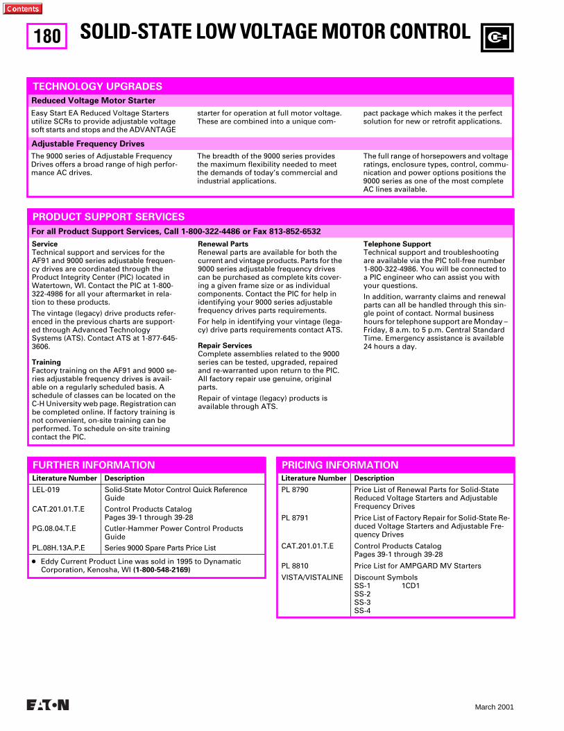
180
March 2001
For all Product Support Services, Call 1-800-322-4486 or Fax 813-852-6532
Adjustable Frequency Drives
Reduced Voltage Motor Starter
SOLID-STATE LOW VOLTAGE MOTOR CONTROL
TECHNOLOGY UPGRADES
The breadth of the 9000 series provides the maximum flexibility needed to meet the demands of today’s commercial and industrial applications.
The full range of horsepowers and voltage ratings, enclosure types, control, commu-nication and power options positions the 9000 series as one of the most complete AC lines available.
The 9000 series of Adjustable Frequency Drives offers a broad range of high perfor-mance AC drives.
Literature Number Description
LEL-019
CAT.201.01.T.E
PG.08.04.T.E
PL.08H.13A.P.E
Solid-State Motor Control Quick Reference Guide
Control Products CatalogPages 39-1 through 39-28
Cutler-Hammer Power Control Products Guide
Series 9000 Spare Parts Price List
PRODUCT SUPPORT SERVICES
Service
Technical support and services for the AF91 and 9000 series adjustable frequen-cy drives are coordinated through the Product Integrity Center (PIC) located in Watertown, WI. Contact the PIC at 1-800-322-4986 for all your aftermarket in rela-tion to these products.
The vintage (legacy) drive products refer-enced in the previous charts are support-ed through Advanced Technology Systems (ATS). Contact ATS at 1-877-645-3606.
Training
Factory training on the AF91 and 9000 se-ries adjustable frequency drives is avail-able on a regularly scheduled basis. A schedule of classes can be located on the C-H University web page. Registration can be completed online. If factory training is not convenient, on-site training can be performed. To schedule on-site training contact the PIC.
Renewal Parts
Renewal parts are available for both the current and vintage products. Parts for the 9000 series adjustable frequency drives can be purchased as complete kits cover-ing a given frame size or as individual components. Contact the PIC for help in identifying your 9000 series adjustable frequency drives parts requirements.
For help in identifying your vintage (lega-cy) drive parts requirements contact ATS.
Repair Services
Complete assemblies related to the 9000 series can be tested, upgraded, repaired and re-warranted upon return to the PIC. All factory repair use genuine, original parts.
Repair of vintage (legacy) products is available through ATS.
Telephone Support
Technical support and troubleshooting are available via the PIC toll-free number 1-800-322-4986. You will be connected to a PIC engineer who can assist you with your questions.
In addition, warranty claims and renewal parts can all be handled through this sin-gle point of contact. Normal business hours for telephone support are Monday – Friday, 8 a.m. to 5 p.m. Central Standard Time. Emergency assistance is available 24 hours a day.
FURTHER INFORMATION
●
Eddy Current Product Line was sold in 1995 to Dynamatic Corporation, Kenosha, WI
(1-800-548-2169)
Literature Number Description
PL 8790 Price List of Renewal Parts for Solid-State Reduced Voltage Starters and Adjustable Frequency Drives
PL 8791 Price List of Factory Repair for Solid-State Re-duced Voltage Starters and Adjustable Fre-quency Drives
CAT.201.01.T.E Control Products CatalogPages 39-1 through 39-28
PL 8810 Price List for AMPGARD MV Starters
VISTA/VISTALINE Discount SymbolsSS-1 1CD1SS-2SS-3SS-4
PRICING INFORMATION
Easy Start EA Reduced Voltage Starters utilize SCRs to provide adjustable voltage soft starts and stops and the ADVANTAGE
starter for operation at full motor voltage. These are combined into a unique com-
pact package which makes it the perfect solution for new or retrofit applications.
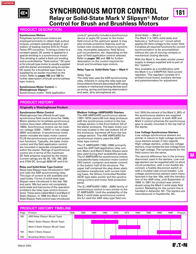
181
March 2001
M
Page Product 1945 1950 1960 1965 1970 1975 1980 1985 1990 1995 Present
182
184
190
ASR Relay Slipsyn (Brush Type)
Mark
I
Static Slipsyn (Brush Type)
Mark
II
Static Slipsyn (Brush Type)
Mark V Static Slipsyn
Brushless Motor Control
Originally a Westinghouse Product
SYNCHRONOUS MOTOR CONTROL
Relay or Solid-State Mark V Slipsyn
T
MotorControl for Brush and Brushless Motors
PRODUCT DESCRIPTION
Synchronous Motors
Polyphase synchronous motors are employed primarily to obtain high pullout torques, constant operating speed or gen-eration of leading reactive kVA for Power Factor (PF) correction. To bring a motor to a constant speed, DC power is applied to a special winding in a synchronous motor. This winding is called a field coil winding and is controlled by ”field control.“ DC pow-er for a brush type motor is usually supplied with the starter and entails using an exciter. DC power for a brushless type motor is supplied by an exciter mounted on the motor. Refer to
pages
182
and
183
for further description of brush and brushless type motors.
Synchronous Motor Control —Westinghouse Slipsyn
T
Synchronous motor ”field application
PRODUCT HISTORY
Synchronous Motor Control
Westinghouse has offered brush type synchronous field control since the 1940s. Motor starters for brushless synchronous motors have been offered since the late 1960s. Synchronous motors can be medi-um voltage (2300 – 7200V) or low voltage (600V and below). A synchronous motor starter includes the basic motor control PLUS the synchronous control and protec-tion functions. Typically, the basic motor control and the field application control are mounted in separate compartments within the starter. Ratings of synchronous control are in terms of the maximum DC field amperes required by the motor. Current ratings are 45, 90, 135, 160, 200 and 270A DC, through 6000 HP and 5 kV.
Relay and Solid-State Type Control
Relay type Slipsyn was introduced in 1947 and uses the ASR synchronizing relay. This type of control is still available and used today. Forms of solid-state type Slipsyn were introduced in the late ‘50s and early ‘60s but were not completely solid-state and had some of the operation problems the relay type control encoun-tered. These were called Mark
I
and Mark
II
Static Slipsyn. In 1989 the Mark V Solid-State Slipsyn field control was introduced.
Medium Voltage (AMPGARD) Starters
The AMI AMPGARD synchronous starter (1957–1970) used a 60-inch deep enclosure with the synchronous control in the low voltage section in the front bottom 2/3 of the starter enclosure. The basic motor con-trol was located in the rear bottom 2/3 of the enclosure, barriered off from the low voltage section. The AMI AMPGARD for synchronous motors used the ASR relay type control.
The LF AMPGARD (1962–1988) primarily used the ASR field application relay con-trol. Mark
I
and Mark
II
Static Slipsyn were also used during their availability periods. The LF AMPGARD for synchronous motors included the basic induction motor control (ISO switch, contactor and starter control) in the bottom half of the structure. The upper half contained the step down static excitation transformer with current limit-ing fuses, the Silicon Controlled Rectifier (SCR) type static exciter and the synchro-nizing control and motor field protection panel.
The SJ AMPGARD (1982 – 2000) family of synchronous control is very similar to the LF AMPGARD. Until the availability of the Mark V solid-state synchronous control, the SJ used the ASR relay type field con-
trol. With the advent of the Mark V, 90% of the synchronous starters are supplied with this type control. In both ASR and Mark V control schemes the synchronous gear is usually mounted in the top half of the starter.
Low Voltage Synchronous Starters
Low voltage synchronous starters are similar in nature to high voltage synchro-nous starters except in two regards. High voltage starters, unlike low voltage starters, must isolate the low voltage from the high voltage. The components for the field control are the same.
The second difference lies in the primary disconnect used in the starters. Low-volt-age starters can be supplied with no short circuit protection, with a non-fusible dis-connect, a fusible disconnect switch or with a molded case circuit breaker. Low voltage synchronous starters were manu-factured in the late ‘40s, with the introduc-tion of the ASR relay, until September of 1989. In 1991 the product was reintro-duced using the Mark V solid-state field control. Marketing for the current line is handled in Asheville, NC. The starters are manufactured in Fayetteville, NC.
control“ generally includes a synchronous device to apply DC power to the motor field circuit at the optimum speed. It may also include protective features such as locked rotor protection, failure to synchro-nize, incomplete sequence, field failure, pull-out protection, etc. depending on the type of field application control selected. Refer to
pages
182
and
183
for further description on the control required for brush and brushless type motors.
Relay Type vs. Solid-State Type — Mark V
Relay Type
The relay type uses the ASR synchronizing relay. Inherent in using the relay type are the problems that are associated with using contacts or mechanical closing devices such as arcing, spring and bearing deterioration and wear, dirty atmospheres etc.
Solid-State — Mark V
The Mark V is 100% solid-state and features a ”soft-turn-on“ circuit which applies DC field voltage to the motor field. It enables all required functions for correct synchronization to be accomplished without the use of moving contacts or mechanical closing devices.
With the Mark V, the static exciter power supply is always supplied and is part of the ”system.“
Also available as a modification with the Mark V is a VAR/PF/DC field current regulator. The regulator consists of a printed circuit board, auxiliary devices and potentiometers for adjustment.
PRODUCT HISTORY TIMELINE
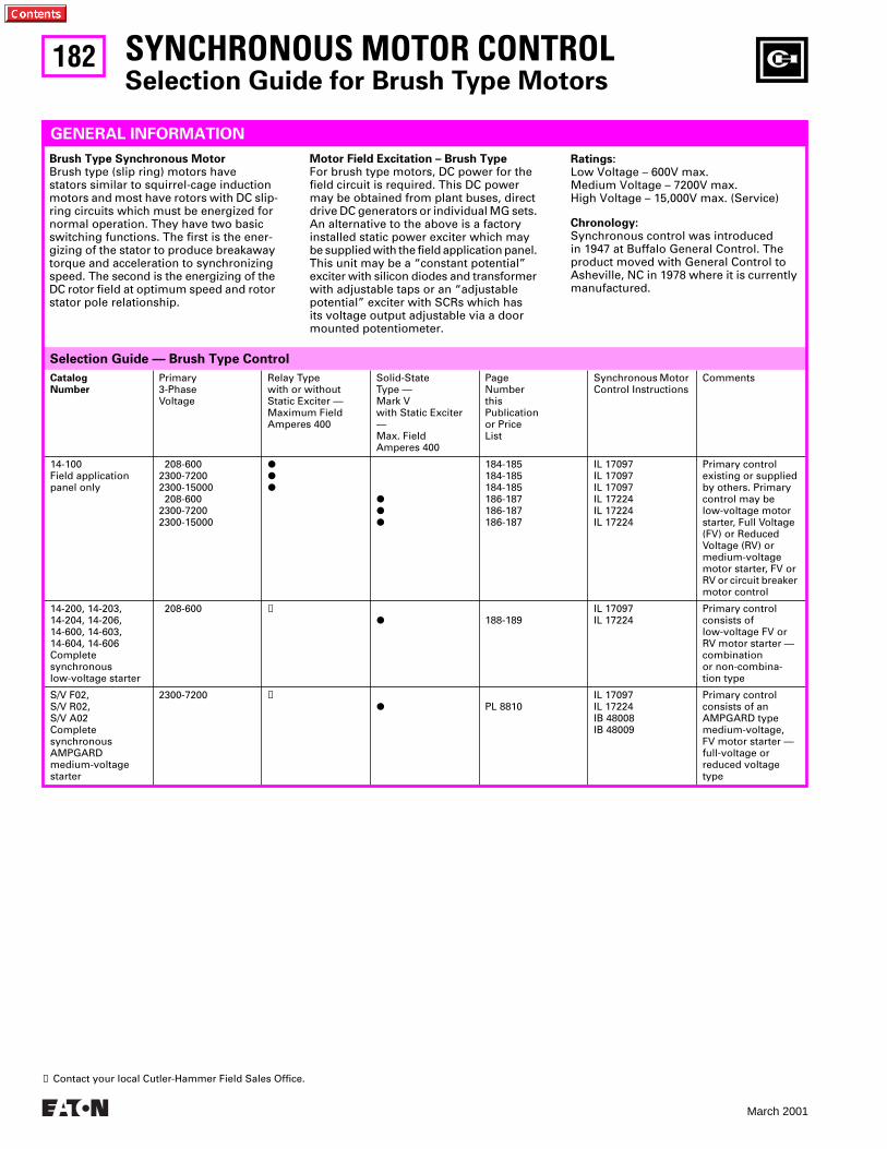
182
March 2001
Selection Guide — Brush Type Control
CatalogNumber
Primary3-PhaseVoltage
Relay Typewith or without Static Exciter — Maximum Field Amperes 400
Solid-StateType — Mark Vwith Static Exciter —Max. FieldAmperes 400
PageNumberthisPublicationor PriceList
Synchronous Motor Control Instructions
Comments
14-100 Field application panel only
208-6002300-72002300-15000 208-6002300-72002300-15000
PPP
PPP
184-185184-185184-185186-187186-187186-187
IL 17097IL 17097IL 17097IL 17224IL 17224IL 17224
Primary control existing or suppliedby others. Primarycontrol may be low-voltage motor starter, Full Voltage (FV) or Reduced Voltage (RV) or medium-voltage motor starter, FV or RV or circuit breaker motor control
14-200, 14-203, 14-204, 14-206, 14-600, 14-603, 14-604, 14-606 Completesynchronous low-voltage starter
208-600
➊
P
188-189IL 17097IL 17224
Primary controlconsists of low-voltage FV or RV motor starter — combination or non-combina-tion type
S/V F02,S/V R02,S/V A02Complete synchronous AMPGARD medium-voltage starter
2300-7200
➊
P
PL 8810IL 17097IL 17224IB 48008IB 48009
Primary control consists of an AMPGARD type medium-voltage, FV motor starter — full-voltage or reduced voltage type
SYNCHRONOUS MOTOR CONTROL
Selection Guide for Brush Type Motors
GENERAL INFORMATION
Brush Type Synchronous Motor
Brush type (slip ring) motors have stators similar to squirrel-cage induction motors and most have rotors with DC slip-ring circuits which must be energized for normal operation. They have two basic switching functions. The first is the ener-gizing of the stator to produce breakaway torque and acceleration to synchronizing speed. The second is the energizing of the DC rotor field at optimum speed and rotor stator pole relationship.
Motor Field Excitation – Brush Type
For brush type motors, DC power for the field circuit is required. This DC power may be obtained from plant buses, direct drive DC generators or individual MG sets. An alternative to the above is a factory installed static power exciter which may be supplied with the field application panel. This unit may be a “constant potential” exciter with silicon diodes and transformer with adjustable taps or an “adjustable potential” exciter with SCRs which has its voltage output adjustable via a door mounted potentiometer.
Ratings:
Low Voltage – 600V max.Medium Voltage – 7200V max.High Voltage – 15,000V max. (Service)
Chronology:
Synchronous control was introduced in 1947 at Buffalo General Control. The product moved with General Control to Asheville, NC in 1978 where it is currently manufactured.
➊
Contact your local Cutler-Hammer Field Sales Office.
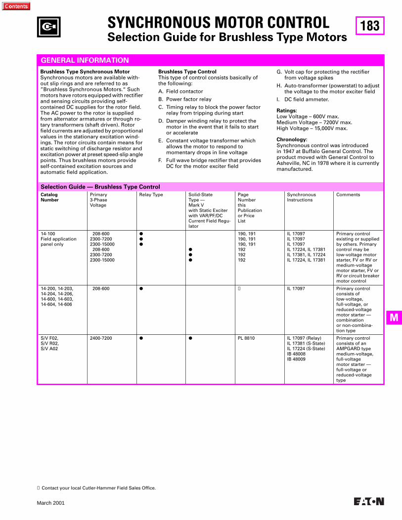
183
March 2001
M
Selection Guide — Brushless Type Control
SYNCHRONOUS MOTOR CONTROL
Selection Guide for Brushless Type Motors
CatalogNumber
Primary3-PhaseVoltage
Relay Type Solid-State Type — Mark Vwith Static Exciterwith VAR/PF/DC Current Field Regu-lator
PageNumberthisPublicationor PriceList
Synchronous Instructions
Comments
14-100 Field application panel only
208-6002300-72002300-15000 208-6002300-72002300-15000
PPP
PPP
190, 191190, 191190, 191192192192
IL 17097IL 17097IL 17097IL 17224, IL 17381IL 17381, IL 17224IL 17224, IL 17381
Primary control existing or suppliedby others. Primarycontrol may be low-voltage motor starter, FV or RV or medium-voltage motor starter, FV or RV or circuit breaker motor control
14-200, 14-203, 14-204, 14-206, 14-600, 14-603, 14-604, 14-606
208-600
P
➊
IL 17097 Primary controlconsists of low-voltage, full-voltage, or reduced-voltage motor starter — combination or non-combina-tion type
S/V F02,S/V R02,S/V A02
2400-7200
P P
PL 8810 IL 17097 (Relay)IL 17381 (S-State)IL 17224 (S-State)IB 48008IB 48009
Primary control consists of an AMPGARD type medium-voltage, full-voltage motor starter — full-voltage or reduced-voltage type
GENERAL INFORMATION
Brushless Type Synchronous Motor
Synchronous motors are available with-out slip rings and are referred to as ”Brushless Synchronous Motors.“ Such motors have rotors equipped with rectifier and sensing circuits providing self-contained DC supplies for the rotor field. The AC power to the rotor is supplied from alternator armatures or through ro-tary transformers (shaft driven). Rotor field currents are adjusted by proportional values in the stationary excitation wind-ings. The rotor circuits contain means for static switching of discharge resistor and excitation power at preset speed-slip angle points. Thus brushless motors provide self-contained excitation sources and automatic field application.
Brushless Type Control
This type of control consists basically of the following:
A. Field contactor
B. Power factor relay
C. Timing relay to block the power factor relay from tripping during start
D. Damper winding relay to protect the motor in the event that it fails to start or accelerate
E. Constant voltage transformer which allows the motor to respond to momentary drops in line voltage
F. Full wave bridge rectifier that provides DC for the motor exciter field
G. Volt cap for protecting the rectifier from voltage spikes
H. Auto-transformer (powerstat) to adjust the voltage to the motor exciter field
I. DC field ammeter.
Ratings:
Low Voltage – 600V max.Medium Voltage – 7200V max.High Voltage – 15,000V max.
Chronology:
Synchronous control was introduced in 1947 at Buffalo General Control. The product moved with General Control to Asheville, NC in 1978 where it is currently manufactured.
➊
Contact your local Cutler-Hammer Field Sales Office.
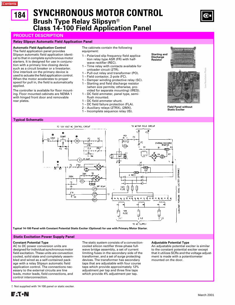
184
March 2001
Typical Schematic
Relay Slipsyn Automatic Field Application Panel
The static system consists of a convection-cooled silicon rectifier three-phase full-wave bridge assembly, a set of current limiting fuses in the secondary side of the transformer, and a set of surge protecting devices. The transformer has secondary taps that are adjustable with four course taps which provide approximately 12% adjustment per tap and three fine taps which provide 4% adjustment per tap.
Static Excitation Power Supply Panel
SYNCHRONOUS MOTOR CONTROL
Brush Type Relay Slipsyn
T
Class 14-100 Field Application Panel
PRODUCT DESCRIPTION
Constant Potential Type
AC to DC power conversion units are designed for individual synchronous motor field excitation. These units are convection cooled, solid state and completely assem-bled and wired as a self-contained pack-age with a relay Slipsyn automatic field application control. The connections nec-essary to the external circuits are line leads, motor leads, field connections, and control interconnection.
Adjustable Potential Type
An adjustable potential exciter is similar to the constant potential exciter except that it utilizes SCRs and the voltage adjust-ment is made with a potentiometer mounted on the door.
Typical 14-100 Panel with Constant Potential Static Exciter (Optional) for use with Primary Motor Starter.
Field Panel without Static Exciter
Automatic Field Application Control
The field application panel provides Slipsyn automatic field application identi-cal to that in complete synchronous motor starters. It is designed for use in conjunc-tion with a primary line closing device such as a circuit breaker or a linestarter. One interlock on the primary device is used to actuate the field application control. When the motor accelerates to proper speed for pull in, the field is automatically applied.
The controller is available for floor mount-ing. Floor mounted cabinets are NEMA 1 with hinged front door and removable rear plates.
The cabinets contain the following equipment:
1 – Polarized slip frequency field applica-tion relay type ASR (FR) with half-wave rectifier (REC).
1 – Time relay with contacts available forunloader circuit (2TR).
1 – Pull-out relay and transformer (PO).1 – Field contactor, 2-pole (FC).1 – Damper winding protective relay (SC).1 – Starting and field discharge resistor
(when size permits; otherwise, pro-vided for separate mounting) (IRES).
1 – DC field ammeter, panel type, semi-flush mounted.
1 – DC field ammeter shunt. 1 – DC field failure protection (FLA).2 – Auxiliary relays (2TRX), (2MX).1 – Incomplete sequence relay (IS).
Starting andDischargeResistor
➊
Not supplied with 14-100 panel or static exciter.
Low
Res
olut
ion
Phot
o
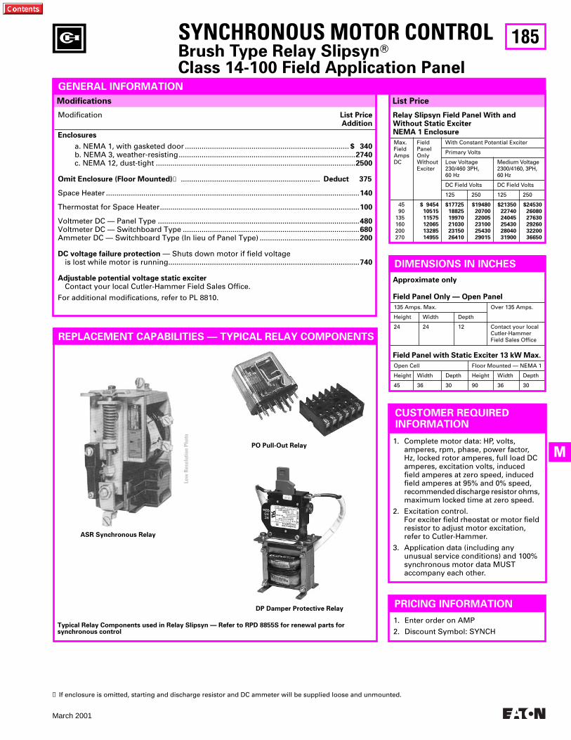
185
March 2001
M
List Price
Relay Slipsyn Field Panel With and Without Static Exciter NEMA 1 Enclosure
Max.FieldAmpsDC
Field Panel Only Without Exciter
With Constant Potential Exciter
Primary Volts
Low Voltage 230/460 3PH,60 Hz
Medium Voltage 2300/4160, 3PH, 60 Hz
DC Field Volts DC Field Volts
125 250 125 250
4590
135160200270
$ 9454
10515
11575
12065
13285
14955
$17725
18825
19970
21030
23150
26410
$19480
20700
22005
23100
25430
29015
$21350
22740
24045
25430
28040
31900
$24530
26080
27630
29260
32200
36650
Modifications
Modification
List PriceAddition
Enclosures
a. NEMA 1, with gasketed door ...............................................................................
$ 340
b. NEMA 3, weather-resisting.....................................................................................
2740
c. NEMA 12, dust-tight ................................................................................................
2500
Omit Enclosure (Floor Mounted)
➊
...................................................................
Deduct 375
Space Heater ..........................................................................................................................
140
Thermostat for Space Heater................................................................................................
100
Voltmeter DC — Panel Type .................................................................................................
480
Voltmeter DC — Switchboard Type .....................................................................................
680
Ammeter DC — Switchboard Type (In lieu of Panel Type) ................................................
200
DC voltage failure protection
— Shuts down motor if field voltageis lost while motor is running............................................................................................
740
Adjustable potential voltage static exciter
Contact your local Cutler-Hammer Field Sales Office.
For additional modifications, refer to PL 8810.
SYNCHRONOUS MOTOR CONTROL
Brush Type Relay Slipsyn
T
Class 14-100 Field Application Panel
REPLACEMENT CAPABILITIES — TYPICAL RELAY COMPONENTS
GENERAL INFORMATION
DP Damper Protective Relay
PO Pull-Out Relay
ASR Synchronous Relay
Typical Relay Components used in Relay Slipsyn — Refer to RPD 8855S for renewal parts for synchronous control
PRICING INFORMATION
1. Enter order on AMP
2. Discount Symbol: SYNCH
CUSTOMER REQUIRED INFORMATION
1. Complete motor data: HP, volts, amperes, rpm, phase, power factor, Hz, locked rotor amperes, full load DC amperes, excitation volts, induced field amperes at zero speed, induced field amperes at 95% and 0% speed, recommended discharge resistor ohms, maximum locked time at zero speed.
2. Excitation control.For exciter field rheostat or motor field resistor to adjust motor excitation, refer to Cutler-Hammer.
3. Application data (including any unusual service conditions) and 100% synchronous motor data MUST accompany each other.
DIMENSIONS IN INCHES
Field Panel with Static Exciter 13 kW Max.
Open Cell Floor Mounted — NEMA 1
Height Width Depth Height Width Depth
45 36 30 90 36 30
Approximate only
Field Panel Only — Open Panel
135 Amps. Max. Over 135 Amps.
Height Width Depth
24 24 12 Contact your local Cutler-Hammer Field Sales Office
➊
If enclosure is omitted, starting and discharge resistor and DC ammeter will be supplied loose and unmounted.
Low
Res
olut
ion
Phot
o
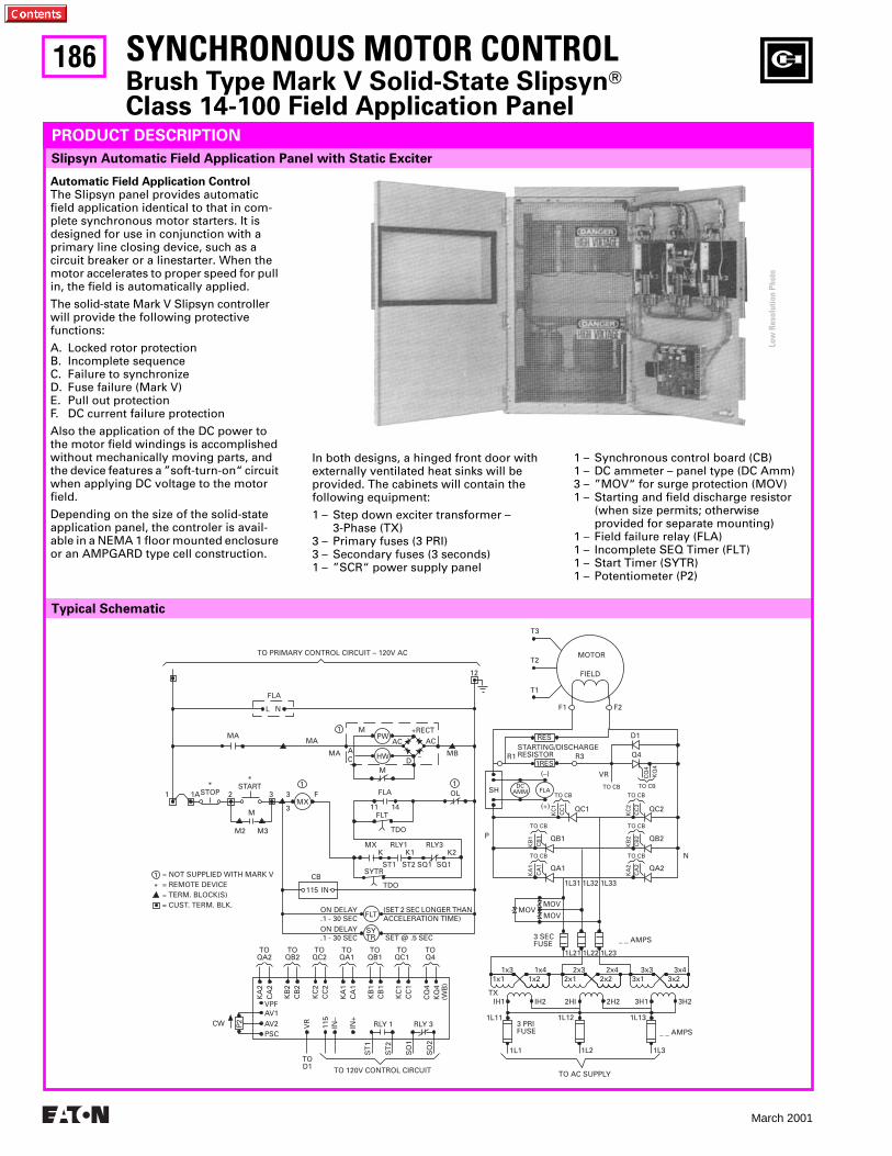
186
March 2001
IN
PSC
P2
1L21 1L22 1L23
_ _ AMPS
1x11x3
1x21x4
2x12x3
2x22x4
3x13x3
3x23x4
IH1 IH2 2HI 2H2 3H1 3H2TX
1L11 1L12 1L13
1L1 1L2 1L3
_ _ AMPS3 PRIFUSE
3 SECFUSE
MOV
MOVMOV
1L31 1L32 1L33
P
N
QA2
CA
2K
A2
CB
2K
B2
CC
2K
C2
CA
1K
A1
CB
1K
B1
QA1
QB2QB1
QC2QC1
CC
1K
C1
TO CB
TO CB
TO CB
TO CB
TO CB TO CB
TO CBTO CB
VR
FLADC
AMMSH
(–)
(+)
KQ
4C
Q4
F2F1
FIELD
MOTOR
T1
T2
T3
R1 Q4
D1
R3STARTING/DISCHARGERESISTOR
1RES
RES
12
MB
OL1
1 +RECT
–
ACAC
DM
CAMA
MA
MMA
L N
FLA
11 1A
*START*
STOP 2 3 3
3MX
F
CB
M
M2 M3
FLA
11 14FLT
TDO
MXK K1
ST1 ST2 SQ1 SQ1
RLY1 RLY3K2
SYTR
TDO115
PW
HW
TO PRIMARY CONTROL CIRCUIT – 120V AC
ON DELAY.1 - 30 SEC
FLT
SYTR
(SET 2 SEC LONGER THANACCELERATION TIME)
SET @ .5 SEC
TOQA2
TOQB2
TOQC2
TOQA1
TOQB1
TOQC1
TOQ4
KA
2C
A2
KB
2C
B2
KC
2C
C2
KA
1C
A1
KB
1C
B1
KC
1C
C1
CQ
4K
Q4
(WB
)
AV2AV1VPF
TOD1
VR
115
IN–
IN+
ST
1
RLY 1 RLY 3
ST
2
SO
1
SO
2
TO 120V CONTROL CIRCUIT
ON DELAY.1 - 30 SEC
= NOT SUPPLIED WITH MARK V= REMOTE DEVICE= TERM. BLOCK(S)= CUST. TERM. BLK.
*
1
CW
TO AC SUPPLY
Typical Schematic
SYNCHRONOUS MOTOR CONTROL
Brush Type Mark V Solid-State Slipsyn
T
Class 14-100 Field Application Panel
Slipsyn Automatic Field Application Panel with Static Exciter
PRODUCT DESCRIPTION
Automatic Field Application Control
The Slipsyn panel provides automatic field application identical to that in com-plete synchronous motor starters. It is designed for use in conjunction with a primary line closing device, such as a circuit breaker or a linestarter. When the motor accelerates to proper speed for pull in, the field is automatically applied.
The solid-state Mark V Slipsyn controller will provide the following protective functions:
A. Locked rotor protectionB. Incomplete sequenceC. Failure to synchronizeD. Fuse failure (Mark V)E. Pull out protectionF. DC current failure protection
Also the application of the DC power to the motor field windings is accomplished without mechanically moving parts, and the device features a ”soft-turn-on“ circuit when applying DC voltage to the motor field.
Depending on the size of the solid-state application panel, the controler is avail-able in a NEMA 1 floor mounted enclosure or an AMPGARD type cell construction.
In both designs, a hinged front door with externally ventilated heat sinks will be provided. The cabinets will contain the following equipment:
1 – Step down exciter transformer –3-Phase (TX)
3 – Primary fuses (3 PRI) 3 – Secondary fuses (3 seconds) 1 – ”SCR“ power supply panel
1 – Synchronous control board (CB) 1 – DC ammeter – panel type (DC Amm) 3 – ”MOV“ for surge protection (MOV) 1 – Starting and field discharge resistor
(when size permits; otherwise provided for separate mounting)
1 – Field failure relay (FLA) 1 – Incomplete SEQ Timer (FLT) 1 – Start Timer (SYTR) 1 – Potentiometer (P2)
Low
Res
olut
ion
Phot
o
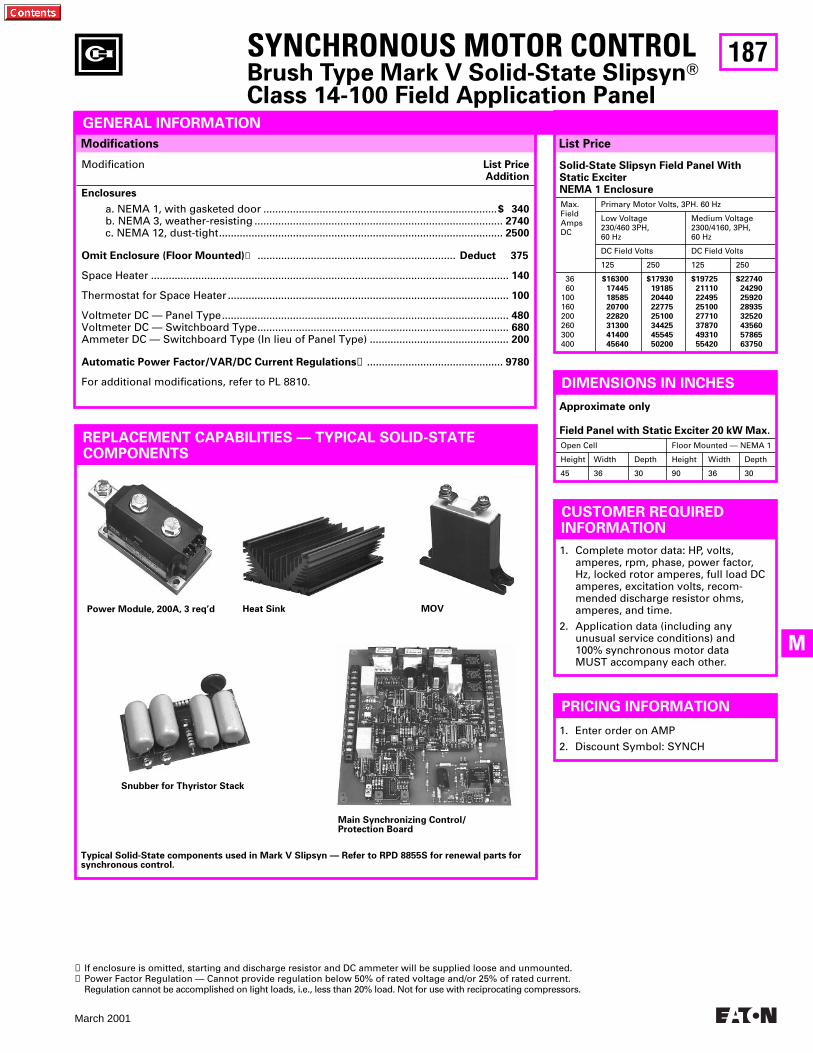
187
March 2001
M
PRICING INFORMATION
1. Enter order on AMP
2. Discount Symbol: SYNCH
DIMENSIONS IN INCHES
Approximate only
Field Panel with Static Exciter 20 kW Max.
Open Cell Floor Mounted — NEMA 1
Height Width Depth Height Width Depth
45 36 30 90 36 30
CUSTOMER REQUIRED INFORMATION
1. Complete motor data: HP, volts, amperes, rpm, phase, power factor, Hz, locked rotor amperes, full load DC amperes, excitation volts, recom-mended discharge resistor ohms, amperes, and time.
2. Application data (including any unusual service conditions) and 100% synchronous motor data MUST accompany each other.
Modifications
SYNCHRONOUS MOTOR CONTROL
Brush Type Mark V Solid-State Slipsyn
T
Class 14-100 Field Application Panel
REPLACEMENT CAPABILITIES — TYPICAL SOLID-STATECOMPONENTS
Modification
List PriceAddition
Enclosures
a. NEMA 1, with gasketed door ...............................................................................
$ 340
b. NEMA 3, weather-resisting ....................................................................................
2740
c. NEMA 12, dust-tight................................................................................................
2500
Omit Enclosure (Floor Mounted)
➊
...................................................................
Deduct 375
Space Heater .........................................................................................................................
140
Thermostat for Space Heater ...............................................................................................
100
Voltmeter DC — Panel Type.................................................................................................
480
Voltmeter DC — Switchboard Type.....................................................................................
680
Ammeter DC — Switchboard Type (In lieu of Panel Type) ...............................................
200
Automatic Power Factor/VAR/DC Current Regulations
➋
..............................................
9780
For additional modifications, refer to PL 8810.
Power Module, 200A, 3 req’d
Snubber for Thyristor Stack
Main Synchronizing Control/Protection Board
Typical Solid-State components used in Mark V Slipsyn — Refer to RPD 8855S for renewal parts for synchronous control.
Heat Sink MOV
List Price
GENERAL INFORMATION
Solid-State Slipsyn Field Panel WithStatic ExciterNEMA 1 Enclosure
Max.FieldAmpsDC
Primary Motor Volts, 3PH. 60 Hz
Low Voltage 230/460 3PH, 60 Hz
Medium Voltage 2300/4160, 3PH, 60 Hz
DC Field Volts DC Field Volts
125 250 125 250
3660
100160200260300400
$16300
17445
18585
20700
22820
31300
41400
45640
$17930
19185
20440
22775
25100
34425
45545
50200
$19725
21110
22495
25100
27710
37870
49310
55420
$22740
24290
25920
28935
32520
43560
57865
63750
➊ If enclosure is omitted, starting and discharge resistor and DC ammeter will be supplied loose and unmounted.➋ Power Factor Regulation — Cannot provide regulation below 50% of rated voltage and/or 25% of rated current.
Regulation cannot be accomplished on Iight loads, i.e., less than 20% load. Not for use with reciprocating compressors.
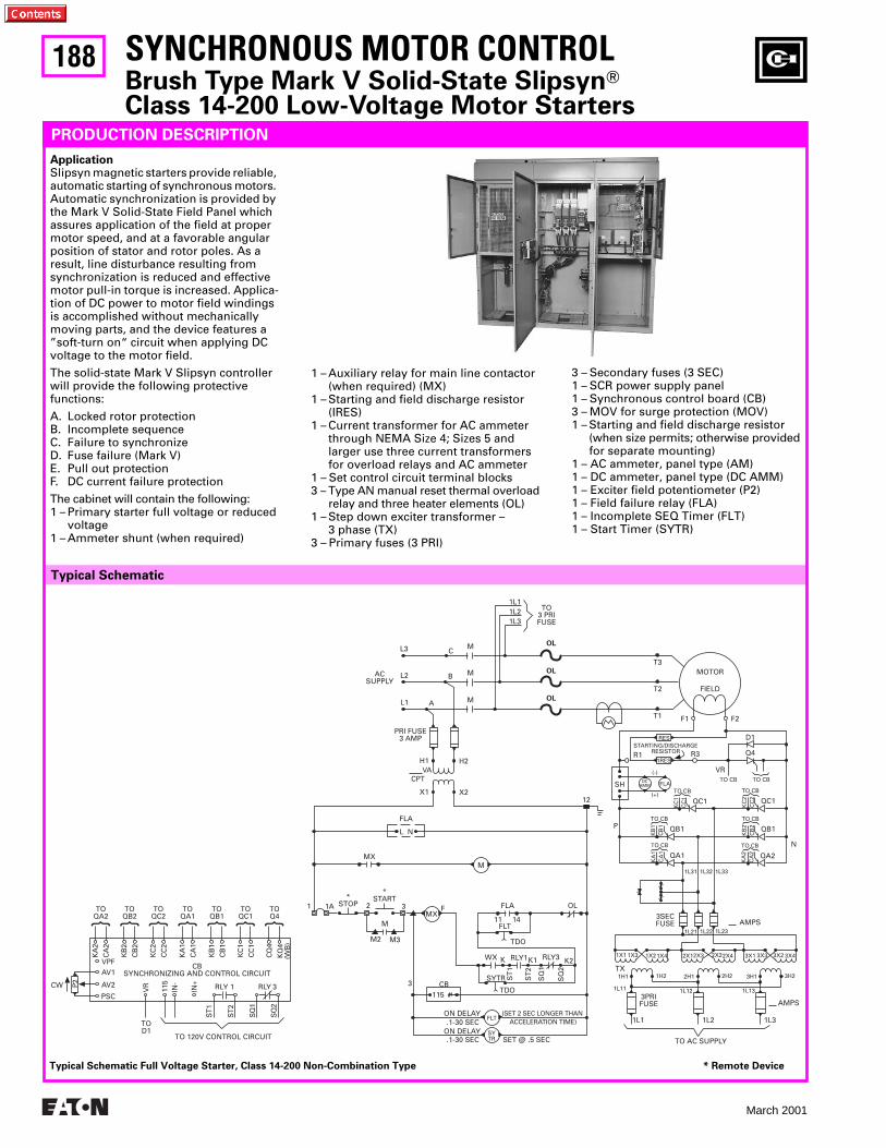
188
March 2001
TOQA2
TOQB2
TOQC2
TOQA1
TOQB1
TOQC1
TOQ4
KA
2
CA
2
KB
2
CB
2
KC
2
CC
2
KA
1
CA
1
KB
1
CB
1
KC
1
CC
1
CQ
4
KQ
4(W
B)
VPFAV1
AV2
PSC
CBSYNCHRONIZING AND CONTROL CIRCUIT
VR
115
IN-
IN+
ST1
ST2
SQ
1
SQ
2
TOD1
TO 120V CONTROL CIRCUIT
RLY 1 RLY 3P2CW
1 1A*
STOP 2
*START
3MX
F
M
M2 M3
FLA
11 14
OL
FLT
TDO
WX K
ST
1
RLY1K1
ST
2
SQ
1
RLY3
SQ
2
K2
SYTR
TDOCB
115
3
ON DELAY.1-30 SEC
(SET 2 SEC LONGER THANACCELERATION TIME)
ON DELAY.1-30 SEC SET @ .5 SEC
3SECFUSE
1L21 1L22 1L23AMPS
1X1 1X3 1X21X4 2X12X3 2X22X4 3X1 3X3 3X2 3X4
TX
3PRIFUSE
1L1 1L2 1L3
1L11 1L12 1L13
AMPS
TO AC SUPPLY
1H1 1H2 2H1 2H2 3H1 3H2
1L31
TO CB
1L32 1L33
P
N
QA1
KA
1C
A1
TO CB
QA2
KA
2C
A2
TO CB
QB1
KB
1C
B1
TO CB
QB1
KB
2C
B2
TO CB
QC1
KC
1C
C1
TO CB
QC1
KC
2C
C2
FLADCAMM
(-)
(+)
SH
RES
1RES
TO CB
Q4
D1
TO CB
VR
R1 R3STARTING/DISCHARGE
RESISTOR
F1 F2
MOTORT3
FIELD
T1
T2
1L11L21L3
TO3 PRIFUSE
MC
B
A
L3
L2
L1
ACSUPPLY
PRI FUSE3 AMP
CPT
X1 X2
M
M
VAH1 H2
OL
OL
OL
12
FLA
L N
MXM
SYTR
FLT
Typical Schematic
SYNCHRONOUS MOTOR CONTROLBrush Type Mark V Solid-State SlipsynTClass 14-200 Low-Voltage Motor Starters
PRODUCTION DESCRIPTION
Application Slipsyn magnetic starters provide reliable, automatic starting of synchronous motors. Automatic synchronization is provided by the Mark V Solid-State Field Panel which assures application of the field at proper motor speed, and at a favorable angular position of stator and rotor poles. As a result, line disturbance resulting from synchronization is reduced and effective motor pull-in torque is increased. Applica-tion of DC power to motor field windings is accomplished without mechanically moving parts, and the device features a ”soft-turn on“ circuit when applying DC voltage to the motor field.
The solid-state Mark V Slipsyn controller will provide the following protective functions:
A. Locked rotor protectionB. Incomplete sequenceC. Failure to synchronizeD. Fuse failure (Mark V)E. Pull out protectionF. DC current failure protection
The cabinet will contain the following: 1 – Primary starter full voltage or reduced
voltage1 – Ammeter shunt (when required)
1 – Auxiliary relay for main line contactor(when required) (MX)
1 – Starting and field discharge resistor (IRES)
1 – Current transformer for AC ammeterthrough NEMA Size 4; Sizes 5 and larger use three current transformers for overload relays and AC ammeter
1 – Set control circuit terminal blocks 3 – Type AN manual reset thermal overload
relay and three heater elements (OL)1 – Step down exciter transformer –
3 phase (TX) 3 – Primary fuses (3 PRI)
3 – Secondary fuses (3 SEC) 1 – SCR power supply panel 1 – Synchronous control board (CB) 3 – MOV for surge protection (MOV) 1 – Starting and field discharge resistor
(when size permits; otherwise providedfor separate mounting)
1 – AC ammeter, panel type (AM) 1 – DC ammeter, panel type (DC AMM) 1 – Exciter field potentiometer (P2)1 – Field failure relay (FLA)1 – Incomplete SEQ Timer (FLT) 1 – Start Timer (SYTR)
Typical Schematic Full Voltage Starter, Class 14-200 Non-Combination Type * Remote Device
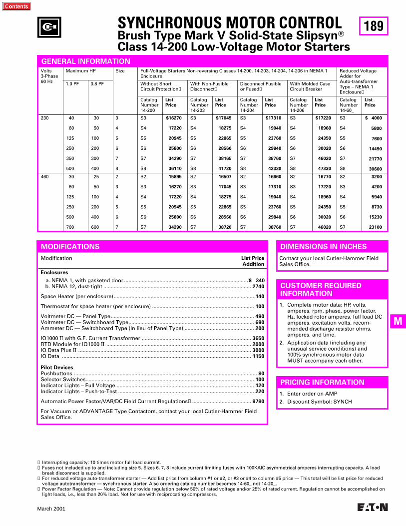
189
March 2001
M
SYNCHRONOUS MOTOR CONTROLBrush Type Mark V Solid-State SlipsynTClass 14-200 Low-Voltage Motor Starters
DIMENSIONS IN INCHES
PRICING INFORMATION
1. Enter order on AMP
2. Discount Symbol: SYNCH
MODIFICATIONS
Modification List PriceAddition
Enclosures
a. NEMA 1, with gasketed door ....................................................................................$ 340b. NEMA 12, dust-tight .................................................................................................... 2740
Space Heater (per enclosure)............................................................................................... 140
Thermostat for space heater (per enclosure) ..................................................................... 100
Voltmeter DC — Panel Type................................................................................................. 480Voltmeter DC — Switchboard Type..................................................................................... 680Ammeter DC — Switchboard Type (In lieu of Panel Type) ............................................... 200
IQ1000 II with G.F. Current Transformer .......................................................................... 3650RTD Module for IQ1000 II .................................................................................................. 2000IQ Data Plus II ..................................................................................................................... 3000IQ Data ................................................................................................................................ 1150
Pilot DevicesPushbuttons ............................................................................................................................ 80Selector Switches.................................................................................................................. 100Indicator Lights – Full Voltage.............................................................................................. 120Indicator Lights – Push-to-Test ............................................................................................ 220
Automatic Power Factor/VAR/DC Field Current Regulations➍........................................ 9780
For Vacuum or ADVANTAGE Type Contactors, contact your local Cutler-Hammer Field Sales Office.
Contact your local Cutler-Hammer Field Sales Office.
GENERAL INFORMATION
Volts3-Phase60 Hz
Maximum HP Size Full-Voltage Starters Non-reversing Classes 14-200, 14-203, 14-204, 14-206 in NEMA 1 Enclosure
Reduced VoltageAdder forAuto-transformerType – NEMA 1Enclosure➌
1.0 PF 0.8 PF Without ShortCircuit Protection➊
With Non-Fusible Disconnect➊
Disconnect Fusible or Fused➋
With Molded Case Circuit Breaker
CatalogNumber14-200
ListPrice
CatalogNumber14-203
ListPrice
CatalogNumber14-204
ListPrice
CatalogNumber14-206
ListPrice
CatalogNumber14-60_
ListPrice
230 40
60
125
250
350
500
30
50
100
200
300
400
3
4
5
6
7
8
S3
S4
S5
S6
S7
S8
$16270
17220
20945
25800
34290
36110
S3
S4
S5
S6
S7
S8
$17045
18275
22865
28560
38165
41720
S3
S4
S5
S6
S7
S8
$17310
19040
23760
29840
38760
42330
S3
S4
S5
S6
S7
S8
$17220
18960
24350
30020
46020
47330
S3
S4
S5
S6
S7
S8
$ 4000
5800
7600
14490
21770
30600
460 30
60
125
250
500
700
25
50
100
200
400
600
2
3
4
5
6
7
S2
S3
S4
S5
S6
S7
15895
16270
17220
20945
25800
34290
S2
S3
S4
S5
S6
S7
16507
17045
18275
22865
28560
38720
S2
S3
S4
S5
S6
S7
16660
17310
19040
23760
29840
38760
S2
S3
S4
S5
S6
S7
16770
17220
18960
24350
30020
46020
S2
S3
S4
S5
S6
S7
3200
4200
5940
8730
15230
23100
➊ Interrupting capacity: 10 times motor full load current. ➋ Fuses not included up to and including size 5. Sizes 6, 7, 8 include current limiting fuses with 100KAIC asymmetrical amperes interrupting capacity. A load
break disconnect is supplied.➌ For reduced voltage auto-transformer starter — Add list price from column #1 or #2, or #3 or #4 to column #5 price — This total will be list price for reduced
voltage autotransformer — synchronous starter. Also ordering catalog number becomes 14-60_ not 14-20_.➍ Power Factor Regulation — Note: Cannot provide regulation below 50% of rated voltage and/or 25% of rated current. Regulation cannot be accomplished on
light loads, i.e., Iess than 20% load. Not for use with reciprocating compressors.
CUSTOMER REQUIRED INFORMATION
1. Complete motor data: HP, volts, amperes, rpm, phase, power factor, Hz, locked rotor amperes, full load DC amperes, excitation volts, recom-mended discharge resistor ohms, amperes, and time.
2. Application data (including any unusual service conditions) and 100% synchronous motor data MUST accompany each other.
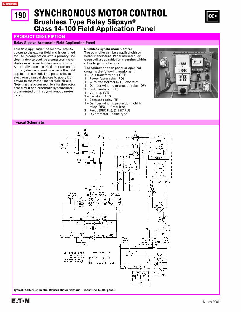
190
March 2001
SYNCHRONOUS MOTOR CONTROLBrushless Type Relay SlipsynTClass 14-100 Field Application Panel
Relay Slipsyn Automatic Field Application Panel
PRODUCT DESCRIPTION
Typical Schematic
Typical Starter Schematic. Devices shown without ➊ constitute 14-100 panel.
This field application panel provides DC power to the exciter field and is designed for use in conjunction with a primary line closing device such as a contactor motor starter or a circuit breaker motor starter. A normally open electrical interlock on the primary device is used to actuate the field application control. This panel utilizes electromechanical devices to apply DC power to the motor exciter field circuit. Note that the power rectifiers for the motor field circuit and automatic synchronizer are mounted on the synchronous motor rotor.
Brushless Synchronous Control The controller can be supplied with or without enclosure. Panel mounted, or open cell are suitable for mounting within other larger enclosures.
The cabinet or open panel or open cell contains the following equipment: 1 – Sola transformer (1 CPT) 1 – Power factor relay (PO) 1 – Auto-transformer (AT) Powerstat 1 – Damper winding protection relay (DP) 1 – Field contactor (FC) 1 – Volt trap (VT) 1 – Rectifier (REC) 1 – Sequence relay (TR) 1 – Damper winding protection hold in
relay (DPX) – if required 2 – Fuses (SEC FU), (2 SEC FU) 1 – DC ammeter – panel type
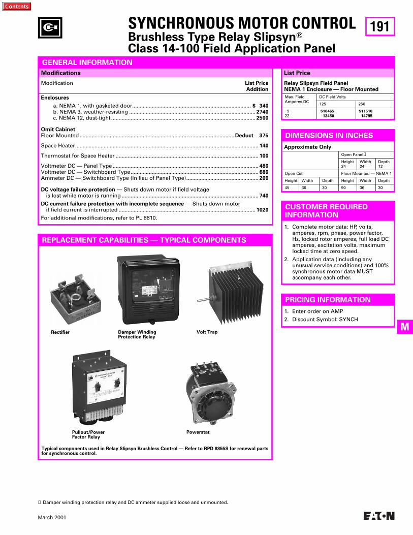
191
March 2001
M
SYNCHRONOUS MOTOR CONTROLBrushless Type Relay SlipsynTClass 14-100 Field Application Panel
Modification List PriceAddition
Enclosures
a. NEMA 1, with gasketed door............................................................................... $ 340b. NEMA 3, weather-resisting .................................................................................... 2740c. NEMA 12, dust-tight ................................................................................................ 2500
Omit CabinetFloor Mounted .......................................................................................................Deduct 375
Space Heater.......................................................................................................................... 140
Thermostat for Space Heater ............................................................................................... 100
Voltmeter DC — Panel Type ................................................................................................. 480Voltmeter DC — Switchboard Type..................................................................................... 680Ammeter DC — Switchboard Type (In lieu of Panel Type)................................................ 200
DC voltage failure protection — Shuts down motor if field voltageis lost while motor is running ........................................................................................... 740
DC current failure protection with incomplete sequence — Shuts down motor if field current is interrupted ........................................................................................... 1020
For additional modifications, refer to PL 8810.
Rectifier
Pullout/PowerFactor Relay
Powerstat
Typical components used in Relay Slipsyn Brushless Control — Refer to RPD 8855S for renewal parts for synchronous control.
Damper WindingProtection Relay
Volt Trap
REPLACEMENT CAPABILITIES — TYPICAL COMPONENTS
Modifications List Price
GENERAL INFORMATION
Relay Slipsyn Field PanelNEMA 1 Enclosure — Floor Mounted
Max. Field Amperes DC
DC Field Volts
125 250
922
$10465
13450
$11510
14795
DIMENSIONS IN INCHES Approximate Only
Open Panel➊
Height24
Width 24
Depth 12
Open Cell Floor Mounted — NEMA 1
Height Width Depth Height Width Depth
45 36 30 90 36 30
➊ Damper winding protection relay and DC ammeter supplied loose and unmounted.
PRICING INFORMATION
1. Enter order on AMP
2. Discount Symbol: SYNCH
CUSTOMER REQUIRED INFORMATION
1. Complete motor data: HP, volts, amperes, rpm, phase, power factor, Hz, locked rotor amperes, full load DC amperes, excitation volts, maximum locked time at zero speed.
2. Application data (including any unusual service conditions) and 100% synchronous motor data MUST accompany each other.
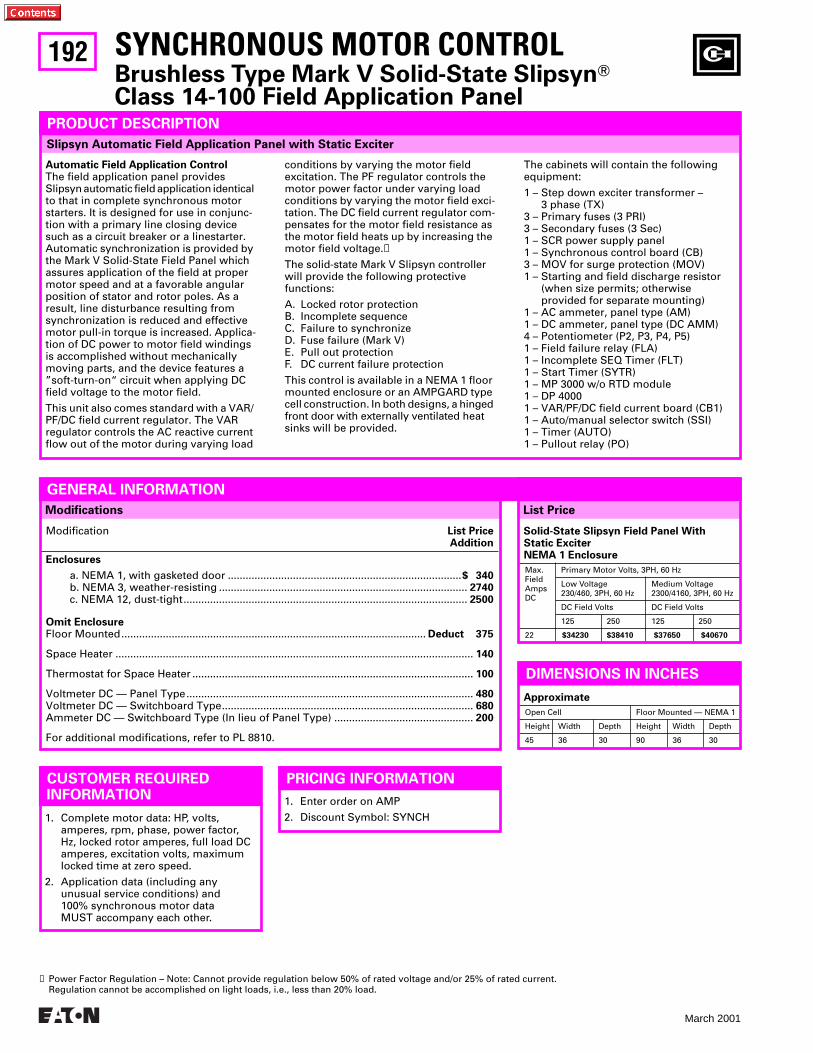
192
March 2001
List PriceModifications
Slipsyn Automatic Field Application Panel with Static Exciter
SYNCHRONOUS MOTOR CONTROLBrushless Type Mark V Solid-State SlipsynTClass 14-100 Field Application Panel
PRODUCT DESCRIPTION
Automatic Field Application Control The field application panel provides Slipsyn automatic field application identical to that in complete synchronous motor starters. It is designed for use in conjunc-tion with a primary line closing device such as a circuit breaker or a linestarter. Automatic synchronization is provided by the Mark V Solid-State Field Panel which assures application of the field at proper motor speed and at a favorable angular position of stator and rotor poles. As aresult, line disturbance resulting fromsynchronization is reduced and effective motor pull-in torque is increased. Applica-tion of DC power to motor field windings is accomplished without mechanically moving parts, and the device features a ”soft-turn-on“ circuit when applying DC field voltage to the motor field.
This unit also comes standard with a VAR/ PF/DC field current regulator. The VAR regulator controls the AC reactive current flow out of the motor during varying load
conditions by varying the motor field excitation. The PF regulator controls the motor power factor under varying load conditions by varying the motor field exci-tation. The DC field current regulator com-pensates for the motor field resistance as the motor field heats up by increasing the motor field voltage.➊
The solid-state Mark V Slipsyn controller will provide the following protective functions:
A. Locked rotor protectionB. Incomplete sequenceC. Failure to synchronizeD. Fuse failure (Mark V)E. Pull out protectionF. DC current failure protection
This control is available in a NEMA 1 floor mounted enclosure or an AMPGARD type cell construction. In both designs, a hinged front door with externally ventilated heat sinks will be provided.
The cabinets will contain the following equipment:
1 – Step down exciter transformer – 3 phase (TX)
3 – Primary fuses (3 PRI) 3 – Secondary fuses (3 Sec) 1 – SCR power supply panel 1 – Synchronous control board (CB) 3 – MOV for surge protection (MOV) 1 – Starting and field discharge resistor
(when size permits; otherwise provided for separate mounting)
1 – AC ammeter, panel type (AM) 1 – DC ammeter, panel type (DC AMM) 4 – Potentiometer (P2, P3, P4, P5) 1 – Field failure relay (FLA) 1 – Incomplete SEQ Timer (FLT) 1 – Start Timer (SYTR) 1 – MP 3000 w/o RTD module 1 – DP 40001 – VAR/PF/DC field current board (CB1) 1 – Auto/manual selector switch (SSI) 1 – Timer (AUTO) 1 – Pullout relay (PO)
Solid-State Slipsyn Field Panel WithStatic ExciterNEMA 1 Enclosure
Max.FieldAmpsDC
Primary Motor Volts, 3PH, 60 Hz
Low Voltage 230/460, 3PH, 60 Hz
Medium Voltage 2300/4160, 3PH, 60 Hz
DC Field Volts DC Field Volts
125 250 125 250
22 $34230 $38410 $37650 $40670
DIMENSIONS IN INCHES Approximate
Open Cell Floor Mounted — NEMA 1
Height Width Depth Height Width Depth
45 36 30 90 36 30
Modification List PriceAddition
Enclosures
a. NEMA 1, with gasketed door ...............................................................................$ 340b. NEMA 3, weather-resisting .................................................................................... 2740c. NEMA 12, dust-tight................................................................................................ 2500
Omit EnclosureFloor Mounted....................................................................................................... Deduct 375
Space Heater ......................................................................................................................... 140
Thermostat for Space Heater ............................................................................................... 100
Voltmeter DC — Panel Type................................................................................................. 480Voltmeter DC — Switchboard Type..................................................................................... 680Ammeter DC — Switchboard Type (In lieu of Panel Type) ............................................... 200
For additional modifications, refer to PL 8810.
➊ Power Factor Regulation – Note: Cannot provide regulation below 50% of rated voltage and/or 25% of rated current. Regulation cannot be accomplished on light loads, i.e., less than 20% load.
GENERAL INFORMATION
PRICING INFORMATION
1. Enter order on AMP
2. Discount Symbol: SYNCH
CUSTOMER REQUIRED INFORMATION
1. Complete motor data: HP, volts, amperes, rpm, phase, power factor, Hz, locked rotor amperes, full load DC amperes, excitation volts, maximum locked time at zero speed.
2. Application data (including any unusual service conditions) and 100% synchronous motor data MUST accompany each other.
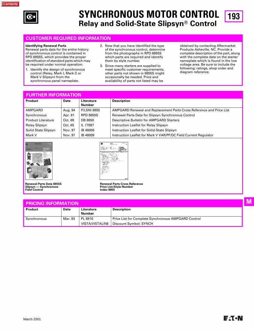
193
March 2001
M
SYNCHRONOUS MOTOR CONTROLRelay and Solid-State SlipsynT Control
CUSTOMER REQUIRED INFORMATION
Identifying Renewal PartsRenewal parts data for the entire history of synchronous control is contained in RPD 8855S, which provides the proper identification of standard parts which may be required under normal operation:
1. Identify the design of synchronous control (Relay, Mark I, Mark II or Mark V Slipsyn) from the synchronous panel nameplate.
2. Now that you have identified the type of the synchronous control, determine from the photographs in RPD 8855S which parts are required and identify them by style number.
3. Since many starters are supplied to meet specific customer requirements, other parts not shown in 8855S might occasionally be needed. Price and availability of parts not listed may be
obtained by contacting Aftermarket Products Asheville, NC. Provide a complete description of the part, along with the complete data on the starter nameplate which is found in the lowvoltage area. Be sure to include the following: ratings, shop order and diagram reference.
Renewal Parts Data 8855SSlipsyn — SynchronousField Control
Renewal Parts Cross ReferencePrice List/Style NumberIndex 8855
Product Date Literature
Number
Description
AMPGARD
Synchronous
Product Literature
Relay Slipsyn
Solid State Slipsyn
Mark V
Aug. 94
Apr. 91
Oct. 89
Oct. 85
Nov. 97
Nov. 97
P/LSNI 8855
RPD 8855S
DB 8850
IL 17097
IB 48008
IB 48009
AMPGARD Renewal and Replacement Parts Cross Reference and Price List
Renewal Parts Data for Slipsyn Synchronous Control
Descriptive Bulletin for AMPGARD Starters
Instruction Leaflet for Relay Slipsyn
Instruction Leaflet for Solid-State Slipsyn
Instruction Leaflet for Mark V VAR/PF/DC Field Current Regulator
FURTHER INFORMATION
Product Date Literature
Number
Description
Synchronous Mar. 93 PL 8810
VISTA/VISTALINE
Price List for Complete Synchronous AMPGARD Control
Discount Symbol: SYNCH
PRICING INFORMATION
194
March 2001
STARTERS (MEDIUM VOLTAGE)
The most completemedium voltage starterfamily in the industry.
AMPGARD
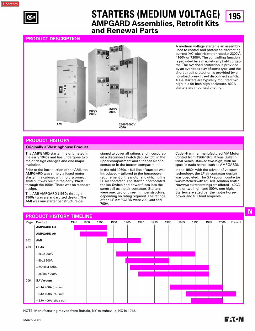
195
March 2001
N
Page Product 1945 1950 1955 1960 1965 1970 1975 1980 1985 1990 1995 2000 Present
202
203
206
AMPGARD Oil
AMPGARD AH
AMI
LF Air
– 25L2 200A
– 50L2 200A
– 25/50L4 400A
– 25/50L7 700A
SJ Vacuum
– SJA 400A (roll out)
– SJA 800A (roll out)
– SJA 400A (slide out)
Originally a Westinghouse Product
PRODUCT DESCRIPTION
A medium voltage starter is an assembly used to control and protect an alternating current (AC) electric motor rated at 2300V, 4160V or 7200V. The controlling function is provided by a magnetically held contac-tor. The overload protection is provided by an overload relay of some type, and the short circuit protection is provided by a non-load break fused disconnect switch. 400A starters are typically mounted two high in a 90-inch high enclosure. 800A starters are mounted one high.
PRODUCT HISTORY
The AMPGARD starter line originated in the early 1940s and has undergone two major design changes and one major evolution.
Prior to the introduction of the AMI, the AMPGARD was simply a fused motor starter in a cabinet with no disconnect switch. It was built in the early 1940s through the 1950s. There was no standard design.
The AMI AMPGARD (1950s through 1960s) was a standardized design. The AMI was one starter per structure de-
signed to cover all ratings and incorporat-ed a disconnect switch (Iso-Switch) in the upper compartment and either an air or oil contactor in the bottom compartment.
In the mid 1960s, a full line of starters was introduced – tailored to the horsepower requirement of the motor and utilizing the LF air contactor. The starter incorporated the Iso-Switch and power fuses into the same cell as the air contactor. Starters were one, two or three high per structure, depending on rating required. The ratings of the LF AMPGARD were 200, 400 and 700A.
PRODUCT HISTORY TIMELINE
Cutler-Hammer manufactured MV Motor Control from 1966-1976. It was Bulletin 9950 Series, stacked two-high, with no specific trade name (such as AMPGARD).
In the 1980s with the advent of vacuum technology, the LF air contactor design was obsoleted. The SJ vacuum contactor was matched with a fused isolation switch. Now two current ratings are offered – 400A, one or two high, and 800A, one high. Starters are sized per the motor horse-power and full load amperes.
5000V200A
AMI
2500V200A
2500/5000V 400A
NOTE: Manufacturing moved from Buffalo, NY to Asheville, NC in 1978.
STARTERS (MEDIUM VOLTAGE)
AMPGARD Assemblies, Retrofit Kits and Renewal Parts
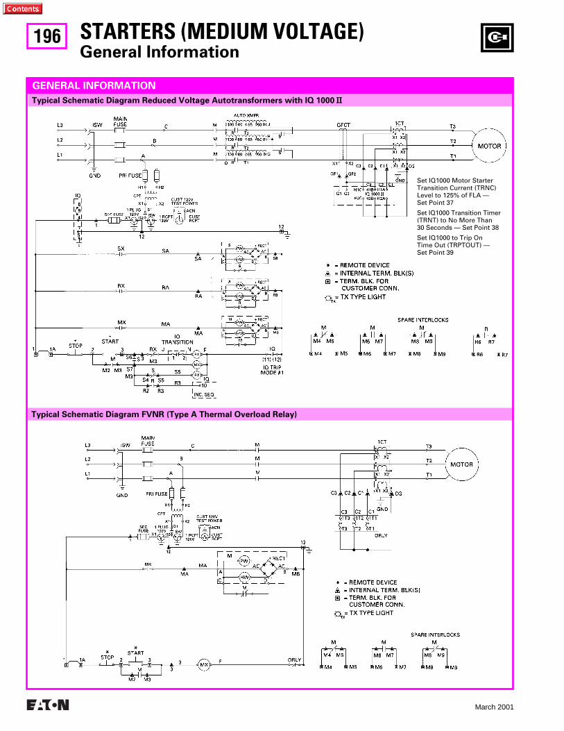
196
March 2001
Typical Schematic Diagram FVNR (Type A Thermal Overload Relay)
STARTERS (MEDIUM VOLTAGE)
General Information
Typical Schematic Diagram Reduced Voltage Autotransformers with IQ 1000
II
GENERAL INFORMATION
Set IQ1000 Motor Starter Transition Current (TRNC) Level to 125% of FLA — Set Point 37
Set IQ1000 Transition Timer (TRNT) to No More Than 30 Seconds — Set Point 38
Set IQ1000 to Trip On Time Out (TRPTOUT) —Set Point 39
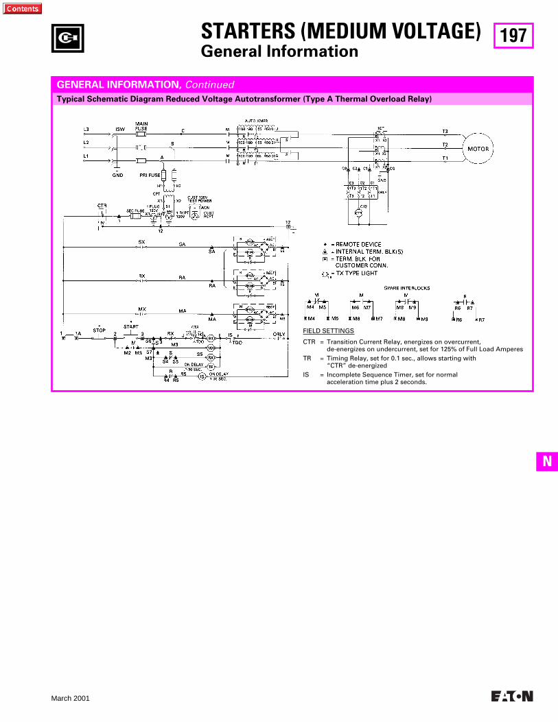
197
March 2001
N
Typical Schematic Diagram Reduced Voltage Autotransformer (Type A Thermal Overload Relay)
STARTERS (MEDIUM VOLTAGE)
General Information
GENERAL INFORMATION,
Continued
FIELD SETTINGS
CTR = Transition Current Relay, energizes on overcurrent, de-energizes on undercurrent, set for 125% of Full Load Amperes
TR = Timing Relay, set for 0.1 sec., allows starting with “CTR” de-energized
IS = Incomplete Sequence Timer, set for normal acceleration time plus 2 seconds.
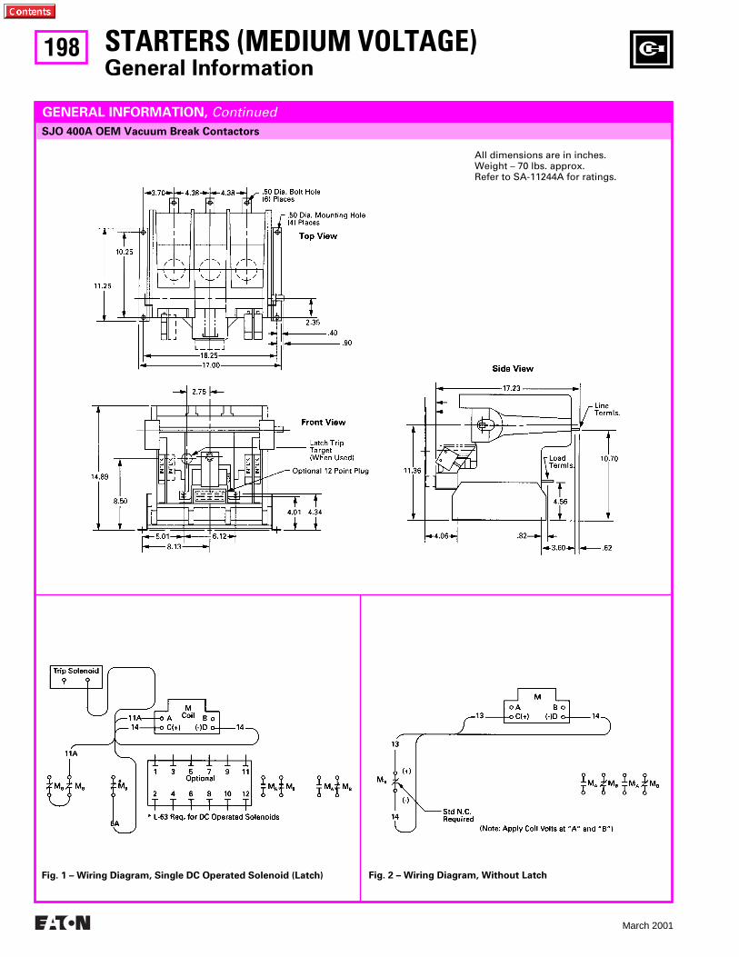
198
March 2001
STARTERS (MEDIUM VOLTAGE)
General Information
SJO 400A OEM Vacuum Break Contactors
GENERAL INFORMATION,
Continued
Fig. 1 – Wiring Diagram, Single DC Operated Solenoid (Latch) Fig. 2 – Wiring Diagram, Without Latch
All dimensions are in inches.Weight – 70 lbs. approx.Refer to SA-11244A for ratings.
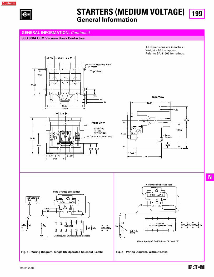
199
March 2001
N
STARTERS (MEDIUM VOLTAGE)
General Information
SJO 800A OEM Vacuum Break Contactors
GENERAL INFORMATION,
Continued
Fig. 1 – Wiring Diagram, Single DC Operated Solenoid (Latch) Fig. 2 – Wiring Diagram, Without Latch
All dimensions are in inches.Weight – 95 lbs. approx.Refer to SA-11506 for ratings.
•L-63 Reg. for DC Operated Solenoids
(Note: Apply AC Coil Volts at “A” and “B”
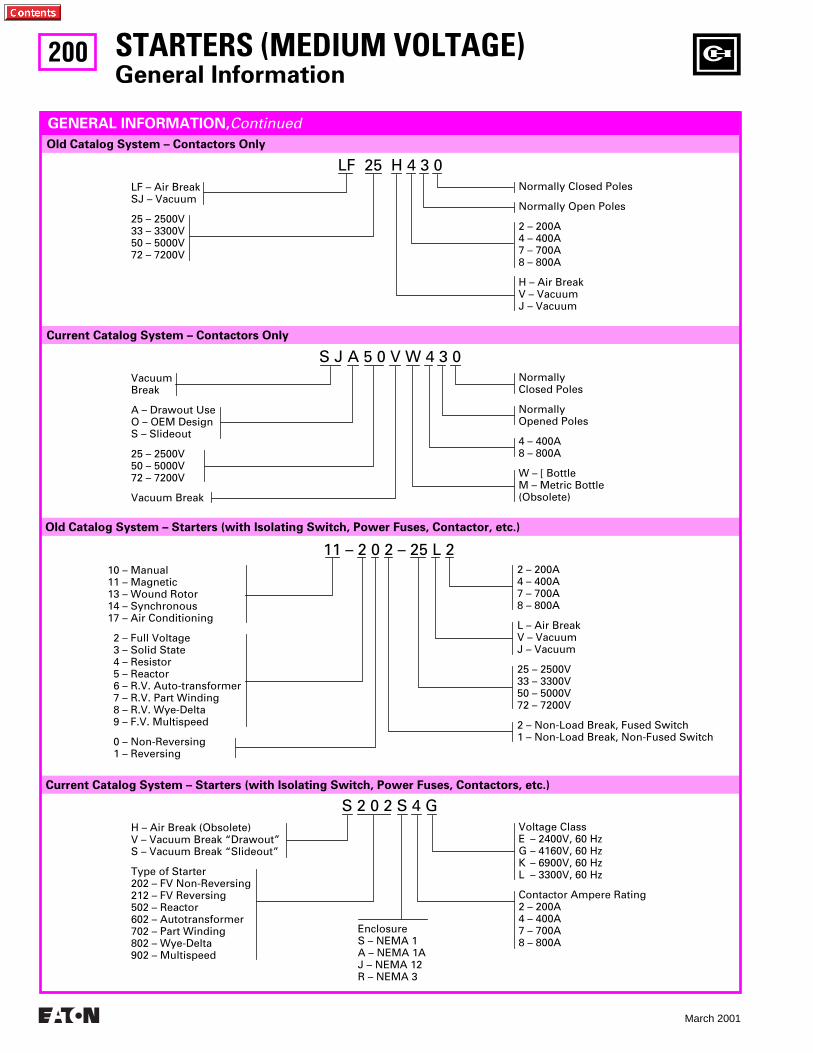
200
March 2001
Current Catalog System – Starters (with Isolating Switch, Power Fuses, Contactors, etc.)
Old Catalog System – Starters (with Isolating Switch, Power Fuses, Contactor, etc.)
Current Catalog System – Contactors Only
S J A 5 0 V W 4 3 0
VacuumBreak
A – Drawout UseO – OEM DesignS – Slideout
25 – 2500V50 – 5000V72 – 7200V
Vacuum Break
NormallyClosed Poles
NormallyOpened Poles
4 – 400A8 – 800A
W –
[
BottleM – Metric Bottle(Obsolete)
LF 25 H 4 3 0
Old Catalog System – Contactors Only
LF – Air BreakSJ – Vacuum
25 – 2500V33 – 3300V50 – 5000V72 – 7200V
Normally Closed Poles
Normally Open Poles
2 – 200A4 – 400A7 – 700A8 – 800A
H – Air BreakV – VacuumJ – Vacuum
11 – 2 0 2 – 25 L 2
10 – Manual11 – Magnetic13 – Wound Rotor14 – Synchronous17 – Air Conditioning
2 – Full Voltage 3 – Solid State 4 – Resistor 5 – Reactor 6 – R.V. Auto-transformer 7 – R.V. Part Winding 8 – R.V. Wye-Delta 9 – F.V. Multispeed
0 – Non-Reversing 1 – Reversing
2 – 200A4 – 400A7 – 700A8 – 800A
L – Air BreakV – VacuumJ – Vacuum
25 – 2500V33 – 3300V50 – 5000V72 – 7200V
2 – Non-Load Break, Fused Switch 1 – Non-Load Break, Non-Fused Switch
GENERAL INFORMATION,
Continued
STARTERS (MEDIUM VOLTAGE)
General Information
S 2 0 2 S 4 G
H – Air Break (Obsolete)V – Vacuum Break “Drawout”S – Vacuum Break “Slideout”
Type of Starter202 – FV Non-Reversing212 – FV Reversing502 – Reactor602 – Autotransformer702 – Part Winding802 – Wye-Delta902 – Multispeed
Voltage ClassE – 2400V, 60 HzG – 4160V, 60 HzK – 6900V, 60 HzL – 3300V, 60 Hz
Contactor Ampere Rating2 – 200A4 – 400A7 – 700A8 – 800A
EnclosureS – NEMA 1A – NEMA 1AJ – NEMA 12R – NEMA 3
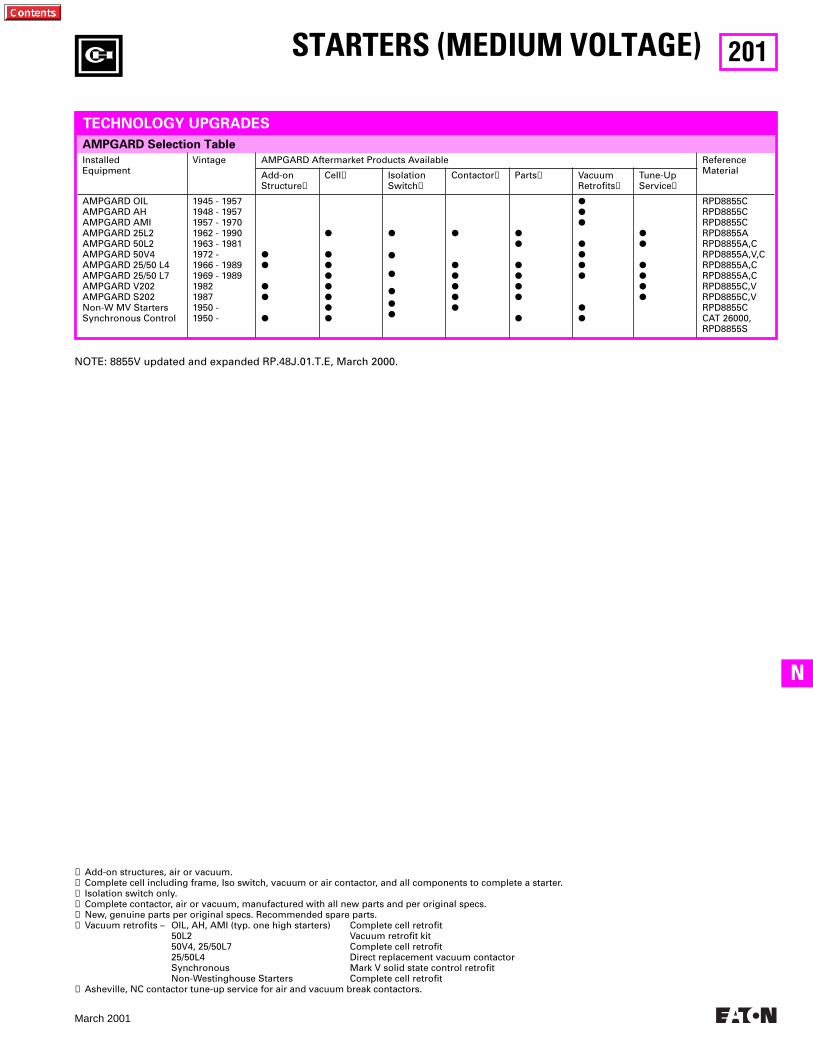
201
March 2001
N
AMPGARD Selection Table
STARTERS (MEDIUM VOLTAGE)
InstalledEquipment
Vintage AMPGARD Aftermarket Products Available ReferenceMaterialAdd-on
Structure
➊
Cell
➋
IsolationSwitch
➌
Contactor
➍
Parts
➎
VacuumRetrofits
➏
Tune-UpService
➐
AMPGARD OILAMPGARD AHAMPGARD AMIAMPGARD 25L2AMPGARD 50L2AMPGARD 50V4AMPGARD 25/50 L4AMPGARD 25/50 L7AMPGARD V202AMPGARD S202Non-W MV StartersSynchronous Control
1945 - 19571948 - 19571957 - 19701962 - 19901963 - 1981 1972 -1966 - 19891969 - 1989198219871950 -1950 -
PP
PP
P
P
PPPPPPP
P
P
P
PPP
P
PPPPP
PP
PPPP
P
PPP
PPPP
PP
PP
PPPP
RPD8855CRPD8855CRPD8855CRPD8855ARPD8855A,CRPD8855A,V,CRPD8855A,CRPD8855A,CRPD8855C,VRPD8855C,VRPD8855CCAT 26000, RPD8855S
TECHNOLOGY UPGRADES
➊
Add-on structures, air or vacuum.
➋
Complete cell including frame, Iso switch, vacuum or air contactor, and all components to complete a starter.
➌
Isolation switch only.
➍
Complete contactor, air or vacuum, manufactured with all new parts and per original specs.
➎
New, genuine parts per original specs. Recommended spare parts.
➏
Vacuum retrofits – OIL, AH, AMI (typ. one high starters) Complete cell retrofit50L2 Vacuum retrofit kit50V4, 25/50L7 Complete cell retrofit25/50L4 Direct replacement vacuum contactorSynchronous Mark V solid state control retrofitNon-Westinghouse Starters Complete cell retrofit
➐
Asheville, NC contactor tune-up service for air and vacuum break contactors.
NOTE: 8855V updated and expanded RP.48J.01.T.E, March 2000.
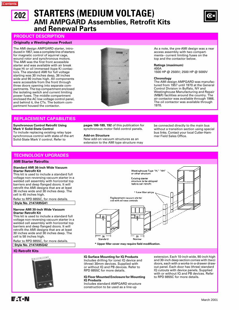
202
March 2001
AMI Starter Retrofits
Synchronous Control Retrofit UsingMark V Solid-State Control
To include replacing existing relay type synchronous control with state-of-the-art Solid-State Mark V control. Refer to
pages 186-189, 192
of this publication for synchronous motor field control panels.
Add-on Structure
New add-on vacuum structures as an extension to the AMI type structure may
be connected directly to the main bus without a transition section using special bus links. Contact your local Cutler-Ham-mer Field Sales Office.
REPLACEMENT CAPABILITIES
IQ Retrofit Kits
Originally a Westinghouse Product
STARTERS (MEDIUM VOLTAGE)
AMI AMPGARD Assemblies, Retrofit Kits and Renewal Parts
PRODUCT DESCRIPTION
The AMI design AMPGARD starter, intro-duced in 1957, was a complete line of starters for magnetic control of squirrel cage, wound rotor and synchronous motors. The AMI was the first front accessible starter and was available with air break (type H) or oil immersed (type K) contac-tors. The standard AMI for full voltage starting was 30 inches deep, 38 inches wide and 90 inches high. All components were accessible from the front through three doors opening into separate com-partments. The top compartment enclosed the isolating switch and current limiting power fuses. The middle compartment enclosed the AC low voltage control panel, and behind it, the CTs. The bottom com-partment housed the contactor.
TECHNOLOGY UPGRADES
Standard AMI 36-inch Wide Vacuum Starter Retrofit Kit
This kit is used to include a standard full voltage non-reversing vacuum starter in a welded cell assembly with horizontal top barriers and deep flanged doors. It will retrofit the AMI designs that are at least 36 inches wide and 30 inches deep. The cell is 45 inches high.Refer to RPD 8855C, for more details.
Style No. 2147A95G41
Narrow AMI 30-inch Wide Vacuum Starter Retrofit Kit
This kit is used to include a standard full voltage non-reversing vacuum starter in a welded cell assembly with horizontal top barriers and deep flanged doors. It will retrofit the AMI designs that are at least 30 inches wide and 30 inches deep. The cell is 58 inches high.Refer to RPD 8855C, for more details.
Style No. 2147A95G42
IQ Surface Mounting for IQ Products
Includes drilling for (one) IQ device and (three) 30mm devices. Supplied with or without IQ and PB devices. Refer to RPD 8855C for more details.
IQ Floor Mounted Enclosure for Mounting IQ Products
Includes standard AMPGARD structure construction to be used as a line-up
As a note, the pre-AMI design was a rear access assembly with two compart-ments– current limiting fuses on the top and the contactor below.
Ratings (maximum)
400A1500 HP @ 2500V; 2500 HP @ 5000V
Chronology
The AMI design AMPGARD was manufac-tured from 1957 until 1970 at the General Control Division in Buffalo, NY and Westinghouse Manufacturing and Repair (M&R) facilities around the country. The air contactor was available through 1966. The oil contactor was available through 1970.
* Upper filler cover may require field modification.
extension. Each 10-inch wide, 90-inch high and 30-inch deep section comes with (two) doors, each with a works-in-a-drawer draw-out panel. Each door has (three) standard IQ cutouts with device panels. Supplied with or without IQ and PB devices. Refer to RPD 8855C for more details.
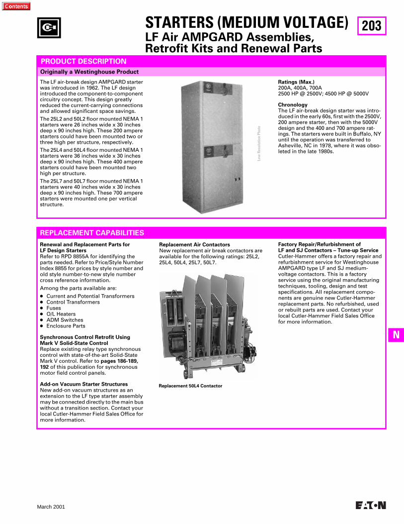
203
March 2001
N
Originally a Westinghouse Product
PRODUCT DESCRIPTION
The LF air-break design AMPGARD starter was introduced in 1962. The LF design introduced the component-to-component circuitry concept. This design greatly reduced the current-carrying connections and allowed significant space savings.The 25L2 and 50L2 floor mounted NEMA 1 starters were 26 inches wide x 30 inches deep x 90 inches high. These 200 ampere starters could have been mounted two or three high per structure, respectively.The 25L4 and 50L4 floor mounted NEMA 1 starters were 36 inches wide x 30 inches deep x 90 inches high. These 400 ampere starters could have been mounted two high per structure.The 25L7 and 50L7 floor mounted NEMA 1 starters were 40 inches wide x 30 inches deep x 90 inches high. These 700 ampere starters were mounted one per vertical structure.
Ratings (Max.)
200A, 400A, 700A 2500 HP @ 2500V; 4500 HP @ 5000V
Chronology
The LF air-break design starter was intro-duced in the early 60s, first with the 2500V, 200 ampere starter, then with the 5000V design and the 400 and 700 ampere rat-ings. The starters were built in Buffalo, NY until the operation was transferred to Asheville, NC in 1978, where it was obso-leted in the late 1980s.
STARTERS (MEDIUM VOLTAGE)
LF Air AMPGARD Assemblies, Retrofit Kits and Renewal Parts
Renewal and Replacement Parts for LF Design Starters
Refer to RPD 8855A for identifying the parts needed. Refer to Price/Style Number Index 8855 for prices by style number and old style number-to-new style number cross reference information.
Among the parts available are:
●
Current and Potential Transformers
●
Control Transformers
●
Fuses
●
O/L Heaters
●
ADM Switches
●
Enclosure Parts
Synchronous Control Retrofit UsingMark V Solid-State Control
Replace existing relay type synchronous control with state-of-the-art Solid-State Mark V control. Refer to
pages 186-189, 192
of this publication for synchronous motor field control panels.
Add-on Vacuum Starter Structures
New add-on vacuum structures as an extension to the LF type starter assembly may be connected directly to the main bus without a transition section. Contact your local Cutler-Hammer Field Sales Office for more information.
Replacement 50L4 Contactor
Replacement Air Contactors
New replacement air break contactors are available for the following ratings: 25L2, 25L4, 50L4, 25L7, 50L7.
Factory Repair/Refurbishment ofLF and SJ Contactors – Tune-up Service
Cutler-Hammer offers a factory repair and refurbishment service for Westinghouse AMPGARD type LF and SJ medium-voltage contactors. This is a factory service using the original manufacturing techniques, tooling, design and test specifications. All replacement compo-nents are genuine new Cutler-Hammer replacement parts. No refurbished, used or rebuilt parts are used. Contact your local Cutler-Hammer Field Sales Office for more information.
REPLACEMENT CAPABILITIES
Low
Res
olut
ion
Phot
o
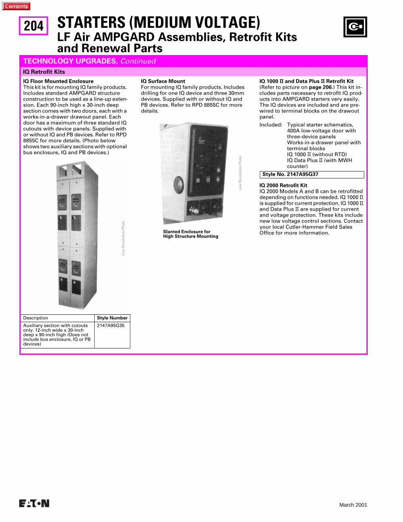
204
March 2001
IQ Retrofit Kits
TECHNOLOGY UPGRADES,
Continued
IQ Floor Mounted Enclosure
This kit is for mounting IQ family products. Includes standard AMPGARD structure construction to be used as a line-up exten-sion. Each 90-inch high x 30-inch deep section comes with two doors, each with a works-in-a-drawer drawout panel. Each door has a maximum of three standard IQ cutouts with device panels. Supplied with or without IQ and PB devices. Refer to RPD 8855C for more details. (Photo below shows two auxiliary sections with optional bus enclosure, IQ and PB devices.)
IQ Surface Mount
For mounting IQ family products. Includes drilling for one IQ device and three 30mm devices. Supplied with or without IQ and PB devices. Refer to RPD 8855C for more details.
Slanted Enclosure forHigh Structure Mounting
IQ 1000
II
and Data Plus
II
Retrofit Kit
(Refer to picture on
page 206
.) This kit in-cludes parts necessary to retrofit IQ prod-ucts into AMPGARD starters very easily. The IQ devices are included and are pre-wired to terminal blocks on the drawout panel.
Included: Typical starter schematics, 400A low-voltage door with three-device panels Works-in-a-drawer panel with terminal blocks IQ 1000
II
(without RTD) IQ Data Plus
II
(with MWH counter)
Style No. 2147A95G37
IQ 2000 Retrofit Kit
IQ 2000 Models A and B can be retrofitted depending on functions needed. IQ 1000
II
is supplied for current protection. IQ 1000
II
and Data Plus
II
are supplied for current and voltage protection. These kits include new low voltage control sections. Contact your local Cutler-Hammer Field Sales Office for more information.
STARTERS (MEDIUM VOLTAGE)
LF Air AMPGARD Assemblies, Retrofit Kits and Renewal Parts
Description
Style Number
Auxiliary section with cutouts only. 12-inch wide x 30-inch deep x 90-inch high (Does not include bus enclosure, IQ or PB devices)
2147A95G35
Low
Res
olut
ion
Phot
o
Low
Res
olut
ion
Phot
o
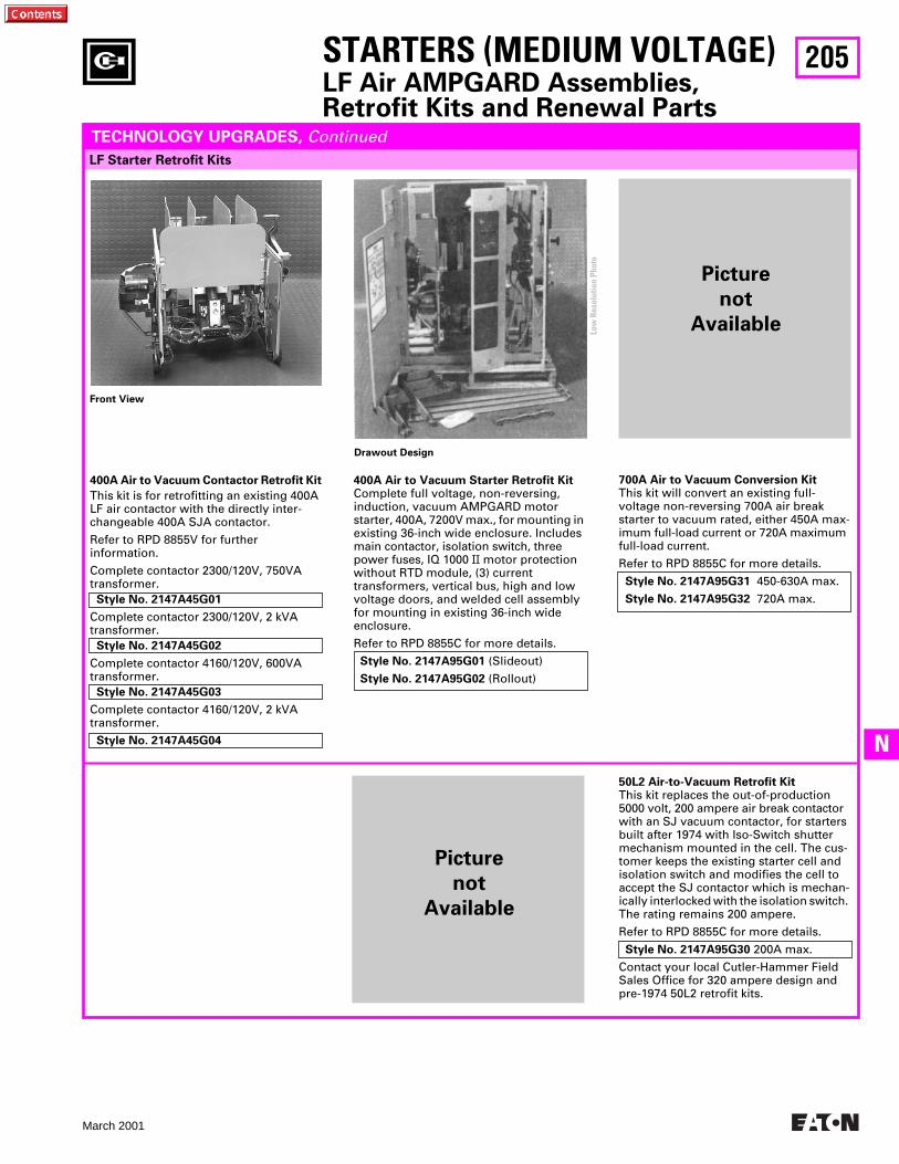
205
March 2001
N
STARTERS (MEDIUM VOLTAGE)
LF Air AMPGARD Assemblies, Retrofit Kits and Renewal Parts
LF Starter Retrofit Kits
Front View
Drawout Design
TECHNOLOGY UPGRADES, Continued
50L2 Air-to-Vacuum Retrofit Kit This kit replaces the out-of-production 5000 volt, 200 ampere air break contactor with an SJ vacuum contactor, for starters built after 1974 with Iso-Switch shutter mechanism mounted in the cell. The cus-tomer keeps the existing starter cell and isolation switch and modifies the cell to accept the SJ contactor which is mechan-ically interlocked with the isolation switch. The rating remains 200 ampere.
Refer to RPD 8855C for more details.
Style No. 2147A95G30 200A max.
Contact your local Cutler-Hammer Field Sales Office for 320 ampere design and pre-1974 50L2 retrofit kits.
Low
Res
olut
ion
Phot
o
400A Air to Vacuum Contactor Retrofit Kit
This kit is for retrofitting an existing 400A LF air contactor with the directly inter-changeable 400A SJA contactor.
Refer to RPD 8855V for further information.
Complete contactor 2300/120V, 750VA transformer. Style No. 2147A45G01
Complete contactor 2300/120V, 2 kVA transformer. Style No. 2147A45G02
Complete contactor 4160/120V, 600VA transformer. Style No. 2147A45G03
Complete contactor 4160/120V, 2 kVA transformer.
Style No. 2147A45G04
400A Air to Vacuum Starter Retrofit KitComplete full voltage, non-reversing, induction, vacuum AMPGARD motor starter, 400A, 7200V max., for mounting in existing 36-inch wide enclosure. Includes main contactor, isolation switch, three power fuses, IQ 1000 II motor protection without RTD module, (3) current transformers, vertical bus, high and low voltage doors, and welded cell assembly for mounting in existing 36-inch wide enclosure.
Refer to RPD 8855C for more details.
Style No. 2147A95G01 (Slideout)
Style No. 2147A95G02 (Rollout)
700A Air to Vacuum Conversion KitThis kit will convert an existing full-voltage non-reversing 700A air break starter to vacuum rated, either 450A max-imum full-load current or 720A maximum full-load current.
Refer to RPD 8855C for more details.
Style No. 2147A95G31 450-630A max.
Style No. 2147A95G32 720A max.
Picture
not
Available
Picture
not
Available
206
March 2001
IQ Surface Mounted Enclosure For mounting IQ family products. Includes drilling for one IQ device and three 30mm devices. Supplied with or without IQ and PB devices. Refer to RPD 8855C for more details.
IQ Floor Mounted Enclosure For mounting IQ family products. Includes standard AMPGARD structure construction to be used as a line-up extension. Each 12-inch wide x 90-inch high x 30-inch deep section comes with two doors, each with a works-in-a-drawer drawout panel. Each door has three standard IQ cutouts with device panels. Supplied with or without IQ and PB devices. Refer to RPD 8855C for more details.
Renewal and Replacement Parts forSJ Design StartersRefer to RPD 8855V or RP.48J.01.T.E for identifying the parts needed. Refer to Price List/Style Number Index 8855 for prices by style number and old style number-to-new style number cross-reference information.
Synchronous Control Retrofit UsingMark V Solid-State ControlReplace existing relay type synchronous control with state-of-the-art solid-state Mark V control. Refer to pages 186-189, 192 of this publication for synchronous motor field control panels.
Add-on Vacuum Starter Structures New add-on vacuum structures as an extension to the SJ type structure may be connected directly to the main bus without a transition section. Contact your local Cutler-Hammer Field Sales Office.
Replacement Vacuum ContactorsNew replacement vacuum break contac-tors are available for all SJ model ratings.
REPLACEMENT CAPABILITIES
Vacuum Starter Retrofits IQ Retrofit Kits
Originally a Westinghouse Product
PRODUCT DESCRIPTION
The SJ Vacuum Contactor was designed and engineered specifically for use in AMPGARD starters. The contactor is a low-chop design that permits application matching of the starter to the motor for 2200V - 7200V and ratings of 400A and 800A. The 400A contactor is available in both slide-out and roll-out configurations. The 800A contactor is available in the roll-out design only. The SJ AMPGARD is a horsepower specific starter design that uses the component-to-component cir-cuitry concept. The full-voltage 400A rat-ing in a NEMA 1 enclosure is 36 inches wide x 30 inches deep x 90 inches high. These 400A starters are mounted one or two high per structure. The 800A rating in an enclosure is 40 inches wide x 30 inches
deep x 90 inches high in a one-high construction for a full voltage starter.
Ratings (max.)400A, 800A
3000 HP @ 2500V; 5500 HP @ 5000V; 8000 HP @ 7200V
ChronologyThe SJ vacuum design AMPGARD starter was introduced in 1982 with the 400A rating. The 800A rating followed in 1987. With the introduction of the vacuum contactor, the air break starter has been gradually phased out and is rarely speci-fied in an assembly. The starters are built in Asheville, NC.
TECHNOLOGY UPGRADES
IQ 1000 II and Data Plus II Retrofit KitThis kit includes parts necessary to retrofit IQ products into AMPGARD starters very easily. The IQ devices are included and are pre-wired to terminal blocks on the drawout panel.Included: Typical starter schematics, 400A
Low-voltage door with threedevice panels Works-in-a-drawer panel withterminal blocksIQ 1000 II (without RTD)IQ Data Plus II (with MWHcounter)
Style No. 2147A95G37
STARTERS (MEDIUM VOLTAGE)SJ Vacuum AMPGARD Assemblies, Retrofit Kits and Renewal Parts
Current Transformer Shorting Terminal Blocks (When Specified)
Routing of Control Wire in Wire Channel
Interposing Control RelayDIN – Rail Mounted
Wiring is Protected Between Low Voltage Panel and Hinged Low Voltage Door
IQ 1000 II/Data Plus II Retrofit
Blank Device Panel
Indicating Lights andPushbuttons Rear View
IQ-1000 Rear View
Predrilled Holes forAdditional Control Devices
Rear of 1/4 Turn Fastener
NOTE: Low Voltage Door is Hinged to Slide Out Control Panel
Low Voltage Panel Completely Extended
400A Vacuum Starter Retrofit KitComplete full-voltage, non-reversing, induction, vacuum AMPGARD motor starter, 400A, 7200V max., for mounting in exist-ing 36-inch wide enclosure. Includes main contactor, isolation switch three power fuses, IQ 1000 II motor protection without RTD module, three current transformers, vertical bus, high- and low-voltage doors, and welded cell assembly for mounting in existing 36-inch wide customer enclosure. Refer to RPD 8855C for more details. Style No. 2147A95G01 (Slideout)
Style No. 2147A95G02 (Rollout)
Low
Res
olut
ion
Phot
o
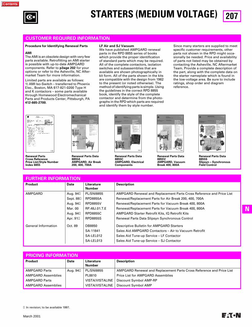
207
March 2001
N
Product Date Literature
Number
Description
AMPGARD
General Information
Aug. 94
➊
Sept. 88
➊
Aug. 94
➊
Mar. 00
Aug. 94
➊
Apr. 91
➊
Oct. 89
PL/SNI8855
RPD8855A
RPD8855V
RP.48J.01.T.E
RPD8855C
RPD8855S
DB8850
SA-11841
SA-LEL012
SA-LEL013
AMPGARD Renewal and Replacement Parts Cross Reference and Price List
Renewal/Replacement Parts for Air Break 200, 400, 700A
Renewal/Replacement Parts for Vacuum Break 400, 800A
Renewal/Replacement Parts for Vacuum Break 400, 800A
AMPGARD Starter Retrofit Kits, IQ Retrofit Kits
Renewal Parts Data Slipsyn Synchronous Control
Descriptive Bulletin for AMPGARD Starters
Sales Aid AMPGARD Contactors – Air to Vacuum Retrofit
Sales Aid Tune-up Service – LF Contactor
Sales Aid Tune-up Service – SJ Contactor
CUSTOMER REQUIRED INFORMATION
Procedure for Identifying Renewal Parts
AMI
The AMI is an obsolete design with very few parts available. Retrofitting an AMI starter is possible with up-to-date AMPGARD components. Refer to
p3age 202
for your options or refer to the Asheville, NC After-market Team for more information.
Limited parts are available as follows:1) AMI Iso-Switch – transferred to Phoenix Elec., Boston, MA 617-821-0200 Type H and K contactors – some parts available through Homewood Electromechanical Parts and Products Center, Pittsburgh, PA
412-665-2700
.
LF Air and SJ Vacuum
We have published AMPGARD renewal parts in the RPD 8855 series of books which provide the proper identification of standard parts which may be required. All of the complete contactors, isolation switches and subassemblies that are available are shown photographically in kit form. All of the parts shown in the kits are compatible with the design from 1962 to the present (or noted otherwise). The method of identifying parts is simple. Using the guidelines in the correct RPD 8855 book, identify the style of the complete contactor and determine from the photo-graphs in the RPD which parts are required and identify them by style number.
Since many starters are supplied to meet specific customer requirements, other parts not shown in the RPD might occa-sionally be needed. Price and availability of parts not listed may be obtained by contacting the Asheville, NC Aftermarket Team. Provide a complete description of the part, along with the complete data on the starter nameplate which is found in the low-voltage area. Be sure to include ratings, shop order and diagram reference.
Renewal PartsCross ReferencePrice List/Style NumberIndex 8855
Renewal Parts Data8855AAMPGARD, Air Break200, 400, 700A
Renewal Parts Data8855CAMPGARD, ElectricalComponents
Renewal Parts Data8855VAMPGARD, VacuumBreak 400, 800A
Renewal Parts Data8855SSlipsyn – SynchronousField Control
FURTHER INFORMATION
Product Date Literature
Number
Description
AMPGARD Parts
AMPGARD Assemblies
AMPGARD Parts
AMPGARD Assemblies
Aug. 94
➊
PL/SNI8855
PL8810
VISTA/VISTALINE
VISTA/VISTALINE
AMPGARD Renewal and Replacement Parts Cross Reference and Price List
Price List for AMPGARD Assemblies
Discount Symbol AMP-RP
Discount Symbol AMP
➊
In revision; to be available 1997.
STARTERS (MEDIUM VOLTAGE)
PRICING INFORMATION
208
March 2001
MOTOR CONTROL CENTERS
Low Voltage MCCs
PRODUCT DESCRIPTION
PRODUCT HISTORY
The MCC structure consists of structural steel, horizontal and vertical wireways for conduit and load cable entry and exit and vertical and horizontal bus systems for distributing power throughout the MCC. The starter unit consists of a rugged steel shell (wrapper) for mounting the unit com-ponents, a combination motor starter with factory wired control, a handle mecha-nism for on/off operation and a rigid unit door.
Nearly fifty years ago, Cutler-Hammer and Westinghouse introduced the low voltage Motor Control Center (MCC) assembly,enabling the group mounting of low volt-age (600V class) electrical controls. Thisallowed for supervision and safe operation of motor starter units, feeder tap units and auxiliary equipment in a flexible structure arrangement at a centralized location.
The foundation for today’s MCCs is a modular plug-in combination motor con-troller assembly with components of proven electrical and mechanical integrity. These assemblies are enclosed in metal struc-tures which prevent accidental contact with live electrical parts.
Group mounted motor control was origi-nally developed by Westinghouse in 1937. What came to be known as motor control centers were built in 14 manufacturing and repair shops around the country, including a plant in Chicago, IL which opened in 1941. In 1963, Chicago became the pri-mary MCC manufacturing plant. The Fayetteville, NC operation was opened in 1980 to relieve some of Chicago’s volume. The Fayetteville plant was expanded in 1984 and the Chicago operation was closed. Motor control centers are currently manufactured in Fayetteville and in eight service centers around the country.
The Westinghouse plug-in starter design for group mounted control (called motor control centers) was first introduced in 1937, and in 1950 became known as the Type 11-300 motor control center and uti-lized the 11-200 motor starter. The Type W MCC replaced the 11-300 in 1965, first using the 11-200 starter and then moving to the A200 starter. The 5 Star was introduced in
1975 to replace the Type W. It, too, used the A200 motor starter. The Series 2100 updated the 5 Star design in 1987, but is mechanically compatible with the 5 Star. The ADVANTAGE MCC was introduced as a sister product to the Series 2100 in 1991 with the introduction of the ADVANTAGE starter. It was also mechanically compatible with the 5 Star. With the merger of Cutler-Hammer and Westinghouse Electric Distribution and Control Business Unit in 1994, a new hybrid motor control center line was introduced. It was called the F2100 MCC and featured the Freedom starter.
The Cutler-Hammer plug-in starter design motor control center was introduced in the late 1950s as the 9800 Series Unitrol. These motor control centers used the 3-Star type motor starter. In 1968, the Cita-tion line of starters replaced the 3-Star type in the 9800 MCC. The motor control center was totally redesigned around the Citation starter in 1972 and was called the
F10 Unitrol. The next generation of MCC was introduced in 1989, using the Freedom line of starters, called the Freedom Unitrol. Freedom Unitrol was discontinued in 1994 and replaced with the Cutler-Hammer F2100 motor control center.
Cutler-Hammer motor control centers were originally built in Milwaukee, WI. In 1962, manufacturing moved out of Milwaukee to plants in Atlanta, GA, Bethlehem, PA, Chicago, IL, Los Angeles, CA, Dallas, TX, San Francisco, CA, and Cleveland, TN. In 1972, these plants con-solidated to Atlanta, Bethlehem, Chicago, Dallas, and Los Angeles. In 1984, another consolidation left manufacturing in only Atlanta and Los Angeles. With the intro-duction of the Freedom starter in 1989, all manufacturing was moved to Atlanta. After the merger all motor control center manufacturing moved to the Fayetteville, NC location.
F2100
Page Product 1945 1950 1955 1960 1965 1970 1975 1980 1985 1990 1995 Present
210
211
212
213
215
214
215
216
217
Westinghouse 11-300
Cutler-Hammer 9800
Westinghouse Type W
Cutler-Hammer F10
Westinghouse 5 Star
Cutler-Hammer Freedom Unitrol
Westinghouse Series 2100
Westinghouse ADVANTAGE
Cutler-Hammer F2100
PRODUCT HISTORY TIMELINE
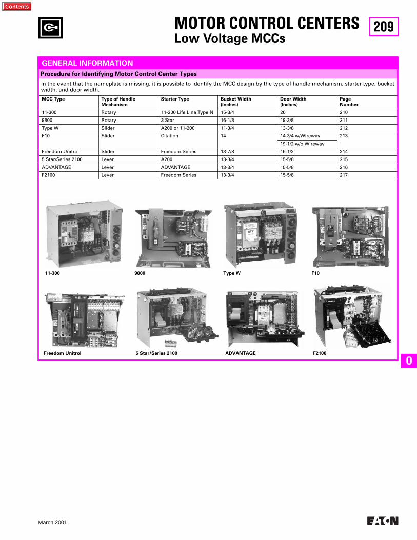
209
March 2001
O
In the event that the nameplate is missing, it is possible to identify the MCC design by the type of handle mechanism, starter type, bucket width, and door width.
MCC Type Type of HandleMechanism
Starter Type Bucket Width(Inches)
Door Width(Inches)
PageNumber
11-300 Rotary 11-200 Life Line Type N 15-3/4 20 210
9800 Rotary 3 Star 16-1/8 19-3/8 211
Type W Slider A200 or 11-200 11-3/4 13-3/8 212
F10 Slider Citation 14 14-3/4 w/Wireway 213
19-1/2 w/o Wireway
Freedom Unitrol Slider Freedom Series 13-7/8 15-1/2 214
5 Star/Series 2100 Lever A200 13-3/4 15-5/8 215
ADVANTAGE Lever ADVANTAGE 13-3/4 15-5/8 216
F2100 Lever Freedom Series 13-3/4 15-5/8 217
Procedure for Identifying Motor Control Center Types
MOTOR CONTROL CENTERS
Low Voltage MCCs
11-300 9800 Type W F10
Freedom Unitrol 5 Star/Series 2100 ADVANTAGE F2100
GENERAL INFORMATION
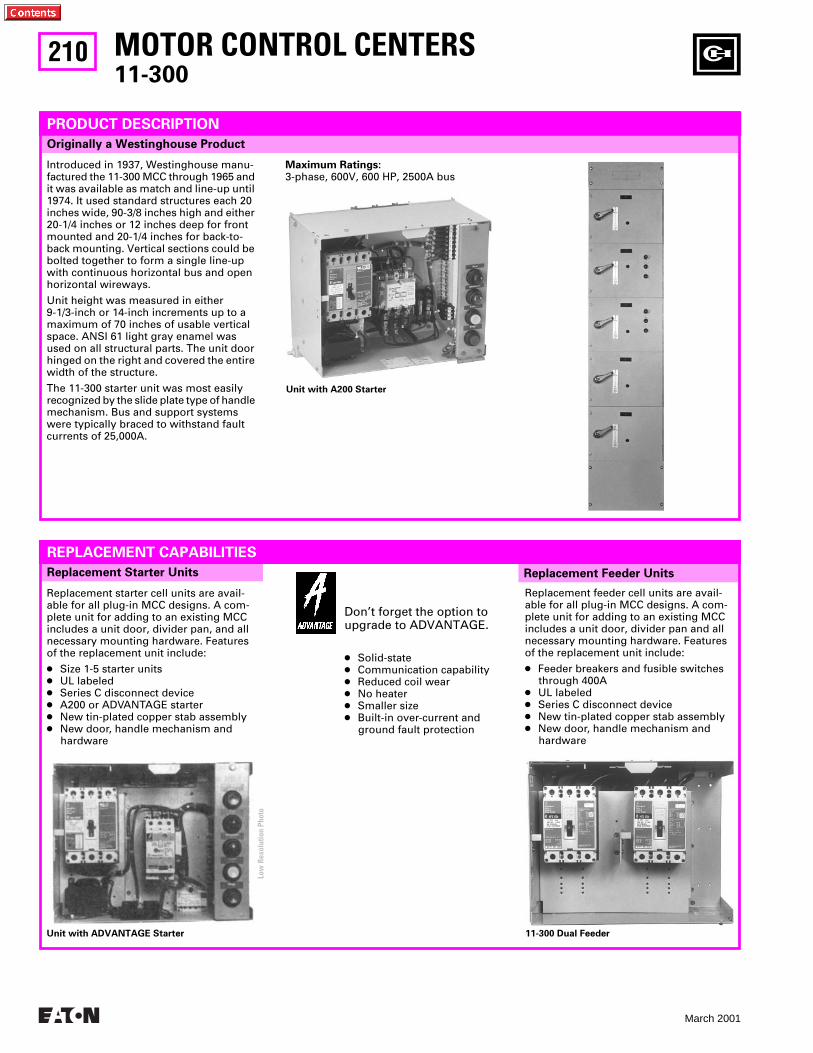
210
March 2001
MOTOR CONTROL CENTERS
11-300
Replacement Feeder Units
Originally a Westinghouse Product
PRODUCT DESCRIPTION
Introduced in 1937, Westinghouse manu-factured the 11-300 MCC through 1965 and it was available as match and line-up until 1974. It used standard structures each 20 inches wide, 90-3/8 inches high and either 20-1/4 inches or 12 inches deep for front mounted and 20-1/4 inches for back-to-back mounting. Vertical sections could be bolted together to form a single line-up with continuous horizontal bus and open horizontal wireways.
Unit height was measured in either 9-1/3-inch or 14-inch increments up to a maximum of 70 inches of usable vertical space. ANSI 61 light gray enamel was used on all structural parts. The unit door hinged on the right and covered the entire width of the structure.
The 11-300 starter unit was most easily recognized by the slide plate type of handle mechanism. Bus and support systems were typically braced to withstand fault currents of 25,000A.
Maximum Ratings:
3-phase, 600V, 600 HP, 2500A bus
Replacement Starter Units
REPLACEMENT CAPABILITIES
Replacement starter cell units are avail-able for all plug-in MCC designs. A com-plete unit for adding to an existing MCC includes a unit door, divider pan, and all necessary mounting hardware. Features of the replacement unit include:
●
Size 1-5 starter units
●
UL labeled
●
Series C disconnect device
●
A200 or ADVANTAGE starter
●
New tin-plated copper stab assembly
●
New door, handle mechanism and hardware
Don’t forget the option to upgrade to ADVANTAGE.
●
Solid-state
●
Communication capability
●
Reduced coil wear
●
No heater
●
Smaller size
●
Built-in over-current and ground fault protection
Replacement feeder cell units are avail-able for all plug-in MCC designs. A com-plete unit for adding to an existing MCC includes a unit door, divider pan and all necessary mounting hardware. Features of the replacement unit include:
●
Feeder breakers and fusible switches through 400A
●
UL labeled
●
Series C disconnect device
●
New tin-plated copper stab assembly
●
New door, handle mechanism and hardware
Unit with ADVANTAGE Starter
Unit with A200 Starter
11-300 Dual Feeder
Low
Res
olut
ion
Phot
o
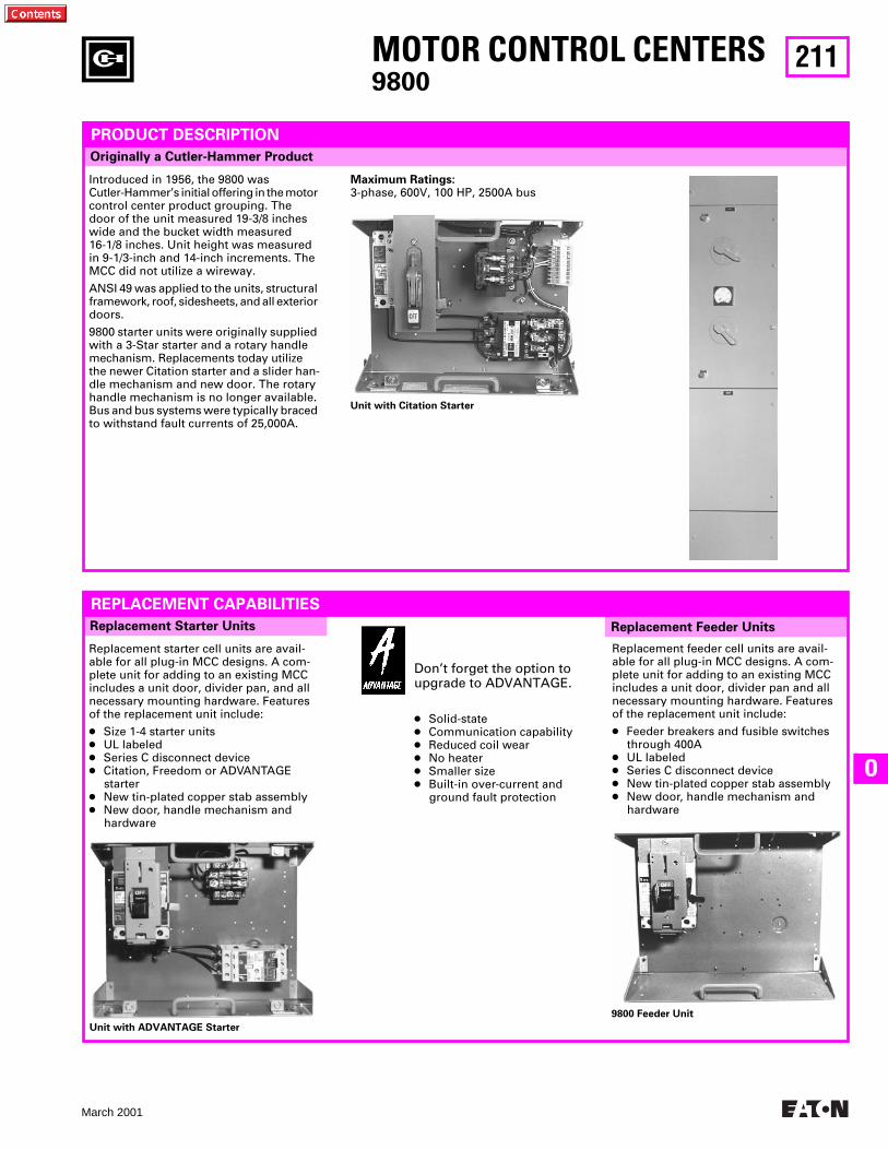
211
March 2001
O
MOTOR CONTROL CENTERS
9800
Replacement Feeder Units
Originally a Cutler-Hammer Product
PRODUCT DESCRIPTION
Introduced in 1956, the 9800 was Cutler-Hammer’s initial offering in the motor control center product grouping. The door of the unit measured 19-3/8 inches wide and the bucket width measured 16-1/8 inches. Unit height was measured in 9-1/3-inch and 14-inch increments. The MCC did not utilize a wireway.
ANSI 49 was applied to the units, structural framework, roof, sidesheets, and all exterior doors.
9800 starter units were originally supplied with a 3-Star starter and a rotary handle mechanism. Replacements today utilize the newer Citation starter and a slider han-dle mechanism and new door. The rotary handle mechanism is no longer available. Bus and bus systems were typically braced to withstand fault currents of 25,000A.
Maximum Ratings:
3-phase, 600V, 100 HP, 2500A bus
Replacement Starter Units
REPLACEMENT CAPABILITIES
Replacement starter cell units are avail-able for all plug-in MCC designs. A com-plete unit for adding to an existing MCC includes a unit door, divider pan, and all necessary mounting hardware. Features of the replacement unit include:
●
Size 1-4 starter units
●
UL labeled
●
Series C disconnect device
●
Citation, Freedom or ADVANTAGE starter
●
New tin-plated copper stab assembly
●
New door, handle mechanism and hardware
Don’t forget the option to upgrade to ADVANTAGE.
●
Solid-state
●
Communication capability
●
Reduced coil wear
●
No heater
●
Smaller size
●
Built-in over-current and ground fault protection
Replacement feeder cell units are avail-able for all plug-in MCC designs. A com-plete unit for adding to an existing MCC includes a unit door, divider pan and all necessary mounting hardware. Features of the replacement unit include:
●
Feeder breakers and fusible switches through 400A
●
UL labeled
●
Series C disconnect device
●
New tin-plated copper stab assembly
●
New door, handle mechanism and hardware
Unit with Citation Starter
Unit with ADVANTAGE Starter
9800 Feeder Unit
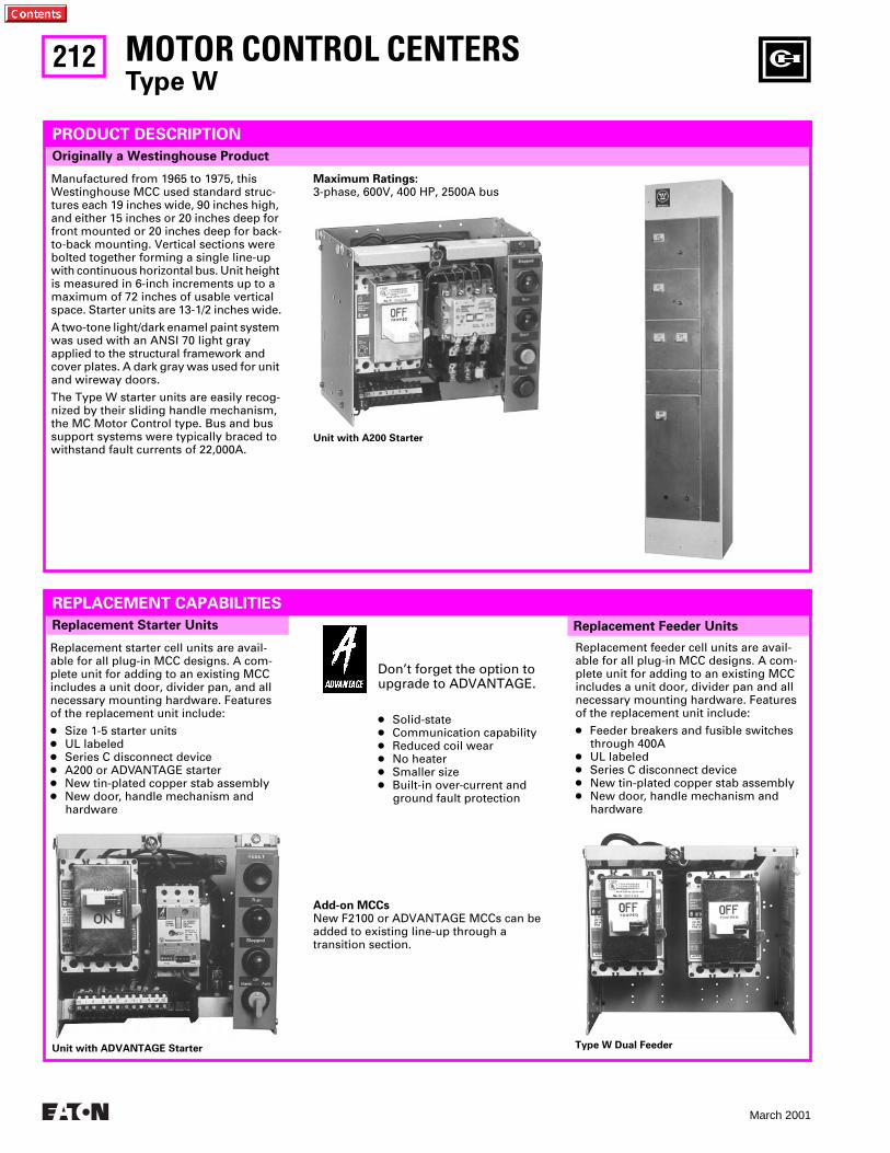
212
March 2001
MOTOR CONTROL CENTERS
Type W
Replacement Feeder Units
Originally a Westinghouse Product
PRODUCT DESCRIPTION
Manufactured from 1965 to 1975, this Westinghouse MCC used standard struc-tures each 19 inches wide, 90 inches high, and either 15 inches or 20 inches deep for front mounted or 20 inches deep for back-to-back mounting. Vertical sections were bolted together forming a single line-up with continuous horizontal bus. Unit height is measured in 6-inch increments up to a maximum of 72 inches of usable vertical space. Starter units are 13-1/2 inches wide.
A two-tone light/dark enamel paint system was used with an ANSI 70 light gray applied to the structural framework and cover plates. A dark gray was used for unit and wireway doors.
The Type W starter units are easily recog-nized by their sliding handle mechanism, the MC Motor Control type. Bus and bus support systems were typically braced to withstand fault currents of 22,000A.
Maximum Ratings:
3-phase, 600V, 400 HP, 2500A bus
Replacement Starter Units
REPLACEMENT CAPABILITIES
Replacement starter cell units are avail-able for all plug-in MCC designs. A com-plete unit for adding to an existing MCC includes a unit door, divider pan, and all necessary mounting hardware. Features of the replacement unit include:
●
Size 1-5 starter units
●
UL labeled
●
Series C disconnect device
●
A200 or ADVANTAGE starter
●
New tin-plated copper stab assembly
●
New door, handle mechanism and hardware
Don’t forget the option to upgrade to ADVANTAGE.
●
Solid-state
●
Communication capability
●
Reduced coil wear
●
No heater
●
Smaller size
●
Built-in over-current and ground fault protection
Replacement feeder cell units are avail-able for all plug-in MCC designs. A com-plete unit for adding to an existing MCC includes a unit door, divider pan and all necessary mounting hardware. Features of the replacement unit include:
●
Feeder breakers and fusible switches through 400A
●
UL labeled
●
Series C disconnect device
●
New tin-plated copper stab assembly
●
New door, handle mechanism and hardware
Unit with A200 Starter
Unit with ADVANTAGE Starter Type W Dual Feeder
Add-on MCCs
New F2100 or ADVANTAGE MCCs can be added to existing line-up through a transition section.
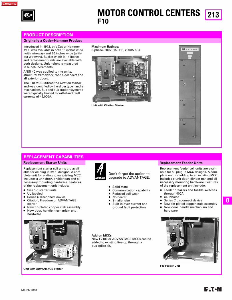
213
March 2001
O
MOTOR CONTROL CENTERS
F10
Replacement Feeder Units
Originally a Cutler-Hammer Product
PRODUCT DESCRIPTION
Introduced in 1972, this Cutler-Hammer MCC was available in both 16 inches wide (with wireway) and 20 inches wide (with-out wireway). Bucket width is 14 inches and replacement units are available with both designs. Unit height is measured in 6-inch increments.
ANSI 40 was applied to the units, structural framework, roof, sidesheets and all exterior doors.
The F10 MCC utilized the Citation starter and was identified by the slider type handle mechanism. Bus and bus support systems were typically braced to withstand fault currents of 42,000A.
Maximum Ratings:
3-phase, 600V, 150 HP, 2000A bus
Replacement Starter Units
REPLACEMENT CAPABILITIES
Replacement starter cell units are avail-able for all plug-in MCC designs. A com-plete unit for adding to an existing MCC includes a unit door, divider pan and all necessary mounting hardware. Features of the replacement unit include:
●
Size 1-5 starter units
●
UL labeled
●
Series C disconnect device
●
Citation, Freedom or ADVANTAGE starter
●
New tin-plated copper stab assembly
●
New door, handle mechanism and hardware
Don’t forget the option to upgrade to ADVANTAGE.
●
Solid-state
●
Communication capability
●
Reduced coil wear
●
No heater
●
Smaller size
●
Built-in over-current and ground fault protection
Replacement feeder cell units are avail-able for all plug-in MCC designs. A com-plete unit for adding to an existing MCC includes a unit door, divider pan and all necessary mounting hardware. Features of the replacement unit include:
●
Feeder breakers and fusible switches through 400A
●
UL labeled
●
Series C disconnect device
●
New tin-plated copper stab assembly
●
New door, handle mechanism and hardware
Unit with Citation Starter
Unit with ADVANTAGE Starter
F10 Feeder Unit
Add-on MCCs
New F2100 or ADVANTAGE MCCs can be added to existing line-up through a bus splice kit.
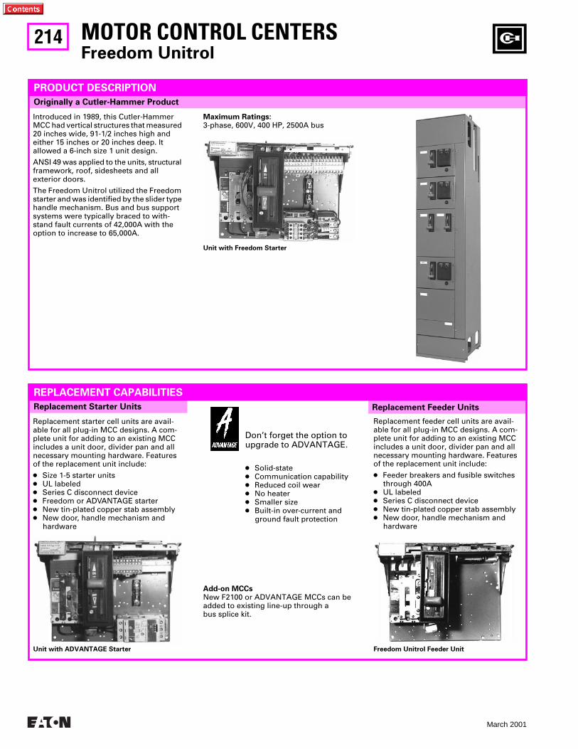
214
March 2001
MOTOR CONTROL CENTERS
Freedom Unitrol
Replacement Feeder Units
Originally a Cutler-Hammer Product
PRODUCT DESCRIPTION
Introduced in 1989, this Cutler-Hammer MCC had vertical structures that measured 20 inches wide, 91-1/2 inches high and either 15 inches or 20 inches deep. It allowed a 6-inch size 1 unit design.
ANSI 49 was applied to the units, structural framework, roof, sidesheets and all exterior doors.
The Freedom Unitrol utilized the Freedom starter and was identified by the slider type handle mechanism. Bus and bus support systems were typically braced to with-stand fault currents of 42,000A with the option to increase to 65,000A.
Maximum Ratings:
3-phase, 600V, 400 HP, 2500A bus
Replacement Starter Units
REPLACEMENT CAPABILITIES
Replacement starter cell units are avail-able for all plug-in MCC designs. A com-plete unit for adding to an existing MCC includes a unit door, divider pan and all necessary mounting hardware. Features of the replacement unit include:
●
Size 1-5 starter units
●
UL labeled
●
Series C disconnect device
●
Freedom or ADVANTAGE starter
●
New tin-plated copper stab assembly● New door, handle mechanism and
hardware
Don’t forget the option to upgrade to ADVANTAGE.
● Solid-state● Communication capability● Reduced coil wear● No heater● Smaller size● Built-in over-current and
ground fault protection
Replacement feeder cell units are avail-able for all plug-in MCC designs. A com-plete unit for adding to an existing MCC includes a unit door, divider pan and all necessary mounting hardware. Features of the replacement unit include:
● Feeder breakers and fusible switches through 400A
● UL labeled● Series C disconnect device● New tin-plated copper stab assembly● New door, handle mechanism and
hardware
Unit with Freedom Starter
Unit with ADVANTAGE Starter Freedom Unitrol Feeder Unit
Add-on MCCsNew F2100 or ADVANTAGE MCCs can be added to existing line-up through a bus splice kit.
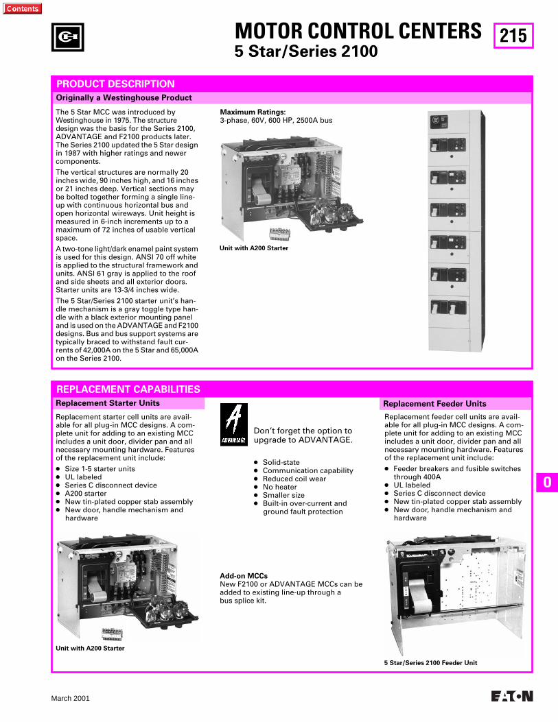
215
March 2001
O
MOTOR CONTROL CENTERS5 Star/Series 2100
Replacement Feeder Units
Originally a Westinghouse Product
PRODUCT DESCRIPTION
The 5 Star MCC was introduced by Westinghouse in 1975. The structure design was the basis for the Series 2100, ADVANTAGE and F2100 products later. The Series 2100 updated the 5 Star design in 1987 with higher ratings and newer components.
The vertical structures are normally 20 inches wide, 90 inches high, and 16 inches or 21 inches deep. Vertical sections may be bolted together forming a single line-up with continuous horizontal bus and open horizontal wireways. Unit height is measured in 6-inch increments up to a maximum of 72 inches of usable vertical space.
A two-tone light/dark enamel paint system is used for this design. ANSI 70 off white is applied to the structural framework and units. ANSI 61 gray is applied to the roof and side sheets and all exterior doors. Starter units are 13-3/4 inches wide.
The 5 Star/Series 2100 starter unit’s han-dle mechanism is a gray toggle type han-dle with a black exterior mounting panel and is used on the ADVANTAGE and F2100 designs. Bus and bus support systems are typically braced to withstand fault cur-rents of 42,000A on the 5 Star and 65,000A on the Series 2100.
Maximum Ratings:3-phase, 60V, 600 HP, 2500A bus
Replacement Starter Units
REPLACEMENT CAPABILITIES
Replacement starter cell units are avail-able for all plug-in MCC designs. A com-plete unit for adding to an existing MCC includes a unit door, divider pan and all necessary mounting hardware. Features of the replacement unit include:
● Size 1-5 starter units● UL labeled● Series C disconnect device● A200 starter● New tin-plated copper stab assembly● New door, handle mechanism and
hardware
Replacement feeder cell units are avail-able for all plug-in MCC designs. A com-plete unit for adding to an existing MCC includes a unit door, divider pan and all necessary mounting hardware. Features of the replacement unit include:
● Feeder breakers and fusible switches through 400A
● UL labeled● Series C disconnect device● New tin-plated copper stab assembly● New door, handle mechanism and
hardware
Unit with A200 Starter
Unit with A200 Starter
5 Star/Series 2100 Feeder Unit
Add-on MCCsNew F2100 or ADVANTAGE MCCs can be added to existing line-up through a bus splice kit.
Don’t forget the option to upgrade to ADVANTAGE.
● Solid-state● Communication capability● Reduced coil wear● No heater● Smaller size● Built-in over-current and
ground fault protection
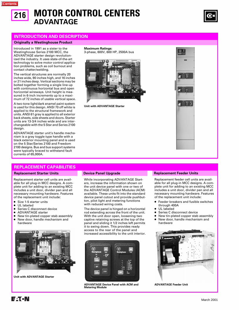
216
March 2001
MOTOR CONTROL CENTERSADVANTAGE
Replacement Feeder Units
Originally a Westinghouse Product
INTRODUCTION AND DESCRIPTION
Introduced in 1991 as a sister to the Westinghouse Series 2100 MCC, the ADVANTAGE starter design revolution-ized the industry. It uses state-of-the-art technology to solve motor control applica-tion problems, such as coil burnout and contact chatter/welding.
The vertical structures are normally 20 inches wide, 90 inches high, and 16 inches or 21 inches deep. Vertical sections may be bolted together forming a single line-up with continuous horizontal bus and open horizontal wireways. Unit height is mea-sured in 6-inch increments up to a maxi-mum of 72 inches of usable vertical space.
A two-tone light/dark enamel paint system is used for this design. ANSI 70 off white is applied to the structural framework and units. ANSI 61 gray is applied to all exterior back sheets, side sheets and doors. Starter units are 13-3/4 inches wide and are inter-changeable with the 5 Star and Series 2100 design.
ADVANTAGE starter unit’s handle mecha-nism is a gray toggle type handle with a black exterior mounting panel and is used on the 5 Star/Series 2100 and Freedom 2100 designs. Bus and bus support systems were typically braced to withstand fault currents of 65,000A.
Maximum Ratings:3-phase, 600V, 600 HP, 2500A bus
Replacement Starter Units
REPLACEMENT CAPABILITIES
Replacement starter cell units are avail-able for all plug-in MCC designs. A com-plete unit for adding to an existing MCC includes a unit door, divider pan and all necessary mounting hardware. Features of the replacement unit include:
● Size 1-5 starter units● UL labeled● Series C disconnect device● ADVANTAGE starter● New tin-plated copper stab assembly● New door, handle mechanism and
hardware
Replacement feeder cell units are avail-able for all plug-in MCC designs. A com-plete unit for adding to an existing MCC includes a unit door, divider pan and all necessary mounting hardware. Features of the replacement unit include:
● Feeder breakers and fusible switches through 400A
● UL labeled● Series C disconnect device● New tin-plated copper stab assembly● New door, handle mechanism and
hardware
Unit with ADVANTAGE Starter
Unit with ADVANTAGE Starter
Device Panel Upgrade
While incorporating ADVANTAGE Start-ers, increase the information shown on the unit device panel with one or two of the ADVANTAGE Control Modules (ACM) available. These units fit into the standard device panel cutout and provide pushbut-ton, pilot light and metering functions with reduced wiring costs.
The device panel is hinged on a horizontal rod extending across the front of the unit. With the unit door open, loosening two captive retaining screws at the top of the panel and sliding it 1/2 inches left permits it to swing down. This provides ready access to the rear of the panel and increased accessibility to the unit interior.
ADVANTAGE Device Panel with ACM and Metering Module
ADVANTAGE Feeder Unit
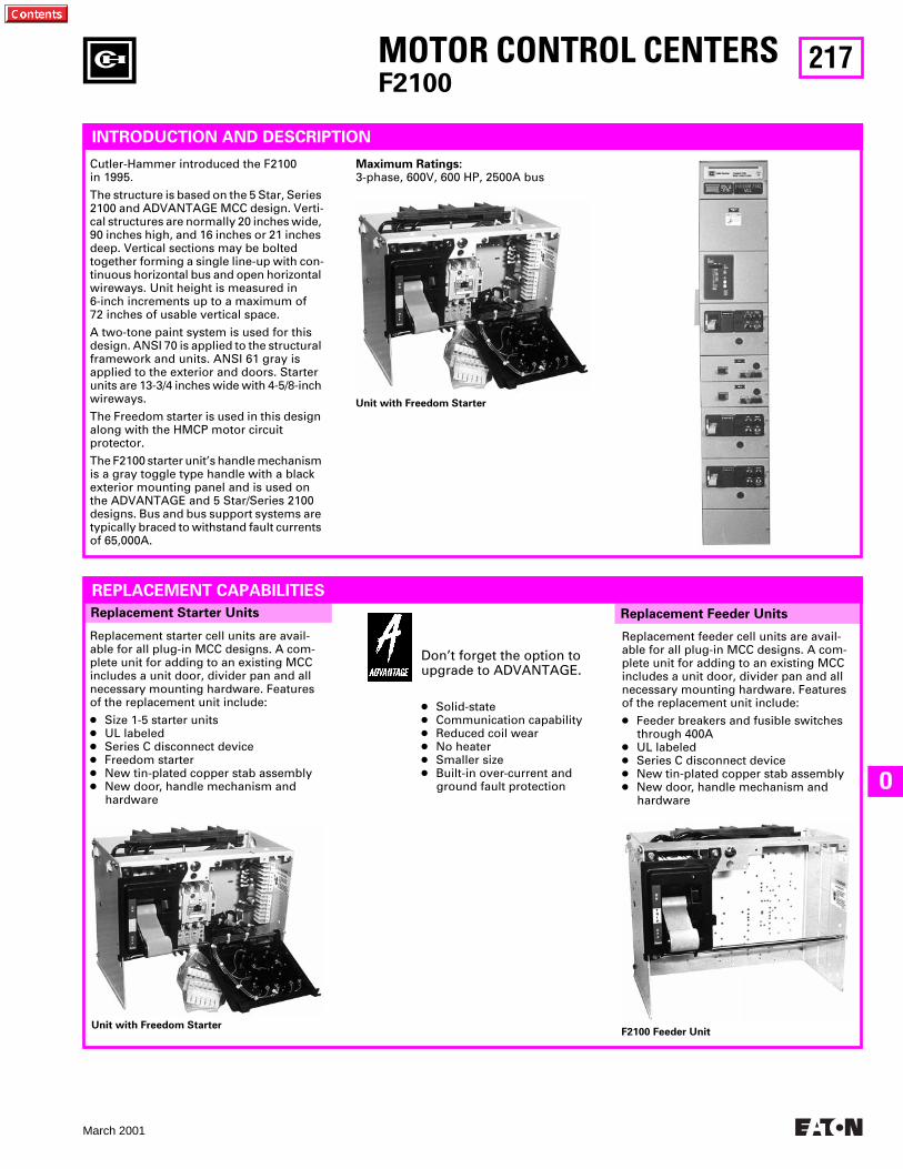
217
March 2001
O
MOTOR CONTROL CENTERSF2100
Replacement Feeder Units
INTRODUCTION AND DESCRIPTION
Cutler-Hammer introduced the F2100 in 1995.
The structure is based on the 5 Star, Series 2100 and ADVANTAGE MCC design. Verti-cal structures are normally 20 inches wide, 90 inches high, and 16 inches or 21 inches deep. Vertical sections may be bolted together forming a single line-up with con-tinuous horizontal bus and open horizontal wireways. Unit height is measured in 6-inch increments up to a maximum of 72 inches of usable vertical space.
A two-tone paint system is used for this design. ANSI 70 is applied to the structural framework and units. ANSI 61 gray is applied to the exterior and doors. Starter units are 13-3/4 inches wide with 4-5/8-inch wireways.
The Freedom starter is used in this design along with the HMCP motor circuit protector.
The F2100 starter unit’s handle mechanism is a gray toggle type handle with a black exterior mounting panel and is used on the ADVANTAGE and 5 Star/Series 2100 designs. Bus and bus support systems are typically braced to withstand fault currents of 65,000A.
Maximum Ratings:3-phase, 600V, 600 HP, 2500A bus
Replacement Starter Units
REPLACEMENT CAPABILITIES
Replacement starter cell units are avail-able for all plug-in MCC designs. A com-plete unit for adding to an existing MCC includes a unit door, divider pan and all necessary mounting hardware. Features of the replacement unit include:
● Size 1-5 starter units● UL labeled● Series C disconnect device● Freedom starter● New tin-plated copper stab assembly● New door, handle mechanism and
hardware
Replacement feeder cell units are avail-able for all plug-in MCC designs. A com-plete unit for adding to an existing MCC includes a unit door, divider pan and all necessary mounting hardware. Features of the replacement unit include:
● Feeder breakers and fusible switches through 400A
● UL labeled● Series C disconnect device● New tin-plated copper stab assembly● New door, handle mechanism and
hardware
Unit with Freedom Starter
Unit with Freedom StarterF2100 Feeder Unit
Don’t forget the option to upgrade to ADVANTAGE.
● Solid-state● Communication capability● Reduced coil wear● No heater● Smaller size● Built-in over-current and
ground fault protection
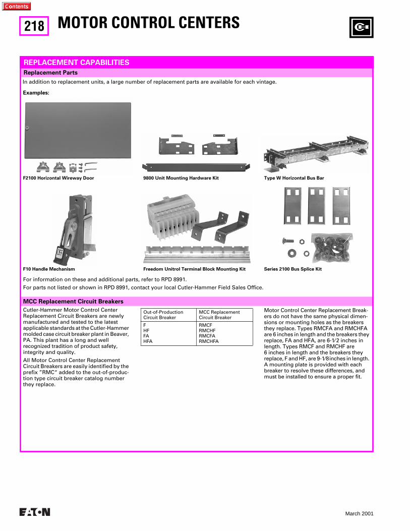
218
March 2001
MCC Replacement Circuit Breakers
Replacement Parts
MOTOR CONTROL CENTERS
REPLACEMENT CAPABILITIES
In addition to replacement units, a large number of replacement parts are available for each vintage.
Examples:
F10 Handle Mechanism
9800 Unit Mounting Hardware Kit
Freedom Unitrol Terminal Block Mounting Kit
Type W Horizontal Bus Bar
Series 2100 Bus Splice Kit
F2100 Horizontal Wireway Door
For information on these and additional parts, refer to RPD 8991.
For parts not listed or shown in RPD 8991, contact your local Cutler-Hammer Field Sales Office.
Out-of-ProductionCircuit Breaker
MCC ReplacementCircuit Breaker
FHFFAHFA
RMCFRMCHFRMCFARMCHFA
Cutler-Hammer Motor Control Center Replacement Circuit Breakers are newly manufactured and tested to the latest applicable standards at the Cutler-Hammer molded case circuit breaker plant in Beaver, PA. This plant has a long and well recognized tradition of product safety, integrity and quality.
All Motor Control Center Replacement Circuit Breakers are easily identified by the prefix ”RMC“ added to the out-of-produc-tion type circuit breaker catalog number they replace.
Motor Control Center Replacement Break-ers do not have the same physical dimen-sions or mounting holes as the breakers they replace. Types RMCFA and RMCHFA are 6 inches in length and the breakers they replace, FA and HFA, are 6-1⁄ 2 inches in length. Types RMCF and RMCHF are 6 inches in length and the breakers theyreplace, F and HF, are 9-1⁄8 inches in length. A mounting plate is provided with each breaker to resolve these differences, and must be installed to ensure a proper fit.
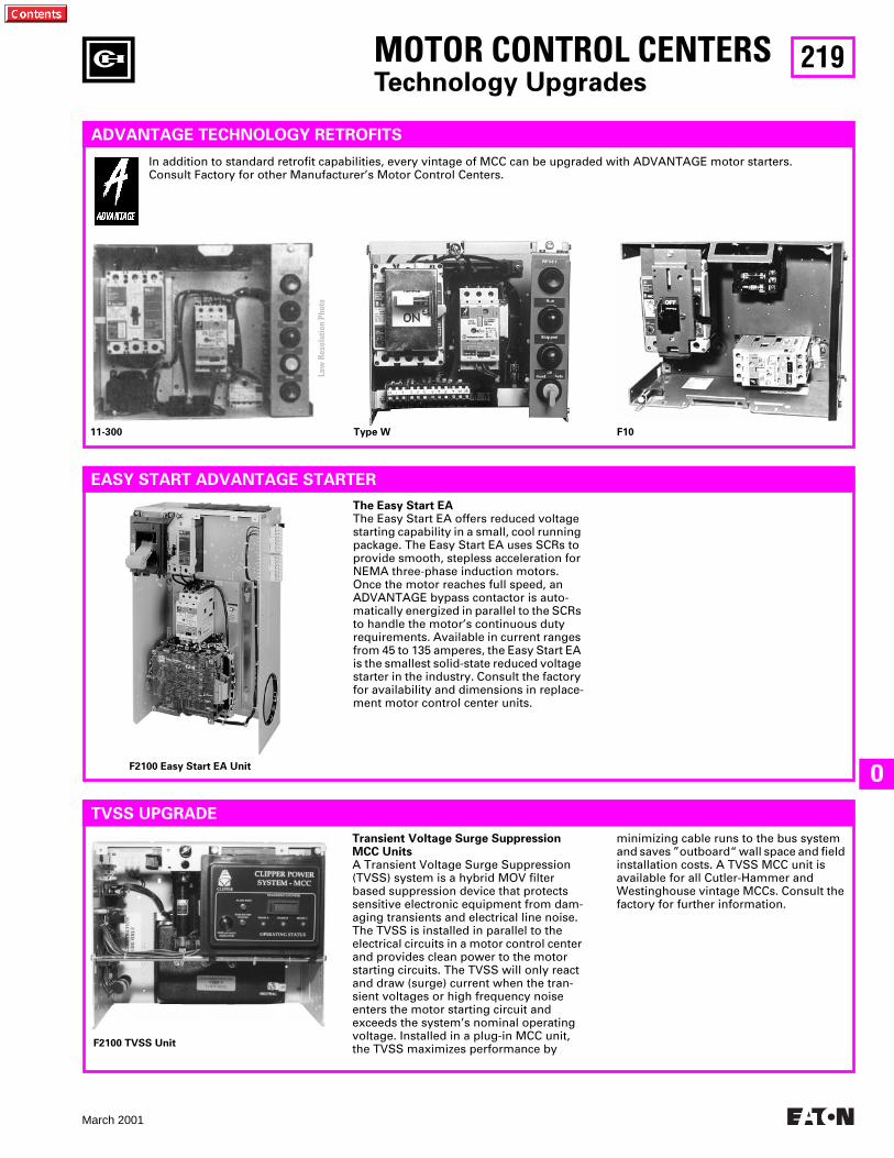
219
March 2001
O
MOTOR CONTROL CENTERSTechnology Upgrades
ADVANTAGE TECHNOLOGY RETROFITS
In addition to standard retrofit capabilities, every vintage of MCC can be upgraded with ADVANTAGE motor starters.Consult Factory for other Manufacturer’s Motor Control Centers.
EASY START ADVANTAGE STARTER
TVSS UPGRADE
Transient Voltage Surge Suppression MCC UnitsA Transient Voltage Surge Suppression (TVSS) system is a hybrid MOV filter based suppression device that protects sensitive electronic equipment from dam-aging transients and electrical line noise. The TVSS is installed in parallel to the electrical circuits in a motor control center and provides clean power to the motor starting circuits. The TVSS will only react and draw (surge) current when the tran-sient voltages or high frequency noise enters the motor starting circuit and exceeds the system’s nominal operating voltage. Installed in a plug-in MCC unit, the TVSS maximizes performance by
minimizing cable runs to the bus system and saves ”outboard“ wall space and field installation costs. A TVSS MCC unit is available for all Cutler-Hammer and Westinghouse vintage MCCs. Consult the factory for further information.
11-300 Type W F10
F2100 Easy Start EA Unit
F2100 TVSS Unit
The Easy Start EAThe Easy Start EA offers reduced voltage starting capability in a small, cool running package. The Easy Start EA uses SCRs to provide smooth, stepless acceleration for NEMA three-phase induction motors. Once the motor reaches full speed, an ADVANTAGE bypass contactor is auto-matically energized in parallel to the SCRs to handle the motor’s continuous duty requirements. Available in current ranges from 45 to 135 amperes, the Easy Start EA is the smallest solid-state reduced voltage starter in the industry. Consult the factory for availability and dimensions in replace-ment motor control center units.
Low
Res
olut
ion
Phot
o
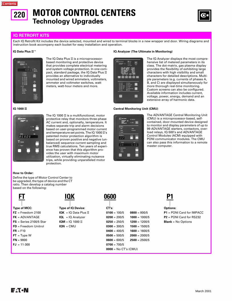
220
March 2001
MOTOR CONTROL CENTERSTechnology Upgrades
IQ RETROFIT KITS
Each IQ Retrofit Kit includes the device selected, mounted and wired to terminal blocks in a new wrapper and door. Wiring diagrams and instruction book accompany each bucket for easy installation and operation.
IQ Data Plus IIE
The IQ Data Plus II is a microprocessor-based monitoring and protective device that provides complete electrical metering and system voltage protection. In one com-pact, standard package, the IQ Data Plus II provides an alternative to individually mounted and wired ammeters, voltmeters, ammeter and voltmeter switches, watt meters, watt-hour meters and more.
IQ 1000 II
The IQ 1000 II is a multifunctional, motor protective relay that monitors three-phase AC current and, optionally, temperature. It makes separate trip and alarm decisions based on user-programmed motor current and temperature set points. The IQ 1000 II’s patented motor protection algorithm is based on proven positive and negative (un-balanced) sequence current sampling and true RMS calculations. Ten years of experi-ence has proven that this algorithm pro-vides the user with maximum motor utilization, virtually eliminating nuisance trips, while providing unparalleled motor protection.
The IQ Analyzer displays the most compre-hensive list of metered parameters in its class. The dot-matrix, gas plasma display provides the flexibility of exhibiting large characters with high visibility and small characters for detailed descriptions. Multi-ple parameters (e.g. currents of phases A, B, and C) are displayed simultaneously for more thorough real-time monitoring. Custom screens can also be configured. Available information includes current, voltage, power, energy, demand and an extensive array of harmonic data.
IQ Analyzer (The Ultimate in Monitoring)
Central Monitoring Unit (CMU)
The ADVANTAGE Central Monitoring Unit (CMU) is a microprocessor-based, self-contained, door-mounted device designed to monitor and display parameters of up to 99 ADVANTAGE starters, contactors, over-load relays, IQ-500’s and ADVANTAGE Control Modules (ACM) equipped with PONI communicator modules. The CMU can also pass this information to a remote master computer.
How to Order:
Define the type of Motor Control Center to be upgraded, the type of device and the CT ratio. Then develop a catalog number based on the following:
FTType of MCC:
FZ = Freedom 2100
FK = ADVANTAGE
FS = Series 2100/5 Star
FD = Freedom Unitrol
FR = F10
FT = Type W
FN = 9800
FJ = 11-300
IQKType of IQ Device:
IQK = IQ Data Plus II
IQL = IQ Analyzer
IQM = IQ 1000 II
IQN = CMU
0600CT’s:
0100 = 100/5 0800 = 800/5
0200 = 200/5 1000 = 1000/5
0250 = 250/5 1200 = 1200/5
0300 = 300/5 1500 = 1500/5
0400 = 400/5 1600 = 1600/5
0500 = 500/5 2000 = 2000/5
0600 = 600/5 2500 = 2500/5
0700 = 700/5
0000 = No CT’s (CMU)
P1Options:
P1 = PONI Card for IMPACC
P2 = PONI Card for RS232
Blank = No Options
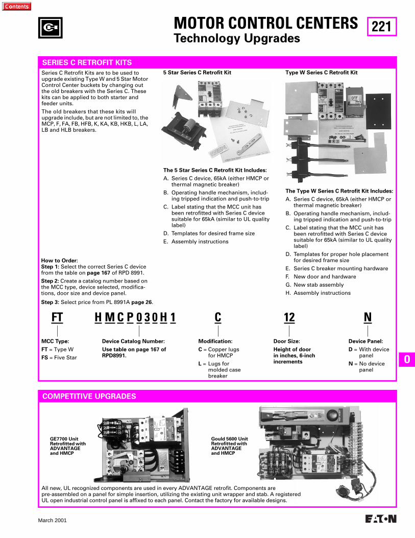
221
March 2001
O
MOTOR CONTROL CENTERSTechnology Upgrades
SERIES C RETROFIT KITS
Series C Retrofit Kits are to be used to upgrade existing Type W and 5 Star Motor Control Center buckets by changing out the old breakers with the Series C. These kits can be applied to both starter and feeder units.
The old breakers that these kits will upgrade include, but are not limited to, the MCP, F, FA, FB, HFB, K, KA, KB, HKB, L, LA, LB and HLB breakers.
5 Star Series C Retrofit Kit Type W Series C Retrofit Kit
The 5 Star Series C Retrofit Kit Includes:
A. Series C device, 65kA (either HMCP or thermal magnetic breaker)
B. Operating handle mechanism, includ-ing tripped indication and push-to-trip
C. Label stating that the MCC unit has been retrofitted with Series C device suitable for 65kA (similar to UL quality label)
D. Templates for desired frame size
E. Assembly instructions
The Type W Series C Retrofit Kit Includes:
A. Series C device, 65kA (either HMCP or thermal magnetic breaker)
B. Operating handle mechanism, includ-ing tripped indication and push-to-trip
C. Label stating that the MCC unit has been retrofitted with Series C device suitable for 65kA (similar to UL quality label)
D. Templates for proper hole placement for desired frame size
E. Series C breaker mounting hardware
F. New door and hardware
G. New stab assembly
H. Assembly instructions
How to Order:Step 1: Select the correct Series C device from the table on page 167 of RPD 8991.
Step 2: Create a catalog number based on the MCC type, device selected, modifica-tions, door size and device panel.
FT
MCC Type:
FT = Type W
FS = Five Star
H
Device Catalog Number:
Use table on page 167 of RPD8991.
C
Modification:
C = Copper lugsfor HMCP
L = Lugs formolded casebreaker
12
Door Size:
Height of doorin inches, 6-inchincrements
N
Device Panel:
D = With devicepanel
N = No devicepanel
M C P 0 3 0 H 1Step 3: Select price from PL 8991A page 26.
COMPETITIVE UPGRADES
GE7700 UnitRetrofitted with ADVANTAGE and HMCP
Gould 5600 UnitRetrofitted with ADVANTAGE and HMCP
All new, UL recognized components are used in every ADVANTAGE retrofit. Components are pre-assembled on a panel for simple insertion, utilizing the existing unit wrapper and stab. A registered UL open industrial control panel is affixed to each panel. Contact the factory for available designs.
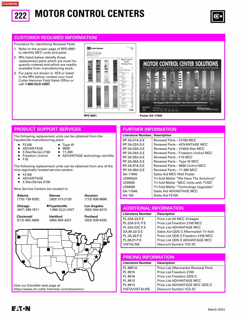
222
March 2001
Literature Number Description
PL.03A.03.P.EPL.03A.01C.P.EPL.03A.02C.P.ESA.8K.02.S.EPL.3A.20.P.EPL.08.01.P.EVISTALINE
Price List All MCC Vintages Price List Freedom 2100 MCCPrice List ADVANTAGE MCC Sales Aid QDS II Aftermarket Tri-fold Price List QDS II Freedom 2100 MCCPrice List QDS II ADVANTAGE MCCDiscount Symbol 1CD-2C
MOTOR CONTROL CENTERS
Literature Number Description
RP.3A.01A.S.ERP.3A.02A.S.ERP.3A.03A.S.ERP.3A.04A.S.ERP.3A.05A.S.ERP.3A.06A.S.ERP.3A.07A.S.ERP.3A.08A.S.ESA-11940LEM002ALEM005LEM006SA-11848SA-162
Renewal Parts – F2100 MCCRenewal Parts – ADVANTAGE MCCRenewal Parts – 2100/5-Star MCCRenewal Parts – Freedom Unitrol MCCRenewal Parts – F10 MCCRenewal Parts – Type W MCCRenewal Parts – 9800 Unitrol MCCRenewal Parts – 11-300 MCCSales Aid MCC Wall PosterTri-fold Mailer “We Have The Solutions” Tri-fold Mailer “MCC Units with TVSS” Tri-fold Mailer “Technology Upgrades”Sales Aid ADVANTAGE MCC Sales Aid F2100
PRODUCT SUPPORT SERVICES
The following replacement units can be obtained from the Fayetteville manufacturing plant:
● F2100 ● Type W● ADVANTAGE ● 9800● 5 Star/Series 2100 ● 11-300● Freedom Unitrol ● ADVANTAGE technology retrofits● F10
The following replacement units can be obtained from any of the nine regionally located service centers:
● F2100● ADVANTAGE● 5 Star/Series 2100
Nine Service Centers are located in:
FURTHER INFORMATION
PRICING INFORMATION
Literature Number Description
PL 8991APL 8915PL 8916PL 8912PL 8913VISTA/VISTALINE
Price List Aftermarket Renewal Parts Price List Freedom 2100 Price List Freedom QDS II Price List ADVANTAGE MCC Price List ADVANTAGE MCC QDS IIDiscount Symbol 1CD-2C
Atlanta(770) 739-6282
Chicago(847) 299-1911
Cincinnati(513) 682-4000
Denver(303) 373-2133
★Fayetteville1-800-OLD-UNIT
Hartford(860) 683-4221
★
CUSTOMER REQUIRED INFORMATION
Procedure for identifying Renewal Parts:
1. Refer to the proper page of RPD 8991 to identify MCC units and parts.
2. RPs listed below identify those replacement parts which are most fre-quently ordered and which are readily available from manufacturing stock.
3. For parts not shown in YES or listed in the RPs below, contact your local Cutler-Hammer Field Sales Office or call 1-800-OLD-UNIT.
RPD 8891 Poster SA-11940
Houston(713) 939-9696
Los Angeles(562) 944-6413
Portland(503) 636-8333
Visit our ExtraNet web page at https://www.ch.cutler-hammer.com/docs/mcc/
ADDITIONAL INFORMATION
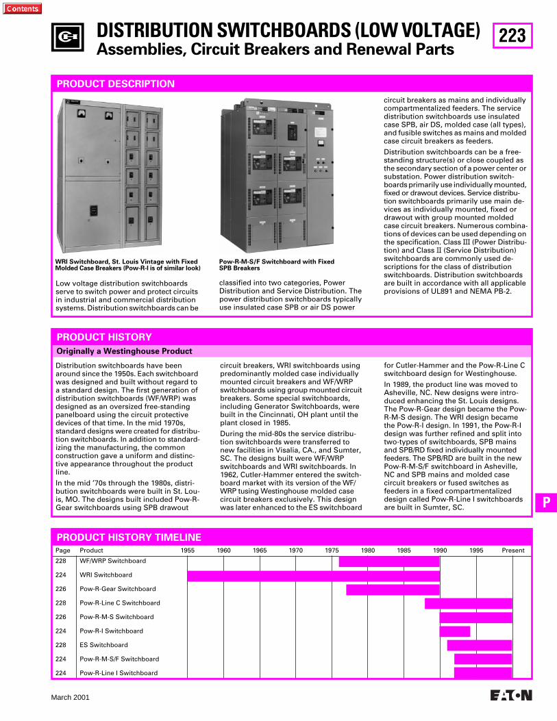
223
March 2001
P
DISTRIBUTION SWITCHBOARDS (LOW VOLTAGE)
Assemblies, Circuit Breakers and Renewal Parts
PRODUCT DESCRIPTION
Low voltage distribution switchboards serve to switch power and protect circuits in industrial and commercial distribution systems. Distribution switchboards can be
WRI Switchboard, St. Louis Vintage with Fixed Molded Case Breakers (Pow-R-I is of similar look)
Pow-R-M-S/F Switchboard with Fixed SPB Breakers
Originally a Westinghouse Product
PRODUCT HISTORY
Distribution switchboards have been around since the 1950s. Each switchboard was designed and built without regard to a standard design. The first generation of distribution switchboards (WF/WRP) was designed as an oversized free-standing panelboard using the circuit protective devices of that time. In the mid 1970s, standard designs were created for distribu-tion switchboards. In addition to standard-izing the manufacturing, the common construction gave a uniform and distinc-tive appearance throughout the product line.
In the mid ’70s through the 1980s, distri-bution switchboards were built in St. Lou-is, MO. The designs built included Pow-R-Gear switchboards using SPB drawout
circuit breakers, WRI switchboards using predominantly molded case individually mounted circuit breakers and WF/WRP switchboards using group mounted circuit breakers. Some special switchboards, including Generator Switchboards, were built in the Cincinnati, OH plant until the plant closed in 1985.
During the mid-80s the service distribu-tion switchboards were transferred to new facilities in Visalia, CA., and Sumter, SC. The designs built were WF/WRP switchboards and WRI switchboards. In 1962, Cutler-Hammer entered the switch-board market with its version of the WF/WRP tusing Westinghouse molded case circuit breakers exclusively. This design was later enhanced to the ES switchboard
for Cutler-Hammer and the Pow-R-Line C switchboard design for Westinghouse.
In 1989, the product line was moved to Asheville, NC. New designs were intro-duced enhancing the St. Louis designs. The Pow-R-Gear design became the Pow-R-M-S design. The WRI design became the Pow-R-I design. In 1991, the Pow-R-I design was further refined and split into two-types of switchboards, SPB mains and SPB/RD fixed individually mounted feeders. The SPB/RD are built in the new Pow-R-M-S/F switchboard in Asheville, NC and SPB mains and molded case circuit breakers or fused switches as feeders in a fixed compartmentalized design called Pow-R-Line I switchboards are built in Sumter, SC.
Page Product 1955 1960 1965 1970 1975 1980 1985 1990 1995 Present
228
224
226
228
226
224
228
224
224
WF/WRP Switchboard
WRI Switchboard
Pow-R-Gear Switchboard
Pow-R-Line C Switchboard
Pow-R-M-S Switchboard
Pow-R-I Switchboard
ES Switchboard
Pow-R-M-S/F Switchboard
Pow-R-Line I Switchboard
PRODUCT HISTORY TIMELINE
classified into two categories, Power Distribution and Service Distribution. The power distribution switchboards typically use insulated case SPB or air DS power
circuit breakers as mains and individually compartmentalized feeders. The service distribution switchboards use insulated case SPB, air DS, molded case (all types), and fusible switches as mains and molded case circuit breakers as feeders.
Distribution switchboards can be a free-standing structure(s) or close coupled as the secondary section of a power center or substation. Power distribution switch-boards primarily use individually mounted, fixed or drawout devices. Service distribu-tion switchboards primarily use main de-vices as individually mounted, fixed or drawout with group mounted molded case circuit breakers. Numerous combina-tions of devices can be used depending on the specification. Class
III
(Power Distribu-tion) and Class
II
(Service Distribution) switchboards are commonly used de-scriptions for the class of distribution switchboards. Distribution switchboards are built in accordance with all applicable provisions of UL891 and NEMA PB-2.
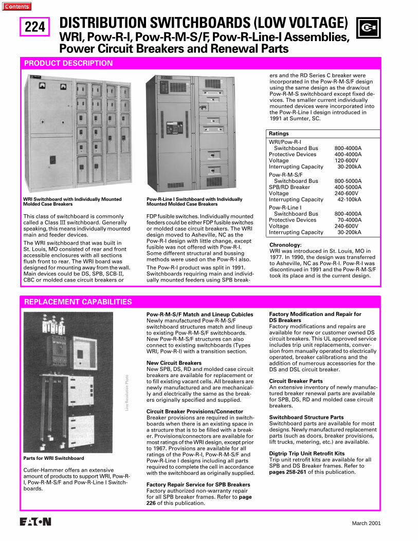
224
March 2001
PRODUCT DESCRIPTION
This class of switchboard is commonly called a Class
III
switchboard. Generally speaking, this means individually mounted main and feeder devices.
The WRI switchboard that was built in St. Louis, MO consisted of rear and front accessible enclosures with all sections flush front to rear. The WRI board was designed for mounting away from the wall. Main devices could be DS, SPB, SCB-
II
, CBC or molded case circuit breakers or
FDP fusible switches. Individually mounted feeders could be either FDP fusible switches or molded case circuit breakers. The WRI design moved to Asheville, NC as the Pow-R-I design with little change, except fusible was not offered with Pow-R-I. Some different structural and bussing methods were used on the Pow-R-I also.
The Pow-R-I product was split in 1991. Switchboards requiring main and individ-ually mounted feeders using SPB break-
ers and the RD Series C breaker were incorporated in the Pow-R-M-S/F design using the same design as the draw/out Pow-R-M-S switchboard except fixed de-vices. The smaller current individually mounted devices were incorporated into the Pow-R-Line I design introduced in 1991 at Sumter, SC.
Chronology:
WRI was introduced in St. Louis, MO in 1977. In 1990, the design was transferred to Asheville, NC as Pow-R-I. Pow-R-I was discontinued in 1991 and the Pow-R-M-S/F took its place and is the current design.
Ratings
WRI/Pow-R-ISwitchboard Bus 800-4000A
Protective Devices 400-4000AVoltage 120-600VInterrupting Capacity 30-200kA
Pow-R-M-S/F Switchboard Bus 800-5000A
SPB/RD Breaker 400-5000AVoltage 240-600VInterrupting Capacity 42-100kA
Pow-R-Line I Switchboard Bus 800-4000A
Protective Devices 70-4000AVoltage 240-600VInterrupting Capacity 30-200kA
Pow-R-Line I Switchboard with Individually Mounted Molded Case Breakers
WRI Switchboard with Individually Mounted Molded Case Breakers
REPLACEMENT CAPABILITIES
Cutler-Hammer offers an extensive amount of products to support WRI, Pow-R-I, Pow-R-M-S/F and Pow-R-Line I Switch-boards.
Pow-R-M-S/F Match and Lineup Cubicles
Newly manufactured Pow-R-M-S/F switchboard structures match and lineup to existing Pow-R-M-S/F switchboards. New Pow-R-M-S/F structures can also connect to existing switchboards (Types WRI, Pow-R-I) with a transition section.
New Circuit Breakers
New SPB, DS, RD and molded case circuit breakers are available for replacement or to fill existing vacant cells. All breakers are newly manufactured and are mechanical-ly and electrically the same as the break-ers originally specified and supplied.
Circuit Breaker Provisions/Connector
Breaker provisions are required in switch-boards when there is an existing space in a structure that is to be filled with a break-er. Provisions/connectors are available for most ratings of the WRI design, except prior to 1967. Provisions are available for all ratings of the Pow-R-I, Pow-R-M-S/F and Pow-R-Line I designs including all parts required to complete the cell in accordance with the switchboard as originally supplied.
Factory Repair Service for SPB Breakers
Factory authorized non-warranty repair for all SPB breaker frames. Refer to
page 226
of this publication.
Factory Modification and Repair for DS Breakers
Factory modifications and repairs are available for new or customer owned DS circuit breakers. This UL approved service includes trip unit replacements, conver-sion from manually operated to electrically operated, breaker calibrations and the addition of numerous accessories for the DS and DSL circuit breaker.
Circuit Breaker Parts
An extensive inventory of newly manufac-tured breaker renewal parts are available for SPB, DS, RD and molded case circuit breakers.
Switchboard Structure Parts
Switchboard parts are available for most designs. Newly manufactured replacement parts (such as doors, breaker provisions, lift trucks, metering, etc.) are available.
Digtrip Trip Unit Retrofit Kits
Trip unit retrofit kits are available for all SPB and DS Breaker frames. Refer to
pages 258-261
of this publication.
DISTRIBUTION SWITCHBOARDS (LOW VOLTAGE)
WRI, Pow-R-I, Pow-R-M-S/F, Pow-R-Line-I Assemblies, Power Circuit Breakers and Renewal Parts
Parts for WRI Switchboard
Low
Res
olut
ion
Phot
o
225
March 2001
P
TECHNOLOGY UPGRADES
IQ and PowerNet Communications Retrofits
Cutler-Hammer offers IQ products to re-place existing analog meters, instruments, and protective relays with microprocessor- based solid-state true-RMS sensing devic-es. IQ products can be furnished as compo-nents for field installation on the switch-gear, or can be provided as new replace-ment front panels. The new replacement front panels available for WRI, Pow-R-I, Pow-R-S/F, and Pow-R-Line I switchboard assemblies include the IQ devices mounted
and wired. The IQ products can be matched in numerous combinations to include the IQ Analyzer, IQ Data Plus
II
, IQ Data, IQ Generator, IQ Data Plus-4000/4100, and the Assemblies Electronic Monitor (AEM
II
). Communications can then be tied to the Cutler-Hammer PowerNet System.
Digtrip Trip Unit Retrofit Kits
Trip unit retrofit kits are available for all SPB and DS breaker frames. Refer to
pages 258-261
of this publication.
Clipper Power System
Transient voltage surge suppression system. Refer to
page
229
of this publication.
Pow-R-Command Lighting Control System
Microprocessor-based lighting control system. Refer to
page
229
of this publication.
DISTRIBUTION SWITCHBOARDS (LOW VOLTAGE)
WRI, Pow-R-I, Pow-R-M-S/F, Pow-R-Line-I Assemblies, Power Circuit Breakers and Renewal Parts
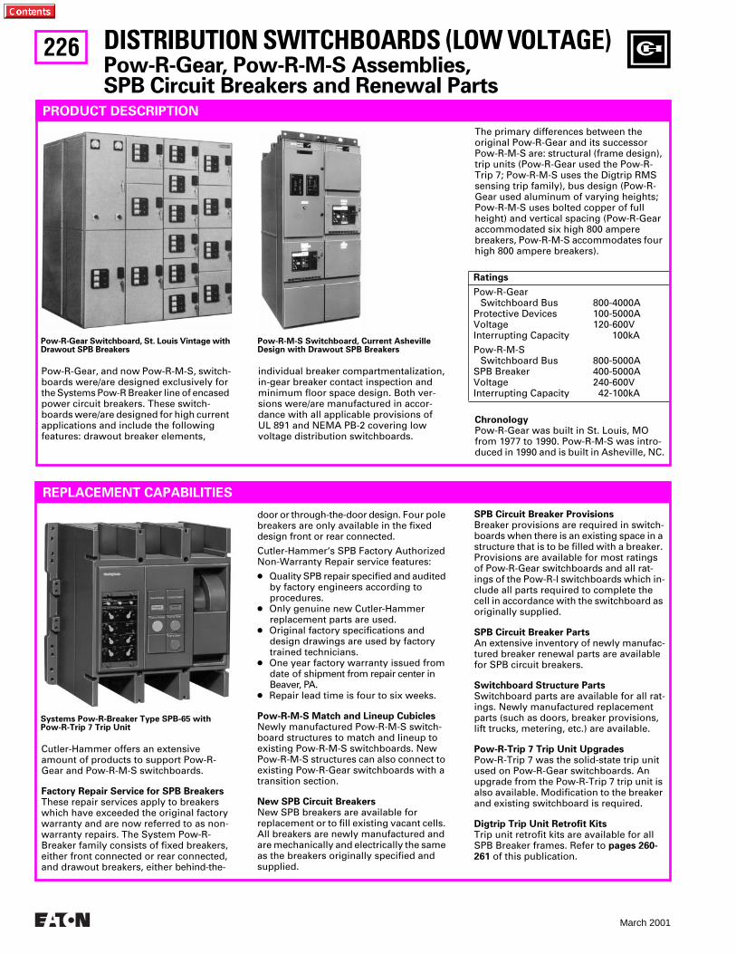
226
March 2001
DISTRIBUTION SWITCHBOARDS (LOW VOLTAGE)
Pow-R-Gear, Pow-R-M-S Assemblies,SPB Circuit Breakers and Renewal Parts
PRODUCT DESCRIPTION
Pow-R-Gear, and now Pow-R-M-S, switch-boards were/are designed exclusively for the Systems Pow-R Breaker line of encased power circuit breakers. These switch-boards were/are designed for high current applications and include the following features: drawout breaker elements,
individual breaker compartmentalization, in-gear breaker contact inspection and minimum floor space design. Both ver-sions were/are manufactured in accor-dance with all applicable provisions of UL 891 and NEMA PB-2 covering low voltage distribution switchboards.
The primary differences between the original Pow-R-Gear and its successor Pow-R-M-S are: structural (frame design), trip units (Pow-R-Gear used the Pow-R-Trip 7; Pow-R-M-S uses the Digtrip RMS sensing trip family), bus design (Pow-R-Gear used aluminum of varying heights; Pow-R-M-S uses bolted copper of full height) and vertical spacing (Pow-R-Gear accommodated six high 800 ampere breakers, Pow-R-M-S accommodates four high 800 ampere breakers).
Chronology
Pow-R-Gear was built in St. Louis, MO from 1977 to 1990. Pow-R-M-S was intro-duced in 1990 and is built in Asheville, NC.
Ratings
Pow-R-Gear Switchboard Bus 800-4000A
Protective Devices 100-5000AVoltage 120-600VInterrupting Capacity 100kA
Pow-R-M-S Switchboard Bus 800-5000A
SPB Breaker 400-5000AVoltage 240-600VInterrupting Capacity 42-100kA
Pow-R-Gear Switchboard, St. Louis Vintage with Drawout SPB Breakers
Pow-R-M-S Switchboard, Current Asheville Design with Drawout SPB Breakers
REPLACEMENT CAPABILITIES
SPB Circuit Breaker Provisions
Breaker provisions are required in switch-boards when there is an existing space in a structure that is to be filled with a breaker. Provisions are available for most ratings of Pow-R-Gear switchboards and all rat-ings of the Pow-R-I switchboards which in-clude all parts required to complete the cell in accordance with the switchboard as originally supplied.
SPB Circuit Breaker Parts
An extensive inventory of newly manufac-tured breaker renewal parts are available for SPB circuit breakers.
Switchboard Structure Parts
Switchboard parts are available for all rat-ings. Newly manufactured replacement parts (such as doors, breaker provisions, lift trucks, metering, etc.) are available.
Pow-R-Trip 7 Trip Unit Upgrades
Pow-R-Trip 7 was the solid-state trip unit used on Pow-R-Gear switchboards. An upgrade from the Pow-R-Trip 7 trip unit is also available. Modification to the breaker and existing switchboard is required.
Digtrip Trip Unit Retrofit Kits
Trip unit retrofit kits are available for all SPB Breaker frames. Refer to
pages 260-261
of this publication.
Cutler-Hammer offers an extensive amount of products to support Pow-R-Gear and Pow-R-M-S switchboards.
Factory Repair Service for SPB Breakers
These repair services apply to breakers which have exceeded the original factory warranty and are now referred to as non-warranty repairs. The System Pow-R-Breaker family consists of fixed breakers, either front connected or rear connected, and drawout breakers, either behind-the-
door or through-the-door design. Four pole breakers are only available in the fixed design front or rear connected.
Cutler-Hammer‘s SPB Factory Authorized Non-Warranty Repair service features:
●
Quality SPB repair specified and audited by factory engineers according to procedures.
●
Only genuine new Cutler-Hammer replacement parts are used.
●
Original factory specifications and design drawings are used by factory trained technicians.
●
One year factory warranty issued from date of shipment from repair center in Beaver, PA.
●
Repair lead time is four to six weeks.
Pow-R-M-S Match and Lineup Cubicles
Newly manufactured Pow-R-M-S switch-board structures to match and lineup to existing Pow-R-M-S switchboards. New Pow-R-M-S structures can also connect to existing Pow-R-Gear switchboards with a transition section.
New SPB Circuit Breakers
New SPB breakers are available for replacement or to fill existing vacant cells. All breakers are newly manufactured and are mechanically and electrically the same as the breakers originally specified and supplied.
Systems Pow-R-Breaker Type SPB-65 with Pow-R-Trip 7 Trip Unit
227
March 2001
P
DISTRIBUTION SWITCHBOARDS (LOW VOLTAGE)
Pow-R-Gear, Pow-R-M-S Assemblies,SPB Circuit Breakers and Renewal Parts
TECHNOLOGY UPGRADES
IQ and PowerNet Communications Retrofits
Cutler-Hammer offers IQ products to replace existing analog meters, instruments, and protective relays with microprocessor- based solid-state true-RMS sensing devices. IQ products can be furnished as compo-nents for field installation on the switch-gear, or can be provided as new replace-ment front panels. The new replacement front panels available for Pow-R-Gear and Pow-R-M-S switchboard assemblies include the IQ devices mounted and wired.
The IQ products can be matched in numer-ous combinations to include the IQ Ana-lyzer, IQ Data Plus
II
, IQ Data, IQ Generator, IQ Data Plus 4000/4100, and the Assemblies Electronic Monitor (AEM
II
). Communica-tions can then be tied to the Cutler-Hammer PowerNet System.
Digtrip Trip Unit Retrofit Kits
Trip unit retrofit kits are available for all SPB and DS breaker frames. Refer to
pages 258-261
of this publication.
Clipper Power System
Transient voltage surge suppression sys-tem. Refer to
page 229
of this publication.
Pow-R-Command Lighting Control System
Microprocessor-based lighting control system. Refer to
page 229
of this publication.
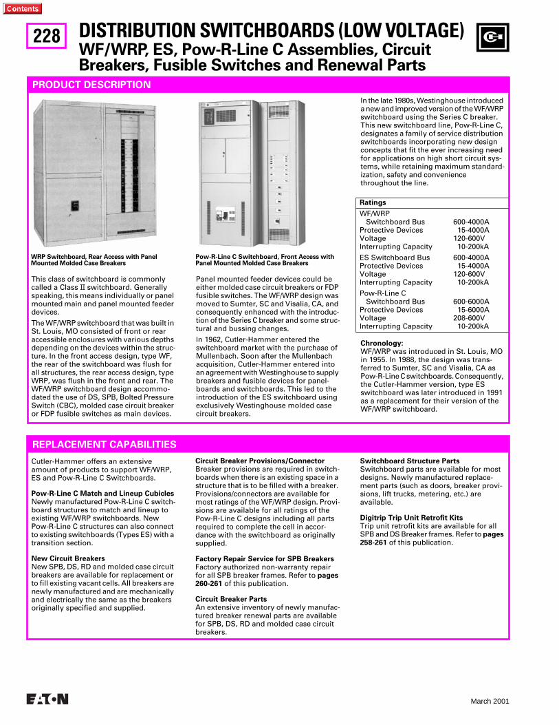
228
March 2001
PRODUCT DESCRIPTION
This class of switchboard is commonly called a Class
II
switchboard. Generally speaking, this means individually or panel mounted main and panel mounted feeder devices.
The WF/WRP switchboard that was built in St. Louis, MO consisted of front or rear accessible enclosures with various depths depending on the devices within the struc-ture. In the front access design, type WF, the rear of the switchboard was flush for all structures, the rear access design, type WRP, was flush in the front and rear. The WF/WRP switchboard design accommo-dated the use of DS, SPB, Bolted Pressure Switch (CBC), molded case circuit breaker or FDP fusible switches as main devices.
Panel mounted feeder devices could be either molded case circuit breakers or FDP fusible switches. The WF/WRP design was moved to Sumter, SC and Visalia, CA, and consequently enhanced with the introduc-tion of the Series C breaker and some struc-tural and bussing changes.
In 1962, Cutler-Hammer entered the switchboard market with the purchase of Mullenbach. Soon after the Mullenbach acquisition, Cutler-Hammer entered into an agreement with Westinghouse to supply breakers and fusible devices for panel-boards and switchboards. This led to the introduction of the ES switchboard using exclusively Westinghouse molded case circuit breakers.
WRP Switchboard, Rear Access with Panel Mounted Molded Case Breakers
Pow-R-Line C Switchboard, Front Access with Panel Mounted Molded Case Breakers
REPLACEMENT CAPABILITIES
Switchboard Structure Parts
Switchboard parts are available for most designs. Newly manufactured replace-ment parts (such as doors, breaker provi-sions, lift trucks, metering, etc.) are available.
Digitrip Trip Unit Retrofit Kits
Trip unit retrofit kits are available for all SPB and DS Breaker frames. Refer to
pages 258-261
of this publication.
Cutler-Hammer offers an extensive amount of products to support WF/WRP, ES and Pow-R-Line C Switchboards.
Pow-R-Line C Match and Lineup Cubicles
Newly manufactured Pow-R-Line C switch-board structures to match and lineup to existing WF/WRP switchboards. New Pow-R-Line C structures can also connect to existing switchboards (Types ES) with a transition section.
New Circuit Breakers
New SPB, DS, RD and molded case circuit breakers are available for replacement or to fill existing vacant cells. All breakers are newly manufactured and are mechanically and electrically the same as the breakers originally specified and supplied.
Circuit Breaker Provisions/Connector
Breaker provisions are required in switch-boards when there is an existing space in a structure that is to be filled with a breaker. Provisions/connectors are available for most ratings of the WF/WRP design. Provi-sions are available for all ratings of the Pow-R-Line C designs including all parts required to complete the cell in accor-dance with the switchboard as originally supplied.
Factory Repair Service for SPB Breakers
Factory authorized non-warranty repair for all SPB breaker frames. Refer to
pages 260-261
of this publication.
Circuit Breaker Parts
An extensive inventory of newly manufac-tured breaker renewal parts are available for SPB, DS, RD and molded case circuit breakers.
In the late 1980s, Westinghouse introduced a new and improved version of the WF/WRP switchboard using the Series C breaker. This new switchboard line, Pow-R-Line C, designates a family of service distribution switchboards incorporating new design concepts that fit the ever increasing need for applications on high short circuit sys-tems, while retaining maximum standard-ization, safety and convenience throughout the line.
Chronology:
WF/WRP was introduced in St. Louis, MO in 1955. In 1988, the design was trans-ferred to Sumter, SC and Visalia, CA as Pow-R-Line C switchboards. Consequently, the Cutler-Hammer version, type ES switchboard was later introduced in 1991 as a replacement for their version of the WF/WRP switchboard.
Ratings
WF/WRPSwitchboard Bus 600-4000A
Protective Devices 15-4000AVoltage 120-600VInterrupting Capacity 10-200kA
ES Switchboard Bus 600-4000AProtective Devices 15-4000AVoltage 120-600VInterrupting Capacity 10-200kA
Pow-R-Line CSwitchboard Bus 600-6000A
Protective Devices 15-6000AVoltage 208-600VInterrupting Capacity 10-200kA
DISTRIBUTION SWITCHBOARDS (LOW VOLTAGE)
WF/WRP, ES, Pow-R-Line C Assemblies, Circuit Breakers, Fusible Switches and Renewal Parts
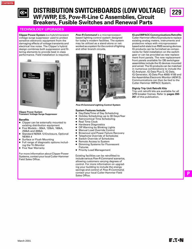
229
March 2001
P
Clipper Power SystemTransient Voltage Surge Suppressor
DISTRIBUTION SWITCHBOARDS (LOW VOLTAGE)
WF/WRP, ES, Pow-R-Line C Assemblies, Circuit Breakers, Fusible Switches and Renewal Parts
TECHNOLOGY UPGRADES
Clipper Power System
is a hybrid transient voltage surge suppressor used to protect sensitive electronic equipment from the damaging effects of voltage transients and electrical line noise. The Clipper’s hybrid design combines both suppression and fil-tering elements to provide best in class performance. Field installation is required.
Benefits
●
Clipper can be externally mounted to existing distribution equipment
●
Five Models – 90kA, 120kA, 160kA, 250kA and 400kA
●
Standard NEMA 12 Enclosure, Optional NEMA 4
●
Surface or Flush Mounting
●
Full range of diagnostic options includ-ing the Tri-Monitor
●
Five Year Warranty
For more information about Clipper Power Systems, contact your local Cutler-Hammer Field Sales Office.
Pow-R-Command
is a microprocessor-based lighting control system designed for today’s modern facilities. The system may be utilized as a stand-alone or net-worked as a system for the control of lighting and other branch circuits.
System Features Include:
●
Day/Date/Time of Day Scheduling
●
Holiday Scheduling–up to 30 Days/Year
●
Astronomical Time Scheduling
●
Real Time Clock
●
Hardware Diagnostics
●
Off Warning by Blinking Lights
●
Manual Load Override Control
●
Brownout and Power Failure Recovery
●
Telephone Override of Schedules
●
Switch Override of Schedules
●
Remote Access to System
●
Dimming Systems for Fluorescent Fixtures
●
Priority Load Management
Existing facilities can be retrofitted to include various
Pow-R-Command
scenarios, allowing customers varying degrees of control. For more information on upgrad-ing your building to include the energy savings and control of
Pow-R-Command
, contact your local Cutler-Hammer Field Sales Office.
Pow-R-Command
Lighting Control System
IQ and IMPACC Communications Retrofits
Cutler-Hammer offers IQ products to replace existing analog meters, instruments and protective relays with microprocessor- based solid-state true-RMS sensing devices. IQ products can be furnished as compo-nents for field installation on the switch-gear or can be provided as new replace-ment front panels. The new replacement front panels available for DB switchgear assemblies include the IQ devices mounted and wired. The IQ products can be matched in numerous combinations to include the IQ Analyzer, IQ Data Plus
II
, IQ Data, IQ Generator, IQ Data Plus 4000/ 4100 and the Assemblies Electronic Monitor (AEM
II). Communications can then be tied to the Cutler-Hammer IMPACC System.
Digtrip Trip Unit Retrofit Kits Trip unit retrofit kits are available for all SPB breaker frames. Refer to pages 260-261 of this publication.
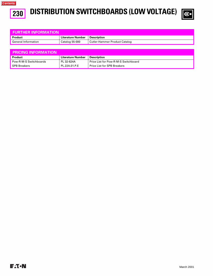
230
March 2001
Product Literature Number Description
General Information Catalog 55-000 Cutler-Hammer Product Catalog
Product Literature Number Description
Pow-R-M-S Switchboards
SPB Breakers
PL 32-624A
PL.22A.01.P.E
Price List for Pow-R-M-S Switchboard
Price List for SPB Breakers
DISTRIBUTION SWITCHBOARDS (LOW VOLTAGE)
FURTHER INFORMATION
PRICING INFORMATION
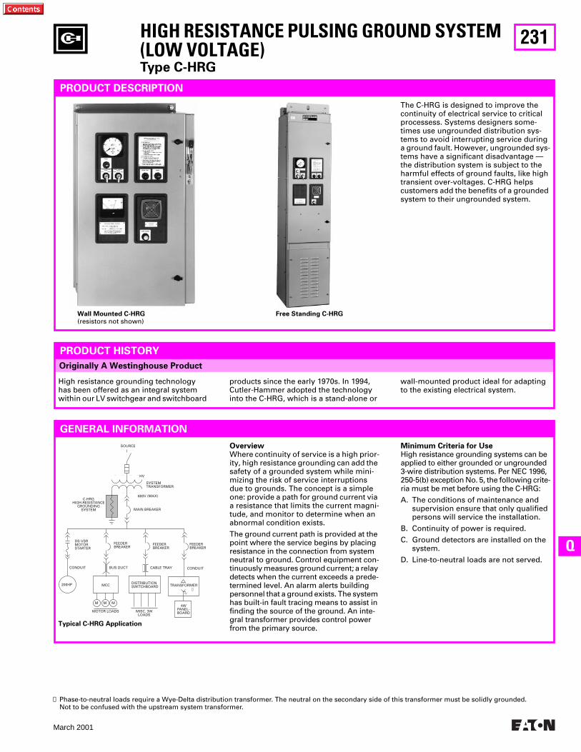
231
March 2001
Q
Originally A Westinghouse Product
DS-VSRMOTORSTARTER
CONDUIT
200HP
MOTOR LOADS
M M M
MCC
BUS DUCT
FEEDERBREAKER
FEEDERBREAKER
FEEDERBREAKER
CONDUITCABLE TRAY
DISTRIBUTIONSWITCHBOARD TRANSFORMER
4WPANEL-BOARDMISC. 3W
LOADS
MAIN BREAKER
600V (MAX)
HV
C-HRGHIGH-RESISTANCE
GROUNDINGSYSTEM
SOURCE
➊
SYSTEMTRANSFORMER
HIGH RESISTANCE PULSING GROUND SYSTEM (LOW VOLTAGE)
Type C-HRG
PRODUCT DESCRIPTION
Overview
Where continuity of service is a high prior-ity, high resistance grounding can add the safety of a grounded system while mini-mizing the risk of service interruptions due to grounds. The concept is a simple one: provide a path for ground current via a resistance that limits the current magni-tude, and monitor to determine when an abnormal condition exists.
The ground current path is provided at the point where the service begins by placing resistance in the connection from system neutral to ground. Control equipment con-tinuously measures ground current; a relay detects when the current exceeds a prede-termined level. An alarm alerts building personnel that a ground exists. The system has built-in fault tracing means to assist in finding the source of the ground. An inte-gral transformer provides control power from the primary source.
Free Standing C-HRGWall Mounted C-HRG
(resistors not shown)
➊
Phase-to-neutral loads require a Wye-Delta distribution transformer. The neutral on the secondary side of this transformer must be solidly grounded. Not to be confused with the upstream system transformer.
Typical C-HRG Application
The C-HRG is designed to improve the continuity of electrical service to critical processess. Systems designers some-times use ungrounded distribution sys-tems to avoid interrupting service during a ground fault. However, ungrounded sys-tems have a significant disadvantage — the distribution system is subject to the harmful effects of ground faults, like high transient over-voltages. C-HRG helps customers add the benefits of a grounded system to their ungrounded system.
PRODUCT HISTORY
High resistance grounding technology has been offered as an integral system within our LV switchgear and switchboard
products since the early 1970s. In 1994, Cutler-Hammer adopted the technology into the C-HRG, which is a stand-alone or
wall-mounted product ideal for adapting to the existing electrical system.
GENERAL INFORMATION
Minimum Criteria for Use
High resistance grounding systems can be applied to either grounded or ungrounded 3-wire distribution systems. Per NEC 1996, 250-5(b) exception No. 5, the following crite-ria must be met before using the C-HRG:
A. The conditions of maintenance and supervision ensure that only qualified persons will service the installation.
B. Continuity of power is required.
C. Ground detectors are installed on the system.
D. Line-to-neutral loads are not served.
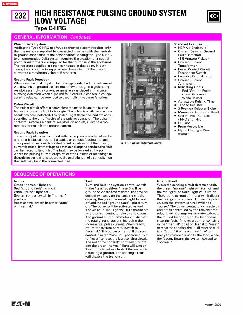
232
March 2001
GENERAL INFORMATION,
Continued
Standard Features
●
NEMA 1 Enclosure
●
Current Sensing Ground Fault Detection (1-5 Ampere Pickup)
●
Ground Current Transformer
●
Fused Control Circuit Disconnect Switch
●
Lockable Door Handle
●
Ground Current Ammeter
●
Indicating LightsRed (Ground Fault)Green (Normal)White (Pulse)
●
Adjustable Pulsing Timer
●
Tapped Resistor
●
3-Position Selector Switch
●
Manual or Automatic Reset
●
Ground Fault Contacts (1-NO and 1-NC)
●
UL Label
●
Front Accessible
●
Nylon Flag-type Wire Markers
HIGH RESISTANCE PULSING GROUND SYSTEM (LOW VOLTAGE)
Type C-HRG
Wye or Delta System
Adding the Type C-HRG to a Wye connected system requires only that the resistors supplied be connected in series with the neutral-to-ground connection of the power source. Adding the Type C-HRG to an ungrounded Delta system requires the creation of a neutral point. Transformers are supplied for that purpose in the enclosure. The resistors supplied are then connected at that point. In both cases, the components supplied are chosen to limit the ground current to a maximum value of 5 amperes.
Ground Fault Detection
When one phase of a system becomes grounded, additional current will flow. As all ground current must flow through the grounding resistor assembly, a current sensing relay is placed in this circuit allowing detection when a ground fault occurs. If chosen, a voltage sensing relay can be provided to accomplish the same function.
Pulser Circuit
The pulser circuit offers a convenient means to locate the faulted feeder and trace the fault to its origin. The pulser is available any time a fault has been detected. The “pulse” light flashes on and off, corre-sponding to the on-off cycles of the pulsing contactor. The pulser contactor switches a bank of resistors on and off, allowing a mo-mentary increase in the ground current.
Ground Fault Location
The current pulses can be noted with a clamp-on ammeter when the ammeter is placed around the cables or conduit feeding the fault. The operation tests each conduit or set of cables until the pulsing current is noted. By moving the ammeter along the conduit, the fault can be traced to its origin. The fault may be located at the point where the pulsing current drops off or stops. If little or no change in the pulsing current is noted along the entire length of a conduit, then the fault may be in the connected load.
SEQUENCE OF OPERATIONS
Normal
Green “normal” light on.Red “ground fault” light off.White “pulse” light off.System control switch in “normal” position.Reset control switch in either “auto” or “manual.”
Test
Turn and hold the system control switch in the “test” position. Phase B will be grounded via the test resistor. The ground current will activate the sensing circuit, causing the green “normal” light to turn off and the red “ground fault” light to turn on. The pulser will be activated as well. The white “pulse” light will turn on and off as the pulser contactor closes and opens. The ground current ammeter will display the total ground current, including the incremental pulse current. When ready, return the system control switch to “normal.” The pulser will stop. If the reset control is in the “manual” position, turn it to “reset” to reset the fault sensing circuit. The red “ground fault” light will turn off, and the green “normal” light will turn on. Test mode is not available if the system is detecting a ground. The sensing circuit will disable the test circuit.
Ground Fault
When the sensing circuit detects a fault, the green “normal” light will turn off and the red “ground fault” light will turn on. The ground current ammeter will indicate the total ground current. To use the puls-er, turn the system control switch to “pulse.” The pulser contactor will cycle on and off as controlled by the recycle timer relay. Use the clamp-on ammeter to locate the faulted feeder. Open the feeder and clear the fault. If the reset control switch is in the “manual” position, turn it to “reset” to reset the sensing circuit. (If reset control is in “auto,” it will reset itself.) When ready to restore service to the load, close the feeder. Return the system control to “normal.”
C-HRG Cabinet Internal Control
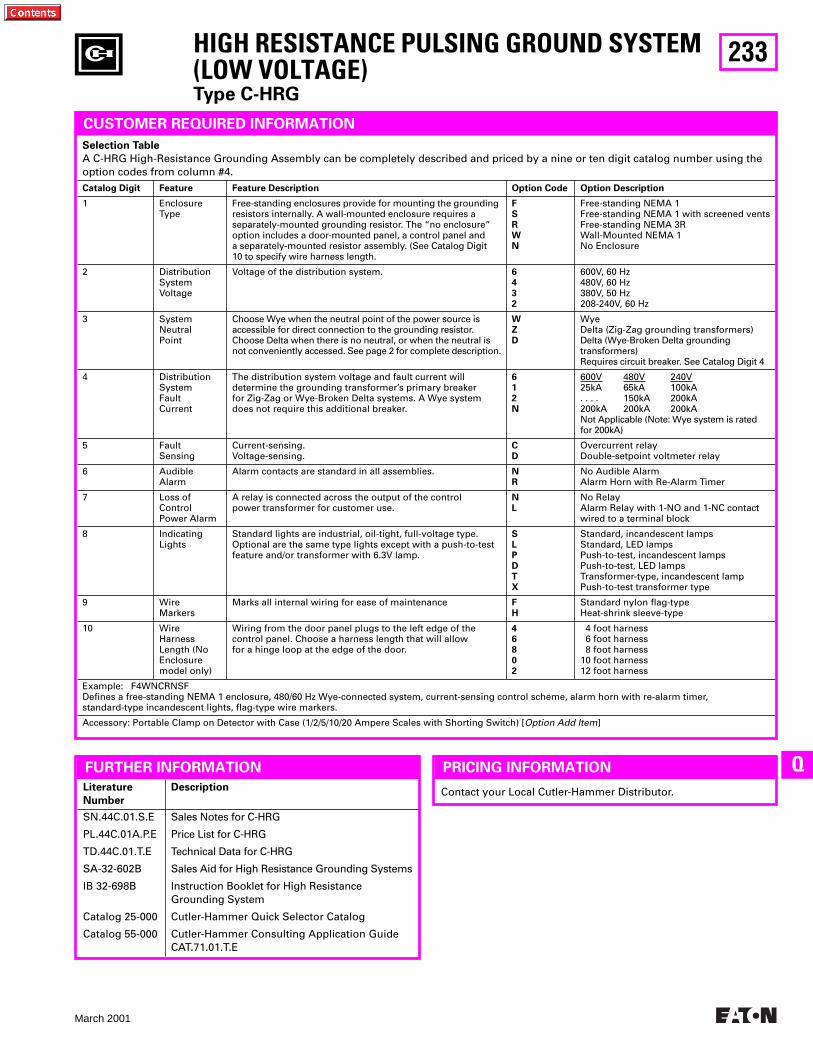
233
March 2001
Q
Literature
Number
Description
SN.44C.01.S.E
PL.44C.01A.P.E
TD.44C.01.T.E
SA-32-602B
IB 32-698B
Catalog 25-000
Catalog 55-000
Sales Notes for C-HRG
Price List for C-HRG
Technical Data for C-HRG
Sales Aid for High Resistance Grounding Systems
Instruction Booklet for High Resistance Grounding System
Cutler-Hammer Quick Selector Catalog
Cutler-Hammer Consulting Application GuideCAT.71.01.T.E
FURTHER INFORMATION
HIGH RESISTANCE PULSING GROUND SYSTEM (LOW VOLTAGE)
Type C-HRG
Contact your Local Cutler-Hammer Distributor.
PRICING INFORMATION
Selection Table
A C-HRG High-Resistance Grounding Assembly can be completely described and priced by a nine or ten digit catalog number using the option codes from column #4.
Catalog Digit Feature Feature Description Option Code Option Description
1 EnclosureType
Free-standing enclosures provide for mounting the grounding resistors internally. A wall-mounted enclosure requires a separately-mounted grounding resistor. The “no enclosure” option includes a door-mounted panel, a control panel and a separately-mounted resistor assembly. (See Catalog Digit 10 to specify wire harness length.
FSRWN
Free-standing NEMA 1Free-standing NEMA 1 with screened ventsFree-standing NEMA 3RWall-Mounted NEMA 1No Enclosure
2 DistributionSystemVoltage
Voltage of the distribution system.
6432
600V, 60 Hz480V, 60 Hz380V, 50 Hz208-240V, 60 Hz
3 SystemNeutralPoint
Choose Wye when the neutral point of the power source is accessible for direct connection to the grounding resistor. Choose Delta when there is no neutral, or when the neutral is not conveniently accessed. See page 2 for complete description.
WZD
WyeDelta
(Zig-Zag grounding transformers)Delta (Wye-Broken Delta grounding transformers)Requires circuit breaker. See Catalog Digit 4
4 DistributionSystemFault Current
The distribution system voltage and fault current will determine the grounding transformer’s primary breaker for Zig-Zag or Wye-Broken Delta systems. A Wye system does not require this additional breaker.
612N
600V 480V 240V25kA 65kA 100kA. . . . 150kA 200kA200kA 200kA 200kANot Applicable (Note: Wye system is rated for 200kA)
5 FaultSensing
Current-sensing.Voltage-sensing.
CD
Overcurrent relayDouble-setpoint voltmeter relay
6 AudibleAlarm
Alarm contacts are standard in all assemblies.
NR
No Audible AlarmAlarm Horn with Re-Alarm Timer
7 Loss ofControlPower Alarm
A relay is connected across the output of the control power transformer for customer use.
NL
No RelayAlarm Relay with 1-NO and 1-NC contact wired to a terminal block
8 IndicatingLights
Standard lights are industrial, oil-tight, full-voltage type. Optional are the same type lights except with a push-to-test feature and/or transformer with 6.3V lamp.
SLPDTX
Standard, incandescent lampsStandard, LED lampsPush-to-test, incandescent lampsPush-to-test, LED lampsTransformer-type, incandescent lampPush-to-test transformer type
9 WireMarkers
Marks all internal wiring for ease of maintenance
FH
Standard nylon flag-typeHeat-shrink sleeve-type
10 WireHarnessLength (NoEnclosuremodel only)
Wiring from the door panel plugs to the left edge of the control panel. Choose a harness length that will allow for a hinge loop at the edge of the door.
46802
4 foot harness 6 foot harness 8 foot harness10 foot harness12 foot harness
Example: F4WNCRNSFDefines a free-standing NEMA 1 enclosure, 480/60 Hz Wye-connected system, current-sensing control scheme, alarm horn with re-alarm timer, standard-type incandescent lights, flag-type wire markers.
Accessory: Portable Clamp on Detector with Case (1/2/5/10/20 Ampere Scales with Shorting Switch) [
Option Add Item
]
CUSTOMER REQUIRED INFORMATION
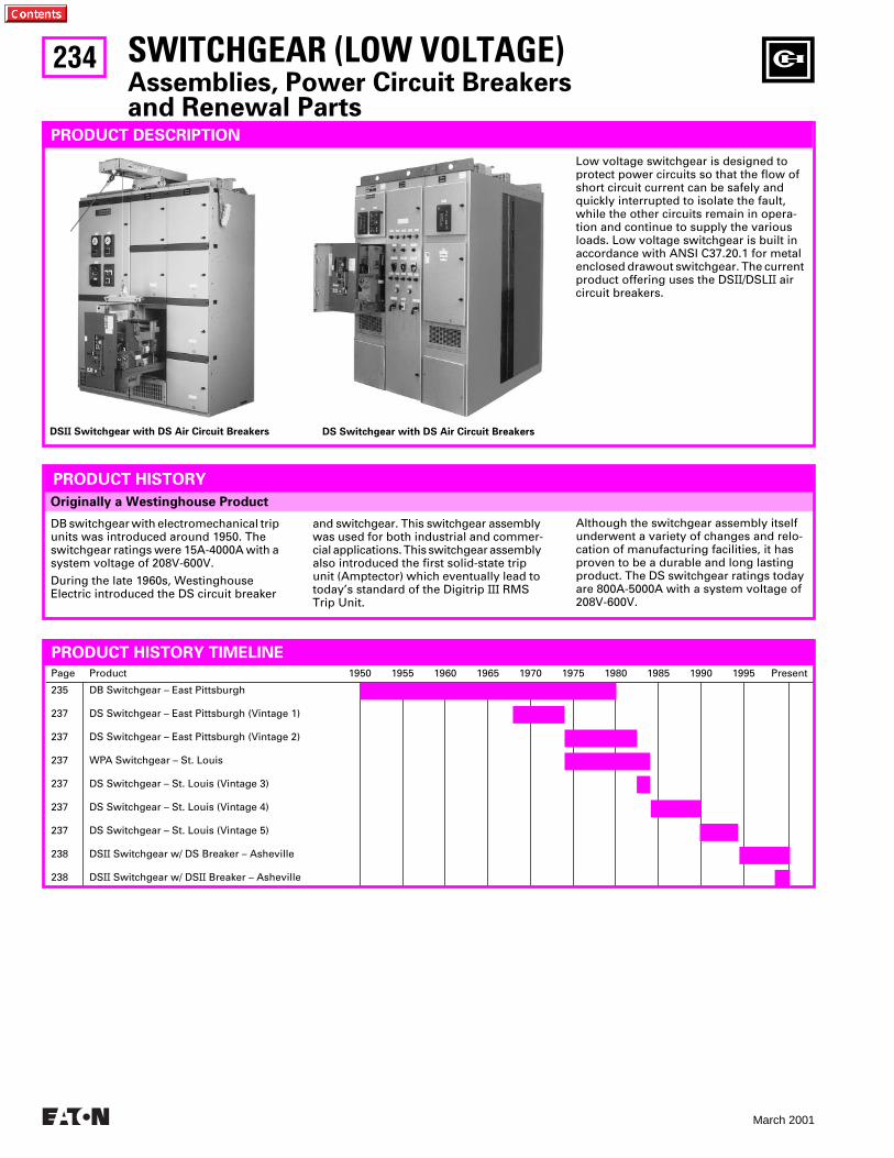
234
March 2001
DB switchgear with electromechanical trip units was introduced around 1950. The switchgear ratings were 15A-4000A with a system voltage of 208V-600V.
During the late 1960s, Westinghouse Electric introduced the DS circuit breaker
and switchgear. This switchgear assembly was used for both industrial and commer-cial applications. This switchgear assembly also introduced the first solid-state trip unit (Amptector) which eventually lead to today’s standard of the Digitrip
III
RMS Trip Unit.
Although the switchgear assembly itself underwent a variety of changes and relo-cation of manufacturing facilities, it has proven to be a durable and long lasting product. The DS switchgear ratings today are 800A-5000A with a system voltage of 208V-600V.
Originally a Westinghouse Product
Page Product 1950 1955 1960 1965 1970 1975 1980 1985 1990 1995 Present
235
237
237
237
237
237
237
238
238
DB Switchgear – East Pittsburgh
DS Switchgear – East Pittsburgh (Vintage 1)
DS Switchgear – East Pittsburgh (Vintage 2)
WPA Switchgear – St. Louis
DS Switchgear – St. Louis (Vintage 3)
DS Switchgear – St. Louis (Vintage 4)
DS Switchgear – St. Louis (Vintage 5)
DS
II
Switchgear w/ DS Breaker – Asheville
DS
II
Switchgear w/ DS
II
Breaker – Asheville
PRODUCT HISTORY TIMELINE
SWITCHGEAR (LOW VOLTAGE)
Assemblies, Power Circuit Breakersand Renewal Parts
PRODUCT DESCRIPTION
Low voltage switchgear is designed to protect power circuits so that the flow of short circuit current can be safely and quickly interrupted to isolate the fault, while the other circuits remain in opera-tion and continue to supply the various loads. Low voltage switchgear is built in accordance with ANSI C37.20.1 for metal enclosed drawout switchgear. The current product offering uses the DS
II
/DSL
II
air circuit breakers.
PRODUCT HISTORY
DS
II
Switchgear with DS Air Circuit Breakers DS Switchgear with DS Air Circuit Breakers
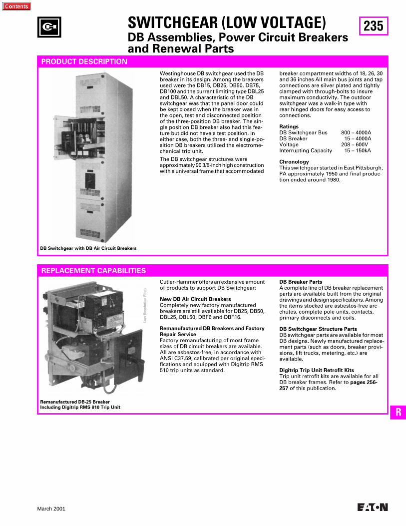
235
March 2001
R
SWITCHGEAR (LOW VOLTAGE)
DB Assemblies, Power Circuit Breakers and Renewal Parts
PRODUCT DESCRIPTION
Westinghouse DB switchgear used the DB breaker in its design. Among the breakers used were the DB15, DB25, DB50, DB75, DB100 and the current limiting type DBL25 and DBL50. A characteristic of the DB switchgear was that the panel door could be kept closed when the breaker was in the open, test and disconnected position of the three-position DB breaker. The sin-gle position DB breaker also had this fea-ture but did not have a test position. In either case, both the three- and single-po-sition DB breakers utilized the electrome-chanical trip unit.
The DB switchgear structures were approximately 90 3/8-inch high construction with a universal frame that accommodated
breaker compartment widths of 18, 26, 30 and 36 inches All main bus joints and tap connections are silver plated and tightly clamped with through-bolts to insure maximum conductivity. The outdoor switchgear was a walk-in type with rear hinged doors for easy access to connections.
Ratings
DB Switchgear Bus 800 – 4000ADB Breaker 15 – 4000AVoltage 208 – 600VInterrupting Capacity 15 – 150kA
Chronology
This switchgear started in East Pittsburgh, PA approximately 1950 and final produc-tion ended around 1980.
REPLACEMENT CAPABILITIES
Cutler-Hammer offers an extensive amount of products to support DB Switchgear:
New DB Air Circuit Breakers
Completely new factory manufactured breakers are still available for DB25, DB50, DBL25, DBL50, DBF6 and DBF16.
Remanufactured DB Breakers and Factory Repair Service
Factory remanufacturing of most frame sizes of DB circuit breakers are available. All are asbestos-free, in accordance with ANSI C37.59, calibrated per original speci-fications and equipped with Digitrip RMS 510 trip units as standard.
DB Breaker Parts
A complete line of DB breaker replacement parts are available built from the original drawings and design specifications. Among the items stocked are asbestos-free arc chutes, complete pole units, contacts, primary disconnects and coils.
DB Switchgear Structure Parts
DB switchgear parts are available for most DB designs. Newly manufactured replace-ment parts (such as doors, breaker provi-sions, lift trucks, metering, etc.) are available.
Digitrip Trip Unit Retrofit Kits
Trip unit retrofit kits are available for all DB breaker frames. Refer to
pages 256-257
of this publication.
Remanufactured DB-25 Breaker Including Digitrip RMS 810 Trip Unit
DB Switchgear with DB Air Circuit Breakers
Low
Res
olut
ion
Phot
o
236
March 2001
SWITCHGEAR (LOW VOLTAGE)
DB Assemblies, Power Circuit Breakers and Renewal Parts
THIS PAGE INTENTIONALLY LEFT BLANK
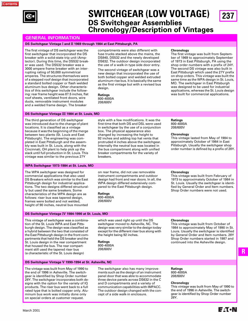
237
March 2001
R
DS Switchgear Vintage
V
1990-1994 at St. Asheville, NC
The vintage was built from May of 1990 to the end of 1996 in Asheville. The switch-gear is identified by Shop Order number 28Y. The switchgear incorporates both de-signs with the option for the variety of IQ products. The riser bus went back to a full rated type that is bolted copper only. Alu-minum bus work was initially done only on special orders at customer request.
The switchgear also has many improve-ments such as the design of an instrument panel door that was able to accommodate three device panels across DS632 in the C and D compartments and a variety of communication capabilities with IMPACC. The outdoor design changed with the con-cept of a side walk-in enclosure.
Ratings
800-4000A208/600V
Chronology
This vintage was built from May of 1990 to the end of 1996 in Asheville. The switch-gear is identified by Shop Order number 28Y.
DS Switchgear Vintage
IV
1984-1990 at St. Louis, MO
WPA Switchgear 1973-1984 at St. Louis, MO
DS Switchgear Vintage
III
1984 at St. Louis, MO
SWITCHGEAR (LOW VOLTAGE)
DS Switchgear AssembliesChronology/Description of Vintages
DS Switchgear Vintage
I
and
II
1969 through 1984 at East Pittsburgh, PA
GENERAL INFORMATION
The first vintage of DS switchgear was the first switchgear that incorporated the DS breaker with a solid-state trip unit (Amp-tector). During this time, the DS532 break-er was used. The DS532 breaker was a 3000 ampere frame breaker with an inter-rupting rating of 50,000 symmetrical amperes. The structures themselves were of a stepped roof design that incorporated a standard bolted copper or flash welded aluminum bus design. Other characteris-tics of this switchgear include the follow-ing: rear frame height was 87.5 inches, flat roof sheets, ventilated front doors, wire ducts, removable instrument modules and a welded frame design. The breaker
compartments were also different with fuse trucks stacked above the mains, the DS840, DS532 and the newly developed DS632. The outdoor design incorporated the use of a walk-in type side door entry.
The second vintage of switchgear was a new design that incorporated the use of both bolted copper and welded extruded aluminum rise bus. It is basically the same as the first vintage but with a revised bus design.
Ratings
800-4000A208/600V
Chronology
The first vintage was built from Septem-ber of 1969 to approximately September of 1973 in East Pittsburgh, PA using the shop order numbers with a prefix of 24Y. The second DS vintage was also built in East Pittsburgh which used the 27Y prefix on shop orders. This vintage was built the same time as the WPA design in St. Louis, MO. The switchgear in East Pittsburgh was designed to be used for industrial applications, whereas the St. Louis design was built for commercial applications.
The third generation of DS switchgear was introduced due to the change of plant locations. It is classified as a vintage because it was the beginning of the merge between two plants (St. Louis and East Pittsburgh). The engineering was com-pleted in East Pittsburgh and the assem-bly was built in St. Louis, along with the Cincinnati, OH plant to help pick up the slack until full production in St. Louis. This vintage was similar to the previous 27Y
style with a few modifications. It was the first time that both DS and DSL were used in switchgear by the use of a conjunction box. The physical appearance also changed by increasing the height to 92 inches and adding top hat vents that protruded 4 inches above the switchgear. Internally the neutral bus was located in the bus compartment along with unified breaker compartments for the variety of breakers.
Ratings
800-4000A208/600V
Chronology
This vintage lasted from May of 1984 to approximately October of 1984 in East Pittsburgh. Usually the switchgear shop order number is defined by a prefix of 28Y.
The WPA switchgear was designed for commercial applications that also used DS Breakers which was similar to the East Pittsburgh design for industrial applica-tions. The two designs differed structural-ly but used the same breakers. Some characteristics of the WPA design are as follows: riser bus was tapered design, frames were bolted and not welded, height of 90 inches, neutral bus mounted
on rear frame, did not use removable instrument compartments and outdoor design had front and rear doors. In all, the WPA design differed extensively com-pared to the East Pittsburgh design.
Ratings
800-4000A208/600V
Chronology
This vintage was built from February of 1973 to approximately October of 1984 in St. Louis. Usually the switchgear is identi-fied by General Order and Item numbers. Shop Order numbers were not used.
This vintage of switchgear was a combina-tion of the St. Louis WPA and East Pitts-burgh design. The design was classified as a hybrid between the two that consisted of the East Pittsburgh design in the front com-partments that held the DS breaker and the St. Louis design in the rear compartment that housed the bus. The rear compart-ment still used the tapered riser bus (a characteristic of the St. Louis design)
which was used right up until the DS switchgear moved to Asheville, NC. The design was very similar to the design today except for the different riser bus along with the height being 92 inches.
Ratings
800-4000A208/600V
Chronology
This vintage was built from October of 1984 to approximately May of 1990 in St. Louis. Usually the switchgear is identified by General Order and Item numbers. 28Y Shop Order numbers started in 1987 and continued into the Asheville design.
238
March 2001
The new design of DS
II
switchgear manu-factured in Asheville includes the new and improved DS
II
/DSL
II
low voltage power circuit breakers. The DS
II
/DSL
II
breakers now include the Digitrip 510 Trip Unit as standard with the DSL
II
providing extended interrupting ratings up to 200kA. A variety of trip units are now available that offer numerous features to benefit the customer: Digitrip 510, 610, 810, 910 and the OPTIM 750 and 1050.
Consequently, they are used on systems where the overload protection and switch-ing functions of air power circuit breakers are required and available fault currents exceed the interrupting ratings of the circuit breakers alone and/or exceed the withstand and interrupting ratings of downstream circuit components.
Ratings
800-6000A208/600V
Chronology
This vintage was built from February of 1996 to the present in Asheville. The switchgear is identified by Shop Order numbers larger than 82Y3000.
DS
II
Switchgear New Design 1995-Present at Asheville, NC
DS
II
Switchgear Original Design 1994-Present at Asheville, NC
The original design of DS
II
switchgear manufactured in Asheville includes the DS/DSL Circuit Breaker and the new and improved DS
II
Switchgear enhancements. These enhancements were developed with the input of our valued customers.
DS
II
switchgear provides enhanced oper-ational features and a new control wiring configuration that builds upon the reliabil-ity and flexibility of the original DS switchgear design. The quality and reliability of DS Switchgear has been consistently proven for over 25 years.
DS
II
switchgear continues to utilize DS/DSL 100% rated air circuit breakers, which represent the largest installed base of domestic low voltage power circuit breakers. Microprocessor-based Digitrip RMS Trip Units are standard on the circuit breakers. This vintage of DS
II
is what we offer to match existing line-ups of DS switchgear via 13 inch wide transition section.
Ratings
800-6000A208/600V
Chronology
This vintage was built from April of 1994 to the present in Asheville. The switchgear is identified by Shop Order number 82Y1000 through 82Y3000.
SWITCHGEAR (LOW VOLTAGE)
DS Switchgear AssembliesChronology/Description of Vintages
GENERAL INFORMATION,
Continued
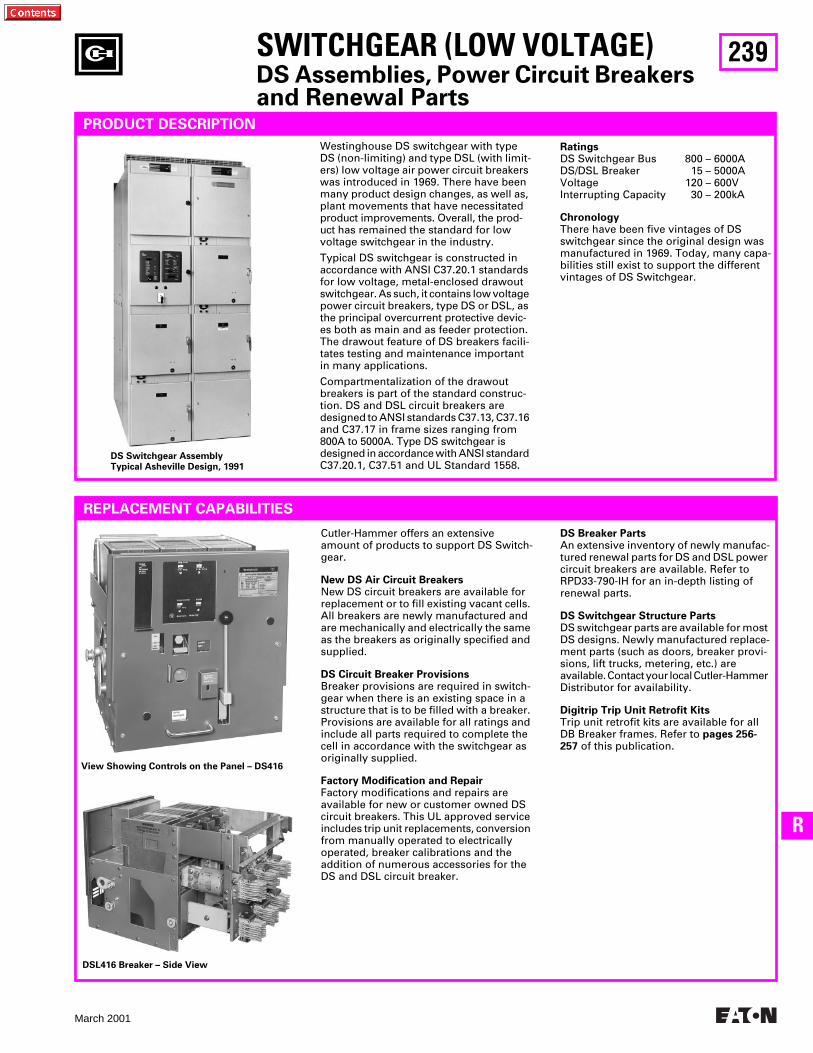
239
March 2001
R
SWITCHGEAR (LOW VOLTAGE)
DS Assemblies, Power Circuit Breakers and Renewal Parts
PRODUCT DESCRIPTION
DS Switchgear AssemblyTypical Asheville Design, 1991
Westinghouse DS switchgear with type DS (non-limiting) and type DSL (with limit-ers) low voltage air power circuit breakers was introduced in 1969. There have been many product design changes, as well as, plant movements that have necessitated product improvements. Overall, the prod-uct has remained the standard for low voltage switchgear in the industry.
Typical DS switchgear is constructed in accordance with ANSI C37.20.1 standards for low voltage, metal-enclosed drawout switchgear. As such, it contains low voltage power circuit breakers, type DS or DSL, as the principal overcurrent protective devic-es both as main and as feeder protection. The drawout feature of DS breakers facili-tates testing and maintenance important in many applications.
Compartmentalization of the drawout breakers is part of the standard construc-tion. DS and DSL circuit breakers are designed to ANSI standards C37.13, C37.16 and C37.17 in frame sizes ranging from 800A to 5000A. Type DS switchgear is designed in accordance with ANSI standard C37.20.1, C37.51 and UL Standard 1558.
Ratings
DS Switchgear Bus 800 – 6000ADS/DSL Breaker 15 – 5000AVoltage 120 – 600VInterrupting Capacity 30 – 200kA
Chronology
There have been five vintages of DS switchgear since the original design was manufactured in 1969. Today, many capa-bilities still exist to support the different vintages of DS Switchgear.
REPLACEMENT CAPABILITIES
Cutler-Hammer offers an extensive amount of products to support DS Switch-gear.
New DS Air Circuit Breakers
New DS circuit breakers are available for replacement or to fill existing vacant cells. All breakers are newly manufactured and are mechanically and electrically the same as the breakers as originally specified and supplied.
DS Circuit Breaker Provisions
Breaker provisions are required in switch-gear when there is an existing space in a structure that is to be filled with a breaker. Provisions are available for all ratings and include all parts required to complete the cell in accordance with the switchgear as originally supplied.
Factory Modification and Repair
Factory modifications and repairs are available for new or customer owned DS circuit breakers. This UL approved service includes trip unit replacements, conversion from manually operated to electrically operated, breaker calibrations and the addition of numerous accessories for the DS and DSL circuit breaker.
DS Breaker Parts
An extensive inventory of newly manufac-tured renewal parts for DS and DSL power circuit breakers are available. Refer to RPD33-790-lH for an in-depth listing of renewal parts.
DS Switchgear Structure Parts
DS switchgear parts are available for most DS designs. Newly manufactured replace-ment parts (such as doors, breaker provi-sions, lift trucks, metering, etc.) are available. Contact your local Cutler-Hammer Distributor for availability.
Digitrip Trip Unit Retrofit Kits
Trip unit retrofit kits are available for all DB Breaker frames. Refer to
pages 256-257
of this publication.
View Showing Controls on the Panel – DS416
DSL416 Breaker – Side View
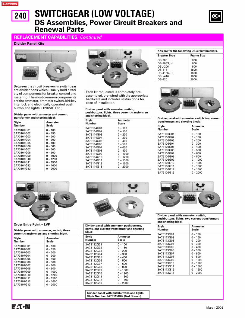
240
March 2001
Kits are for the following DS circuit breakers.
Breaker Type Frame Size
DS-206DS-206S, HDSL-206DS-416DS-416S, HDSL-416DS-420
8
00 800 8001600160016002000
Divider Panel Kits
SWITCHGEAR (LOW VOLTAGE)
DS Assemblies, Power Circuit Breakers and Renewal Parts
Divider panel with ammeter and current transformer and shorting block
StyleNumber
AmmeterScale
3A73104G01 3A73104G02 3A73104G03 3A73104G04 3A73104G05 3A73104G06 3A73104G07 3A73104G08 3A73104G09 3A73104G10 3A73104G11 3A73104G12 3A73104G13
0 – 1000 – 1500 – 2000 – 3000 – 4000 – 5000 – 6000 – 8000 – 10000 – 12000 – 15000 – 16000 – 2000
REPLACEMENT CAPABILITIES,
Continued
Between the circuit breakers in switchgear are divider pans which usually hold a vari-ety of components for breaker control and metering. The most common components are the ammeter, ammeter switch, kirk key interlock and electrically operated push button and lights. (120VAC Std.)
Each kit requested is completely pre-assembled, pre-wired with the appropriate hardware and includes instructions for ease of installation.
Divider panel with ammeter, switch, pushbuttons, lights, three current transformers and shorting block.
StyleNumber
AmmeterScale
3A73114G01 3A73114G02 3A73114G03 3A73114G04 3A73114G05 3A73114G06 3A73114G07 3A73114G08 3A73114G09 3A73114G10 3A73114G11 3A73114G12 3A73114G13
0 – 1000 – 1500 – 2000 – 3000 – 4000 – 5000 – 6000 – 8000 – 10000 – 12000 – 15000 – 16000 – 2000
Divider panel with ammeter, switch, two current transformers and shorting block.
StyleNumber
AmmeterScale
3A73106G01 3A73106G02 3A73106G03 3A73106G04 3A73106G05 3A73106G06 3A73106G07 3A73106G08 3A73106G09 3A73106G10 3A73106G11 3A73106G12 3A73106G13
0 – 1000 – 1500 – 2000 – 3000 – 4000 – 5000 – 6000 – 8000 – 10000 – 12000 – 15000 – 16000 – 2000
Divider panel with ammeter, switch, three current transformers and shorting block.
StyleNumber
AmmeterScale
3A73107G01 3A73107G02 3A73107G03 3A73107G04 3A73107G05 3A73107G06 3A73107G07 3A73107G08 3A73107G09 3A73107G10 3A73107G11 3A73107G12 3A73107G13
0 – 1000 – 1500 – 2000 – 3000 – 4000 – 5000 – 6000 – 8000 – 10000 – 12000 – 15000 – 16000 – 2000
Divider panel with ammeter, pushbuttons, lights, one current transformer and shorting block.
StyleNumber
AmmeterScale
3A73112G01 3A73112G02 3A73112G03 3A73112G04 3A73112G05 3A73112G06 3A73112G07 3A73112G08 3A73112G09 3A73112G10 3A73112G11 3A73112G12 3A73112G13
0 – 1000 – 1500 – 2000 – 3000 – 4000 – 5000 – 6000 – 8000 – 10000 – 12000 – 15000 – 16000 – 2000
Divider panel with ammeter, switch, pushbuttons, lights, two current transformers and shorting block.
StyleNumber
AmmeterScale
3A73113G01 3A73113G02 3A73113G03 3A73113G04 3A73113G05 3A73113G06 3A73113G07 3A73113G08 3A73113G09 3A73113G10 3A73113G11 3A73113G12 3A73113G13
0 – 1000 – 1500 – 2000 – 3000 – 4000 – 5000 – 6000 – 8000 – 10000 – 12000 – 15000 – 16000 – 2000
Order Entry Point – LVP
Divider panel with pushbuttons and lights Style Number 3A73115G02 (Not Shown)
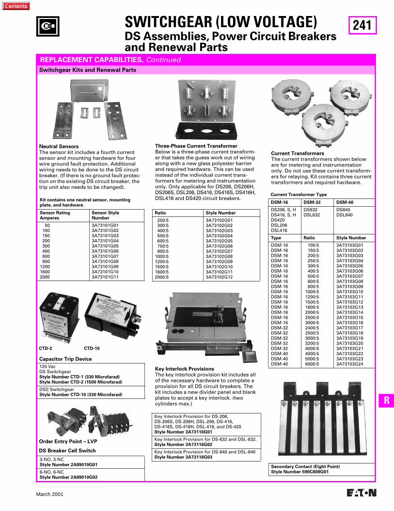
241
March 2001
R
Switchgear Kits and Renewal Parts
SWITCHGEAR (LOW VOLTAGE)
DS Assemblies, Power Circuit Breakers and Renewal Parts
REPLACEMENT CAPABILITIES,
Continued
Neutral Sensors
The sensor kit includes a fourth current sensor and mounting hardware for four wire ground fault protection. Additional wiring needs to be done to the DS circuit breaker. (If there is no ground fault protec-tion on the existing DS circuit breaker, the trip unit also needs to be changed).
Three-Phase Current Transformer
Below is a three-phase current transform-er that takes the guess work out of wiring along with a new glass polyester barrier and required hardware. This can be used instead of the individual current trans-formers for metering and instrumentation only. Only applicable for DS206, DS206H, DS206S, DSL206, DS416, DS416S, DS416H, DSL416 and DS420 circuit breakers.
Current Transformers
The current transformers shown below are for metering and instrumentation only. Do not use these current transform-ers for relaying. Kit contains three current transformers and required hardware.
Kit contains one neutral sensor, mounting plate, and hardware.
Sensor Rating Amperes
Sensor StyleNumber
50 100 150 200 300 400 600 800 1200 1600 2000
3A73101G01 3A73101G02 3A73101G03 3A73101G04 3A73101G05 3A73101G06 3A73101G07 3A73101G08 3A73101G09 3A73101G10 3A73101G11
Ratio Style Number
250:5 300:5 400:5 500:5 600:5 750:5 800:51000:51200:51500:51600:52000:5
3A73102G01 3A73102G02 3A73102G03 3A73102G04 3A73102G05 3A73102G06 3A73102G07 3A73102G08 3A73102G09 3A73102G10 3A73102G11 3A73102G12
Current Transformer Type
DSM-16 DSM-32 DSM-40
DS206, S, H DS416, S, H DS420 DSL206 DSL416
DS632 DSL632
DS840DSL840
Type Ratio Style Number
DSM-16 DSM-16 DSM-16 DSM-16 DSM-16 DSM-16 DSM-16 DSM-16 DSM-16 DSM-16 DSM-16 DSM-16 DSM-16 DSM-16 DSM-16 DSM-16 DSM-32 DSM-32 DSM-32 DSM-32 DSM-32 DSM-40 DSM-40 DSM-40
100:5150:5200:5250:5300:5400:5500:5600:5800:5
1000:51200:51500:51600:52000:52500:53000:52400:52500:53000:53200:54000:54000:55000:56000:5
3A73103G01 3A73103G02 3A73103G03 3A73103G04 3A73103G05 3A73103G06 3A73103G07 3A73103G08 3A73103G09 3A73103G10 3A73103G11 3A73103G12 3A73103G13 3A73103G14 3A73103G15 3A73103G16 3A73103G17 3A73103G18 3A73103G19 3A73103G20 3A73103G21 3A73103G22 3A73103G23 3A73103G24120 Vac
DS Switchgear
Style Number CTD-1 (330 Microfarad)Style Number CTD-2 (1500 Microfarad)
DS
II
Switchgear
Style Number CTD-10 (330 Microfarad)
DS Breaker Cell Switch
3-NO, 3-NC
Style Number 2A89010G01
6-NO, 6-NC
Style Number 2A89010G02
Key Interlock Provisions
The key interlock provision kit includes all of the necessary hardware to complete a provision for all DS circuit breakers. The kit includes a new divider panel and blank plates to accept a key interlock. (twocylinders max.)
Key Interlock Provision for DS-206, DS-206S, DS-206H, DSL-206, DS-416,DS-416S, DS-416H, DSL-416, and DS-420
Style Number 3A73116G01
Key Interlock Provision for DS-632 and DSL-632.
Style Number 3A73116G02
Key Interlock Provision for DS-840 and DSL-840
Style Number 3A73116G03
Secondary Contact (Eight Point)Style Number 590C808G01
Order Entry Point – LVP
CTD-2 CTD-10
Capacitor Trip Device
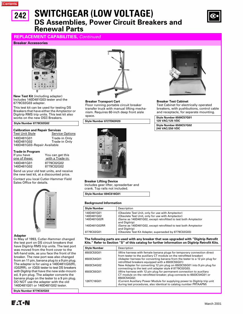
242
March 2001
Background Information
Style Number Description
140D481G01140D481G02140D481G02R
140D481G02RR
8779C02G01
(Obsolete Test Unit, only for use with Amptector)(Obsolete Test Unit, only for use with Amptector)(Same as 140D481G02, except retrofitted to test both Amptector and Digitrip)(Same as 140D481G02, except retrofitted to test both Amptector and Digitrip)(Obsolete Test Kit Adapter, superseded by 8779C02G03)
The following parts are used with any breaker that was upgraded with ”Digitrip Retrofit Kits.“ Refer to Section ”S“ of this catalog for further information on Digitrip Retrofit Kits.
Style Number Description
6503C53G01
6503C54G01
6503C54G02
6503C55G01
1267C16G01
(Wire harness with female banana plugs for temporary connection directfrom tester to the auxiliary CT module on the retrofitted breaker)(Adapter harness for converting banana from the tester to a 12 pin plug for retrofitted breakers equipped with a 6503C55G01)New Adapter for converting 12 pin plug on 6503C55G01 into 9 pin plug for connecting to the test unit adapter style # 8779C02G03.(Wire harness with 12 pin plug for permanent connection to auxiliary CT module on the retrofitted breaker; plug connects to 6503C54G01 or6503C54G02)(Current Auxiliary Power Module for supplying power to Digitrip trip unitduring test procedures, also identical to catalog number PRTAAPM)
Breaker Accessories
SWITCHGEAR (LOW VOLTAGE)DS Assemblies, Power Circuit Breakers and Renewal Parts
REPLACEMENT CAPABILITIES, Continued
Breaker Lifting DeviceIncludes gear lifter, spreaderbar and crank. Top rails not included.
Style Number 694C616G01
Breaker Transport CartFloor running portable circuit breaker transfer truck with manual lifting mecha-nism. Requires 60-inch deep front aisle space.
Style Number 6727D63H20
Breaker Test CabinetTest Cabinet for electrically operated breakers, with pushbuttons, control cable and receptacle, for separate mounting.
Style Number 6500C57G01120 VAC/125 VDC
Style Number 6500C57G02240 VAC/250 VDC
New Test Kit (including adapter)Includes 140D481G03 tester and the 6779C02G03 adapter.This test kit can be used for testing DS Breakers that have either the Amptector or Digitrip RMS trip units. This test kit also works on the new DSII Breakers.
Calibration and Repair ServicesTest Unit Style Service Options140D481G01 Trade-in Only140D481G02 Trade-in Only140D481G03–Repair Available
Trade-in ProgramIf you have You can get thisone of these: with a Trade-in:140D481G01 8779C02G02140D481G02 8779C02G02Send us your old test units, and receive the new test kit, at a discounted price.Contact you local Cutler-Hammer Field Sales Office for details.
Style Number 8779C02G02
AdapterIn May of 1993, Cutler-Hammer changed the test port on DS circuit breakers that have Digitrip RMS trip units. The test port was moved from the front cover to the left-hand side, as you face the front of the breaker. The new port was also changed from an 11 pin, banana plug to a 9 pin plug. The adapter is for using a 140D481(G02R), (G02RR), or (G03) tester to test DS breakers with Digitrip that have the new side-mount-ed, 9 pin plug. The adapter converts the banana plugs on the tester to a 9 pin plug. DO NOT use the adapter with the old 140D481G01 or 140D481G02 tester.
Style Number 8779C02G03
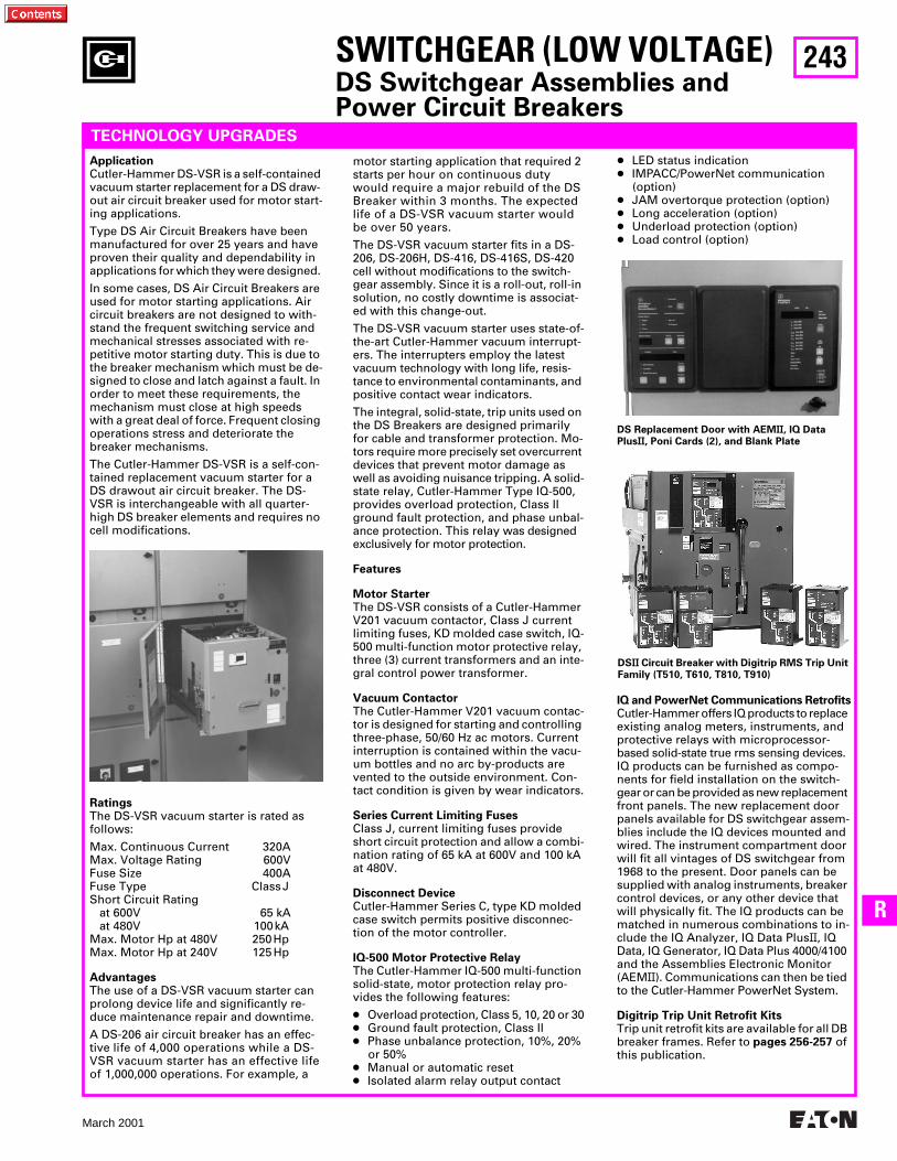
243
March 2001
R
SWITCHGEAR (LOW VOLTAGE)DS Switchgear Assemblies and Power Circuit Breakers
TECHNOLOGY UPGRADES
Application Cutler-Hammer DS-VSR is a self-contained vacuum starter replacement for a DS draw- out air circuit breaker used for motor start-ing applications.
Type DS Air Circuit Breakers have been manufactured for over 25 years and have proven their quality and dependability in applications for which they were designed.
In some cases, DS Air Circuit Breakers are used for motor starting applications. Air circuit breakers are not designed to with-stand the frequent switching service and mechanical stresses associated with re-petitive motor starting duty. This is due to the breaker mechanism which must be de-signed to close and latch against a fault. In order to meet these requirements, the mechanism must close at high speeds with a great deal of force. Frequent closing operations stress and deteriorate the breaker mechanisms.
The Cutler-Hammer DS-VSR is a self-con-tained replacement vacuum starter for a DS drawout air circuit breaker. The DS-VSR is interchangeable with all quarter-high DS breaker elements and requires no cell modifications.
Ratings The DS-VSR vacuum starter is rated as follows:
Max. Continuous Current 320A Max. Voltage Rating 600V Fuse Size 400A Fuse Type Class J Short Circuit Rating at 600V 65 kA at 480V 100 kA Max. Motor Hp at 480V 250 Hp Max. Motor Hp at 240V 125 Hp
Advantages The use of a DS-VSR vacuum starter can prolong device life and significantly re-duce maintenance repair and downtime.
A DS-206 air circuit breaker has an effec-tive life of 4,000 operations while a DS-VSR vacuum starter has an effective life of 1,000,000 operations. For example, a
motor starting application that required 2 starts per hour on continuous duty would require a major rebuild of the DS Breaker within 3 months. The expected life of a DS-VSR vacuum starter would be over 50 years.
The DS-VSR vacuum starter fits in a DS-206, DS-206H, DS-416, DS-416S, DS-420 cell without modifications to the switch-gear assembly. Since it is a roll-out, roll-in solution, no costly downtime is associat-ed with this change-out.
The DS-VSR vacuum starter uses state-of-the-art Cutler-Hammer vacuum interrupt-ers. The interrupters employ the latest vacuum technology with long life, resis-tance to environmental contaminants, and positive contact wear indicators.
The integral, solid-state, trip units used on the DS Breakers are designed primarily for cable and transformer protection. Mo-tors require more precisely set overcurrent devices that prevent motor damage as well as avoiding nuisance tripping. A solid-state relay, Cutler-Hammer Type IQ-500, provides overload protection, Class II ground fault protection, and phase unbal-ance protection. This relay was designed exclusively for motor protection.
Features
Motor Starter The DS-VSR consists of a Cutler-Hammer V201 vacuum contactor, Class J current limiting fuses, KD molded case switch, IQ-500 multi-function motor protective relay, three (3) current transformers and an inte-gral control power transformer.
Vacuum Contactor The Cutler-Hammer V201 vacuum contac-tor is designed for starting and controlling three-phase, 50/60 Hz ac motors. Current interruption is contained within the vacu-um bottles and no arc by-products are vented to the outside environment. Con-tact condition is given by wear indicators.
Series Current Limiting Fuses Class J, current limiting fuses provide short circuit protection and allow a combi-nation rating of 65 kA at 600V and 100 kA at 480V.
Disconnect Device Cutler-Hammer Series C, type KD molded case switch permits positive disconnec-tion of the motor controller.
IQ-500 Motor Protective Relay The Cutler-Hammer IQ-500 multi-function solid-state, motor protection relay pro-vides the following features:
● Overload protection, Class 5, 10, 20 or 30● Ground fault protection, Class II ● Phase unbalance protection, 10%, 20%
or 50% ● Manual or automatic reset ● Isolated alarm relay output contact
DS Replacement Door with AEMII, IQ Data PlusII, Poni Cards (2), and Blank Plate
IQ and PowerNet Communications RetrofitsCutler-Hammer offers IQ products to replace existing analog meters, instruments, and protective relays with microprocessor- based solid-state true rms sensing devices. IQ products can be furnished as compo-nents for field installation on the switch-gear or can be provided as new replacement front panels. The new replacement door panels available for DS switchgear assem-blies include the IQ devices mounted and wired. The instrument compartment door will fit all vintages of DS switchgear from 1968 to the present. Door panels can be supplied with analog instruments, breaker control devices, or any other device that will physically fit. The IQ products can be matched in numerous combinations to in-clude the IQ Analyzer, IQ Data PlusII, IQ Data, IQ Generator, IQ Data Plus 4000/4100 and the Assemblies Electronic Monitor (AEMII). Communications can then be tied to the Cutler-Hammer PowerNet System.
Digitrip Trip Unit Retrofit Kits Trip unit retrofit kits are available for all DB breaker frames. Refer to pages 256-257 of this publication.
● LED status indication ● IMPACC/PowerNet communication
(option) ● JAM overtorque protection (option) ● Long acceleration (option) ● Underload protection (option) ● Load control (option)
DSII Circuit Breaker with Digitrip RMS Trip Unit Family (T510, T610, T810, T910)
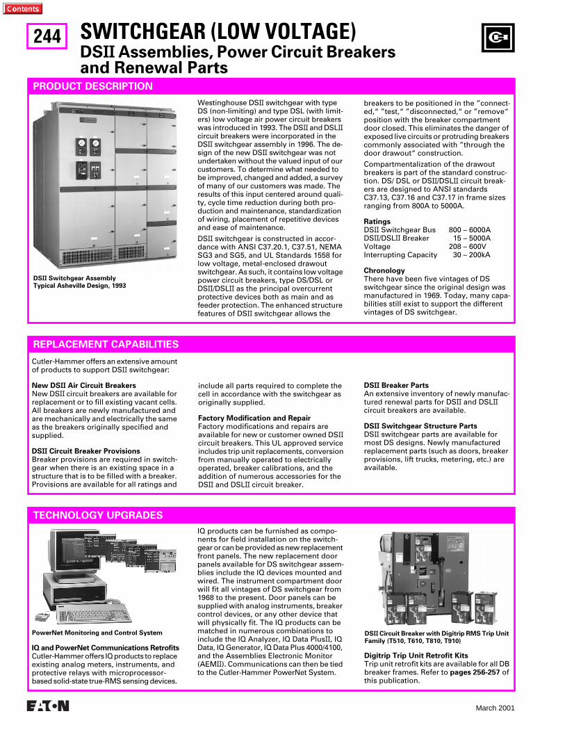
244
March 2001
SWITCHGEAR (LOW VOLTAGE)DSII Assemblies, Power Circuit Breakers and Renewal Parts
PRODUCT DESCRIPTION
Westinghouse DSII switchgear with type DS (non-limiting) and type DSL (with limit-ers) low voltage air power circuit breakers was introduced in 1993. The DSII and DSLII circuit breakers were incorporated in the DSII switchgear assembly in 1996. The de-sign of the new DSII switchgear was not undertaken without the valued input of our customers. To determine what needed to be improved, changed and added, a survey of many of our customers was made. The results of this input centered around quali-ty, cycle time reduction during both pro-duction and maintenance, standardization of wiring, placement of repetitive devices and ease of maintenance.
DSII switchgear is constructed in accor-dance with ANSI C37.20.1, C37.51, NEMA SG3 and SG5, and UL Standards 1558 for low voltage, metal-enclosed drawout switchgear. As such, it contains low voltage power circuit breakers, type DS/DSL or DSII/DSLII as the principal overcurrent protective devices both as main and as feeder protection. The enhanced structure features of DSII switchgear allows the
breakers to be positioned in the ”connect-ed,“ ”test,“ ”disconnected,“ or ”remove“ position with the breaker compartment door closed. This eliminates the danger of exposed live circuits or protruding breakers commonly associated with ”through the door drawout“ construction.
Compartmentalization of the drawout breakers is part of the standard construc-tion. DS/ DSL or DSII/DSLII circuit break-ers are designed to ANSI standards C37.13, C37.16 and C37.17 in frame sizes ranging from 800A to 5000A.
RatingsDSII Switchgear Bus 800 – 6000ADSII/DSLII Breaker 15 – 5000AVoltage 208 – 600VInterrupting Capacity 30 – 200kA
Chronology There have been five vintages of DS switchgear since the original design was manufactured in 1969. Today, many capa-bilities still exist to support the different vintages of DS switchgear.
REPLACEMENT CAPABILITIES
Cutler-Hammer offers an extensive amount of products to support DSII switchgear:
New DSII Air Circuit Breakers New DSII circuit breakers are available for replacement or to fill existing vacant cells. All breakers are newly manufactured and are mechanically and electrically the same as the breakers originally specified and supplied.
DSII Circuit Breaker Provisions Breaker provisions are required in switch-gear when there is an existing space in a structure that is to be filled with a breaker. Provisions are available for all ratings and
include all parts required to complete the cell in accordance with the switchgear as originally supplied.
Factory Modification and Repair Factory modifications and repairs are available for new or customer owned DSII circuit breakers. This UL approved service includes trip unit replacements, conversion from manually operated to electrically operated, breaker calibrations, and the addition of numerous accessories for the DSII and DSLII circuit breaker.
DSII Switchgear AssemblyTypical Asheville Design, 1993
DSII Breaker Parts An extensive inventory of newly manufac-tured renewal parts for DSII and DSLII circuit breakers are available.
DSII Switchgear Structure Parts DSII switchgear parts are available for most DS designs. Newly manufactured replacement parts (such as doors, breaker provisions, lift trucks, metering, etc.) are available.
TECHNOLOGY UPGRADES
IQ and PowerNet Communications RetrofitsCutler-Hammer offers IQ products to replace existing analog meters, instruments, and protective relays with microprocessor- based solid-state true-RMS sensing devices.
IQ products can be furnished as compo-nents for field installation on the switch-gear or can be provided as new replacement front panels. The new replacement door panels available for DS switchgear assem-blies include the IQ devices mounted and wired. The instrument compartment door will fit all vintages of DS switchgear from 1968 to the present. Door panels can be supplied with analog instruments, breaker control devices, or any other device that will physically fit. The IQ products can be matched in numerous combinations to include the IQ Analyzer, IQ Data PlusII, IQ Data, IQ Generator, IQ Data Plus 4000/4100, and the Assemblies Electronic Monitor (AEMII). Communications can then be tied to the Cutler-Hammer PowerNet System.
Digitrip Trip Unit Retrofit Kits Trip unit retrofit kits are available for all DB breaker frames. Refer to pages 256-257 of this publication.
DSII Circuit Breaker with Digitrip RMS Trip Unit Family (T510, T610, T810, T910)
PowerNet Monitoring and Control System
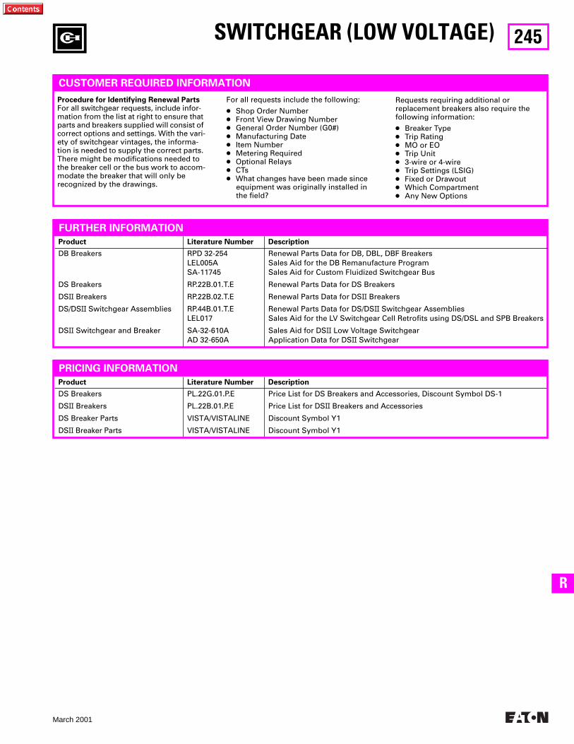
245
March 2001
R
Product Literature Number Description
DS Breakers
DSII Breakers
DS Breaker Parts
DSII Breaker Parts
PL.22G.01.P.E
PL.22B.01.P.E
VISTA/VISTALINE
VISTA/VISTALINE
Price List for DS Breakers and Accessories, Discount Symbol DS-1
Price List for DSII Breakers and Accessories
Discount Symbol Y1
Discount Symbol Y1
Product Literature Number Description
DB Breakers
DS Breakers
DSII Breakers
DS/DSII Switchgear Assemblies
DSII Switchgear and Breaker
RPD 32-254LEL005ASA-11745
RP.22B.01.T.E
RP.22B.02.T.E
RP.44B.01.T.ELEL017
SA-32-610AAD 32-650A
Renewal Parts Data for DB, DBL, DBF BreakersSales Aid for the DB Remanufacture ProgramSales Aid for Custom Fluidized Switchgear Bus
Renewal Parts Data for DS Breakers
Renewal Parts Data for DSII Breakers
Renewal Parts Data for DS/DSII Switchgear AssembliesSales Aid for the LV Switchgear Cell Retrofits using DS/DSL and SPB Breakers
Sales Aid for DSII Low Voltage SwitchgearApplication Data for DSII Switchgear
SWITCHGEAR (LOW VOLTAGE)
CUSTOMER REQUIRED INFORMATION
Procedure for Identifying Renewal PartsFor all switchgear requests, include infor-mation from the list at right to ensure that parts and breakers supplied will consist of correct options and settings. With the vari-ety of switchgear vintages, the informa-tion is needed to supply the correct parts. There might be modifications needed to the breaker cell or the bus work to accom-modate the breaker that will only be recognized by the drawings.
For all requests include the following:
● Shop Order Number ● Front View Drawing Number ● General Order Number (G0#)● Manufacturing Date ● Item Number ● Metering Required ● Optional Relays ● CTs ● What changes have been made since
equipment was originally installed in the field?
Requests requiring additional or replacement breakers also require the following information:
● Breaker Type● Trip Rating● MO or EO● Trip Unit● 3-wire or 4-wire● Trip Settings (LSIG) ● Fixed or Drawout ● Which Compartment● Any New Options
FURTHER INFORMATION
PRICING INFORMATION
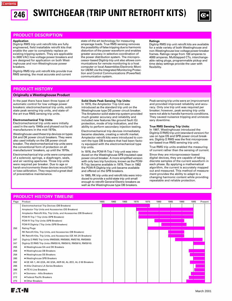
246
March 2001
Originally a Westinghouse Product
SWITCHGEAR (TRIP UNIT RETROFIT KITS)
PRODUCT DESCRIPTION
Application
Digitrip RMS trip unit retrofit kits are fully engineered, field installable retrofit kits that enable the user to completely replace an existing tripping system. They are applicable to (600 VAC) low-voltage power breakers and are designed for application on both West-inghouse and non-Westinghouse power breakers.
Digitrip RMS trip unit retrofit kits provide true RMS sensing, the most accurate and current
PRODUCT HISTORY
In the past there have been three types of automatic control for low voltage power breakers: electromechanical trip units, solid-state peak sensing trip units, and state-of-the-art true RMS sensing trip units.
Electromechanical Trip Units:
Electromechanical trip units were initially used in the early 1940s and phased out by all manufacturers in the mid-1970s.
Westinghouse used these trip devices on types DA and DK power circuit breakers. They were also used initially on the DB power circuit breaker. The electromechanical trip units were the conventional form of protection on all manufacturers’ breakers, up until the 1970s.
Electromechanical trip units were composed of a solenoid, springs, a diaphragm, seals, and air venting apertures. Three trip units were required per breaker. Due to age or harsh environments these devices would fail or lose calibration. They required a great deal of preventative maintenance.
Solid State Peak Sensing Trip Units:
In 1970, the Amptector Trip Unit was introduced as the standard trip unit on the Westinghouse type DS power circuit breaker. The Amptector solid-state trip system provided much greater accuracy and reliability and included new features like ground fault (G) protection, mode of trip indication, and the ability to perform secondary injection testing.
Electromechanical trip devices immediately became obsolete, creating a retrofit market. Amptector retrofit kits were introduced to con-vert the type DB breakers that had been facto-ry equipped with the electromechanical type trip units.
In 1976, the POW-R-Trip 7 trip unit was intro-duced on the Westinghouse SPB insulated case power circuit breaker. A more simplified version with only two trip functions, known as the POW-R-Trip; became available in 1978. Then in 1982 the POW-R Digitrip trip unit became available and offered on the SPB breakers.
In 1985, RK trip units and retrofit kits were intro-duced to provide a solid-state trip unit small enough to retrofit General Electric breakers as well as the Westinghouse type DB breakers.
Peak sensing trip units were an improvement and provided improved reliability and accu-racy. Only one trip unit was required per breaker; however, peak sensing trip units were not able to handle harmonic conditions. They caused nuisance tripping and unneces-sary downtime.
True RMS Sensing Trip Units:
In 1987, Westinghouse introduced the Digitrip
II
RMS trip unit (standard version) for use on type DS and SPB power circuit break-ers. Digitrip
II
RMS was the first microproces-sor-based true RMS sensing trip unit.
True RMS trip units enabled the measuring of current rather than the sensing of current.
Since they are microprocessor-based digital devices, they are capable of taking discrete samples of the current waveform in each phase. By applying a mathematical algorithm, the current is accurately mapped out and measured. This method of measure-ment provides the ability to adapt to a changing harmonic content while providing repeatable and reliable protection.
state-of-the-art technology for measuring amperage loads. True RMS sensing removes the possibility of false tripping due to harmonic distortion of the power waveform and enables greater accuracy in selective coordination of the power distribution system. The micropro-cessor-based Digitrip trip unit also allows com-munications for remote monitoring to a host computer or local Assemblies Electronic Moni-tor (AEM) via the Integrated Monitoring Protec-tion and Control Communications (PowerNet) communication system.
Ratings
Digitrip RMS trip unit retrofit kits are available for a wide variety of both Westinghouse and non-Westinghouse low-voltage power breaker frames. Ratings range from 100 amperes to 4000 amperes. Multitapped CTs, interchange-able rating plugs, programmable pickup and time delay settings provide the user with flexibility.
Page Product 1955 1960 1965 1970 1975 1980 1985 1990 1995 Present
250
247
247
255
256
258
260
262
266
268
271
272
273
Electromechanical Trip Devices (DB Breakers)
Amptector Trip Units and Accessories (DS Breakers)
Amptector Retrofit Kits, Trip Units, and Accessories (DB Breakers)
POW-R-Trip 7 Trip Units (SPB Breakers)
POW-R-Trip Trip Units (SPB Breakers)
POW-R Digitrip
I
Trip Units (SPB Breakers)
Rating Plugs
RK Retrofit Kits, Trip Units, and Accessories (DB Breakers)
RK Retrofit Kits, Trip Units, and Accessories (GE AK-2A Breakers)
Digitrip
II
RMS Trip Units (RMS500, RMS600, RMS700, RMS800)
Digitrip
III
RMS Trip Units (RMS510, RMS610, RMS810, RMS910)
●
Westinghouse DA and DK Breakers
●
Westinghouse DB Breakers
●
Westinghouse DS Breakers
●
Westinghouse SPB Breakers
●
GE AK-1, AK-2/2A, AK-3/3A, AKR-50, AL-2EO, AL-2-50 Breakers
●
Allis Chalmers LA Series Breakers
●
ITE K-Line Breakers
●
Siemens – Allis Breakers
●
Federal Pacific Breakers
●
Other Breakers
PRODUCT HISTORY TIMELINE
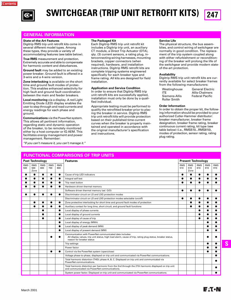
247
March 2001
SS
SWITCHGEAR (TRIP UNIT RETROFIT KITS)
GENERAL INFORMATION
State-of-the-Art Features
Digitrip RMS trip unit retrofit kits come in several different model types. Among these types, they provide a variety of accommodating features (see table below).
True RMS
measurement and protection. Extremely accurate and able to compensate for harmonic content and disturbances.
Ground fault
may be added to an existing power breaker. Ground fault is offered in a 3-wire and a 4-wire version.
Zone interlocking
is available on the short time and ground fault modes of protec-tion. This enables enhanced selectivity for high fault and ground fault coordination between the main and feeder breakers.
Local monitoring
via a display. A red Light Emitting Diode (LED) display enables the user to step through and read currents and energy readings for each phase and ground.
Communications
via the PowerNet system. This allows all pertinent information, regarding static and dynamic operation of the breaker, to be remotely monitored either by a host computer or IQ AEM. This facilitates energy management and power management. Remember:
The Packaged Kit
Each Digitrip RMS trip unit retrofit kit includes a Digitrip trip unit, an auxiliary CT module, a Direct Trip Actuator (DTA), qty. (3) current sensors, a rating plug, in-terconnecting wiring harnesses, mounting brackets, copper connectors (when required), hardware, and installation instructions. Digitrip RMS retrofit kits are complete tripping systems engineered specifically for each breaker type and frame rating. All kits are designed for field installation.
Application and Service Condition
In order to ensure that Digitrip RMS trip unit retrofit kits are successfully applied, installation must only be done by a quali-fied individual.
Appropriate testing must be performed to qualify the retrofitted breaker prior to plac-ing the breaker in service. Digitrip RMS trip unit retrofit kits will provide protection based on their published time-current curves when the breaker is properly main-tained and operated in accordance with the original manufacturer’s specification and instructions.
Service Life
The physical structure, the bus assem-blies, and control wiring of switchgear are normally in good condition. The replace-ment of the trip system coupled along with either refurbishment or recondition-ing of the breaker will prolong the life of the switchgear and provide modern state-of-the-art protection.
Availability
Digitrip RMS trip unit retrofit kits are cur-rently available for select breaker frames from the following manufacturers:
Westinghouse General Electric ITE Allis-Chalmers Siemens-Allis Federal PacificRoller Smith
Order Information
In order to obtain the proper kit, the follow-ing information should be provided to your authorized Cutler-Hammer distributor:breaker manufacturer, breaker frame designation, breaker frame rating, breaker continuous current rating, kit type (see table below) (i.e., RMS510...RMS810), modes of protection, sensor rating, rating plug rating.
Past Technology Features Present Technology
RMS500
RMS500Zone
RMS600
RMS700
RMS800
RMS510
RMS510Zone
RMS610
RMS810
RMS910
● ● ● ● ●
Cause of trip LED indicators
● ● ● ● ●
● ● ● ● ●
Integral self test
● ● ● ● ●
● ● ● ● ●
Trip reset button
● ● ● ● ●
● ● ● ● ●
Hardware driven thermal memory
Software driven thermal memory (sel. O/O)
● ● ● ● ●
● ● ● ● ●
Discriminator circuit on LS and LSG protection modes
Discriminator circuit on LS and LSG protection modes selectable (on/off)
● ● ● ● ●
● ● ● ●
Zone protective interlocking for short time and ground fault modes of protection
● ● ● ●
● ● ● ●
Auxiliary contact for long time, short circuit, and ground fault functions
● ● ● ●
● ●
Local display of phase currents
● ● ●
● ●
Local display of ground currents
● ● ●
● ●
Local display of cause of trip
● ● ●
●
Local display of energy (MWh)
● ●
●
Local display of peak demand (MW)
● ●
●
Local display of present demand (MW)
● ●
● ●
Communication with PowerNet communicated data includes:All display values, trip unit status, high load alarm, cause of trip, rating plug status, breaker status, reason for breaker status
● ●
Trip settings
● ●
Power factor
● ●
● ●
Control via the PowerNet system (open/close)
● ●
Voltage phase-to-phase, displayed on trip unit and communicated via PowerNet communications.
●
Total harmonic distortion (THD); phase A, B, C. Displayed on trip unit and communicated via PowerNet communications.
●
Total harmonic distortion per harmonic from the 2nd through the 27th harmonic displayed on trip unit and communicated via PowerNet communications.
●
System power factor. Displayed on trip unit and communicated via PowerNet communications.
●
FUNCTIONAL COMPARISONS OF TRIP UNITS
“If you can’t measure it, you can’t manage it.”
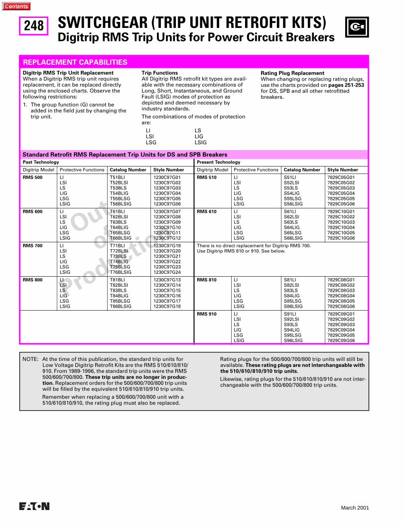
248
March 2001
Out
of
Productio
n
SWITCHGEAR (TRIP UNIT RETROFIT KITS)
Digitrip RMS Trip Units for Power Circuit Breakers
Standard Retrofit RMS Replacement Trip Units for DS and SPB Breakers
Past Technology Present Technology
Digitrip Model Protective Functions
Catalog Number Style Number
Digitrip Model Protective Functions
Catalog Number Style Number
RMS 500
LlLSILSLIGLSGLSIG
T51BLIT52BLSIT53BLST54BLIGT55BLSGT56BLSIG
1230C97G011230C97G021230C97G031230C97G041230C97G051230C97G06
RMS 510
LlLSILSLIGLSGLSIG
S51LIS52LSIS53LSS54LIGS55LSGS56LSIG
7829C05G017829C05G027829C05G037829C05G047829C05G057829C05G06
RMS 600
LlLSILSLIGLSGLSIG
T61BLIT62BLSIT63BLST64BLIGT65BLSGT66BLSIG
1230C97G071230C97G081230C97G091230C97G101230C97G111230C97G12
RMS 610
LlLSILSLIGLSGLSIG
S61LIS62LSIS63LSS64LIGS65LSGS66LSIG
7829C10G017829C10G027829C10G037829C10G047829C10G057829C10G06
RMS 700
LlLSILSLIGLSGLSIG
T71BLIT72BLSIT73BLST74BLIGT75BLSGT76BLSIG
1230C97G191230C97G201230C97G211230C97G221230C97G231230C97G24
There is no direct replacement for Digitrip RMS 700.Use Digitrip RMS 810 or 910. See below.
RMS 800
LlLSILSLIGLSGLSIG
T81BLIT82BLSIT83BLST84BLIGT85BLSGT86BLSIG
1230C97G131230C97G141230C97G151230C97G161230C97G171230C97G18
RMS 810
LlLSILSLIGLSGLSIG
S81LIS82LSIS83LSS84LIGS85LSGS86LSIG
7829C08G017829C08G027829C08G037829C08G047829C08G057829C08G06
RMS 910
LlLSILSLIGLSGLSIG
S91LIS92LSIS93LSS94LIGS95LSGS96LSIG
7829C09G017829C09G027829C09G037829C09G047829C09G057829C09G06
REPLACEMENT CAPABILITIES
Digitrip RMS Trip Unit Replacement
When a Digitrip RMS trip unit requires replacement, it can be replaced directly using the enclosed charts. Observe the following restrictions:
1. The group function (G) cannot be added in the field just by changing the trip unit.
Trip Functions
All Digitrip RMS retrofit kit types are avail-able with the necessary combinations of Long, Short, Instantaneous, and Ground Fault (LSIG) modes of protection as depicted and deemed necessary by industry standards.
The combinations of modes of protection are:
Ll LSLSI LIGLSG LSIG
Rating Plug Replacement
When changing or replacing rating plugs, use the charts provided on
pages 251-253
for DS, SPB and all other retrofittedbreakers.
NOTE: At the time of this publication, the standard trip units for Low Voltage Digitrip Retrofit Kits are the RMS 510/610/810/910. From 1989-1996, the standard trip units were the RMS 500/600/700/800.
These trip units are no longer in produc-tion.
Replacement orders for the 500/600/700/800 trip units will be filled by the equivalent 510/610/810/910 trip units.
Remember when replacing a 500/600/700/800 unit with a 510/610/810/910, the rating plug must also be replaced.
Rating plugs for the 500/600/700/800 trip units will still be available.
These rating plugs are not interchangeable with the 510/610/810/910 trip units.
Likewise, rating plugs for the 510/610/810/910 are not inter-changeable with the 500/600/700/800 trip units.
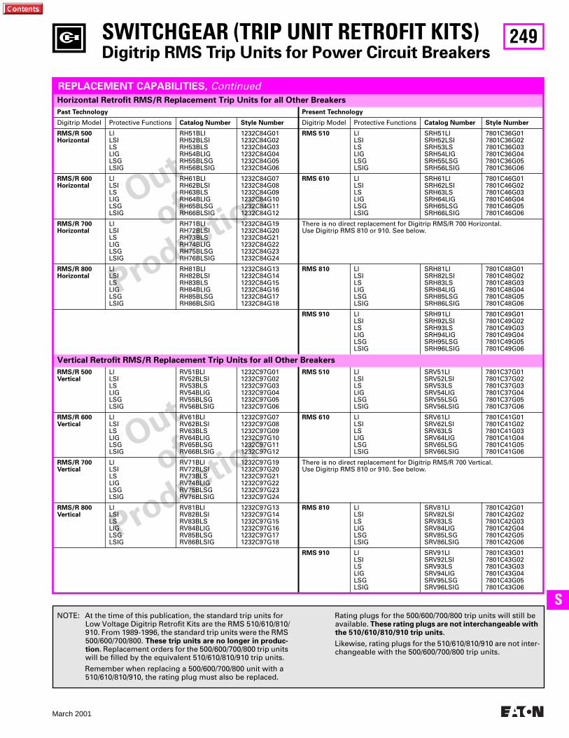
249
March 2001
SS
Out
of
Productio
n
Out
of
Productio
n
SWITCHGEAR (TRIP UNIT RETROFIT KITS)
Digitrip RMS Trip Units for Power Circuit Breakers
Horizontal Retrofit RMS/R Replacement Trip Units for all Other Breakers
Past Technology Present Technology
Digitrip Model Protective Functions
Catalog Number Style Number
Digitrip Model Protective Functions
Catalog Number Style Number
RMS/R 500 Horizontal
LlLSILSLIGLSGLSIG
RH51BLIRH52BLSIRH53BLSRH54BLIGRH55BLSGRH56BLSIG
1232C84G011232C84G021232C84G031232C84G041232C84G051232C84G06
RMS 510
LlLSILSLIGLSGLSIG
SRH51LISRH52LSISRH53LSSRH54LIGSRH55LSGSRH56LSIG
7801C36G017801C36G027801C36G037801C36G047801C36G057801C36G06
RMS/R 600 Horizontal
LlLSILSLIGLSGLSIG
RH61BLIRH62BLSIRH63BLSRH64BLIGRH65BLSGRH66BLSIG
1232C84G071232C84G081232C84G091232C84G101232C84G111232C84G12
RMS 610
LlLSILSLIGLSGLSIG
SRH61LISRH62LSISRH63LSSRH64LIGSRH65LSGSRH66LSIG
7801C46G017801C46G027801C46G037801C46G047801C46G057801C46G06
RMS/R 700 Horizontal
LlLSILSLIGLSGLSIG
RH71BLIRH72BLSIRH73BLSRH74BLIGRH75BLSGRH76BLSIG
1232C84G191232C84G201232C84G211232C84G221232C84G231232C84G24
There is no direct replacement for Digitrip RMS/R 700 Horizontal.Use Digitrip RMS 810 or 910. See below.
RMS/R 800 Horizontal
LILSILSLIGLSGLSIG
RH81BLIRH82BLSIRH83BLSRH84BLIGRH85BLSGRH86BLSIG
1232C84G131232C84G141232C84G151232C84G161232C84G171232C84G18
RMS 810
LlLSILSLIGLSGLSIG
SRH81LISRH82LSISRH83LSSRH84LIGSRH85LSGSRH86LSIG
7801C48G017801C48G027801C48G037801C48G047801C48G057801C48G06
RMS 910
LlLSILSLIGLSGLSIG
SRH91LISRH92LSISRH93LSSRH94LIGSRH95LSGSRH96LSIG
7801C49G017801C49G027801C49G037801C49G047801C49G057801C49G06
Vertical Retrofit RMS/R Replacement Trip Units for all Other Breakers
RMS/R 500Vertical
LlLSILSLIGLSGLSIG
RV51BLIRV52BLSIRV53BLSRV54BLIGRV55BLSGRV56BLSIG
1232C97G011232C97G021232C97G031232C97G041232C97G051232C97G06
RMS 510
LlLSILSLIGLSGLSIG
SRV51LlSRV52LSISRV53LSSRV54LIGSRV55LSGSRV56LSIG
7801C37G017801C37G027801C37G037801C37G047801C37G057801C37G06
RMS/R 600Vertical
LlLSILSLIGLSGLSIG
RV61BLIRV62BLSIRV63BLSRV64BLIGRV65BLSGRV66BLSIG
1232C97G071232C97G081232C97G091232C97G101232C97G111232C97G12
RMS 610
LlLSILSLIGLSGLSIG
SRV61LlSRV62LSISRV63LSSRV64LIGSRV65LSGSRV66LSIG
7801C41G017801C41G027801C41G037801C41G047801C41G057801C41G06
RMS/R 700 Vertical
LlLSILSLIGLSGLSIG
RV71BLIRV72BLSIRV73BLSRV74BLIGRV75BLSGRV76BLSIG
1232C97G191232C97G201232C97G211232C97G221232C97G231232C97G24
There is no direct replacement for Digitrip RMS/R 700 Vertical. Use Digitrip RMS 810 or 910. See below.
RMS/R 800 Vertical
LlLSILSLIGLSGLSIG
RV81BLIRV82BLSIRV83BLSRV84BLIGRV85BLSGRV86BLSIG
1232C97G131232C97G141232C97G151232C97G161232C97G171232C97G18
RMS 810
LlLSILSLIGLSGLSIG
SRV81LlSRV82LSISRV83LSSRV84LIGSRV85LSGSRV86LSIG
7801C42G017801C42G027801C42G037801C42G047801C42G057801C42G06
RMS 910
LlLSILSLIGLSGLSIG
SRV91LlSRV92LSISRV93LSSRV94LIGSRV95LSGSRV96LSIG
7801C43G017801C43G027801C43G037801C43G047801C43G057801C43G06
REPLACEMENT CAPABILITIES,
Continued
NOTE: At the time of this publication, the standard trip units for Low Voltage Digitrip Retrofit Kits are the RMS 510/610/810/910. From 1989-1996, the standard trip units were the RMS 500/600/700/800.
These trip units are no longer in produc-tion.
Replacement orders for the 500/600/700/800 trip units will be filled by the equivalent 510/610/810/910 trip units.
Remember when replacing a 500/600/700/800 unit with a 510/610/810/910, the rating plug must also be replaced.
Rating plugs for the 500/600/700/800 trip units will still be available.
These rating plugs are not interchangeable with the 510/610/810/910 trip units.
Likewise, rating plugs for the 510/610/810/910 are not inter-changeable with the 500/600/700/800 trip units.
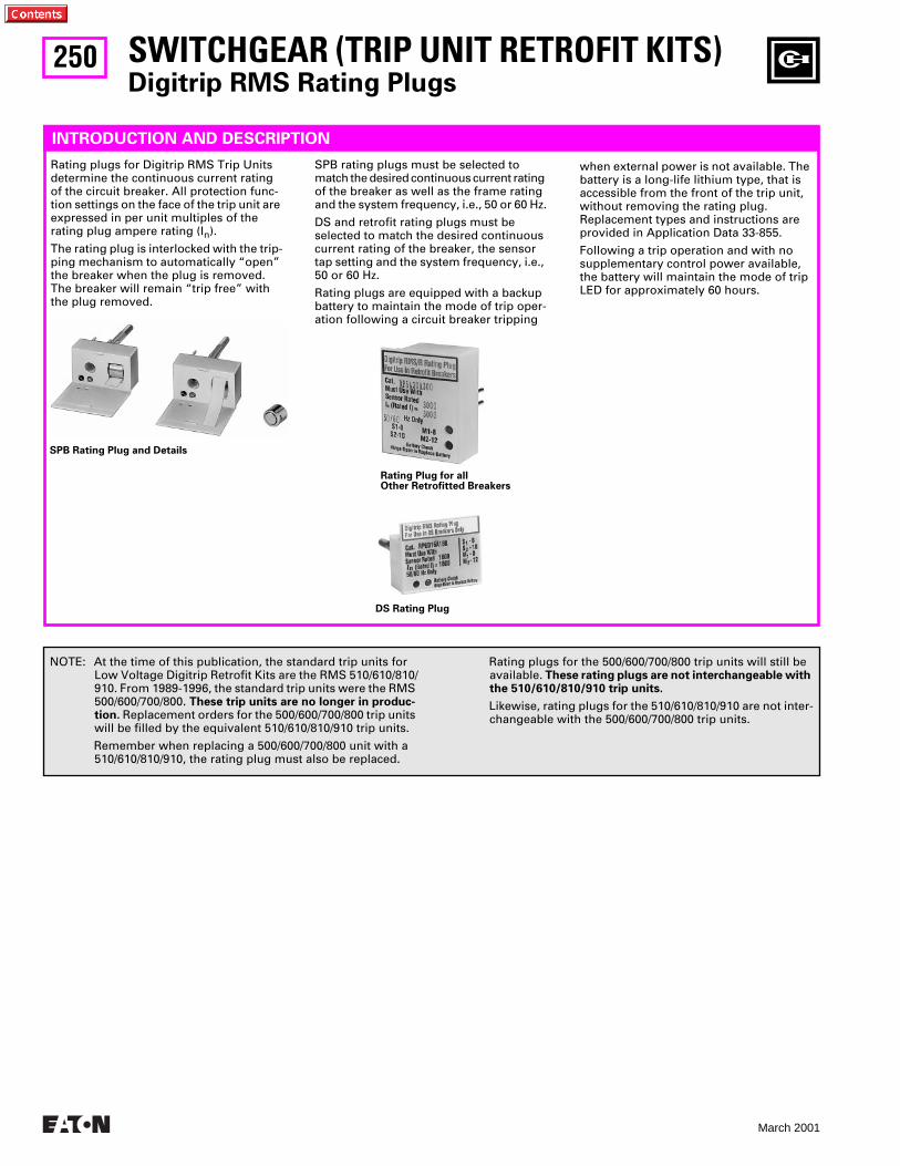
250
March 2001
SWITCHGEAR (TRIP UNIT RETROFIT KITS)
Digitrip RMS Rating Plugs
INTRODUCTION AND DESCRIPTION
Rating plugs for Digitrip RMS Trip Units determine the continuous current rating of the circuit breaker. All protection func-tion settings on the face of the trip unit are expressed in per unit multiples of the rating plug ampere rating (I
n
).
The rating plug is interlocked with the trip-ping mechanism to automatically “open” the breaker when the plug is removed. The breaker will remain “trip free” with the plug removed.
SPB rating plugs must be selected to match the desired continuous current rating of the breaker as well as the frame rating and the system frequency, i.e., 50 or 60 Hz.
DS and retrofit rating plugs must be selected to match the desired continuous current rating of the breaker, the sensor tap setting and the system frequency, i.e., 50 or 60 Hz.
Rating plugs are equipped with a backup battery to maintain the mode of trip oper-ation following a circuit breaker tripping
SPB Rating Plug and Details
when external power is not available. The battery is a long-life lithium type, that is accessible from the front of the trip unit, without removing the rating plug. Replacement types and instructions are provided in Application Data 33-855.
Following a trip operation and with no supplementary control power available, the battery will maintain the mode of trip LED for approximately 60 hours.
NOTE: At the time of this publication, the standard trip units for Low Voltage Digitrip Retrofit Kits are the RMS 510/610/810/910. From 1989-1996, the standard trip units were the RMS 500/600/700/800.
These trip units are no longer in produc-tion.
Replacement orders for the 500/600/700/800 trip units will be filled by the equivalent 510/610/810/910 trip units.
Remember when replacing a 500/600/700/800 unit with a 510/610/810/910, the rating plug must also be replaced.
Rating plugs for the 500/600/700/800 trip units will still be available.
These rating plugs are not interchangeable with the 510/610/810/910 trip units.
Likewise, rating plugs for the 510/610/810/910 are not inter-changeable with the 500/600/700/800 trip units.
Rating Plug for all Other Retrofitted Breakers
DS Rating Plug
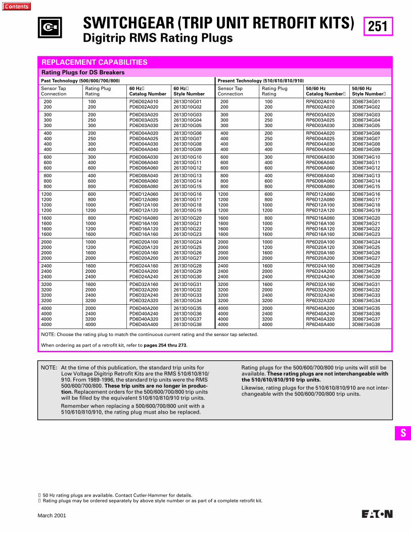
251
March 2001
SS
➊
50 Hz rating plugs are available. Contact Cutler-Hammer for details.
➋
Rating plugs may be ordered separately by above style number or as part of a complete retrofit kit.
SWITCHGEAR (TRIP UNIT RETROFIT KITS)
Digitrip RMS Rating Plugs
Past Technology (500/600/700/800) Present Technology (510/610/810/910)
Sensor Tap Connection
Rating Plug Rating
60 Hz
➊
Catalog Number60 Hz
➊
Style Number
Sensor Tap Connection
Rating Plug Rating
50/60 HzCatalog Number
➋
50/60 HzStyle Number
➋
200200
100200
PD6D02A010PD6D02A020
2613D10G012613D10G02
200200
100200
RP6D02A010RP6D02A020
3D86734G013D86734G02
300300300
200250300
PD6D03A020PD6D03A025PD6D03A030
2613D10G032613D10G042613D10G05
300300300
200250300
RP6D03A020RP6D03A025RP6D03A030
3D86734G033D86734G043D86734G05
400400400400
200250300400
PD6D04A020PD6D04A025PD6D04A030PD6D04A040
2613D10G062613D10G072613D10G082613D10G09
400400400400
200250300400
RP6D04A020RP6D04A025RP6D04A030RP6D04A040
3D86734G063D86734G073D86734G083D86734G09
600600600
300400600
PD6D06A030PD6D06A040PD6D06A060
2613D10G102613D10G112613D10G12
600600600
300400600
RP6D06A030RP6D06A040RP6D06A060
3D86734G103D86734G113D86734G12
800800800
400600800
PD6D08A040PD6D08A060PD6D08A080
2613D10G132613D10G142613D10G15
800800800
400600800
RP6D08A040RP6D08A060RP6D08A080
3D86734G133D86734G143D86734G15
1200120012001200
600800
10001200
PD6D12A060PD6D12A080PD6D12A100PD6D12A120
2613D10G162613D10G172613D10G182613D10G19
1200120012001200
600800
10001200
RP6D12A060RP6D12A080RP6D12A100RP6D12A120
3D86734G163D86734G173D86734G183D86734G19
1600160016001600
800100012001600
PD6D16A080PD6D16A100PD6D16A120PD6D16A160
2613D10G202613D10G212613D10G222613D10G23
1600160016001600
800100012001600
RP6D16A080RP6D16A100RP6D16A120RP6D16A160
3D86734G203D86734G213D86734G223D86734G23
2000200020002000
1000120016002000
PD6D20A100PD6D20A120PD6D20A160PD6D20A200
2613D10G242613D10G252613D10G262613D10G27
2000200020002000
1000120016002000
RP6D20A100RP6D20A120RP6D20A160RP6D20A200
3D86734G243D86734G253D86734G263D86734G27
240024002400
160020002400
PD6D24A160PD6D24A200PD6D24A240
2613D10G282613D10G292613D10G30
240024002400
160020002400
RP6D24A160RP6D24A200RP6D24A240
3D86734G283D86734G293D86734G30
3200320032003200
1600200024003200
PD6D32A160PD6D32A200PD6D32A240PD6D32A320
2613D10G312613D10G322613D10G332613D10G34
3200320032003200
1600200024003200
RP6D32A160RP6D32A200RP6D32A240RP6D32A320
3D86734G313D86734G323D86734G333D86734G34
4000400040004000
2000240032004000
PD6D40A200PD6D40A240PD6D40A320PD6D40A400
2613D10G352613D10G362613D10G372613D10G38
4000400040004000
2000240032004000
RP6D40A200RP6D40A240RP6D40A320RP6D40A400
3D86734G353D86734G363D86734G373D86734G38
Rating Plugs for DS Breakers
REPLACEMENT CAPABILITIES
NOTE: At the time of this publication, the standard trip units for Low Voltage Digitrip Retrofit Kits are the RMS 510/610/810/910. From 1989-1996, the standard trip units were the RMS 500/600/700/800.
These trip units are no longer in produc-tion.
Replacement orders for the 500/600/700/800 trip units will be filled by the equivalent 510/610/810/910 trip units.
Remember when replacing a 500/600/700/800 unit with a 510/610/810/910, the rating plug must also be replaced.
Rating plugs for the 500/600/700/800 trip units will still be available.
These rating plugs are not interchangeable with the 510/610/810/910 trip units.
Likewise, rating plugs for the 510/610/810/910 are not inter-changeable with the 500/600/700/800 trip units.
NOTE: Choose the rating plug to match the continuous current rating and the sensor tap selected.
When ordering as part of a retrofit kit, refer to
pages 254 thru 273
.
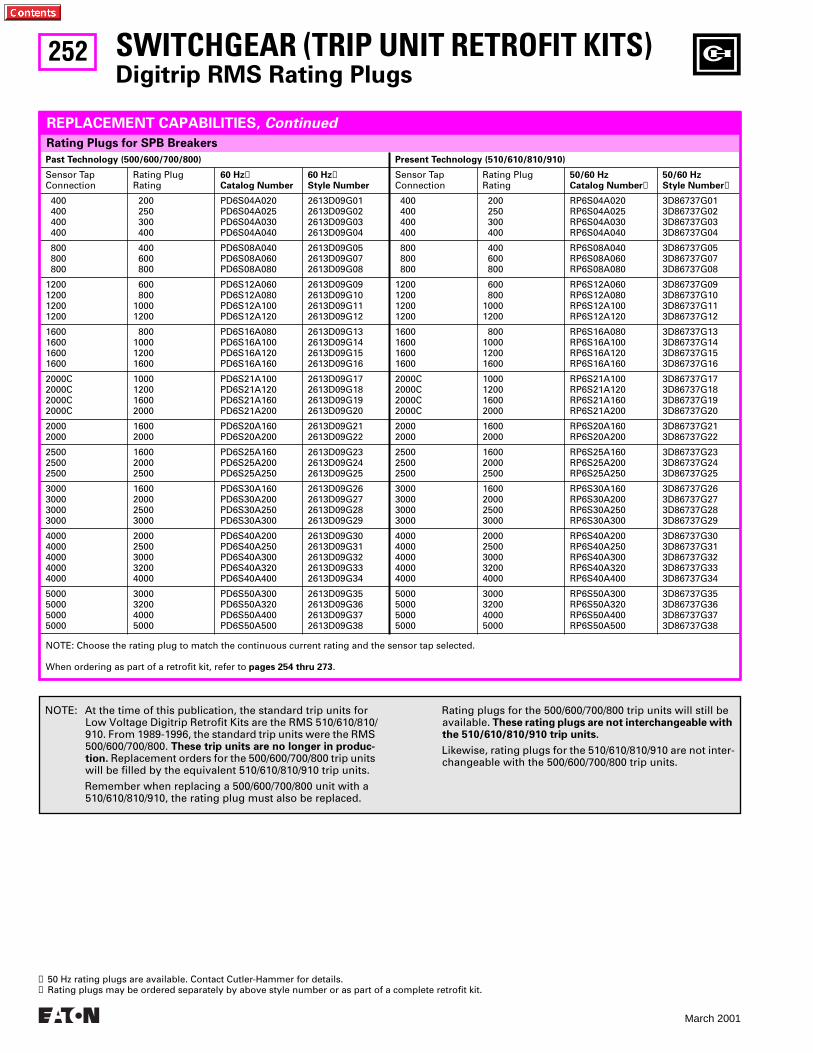
252
March 2001
SWITCHGEAR (TRIP UNIT RETROFIT KITS)
Digitrip RMS Rating Plugs
Past Technology (500/600/700/800) Present Technology (510/610/810/910)
Sensor Tap Connection
Rating Plug Rating
60 Hz➊Catalog Number
60 Hz➊Style Number
Sensor Tap Connection
Rating Plug Rating
50/60 HzCatalog Number➋
50/60 HzStyle Number➋
400 400 400 400
200250300400
PD6S04A020PD6S04A025PD6S04A030PD6S04A040
2613D09G012613D09G022613D09G032613D09G04
400 400 400 400
200250300400
RP6S04A020RP6S04A025RP6S04A030RP6S04A040
3D86737G013D86737G023D86737G033D86737G04
800 800 800
400600800
PD6S08A040PD6S08A060PD6S08A080
2613D09G052613D09G072613D09G08
800 800 800
400600800
RP6S08A040RP6S08A060RP6S08A080
3D86737G053D86737G073D86737G08
1200120012001200
600800
10001200
PD6S12A060PD6S12A080PD6S12A100PD6S12A120
2613D09G092613D09G102613D09G112613D09G12
1200120012001200
600800
10001200
RP6S12A060RP6S12A080RP6S12A100RP6S12A120
3D86737G093D86737G103D86737G113D86737G12
1600160016001600
800100012001600
PD6S16A080PD6S16A100PD6S16A120PD6S16A160
2613D09G132613D09G142613D09G152613D09G16
1600160016001600
800100012001600
RP6S16A080RP6S16A100RP6S16A120RP6S16A160
3D86737G133D86737G143D86737G153D86737G16
2000C2000C2000C2000C
1000120016002000
PD6S21A100PD6S21A120PD6S21A160PD6S21A200
2613D09G172613D09G182613D09G192613D09G20
2000C2000C2000C2000C
1000120016002000
RP6S21A100RP6S21A120RP6S21A160RP6S21A200
3D86737G173D86737G183D86737G193D86737G20
20002000
16002000
PD6S20A160PD6S20A200
2613D09G212613D09G22
20002000
16002000
RP6S20A160RP6S20A200
3D86737G213D86737G22
250025002500
160020002500
PD6S25A160PD6S25A200PD6S25A250
2613D09G232613D09G242613D09G25
250025002500
160020002500
RP6S25A160RP6S25A200RP6S25A250
3D86737G233D86737G243D86737G25
3000300030003000
1600200025003000
PD6S30A160PD6S30A200PD6S30A250PD6S30A300
2613D09G262613D09G272613D09G282613D09G29
3000300030003000
1600200025003000
RP6S30A160RP6S30A200RP6S30A250RP6S30A300
3D86737G263D86737G273D86737G283D86737G29
40004000400040004000
20002500300032004000
PD6S40A200PD6S40A250PD6S40A300PD6S40A320PD6S40A400
2613D09G302613D09G312613D09G322613D09G332613D09G34
40004000400040004000
20002500300032004000
RP6S40A200RP6S40A250RP6S40A300RP6S40A320RP6S40A400
3D86737G303D86737G313D86737G323D86737G333D86737G34
5000500050005000
3000320040005000
PD6S50A300PD6S50A320PD6S50A400PD6S50A500
2613D09G352613D09G362613D09G372613D09G38
5000500050005000
3000320040005000
RP6S50A300RP6S50A320RP6S50A400RP6S50A500
3D86737G353D86737G363D86737G373D86737G38
Rating Plugs for SPB Breakers
REPLACEMENT CAPABILITIES, Continued
NOTE: At the time of this publication, the standard trip units for Low Voltage Digitrip Retrofit Kits are the RMS 510/610/810/910. From 1989-1996, the standard trip units were the RMS 500/600/700/800. These trip units are no longer in produc-tion. Replacement orders for the 500/600/700/800 trip units will be filled by the equivalent 510/610/810/910 trip units.
Remember when replacing a 500/600/700/800 unit with a 510/610/810/910, the rating plug must also be replaced.
Rating plugs for the 500/600/700/800 trip units will still be available. These rating plugs are not interchangeable with the 510/610/810/910 trip units.
Likewise, rating plugs for the 510/610/810/910 are not inter-changeable with the 500/600/700/800 trip units.
➊ 50 Hz rating plugs are available. Contact Cutler-Hammer for details.➋ Rating plugs may be ordered separately by above style number or as part of a complete retrofit kit.
NOTE: Choose the rating plug to match the continuous current rating and the sensor tap selected.
When ordering as part of a retrofit kit, refer to pages 254 thru 273.
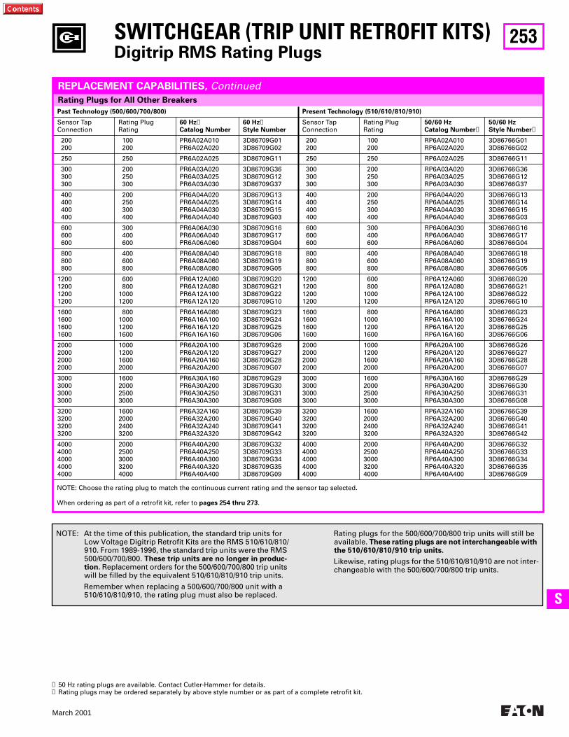
253
March 2001
SS
Past Technology (500/600/700/800) Present Technology (510/610/810/910)
Sensor Tap Connection
Rating Plug Rating
60 Hz➊Catalog Number
60 Hz➊Style Number
Sensor Tap Connection
Rating Plug Rating
50/60 HzCatalog Number➋
50/60 HzStyle Number➋
200200
100200
PR6A02A010PR6A02A020
3D86709G013D86709G02
200200
100200
RP6A02A010RP6A02A020
3D86766G013D86766G02
250 250 PR6A02A025 3D86709G11 250 250 RP6A02A025 3D86766G11
300300300
200250300
PR6A03A020PR6A03A025PR6A03A030
3D86709G363D86709G123D86709G37
300300300
200250300
RP6A03A020RP6A03A025RP6A03A030
3D86766G363D86766G123D86766G37
400400400400
200250300400
PR6A04A020PR6A04A025PR6A04A030PR6A04A040
3D86709G133D86709G143D86709G153D86709G03
400400400400
200250300400
RP6A04A020RP6A04A025RP6A04A030RP6A04A040
3D86766G133D86766G143D86766G153D86766G03
600600600
300400600
PR6A06A030PR6A06A040PR6A06A060
3D86709G163D86709G173D86709G04
600600600
300400600
RP6A06A030RP6A06A040RP6A06A060
3D86766G163D86766G173D86766G04
800800800
400600800
PR6A08A040PR6A08A060PR6A08A080
3D86709G183D86709G193D86709G05
800800800
400600800
RP6A08A040RP6A08A060RP6A08A080
3D86766G183D86766G193D86766G05
1200120012001200
600800
10001200
PR6A12A060PR6A12A080PR6A12A100PR6A12A120
3D86709G203D86709G213D86709G223D86709G10
1200120012001200
600800
10001200
RP6A12A060RP6A12A080RP6A12A100RP6A12A120
3D86766G203D86766G213D86766G223D86766G10
1600160016001600
800100012001600
PR6A16A080PR6A16A100PR6A16A120PR6A16A160
3D86709G233D86709G243D86709G253D86709G06
1600160016001600
800100012001600
RP6A16A080RP6A16A100RP6A16A120RP6A16A160
3D86766G233D86766G243D86766G253D86766G06
2000200020002000
1000120016002000
PR6A20A100PR6A20A120PR6A20A160PR6A20A200
3D86709G263D86709G273D86709G283D86709G07
2000200020002000
1000120016002000
RP6A20A100RP6A20A120RP6A20A160RP6A20A200
3D86766G263D86766G273D86766G283D86766G07
3000300030003000
1600200025003000
PR6A30A160PR6A30A200PR6A30A250PR6A30A300
3D86709G293D86709G303D86709G313D86709G08
3000300030003000
1600200025003000
RP6A30A160RP6A30A200RP6A30A250RP6A30A300
3D86766G293D86766G303D86766G313D86766G08
3200320032003200
1600200024003200
PR6A32A160PR6A32A200PR6A32A240PR6A32A320
3D86709G393D86709G403D86709G413D86709G42
3200320032003200
1600200024003200
RP6A32A160RP6A32A200RP6A32A240RP6A32A320
3D86766G393D86766G403D86766G413D86766G42
40004000400040004000
20002500300032004000
PR6A40A200PR6A40A250PR6A40A300PR6A40A320PR6A40A400
3D86709G323D86709G333D86709G343D86709G353D86709G09
40004000400040004000
20002500300032004000
RP6A40A200RP6A40A250RP6A40A300RP6A40A320RP6A40A400
3D86766G323D86766G333D86766G343D86766G353D86766G09
SWITCHGEAR (TRIP UNIT RETROFIT KITS)Digitrip RMS Rating Plugs
Rating Plugs for All Other Breakers
REPLACEMENT CAPABILITIES, Continued
NOTE: At the time of this publication, the standard trip units for Low Voltage Digitrip Retrofit Kits are the RMS 510/610/810/910. From 1989-1996, the standard trip units were the RMS 500/600/700/800. These trip units are no longer in produc-tion. Replacement orders for the 500/600/700/800 trip units will be filled by the equivalent 510/610/810/910 trip units.
Remember when replacing a 500/600/700/800 unit with a 510/610/810/910, the rating plug must also be replaced.
Rating plugs for the 500/600/700/800 trip units will still be available. These rating plugs are not interchangeable with the 510/610/810/910 trip units.
Likewise, rating plugs for the 510/610/810/910 are not inter-changeable with the 500/600/700/800 trip units.
➊ 50 Hz rating plugs are available. Contact Cutler-Hammer for details.➋ Rating plugs may be ordered separately by above style number or as part of a complete retrofit kit.
NOTE: Choose the rating plug to match the continuous current rating and the sensor tap selected.
When ordering as part of a retrofit kit, refer to pages 254 thru 273.
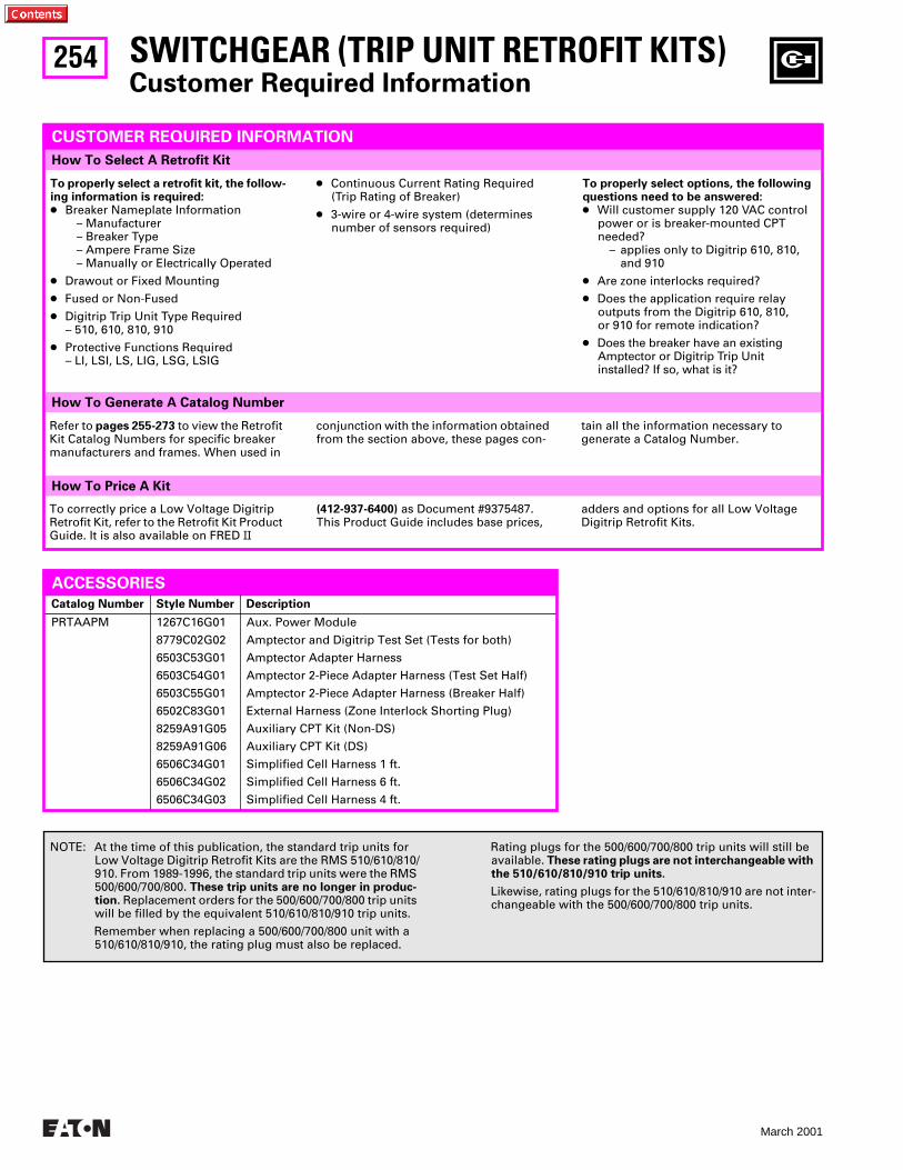
254
March 2001
How To Price A Kit
How To Generate A Catalog Number
How To Select A Retrofit Kit
SWITCHGEAR (TRIP UNIT RETROFIT KITS)Customer Required Information
CUSTOMER REQUIRED INFORMATION
To properly select a retrofit kit, the follow-ing information is required:● Breaker Nameplate Information
– Manufacturer– Breaker Type– Ampere Frame Size– Manually or Electrically Operated
● Drawout or Fixed Mounting
● Fused or Non-Fused
● Digitrip Trip Unit Type Required– 510, 610, 810, 910
● Protective Functions Required– LI, LSI, LS, LIG, LSG, LSIG
● Continuous Current Rating Required (Trip Rating of Breaker)
● 3-wire or 4-wire system (determines number of sensors required)
To correctly price a Low Voltage Digitrip Retrofit Kit, refer to the Retrofit Kit Product Guide. It is also available on FRED II
To properly select options, the following questions need to be answered:● Will customer supply 120 VAC control
power or is breaker-mounted CPT needed?
– applies only to Digitrip 610, 810, and 910
● Are zone interlocks required?
● Does the application require relay outputs from the Digitrip 610, 810, or 910 for remote indication?
● Does the breaker have an existing Amptector or Digitrip Trip Unit installed? If so, what is it?
NOTE: At the time of this publication, the standard trip units for Low Voltage Digitrip Retrofit Kits are the RMS 510/610/810/910. From 1989-1996, the standard trip units were the RMS 500/600/700/800. These trip units are no longer in produc-tion. Replacement orders for the 500/600/700/800 trip units will be filled by the equivalent 510/610/810/910 trip units.
Remember when replacing a 500/600/700/800 unit with a 510/610/810/910, the rating plug must also be replaced.
Rating plugs for the 500/600/700/800 trip units will still be available. These rating plugs are not interchangeable with the 510/610/810/910 trip units.
Likewise, rating plugs for the 510/610/810/910 are not inter-changeable with the 500/600/700/800 trip units.
(412-937-6400) as Document #9375487. This Product Guide includes base prices,
adders and options for all Low Voltage Digitrip Retrofit Kits.
Refer to pages 255-273 to view the Retrofit Kit Catalog Numbers for specific breaker manufacturers and frames. When used in
conjunction with the information obtained from the section above, these pages con-
tain all the information necessary to generate a Catalog Number.
ACCESSORIES
Catalog Number Style Number Description
PRTAAPM 1267C16G01
8779C02G02
6503C53G01
6503C54G01
6503C55G01
6502C83G01
8259A91G05
8259A91G06
6506C34G01
6506C34G02
6506C34G03
Aux. Power Module
Amptector and Digitrip Test Set (Tests for both)
Amptector Adapter Harness
Amptector 2-Piece Adapter Harness (Test Set Half)
Amptector 2-Piece Adapter Harness (Breaker Half)
External Harness (Zone Interlock Shorting Plug)
Auxiliary CPT Kit (Non-DS)
Auxiliary CPT Kit (DS)
Simplified Cell Harness 1 ft.
Simplified Cell Harness 6 ft.
Simplified Cell Harness 4 ft.
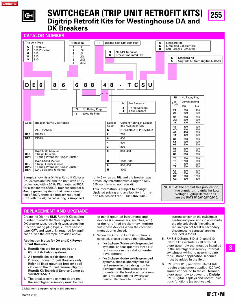
255
March 2001
SS
RP No Rating Plug
Cat.Code
Current Rating
Tap Plug
2122
200200
100200
323Q33
300300300
200250300
424Q4344
400400400400
200250300400
636466
600600600
300400600
848688
800800800
400600800
T6T8TATT
1200120012001200
600800
10001200
C8CACTCC
1600160016001600
800100012001600
D E 6 8 6 6 8 8 4 8 - T C S U
NC
No CPT SuppliedBreaker-mounted CPT
SWITCHGEAR (TRIP UNIT RETROFIT KITS)Digitrip Retrofit Kits for Westinghouse DA and DK Breakers
CATALOG NUMBER
Sample shown is a Digitrip Retrofit Kit for a DK-25, with an RMS 810 trip unit, with LSIG protection, with a 60 Hz Plug, rated at 800A for a sensor tap of 800A, four sensors (for a 4-wire ground system) that have a sensor tap of 800A, there is a breaker-mounted CPT with the kit, the cell wiring is simplified
Trip Unit Type
5Z689
510 Basic510 Zone Int.610810910
T Digitrip 510, 610, 810, 910Protection
123456
LILSILSLIGLSGLSIG
NSR
Standard KitSimplified Cell HarnessCell Harness Removed
NU
Standard KitUpgrade Kit from Digitrip 500/510
N No Rating Plug
6 50/60 Hz Plug
N No Sensors
34
Three SensorsFour Sensors
Code Breaker Frame Description SensorCode
Current Rating of Sensor and Available Taps
ALL FRAMES S NO SENSORS PROVIDED
DE2 DK-15➊ 2 200
DE6 DK-25 6 600
4 400
2 200
DT8DW8
DA-50-800 Manual“Tulip” Clusters“Spring Wrapped” Finger Cluster
8 800, 400
DTCDWCDEH
DA-50-1600 Manual“Tulip” Finger Cluster“Spring Wrapped” Finger ClusterDA-75 Electric & Manual
C 1600, 800
8 800, 400
H 3000
Create the Digitrip RMS Retrofit Kit catalog number to match the Westinghouse DA or DK breaker type, retrofit kit type, protection function, rating plug type, current sensor type, CPT, and type of kit required for appli-cation. See the example provided above.
Application Notes for DA and DK Power Circuit Breakers
1. Retrofit kits are for use on 50 and 60 Hz distribution systems.
2. All retrofit kits are designed for Drawout Power Circuit Breakers only. Refer all fixed mounted breaker appli-cations to the Cutler-Hammer Digitrip Retrofit Kit Technical Service Center at 1-800-937-5487.
3. The breaker compartment doors on the switchgear assembly must be free
of panel mounted instruments and devices (i.e. ammeters, switches, etc.) or the retrofitted breaker may interfere with these devices when the compart-ment door is closed.
4. When the Ground Fault (G) option is selected, please observe the following:
a. For 3-phase, 3-wire solidly grounded systems, choose quantity three cur-rent sensors in the catalog number development.
b. For 3-phase, 4-wire solidly grounded systems, choose quantity four cur-rent sensors in the catalog number development. Three sensors are mounted on the breaker and one sen-sor is mounted on the switchgear neutral. Hardware to mount the
current sensor on the switchgear neutral and provisions to wire it into the trip unit circuit (including a required pair of breaker secondary disconnecting contacts) are not included in the kit.
5. RMS 510 Zone, 610, 810, and 910 Retrofit kits include a cell terminal block assembly that must be installed in the switchgear assembly. Internal switchgear wiring to accommodate the customer application schemes must be added in the field.
6. RMS 610, 810, and 910 Retrofit Kits require a customer supplied 120 VAC source connected to the cell terminal block assembly to power the Digitrip RMS Digital Displays and Communica-tions functions (as applicable).
REPLACEMENT AND UPGRADE
➊ Maximum ampere rating is 200 amperes.
NOTE: At the time of this publication, the standard trip units for Low Voltage Digitrip Retrofit Kits are the RMS 510/610/810/910.
(only 6 wires vs. 16), and the breaker was previously retrofitted with a Digitrip 500/510, so this is an upgrade kit.
This information is subject to change. Updated pricing and availability informa-tion resides on Fred II. (412-937-6400)
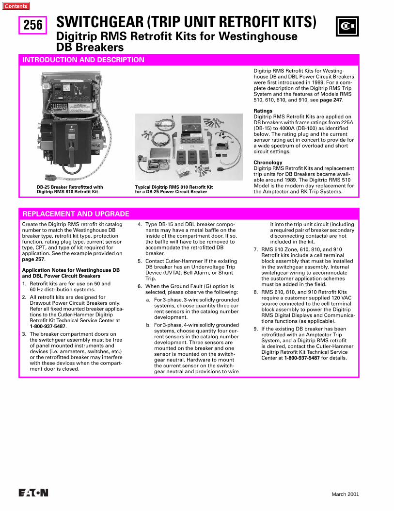
256
March 2001
SWITCHGEAR (TRIP UNIT RETROFIT KITS)Digitrip RMS Retrofit Kits for Westinghouse DB Breakers
INTRODUCTION AND DESCRIPTION
Digitrip RMS Retrofit Kits for Westing-house DB and DBL Power Circuit Breakers were first introduced in 1989. For a com-plete description of the Digitrip RMS Trip System and the features of Models RMS 510, 610, 810, and 910, see page 247.
Ratings Digitrip RMS Retrofit Kits are applied on DB breakers with frame ratings from 225A (DB-15) to 4000A (DB-100) as identified below. The rating plug and the current sensor rating act in concert to provide for a wide spectrum of overload and short circuit settings.
ChronologyDigitrip RMS Retrofit Kits and replacement trip units for DB Breakers became avail-able around 1989. The Digitrip RMS 510 Model is the modern day replacement for the Amptector and RK Trip Systems.
REPLACEMENT AND UPGRADE
Create the Digitrip RMS retrofit kit catalog number to match the Westinghouse DB breaker type, retrofit kit type, protection function, rating plug type, current sensor type, CPT, and type of kit required for application. See the example provided on page 257.
Application Notes for Westinghouse DB and DBL Power Circuit Breakers
1. Retrofit kits are for use on 50 and 60 Hz distribution systems.
2. All retrofit kits are designed for Drawout Power Circuit Breakers only. Refer all fixed mounted breaker applica-tions to the Cutler-Hammer Digitrip Retrofit Kit Technical Service Center at 1-800-937-5487.
3. The breaker compartment doors on the switchgear assembly must be free of panel mounted instruments and devices (i.e. ammeters, switches, etc.) or the retrofitted breaker may interfere with these devices when the compart-ment door is closed.
4. Type DB-15 and DBL breaker compo-nents may have a metal baffle on the inside of the compartment door. If so, the baffle will have to be removed to accommodate the retrofitted DB breaker.
5. Contact Cutler-Hammer if the existing DB breaker has an Undervoltage Trip Device (UVTA), Bell Alarm, or Shunt Trip.
6. When the Ground Fault (G) option is selected, please observe the following:
a. For 3-phase, 3-wire solidly grounded systems, choose quantity three cur-rent sensors in the catalog number development.
b. For 3-phase, 4-wire solidly grounded systems, choose quantity four cur-rent sensors in the catalog number development. Three sensors are mounted on the breaker and one sensor is mounted on the switch-gear neutral. Hardware to mount the current sensor on the switch-gear neutral and provisions to wire
it into the trip unit circuit (including a required pair of breaker secondary disconnecting contacts) are not included in the kit.
7. RMS 510 Zone, 610, 810, and 910 Retrofit kits include a cell terminal block assembly that must be installed in the switchgear assembly. Internal switchgear wiring to accommodate the customer application schemes must be added in the field.
8. RMS 610, 810, and 910 Retrofit Kits require a customer supplied 120 VAC source connected to the cell terminal block assembly to power the Digitrip RMS Digital Displays and Communica-tions functions (as applicable).
9. If the existing DB breaker has been retrofitted with an Amptector Trip System, and a Digitrip RMS retrofit is desired, contact the Cutler-Hammer Digitrip Retrofit Kit Technical Service Center at 1-800-937-5487 for details.
DB-25 Breaker Retrofitted withDigitrip RMS 810 Retrofit Kit
Typical Digitrip RMS 810 Retrofit Kit for a DB-25 Power Circuit Breaker
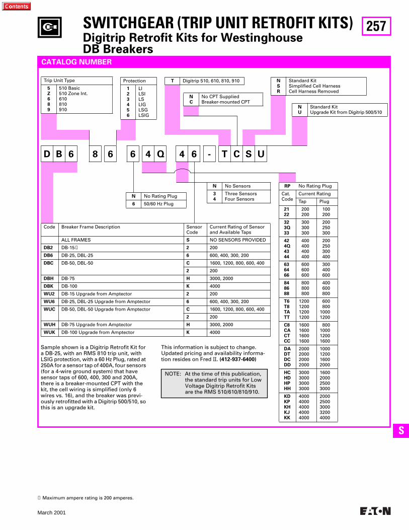
257
March 2001
SS
SWITCHGEAR (TRIP UNIT RETROFIT KITS)Digitrip Retrofit Kits for Westinghouse DB Breakers
RP No Rating Plug
Cat.Code
Current Rating
Tap Plug
2122
200200
100200
323Q33
300300300
200250300
424Q4344
400400400400
200250300400
636466
600600600
300400600
848688
800800800
400600800
T6T8TATT
1200120012001200
600800
10001200
C8CACTCC
1600160016001600
800100012001600
DADTDCDD
2000200020002000
1000120016002000
HCHDHPHH
3000300030003000
1600200025003000
KDKPKHKJKK
40004000400040004000
20002500300032004000
D B 6 8 6 6 4 Q 4 6 - T C S U
NC
No CPT SuppliedBreaker-mounted CPT
CATALOG NUMBER
Sample shown is a Digitrip Retrofit Kit for a DB-25, with an RMS 810 trip unit, with LSIG protection, with a 60 Hz Plug, rated at 250A for a sensor tap of 400A, four sensors (for a 4-wire ground system) that have sensor taps of 600, 400, 300 and 200A, there is a breaker-mounted CPT with the kit, the cell wiring is simplified (only 6 wires vs. 16), and the breaker was previ-ously retrofitted with a Digitrip 500/510, so this is an upgrade kit.
Trip Unit Type
5Z689
510 Basic510 Zone Int.610810910
T Digitrip 510, 610, 810, 910Protection
123456
LILSILSLIGLSGLSIG
NSR
Standard KitSimplified Cell HarnessCell Harness Removed
NU
Standard KitUpgrade Kit from Digitrip 500/510
N No Rating Plug
6 50/60 Hz Plug
N No Sensors
34
Three SensorsFour Sensors
Code Breaker Frame Description SensorCode
Current Rating of Sensor and Available Taps
ALL FRAMES S NO SENSORS PROVIDED
DB2 DB-15➊ 2 200
DB6 DB-25, DBL-25 6 600, 400, 300, 200
DBC DB-50, DBL-50 C 1600, 1200, 800, 600, 400
2 200
DBH DB-75 H 3000, 2000
DBK DB-100 K 4000
WU2 DB-15 Upgrade from Amptector 2 200
WU6 DB-25, DBL-25 Upgrade from Amptector 6 600, 400, 300, 200
WUC DB-50, DBL-50 Upgrade from Amptector C 1600, 1200, 800, 600, 400
2 200
WUH DB-75 Upgrade from Amptector H 3000, 2000
WUK DB-100 Upgrade from Amptector K 4000
➊ Maximum ampere rating is 200 amperes.
This information is subject to change. Updated pricing and availability informa-tion resides on Fred II. (412-937-6400)
NOTE: At the time of this publication, the standard trip units for Low Voltage Digitrip Retrofit Kits are the RMS 510/610/810/910.
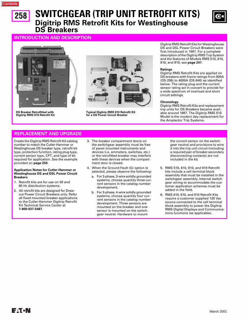
258
March 2001
SWITCHGEAR (TRIP UNIT RETROFIT KITS)Digitrip RMS Retrofit Kits for WestinghouseDS Breakers
INTRODUCTION AND DESCRIPTION
Digitrip RMS Retrofit Kits for Westinghouse DS and DSL Power Circuit Breakers were first introduced in 1987. For a complete description of the Digitrip RMS Trip System and the features of Models RMS 510, 610, 810, and 910, see page 247.
RatingsDigitrip RMS Retrofit Kits are applied on DS breakers with frame ratings from 800A (DS-206) to 4000A (DS-840) as identified below. The rating plug and the current sensor rating act in concert to provide for a wide spectrum of overload and short circuit settings.
ChronologyDigitrip RMS Retrofit Kits and replacement trip units for DS Breakers became avail-able around 1987. The Digitrip RMS 510 Model is the modern day replacement for the Amptector Trip Systems.
REPLACEMENT AND UPGRADE
Create the Digitrip RMS Retrofit Kit catalog number to match the Cutler-Hammer or Westinghouse DS breaker type, retrofit kit type, protection function, rating plug type, current sensor type, CPT, and type of kit required for application. See the example provided on page 259.
Application Notes for Cutler-Hammer or Westinghouse DS and DSL Power Circuit Breakers
1. Retrofit kits are for use on 50 and 60 Hz distribution systems.
2. All retrofit kits are designed for Draw-out Power Circuit Breakers only. Refer all fixed mounted breaker applications to the Cutler-Hammer Digitrip Retrofit Kit Technical Service Center at 1-800-937-5487.
3. The breaker compartment doors on the switchgear assembly must be free of panel mounted instruments and devices (i.e. ammeters, switches, etc.) or the retrofitted breaker may interfere with these devices when the compart-ment door is closed.
4. When the Ground Fault (G) option is selected, please observe the following:
a. For 3-phase, 3-wire solidly grounded systems, choose quantity three cur-rent sensors in the catalog number development.
b. For 3-phase, 4-wire solidly grounded systems, choose quantity four cur-rent sensors in the catalog number development. Three sensors are mounted on the breaker and one sensor is mounted on the switch-gear neutral. Hardware to mount
the current sensor on the switch-gear neutral and provisions to wire it into the trip unit circuit (including a required pair of breaker secondary disconnecting contacts) are not included in the kit.
5. RMS 510, 610, 810, and 910 Retrofit kits include a cell terminal block assembly that must be installed in the switchgear assembly. Internal switch-gear wiring to accommodate the cus-tomer application schemes must be added in the field.
6. RMS 610, 810, and 910 Retrofit Kits require a customer supplied 120 Vac source connected to the cell terminal block assembly to power the Digitrip RMS Digital Displays and Communica-tions functions (as applicable).
DS Breaker Retrofitted withDigitrip RMS 810 Retrofit Kit
Typical Digitrip RMS 810 Retrofit Kit for a DS Power Circuit Breaker
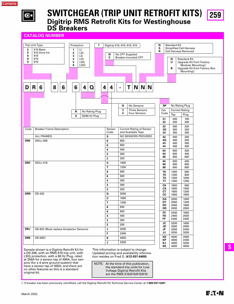
259
March 2001
SS
SWITCHGEAR (TRIP UNIT RETROFIT KITS)Digitrip RMS Retrofit Kits for WestinghouseDS Breakers
RP No Rating Plug
Cat.Code
Current Rating
Tap Plug
2122
200200
100200
323Q33
300300300
200250300
424Q4344
400400400400
200250300400
636466
600600600
300400600
848688
800800800
400600800
T6T8TATT
1200120012001200
600800
10001200
C8CACTCC
1600160016001600
800100012001600
DADTDCDD
2000200020002000
1000120016002000
FCFDFF
240024002400
160020002400
JCJDJFJJ
3200320032003200
1600200024003200
KDKPKJKK
4000400040004000
2000240032004000
D R 6 8 6 6 4 Q 4 4 - T N N N
NC
No CPT SuppliedBreaker-mounted CPT
CATALOG NUMBER
Sample shown is a Digitrip Retrofit Kit for a DS-206, with an RMS 810 trip unit, with LSIG protection, with a 60 Hz Plug, rated at 250A for a sensor tap of 400A, four sen-sors (for a 4-wire ground system) that have a sensor tap of 400A, and there are no other features so this is a standard original kit.
Trip Unit Type
5Z689
510 Basic510 Zone Int.610810910
T Digitrip 510, 610, 810, 910Protection
123456
LILSILSLIGLSGLSIG
NSR
Standard KitSimplified Cell HarnessCell Harness Removed
NU
B
Standard KitUpgrade Kit from Factory Modular Mounting➊Upgrade Kit from Factory Box Mounting➊
N No Rating Plug
6 50/60 Hz Plug
N No Sensors
34
Three SensorsFour Sensors
Code Breaker Frame Description SensorCode
Current Rating of Sensor and Available Taps
ALL FRAMES S NO SENSORS PROVIDED
DR6 DS(L)-206 8 800
6 600
4 400
3 300
2 200
DRC DS(L)-416 C 1600
T 1200
8 800
6 600
4 400
3 300
2 200
DRD DS-420 D 2000
C 1600
T 1200
8 800
6 600
4 400
3 300
2 200
DRJ DS-632 (Must replace Amptector Sensors) J 3200
F 2400
DRK DS-840➋ K 4000
J 3200
This information is subject to change. Updated pricing and availability informa-tion resides on Fred II. (412-937-6400)
➊ If breaker has been previously retrofitted, call the Digitrip Retrofit Kit Technical Service Center at 1-800-937-5487.
NOTE: At the time of this publication, the standard trip units for Low Voltage Digitrip Retrofit Kits are the RMS 510/610/810/910.
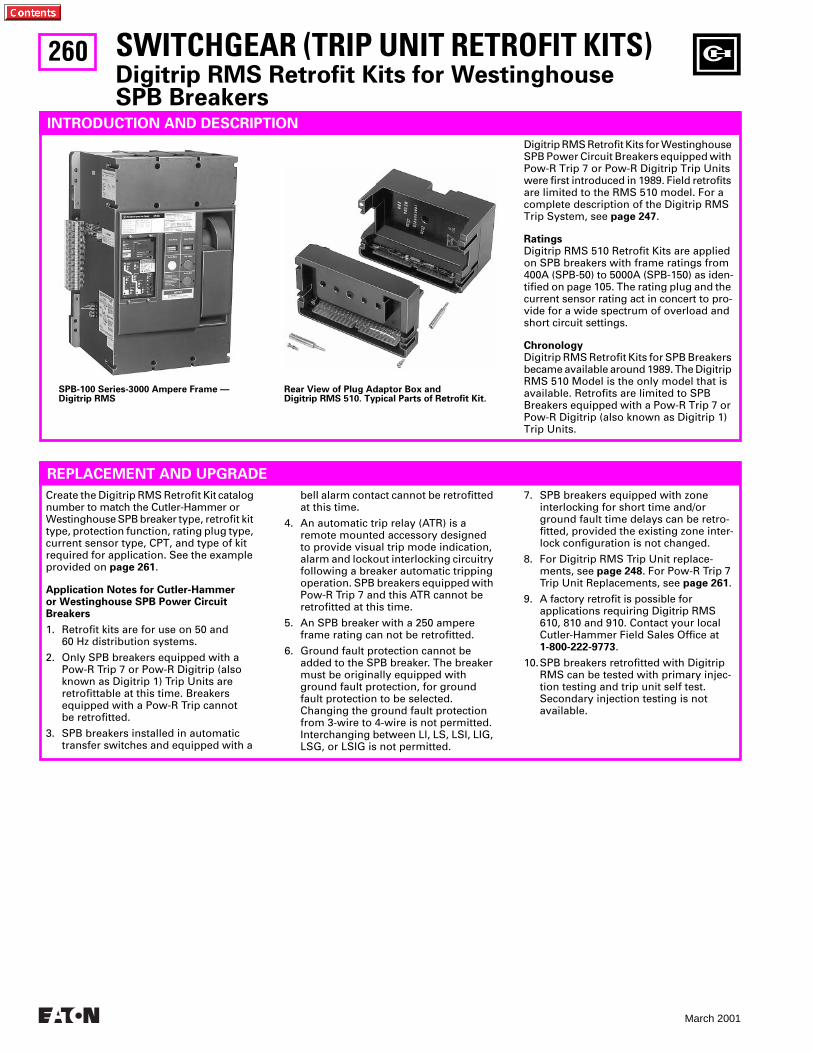
260
March 2001
SWITCHGEAR (TRIP UNIT RETROFIT KITS)Digitrip RMS Retrofit Kits for WestinghouseSPB Breakers
INTRODUCTION AND DESCRIPTION
Digitrip RMS Retrofit Kits for Westinghouse SPB Power Circuit Breakers equipped with Pow-R Trip 7 or Pow-R Digitrip Trip Units were first introduced in 1989. Field retrofits are limited to the RMS 510 model. For a complete description of the Digitrip RMS Trip System, see page 247.
RatingsDigitrip RMS 510 Retrofit Kits are applied on SPB breakers with frame ratings from 400A (SPB-50) to 5000A (SPB-150) as iden-tified on page 105. The rating plug and the current sensor rating act in concert to pro-vide for a wide spectrum of overload and short circuit settings.
ChronologyDigitrip RMS Retrofit Kits for SPB Breakers became available around 1989. The Digitrip RMS 510 Model is the only model that is available. Retrofits are limited to SPB Breakers equipped with a Pow-R Trip 7 or Pow-R Digitrip (also known as Digitrip 1) Trip Units.
REPLACEMENT AND UPGRADE
Create the Digitrip RMS Retrofit Kit catalog number to match the Cutler-Hammer or Westinghouse SPB breaker type, retrofit kit type, protection function, rating plug type, current sensor type, CPT, and type of kit required for application. See the example provided on page 261.
Application Notes for Cutler-Hammer or Westinghouse SPB Power Circuit Breakers
1. Retrofit kits are for use on 50 and 60 Hz distribution systems.
2. Only SPB breakers equipped with a Pow-R Trip 7 or Pow-R Digitrip (also known as Digitrip 1) Trip Units are retrofittable at this time. Breakers equipped with a Pow-R Trip cannot be retrofitted.
3. SPB breakers installed in automatic transfer switches and equipped with a
belI alarm contact cannot be retrofitted at this time.
4. An automatic trip relay (ATR) is a remote mounted accessory designed to provide visual trip mode indication, alarm and lockout interlocking circuitry following a breaker automatic tripping operation. SPB breakers equipped with Pow-R Trip 7 and this ATR cannot be retrofitted at this time.
5. An SPB breaker with a 250 ampere frame rating can not be retrofitted.
6. Ground fault protection cannot be added to the SPB breaker. The breaker must be originally equipped with ground fault protection, for ground fault protection to be selected. Changing the ground fault protection from 3-wire to 4-wire is not permitted. Interchanging between Ll, LS, LSI, LIG, LSG, or LSIG is not permitted.
7. SPB breakers equipped with zone interlocking for short time and/or ground fault time delays can be retro-fitted, provided the existing zone inter-lock configuration is not changed.
8. For Digitrip RMS Trip Unit replace-ments, see page 248. For Pow-R Trip 7 Trip Unit Replacements, see page 261.
9. A factory retrofit is possible for applications requiring Digitrip RMS 610, 810 and 910. Contact your local Cutler-Hammer Field Sales Office at 1-800-222-9773.
10.SPB breakers retrofitted with Digitrip RMS can be tested with primary injec-tion testing and trip unit self test. Secondary injection testing is not available.
SPB-100 Series-3000 Ampere Frame —Digitrip RMS
Rear View of Plug Adaptor Box andDigitrip RMS 510. Typical Parts of Retrofit Kit.
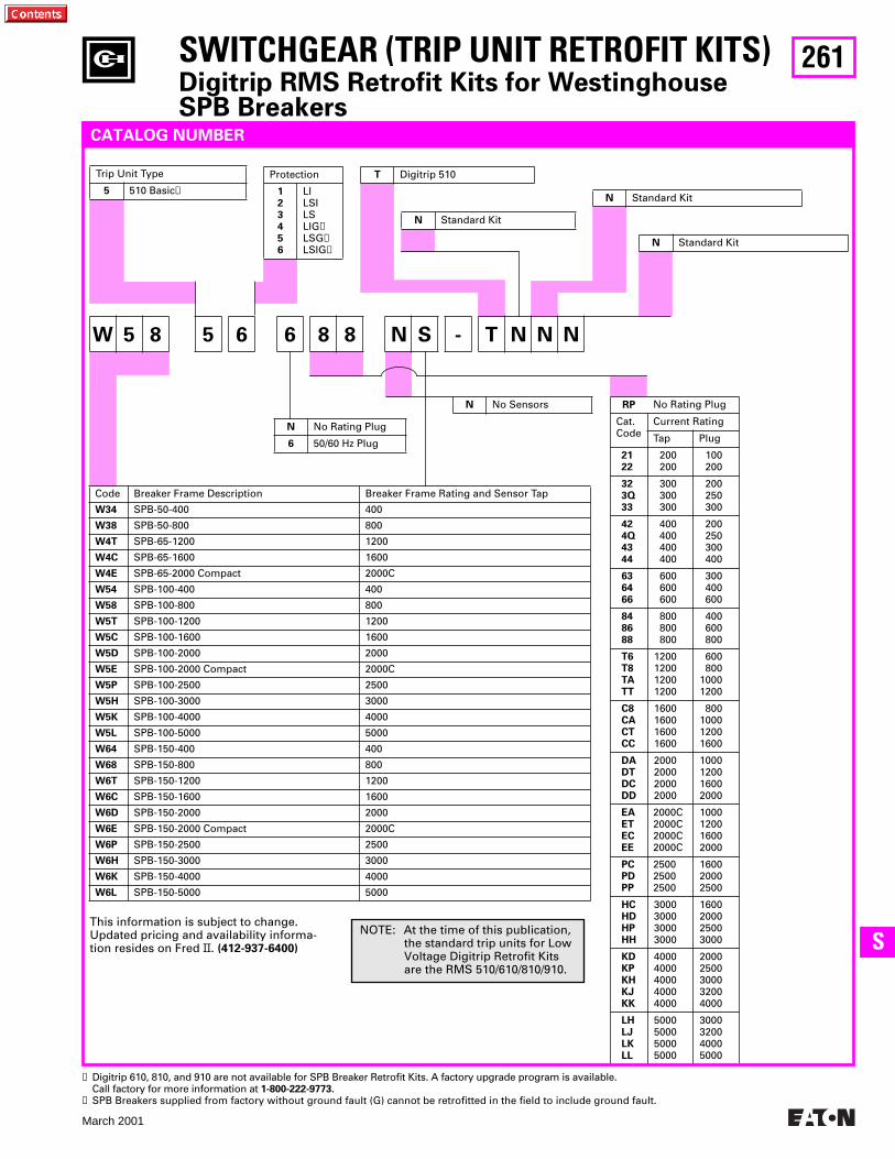
261
March 2001
SS
SWITCHGEAR (TRIP UNIT RETROFIT KITS)Digitrip RMS Retrofit Kits for WestinghouseSPB Breakers
RP No Rating Plug
Cat.Code
Current Rating
Tap Plug
2122
200200
100200
323Q33
300300300
200250300
424Q4344
400400400400
200250300400
636466
600600600
300400600
848688
800800800
400600800
T6T8TATT
1200120012001200
600800
10001200
C8CACTCC
1600160016001600
800100012001600
DADTDCDD
2000200020002000
1000120016002000
EAETECEE
2000C2000C2000C2000C
1000120016002000
PCPDPP
250025002500
160020002500
HCHDHPHH
3000300030003000
1600200025003000
KDKPKHKJKK
40004000400040004000
20002500300032004000
LHLJLKLL
5000500050005000
3000320040005000
W 5 8 5 6 6 8 8 N S - T N N N
N Standard Kit
CATALOG NUMBER
Trip Unit Type
5 510 Basic➊
T Digitrip 510Protection
123456
LILSILSLIG➋LSG➋LSIG➋
N Standard Kit
N Standard Kit
N No Rating Plug
6 50/60 Hz Plug
N No Sensors
Code Breaker Frame Description Breaker Frame Rating and Sensor Tap
W34 SPB-50-400 400
W38 SPB-50-800 800
W4T SPB-65-1200 1200
W4C SPB-65-1600 1600
W4E SPB-65-2000 Compact 2000C
W54 SPB-100-400 400
W58 SPB-100-800 800
W5T SPB-100-1200 1200
W5C SPB-100-1600 1600
W5D SPB-100-2000 2000
W5E SPB-100-2000 Compact 2000C
W5P SPB-100-2500 2500
W5H SPB-100-3000 3000
W5K SPB-100-4000 4000
W5L SPB-100-5000 5000
W64 SPB-150-400 400
W68 SPB-150-800 800
W6T SPB-150-1200 1200
W6C SPB-150-1600 1600
W6D SPB-150-2000 2000
W6E SPB-150-2000 Compact 2000C
W6P SPB-150-2500 2500
W6H SPB-150-3000 3000
W6K SPB-150-4000 4000
W6L SPB-150-5000 5000
This information is subject to change. Updated pricing and availability informa-tion resides on Fred II. (412-937-6400)
➊ Digitrip 610, 810, and 910 are not available for SPB Breaker Retrofit Kits. A factory upgrade program is available. Call factory for more information at 1-800-222-9773.
➋ SPB Breakers supplied from factory without ground fault (G) cannot be retrofitted in the field to include ground fault.
NOTE: At the time of this publication, the standard trip units for Low Voltage Digitrip Retrofit Kits are the RMS 510/610/810/910.
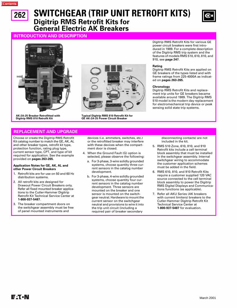
262
March 2001
SWITCHGEAR (TRIP UNIT RETROFIT KITS)Digitrip RMS Retrofit Kits forGeneral Electric AK Breakers
INTRODUCTION AND DESCRIPTION
Digitrip RMS Retrofit Kits for various GE power circuit breakers were first intro-duced in 1989. For a complete description of the Digitrip RMS trip system and the features of models RMS 510, 610, 810, and 910, see page 247.
RatingDigitrip RMS Retrofit Kits are applied on GE breakers of the types listed and with frame ratings from 225-4000A as indicat-ed on pages 263-265.
ChronologyDigitrip RMS Retrofit Kits and replace-ment trip units for GE breakers became available around 1989. The Digitrip RMS 510 model is the modern day replacement for electromechanical trip device or peak sensing solid state trip systems.
REPLACEMENT AND UPGRADE
Choose or create the Digitrip RMS Retrofit Kit catalog number to match the GE, AK, AL and other breaker types, retrofit kit type, protection function, rating plug type, current sensor type, CPT, and type of kit required for application. See the example provided on pages 263-265.
Application Notes for GE, AK, AL and other Power Circuit Breakers
1. Retrofit kits are for use on 50 and 60 Hz distribution systems.
2. All retrofit kits are designed for Drawout Power Circuit Breakers only. Refer all fixed mounted breaker applica-tions to the Cutler-Hammer Digitrip Retrofit Kit Technical Service Center at 1-800-937-5487.
3. The breaker compartment doors on the switchgear assembly must be free of panel mounted instruments and
devices (i.e. ammeters, switches, etc.) or the retrofitted breaker may interfere with these devices when the compart-ment door is closed.
4. When the Ground Fault (G) option is selected, please observe the following:
a. For 3-phase, 3-wire solidly grounded systems, choose quantity three cur-rent sensors in the catalog number development.
b. For 3-phase, 4-wire solidly grounded systems, choose quantity four cur-rent sensors in the catalog number development. Three sensors are mounted on the breaker and one sensor is mounted on the switch-gear neutral. Hardware to mount the current sensor on the switchgear neutral and provisions to wire it into the trip unit circuit (including a required pair of breaker secondary
disconnecting contacts) are not included in the kit.
5. RMS 510 Zone, 610, 810, and 910 Retrofit kits include a cell terminal block assembly that must be installed in the switchgear assembly. Internal switchgear wiring to accommodate the customer application schemes must be added in the field.
6. RMS 610, 810, and 910 Retrofit Kits require a customer supplied 120 VAC source connected to the cell terminal block assembly to power the Digitrip RMS Digital Displays and Communica-tions functions (as applicable).
7. Refer all AKU Series (AK breakers with current limiters) breakers to theCutler-Hammer Digitrip Retrofit Kit Technical Service Center at 1-800-937-5487 for evaluation.
AK-2A-25 Breaker Retrofitted withDigitrip RMS 810 Retrofit Kit
Typical Digitrip RMS 810 Retrofit Kit forGE AK-2A-25 Power Circuit Breaker
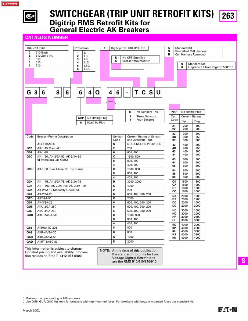
263
March 2001
SS
Code Breaker Frame Description SensorCode
Current Rating of Sensor and Available Taps
ALL FRAMES S NO SENSORS PROVIDEDG12 AK-1-15 Manual➊ 2 200G16 AK-1-25 6 600, 400G2C AK-1-50, AK-2/2A-50, AK-3/3A-50
(if frameless use GMC)C 1600, 8008 800, 4004 400, 200
GMC AK-1-50 Slow Close No Top Frame C 1600, 8008 800, 4004 400, 200
G2H AK-1-75, AK-2/2A-75, AK-3/3A-75 H 3000, 2000G2K AK-1-100, AK-2/2A-100, AK-3/3A-100 K 4000G22 AK-2/2A-15 Manually Operated➊ 2 200G26 AK-2/2A-25 6 600, 400, 300, 200GTD AKT-2A-50 C 2000G36 AK-3/3A-25 6 600, 400, 300, 200GU6 AKU-2/2A-25➋ 6 600, 400, 300, 200GU7 AKU-3/3A-25➋ 6 600, 400, 300, 200GUC AKU-2A/3A-50➋ C 1600, 800
8 800, 4004 400, 200
G58 AKR(u)-7D-305 8 800
GA8 AKR-4A/5A-30 8 800
GAC AKR-4A/5A-50 C 1600
GAD AKRT-4A/5C-50 D 2000
SWITCHGEAR (TRIP UNIT RETROFIT KITS)Digitrip RMS Retrofit Kits forGeneral Electric AK Breakers
NRP No Rating Plug
Cat.Code
Current Rating
Tap Plug
2122
200200
100200
323Q33
300300300
200250300
424Q4344
400400400400
200250300400
636466
600600600
300400600
848688
800800800
400600800
C8CACTCC
1600160016001600
800100012001600
DADTDCDD
2000200020002000
1000120016002000
HCHDHPHH
3000300030003000
1600200025003000
KDKPKHKJKK
40004000400040004000
20002500300032004000
G 3 6 8 6 6 4 Q 4 6 - T C S U
NC
No CPT SuppliedBreaker-mounted CPT
CATALOG NUMBER
Trip Unit Type
5Z689
510 Basic510 Zone Int.610810910
T Digitrip 510, 610, 810, 910Protection
123456
LILSILSLIGLSGLSIG
NSR
Standard KitSimplified Cell HarnessCell Harness Removed
NU
Standard KitUpgrade Kit from Digitrip 500/510
NRP No Rating Plug
6 50/60 Hz Plug
N No Sensors “NS”
34
Three SensorsFour Sensors
This information is subject to change. Updated pricing and availability informa-tion resides on Fred II. (412-937-6400)
➊ Maximum ampere rating is 200 amperes.➋ Use GU6, GU7, GUC kits only for breakers with top mounted fuses. For breakers with bottom mounted fuses use standard kit.
NOTE: At the time of this publication, the standard trip units for Low Voltage Digitrip Retrofit Kits are the RMS 510/610/810/910.
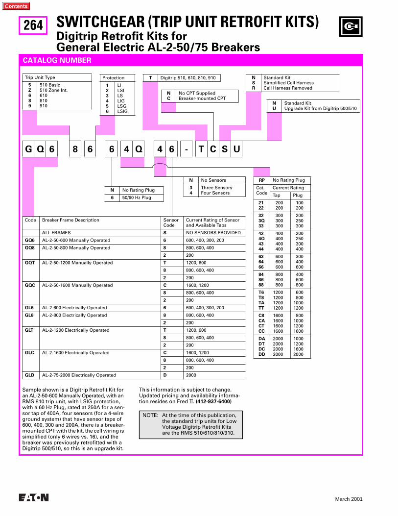
264
March 2001
SWITCHGEAR (TRIP UNIT RETROFIT KITS)Digitrip Retrofit Kits forGeneral Electric AL-2-50/75 Breakers
RP No Rating Plug
Cat.Code
Current Rating
Tap Plug
2122
200200
100200
323Q33
300300300
200250300
424Q4344
400400400400
200250300400
636466
600600600
300400600
848688
800800800
400600800
T6T8TATT
1200120012001200
600800
10001200
C8CACTCC
1600160016001600
800100012001600
DADTDCDD
2000200020002000
1000120016002000
G Q 6 8 6 6 4 Q 4 6 - T C S U
NC
No CPT SuppliedBreaker-mounted CPT
CATALOG NUMBER
Sample shown is a Digitrip Retrofit Kit for an AL-2-50-600 Manually Operated, with an RMS 810 trip unit, with LSIG protection, with a 60 Hz Plug, rated at 250A for a sen-sor tap of 400A, four sensors (for a 4-wire ground system) that have sensor taps of 600, 400, 300 and 200A, there is a breaker-mounted CPT with the kit, the cell wiring is simplified (only 6 wires vs. 16), and the breaker was previously retrofitted with a Digitrip 500/510, so this is an upgrade kit.
Trip Unit Type
5Z689
510 Basic510 Zone Int.610810910
T Digitrip 510, 610, 810, 910Protection
123456
LILSILSLIGLSGLSIG
NSR
Standard KitSimplified Cell HarnessCell Harness Removed
NU
Standard KitUpgrade Kit from Digitrip 500/510
N No Rating Plug
6 50/60 Hz Plug
N No Sensors
34
Three SensorsFour Sensors
Code Breaker Frame Description SensorCode
Current Rating of Sensor and Available Taps
ALL FRAMES S NO SENSORS PROVIDED
GQ6 AL-2-50-600 Manually Operated 6 600, 400, 300, 200
GQ8 AL-2-50-800 Manually Operated 8 800, 600, 400
2 200
GQT AL-2-50-1200 Manually Operated T 1200, 600
8 800, 600, 400
2 200
GQC AL-2-50-1600 Manually Operated C 1600, 1200
8 800, 600, 400
2 200
GL6 AL-2-600 Electrically Operated 6 600, 400, 300, 200
GL8 AL-2-800 Electrically Operated 8 800, 600, 400
2 200
GLT AL-2-1200 Electrically Operated T 1200, 600
8 800, 600, 400
2 200
GLC AL-2-1600 Electrically Operated C 1600, 1200
8 800, 600, 400
2 200
GLD AL-2-75-2000 Electrically Operated D 2000
This information is subject to change. Updated pricing and availability informa-tion resides on Fred II. (412-937-6400)
NOTE: At the time of this publication, the standard trip units for Low Voltage Digitrip Retrofit Kits are the RMS 510/610/810/910.
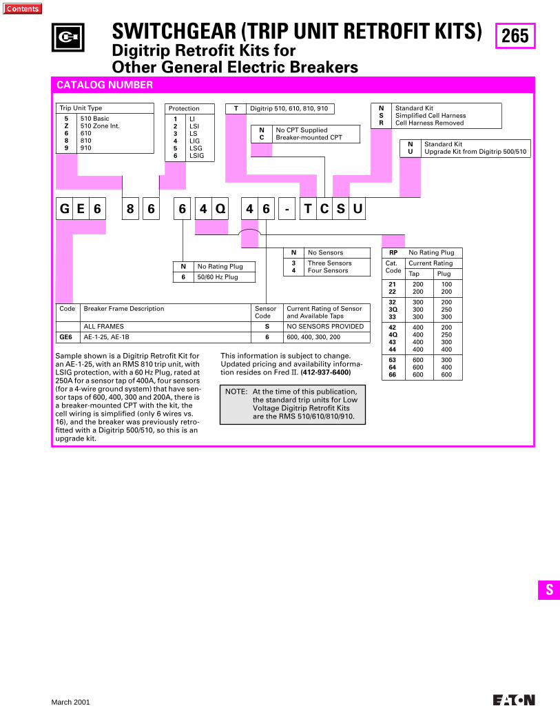
265
March 2001
SS
SWITCHGEAR (TRIP UNIT RETROFIT KITS)Digitrip Retrofit Kits forOther General Electric Breakers
RP No Rating Plug
Cat.Code
Current Rating
Tap Plug
2122
200200
100200
323Q33
300300300
200250300
424Q4344
400400400400
200250300400
636466
600600600
300400600
G E 6 8 6 6 4 Q 4 6 - T C S U
NC
No CPT SuppliedBreaker-mounted CPT
CATALOG NUMBER
Sample shown is a Digitrip Retrofit Kit for an AE-1-25, with an RMS 810 trip unit, with LSIG protection, with a 60 Hz Plug, rated at 250A for a sensor tap of 400A, four sensors (for a 4-wire ground system) that have sen-sor taps of 600, 400, 300 and 200A, there is a breaker-mounted CPT with the kit, the cell wiring is simplified (only 6 wires vs. 16), and the breaker was previously retro-fitted with a Digitrip 500/510, so this is an upgrade kit.
Trip Unit Type
5Z689
510 Basic510 Zone Int.610810910
T Digitrip 510, 610, 810, 910Protection
123456
LILSILSLIGLSGLSIG
NSR
Standard KitSimplified Cell HarnessCell Harness Removed
NU
Standard KitUpgrade Kit from Digitrip 500/510
N No Rating Plug
6 50/60 Hz Plug
N No Sensors
34
Three SensorsFour Sensors
Code Breaker Frame Description SensorCode
Current Rating of Sensor and Available Taps
ALL FRAMES S NO SENSORS PROVIDED
GE6 AE-1-25, AE-1B 6 600, 400, 300, 200
This information is subject to change. Updated pricing and availability informa-tion resides on Fred II. (412-937-6400)
NOTE: At the time of this publication, the standard trip units for Low Voltage Digitrip Retrofit Kits are the RMS 510/610/810/910.

266
March 2001
SWITCHGEAR (TRIP UNIT RETROFIT KITS)Digitrip RMS Retrofit Kits for Allis Chalmers LA Breakers
INTRODUCTION AND DESCRIPTION
Digitrip RMS Retrofit Kits for Allis Chalmers, LA power circuit breakers were first intro-duced in 1991. For a complete description of the Digitrip RMS trip system and the features of models RMS 510, 610, 810, and 910, see page 247.
RatingsDigitrip RMS Retrofit Kits are applied on Allis Chalmers breakers from 600A (LA 600) to 3000A (LA 3000). The rating plug and the current sensor act in concert to provide for a wide spectrum of over-load and short circuit settings.
ChronologyDigitrip RMS Retrofit Kits and replacement trip units for Allis Chalmers LA breakers became available in 1991. The Digitrip RMS 510 model is the modern day replace-ment for electromechanical trip device or peak sensing solid state trip systems.
REPLACEMENT AND UPGRADE
Choose or create the Digitrip RMS Retrofit Kit catalog number to match the Allis Chalmers LA breaker type, retrofit kit type, protection function, rating plug type, cur-rent sensor type, CPT, and type of kit required for application. See the example provided on page 267.
Application Notes for Allis Chalmers LA Power Circuit Breakers
1. Retrofit kits are for use on 50 and 60 Hz distribution systems.
2. All retrofit kits are designed for Draw-out Power Circuit Breakers only. Refer all fixed mounted breaker applications to the Cutler-Hammer Digitrip Retrofit Kit Technical Service Center at 1-800-937-5487.
3. The breaker compartment doors on the switchgear assembly must be free of panel mounted instruments
(i.e. meters, instruments, control switches, indicating lamps, etc.) or the retrofitted breaker may interfere with these devices when the compartment door is closed.
4. When the Ground Fault (G) option is selected, please observe the following:
a. For 3-phase, 3-wire solidly grounded systems, choose quantity three cur-rent sensors in the catalog number development.
b. For 3-phase, 4-wire solidly grounded systems, choose quantity four cur-rent sensors in the catalog number development. Three sensors are mounted on the breaker and one sensor is mounted on the switch-gear neutral. Hardware to mount the current sensor on the switch-gear neutral and provisions to wire it into the trip unit circuit (including
a required pair of breaker secondary disconnecting contacts) are not included in the kit.
5. RMS 510 Zone, 610, 810, and 910 Retrofit kits include a cell terminal block assembly that must be installed in the switchgear assembly. Internal switchgear wiring to accommodate the customer application schemes must be added in the field.
6. RMS 610, 810, and 910 Retrofit Kits require a customer supplied 120 Vac source connected to the cell terminal block assembly to power the Digitrip RMS Digital Displays and Communica-tions functions (as applicable).
7. Refer all LAF (LA breakers with current limiters) breakers to the Cutler-Hammer Digitrip Retrofit Kit Technical Service Center at 1-800-937-5487 for evaluation.
Allis Chalmers LA 600 Gold Breaker Retrofitted with Digitrip RMS 810 Retrofit Kit
Typical RMS 810 Retrofit Kit for Allis ChalmersLA 600 Gold Power Circuit Breaker

267
March 2001
SS
SWITCHGEAR (TRIP UNIT RETROFIT KITS)Digitrip RMS Retrofit Kits for Allis Chalmers LA Breakers
RP No Rating Plug
Cat.Code
Current Rating
Tap Plug
2122
200200
100200
323Q33
300300300
200250300
424Q4344
400400400400
200250300400
636466
600600600
300400600
848688
800800800
400600800
T6T8TATT
1200120012001200
600800
10001200
C8CACTCC
1600160016001600
800100012001600
DADTDCDD
2000200020002000
1000120016002000
HCHDHPHH
3000300030003000
1600200025003000
A 2 6 8 6 6 4 Q 4 6 - T C S U
NC
No CPT SuppliedBreaker-mounted CPT
CATALOG NUMBER
Sample shown is a Digitrip Retrofit Kit for an LA-600 Gold, with a RMS 810 trip unit, with LSIG protection, with a 60 Hz Plug, rated at 250A for a sensor tap of 400A, four sensors (for a 4-wire ground system) that have sensor taps of 600, 400, 300 and 200A, there is a breaker-mounted CPT with the kit, the cell wiring is simplified (only 6 wires vs. 16), and the breaker was previously retrofitted with a Digitrip 500/510, so this is an upgrade kit.
Trip Unit Type
5Z689
510 Basic510 Zone Int.610810910
T Digitrip 510, 610, 810, 910Protection
123456
LILSILSLIGLSGLSIG
NSR
Standard KitSimplified Cell HarnessCell Harness Removed
NU
Standard KitUpgrade Kit from Digitrip 500/510
N No Rating Plug
6 50/60 Hz Plug
N No Sensors
34
Three SensorsFour Sensors
Code Breaker Frame Description SensorCode
Current Rating of Sensor and Available Taps
ALL FRAMES S NO SENSORS PROVIDED
A16 LA-600 Blue Cover (Plastic) 6 600, 400, 300, 200
A1C LA-1600 Blue Cover (Plastic) C 1600, 1200, 800, 600, 400
2 200
A26 LA-600 Gold Cover (Metal) 6 600, 400, 300, 200
A2C LA-1600 Gold Cover (Metal) C 1600, 1200, 800, 600, 400
2 200
A2H LA-3000 Gold/Blue H 3000, 2000
A4H LA-3000A H 3000, 2000
A36 LA-25A Manually Operated 6 600, 400, 300, 200
A3C LA-50A Manually Operated C 1600, 1200, 800, 600, 400
8 800, 600, 400
2 200
A3H LA-75A Manually Operated H 3000, 2000
G5C G-50A C 1600
This information is subject to change. Updated pricing and availability informa-tion resides on Fred II. (412-937-6400)
NOTE: At the time of this publication, the standard trip units for Low Voltage Digitrip Retrofit Kits are the RMS 510/610/810/910.
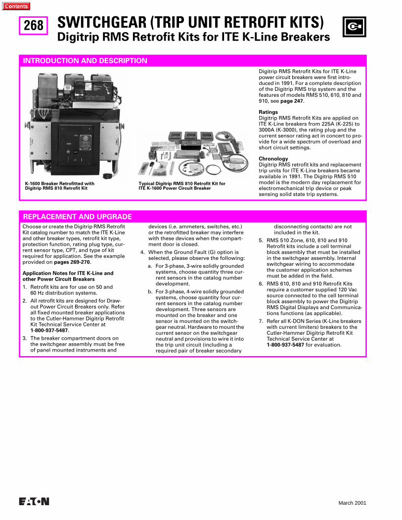
268
March 2001
SWITCHGEAR (TRIP UNIT RETROFIT KITS)Digitrip RMS Retrofit Kits for ITE K-Line Breakers
INTRODUCTION AND DESCRIPTION
Digitrip RMS Retrofit Kits for ITE K-Line power circuit breakers were first intro-duced in 1991. For a complete description of the Digitrip RMS trip system and the features of models RMS 510, 610, 810 and 910, see page 247.
RatingsDigitrip RMS Retrofit Kits are applied on ITE K-Line breakers from 225A (K-225) to 3000A (K-3000), the rating plug and the current sensor rating act in concert to pro-vide for a wide spectrum of overload and short circuit settings.
ChronologyDigitrip RMS retrofit kits and replacement trip units for ITE K-Line breakers became available in 1991. The Digitrip RMS 510 model is the modern day replacement for electromechanical trip device or peak sensing solid state trip systems.
REPLACEMENT AND UPGRADE
Choose or create the Digitrip RMS Retrofit Kit catalog number to match the ITE K-Line and other breaker types, retrofit kit type, protection function, rating plug type, cur-rent sensor type, CPT, and type of kit required for application. See the example provided on pages 269-270.
Application Notes for ITE K-Line and other Power Circuit Breakers
1. Retrofit kits are for use on 50 and 60 Hz distribution systems.
2. All retrofit kits are designed for Draw-out Power Circuit Breakers only. Refer all fixed mounted breaker applications to the Cutler-Hammer Digitrip Retrofit Kit Technical Service Center at 1-800-937-5487.
3. The breaker compartment doors on the switchgear assembly must be free of panel mounted instruments and
devices (i.e. ammeters, switches, etc.) or the retrofitted breaker may interfere with these devices when the compart-ment door is closed.
4. When the Ground Fault (G) option is selected, please observe the following:
a. For 3-phase, 3-wire solidly grounded systems, choose quantity three cur-rent sensors in the catalog number development.
b. For 3-phase, 4-wire solidly grounded systems, choose quantity four cur-rent sensors in the catalog number development. Three sensors are mounted on the breaker and one sensor is mounted on the switch-gear neutral. Hardware to mount the current sensor on the switchgear neutral and provisions to wire it into the trip unit circuit (including a required pair of breaker secondary
disconnecting contacts) are not included in the kit.
5. RMS 510 Zone, 610, 810 and 910 Retrofit kits include a cell terminal block assembly that must be installed in the switchgear assembly. Internal switchgear wiring to accommodate the customer application schemes must be added in the field.
6. RMS 610, 810 and 910 Retrofit Kits require a customer supplied 120 Vac source connected to the cell terminal block assembly to power the Digitrip RMS Digital Displays and Communica-tions functions (as applicable).
7. Refer all K-DON Series (K-Line breakers with current limiters) breakers to theCutler-Hammer Digitrip Retrofit Kit Technical Service Center at 1-800-937-5487 for evaluation.
K-1600 Breaker Retrofitted withDigitrip RMS 810 Retrofit Kit
Typical Digitrip RMS 810 Retrofit Kit forITE K-1600 Power Circuit Breaker
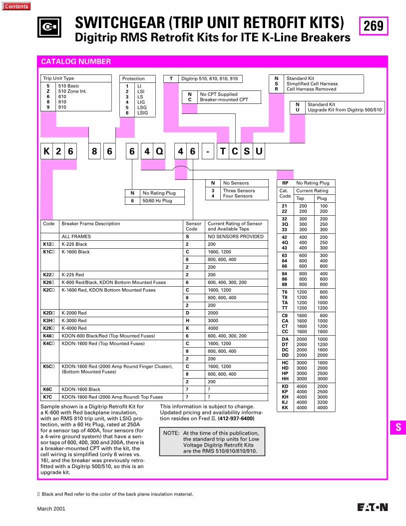
269
March 2001
SS
RP No Rating Plug
Cat.Code
Current Rating
Tap Plug
2122
200200
100200
323Q33
300300300
200250300
424Q43
400400400
200250300
636466
600600600
300400600
848688
800800800
400600800
T6T8TATT
1200120012001200
600800
10001200
C8CACTCC
1600160016001600
800100012001600
DADTDCDD
2000200020002000
1000120016002000
HCHDHPHH
3000300030003000
1600200025003000
KDKPKHKJKK
40004000400040004000
20002500300032004000
K 2 6 8 6 6 4 Q 4 6 - T C S U
NC
No CPT SuppliedBreaker-mounted CPT
CATALOG NUMBER
Sample shown is a Digitrip Retrofit Kit for a K-600 with Red backplane insulation, with an RMS 810 trip unit, with LSIG pro-tection, with a 60 Hz Plug, rated at 250A for a sensor tap of 400A, four sensors (for a 4-wire ground system) that have a sen-sor taps of 600, 400, 300 and 200A, there is a breaker-mounted CPT with the kit, the cell wiring is simplified (only 6 wires vs. 16), and the breaker was previously retro-fitted with a Digitrip 500/510, so this is an upgrade kit.
Trip Unit Type
5Z689
510 Basic510 Zone Int.610810910
T Digitrip 510, 610, 810, 910Protection
123456
LILSILSLIGLSGLSIG
NSR
Standard KitSimplified Cell HarnessCell Harness Removed
NU
Standard KitUpgrade Kit from Digitrip 500/510
N No Rating Plug
6 50/60 Hz Plug
N No Sensors
34
Three SensorsFour Sensors
Code Breaker Frame Description SensorCode
Current Rating of Sensor and Available Taps
ALL FRAMES S NO SENSORS PROVIDED
K12➊ K-225 Black 2 200
K1C➊ K-1600 Black C 1600, 1200
8 800, 600, 400
2 200
K22➊ K-225 Red 2 200
K26➊ K-600 Red/Black, KDON Bottom Mounted Fuses 6 600, 400, 300, 200
K2C➊ K-1600 Red, KDON Bottom Mounted Fuses C 1600, 1200
8 800, 600, 400
2 200
K2D➊ K-2000 Red D 2000
K3H➊ K-3000 Red H 3000
K2K➊ K-4000 Red K 4000
K46➊ KDON-600 Black/Red (Top Mounted Fuses) 6 600, 400, 300, 200
K4C➊ KDON-1600 Red (Top Mounted Fuses) C 1600, 1200
8 800, 600, 400
2 200
K5C➊ KDON-1600 Red (2000 Amp Round Finger Cluster),(Bottom Mounted Fuses)
C 1600, 1200
8 800, 600, 400
2 200
K6C KDON-1600 Black ? ?
K7C KDON-1600 Red (2000 Amp Round) Top Fuses ? ?
This information is subject to change. Updated pricing and availability informa-tion resides on Fred II. (412-937-6400)
SWITCHGEAR (TRIP UNIT RETROFIT KITS)Digitrip RMS Retrofit Kits for ITE K-Line Breakers
➊ Black and Red refer to the color of the back plane insulation material.
NOTE: At the time of this publication, the standard trip units for Low Voltage Digitrip Retrofit Kits are the RMS 510/610/810/910.
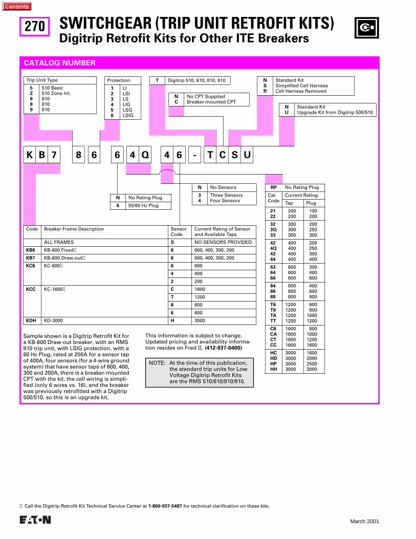
270
March 2001
SWITCHGEAR (TRIP UNIT RETROFIT KITS)Digitrip Retrofit Kits for Other ITE Breakers
RP No Rating Plug
Cat.Code
Current Rating
Tap Plug
2122
200200
100200
323Q33
300300300
200250300
424Q4344
400400400400
200250300400
636466
600600600
300400600
848688
800800800
400600800
T6T8TATT
1200120012001200
600800
10001200
C8CACTCC
1600160016001600
800100012001600
HCHDHPHH
3000300030003000
1600200025003000
K B 7 8 6 6 4 Q 4 6 - T C S U
NC
No CPT SuppliedBreaker-mounted CPT
CATALOG NUMBER
Sample shown is a Digitrip Retrofit Kit for a KB-600 Draw-out breaker, with an RMS 810 trip unit, with LSIG protection, with a 60 Hz Plug, rated at 250A for a sensor tap of 400A, four sensors (for a 4-wire ground system) that have sensor taps of 600, 400, 300 and 200A, there is a breaker-mounted CPT with the kit, the cell wiring is simpli-fied (only 6 wires vs. 16), and the breaker was previously retrofitted with a Digitrip 500/510, so this is an upgrade kit.
Trip Unit Type
5Z689
510 Basic510 Zone Int.610810910
T Digitrip 510, 610, 810, 910Protection
123456
LILSILSLIGLSGLSIG
NSR
Standard KitSimplified Cell HarnessCell Harness Removed
NU
Standard KitUpgrade Kit from Digitrip 500/510
N No Rating Plug
6 50/60 Hz Plug
N No Sensors
34
Three SensorsFour Sensors
Code Breaker Frame Description SensorCode
Current Rating of Sensor and Available Taps
ALL FRAMES S NO SENSORS PROVIDED
KB6 KB-600 Fixed➊ 6 600, 400, 300, 200
KB7 KB-600 Draw-out➊ 6 600, 400, 300, 200
KC6 KC-600➊ 6 600
4 400
2 200
KCC KC-1600➊ C 1600
T 1200
8 800
6 600
KDH KD-3000 H 3000
This information is subject to change. Updated pricing and availability informa-tion resides on Fred II. (412-937-6400)
➊ Call the Digitrip Retrofit Kit Technical Service Center at 1-800-937-5487 for technical clarification on these kits.
NOTE: At the time of this publication, the standard trip units for Low Voltage Digitrip Retrofit Kits are the RMS 510/610/810/910.
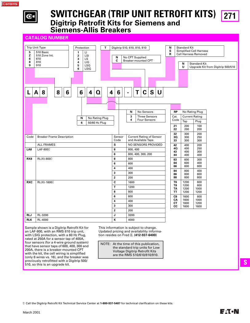
271
March 2001
SS
SWITCHGEAR (TRIP UNIT RETROFIT KITS)Digitrip Retrofit Kits for Siemens and Siemens-Allis Breakers
RP No Rating Plug
Cat.Code
Current Rating
Tap Plug
2122
200200
100200
323Q33
300300300
200250300
424Q4344
400400400400
200250300400
636466
600600600
300400600
848688
800800800
400600800
T6T8TATT
1200120012001200
600800
10001200
C8CACTCC
1600160016001600
800100012001600
L A 8 8 6 6 4 Q 4 6 - T C S U
NC
No CPT SuppliedBreaker-mounted CPT
CATALOG NUMBER
Sample shown is a Digitrip Retrofit Kit for an LAF-800, with an RMS 810 trip unit, with LSIG protection, with a 60 Hz Plug, rated at 250A for a sensor tap of 400A, four sensors (for a 4-wire ground system) that have sensor taps of 600, 400, 300 and 200A, there is a breaker-mounted CPT with the kit, the cell wiring is simplified (only 6 wires vs. 16), and the breaker was previously retrofitted with a Digitrip 500/510, so this is an upgrade kit.
Trip Unit Type
5Z689
510 Basic510 Zone Int.610810910
T Digitrip 510, 610, 810, 910Protection
123456
LILSILSLIGLSGLSIG
NSR
Standard KitSimplified Cell HarnessCell Harness Removed
NU
Standard KitUpgrade Kit from Digitrip 500/510
N No Rating Plug
6 50/60 Hz Plug
N No Sensors
34
Three SensorsFour Sensors
Code Breaker Frame Description SensorCode
Current Rating of Sensor and Available Taps
ALL FRAMES S NO SENSORS PROVIDED
LA8 LAF-800➊ 8 800, 400
6 600, 400, 300, 200
RX8 RL(X)-800➊ 8 800
6 600
4 400
3 300
2 200
RXC RL(X)-1600➊ C 1600
T 1200
8 800
6 600
4 400
3 300
2 200
RLJ RL-3200 J 3200
RLK RL-4000 K 4000
This information is subject to change. Updated pricing and availability informa-tion resides on Fred II. (412-937-6400)
➊ Call the Digitrip Retrofit Kit Technical Service Center at 1-800-937-5487 for technical clarification on these kits.
NOTE: At the time of this publication, the standard trip units for Low Voltage Digitrip Retrofit Kits are the RMS 510/610/810/910.
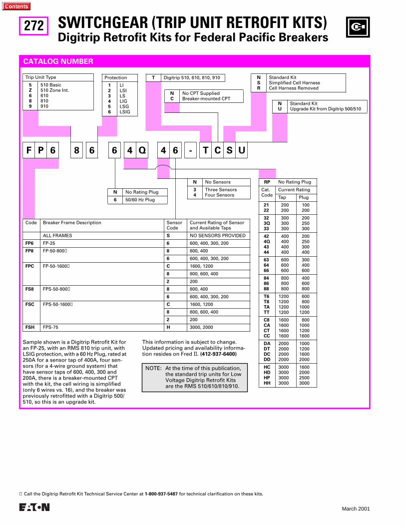
272
March 2001
SWITCHGEAR (TRIP UNIT RETROFIT KITS)Digitrip Retrofit Kits for Federal Pacific Breakers
RP No Rating Plug
Cat.Code
Current Rating
Tap Plug
2122
200200
100200
323Q33
300300300
200250300
424Q4344
400400400400
200250300400
636466
600600600
300400600
848688
800800800
400600800
T6T8TATT
1200120012001200
600800
10001200
C8CACTCC
1600160016001600
800100012001600
DADTDCDD
2000200020002000
1000120016002000
HCHDHPHH
3000300030003000
1600200025003000
F P 6 8 6 6 4 Q 4 6 - T C S U
NC
No CPT SuppliedBreaker-mounted CPT
CATALOG NUMBER
Sample shown is a Digitrip Retrofit Kit for an FP-25, with an RMS 810 trip unit, with LSIG protection, with a 60 Hz Plug, rated at 250A for a sensor tap of 400A, four sen-sors (for a 4-wire ground system) that have sensor taps of 600, 400, 300 and 200A, there is a breaker-mounted CPT with the kit, the cell wiring is simplified (only 6 wires vs. 16), and the breaker was previously retrofitted with a Digitrip 500/510, so this is an upgrade kit.
Trip Unit Type
5Z689
510 Basic510 Zone Int.610810910
T Digitrip 510, 610, 810, 910Protection
123456
LILSILSLIGLSGLSIG
NSR
Standard KitSimplified Cell HarnessCell Harness Removed
NU
Standard KitUpgrade Kit from Digitrip 500/510
N No Rating Plug
6 50/60 Hz Plug
N No Sensors
34
Three SensorsFour Sensors
Code Breaker Frame Description SensorCode
Current Rating of Sensor and Available Taps
ALL FRAMES S NO SENSORS PROVIDED
FP6 FP-25 6 600, 400, 300, 200
FP8 FP-50-800➊ 8 800, 400
6 600, 400, 300, 200
FPC FP-50-1600➊ C 1600, 1200
8 800, 600, 400
2 200
FS8 FPS-50-800➊ 8 800, 400
6 600, 400, 300, 200
FSC FPS-50-1600➊ C 1600, 1200
8 800, 600, 400
2 200
FSH FPS-75 H 3000, 2000
This information is subject to change. Updated pricing and availability informa-tion resides on Fred II. (412-937-6400)
➊ Call the Digitrip Retrofit Kit Technical Service Center at 1-800-937-5487 for technical clarification on these kits.
NOTE: At the time of this publication, the standard trip units for Low Voltage Digitrip Retrofit Kits are the RMS 510/610/810/910.
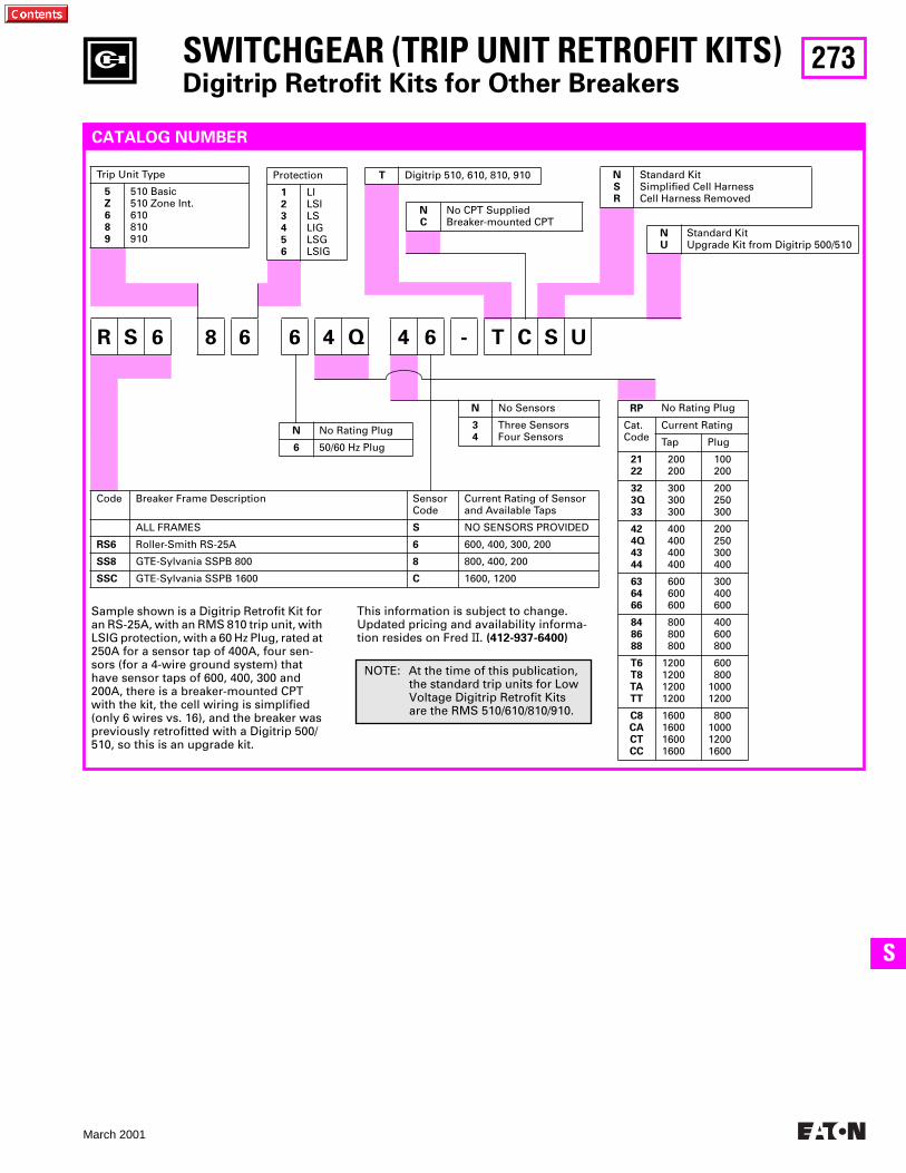
273
March 2001
SS
SWITCHGEAR (TRIP UNIT RETROFIT KITS)Digitrip Retrofit Kits for Other Breakers
RP No Rating Plug
Cat.Code
Current Rating
Tap Plug
2122
200200
100200
323Q33
300300300
200250300
424Q4344
400400400400
200250300400
636466
600600600
300400600
848688
800800800
400600800
T6T8TATT
1200120012001200
600800
10001200
C8CACTCC
1600160016001600
800100012001600
R S 6 8 6 6 4 Q 4 6 - T C S U
NC
No CPT SuppliedBreaker-mounted CPT
CATALOG NUMBER
Sample shown is a Digitrip Retrofit Kit for an RS-25A, with an RMS 810 trip unit, with LSIG protection, with a 60 Hz Plug, rated at 250A for a sensor tap of 400A, four sen-sors (for a 4-wire ground system) that have sensor taps of 600, 400, 300 and 200A, there is a breaker-mounted CPT with the kit, the cell wiring is simplified (only 6 wires vs. 16), and the breaker was previously retrofitted with a Digitrip 500/510, so this is an upgrade kit.
Trip Unit Type
5Z689
510 Basic510 Zone Int.610810910
T Digitrip 510, 610, 810, 910Protection
123456
LILSILSLIGLSGLSIG
NSR
Standard KitSimplified Cell HarnessCell Harness Removed
NU
Standard KitUpgrade Kit from Digitrip 500/510
N No Rating Plug
6 50/60 Hz Plug
N No Sensors
34
Three SensorsFour Sensors
Code Breaker Frame Description SensorCode
Current Rating of Sensor and Available Taps
ALL FRAMES S NO SENSORS PROVIDED
RS6 Roller-Smith RS-25A 6 600, 400, 300, 200
SS8 GTE-Sylvania SSPB 800 8 800, 400, 200
SSC GTE-Sylvania SSPB 1600 C 1600, 1200
This information is subject to change. Updated pricing and availability informa-tion resides on Fred II. (412-937-6400)
NOTE: At the time of this publication, the standard trip units for Low Voltage Digitrip Retrofit Kits are the RMS 510/610/810/910.
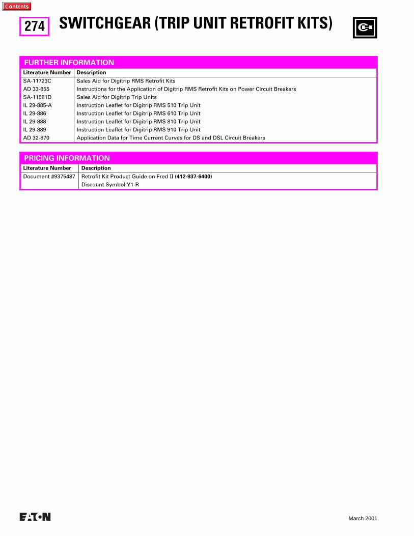
274
March 2001
Literature Number Description
Document #9375487 Retrofit Kit Product Guide on Fred II (412-937-6400)
Discount Symbol Y1-R
SWITCHGEAR (TRIP UNIT RETROFIT KITS)
FURTHER INFORMATION
Literature Number Description
SA-11723C
AD 33-855
SA-11581D
IL 29-885-A
IL 29-886
IL 29-888
IL 29-889
AD 32-870
Sales Aid for Digitrip RMS Retrofit Kits
Instructions for the Application of Digitrip RMS Retrofit Kits on Power Circuit Breakers
Sales Aid for Digitrip Trip Units
Instruction Leaflet for Digitrip RMS 510 Trip Unit
Instruction Leaflet for Digitrip RMS 610 Trip Unit
Instruction Leaflet for Digitrip RMS 810 Trip Unit
Instruction Leaflet for Digitrip RMS 910 Trip Unit
Application Data for Time Current Curves for DS and DSL Circuit Breakers
PRICING INFORMATION
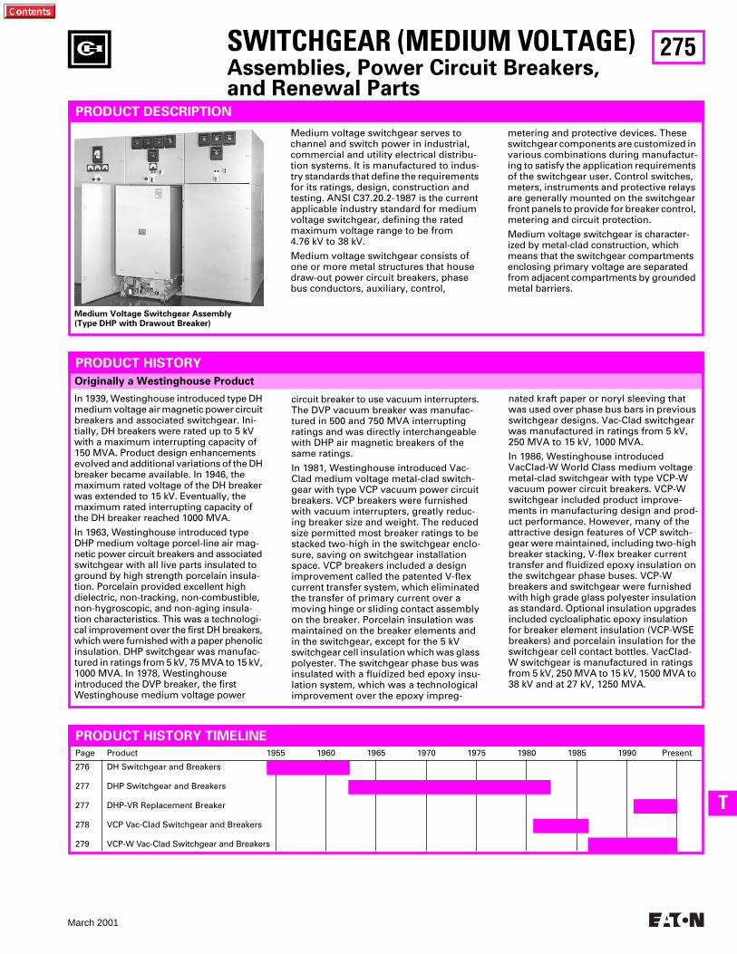
275
March 2001
T
Originally a Westinghouse Product
SWITCHGEAR (MEDIUM VOLTAGE)
Assemblies, Power Circuit Breakers,and Renewal Parts
Page Product 1955 1960 1965 1970 1975 1980 1985 1990 Present
276
277
277
278
279
DH Switchgear and Breakers
DHP Switchgear and Breakers
DHP-VR Replacement Breaker
VCP Vac-Clad Switchgear and Breakers
VCP-W Vac-Clad Switchgear and Breakers
PRODUCT DESCRIPTION
metering and protective devices. These switchgear components are customized in various combinations during manufactur-ing to satisfy the application requirements of the switchgear user. Control switches, meters, instruments and protective relays are generally mounted on the switchgear front panels to provide for breaker control, metering and circuit protection.
Medium voltage switchgear is character-ized by metal-clad construction, which means that the switchgear compartments enclosing primary voltage are separated from adjacent compartments by grounded metal barriers.
PRODUCT HISTORY
In 1939, Westinghouse introduced type DH medium voltage air magnetic power circuit breakers and associated switchgear. Ini-tially, DH breakers were rated up to 5 kV with a maximum interrupting capacity of 150 MVA. Product design enhancements evolved and additional variations of the DH breaker became available. In 1946, the maximum rated voltage of the DH breaker was extended to 15 kV. Eventually, the maximum rated interrupting capacity of the DH breaker reached 1000 MVA.
In 1963, Westinghouse introduced type DHP medium voltage porcel-line air mag-netic power circuit breakers and associated switchgear with all live parts insulated to ground by high strength porcelain insula-tion. Porcelain provided excellent high dielectric, non-tracking, non-combustible, non-hygroscopic, and non-aging insula-tion characteristics. This was a technologi-cal improvement over the first DH breakers, which were furnished with a paper phenolic insulation. DHP switchgear was manufac-tured in ratings from 5 kV, 75 MVA to 15 kV, 1000 MVA. In 1978, Westinghouse introduced the DVP breaker, the first Westinghouse medium voltage power
circuit breaker to use vacuum interrupters. The DVP vacuum breaker was manufac-tured in 500 and 750 MVA interrupting ratings and was directly interchangeable with DHP air magnetic breakers of the same ratings.
In 1981, Westinghouse introduced Vac-Clad medium voltage metal-clad switch-gear with type VCP vacuum power circuit breakers. VCP breakers were furnished with vacuum interrupters, greatly reduc-ing breaker size and weight. The reduced size permitted most breaker ratings to be stacked two-high in the switchgear enclo-sure, saving on switchgear installation space. VCP breakers included a design improvement called the patented V-flex current transfer system, which eliminated the transfer of primary current over a moving hinge or sliding contact assembly on the breaker. Porcelain insulation was maintained on the breaker elements and in the switchgear, except for the 5 kV switchgear cell insulation which was glass polyester. The switchgear phase bus was insulated with a fluidized bed epoxy insu-lation system, which was a technological improvement over the epoxy impreg-
nated kraft paper or noryl sleeving that was used over phase bus bars in previous switchgear designs. Vac-Clad switchgear was manufactured in ratings from 5 kV, 250 MVA to 15 kV, 1000 MVA.
In 1986, Westinghouse introduced VacClad-W World Class medium voltage metal-clad switchgear with type VCP-W vacuum power circuit breakers. VCP-W switchgear included product improve-ments in manufacturing design and prod-uct performance. However, many of the attractive design features of VCP switch-gear were maintained, including two-high breaker stacking, V-flex breaker current transfer and fluidized epoxy insulation on the switchgear phase buses. VCP-W breakers and switchgear were furnished with high grade glass polyester insulation as standard. Optional insulation upgrades included cycloaliphatic epoxy insulation for breaker element insulation (VCP-WSE breakers) and porcelain insulation for the switchgear cell contact bottles. VacClad-W switchgear is manufactured in ratings from 5 kV, 250 MVA to 15 kV, 1500 MVA to 38 kV and at 27 kV, 1250 MVA.
PRODUCT HISTORY TIMELINE
Medium Voltage Switchgear Assembly (Type DHP with Drawout Breaker)
Medium voltage switchgear serves to channel and switch power in industrial, commercial and utility electrical distribu-tion systems. It is manufactured to indus-try standards that define the requirements for its ratings, design, construction and testing. ANSI C37.20.2-1987 is the current applicable industry standard for medium voltage switchgear, defining the rated maximum voltage range to be from 4.76 kV to 38 kV.
Medium voltage switchgear consists of one or more metal structures that house draw-out power circuit breakers, phase bus conductors, auxiliary, control,
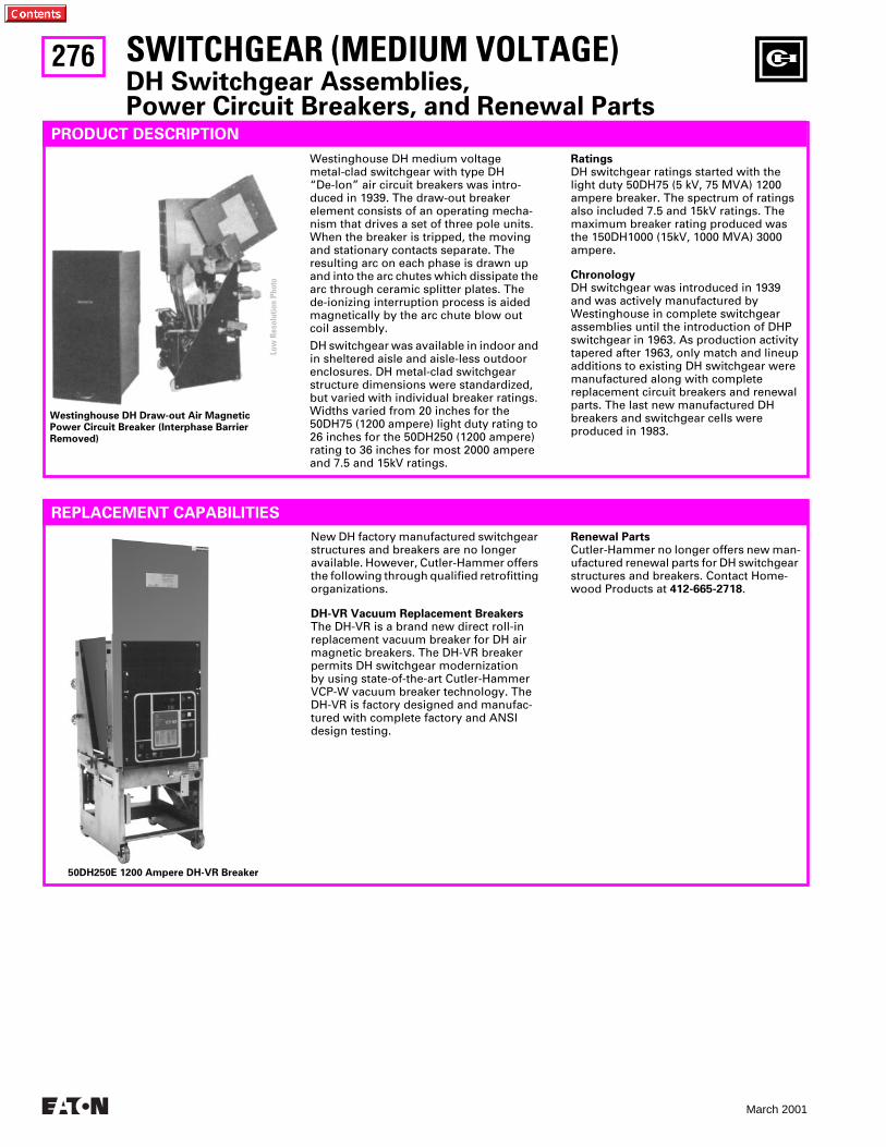
276
March 2001
SWITCHGEAR (MEDIUM VOLTAGE)
DH Switchgear Assemblies,Power Circuit Breakers, and Renewal Parts
PRODUCT DESCRIPTION
REPLACEMENT CAPABILITIES
Westinghouse DH medium voltage metal-clad switchgear with type DH “De-Ion” air circuit breakers was intro-duced in 1939. The draw-out breaker element consists of an operating mecha-nism that drives a set of three pole units. When the breaker is tripped, the moving and stationary contacts separate. The resulting arc on each phase is drawn up and into the arc chutes which dissipate the arc through ceramic splitter plates. The de-ionizing interruption process is aided magnetically by the arc chute blow out coil assembly.
DH switchgear was available in indoor and in sheltered aisle and aisle-less outdoor enclosures. DH metal-clad switchgear structure dimensions were standardized, but varied with individual breaker ratings. Widths varied from 20 inches for the 50DH75 (1200 ampere) light duty rating to 26 inches for the 50DH250 (1200 ampere) rating to 36 inches for most 2000 ampere and 7.5 and 15kV ratings.
Ratings
DH switchgear ratings started with the light duty 50DH75 (5 kV, 75 MVA) 1200 ampere breaker. The spectrum of ratings also included 7.5 and 15kV ratings. The maximum breaker rating produced was the 150DH1000 (15kV, 1000 MVA) 3000 ampere.
Chronology
DH switchgear was introduced in 1939 and was actively manufactured by Westinghouse in complete switchgear assemblies until the introduction of DHP switchgear in 1963. As production activity tapered after 1963, only match and lineup additions to existing DH switchgear were manufactured along with complete replacement circuit breakers and renewal parts. The last new manufactured DH breakers and switchgear cells were produced in 1983.
Westinghouse DH Draw-out Air Magnetic Power Circuit Breaker (Interphase Barrier Removed)
50DH250E 1200 Ampere DH-VR Breaker
New DH factory manufactured switchgear structures and breakers are no longer available. However, Cutler-Hammer offers the following through qualified retrofitting organizations.
DH-VR Vacuum Replacement Breakers
The DH-VR is a brand new direct roll-in replacement vacuum breaker for DH air magnetic breakers. The DH-VR breaker permits DH switchgear modernization by using state-of-the-art Cutler-Hammer VCP-W vacuum breaker technology. The DH-VR is factory designed and manufac-tured with complete factory and ANSI design testing.
Renewal Parts
Cutler-Hammer no longer offers new man-ufactured renewal parts for DH switchgear structures and breakers. Contact Home-wood Products at
412-665-2718
.
Low
Res
olut
ion
Phot
o
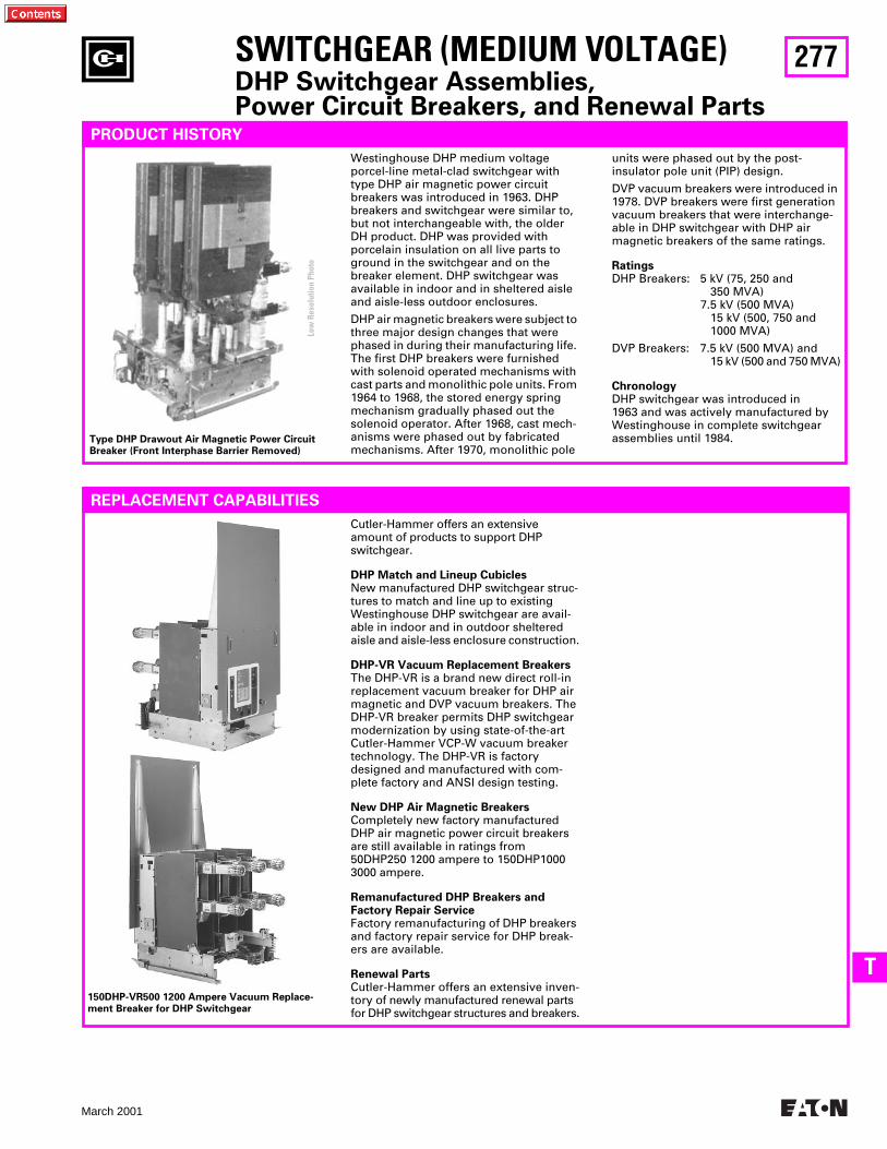
277
March 2001
T
SWITCHGEAR (MEDIUM VOLTAGE)
DHP Switchgear Assemblies,Power Circuit Breakers, and Renewal Parts
PRODUCT HISTORY
units were phased out by the post-insulator pole unit (PIP) design.
DVP vacuum breakers were introduced in 1978. DVP breakers were first generation vacuum breakers that were interchange-able in DHP switchgear with DHP air magnetic breakers of the same ratings.
Ratings
DHP Breakers: 5 kV (75, 250 and 350 MVA)
7.5 kV (500 MVA)15 kV (500, 750 and1000 MVA)
DVP Breakers: 7.5 kV (500 MVA) and15 kV (500 and 750 MVA)
Chronology
DHP switchgear was introduced in 1963 and was actively manufactured by Westinghouse in complete switchgear assemblies until 1984.
REPLACEMENT CAPABILITIES
Cutler-Hammer offers an extensive amount of products to support DHP switchgear.
DHP Match and Lineup Cubicles
New manufactured DHP switchgear struc-tures to match and line up to existing Westinghouse DHP switchgear are avail-able in indoor and in outdoor sheltered aisle and aisle-less enclosure construction.
DHP-VR Vacuum Replacement Breakers
The DHP-VR is a brand new direct roll-in replacement vacuum breaker for DHP air magnetic and DVP vacuum breakers. The DHP-VR breaker permits DHP switchgear modernization by using state-of-the-art Cutler-Hammer VCP-W vacuum breaker technology. The DHP-VR is factory designed and manufactured with com-plete factory and ANSI design testing.
New DHP Air Magnetic Breakers
Completely new factory manufactured DHP air magnetic power circuit breakers are still available in ratings from 50DHP250 1200 ampere to 150DHP1000 3000 ampere.
Remanufactured DHP Breakers and Factory Repair Service
Factory remanufacturing of DHP breakers and factory repair service for DHP break-ers are available.
Renewal Parts
Cutler-Hammer offers an extensive inven-tory of newly manufactured renewal parts for DHP switchgear structures and breakers.
Type DHP Drawout Air Magnetic Power Circuit Breaker (Front Interphase Barrier Removed)
Westinghouse DHP medium voltage porcel-line metal-clad switchgear with type DHP air magnetic power circuit breakers was introduced in 1963. DHP breakers and switchgear were similar to, but not interchangeable with, the older DH product. DHP was provided with porcelain insulation on all live parts to ground in the switchgear and on the breaker element. DHP switchgear was available in indoor and in sheltered aisle and aisle-less outdoor enclosures.
DHP air magnetic breakers were subject to three major design changes that were phased in during their manufacturing life. The first DHP breakers were furnished with solenoid operated mechanisms with cast parts and monolithic pole units. From 1964 to 1968, the stored energy spring mechanism gradually phased out the solenoid operator. After 1968, cast mech-anisms were phased out by fabricated mechanisms. After 1970, monolithic pole
150DHP-VR500 1200 Ampere Vacuum Replace-ment Breaker for DHP Switchgear
Low
Res
olut
ion
Phot
o
278
March 2001
SWITCHGEAR (MEDIUM VOLTAGE)
VCP Vac-Clad Switchgear Assemblies,Power Circuit Breakers, and Renewal Parts
PRODUCT HISTORY
ratings in the switchgear enclosure. VCP breakers withdraw onto switchgear rail assemblies for ease of inspection. Mainte-nance associated with air magnetic arc chutes was eliminated and contact main-tenance was reduced to visual inspection of wear gap indicators.
VCP breakers included a design improve-ment called the patented V-flex current
Vac-Clad Switchgear with Type VCP Drawout Vacuum Power Circuit Breakers
Westinghouse Vac-Clad medium voltage metal-clad switchgear with type VCP vac-uum power circuit breakers was intro-duced in 1981. Vacuum interrupter technology provided many advantages over the previous DH and DHP air magnet-ic breaker designs. Vacuum interrupters permitted the breaker size and weight to be significantly reduced, allowing for two-high stacking construction of most breaker
Type VCP-W Vacuum Power Circuit Breaker (Front and Rear Views)
transfer system, which eliminated the transfer of primary current over a moving hinge (like DHP breakers) or sliding contact assembly (like DVP breakers). Porcelain insulation was maintained on the breaker elements and in the switchgear except for the 5 kV switchgear cell insulation, which was glass polyester as standard. The switchgear phase bus was insulated with a fluidized bed epoxy insulation system, which was a major improvement over the epoxy impregnated kraft paper or noryl that was used as sleeving on phase bus bars in previous switchgear designs. Vac-Clad switchgear was manufactured in indoor and in sheltered aisle and aisle-less outdoor enclosures.
Ratings
VCP switchgear provided the first com-plete line of Westinghouse vacuum break-ers in the medium voltage ratings:
5 kV (250 and 350 MVA)7.5 kV (500 MVA)15 kV (500, 750 and 1000 MVA)
Chronology
Vac-Clad switchgear was introduced in 1981 and was manufactured by Westing-house in complete switchgear assemblies until the introduction of VacClad-W switchgear in 1986. Today, many capa-bilities still exist to support Vac-Clad switchgear.
Cutler-Hammer offers an extensive amount of products to support Vac-Clad switchgear.
New VCP Vacuum Breakers
Completely new factory manufactured VCP vacuum power circuit breakers are still available in ratings from 50VCP250 1200 ampere to 150VCP1000 3000 ampere.
Remanufactured VCP Breakers and Factory Repair Service
Factory remanufacturing of VCP Breakers and factory repair service for VCP Break-ers are available.
Renewal Parts
Cutler-Hammer offers an extensive inven-tory of newly manufactured renewal parts for VCP switchgear structures and breakers.
Fluidized Switchgear Bus
Cutler-Hammer offers new fluidized ep-oxy bus – insulated bus to replace existing switchgear phase bus insulation.
REPLACEMENT CAPABILITIES
Low
Res
olut
ion
Phot
o
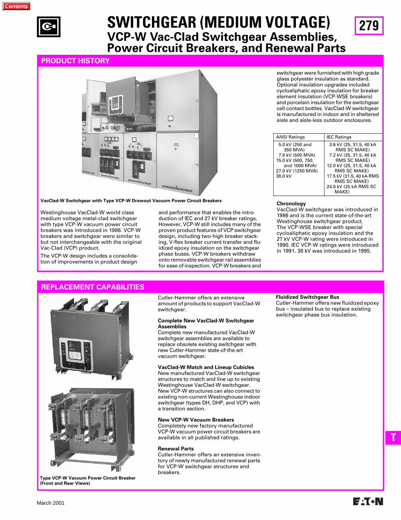
279
March 2001
T
switchgear were furnished with high grade glass polyester insulation as standard. Optional insulation upgrades included cycloaliphatic epoxy insulation for breaker element insulation (VCP-WSE breakers) and porcelain insulation for the switchgear cell contact bottles. VacClad-W switchgear is manufactured in indoor and in sheltered aisle and aisle-less outdoor enclosures.
Chronology
VacClad-W switchgear was introduced in 1986 and is the current state-of-the-art Westinghouse switchgear product. The VCP-WSE breaker with special cycloaliphatic epoxy insulation and the 27 kV VCP-W rating were introduced in 1990. IEC VCP-W ratings were introduced in 1991. 38 kV was introduced in 1995.
ANSI Ratings IEC Ratings
5.0 kV (250 and350 MVA)
7.5 kV (500 MVA)15.0 kV (500, 750,
and 1000 MVA)27.0 kV (1250 MVA)38.0 kV
3.6 kV (25, 31.5, 40 kA RMS SC MAKE) 7.2 kV (25, 31.5, 40 kA RMS SC MAKE)12.0 kV (25, 31.5, 40 kA
RMS SC MAKE)17.5 kV (31.5, 40 kA RMS
RMS SC MAKE)24.0 kV (25 kA RMS SC
MAKE)
SWITCHGEAR (MEDIUM VOLTAGE)
VCP-W Vac-Clad Switchgear Assemblies,Power Circuit Breakers, and Renewal Parts
PRODUCT HISTORY
and performance that enables the intro-duction of IEC and 27 kV breaker ratings. However, VCP-W still includes many of the proven product features of VCP switchgear design, including two-high breaker stack-ing, V-flex breaker current transfer and flu-idized epoxy insulation on the switchgear phase buses. VCP-W breakers withdraw onto removable switchgear rail assemblies for ease of inspection. VCP-W breakers and
VacClad-W Switchgear with Type VCP-W Drawout Vacuum Power Circuit Breakers
Westinghouse VacClad-W world class medium voltage metal-clad switchgear with type VCP-W vacuum power circuit breakers was introduced in 1986. VCP-W breakers and switchgear were similar to but not interchangeable with the original Vac-Clad (VCP) product.
The VCP-W design includes a consolida-tion of improvements in product design
Cutler-Hammer offers an extensive amount of products to support VacClad-W switchgear.
Complete New VacClad-W Switchgear Assemblies
Complete new manufactured VacClad-W switchgear assemblies are available to replace obsolete existing switchgear with new Cutler-Hammer state-of-the-art vacuum switchgear.
VacClad-W Match and Lineup Cubicles
New manufactured VacClad-W switchgear structures to match and line up to existing Westinghouse VacClad-W switchgear. New VCP-W structures can also connect to existing non-current Westinghouse indoor switchgear (types DH, DHP, and VCP) with a transition section.
New VCP-W Vacuum Breakers
Completely new factory manufactured VCP-W vacuum power circuit breakers are available in all published ratings.
Renewal Parts
Cutler-Hammer offers an extensive inven-tory of newly manufactured renewal parts for VCP-W switchgear structures and breakers.
Type VCP-W Vacuum Power Circuit Breaker (Front and Rear Views)
REPLACEMENT CAPABILITIES
Fluidized Switchgear Bus
Cutler-Hammer offers new fluidized epoxy bus – insulated bus to replace existing switchgear phase bus insulation.
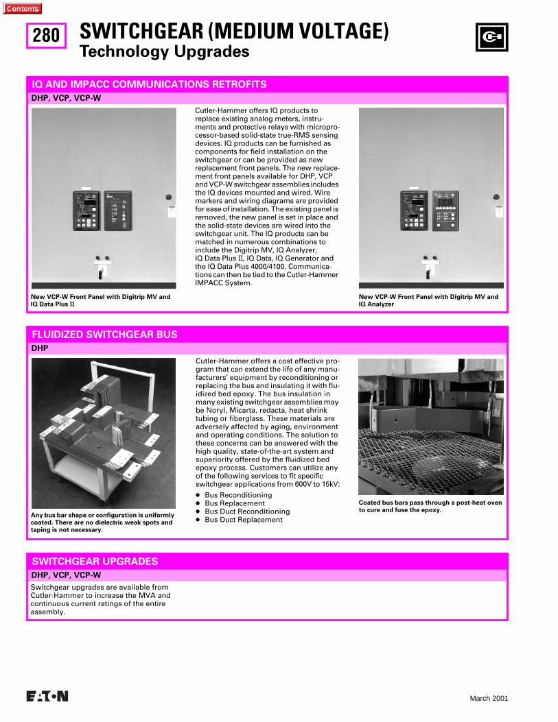
280
March 2001
DHP, VCP, VCP-W
SWITCHGEAR (MEDIUM VOLTAGE)
Technology Upgrades
IQ AND IMPACC COMMUNICATIONS RETROFITS
Cutler-Hammer offers IQ products to replace existing analog meters, instru-ments and protective relays with micropro-cessor-based solid-state true-RMS sensing devices. IQ products can be furnished as components for field installation on the switchgear or can be provided as new replacement front panels. The new replace-ment front panels available for DHP, VCP and VCP-W switchgear assemblies includes the IQ devices mounted and wired. Wire markers and wiring diagrams are provided for ease of installation. The existing panel is removed, the new panel is set in place and the solid-state devices are wired into the switchgear unit. The IQ products can be matched in numerous combinations to include the Digitrip MV, IQ Analyzer, IQ Data Plus
II
, IQ Data, IQ Generator and the IQ Data Plus 4000/4100. Communica-tions can then be tied to the Cutler-Hammer IMPACC System.
New VCP-W Front Panel with Digitrip MV andIQ Data Plus
II
New VCP-W Front Panel with Digitrip MV andIQ Analyzer
Any bus bar shape or configuration is uniformly coated. There are no dielectric weak spots and taping is not necessary.
Coated bus bars pass through a post-heat oven to cure and fuse the epoxy.
Switchgear upgrades are available from Cutler-Hammer to increase the MVA and continuous current ratings of the entire assembly.
Cutler-Hammer offers a cost effective pro-gram that can extend the life of any manu-facturers’ equipment by reconditioning or replacing the bus and insulating it with flu-idized bed epoxy. The bus insulation in many existing switchgear assemblies may be Noryl, Micarta, redacta, heat shrink tubing or fiberglass. These materials are adversely affected by aging, environment and operating conditions. The solution to these concerns can be answered with the high quality, state-of-the-art system and superiority offered by the fluidized bed epoxy process. Customers can utilize any of the following services to fit specific switchgear applications from 600V to 15kV:
●
Bus Reconditioning
●
Bus Replacement
●
Bus Duct Reconditioning
●
Bus Duct Replacement
DHP
FLUIDIZED SWITCHGEAR BUS
DHP, VCP, VCP-W
SWITCHGEAR UPGRADES
281
March 2001
T
FURTHER INFORMATION
Product Literature
Number
Description
VCP-W BreakerVCP-WR BreakerMV Air/Vacuum Switchgear Parts
PL 33-729PL 33-724VISTA/VISTALINE
Price List for VCP-W Breaker PartsPrice List for VCP-WR Fixed Vacuum BreakersDiscount Symbol Y1
Product Literature
Number
Description
DHP Switchgear and Breaker
VCP Switchgear and Breaker
VCP-W Switchgear and Breaker
Fluidized Bus
General Information
RPD 32-253-4DLEL006ASA-11876BLEL014RPD 32-290
RPD 32-274LEL007A
RPD 32-255ASA-11671DB 32-255AD 32-265
SA-11745
SA-11936BLEL004ASA-104
Renewal Parts Data for DHP Breaker and Switchgear PartsSales Aid for the DHP Remanufacture ProgramSales Aid for the DHP-VR Vacuum Replacement BreakerSales Aid for the DHP-VR Breaker vs. Retrofitted BreakerRenewal Parts Data for the DHP-VR Vacuum Replacement Breaker
Renewal Parts Data for VCP Breaker and Switchgear PartsSales Aid for the VCP Remanufacture Program
Renewal Parts Data for VCP-W Switchgear PartsSales Aid for VCP-W SwitchgearDescriptive Bulletin for VCP-W SwitchgearApplication Data for VCP-W Switchgear
Sales Aid for Custom Fluidized Switchgear Bus
Sales Aid for Greenwood Aftermarket Product Center CapabilitiesSales Aid for Breaker Remanufacture ProgramSales Aid for MV Switchgear Replacement Front Panels with IQ Devices
SWITCHGEAR (MEDIUM VOLTAGE)
DHP, VCP, VCP-W Switchgear Assemblies
PRICING INFORMATION
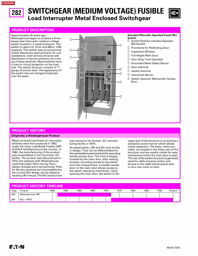
282
March 2001
SWITCHGEAR (MEDIUM VOLTAGE) FUSIBLE
Load Interrupter Metal Enclosed Switchgear
PRODUCT DESCRIPTION
Approximately 40 years ago, Westinghouse began to produce a three-phase load interrupter medium-voltage switch housed in a metal enclosure. The switch is rated 5 to 15 kV and 600 to 1200 amperes. This switch was an economical visible disconnect used primarily for unit substations, main service entrance and distribution of service entrance via a line-up of these switches. Most switches have a fuse for circuit protection on the load side. The switch structure consists of 11 gauge structural steel. The appearance of the switch has not changed drastically over the years.
Originally a Westinghouse Product
PRODUCT HISTORY
Metal enclosed load break air interrupter switches were first produced in 1952 under the name Load Break Fusible (LBF) at M & R facilities around the country. In 1964, the manufacturing of the product was consolidated in the Cincinnati, OHfacility. The product was discontinued in 1972 and replaced with Westinghouse Load Interrupter (WLI) having many design changes and improvements. Parts for the two products are incompatible but the current WLI design can be added to existing LBF lineups. The WLI product line
was moved to the Sumter, SC manufac-turing facility in 1979.
As stated earlier, LBF and WLl look similar in design. They can be differentiated by the nameplate located behind the operating handle access door. The front is largely covered by the main door, with viewing window, providing access to the switch and fuse compartment. A smaller access door on the main door allows access to the switch operating mechanism. Upon opening the main door, the switch in the
Page Product 1950 1955 1960 1965 1970 1975 1980 1985 1990 Present
283
284
Westinghouse LBF
WLI + MVS
PRODUCT HISTORY TIMELINE
Standard Manually Operated Fused WLI Switch
➀
Switch Position Indicator/OperatorMechanism
➁
Provisions for Padlocking Door
➂
Inspection Window
➃
Full Height Main Door
➄
Door Stop, Foot Operated
➅
Grounded Metal Safety Barrier
➆
Door Interlock
➇
Switch Interlock
➈
Interphase Barrier
➉
Switch Operator Mechanism AccessDoor
➁
➅
➀
➈
➃
➂
➉
➁
➆
➇
➄
upper part of the structure is covered by a protective screen barrier which allows visual inspection. The fuses, when pro-vided, are located in the lower part of the structure, and are readily visible for easy maintenance when the main door is open. The rear of the switch structure is generally used for cable entrance and/or exit. Access to the cable entrance/exit area is via a rear cover or door.
283
March 2001
U
LBF Load Break Switch
SWITCHGEAR (MEDIUM VOLTAGE) FUSIBLE
LBF Load Interrupter Metal Enclosed Switchgear
PRODUCT DESCRIPTION
The LBF switch standard structure was 33-inch wide, 90.38-inch high (indoor), 98.88-inch high (outdoor), with varying depths. Vertical sections were freestand-ing, close coupled to transformers, and bolted together forming lineups. ANSI 61
The MVS product, which replaces the LBF, is a completely new and improved design and parts are incompatible.
REPLACEMENT CAPABILITIES
light gray enamel was the internal color for all structures and external color for indoor structures. ANSI 24 dark gray enamel was the external color for outdoor structures.
LBF Ratings
Three-phase, 5 and 15 kV maximum, 600 and 1200 amperes.
TECHNOLOGY UPGRADES
The LBF product line was discontinued in 1972. Due to design change and retooling, replacement parts are no longer available.
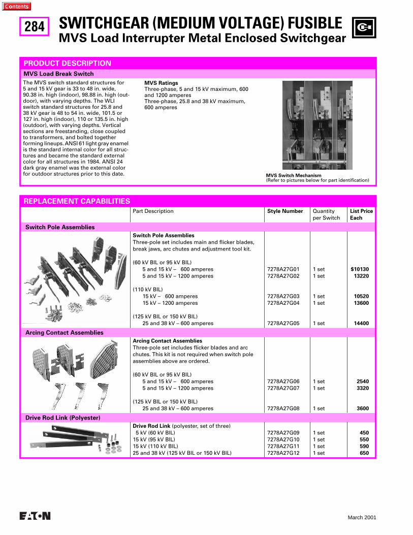
284
March 2001
MVS Load Break Switch
Part Description
Style Number
Quantityper Switch
List Price
Each
Switch Pole Assemblies
Switch Pole Assemblies
Three-pole set includes main and flicker blades, break jaws, arc chutes and adjustment tool kit.
(60 kV BIL or 95 kV BIL)5 and 15 kV – 600 amperes5 and 15 kV – 1200 amperes
(110 kV BIL)15 kV – 600 amperes15 kV – 1200 amperes
(125 kV BIL or 150 kV BIL)25 and 38 kV – 600 amperes
7278A27G017278A27G02
7278A27G037278A27G04
7278A27G05
1 set1 set
1 set1 set
1 set
$10130
13220
10520
13600
14400
Arcing Contact Assemblies
Arcing Contact Assemblies
Three-pole set includes flicker blades and arcchutes. This kit is not required when switch pole assemblies above are ordered.
(60 kV BIL or 95 kV BIL)5 and 15 kV – 600 amperes5 and 15 kV – 1200 amperes
(125 kV BIL or 150 kV BIL)25 and 38 kV – 600 amperes
7278A27G06 7278A27G07
7278A27G08
1 set1 set
1 set
2540
3320
3600
Drive Rod Link (Polyester)
Drive Rod Link
(polyester, set of three) 5 kV (60 kV BIL)15 kV (95 kV BIL)15 kV (110 kV BIL)25 and 38 kV (125 kV BIL or 150 kV BIL)
7278A27G097278A27G107278A27G117278A27G12
1 set1 set1 set1 set
450
550
590
650
SWITCHGEAR (MEDIUM VOLTAGE) FUSIBLE
MVS Load Interrupter Metal Enclosed Switchgear
PRODUCT DESCRIPTION
The MVS switch standard structures for 5 and 15 kV gear is 33 to 48 in. wide, 90.38 in. high (indoor), 98.88 in. high (out-door), with varying depths. The WLI switch standard structures for 25.8 and 38 kV gear is 48 to 54 in. wide, 101.5 or 127 in. high (indoor), 110 or 135.5 in. high (outdoor), with varying depths. Vertical sections are freestanding, close coupled to transformers, and bolted together forming lineups. ANSI 61 light gray enamel is the standard internal color for all struc-tures and became the standard external color for all structures in 1984. ANSI 24 dark gray enamel was the external color for outdoor structures prior to this date.
REPLACEMENT CAPABILITIES
MVS Ratings
Three-phase, 5 and 15 kV maximum, 600 and 1200 amperes Three-phase, 25.8 and 38 kV maximum, 600 amperes
MVS Switch Mechanism
(Refer to pictures below for part identification)
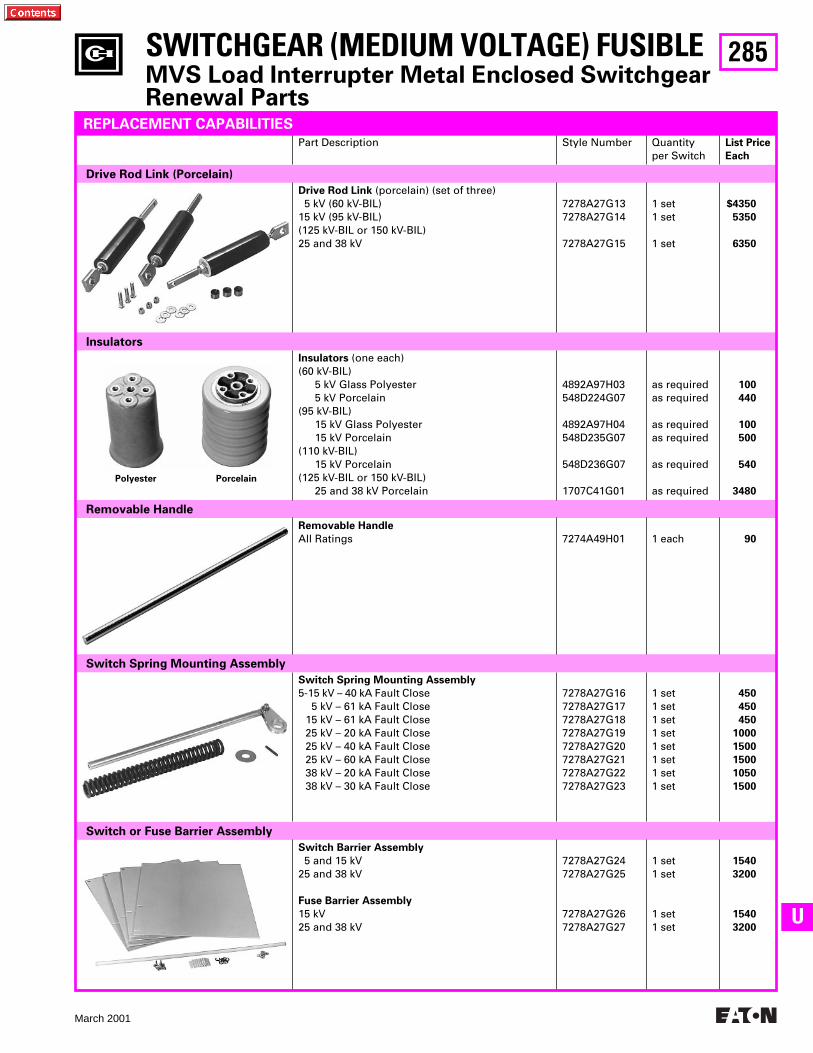
285
March 2001
U
SWITCHGEAR (MEDIUM VOLTAGE) FUSIBLE
MVS Load Interrupter Metal Enclosed SwitchgearRenewal Parts
Part Description Style Number Quantityper Switch
List Price
Each
Drive Rod Link (Porcelain)
Drive Rod Link
(porcelain) (set of three) 5 kV (60 kV-BIL)15 kV (95 kV-BIL)(125 kV-BIL or 150 kV-BIL)25 and 38 kV
7278A27G137278A27G14
7278A27G15
1 set1 set
1 set
$4350
5350
6350
Insulators
Polyester Porcelain
Insulators
(one each)(60 kV-BIL)
5 kV Glass Polyester5 kV Porcelain
(95 kV-BIL)15 kV Glass Polyester15 kV Porcelain
(110 kV-BIL)15 kV Porcelain
(125 kV-BIL or 150 kV-BIL)25 and 38 kV Porcelain
4892A97H03548D224G07
4892A97H04548D235G07
548D236G07
1707C41G01
as required as required
as required as required
as required
as required
100
440
100
500
540
3480
Removable Handle
Removable Handle
All Ratings 7274A49H01 1 each
90
Switch Spring Mounting Assembly
Switch Spring Mounting Assembly
5-15 kV – 40 kA Fault Close 5 kV – 61 kA Fault Close
15 kV – 61 kA Fault Close25 kV – 20 kA Fault Close25 kV – 40 kA Fault Close25 kV – 60 kA Fault Close38 kV – 20 kA Fault Close38 kV – 30 kA Fault Close
7278A27G167278A27G177278A27G187278A27G197278A27G207278A27G217278A27G227278A27G23
1 set1 set1 set1 set1 set1 set1 set1 set
450
450
450
1000
1500
1500
1050
1500
Switch or Fuse Barrier Assembly
Switch Barrier Assembly
5 and 15 kV25 and 38 kV
Fuse Barrier Assembly
15 kV25 and 38 kV
7278A27G247278A27G25
7278A27G267278A27G27
1 set1 set
1 set1 set
1540
3200
1540
3200
REPLACEMENT CAPABILITIES
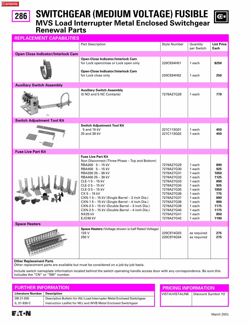
286
March 2001
SWITCHGEAR (MEDIUM VOLTAGE) FUSIBLE
MVS Load Interrupter Metal Enclosed SwitchgearRenewal Parts
Part Description Style Number Quantityper Switch
List Price
Each
Open Close Indicator/Interlock Cam
Open-Close Indicator/lnterlock Cam
for Lock open/close or Lock open only
Open-Close Indicator/lnterlock Cam
for Lock close only
220C934H01
220C934H02
1 each
1 each
$250
250
Auxiliary Switch Assembly
Auxiliary Switch Assembly
(5 NO and 5 NC Contacts) 7278A27G28 1 each
770
Switch Adjustment Tool Kit
Switch Adjustment Tool Kit
5 and 15 kV25 and 38 kV
221C113G01221C113G02
1 each1 each
450
450
Fuse Live Part Kit
Fuse Live Part Kit
Non Disconnect (Three-Phase – Top and Bottom)RBA200 5 – 15 kVRBA400 5 – 15 kVRBA200 25 – 38 kVRBA400 25 – 38 kVCLE-1 5 – 15 kVCLE-2 5 – 15 kVCLE-3 5 – 15 kVCX 5 – 15 kVCXN-1 5 – 15 kV (Single Barrel – 3 inch Dia.)CXN-1 5 – 15 kV (Single Barrel – 4 inch Dia.)CXN-2 5 – 15 kV (Double Barrel – 3 inch Dia.)CXN-2 5 – 15 kV (Double Barrel – 4 inch Dia.)NX25 kVEJO38 kV
7278A27G297278A27G307278A27G317278A27G327278A27G337278A27G347278A27G357278A27G367278A27G377278A27G387278A27G397278A27G407278A27G417278A27G42
1 each1 each1 each1 each1 each1 each1 each1 each1 each1 each1 each1 each1 each1 each
890
925
1050
1125
890
925
1050
775
890
890
1175
1175
850
1190
Space Heaters
Space Heaters
(Voltage shown is half Rated Voltage)125 V250 V
220C974G03 220C974G04
as required as required
275
275
Other Replacement Parts
Other replacement parts are available but must be considered on a job-by-job basis.
Include switch nameplate information located behind the switch operating handle access door with any correspondence. Be sure this includes the ”CN“ or ”SM“ number.
REPLACEMENT CAPABILITIES
Literature Number Description
DB 31-935
IL 31-930-C
Descriptive Bulletin for WLI Load Interrupter Metal Enclosed Switchgear
Instruction Leaflet for WLI and WVB Metal Enclosed Switchgear
VISTA/VISTALINE Discount Symbol Y2
PRICING INFORMATIONFURTHER INFORMATION
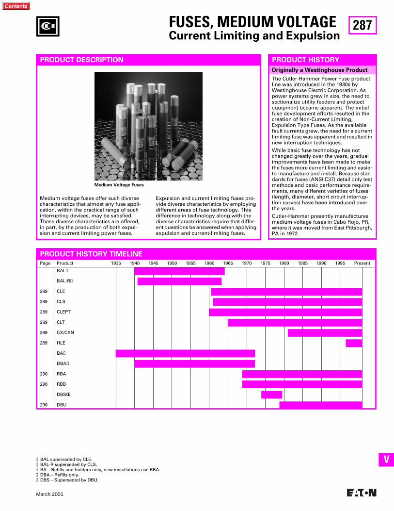
287
March 2001
V
Page Product 1935 1940 1945 1950 1955 1960 1965 1970 1975 1980 1985 1990 1995 Present
289
289
289
289
289
289
290
290
290
BAL
➊
BAL-R
➋
CLE
CLS
CLEPT
CLT
CX/CXN
HLE
BA
➌
DBA
➍
RBA
RBD
DBSŒ
DBU
Originally a Westinghouse Product
FUSES, MEDIUM VOLTAGE
Current Limiting and Expulsion
PRODUCT DESCRIPTION
Medium voltage fuses offer such diverse characteristics that almost any fuse appli-cation, within the practical range of such interrupting devices, may be satisfied. These diverse characteristics are offered, in part, by the production of both expul-sion and current limiting power fuses.
Expulsion and current limiting fuses pro-vide diverse characteristics by employing different areas of fuse technology. This difference in technology along with the diverse characteristics require that differ-ent questions be answered when applying expulsion and current-limiting fuses.
PRODUCT HISTORY
The Cutler-Hammer Power Fuse product line was introduced in the 1930s by Westinghouse Electric Corporation. As power systems grew in size, the need to sectionalize utility feeders and protect equipment became apparent. The initial fuse development efforts resulted in the creation of Non-Current Limiting, Expulsion Type Fuses. As the available fault currents grew, the need for a current limiting fuse was apparent and resulted in new interruption techniques.
While basic fuse technology has not changed greatly over the years, gradual improvements have been made to make the fuses more current limiting and easier to manufacture and install. Because stan-dards for fuses (ANSI C37) detail only test methods and basic performance require-ments, many different varieties of fuses (length, diameter, short circuit interrup-tion curves) have been introduced over the years.
Cutler-Hammer presently manufactures medium voltage fuses in Cabo Rojo, PR, where it was moved from East Pittsburgh, PA in 1972.
PRODUCT HISTORY TIMELINE
➊
BAL superseded by CLE.
➋
BAL-R superseded by CLS.
➌
BA – Refills and holders only, new installations use RBA.
➍
DBA – Refills only.
➎
DBS – Superseded by DBU.
Medium Voltage Fuses
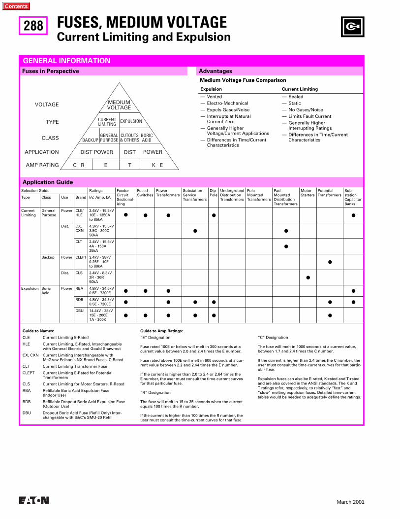
288
March 2001
Selection Guide Ratings FeederCircuitSectional-izing
FusedSwitches
PowerTransformers
SubstationServiceTransformers
DipPole
UndergroundDistributionTransformers
PoleMountedTransformers
Pad-MountedDistributionTransformers
MotorStarters
PotentialTransformers
Sub-stationCapacitorBanks
Type Class Use Brand kV, Amp, kA
CurrentLimiting
GeneralPurpose
Power CLE/HLE
2.4kV - 15.5kV10E - 1350Ato 85kA
● ● ● ● ●
Dist. CX,CXN
4.3kV - 15.5kV3.5C - 300C50kA
● ●
CLT 2.4kV - 15.5kV4A - 150A25kA
●
Backup Power CLEPT 2.4kV - 38kV0.25E - 10Eto 80kA
●
Dist. CLS 2.4kV - 8.3kV2R - 36R50kA
●
Expulsion BoricAcid
Power RBA 4.8kV - 34.5kV0.5E - 7200E
● ● ● ●
RDB 4.8kV - 34.5kV0.5E - 7200E
● ● ● ● ● ●
DBU 14.4kV - 38kV15E - 200E1A - 200K
● ● ● ● ● ●
Application Guide
Fuses in Perspective
FUSES, MEDIUM VOLTAGE
Current Limiting and Expulsion
GENERAL INFORMATION
Medium Voltage Fuse Comparison
Expulsion Current Limiting
— Vented— Electro-Mechanical— Expels Gases/Noise— Interrupts at Natural
Current Zero— Generally Higher
Voltage/Current Applications— Differences in Time/Current
Characteristics
— Sealed— Static— No Gases/Noise— Limits Fault Current— Generally Higher
Interrupting Ratings— Differences in Time/Current
Characteristics
Guide to Names:
CLE Current Limiting E-Rated
HLE Current Limiting, E-Rated, Interchangeable with General Electric and Gould Shawmut
CX, CXN Current Limiting Interchangeable with McGraw-Edison’s NX Brand Fuses, C-Rated
CLT Current Limiting Transformer Fuse
CLEPT Current Limiting E-Rated for Potential Transformers
CLS Current Limiting for Motor Starters, R-Rated
RBA Refillable Boric Acid Expulsion Fuse (Indoor Use)
RDB Refillable Dropout Boric Acid Expulsion Fuse (Outdoor Use)
DBU Dropout Boric Acid Fuse (Refill Only) Inter-changeable with S&C’s SMU-20 Refill
Guide to Amp Ratings:
“E” Designation
Fuse rated 100E or below will melt in 300 seconds at a current value between 2.0 and 2.4 times the E number.
Fuse rated above 100E will melt in 600 seconds at a cur-rent value between 2.2 and 2.64 times the E number.
If the current is higher than 2.0 to 2.4 or 2.64 times the E number, the user must consult the time-current curves for that particular fuse.
“R” Designation
The fuse will melt in 15 to 35 seconds when the current equals 100 times the R number.
If the current is higher than 100 times the R number, the user must consult the time-current curves for that fuse.
“C” Designation
The fuse will melt in 1000 seconds at a current value,between 1.7 and 2.4 times the C number.
If the current is higher than 2.4 times the C number, the user must consult the time-current curves for that partic-ular fuse.
Expulsion fuses can also be E-rated, K-rated and T-rated and are also covered in the ANSI standards. The K and T ratings refer, respectively, to relatively “fast” and “slow” melting expulsion fuses. Detailed time-current tables would be needed to adequately define the ratings.
MEDIUMVOLTAGE
CURRENTLIMITING
EXPULSION
BACKUPGENERALPURPOSE
CUTOUTS& OTHERS
BORICACID
DIST POWER DIST POWER
C R E T K E
VOLTAGE
TYPE
CLASS
APPLICATION
AMP RATING
Advantages
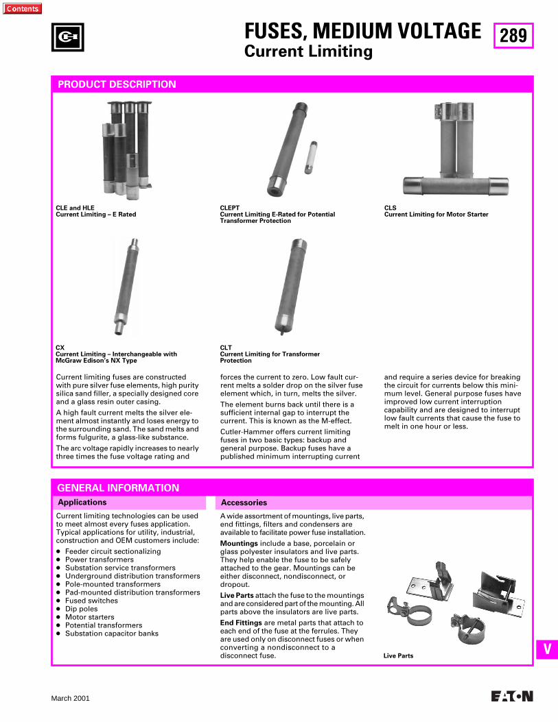
289
March 2001
V
AccessoriesApplications
FUSES, MEDIUM VOLTAGE
Current Limiting
PRODUCT DESCRIPTION
CLE and HLECurrent Limiting – E Rated
CLEPTCurrent Limiting E-Rated for PotentialTransformer Protection
CLSCurrent Limiting for Motor Starter
CXCurrent Limiting – Interchangeable withMcGraw Edison’s NX Type
CLTCurrent Limiting for TransformerProtection
Current limiting fuses are constructed with pure silver fuse elements, high purity silica sand filler, a specially designed core and a glass resin outer casing.
A high fault current melts the silver ele-ment almost instantly and loses energy to the surrounding sand. The sand melts and forms fulgurite, a glass-like substance.
The arc voltage rapidly increases to nearly three times the fuse voltage rating and
forces the current to zero. Low fault cur-rent melts a solder drop on the silver fuse element which, in turn, melts the silver.
The element burns back until there is a sufficient internal gap to interrupt the current. This is known as the M-effect.
Cutler-Hammer offers current limiting fuses in two basic types: backup and general purpose. Backup fuses have a published minimum interrupting current
A wide assortment of mountings, live parts, end fittings, filters and condensers are available to facilitate power fuse installation.
Mountings
include a base, porcelain or glass polyester insulators and live parts. They help enable the fuse to be safely attached to the gear. Mountings can be either disconnect, nondisconnect, or dropout.
Live Parts
attach the fuse to the mountings and are considered part of the mounting. All parts above the insulators are live parts.
End Fittings
are metal parts that attach to each end of the fuse at the ferrules. They are used only on disconnect fuses or when converting a nondisconnect to a disconnect fuse.
Current limiting technologies can be used to meet almost every fuses application. Typical applications for utility, industrial, construction and OEM customers include:
●
Feeder circuit sectionalizing
●
Power transformers
●
Substation service transformers
●
Underground distribution transformers
●
Pole-mounted transformers
●
Pad-mounted distribution transformers
●
Fused switches
●
Dip poles
●
Motor starters
●
Potential transformers
●
Substation capacitor banks
Live Parts
and require a series device for breaking the circuit for currents below this mini-mum level. General purpose fuses have improved low current interruption capability and are designed to interrupt low fault currents that cause the fuse to melt in one hour or less.
GENERAL INFORMATION
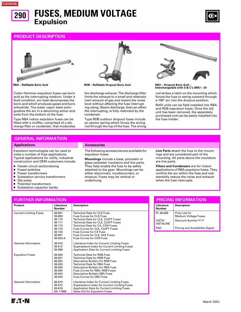
290
March 2001
Product LiteratureNumber
Description
Current Limiting Fuses
General Information
Expulsion Fuses
General Information
36-691 36-69336-71036-71136-71336-71536-73336-901 36-933-A
36-61036-61236-686
36-63036-63136-63236-63336-63436-63536-64236-643
36-61036-61236-616SA-11888
Technical Data for CLS FuseFuse Curves for CLS FuseTechnical Data for CLE, CLEPT FusesTechnical Data for CLE, CLEPT FusesTechnical Data for CX, CXN FusesFuse Curves for CLE, CLEPT FusesFuse Curves for CX FuseFuse Curves for CLE, HLE FusesFuse Curves for CXN Fuse
Literature Index for Current Limiting FusesSupersedure Index for Current Limiting FusesApplication Data for Current Limiting Fuses
Technical Data for RDB FuseTechnical Data for RDB FuseDescriptive Bulletin for RDB FuseTechnical Data for RBA FuseDescriptive Bulletin for RBA FuseFuse Curves for RBA, RDB FusesDescriptive Bulletin DBU FuseFuse Curves for DBU Fuse
Literature Index for Current Limiting FusesSupersedure Index for Current Limiting FusesApplication Data for Current Limiting FusesSales Aid for Expulsion Fuses
Applications Accessories
Expulsion technologies can be used to meet a number of fuse applications. Typical applications for utility, industrial construction and OEM customers include:
●
Feeder circuit sectionalizing
●
Fused switches
●
Power transformers
●
Substation service transformers
●
Dip poles
●
Potential transformers
●
Substation capacitor banks
FUSES, MEDIUM VOLTAGE
Expulsion
PRODUCT DESCRIPTION
RBA – Refillable Boric Acid RDB – Refillable Dropout Boric Acid DBU – Dropout Boric Acid –Interchangeable with S & C’s SMU – 20
Cutler-Hammer expulsion fuses use boric acid as the interrupting medium. Under a fault condition, arc heat decomposes the boric acid which produces gases and boric anhydride. The water vapor blast extin-guishes the arc in a deionizing action and exits from the bottom of the fuse.
Type RBA indoor expulsion fuses can be fitted with a muffler, comprised of a dis-charge filter or condenser, that moderates
the discharge exhaust. The discharge filter limits the exhaust to a small and relatively inert amount of gas and lowers the noise level without affecting the fuse interrupt-ing rating. Steam discharge, that can affect the interrupting, is fully restricted by the condenser.
Type RDB outdoor dropout fuses include an ejector spring which forces the arcing rod through the top of the fuse. The arcing
The following accessories are available for expulsion fuses:
Mountings
include a base, porcelain or glass polyester insulators and live parts. They help enable the fuse to be safely attached to the gear. Mountings can be either disconnect, nondisconnect, or dropout. Fuses may be vertical or underhung.
FURTHER INFORMATION
rod strikes a latch on the mounting which forces the fuse to swing outward through a 180° arc into the dropout position.
Refill units can be field installed into RBA and RDB expulsion fuses. Once the old unit has been removed, the separately purchased unit can be easily installed into the fuse holder.
Live Parts
attach the fuse to the mount-ings and are considered part of the mounting. All parts above the insulators are live parts.
Filters and Condensers
are for indoor applications of RBA expulsion fuses. They confine the arc within the fuse and sub-stantially reduce the noise and exhaust when the fuse interrupts.
LiteratureNumber
Description
PL 36-609
VISTA/VISTALINE
PAD
Price List forMedium Voltage Fuses
Discount Symbol Y1-F
Pricing and Availability Digest
PRICING INFORMATION
GENERAL INFORMATION
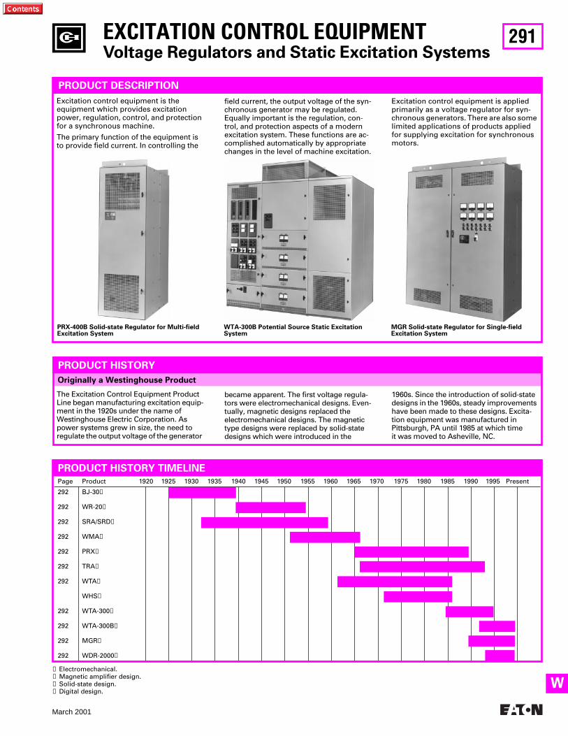
291
March 2001
W
Page Product 1920 1925 1930 1935 1940 1945 1950 1955 1960 1965 1970 1975 1980 1985 1990 1995 Present
292
292
292
292
292
292
292
292
292
292
292
BJ-30
➊
WR-20
➋
SRA/SRD
➊
WMA
➋
PRX
➌
TRA
➌
WTA
➌
WHS
➌
WTA-300
➌
WTA-300B
➌
MGR
➌
WDR-2000
➍
Originally a Westinghouse Product
EXCITATION CONTROL EQUIPMENT
Voltage Regulators and Static Excitation Systems
PRODUCT DESCRIPTION
Excitation control equipment is the equipment which provides excitation power, regulation, control, and protection for a synchronous machine.
The primary function of the equipment is to provide field current. In controlling the
PRODUCT HISTORY TIMELINE
PRODUCT HISTORY
field current, the output voltage of the syn-chronous generator may be regulated. Equally important is the regulation, con-trol, and protection aspects of a modern excitation system. These functions are ac-complished automatically by appropriate changes in the level of machine excitation.
Excitation control equipment is applied primarily as a voltage regulator for syn-chronous generators. There are also some limited applications of products applied for supplying excitation for synchronous motors.
The Excitation Control Equipment Product Line began manufacturing excitation equip-ment in the 1920s under the name of Westinghouse Electric Corporation. As power systems grew in size, the need to regulate the output voltage of the generator
became apparent. The first voltage regula-tors were electromechanical designs. Even-tually, magnetic designs replaced the electromechanical designs. The magnetic type designs were replaced by solid-state designs which were introduced in the
1960s. Since the introduction of solid-state designs in the 1960s, steady improvements have been made to these designs. Excita-tion equipment was manufactured in Pittsburgh, PA until 1985 at which time it was moved to Asheville, NC.
PRX-400B Solid-state Regulator for Multi-field Excitation System
WTA-300B Potential Source Static Excitation System
MGR Solid-state Regulator for Single-field Excitation System
➊
Electromechanical.
➋
Magnetic amplifier design.
➌
Solid-state design.
➍
Digital design.
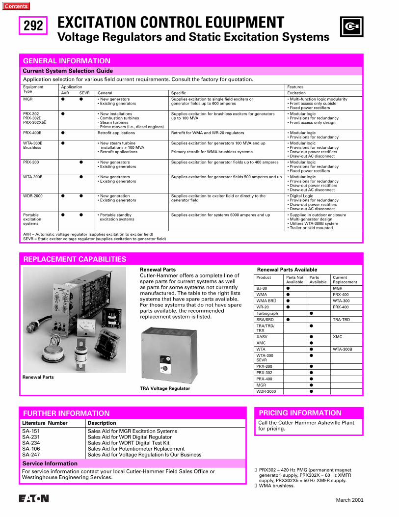
292
March 2001
Literature Number Description
SA-151SA-231SA-234SA-106SA-247
Sales Aid for MGR Excitation SystemsSales Aid for WDR Digital RegulatorSales Aid for WDRT Digital Test KitSales Aid for Potentiometer ReplacementSales Aid for Voltage Regulation Is Our Business
Service Information
Current System Selection Guide
Renewal Parts Available
Product Parts NotAvailable
PartsAvailable
CurrentReplacement
BJ-30
●
MGR
WMA
●
PRX-400
WMA BR
➋
●
WTA-300
WR-20
●
PRX-400
Turbograph
●
SRA/SRD
●
TRA-TRD
TRA/TRD/TRX
●
XASV
●
XMC
XMC
●
WTA
●
WTA-300B
WTA-300SEVR
●
PRX-300
●
PRX-302
●
PRX-400
●
MGR
●
WDR-2000
●
EXCITATION CONTROL EQUIPMENT
Voltage Regulators and Static Excitation Systems
REPLACEMENT CAPABILITIES
FURTHER INFORMATION
Renewal Parts
Renewal Parts
Cutler-Hammer offers a complete line of spare parts for current systems as well as parts for some systems not currently manufactured. The table to the right lists systems that have spare parts available. For those systems that do not have spare parts available, the recommendedreplacement system is listed.
TRA Voltage Regulator
GENERAL INFORMATION
PRICING INFORMATION
Call the Cutler-Hammer Asheville Plant for pricing.
For service information contact your local Cutler-Hammer Field Sales Office or Westinghouse Engineering Services.
➊
PRX302 = 420 Hz PMG (permanent magnet generator) supply, PRX302X = 60 Hz XMFR supply, PRX302X5 = 50 Hz XMFR supply.
➋
WMA brushless.
Application selection for various field current requirements. Consult the factory for quotation.
EquipmentType
Application Features
AVR SEVR General Specific Excitation
MGR
● ●
• New generators• Existing generators
Supplies excitation to single field exciters or generator fields up to 600 amperes
• Multi-function logic modularity• Front access only cubicle• Fixed power rectifiers
PRX-302PRX-302
➊
PRX-302X5
➊
●
• New installations - Combustion turbines - Steam turbines - Prime movers (i.e., diesel engines)
Supplies excitation for brushless exciters for generators up to 100 MVA
• Modular logic• Provisions for redundancy• Front access only design
PRX-400B
●
Retrofit applications Retrofit for WMA and WR-20 regulators • Modular logic• Provisions for redundancy
WTA-300BBrushless
●
• New steam turbine installations > 100 MVA• Retrofit applications
Supplies excitation for generators 100 MVA and up
Primary retrofit for WMA brushless systems
• Modular logic• Provisions for redundancy• Draw-out power rectifiers• Draw-out AC disconnect
PRX-300
●
• New generators• Existing generators
Supplies excitation for generator fields up to 400 amperes • Modular logic• Provisions for redundancy• Fixed power rectifiers
WTA-300B
●
• New generators• Existing generators
Supplies excitation for generator fields 500 amperes and up • Modular logic• Provisions for redundancy• Draw-out power rectifiers• Draw-out AC disconnect
WDR-2000
● ●
• New generation• Existing generators
Supplies excitation to exciter field or directly to the generator field
• Digital Logic• Provisions for redundancy• Draw-out power rectifiers• Draw-out AC disconnect
Portable excitation systems
● ●
• Portable standby excitation systems
Supplies excitation for systems 6000 amperes and up • Supplied in outdoor enclosure• Multi-generator design• Utilizes WTA-300B system• Trailer or skid mounted
AVR = Automatic voltage regulator (supplies excitation to exciter field)SEVR = Static exciter voltage regulator (supplies excitation to generator field)
293
March 2001
INDEX
A
A10 Contactors and Starters . . . . . . . . . . . . . . . . . . . . . . . . . . 153-162A11 Contactors and Starters . . . . . . . . . . . . . . . . . . . . . . . . . . 153-162A13 Contactors and Starters . . . . . . . . . . . . . . . . . . . . . . . . . . 153-162A200 Contactors and Starters . . . . . . . . . . . . . . . . . . . . . . . . . 165-167A200 Contactors and Starters . . . . . . . . . . . . . . . . . . . . . . . . . 165-171A201 Contactors and Starters . . . . . . . . . . . . . . . . . . . . . . . . . 165-171A202 Lighting Contactors . . . . . . . . . . . . . . . . . . . . . . . . . . . . 172-173A203 Contactors and Starters . . . . . . . . . . . . . . . . . . . . . . . . . 165-171A204 Contactors and Starters . . . . . . . . . . . . . . . . . . . . . . . . . 165-171A206 Contactors and Starters . . . . . . . . . . . . . . . . . . . . . . . . . 165-171A210 Contactors and Starters . . . . . . . . . . . . . . . . . . . . . . . . . 165-171A211 Contactors and Starters . . . . . . . . . . . . . . . . . . . . . . . . . 165-171A213 Contactors and Starters . . . . . . . . . . . . . . . . . . . . . . . . . 165-171A214 Contactors and Starters . . . . . . . . . . . . . . . . . . . . . . . . . 165-171A216 Contactors and Starters . . . . . . . . . . . . . . . . . . . . . . . . . 165-171A220 Contactors and Starters . . . . . . . . . . . . . . . . . . . . . . . . . 165-171A223 Contactors and Starters . . . . . . . . . . . . . . . . . . . . . . . . . 165-171A224 Contactors and Starters . . . . . . . . . . . . . . . . . . . . . . . . . 165-171A226 Contactors and Starters . . . . . . . . . . . . . . . . . . . . . . . . . 165-171A250 Contactors and Starters . . . . . . . . . . . . . . . . . . . . . . . . . 165-171A251 Contactors and Starters . . . . . . . . . . . . . . . . . . . . . . . . . 165-171A2B Panelboard . . . . . . . . . . . . . . . . . . . . . . . . . . . . . . . . . . . . . . . .100A30 Contactors and Starters . . . . . . . . . . . . . . . . . . . . . . . . . . 153-162A31 Contactors and Starters . . . . . . . . . . . . . . . . . . . . . . . . . . 153-162A40 Contactors and Starters . . . . . . . . . . . . . . . . . . . . . . . . . . 153-162A41 Contactors and Starters . . . . . . . . . . . . . . . . . . . . . . . . . . 153-162A415/A445/A485 Solid State Reduced Voltage Starters . . . . . . . .177A50 Contactors and Starters . . . . . . . . . . . . . . . . . . . . . . . . . . 153-162A51 Contactors and Starters . . . . . . . . . . . . . . . . . . . . . . . . . . 153-162A515/A545 Solid State Reduced Voltage Starters . . . . . . . . . . . . .177A600 Contactors and Starters . . . . . . . . . . . . . . . . . . . . . . . . . 165-171A603 Contactors and Starters . . . . . . . . . . . . . . . . . . . . . . . . . 165-171A604 Contactors and Starters . . . . . . . . . . . . . . . . . . . . . . . . . 165-171A606 Contactors and Starters . . . . . . . . . . . . . . . . . . . . . . . . . 165-171A70 Contactors and Starters . . . . . . . . . . . . . . . . . . . . . . . . . . 153-162A700 Contactors and Starters . . . . . . . . . . . . . . . . . . . . . . . . . 165-171A703 Contactors and Starters . . . . . . . . . . . . . . . . . . . . . . . . . 165-171A704 Contactors and Starters . . . . . . . . . . . . . . . . . . . . . . . . . 165-171A706 Contactors and Starters . . . . . . . . . . . . . . . . . . . . . . . . . 165-171A71 Contactors and Starters . . . . . . . . . . . . . . . . . . . . . . . . . . 153-162A80 Contactors and Starters . . . . . . . . . . . . . . . . . . . . . . . . . . 153-162A800 Contactors and Starters . . . . . . . . . . . . . . . . . . . . . . . . . 165-171A804 Contactors and Starters . . . . . . . . . . . . . . . . . . . . . . . . . 165-171A806 Contactors and Starters . . . . . . . . . . . . . . . . . . . . . . . . . 165-171A81 Contactors and Starters . . . . . . . . . . . . . . . . . . . . . . . . . . 153-162AA –– Overload. . . . . . . . . . . . . . . . . . . . . . . . . . . . . . . . . . . . . . . . .169ABH Panelboard . . . . . . . . . . . . . . . . . . . . . . . . . . . . . . . . . . . . . . . .100
Accessories
Current Limiting Fuses (MV) . . . . . . . . . . . . . . . . . . . . . . . . . . . .289Expulsion Fuses (MV) . . . . . . . . . . . . . . . . . . . . . . . . . . . . . . . . .290Low Voltage Retrofit Kits. . . . . . . . . . . . . . . . . . . . . . . . . . . . . . .254Molded Case Circuit Breakers. . . . . . . . . . 11, 23, 30-35, 37-39, 43,. . . . . . . . . . . . . . . . . . . . . . . . . . . . . 44, 46-50, 52, 58-68, 75, 79, 80
Accutrol
100 Adjustable Frequency AC Drive. . . . . . . . . . . . . . . . . . . . . .179110 Adjustable Frequency AC Drive. . . . . . . . . . . . . . . . . . . . . .179150 Adjustable Frequency AC Drive. . . . . . . . . . . . . . . . . . . . . .179200 Adjustable Frequency AC Drive. . . . . . . . . . . . . . . . . . . . . .179300 Adjustable Frequency AC Drive. . . . . . . . . . . . . . . . . . . . . .179400 Adjustable Frequency AC Drive. . . . . . . . . . . . . . . . . . . . . .179700 Adjustable Frequency AC Drive. . . . . . . . . . . . . . . . . . . . . .179
Addressable Relay
II
. . . . . . . . . . . . . . . . . . . . . . . . . . . . . . . . . . . .142
Addressable Relay
II
(AR
II
) . . . . . . . . . . . . . . . . . . . . . . . . . . . . . . 136Adjustable Frequency AC Drives . . . . . . . . . . . . . . . . . . . . . . 178-180
ADVANTAGE
MCC (Motor Control Center) . . . . . . . . . . . . . . . . . . . . . . . 209, 216Retrofits - Motor Control Centers . . . . . . . . . . . . . . . . . . . . . . . 219Starter . . . . . . . . . . . . . . . . . . . . . . . . . . . . . . . . . . . . . . . . . . . . . 142
AEM
II
(Assemblies Electronic Monitor) . . . . . . . . . . . . . . . . . . . . 142AF-1000 Adjustable Frequency AC Drive . . . . . . . . . . . . . . . . . . . 179AF-1500 Adjustable Frequency AC Drive . . . . . . . . . . . . . . . . . . . 179AF-1600 Adjustable Frequency AC Drive . . . . . . . . . . . . . . . . . . . 179AF-2000 Adjustable Frequency AC Drive . . . . . . . . . . . . . . . . . . . 179AF-300 Adjustable Frequency AC Drive . . . . . . . . . . . . . . . . . . . . 179AF-3000 Adjustable Frequency AC Drive . . . . . . . . . . . . . . . . . . . 179AF-5000 Adjustable Frequency AC Drive . . . . . . . . . . . . . . . . . . . 179AF-5000+ Adjustable Frequency AC Drive . . . . . . . . . . . . . . . . . . 179AF-6000 Adjustable Frequency AC Drive . . . . . . . . . . . . . . . . . . . 179AF-7000 Adjustable Frequency AC Drive . . . . . . . . . . . . . . . . . . . 179AF-8000 Adjustable Frequency AC Drive . . . . . . . . . . . . . . . . . . . 179AF-93 Adjustable Frequency AC Drive . . . . . . . . . . . . . . . . . . . . . 179AF-95 Adjustable Frequency AC Drive . . . . . . . . . . . . . . . . . . . . . 179AF-97 Adjustable Frequency AC Drive . . . . . . . . . . . . . . . . . . . . . 179AFD Device Panel . . . . . . . . . . . . . . . . . . . . . . . . . . . . . . . . . . . . . . 142Air Circuit Breakers - DB . . . . . . . . . . . . . . . . . . . . . . . . . . . . . . . . . 235Air Circuit Breakers - DS . . . . . . . . . . . . . . . . . . . . . . . . . . . . . . . . . 234Air to Vacuum Contactor Retrofits (Medium Voltage) . . . . . 204-205Air to Vacuum Starter Retrofits (Medium Voltage) . . . . . . . 204-206AK/AL/AE Breaker Retrofit Kits. . . . . . . . . . . . . . . . . . . . . . . . 262-265Allis Chalmers Breaker Trip Unit Retrofit Kits. . . . . . . . . . . . 266-267AMI AMPGARD, Medium Voltage Starters . . . . . . . . . . . . . . 202, 207AMPGARD Medium Voltage Starters . . . . . . . . . . . . . . . . . . 195-207AMPGARD, AMI Medium Voltage Starters . . . . . . . . . . . . . . 202, 207AMT Vari-Depth Handle Mechanism . . . . . . . . . . . . . . . . . . . . . . . . 89AR
II
(Addressable Relay
II
) . . . . . . . . . . . . . . . . . . . . . . . . . . . . . . 136ASR Relay Slipsyn. . . . . . . . . . . . . . . . . . . . . . . . . . . . . . . . . . . . . . 182Assemblies Electronic Monitor (AEM
II
) . . . . . . . . . . . . . . . . . . . . 142
B
B10 Contactors and Starters. . . . . . . . . . . . . . . . . . . . . . . . . . 153-162B10B (Panelboard). . . . . . . . . . . . . . . . . . . . . . . . . . . . . . . . . . . . . . . 98B11 Contactors and Starters. . . . . . . . . . . . . . . . . . . . . . . . . . 153-162B50 Contactors and Starters. . . . . . . . . . . . . . . . . . . . . . . . . . 153-162B51 Contactors and Starters. . . . . . . . . . . . . . . . . . . . . . . . . . 153-162B52 Contactors and Starters. . . . . . . . . . . . . . . . . . . . . . . . . . 153-162BA –– Overload . . . . . . . . . . . . . . . . . . . . . . . . . . . . . . . . . . . . . . . . 168BAB Miniature Circuit Breaker . . . . . . . . . . . . . . . . . . . . . . . . . 13-14BJ-30 Excitation Control . . . . . . . . . . . . . . . . . . . . . . . . . . . . . . . . . 292Breaker Identification, Nameplate . . . . . . . . . . . . . . . . . . . . . . . . . . . 6Breaker Interface Module (BIM) - OPTIM . . . . . . . . . . . . . . . . . . . 142
Breakers
Accessories, Molded Case . . . . . . . . . . . . . . . . . . . . . . . . . . . 58-68Miniature Circuit . . . . . . . . . . . . . . . . . . . . . . . . . . . . . . . . . . . 13-15Molded Case Circuit . . . . . . . . . . . . . . . . . . . . . . . . . . . . . . . . . 4-95
Handle Mechanisms . . . . . . . . . . . . . . . . . . . . . . . . . . . . . . 82-93Motor Control Center Replacement. . . . . . . . . . . . . . . . . . . . 76-80Panelboard Replacement . . . . . . . . . . . . . . . . . . . . . . . . . . . . 69-75Power
Low Voltage. . . . . . . . . . . . . . . . . . . . 226-227, 234-236, 239-245Medium Voltage . . . . . . . . . . . . . . . . . . . . . . . . . . . . . . . 275-279
Rating Plugs. . . . . . . . . . . . . . . . . . . . . . . . . . . . . . . . . . . . . . . . . . 53Replacement Circuit . . . . . . . . . . . . . . . . . . . . . . . . . . . . . . . . 22-53Replacement Guide. . . . . . . . . . . . . . . . . . . . . . . . . . . . . . . . . 16-21
Brush Type Motor Control . . . . . . . . . . . . . . . . . . . . . . . 182, 184-189
INDEX

294
March 2001
INDEX
Brushless Motor Control . . . . . . . . . . . . . . . . . . . . . . . . . 183, 190-192Buffered PONI (BPONI) . . . . . . . . . . . . . . . . . . . . . . . . . . . . . . . . . .144Bus, Fluidized Bus (Medium Voltage) . . . . . . . . . . . . . . . . . . . . . .280
BUSWAY (LOW VOLTAGE)
. . . . . . . . . . . . . . . . . . . . . . . . . . . 116-130BV Bus (Busway) . . . . . . . . . . . . . . . . . . . . . . . . . . . . . . . . . . . . . . .118
C
C-HRG
Catalog Numbering System . . . . . . . . . . . . . . . . . . . . . . . . . . . .233Ground Fault Detection . . . . . . . . . . . . . . . . . . . . . . . . . . . . . . . .232Ground Fault Location. . . . . . . . . . . . . . . . . . . . . . . . . . . . . . . . .232Pulser Circuit . . . . . . . . . . . . . . . . . . . . . . . . . . . . . . . . . . . . . . . .232Sequence of Operation . . . . . . . . . . . . . . . . . . . . . . . . . . . . . . . .232Typical Application . . . . . . . . . . . . . . . . . . . . . . . . . . . . . . . . . . .231Wye or Delta System. . . . . . . . . . . . . . . . . . . . . . . . . . . . . . . . . .232Type . . . . . . . . . . . . . . . . . . . . . . . . . . . . . . . . . . . . . . . . . . . 231-233
C10 Contactors and Starters . . . . . . . . . . . . . . . . . . . . . . . . . . 153-162C30 Contactors and Starters . . . . . . . . . . . . . . . . . . . . . . . . . . 153-162C50 Contactors and Starters . . . . . . . . . . . . . . . . . . . . . . . . . . 153-162C514 Solid State Reduced Voltage Starters. . . . . . . . . . . . . . . . . .177Catalog Numbering System - C-HRG . . . . . . . . . . . . . . . . . . . . . . .233Catalog Numbering, Miniature Circuit Breaker . . . . . . . . . . . . . . . .15Cataloging, Medium Voltage Contactors/Starters. . . . . . . . . . . . .200CBP Panelboard . . . . . . . . . . . . . . . . . . . . . . . . . . . . . . . . . . . . . . . .102CED
II
(Central Energy Display
II
) . . . . . . . . . . . . . . . . . . . . . . . . . .142Central Energy Display II (CED
II
) . . . . . . . . . . . . . . . . . . . . . . . . . .142Central Monitoring Unit (CMU). . . . . . . . . . . . . . . . . . . . . . . .137, 142Central Monitoring Unit (CMU) - Motor Control Centers . . . . . . .220CG11 Meter Center. . . . . . . . . . . . . . . . . . . . . . . . . . . . . . . . . . . . . .112CG2 Meter Center. . . . . . . . . . . . . . . . . . . . . . . . . . . . . . . . . . . . . . .112CG3 Meter Center. . . . . . . . . . . . . . . . . . . . . . . . . . . . . . . . . . . . . . .112CG4 Meter Center. . . . . . . . . . . . . . . . . . . . . . . . . . . . . . . . . . . . . . .112CG5 Meter Center. . . . . . . . . . . . . . . . . . . . . . . . . . . . . . . . . . . . . . .112CG7 Meter Center. . . . . . . . . . . . . . . . . . . . . . . . . . . . . . . . . . . . . . .112CG9 Meter Center. . . . . . . . . . . . . . . . . . . . . . . . . . . . . . . . . . . . . . .112CHB Panelboard . . . . . . . . . . . . . . . . . . . . . . . . . . . . . . . . . . . . . . . . .98CHP Panelboard . . . . . . . . . . . . . . . . . . . . . . . . . . . . . . . . . . . . . . . . .98
Circuit Breakers
Miniature . . . . . . . . . . . . . . . . . . . . . . . . . . . . . . . . . . . . . . . . . 13-15Molded Case (see Molded Case Circuit Breakers) . . . . . . . . . 4-95Replacement. . . . . . . . . . . . . . . . . . . . . . . . . . . . . . . . . . . . . . . 22-53
Citation Contactors and Starters. . . . . . . . . . . . . . . . . . . . . . . 152-154Class 14-100 Field Application Panel (Synchronous) . . . . . . 184-187Class 14-200 Low Voltage Motor Starters
(Synchronous) . . . . . . . . . . . . . . . . . . . . . . . . . . . . . . .188, 190-192CLE/HLE Fuses . . . . . . . . . . . . . . . . . . . . . . . . . . . . . . . . . . . . . 288-289CLEPT Fuses . . . . . . . . . . . . . . . . . . . . . . . . . . . . . . . . . . . . . . . 288-289
Clipper Power System
Distribution Switchboards . . . . . . . . . . . . . . . . . . . . . . . . . . . . .229Panelboard . . . . . . . . . . . . . . . . . . . . . . . . . . . . . . . . . . . . . . . . . .108Busway TVSS. . . . . . . . . . . . . . . . . . . . . . . . . . . . . . . . . . . . . . . .128
CLS Fuses . . . . . . . . . . . . . . . . . . . . . . . . . . . . . . . . . . . . . . . . . 288-289CLT Fuses . . . . . . . . . . . . . . . . . . . . . . . . . . . . . . . . . . . . . . . . . 288-289CMU (Central Monitoring Unit). . . . . . . . . . . . . . . . . . . . . . . .137, 142
Coils
3-Star. . . . . . . . . . . . . . . . . . . . . . . . . . . . . . . . . . . . . . . . . . . . . . .151A200 . . . . . . . . . . . . . . . . . . . . . . . . . . . . . . . . . . . . . . . . . . . 165-167A202 Lighting Contactor . . . . . . . . . . . . . . . . . . . . . . . . . . . 172-173Citation . . . . . . . . . . . . . . . . . . . . . . . . . . . . . . . . . . . . . . . . . . . . .153JF Autostarter. . . . . . . . . . . . . . . . . . . . . . . . . . . . . . . . . . . . . . . .174Type N. . . . . . . . . . . . . . . . . . . . . . . . . . . . . . . . . . . . . . . . . . . . . .164Definite Purpose. . . . . . . . . . . . . . . . . . . . . . . . . . . . . . . . . . . . . .163
COMMUNICATIONS SYSTEMS (IMPACC)
. . . . . . . . . . . . . . .138-145Competitive Upgrades - Motor Control Centers. . . . . . . . . . . . . . 221Computer Operated Network Interface (CONI). . . . . . . . . . . . . . . 144CONI . . . . . . . . . . . . . . . . . . . . . . . . . . . . . . . . . . . . . . . . . . . . . .142-144
Contact Kits
3-Star . . . . . . . . . . . . . . . . . . . . . . . . . . . . . . . . . . . . . . . . . . . . . . 151A200 . . . . . . . . . . . . . . . . . . . . . . . . . . . . . . . . . . . . . . . . . . . .165-167A202 Lighting Contactor. . . . . . . . . . . . . . . . . . . . . . . . . . . .172-173Citation. . . . . . . . . . . . . . . . . . . . . . . . . . . . . . . . . . . . . . . . . . . . . 153Definite Purpose . . . . . . . . . . . . . . . . . . . . . . . . . . . . . . . . . . . . . 163JF Autostarter . . . . . . . . . . . . . . . . . . . . . . . . . . . . . . . . . . . . . . . 174
CONTACTORS AND STARTERS
. . . . . . . . . . . . . . . . . . . . . . .149-175Contactors, Medium Voltage LF . . . . . . . . . . . . . . . . . . . . . . 195, 203Contactors, Medium Voltage SJ . . . . . . . . . . . . . . . . . . . . . . . . . . 195Contractors, Medium Voltage Tune-up. . . . . . . . . . . . . . . . . . . . . 203Control, Excitation. . . . . . . . . . . . . . . . . . . . . . . . . . . . . . . . . . .291-292CP2 (Busway). . . . . . . . . . . . . . . . . . . . . . . . . . . . . . . . . . . . . . 118, 127CP3 (Busway). . . . . . . . . . . . . . . . . . . . . . . . . . . . . . . . . . . . . . 118, 126CP4 (Busway). . . . . . . . . . . . . . . . . . . . . . . . . . . . . . . . . . . . . . 118, 126Current Limiting Bus (Busway) . . . . . . . . . . . . . . . . . . . . . . . . . . . 118CX, CXN Fuses . . . . . . . . . . . . . . . . . . . . . . . . . . . . . . . . . . . . .288-289
D
D120 Programmable Logic Controller. . . . . . . . . . . . . . . . . . . . . . 148D300 Programmable Logic Controller. . . . . . . . . . . . . . . . . . . . . . 146D50 Programmable Logic Controller. . . . . . . . . . . . . . . . . . . . . . . 146D500 Programmable Logic Controller. . . . . . . . . . . . . . . . . . . . . . 148DA Molded Case Circuit Breakers . . . . . . . . . . . . . . . . . . . . . . . . . . 31DA/DK Breaker Retrofit Kits . . . . . . . . . . . . . . . . . . . . . . . . . . . . . . 254DB Air Circuit Breakers . . . . . . . . . . . . . . . . . . . . . . . . . . . . . . . . . . 235DB Assemblies . . . . . . . . . . . . . . . . . . . . . . . . . . . . . . . . . . . . . . . . 235DB Breaker Retrofit Kits . . . . . . . . . . . . . . . . . . . . . . . . . . . . . .256-257DB Cell Retrofits . . . . . . . . . . . . . . . . . . . . . . . . . . . . . . . . . . . . . . . 236DB Renewal Parts . . . . . . . . . . . . . . . . . . . . . . . . . . . . . . . . . . . . . . 235DB Switchgear - East Pittsburgh . . . . . . . . . . . . . . . . . . . . . . . . . . 235DBU Fuses . . . . . . . . . . . . . . . . . . . . . . . . . . . . . . . . . . . . . . . . 288, 290DC Bus (Busway). . . . . . . . . . . . . . . . . . . . . . . . . . . . . . . . . . . . . . . 118Definite Purpose Contactors and Starters. . . . . . . . . . . . . . . . . . . 163Device Selection . . . . . . . . . . . . . . . . . . . . . . . . . . . . . . . . . . . .142-143DH Switchgear. . . . . . . . . . . . . . . . . . . . . . . . . . . . . . . . . . . . . . . . . 276DH Switchgear Ratings. . . . . . . . . . . . . . . . . . . . . . . . . . . . . . . . . . 276
DHP
Drawout Air Magnetic Power Circuit Breaker. . . . . . . . . . . . . . 277Factory Repair Service . . . . . . . . . . . . . . . . . . . . . . . . . . . . . . . . 277Medium Voltage Switchgear Upgrades . . . . . . . . . . . . . . . . . . 280Remanufactured Breakers . . . . . . . . . . . . . . . . . . . . . . . . . . . . . 277Renewal Parts . . . . . . . . . . . . . . . . . . . . . . . . . . . . . . . . . . . . . . . 277Retrofits, IQ/IMPACC (Medium Voltage Switchgear). . . . . . . . 280Switchgear. . . . . . . . . . . . . . . . . . . . . . . . . . . . . . . . . . . . . . . . . . 277Fluidized Bus (Medium Voltage) . . . . . . . . . . . . . . . . . . . . . . . . 280
DHP-VR - Replacement Breaker . . . . . . . . . . . . . . . . . . . . . . . . . . . 277
Digitrip
3000 . . . . . . . . . . . . . . . . . . . . . . . . . . . . . . . . . . . . . . . . . . . 133, 135500 . . . . . . . . . . . . . . . . . . . . . . . . . . . . . . . . . . . . . . . . . . . . .247-249510 . . . . . . . . . . . . . . . . . . . . . . . . . . . . . . . . . . . . . . . . . . . . .247-249600 . . . . . . . . . . . . . . . . . . . . . . . . . . . . . . . . . . . . . . . . . . . . .247-249610 . . . . . . . . . . . . . . . . . . . . . . . . . . . . . . . . . . . . . . . . . . . . .247-249700 . . . . . . . . . . . . . . . . . . . . . . . . . . . . . . . . . . . . . . . . . . . . .247-249800 . . . . . . . . . . . . . . . . . . . . . . . . . . . . . . . . . . . . . . . . . . . . .247-249810 . . . . . . . . . . . . . . . . . . . . . . . . . . . . . . . . . . . . . . . . . . . . .247-249910 . . . . . . . . . . . . . . . . . . . . . . . . . . . . . . . . . . . . . . . . . . . . .247-249MV . . . . . . . . . . . . . . . . . . . . . . . . . . . . . . . . . . . . . . . . . . . . . . . . 135MV . . . . . . . . . . . . . . . . . . . . . . . . . . . . . . . . . . . . . . . . . . . . . . . . 142
INDEX
295
March 2001
INDEX
MV, Medium Voltage Switchgear Retrofit . . . . . . . . . . . . . . . . .280OPTIM 1050 . . . . . . . . . . . . . . . . . . . . . . . . . . . . . . . . . . . . . . . . .142OPTIM 750 . . . . . . . . . . . . . . . . . . . . . . . . . . . . . . . . . . . . . . . . . .142OPTIM Systems . . . . . . . . . . . . . . . . . . . . . . . . . . . . . . . . . . . . . 9-12RMS Rating Plugs . . . . . . . . . . . . . . . . . . . . . . . . . . . . . . . . 250-253RMS 810 . . . . . . . . . . . . . . . . . . . . . . . . . . . . . . . . . . . . . . . . . . . .142RMS 910 . . . . . . . . . . . . . . . . . . . . . . . . . . . . . . . . . . . . . . . . . . . .142Trip Units, Replacements . . . . . . . . . . . . . . . . . . . . . . . . . . 248-249
Dimensions, SJO 400/800 Amp Medium Voltage Contactors. . . . . . . . . . . . . . . . . . . . . . . . . . . . . . . . 198-199
DISTRIBUTION SWITCHBOARDS (LOW VOLTAGE)
. . . . . . . 223-230Distribution System . . . . . . . . . . . . . . . . . . . . . . . . . . . . . . . . . . . . . 2-3Drives, Adjustable Frequency . . . . . . . . . . . . . . . . . . . . . . . . . 176-180Drives, Variable Frequency (see Adjustable Frequency
AC Drives) . . . . . . . . . . . . . . . . . . . . . . . . . . . . . . . . . . . . . . . 176-180
DRY TYPE DISTRIBUTION TRANSFORMERS
. . . . . . . . . . . . 114-115DS Air Circuit Breakers . . . . . . . . . . . . . . . . . . . . . . . . . . . . . .234, 239
DS
Breaker Cell Switch . . . . . . . . . . . . . . . . . . . . . . . . . . . . . . . . . . .241Breaker Cell Upgrade. . . . . . . . . . . . . . . . . . . . . . . . . . . . . . . . . .243Breaker Interchangeability . . . . . . . . . . . . . . . . . . . . . . . . . . . . .243Breaker Lifting Devices . . . . . . . . . . . . . . . . . . . . . . . . . . . . . . . .242Breaker Retrofit Kits . . . . . . . . . . . . . . . . . . . . . . . . . . . . . . . 258-259Breaker Test Cabinet . . . . . . . . . . . . . . . . . . . . . . . . . . . . . . . . . .242Breaker Transport Cart . . . . . . . . . . . . . . . . . . . . . . . . . . . . . . . .242Capacitor Trip Device . . . . . . . . . . . . . . . . . . . . . . . . . . . . . . . . .241Circuit Breaker Provisions . . . . . . . . . . . . . . . . . . . . . . . . . . . . . .239Current Transformers . . . . . . . . . . . . . . . . . . . . . . . . . . . . . . . . .241Factory Modification and Repair. . . . . . . . . . . . . . . . . . . . . . . . .239Key Interlock Provisions . . . . . . . . . . . . . . . . . . . . . . . . . . . . . . .241Neutral Sensors . . . . . . . . . . . . . . . . . . . . . . . . . . . . . . . . . . . . . .241New Test Kit . . . . . . . . . . . . . . . . . . . . . . . . . . . . . . . . . . . . . . . . .242Renewal Parts. . . . . . . . . . . . . . . . . . . . . . . . . . . . . . . . . . . . 239-242Test Port Adapter . . . . . . . . . . . . . . . . . . . . . . . . . . . . . . . . . . . . .242Three-Phase Current Transformer . . . . . . . . . . . . . . . . . . . . . . .241VSR . . . . . . . . . . . . . . . . . . . . . . . . . . . . . . . . . . . . . . . . . . . . . . . .243
DS Switchgear
Description of Vintages . . . . . . . . . . . . . . . . . . . . . . . . . . . . . . . .237East Pittsburgh . . . . . . . . . . . . . . . . . . . . . . . . . . . . . . . . . . . . . . .237St. Louis . . . . . . . . . . . . . . . . . . . . . . . . . . . . . . . . . . . . . . . . . . . .237Structure Parts . . . . . . . . . . . . . . . . . . . . . . . . . . . . . . . . . . . 239-240
DS-3 Dry Type Distribution Transformer . . . . . . . . . . . . . . . . . . . .114DS
II
Switchgear . . . . . . . . . . . . . . . . . . . . . . . . . . . . . . . . . . . . 244-245DS
II
Switchgear - Description of Vintages. . . . . . . . . . . . . . . . . . .238DT-3 Dry Type Distribution Transformer . . . . . . . . . . . . . . . . . . . .114DVP Vacuum Breakers . . . . . . . . . . . . . . . . . . . . . . . . . . . . . . . . . . .277
E
E-Bill Software . . . . . . . . . . . . . . . . . . . . . . . . . . . . . . . . . . . . . . . . .145
Easy Start
100 Solid State Reduced Voltage Starters . . . . . . . . . . . . . . . . .177120 Solid State Reduced Voltage Starters . . . . . . . . . . . . . . . . .177ADVANTAGE Solid State Reduced Voltage Starters . . . . . . . .177ADVANTAGE Starters - Motor Control Centers. . . . . . . . . . . . .219EA Solid State Reduced Voltage Starters . . . . . . . . . . . . . . . . .177EC Solid State Reduced Voltage Starters. . . . . . . . . . . . . . . . . .177ED Solid State Reduced Voltage Starters . . . . . . . . . . . . . . . . .177EJ Solid State Reduced Voltage Starters . . . . . . . . . . . . . . . . . .177ES Solid State Reduced Voltage Starters. . . . . . . . . . . . . . . . . .177Jr. Solid State Reduced Voltage Starters. . . . . . . . . . . . . . . . . .177
EB Molded Case Circuit Breakers . . . . . . . . . . . . . . . . . . . . . . . . . . .22EE Panelboard . . . . . . . . . . . . . . . . . . . . . . . . . . . . . . . . . . . . . . . . .104EHB Molded Case Circuit Breakers . . . . . . . . . . . . . . . . . . . . . . . . . .22
Electric Utility Bus (Busway) . . . . . . . . . . . . . . . . . . . . . . . . . . . . . 118Electromechanical Contactors and Starters . . . . . . . . . . . . . 149-175Energy Met, IMPACC. . . . . . . . . . . . . . . . . . . . . . . . . . . . . . . . . . . . 138Energy Monitoring . . . . . . . . . . . . . . . . . . . . . . . . . . . . . . . . . . . . . 132Energy Sentinel (Bus Plugs) . . . . . . . . . . . . . . . . . . . . . . . . . . . . . . 129Enhanced Graphics Software. . . . . . . . . . . . . . . . . . . . . . . . . . . . . 145EP Panelboard . . . . . . . . . . . . . . . . . . . . . . . . . . . . . . . . . . . . . . . . . 104EP Dry Type Distribution Transformer . . . . . . . . . . . . . . . . . . . . . 114EPT Dry Type Distribution Transformer . . . . . . . . . . . . . . . . . . . . 114ES Switchboard. . . . . . . . . . . . . . . . . . . . . . . . . . . . . . . . . . . . . . . . 228Ethernet Interface Bridge . . . . . . . . . . . . . . . . . . . . . . . . . . . . 142-143
EXCITATION CONTROL EQUIPMENT
. . . . . . . . . . . . . . . . . . 291-292
F
F10 (Motor Control Center). . . . . . . . . . . . . . . . . . . . . . . . . . . 209, 213F2100 (Motor Control Center). . . . . . . . . . . . . . . . . . . . . . . . . 209, 217FB Molded Case Circuit Breakers. . . . . . . . . . . . . . . . . . . . . . . . . . . 22FDP Panelboard. . . . . . . . . . . . . . . . . . . . . . . . . . . . . . . . . . . . . . . . 102Federal Pacific Breaker Trip Unit Retrofit Kits. . . . . . . . . . . . . . . . 272FH –– Heaters. . . . . . . . . . . . . . . . . . . . . . . . . . . . . . . . . . . . . . . . . . 171Field Service Low Voltage Solid State Motor Control . 177, 179-180Flex Shaft Handle Mechanism . . . . . . . . . . . . . . . . . . . . . . . . . . . . . 93Fluidized Bus, DHP (Medium Voltage). . . . . . . . . . . . . . . . . . . . . . 280Fluidized Switchgear Bus . . . . . . . . . . . . . . . . . . . . . . . . . . . . . . . . 236Fluidized Switchgear Bus - VCP Vac-Clad Switchgear . . . . . . . . . 278FP(S) Breaker Retrofit Kits . . . . . . . . . . . . . . . . . . . . . . . . . . . . . . . 272Freedom Unitrol (Motor Control Center). . . . . . . . . . . . . . . . 209, 214FT –– Overload. . . . . . . . . . . . . . . . . . . . . . . . . . . . . . . . . . . . . . . . . 170
Fuses
Current Limiting (Medium Voltage) . . . . . . . . . . . . . . . . . 287-289Expulsion (Medium Voltage) . . . . . . . . . . . . . . . . . . . 287-288, 290Medium Voltage . . . . . . . . . . . . . . . . . . . . . . . . . . . . . . . . . 287-290
G
GB Miniature Circuit Breaker. . . . . . . . . . . . . . . . . . . . . . . . . . . 13-14GE Breaker Trip Unit Retrofit Kits . . . . . . . . . . . . . . . . . . . . . 262-265GE 7700 MCC Bucket Upgrade. . . . . . . . . . . . . . . . . . . . . . . . . . . . 221G-Frame Vari-Depth Handle Mechanism . . . . . . . . . . . . . . . . . . . . 94GHB Miniature Circuit Breaker . . . . . . . . . . . . . . . . . . . . . . . . . 13-14Gould 5600 MCC Bucket Upgrade . . . . . . . . . . . . . . . . . . . . . . . . . 221Ground Fault Detection - C-HRG . . . . . . . . . . . . . . . . . . . . . . . . . . 232Ground System, High Resistance Pulsing. . . . . . . . . . . . . . . 231-233GTE-Sylvania Breaker Trip Unit Retrofit Kits . . . . . . . . . . . . . . . . 273Guide to Panelboard Replacement Breakers . . . . . . . . . . . . . . 70-71
H
H10 –– (Heaters). . . . . . . . . . . . . . . . . . . . . . . . . . . . . . . . . . . . 157-162H11 –– (Heaters). . . . . . . . . . . . . . . . . . . . . . . . . . . . . . . . . . . . 157-162H5000 Feeder (Busway) . . . . . . . . . . . . . . . . . . . . . . . . . . . . . . . . . 118H5000 Plug-in (Busway) . . . . . . . . . . . . . . . . . . . . . . . . . . . . . . . . . 118
Handle Mechanism
AMT Vari-Depth . . . . . . . . . . . . . . . . . . . . . . . . . . . . . . . . . . . 89-91MC Motor Control . . . . . . . . . . . . . . . . . . . . . . . . . . . . . . . . . . . . . 88SM Safety Handle . . . . . . . . . . . . . . . . . . . . . . . . . . . . . . . . . . 86-87Vari-Depth . . . . . . . . . . . . . . . . . . . . . . . . . . . . . . . . . . . . . . . . . . . 84Molded Case Circuit Breakers . . . . . . . . . . . . . . . . . . . . . . . . . . . 82Slide Plate . . . . . . . . . . . . . . . . . . . . . . . . . . . . . . . . . . . . . . . . . . . 85
Harmonics . . . . . . . . . . . . . . . . . . . . . . . . . . . . . . . . . . . . . . . . . . . . 132HBAW Miniature Circuit Breaker. . . . . . . . . . . . . . . . . . . . . . . . 13-14HBAX Miniature Circuit Breaker . . . . . . . . . . . . . . . . . . . . . . . . 13-14Heaters, A200 . . . . . . . . . . . . . . . . . . . . . . . . . . . . . . . . . . . . . 170-171Heaters, Citation . . . . . . . . . . . . . . . . . . . . . . . . . . . . . . . . . . . 156-162
INDEX
296
March 2001
INDEX
HF365N Safety Switch . . . . . . . . . . . . . . . . . . . . . . . . . . . . . . . . . . 113HFB Molded Case Circuit Breakers . . . . . . . . . . . . . . . . . . . . . . . . . 22High Frequency Bus (Busway) . . . . . . . . . . . . . . . . . . . . . . . . . . . 118
HIGH RESISTANCE PULSING GROUND SYSTEM
. . . . . . . . 231-233HKA Molded Case Circuit Breakers. . . . . . . . . . . . . . . . . . . . . . . . . 27HKB Molded Case Circuit Breakers. . . . . . . . . . . . . . . . . . . . . . . . . 25HLA Molded Case Circuit Breakers . . . . . . . . . . . . . . . . . . . . . . . 33-34HLB Molded Case Circuit Breakers . . . . . . . . . . . . . . . . . . . . . . . . . 29HLC Molded Case Circuit Breakers . . . . . . . . . . . . . . . . . . . . . . . . . 42HLCA Molded Case Circuit Breakers. . . . . . . . . . . . . . . . . . . . . . . . 42HLCC Molded Case Circuit Breakers. . . . . . . . . . . . . . . . . . . . . . . . 42HLCCA Molded Case Circuit Breakers . . . . . . . . . . . . . . . . . . . . . . 42HLCCG Molded Case Circuit Breakers . . . . . . . . . . . . . . . . . . . . . . 43HLCCGA Molded Case Circuit Breakers . . . . . . . . . . . . . . . . . . . . . 43HLCG Molded Case Circuit Breakers . . . . . . . . . . . . . . . . . . . . . . . 43HLCGA Molded Case Circuit Breakers . . . . . . . . . . . . . . . . . . . . . . 43HMA Molded Case Circuit Breakers . . . . . . . . . . . . . . . . . . . . . . . . 36HMC Molded Case Circuit Breakers . . . . . . . . . . . . . . . . . . . . . . . . 45HMCA Molded Case Circuit Breakers . . . . . . . . . . . . . . . . . . . . . . . 45HMCC Molded Case Circuit Breakers . . . . . . . . . . . . . . . . . . . . . . . 45HMCCA Molded Case Circuit Breakers. . . . . . . . . . . . . . . . . . . . . . 45HMCCG Molded Case Circuit Breakers. . . . . . . . . . . . . . . . . . . . . . 45HMCCGA Molded Case Circuit Breakers . . . . . . . . . . . . . . . . . . . . 45HMCG Molded Case Circuit Breakers . . . . . . . . . . . . . . . . . . . . . . . 45HMCGA Molded Case Circuit Breakers . . . . . . . . . . . . . . . . . . . . . 45HNC Molded Case Circuit Breakers . . . . . . . . . . . . . . . . . . . . . . . . 48HNCA Molded Case Circuit Breakers . . . . . . . . . . . . . . . . . . . . . . . 48HNCG Molded Case Circuit Breakers . . . . . . . . . . . . . . . . . . . . . . . 48HNCGA Molded Case Circuit Breakers . . . . . . . . . . . . . . . . . . . . . . 48HQP Miniature Circuit Breaker . . . . . . . . . . . . . . . . . . . . . . . . . . 13-14
I
Identifying Types - Motor Control Centers. . . . . . . . . . . . . . . . . . 209
IMPACC
Communications Systems – (See IQ Products) . . . . . . . . . 138-145Distribution Switchboards. . . . . . . . . . . . . . . . . . . . . . . . . . . . . 229Communications Retrofit – DB . . . . . . . . . . . . . . . . . . . . . . . . . 236DS
II
Switchgear . . . . . . . . . . . . . . . . . . . . . . . . . . . . . . . . . . . . . 244INCOM. . . . . . . . . . . . . . . . . . . . . . . . . . . . . . . . . . . . . . . . . . . . . . . 138
IQ PRODUCTS (METERING AND MOTOR PROTECTION)
. . . 131-137Distribution Switchboards. . . . . . . . . . . . . . . . . . . . . . . . . . . . . 2291000
II
. . . . . . . . . . . . . . . . . . . . . . . . . . . . . . . . . 133, 142, 204, 2061000
II
- Motor Control Centers . . . . . . . . . . . . . . . . . . . . . . . . 2202000 . . . . . . . . . . . . . . . . . . . . . . . . . . . . . . . . . . . . . . . . . . . . . . . 2042000 Model A . . . . . . . . . . . . . . . . . . . . . . . . . . . . . . . . . . . . . . . 1372000 Model B . . . . . . . . . . . . . . . . . . . . . . . . . . . . . . . . . . . . . . . 137500 . . . . . . . . . . . . . . . . . . . . . . . . . . . . . . . . . . . . . . . . . . . . 133, 142Analyzer . . . . . . . . . . . . . . . . . . . . . . . . . . . . . . . . . . . . 135, 142-143Analyzer - Motor Control Centers . . . . . . . . . . . . . . . . . . . . . . . 220Analyzer 6000 . . . . . . . . . . . . . . . . . . . . . . . . . . . . . . . . . . . 132, 135Analyzer 6200 . . . . . . . . . . . . . . . . . . . . . . . . . . . . . . . . . . . 132, 135Analyzer, Medium Voltage Switchgear Retrofit . . . . . . . . . . . 280Cable . . . . . . . . . . . . . . . . . . . . . . . . . . . . . . . . . . . . . . . . . . . . . . 136Data . . . . . . . . . . . . . . . . . . . . . . . . . . . . . . . . . . . . . . . 132, 134, 142Data Plus 4000/4100, Medium Voltage Switchgear Retrofit . . 280Data Plus
II
. . . . . . . . . . . . . . . . . . . . . . . . . . . . . 137, 142, 204, 206Data Plus
II
- Motor Control Centers . . . . . . . . . . . . . . . . . . . . 220Data Plus
II
, Medium Voltage Switchgear Retrofit . . . . . . . . . 280Data, Medium Voltage Switchgear Retrofit . . . . . . . . . . . . . . . 280DC Power Supply . . . . . . . . . . . . . . . . . . . . . . . . . . . . . . . . 136, 142DP-4000 . . . . . . . . . . . . . . . . . . . . . . . . . . . . . . . . . 132, 135, 142-143DP-4100 . . . . . . . . . . . . . . . . . . . . . . . . . . . . . . . . . . . . . . . . 132, 135DS
II
Switchgear . . . . . . . . . . . . . . . . . . . . . . . . . . . . . . . . . . . . . 244
Enclosures — Surface Mounted and Floor Mounted. . . . . . . . 136Energy Sentinel . . . . . . . . . . . . . . . . . . . . . . . . . . . . . . . . . . . . . . 142Energy Sentinel (Bus Plugs). . . . . . . . . . . . . . . . . . . . . . . . . . . . 129Energy Sentinel (IQES) . . . . . . . . . . . . . . . . . . . . . . . . . . . . 132, 134Flange. . . . . . . . . . . . . . . . . . . . . . . . . . . . . . . . . . . . . . . . . . . . . . 136Generator. . . . . . . . . . . . . . . . . . . . . . . . . . . . . . . . . . . . . . . 132, 134Generator, Medium Voltage Switchgear Retrofit. . . . . . . . . . . 280Retrofit Kits - Motor Control Centers. . . . . . . . . . . . . . . . . . . . . 220Retrofits - DB . . . . . . . . . . . . . . . . . . . . . . . . . . . . . . . . . . . . . . . . 236Transfer . . . . . . . . . . . . . . . . . . . . . . . . . . . . . . . . . . . . . . . . . . . . 142
IQ-500 DS Switchgear . . . . . . . . . . . . . . . . . . . . . . . . . . . . . . . . . . . 243IQES (IQ Energy Sentinel). . . . . . . . . . . . . . . . . . . . . . . . . . . . 132, 134ITE Breaker Trip Unit Retrofit Kits . . . . . . . . . . . . . . . . . . . . . 268-269
J
JA Molded Case Circuit Breakers. . . . . . . . . . . . . . . . . . . . . . . . . . . 26JB Molded Case Circuit Breakers. . . . . . . . . . . . . . . . . . . . . . . . . . . 24JF Autostarter . . . . . . . . . . . . . . . . . . . . . . . . . . . . . . . . . . . . . . . . . 174
K
K Series Safety Switch . . . . . . . . . . . . . . . . . . . . . . . . . . . . . . . . . . 113K-Line Breaker Retrofit Kits . . . . . . . . . . . . . . . . . . . . . . . . . . 268-270KA Molded Case Circuit Breakers . . . . . . . . . . . . . . . . . . . . . . . . . . 27KB Molded Case Circuit Breakers . . . . . . . . . . . . . . . . . . . . . . . . . . 25KT Dry Type Distribution Transformer . . . . . . . . . . . . . . . . . . . . . 114
L
LA Breaker Retrofit Kits. . . . . . . . . . . . . . . . . . . . . . . . . . . . . . 266-267LA Molded Case Circuit Breakers. . . . . . . . . . . . . . . . . . . . . . . . 33-34LA/RL(X) Breaker Retrofit Kits . . . . . . . . . . . . . . . . . . . . . . . . . . . . 271LAB Molded Case Circuit Breakers . . . . . . . . . . . . . . . . . . . . . . . . . 32LAY Molded Case Circuit Breakers . . . . . . . . . . . . . . . . . . . . . . . . . 35LB Molded Case Circuit Breakers. . . . . . . . . . . . . . . . . . . . . . . . . . . 29LBB Molded Case Circuit Breakers . . . . . . . . . . . . . . . . . . . . . . . . . 28LBF Medium Voltage Switchgear . . . . . . . . . . . . . . . . . . . . . . . . . 283LC Molded Case Circuit Breakers. . . . . . . . . . . . . . . . . . . . . . . . . . . 42LCA Molded Case Circuit Breakers . . . . . . . . . . . . . . . . . . . . . . . . . 42LCC Molded Case Circuit Breakers . . . . . . . . . . . . . . . . . . . . . . . . . 42LCCA Molded Case Circuit Breakers . . . . . . . . . . . . . . . . . . . . . . . . 42LCCG Molded Case Circuit Breakers . . . . . . . . . . . . . . . . . . . . . . . . 43LCCGA Molded Case Circuit Breakers . . . . . . . . . . . . . . . . . . . . . . . 43LCG Molded Case Circuit Breakers . . . . . . . . . . . . . . . . . . . . . . . . . 43LCGA Molded Case Circuit Breakers . . . . . . . . . . . . . . . . . . . . . . . . 43LCY Molded Case Circuit Breakers . . . . . . . . . . . . . . . . . . . . . . . . . 44LCYA Molded Case Circuit Breakers . . . . . . . . . . . . . . . . . . . . . . . . 44LCYG Molded Case Circuit Breakers . . . . . . . . . . . . . . . . . . . . . . . . 44LCYGA Molded Case Circuit Breakers . . . . . . . . . . . . . . . . . . . . . . . 44LF Medium Voltage Air Contactors . . . . . . . . . . . . . . . . . . . . . . . . 195Life Line Unibus (Busway) . . . . . . . . . . . . . . . . . . . . . . . . . . . . . . . 118Lighting Control System, Pow-R-Command. . . . . . . . . . . . . . . . . 108Load Interrupter Switchgear, Medium Voltage . . . . . . . . . . 282-286Load Interrupter, Medium Voltage Switchgear . . . . . . . . . . 282-286
LOADCENTERS
. . . . . . . . . . . . . . . . . . . . . . . . . . . . . . . . . . . . 110-111Low Impedance Bus (Busway) . . . . . . . . . . . . . . . . . . . . . . . . . . . . 118Low Impededance Plug-in (Busway) . . . . . . . . . . . . . . . 118, 121-123
Low Voltage
Busway. . . . . . . . . . . . . . . . . . . . . . . . . . . . . . . . . . . . . . . . . 116-130Contactors and Starters . . . . . . . . . . . . . . . . . . . . . . . . . . . 149-175Distribution Switchboards . . . . . . . . . . . . . . . . . . . . . . . . . 223-230Retrofit Kits, Accessories . . . . . . . . . . . . . . . . . . . . . . . . . . . . . . 254Switchgear. . . . . . . . . . . . . . . . . . . . . . . . . . . . . . . . . . . . . . 234-245Switchgear, Retrofit Kits. . . . . . . . . . . . . . . . . . . . . . . . . . . 246-274
INDEX
297
March 2001
INDEX
M
MA Molded Case Circuit Breakers . . . . . . . . . . . . . . . . . . . . . . . . . .36Mark V Solid State . . . . . . . . . . . . . . . . . . . . . . . . . . . . . . . . . . . . . .203Mark V Static Slipsyn. . . . . . . . . . . . . . . . . . . . . . . . . . . . . . . . . . . .186Master INCOM Network Translator
II
(MINT
II
). . . . . . . . . . . . . . .144MC Molded Case Circuit Breakers . . . . . . . . . . . . . . . . . . . . . . . . . .45MC Motor Control Handle Mechanism. . . . . . . . . . . . . . . . . . . . . . .88MCA Molded Case Circuit Breakers . . . . . . . . . . . . . . . . . . . . . . . . .45MCC Molded Case Circuit Breakers . . . . . . . . . . . . . . . . . . . . . . . . .45MCCA Molded Case Circuit Breakers . . . . . . . . . . . . . . . . . . . . . . . .45MCCG Molded Case Circuit Breakers . . . . . . . . . . . . . . . . . . . . . . . .45MCCGA Molded Case Circuit Breakers. . . . . . . . . . . . . . . . . . . . . . .45MCG Molded Case Circuit Breakers . . . . . . . . . . . . . . . . . . . . . . . . .45MCGA Molded Case Circuit Breakers. . . . . . . . . . . . . . . . . . . . . . . .45MCY Molded Case Circuit Breakers . . . . . . . . . . . . . . . . . . . . . . . . .47MCYA Molded Case Circuit Breakers . . . . . . . . . . . . . . . . . . . . . . . .47MCYG Molded Case Circuit Breakers . . . . . . . . . . . . . . . . . . . . . . . .47MCYGA Molded Case Circuit Breakers. . . . . . . . . . . . . . . . . . . . . . .47MD Dry Type Distribution Transformer . . . . . . . . . . . . . . . . . . . . .114
Medium Voltage
Fuses . . . . . . . . . . . . . . . . . . . . . . . . . . . . . . . . . . . . . . . . . . . 287-290Load Interrupter Switchgear . . . . . . . . . . . . . . . . . . . . . . . . 282-286Motor Control. . . . . . . . . . . . . . . . . . . . . . . . . . . . . . . . . . . . 195-207Motor Starters . . . . . . . . . . . . . . . . . . . . . . . . . . . . . . . . . . . 195-207Switchgear . . . . . . . . . . . . . . . . . . . . . . . . . . . . . . . . . . . . . . 275-281
Metal Enclosed Switchgear, Medium Voltage. . . . . . . . . . . . 282-286
METER CENTERS
. . . . . . . . . . . . . . . . . . . . . . . . . . . . . . . . . . . . . . .112Metering . . . . . . . . . . . . . . . . . . . . . . . . . . . . . . . . . . . . . . . . . . . . . .132Metering and Motor Protection (IQ Products) . . . . . . . . . . . . 131-137MGR Excitation Control . . . . . . . . . . . . . . . . . . . . . . . . . . . . . . . . . .292Miniature Circuit Breakers. . . . . . . . . . . . . . . . . . . . . . . . . . . . . . 13-15Miniature Circuit Breakers, Catalog Numbering . . . . . . . . . . . . . . .15MINT . . . . . . . . . . . . . . . . . . . . . . . . . . . . . . . . . . . . . . . . . . . . . 142-144Mod Bus Gateway . . . . . . . . . . . . . . . . . . . . . . . . . . . . . . . . . . 142-143
MOLDED CASE CIRCUIT BREAKERS
. . . . . . . . . . . . . . . . . . . . . . 4-95Accessories. . . . . . . . . . . 23, 30-35, 37-39, 43, 44, 46-50, 52, 58-68Handle Mechanisms . . . . . . . . . . . . . . . . . . . . . . . . . . . . . . . . . . .82Identifying Genuine . . . . . . . . . . . . . . . . . . . . . . . . . . . . . . . . . . . . .7Motor Control Center Replacement Breaker Accessories . . 79-80Motor Control Center Replacement Breakers . . . . . . . . . . . . . . .76Motor Control Center Series C Retrofit Kits. . . . . . . . . . . . . . . . .78Panelboard Replacement . . . . . . . . . . . . . . . . . . . . . . . . . . . . 69-75Rating Plugs . . . . . . . . . . . . . . . . . . . . . . . . . . . . . . . . . . . . . . . . . .53Replacement Capabilities . . . . . . . . . . . . . . . . . . . . . . . . . . . . . . . .8Replacement Circuit. . . . . . . . . . . . . . . . . . . . . . . . . . . . . . . . . 22-53Replacement Guide . . . . . . . . . . . . . . . . . . . . . . . . . . . . . . . . . 16-21
Molded Case Switches. . . . . . . . . . . . . . . . . . . . . . . . . . . . . . . . . 54-55Molded Case Switches, Replacement . . . . . . . . . . . . . . . . . . . . 54-55Motor Circuit Protectors . . . . . . . . . . . . . . . . . . . . . . . . . . . . . . . . . .56Motor Circuit Protectors, Replacement . . . . . . . . . . . . . . . . . . . . . .56
MOTOR CONTROL CENTERS
. . . . . . . . . . . . . . . . . . . . . . . . . 208-222ADVANTAGE Retrofits. . . . . . . . . . . . . . . . . . . . . . . . . . . . . . . . .219Central Monitoring Unit (CMU) . . . . . . . . . . . . . . . . . . . . . . . . .220Competitive Upgrades. . . . . . . . . . . . . . . . . . . . . . . . . . . . . . . . .221Easy Start ADVANTAGE Starters . . . . . . . . . . . . . . . . . . . . . . . .219Identifying Types . . . . . . . . . . . . . . . . . . . . . . . . . . . . . . . . . . . . .209IQ 1000
II
. . . . . . . . . . . . . . . . . . . . . . . . . . . . . . . . . . . . . . . . . . . .220IQ Analyzer . . . . . . . . . . . . . . . . . . . . . . . . . . . . . . . . . . . . . . . . . .220IQ Data Plus
II
. . . . . . . . . . . . . . . . . . . . . . . . . . . . . . . . . . . . . . . .220IQ Retrofit Kits . . . . . . . . . . . . . . . . . . . . . . . . . . . . . . . . . . . . . . .220Renewal Parts. . . . . . . . . . . . . . . . . . . . . . . . . . . . . . . . . . . . . . . .222Replacement. . . . . . . . . . . . . . . . . . . . . . . . . . . . . . . . . . . . . . . . .218Replacement Circuit Breakers. . . . . . . . . . . . . . . . . . . . . . . . . . .218
Series C Retrofit Kits. . . . . . . . . . . . . . . . . . . . . . . . . . . . . . . . . . 221Service Centers . . . . . . . . . . . . . . . . . . . . . . . . . . . . . . . . . . . . . . 222Technology Upgrades . . . . . . . . . . . . . . . . . . . . . . . . . . . . 219-221TVSS Upgrade. . . . . . . . . . . . . . . . . . . . . . . . . . . . . . . . . . . . . . . 219
Motor Control, Medium Voltage . . . . . . . . . . . . . . . . . . . . . . 195-207Motor Control, Synchronous . . . . . . . . . . . . . . . . . . . . . . . . . 181-194Motor Field Excitation. . . . . . . . . . . . . . . . . . . . . . . . . . . . . . . . . . . 182MP100 Panelboard . . . . . . . . . . . . . . . . . . . . . . . . . . . . . . . . . . . . . . 99MP40 Panelboard . . . . . . . . . . . . . . . . . . . . . . . . . . . . . . . . . . . . . . 103MPC Dry Type Distribution Transformer . . . . . . . . . . . . . . . . . . . 114MPC1 Programmable Logic Controller . . . . . . . . . . . . . . . . . . . . . 148MTA Dry Type Distribution Transformer . . . . . . . . . . . . . . . . . . . 114MTC Dry Type Distribution Transformer . . . . . . . . . . . . . . . . . . . 114MV Trip Unit . . . . . . . . . . . . . . . . . . . . . . . . . . . . . . . . . . . . . . . . . . 135
N
NAB Panelboard . . . . . . . . . . . . . . . . . . . . . . . . . . . . . . . . . . . . . . . 100NB Molded Case Circuit Breakers . . . . . . . . . . . . . . . . . . . . . . . . . . 38NBY Molded Case Circuit Breakers . . . . . . . . . . . . . . . . . . . . . . . . . 39NC Molded Case Circuit Breakers . . . . . . . . . . . . . . . . . . . . . . . . . . 48NCA Molded Case Circuit Breakers . . . . . . . . . . . . . . . . . . . . . . . . . 48NCG Molded Case Circuit Breakers . . . . . . . . . . . . . . . . . . . . . . . . . 48NCGA Molded Case Circuit Breakers . . . . . . . . . . . . . . . . . . . . . . . 48NCY Molded Case Circuit Breakers . . . . . . . . . . . . . . . . . . . . . . . . . 49NCYA Molded Case Circuit Breakers. . . . . . . . . . . . . . . . . . . . . . . . 49NCYG Molded Case Circuit Breakers. . . . . . . . . . . . . . . . . . . . . . . . 49NCYGA Molded Case Circuit Breakers . . . . . . . . . . . . . . . . . . . . . . 49NEB Panelboard . . . . . . . . . . . . . . . . . . . . . . . . . . . . . . . . . . . . . . . 100Network Gateways/Bridges . . . . . . . . . . . . . . . . . . . . . . . . . . . . . . 144NFB Panelboard . . . . . . . . . . . . . . . . . . . . . . . . . . . . . . . . . . . . . . . . 98NHEB Panelboard . . . . . . . . . . . . . . . . . . . . . . . . . . . . . . . . . . . . . . 100NLAB Panelboard . . . . . . . . . . . . . . . . . . . . . . . . . . . . . . . . . . . . . . 100NQB Panelboard . . . . . . . . . . . . . . . . . . . . . . . . . . . . . . . . . . . . . . . 101NQC Panelboard . . . . . . . . . . . . . . . . . . . . . . . . . . . . . . . . . . . . . . . 101NQP Panelboard . . . . . . . . . . . . . . . . . . . . . . . . . . . . . . . . . . . . . . . 101
O
OPTIM Trip Unit Systems. . . . . . . . . . . . . . . . . . . . . . . . . . . . . . . 9-12
OVERLOAD RELAYS
A200 . . . . . . . . . . . . . . . . . . . . . . . . . . . . . . . . . . . . . . . . . . . 168-169Citation. . . . . . . . . . . . . . . . . . . . . . . . . . . . . . . . . . . . . . . . . . . . . 155FT Fast Trip . . . . . . . . . . . . . . . . . . . . . . . . . . . . . . . . . . . . . . . . . 170
P
Panelboard Replacement Breaker Guide . . . . . . . . . . . . . . . . . 70-71Panelboard Replacement Breakers . . . . . . . . . . . . . . . . . . . . . . 69-75
PANELBOARDS
. . . . . . . . . . . . . . . . . . . . . . . . . . . . . . . . . . . . . 96-109PB Panelboard . . . . . . . . . . . . . . . . . . . . . . . . . . . . . . . . . . . . . . . . . 103PB Molded Case Circuit Breakers . . . . . . . . . . . . . . . . . . . . . . . . . . 40PBF Molded Case Circuit Breakers . . . . . . . . . . . . . . . . . . . . . . . . . 40PC 100/110 Programmable Logic Controller. . . . . . . . . . . . . . . . . 147PC 300 Programmable Logic Controller . . . . . . . . . . . . . . . . . . . . 147PC 400 Programmable Logic Controller . . . . . . . . . . . . . . . . . . . . 147PC 50/55 Programmable Logic Controller. . . . . . . . . . . . . . . . . . . 147PC 500 Programmable Logic Controller . . . . . . . . . . . . . . . . . . . . 147PC 700 Programmable Logic Controller . . . . . . . . . . . . . . . . . . . . 147PC Molded Case Circuit Breakers . . . . . . . . . . . . . . . . . . . . . . . . . . 50PCA Molded Case Circuit Breakers . . . . . . . . . . . . . . . . . . . . . . . . . 50PCC Molded Case Circuit Breakers . . . . . . . . . . . . . . . . . . . . . . . . . 50PCCA Molded Case Circuit Breakers . . . . . . . . . . . . . . . . . . . . . . . . 50PCCG Molded Case Circuit Breakers . . . . . . . . . . . . . . . . . . . . . . . . 51PCCGA Molded Case Circuit Breakers. . . . . . . . . . . . . . . . . . . . . . . 51
INDEX
298
March 2001
INDEX
PCG Molded Case Circuit Breakers. . . . . . . . . . . . . . . . . . . . . . . . . 51PCGA Molded Case Circuit Breakers . . . . . . . . . . . . . . . . . . . . . . . 51PH Panelboard . . . . . . . . . . . . . . . . . . . . . . . . . . . . . . . . . . . . . . . . 103PLC Interface Card . . . . . . . . . . . . . . . . . . . . . . . . . . . . . . . . . . 142-143PLC Interface Modules . . . . . . . . . . . . . . . . . . . . . . . . . . . . . . . . . . 144PLCs (Programmable Logic Controllers) . . . . . . . . . . . . . . . . 146-148Plug-in Units, Breaker (Busway) . . . . . . . . . . . . . . . . . . . . . . . . . . 119Plug-in Units, Fusible (Busway) . . . . . . . . . . . . . . . . . . . . . . . . . . 119PONI (1200 Baud) . . . . . . . . . . . . . . . . . . . . . . . . . . . . . . . . . . . 142-144Pow-R-Command (Distribution Switchboards) . . . . . . . . . . . . . . 229Pow-R-Command (Lighting Control System) . . . . . . . . . . . . . . . 108POW-R-GEAR Switchboards . . . . . . . . . . . . . . . . . . . . . . . . . . . . . 226POW-R-I Switchboard . . . . . . . . . . . . . . . . . . . . . . . . . . . . . . . . . . 224POW-R-LINE C Switchboards . . . . . . . . . . . . . . . . . . . . . . . . . . . . 228POW-R-LINE I Switchboard . . . . . . . . . . . . . . . . . . . . . . . . . . . . . . 224POW-R-M-S Switchboard . . . . . . . . . . . . . . . . . . . . . . . . . . . . . . . 226POW-R-M-S/F Switchboard . . . . . . . . . . . . . . . . . . . . . . . . . . . . . . 224Pow-R-Way (Busway). . . . . . . . . . . . . . . . . . . . . . . . . . . . . . . . . . . 118Pow-R-Way
II
(Busway) . . . . . . . . . . . . . . . . . . . . . . . . . . . . . . . . . 118Pow-R-Way
III
(Busway) . . . . . . . . . . . . . . . . . . . . . . . . . . . . . . . . 118Power Distribution Bus (Busway) . . . . . . . . . . . . . . . . . . . . . . . . . 118Power Miser Solid State Reduced Voltage Starters . . . . . . . . . . 177Power Quality . . . . . . . . . . . . . . . . . . . . . . . . . . . . . . . . . . . . . . . . . 132Pre 3-Star Contactors and Starters . . . . . . . . . . . . . . . . . . . . . . . . 150PRL1 Panelboard . . . . . . . . . . . . . . . . . . . . . . . . . . . . . . . . . . . . . . 105PRL2 Panelboard . . . . . . . . . . . . . . . . . . . . . . . . . . . . . . . . . . . . . . 105PRL3 Panelboard . . . . . . . . . . . . . . . . . . . . . . . . . . . . . . . . . . . . . . 106PRL3a Panelboard . . . . . . . . . . . . . . . . . . . . . . . . . . . . . . . . . . . . . 106PRL4B Panelboard . . . . . . . . . . . . . . . . . . . . . . . . . . . . . . . . . . . . . 107PRL4F Panelboard . . . . . . . . . . . . . . . . . . . . . . . . . . . . . . . . . . . . . 107
PROGRAMMABLE LOGIC CONTROLLERS (PLCS)
. . . . . . . . 146-148PRX-300 Excitation Control . . . . . . . . . . . . . . . . . . . . . . . . . . . . . . 292PRX-302 Excitation Control . . . . . . . . . . . . . . . . . . . . . . . . . . . . . . 292PRX-302X5 Excitation Control. . . . . . . . . . . . . . . . . . . . . . . . . . . . 292PRX-400 Excitation Control . . . . . . . . . . . . . . . . . . . . . . . . . . . . . . 292Pulser Circuit - C-HRG . . . . . . . . . . . . . . . . . . . . . . . . . . . . . . . . . . 232
Q
Q10P Panelboard . . . . . . . . . . . . . . . . . . . . . . . . . . . . . . . . . . . . . . . 98QBHW Miniature Circuit Breaker . . . . . . . . . . . . . . . . . . . . . . . . 13-14QC Miniature Circuit Breaker. . . . . . . . . . . . . . . . . . . . . . . . . . . . 13-14QCF Miniature Circuit Breaker. . . . . . . . . . . . . . . . . . . . . . . . . . . 13-14QCHW Miniature Circuit Breaker . . . . . . . . . . . . . . . . . . . . . . . . 13-14QCR Miniature Circuit Breaker . . . . . . . . . . . . . . . . . . . . . . . . . . 13-14QHCW Miniature Circuit Breaker . . . . . . . . . . . . . . . . . . . . . . . . 13-14QHCX Miniature Circuit Breaker . . . . . . . . . . . . . . . . . . . . . . . . 13-14QHPW Miniature Circuit Breaker. . . . . . . . . . . . . . . . . . . . . . . . . 13-14QHPX Miniature Circuit Breaker . . . . . . . . . . . . . . . . . . . . . . . . . 13-14QP Meter Center . . . . . . . . . . . . . . . . . . . . . . . . . . . . . . . . . . . . . . . 112QPHW Miniature Circuit Breaker. . . . . . . . . . . . . . . . . . . . . . . . . 13-14QS Meter Center. . . . . . . . . . . . . . . . . . . . . . . . . . . . . . . . . . . . . . . 112QUICKLAG Miniature Circuit Breakers . . . . . . . . . . . . . . . . . . . . 13-14
R
Rating Plug, Replacements . . . . . . . . . . . . . . . . . . . . . . . . . . . 250-253Rating Plugs, Molded Case Circuit Breakers . . . . . . . . . . . . . . . . . 53RBA Fuses . . . . . . . . . . . . . . . . . . . . . . . . . . . . . . . . . . . . . . . . 288, 290RDB Fuses . . . . . . . . . . . . . . . . . . . . . . . . . . . . . . . . . . . . . . . . 288, 290RE Panelboard Replacement Breakers . . . . . . . . . . . . . . . . . . . . . . 72REA Panelboard Replacement Breakers. . . . . . . . . . . . . . . . . . . . . 72Reduced Voltage Solid State Motor Starters . . . . . . . . . . . . . 176-180Reduced Voltage Starters . . . . . . . . . . . . . . . . . . . . . . . . 176-177, 180REH Panelboard Replacement Breakers. . . . . . . . . . . . . . . . . . . . . 72
Relay Slipsyn - Brush Type. . . . . . . . . . . . . . . . . . . . . . . . . . . . . . . 184Relay Slipsyn Automatic Field Application Panel. . . . . . . . . 190-192Renewal Parts - Motor Control Centers. . . . . . . . . . . . . . . . . . . . . 222Repair Low Voltage Solid State Motor Control . . . . . . 177, 179-180Repair Services, PLCs . . . . . . . . . . . . . . . . . . . . . . . . . . . . . . . . . . . 148
Replacement
Motor Control Centers . . . . . . . . . . . . . . . . . . . . . . . . . . . . . . . . 218Breakers, Motor Control Center . . . . . . . . . . . . . . . . . . . . . . . . . . 76Breakers, Panelboard . . . . . . . . . . . . . . . . . . . . . . . . . . . . . . . 69-75Capabilities, Molded Case Circuit Breakers . . . . . . . . . . . . . . . . . 8Circuit Breakers . . . . . . . . . . . . . . . . . . . . . . . . . . . . . . . . . . . . 22-53Circuit Breakers - Motor Control Centers . . . . . . . . . . . . . . . . . 218Contactors, LF . . . . . . . . . . . . . . . . . . . . . . . . . . . . . . . . . . . . . . . 203Contactors, SJ . . . . . . . . . . . . . . . . . . . . . . . . . . . . . . . . . . . . . . . 206Guide, Molded Case Circuit Breaker . . . . . . . . . . . . . . . . . . . 16-21Molded Case Switches . . . . . . . . . . . . . . . . . . . . . . . . . . . . . . 54-55Motor Circuit Protectors . . . . . . . . . . . . . . . . . . . . . . . . . . . . . . . . 56Digitrip Trip Units . . . . . . . . . . . . . . . . . . . . . . . . . . . . . . . . 248-249Rating Plugs. . . . . . . . . . . . . . . . . . . . . . . . . . . . . . . . . . . . . 250-253
Retrofit Kits . . . . . . . . . . . . . . . . . . . . . . . . . . . . . . . . . . . . . . . 246-274
Retrofits
IQ Products . . . . . . . . . . . . . . . . . . . . . . . . . . . . . . . . . . . . . 204, 206LF AMPGARD . . . . . . . . . . . . . . . . . . . . . . . . . . . . . . . . . . . 203-204Mark V Solid State . . . . . . . . . . . . . . . . . . . . . . . . . . . . . . . 203, 206Synchronous Control . . . . . . . . . . . . . . . . . . . . . . . . . . . . . . . . . 203
RF Panelboard Replacement Breakers . . . . . . . . . . . . . . . . . . . . . . 73RFA Panelboard Replacement Breakers . . . . . . . . . . . . . . . . . . . . . 73RHF Panelboard Replacement Breakers . . . . . . . . . . . . . . . . . . . . . 73RHFA Panelboard Replacement Breakers . . . . . . . . . . . . . . . . . . . . 73RHK Panelboard Replacement Breakers . . . . . . . . . . . . . . . . . . . . . 75RHKL Panelboard Replacement Breakers . . . . . . . . . . . . . . . . . . . . 75RHLM Panelboard Replacement Breakers . . . . . . . . . . . . . . . . . . . 75RJ Panelboard Replacement Breakers . . . . . . . . . . . . . . . . . . . . . . 74RK Panelboard Replacement Breakers . . . . . . . . . . . . . . . . . . . . . . 74RKL Panelboard Replacement Breakers . . . . . . . . . . . . . . . . . . . . . 74RLM Panelboard Replacement Breakers . . . . . . . . . . . . . . . . . . . . . 74RMCF Motor Control Center Replacement Breakers . . . . . . . . . . . 77RMCFA Motor Control Center Replacement Breakers . . . . . . . . . . 77RMCHF Motor Control Center Replacement Breakers . . . . . . . . . . 77RMCHFA Motor Control Center Replacement Breakers. . . . . . . . . 77RMS Sensing . . . . . . . . . . . . . . . . . . . . . . . . . . . . . . . . . . . . . . 246-247Roller-Smith Breaker Trip Unit Retrofit Kits . . . . . . . . . . . . . . . . . 273RS/SSPB Breaker Retrofit Kits . . . . . . . . . . . . . . . . . . . . . . . . . . . . 273RTD Module . . . . . . . . . . . . . . . . . . . . . . . . . . . . . . . . . . . . . . . . . . . 142RTD Modules . . . . . . . . . . . . . . . . . . . . . . . . . . . . . . . . . . . . . . . . . . 137
S
SAFETY SWITCHES
. . . . . . . . . . . . . . . . . . . . . . . . . . . . . . . . . . . . . 113Satellite Plants (Panelboards) . . . . . . . . . . . . . . . . . . . . . . . . . . . . 109Schematics, Medium Voltage Motor Control . . . . . . . . . . . . 196-197Selection, Low Voltage Retrofit Kits . . . . . . . . . . . . . . . . . . . . . . . 255SELTRONIC
E
Ground Fault Indicator . . . . . . . . . . . . . . . . . . . . . . . 58Sequence of Operation - C-HRG . . . . . . . . . . . . . . . . . . . . . . . . . . 232Series 2100 (Motor Control Center) . . . . . . . . . . . . . . . . . . . . 209, 215Series C Retrofit Kits - Motor Control Centers . . . . . . . . . . . . . . . 221Series C Retrofit Kits for Motor Control Centers . . . . . . . . . . . . . . 78Series C Rotary Handle Mechanism . . . . . . . . . . . . . . . . . . . . . . . . 88Series
III
, IMPACC Software. . . . . . . . . . . . . . . . . . . . . . . . . . 139, 145Service Centers - Motor Control Centers . . . . . . . . . . . . . . . . . . . 222Siemens Breaker Trip Unit Retrofit Kits . . . . . . . . . . . . . . . . . . . . 271Siemens-Allis Breaker Trip Unit Retrofit Kits . . . . . . . . . . . . . . . . 271SJ Medium Voltage Vacuum Contactors . . . . . . . . . . . . . . . . . . . 195Slide Plate Handle Mechanism . . . . . . . . . . . . . . . . . . . . . . . . . . . . 85
INDEX
299
March 2001
Slide Plate Handle Mechanism Accessories . . . . . . . . . . . . . . . . . .85Slipsyn
T
. . . . . . . . . . . . . . . . . . . . . . . . . . . . . . . . . . . . . . . . . . 181-193SM Safety Handle Mechanism . . . . . . . . . . . . . . . . . . . . . . . . . . 86-87Software, Series
III
. . . . . . . . . . . . . . . . . . . . . . . . . . . . . . . . . . . . . .139
SOLID STATE LOW VOLTAGE MOTOR CONTROL
. . . . . . . . 176-180Solid State Slipsyn
T
Control . . . . . . . . . . . . . . . . . . . . . . . . . . . . . .193SPB Breaker Retrofit Kits . . . . . . . . . . . . . . . . . . . . . . . . . . . . . 260-261SPB Circuit Breakers . . . . . . . . . . . . . . . . . . . . . . . . . . . . . . . . 226-227SRA/SRD Excitation Control . . . . . . . . . . . . . . . . . . . . . . . . . . . . . .292Standard Plug-in (Busway) . . . . . . . . . . . . . . . . . . . . . . . 118, 120-123
Starters
AMPGARD . . . . . . . . . . . . . . . . . . . . . . . . . . . . . . . . . . . . . . 195-207Low Voltage Electromechanical . . . . . . . . . . . . . . . . . . . . . 149-175Medium Voltage. . . . . . . . . . . . . . . . . . . . . . . . . . . . . . . . . . 195-207Reduced Voltage Solid State . . . . . . . . . . . . . . . . . . . . . . . 176-180
Startrol Power Miser Solid State Reduced Voltage Starters . . . .177Startrol Solid State Reduced Voltage Starters. . . . . . . . . . . . . . . .177Static Excitation Power Supply Panel. . . . . . . . . . . . . . . . . . . . . . .184Static Excitation Systems Excitation Control. . . . . . . . . . . . . 291-292Switchboards, Low Voltage Distribution . . . . . . . . . . . . . . . . 223-230
SWITCHGEAR
Low Voltage . . . . . . . . . . . . . . . . . . . . . . . . . . . . . . . . . . . . . 234-245Low Voltage Trip Unit Retrofit Kits. . . . . . . . . . . . . . . . . . . 246-274Medium Voltage. . . . . . . . . . . . . . . . . . . . . . . . . . . . . . . . . . 275-281Medium Voltage Load Interrupter . . . . . . . . . . . . . . . . . . . 282-286
SYNCHRONOUS MOTOR CONTROL
. . . . . . . . . . . . . . . . . . . 181-193
SYNCHRONOUS MOTORS
. . . . . . . . . . . . . . . . . . . . . . . . . . . . . . .181Brush Type . . . . . . . . . . . . . . . . . . . . . . . . . . . . . . . . . . . . . . . . . .182Brushless Type. . . . . . . . . . . . . . . . . . . . . . . . . . . . . . . . . . . . . . .183
Synchronous Starters . . . . . . . . . . . . . . . . . . . . . . . . . . . . . . . . . . .181Synchronous Starters - Low Voltage . . . . . . . . . . . . . . . . . . . . . . .181
T
Technical Assistance, PLCs . . . . . . . . . . . . . . . . . . . . . . . . . . . . . . .148Technology Upgrades - Motor Control Centers . . . . . . . . . . 219-221THD . . . . . . . . . . . . . . . . . . . . . . . . . . . . . . . . . . . . . . . . . . . . . . . . . .130TRA/TRD/TRX Excitation Control . . . . . . . . . . . . . . . . . . . . . . . . . .292Training Low Voltage Solid State Motor Control . . . . . . . . . . . . .180Training, PLCs . . . . . . . . . . . . . . . . . . . . . . . . . . . . . . . . . . . . . . . . .148Transformers, Dry Type Distribution . . . . . . . . . . . . . . . . . . . . . 14-15Trip Curve Display Software . . . . . . . . . . . . . . . . . . . . . . . . . . . . . .145Trip Unit – Digitrip OPTIM System . . . . . . . . . . . . . . . . . . . . . . . . 9-12Trip Unit Retrofit Kits, Low Voltage Switchgear . . . . . . . . . . 246-274Trip Unit Retrofit Kits, Switchgear . . . . . . . . . . . . . . . . . . . . . 246-274
TVSS
Panelboard . . . . . . . . . . . . . . . . . . . . . . . . . . . . . . . . . . . . . . . . . .108Upgrade - Motor Control Centers. . . . . . . . . . . . . . . . . . . . . . . .219Clipper Power Systems (Busway) . . . . . . . . . . . . . . . . . . . . . . .128Type C-HRG . . . . . . . . . . . . . . . . . . . . . . . . . . . . . . . . . . . . . 231-233
Type N Contactors and Starters . . . . . . . . . . . . . . . . . . . . . . . . . . .164Type W (Motor Control Center). . . . . . . . . . . . . . . . . . . . . . . .209, 212Typical Application - C-HRG. . . . . . . . . . . . . . . . . . . . . . . . . . . . . .231
U
Unibus (Busway) . . . . . . . . . . . . . . . . . . . . . . . . . . . . . . . 118, 124-125Universal RTD Module . . . . . . . . . . . . . . . . . . . . . . . . . . . . . . . . . .137Upgrades, AMPGARD . . . . . . . . . . . . . . . . . . . . . . . . . . . 201, 203-206Upgrades, Medium Voltage Motor Control . . . . . . . . . . 201, 203-206
V
Vacuum Retrofits - VCP-WR . . . . . . . . . . . . . . . . . . . . . . . . . . . . . .276Vari-Depth Handle Mechanism . . . . . . . . . . . . . . . . . . . . . . . . . . . . .84
Vari-Depth Handle Mechanisms Accessories . . . . . . . . . . . . . . . . . 84Variable Frequency Drives (see Adjustable Frequency
AC Drives) . . . . . . . . . . . . . . . . . . . . . . . . . . . . . . . . . . . . . . 176-180
VCP
Medium Voltage Switchgear Upgrades . . . . . . . . . . . . . . . . . . 280Remanufactured Breakers . . . . . . . . . . . . . . . . . . . . . . . . . . . . . 278Renewal Parts . . . . . . . . . . . . . . . . . . . . . . . . . . . . . . . . . . . . . . . 278Retrofits, IQ/IMPACC (Medium Voltage Switchgear). . . . . . . . 280Vac-Clad Switchgear. . . . . . . . . . . . . . . . . . . . . . . . . . . . . . . . . . 278Vacuum Breakers . . . . . . . . . . . . . . . . . . . . . . . . . . . . . . . . . . . . 278
VCP-W
Drawout Vacuum Circuit Breakers . . . . . . . . . . . . . . . . . . . . . . 279Match and Lineup Cubicles . . . . . . . . . . . . . . . . . . . . . . . . . . . . 279Medium Voltage Switchgear Upgrades . . . . . . . . . . . . . . . . . . 280Renewal Parts . . . . . . . . . . . . . . . . . . . . . . . . . . . . . . . . . . . . . . . 279Retrofits, IQ/IMPACC (Medium Voltage Switchgear). . . . . . . . 280Vac-Clad Switchgear. . . . . . . . . . . . . . . . . . . . . . . . . . . . . . . . . . 279
Vectrol Energy Saver Solid State Reduced Voltage Starters . . . 177Vectrol VMS Solid State Reduced Voltage Starters . . . . . . . . . . . 177Victory Bus Duct (Busway) . . . . . . . . . . . . . . . . . . . . . . . . . . . . . . . 118VLT-5 Adjustable Frequency AC Drive . . . . . . . . . . . . . . . . . . . . . 179Voltage Regulators Excitation Control . . . . . . . . . . . . . . . . . 291-292
W
W10B Panelboard . . . . . . . . . . . . . . . . . . . . . . . . . . . . . . . . . . . . . . 101W10P Panelboard . . . . . . . . . . . . . . . . . . . . . . . . . . . . . . . . . . . . . . 101Waveform Display Software . . . . . . . . . . . . . . . . . . . . . . . . . . . . . 145WCA Panelboard . . . . . . . . . . . . . . . . . . . . . . . . . . . . . . . . . . . . . . . 101WCG11 Meter Center . . . . . . . . . . . . . . . . . . . . . . . . . . . . . . . . . . . 112WCG3 Meter Center . . . . . . . . . . . . . . . . . . . . . . . . . . . . . . . . . . . . 112WCG5 Meter Center . . . . . . . . . . . . . . . . . . . . . . . . . . . . . . . . . . . . 112WCG7 Meter Center . . . . . . . . . . . . . . . . . . . . . . . . . . . . . . . . . . . . 112WCG9 Meter Center . . . . . . . . . . . . . . . . . . . . . . . . . . . . . . . . . . . . 112WDR-2000 Excitation Control. . . . . . . . . . . . . . . . . . . . . . . . . . . . . 292WEB Panelboard . . . . . . . . . . . . . . . . . . . . . . . . . . . . . . . . . . . . . . . 101WEHB Panelboard. . . . . . . . . . . . . . . . . . . . . . . . . . . . . . . . . . . . . . 101WF/WRP Switchboards. . . . . . . . . . . . . . . . . . . . . . . . . . . . . . . . . . 228WFB Panelboard . . . . . . . . . . . . . . . . . . . . . . . . . . . . . . . . . . . . . . . 101WGB Panelboard. . . . . . . . . . . . . . . . . . . . . . . . . . . . . . . . . . . . . . . 101WGHB Panelboard . . . . . . . . . . . . . . . . . . . . . . . . . . . . . . . . . . . . . 101WHS Excitation Control . . . . . . . . . . . . . . . . . . . . . . . . . . . . . . . . . 292WLI Medium Voltage Switchgear . . . . . . . . . . . . . . . . . . . . . . . . . 284WM Meter Center . . . . . . . . . . . . . . . . . . . . . . . . . . . . . . . . . . . . . . 112WMA BR Excitation Control . . . . . . . . . . . . . . . . . . . . . . . . . . . . . . 292WMA Excitation Control . . . . . . . . . . . . . . . . . . . . . . . . . . . . . . . . . 292WP Meter Center . . . . . . . . . . . . . . . . . . . . . . . . . . . . . . . . . . . . . . . 112WPA Switchgear - St. Louis . . . . . . . . . . . . . . . . . . . . . . . . . . . . . . 237WR-20 Excitation Control . . . . . . . . . . . . . . . . . . . . . . . . . . . . . . . . 292WRI Switchboards. . . . . . . . . . . . . . . . . . . . . . . . . . . . . . . . . . . . . . 224WTA Excitation Control . . . . . . . . . . . . . . . . . . . . . . . . . . . . . . . . . 292WTA-300 Excitation Control . . . . . . . . . . . . . . . . . . . . . . . . . . . . . . 292WTA-300 SEVR Excitation Control. . . . . . . . . . . . . . . . . . . . . . . . . 292WTA-300B Excitation Control. . . . . . . . . . . . . . . . . . . . . . . . . . . . . 292Wye or Delta System - C-HRG . . . . . . . . . . . . . . . . . . . . . . . . . . . . 232
X
XASV Excitation Control. . . . . . . . . . . . . . . . . . . . . . . . . . . . . . . . . 292XMC Excitation Control . . . . . . . . . . . . . . . . . . . . . . . . . . . . . . . . . 292100 Ampere Busway (Busway) . . . . . . . . . . . . . . . . . . . . . . . . . . . 11811-300 (Motor Control Center) . . . . . . . . . . . . . . . . . . . . . . . . 209-21025/50 L4 LF Air Contactors . . . . . . . . . . . . . . . . . . . . . . . . . . . . . . . 20325/50 L7 LF Air Contactors . . . . . . . . . . . . . . . . . . . . . . . . . . . . . . . 203
INDEX
INDEX
300
March 2001
25L2 LF Air Contactors. . . . . . . . . . . . . . . . . . . . . . . . . . . . . . . . . . 2033-Star Contactors and Starters . . . . . . . . . . . . . . . . . . . . . . . . . . . 1514103 Safety Switch. . . . . . . . . . . . . . . . . . . . . . . . . . . . . . . . . . . . . 1134105 Safety Switch. . . . . . . . . . . . . . . . . . . . . . . . . . . . . . . . . . . . . 1135 Star (Motor Control Center) . . . . . . . . . . . . . . . . . . . . . . . . 209, 21550L2 LF Air Contactors. . . . . . . . . . . . . . . . . . . . . . . . . . . . . . . . . . 2039556 Contactors and Starters . . . . . . . . . . . . . . . . . . . . . . . . . . . . 1519560 Contactors and Starters . . . . . . . . . . . . . . . . . . . . . . . . . . . . 1519560 Contactors and Starters . . . . . . . . . . . . . . . . . . . . . . . . . . . . 163
9584 Contactors and Starters . . . . . . . . . . . . . . . . . . . . . . . . . . . . . 1639586 Contactors and Starters . . . . . . . . . . . . . . . . . . . . . . . . . . . . . 1519586 Contactors and Starters . . . . . . . . . . . . . . . . . . . . . . . . . . . . . 1639589 Contactors and Starters . . . . . . . . . . . . . . . . . . . . . . . . . . . . . 1519591 Contactors and Starters . . . . . . . . . . . . . . . . . . . . . . . . . . . . . 1519658 Contactors and Starters . . . . . . . . . . . . . . . . . . . . . . . . . . . . . 1519736 Contactors and Starters . . . . . . . . . . . . . . . . . . . . . . . . . . . . . 1519739 Contactors and Starters . . . . . . . . . . . . . . . . . . . . . . . . . . . . . 1519800 (Motor Control Center). . . . . . . . . . . . . . . . . . . . . . . . . . 209, 211
INDEX
INDEX
301
March 2001
CUTLER-HAMMER SALES OFFICES
Cutler-Hammer, a part of Eaton Corporation, is a worldwide leader providing customer-driven
solutions. From power distribution and electrical control products to industrial automation,
Cutler-Hammer utilizes advanced product development, world-class manufacturing, and offers
global engineering services and support.
For more information on Cutler-Hammer products and services, call 1-800-525-2000 or
1-616-982-1059, for engineering services call 1-800-498-2678, or visit our web site at
www.cutlerhammer.eaton.com
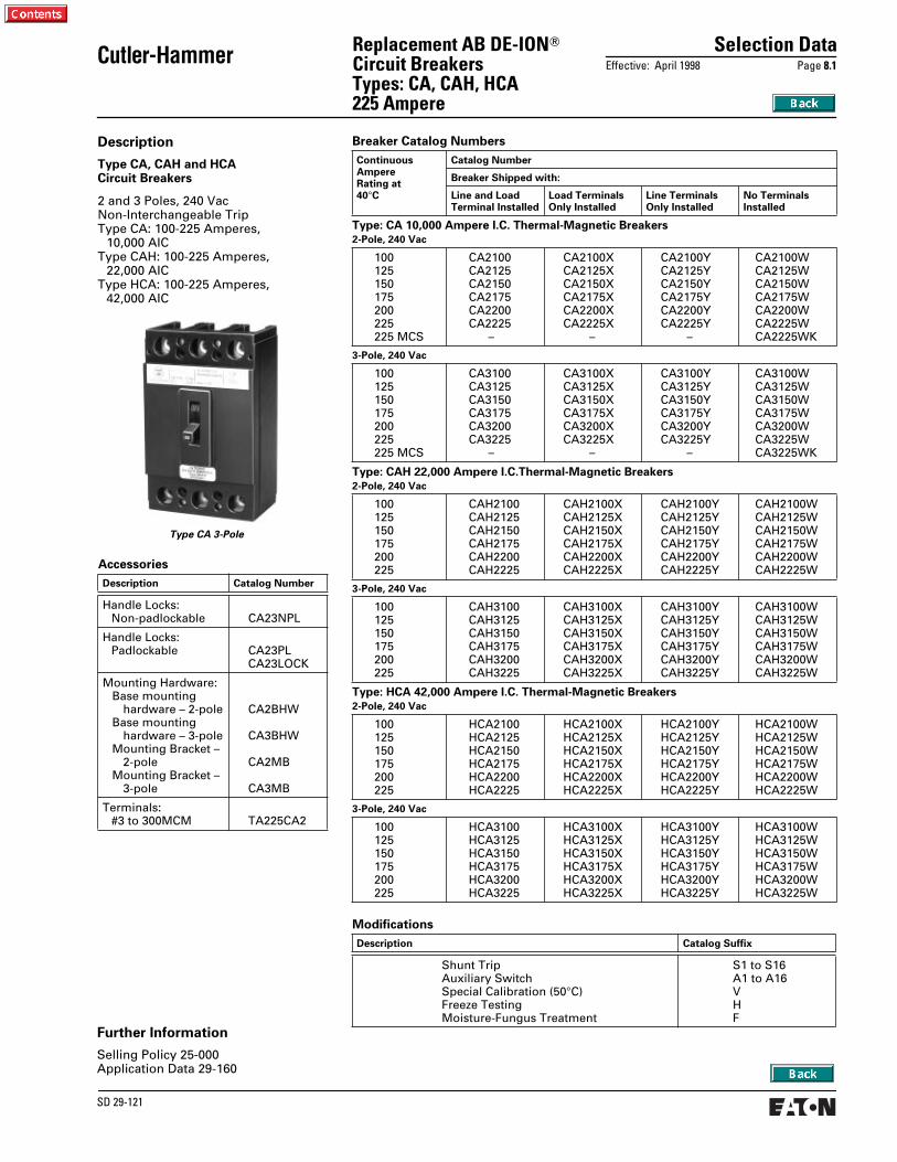
Selection Data
Effective: April 1998 Page
8.1
SD 29-121
Cutler-Hammer
Replacement AB DE-ION
T
Circuit BreakersTypes: CA, CAH, HCA 225 Ampere
Breaker Catalog Numbers
Continuous AmpereRating at 40
°
C
Catalog Number
Breaker Shipped with:
Line and LoadTerminal Installed
Load TerminalsOnly Installed
Line TerminalsOnly Installed
No TerminalsInstalled
Type: CA 10,000 Ampere I.C. Thermal-Magnetic Breakers
2-Pole, 240 Vac
100125150175200225225 MCS
CA2100CA2125CA2150CA2175CA2200CA2225 –
CA2100XCA2125XCA2150XCA2175XCA2200XCA2225X –
CA2100YCA2125YCA2150YCA2175YCA2200YCA2225Y –
CA2100WCA2125WCA2150WCA2175WCA2200WCA2225WCA2225WK
3-Pole, 240 Vac
100125150175200225225 MCS
CA3100CA3125CA3150CA3175CA3200CA3225 –
CA3100XCA3125XCA3150XCA3175XCA3200XCA3225X –
CA3100YCA3125YCA3150YCA3175YCA3200YCA3225Y –
CA3100WCA3125WCA3150WCA3175WCA3200WCA3225WCA3225WK
Type: CAH 22,000 Ampere I.C.Thermal-Magnetic Breakers
2-Pole, 240 Vac
100125150175200225
CAH2100CAH2125CAH2150CAH2175CAH2200CAH2225
CAH2100XCAH2125XCAH2150XCAH2175XCAH2200XCAH2225X
CAH2100YCAH2125YCAH2150YCAH2175YCAH2200YCAH2225Y
CAH2100WCAH2125WCAH2150WCAH2175WCAH2200WCAH2225W
3-Pole, 240 Vac
100125150175200225
CAH3100CAH3125CAH3150CAH3175CAH3200CAH3225
CAH3100XCAH3125XCAH3150XCAH3175XCAH3200XCAH3225X
CAH3100YCAH3125YCAH3150YCAH3175YCAH3200YCAH3225Y
CAH3100WCAH3125WCAH3150WCAH3175WCAH3200WCAH3225W
Type: HCA 42,000 Ampere I.C. Thermal-Magnetic Breakers
2-Pole, 240 Vac
100125150175200225
HCA2100HCA2125HCA2150HCA2175HCA2200HCA2225
HCA2100XHCA2125XHCA2150XHCA2175XHCA2200XHCA2225X
HCA2100YHCA2125YHCA2150YHCA2175YHCA2200YHCA2225Y
HCA2100WHCA2125WHCA2150WHCA2175WHCA2200WHCA2225W
3-Pole, 240 Vac
100125150175200225
HCA3100HCA3125HCA3150HCA3175HCA3200HCA3225
HCA3100XHCA3125XHCA3150XHCA3175XHCA3200XHCA3225X
HCA3100YHCA3125YHCA3150YHCA3175YHCA3200YHCA3225Y
HCA3100WHCA3125WHCA3150WHCA3175WHCA3200WHCA3225W
Accessories
Description Catalog Number
Handle Locks:Non-padlockable CA23NPL
Handle Locks:Padlockable CA23PL
CA23LOCK
Mounting Hardware:Base mounting
hardware – 2-poleBase mounting
hardware – 3-poleMounting Bracket –
2-poleMounting Bracket –
3-pole
CA2BHW
CA3BHW
CA2MB
CA3MB
Terminals:#3 to 300MCM TA225CA2
Modifications
Description Catalog Suffix
Shunt TripAuxiliary SwitchSpecial Calibration (50
°
C)Freeze TestingMoisture-Fungus Treatment
S1 to S16A1 to A16VHF
Description
Type CA, CAH and HCA Circuit Breakers
2 and 3 Poles, 240 VacNon-Interchangeable TripType CA: 100-225 Amperes,
10,000 AICType CAH: 100-225 Amperes,
22,000 AICType HCA: 100-225 Amperes,
42,000 AIC
Type CA 3-Pole
Further Information
Selling Policy 25-000Application Data 29-160