YEoman CL3 & CL5 - Knight Stoves
36
Instructions for Use, Installation and Servicing For use in GB, IE (Great Britain and Eire) PR1407 Issue 1 (October 2011) IMPORTANT THE OUTER CASING, FRONT AND GLASS PANEL BECOME EXTREMELY HOT DURING OPERATION AND WILL RESULT IN SERIOUS INJURY AND BURNS IF TOUCHED. IT IS THEREFORE RECOMMENDED THAT A FIREGUARD COMPLYING WITH BS 8423:2002 IS USED IN THE PRESENCE OF YOUNG CHILDREN, THE ELDERLY OR INFIRM. This product contains a Heat resistant glass panel. This panel should be checked during Installation and at each servicing interval. If any damage is observed on the front face of the glass panel (scratches, scores, cracks or other surface defects), the glass panel must be replaced and the appliance must not be used until a replacement is installed. Under no circumstances should the appliance be used if any damage is observed, the glass panel is removed or broken. This appliance is guaranteed for 2 years (subject to the conditions on page 3 of this Instruction manual). The second year of the guarantee will only be valid if the annual service recommended in this Instruction manual has been completed by a Gas Safe registered engineer, and a copy of the service report is available for inspection by a Yeoman engineer. These Instructions must be left with the appliance for future reference and for consultation when servicing the appliance. Please make the customer aware of the correct operation of the appliance before leaving these instructions with them. The commissioning sheet found on Page 3 of this Instruction manual must be completed by the Installer prior to leaving the premises. Conventional Flue Log Effect Fire YEOMAN CL3 & CL5
-
Upload
khangminh22 -
Category
Documents
-
view
3 -
download
0
Transcript of YEoman CL3 & CL5 - Knight Stoves

Instructions for Use,Installation and ServicingFor use in GB, IE (Great Britain and Eire)
PR1407 Issue 1 (October 2011)
IMPORTANTTHE OUTER CASING, FRONT AND GLASS PANEL BECOME EXTREMELY HOT DURING OPERATION AND WILL RESULT IN
SERIOUS INJURY AND BURNS IF TOUCHED. IT IS THEREFORE RECOMMENDED THAT A FIREGUARD COMPLYING WITH BS 8423:2002 IS USED IN THE PRESENCE OF YOUNG CHILDREN, THE ELDERLY OR INFIRM.
This product contains a Heat resistant glass panel. This panel should be checked during Installation and at each servicing interval. If any damage is observed on the front face of the glass panel (scratches, scores, cracks or other surface defects), the
glass panel must be replaced and the appliance must not be used until a replacement is installed. Under no circumstances should the appliance be used if any damage is observed, the glass panel is removed or broken.
This appliance is guaranteed for 2 years (subject to the conditions on page 3 of this Instruction manual). The second year of the guarantee will only be valid if the annual service recommended in this Instruction manual has been completed by a Gas Safe
registered engineer, and a copy of the service report is available for inspection by a Yeoman engineer.
These Instructions must be left with the appliance for future reference and for consultation when servicing the appliance. Please make the customer aware of the correct operation of the appliance before leaving these instructions with them.
The commissioning sheet found on Page 3 of this Instruction manual must be completed by the Installer prior to leaving the premises.
Conventional Flue Log Effect FireYEoman CL3 & CL5

2
COVERING THE FOLLOWING MODELS:
PAGE
APPLIANCE COMMISSIONING CHECkLIST 3
USER INSTRUCTIONS 4
INSTALLATION INSTRUCTIONS 11
Technical Specifications 11
Site Requirements 13
Installation 15
Commissioning 22
SERVICING INSTRUCTIONS 24
Fault Finding 24
How to replace parts 27
Basic spare parts list 34
Service Records 36
Model Natural Gas LPG
Top Exit Rear Exit Top Exit Rear Exit
CL3 YM581-310 YM581-182 YM581-414 YM581-437
CL5 YM581-258 YM581-293 YM581-611 YM581-497
3
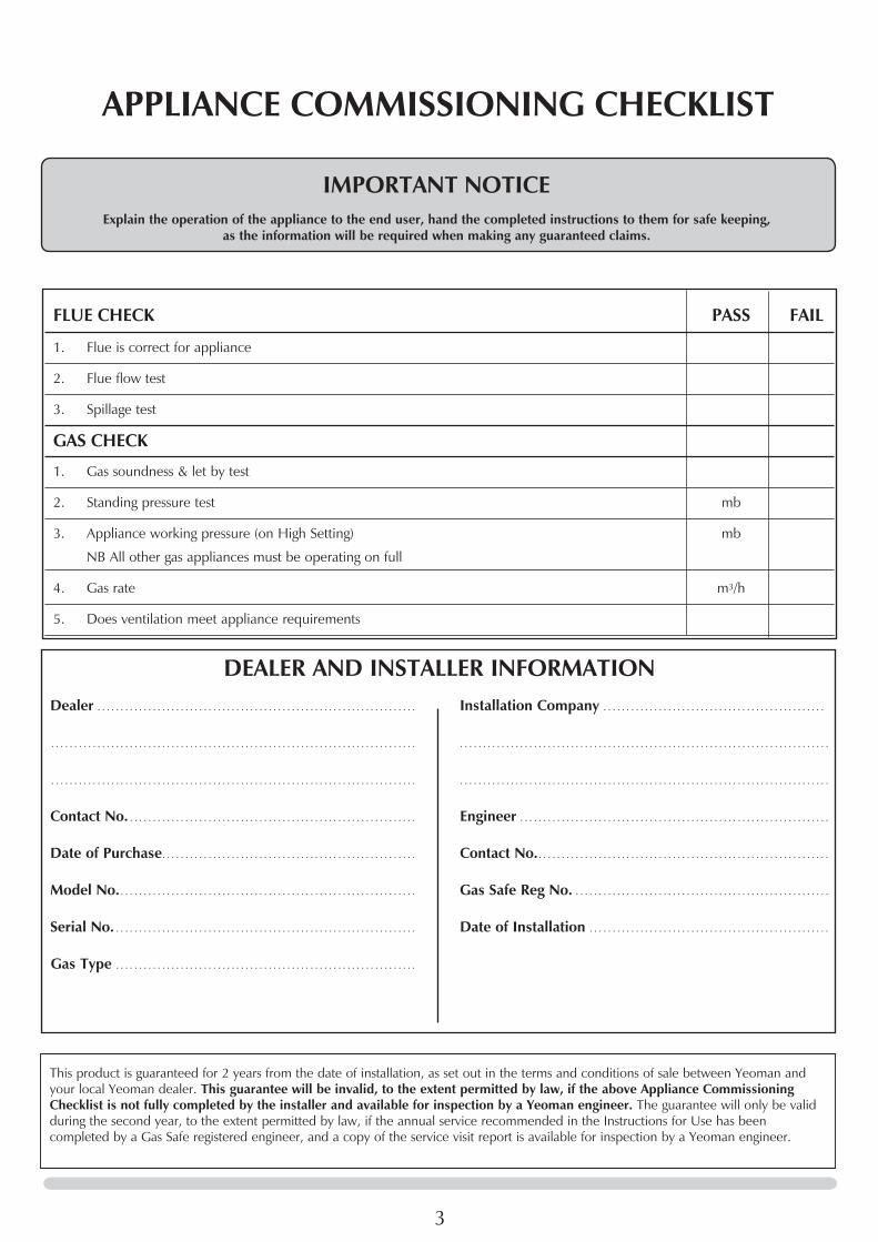
FLUE CHECk PASS FAIL
1. Flue is correct for appliance
2. Flue flow test
3. Spillage test
GAS CHECk
1. Gas soundness & let by test
2. Standing pressure test mb
3. Appliance working pressure (on High Setting) mb
NB All other gas appliances must be operating on full
4. Gas rate m3/h
5. Does ventilation meet appliance requirements
APPLIANCE COMMISSIONING CHECkLIST
Dealer . . . . . . . . . . . . . . . . . . . . . . . . . . . . . . . . . . . . . . . . . . . . . . . . . . . . . . . . . . . . . . . . . . . . .
. . . . . . . . . . . . . . . . . . . . . . . . . . . . . . . . . . . . . . . . . . . . . . . . . . . . . . . . . . . . . . . . . . . . . . . . . . . . . . .
. . . . . . . . . . . . . . . . . . . . . . . . . . . . . . . . . . . . . . . . . . . . . . . . . . . . . . . . . . . . . . . . . . . . . . . . . . . . . . .
Contact No. . . . . . . . . . . . . . . . . . . . . . . . . . . . . . . . . . . . . . . . . . . . . . . . . . . . . . . . . . . . . . .
Date of Purchase . . . . . . . . . . . . . . . . . . . . . . . . . . . . . . . . . . . . . . . . . . . . . . . . . . . . . . .
Model No. . . . . . . . . . . . . . . . . . . . . . . . . . . . . . . . . . . . . . . . . . . . . . . . . . . . . . . . . . . . . . . . .
Serial No. . . . . . . . . . . . . . . . . . . . . . . . . . . . . . . . . . . . . . . . . . . . . . . . . . . . . . . . . . . . . . . . . .
Gas Type . . . . . . . . . . . . . . . . . . . . . . . . . . . . . . . . . . . . . . . . . . . . . . . . . . . . . . . . . . . . . . . . .
Installation Company . . . . . . . . . . . . . . . . . . . . . . . . . . . . . . . . . . . . . . . . . . . . . . . .
. . . . . . . . . . . . . . . . . . . . . . . . . . . . . . . . . . . . . . . . . . . . . . . . . . . . . . . . . . . . . . . . . . . . . . . . . . . . . . . .
. . . . . . . . . . . . . . . . . . . . . . . . . . . . . . . . . . . . . . . . . . . . . . . . . . . . . . . . . . . . . . . . . . . . . . . . . . . . . . . .
Engineer . . . . . . . . . . . . . . . . . . . . . . . . . . . . . . . . . . . . . . . . . . . . . . . . . . . . . . . . . . . . . . . . . . .
Contact No. . . . . . . . . . . . . . . . . . . . . . . . . . . . . . . . . . . . . . . . . . . . . . . . . . . . . . . . . . . . . . . .
Gas Safe Reg No. . . . . . . . . . . . . . . . . . . . . . . . . . . . . . . . . . . . . . . . . . . . . . . . . . . . . . . .
Date of Installation . . . . . . . . . . . . . . . . . . . . . . . . . . . . . . . . . . . . . . . . . . . . . . . . . . . .
IMPORTANT NOTICEExplain the operation of the appliance to the end user, hand the completed instructions to them for safe keeping,
as the information will be required when making any guaranteed claims.
DEALER AND INSTALLER INFORMATION
This product is guaranteed for 2 years from the date of installation, as set out in the terms and conditions of sale between Yeoman and your local Yeoman dealer. This guarantee will be invalid, to the extent permitted by law, if the above Appliance Commissioning Checklist is not fully completed by the installer and available for inspection by a Yeoman engineer. The guarantee will only be valid during the second year, to the extent permitted by law, if the annual service recommended in the Instructions for Use has been completed by a Gas Safe registered engineer, and a copy of the service visit report is available for inspection by a Yeoman engineer.

4
USER INSTRUCTIONS
1. GENERAL
In the event of a gas escape or if you can smell gas, please take the following steps:
• Immediatelyturnoffthegassupplyatthemeter/ emergency control valve
• Extinguishallsourcesofignition • Donotsmoke • Donotoperateanyelectricallightorpowerswitches (On or Off) • Ventilatethebuilding(s)byopeningdoorsand
windows • Ensureaccesstothepremisescanbemade
Please report the incident immediately to the National Gas Emergency Service Call Centre on 0800 111 999 (England, Scotland and Wales) , 0800 002 001 (N. Ireland) or in the case of LPG, the gas supplier whose details can be found on the bulk storage vessel or cylinder.
The gas supply must not be used until remedial action has been taken to correct the defect and the installation has been recommissioned by a competent person.
1.1 Installation and servicing must only be carried out by a competent person whose name appears on the Gas Safe register. To ensure the engineer is registered with Gas Safe they should possess an ID Card carrying the following logo:
1.2 In all correspondence, please quote the appliance type and serial number, which can be found on the data badge located on a plate attached to the lower slotted trim.
1.3 Do not place curtains above the appliance: You must have 300mm (1’) clearance between the
appliance and any curtains at either side.
1.4 No furnishings or other objects should be placed within 1 metre of the front of the appliance.
1.5 If any cracks appear in the glass panel do not use the appliance until the panel has been replaced.
1.6 In the unlikely event the appliance is receiving interference from other electronic devices, the handset/Control box can be reprogrammed. Please consult your dealer if you think this may be the case.
1.7 If, for any reason, the flue has to be removed from the appliance, the seals must be replaced in the inner spigot.
1.8 Do not obstruct the flue terminal in any way i.e. by planting flowers, trees shrubs etc. in the near vicinity, or by leaning objects up against the terminal guard.
1.9 Do not use a garden sprinkler or hose near the terminal.
1.10 This product is guaranteed for 2 years from the date of installation, as set out in the terms and conditions of sale between Yeoman and your local Yeoman dealer. Please consult with your local Yeoman dealer if you have any questions. In all correspondence always quote the Model Number and Serial Number.
2A. OPERATING THE APPLIANCE
IMPORTANT - THE CONTROL SYSTEM HAS BEEN PROGRAMMED TO OPERATE ON CHANNEL 'A'. IN SOME INSTANCES MULTIPLE HOUSEHOLD APPLIANCES MAY HAVE ALSO BEEN SET TO OPERATE ON THE SAME CHANNEL. ALTHOUGH THIS HAS NO EFFECT ON THE SAFETY OF THE SYSTEM YOU MAY ENCOUNTER AN EXCESSIVE DELAY BETWEEN COMMANDS. IF THIS OCCURS PLEASE FOLLOW THE INSTRUCTIONS IN INSTALLATION INSTRUCTIONS, COMMISSIONING, SECTION 3 TO CHANGE THE CHANNEL.
The remote control handset has been factory set to only
communicate with the appliance it is supplied with. The appliance will not respond to any other remote control, even one from an identical appliance.
Note: In the event of a replacement handset being acquired, pairing of the handset with the appliance will need to be carried out. Please refer to Commissioning, Section 2, Pairing Handset on page 29.
The appliance can be operated in two ways:
— Using the remote control handset. — Using the touch pad control on the appliance.
The appliance has four flame settings which can be controlled manually or automatically via temperature sensing:
1. High (Pilot lit and main burner lit at the highest flame setting).
2. Med (Pilot lit and main burner lit at the medium flame setting).
3. Low (Pilot lit and main burner lit at the minimum flame setting).
4. Standby (Pilot only).
1
AR2516a
On/Off Button
Up Button
Down Button

5
USER INSTRUCTIONS
2.1 To light the appliance using the remote handset press the On/Off (�) button followed directly by the OK button. The appliance will emit a beep to confirm the order has been received and the LED on the handset will briefly illuminate.
After the start up cycle has completed the appliance will light on the high flame setting (this can take up to 20 seconds).
To decrease the flame height:
2.2 From the high flame setting press the DOWN () button once to lower the flame to the medium setting.
Each time a command from the handset is received by the appliance a beep will be emitted and the LED on the handset will briefly illuminate.
NOTE: In normal operating mode the LED on the remote control will flash approximately every 4 seconds to show that it is in communication with the appliance. After each command has been accepted the LED will cease flashing until the command has been carried out. Wait until the LED resumes flashing before giving another command.
2.3 From the medium flame setting press the DOWN () button once to lower the flame to the low setting.
2.4 From the low flame setting press the DOWN () button once to put the appliance in Standby mode (Pilot only).
To increase the flame height:
2.5 To light the appliance when it is in Standby mode press the UP () button once. The appliance will light on the high flame setting.
2.6 From the low setting press the UP () button once to increase the flame setting to medium.
2.7 From the medium setting press the UP () button once to increase the flame setting to high.
BATTERIES
2.8 The remote handset contains 2 x AA 1.5v alkaline batteries. Replace exhausted batteries like for like (use high quality batteries, Duracell or similar). DO NOT USE RECHARGEABLE BATTERIES.
2.9 Communication between the handset and the appliance may take up to 2 mins after batteries have been replaced.
2.10 If communication is not regained after this time the control unit and the handset may need pairing. Please refer to Commissioning, Section 2, Pairing Handset on page 29.
2B. OPERATING THE APPLIANCE TOUCH PAD CONTROL
TOUCH PAD CONTROL
The touch pad control is located at the base of the front of the appliance (see Diagram 2).
2
AR2698
Touch pad
2.11 To light the appliance press the On/Off button once. The appliance will emit a beep to confirm the order has been received and the LED on the touch pad will briefly illuminate.
After the start up cycle has completed the appliance will light on the high flame setting (this can take up to 20 seconds). A second beep and flash of the touch pad LED will confirm the command has been carried out.
To decrease the flame height:
2.12 From the high flame setting press the DOWN () button once to lower the flame to the medium setting.
Each time a command from the touch pad is received by the appliance a beep will be emitted and the LED on the touch pad will briefly illuminate. A second beep and flash of the touch pad LED will confirm the command has been carried out. Wait for this confirmation before giving another command.
2.13 From the medium flame setting press the DOWN () button once to lower the flame to the low setting.
2.14 From the low flame setting press the DOWN () button once to put the appliance in Standby mode (Pilot only).
To increase the flame height:
2.15 To light the appliance when it is in Standby mode press the UP (w) button once. The appliance will light on the high flame setting.

6
USER INSTRUCTIONS
2.16 From the low setting press the UP (w) button once to increase the flame setting to medium.
2.17 From the medium setting press the UP (w) button once to increase the flame setting to high.
YELLOW FLAMES WILL APPEAR WHEN THE FIRE HAS
GAINED SUFFICIENT HEAT - TYPICALLY 10 TO 20 MINUTES.
TOUCH PAD CONTROL NOT WORkING
If the appliance is not operating with the touch pad control:
2.18 Replace the batteries in the battery pack following Section 4.
2.19 If the appliance still fails to operate consult your installer or Yeoman dealer.
3. TURNING THE APPLIANCE OFF
REMOTE CONTROL
3.1 To turn the appliance off press the On/Off (�) button once.
TOUCH PAD CONTROL
3.2 To turn the appliance off press the On/Off button once. IF THE FIRE IS EXTINGUISHED OR GOES OUT IN USE,
WAIT 3 MINUTES BEFORE ATTEMPTING TO RELIGHT IT. THE CONTROL VALVE HAS AN INTERLOCk DEVICE AND THEREFORE CANNOT BE LIT UNTIL THE 3 MINUTES HAVE ELAPSED.
4. CLEANING THE RIVA VISION
IMPORTANT: THE OUTER PANELLING OF THE YEOMAN CL IS MADE FROM CAST IRON. USE CAUTION WHEN INSTALLING, REMOVING AND STORING AS THE COMPONENTS ARE HEAVY AND SHOULD BE HANDLED CAREFULLY.
4.1 Make sure the fire and surrounds are cool before cleaning. Use: – A dry cloth or stainless steel product to clean the
polished plate. – A damp cloth for the glass front.
4.2 All Models
Unscrew the handle from the upper door.
Remove the plinth to access the touchpad and battery box by lifting the hooks clear of the slots on the front of the appliance, See Diagram 3.
3
AR2694
4.3 Remove the frame to gain complete access to the control box and the viewing aperture by lifting the hooks clear of the slots on the front of the appliance, See Diagram 4.
4
AR2693
4.4 Using screwdriver remove the eight screws securing the window panel to the appliance, Diagram 5.
Take care to support the glass when removing the screws.
5
AR2697
7
USER INSTRUCTIONS
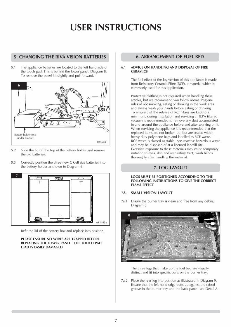
5. CHANGING THE RIVA VISION BATTERIES
5.1 The appliance batteries are located to the left hand side of the touch pad. This is behind the lower panel, Diagram 8.
To remove the panel lift slightly and pull forward.
6
AR2698
Battery holder rests under bracket
5.2 Slide the lid off the top of the battery holder and remove the old batteries.
5.3 Correctly position the three new C Cell size batteries into the battery holder as shown in Diagram 6.
7
AR1488a
Refit the lid of the battery box and replace into position.
PLEASE ENSURE NO WIRES ARE TRAPPED BEFORE REPLACING THE LOWER PANEL. THE TOUCH PAD LEAD IS EASILY DAMAGED
6. ARRANGEMENT OF FUEL BED
6.1 ADVICE ON HANDLING AND DISPOSAL OF FIRE CERAMICS
The fuel effect of the log version of this appliance is made from Refractory Ceramic Fibre (RCF), a material which is commonly used for this application.
Protective clothing is not required when handling these articles, but we recommend you follow normal hygiene rules of not smoking, eating or drinking in the work area and always wash your hands before eating or drinking.
To ensure that the release of RCF fibres are kept to a minimum, during installation and servicing a HEPA filtered vacuum is recommended to remove any dust accumulated in and around the appliance before and after working on it.
When servicing the appliance it is recommended that the replaced items are not broken up, but are sealed within heavy duty polythene bags and labelled as RCF waste.
RCF waste is classed as stable, non-reactive hazardous waste and may be disposed of at a licensed landfill site.
Excessive exposure to these materials may cause temporary irritation to eyes, skin and respiratory tract; wash hands thoroughly after handling the material.
7. LOG LAYOUT
LOGS MUST BE POSITIONED ACCORDING TO THE FOLLOWING INSTRUCTIONS TO GIVE THE CORRECT FLAME EFFECT
7A. SMALL VISION LAYOUT
7a.1 Ensure the burner tray is clean and free from any debris, Diagram 8.
8
AR2103
The three logs that make up the fuel bed are visually distinct and fit into specific parts on the burner tray.
7a.2 Place the rear log into position as illustrated in Diagram 9.
Ensure that the left hand edge butts up against the raised groove in the burner tray and the back panel- see Detail A.

8
9
AR2103
Log 1
Detail A
7a.3 Place the second log into the left hand groove on the burner tray and ensure it is pushed as far into the cent re as the groove will allow, Diagram 10.
10
AR2103
Log 2
7a.4 Place the third log into the groove on the right hand side and ensure it is pushed as far into the centre as the groove will allow, Diagram 11.
USER INSTRUCTIONS
11
AR2103Log 3
7a.5 Once the logs are in place use some of the Embaglow wire wool provided and cover the ports in the burner tray with a liberal amount of fibres, See Diagram 14.
NOTE: It is not necessary to use all of the Embaglow.
12
AR2103
Embaglow
7a.6 Fix log bar into position, See Diagram 15.
13
AR2103

9
7B. MIDI VISION LAYOUT
7b.1 Ensure the burner tray is clean and free from any debris, Diagram 14.
14
AR2103
The three logs that make up the fuel bed are visually distinct and fit into specific parts on the burner tray.
7b.2 Place the rear log into position between the rear brackets
and pushed up against the back panel as illustrated in Diagram 15.
15
AR2103Log 1
7b.3 Place the second log into the left hand groove on the burner tray, Diagram 16.
The log should butt up against the raised molding and the left hand side liner.
16
AR2103
Log 2
7b.4 Place the third log into the groove on the right hand side, Diagram 17.
USER INSTRUCTIONS
The log should butt up against the raised molding and the right hand side liner.
17
AR2103Log 3
7b.5 Once the logs are in there are two embers which can be loosely placed at the front of the fire bed and cover the tabs securing the burner tray, See Diagram 18.
18
AR2103
Embers
7b.6 Use some of the Embaglow provided and cover the ports in the burner tray with a liberal amount of fibres, See Diagram 19.
It is essential to cover the port in the middle of the burner tray in order to get the most visually appealing flame picture.
NOTE: It is not necessary to use all of the Embaglow.
19
AR2103
It is essential to cover the central
port
Embaglow
10
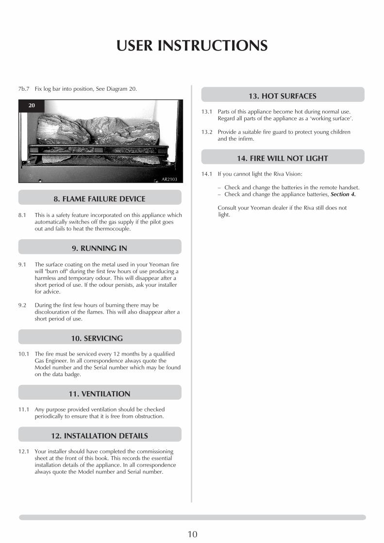
7b.7 Fix log bar into position, See Diagram 20.
20
AR2103
8. FLAME FAILURE DEVICE
8.1 This is a safety feature incorporated on this appliance which automatically switches off the gas supply if the pilot goes out and fails to heat the thermocouple.
9. RUNNING IN
9.1 The surface coating on the metal used in your Yeoman fire will "burn off" during the first few hours of use producing a harmless and temporary odour. This will disappear after a short period of use. If the odour persists, ask your installer for advice.
9.2 During the first few hours of burning there may be discolouration of the flames. This will also disappear after a short period of use.
10. SERVICING
10.1 The fire must be serviced every 12 months by a qualified Gas Engineer. In all correspondence always quote the Model number and the Serial number which may be found on the data badge.
11. VENTILATION
11.1 Any purpose provided ventilation should be checked periodically to ensure that it is free from obstruction.
12. INSTALLATION DETAILS
12.1 Your installer should have completed the commissioning sheet at the front of this book. This records the essential installation details of the appliance. In all correspondence always quote the Model number and Serial number.
13. HOT SURFACES
13.1 Parts of this appliance become hot during normal use. Regard all parts of the appliance as a ‘working surface’.
13.2 Provide a suitable fire guard to protect young children and the infirm.
14. FIRE WILL NOT LIGHT
14.1 If you cannot light the Riva Vision:
– Check and change the batteries in the remote handset. – Check and change the appliance batteries, Section 4.
Consult your Yeoman dealer if the Riva still does not light.
USER INSTRUCTIONS

11
INSTALLATION INSTRUCTIONSTECHNICAL SPECIFICATION
COVERING THE FOLLOWING MODELS:
EfficiencyClass2-75% NOx Class 4
Flue Size
TOP/REAREXIT127mm ø
Gas Inlet Connection Size = 8mm ø
Minimum Flue Specification = T260/N2/0/D/1
Maximum Flue Temp = 220oC
Model Gas CAT.
Gas Type WorkingPressure
Aeration Injector Gas Ratem3/h
Input kW (Gross)
Country
High Low
CL3 CF I2H Natural (G20) 20mbar 6mm Ø 190 0.324 3.4 2.3 GB, IE
CL3 CFI3+ Propane (G30) 37mbar
One side open1 x (9 x 15 offset) 90 0.120 3.2 2 GB, IE
CL5i CF I2H Natural (G20) 20mbar 6 x 6 260 0.433 4.55 2.5 GB, IE
CL5 CFI3+ Propane (G30) 29mbar
One side open1 x (14 x 15) 102 0.164 4.35 2.5 GB, IE
Model Natural Gas LPG
Top Exit Rear Exit Top Exit Rear Exit
CL3 YM581-310 YM581-182 YM581-414 YM581-437
CL5 YM581-258 YM581-293 YM581-611 YM581-497

12
INSTALLATION INSTRUCTIONSTECHNICAL SPECIFICATION
AR2686
CL3
CL5
This appliance has been certified for use in countries other than those stated. To install this appliance in these countries, it is essential to obtain the translated instructions and in some cases the appliance will require modification. Contact Yeoman for further information.
PACkING CHECkLIST
Qty Description Fixing kit containing:-
For Log Layout1 Log Set1 x Packet of Embaglow
1 x Instruction Manual2 x Wood Screws2 x Rawl Plugs1 x Handset3 x C cell batteries2 x AA batteries2 x Self Tapping Screws2 x Wingnuts1 x Fixing Plate2 x Washers

13
INSTALLATION INSTRUCTIONSSITE REQUIREMENTS
1. FLUE AND CHIMNEY REQUIREMENTS 1.1 The chimney or flue system must comply with the rules in
force, and must be a minimum of 127mm in diameter. (5").
1.2 The minimum flue height for the appliance must be 3 metres (10ft). Any horizontal flue run from the rear outlet must not exceed 100mm from the back of the appliance.
1.3 The chimney or flue must be free from any obstruction. Any damper plates must be removed or secured in the fully open position, and no restrictor plates fitted.
1.4 The chimney must be swept prior to the installation, but it need not be swept if it can be seen the chimney is clean and unobstructed throughout its entire length.
1.5 A5" (127mm) liner must be used if fitting the stove into an existing brick built chimney.
Larger lined flues can work, but in some instances could cause cold start flue problems resulting in nuisance shutdown. Lined flues above 7" (175mm) are not recommended.
1.6 Due to recent changes to European chimney standards, new flues and chimneys are described by their temperature, pressure and resistance to corrosion, condensation and fire. To assist in identifying the correct flue system, the minimum flue specification is shown in the Technical Specification. Existing chimneys are not covered by this system.
2. FLUE OPTIONS
2.1 Consult the rules in force. NOTE: This appliance does not normally require any
additional ventilation when installed in GB.
A range of Vitreous Enamel Gloss Black flue pipe is available to compliment the Riva Vision. Please contact your Yeoman retailer for further information.
3. GAS SUPPLY
THIS APPLIANCE IS INTENDED FOR USE ON A GAS INSTALLATION WITH A GOVERNED METER.
3.1 Before installation, ensure that the local distribution conditions (identification of the type of gas and pressure) and the adjustment of the appliance are compatible.
3.2 Ensure the gas supply delivers the required amount of gas and is in accordance with the rules in force.
3.3 You can use soft copper tubing on the installation and soft soldered joints outside the appliance and below the fire.
3.4 A factory fitted isolation device is part of the inlet connection; no further isolation device is required.
3.5 All supply gas pipes must be purged of any debris that may have entered prior to connection to the appliance.
3.6 The gas supply enters through the rear of the LEFT-HAND side of the outer box:
3.7 The gas supply must be installed in a way that does not restrict the removal of the appliance for servicing and inspection.
4. VENTILATION
IMPORTANT: Ensure any national ventilation requirements are taken into account during installation of the fire.
Uk ONLY: The Riva Vision has a nominal input not exceeding 7.0kW
and does not normally require any additional permanent ventilation.
FOR THE REPUBLIC OF IRELAND REFER TO THE RULES IN FORCE FOR VENTILATION REQUIREMENTS.
5. APPLIANCE LOCATION
5.1 This appliance has been designed to stand on either a hearth or an optional bench:
RVACLB100B - Riva Bench Low (100cm wide) RVACB100B - Riva Bench (100cm wide) RVACLB120B - Riva Bench Low (120cm wide) RVACB120B - Riva Bench (120cm wide) RVACLB140B - Riva Bench Low (140cm wide) RVACB140B - Riva Bench (140cm wide)
5.2 To Install the Bench: Follow Section 1 Installation - All Models in Installation
guide PM205 supplied with the bench kit.
5.3 To secure the appliance to the bench: You must consider where you place the appliance on the
bench before drilling the bench. Diagram 1.
1
AR1894
Once the position of the appliance has been decided: Follow the instructions for securing the appliance on Page
15.

14
INSTALLATION INSTRUCTIONSSITE REQUIREMENTS
5.4 The non-combustible hearth must be at least 12mm thick, and project a minimum of 50mm from the base of the appliance in all directions.
5.5 The appliance is not suitable for installation against a combustible wall. A combustible side wall must be a minimum of 150mm from the appliance.
5.6 This appliance can be installed with an up and out flue (vertical wall - horizontal flue) or with a vertical flue with roof termination (see Flue options, Section 2 Site Requirements).
HEARTH INSTALLATION
5.7 This appliance must stand on a non-combustible hearth that is at least 12mm thick and projects 50mm minimum from the base of the appliance in all directions (see Diagram 2).
AR0604
CA
B2
Dimensions Small Midi
A 470mm 515mm
B 390mm 410mm
C 12mm 12mm
MINIMUM CLEARANCE
5.8 The appliance is not suitable for installation against a combustible wall. All combustible materials must be removed from behind the appliance.
5.9 Ensure that all minimum clearances to combustible materials are complied with as shown in Diagrams 3 & 4.
The specified clearances provide the minimum distance to combustible materials. If the appliance is intended to be installed into a non-combustible opening the clearance to the sides and above the appliance can be reduced. However, it is recommended that the specified clearances are maintained irrespective of the materials used in the construction of the opening to allow adequate air flow and access to controls. The clearance at the rear of the appliance must always be a minimum of 50mm.
AR2483a
150
225
150
3
4
100mm
150m
m
AR0531a
5.10 The above dimensions provide adequate clearance to combustible materials. It may be necessary to add additional clearance so that spillage tests can be performed when necessary.

15
IMPORTANT: REFER TO DATA BADGE AND TECHNICAL SPECIFICATION AT THE FRONT OF THE MANUAL TO ENSURE THE APPLIANCE IS CORRECTLY ADJUSTED FOR THE GAS TYPE AND CATEGORY APPLICABLE IN THE COUNTRY OF USE.
FOR DETAILS OF CHANGING BETWEEN GAS TYPES REFER TO SECTION 14, SERVICInG, ‘REPLaCInG PaRTS’.
1. SAFETY PRECAUTIONS
1.1 For your own and other’s safety, you must install this appliance according to local and national codes of practice. Failure to install the stove correctly could lead to prosecution.
Read these instructions before installing and using this appliance.
1.2 These instructions must be left intact with the user.
1.3 Do not attempt to burn rubbish on this appliance.
1.4 Keep all plastic bags away from young children.
1.5 Do not place any object on or near to the appliance and allow adequate clearance above the appliance.
IF THE APPLIANCE IS EXTINGUISHED OR GOES OUT IN USE, WAIT 3 MINUTES BEFORE ATTEMPTING TO RELIGHT THE APPLIANCE.
2. INSTALLATION OF THE APPLIANCE IMPORTANT: THE OUTER PANELLING OF THE RIVA
VISION IS MADE FROM GLASS. USE CAUTION WHEN INSTALLING, REMOVING AND STORING AS THE COMPONENTS ARE FRAGILE AND COULD BREAk UNLESS HANDLED CAREFULLY.
2.1 Remove the appliance from the carton and discard all unnecessary packaging ensuring no components are thrown away when unpacking. The glass lid is stored on top of the appliance. Remove and store in a safe place.
2.2 All Models
Remove the plinth to access the touchpad and battery box by lifting the hooks clear of the slots on the front of the appliance, See Diagram 1.
1
AR2694
2.3 Remove the frame to gain complete access to the control box and the viewing aperture by lifting the hooks clear of the slots on the front of the appliance, See Diagram 2.
2
AR2693
SECURING THE APPLIANCE
The appliance sits on a mounting bracket to secure it in place to either the hearth or bench.
2.4 Position the appliance: Loosely attach the bracket to the appliance and place
centrally on the hearth OR in the desired position on the bench. Remove the appliance leaving the bracket in the correct position and mark the holes to drill the bracket screws, Diagram 3.
3
AR2458
Brackets
INSTALLATION INSTRUCTIONSINSTALLATION

16
INSTALLATION INSTRUCTIONSINSTALLATION
2.5 Remove the bracket and drill the guide holes.
2.6 Fix the bracket either to the hearth or the bench, see Diagram 3.
NOTE: Use the wood screws and rawl plugs in the fixing kit supplied for hearth mounting installations and the self tapping screws for installation onto a bench.
2.7 Lift the appliance so as to locate the key slots in the carcass onto the fixing screws. There are two large holes the lower flanges on the front edges of the base, see Diagram 4.
4
AR2688
WingnutWasher
Key slots
2.8 Place the two large washers over the studs and fix with two wingnuts, see Diagram 8.
2.9 Connect the gas to the 8mm elbow located on the right hand side under the firebox, Diagram 5.
5
AR2698
3. FITTING THE TOP PLATE
3.1 The Riva Vision has a decorative plate that sits on top of the outer box. Depending on the choice of flue exit this top will have a hole for the flue pipe to pass through or be completely smooth.
The hole will be situated in an off set position to the rear The hole will be situated in an off set position to the rear edge of the cast top.
When installing the spigot must be put in place before the cast top is located. Then the connection to the flue can be made.
NOTE: For Top Exit appliances the flue collar must be placed on the flue exit before the top is fitted.
3.2 To fit the top line up the raised fins on the underside of the glass plate with the cut outs in the top of the box, see Diagram 6.
6
AR2703AR2692
Rear Exit
Top Exit
FinsCut Outs
Cut Outs
Offset edge to rear
Fins
AR2696
3.2 When properly fitted the rear of the glass plate should sit flush with the rear of the appliance, see Diagram 7.
7
AR2695

17
INSTALLATION INSTRUCTIONSINSTALLATION
4. ARRANGEMENT OF FUEL BED
4.1 ADVICE ON HANDLING AND DISPOSAL OF FIRE CERAMICS
The fuel effect of the log version of this appliance is made from Refractory Ceramic Fibre (RCF), a material which is commonly used for this application.
Protective clothing is not required when handling these articles, but we recommend you follow normal hygiene rules of not smoking, eating or drinking in the work area and always wash your hands before eating or drinking.
To ensure that the release of RCF fibres are kept to a minimum, during installation and servicing a HEPA filtered vacuum is recommended to remove any dust accumulated in and around the appliance before and after working on it.
When servicing the appliance it is recommended that the replaced items are not broken up, but are sealed within heavy duty polythene bags and labelled as RCF waste.
RCF waste is classed as stable, non-reactive hazardous waste and may be disposed of at a licensed landfill site.
Excessive exposure to these materials may cause temporary irritation to eyes, skin and respiratory tract; wash hands thoroughly after handling the material.
5. LOG LAYOUT
LOGS MUST BE POSITIONED ACCORDING TO THE FOLLOWING INSTRUCTIONS TO GIVE THE CORRECT FLAME EFFECT
Small Vision Layout
5a.1 Ensure the burner tray is clean and free from any debris, Diagram 16.
16
AR2103
The three logs that make up the fuel bed are visually distinct and fit into specific parts on the burner tray.
5a.2 Place the rear log into position as illustrated in Diagram 17. Ensure that the left hand edge butts up against the raised groove in the burner tray and the back panel- see Detail A.
17
AR2103
Log 1
Detail A
5a.3 Place the second log into the left hand groove on the burner tray and ensure it is pushed as far into the cent re as the groove will allow, Diagram 12.
18
AR2103
Log 2
5a.4 Place the third log into the groove on the right hand side and ensure it is pushed as far into the centre as the groove will allow, Diagram 19.

18
INSTALLATION INSTRUCTIONSINSTALLATION
19
AR2103Log 3
5a.5 Once the logs are in place use some of the Embaglow wire wool provided and cover the ports in the burner tray with a liberal amount of fibres, See Diagram 20.
NOTE: It is not necessary to use all of the Embaglow.
20
AR2103
Embaglow
5a.6 Fix log bar into position, See Diagram 21.
21
AR2103
Midi Vision Layout
5b.1 Ensure the burner tray is clean and free from any debris, Diagram 22.
22
AR2103
The three logs that make up the fuel bed are visually distinct and fit into specific parts on the burner tray.
5b.2 Place the rear log into position between the rear brackets
and pushed up against the back panel as illustrated in Diagram 23.
23
AR2103Log 1
5b.3 Place the second log into the left hand groove on the burner tray, Diagram 24.
The log should butt up against the raised molding and the left hand side liner.
24
AR2103
Log 2

19
INSTALLATION INSTRUCTIONSINSTALLATION
27
AR2103
It is essential to cover the central
port
Embaglow
5b.7 Fix log bar into position, See Diagram 28.
28
AR2103
6. COMPLETION OF ASSEMBLY6.1 To fit the window frame:
Offer the frame to the foot of the opening and secure using 6 screws as shown, Diagram 21.
21
AR2697
5b.4 Place the third log into the groove on the right hand side, Diagram 25.
The log should butt up against the raised molding and the right hand side liner.
25
AR2103Log 3
5b.5 Once the logs are in there are two embers which can be loosely placed at the front of the fire bed and cover the tabs securing the burner tray, See Diagram 26.
26
AR2103
Embers
5b.6 Use some of the Embaglow provided and cover the ports in the burner tray with a liberal amount of fibres, See Diagram 27.
It is essential to cover the port in the middle of the burner tray in order to get the most visually appealing flame picture.
NOTE: It is not necessary to use all of the Embaglow.

20
INSTALLATION INSTRUCTIONSINSTALLATION
6.2 Fit the front and the plinth by inserting the hooks on the back of the frame into the slots on the front of the appliance, See Diagram 22 & 23.
22
AR2694
23
AR2693
7. OPERATING THE APPLIANCE
IMPORTANT - THE CONTROL SYSTEM HAS BEEN PROGRAMMED TO OPERATE ON CHANNEL 'A'. IN SOME INSTANCES MULTIPLE HOUSEHOLD APPLIANCES MAY HAVE ALSO BEEN SET TO OPERATE ON THE SAME CHANNEL. ALTHOUGH THIS HAS NO EFFECT ON THE SAFETY OF THE SYSTEM YOU MAY ENCOUNTER AN EXCESSIVE DELAY BETWEEN COMMANDS. IF THIS OCCURS PLEASE FOLLOW THE INSTRUCTIONS IN INSTALLATION INSTRUCTIONS, COMMISSIONING, SECTION 3 TO CHANGE THE CHANNEL.
The remote control handset has been factory set to only
communicate with the appliance it is supplied with. The appliance will not respond to any other remote control, even one from an identical appliance.
Note: In the event of a replacement handset being acquired, pairing of the handset with the appliance will need to be carried out. Please refer to Commissioning, Section 2, Pairing Handset on page 29.
The appliance can be operated in two ways:
— Using the remote control handset. — Using the touch pad control on the appliance.
The appliance has four flame settings which can be controlled manually or automatically via temperature sensing:
1. High (Pilot lit and main burner lit at the highest flame setting).
2. Med (Pilot lit and main burner lit at the medium flame setting).
3. Low (Pilot lit and main burner lit at the minimum flame setting).
4. Standby (Pilot only).
24
AR2516a
On/Off Button
Up Button
Down Button
7.1 To light the appliance using the remote handset press the On/Off button (�) followed directly by the OK button. The appliance will emit a beep to confirm the order has been received and the LED on the handset will briefly illuminate.
After the start up cycle has completed the appliance will light on the high flame setting (this can take up to 20 seconds).
To decrease the flame height:
7.2 From the high flame setting press the DOWN () button once to lower the flame to the medium setting.
Each time a command from the handset is received by the appliance a beep will be emitted and the LED on the handset will briefly illuminate.
NOTE: In normal operating mode the LED on the remote control will flash approximately every 4 seconds to show that it is in communication with the appliance. After each command has been accepted the LED will cease flashing until the command has been carried out. Wait until the LED resumes flashing before giving another command.
7.3 From the medium flame setting press the DOWN () button once to lower the flame to the low setting.

21
7.4 From the low flame setting press the DOWN () button once to put the appliance in Standby mode (Pilot only).
To increase the flame height:
7.5 To light the appliance when it is in Standby mode press the UP () button once. The appliance will light on the high flame setting.
7.6 From the low setting press the UP () button once to increase the flame setting to medium.
7.7 From the medium setting press the UP () button once to increase the flame setting to high.
BATTERIES
7.8 The remote handset contains 2 x AA 1.5v alkaline batteries. Replace exhausted batteries like for like (use high quality batteries, Duracell or similar). DO NOT USE RECHARGEABLE BATTERIES.
7.9 Communication between the handset and the appliance may take up to 2 mins after batteries have been replaced.
7.10 If communication is not regained after this time the control unit and the handset may need pairing. Please refer to Commissioning, Section 2, Pairing Handset on page 29.
7B. OPERATING THE APPLIANCE TOUCH PAD CONTROL
TOUCH PAD CONTROL
The touch pad control is located at the base of the front of the appliance (see Diagram 25).
25
AR2698Touch pad
7.11 To light the appliance press the On/Off button once. The appliance will emit a beep to confirm the order has been received and the LED on the touch pad will briefly illuminate.
After the start up cycle has completed the appliance will light on the high flame setting (this can take up to 20 seconds). A second beep and flash of the touch pad LED will confirm the command has been carried out.
To decrease the flame height:
7.12 From the high flame setting press the DOWN () button once to lower the flame to the medium setting.
Each time a command from the touch pad is received by the appliance a beep will be emitted and the LED on the touch pad will briefly illuminate. A second beep and flash of the touch pad LED will confirm the command has been carried out. Wait for this confirmation before giving another command.
7.13 From the medium flame setting press the DOWN () button once to lower the flame to the low setting.
7.14 From the low flame setting press the DOWN () button once to put the appliance in Standby mode (Pilot only).
To increase the flame height:
7.15 To light the appliance when it is in Standby mode press the UP (w) button once. The appliance will light on the high flame setting.
7.16 From the low setting press the UP (w) button once to increase the flame setting to medium.
7.17 From the medium setting press the UP (w) button once to increase the flame setting to high.
YELLOW FLAMES WILL APPEAR WHEN THE FIRE HAS
GAINED SUFFICIENT HEAT - TYPICALLY 10 TO 20 MINUTES.
TOUCH PAD CONTROL NOT WORkING
If the appliance is not operating with the touch pad control:
7.18 Replace the batteries in the battery pack following Section 4.
7.19 If the appliance still fails to operate consult your installer or Yeoman dealer.
8. TURNING THE APPLIANCE OFF
REMOTE CONTROL
8.1 To turn the appliance off press the On/Off (�) button once.
TOUCH PAD CONTROL
8.2 To turn the appliance off press the On/Off button once. IF THE FIRE IS EXTINGUISHED OR GOES OUT IN USE,
WAIT 3 MINUTES BEFORE ATTEMPTING TO RELIGHT IT. THE CONTROL VALVE HAS AN INTERLOCk DEVICE AND THEREFORE CANNOT BE LIT UNTIL THE 3 MINUTES HAVE ELAPSED.
INSTALLATION INSTRUCTIONSINSTALLATION

22
1. COMMISSIONING THE APPLIANCE
1.1 Complete the Commissioning Checklist at the front of this manual covering:
— Flue checks
— Gas checks
— Log layout - flame picture
For working pressure test, use the access panel at the gas connection ensuring the burner is in position. Refer to Installation Instructions, Section 3.
1.2 Upon completion of of the commissioning and testing of the installation and correct operation of the appliance, the installer must instruct the user how to operate the appliance.
1.3 Guide the user through the User Instructions paying particular attention to:
a) Regular servicing (Section 9 of the User Instructions).
b) Ventilation (Section 10 of the User Instructions) - point out the ventilation positions where applicable.
c) Hot surfaces (Section 12 of the User Instructions).
d) How the appliance works with the touch pad control (Section 2B of the User Instructions).
e) How the appliance works with the remote control handset and the modes of operation (Section 2A of the User Instructions).
g) What to do if the appliance fails to operate (Section 14 of the User Instructions).
2. PAIRING THE HANDSET WITH THE APPLIANCE
Prior to re-connection of the control box to the appliance, if there is no communication between the remote handset and the appliance, or if the handset is replaced, it will be necessary to pair the (new) handset with the appliance.
2.1 Remove the 2 x screws securing the control box bracket.
1
AR2698
Screws
2.2 Ensure batteries are fitted and working in the handset.
2.3 Ensure all leads and cables are connected correctly.
2.4 Press the On/Off button (�) for at least 10 seconds. The LED will flash on and off as normal during this time. When the LED on the control lights up for at least 1 second release the button.
2.5 Within 5 seconds of the LED going out press the () button followed directly by the () button.
2.6 Within 20 seconds press the yellow button on the control box (see Diagram 2). This may be easier using a pencil, ball point pen or similar.
2
AR2510
Remote HandsetPairing Button
2.7 The control box will beep to confirm the pairing operation has been successful.
INSTALLATION INSTRUCTIONSCOMMISSIONING

23
INSTALLATION INSTRUCTIONSCOMMISSIONING
If there are any difficulties achieving pairing ensure that the handset is set to Channel A. To do this follow the steps below:
2.8 Press the On/Off button (�) for at least 10 seconds. The LED will flash on and off as normal during this time. When the LED on the control lights up for at least 1 second release the button.
2.9 Within 5 seconds of the LED going out press the OK button and then press the () button.
2.10 Disconnect the batteries from the control box and reconnect after 10 seconds. The handset will now be set to Channel A.
2.11 Attempt the pairing again following the steps below:
NOTE: These steps differ from the previous.
2.12 Press the On/Off button (�) for at least 10 seconds. The LED will flash on and off as normal during this time. When the LED on the control lights up for at least 1 second release the button.
2.13 Within 5 seconds of the LED going out press the () button followed directly by the () button.
2.14 Disconnect the battery pack from the control box and reconnect after 10 seconds.
2.15 The motor on the valve will turn. Once it has stopped repeatedly press and release the yellow button on the control box until the control box beeps to confirm the pairing operation has been successful.
3. CHANGING COMMUNICATION CHANNEL
3.1 Press the On/Off button (�) for at least 10 seconds. The LED will flash on and off as normal during this time. When the LED on the control lights up for at least 1 second release the button.
3.2 Within 5 seconds of the LED going out press the OK button.
3.3 Use the UP () and DOWN () buttons to select a new communication channel. Assuming the appliance is set to Channel A press the UP () button once to select Channel B, and again to select Channel C. From Channel C press the DOWN () button once to select Channel B, and again to select Channel A.
3.4 Once the chosen channel has been selected disconnect the battery pack from the control box and reconnect after 10 seconds. This completes the channel change.
3.5 To reset the communication channel to Channel A press the On/Off button (�) for at least 10 seconds. The LED will flash on and off as normal during this time. When the LED on the control lights up for at least 1 second release the button.
3.6 Within 5 seconds of the LED going out press the OK button. Do not give any further commands for at least 10 seconds.
3.7 To return to normal operating mode wait for at least 5 seconds or press the On/Off button (�) once.

24
SERVICING INSTRUCTIONSSERVICING/FAULTFINDINGCHARTS
1. SERVICING REQUIREMENTS
IMPORTANT – The glass panel on this appliance should be checked for any signs of damage on the front face of the glass panel (scratches, scores, cracks or other surface defects). If damage is observed, the glass panel must be replaced and the appliance must not be used until a replacement is installed. Under no circumstances should the appliance be used if any damage is observed. Please isolate the appliance until a replacement glass panel has been obtained and installed. Replacement glass panels can be purchased from Yeoman via the dealer from which the appliance was purchased or any other Yeoman distributor.
This appliance must be serviced at least once a year by a competent person.
All tests must be carried out in accordance with the current Gas Safe recommendations.
1.1 Before Testing:
—Conduct a gas soundness test for the property ensuring there are no leaks before servicing.
—Check the operation of the appliance before testing.
1.2 Special checks:
—Clean away lint or fluff from the pilot. —Clean away lint or fluff from under the burner. —Check the spark gap on the pilot is correct.
1.3 Correct any faults found during the initial test.
1.4 Re-commission the appliance in accordance with Commissioning Procedures as detailed on page 22 of these instructions.
1.5 Advise the customer of any remedial work undertaken.
REPLACE BATTERIES BEFORE ATTEMPTING TO RECTIFY ANY FAULTS.
IGN
ITIO
N F
UN
CTI
ON
AL C
HEC
k 1
PILO
T W
ILL
NO
T LI
GH
T
Ensu
re th
ere
is no
deb
ris a
roun
d th
e pi
lot a
ssem
bly,
(e
.g. s
oot,
etc.
) whi
ch c
ould
sho
rt th
e sp
ark,
cle
an th
e ar
ea.
Ope
rate
the
valv
e co
ntro
l sy
stem
in th
e m
anua
l m
ode
via
the
touc
h pa
d or
rem
ote.
Is th
ere
a sp
ark?
Con
sult
Use
r
Inst
ruct
ions
and
ret
ry.
Che
ck a
lignm
ent o
f pilo
t bu
rner
hea
d.
Cha
nge
the
igni
tion
lead
. Se
e Re
plac
ing
Parts
, sec
tion
8.
Che
ck is
olat
ion
tap
and
gas
met
er, r
etry
.
Cor
rect
and
re
try.
Purg
e th
e ga
s pi
pes
and
retry
.
GO
TO
TH
E N
EXT
C
HAR
T IG
NIT
ION
FU
NC
TIO
NAL
CH
ECk
2SY
STEM
Ok
Ther
e is
a bl
ocka
ge in
the
syst
em, c
heck
the
inle
t tes
t poi
nt,
the
mag
sea
ting
and
valv
e. C
heck
ther
moc
oupl
e le
ads
for
corr
ect o
rient
atio
n,
cond
ition
and
con
nect
ion
Is th
e ga
s tu
rned
on
to th
e ap
plia
nce?
Is th
e ga
s pr
essu
re c
orre
ct?
Has
the
syst
em g
ot
any
air
in it
?
Doe
s th
e pi
lot l
ight
?
Is th
e co
ntro
l bei
ng
oper
ated
cor
rect
ly?
Will
the
pilo
t lig
ht
with
a m
atch
?
No
Yes
No
Yes
No
Yes
Yes
No
NoYe
s
No
No
Yes
Yes

25
PILO
T W
ILL
NO
T ST
AY L
IT O
R FI
RE G
OES
OU
T IN
USE
Ensu
re th
ere
is no
deb
ris a
roun
d th
e pi
lot a
ssem
bly,
(e
.g. s
oot e
tc.)
Che
ck fo
r flu
ff in
the
pilo
t aer
atio
n ho
le.
See
the
Dia
gram
in th
e Re
plac
ing
Parts
sec
tion.
Prob
lem
is w
ith th
e pi
pe w
ork
or
fittin
gs w
hich
lead
to
the
appl
ianc
e.
Cor
rect
an
d re
try.
Is th
erm
ocou
ple
conn
ectio
n go
od
in b
ack
of v
alve
?
Repl
ace
pilo
t uni
t.
Will
pilo
t st
ay a
light
?
Cha
nge
mag
un
it.
Is th
e pi
lot f
lam
e of
the
corr
ect l
engt
h? Is
the
ther
moc
oupl
e in
its
corr
ect p
ositi
on in
the
pilo
t bra
cket
. See
Re
plac
ing
Part
s, s
ectio
n 8
Cha
nge
the
pilo
t uni
t.
Will
pilo
t st
ay a
light
?W
ith th
e pi
lot
runn
ing
is th
e ga
s pr
essu
re a
s st
ated
on
the
data
bad
ge?
With
the
appl
ianc
e ru
nnin
g on
full
is th
e ga
s at
th
e pr
essu
re s
tate
d
on th
e da
ta b
adge
?
Run
for
3 m
ins,
tu
rn o
ff, ti
me
inte
rval
un
til m
ag u
nit s
huts
w
ith a
clic
k. Is
this
grea
ter
than
7
seco
nds?
Run
for
3 m
ins,
turn
of
f, tim
e in
terv
al u
ntil
mag
uni
t shu
ts w
ith a
cl
ick.
Is th
is gr
eate
r th
an 7
sec
onds
?
Tigh
ten
the
co
nnec
tion
and
retry
.
No
No
No
No
No
No
Yes
SYST
EM O
k
Yes
Yes
Yes
Yes
No
Yes
Yes
No
Ligh
t the
pilo
t usin
g ei
ther
the
hand
set o
r th
e to
uch
pad
FLAM
E FA
ILU
RE F
UN
CTI
ON
AL C
HEC
k 3
IGN
ITIO
N F
UN
CTI
ON
AL C
HEC
k 2
NO
SPA
RK
Ensu
re th
ere
is no
deb
ris a
roun
d th
e pi
lot a
ssem
bly,
(e
.g. s
oot e
tc.)
whi
ch c
ould
sho
rt th
e sp
ark,
cle
an th
e ar
ea.
Con
sult
the
user
s in
stru
ctio
ns, r
etry
.
From
Igni
tion
Faul
t Fi
ndin
g C
hart
1
Is th
e ga
p be
twee
n el
ectro
de a
nd
ther
moc
oupl
e 4.
0mm
?
Has
igni
tion
lead
be
com
e de
tach
ed o
r is
conn
ectio
n po
or?
Rem
ove
the
igni
tion
lead
fro
m e
lect
rode
. With
insu
late
d
plie
rs. H
old
the
tip 4
.0m
m fr
om th
e
pilo
t pip
e w
ork,
is th
ere
a sp
ark
w
hen
the
syst
em is
ope
rate
d?
Has
the
igni
tion
lead
be
com
e de
tach
ed fr
om th
e co
ntro
l box
?
Repl
ace
the
lead
, ret
ry.
Cor
rect
and
ret
ry.
Che
ck h
ands
et b
atte
ries
are
OK.
Re
plac
e if
requ
ired.
Che
ck h
ands
et is
on
man
ual.
Che
ck if
han
dset
lock
is
off.
Che
ck b
atte
ries
to th
e co
ntro
l un
it. R
epla
ce if
req
uire
d. R
etry
with
ha
ndse
t and
touc
h pa
d.
Is th
e co
ntro
l sys
tem
bei
ng
oper
ated
cor
rect
ly?
Che
ck th
e ta
b on
the
pilo
t bu
rner
is
not d
amag
ed. E
ither
re
pair
tab
or r
epla
ce p
ilot
burn
er a
nd r
etry
.
Yes
Yes
Yes
No
No
No
Yes
Yes
Yes
No N
o
Repl
ace
the
elec
trode
Repl
ace
the
igni
tion
lead
and
ret
ry.
Is th
e flu
e w
orki
ng?
Rec
tify
flue
No
Yes
Yes
SERVICING INSTRUCTIONSFAULT FINDING CHARTS

26
SERVICING INSTRUCTIONSFAULT FINDING CHARTS
ELECTRONIC CONTROL VALVE FAULT ANALYSIS
Problem Cause Error Message LCD Display Solution
Does not ignite
No batteries or flat batteries in battery box 10 beeps BATTERY ERROR Place new batteries in battery box
ROM error 2 cycles of 3 beeps ROM ERROR Change control unit
Support test error 2 cycles of 5 beeps SUPPORT ERROR Connect earth cable from control box to valve
Bad reception of remote handset signal
Change batteries in the remote handset
Check the reception of signal from a shorter distance
Try pairing again
Try changing the channel in the configuration menu
No response to touch control buttons If LED is continuously on, the cable is con-
nected the wrong way round
Ensure the touch control cable is correctly connected (see installation manual)
Cable loose or broken or connected wrong way round Change touch control
Supply cable to valve disconnected or broken 2 cycles of 5 beeps SUPPORT
ERROR Reconnect or replace valve cable
Ignition cable disconnected or broken Connect ignition cable
Sparks but no pilot ignition
Gas valve supply off or no gas Check gas installation. Open gas valve
Valve cable disconnected or broken Connect valve cable correctly
Pilot cable disconnected or broken Connect correctly or replace pilot cable
Pilot ignites but does not stay on
Pilot is not warmed up Check pilot flame and verify that it heats the pilot
Pilot cable badly connected Change polarity of pilot cable
Pilot cable disconnected or broken Connect pilot cable
Ignites from remote handset but not from touch pad
Touch control cable disconnected or broken Connect or replace touch control cable
Defective touch control buttons Change touch control
Ignites from touch pad but not from remote Bad communication with handset
Check batteries in handset
Check reception of signal from a shorter distance
Try pairing again
Try changing the channel in the configuration menu
Switches off after 6 seconds Short circuit in touch control 5 beeps BUTTON ERROR Change touch control wiring
Low batteries on remote Low battery Change the batteries in the remote
Appliance switches off
2 cycles of 3 beeps CONFIG ERROR Change control unit
2 cycles of 3 beeps EEPRON ERROR
Try pairing again
Change control unit
Loss of communication between appliance and remote for 18min 20 beeps
The remote is too far from the appliance
Replace batteries in handset
High temperature on control unit 1 long beep TEMP ERROR If this occurs more than once call the technical service
Ambient temperature higher than config-ured
Over Temperature
Check the correct configuration of safety temperature

27
2
AR2693
2.2 Remove the frame to gain complete access to the control box and the viewing aperture by lifting the hooks clear of the slots on the front of the appliance, See Diagram 2.
3. WINDOW FRAME ASSEMBLY
3.1 Using screwdriver remove the six screws securing the window panel to the appliance, Diagram 3.
Take care to support the glass when removing the screws.
3
AR2697
3.2 Place carefully to one side.
3.3 Refit in reverse order.
1. GENERAL
IMPORTANT: THE OUTER PANELLING OF THE RIVA VISION IS MADE FROM GLASS. USE CAUTION WHEN INSTALLING, REMOVING AND STORING AS THE COMPONENTS ARE FRAGILE AND COULD BREAk UNLESS HANDLED CAREFULLY.
1.1 All main components can be replaced without removing the appliance from its installation. It Is essentIal that the gas supply to the applIance Is turned off at the IsolatIon devIce before proceedIng further.
1.2 DISCONNECT BATTERIES BEFORE SERVICING THE APPLIANCE
1.3 Removal of Flue If, for any reason, the flue has to be removed from the
appliance, the seal must be replaced in the inner spigot. 1.4 Access to the controls is restricted and the whole of the
control assembly is to be removed as one unit. Refer to Section 8 below
2. DECORATIVE FRONT
IMPORTANT: THE OUTER PANELLING OF THE YEOMAN CL IS MADE FROM CAST IRON. USE CAUTION WHEN INSTALLING, REMOVING AND STORING AS THE COMPONENTS ARE HEAVY AND SHOULD BE HANDLED CAREFULLY.
2.1 All Models
Unscrew the door handle from the upper door.
Remove the plinth to access the touchpad and battery box by lifting the hooks clear of the slots on the front of the appliance, See Diagram 1.
1
AR2694
SERVICING INSTRUCTIONSREPLACING PARTS

28
SERVICING INSTRUCTIONSREPLACING PARTS
4. BAFFLE & CERAMIC LINERS
4.1 To access the burner tray and interior workings of the appliance it may be necessary to remove the baffle and the liners.
BAFFLE
4.2 The baffle must be removed before the liners can be taken out of the appliance.
To do this undo the two screws securing it to the roof of the firebox, See Diagram 4.
4
AR1865
Screws
4.3 The baffle can now be removed through the front of the appliance.
CERAMIC LINERS
Once the baffle has been placed carefully to one side the liners can then been taken out in the following order.
4.4 To remove the Left Hand liner first tilt inwards towards the centre of the firebox before lifting up and pulling out through the front of the firebox, Diagram 5.
5
AR2148
4.5 To remove the Right Hand liner first tilt inwards towards the centre of the firebox before lifting up and pulling out through the front of the firebox, Diagram 15.
The two side liners also support the raised rear liner. Taking out the side liners will allow the rear liner to drop
down so ensure it is supported and removed carefully, Diagram 16.
16
AR2149
4.6 The lower rear liner does not need to be removed from the bracket in order to access the burner tray for maintenance, but can be lifted off in order to clean or replace, Diagram 17.
17
AR2150
4.7 With the liners and baffle removed the firebox is clear for cleaning and maintenance, See Diagram 18.

18
AR2150
4.8 To replace the liners liner and baffle reverse these procedures.
5. MAIN BURNER
5.1 To replace the main burner:
Remove the baffle and enamel liners, see Section 4.
Remove the burner bracket screw on the left hand side of the firebox, Diagram 19.
Remove the three securing screws from the edges of the burner, Diagram 19.
19
AR1868
Screws
Burner Bracket
5.2 Slide the burner fully to the right whilst lifting the Left Hand side clear of the bracket, Diagram 20.
29
20
AR1868
Slide to the right and lift the Left
hand side
5.3 Slide the burner back to the left and out of its location. IMPORTANT: Take care when removing the burner not
to damage the ceramic pad with the pilot unit attached.
Refit in reverse order
6. CONTROL ASSEMBLY
DISCONNECT THE BATTERIES PRIOR TO REMOVAL OF THE ASSEMBLY PARTS. SEE SECTION 5 USERS INSTRUCTIONS.
6.1 It is not necessary to remove the complete control assembly to service or replace parts of this appliance. The following sections will detail how to individually remove and replace each element.
7. PILOT UNIT
The pilot assembly consists of five components, which can be individually changed, these are:
1) Pilot burner bracket 2) Pilot injector 3) Electrode 4) Thermocouple 5) Gasket.
7.1 Turn the gas supply off at the isolation device, remove the door and place to one side, carefully remove the ceramic fuel bed components.
7.2 Remove the two fixing screws from the pilot bracket, see Diagram 21. Gently draw the assemble away from the firebox to give access to the nuts and ignition lead.
NOTE: TAkE CARE NOT TO DAMAGE THE GASkET.
SERVICING INSTRUCTIONSREPLACING PARTS

30
SERVICING INSTRUCTIONSREPLACING PARTS
AR0614
21
7.3 To remove the pilot injector, undo the compression nut on the pilot feed pipe and withdraw the injector which will be hooked onto the olive. When replacing an injector always make sure it is hooked onto the olive before inserting it into the pilot burner. See Diagram 22.
22
AR1604
7.4 To remove the electrode, disconnect the ignition lead and undo the retaining nut. The electrode can now be removed, note the orientation of the electrode terminal when reassembling. See Diagram 23.
AR0616
24
7.5 To remove the thermocouple, undo the retaining nut and withdraw the thermocouple. Undo the thermocouple from the back of the gas valve, see Diagram 25. Reassemble in reverse order. Do not overtighten.
AR1617
25
7.6 To remove the gasket, disconnect all the above components and withdraw the gasket. If it is damaged, replace with a new item. Always replace the gasket first when reassembling the pilot components.
8. IGNITION LEAD
8.1 Gain access to the back of the pilot assembly, see Section 7 above and disconnect the ignition lead from the electrode.
8.2 Cut the cable tie securing the vida flex (if present) and pull the lead through the vida flex.
8.3 If necessary cut any cable ties and disconnect the lead from the control box (see Diagram 26).
AR2506a
26 Ignition lead connection
8.4 Replace in reverse order.
8.5 Ensure the lead is passed through the vida flex, secured with a cable tie and the red insulated end is attached to the electrode.
Note the direction of the lead. The new lead must follow
exactly the same route.

31
9. GAS VALVE
Gas Inlet Supply Pipe
Interrupter Lead Set(Note position of red tag lead)
Thermocouple Connection
Pilot Pipe
Gas Outlet Pipe
Earth Connection
Stepper Plug
Valve Fixings
AR2505
To change the gas valve:
9.1 Disconnect the pilot pipe.
9.2 Disconnect the thermocouple, interrupter leads and the interrupter block.
9.3 Remove the 2 x M4 nuts securing the valve to the front of the bracket.
9.4 Disconnect the gas injector pipe.
Note - make a note of the location in the interrupter block of the lead with the red tag marking.
9.5 Carefully pull the valve and bracket forward making sure there is no damage to the wires.
Note: To ease this process the control box can be pulled to one side for access.
9.6 Disconnect the valve lead. To do this insert a screwdriver into the locking mechanism
and pull out the lead, See Diagram 28.
AR2505
28
9.7 Remove the 2 fixing nuts and earth lead.
9.8 Replace the valve and refit into the appliance following this section in reverse order ensuring:
9.9 The earth cable ring tag is positioned between the valve body and the bracket.
9.10 The interrupter leads are connected correctly with the red tag lead nearest to the gas valve body.
9.11 The touchpad lead locates in the tab on the control box and is not trapped behind the fixings.
10. MAGNETIC SAFETY VALVE
To replace the magnetic safety valve:
10.1 Undo the thermocouple from the interrupter block and remove the two interrupter leads.
10.2 Unscrew the interrupter block from the back of the valve.
10.3 Undo the silver magnetic valve retaining nut on the back of the valve.
10.4 Gently tap out the mag valve.
10.5 Replace with a new unit.
10.6 Reassemble in reverse order ensuring that the interrupter leads are connected correctly with the red tag lead nearest to the gas valve body.
10.7 Check for leaks.
11. CONTROL BOX
11.1 Undo the two screws securing the control box to the control assembly bracket.
11.2 Disconnect from the control box:
SERVICING INSTRUCTIONSREPLACING PARTS

32
— Ignition lead — Thermo current cables — Earth connection — 7-way stepper motor plug — The battery power supply cable — The touch pad control cable Refer to Diagram 27 for details.
Ignition lead
27
Earth Connection
Stepper MotorHarness
Interrupter Set Cables
AR2510
Touch Pad Supply Cable
Battery Power Supply Cable
Remote HandsetPairing Button
Screw
Screw
11.3 Undo the 2 x screws holding the control box (see Diagram 17). The control box can now be replaced.
11.4 After replacing the control box ensure all cables and connections are refitted as detailed in Diagram 28.
AR2660a
Touch Pad Supply Cable
Battery Power Supply
Touch Pad Control
Ignition Lead
28
Stepper Motor Cable
Pilot Pipe
ThermocoupleEarth Lead
Interrupter Leads
11.5 Prior to re-connection of the control box to the appliance, if there is no communication between the remote handset and the appliance, or if the handset is replaced, it will be necessary to pair the (new) handset with the appliance.
11.6 Ensure batteries are fitted and working in the handset.
11.7 Re-fit the touch pad control cable and the battery power supply cable to the control box.
11.8 Press the On/Off button (�) for at least 10 seconds. The LED will flash on and off as normal during this time. When the LED on the control lights up for at least 1 second release the button.
11.9 Within 5 seconds of the LED going out press the () button followed directly by the () button.
11.10 Within 20 seconds press the yellow button on the control box (see Diagram 17). This may be easier using a pencil, ball point pen or similar.
11.11 The control box will beep to confirm the pairing operation has been successful.
If there are any difficulties achieving pairing ensure that the handset is set to Channel A. To do this follow the steps below:
11.12 Press the On/Off button (�) for at least 10 seconds. The LED will flash on and off as normal during this time. When the LED on the control lights up for at least 1 second release the button.
11.13 Within 5 seconds of the LED going out press the OK button and then press the () button.
11.14 Disconnect the batteries from the control box and reconnect after 10 seconds. The handset will now be set to Channel A.
11.15 Attempt the pairing again following the steps below:
NOTE: These steps differ from the previous.
11.16 Press the On/Off button (�) for at least 10 seconds. The LED will flash on and off as normal during this time. When the LED on the control lights up for at least 1 second release the button.
11.17 Within 5 seconds of the LED going out press the () button followed directly by the () button.
11.18 Disconnect the battery pack from the control box and reconnect after 10 seconds.
11.19 The motor on the valve will turn. Once it has stopped repeatedly press and release the yellow button on the control box until the control box beeps to confirm the pairing operation has been successful.
SERVICING INSTRUCTIONSREPLACING PARTS

33
12. MAIN INJECTOR
12.1 Turn the gas supply off at the isolation device. Refer to Section 5, Replacing Parts to remove the main burner.
12.2 Undo the compression nut from the feed pipe at the gas control under the appliance.
12.3 Working from inside the firebox, remove the lock nut from the injector, see Diagram 31 and withdraw the injector complete with the feed pipe from under the appliance.
AR0918
31
12.4 Holding the injector with a spanner, undo the feed pipe. NOTE: THE ORIENTATION OF THE INJECTOR.
12.5 Reassemble in reverse order, turn on the gas supply and check for any leaks.
13. PRIMARY AERATION PLATE
NOT ALL MODELS HAVE AERATION PLATES. REFER TO NOTE AT BEGINNING OF INSTALLATION INSTRUCTIONS.
13.1 Remove the burner module as described in Servicing section 7.
13.2 Remove the fixing screw and slide the plate off the venturi.
13.3 Replace with the correct size plate and secure with the screw. Ensure the lower edge of the plate is located over the venturi flange, Diagram 32.
32
AR0766
SERVICING INSTRUCTIONSREPLACING PARTS
14. CHANGING BETWEEN GAS TYPES
In order to change between gas types, it will be necessary to change the following items:
Burner Unit Pilot Injector Control Valve Injector Aeration Plate (if required) Data Badge
A kit of parts is available for this, always quote the Model number and Serial number when ordering any spare parts.
NOTE: THE CONTROL VALVE IS FACTORY PRESET FOR THE CORRECT GAS TYPE AND MODEL, A NEW UNIT WILL NEED TO BE ORDERED WHEN CHANGING BETWEEN GAS TYPES.
15. PRESSURE AND LEAk TESTING THE APPLIANCE
15.1 Remove the decorative front and plinth - see section 2.
15.2 Access to the pressure test point can now be reached (see Diagram 33).
15.3 Light the appliance and spray any joints with leak detector fluid.
15.4 Tighten joints or replace if required.
33
AR2698
15.5 To check the inlet working pressure connect a manometer to the pressure test point as depicted in Diagram 22. Operate the appliance at highest flame setting and check that the inlet pressure is in accordance with specifications detailed on page 13.

34
16. SHORT SPARES LIST
RIVA VISION SMALL RIVA VISION MIDICOMPONENT NG LPG NG LPG
PILOT INJECTOR PI0026 PI0015 PI0026 PI0015
MAIN INJECTOR IN0014 IN0071 IN0001 IN0065
AERATION PLATE G20 -GZ9708
G31 -GZ3868
G20 -GZ3270
G31 -GZ2025
ELECTRODE PI0053
THERMOCOUPLE PI0010
MAG UNIT GC0107
IGNITION LEAD EL0508
GAS VALVE GC0107
CONTROL BOX EL0545 EL0538 EL0545 EL0538
REMOTE CONTROL EL0534 EL0534
INTERRUPTOR BLOCK GC0026 GC0026
INTERRUPTOR CABLE (3 LEADS INCLUDING TTB)
EL0064EL0317EL0534
THERMOCURRENT SWITCH CABLE
GC0128 GC0128
TOUCH PAD LEAD EL0273 EL0273
BATTERY HOLDER EL0410 EL0410
BATTERY HOLDER CABLE EL0503
CONTROL BOX/VALVE CABLE EL0505 EL0505
LH CERAMIC PANEL CE1004 GZ9743
RH CERAMIC PANEL CE1005 GZ9743
BACK CERAMIC PANEL CE1006 CE1015
TOP CERAMIC PANEL CE1008 CE1016
CERAMIC LOG SET CE0953 CE0960
SERVICING INSTRUCTIONSREPLACING PARTS

35
SERVICE RECORDS
1ST SERVICEDate of Service:...........................................................................Next Service Due:.......................................................................Signed:........................................................................................Dealer's Stamp/Gas Safe Registration Number
3RD SERVICEDate of Service:...........................................................................Next Service Due:........................................................................Signed:........................................................................................Dealer's Stamp/Gas Safe Registration Number
5TH SERVICEDate of Service:...........................................................................Next Service Due:.......................................................................Signed:........................................................................................Dealer's Stamp/Gas Safe Registration Number
7TH SERVICEDate of Service:...........................................................................Next Service Due:.......................................................................Signed:........................................................................................Dealer's Stamp/Gas Safe Registration Number
9TH SERVICEDate of Service:...........................................................................Next Service Due:.......................................................................Signed:........................................................................................Dealer's Stamp/Gas Safe Registration Number
2ND SERVICEDate of Service:...........................................................................Next Service Due:.......................................................................Signed:........................................................................................Dealer's Stamp/Gas Safe Registration Number
4TH SERVICEDate of Service:...........................................................................Next Service Due:.......................................................................Signed:........................................................................................Dealer's Stamp/Gas Safe Registration Number
6TH SERVICEDate of Service:...........................................................................Next Service Due:.......................................................................Signed:........................................................................................Dealer's Stamp/Gas Safe Registration Number
8TH SERVICEDate of Service:...........................................................................Next Due:........................................................................Signed:........................................................................................Dealer's Stamp/Gas Safe Registration Number
10TH SERVICEDate of Service:...........................................................................Next Service Due:.......................................................................Signed:........................................................................................Dealer's Stamp/Gas Safe Registration Number

Yeoman Limited, Osprey Road, Sowton Industrial Estate, Exeter, Devon, England EX2 7JGTel: (01392) 261999 Fax: (01392) 444148 E-mail: [email protected]
A member of the Stovax Group