XTRA POWER HF HYBRID INVERTER XTHF5KVAPC Manual
55
User Manual XTHF5KVAPC INVERTER / CHARGER Version: 1.0 FOSHAN XTRA POWER TECHNOLOGY CO., LTD. 佛山市艾斯特能源设备有限公司 FOSHAN XTRA POWER TECHNOLOGY CO., LTD. 佛山市艾斯特能源设备有限公司
-
Upload
khangminh22 -
Category
Documents
-
view
1 -
download
0
Transcript of XTRA POWER HF HYBRID INVERTER XTHF5KVAPC Manual

User Manual
XTHF5KVAPC
INVERTER / CHARGER
Version: 1.0
FOSHAN XTRA POWER TECHNOLOGY CO., LTD. 佛山市艾斯特能源设备有限公司
FOSHAN XTRA POWER TECHNOLOGY CO., LTD. 佛山市艾斯特能源设备有限公司

Table Of Contents
ABOUT THIS MANUAL....................................................................................................................................................1
Purpose............................................................................................................................................................................ 1Scope................................................................................................................................................................................1
SAFETY INSTRUCTIONS................................................................................................................................................1
INTRODUCTION...............................................................................................................................................................2
Features............................................................................................................................................................................2Basic System Architecture.............................................................................................................................................2Product Overview............................................................................................................................................................3
INSTALLATION.................................................................................................................................................................4
Unpacking and Inspection............................................................................................................................................. 4Preparation.......................................................................................................................................................................4Mounting the Unit............................................................................................................................................................4Battery Connection......................................................................................................................................................... 5AC Input/Output Connection......................................................................................................................................... 7PV Connection.................................................................................................................................................................8Final Assembly................................................................................................................................................................ 9Communication Connection........................................................................................................................................10Dry Contact Signal........................................................................................................................................................10
OPERATION.....................................................................................................................................................................11
Power ON/OFF..............................................................................................................................................................11Operation and Display Panel.......................................................................................................................................11LCD Display Icons........................................................................................................................................................ 12LCD Setting....................................................................................................................................................................14Display Setting.............................................................................................................................................................. 25Operating Mode Description....................................................................................................................................... 28Fault Reference Code..................................................................................................................................................29Warning Indicator..........................................................................................................................................................30
BATTERY EQUALIZATION.......................................................................................................................................... 31
SPECIFICATIONS.......................................................................................................................................................... 33
Table 1 Line Mode Specifications................................................................................................................................33Table 2 Inverter Mode Specifications.........................................................................................................................34Table 3 Charge Mode Specifications...........................................................................................................................35
TROUBLE SHOOTING...................................................................................................................................................37
FOSHAN XTRA POWER TECHNOLOGY CO., LTD. 佛山市艾斯特能源设备有限公司
FOSHAN XTRA POWER TECHNOLOGY CO., LTD. 佛山市艾斯特能源设备有限公司

1
ABOUT THIS MANUAL
PurposeThis manual describes the assembly, installation, operation and troubleshooting of this unit. Please readthis manual carefully before installations and operations. Keep this manual for future reference.
ScopeThis manual provides safety and installation guidelines as well as information on tools and wiring.
SAFETY INSTRUCTIONS
WARNING: This chapter contains important safety and operating instructions. Read andkeep this manual for future reference.
1. Before using the unit, read all instructions and cautionary markings on the unit, the batteries and allappropriate sections of this manual.
2. CAUTION --To reduce risk of injury, charge only deep-cycle lead acid type rechargeable batteries.Other types of batteries may burst, causing personal injury and damage.
3. Do not disassemble the unit. Take it to a qualified service center when service or repair is required.Incorrect re-assembly may result in a risk of electric shock or fire.
4. To reduce risk of electric shock, disconnect all wirings before attempting any maintenance or cleaning.
Turning off the unit will not reduce this risk.
5. CAUTION – Only qualified personnel can install this device with battery.6. NEVER charge a frozen battery.7. For optimum operation of this inverter/charger, please follow required spec to select appropriate cable
size. It’s very important to correctly operate this inverter/charger.
8. Be very cautious when working with metal tools on or around batteries. A potential risk exists to dropa tool to spark or short circuit batteries or other electrical parts and could cause an explosion.
9. Please strictly follow installation procedure when you want to disconnect AC or DC terminals. Please
refer to INSTALLATION section of this manual for the details.10. Fuses (3 pieces of 40A, 32VDC for 1KVA, 4 pieces of 40A, 32VDC for 2KVA and 6 pieces for 3KVA, 1
piece of 200A, 58VDC for 4KVA and 5KVA) are provided as over-current protection for the battery
supply.
11. GROUNDING INSTRUCTIONS -This inverter/charger should be connected to a permanent grounded
wiring system. Be sure to comply with local requirements and regulation to install this inverter.12. NEVER cause AC output and DC input short circuited. Do NOT connect to the mains when DC input
short circuits.
13. Warning!! Only qualified service persons are able to service this device. If errors still persist afterfollowing troubleshooting table, please send this inverter/charger back to local dealer or service center
for maintenance.
FOSHAN XTRA POWER TECHNOLOGY CO., LTD. 佛山市艾斯特能源设备有限公司
FOSHAN XTRA POWER TECHNOLOGY CO., LTD. 佛山市艾斯特能源设备有限公司

2
INTRODUCTION
This is a multi-function inverter/charger, combining functions of inverter, MPPT solar charger and batterycharger to offer uninterruptible power support with portable size. Its comprehensive LCD display offersuser-configurable and easy-accessible button operation such as battery charging current, AC/solar charger
priority, and acceptable input voltage based on different applications.
Features Pure sine wave inverter
Built-in MPPT solar charge controller
Configurable input voltage range for home appliances and personal computers via LCD setting
Configurable battery charging current based on applications via LCD setting
Configurable AC/Solar Charger priority via LCD setting
Compatible to mains voltage or generator power
Auto restart while AC is recovering
Overload/ Over temperature/ short circuit protection
Smart battery charger design for optimized battery performance
Cold start function
Basic System ArchitectureThe following illustration shows basic application for this inverter/charger. It also includes following devices to
have a complete running system:
Generator or Utility.
PV modules (option)
Consult with your system integrator for other possible system architectures depending on your requirements.
This inverter can power all kinds of appliances in home or office environment, including motor-type appliancessuch as tube light, fan, refrigerator and air conditioner.
Figure 1 Hybrid Power System
FOSHAN XTRA POWER TECHNOLOGY CO., LTD. 佛山市艾斯特能源设备有限公司
FOSHAN XTRA POWER TECHNOLOGY CO., LTD. 佛山市艾斯特能源设备有限公司

3
Product Overview
4KVA/5KVA single model
1-3KVA model
NOTE: For parallel model installation and operation,please check separate parallel installation guide for
the details.
4KVA/5KVA parallel model1. LCD display
2. Status indicator
3. Charging indicator
4. Fault indicator
5. Function buttons
6. Power on/off switch
7. AC input
8. AC output
9. PV input
10. Battery input
11. Circuit breaker
12. RS232 communication port
13. Parallel communication cable (only for parallel model)
14. Current sharing cable (only for parallel model)
15. Dry contact
16. USB communication port
FOSHAN XTRA POWER TECHNOLOGY CO., LTD. 佛山市艾斯特能源设备有限公司
FOSHAN XTRA POWER TECHNOLOGY CO., LTD. 佛山市艾斯特能源设备有限公司

4
INSTALLATION
Unpacking and InspectionBefore installation, please inspect the unit. Be sure that nothing inside the package is damaged. You shouldhave received the following items inside of package:
The unit x 1
User manual x 1
Communication cable x 1
Software CD x 1
PreparationBefore connecting all wirings, please take off bottom cover by removing two screws as shown below.
Mounting the UnitConsider the following points before selecting where to install: Do not mount the inverter on flammable construction
materials. Mount on a solid surface Install this inverter at eye level in order to allow the LCD
display to be read at all times. The ambient temperature should be between 0°C and 55°C
to ensure optimal operation. The recommended installation position is to be adhered to
the wall vertically. Be sure to keep other objects and surfaces as shown in the
right diagram to guarantee sufficient heat dissipation andto have enough space for removing wires.
SUITABLE FOR MOUNTING ON CONCRETE OROTHER NON-COMBUSTIBLE SURFACE ONLY.
FOSHAN XTRA POWER TECHNOLOGY CO., LTD. 佛山市艾斯特能源设备有限公司
FOSHAN XTRA POWER TECHNOLOGY CO., LTD. 佛山市艾斯特能源设备有限公司
5
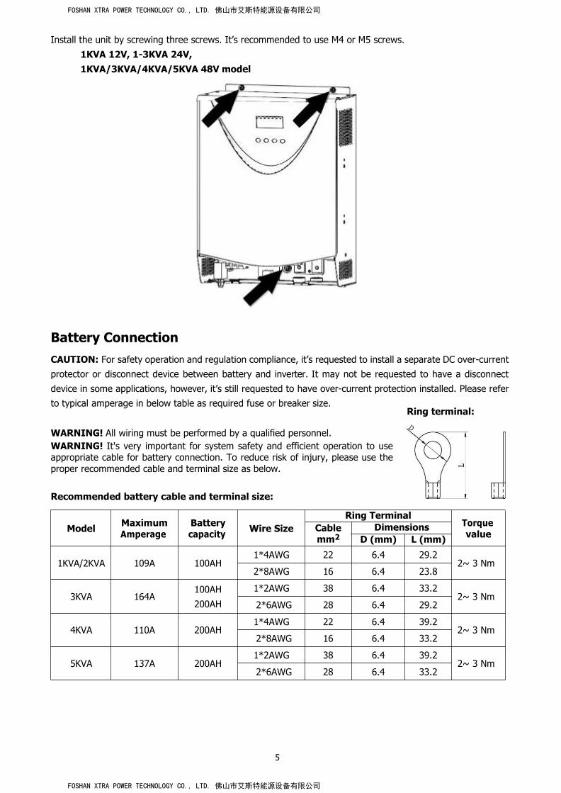
Install the unit by screwing three screws. It’s recommended to use M4 or M5 screws.
1KVA 12V, 1-3KVA 24V,1KVA/3KVA/4KVA/5KVA 48V model
Battery ConnectionCAUTION: For safety operation and regulation compliance, it’s requested to install a separate DC over-currentprotector or disconnect device between battery and inverter. It may not be requested to have a disconnectdevice in some applications, however, it’s still requested to have over-current protection installed. Please referto typical amperage in below table as required fuse or breaker size.
Ring terminal:
WARNING! All wiring must be performed by a qualified personnel.WARNING! It's very important for system safety and efficient operation to useappropriate cable for battery connection. To reduce risk of injury, please use theproper recommended cable and terminal size as below.
Recommended battery cable and terminal size:
Model MaximumAmperage
Batterycapacity Wire Size
Ring TerminalTorquevalue
Cablemm2
DimensionsD (mm) L (mm)
1KVA/2KVA 109A 100AH1*4AWG 22 6.4 29.2
2~ 3 Nm2*8AWG 16 6.4 23.8
3KVA 164A100AH
200AH
1*2AWG 38 6.4 33.22~ 3 Nm
2*6AWG 28 6.4 29.2
4KVA 110A 200AH1*4AWG 22 6.4 39.2
2~ 3 Nm2*8AWG 16 6.4 33.2
5KVA 137A 200AH1*2AWG 38 6.4 39.2
2~ 3 Nm2*6AWG 28 6.4 33.2
FOSHAN XTRA POWER TECHNOLOGY CO., LTD. 佛山市艾斯特能源设备有限公司
FOSHAN XTRA POWER TECHNOLOGY CO., LTD. 佛山市艾斯特能源设备有限公司

6
Please follow below steps to implement battery connection:1. Assemble battery ring terminal based on recommended battery cable and terminal size.
2. Connect all battery packs as units requires. It’s suggested to connect at least 100Ah capacity battery for
1-3KVA model and at least 200Ah capacity battery for 4KVA/5KVA model.
3. Insert the ring terminal of battery cable flatly into battery connector of inverter and make sure the bolts are
tightened with torque of 2-3 Nm. Make sure polarity at both the battery and the inverter/charge is correctlyconnected and ring terminals are tightly screwed to the battery terminals.
WARNING: Shock HazardInstallation must be performed with care due to high battery voltage in series.
CAUTION!! Do not place anything between the flat part of the inverter terminal and the ringterminal. Otherwise, overheating may occur.
CAUTION!! Do not apply anti-oxidant substance on the terminals before terminals areconnected tightly.
CAUTION!! Before making the final DC connection or closing DC breaker/disconnector, be surepositive (+) must be connected to positive (+) and negative (-) must be connected to negative
(-).
FOSHAN XTRA POWER TECHNOLOGY CO., LTD. 佛山市艾斯特能源设备有限公司
FOSHAN XTRA POWER TECHNOLOGY CO., LTD. 佛山市艾斯特能源设备有限公司

7
AC Input/Output ConnectionCAUTION!! Before connecting to AC input power source, please install a separate AC breaker between
inverter and AC input power source. This will ensure the inverter can be securely disconnected duringmaintenance and fully protected from over current of AC input. The recommended spec of AC breaker is 10A
for 1KVA, 20A for 2KVA, 32A for 3KVA, 40A for 4KVA and 50A for 5KVA.
CAUTION!! There are two terminal blocks with “IN” and “OUT” markings. Please do NOT mis-connect inputand output connectors.
WARNING! All wiring must be performed by a qualified personnel.WARNING! It’s very important for system safety and efficient operation to use appropriate cable for AC inputconnection. To reduce risk of injury, please use the proper recommended cable size as below.Suggested cable requirement for AC wires
Model Gauge Torque Value
1KVA 16 AWG 0.5~ 0.6 Nm
2KVA 14 AWG 0.8~ 1.0 Nm
3KVA 12 AWG 1.2~ 1.6 Nm
4KVA 10 AWG 1.4~ 1.6Nm
5KVA 8 AWG 1.4~ 1.6Nm
Please follow below steps to implement AC input/output connection:1. Before making AC input/output connection, be sure to open DC protector or disconnector first.2. Remove insulation sleeve 10mm for six conductors. And shorten phase L and neutral conductor N 3mm.3. Insert AC input wires according to polarities indicated on terminal block and tighten the terminal screws. Be
sure to connect PE protective conductor ( ) first.→Ground (yellow-green)L→LINE (brown or black)N→Neutral (blue)
WARNING:Be sure that AC power source is disconnected before attempting to hardwire it to the unit.
4. Then, insert AC output wires according to polarities indicated on terminal block and tighten terminal screws.Be sure to connect PE protective conductor ( ) first.
→Ground (yellow-green)L→LINE (brown or black)N→Neutral (blue)
FOSHAN XTRA POWER TECHNOLOGY CO., LTD. 佛山市艾斯特能源设备有限公司
FOSHAN XTRA POWER TECHNOLOGY CO., LTD. 佛山市艾斯特能源设备有限公司

8
5. Make sure the wires are securely connected.
CAUTION: Appliances such as air conditioner are required at least 2~3 minutes to restart because it’s requiredto have enough time to balance refrigerant gas inside of circuits. If a power shortage occurs and recovers in a
short time, it will cause damage to your connected appliances. To prevent this kind of damage, please check
manufacturer of air conditioner if it’s equipped with time-delay function before installation. Otherwise, thisinverter/charger will trig overload fault and cut off output to protect your appliance but sometimes it still causes
internal damage to the air conditioner.
CAUTION: ImportantBe sure to connect AC wires with correct polarity. If L and N wires are connected reversely, it may causeutility short-circuited when these inverters are worked in parallel operation.
PV ConnectionCAUTION: Before connecting to PV modules, please install separately a DC circuit breaker between inverterand PV modules.
WARNING! All wiring must be performed by a qualified personnel.WARNING! It'’ very important for system safety and efficient operation to use appropriate cable for PV moduleconnection. To reduce risk of injury, please use the proper recommended cable size as below.
Model Typical Amperage Cable Size Torque
1KVA 12V 40A 10 AWG 1.2~1.6 Nm
1KVA 24V / 2KVA 24V/
3KVA 24V25A 12 AWG 1.2~1.6 Nm
1KVA 48V / 3KVA 48V 18A 14 AWG 1.2~1.6 Nm
2KVA 24V Plus3KVA 24V Plus
2KVA 48V Plus
3KVA 48V Plus
60A 8 AWG 1.4~1.6 Nm
4KVA / 5KVA 80A 6 AWG 1.4~1.6 Nm
FOSHAN XTRA POWER TECHNOLOGY CO., LTD. 佛山市艾斯特能源设备有限公司
FOSHAN XTRA POWER TECHNOLOGY CO., LTD. 佛山市艾斯特能源设备有限公司

9
PV Module Selection:When selecting proper PV modules, please be sure to consider below parameters:1. Open circuit Voltage (Voc) of PV modules not exceeds max. PV array open circuit voltage of inverter.2. Open circuit Voltage (Voc) of PV modules should be higher than min. battery voltage.
Solar Charging Mode
INVERTER MODEL 1KVA 12V
1KVA 24V
2KVA 24V
3KVA 24V
1KVA 48V
3KVA 48V
2KVA 24V Plus/
3KVA 24V Plus
2KVA 48V Plus/
3KVA 48V Plus/
4KVA/5KVA
Max. PV Array Open Circuit Voltage 102Vdc max 75Vdc max 102Vdc max 145Vdc
PV Array MPPT Voltage Range 15~80Vdc 30~66Vdc 60~88Vdc 30~115Vdc 60~115Vdc
Min. battery voltage for PV charge 8.5Vdc 17Vdc 34Vdc 17Vdc 34Vdc
Please follow below steps to implement PV module connection:1. Remove insulation sleeve 10 mm for positive and negative conductors.2. Check correct polarity of connection cable from PV modules and PV input
connectors. Then, connect positive pole (+) of connection cable to positivepole (+) of PV input connector. Connect negative pole (-) of connectioncable to negative pole (-) of PV input connector.
3. Make sure the wires are securely connected.
Final AssemblyAfter connecting all wirings, please put bottom cover back by screwing two screws as shown below.
1KVA/2KVA/3KVA/4KVA/5KVA
FOSHAN XTRA POWER TECHNOLOGY CO., LTD. 佛山市艾斯特能源设备有限公司
FOSHAN XTRA POWER TECHNOLOGY CO., LTD. 佛山市艾斯特能源设备有限公司

10
Communication ConnectionPlease use supplied communication cable to connect to inverter and PC. Insert bundled CD into a computer and
follow on-screen instruction to install the monitoring software. For the detailed software operation, pleasecheck user manual of software inside of CD.
Dry Contact SignalThere is one dry contact (3A/250VAC) available on the rear panel. When program 38 is set as “disable”, it couldbe used to deliver signal to external device when battery voltage reaches warning level. When program 38 is
set as “enable” and the unit is working in battery mode, it could be used to trigger the grounding box toconnect neutral and grounding of AC output together.
When program 38 is set as “disable” (default setting):
Unit Status Condition Dry contact port:
NC & C NO & C
Power Off Unit is off and no output is powered. Close Open
Power On
Output is powered from Utility. Close Open
Output ispowered
from
Battery orSolar.
Program 01set as Utility
Battery voltage < Low DC warning
voltageOpen Close
Battery voltage > Setting value inProgram 13 or battery charging
reaches floating stageClose Open
Program 01is set as
SBU orSolar first
Battery voltage < Setting value in
Program 12Open Close
Battery voltage > Setting value inProgram 13 or battery charging
reaches floating stage
Close Open
When program 38 is set as “enable”:
Unit Status ConditionDry contact port:
NC & C NO & C
Power Off Unit is off and no output is powered. Close Open
Power OnUnit works in standby mode, line mode or fault mode Close Open
Unit works in battery mode or power saving mode Open Close
FOSHAN XTRA POWER TECHNOLOGY CO., LTD. 佛山市艾斯特能源设备有限公司
FOSHAN XTRA POWER TECHNOLOGY CO., LTD. 佛山市艾斯特能源设备有限公司

11
OPERATION
Power ON/OFF
Once the unit has been properly installed and the batteries are connected well, simply press On/Off switch(located on the button of the case) to turn on the unit.
Operation and Display PanelThe operation and display panel, shown in below chart, is on the front panel of the inverter. It includes
three indicators, four function keys and a LCD display, indicating the operating status and input/output
power information.
LCD display
LED indicatorsFunction keys
LED Indicator
LED Indicator Messages
GreenSolid On Output is powered by utility in Line mode.
Flashing Output is powered by battery or PV in battery mode.
GreenSolid On Battery is fully charged.
Flashing Battery is charging.
RedSolid On Fault occurs in the inverter.
Flashing Warning condition occurs in the inverter.
Function Keys
Function Key Description
ESC To exit setting mode
UP To go to previous selection
DOWN To go to next selection
ENTER To confirm the selection in setting mode or enter setting mode
FOSHAN XTRA POWER TECHNOLOGY CO., LTD. 佛山市艾斯特能源设备有限公司
FOSHAN XTRA POWER TECHNOLOGY CO., LTD. 佛山市艾斯特能源设备有限公司

12
LCD Display Icons
Icon Function description
Input Source Information
Indicates the AC input.
Indicates the PV input
Indicate input voltage, input frequency, PV voltage, battery voltage andcharger current.
Configuration Program and Fault Information
Indicates the setting programs.
Indicates the warning and fault codes.
Warning: flashing with warning code.
Fault: lighting with fault code
Output Information
Indicate output voltage, output frequency, load percent, load in VA, load inWatt and discharging current.
Battery Information
Indicates battery level by 0-24%, 25-49%, 50-74% and 75-100% in batterymode and charging status in line mode.
In AC mode, it will present battery charging status.
Status Battery voltage LCD Display<2V/cell 4 bars will flash in turns.
ConstantCurrent mode /Constant
2 ~ 2.083V/cell Bottom bar will be on and the other threebars will flash in turns.
2.083 ~ 2.167V/cell Bottom two bars will be on and the othertwo bars will flash in turns.
Voltage mode> 2.167 V/cell
Bottom three bars will be on and the top
bar will flash.
Floating mode. Batteries are fully charged. 4 bars will be on.
FOSHAN XTRA POWER TECHNOLOGY CO., LTD. 佛山市艾斯特能源设备有限公司
FOSHAN XTRA POWER TECHNOLOGY CO., LTD. 佛山市艾斯特能源设备有限公司

13
In battery mode, it will present battery capacity.
Load Percentage Battery Voltage LCD Display
Load >50%
< 1.717V/cell
1.717V/cell ~ 1.8V/cell
1.8 ~ 1.883V/cell
> 1.883 V/cell
50%> Load > 20%
< 1.817V/cell
1.817V/cell ~ 1.9V/cell
1.9 ~ 1.983V/cell
> 1.983
Load < 20%
< 1.867V/cell
1.867V/cell ~ 1.95V/cell
1.95 ~ 2.033V/cell
> 2.033
Load Information
Indicates overload.
Indicates the load level by 0-24%, 25-49%, 50-74% and 75-100%.
0%~24% 25%~49% 50%~74% 75%~100%
Mode Operation Information
Indicates unit connects to the mains.
Indicates unit connects to the PV panel.
Indicates load is supplied by utility power.
Indicates the utility charger circuit is working.
Indicates the DC/AC inverter circuit is working.
Mute Operation
Indicates unit alarm is disabled.
FOSHAN XTRA POWER TECHNOLOGY CO., LTD. 佛山市艾斯特能源设备有限公司
FOSHAN XTRA POWER TECHNOLOGY CO., LTD. 佛山市艾斯特能源设备有限公司

14
LCD SettingAfter pressing and holding ENTER button for 3 seconds, the unit will enter setting mode. Press “UP” or “DOWN”
button to select setting programs. And then, press “ENTER” button to confirm the selection or ESC button toexit.
Setting Programs:
Program Description Selectable option
00 Exit setting mode
Escape
01
Output source priority:To configure load power
source priority
Solar first
Solar energy provides power to theloads as first priority.
If solar energy is not sufficient to
power all connected loads, batteryenergy will supply power the loads at
the same time.
Utility provides power to the loads only
when any one condition happens:
- Solar energy is not available
- Battery voltage drops to eitherlow-level warning voltage or thesetting point in program 12.
Utility first (default)
Utility will provide power to the loadsas first priority.
Solar and battery energy will provide
power to the loads only when utility
power is not available.
SBU priority
Solar energy provides power to the
loads as first priority.
If solar energy is not sufficient topower all connected loads, battery
energy will supply power to the loadsat the same time.
Utility provides power to the loads only
when battery voltage drops to eitherlow-level warning voltage or the
setting point in program 12.
02
Maximum charging current:To configure total chargingcurrent for solar and utilitychargers.(Max. charging current =utility charging current +solar charging current)
Available options in 1KVA 12V model:
10A 20A
30A 40A (default)
50A 60A
FOSHAN XTRA POWER TECHNOLOGY CO., LTD. 佛山市艾斯特能源设备有限公司
FOSHAN XTRA POWER TECHNOLOGY CO., LTD. 佛山市艾斯特能源设备有限公司

15
02
Maximum charging current:To configure total chargingcurrent for solar and utilitychargers.(Max. charging current =utility charging current +solar charging current)
Available options in 1KVA 24V and 1KVA/3KVA 48V models:
10A 20A (default)
30A 40A
Available options in 2-3KVA 24V models:
20A 30A (default)
40A 50A
60A
02
Maximum charging current:To configure total chargingcurrent for solar and utilitychargers.(Max. charging current =utility charging current +solar charging current)
Available options in 2-3KVA 24V/48V Plus models:
10A (Not availablefor 2-3KVA 24V Plus)
20A
30A 40A
50A 60A (default)
70A 80A
90A (Not available for 2-3KVA 48V Plus)
Available options in 4K/5K model
10A 20A
30A 40A
50A 60A (default)
70A 80A
FOSHAN XTRA POWER TECHNOLOGY CO., LTD. 佛山市艾斯特能源设备有限公司
FOSHAN XTRA POWER TECHNOLOGY CO., LTD. 佛山市艾斯特能源设备有限公司

16
90A 100A
110A 120A
130A 140A
03 AC input voltage range
Appliances (default) If selected, acceptable AC inputvoltage range will be within
90-280VAC.
UPS If selected, acceptable AC inputvoltage range will be within
170-280VAC.
04 Power saving modeenable/disable
Saving mode disable(default)
If disabled, no matter connected loadis low or high, the on/off status ofinverter output will not be effected.
Saving mode enable If enabled, the output of inverter willbe off when connected load is prettylow or not detected.
05 Battery type
AGM (default) Flooded
User-Defined(Lithium ironphosphate or othertypes)
If “User-Defined” is selected, battery
charge voltage and low DC cut-offvoltage can be set up in program 26,
27 and 29.
06 Auto restart when overloadoccurs
Restart disable(default)
Restart enable
07 Auto restart when overtemperature occurs
Restart disable
(default)
Restart enable
09 Output frequency
50Hz (default) 60Hz
FOSHAN XTRA POWER TECHNOLOGY CO., LTD. 佛山市艾斯特能源设备有限公司
FOSHAN XTRA POWER TECHNOLOGY CO., LTD. 佛山市艾斯特能源设备有限公司

17
11 Maximum utility chargingcurrent
Available options in 1KVA 12V/ 24V model:
10A 20A(default):
Available options in 2-3KVA 24V and 2-3KVA 24V Plus models:
20A 30A (default)
11 Maximum utility chargingcurrent
Available options in 1KVA/3KVA 48V and 2-3KVA 48V Plusmodels:
10A 15A(default):
Available options in 4KVA/5KVA models:
2A 10A
20A 30A (default)
40A 50A
60A
12
Setting voltage point backto utility source whenselecting “SBU priority” or“Solar first” in program 01.
Available options in 12V model:
11.0V 11.3V
11.5V (default) 11.8V
12.0V 12.3V
12.5V 12.8V
FOSHAN XTRA POWER TECHNOLOGY CO., LTD. 佛山市艾斯特能源设备有限公司
FOSHAN XTRA POWER TECHNOLOGY CO., LTD. 佛山市艾斯特能源设备有限公司

18
12
Setting voltage point backto utility source whenselecting “SBU priority” or“Solar first” in program 01.
Available options in 24V models:
22.0V 22.5V
23.0V (default) 23.5V
24.0V 24.5V
25.0V 25.5V
Available options in 48V models:
44V 45V
46V (default) 47V
48V 49V
50V 51V
12
Setting voltage point backto utility source whenselecting “SBU priority” or“Solar first” in program 01.
Below options only available for the model with 64VDC
maximum charging voltage
52V 53V
54V 55V
FOSHAN XTRA POWER TECHNOLOGY CO., LTD. 佛山市艾斯特能源设备有限公司
FOSHAN XTRA POWER TECHNOLOGY CO., LTD. 佛山市艾斯特能源设备有限公司

19
12
Setting voltage point backto utility source whenselecting “SBU priority” or“Solar first” in program 01.
56V 57V
13
Setting voltage point backto battery mode whenselecting “SBU priority” or“Solar first” in program 01.
Available options in 12V model:
Battery fully charged 12.0V
12.3V 12.5V
12.8V 13.0V
13.3V 13.5V (default)
13.8V 14.0V
14.3V 14.5V
Available options in 24V models:
Battery fully charged 24V
24.5V 25V
25.5V 26V
26.5V 27V (default)
FOSHAN XTRA POWER TECHNOLOGY CO., LTD. 佛山市艾斯特能源设备有限公司
FOSHAN XTRA POWER TECHNOLOGY CO., LTD. 佛山市艾斯特能源设备有限公司

20
13
Setting voltage point backto battery mode whenselecting “SBU priority” or“Solar first” in program 01.
27.5V 28V
28.5V 29V
Available options in 48V models:
Battery fully charged 48V
49V 50V
51V 52V
53V 54V (default)
55V 56V
57V 58V
Below options only available for the model with 64VDCmaximum charging voltage
59V 60V
61V 62V
63V 64V
FOSHAN XTRA POWER TECHNOLOGY CO., LTD. 佛山市艾斯特能源设备有限公司
FOSHAN XTRA POWER TECHNOLOGY CO., LTD. 佛山市艾斯特能源设备有限公司

21
16Charger source priority:To configure charger sourcepriority
If this inverter/charger is working in Line, Standby or Fault
mode, charger source can be programmed as below:
Solar first Solar energy will charge battery asfirst priority.
Utility will charge battery only when
solar energy is not available.
Utility first
(default for 1K~3K)
Utility will charge battery as firstpriority.
Solar energy will charge battery only
when utility power is not available.
Solar and Utility(default for 4K/5K) Solar energy and utility will charge
battery at the same time.
Only Solar Solar energy will be the only charger
source no matter utility is availableor not.
If this inverter/charger is working in Battery mode or Powersaving mode, only solar energy can charge battery. Solar
energy will charge battery if it's available and sufficient.
18 Alarm controlAlarm on (default) Alarm off
19 Auto return to defaultdisplay screen
Return to defaultdisplay screen (default)
If selected, no matter how usersswitch display screen, it will
automatically return to defaultdisplay screen (Input voltage
/output voltage) after no button is
pressed for 1 minute.
Stay at latest screen If selected, the display screen willstay at latest screen user finallyswitches.
20 Backlight control
Backlight on (default) Backlight off
22 Beeps while primary sourceis interrupted
Alarm on (default) Alarm off
23
Overload bypass:When enabled, the unit willtransfer to line mode ifoverload occurs in batterymode.
Bypass disable(default)
Bypass enable
25 Record Fault codeRecord enable Record disable (default)
FOSHAN XTRA POWER TECHNOLOGY CO., LTD. 佛山市艾斯特能源设备有限公司
FOSHAN XTRA POWER TECHNOLOGY CO., LTD. 佛山市艾斯特能源设备有限公司

22
26Bulk charging voltage(C.V voltage)
12V model default setting: 14.1V
24V model default setting: 28.2V
48V model default setting: 56.4V
If self-defined is selected in program 5, this program can be
set up. Setting range is from 12.0V to 14.6V for 12V model,24.0V to 29.2V for 24V model and 48.0V to 58.4V for 48V
model. For the model with 64V maximum charging voltage,the setting range is from 48.0V to 64.0V. Increment of each
click is 0.1V.
27 Floating charging voltage
12V model default setting: 13.5V
24V model default to 27.0V
48V model default setting: 54.0V
If self-defined is selected in program 5, this program can beset up. Setting range is from 12.0V to 14.6V for 12V model,
24.0V to 29.2V for 24V model, 48.0V to 58.4V for 48V model.For the model with 64V maximum charging voltage, the
setting range is from 48.0V to 64.0V. Increment of each click
is 0.1V.
29 Low DC cut-off voltage
12V model default setting: 10.5V
24V model default setting: 21.0V
48V model default setting: 42.0V
FOSHAN XTRA POWER TECHNOLOGY CO., LTD. 佛山市艾斯特能源设备有限公司
FOSHAN XTRA POWER TECHNOLOGY CO., LTD. 佛山市艾斯特能源设备有限公司

23
If self-defined is selected in program 5, this program can beset up. Setting range is from 10.0V to 12.0V for 12V model,
20.0V to 24.0V for 24V model, 40.0V to 48.0V for 48V model.For the model with 64V maximum charging voltage, the
setting range is from 40.0Vto 54.0V. Increment of each clickis 0.1V. Low DC cut-off voltage will be fixed to setting value no
matter what percentage of load is connected.
31
Solar power balance:When enabled, solar inputpower will be automaticallyadjusted according toconnected load power.(Only available for4KVA/5KVA model)
Solar power balanceenable (Default):
If selected, solar input power willbe automatically adjustedaccording to the following formula:Max. input solar power = Max.battery charging power +Connected load power.
Solar power balancedisable:
If selected, the solar input powerwill be the same to max. batterycharging power no matter howmuch loads are connected. Themax. battery charging power willbe based on the setting current inprogram 02.(Max. solar power = Max. batterycharging power)
32
Bulk charging time
(C.V stage)
(Only available for4KVA/5KVA model)
Automatically (Default): If selected, inverter will judge thischarging time automatically.
5 min The setting range is from 5 min to900 min. Increment of each click is5 min.
900 min
If “USE” is selected in program 05, this program can be set up.
33 Battery equalization
Battery equalization Battery equalization disable(default)
If “Flooded” or “User-Defined” is selected in program 05, thisprogram can be set up.
34 Battery equalization voltage
1K default setting: 14.6V. Setting range is from 12V ~ 14.6V.Increment of each click is 0.1V.
2KVA/3KVA default setting: 29.2V. Setting range is from 24V ~29.2V. Increment of each click is 0.1V.
FOSHAN XTRA POWER TECHNOLOGY CO., LTD. 佛山市艾斯特能源设备有限公司
FOSHAN XTRA POWER TECHNOLOGY CO., LTD. 佛山市艾斯特能源设备有限公司

24
34 Battery equalization voltage
4KVA/5KVA default setting: 58.4V. Setting range is from 48V ~58.4V. Increment of each click is 0.1V.
For 4KVA/5KVA with 64V maximum charging voltage, defaultsetting is 64V. Setting range is from 48V ~ 64V. Increment of
each click is 0.1V.
35 Battery equalized time60min (default) Setting range is from 5min to
900min. Increment of eachclick is 5min.
36 Battery equalized timeout120min (default) Setting range is from 5min to
900 min. Increment of eachclick is 5 min.
37 Equalization interval30days (default) Setting range is from 0 to 90
days. Increment of each click
is 1 day
38
Allow neutral and groundingof AC output is connectedtogether:When enabled, inverter candeliver signal to triggergrounding box to shortneutral and grounding
Disable: Neutral and grounding of AC output is disconnected.(Default)
Enable: Neutral and grounding of AC output is connected.
This function is only available when the inverter isworkingwith external grounding box. Only when the inverter isworking in battery mode, it will trigger grounding box toconnect neutral and grounding of AC output.
39Equalization activatedimmediately
Enable Disable (default)
If equalization function is enabled in program 33, this programcan be set up. If “Enable” is selected in this program, it’s toactivate battery equalization immediately and LCD main page
will shows “ ”. If “Disable” is selected, it will cancelequalization function until next activated equalization time
arrives based on program 37 setting. At this time, “ ” willnot be shown in LCD main page.
FOSHAN XTRA POWER TECHNOLOGY CO., LTD. 佛山市艾斯特能源设备有限公司
FOSHAN XTRA POWER TECHNOLOGY CO., LTD. 佛山市艾斯特能源设备有限公司

25
Display SettingThe LCD display information will be switched in turns by pressing “UP” or “DOWN” key. The selectableinformation is switched as below order: input voltage, input frequency, PV voltage, MPPT charging current,MPPT charging power, battery voltage, output voltage, output frequency, load percentage, load in VA,load in Watt, DC discharging current, main CPU Version and second CPU Version.
Selectable information LCD display
Input voltage/Output voltage
(Default Display Screen)
Input Voltage=230V, output voltage=230V
Input frequency
Input frequency=50Hz
PV voltage
PV voltage=60V
MPPT Charging current
Current ≧10A
Current < 10A
MPPT Charging power MPPT charging power=500W
FOSHAN XTRA POWER TECHNOLOGY CO., LTD. 佛山市艾斯特能源设备有限公司
FOSHAN XTRA POWER TECHNOLOGY CO., LTD. 佛山市艾斯特能源设备有限公司

26
Battery voltage/ DC discharging current
Battery voltage=25.5V, discharging current=1A
Output frequency
Output frequency=50Hz
Load percentage
Load percent=70%
Load in VA
When connected load is lower than 1kVA, load inVA will present xxxVA like below chart.
When load is larger than 1kVA (≧1KVA), load in
VA will present x.xkVA like below chart.
FOSHAN XTRA POWER TECHNOLOGY CO., LTD. 佛山市艾斯特能源设备有限公司
FOSHAN XTRA POWER TECHNOLOGY CO., LTD. 佛山市艾斯特能源设备有限公司

27
Load in Watt
When load is lower than 1kW, load in W willpresent xxxW like below chart.
When load is larger than 1kW (≧1KW), load in
W will present x.xkW like below chart.
Main CPU version checking
Main CPU version 00014.04
Secondary CPU version checking
Secondary CPU version 00003.03
FOSHAN XTRA POWER TECHNOLOGY CO., LTD. 佛山市艾斯特能源设备有限公司
FOSHAN XTRA POWER TECHNOLOGY CO., LTD. 佛山市艾斯特能源设备有限公司

28
Operating Mode DescriptionOperation mode Description LCD display
Standby mode / Powersaving modeNote:
*Standby mode: The inverter is
not turned on yet but at this
time, the inverter can charge
battery without AC output.
*Power saving mode: If
enabled, the output of inverter
will be off when connected load
is pretty low or not detected.
No output is supplied by theunit but it still can charge
batteries.
Charging by utility and PV energy.
Charging by utility.
Charging by PV energy.
No charging.
Fault modeNote:
*Fault mode: Errors are caused
by inside circuit error or external
reasons such as over
temperature, output short
circuited and so on.
PV energy and utility can
charge batteries.
Charging by utility and PV energy.
Charging by utility. (Only available in 1K/2K/3Kmodel)
Charging by PV energy.
No charging.
Line Mode
The unit will provide output
power from the mains. It will
also charge the battery atline mode.
Charging by PV energy
Charging by utility.
FOSHAN XTRA POWER TECHNOLOGY CO., LTD. 佛山市艾斯特能源设备有限公司
FOSHAN XTRA POWER TECHNOLOGY CO., LTD. 佛山市艾斯特能源设备有限公司

29
Battery Mode
The unit will provide outputpower from battery and PV
power.
Power from battery and PV energy.
Power from battery only.
Fault Reference Code
Fault Code Fault Event Icon on
01 Fan is locked when inverter is off.
02 Over temperature
03 Battery voltage is too high
04 Battery voltage is too low
05 Output short circuited or over temperature is detectedby internal converter components.
06 Output voltage is abnormal. (For 1K/2K/3K model)Output voltage is too high. (For 4K/5K model)
07 Overload time out
08 Bus voltage is too high
09 Bus soft start failed
11 Main relay failed
51 Over current or surge
52 Bus voltage is too low
53 Inverter soft start failed
55 Over DC voltage in AC output
56 Battery connection is open
57 Current sensor failed
58 Output voltage is too low
NOTE: Fault codes 51, 52, 53, 55, 56, 57 and 58 are only available in 4K/5K model.
FOSHAN XTRA POWER TECHNOLOGY CO., LTD. 佛山市艾斯特能源设备有限公司
FOSHAN XTRA POWER TECHNOLOGY CO., LTD. 佛山市艾斯特能源设备有限公司

30
Warning Indicator
WarningCode Warning Event Audible Alarm Icon flashing
01 Fan is locked wheninverter is on.
Beep three times everysecond
03 Battery is over-charged Beep once every second
04 Low battery Beep once every second
07 Overload Beep once every 0.5 second
10 Output power derating Beep twice every 3 seconds
12Solar charger stops due
to low battery.
13Solar charger stops due
to high PV voltage.
14Solar charger stops due
to overload.
Battery equalization
FOSHAN XTRA POWER TECHNOLOGY CO., LTD. 佛山市艾斯特能源设备有限公司
FOSHAN XTRA POWER TECHNOLOGY CO., LTD. 佛山市艾斯特能源设备有限公司

31
BATTERY EQUALIZATIONEqualization function is added into charge controller. It reverses the buildup of negative chemical effects likestratification, a condition where acid concentration is greater at the bottom of the battery than at the top.
Equalization also helps to remove sulfate crystals that might have built up on the plates. If left unchecked, thiscondition, called sulfation, will reduce the overall capacity of the battery. Therefore, it’s recommended toequalize battery periodically.
How to Apply Equalization FunctionYoumust enable battery equalization function in monitoring LCD setting program 33 first. Then, you may apply
this function in device by either one of following methods:
1. Setting equalization interval in program 37.
2. Active equalization immediately in program 39.
When to EqualizeIn float stage, when the setting equalization interval (battery equalization cycle) is arrived, or equalization isactive immediately, the controller will start to enter Equalize stage.
Equalize charging time and timeoutIn Equalize stage, the controller will supply power to charge battery as much as possible until battery voltageraises to battery equalization voltage. Then, constant-voltage regulation is applied to maintain battery voltage
at the battery equalization voltage. The battery will remain in the Equalize stage until setting battery equalized
time is arrived.
FOSHAN XTRA POWER TECHNOLOGY CO., LTD. 佛山市艾斯特能源设备有限公司
FOSHAN XTRA POWER TECHNOLOGY CO., LTD. 佛山市艾斯特能源设备有限公司

32
However, in Equalize stage, when battery equalized time is expired and battery voltage doesn’t rise to batteryequalization voltage point, the charge controller will extend the battery equalized time until battery voltageachieves battery equalization voltage. If battery voltage is still lower than battery equalization voltage when
battery equalized timeout setting is over, the charge controller will stop equalization and return to float stage.
FOSHAN XTRA POWER TECHNOLOGY CO., LTD. 佛山市艾斯特能源设备有限公司
FOSHAN XTRA POWER TECHNOLOGY CO., LTD. 佛山市艾斯特能源设备有限公司
33
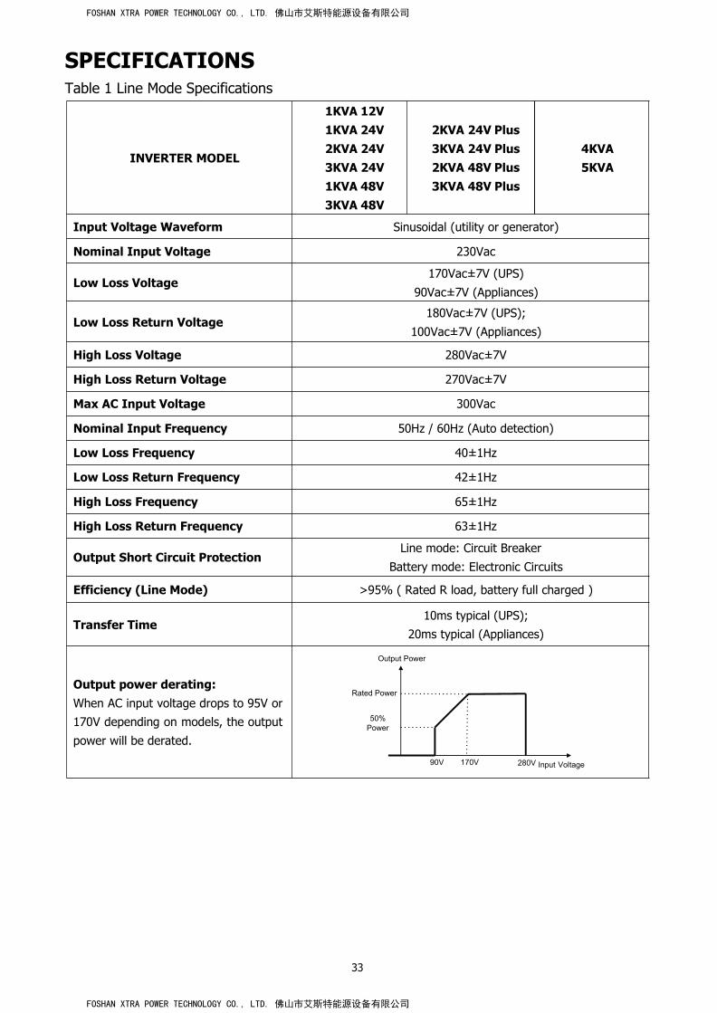
SPECIFICATIONSTable 1 Line Mode Specifications
INVERTER MODEL
1KVA 12V1KVA 24V2KVA 24V3KVA 24V1KVA 48V3KVA 48V
2KVA 24V Plus3KVA 24V Plus2KVA 48V Plus3KVA 48V Plus
4KVA5KVA
Input Voltage Waveform Sinusoidal (utility or generator)
Nominal Input Voltage 230Vac
Low Loss Voltage170Vac±7V (UPS)
90Vac±7V (Appliances)
Low Loss Return Voltage180Vac±7V (UPS);
100Vac±7V (Appliances)
High Loss Voltage 280Vac±7V
High Loss Return Voltage 270Vac±7V
Max AC Input Voltage 300Vac
Nominal Input Frequency 50Hz / 60Hz (Auto detection)
Low Loss Frequency 40±1Hz
Low Loss Return Frequency 42±1Hz
High Loss Frequency 65±1Hz
High Loss Return Frequency 63±1Hz
Output Short Circuit ProtectionLine mode: Circuit Breaker
Battery mode: Electronic Circuits
Efficiency (Line Mode) >95% ( Rated R load, battery full charged )
Transfer Time10ms typical (UPS);
20ms typical (Appliances)
Output power derating:When AC input voltage drops to 95V or170V depending on models, the output
power will be derated.
Output Power
Rated Power
50%Power
90V 170V 280V Input Voltage
FOSHAN XTRA POWER TECHNOLOGY CO., LTD. 佛山市艾斯特能源设备有限公司
FOSHAN XTRA POWER TECHNOLOGY CO., LTD. 佛山市艾斯特能源设备有限公司

34
Table 2 Inverter Mode Specifications
INVERTER MODEL 1KVA 12V
1KVA 24V2KVA 24V3KVA 24V
2KVA 24V Plus3KVA 24V Plus
1KVA 48V3KVA 48V
2KVA 48V Plus3KVA 48V Plus
4KVA5KVA
Rated Output Power 1KVA/1KW1KVA/1KW2KVA/2KW3KVA/3KW
1KVA/1KW2KVA/2KW3KVA/3KW
4KVA/4KW5KVA/5KW
Output Voltage Waveform Pure Sine Wave
Output Voltage Regulation 230Vac±5%
Output Frequency 60Hz or 50Hz
Peak Efficiency 90%
Overload Protection 5s@≥150% load; 10s@110%~150% load
Surge Capacity 2* rated power for 5 seconds
Nominal DC Input Voltage 12Vdc 24Vdc 48Vdc
Cold Start Voltage 11.5Vdc 23.0Vdc 46.0Vdc
Low DC Warning Voltage@ load < 20% 11.0Vdc 22.0Vdc 44.0Vdc
@ 20% ≤ load < 50% 10.7Vdc 21.4Vdc 42.8Vdc
@ load ≥ 50% 10.1Vdc 20.2Vdc 40.4Vdc
Low DC Warning Return Voltage@ load < 20% 11.5Vdc 23.0Vdc 46.0Vdc
@ 20% ≤ load < 50% 11.2Vdc 22.4Vdc 44.8Vdc
@ load ≥ 50% 10.6Vdc 21.2Vdc 42.4Vdc
Low DC Cut-off Voltage
@ load < 20% 10.5Vdc 21.0Vdc 42.0Vdc
@ 20% ≤ load < 50% 10.2Vdc 20.4Vdc 40.8Vdc
@ load ≥ 50% 9.6Vdc 19.2Vdc 38.4Vdc
High DC Recovery Voltage 14.5Vdc 29Vdc 58Vdc 58Vdc or 62Vdc
High DC Cut-off Voltage 15.5Vdc 31Vdc 62Vdc 60Vdc or 66Vdc
No Load Power Consumption <15W <25W <50W
Saving Mode Power Consumption <5W <10W <15W
FOSHAN XTRA POWER TECHNOLOGY CO., LTD. 佛山市艾斯特能源设备有限公司
FOSHAN XTRA POWER TECHNOLOGY CO., LTD. 佛山市艾斯特能源设备有限公司

35
Table 3 Charge Mode Specifications
Utility Charging Mode
INVERTER MODEL 1KVA 12V 1KVA 24V
2KVA 24V
3KVA 24V
2KVA 24V Plus
3KVA 24V Plus
1KVA 48V
3KVA 48V
2KVA 48V Plus
3KVA 48V Plus
4KVA
5KVA
Charging Current (UPS)@ Nominal Input Voltage
10/20A 20/30A 10/15A
2/10A/
20/30A/
40/50/60A
BulkChargingVoltage
FloodedBattery
14.6 29.2 58.4
AGM / GelBattery
14.1 28.2 56.4
Floating Charging Voltage 13.5Vdc 27Vdc 54Vdc 54Vdc or 64Vdc
Overcharge Protection 15.5Vdvc 31Vdc 60Vdc 66Vdc
Charging Algorithm 3-Step
Charging Curve
Battery Voltage, per cell Charging Current, %
2.43Vdc (2.35Vdc) Voltage2.25Vdc
100%
50%
T0 T1
T1 = 10* T0, minimum 10mins, maximum 8hrs
Current
TimeBulk Absorption Maintenance
(Constant Current) (Constant Voltage) (Floating)
FOSHAN XTRA POWER TECHNOLOGY CO., LTD. 佛山市艾斯特能源设备有限公司
FOSHAN XTRA POWER TECHNOLOGY CO., LTD. 佛山市艾斯特能源设备有限公司

36
Solar Charging Mode
INVERTER MODEL 1KVA 12V
1KVA 24V
2KVA 24V
3KVA 24V
1KVA 48V
3KVA 48V
2KVA 24V Plus
3KVA 24V Plus
2KVA 48VPlus
3KVA 48V Plus
4KVA
5KVA
Rated Power 500W 600W 900W 1500W 3000W 4000W
Efficiency 98.0% max.
Max. PV Array OpenCircuit Voltage
102Vdc 75Vdc 102Vdc 145Vdc
PV Array MPPT VoltageRange
15~80Vdc 30~66Vdc 60~88Vd 30~115Vdc 60~115Vdc
Min battery voltage forPV charge
8.5Vdc 17Vdc 34Vdc 17Vdc 34Vdc
Standby PowerConsumption
2W
Battery VoltageAccuracy
+/-0.3%
PV Voltage Accuracy +/-2V
Charging Algorithm 3-Step
Joint Utility and Solar Charging
Max Charging Current60Amp
1K: 45Amp
2K/3K:
55Amp
33Amp 90Amp 75Amp 140Amp
Default ChargingCurrent 40Amp
1K: 20Amp2K/3K:
30Amp
20Amp 60 Amp 60 Amp 60Amp
Table 4 General Specifications
INVERTERMODEL
1KVA 12V1KVA 24V1KVA 48V
2KVA 24V3KVA 24V3KVA 48V
2KVA 24V Plus3KVA 24V Plus2KVA 48V Plus3KVA 48V Plus
4KVA 5KVA
SafetyCertification
CE
OperatingTemperatureRange
0°C to 55°C
Storagetemperature
-15°C~ 60°C
Humidity 5% to 95% Relative Humidity (Non-condensing)
Dimension(D*W*H), mm
100 x 272 x 355 140 x 295 x 479 120 x 295 x 468
Net Weight, kg 6.8 7.0 7.4 11.5 11
FOSHAN XTRA POWER TECHNOLOGY CO., LTD. 佛山市艾斯特能源设备有限公司
FOSHAN XTRA POWER TECHNOLOGY CO., LTD. 佛山市艾斯特能源设备有限公司

37
TROUBLE SHOOTINGProblem LCD/LED/Buzzer Explanation / Possible cause What to do
Unit shuts downautomaticallyduring startupprocess.
LCD/LEDs and buzzerwill be active for 3seconds and thencomplete off.
The battery voltage is too low(<1.91V/Cell)
1. Re-charge battery.2. Replace battery.
No response afterpower on. No indication.
1. The battery voltage is far toolow. (<1.4V/Cell)2. Battery polarity is connectedreversed.
1. Check if batteries and thewiring are connected well.2. Re-charge battery.3. Replace battery.
Mains exist but theunit works inbattery mode.
Input voltage isdisplayed as 0 on theLCD and green LED isflashing.
Input protector is trippedCheck if AC breaker is trippedand AC wiring is connectedwell.
Green LED is flashing.Insufficient quality of AC power.(Shore or Generator)
1. Check if AC wires are toothin and/or too long.2. Check if generator (ifapplied) is working well or ifinput voltage range setting iscorrect. (UPSAppliance)
Green LED is flashing. Set “Solar First” as the priority ofoutput source.
Change output source priorityto Utility first.
When the unit isturned on, internalrelay is switched onand off repeatedly.
LCD display and LEDsare flashing Battery is disconnected. Check if battery wires are
connected well.
Buzzer beepscontinuously andred LED is on.
Fault code 07 Overload error. The inverter isoverload 110% and time is up.
Reduce the connected load byswitching off someequipment.
Fault code 05
Output short circuited.Check if wiring is connectedwell and remove abnormalload.
Temperature of internal convertercomponent is over 120°C. (Onlyavailable for 1-3KVA models.)
Check whether the air flow ofthe unit is blocked or whetherthe ambient temperature istoo high.Fault code 02 Internal temperature of inverter
component is over 100°C.
Fault code 03
Battery is over-charged. Return to repair center.
The battery voltage is too high.Check if spec and quantity ofbatteries are meetrequirements.
Fault code 01 Fan fault Replace the fan.
Fault code 06/58Output abnormal (Inverter voltagebelow than 190Vac or is higherthan 260Vac)
1. Reduce the connectedload.2. Return to repair center
Fault code08/09/53/57 Internal components failed. Return to repair center.
Fault code 51 Over current or surge.Restart the unit, if the errorhappens again, please returnto repair center.
Fault code 52 Bus voltage is too low.
Fault code 55 Output voltage is unbalanced.
Fault code 56 Battery is not connected well orfuse is burnt.
If the battery is connectedwell, please return to repaircenter.
FOSHAN XTRA POWER TECHNOLOGY CO., LTD. 佛山市艾斯特能源设备有限公司
FOSHAN XTRA POWER TECHNOLOGY CO., LTD. 佛山市艾斯特能源设备有限公司

1
4KVA/5KVA Parallel Installation Guide1.IntroductionThis inverter can be used in parallel with two different operation modes.
1. Parallel operation in single phase with up to 6 units. The supported maximum output power is
24KW/30KVA.
2. Maximum six units work together to support three-phase equipment. Four units support one phase
maximum. The supported maximum output power is 24KW/30KVA and one phase can be up to
16KW/20KVA.
NOTE: If this unit is bundled with share current cable and parallel cable, this inverter is default supported
parallel operation. You may skip section 3. If not, please purchase parallel kit and install this unit by following
instruction from professional technical personnel in local dealer.
2. Package ContentsIn parallel kit, you will find the following items in the package:
Parallel board Parallel communication cable Current sharing cable
3. Parallel board installationThis installation steps are only applied to 4K/5K models.
Step 1: Remove wire cover by unscrewing all screws.
Step 2: Remove communication board by unscrewing two screws as below chart.
FOSHAN XTRA POWER TECHNOLOGY CO., LTD. 佛山市艾斯特能源设备有限公司
FOSHAN XTRA POWER TECHNOLOGY CO., LTD. 佛山市艾斯特能源设备有限公司

2
Step 3: Remove two screws as below chart and remove 2-pin and 14-pin cables. Take out the board under the
communication board.
Step 4: Remove two screws as below chart to take out cover of parallel communication.
Step 5: Install new parallel board with 2 screws tightly.
Step 6: Re-connect 2-pin and 14-pin to original position.
Parallel board Communication board
FOSHAN XTRA POWER TECHNOLOGY CO., LTD. 佛山市艾斯特能源设备有限公司
FOSHAN XTRA POWER TECHNOLOGY CO., LTD. 佛山市艾斯特能源设备有限公司

3
Step 7: Put communication board back to the unit.
Step 8: Put wire cover back to the unit. Now the inverter is providing parallel operation function.
4. Mounting the UnitWhen installing multiple units, please follow below chart.
NOTE: For proper air circulation to dissipate heat, allow a clearance of approx. 20 cm to the side and approx.
50 cm above and below the unit. Be sure to install each unit in the same level.
5. Wiring ConnectionThe cable size of each inverter is shown as below:
Recommended battery cable and terminal size for each inverter:Ring terminal:
WARNING:Be sure the length of all battery cables is the same. Otherwise, there will be voltage differencebetween inverter and battery to cause parallel inverters not working.
Model Wire SizeRing Terminal
Torquevalue
Cablemm2
DimensionsD (mm) L (mm)
4KVA1*4AWG 22 6.4 33.2
2~ 3 Nm2*8AWG 14 6.4 29.2
5KVA1*4AWG 22 6.4 33.2
2~ 3 Nm2*8AWG 14 6.4 29.2
FOSHAN XTRA POWER TECHNOLOGY CO., LTD. 佛山市艾斯特能源设备有限公司
FOSHAN XTRA POWER TECHNOLOGY CO., LTD. 佛山市艾斯特能源设备有限公司

4
Recommended AC input and output cable size for each inverter:Model AWG no. Torque
4KVA 10 AWG 1.4~1.6Nm
5KVA 8 AWG 1.4~1.6Nm
You need to connect the cables of each inverter together. Take the battery cables for example: You need to
use a connector or bus-bar as a joint to connect the battery cables together, and then connect to the battery
terminal. The cable size used from joint to battery should be X times cable size in the tables above. “X”
indicates the number of inverters connected in parallel.
Regarding AC input and output, please also follow the same principle.
CAUTION!! Please install the breaker at the battery and AC input side. This will ensure the inverter can be
securely disconnected during maintenance and fully protected from over current of battery or AC input. The
recommended mounted location of the breakers is shown in the figures in 5-1 and 5-2.
Recommended breaker specification of battery for each inverter:Model 1 unit*
4KVA 80A/60VDC
5KVA 100A/60VDC
*If you want to use only one breaker at the battery side for the whole system, the rating of the breaker should
be X times current of 1 unit. “X” indicates the number of inverters connected in parallel.
Recommended breaker specification of AC input with single phase:Model 2 units 3 units 4 units 5 units 6 units
4KVA 80A/230VAC 120A/230VAC 160A/230VAC 200A/230VAC 240A/230VAC
5KVA 100A/230VAC 150A/230VAC 200A/23VAC 250A/23VAC 300A/23VAC
Note1: Also, you can use 40A breaker (50A for 5KVA) for only 1 unit, and each inverter has a breaker at its AC
input.
Note2: Regarding three phase system, you can use 4 poles breaker, the rating is up to the current of the
phase which has the maximum units. Or you can follow the suggestion of note 1.
Recommended battery capacityInverter parallel numbers 2 3 4 5 6
Battery Capacity 400AH 600AH 800AH 1000AH 1200AH
WARNING!
Be sure that all inverters will share the same battery bank. Otherwise, the inverters will
transfer to fault mode.
FOSHAN XTRA POWER TECHNOLOGY CO., LTD. 佛山市艾斯特能源设备有限公司
FOSHAN XTRA POWER TECHNOLOGY CO., LTD. 佛山市艾斯特能源设备有限公司

5
5-1. Parallel Operation in Single phase
Two inverters in parallel:
Power Connection
Load
Communication Connection
Three inverters in parallel:
Power Connection
Load
N
L
N
L
N
L
N
L
FOSHAN XTRA POWER TECHNOLOGY CO., LTD. 佛山市艾斯特能源设备有限公司
FOSHAN XTRA POWER TECHNOLOGY CO., LTD. 佛山市艾斯特能源设备有限公司

6
Communication Connection
Four inverters in parallel:
Power Connection
Load
Communication Connection
N
L
N
L
FOSHAN XTRA POWER TECHNOLOGY CO., LTD. 佛山市艾斯特能源设备有限公司
FOSHAN XTRA POWER TECHNOLOGY CO., LTD. 佛山市艾斯特能源设备有限公司


8
5-2. Support 3-phase equipmentTwo inverters in each phase:
Power Connection
P1 P2 P3
Communication Connection
Four inverters in one phase and one inverter for the other two phases:
Power Connection
P1 P2 P3
Note: It’s up to customer’s demand to pick 4 inverters on any phase.P1: L1-phase, P2: L2-phase, P3: L3-phase.
NL1L2L3
N
Load L1
L2L3
NL1L2L3
N
Load L1
L2L3
FOSHAN XTRA POWER TECHNOLOGY CO., LTD. 佛山市艾斯特能源设备有限公司
FOSHAN XTRA POWER TECHNOLOGY CO., LTD. 佛山市艾斯特能源设备有限公司

9
Communication Connection
Three inverters in one phase, two inverters in second phase and one inverter for the third phase:
Power Connection
P1 P2 P3
Communication Connection
NL1L2L3
N
Load L1
L2L3
FOSHAN XTRA POWER TECHNOLOGY CO., LTD. 佛山市艾斯特能源设备有限公司
FOSHAN XTRA POWER TECHNOLOGY CO., LTD. 佛山市艾斯特能源设备有限公司


11
Communication Connection
Two inverters in one phase and only one inverter for the remaining phases:
Power Connection
P1 P2 P3
Load
Communication Connection
NL1L2L3
NL1L2L3
FOSHAN XTRA POWER TECHNOLOGY CO., LTD. 佛山市艾斯特能源设备有限公司
FOSHAN XTRA POWER TECHNOLOGY CO., LTD. 佛山市艾斯特能源设备有限公司

12
One inverter in each phase:
Power Connection
Load
Communication Connection
WARNING: Do not connect the current sharing cable between the inverters which are in different phases.
Otherwise, it may damage the inverters.
6. PV ConnectionPlease refer to user manual of single unit for PV Connection.
CAUTION: Each inverter should connect to PV modules separately.
P1 P2 P3
NL1L2L3
NL1L2L3
FOSHAN XTRA POWER TECHNOLOGY CO., LTD. 佛山市艾斯特能源设备有限公司
FOSHAN XTRA POWER TECHNOLOGY CO., LTD. 佛山市艾斯特能源设备有限公司

13
7. LCD Setting and DisplaySetting Program:Program Description Selectable option
28
AC output mode*This setting is onlyavailable when theinverter is in standbymode (Switch off).
Single: When the units are used in parallel withsingle phase, please select “PAL” in program28.
It is required to have at least 3 inverters ormaximum 6 inverters to supportthree-phase equipment. It’s required tohave at least one inverter in each phase orit’s up to four inverters in one phase. Pleaserefers to 5-2 for detailed information.Please select “3P1” in program 28 for theinverters connected to L1 phase, “3P2” inprogram 28 for the inverters connected toL2 phase and “3P3” in program 28 for theinverters connected to L3 phase.
Be sure to connect share current cable tounits which are on the same phase.Do NOT connect share current cablebetween units on different phases.
Besides, power saving function will beautomatically disabled.
Parallel:
L1 phase:
L2 phase:
L3 phase:
30
PV judge condition(Only apply forsetting “Solar first”in program 1:Outputsource priority)
One Inverter(Default):
When “ONE” is selected, as long as one ofinverters has been connected to PVmodules and PV input is normal, parallel or3-phase system will continue workingaccording to rule of “solar first” setting.For example, two units are connected inparallel and set “SOL” in output sourcepriority. If one of two units has connected toPV modules and PV input is normal, theparallel system will provide power to loadsfrom solar or battery power. If both of themare not sufficient, the system will providepower to loads from utility.
All of Inverters:
When “ALL” is selected, parallel or 3-phasesystem will continue working according torule of “solar first” setting only when all ofinverters are connected to PV modules.For example, two units are connected inparallel and set “SOL” in output sourcepriority. When selecting “ALL” in program30, it’s necessary to have all invertersconnected to PV modules and PV input isnormal to allow the system to providepower to loads from solar and batterypower. Otherwise, the system will providepower to loads from utility.
FOSHAN XTRA POWER TECHNOLOGY CO., LTD. 佛山市艾斯特能源设备有限公司
FOSHAN XTRA POWER TECHNOLOGY CO., LTD. 佛山市艾斯特能源设备有限公司

14
Fault code display:
Fault Code Fault Event Icon on
60 Power feedback protection
71 Firmware version inconsistent
72 Current sharing fault
80 CAN fault
81 Host loss
82 Synchronization loss
83 Battery voltage detected different
84 AC input voltage and frequency detected different
85 AC output current unbalance
86 AC output mode setting is different
8. CommissioningParallel in single phaseStep 1: Check the following requirements before commissioning: Correct wire connection Ensure all breakers in Line wires of load side are open and each Neutral wires of each unit are connected
together.Step 2: Turn on each unit and set “PAL” in LCD setting program 28 of each unit. And then shut down all units.NOET: It’s necessary to turn off switch when setting LCD program. Otherwise, the setting can not beprogrammed.Step 3: Turn on each unit.
LCD display in Master unit LCD display in Slave unit
NOTE: Master and slave units are randomly defined.
FOSHAN XTRA POWER TECHNOLOGY CO., LTD. 佛山市艾斯特能源设备有限公司
FOSHAN XTRA POWER TECHNOLOGY CO., LTD. 佛山市艾斯特能源设备有限公司

15
Step 4: Switch on all AC breakers of Line wires in AC input. It’s better to have all inverters connect to utility atthe same time. If not, it will display fault 82 in following-order inverters. However, these inverters willautomatically restart. If detecting AC connection, they will work normally.
LCD display in Master unit LCD display in Slave unit
Step 5: If there is no more fault alarm, the parallel system is completely installed.Step 6: Please switch on all breakers of Line wires in load side. This system will start to provide power to theload.
Support three-phase equipmentStep 1: Check the following requirements before commissioning: Correct wire connection Ensure all breakers in Line wires of load side are open and each Neutral wires of each unit are connected
together.Step 2: Turn on all units and configure LCD program 28 as P1, P2 and P3 sequentially. And then shut down allunits.NOET: It’s necessary to turn off switch when setting LCD program. Otherwise, the setting can not beprogrammed.Step 3: Turn on all units sequentially.LCD display in L1-phase unit LCD display in L2-phase unit LCD display in L3-phase unit
Step 4: Switch on all AC breakers of Line wires in AC input. If AC connection is detected and three phases arematched with unit setting, they will work normally. Otherwise, the AC icon will flash and they will not workin line mode.LCD display in L1-phase unit LCD display in L2-phase unit LCD display in L3-phase unit
Step 5: If there is no more fault alarm, the system to support 3-phase equipment is completely installed.Step 6: Please switch on all breakers of Line wires in load side. This system will start to provide power to theload.
Note 1: To avoid overload occurring, before turning on breakers in load side, it’s better to have whole systemin operation first.Note 2: Transfer time for this operation exists. Power interruption may happen to critical devices, which cannotbear transfer time.
FOSHAN XTRA POWER TECHNOLOGY CO., LTD. 佛山市艾斯特能源设备有限公司
FOSHAN XTRA POWER TECHNOLOGY CO., LTD. 佛山市艾斯特能源设备有限公司

16
9. Trouble shootingSituation
SolutionFaultCode Fault Event Description
60Current feedback intothe inverter isdetected.
1. Restart the inverter.2. Check if L/N cables are not connected reversely in all inverters.3. For parallel system in single phase, make sure the sharing are
connected in all inverters.For supporting three-phase system, make sure the sharing cables areconnected in the inverters in the same phase, and disconnected in theinverters in different phases.
4. If the problem remains, please contact your installer.
71The firmware versionof each inverter is notthe same.
1. Update all inverter firmware to the same version.2. Check the version of each inverter via LCD setting and make sure the
CPU versions are same. If not, please contact your instraller to providethe firmware to update.
3. After updating, if the problem still remains, please contact yourinstaller.
72The output current ofeach inverter isdifferent.
1. Check if sharing cables are connected well and restart the inverter.2. If the problem remains, please contact your installer.
80 CAN data loss1. Check if communication cables are connected well and restart the
inverter.2. If the problem remains, please contact your installer.
81 Host data loss
82 Synchronization dataloss
83The battery voltage ofeach inverter is not thesame.
1. Make sure all inverters share same groups of batteries together.2. Remove all loads and disconnect AC input and PV input. Then, check
battery voltage of all inverters. If the values from all inverters are close,please check if all battery cables are the same length and samematerial type. Otherwise, please contact your installer to provide SOPto calibrate battery voltage of each inverter.
3. If the problem still remains, please contact your installer.
84AC input voltage andfrequency are detecteddifferent.
1. Check the utility wiring conncetion and restart the inverter.2. Make sure utility starts up at same time. If there are breakers installed
between utility and inverters, please be sure all breakers can be turnedon AC input at same time.
3. If the problem remains, please contact your installer.
85 AC output currentunbalance
1. Restart the inverter.2. Remove some excessive loads and re-check load information from LCD
of inverters. If the values are different, please check if AC input andoutput cables are in the same length and material type.
3. If the problem remains, please contact your installer.
86 AC output modesetting is different.
1. Switch off the inverter and check LCD setting #28.2. For parallel system in single phase, make sure no 3P1, 3P2 or 3P3 is set
on #28.For upporting three-phase system, make sure no “PAL” is set on #28.
3. If the problem remains, please contact your installer.
FOSHAN XTRA POWER TECHNOLOGY CO., LTD. 佛山市艾斯特能源设备有限公司
FOSHAN XTRA POWER TECHNOLOGY CO., LTD. 佛山市艾斯特能源设备有限公司