WoodWorks® Design Office User Guide - West Orange, NJ
234
WoodWorks ® Design Office Sizer | Shearwalls | Connections | Database Editor User Guide For Canadian and U.S. version This edition of the guide includes new features introduced in the U.S. Design Office 9 Canadian Wood Council American Wood Council Developed by Acronym Software Inc.
-
Upload
khangminh22 -
Category
Documents
-
view
0 -
download
0
Transcript of WoodWorks® Design Office User Guide - West Orange, NJ

WoodWorks® Design Office
Sizer | Shearwalls | Connections | Database Editor
User GuideFor Canadian and U.S. version
This edition of the guide includes new features introduced in the U.S. Design Office 9
Canadian Wood Council American Wood Council
Developed byAcronym Software Inc.

© 2010 Copyright by CWCISBN 0-921628-52-8
1.0M0900, 1.0M1199, 0.5M1098, 0.5M198, 0.5M1206, POD1010
Version 2010October 2010
Printed in Canada.
Limited WarrantyThe American Wood Council and the Canadian Wood Council make no representations or warranties with respect to the con-tents of this user guide and specifically disclaim any implied
warranties of merchantability or fitness for any particular pur-pose. The contents of this documentation may include techni-
cal inaccuracies or typographical errors.The American Wood Council and the Canadian Wood Council disclaim all warranties with respect to the software contained on disk or in printed form, including all expressed or implied warranties of merchantability and fitness; and any stated or expressed warranties are in lieu of all obligations or liabili-ties of the American Wood Council and the Canadian Wood Council for damages, including, but not limited to special,
indirect or consequential damages arising out of or in connec-tion with the performance of the software.
As always, the engineer is ultimately responsible for his or her design.
Refer to Read Me for further information.

WoodWorks® Design Office i
A — Sizer 1
A.1 What is Sizer? . . . . . . . . . . . . . . . . . . 1 A.2 Designing a Beam . . . . . . . . . . . . . . 17 A.3 Designing a Column . . . . . . . . . . . . 41 A.4 Designing a Structure . . . . . . . . . . . 59
B — Shearwalls 115
B.1 What is Shearwalls? . . . . . . . . . . . . 115 B.2 Designing for Wind
& Seismic Forces . . . . . . . . . . . . . . . 131 B.3 Shearwalls Tutorial . . . . . . . . . . . . . . 167
B.4 Shearwall Settings . . . . . . . . . . . . . . 187
C — Connections 197
B.1 What is Connections? . . . . . . . . . . . 199 B.2 Post & Beam Connections . . . . . . 204 B.3 Lapped Shear Connections . . . . . . 211
D — The Database Editor 217
A.1 What is the Database Editor? . . . 219 A.2 Material Databases . . . . . . . . . . . . . 221 A.3 Creating Custom Databases . . . . . 222 A.4 Viewing Standard Databases . . . . 226 A.5 Customizing the Database List . . 228
Welcome ii
Table of contents

ii
Welcome
What Is Design Office
WoodWorks® Design Office is an integrated design suite for engi-neering projects. The three programs that complement each other are Sizer, Shearwalls, and Connections.
This User Guide applies to both Cana-dian and USA versions of WoodWorks® software. Minor dif-ferences in the programs do exist and some screen captures may not do exactly as shown in this document.
This User Guide covers all three mod-ules of the Design Office suite.
The purpose of this Guide is to help the beginner quickly and efficiently learn how to use all three modules of the software, and includes tutorials. More information is available in the help files that can be opened within the software. Refer also to www.woodworks-software.com.
Technical Support
If you have installation or perfor-mance problems, please contact WoodWorks® Support via one of the options listed below.
For questions about engineering assumptions, features and functions, please consult the online help which provides a keyword search feature.
The WoodWorks® website contains additional information which includes product news, frequently asked ques-tions, maintenance releases, and updates for registered software own-ers.
Email: [email protected]
Voice: 1-800-844-1275URL: www.woodworks-
software.com

WoodWorks® Design Office iii
Welcom
e
Installing Design OfficeSystem RequirementsThe following are the requirements for running WoodWorks® Design Office on your computer:• PC-compatiblesystemwithamini-
mum of:• 1.0GHzprocessor(recommended:2.0GHzorbetter)
•512MBorrandomaccessmem-bory(RAM)(recommended1GBormore)
• 800 x 600/500 or higher video resolution(recommended:1280x1024/768)
•Microsoft Windows 7, Vista, XP, and2000(32and64bit)
Installation from CD
•StartupWindows•InserttheWoodWorks® Design
Office CD into your CD-ROM drive.
•IftheAutoPlayoptionisturnedon, you will see the WoodWorks® Design Office Setup screen. Other-wise,
•FromtheWindowsExplorer,selectyour CD-ROM drive and double-click on setup.exe, or
•GototheStart menu and choose Run…
•Typed:setup(‘d’ being your CD-ROMdrive)andpressENTER.
•Followtheinstructionsonscreen.
Downloading Electronic Version
•Alinkwillbeprovidedtopurchas-ers.
•Complete Registration information• SaveappropriateDesignOffice.exefiletoharddriveorRun
•ClickonDownloaded File and fol-low Installation Procedure instruc-tions.
Downloading Demo Version
•Gotowww.woodworks-software.com
•GotoSoftware Downloads and select Begin Download Now.
•Youwillbedirectedthroughtheregistration page.
• SaveappropriateDesignOffice.exefiletoharddriveorRun
•ClickonDownloaded File and fol-low Installation Procedure instruc-tions
•Use"DEMO"asthekeycode
Installation Procedure
The installation program allows you to specify the installation folder and the start menu folder on your computer. The installation folder is C:\Program Files\WoodWorks\ [USA or Cdn]; you need to change this if you wish to also retain a previous version of Wood-Works®.

Welcomeiv
Retaining Database and Custom SettingsYoucanretaindatabasecustom-izations made with WoodWorks® Database Editor from an existing installation by specifying the same in-stallation folder as the existing instal-lation, choosing the Custom Install Setup Type, then unchecking Custom Materials Database in Select Compo-nents.
Youcanretainyoursettingscustom-izations for any of the WoodWorks® programs by specifying the same installation folder as an existing installation, choosing the Custom Install Setup Type, selecting the program name, e.g. Sizer, in Select Components, pressing the Change ... button, then unchecking Settings in Select Sub-components.
Refer to Read Me files for additional instructions regarding Installing and Uninstalling software.
Network InstallationsThere is no network install ver-sion of WoodWorks®, however the Design Office readme.htm file includes instructions on how to run WoodWorks® from a network (See"NetworkInstallations"intheReadmefile).
Registration Keycodes
When one of the Design Office programs is run for the first time, a keycode will be requested. Keycodes will only be given to purchasers of the software. Those wishing to simply evaluate the program may type demo
instead of a keycode.
To receive your keycode, email the Software ID that appears at the bottom of the keycode prompt screen(alsofoundinthe"AboutWoodWorks..."screen)[email protected].
It is very important that you register with your correct email address, fax andphonenumber(s).ThiswillallowWoodWorks®tosendnotificationof updates and new releases. Please send contact information updates to [email protected].
Please refer to Read Me notes once the software is installed for topics includingVersionHistory,TechSup-port, Uninstall.

What is Sizer?
1.1 Operating Modes— Beam, Column, & Concept 31.2 Settings 71.3 Working with Files and Projects 13 A•1


A•1
What is Sizer
1.1 Operating Modes—Beam, Column & Concept
WoodWorks® Design Office 3
Beam Mode
Beam mode allows you to quickly enter and design individual wood bending members. This includes up to six span continuous beams, or beams with cantilevers. Sizer uses the stiff-ness method for the analysis.
To select Beam mode when first starting Sizer, click on the beam tool-bar button or select Beam from the Mode menu.
The main work area allows you to specify a number of parameters for your beam or joist. The tool-bar allows you to quickly change between Beam, Load, Point of Interest, Results and Diagram views and to make Sizer design your beam or joist.
When Beam mode is active, a checkmark is displayed next to Beam on the Mode menu.
A•1
What is Sizer?
Note: The Database button on the tool-bar allows for viewing of mate-rial properties and is accessible in all three modes in Sizer. For more information on the Data-base Editor see section D.

Sizer4
Column Mode
Column mode allows you to quickly enter and design individual wood column or beam-column members. Sizer analyzes using the stiffness method.
To select Column mode when first starting Sizer, click on the column toolbar button or select Column from the Mode menu.
The main work area allows you to specify a number of parameters. The toolbar allows you to quickly change between Column, Load, Point of Interest, Results and Diagram views and to make Sizer design your col-umn or beam-column.
When Column mode is active, a checkmark is displayed next to Column on the Mode menu.

WoodWorks® Design Office
Concept Mode
Concept mode is a graphical design and analysis work area for the pre-liminary design of structures consid-ering gravity loads.
To select Concept mode, click on the concept toolbar button or select Concept from the Mode menu.
Concept mode provides a graphical work area where you can configure and design a complete structure in plan.
The main work area contains rulers to allow you to position the cursor within the work area accurately and quickly.
The Concept Mode toolbar is the box below the menu bar and to the left with fourteen buttons titled cre-ate or manage project mode, level, grid, column, wall, beam, joist, loads, group, design, elevation view, print, and database. The Concept Mode toolbar allows you to change between Grid, Column, Beam, Joist and Load views. The run button makes Sizer design the elements in your structure and display the results.
The Concept Mode Data toolbar is the box below the menu bar and to the right of the Concept Mode toolbar. This toolbar gives a variety of information depending on the selected view. This includes informa-tion such as group names, member names, gridpoint elevations, grid line locations, load magnitudes, load locations or joist direction.
5
A•1
What is Sizer?

Sizer6
The status bar is located at the bot-tom of the Sizer window. The status bar indicates the function of a given toolbar button, the current level and height,andtheXandYcursorposi-tions.
The tool bar, status bar, and data bar are turned on or off through the View menu. When Concept mode is active, a checkmark is displayed next to Concept in the Mode menu.

1.2 Settings
WoodWorks® Design Office
Settings Dialog
Choose Settings from the main menu and then click Change to open the Settings dialog.
Company Information Tab
Choose the Company Information tab from the Settings Dialog. This tab allows you to enter your com-pany contact.
Youonlyneedtoentercompanyinformationonce.Youcanchangeitat any time by following the proce-dure described above.
Project Description Tab
Choose the Project Description tab from the Settings Dialog. This tab allows you to enter project informa-tion, including the project name, location, client and job number.
Every time you start a new project, you should enter new project infor-mation.
7
A•1
What is Sizer?

Note: The workspace feature allows forthecreationofa"Project"file meant to correspond to a typical user building project, with one concept mode file and a number of beam and column files to be open simul-taneously.
Preferences Tab
Choose the Preferences tab from the Settings Dialog. This tab allows you to make choices about the operation of the program.
Start Up ModeThis item specifies which one of the three design modes—Concept, Beam, or Column— should auto-matically appear as Sizer begins each session.
Save Before DesignSpecify whether or not Sizer should prompt you to save before design-ing.
Prompt - Sizer prompts you to save the current project prior to starting the design process. This is the default.
Always - Sizer always saves the cur-rent project automatically (withoutprompting)priorto designing.
Never - Sizer will not save the cur-rent project prior to start-ing the design process. There will be no prompt.
Concept Mode OptionsThese settings apply only to the Concept Mode and allow you to specify:• whethertouseasingleordouble
click with the mouse, • whetherornotsupportingmem-
bers can be deleted temporarily while you make changes to the structure,
• ifamaterialslistshouldbegener-ated,
• ifDesignResultsshouldbegener-atedforeachmember(pergrouporindividually)
Beam and Column Mode OptionsThese settings apply only to Beam and Column mode and allow you to specify:• whethertoenterbeamorjoist
slopes: a)indegrees,or b)asavalueover12(i.e.4in 12)
Sizer8

WoodWorks® Design Office
• whethertoincludetheAdditionalDatasection(adjustmentfactorsforreferencedesignvalues)intheDesign Check report,
• ifyouwanttoshowdetailedbear-ing results in the Design Check report(ifnotselected,onlythebearing length and minimum required bearing length is shown; if selected, additional information including the bearing capacity, the governing load combination, and bearingfactorsareshown),
• ifthejoistreactionsshouldbeshown as a uniform distributed line load to the support below (iejoistreactiondividedbyjoistspacing),orastheindividualtotaljoistreaction(asabeam'sreactionwouldbeshown),
• whethertoincludethestocklength warning,
• ifthemember'swoodtextureshould be shown when viewing the computer screen, and/or when printing.
Design Tab
Choose the Design tab from the set-tings dialog. This tab allows you to specify deflection options, fire enduranceoptions(USA),andmodi-ficationfactoroptions(Canada).
Fire Endurance Rating (U.S. Only) A Fire Endurance Rating option per-mits you to specify the minimum required fire endurance rating for solid sawn beams and columns.
If you enable this feature, Sizer will add fire endurance as another design
criterion that must be satisfied. The number that appears in the Fire Endurance field is a default that auto-matically appears for each project. In Concept mode this default can be over-ridden in the Groups dialog on a group-by-group basis. Similar input fields exist in the Fire Resistance and Treatment dialog of Beam and Column modes, that is accessed from the Fire Design button. The number ofsidesexposedtofire(0,3or4)canalso be set.
Fire endurance is calculated accord-ing to IBC 721.6.3, which is available from the American Wood Council at www.awc.org
9
A•1
What is Sizer?

Sizer10
Deflection Options•reportinteriorandcantilever
deflection separately in Beam mode'sDesignCheckreport,
•reportthedeadloaddeflection,•ignorecantileverdeflectionsin
design so that the deflection of a cantilever never governs a design.
Minimum Bearing LengthSizer provides designers with the flexibility of setting absolute lim-its for the minimum bearing length for both exterior and interior sup-port locations. The values entered in these boxes indicate the smallest bearing the program considers. If the program calculates a minimum bear-ing less than this value, it overrides it with the value entered.
Selecting the "Use to determine design span"checkbox uses this absolute bearing length in the deter-mination of beam spans, unless the calculated minimum bearing length is larger. De-selecting this option allows the design span to be based on the calculated minimum bearing length, which will be advantageous if the calculated minimum bear-ing length is smaller than the user defined absolute minimum bear-ing length because the design span, calculated from center of bearing, is reduced.
Modification Factor Options (Cana-da Only)Apply KB FactorSpecifiedstrengthmaybemultipliedby the length of bearing factor KB based on CSA O86 Table 5.5.7.6 pro-
vided the conditions in clause 5.5.7.6 are met. The length of bearing factor should not be applied if the points of bearing occur in areas of high bend-ing stress. The software allows the user to specify the maximum ratio of factored bending moment to bending resistance for which the KB factor will be applied.
For bilateral bending, where a col-umn has an axial load and a load causing bending moment, such as eccentric axial loads or loads per-pendiculartothecolumn(likewind),selectingthe"Include secondary moment..."willamplifytheprimarybending moment.

WoodWorks® Design Office
KL Factor OptionsWhen lateral support is provided at points of bearing, the lateral stabil-ity factor KL may be taken as one, provided the maximum depth-to-depth ratio meets the conditions listed in CSA O86 clause 5.5.4.2. Alternatively, KL may be calculated according to clause 6.5.6.4.
Format Tab
Choose the Format tab from the Settings Dialog. This tab allows you to enter the unit system to be used and format the font size for printing and viewing.
Unit SystemThis option allows you to select whether Sizer will operate in Imperial(English)ormetricunits
Imperial Length FormatChooseImperial(English)unitstobe displayed in either decimal feet, in feet with decimal inches, or in feet with inch fractions. This can affect either distances or member sizes.
Force is an option that permits theusertoselecttheImperial(orEnglish)unitsforPointLoadsaseither lbs(pounds)orkips. This only applies to the input fields for loads – the output unit for analysis and design results are always kips.
Selectingthe"Allow span load input in ft.in.16ths" provides designers with an easy way to enter, for exam-ple,12'-61/2"as"120608".
Font SizeThis option allows you to set the font size to be used for results and diagram text for either viewing or printing.
Print to fit on one pageThis is an option that automatically reduces the printing font to allow the output to fit on a single page. Note that this feature is bypassed if the font size required is less than 4 pt.
Design Notes Tab
Choose the Design Notes tab from the Settings Dialog. This tab allows you to specify standard design notes that are to be added to the Design Notes section of the Design Check report in Beam and Column modes. User specified design notes can be activated or inactivated using the check box to the right of the design note.
11
A•1
What is Sizer?
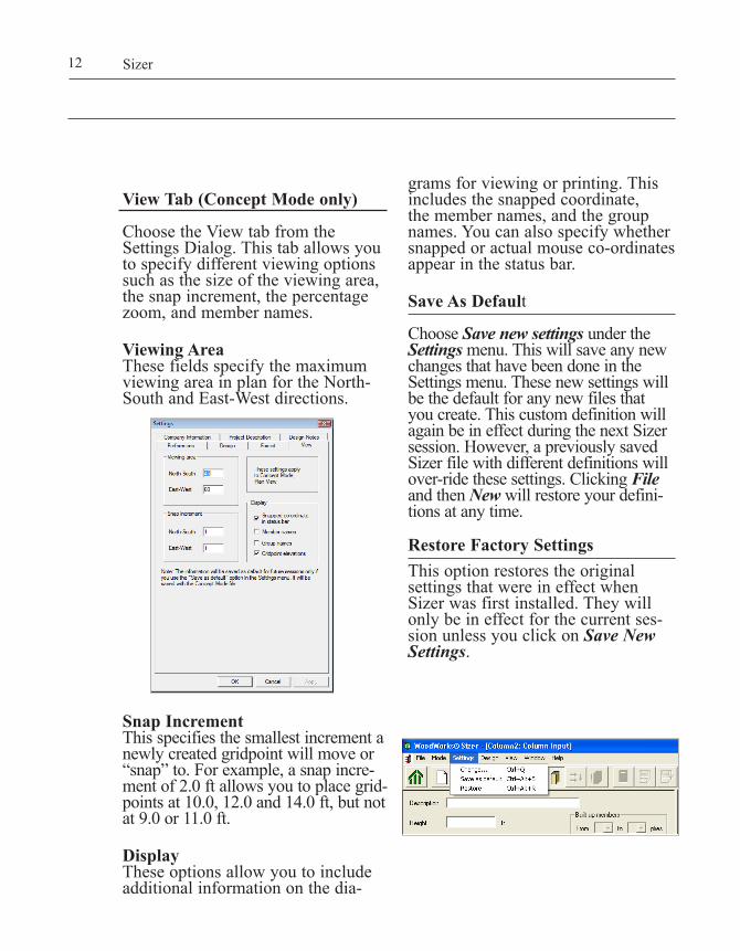
View Tab (Concept Mode only)
Choose the View tab from the Settings Dialog. This tab allows you to specify different viewing options such as the size of the viewing area, the snap increment, the percentage zoom, and member names.
Viewing AreaThese fields specify the maximum viewing area in plan for the North- South and East-West directions.
Snap IncrementThis specifies the smallest increment a newly created gridpoint will move or “snap” to. For example, a snap incre-ment of 2.0 ft allows you to place grid-points at 10.0, 12.0 and 14.0 ft, but not at 9.0 or 11.0 ft.
DisplayThese options allow you to include additional information on the dia-
grams for viewing or printing. This includes the snapped coordinate, the member names, and the group names.Youcanalsospecifywhethersnapped or actual mouse co-ordinates appear in the status bar.
Save As Default
Choose Save new settings under the Settings menu. This will save any new changes that have been done in the Settings menu. These new settings will be the default for any new files that you create. This custom definition will again be in effect during the next Sizer session.However,apreviouslysavedSizer file with different definitions will over-ride these settings. Clicking File and then New will restore your defini-tions at any time.
Restore Factory SettingsThis option restores the original settings that were in effect when Sizer was first installed. They will only be in effect for the current ses-sion unless you click on Save New Settings.
Sizer12

Creating New Files
When you start Sizer, it displays an untitled screen, allowing you to cre-ate a new file.
Whenever you choose New File from the File menu, Sizer clears the screen, discarding the current project. If you have modified the current project since you last saved it, Sizer asks you whether to save or discard your modi-fications.
Creating New Projects
In the file menu, there is an option of creatinganewproject(thiscanalsobe done by clicking on the Create or Manage Projects button on the toolbar),whichallowsseveralfilesto be grouped together from Sizer to form a project. When creating a new project, Sizer will prompt you to enter a project description that will be shared by each file in the project. The project can contain only one concept mode file and a number of beam and column files.
Saving Files
If you choose Save File from the File menu, Sizer saves the current file using the last name you gave it. If the file is a new one and you have not given it a name, the Save File command has the same effect as Save File As...(seebelow).If you choose Save File As... from the File menu, the current file is saved with the name you enter. In the Save As dialog box, the File Name fieldcontains(bydefault)thelast
namegiventothefile.Youcanspec-ify a different name if you wish.To change the file type, click the down arrow, select a file type and double-click it.
To change folders, select a folder from the Folders list and simply double-click the folder.
Click on Save File As... to save the file under the new name. If a file already exists with the name you specified, Sizer asks you to confirm that the exist-ing file should be overwritten. Click on Cancel to exit the Save File As... dialog without saving your file.
If you choose Save Project from the File menu, Sizer saves the current filesintheprojectwiththelastnameyou gave it. If the project is new and or has not been given a name, the Save Project command has the same effect as Save Project As...
Ifyouhaveseveralfilesopen(beam,columnandaconcept)andwishtosavealltheopenfilesintoanewproject, simply click on the Create or Manage Project button on the tool-bar.
1.3 Working with Files and Projects
WoodWorks® Design Office 13
A•1
What is Sizer?

Sizer14
The Save All button has the same ef-fect as Saveforalltheopenfiles.
Opening Files
To open an existing project, choose Open File from the File menu. The Open dialog appears. Type a file name(orselectonefromthelist)and then click Open to open that file.
If you select a new folder in the Folders list, the selected folder becomes the current folder. Select Cancel to return to editing the current file without opening a new one.
Opening Projects
To open an existing project, select Open Project from the File menu. The open dialog appears and the file type is .wprj. When a project is opened, all the files within that proj-ect are opened.
Printing Files and Graphics
To print a file or on-screen graph-ics, click on the Print button from the toolbar or choose Print from the
File menu. This will print the text or graphics image that is currently shown on screen.Depending on the mode you are in, you will have the choice of print-ing various text and graphics files as described below.
Concept Mode
Results by GroupThis text file contains the suggested sections for each group in a given structure after Sizer has designed them. This is the default design out-put when Sizer performs a design.

Results By MembersThe Results by Member output con-tains design results by group or by individual member, depending on the setting used in the Settings Prefer-ences tab. In both cases, Sizer identi-fies how each individual member has performed in the design stage.
Materials ListThis file contains a materials list, per floor, of all the framing elements used in your design.
GraphicsThe Concept mode allows you to print the plan and elevation views of the structure as they are displayed on the screen.
Beam and Column Modes
Analysis Results TextThis file contains the analysis results computed by Sizer. This includes such things as the maximum shears and bending moments.
Design Results TextThis file contains the suggested sec-tions for a given beam or column after Sizer has designed it.
Design Check TextThis file contains the design results computed by Sizer for a specific sec-tion. It includes such things as allow-able shear and bending stresses.
GraphicsThe Beam and Column modes al-low you to print the reaction, shear, bending moment, and deflection diagrams.
WoodWorks® Design Office 15
A•1
What is Sizer?

Sizer16

Designing a Beam
2.1 Beam Mode 192.2Beam(orJoist)Parameters 202.3 Loads 252.4 Points of Interest 312.5 The Design Process 322.6 Tutorial 37 A•2


What It Does
Beam mode allows you to quickly enter and design individual wood bending members. Beam mode pro-vides extensive information about a single beam or joist in your project. Typically you would use Beam mode to verify the design of critical mem-bers.
To select Beam mode, choose New File from the File menu and select Beam Mode or click on the Beam button on the toolbar.
When Beam mode is active, a check-mark is displayed next to Beam on the Mode menu.
Transfer of a Beam or Joist from Concept ModeIf you are operating in Concept mode and you wish to further ana-lyze a particular beam or joist, click on the beam or joist to select it and then choose Beam from the Mode menu or click the mode button on the toolbar.
Sizer first determines the design loads for the member in question, based on the structure entered in Concept mode. Sizer automatically transfers the load information to Beammode'sinputfields.
Note: The transfer from Concept to Beam mode is one-way. Any changes made to the transferred member can-not be exported back to the original member in Concept mode. There are a few exceptions, such as the selection of Self Weight:"manuallyinput"or"automaticallyincludedinloadsanalysis".Referto Helpon"Apply options to Concept Mode"whichrefers to what options can be tranferred with a click of a button in the Loads view, activated if Concept mode is open.
Transfer of Beam or Column from Autodesk's Revit® to SizerIf you have a structure designed in Revit®, you can import it into Sizer forspecificdesignverifications.Formore information, visit our website at www.woodworks-software.com.
2.1 Beam Mode
WoodWorks® Design Office 19
A•2
Designing a B
eam

Sizer20
2.2 Beam (or Joist) Parameters
Click the beam button on the toolbar todescribethebeam(orjoist)tobedesigned.
Sizer displays a diagram of the spans in the lower portion of the screen. The Design Span, Clear span, and Full span are all shown on the dia-gram. Sizer can also display cantile-vered and sloped beams.
DescriptionA description of the beam can be en-tered which will appear in the Design Results output and Design Check output.
Spans and Span TypeThislistboxdefines(inleft-to-rightsequence)thelengthofeachspan and cantilevers.
Before entering spans it is important to understand what type of span is being entered. Immediately be-low the Add, Delete and Modify is
a"Spantype"entrywhereDesign,Full, or Clear span can be selected. "Designspan"hasbeenthetradi-tional method used to enter spans in Sizer, and is the distance between support points on beams. Support points for exterior supports are ½ the minimum required bearing length from the inside of the support. For in-terior supports, they are at the centre of the support. The clear span is the distance between the inside faces of the supports, for all spans. Full span is measured from the outside faces of exterior supports, to the centre of interior supports. It is the beam length for single-span members. The graphical representation of the beam accurately illustrates these span types using dimensions.
To change the length of the span, select the span in the list of spans, change the length in the spans box, and then click Modify.
To delete spans, click the span you wish to delete and then click Delete.
CantileverThis drop-down list is only active when two or more spans have been added and it specifies cantilevers at either end of the beam. The outer end of a cantilevered span is unsup-ported.ThedefaultisNone(nocan-tileverateitherend).
Slope/PitchThis field specifies the slope of the beam in degrees or as a pitch. A horizontalbeam(thedefault)hasaslope of zero. A beam that slopes up

WoodWorks® Design Office 21
A•2
Designing a B
eam
to the right has a positive value. A beam that slopes down to the right has a negative value.
Level bearing is assumed and thus there is no horizontal thrust at sup-ports. Sloped members are only designed for flexure. It is assumed that axial force is insignificant in these members.
Joists supported by sloped members are spaced with respect to the longitu-dinal axis of the sloped member.
Built-up MembersIf the selected material can be used in built-up or multi-ply sections, these two drop-down lists specify the range of plies to use. The default selection is (unknown), which forces Sizer to select suitable sections for a range of plies.
If the material cannot be used in mul-tiply sections, these lists are disabled.
TypeThisdrop-downlistspecifiesthetypeof bending member to be designed -beam,floorjoistorroofjoist.Thedefault selection is Beam.
MaterialThisdrop-downlistspecifiesthematerial database to use. Standard choices include lumber, lumber n-ply, timber, glulam and many others. The default for beams is Timber.
SpeciesThisdrop-downlistspecifiesthespecies of wood to use for member design. Available species depend on
the selected material.
Thedefaultselectionis(unknown),which forces Sizer to select suitable sections from each species.
Grade or CombinationThis drop-down list specifies the grades of wood to use to design the member. Available grades depend on the selected database.
The default selection is (unknown),whichforcesSizertoselect suitable sections from each grade.
This list box is unavailable if the speciesisspecifiedas(unknown).
Width and DepthThe two width drop-down lists spec-ify the width range of the sections Sizer should use when designing the member. Similarly, the two depth drop-down lists specify the depth range. Available widths and depths depend on the selected database, spe-cies and grade.
The default selection for each of thesedrop-downlistsis(unknown),which forces Sizer to select from a full range of section sizes.
Youcanlimitthesectionsizestobeconsidered by selecting appropriate width and depth ranges in the drop-down lists.
These drop-down lists are unavail-ableifthegradeis(unknown).

Sizer22
To specify a custom section, enter somenon-standardsize(inactualdimensions)ineachdrop-downlist. Note that a custom size may not be commercially available.
Note: Sizer performs a design check rather than a design selection if both the width range and depth range specify single values. Sizer cannot design a section if only the width or depth is a custom size. For example, you cannot have one field as (unknown) when the other contains a custom size.
Deflection LimitsThese fields allow you to specify the deflection limits to be used for design,basedonthespan(exampleL/360)andinabsoluteterms(1inch).Defaultdeflectionlimitsareentered in Settings [Design] tab. See alsothe"Loads"buttonand"Loadtypesandcombinations"forlongtermdeflection(creep)andloadreductions(USonly).
Fire-retardant FactorThis field permits you to specify the reduction in bending, shear, and deflection resistance of wood treated with fire-retardant chemicals. In the U.S. version, to specify a value, click the check box.
NotchesSizer only designs notches at the ends of a beam. Notches can be
specified as being on the top or bot-tom of a beam. Both notch depth and length are required as input.
Lateral Support SpacingThese drop-down lists permit top and bottom lateral support to be specified as Full(fulllateralsupport),At Supports(lateralsupportprovidedatbearingsupportsonly),orataspeci-fied numeric interval. The defaults are Full for the top and At Supports for the bottom. Note: For some materials, this selec-tion is disabled. Notes in the output specify the necessary lateral support.
Glulam Lay-upThisfieldallowstheinputofwanefor certain combinations, with associ-ate strength reduction. It also allows the input of non-edge bonding with associated strength reduction
Oblique AngleThis field specifies the angle for oblique purlins. The default is blank (noangle).Byspecifyinganangleof 90°, you can investigate the use of the selected material database as a plank.
Treatment (Canada Only)When you select Fire-retardant treatment or Preservative treatment from the drop-down, an input field becomes active for you to input the corresponding modification factor.

WoodWorks® Design Office
Fire Design Button (U.S. Only)Clicking on this button opens the Fire Resistance dialog that allows you to specify fire endurance design criteria provided the Fire-endurance rating is activated in the Settings / Design tab.
Fire Endurance RatingSizer checks the Fire Endurance Rating of timber and glulam beams or columns. Sizer calculates the Fire Endurance Rating based on the num-ber of exposed sides and on the loads applied to a member. To activate the fire endurance check, the number of exposed sides must be defined. If the number of exposed sides is set to zero, the program will not perform the fire endurance check.
Fire Endurance Rating is activated through the Settings/Design tab.
Joist SpacingActive for joists only, this drop-down listspecifiesthejoistspacing.You can select one of the standard 12 in. (300mm),16in.(400mm),or24in.(600mm)spacingsorenteryourownvalue.
The tributary width for uniform area and partial area loads in Loads view is equal to the joist spacing set in the Joist Spacing field.
Incising Factor (U.S. Only)This field allows you to specify whether an incising modification fac-tor should be applied according to NDS 4.3.8.
Repetitive Member Factor(U.S.)/System Factor (Canada)This control allows you to specify if a load sharing factor is to be applied.
Service ConditionsThis drop-down list specifies either Wet or Dry service conditions for the beam. The default is Dry.
Temperature (U.S. Only)The default is T<100°F. Other val-ues for T are 100°F<T<125°F and 125°F<T<150°F.
Supports for Bearing DesignThese fields allow you to select the type of bearing as well as the support material for the bearing design. The type can be selected as hanger, beam, column, sill plate or other non-wood. The bearing length or width can be entered or the calculation of the bearing length can be made more specific.
23
A•2
Designing a B
eam

Sizer24
The bearing design information can beenteredfor"allsupports"atonce
(asshowninscreencapture)orsepa-ratelyfor"interior"versus"exterior"supports, or for each support inde-pendently. When the bearing length isnotentered(orleftas"unknown"),the"Forunknownbearinglength"entry is activated, and several choic-es are made available including: using the exact calculated minimum bearing length, rounding the calculat-ed bearing length to the closest user specified designation, automatically rounding up to the next choice in the "BearingLength"dropdownbox,ora combination of the previous two options useful for when a beam sits only partially on end supports but fully on interior supports.
Minimum bearing lengths can be specified in the Design tab of the Settings menu.
Vibration Buttons (Canada Only,Floor Joists Only)
This button opens the Vibration Design dialog box that allows you to specifydetailsthataffectfloorvibra-
tion. Vibration analysis is carried out accordingtoA-9.23.4.2.(2),Appen-dix A of the National Building Code of Canada.
Selecting Sections for Design Check
Sizer provides you with an extensive list of suggested sections for the beam it is designing. To get more details about a single section size, you can perform a design check on that section.
After running an initial design, select the section you want to check from the drop-down list entitled Suggested Beam Sections at the right side of the toolbar.
Sizer automatically fills in the Species, Grade, Width and Depth fields with the appropriate values. Sizer automatically performs a design check of the selected section.
The list of suggested sections on the toolbar remains available until you performanotherdesign(ratherthanadesigncheck).

WoodWorks® Design Office
Click the Loads View button on the toolbar to specify the loading of a beam(orjoist)thatistobedesigned.The Loads view opens.
NameUse the Name field to enter the name of the load you want to apply to the beam.(Sizergeneratesanappropriatenameifyouleavethisfieldblank.)The list box beneath this field con-tains the names of all the loads you have specified for this beam. Click one to select it.
TypeThis drop-down list specifies the type of load being applied. Sizer allows you to select from a variety of load types, including dead, live, roof live(U.S.only),snow,wind,impact(U.S.only),sustainedlive(storageandcontainedfluids)anddead(soil)(Canadianonly),earthquake,andhydrostatic(Canadaonly,columnsonly).TheU.S.versionalsoallowsall live loads or all roof live loads to beconsidereda"construction"load,and will use the appropriate duration factor if this is selected.
Depending on the load type speci-fied, Sizer will apply the correct load duration factor and load combina-tion factor to each load combination. For the Canadian version, Sizer also applies the correct load factor. The default load type is Dead.
25
A•2
Designing a B
eam
2.3 Loads

DistributionThis drop-down list specifies the type of load distribution: Full Uniform Line, Full Uniform Area, Partial Line, Partial Area, Triangular, Trap-ezoidal, Point and Applied Moment.At the bottom of the input section isa"Lineloadsappliedoverdesignspanonly"checkbox.Ifcheckedthe software distributes the line and area loads to the design span, not the entire beam. This is more a tool to compare files made in previous ver-sions which only applied loads to the design span.
MagnitudeThisfieldspecifiesthemagnitude(s)of the loads being applied. These magnitudes should be entered as specifiedloads(suchasthosestatedinbuildingcodes).WhenusingEng-lish units, Sizer allows you to change whether point loads are entered in pounds(lbs)orkilopounds(kips)through the Settings Format tab.
Note that area loads are converted toanddisplayedaslineloads(plforkN/m)ontheloaddiagram.
Magnitude: WidthThis field is only active for Full Uni-form Area and Partial Area load dis-tributions and is equal to the tributary width for the bending member. For joists, this value automatically cor-responds to the joist spacing selected in Beam input view.
Location From LeftThis field specifies the location of the selected load. It is active if the load distribution is Partial Line, Partial Area, Triangular, Trapezoidal, Point Load and Applied Moment.
For Partial Line loads, specify a start and an end measurement. For Trian-gular loads, specify a location where the load is zero and a location for the maximum load. For Trapezoidal loads, specify the locations of the minimum and maximum loads.
Pattern LoadingCheck this box to activate automatic pattern loading. Pattern loading is available in the Beam mode and is applicable to multi-span beams or joists when a live or snow load type is being applied continuously across the member. Sizer will take the live load and pat tern it on the various spans to find the worst case for de-sign. Pattern loading is an option that can be turned on or off at the Load input stage. Live loads are patterned as full- or no-load intensity. Snow loads are patterned as full- or half-load intensity.
Save as default loads:Once loads have been entered, click-ingthe"Save as default loads"but-ton stores the loads so that the next time the same member type is select-ed, the default loads will appear.
Saving default loads deletes the default loads that were previously savedforamembertype.Youcaneliminate default loads by pressing Save as default loads for a blank set of loads.
If repeating loads are included, the program includes only those repeat-ing loads that were applied to the original member when default loads are saved. It is advisable to create the longest possible member to apply default repeating loads to.
Sizer26

Default loads are automatically created for members that have not beensavedtodisk(anddonothaveafilelocation).Onceamemberhasbeen saved, no loads will be auto-matically created or deleted.
Repeating Point LoadsClick this button to specify multiple point loads with equal spacing and magnitude.
Loads
Load Direction AssumptionsSizer automatically applies the loads according to the following rules:• Mostloads,includingsnow,live
and dead loads, are applied verti-cally.
• Windloadsareappliedperpendic-ular to both sloped and horizontal members.
Gravityloads(downward)arerepre-sented by a positive load magnitude whilesuction(upward)loadsarerepresented by a negative load mag-nitude.
Sloped Member Load LocationWhen specifying the location of a load on a sloped member, use the horizontal projected length as a reference.
Sizer automatically applies dead and wind loads along the actual length of a sloped member. All other loads are applied along the horizontal projected length of a sloped member.
Load Entry"Enter point load as UDL"usesthe spacing to convert a point load to a uniformly distributed load on joists based on the spacing. More typically, this is used to create point loads on joists based on a uniformly distributed load, say from a wall above. This is especially useful when the spacing of joists is being reviewed, in that the line load from above is automatically converted to the correct point load on the joist based on revised spacing. For example a 1200 plf line load from a wall perpendicular to the floor joists imposes a 2400 lb point load onjoistsspacedat24"o.c.,1600lbsperjoistwhenspacedat16"o.c., and 1200 lbs per joist when spacedat12"o.c.Insteadofmanu-ally revising this point load for each spacing run, this load entry tool automates the process.
Add moving concentrated live load (Floor Joists Only)Onlyapplicabletofloorjoists,thisoptionallowsyoutodesignafloorjoist for a moving concentrated floorliveloadthatisrequiredby
WoodWorks® Design Office 27
A•2
Designing a B
eam

most building codes for certain build-ingcategoriesorflooruses.Whense-lected, Sizer automatically creates a concentrated live load with a default magnitude that acts over a default width. The magnitude and width canbemodified.Duringthedesignprocess, Sizer will determine the worst affects of the concentrated load located anywhere along the length of the member in conjunction with all other applied loads, except live loads, and all required load combinations where the concentrated live load acts in place of any loads of type live specifiedbytheuser.
Self-WeightIf "automatically included in loads analysis"isselectedbytheuser,theself-weight of a member is consid-ered in the design. The actual ef-fects of self-weight are calculated by multiplyingthespecificgravityofthematerial times the area of the section. This load is then added to the dead load when checked. Alternatively the self weight can be ignored or manu-allyaddedbyselecting"Must be manually input as load"
Beam supports area load from con-tinuous joistsWhen continuous joists, rather than simply supported joists, are load-ing on a beam, the reaction from the continuous joist is greater than the reaction that would be imposed sim-ply supported joists that end at the beam. In other words the reactions the continuous member imposes are not based on the tributary area alone. For example, when a continuous joist spans over the supporting beam, and the joist length is equal on both sides
of the designed beam, the reaction imposed on the designed beam is 1.25 times greater than would be calculated by the tributary area alone, asperbelowFigure29fromAWC'sDesign Aid No. 6, Beam Design Formulas with Shear and Moment Diagrams. The general case where the joists are continuous over the designed beam with unequal spans is also shown below, from Design Aid No. 6, Figure 31.
Accounting for the increased load a beam should be designed for when joists are continuous over the beam is donebyselectingthe"Beam supports area load from continuous supports"checkbox, and either indicating the ratio of the joist span on either side ofthebeambeingdesignedbyfirstselecting"2-spans",orindicatethepercent of load on the beam manually byselecting"Other".
Sizer28

WoodWorks® Design Office 29
A•2
Designing a B
eam
"Beam supports area load from continuous supports"isonlyenabledwhen a beam is being designed, and only applies to full uniform area and partial area loads.
Combine loads of same type in drawingThis option only applies to the load-ing diagram. When enabled, indi-vidual loads are accumulated into a singleloadingprofileforeachloadtype(dead,live,etc).Whennoten-abled, loads overlap with other loads of the same type. The selected load appears in bold.
Load Types and CombinationsSizer combines loads based on the Allowable Stress Design method using the basic load combinations intheIBC/ASCE(US)andLimitsStates Design load combinations (Canada).Inadditiontoconsideringthe building code load combinations based on the load types present, Sizer also creates load combinations to consider the affects of pattern loading live type loads for multi-span beams or joists when pattern loading is active. Refer to the Pattern Loading section for more informa-tion on pattern loads. The designer should verify that the load combina-tions used are adequate.
For Beam mode, Sizer outputs a list of load combinations with an explana-tion of each load combination number referred to in the results along with the appropriate load duration factor.
When snow loads are present S and s represent full and half snow loads respectively(e.g.,pattern:SsS).When
both snow and live loads are present X represents the full application of bothtypes(e.g.,pattern:XsX-U.S.Only).Windloadsarenotpatternedsince they are assumed to apply to all spans simultaneously.
For more information on load combi-nations or on pattern loading, refer to Onlinehelp.Youcancheckobscureload combinations by manually adjusting the load duration factors (U.S.only),orperformingindividualload combinations and load patterns.
Deflection Factors (U.S. Only)There are two leniencies offered in theIBCrelatedtodeflection.TheseoptionalIBCdeflectionfactorscanbe selected using two checkboxes. Thefirstallowsthedeflectionresult-ing from L + D to be calculated using L+ 0.5D for wood structural mem-bers having a moisture content under 16 percent at the time of installation and used in dry conditions. The second option is related to compo-nents and cladding wind loads, where deflectionmaybecalculatedusingonly 70 percent of the wind load.
The NDS provides guidance on considering the effects of long term deflectionbyincreasingthecontribu-tion of dead load by a creep factor, Kcr, that typically ranges from 1.5 to 2; any value can be entered if the "Include creep factor"ischecked.

Sizer30
Load Duration FactorsSizer applies load duration factors according to the load type. These factors are set to the standard NDS (U.Sversion)orCSAO86(Canadianversion)valuesbydefaultbutthesecan be changed using this form. (NotethatintheCanadianversion,when D > L, Sizer determines the default duration factor for standard term loads according to the equation shown in CSA O86-01 4.3.2.3 - refer totheonlinehelpfordetails).
Apply Options to Concept ModeThis button in Beam Load View and Column Load View, is only active when there is a Concept mode file open, and allows the application of the following settings to have an affect on Concept mode. This items can only be accessed from Beam or Column mode, and are:
• Self-weight• LineLoadsappliedoverdesign span only• Long-termdeflectionfactor• UseL+0.5Dfordeflection• LoaddurationfactorsCD• Loadcombinationsfrom…• Temperature(frombeamview)

2.4 Points of Interest
WoodWorks® Design Office 31
A•2
Designing a B
eam
Click the points of interest button on the toolbar to investigate the shear and moment at any point along the length of a beam or column. A point of interest is generated by specifying a location to perform the analysis. Now click Add to add this to the list. Several points of interest can be specified.
After performing a design, the point of interest results will be shown in the Diagrams window and in the Analysis results output.

Sizer32
2.5 The Design Process
Starting the Design Process
To start the design process, click the design button on the toolbar. Sizer performs an analysis, designs your beam with the information you entered and automatically displays the results.
If you selected (unknown) for some entries, Sizer selects a series of suit-able sections that provide acceptable results. If there are no (unknowns) and you have not specified ranges in the width or depth fields, Sizer does a design check on the specified section and verifies that the results are within the selected design code’s limits.
The number of sections that Sizer selects depends on how many fields you specified as (unknown) in the beam screen.
Sizer normally prompts you to save the current project prior to doing the design. To change this, choose one of the Save Before Design options from the Settings dialog.
Save Before Design (Prompt first)Tells Sizer to prompt you to save the current worksheet prior to start-ing the design process. This is the default.
Save Before Design (Always save)Tells Sizer always to save the cur-rentprojectautomatically(withoutpromptingyou)priortostartingthedesign process.
Save Before Design (Never save)Tells Sizer not to save the current project prior to starting the design process. Sizer will not even prompt you to save.

WoodWorks® Design Office
Viewing and Printing the Results
Once Sizer has designed the beam, it creates results files. Sizer then gives you several options for viewing the results.
Analysis ResultsClick the analysis button on the toolbar to see the analysis results for each load combination (maximumshears,bendingmomentsandsoon)foryourbeamorjoistin tabular form.
Design ResultsIf you specified any field as (unknown) for your beam or joist, Sizer computes all the possible beam or joist sections dur-ing the design process. It also com-putes the ratios of analysis/design values for bending, shear, and dis-placement for each section.
To see these results, click on the Design Summary button on the tool-bar menu or choose Design Results from the View menu.
33
A•2
Designing a B
eam
Sizer34
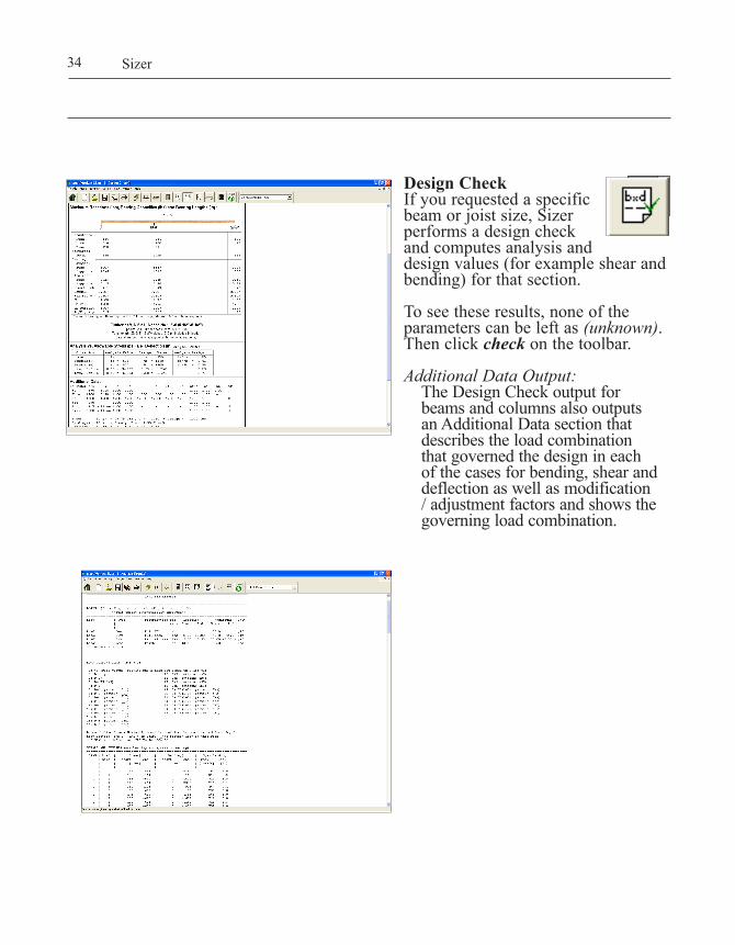
Design CheckIf you requested a specific beam or joist size, Sizer performs a design check and computes analysis and designvalues(forexampleshearandbending)forthatsection.
To see these results, none of the parameters can be left as (unknown). Then click check on the toolbar.
Additional Data Output:The Design Check output for beams and columns also outputs an Additional Data section that describes the load combination that governed the design in each of the cases for bending, shear and deflection as well as modification / adjustment factors and shows the governing load combination.

WoodWorks® Design Office
Analysis DiagramsClick the diagram button on the toolbar to view theanalysis diagrams.
Sizer creates four analysis diagrams including Support, Shear, Bending, and Deflection diagrams.
To print the current diagram, click the print button on the toolbar.• View… – This button con-
trols which analysis diagrams are shown, including the Load Envelope, Reaction, Shear, Moment and Deflection diagrams. The Load Envelope diagram is not available when Critical Results is selected as the load combination.
• Load Combinations – The dia-gram view results shown are based on the load combination selected in this pull-down menu. When Critical Results is selected, the analysis diagrams shown are for the worst case results of all load combinations. Load combina-tion numbers shown correspond to those used throughout Sizer (AnalysisResults,DesignCheck,diagrams,etc.).
• Deflection Results - The deflec-tion results can be viewed as total load or live load, based on this pull-down menu.
35
A•2
Designing a B
eam

Printing ResultsTo print results, click on the Print All button from the toolbar when the result file or graphics screen that you wish to print is on screen. To batch print the analysis diagrams for all load combi-nations, press Print All.
Sizer36

2.6 Tutorial
WoodWorks® Design Office
Defining the Parameters1. Start the program in Beam mode.2. Select the Span field and enter a spanof15(ft).
3. Click Add.4. Repeat steps 2 and 3 for two addi-
tional spans of 15 ft and 5 ft 6 in.5. Choose Right from the Cantilever
drop-down list.6. Although you can try different
materials, select Lumber n-plyfor this example.
7. Select species type S-P-F.
8. Under End Notches select the at Top field and enter a depth of 2 (in)andanunsupportedlengtheof3(in).
37
A•2
Designing a B
eam

Sizer38
Loading the Beam1. Click the loads button on the
toolbar.2. Choose Dead from the Type drop-
down list.3. Ensuring that the Distribution
field is Full Uniform Line, select the Magnitude field and enter a valueof100(plf).
4. Click Add.
5. Choose Live from the Type drop-down list.
6. Select the Magnitude field and enteramagnitudeof200(plf).
7. Ensure that the Pattern Loading box is checked.
8. Click Add.9. Changing the Distribution field to
Point Load, select the Magnitude field and enter a magnitude of 350(lbs).
10. Select the Location From Left field and enter a distance of 35 ft 6 in.
11. Choose Live from the Type drop-down list and click the Pattern Loading checkbox.
12. Click Add.

Designing the Beam1. Click the design button on the
toolbar. Sizer automatically designs the member.
2. Youwillbeaskedtoenterafilename for your project.
View Results1. Click the up and down arrows to
scroll through the Design Results output.
2. To print these results, choose the print button from the toolbar.
NOTE: The output shown is based on the U.S. National Design Specification®.
View Analysis Diagrams1. Click the diagram button on the
toolbar to view reactions, shear, bending moments and deflection diagrams.
WoodWorks® Design Office 39
A•2
Designing a B
eam

Sizer40
Perform a Detailed Design on a Specific Section1. Choose S-P-F No.1/No.2 2-2X10
from the Suggested Beam Sections drop-down list on the toolbar.
2 Sizer will automatically perform a detailed design on the specific section chosen.
3. The results for the specified sec-tion are now displayed as shown.
4.Youcanrepeattheabovestepstoperform a detailed design on any other glulam section listed in the Suggested Beam Sections drop-down list.

Designing a Column
3.1 Column Mode 433.2Column(orWall)Parameters 443.3 Loads 483.4 Points of Interest 513.5 The Design Process 523.6 Tutorial 55
A•3


What It Does
Column mode allows you to quickly enter and design individual wood columns, walls and beam-columns under multiple load conditions. Column mode provides extensive information about a single column or wall in your project. Typically, you would use Column mode to verify the design of critical members.
To select Column mode, click new on the toolbar and choose column.
When Column mode is active, a checkmark is displayed next to Column on the Mode menu.
Transfer of a Column (or Wall) from Concept ModeIf you are operating in Concept mode and you wish to further ana-lyze a particular column or wall, click the column or wall to select it and then choose Column from the Mode menu, or click the mode but-ton on the toolbar.
Sizer first determines the axial design loads for the column or wall in question, based on the structure entered in Concept mode. Sizer auto-matically transfers the load informa-tion to the input fields of Column mode. For walls, it transfers the load information for a single wall stud.
Note: The transfer from Concept to Column mode is one-way. Any changes you make to the transferred member cannot be exported back to the original mem-ber in Concept mode. There are a few exceptions, such as the selection of Self Weight:"manuallyinput"or"automaticallyincludedinloadsanalysis".Referto Helpon"Apply options to Concept Mode"whichrefers to what options can be tranferred with a click of a button in the Loads view, activated if Concept mode is open.
WoodWorks® Design Office 43
A•3
Designing a C
olumn
3.1 Column Mode

Sizer44
3.2 Column (or Wall) Parameters
Click column on the toolbar to describethecolumn(orwall)tobedesigned.
HeightThis field specifies the height of the column or wall in the current units.
A height must be specified in order to continue with the design.
TypeThis drop-down list specifies the type of compression member (ColumnorWall)tobedesigned.The default selection is Column.
DescriptionA description of the column can be entered which will appear in the Design Results output and Design Check output.
MaterialThis drop-down list specifies the material database to use. Standard choices include timber post, glulam and a number of others. The default for columns is Timber-soft. The default for walls is Lumber Stud.
SpeciesThis drop-down list specifies the species of wood to use to design the member. Available species depend on the selected database. For example, common choices for softwood timber areD.Fir-L,Hem-Fir,S-P-F,andS.Pine.
The default selection is (unknown) which forces Sizer to select suit-able sections from each species.
Grade or CombinationThis drop-down list specifies the grades of wood to use to design the member. Available grades depend on the selected database. For example, common choices for timber are No.2, No.1, and SS.
The default selection is (unknown) which forces Sizer to select suit-able sections from each grade.
This list box is unavailable if the species is (unknown).

WoodWorks® Design Office
Width and DepthThe two width drop-down lists spec-ify the width range of the sections Sizer should use when designing the member. Similarly, the two depth drop-down lists specify the depth range. Available widths and depths depend on the selected database, spe-cies and grade.
The default selection for each of these drop-down lists is (unknown), which forces Sizer to select from a full range of section sizes.
Youcanlimitthesectionsizestobeconsidered by selecting appropriate width and depth ranges in the drop-down lists.
These drop-down lists are unavail-able if the grade is (unknown).
To select a custom section, enter somenon-standardsize(inactualdimensions)ineachdrop-downlist. Note that a custom size may not be commercially available.
Note: Sizer performs a design check rather than a design selection if both the width range and depth range specify single values. Sizer cannot design a section if only the width or depth is a custom size. For example, you cannot have one field as (unknown) when the other contains a custom size.
Built-up MembersIf the selected material can be used in built-up sections, these two drop-down lists specify the range of plies to use. The default selection is (unknown), which forces Sizer to select suitable sections of a range of plies.
For built-up members, the connec-tion type used to assemble the mem-ber can also be specified. This affects the resistance of a member.
If the material cannot be used in built-up sections, these lists are dis-abled.
Deflection LimitsThese fields allow you to specify the deflection limits to be used for design,basedonthespan(exampleL/360)andinabsoluteterms(1inch).Defaultdeflectionlimitsareentered in Settings [Design] tab. Seealsothe"Loads"buttonand"Load types and combinations"forlongtermdeflection(creep)andloadreductions(USonly).
45
A•3
Designing a C
olumn

Sizer46
Lateral Support Spacing andEnd ConnectionsSelect Pinned if the column base does not resist bending, or Fixed for a column base that does resist. For fixed column base, select pinned or free for the column top. Free column tops do not resist bending or transla-tion.
KeL for WidthThe Lb field specifies the unsupport-ed length associated with width b. The Ke field specifies the effective length factor. Its default value is 0.8 for columns with a fixed base, and 1.0 for columns with a pinned base. For free tops, the default value is 2.1 for U.S. and 2.0 for Canada.
KeL for DepthThe Ld field specifies the unsupport-ed length associated with depth d. The Ke field specifies the effective length factor. Its default value is 0.8 for columns with a fixed base, and 1.0 for columns with a pinned base. For free tops, the default value is 2.1.
Glulam Lay-up (U.S. Only)This field allows the input of wane for certain combinations, with associ-ated strength reduction. It also allows the input of non-edge bonding with associated strength reduction.
Fire Design Button (U.S. Only)Clicking on this button opens the Fire Resistance and Treatment dia-log that allows you to specify fire endurance design criteria and a fire-retardant factor.
Fire Endurance RatingSizer checks the Fire Endurance Rating of timber and glulam beams or columns. Sizer calculates the Fire Endurance Rating based on the num-ber of exposed sides and on the loads applied to a member. To activate the fire endurance check, the number of exposed sides must be defined. If the number of exposed sides is set to zero, the program will not perform the fire endurance check.
Fire Endurance Rating is activated through the Settings/Design tab.
Service ConditionThis drop-down list specifies either Wet or Dry service conditions for the column or wall. The default is Dry.
Temperature (U.S. Only)The default is T<100°F. Other val-ues for T are 100°F<T<125°F and 125°F<T<150°F.
Support for Bearing DesignThese fields allow the user to choose the type, material, species, grade and bearing length for the column or wall stud. These fields cannot be left as unknown. The results will be shown in the Design Results to let the user know if the support bearing is suf-ficient for the column. For example, a bottom plate supporting a lumber stud can be designed if the Type is appropriatelyselected.If"Same as wall stud"isnotselected,thebottomplate'sspecificmaterial, species, and grade can be entered. otherwise the same materials as the wall stud is used.

WoodWorks® Design Office
The checkbox “Bearing at Support End” indicates that the supporting beam, sill plate, or wall bottom plate ends at the column or wall, so that the bearing length factor CB is not applied.
Fire-Retardant FactorThis field permits you to specify the reduction in compression, bend-ing, shear, and deflection resistance of wood treated with fire-retardant chemicals.
Treatment (Canada Only)When you select Fire-retardant treatment or Preservative treatment from the drop-down, an input field becomes active for you to input the corresponding modification factor.
Stud SpacingActive for walls only, this drop-down listspecifiesthestudspacing.Youcan select one of the three standard spacingsof12in.(300mm),16-in.
(400mm),or24in.(600mm),orenter your own value.
Repetitive Member Factor (U.S.)/Load Sharing (Canada)This control allows you to specify if a sharing factor is to be applied.
Incising Factor (U.S. Only)This field allows you to specify whether an incising adjustment fac-tor should be applied.
Selecting Sections for Design Check
Sizer provides you with an extensive list of suggested sections for the column it is designing. To get more details about a single section size, you can perform a design check on that section.
After running an initial design, select the section you want to check from the drop-down list entitled Suggested Column Sections at the right side of the toolbar. Sizer automatically fills in the Species, Grade, Width and Depth fields with the appropriate values. Sizer also automatically performs a design check on the selected section.
The list of suggested sections on the toolbar remains available until you performanotherdesign(ratherthanadesigncheck).
47
A•3
Designing a C
olumn

Click loads view on the toolbar to specify the loading of a column that is to be designed.
NameUse the Name field to enter the name of the load you want to apply to the column.(Sizergeneratesanappro-priate name if you leave this field blank.)Thelistboxbeneaththisfieldcontains the names of all the loads you have specified for this column. Click one to select it.
TypeThis drop-down list specifies the type of load being applied. Sizer allows you to select from a variety of load types, includingdead,live,rooflive(U.S.only),snow,wind,impact(U.S.only),sustainedlive(storageandcontainedfluids)anddead(soil)(Canadianonly),earthquake,andhydrostatic(Canadaonly,columnsonly).TheU.S. version also allows all live loads or all roof live loads to be considered a"construction"load,andwillusetheappropriate duration factor if this is selected.
Depending on the load type specified, Sizer will apply the correct load dura-tion factor and load combination fac-tor to each load combination. For the Canadian version, Sizer also applies the correct load factor. The default load type is Dead.
DistributionThis drop-down list specifies the type of load distribution: Axial, Full Uniform Line, Partial Line, Full Uniform Area, Partial Area, Triangular, Trapezoidal, Point and Applied Moment.
Axial loads are applied to the top of the column, where a positive value loads the column in compression. The remaining loads are applied laterally and load the column as a beam.
For walls, an axial load is entered as a uniformly distributed line load along the top of the wall.
Sizer applies lateral loads to the face identified in the Load Face box of the Column screen.
MagnitudeThisfieldspecifiesthemagnitude(s)of the column load at the beginning and end of the loaded portion of themember(ForaPointload,onlyoneloadmagnitudeisspecified.).True Uniform loads should have the same magnitude at point a and b. Trapezoidal loads usually have dif-ferent values for the two magnitudes.
Sizer48
3.3 Loads

Note that area loads are converted toanddisplayedaslineloads(plforkN/m)ontheloaddiagram.
EccentricityThis field applies only to axial loads, with the same eccentricity for all. The bend ing effect is the same for an eccentricity and a lateral load, when both have positive values.
Location From BottomThis field specifies the location of the selected load. The information required depends on the type of load distribution.
For lateral loads, distance is mea-sured from the bottom of the col-umn. For axial loads, eccentricity is measured from the center of the column.
Add Loads of Same TypeThis option only applies to the load-ing diagram. When enabled, indi-vidual loads are accumulated into a single loading profile for each load type(dead,live,etc).Whennotenabled, loads overlap with other loads of the same type. The selected load appears in bold.
Loads and Load Combinations
Load Types and CombinationsSizer combines loads based on the Allowable Stress Design method using the basic load combinations in the IBC/ASCE(US)andLimitsStatesDesignloadcombinations(Canada).In addition to considering the build-ing code load combinations based on the load types present, Sizer also creates load combinations to consider the affects of pattern loading live type loads for multi-span beams or joists when pattern loading is active.
LoadDurationFactors(U.S.Only)Sizer applies load duration fac-tors according to the load type. These factors are set to the standard NDS(U.S.version)orCSAO86(Canadianversion)valuesbydefaultbut can be changed using this form. (NotethatintheCanadianversion,when D > L, Sizer determines the default factor for standard term loads according to the equation shown in CSA O86-01 4.3.2.3 - refer to the onlinehelpfordetails).
WoodWorks® Design Office 49
A•3
Designing a C
olumn

Apply Options to Concept ModeThis button in Beam Load View and Column Load View, is only active when there is a Concept mode file open, and allows the application of the following settings to have an affect on Concept mode. This items can only be accessed from Beam or Column mode, and are:
• Self-weight• LineLoadsappliedoverdesign span only• Long-termdeflectionfactor• UseL+0.5Dfordeflection• LoaddurationfactorsCD• Loadcombinationsfrom…• Temperature(frombeamview)
Self-WeightIf "automatically included in loads analysis"isselectedbytheuser,theself-weight of a member is consid-ered in the design. The actual ef-fects of self-weight are calculated by multiplyingthespecificgravityofthematerial times the area of the section. This load is then added to the dead load when checked. Alternatively the self weight can be ignored or manu-allyaddedbyselecting"Must be manually input as load".
Load FaceSelect Width if lateral loads such as wind are applied to the narrow face of the member, or Depth if applied to the wide face. All lateral loads and eccentric axial loads cause bending about the same axis.
Deflection Factors (U.S. Only)There are two leniencies offered in theIBCrelatedtodeflection.TheseoptionalIBCdeflectionfactorscanbeselected using two checkboxes. The firstallowsthedeflectionresultingfrom L + D to be calculated using L+ 0.5D for wood structural members having a moisture content under 16 percent at the time of installation and used in dry conditions. The second option is related to components and claddingwindloads,wheredeflec-tion may be calculated using only 70 percent of the wind load.
The NDS provides guidance on considering the effects of long term deflectionbyincreasingthecontribu-tion of dead load by a creep factor, Kcr, that typically ranges from 1.5 to 2; any value can be entered if the "Include creep factor"ischecked.
Sizer50

WoodWorks® Design Office 51
A•3
Designing a C
olumn
3.4 Points of Interest
Click the points of interest button on the toolbar to investigate the shear and moment at any point along the length of column or beam. A point of interest is generated by specifying a location to perform the analysis. Now click Add to add this to the list. Several points of interest can be specified.
After performing a design, the point of interest result will be shown in the Diagrams window and in the Analysis results output.

Sizer52
3.5 The Design Process
Starting the Design Process
To start the design process, click design on the toolbar. Sizer per-forms an analysis and design of your column with the information you entered and automatically displays the results.
If you specified (unknown) for some entries, Sizer selects a series of suit-able sections that provide acceptable results. If there are no (unknowns) and you have not specified ranges in the width or depth fields, Sizer does a design check on the specified section and verifies that the results are within the selected design code’s limits.
The number of sections that Sizer selects depends on how many fields you specified as (unknown) in the column screen.
Sizer prompts you to save the current project prior to doing the design. To change this, choose one of the Save Before Design options from the Settings menu.
Save Before Design (Prompt first)Tells Sizer to prompt you to save the current worksheet prior to start-ing the design process. This is the default.
Save Before Design (Always save)Tells Sizer always to save the cur-rentprojectautomatically(withoutpromptingyou)priortostartingthedesign process.
Save Before Design (Never save)Tells Sizer not to save the current proj-ect prior to starting the design process. Sizer will not even prompt you to save.

WoodWorks® Design Office 53
A•3
Designing a C
olumn
Viewing and Printing the Results
Once Sizer has designed the column, it creates results files. Sizer then gives you several options for view-ing the results.
Analysis ResultsClick the analysis button onthe toolbar to see the analysisresults(maximumshears,bendingmomentsandsoon)foryourcol-umn, beam-column or stud wall in tabular form.
Design ResultsIf you specified any field as (unknown) for your columnor stud wall, Sizer computes all the possible column, beam-column or stud wall sections during the design process. It also computes the ratios of analysis/design values for axial, bending, combined axial and bend-ing, shear, and displacement for each section.
To see these results, click on the results button on the toolbar menu or choose Design Results (Suggested Sections) from the View menu.
Design CheckIf you requested a specificcolumn, beam-column, orstud size, Sizer performs adesign check and computes analysis anddesignvalues(forexampleaxial,shear,andbendingmoment)forthesection.
To see these results, none of the parameters can be left as (unknown). Then click check on the toolbar.

Sizer54
Printing ResultsTo print results, click on the print button when the resultfile or diagram screen that you wish to print is on screen. To batch print the analysis diagrams for all load combinations, press Print All.
Analysis DiagramsClick the diagram button onthe toolbar to view the analy-sis diagrams.
Sizer creates five analysis diagrams; the load Envelope, Support, Shear, Bending, and Deflection diagrams.
To print the current diagram, click the print button on the toolbar• View… – This button con-
trols which analysis dia-grams are shown, includ-ing the Load Envelope, Reaction, Shear, Moment and Deflection diagrams. The Load Envelope diagram is not available when Critical Results is selected as the load combination.
• Load Combinations – The dia-gram view results shown are based on the load combination selected in this pull-down menu. When Critical Results is selected, the analysis diagrams shown are for the worst case results of all load combinations. Load combina-tion numbers shown correspond to those used throughout Sizer (AnalysisResults,DesignCheck,diagrams,etc.).

WoodWorks® Design Office 55
A•3
Designing a C
olumn
3.6 Tutorial
Defining the Parameters1. Start the program in Column
mode.2. Select the Height field and
enter a height of 9(ft).
3. Under Lateral Support Spacing for KeL, select Width (Lb) field and enter 36(in)fortheunbracedlength in the narrow direction.

Sizer56
Loading the Column1. Click load on the toolbar.2. Choose Dead from the Type
drop-down list.3. Specify Axial as the load
Distribution.4. Select the Magnitude field and
enteramagnitudeof5600(lbs).5. Click Add.
6. Repeat steps 2 to 5 for the fol-lowing:
Snow, 8400(lbs) Live, 6750(lbs)7. Choose Full Uniform Line from
the Distribution pull-down.8. Select the Magnitude field and
enter a magnitude of 150(plf).9. Choose Wind from the Type
drop-down list.10. Click Add.

WoodWorks® Design Office 57
A•3
Designing a C
olumn
Designing the Column1. Click the design button on the
toolbar. Sizer automatically designs the member.
2. Youwillbeaskedtoenterafilename for your project.
View Results1. Click the up and down arrows to
scroll through the results.2. To print these results, click the
print button on the toolbar.
NOTE: The output shown is based on the most recent U.S. National Design Specification® for Wood Construction.
View Analysis Diagrams1. Click diagram in the toolbar to
view reactions, shear, bending moments and deflection diagrams.

Sizer58
Perform a Detailed Design on a Specific Section1. Choose D.Fir L > No.2> 6-x 8
from the Suggested Sections drop-down list on the status bar. Sizer automatically performs a detailed design for this section.
2. Click the up and down arrows to scroll through the results.
3. Repeat step 1 to perform a detailed design on any other section listed in the Suggested Sections drop-down list.

Designing a Structure
4.1 Concept Mode 614.2 Levels 624.3 Design Groups 634.4 Gridlines and Gridpoints 694.5 Columns 734.6 Walls 754.7 Beams 784.8 Joists 824.9 Loads 904.10 Elevation View 934.11 The Design Process 944.12 Advanced Features 964.13 Tutorial 99
A•4


WoodWorks® Design Office
By default, Sizer starts in Concept mode. If you wish, you can recon-figure Sizer to start in Beam mode or Column mode by changing the default Startup Mode option in the Settings menu under Preferences. To switch to Concept mode at any time, choose Concept from the Mode menu.
The Concept mode graphical work area allows you to quickly design a complete structure using columns, walls, beams and joists. The Concept mode will only design for grav-ity type loads. These loads must be applied as uniformly distributed line or area loads.
The Concept mode is meant to be used as a preliminary design step. For a more detailed design, individ-ual members can be imported from the Concept mode to the Beam or Column modes.
Click items in the work area to select them. If you hold down the ctrl key when you click, you can add or remove items from the currently selectedset.Youcanchoose Select All from the Edit menu to select all of the items in the current view.
61
A•4
Designing a Structure
4.1 Concept Mode

Sizer62
4.2 Levels
Click on the level button on the tool-bar menu. The Levels dialog opens and allows you to specify the eleva-tion for each level of your structure.
To add level elevations, enter a new value and click Add. The maximum number of new levels is six.
When design of a structure has already begun, the option of copying the selected levels to the new ones is visible. Sizer will not, however, convertroofjoiststofloorjoistsorvice versa.
To modify any existing level eleva-tion, select it, enter a new value and click Modify.
To delete a level elevation, select it and click Delete.
Click OK to save your changes or click Cancel to discard your chang-es.
The Levels dialog is also used to change to different levels. Select a level by clicking on it so that it is highlighted. Click OK and Sizer will change to the selected level. Another way to change to different levels is by using the drop-list in the toolbar.

4.3 Design Groups
WoodWorks® Design Office
Why they are used
The Sizer design process is based on “design groups”. Design groups allow you to group similar mem-bers together for the design process. Sizer determines the lightest section size that can be used for each of the design groups, based on the most critical member in each group.
Youcanmakeyourgroupdivisionsas coarse or as fine as you wish. Anything from a single group for all beams to a separate beam group for eachbeamisacceptable.However,asingle group for all beams will likely result in excessively large section size for many beams. Similarly, a separate beam group for each beam (whiledeterminingtheoptimalsizeforeachbeam)resultsinanexces-sively large number of different sec-tions for construction.
How to create them
Design groups are created using a dialog, as described in the following sections. To help you get started, Sizer provides default design groups for each major structural element:• Columnforcolumns• Wallforwalls• Beamforbeams• FloorJoistforfloorjoists• RoofJoistforroofjoists
Group DialogTo create a new group, enter appropri-ate values in the dialog fields and then click Add.
To change a design group, select the group from the list, change any of the values in the dialog fields and then click Modify.
To delete a design group, select the group from the list and then click Delete.
63
A•4
Designing a Structure

Sizer64
Column Groups
Click column on the toolbar to change the view to Columns. Now click Groups on the toolbar. The dialog box named Column Design Groups opens.
Column Dialog Items
NameThis field contains the name of the currently selected group. The list beneath contains all the column groups created. Click on a group to select it. Once highlighted, you can modify or delete it.
To Be DesignedSelect this check box if the design group is to-be-designed. Leave it unchecked if the design group is not-to-be-designed. Unchecking it disables all field selections. Either design group supports and transfers loads.
Dry ServiceThis check box is checked if the ser-vice condition of the design group is dry. If the service condition is wet, this box should be unchecked.
MaterialThis drop-down list specifies the material database. The standard choices include timber, multi-ply lumber, glulam and a number of others. The default for columns is Softwood Timber.

SpeciesThis drop-down list specifies the spe-cies of wood to use for the design process. Available species depend on the selected database, but common choicesfortimberareD.Fir-L,Hem-Fir, S–P–F and S.Pine. The default is the first species in the list.
GradeThis drop-down list specifies the grades of wood to use for the design process. Available grades depend on the selected database, but common choices for tim ber are No. 2, Dense No.2(U.S.Only),No.-1andDenseNo.1(U.S.Only).ThedefaultisNo.2.
WidthThese two drop-down lists determine the width range of the sections to be considered in the design process. Available widths depend on the selected database, species and grade. The default selection is (unknown) for each of the lists, which forces the design process to select from the full range of section widths. To specify a limited range of widths to be consid-ered, select a different width in either or both of the lists.
DepthThese two drop-down lists deter-mine the depth range of the sec-tions to be considered in the design process. Available depths depend on the selected database, species, grade and width. The default selection is (unknown) for each of the lists, which forces the design process to select from the full range of section depths.
To specify a limited range of depths to be considered, select a different depth in either or both of the lists.
No. Of Sides Exposed (U.S. Only)Select the number of sides of the member that are exposed for cal-culating fire endurance rating. The selections are 0, 3 or 4 sides. Select 0 to indicate that the member is fully sheathed and no fire resistance calcu-lation is to be performed.
Fire Endurance Rating (U.S. Only)Enter the required fire endurance time. Do not enter a value greater than 60 minutes as this falls outside the research upon which the method-ology is based. Sizer will attempt to find a section whose fire endurance meets or exceeds the value you enter, according to IBC 721.6.3.
Column Assumptions
Note that Sizer defaults to the fol-lowing assumptions:• Columnsarepinnedatboth
ends.• Columnsarelaterally
restrained only at the ends.
WoodWorks® Design Office 65
A•4
Designing a Structure

Sizer66
Wall Groups
Click wall on the toolbar to change to Walls view. Now click Groups on the toolbar. The dialog box named Wall Design Groups opens.
Wall Dialog Items
When creating design groups for walls, you use a dialog similar to the one used to create design groups for columns. The additional informa-tion in the beam dialog is described below.
SpacingThis drop-down list specifies the studspacing.Youcanselectoneofthree standard spacings or enter your own value.
Repetitive Member Factor (U.S.) Load Sharing System Factor (Canada)Sizer assumes that all walls act as a system and as a default applies the repetitive member factor Cr for the U.S. or the system factor KH for Canada.
Wall Assumptions
Note that Sizer defaults to the fol-lowing assumptions:• Wallsarepinnedatboth
ends.• Wallsarepreventedfrombuck-
ling about the weak axis by wall sheathing.

WoodWorks® Design Office
Beam Groups
Click beam on the toolbar to change to Beams view. Now click Groups on the toolbar. The dialog entitled Beam Design Groups opens.
Beam Dialog ItemsWhen creating design groups for beams, you use a dialog similar to the one used to create design groups for columns and walls. The addi-tional information in the beam dialog is described below.
MaterialIn addition to the standard choices such as timber and glulam, new material databases have been addedtoincludeSCL(StructuralCompositeLumber)materialsfor
beams only. This material is more commonly known as Parallel Strand Lumber(PSL),LaminatedStrandLumber(LSL)orLaminatedVeneerLumber(LVL).
Deflection LimitsThe Live field specifies the maxi-mum allowed deflection of the design group member for live loads.
The Total field specifies the maxi-mum allowed deflection of the design group member for total loads.
Laterally SupportedSelect this check box if the top of the beam is laterally braced continu-ously while the bottom is laterally restrained only at supports.
Note: This selection is only avail-ableforglulam(Canadianonly).Forallothermaterials,notes are provided in the out-put specifying the necessary lateral support.
67
A•4
Designing a Structure

Sizer68
Load Transfer Number (beam-to-beam)This field determines how loads are transferred from beams of one group to beams of another group. Loads always transfer from a group with a higher load transfer number to a group with a lower load transfer num-ber. For instance, in order to transfer the load from one beam directly to another beam the supported beam needs a higher Load Transfer number than the supporting beam. Use num-bersbetween0(default)and99.Theactual Load Transfer number is not significant, a supported member only needs to have a higher number than the supporting member.
Joist Groups
Click joist on the toolbar to change the view to Joists. Now click Groups on the toolbar. The dialog entitled Joist Design Groups opens.
Floor Joist Vibration (Canada Only)When using floor joists, the sheath-ing thickness, lateral support and connection to subfloor can be select-ed from a drop-down list for the determination of floor vibration
Joist Dialog ItemsWhen creating design groups for joists, you use a dialog similar to the one used to create design groups for columns, walls and beams. The addi-tional information in the joist dialog is described below.
MaterialStandard choices for joists include I–joists and dimension lumber. Visually graded dimension lum-ber is referred to as Lumber and machine stress rated dimension lum-ber as MSR Lumber. The default is Softwood Lumber.
GradeAvailable grades depend on the selected database, but common choic-es for lumber are Select Structural, No.-1 and No. 2. The default is No. 2.
SpacingThis drop-down list specifies the joist spacing. Select one of three standard spacings or enter your own value.
Design Groups Summary
Once you have specified your design groups, you can create your structure in the Concept mode.

4.4 Gridlines and Gridpoints
WoodWorks® Design Office
Gridlinesarehorizontal(East-West)orvertical(North-South)linesposi-tioned on the work area. Gridlines appear as dark blue dashed lines in the Grid view. The intersection of a North-South gridline with an East-West gridline is a gridpoint.
When you change from Grid view to any other view, the gridlines appear as light gray dashed lines.
Under View in the Settings menu, a snap increment option is available for gridlines. A snap increment allows you to determine the smallest incre-ment a newly created gridpoint will move or “snap” to.
Automatic Generation
This feature makes a simple task of producing a screenfull of grid-lines at regular intervals. First start a new Concept mode project. Next, from the menu bar select Settings|Change...|View and enter the desired gridline interval as the N-S and E-W snap increments. Press the Ok button and from the menu bar select Edit|Generate Grid.
Manual Generation
Click grid on the toolbar. The grid button on the toolbar appears as light gray to indicate the view. The Sizer window title also indicates the current view.
Point close to where you want to place a gridpoint and click to create it.
The first time you click in the work area, Sizer creates a North-South gridline designated A and an East-West gridline designated 1. The intersection of these gridlines is at gridpoint A.1.(Gridlineintersectionsare referred to as character.num-ber.)
If you specified a snap increment, the gridpoint snaps to the nearest incre-ment.
To create more gridpoints along an existing gridline, click at the required position along the existing gridline. Youcanplaceasmanygridpointsasyou wish in the work area.
69
A•4
Designing a Structure

Sizer70
Moving GridlinesTo move a gridline, click on it and hold the mouse button and drag it (whichchangestored)tothepositionyou want. Use ctrl-click to select multiple gridlines. Dragging any one of the selected gridlines moves all of them.
To deselect a gridline, ctrl-click it. To deselect all selected gridlines, click any blank spot in the work area.
Removing Unwanted GridlinesTo delete individual gridlines, select them by clicking on them so that they appear in red and then press the delete key on the keyboard.
Youcannotdeleteagridlinethathas a wall or column located on it.
Should you accidentally generate a screenfull of gridlines you can eas-ily delete them. First make sure that the Grid button on the toolbar is the active button. From the menu bar select Edit|Select All. Then press the Del key. Sizer will delete all unused gridlines and will issue a warning for each gridline that is in use and can-not be removed.
Selecting the Generate Gridlines item on the Edit menu automatically gen-erates gridlines over the whole view-ing area. The spacing between grid-lines equals the current snap incre-ment, which is set under the View tab of the Settings options. If you make a mistake and gener ate gridlines at the wrong increment you need only use
the Select All item of the Edit menu and then press the delete key. This will remove all gridlines that are currently not “in use” by members.
Concept Mode Data Bar
The Concept Mode Data toolbar is active in the grid view when a grid-line or gridpoint is selected. The Concept Mode Data toolbar will display information on the selected item, including gridline name, grid-line position and gridpoint elevation.
Gridline NameIf a gridline is selected, the Concept Mode Data toolbar will indicate the name of the gridline.
The gridline name can be changed by typing over the existing name included in the toolbar
Gridline PositionIf a gridline is selected, the Concept Mode Data toolbar will indicate the position of the gridline as the distance fromtheparallelaxis(eitherXorY).For example, if a gridline runs East-West, the position indicated will be the Y-coordinate.
The gridline position can be changed by typing over the existing name included in the toolbar.

WoodWorks® Design Office
Gridpoint ElevationIf a gridpoint is selected, the Concept Mode Data toolbar will indicate the gridpoint elevation.
The gridpoint elevation can be changed by typing over the existing elevation in the toolbar. If a gridpoint elevation is changed, a plus or minus elevation will appear beside the grid-point on the Grid view to indicate its elevation in reference to the eleva-tion of the current level.
To create a structure with sloped members(suchasagableroof),youneed to specify non-standard eleva-tions for some members. In Sizer you specify gridpoint elevations from ground level.
Changing the elevation at a gridpoint changes a column’s or wall’s height at that point. Naturally, this affects the results of the design process.
The elevation of a gridpoint specifies the elevation of all beams and joists supported by the column or wall locatedatthegridpoint.Youcannothave two beams at different eleva-tions supported at the same grid-point.
71
A•4
Designing a Structure

Sizer72
View Options
Choose the View tab from the Settings Dialog. This tab allows you to specify different viewing options such as the size of the viewing area, the snap increment, the percentage zoom, and member names.
Viewing AreaThese fields specify the maximum viewing area in plan for the North-South and East-West directions.
Snap IncrementThis specifies the smallest increment a newly created gridpoint will move or “snap” to. For example, a snap increment of 2.0 ft allows you to place gridpoints at 10.0, 12.0 and 14.0 ft, but not at 9.0 or 11.0 ft.
DisplayThese options allow you to include additional information on the dia-grams for viewing or printing. This includes the snapped coordinates, the member names, and the group names.

WoodWorks® Design Office
Creating Columns
Click column on the toolbar. The column button on the toolbar appears as light gray to indicate the view. The Sizer window title also indicates the current view.
All to-be-designed columns appear as hollow blue squares, while not-to-be-designed columns appear as solid blue squares.
In Walls, Beams, Joists, and Loads view, columns appear as light grey squares.
ColumnsNew columns must be added to existing column groups. If you have created column design groups, sim-ply choose the appropriate group from the drop-down list included in the Concept Mode Data toolbar. If you have not created the column design groups, click the groups button on the toolbar to access the dialog for creating column and wall groups. See section 4.3 for more details.
Columns must be created on a grid-point. Click a gridpoint to create a column there. Click on any position other than a gridpoint is ignored.
Deleting Columns
Click a column to select it. Selected columns appear red.
To delete a column, select it and press the delete key on the key-board.
73
A•4
Designing a Structure
4.5 Columns

Sizer74
Concept Mode Data Bar
The Concept Mode Data toolbar is active in the Column view when a column is selected. The Concept Mode Data toolbar will display information on the selected item, including the column name and the column group name.
Column NameIf a column is selected, the Concept Mode Data toolbar will display the column name.
As a default, the column name is c1 for the first column, c2 for the sec-ond, and so on. This can be changed however by typing over the existing name included in the toolbar
Column GroupIf a column is selected, the Concept Mode Data toolbar indicates which column design group it belongs to.
The group of a column can be changed by selecting a differ-ent group from the drop-down list included in the toolbar.

4.6 Walls
WoodWorks® Design Office
Creating Walls
Click wall on the toolbar. The wall button on the toolbar appears as light gray to indicate the view. The Sizer window title also indicates the current view.
All to-be-designed walls appear as hollow blue lines, while not-to-be designed walls appear as solid blue lines.
In Columns, Beams, Joists, and Loads view, walls appear solid gray lines. In Grid view, the walls are shown as light grey lines.
WallsNew walls must be added to existing wall groups. If you have created the wall design groups, simply choose the appropriate group from the drop-down list at the right of the status bar. If you have not created the wall design groups, click groups on the toolbar to access the dialog for creat-ing column and wall groups. See sec-tion 4.3 for more details.
To create a wall, drag from the start gridpoint to the end gridpoint. As you drag, Sizer displays a solid “rubber band” line showing where the wall will go. Release the mouse button at the gridpoint where you wish to end the wall. Sizer draws the wall between the two gridpoints.
Youcancreatewallsbetweenanytwo gridpoints. One wall can cross (orintersect,ifyouprefer)anotherwall, but two walls cannot overlap. For example, you cannot create two walls between the same pair of grid-points. Sizer indicates an error if you try to overlap walls.
Even if a wall spans several grid-points, it is treated as continuous. However,ifyoucreateseveralwallsin a row, spanning a series of grid-points along one gridline, the walls are treated as discontinuous. This does not affect the design results unless the discontinuous wall seg-ments belong to different wall design groups.
Previous versions of Sizer required that a wall or beam on a lower-story support an upper story wall. This limi-tation has been removed and joist areas can now support upper story walls in two ways:
End of a Cantilevered Joist AreaWalls can sit on the end of canti-levered joist areas. Please refer to Sizer’s online help and the examples in this document for further details.
Across the Interior of a Joist AreaA joist area where the joist direc-tion is not parallel to a wall can now support that wall. The wall produces a uniformly distributed load which results in a point load on each joist in the joist area. Please refer to Sizer’s online help and the examples in this document for further details.
75
A•4
Designing a Structure

Sizer76
Deleting Walls
Click a wall to select it. Selected walls appear red.
To delete a wall, select it and press the delete key on the keyboard.
Concept Mode Data Bar
The Concept Mode Data toolbar is active in the Wall view when a wall is selected. The Concept Mode Data toolbar will display information on the selected item, including the wall name and the wall group name.
Wall NameIf a wall is selected, the Concept Mode Data toolbar will display the wall name.
As a default, the wall name is w1 for the first wall, w2 for the second, and so on. This can be changed however by typing over the existing name included in the toolbar.
Wall GroupIf a wall is selected, the Concept Mode Data toolbar indicates which wall design group it belongs to.
The group of a wall can be changed by selecting a different group from the drop-down list included in the toolbar.
Examples of Walls Supported by Joist AreasBasic Rules are:1. A Wall cannot be supported by a
3-sided joist area.
2. A wall can be supported by a 4-sided joist area on the floor below if the wall extends exactly from one edge joist to the other. This ensures that it is fully sup-ported and that it loads all of the joists.
3. If the wall spans the interior of the joist area, it must be parallel to all but possibly one of the underly-ing supports of the joist area. Thus if there are four supports under a multi-span joist area, the wall must be parallel to at least three of them. This ensures that the out-ermost(oredge)joistsinthejoistarea are the critical ones.
4. Walls can always be supported at the end of cantilevered joists.
Refer to the online help for more information about Wall Supports.

WoodWorks® Design Office
In this example there are two walls (w1andw2)supportingajoistareaon the first level. It is not possible to place a wall along gridline C because it would not be parallel to either w1 or w2 below. A wall on the second level must be parallel to at least 1 (i.e.2–1=1)ofthejoistsupportson the first level. This is the case for wall w3.
In the same example, a wall can be placed at the end of the cantilevered joist area, and such is the case for wall w4.
It is worth noting that, as in previous versions of Sizer, a second level wall could be placed directly over any of the first level walls. The load would then be transferred directly to the lower wall.
Partial Wall on joist areaSizer allows partial walls to be placed on joist areas if there is a support ing wall below it or if it is at the end of acantileveredjoistarea.However,these partial walls will not be carried by the joists, but extend to a wall or the ground below.
In this example, we are on the sec-ond floor. Wall w1 and wall w2 are allowed, but the joist area does not support them. They extend down to the ground. Wall w3 is supported by the wall below. An attempt to create a wall from B6 to C6 fails because it does not span the whole extent of the joist area. An attempt to create a wall from B6 to F6 fails, because part of the wall is not supported by the joist area.
77
A•4
Designing a Structure

Sizer78
4.7 Beams
Creating Beams
Click beam on the toolbar. The beam button on the toolbar appears as light grey to indicate the Beam view. The Sizer window title bar also indicates the current view.
All to-be-designed beams appear as hollow blue lines, while not-to-be designed beams appear as solid blue lines.
In Columns, Walls, Joists, and Loads view, beams appear as solid grey lines. In Grid view, beams appear as light grey solid lines.
BeamsNew beams must be added to exist-ing beam groups. If you have cre-ated the beam design groups, simply choose the appropriate group from the drop-down list included in the Concept Mode Data toolbar.
To create a beam, drag from the start gridpoint to the end gridpoint. As you drag, Sizer displays a solid green “rubber band” line showing where the beam will go. Release the mouse button at the gridpoint where you wish to end the beam. Sizer draws the beam between the two gridpoints.
Youcancreatebeamsbetweenany two gridpoints. One beam can cross another beam, but two beams cannot overlap. For exam-ple, you cannot create two beams between the same pair of grid-points. Sizer indicates an error if you try to overlap beams.
Even if a beam spans several grid-points, it is treated as continuous. However,ifyoucreateseveralbeamsin a row, spanning a series of grid-points along one gridline, the beams are treated as discontinuous.
Deleting Beams
To delete a beam, select it and press the delete key on the keyboard.

WoodWorks® Design Office
Concept Mode Data Bar
The Concept Mode Data toolbar is active in the Beam view when a beam is selected. The Concept Mode Data toolbar will display informa-tion on the selected item, including the beam name and the beam group name.
Beam NameIf a beam is selected, the Concept Mode Data toolbar will display the beam name.
As a default, the beam name is b1 for the first beam, b2 for the sec-ond, and so on. This can be changed however by typing over the existing name included in the toolbar.
Beam GroupIf a beam is selected, the Concept Mode Data toolbar indicates which beam design group it belongs to.
The group of a beam can be changed by selecting a different group from the drop-down list included in the toolbar.
79
A•4
Designing a Structure

Sizer80
Examples of Beam Supports in Concept ModeBeam supported by 2 other beamsIn this example, beam group Beam1 has a load transfer number of 0. In order to create b3, its beam group, Beam2, must have a higher load transfer number than the supporting beams. In this case, a load transfer number of 1 or higher for Beam2 would work. The load transfer num-ber is entered in the beam groups dialog(pressthe Groups button after pressing the Beam button on the toolbarwhileinConceptmode).
Sloped beam supported by 2 other beamsGridpoint elevations of support points must be entered explicitly when they differ from the elevation of the floor level. From the previous example, the elevation of beam b2 has been increased by 2 feet. In order to create beam b3 it is also necessary to raise the elevation of the support point C6 to the same elevation as the rest of the supporting beam b2.

WoodWorks® Design Office
Sloped beam supported by more than 2 other beamsThe slope of a beam with more than 2 possible supports is now defined by the elevation of the two extreme supports. In this example, the slope of beam b4 is defined by the eleva-tion of beam b1 at elevation 10 feet and the column at gridpoint C7 with an elevation of 15 feet. The column at gridpoint C3 and the cantilevered end of beam b2 also support b4 because their elevations lie along the slope of b4, and, as noted in the previous example, the elevations of the support points have been entered explicitly.
Beam b3 does not support b4 even though the support gridpoint has been raised to the correct elevation. This is because the beam b3 is at a lower elevation. Its elevation is defined by the columns at B6 and D6.
The column at C5 also does not sup-port beam b4 because its gridpoint elevation has not been raised to meet the beam. The plan and elevation views shown here illustrates these points.
81
A•4
Designing a Structure

Sizer82
Creating Joists
Click joist on the toolbar. The joist button on the toolbar appears as light grey to indicate the Joists view. The Sizer window title also indicates the current view.
All to-be-designed joist areas appear as solid blue outlines with a blue direction indicator. All not-to-be-designed joist areas appear as solid blue outlines with a black direction indicator.
JoistsNew joists must be added to existing joist groups. If you have created the joist design groups, simply choose the appropriate group from the drop-down list in the Concept Mode Data toolbar. To create a rectangular joist area, click on the four gridpoints at the corners of the area in question. As you click, a rubber-band line stretches from one gridpoint to the next. Sizer encloses the joist area defined by these four gridpoints with a solid blue outline. Within this
outline is a double-headed arrow showing the direction of the joists. The arrow is blue for joists to-be-designed and black for joists not-to-be-designed.
To create a triangular joist area, click on the same gridpoint for the first and fourth points.
Joist areas can be either simply supported, multi-span or canti-levered. Joist areas must have at least two supporting beams or walls. If there are four supporting beams or walls, Sizer assumes the joists span the shorter direction. Where the number of supporting beams or walls exceeds four, you should define several joist areas, each with no more than four sup-porting beams or walls.
Deleting Joists
To delete a joist area, select it and press the delete key on the key-board. If the joist area supports a load, Sizer does not allow you to delete it.
4.8 Joists

WoodWorks® Design Office
Concept Mode Data Bar
The Concept Mode Data toolbar is active in the Joist view when a joist area is selected. The Concept Mode Data toolbar will display information on the selected item, including the joist area name, the joist areas group name, and the joist areas direction.
Joist Area NameIf a joist area is selected, the Concept Mode Data toolbar will display the joist area name.
As a default, the joist area name is j1 for the first joist area, j2 for the sec-ond, and so on. This can be changed however by typing over the existing name included in the toolbar.
Joist Area GroupIf a joist area is selected, the Concept Mode Data toolbar indicates which beam design group it belongs to.
The group of a joist area can be changed by selecting a differ-ent group from the drop-down list included in the toolbar.
Joist Area DirectionIf a beam is selected, the Concept Mode Data toolbar indicates the direction which the joist area spans.
The direction of a joist area can be changed by selecting an alternate direction from the drop-down list included in the toolbar. Note that an alternate direction is only available if there are beams or walls in the alter-nate direction to support the joists.
Examples for Joist AreasSloped Joists and Gridpoint ElevationsThe slope of a joist area is deter-mined by the gridpoint elevations of the members that support it rather than by the elevations at the corners of the joist area itself. This is signifi-cant when you want to create a canti-levered joist area that sits on 2 beams at different elevations.
83
A•4
Designing a Structure

Maximum of 6 potential supports per member typeError Message: “There are more than 6 support beams...”Sizer is limited to considering a maximum of six potential support members of one type. In this exam-ple, an attempt to create the joist area B1-B5-E5-E1 fails because there are 5 beam supports in the N-S direc-tion and 2 beam supports in the E-W direction, creating a total of 7 beams forming potential supports for the joist area in both directions. This example would not have failed had one of the beams been removed or replaced by a wall.
Maximum of 6 spans or 6 supportsError Message: “No more than 6 supports or 6 spans...”Sizer limits multi-span joists to a maximum of 6 supports or 6 spans. In this example, an attempt to cre-ate the joist area B1-B8-E8-E1 fails because there are 4 beam supports and 3 wall supports in the NS direc-tion, exceeding the maximum of 6 supports of both types in that direc-tion, but no supports in the E-W direction.
Sizer84

Only one valid span directionTwo walls have been added to the previous example, allowing us to create a joist area running in the E-W direction. E-W is the only feasible joist direction as there are still too many supports in the N-S direction. Note that we have not exceeded the limit of 6 beams or 6 walls in both directions.
Partial SupportsError Message: “Joist area is not FULLY spanned by at least 2 sup-ports...”Sizer does not permit partial sup-ports. In this example, an attempt to create the joist area B2-B4-E4-E2 fails because beam b6 only supports some of the joists in the N-S direc-tion, and there are no supports for joist in the E-W direction.
WoodWorks® Design Office 85
A•4
Designing a Structure

Sizer86
Partial Supports are ignored if another direction can be spannedTwo beams have been added to the previous example, running in the N-S direction. Therefore it is pos-sible to create a joist area running in the E-W direction, even though there is a partial support disqualifying the N-S direction.
Angled Partial SupportsError Message: “There is a beam or wall which only supports part...”Joist areas cannot be placed over angled partial supports. In this exam-ple, the partial support is at an angle to the joists in both directions so that it supports some of the joists in both directions. This makes it impossible to create a joist area.

WoodWorks® Design Office
Partial Supports are ignored when they lie at a different elevation than the joistsIn this example, the end of the par-tial support has been elevated 2 feet above the other supports so that it no longer is able to support any of the joists. It is now possible to create a joist area with joists running in either direction. Sizer assumes that the col-umn supporting the elevated beam pierces the joist area.
Out-of-plane supportsError Message: “Joist area is not FULLY spanned by at least 2 sup-ports...”When there are more than two sup-ports, Sizer does not permit out-of-plane supports. In this example, an attempt to create the joist area B2-B4-E4-E2 fails because all three wall supports do not lie in the same plane. A solution in this case might be to create two separate joist areas, B2-B3-E3-E2 and B4-B3-E3-E4.
87
A•4
Designing a Structure

Sizer88
Out-of-plane joist areasError Message: “Joist areas could not be designed because they do not lie in a plane.”Sizer cannot design out-of-plane joist areas. Despite the fact that the two beam supports do not lie in the same plane – support B4-E4 is sloped and support B2-E2 is horizontal – the joist area B2-B4-E4-E2 can be cre-ated.However,Sizercannotdesignsuch out-of-plane joist areas. Note that if there are more than two sup-ports, they must all lie in the same plane.
Supports Intersect under a joist areaError Message: “Beams or walls supporting joist area in same direc-tion intersect.”In this example, an attempt to create the joist area B2-B4-E4-E2 fails because the potential supports b2 and b3 intersect within the joist area. It is, however, possible to create a joist area that does not include the inter-section; B2-B4-D4-D2 is allowed because the intersection is outside the joist area.

WoodWorks® Design Office
Supports Intersect at the edge of a joist areaError Message: “Beams or walls supporting joist area in same direc-tion intersect.”In this example, an attempt to create the joist area B2-B4-E4-E2 fails because potential supports b2 and b3 meet on the edge of the joist area. Not all joists would have the same number of supports if this was allowed.
Example of Transferring Joists from Concept to Beam ModeSelect Joist for transfer to Beam modeNow that Sizer permits multi-span joist areas and wall loads on joist areas, it is no longer the case that the longest joist from the joist area is critical.Youarenowgivenachoicebetween the two joist edges when transferring the joist to beam mode from concept mode. During the design process of the Concept mode, the edges are designed separately and the more critical side controls the design.
89
A•4
Designing a Structure

Creating Loads
Click load on the toolbar. The load button on the toolbar appears as light grey to indicate Loads view. The Sizer window title also indicates the current view.
In Loads view, area loads appear as diagonal blue lines. Area loads appear as cross-hatched diagonal lines if both live and dead area loads are applied to the same area. Line loads appear as solid blue lines in Loads view.
In Grid, Column, Wall, Beam, and Joist views, loads are not shown.
Before you create a load, you must choose its type and its magnitude. This is done through the Concept Mode Data Bar by selecting the loadtype(dead,live,snow,wind,earthquakeetc.)fromtheType drop-down list and selecting the load dis-tribution(Line,AreaorPoint).Thenenter the magnitude of the load as a numeric value in the field directly to the right of the Type drop-down list. To load a rectangular area, click on the four gridpoints at the corners of the area in question. As you click, a rubber-band line stretches from one gridpoint to the next. Sizer fills the load area defined by these four grid-points with diagonal blue lines.
Since a structure may not be rect-angular, Sizer allows you to create a load area larger than the struc-ture. The load is automatically applied only to the joists contained within the selected area.
To create a uniformly distributed line load, double-click a beam. The loaded beam is displayed in blue. Load walls the same way.
Youcancreateanynumberofoverlap-ping loads.
Deleting Loads
To delete an area or beam load, select it and press the delete key on the keyboard.
Sizer90
4.9 Loads

WoodWorks® Design Office
Concept Mode Data Bar
The Concept Mode Data toolbar is active in the Load view when a load is selected. The Concept Mode Data toolbar allows you to edit and dis-plays information on the selected load. This includes the load name, type, and magnitude.
Note: To select a load, click on the load. Selected loads appear in red. If loads overlap, sim-ply click repeatedly until you reach the desired load.
Load NameIf a load is selected, the Concept Mode Data toolbar will display the load name.
As a default, the load name is load1 for the first load, load2 for the sec-ond, and so on. This can be changed however by typing over the existing name included in the toolbar.
Load TypeIf a load is selected, the Concept Mode Data toolbar will display the load type. This drop-down list con-tains the types of loads available (deadorlive).
Note: Live loads applied on the roof level are automatically treated as Snow loads. To specify other load types for roofs(e.g.Wind),changetheload duration factor for the Snow load type in the Load Duration Factors dialog box(U.S.only).
Load MagnitudeIf a load is selected, the Concept Mode Data toolbar will display the load type. This field allows you to assign the magnitude for an area load (psforkN/m2)orforalineload(plforkN/m).
91
A•4
Designing a Structure

Sizer92
Loads and Load Combinations
Load DirectionAll live and dead loads are applied vertically downward.
Load LocationSizer automatically applies dead loads along the length of a sloped member. Live loads are applied along the horizontal projected length of a sloped member.
Load CombinationsCombinations are automatically gener-ated for the following loads:
• deadloadonly• deadandliveloads
Pattern LoadsPattern loads are only available in Beam mode for live, snow, wind, construction(U.S.only)andimpactloads(U.S.only)onmulti-spanbeams.
Load TransferLoads are transferred in Concept mode using the following rules:• Joiststransfertosupportingbeams
or walls.• Beamstransfertosupporting
beams or columns.• Wallstransfertosupportingwalls
or beams on a lower floor.• Columnstransfertocolumnsor
beams on a lower floor.
Sizer determines whether a beam is supporting or supported based solely ontheLoadTransferNumber(LT#)entered for the beam’s design group. AbeamwithahigherLT#alwaystransfers loads to beams with lower LT#’s.Inotherwords,abeamwithalowerLT#alwayssupportsabeamwithahigherLT#.
There are two points to note, how-ever:• Sizerdeterminesmaximumjoist
and beam reactions from a struc-tural analysis of each member. In the case of joist areas, Sizer only analyzes the first and last joists by determining the reactions at the two supports of the first and last joists. Sizer uses these com-puted reactions as the start and end values of a distributed load on the supporting beams or walls. It is assumed that the resulting distributed load varies linearly between the first and last joists. In the case of a rectangular joist area on parallel supports, this produces a uniformly distributed load on the beam or wall. Any other conditions produce a trap-ezoidal load on the beam or wall. Should uplift occur at one end of a joist area but not the other, Sizer computes two triangular distributed loads—a positive load over a portion of the supporting member and a negative load over the remainder of the member.
• Wallssupportedbybeamsonalower floor cannot span over a column unless the beam is continuous over the column.

WoodWorks® Design Office
Sizer includes a feature to view the elevation or cross-section of your structure along any gridline. To do this, change to the Grid view and select any gridline in either the North-South or East-West directions. The selected gridline will appear in red. Now click on the elevation view button and the program automatical-ly displays the elevation view along the selected gridline.
Member Display
The elevation view displays mem-bers in the following fashion:• Membersthatareontheselected
gridline are shown in red.• Membersthatarenotonthecur-
rent gridline and are South or East of the gridline are shown in light grey lines.
• Membersthatarenotonthecur-rent gridline and are North or West of the gridline are shown in dark grey lines.
View Options
The elevation view can be enhanced to include the member names and the group names by selecting these options in the View tab from the Settings dialog.
93
A•4
Designing a Structure
4.10 Elevation View

Sizer94
Starting the Design Process
To start the design process, click design on the toolbar. Sizer performs an analysis and a design of your structure with the information you entered and automatically displays the results.
Sizer normally prompts you to save the current project prior to doing the design. To change this, choose one of the Save Before Design options from the Preferences tab under the Settings dialog.
Limiting the Design
By default, Sizer designs the ele-ments for your entire project. However,youcanforceSizertodesign only the elements on the current level.
To limit the design, choose Design Current Level Only from the Preferences item under the Settings menu.
To design the elements for the entire project, choose Design Entire Structure from the Preferences tab under the Settings dialog.
4.11 The Design Process

WoodWorks® Design Office
Viewing and Printing the Results
Once Sizer has designed the ele-ments in your project, it automati-cally displays the design summary on the screen.
Usethescrollbars(orthePgUpandPgDnkeys)toscrollthoughtheresults.
To close the results window, double-click the close box in the top left corner of the window.
To redisplay the design results at any time, choose Design Results from the View menu.
To print the results, choose Print from the File menu. The Print sub-menuprovidesseveraloptions(suchasSuggestedSections).
There are new files and diagrams available for printing in Concept mode.
Reactions at Base drawing shows that Column and Wall reactions at the base of a structure.
Results by Member shows the design response of all the members in each design group.
Design Members Individually shows the design of each member in the entire structure.
Materials List tabulates all the mate-rial used in the structure.
95
A•4
Designing a Structure

Sizer96
4.12 Advanced Features
Performing a Detailed Design
The Concept mode design process computes the lightest acceptable section size for each design group. However,theseresultsshowonlyalimited amount of detail, and they do not indicate the margins by which the sections passed the various crite-ria(bending,shearanddeflection).
Sizer can perform a detailed design for single beams, joists, columns and walls. This is done by importing the critical member into the Beam or Column mode. To import, click on the critical member so that it appears in red, and then press the mode button on the main toolbar. This imports the member into the appropriate single member mode for a more detail design and analysis.
Sizer first determines the reactions of the other members to be transferred to the selected one, and converts the reactions to the appropriate types of loads. Sizer then transfers these loads(alongwithallthedesigngroupinformation)toBeamorColumn mode, where you can per-form a detailed design or code check on the member.
The load names of these transferred loads indicate where each of the loads are coming from. For example, a load named 1_j1 would come from joist area j1.
Important note:Youcannottransfer a member from Beam mode or Column mode back to Concept mode.

WoodWorks® Design Office
Reactions at BaseSelect this option from the View menu(orfromtheright-buttoncontextmenu)todisplaywallandcolumn reactions at the base of the structure. Wall loads are output as lineloads(plforkN/m)andcolumnsloadsaspointloads(lbsorkN).
Due to the way Sizer designs walls it is possible that, for some layouts, the sum of the reactions will exceed the sum of the applied loads. This occurs when the intensity of loads applied to the top of a wall is not uniform along the entire wall length. Sizer designs walls by determining the largest load on a single wall stud within the wall. This same design load becomes the reaction that is transferred to a lower story as a uniform load along the entire length of the wall. This is a conservative approach since the single largest load at the top becomes the uniform reaction at the bottom.
Materials ListSelect this option from the View menu(orfromtheright-buttoncon-textmenu)todisplayalistofmateri-als. All the materials used in the struc-ture are listed in a table, organized by group. The table includes the number of pieces for each length of the mate-rial, area of floors, roofs and walls, total length of joist trimmers and wall plates.
97
A•4
Designing a Structure

Sizer98
Results by MemberDesigned by GroupEach member is listed in a table that displays how it performed with respect to various design criteria (bending,shear,deflection,axial,andfireendurance).Theinformationin this table can be used to evalu-ate which members in a group are theleastormost“stressed”.Youcandisable this feature in the Settings Preferences tab. Activating this fea-ture increases the time it takes Sizer to complete a design.
Individual DesignSizer includes an option that allows you to design each member of the structure individually rather than designing using the worst case memberinthedesigngroup.Youcan enable this feature through the Settings Preferences tab by check-ing the Design members individu-ally box. This option will modify the Results by Member report to include the design for each member along with information on how each mem-ber performed.

4.13 Tutorial
WoodWorks® Design Office
IntroductionIn this tutorial you will create and design a commercial two-story wood-frame structure with a pitched roofasshown(incross-section)below.
To begin, ensure that you are in the Concept mode by selecting Concept from the Mode menu.
Company Information
1. From the Settings menu under Change, choose the Company Information tab.
2. Enter relevant company informa-tion.
Project Description1. Now click on the Project Description
tab.2. Enter relevant project information.
99
A•4
Designing a Structure

Sizer100
Snap Increment and Display Options1. Click on the View tab.2. In the Viewing Area field,
increase the North-South limit to 75.0(ft)andtheEast-West limit to 100.0(ft).
3. Enter North-South and East-West Snap Increments of 15.0(ft).
4. Switch the Display... Group Names optiontoon,sothatan‘x’appears in this field.
5. Click OK. 6.(Optional)Tosavethesesettings
as default settings, select Save New Settings under the Settings menu.
Levels Above Grade1. Click on the levels button from the
main toolbar.
2. Enter a roof elevation of 20(ft).Click Add. Click OK.
3. Click on Floor 1 so that it is high lighted. Click OK.(Thiswillchange the current level to Floor 1).

WoodWorks® Design Office
Gridlines1. Click on the grid button from the
main toolbar.
2.ClickatthefollowingXandYlocations on the grid:
X=0(ft) Y=0(ft) X=15(ft) Y=15(ft) X=30(ft) Y=30(ft) X=45(ft) Y=45(ft) X=60(ft) Y=60(ft) X=75(ft) Y=nearedge
of scale
101
A•4
Designing a Structure

Floor Level
Columns1. Click column on the toolbar.2. Click Design, Design Groups
to define an additional column group.
3. Enter a new name in the Name field: Centre.
4. Click Add.5. Click OK.
6. Choose Centre from the Group drop-down list on the data bar.
7. Click gridpoints A-3, B-3, C-3, D-3, E-3, and F-3.
8. Choose Column1 from the Group drop-down list on the data bar.
9. Click all remaining gridpoints.
Sizer102

WoodWorks® Design Office
Walls1. Click walls on the toolbar.2. Click Design, Design Groups to
define an additional wall group.3. Enter a new name in the Name
field: Wall2.4. Click Add.5. Click OK.
6. Choose Wall1 from the Group drop-down list on the data bar.
7. Point to gridpoint F-1, click and drag a wall to F-3.
8. Choose Wall2 from the Group drop-down list on the data bar.
9. Point to gridpoint F-3, click and drag a wall to F-5.
103
A•4
Designing a Structure

Sizer104
Beams
1. Click Beam on the toolbar.2. Click Design Groups to add a
beam group.3. Select the Glulam Unbalan
material type in the Material field.
4. Select the Name field and enter a new name: Purlin.
5. Enter a value of 1 in the Load Transfer box.
6. Click Add.7. Click OK.

WoodWorks® Design Office
8. Point to gridpoint A-1, click and drag a beam to A-3.
9. Repeat step 8 to create beams spanning in the North-South direction as shown on the left screen.
10. Choose Purlin from the Group drop-down list on the status bar.
11. Point to gridpoint A-1, click and drag a beam to B-1.
12. Repeat step 11 to create single span beams spanning in the East-West direction as shown on the left screen.
105
A•4
Designing a Structure

Joists1. Click on the Joist button.2. Click gridpoints A-1, B-1, B-3 and
A-3 to create the first joist area.3. Repeat step 2 to create the joist
areas as shown above.4. Click gridpoints E-5, E-4, D-4 and
D-5.
Note: In this case, the joists could span either North-SouthorEast-West.Youcan change the direction you wish the joists to span by highlighting the joist area and then changing the direction indicated in the Direction field of the data bar.
5. Repeat step 4 to create the remain-ing joist areas as shown above.
Note: The Concept Mode Data bar can be moved to a dif-ferent location on screen for ease of use by clicking on the Data Bar and while holding the mouse button down, dragging the Data Bar around the screen.
Sizer106

WoodWorks® Design Office
Loads1. Click Load on the toolbar.2. The Load Type should be set to
Dead Area. Enter a load magnitude of 20 (psf) in the right most field of the data bar.
3. Click gridpoints A-1, F-1, F-5, and A-5 to load the area.
4. Choose Live Area from the Load Type drop-down list on the data bar.
5. Enter a load magnitude of 50 (psf) in the data bar.
6. Click gridpoints A-1, F-1, F-5, and A-5 to load the area.
107
A•4
Designing a Structure

Sizer108
Roof Level
Gridlines1. Click the right mouse button.
Change the current level to Roof by clicking on Up One Level.
2. Click on Grid from the toolbar.3. Select gridpoint A-3 so that it is highlightedinred(bothgridlineA and 3shouldappearinred).
4. Select the Gridpoint Elevation field from the data bar and enter an elevation of 23(ft)andpressEnter.
5. Create elevations of 23 ft at the following locations:
B-3 C-3 D-3 E-3 F-3

WoodWorks® Design Office
Columns1. Click Column on the toolbar.2. Choose Centre from the Group
drop-down list on the data bar.3. Click gridpoints A-3, B-3, C-3,
D-3, E-3, and F-3.
Walls1. Click Wall on the toolbar.2. Choose Wall1 from the Group
drop-down list on the data bar.3. Point to gridpoint F-1, click and
drag a wall to gridpoint F-34. In a similar manner, create the
remaining walls as shown on the left screen.
Note: Youcannotdefineacontinu-ous stud wall for either the North or South walls since the beams that support these walls from below are not continuous over the columns.
109
A•4
Designing a Structure

Sizer110
Beams1. Click Beam on the toolbar.2. Click Design Groups to define an
additional beam group.3. Select the Name field and enter a
new name: Ridge.4. Choose Glulam Unbalan from the
Material drop-down list.5. Click Add.
6. Click OK.7. Choose Ridge from the Group
drop-down list on the data bar.
8. Point to grid point A-3, click and drag a beam to B-3.
9. Repeat step 8 to create beams between:
B-3 and C-3 C-3 and D-3 D-3 and E-3 E-3 and F-3

WoodWorks® Design Office
Joists1. Click Joist on the toolbar.2. Click Design Groups to define an
additional joist group.3. Select Roof Joist in the Type field.4. Select the Name field and enter a
new name: Parall.Truss.5. Click the check box beside To Be
Designed.(ThistellsSizernottosize the members belonging to this group. Use this feature to model trusses or non-wood load-bearing membersinthestructure.)
6. Click Add and then click OK.7. Choose Parall.Truss from the
Group drop-down list in the status bar.
8. Click gridpoints A-1, B-1, B-3, and A-3 to create the first joist area.
9. Repeat step 7 to create the remain-ing joist areas as shown on the left screen.
111
A•4
Designing a Structure

Sizer112
Elevation View1. Click on the Grid button from the
toolbar.2. Click on gridline A so that it is
highlighted in red.3. Click on Elev. View from the tool-
bar.4. The elevation view along the North-Southgridline"A"isnowshown.
5. To see successive views along gridlines B, C, D, etc. click the Grid button, and repeat Steps 1 and 2.
6. To return to the main window, click any of the toolbar buttons.
Loads1. Click Load on the toolbar.2. Choose Dead Area from the Type
drop-down list on the data bar.3. Enter a load magnitude of 20(psf)
in the data bar.4. Click gridpoints A-1, F-1, F-5 and
A-5 to load the area.

WoodWorks® Design Office
Design the Members1. Click Design on the toolbar. Sizer
designs all of the members in your structure and then displays the results.
View Results1. Click the up or down arrows to
scroll through the results.2. To close the results window, click
on any of the view toolbar buttons.
113
A•4
Designing a Structure

Sizer114
More Practice
To further familiarize yourself with Concept mode, try the following:1. Move some gridlines and click
Design on the toolbar to re-design the structure.
2.Tryusingtransferbeams(columnssupportedonabeam).
3. Create an addition to your project.

What is Shearwalls?
1.1 About Shearwalls 1171.2 Design Methods 1181.3 Input and Output 1191.4 Toolbars 1201.5 Data Bars 1211.6 Menus 1231.7 Views and Results 1241.8 Settings 130
B•1


1.1 About Shearwalls
WoodWorks® Design Office 117
B•1
What is Shearw
alls?
Shearwalls is an engineering design aid for lateral wind and seismic load determination and for the design of shearwalls for buildings subject to these loads. Shearwalls will:• ImportCAD.wmffilestoestab-
lish the building footprint for each level
• Modelwoodstructureswithupto six stories
• Automaticallycalculateseismicand wind loads based on the build-ing code, relevant standards and site information
• Acceptuserspecifiedseismicandwind loads applied to building sur-faces
• Acceptinputfordeadloadsandwind uplift loads acting on shear-walls
• Distributeshearforcestoshear-walls using either a flexible or rigiddiaphragmanalysis(includ-ingtorsionaleffects)
• Acceptinputofforcesapplieddirectly to shearwalls to adjust the shearline load distributions
• Allowthespecificationofopen-ings in shearwalls, such as win-dows and doors
• Designshearwallsfortheirsheath-ing thickness and nailing require-ments
• Determinethecapacityofwallsheathing and nailing to resist wind suction
• Specifyrequiredhold-downforcesfor shearwall segments
• Specifyrequireddragstrutforcesacross openings and at the ends of shearwalls
• Designstandardshearwallswithhold-downs at each segment, per-foratedshearwalls(U.S.only)orshearwalls with anchorages in lieu ofhold-downs(Canadaonly).
Getting Started Button – Provides instructions on the main steps required to design a building using Shearwalls.

Shearwalls118
1.2 Design Methods
U.S. Version
Codes and Standards referenced: International Building Code (IBC®),MinimumDesignLoadsfor Buildings and Other Structures (ASCE7),NationalDesignSpecification for Wood Construction (NDS®),andAF&PA'sSpecialDesign Provisions for Wind and Seismic(SDPWS).
Design Procedure: Allowable Stress Design(ASD)
Wind Procedure: ASCE 7 Method 2(AnalyticalProcedure),bothAll-heights and Low Rise
Seismic Procedure: ASCE 7 Equivalent lateral force procedure
Horizontal Distribution: Flexible and rigid diaphragm distribution
Shearwall types: Individual full-height wall segment and perforated shear walls. Includes deflection and story drift analysis.
Canadian Version
Codes and Standards referenced: National Building Code of Canada,User'sGuide-StructuralCommentaries, CSA O86 EngineeringDesigninWood(LimitStatesDesign).
Wind Procedure: NBCCHigh-rise(figI-15)andNBCCLow-rise(figI-7/8)
Seismic Procedure: NBCC Equivalent static force procedure
Horizontal Distribution: Flexible and rigid diaphragm distribution
Shearwall types: Segmented with hold downs and segmented with hold downs removed

1.3 Input and Output
WoodWorks® Design Office
Shearwalls generates several file types to store general program set-tings and project information for a design run. This includes the follow-ing file types:• .wsw – main file type for
Shearwalls which stores binary project data and can be opened directly by Shearwalls to retrieve previously saved runs.
• .pdf – Engineering design results can be saved as Portable DocumentFormat(.pdf)fileslocated in the same folder as the correspond ing .wsw file. These can then be opened by Adobe Acrobat or another pdf reader.
• .rtf – Engineering design results can be saved as Rich Text Format (.rtf)fileslocatedinthesamefolder as the correspond ing .wsw file. These can then be opened and viewed by text editors such as Word and Wordpad, and converted toWorddocument(.doc)files.
• .log – intermediate calculations used to generate wind and seis-mic loads, and used in the rigid diaphragm analysis are stored in text files with the same name and located in the same folder as the corresponding .wsw file. These files can be opened and viewed through any text editor, such as Notepad or Word.
• shearwalls.wss – Standard Walls are stored in this binary file located in the same folder as the Shearwalls program. If lost, it will be regenerated automatically by Shearwalls.
• Shearwalls.ini – Program settings that apply to all designs are stored inthisInitialisationfile,locatedinthe Shearwalls installation folder.
119
B•1
What is Shearw
alls?

Shearwalls120
1.4 Toolbars
The toolbar across the top of the main window is split into three groups of buttons:• File Operations: New, Open,
Save, Print, Import
• Actions: Structure, Walls, Openings, Extend Walls, Roofs, Building Site, Generate Loads, Loads and Forces, Design
• Views: Plan View, Form View, Elevation View, Results View
For both the Action and the View buttons, a depressed button indicates the current activity or view.
Status BarThe bar at the bottom of the screen displays a line of text that contains hints and instructions to the user, and descriptions of the programs buttons, menu items, and data fields. Consult the status bar when you are uncertain as to how to proceed.

1.5 Data Bars
WoodWorks® Design Office
Data bars are located at the top of each window or “view”. They allow users to change building levels, to turn data on and off in the cor-responding view, and provide for quicker selection of options and set-tings than by the Settings dialog or the main menu. The buttons vary for each view.
The data bar for each view is described below:
•Plan View: Show, View, Settings, Hold-downs,Logfile,CurrentLevel, Zoom In, Zoom Out, Undo, Redo, Getting Started
•Elevation View: Show, View, Selected Walls / Entire Shearline, Level
•Results View: Show, Settings, Preview, Go To Table
Show ButtonThis button is used to turn data on and off in the corresponding view.
View ButtonThis button is used to change view-ing options.
Settings Button This button is used to modify design settings.
121
B•1
What is Shearw
alls?

Shearwalls122
Preview ButtonThis button is used in the Results view to create a print preview of the Design Results output report.
Log FileThis button is used to view the results in a log file. For more information on the log file, see 2.13, Results.
Go To Table ButtonThis button is used in the Results view to select which table to view. For more information on accessing Results, see section 2.13.
Hold-Down ButtonThis button opens the hold-down database window where hold-downs can be created and designed. See section 2.16 for more details on hold down design
Other Data Bar Options
•Current Level Button – Controls the active level while in the Plan View. Only one level can be active while in this view.
•Level Buttons – Control the lev-els shown in the Elevation View and those for which output results are desired in the Results View.
•Selected Walls / Entire Shearline Button – Controls which walls along a shearline are shown in the Elevation View.

WoodWorks® Design Office 123
A•1
What is Sizer
1.6 Menus
The main menu bar of the program contains all of the commands rep-resented by the toolbar buttons. In addition, it contains several less commonly used commands, such as Print Preview, Fit View To Window, Select All Shearwalls, Delete Shearwall, and Merge Shearwalls.
Context Menus
Context menus will pop up any time the user performs a right mouse-click. They contain some of the more commonly used menu and toolbar commands, and some extra shortcuts such as tiling the Plan View with the Elevation View.
B•1
What is Shearw
alls?

Shearwalls124
1.7 Views and Results
Shearwalls is divided into three main views in large windows that usually cover the whole viewing area, and several data input views that appear in a smaller window. The three main views are Plan View, Elevation View and Results View. The data input window is known as the Form View, which is visible only when the Plan View is active, and allows for the input of structure, shearwall, opening and load data.
The data and viewing options for the Plan, Elevation and Results Views are controlled through the Data Bars or the Settings menu.
1. Plan View • Thisisthemainworking
window for interactive graphical input of CAD drawings, structure outline, build-ing levels, shearwalls, openings, and loads.
• Thiswindowisalwayspresent,
but may be hidden by other win-dows. Pressing the Plan View but-ton brings the Plan View window back into view.
• InPlanView,theuserhastheoption of sizing the building to fit the current size of the window, or setting fixed extents for the window and using scroll bars, if necessary, to navigate around the building. The fixed extents are set in Settings/View.
• Rulersappearalongthesidesofthe plan view to show the scale, and the current mouse position is displayed in the Status Bar at the bottom right corner of the view.
• Gridlinesarenotnamed,orcreatedby the user, as in Sizer. Instead, they are shown at regular multiples of the program’s snap increment. Both the snap increment and the multiple are specified in the View settings.

WoodWorks® Design Office 125
B•1
What is Shearw
alls?
2. Form ViewThis view contains one of a set of forms for the input of data for building elements and loads. Each form con-tains data fields appropriate to the depressed Action button in the main toolbar:•Structure Input Form –
Available when the Structure action button is depressed, and is used to input the structure blocks, the number of levels for each block, and the wall heights and joist depths for each level.
•Wall and Shearline Input Form – Available when the Walls action button is depressed. It is used to modify wall locations, and to input wall material data for the entire shearline(sheathing,fastening andframingdetails).Itcanalsobe used to create “Standard Walls” for future use.

Shearwalls126
•Opening Input Form – Available when the Opening action button is depressed. It is used to specify opening locations and dimensions.
• Roof Input Form – Available when the Roof Block action but-ton is depressed. It is used to specify the roof geometry.
• Generate Loads Form – Available when the Generate Loads action button is depressed. It is used to generate wind and seismic loads.
•Load Input Form – Available when the Load action button is depressed. It is used to add and modify seismic, wind shear, C&C (suction),buildingmass,deadand uplift loads to wall lines and building faces.
The Form View displays the data for whatever object the user has selected inPlanView.(Anitemisselectedby clicking on it with the mouse to highlightitinred).
When visible, the Form View remains on top of all other windows, so that the user can see the building elements and their data simultane-ously.
Pressing the Form View button makes the form disappear or reap-pear.

WoodWorks® Design Office
3. Elevation View • Elevationviewshowsa
dra wing in elevation of the shearwall or walls selected in plan view.
• Itwillonlyshowmultiplewallsifthey are along the same shearline (alineofshearwallsegmentssub-jecttothesameloads).
• Itdisplayseitherthewallsselect-ed in Plan View or all walls on the selected shearline.
• Itwillshowallwallsontheshearline for any range of build-ing levels.
• Itdisplaysthedimensionsofbuilding elements; openings; applied shears, dead and uplift loads; and output data such as shear resistance; hold-down forces; dragstrut forces; nailing patterns required; and sheathing thickness.
• PressingtheElevation View but-ton creates the window if it does not already exist, and brings it
into view. • Itisusefultotilethiswindow
with Plan View, where you can select the shearwall you wish to appear in Elevation View.
4. Results View Results view shows a detailed design summary organized into the five main sections: Project Information; Structural Data; Loads;andDesign(Wind,Seismic).These five sections can be accessed quickly once the Design Results is viewedbyusingthe"Go to table"button in the Data bar. Each of these contains several tables, described below.
127
B•1
What is Shearw
alls?

Shearwalls128
•Project Information: The Company Information, Project Description and Design Settings entered by the user in the Settings dialog are shown in the first two tables of this section. Data entered in the Load Site Information form is presented in the third table.
•Structural Data: The geometry of the building model is summarized in the Story Information and Block and Roof Information tables. The program creates Design Groups of walls with identical materials, and lists these in the two separate tables: Sheathing Materials by Wall Group; and Framing Materials by Wall Group. These two tables, in conjunction with the designed Wall groups shown in the Shear Results tables, summarize

the shearwall construction require-ments for the entire building. The dimensions and properties of individual walls, including the group to which they belong, are listed under Shearline, Wall and Opening Dimensions.
•Loads: Dead loads, seismic loads and wind loads input by the user or generated by the software are listed in separate tables.
•Design: The Wind and Seismic Design Sections each include both flexible and rigid diaphragm design results. There are separate tables for shear results, hold-down design, dragstrut forces, shear-wall deflection, and hold-down displacement. The Wind Design sections includes an additional table, Components and Cladding by Shearline, that compares the applied C&C wind suction load to the sheathing strength and fastener capacity in withdrawal. Only the Seismic design tables include story drift.
•Theusercantailortheoutputreports using the Show button and can navigate from table to table
with the Go To Table button.•Designnotesappearattheendof
the wall materials table, and warn-ings are displayed where failed designs occur.
• TheResultsViewwindowiscre-ated and displayed whenever a design is first performed.
• PressingtheResults View button brings this window into view for the most recent design run.
WoodWorks® Design Office 129
B•1
What is Shearw
alls?

Shearwalls includes a comprehen-sive Settings dialog box that is accessed by pressing the Settings button in the data bar. It allows the user to control graphical interface options such as the units format, font sizes, view area and snap incre-ments; to specify design settings; and to filter what will be shown in the Plan, Elevation and Results Views.
The Settings menu options are organized into seven tabs:•Design – Controls the engineering
design options, including the wind design method to be followed.
• Default Values – Controls the default materials, conditions, and dimensions used to generate the building and the loading model.
•View – Controls the viewing area limits, the snap increment and the gridline spacing.
•Format – Controls the unit for-mat and the font size for the screen and printer output.
• Options – Control the text to be shown in the Plan and Elevation Views, and the tables included in Results View.
•Loads and Forces – Controls the loads and forces to be shown in the Plan, Elevation and Results Views.
•Company Information – Controls the input of company information to appear in the Design Results output.
•Project Description – Controls the input of the project description to appear in the Design Results output.
•Hold-Downs – Controls the hold-down offset and displacement options.
The group of settings on each tab can be saved as the default settings used by new files. The settings that came with the program can also be restored.
Refer to section B.4 for more in-depth information on Shearwalls Settings.
130 Shearwalls
1.8 Settings

1.1 About the User Guide
WoodWorks® Design Office 131
A•1
What is Sizer
Designing for Wind & Seismic Forces
2.1 Getting Started 1332.2 Importing a CAD File 1342.3 Creating Building Blocks 1352.4 Creating Stories 1362.5 Working with Walls 1372.6 Creating Openings 1432.7 Creating Roofs 1442.8 Specifying Site Information 1452.9 Automatically Generating Loads 1462.10 Manually Applying & Modifying Loads 1482.11 Generating Shearline Forces 1512.12 Viewing Loads, Forces & Building Masses 1522.13 Results 1552.14 Perforated Shearwalls (U.S. Only) 1582.15 Shearwall Segments Without Hold-downs(Canada Only) 1612.16 Deflection of Shearwalls 163
B•2

WoodWorks® SIZER 97 New Features132

WoodWorks® Design Office 133
A•1
What is Sizer
2.1 Getting Started
General
There are four main steps to design-ing the shearwalls in a structure with Shearwalls:1. Define the building geometry by
placing building blocks, specify-ing the number of levels and their elevations, and graphically modi-fying and drawing walls, using the mouse.
2. Using the Form View, provide details for each of the walls, for their openings, and define the roof geometry. Leave those items you wish the program to design as “Unknown”.
3. Apply wind and seismic loads either generated automatically by the program or specified manually by you. Loads can be modified or regenerated at any time.
4. Run the design to determine the unknown values, calculate the forces and capacities, then display diagrams and the design results summary for all of the shearwalls.
Starting Off
Starting the Shearwalls program, or pressing the File New button, places you in Plan View, with the Structure Action button depressed. At this point you may start drawing your main building blocks to define the building footprint, or “Structure Outline”, or you may import a CAD drawing first.
B.2
Designing for W
ind & Seism
ic Forces

Shearwalls has the capability of importingWindowsmetafiles(exten-sion.wmf),independentlyforeachfloor. This is a file format that is an export option in CAD programs such as AutoCAD®.
ImportantNote:Youmustusea white or light background with black or dark lines and text for your CAD file. Dark back-grounds are incompa tible with the Shearwalls screen graphics.
The Import function opens these files and displays the drawing in Plan View for the user to trace over and to recreate the structure. Afterwards, the user can view or hide the original drawing at any time by pressing the Import button. 1. Click the Import CAD Drawing
button on the toolbar.2. Locate your CAD files using the
dialog box and Open it.
3. The CAD drawing will be dis-played in Plan View, and the rul-ers will temporarily disappear.
The Form View will display a form called CAD Import Wizard. Follow the instructions to position and scale the CAD drawing in the coordinate system of Plan View. Once this is done, rulers will appear on both axes showing the new scale. Use the Zoom buttons, and the scroll bars to resize or reposition the drawing on the screen. The limits of the viewing area and the snap incre-ments can be set from the View tab of the Settingsdialog(selectSetting/View).
134 Shearwalls
2.2 Importing a CAD File
Note: Once you have posi-tioned the last level of the structure and exited the CAD Import Wizard, it is not pos-sible to re-enter the Wizard tochangeaCADImportfile.Chooseyourimportedfilescarefully!

WoodWorks® Design Office 135
A•1
What is Sizer
2.3 Creating Building Blocks
Footprint1. When the program opens, a new
file is started, or you have just imported a CAD drawing, you will be in Plan View with the Structure button selected.
2. Click the mouse at the point where you want one of the cor-ners of your first building block to be.
3. Drag the cursor to another point and release the mouse button to create your first block.
4. Resize or reposition the block by highlighting it by clicking on a handle and dragging it, or by changing the location or extents that appear in the Form View for Structure Input.
5. Block names can be specified by editing the Block Name field. The number of levels for a block, hold-down lengths and general level information can also be specified at this point.
6. Additional blocks are created by following steps 2 to 5 above and by ensuring that new blocks abut or overlap an existing block. New blocks being created cannot abut or overlap more than one of the existing blocks.
7. When exiting Structure Action, walls will be placed automatically around the edges of the intersect-ingblocks.Youwillnotbeableto move, resize or reposition the blocks while in Walls action, but the blocks will automatically resize to follow movements of the exterior walls.
B.2
Designing for W
ind & Seism
ic Forces

Shearwalls136
2.4 Creating Storeys
The building levels are defined in the Structure Input Form before proceeding to the rest of the design sequence. The number of levels can-not be modified once the Extend Walls button or the Roof Blocks button has been pressed, but the story data can be changed at any time.
1. While in the Structure action in Plan View, the Structure Input Formwillappear.(ClickontheForm button if this Form is not showing).
2.Highlightoneofthebuildingblocks and in the Levels portion of the Form, select the number of
levels for your block by clicking on the arrows or by entering a value. The maximum number of levels is six.
3. Specify the number of levels for all remaining blocks.
4. The program will automatically enter a 2 ft. US version imperial / 1 meter(Cdn,metric)foundationel-evation, and the default wall height andfloordepthvalues(asdefinedinSettings/Design)foreachlevel.
5. Edit the foundation elevation, the wallheightsandfloordepthsforeach level. This information ap-pliestoallblocks,sothatthefloorelevations are the same for each block. The blocks can have differ-ent numbers of levels.
Extending WallsThe last step in creating levels is to extend the first floor upwards once the elevations have been specified and walls and openings have been created for the first level.
1. When in Walls action or Openings action, click on the Extend Walls button. All exterior walls defined for the first level will be copied to all levels above for all blocks up to the maximum number of levels specified for each block.
2. Note that the user may choose to extend the levels after modeling the first floor for only those elements that are common to all levels.
3. The Extend Walls button can only be applied once.

137
B.2
Designing for W
ind & Seism
ic Forces
2.5 Working with Walls
Clicking on the Walls button allows you to manipulate all the walls on the screen, and displays the Shearwalls data form in the Form View. 1. Selecting Walls• Youcanselectawallorwallseg-
ment by clicking on it. It will then appear red.
• Thedataforthiswallwillappearin the Form View, and you can per-form any of the graphical or text editing procedures on the wall that are described below.
• Youcanselectmultiplewallsbykeeping the CTRL key depressed while you select walls. Those data common to the selected wall will appear in the Form View, and cer-tain editing actions will be avail-able.
2. Creating Walls• Newinteriorwallscanbecreatedby
clicking the start point of the wall, dragging the mouse to the endpoint, and then releasing the mouse but-ton.
• Itisnotpossibletocreatenewwalls outside the footprint of exte-rior walls that were created in the Structure Outline View.
• Thewallwillhavethesameshear-wall type and be composed of the same materials as the currently selected “Standard Wall” in the Wall Form View.
WoodWorks® Design Office

Shearwalls138
3. Subdividing Walls • Wallsegmentscanbecreatedfrom
existing walls in order to give them different properties, or to off-set portions of a wall from the rest of the wall.
• Clickonapointanywherealongan existing wall, drag the mouse to the end of the segment and then release the mouse. The wall will then appear broken into 2 or 3 segments, each with its own name.
• Thenewwallsegmentwillhavethe same properties as the wall it was created from.
4. Moving Walls• Entirewallsandwallsegments
can be moved perpendicular to themselves.
• HoldtheSHIFTkey,thenclickthemouse anywhere along the wall to be moved and small arrows will appear around the line.
• Dragthemousetothenewposi-tion of the wall, then release. Note that walls cannot be repositioned past other walls.
• Whenmovingawallsegment,two new walls will appear perpen-dicular to the wall being moved, to maintain connectivity with its previous position.
• Inthisway,extensionstothebuilding can be made quickly.
• Whenmovinganentirewall,the connecting perpendicular walls will be stretched or shrunk to maintain connectivity.

139
B.2
Designing for W
ind & Seism
ic Forces
WoodWorks® Design Office
5. Resizing Walls• PresstheSHIFTkey,thenclickon
the endpoint of a wall, or where the ends of several walls meet; these walls will be selected and appear red.
• Smallarrowswillappearindicat-ing the direction that you must move the mouse to resize the walls.
• Dragthemouseinthatdirection,and release it where you want the new endpoint to be.
• Bothwallsthatareselectedinonedirection will be resized. Other exte rior walls may be moved to maintain the integrity and connec-tivity of the structure.
6. Merging Walls• Youmaywishtoundoasubdivi-
sion of a wall, or to combine a wall segment with an adjacent one.
• WiththeCTRLkeydepressed,select the walls to be combined.
• SelecttheEdit/Merge command from the main menu or from the right mouse button context menu.
• Thecombinedwallwillremainsele cted. It will have the proper-ties of the first wall selected.
7. Deleting Walls• Selectanynumberofwalls,and
press the delete key or select the Edit/Delete menu item.
• Interiorwallswilldisappearentirely. Exterior walls will be merged with adjacent walls.
ShearlinesA shearline consists of one or more parallel shearwalls that act as one to resist an applied shear load. A shear line may contain gaps or non-shearwall components. A wall can be designated as a non-shearwall should the designer wish to neglect its contribution to a shearline. The walls may be on different wall lines and considered as part of the same shearline as long as they are sepa-rated by no more than the maximum shearwall plan offset. The maximum shearwall offset is defined in the Settings Design tab, and is defaulted to the following values:• U.S.–Thedefaultoffsetis6
inches.• Canada–Thedefaultoffsetis
150 mm.
Note: A warning is generated in the output if the offset is greater than zero for the Canadian version.
A bandwidth approach is used to determine which walls belong to a shearline, where the bandwidth is equal to the maximum shearwall offset. For example, N-S running shearlines are created from left to right on the plan layout. The first N-S wall encountered becomes the left limit of the first shearline’s band-width. Any wall found within the bandwidth is considered to be part of the same shearline.
The next N-S shearline starts at the first wall found beyond the previous shearline’s bandwidth.

Shearlines are automatically generated by the Shearwalls program. They are created or deleted as walls are created and moved about. If a wall can belong to more than one shearline, it can be redesignated using the Wall Input form.
Shearlines are not drawn in any of the views but when you select a wall to load in Plan View all walls on the shearline will be highlighted in purple. The text output is generated on a shearline by shearline basis.
Changing Wall Properties
If the Form View is not visible, press the Form View button on the main toolbar. In Plan View, select a wall by clicking on it with the mouse. It will appear in red. Going back to the Form View, you can then
change any of the properties of the wall as follows:1. Wall Type (U.S. Version) • Specifythetypeofwallbyselect-
ing from the drop-down menu for Shear wall Type. It can be a Non-Shearwall(notdesignedasashearwall)oraShearwall.AShearwall can be iden tified as a Segmented or Perforated wall.
2. Hold-down Configuration (Canada Only)
• Specifythelocationofhold-downconnections by choosing one of the following options from the pull-down list:
Non-shearwall The wall is not designed as a
shearwall. All segments Hold-downsareplacedateach
end of the wall and on either side of every opening, except where there is no net overturning.
Ends of shearwall and where required
Hold-downsareplacedateach end of the wall, as well as at the end of any shearwall segment whererequired(basedon material selections and anchorage restrictionsettings).
Ends of shearline and where requiredHold-downsareplacedateachend of the shearline, as well as at the end of any shearwall segment whererequired(basedonmaterialselections and anchorage restric-tionsettings).
Shearwalls140

Where required onlyHold-downsareplacedonlywheretheyarerequired(basedonmaterial selections and anchorage restrictionsettings).
Note: There is a trade-off between the use of hold-downs and the materials required for shearwall design. For example, designing without hold-downs may require thicker panels and/or a tighter nail spacing to achieve the required resistance.
Use the Hold-down Configuration pull-down in conjunction with the Anchorage Restriction Settings (fromtheDesignTaboftheSettingsmenu)tospecifywhichshouldtakeprecedence in the design: use of hold-downs or the materials selected
for shearwall design. Refer to the on-line help for a detailed description.
3. Standard Walls• Ifyouselectfromthelistof
“Standard Walls” while a wall is selected, all of the properties for the standard wall are transferred to the selected wall.
• Ifyouchangeawallsothatitbecomes identical to a Standard Wall, that Standard Wall name will appear. If you make a change so that it is no longer the same as a Standard Wall, a blank space will appear.
• Pressthe“EditStandardWalls…”button in order to add, delete or modify standard walls. Existing walls will not be affected by changes made to standard walls other than to cause the Standard Wall field to be cleared.
4. Wall DimensionsYoucan:• Changethelocationofthewall.
This has the same effect as mov-ing the wall graphically, as describedunder‘MovingWalls’,earlier in this section.
• Changethestartorendofthewall, with the same impact as resizing the wall graphically.
5. Wall MaterialsTo change the material properties of the wall: • Firstyoumustspecifywhich
shea thing surface the changes apply to: exterior, interior, or both sides.(Selecting“ExteriorOnly”indicates that there is no interior sheathing.)
WoodWorks® Design Office 141
B.2
Designing for W
ind & Seism
ic Forces

Shearwalls142
• Next,specifythetypeofsheath-ing material. This causes a new list of choices for sheathing thickness to appear. These thicknesses are the ones that yield differences in design strengths(U.S.only).Ifyouareusing a slightly different thickness, just select the next available smaller thicknessfromthelist.Youmayalso specify “Unknown” and the program will design a thickness for you.Youcanalsospecifytheorien-tation of application.
• NowselectFastener,Type,Size,and the Nail Spacing for the edges and for the interior of the sheath-ing panel. Choosing “Unknown” for edge spacing allows Shearwalls to determine this value
during the design process. • Finally,specifytheframing
details, material, species and spacing of the lumber studs, and whether there is blocking between them. Stud Spacing may be “Unknown”
6. Multiple Walls• Tochangethematerialsorwall
type of several walls at once, select the walls in Plan View using the CTRL key, or from the Edit menu or by right clicking, choose Select All to highlight all walls on the level.
• Ifnotalloftheselectedwallsshare a certain property, that field on the input form will become blank.
• Anychangestothepropertieswillnow affect all the selected walls.
Hold-Downs for Selected WallsSelect the type of hold-down for the selectedwall.Youcanalsoaccessthe hold-down database to create new hold-downs to be used in the design and the hold-down settings window.
Selecting Apply to openings will specify these same hold downs for each window and door opening in the selectedwall(s).SelectingaDouble bracket means that there is a hold down above and below the bottom of thewall,typicalforfloorsabovethefirstlevel,andwilldoubletheholddown elongation/displacement for thepurposeofcalculatingdeflection.

B.2
Designing for W
ind & Seism
ic Forces
WoodWorks® Design Office
2.6 Creating Openings
1. Click on the Openings button. The input form will display information abouttheopenings(windowsanddoors)inthecurrentlyselectedwall.
2. In Plan View, you can draw any number of openings in a selected wall by dragging a line from one point on a wall to another.
• Theopeningwillappearasathinnerline than the wall.
• Theopeningwillinitiallyhaveaheight and an offset from the bottom as specified in the Settings/Design.
3. To change the location or the dimen-sions of an opening: •Selecttheopening number in the drop-down box
at the top of the form. The current dimensions will appear in the form.•Typeoverthedimension you wish to change and press Enter.•Notethatopen-ings cannot be altered graphically after they have been created: they must be resized or relocated using the
Form View.
4. It is possible to create a new open-ing without using the Plan View. •Select“new opening” in the
Openings drop-down list, enter the dimensions and location of the opening, and then press the Add button.
•Youcanaddasuccessionofsimi-larly sized openings in this way.
5. Deleting openings:•Todeleteanopening,clickona
wall, select an opening from the Openings drop-down list, then press the Delete button.
6.Holddownsarespecifiedforeachside of each window and door opening. If the Apply to all open-ings on wall is selected, the choice of hold down will apply to all the openings along the selected wall. Unchecked, unique hold downs can be specified for each opening. By default, this option is disabled, and checked, so that a wall with mul-tiple openings have consistent hold downs. To enable the checkbox, the"Apply to openings"intheWall and Shearline Input form needs to be unchecked. To reset the hold downs entered in the Openings Input form to match those entered forthewall,recheckthe"Apply to openings"orchooseaholddown for the left and right end of the selected walls in the Wall and Shearline Input form. The left end in the wall and shearline input correspondstothe"left side"intheOpening Input form. It would be more typical to specify a consistent hold down for the entire wall sys-tem, perhaps even the entire build-ing.
143

Roof Action becomes available for single story buildings when the Wall Action button is pressed and walls are created, or for multi-story build-ings when the Extend Walls Upwards buttonispressed.Youmustpressonroof action before proceeding to cre-ate loads.
Click on the Roof Blocks button tospecify the building roof geometry. A Roof Block is created for each struc-ture Block. Each Structure Block will be assigned an initial roof geometry based on the construction type, slope and overhang settings in Settings/Default Values.
After the Roof Blocks button is pressed for the first time, the exte-rior walls remain associated with the blocks. If these walls are repo-sitioned, the roof block is resized to matchtheirfurthestextent.However,the opposite is not true, It is also possible to create roof blocks that are not associated with any walls by dragging them on the screen while in Roof View.
Similarly, if the exterior walls associ-ated with a particular block are repo-sitioned,theroofblock(and structureblock)willadjustitselftomatch the furthest extents of the exte-rior walls. The opposite is not true.
Adjusting Roof BlocksThe Roof Input Form controls the editing of roof blocks to define the roof blocks location and geometry.
1. Select a Roof Block by clicking on it in plan view, or by choosing it in the Block pull-down in the Roof Input Form. Selected blocks are highlighted in red.
2. Resize or reposition the block by clicking on a handle and dragging it, or by changing the location or extents that appear in the Form View for Roof Input.
3. Define the roof construction, ridge direction, roof slopes, ridge eleva-tion, plan location and size of overhangs by editing the appropri-ate fields in Form View.
4. To delete a roof block, select a block and then press the Delete button.
Shearwalls144
2.7 Creating Roofs

2.8 Specifying Site Information
WoodWorks® Design Office 145
B.2
Designing for W
ind & Seism
ic Forces
The Building Site information pertains to characteristics of the building such as period, enclosure, exposure, and occupancy; and clima-tologic, topographic, seismologic and soil characteristics of the site. The site information is used for the auto-matic generation of wind and seismic loads.
The initial build-ing site informa-tion is based on the settings in Settings/Default Values and Settings/Design.
The Building Site dialog box can be accessed while in any of the Views and Actions, and after entering the data you return to the previous state. Occupancy / Importance Category (U.S. / Cdn)The building Occupancy(US) / Importance cat-egory (Canada)isselected based on the nomenclature used in the build-ing code selected for design.
Wind & Seismic Load GenerationDepending on the design method standard selected for wind generation (refertoSettings),theinputfieldsforwind load generation will vary and certain fields may become inactive. Refer back to section 1.2 Design Methods for more information
Refer to the Help for more informa-tion on Terrain(Cdn)/Speed up over hills(US),Hurricane prone regions (US),andDynamic Analysis (flexible buildings) (US,windonly),aswellasotherspecificinputcriteriaforwind and seismic generation.
NOTE: the Dynamic Analy-sis(flexiblebuildings)allowsamanually calculated entry of Gust factorsuitableforflexiblebuild-ings.However,itwouldbehighlyunusual that any wood structure, even midrise, to be considered a "flexible"building."Flexible"buildingsaretypicallydefinedasbeing slender with a fundamental naturalfrequencyoflessthan1Hz(thatis,aperiodofgreaterthan1second).Almostallwoodstruc-turesareconsidered"rigid",withaperiod of less than 1 second. The fundamental(Cdn)/approximate(US)periodTashownintheLoadGeneration Site Information input will help determine if the designed buildingcanbeconsidered"Rigid"or"Flexible".Notealso,thatthedeterminationofa"flexible"or"rigid"buildingisnotrelatedtothe distribution of loads based on a "flexible"or"rigid"diaphragm.

Click on the Generate Loads button to generate wind and seismic loads. Wind or seismic loads can be gener-ated separately or at the same time by selecting the appropriate type of loads to generate. Loads can be gen-erated on the entire building, on a range of levels or on a single level by choosing the appropriate levels in the Generate Loads form.
Wind Loads Use the wind direction pull-down to generate wind loads for all directions at once or for a single direction only. Similarly, use the Building Face pull-down to generate loads on differ-ent building faces.
MWFRS(MainWindForceResist-ingSystem)loadscanbegeneratedas either line loads or area loads. Line loads is the default, but both produce the same results.
Loads can be generated individually for walls, roofs and gable ends. Gable ends are considered as the portion of the wall at the gable end that is above the eave. The portion of the wall below the eave is con-sidered in the Walls selection.C&C(com-ponents&cladding)wall loads can also be generated.
In the US, WoodWorks® allows you to select the option of generating a 10 psf minimum wind pressure. In the All-heights method, the 10 psf mini-mum option is selected automatically and the generated pressures will be thehigherofthe"windspeed"gener-ated loads and the 10 psf pressure. In the Low-Rise method, the 10 psf minimum pressure is not selected as default and must be analyzed sepa-ratelyfromthe"windspeed"generat-ed cases by selecting and deselecting the 10 psf minimum option.
For Rigid Diaphragm Analysis using the All-heights method, the Settings form allows you to select between two separate cases: full wind pres-sures without torsion and reduced wind pressures with torsional effects. This analysis requires separate runs and must be compared to determine the worst case. Refer to Section B.4 for further information on Shearwalls Settings.
Shearwalls146
2.9 Automatically Generating Loads

WoodWorks® Design Office 147
B.2
Designing for W
ind & Seism
ic Forces
Seismic LoadsThe loads generated correspond to building masses that are also gener-ated by the program. Check the box for each building element - walls, roofs, floors and ceilings, that you want the masses to be generated for, and specify the area self weight of these elements. The self weight specified for the roof can be input as acting along a horizontal projection of the roof or along the surface of the roof.
The Generate Loads button allows you to use different self weights for different levels, by selecting each level in turn, changing the self-weight and generating the loads for that level.
The initial self weights used to gener-ate seismic building masses are based on the values in Settings/Default Values.
Refer to Section B.4 for further in-formation on Shearwalls Settings.
Use wall self-weights to generate wall dead loads for Jhd calcula-tions (Canadian Version)Activate this checkbox to include the self-weight of walls to calculate wall dead loads that are considered to resist overturning. Note that the self-weight of floors, ceilings and the roof, entered in the Generate Loads form, are only used to gener-ate building masses which are used to calculate seismic loads – they are not considered to resist overturning.

Click on the Loads and Forces but-ton to add a variety of load types and profiles to the structure, as described below in the Load Input Form sec-tion. Shearwalls has the flexibility to add loads to one or several levels at once, to individual walls or entire building faces.
Load Input FormThis form controls the adding, edit-ing and deleting of loads and forces that can be applied to the structure.
The loads list can be controlled to only show certain categories of loads:• Show… Button – Show loads accordingtotheirtype(Seismic,Wind Shear, Wind Uplift, Dead, C &C).
• Level Control – Show loads according to the level on which they are applied. This can be done for one or a range of levels.
• Selected Building Face – Shows loads that are only applied to the selected building face in Plan View.
Load TypesShearwalls accounts for the follow-ing load types:• Seismic – Earthquake generated
loads restricted by the lateral load resisting system.
• Wind Shear – External wind loads resisted by the lateral load resist-ing system.
• Wind C&C – Wind suction effects on the Components and Cladding forexteriorwallsonly(roofsnot included).Thisincludesthebend-ing of sheathing between studs and the withdrawal of nails fasten-ing the sheathing to the wall studs.
• Wind Uplift – Overturning loads, especially wind uplift load trans-ferred from the roof to supporting walls on the top story.
Shearwalls148
2.10 Manually Applying & Modifying Loads

WoodWorks® Design Office
• Building Mass – Weight of a building attributable to the dia-phragm that transfers loads to the specified level. This weight is used for automatic generation ofseismicloads(seeSection2.9)only, and should include all mate-rial self-weights along with any roof snow loads or permanent dead loads required by the build-ing code. Building Mass is not considered to resist overturning.
Load ProfilesA variety of load profiles can be applied to the structure, includ-ing point loads, line loads and area loads. Loads can be applied to one or more floor levels.
Load LocationLoads are applied to building faces, wall lines, or selected walls. The location and tributary area can be changed to create partial loads or overhanging loads. Wind shear loads can be applied as windward and/orleewardloads.Highlightawallin Plan View to add corresponding loads.
MagnitudesLoad magnitudes represent the inten-sity of the load applied to the exte-rior of the structure. These loads are based on the code requirements for your jurisdiction.
Implement as a Force Applied DirectlyRefer to section 2.11 under Direct Applied Shearline Forces for a description of this feature.
149
B.2
Designing for W
ind & Seism
ic Forces

Shearwalls150
Working With Loads1. Adding Loads• ClickontheLoads Action button
to input loads through the Load Input Form.
• IntheLoadInputFormselectAdd… to add loads to the struc-ture. The Add a New Load input dialog will appear.
• Selecttheloadtype,profile,loca-tion and floors to which the load applies.
• ThemagnitudeisenteredasaFrom and To value to facilitate trapezoidal and triangular line loads.
• Arealoadsrequireatributarywidth.
• ClickOK to add the new load to the list of loads in the Load Input Form.
2. Editing Loads• Selecttheloadtobeeditedfrom
the Load Input Form. • Edittheloadlocationormagni-
tude information as required and click on the Apply Changes but-ton. The load type or profile can-not be changed.
3. Deleting Loads• Selecttheloadtobedeletedfrom
the Load Input Form. • ClickontheDelete button.• Todeleteallloads,clickonDelete
all showing button.
To edit or delete individual loads, select the wall in Plan View to which the loads are applied. The loads list in the Load Input Form will now dis-play only those loads applied to the selected building face.
Note: After editing gener-ated loads, you must perform a design before you regener-ate the loads, otherwise your changes will be lost when the new loads are generated.

2.11 Generating Shearline Forces
WoodWorks® Design Office
For the Flexible diaphragm analysis method, Shearwalls automatically distributes loads to the shearlines each time a new load is added. It also adjusts the distribution of forces if changes are made to the building’s walls.
For the Rigid diaphragm analysis method, loads will be distributed to the shearlines once the Design button is pressed after creating or adjust-ing loads or making changes to the building’s walls. The rigid method considers the torsional resistance of walls both parallel and perpen-dicular to the applied load, therefore all walls in all directions must be loaded in order to perform a rigid diaphragm analysis.
Direct Applied Shearline ForcesAs an advanced feature, Shearwalls allows forces to be directly applied to shearlines as a manual method of adjusting the load distribution. A force magnitude can be entered as either a positive or negative value to facilitate redistribution of the loads by adding forces to some shearlines and sub tracting forces from oth-ers(Theloaddistributionmethodcan be Flex ible Diaphragm, Rigid Diaphragm or both. Most often, both methodswillbeselected).
These direct forces are added in the same manner as for new loads:•Clickonthe Loads button.• SelectorhighlightinPlanView
the wall in the shearline that the force applies to.
•ClickontheAdd… button and select Implement as a Force Applied Directly.
• Specifytheforcedirectioninthecase of wind, enter the magnitude and select the load distribution method to which the force applies.
Direct forces are not shown in the plan or elevation views as applied loads. Rather, the results of applying these loads are shown as adjusted shearline design forces in both the Plan and Elevation views. Direct forces appear in the results view.
151
B.2
Designing for W
ind & Seism
ic Forces
There is a lot of additional in-formation in Help pertaining to generation and distribution of loads, and the related engineering assumptions used in the software.

Applied loads and corresponding forces can be viewed in the Plan and Elevation views.
First click on the Show Button to select the loads/forces to be viewed. Viewing is made easier if wall names are turned off.
Forces in Plan and Elevation views can be shown based on either the Flexible or Rigid diaphragm analysis methods for the distribution of lat-eral loads to shearlines. A torsional analysis is performed for the rigid method.
Note: Loads appearing are the sum of all loads of a similar type that have been applied to the building face at the current level.
Plan ViewBoth loads and forces can be viewed in the Loads and Forces view, while forces cannot be viewed in the Generate Loads view.•Aseismic load is distributed (point/uniform/trapezoidal)overthe length of an exterior wall as horizontally applied double-head-ed arrows with specified magni-tude. The corresponding horizontal shearline forces appear as double-headed arrows with calculated magnitude shown at mid-length of the affected shearlines. The calcu-lated magnitudes of the hold-down forces are shown at the end of each wall segment.
•Awind shear load is distributed (point/uniform/trapezoidal)overthe length of an exterior wall as horizontally applied single-headed arrows with specified magnitude. The corresponding horizontal shearline forces appear as single-headed arrows with calculated magnitude shown at one end of the affected shearlines. The calcu-lated magnitudes of the hold-down forces are shown at the end of each wall segment.
•Awind C&C load(windsuctiononComponentsandCladding)is listed beside the affected exte-rior wall as Wind C&C Interior Magnitude/ End Zone Magnitude.
2.12 Viewing Loads, Forces & Building Masses
152 Shearwalls

WoodWorks® Design Office 153
B.2
Designing for W
ind & Seism
ic Forces
•Awind uplift load is indicated by at the two ends of a straight line drawn parallel to the affected exterior wall. The magnitude of the load is shown at mid-length of the line.
•Dead loads and building masses are indicated by at the two ends of a straight line drawn parallel to the affected exterior wall. The magnitude of the load is shown at mid-length of the line. Dead loads are shown in blue while masses are shown in purple. Dead loads and building masses cannot be viewed at the same time.
•Uplift,deadandbuildingmasspoint loads are indicated by single arrowheads.
• Diaphragmsareshownaspurplerectangles that are numbered as F1, F2, etc. for each segment of the diaphragm for a given seismic load direction. The diaphragm segments are used for determining the horizontal distribution of seis-mic loads. Diaphragms can only be viewed in Generate Loads view and should only be viewed for one orientation at a time.
• Hold-down forces are indicated at the end of shearwall segments with a with the magnitude of the force adjacent to it and written diagonally to the shearwall direc-tion. Plan view reports combined hold-down forces that indicate the combined affect of shear, uplift anddeadloads(withtheappropri-ateloadreductionfactorsapplied)at the hold-down location. If a compression load is present a singledotnexttoa"C"isshownon plans.

154 Shearwalls
Elevation View•Awind and seismic shear force is
shown as horizontal single-headed shear flow arrows distributed along the top and bottom edges of affected shear walls. The total magnitude of the shear force for the shearline is shown, as are the magnitudes of the top and bottom shear flows accounting for open-ings. Also shown are the mag-nitudes of horizontal drag strut forces at the top of openings and vertical hold-down forces at the end of wall segments.
•Awind C&C load(windsuctiononComponentsandCladding)is listed beside the affected exte-rior wall as Wind C&C Interior Magnitude/ End Zone Magnitude.
•Awind uplift load is indicated by upward-pointing arrowheads distri buted along the top edge of the affected wall. The magnitude of the load is shown at mid-length of the wall.
•Dead loads and building masses are indicated by downward-point-ing arrowheads distributed along the top edge of the affected wall panels and openings. The magni-tude of the load is shown at mid-length of the load. Dead loads and building masses cannot be viewed at the same time.
• ElevationViewcanreporthold-down forces as Separate or Combined through the Show menu. Separate indicates the indi-vidual shear(S),uplift(U)anddead load(D)components,whileCombined combines all of these
affects together along with the appropriate load reduction factors applied.
In the U.S. version, a compression force is indicated at the bottom corners of shearwall segments by downward-pointing arrows, with the magnitude adjacent to the ar-rows.
A hold- down connection is depict-ed as two triangles, one on either sideofthefloor(torepresentcon-nectorbrackets).
•InCanada,ananchorageisdepict-ed in the shape of an uppercase I (torepresentathreadedrodwithwashers and nuts connecting the bottom plate of the upper wall to thetopplateofthewallbelow).
• A dragstrut force is indicated byhorizontal arrows acting on either side of and at the top of an open-ing. The magnitude of the force is shown directly under the arrow.

WoodWorks® Design Office 155
2.13 Results
B.2
Designing for W
ind & Seism
ic Forces
The Results View produces the design results report for a design run. This view is automatically opened when the user clicks on the Run Design action button and generates a new design results report. The report for the last design run is opened when the user directly clicks on the Results View action button. In both cases, the design must first be run to activate the Results View button. As well, the design must be re-run to produce an updated results report any time changes are made to the design data.
The design results report is divided into several sections, as described below. The sections which appear depend on the design option and the settings selected through the Show button or the Settingsdialog(boththe Loads and Forces and the Option menuitems)boxes.
There is a lot of additional informa-tioninHelppertainingtogenerationand distribution of loads, and the related engineering assumptions used in the software.
The basic sections are Project Information, Structural Data, Loads, Wind Design and Seismic Design.

• TheStructural Data section includes story data, design set-tings, site information, wall mate-rials by wall groups, and shearline dimensions for the design.
• The Loads section includes the profiles, locations and magnitudes
of wind shear, seismic, uplift and C&C loads, and direct forces, specified for the design.
• TheWind Design section contains the results of flexible and/or rigid diaphragm design, including shear results by shearline, dragstrut forc-es, hold-down design and deflec-tion. It also provides component and cladding design results by shearline.
• TheSeismic Design section con-tains the results of flexible and/or rigid diaphragm design, includ-ing shear results by shearline and dragstrut and hold-down forces.
Wall GroupsShearwalls gathers wall assemblies ofsimilarwallmaterials(sheath-ing,fasteningandframing)intoWall Groups and assigns a wall group number to each group. This is sum-marized in the Structural Data sec-tion of the design results report.
156 Shearwalls
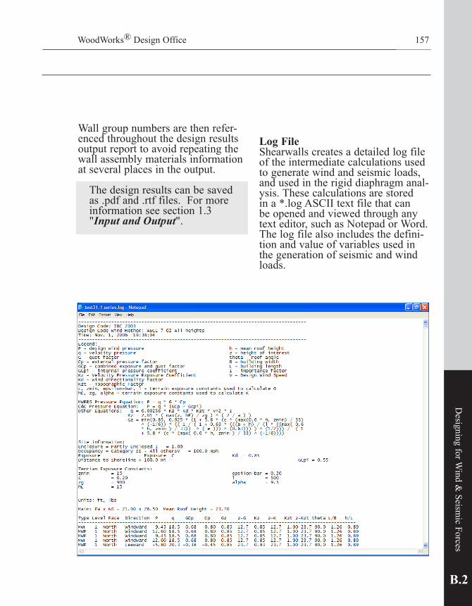
WoodWorks® Design Office
Wall group numbers are then refer-enced throughout the design results output report to avoid repeating the wall assembly materials information at seve ral places in the output.
The design results can be saved as .pdf and .rtf files. For more information see section 1.3 "Input and Output".
Log FileShearwalls creates a detailed log file of the intermediate calculations used to generate wind and seismic loads, and used in the rigid diaphragm anal-ysis. These calculations are stored in a *.log ASCII text file that can be opened and viewed through any text editor, such as Notepad or Word. The log file also includes the defini-tion and value of variables used in the generation of seismic and wind loads.
157
B.2
Designing for W
ind & Seism
ic Forces

Traditional Shearwalls (Type I)Wood frame shearwalls are tradition-ally designed using shearwall seg-ments that extend the full-height of the wall.
Shearwalls containing openings are treated as multiple shearwall seg-ments, as shown in Figure 1. Each segment requires fasteners to trans-fer shear and provide overturning restraint resulting in additional hold-downs per wall. The design capacity of the shearwall is assumed to equal the sum of the capacities of each shearwall segment. Sheathing above and below openings typically is not considered to contribute to the over-all performance of the wall.
Perforated Shearwalls (Type II)Another approach considers a shear-wall segment with openings, which isillustratedinFigure2.Here,thewall is identical to the shearwall in Figure 1, but without intermediate overturning restraints next to the openings. This condition is con-sidered a shearwall segment with unrestrainedopenings(perforatedorTypeIIshearwall).Thecapacityisclearly less than would be expected from the same shearwall containing multiple shearwall segments, each fully restrained against overturning. However,thecapacityofthewallshown in Figure 2 may be sufficient for a particular application while reducing the total number of over-turning connections.
Shearwalls158
2.14 Perforated Shearwalls (U.S. Only)
FIGURE 1. Typical Shearwall Composed of Three Traditional Shearwall Segments
FIGURE 2. Typical Perforated Shearwall with Unrestrained Openings
Shearwall segment with unrestrained openings
LL1 L2 L3

WoodWorks® Design Office 159
A•1
What is Sizer
MethodFinding the design shear capacity involves relating the strength of a shearwall with unrestrained open-ings to a similar shearwall consisting of traditional shearwall segments. Empirically derived adjustment factors that relate the strength of shearwalls with unrestrained open-ings to similar shearwalls containing multiple traditional shearwall seg-ments are presented in Table 1. The perforated shearwall procedure calls the adjustment factor the “opening adjustment factor.” This is refered to as the Perforated Factor in the Result output.
Openingadjustmentfactors(referedto as Perforated Factor in the Results output)forarangeoftypicalopen-ing heights are provided in Table 1 for eight and ten-foot high walls. Factors for other wall heights can be determined from the ratio of opening height to wall height.
B.2
Designing for W
ind & Seism
ic Forces
Table 1 — Opening Adjustment Factor for Perforated Shearwalls
0% 10% 20% 30% 40% 50% 60% 70% 80% 90% 100%
1.001.001.001.001.001.001.001.001.001.001.00
0.670.690.710.740.770.800.830.870.910.951.00
0.500.530.560.590.630.670.710.770.830.911.00
0.400.430.450.490.530.570.630.690.770.871.00
0.330.360.380.420.450.500.560.630.710.831.00
8'Wall
10'Wall
2'-8"
3'-4"
4'-0"
5'-0"
5'-4"
6'-8"
6'-8"
8'-4"
H/3 H/2 2H/3 5H/6 H
Percent Full-Height EffectiveShearCapacityRatio Sheathing
MaximumUnrestrainedOpeningHeight(WindoworDoorHeight)

160
Full-Height SheathingThe percentage of full-height sheath-ing(FHS)isbasedontheratiooffull-height sheathing length to shear-wall segment length. To be consid-ered full-height sheathing, the length of each full-height sheathed section must equal or exceed the prescribed height-to-length ratios for shearwall segments in the applicable building code.
Values for 0% full-height sheath-ing are provided for interpolation purposes only. The 100% full-height sheathed case represents a traditional shearwall segment with a corre-sponding opening adjustment factor of one.
Shear connectionsShear connections capable of resist-ing the allowable unit shear of a traditional shearwall segment are required throughout the segment. While the actual shear connection requirements may be less when using the perforated shearwall method, traditional shearwall segment shear connector requirements account for the non-uniform distribution of shear loads in the perforated wall.
Shearwalls
ReferencesDiekmann, E. 1992. Designing for wind or seismic loads. Proceedings of the International Seminar on Wood Engineering.Dolan, J.D.; Johnson, A.C. 1996. Monotonic and cyclic tests of shearwalls with openings. Blacksburg, VA: Virginia Polytechnic Institute and State University. Timber Engineering. Douglas,Bradford;Sugiyama,Hideo.1995.Perforatedshearwalldesignapproach.Washington, DC: American Forest & Paper Association.StandardBuildingCode(SBC)WoodSection1994editionwith1996revisions.Birmingham, AL: Standard Building Code Congress International.Sugiyama,Hideo.1981.Theevaluationofshearstrengthofplywood-sheathedwallswith openings.MokuzaiKogyo(WoodIndustry).36-7,1981.WFCM-96 Wood Frame Construction Manual for One- and Two- Family Dwellings — 1995SBCHighWindEdition.Washington,DC:AmericanForest&PaperAssociation.235 p.

WoodWorks® Design Office 161
2.15 Shearwall Segments Without Hold-downs (Canada Only) (excerpt from Wood Design Manual 2001)Traditionally, shearwalls have been designed using chords and hold-down connections at the ends of all shearwallsegments.Hold-downsaredesigned to transfer the chord seg-ment overturning force, Tf, to the shearwall or foundation below. CSA O86 includes provisions for design of shearwall segments without hold-down connections.
Without hold-downs, the overturning tension force is transferred from the top wall plate to the bottom wall plate through the shearwall sheath-ing. Since a portion of the shearwall sheathing is used to resist the over-turning force, the shear capacity of the sheathing is reduced. Even though hold-down anchors are not used, anchorage is still required to transfer the uplift force from the wall plate to the foundation or shearwall below(seeCommentarytoCSAO86-01)
In some cases, hold-down connec-tions may be placed at one end of a shearwall segment. Where the load is from the end of the segment that contains the hold-down, overturning uplift forces will be resisted by the hold-down. When the load is from the direction opposite the hold-down, the sheathing resists over-turning uplift forces. The shear capacity of the shearwall segment is multiplied by the hold-down factor, Jhd, which must be calculated for loads acting in opposite directions.
Hold-downconnectionsarenotrequired for shearwall segments where the specified strength is adjusted by the Jhd, factor, and the following conditions are met:• thesumofthefactoredbasicshear
resistances on both sides of the shearwall, Vhd /LW, < 10.3 kN/m;
• shearresistanceofthewood-basedpanel, vr, is based on nail diam-eters≤3.25mm;andedgepanelnailspacing-≥100mm;
• themaximumheightoftheshear-wall,Hs, is 3.6m; and
• thefactoredupliftrestraintforceatthe bottom of the end stud of the shearwall segment, Pj,is≥0.
B.2
Designing for W
ind & Seism
ic Forces
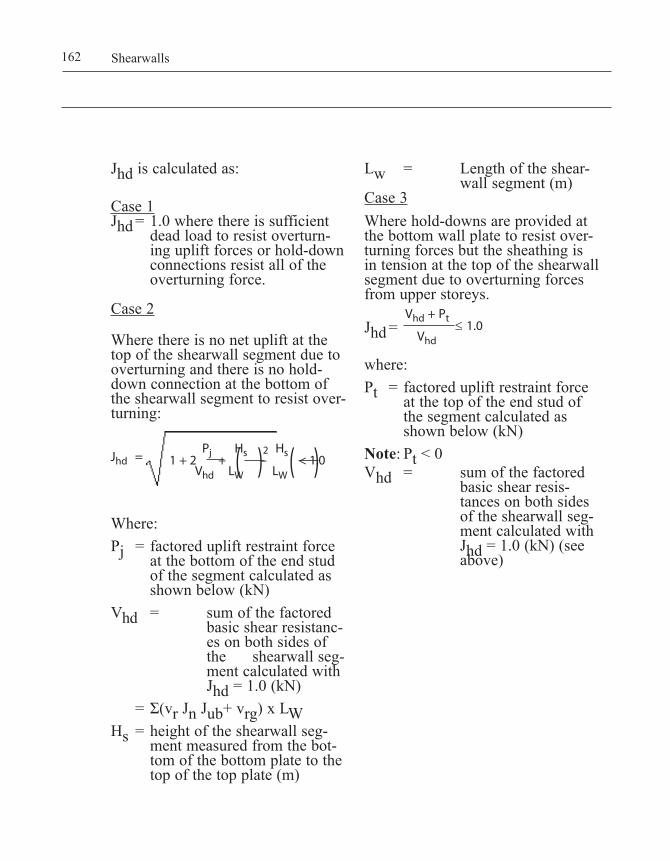
162 Shearwalls
Jhd is calculated as:
Case 1Jhd= 1.0wherethereissufficientdead load to resist overturn-
ing uplift forces or hold-down connections resist all of the overturning force.
Case 2
Where there is no net uplift at the top of the shearwall segment due to overturning and there is no hold-down connection at the bottom of the shearwall segment to resist over-turning:
Where:Pj = factoredupliftrestraintforceat the bottom of the end stud
of the segment calculated as shownbelow(kN)
Vhd = sumofthefactoredbasic shear resistanc-es on both sides of the shearwall seg-ment calculated with Jhd=1.0(kN)
=Σ(vr Jn Jub+ vrg)xLWHs = heightoftheshearwallseg-
ment measured from the bot-tom of the bottom plate to the topofthetopplate(m)
Lw = Lengthoftheshear-wallsegment(m)
Case 3 Where hold-downs are provided at the bottom wall plate to resist over-turning forces but the sheathing is in tension at the top of the shearwall segment due to overturning forces from upper storeys. Jhd= where:Pt = factoredupliftrestraintforceat the top of the end stud of
the segment calculated as shownbelow(kN)
Note: Pt < 0Vhd = sumofthefactored
basic shear resis-tances on both sides of the shearwall seg-ment calculated with Jhd=1.0(kN)(seeabove)
1 + 2 Pj
+ Hs
– Hs
< 1.0 Vhd LW LW( )2 ( )
Vhd + Pt ≤ 1.0
Vhd
Jhd =

1.1 About the User Guide
WoodWorks® Design Office 163
A•1
What is Sizer
163 Shearwalls
2.16 Deflection of Shearwalls
Shearwalls calculates the deflection of each wall segment between open-ings for each design case. It uses this deflection to determine the storey drift and check that the drift is within allowable limits for seismic design. Shearwalls also distributes loads to shearlines and within shearlines to segments based on equalized deflec-tion of segment. That is, rather than using the capacity of the shear walls to approximate the rigidities for distributing loads to and within shear lines, the software includes the option to determine rigidities based on deflection-derived stiffness. The option to Use shearwall deflection to calculate rigidity is available only if the Settings / Design: Include deflection analysis is selected.
Whiledeflectionanalysisisconsid-ered more accurate in certain circum-stances, the added iterative calcula-tions running in the background can slow the run time of Shearwalls. For example, it would not be unusual for a design run to take 3 times longer, in the order of several minutes, when deflectionanalysisisselectedandthe distribution of loads is based on rigidityderivedfromdeflection.
Hold-downsThe ability to input hold-down con-nectors to a hold-down database for use in design for overturning forces andfordeflectionanalysisgivesadd-edflexibilitytoShearwalls.Previ-ously Shearwalls reported hold-down forces at each hold-down location, but did not specify the hold-down connections used.

164 Shearwalls
Hold-downs buttonThis button opens the hold-down database window where hold-downs can be created and used in the design. Several hold-downs are already created and can be chosen from a drop0down list. The hold-downs specified in the database are selected in the Wall and Shearline Input as well as the Opening Input at each hold-down location for use in determining the component of deflection attributable to the wall anchoragesystem'sslip.
Horizontalandverticalfastenerinformation as appropriate for the hold-down is entered in the fastener section.
There are four check boxes that allow the user to specify what will be taken into account for the dis-placement.
• Elongation and slippage com-bined as single hold-down dis-placement: If this is checked, the displacement value entered in the table below includes displacement from all sources of deflection related to the connection assem-bly, including the elongation of the connector itself, the horizontal fastener slippage used to con-nect the hold-down bracket to the studs, and the vertical bolt elonga-tion up to the length of vertical bolt shown in the top right of this input form. Manufacturers typi-cally include all these sources of deflection in their tables, therefore selecting this checkbox will be typical. If it is not checked, the value indicates the elongation only and therefore the slippage will be calculated separately.

WoodWorks® Design Office 165
A•1
What is Sizer
• Elongation for connector only (without anchor bolt): When this box is checked, the elonga-tion value does not represent the anchor bolt elongation, which is calculated using the bolt length indicated in the Structure dialog. This option is not viable when the elongation and slippage are combined as single hold-down displacement.
• Shrinkage compensating device: If the hold-down is capable to adjust to the wood movement, this box should be checked so the wood shrinkage and crush com-ponent are not included in the dis-placement.
• Always use elongation/displace-ment at maximum capacity: If this box is checked, the displace-ment is assumed to correspond to the allowable hold-down capac-ity even if the actual force at the hold-down is less than the listed capacity of the hold down. For example, if Always use elonga-
tion/displacement at maximum capacity is checked, and if the calculated uplift force that a hold-down is required to resist is 1000 lbs, but the selected hold-down has a capacity of 2000 lbs with a corresponding displacement of 0.20 inches, the hold-down elon-gation or displacement will be based on the listed displacement value of 0.20 inches associated with the maximum 2000 lb capac-ity. Left unchecked, the displace-ment will be based on the ratio of actual force : capacity, in this case 50% of 0.20 inches, or 0.10 inches.
The deflection of shearwall is impor-tant to ensure it remains within the allowable storey drift limits. It also determines the rigidity of the shear-wall segments for load distribution within shearlines, and the rigidity of the shearline for use in the rigid dia-phragm distribution method.
B•1
What is Shearw
alls?

WoodWorks® SIZER 97 New Features166
1.2 HardwareandSoftwareRequirements
WoodWorks® Design Office 166
A•1
What is Sizer
For more information, use the con-text sensitive help found on this Hold-down database input form by selecting the ? symbol at the top right and clicking on the area for which help is needed.
For more detailed information regardingdeflectionandholddownrelated information refer to Help and search for keywords as shown below. Also, refer to the Shearwalls - New Features filelocatedinthemainWoodWorks folder.
B•1
What is Shearw
alls?

B•3
Shearwalls Tutorial
3.1 Quick Start Tutorial 1693.2 Advanced Tutorial 173
A•1
What is Sizer
B•1
What is Shearw
alls?

168 Shearwalls

WoodWorks® Design Office 169
B.3
Shearwalls Tutorial
3.1 Quick Start Tutorial
This tutorial will quickly provide you with the major steps and pro-cedures required to design a wood-frame building for manually applied lateral loads. See the Advanced Tutorial for a more complete design example with automatically gener-ated loads.
1. Start Shearwalls. The Structure button is highlighted and the Structure Input form is active.
2. Define a structure block by click-ing & holding the left mouse button while the cursor points at approximately X=0 & Y=0 and dragging the cursor to approxi-mately X=25 & Y=35.Youmayneed to manually adjust the Location and Extents in the Structure Input form to define the structure block.
3. Increment No. of Levels in the Structure Input form to 3 levels for the selected structure block.
4. Click the Walls button and high-light wall 2-1.Youmaychangethe length, location, type or mate-rial of the wall in the Wall Input form.
5. Split wall 2-1 by pointing the cur-sorat(25,0)holdingdowntheleftmouse button while dragging the cursorto(25,20),thenreleasingthe left mouse button. Walls 2-1 and 2-2 will now be created.

170 Shearwalls
6. Move wall 2-1 by pointing the cursorat(25,10)holdingdownthe shift key & left mouse but-ton while dragging the cursor to (15,10),thenreleasingtheleftmouse button & Shift key.
7. Click the Openings button, point thecursorat(15,5),holddowntheleft mouse button & drag the cur-sorto(15,15)andreleasetheleftmousebutton.Youmaychangethe offsets, width and height of the opening in the Opening Input form.
8. Click on the Extend Levels but-ton. This will automatically create the levels 2 and 3 as a copy of level 1.
9. Click on the Roof Blocks button. In the Roof Input form, under Construction select Hip for the north and south sides of the build-ing, and enter overhangs of 2ft for all sides of the building.

WoodWorks® Design Office 171
B.3
Shearwalls Tutorial
10. Click on the Generate Loads... button to automatically gener-ate wind or seismic loads. Loads will be added manually for this example, therefore do not gener-ate loads and proceed to step 11.
11. Click on the Loads & Forces button, click Add…, select Wind Shear, West Building Face, Line Load, apply from level 1 to 3,Magnitude=100plfandclickOK.

172 Shearwalls
12. Click on the Run Design but-ton and view the Results report. Youcannavigatedirectlytothedesired table using the Go To Table button.
13. Click on the Loads and Forcesbutton, highlight wall A-1 and click on the Elevation View but-ton to see the load distribution graphically on a shearwall or entire shearline.
14. If you close an Input form, click on the Forms button to restore the appropriate form.

WoodWorks® Design Office 173
B.3
Shearwalls Tutorial
3.2 Advanced Tutorial
In this tutorial you will create a two-story wood-frame structure with a one-story garage and design it for automatically generated wind and seismic loads.
To begin, start the Shearwalls pro-gram or select File/New to start a new file if you are already in Shearwalls.
SettingsDefine the initial settings and prefer-ences for your project.
Company Information
1. From the Settings menu, select the Company Information tab.
2. Enter your company information.
Project Description
1. Now click on the Project Description tab.
2. Enter the relevant project descrip-tion.
View Options
1. Click on the View tab.2. Set the snap increment to 6 inch-
es.3. Set Fit View Area to Window and
Fit Building to View Area to off.4. Set the Display Gridlines… to off
Check out our online video called"Advanced tutorial from User Guide"toseethisad-vanced tutorial demonstrated.

WoodWorks® SIZER 97 New Features174
1.2 HardwareandSoftwareRequirements
174 Shearwalls
Design Options
1. Click on the Design tab.2. Click on Reset Original Settings.3. Select appropriate Wind load
design standard.
To save any of the Settings information as the default, click on the Save as Default for New Files option for the appropriate tab.
4. Click OK.
CAD Import
1. Click on the Import CAD button andselectNumberofLevels=2.
2. Click Import Metafile and from the Examples subdirectory under the Shearwalls directory, select the example.wmf file and click Open. Repeat for second level.
3. Following the Import Wizard instructions, select the Start Positioning button and enter the first reference point as the bottom left hand corner of the building using the mouse.
Note: For multi-level buildings with varying layouts on each level, importing different metafiles for each level can be done.

1.1 About the User Guide
WoodWorks® Design Office 175
A•1
What is Sizer
WoodWorks® Design Office
4. Click OK.5. Select the bottom right corner of
the building as the second refer-ence point.
6.Enter20(ft)asthedistancebetween the two reference points.
7. Click Finish level 1.
8. Continue with CAD Import Wizard scaling instructions for level 2.
B.3
Shearwalls Tutorial
175

WoodWorks® SIZER 97 New Features176
1.2 HardwareandSoftwareRequirements
Shearwalls176
Structure Blocks & Levels1. Click on the Structure button.2. Use the Zoom In and Zoom Out
buttons to adjust the CAD build-ing image to fill the viewing area.
3. Layout the first Structure Block along the exterior walls by click-ing and dragging a rectangle from the top right hand corner of the structure to the only inside corner on the left hand side of the build-ing. With the block still highlight-ed, enter Main in the Block Name field and select 2 as the number of levels. This block will represent the two-story living space of the structure.
4. Layout a second structure block representing the garage portion of the structure by clicking and drag-ging a rectangle from the bottom left hand corner of the structure to the inside corner on the right hand side of the building where the garage ends. Blocks must abut or over lap slightly. Enter Garage as the block name and select 1 as the number of levels.
5. Set the foundation elevation as 3 ft.

1.1 About the User Guide
WoodWorks® Design Office 177
A•1
What is Sizer
1st StoryWalls1. Click on the Walls button.2. Extend outward the main entrance
of the structure. Click on wall 4-1 and click and the mouse from a point on wall 4-1 where the main entrance extension first begins to where it ends. There should now be three walls along shearline 4, including 4-1, 4-2 and 4-3.
3. Move wall 4-2 to the right to extend the main entrance and match the CAD file by holding the Shift key and clicking on wall 4-2. While holding the left mouse but-ton down, move the arrows to the new position and release.
4. Continue this process until the building footprint matches the CAD file as shown.
B.3
Shearwalls Tutorial
WoodWorks® Design Office 177

WoodWorks® SIZER 97 New Features178
1.2 HardwareandSoftwareRequirements
Shearwalls178
5. Add three interior walls by click-ing at the start of each wall and dragging the mouse to the end of the wall.
6. Select all three interior walls by holding CTRL and clicking on walls.
7. Change from Exterior Segmented to GWB 1 ply both sides same in Wall and Shearline Input.

WoodWorks® Design Office 179
B•3
Shearwalls Tutorial
Openings1. Click on the Openings button.2. Create a garage door opening by
selecting wall 3-1 and clicking on a point offset 3 ft from the edge of thebuildinganddragginga14(ft)opening. This can also be achieved by directly entering input in the Opening Input form.
3. Continue to place door and win-dow openings around the structure as desired.
4. To ease viewing, click on the Import CAD button to remove the CAD image from the background. This can be turned back on at any time.

180 Shearwalls
2nd Story
1. Click on the Extend Walls but-ton. This automatically creates the upper levels for all multi-leveled blocks. In this case the second level is created for the Main struc-ture block.
2. The current level should be level 2.
Walls1. Click on the Walls button. Add
two interior walls on the level 2 directly above the interior walls on level 1, as shown.
Openings 1. Click on the
Openings button. 2. Select wall E-1 and
createtwosmall6(ft)wide window open-ingswitha3.75(ft)heightand3(ft)offsetfrom the bottom.
3. To view the current openings, select wall E-1 and click on the Elevation button.
4. Select level 1 to 2 in the data bar.

Roof Blocks1. Click on the Roof Blocks button.
Roof blocks will automatically be assigned to all structure blocks having an initial geometry based on the defaults set in Settings/Default Values.
2. Select the Main block. Set the east and west slopes of the roof at 30 degrees and set overhangs of 2 ft. on all sides of the roof.
3. Select the Garage block. Set the ridge direction to E-W, set the north and south slopes of the roof at 30 degrees and set overhangs of 2 ft. on all sides of the roof.
4. Click on the Import CAD button to turn off the CAD image in the background.
WoodWorks® Design Office 181
B.3
Shearwalls Tutorial

182 Shearwalls
Generating Loads1. Before generating loads, click on
the Site Information toolbar icon. From the Load Generation Site Information input dialog you can set the parameters to be used to generate wind and seismic loads. To change the Design Code selec-tion, go to the Settings/Design tab.
2. Close Site Information.Note:Youcanlimitloadgeneration
to specific levels by select-ing only the range of floors. Skipping floor load generation can be achieved by select-ing the "Loads and Forces" screen, select the floor for which you do not want loads generated and "Delete all Showing."
3. Click on the Generate Loads tool-bar icon.
4. Select Wind and Seismic loads to be generated from level 1 to 2. All other setting should remain as shown.
5. Click on Generate Loads on Selected Levels to automatically generate loads.

6. Use the Show button menu in the data bar to turn on and off viewing of a variety of data.
7. To view seismic loads, click on Show/Seismic/Seismic Loads and Forces. Go to Show/Orientation to view an alternative load orienta-tion.
Note: Loads shown based on seismic, R=6,flexiblediaphragm,andmay not be identical to results using the latest ASCE 7 / IBC.
WoodWorks® Design Office 183
B.3
Shearwalls Tutorial

184 Shearwalls
Modifying & Manually Applying Loads1. Click on the Loads and Forces
button.2.Selectthesouthwall(A-1)on
level 1. All generated loads act-ing on wall A-1 will appear in the Load Input form.
3. Generated loads can be modified or deleted at this stage based on your judgement.
4. Loads can also be added. With wall A-1 still selected, click on the Add… button.
5. Select a seismic uniform line load with a magnitude of 10 plf applied to the selected walls only. Click OK.

Plan View To view the various loads and forces applied, use the Show menu.
1. Select Show/Loads/Masses to not show building masses
\
2. Click on the Design button then return to the Loads view.
3. Select Show/Forces/Rigid to view the rigid analysis force distribution.
WoodWorks® Design Office 185
B.3
Shearwalls Tutorial

Shearwalls186
Elevation View1. Select wall E-1 and click on the
Elevation button.2. Set the levels from 1 to 2 to show
both levels at once.3. Shear forces, hold-down forces
and dragstrut forces are shown.4. Select Show/Forces/Hold-
downs/Separate to view the hold-down force broken-up by its com-ponents.
Results1. Click on the Design button. The
Design Results view will appear.2. Scroll up and down to view the
results.3. The Show button
options allow the Design Results to be customized.
4. Print the results by clicking on the Print button.

1.1 About the User Guide
WoodWorks® Design Office 187
A•1
What is Sizer
A•1
What is Sizer
Shearwall Settings
4.1 General 1894.2 Design Settings 1904.3 HoldDownSettings 1954.4 Other Settings 196 B•4

WoodWorks® SIZER 97 New Features188
1.2 HardwareandSoftwareRequirements

WoodWorks® Design Office 189
4.1 General
Click on Settings… in the toolbar to access the Settings dialog box hav-ing tabs for setting data relating to Design, Format, Options, Loads and Forces, View, Company Information and Project Description.
Shearwalls provides original settings, however the user should verify the suitability of these default settings and change them as required. For each tab of the dialog box there is a button to Reset Original Settings, and a check-box to Save As Default for New Files any settings changed by the user.
A general description of these settings is given in the follow-ing. Note that the settings for each tab of the dialog box are independent of those for all other tabs.
B•4
Shearwall Settings
Check out the online tutorial entitled"Design Settings"onwoodworks-software.com(Sup-port and Training Section)

190 Shearwalls
4.2 Design Settings
Design Procedures: Wind Load De-sign StandardUse this drop-down to choose which design procedure to follow in the generation of wind loads.
Design Procedures: "Include deflec-tion analysis":Selectingadeflectionanalysisnotonly activates the calculation of shearwalldeflections,italsoacti-vates the option of distributing forces based on stiffness derived from deflections.
Load Combination Factors (U.S. Only)Use these boxes to set Allowable StressDesign(ASD)loadcombina-tion factors for combinations of dead
load with seismic or wind loads, as per your building code. Factors may be applied to dead loads to reduce their contribution to overturning resistance in the calculation of hold-down forces. Seismic loads are also normally factored in ASD design to account for the fact that the calcula-tion of E is based on strength prin-ciples(i.e.thefactoristoconvertEfromLRFDtoASD).
Wind Capacity Increase Factors (U.S. only)Various design codes recognize higher resistance values for wood panels for wind design than for seis-mic design. Use the allowable shear stress adjustment to increase the base shear capacity for MWFRS wind design(Thedefaultvalueof1.4con-forms to the 40% increase in capac-ity both IBC and SDPWS allow for woodsheathings).UsetheC&Cloadduration setting to adjust the load duration factor applied in the design of nails and panels subject to C&C suction wind loads. The default value of 1.6 conforms to the NDS load duration factor associated with wind loads.
Local Building Code Capacity mod-ification (U.S. only)Some local building codes recognize lower allowable shear values for wood panel shearwalls than those listed in model building codes. If required by your building code, use these settings to adjust the allowable shear. This setting may also be used to simulate the overstrength factor:

WoodWorks® Design Office 191
Disregard shearwall height-to-width ratio limitations (U.S. only)Narrowwoodandfibreboardwallsegments are generally not consid-ered to contribute to lateral load resistance. By default, Shearwalls implements the height-to-width ratio limitations listed in model build-ing codes for various wall materials subject to wind or seismic loads. Use this setting to disregard these limita-tions.
Seismic wood panels and fiberboard (U.S. only)If"Allow 3.5:1 height-to-width ratios"isselected,theprogramcon-siders full height segments with a height-to-width ratio between 2 and 3.5 as shear resisting elements for seismic design. The allowable shear values are reduced as per the NDS.
Ignore non-wood panel contribu-tion...If"when combined with structural wood panels"isselectedforwindand/or seismic design, then the resis-tance of two-sided shearwalls will be based only on the allowable shear of woodandfibreboardpanels(gypsumandothermaterialwillbeignored).This allows higher aspect ratios to be used for wind and / or seismic design forpanelswherewoodorfiberboardis combined with other sheathing materials.
For seismic design, it may be ben-eficialtoIgnore non-wood panel contribution for all walls. This removes the penalty of the increased
B•4
Shearwall Settings
The software automatically calculates rho and applies it to the load, as per ASCE7-05 12.4.2. In certain circum-stances, such as irregular buildings (weakstories12.3.3.2),usersarere-quired to multiply the load by omega instead of the redundancy factor rho. WoodWorks does not include an option of multiplying by omega, but does have a work around solution by reducing the capacity rather than increasing the load. 12.4.3.3 permits the capacity to be increased by 1.2 when the overstrength factor omega is used, and this too can be incorporated in WoodWorks based on the following capacity vs. load equa-tion:
[Capacityx1.2]=[Loadxomega/rho]This shows we are multiplying the capacity by 1.2, and dividing rho out of the load that WoodWorks puts in, and multiplying omega into the load. But since WoodWorks can only handle the modificationstothecapacity,wewillreducethecapacity(rho/omega)bythe same amount we would have in-creasedtheload(omega/rho).
Example:In the settings/design menu “local build-ingcodecapacitymodification”,seismiccell compute the following, based on omega=3.0,rho=1.3,andallowedcapacity increase of 1.2:1.2*(1.3/3.0)=0.52(seebelow)
Note of caution: This method is meant to give a relative comparison of the load vs. capacity. The ratio of load vs. capacity is correct based on this work-around method, however, the value of the load and capacity are both under-stated by the same amount.

Shearwalls192
seismic loading that would result fromthelowerresponsemodificationfactor, R, which must be used when non-wood materials are part of the seismic resistance system.
Out of plane sheathing assumption: The Special Design Provisions for WindandSeismic(SDPWS)out-of-plane sheathing values are based on a2-spanconfiguration.Otherpub-lications, such as the Wood Frame Construction Manual, lists these values based on sheathing supported over 3 spans. Furthermore note under SDPWS table 3.2.2 allows for an increase of values if the sheathing is continuous over 3-spans. Selecting the 3-span here increases the tabu-lated values by the intended 25%.
Service ConditionsUse this setting to specify tem-perature and moisture conditions. Shearwalls will apply the appropriate design factors.
Anchorage Restriction Settings (Canada only)Use the radio buttons to choose one of the following options:i. Override hold-down selection
to achieve design The program allows a choice of all
materials in the design of shear-walls. It specifies hold-downs if the required shear capacity of a wall cannot be achieved without them, using the wall materi-als selected by the user. If wall materials are selected that always require hold-downs, the hold-

WoodWorks® Design Office
down setting automatically chang-es to Hold-downs all segments.
ii. Restrict materials because of anchorage selection
The program restricts the mate-rials available for the design of shearwalls to those that can achieve the required shear resis-tance with the hold-down configu-ration specified by the user. If the user leaves a wall material selec-tion unknown, the program still limits the wall design in accor-dance with the material restric-tions.
iii.Restrict materials, but override when unknown The program restricts materials the same way as in option ii, with the following exception: if the user leaves a wall material selec-tion as unknown, the program will not limit this parameter in its design of shearwalls. It will override the user-specified hold-down configuration to achieve the required shear capacity, rather than limit the unknown parameter.
Shearwall LimitationsThe Maximum Plan Offset defines the distance up to which shearwalls on the same level may be apart and still be considered part of the same shearline.
The Maximum Elevation Offset defines the distance up to which shearwalls on different levels may be apart and still be considered part of the same shearline.
Hold-down / Dragstrut Forces based on...The hold-down and dragstrut forces may be based either on the presum-ably higher capacity of the associated shearwall or on the calculated value of the corresponding hold-down force, that is, the applied loads.
Rigid Diaphragm Analysis (Canada) / Shearwall Rigidity per unit length (U.S.)There are four methods to establish the relative rigidity of shearwalls for a Rigid Diaphragm Analysis: by using shearwall capacity to approxi-mate rigidity; by considering that all shearwalls have equal rigidity; by manual input of relative rigidity; or using deflection derived stiffness.
It is possible to select either the shearwall capacity or deflection option, then adjust rigidities using the manual method. This method can help simulate proprietary shearwall sections. The method of distributing loads within the shearline will be the same as the method chosen to dis-tribute loads to the shearlines
Distributed Forces to Wall Segments Based on Rigidity (U.S. Only)Selecting this option distributes the shear load within the shearline based on individual wall rigidities, rather than distributing the shear uniformly along all walls within the shearline. This option does not effect the total shear distributed to the shearline.
193
B•4
Shearwall Settings

Shearwalls194
ASCE 7 all heights wind load case for rigid analysis (U.S. only)
Case 1: full wind loads without ac-counting for torsional effects will be used if this option is selected for rigid analysis.
Case 2: 75% of wind loads plus the effect of torsion will be used for rigid analysis.
Both options can potentially gov-ern, depending on the shape of your building, and therefore the design results for both cases should be re-viewed.

4.3 Hold-Down Settings
WoodWorks® Design Office 195
B•4
Shearwall Settings
The Hold-down offset will be used in the calculation of hold-down forces if Subtract offset from seg-ment length..."isselected.Leftunchecked, the moment arm will be based on the total distance from end to end of the segment, resulting in lower forces in tension and compres-sion at the ends of the panel .
In the US, the joist depth is not included in the overturning calcu-lation, as shown in the SDPWS. However,someengineersprefertotake the more conservative approach of including this extra height, and selecting"Include joist depth in wall height..."willgivethisextraflexibil-
ity. The Canadian version automati-cally includes the floor depth as per the CSA O86.
Displacement da for deflection:If the boxes are checked in the Displacement da for deflection sec-tion, the user can input values for the elongation, displacement, shrinkage and slippage that will override the hold-down properties given in the hold-down database. These values will be used for all the hold-down in the structure.
The Wood properties and construc-tion details section indicates the dif-ferent sources for vertical shearwall displacement at the hold-downs due to wood shrinkage, crushing of wood, slippage in bolt hole and con-struction quality and allows the user to input specific values.
From the hold-down settings, you can reset the original settings and access the hold-down database This database contains pre-existing hold-downs and allows you to create new hold-downs.

196 Shearwalls
4.4 Other Settings
Default Values SettingsDefault values that are used with all new files can be specified for member dimensions, self-weights for seismic building mass determina-tion, roof geometry, site information for load generation, and the standard wall type to be used.
Format SettingsIt is possible to set the Unit System, Imperial(English) Formatting and the Font Size for both Printer and Screen.
Options SettingsA number of options exist to Display information and data, and to set the default standard wall used when creating new walls.
Loads and Forces SettingsIt is possible to selectively display Loads and Forces in Plan View and Elevation View, as well as to selec-tively display Design Results.
View SettingsIt is possible to set the Limits of the Viewing Area, the Snap Increment (itcanonlybedecreased,andoncedecreaseditcannotbeincreased), and the intervals that gridlines are displayed, if at all.
Company and Project SettingsCompany Information can be dis-played on text and diagram output for all projects. A specific Project Description can be displayed for individual projects.
The same settings can be set with the data bar show button. This tab should be used to overhaul the con-figuration of loads and forces you wish to view.

1.1 About the User Guide
WoodWorks® Design Office 197
A•1
What is Sizer
Connections
1 What is Connections? 1992 Post & Beam Connections 2043 Lapped Shear Connections 211 C

WoodWorks® SIZER 97 New Features198
1.2 HardwareandSoftwareRequirements

WoodWorks® Design Office 199
A•1
What is Sizer
1 What is Connections?
About Connections
The WoodWorks® Connectionssoftware will be referred to as Connections throughout this section.
This is meant to give a brief intro-duction to the features and on how to use Connections. This brief introduc-tion to Connections should be suf-ficient to help you become an expert userofthesoftware.However,tech-nical support is available if you have further questions.
Connections is made-up of several different screens which are fol-lowed in sequence to complete the designofaconnection.Youproceedthrough these screens using Drop-Down Menus and toolbars.
Drop-Down Menus
The top of the Connections window always contains a drop-down menu bar.To make a menu selection:• movethemousetopointtoa
menu bar item• presstheleftmousebuttondown• whileholdingthemousebutton
down, move to the appropriate drop-down menu item
• releasethemousebutton
An alternative selection method is toclickthemouse(pressandreleasetheleftmousebuttonrapidly)onamenu bar item. This causes the drop-down list to drop down and stay. Now click on the appropriate sub-menu item to make your selection.
C
Connections

200 Connections
Toolbars
Connections includes toolbars with toolbar buttons for the main proce-dures of the program. When per-forming a design from start to finish, you should proceed from left to right along the toolbar. The toolbar but-tons are placed in a sequential order to facilitate designing.
Almost all of Connections features can be accessed through toolbars. This speeds-up the design process by minimizing the use of drop-down menus.
toolbars are placed near the top of the Connections window directly under the drop-down menu bar.
To make a selection using a toolbar:• movethemousetopointtoatool-
bar button• presstheleftmousebuttondown• releasethemousebutton

WoodWorks® Design Office 201
A•1
What is Sizer
Toolbar Buttons
The following describes the main features of each of the toolbar buttons in Connections.
NewClick on the New button in thetoolbar to a start a new connection design file.
OpenClick on the Open button in thetoolbar to retrieve an existing file. This command can be used to edit an existing file or to use an existing file as the basis for a new design.
SaveClick on the Save button in thetoolbar to save the current design.
Save AsClick on the Save As button inthe toolbar to save the current design but with a different name.
DXF ExportSelected fasteners can be exported for use in CAD.
PrintClick on the Print button in thetoolbar to print the diagram or the design results. These screens must first be open.
GeometryClick on the Geometry buttonin the toolbar to change to the Geometry view. In this view, you can change the current connection geometry.
Load MaterialClick on the Load Materialbutton in the toolbar to change to the Load Material view. Inthis view, you can specify the applied load and the material parameters.
MethodClick on the Method buttonin the toolbar to change to the Method view. In this view, you can change specify the type of connector to be used.
DetailsClick on the Details button inthe toolbar to change to the Details view. In this view, you can spec-ify connector parameters.
DiagramClick on the Diagram buttonin the toolbar to change to the Diagram view. This viewdisplays the current connection detail diagram.
ResultsClick on the Results buttonin the toolbar to change to the Results view. This view displays the design results output.
AcceptClick on the Accept button toaccept the current design results and to input this information into the details screen.
C
Connections

202 Connections
Connection Types
Connections can design for both Post & Beam and Lapped Shear connec-tion types.
Post & Beam ConnectionsPost & Beam connections include the following configurations:• Beam-to-Beam
• Beam-to-Column
• Column-to-Base
The Post & Beam connections can be designed using any of the follow-ing connector types:• Bolts• ShearPlates• Rivets(Canadianonly)• Heavy-dutyHangers•Lagscrews

WoodWorks® Design Office 203
A•1
What is Sizer
Lapped Shear ConnectionsConnections designs for the follow-ing Lapped Shear connections using nails or bolts.• Wood-to-Wood
• Wood-to-Steel
• Wood-to-Concrete
C
Connections

204 Connections
2 Post & Beam Connections
Introduction
In this tutorial you will create and design a bolted bottom hanger for a post to beam type connection as shown below.
Connection Type
1. Click the New button on the toolbar.
2. Select the connection type Post & Beam with a Beam-to-Column configuration.
3. Click on OK.

WoodWorks® Design Office 205
A•1
What is Sizer
Connection Geometry1. Clickonthefirst(leftmost)con-
nection geometry, as shown. Note that a description of the con-
nection geometry appears on the status bar.
Load and Material Details
1. Click on the Load/Material button.
2. Enterawidth,b,of8"andadepth,d,of8"forthecolumn.
C
Connections

206 Connections
3. Click on the beam which is shown graphically in the plan view. This allows you to specify the beam parameters.
4. Specify a width, b, of 6" and a depth, d, of 14" for the beam.
5. Enter a Force Y of 3000 lbs and a Force X of 800 lbs.

WoodWorks® Design Office 207
A•1
What is Sizer
Connector Type
1. Click on the Method but-ton.
2. Select Bolts as the connector type by clicking on the Bolts graphic.
3. For selected connectors exporting dxf files of the connection drawing for use in AutoCAD can be done. Three separate dxf files will be exported, approriate for:
•shopdrawings •assemblydrawings •combined,exportingalllay-
ers
Connector Details
1. Click on the Details but-ton.
At this point you can specify details about the connection such as bolt diameter, plate thickness, or spac-ing.Youcanalsoleavesomeorallof the details as unknown and allow Connections to choose these parame-ters. In this example, leave everything as unknown to start.
C
Connections

208 Connections
Connection Detail
1. Click on the Diagram but-ton.
2. To print the connection detail, click on the Print button.
Design Results
1. Click on the Results button to view the design results for the connection.
2. To print the design results, click on the Print button.

WoodWorks® Design Office 209
A•1
What is Sizer
3. Youcanscrollupanddowntoview more of the design results output.
4. Click on the Accept but-ton. This will automatical-ly accept the parameters chosen by Connections during the design and will place you in the Details view.
Youwillnoticethatalloftheparameters now have specified val-ues(Spacing Between Rows and Spacing Within Rows will remain as unknown when there is only one row of connectors or only one con-nectorrequired).
C
Connections

210 Connections
Re-Designing the Connection
If at this point you are not satis-fied with the suggested design, you can change some parameters in the Details view and re-design the con-nection.
1. Change the Bolt Diameter to1/2"for the Face Plate.
2. Change all of the remaining Face Plate parameters to unknown except for the plate thickness. Leavethisas1/8".
3. Click on the Diagram button.
4. Click on the Results button.
5. Repeat the above steps while changing load conditions, connec-tion geometry, connector details or any other parameters. This will allow you to quickly become familiar with Connections.

WoodWorks® Design Office 211
A•1
What is Sizer
3 Lapped Shear Connections
IntroductionIn this tutorial you will create and design a bolted wood to steel splice connection as shown below.
Connection Type
1. Click the New button on the toolbar.
2. Select the connection type Lapped Shear with a Wood-to-Steel configuration.
C
Connections

212 Connections
Connection Geometry
1. Click on the geometry which represents a double shear splice connection(fourthimage),asshown.
Load and Material Details
1. Click on the Load/Material but-ton.
2. Enter a width, b, of 2 in. And a depth, d, of 10 in. for the main wood member.
3. Click on the steel side plate which is shown graphically in the elevation view. This allows you to specify the width of the steel side plate.
4.Specifyawidthof6in.(Notethat the thickness of the plate for bolt-ed connections is specified in the detailsscreen.)
5. Enter a force of 3000 lbs.

WoodWorks® Design Office 213
C
Connections
Connector Type
1. Note that the connector type but-ton is grayed out. Only bolted connections are available for this configuration. Proceed to connec-tor details.
Connector Details
1. Click on the details button.
At this point you can specify details abouttheconnection.Youcanalsoleave some or all of the details as unknown and allow Connections to choose these parameters. In this example, leave everything as unknown to start.

214 Connections
Connection Detail
1. Click on the Diagram button.
2. To print the connection detail, click on the Print button.

WoodWorks® Design Office 215
C
Connections
Design Results
1. Click on the Results but-ton to view the design results for the connec-tion.
2. To print the design results click on the Print button.
3.Youcanscrollupanddowntoview more of the Results output.
4. Click on the Accept button. This will auto-matically accept the parameters chosen by Connections during the design and place you in the Details view.

216 Connections
Re-Designing the ConnectionIf at this point you are not satis-fied with the suggested design, you can change some parameters in the Details view and re-design the con-nection.
1. Change the Bolt Diameter to 1/2 inch.
2. Change the Rows per Plate to 2.
3. Change the Bolts per Row to unknown.
4. Click on the Diagram button.

1.1 About the User Guide
WoodWorks® Design Office 217
A•1
What is Sizer
The Database Editor
1 What is the Database Editor? 2192 Material Databases 2213 Creating Custom Databases 2224 Viewing Standard Databases 2265 Customizing the Database List 228 D

WoodWorks® SIZER 97 New Features218
1.2 HardwareandSoftwareRequirements

WoodWorks® Design Office 219
A•1
What is Sizer
1 What is the Database Editor?
The Database Editor is a simple ap-plication that allows you to create new material databases, view existing databases, and customize the material database list for local availability.
Scope of Database Editor
The Database Editor is currently limited to operating on databases of wood FRAMING materials only. This includes beams, columns, joists and wall studs consisting of solid sawn, glulam and engineered wood products. Sheathing materials and fasteners have not been incorporated at this time.
Databases used by the Design Office programs:• Sizer — all databases • Connections — all databases
except I-joists, LVL, PSL materi-als
• Shearwalls — only the wall stud databases
Note:1. ALL the Design Office pro-
grams use a common set of databases that can be viewed and modified by the Database Editor.
2. Sizer exploits all features of the Database Editor.
3. Connections and Shearwalls do not skip Species, Grades and Sections that have been set to "Ignore"bytheDatabaseEditor.
4. A change to any database will affect all programs that use it (withtheexceptionofitem3).
File Buttons
NewClick on the new button in the toolbar to a create custom database file. The program will prompt you with a series of dialog boxes to walk you through the process of creating a custom database file.
OpenClick on the open button in the toolbar or click on the data-base file name in the file list to retrieve an existing database. This command retrieves an existing materialdatabasefile.Youcanspecifythe type of database, such as Beams, Columns, Joists, and Wall Studs.
SaveClick on the save button in the toolbar to update a material database which you applied changes to. The save button also updates the current use and ignore set-tings for customizing the database list.
D
The Database Editor

220 Database Editor
Save AsClick on the save as button in the toolbar to make a copy of the current database but with a different name.
CloseClick on the close button in the toolbar to close the current database without saving any changes which may have been done to this file.
Editing and Viewing Buttons
AddClick on the add button in the toolbar to add new species, grades or sections to a Custom database file. The add button is only available for Custom database files. A maximum of three species, three grades, and six sec-tions is allowed for Custom database files.
DeleteClick on the delete button in the toolbar to delete existing species, grades or sections in a Custom database file. The delete button is only avail able for Custom database files.
EditClick on the edit button in the toolbar to edit the species, grade or section properties of a Custom database file. The edit button is only available for Custom database files.
ViewClick on the view button in the toolbar to view the species, grade or section properties of a Standard database file. The view but-ton is only available for the Standard databasefiles.
Customizing Buttons
The customizing buttons allow you to select those material databases that will be used or ignored during the design process. This type of custom-ization affects Sizer and Shearwalls only. Connections disregards the ignore settings and can use all of the material databases.
UseClick on the use button in the toolbar to allow a selected spe-cies, grade, or section of a mate-rial database to be used by Sizer and Shearwalls during the design pro-cess. A check mark will appear beside the species, grade or section to indi-cate that it can be used by Sizer and Shearwalls. The use button applies to both Standard and Custom databases.
IgnoreClick on the ignore button in the toolbar to prevent Sizer and Shearwalls from using a selected species, grade or sec-tion during the design process. An ‘X’willappearbesidethespecies,grade or section to indicate that it can not be used by Sizer and Shearwalls. The ignore button applies to both Standard and Custom databases.

WoodWorks® Design Office 221
A•1
What is Sizer
2 Material Databases
Material databases are described as either being a Standard database or a Custom database. The proper-ties of the Standard databases can be viewed, but not edited. Custom database can be viewed, edited and created.
The Database Type drop-down list allows you to switch between the Standard and Custom data-bases.
Standard Material Databases
Standard material databases include sawn timber and glulam members whose strength properties are based on those published in the applicable design standards. The Standard data-bases are based on values published intheNationalDesignSpecification(NDS)forWoodConstructionfortheU.S. and based on the CSA O86.1 for Canada.
Custom Material Databases
Custom material databases includeI-joists, Parallel Strand Lumber (PSL),LaminatedVeneerLumber(LVL),andLaminatedStrandLumber(LSL)asadefault.Genericvalues for the strength properties have been included in these data-bases. Since these are generic values, verification of these proper-ties should be done to ensure that they are applicable to the material you wish to design.
Warning: Custom databases included with WoodWorks or created by the user should only be used for preliminary sizing of members. Contact the engi-neered wood product manufac-turer directly for an accurate and complete design of propri-etary wood products.
Warning: Youcanretaindatabase customizations made with WoodWorks® Database Editor from an existing instal-lation by specifying the same installation folder as the exist-ing installation, choosing the Custom Install Setup Type, then unchecking Custom Materials Database in Select Components. Failing to remove the check-mark will result in your custom database being overwritten by the new custom database.
D
The Database Editor

222 Database Editor
3 Creating Custom Databases
The Database Editor allows you to create custom material databases for beams, joist, columns, and walls. Youcanspecifymaterialtype,spe-cies, grade, dimension, and strength properties.
MaterialClick the new button on the toolbar menu. The New Material dialog opens and prompts you to enter a database name, specify the type of material, define the COVE(ifappli-cable)anddefinewhetherthisisamulti-ply member or not.
SpeciesClick on Add First Species in the New Material dialog. Now the New Species dialog automatically opens and prompts you to enter a species name, the specific gravity of the material(forself-weightcalcula-tions),andasouthernpineoptionforglulam.

WoodWorks® Design Office 223
A•1
What is Sizer
GradeClick on Add First Grade in the New Species dialog. Now the New Grade dialog automatically opens and prompts you to enter a grade name, the allowable stress values, themodulusofelasticity(E),andtospecify the material use as a beam, post or both.
SectionClick on Add First Section in the New Grade dialog. Now the New Section dialog automatically opens and prompts you to enter the actual and nominal dimensions, the size factors, the stock length, and the material shape as either beam, post or both.
D
The Database Editor

224 Database Editor
Modifying Custom Databases
The Database Editor allows you to modify Custom database files by adding, deleting or editing the mate-rial, species, grade or section proper-ties.
The following steps describe how to modify a custom database file.
Step 1YoumustfirstopentheCustomdata-base file that you want to modify. This is done by using the open button or by clicking on the file name in the file list.

WoodWorks® Design Office 225
A•1
What is Sizer
Step 2Youmustnowselectthepropertythat you want to edit. This is done by highlighting the material, species, grade or section that you wish to edit and then clicking on the add, delete, or edit button from the toolbar.
Depending on the information that you are editing, one of the four fol-lowing dialog boxes will open:• Material Properties dialog• Species Properties dialog• Grade Properties dialog• Section Properties dialog
Step 3Click on the save button to save any of the changes.
Note: Installing updates of the custom database will erase any modifications made previously. Remove checkmark from cus-tom database during the instal-lation process in order to retain your original copy of the cus-tom database.
D
The Database Editor

226 Database Editor
4 Viewing Standard Databases
The Database Editor allows you to view the material, species, grade and section properties of the Standard databases. The following steps describe how to do this.
Step 1YoumustfirstopentheStandarddatabase file that you want to mod-ify. This is done by using the open button or by clicking on the file name in the file list.

WoodWorks® Design Office 227
A•1
What is Sizer
Step 2Youmustnowselectthepropertythat you want to view. This is done by highlighting the material, species, grade or section that you wish to view and then clicking on the view button from the toolbar.
Depending on the information that you are viewing, one of the four fol-lowing dialog boxes will open:• MaterialPropertiesdialog• SpeciesPropertiesdialog• GradePropertiesdialog
• SectionPropertiesdialogStep 3Click on the save button to save any of the changes.
D
The Database Editor

228 Database Editor
5 Customizing the Database List (Sizer Only)
The database editor includes a fea-ture which will allow you to custom-ize the entire database list for your needs by designing for only certain materials, species, grades, or section sizes.
This type of customization only affects Sizer. Connections and Shearwalls disregard the ignore settings and can use all of the material databases.
The customizing feature simply placesa‘’oran‘’ beside the material, species, grade, or section to let Sizer know which properties to use or ignore during the design pro-cess. These properties are not erased by the customizing feature and can therefore be retrieved at a later time. Sizer initially sets all properties to use ()asadefault.
Customizing
The following steps describe how to customize your database list.
Step 1Youmustfirstopenthedatabasefile(eitherStandardorCustom)thatyouwant to customize. This is done by using the open button or by clicking on the file name.
Step 2Clickonthematerial(s),species,grade(s),orsection(s)thatyouwishto customize so that it is highlighted (Notethatmultipleselectionscanbemade at once by clicking while hold-ing down the cntrl or shiftkey).
Step 3Click on the use button()tousethis selection during the design pro-cess or click on the ignore button ()toignorethisselectionduringthe design process.
Step 4Click on the save button to save any customizing done to the materials list.
Important note: Clicking the save button at this point will also save any changes done to an open Custom database file.