![Hamilton Beach Contact Grill With Reversible Grids [25340C] - Use ...](https://static.fdokumen.com/doc/165x107/6324aab3b5f3f5fc2b049aee/hamilton-beach-contact-grill-with-reversible-grids-25340c-use-.jpg)
Hamilton Beach Contact Grill With Reversible Grids [25340C] - Use ...
Upload
khangminh22Category
view
0download
0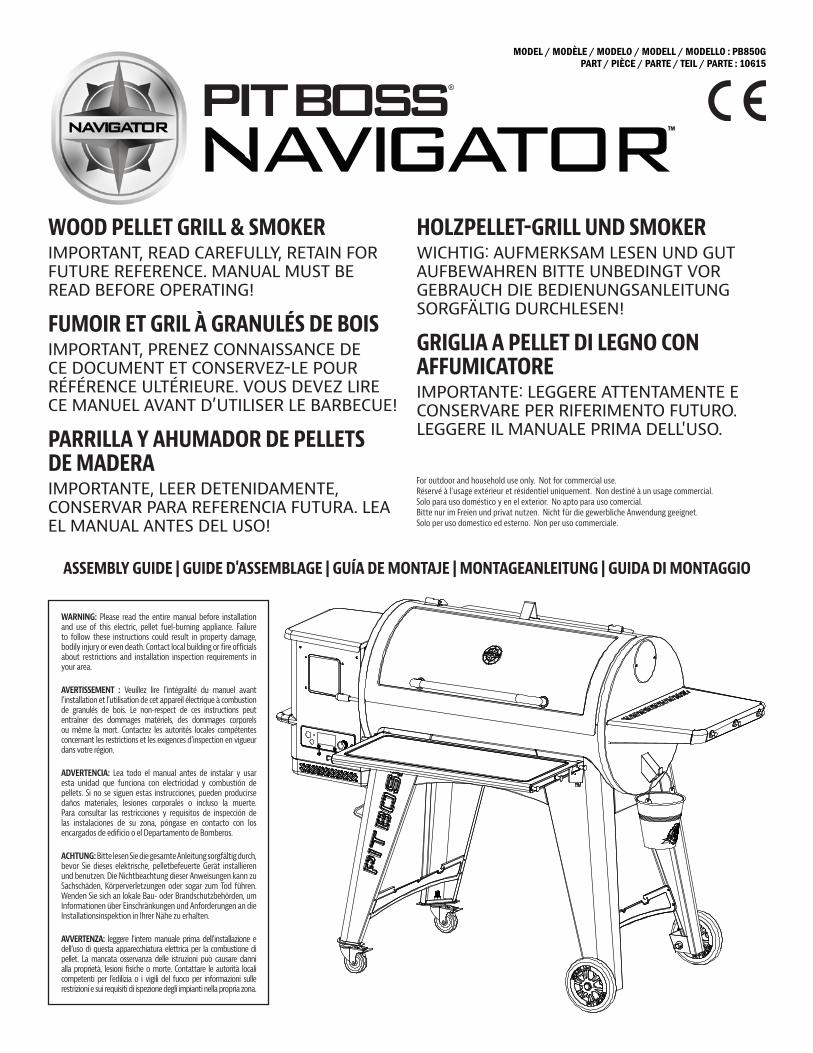
MODEL / MODÈLE / MODELO / MODELL / MODELLO : PB850GPART / PIÈCE / PARTE / TEIL / PARTE : 10615
WOOD PELLET GRILL & SMOKERIMPORTANT, READ CAREFULLY, RETAIN FOR FUTURE REFERENCE. MANUAL MUST BE READ BEFORE OPERATING!
FUMOIR ET GRIL À GRANULÉS DE BOISIMPORTANT, PRENEZ CONNAISSANCE DE CE DOCUMENT ET CONSERVEZ-LE POUR RÉFÉRENCE ULTÉRIEURE. VOUS DEVEZ LIRE CE MANUEL AVANT D’UTILISER LE BARBECUE!
PARRILLA Y AHUMADOR DE PELLETS DE MADERAIMPORTANTE, LEER DETENIDAMENTE, CONSERVAR PARA REFERENCIA FUTURA. LEA EL MANUAL ANTES DEL USO!
HOLZPELLET-GRILL UND SMOKERWICHTIG: AUFMERKSAM LESEN UND GUT AUFBEWAHREN BITTE UNBEDINGT VOR GEBRAUCH DIE BEDIENUNGSANLEITUNG SORGFÄLTIG DURCHLESEN!
GRIGLIA A PELLET DI LEGNO CON AFFUMICATOREIMPORTANTE: LEGGERE ATTENTAMENTE E CONSERVARE PER RIFERIMENTO FUTURO. LEGGERE IL MANUALE PRIMA DELL'USO.
ASSEMBLY GUIDE | GUIDE D'ASSEMBLAGE | GUÍA DE MONTAJE | MONTAGEANLEITUNG | GUIDA DI MONTAGGIO
WARNING: Please read the entire manual before installation and use of this electric, pellet fuel-burning appliance. Failure to follow these instructions could result in property damage, bodily injury or even death. Contact local building or fire officials about restrictions and installation inspection requirements in your area.
AVERTISSEMENT : Veuillez lire l’intégralité du manuel avant l’installation et l’utilisation de cet appareil électrique à combustion de granulés de bois. Le non-respect de ces instructions peut entraîner des dommages matériels, des dommages corporels ou même la mort. Contactez les autorités locales compétentes concernant les restrictions et les exigences d'inspection en vigueur dans votre région.
ADVERTENCIA: Lea todo el manual antes de instalar y usar esta unidad que funciona con electricidad y combustión de pellets. Si no se siguen estas instrucciones, pueden producirse daños materiales, lesiones corporales o incluso la muerte. Para consultar las restricciones y requisitos de inspección de las instalaciones de su zona, póngase en contacto con los encargados de edificio o el Departamento de Bomberos.
ACHTUNG: Bitte lesen Sie die gesamte Anleitung sorgfältig durch, bevor Sie dieses elektrische, pelletbefeuerte Gerät installieren und benutzen. Die Nichtbeachtung dieser Anweisungen kann zu Sachschäden, Körperverletzungen oder sogar zum Tod führen. Wenden Sie sich an lokale Bau- oder Brandschutzbehörden, um Informationen über Einschränkungen und Anforderungen an die Installationsinspektion in Ihrer Nähe zu erhalten.
AVVERTENZA: leggere l'intero manuale prima dell'installazione e dell'uso di questa apparecchiatura elettrica per la combustione di pellet. La mancata osservanza delle istruzioni può causare danni alla proprietà, lesioni fisiche o morte. Contattare le autorità locali competenti per l'edilizia o i vigili del fuoco per informazioni sulle restrizioni e sui requisiti di ispezione degli impianti nella propria zona.
For outdoor and household use only. Not for commercial use. Réservé à l'usage extérieur et résidentiel uniquement. Non destiné à un usage commercial.Solo para uso doméstico y en el exterior. No apto para uso comercial. Bitte nur im Freien und privat nutzen. Nicht für die gewerbliche Anwendung geeignet. Solo per uso domestico ed esterno. Non per uso commerciale.
TM

2
ENENGLISH
Parts & Specs ...................................................................... 3
Assembly Preparation ...................................................... 5
Assembly Instructions Securing Feet To Support Legs .................................................. 5 Securing Support Plates and Caster Wheels .......................... 5 Securing Support Plates and Wheels .......................................6 Securing Support Plate To Support Legs For Wheels ...........6 Securing Support Plate To Support Legs For Casters ...........6 Mounting Main Barrel To The Cart ........................................... 7 Securing Support Plates To The Grill ........................................ 7 Installing The Lid Stopper .......................................................... 7 Installing The Lid Handle ............................................................8 Installing The Flame Broiler Components...............................8 Installing Flame Broiler Adjusting Bar .....................................8 Installing The Side Shelf .............................................................9 Securing The Front Shelf Brackets ............................................9 Installing The Front Shelf ...........................................................9 Installing The Grill Cooking Components ............................. 10 Installing Grease Bucket .......................................................... 10 Connecting To A Power Source ................................................ 10
TABLE OF CONTENTS
COPYRIGHT NOTICE
Copyright 2020. All right reserved. No part of this manual may be copied, transmitted, transcribed, stored in a retrieval system, in any form or by any means without expressed written permission of,
Dansons 3411 North 5th Avenue, Suite 500, Phoenix, AZ, USA 85013 [email protected] | [email protected] www.pitboss-grills.com
Customer Service Monday through Sunday, 4am - 8pm PST (EN/FR/ES) Toll-Free: 1-877-303-3134, Fax: 1-877-303-3135

3
ENEN
GLISH
PARTS & SPECS
Part# Description1 Lid Stopper (x1)2 Lid Handle (x1)3 Lid Handle Bezel (x2)4 Main Barrel/Hopper Assembly (x1)5 Flame Broiler Adjusting Bar (x1)6 Flame Broiler Adjusting Bar Handle (x1)7 Flame Broiler Slider (x1)8 Flame Broiler Main Plate (x1)9 Left Front Leg (x1)10 Left Back Leg (x1)11 Right Front Leg (x1)12 Right Back Leg (x1)13 Left Front Leg Trim Piece (x1)
14 Left Back Leg Trim Piece (x1)15 Swivel Caster with Brake (x2)16 Wheel (x2)17 Right Bottom Support Plate (x1)18 Left Bottom Support Plate (x1)19 Short Support Plate (x2)20 Front Long Support Plate (x1)21 Back Long Support Plate (x1)22 Front Shelf (x1)23 Front Shelf Bracket Right (x1)24 Front Shelf Bracket Left (x1)25 Grease Bucket (x1)26 Right Side Table (x1)27 Cooking Grid A (x1)28 Cooking Grid B (x2)29 Warming Rack (x1)30 Meat Probe (x1)31 Cable Clip (x1)32 Power Cord (x1)
Part# DescriptionA Screw (x18)B Washer (x18)C Locking Washer (x18)D Screw (x30)E Screw (x4)F Wheel Axle Pin (x2)G Wheel Cotter Pin (x2)H Wheel Washer (x2)
NOTE: Due to ongoing product development, parts are subject to change without notice. Contact Customer Service if parts are missing when assembling the unit.
PB – ELECTRIC REQUIREMENTS220-240V, 50HZ, 250W, 3-PRONG GROUNDED PLUG
Diagram Illustration on next page.
MODEL UNIT ASSEMBLED (WxHxD) UNIT WEIGHT COOKING AREA TEMP. RANGE DIGITAL FEATURES
PB PB850G 1,472mm x 1,195mm x 940mm / 57.9” x 47” x 37”
74.5 kg / 164.24 lb
Main - 3,825.8 cm² / 593 sq. in. Upper Rack - 1,845.2 cm² / 286 sq. in. TOTAL - 5,671 cm² / 879 sq. in.
82-260°C / 180-500°F
Ten temperature presets, start-up and cool-down cycles, electric igniter

4
ENENGLISH
PARTS & SPECS
HGFEDCBA
1
25
4
3
13
12
14
16
19
18
20
22
24
25
23
21
9
10
7
8
11
6
17
29
27
3
15
26
28
30
31
32
5
ENEN
GLISH
ASSEMBLY INSTRUCTIONS
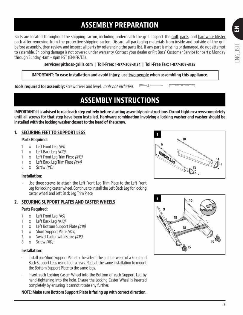
IMPORTANT: It is advised to read each step entirely before starting assembly on instructions. Do not tighten screws completely until all screws for that step have been installed. Hardware combination involving a locking washer and washer should be installed with the locking washer closest to the head of the screw.
1. SECURING FEET TO SUPPORT LEGS Parts Required:
1 x Left Front Leg (#9)1 x Left Back Leg (#10)1 x Left Front Leg Trim Piece (#13)1 x Left Back Leg Trim Piece (#14)6 x Screw (#D)
Installation:• Use three screws to attach the Left Front Leg Trim Piece to the Left Front
Leg for locking caster wheel. Continue to install the Left Back Leg for locking caster wheel and Left Back Leg Trim Piece.
2. SECURING SUPPORT PLATES AND CASTER WHEELS Parts Required:
1 x Left Front Leg (#9)1 x Left Back Leg (#10)1 x Left Bottom Support Plate (#18)1 x Short Support Plate (#19)2 x Swivel Caster with Brake (#15)8 x Screw (#D)
Installation:• Install one Short Support Plate to the side of the unit between of a Front and
Back Support Legs using four screws. Repeat the same installation to mount the Bottom Support Plate to the same legs.
• Insert each Locking Caster Wheel into the Bottom of each Support Leg by hand-tightening into the hole. Ensure the Locking Caster Wheel is inserted completely by ensuring it cannot rotate any further.
NOTE: Make sure Bottom Support Plate is facing up with correct direction.
ASSEMBLY PREPARATIONParts are located throughout the shipping carton, including underneath the grill. Inspect the grill, parts, and hardware blister pack after removing from the protective shipping carton. Discard all packaging materials from inside and outside of the grill before assembly, then review and inspect all parts by referencing the parts list. If any part is missing or damaged, do not attempt to assemble. Shipping damage is not covered under warranty. Contact your dealer or Pit Boss® Customer Service for parts: Monday through Sunday, 4am - 8pm PST (EN/FR/ES).
[email protected] | Toll-Free: 1-877-303-3134 | Toll-Free Fax: 1-877-303-3135
IMPORTANT: To ease installation and avoid injury, use two people when assembling this appliance.
Tools required for assembly: screwdriver and level. Tools not included.
1
910
13
14
2
19
9
10
18
1515
6
ENENGLISH
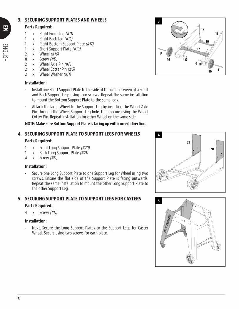
3. SECURING SUPPORT PLATES AND WHEELS Parts Required:
1 x Right Front Leg (#11)1 x Right Back Leg (#12)1 x Right Bottom Support Plate (#17)1 x Short Support Plate (#19)2 x Wheel (#16)8 x Screw (#D)2 x Wheel Axle Pin (#F)2 x Wheel Cotter Pin (#G)2 x Wheel Washer (#H)
Installation:• Install one Short Support Plate to the side of the unit between of a Front
and Back Support Legs using four screws. Repeat the same installation to mount the Bottom Support Plate to the same legs.
• Attach the large Wheel to the Support Leg by inserting the Wheel Axle Pin through the Wheel Support Leg hole, then secure using the Wheel Cotter Pin. Repeat installation for other Wheel on the same side.
NOTE: Make sure Bottom Support Plate is facing up with correct direction.
4. SECURING SUPPORT PLATE TO SUPPORT LEGS FOR WHEELS Parts Required:
1 x Front Long Support Plate (#20)1 x Back Long Support Plate (#21)4 x Screw (#D)
Installation:• Secure one Long Support Plate to one Support Leg for Wheel using two
screws. Ensure the flat side of the Support Plate is facing outwards. Repeat the same installation to mount the other Long Support Plate to the other Support Leg.
5. SECURING SUPPORT PLATE TO SUPPORT LEGS FOR CASTERS Parts Required:
4 x Screw (#D)
Installation:• Next, Secure the Long Support Plates to the Support Legs for Caster
Wheel. Secure using two screws for each plate.
5
3
1211
19
17
16
16
F
F
G HH G
4
21
20

7
ENEN
GLISH
6. MOUNTING MAIN BARREL TO THE CART Parts Required:
1 x Main Barrel (#4)12 x Screw (#A)12 x Washer (#B)12 x Locking Washer (#C)1 x Power Cord (#32)1 x Cable Clip (#31)
Installation:• Please replace with the correct power cord for your country, if you find
the power cord does not match the plug you are using. • Place the cable clips on the correct power cord. Insert the power cord
into the grove at the bottom of the hopper. Secure the cable clip to the bottom of the hopper with the previously installed screw. Note Illustration 6A.
• Prepare the Main Barrel to be mounted to the Cart. Carefully, lift the Cart into an upright position with the wheels on the bottom. Position the Cart next to the Main Barrel, with both facing the same direction. Lock the Caster Wheels on the Cart. Using a second person, prepare to lift the Main Barrel onto the Cart. With one person lifting from the hopper side, and the other person lifting from the opposing barrel end, carefully lift the Main Barrel, and slowly lower onto the Cart. Note illustration 6B.
• Next, open the Main Barrel lid. Adjust the rotation as needed to align the screw holes of the Main Barrel to the Cart. Once placed, secure each leg to the Main Barrel using three screws, washers, and locking washers. Note illustration 6C.
7. SECURING SUPPORT PLATES TO THE GRILL Parts Required:
4 x Screw (#E)
Installation:• Secure each Long Support Plate to the Main Barrel using two screws.
8. INSTALLING THE LID STOPPER Parts Required:
1 x Lid Stopper (#1)
Installation:• Secure the Lid Stopper onto the top of the Main Barrel using the pre-
installed screw on top of the Main Barrel.
81
7
6B
4
6C
BAC
6A
3132

8
ENENGLISH
C
9. INSTALLING THE LID HANDLE Parts Required:
1 x Lid Handle (#2)2 x Lid Handle Bezel (#3)
Installation:• Remove the pre-installed screws from the Lid Handle. From inside the
barrel lid, insert one screw protrude to the outside. Add a Bezel on the screw. Then hand-tighten the screw (from the inside) into the Lid Handle. Repeat for other side.
10. INSTALLING THE FLAME BROILER COMPONENTS Parts Required:
1 x Flame Broiler Main Plate (#8)1 x Flame Broiler Slider (#7)
Installation:• Insert the Flame Broiler Main Plate into the main grill. Rest the Flame
Broiler Main Plate on the built-in ledge (on the inside right) of the Main Grill that directs grease towards the grease bucket spout. Slide the entire piece to the left side, and the two slots on the Flame Broiler Main Plate will fit into the rounded ledge above the burn pot. It will sit slightly at a downward angle. Note illustration 10A.
IMPORTANT: If the Main Plate is resting on the base of the Barrel, it is installed incorrectly. Poor installation may result in damage to your Main Grill Barrel.• Place the Flame Broiler Slider on top of the Flame Broiler Main Plate
covering the slotted openings. Ensure the raised tab is on the left and the two pins at the bottom of the Flame Broiler Slider place into the holes of the Flame Broiler Main Plate to easily adjust for direct and indirect flame when cooking. Both flame broiler parts are lightly coated with oil to avoid rusting when shipped. Note illustration 10B.
NOTE: To maintain the searing and grilling performance of your cooking grids, regular care and maintenance Is required. See Owner's Manual.
11. INSTALLING FLAME BROILER ADJUSTING BAR Parts Required:
1 x Flame Broiler Adjusting Bar (#5)1 x Flame Broiler Adjusting Bar Handle (#6)
Installation:• Insert the Flame Broiler Adjusting Bar through the opening hole on
the left side of the Main Barrel. Add the Flame Broiler Adjusting Bar Handle on the end outside the Barrel. Next, slide the notched end of the Adjusting Bar into the locking tab on the Flame Broiler Slider, giving you adjustable access to the Flame Broiler Slider on the Main Plate.
10B7
8
10A
8
11
A
B
6
5
5
CB
9 23
3
9
ENEN
GLISH
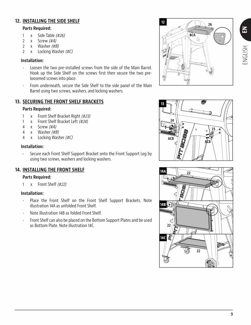
12. INSTALLING THE SIDE SHELF Parts Required:
1 x Side Table (#26)2 x Screw (#A)2 x Washer (#B)2 x Locking Washer (#C)
Installation:• Loosen the two pre-installed screws from the side of the Main Barrel.
Hook up the Side Shelf on the screws first then secure the two pre-loosened screws into place.
• From underneath, secure the Side Shelf to the side panel of the Main Barrel using two screws, washers, and locking washers.
13. SECURING THE FRONT SHELF BRACKETS Parts Required:
1 x Front Shelf Bracket Right (#23)1 x Front Shelf Bracket Left (#24)4 x Screw (#A)4 x Washer (#B)4 x Locking Washer (#C)
Installation:• Secure each Front Shelf Support Bracket onto the Front Support Leg by
using two screws, washers and locking washers.
14. INSTALLING THE FRONT SHELF Parts Required:
1 x Front Shelf (#22)
Installation:• Place the Front Shelf on the Front Shelf Support Brackets. Note
illustration 14A as unfolded Front Shelf.• Note illustration 14B as folded Front Shelf.• Front Shelf can also be placed on the Bottom Support Plates and be used
as Bottom Plate. Note illustration 14C.
12 26
BCA
13
24
23
ACBACB
14A
14B
14C
22
22
22

10
ENENGLISH
15. INSTALLING THE GRILL COOKING COMPONENTS Parts Required:
1 x Cooking Grid A (#27)2 x Cooking Grid B (#28)1 x Porcelain-Coated Steel Upper Warming Rack (#29)
Installation:• Place the Cooking Grids, side by side, on the grid ledge inside the Main Grill.• Place the Upper Cooking Rack on the upper ledge inside the Main Grill.
The Warming Rack will lock into place.
16. INSTALLING THE GREASE BUCKET Parts Required:
1 x Grease Bucket (#25)
Installation:• Place the Grease Bucket on the spout hook on the end of the Main Barrel.
Ensure it is level to avoid grease spills. • The unit is now completely assembled.
17. CONNECTING TO A POWER SOURCE NOTE: Before plugging your Pit Boss® into any electrical outlet, ensure the temperature dial is in the OFF position.
• STANDARD OUTLET This appliance requires 220-240 volts, 50hz, 250w service. It must be a
3-prong grounded plug.
• GFCI OUTLETS This appliance will work on most GFCI outlets, with a recommended
size of 15 amp service. If your GFCI outlet is highly sensitive to power surges, it will likely trip during the start-up phase of operation. During the start-up phase, the igniter draws 200-700 watts of electricity, which can be too much power for a GFCI outlet to handle. Each time it trips, it increases in sensitivity. If the GFCI keeps tripping, replace the outlet or change to a non-GFCI outlet.
IMPORTANT: Disconnect unit from power source when not in use.
IMPORTANT: Refer to Owner's Manual for Operating Instructions
17
FAST-BLOW FUSE, 5 AMP
16
25
15
2828
29
27
Copyright © 2022 FDOKUMEN