
WIRELESS - World Radio History
88
WIRELESS ENGINEER JANUARY 1947 VOL XXIV TWO SHILLINGS AND SIXPENCE No. 280
-
Upload
khangminh22 -
Category
Documents
-
view
1 -
download
0
Transcript of WIRELESS - World Radio History

WIRELESSENGINEER
JANUARY 1947
VOL XXIV TWO SHILLINGS AND SIXPENCE No. 280

calMade in ThreePrincipal Materials
FREQUELEX04d/
An insulating material of Low DielectricLoss, for Coil Formers, Aerial Insulators,Valve Holders, etc.PERMALEXA High Permittivity Material. For theconstruction of Condensers of the small-.est possible dimensions.
TEMPLEXA Condenser material of medium per-mittivity. For the construction ofCondensers having a constant capacityat all temperatures.
des/4osET US BRING THEM TO
BulletsBULLERS LOW LOSS CERAMI
BULLERS LTD., 6, LAURENCE POUNTNEY HILL, LONDON, E,C:,Telephone : Mansion House 9971 (3 lines) Telegrams "Bullers, Cannon, Loden :f
nary, 1947 WIRELESSENGINEER
1,
Y
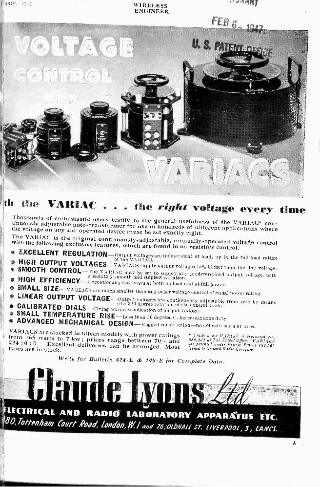
th the VAMAC . . . She right voltage every timeThousands of enthusiastic users testify to the general usefulness of the VARIAC* con-tinuously adjustable auto -transformer for use in hundreds of different applications wherethe voltage on any a.c. operated device must be set exactly right.The VARIAC is the original continuously -adjustable, manually -operated voltage controlwith the following exclusive features, which are found in no resistive control.
! EXCELLENT REGULATION-output voltages are independent of load, up to the full load rating
'It
of the VARIAC.I
HIGH OUTPUT VOLTAGES-VARIACS supply output voltages 15% higher than the line voltage.4
SMOOTH CONTROL-The VARIAC may be set to supply any predetermined output voltage, withabsolutely smooth and stepless variation.1 HIGH EFFICIENCY-Exceptionally low losses at both no load and at full power.It
SMALL SIZE-VARIACS are much smaller than any other voltage control of equal power rating. LINEAR OUTPUT VOLTAGE-output voltages are continuously adjustable from zero by meansof a 320 degree rotation of the control knob. CALIBRATED DIALS-Giving accurate indication of output voltage. SMALL TEMPERATURE RISE-Less than 50 degrees C. for continuous duty. ADVANCED MECHANICAL DESIGN-Rugged construction-no delicate parts or wires.VARIACS are stocked in fifteen models with power ratingsi from 165 watts to 7 kw ; prices range between 70/- and£34 :0 : 0. Excellent deliveries can be arranged. Mosttypes are in stock.
Write for Bulletin 424-E & 146-E for Complete Data.
* Trade name VARIAC is registered No.580,454 at The Patent Office. V ARIAGSare patented under British Patent 439,567issued to General Radio Company.
1, 1. All hpylfkal
LECTRI(AL AND RADIO LABORATORY ,APPARATUS ETC.80, Tottenheim Court Road, 101715/0/7,/11./ and 76,01MAIL ST. LIVERPOOL, 3, LANCi
A

2
c
WIRELESSENGINEER
January, 194
IF you are interested in any of the following divisions of instrume
work, fill in just one more form and send it to us. We will then keep yl
posted with our developments in your particular field. Just let us know yo
name, the address to which we should send infcmation, the name of your organization and tposition you hold ; and mention which of tfollowing divisions of our work interests you:
* For Jour convenience a detachable form is added.
NVIEHEADMuirhead & Company Ltd. Elmers End,
Beckenham, Kent. Tel. Beckenham 0041-2
FOR OVER 60 YEARS DESIGNERS ANDMAKERS OF PRECISION INSTRUMENTS
Resistances and Resistance Networks.Laboratory Condensers and Inductances.A.C. Bridges and Accessories.Oscillators, Tuning Forks and Timing Device
Dials and Drives. Switches.D.C. Testing Equipment.pH Meters and Equipment for the Chemise
Industry.
Name
Address tohich information
is to be sentEmployed
byPosition
held
Divisions of Instrument Work
Resistances & Resistance Networks
Laboratory Condensers & Inductances
A.C. Bridges & Accessories .
Oscillators, Tuning Forks & TimingDevices
(Please indicate in the right-hand columnthe divisions in which you are interested.)
Dials & Drives
Switches .....
D.C. Testing Equipment
pH Meters & Equipment for theChemical Industry
NIStEor to
fl
11)
Resistors produced by the cracked
carbon process remain stable to + i%
of initial value.
Tolerances + 1% ±2% 5%
Low temperature co -efficient.
e awng@TIADODE resistor
WELWYN ELECTRICAL LABORATORIES LTD.'
Welwyn Garden City, Herts. Telephone : Welwyn Garden 3.
ary, 1947 WIRELESSENGINEER 3
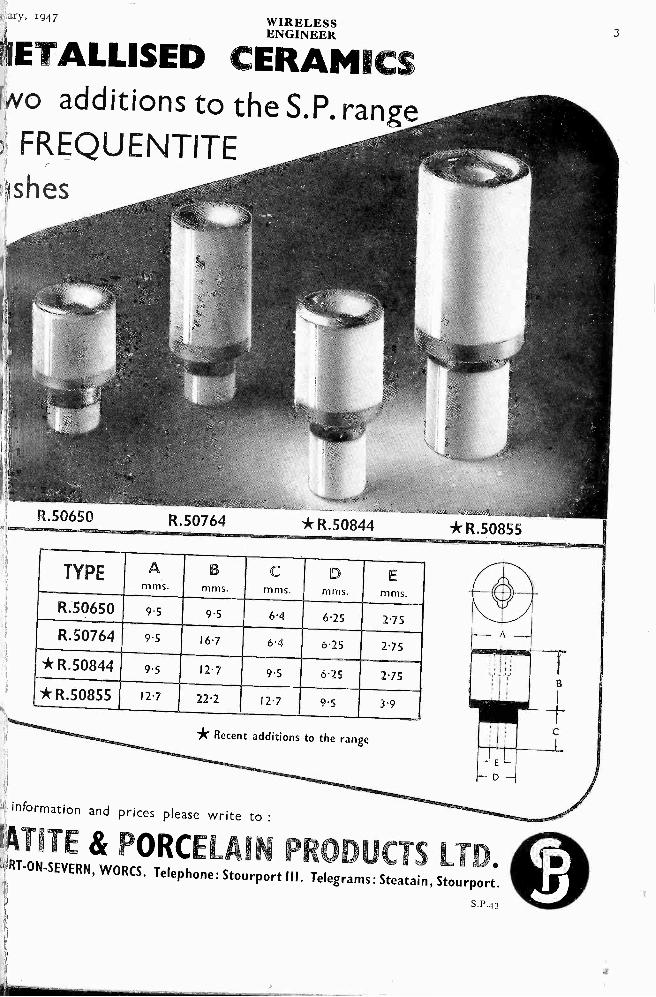
IIETALLISED CERAMICSNO additions to the S.P. rangeFREQUENTITE
Ishes
R.50650 R.50764
TYPE Amms.
R.50650 9.5
R.50764
* R.50844
* R.50855
*R.50844 *R.50855
mms. I mms. mms. mms.
9.5 I 6.4 6.25 I 2.75
9.5 16.7 6.4 6.25 2.75
9.5 12.7 9.5 6.25 2.75
121 222 127 9.5 3.9
* Recent additions to the range
information and prices please write to :
ATITE & PORCELAIN PRODUCTS LTDRT-ON-SEVERN, WORCS. Telephone: Stourport Ill. Telegrams: Steatain, Stourport.
s.P.43

4WI RELESSENGINEER
January, it
CO )6CA
with TE Lc971.1 ENE insulation
A complete range of co -axial and twin Telcon
cables is available for the Reception andTransmission of Radio Frequencies up to thecentimetre range. CAPACITIES extend up-wards from 10/4 /4F/ft. with CHARACTERISTICIMPEDANCES of from 50 ohms to 150 ohms.ATTENUATION from 0.4 db/100-ft. at 100 Mc/s
is provided by the air -spaced types, solid
dielectric types ranging from 0.95 db/100-ft.
to 6.5 db/100-ft. at 100 Mc/s. POWERHANDLING capacity of the various types is
from 1KW to 20KW at 10 Mc/s. For furtherdetails apply for R.F. brochure.
* TELCON DESIGNED R.F. CABLES ARE TFLcoti
THE BASIS OF WORLD STANDARDS
THE TELEGRAPH CONSTRUCTION & MAINTENANCE CO. LTD.
Founded 1864
Head Office :22 OLD BROAD ST., LONDON, E.C.2. Tel : LONdon Wall 3141
Enquiries to TELCON WORKS, GREENWICH, S.E.I0. Tel : GREenwich 1040
S.E.M. MINIATURE
MOTORSThe S.E.M. A.C. minia-ture electric motor, whichhas dimensions of motorbody 'a" long by 11"
diameter
FOR special use in Indicating and
Recording Instruments, S.E.M. en-gineers have designed and manufactureddependable miniature electric motors. i
The A.C. model can be used on 5o or200-1,000 c.p.s. supply at 25-30 volts, andthe D.C. model up to 24 volts. Bothmachines have a torque of 14 in. oz. and
are capable of up to io,000 r.p.m.
In common with all S.E.M. machines,;
these motors are manufactured to the
highest standards of mechanical detail and
have passed rigid inspection and tests.
SMALL ELECTRIC
MOTORS LTD.have specialized for over 30 years in
making electrical machinery and
switchgear up to 10 kW capacity.They are experts in the design and
manufacture of ventilating fans and
blowers, motors, generators, air-
craft and motor generators, high -
frequency alternators, switchgear,starters and regulators.
BECKEN HAM KENT
uary, 1947 WIRELESSENGINEER 5
11
ecd291.8
ma.i.,,, veezahc .e/4.,e Rarnl.e. 4
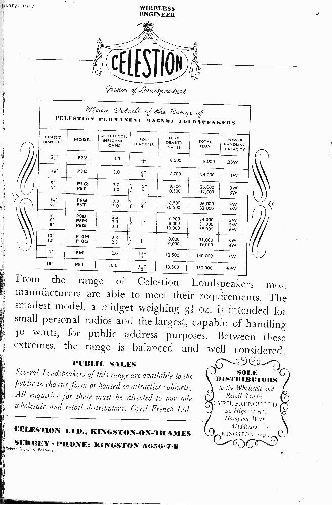
cELEsTfoN PERMANENT !MAGNET LOUDSPEAKERS
CHASSISDIAMETER MODEL
SPEECH COILIMPEDANCE
OHMS
POLEDIAMETER
FLUXDENSITY
GAUSS
TOTALFLUX
POWERHANDLINGCAPACITY
2!" P2V 3.0 7 "1-6 8,500 8,000 .25W
3!" P3C 3.0 7,700 24,000 I I W
5" PS Q 3.0 8,500 26,000 3W5" PST } r 10,500 32,000 3W61" P6 Q 3.0 8,500 26,000 4W61" P6T 3.0 I I" 10,500 32,000 4W8' P8D 2.3 6,200 24,000 5W8" P8M 2.3 I" 8,000 31,000 5W8" P8G 2.3 10,000 39,000 6W
10" P I OM,2.3
1 , 8,000 31,000 6W10" P I OG 2.3 f 1 10,000 39,000 8W12" P64 12.0 I
12,500 140,000 15W
18" P84 10.0 21" 13,500 350,000 40W
From the range of Celestion Loudspeakers mostmanufacturers are able to meet their requirements. Thesmallest model, a midget weighing 31 oz. is intended forsmall personal radios and the largest, capable of handling40 watts, for public address purposes. Between theseextremes, the range is balanced and well considered.
PUBLIC SALESSeveral Loudspeakers of this range are available to thepublic in chassis form or housed in attractive cabinets.All enquiries for these must be directed to our solewholesale and retail distributors, Cyril French Ltd.
CELESTION LTD.. KINGSTON -ON -THAMESr SURREY PHONE: KINGSTON 54;56.7-8lARobert Sharp & Partners
ill
SOLEDISTRIBUTORS
to the Wholesale andRetail Trades:
CYRIL FRENCH LTD.29 High Street,Hampton Wick,
Middlesex.-17))li I NGS

6 WIRELESSENGINEER
J anuary,
Reg. Trade Mark.
PRECISIONTESTING INSTRUMENTS
Radio manufacturers, service engineers,workshop and laboratory technicians are
familiar with the precision and dependabilityof " AVO " Electrical Testing Instruments.Long years of successful experience in thedesign and manufacture of first -gradeinstruments have produced a consistentlyhigh standard of accuracy which has becomea tradition as well as a standard by whichother instruments are frequently judged.
Rtstd rad Mcrt
MEANS ACCURACY
The MODEL 7 50 -Range Universal
AVOMETERElectrical Measuring Instrument
A self-contained, precision moving -coil instrument, conforming toB.S. 1st Grade accuracy requirements. Has so ranges, providingfor measuring A.C. & D.C. volts, A.C. & D.C. amperes, resistance,capacity, audio -frequency power output and decibels. Diectreadings. No external shunts or series resistances. Provided with!automatic compensation for errors arising from variations initemperature, and is protected by an automatic cut-out againsti
damage through overlc ad.
Sole Proprietors and Manufacturers:THE AUTOMATIC COIL WINDER & ELECTRICAL EQUIPMENT CO., LTD., Winder House, Douglas Street, London, S.W.1. 'Phone : VICtoria
CARPENTER
MAINRELAY
FEATURES OF STANDARD MODELHigh Speed. Short transit time-normally below 1 millisecond.Contact gap a function of input power, hence small distortion almostdown to failure point. High contact pressures. No contact chatter.High sensitivity-robust operation at 5 mV.A. at 100 cis or 0.2 mW.D.C.Great ease of adjustment. Magnetic bias adjustment giving absolutelysmooth control.Balanced armature-hence immunity to considerable vibration and nopositional error.
DIMENSIONS IN COVER: 2f x 1,, x 4}. WEIGHT with standard socket: 22 ozs.
Complete details available on request.
TELEPHONE MANUFACTURING CO., LTD.HOLLINGSWORTH WORKS DULWICH LONDON S.E.21
Telephone: GIPsy Hill 2211 (I0 lines)
.stO\,,S,Ses'

ivary, 1947 WIRELESSENGINEER 7
A NEW SENSIBLE COAXIAL PLUGAND SOCKET
For Television, Car
Illustration cf the plug and socket members of L604,showing finished preparation for loading.
Judging by the enthusiastic receptiongiven to this little component* by theradio and electronic industry, it appearsto have satisfied a long overdue require-ment for a coaxial plug and socket whichwill meet the following requirements :-(I) An obvious and simple method of loading
necessity of solder-ing the shielding or using additionalclamping means.
(2) Low capacitance.(3) Low contact resistance.(4) " Click " engagement action.(5) Clean instrument like appearance and
finish.A large number of models were
designed, and very careful judgment wasexercised on the electrical, mechanical,and economic properties of each beforethe final design was chosen.
The collett system of clamping has beendesigned to cover a range of cable shielddiameters from 0.125 to 0.25 inches. Avery popular cable specified as Uniradio 32is particularly convenient to load.
The characteristic impedance of theplug/socket combination is of the orderof 50 ohms and it might be asked why theimpedance was not designed to match a70 ohm cable (e.g., Uniradio 32.)
A little calculation will show that theattainment of this impedance necessitateseither increasing considerably the overalldiameter of the component out of allproportion to the cable diameter
H * L604 Coaxial PlIg and Socket. Price complete 3/-.
radio and Electronic applications.(and raising the, price), or reducing thediameter of the inner pin and socket toan extent sufficient to introduce con-siderable mechanical weakness and diffi-culty in connecting the inner conductorof the cable.
We were principally interested inintroducing this plug and socket for theconnection of television aerial feeders todomestic television receivers, and ananalysis of the problem revealed, that forwavelengths very long in comparisonwith the length of the plug and socket, -the matching of cable and plug/socketcharacteristic impedances was ofsecondary importance, the main require-ment being that of low total self capaci-tance, which is 3 p.f. in our design. Thesame statement is even more true inmany other plug and socket applicationsin radio and electronic equipment operat-ing at high radio frequencies, when low selfcapacitance is an outstanding requirement.
A particularly useful application is forthe aerial input circuit to car radioinstallations. Owing to the low selfcapacitance of the average rcd type caraerial, particular attention must be givento providing a low capacitance shieldedline from the aerial to the receiver, andthe coaxial cable designed expressly forthis purpose loads perfectly into this plug,while the " click " engagement preventsdisengagement through vibration.
It is important to note that, dimen-sionally, this component complies withthe recently approved R.C.M.F. standardfor a coaxial plug and socket for pro-viding the input connections to domestictelevision receivers.
The follcwing additional versions cf this plug/socket are near completion :(I) Single cable right angle entry.(2) Double cable right angle entry.(3) Cable to cable junction.(4) Double ended panel mounting scckee for
continuation of shielding into the chassis.A plug similar to L.604 but for the attach-ment of larger diameter cables up to0.375 inches.
(5)
BELLING & LEE LTDCAMBRIDGE ARTERIAL ROAD, ENFIELD. MIDDX
8WI RELESSENGINEER
January, 191
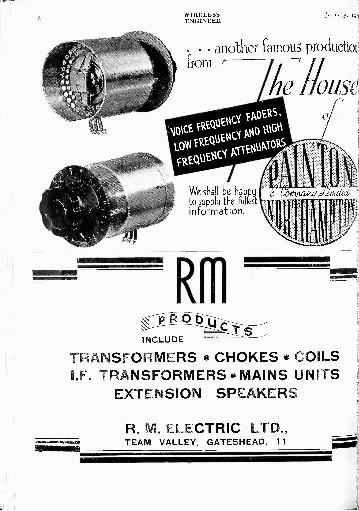
another famous productiorfrom
We shall be happyto supply the fullestinformation.
RR1PROClu
INCLUDEs
TRANSFORMERS CHOKES COILSI.F. TRANSFORMERS MAINS UNITS
EXTENSION SPEAKERS
R. M. ELECTRIC LTD.,TEAM VALLEY, GATESHEAD, 11
ry, 1917 WIRELESS9ENGINEER
IIIIIIIIIIIIIIIIIIIIIIIIIIIIIIIIIIIIIIIIIIIIIIIIII111111111111111111111111 III III 1111111111111111111111111111111111111111111111111111111111111111111111111111111!iff
aA'rINST
but NOT"Laboratory" Price !
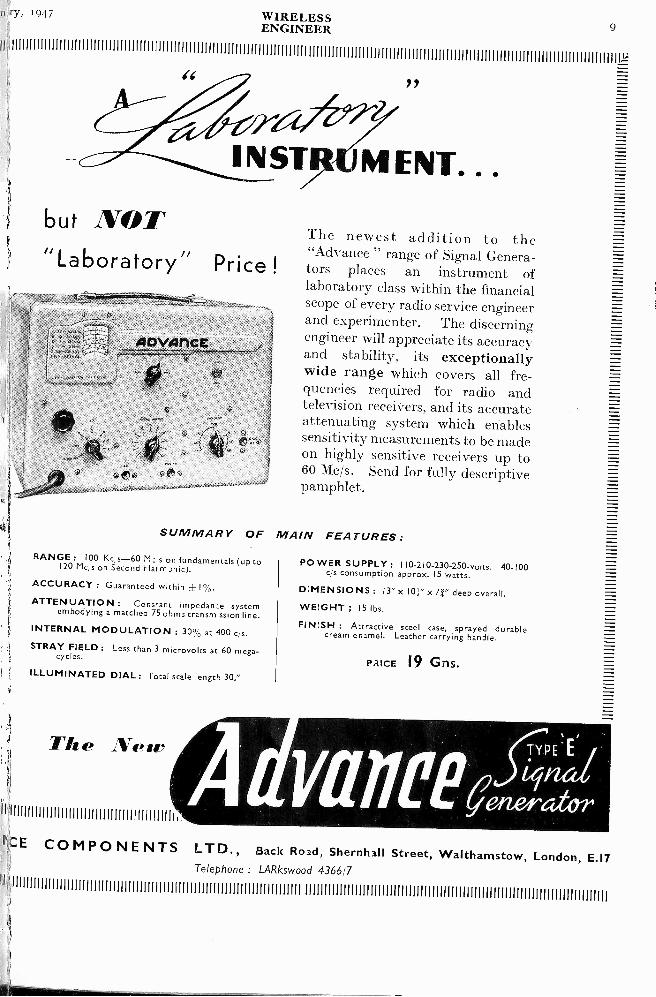
The newest addition to the"Advance " range of Signal Genera-tors places an instrument oflaboratory class within the financialscope of every radio service engineerand experimenter. The discerningengineer will appreciate its accuracy -and stability, its exceptionallywide range which covers all fre-quencies required for radio andtelevision receivers, and its accurateattenuating system which enablessensitivity measurements to be madeon highly sensitive receivers up to60 MO. Send for fully descriptivepamphlet.
SUMMARY OF MAIN FEATURESRANGE : 100 Kc s-60 M: s on fundamentals (up to
120 Mc s on Second Harmonic).
ACCURACY : Guaranteed within ±14.
ATTENUATION: Cons,ant impedance systemembodying a matched 75 ohms transmission line.
INTERNAL MODULATION : 30% at 400 c s.
STRAY FIELD : Less than 3 microvolts at 60 mega-cycles.
ILLUMINATED DIAL: Total scale length 30."
The Nese
9111111111111111111111111111111111111111111h
I°)CE CO M PO NE NTS LTD., Back Road, Shernhall Street, Walthamstow, London, E.17Telephone : LARkswood 4366'7
ir111111111M1111111111i111111111111111111111111111111111111111111rniiii
POWER SUPPLY : 110 -210 -230 -250 -volts. 40-100c s consumption approx. 15 watts.
DIMENSIONS : 13" x 10r x 71" deep overall.
WEIGHT ; 15 lbs.
FINISH : Attractive steel case, sprayed durablecream enamel. Leather carrying handle.
PUCE 19 Gns.
1)

I0 WIRELESSENGINEER
January,
weq0CAMITOL* CALCULATED TO ANSWER
THE MOST EXACTING DEMANDS
* FOR ALL RADIOAND ELECTRICAL PURPOSES
WEGO CONDENSER CO LTD BIDEFORD AVE PERIVALE GREENFORD MIDDX Tel. PERIVALE
NEW TYPES FORMIDGET RECEIVERS
HEARING AIDSMETEOROLOGICAL
INSTRUMENTSETC.
THE SCIENTIFICVALVE
BRITISH MADE
HIVAC LIMITEDGreenhill Crescent. Phone HARRCW
Harrow on the Hill.Middx. 0895
COD
1"10"1t-OVI
l-ENIE.1.5in opv
and attenuationof CO -NY.
0
leannev4
poss.00tesin elec.
equiproent
*t
designthe pos
bothfa
fI
mar effortand f
ooricage,
electrn
BASICALLY SETT'
4/R-SPACEi
10P/10ffTRANSRADIO LTD. I6THE HIGHWAY. BEACONSFIELD

1,6 ry, 1947
DISC TYPE
H.V.D.
Speciallysuitable for
'PULSE WORKINGCapacitance Range
3 pF - 50 pFWorking Voltage
2 kV R.M.S.RF. Load
ilia to 10 pF 2 kVA with 2 amps.ti,to 50 pF 0.8 kVA with 1.5 amps.
I,ED INSULATOR CO. LTD.,: Elmbridge 5241 (6 lines)
1
[Unsurpassed In Ceramics
WIRELESSENGINEER
ERAMIC'//; APACITORS
4744007cm77,
THE U.I.C. Fixed Ceramic Pot Capacitor - KO2944-illustrated above, has been primarily developedfor use in transmitter circuits. Made only from thehighest grade raw materials and subjected to the mostrigorous tests, its rating for its size is unsurpassed.Capacitance Range: I20 -25o pF. RF Load : 26 kVAwith 14 amps. Working Voltage : 5 kV R.M.S.Further details on application.
OAKCROFT RD., TOLWORTH, SURBITON, SURREYTelegrams : Calanel, Surbitan
II
12WIRELESSENGINEER
January,
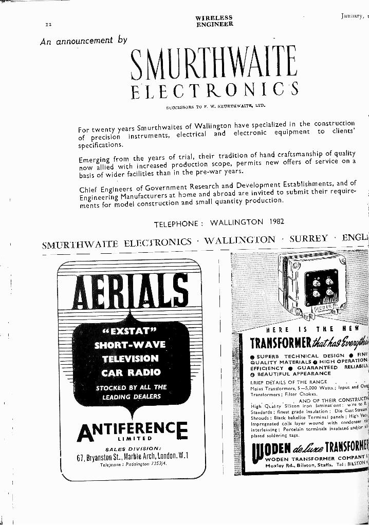
An announcement by
SVLRTHWAITEELECTRONICS
SUOCESSORS TO F. W. S111JRTHWAITE, LTD.
For twenty years Smurthwaites of Wallington have specialized in the construction
of precision instruments, electrical and electronic equipment to clients'
specifications.
Emerging from the years of trial, their tradition of hand craftsmanship of quality
now allied with increased production scope, permits new offers of service on a
basis of wider facilities than in the pre-war years.
Chief Engineers of Government Research and Development Establishments, and of
Engineering Manufacturers at home and abroad are invited to submit their require-
ments for model construction and small quantity production.
TELEPHONE : WALLINGTON 1982
SMURTHWAITE ELECTRONICS WALLINGTON SURREY ENG-Li
4E11 ALS" EXSTAT
SHORT-WAVETELEVISION
CAR RADIOSTOCKED BY ALL THE
LEADING DEALERS
ANT I fIFTtENCELI
SALES DIVISION:67, Bryanston St., Marble Arch, London, W.1
Telephone : Paddington 7253/4.
HERE IS THE NE
TRANSFORMERaelaf SUPERB TECHNICAL DESIGN FINE
QUALITY MATERIALS HIGH OPERATION),EFFICIENCY GUARANTEED RELIABILE
0 BEAUTIFUL APPEARANCELRIEF DETAILS OF THE RANGE .
Mains Transformers, 5-5,000 Watts.; Input and Outl.
Transformers ; Filter Chokes.
. . AND OF THEIR CONSTRUCTIfHigh Quality Silicon iron laminations ; wire to B.:i
Standards : finest grade insulation ; Die Cast Streaml
Shrouds ; Black bakelite Terminal panels ; High V2C11.
Impregnated coils layer wound with condenser tis!.
interleaving ; Porcelain terminals insulated and/or sil
plated soldering tags.
ODEN eth44.-e TRANSFORMY
WODEN TRANSFORMER COMPANY L,
Moxley Rd., Bilston, Staffs. Tel : BILSTON 4,

y, 1947 W I RELESSENGINEER 13
FREQUENCYCONVERTER
The Syncycle provides low frequency current at one-third mains supply frequency-e.g., 16 c/s or 20 c/s forsuch purposes as signalling, alarm systems, laboratoryuse, etc. It is particularly suitable as a source ofringing current for telephone exchanges.The Syncycle is compact and easily installed. It hasno moving parts, thermionic valves, electrolytic capaci-tors, or any other components liable to require mainte-nance. It is automatically protected against overloads." 5 watt" series for Wall, Batten or Rack mounting :
Input:from yov. to 2.0or. A.C.
Output :from ,150. to got. A.C.
" 20 watt" series for Wall or Batten mounting :Input: Output :
from 200v. to 25ov. A.C. trom 200. to 90V. A.C.Fully Tropical models for wall mounting aro available.
\V"ritc for full details to the Sole .11-anufacturcrs ,o1,1 Patentees:TELEPHONE MANUFACTURING CO. LTD.HOLLINGSWORTH WORKS, DULWICH, LONDON. S.E.21
Telephone : GIPsy Hill 2211 (to lines)
& TELEVISION
(IPONENTS . .
No.! POINTS OF LOW CONTACT RESISTANCE INCIRCUIT DESIGN
RADAR-
TELEVISION-ELECTRONICS
ARE USED BY
ME LEADING SET MANUFACTURERS
MECHANICAL PRODUCTIONS LTD.!I BRUTON ST., LONDON, W.1
Telephone : MAYfair 5543
Foremost in Valveholder design
CLIX B9G valveholder for use with EF50, e:c.Cat. No. VH359/9, Polystyrene Body.
VH369/9, Ceramic Body.
BODY-Silica-loaded Polystyrene
CONTACTS - Phosphor Bronze.silver plated
SADDLE-Steel, zinc plated andpassivated.

14WIRELESSENGINEER
January,
Electrical Standards1
WAVEMETERS Research and Indusi
OSCILLATORSTesting and Measuring Appar
FOR COMMUNICATIONCONDENSERS ENGINEERING
INDUCTANCES
ALL TYPES
ALL ACCURACIES
AND ALL FREQUENCIES
MAINS OPERATED
RESISTANCESBR I D C E S_ Czpacitar
InductancResistance
UNIVERSAL WAVEMETER
32 KC/S - 24 MC/S
ACCURACY 0.1%
SCALE READING ACCURACY 0.03(,(
FREQUENCY STABILITY 0.003Yo
or
100 KC/S - 10 MC/S
ACCURACY 0.06',
SCALE READING ACCURACY 0.015c(
FREQUENCY STABILITY 0.003`
H. W. SULLIVANLIMITED -
LONDON, S.E.15Telephone : New Cross 3225 (P.B.X.)
Note theentire absenceof controls and thesimplicity of operation
in consequence.
DIRECT READING FREQUENCY SCALES
OSCILLATING AND ABSORPTION WITHOUTCHANGE OF CALIBRATION
1947 WIRELESSENGINEER
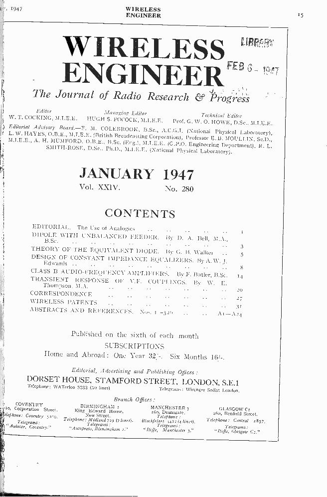
WIRELESS1,7E8 _ENGINEER
The Journal of Radio Research & ProgressEditor Managing Editor Technical EditorW. T. COCKING, M.I.E.E. HUGH S. POCOCK, M.I.E.E. Prof. G. W. 0. HOWE, D.Sc., M.I.E.E.
Editorial Advisory Board.-F. M. COLEBROOK, B.Sc., A.C.G.I. (National Physical Laboratory),L. W. HAYES, O.B.E., M.I.E.E. (British Broadcasting Corporation), Professor E. B. MOULLIN, Sc.D.,M.I.E.E., A. H. MUMFORD, O.B.E., B.Sc. (Eng.), M.I.E.E. (G.P.O. Engineering Department), R. L.SMITH -ROSE, D.Sc., Ph.D., M.I.E.E. (National Physical Laboratory).
JANUARY 1947Vol. XXIV. No. 280
CONTENTSEDITORIAL. The Use of Analogies ..DIPOLE WITH UNBALANCED FEEDER. By D. A. Bell, M.A.,B.Sc. .. .
THEORY OF THE EQUIVALENT DIODE. By G. B. Walker ..DESIGN OF CONSTANT IMPEDANCE EQUALIZERS. By A. W. J.Edwards ..CLASS B AUDIO -FREQUENCY AMPLIFIERS. By F. Butler, B.Sc.TRANSIENT RESPONSE OF Y.E. COUPLINGS. By W. E.Thompson. M.A.CORRESPONDENCEWIRELESS PATENTSABSTRACTS AND REFERENCES. Nos. 1-320
3
5
S
20
27
.31
A I -A24
Published on the sixth of each month
SUBSCRIPTIONSHome and Abroad : One Year 32:-. Six Months 16,/-.
Editorial, Advertising and Publishing Offices :
DORSET HOUSE, STAMFORD STREET, LONDON, S.E.1Telephone: WATerloo 3333 (50 lines) Telegrams: 1,Virenger Sedist London.
COVENTRY-Io, Corporation Street.telephone: Coventry 5210.
Telegrams:" Autocar, Coventry."
Branch Offices :BIRMINGHAM 2
Ring Edward House,New Street.
Telephone: Midland 719 (7 lines).Telegrams :
"A 'depress, Birmingham 2."
MANCHESTER 3260, Deansgate.
Telephone :Blackfriars 4412 (4 lines).
Telegrams :"Iliffe, Manchester 3."
GLASGOW C226n, Renfield Street.
Telephone: Central 4857.Telegrams :
"Iliffe, Glasgow C2."

WIRELESSENGINEER
January, I!!
NEW . . . butwith a
Time - Testedtechnique
Twenty-five years ago Mullard success-fully pioneered the silica thermionicvalve. The need then was for a valvewith long electrical life plus mechanicalstrength - strength that would with-stand the concussion of a battleship'sbroadside.To -day, when valves must stand up tothe trying requirements of industrialapplications, this unique experience isproving invaluable. Designers can choosea modern Mullard Silica Valve and beconfident of dependable performanceunder all conditions.The TYS4-500 R.F. Power Triode istypically efficient, dependable and econ-omical. The thoriated tungsten filamentprovides high emission at low filamentconsumption. The silica en-velope will bear high tempera-tures and does not requireforced air or water cooling.And, finally, like other types inthe Mullard silica range, theTYS4-500 is repairable - animportant extra factor to bearin mind when considering lowcost per Kilowatt hour.
TYS4-500 R.F. POWER TRIODEAnode Voltage 4000 V
Anode Dissipation 500 W
Max. Frequency for full Ratings 50 Mc s
FILAMENT - THORIATED TUNGSTENVoltage 10 V A.C. or D.C.Current 10 A
For further developments watch
IMullardiVALVE DEPT., CENTURY HOUSE, SHAFTESBURY AVENUE, LONDON,
THE MASTER VALTechnical data and advice on the application oftht TYS4-500 and other silica valves can beobtained from :-
THE MULLARD WIRELESS SERVICE CO. LTD., TRANSMITTING AND INDUSTRY
v. 19-17 WIRELESSENGINEER 17
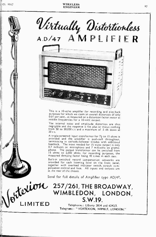
A.D/47 AMPLIFIER
.6. .6. .6. ...AY. 114.6 IN.'
.66. .4. .1. ... ..... ...... ....... .... ........ ....."""'
... ..... 15..2111116 Val. 4.11. 41/...
11.11.... . . : ..... . ......... .. :At .. ... ...,
... . . . . . . .. ..." .4 . .
. ." " : . . . .-.:" 7. . .1" SI.. ... ...*MN INN. .1111.11*
....".......4.6.6.66
616.6 .... .1.16. ../.. *W. am..
.,6 ',.. ..:-.4. _....,
This is a 10 -valve amplifier for recording and play -backpurposes for which we claim an overall distortion of only0.01 per cent., as measured on a distortion factor meter atmiddle frequencies for a 10 -watt output.The internal noise and amplitude distortion are thusnegligible and the response is flat plus or minus nothingfrom 50 to 20,000 c s and a maximum of .5 db down at20 c s.
A triple -screened input transformer for 71- to 15 ohms isprovided and the amplifier is push-pull throughout,terminating in cathode -follower triodes with additionalfeedback. The input needed for 15 watts output is only0.7 millivolt on microphone and 7 millivolts on gramo-phone. The output transformer can be switched from15 ohms to 2,000 ohms, for recording purposes, themeasured damping factor being 40 times in each case.Built-in switched record compensation networks areprovided for each listening level on the front panel,together with overload indicator switch, scratch ccm-pensation control and fuse. All inputs and outputs areat the rear of the chassis.
Send for full details of Amplifier type AD/47.
257/261, THE BROADWAY,WIMBLEDON, LONDON,
S.W.19.LIMITED Telephones : LIBerty 2814 and 6242/3.Telegrams : " VORTEXION, WIMBLE, LONDON."

18 WIRELESSENGINEER
January,
ACOUSTICAL RESEARCHTHE TANNOY LABORATORY can pro-
vide a skilled and specialised service inthe investigation of all problems connectedwith vibration and sound. This coversmost aspects of acoustical research and isavailable to industry and GovernmentDepartments engaged on priority projects.
\\TAN NOr/RESEARCH LABORATORY
GUY R. FOUNTAIN, LTD.THE SOUND PEOPLE "
-ForTransformers aren'tCLOTHES PEGS
Clothes pegs work just aswell on any line. Trans-formers are only completelyefficient when built for thejob they have to do.That's why we specialise inbuilding transformers forspecial industrial purposes.If you want transformersdesigned and built to do adefinite job, we can help
you.
51, NORTHGATE STREET, DEVIZES. Phone 536
"TANNOY"is the registered Trade Mark of
Equipment manufactured by
GUY R. FOUNTAIN, LTD."THE SOUND PEOPLE"
WEST NORWOOD, S.E.27and Branches.
'Phone - - Gipsy Hill 1131
High Efficiency-Components-4i,
EDDYS ONE
CATALOG UWrite for a copy of this new Catalato -day. It contains a range of poshcomponents with the traditional Eo
stone standard of dependable efficietManufacturers' enquiries are particuiinvited.TRANSMITTING RACThis rack comprises uprights, top!,bottom frames, top plate, side brray
front panel and chassis. The direconform to international standarchassis measuring 17"x 10" >, 2', trights 63" in length. Holes puntin all members to facilitate asMild steel construction. Finish;';black, except panels, which are
black on the outside. Panels availfour sizes, ranging from 3b" to 10items sold separately.
Write for Address of yournearest Eddystone Agent
Puts Perfection into Performano,Manufacturers:
STRATTON & CO LTDA
Birmingham, 31.

WIRELESSENGINEER
High performance Strength StabilityClose electrical and mechanical tolerancesGrades to suit various applications
-.Uniied 23 25 Hyde Way , Welwyn Carden Cdy , Herts , England Tel Welwyn Garden 925.
19
eaW.E.2

20 WIRELESSENGINEER
January, 1,
SWITCHES ARECONDEMNED
toHard Labour
for Life-
* Only genuine whenbearing these PatentNos. 478391, 478392NSF OAK.
Head Office andExport Sales :
BRITISH N.S.F. CO. LTD., Keighley, Yorkshire.London Office: 9, Stratford Place, W.I. Phone: MAYfair 4234.
(Sole Licensees of OAK Manufacturing Co. Chicago)
SWITCHES
THE WORLD'S GREATEST BOOKSHOP
0 IZ. BOOKS 4 *New and second-hand Books on every subject.
119-125, CHARING CROSS ROAD, LONDON, W.C.2.Gerrard 5660 (16 lines) * OPEN 9-6 (inc. Sat.)
FORELECTRICAL MEASUREMENTS
in
lalliPetEittp or Industryspecify
LABGEARINSTRUMENTSCAMBRIDGE
Phone 2494
GP,x,c>
cice9Lists now.
LON D EX for RELAYSLEFT. Stepping RelayLF/Selector with 12 posi-
' tion driving mechanismfor A.C. or D.C.
RIGHT. Two Step RelayLF/FS (Heavy Silver Con-tacts). First impulse "on."Second Impulse "off."Also Aerial ChangeoverRelays. Ask for leaflets 106 and 88/WE
11111111"
LONDEXLTDMANUFACTURERS OF RELAYS
207 ANERLEY ROAD - LONDON S.E.20
SYD
6258-9
TEST EQUIPMENTRESISTANCE CAPACITANCE
BRIDGE.(Available From Stock).Ranges :Resistance: I ohm to 100 megohmsCapacity : lmmfd to 100 mfd.A rugged and reliable instrumentwith an accuracy better than5% designed for use on the testbench and in the laboratory, em-ploying many useful features:-
* Electron Beam Indicator.* Leakage Indicator.* Power Factor Measurement.* Large Inset Dial.
Every Instrument is IndividuallyCalibrated. EA20 Resistance Capacitance Br.
AN EXTENSIVE RANGE OF HIGH GRADE TRANSFORME1MAINS TRANSFORMERS 60 and 100 watt, 350-0-3!
0-4-5v. 0-4-6.3v. Totally enclosed in Metal Shell.UNIVERSAL OUTPUT TRANSFORMERS. Suitable
Triode, Pentode, Class B and Q.P.P. Output StaFully Tropicallised.
PRECISION TRANSFORMERS AND CHOKES. Tra
formers and Chokes in this range are precision bcomponents with a gua-anteed tolerance of 2% of ravalues. First Grade Materials only are used in tl
manufacture. These components can be madeindividual specifications or supplied from our COINhensive Catalogue.
Telephal;WELBE
237141
S ALESRECORDER HOUSE, 48 & 50, GEORGE STREI
PORTMAN SQUARE, LONDON, W.1.Cables : Telegrams :
SIMSALE, LONDON. SIMSALE WESDO, LOW:al
Use "QuiXo " method of batterytesting. Reliable results guaran-teed. Send for interestingleaflet G215, on bat-tery testing.
A firm in London requires communication engineerconsiderable experience of radio circuit design especia,aircraft equipment and miniaturisation. Good basic to
and subsequent industrial experience essential. Post
responsible one with very interesting prospects for right
Initial salary up to £850 per annum.Write full details of education, qualifications and expo
to Box No. 4465.
THE HARBORO' RUBBER CO. LTD. MARKET

.ry, 1947 WIRELESS 21ENGINEER
.moilill111111111Prom
illn111111FURZERILL LABORATORIES L. -hill
AMINE.
111111111111M
iiNemo'a
ostillOSCOPE TYPE1584411111/11,1.10918
:
ii
INCIPAL
JBE. 31 in.Blue or
r' screen.
r-:11FTS. D.C.instantan-
3 on both
MPLIFIERS.Y ampli-
re similar.to 3 Mc'sr.m.s. per
mi D.C. tos 8 mV.
Toper cm.
11E BASE.Z s to 200
Variableh X ampli-
to 5r.1 d i a -:C. Singlee, available.
TYPE I684B
The Oscilloscope Type I 684B has
proved an invaluable instrument forapplications ranging from ServoDevelopment, where signal fre-quencies may be as low as 0.1 c/s, toTelevision Research. The Oscillo-scope is equipped with high gainD.C. coupled amplifiers having afrequency response from D.C. to3 me/s. These amplifiers will handlesymmetrical and asymmetrical in-put. In general the instantaneousshifts, semi -automatic synch, steadi-ness of image and general ease ofoperation are features which appealto all engineers.
Price E100
1171IZEIIILL LABORATORIES LTDi,5HONE I BOREHAM W-OOD..;,T3F;EE H ER TSr
Truvox, pioneers in public addressequipment, offer this new range of"M o nobo It" permanent magnetmoving coil speakers for radio receivers,with a patented assembly making foraccurate and economical productionand giving unshakeable rigidity intransit and use. Response curves canbe adjusted to special requirements,and full technical specifications areavailable on request.
Entirely new patented construction with singlebolt fixing of components concentrically locatesthe chassis and complete magnet assembly.
Brass centring ring prevents magnet beingknocked out of centre.
Special magnet steel gives powerful flux withcompactness and light weight.
Speech coil connections carried to suspensionpiece, ensuring freedom from rattles, conedistortion and cone tearing.
Clean symmetrical surfaces, no awkward pro-jections.
Speech coil and former bakelised to preventformer distortion and speech coil turns slippingor becoming loose.
Two point fixing to the suspension piece withfour point suspension for the speech coil.
Widely spaced fixing points for the suspensionpermit maximum movement of the cone, pro-ducing the lowest response physically obtainablefrom each size of speaker.
Supplied in four sizes-Sin., 6in., 8in., and 10in.
TRUVOXENGINEERING CO. LTD.
TRUVOX HOUSE, EXHIBITION GROUNDS, WEMBLEY,MIDDX.

2 2WIRELESS January,ENGINEER
`MAPfor Quality
RADIO CABINETSM & P WOODWAREMANUFACTURERS LTD.
We are pleased to announce that weare again producing the well-knownM & P Radio Cabinets of fine quality andexcellent value.Let us know your requirements and weshall be pleased to quote you and
supply full particulars of our presentproductions.
M & PWOODWARE MANUFACTURERS LTD.
STERLING WORKS, ALEXANDRA ROAD,PONDERS END, MIDDLESEX
'Phone: Telegraphic Address:Howard 2214-5 and 1755 Emanpe, Enfield
& SCREENS 1RADIOMETAL PERMALLOY
SILICON ALLOYS iELECTRICAL SOUND & TELEVISION PATENTS LTD.
12, PEMBROKE STREET, LONDON, N.1
Approximately 5,000 small Pneumatic Hand Tools, comprisingassorted hammers, rivetters and drills, made by Desoutter Bros.,Broome & Wade, Aircraft Materials, Cleveland Pneumatic,Independent Pneumatic, Aircraft Motors Ltd., ConsolidatedPneumatic, Armstrong Whitworth and various other first-classmakers. All tools, although used, are in excellent condition andare offered on a very attractive basis for immediate delivery ex stock.Full schedule of quantities, types and descriptions is available onrequest to G.T.C., 82-04, Seymour Place, London, W.1.
400 CONDENSERS
ARE MADE FOR
WALT E1INSTRUMENTS. LTD:1
GARTH ma., LOWER AflOROEN, SURREYDERWENT 4421. Grams: WALINST, MORDEN, SURREY
C. R. Casson 75
Standard Signal GeneratorWith its extreme accuracy and stability, the
Airmec Signal Generator is an indispensable instrument wherever radio-frequenomeasurements are made. Whether inlaboratory, a service station, or on a production line, it will speed the work an(guarantee accurate results.
Write for full descriptive literatureAIRMEC LIMITED
Wadsworth Road, Peri vale, Greenford, MiddleselTelephone: Perivale 3344
A Group Company of Rad
evs-I & Television Trust Ltd.
Piezo QUARTZ CRYSVfor all applications.
Full details on request.
QUARTZ CRYSTAL CO., LTD.,(Phone : MALden 0334.) S3-71, Kingston Rd., New Malden,SUF
Chief Inspector required for West London Works manufactaudio frequency amplifiers, electronic equipment and, toinstruments. Applicants must have previous experiencecapacity, theoretical knowledge equivalent to Higher Na:Certificate standard radio and electrical sections, and be c -of controlling personnel. Apply giving full details past exp.,and salary required, to Box No. 4786.
ELECTRIC
CHAINPULLEYBLOCK
Write for book-let on lifting andshifting or separ-ate catalogue ofconveyors, cranes,and other mech-anical handlingequipment.
GEO. W. KING LTD.,P.E.B. WORKS HITCH! N HERTS.MANCHEETHR CENTRAL 5947 NEWCASTLE 24196
y, 1947 WIRELESSENGINEER
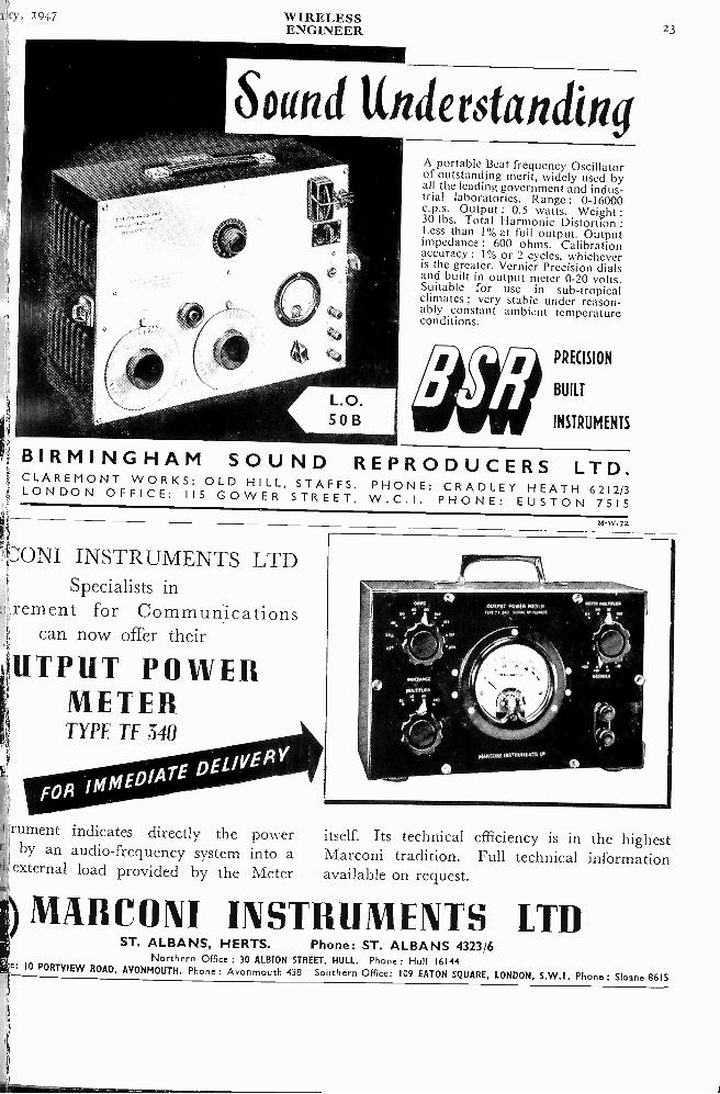
Sound UnderstandingA portable Beat frequency Oscillatorof outstanding merit, widely used byall the leading government and indus-trial laboratories. Range : 0-16000c.p.s. Output 0.5 watts. Weight :30 lbs. Total Harmonic Distortion
:Less than 1% at full output. Outputimpedance : 600 ohms. Calibrationaccuracy : 1% or 2 cycles, whicheveris the greater. Vernier Precision dialsand built in output meter 0-20 volts.Suitable for use in sub -tropicalclimates ; very stable under reason-ably constant ambient temperatureconditions.
PRECISION
BUILT
INSTRUMENTS
BIRMINGHAM SOUND REPRODUCERS LTD.CLAREMONT WORKS: OLD HILL, STAFFS. PHONE: CRADLEY HEATH 62123-ONDON OFFICE: 115 GOWER STREET, W.C.I. PHONE: EUSTON 7515
M -W.72
LA'ONI INSTRUMENTS LTDSpecialists in
rement for Communicationscan now offer their
k TPUT POWERMETER
i
'rument indicates directly the power itself. Its technical efficiency is in the highestby an audio -frequency system into a Marconi tradition. Full technical information
external load provided by the Meter available on request.
g) MARCONI INSTRUMENTS LTDST. ALBANS, HERTS. Phone: ST. ALBANS 4323/6
Northern Office : 30 ALBION STREET, HULL. Phone: Hull 16144e. 10 PORTVIEW ROAD, AVONMOUTH. Phone : Avonmouth 438 Southern Office: 109 EATON SQUARE, LONDON, S.W.1. Phone: Sloane 8615
24WIRELESSENGINEERENGINEER
January, i(
Yeedz
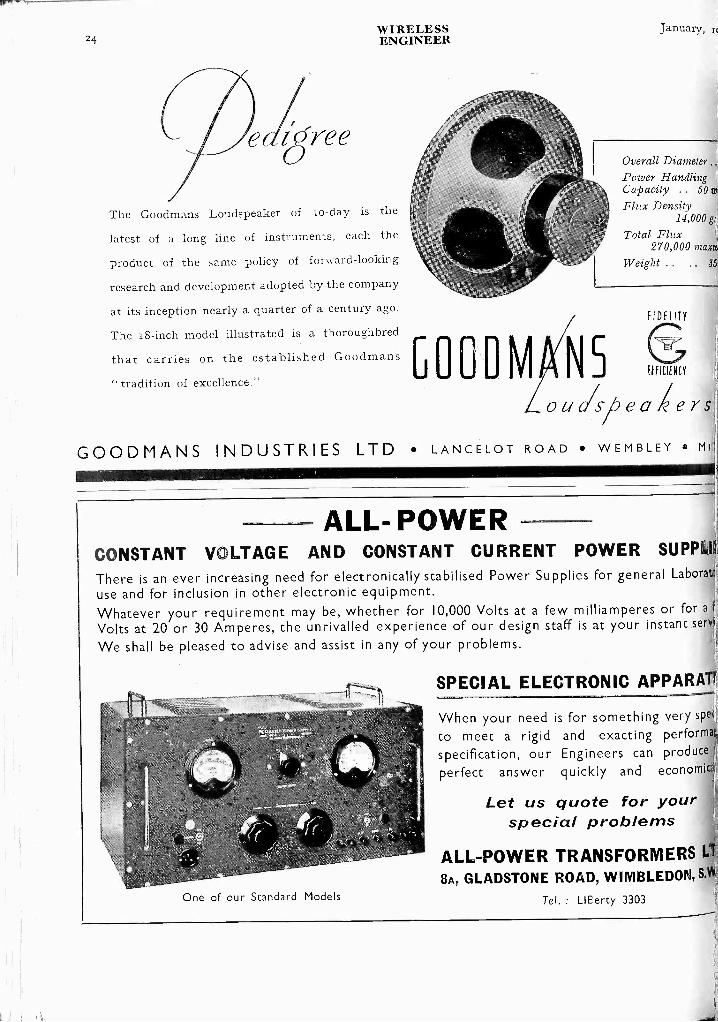
The Goodmans Loudspeaker of to -clay is the
latest of a long line of instruments, each the
product of the same policy of forward -looking
research and development adopted by the company
at its inception nearly a quarter of a century ago.
The i8 -inch model illustrated is a thoroughbred
that carries on the established Goodmans"tradition of excellence." GOODIVI 115
Overall DiameterPower Handling .;
Capacity .. 50 fv,
Flux Density14,000 gr
Total Flux270,000 mum
Weight .. 35;
FIDELITY
ifflEIENCY
ulsibea erS
GOODMANS INDUSTRIES LTD LANCELOT ROAD WEMBLEY MI
ALL- POWERCONSTANT VOLTAGE AND CONSTANT CURRENT POWER SUPPLII1
There is an ever increasing need for electronically stabilised Power Supplies for general Laborati':,
use and for inclusion in other electronic equipment.Whatever your requirement may be, whether for 10,000 Volts at a few milliamperes or for a 1Volts at 20 or 30 Amperes, the unrivalled experience of our design staff is at your instant seri.,We shall be pleased to advise and assist in any of your problems.
SPECIAL ELECTRONIC APPARATt
One of our Standard Models
When your need is for something very spe4.
to meet a rigid and exacting performat
specification, our Engineers can produceperfect answer quickly and economic r
Let us quote for yourspecial problems
ALL -POWER TRANSFORMERS Lit
8A, GLADSTONE ROAD, WIMBLEDON &
Tel. LlEerty 3303

iiia 1947 WIRELESS
ENGINEER
SISTORS CERAMICONS Hi -K CERAMICONS
SUPPRESSORS POTENTIOMETERS
1: ERIE RESISTOR LIMITEDI)LE ROAD - THE HYDE - LONDON - N.W.9 - ENGLANDCOLINDALE 8011-4 TELEGRAMS: RESISTOR, PHONE, LONDON CABLES: RESISTOR, LONDONI LONDON ENGLAND TORONTO CANADA ERIE, PA., U.S.A.
ivWIRELESSENGINEER
January,
\tit
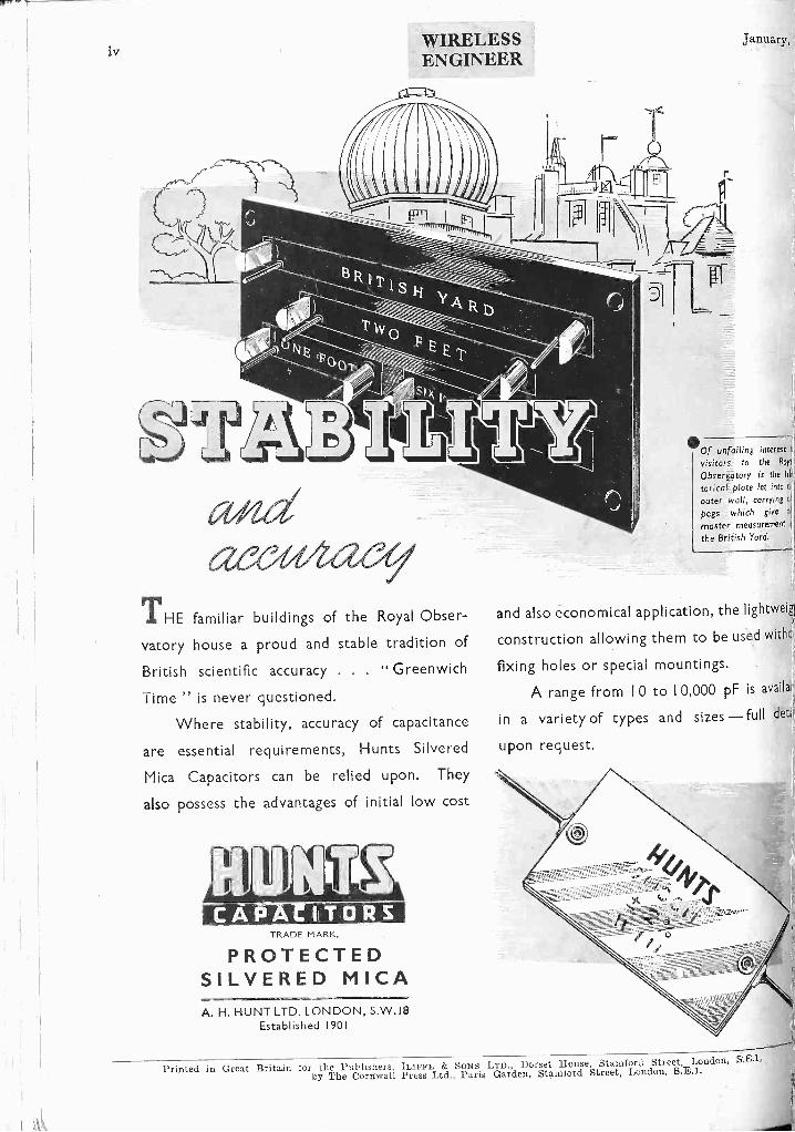
THE familiar buildings of the Royal Obser-
vatory house a proud and stable tradition of
British scientific accuracy . . . " Greenwich
Time " is never questioned.
Where stability, accuracy of capacitance
are essential requirements, Hunts Silvered
Mica Capacitors can be relied upon. They
also possess the advantages of initial low cost
11111-1-1Y,CAPACITORS
TRADE MARK,
PROTECTEDSILVERED MICAA. H. HUNT LTD. LONDON, S.W.18
Established 1901
411110f unfailing interest tvisitors to the Roy{,
Observatory is the his
torical plate let into tiouter wall, carrying t.q
pegs which give ti'
master measurement fl
the British Yard.
and also economical application, the lightweig,
construction allowing them to be used withc
fixing holes or special mountings.
A range from I 0 to I 0,000 pF is availal
in a variety of types and sizes -full det
upon request.
Printed in Great Britain for the Publishers, ILSFFE & SONS LTD., Dorset House, Stamford Street, London, S.E.1,
by The Cornwall Press Ltd., l'aris Garden, Stamford Street, London, S.E.I.
WIRELESS FEBENGINES `-!
19117
Vol. XXIV. JANUARY 1947 No. 280
EDITORIAL
The Use of AnalogiesSOME years ago a student complained
that whenever he asked a question aboutan electric circuit he was told to imagine
a pipe full of water, etc. He said thathe knew all about the pipe full of waterbut wanted to know about the electriccircuit and he disapproved of being fobbedoff with hydraulic analogies. We werereminded of this by some statements madeby Professor Livens in a recent paper* on" The energy and mechanical relations of themagnetic field " in which he criticizes the useof magnetic and electric analogies as well asmagnetic and mechanical analogies. Hesays, " The persistent adherence to asupposed analogy with the electrostatic case,which does not exist, and to frequentlyfanciful analogies of the stress -strain 'type,which have introduced more confusion thanthey have saved, seem to have blinded to thereal solution those few authors who were ableto see clearly that there are anomalies inthe usual discussion, and the usual dimen-sional treatment which starts by assuming-again on the basis of some supposed stress -strain analogy-that the nature of thevectors of force and induction in the fieldmust be different, has perhaps not helpedin any way to clear the air for a more satis-factory treatment."
This raises some interesting and importantpoints, especially for those engaged inteaching. Electrical engineering differs frommechanical engineering in that the student
*Phil. Mag. January 1945, Vol. XXXVI, p. I.
of the latter is dealing with concepts, suchas force, mass, deflection, temperature, etc.,with which he has been familiar since child-hood, whereas the electrical student isintroduced fo a system of new and intangibleconcepts, such as potential difference, electro-motive force, current, magnetic induction,etc. It is difficult to see how these can heexplained without the use of analogies ; theobvious way of explaining new and intangibleconcepts is by means of familiar and tangibleconcepts. It is, of course, essential toemphasize the danger of pushing - theanalogies too far ; they should perhaps beregarded not as analogies but rather asparallel lines of thought. It is surely betterfor a student to have even a crude mentalpicture of what is happening in electric andmagnetic phenomena than to have nomental picture at all, but to regard it all asa collection of words and symbols. Thenomenclature of electromagnetism showsthat it was largely based on mechanicalanalogies ; the words current, pressure,tension, electromotive force, resistance, allsuggest mechanical lines of thought, and thenatural explanation of the unknown interms of the known. We disagree withProfessor Livens' contention that analogiesof the stress -strain type have introducedmore confusion than they have saved ; onthe contrary we think that the confusionthat existed a few years ago with regard toB and H has been eliminated largely owingto the application of the stress -strain line of

2WIRELESS January, 1947ENGINEER
thought, or, as some might prefer to call it,the cause and effect line of thought. Whencurrent passes round a coil it produces amagnetic field ; when a pull is applied to arod it produces an extension. The strainproduced at any point in the material of therod depends on the stress (i.e., the pull perunit area at the point) and on a property of
the material. If one can assume that thestress is uniform over the cross-section it canbe calculated by dividing the total pull bythe cross-sectional area. Similarly the mag-netic induction B produced at any point,say, in a mass of iron, must depend on somecause which we call the magnetizing force Hat the point and some property of thematerial which we call the permeability.Instead of the total prime cause beingdistributed over a cross-sectional area as thepull is in the mechanical specimen undergoinga tension test, it is distributed over the lengthof a closed path. The prime cause in themagnetic case is the current or ampere- turnsand the localized cause H is the current perunit length-neglecting such details as 4w..
Is Magnetizing Force a Force?
Just as in the special case of the stress beinguniform over the cross-section, the localizedcause is obtained by dividing the total causeby the area, so, in the special case of theuniformly wound toroid, the localized causeH is obtained by dividing the total cause,viz. the total current or ampere -turns, bythe length. In both cases one has the totalcause, the localized cause, and the localizedeffect depending on some property of thematerial, and we fail to see how such parallellines of thought or fanciful analogies asProfessor Livens calls- them-can introduceconfusion or blind anyone to the real solu-tion. We gather from Professor Livens'paper that there is some confusion dueto a misunderstanding of the term " mag-netic force " or " magnetizing force." Whenone refers to H as the magnetizing forceone does not use the word " force " in itsmechanical sense ; the unit of H is not thedyne, although junior students sometimesmake the mistake and give a field strengthas so many dynes. It is true that H multi-plied by a pole strength m gives a force indynes, but this only shows that H itselfcannot be a force in the mechanical sense.When we speak of a. magnetic force ormagnetizing force we mean the intensity of
the magnetizing cause acting at a point.When one speaks of the force of circum-stances or the force of an argument, one isusing the word " force " to designate some-thing that cannot be measured in dynesand, although somewhat far-fetched, theseexamples may serve as a warning againstregarding H, by whatever name it may becalled, as a mechanical force.
Cause (ti) and Effect (B)Now the mechanical force on a conductor
carrying a current or on a moving electrondepends on the magnetic induction or fluxdensity B in which it is situated and noton the causative force H which producedthe magnetic induction. This fact has ledsome people to suggest that B and not Hshould be called the magnetic or magnetizingforce. In the paper to which we havereferred, for example, Professor Livenssays : " This last step in our thesis involvesa complete inversion of the roles of B andH," and again " If this thesis is accepted,then we must prepare for a complete in-version of the whole of our traditionalnotions on this subject, that is, of course,if we admit that the claims of theoreticalconsistency must ultimately take precedenceover those of traditional and almost uni-versal and long standing practice." Appa-rently the idea is to refer to the magneticinduction B as the magnetizing force andto the magnetizing force H as the induction.We cannot imagine for a moment thatProfessor Livens expects his suggestion tobe adopted.
If instead of an iron toroid linked by acurrent we have a dielectric toroid linkedby a changing magnetic flux, the magneticforce or cause H is replaced by the electricforce or cause & which depends only on thechanging flux and the length of path andis independent of the material of the toroid.It is the causative force acting at any pointand its effect will depend on the materialof the toroid. I has been replaced bychbldt and p. by K. Surely nothing but goodcan come from drawing the student's atten-tion to these parallel lines of thoughtit is one's duty to do so. In each case onecan divide the effect into two parts, viz.that which would exist in the absence of themagnetic material or dielectric and that dueto its presence, thus getting the two formulae
B ti,oH + 47j

January, 1947 WIRELESSENGINEER
and = Ko& 477Pin which J is the intensity of magnetization,D the displacement and P the polarizationof the dielectric. Also
= = I -to + 4771[111
477-D= Ko ± 47TP/6
For the energy per cm3 we have in one caseµH2/ 87T and in the other K 6287r.
and K
In view of these formulae it is difficult tounderstand how anyone can complain ofthe " persistent adherence to a supposedanalogy which does not exist." The paral-lelism is so striking that it should be em-phasized when teaching the subject, butalways with a warning that parallel linesof thought and symbolism do not indicateany physical likeness in the phenomenainvolved. G.W.O.H.
DIPOLE WITH UNBALANCED FEEDER*By D. A. Bell, M.A., B.Sc.
IN the course of their paper on " AerialImpedance Measurements ' L. Essen andM. H. Oliver' mention that a half -wave
dipole can be connected directly to a con --centric feeder cable without any greatimpedance mis-match, but that they havenot investigated the symmetry of the field.
The complementary observations havebeen made by the writer during the examina-tion of directional aerials of the type com-monly used for television reception, namelya vertical dipole associated with a singlehalf -wave parasitic element. The aerialunder examination was connected to areceiver, a low -power oscillator was set upabout Io wavelengths away, and a polardiagram of the aerial was measured byrotating the aerial supporting mast aboutits (vertical) axis and plotting receivedsignal strength against the azimuthal angleof the aerial assembly. Two alternativemethods of connecting the aerial to thereceiver were available :
(i) Through screened and balanced twincable and a balanced coupling -coil to thefirst tuned circuit of the receiver.
(ii) Through coaxial cable and a couplingcoil having one side earthed and joined tothe 'outer of the coaxial feeder. The coaxialcable was connected directly to the aerial, thecentral conductor to one limb of the dipoleand the outer conductor to the other limb.
Preliminary tests with a simple dipolefailed to reveal any substantial difference insignal strengths between the two feedersystems ; but with the addition -of a directoradjusted to give maximum suppression in the
*MS. accepted by the Editor, July 1946.
backward direction, the balanced feedergave a symmetrical polar diagram while thecoaxial feeder gave an asymmetrical diagram.These are shown by the full line and dottedcurves respectively in Fig. 1. This asym-metrical characteristic can produce a sharperminimum than would otherwise be available ;but the exact shape of the characteristic islikely to vary with aerial site and feederlength, since it depends upon the " vertical-aerial pick-up " effect of the whole elevatedsystem and upon the impedance of the outerconductor of the feeder.
Fig. I. Polar diagrams of vertical dipole anddirector with balanced (solid line) and un-
balanced (dotted line) feeders.
A balanced aerial should preferably beconnected to a coaxial feeder through abalancing device, of. which the simplest form

4
is the quarter -wave " sleeve " as shown byEssen and Oliver in their Fig. 8, and theequivalent circuit shown in Fig. z gives anidea of the behaviour of a centre -fed half -
wave dipole connec-ted in this way. Thesymmetrical dipoleis represented by asource of e.m.f. E1at the centre of aresistance of 76 ohmstotal value, and theterminals A, B of thedipole are connectedto a feeder which isassumed to be of 76ohms characteristic
Fig. 2. Equivalentcircuit of dipol3
aerial.
impedance and non -reflectively terminatedso far it makes no difference whether thefeeder consists of balanced -twin or coaxialcable, and no " earth " has been introduced.Practical dipoles, however, are not mountedin free space but usually near an " earth,"whether this be the surface' of the ground,the body of --an aircraft, or the generalstructure of a tower on which the aerial ismounted.
Now it is well-known that an elevatedconductor connected to earth by a wireconstitutes an aerial system : an alternatingcurrent can be established in the wire by aradio wave, and this current can be detectedby a suitable instrument as shown in Fig.3(a). Moreover, it is known that this pheno-menon can be represented by an equivalentcircuit of the type illustrated in Fig. 3(b),where the aerial is replaced by a voltagegenerator E in series with an " aerial imped-dance " Zee. Returning now to the dipole,when associated with a feeder cable goingdown to a receiver situated on the " earth "each limb of this is equivalent to an aerialof the type of Fig. 3(a), and according to theequivalent circuit of Fig. 3(b) this fact isindicated in Fig. 2 by adding the generatorsE2 and E'2 each in series with an appropriateimpedance Z2, Z'2. Since the two limbs aresimilarly situated above the earth, the twogenerators will be in the same phase, and so
WIRELESSENGINEER
long as the load connected between A and Bis balanced to earth, they will introduce nonet difference of potential betWeen theseterminals. But if, for example, terminal B
were directly earthed, the generator E2 wouldbe connected in series with Z2 and the load,and would cause a voltage to appear acrossthe load ; i.e., across the receiver inputcircuit.
In most cases the outer of the concentricfeeder is earthed at the receiving end of thefeeder, not at the aerial end, and the impe-dance to earth presented at B is then afunction of feeder length : for odd multiplesof A/4 it is very high and for even multiplesvery low if the transmission line made up
3811of cable outer and earth is of low loss. Inpractice, there is likely to be considerableloss due to the waterproof covering over theouter of the cable and to miscellaneousobjects between cable and earth ; but it isperhaps worth noting also that Schelkunoff2has given figures for the input impedanceof an infinitely long conductor in free space,and for television feeder and frequencies asused by the writer it is of the order of 500ohms. Since losses will damp out anyresonance effects, it seems probable thatthe impedance to earth presented by thelength of outer conductor of the coaxialfeeder would be of the order of 500 ohms.
January, 1947
Fig. 3, Vertical effect with a 4ipol3aerial (a) and its equivalent circuit (b).
( b )
This is the impedance represented by Z1 inFig. z, and two deductions can be made fromthe magnitude assigned to it : (i) So longas the load impedance between A and B issmall compared with 500 ohms, the generatorE2 is likely to produce only a secondaryeffect, and (ii) any impedance (such as thatrepresented. by L, C in Fig. 2) which may beadded in order to reduce this effect must beappreciably greater than Soo ohms. Theresonant -line analogue of the parallel-

January, 1947 WIRELESSENGINEER
5
resonant circuit L, C of Fig. 2 is a short-circuited quarter -wave line, or in other wordsthe quarter -wave " sleeve " on the outer ofthe concentric cable to which reference has
- - a
Fig. 4. Quarter -wave balancing sleeve.
already been made, and which is illustratedin more detail in Fig. 4. As an alternative tothe general explanation that a short-circuitedquarter -wave line presents a high impedanceat the open end, the mode of operation of thesleeve may be interpreted as follows. Assum-ing the sleeve to be a perfect conductor, itwill act as a screen so that any current in
the cable produces no external field ; andthis implies that for any current it down theconductor i (the outer of the coaxial cable),there must be an equal and opposite current-11 along the inside of the sleeve, and thesecurrents will balance at the closed end of thequarter -wave so as to leave no net current toilow down the remainder of the feeder. Theresonance of the quarter -wave is necessary tominimize the unbalancing of the dipole dueto attaching this impedance to one limb ofit but not to the other. (There are moreelaborate balance -to -unbalance transformerswhich maintain a higher degree of symmetrybut also function as " stubs " in parallelwith the balanced circuit.)
This note is based on work carried out inthe Research Laboratories of A. C. CossorLtd., and acknowledgments are due toMr. L. H. Bedford, Director of Research,and to other members of the Research Staffwith whom these questions have beendiscussed.
REFERENCES1 wireless Engineer, December 1945, Vol. XXII, p. 587.2 " Theory of Antennas of Arbitrary Size and Shape," by S. A.
Schelkunoff, Proc. Inst. Rad. Engrs., September 1941, Vol. 29,p. 493.
THEORY OF THE EQUIVALENT DIODE*By G. B. Walker
(The Mallard Radio Valve Co., Ltd.)
SIIMMARY.-The theory of the equivalent diode is discussed and a new method, based onelectrostatic considerations, is suggested whereby the equivalent diode can be uniquelydetermined.
IntroductionTHE " equivalent " diode is a concept
which has always lacked a precisedefinition, and like some other concepts
in electronic engineering has taken on adifferent colouring to suit the taste of theuser. The importance of the concept lies inthe fact that it makes a rough calculation ofthe current passed by a triode possible, butthere can be no doubt that if the physics ofthe triode were more simple the conceptwould never have arisen. One might be ledto believe, therefore, that the equivalentdiode is no more than a useful device,essentially arbitrary and having no realexistence, but we feel that the logic of thequestion still merits consideration.
* MS accepted by the Editor, June 1946.
The supposition that a diode can beconstructed which will have the samecurrent -voltage relationship as a given triodehas a practical basis in the discovery byVan der Bij11 in 1913 that for a limited rangeof applied voltages the current passed by atriode obeys the empirical law-
/ = k(V, µV, + E)P . .. (I)
k, and f3 being constants.The form of this law, in which the applied
voltages are combined in a linear term,together with the experimental fact that $has a value in the neighbourhood of 3/2indicates that over the limited voltage rangea triode behaves as a diode. This is the onlyjustification for an attempt to form theconception of an equivalent diode but wemust appeal to theory for aid in advancing

WIRELESSENGINEER
January, 1947
the matter. It is at this point that adivergence of opinion occurs.
The Electrostatic ApproachThe favourite approach to the question,
and in the writer's opinion the most con-sistent, as will be shown later, is to postulatethat a diode is equivalent to a triode if, whenthe cathode is cold and no current is flowing,the off -cathode electrostatic field strength isthe same in both valves. Let us examinethis requirement for the case of a triodehaving planar electrodes.
The average value of the off -cathode fieldstrength in the absence of space current canbe written-
+ /2.1/gFa +µg
where g is the spacing between cathode andgrid and a is the spacing between the cathodeand anode. p. is the amplification factor ofthe valve calculated on electrostatic groundsand depending only on the geometry of thevalve.
For the equivalent diode we can writeV
. . . . . (3)where d is the spacing between cathode andanode.
Thusd V +
d a p.gThis equation is insufficient to determineboth Vd and d, so let us write
V d = a(Va ± /IT ,)and
d = a(a + µ,g)where a is some, so far undetermined,dimensionless constant.
Now the current passed by the diode isVdSI= 2.34 x -a2
(omitting the term £ in (I) which takescontact -potential differences into account),and so for the triode we have
µTig)4
(2)
2.34 X 10⁻⁶Vcc- [a + ttg12
The difficulty now is to evaluate a or, whichis the same thing, find the proper spacing inthe equivalent diode. Many plausible thoughdivergent arguments have been given whichneed not be discussed here.
Most writers give it the value -, (c.f. Downand Benham3), the latter coming to thisdecision after considering no less than six
alternatives. There can be no doubt that inmost cases the value should be in the
neighbourhood of - as, current measurements
on a triode will confirm, but let us examinewhat happens when ,a tends to zero. In thelimit this is equivalent to the removal of thegrid from the valve and we can deduce,therefore, that the current passed should be
17,11/ = 2.34 x io--a -
whereas a,Tording to (7) if a - and p, tendsto zero I vanishes!
The Current ApproachTo obviate the difficulty in determining a
and at the same time to pay greater attentionto the behaviour of space charge in the valvesome writers have rejected the electrostaticapproach. We shall now examine aningenious method given by Fremlin4 whichillustrates the essential features of thecurrent approach.
Fremlin accepts the expressionI = k (Va + µV0)1andevaluates k in the following way.
If the grid of the triode is removed theanode current is,
(9)
I = 2.34 X Io--a
Or
Va (1o)--(2.34 X io6)1The potential at the plane where the gridwas, is
V=,
g (2.34 10-6)1 g4 (II)
and so if the grid is replaced and maintainedat that potential no change should occur inthe current passed by the valve. Thus, bysubstituting (io) and (II) in (9) he obtains
/ = k[ al Igo(2 .3 1 x IO-6)1 (2.34 X 1-0-6)412.3.1. X 10-6or k=
pg1,8
and so I = 2.34 X 10⁶ (v.-1-070. . (Z2)
Apparently the equivalent diode hasdisappeared from the argument, but if wecompare expressions (r2) and (7) we see thatin Fremlin's treatment a is given the value[a + tie] 3.
In this way it is possible to[a + aug14define an equivalent diode.
January, 1947 WIRELESSENGINEER
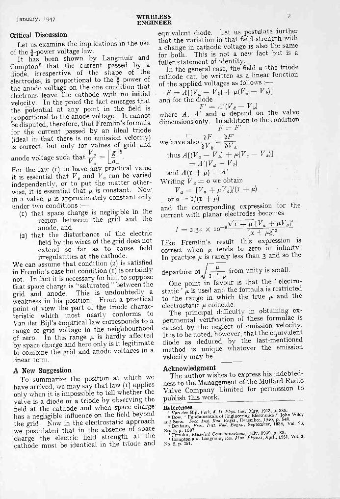
Critical DiscussionLet us examine the implications in the use
of the 4 -power voltage law.It has been shown by Langmuir and
Compton 5 that the current passed by adiode, irrespective of the shape of theelectrodes, is proportional to the 4 power ofthe anode voltage on the one condition thatelectrons leave the cathode with no initialvelocity. In the proof the fact emerges thatthe potential at any point in the field isproportional to the anode voltage. It cannotbe disputed, therefore, that Fremlin's formulafor the current passed by an ideal triode(ideal in that there is no emission velocity)is correct, but only for values of grid and
anode voltage such that -VgVa t_a '
For the law (1) to have any practical valueit is essential that V, and Va can be variedindependently, or to put the matter other-wise, it is essential that p, is constant. Nowin a valve,µ is approximately constant onlyunder two conditions :-
(1) that space charge is negligible in theregion between the grid and theanode, and
(2) that the disturbance of the electricfield by the wires of the grid does notextend so far as to cause fieldirregularities at the cathode.
We can assume that condition (2) is satisfiedin Fremlin's case but condition (I) is certainlynot. In fact it is necessary for him to supposethat space charge is " saturated" between thegrid and anode. This is undoubtedly aweakness in his position. From a practicalpoint of view the part of the triode charac-teristic which most nearly conforms toVan der Bijl's empirical law corresponds to arange of grid voltage in the neighbourhoodof zero. In this rangeµ is hardly affectedby space charge and here only is it legitimateto combine the grid and anode voltages in alinear term.
A New SuggestionTo summarize the position at which we
have arrived, we may say that law (I) appliesonly when it is impossible to tell whether thevalve is a diode or a triode by observing thefield at the cathode and when space chargehas a negligible influence on the field beyondthe grid. Now in the electrostatic approachwe postulated that in the absence of space`charge the electric field strength at thecathode must be identical in the triode and
equivalent diode. Let us postulate furtherthat the variation in that field strength witha change in cathode voltage is also the samefor both. This is not a new fact but is afuller statement of identity.
In the general case, the field a ithe triodecathode can be written as a linear functionof the applied voltages as follows :-
F = A[(Va - Vk) p,(V - Vk)]and for the diode.
F' = A' (V d -V k)where A, A' and p, depend on the valvedimensions only. In addition to the condition
F F'
we have alsobV1c k
thusA[(Va - Vk) p,(V - Vk)]= A' (V d - Vie)
and A (i = A'Writing V k = o we obtain
V d = [Va + all (I +or = (I -I- µ)
and the corresponding expression for thecurrent with planar electrodes becomes
g p, [V a + p,VI = 2 . 3 4 X Io
Eoc + pg?Like Fremlin's result this expression iscorrect when p, tends to zero or infinity.In practice p, is rarely less than 3 and so the
tkdeparture of from unity is small.NNN
p,
One point in favour is that the ' electro-static ' p is used and the formula is restrictedto the range in which the true p, and theelectrostatic p, coincide.
The principal difficulty in obtaining ex-perimental verification of these formulae iscaused by the neglect of emission velocity.It is to be noted, however, that the equivalentdiode as deduced by the last-mentionedmethod is unique whatever the emissionvelocity may be.
AcknowledgmentThe author wishes to express his indebted-
ness to the Management of the Mullard RadioValve Company Limited for permission topublish this work.References
1 Van der Bijl, Verh. d. D. Phys. Ges., May, 1913, p. 338.2 Dow, " Fundamentals of Engineering Electronics," John Wiley
and Sons. Proc. Inst. Rad. Engrs., December, 1940, p. 548.
2 Benham, Proc. Inst. Rad. Engrs., September, 1938, Vol. 26,No. 9, p. 1097.
Fremlin, Electrical Communications, July, 1939, p. 33.5 Compton and Langmuir, Rev. Mod. Physics, April, 1931, Vol. 3,
No. 2, p. 251.

WIRELESS January, 1947ENGINEER
DESIGN OF CONSTANT IMPEDANCEEQUALIZERS *
By A. W. J. Edwards, Dipl. Ing., A.M.I.E.E.(Formerly of the Engineer -in -Chief's School, P 0. Eng. Dept.)
SUMMARY.-Some useful properties of inverse networks (as used in line equalization)are deduced and applied to the development of simple practical design procedures involvingno calculations when suitable test equipment is available.
1. IntroductionTHE method suggested in this article
applies to all bridged -T, -1 and Lnetworks fulfilling the condition that
axb=Z 02 where a and b are the im-pedances designated as such in Figs. 1(a),(b), and (c), and Zo is the iterative impedanceof the respective network. So far as thebridged -T network is concerned a modifiedform is sometimes employed where thebranch impedances shown as Zo in Fig. 1(a)appear modified by the factor i/c. A net-work of this kind [shown in Fig. 1(d)] cannotbe treated directly by the method to bedeveloped. It will, however, be shown inthe appendix that this network is obtainedfrom the one of Fig. 1(a), for which c =- 1,by a simple star -mesh transformation.
Lattice networks can be treated by amodified version of the suggested designmethod, which will also be discussed.
* MS. accepted by the Editor, May 1946.
( a )
2. Theoretical Basis of DesignThe theoretical basis of the design can be
represented in the form of three propositions,for which proofs will be given under 2.2.2.I. The three principles of the design
I(a). A bridged -T network with c = Ican be converted into an -1 network of thesame iterative transfer coefficient and thesame iterative impedance by short circuitingthe Zo arm next to the output terminals ofthe network.
I(b). A bridged -T network with ccan be converted into an L network of thesame iterative transfer coefficient and thesame iterative impedance by disconnectingthe Zo arm next to the output terminalsof the network.
These two rules obviate the necessity oftreating the three networks separately.The -1 and the L network are simplyviewed as derivatives of the bridged -Tnetwork.
(c)
Fig. 1. Bridged -T andthe equivalent bridgenetworks are shownat (a), with andL networks at (b) and(c). A modified formof (a) appears at (d).
(d)
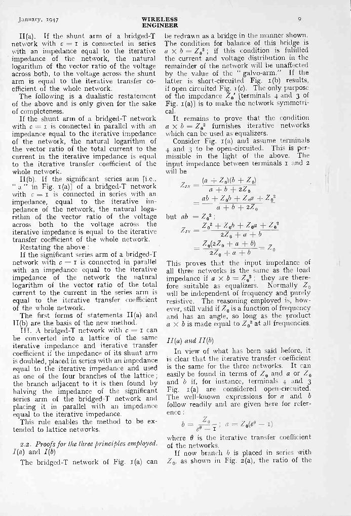
January, 1947 WIRELESS 9ENGINEER
II(a). If the shunt arm of a bridged -Tnetwork with c = i is connected in serieswith an impedance equal to the iterativeimpedance of the network, the naturallogarithm of the vector ratio of the voltageacross both, to the voltage across the shuntarm is equal to the iterative transfer co-efficient of the whole network.
The following is a dualistic restatementof the above and is only given for the sakeof completeness.
If the shunt arm of a bridged -T networkwith c = i is connected in parallel with animpedance equal to the iterative impedanceof the network, the natural logarithm ofthe vector ratio of the total current to thecurrent in the iterative impedance is equalto the iterative transfer coefficient of thewhole network.
II(b). If the significant series arm [i.e.," a " in Fig. 1(a)] of a bridged -T networkwith c = i is connected in series with animpedance, equal to the iterative im-pedance of the network, the natural loga-rithm of the vector ratio of the voltageacross both to the voltage across theiterative impedance is equal to the iterativetransfer coefficient of the whole network.
Restating the above :If the significant series arm of a bridged -T
network with c = i is connected in parallelwith an impedance equal to the iterativeimpedance of the network the naturallogarithm of the vector ratio of the totalcurrent to the current in the series arm isequal to the iterative transfer coefficientof the whole network.
The first forms of statements II(a) andII(b) are the basis of the new method.
III. A bridged -T network with c = I canbe converted into a lattice of the. sameiterative impedance and iterative transfercoefficient if the impedance of its shunt armis doubled, placed in series with an impedanceequal to the iterative impedance and usedas one of the four branches of the lattice ;the branch adjacent to it is then found byhalving the impedance of the significantseries arm of the bridged -T network andplacing it in parallel with an impedanceequal to the iterative impedance.
This rule enables the method to be ex-tended to lattice networks.
2.2. Proofs for the three principles employed.I(a) and I(b)
The bridged -T network of Fig. 1(a) can
be redrawn as a bridge in the manner shown.The condition for balance of this bridge isa x b = Z02 ; if this condition is fulfilledthe current and voltage distribution in theremainder of the network will be unaffectedby the value of the " galvo-arm." If thelatter is short-circuited Fig. i (b) results,if open circuited Fig. 1(c). The only purposeof the impedance Zo [terminals 4 and 3 ofFig. I (a)] is to make the network symmetri-cal.
It remains to prove that the conditiona x b = Z02 furnishes iterative networkswhich can be used as- equalizers.
Consider Fig. 1(a) and assume terminals4 and 3 to be open -circuited. This is per-missible in the light of the above. Theinput impedance between terminals i and 2will be
but
ZIN(a + Z o) (b + Z 0)a ± b 2Z 0
ab Z ob + Z + 7_ 02a b zZ o
ab = Z02 ;Z° 2 Zob Z oa ± Z02
ZIN 2Z 0 ± a ± b
=__Z o(zZo ± a ± b)Z
2Z04- a + bThis proves that the input impedance ofall three networks is the same as the loadimpedance if a x b = Z 02 ; they are there-fore suitable as equalizers. Normally Z0will be independent of frequency and purelyresistive. The reasoning employed is, how-ever, still valid if Z0 is a function of frequencyand has an angle, so long as the producta x b is made equal to Z02 at all frequencies.
II (a) and II (b)In view of what has been said before, it
is clear that the iterative transfer coefficientis the same for the three networks. It caneasily be found in terms of Z0 and a or Z0and b if, for instance, terminals 4 and 3Fig. 1(a) are considered open -circuited.The well-known expressions for a and b
follow readily and are given here for refer-ence :
b ° a =ee-I, Z 0(e° - i)
where B is the iterative transfer coefficientof the networks.
If now branch b is placed in series withZ0, as shown in Fig. 2(a), the ratio of the

I0
applied voltage to the voltage across b isgiven by :-
= 7 + Z, /(6 -TNZ, 7
V2 b-o co I/ C ,
L'o- = 6° = 6" 1_13
Similarly for branch a, Fig. 2(b). The ratioof the applied voltage, to the voltage acrossZo is given by
V' Z0 -1- a Z0 + Z o(c° -- 1)I/ I/ Zo Zo= ee = Lp
where a is the attenuation of the completenetwork in nepers and f its phase -shift inradians.
(a) ( b)
Fig. 2. Basic circuits used in determining thenetworks" a" and" b."
IIIThe well-known expressions for the two
arms of a lattice network are0 ,0Zl = Zo tanh - and Z2 = Zo coth - where2 2
Z1 and Z2 are the impedances so designatedin Fig. 3.
This can be rewritten asc° eo I
Z1 =C° + I anu Z2= Zn
It follows from these expressions that Z1can be considered as consisting of Zo(e° - 1)in parallel with a similar impedance andboth in parallel with Zo.
The proof is simple :Zo(6° - 1) in parallel with Z 0(e° - 1)- Z0(6° - 1)
2Zo(6° - I)
in parallel with Z2
Z02(60 1) e - I- 20(e° - I) + 2Z0 = 0 co ,
Similarly the branch Z2 can be con-
sidered as consisting of Zoe
I in serieswith a similar impedance and both in serieswith Zo.
The significant elements of this type of
WIRELESS January, 1947ENGINEER
network are therefore equal to Zo(e° - 1)
Iand Zo respectively and can be found0 - I
by the method discussed (see section 3.3).
3. Practical Design Procedure3.1. To meet given attenuation requirements
Considering Figs. 2(a) and (b) and applyingPrinciples 11(a) and (b) we get
V1 T7'e0 and -= 6- ;
V2 V"if only the moduli of the two voltages areof interest we can write :
IVilE-,
ea and IIT/21
v,,I - Ca
If actual measurements are carried outthe voltmeter used will, of course, ignorethe angles. If instead of a voltmeter atransmission measuring set if employed thereadings corresponding to V1 and V2 will be
1 V, IinM = log'
I-V Iand = log, 1V-21
Vrespec-
RI
tively, if VR is the reference voltage and theset is calibrated in nepers.
The difference between the two readingsis then :
vi T2M - Iloge -l - 1
v -al
= log,I v
V, I
2I
= log, Ea = a
In other words the difference between thetwo readings gives the attenuation of thebridged -T or of the L network of which bforms a part, in the units in which the set iscalibrated. Similar considerations hold forbranch d and the voltages V' and V".
This enables us tofind the componentvalues of, say, branchb experimentally. All
Fig. 3. Basic latticenetwork.
that is necessary is to adjust the com-ponents until M in is equal to the desiredattenuation of the complete network at allfrequencies of importance. The branch ais then found by carrying out a similaradjustment, or, for preference, simply bymaking it inverse to b with respect to Ro,following the well-known rules for networkswhich are inverse with respect to a constantresistance.
jantla.ry, 1947 WIRELESSENGINEER
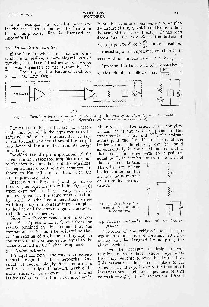
As an example, the detailed procedurefor the adjustment of an equalizer suitablefor a lump -loaded line is discussed inAppendix II.
3.2. To equalize a given lineIf the line for which the equalizer is in-
tended is accessible, a more elegant way, ofcarrying out these adjustments is possibleand was suggested to the author by Mr.H. J. Orchard, of the Engineer -in -Chief'sSchool, P.O. Eng. Dept.
OSCILLATOR
In practice it is more convenient to employthe circuit of Fig. 5 which enables us to findthe arms of the lattice directly. It has beenshown that the arm Z2 of the lattice ofFig. 3 (equal to Zo coth
6\ can be considered
as consisting of an impedance equal to Zo in
series with an impedance q = 2 X Zo eo -Applying the basic idea of Proposition II
I Vx"to this circuit it follows that - Ca,V:
m
(a)Fig. 4. Circuit in (a) shows method of determining "b" arm of equalizer for line
is available for test. Equivalent electrical circuit is shown in (b).
The circuit of Fig. 4(a) is set up, where 1is the line for which the equalizer is to beadjusted and P is an attenuator of say,io db, to mask any deviations of the outputimpedance of the amplifier from its designimpedance.
Provided the design impedances of theattenuator and associated amplifier are equalto the iterative impedance of the equalizer,the equivalent circuit of this arrangement,shown in Fig. 4(b), is identical with thecircuit previously used.
Inspection of Figs. 4(a) and .(b) showsthat E [the equivalent e.m.f. in Fig. 4(b)]when expressed in db will vary with fre-quency by exactly the same amount as thatby which A (the line attenuation) .varieswith frequency, if a constant input is appliedto the line and the amplifier gain is assumedto be flat with frequency.
Since E in db corresponds to M in section3.1 and in Appendix II, it follows from theresults obtained in this section that thecomponents in 'b should be adjusted so thatIn [the reading of a db meter, Fig. 4(a)] isthe same at all frequencies and equal to thevalue obtained at thehighest frequency.3.3. Lattice networks
Principle III points the way to an experi-mental design for lattice networks. Onecould, of course, simply find the arms aand b of a bridged -T .network having thesame iterative parameters as the desiredlattice and convert to the lattice afterwards.
experimentally in thethen placed in seriesequal to Zo to furnishthe desired lattice.The other arm of thelattice can be found inan analogous manneror better by recipro-cation.
Fig. 5. Circuit used infinding the arms of a
lattice network.
( b )which
where a is the attenuation of the completelattice, VX is the voltage applied to thisexperimental circuit and Vxx, the voltageacross q, is the " significant " part of thelattice arm. Therefore q can be found
usual manner and iswith an impedancethe complete arm of
3.4. Inverse networks not of constant -re-sistance.
Networks of the bridged -T and L typewhose impedance is not constant with fre-quency can be designed by adapting theabove method.
It will be necessary to design a two -terminal network first, whose impedance -frequency response follows the desired law.This network is then used in place of Reither in actual experiment or for theoreticalinvestigations. Let the impedance of thisnetwork = Zo(w). The branches a and b will
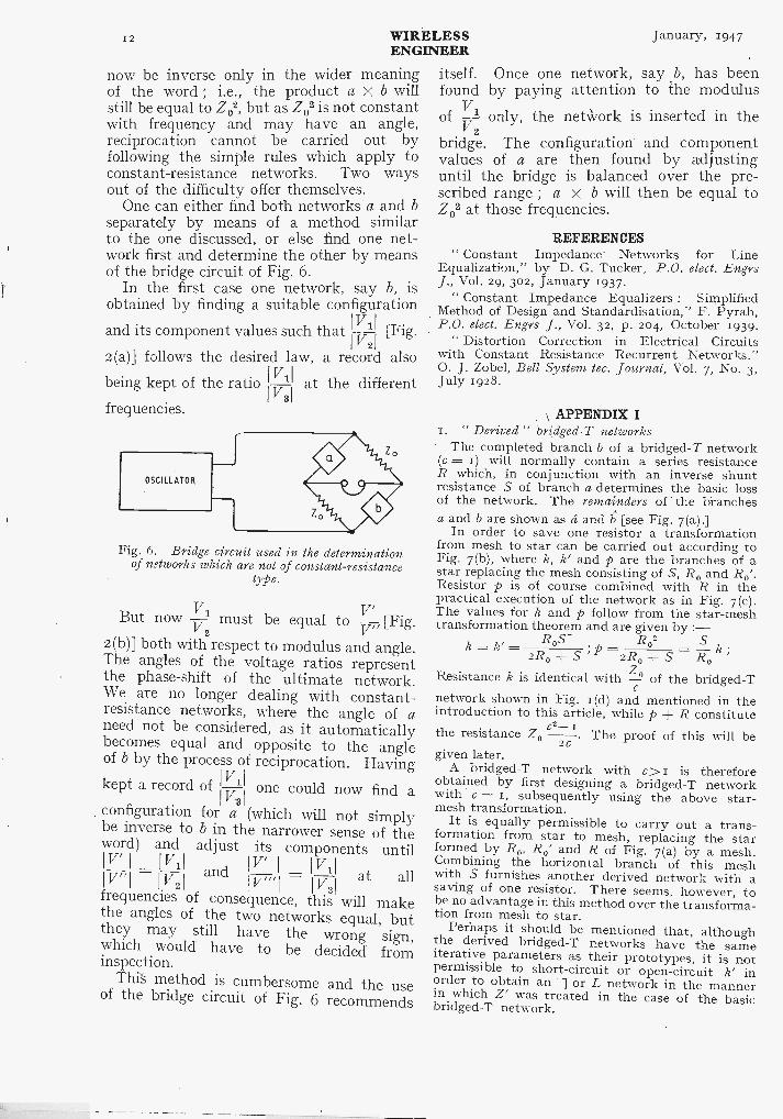
12 WIRELESS January, 1947ENGINEER
now be inverse only in the wider meaningof the word ; i.e., the product a x b willstill be equal to Z02, but as Z02 is not constantwith frequency and may have an angle,reciprocation cannot be carried out byfollowing the simple rules which apply toconstant -resistance networks. Two waysout of the difficulty offer themselves.
One can either find both networks a and bseparately by means of a method similarto the one discussed, or else find one net-work first and determine the other by meansof the bridge circuit of Fig. 6.
In the first case one network, say b, isobtained by finding a suitable configuration
I V Iand its component values such that [Fig.Ali
2(a)] follows the desired law, a record alsoI Viibeing kept of the ratio at the different
3
frequencies.
Fig. 6. Bridge circuit used in the determinationof networks which are not of constant -resistance
type.
V V'But now V1 must be equal to - [Fig.2 V"
2(b)] both with respect to modulus and angle.The angles of the voltage ratios representthe phase -shift of the ultimate network.We are no longer dealing with constant-resistance networks, where the angle of aneed not be considered, as it automaticallybecomes equal and opposite to the angleof b by the process of reciprocation. Havingkept a record of
I-v31one could now find a
configuration for a (which will not simplybe inverse to b in the narrower sense of theword) and adjust its components untilIV'11/11 V/ I !VI-I
I
= I V2I I Vm1 I V3I
and at allfrequencies of consequence, this will makethe angles of the two networks equal, butthey may still have the wrong sign,which would have to be decided frominspection.
This method is cumbersome and the useof the bridge circuit of Fig. 6 recommends
itself. Once one network, say b, has beenfound by paying attention to the modulusof
Vi only, the network is inserted in thev2
bridge. The configuration and componentvalues of a are then found by adjustinguntil the bridge is balanced over the pre-scribed range ; a x b will then be equal toZ02 at those frequencies.
REFERENCES" Constant Impedance Networks for Line
Equalization," by D. G. Tucker, P.O. elect. EngrsJ., Vol. 29, 302, January 1937.
" Constant Impedance Equalizers : SimplifiedMethod of Design and Standardisation," F. Pyrah,P.O. elect. Engrs J., Vol. 32, p. 204, October 1939.
" Distortion Correction in Electrical Circuitswith Constant Resistance Recurrent Networks."0. J. Zobel, Bell System tec. Journal, Vol. 7, No. 3,July 1928.
APPENDIX I1. " Derived " bridged -T networks
The completed branch b of a bridged -T network(c = 1) will normally contain a series resistanceR which, in conjunction with an inverse shuntresistance S of branch a determines the basic lossof the network. The remainders of the branchesa and b are shown as ci and b [see Fig. 7(a).]
In order to save one resistor a transformationfrom mesh to star can be carried out according toFig. 7(b), where k, k' and p are the branches of astar replacing the mesh consisting of S, R, and R,'.Resistor p is of course combined with R in thepractical execution of the network as in Fig. 7(c).The values for k and p follow from the star -meshtransformation theorem and are given by
R02k k2R, ± S; p -2R, + S R0k;
ZoResistance k is identical with of the bridged -Tnetwork shown in Fig. 1(d) and mentioned in theintroduction to this article, while p R constitute0 ,the resistance Z, . The proof of this will be
2Cgiven later.
A bridged -T network with c> r is thereforeobtained by first designing a bridged -T networkwith c = 1, subsequently using the above star-mesh transformation.
It is equally permissible to carry out a trans-formation from star to mesh, replacing the starformed by R0, R,' and R of Fig. 7(a) by a mesh.Combining the horizontal branch of this meshwith S furnishes another derived network with asaving of one resistor. There seems, however, tobe no advantage in this method over the transforma-tion from mesh to star.
Perhaps it should be mentioned that, althoughthe derived bridged -T networks have the sameiterative parameters as their prototypes, it is notpermissible to short-circuit or open -circuit inorder to obtain an -1 or L network in the mannerin which Z' was treated in the case of the basicbridged -T network.
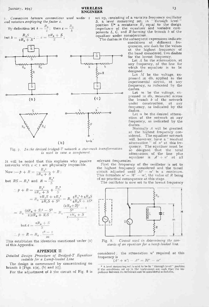
January, 1947 WIRELESSENGINEER
2. Connection between conventions used underand notation employing the factor c.
By definition let k = R0 ; then c = R°
Sbut k
R0S2/20 S '
(a)
( b)
Fig. 7. In the derived bridged -T netuork a star -mesh transformationis used to save a component.
(c)
k= k'
It will be noted that this explains why passivenetworks with c < I are physically impossible.
R2Now :-p R 2R0 SR ;+,
but RS = Ro2 and R = -Rf2
p R = + R02R02
2R0 + S2R,S - R,2R02 4R02±. S
= .11°2R0.5 ± S2 4145
(2 R 0 ± .5)2
= (2R, + S)2 - 52 S2
2(2R0 + S)S - R0 21(0 + S
2R0 Sbutt=
p R Roc2 - r
2cThis establishes the identities mentioned under (I)of this Appendix.
APPENDIX IIDetailed Design Procedure of Bridged -T Equalizer
suitable for a Lump -loaded LineThe design is commenced by concentrating on
branch b [Figs. i (a), (b) and (c)].For the adjustment of b the circuit of Fig. 8 is
set up, consisting of a variable frequency oscillatorS, a level measuring set, in " through level "position U* a resistance R, equal to the designimpedance of the equalizer and variable com-ponents L, C, and R forming the branch b of theequalizer under consideration.
The dashes in the subsequent expressions indicateconditions at different fre-quencies, one dash for the valuesat the highest frequency ofthe band considered, two dashesfor the lowest frequency.
Let A be the attenuation, atany frequency, of the line forwhich the equalizer is to bedesigned.
Let 31 be the voltage, ex-pressed in (lb, applied to theexperimental circuit, at anyfrequency, as indicated by thedashes.
Let m he the voltage, ex-pressed in db, measured acrossthe branch b of the networkunder construction, at anyfrequency, as indicated by thedashes.
Let n be the desired attenu-ation of the network at anyfrequency, as indicated by thedashes.
Normally A will be greatestat the highest frequency con-sidered. The equalizer networkwill, however, have a " residualattenuation " of n' at this fre-quency. The equalizer must beso designed that the tot alattenuation of the line plusequalizer is .1' n' at all
relevant frequencies.First the frequency of the oscillator is set to
the highest frequency considered and the tunedcircuit adjusted until 31' m' is a minimum.This furnishes n' = - 111', the value of 1? beingof no practical consequence at this stage.
The oscillator is now set to the lowest frequemy
M
Fig. 8. f. irctul u:ci'd rn dehrinineng lite con-stants of an equalizer for a lump.loaded line.
considered ; the attenuation »" required at thisfrequency is
(A' 4- - A' A level measuring set is said to be in " through level " position
if the conditions set up in the instrument are such that the nu.pedanco between its terminals can be considered as infinite.

14
R is therefore adjusted until M" - m" = (A'± - A".
The correct attenuation at intermediate fre-L
quencies is obtained by altering the ratio -c withoutaltering L x C in such a way that M -m =
12,1 - A within the required tolerance at allrelevant frequencies.
As M is adjustable at will the work can be madeeasier by keeping M to zero db at all frequencies.In this case the above expression becomes :--
-m = (A' le) -AIn other words the components of b are then
WIRELESSENGINEER
adjusted in such a way that m is numerically equalto the desired attenuation at all frequencies.
Perhaps it is still speedier to make ./l/ negativeand numerically equal to A at all frequencies, then
-A -m (A' ± -A.*. m = - (A' + = a constant.
This means that all that is necessary in this caseis to adjust the tuned circuit at the highest fre-quency until m' becomes a (negative) minimum,and then carry out all subsequent adjustments insuch a way that m remains constant within thetolerances allowed.
January, 1947
CLASS B AUDIO -FREQUENCYAMPLIFIERS*
By F. Butler, B.Sc., A.M.I.E.E.
SUMMARY.-Distortion caused by the variable input impedance of an amplifier inwhich grid current flows during a part of each cycle of the driving voltage is reduced by theuse of an output stage having an input impedance which is very low at all values of signalamplitude. In this case, the additional parallel loading represented by grid -current flow iscomparatively small.
An earthed -grid, cathode -coupled amplifier has the desired characteristics and has thefurther advantage that although it requires considerable excitation power, a large proportionof this appears as useful output. The division of power between the final and penultimatestages is of special importance in the design of high -power modulators, in which it may bedifficult to secure the desired output from a single stage.
1. IntroductionT T audio frequencies, the input imped-
ance of a conventional triode amplifieris almost infinite, except when the
amplitude of the excitation voltage exceedsthe standing negative grid bias. The inter-mittent flow of grid current then constitutesa variable loading on the driver valve, andunless the voltage regulation of this stage isexceptionally good, amplitude distortionbecomes serious, due to the clipping of thecrests of the positive half -cycles of thedriving voltage. Abrupt changes in inputimpedance also tend to cause undesirabletransient oscillations, or " ringing ", oftendifficult to suppress.
Negative feedback can be used to lowerthe output impedance of the driver valve,at the expense of a corresponding reductionin stage gain. Alternatively a step-downdriver transformer may be employed, itsturns ratio being subject to the restrictionthat adequate excitation for the outputvalves must be available without excessivedistortion in the penultimate stage. For the
*MS. accepted by the Editor, May 1946.
from thedriver must be greatly in excess of theminimum excitation power requirements ofthe final amplifier, the balance being dissi-pated in a dummy load.
An examination- of the properties of theearthed -grid, or cathode -coupled, amplifiershows that it is almost ideally suited tooperation under Class B conditions. In thefirst place, its mean input impedance is verylow at all values of signal level, and, incomparison, the maximum variations due tointermittent grid current flow are negligible.Moreover, the high excitation power requiredis not entirely dissipated as in the conven-tional system. By proper design, a largefraction of the driver output can be trans-ferred to the final stage. In the case of high-pover amplifiers or modulators, the contribu-tion from the driver reduces the requirementsfrom the final stage and thus simplifiesdesign.
2. Cathode -input AmplifierFig. shows a triode driver V1 coupled to
an earthed -grid amplifier V2. Replacing theactual valves by their equivalent generator

January, 1947 WIRELESSENGINEER
15
circuits and restricting the analysis to linearconditions, equations may be derived for theoverall stage -gain, the final power outputand the requisite output from the driverstage. The case of impedance coupling willfirst be discussed and the necessary modifica-tions for ideal transformer coupling will thenbe given.
Replacing the actual circuit of Fig. i by itselectrical equivalent, shown in Fig. 2, thenetwork equations may be derived.Let E = input Voltage to V1.
E, = equivalent generator e.m.f. ofi1, i2 = mesh currents in the network.
R, = anode slope resistance of V1./1,0 = amplification factor of V1.z = effective anode load impedance of
excluding the input impedance of V2.z1 and z2 in parallel.
RL = load resistanceof 172.R, = slope resistance of V,.
= amplification factor of V2.R2 =E, =grid -cathode potential of V2.
= voltage drop across the impedance z.E2 =E, = final output voltage.
Applying Kirchhoff's laws, it can be shownthat the ratio of the output voltage E0 tothe equivalent generator voltage El of thedriver valve is given by :E0 z r) RLEi R0 z 12,z
RL +Ra+(li± 1)
The overall stage gain Eo/E is obtained bysubstituting, in equation (i), El =µ,E.
(I)
r. Basic circuit of a cathode -input stageand its driver.
The terms of this equation have beengrouped in such a manner as to stress thephysical significance of each. First, there is
a reduction of gain below the theoreticalmaximum, due to the finite value of the loadimpedance z, the extent of the loss beingsettled by the relative magnitudes of loadand valve impedance in the first amplifier
zstage. The term (µ+ 1)
R0 representsR0 + z
an increase of effective valve resistancecaused by. impedance in the cathode circuitof the final stage.The increase is dueto a form ofnegative feedbacksimilar to that which
Fig. 2. Equivalent cir-cuit of the amplifier
of Fig. 1.
is observed in the case of an amplifierwith an unshunted cathode -bias resistance.
The impedance RRozo
zis the parallel com-
bination of the driver -valve resistance andits load impedance, and is the effectiveoutput impedance viewed from the cathodeof the driven stage. With a fixed valueassigned to the load resistance RL, themaximum gain is obtained when z, theparallel combination of z and z2, is infinite.For all practical purposes this assumptionis permissible if zi and Z2 are iron -coredchokes of sufficiently high inductance.
Reference to Fig. 2 shows that, in thisspecial case, the two valves are effectivelyin series and the currents i 1 and i2 becomeidentical.Setting it = /2 = i, with z = co, the outputvoltage E0 = iRt and equation (1) may bere -written :
Ra RL= =Rot.. (2)+
EI is the equivalent generator voltage andRo the internal output impedance of VI.The second term of equation (2) is clearlythe input impedance of V2, which forms theload impedance of V1. The practical designof an amplifier of this kind then reduces tothe problem of securing a proper matchbetween the generator impedance Ro and
the load impedanceR, RLand to the
proper choice of the final load impedance Rt.The latter is selected according to well -estab-lished rules and, for standard valves, maybe derived from manufacturers' data sheets.There remains the question of matching R,

16
to + + R.L.
In general, direct coupling will
be found impracticable and a matchingtransformer must be used. The insertion ofan ideal transformer of turns ratio n betweenthe valves converts the load impedance to
Rµ-I- I
the value Z n2Ralk RL
The exact theory of transformer couplingis very complex but subject to the conditionthat the primary inductance is sufficientlylarge to make its reactance, at the lowest
Fla. Z
tLo +1R
Zto + I
WIRELESS January, 1947ENGINEER
valves and the use of centre -tapped chokesand transformers.
The theory already given is sufficientlygeneral to cover the present case. Thecathode -follower valve can be replaced byan electrical equivalent. If t.co, Ro arerespectively the amplification factor andslope resistance of the valve and if E isthe input voltage, the equivalent generatorhas an e.m.f. µo/(µo + 1) . E and an internalresistance Ro/(p.0 1).
Substituting these values in equation (1),the stage gain is given by :-
+ 7 ) FL
F, Ra (la +I) PoIan±
significant frequency, of the order of tentimes the first valve slope resistance, there islittle loss of accuracy in considering only theideal case.
3. Cathode -Follower Driver ValveIt has already been stated that the relative
values of the resistances R 0 andRe'
+RL
are
in practice such as to preclude the possibilityof direct coupling.
It is of interest to consider the use of acathode -follower as a driver valve. Thecircuit is shown in a schematic form in Fig. 3.
Fig. 3. Cathode -input amplifier driven by acathode -follower.
Normally Z will be an iron -core inductance,and instead of Rz, an output transformer willbe used. The modifications for push-pulloperation simply involve duplication of the
(3)
/Lc, 4 -
Assuming iko and p.> I and setting Z-- co,equation (3) can be simplified and be-
comes : Eo/E =Rh + Ra ihIgnz,
where
gm is the mutual conductance of V1.The use of a cathode -follower avoids the
necessity for a coupling transformer and acentre -tapped choke may be substituted.The greatest disadvantage is the low gain,which calls for the use of additional pre-amplifier stages. It must also be rememberedthat, the driver and the driven stages areeffectively in series and therefore the alterna-ting component of anode current is the samein each. This consideration limits the choiceof suitable driver valves. The foregoingremarks are restricted to the use of valvesunder linear, Class A conditions. Modifica-tions must be introduced to cover the caseof Class B operation. These will now bediscussed in empirical terms.4. Design of Class B Cathode-Coupled
AmplifiersThe successive steps to be performed in
the design of a push-pull Class B cathode -coupled amplifier are as follows. The re-marks apply to the use of triodes, usinginterstage transformer coupling. This caseis of more general interest than that of thecathode -follower.
(i) Select a pair of valves to give thedesired output from the final stageunder normal Class B conditions.
(ii) Consult valve tables and determine theanode -to -anode load resistance, the h.1 .voltage and negative grid bias.
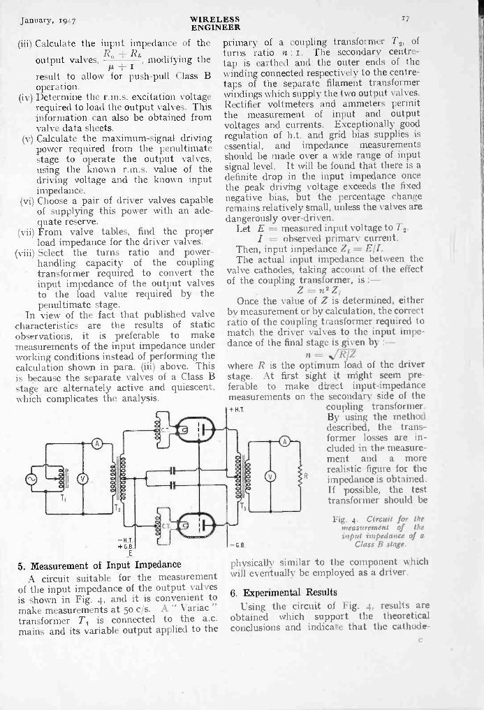
January, 1947 WIRELESS 17
ENGINEER
(iii) Calculate
output v
result tooperation.
(iv) Determine the r.m.s. excitation voltagerequired to load the output valves. Thisinformation can also be obtained fromvalve data sheets.
(v) Calculate the maximum -signal drivingpower required from the penultimatestage to operate the output valves,using the known r.m.s. value of thedriving voltage and the known inputimpedance.
(vi) Choose a pair of driver valves capableof supplying this power with an ade-quate reserve.
(vii) From valve tables, find the properload impedance for the driver valves.
(viii) Select the turns ratio and power -handling capacity of the couplingtransformer required to convert theinput impedance of the output valvesto the load value required by thepenultimate stage.
In view of the fact that published valvecharacteristics are the results of staticobservations, it is preferable to makemeasurements of the input impedance underworking conditions instead of performing thecalculation shown in para. (iii) above. Thisis because the separate valves of a Class Bstage are alternately active and quiescent,which complicates the analysis.
the input impedance of thealves,
R+
RL, modifying the
allow for push-pull Class B
-H+G
E
5. Measurement of Input ImpedanceA circuit suitable for the measurement
of the input impedance of the output valvesis shown in Fig. 4, and it is convenient tomake measurements at 5o c/s. A " Variactransformer T1 is connected to the a.c.mains and its variable output applied to the
primary of a coupling transformer T2, ofturns ratio n : I. The secondary centre -tap is earthed and -the outer ends of thewinding connected respectively to the centre -taps of the separate filament transformerwindings which supply the two outputRectifier voltmeters and anunciers permitthe measurement of input and outputvoltages and currents. Exceptionally goodregulation of h.t. and grid bias supplieressential, and impedance measurementshould be made over a wide range of inpulsignal level. It will be found that there it adefinite drop in the input impedance oncethe peak driving voltage exceeds the fixednegative bias, but the percentage changeremains relatively small, unless the valves aredangerously over -driven.
Let F = measured input voltage to 1-2.I =- observed primary current.
Then, input impedance Z, E:I.The actual input impedance between the
valve cathodes, taking account of the effectof the coupling transformer, is :--
Z =n2 ZiOnce the value of Z is determined, either
by measurement or by calculation, the correctratio of the coupling transformer required tomatch the driver valves to the input impe-dance of the final stage is given by :-
/Iwhere R is the optimum load of the driverstage. At first sight it might seem pre-ferable to make direct input -impedancemeasurements on the secondary side of the+ H.T. coupling transformer.
By using the methoddescribed, the trans-former losses are in-cluded in the measure-ment and a morerealistic figure for theimpedance is obtained.If possible, the testtransformer should be
- G.8.
Fig. 4. Circa it for themeasurement of theinput impedance of a
Class 11 stage.
physically similar to the component whichwill eventually he employed as a driver.
6. Experimental ResultsUsing the circuit of Fig. 4, results arc
obtained which support the theoreticalconclusions and indicate that the cathode-

18 WIRELESSENGINEER
January, 1947
coupled audio -frequency amplifier has usefulproperties not possessed by normal Class Bamplifiers. In making such measurements,the experimental procedure is as follows :
(i) From valve data sheets select a pair ofvalves capable of delivering the desiredoutput and choose an appropriate loadresistance, allowing for the turns ratioof the output transformer.
(ii) Using a double -beam oscilloscope, dis-play the input voltage to the drivertransformer on one trace and the ampli-fier output voltage on the other.
(iii) Adjust the input and output signal levelsto equality and bias the deflector platesuntil the two displays can be super-imposed. Auxiliary potentiometers usedfor this purpose must be of high resistancein comparison with the load resistanceand with the input impedance of thedriver transformer. Alternatively, allow-ance must be made for power dissipatedin them.
(iv) Raise the input signal level until theoutput shows signs of distortion. Thisis recognised by the fact that the twotraces can no longer be brought intocoincidence, and is an indication that themaximum useful power output has beenattained.
(v) Record the input and andcurrents. Note the h.t. supply voltageand feed current.
Results are recorded below for the caseof a particular amplifier using 25 -watttriodes in the output stage. The valves areapparently being over -run, but although the
INPUT
h.t. voltage is 50 per cent above the makers'rating, the maximum permissible anodedissipation is not exceeded. .
Type of valve : Marconi-Osram PX25H.T. Voltage : 600 VFeed Current : 17o mAD.C. Grid Current : 3 mAInput Power : 102 WInput Transformer (T, in Fig. 4) turns ratio
(Primary : Secondary) : i : 2.Output Transformer (T3 in Fig. 4) turns ratio
(Primary : Secondary) : 2.8 : 1.Load Resistance : f,f 0011Equivalent load resistance at anodes of output
valves :(2.8)2 X 1100 = 8,624 r/
Output Voltage : 245 V r.m.s.Output Current : 0.223 A r.m.s.Output Power (maximum undistorted): 54.63WInput Voltage : 65 r.m.s.Input Current : 0.22 A r.m.s.Driving Power : 14.3 WInput Impedance at primary of T2 : 295.541Equivalent Input Impedance (between valve
cathodes) :22 X 295.5 = 1,182 n.
The high ratio of driving power to thefinal output power is clearly evident. Asalready pointed out, a proportion of thedriving power of 14.3 W is transferred to theoutput and contributes to the total of 54.63watts delivered to the load. The apparentconversion efficiency of the amplifier is54.63/102 = 53.6 per cent. The actual value
than this since the excitation powerhas not been included in the calculations.
If an attempt is made to increase the out-put power by raising the excitation voltage,there is a rapid increase in grid current, duefirst to the increased positive grid voltage,and to the simultaneous reduction of mini-
-H.T.+G.B.E
Push-pull driver and amplifier stages embodying .the principle described.
OUTPUT

January, 1947 -WIRELESSENGINEER
19
mum anode potential due to the largeralternating voltage developed across the load.This is exactly analogous to the case of ClassB or Class C radio -frequency amplifiers,in which there is corresponding rapid rise ofexcitation power once a certain output isexceeded. Correct choice of load resistanceminimizes this difficulty at the expenseof reduced efficiency.
The above experimental figures do notreveal_all the properties of the amplifier.The relationships between driving power andfinal output, between excitation voltage andgrid current, and between input impedance,excitation voltage and load resistance shouldalso be studied. These are straightforwardinvestigations, and will not be described infurther detail.
7. Practical Amplifier CircuitFig. 5 shows a push-pull driver and output
stage employing the principles already de-scribed. With the valve types shown,operating at maximum ratings, the outputshould be nearly zoo watts. Conventionalpre -amplifier stages may be added to raisethe overall gain to any desired level. Ifdesired, beam-tetrode driver valves may beemployed. These have the advantage ofhigher efficiency, though distortion may berather greater than with triodes.
To secure a large output with minimumdistortion, it is essential that h.t. and gridbias supplies are well regulated. In high -power modulators, supplied from mercury -vapour rectifiers, the voltage regulation issatisfactory. It is usually possible to selectgas -discharge regulators for stabilizing thegrid -bias supplies of medium power amplifiers.Alternatively, electronic regulators must beused. It is also of importance to keep thedriver -transformer secondary windings oflow resistance, otherwise an undesired vari-able cathode bias will be introduced, due tothe fluctuating anode current of the outputvalves.
No reference has been made to the use of
negative feedback in connection withcathode -driven amplifiers. Any of the usualsystems may be employed, though voltagefeedback will normally be preferred, in orderto reduce the output impedance of the ampli-fier. Reference to equation (t) shows thatthe normal valve resistance Ra is increasedto a value :-
RczRa (tt + I) R0 + z
In transmitter modulators, this increaseis not objectionable, but in public addressamplifiers the loudspeaker damping is notquite so good as with the usual Class Bsystem. Voltage feedback can correct thisdefect and simultaneously reduce the residualdistortion.
As regards the response at high audiofrequencies, the cathode -driven valve has aninherent advantage over other triode ampli-fiers, since the earthed grid avoids degenera-tive feedback due to anode -grid capacitance.To obtain a comparable performance withnormal amplifiers, audio -frequency neutraliz-ing would be necessary.
Professor G. W. 0. HoweOn his retirement from the James Watt Chair of
Electrical Engineering in the University of Glasgow,Professor Howe was presented with a cheque for2oo, the presentation being carried out by Pro-
fessor Bernard Hague.Professor Howe has handed the gift to the
Principal of the University for the endowment ofa prize for the most outstanding graduate inelectrical engineering.
R. N. VyvyanWe regret to announce the death of R. N. Vyvyan
on December 14th, at the age of 70. FormerlyEngineer -in -Chief of the Marconi Company, Mr.Vyvyan was one of the pioneers of wireless. Hesupervised the erection of the famous Poidhu andCape Cod stations.
While Managing -Engineer in Canada for theMarconi Company he built the Glace Bay station,which formed the western link of the first regulartransatlantic wireless service. He returned tothis country in 1908.
He was responsible for the construction andengineering design of the short-wave beam systemof . the Imperial wireless stations which came intobeing after the first World War. He retired in-1936.
Popov MedalInstituted by a decree of the Soviet Government,
the Popov Gold Medal i s awarded annually on7th May by the Academy of Sciences of theU.S.S.R. to a scientist of any nationality for out-standing scientific research or invention in the fieldof radio. The first award will be made in 1947for work completed in the period 1933-1943 andwork submitted must reach the Academy ofSciences Radio Physics and Radio EngineeringCouncil not later than 1st February.*
Papers may be in any language, typed or printed,and there should be three copies. The address ofthe Council is Tretya Miusskaya d 3, Moscow,U.S.S.R
*Notification of this competition was not received until earlyDecember, and the early closing date would seem to make entriesfrom this country difficult.-Ed.

WIRELESSENGINEER
January, 1947
TRANSIENT RESPONSE OF V.F.COUPLINGS*
Compensated Networks for Wide -Band AmplifiersBy W. E. Thomson, M.A.
(P.O. Radio Branch)
SUMMARY.-Formulae and curves are given for the response to the Heaviside unitfunction of a single resistance -capacitance coupled stage as commonly used in wide -bandamplifiers, the nominally resistive load being compensated to offset the low- and high -frequencydeficiencies associated with this type of coupling.
The analysis of the low -frequency response deals mainly with the compensation of gridcoupling by anode decoupling. Two orders of compensation are dealt with.
For high -frequency compensation, one particular type of compensating circuit isanalysed. Attention is confined to conditions which give " critical damping." The ultimatepossible improvement with this type of circuit is demonstrated.
CONTENTS1. Introduction2. Low -Frequency Compensation
2.1 General2.2 Compensation of grid coupling *by
decoupling3. High -Frequency Compensation
3.1 General3.2 Particular cases3.3 Maximum possible improvement3.4 Attenuation and delay -frequency response
Appendices1. Operational formulae2. Compensation of grid coupling by anode de -
coupling2.1 General2.2 Special case ; n = 2
3. High -frequency compensation-critically dampedresponse
3.1 Second order3.2 Infinite order3.3 Attenuation and delay characteristics
References
anode
1. IntroductionFOR amplifiers, such as oscillograph and
video amplifiers, which must pass asignal with as little change of waveform
as possible, the amplitude -frequency andphase -frequency responses do not give anentirely satisfactory criterion of performance.It is preferable, and now fairly general, totake as a criterion of performance the indicialresponse ; that is, the response to' a Heavi-side unit function.
In this article, several commonly usedtypes of coupling are analysed. The workis of a general nature and includes previousresults as particular cases. Attention has
* MS. accepted by the Editor, April 1946.
been confined to the theoretical aspects, andthe numerous practical considerations in-volved are not discussed.
The usual assumptions have been made.These are :-
(I) The valve concerned can be regardedas a constant -current generator.
(z) ,The high -frequency response can beconsidered separately from the low -frequencyresponse. For each case an equivalent circuitis used which neglects certain impedances.As far as the indicial response is concerned,this distinction corresponds to a distinctionbetween the initial build-up period, which isassociated with the high -frequency response,and the maintenance of the response at theideal level up to a certain maximum period,which is associated with the low -frequencyresponse.
(3) The impedance of the d.c. supply isnegligible.
The symbols used are either standard orare defined when required ; certain symbols,such as a, /3, have different meanings indifferent sections.
2. Low -Frequency Compensation2.1. General
For an amplifier which cannot amplifyd.c. the indicial response must tend tozero with increasing time. It is possible,however, to design the amplifier so that theresponse may approximate the ideal, withingiven limits, up to a certain maximum time.Let the indicial response be expressed in aMaclaurin series in t :
V + alt a2t2I2! a3t313!

January, 1947 WIRELESSENGINEER
21
G - (1 + g,Z, crsZs) (I + I/pC,R,)where g, = sum of grid -anode, grid -screen,
and screen -anode mutual con-ductances,
as = screen conductance,Zd, Zs, Zs are anode decoupling, cathode,
and screen networks,and it is assumed that the coupling capacitorand grid leak can be regarded as of highimpedance.
Then the response may be made more andmore nearly ideal by choosing the designparameters so that
ai = a2 a3 = . . . = ofor n as large as possible.
The corresponding expressionoperational gain is1
G I + a2/p2 + a2/p3 + . . .
The above condition may also he expressedin terms of derivatives, thus :
idV1 rd2vidt J. do j
for
[del. o-= ,
the
orr dG r d2G 1_ r d"G
oLd ki (11192.1. Lc/ (I/pd.
In practical work it is usually sufficientto make a1 = o only, and the conditions forthis can be determined fairly readily fromthe operational gain. For example thenormalized gain for the circuit of Fig. I is*
+ Zd/Rz
Fig. I.stage
Typical resistance -capacitance coupleducluding decoupling, screen -feed, and
cathode -bias networks.
Each of the networks Zd, Z,, and Z,consistseffectively of a resistance in parallel with a
* Adapted from a formula. of Edwards andcherry.9
capacitance. 'The operational impedance isof the form :
RIK =i/pCR i/pc; I + IHocR
= (ripc)[1-iipcR i/(pCR)2
= ripc to a first approximation.Hence, to a first approximation :
I + I 'pc RLG = (1 + gc/pC, + asipcs)(1 + lipc,R,)
= (1 (ix dRL -gc1C,- 0-81C,- TIC,R,)
Thus the condition which makes [di
d = o is0
I/CdRL = ge1C,+0.81C,+ TIC,R
Fig. 2. The basic coupling circuit ; RaL and.12,Z, are networks which respectively do and
do not pass direct current.
2.2.-Compensation of grid coupling by anodedecoupling.A case frequently considered is illustrated
in Fig. 2 in which RL and R, are the anodeload and grid leak respectively ; RLZL is adecoupling network which must pass d.c.and RZ, is a coupling network which doesnot pass d.c. The impedance of bothnetworks tends to zero with increasingfrequency. The normalized operational gainof such a stage, assuming that the gridnetwork can be regarded as a high -impedancepotential divider across the effective load is :
G=I+ ZzI Zu
Obviously if, ZL = Z, the gain will beindependent of frequency and the indicialresponse perfect. The d.c. requirements,of course, make this condition impossible.It is possible, however, by making ZL andalmost equal, to satisfy the conditions statedin the previous section. ZL and Z, have theform shown in Fig. 3. These forms auto-matically fulfil the d.c. and high -frequencyconditions stated above. In Fig. 3, ZL and
73412

22 WIRELESSENGINEER
January, 1947
Z9 have n components identical ; inZ, has an extra component 2 and inZL has the extra component Rn4.2. Incases, as is shown in Appendix 2.1,
Fin id2V1 Cr' V
dt dt2 jo-
R3 R5
-
Zi
T0
R3
n = 0
= [--] -di"
Rn_1 R,+,
R0-1 Rn+1
T"
3 (a),3(b),both
0
t C 0+ 2
-= 0 ; V = e-OT
n= ; V= (e-t/ OT r e-11)
where T = CRL = C9R9, and a, as is shownin Fig. 4, is the ratio of decoupling to loadresistance.
R3 R5
TCZ -140
R,
n+
(a) (b)Fig. 3. General forms of ZL and Z g of Fig. 2 are shown here.
n-iRLCd = R9C9 = T
Fig. 4. The three simplest practical forms of Fig. 2 : n = 0, uncompensated ;compensation ; n = 2, second -order compensation.
a
H
Fig. 4 shows the three simplest cases, forn = o, I, and z respectively ; the com-1ponents, have been renamed for convenience.Case n = o is the basic resistance-capacitancecoupled stage. For case n = i, the anodeload has been modified. The addition of thecapacitor Cd alone, with value CgRg/RLwould give perfect response ; the capacitormust however be bypassed by aRL to allowh.t. current to flow. The correct relation-ship CdRL = C9R9 gives an judicial responsefor which [dVidt]c, = o as is shown in Fig. 5,which gives responses for various values ofa; the curve oc = o corresponds to the case
o. This circuit has been adequatelyanalysed elsewhere so only theformulae are given here ;
n = 2
= i, first -order
The case n = 2 is not so widely known.This carries the process a stage further byadding components to the grid couplingnetwork which compensates, to some extent,for the resistor a& which prevents the res-ponse being ideal in the case n = I. PerfectcompenSation would be achieved by shuntingC9 by a resistor of value cxR,, but, in order toblock h.t., a capacitor /3C9 must be added inseries with aR9. The addition of these twocomponents does not affect [dV/dt] 0: providedCA.& = C9R9 we still have [dV ldt]o = o.The correct value of resistor, namely (xR,,improves the indicial response still further,by making [d2Vidt2] 0 = o. This is shown inFig. 6 which gives responses for variousvalues of a and /3. The curves 3 = o corres-
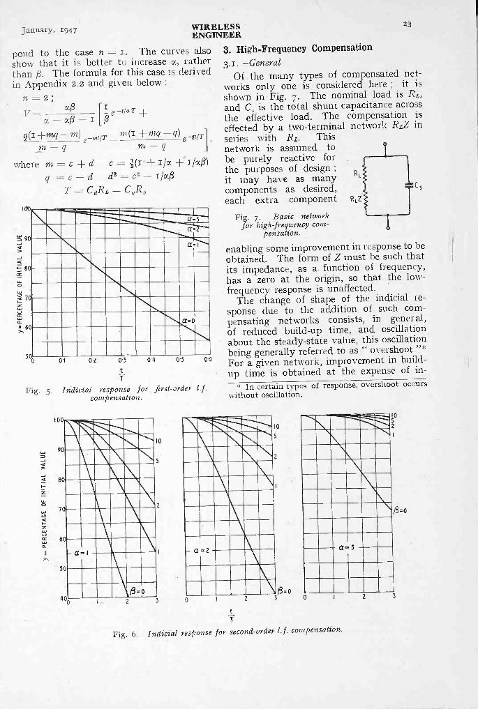
January, 1947 WIRELESSENGINEER
23
pond to the case n = I. The curves alsoshow that it is better to increase cc, ratherthan g. The formula for this case is derivedin Appendix 2.2 and given below :
n = 2 ;v=
of./3 - IeT
R
q(f +mq -m) m (1 -4-mq - e-qtIT- q m - q
where m = c d c= i/uPd2 c2 -
100
t' 90
q = c -dT = CURL = C,R,
5%0-I 02 0'3
CC= 1
a=o
0.4 0.5 00
T
Fig. 5. Indicial response for first -order 1.f.compensation.
100
90
80
70
60
50
400 2 3
10
5
2
3. High -Frequency Compensation3.1.-General
Of the many types of compensated net-works only one is considered here ; it isshown in Fig. 7. The nominal load is RL,and Cs is the total shunt capacitance acrossthe effective load. The compensation iseffected by a two -terminal network RLZ in
series with RL. Thisnetwork is assumed tobe purely reactive forthe purposes of design ;it may have as manycomponents as desired,each extra component RLZ
Fig. 7. Basic networkfor high frequencycom-
pensation.
enabling some improvement in response to beobtained. The form of Z must be such thatits impedance, as a function of frequency,has a zero at the origin, so that the low -frequency response is unaffected.
The change of shape of the indicial re-sponse due to the addition of such com-pensating networks consists, in general,of reduced build-up time, and oscillationabout the steady-state value, this oscillationbeing generally referred to as " overshoot "*For a given network, improvement in build-up time is obtained at the expense of in-
* In certain types of response, overshoot occurswithout oscillation.
10
5
a= 5
0
t
T
Fig. 6. Indicial response for second -order 1.f. compensation.
2
1052
8=0
3
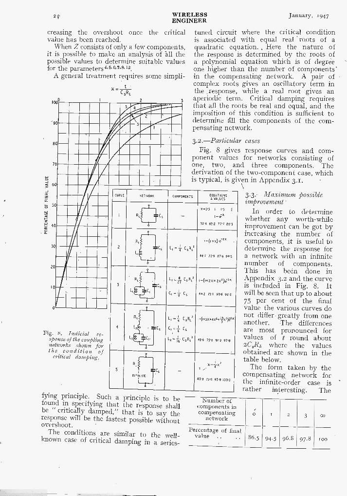
24' WIRELESSENGINEER
January, 1947
creasing the overshoot once the criticalvalue has been reached.
When Z consists of only a few components,it is possible to make an analysis of all thepossible values to determine suitable valuesfor the parameters 4. 5, 6, 7'8,12.
A general treatment requires some simpli-
1000
90
80
70
60
50
40
30
20
I 0
Fig. 8. Indicial re-sponse of the couplingnetworks shown forthe condition of
critical damping.
C SRE
5 4
3
2
2
3
tuned circuit where the critical conditionis associated with equal real roots of aquadratic equation. , Here the nature ofthe response is determined by the roots ofa polynomial equation which is of degreeone higher than the number of components'in the compensating network. A pair ofcomplex roots gives an oscillatory term inthe response, while a real root gives anaperiodic term. Critical damping requiresthat all the roots be real and equal, and theimposition of this condition is sufficient todetermin,, all the components of the com-pensating network.
3.2.-Particular casesFig. 8 gives response curves and com-
ponent values for networks consisting ofone, two, and three components. Thederivation of the two -component case, whichis typical, is given in Appendix 3.1.
CURVE NETWORK COMPONENTS EQUATIONS& VALUES
I -X-0-5 I TS 2
I-ix391 632 7T7 86-5
Rir:IrCs
2 C L, = CsR,!
1_(I1.x) -2X
447 72.9 8T6 941
I.
1,
3 CSL
L , =.214 Cs R1
, 1 ,CI = 1-3- Ls
I -(i+2x4-2xz)e3x
442 75-I 90-6 961
i
C,
4 C5
L, - Ir Cska
CI, =-r C59
L2 = -1,T Cont.'
i+3x+4xz+Ii5x3)64x
43-6 75-6 91-9 971
i
L,-
L : C,
5 C -X-jee
---
431 75'0 93.8 100-0
Ri
1
INFINITE
fying principle. Such a principle is to befound in specifying that the response shallbe " critically damped," that is to say theresponse will be the fastest possible withoutovershoot.
The conditions are similar to the well-known case of critical damping in a series-
3.3.-Maximum possibleimprovement
In order to determinewhether any worth -whileimprovement can be got byincreasing the number ofcomponents, it is useful todetermine the response fora network with an infinitenumber of components.This has been done inAppendix 3.2 and the curveis included in Fig. 8. Itwill be seen that up to about75 per cent of the finalvalue the various curves donot differ greatly from oneanother. The differencesare most pronounced forvalues of t round about2C3RL where the valuesobtained are shown in thetable below.
The form taken by thecompensating, network forthe infinite -order case israther interesting. The
Number ofcomponents incompensating
networko I 2 3 co
Percentage of finalvalue .. .. 86.5 94.5 96.8 97.8 roo
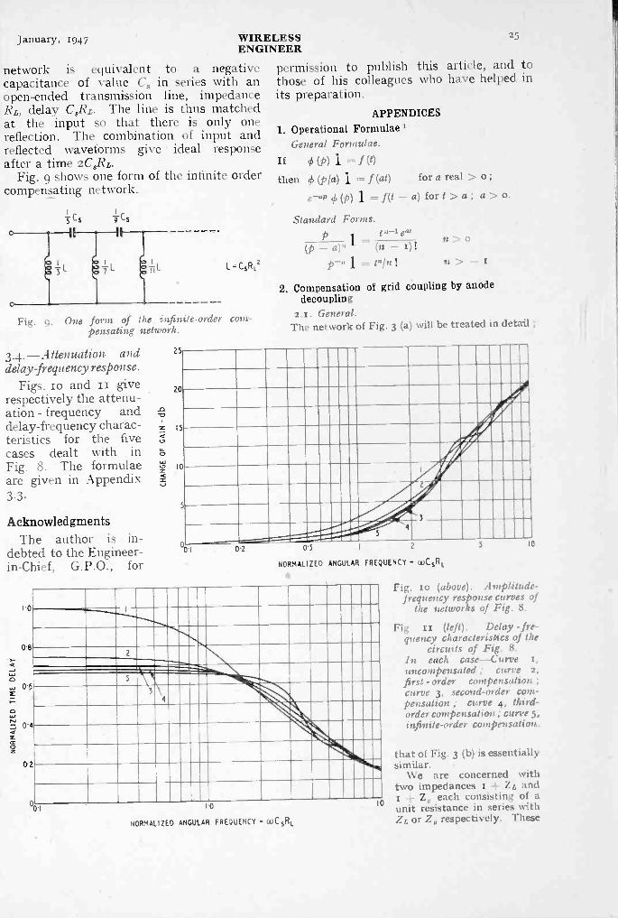
January, 1947 WIRELESS 25
ENGINEER
network is equivalent to a negative permission to publish this article, and tocapacitance of value Cs in series with an those of his colleagues who have helped in
open-ended transmission line, impedance its preparation.Rz, delay CsRL. The line is thus matchedat the input so that there is only one APPENDICES
reflection. The combination of input and 1. Operational Formulae I
reflected waveforms give ideal response General Formulae.
after a time 2CsRz. If 0 (P) 1 = 1 (t)Fig. 9 shows one form of the infinite order
compensating network.then ch (Pia) 1 = f (at) for a real > o ;
e-a" (16 (p) 1 = i (t - a) for t > a ; a ::-.-- o.
Cs -0-Ls
L=CsRtz
Fig. 9. One form of tl e infinite -order com-pensating a etwork.
3.4. -Attenuation anddelay -frequency response.
Figs. 10 and II giverespectively the attenu-ation - frequency anddelay -frequency charac-teristics for the fivecases dealt with inFig. 8. The formulaeare given in Appendix3.3 -
AcknowledgmentsThe author is in-
debted to the Engineer -in -Chief, G.P.O., for
1.0
0-8
0.6
0'4
0-2
25
20
I5
10
5
Standard Forms.p I e.,
- a)" L- (n -
V" = PM!
n > 0
77 -
2. Compensation of grid coupling by anodedecoupling
2.1. General.The network of Fig. 3 (a) will be treated in detail ;
0.1 02 01 2 5 10
NORMALIZED ANGULAR FREQUENCY - toCsRt.
2
5
3
4
0.1 IO
NORMALIZED ANGULAR FREQUENCY = WCsRL
10
Fig. i o (above). A mptitude-frequency response curves of
the networks of Fig. 8.
Fig i I (left). Delay - fre-quency characteristics of the
circuits of Fig. 8.In each case-Curve t,it )1COM pcnSated curve 2,
first -order cmnpensationcurve 3, second -order com-pensation ; curve .1, third -order compensation ; curve 3,infinite -order compensation.
that of Fig. 3 (b) is essentiallysimilar.
We are concerned withtwo impedances t + Zs andt ± Z, each consisting of aunit resistance in series withZs or Z, respectively. These

26 WIRELESSENGINEER
January, 1947
may be expressed as the ratio of two polynomialsin p2.
I - a, + alp + +din pi"I + b1p +bi.pi"
Pln+1I + Zg =Pln+1+
1 + ZL + a}t, d: pP:+3.1
± Z, (b,± c,)p ±..+ bApart from the unity term in the denominator,
numerator and denominator are equal. This canbe shown by general continued fraction theory.3
ZL and I + z, can be considered as the(n i)th and (n + 2)th convergents of the samecontinued fraction :
I +
I + +
I I I I I
c2p R3+ c4p -r Rn-1-1± Cn-F2PI + ZL
where p, and qr are as defined in reference (3)are, in this case, polynomials in p ; similarly
I 4- Z, = pit+2/q7,4.2ZL qn+a
= + Zg P n-1-2 n+iNow, in general,
Pnqn-i- .P.-14.= (- i)nPn+2 qn+1 Pn+1 qn+2 = (- r)"+2 =
in this case, n is even.ZL Pn-I-1 qn-4-2
+ Zg I Pn-1-1 qn+2
Comparing - this with the previous expressionwe see that pn+1 qn+, must be identified with thenumerator and that the must beequal the numerator plus one. Now convert to aratio of polynomials in i/p :
and
1, since,
3. High -Frequency Compensation -Critically -Damped Response
3.1. Second order.Normalized operational impedance of load
pL1 \I(RL + pCs
RL (RL +pL+ I+ p211LCI + ax + cox'
- x + a (I ± 13) ,(4 ocPx3
where pC,RL = x, L, = aC3RL2,For critical damping, denominatorhence, comparing coefficients, wea = P = I + x X2
(1 + 43)3x2 + 8x + 27
So impedance
c1= pc,(i bx)3
have b =
x(x2 ± 8x ± 19)(x + 3)3 -I (x + 3)3
2X 4X- I x+3 (x + 3)2 (x + 3)3Each of these terms may be interpreted by standardforms to give the indicial response
V = I - (1 + 2t/T 2t2/T2) e-st/Twhere T = CsRL
3.2. Infinite order.For n components the operational impedance Z
of the compensating network will be of the form
Z = a1x a3x3 ± a xn--1I + a2x anx"
where x = pC,RL and the a's are coefficientsspecifying Z ; n has arbitrarily been taken as even.For this value of Z the normalized impedance ofthe load becomes+
F is a polynomialin ill,
I/(Fp,t+1)2 -
I ± a1x + a 2x3 anxnI Z F + i/pn+1 where
I x (a, + a2x3 + (a3 + a4)x4+ (an-, + a,zx"+I
xFor damping, denominator
I ± /Fpn.1-1= I - I/Fpn-1-1 critical = (1 ±-t±The lowest term in i/p in this expression is ,ofdegree n I therefore, for the corresponding
indicial response :As is -->- oo the impedance becomes the ratio of
two infinite series, and for critical damping thedenominator equals ex. This specifies the a's asrdV1 rd2V1 icing follows
2.2.
dt
Special
dt2
case ; n 2
dt'n J ° a1 ± a2 = 1/2 ! whence a1 =1/2 ! - 1/3 !a, = 1/3 -
normalized operational gain a3 + a4 = 1/4! a3 = 1/4 - 1/5 !etc.__ZL pT(i a + apT)(i +p f3 appT)
I ± Z., (I 4- apT)i + (I+ a)pT app27-2]
after simplificationwhere a, fi, and T are as defined in Fig. 4.
The denominator may be factorized thus :oci3(p locT)(p IT)(p q IT)
where in = c d c= ± +I/4)q = c d d2 c2 - 1/43
the gain may therefore be split into three partialfractions each of the standard form kpl(p + a) andhence interpreted to give the indicial response asquoted in section 2.2.
The numerator therefore is :
I+ ! - x/3 ! x2/3 ! x3/4 ! - x3/5 !This series can be shown to be absolutely convergent.It may therefore be rearranged :
+ (x2/2 ! + x3/3 ! . )/x-- (x3/3. ! x3/5 ! + )/x2
- + (ex - I - x) - ex - e -x x) /x2= ex - ex 12x2 + e -r zx2
SO' the impedance is/ix ii2x2 e -2x/2,2
Each of these terms may be interpreted by standard forms. The factor e -2r in the third term delays its

January, 1947 WIRELESSENGINEER
27
contribution to the indicial response, which mustbe considered in two time intervals :
(1) o < t/T < 2 T CsRLV = tIT - t2/4T2
(2) 2 < tIT < ooV = tIT -0142-2 (t/T - 2)2 /4 =
The curve is shown in Fig. 8Z may be obtained from the equation
+ Zimpedance = +x(1 +Z)We find that Z = coth x - r/x;coth x is the impedance of an open-ended trans-mission line and - i/x that of a negative capacitance.The network of Fig. 9 is readily obtained from thecontinued fraction expansion of coth x
I I
coth x = i/x +31x-1- 5/x
3.3. Attenuation and Delay Characteristics.
Order ofCompensation
AttenuationCharacteristics
DelayCharacteristics
o io log (1 +x2) (tan-lx), x
I 20 logn (4+x2) -io log (16-1-x2)
:2 tan-' 4a -tan-I ix; ix
2 3o log (9+x2) -io log,0 :(27-x2)2+ 64x2
3 tan-I if -tan -1'
3 4o log (1.6 +x2)-iolog1(256-16x2)2 ±(8ox -.x3)21
14tan-1 ix- tan -18ox - '3
256 - 16.e: /X
OO zo log 2X2 -Da log,0 {(I -COS 2%)2 -1- (2%- sin 2x)21
(tan-I2% - sin 2%)1I - COS 2X )IX
,
x = coC8R,L
The delay formulae are for the normalized delay;i.e., ratio of delay to time constant CaRz.
REFERENCES McLachlan : " Complex Variable and Operational Calculus."2 Guillemin : " Communication Networks." Vol. 11, Chap. V.3 Barnard and Child : " Higher Algebra." Chap. XXIV. Jackson : " Transient Response of Triode Equivalent Network."
Pill. Mag., Jan. 1932." Builder: " Amplification of Transients." Wireless Engineer,
May 1935.6 McLachlan : ." Reproduction of Transients by a Television
Amplifier." Phil. Mag., Sept. 1936. Mandel : " Reponse des Amplificateurs pour Television aux
Signaux Periodiques de Courte Dm& et aux Phenornimes Transi-toires." L'On.de Electrigue, Oct. 1938.
Bedford and Fredendall: " Transient Response of Multi -stageVideo Frequency Amplifiers." Proc. Inst. Radio Eng., April 1939.
9 Edwards and Cherry : " Amplifier Characteristics at LowFrequencies with particular reference to a new method of frequencycampensation of single stages." Journ. Inst. Elec. Eng., August1940.
" Donley and Epstein : " Low Frequency characteristics of thecoupling circuits of single and multi -stage Video Amplifiers."R.C.A. Review, April 1942.
" Lynch : " Video Amplifier Low Frequency Correction."Communications, April 1943.
12 Kallmann, Spencer and Singer :Proc. Inst. Radio Eng., March 1945.
" Transient Response."
CORRESPONDENCETransient Response of Filters
To the Editor, " Wireless Engineer "SIR,-In the March issue D. G. Tucker' attempts
to find mathematically the transient response of a" Six -element symmetrical " filter section. Theordinary methods of solution prove to give only aguide as to the nature of the solution, and anindirect method of finding the constants involvedin the final solution has to be resorted to. Furl hera number of approximations have to be made.
C. C. Eaglesfield2 in an article in the Novemberissue attempts and obtains a solution which relieson the bandwidth being small compared with themid -band frequency.
Acting on a remark made by Tucker in a footnote(page 87) an attempt was made to line-up thetransient response of a band-pass network with thatof its low-pass analogue.
A low-pass network, which includes componentsR1, R2, . L,, L,. . C,, C2. ., has a transferimpedance Z(0.)L,p which may be written
Z(w)Lx= f 1 R,, R2, . . jwL1,
.1WC, :AC.Now if in series with every inductance L we
place a capacitance and in parallel with every(AWL -
capacitance C we place an inductance 00,02C weobtain the band-pass analogue. This is just a
statement of Landon's Low -I 'ass -Ba nd - I 'ass
Analogue Theorem. For
ja)L. becomes jaiL
WO')= iti/L (1 - -(02
cy' 1
(0,21..)
and becomes I joJCcoU
/ wo-,, 1
= i -I jeoC (1 - ---72)wo ,
Thus if we replace w for the low-pass case by
oi( I - w0)\ of-
we have the band-pass case. How-
ever, this just states the analogy for the amplitudeand phase frequency characteristics. We maydemonstrate the analogy for a transient.
By Fourier's Integral Theorem the frequencycharacteristic of unit step is
I -jie
c4 ad I
g(w) =o
. al =2nlo.i
while the frequency response for the wave cos coot. 1
is
I
-foilg(w) - cos w01. It
217i (1)--(0,,'27r.Comparing these two cases, we see again that
the analogy is obtained by replacing w by w{
Thus we we may state that if the wave cos wr,t. 1
put into a band-pass network then the envelope ofthe output wave is exactly the same as the output.

28 WIRELESSENGINEER
January, 1947
wave obtained when unit step is placed into thelow-pass analogue. This is a result (with norestrictions on bandwidth) that should prove ofutmost use in the solving of transient problems.
For the " Six -element symmetrical " filter theequivalent low-pass network is clearly (using D. G.Tucker's notation)
where nco,mitL1=2M
C2 =
(I = M2)RL3 =2r/2(0i
When E0 is unit step, the voltage appearing across R.is easily found to be given by
{-wit
V, = i i - e 2/12
sin Cul 4.7 - - .m22 4
112e
m2
4 ,
- 1120)1f
after measurement with a travelling microscope.With these dimensions the calculated capacitanceper unit length of the thermistor becomes about3.o µµF.
To calculate the effective impedance we nowregard the thermistor as equivalent to a shortedtransmission line of length 1, resistance per unitlength r and capacitance per unit length c where
1 = semi -length of thermistor beadr = resistance per unit length of line ; i.e., R/lR = d.c. resistance of thermistorc = capacitance per unit length of thermistor
= 3.0 µ,µF per cm in our case.The input impedance of such a line is quoted by
Howe asZ = Z tanh al
Zo = Vrljwc04 = Vjcocr
For a/ large we can take4 Z Z,
This impedance is equivalent to a resistance
which corresponds to equation (7) in C. C. Eagles-field's article.London, E.14. E. T. Emms.
FILTERSD. G. Tucker. " Transient Response of Filters." Wireless
Engineer, March 1946, p. 84.I C. C. Eaglesfield. " Transient Response of Filters." Wireless
Engineer, November 1946, p. 306.
Thermistors at High FrequenciesTo the Editor," Wireless Engineer "
SIR,-I have been using directly -heated high -resistance thermistor* elements to assist impedancemeasurements on cyclotron models. The modelshave been operated at about 400 Mc/s and someconsideration has been given to the performanceof the high -resistance thermistor at these fre-quencies. Three points have been considered ;lead reactance, skin effect and distributed capaci-tance. Simple calculation has shown that thefirst two of these cause very small changes inthermistor resistance for the frequency range0-400 Mc/s. The distributed capacitance does,however, exert considerable influence on theperformance of thermistors which have a resistanceof over a, few thousand ohms.
Using the equivalent transmission line methodsuggested by Howe1,2 for carbon-rod resistors,an estimate has been made of the high -frequencyresistance of a thermistor of known resistance todirect current. For calculation, the thermistorwas regarded as a cylinder of diameter 0.075 cmand length 0.025 cm. These values were taken
1 G. W. 0. Howe, Wireless Engineer, Vol. 12, p. 291, 1935.2 G. W. 0. Howe, Wireless Engineer, Vol. 17, p. 471, 1940.* The thermistoris a small bead composed of a mixture of metallicoxides and enclosed in a small glass capsule with sealed -in leads.The main characteristic is a very large negative temperature
coefficient of resistance. In the directly -heated type of thermistor,the resistance is varied by means of the current through the bead.An indirectly -heated type is also made in which the temperatureand, hence, resistance are controlled by a separate heating wire.See G. L. Pearson, Physical Review, Vol. 57, p. 1065, 1940.
where
V2r1wc and a capacitance of reactance 1/2r/coc inparallel.
Thus, for sufficiently high values of resistance andfrequency, the high -frequency resistance of thethermistor varies as the square root of the resistanceto direct current. This condition is satisfied in ourcase of resistance greater than 30,000 ohms andfrequency of about 400 Mc/s.
Calculated values of the high -frequency resistancefor different d.c. resistance values are given incolumn 2 of the following table.
These can be compared with measured valuesgiven in column 3.
D.C. Calculated h.f. Measured h.f.resistance resistance
(M.0.) (MD.)0.39 0.30
0.073 0.035 0.025The measured high -frequency resistance has been
obtained by using the thermistor as a load on ashorted quarter -wave transmission line. Thethermistor was actually soldered between the outerconductor and an insulated core of the inner con-ductor to enable the so -cis control voltage to beapplied to the thermistor and to enable d.c.resistance measurements to be made. Screeningof the thermistor to prevent radiation was obtainedby continuing the outer conductor. The line wasformed from brass tube and was damped by a smallring of plasticine attached to the inner conductorto bring the Q down to about 500. From themeasured Q and the known dimensions of the linethe effective resonant impedance at the open endwas calculated. With the thermistor mountedacross the open end, the Q' of the line was againmeasured for different thermistor resistances.From the known Q and unloaded input impedance,the effective thermistor resistance was determinedfrom the relation
Qi RE RiQ2 REQ1 = Q without thermistor
Q,= Q with thermistorRE = Effective resistance of thermistor 19Ri = Input resistance of unloaded line atresonanceThe possibility of comparing calculated andmeasured capacitances for the thermistor was
resistance(Mn)8.9

January, 1947 WIRELESSENGINEER
29
0.7 06
rejected as the calculated value was of the order0.001 wiF, which was certainly far too low tomeasure with the equipment used. It was merelychecked that the capacitance was small enough toproduce no measurable change in resonant frequencywhen the effective thermistor impedance changedby a factor of to. For the apparatus used this meantthat the change in capacitance was less than0.002 it,p,F.
I am grateful to Standard Telephones and CablesLtd. for giving the thermistor elements which werespecially prepared under the direction of H. Wolfson.Dr. J. H_Fremlin suggested the use of thermistorsin cyclotron model measurements and has helpedgreatly with several stimulating discussions.Nuffield Physics Laboratory, J. WALKER.
University of Birmingham.
Effect of Aircraft on FadingTo the Editor, " Wireless Engineer."
SIR,-While some beam communication trials on, 3o to 4o Mc/s and 65 to too Mc/s were in progress inj 1944, the attention of the writer was brought to
frequent occurrences of fading signals in which thefading exhibited the characteristics of steadilychanging amplitude and frequency of fade. It wassubsequently proved that the phenomenon was dueto the presence of aircraft in the transmitted beam,and although the effect was generally most notice-able when field strength measurements were inprogress within a mile or two of the transmitter,it was also observed, but to a less extent, when
10
transmitter and receiver were at, or a little beyond,the limits of optical range.
Under the - latter conditions of transmitter -receiver separation, there is normally only the directray from the transmitter to the receiver ; but whenthere is an aircraft in the vicinity, there may alsobe at the receiver an indirect ray reflected from the
This indirect ray will have travelled over agreater distance than the direct ray, and con-sequently there will be a phase difference betweenthe two signals at the receiver, the resultant beinga minimum or maximum according to whether thephase difference is (2n 4- i)ir or zn3r. Thus, asthe aircraft position changes, there is a variationof field strength at the receiver.
The accompanying figure shows the positions ofan aircraft relative to the transmitter and receiverwhich will give signal reinforcement (shown by fulllines) at the receiver, and also the positions whichwill result in a signal minimum at the receiver(shown by dotted lines). The loci of these positions,when plotted in a plane passing through the linejoining the transmitter and receiver, are a set ofconfocal ellipses, with the transmitter and receiveras foci. The ellipses have been plotted with dis-tances parallel to the line joining the transmitterand receiver measured in terms of "d," the distancebetween transmitter and receiver. Lateral dis-placements from this line are measured in terms ofwavelengths.
The resulting variation in field strength due to anaircraft is shown for the particular case of anaircraft flying along the path A 0. Curve (a) showsthe rate of fading without taking into account
rdIMIPIPr7-Allarerdr7-MEM
I
f/M741211kM-11111111111MM6:---i- -------- -
I , , ,1 I. I 1
10 09. 08
rs-
9
B------------
VJ 6_-----.`
4
4,n
0
tm09
N
03 02 01 0 01 02 03
LONGITUDINAL DISPLACEMENT AS ,A FRACTION. OF THE'
DISTANCE "CI'. BETWEEN TRANSMITTER AND RECEIVER
d
TIME
TIME
171
(a)
(b)
06 07 08 09 10
the probable amplitude of the reflected wave.Curve (b) shows the type of fading which mightbe expected due to the reduction of the reflectedsignal strength as the aircraft travels furtherfrom the transmitter. The latter curve agreesclosely with observations which have beenmade in connection with the alignment of beamtransmitters.
Potters Bar, Middlesex. J. W. WHITEHEAD,(Correspondence continued overleaf.)
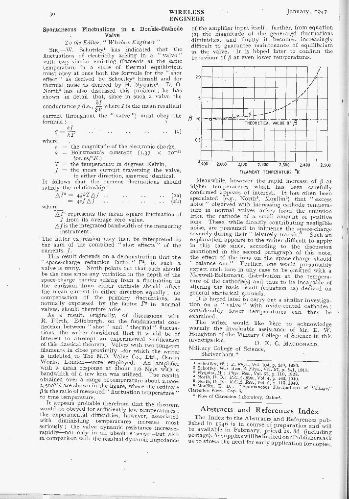
30 WIRELESSENGINEER
January, 1947
Spontaneous Fluctuations in a Double -CathodeValve
To the Editor, " Wireless Engineer "SIR,-W. Schottky' has indicated that the
fluctuations of electricity arising in a " valve "with two similar emitting filaments at the sametemperature in a state of thermal equilibriummust obey at once both the formula for the " shoteffect " as derived by Schottky' himself and forthermal noise as derived by H. Nyquist'. D. 0.North4 has also discussed this problem ; he hasshown in detail that, since in such a valve theconductance g (i.e., -8/ where I is the mean resultant
8 Vcurrent throughout the " valve ") must obey theformula :-
efg kT (I)
wheree = the magnitude of the electronic charge,k = Boltzmann's constant (1.37 x 10⁻²³
j oules/°K.)T = the temperature in degrees Kelvin,J = the mean current traversing the valve,
in either direction, assumed identical.It follows that the current fluctuations shouldsatisfy the relationship :
p/2 = 4gRI- .. (2a)= 4eJL.f .. (2b)
wherep /2 represents the mean square fluctuation of
I from its average zero value.f is the integrated bandwidth of the measuringinstrument.
The latter expression may then be interpreted asthe sum of the combined " shot effects " of thecurrents J.
This result depends on a demonstration that the" space -charge reduction factor " F2, in such avalve is unity. North points out that such shouldbe the case since any variation in the depth of thespace -charge barrier arising from a fluctuation inthe emission from either cathode should affectthe mean current in either direction equally ; nocompensation of the primary fluctuations, asnormally expressed by the factor .r2 in normalvalves, should therefore arise.
As a result, originally, of discussions withR. Furth, Edinburgh, on the fundamental con-nection between " shot " and " thermal " fluctua-tions, the writer considered that it would be ofinterest to attempt an experimental verificationof this classical theorem. Valves with two tungstenfilaments in close proximity-for which the writeris indebted to The M.O. Valve Co., Ltd., OsramWorks, London-were employed. An amplifierwith a mean response at about 1.6 Mcis with abandwidth of a few kc/s was utilized. The resultsobtained over a range of temperature about 2,000-2,500°K are shown in the figure, where the ordinatePis the ratio of measured " fluctuation temperature "to true temperature.
It appears probable therefrom that the theoremwould be obeyed for sufficiently low temperatures
;
the experimental difficulties, however, associatedwith diminishing temperatures increase mostseriously ; the valve dynamic resistance increasesrapidly-not only in an absolute sense-but alsoin comparison with the residual dynamic impedance
of the amplifier input itself ; further, from equation(2) the magnitude of the generated fluctuationsdiminishes, and finally it becomes increasinglydifficult to guarantee maintenance of equilibriumin the valve. It is hbped later to confirm thebehaviour of ,8 at even lower temperatures.
21)
15
1..
0'5
z
o-A...-
THEORETICAL VALUE OF ti
°I 900 2,000 2,100 2,200 2,300 2,400
FILAMENT TEMPERATURE °K
Meanwhile, however the rapid increase of p athigher temperatures which has been carefullyconfirmed appears of interest. It has often beenspeculated (e.g., North', Moullin6) that " excessnoise " observed with increasing cathode tempera-ture in normal valves arises from the emissionfrom the cathode of a small amount of positiveions. These, while directly contributing negligiblenoise, are presumed to influence the space -chargeseverely during their " leisurely transit. Such anexplanation appears to the writer difficult to applyin this case since, according to the discussionmentioned in the second paragraph of this note,the effect of the ions on the space -charge should" balance out." Further, one would presumablyexpect such ions in any case to be emitted with aMaxwell -Boltzmann distribution at the tempera-ture of the cathode(s) and thus to be incapable ofaltering the basic result (equation 2a) derived ongeneral statistical grounds.
It is hoped later" toto carry out a similar investiga-tion on a " valve " with oxide -coated cathodesconsiderably lower temperatures can thus beexamined.
The writer would like here to acknowledgewarmly the invaluable assistance of Mr. E. W.Houghton of the Military College of Science in thisinvestigation.
D. K. C. MACDONALD.Military College of Science,
Shrivenham. *
2,500
1 Schottky, W.: Z. Phys., Vol. 104, p. 248, 1936.2 Schottky, W.: Ann. d. Phys., Vol. 57, p. 541, 1918.3 Nyquist, H.: Phys. Rev., Vol. 32, p. 110, 1928.4 North, D. O.: R.C.A. Rev., Vol. 4, p. 466, 1940.5 North, D. 0.: R.C.A. Rev., Vol. 5, p. 115, 1940.6 Moullin, E. B.: " Spontaneous Fluctuations of Voltage,Clarendon Press. Cap. 6.* Now of Clarendon Laboratory, Oxford.
Abstracts and References IndexThe Index to the Abstracts and References pub-lished in 1946 is in course of preparation and will
be available in February, priced 2s. 8d. (includingpostage) . As supplies will be limited our Publishers askus to stress the need for early application for copies.

anuary, 1947 WIRELESSENGINEER 31
WIRELESS PATENTSA Summary of Recently Accepted Specifications
The following abstracts are prepared, with the permission of the Controller of H.M. Stationery Office, fromSpecifications obtainable at the Patent Office, 25, Southampton Buildings, London, W.C.2, price 11- early.
ACOUSTICS AND AUDIO -FREQUENCY CIRCUITSAND APPARATUS
577 969.-Disposition of the carbon -content in adirectional -microphone of the velocity or pressuretype.
H. Dewhurst. Application date 15th February,1935 (Secret patent : published 7th May, 1946.)
AERIALS AND AERIAL SYSTEMS577 75o.-Flexible mounting for the base of afolded dipole aerial for use on the roof of a roadvehicle.
The General Electric Co. Ltd., G. C. L. Campbell,W. Grimbaldeston. Application date ist March,1943-
f t, 578 or 8.-Dipole aerial, with coaxial reflectorsmounted above and below, for broadcasting centi-metre waves outwards and downwards over arestricted service -area.
D. I. Lawson, D. Ireighton and Pye Ltd. Applica-tion date 8th April, 1943.578 457.-Dipole aerial, comprising conical anddisk -shaped elements, suitable for use on an aero-plane.
Standard Telephones and Cables, Ltd. (assigneesof A. G. Kandoian). Convention date (U.S.A.)15th May, 1943.
:1 DIRECTIONAL AND NAVIGATIONAL SYSTEMS577 453.-D. F. receiver in which the signals fromtwo or more separate aerials are combined togenerate an harmonic frequency which varies inamplitude or phase in accordance with the directionof the incoming signals.
J. Robinson. Application dates loth A pril,1939, and 28th March, 1940.
t577 455.-Frequency-changing device for use in adirection finder receiving signals from two separateaerials, combined with means for selecting a givenharmonic frequency (divided from 577 453).
J. Robinson. Application dates loth April, 1939,ly and 28th March, 1940.
577 .458.-Directional signalling system in whichone or more gas -discharge tubes are utilizedto modulate a narrow -central zone in an existingbeam of radiation.
H. Hughes and Son Ltd., A. H. IV, Beck, and A. J.A Hughes. Application date loth January, 1941.
577 46o.-D. F. system wherein a directional aerialis constantly rotated in synchronism with anelectromagnet which is controlled by the incomingsignals to actuate a pointer.
H. E. Sjostrand. Convention date (Sweden)26th March, 1942.577 527.-Blind-landing system in which one of twooverlapping beams is more sharply directive in avertical plane than the other (addition to 577 276).
Standard Telephones and Cables Ltd., C. W.
lEarp, and G. C. Samson. Application dale lothSeptember, 1941,
577 672.-Spaced array of aerials. coupled to 3
common generator through phase -delay net wi-1;s,for scanning a predetermined area in a radiolocationsystem.
Hazeltine Corporation (asNigners of A. V, 1.01q,hrerilConvention date (I ..S.A.) 26th Matt, ta1r.
577 674. Radioli tion system in which the beamfrom a fixed aerial array is swung by eh?, tric ronireilso as to scan systematically the area to be explored(divided out of 577 0721.
Ha:eltine Corporation to I,Lorre, 1". ImughifCo)trelaion dale (l.".:;,,-1.) 2.1qh
577 7.12. ----Arrangement for maintaining correiphase and amplitude relations between the signalsreceived on the directional and omni-directionalaerials in a sense -determining d.f. receiver.
Marconi's W. T. Co. Ltd., S. ft. Smith, and 1, F.Hatch. Application date till? ()dolor, 194+,
577 824.-Navigational sYstem in which two spacedtransmitters radiate characteristic pulses, so that amobile craft can follow a predetermined course bymaintaining a given time -interval between theirreception.
Standard Telephones and Cables, lid. (communi-cated by International Standard Electric Carporation.A pplIcarim1 date 14th May, 1,42.
577 853.-- Blind -landing aerial in which the pha,excitation is arranged to onset distortion due toearth -reflections.
Standard Telephones and Cabin:. Ltd., and I-2 II.Ultrich. Application date 25111 Se ph-mber.
577 854.--Radiolocation system in v.1n, hexploring pulse partly ov erlap,. the resulting echo,the residual echoes Iteints. utilized to give a distant v-indication in a graduated milliammeter.
Standard ridcphoncs and t'ab!c, Ltd ^Conrnnui.H-cated by Int, inatinnal Standard Elertrt,-.01 Coppov4-
..I pplirarron date 21,111 Dcomdo r, 1941
577 855 Hatholocation system in whi, hout -of -phase pulses are utilized to offset tirldt's94,1reflections from the ground or from fixed oble, ts.
Standard Telephones and (. aid e+. 1,1,1 and IL G.Ct,i1;.( ntiim date a t 'S..I.! 50`11 Match,
1941.
577 o37. katholot ation system in which thedistance is militated Ity the charge flevel9ptal 111thyratron-t ontrolled apacitor during the intervalbetween the outgoing pulse and the in, 9111111g echo.
ForMan and I've Ltd. ,I pplieateon 4in!.171h April 1941.
577 o3o.---Aerial and reflector system, locatedor below ground level, for radiating a navigationalbeam of rotational symmetry
II. .11 Ihm,,ett. ppliraton data e,frr Jane,
WIRELESS January, 1947ENGINEER
RECEIVING CIRCUITS AND APPARATUS(See also under Television)
577 641. -Broadcast receiver in which the press -button tuning control also brings a rotary frameaerial into orientation with the selected transmitter.
E. K. Cole Ltd., and A. W. Martin. Applicationdates, loth March, and 3rd November, 1944.577 775. -Discriminator circuit, for stabilizing fre-quency -modulated signals on centimetre waves,comprising two velocity -modulating valves of theresonator type (divided out of 577 758).
E. L. C. White. Application date 25th March,1944.577 795.-Remotc-control system for use say inradiolocation wherein pulsed signals are trans-mitted over a radio link to synchronize distantapparatus with the rotation of a local directionalaerial.
W. Jones and Pye Ltd. Application date 22ndJanuary, 1943.577 796. -Remote -control system for aligning a localwith a distant rotating indicator, applicable toradiolocation equipment.
L. W. Germany and Pye Ltd. .Application date19th February, 1943.577 800. -Frequency -discriminator for developinga fixed beat -frequency from a variably -tuned cir-cuit and any one of a series of standard oscillators.
The General Electric Co. Ltd., N. R. Bligh, andJ. B. L. Foot. Application date 5th April, 1943.
577 8oi.-Cathode-follower valve circuit, arrangedto give an output which is proportional in magnitudeand sense to the difference between two inputvoltages.
D. G. 0. Morris and Metropolitan -Vickers Elec-trical Co. Ltd. Application date 16th April, 1943.
TELEVISION CIRCUITS AND APPARATUSFOR TRANSMISSION AND RECEPTION
577 2i6. -Preventing the d. c. component of a saw -tooth waveform from entering the deflecting coilsof a c.r. tube, used say, for television.
Marconi's W .T. Co. Ltd. (assignees of T. T. Eaton).Convention date (U.S.A.) 25th September, 1941.577 670. -Television system in which, to ensuresecrecy, certain of the synchronizing signals areprovided by separately -phased local generators atthe transmitter and receiver.
Scophony Ltd., and G. Wikkenhauser. Applicationdate, 22nd April, 1938.577 758. -Stabilizing device for frequency -modu-lated signals, such as television, where there is nodefinite or constant mean -frequency.
E. L. C. White. Application' date 25th March,1944.SIGNALLING SYSTEMS OF DISTINCTIVE TYPE577 572. -Combined transmitter -and -receiver in-stallation for carrier -wave signalling over a power-line through a common tuned input-output couplingand a frequency -changing circuit.
Standard Telephones and Cables Ltd. (communi-cated by International Standard Electric Corporation).Application date 6th November, 1943.
577 710. -Impulse -generator of the multivibratortype comprising means for varying the repetition-
frequency, and also the duration of the impulses.E. A. Newman. Application date 8th March,
1944.577 7i3. -Pulse -generator of the blocking -oscillatortype in which high -frequency stability is com-bined with a short build-up time.
Standard Telephones and Cables Ltd. (assignees ofA. Alford). Convention date (U.S.A.) 12th January,1943.
CONSTRUCTION OF ELECTRONIC DISCHARGEDEVICES
577 599. -The use of barium thorate as the activa-ting material in a thermionic cathode surroundedby a perforated metal container.
The General Electric Co. Ltd., S. H. Noble, H. P.Rooksby, W. G. S. Branson,' and J. S. Herriott.Application date, 19th January, 1944.577 6o2.-Thermionic filament consisting of aplurality of bifilar windings in which the heatingcurrent flows in opposite directions through adjacentturns.
Standard Telephones and Cables Ltd (assignees of.C. V.LiItt73.). Convention date (I' S .4 1 3othJanuary,
SUBSIDIARY APPARATUS AND MATERIALS
577 585. -Method of adding a thalliam content tothe barrier on boundary layer of a rectifier of theselenium type.
Westinghouse Brake and Signal Co. Ltd., L. E.Thompson, and A. Jenkins. Application date 2ndMarch, 1944.
577 6o8. -Band-pass filter in which the mid -bandfrequency can be varied over a wide range, whilstpreserving a constant impedance
F. G. Clifford. Application date, iith February,1944.
577 613. -Capacitance arrangement for varying thenatural frequency of a coaxial resonator, as usedfor ultra -short waves.
" Patelhold " Patentverwertungs & Elektro-Hold-ing A.G. Convention date (Switzerland), 18thFebruary, 1943.
577 616. -Spraying or sputtering process for pre-paring the counter -electrode of a rectifier of theselenium type.
Westinghouse Brake and Signal Co., Ltd., L. E.Thompson, and A. Jenkins. Application date,2nd March, 1944.577 662. Compensating for temperature -varia-tions in cayity-resonators as used for signallingthrough waveguides.
Automatic Telephone and Electric Co. and T. H.Turney. Application date, 3rd May, 1944.577 663. -Circuit which is triggered by a firingpulse of one microsecond to generate a sweepvoltage, or an abrupt change of potential, for appli-cation to a c. r. indicator.
A. C. Cossor Ltd., B. C. Fleming -Williams, and A.Allen. Application date 4th May, 1944.
577 859.-Piezo-electric crystal with roller elec-trodes which make contact only at points, or alonglines, in the nodal plane of oscillation.
The General Electric Co. Ltd. and E. A. Fielding.Application date, gth September, 1942.

January, 1947 WIRELESS A.'ENGINEER
ABSTRACTS AND REFERENCESCompiled by the Radio Research Board and published by arrangement
with the Department of Scientific and Industrial Research
The abstracts are classified in accordance with the Universal Decimal Classification.They are arranged within broad subject sections in the order of the U.D.C.
-numbers, except that notices of book reviews are placed at the ends of the sections.. Theabbreviations of the titles of journals are taken from the World List of ScientificPeriodicals. Titles that do not appear in this List are abbreviated in a style conforming
to the World List practice.
,coustics and Audio Frequencies.erials and Transmission Linesircuits and Circuit Elementseneral Physics ..eophysical and Extraterrestrial Phenomena..ocation and Aids to NavigationEaterials and Subsidiary Techniques ..lathematics .
leasurements and Test Gear ..lther Applications of Radio and Electronicsropagation of Waves ..,eception :
ations and Communication Systems..ibsidiary Apparatus ..,Blevision and Phototelegraphy!ansmissionpves and Thermionics,iscellaneous
.
PAGEA
1
367
8
1012
12
15
1617
1819
202121
23
. ACOUSTICS AND AUDIO FREQUENCIES'4.2-14 1`Transmission, Reflection, and Guiding of an:ponential Pulse by a Steel Plate in Water : Part- Experiment.-M. F. M. Osborne & S. D. Hart.acoust. Soc. Amer., July 1946, Vol. 18, No. I,
. 170-184.) Part 1 (Theory) was abstracted in6o of 1945, with brief reference to the presentperimental work.
11.22-13 2The Velocity of Sound : a Molecular Property.-' G. Richardson. (Nature, Lond., 31st Aug. 1946,'1. 158, No. 4009, pp. 296-298.)
p.263
".'he Diffraction of Sound Pulses : Part 1- Dif-etion by a Semi -Infinite Plane ; Part 2 - Dil-ation by an Infinite Wedge ; Part 3 - Note onIntegral occurring in the Theory of Diffraction
Semi -Infinite Screen ; Part 4 - On a Paradoxthe Theory of Reflexion.-F. G. Friedlander.oc. roy. Soc. A., 24th Sept. 1946, Vol. 186, No.6, pp. 322-344, 344-351, 352-356 & 356-367.).321.9 : 621.396.9 4tadar in Nature.-T. Roddam. (Wireless World,
at.1946, Vol. 52, No. 9, pp. 286-288.) The
re of the mechanism by which a bat producesi
supersonic pulses was described in 258 of 1946(Hartridge). Its performance is here considered,with a theoretical discussion of the requirements of aradar model using supersonic waves in air.534.84 5
Improvement in the Acoustics of ReinforcedConcrete Buildings by the Oelsner Method.-(tech.wet. T tjdschr., Jan./March 1945, Vol. 14, Nos. 1/3,p. 14. In Flemish.) Summary of a paper inIngeni0r-og-Bygningsvoesen, loth Feb. 1943.621.317.75.029.3 : 532.593 6
A Frequency Analyser used in the Study <OceanWaves.-Barber, Ursell, Darbyshire & Tucker.(See 203.)
621.395.61 : 534.43 7Tuned -Ribbon Pickup.-W. F. LE idel, Jr., & N. E.Payne. (Electronic lndustr., Cct. 1946, Vol. 5,No. 10, pp. 67-69 . . ioi.) Describes a variable -
reluctance type of gramophone pickup in which thearmature is supported by a tensioned ribbon.Extremely low mass and a flat response up to10 000 c/s are claimed.
621.396.615.11 8A Simple " Wien Bridge " Audio Oscillator.-H. T. Sterling. (QST, Oct. 1946, Vol. 3o, No. 10,pp. 29-32.) Details of the theory of operationshow that the oscillator has a good waveform anda uniform output amplitude with respect to fre-quency. Practical circuits are given for (a) anoscillator having a variable range from 15 c/s to150 kc/s, and (b) an oscillator having ten spotfrequencies between 20 c/s and zo kc/s.621.395.625.6
916 -mm Sound -on -Film Recorders.-J. Neil.(Electronic Engng, Oct. 1946, Vol. 18, No. 224,pp. 309-312.)
AERIALS AND TRANSMISSION LINES621.315.2 : 621.317.33.029.63 10The Measurement of Cable Characteristics atUltra -High Frequencies.-Jones & Sear. (See175.)
621.315.21.029.4/.6] : 621.317.33Characteristics of R.F. Cables.-StamfordQuarmby. (See 174.)
621.315 [.211.2 + .22 12Mineral -Insulated Metal -Sheathed Conductors.-F. W. Tomlinson & H. M. Wright. (J. Instn
elect. Engrs, Part II, Aug. 1946, Vol. 93, No. 34,D
11

A.2 WIRELESS January, 1947ENGINEER
pp. 325-335. Discussion, pp. 336-34o.) Powderedmagnesium oxide is a very satisfactory insulatingmaterial. Its dielectric constant is 3.6 and powerfactor o.000 5. Copper -covered cable with thisinsulator is suitable for transmission at frequenciesup to several hundred megacycles per second.Properties, applications, and methods of manu-facture and installation of such cables arediscussed.
621.315.232.014.1 13[Current] Rating of Cables in Ducts.-C. C. Barnes.
(Elect. Times, 31st Oct. 1946, Vol. iro, No. 2871,pp. 583-586.) Tables and graphs are given forcalculating the rating, which is lower owing toheat effects than for other forms of installation.
621.317.336 14Impedance Matching with an Antenna Tuner.-
G. G. (QST, Oct. 1946, Vol. 3o, No. ro, pp. 38-40.)
621.392 15
On the Eigen-Values of an ElectromagneticWaveguide.-T. Kahan. (C. R. Acad. Sci., Paris,
ith Feb. 1946, Vol. 222, No. 7, pp. 38o-381.) Thebehaviour of a straight waveguide of rectangularcross-section is illustrated by means of the specialcase of a square cross-section. The form of thevector potential and nodal surfaces (which dividethe guide into electrically distinct portions) is
considered for some of the simpler possible modes.
621.392.2 16
On the Propagation of Waves in Curved Guides.-M. Jouguet. (C. R. Acad. Sci., Paris, 4th March1946, Vol. 222, No. io, pp. 537-538.) The methodof perturbation can be used to determine thedeformation of Fo or Ho waves in cylindrical guideseven when the conductivity o of the walls is finite.The perturbation terms remain small providedthat the curvature C does not exceed a valueindependent of a for E0 waves and a much smallervalue, decreasing to zero as a increases indefinitely,for Ho waves. The E1 waves are stable ; the phasevelocity and attenuation factor (dependent on a) areindependent of curvature to a second -orderapproximation. For a perfectly conducting guidethe Ho wave is unstable ; for large C and a asolution still exists but differs radically from the Howave. For rectangular guides, an analogous methodyields an approximate formula easier to use thanthe exact formula obtained by the Bromwich-Borgnis method. If the walls are perfect conductors,the phase velocity is not modified (to a second -order approximation) by the curvature, and both E0and Ho waves are stable.
621.392.43 17Conditions of Termination in a Waveguide.-
T. Kahan. (C. R. Acad. Sci., Paris, 4th March 1946,Vol. 222, No. ro, pp. 535-537.) A proof that if awaveguide is terminated by a semi -transparentcavity whose length is an odd number of quarterwavelengths, no standing waves are produced what-ever the mode of vibration. For a definition ofsemi -transparent cavity see 1795 of 1946.
621.392.43.082.7 18Note on a Reflection -Coefficient Meter.-N. I.
Korman. (Proc. Inst. Radio Engrs, W. & E.,Sept. 1946, Vol. 34, No. 9, pp. 657-658.) The reflec-tion coefficient of a network N terminated by an
impedance LL is defined as r =Z L where Zo is
an impedance such that the current through anindicating device V is zero. It is deduced that theindication of V will be proportional to r if (r) N is alinear, bilateral, passive network, (2) Zo is a physi-cally realizable impedance and (3) the outputimpedance of N equals Zo.
621.392.5Equalized Delay Lines.-Kallmann. (See
1941.)
621.396.67 20
New B.B.C. Mast.-(Elect. Rev., Lond., 25th Oct.1946, Vol. 139, No. 3596, p. 643 ; Electrician,18th Oct. 1946, Vol. 137, No. 3568, p. 1078.)
Improved reception of the B.B.C. Home Ser-vice programme on 342.1 m was made possiblefrom 29th Sept. 1946, by the use of a new 500 -ftvertical radiator (with adjustable capacitance -load-ing) erected at Brookman's Park.
621.396.67 21
Aerials.-W. Buys. ( Tech. wet. Tijdschr., Jan./March, April/June & July/Sept. 1945, Vol. 14,
Nos. 1/3, 4/6 & 7/9, pp. 6-13, 29-41 & 63-72.In Flemish.) Summarizes theory and practice upto 1941.
621.396.67 22
The Calculation of Auxiliary Functions for
Straight Receiving Aerials of Any Height.-J. Muller -Strobel & J. Patry. (Hely. phys. Acta,1944, Vol. 17, No. 6, pp. 455-462.) An extension of3527 of 1945 to aerials of any length compared withthe wavelength, but assuming constant field
strength along the aerial.
621.396.67.011.2 23
Simplifications in the Consideration of MutualEffects between Half -Wave Dipoles in Collinear andParallel Orientations.-K. J. Affanasiev. (Proc.Inst. Radio Engrs, IF. & E., Sept. 1946, Vol. 34,No. 9, pp.. 635-638.) Simple expressions for themutual impedance which do not involve the Siand Ci functions are derived. They are in closeagreement with the more exact results of Carter(1932 Abstracts, p. 585) for aerial separations greaterthan one wavelength. For parallel A/2 dipoleswith spacing D the modulus of the mutual im-pedance is given as 6oA/7rD n.
621.396.674 24
Radiation from Large Circular Loops.-E. B.Moullin. (J. Instn elect. Engrs, Part III, Sept.
1946, Vol. 93, No. 25, pp. 345-351.) A calculationof the radiation resistance and polar diagram ofloops of any radius at a large distance. The field
can, by suitable choice of radius, be made zero inthe equatorial plane or at any angle of elevation." It is shown that the ' high -angle ' radiation can besensibly removed by using two concentric and co-planar loops having suitably chosen radii ; but
with this disposition the current must be suppliedto both loops and it is impracticable to induce onecurrent from the other. The ' high -angle ' radia-
tion can also be much reduced by the use of twosimilar coaxial large loops in parallel planes, andthis offers a disposition which may be useful inpractice."
January, 1947 WIRELESS A.3ENGINEER
621.396.674.011.2 25Special Aspects of Balanced Shielded Loops.-
L. L. Libby. (Proc. Inst. Radio Engrs, & E.,Sept. 1946, Vol. 34, No. 9, pp. 641-646.) An analysisof the impedance of the screened loop aerial interms of an equivalent uniform transmission -line:section. In a numerical example concerning aaircular loop of I -ft diameter, the theoretical resonantfrequency (79.4 Mc/s) is found to be within 5% ofthe measured value.621.396.677 : 621.397.5 26
Rhombic- Antennas for Television.-J. Minter.(Electronic Industr., Oct. 1940, Vol. 5, No. to, pp.;8-61.) Design data for aerials receiving horizon -:ally polarized signals in the ranges 44-215 Mc,'sa.nd 480-920 Mc/s with polar diagrams for variousengths of side. A forward inclination of therhombic is used to lower the main lobe.21.396.678 27A New Kind of Skyhook.-D. T. Ferrier & \V. G.
Baird, Jr. (QST, Oct. 1946, Vol. 3o, No. to, pp.24-25.) A description of a " kytoon " having theadvantages of both a kite and a balloon. The:axing is made of light nylon fabric and the bladderif neoprene. The kytoon when deflated can beL:arried in a package 14 inches long and 3 inches iniameter. It is used for erecting aerials at mobile
.tations in a short time.,21.396.67 (02) 28Currents in Aerials and High Frequency Net-
forks. [Book Review] -F. B. Pidduck. OxfordJniv. Press, 97 pp., 8s. 6d. (Phil. Mag., Oct.945, Vol. 36, No. 261, p. 730.) " . . no one inter-
isted in aerial theory can afford to neglect thislitherto unpublished account." See also 1182 of'946.
CIRCUITS AND CIRCUIT ELEMENTS121.3 : 519.241.6 29
An Extension of Campbell's Theorem of Randomluctuations.-R. S. Rivlin. (Phil. Mag., Oct.)945, Vol. 36, No. 261, pp. 688-693.) Campbell's!ieorem giving the mean square deviation of theI,sponse - y)2 of a linear system to a large)umber of identical random events is extended toto case in which the events are dissimilar, and the
41antity (y - i;)P is also calculated. In an adden-inn the result obtained by Rice for p = 3 in theJse of identical events is shown to agree with that).' the present paper.
tlx.3.015.1 :621.396.012.8 30; Differentiation of a Voltage.-J. Garner. (A rch.4:h. Messen, July 1940, No. 109, pp. T77-78.))11sideration of RCL, RC, transformer and choke
i.rcuits and electromechanical methods."21.316.313.025 31.1A.C. Network Analyzer.-N. H. Meyers & N. R.(hultz. (Gen. elect. Rev., Sept. 1946, Vol. 49, No. 9,41.34-40.) A general description of the analyser',given. It may be used for determining physicalJtities from equivalent circuits in problems of the.lowing types : (a) short circuits, (6) transientbility, (c) steady state stability, (d) shunting and
t -of -step operation of electrical machinery, (e),rsional oscillations, (1) electromagnetic cavitytionators and (g) Schrodinger equation of atomf-uctu re .
.Once a particular equivalent circuit has been
determined, it can be set up on the analyser;readings of current, voltage and power then corre-spond to certain physical entities in the physicalsystem for which the equivalent circuit has beenobtained.
621.316.86 : 546.281.26 32Silicon Carbide Non -Ohmic Resistors. ---Ashworth,
Needham & Sillars. (See 141.)
621.316.974 : 621.318.4.017.31 33Power Loss in Electromagnetic Screens. ---C. E.
Davidson, R. C. Looser & J. C. Simmonds. (Wire-less Engr, Nov. 1946, Vol. 23, No. 278, pp. 315-316.)Discussion of the formula derived by C. A. Siocos(2716 of 1946) for the eddy current density in aplane sheet due to an inductor of finite length.It agrees with the formula derived by the writers(see 1077 of 1946) and is more convenient when theinductor is a solenoid.
021 .317.330 34Impedance Matching with an Antenna Tuner. ---
G. G. (QST, Oct. 194o, Vol. 30, No. to, pp. 38-4o.)
621.318.323.2.042.15 35Permeability of Iron -Dust Cores. ---G. \V. 0. H. :
H. W. Lamson :. R. E. Burgess. (Wireless Engr,Nov. 1940, Vol. 23, No. 278, pp. 291-292 & 313-315.)An editorial discussion of various permeabilityformulae proposed by Doebke and Howe, and theletters from H. W. Lamson and R. E. Burgess whichinspired it. Lamson investigates theoretically thepermeability for three arrangements of Particles :
(i) uniform distribution of aligned cubes, (ii)random distribution of aligned cubes, and (iii)uniformly distributed spheres. The results aretabulated and compared with the experimentalvalues of Legg & Given (4424 of 1940) which arcmuch higher at large iron concentrations. Reasonsfor this discrepancy are discussed.
Burgess comments on Howe's formula (1933Abstracts, p. 173) at small iron concentrations,suggests reasons for the discrepancy between thistheory and measurement, and draws attention toL. Page's work (1 171, of 1042) which providessatisfactory agreement for large iron concentrations.
()21.385 : 621.3.011.2 26Negative Resistance Circuit Element.- G. A.
Hay. (Wireless Engr, Nov. 1940, Vol. 23, No. 278,pp. 299-305.) The possibility of making the clyna-tron available for dynamic resistance measurementup to too Me/s is considered. After a review ofprevious work the optimum operating conditionsand the equivalent circuit of the dynatron areconsidered. Measurements of the low frequencyvalue of the negative resistance (R.' ) by abridge method and of the high -frequency value(Re) by a tuned circuit method are described.The ratio e = R,R is investigated up totoo Me/s after removing a spurious (fleet due toresonances in the voltage supply leads. It isconcluded that c lies between 0.95 and 1.05 up to5o Mc/s. At higher frequencies the effects of dielec-tric loss, transit time and valve lead inductanceslimit the usefulness of the dynatron.
621.385.831.012.8 37Equivalent Noise Representation of Multi -Grid
Amplifier Tubes.-R. Q. Twiss & E. J. Sella nip.

A.2 WIRELESSENGINEER
January, 1947
pp. 325-335. Discussion, pp. 336-34o.) Powderedmagnesium oxide is a very satisfactory insulatingmaterial. Its dielectric constant is 3.6 and powerfactor 0.000 5. Copper -covered cable with thisinsulator is suitable for transmission at frequenciesup to several hundred megacycles per second.Properties, applications, and methods of manu-facture and installation of such cables arediscussed.
621.315.232.014.1 13[Current] Rating of Cables in Ducts.-C. C. Barnes.
(Elect. Times, 31st Oct. 1946, Vol. II°, No. 2871,pp. 583-586.) Tables and graphs are given forcalculating the rating, which is lower owing toheat effects than for other forms of installation.
621.317.336 14Impedance Matching with an Antenna Tuner.-
G. G. (QST, Oct. 1946, Vol. 3o, No. to, pp. 38-40.)
621.392 15
On the Eigen-Values of an ElectromagneticWaveguide.-T. Kahan. (C. R. Acad. Sci., Paris,
rth Feb. 1946, Vol. 222, No. 7, pp. 38o-381.) Thebehaviour of a straight waveguide of rectangularcross-section is illustrated by means of the specialcase of a square cross-section. The form of thevector potential and nodal surfaces (which dividethe guide into electrically distinct portions) is
considered for some of the simpler possible modes.
621.392.2 16
On the Propagation of Waves in Curved Guides.-M. Jouguet. (C. R. Acad. Sci., Paris, 4th March1946, Vol. 222, No. to, pp. 537-538.) The methodof perturbation can be used to determine thedeformation of Eo or Po waves in cylindrical guideseven when the conductivity a of the walls is finite.The perturbation terms remain small providedthat the curvature C does not exceed a valueindependent of a for Lo waves and a much smallervalue, decreasing to zero as a increases indefinitely,for Ho waves. The Ej waves are stable ; the phasevelocity and attenuation factor (dependent on a) areindependent of curvature to a second -orderapproximation. For a perfectly conductino-b guidethe Ho wave is unstable ; for large C and a asolution still exists but differs radically from the Howave. For rectangular guides, an analogous methodyields an approximate formula easier to use thanthe exact formula obtained by the Bromwich-Borgnis method. If the walls are perfect conductors,the phase velocity is not modified (to a second -order approximation) by the curvature, and both E0and Ho waves are stable.
621.392.43 17Conditions of Termination in a Waveguide.-
T. Kahan. (C. R. Acad. Sci., Paris, 4th March 1946,Vol. 222, No. io, pp. 535-537.) A proof that if awaveguide is terminated by a semi -transparentcavity whose length is an odd number of quarterwavelengths, no standing waves are produced what-ever the mode of vibration. For a definition ofsemi -transparent cavity see 1795 of 1946.
621.392.43.082.7 18
Note on a Reflection-Coefficient Meter.-N. I.Korman. (Proc. Inst. Radio Engrs, W. & E.,Sept. 1946, Vol. 34, No. 9, pp. 657-658.) The reflec-tion coefficient of a network N terminated by an
Z0 ZLwhere Zo is
o ZLimpedance ZL is defined as r = Z
an impedance such that the current through anindicating device V is zero. It is deduced that theindication of V will be proportional to r if (i) N is alinear, bilateral, passive network, (2) Z0 is a physi-cally realizable impedance and (3) the outputimpedance of N equals Zo.
621.392.5Equalized Delay Lines.-Kallmann. (See
1941.)
621.396.67 20
New B.B.C. Mast.-(Elect. Rev., Lond., 25th Oct.1946, Vol. 139, No. 3596, p. 643 ; Electrician,18th Oct. 1946, Vol. 137, No. 3568, p. 1078.)
Improved reception of the B.B.C. Home Ser-vice programme on 342.1 m was made possiblefrom 29th Sept. 1946, by the use of a new 500 -ftvertical radiator (with adjustable capacitance -load-ing) erected at Brookman's Park.
621.396.67 21
Aerials.-W. Buys. (Tech. wet. Tijdschr., Jan./March, April/June & July/Sept. 1945, Vol. 14,
Nos. 1/3, 4/6 & 7/9, pp. 6-13, 29-41 & 63-72.In Flemish.) Summarizes theory and practice upto 1941.
621.396.67 22
The Calculation of Auxiliary Functions for
Straight Receiving Aerials of Any Height.-J. Muller -Strobel & J. Patry. (Hein. plzys. Acta,1944, Vol. 17, No. 6, pp. 455-462.) An extension of3527 of 1945 to aerials of any length compared withthe wavelength, but assuming constant field
strength along the aerial.
621.396.67.011.2 23
Simplifications in the Consideration of MutualEffects between Half -Wave Dipoles in Collinear andParallel Orientations.-K. J. Affanasiev. (Proc.
Inst. Radio Engrs, W. & E., Sept. 1946, Vol. 34,No. 9, pp. 635-638.) Simple expressions for themutual impedance which do not involve the Siand Ci functions are derived. They are in closeagreement with the more exact results of Carter(1932 Abstracts, p. 585) for aerial separations greaterthan one wavelength. For parallel A/2 dipoleswith spacing D the modulus of the mutual im-pedance is given as 6oA/irD
621.396.674 24
Radiation from Large Circular Loops.-E. B.Moullin. (J. Instn elect. Engrs, Part III, Sept.
1946, Vol. 93, No. 25, pp. 345-351.) A calculationof the radiation resistance and polar diagram ofloops of any radius at a large distance. The fieldcan, by suitable choice of radius, be made zero inthe equatorial plane or at any angle of elevation." It is shown that the ' high -angle ' radiation can besensibly removed by using two concentric and co-planar loops having suitably chosen radii; but
with this disposition the current must be suppliedto both loops and it is impracticable to induce onecurrent from the other. The high -angle' radia-
tion can also be much reduced by the use of twosimilar coaxial large loops in parallel planes, andthis offers a disposition which may be useful inpractice."

January, 1947 WIRELESSENGINEER
A.3
621.396.674.011.2 25Special Aspects of Balanced Shielded Loops.-
L. L. Libby. (Proc. Inst. Radio Engrs, W. & E.,Sept. 1946, Vol. 34, No. 9, pp. 641-646.) An analysisof the impedance of the screened loop aerial interms of an equivalent uniform transmission -linesection. In a numerical example concerning a,ircular loop of 1 -ft diameter, the theoretical resonantfrequency (79.4 Mc/s) is found to be within 5% ofthe measured value.521.396.677 : 621.397.5 26
Rhombic -Antennas for Television.-J. Minter.(Electronic Industr., Oct. 1946, Vol. 5, No. Io, pp.;8-61.) Design data for aerials receiving horizon -;ally polarized signals in the ranges 44-215 Mc/send 480-92o Mc/s with polar diagrams for variousengths of side. A forward inclination of therhombic is used to lower the main lobe.21.396.678 27A New Kind of Skyhook.-D. T. Ferrier & W. G.
Baird, Jr. (QST, Oct. 1946, Vol. 3o, No. 1o, pp.4-25.) A description of a "kytoon " having the
advantages of both a kite and a balloon. TheEasing is made of light nylon fabric and the bladderif neoprene. The kytoon when deflated can beLathed in a package 14 inches long and 3 inches inPameter. It is used for erecting aerials at mobiletations in a short time.121.396.67 (02) 28
Currents in Aerials and High Frequency Net-corks. [Book Review] -F. B. Pidduck. OxfordJniv. Press, 97 pp., 8s. 6d. (Phil. Mag., Oct.945, Vol. 36, No. 261, p. 73o.) ' . . . no one inter-,ted in aerial theory can afford to neglect thisitherto unpublished account." See also 1182 of
'946 -
CIRCUITS AND CIRCUIT ELEMENTS21.3 : 519.241.6 29An Extension of Campbell's Theorem of Random
lluctuations.-R. S. Rivlin. (Phil. Mag., Oct.:1)45, Vol. 36, No. 261, pp. 688-693.) Campbell's
1
31eorem giving the mean square deviation of the'% sponse (y - .1.92 of a linear system to a largeumber of identical random events is extended toace case in which the events are dissimilar, and the,iantity (y - 5,)P is also calculated. In an adden-im the result obtained by Rice for p = 3 in theose of identical events is shown to agree with that? the present paper.
s!1.3.015.1 :621.396.012.8 30Differentiation of a Voltage.-J. Corner. (Arch.;h. Messen, July 1940, No. 109, pp. T77-78.)
i)nsideration of RCL, RC, transformer and chokeorcuits and electromechanical methods.1.316.313.025 31
ql..C. Network Analyzer.-N. H. Meyers & N. R.hultz. (Gen. elect. Rev., Sept. 1946, Vol. 49, No. 9,
-I. 34-4o.) A general description of the analyser4given. It may be used for determining physical- tities from equivalent circuits in problems of thelowing types : (a) short circuits, (b) transientbility, (c) steady state stability, (d) shunting and
r -of -step operation of electrical machinery, (e)pional oscillations, ( f) electromagnetic cavity(;onators and (g) Schrodinger equation of atomOucture.
)Once a particular equivalent circuit has beenV
determined, it can be set up on the analyser;readings of current, voltage and power then corre-spond to certain physical entities in the physicalsystem for which the equivalent circuit has beenobtained.
621.316.86 : 546.281.26 32Silicon Carbide Non -Ohmic Resistors.-Ashworth,
Needham & Sillars. (See 141.)
621.316.974 : 621.318.4.017.31 33Power Loss in Electromagnetic Screens.-C. F.
Davidson, R. C. Looser & J. C. Simmonds. (Wire-less Engr, Nov. 1946, Vol. 23, No. 278, pp. 315-316.)Discussion of the formula derived by C. A. Siocos(2716 of 1946) for the eddy current density in aplane sheet due to an inductor of finite length.It agrees with the formula derived by the writers(see 1077 of 1946) and is more convenient when theinductor is a solenoid.
621.317.336 34Impedance Matching with an Antenna Tuner.-
G. G. (QST, Oct. 1946, Vol. 3o, No. 1o, pp. 38-40.)
621.318.323.2.042.15 35Permeability of Iron -Dust Cores.-G. W. 0. H. :
H. W. Lamson :. R. E. Burgess. ( ll'ireless Engr,Nov. 1946, Vol. 23, No. 278, pp. 291-292 & 313-315.)An editorial discussion of various permeabilityformulae proposed by Doebke and Howe, and theletters from H. W. Lamson and R. E. Burgess whichinspired it. Lamson investigates theoretically thepermeability for three arrangements of particles :
(i) uniform distribution of aligned cubes, (ii)random distribution of aligned cubes, and (iii)uniformly distributed spheres. The results aretabulated and compared with the experimentalvalues of Legg & Given (4424 of 1940) which aremuch higher at large iron concentrations. Reasonsfor this discrepancy are discussed.
Burgess comments on Howe's formula (1933Abstracts, p. 173) at small iron concentrations,suggests reasons for the discrepancy between thistheory and measurement, and draws attention toL. Page's work (1176 of 1942) which providessatisfactory agreement for large iron concentrations.
621.385 : 621.3.011.2 36Negative Resistance Circuit Element.-G. A.
Hay. (Wireless Engr. Nov. 1946, Vol. 23, No. 278,pp. 299-305.) The possibility of making the dyna-tron available for dynamic resistance measurementup to ioo Mc/s is considered. After a review ofprevious work the optimum operating conditionsand the equivalent circuit of the dynatron areconsidered. Measurements of the low -frequencyvalue of the negative resistance (R°.) by abridge method and of the high -frequency value(Ra) by a tuned circuit method are described.The ratio e = R°./R. is investigated up toIoo Mc/s after removing a spurious effect due toresonances in the voltage supply leads. It isconcluded that e lies between 0.95 and 1.05 up to5o Mc/s. At higher frequencies the effects of dielec-tric loss, transit time and valve lead inductanceslimit the usefulness of the dynatron.
621.385.831.012.8 37Equivalent Noise Representation of Multi -Grid
Amplifier Tubes.-R. Q. Twiss & E. J. Schremp.
A.4 WIRELESSENGINEER
January, 1947
(Phys. Rev., ist/i5th June 1946, Vol. 69, Nos. 11/12,p. 696.) North's results for noise generated bymulti -grid amplifier valves are extended to the casewhere there are arbitrary impedances in all theelectrode leads. Equations for a pentode aregiven. Summary of Amer. Phys. Soc. paper.
621.392 38Unification of Linear Network Theory.-J. D.
Weston. (J. Brit. Instn Radio Engrs, Jan./Feb.1946, Vol. 6, No. r, pp. 4-14.) " The concern ofthis paper is not so much to present new conceptsas to achieve a unification of old ones in a consist-ent scheme." The axioms of projective geometryfall into pairs, so that either member of a pair canbe converted into the other by interchanging certainwords (correlatives). Associated, therefore, witheach theorem derived from the axioms is a validcorrelated theorem which may be written down frominspection of the first. There is similar dualityin the six axioms (restatements of the laws ofKirchhoff, Ohm, Coulomb and Neumann) applicableto linear, invariant networks having lumped circuitparameters and in which the currents and poten-tials are steady or slowly varying. " In virtue ofthis [dual] correspondence it is possible to halve thenumber of axioms required, provided we add to themthe Principle of Duality."
The correlative terms are listed (e.g. junction andmesh ; admittance and impedance ; current andfall of potential) and it is shown how they may beused to group the network theorems into pairs.An outline of the application of the above principlesto field theory is given, in which H and jE : M andjP are the pairs of correlatives. " It is importantto notice . . . that the same general principlesapply to any dynamical system, the axioms of whichcan be formulated in an analogous way."
621.392.001.1 39Node -Pair Method of Circuit Analysis.-W. H.
Huggins. (Proc. Inst. Radio Engrs, W & E., Sept.1946, Vol. 34, No. 9, pp. 661-662.) It is claimed thatthe confusion and duplication of the impedance andadmittance treatments of circuit analysis could beavoided by greater use of the node -pair method,particularly for valve systems. " The node -pairquantities are the most natural and consistent withthose already used in everyday measurements."
621.392.5 40Note on a Parallel -T Resistance -Capacitance Net-
work.-A. Wolf. (Proc. Inst. Radio Engrs, W. & E.,Sept. 1946, Vol. 34, No. 9, p. 659.) Formulaeare developed for the performance of a four -terminalparallel -T resistance -capacitance network whichserves for the elimination of a given frequency. Itis shown that an unsymmetrical form of the networkis advantageous when a high degree of frequencydiscrimination is desired.
621.392.5 41Equalized Delay Lines.-H. E. Kallmann. (Proc.
Inst. Radio Engrs, W. & E., Sept. 1946, Vol. 34,No. 9, pp. 646-657.) The decrease in delay timedue to decrease in effective inductance of the coilwhen the wavelength along the line becomescomparable with the length of the line may becompensated by an increase in the capacitance.This capacitance may be artificially increased bycopper strips on the outside of the central coiledconductor, insulated from it, from each other
and from earth. Automatic compensation dueto the self - capacitance of the coil may sufficewith high impedance lines.
The technique of measurement of delay andtransmission characteristics is discussed and it isconcluded that most of the transmission losses atthe higher frequencies occur in the insulation of wireforming the coil. The measurement of inputimpedance and the matching of the line to sourceand load are also discussed.
Practical delay lines are described includingsome with sectional windings. There is a shortdiscussion of the delay in low-pass filters withlumped parameters.
621.392.5 42Network Synthesis, especially the Synthesis of
Resistanceless Four -Terminal Networks.-B. D. H.Tellegen. (Philips Res. Rep., April 1946, Vol. 1,No. 3, pp. 169-184.) For a two -terminal network,the " order " is defined as the order of the differ-ential equation of the free vibrations when itsterminals are connected by a resistance. Thisconcept is extended to four -terminal networks, andpossible types of resistanceless network for variousorders are discussed.
621.392.5 43Determination of a Class of Coupled Circuits with
n Degrees of Freedom, having the Same NaturalFrequencies as a Given Assemblage of n CoupledCircuits, and such that Each Mesh also has the SameTotal and Coupling Self -Inductance as the Corre-sponding Mesh of the Given Assemblage.-M.Parodi. (C. R. Acad. Sci., Paris, nth Feb. 1946,Vol. 222, No. 7, pp. 379-380.) A continuation of2501 of 1946. The self-inductance condition issatisfied by requiring one of the matrices involvedin the earlier theory to be of a special type.
621.392.5 : 621.316.722.078.3 44
The Theory of the Non -Linear Bridge Circuit.-G. N. Patchett, (J. Instn elect. Engrs, Part III,Sept. 1946, Vol. 93, No. 25, p. 343.) Discussion of867 of 1946.621.392.5 : 621.316.722.078.3 : 621.326[.I ± .3/.4 45
The Characteristics of Lamps as applied to theNon -Linear Bridge, used as the Indicator in VoltageStabilizers.-G. N. Patchett. (J. Instn elect. Engrs,Part III, Sept. 1946, Vol. 93, No. 25, pp. 305-322.)The effect of ambient temperature and vibration onthe usefulness of various types of lamp in d.c.
bridges is considered. " Experimental and mathe-matical results are given for the response time ofvarious lamps when used in this circuit. Methodsof overcoming this delay by means of suitablydesigned capacitance -resistance networks are given,together with experimental results." See also 867of 1946.621.392.52 46
The Universal Characteristics of Triple-Resonant -
Circuit Band -Pass Filters. --K. R. Spangenberg.(Proc. Inst. Radio Engrs, & E., Sept. 1946,Vol. 34, No. 9, pp. 629-634.) " The universal'insertion -loss versus frequency characteristics of aband-pass filter composed of one, two, or threelossless resonant circuits in a loosely coupled cascadeconnection between a source and a load impedanceare given. The effects of load and source couplingand of intermesh coupling upon pass -band insertion:,loss variations and upon band width are discussed.

January, 1947 WIRELESSENGINEER
A.5
621.392.52 47Double -Derived Terminations.-R. 0. Rowlands.
(Wireless Engr, Nov. 1946, Vol. 23, No. 278, pp.292-295.) Extension of an earlier method (872 of1946) of terminating complementary filters at theircommon ends so that the real part of the imageimpedance is that of a double -derived section. Thetechnique now described permits a wider choiceof attenuation function for a prescribed impedancefunction.
621.392.52,S:95.3 48Transient Response of Filters.-C. C. Eaglesfield.
,(Wireless Engr, Nov. 1946, Vol. 23, No. 273,pp. 306-307.) Analysis of the response of a 6 -elementsymmetrical filter section to a sudden applicationof cos coot, on the assumption that the pass -band-width is small compared with the central frequency.Equation (7) for the envelope of the output voltage
the same form as Tucker's empirical equation(see 1135 of 1946) but there is a discrepancy betweenthe numerical results which is not fully understood.
021.392.52.091 49TheEffect of Incidental Dissipation in Filters.-
'E. A. Guillemin. (Electronics, Oct. 1946, Vol. 19,ro, pp. 130-135.) A theoretical paper which
j)resents " a method of ascertaining the effect ofthese losses on propagation factor, reflection factortimid interaction factor ". Approximate formulae
filterdeveloped for the various portions of a low-pass
lifter characteristic. It is shown how to extend theesults to more complicated networks.
12 1.3')4 3q 7..645.34 50A Variation on the Gain Formula for Feedback
'Amplifiers for a Certain Driving -Impedance Con-:iguration.-T. W. \\'internitz. (Proc. Inst. Rad:o'1igrs, IF. & E., Sept. 1946, Vol. 34, No. 9, pp.;),39-641.) An expression is obtained for the gainA.then the source impedance is the only one acrosswhich the feedback voltage is developed. Thisexpression is then used to obtain the response, to aleaviside unit step, of differentiating and integrating
Implifiers and a sweep amplifier driving a cathode -jay tube with magnetic deflexion.
21.39.4.1.396:.645.015.33 51Pulse Transmission in Amplifiers. --A. E. Newlon.
'Electronics, Oct. 1946, Vol. 19, No. to, pp. 116-121.)4n experimental investigation carried out withiprig pulses at a carrier frequency of 460 kc.s. The1.esults may be ' scaled ' to cover much shorterulses. The rounding of the leading edge and the
transmissionin length of the pulse are determined for
iransmission through amplifiers having variousiteady-state response characteristics ; simple ex-.,,)ressions are derived empirically for the pulseistortion in terms of such characteristics. The
kansmission properties of amplifiers employinglingle- and double -tuned circuits are compared.
1121.396.611 : 518.61 52Calculation of the Electromagnetic Field, Fre-ency and Circuit Parameters of High -Frequency
. esonator Cavities.-H. Motz. (I. Instil elect.ngrs, Part III, Sept. 1946, Vol. 93, No. 25, pp.
35-343.) The wave equation 44, -,- (wa c24 - 0replaced by a system of difference equations which
pr free vibrations are soluble only for the ' proper 'hlues of ca/c. A method for finding the least
1
value of (0,/c without solving a determinantalequation is described. The sharp corners of klystronresonator boundaries present a special problem.The analytic behaviour of the fields near suchsharp corners is allowed for, in a manner well suitedto the relaxation method of solving the equations ;
the computation work is thereby reduced. Oncethe field components and the resonant frequencyare found, the beam impedance and the dampingconstant are easily determined.
621.396.611 : 534.014.2 53An Experimental Investigation of Forced Vibrations
in a Mechanical System having a Non -Linear Res-toring Force. --C. A. Ludeke. (I. a ppi. Phi s.,July 19.16, Vol. 17, No. 7, pp. 6o3-609.) The appara-tus is capable of generating and recording forcedvibrations ; and the experimental waveformsare compared with the theoretical results givenby three graphical methods due to Martienssen(Phys. Z., 191o, Vol. 11, pp. 448-460), den 1-lartog( J. Franklin Inst., Oct 1933, Vol. 216, No. 4,PP. 459-473) and Ranscher (J. app!. Mech.. 193S,Vol. 5, pp. A169- .\ 1 77). In all cases, the wave-forms of the resulting motion are nearly sinusoidalas long as the frequency of the observed motionis the same as the frequency of the disturbing force,but for a certain kind of non -linearity the frequencyof the forced vibration can be made a submultiple(e.g. 1 3 or 1 5) of that of the driving force.
621.396.611.3 54Universal Optimum -Response Curves for Arbi-
trarily Coupled Resonators.- I I. Richards. (Proc.hist. Radio Engrs, & E., Sept. 1946, Vol. 34.No. 9, pp. 624-629.) Generalized analysis of thefrequency response of a source and sink linked byn coupling elements and n resonators, with therest' ictior.s that (0 all the elements arc lossless.(ii) I he coupling circuits arc not resonant near thecentral frequency Jo. (iii) all the resonators havetheir resonant frequencies near f and (iv) thedesired bandwidth A/ is small compared with fo.
The overall loss M has the form to log ( Z.) dbwhere Z is a polynomial of degree 211 in x andwhere x AI if and I is any freqm ne.y.There is only one optimum form for Z givingmaximum off -band rejection with M-<1/0 (theallowed lo:.) in the pass band. This is7. d T ' .-x)2 where d antiloglo (M0 to) t
and T(2x is the 1'i:11(1)p:heti polynomial ofdegree n.
21 .31x6.615.11 55A Simple " Wien Bridge " Audio Oscillator. --
Sterling. (See S.)
621.396.615.17 56Multivibrator Circuits. N. \V. Mather. (Hec-
tronics. C'et. 1..10, V . 16, NO. to, pp. 136, 138.)Basic types colltct«I for reference, shcwing wave-forms different points. methods of injectingsynchronizing signals, and frequency -determiningequations.
621.396.616.029.6.1 57Buzzer Signal Generator for 3 000 Mc/s.
(Etectrouics, Oct. 1916, Vol. to. No. to, p. 1.10.) Abuzzer produces r.f. pulses of complex waveformwhich pass through a coaxial cable and a couplingloop to a resonator tunable frum t coo to 3 50o ile s.The output is controlled by a piston attenuator.

A.6 WIRELESSENGINEER
January, 1947
621.396.645 58Preventing Self -Oscillation in Tetrode Amplifiers.
-P. D. Frelich. (QST, Oct. 1946, Vol. 3o, No. ro,pp. 22-23 . . 112.) The grid must be driven from asource of low impedance, e.g. a cathode follower.Practical details of a typical circuit are given.
621.396.645 59Transoceanic Radio Amplifier.-C. F. P. Rose.
(Bell Lab. Rec., Sept. 1946, Vol. 24, No. 9, pp. 326-329.) A description of the Western ElectricD-158974 amplifier, the frequency of which canbe rapidly changed between 4.5 and 23 Mc/sand which can operate for 22 hours a day.
The amplifier has one stage employing four 25 -kWtubes connected in a push-pull bridge -neutralizedcircuit with the two tubes on each side of the circuitconnected in parallel. The outdoor power planttransforms the three-phase input of 4 16o V to 23o Vfor the low -voltage equipment and to 13 000 V forthe three-phase high -voltage rectifier.
621.396.645.35 60Gas -Tube Coupling for D.C. Amplifiers.-F.
Iannone & H. Baller. (Electronics, Oct. 1946,Vol. 19, No. ro, pp. 106-107.) " Combining acathode follower with a gas diode gives a stable andefficient coupling network." The grid of the cathodefollower is connected directly to the anode of thedriver stage, while the isolating gas tube is in thecathode circuit of the cathode follower.
621.397.645 61Video Amplifier H.F. Response : Part 1. (Wire-
less World, Sept. 1946, Vol. 52, No. 9, pp. 301-302.)The procedure for determining the optimum circuitvalues for the shunt -corrector circuit is given,together with several examples. See part 2 below.
621.397.645 62Video Amplifier H.F. Response : Part 2.-(Wire-
less World, Oct. 1946, Vol. 52, No. to, pp. 333-334.)The procedure is explained for finding circuit values(a) for the flattest frequency response, (b) for criticaldamping, given the drop in response required at aknown maximum frequency, or the responserequired at a known time after the onset of a pulse,and the total circuit capacitance. See part 1 above.
621.392: 517.432.1 (02) 63Heaviside's Electric Circuit Theory. (Book Review]
-H. J. Josephs. Methuen, London, 115 pp.,4s. 6d. (Wireless World, Oct. 1946, Vol. 52, No. ro,P 332.) See also 2535 of 1946.
621.396.67 (02) 64Currents in Aerials and High Frequency N etworks.
[Book Rey iew] -Pidduck. (See 28.)
GENERAL PHYSICS530.162 65
On Onsager's Principle of Microscopic Reversi-bility.-H. B. G. Casimir (Philips Res. Rep.,April 1946, Vol. r, No. 3, pp. 185-196.) Onsager'stheory of reciprocal relations in irreversible pro-cesses is summarized and the fluctuations in theparameters of an adiabatic system are evaluatedin a general form. The theory is applied to anumber of simple examples : the thermon olecularpressure difference, the conduction of heat in
crystals, and the conduction of electricity of solids,considered in terms of an arbitrary four -pole.
535.13 -+- 621.396.11 66On an Interpretation of the Propagation of E.M.
Waves and Its Consequences.-Haubert. (See 218.)
535.241.4 67" Foot -Lambert " Unit of Picture Brightness.-
(Electronic DidUSEY., Oct. 1946, Vol. 5, No. ro,pp. 57, III.) Definition of the term, and its adoptionin the television industry.
535.3434 538.569.4.029.64 68± 621.396.1 .o29.64.] :551.57
The Absorption of 1 -cm Electromagnetic Wavesty Atmospheric Water Vapor.-Kyhl, Dicke &Beringer. (See 219.)
535343-4 621.317.011.5 69+ 621.396.11.029.64] : 546.171.1
The Inversion Spectrum of Ammonia.-\V. E.Good. (Phys. Rev., 1st/15th Aug. 1946, Vol. 70,Nos. 3/4, pp. 213-218.) For a preliminary accountsee 3236 of 1946.
536 : 621.3.012.8 70Thermal Inductance.-R. C. L. Bosworth. (Natuic,
Lond., 31st Aug. 1946, Vol. 158, No. 4009, p. 3o9.Earlier theory suggested that there are no induct-ances in the equivalent circuits of a thermal systembecause of the absence of oscillatory phenomena.Further theoretical and experimental investigationshows that transients in a fluid system with con-vection currents can only be explained by postu-lating an inductance corresponding to the kineticenergy of the currents.
537.122 : [537.312.62 + 538.224 71Diamagnetism and Superconductivity of a Col-
lective Electron Assembly. W. Band. (Proc.Camb. phil. Soc., Oct. 1946, Vol. 42, Part 3,
pp. 311-327.)
537.122 : 538.3 72The Classical Equations of Motion of an Electron.
-C. J. Eliezer. (Proc. Camb. phil. Soc., Oct. 1946,Vol. 42, Part 3, pp. 278-286.)
537.222.1 73The Two -Dimensional Electric Field of a Single
Semi -Infinite Rectangular Conductor.-N. Davy.(Phil. Mag., Oct. 1945, Vol. 36, No. 261, pp.694-705.) The equipotentials and lines of forceinside and outside a charged semi -infinite rectangularconductor are investigated theoretically and experi-mentally and their distribution shown in diagrams.The electric intensities, surface densities, totalcharges, capacitances, and mechanical forces on anexternal object are discussed, and special cases of asemi -infinite thin plate and an infinitely narrowhollow conductor are considered.
537.226 : 62 74 hi
Theoretical Physics [of dielectrics] in Industry.-Frohlich. (See 124.)
537.291 75
Influence of Space Charge on the Bunching ofElectron Beams.-L. Brillouin. (Phis. Rev.,1st/15th Aug. 1946, Vol. 7o, Nos. 3/4, pp. I87-196.),

January, 1947
The application of the Llewellyn method of integra-
1
tion to electron motion within plane structures,taking account of space charge effects, is described.The conditions for bunching, i.e. intersection oftrajectories, are investigated by this method for thecases of (1) a conventional plane diode, (2) a diode
.- with given initial electron velocity (with sinusoidalvelocity modulation as a special case), (3) a planemagnetron, (4) a plane magnetron with velocitymodulation. In the last case it is shown thatmultiple intersections occur with strong magnetic
) fields.
r6 8' 8 6 76537.5 : _21.3_5 .1_029..4
Conductivity of Electrons in a Gas at MicrowaveFrequencies.-H. Margen au. (Phys. Rev., 1st/15thJune 1946, Vol. 69, Nos. 11/12, p. 698.) " Usingthe energy distribution law the complex conduc-tivity is calculated as function of electron density,gas pressure and frequency of the field." Theresults are applied to t.r. switches. See 3818 of1946. Summary of Amer. Phys. Soc. paper.
537-531 + 539.165 77Calorimetric Experiment on the Radiation Losses
of 2-Mev Electrons.-W. W. Buechner & R. J.Van de Graaff. (Phys. Rev., 1st/15th Aug. 1946,Vol. 7o, Nos. 3/4, pp. 174-177.)
538.691 78J Apparatus showing the Path of an ElectrifiedParticle in a Magnetic Field.-J. Loeb. (C.R.Acad. Sci., Paris, 25th Feb. 1946, Vol. 222, No. 9,
i pp. 488-490.) If a light flexible wire is placed in anygiven magnetic field, the ratio of the (direct)current carried to the tension can be chosen so thatit assumes the shape of the trajectory of a givencharged particle in the same field. For example,
O. silver wire of diameter 2.10-3 cm carrying acurrent of 500 mA and with a tension of 18 dynesrepresents a particle charged to io 000 V. Themethod can be applied to the study of (a) the motionof charged particles in the earth's magnetic field,(b) finding pairs of image points for magneticelectron lenses, and (c) the movement of ions inapparatus used in nuclear chemistry.
539.16.08 79A Report on the Wilson Cloud Chamber and Its
Applications in Physics. N. N. Das Gupta & S. K.AGhosh. (Rev. mod. Phys., April 1946, Vol. 18,No. 2, pp. 225-29o.) A comprehensive account ofrecent developments in the design and use of the;apparatus, with particular reference to its applica-tion to the study of cosmic rays. The physics ofdrop formation is also discussed. There is an ex -t ensive bibliography.
16.3 + 669 80Electrons and Metals : Part 2 - The Nature ofMetal.-Hume-Rothery. (See 145.)
530.145 (02) 81Philosophic Foundations of Quantum Mechanics.
[Book Review] -Reichenbach. (See 321.)
)537 + 5381(075.3) 82Principles of Physics. Vol. 2 : Electricity and
'Magnetism. [Book Review] -F. W. Sears. Addi-lson-Wesley Press, Cambridge, Mass., 1946, 434 pp.,15.0o. (Science, 2nd Aug. 1946, Vol. 104, No. 2692,pp. 112-113.) Written for a two-year elementary
)l)
WIRELESSENGINEER
A.7
course. " A genius for clear explanations runsthrough . . . the whole series . . . The usual welterof units and viewpoints', is brought here into a lucid,teachable orderliness." Vols 1 and 3 were publishedin 1945.
537.591(042) 83Kosmische Strahlung. [Book Review] -W.
Heisenberg (Ed.). Springer, Berlin, 1943. (Schweiz.Arch. angew. Wiss. Tech., March 1946, Vol. 12, No. 3,p. 104.) Reprints of lectures given at the MaxPlanck Institute, Berlin. ' . . . in highly concen-trated form the best review of the properties ofcosmic radiation hitherto published."
GEOPHYSICAL AND EXTRATERRESTRIALPHENOMENA.
523.2: 621.396.9 84Radar Measurement of Inter -Planetary Dis-
tances. (See io5.)
523.2 : 621.396.9 : 621.396.1 85Astronomical Radar.-Clarke. (See io6.)
523.72 : 621.396.822.029.62 86Circular Polarization of Solar Radio Noise.-
E. V. Appleton & J. S. Hey. (Nature, Lond.,7th Sept. 1946, Vol. 158, No. 4010, p. 339.) Appli-cation of the magneto -ionic theory to the radiationof electromagnetic waves from sunspots showsthat such radiation (solar noise) should be circularlypolarized. This result was experimentally verifiedfor noise from sunspots on a frequency of 85 Mc/s.See also 323 of 1946 (Appleton) and 1825 of 1946(Hey : Stratton) and 87 and 89 below.
523.72 : 621.396.822.029.62 87Origin of Solar Radiation in the 1-6 Metre Radio
Wave -Length Band.-K. 0. Kiepenheuer. (Nature,Lond., 7th Sept. 1946, Vol. 158, No. 4010, p. 34o.)It is claimed that the oscillation of electrons incircular orbits under the influence of the magneticfield in the neighbourhood of a sunspot is sufficientto explain the increased radiation of solar noisefrom these regions. See also 86 and 89.
523.72 : 621.396.822.029.62 88Polarization of Solar Radio -Frequency Emissions.
-D. F. Martyn. (Nature, Load., 31st Aug. 1946,Vol. 158, No. 4009, p. 308.) Observations weremade at Canberra on 200 Mcis of the large sunspotgroup at the end of July 1946. Four Yagi arraysin two perpendicular sets spaced by A/4 in the lineof sight were used to accept only one sense ofcircular polarization. The (power) ratio of right-handed polarization to left-handed was about 7 :before the group reached the solar meridian, butbecame 1 : 5 after the group had crossed it. Magneto -ionic theory shows that in both cases, the " extra-ordinary " ray is stronger than the " ordinary ".See also 1823 of 1946 (Pawsey, Payne -Scott &McCready) and 3252 of 1945 (Southworth).
523.72 : 621.396.822.029.62 89Solar Radiation on 175 Mc/s.-M. Ryle & D. D.
Vonberg. (Nature, Lond., 7th Sept. 1946, Vol. 158,No. 4010, pp. 339-340.) By the use of two aerialsystems spaced several wavelengths apart, solarradiation on a frequency of 175 Mc/s has beenobserved even on days of low sunspot activity.The method is analogous to Michelson's inter-
A.8 WIRELESS January, 1947ENGINEER
ference method of measuring stellar diameters.On the occasion of the passage of a large sunspot,the approximate diameter of the source of radiationwas found to correspond with that of the visualspot. The circular polarization of the radiationfrom the spot was confirmed. See also 86 and 87above, and 1823 of 1946 (Pawsey, Payne -Scott &McCready).
523.74/75] 550.385 90Magnetic Storms and Solar Activity, 1945.-
(Observatory, Feb. 1946, Vol. 66, No. 83o, p. 225.)Statement of sunspot numbers, positions, andsizes, with number and intensity of solar flares.Eleven geomagnetic storms were recorded ; therewas little tendency for recurrence at 27 -day inter-vals as in the recent sunspot minimum epoch.
523.746 : [550.385 + 621.396 91Sunspots and Radio. H. Spencer Jones. (Observa-
tory, Aug. 1946, Vol. 66, No. 833, pp. 326-327.)Lecture by the Astronomer Royal on the history andcharacteristics of sunspots, and the consequentradio fade-out, radio noise, and magnetic storms.
523.747 550.38 92On the Coincidence of Short Period Magnetic
Activity and the Appearance of Faculae on the Sun.-M. Burgaud. (C. R. Acad, Sci., Paris, 4th March1946, Vol. 222, No. io, pp. 563-564.) It is suggested,as a result of examining past records, that geomag-netic disturbances of gradual commencement areconnected with the growth, or rather the birth,of faculae. Tables are given comparing geomagneticdisturbances with the appearance of calcium flocculifor Jan./Feb. 1925, and for 1920-1931.
537.591 93Cosmic Rays and Their Origin. A. C. B. Lovell.
(Endeavour, April 1946, Vol. 5, No. 18, pp. 74-79.)" This article gives a brief description of recentwork and of previous experiments." The natureof the incident radiation from space is discussedtogether with the ensuing collision processes.
537.591 94Cosmic Radiation above 40 Miles.-S. E. Golian,
E. H. Krause & G. J. Perlow. (Phys. Rev.,1stli5th Aug. 1946, Vol. 7o, Nos. 3/4, pp. 223-224.) Cosmic -ray data at heights of 200 000 to35o 000 ft have been obtained by apparatus con-tained in a V 2 rocket. A number of counters inthe warhead were made to transmit results to theground by multichannel radio equipment. Thecounters were arranged to provide data on showersand coincidences, one set being shielded by lead.Provisional results are given.
537.591 95On the Production of Penetrating Ionizing
Particles by the Non -Ionizing Component of CosmicRadiation. P. J. G. de Vos & S. J. du Toit. (Phys.Rev., 1st/15th Aug. 1946, Vol. 70, Nos. 3/4, pp.229-230.)
537.591 96The Power Spectrum of the Cosmic -Ray Cascade
Component.-E. P. Ney. (Phys. 1?ev., 1st/15thAug. 1946, Vol. 7o, Nos. 3/4, pp. 221-222.)
539.16.08 97A Report on the Wilson Cloud Chamber and Its
Applications in Physics.-Das Gupta & Ghosh.(See 79.)
550.38 98Induction Effects in Terrestrial Magnetism :
Part 2-The Secular Variation.-W. M. Elsasser.(Phys. Rev., 1st/15th Aug. 1946, Vol. 7o, Nos. 3/4,pp. 202-212.) For part I see 1834 of 1946 ; see also958 of 1942.
550.38 99On the Origin of Terrestrial Magnetism.-Y. P.
Bulashevich. (Bull. Acad. Sci. U.R.S.S., ser.geogr. geophys., 1944, Vol. 8, Nos. 2/3, pp. 93-95In Russian.) According to Haalck's theory theexistence of temperature and pressure gradients inthe crust of the earth causes a partial movement ofelectrons from the central part of a metallic nucleustowards its periphery. The rotation of the redis-tributed charges, owing to the diurnal rotation ofthe earth, causes the appearance of the magneticfield. A formula is given for the magnetic momentM in which a coefficient p is determined by equatingM to an observed value. Haalck's theory is basedon erroneous conceptions of the behaviour ofelectrons in a metal and if p is calculated fromtheoretical considerations instead of an empiricalcomparison, the formula for M will give a value
times too low.
551.509 100Weather Forecasting.-H. B. Brooks. (Elec-
tronics, Oct. 1946, Vol. 19, No. 10, pp. 84-87.) Abrief account of the methods and equipment usedby the U.S. Army for the measurement of windvelocity at high levels in the atmosphere, and ofthe application of centimetre -wave radar apparatusto storm detection. The importance of thesetechniques in weather forecasting and in reducingflying risks is indicated.
551.510.535 : 621.396.11 101The Effect of the Ionosphere on Radio Com-
munication.-McNicol. (See 219.)
624.13 102Soil Compaction, Moisture, and [load] Bearing
Value.-A. H. Gawith. (J. Instn Engrs Aust.,June 1946, Vol. 18, No. 6, pp. 109-115.)
LOCATION AND AIDS TO NAVIGATION519.2 103
On the Location of a Point on a Plane by CrossBearings from Three Known Points.-M. I. Yudin.(Bull. Acad. Sci. U.R.S.S., ser. fe'ogr. keophys.,1944, Vol. 8, Nos. 2/3, pp. 96-102. In Russian.)Experience has shown that in plotting on a chartthe position 0 of a point in a plane by takingbearings from different known points, the mosteffective results are obtained when these observa-tions are taken from three such points. On account :1of errors in observations, the straight lines drawnfrom the three points will not intersect at a singlepoint, but form a small triangle. In the presentpaper equations are derived for determining themost probable position 0' of the observedpoint within the area of the triangle, and for

January, 1947 WIRELESSENGINEER
A.9
calculating the quadratic error of such a determina-tion. This is compared with the quadratic errorfor the case when two observations only are made.The advantages of using three observation pointsare discussed and methods are indicated for themost rational selection of the observation points.In conclusion, a graphical method for determining0' is described.
The method discussed has wide applications inartillery practice and in geodesic surveys. It isalso used in radio direction finding and for variousother purposes, such as the determination of thewind front -three angles of drift of an aeroplane.
For an extension of this paper, see 2959 of1946.
621.396.9 104The Evolution of Radiolocation.-R. A. Watson -Watt. (J. Insin elect. Engrs, Part I, Sept. 1946,Vol. 93, No. 69, pp. 374-382.) A general historical
survey of British radar development, delivered atthe I.E.E. Radar Convention, March 1946. Funda-mental scientific research, the British radio industry,and the needs of the Royal Air Force all vitallyaffected radar development ; the interplay ofoperational and technical experience and opinion,and close collaboration between scientists and
;Service users might be called our real secret weapon.IA few ' technical milestones ' briefly describedwere : monostatic working ; first radar respondersystem ; rotating beams ; precision range- and
jdirection-finding ; airborne and shipborne radar ;;the plan position indicator ; common aerial forI}transmission and reception ; the ' memory tube ' ;
hyperbolic navigation ; development of centimetretechnique ; terrain discrimination ; unorthodox
Ivisibility and radar detection of clouds ; andelilocation of V2 sites.1 In conclusion, tribute is paid to the radio in-4dustry's achievements under ' crash programme '
onditions, and some outstanding land, sea, andit uses of radar as a weapon of war are mentioned.
621.396.9 : 523.2 105Radar Measurement of Inter -Planetary Distances.
'-(Observatory, Feb. 1946, Vol. 66, No. 83o, pp.1193-194.) Successful radar detection of the moon:uggests the use of radar to measure interplanetarylistances more accurately. Milne's kinematicelativity theory assumes in effect that astronomicaldistances are thus measured.
)21.396.9: 523.2: 621.396.1 106Astronomical Radar.-A. C. Clarke. (Wireless
Vorld, Oct. 1946, Vol. 52, No. 1o, pp. 321-323.); description of U.S. Signals Corps work on radarchoes from the moon using a parabolic aerialarray, and a discussion of the possibility of,btaining echoes from the nearer planets or theen by pulse methods using either microwave or
'-ptical frequencies. Future applications of lunar:flection for point-to-point radio transmission areiggested.
'21.396.9 : 534.321.9Radar in Nature.-Roddam. (See 4.)
21.396.9 : 621.385.832Skiatron.-(See 302.)
107
103
621.396.93 109Naval Airborne Radar.-L. V. Berkner. (Proc.
Inst. Radio Engrs, W. & E., Sept. 1946, Vol. 34,No. 9, pp. 671-706.) " Requirements in the earlymonths of the war were fulfilled by meter -wave radarusing lobe -switching techniques. The developmentof microwave radar gave enormous impetus toairborne applications and produced advanced typesfor air-to-air interception, high- and low -altitudebombing, reconnaissance, submarine search, andmany specialized applications. The sharp beamproduced by microwave radiation with relativelysmall antennas makes microwave techniquesparticularly adaptable to aircraft use and providesa vastly improved display permitting installationwith low aerodynamic drag. Several types ofairborne radar are briefly described and illustrated.Fundamental problems of design are reviewed.Related problems such as size, weight, and per-formance at high altitude are considered andsolutions are discussed. Several types of displayparticularly suited to aircraft use, such as PPI,B, 0, and G are illustrated. Utilization, applica-tions, and advantages of auxiliary devices, such ascomputers, beacons, delay circuits, etc., are dis-cussed. Solutions to systems problems introducedby use of a multiplicity of electronic gear withinthe aircraft are reviewed. The limitations andadvantages of airborne radar as a solution to futureaircraft problems are briefly considered."
621.396.93 110Airborne Search Radar.-J. H. Cook. (Bell
Lab. Rec., Sept. 1946, Vol. 24, No. 9, pp. 321-325.)The American ASH or AN/APS-4 airborne radarequipment has a bomb -shaped unit containing theaerial, power circuits, transmitter and receiver.It weighs 15o lb (with associated units) and hangsin a standard bomb -rack under the wing of theaircraft. The wavelength is 3.2 cm, and beamwidth 6°. The beam is scanned horizontally over15o° once or twice per second. The equipment isused for ground scanning or to determine therelative elevation of another aircraft. Reports ofits operational use are included.
621.396.93 111Radar for Carrier -Based Planes.-C. B. Barnes.
(Electronics, Oct. 1946, Vol. 19, No. 10, pp. 100-105.) Details of the APS-4 light -weight radarequipment operating on about 9 375 Mc/s. Theequipment is suitable for search and interceptionroles while provision is also made for beaconoperation. In each applical ion type B display isused (slant range/azimuth on a Cartesian graticule) ;in in`erception operation there is special provisionfor simultaneous indication of the angle of elevationof the target on the display tube.
621.396.933 112Radio Aids to Civil Aviation.-(Engineering,
Loud., 13th Sept. 1946, Vol. 162, No. 4209, p. 254.)An editorial dealing with the visit of delegates ofthe Provisional International Civil AviationOrganization to this country to inspect Britishequipment already in operation for controllingaircraft, and other experimental apparatus. Methodsdemonstrated included short-range supervisionof flight and control of aircraft outside the apprcachzone, using very high frequency voice telephonyand long-distance communication associated with
A . o WIRELESSENGINEER
January, 1947
teleprinters. Demonstrations were also given of
radar methods of aircraft control, Babs and Gee.For another account see Electrician, 13th Sept.1946, Vol. 137, No. 3563, p. 718.
621.396.933.2 113
On the Error in the Determination of the MedianPlane of a Radio Beacon in a Tilted Airplane.-K. F. Niessen. (Philips Res. Rep., April 1946,Vol. 2, No. 3, pp. 161-168.) The electric field froma vertical radiator situated on the ground has aradial as well as a vertical component at an elevatedreceiving point such as an aircraft. The effect ofthis on the accuracy of air navigation systems havingspaced vertical radiators is considered. It is shownthat bearing errors will occur if the aircraft aerialresponds to non -vertical electric fields, e.g. whenthe aircraft banks.
621.396.9(02) 114Introduzione alla Radiotelemetria (Radar).[ Book
Review] -U. Tiberio. Editore Rivista Marittima,Rome, 1946, 277 pp., 300 lire. (Nature, Lond.,3ist Aug. 1946, Vol. 158, No. 4009, pp. 288-289.)" . . . an account of the Italian research on radarfrom 1935 until the end of hostilities. The treat-ment [of elementary piinciples] is simple and lucid."
621.396.932 (02) 115Radio Aids to Navigation. [Book Notice] -[U.S.]
Hydrographic Office Publ. No. 206, 1946, 463 PP-.$2.00. (U.S. Govt Publ., June 1946, No. 617,
p. 667.)
MATERIALS AND SUBSIDIARY TECHNIQUES
531.788 116An Easily Constructed All -Metal Vacuum Gauge.-
R. T. Webber & C. T. Lane. (Rev. sci. lnstrum.,Aug. 1946, Vol. 17, No. 8, p. 308.)
531.788.7 117Radio -Active Ionization Gauge.-National Re-
search Corporation. (J. sci. Instrum., Oct. 1946,Vol. 23, No. io, p. 247.) The replacement of theusual hot filament by a radium pellet as a sourceof ionization results in a smaller liability to zerodrift and the coverage of a greater range of pressure.There is a loss of sensitivity at low pressures.
533-5 118A Vacuum ' Lead-in'.-H. Herne. (J. sci.
Instrum., Oct. 1946, Vol. 23, No. p. 244.) Acurrent of up to 5o A had to be passed through ametal base -plate into a high vacuum chamber.A metal -rubber anti -vibration bush was used as aninsulator ; the outer metal cylinder of the bush wassoft -soldered to the base plate, and the inner oneto a solid conductor which would carry the requiredcurrent.
533.5: 621.3.032.53 119Theory and Practice of Glass -Metal Seal, :
Parts 1-3.-A. J. Monack. (Glass Ind., Aug. -Oct.1946, Vol. 27, Nos. 8-10, pp. 389 -420, 446..476 &
502..528.)
535.37 : 535.61-15 120Development of Infra -Red Sensitive Phosphors.-
B. O'Brien. (J. opt. Soc. Amer., July 1946, Vol. 36,No. 7, pp. 369-371.)
535.37 535.61-15 121
On Infra -Red Sensitive Phosphors.-F. Urbach,D. Pearlman & H. Hemmendinger. (J. opt. Soc.Amer., July 1946, Vol:- 36, No. 7, pp. 372-381.)
535.37 : 535.61-15 122Preparation and Characteristics of Zinc Sulfide
Phosphors Sensitive to Infra-Red.-G. R. Fonda.(J. opt. Soc. Amer., July 1946, Vol. 36, No. 7,
pp. 382-389.)
535.371.07 : 621.385.832 123Long Persistence C.R. Tube Screens.-R. Feldt.
(Electronic Industr., Oct. 1946, Vol. 5, No. io,pp. 7o-71.) A comparison of the persistence of thetrace in DuMont tubes with the P2 screen (greensingle layer) and the P7 screen (blue ZnS.Ag andyellow ZnCdS.Cu) under various conditions ofvoltage, writing speed and ambient illumination.Curves and a table of results are given.
537.226 : 62 124Theoretical Physics [of dielectrics] in Industry.-
H. FrOhlich. (Nature, Lond., 7th Sept. 2946,
Vol. 158, No. 4010, pp. 332-334.) The behaviourof electrons in crystalline solids is discussedtheoretically with particular reference to theproperties of dielectrics. In insulators the occupiedenergy bands in the atoms are completely filled,while conduction in metals is associated withincompletely filled bands. Dielectric breakdownoccurs when electrons are continuously raised tohigher energy levels until internal ionization occurs.Dielectric strength increases with temperature up
to a critical temperature at which collisions betweenelectrons become important ; dielectric strengthdecreases with further temperature increase.Dielectric loss is due to the phase lag between themotion of elementary dipoles and the applied field.
537.226.3 + 621.315.611.011.5 125
The Relation between the Power Factor and theTemperature Coefficient of the Dielectric Constant ofSolid Dielectrics : Part 1.-M. Gevers. (PhilipsRes. Rep., April 1946, Vol. 1, No. 3, pp. 197-224.)" The ratio of the temperature coefficient to . . .
tan S at a given temperature and frequency isnearly the same for most solid dielectrics." This
cannot be explained by existing theories, such asthose of Pellat, von Schweidler, Wagner, Debye,Gyemant and others which are summarized. A
bibliography of 44 items is given. Later articleswill describe the experimental technique, and give atheoretical explanation of the result quoted.
538.22 : 546.77 126
Magnetic Anisotropy of Molybdenite at DifferentTemperatures.-A. K. Dutta. (Indian J. Phys.,Dec. 1945, Vol. 19, No. 6, pp. 225-234.)
538.652 : 62 127
Magnetostriction in Industry Processes.-F.Sloane. (Electronic Industr., Oct. 2946, Vol. 5,
No. io, pp. 74-76, lot.) A general survey of the
physical principles, and of magnetostriction oscil-
lators.
538.662.13 : 537.228.1 128
The Lower Curie Point of Ferro-Electric Salts. -H. M. Barkla. (Nature, Lond., 7th Sept. 1946.Vol. 158, No. 4010, pp. 340-341.) In a constant.electric field the electric moment of ferro-electric
F.
t.
January, 1947 WIRELESS A.iiENGINEER
salts analogous to potassium dihydrogen phosphateremains unchanged in passing through the lowerCurie point.
546.287 129Take a Grain of Sand.-H. C. E. Johnson. (Sci.
Amer., Sept. 1946, Vol. 175, No. 3, pp. 105-107.)Elementary survey of silicones and their uses inliquid, rubber or resin form.
546.621: 620.193.2 130Study of the Oxidation of Aluminium by Air at
Ordinary -Temperatures, by measuring the Potentialof [electrolytic] Dissolution.-P. Morize & P.Lacombe. (C. R. Acad. Sci., Paris, 18th March1946, Vol. 222, No. 12, pp. 658-659.) For pureelectrolytically -polished aluminium the potential is- 1.20 V. Exposure to air causes a fall whichincreases with time at a rate dependent on atmo-spheric humidity : the value of the potentialindicates the thickness of the oxide layer.
546.72 131Preparation and Magnetic Properties of the
Compound Fe4N.-C. Guillaud & H. Creveaux.(C. R. Acad. Sci., Paris, 13th May 1946, Vol. 222,No. zo, pp. 1170-1172.)
551.582: 620.19 132Climate and the Deterioration of Materials.-
C. E. P. Brooks. (Quart. J.R. met. Soc., Jan. 1946,) Vol. 72, No. 311, pp. 87-97.) The relation of air
temperature to that of exposed surfaces or containersis explained. Temperature and moisture effects onmaterials are considered in general terms, and arough index of their relative seriousness in variousregions is plotted on a world chart.
620.197(213) : 621.396.6.045 133Tropicalizing [transformers and chokes],-O. P.
Scarff. (Wireless World, Sept. 1946, Vol. 52, No. 9,pp. 312-313.) See also 134 below.
620.197(213) : 621.314.045 134Impregnated Windings [for tropicalizing trans-
formers1-T. Williams : R. Burkett. (WirelessWorld, Oct. 1946, Vol. 52, No. 1o, pp. 345-346.)Correspondence on 133 above.
621.314.63 135Metal Rectifier Developments - Possible Applica-
tions of Titanium Dioxide.-Henisch. (See 248.)
621.315[.211.2 + .22 136Mineral -Insulated Metal -Sheathed Conductors.-
Tomlinson & Wright. (See 12.)
621.315.6 + [621.39: 371.3 137I.E.E. Radio Section Address : Part 1- Training
;(Courses ; Part 2 - Dielectric Developments.-Jack-on. (See 3I4.)
021.315.61 138The Transformation of Anatase into Rutile.
C. Nguyen. (C. R. Acad. Sci., Paris, 13th May 1946,vol. 222, No. 20, pp. 1178-1179.)
21.315.612.3.029.6 139Steatite for High Frequency Insulation.-J. M.
,xleason. (J. Brit. Instn Radio Engrs, Jan./Feb.,91.6, Vol. 6, No. 1, pp. 20-32.) Reprint of 3059
14 1945.
621.315.617.3 140Film -Forming Materials used in Insulation.-
(J. Instn elect. Engrs, Part III, Sept. 1946, Vol. 93,No. 25, p. 344.) Report of I.E.E. Radio Sectiondiscussion led by C. R. Pye : for other accounts see641 and 352 of 1946.
621.316.86: 546.281.26 141Silicon Carbide Non -Ohmic Resistors.-F. Ash-
worth, W. Needham & R. W. Sillars. (J. Instnelect. Engrs, Part I, Sept. 1946, Vol. 93, No. 69,pp. 385-401. Discussion, pp. 401-405.) Anintegrating paper, discussing the properties andconstruction of these resistors, and the charac-teristics of single contacts between silicon carbidecrystals. A method of calculating currents andvoltages in circuits involving these resistors is givenin an appendix, and their uses, limitations, andspecification are considered.
621.357.1 : 620.192.43 142Electrolytic Detection of Small Amounts of Lead
in Brass or Zinc.-D. McLean. (Nature, Land.,31st Aug. 1946, Vol. 158, No. 4009, p. 307.) Thelocal cell set up between the lead and the ground -mass during electrolytic polishing produces a' moat ' around the lead particles which can beidentified microscopically.
621.357.8: 669.018.2 21 143Anodizing and Its Uses in Engine Construction.-
N. D. Tomashov. After Treatment of Aluminium -Alloy Castings.-E. Carrington. Anodizing -ACommentary.-P. Smith. (Light Metals, Aug. &Oct. 1946, Vol. 9, Nos. 103 & 105, pp. 429-438,439-450 & 515-516.)
666.1 : 62 144New Glass Compositions for Industry.-(Electronic
Engng, Oct. 1946, Vol. 18, No. 224, p. 299.) Noteon recent work by the British Thomson -HoustonCo. on glasses for the lamp and radio valve industry,including " C40 " for sealing to Kovar, a leadlessglass for sealing to iron, and phosphate glasses.Expansion viscosity and annealing properties arealso being fundamentally investigated.
669 + 546.3 145Electrons and Metals : Part 2 - The Nature of
a Metal.-W. Hume-Rothery. (Metal Ind., Lond.,25th Oct. 1946, Vol. 69, No. 17, pp. 343-346.)Twenty-fifth instalment of a series ; written as adiscussion between a young scientist and an oldermetallurgist on co-valent bonds.
669 : 061.6 146Metallurgical Research.-(Electrician, 25th Oct.
1946, Vol. 137, No. 3569, pp. 1139-1140.) Anaccount of a new laboratory built at the Bilstonworks of Joseph Sankey Ltd. for research on cold -rolling processes, the fundamental nature of ferro-magnetism, testing of sheet steels, and productioncontrol.
669.295/.296 147Titanium and Zirconium.-W. J. Kroll & A. W.
Schlechten. (Metal Ind., Lond., 18th Oct. 1946,Vol. 69, No. 16, pp. 319-322.) Properties andextraction methods.
669.35.5.55 148Electrical Resistance Alloy.-(Engineering, Loud.,
30th Aug. 1946, Vol. 162, No. 4207, p. 211.) the
A.12 WIRELESSENGINEER
January, 1947
physical properties of a new copper base resistancealloy ' Kumanal '. Its specific resistance is41 x 10-6 n.cm and varies little between 20°C and350°C.
679.5 149Polytetrafluoroethylene.-M. M. Renfrew & E. E.
Lewis. (Industr. Engng Chem., Sept. 1946, Vol. 38,No. 9, pp. 870-877.) A full account of the electrical,mechanical and chemical properties of this newplastic. It will withstand 3oo-C and is not brittleat low temperatures. The dielectric constant is 2.0and the power factor less than o.000 2 at frequenciesup to 3 000 Mc/s. When subject to an electric arcthe plastic does not form a conducting carbon trackbut is reduced to a volatile gas. It is used for h.f.electrical insulation and in equipment for handlinghot corrosive liquids.
679.5 150Progress in Plastics : Parts 1 & 2.-A. E.
Williams. (Engineer, Load., 6th & 13th Sept.1946, Vol. 182, Nos. 4730 & 4731, pp. 206-207 &pp. 229-232.)
681.2.085 : 621.972.6 151Improved Methods of Illuminating Instrument
Dials.-H. Huxley. (J. sci. Instrum., Oct. 1946,Vol. 23, No. 10, pp. 234-237.) Methods involvingthe leading of light in perspex can be used to givemaximum uniformity of dial illumination withminimum extraneous light.
621.315.614.72(02) 152Varnished Cloths for Electrical Insulation. [Book
Review] -H. W. Chatfield & J. H. Wreddon.J. & A. Churchill, London, 1946, 255 pp., 2IS.(Gen. elect. Rev., Sept. 1946, Vol. 49, No. 9, p. 62 ;Wireless World, Sept. 1946, Vol. 52, No. 9, p. 307.)One of the authors is employed by a varnishmanufacturer, and the other by an electricalmanufacturer. See also 3648 of 1946.
MATHEMATICS512.52 153
Interpolation with the Aid of a Plot of FirstDifferences.-G. S. Fulcher. (J. appl. Phys.,July 1946, Vol. 17, No. 7, pp. 617-628.)
518.5 154Differential Analyzer.-( Electronic Industr., Oct.
1946, Vol. 5, No. Io, pp. 62-66..100.) A generaldescription, with photographs, of the MassachusettsInstitute of Technology equipment. INfechanicalintegrators are used with servo -operated capacitorbridges for transmitting the information electricallybetween integrators. Punched tape is used forautomatic control of the equipment. For a fulldescription see 361 of 1946.
518.61 155Calculation of the Electromagnetic Field, Fre-
quency and Circuit Parameters of High -FrequencyResonator Cavities.-Motz. (See 52.)
518.61 156Calculation of the Magnetic Field in Dynamo -
Electric Machines by Southwell's Relaxation Method.-H. Motz & W. D. Worthy. (J. Instn elect.Engrs, Part II, Aug. 1946, Vol. 93, No. 34, pp.379-382.) Discussion of 658 of 1946.
519.2 157On the Location of a Point on a Plane by Cross
Bearings from Three Known Points.-Yudin.(See 103.)
519.2 158The Resultant of a Large Number of Events of
Random Phase.-Domb. (See 278.)
519.241.6:621.3 159An Extension of Campbell's Theorem of Random
Fluctuations.-Rivlin. (See 29.)
534.014.2 : 621.396.611 160An Experimental Investigation of Forced Vibra-
tions in a Mechanical System having a Non -LinearRestoring Force.-Ludeke. (See 53.)
621.317.727: 514 161A Simple Potentiometer Circuit for Production
of the Tangent Function. R. Hofstadter. (Rev. sci.Instrum., Aug. 1946, Vol. 17, No. 8, pp. 298-300.)
51(075) : 621.396 162Basic Mathematics for Radio Students. [Book
Review] -F. M. Colebrook. Iliffe & Sons, London,1946, 27o pp., los. 6d. (Electronic Engne, Sept.1946, Vol. 13, No. 223, p. 293.) " . . . the subjectis presented with the lucidity we expect from thiswell-known contributor to radio technical journals."See also 3338 of 1946.
518.2(083) : 517.564.4 163Tables of Associated Legendre Functions. [Book
Review] -Mathematical Tables Project. ColumbiaUniv. Press, New York, 1945, 303 pp., $5.00.(Phil. Mag., Oct. 1945, Vol. 36, No. 261, pp. 729-730) See also 1279 of 1946.
519.21(02) 164An Experimental Introduction to the Theory of
Probability. [Book Review] -J. E. Kerrich. EinarMunksgaard, Copenhagen, 1946, 98 pp., 8.5o kroner.(Nature, Load., 14th Sept. 1946, Vol. 158, No. 4011,p. 36o.)
MEASUREMENTS AND TEST GEAR538.12 : 621.3.08 165
Production of Uniform and Constant MagneticFields for Measurement Purposes : Parts 1 & 2.-H. Neumann. (Arch. tech. Messen, Nov. & Dec.1940, Nos. 113 & 114, pp. T128-129 & T138-139.)Parts 3 & 4 were noted in 2823 of 1942.
538.214.082.1 166
Apparatus for Measuring Magnetic Moments.- -G. N. Rathenau & J. L. Snoek. (Philips Res.Rep., April 1946, Vol. 1, No. 3, p. 239.) Thespecimen whose susceptibility is required is sus-pended in a magnetic field such that the restoringforce on the specimen for small displacements is
proportional to the displacement. Measurementof the period of oscillation with and without themagnetic field enables the susceptibility to bededuced.
549.514.51 : 620.1 167
Quartz Crystal Testing Instrumentation.-D. S.
Dickey. (Instruments, Jan. 1946, Vol. 19, No. 1,pp. 9-11.) Describes the use of recording instru-.ments for production testing of the variation of
crystal frequency and activity with temperature.
1

January, 1947 WIRELESSENGINEER A . 13
62E317 168The History and Development of the British
Scientific Instrument Industry.-Barron. (See 315.)
621.317 : 621.396.6.004.67 (73) 169Measuring Equipment in American Radio Repair
Workshops : Parts 1 & 2.-G. Keinath. (Arch.tech. Messen, Nov. & Dec. 1940, Nos. 113 & 114,pp. T120 & T132-133.) The noteworthy featuresof this equipment are (i) flexibility, (ii) limited
I accuracy, (iii) convenience in use, (iv) portability,and (v) cheapness. The article considers in somedetail with diagrams and circuits : (a) high resist-ance d.c. voltmeters, (b) capacitance meters, (c) valvetesters, (d) vibrator testers, (e) test oscillators,(j) universal receiver tester and (g) oscilloscopes.
621.317.2 : 621.396.623Notes on Field Laboratory Design.-Matthews.
(See 228.)
621.317.2 : 621.397.51 TV [television] Test! 268.)
'62E317.2 : 621.397.5A Television Pattern Test Generator.-Inskip.
(See 267.)
621.317.3 : 621.392 173Waveguide Measurements.-G. Ashdown. (Elec-
' tronic Engng, Oct. 1946, Vol. 18, No. 224, pp. 318-319.) A description of a io 000-Mc/s waveguide:est-bench whose main components are : a shortlength of waveguide carrying a klystron oscillator,
la launching aerial, a io-db attenuator, a coaxial-' .1:1ne wavemeter and a standing -wave detector.
oi
-')21.317.33 : 621.315.21.029.4/.6 174Characteristics of R.F. Cables.-N. C. Stamford &
H. B. Quarmby. (Wireless Engr, Nov. 1946, Vol.23, No. 278, pp. 295-298.) A technique of measure-' Went at Goo 1VIc/s, for coaxial or twin cables,leveloped at Manchester University. The cables magnetically coupled to an oscillator at one,nd and left open at the other. The variations)f input current, measured by a thermojunction,,Ire observed as short lengths are cut from the open
1!.:nd. The phase constant is then determined from:he lengths at which successive minima of currentoccur. The attenuation constant is found byomparing the outputs of short and long line lengthsor equal inputs when the power measuring device17s matched to the line. Characteristic impedance
measured by substituting a A/4 section of air-,paced coaxial line whose characteristic impedances varied (by variation of the diameter of the inner
loonductor) until the matched condition is restored.ti;,.21.317.33.029.63 : 621.315.2 17514 The Measurement of Cable Characteristics at011tra-High Frequencies.-F. Jones & R. Sear.I. Brit. Instn Radio Engrs, Aug./Sept. 1945,of 5, No. 4, pp. 154-169. Discussion, pp. 170-72.) " The paper describes the two main methodsf impedance measurement at frequencies above00 Alois which are in general use, and their applica-'on to the determination of cable characteristics,ith particular attention to the work of the authors.
i " A preliminary account is given of the various
170
171Equipment.-Hunter. (See
172
conditions in which cables can be measured, andwhich are applicable to both of the methodsdescribed.
" An outline of the theory of the standing wavemethod is given, together with a general descriptionof the equipment required. Attention is paid toconed connectors for the attachment of the cableto the measuring line, and the errors liable to beincurred by their use.
" The theory and equipment for the resonanceline method are described, and an account is givenof several investigations that have been conductedin order to extend its usefulness. These includethe measurement of twin cables, the effect on cableattenuation values of reactive discontinuities atthe junction of measuring line and cable and atinternal supports in the line, the direct determina-tion of the characteristic impedance of measuringlines, and the radiation and reactive effects whichoccur at their open ends.
" The application of the resonance line method tothe determination of dielectric power factor is dis-cussed, and a method is described which permitsgreater accuracy than has been obtained up to thepresent."
621.317.372: 621.315.2 176End Leakage in Cable Power -Factor Measurement.
-A. Rosen. (J. Instn elect. Engrs, Part II, Aug.1946, Vol. 93, No. 34, pp. 383-386.) In d.c.measurements of the insulation resistance of cablesa simple guard wire is used to eliminate the effectsof leakage at the cable ends. This guard wire hasbeen modified to make it effective for a.c. measure-ments when used in conjunction with a suitablebridge ; end leakage error is thereby completelyavoided.
621.317.374.029.6 177A Microwave Dielectric Loss Measuring Technique.
-W. R. MacLean. (J. appl. Phys., July 1946,Vol. 17, No. 7, pp. 558-566.) The dielectric loss ismeasured by determinations of the Q -factor of aresonator partially filled with the sample. Themethod is restricted to the determination of smallloss factors, and requires a preliminary approximatedetermination of the dielectric constant. Thesample is placed inside the resonator as a dielectriccore which confines the field almost entirely to thedielectric. Double sample technique is used toeliminate dominant spurious losses. Detuningfor the half -power points in the determination ofthe Q -factor is accomplished by large movement ofa small rod, whose characteristics as a tuningelement can be calculated.
621.317.374.029.6 178A New Method for Measuring Dielectric Constant
and Loss in the Range of Centimeter Waves.-S. Roberts & A. von Hippel. (J. appl. Phys., July1946, Vol. 17, No. 7, pp. 610-616.) The closed endof a rectangular waveguide is covered by a slabof the material, the dielectric constant of whichis deduced from measurements of the standing -wave pattern in the guide, determined by means ofa sliding crystal -valve probe. Certain previoussources of error are eliminated in this method.The paper gives a description of the apparatus,the theory of the method, and results for varioussolid and liquid dielectrics at 25 eC for A = 6 cm.
0.
A.I4 WIRELESSENGINEER
January, 1947
621.317.374 : 519.283 179
Quality Control [of dielectric material] by meansof H.F. Currents.-P. Toulon. (C. R. Acad. Sci.,Paris, 4th March 1946, Vol. 222, No. to, pp. 543-544) Describes methods of measurement of
dielectric loss by means of a Q -meter.
621.317.384 : 621.314.2 180
A Device for the Measurement of No -Load Lossesin Small Power Transformers.-L. Medina. (Proc.
Instn Radio Engrs, Aust., Sept. 1946, Vol. 7, No. 9,
pp. 13-16.) The magnetizing component of theexciting current is cancelled by means of a variableshunt capacitance, and the no-load loss current ismeasured by a rectifier -type microammeter inconjunction with a filter arrangement tuned to thefundamental frequency of the supply voltage.
It is a method for production testing and theaccuracy is 5-10% ; circuit details are given for apractical instrument.
621.317.7 181
Developments in Electrical Measuring Instru-ments.-(Engineering, Lond., 6th Sept. 1946, Vol.162, No. 4208, pp. 234-235.) Comment on 3351 of1946.
621.317.7.082.7.029.63 : 621.315.212 182
Standing -Wave Indicator.-G. E. Feiker. (Gen.
elect. Rev., Sept. 1946, Vol. 49, No. 9, PP. 43-46.)The indicator consists of a slotted section of coaxialline with an adjustable outer conductor so that aprobe may be driven by a rack and pinion arrange-ment along the line. Its operating frequency is ofthe order of 3 000 Mc/s. Methods are explained forusing it to measure (a) standing wave ratio, (b) com-plex impedance, (c) net power flow, (d) attenuation.
621.317[.72 -4- .784 183A Precision A.C./D.C. Comparator for Power and
Voltage Measurements.-G. F. Shotter & H. D.Hawkes. (J. Instn elect. Engrs, Part II, Aug. 1946,
Vol. 93, No. 34, pp. 314-319. Discussion, pp.320-324.) The sources of error common to dynamo-meter wattmeters are briefly reviewed, and a newinstrument for measuring a.c. power and voltageby direct comparison with a standard d.c. potentio-meter is described.
621.317.727 184Self Balancing Potentiometer.- (Electronic Ind
ustr., Oct. 1946, Vol. 5, No. Io, p. 79.) A
' slide back ' arrangement using a galvanometerand a double photocell in a valve bridge circuit,drawing less than o.ot pA from the source. Itmeasures potentials between loo pV and i V ; itwill produce a maximum drop of to V across anoutput load of 2 000 11.
621.317.733 : 621.326 185A Method of Measuring the Current Distortion
and Phase -Angle due to a Non -Linear Impedance.-G. M. Petropoulos. (Beama J., Sept. 1946, Vol. 53,No. 111,pp. 320-323.) A sinusoidal voltage isapplied and a suppression method using a Wheat-stone bridge arrangement is employed. The non-linear impedance of incandescent lamps causescurrent distortion, the distortion factor and phase -angle increasing with applied voltage, but its magni-tude is not considered of practical importance.
621.317.76 186A Standard of Frequency and Its Applications.-
C. F. Booth & F. J. Il. Laver. (J. Instn elect.Engrs, Part I, Sept. 1946, Vol. 93, No. 69, pp.417-418.) Summary of 2973 of 1946.
621.317.784.029.6 187
Air -Flow U.H.F. Watt-Meter.-Z. W. Wil-chinsky & R. H. Kyser. (Electronics, Oct. 1946,Vol. 19, No. to, pp. 128-129.) " Description of alaboratory -type instrument, suitable for calibra-tion of general-purpose wattmeters. A tungsten -filament dissipative element [in an evacuatedenvelope] is inserted as the central conductor in asection of coaxial transmission line." The operatingwavelength is about 3o cm at power levels up toabout 20 W. The temperature rise of the airpassing the load is measured by thermocouples.Calibration at mains frequency is recommended.The chief drawback of the instrument is " thatseveral minutes may be required for a steady stateto be obtained ".
621.317.79 : 621.396.9 188Production of Airplane Radar speeded by New
Testing Technique.-F. P. Wight. (Bell Lab. Rec.,Sept. 1946, Vol. 24, No. 9, pp. 330-334.) Descrip-tion of test apparatus and methods designed bythe Western Electric Laboratories as an integralpart of the production programme for certain air-borne radar units. The tests included determinationof wave shapes, amplitudes, frequencies, and band-widths, and checks of general circuit performanceand mechanical alignment.
621.317.794.029.6 189Bolometers for V.H.F. Power Measurement.-M. Hickin. (Wireless Engr, Nov. 1946, Vol. 23,
No. 278, pp. 308-313.) " In this method the poweris dissipated in a resistor having a large temperaturecoefficient (an ' indicator ') which forms one armof a Wheatstone_ bridge. By direct -current powersubstitution the indicator may be calibrated andthen one measurement of resistance will give thepower in the load.
" Some details are given of indicators and circuitsto deal with powers from a few microwatts to afew watts at frequencies up to 10 000 Mc/s. Thelimitations of the method and possible sources of
error are discussed."The construction of power indicators is treated
in detail : the CV 95 using a 0.01 -mm tungstenwire in vacuo, or in an inert gas to a given increasedpower rating, and the possible use for the filamentof Wollaston wire (Pt coated with Ag), carbon or
iron is described.
621.362 190Schwarz Thermopiles.-A. Hilger Ltd. (J. sci.
histram., Oct. 1946, Vol. 23, No. 10, p. 246.) A
new design, said to have unusually high sensitivityand speed and to be more robust than previoustypes.
621.384.5.08 191
The Properties of Glow Tubes and their Applica-tions for Measurement Purposes.-A. Glaser. (Arch.
tech. Messen, Dec. 1940, No. 114, pp. T136-137.)
621.392.43.082.7 192
Note on a Reflection -Coefficient Meter.-Korman.(See 18.)

I On, 1'21, WIRELESS A.15ENGINEER
1.93Specification of Receiver Sensitivity and Trans-
mitter Power Output at Ultra -High Frequencies.I -, .1,17', I', ,/,` J.), Lt..). if e'rp,
,4,, r,e,s fr,r ri N, ',IC 12 In,. love
r1, T.,11,,r- /11 1c
HI .2" 1 12,1212 -Ill-2112111N I ;
1,, 1112 21 I, 212 11, .- ',11 55
,1))1.1% ,)Ti 1hr thyratron grid. The application of2))11,1 system to a roo-kW power supply is
ritc,l
il', 5-.,.i 774 200A Timer for Photo -Printing.- N. Phclp & F.
Tappenden :Iiirlit,Ililf LI gilL,', (kt . 1940, \ ol. 18,:sr, 224, pp. 3o,;r 301.) A '11'6 (1- ValVe electronic switch
i ont rolled by the exponentially decreasing!citerviial difference across the terminals of a capaci-
..; 1 i , 194 1,in.1- shunted by a discharging resistance," whose...lie deterrnim, the exposure time.The Measurement of Time. II -pen ( r 1. -ii, ,
/ , I h t 1.,r; f, l I. rp,f,d, on .3, ,.f the 2111211. 21.112.r,- /.1 , rtai
(ii..ecs..tors ir ,i/1\,1111,11.,1 c.,1111 othrr 1 \ 1,4
hi- orctl ii,c I ,i)/III
1211,21 .111111 f 102211.21112 12211,
¢ /2 111111 2/1 111112. 2.. 12112'11 \. 292 ac .1, Booth,
195Thermistor-Regulated Low -Frequency Oscillator.
1 1 12 n2/ 222," (12 1 12q(2 \ 221 Ire,pi' , r (insoderat Hl, and de
ipt 1,11A41' 11,1111.11W 2 ,,,,cringfir "P"',1' 111 f/f /(1 r - m four band..
tollutter in, Iri lerl 1n thek I ham, anti a separate r at hotie tollovier
ii -,,1 at the output -4,11.2.e. The feedliii, k her -ha, 1 11111e f)11,1;1111 01 About one sel (111(1
1114. 12,2% 1111111 10 the II -1-1111(11 y range
196
11,011, him.in I .,ridr,n (it h CrnI /"1"" I rcpt1"1(' \ "1 ri i
I 1 i 11.1 his new edition. like its- +112211121 Is' in ilp hands 1)1 all engineers
has -e .10 interest in bridgeII, II 1
OTHER APPLICATIONS OF RADIO ANDELECTRONICS
-11 517 39 197Electronic Micrometer for Thin Materials.
1 p.1.0,, \-()I pi, No to pp peor /intuitions produi 11, 01 111(`.1,111V-
Slf-nt "1 v,17(' and strip thirkne.s. TheMaterial passes an aperture illuminated by aarming spot 0hii11 throws a Sha(1011, 2111 ph21121-
HI I he" -17e of the sharlrrw determines theIL., signal in the 10,61 resistor of the photo, ell.
1; '.1 1; 198Radioactive Infrared Detector.- li i, , /,,,,, , Oct.
11411 \ 2,1 12). No. 1", PI' 1.12. 111' ' IC1(11,',1, live- . iti rod . ,titaini'd in the detector. hargi.. a viewing
111211) 11111 MAC', it sensitise to in. onung infra-'''''i_l radiation ii tie( led ill.' to it by a pet 1,--r 01,0 lleVli e'
pf`111111s the detection of 11111,1 It'd r,1111,111011 hill(it the 1,10011fitation of obi,. I,
21 ill I,- 111.1"5 is 621 i!'5 199Grid -Controlled Rectifiers for R.F. Heating.
ii,,,N.,1 ,1 1, II 11H, N (St t 1040. \ (11 ti) No toII 1 .2 5 12- I ( Mit rud of the .l c. 1,11t1,11i voltage is
V't"I""I l'N "" I"' the i'1"1" "I .in ""\11LIIN " c
'221 3111' 2223 (223,115 201Fuzes for Electronic magnetic Mines.- (Lia-
r/ Mit s. (h t 10.41r, Vol. 19, NO. 10. pp. 162, 16o.)
021 317 3e 202The " Aquatector 18th Oct. 1946,
\ 01 137, No. 3508, pp. 1073-1074.) Brief descrip-tion of the performance of two instruments forthe 214 orate detection and measurement of themoisture content in a wide range of solid materialsand emulsions.
02 1.31 7. 75,02,.).3 203A Frequency Analyser used in the Study of Ocean
Waves. N. 1'. Barber, I', Crsell, J. Darbvshire &\I. I, u. ker. (Nature, Lond., 7th St pt. 1940,\ ol. 15s. No. 4010, pp. 329-332.) The records ofwater pressure with whii h the analyser is fed arein the form of a black trace of variable width on awhite background. Such a record is attached to theperimeter of a wheel 30 inches in diameter which isrotated at a speed of several revolutions per second
scanned by a photocell. The amplified outputfrom the photocell is fed to a vibration galvanometer,the motion of which is recorded on a trace formingthe frequency spectrum. As the speed of rotation ofthe wheel is allowed to diminish continuously andnaturally under the action of friction, the variousfrequency components present in the original record
glide in turn through the resonant frequency ofthe galvanometer. Satisfactory resolution of har-monics up to the order of sixty has been achieved.
1,2 I 305.5 204Volman-Stivin High -Frequency Induction Harden-
ing Machines. -(.1/(ichillfry, Loyd., 17th Oct.No. 1775, pp. 498-50o.) Automatic
or semi -automatic machinery for hardening specialalloy -steel and carbon -steel components by induc-tion heating methods. Plant is available withpowers up to 200 k \V for handling work rangingfrom small components up to workpieces four feetin length such as crankshafts and camshafts.
0,21.3..11s..41 205The Effect of Frequency in Induction Heating. --
A. Nielson. (I-/ee-ironic 1:12,,12 Oct. 1946,\ of IS. No. 224. pp. 320-322.) A simple approxi-mate formula is derived for the power dissipationin a cylinder heated in a long solenoid. Increasingfrequency decreases the necessary current ornumber of turns. The limitation is occurrence ofarcing.
1.2 I 3M 001 S 206Electronics-Servant or Fad? - \V( iller. (See 318.)
A.16 WIRELESSENGINEER
January, 1947
621.38.001.8 207[Electronic] Machine -Tool Contour Controller.-
J. M. Morgan. (Electronics, Oct. 1946, Vol. 19,No. 10, pp. 92-96.)
621.38.001.8 : 551.576 208Remote Cloud Indicator.-(Electronics, Oct. 1946,
Vol. 19, No. io, p. 162.) Instrument de\ eloped inBritain for attaching to a barrage balloon to indicatewhen the balloon is flying in cloud. Strips ofmetal foil separated by very thin mica sheets arebridged by moisture when in cloud, thus firing athyratron operating a transmitter.
261.38.078 : 538.56.029.6 209Will Industrial Electronic Control use Micro-
waves?-W. C. White. (Gen. elect. Rev., Sept.1946, Vol. 49, No. 9, pp. 8-1i.) A simple r.f.oscillator is described, consisting of a cavity reso-nator with output up to 1 W at a frequency of3 000 Mc/s, together with a detector unit comprisinga half -wave dipole, silicon crystal detector, andmicroammeter.
Demonstration technique is then discussed for(a) directivity and propagation through metallicand non-metallic objects, (b) reflection and polariza-tion, (c) standing waves, and (d) use of waveguides.
The object is to make properties peculiar tomicrowaves more familiar to non -radio engineers :their application will probably be similar to thatof present photoelectric relay devices.
621.383.001.8 : 535.61-15 210The Development of Infra -Red Technique in
Germany.-V. Kniek & V. Vand. (ElectronicEngng, Oct. 1946, Vol. 18, No. 224, pp. 316-317..322.) Resistance photocells were thought to bethe best type of detector. Thallium sulphide orlead sulphide are the best materials for wave-lengths up to 5 a. An infra -red image projectedon a photocathode could be converted into a visibleimage on a fluorescent screen. An infra -red icono-scope used a semiconducting layer whose resistancechanged with the intensity of illumination. An' electron mirror ' is also described. These infra-red devices will probably be appreciably cheaperthan radar equipment for safeguarding transportagainst collision.
621.385.38.078 211Simplified Thyratron Motor Control.-H. H.
Leigh. (Gen. elect. Rev., Sept. 1946, Vol. 49, No. 9,pp. 18-27.) Basic types of control are explained,and typical applications specified.
621.396.611.21 : 529.78The Measurement of Time.-Jones.
212(See 194.)
621.396.619.018.41 : 621.384 213Mechanical Frequency Modulation System as
applied to the Cyclotron.-F. H. Schmidt. (Rev.sci. Instrurn., Aug. 1946, Vol. 17, No. 8, pp. 301-306.)
621.396.9: 623.26 214Metal Detectors.-Cinema-Television Ltd. (J.
sci. Instrum., Oct. 1946, Vol. 23, No. ro, pp. 244-245.) An adaptation of the Mark IV mine detectorinvolving eddy -current or magnetic coupling be-tween two coils.
621.396.9 : 629.135.053.2 215Radio -Beam Speedometer for Aircraft.-(Elec-
tronics, Oct. 1946, V017-19, No. 10, p. 170.) Thetimes at which the aircraft crosses three parallelradar beams at right angles to its path are signalledto a central recording station. The aircraft speedis deduced from the known distance between thebeams.
622.19 : 621.396 216The Propagational Method of Radio Prospecting
A. - Subterranean Methods.-V. Fritsch. (Arch.tech. _Wessell, Dec. 1940, No. 114, pp. T134-135.)The measurement of the absorption of radio wavespassing through or into a mountain providesinformation on the properties (conductivity anddielectric constant) of the material. The propaga-tion path is chosen to be about 100 m for rocks ofgood conductivity and may be longer for materialssuch as granite. The variation of relative field -strength with frequency provides the radio -geological curve ' which usually has a minimumat some frequency which depends on the material.
The effects of geological inhomogeneities and ofthe disposition of the transmitter and receiver (withparticular reference to multiple propagation paths)are discussed. A brief reference to the reflectionmethod of measurement is made. See also 3710of 1946.
621.365.5(02) 217High -Frequency Induction Heating. [Book Re-
view] -F. W. Curtis. McGraw-Hill, New York,1944, 235 pp., 249 figs., 16s. 6d. (Electronic Film,Oct. 1946, Vol. 18, No. 224, p. 324.) " . . athoroughly practical, lavishly illustrated workwhich incorporates all the major developmentsof recent years."
PROPAGATION OF WAVES
621.396.11 ± 535.13 218On an Interpretation of the Propagation of E.M.
Waves and Its Consequences.-A. Haubert. (C.R.Acad. Sci., Paris, 4th March 1946, Vol. 222, No. 1o,pp. 539-541.) Schelkunoff's concept of the char-acteristic impedance of a medium (see 803 of 1938)has suggested the author's consideration of atmos-pherics in terms of the waveguide formed bythe ground and the ionosphere.
Formulae for reflection and transmission co-efficients at a boundary between two media arederived, which by use of complex quantities canbe extended to conducting media, but only reduceto the Fresnel formulae when the media are dielec-trics of equal permeability. The conception of theapparent permittivity of an ionized gas can bereplaced by that of a uniformly distributed shuntadmittance.
621.396.11.029.64 ± 535.343.4 219+ 538.569.4.029.64] : 551.57
The Absorption of 1 -cm Electromagnetic Waves byAtmospheric Water Vapor. R. L. Iiyhl, R. H.Dicke & R. Beringer. (Phys. Rev., 1st/15th June1946, Vol. 69, Nos. 11/12, p. 694.) The position(1.34 cm) and width (0.1 cm -1) of the absorptionline were determined using a radiometer due toR. H. Dicke. These results agree with Van Vleck's
1

January, 1947 WIRELESS A.17ENGINEER
predictions but the absolute absorption is greater.See also 3396 of 1946 (Beringer). Summary ofAmer. Phys. Soc. paper.
521.396.11: 551.510.535 220The Effect of the Ionosphere on Radio Com-
munication.-R. W. E. McNicol. (Proc. InstnRadio Engrs, Aust., Aug. 1946, Vol. 7, No. 8, pp.[4-20.) A very general lecture on the formation andstructure of the ionosphere, and the choice of radiorequency for transmitting under prevailing condi-:ions. Measurements of ionospheric characteristics,such as virtual height, critical frequency andibsorption are briefly discussed, and illustrations)f ionospheric storms and fade-out effects arencluded.
521.396.11 : 551.510.535 221Short -Wave [ionospheric] Forecasting.-T. W.
3ennington. (Wireless World, Sept. 1946, Vol. 52,1.(3. 9, pp. 292-295.) A continuation of 3721 of[946 describing how the predicted average M.U.F.:an be determined for a transmission path of anyength, in any part of the world, for every hour oflay for the month, from the contour charts compiledYom the critical frequency measurements.
RECEPTION;21.396/.397]-621.004.67 222
The Servicing of Radio and Television Receivers.-. Instn elect. Engrs, Part III, Sept. 1946, Vol. 93,
lie). 25, pp. 362-363.) Summary of I.E.E. Radioection discussion led by R. C. G. Williams. It wasmsidered that, while a good grounding in princi-les was essential for servicing technicians,imiliarity with the practical technique of fault-nding was exceedingly important.
:t Standardization of components was desirablereduce the number of parts a repairer had to
ock. The provision by the manufacturer of moreformation in handbooks and circuit diagrams wasiggested. Test equipment requirements weretn,,idered. See also 2686 of 1946.
'1.396.62 223Tendencies in the Design of the Communicationrpe of Receiver.-G. L. Grisdale & R. B. Armstrong.
Instn elect. Engrs, Part III, Sept. 1946, Vol. 93,,5. 25, pp. 365-378. Discussion, pp. 378-384.)4A critical survey of the nature of the design[:oblems and the solutions adopted in typical;ceivers, rather than . . . detailed design infor-ation in connection with any particular feature."In general, superheterodyne circuits are used withe or two signal -frequency circuits and an i.f.400-700 kc/s. Double -superheterodyne circuits
,3 also used and give improved image -signaliection characteristics.;The problem of input coupling for obtainingtimum signal /noise ratio is considered andfated mathematically in an appendix and it isfind that optimum conditions exist when the first
plmit impedance is greater than the aerial feederedance. Curves are given of noise factor in
[ ms of receiver input impedance, aerial impedancedetune ratio.
consideration is given to the design of the fre-pncy-change oscillator to minimize frequencyItability due to variation of supply voltage and.,riges in circuit parameters due to humidity,iiperature and mechanical vibration.
Among other topics discussed are the i.f. circuit(including crystal resonator circuits), the 1.f. circuit,automatic gain control and noise limiter systems,crystal calibrators, electrical band -spreading andpower supply systems.
Future developments are considered to includeproofing against extremes of temperature, climaticand humidity variations, the reduction in sizeof components and receivers as a whole and in-creased facilities for performance checking.
621.396.621 224Looking over the Postwar Receivers.-B.G.
(QST, Oct. 1946, Vol. 3o, No. Io, pp. 48-49.) Adescription of the receiver type RME-45 shows thatit is " built along conventional lines
: one stage ofr.f. amplification, converter and two stages of i.f.amplification, with the crystal filter between theconverter and first i.f. stage ; diode second detector,b.f.o., noise limiter, and two stages of audio ampli-fication ".
621.396.621.53 225Tubeless Converter for New F. M. Band.-H. A.
Audet. (Electronics, Oct. 1946, Vol. 19, No. Jo,pp. 140, 142.) F.m. receivers may be converted forthe new 88-108 Mc/s band by using the originallocal oscillator to supply r.f. to the germaniumcrystal mixers to be added between the aerial andthe first detector.
621.396.621.54 226Superhet Tracking Formulas.-J. Marshall. (Elec
tronics, Oct. 1946, Vol. 19, No. To, pp. 202A method is explained for calculating with sufficientaccuracy the capacitance and inductance valuesneeded for packing and trimming various types ofsuperheterodyne receiver. Design procedure isalso explained in seven stages.
621.396.622: 621.396.619.018.41 227Single -Stage F.M. Detector.-W. E. Bradley.
(Electronics, Oct. 1946, Vol. 19, No. io, pp. 88-91.)The circuit comprises a special heptode valve, thefirst control grid and cathode of which form theelectrodes of an oscillator arranged to give pulseoutput at i.f. A heavily damped tuned circuitin the anode circuit is reactively coupled to theoscillator, while the f.m. output from the i.f. chainis applied to the second control grid. It is shownthat the mean anode current is amplitude -modu-lated with the intelligence contained in the f.m.signal.
621.396.623 : 621.317.2 228Notes on Field Laboratory Design.-A. C.
Matthews. (Radio, AT .Y ., Aug. 1946, Vol. 3o, No. 8,pp. 18-19.) Built to simulate the average user's'.home conditions as closely as possible, and equippedfor testing and comparing receivers.
621.396.82.029.6 229Elimination of Interference -Type Fading at
Microwave Frequencies with Spaced Antennas.-R. Bateman. (Proc. Inst. Radio Engrs, W .6, E.,Sept. 1946, Vol. 34, No. 9, pp. 662-663.) This typeof fading, due to tropospheric changes which alterthe path length of the direct wave or the wavereflected from the ground, may be eliminated bydiversity reception on suitably spaced aerials. An
A.I6 WIRELESSENGINEER
January, 1947
621.38.001.8 207[Electronic] Machine -Tool Contour Controller.-
J. M. Morgan. (Electronics, Oct. 1946, Vol. 19,No. io, pp. 92-96.)
621.38.001.8 : 551.576 208Remote Cloud Indicator.-(Electronics, Oct. 1946,
Vol. 19, No. 10, p. 162.) Instrument deA, eloped inBritain for attaching to a barrage balloon to indicatewhen the balloon is flying in cloud. Strips ofmetal foil separated by very thin mica sheets arebridged by moisture when in cloud, thus firing athyratron operating a transmitter.
261.38.078: 538.56.029.6 209Will Industrial Electronic Control use Micro-
waves?-W. C. White. (Gen. elect. 1?ev., Sept.1946, Vol. 49, No. 9, pp. 8-1i.) A simple r.f.oscillator is described, consisting of a cavity reso-nator with output up to i W at a frequency of3 000 Mc/s, together with a detector unit comprisinga half -wave dipole, silicon crystal detector, andmicroammeter.
Demonstration technique is then discussed for(a) directivity and propagation through metallicand non-metallic objects, (b) reflection and polariza-tion, (c) standing waves, and (d) use of waveguides.
The object is to make properties peculiar tomicrowaves more familiar to non -radio engineers :their application will probably be similar to thatof present photoelectric relay devices.
621.383.001.8 : 535.61-15 210The Development of Infra -Red Technique in
Germany.-V. Kniek & V. Vand. (ElectronicEngng, Oct. 1946, Vol. 18, No. 224, pp. 316-317..322.) Resistance photocells were thought to bethe best type of detector. Thallium sulphide orlead sulphide are the best materials for wave-lengths up to 5 p. An infra -red image projectedon a photocathode could be converted into a visibleimage on a fluorescent screen. An infra -red icono-scope used a semiconducting layer whose resistancechanged with the intensity of illumination. Anelectron mirror ' is also described. These infra-
red devices will probably be appreciably cheaperthan radar equipment for safeguarding transportagainst collision.
621.385.38.078 211Simplified Thyratron Motor Control.-H. H.
Leigh. (Gen. elect. 1?ev., Sept. 1946, Vol. 49, No. 9,pp. 18-27.) Basic types of control are explained,and typical applications specified.
621.396.611.21 : 529.78 212The Measurement of Time. Jones. (See 194.)
621.396.619.018.41 : 621.384 213Mechanical Frequency Modulation System as
applied to the Cyclotron.-F. H. Schmidt. (Rev.sci. Instrum., Aug. 1946, Vol. 17, No. 8, pp. 301-306.)
621.396.9 : 623.26 214Metal Detectors.-Cinema-Television Ltd. (J.
sci. Instrum., Oct. 1946, Vol. 23, No. 10, pp. 244-245.) An adaptation of the Mark IV mine detectorinvolving eddy -current or magnetic coupling be-tween two coils.
621.396.9: 629.135.053.2 215Radio -Beam Speedometer for Aircraft.-(Elec-
ironies, Oct. 1946, Vol -:19, No. Jo, p. 170.) Thetimes at which the aircraft crosses three parallelradar beams at right angles to its path are signalledto a central recording station. The aircraft speedis deduced from the known distance between thebeams.
622.19 : 621.396 216The Propagational Method of Radio Prospecting :
A.- Subterranean Methods.-V. Fritsch. (Arch.tech. Messen, Dec. 1940, No. 114, pp. T134-135.)The measurement of the absorption of radio wavespassing through or into a mountain providesinformation on the properties (conductivity anddielectric constant) of the material. The propaga-tion path is chosen to be about loom for rocks ofgood conductivity and may be longer for materialssuch as granite. The variation of relative field -strength with frequency provides the radio -geological curve ' which usually has a minimumat some frequency which depends on the material.
The effects of geological inhomogeneities and ofthe disposition of the transmitter and receiver (withparticular reference to multiple propagation paths)are discussed. A brief reference to the reflectionmethod of measurement is made. See also 3710of 1946.
621.36J.5(02) 217High -Frequency Induction Heating. Book Re-
view] -F. W. Curtis. McGraw-Hill, New York,1944, 235 pp., 249 figs., 16s. 6d. (Electronic Engng,Oct. 1946, Vol. 18, No. 224, p. 324.) " . . athoroughly practical, lavishly illustrated workwhich incorporates all the major developmentsof recent years."
PROPAGATION OF WAVES
621.396.11 535.13 218On an Interpretation of the Propagation of E.M.
Waves and Its Consequences. A. Haubert. (C.R.Acad. Sci., Paris, 4th March 1946, Vol. 222, No. to,pp. 539-541.) Schelkunoff's concept of the char-acteristic impedance of a medium (see 803 of 1938)has suggested the author's consideration of atmos-pherics in terms of the waveguide formed bythe ground and the ionosphere.
Formulae for reflection and transmission co-efficients at a boundary between two media arederived, which by use of complex quantities canbe extended to conducting media, but only reduceto the Fresnel formulae when the media are dielec-trics of equal permeability. The conception of theapparent permittivity of an ionized gas can bereplaced by that of a uniformly distributed shuntadmittance.
621.396.11.029.64 + 535.343.4 219+ 538.569.4.029.64] : 551.57
The Absorption of 1 -cm Electromagnetic Waves byAtmospheric Water Vapor.-R. L. Kyhl, R. H.Dicke & R. Beringer. (Phys. Rev., 1st/15th June1946, Vol. 69, Nos. 11/12, p. 694.) The position(1.34 cm) and width (o.t cm -1) of the absorptionline were determined using a radiometer due toR. H. Dicke. These results agree with Van Vleck's
tij

January, 1947 WIRELESS A.17ENGINEER
predictions but the absolute absorption is greater.See also 3396 of 1946 (Beringer). Summary oftimer. Phys. Soc. paper.
521.396.11: 551.510.535 220The Effect of the Ionosphere on Radio Corn-
munieation.-R. W. E. McNicol. (Proc. InstnRadio Engrs, Aust., Aug. 1946, Vol. 7, No. 8, pp.4-20.) A very general lecture on the formation andrtructure of the ionosphere, and the choice of radio'requency for transmitting under prevailing condi-:ions. Measurements of ionospheric characteristics,>uch as Virtual height, critical frequency andabsorption are briefly discussed, and illustrations)f ionospheric storms and fade-out effects arencluded.
121.396. : 551.510.535 221Short -Wave [ionospheric] Forecasting.-T. W.
3ennington. (Wireless World, Sept. 1946, Vol. 52,INTO. 9, pp. 292-295.) A continuation of 3721 of[946 describing how the predicted average M.U.F.:an be determined for a transmission path of anyength, in any part of the world, for every hour oflay for the month, from the contour charts compiled:rom the critical frequency measurements.
RECEPTION21.396/.397].621.004.67 222The Servicing of Radio and Television Receivers.-
l. elect. Engrs, Part III, Sept. 1946, Vol. 93,(o. 25, pp. 362-363.) Summary of I.E.E. Radiosection discussion led by R. C. G. Williams. It was)nsidered that, while a good grounding in princi-
res was essential for servicing technicians,miliarity with the practical technique of fault-
Inding was exceedingly important.Standardization of components was desirable
): reduce the number of parts a repairer had toNock. The provision by the manufacturer of moreformation in handbooks and circuit diagrams wasiggested. Test equipment requirements weremsidered. See also 2686 of 1946.
1.396.62 223Tendencies in the Design of the Communicationrpe of Receiver.-G. L. Grisdale & R. B. Armstrong.
Instn elect. Engrs, Part III, Sept. 1946, Vol. 93,). 25, pp. 365-378. Discussion, pp. 378-384.)A critical survey of the nature of the designoblems and the solutions adopted in typical°elvers, rather than . . . detailed design inf or-ation in connection with any particular feature."'In general, superheterodyne circuits are used withe or two signal -frequency circuits and an i.f.400-700 kc/s. Double -superheterodyne circuits
also used and give improved image -signalection characteristics.
,The problem of input coupling for obtainingtimum signal/noise ratio is considered andfated mathematically in an appendix and it isand that optimum conditions exist when the firstpuit impedance is greater than the aerial feederDedance. Curves are given of noise factor inms of receiver input impedance, aerial impedance
detune ratio.i.onsideration is given to the design of the fre-pncy-change oscillator to minimize frequencyliability due to variation of supply voltage andtriges in circuit parameters due to humidity,perature and mechanical vibration.
Among other topics discussed are the i.f. circuit(including crystal resonator circuits), the 1.f. circuit,automatic gain control and noise limiter systems,crystal calibrators, electrical band -spreading andpower supply systems.
Future developments are considered to includeproofing against extremes of temperature, climaticand humidity variations, the reduction in sizeof components and receivers as a whole and in-creased facilities for performance checking._
621.396.621 224Looking over the Postwar Receivers.-B.G.
(QST, Oct. 1946, Vol. 3o, No. ro, pp. 48-49.) Adescription of the receiver type RME-45 shows thatit is ' built along conventional lines : one stage ofr.f. amplification, converter and two stages of i.f.amplification, with the crystal filter between theconverter and first i.f. stage ; diode second detector,b.f.o., noise limiter, and two stages of audio ampli-fication ".
621.396.621.53 225Tubeless Converter for New F. M. Band.-H. A.
Audet. (Electronics, Oct. 1946, Vol. 19, No. 10,pp. 140, 142.) F.m. receivers may be converted forthe new 88-108 Mc/s band by using the originallocal oscillator to supply r.f. to the germaniumcrystal mixers to be added between the aerial andthe first detector.
621.396.621.54 226Superhet Tracking Formulas.-J. Marshall. (Elec
tronics, Oct. 1946, Vol. 19, No. ro, pp. 202 -214.)A method is explained for calculating with sufficientaccuracy the capacitance and inductance valuesneeded for packing and trimming various types ofsuperheterodyne receiver. Design procedure isalso explained in seven stages.
621.396.622 : 621.396.619.018.41 227Single -Stage F.M. Detector.-W. E. Bradley.
(Electronics, Oct. 1946, Vol. 19, No. ro, pp. 88-91.)The circuit comprises a special heptode valve, thefirst control grid and cathode of which form theelectrodes of an oscillator arranged to give pulseoutput at i.f. A heavily damped tuned circuitin the anode circuit is reactively coupled to theoscillator, while the f.m. output from the i.f. chainis applied to the second control grid. It is shownthat the mean anode current is amplitude -modu-lated with the intelligence contained in the f.m.signal.
621.396.623 : 621.317.2 228Notes on Field Laboratory Design.-A. C.
Matthews. (Radio, N.Y., Aug. 1946, Vol. 3o, No. 8,pp. 18-19.) Built to simulate the average user'shome conditions as closely as possible, and equippedfor testing and comparing receivers.
621.396.82.029.6 229Elimination of Interference -Type Fading at
Microwave Frequencies with Spaced Antennas.-R. Bateman. (Proc. Inst. Radio Engrs, W. & E.,Sept. 1946, Vol. 34, No. 9, pp. 662-663.) This typeof fading, due to tropospheric changes which alterthe path length of the direct wave or the wavereflected from the ground, may be eliminated bydiversity reception on suitably spaced- aerials. An

A.18 WIRELESS January, 1947ENGINEER
alternative scheme is to radiate a very narrowbeam such that the wave reflected from the groundis small, or to use a system such that there is a gapbetween two lobes in the direction of the ground -reflected wave.
621.396.822 : 621.396.619.16 230Pulse Distortion : the Probability Distribution of
Distortion Magnitudes due to Inter -Channel Inter-ference in Multi -Channel Pulse -Transmission Sys-tems.-D. G. Tucker. (J. Instn elect. Engrs, Part III,Sept. 1946, Vol. 93, No. 25, pp. 323-334.) If theprobability distribution of pulse distortion magni-tudes in a multichannel pulse -transmission systemis adequately considered, considerable economies indesign may be made. An analysis of inter -channelinterference distortion is given, and it is shownhow to determine the probability distribution forinterference of equal amplitudes from two adjacentchannels on two or more links in tandem. On atypical multichannel v.f. telegraph system withtwo links in tandem, only about one pulse in athousand is distorted more than half the maximumamount ; the corresponding probabilities for othertypical systems are much less. It is thereforeevident that the basis of design should be not themaximum distortion but a fraction of it, perhapsbetween and 1.
621.397.823 231The Noise Suppressor in the V114 [television set].-
Fairhurst. (See 274.)
STATIONS AND COMMUNICATION SYSTEMS621.396.029.63/.64 232
Hyper -Frequency Radio.-J. M. A. Lenihan.(J. Brit. Instn Radio Engrs, Oct./Dec. 1944, Vol. 4,No. 3, pp. 178-186. Discussion, pp. 186-189.) Asurvey of problems and techniques involved atwavelengths below 3o cm, where conventionaloscillators fail. The devices used include positivegrid triodes, and cavity resonators. The principlesof operation of these oscillators are outlined ; themost efficient and widely used are the klystron andthe magnetron for which methods of modulationare given. Reception and the application of wave -guides are briefly discussed, and future u.h.f.developments forecast. A selected bibliography of33 items is given (p. 189).
621.396.1.029.6 : 523.2Astronomical Radar.-Clarke. (See 106.)
621.396.4.029.6 234336 Channels for V.H.F.-(Electronics, Oct. 1946,
Vol. 19, No. 10, pp. 15o, 154.) Brief description ofequipment shown to the Physical Society in 1946.336 channels were frequency -controlled to + 10 kc/sduring transmission and reception by only threecrystals, selection being made remotely by meansof numbered or lettered dials.
233
621.396.619.018.41 235A Review of Wide Band Frequency Modulation
Technique.-C. E. Tibbs. (J. Brit. Instn RadioEngrs, June/Septf_. _1944, Vol. 4, No. 2, pp. 85-119.Discussion, pp. 119-129.) The basic theory offrequency modulation is first outlined and the formof the frequency spectrum derived. The improve-ment in signal/noise ratio resulting from the useof frequency modulation is discussed and illustrated
graphically, and the effects of increasing the fre-quency deviation, the use of pre -emphasis and thesuppression of a weaker signal by a stronger one areexplained.
It is shown that selective fading during propaga-tion of a frequency -modulated signal can lead toserious distortion and that a system operating overan ionospheric path would therefore be unsatis-factory. Most frequency -modulated systems operatein the v.h.f. band with a stacked dipole or ' turn-stile ' transmitting aerial array and a simple dipolereceiving aerial.
Transmitter features peculiar to this form ofmodulation are discussed, including the modulatororiginally designed by Armstrong and one in-corporating a reactance valve. Two types ofstation monitor are described, with a signalgenerator suitable for test work. The generaldesign of a suitable receiver is given, with detailsof a typical limiter circuit, double tuned circuits,phase difference discriminators, and a tuningindicator.
A bibliography of 28 items is appended.
621.396.619.16 -I- 621.396.61.029.64 236Army No. 10 Set.-(Wireless World, Sept. 1946,
Vol. 52, No. 9, pp. 282-285.) Description of theu.h.f. sender, a split -anode magnetron with thesegments arranged cylindrically about the cathodeas axis, the receiver and the aerial system. Aminiature triode is used as a local oscillator, witha crystal as the first detector, in the superheterodynereceiver. The aerial system comprises a waveguidematching section connected to a flexible wave -guide, with a reflector placed before its open end,brought through the centre of a parabolic mirror.For previous articles on this set see 470 and 2706of 1946.
621.396.619.16 237Pulse Terminology.-W. A. Beatty : " Cathode
Ray ". (Wireless World, Sept. 1946, Vol. 52, No. 9,pp. 311-312.) Discussion of the proper terminologyfor various types of pulse modulation, arising outof 2006 of 1946 (" Cathode Ray ").
621.396.619.16 : 621.396.822 238Noise and Pulse Modulation.-T. Roddam.
(Wireless World, Oct. 1946, Vol. 52, No. lo, pp.327-329.) Pulse position modulation, with constantamplitude pulses and a constant number of pulsesper second, would appear to give a noise -freecommunication system, since reception dependsonly on the position of the leading edge of eachpulse. Considerations of bandwidth, however,show that this is untrue, and a value for the ratioof bandwidth to highest modulation frequency isobtained for the signal-to-noise ratio to be an im-provement over a.m. systems. Examples of
typical pulse systems show an improvement ofup to 3o db. The effect of impulsive noise is alsoconsidered. See also 2006 of 1946 (" CathodeRay ") for basic principles of pulse modulation.
Ali
621.396.619.16 : 621.396.97 239-'
Pulse Time Multiplex System tested at New YorkDemonstration.-( Telegr. Teleph. Age, Oct. 1946,Vol. 64, No. 10, pp. 15-18.) Outline descriptiona system employing pulse -time modulation, with4'notes on a recent demonstration in which eight:.:'programmes of various types (ordinary broadcast
January, 1947 WIRELESSENGINEER
A.19
facsimile, teleprinter, recording of music, etc.)were dealt with simultaneously. The pulse repeti-:ion frequency for each channel is 24 coo per sec.A width of 9 kc/s is available on each channel fornodulation purposes ; each channel may carry.ow definition information (such as high-speednorse) on a number of sub -channels defined byappropriate tone filters. The demonstration wastarried out at a frequency of 93o Mc,'s (peak powertoo W), omnidirectional and paraboloid typeserials being used respectively at the transmittercad the receiver. See also 3049 of 1940 (Gricg).
521.396.7 240H.M.S. " Boxer ".-G. M. Bennett. (11'ireless
World, Oct. 1946, Vol. 52, No. to, pp. 324-326.)Fitted with equipment designed for fighter directionwer sea and shore, this British warship has sixsigh -power radar sets of various ranges withassociated interrogators and beacons. Othernstallations include transmitters and receivers'ear use in all frequency bands, direction -findingequipment and a WiT homing beacon. Sets canle operated without mutual interference and dataere collated in a central control room.
,)21.396.82 : 621.396.1 241Interference Considerations affecting Channel-
Trequency Assignments.-M. Reed & S. H. Moss.J. Instn elect. En,grs, Part III, Sept. 1946, Vol. 93,
1,Zo. 25, pp. 355-361.) A study is made of thelautual interference problems which arise when a?umber of stations transmitting c.w. signals and1-
)aving the same frequency tolerance share a given.-equency band. On the assumption that theiransmitters are grouped into a number of channelspread over the frequency band, it is shown that,
5)r a given receiver selectivity specified by its gateidth, no practical advantage is gained by havingspacing of the channel frequencies less than
bout 75% of the nominal transmitter toleranceandwidth, although (except over a limited region
the receiver gate is wider than the transmitter,-)lerance) a spacing equal to this bandwidthi.ould not be exceeded. For a given separation:etween channels it is demonstrated that, in.neral, the interference falls with reduction of theceiver gatewidth.
!1.396.97(4) 242Broadcasting in Europe.-(J. Bra. hist): Badto
-ngrs, Jan./Feb. & March/May 1940, Vol. 6,(cis. 1 & 2, pp. 33-40 & 41-46.) A summary of-'scussions held by various sections of the Britishistitution of Radio Engineers on a plan suggested
lz the Radio Industry Council in July, re,45,ir a complete reallocation of broadcast frequencieslroughout Europe (see 3667 of 1945).'1.1.396.97(058) 243
Broadcasting " Year Book, 1948. "Bookletviewl -Broadcasting Publications Inc., 'Wash-4gton, 58o pp. (Wireless World, Oct. 1946, Vol.
No. to, p. 332.) A reference book containingIe F.C.C. broadcasting regulations and directories
U.S., Canadian, and S. American stations.
SUBSIDIARY APPARATUS18.652 : 6z 244tMagnetostriction in Industry Processes.-Sloane.e 127.)
021-520 245Theory of Servo Systems, with particular reference
to Stabilization.-A. L. Whiteley. (J. lush; elect.Engrs, Part II, Aug. 1946, Vol. 93, No. 34, pp.353-367. Discussion, pp. 308-372.) Methods aredescribed for achieving stability in continuous -control servo systems. Stability may be improvedby the insertion of passive networks at the inputend of the system to give approximations to de-rivatives and,or integrals of error which may beused to modify the performance characteristics.Feedback methods may often be used similarly.To assist calculations of constants of the addedstabilizing networks, standard forms, which havebeen found to apply to widely different electricservos, arc tabulated. A summary of this paperwas noted in 2013 of 1946.
621-526 246Dynamic Behavior and Design of Servomech-
anisms.-G. S. Brown & C. Hall. (Trams.Airier. Soc. mech. En,ers, July 19.06. Vol. (A No. 5,pp. 503-522. Discussion, pp. .522-52.4.)
621-520: 621.313.2s 247A New Torque Motor.-A. E. Adams & D. Waloff.
(Electronic Lii.e94,,, Oct. 1940, Vol. 18, No. 22.1,p. 308.) For servo applications. The normalrotating armature is replaced by gyratory motionof a low -inertia armature so that starting andstopping arc almost instantaneous. The gyratorymotion is transformed into rot ation in the outputshaft by a single stage of planetary gearing.
621.31.1.63 248Metal Rectifier Developments - Possible Applica-
tions of Titanium Dioxide. ---H. K. 1-1(.6i,(11.(Llectramc Oct. 1,1r. Vol. IS, No. 224,pp. 313-315.) The three main problems are :(a) producing the conducting material consistently,(1.) making the semiconductor as a thin film, and(c) the nature of the best electrodes.
021,315.21.029,4.0: : 536.4 249The Power Rating (Thermal) of Radio -Frequency
Cables.-- H. (-. Mildner. 1 n,,tr, fled. I -11;0'J, PartI, Sept. 1.140, Vol. .13, No, p. 414.) Summaryof 3,100 of 1.40.
621.315.01,s.2 250Steel Tower Economics.- P. J. Ityle. J. /win
elect. Luer,, I 'art I, :714. Pour, 03, No. 60,pp. ..p17 4r r.) Summary of paper. See also3007 of 1.146.
621.316.801: 546.281.2()Silicon Carbide Non -Ohmic Resistors. ---
Needham & Sillars. (Sec 141.)
251.\ shworth,
621.317.755 252A New Oscilloscope with D.C. Amplification.--J. H. Reviler & F. R. Milsom. ILlertram( Errol,,
Oct. 1940, Vol, /8, No. 224,purpose instrument designed so that (a) all fre-quencies from zero to the megacycle region can behandled. (61 the image is sharply defined and com-pletely steady, (c) instantaneous positioning at anypart of the screen is provided, (d) any part of thetrace can be expanded, (e) the various controlsarc independent, and (I) performance is consistent,

.A.20 WIRELESSENGINEER
January, 1947
and the instrument has long life. Methods ofachieving these objectives are explained.
621.318.323.2.042.15 253Permeability of Iron -Dust Cores.-G. W. 0. H. :
Lamson : Burgess. (See 35.)
621.318.4.017.31 : 621.316.974 254Power Loss in Electromagnetic Screens.- David-
son, Looser & Simmonds. (See 33.)
621.394.652 : 621.394.141 255A Deluxe Electronic Key.-W. R. De Hart.
(QST, Sept. 1946, Vol. 3o, No. 9, pp. 17-23.) Anelectronic circuit for automatic keying and monitor-ing purposes. The apparatus consists of two units :(a) a multivibrator which gives an output of dotsor dashes depending on the position of an operatingkey ; (b) A keying amplifier, monitoring oscillatorand loudspeaker. The system has the advantagethat no mechanical device is included.
621.396.615.17 256Laboratory Pulse Generator with Variable Time
Delay.-D. R. Scheuch & F. P. Cowan. (Rev.sci. Instrum., June 1946, Vol. 17, No. 6, pp. 223--226.) A biased multivibrator flip-flop') can beadjusted so that the output pulse occurs at anydesired interval between 2 ps and 850 tis afterthe input. Output pulse width is adjustablebetween 1µs and 4o µs. Input signals of arbitrarywaveform may be used at frequencies up toroo kc/s. At 10 kc/s the minimum sine -wave inputsignal to operate the instrument is 0.2 V. Thedelayed pulse is delivered at low impedance withmaximum amplitude 150 V. Block and circuitdiagrams are given and fully explained.
621.396.68: 621.397.5 25730 kV Power Supply.-H. C. Baumann. (Elec-
tronic Industr., Oct. 1946, Vol. 5, No. ro, pp. 77-78.)Details of a voltage trebler circuit giving roo µAat 3o kV. It has a push-pull oscillator at 30o kc/swith a 350-V plate supply, and a r.f. transformerwith separate secondaries for the high voltage andthe rectifier filaments.
621.396.681 258A Simple Battery Operated High Voltage Supply.-
L. E. Williams. (Rev. sci. Instrum., Aug. 1946, Vol.17, No. 8, pp. 296-297.) The audio frequency froma blocking oscillator is transformed to a highvoltage and is rectified by a diode to give an outputof more than i 000 V at ioo µA. The battery supplyis 90 V at about 15 mA. and a variable resistance inseries with this battery adjusts the voltage output.(Appears similar to 3539 of 1940 [Burgess].)
TELEVISION AND PHOTOTELEGRAPHY.
535.241.4 259" Foot -Lambert " Unit of Picture Brightness.-
(See. 67.)
621.385.832.032.2Magnetic Focusing and Deflection. Rawcliffe &
Dressel. (See 303.)
621.385.832.032.2 261Comparison of Electrostatic and Electromagnetic
Deflection in Cathode -Ray Tubes.-(See 304.)
260
621.397.26 262Electronic Newspaper.-(Gen. elect. Rev., Sept.
1946, Vol. 49, No. 9, --pp. 49-50.) In a trial nextyear, four 9- inch by 12 inch pages of text or photo-graphs will be relayed by f.m. broadcasting stationsto facsimile receivers during transmissions lasting15 minutes. See also 3444 of 1946.
621.397.26 263Method of Transmitting Sound on the Vision
Carrier of a Television System.-D. I. Lawson,A. V. Lord & S. R. Kharbanda. (J. Televis. Soc.,June 94_ 6 , Vol. 4, No. ro, pp. 239-250.) See 3091of 1946 and back references.
621.397.26 264A Method of Transmitting Sound on the Vision
Carrier of a Television System.-D. I. Lawson,A. V. Lord & S. R. Kharbanda. (J. Instn elect.Engrs, Part I, Sept. 1946, Vol. 93, No. 69, pp.415-416.) Summary of 3091 of 1946.
621.397.4 : 621.394.64.029.64 265
Facsimile over 4 000-Mc/s Relay System.-(Electronics, Oct. 1946, Vol. 19, No. 10, pp. 146,150.) An experimental two-way radio relay system,with repeater stations, has been used for trans-mitting various types of intelligence includingfacsimile transmission of text and photographsusing a 4.8 kc/s bandwidth.
621.397.5 266
System Standards.-(Electronic Industr., Oct.1946, Vol. 5, No. 10, pp. 72-73.) Reference dataand standards currently in use for the informationand guidance of television design engineers.
621.397.5 : 621.317.2 267A Television Pattern Test Generator.-F. A.
Inskip. (J. Televis. Soc., June 1946, Vol. 4, No. 10,pp. 255-256. Discussion, p. 257.) The unit isportable and is modulated to give a simple patternon a c.r. tube screen. The tuning range is 3o -6o MOwith calibration points at 45 and 41.5 Mc/s sothat the sound section of the receiver can also bechecked. A circuit diagram is given, and theprocedure for testing receivers and sound explained.
621.397.5 : 621.317.2 268
TV [television] Test Equipment.-P. H. Hunter.(Electronic Industr., Oct. 1946, Vol. 5, No. ro,
pp. 49-51 ..108.) There is a particularly urgentdemand for a " . . synthetic video patterngenerator capable of producing various types of
test patterns on television receiver screens for theevaluation of their over-all performance ". Designtrends are discussed, and existing equipmentreviewed.
621.397.5 : 621.396.677Rhombic Antennas for Television.-Minter.
(See 26.)
621.397.5(44) 270
Television in France.-(J. Televis. Soc., March1946, Vol. 4, No. 9, pp. 224-225.) An abstraetof a report by the Combined Intelligence ObjectiveSub -Committee, which describes visits to theCompagnie des Compteurs, Montrouge, and to thestudios of the R.D.F. At the former a 400 -lineprojection on a screen 6 ft by 4 ft was seen, thequality being comparable with that from AlexandraPalace. Iconoscopes were employed for all cameras;
269

January, 1947 WIRELESSENGINEER A.21
owing to the shortage of mica the mosaic wasdeposited on oxidized aluminium sheet. Demon-strations of both a 1050- and a 450 -line systemwere seen, the increase in entertainment valuewith the io50-line system being most marked.Electrostatic lenses were used in all the icono-scopes, but magnetic lenses were used in the pro-jection tubes.
The transmitter in the Eiffel Tower belongingto ' R.D.F.' was damaged by the Germans beforethey left, and will probably not be in operation fortwo years.- ' R.D.F.' has a large television studiobuilt to the order of the Germans and in which allthe equipment is German and made by FernsehiA.G. Demonstrations of film transmission with a441 -line interlaced system gave very good definitionand a quality comparable with film transmissionfrom Alexandra Palace. Three additional studioswere under construction. See also 2741 and 1105pf 1946.
621.397.621 271Line Scanning Systems for Television.-A. M.
Spooner & E. E. Shelton. (Electronic Engng, Oct.!.1946, Vol. 18, No. 224, pp. 302-307.) Formulaeare derived for the time -base wattage of electro-tatic and electromagnetic deflecting systems. Afigure of merit ' is obtained for deflecting coils,
Itnd its experimental measurement considered.rite importance of each variable involved, such asIlumination, anode voltage, beam current, and tubeNape, is considered, and the relative merits of'arious scanning coils deduced.
21.397.621: 621.397.645 272Electromagnetic Frame Scanning.-W. T. Cocking.
Wireless World, Sept. 1946, Vol. 52, No. 9, pp.89-291.) A linear frame -scan can be obtained
economically only by compensating for the non-; nearity of the coupling to the scan coils by thealve curvature. See also 3080 of 1946 (Cocking).
$21.397.645 273Video Amplifier H.F. Response : Parts 1 & 2.-
See 61 & 62.)
.0,21.397.823 274( The Noise Suppressor in the V114 [television set].12-H. A. Fairhurst. (Murphy News, Oct. 1946,i'01. 21, No. 1o, pp. 244-246.) Suppression foroise pulses shorter than the periodic time of theighest audio frequency is obtained by a series
diode in which a backino-° potential is derived from4he audio signal through a circuit of time constantss than that corresponding to the maximum audioequency but greater than the noise pulse duration.
'i TRANSMISSION.21.396.13 : 621.394.65 275
Frequency Shift Keying Techniques.-C. Buff.?adio, N.Y., Aug. 1946, Vol. 3o, No. 8, pp. 14 . .
).) The change in bias of a reactance tube, con-cted across the tuned circuit of a 200 kc/s
;cillator, produces the desired frequency shift.e gain in signal-to-noise ratio is experimentally
timated as it to 20 db better than for on -offying. Circuit and design data are included.e also 2306 of 1946 (Peterson et al.).
>1.396.61 276A Medium -Power Bandswitching Transmitter.-
J. M. Smith. (QST, Oct. 1946, Vol. 3o, No. to,
pp. 13-21 . . 108.) A crystal oscillator, arranged forfive alternative crystals, is connected directly to atype 807 amplifier on the 8o- and 40 -metre amateurbands or through a type 6N7 frequency multiplierinto the 807 amplifier on the 20- and ro-metrebands. The final amplifier uses a type 4-125Abeam tetrode with an input of 375 W for c.w. or270 W for telephonic operation.
621.396.619.018.41 : 621.385.5 277Phasitron F.M. Transmitter.-F. M. Bailey &
H. P. Thomas. (Electronics, Oct. 1946, Vol. 19,No. 1o, pp. 108-112.) Describes in detail the modeof operation of the phasitron (see also 1405 and 2767of 1946) and its application to a 250-W transmittercovering the frequency range 88-108 Mc/s. Thephasitron output frequency is multiplied by 432 togive carrier frequency. Inductive tuning is employedin the output tank circuit of the transmitter, theentire frequency range being covered withoutchanging coils or taps.
VALVES AND THERMIONICS519.2 278
The Resultant of a Large Number of Events ofRandom Phase.-C. Domb. (Proc. Carnb. phil.Soc., Oct. 1946, Vol. 42, Part 3, pp. 245-249.)" Rayleigh's method of deducing the probabilitydistribution of the amplitude of the sum of nequal vibrations of random phase is generalizedto the case when the amplitude of each vibration is adefinite function of its phase. The same method isapplied to the shot effect and it enables the distri-bution of random noise to be obtained. Campbell'stheorem and its generalizations can then be deducedfrom this."
537.291 279Influence of Space Charge on the Bunching of
Electron Beams.-Brillouin. (See 75.)
537.533.8 : 621.385.1.032.216 280Dissociation Energies of Surface Films of Various
Oxides as determined by Emission Measurementsof Oxide Coated Cathodes.-H. Jacobs. (Ph5 s. Rev.,1stl15th June 1946, Vol. 69, Nos. 11/12, pp. 692-693.)Summary of Amer. Phys. Soc. paper.537.533.8 : 621.385.1.032.216 281
Enhanced Thermionic Emission from OxideCathodes.-J. B. Johnson. (Phys. Rev., 1st/15thJune 94_ 6 , Vol. _ 69, Nos. 11/12, p. 702.) Afterbombardment by a short pulse of electrons, thethermionic activity of a cathode in the tempera-ture range for emission can remain abnormallyhigh for many microseconds. Summary of Amer.Phys. Soc. paper.
537.533.8 : 621.385.1.032.216 282Secondary Emission of Thermionic Oxide Cathodes.
-J. B. Johnson. (Phys. Rev., 1st/15th June 1946,Vol. 69, Nos. 11/12, p. 693.) The number, 6, ofsecondary electrons emitted per primary, rises
'with primary energy from 1 at about 3o eV to amaximum of 4-10 at 1 200-I 500 eV. When coldthe oxide has a higher 8 but acquires a surfacecharge which limits the escape of secondaries.6 decreases with increased temperature and thereported exponential increase with temperature(see 1925 of 1939, Morgulis & Nagorsky) is attributedto a temporary increase in thermionic activity.Summary of Amer. Phys. Soc. paper.
it

A.22 WIRELESS January, 1947ENGINEER
537.533.8 : 621.385.1.032.216 283The Poisoning of Oxide Cathodes by Gold.-J.
Rothstein. (Phys. Rev., 1st/15th June 1946,Vol. 69, Nos. ii/i2, p. 693.) The experimentaltechnique is described. It is concluded that " Aureadily migrates (diffuses) over (BaSrCa)O and Ni,that Au inhibits emission, and that suitable thermalgradients can alter Au concentration and restoreemission. It seems likely that Au exerts its maxi-mum inhibiting effect when present at the outersurface of the oxide." Summary of Amer. Phys.Soc. paper.
537.533.8 : 621.385.1.032.216 284Dissociation Energies of Surface Films of Various
Oxides as determined by Emission Measurementsof Oxide Coated Cathodes.-H. Jacobs. (J. app/.Phys., July 1946, Vol. 17, No. 7, pp. 596-603.)When an electron achieves a critical kinetic energyin moving from cathode to an oxide -coated anode, adissociation of the oxide results. Liberated oxygenreturning to the cathode reduces emission. Thiscritical energy was found to be equivalent to theheats of formation of the oxides bombarded.
621.314.632 285Small Deviations from Diode Behavior in Crystal
Rectification.-K. F. Herzfeld. (Phys. Rev., 1stl15thJune 1946, Vol. 69, Nos. 11/12, p. 683.) Assumingthat the mean free path of the electrons in theblocking layer is large, but not infinite, comparedwith the thickness of the layer, it is found that thedependence of current on voltage is slightly lessthan in the pure diode theory. Summary of Amer.Phys. Soc. paper.
621.326[.I 4- .3/.41 : 621.392.5 :621.316.722.078.3
The Characteristics of Lamps as applied to theNon -Linear Bridge, used as the Indicator in VoltageStabilizers.-Patchett. (See 45.)
621.384.5.08 287The Properties of Glow Tubes and Their Applica-
tions for Measurement Purposes.-Glaser. (See 191.)
621.38.216 288A High Power Rising Sun Magnetron.-A.
Ashkin. (Phys. Rely., 1st/15th June 1946, Vol. 69,Nos. 11/12, p. 701.) A mode separation of a risingsun magnetron is independent of anode length.Tubes with long anodes have been constructed togive a peak power of 1 MW for A 3 cm with outputefficiency of about 45%. Summary of Amer. Phys.Soc. paper.
621.385.16 289" Crown of Thorns " Tuning of Magnetrons.-
S. Sonkin. (Phys. Rev., 1st/i5th June 1946,Vol. 6g, Nos. 11/12, p. 701.) Description of amechanically tunable vane -type magnetron forwhich linear tuning up to To% was obtained. Thecauses and elimination of variations in power outputwith wavelength are discussed. Summary of Amer.Phys. Soc. paper.
621.385.16 290Space -Charge Frequency Dependence of a Mag-
netron Cavity.-M. Phillips & W. E. Lamb, J r.(Phys. Rev., 1st/15th June 1946, Vol. 69, Nos. 11/12,p. 701.) A correction to the resonant frequencydue to a thin layer of space charge surrounding thecathode is given " by a resonance type formula
286
about the cyclotron frequency eB/27rm ". A smallamplitude theory is used based on a single streamsteady state, and is limited to low level oscillations.Summary of Amer. Phys. Soc. paper.
621.385.16 291Energy Build -Up in Magnetrons.-L. P. Hunter.
(Phys. Rev., 1st/15th June 1946, Vol. 69, Nos.11/12, p. 700.) Analysis of the law of build-upand its dependence on load, initial noise level andcavity Q. Summary of Amer. Phys. Soc. paper.
621.385.16 292One Centimeter Rising Sun Magnetrons with
26 and 38 Cavities.-A. V. Hollenberg, S. Millman& N. Kroll. (Phys. Rev., 1st/15th June 1946,
Vol. 69, Nos. 11/12, p. 701.) Summary of Amer,Phys. Soc. paper.
621.385.16: 621.396.615.14.029.63/.64 293The Magnetron as a Generator of Centimeter
Waves : Parts 1 & 2.-J. B. Fisk. H. D. Hagstrum& P. L. Hartman. (Bell Syst. tech. J., April 1946,
Vol. 25, No. 2, pp. 167-263 & 264-348.) In Partthe fundamentals of the magnetron are discussed.A general picture is given of the nature of theelectronic mechanism, and of the role played bythe r.f. circuit and load. The second part gives adescription of tests on a British io-cm, io-kW,8 -resonator magnetron which led to the develop-ment of radar magnetrons for A zo to 45 cm withpeak power up to 700 kW ; the introduction ofstrapping improved efficiency greatly at the higherpowers. Tunable magnetrons were first investi-gated at this wavelength, but later also for A 3 cm.Variations of the British design resulted in a seriesof magnetrons with powers up to I MW for A 10 cm.Then came magnetrons with A 3 cm for airborne andmarine applications, while finally for A 1 cm the3 J21 ' rising sun ' magnetron was developed.
Details of design, production problems, andgeneral performance of all these magnetrons aregiven, together with a short account of work oncathode design.
621.385.16.029.63 294
New Magnetron Designs for Continuous Operationin the Decimeter Wave Range.-D. A. Wilbur.(Phys. Rev., 1st/15th July 1946, Vol. 70, Nos. r/z,p. 118.) Two devices to eliminate cathode backheating from high -frequency operation of the split -
anode magnetron are described, in which multi -gapoperation is attained together with an easily tunableexternal tank circuit. (1) Only two segments ofthe multi -gap are used, the remainder being replacedby a single electrode maintained at zero r.f. potential.(2) A multiplicity of electrodes is used mountedinternally on a conducting helix.
Abstract of an Amer. Phys. Soc. paper.621.385.16.032.21.029.63 20
A 10 -Kilowatt Magnetron with Water-Cooled,Cathode.-R. V. Langmuir & R. B. Nelson. (Phys.Rev., 1stlx5th July 1946, Vol. 70, Nos. 12, p. 0.).'A simple split -anode magnetron delivering over'ro kW c.w. at 6o% efficiency and tuning from 56oto 625 Mc/s was developed for radar jamming.The efficiency is comparable with that of multipleanode types. The cathode operates by secondaryemission, and is water-cooled ; the best secondaryemission surface found was made of a magnesiumalloy.
Abstract of an Amer. Phys. Soc. paper.

January, 1947 WIRELESSENGINEER A.23
521.385.16.032.22 296Development of the Rising Sun Magnetron Anode
itrueture.-S. Millman & A. Nordsieck. (Phys.Rev., 1st/15th June 1946, Vol. 69, Nos. 11/12,1. 701.) With very short waves the mode separation)f magnetrons by strapping becomes difficult andxpensive. An alternative method is to make the-esonator cavities alternately large and small with-esonant wavelength ratio between 1.5 and 2.5.The mode spectrum, and the advantages andimitations of these magnetrons are discussed.Summary of Amer. Phys. Soc. paper.
521.385.16.032.22 297Theory of the Rising Sun Magnetron Anode.-
iq. Kroll & W. E. Lamb, Jr. (Phys. Rev., 1st/15thJune 1946, Vol. 69, Nos. 11/1 2, p. 701.) Thenethod is analogous to that of Clogston for a>ymmetric anode. Maxwell's equations can beiolved for both the cathode -anode space and theride resonators for a specified boundary tangentialblectric field. Resonance is determined by the-ontinuity of the average magnetic field at thelunctions. The method may be extended to otherstructures. Summary of Amer. Phys. Soc. paper.
21.385.18.029.64 : 537.5 298kequeConductivity of Electrons in a Gas at Microwave
ncies.-Margenau. (See 76.)A
;21.385.831.012.8 299, Equivalent Noise Representation of Multi -Grid}amplifier Tubes.-Twiss & Schremp. (See 37.)
21.385.832 + 621.397.331.2 300Simplification of Cathode Ray Tube Design by
le Application of the Theory of Similitude.-tif. Moss. (J. Televis. Soc., March 1946, Vol. 4,"o. 9, pp. 206-219. Discussion, p. 228.) A discus -on of " the application of the general theories' scale, dimensional homogeneity, and energynservation to cathode-ray tube designing. From
Itese simple bases it is shown that many importantinductions can be drawn about the general formhich the tube geometry should assume."The following four rules form the basis of the
relaxation' methods of cathode-ray -tube design.'ae first three are quite rigorous within theirniting postulates. The fourth has some theoreticalstification, but the main support is experimental.(t) Principle of voltage similitude : in any
lectron optical system, in which space charge is4',gligible, and in which the electrons start from1st, the electron trajectory is unaltered by multi -[cation of all electrode potentials by a constantctor k. The transit time between any two fixed,,ints in the system varies as i/A/k.(z) Principle of geometrical similitude : in any
,?.ctron optical system in which the total currentw is constant, the shape of the field and of the
ectron trajectory is unaltered by multiplication ofe size of all the bounding electrodes by a constant'tor k. The transit time between correspondingdints in the two systems is proportional to k.3) Spot size/crossover size relationship : if thessover and spot are formed in regions of the sametential, then spot size = crossover size x geo-trical magnification (M). More generally, if V1he crossover potential, and V2 the spot potential,n spot size = crossover size x M x A/VilV V2.
6(4) Dependence of crossover size on voltage on
crossover forming electrode : to a close approxima-tion, in any system where the space charge isnegligible, the crossover diameter is inversely. -pro-portional to the square root of the potential on thecrossover -forming electrode.
Proofs of these principles are given, and they areapplied to some specific problems including thedesign of projection tubes.
621.385.832 : 535.371.07 301Long Persistence C.R. Tube Screens.-Feldt.
(See 123.)
621.385.832 : 621.396.9 302Skiatron.-(Electronics, Oct. 1946, Vol. 19, No. to,
pp. 216..220.) A short account of a lecture byP. G. R. King at the I.E.E. Radiolocation Conven-tion, already noted in 2404 of 1946.
621.385.832.032.2 303Magnetic Focusing and Deflection.-D. Raw-
cliffe & R. W. Dressel. (Electronic Industr., Oct.1946, Vol. 5, No. to, pp. 52-56..111.) Magnets havethe advantages of light weight and stability withrespect to temperature, but generally give a focusinferior to that obtained with coils. Air -core andiron -core deflection coils are designed to overcomethe distortion in a display pattern due to the curva-ture of the tube screen, non -uniformity of the mag-netic field and inductive and capacitive couplingbetween the various points of the coils.
621.385.832.032.2 304Comparison of Electrostatic and Electromagnetic
Deflection in Cathode -Ray Tubes.-(J. Instn elect.Engrs, Part III, Sept. 1946, Vol. 93, No. 25, p. 364.)Summary of I.E.E. Radio Section discussion ledby E. W. Bull and V. A. Stanley. It was pointedout that defocusing with beam deflexion wasgreater with electrostatic deflexion because, theelectron beam underwent energy changes in thedeflecting field. Electrostatic tubes suffered fromtrapezium distortion. The effects of gaseous ionswere less with electrostatic deflexion. Less energywas required to scan an electrostatic tube.
The use of mixed magnetic and electrostaticdeflection, the difficulties of aligning deflexion andfocusing coils when replacing magnetic tubes andthe question of deflexion methods for oscillographpurposes were also discussed. For another accountsee J. Televis. Soc., June 1946, Vol. 4, No. to,p. 264.
621.396.622 : 621.396.619.o18.41 305Single -Stage F. M. Detector.-Bradley. (See
227.)
621.385 (02) 306Inside the Vacuum Tube. [Book Review]-
J. F. Rider. J. F. Rider Publisher Inc., NewYork, $4.50. (Proc. Instn Radio Engrs, Aust..Sept. 1946, Vol. 7, No. 9, p. 37.) " The aim in hisIthe author's] numerous well-known works has beento cover one subject at a time, dealing mainly withfundamentals and starting from ground level."
MISCELLANEOUS001.891 307
Research Problems of the Smaller Firm.-(Electrician, 25th Oct. 1946, Vol. 137, No. 3569,p. 1140.) Brief summary of address by Sir EdwardAppleton.

A.24 WIRELESSENGINEER
January, 1947
002: 001.81 308The Preparation of Technical Papers.-W. E.
Clegg. (J. Instn Engrs Aust., June 1946, Vol. 18,No. 6, pp. 135-139.) Paper presented before theJuniors' and Students' Section of Newcastledivision. A bibliography of II items is given.
o61.6 309The National Physical Laboratory at Teddington.-
(Nature, Lond., 14th Sept. 1946, Vol. 158, No. 4011,pp. 361-363.) A review of its work as seen on thefirst post-war open day.
614.825 310Dangerous Electric Currents.-C. F. Dalziel.
(Trans. Amer. Inst. elect. Engrs, Aug./Sept. 1946,Vol. 65, Nos. 8/9, pp. 579-584.) A general accountof the physiological effects, and the factors deter-mining their magnitude, of the passage of electriccurrents through the body. Illustrative results ofparticular tests applied to certain animals and toman are included.
620.197 (213) : 621.396.6.045 311Tropicalizing [transformers and chokes].-Scarff.
(See 133.)
620.197 (213) : 621.314.045 312Impregnated Windings [for " tropicalizing " trans-
formers% Williams : Burkett. (See 134.)
621.3(091) : 51 313Notable Electrotechnical Forecasts. C. Grover.
(Distrib. Elect., Oct. 1946, Vol. 19, No. 164, pp.180-182.) An historical review of the contributionof mathematics to the development of electricaltheory and forecasting of phenomena.
621.39 : 371.3] -I- 621.315.6 314I.E.E. Radio Section Address : Part 1- Training
Courses ; Part 2- Dielectric Developments.-W.Jackson. (Elect. Rev., Lond., 18th Oct. 1946,Vol. 139, No. 3595, p. 609 ; Electrician, 18th Oct.1946, Vol. 137, No. 3568, pp. 1065-1066.) Summa-ries of Chairman's inaugural address,
621.317 315The History and Development of the British
Scientific Instrument Industry.-S. L. Barron.(Beama J., Sept. 1946, Vol. 53, No. 111, pp. 325-328.) Abridged version of a lecture delivered at theStockholm Exhibition of British Scientific Instru-ments, 1946.
621.317.785 316Trends in Measurements.-L. J. Matthews. (Elect.
Times, 31st Oct. 1946, Vol. IIo, No. 2871, p. 603.)Summary of inaugural address of the Chairman tothe I.E.E. Measurements Section dealing par-ticularly with recent developments in consumers'a.c. meters.
621.327.43 : 628.971.6 317Dimming Fluorescent Lighting.-H. A. Miller.
(Elect. Rev., Lond., zoth Sept. 1946, Vol. 139,No. 3591, pp 457-458.) The possible circuitsdiscussed are (a) series resistance, (b) variable -voltage auto -transformer, (c) saturable reactorcontrol, (d) thyratron control. Diagrams are givenfor each.
621.38.001.8 318Electronics - Servant or Fad ?-P. G. Weiller.
(Instruments, Jan. 1946, VOL 19, No. 1, pp. 2-8.)
Verbatim account of a lecture in which the advan-tages and disadvantages of electronic control andmeasuring devices fgr industrial applications arediscussed. It is stressed that very careful priorconsideration is necessary to decide whether sucha device is likely to provide a practicable andeconomic solution to the problem in hand. Severalinstructive examples are described.
621.396: 371.3 319Aids to [radio] Training.-M. G. Scroggie. (Wire-
less World, Sept. 1946, Vol. 52, No. 9, pp. 303-304.)A review of an exhibition of equipment used in theteaching and training of R.A.F. personnel in theoperation and maintenance of radio and radarapparatus.
654.19(41) 320Broadcasting in Great Britain.-(Nature, Lond,
31st Aug. 1946, Vol. 158, No. 4009, pp. 314-315.)Abstract of the White Paper on Broadcastingpolicy which justifies the renewal of the B.B.C.'sRoyal Charter for 5 years from 1st January, 1947,
530.145(02) 321Philosophic Foundations of Quantum Mechanics.
[Book Review] -H. Reichenbach. University ofCalifornia Press, Berkeley & Los Angeles :Cambridge University Pi ess, London, 1944, 182 pp.,$3. (Nature, Lond., 14th Sept. 1946, Vol. 158,No. 4011, pp. 356-357.)
621.3(031) 322Whittaker's Electrical Engineer's Pocket Book.
[Book Review] - R. E. Neale (Ed.). Pitman,London, 7th edn 1946, 938 pp., 3os. (Electrician,12th July 1946, Vol. 137, No. 3554, p. ioo ;Wireless World, Oct. 1946, Vol. 52, No. Io, p. 332.)New edition, almost completely rewritten to bringit into line with modern practice.
621.394/.3951(021) 323A Handbook of Telecommunication (Telephony &
Telegraphy over Wires). [Book Review] -B. Cohen.Pitman, London, 437 pp., 3os. (Elect. Rev., Lond.,25th Oct. 1946, VOL 139, No. 3596, p. 652.)
621.396(075) 324An Experimental Course in the Fundamental
Principles of Radio. [Book Revie.w. -R. H.Humphrey. Pitman, London, 194 pp., I2S. 6d.(Electronic Engng, Sept. 1946, Vol. 18, No. 223, p.292.)
621.396(075) 325
Radio Communications. [Book Review] -W. T.Perkins & R. W. Barton. George Newnes, London,312 pp., I2S. 6d. (Elect. Rev., Lond., 23rd Aug. 1946,Vol. 139, No. 3587, p. 296; Wireless World, Sept.1946, Vol. 52, No. 9, p. 307.) " . . . primarily amanual of the ' question and answer ' type,intended for students ...."
621.396.3 (075) 326Handbook of Technical Instruction for WirelesS
Telegraphists. [Book Review] -H. M. Dowsett &L. E. Q. Walker. Iliffe & Sons, London, 8th edn,66o pp., 3os. (Electronic Engng, Sept. 1946, Vol. 18,No. 223, pp. 292-293.) ". . . It is an essential require-ment for passing the P.M.G. Certificate and can beconfidently recommended to all prospective wirelesstelegraphists."