
Winsted Addendum #4-1 RENOVATE - Town of Winchester CT
119
ADDENDUM #4 State Project No. 162-0043 RVN Mary P. Hinsdale Elementary School Renovate as New – Winsted Addendum #4-1 RENOVATE AS NEW MARY P. HINSDALE ELEMENTARY SCHOOL 15 HINSDALE AVENUE WINSTED, CT 06098 STATE PROJECT #162-0043 RNV S/P+A PROJECT NO. 18.223 DATE: March 4, 2021 The following changes to the Drawings and Project Specifications shall become a part of the Drawings and Project Specifications; superseding previously issued Drawings and Project Specifications to the extent modified by Addendum No. 4. General Information: • The deadline for RFIs was Tuesday, March 2, 2021. • See attached RFI log. (9) • See attached Substitution Requests. (54) • The ARCHITECTURAL drawings indicated to be deleted in Addendum #3 were also replaced with new drawings in said addendum. Changes to Addenda: • Addendum #1, BID FORM has been deleted in its entirety. A new BID FORM has been added and is attached as part of this addendum. (7) (Per RFIs #111 and 112) New Specifications: • The following SECTIONS have been added and are attached as part of this addendum: o 040120.64 MAINTENANCE OF UNIT MASONRY (6) (Per RFIs #111 and 112) o 230523 GENERAL-DUTY VALVES FOR HVAC PIPING (11) (Per RFI #127) Changes to the Specifications: • TABLE OF CONTENTS: o Page 2, Division 04 – Masonry, add the following: “Section 040120.64 Maintenance of Unit Masonry 6” (Per RFIs #111 and 112) o Page 5, Division 23 – Heating, Ventilating and Air Conditioning: Section 230993, Pages, revise “16” to read “17”. (Per Commissioning Review) Section 235100, delete in its entirety. (Per RFIs #125 & 126)
-
Upload
khangminh22 -
Category
Documents
-
view
0 -
download
0
Transcript of Winsted Addendum #4-1 RENOVATE - Town of Winchester CT

ADDENDUM #4
State Project No. 162-0043 RVN Mary P. Hinsdale Elementary School Renovate as New – Winsted Addendum #4-1
RENOVATE AS NEW
MARY P. HINSDALE ELEMENTARY SCHOOL 15 HINSDALE AVENUE WINSTED, CT 06098 STATE PROJECT #162-0043 RNV
S/P+A PROJECT NO. 18.223
DATE: March 4, 2021
The following changes to the Drawings and Project Specifications shall become a part of the Drawings and Project Specifications; superseding previously issued Drawings and Project Specifications to the extent modified by Addendum No. 4.
General Information:
• The deadline for RFIs was Tuesday, March 2, 2021.
• See attached RFI log. (9)
• See attached Substitution Requests. (54)
• The ARCHITECTURAL drawings indicated to be deleted in Addendum #3 were also replaced with new drawings in said addendum.
Changes to Addenda:
• Addendum #1, BID FORM has been deleted in its entirety. A new BID FORM has been added and is attached as part of this addendum. (7) (Per RFIs #111 and 112)
New Specifications:
• The following SECTIONS have been added and are attached as part of this addendum:
o 040120.64 MAINTENANCE OF UNIT MASONRY (6) (Per RFIs #111 and 112) o 230523 GENERAL-DUTY VALVES FOR HVAC PIPING (11) (Per RFI #127)
Changes to the Specifications:
• TABLE OF CONTENTS:
o Page 2, Division 04 – Masonry, add the following:
“Section 040120.64 Maintenance of Unit Masonry 6” (Per RFIs #111 and 112)
o Page 5, Division 23 – Heating, Ventilating and Air Conditioning:
Section 230993, Pages, revise “16” to read “17”. (Per Commissioning Review) Section 235100, delete in its entirety. (Per RFIs #125 & 126)

ADDENDUM #4
State Project No. 162-0043 RVN Mary P. Hinsdale Elementary School Renovate as New – Winsted Addendum #4-2
Add the following:
“Section 230523 General-Duty Valves for HVAC Piping 11” (Per RFI #127)
• SUPPLEMENTARY INSTRUCTIONS TO BIDDERS, Page 6, Article 9.3, 2nd sentence, revise “a cost” to read “NO cost” and “including” to read “excluding”. (Per RFI #110)
• SECTION 012100, ALLOWANCES:
o Page 1, Article 1.2.B., add the following:
“2. Lump sum allowances”.
o Page 3, Article 3.3, add the following:
“C. Allowance No. 3: Brick Replacement and Mortar Repointing: Include in the Base Bid an allowance of five thousand dollars ($5,000) for the labor, material, and equipment to replace existing bricks and repoint existing mortar with new to match existing in areas as directed by the Architect. Removal and replacement shall include all manpower, scaffolding and tools to complete the work. Refer to Section 040120.64 “Maintenance of Unit Masonry” for additional information.” (Per RFIs #111 and 112)
• SECTION 013233, PHOTOGRAPHIC DOCUMENTATION, Page 1, Article 1.3.C., delete in its entirety. (Per RFI #097)
• SECTION 013300, SUBMITTAL PROCEDURES, Page 2, Article 1.5.A., revise “CAD Drawings of the Contract Drawings” to read “the Building Information Model (BIM)”. (Per Internal Review)
• SECTION 087100, DOOR HARDWARE:
o Page 12, Article 2.11.B.1.d., delete “XP” in its entirety. o Page 13, Article 2.12.B.1.b., revise “4040 Series” to read “4040/4050A Series”. (Per Internal
Review)
• SECTION 102800, TOILET, BATH, AND LAUNDRY ACCESSORIES:
o Page 3, Article 2.3, add the following:
“F. Sanitary-Napkin Disposal Unit:
1. Basis-of-Design Product: Bobrick #B-254 2. Mounting: Surface mounted. 3. Door or Cover: Self-closing, disposal-opening cover. 4. Receptacle: Removable. 5. Material and Finish: Stainless-steel, No. 4 finish (satin).” (Per RFI #095)
o Page 4, Article 2.6.A.1., revise “Bobrick #B-7316” to read “Global Industrial #WG436953SS”. (Per RFI #094)

ADDENDUM #4
State Project No. 162-0043 RVN Mary P. Hinsdale Elementary School Renovate as New – Winsted Addendum #4-3
• SECTION 114000, FOODSERVICE SPECIFICATIONS, Page 42, Item #4, revise “swivel casters” to read “feet” and add the following:
“2. Profile with electrical subpanel.” (Per Internal Review)
• SECTION 230993, SEQUENCE OF OPERATION FOR HVAC CONTROLS has been deleted in its entirety. A new SECTION 230993 has been added and is attached as part of this addendum. (17) (Per Commissioning Review)
• SECTION 235100, BREECHINGS, CHIMNEYS, AND STACKS, delete in its entirety. (Per RFIs #125 & 126)
• SECTION 235216, CONDENSING BOILERS, Page 7:
o Article 2.5.A., 2nd sentence after “stainless-steel” add “or CPVC” and add to the end of the paragraph the following:
“Foam core pipe is not allowed for venting. Boilers must be vented per the manufacturer’s recommendation.” (Per RFI #125)
o Article 2.5.C., revise “PVC” to read “CPVC” and add to the end of the paragraph the following:
“Foam core pipe is not allowed for combustion air.” (Per RFI #126)
Changes to the Drawings:
• The following ARCHITECTURAL drawings have been deleted in their entirety. New ARCHITECTURAL drawings have been added and are attached as part of this addendum.*
o A101 FLOOR PLAN – AREA ‘A’ o A102 FLOOR PLAN – AREA ‘B’ o A540 SECTION DETAILS – AREA ‘A’ (Per RFI #093)
• DRAWING A721, INTERIOR ELEVATIONS – AREA ‘B’, HUB Room B137 South Elevation 3, revise “Tack Board” on right to read “White Board”. (Per RFI #074)
• DRAWING A727, INTERIOR ELEVATIONS – AREA ‘B’, SW/BT/Psych Room B162 East Elevation 7 and West Elevation 9, revise “Tack Board” on right to read “White Board”. (Per RFI #075)
• DRAWING S200, COLUMN SCHEDULE has been deleted in its entirety. A new DRAWING S200 has been added and is attached as part of this addendum.* (Per Internal Review)
• The following PLUMBING drawings have been deleted in their entirety. New PLUMBING drawings have been added and are attached as part of this addendum.*
o P801-P802 PLUMBING DETAILS (Per Commissioning Review)

ADDENDUM #4
State Project No. 162-0043 RVN Mary P. Hinsdale Elementary School Renovate as New – Winsted Addendum #4-4
• DRAWING P102, PLUMBING – AREA ‘B’, Corridor B100.K, FCO Note, 2nd sentence, revise to read as follows:
“Remove and replace cover plate with new – typical.” (Per RFI #120)
• DRAWING P901, PLUMBING SCHEDULES:
o Plumbing Fixture/Equipment Schedule, Description:
LAV1-HC, LAV2-HC, and SK-HC Faucets and TMV-K, add “Maximum Hot Water Temperature: 105oF.”.
MSK, SSK, and TMV, add “Maximum Hot Water Temperature: 120oF.”. (Per Commissioning Review)
o Fixture Connection Schedule, Description, Dishwasher, revise “11452” to read “114000”. (Per Internal Review)
• The following MECHANICAL drawings have been deleted in their entirety. New MECHANICAL drawings have been added and are attached as part of this addendum.*
o M001 MECHANICAL NOTES, LEGEND & ABBREVIATIONS o M701 MECHANICAL CONTROLS o M803 MECHANICAL DETAILS o M805 MECHANICAL FLOW DIAGRAMS (Per Commissioning Review) o M901 MECHANICAL SCHEDULES (Per RFI #117 and Commissioning Review)
The bid date has been extended to March 16, 2021 at 10:00am by this addendum. The addendum consists of one hundred eight (108) pages of 8½” x 11” text and eleven (11) 30” x 42” drawings*. End of Addendum ‘4’

SILVER/PETRUCELLI + ASSOCIATES RFI LOG Architects / Engineers / Interior Designers
Project: Mary P. Hinsdale Elementary School Renovate As NewState Project #: 162-0043 RVN RFI Deadline: 03/02/21
S/P+A Project #: 18.223 Bids Due: 03/16/21
RFI # DESCRIPTION DATE COMMENTS ADDENDUM #RECEIVED ISSUED
001 Who is the Obligee for the Bid Bond? 01/28/21 Town of Winchester 3
002What is the budget for this project? I need a range to acquire my bid bond. Please advise.
01/28/21 Between $15.5-16 million. 2
003 What is the anticipated start date? 01/28/21 March/April 2021 2
004 What is the project duration? 01/28/21Duration to be established by GC and submitted with bid. It is anticipated to take 12-14 months.
2
005Is Schneider Electric Ecostruxure by Environmental Systems Corp (ESC) an acceptable Building Automation System (230900 1.4).
02/01/21ESC is not acceptable. Only those manufacturers listed are acceptable. Refer to Addendum #2 for additional information.
2
006Will the school be occupied throughout the renovation and addition duration? As referenced in the Summary Section 011000.1.4
02/04/21No, the school will be unoccupied. Refer to revised Section 011000 in Addendum #2.
2
007I am writing today to ask if Distech Controls Building Automation System for the Mary Hinsdale School would be considered acceptable.
02/04/21Distech is not acceptable. Only those manufacturers listed are acceptable. Refer to Addendum #2 for additional information.
2
008The specs call for the installation of a flow meter Onicon F-3500 on heating system. This does not show on the drawings or within the temperature controls. Is this required for the job?
02/08/21 Yes, provide and install as indicated in Section 230519. 2
009
As per the Summary of Work, 011000, the Owner will have full Occupancy of the site and building for the entire construction period and yet there is absolutely no direction other than providing the school year schedules for 2021 & 2022. Please provide a Phasing Plan for the subcontractors to base their proposal on.
02/09/21The school will be unoccupied, therefore no Phasing Plan is required. Refer to revised Section 011000 in Addendum #2.
2
010
Some of the Tele data specs appear to be incorrectly cut and pasted, incomplete or obsolete. There are no part numbers to compare products to or reference, it is all very generic without specifics. Please clarify the following:Horizontal cable- Category 6/6e/6A? CMR or CMP?Backbone cabling- please provide riser diagram and types requiredCloset- please provide layout and materials required
02/10/21 Refer to revised Drawing E603. 3
011Is JCI/Metasys an acceptable alternate for SECTION 230900 - INSTRUMENTATION AND CONTROL FOR HVAC?
02/10/21JCI/Metasys is not acceptable. Only those manufacturers listed are acceptable. Refer to Addendum #2 for additional information.
2
012Is JCI an acceptable alternate for SECTION 237416.13 - PACKAGED ROOFTOP AIR-CONDITIONING UNITS?
02/10/21JCI is not acceptable. Only those manufacturers listed are acceptable. Refer to Addendum #2 for additional information.
2
013Is JCI an acceptable alternate for SECTION 233600 - AIR TERMINAL UNITS?
02/10/21JCI is not acceptable. Only those manufacturers listed are acceptable. Refer to Addendum #2 for additional information.
2
014Is JCI an acceptable alternate for SECTION 238126 - SPLIT-SYSTEM AIR-CONDITIONERS?
02/10/21JCI is not acceptable. Only those manufacturers listed are acceptable. Refer to Addendum #2 for additional information.
2
015Does the foodservice consultant have a list of approved stainless fabricators we should be using for this project in regards to the custom fab items?
02/11/21 Refer to Section 114000, Article 1.03.C.5. 2
016
In reviewing the bid documents for State Project No. 162-0043 RVN, the bid form notes the “Contractor’s Pre-Qualification Statement” is to be attached and included with bid submission. In the A701 Instructions to Bidders, it indicates the “Contractor’s Qualification Statement” (A305) as “Article 6 Post Bid Information, item 6.1 Contractor’s Qualification Statement”. Can you please confirm the A305 Contractor’s Qualification Statement is to be included with the initial bid submission and is the same as the “Contractor’s Pre-Qualification Statement”. Or does “Contractor’s Pre-Qualification Statement” noted on the bid form refer to the DAS Pre-Qualification Certificate?
02/11/21
AIA A305 is not the same as the Contractor Prequalification Statement and is not required for the initial bid submission. The Contractors Prequalification Statement refers to the DAS Prequalification Certificate and is required as part of the bid submission.
2
017Is the firestopping contractor responsible for all acoustical caulking of ductwork?
02/12/21GC is responsible for all work as indicated in the Drawings and Specifications.
3
018Must all ductwork be hung with threaded road, cables and angle iron, if not is galvanized 24 gauge sheet metal strap acceptable?
02/12/2124-gauge sheet metal strap is acceptable in accordance to the latest SMACNA HVAC Duct Standards.
3
019 Which material is to be used for combustion air on the boilers? 02/12/21Combustion air material for the boilers shall be per the requirements of the manufacturer.
3
020Does all the ductwork in the cafeteria/multipurpose room have to be double wall?
02/12/21 Yes. 3
021 Who is to provide all accessories for the kiln? 02/12/21GC is responsible for all work as indicated in the Drawings and Specifications.
3
Page 1 of 9

SILVER/PETRUCELLI + ASSOCIATES RFI LOG Architects / Engineers / Interior Designers
Project: Mary P. Hinsdale Elementary School Renovate As NewState Project #: 162-0043 RVN RFI Deadline: 03/02/21
S/P+A Project #: 18.223 Bids Due: 03/16/21
RFI # DESCRIPTION DATE COMMENTS ADDENDUM #RECEIVED ISSUED
022Which trade is responsbile for wall caps for the exterior of the building?
02/12/21GC is responsible for all work as indicated in the Drawings and Specifications.
3
023Is the sheet metal contactor to only provide new supply deuctwork from all RTU's?
02/12/21GC shall furnish and install all the sheet metal for this project as indicated on Mechanical drawings.
3
024 Are all lightly shaded ductwork on the plans existing to remain? 02/12/21 All ductwork on this project is new. 3
025 Is there a drawing reflecting the kiln duct in detail? 02/12/21Refer to manufacturer's detail for Vent-A-Kiln #1544. The Vent-Sure kit with Vent Control option is to exhaust tthrough the outside wall.
3
026Must all ductwork from exhaust fans associated with bathrooms be of aluminum construction?
02/12/21 Yes, in accordance with the specifications. 3
027 Please clarify duct liner size and type for VAV's, RTUs? 02/12/21Ductwork for RTU’s supply and return shall be lined within 10 feet of unit as indicated in Construction Documents. VAV duct liner shall be as indicated on Detail 7/M801.
3
028Detail 3 on M-804 refers to lining duct for inline fans, please clarify?
02/12/21Provide ¾-inch-thick lining. Refer to Section 233113 for additional information.
3
029Will MUA-1 ductwork require support curb rails and if so are ES-200 BUCKLEY 24" acceptable?
02/12/21 There is no ductwork on the roof for this unit. 3
030 Is duct cleaning required for this project? 02/12/21Contractor shall follow guidelines in accordance to “SMACNA DUCT CLEANLINESS FOR NEW CONSTRUCTION”.
3
031M-102 describes angled exhuast hood for the dryer vent, is there a detailed drawing reflecting dimensions and material to be used?
02/12/21 Aluminum duct shall be used, cut at 45 degrees for outlet. 3
032 What is the baseline schedule for this project? 02/12/21 Refer to RFIs #003 & #004. 3
033 Will all ceilings be open to conduct all work? 02/12/21 Refer to Demolition Plans for removal of existing ceilings. 3
034Will the areas of the building be fully occupied during construction?
02/12/21 No. Refer to RFIs #006 & #009. 3
035There is a spec section for Decorative Metal Panels. Where are they located?
02/12/21Section 057100 are for the monumental sign. Refer to Drawing A921.
3
036 Please confirm that the playground equipment is NIC. 02/12/21 Confirmed. 3
037What is the approximate installation date for the food service equipment?
02/12/21Food service equipment is to be provided per the GC as part of this project and will be based on their schedule.
3
038 Are there any GFRC column covers on this project? 02/12/21 No. 3
039 Can a second site visit be arranged to view the property interior? 02/15/21A second site visit for February 22, 2021 at 12:00pm was posted on the Town's website on February 16, 2021.
3
040 Will the sign-in sheets be released showing GC's and Subs? 02/15/21Sign-in sheets were posted on the Town's website as well as issued as part of Addendum #2.
3
041Will the school system remove all items presently in the building being stored or left after school was closed down?
02/15/21The Owner will remove all loose items (furniture and equipment) presently stored in the building.
3
042As far as asbestos abatement: In the original school boiler room we found (3) separate entrances into the crawl spaces. Are there any other crawl space entrances?
02/15/21These are the only three (3) we are aware of. The abatement contractor could opt to make additional access hatches in the building that is being demolished.
3
043
The HazMat drawing indicates: THE HAZARDOUS BUILDING MATERIALS ABATEMENT CONTRACTOR, THEIR SUBCONTRACTORS, WASTE TRANSPORTERS MUST SUBMIT LANDFILL INFORMATION TO LANGAN AND THE OWNER PRIOR TO THE SHIPMENT OF ANY WASTE. THE CONTRACTOR(S)/HAULER(S) CANNOT SHIP WASTE UNTIL LANGAN AND THE OWNER HAVE APPROVED THE LANDFILL THE CONTRACTOR/HAULER IS/ARE PROPOSING TO SHIP THE WASTE TO. Does Langan have a predetermined list of landfills?
02/15/21No, the Contractor awarded the project will submit proposed landfills for each waste stream (asbestos, etc.) and the landfills will be reviewed to see if they are acceptable.
3
044
In asbestos specification section 028213 page 3 Sub Section 1.5 H. States that abatement contractor responsible for paying utility costs for power & water (unless owner agrees to supply at no cost to contractor). Please clarify.
02/15/21
Normally the Owner will pay for power and water but the Contractor will need to confirm with them. If power and/or water is cut, the Contractor will be required to supply separate sources of power (generators, tie in to street lines, etc.) and water.
3
045Can we get clarification of the following material: Black Wall Adhesives and Contaminated Substrate/ What is the adhesive associated with, I.E. chalk boards, mirrors, bulletin boards, etc.
02/15/21Associated with black/white/green/etc. boards, bulletin boards, mirrors, cork, other materials, walls.
3
046Please advise if Trane Tracer SC + building management system is an acceptable building management system per the attached substitution request received from Trane.
02/15/21Trane Tracer SC + is not acceptable. Only those manufacturers listed are acceptable. Refer to Addendum #2 for additional information.
3
Page 2 of 9
SILVER/PETRUCELLI + ASSOCIATES RFI LOG Architects / Engineers / Interior Designers
Project: Mary P. Hinsdale Elementary School Renovate As NewState Project #: 162-0043 RVN RFI Deadline: 03/02/21
S/P+A Project #: 18.223 Bids Due: 03/16/21
RFI # DESCRIPTION DATE COMMENTS ADDENDUM #RECEIVED ISSUED
047
Fooservice specs. Item #'s 3, 4, 5, 6We received your request for the Multiteria items, however the specified QS series of counters is no longer available. In its place we can offer either the Essence line or the new M-Power line. Are either of these acceptable?
02/16/21 Essence line is acceptable. 3
048Please confirm that the Owner will remove all the furniture and materials left in the classrooms before the project begins.
02/16/21The Owner will remove all loose items (furniture and equipment) presently stored in the building.
3
049Insurance - Supplementary General Conditions, page SGC-8 paragraph 11.6.8. Please confirm that none of the insurance requirement listed here are applicable since no “X” appears.
02/16/21 Confirmed. 3
050
Insurance Supplementary General Conditions, pages SGC-8 and 9, paragraph 11.6.9. Boxes for “Installation Floater” and “Amount equal to the Contract Sum” are checked with “X”. Installation Floater for that amount is akin to having the Contractor carrying the “Builder’s Risk” for the whole project.a. If Contractor shall carry just Installation Floater, please specify a much more reasonable amount.b. Please confirm if Owner OR Contractor is carrying Builder’s Risk Policy.c. If Builder’s Risk (All Risk) Policy shall be provided by the Contractor, please immediately clarify/provide the following so that policy cost can be included in the bid: i. Elevation Certificate FEMA Form 086-0-33 - prepared by licensed surveyor, engineer or architect as the property is located near a presumed Flood Zone. ii. For Earthquake coverage – Provide Structural Engineering report prepared by licensed structural/professional engineer, indicating that building is structurally sound.
02/16/21
051We have reviewed the plans/specs are interested in learning if you folks have a signage-schedule available? Are you aware if there are any large-format digitally-printed graphics needed on this project?
02/16/21
Refer to Door Schedule on Drawing A910 for signs associated with doors and to floor plans for other signs.Yes, large-format graphics are part of the scope. Refer to floor plan on Drawing A101 and Elevation 1/A710.
3
052What is the elevation of the existing boiler room floor and the elevation of the new 3” fiber reinforced slab?
02/16/21Existing Boiler Room slab at el.: 749.5’ (-13’-3¾”), but V.I.F. Top of 3” slab to match existing crawl space slab (about 5 ft below top of main floor), but V.I.F.
3
053 Where is the cementitious underlayment located? 02/16/21
Underlayment is to be used as floor leveler for all existing concrete substrates receiving new finish flooring. Refer to each individual flooring specification for additional information.
3
054Window type SF7 is 125” wide – how do they want this broken up or do they want one large shade?
02/16/21 Four (4) equal sections. 3
055
This note is on the window schedule page "NOTE: IN RESTROOMS PROVIDE GLAZING TYPE GL-29 INSTEAD OF GL-17" GL-29 is tinted glass, some windows had notes on floor plans to receive shades in bathrooms, should they received the shades or not?
02/16/21No shades are required in the bathrooms. Refer to Addendum #3 for additional information.
3
056
Section 237423, the specs note the following in regards to VFD's. "Variable frequency drives shall be furnished by a single source manufacturer and shall be ABB." Could you please advise if Yaskawa would be an acceptable manufacturer.
02/16/21 Yaskawa is an acceptable manufacturer. 3
057
The piping specifications state in Section 232113, Part 3 (Execution), Subsection B Hot Water Piping states “Hot-water heating piping aboveground, NPS 2-1/2 (DN 65) and larger shall be the following: 1. Schedule 40 steel pipe, wrought-steel fittings and wrought-cast or forged-steel flanges and flange fittings, and welded and flanged joints.” Would Schedule 40 steel pipe with grooved Victaulic fittings and flanges be an acceptable piping alternate?
02/16/21Schedule 40 steel pipe with grooved Victaulic fittings and flanges is an acceptable alternate.
3
058
Sub-Section’s 2.5 and 3.4 of Section 093000 Tiling suggest that the Tile Contractor will be responsible for furnish and install of Tile Backing Panels. The Drywall Spec. 092900 does not have a section for Tile Backing Panels. We plan to have the Drywall Contractor perform the work, but, need the spec for div 9. Or should we use the backer spec in the tile section?
02/17/21
Tile backing panels are as specified in Section 093000. GC is responsible for all work as indicated in the Drawings and Specifications. How the GC divides the trades is up to the GC.
3
059There are Multiteria counters (items 3-6) called out in the specifications. Per the factory, these units are no longer available. Please provide an updated spec from the consultant.
02/17/21 Refer to RFI #047. 3
060Aluminum windows, spec section 085113 is specifying a hung window but showing projected. Please review and advise.
02/19/21 Windows are single hung as specified. 3
Page 3 of 9

SILVER/PETRUCELLI + ASSOCIATES RFI LOG Architects / Engineers / Interior Designers
Project: Mary P. Hinsdale Elementary School Renovate As NewState Project #: 162-0043 RVN RFI Deadline: 03/02/21
S/P+A Project #: 18.223 Bids Due: 03/16/21
RFI # DESCRIPTION DATE COMMENTS ADDENDUM #RECEIVED ISSUED
061
Is there an opportunity to provide KD Metal lockers from Vendors on the specification? These would be purchased, and built/put together with nuts and bolts, then shipped to the site and installed.This could provide Value Engineering.
02/19/21 Knock down lockers are not accepted. 3
062
The Roller Shades have a conflict of information with the fabric. C2616 Dove is the Conceal Fabric Line by SWF. Not the Enterprise Fabric Line. Can you confirm which you would want carried in the bid? There is a cost different between Fabric Lines.
02/19/21 Provide the Conceal fabric per color specification. 3
063
Please provide frame types for door #B152 shown in the nurse’s office & door #B142 shown in Work room. These doors are shown to be in a frame with side lites. Frame types on A915 do not show any frames with side lites. Review and advise on frame types.
02/19/21 Refer to revised Drawings A021, A910, and A915. 3
064
Concerning the 3 sided bridge on the project do we need to follow State of Ct Dot specs? Basically need to know if the rebar needs to be galvanized. And do we have to follow Ashtoware and load ratings?
02/22/21
The 3 sided precast concrete box culvert (frame) is designed, furnished and installed by the GC. The GC is responsible for designing and detailing the precast concrete box culvert (frame) including all other box culvert (frame) components, such as footings and headwalls. The project engineer is responsible for reviewing the GC’s design, shop and working drawing submittals for the box culvert (frame).The precast concrete box culvert (frame) and footing sections shall be designed for HS20 - 44 highway loading (not AASHTOWare) and all construction load effects that may be applied during all stages/phases of construction.The concrete for the precast concrete Box culvert (frame) sections shall have a minimum compressive strength (f’c) of 5,000 psi. The concrete mix design is submitted by the GC for review by the project engineer.Bar reinforcement shall meet the requirements of ASTM A615, Grade 60, and shall be epoxy coated after fabrication to the requirements of ASTM A775.The minimum size bar shall be #4, unless otherwise authorized. The minimum cross sectional area of load-carrying reinforcement shall be that supplied by #5 bars spaced at 12 inches. Temperature and shrinkage reinforcement in walls will typically be #5 bars spaced at 18 inches.
3
065
Regarding the GLAZING 088000 spec;1. Please provide tint color. Should we price with a standard tint (green, gray, bronze, blue-green?)2. Please provide make up and low-e coating for the glass. We do not see any coatings, tints, performance listed in the spec.
02/22/211. Gray tint. Provide minimum of three (3) to select from.2. Glazing makeup is in the Part 3 Schedules and performance requirements are in Article 2.2.
3
066
Drawing E500 – Electrical Riser Denotes Key Note 14 for Feeder from Generator to ATS 1 (1000Amp). Is this the correct size Feeder – Per Table Key Note 14 is good for 400Amps – ATS 1 is 1000Amps
02/22/21The feeder noted for 400A is correct since it is rated for the generator output circuit breaker.
3
067Are Aluminum Conductors for Feeders acceptable as long as they are sized accordingly
02/22/21 No, all conductors shall be copper. 3
068
In Specification Section 232113-14 Section 3.8 the specs talk about Chilled Beam Piping Installation. Where are these Chilled Beams Located and Scheduled on the drawings? I cannot find them, only the verbiage within the Spec.
02/22/21 There is no chilled beams/piping as part of the scope. 3
069
3.2A of 093000 Tiling states “[To] expect and include in the Base Bid the requirement to apply and machine level at least three (3) coats of leveler in all spaces”.1. Will the Tile/Flooring Contractors be expected to shot-blast floors or will this be the Demolition Contractors responsibility?2. What thickness of leveling bed should be included in the Base Bid for the Tile/Flooring Contractor?
02/23/211. GC is responsible for all work as indicated in the Drawings and Specifications.2. Refer to Section 035416 for underlayment requirements.
3
070
You are calling out for our 3460 hung window but you’re showing an awing window. Not sure what your intention is here. Also, the specification is calling for our 403i storefront but it won’t meet the specified .33 u-value. I would suggest our 403X.
02/23/21Refer to RFI #060.Storefront series will be changed to meet the required U-value. Refer to Addendum #3.
3
071The insurance requirements for the project include an Installation Floater which in some cases can be considered Builders Risk. Please clarify the coverage required.
02/23/21
Page 4 of 9

SILVER/PETRUCELLI + ASSOCIATES RFI LOG Architects / Engineers / Interior Designers
Project: Mary P. Hinsdale Elementary School Renovate As NewState Project #: 162-0043 RVN RFI Deadline: 03/02/21
S/P+A Project #: 18.223 Bids Due: 03/16/21
RFI # DESCRIPTION DATE COMMENTS ADDENDUM #RECEIVED ISSUED
072
101100-Visual Display -A107/Pre-K 3 elevation (A714/8) mismatch with FPThe elevation calls for whiteboard and tackboard, but FP calls for (2) whiteboards. Which is correct?
02/23/21 Floor plan is correct. 3
073
101100-Visual Display - A134/Girls Toilet Rm Elevation & FP mismatch - Roller ShadesFP indicates window receives WS-1 shade, but elevation (A701/6) does not. Which is correct?The same issue applies in A133/Boys Toilet Rm
02/23/21 Refer to RFI #055. 3
074
101100-Visual Display - B137/Hub Rm Elevation & FP mismatch - Mark & TackboardsFP indicates 8 ft Mark & Tackboards, but elevation (A721/3) calls for both as 8 ft tackboards. Which is correct?
02/23/21 Floor plan is correct. 4
075
101100-Visual Display - B162/SW/BT Rm Elevation & FP mismatch - Mark & TackboardsFP indicates 2 - 8 ft Markerboards, but elevation (A727/7&9) call for both as 8 ft tackboards. Which is correct?
02/23/21 Floor plan is correct. 4
076
115213 - Projection Screen - B164/Media.Ctr - not specified?There is a manual projection screen elevated (Dwg A728/2) for B158/Media.Ctr, but the spec only provides for motorized projection Screens. Is this part of the project, and if so, will the spec be updated?
02/23/21 Revised specification is provided in Addendum #3. 3
077
115213 - Projection Screen - B158/Cafeteria - no sizing info?The motorized projection screen elevations (Dwg A729/6) does not carry any sizing info and there is nothing in the spec or project manual (?) providing that information, just a Da-Lite Model name. Please request sizing info, along with any details about configuration.
02/23/21 Refer to revised specification provided in Addendum #3. 3
078
104413 - Fire Cabinets - Oversize cabinet required?The specified cabinet (2712 model) is much larger than required for the 10 lb extinguishers scheduled for the project. The 2409 cabinet models would be sufficient. Which cabinet type should be provided?
02/23/21Oversized cabinet is not required. Refer to Addendum #3 for additional information.
3
079
102123-Cubicle Tracks - Missing RCP drawing of tracks? The elevations for cubicle curtains in B152/Nurse.Exam (Dwg A724/6-8) all indicate there is a track configuration shown on te RCP, but none is shown. Based on the elevations, it appears there will be two tracks, one wall-to-wall across the room, and a smaller track bisecting the enclosed space. This will not provide any privacy for the space on right side because there is a borrow light along the wall between the Exam room and the Nurses office. Is this correct, and will an updated RCP be provided?
02/23/21 Refer to revised Drawing A202. 3
080
Please confirm the surrounding structure for opening CW1 is adequate to support the blast-resistant framing drawn and specified. The construction shown in the referenced details is not typical of previous blast rated projects we have completed.
02/23/21
081Opening SF-6 is configured in a way that would be very difficult, if not impossible to properly install, glaze and seal. Would a 6" deep curtain wall system be acceptable at this opening type?
02/23/21Yes, a 6" deep curtain wall is acceptable as part of the Base Bid.
3
082
Openings SF-1 & SF-10 are indicated as hung windows in the header and specifications. However, the elevation indicates a project out designation for the lower cash of the windows. Further, the designation "SF" would lead us to believe this may be a storefront frame. Please clarify if these are to be single-hung windows or if they are to be storefront framing with project-out vent units.a. If these are to be single hung windows, we believe we will need to utilize a 3-piece mullion to join the windows at the intermediate vertical given their size. Is this acceptable?b. If these are to be single hung windows, we respectfully request addition time be added to the bid. Several of our vendors are indicating they would have a tough time getting pricing bck in time to complete the bid.
02/23/21Refer to RFI #060.a. Yes.b. There is to be no bid extension at this time.
3
083Please confirm if there is a desired pitch for the pyramid skylights or if we are to go with the manufacturer's standard based upon curb dimension.
02/23/21 Skylight pitch shall be 6:12. 3
Page 5 of 9

SILVER/PETRUCELLI + ASSOCIATES RFI LOG Architects / Engineers / Interior Designers
Project: Mary P. Hinsdale Elementary School Renovate As NewState Project #: 162-0043 RVN RFI Deadline: 03/02/21
S/P+A Project #: 18.223 Bids Due: 03/16/21
RFI # DESCRIPTION DATE COMMENTS ADDENDUM #RECEIVED ISSUED
084
Specification 077100 Roof Specialties describes an edge metal system with a snap-on fascia piece of .063” aluminum. Details are calling out the snap-on fascia piece to be .050” aluminum. Please confirm if the snap-on piece is to be .063” aluminum or .050” aluminum.
02/24/21 Snap-on fascia to be 0.050-inch aluminum. 3
085Specification 077100 Roof Specialties, is the edge metal system to have a formed anchor bar or an extruded anchor bar? Please advise.
02/24/21Provide anchor bar as recommended by manufacturer to provide the specified warranty.
3
086
Details for the roof edge are showing that a sloped perlite board are to be installed with an anchor bar type edge system to be installed atop the perlite. The edge system requires a solid substrate to properly attach the edge metal. There are concerns that the anchor bar attached over perlite insulation will not provide a proper compression of the membrane. Please review and revise as necessary.
02/24/21All fasteners are to be anchored to wood plate(s) below the sloped perlite.
3
087
On Drawing E500 – Electrical Riser –There are Existing Panels that are to Remain & (1) Panel that is to be Removed & Replaced with Key Note 1 – to alter Conduit & Wire to extend feeders to New MDP. Is there anyway the size of the conduits and wire size can be provided?
02/24/21
The size of the wire & conduit is unknown, see below for panel sizes, assume the feeder is rated for the panel size in copper.Janitor’s Closet:-Panel L2: 100AExisting Electrical Room:-Panel LP3 (Double Section Panel): 225AWing A Mechanical Room (Boiler Room):-Panel SDP: 125A MCB in panel-Panel LP1 (Double Section Panel): 200A-Panel LP2: 100A, fed from Panel SDP in Boiler Room, not MDPThe panels listed above which are shown as Double Section Panels are shown as (2) panels on the one-line diagram. Refer to Drawing E700 Switchgear Schedule SB-1 as well.
3
088Specification 105113 Metal Lockers and the drawings do not seem to indicate what the construction of the locker bases consist of. Please confirm locker base construction.
02/24/21Refer to Article 2.3.J. of Section 105113 and manufacturer's details.
3
089
Drawing E001 – Fixture Schedule Denotes Fixture Type T1 (2 Sided Bollard) – This Fixture does not appear on the Lighting or Site Electrical Drawings. Please advise if this Fixture is in fact to be utilized on this project
02/24/21Refer to Electrical Site Plan E400. T1 fixture is shown at the bottom of the sheet, next to the Hinsdale H, by Hinsdale Avenue & the flagpole fixture.
4
090Is it possible to get Vollrath listed as Alternate for the fabrication and millwork on this project. Vollrath can meet or exceed the specified equipment listed.
02/24/21 Vollrath is an unacceptable alternate. 4
091Per specification # 232113 - 3.1A - heating pipe is called to be type L with brazed joints, are soldered joints acceptable?
02/25/21 Soldered joints are acceptable. 4
092Per specification # 232113 - 3.1B - heating pipe 2 1/2'' and up is called to be welded, is grooved pipe acceptable?
02/25/21 Grooved piping is acceptable. 4
093Per Mechanical Demolition Note DM-1 on MD-1 & MD-2 outside louvers are to be removed, is there a detail as to how these voids are filled?
02/25/21 Refer to revised Drawings A101, A102, and A540. 4
094The Bobrick Narcotics Cabinet can only be sold in Canada. ASI makes a Narcotics Cabinet 10-0546 can be considered equal. Please confirm we can use this.
02/26/21Model suggested does not meet size requirements. Refer to Addendum #4 for information.
4
095There are Sanitary Napkin Disposals on the Plans, but there is no model number Or basis of design for the product. The drawing appears to resemble B-254.
02/26/21 Refer to Addendum #4 information. 4
096
Section 013233 1.6 Construction Webcam. Is it really important to have a fixed location all weather webcam for this project? The coverage will be very limited and the expense seems way out of whack with the one exterior view it would provide.
02/27/21 Yes, camera is required. 4
097Section 013233 1.3 C Time Lapse Video. This section mentions submitting time lapse video within 3 days, but there is no description about shooting any time lapse video.
02/27/21 Time lapse video is not required. 4
098
Section 013233 1.5 B Periodic Construction Photos. This part mentions taking 18‐20 photos weekly, but then says coincide with the cutoff date for App for Payment, which is monthly. Would not more photos throughout the school but with less frequency than weekly work better, maybe 60 shots once a month or 40 shots every 2 weeks?
02/27/21 Provide photos as specified. 4
Page 6 of 9

SILVER/PETRUCELLI + ASSOCIATES RFI LOG Architects / Engineers / Interior Designers
Project: Mary P. Hinsdale Elementary School Renovate As NewState Project #: 162-0043 RVN RFI Deadline: 03/02/21
S/P+A Project #: 18.223 Bids Due: 03/16/21
RFI # DESCRIPTION DATE COMMENTS ADDENDUM #RECEIVED ISSUED
099
Clocks:Are all of the clocks being replaced/upgraded in the classrooms along with the one outside of the Media Center?Is a new master clock controller also needed? If so, is there any particular protocal requested, ie. 3 wire, wireless, IP, etc.Are the existing timetone backboxes and faceplates being reused? (clock and PA speaker housing in classrooms)Are there power requirements for the clocks? (110v, 24v)
03/01/21
All clocks are to be replaced/upgraded in the school. Clock outside of Media Center does not need to be replaced/upgraded.Provide new master clock controller; system shall be 3 wire 110V. Coordinate with electrical contractor for installation.Preference is to reuse existing backboxes. Where not possible to reuse existing backboxes a new surface mounted one shall be installed next to door entering the room. There shall be a new timetone faceplate, clock & speaker provided/installed.Power requirements for the clocks shall be 110V.
4
100
PA System:Is the whole PA System being replaced or just speakers?Where is the location of the PA head end unit?Is there any specific manufacture of the PA/Intercom system desired?
03/01/21
The whole PA system is being replaced.The PA head end unit will be located in IT Closet B150, same location as the MDF.The desired PA/Intercom system shall be equal to the BOGEN MULTICOM 2000. Provide link between phone system & PA for paging. Provide compatible Administrative Handset as well.
4
101Projector in Cafe/Gym:There is a location for a projector in the Cafe/Gym. Is the projector part of this project? If so, what brand and model is requested?
03/01/21
The projector for the Gym/Cafeteria shall be equal to Panasonic PT-EZ590. Provide all necessary accessories for a complete system & mounting from the ceiling. Projector shall be mounted in a location to get the best image/focus for the size of the screen specified in Section 115213.
4
102Projector Screen in Media Center:Can you confirm screen size requested in Addendum #3 2.3B is 96inch by 96 inch?
03/01/21 Confirmed. 4
103Sound System in Cafe/Gym:Where is the Sound System Rack to be located?Are assisted listening devices needed, if so how many?
03/01/21
Sound system rack is located in Gym Storage B158.3. There shall be (1) system for the Gym/Cafeteria & (1) for the Media Center.Assisted listening devices are required. Provide equal to the ListenTech equipment listed below. Quantity is in ().(1) LT-803-072 Transmitter with Rack Mount Kit(1) LA-122 Universal Antenna Kit(1) Notification Signage Kit(4) LR-300-072 Receivers(4) LA-170 Earphones(4) LA-164 Ear Speakers(8) LA-163 Replacement Ear Cushions(2) LA-166 Neck Loops(2) LA-311 Charging/Carrying Cases
4
104
Insurance Requirements: 11.6.7.2 General Liability - Requires $1M Each Occurrence / $5M Aggregate & Completed Operations. Please confirm that they will allow your $10M Umbrella to help satisfy the $5M requirement.
03/01/21
105Insurance Requirements: 11.6.7.2.(a) (b) (e) - these all show the $1M/$5M limit shown above so would like to confirm that the policy does not provide separate limits as shown.
03/01/21
106
Insurance Requirements: Another note under the GL section is asking for “Personal Injury, with Employment Exclusion deleted”. I believe this may refer to an older coverage form. The Employers Liability Exclusion with an exception for contractual liability. Please confirm this is what you’re asking for.
03/01/21
107
Insurance Requirements: 11.6.7.3 Auto – Requires $1M Each Person / $1M Each Accident / $500,000 Property Damage split limits. Please confirm they will accept CSL (Combined Single Limit) Auto.
03/01/21
108Insurance Requirements: 11.6.8 OCP – Please confirm that you’re not required to provide $1M/$5M OCP. They don’t have an “X” on the line so just want to make certain.
03/01/21
109
Insurance Requirements: 11.6.9 Property – They are requiring an installation floater for amount equal to contract sum and have indicated that it should include the interested parties. This is not feasible under an installation floater as it is designed to cover just the contractor’s materials incorporated into the project. Please clarify. Builders Risk should be provided on a 16M project. Please confirm if it will be the Owner or Contractor.
03/01/21
Page 7 of 9

SILVER/PETRUCELLI + ASSOCIATES RFI LOG Architects / Engineers / Interior Designers
Project: Mary P. Hinsdale Elementary School Renovate As NewState Project #: 162-0043 RVN RFI Deadline: 03/02/21
S/P+A Project #: 18.223 Bids Due: 03/16/21
RFI # DESCRIPTION DATE COMMENTS ADDENDUM #RECEIVED ISSUED
110Supplementary Instructions to Bidders - 9.3 Permits: states that the Contractor is responsible for the cost of the building permit as well as the State Education permit, is this correct?
03/01/21Town fees are waived however the State Education fee is not.
4
111
Section 042000 3.15A states to “Remove and replace masonry units that are loose, chipped, broken, stained, or otherwise damaged or that do not match adjoining units. Install new units to match adjoining units; install in fresh mortar, pointed to eliminate evidence of replacement.” I saw no notes on the elevations identifying areas of replacement. Can you clarify the extent of brick replacement?
03/02/21This paragraph is for new masonry, refer to Article 2.2 of this Section. Refer to Addendum #4 for brick repair section and allowance.
4
112Section 042000 3.15B Pointing - I saw no notes on the elevations identifying areas of repointing existing brick. Can you confirm?
03/02/21This is for pointing of all new mortar, not repointing of existing. Refer to Addendum #4 for repointing section and allowance.
4
113
Cafeteria B158 East Elevation 3/A726 – Interior Elevations – Area B indicates in addition to the deck receiving K-13 Spray-On Insulation (PT-9) but the arrow points to the existing 28 LH09 joists. Are these joist to receive spray-on insulation?
03/02/21The elevation in question is 2/A726. The sound absortion spray shall be provided at underside of deck in the entire room. The joists do not receive the spray.
4
114Dr. A110 Schedule Roof #5- Wood Deck. Dr. A112 Section A552/5 & A550/8 shows metal deck. Please clarify.
03/02/21
5/A552 is SIM. (existing deck is wood). 8/A550 is the new portion of the roof addition and parapet. Refer to Structural Drawings for new deck material adjacent to existing wood deck.
4
115
We respectfully request that the bid date be move back several days so that we may bid it.We also ask for the bid opening to be moved back later in the day, in the afternoon. Here in CT, vendors release their price on bid day.
03/02/21Bid date has been extended. Refer to Addendum #4.Bid opening time is to remain.
4
116Are there any associated CAD fees with signing over the release forms from the Architect to start our 3D coordination?
03/02/21No fees, however the GC is required to sign a user agreement for the electronic documents per Section 013000.
4
117
Please verify that all Smoke Detectors, Smoke Dampers and Fire Dampers required for this project are shown on the drawings? If not, please update drawings to show all required dampers and detectors so our Sheet Metal and Controls subs can account for any additional ones required other than the ones shown with their bids. Sheet Metal & Control subs will not account for any not shown, due to this being a life safety device that needs to be designed and shown on the drawings for accurate bidding and installation purposes.
03/02/21
There are no fire rated walls and no rated horizontal assemblies, therefore smoke and fire dampers are not required. Refer to Mechanical and Electrical Drawings for required smoke detectors.
4
118Please advise if Sterling & Vulcan would also be acceptable manufacturers for the unit heaters?
03/02/21Sterling is listed in the specifications. Vulcan is not acceptable.
4
119Please advise if Vulcan would also be acceptable manufacturers for the cabinet unit heaters?
03/02/21 Vulcan is not acceptable. 4
120
On drawing P102 there I a note for a floor cleanout within the corridor that states "EXSISTING FLOOR CLEANOUT BELOW SLAB TO REMAIN. REMOVE AND REPLACE WITH NEW - TYPICAL". Please clarify the intent of this note. Will all existing floor cleanouts be existing to remain unless otherwise noted? Please advise.
03/02/21The intent is for all floor cleanouts to remain with removal and replacement of the existing brass floor cleanout cover plate with new. Match existing size.
4
121
There are three ductless split systems (AC-1~3) shown on the HVAC drawings, but the condensate is not shown on the HVAC or Plumbing drawings? Can the routes and sized be added to the plumbing drawings so we can account for it with the plumbing sub-bid package, as noted on Note #9, on drawing P001?
03/02/21
Condensate piping is not shown as it's a performance specification as required by HVAC. The routes and sizes are a performance-based note indicated by Note #4 of the Ductless Split System Schedule on Drawing M901 with type and material listed.
4
122
Condensate Piping for HVAC AC Splits not defined in the specifications? Please advise if schedule 40 PVC is acceptable for indoor condensate piping, or does the system need to be Type L Copper?
03/02/21Refer to Note #4 of the Ductless Split System Schedule on Drawing M901 for type and material.
4
123Please advise if ProPress Copper Systems (Viega, Nibco, etc.,) would be acceptable for hydronic piping systems including condensate systems for piping 2" and smaller?
03/02/21 ProPress is acceptable. 4
124
Section 230593Please advise if a TABB certified Testing and Balancing subcontractor would be acceptable? TABB certification is extremely similar and as stringent as a NEBB and/or AABC certification.
03/02/21 TABB certification is acceptable. 4
125For clarification purposes amongst bidding sheet metal subcontractors, please confirm the exhaust vent for the condensing boilers should be as spec'd under 235100, section 2.1.
03/02/21 Disregard Section 235100 and refer to Section 235216. 4
Page 8 of 9

SILVER/PETRUCELLI + ASSOCIATES RFI LOG Architects / Engineers / Interior Designers
Project: Mary P. Hinsdale Elementary School Renovate As NewState Project #: 162-0043 RVN RFI Deadline: 03/02/21
S/P+A Project #: 18.223 Bids Due: 03/16/21
RFI # DESCRIPTION DATE COMMENTS ADDENDUM #RECEIVED ISSUED
126Please confirm the combustion air for the condensing boilers should be single wall polypropylene as spec'd under 235100, section 2.3?
03/02/21 Disregard Section 235100 and refer to Section 235216. 4
127There appears to be only a balancing valve and control valve spec in the hydronic piping spec. Please advise if a general duty valve spec will be added in any of the upcoming addendums.
03/02/21 Refer to Addendum #4 for new spec section. 4
128
Drawing P902The Storm and Soil, Waste and Vent Schedule show PVC schedule 40 to be acceptable for above and below ground. Will standard PVC DWV pipe and fittings be acceptable for the drainage waste and storm systems? Or will pressure rate schedule 40 PVC be required? Please advise.
03/02/21Standard PVC is acceptable. Foam core or cellular core is not allowed.
4
129
The Natural-Gas piping specification 221623-3.15A states to refer to the schedule on the drawing for the piping schedule. The piping Schedule on drawing P902 does not include the schedule for natural gas. Will Schedule 40 steel ERW pipe with threaded fittings for 2" and below and Schedule 40 steel ERW pipe with welded fittings for 2-1/2" and above be acceptable Please advise.
03/02/21Schedule 40 steel ERW pipe with threaded fittings for 2-inch and below Schedule 40 steel ERW pipe with welded fittings for 2-1/2-inch and above is acceptable.
4
130
Section 232113The Hot-Water Piping 2" and smaller and Make-Up water are spec'd as copper tubing with wrought fittings. Would copper tubing with sweat fittings be acceptable in lieu of wrought fittings?
03/02/21 Copper tubing with sweat fittings would be acceptable. 4
131
Section 221623Will gas pressure regulators with bent limiters be acceptable? This will remove the need for have gas regulator vent pipe that would run out of the building. Please advise.
03/02/21Regulator may include vent limiting device, instead of vent connection, if approved by authorities having jurisdiction.
4
132What is the quantity of climbing ropes for this project? One seems unusual.
03/02/21 One complete climbing setup is correct. 4
133Please confirm that the town will waive the building permit fee and that we are only responsible for paying the state education fee of $0.26/$1,000.
03/02/21 Confirmed. Refer to RFI #110. 4
134
The drawings do not appear to show the base bid scope for the add alternate 2 West Parking area in the event that this add alternate is not accepted. Please advise what we are to assume for scope in this area per the base bid.
03/02/21 Surface Code Legend G (Loam and Seed) 4
135
In regards to RFI 044, please advise if the Owner is going to allow the contractor to tap off of the Owner’s onsite power and water for construction use at no cost to the contractor for power and water consumption.
03/02/21
Owner will provided water and power to the GC at no cost. GC is responsible for managing and maintaining site utilities during the course of construction, especially applicable during demolition of the 2-story portion of the building, removal/infill of the existing boiler room, and relocation of utilities.
4
136Drawing C201 –Playscape and Playscape#2 don’t have any site furnishing or details on the drawing or Specs. Please advise.
03/02/21Playground equipment is a separate project phase, not in the current bid scope.
4
Page 9 of 9

February 25, 2021Silver/Petrucelli + Associates3190 Whitney Avenue, Building 2Hamden, CT 06518203-230-9007ATTN: Paul [email protected]
Mary P Hinsdale Elementary-Winchester Public Schools
105113 1-6 Metal Lockers
LockersMFG All-Welded Metal Locker Series
Lifetime Warranty, MADE IN THE USA!!!, GreenGuard and SCS Global Certifications
SR #005

METAL LOCKER PRODUCT COMPARISON
Top Back Side Bottom Door
16 18 16 16 14
Handles 1T, 2T Recessed, multi-point latch Handles 6T Door pull, single point latch Lock Compatible Yes ADA Compliancy 1T, 2T - Yes Door Frame 16ga spot welded Ventilation meets specs Interior Equip. meets specs Rubber Silencers meets specs Shelf
16 18 16 16 14
Recessed, multi-point latch Door pull, single point latch
Yes 1T, 2T - Yes
16ga spot welded meets specs meets specs meets specs
16 16 Hinge 16ga Continuous 2" 5-knuckle Fillers 20 20 Zee base 14ga - 2mil galvanized n/c 14ga - galvanized Slope Hoods 18 Pedestals Bench tops
10 hardwood, lacquered
Finish 2 mil thick powder coat Material cold rolled steel Warranty Lifetime Colors 24 Custom Colors no upcharge Size WxDxH meets specs Construction elded Hardware n/a Steel Surcharges 0% Lead time 8-1 weeks assembled
18 10
hardwood, lacquered 1 mil powder coat cold rolled steel
1 year 21
6% upcharge WxDxH meets spec
welded n/a
12% 8-1 weeks
Lockers All Welded Penco Welded


SUBSTITUTION REQUEST
(During the Bidding Phase)
Project:
To:
Re:
Substitution Request Number:
From:
Date:
A/E Project Number:
Contract For:
Specification Title:
Section: Page:
Description:
Article/Paragraph:
Proposed Substitution:Manufacturer: Address: Phone:
Model No.:
Attached data includes product description, specifications, drawings, photographs, and performance and test data adequate for evaluation of the request; applicable portions of the data are clearly identified.
Attached data also includes a description of changes to the Contract Documents that the proposed substitution will require for its proper installation.
The Undersigned certifies: Proposed substitution has been fully investigated and determined to be equal or superior in all respects to specified product. Same warranty will be furnished for proposed substitution as for specified product. Same maintenance service and source of replacement parts, as applicable, is available. Proposed substitution will have no adverse effect on other trades and will not affect or delay progress schedule. Proposed substitution does not affect dimensions and functional clearances. Payment will be made for changes to building design, including A/E design, detailing, and construction costs caused by the substitution.
Submitted by:Signed by: Firm: Address:
Telephone:
A/E s REVIEW AND ACTION
Substitution approved - Make submittals in accordance with Specification Section 01330. Substitution approved as noted - Make submittals in accordance with Specification Section 01330. Substitution rejected - Use specified materials. Substitution Request received too late - Use specified materials.
Signed by: Date:
Supporting Data Attached: Drawings Product Data Samples Tests Reports
Copyright 1996, Construction SpecificationsInstitute, 99 Canal Center Plaza, Suite 300 Alexandria, VA 22314
Page of September 1996 CSI Form 1.5C
6161 E. 75th Street, Indianapolis, INdormakaba Group
dormakaba Group - including BEST Locks, Precision (PHI) Exit Hardware, Stanley Commercial Hardware and dormakaba Access Control & Security products and software
6161 E. 75th Street, Indianapolis, IN Corporate Headquarters- Local Office
Hinsdale Elementary School Alterations
15 Hinsdale Avenue. Winsted, CT 06098
Mr. Paul Jorgensen, AIA Associate
E-mail: [email protected]
Lucas Cherry
March 1, 2021
State Proj. No. 162-0043 RNV Phase 1 of 3
13 2.12 Door Closers / B. Door Closers, Surface Mounted,(Heavy-Duty)
860-422-0386
Lucas L. Cherrydormakaba Group - including BEST Locks, Precision (PHI) )))) EExit
161 E 75th Street Indianapolis IN Corporate
Lucas L. CCCCCCCCCCCCCherryy
Somers, CT
Trade Name:
SR #006

Premium Access Solutions & Services
Some of the information
contained in this document has
been obtained from third-parties
and/or public documents and
DORMA makes no guarantees
over the accuracy, currency,
content, or quality of such
information. DORMA disclaims
any and all warranties,
responsibility or liability for the
accuracy of this information and/
or content contained in this
Brochure. Product images are for
illustration purposes only and
may not reflect the actual
products.
*Other names and brands may
be claimed as the property of
others. The display of these
names, trademarks, logos, or
images does not imply any form
of recommendation,
endorsement or affiliation of the
third-party with, or by, DORMA.
DORMA is a registered trademark of DORMA Properties, Inc. 1.14
Surface Closer Grade 1 DORMA CorbinRusswin*
Series 8916/8956 DC
ANSI/BHMA A156.4, Grade 1 Yes Yes
Listed, U.L. 10C, U.L. 10B, C.U.L., & CSFM Yes Yes
Warranty 25
10M Cycle Tested While Meeting U.L. 10C Yes No
Standard Full Cover Yes Yes
Standard Fasteners for Metal or Wood Applications Yes No
Self Drilling and Tapping Fasteners Available Yes Yes
Standard Corrosion Resistant Closer Yes No
Front Facing, Easy Access Adjustment Valves Yes No
Spring Stop Arm Available for Regular, Top Jamb, and Parallel Arm Yes No
While Meeting U.L. 10C
Standard Corrosion Resistant Closer
Front Facing, Easy Access Adjustment Valves
Spring Stop Arm Available for Regular, Top Jamb, and Parallel Arm
10M Cycle Tested

Technical Details . Available as 8916 with
fully adjustable spring
sizes 1–6. Size 1 (5 lb
opening force) meets interior
barrier-free AD requirements. . 8916 may be used on doors up
to 48" wide interior (42" wide
exterior) and up to 180 lb. . 8956 available with adjustable
spring sizes of 5–6 +50% for
use on exceptionally wide, tall,
or heavy doors. . Non-handed for regular, top
jamb, and parallel arm
applications. . Backcheck (BC) valve
(standard) provides adjustable-
intensity hydraulic cushioning,
preventing uncontrolled door
opening to protect door and
frame during abusive or abrupt
opening. . POS backcheck positioning
valve (standard) maintains an
effective backcheck range on
parallel arm applications.
Valve is accessible with the
closer installed. . Full adjustment using BC, POS,
Sweep and Latch valves
standard. . Optional delayed action (DA)
adjustable with separate
independent valve to allow for
unobstructed passage through
opening. . Full plastic cover standard.
Full metal or full plastic
slotted covers optional. . All tamper-resistant (hex key)
valve adjustments (including
POS) accessible with closer
installed. . Standard components required
for three most popular
mounting configurations (Reg.,
TJ, PA). . Standard fasteners include
separate wood and metal
screws and SN1 sex nuts for
1-3/4" thick doors. . Full-sized templates enable
accurate installation. . A variety of specialty arm
options, interchangeable
across most DORMA surface
closer models.
. Full complement of optional
plates and brackets available
for special applications. . Screw options include self-
drilling and tapping screws
(DPK89) for steel door and
frame applications or self-
tapping screws (TPK89) for
aluminum door and frame
applications. . Stainless steel (STA Series)
model available (see STA
brochure for details). . Available with holder/release
with (EMR Series) or without
(EMF Series) photoelectric
detector to control spread of
smoke and fire (see EMR/EMF
brochure for details).
Certifications . ANSI/BHMA
A156.4 Grade 1
certified. . UL and CUL listed. . Meets UL10C for
positive pressure. . Meets ANSI/BHMA A117.1
and ADA for barrier-free
accessibility. . CSFM approved.
SpecificationThe heavy-duty 8900 Series
non-handed surface applied door
closer with adjustable spring
power and backcheck positioning
adjustment. The 8900 has two
independent, noncritical adjust-
ment valves to control sweep and
latch closing speeds. The back-
check positioning valve maintains
an effective backcheck range on
parallel arm applications. The
8916 will be available with field
adjustable spring power from size
1–6 for barrier-free requirements.
All closers to have field adjust-
able spring power from size 1–6
and meet barrier-free require-
ments. The 8956 will be adjust-
able size 5 to 6 +50% additional
closing force over the size 6. All
8900 fully adjustable spring
force door closers to include an
integral design to positively stop
adjustment of the spring at the
minimum and maximum spring
force settings.
Optional Specifications:The 8600 Series closer will have
delayed action (DA). Delayed
action range will be effective from
maximum opening to
approximately 65°. All 8900
closers to have full metal covers.
All 8900 closers to have sex nuts
with machine screws for 1-3/8"
door (SN2). Closers to have self-
drilling screws for steel doors and
frames (DPK86). Closers to have
self-tapping screws for aluminum
doors and frames (TPK86).
Closers to have TORX security for
all exposed fasteners (TX89).
Finishes Standard Sprayed Finishes . Aluminum: 689 . Bronze: 691 (Dull), 690
(Statuary), or 695 (Dark
Duranodic) . Gold: 696 . Black: 693
Optional DORMA Custom Color or Designer Color Finishes Contact Customer Service.
Optional Plated/ Architectural Finishes . Brass: 605 (Bright) or
606 (Satin) . Bronze: 611 (Bright), 612
(Satin), or 613 (Oxidized Satin
Oil Rubbed) . Nickel: 618 (Bright) or
619 (Satin) . Chrome: 625 (Bright) or
626 (Satin) . Stainless: 630 (Satin)
Warranty For details, refer to DORMA Limited Warranty on our website
at go.dorma.com/terms.
REDUCED OPENING FORCE INSTALLATIONS CAUTION
Manual door closers, including
those certified to meet ANSI/
BHMA A156.4, when installed
and adjusted to conform to ADA
or other reduced opening force
requirements, may not provide
sufficient power to reliably close
and latch a door.
Refer to catalog for Low Energy
Operators to meet reduced
opening force requirements
without affecting closing power.
Features 8916 8956
Spring size (8916 shipped as size 4) 1–6 5–6 + 50%
Non-handed • •
Parallel arm bracket • •
Full line of specialty function arms
and plates
• •
Backcheck positioning adjustment • •
Controlled closing with two
adjustment valves
180°–15°
15°–0°
180°–15°
15°–0°
Backcheck • •
Hydraulic delayed action
Hold open
SN1 sex nuts for 1-3/4" thick
doors included
• •
Self-drilling screws
Self-tapping screws
Tamper-resistant TORX screws
Full cover (plastic) • •
Full cover (metal)
• standard optional
4 DORMA
8900 TECHNICAL DETAILS SPECIFICATIONS

SUBSTITUTION REQUEST
Project: Mary P Hinsdale Elementary School Renovation Winsted, CT 06098 To: Silver Petrucelli & Associates
Re: Request for Approval
Substitution Request Number: From: Allegion, PLC Date: March 2, 2021 A/E Project Number: State Project No. 162-0043 RVN Contract For: Door Hardware
Specification Title: Division 08 Description: Hanging Devices
Section: 087100 Page: 6 -7 Article/ Paragraph 2.2A ,2.2B, 2.2C Proposed Substitution: Add Allegion as an Acceptable Manufacturer Manufacturer: Allegion, PLC Address: 11819 N Pennsylvania Street Phone: 877-761-7011 Trade Name: Ives Carmel, IN 46032 Model No. 2.2A: 5BB1 Series 2.2B: 112XY 2.2C: 7253 History: New product 2-5 years old 5-10 years old More than 10 years old Differences between proposed substitution and specified product: Meets or exceeds specification criteria
Point-by-point comparative data attached - Reason for not providing specified item: Add another hardware manufacturer to encourage competitive bidding. Proposed substitution affects other parts of Work: No Yes; explain Savings to Owner for accepting substitution: ($ ). Proposed substitution changes Contract Time: No Yes [Add] [Deduct] days.
Supporting Data Attached: Drawings Product Data Samples Tests Reports Page 1 of 2
SR #007

SUBSTITUTION REQUEST
(Continued)
The Undersigned certifies: Proposed substitution has been fully investigated and determined to be equal or superior in all respects to specified product. Same warranty will be furnished for proposed substitution as for specified product. Same maintenance service and source of replacement parts, as applicable, is available. Proposed substitution will have no adverse effect on other trades and will not affect or delay progress schedule. Cost data as stated above is complete. Claims for additional costs related to accepted substitution which may subsequently become
apparent are to be waived. Proposed substitution does not affect dimensions and functional clearances. Coordination, installation, and changes in the Work as necessary for accepted substitution will be complete in all respects.
Submitted by: Debby Nelson
Signed by:
Firm: Allegion, Plc
Address: 77 Wexford Street
Needham Heights, MA 02494
Telephone: 781-453-5311
Attachments: 5BB1 Hinge Series, 112XY Continuous Hinges, and 7253 Pivots Product Information
A/E’s REVIEW AND ACTION
Substitution approved - Make submittals in accordance with Specification Section 01330. Substitution approved as noted - Make submittals in accordance with Specification Section 01330. Substitution rejected - Use specified materials. Substitution Request received too late - Use specified materials.
Signed by: Date:
Additional Comments: Contractor Subcontractor Supplier Manufacturer A/E
Page 2 of 2
R. Bouchard
Hinges and Continuous Hinges are approved.There are no pivots on the project.

A11
Hinges &
pivotsB
Pulls & plates
CFlush bolts &
coordinatorsD
Latches, catches & bolts
EStopsF
Exterior hardware
GM
iscellaneous hardware
Ives Architectural hardware productsA11
Architectural hinges
5BB1 5 Knuckle, ball bearing full mortise hinge Recommended for medium weight doors (<150 lbs)
Recommended for medium frequency usage (<400 cycles per day)
Made with two ball bearing assemblies
Recommended for use with a door closer
Packed with fasteners for hollow metal and wood doors
12-24 x 1/2 UFPHMS, 12 x 1 1/4 FPHWS
10-24 x 1/2 UFPHMS, 10 x 1 FPHWS (3.5x3.5 hinge size only)
Certifications Certified to ANSI/BHMA A156.1 for
performance standards
Meets ANSI/BHMA 156.7 for template
hinge dimensions
UL Classified for windstorm rated
assemblies - R37965
UL Listed, 3 hour fire doors
Material substrate Made from brass, 1040 steel, or 304
series stainless steel
Options NRP . . . . . . . . . . . . . .Non-removable pin
HT . . . . . . . . . . . . . . . .Hospital tip
SH . . . . . . . . . . . . . . . . Security stud - comes
standard with NRP
RC-1/4, RC-5/8 . . .Rounded corners
SEC . . . . . . . . . . . . . . Security fasteners -
pin-in-socket
TW4 . . . . . . . . . . . . .Four wire
TW4M . . . . . . . . . . .Four wire with monitor
TW8 . . . . . . . . . . . . .Eight wire
TW8M . . . . . . . . . . .Eight wire with monitor
MON . . . . . . . . . . . . . Monitor (not available
on 3.5X3.5)DimensionsHeight x Width Size (mm) Gauge3.5 x 3.5 89 x 89 0.123
4 x 4 102 x 102 0.130
4.5 x 4 114 x 102 0.134
4.5 x 4.5 114 x 114 0.134
5 x 4.5 127 x 114 0.146
5 x 5 127 x 127 0.146
Refer to General Hinge Information page to determine proper hinge for application
5BB1 FinishesBHMA Description Substrate Finish
600 Primer paint Steel USP
605 Bright brass Brass US3
606 Satin brass Brass US4
610 Satin bronze Brass US10
613 Oil rubbed bronze Brass US10B
614 Oxidized bronze Brass US10A
616 Blackened bronze Brass US11
619 Satin nickel Brass US15
622 Matte black Brass B-BLK
625 Bright chrome Brass US26
626 Satin chrome Brass US26D
643e/716 Aged bronze Brass B-643e/716
629 Bright stainless Stainless steel US32
630 Satin stainless Stainless steel US32D
631 Matte black Steel F-BLK
632 Bright brass Steel US3
633 Satin brass Steel US4
639 Satin bronze Steel US10
640 Oil rubbed bronze Steel US10B
641 Oxidized bronze Steel US10A
643 Blackened bronze Steel US11
646 Satin nickel Steel US15
651 Bright chrome Steel US26
652 Satin chrome Steel US26D
643e/716 Aged bronze Steel F-643e/716
For other colors, consult factory.
5BB1 5 Knuckle, ball bearing full mortise hinge

Ives Architectural hardware productsA12
A12
Hin
ges
& p
ivot
sB
Pulls
& p
late
sC
Flus
h bo
lts &
coo
rdin
ator
sD
Latc
hes,
cat
ches
& b
olts
E Stop
sF
Exte
rior h
ardw
are
GM
isce
llane
ous h
ardw
are
Architectural hinges
5BB1HW 5 Knuckle, ball bearing, heavy weight full mortise hinge Recommended for heavier weight doors (>150 lbs)
Recommended for high frequency usage (400 cycles per day)
Made with four ball bearing assemblies
Recommended for use with a door closer
Packed with fasteners for hollow metal and wood doors
12-24 x 1/2 UFPHMS, 12 x 1 1/4 FPHWS
Certifications Certified to ANSI/BHMA A156.1 for
performance standards
Meets ANSI/BHMA 156.7 for template
hinge dimensions
UL Classified for windstorm rated
assemblies - R37965
UL Listed, 3 hour fire doors
Material substrate Made from brass, 1040 steel, or 304
series stainless steel
Options NRP . . . . . . . . . . . . . . Non-removable pin
HT . . . . . . . . . . . . . . . . Hospital tip
SH . . . . . . . . . . . . . . . . Security stud - comes
standard with NRP
RC-1/4, RC-5/8 . . . Rounded corners
SEC . . . . . . . . . . . . . . Security fasteners -
pin-in-socket
TW4 . . . . . . . . . . . . .Four wire
TW4M . . . . . . . . . . .Four wire with monitor
TW8 . . . . . . . . . . . . .Eight wire
TW8M . . . . . . . . . . . Eight wire with monitor
MON . . . . . . . . . . . . .MonitorDimensionsHeight x Width Size (mm) Gauge4.5 x 4 114 x 102 0.180
4.5 x 4.5 114 x 114 0.180
5 x 4.5 127 x 114 0.190
5 x 5 127 x 127 0.190
Refer to General Hinge Information page to determine proper hinge for application
5BB1HW FinishesBHMA Description Substrate Finish
600 Primer paint Steel USP
605 Bright brass Brass US3
606 Satin brass Brass US4
610 Satin bronze Brass US10
613 Oil rubbed bronze Brass US10B
614 Oxidized bronze Brass US10A
616 Blackened bronze Brass US11
619 Satin nickel Brass US15
622 Matte black Brass B-BLK
625 Bright chrome Brass US26
626 Satin chrome Brass US26D
643e/716 Aged bronze Brass B-643e/716
629 Bright stainless Stainless steel US32
630 Satin stainless Stainless steel US32D
631 Matte black Steel F-BLK
632 Bright brass Steel US3
633 Satin brass Steel US4
639 Satin bronze Steel US10
640 Oil rubbed bronze Steel US10B
641 Oxidized bronze Steel US10A
643 Blackened bronze Steel US11
646 Satin nickel Steel US15
651 Bright chrome Steel US26
652 Satin chrome Steel US26D
643e/716 Aged bronze Steel F-643e/716
For other colors, consult factory.
5BB1HW 5 Knuckle, ball bearing, heavy weight full mortise hinge

Ives Architectural hardware productsA32
A32
Hin
ges
& p
ivot
sB
Pulls
& p
late
sC
Flus
h bo
lts &
coo
rdin
ator
sD
Latc
hes,
cat
ches
& b
olts
E Stop
sF
Exte
rior h
ardw
are
GM
isce
llane
ous h
ardw
are
Aluminum geared hinges
112XY Full mortise - narrow frame and door leaf For 1 3/4" doors
Patented center loaded, interlocking bearing design
Non Handed for custom cut lengths
Flush mounted, no inset
48" Maximum door width
Beveled or square edge doors
Frame guidance lip is extended further for retrofit applications to cover existing heavy weight
architectural hinge preps
For doors weighing up to 450 pounds without reinforcing, 600 pounds with reinforcing
For lead-lined application consult factory for engineering specials
Certifications Meets ANSI 156.26 for 150lbs and 300lbs
UL10C certified
Standard lengths 83", 85", 95", 119"
Standard mounting hardware 12-24 x 3/4" Steel self drilling / self tapping phillips head screw
Finishes Clear Anodized (US28), Dark Bronze Anodized (313AN), Black Anodized (315AN)
Custom anodizing and painting are available, consult factory.
Options: HT . . . . . . . . . . . . . . . .Hospital tip
EPT . . . . . . . . . . . . . .Electric power transfer
TWP CON . . . . . . . .Electrical through wire panel with Allegion Connect
Optional mounting hardware: SECHM . . . . . . . . . . .Security screws - hollow metal door and frame
SECWDHM. . . . . . .Security screws - 1/2 wood, 1/2 hollow metal
SECWDWD . . . . . .Security screws - wood door and frame
TEKWD . . . . . . . . . .1/2 self drill, self tap 1/2 wood
WD . . . . . . . . . . . . . . .Wood door and frame
For single door applications:For pairs of doors see chart and general information
1 9/16"
2 5/16"
Bevel Edge
5/16" Clearance for Square Edge Door11/32" Clearance for Beveled Edge Door
112XY Full mortise - narrow frame and door leaf

A6
7H
inges & pivots
BPulls &
platesC
Flush bolts & coordinators
DLatches, catches &
boltsEStops
FExterior hardw
areG
Miscellaneous hardw
are
Ives Architectural hardware productsA67
Pivots
7253 FinishesBHMA Description Substrate Finish
605 Bright brass Brass US3
606 Satin brass Brass US4
610 Satin bronze Brass US10
613 Oil rubbed bronze Brass US10B
619 Satin nickel Brass US15
622 Matte black Brass BLK
625 Bright chrome Brass 625
626 Satin chrome Brass 626
--- Aged bronze Brass 643e/716
689 Aluminum painted Brass SP28
691 Bronze painted Brass SP10
695 Dark bronze painted Brass SP313
706 Brass painted Brass SP4
For other colors, consult factory.
Table DClearance Depth of Mortise
3/16" (5mm) 1-3/16" (30mm)
3/8" (10mm) 1" (25mm)
1/2" (13mm) 7/8" (22mm)
5/8" (16mm) 3/4" (19mm)
3/4" (19mm) 5/8" (16mm)
7253 Center hung pivot, 300lb with bottom base mount Maximum door load 300 pounds
Recommended for use with 1-3/4" minimum door thickness
Not recommended for doors larger than 4'0" X 8'0"
Easy installation, tilt on bearing and bearing pin
Adjustable floor to door clearance 3/16" to 3/4", consult product support if greater than 3/4"
Vertical adjustment range 3/16", with positive locking
Non-handed
7253 Set (7253 Top and 7253 Btm)
7253 Top (7253-7255-7255J-7256 Top), header mount
7253 Btm (7253 Btm), base plate mount
Certifications Meets ANSI/BHMA A156.4 C07032
UL Listed, 20 minute fire doors
Material substrate Made from cast brass
Dimensions Radius Stop (A) to clear heel of door edge.
Pivot distance (B) 1-3/4" (44mm) minimum from jamb to centerline of pivot pin. Radius heel
edge of door, 1-5/8" (41mm) minimum recommended.
Clearance from bottom edge of door to floor mounting surface is adjustable from 3/16"
(5mm) to 3/4" (19mm) by varying the depth of the mortise (C ) in the bottom of the door,
refer to Chart D. Consult product support when clearance is over 3/4" (19mm).
Top
Btm
7253 Center hung pivot, 300lb with bottom base mount

SUBSTITUTION REQUEST
Project: Mary P Hinsdale Elementary School Renovation Winsted, CT 06098 To: Silver Petrucelli & Associates
Re: Request for Approval
Substitution Request Number: From: Allegion, PLC Date: March 2, 2021 A/E Project Number: State Project No. 162-0043 RVN Contract For: Door Hardware
Specification Title: Division 08 Description: Power Transfer Devices
Section: 087100 Page: 7 - 8 Article/ Paragraph 2.3A Proposed Substitution: Add Allegion as an Acceptable Manufacturer Manufacturer: Allegion, PLC Address: 11819 N Pennsylvania Street Phone: 877-761-7011 Trade Name: Von Duprin Carmel, IN 46032 Model No. Allegion Connect & EPT-10 History: New product 2-5 years old 5-10 years old More than 10 years old Differences between proposed substitution and specified product: Meets or exceeds specification criteria
Point-by-point comparative data attached - Reason for not providing specified item: Add another hardware manufacturer to encourage competitive bidding. Proposed substitution affects other parts of Work: No Yes; explain Savings to Owner for accepting substitution: ($ ). Proposed substitution changes Contract Time: No Yes [Add] [Deduct] days.
Supporting Data Attached: Drawings Product Data Samples Tests Reports Page 1 of 2
SR #008

SUBSTITUTION REQUEST
(Continued)
The Undersigned certifies: Proposed substitution has been fully investigated and determined to be equal or superior in all respects to specified product. Same warranty will be furnished for proposed substitution as for specified product. Same maintenance service and source of replacement parts, as applicable, is available. Proposed substitution will have no adverse effect on other trades and will not affect or delay progress schedule. Cost data as stated above is complete. Claims for additional costs related to accepted substitution which may subsequently become
apparent are to be waived. Proposed substitution does not affect dimensions and functional clearances. Coordination, installation, and changes in the Work as necessary for accepted substitution will be complete in all respects.
Submitted by: Debby Nelson
Signed by:
Firm: Allegion, Plc
Address: 77 Wexford Street
Needham Heights, MA 02494
Telephone: 781-453-5311
Attachments: Allegion Connect & EPT-10 Product Information
A/E’s REVIEW AND ACTION
Substitution approved - Make submittals in accordance with Specification Section 01330. Substitution approved as noted - Make submittals in accordance with Specification Section 01330. Substitution rejected - Use specified materials. Substitution Request received too late - Use specified materials.
Signed by: Date:
Additional Comments: Contractor Subcontractor Supplier Manufacturer A/E
Page 2 of 2

Cross category electrified solution for FAlcon, IVES, Schlage and Von Duprin
Allegion Connect
Overview
Allegion Connect is a cross-category electrified
solution utilizing common interconnect components
to our electrified options. Allegion Connect is a quick
and easy way to connect power sources; all the way
from your power supply to electrified door hardware.
There is no wire cutting; reducing installation and
maintenance time ultimately cutting cost. After
installation, Allegion Connect continues to provide
benefits throughout the lifetime of the opening
by offering a comprehensive service kit. Our cross
category product offering is interchangeable which
allows for simple upgrades and replacements.
Features and benefits Quick: common connections reducing installation time
Perfect connections: these factory installed connectors
ensure the right wires match up every time
Protective: the connectors protect the connection
points throughout the installation process and lifetime
of the opening
Interchangeable: all Allegion Connect products utilize
the same connectors
Maintenance: you no longer need to cut away wire to
disconnect Allegion products, also available are service
kits specifically for Allegion Connect
Available productsVon Duprin Exits 22, 33A/35A, 98/99 Series
Electric strikes 6100, 6200 Series
EPT 10
Schlage Locks ND Series - 10, 12, 80, 96 functions
L Series - 9080, 9082 functions
Falcon Exits 24, 25 Series
Locks T Series - 851, 881 functions
MA Series - 851, 881 functions
IVES Architectural
hinges
3CB1, 5BB1
Standard and heavyweight
Geared hinges 112, 224
Pin/barrel
hinges
600, 700, 715
For more visit www.allegion.com/us or call 877-671-7011.

Allegion (NYSE: ALLE) creates peace of mind by pioneering safety and security. As a
$2 billion provider of security solutions for homes and businesses, Allegion employs
more than 8,000 people and sells products in more than 120 countries across the
world. Allegion comprises more than 25 global brands, including strategic brands
CISA®, Interflex®, LCN®, Schlage® and Von Duprin®. For more, visit www.allegion.com.
About Allegion
© 2014 Allegion
010220, Rev. 10/14
www.allegion.com/us
Allegion Connect - the perfect connectionLocks, exits, hinges and accessories
Wire run options
How to order examples
Von Duprin CX-99-EO-CON
EPT-10-CON
Schlage locks ND80PDEL-RHO-626-CON
L9080EUP-03A-626-CON
Falcon exits EL-25-R-L-US26D-RHR-CON
Falcon locks MA-851P-24-DG-626-CON
IVES 5BB-1-HW-4.5x4.5-626-CON-TW8
112HD-CL-83-TW8-CON
700-630-83-TW8-CON
How to order
1. Specify CON for Connect electronic options
Example: EL-99-EO-CON (99 Series Electrified
Latching exit only with ConneX connectors)
2. Specify harness length; Consult door
manufacturer for harness length
3. Specify Von Duprin EPT10-CON or Ives 7200
power transfer hinge
Note: Must be ordered with exit devices and locks
Note: You will need to purchase a separate wiring harness to go
from exit device to EPT/hinge/electric strike. We recommend
the use of our 6" power supply harness (connectors on one
end, flying lead on the other) to tie into wiring coming out from
power supply or access control system.
Harness lengths
Harness length Connectors
on both ends
Connectors on one end,
crimped pins on other end
(recommended for doors with narrow channel)
6 inches CON-6 CON-6P
12 inches CON-12 CON-12P
26 inches CON-26 CON-26P
32 inches CON-32 CON-32P
38 inches CON-38 CON-38P
44 inches CON-44 CON-44P
50 inches CON-50 CON-50P
192 inches CON-192 CON-192P
Optional power supply wire harness: Connectors on one end, stripped leads on the other end, offereing a direct connection to the power supply
6 inches CON-6W - wire extension to power supply
Note: Wiring harnesses are used to connect the door hardware (lock, exit device) to the EPT/hinge, and an
additional wiring harness can be used to route from the EPT/hinge to locations outside of the frame. Wiring
harnesses are not to be used to connect system to power supply, refer to your power supply installation
instructions for more information. We recommend the use of our optional 6” power supply harness (connectors
on one end, flying leads on the other) to tie into wiring coming out from power supply or access control system.
Consult door manufacturer for harness length requirements.
Harness part numbers with ordering information can be located in the Schlage, Von Duprin and Falcon pricebooks.
A service kit is available for order in the Schlage, Von Duprin and Falcon pricebooks.
Included in this kit are male end plugs, female end plugs and pins to customize
harnesses to your application.
Refer to
power supply
installation
instructions for
information
on wiring
requirements
(wire gauge,
distance
requirements,
etc.)for
system.
Optional 6”
power supply
harness with
connectors on
one end and
flying leads on
the other end
for ease of
connection to
power supply
Note: For
illustration
purposes only.
Consult your door
manufacturer for
harness length
requirements.
Wiring harnesses have 8 pin and 4 pin
connectors on each end, or can be ordered with
the connectors on one end only. Harnesses are
available in several configurations and lengths
to fit your opening requirements.
Options include: connector to connector,
connector to pin end, connector to flying leads
Connect ready
door hardware
Von Duprin EPT10/IVES
power transfer hinge
- must be ordered when using exit device or locks
Contact your local Allegion Representative today at 877-671-7011 or visit allegion.com/usto learn how our Connect solution can simplify your installation and maintenance processes.
2
5
4
31

Electrical and pneumatic power transfers
Electrical power transfer (EPT) Pneumatic transfer (PNT)
Electrical Power Transfer provides a
means of transferring electrical
power from a door frame to the edge
of a swinging door. The units are
completely concealed when the
door is in the closed position, and
are ideal for installations involving
abuse or heavy traffic.
Two models are available; EPT-2, two 18 gauge wires and
EPT-10, ten 24 gauge wires. The EPT-2 and EPT-10 are
U/L listed as “miscellaneous door accessory”. UL Listed
for use on fire doors.
Door applicationsDegree of opening Hinge type Door thickness
0-180 Up to 5" butt hinges 1 3⁄4"
0-180 Up to 3/4" offest pivots 1 3⁄4"
0-130 5 1⁄2" butt hinges 1 3⁄4"
0-110 6" butt hinges 1 3⁄4"
0-90 Swing clear hinges 1 3⁄4"
Finishes
SP28 (sprayed aluminum)
SP313 (sprayed duranodic)
DimensionsHousing 9" x 1 1⁄4" x 1 5⁄8" (229mm x 32mm x 38mm)
EPT-2 Two 18 gauge wires, Up to 2 amps @ 24VDC,
with a 16 amps Maximum Surge
EPT-10 Ten 24 gauge wires, Up to 1 amps @ 24VDC,
with a 16 amps Maximum Surge
PNT-1 5⁄32" Tubing
To order, specify:1. EPT-2 ,EPT-10 or PNT-1
2. Finish, SP28 or SP313
Electrified options
59 • Von Duprin • 98/99 Series
De
vice
typ
es
Intro
du
ction
Trim
o
ptio
ns
Ho
w to
ord
er
Me
cha
nica
lo
ptio
ns
Ele
ctrifie
do
ptio
ns
Ad
ditio
na
lin
form
atio
nA
ccesso
ries
EPT-10
Electrical power transfer (EPT)

SUBSTITUTION REQUEST
Project: Mary P Hinsdale Elementary School Renovation Winsted, CT 06098 To: Silver Petrucelli & Associates
Re: Request for Approval
Substitution Request Number: From: Allegion, PLC Date: March 2, 2021 A/E Project Number: State Project No. 162-0043 RVN Contract For: Door Hardware
Specification Title: Division 08 Description: Door Operating Trim
Section: 087100 Page: 8 Article/ Paragraph 2.4 A & 2.4B Proposed Substitution: Add Allegion as an Acceptable Manufacturer Manufacturer: Allegion, PLC Address: 11819 N Pennsylvania Street Phone: 877-761-7011 Trade Name: Ives Carmel, IN 46032 Model No. 2.4A: FB457, FB51P, FB61P 2.4B: 8200, 8145EZHD, 8190EZHD. 8303 History: New product 2-5 years old 5-10 years old More than 10 years old Differences between proposed substitution and specified product: Meets or exceeds specification criteria
Point-by-point comparative data attached - Reason for not providing specified item: Add another hardware manufacturer to encourage competitive bidding. Proposed substitution affects other parts of Work: No Yes; explain Savings to Owner for accepting substitution: ($ ). Proposed substitution changes Contract Time: No Yes [Add] [Deduct] days.
Supporting Data Attached: Drawings Product Data Samples Tests Reports Page 1 of 2
SR #009

SUBSTITUTION REQUEST
(Continued)
The Undersigned certifies: Proposed substitution has been fully investigated and determined to be equal or superior in all respects to specified product. Same warranty will be furnished for proposed substitution as for specified product. Same maintenance service and source of replacement parts, as applicable, is available. Proposed substitution will have no adverse effect on other trades and will not affect or delay progress schedule. Cost data as stated above is complete. Claims for additional costs related to accepted substitution which may subsequently become
apparent are to be waived. Proposed substitution does not affect dimensions and functional clearances. Coordination, installation, and changes in the Work as necessary for accepted substitution will be complete in all respects.
Submitted by: Debby Nelson
Signed by:
Firm: Allegion, Plc
Address: 77 Wexford Street
Needham Heights, MA 02494
Telephone: 781-453-5311
Attachments: Ives Door Operating Trim Product Information
A/E’s REVIEW AND ACTION
Substitution approved - Make submittals in accordance with Specification Section 01330. Substitution approved as noted - Make submittals in accordance with Specification Section 01330. Substitution rejected - Use specified materials. Substitution Request received too late - Use specified materials.
Signed by: Date:
Additional Comments: Contractor Subcontractor Supplier Manufacturer A/E
Page 2 of 2
Provide dust proof strikes for bottom bolts.

Ives Architectural hardware productsC14
AH
inge
s &
piv
ots
BPu
lls &
plat
esC1
4Fl
ush
bolt
s & c
oord
inat
ors
DLa
tche
s, c
atch
es &
bol
tsE Stop
sF
Exte
rior h
ardw
are
GM
isce
llane
ous h
ardw
are
Manual flush bolts – Metal doors
FB457 Top or bottom bolts When the active door is opened, the lever can be moved to the ‘up’ position, retracting the
bolt and allowing the inactive leaf to be opened. When the inactive leaf is closed, the lever can
be moved to the ‘down’ position, projecting the bolt into the strike and securely locking the
inactive leaf.
Simplified installation in metal frames. Round bolt head requires only a punched hole. Use of
strike optional. Special design of guide and flat sided bolt tip to prevent bolt rotation.
Non-handed
Bolt tip 1/2" diameter
Bolt throw is 3/4" with a 7/8" vertical adjustment
Bolt backset is 3/4"
Standard rod length is 12", which is measured from the center of the flush bolt body to the
bolt tip
Certifications Meets ANSI A156.16, L04261
UL Listed 3 Hour fire doors 8’0" X 10’0". Fire rated openings require top and bottom bolt.
Mounting 8-32 X 1" FPHMS
Dimensions
Body size(Width X Length X Depth)
Guide Size(Width X Length X Thickness)
Strike size(Width X Length X Thickness)
1-1/4" x 6-3/4" x 1-1/8" 1" x 2" x 5/64" 15/16" x 2-1/4" x 5/64"
Finishes
BHMA Description Substrate US
605 Bright brass Brass US3
606 Satin brass Brass US4
612 Satin bronze Brass US10
613 Oil rubbed bronze Brass US10B
619 Satin nickel Brass US15
622 Matte black Brass BLK
625 Bright chrome Brass US26
626 Satin chrome Brass US26D
643e/716 Aged bronze Brass –
Custom finishes are available as engineering special, consult customer service.
Available options
Optional rod lengths available for top bolt only on non-fire rated openings—
18", 24" for fire rated doors with AHJ approval, 36" and 48" for non-fire rated doors
Available accessory items DP1 and DP2 dust proof strike, see page C16
FB457 Top or bottom bolts

Ives Architectural hardware productsC6
AH
inge
s &
piv
ots
BPu
lls &
plat
esC6
Flus
h bo
lts &
coo
rdin
ator
sD
Latc
hes,
cat
ches
& b
olts
E Stop
sF
Exte
rior h
ardw
are
GM
isce
llane
ous h
ardw
are
Constant latching flush bolts – Metal doors
Top bolt
Bottombolt
FB51P Top and bottom bolts (pair) FB51T Top bolt only For use with metal doors only
Constant latching—inactive door remains latched until the active door is opened, releasing
the automatic bottom bolt and then the top bolt can be manually released. Inactive door will
relatch automatically when closed.
Low actuation forces
Non-handed.
Bolt throw is 3/4" with a 7/8" vertical adjustment.
Bolt backset is 3/4"
Standard rod length is 12", which is measured from the center of the flush bolt body to the
bolt tip.
Certifications Meets ANSI A156.3 Type 27
Fits standard ANSI A115.4 door frame preparations.
UL Listed 3 Hour fire doors 8’0" X 8’0"
Mounting 8-32 X 3/8" UFPHMS
10-12 X1-1/4" Plastic anchor
6-32 X 3/8 FPHMS
6 X 3/4 FPHSMS
8 X 1 FPHSMS
10 X 1 FPHSMS
Dimensions
Body size(Width X Length X Depth)
Guide size(Width X Length X Height X Thickness)
Strike size(Width X Length X Thickness)
Rub plate size(Width X Length X Thickness)
1" x 6-3/4" x 2" 1" x 1-27/32" x 11/16" x 3/32" 15/16" x 2-1/4" x 1/16" 1-1/4" x 1-11/16" x 3/64"
Finishes
BHMA Description Substrate US
605 Bright brass Brass US3
606 Satin brass Brass US4
612 Satin bronze Brass US10
613 Oil rubbed bronze Brass US10B
BLK Matte black Stainless steel –
629 Bright stainless steel Stainless steel US32
630 Satin stainless steel Stainless steel US32D
Custom finishes are available as engineering special, consult customer service.
Additional options Optional rod lengths available for top bolt only on non-fire rated openings—
18", 24", 36" and 48".
Available accessory items Security pin screws
DP1 and DP2 dust proof strike, see page C16
FB51P Top and bottom bolts (pair)
Ives Architectural hardware productsC8
AH
inge
s &
piv
ots
BPu
lls &
plat
esC8
Flus
h bo
lts &
coo
rdin
ator
sD
Latc
hes,
cat
ches
& b
olts
E Stop
sF
Exte
rior h
ardw
are
GM
isce
llane
ous h
ardw
are
Constant latching flush bolts – Wood doors
Top bolt
Bottombolt
FB61P Top and bottom bolts (pair) FB61T Top bolt only For use with wood doors only
Constant latching—inactive door remains latched until the active door is opened, releasing
the automatic bottom bolt and then the top bolt can be manually released. Inactive door will
relatch automatically when door closes.
Low actuation forces
Non-handed.
Bolt throw is 3/4" with a 7/8" vertical adjustment.
Bolt backset is 3/4"
Certifications Meets ANSI A156.3 Type 27
UL Listed 90 Min fire doors 8’0" X 8’0"
Mounting 8-32 X 3/8" UFPHMS
10-12 X1-1/4" Plastic anchor
6-32 X 3/8 FPHMS
6 X 3/4 FPHSMS
8 X 1 FPHSMS
10 X 1 FPHSMS
Dimensions
Body size(Width X Length X Depth)
Guide size(Width X Length X Thickness)
Strike size(Width X Length X Thickness)
Rub plate size(Width X Length X Thickness)
1" x 8-1/2" x 2" 1" x 6" x 1/8" 15/16" x 2-1/4" x 1/16" 1-1/4" x 1-11/16" x 3/64"
Finishes
BHMA Description Substrate US
605 Bright brass Brass US3
606 Satin brass Brass US4
612 Satin bronze Brass US10
613 Oil rubbed bronze Brass US10B
BLK Matte black Stainless steel –
629 Bright stainless steel Stainless steel US32
630 Satin stainless steel Stainless steel US32D
Custom finishes are available as engineering special, consult customer service.
Available accessory items Security pin screws
DP1 and DP2 dust proof strike, see page C16
FB61P Top and bottom bolts (pair)

AH
inges & pivots
B41
Pulls & plates
CFlush bolts &
coordinatorsD
Latches, catches & bolts
EStopsF
Exterior hardware
GM
iscellaneous hardware
Ives Architectural hardware productsB41
Push and pull plates
2”
2”
2”
CFC
2”
CFT
CFC
2”
2”
CFT
8200 Push plate 8300 Pull plate, prep for pull (less pull)
Certifications Meets ANSI A156.6 for J301 Materials
Mounting Standard mounting package
− #6X5/8 oval head screws
Optional TEK/TORX package
− #6X5/8 Self-drilling, Self-tapping screws
− #6X5/8 Torx screws
Widths and heights 3" X 12"
3-1/2" X 15"
4" X 16"
6" X 16"
8" X 16"
Optional pull center to center spacing For 8300 pull plates, plates are prepped with 2 3/8" holes for pull machining
For holes prepped for G mounting hardware, consult customer service.
− 5-1/4”
− 6”
− 8”
− 10”
− 12”
Finishes Available in Aluminum, Brass, and Stainless Steel substrates. See general information section
for specific BHMA finish code, finish description, US finish code, and substrate information.
Standard finishes available;
605, 606, 612, 613, 619, 625, 626, 626-AM, 628, 630, 630-AM, BLK
Custom finishes are available as engineering special, consult customer service.
Additional information Specify PR when ordering a set of plates for back to back mounting
Custom widths, heights, and special cut-outs are available as engineering special, consult
customer service.
Plates cut for cylinder or thumbturnsPlates are available with cutout for cylinder or thumbturn; standard cutout is 2” from
top and centered on plates up to 4” wide. For plates wider than 4” cutout is located
2” from outer edge, specify LH or RH. When pull location interferes with standard
cutout location a detail drawing should be furnished with the order.
Standard cutout is 1-1/4” for cylinder and 3/8” for thumbturn.
Specify CFC for cutout for cylinder or CFT for cutout for thumbturn.
For plates up to 4"
For plates greater than 4" (RH shown)
8200 Push plate

AH
inges & pivots
B15
Pulls & plates
CFlush bolts &
coordinatorsD
Latches, catches & bolts
EStopsF
Exterior hardware
GM
iscellaneous hardware
Ives Architectural hardware productsB15
Architectural pulls and push bars
8145EZHD 45° Offset solid door pullAvailable Sizes: 8", 10", 12", 18"
CertificationsMeets ANSI A156.06
Complies with ADA and Barrier Free Applications
Mounting Heavy duty mounting hardware exceeds industry standards
3/8-16 mounting hardware
Specify door thickness. Standard mounting hardware for door thickness of 1-1/2" to 1-3/4"
unless otherwise specified. Optional package available for 2" and 2-1/4" thick doors.
Comes standard with thru-bolt screws and decorative washers.
Optional mounting hardware available (see general information section for details)
A, F, I, L, N, O, P, Q, X
Mounting hardware for other door thicknesses are available as engineering special, consult
customer service.
Product number Projection “A” Clearance Center to center “B” Overall length “C” Offset "D"
8145EZHD-8 3-1/2" 2-1/2” 8" 9" 2-1/2"
8145EZHD-0 3-1/2" 2-1/2” 10" 11" 2-1/2"
8145EZHD-2 3-1/2" 2-1/2” 12" 13" 2-1/2"
8145EZHD-18 3-1/2" 2-1/2” 18” 19” 2-1/2"
Finishes Available in Aluminum, Brass, and Stainless Steel substrates. See general information section
for specific BHMA finish code, finish description, US finish code, and substrate information.
316 Series Stainless Steel standard, exceeding industry standards for corrosion resistance.
Recommended for external applications
Standard finishes available;
605, 606, 612, 613, 619, 625, 626, 626-AM, 628, 629-316, 630-316, 630-AM, 643e/716, BLK
Custom finishes are available as engineering special, consult customer service.
Additional information Specify PR when ordering a set of pulls for back to back mounting
For one back to back machined pull, specify Nsgl or Psgl (glass doors)
Custom lengths are available as engineering special, consult customer service.
1"
ROUND
8145EZHD 45° Offset solid door pull

AH
inges & pivots
B17
Pulls & plates
CFlush bolts &
coordinatorsD
Latches, catches & bolts
EStopsF
Exterior hardware
GM
iscellaneous hardware
Ives Architectural hardware productsB17
Architectural pulls and push bars
8190EZHD 90° Offset solid door pullAvailable Sizes: 8”, 10", 12", 18"
CertificationsMeets ANSI A156.06
Complies with ADA and Barrier Free Applications
Mounting Heavy duty mounting hardware exceeds industry standards
3/8-16 mounting hardware
Specify door thickness. Standard mounting hardware for door thickness of 1-1/2" to 1-3/4"
unless otherwise specified. Optional package available for 2" and 2-1/4" thick doors.
Comes standard with thru-bolt screws and decorative washers.
Optional mounting hardware available (see general information section for details)
A, F, I, L, N, O, P, Q, X
Mounting hardware for other door thicknesses are available as engineering special, consult
customer service.
Product number Projection “A” Clearance Center to center “B” Overall length “C” Offset "D"
8190EZHD-8 3-1/2" 2-1/2” 8" 9" 3-1/4"
8190EZHD-0 3-1/2" 2-1/2” 10" 11" 3-1/4"
8190EZHD-2 3-1/2" 2-1/2” 12" 13" 3-1/4"
8190EZHD-18 3-1/2" 2-1/2” 18” 19” 3-1/4"
Finishes Available in Aluminum, Brass, and Stainless Steel substrates. See general information section
for specific BHMA finish code, finish description, US finish code, and substrate information.
316 Series Stainless Steel standard, exceeding industry standards for corrosion resistance.
Recommended for external applications
Standard finishes available;
605, 606, 612, 613, 619, 625, 626, 626-AM, 628, 629-316, 630-316, 630-AM, 643e/716, BLK
Custom finishes are available as engineering special, consult customer service.
Additional information Specify PR when ordering a set of pulls for back to back mounting
For one back to back machined pull, specify Nsgl or Psgl (glass doors)
Custom lengths are available as engineering special, consult customer service.
1"
ROUND
8190EZHD 90° Offset solid door pull

AH
inges & pivots
B43
Pulls & plates
CFlush bolts &
coordinatorsD
Latches, catches & bolts
EStopsF
Exterior hardware
GM
iscellaneous hardware
Ives Architectural hardware productsB43
Push and pull plates
8303 Pull plate
Certifications Meets ANSI A156.06
Mounting Heavy duty mounting hardware exceeds industry standards
3/8-16 mounting hardware
Specify door thickness. Standard mounting hardware for door thickness of 1-1/2" to 1-3/4"
unless otherwise specified. Optional package available for 2" and 2-1/4" thick doors.
Comes standard with thru-bolt screws and decorative washers.
Optional mounting hardware available (see general information section for details)
A, F, G, I, L, N
Mounting hardware for other door thicknesses are available as engineering special, consult
customer service.
Standard mounting package for plate
− #6 X 5/8 oval head screws
Optional TEK/TORX package
− #6 X 5/8 Self-drilling, Self-tapping screws and
− #6 X 5/8 Torx screws
Plate prepped with 2 pull mounting holes spaced at 8" or 10" center to center
Widths and heights 3-1/2" X 15"
4" X 16"
6" X 16"
Pull center to center 8"
10"
Finishes Available in Aluminum, Brass, and Stainless Steel substrates. See general information section
for specific BHMA finish code, finish description, US finish code, and substrate information.
Standard finishes available;
605, 606, 612, 613, 619, 625, 626, 626-AM, 628, 630, 630-AM, 643e/716, BLK
Custom finishes are available as engineering special, consult customer service.
Additional information Specify PR when ordering a set of pulls for back to back mounting
For one back to back machined pull, specify Nsgl
Custom widths, heights, and special cut-outs are available as engineering special, consult
customer service.
1"
ROUND
8303 Pull plate

SUBSTITUTION REQUEST
Project: Mary P Hinsdale Elementary School Renovation Winsted, CT 06098 To: Silver Petrucelli & Associates
Re: Request for Approval
Substitution Request Number: From: Allegion, PLC Date: March 2, 2021 A/E Project Number: State Project No. 162-0043 RVN Contract For: Door Hardware
Specification Title: Division 08 Description: Architectural Trim
Section: 087100 Page: 14 - 15 Article/ Paragraph 2.14 Proposed Substitution: Add Allegion as an Acceptable Manufacturer Manufacturer: Allegion, PLC Address: 11819 N Pennsylvania Street Phone: 877-761-7011 Trade Name: Ives Carmel, IN 46032 Model No. 8400 B4E CSK History: New product 2-5 years old 5-10 years old More than 10 years old Differences between proposed substitution and specified product: Meets or exceeds specification criteria
Point-by-point comparative data attached - Reason for not providing specified item: Add another hardware manufacturer to encourage competitive bidding. Proposed substitution affects other parts of Work: No Yes; explain Savings to Owner for accepting substitution: ($ ). Proposed substitution changes Contract Time: No Yes [Add] [Deduct] days.
Supporting Data Attached: Drawings Product Data Samples Tests Reports Page 1 of 2
SR #010

SUBSTITUTION REQUEST
(Continued)
The Undersigned certifies: Proposed substitution has been fully investigated and determined to be equal or superior in all respects to specified product. Same warranty will be furnished for proposed substitution as for specified product. Same maintenance service and source of replacement parts, as applicable, is available. Proposed substitution will have no adverse effect on other trades and will not affect or delay progress schedule. Cost data as stated above is complete. Claims for additional costs related to accepted substitution which may subsequently become
apparent are to be waived. Proposed substitution does not affect dimensions and functional clearances. Coordination, installation, and changes in the Work as necessary for accepted substitution will be complete in all respects.
Submitted by: Debby Nelson
Signed by:
Firm: Allegion, Plc
Address: 77 Wexford Street
Needham Heights, MA 02494
Telephone: 781-453-5311
Attachments: Ives 8400 Series product information
A/E’s REVIEW AND ACTION
Substitution approved - Make submittals in accordance with Specification Section 01330. Substitution approved as noted - Make submittals in accordance with Specification Section 01330. Substitution rejected - Use specified materials. Substitution Request received too late - Use specified materials.
Signed by: Date:
Additional Comments: Contractor Subcontractor Supplier Manufacturer A/E
Page 2 of 2

Ives Architectural hardware productsB14
Protection Plates
B14
Pulls
& P
late
sA
Hin
ges
& P
ivot
sC
Flus
h Bo
lts &
Coo
rdin
ator
sD
Latc
hes,
Cat
ches
& B
olts
E Stop
sF
Exte
rior H
ardw
are
GM
isce
llane
ous H
ardw
are
8400 Series Protection Plates
steel or aluminum; and 1/8” thick high impact polyethylene in clear or black.
Optional screw packs are available for TEK or TORK screw heads. Refer to the following chart for ordering.
Kickplate Gasket Tape Tape is recommended when using a brass plate on a metal door to reduce tarnishing from electrolytic oxidation. One tape pack will cover an the perimeters of a 8” x 34” kickplate. Order 8401 Gasket Tape.
8400 Protection Plate8402 (UL)* Protection Plate*UL mark appears in upper right corner. Factory supplied screws must be used.Number of screw packs required by plate size (specify TEK Screws or TORK screws).
22”-25” 26”-33” 34”-41” 42”-48”4”-8” 1 1 1 19”-16” 1 1 1 117”-24” 1 1 1 225”-32” 1 1 2 233”-40” 1 2 2 241”-48” 2 2 2 2
Finishes brass 24” x 48” max. sizeUS Number US3 US4 US10 US10B US15 US26 US26D
BHMA 605 606 612 613 619 625 626
Finishes stainless steelUS Number US32 US32D
BHMA 629 630
Finishes aluminumUS Number US28
BHMA 628
Finishes plasticClear and Black
Residential Grade Kickplates available Carded only, finishes PA28, PA3, PA619, PA716, B3, B505, B619, B716
8400 Series Protection Plates

Ives Architectural hardware productsB18
Protection Plates
B18
Pulls
& P
late
sA
Hin
ges
& P
ivot
sC
Flus
h Bo
lts &
Coo
rdin
ator
sD
Latc
hes,
Cat
ches
& B
olts
E Stop
sF
Exte
rior H
ardw
are
GM
isce
llane
ous H
ardw
are
Mop Plates
and mopping procedures.
Kick Plates
scuffing from foot traffic.
(especially doors using a closer).
Stretcher Plates
made by stretchers, service carts or other equipment.
Armor Plates
trucks and rough usage.
of double acting doors.

SUBSTITUTION REQUEST
Project: Mary P Hinsdale Elementary School Renovation Winsted, CT 06098 To: Silver Petrucelli & Associates
Re: Request for Approval
Substitution Request Number: From: Allegion, PLC Date: March 2, 2021 A/E Project Number: State Project No. 162-0043 RVN Contract For: Door Hardware
Specification Title: Division 08 Description: Door Stops and Holders
Section: 087100 Page: 15 Article/ Paragraph 2.15B Proposed Substitution: Add Allegion as an Acceptable Manufacturer Manufacturer: Allegion, PLC Address: 11819 N Pennsylvania Street Phone: 877-761-7011 Trade Name: Ives Carmel, IN 46032 Model No. WS401/402CCV, FS436x435, SR64 History: New product 2-5 years old 5-10 years old More than 10 years old Differences between proposed substitution and specified product: Meets or exceeds specification criteria
Point-by-point comparative data attached - Reason for not providing specified item: Add another hardware manufacturer to encourage competitive bidding. Proposed substitution affects other parts of Work: No Yes; explain Savings to Owner for accepting substitution: ($ ). Proposed substitution changes Contract Time: No Yes [Add] [Deduct] days.
Supporting Data Attached: Drawings Product Data Samples Tests Reports Page 1 of 2
SR #011

SUBSTITUTION REQUEST
(Continued)
The Undersigned certifies: Proposed substitution has been fully investigated and determined to be equal or superior in all respects to specified product. Same warranty will be furnished for proposed substitution as for specified product. Same maintenance service and source of replacement parts, as applicable, is available. Proposed substitution will have no adverse effect on other trades and will not affect or delay progress schedule. Cost data as stated above is complete. Claims for additional costs related to accepted substitution which may subsequently become
apparent are to be waived. Proposed substitution does not affect dimensions and functional clearances. Coordination, installation, and changes in the Work as necessary for accepted substitution will be complete in all respects.
Submitted by: Debby Nelson
Signed by:
Firm: Allegion, Plc
Address: 77 Wexford Street
Needham Heights, MA 02494
Telephone: 781-453-5311
Attachments: Ives Door Stops product information
A/E’s REVIEW AND ACTION
Substitution approved - Make submittals in accordance with Specification Section 01330. Substitution approved as noted - Make submittals in accordance with Specification Section 01330. Substitution rejected - Use specified materials. Substitution Request received too late - Use specified materials.
Signed by: Date:
Additional Comments: Contractor Subcontractor Supplier Manufacturer A/E
Page 2 of 2

AH
inges & pivots
BPulls &
platesC
Flush bolts & coordinators
DLatches, catches &
boltsE11Stops
FExterior hardw
areG
Miscellaneous hardw
are
Ives Architectural hardware productsE11
Wall bumpers
WS401CCV & WS402CCV
WS401/402CVX (Convex) wall bumpers WS401/402CCV (Concave) wall bumpers Constructed in heavy-duty cast brass
Special retainer ring makes rubber tamper resistant
Grey rubber bumper
WS401/402CVX – convex rubber bumper, packed with fasteners for drywall/wood
applications
WS401/402CCV – concave rubber bumper which avoids damage to locks with
projecting buttons, packed with fasteners for drywall/wood applications
Certifications WS401/402CVX Meets ANSI/BHMA 156.16, L12101
WS401/402CCV Meets ANSI/BHMA 156.16, L12251
Material substrate Made from cast brass
Dimensions Base diameter: 2-1/2"
Base thickness: 3/8"
Overall projection: 1"
WS404CVX (Convex) wall bumpers Compact size
Constructed in cast brass
Totally concealed mounting discourages vandalism or tampering
Unit furnished with grey convex rubber bumper
Packed with fasteners for drywall/wood applications
Material substrate Made from cast brass
Dimensions Base diameter: 1"
Overall projection: 17/32"
Finishes - BrassBHMA Description Substrate Finish
605 Bright brass Brass US3
606 Satin brass Brass US4
612 Satin bronze Brass US10
613 Oil rubbed bronze Brass US10B
619 Satin nickel Brass US15
625 Bright chrome Brass US26
626 Satin chrome Brass US26D
For other colors, consult factory.
Finishes - BrassBHMA Description Substrate Finish
605 Bright brass Brass US3
606 Satin brass Brass US4
609 Blackened brass Brass US5
612 Satin bronze Brass US10
613 Oil rubbed bronze Brass US10B
619 Satin nickel Brass US15
622 Matte black Brass BLK
625 Bright chrome Brass US26
626 Satin chrome Brass US26D
--- Aged bronze Brass 643e/716
For other colors, consult factory.

AH
inges & pivots
BPulls &
platesC
Flush bolts & coordinators
DLatches, catches &
boltsE3
StopsF
Exterior hardware
GM
iscellaneous hardware
Ives Architectural hardware productsE3
Floor stops — dome
PADFLOOR
1" ORLESS
1"
1-7/16"
FS438
FS436
FS436 Dome stop FS438 Dome stop FS436 for doors without threshold
FS438 for doors with threshold or undercut doors
Heavy-duty cast dome stops
Packed with fasteners for light duty masonry and wood applications
Grey rubber bumper
Certifications FS436 Meets ANSI/BHMA A156.16, L12141 for brass and L32141 for aluminum
FS438 Meets ANSI/BHMA A156.16, L12161 for brass and L32161 for aluminum
Material substrate Made from cast brass or aluminum
Available accessory items Security pin screws
DimensionsFS436
Overall height: 1"
Base height: 3/16"
Base diameter: 1-3/4" x 2" oval
FS438
Overall height: 1-3/8"
Base height: 9/16"
Base diameter: 1-3/4" x 2" oval
R435 Riser for FS436 Dome stop R437 Riser for FS438 Dome stop R435 for conversion of FS436 Dome stop to carpet installation
R437 For conversion of FS438 Dome stop to carpet installation
Packed with fasteners for heavy duty masonry and wood applications
Material substrate Made from aluminum, mill finish
Dimensions Base diameter: 1" X 1-7/16" oval
Heights: available in 1/4", 3/8", 1/2" 5/8", 3/4" and 1" height
Finishes - BrassBHMA Description Substrate Finish
605 Bright brass Brass US3
606 Satin brass Brass US4
609 Blackened brass Brass US5
612 Satin bronze Brass US10
613 Oil rubbed bronze Brass US10B
619 Satin nickel Brass US15
622 Matte black Brass BLK
625 Bright chrome Brass US26
626 Satin chrome Brass US26D
--- Aged bronze Brass 643e/716
Finishes - AluminumBHMA Description Substrate Finish
628 Satin aluminum Aluminum US28
For other colors, consult factory.
FS436 Dome stop
R435 Riser for FS436 Dome stop

AH
inges & pivots
BPulls &
platesC
Flush bolts & coordinators
DLatches, catches &
boltsE25Stops
FExterior hardw
areG
Miscellaneous hardw
are
Ives Architectural hardware productsE25
Door silencers
SR64 Door silencer - metal For use on metal frames featuring pneumatic design that, once installed,forms an
air pocket to absorb shock and reduce noise of door closing
Tamper-proof once installed on the frame
Proper installation also eliminates door rattle and provides constant tension for
door latches or locks
Packed in bags of 100
Grey also available in bulk pack of 2500
Each bag has an installation tool included
Certifications Meets ANSI/BHMA 156.16, L03011
Material substrate Made from 60 Durometer styrene
butadiene rubber
Dimensions Diameter: 1/2"
Thickness: 1/8" (projection from
frame when inserted)
SR65 Door silencer - wood For use on wood frames, also feature pneumatic design to cushion shock and
absorb noise
To prevent removal, a small brad should be driven into stop strip and through stem
of silencer, as shown in the detail
Packed in bags of 100
Certifications Meets ANSI/BHMA 156.16, L03021
Material substrate Made from 60 Durometer styrene
butadiene rubber
Dimensions Height: 3/4"
Width: 3/8"
Thickness: 1/8" (projection from
frame when inserted)
SR66 Door silencer - adhesive Self adhesive rubber silencers
Economical installation requires no drilling of frames
Packed two sheets of 50 (100 minimum)
Certifications Meets ANSI/BHMA 156.16, L03021
Material substrate Made from 60 Durometer styrene
butadiene rubber
Dimensions Diameter: 1/2"
Thickness: 1/8" (projection from
frame when inserted)
Finishes BHMA Description Substrate Finish
--- Grey Rubber GRY
For other colors, consult factory.
Finishes BHMA Description Substrate Finish
--- Grey Rubber GRY
For other colors, consult factory.
Finishes BHMA Description Substrate Finish
--- Brown Rubber BRN
--- Grey Rubber GRY
--- White Rubber WHT
For other colors, consult factory.
SR64 Door silencer - metal
SR65 Door silencer - wood

SUBSTITUTION REQUEST
Project: Mary P Hinsdale Elementary School Renovation Winsted, CT 06098 To: Silver Petrucelli & Associates
Re: Request for Approval
Substitution Request Number: From: Allegion, PLC Date: March 2, 2021 A/E Project Number: State Project No. 162-0043 RVN Contract For: Door Hardware
Specification Title: Division 08 Description: Architectural Seals
Section: 087100 Page: 16 Article/ Paragraph 2.16 Proposed Substitution: Add Allegion as an Acceptable Manufacturer Manufacturer: Allegion, PLC Address: 11819 N Pennsylvania Street Phone: 877-761-7011 Trade Name: Zero Carmel, IN 46032 Model No. 429AA, 39AA, 545A, 8192AA, 8303AA, 117-BK, 44STST, 360AA, 8780N, 361, 41AA 65A, 655A + V-3, 226 History: New product 2-5 years old 5-10 years old More than 10 years old Differences between proposed substitution and specified product: Meets or exceeds specification criteria
Point-by-point comparative data attached - Reason for not providing specified item: Add another hardware manufacturer to encourage competitive bidding. Proposed substitution affects other parts of Work: No Yes; explain Savings to Owner for accepting substitution: ($ ). Proposed substitution changes Contract Time: No Yes [Add] [Deduct] days.
Supporting Data Attached: Drawings Product Data Samples Tests Reports Page 1 of 2
SR #012
SUBSTITUTION REQUEST
(Continued)
The Undersigned certifies: Proposed substitution has been fully investigated and determined to be equal or superior in all respects to specified product. Same warranty will be furnished for proposed substitution as for specified product. Same maintenance service and source of replacement parts, as applicable, is available. Proposed substitution will have no adverse effect on other trades and will not affect or delay progress schedule. Cost data as stated above is complete. Claims for additional costs related to accepted substitution which may subsequently become
apparent are to be waived. Proposed substitution does not affect dimensions and functional clearances. Coordination, installation, and changes in the Work as necessary for accepted substitution will be complete in all respects.
Submitted by: Debby Nelson
Signed by:
Firm: Allegion, Plc
Address: 77 Wexford Street
Needham Heights, MA 02494
Telephone: 781-453-5311
Attachments: Zero Seals product information
A/E’s REVIEW AND ACTION
Substitution approved - Make submittals in accordance with Specification Section 01330. Substitution approved as noted - Make submittals in accordance with Specification Section 01330. Substitution rejected - Use specified materials. Substitution Request received too late - Use specified materials.
Signed by: Date:
Additional Comments: Contractor Subcontractor Supplier Manufacturer A/E
Page 2 of 2
Thresholds to be sized as specified or required.Door Bottoms to be mortised or semi-mortised, not surface mounted.

www.zerointernational.com • Door sealing systems • Zero • 11
Finishes:
A Aluminum mill finish
BK Aluminum black anodized
D Aluminum dark bronze anodized
G Aluminum gold anodized
B Bronze, architectural mill finish
B-ORB Oil-rubbed bronze
Options:
E Epoxy abrasive tread
EL Photoluminescent and abrasive epoxy tread
V3 Full body strength fill
EV3 Epoxy and full body strength fill
ELV3 Photoluminescent and abrasive epoxy tread, full body
strength fill
Note:
Special anchors available for mounting most
thresholds on concrete surfaces.
Thresholds
See Thresholds Accessories & options page for details.
Appendix
Specialty
applicationsS
ound controlIntum
escentW
eatherstrippingP
erimeter seals
Autom
atic door bottom
sT
hresholdsAccessories and options
FastenersThresholds are supplied with the appropriate screws and quantities needed for installation based on
threshold width, unless noted to order separately. Use the part numbers below for ordering additional
screws, or ordering separately where indicated.
All-purpose screwsPart # Description Applicable threshold models Package contents
47254099 Threshold screw pack — Clear Anodized All “A” finish thresholds 4 screws #10 X 1-1/2"
FPHSMS
47254100 Threshold screw pack — Dark Bronze All “D” finish thresholds 4 screws #10 X 1-1/2"
FPHSMS Black ZP
47254101 Threshold screw pack — Bronze All “B” and “G” finish thresholds 4 screws #10 X 1-3/4“
FPHWS Brass
47254102 Threshold screw pack — Stainless Steel All “STST” finish thresholds 4 screws #10 X 1-1/4”
FPHSMS S.S.
47254101-10B Threshold screw pack — Oil Rubbed Bronze All ORB finish thresholds 4 screws #10 X 1-3/4”
FPHWS Brass, Oil Rubbed
Anchors for concrete installationsPart # Description/Model number Applicable threshold models Package contents
47257389 221-Plastic shield screw pack
Silver metallic finish
Screw pack for 221 4 plastic shields and 4
#10 X 1-1/4" FPHSMS
47257390 222-Lead shield screw pack
Silver metallic finish
Screw pack for 222 4 lead shields and 4
#10 X 1-1/4" FPHSMS
47257391 223-10-24 Concrete anchor screw pack
Silver metallic finish
Screw pack for 223 4 10-24 anchors with 4
#10-24 X 1-1/2" FPHMS
47257392 224-1/4-20 Concrete anchor screw pack
Silver metallic finish
Screw pack for 224 4 10-24 anchors with 4
1/4-20 X 1-1/2" FPHMS
47257393 226-S.S. Sleeve anchor 1/4X3"
Silver metallic finish
Screw pack for 226 4 sleeve anchors
221Plastic shield
222Lead shield
223MSLA-10Anchor with
machine screw
10/24
224MSLA-4Anchor with
machine screw
1/4-20
226Stainless steel sleeve anchorOptional for all thresholds
• An expansion anchor with
a unique flat head machine
screw all in one unit.
• Easy installation. Place
threshold in position and drill
1/4" dia. x 3 1/2" deep hole
through countersunk hole in
threshold. Drop the anchor in
place and tighten with
screwdriver.
226-S.S. Sleeve anchor 1/4X3"

14 • Zero • Door sealing systems • www.zerointernational.com
Finishes:
A Aluminum mill finish
BK Aluminum black anodized
D Aluminum dark bronze anodized
G Aluminum gold anodized
B Bronze, architectural mill finish
B-ORB Oil-rubbed bronze
Options:
E Epoxy abrasive tread
EL Photoluminescent and abrasive epoxy tread
V3 Full body strength fill
EV3 Epoxy and full body strength fill
ELV3 Photoluminescent and abrasive epoxy tread, full body
strength fill
Note:
Special anchors available for mounting most
thresholds on concrete surfaces.
Thresholds
See Thresholds Accessories & options page for details.
App
endi
xS
peci
alty
ap
plic
atio
nsS
ound
con
trol
Intu
mes
cent
Wea
ther
stri
ppin
gP
erim
eter
sea
lsA
utom
atic
doo
r bo
ttom
sT
hres
hold
s
Saddle thresholds
63
Finishes:
A, BK, D, G
Options:
E, EL, V3,
EV3, ELV3
ANSI/BHMA:
63A, 63BK, 63D, 63G J32100, J32130
63A-E, 63BK-E, 63D-E, 63G-E J32200, J32230
544
Finishes:
A, BK, D, G
Options:
E, EL, V3,
EV3, ELV3
ANSI/BHMA:
544A, 544BK, 544D, 544G J32100, J32130
544A-E, 544BK-E, 544D-E, 544G-E J32200, J32230
545
Finishes:
A, BK, D, G
Options:
E, EL, V3,
EV3, ELV3
ANSI/BHMA:
545A, 545BK, 545D, 545G J32100, J32130
545A-E, 545BK-E, 545D-E, 545G-E J32200, J32230
.250"(6.4)
.125"(3.2)
5.00"(127.0)
1.60"(40.6).125"(3.2)
546
Finishes:
A, BK, D, G
Options:
E, EL, V3,
EV3, ELV3
ANSI/BHMA:
546A, 546BK, 546D, 546G J32100, J32130
546A-E, 545BK-E, 546D-E, 546G-E J32200, J32230
Supplied without mounting holes.
.250"(6.4)
.140"(3.6)
6.00"(152.4)
2.00"(50.8).188"(4.8)
545B
Finishes:
B, B-ORB
Options:
E, EL, V3,
EV3, ELV3
(not available for B-ORB finish)
ANSI/BHMA:
545B J12100, J12130
545B-E J12200, J12230
5.00"(127.0)
.250"(6.4)
.125"(3.2)
.125"(3.2) 1.60"(40.6)Claw-grip edge
64
Finishes:
A, BK, D, G
Options:
E, EL, V3,
EV3, ELV3
ANSI/BHMA:
64A, 64BK, 64D, 64G J32100, J32130
64A-E, 64BK-E, 64D-E, 64G-E J32200, J32230
.250"(6.4)
.125"(3.2)
3.00"(76.2)
.250"(6.4)
.125"(3.2)
4.00"(101.6)
1.50"(38.1).125"(3.2)
2.50"(63.5)
.125"(3.2)
.250"(6.4)
545

16 • Zero • Door sealing systems • www.zerointernational.com
Finishes:
A Aluminum mill finish
BK Aluminum black anodized
D Aluminum dark bronze anodized
G Aluminum gold anodized
B Bronze, architectural mill finish
B-ORB Oil-rubbed bronze
Options:
E Epoxy abrasive tread
EL Photoluminescent and abrasive epoxy tread
V3 Full body strength fill
EV3 Epoxy and full body strength fill
ELV3 Photoluminescent and abrasive epoxy tread, full body
strength fill
Note:
Special anchors available for mounting most
thresholds on concrete surfaces.
Thresholds
See Thresholds Accessories & options page for details.
App
endi
xS
peci
alty
ap
plic
atio
nsS
ound
con
trol
Intu
mes
cent
Wea
ther
stri
ppin
gP
erim
eter
sea
lsA
utom
atic
doo
r bo
ttom
sT
hres
hold
s
Saddle thresholds
8655
Finishes:
A, BK, D, G
Options:
E, EL, V3,
EV3, ELV3
ANSI/BHMA:
8655A, 8655BK, 8655D, 865G J32100, J32130
8655A-E, 8655BK-E, 8655D-E, 8655G-E J32200, J32230
.500"(12.7)
5.00"(127.0)
.115"(2.9)
1.60"(40.6).115"(2.9)
655
Finishes:
A, BK, D, G,
B, B-ORB
Options:
E, EL, V3,
EV3, ELV3
(not available for B-ORB finish)
ANSI/BHMA:
655A, 655BK, 655D, 655G J32100, J32130
655A-E, 655BK-E, 655D-E, 655G-E J32200, J32230
655B J12100, J12130
655B-E J12200, J12230
.200"(5.1)
.500"(12.7)
5.00"(127.0)
Claw-grip edge (for 655A only)
656
Finishes:
A, BK, D, G,
B, B-ORB
Options:
E, EL, V3,
EV3, ELV3
(not available for B-ORB finish)
ANSI/BHMA:
656A, 656BK, 656D, 656E J32100, J32130
656A-E, 656BK-E, 656D-E, 656G-E J32200, J32230
656B J12100, J12130
656B-E J12200, J12230Supplied without mounting holes.
6.00"(152.4)
.500"(12.7)
Claw-grip edge
.200"(5.1)
164
Finishes:
A, BK, D, G
ANSI/BHMA:
164A, 164BK, 164D, 164G J32300, J32330
164A-E, 164BK-E, 164D-E, 164G-E J32400, J32430
Model #654 is a recommended alternative if epoxy and/or body strength fills are desired.
.187"(4.7)
4.00"(101.6)
.500"(12.7)
164B
Finishes:
B, B-ORB
ANSI/BHMA:
164B J12100, J12130
164B-E J12200, J12230
Model #654 is a recommended alternative if epoxy and/or body strength fills are desired.
.500"(12.7)
4.00"(101.6)
.187"(4.7)
655A-V3 (Full body strength)
655
V33 Full body strength fill

See ADB Accessories & options page for details.
www.zerointernational.com • Door sealing systems • Zero • 49
Automatic door bottoms
Finishes:
AA Aluminum clear anodized
BK Aluminum black anodized
D Aluminum dark bronze anodized
G Aluminum gold anodized
Options:
LS Light spring
FLO Air flow/ sound block
Z49 Removable end cap
PL Pull out
SEC Torx security screws
LK Locking key
NH No holes
Note:
Maximum order length is 60" unless noted otherwise. Lengths up to 96" on some
models available as engineering special order.
Lengths 10" - 18" available only with light spring drop mechanism.
Not recommended for maximum drop greater than .500".
Except where noted, all models on this page are shipped in standard LH/RHR
configuration with locking screw concealed (facing the door). Handing is reversible.
Appendix
Specialty
applicationsS
ound controlIntum
escentW
eatherstrippingP
erimeter seals
Autom
atic door bottom
sT
hresholdsHeavy duty
364
Finishes:
AA
Options:
LS, Z49
End Cap,
PL, NH
ANSI/BHMA:
364AA R3B3241
Mortised. Supplied with solid neoprene extrusion.
Note: consult your local AHJ for maximum allowable
door undercut.
.371"(9.4)
1.575"(40.0)
.924"(23.5)
Max. effective drop
.875"(22.2)
#6 x .750"(19.1) PPHSDS
.075"(1.9)
Zero quiet
seal
360
Finishes:
AA
Options:
LS, Z49
End Cap,
PL, NH
ANSI/BHMA:
360AA R3C3241
Mortised. Supplied with closed cell sponge neoprene.
Note: Consult your local AHJ for maximum allowable
door undercut.
.075"(1.9)
.371"(9.4)
1.575"(40.0)
.924"(23.5)
Max. effective drop
.875"(22.2)
#6 x .750"(19.1) PPHSDS
Zero quiet
seal
362
Finishes:
AA, BK,
D, G
Options:
LS, PL,
SEC,LK, NH
ANSI/BHMA:
362AA, 362BK, 362D, 362G R3B3441
Semi-mortised applications. Supplied with closed cell sponge
neoprene. Note: Consult your local AHJ for maximum allowable
door undercut.
1.901"(48.3)
.916"(23.3)
Max. effective drop
.875"(22.2)
Zero quiet
seal
.083"(2.2)
Closed cell sponge neoprene
#8 x 1.500"(38.1) FPHSMS
361
Finishes:
AA, BK,
D, G
Options:
LS, PL,
NH, LK, SEC
ANSI/BHMA:
361AA, 361BK, 361D, 361G R3C3341
Surface-mounted applications. Supplied with closed cell sponge
neoprene.
1.901"(48.3)
.916"(23.3)
Max. effective drop
.875"(22.2)
Zero quiet
seal
.083"(2.2)
Closed cell sponge neoprene
#8 x 1.500"(38.1) TPHSMS
365
Finishes:
AA, BK,
D, G
Options:
LS, PL, SEC,
LK, NH
ANSI/BHMA:
365AA, 365BK, 365D, 365G R3B3341
Surface-mounted applications.
Supplied with solid neoprene extrusion.
Neoprene Max. effective drop
.875"(22.2)
.083"(2.2)
1.901"(48.3)
.916"(23.3)
#8 x 1.500"(38.1) TPHSMS
Zero quiet
seal
366
Finishes:
AA, BK,
D, G
Options:
LS, PL, SEC,
LK, NH
ANSI/BHMA:
366AA, 366BK, 366D, 366G R3B3441
Semi-mortised applications. Suppiled with solid neoprene
extrusion. Note: Consult your local AHJ for maximum allowable door
undercut.
#8 x 1.500"(38.1) FPHSMS
Neoprene
Zero quiet
seal
Max. effective drop
.875"(22.2)
.083"(2.2)
1.901"(48.3)
.916"(23.3)
3613360
is
A,
D,
edon
eo
TP
See Perimeter seals Accessories & options page for details.
62 • Zero • Door sealing systems • www.zerointernational.com
Perimeter seals
Finishes:
A Aluminum mill finish
AA Aluminum clear anodized
BK Aluminum black anodized
D Aluminum dark bronze anodized
G Aluminum gold anodized
B Bronze, architectural mill finish
B-ORB Oil-rubbed aged bronze
Options:
FLO Air flow/ sound block
PSA Pressure-sensitive adhesive
ZAG Ligature resistant gasketing
S Order as a set
SEC Security screws
Note:
App
endi
xS
peci
alty
ap
plic
atio
nsS
ound
con
trol
Intu
mes
cent
Wea
ther
stri
ppin
gP
erim
eter
sea
lsA
utom
atic
doo
r bo
ttom
sT
hres
hold
s
Door sweeps
339
Finishes:
AA, BK, D, G,
B, B-ORB
Options:
SEC
ANSI/BHMA:
339AA, 339BK, 339D, 339G R3B434
339B R1B434
39
Finishes:
A, BK,
D, G
Options:
SEC
ANSI/BHMA:
39A, 39BK, 39D, 39G R3B434
Solid neoprene.125"(3.2) x 1.375"(34.9)
.195"(5.0)
.070"(1.8)
1.250"(31.8)
.500"(12.7)
#6x1.00"(25.4)PPHSDS
339W
Finishes:
AA, BK, D, G
B, B-ORB
Options:
SEC
ANSI/BHMA:
339WAA, 339WBK, 339WD, 339WG R3B434
339WB R1B434
Solid neoprene.125"(3.2) x 2.00"(50.8)
.219"(5.6)
.094"(2.4)
1.00"(25.4)
1.440"(36.6)
#6 x 1.00"(25.4) PPHSDS
#6 x 1.00"(25.4) PPHSDS
Solid neoprene.125"(3.2) x 1.375"(34.9)
.219"(5.6)
.094"(2.4)
1.00"(25.4)
.815"(20.7)
539
Finishes:
AA, BK,
D, G
Options:
SEC
ANSI/BHMA:
539AA, 539BK, 539D, 539G R3B434
Solid neoprene
.408(10.4)
1.00"(25.4)
1.00"(25.4)
#6x1.00"(25.4)PPHSDS
39W
Finishes:
A, BK,
D, G
Options:
SEC
ANSI/BHMA:
39WA, 39WBK,
39WD, 39WG R3B434
Solid neoprene.125"(3.2) x 2.00"(50.8)
#6 x 1.00"(25.4) PPHSDS
.195"(5.0)
.070"(1.8)
1.250"(31.8)
1.111"(28.2)
328
Finishes:
AA, BK, D, G,
B, B-ORB
Options:
ZAG, S,
SEC
ANSI/BHMA:
328AA, 328BK, 328D, 328G R3B434
328B R1B434
Solid neoprene
.219"(5.6)
.094"(2.4)
1.00"(25.4)
.250"(6.4)
#6 x 1.00"(25.4) PPHSDS
39

See Perimeter seals Accessories & options page for details.
64 • Zero • Door sealing systems • www.zerointernational.com
Perimeter seals
Finishes:
A Aluminum mill finish
AA Aluminum clear anodized
BK Aluminum black anodized
D Aluminum dark bronze anodized
G Aluminum gold anodized
B Bronze, architectural mill finish
B-ORB Oil-rubbed aged bronze
Options:
FLO Air flow/ sound block
PSA Pressure-sensitive adhesive
ZAG Ligature resistant gasketing
S Order as a set
SEC Security screws
Note:
App
endi
xS
peci
alty
ap
plic
atio
nsS
ound
con
trol
Intu
mes
cent
Wea
ther
stri
ppin
gP
erim
eter
sea
lsA
utom
atic
doo
r bo
ttom
sT
hres
hold
s
Door sweeps
871
Finishes:
AA, BK,
D, G
Options:
S, SEC
ANSI/BHMA:
871AA, 871BK, 871D, 871G R3F434
Adjustable
Pile with fin seal
Unit has adjusting
screws approx.
10" on center.
Max. adjusment
.250"(6.4)
.875"(22.2)
#6 x 1.00"(25.4)PPHSDS
.500"(12.7)
98
Finishes:
A, BK,
D, G
Options:
PSA, S,
SEC
ANSI/BHMA:
98A, 98BK, 98D, 98G R3F436
Pile with fin seal
.075"(1.9)
1.00"(25.4)
#6 x 1.00"(25.4)PPHSDS
.380"(9.7)
.500"(12.7)
255
Finishes:
AA, BK,
D, G
Options:
SEC
ANSI/BHMA:
255AA, 255BK, 255D, 255G R3F434
Adjustable
Spring
Pile with fin seal
Adjusting screw
1.00"(24.5)
.561"(14.2)
#6 x 1.00"(25.4)PPHSDS
8192
Finishes:
AA, BK,
D, G
Options:
PSA, SEC
ANSI/BHMA:
8192AA, 8192BK, 8192D, 8192G R3A436
Nylon brush
.300"(7.6)
.625"(15.9)
1.00"(25.4)
#6 x 1.00"(25.4)PPHSDS
96
Finishes:
A, BK,
D, G
Options:
SEC
ANSI/BHMA:
96A, 96BK, 96D, 96G R3A436
Suitable for mixed-use commercial, hospitality,
multi-family, as well as sliding barn doors.
Nylon brush
.075"(1.9)
1.250"(31.8)
1.875"(47.6)
#6 x 1.00"(25.4)PPHSDS
8192

See Perimeter seals Accessories & options page for details.
76 • Zero • Door sealing systems • www.zerointernational.com
Perimeter seals
Finishes:
A Aluminum mill finish
AA Aluminum clear anodized
BK Aluminum black anodized
D Aluminum dark bronze anodized
G Aluminum gold anodized
B Bronze, architectural mill finish
B-ORB Oil-rubbed aged bronze
Options:
FLO Air flow/ sound block
PSA Pressure-sensitive adhesive
ZAG Ligature resistant gasketing
S Order as a set
SEC Security screws
Note:
App
endi
xS
peci
alty
ap
plic
atio
nsS
ound
con
trol
Intu
mes
cent
Wea
ther
stri
ppin
gP
erim
eter
sea
lsA
utom
atic
doo
r bo
ttom
sT
hres
hold
s
Head and jamb gasketing
429
Finishes:
AA, BK,
D, G
Options:
S, SEC
ANSI/BHMA:
429AA, 429BK, 429D, 429G R3E164
Gasketing protection for closer bracket or door coordinator.
302FS
Finishes:
AA, BK,
D, G, B
Options:
S, SEC
ANSI/BHMA:
302FS-AA, 302FS-BK, 302FS-D, 302FS-G R3R164
#6 x 1.00"(25.4) PPHSDS
1.00"(25.4)
.219"(5.6)
Solid neoprene
Intumescent
328FS
Finishes:
AA, BK,
D, G
Options:
S, SEC
ANSI/BHMA:
328FS-AA, 328FS-BK, 328FS-D, 328FS-G R3R164
#6 x 1.00"(25.4) PPHSDS
1.00"(25.4)
.408"(10.4)
Solid neoprene
Intumescent
Silicone
1.500"(38.1).250"
(6.4)
.250"(6.4)
#10x.750”(19.1)
PPHSDS
326
Finishes:
AA, BK, D, G,
B, B-ORB
Options:
ZAG, S,
SEC
ANSI/BHMA:
326AA, 326BK, 326D, 326G R3B164
326B R1B164
Extruded Bulb/Finger for double-sealing protection.
#6 x 1.00"(25.4) PPHSDS
1.00"(25.4)
.219"(5.6)
Solid neoprene
328
Finishes:
AA, BK, D, G,
B, B-ORB
Options:
ZAG, S,
SEC
ANSI/BHMA:
328AA, 328BK, 328D, 328G R3B164
328B R1B164
ZAG option for mental health applications includes security screws
#6 x 1.00"(25.4) PPHSDS
1.00"(25.4)
.219"(5.6)
Solid neoprene
8305
Finishes:
AA, BK,
D, G
Options:
S, SEC
ANSI/BHMA:
8305AA, 8305BK, 8305D, 8305G R3A166
Nylon brush
.500"(12.7)
.279"(7.1)
#6 x 1.00"(25.4) PPHSDS
429

See Perimeter seals Accessories & options page for details.
www.zerointernational.com • Door sealing systems • Zero • 77
Perimeter seals
Finishes:
A Aluminum mill finish
AA Aluminum clear anodized
BK Aluminum black anodized
D Aluminum dark bronze anodized
G Aluminum gold anodized
B Bronze, architectural mill finish
B-ORB Oil-rubbed aged bronze
Options:
FLO Air flow/ sound block
PSA Pressure-sensitive adhesive
ZAG Ligature resistant gasketing
S Order as a set
SEC Security screws
Note:
Appendix
Specialty
applicationsS
ound controlIntum
escentW
eatherstrippingP
erimeter seals
Autom
atic door bottom
sT
hresholdsHead and jamb gasketing
8302
Finishes:
AA, BK,
D, G
Options:
S, SEC
ANSI/BHMA:
8302AA, 8302BK, 8302D, 8302G R3B164
Solid neoprene
.590"(14.9)
.220"(5.6)
#6 x 1.00"(25.4) PPHSDS
8193
Finishes:
AA, BK,
D, G
Options:
PSA, S,
SEC
ANSI/BHMA:
8193AA, 8193BK, 8193D, 8193G R3A166
.590"(14.9)
.220"(5.6)
#6 x 1.00"(25.4) PPHSDS
Nylon brush
8303
Finishes:
AA, BK,
D, G
Options:
S, SEC
ANSI/BHMA:
8303AA, 8303BK, 8303D, 8303G R3E164
Silicone
.590"(14.9)
.250"(6.4)
.220"(5.6)
#6 x 1.00"(25.4) PPHSDS
.125"(3.2)
8877
Finishes:
AA, BK,
D, G
Options:
S, SEC
ANSI/BHMA:
8877AA, 8877BK, 8877D, 8877G R3B164
Solid neoprene
.625"(15.9)
.220"(5.6)
#6 x 1.00"(25.4) PPHSDS
Snap-on coverBlack EPDM rubber
8878
Finishes:
AA, BK,
D, G
Options:
S, SEC
ANSI/BHMA:
8878AA, 8878BK, 8878D, 8878G R3E164
Silicone
.625"(15.9)
.250"(6.4)
.220"(5.6)
#6 x 1.00"(25.4) PPHSDS
.125"(3.2)
Snap-on coverBlack EPDM rubber
8879
Finishes:
AA, BK,
D, G
Options:
PSA, S,
SEC
ANSI/BHMA:
8879AA, 8879BK, 8879D, 8879G R3A166
Nylon brush
.625"(15.9)
.220"(5.6)
#6 x 1.00"(25.4) PPHSDS
Snap-on coverBlack EPDM rubber
8303

See Perimeter seals Accessories & options page for details.
84 • Zero • Door sealing systems • www.zerointernational.com
Perimeter seals
Finishes:
A Aluminum mill finish
AA Aluminum clear anodized
BK Aluminum black anodized
D Aluminum dark bronze anodized
G Aluminum gold anodized
B Bronze, architectural mill finish
B-ORB Oil-rubbed aged bronze
App
endi
xS
peci
alty
ap
plic
atio
nsS
ound
con
trol
Intu
mes
cent
Wea
ther
stri
ppin
gP
erim
eter
sea
lsA
utom
atic
doo
r bo
ttom
sT
hres
hold
s
Options:
FLO Air flow/ sound block
PSA Pressure-sensitive adhesive
ZAG Anti-ligature gasketing
S Order as a set
NH No holes
NRGC Rubber not assembled, no glue or no crimp on seal
SEC Security screws
Note:
See Ives catalog for door coordinators.
Finishes: SP = Steel Primed, STST=Stainless Steel.
Follow NFPA 80 requirements for fire door clearances.
Meeting stilesAstragals — One door active or coordinating doors
383FS
Finishes:
AA, BK, D,
G
Options:
SEC
ANSI/BHMA:
383FS-AA, 383FS-BK, 383FS-D, 383FS-G R3B634
90 minute max fire rating
43
Finishes:
SP, STST
905
Finishes:
AA, BK,
D, G
Options:
SEC
ANSI/BHMA:
905AA, 905BK, 905D, 905G R3Y636
47
Finishes:
AA, BK, D,
G
Options:
SEC
ANSI/BHMA:
47AA, 47BK, 47D, 47G R3Y636
383
Finishes:
AA, BK,
D, G
Options:
SEC
ANSI/BHMA:
383AA, 383BK, 383D, 383G R3B634
90 minute max fire rating
44
Finishes:
STST
Options:
SEC
ANSI/BHMA:
44STST R5Y636
Stainless steel finish only.
#6 x 1.00"(25.4) PPHSDS
.187"(4.7)
1.500"(38.1)
#6 x 1.00"(25.4) PPHSDS
.093"(2.4)
1.500"(38.1)
#6 x 1.00"(25.4) PPHSDS
.125"(3.2)
1.750" (44.5)
#8 x .750"(19.1) FPHSMS
1.625"(41.3)
.387"(9.8)
Neoprene
.125"(3.2)
Neoprene lip
#8 x .750"(19.1) FPHSMS
1.625"(41.3)
.387"(9.8)
Intumescent
.125"(3.2)
Neoprene lip
Security astragal
2.250"(57.2)
.795"(20.2)
.531"(13.5)
1.750"(44.5)
Strike plate by others
Active Door
1/4-20x1"(25.4)
Thru bolt
Steel prime or Stainless steel
44STST
44

See Perimeter seals Accessories & options page for details.
www.zerointernational.com • Door sealing systems • Zero • 85
Perimeter seals
Finishes:
A Aluminum mill finish
AA Aluminum clear anodized
BK Aluminum black anodized
D Aluminum dark bronze anodized
G Aluminum gold anodized
B Bronze, architectural mill finish
B-ORB Oil-rubbed aged bronze
Options:
FLO Air flow/ sound block
PSA Pressure-sensitive adhesive
ZAG Ligature resistant gasketing
S Order as a set
SEC Security screws
Appendix
Specialty
applicationsS
ound controlIntum
escentW
eatherstrippingP
erimeter seals
Autom
atic door bottom
sT
hresholds
Note:
See Ives catalog for door coordinators.
Meeting stilesAstragals — One door active or coordinating doors (cont.)
40Finishes:
AA, BK,
D, G
ANSI/BHMA:
40AA, 40BK, 40D, 40G R3L635
Magnetic astragal, inswing. For use on interior metal doors only. Available to order as
engineering special.
41Finishes:
AA, BK,
D, G
ANSI/BHMA:
41AA, 41BK, 41D, 41G R3F636
40/41
41
Pile brush
VinylMagnet
40
.749"(19.0)
.188"(4.8)
.094"(2.4)
#6x.750"(19.1)FPHSMS
.094"(2.4)
.729"(18.5)
1.265"(32.1)
.521"(13.2)
1.470"(37.3)
.688"(17.5)
1840/41
41
Pile brush
Vinyl
Spongeneoprene
1840
.749"(19.0)
.188"(4.8)
.094"(2.4)
#6x.750"(19.1)FPHSMS
1.470"(37.3)
.688"(17.5)
.094"(2.4)
.729"(18.5)
1.265"(32.1)
.521"(13.2)
Aluminum or wood door
1840Finishes:
AA, BK,
D, G
ANSI/BHMA:
1840AA, 1840BK, 1840D, 1840G R3C635
Astragal, inswing.
41

See Weatherstripping Accessories & options page for details.
www.zerointernational.com • Door sealing systems • Zero • 97
Weatherstripping
Finishes:
BK Black
BR Brown
CL Clear
GY Gray
WH White
B Architectural mill finish bronze
Z Mill finish Zinc
Options:
PSA Pressure-sensitive adhesive
ZAG Ligature-resistant gasketing
Appendix
Specialty
applicationsS
ound controlIntum
escentW
eatherstrippingP
erimeter seals
Autom
atic door bottom
sT
hresholdsSelf-adhesive weatherstrippingSolid neoprene and silicone seals (cont.)
8172N
Finishes:
BK
Options:
ZAG
ANSI/BHMA:
8172N R0C155
PSA standard.
8780N
Finishes:
BK
Options:
PSA, ZAG
ANSI/BHMA:
8780N R0C155
Mullion seal
926N
Finishes:
BK
Options:
PSA, ZAG
ANSI/BHMA:
926N R0C155
PSA standard.
139N
Finishes:
BK
Options:
PSA, ZAG
318N
Finishes:
BK
Options:
PSA, ZAG
826N
Finishes:
BK
Options:
ZAG
ANSI/BHMA:
826N R0C155
PSA standard.
3708N
Finishes:
BK
Options:
PSA, ZAG
8770N
Finishes:
BK
Options:
ZAG
ANSI/BHMA:
8770N R0C155
PSA standard.
312N
Finishes:
BK
Options:
ZAG
ANSI/BHMA:
312N R0C155
PSA standard.
8216S
Finishes:
BK
Options:
ZAG
ANSI/BHMA:
8216S R0E154
PSA standard.
PSA
.234"(5.9)
.500"(12.7)
117S
Finishes:
BK
Options:
ZAG
ANSI/BHMA:
117S R0E154
PSA standard.
.400"(10.2)
PSA
8150S
Finishes:
BK
Options:
ZAG
ANSI/BHMA:
8150S R0E154
PSA standard.
.500"(12.7)
.375"(9.5)PSA
Closed cell sponge neoprene seals
.125"(3.2)
.250"(6.4)
PSA
.125"(3.2)
PSA
.500"(12.7)
.185"(4.7)
PSA
.500"(12.7)
.094"(2.4)
1.00"(25.4)
PSA (optional)
.125"(3.2)
1.250"(31.8)
PSA (optional).125"(3.2)
.375"(9.5)
PSA
.185"(4.7)
.375"(9.5)
PSA
.375"(9.5)
.750"(19.1)
PSA (optional)
.400"(10.2)
1.00"(25.4)
PSA (optional)
117S
8780N
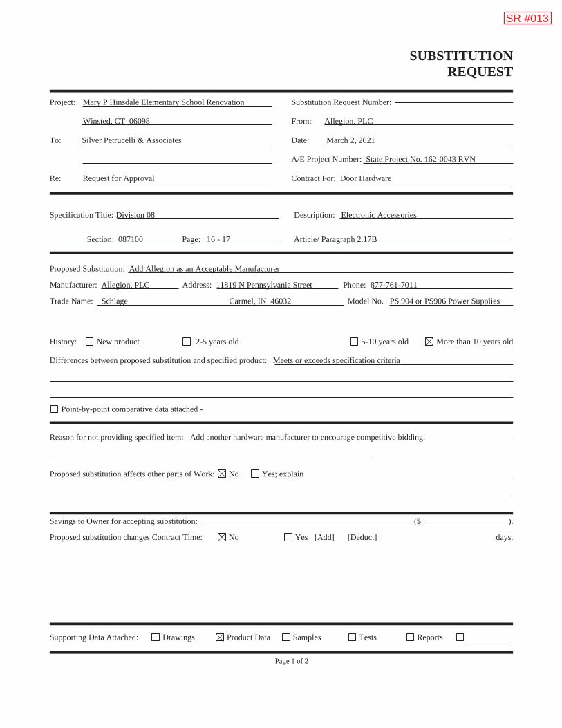
SUBSTITUTION REQUEST
Project: Mary P Hinsdale Elementary School Renovation Winsted, CT 06098 To: Silver Petrucelli & Associates
Re: Request for Approval
Substitution Request Number: From: Allegion, PLC Date: March 2, 2021 A/E Project Number: State Project No. 162-0043 RVN Contract For: Door Hardware
Specification Title: Division 08 Description: Electronic Accessories
Section: 087100 Page: 16 - 17 Article/ Paragraph 2.17B Proposed Substitution: Add Allegion as an Acceptable Manufacturer Manufacturer: Allegion, PLC Address: 11819 N Pennsylvania Street Phone: 877-761-7011 Trade Name: Schlage Carmel, IN 46032 Model No. PS 904 or PS906 Power Supplies History: New product 2-5 years old 5-10 years old More than 10 years old Differences between proposed substitution and specified product: Meets or exceeds specification criteria
Point-by-point comparative data attached - Reason for not providing specified item: Add another hardware manufacturer to encourage competitive bidding. Proposed substitution affects other parts of Work: No Yes; explain Savings to Owner for accepting substitution: ($ ). Proposed substitution changes Contract Time: No Yes [Add] [Deduct] days.
Supporting Data Attached: Drawings Product Data Samples Tests Reports Page 1 of 2
SR #013

SUBSTITUTION REQUEST
(Continued)
The Undersigned certifies: Proposed substitution has been fully investigated and determined to be equal or superior in all respects to specified product. Same warranty will be furnished for proposed substitution as for specified product. Same maintenance service and source of replacement parts, as applicable, is available. Proposed substitution will have no adverse effect on other trades and will not affect or delay progress schedule. Cost data as stated above is complete. Claims for additional costs related to accepted substitution which may subsequently become
apparent are to be waived. Proposed substitution does not affect dimensions and functional clearances. Coordination, installation, and changes in the Work as necessary for accepted substitution will be complete in all respects.
Submitted by: Debby Nelson
Signed by:
Firm: Allegion, Plc
Address: 77 Wexford Street
Needham Heights, MA 02494
Telephone: 781-453-5311
Attachments: PS904 and PS906 Power Supply datasheets
A/E’s REVIEW AND ACTION
Substitution approved - Make submittals in accordance with Specification Section 01330. Substitution approved as noted - Make submittals in accordance with Specification Section 01330. Substitution rejected - Use specified materials. Substitution Request received too late - Use specified materials.
Signed by: Date:
Additional Comments: Contractor Subcontractor Supplier Manufacturer A/E
Page 2 of 2

Overview
The Schlage comprehensive line of power supplies and option boards was designed to
address the changing needs of the access control market.
Installation is simplified by utilizing a flat mounting design and polarized locking
connectors for option boards. This design eliminates the need for racks and side
connectors. The flat mounting of the option boards also provides for easier access to
the terminal blocks for connection of electrified devices (such as electrified strikes,
electromagnetic locks, card readers, etc.).
Common to the line of PS900 Series power supplies is a constant output rating at both
12v and 24v settings, universal 120 VAC to 240 VAC input, and polarized option board
connectors. New fire alarm interface board mounting allows outputs to be configured as
switched (power cut) or unswitched (power continues) when signal is provided.
Features and benefits
4A @ 12/24 VDC constant output, field
selectable with jumper
Provides low-voltage, Class 2, filtered and
regulated power
Universal 120-240 VAC, fused primary input
Two polarized option board connectors
eliminate need for racks and side connectors
AC input and DC output monitoring circuit
with LED indicators
Externally visible AC input indicator with
isolated SPDT contacts
High-voltage protective cover for AC circuitry
(not shown)
Battery back-up board auto-selects voltage
Optional Fire Alarm plug-in board available
UL 294, ULC-S318, RoHS, and FCC Part 15
certified
Photo as shown includes optional board(s). Please
contact your local sales office or visit the support
section on our website for configuration assistance.
Photo as shown includes optional board(s). Please
contact your local sales office or visit the support
section on our website for configuration assistance.
PS9044 amp power supply

Allegion, the Allegion logo, Schlage, and the Schlage logo are trademarks of Allegion plc, its subsidiaries and/or affiliates in the
United States and other countries. All other trademarks are the property of their respective owners.
PS904 power supply specificationsSpecification Description
Input voltage 120/240 VAC, 50/60 Hz, universal input
Output voltage 4A @ 12 or 24 VDC
Field selectable with jumper
Switching supply, 5% regulation, 240mVpp max ripple
Enclosure Grey/baked enamel
14" x 12" x 4" (H x W x D)
Eight 1⁄2" x 3⁄4" knockouts
NEMA Grade 1
Hinged cover with lock down screws
Operating temperature 32° - 120°F (0° - 49°C)
Certifications ANSI/UL 294
ULC-S318
RoHS
FCC Part 15
Class 2
Battery backup(install on main board)
900-BB: Battery backup board only
900-BBK: Battery backup kit (backup board plus battery pack)
Available option boards 900-FA: Plug-in fire alarm (must be installed on option boards)
900-2RS*: 2 Relay option board capable of individual or
sequential operation for single and pair door applications
900-4R*: 4 Relay option board
900-4RL*: 4 Relay option board with integrated logic and
individual or sequential operation capability for controlling
security interlocks, auto operators and time delay function
900-8F*: Fused, 8 zone option board
900-8P*: PTC, 8 zone option board
AC primary fuse size 4A, 250v, 5 x 20mm
Battery fuse size 7.5A 32v ATO blade style
DC output protection Overload protection - current limited foldback circuit
Indicators LED indicators:
- AC input (visible on outside of enclosure)
- DC output
Isolated SPDT contacts to monitor AC power status
Weight (power supply) Approx. 9.0 lbs
Weight (each battery) 4.0 lbs
AC input termination 3 position terminal block with protective cover
Wire capacity: 10 AWG max.
DC output termination 2 position terminal block
Wire capacity: 12 AWG max.
Option board connectors 2
Fire alarm board connector Yes (requires connection on option board)
Keylock Optional
Accessories 900-BAT: Backup battery pack
* Compatible with plug-in fire alarm board (900-FA)
Configuration optionsAvailable option board, fire alarm and
battery backup connection locations:
Exit device support
Von Duprin QEL Up to 41
Von Duprin EL None
Falcon EL None
1. Requires the use of one 900-4RL option board
1 2
BB
K
FA
Battery 2Battery 1
Allegion (NYSE: ALLE) is a global pioneer in safety and security, with leading brands
like CISA®, Interflex®, LCN®, Schlage®, SimonsVoss® and Von Duprin®. Focusing on
security around the door and adjacent areas, Allegion produces a range of solutions
for homes, businesses, schools and other institutions. Allegion is a $2 billion company,
with products sold in almost 130 countries. For more, visit www.allegion.com.
About Allegion
© 2017 Allegion
004194, Rev. 08/17
www.allegion.com/us

Overview
The Schlage comprehensive line of power supplies and option boards was designed to
address the changing needs of the access control market.
Installation is simplified by utilizing a flat mounting design and polarized locking
connectors for option boards. This design eliminates the need for racks and side
connectors. The flat mounting of the option boards also provides for easier access to
the terminal blocks for connection of electrified devices (such as electrified strikes,
electromagnetic locks, card readers, etc.).
Common to the line of PS900 Series power supplies is a constant output rating at both
12v and 24v settings, universal 120 VAC to 240 VAC input, and polarized option board
connectors. New fire alarm interface board mounting allows outputs to be configured as
switched (power cut) or unswitched (power continues) when signal is provided.
Features and benefits
6A @ 12/24 VDC constant output, field
selectable with jumper
Provides low-voltage, Class 1, filtered and
regulated power (Class 2 when used with
900-8P option board)
Universal 120-240 VAC, fused primary input
Three polarized option board connectors
eliminate need for racks and side connectors
AC input and DC output monitoring circuit
with LED indicators
Externally visible AC input indicator with
isolated SPDT contacts
High-voltage protective cover for AC circuitry
(not shown)
Battery back-up board auto-selects voltage
Optional Fire Alarm plug-in board available
UL 294, ULC-S318, RoHS, and FCC Part 15
certified
Photo as shown includes optional board(s). Please
contact your local sales office or visit the support
section on our website for configuration assistance.
Photo as shown includes optional board(s). Please
contact your local sales office or visit the support
section on our website for configuration assistance.
PS9066 amp power supply
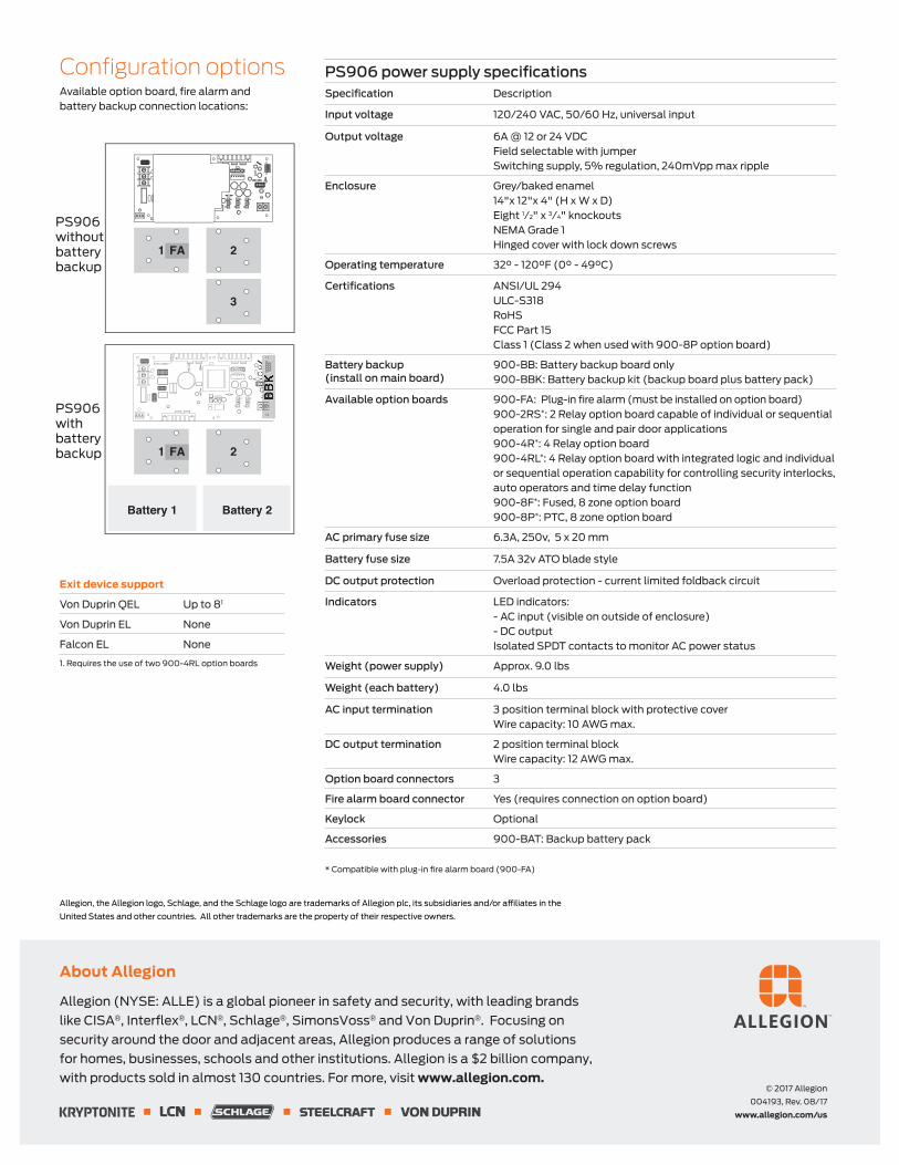
Allegion, the Allegion logo, Schlage, and the Schlage logo are trademarks of Allegion plc, its subsidiaries and/or affiliates in the
United States and other countries. All other trademarks are the property of their respective owners.
Configuration optionsAvailable option board, fire alarm and
battery backup connection locations:
PS906 power supply specificationsSpecification Description
Input voltage 120/240 VAC, 50/60 Hz, universal input
Output voltage 6A @ 12 or 24 VDC
Field selectable with jumper
Switching supply, 5% regulation, 240mVpp max ripple
Enclosure Grey/baked enamel
14"x 12"x 4" (H x W x D)
Eight 1⁄2" x 3⁄4" knockouts
NEMA Grade 1
Hinged cover with lock down screws
Operating temperature 32° - 120°F (0° - 49°C)
Certifications ANSI/UL 294
ULC-S318
RoHS
FCC Part 15
Class 1 (Class 2 when used with 900-8P option board)
Battery backup(install on main board)
900-BB: Battery backup board only
900-BBK: Battery backup kit (backup board plus battery pack)
Available option boards 900-FA: Plug-in fire alarm (must be installed on option board)
900-2RS*: 2 Relay option board capable of individual or sequential
operation for single and pair door applications
900-4R*: 4 Relay option board
900-4RL*: 4 Relay option board with integrated logic and individual
or sequential operation capability for controlling security interlocks,
auto operators and time delay function
900-8F*: Fused, 8 zone option board
900-8P*: PTC, 8 zone option board
AC primary fuse size 6.3A, 250v, 5 x 20 mm
Battery fuse size 7.5A 32v ATO blade style
DC output protection Overload protection - current limited foldback circuit
Indicators LED indicators:
- AC input (visible on outside of enclosure)
- DC output
Isolated SPDT contacts to monitor AC power status
Weight (power supply) Approx. 9.0 lbs
Weight (each battery) 4.0 lbs
AC input termination 3 position terminal block with protective cover
Wire capacity: 10 AWG max.
DC output termination 2 position terminal block
Wire capacity: 12 AWG max.
Option board connectors 3
Fire alarm board connector Yes (requires connection on option board)
Keylock Optional
Accessories 900-BAT: Backup battery pack
* Compatible with plug-in fire alarm board (900-FA)
Allegion (NYSE: ALLE) is a global pioneer in safety and security, with leading brands
like CISA®, Interflex®, LCN®, Schlage®, SimonsVoss® and Von Duprin®. Focusing on
security around the door and adjacent areas, Allegion produces a range of solutions
for homes, businesses, schools and other institutions. Allegion is a $2 billion company,
with products sold in almost 130 countries. For more, visit www.allegion.com.
About Allegion
© 2017 Allegion
004193, Rev. 08/17
www.allegion.com/us
Exit device support
Von Duprin QEL Up to 81
Von Duprin EL None
Falcon EL None
1. Requires the use of two 900-4RL option boards
PS906
without
battery
backup
2
3
1
PS906
with
battery
backup 2
Battery 2
1
Battery 1
FA
BB
K
FA

BID FORM
State Project No. 162-0043 RVN Mary P. Hinsdale Elementary School Renovate as New – Winsted Bid Form-1
(To be submitted in duplicate)
BIDDER: __________________________________________ Name __________________________________________ Address
To: Town of Winchester c/o Purchasing Department 338 Main Street Winsted, CT 06098
Project: Mary P. Hinsdale Elementary School Renovate as New 15 Hinsdale Avenue Winsted, CT 06098 State Project #162-0043 RNV
In preparing this bid, we have carefully examined the Bidding Documents for this Project. We have visited the site and noted the conditions affecting the Work.
The Bidding Documents referred to include Drawings and Project Manual dated September 1, 2020, prepared by Silver/Petrucelli + Associates, Inc., Hamden, Connecticut.
We propose to perform the work described in the Bidding Documents, in keeping with definitions of Article 1 of the Instructions to Bidders, for the Base Bid Sum as follows:
Base Bid:
Entire Project for the Total Cost of:
$ Dollars ($ .00). written figure
We will commence work on the project _______ calendar days after receipt of "Notice to Proceed" or signing of Contract, whichever is sooner. We will be able to substantially complete the project within ________ calendar days thereafter. (See Invitation to Bid and SIB 1.1.B).
Allowances: (See Section 012100)
Allowance No. 1: Metal Roof Deck Replacement (part of Base Bid) $ __________ Allowance No. 2: Wood Roof Deck Replacement (part of Base Bid) $ __________ Allowance No. 3: Brick Replacement and Mortar Repointing (part of Base Bid) $ __________
Alternates:
The undersigned proposes to furnish all Labor, Materials, Equipment and Services necessary to construct the items listed in the Alternates described in Section 012300 for the stipulated sum of:

BID FORM
State Project No. 162-0043 RVN Mary P. Hinsdale Elementary School Renovate as New – Winsted Bid Form-2
ADD ALTERNATE NO. 1: Gilbert Home Brook Path (Watercourse) Restoration: Add to the Base Bid a Total of:
$ Dollars ($ .00). written figure
The project schedule will be (increased/decreased) by _____ calendar days to complete the work indicated under Add Alternate 1.
ADD ALTERNATE NO. 2: West Parking Area: Add to the Base Bid a Total of:
$ Dollars ($ .00). written figure
The project schedule will be (increased/decreased) by _____ calendar days to complete the work indicated under Add Alternate 2.
ADD ALTERNATE NO. 3: Existing Window Replacement: Add to the Base Bid a Total of:
$ Dollars ($ .00). written figure
The project schedule will be (increased/decreased) by _____ calendar days to complete the work indicated under Add Alternate 3.
ADD ALTERNATE NO. 4: Retractable Stage: Add to the Base Bid a Total of:
$ Dollars ($ .00). written figure
The project schedule will be (increased/decreased) by _____ calendar days to complete the work indicated under Add Alternate 4.
ADD ALTERNATE NO. 5: Skylights: Add to the Base Bid a Total of:
$ Dollars ($ .00). written figure
The project schedule will be (increased/decreased) by _____ calendar days to complete the work indicated under Add Alternate 5.
ADD ALTERNATE NO. 6: Brick & Precast Cleaning: Add to the Base Bid a Total of:
$ Dollars ($ .00). written figure
The project schedule will be (increased/decreased) by _____ calendar days to complete the work indicated under Add Alternate 6.

BID FORM
State Project No. 162-0043 RVN Mary P. Hinsdale Elementary School Renovate as New – Winsted Bid Form-3
ADD ALTERNATE NO. 7: Main Entry Canopy & Sign: Add to the Base Bid a Total of:
$ Dollars ($ .00). written figure
The project schedule will be (increased/decreased) by _____ calendar days to complete the work indicated under Add Alternate 7.
ADD ALTERNATE NO. 8: Casework: Add to the Base Bid a Total of:
$ Dollars ($ .00). written figure
The project schedule will be (increased/decreased) by _____ calendar days to complete the work indicated under Add Alternate 8.
ADD ALTERNATE NO. 9: Electric Car Charging Station: Add to the Base Bid a Total of:
$ Dollars ($ .00). written figure
The project schedule will be (increased/decreased) by _____ calendar days to complete the work indicated under Add Alternate 9.
Unit Prices:
As required by the Base Bid, should deteriorated or damaged materials be required to be removed as determined by the Architect or Owner, the cost to remove and replace the referenced material, (or credit for specified material not provided or installed) including all labor, material, equipment and related furnishings is as follows:
Item Description Unit Price
1.
Small containment preparation containment (less than 160 square/260 linear feet of asbestos-containing material) Pricing for containments with larger amounts of materials are to be INCLUDED in the unit prices themselves listed below. There is no separate unit price for containments with larger amounts
$ containment
2. Cove base and adhesives (multiple layers, including contaminated substrates), removal and disposal as ACM $ lf
3.
Floor tile/flooring materials and mastics (includes all layers of carpeting, adhesives, multiple layers of floor tiles/flooring materials/linoleum/sheet flooring/vinyl flooring/wood/mastics, levelastics, contaminated flooring materials, etc.), removal and disposal as ACM
$ sf
4.
Gymnasium flooring materials, mastics, dampproofing, tars (includes all layers of materials, wood, cork, other contaminated flooring materials and substrates, etc.), removal and disposal as ACM
$ sf
5. Mudded pipe fitting insulation, removal and disposal as ACM $ fitting/joint 6. Glove bag, removal and disposal as ACM $ bag

BID FORM
State Project No. 162-0043 RVN Mary P. Hinsdale Elementary School Renovate as New – Winsted Bid Form-4
Item Description Unit Price
7. Pipe and pipe fitting insulation, removal and disposal as ACM $ lf
8. Thermal system insulation/pipe and pipe fitting insulation debris and contaminated soil, removal and disposal as ACM
$ sf (includes 3 inches deep)
9. Thermal system insulation/pipe fitting insulation debris removal, cleaning concrete tunnel flooring and disposal as ACM
$ sf (includes 3 inches deep)
10. Duct insulation, removal and disposal as ACM $ sf
11. Duct adhesives (including contaminated substrates), removal and disposal as ACM $ sf
12. Duct seam sealants (including contaminated substrates), removal and disposal as ACM $ lf
13. Duct vibration isolation cloth, removal and disposal as ACM $ cloth
14. Boiler/Incinerator (including all exterior and interior materials), removal and disposal as ACM $ boiler
15. Freezers/Dampproofing/Contaminated Cork/Contaminated Substrates/Other material, removal and disposal as ACM $ freezer
16. Light backing paper insulation, removal and disposal as ACM $ light fixture 17. Electrical insulation, removal and disposal as ACM $ lf 18. Sink undercoating, removal and disposal as ACM $ sink 19. Fire door/insulation, removal and disposal as ACM $ door 20. Water fountain/dampproofing, removal and disposal as ACM $ fountain 21. Custodial slop sink/dampproofing, removal and disposal as ACM $ slop sink
22. Countertop/Adhesive/Caulking compounds, removal and disposal as ACM $ sf
23. Transite cement board, removal and disposal as ACM $ sf
24. Wall adhesives including contaminated substrates (mirrors/blackboards/bulletin boards/wood/wall tiles, etc.), removal and disposal as ACM
$ sf
25. Vermiculite and associated wall/ceiling materials, removal and disposal as ACM $ sf
26. Ceramic tile and terrazzo wall/floor, adhesives, mudset, grout, dampproofing and contaminated substrates, removal and disposal as ACM
$ sf
27. Wall/Ceiling plaster (multiple layers) and supporting systems and contaminated substrates, removal and disposal as ACM $ sf
28. Wall/Ceiling board/sheetrock/taping/joint compounds (multiple layers), removal and disposal as ACM $ sf
29. Wall, ceiling tile and glue daubs and contaminated substrates, removal and disposal as ACM $ sf
30.
Dampproofing/tars/mastics – interior/exterior walls/floors/slab/foundation and associated substrate/adjacent materials (includes multiple layers, contaminated materials and substrates), removal and disposal as ACM
$ sf

BID FORM
State Project No. 162-0043 RVN Mary P. Hinsdale Elementary School Renovate as New – Winsted Bid Form-5
Item Description Unit Price
31. Caulking, glazing and sealant compounds (includes substrate and contaminated materials), removal and disposal as ACM $ lf
$ window opening (multiple windows/sizes exist in openings)
$ door opening (multiple doors/sizes exist in openings)
32. Caulking, glazing and sealant compounds, removal and disposal as ACM and PCB <50ppm (CT DEEP Regulated PCB Waste) $ lf
$ window opening (multiple windows/sizes exist in openings)
$ door opening (multiple doors/sizes exist in openings)
33. Caulking, glazing and sealant compounds, removal and disposal as ACM and PCB >50ppm (PCB Bulk Product Waste) $ lf
$ window opening (multiple windows/sizes exist in openings)
$ door opening (multiple doors/sizes exist in openings)
34. Caulking, glazing and sealant compounds, removal and disposal as ACM and PCB Remediation Waste $ lf
$ window opening (multiple windows/sizes exist in openings)
$ door opening (multiple doors/sizes exist in openings)
35. Roofing core/field base material (includes multiple layers and substrates), removal and disposal as ACM $ sf
36. Roof flashing (includes multiple layers and substrates), removal and disposal as ACM $ sf
37. Roofing debris (includes contaminated ceiling substrates), removal and disposal as ACM $ sf
38. Off-site transportation and disposal of natural soil ‘Natural’ soils have no detectable concentrations of non-naturally occurring compounds $ ton
39.
Off-site transportation and disposal of polluted soil ‘Polluted’ soils contain concentrations of non-naturally occurring compounds detected above laboratory reporting limits, but below the CT DEEP RSR criteria in accordance with RCSA 22a-133k-1(a)(45). Polluted soils can be reused on-site with the preparation of a Materials Management Plan and approval from the Engineer.
$ ton
40.
Off-site transportation and disposal of contaminated soil ‘Contaminated’ materials contain concentrations of compounds that exceed CT DEEP RSR criteria in accordance with RCSA 22a-133k. Contaminated materials (concrete, soil, sediment, groundwater or surface water) can NOT be reused on-site and must be disposed of at an off-site disposal facility.
$ ton

BID FORM
State Project No. 162-0043 RVN Mary P. Hinsdale Elementary School Renovate as New – Winsted Bid Form-6
Item Description Unit Price
41.
Off-site transportation and disposal of hazardous waste/soils ‘Hazardous Waste/Soils’ include all soil/fill material that exceeds regulatory limits for hazardous substances as defined in 40 CFR, Part 261.20 Subpart C – Characteristics of Hazardous Waste. This material can NOT be reused on-site and must be disposed of at an off-site approved disposal facility.
$ ton
42. Off-site transportation and disposal of hazardous lead-based paint demolition debris $ 40-yd dumpster
$ 100-yd dumpster
43. Metal roof deck, thickness to match existing roof deck to be removed (including deteriorated roof deck removal, credit and add) $ sf
44. Wood roof deck, thickness to match existing roof deck to be removed (including deteriorated roof deck removal, credit and add) $ sf
45. Pressure treated wood blocking, as specified, cut to fit around roof structure and systems installed $ bf (add)
$ bf (deduct)
46. Mass rock excavation, on-site management, removal and disposal off site $ cy
47. Unsuitable soils, over-excavation, on-site management, removal and disposal off site $ cy
48. Excess soil, removal and disposal off site $ cy
49. Brick and mortar, to match existing, removal, disposal, and replacement $ sf
50. Mortar repointing, removal, cleaning, to match existing $ lf
If written notice of the acceptance of this Bid is mailed, telegraphed or delivered to the undersigned at the Address designated below, within ninety (90) days after the date of Bid Opening, or any time thereafter before this Bid is withdrawn, the undersigned will, within ten (10) days after the date of mailing, telegraphing or delivering of the notice, execute and deliver a contract in the Standard Form of Agreement Between the Owner and Contractor, AIA Document A101, or similar contract modified as may be mutually agree upon.
The undersigned acknowledges that he has examined the documents, visited and examined the site as required under "Instructions to Bidders", examined the availability of labor and materials and further agrees to comply with all the requirements as to the conditions of employment and wage rates set forth by the Department of Labor.
Addenda:
The undersigned acknowledges receipt of the following addenda to the Contract Documents, listed by number and date:
Number , Dated: Number , Dated: Number , Dated: Number , Dated:
Exceptions:

BID FORM
State Project No. 162-0043 RVN Mary P. Hinsdale Elementary School Renovate as New – Winsted Bid Form-7
ATTACHMENTS – Attached (by Contractor) hereto is:
1. Bid Bond 2. Contractor Prequalification Statement 3. Update Bid Statement 4. CHRO Bidder Contract Compliance Monitoring Report
NON-COLLUSIVE BID STATEMENT
The undersigned bidder certifies that this bid is made independently and without collusion, agreement, understanding or planned course of action with any other bidder and that the contents of the bid shall not be disclosed to anyone other than employees, agents or sureties prior to the official bid opening.
Signature: Date:
Printed Name and Title of Agent submitting bid:
Name of Company:
Address:
Telephone Number: Fax Number:
E-mail:
This Bid may be withdrawn prior to the scheduled Bid Opening or any postponement thereof.

MAINTENANCE OF UNIT MASONRY
State Project No. 162-0043 RVN Mary P. Hinsdale Elementary School Renovate as New – Winsted 040120.64-1
SECTION 040120.64 - MAINTENANCE OF UNIT MASONRY
PART 1 - GENERAL
1.1 RELATED DOCUMENTS
A. Drawings and general provisions of the Contract, including General and Supplementary Conditions and Division 01 Specification Sections, apply to this Section.
1.2 SUMMARY
A. Section Includes:
1. Repairing unit masonry, including replacing units. 2. Repointing joints with mortar.
B. Related Section:
1. Section 012100 “Allowances”.
1.3 PREINSTALLATION MEETINGS
A. Preinstallation Conference: Conduct conference at Project site.
1. Review methods and procedures related to repointing brick masonry including, but not limited to, the following:
a. Materials, material application, sequencing, tolerances, and required clearances. b. Coordination with building occupants.
1.4 SEQUENCING AND SCHEDULING
A. Work Sequence: Perform brick masonry repointing work in the following sequence, which includes work specified in this and other Sections:
1. Remove plant growth. 2. Inspect masonry for open mortar joints and permanently or temporarily point them before
cleaning to prevent the intrusion of water and other cleaning materials into the wall. 3. Clean masonry. 4. Rake out mortar from joints surrounding masonry to be replaced and from joints adjacent
to masonry repairs along joints. 5. Repair masonry, including replacing existing masonry with new masonry materials. 6. Rake out mortar from joints to be repointed. 7. Point mortar and sealant joints. 8. After repointing has been completed and cured, perform a final cleaning to remove
residues from this work.
1.5 ACTION SUBMITTALS
A. Product Data: For each type of product.
MAINTENANCE OF UNIT MASONRY
State Project No. 162-0043 RVN Mary P. Hinsdale Elementary School Renovate as New – Winsted 040120.64-2
1. Include construction details, material descriptions, dimensions of individual components and profiles, and finishes.
2. Include recommendations for product application and use. Include test data substantiating that products comply with requirements.
B. Samples: For the following:
1. Pointing Mortar: Submit sets of mortar for pointing in the form of sample mortar strips, 6 inches long by ¼-inch-wide, set in aluminum or plastic channels.
a. Have each set contain a close color range of at least three (3) Samples of different mixes of colored sands and cements that produce a mortar matching existing, cleaned mortar when cured and dry.
b. Submit with precise measurements on ingredients, proportions, gradations, and source of colored sands from which each Sample was made.
2. Sand Type Used for Pointing Mortar: Minimum 8 oz. of each in plastic screw-top jars.
1.6 DELIVERY, STORAGE, AND HANDLING
A. Deliver packaged materials to Project site in manufacturer's original and unopened containers, labeled with manufacturer's name and type of products.
B. Store cementitious materials on elevated platforms, under cover, and in a dry location. Do not use cementitious materials that have become damp.
C. Store hydrated lime in manufacturer's original and unopened containers. Discard lime if containers have been damaged or have been opened for more than two (2) days.
D. Store sand where grading and other required characteristics can be maintained and contamination avoided.
1.7 FIELD CONDITIONS
A. Weather Limitations: Proceed with installation only when existing and forecasted weather conditions permit repointing work to be performed according to product manufacturers' written instructions and specified requirements.
B. Temperature Limits, General: Repoint mortar joints only when air temperature is between 40 and 90 deg F (4 and 32 deg C) and is predicted to remain so for at least seven (7) days after completion of the Work unless otherwise indicated.
PART 2 - PRODUCTS
2.1 MATERIALS, GENERAL
A. Source Limitations: Obtain each type of material for repointing brick masonry (cement, sand, etc.) from single source with resources to provide materials of consistent quality in appearance and physical properties.
MAINTENANCE OF UNIT MASONRY
State Project No. 162-0043 RVN Mary P. Hinsdale Elementary School Renovate as New – Winsted 040120.64-3
2.2 MASONRY MATERIALS
A. Comply with requirements in Section 042000 “Unit Masonry”.
2.3 MORTAR MATERIALS
A. Comply with requirements in Section 042000 “Unit Masonry”.
2.4 ACCESSORY MATERIALS
A. Masking Tape: Non-staining, nonabsorbent material; compatible with mortar, joint primers, sealants, and surfaces adjacent to joints; and that easily comes off entirely, including adhesive.
B. Other Products: Select materials and methods of use based on the following:
1. Previous effectiveness in performing the work involved. 2. Minimal possibility of damaging exposed surfaces. 3. Consistency of each application. 4. Uniformity of the resulting overall appearance. 5. Do not use products or tools that could leave residue on surfaces.
2.5 MORTAR MIXES
A. Measurement and Mixing: Measure cementitious materials and sand in a dry condition by volume or equivalent weight. Do not measure by shovel; use known measure. Mix materials in a clean, mechanical batch mixer.
1. Mixing Pointing Mortar: Thoroughly mix cementitious materials and sand together before adding any water. Then mix again, adding only enough water to produce a damp, unworkable mix that retains its form when pressed into a ball. Maintain mortar in this dampened condition for 15 to 30 minutes. Add remaining water in small portions until mortar reaches desired consistency. Use mortar within 1 hour of final mixing; do not retemper or use partially hardened material.
B. Colored Mortar: Produce mortar of color required by using specified ingredients. Do not alter specified proportions without Architect's approval.
1. Mortar Pigments: Where mortar pigments are indicated, do not add pigment exceeding ten percent (10%) by weight of the cementitious or binder materials, except for carbon black which is limited to two percent (2%), unless otherwise demonstrated by a satisfactory history of performance.
C. Do not use admixtures in mortar unless otherwise indicated.
D. Mixes: Mix mortar materials in the following proportions:
1. Pointing Mortar by Property: ASTM C 270, Property Specification, Type N unless otherwise indicated; with cementitious material limited to Portland cement and lime. Add mortar pigments to produce mortar colors required.

MAINTENANCE OF UNIT MASONRY
State Project No. 162-0043 RVN Mary P. Hinsdale Elementary School Renovate as New – Winsted 040120.64-4
PART 3 - EXECUTION
3.1 PROTECTION
A. Prevent mortar from staining face of surrounding masonry and other surfaces.
1. Cover sills, ledges, and other projecting items to protect them from mortar droppings. 2. Keep wall area wet below pointing work to discourage mortar from adhering. 3. Immediately remove mortar splatters in contact with exposed masonry and other surfaces.
3.2 BRICK REMOVAL AND REPLACEMENT
A. At locations indicated, remove bricks that are damaged, spalled, or deteriorated. Carefully demolish or remove entire units from joint to joint, without damaging surrounding masonry, in a manner that permits replacement with full-size units.
1. When removing single bricks, remove material from center of brick and work toward outside edges.
B. Support and protect remaining masonry that surrounds removal area. Maintain flashing, reinforcement, lintels, and adjoining construction in an undamaged condition.
C. Notify Architect of unforeseen detrimental conditions including voids, cracks, bulges, and loose units in existing masonry backup, rotted wood, rusted metal, and other deteriorated items.
D. Remove in an undamaged condition as many whole bricks as possible.
1. Remove mortar, loose particles, and soil from brick by cleaning with hand chisels, brushes, and water.
2. Remove sealants by cutting close to brick with utility knife and cleaning with solvents. 3. Store brick for reuse. Store off ground, on skids, and protected from weather. 4. Deliver cleaned brick not required for reuse to Owner unless otherwise indicated.
E. Clean bricks surrounding removal areas by removing mortar, dust, and loose particles in preparation for replacement.
F. Replace removed damaged brick with other removed brick in good quality, where possible, or with new brick matching existing brick, including size. Do not use broken units unless they can be cut to usable size.
G. Install replacement brick into bonding and coursing pattern of existing brick. If cutting is required, use a motor-driven saw designed to cut masonry with clean, sharp, unchipped edges.
1. Maintain joint width for replacement units to match existing joints. 2. Use setting buttons or shims to set units accurately spaced with uniform joints.
H. Lay replacement brick with completely filled bed, head, and collar joints. Butter ends with sufficient mortar to fill head joints and shove into place. Wet both replacement and surrounding bricks that have ASTM C 67 initial rates of absorption (suction) of more than 30 g/30 sq. in. per min. Use wetting methods that ensure that units are nearly saturated but surface is dry when laid.

MAINTENANCE OF UNIT MASONRY
State Project No. 162-0043 RVN Mary P. Hinsdale Elementary School Renovate as New – Winsted 040120.64-5
1. Tool exposed mortar joints in repaired areas to match joints of surrounding existing brickwork.
2. When mortar is sufficiently hard to support units, remove shims and other devices interfering with pointing of joints.
3.3 MASONRY REPOINTING, GENERAL
A. Appearance Standard: Repointed surfaces are to have a uniform appearance as viewed from 20 feet away by Architect.
3.4 REPOINTING MASONRY
A. Rake out and repoint joints to the following extent:
1. All joints in areas indicated.
B. Do not rake out and repoint joints where not required.
C. Rake out joints as follows:
1. Remove mortar from joints to depth of joint width plus 1/8-inch, but not less than ½-inch or not less than that required to expose sound, unweathered mortar. Do not remove unsound mortar more than 2 inches deep; consult Architect for direction.
2. Remove mortar from masonry surfaces within raked-out joints to provide reveals with square backs and to expose masonry for contact with pointing mortar. Brush, vacuum, or flush joints to remove dirt and loose debris.
3. Do not spall edges of masonry units or widen joints. Replace or patch damaged masonry units as directed by Architect.
a. Cut out mortar by hand with chisel and resilient mallet. Do not use power-operated grinders without Architect's written approval.
D. Notify Architect of unforeseen detrimental conditions including voids in mortar joints, cracks, loose masonry units, rotted wood, rusted metal, and other deteriorated items.
E. Pointing with Mortar:
1. Rinse joint surfaces with water to remove dust and mortar particles. Time rinsing application so, at time of pointing, joint surfaces are damp but free of standing water. If rinse water dries, dampen joint surfaces before pointing.
2. Apply pointing mortar first to areas where existing mortar was removed to depths greater than surrounding areas. Apply in layers not greater than 3/8-inch until a uniform depth is formed. Fully compact each layer and allow it to become thumbprint hard before applying next layer.
3. After deep areas have been filled to same depth as remaining joints, point joints by placing mortar in layers not greater than 3/8-inch. Fully compact each layer and allow to become thumbprint hard before applying next layer. Where existing masonry units have worn or rounded edges, slightly recess finished mortar surface below face of masonry to avoid widened joint faces. Take care not to spread mortar beyond joint edges onto exposed masonry surfaces or to featheredge the mortar.

MAINTENANCE OF UNIT MASONRY
State Project No. 162-0043 RVN Mary P. Hinsdale Elementary School Renovate as New – Winsted 040120.64-6
4. When mortar is thumbprint hard, tool joints to match original appearance of joints. Remove excess mortar from edge of joint by brushing.
5. Cure mortar by maintaining in thoroughly damp condition for at least 72 consecutive hours, including weekends and holidays.
6. Hairline cracking within mortar or mortar separation at edge of a joint is unacceptable. Completely remove such mortar and repoint.
3.5 FINAL CLEANING
A. Clean adjacent non-masonry surfaces. Use detergent and soft brushes or cloths.
B. Clean mortar and debris from roof; remove debris from gutters and downspouts. Rinse off roof and flush gutters and downspouts.
C. Remove masking materials, leaving no residues that could trap dirt.
END OF SECTION 040120.64

GENERAL-DUTY VALVES FOR HVAC PIPING
State Project No. 162-0043 RVN Mary P. Hinsdale Elementary School Renovate as New-Winsted 230523-1
SECTION 230523 - GENERAL-DUTY VALVES FOR HVAC PIPING
PART 1 - GENERAL
1.1 RELATED DOCUMENTS
A. Drawings and general provisions of the Contract, including General and Supplementary Conditions and Division 01 Specification Sections, apply to this Section.
B. Section Includes:
1. Bronze angle valves. 2. Bronze ball valves. 3. Iron ball valves. 4. Iron, single-flange butterfly valves. 5. Iron, grooved-end butterfly valves. 6. Bronze swing check valves. 7. Iron swing check valves. 8. Iron, grooved-end swing check valves. 9. Iron, center-guided check valves. 10. Bronze gate valves. 11. Iron Gate valves 12. Bronze globe valves. Iron globe valves. 13. Iron Globe 14. Chainwheels.
C. Related Sections:
1. Section 230553 "Identification for HVAC Piping and Equipment" for valve tags.
1.2 DEFINITIONS
A. CWP: Cold working pressure.
B. EPDM: Ethylene propylene copolymer rubber.
C. NBR: Acrylonitrile-butadiene, Buna-N, or nitrile rubber.
D. NRS: Nonrising stem.
E. OS&Y: Outside screw and yoke.
F. RS: Rising stem.
G. SWP: Steam working pressure.
1.3 ACTION SUBMITTALS
A. Product Data: For each type of valve indicated.

GENERAL-DUTY VALVES FOR HVAC PIPING
State Project No. 162-0043 RVN Mary P. Hinsdale Elementary School Renovate as New-Winsted 230523-2
1.4 QUALITY ASSURANCE
A. Source Limitations for Valves: Obtain each type of valve from single source from single manufacturer.
B. ASME Compliance:
1. ASME B16.10 and ASME B16.34 for ferrous valve dimensions and design criteria. 2. ASME B31.1 for power piping valves. 3. ASME B31.9 for building services piping valves.
C. To assure uniformity and compatibility, all grooved end valves and adjoining couplings shall be the products of a single manufacturer.
1.5 DELIVERY, STORAGE, AND HANDLING
A. Prepare valves for shipping as follows:
1. Protect internal parts against rust and corrosion. 2. Protect threads, flange faces, grooves, and weld ends. 3. Set angle, gate, and globe valves closed to prevent rattling. 4. Set ball and plug valves open to minimize exposure of functional surfaces. 5. Set butterfly valves closed or slightly open. 6. Block check valves in either closed or open position.
B. Use the following precautions during storage:
1. Maintain valve end protection. 2. Store valves indoors and maintain at higher than ambient dew point temperature. If
outdoor storage is necessary, store valves off the ground in watertight enclosures.
C. Use sling to handle large valves; rig sling to avoid damage to exposed parts. Do not use handwheels or stems as lifting or rigging points.
PART 2 - PRODUCTS
2.1 GENERAL REQUIREMENTS FOR VALVES
A. Refer to HVAC valve schedule articles for applications of valves.
B. Valve Pressure and Temperature Ratings: Not less than indicated and as required for system pressures and temperatures.
C. Valve Sizes: Same as upstream piping unless otherwise indicated.
D. Valve Actuator Types:
1. Gear Actuator: For For quarter-turn valves NPS 8 (DN 200) and larger 2. Handwheel: For valves other than quarter-turn types. 3. Handlever: For quarter-turn valves NPS 6 (DN 150) and smaller except plug valves.

GENERAL-DUTY VALVES FOR HVAC PIPING
State Project No. 162-0043 RVN Mary P. Hinsdale Elementary School Renovate as New-Winsted 230523-3
4. Chainwheel: Device for attachment to valve handwheel, stem, or other actuator; of size and with chain for mounting height, as indicated in the "Valve Installation" Article.
E. Valves in Insulated Piping: With 2-inch stem extensions and the following features:
1. Gate Valves: With rising stem. 2. Ball Valves: With extended operating handle of non-thermal-conductive material, and
protective sleeve that allows operation of valve without breaking the vapor seal or disturbing insulation.
3. Butterfly Valves: With extended neck.
F. Valve-End Connections:
1. Flanged: With flanges according to ASME B16.1 for iron valves. 2. Threaded: With threads according to ASME B1.20.1.
G. Valve Bypass and Drain Connections: MSS SP-45.
2.2 BRONZE ANGLE VALVES
A. Class 150, Bronze Angle Valves with Bronze Disc:
1. Manufacturers: Subject to compliance with requirements, provide product by one (1) of the following:
a. Crane Co.; Crane Valve Group; Stockham Division b. Kitz Corporation c. Milwaukee Valve Company
2. Description:
a. Standard: MSS SP-80, Type 1. b. CWP Rating: 300 psig. c. Body Material: ASTM B 62, bronze with integral seat and union-ring bonnet. d. Ends: Threaded. e. Stem and Disc: Bronze. f. Packing: Asbestos free. g. Handwheel: Malleable iron.
2.3 BRONZE BALL VALVES
A. Two-Piece, Full-Port, Bronze Ball Valves with Bronze Trim:
1. Manufacturers: Subject to compliance with requirements, provide products by one (1) of the following:
a. American Valve, Inc. b. Conbraco Industries, Inc.; Apollo Valves c. Crane Co.; Crane Valve Group; Crane Valves d. Hammond Valve e. Milwaukee Valve Company

GENERAL-DUTY VALVES FOR HVAC PIPING
State Project No. 162-0043 RVN Mary P. Hinsdale Elementary School Renovate as New-Winsted 230523-4
2. Description:
a. Standard: MSS SP-110. b. SWP Rating: 150 psig. c. CWP Rating: 600 psig. d. Body Design: Two-piece. e. Body Material: Bronze. f. Ends: Threaded. g. Seats: PTFE or TFE. h. Stem: Bronze. i. Ball: Chrome-plated brass. j. Port: Full.
2.4 IRON BALL VALVES
A. Class 150, Iron Ball Valves:
1. Manufacturers: Subject to compliance with requirements, provide products by one (1) of the following:
a. American Valve, Inc. b. Conbraco Industries, Inc.; Apollo Valves c. Kitz Corporation d. Sure Flow Equipment Inc. e. Watts Regulator Co.; a division of Watts Water Technologies, Inc.
2. Description:
a. Standard: MSS SP-72. b. CWP Rating: 285 psig. c. Body Design: Split body. d. Body Material: ASTM A 126, gray iron. e. Ends: Flanged. f. Seats: TFE. g. Stem: Stainless-steel. Blowout-proof. h. Ball: Stainless-steel. i. Port: Full. j. Flanged ends.
2.5 IRON, SINGLE-FLANGE BUTTERFLY VALVES
A. 200 CWP, Iron, Single-Flange Butterfly Valves with EPDM Seat and Stainless-Steel Disc:
1. Manufacturers: Subject to compliance with requirements, provide products by one (1) of the following:
a. American Valve, Inc. b. Conbraco Industries, Inc.; Apollo Valves c. Hammond Valve d. Kitz Corporation e. Milwaukee Valve Company

GENERAL-DUTY VALVES FOR HVAC PIPING
State Project No. 162-0043 RVN Mary P. Hinsdale Elementary School Renovate as New-Winsted 230523-5
f. Watts Regulator Co.; a division of Watts Water Technologies, Inc.
2. Description:
a. Standard: MSS SP-67, Type I. b. CWP Rating: 200 psig. c. Body Design: Lug type; suitable for bidirectional dead-end service at rated
pressure without use of downstream flange. d. Body Material: ASTM A 126, cast iron or ASTM A 536, ductile iron. e. Seat: EPDM. f. Stem: One- or two-piece stainless-steel. g. Disc: Stainless-steel.
2.6 IRON, GROOVED-END BUTTERFLY VALVES
A. 300 CWP, Iron, Grooved-End Butterfly Valves:
1. Manufacturers: Subject to compliance with requirements, provide products by one (1) of the following:
a. Victaulic; Vic®-300 MasterSeal™ and Vic®-300 AGS b. Substitutions: Under provision of Section 012500 “Substitution Procedures”.
2. Description:
a. Standard: MSS SP-67, Type I. b. NPS 8 and Smaller CWP Rating: 300 psig. c. NPS 10 and Larger CWP Rating: 300 psig. d. Body Material: Coated, ductile iron. e. Stem: Two-piece stainless-steel. f. Disc: Coated, ductile iron, offset. g. Seal: EPDM.
2.7 BRONZE SWING CHECK VALVES
A. Class 150, Bronze Swing Check Valves with Bronze Disc:
1. Manufacturers: Subject to compliance with requirements, provide products by one (1) of the following:
a. American Valve, Inc. b. Crane Co.; Crane Valve Group; Crane Valves c. Milwaukee Valve Company d. Hammond Valve e. Kitz Corporation
2. Description:
a. Standard: MSS SP-80, Type 3. b. CWP Rating: 300 psig. c. Body Design: Horizontal flow.

GENERAL-DUTY VALVES FOR HVAC PIPING
State Project No. 162-0043 RVN Mary P. Hinsdale Elementary School Renovate as New-Winsted 230523-6
d. Body Material: ASTM B 62, bronze. e. Ends: Threaded. f. Disc: Bronze.
2.8 IRON SWING CHECK VALVES
A. Class 250, Iron Swing Check Valves with Metal Seats:
1. Manufacturers: Subject to compliance with requirements, provide products by one (1) of the following:
a. Crane Co.; Crane Valve Group; Crane Valves b. Hammond Valve c. Milwaukee Valve Company
2. Description:
a. Standard: MSS SP-71, Type I. b. NPS 2-1/2 to NPS 12 (DN 65 to DN 300), CWP Rating: 500 psig. c. Body Design: Clear or full waterway. d. Body Material: ASTM A 126, gray iron with bolted bonnet. e. Ends: Flanged. f. Trim: Bronze. g. Gasket: Asbestos free. h. Style: Compact wafer. i. Seat: EPDM.
2.9 IRON, GROOVED-END SWING CHECK VALVES
A. 300 CWP, Iron, Grooved-End Swing Check Valves:
1. Manufacturers: Subject to compliance with requirements, provide products by one (1) of the following:
a. Victaulic; Series 716H, 716, or 779 b. Substitutions: Under provision of Section 012500 “Substitution Procedures”.
2. Description:
a. NPS 2 to NPS 3, CWP Rating: 365 psig. b. NPS 4 to NPS 12, CWP Rating: 300 psig. c. Body Material: ASTM A 536, ductile iron. d. Seal: EPDM. e. Disc: Spring operated, ductile iron or stainless-steel.
B. 230 CWP, Iron, Grooved-End Swing Check Valves:
1. Manufacturers: Subject to compliance with requirements, provide products by one (1) of the following:
a. Victaulic; Series W715
GENERAL-DUTY VALVES FOR HVAC PIPING
State Project No. 162-0043 RVN Mary P. Hinsdale Elementary School Renovate as New-Winsted 230523-7
b. Substitutions: Under provision of Section 012500 “Substitution Procedures”.
2. Description:
a. NPS 14 to NPS 24 CWP Rating: 230 psig. b. Body Material: ASTM A 395, ductile iron. c. Seal: EPDM. d. Disc: Spring operated, stainless-steel.
2.10 IRON, CENTER-GUIDED CHECK VALVES
A. Class 150, Iron, Compact-Wafer, Center-Guided Check Valves with Metal Seat:
1. Manufacturers: Subject to compliance with requirements, provide products by one (1) of the following:
a. APCO Willamette Valve and Primer Corporation b. Crispin Valve c. Val-Matic Valve & Manufacturing Corp.
2. Description:
a. Standard: MSS SP-125. b. NPS 2-1/2 to NPS 12 (DN 65 to DN 300), CWP Rating: 300 psig. c. NPS 14 to NPS 24 (DN 350 to DN 600), CWP Rating: 250 psig. d. Body Material: ASTM A 395 or ASTM A 536, ductile iron. e. Style: Compact wafer. f. Seat: Bronze.
2.11 BRONZE GATE VALVES
A. Class 150, RS Bronze Gate Valves:
1. Manufacturers: Subject to compliance with requirements, provide products by one (1) of the following:
a. Crane Co.; Crane Valve Group; Crane Valves b. Hammond Valve c. Milwaukee Valve Company d. Kitz Corporation
2. Description:
a. Standard: MSS SP-80, Type 2. b. CWP Rating: 300 psig. c. Body Material: ASTM B 62, bronze with integral seat and union-ring bonnet. d. Ends: Threaded. e. Stem: Bronze. f. Disc: Solid wedge; bronze. g. Packing: Asbestos free. h. Handwheel: Malleable iron.

GENERAL-DUTY VALVES FOR HVAC PIPING
State Project No. 162-0043 RVN Mary P. Hinsdale Elementary School Renovate as New-Winsted 230523-8
2.12 IRON GATE VALVES
A. Class 250, OS&Y, Iron Gate Valves:
1. Manufacturers: Subject to compliance with requirements, provide products by one (1) of the following:
a. Crane Co.; Crane Valve Group; Crane Valves b. Milwaukee Valve Company c. NIBCO INC. d. Powell Valves e. Watts Regulator Co.; a division of Watts Water Technologies, Inc.
2. Description:
a. Standard: MSS SP-70, Type I. b. NPS 2-1/2 to NPS 12 (DN 65 to DN 300), CWP Rating: 500 psig. c. Body Material: ASTM A 126, gray iron with bolted bonnet. d. Ends: Flanged. e. Trim: Bronze. f. Disc: Solid wedge. g. Packing and Gasket: Asbestos free.
2.13 BRONZE GLOBE VALVES
A. Class 150, Bronze Globe Valves with Nonmetallic Disc:
1. Manufacturers: Subject to compliance with requirements, provide products by one (1) of the following:
a. Crane Co.; Crane Valve Group; Crane Valves b. Hammond Valve c. Milwaukee Valve Company d. Kitz Corporation e. NIBCO INC.
2. Description:
a. Standard: MSS SP-80, Type 2. b. CWP Rating: 300 psig. c. Body Material: ASTM B 62, bronze with integral seat and union-ring bonnet. d. Ends: Threaded. e. Stem: Bronze. f. Disc: PTFE or TFE. g. Packing: Asbestos free. h. Handwheel: Malleable iron, bronze.
2.14 IRON GLOBE VALVES
A. Class 250, Iron Globe Valves:

GENERAL-DUTY VALVES FOR HVAC PIPING
State Project No. 162-0043 RVN Mary P. Hinsdale Elementary School Renovate as New-Winsted 230523-9
1. Manufacturers: Subject to compliance with requirements, provide products by one (1) of the following:
a. Crane Co.; Crane Valve Group; Crane Valves b. Milwaukee Valve Company c. NIBCO INC. d. Watts Regulator Co.; a division of Watts Water Technologies, Inc.
2. Description:
a. Standard: MSS SP-85, Type I. b. CWP Rating: 500 psig. c. Body Material: ASTM A 126, gray iron with bolted bonnet. d. Ends: Flanged. e. Trim: Bronze. f. Packing and Gasket: Asbestos free.
2.15 CHAINWHEELS
A. Manufacturers: Subject to compliance with requirements, provide products by one (1) of the following:
1. Babbitt Steam Specialty Co. 2. Roto Hammer Industries 3. Trumbull Industries
B. Description: Valve actuation assembly with sprocket rim, brackets, and chain.
1. Brackets: Type, number, size, and fasteners required to mount actuator on valve. 2. Attachment: For connection to ball valve stems. 3. Sprocket Rim with Chain Guides: Ductile iron of type and size required for
valve. Include zinc coating. 4. Chain: Hot-dip, galvanized steel, of size required to fit sprocket rim.
PART 3 - EXECUTION
3.1 EXAMINATION
A. Examine valve interior for cleanliness, freedom from foreign matter, and corrosion. Remove special packing materials, such as blocks, used to prevent disc movement during shipping and handling.
B. Operate valves in positions from fully open to fully closed. Examine guides and seats made accessible by such operations.
C. Examine threads on valve and mating pipe for form and cleanliness.
D. Examine mating flange faces for conditions that might cause leakage. Check bolting for proper size, length, and material. Verify that gasket is of proper size, that its material composition is suitable for service, and that it is free from defects and damage.

GENERAL-DUTY VALVES FOR HVAC PIPING
State Project No. 162-0043 RVN Mary P. Hinsdale Elementary School Renovate as New-Winsted 230523-10
E. Do not attempt to repair defective valves; replace with new valves.
F. Examine grooved ends for conditions that might cause leakage. Ends should be free from indentations or projections in the area from valve end to groove.
3.2 VALVE INSTALLATION
A. Install valves with unions, grooved-joint mechanical couplings or flanges at each piece of equipment arranged to allow service, maintenance, and equipment removal without system shutdown.
B. Locate valves for easy access and provide separate support where necessary.
C. Install valves in horizontal piping with stem at or above center of pipe.
D. Install valves in position to allow full stem movement.
E. Install chainwheels on operators for ball, butterfly, gate and globe valves, NPS 4 (DN 100) and larger and more than 96 inches above floor. Extend chains to 60 inches above finished floor.
F. Install check valves for proper direction of flow and as follows:
1. Swing Check Valves: In horizontal position with hinge pin level. 2. Center-Guided Check Valves: In horizontal or vertical position, between flanges.
3.3 ADJUSTING
A. Adjust or replace valve packing after piping systems have been tested and put into service but before final adjusting and balancing. Replace valves if persistent leaking occurs.
3.4 GENERAL REQUIREMENTS FOR VALVE APPLICATIONS
A. If valve applications are not indicated, use the following:
1. Shutoff Service: Ball, butterfly, or ball valves. 2. Butterfly Valve Dead-End Service: Single-flange (lug) type. 3. Throttling Service except Steam: Globe valves. 4. Pump-Discharge Check Valves:
a. NPS 2 (DN 50) and Smaller: Bronze swing check valves with bronze disc. b. NPS 2-1/2 (DN 65) and Larger: Iron swing check valves with lever and weight or
with spring or iron, center-guided, resilient-seat check valves.
B. If valves with specified SWP classes or CWP ratings are not available, the same types of valves with higher SWP classes or CWP ratings may be substituted.
C. Select valves, except wafer types, with the following end connections:
1. For Copper Tubing, NPS 2 (DN 50) and Smaller: Threaded ends except where solder-joint valve-end option is indicated in valve schedules below.
2. For Steel Piping, NPS 2-1/2 to NPS 4 (DN 65 to DN 100): Flanged ends. 3. For Steel Piping NPS 5 (DN125) and Larger: Flanged ends.

GENERAL-DUTY VALVES FOR HVAC PIPING
State Project No. 162-0043 RVN Mary P. Hinsdale Elementary School Renovate as New-Winsted 230523-11
4. For Grooved-End Copper Tubing and Steel Piping except Steam and Steam Condensate Piping: Valve ends may be grooved.
3.5 HEATING-WATER VALVE SCHEDULE
A. Pipe NPS 2 (DN 50) and Smaller:
1. Bronze Valves: May be provided with solder-joint ends instead of threaded ends. 2. Bronze Angle Valves: Class 150, bronze disc. 3. Ball Valves: Two-piece, full port, bronze with bronze trim. 4. Bronze Swing Check Valves: Class 150, bronze disc. 5. Bronze Gate Valves: Class 150, RS. 6. Bronze Globe Valves: Class 150, bronze disc.
B. Pipe NPS 2-1/2 (DN 65) and Larger:
1. Iron Valves, NPS 2-1/2 to NPS 4 (DN 65 to DN 100): flanged ends. 2. Iron, Grooved-end Butterfly Valves NPS 2 and larger: 300 PSI CWP 3. Iron Ball Valves, NPS 2-1/2 to NPS 10 (DN 65 to DN 250): Class 150. 4. Iron Swing Check Valves: Class 250, metal seats. 5. Iron, Grooved-end Swing Check Valves NPS 2 to NPS 12: 300 PSI CWP
END OF SECTION 230523

SEQUENCE OF OPERATION FOR HVAC CONTROLS
State Project No. 162-0043 RVN Mary P Hinsdale elementary School Renovate as New-Winsted 230993-1
SECTION 230993 - SEQUENCE OF OPERATION FOR HVAC CONTROLS
PART 1 - GENERAL
1.1 RELATED DOCUMENTS
A. Drawings and general provisions of the Contract, including General and Supplementary Conditions and Division 01 Specification Sections, apply to this Section.
1.2 SUMMARY
A. This Section includes control sequences for HVAC systems, subsystems, and equipment.
B. Related Sections include the following:
1. Section 230900 "Instrumentation and Control for HVAC" for control equipment and devices and for submittal requirements.
1.3 DEFINITIONS
A. DDC: Direct digital control.
B. VAV: Variable air volume.
C. ATC: Automatic temperature control.
1.4 GENERAL
A. Unless noted otherwise herein, all control functions described in this sequence of operation shall be accomplished by the Building Automation System (BAS), and all equipment shall be started, stopped, and positioned (if a modulating device) by the BAS. All hardware necessary to accomplish the control functions shall be provided by the ATC contractor, unless noted otherwise. The BAS contractor shall coordinate the quantity of required final drive devices (damper motors, control valves, etc.) and sensors with the mechanical equipment vendor’s products.
B. All setpoints described in this sequence of operation shall be fully adjustable throughout the entire range of the sensors being used to measure the variable being controlled. All controlled variables identified in the following sequence of operation shall be maintained at setpoint using proportional-integral control algorithms, in order to ensure that no error exists between the controlled variable and its setpoint at steady-state conditions. Proportional-integral-derivative algorithms shall be used if the process so warrants, at the discretion of the control software programmer.
C. Point Lists provided in the Sequence are a minimum and should be used as a guideline. All points listed are required. Any additional points required to meet the sequence of operations, the specification, or the intent of the specification will be included.

SEQUENCE OF OPERATION FOR HVAC CONTROLS
State Project No. 162-0043 RVN Mary P Hinsdale elementary School Renovate as New-Winsted 230993-2
D. Alarms will be set up initially by the ATC contractor. The system will be capable of unlimited alarms, but the selected alarms will not be the left for the customer to set. Any alarms that the customer requests to be set up will be done by the Contractor at no additional charge.
E. Trending. At a minimum, all points of physical control shall be trended and stored for a minimum of one (1) year. Digital points shall be trended on change of value. Analog points shall be trended in 15-minute intervals.
F. ATC Contractor shall provide all necessary points and sensors for monitoring and controlling the sequence of operations as well as all points shown on the DDC schematics in the contract documents.
G. All points shall be alarmed at the DDC workstation if found to be deviating from their normal operating conditions.
1.5 HYDRONIC HEATING BOILERS
A. The hydronic gas-fired boiler/burner units shall be controlled by a microprocessor based pre-engineered and programmed control system furnished by the boiler manufacturer. The Building Automation System will communicate with boiler provided controls. All boiler/burner control wiring from burner control panels to multiple boiler control system shall be provided by the Automatic Temperature Control Contractor per manufacturer's instructions. The factory boiler control system shall be furnished with supply water temperature sensor, outdoor air sensors, and automatic isolation valve (provided by the ATC contractor) will be wired directly to the factory panel by the Automatic Temperature Control Contractor.
B. Boiler controller shall be set to achieve supply water temperature reset indicated below while optimizing the energy consumption of the plant. Boiler controller shall initiate respective boiler automatic isolation valve prior to firing respective boiler.
C. The DDC shall monitor the boilers via BACnet, but as a minimum interface must allow user to view all operating points, firing rates, energy consumptions, etc.
D. Boilers system shall be enabled when the system pumps are on and the system is in the heating mode. In general, the boiler plant shall be enabled at outdoor temperatures below 65°F (adj.). Factory boiler control system shall modulate as required to maintain supply water temperature. Based on the following outdoor air schedule, the hot water supply temperature shall be reset. The reset schedule range shall be linear.
1. O.A. Temp Supply Temp. 2. 0°F 140°F 3. 60°F 120°F
E. Provide two (2) remote shutoff switches for the boiler room. One (1) switch shall be located just outside the interior door to the boiler room. Switch must be located in a break glass or equal tamper resistant enclosure properly labeled. The second switch should be located just inside the boiler room exterior door properly labeled as to its service. Switches must be wired and programmed so that when either switch is placed in the off position a disable signal shall be immediately sent to all the heating boilers and domestic hot water heaters.

SEQUENCE OF OPERATION FOR HVAC CONTROLS
State Project No. 162-0043 RVN Mary P Hinsdale elementary School Renovate as New-Winsted 230993-3
F. The heating water supply set point is reset based on outdoor air temperature. When the outdoor air temperature is 10 degrees F the set point is 120 degrees F and when the outdoor air temperature is 60 degrees F, the set point is 120 degrees F. The hot water temperature will be capable of reset from 100 to 180 based on outdoor temperature is linear proportion.
1.6 HOT WATER PRIMARY/VARIABLE PUMPING SYSTEM
A. Pumps shall be enabled by the BAS based on outside air temperature.
B. Once the outside temperature falls below 65 °F (adj.), the pumps shall be enabled as follows:
1. Start the hot water pumps. The controller shall monitor pump status. If pump status does not match the commanded value, an alarm shall be generated at the Operator Workstation.
2. The pumps shall slowly ramp up and down in speed to maintain system pressure control setpoint.
3. The Hot Water System shall be controlled to maintain the design pressure setpoint for the system as determined by the TAB. As the system pressure drop increases, the BAS will command the hot water pumps VFD to decrease its output. As the system pressure drop decreases, the BAS will command the hot water pump VFD to increase its output. VFD output will be monitored by the BAS.
1.7 HOT WATER BYPASS VALVE
A. When the operating secondary pump VFD is at minimum operating speed and the system differential pressure continues to rise above setpoint, the system bypass valve shall modulate open to maintain the supply and return differential pressure at setpoint. ATC shall be provided with the minimum operating speed of thirty-five percent (35%) for the hot water pumps. Refer to location on Mechanical Drawings.
1.8 GENERATOR/TRANSFER SWITCH
A. The Generator will be monitored for run status and alarm status.
B. The Transfer Switch will be monitored for “Normal” position status and “Emergency Power” status.
C. If the Generator is on and the transfer switch is in the emergency power position, the roof top units will function under an emergency power rotation.
D. A dedicated Emergency Power graphic will be provided at the operator workstation and be accessible remotely as well. The screen will allow:
1. Manual selection of which of the four (4) roof top units will be in the rotation. 2. Manual selection of which RTU will be the “Lead” unit, the 2nd unit in the rotation, 3rd in
rotation, and 4th in rotation. 3. What average space temperature setpoint will allow the Lead RTU to be disabled and
then allow the next RTU in the rotation to run. 4. Allow a Generator test mode, so the Generator can be run and the RTUs will continue to
operate. The mode will be switched manually at the graphic.

SEQUENCE OF OPERATION FOR HVAC CONTROLS
State Project No. 162-0043 RVN Mary P Hinsdale elementary School Renovate as New-Winsted 230993-4
E. Electric Cabinet Unit Heaters will be Disabled during Emergency Power Mode.
F. During Emergency Power mode, the lead RTU (Cooling Mode) will run normally, except the Occupied Cooling Setpoint will be increased by 2 degrees (adj.). All other RTUs will be off.
G. Mechanical cooling will be locked out at 60 degrees OAT.
H. When the lead RTU average zone temperature reaches the setpoint, the unit will be off and the next RTU in the rotation will start and run until the average zone temperature reaches the setpoint. Then the 3rd will cycle on in rotation and then the 4th.
I. During Emergency Power mode, the lead RTU (Heating Mode) will run normally, except the Occupied Cooling Setpoint will be decreased by 2 degrees (adj.). All other RTUs will be off.
J. All units will have a minimum run time and a minimum off time.
K. VAV reheats will remain enabled in fan systems that are “On”.
1.9 RTU CONTROL
A. Enabling: RTU will be controlled by the building automation system (BAS) as provided by the ATC. BAS unit controller to operate in occupied mode or unoccupied mode if any of the following devises are not activated.
1. Internal safety devices.
a. Fans shall be off. b. OA and EA dampers shall be closed. c. MA damper shall be full open. d. Issue alarm to operator’s work station.
2. Fire Alarm Control Panel.
a. Fans shall be off. b. OA and EA dampers shall be closed. c. MA damper shall be full open. d. Issue alarm to operator’s work station.
3. Low temperature limit.
a. Fans shall be off. b. Gas valves shall be modulated open. c. OA and EA dampers shall be closed. d. MA damper shall be full open. e. Issue alarm to operator’s work station.
4. High static.
a. Fans shall be off. b. OA and EA dampers shall be closed. c. MA damper shall be full open. d. Issue alarm to operator’s work station.

SEQUENCE OF OPERATION FOR HVAC CONTROLS
State Project No. 162-0043 RVN Mary P Hinsdale elementary School Renovate as New-Winsted 230993-5
B. General Conditions:
1. Control dampers and actuators are provided with unit. ATC to wire actuators. 2. Damper position feedback on Air Handling Units shall be hardwired from the actuator to
the DDC field controller. 3. Airflow station provided by ATC. Airflow reading monitored at operation’s work station. 4. Static pressure sensor is to be installed 2/3 of the distance in the effectively longest duct
run downstream from the supply fan.
C. Supply Air Temperature Reset:
1. Supply air temperature reset shall be enabled when the supply fan is operating. 2. When enabled, initial discharge air temperature set point shall be 60 F. 3. Discharge air temperature range shall be between 65 F and 54 F. 4. If any space temperature zone is in heating mode and none are in cooling mode, the
discharge air temperature set point shall be reset 2 degrees higher every 15 minutes until the heating zone temperature set point is achieved or the upper discharge air temperature set point is reached.
5. If any space temperature zone is in cooling mode and none are in heating mode, the discharge air temperature set point shall be reset 2 degrees lower every 15 minutes until the cooling zone temperature set point is achieved or the lower discharge air temperature set point is reached.
D. Morning Warmup:
1. Outside air damper shall be fully closed. 2. Exhaust air damper shall be fully closed. 3. Mixed air damper shall be fully open. 4. Supply air energy wheel bypass damper shall be fully closed. 5. Exhaust air energy wheel bypass damper shall be fully closed. 6. Energy wheel shall be off. 7. The supply fan and return shall run continuously. 8. The gas valve shall modulate open until the return air temperature reaches the “occupied”
average space temperature set point.
E. Morning Cool Down:
1. Outside air damper shall be fully closed 2. Exhaust air damper shall be fully closed. 3. Mixed air damper shall be fully open. 4. Supply air energy wheel bypass damper shall be fully closed. 5. Exhaust air energy wheel bypass damper shall be fully closed. 6. Energy wheel shall be off. 7. The supply fan and return shall run continuously. 8. The DX compressors will stage/modulate to maintain 55 degrees supply air temperature.
F. Unoccupied Damper Control and Energy Recovery Wheel Control:
1. Outside air damper shall be fully closed unless unoccupied economizer mode is enabled. 2. Exhaust air damper shall be fully closed unless unoccupied economizer mode is enabled. 3. Mixed air damper shall be fully open unless unoccupied economizer mode is enabled.

SEQUENCE OF OPERATION FOR HVAC CONTROLS
State Project No. 162-0043 RVN Mary P Hinsdale elementary School Renovate as New-Winsted 230993-6
4. Supply air energy wheel bypass damper shall be fully closed unless unoccupied economizer mode is enabled.
5. Exhaust air energy wheel bypass damper shall be fully closed unless unoccupied economizer mode is enabled.
6. Energy wheel shall be off. 7. If the exhaust temperature drops below 38 degrees (adj.) the energy wheel will be off,
and alarm will be issued at the operator work station.
G. Economizer Unoccupied Cooling Control:
1. Economizer unoccupied cooling mode shall be enabled when the following conditions are true:
a. Associated zone requires cooling. b. Supply fan is operating. c. Outdoor air is at or less than 25 deg BTUH. (adj.) d. Mixed air temperature is less than the discharge air temperature.
2. When economizer unoccupied mode is enabled:
a. Exhaust air damper shall fully open. b. Outside air and mixed air damper shall modulate to maintain discharge air
temperature setpoint. c. Supply air energy wheel bypass damper shall be fully open. d. Exhaust air energy wheel bypass damper shall be fully open.
H. Mixed Air Temperature Reset:
1. Mixed air temperature will be the result of the discharge of the energy wheel and the return air. The speed of the energy recovery wheel is a fixed value, so the mixed air temperature is controlled to setpoint by use of modulating the return air damper.
I. Unoccupied Heating: When the space temperature drops in below heating unoccupied set point, BAS will initiate mechanical heating unoccupied mode as follows:
1. Supply fan shall cycle on. 2. Gas valve shall modulate to maintain discharge temperature set point until unoccupied
space temperature set point is satisfied.
J. Unoccupied Cooling: When an associated space temperature rises above cooling unoccupied set point, BAS will initiate mechanical cooling unoccupied mode as follows:
1. Outdoor air damper will be closed unless Economizer is available. 2. Recirculation damper will be opened. 3. Supply fan will cycle on. 4. Initiate compressors and modulate to maintain Un-occupied space temperature set point.
Compressor shall not operate if supply fan current relay is not activated. 5. Enabled compressors will not be allowed to deactivate until the minimum run time has
elapsed.

SEQUENCE OF OPERATION FOR HVAC CONTROLS
State Project No. 162-0043 RVN Mary P Hinsdale elementary School Renovate as New-Winsted 230993-7
K. Unoccupied Dehumidification: When the space dew point temperature rises above dew point unoccupied set point, BAS will initiate dehumidification unoccupied mode as follows:
1. Supply Fan will cycle on. 2. Initiate compressor to maintain unoccupied space dehumidification set point.
Compressor shall not operate if supply fan current relay is activated. 3. Modulate hot gas reheat coil to maintain discharge air temperature setpoint (68 F)
adjustable.
L. Occupied Damper Control:
1. Supply air energy wheel bypass damper shall be fully closed unless in Economizer Mode. 2. Exhaust air energy wheel bypass damper shall be fully closed unless in Economizer
Mode. 3. Damper position status will be monitored. If the damper position does not match the
damper position setpoint within 5 minutes, and alarm will be generated.
M. Occupied Economizer Cooling Control:
1. BMS will allow economizer cycles to be activated based on outside air conditions if the return air temperature and enthalpy is greater than the outside air temperature and enthalpy with a hysteresis of 5°F, the outside air enthalpy is less than 22 Btu/lb with a hysteresis of 2 Btu/lb, the outside air temperature is less than 65°F with a hysteresis of 2°F, and the outside air readings are valid.
2. If the mixed air temperature drops below 48°F, the AHU controller will begin to close the economizer to protect the coil. The controller will continue to close the damper linearly until the temperature drops to 40°F, when the economizer/ventilation damper will be one hundred percent (100%) closed.
3. If the mixed air temperature remains lower than 45°F for 5 minutes with a 5°F hysteresis an alarm will be generated. This alarm will not be enabled until the supply fan has been running for 30 minutes.
4. If the mixed air temperature remains higher than 90°F for 5 minutes with a 5°F hysteresis, an alarm will be generated. This alarm will not be enabled until the supply fan has been running for 30 minutes.
5. DX cooling and dehumidification mode shall be locked out. 6. Outside air damper and return air damper shall modulate to maintain discharge air set
point. 7. Energy wheel bypass dampers will be open. 8. Energy wheel will be off. 9. Relief air fan shall be enabled. 10. The relief fan VFD speed shall modulate to maintain the relief CFM offset setpoint from
the Outdoor air CFM.
N. Demand Control Ventilation Occupied Damper Control:
1. CO2 damper control shall be enabled when the following conditions are true:
a. An associated zone is at or above the zone CO2 level setpoint for 15 minutes or more.
b. The outdoor CO2 level is below the indoor level setpoint.

SEQUENCE OF OPERATION FOR HVAC CONTROLS
State Project No. 162-0043 RVN Mary P Hinsdale elementary School Renovate as New-Winsted 230993-8
2. When Demand Control Ventilation is enabled:
a. Modulate OA damper between scheduled minimum damper position and fully open damper position as required to maintain CO2 level setpoint.
b. When all associated zones are within the CO2 level setpoint, the unit will resume in the Occupied Mode.
O. Occupied Energy Wheel Control:
1. Energy wheel shall operate unless in economizer mode or defrost mode. 2. In economizer or defrost mode, energy wheel shall not rotate. 3. Defrost Control: When the differential pressure across the wheel exceeds the
recommended setpoint, the wheel will be stopped to defrost a portion of the wheel. The wheel will then be jogged ON and the stopped at another section, the defrost cycle will continue until the differential pressures indicate the wheel has been defrosted.
P. Occupied Fan Control:
1. Supply fan VFD shall modulate the supply fan speed to maintain “reset” duct static pressure setpoint. As the system pressure increases, the BAS will command the supply fan VFD to decrease its output. As the system pressure drop decreases, the BAS will command the supply fan VFD to increase its output. VFD output will be monitored by the BAS. The duct static pressure setpoint will reset to maintain the flow required at the associated VAV box with the highest demand. If the VAV with the highest demand begins to close, the duct pressure setpoint will decrease. The static pressure setpoint will be lowered until the one of the boxes is open one hundred percent (100%).
2. The relief fan VFD speed shall modulate to maintain the relief CFM offset setpoint from the Outdoor air CFM.
Q. Unoccupied Fan Control:
1. The supply and exhaust fans will be off unless one (1) of the associated zones calls for heating or cooling in night setback mode, or one (1) of the associated zones is set into Occupied mode by one (1) of the zone override buttons.
2. If the zone is set into Occupied mode by an Override, then the fans will operate as in “Occupied” mode.
3. If the fans are operating to maintain a night setback temperature, the supply fan will turn on and modulate the supply fan speed to maintain duct static pressure. As the system pressure drop increases, the BAS will command the supply fan VFD to decrease its output. As the system pressure drop decreases, the BAS will command the supply fan VFD to increase its output. VFD output will be monitored by the BAS.
4. In the off position, the fan shall ramp back up if more than thirty percent (30%) of the space required additional cooling. To avoid fan on-off short cycling, the fan shall remain off for a predetermined time period.
5. The relief fan VFD speed shall modulate to maintain the relief CFM offset setpoint from the Outdoor air CFM.
R. Occupied Gas Heat Control:
1. When discharge air temperature drops below set point, gas heat mode shall be enabled. 2. Modulate the gas valve as required to maintain discharge air set point.

SEQUENCE OF OPERATION FOR HVAC CONTROLS
State Project No. 162-0043 RVN Mary P Hinsdale elementary School Renovate as New-Winsted 230993-9
S. Occupied DX Cooling Control
1. When discharge air temperature increases above set point and the unit is not in economizer mode, DX cooling mode shall be enabled.
2. The unit will reset the supply air setpoint based on polling all the associated VAV boxes on the system. The point being polled will be the ‘Need Cooler Air Signal’. This point is generated by the program in each VAV box. As the space temperature rises above the space setpoint, the VAV box will increase its desired CFM setpoint from Minimum to Maximum. After the box has been at Maximum CFM setpoint for 15 minutes, on a continued call for cooling the ‘Need Cooler Air Signal’ will slowing increment from zero to one hundred percent (0-100%) this will slowly lower the supply air temperature that the unit supplies to the VAV box. This will minimize the air handler from overcooling the overall space, which will minimize the amount of reheat required. Any box can be removed from the polling process.
3. Dehumidification mode and economizer cooling mode shall be locked out. 4. Initiate DX compressor(s). Modulating compressors shall operate as the first cooling
stage. If the modulating compressor cannot maintain the discharge air temperature setpoint, the second modulating compressor will be enabled and modulated to maintain the discharge air temperature setpoint. Compressors, once enabled, will be on until the minimum run time has elapsed. Compressor shall not operate if supply fan current relay is not activated, condensate pan water detection is activated, or compressor high pressure is activated. Roof top equipment manufacture shall take control of the condenser fan operation.
T. Occupied Dehumidification Control:
1. If the return air dewpoint rises above 55°F (adj) = (75°F @ 50%RH), the modulation of the D/X cooling compressors will be overridden to dehumidify the air and the hot gas reheat valve will be modulated to maintain the supply air setpoint.
2. Reset outside air damper to minimum position. 3. Initiate DX compressor(s). Modulating compressors shall operate as the first
dehumidification stage and run at one hundred percent (100%) capacity. Compressor shall not operate if supply fan current relay is not activated, condensate pan water detection is activated, or compressor high pressure is activated. Roof top equipment manufacture shall take control of the condenser fan operation.
4. Enable and Modulate the hot gas reheat valve to maintain the last discharge air temperature setpoint.
U. UV Light Filters:
1. UV light filters will be run continuously. The UV will be monitored for “On” status. 2. If the UV status is Off, an alarm will be generated at the operator work station.
1.10 RTU-4 CONTROL (Single Zone VAV)
A. Enabling: RTU will be controlled by the building automation system (BAS) as provided by the ATC. BAS unit controller to operate in occupied mode or unoccupied mode if any of the following devises are not activated.
1. Internal safety devices.

SEQUENCE OF OPERATION FOR HVAC CONTROLS
State Project No. 162-0043 RVN Mary P Hinsdale elementary School Renovate as New-Winsted 230993-10
a. Fans shall be off. b. OA and EA dampers shall be closed. c. MA damper shall be full open. d. Issue alarm to operator’s work station.
2. Fire Alarm Control Panel.
a. Fans shall be off. b. OA and EA dampers shall be closed. c. MA damper shall be full open. d. Issue alarm to operator’s work station.
3. Low temperature limit.
a. Fans shall be off. b. Gas valves shall be modulated open. c. OA and EA dampers shall be closed. d. MA damper shall be full open. e. Issue alarm to operator’s work station.
4. High static.
a. Fans shall be off. b. OA and EA dampers shall be closed. c. MA damper shall be full open. d. Issue alarm to operator’s work station.
B. General Conditions:
1. Control dampers and actuators are provided with unit. ATC to wire actuators. 2. Airflow station provided by ATC. Airflow reading monitored at operation’s work station.
C. Supply Air Temperature Reset:
1. Supply air temperature reset shall be enabled when the supply fan is operating. 2. When enabled, initial discharge air temperature set point shall be 60 F. 3. Discharge air temperature range shall be between 68 F and 54 F. 4. If the space temperature is in heating mode, the discharge air temperature set point shall
be reset 2 degrees higher every 15 minutes until the heating zone temperature set point is achieved or the upper discharge air temperature set point is reached.
5. If the space temperature zone is in cooling mode, the discharge air temperature set point shall be reset 2 degrees lower every 15 minutes until the cooling zone temperature set point is achieved or the lower discharge air temperature set point is reached.
6. Initially, if the unit is in cooling mode, the fan speed will operate at its minimum speed. If the space temperature continues to increase, the discharge air temperature setpoint will decrease. If the space temperature continues to increase, the fan speed will modulate towards its maximum speed setpoint.
7. If the unit is in heating mode, the fan speed will operate at its minimum speed. If the space temperature continues to decrease, the discharge air temperature setpoint will increase. If the space temperature continues to decrease, the fan speed will modulate towards its maximum speed setpoint.

SEQUENCE OF OPERATION FOR HVAC CONTROLS
State Project No. 162-0043 RVN Mary P Hinsdale elementary School Renovate as New-Winsted 230993-11
D. Morning Warmup:
1. Outside air damper shall be fully closed. 2. Exhaust air damper shall be fully closed. 3. Mixed air damper shall be fully open. 4. Supply air energy wheel bypass damper shall be fully closed. 5. Exhaust air energy wheel bypass damper shall be fully closed. 6. Energy wheel shall be off. 7. The supply fan and return shall run continuously. 8. The gas valve shall modulate open until the return air temperature reaches the “occupied”
average space temperature set point.
E. Unoccupied Damper Control and Energy Recovery Wheel Control:
1. Outside air damper shall be fully closed unless unoccupied economizer mode is enabled. 2. Exhaust air damper shall be fully closed unless unoccupied economizer mode is enabled. 3. Mixed air damper shall be fully open unless unoccupied economizer mode is enabled. 4. Supply air energy wheel bypass damper shall be fully closed unless unoccupied
economizer mode is enabled. 5. Exhaust air energy wheel bypass damper shall be fully closed unless unoccupied
economizer mode is enabled. 6. Energy wheel shall be off. 7. If the exhaust temperature drops below 38 degrees (adj.) the energy wheel will be off,
and alarm will be issued at the operator work station.
F. Economizer Unoccupied Cooling Control:
1. Economizer unoccupied cooling mode shall be enabled when the following conditions are true:
a. Associated zone requires cooling. b. Supply fan is operating. c. Mixed air temperature is less than the discharge air temperature.
2. When economizer unoccupied mode is enabled:
a. Exhaust air damper shall fully open. b. Outside air and mixed air damper shall modulate to maintain discharge air
temperature setpoint. c. Supply air energy wheel bypass damper shall be fully open. d. Exhaust air energy wheel bypass damper shall be fully open.
G. Unoccupied Heating: When the space temperature drops in below heating unoccupied set point, BAS will initiate mechanical heating unoccupied mode as follows:
1. Supply fan shall cycle on. 2. Gas valve shall modulate to maintain discharge temperature set point until unoccupied
space temperature set point is satisfied.
H. Unoccupied Cooling: When an associated space temperature rises above cooling unoccupied set point, BAS will initiate mechanical cooling unoccupied mode as follows:

SEQUENCE OF OPERATION FOR HVAC CONTROLS
State Project No. 162-0043 RVN Mary P Hinsdale elementary School Renovate as New-Winsted 230993-12
1. Outdoor air damper will be closed unless Economizer is available. 2. Supply fan will cycle on. 3. Initiate compressors and modulate to maintain Un-occupied space temperature set point.
Compressor shall not operate if supply fan current relay is not activated. 4. Enabled compressors will not be allowed to deactivate until the minimum run time has
elapsed.
I. Unoccupied Dehumidification: When the space dew point temperature rises above dew point unoccupied set point, BAS will initiate dehumidification unoccupied mode as follows:
1. Supply Fan will cycle on. 2. Initiate compressor to maintain unoccupied space dehumidification set point.
Compressor shall not operate if supply fan current relay is activated. 3. Modulate hot gas reheat coil to maintain discharge air temperature setpoint (68 F)
adjustable.
J. Occupied Damper Control:
1. Outside air damper shall open to minimum position as determined by the TAB. 2. Exhaust air damper shall open to minimum position as determined by the TAB. 3. Mixed air damper shall open to minimum position as determined by the TAB. 4. Supply air energy wheel bypass damper shall be fully closed unless in Economizer Mode. 5. Exhaust air energy wheel bypass damper shall be fully closed unless in Economizer
Mode.
K. Occupied Economizer Cooling Control:
1. When discharge air temperature increases above the supply air set point and the outdoor air is at or less than 25 deg BTUH. (adj.)
2. DX cooling and dehumidification mode shall be locked out. 3. Outside air damper and return air damper shall modulate to maintain discharge air set
point. 4. Energy wheel bypass dampers will be open. 5. Energy wheel will be off. 6. Relief air fan shall be enabled. 7. The relief fan VFD speed shall modulate to maintain the relief CFM offset setpoint from
the outdoor air CFM.
L. Demand Control Ventilation Occupied Damper Control:
1. CO2 damper control shall be enabled when the following conditions are true:
a. An associated zone is at or above the zone CO2 level setpoint for 15 minutes or more.
b. The outdoor CO2 level is below the indoor level setpoint.
2. When Demand Control Ventilation is enabled:
a. Modulate OA damper between scheduled minimum damper position and fully open damper position as required to maintain CO2 level setpoint.

SEQUENCE OF OPERATION FOR HVAC CONTROLS
State Project No. 162-0043 RVN Mary P Hinsdale elementary School Renovate as New-Winsted 230993-13
b. When all associated zones are within the CO2 level setpoint, the unit will resume in the Occupied Mode.
M. Occupied Energy Wheel Control:
1. Energy wheel shall operate unless in economizer mode or defrost mode. 2. In economizer or defrost mode, energy wheel shall not rotate. 3. Defrost Control: When the differential pressure across the wheel exceeds the
recommended setpoint, the wheel will be stopped to defrost a portion of the wheel. The wheel will then be jogged ON and the stopped at another section, the defrost cycle will continue until the differential pressures indicate the wheel has been defrosted.
N. Occupied Fan Control:
1. The Supply fan will start and run continuously. If the fan fails to operate, an alarm will be generated.
2. The relief fan VFD speed shall modulate to maintain the relief CFM offset setpoint from the outdoor air CFM.
3. Initially, if the unit is in cooling mode, the fan speed will operate at its minimum speed. If the space temperature continues to increase, the discharge air temperature setpoint will decrease. If the space temperature continues to increase, the fan speed will modulate towards its maximum speed setpoint.
4. If the unit is in heating mode, the fan speed will operate at its minimum speed. If the space temperature continues to decrease, the discharge air temperature setpoint will increase. If the space temperature continues to decrease, the fan speed will modulate towards its maximum speed setpoint.
O. Unoccupied Fan Control:
1. The supply and exhaust fans will be off unless one (1) of the associated zones calls for heating or cooling in night setback mode, or one (1) of the associated zones is set into Occupied mode by one (1) of the zone override buttons.
2. If the zone is set into Occupied mode by an override, then the fans will operate as in “Occupied” mode.
3. If the fans are operating to maintain a night setback temperature, the supply fan will turn on.
4. To avoid fan on-off short cycling, the fan shall remain off for a predetermined time period.
5. Return fan VFD operation shall track the supply fan speed with a ten percent (10%) offset. If the supply fan is off, the return fan shall be off.
P. Occupied Gas Heat Control:
1. When discharge air temperature drops below set point, gas heat mode shall be enabled. 2. Modulate the gas valve as required to maintain discharge air set point.
Q. Occupied DX Cooling Control
1. When discharge air temperature increases above set point and economizer is not available DX cooling mode shall be enabled.
2. Dehumidification mode and economizer cooling mode shall be locked out.
SEQUENCE OF OPERATION FOR HVAC CONTROLS
State Project No. 162-0043 RVN Mary P Hinsdale elementary School Renovate as New-Winsted 230993-14
3. Reset outside air and mixed air damper to minimum position. 4. Initiate DX compressor(s). Modulating compressors shall operate as the first cooling
stage. If the modulating compressor cannot maintain the discharge air temperature setpoint, the second modulating compressor will be enabled and modulated to maintain the discharge air temperature setpoint. Compressors, once enabled, will be on until the minimum run time has elapsed. Compressor shall not operate if supply fan current relay is not activated, condensate pan water detection is activated, or compressor high pressure is activated. Roof top equipment manufacture shall take control of the condenser fan operation.
R. Occupied Dehumidification Control:
1. If the return air dewpoint rises above 55°F (adj) = (75°F @ 50%RH) the modulation of the D/X cooling compressors will be overridden to dehumidify the air and the hot gas reheat valve will be modulated to maintain the supply air setpoint.
2. Reset outside air damper to minimum position. 3. Initiate DX compressor(s). Modulating compressors shall operate as the first
dehumidification stage and run at one hundred percent (100%) capacity. Compressor shall not operate if supply fan current relay is not activated, condensate pan water detection is activated, or compressor high pressure is activated. Roof top equipment manufacture shall take control of the condenser fan operation.
4. Enable and Modulate the hot gas reheat valve to maintain the last discharge air temperature setpoint.
S. UV Light Filters:
1. UV light filters will be run continuously. The UV will be monitored for “On” status. 2. If the UV status is Off, an alarm will be generated at the operator work station.
1.11 TYPICAL VAV ZONE CONTROL WITH HW REHEAT
A. Enabling: VAV will be controlled by the building automation system (BAS). BAS unit controller to operate in occupied mode or unoccupied mode.
B. Each VAV zone will be monitored for space temperature, space humidity, and space CO2 levels. The space sensors will be equipped with a digital display, local timed override button, and programmable local setpoint adjustment.
C. Air Flow Monitoring: Each VAV will be monitored for air flow. The air flow will be displayed at the Operator Workstation in graphical format.
D. The VAV terminal unit is controlled within user defined maximum and minimum supply air volume settings, refer to Schedules.
E. The discharge air temperature of each coil will be monitored.
F. Unoccupied Heating Mode: (Night Setback)
1. The heating setpoint will drop to 65 degrees. (adj.) 2. When the zone temperature is less than the unoccupied set point, the following sequence
shall occur:

SEQUENCE OF OPERATION FOR HVAC CONTROLS
State Project No. 162-0043 RVN Mary P Hinsdale elementary School Renovate as New-Winsted 230993-15
a. The Associated AHU will be enabled. b. Damper shall modulate open. c. Hot water control valve shall modulate open. d. If all zones associated with an air handler are satisfied, the AHU will be disabled.
G. Unoccupied Cooling Mode:
1. The cooling setpoint will be increased to 80 degrees (adj.) 2. When the zone temperature is increase above the unoccupied set point, the following
sequence shall occur:
a. The associated AHU will be enabled. b. Damper shall modulate between the closed damper position and maximum airflow
value until the zone is satisfied. c. Hot water control valve shall be fully closed. d. If all zones associated with an air handler are satisfied, the AHU will be disabled
as long as the AHU has been enabled for the pre-set minimum run time.
H. Occupied Heating Mode:
1. When the zone temperature is between the occupied heating and cooling setpoints (inside of the bias), the primary air valve shall be at the minimum position and the reheat valve will be fully closed.
2. When the zone temperature is less than the occupied set point, the following sequence shall occur:
a. Damper shall modulate to the minimum heating position. b. Hot water control valve shall modulate open.
I. Occupied Cooling Mode:
1. When the zone temperature increases above the occupied set point, the following sequence shall occur:
a. Damper shall modulate between the minimum position and maximum airflow value until the zone is satisfied.
b. Hot water control valve shall be fully closed.
J. Demand Control Ventilation:
1. If the zone CO2 level rises above the setpoint, the VAV damper will open. (Also refer to AHU Sequence).
2. If the CO2 level remains above the setpoint for 30 minutes or more, an alarm will be generated at the Operator Workstation.
K. Occupancy Override:
1. The occupant can place the zone into occupied mode by pressing the occupancy override button on the room sensor.
2. When a zone is occupied the corresponding air handling unit shall be indexed to the occupied mode also.

SEQUENCE OF OPERATION FOR HVAC CONTROLS
State Project No. 162-0043 RVN Mary P Hinsdale elementary School Renovate as New-Winsted 230993-16
3. Occupancy override will stay enabled for 3 hours (adjustable).
1.12 TYPICAL EXHAUST FAN CONTROL
A. Enabling: Exhaust fan will be controlled by the building automation system (BAS). BAS unit controller to operate in occupied mode or unoccupied mode.
B. Unoccupied Mode:
1. Damper shall be fully closed. 2. Fan shall not operate.
C. Occupied Mode:
1. Damper shall be fully open. 2. Fan shall be enabled via damper fully open position. When enable, fan shall operate
continuously.
D. Kiln Room Exhaust Fan: Shall operate continuously when the kiln is in use. The fan will continue to operate 30 minutes after the kiln is Off. The exhaust air control damper (located in exhaust ductwork) shall be closed when the exhaust fan is off and open when the exhaust fan is on. The exhaust fan shall not start until proof (by end switch) that the exhaust air control damper is open.
1.13 CUH/UH SEQUENCE OF OPERATIONS
A. When space temperature decreases below setpoint, two-position HW control valve shall fully open and CUH fan will be energized when the return water aqua-stat senses hot water.
1.14 SPLIT SYSTEM AIR CONDITIONING UNITS
A. The split system air conditioning units will be provided with integral controllers and wireless zone sensors by the unit manufacturer. The ATC will provide all network and condensing unit interlock wiring.
B. The ATC shall be responsible for providing an additional temperature sensor monitoring purposes.
1.15 WATER HEATERS
A. The Building Automation System will communicate with Water Heater Manufacturer Supplied Control Panel via Bacnet.
B. This division shall wire manufacturer supplied control panels so as to provide a complete and operational system. The following points will be made available for monitoring/control: (1) Status, (2) Water Temp, (3) Firing Rate Out, (4) Run Cycles Low, (5) Run Hours Low, and (6) Firing Rate In.
1.16 ALARMS
A. Safety Alarms: Alarm shall be issued to BAS head end if any internal safety alarms are activated.

SEQUENCE OF OPERATION FOR HVAC CONTROLS
State Project No. 162-0043 RVN Mary P Hinsdale elementary School Renovate as New-Winsted 230993-17
B. Smoke Detector and FACP Alarm: Alarm shall be issued to the BAS head end if duct mounted smoke detector or FACP is activated. Associated unit and fans shall not operate.
C. Fan Alarm: Alarm shall be issued to BAS head end if current relay is activated when fan does not operate when enabled.
D. Filter Alarm: Alarm shall be issued to the head end if pressure level is activated.
E. Damper Position Alarm: Alarm shall be issued to the head end if damper position in not in the correct location during occupied or unoccupied mode.
F. VFD Alarm: Alarm shall be issued to the head end if VFD fault is activated.
G. Boiler High Temperature Limit: BAS receives signal from boiler control panel via BACnet interface.
H. Boiler Low Temperature Limit: BAS receives signal from boiler control panel via BACnet interface.
I. Boiler Low Water Cut-Off: BAS receives signal from boiler control panel via BACnet interface.
J. Burner Failure: BAS receives signal from boiler control panel via BACnet interface.
K. Pump Alarm: Alarm shall be issued to BAS head end if current relay is activated when pump does not operate when enabled.
L. Occupied and Unoccupied Zone Temperature Alarm: If space condition cannot be maintained for a specified time duration, alarm shall be issued to the BAS head end.
END OF SECTION 230993

E
E
E
E
SYMBOL LEGEND
- NEW METAL STUD PARTITIONS
- DOOR NUMBER
- WINDOW TYPE (NEW CURTAIN WALL,STORE FRONT OR REPLACED WINDOW)
- ROOM NUMBER
- PARTITION TYPE
- CONSTRUCTION NOTE
4
Room name101
- ROOM NAME
- NEW BRICK VENEER
- NEW CMU WALL
- WALL SECTION NUMBER- SHEET NUMBER
1. READ ALL GENERAL NOTES ON DRAWING A001.2. CONTRACTORS SHALL FIELD VERIFY ALL
CONDITIONS AND DIMENSIONS.3. PATCH TO MATCH ALL EXISTING WALLS AND
CEILINGS TO REMAIN AFFECTED BY NEW WORK.4. ALL DIMENSIONS ARE TO OUTSIDE FACE OF BRICK,
CONCRETE MASONRY UNITS AND FACE OF GYPSUM BOARDS UNLESS OTHERWISE NOTED.
5. ALL NEW WALL AND PARTITION ASSEMBLIES SHALL EXTEND TO UNDERSIDE OF DECK UNLESS OTHERWISE NOTED.
6. PROVIDE CMU WITH PRE-MANUFACTURED BULLNOSE AT ALL EXPOSED CORNERS.
7. WHERE THE WORD "ALIGN" IS INDICATED IT SHALL MEAN TO ALIGN BOTH SIDES OF WALL.
#
SF-1
101A
2A101
- BUILDING SECTION NUMBER- SHEET NUMBER
2A101
- EXTERIOR ELEVATION NUMBER- SHEET NUMBER2A101
- INTERIOR ELEVATION NUMBER- SHEET NUMBER
2A101
- SMART BOARD, SEE INT. ELEVATIONSAND SCHEDULES.
SB-#
GENERAL NOTES
- WHITE BOARD, SEE INT. ELEVATIONSAND SCHEDULES.
WB-#
- TACK BOARD, SEE INT. ELEVATIONSAND SCHEDULES.
TB-#
# - EXTERIOR DOOR LABEL, SEE DWG. A910
MUSICA103
ARTA104
ART STORAGEA104.1
KILNA104.2
INTERVENTIONAND ELL
A105
PRE-K 3CLASSROOM
A106
PRE-K 3CLASSROOM
A107
SCIENCE LABA123
1ST GRADECLASSROOM
A124
1ST GRADECLASSROOM
A125
1ST GRADECLASSROOM
A126
1ST GRADECLASSROOM
A127
CORRIDORA100.B
FAMILYRESOURCE
CENTERA102
CORRIDORA100.A VESTIBULE
A100
MAIN OFFICEA101
SPHC OFFICEA130 FILE STOR.
A131
EARLY LEARNINGLABA132
CHAMPS ROOMA133
GIRL'S TOILETA134
BOY'S TOILETA135
HUBB137
2ND GRADECLASSROOM
B166
2ND GRADECLASSROOM
A167
2ND GRADECLASSROOM
A168
2ND GRADECLASSROOM
A169
A301
2
A3014
A3021
STORAGEB136
STORAGEB137.2
TLT.B137.1
IT CLOSETA102.1
REC.A108
GIRL'S TOILETA122
BOY'S TOILETA121
STAFF TLT.A109
CWT. OFF.A108.1
A714
7
A712 10
1A400
2A400
8
7
A713
3
286
A712
4
5
A710
7
A7113
A
B
AB
AC
AC
3A401
A716 42
9
5
4
TLT.A106.1
A710
4
A1303
A1302
A1301
A1304
4
A7142
3
4
1
A715
3
4
1
2
3
1
A7136
7
8
5
1
A710
8
A711
2
A710
3
1
2
A8001
A716
8
7
9
A717
8
7
6
5
ALIGN
ALIGN
A710 6
CORRIDORA100.C
HALLA100.D
MECHANICALROOMA128
LSH OFFICEA129
CORRIDORA100.J
CD
A100
A100.1
A100.2
A100.3
A104.1
A104.2
A106.1
A106.2
A100H
A132
A7123
A101
A102 A
102.1A103
A104
A105
A106
A107
A127
A126
A125
A124
A123A
122A121
A109
A108
A108.1
A1401
A100.4
A128
A131
A135
A134
A167
A168
A169
A600
15
A13110
B166
A711
1
A1402
A1405
9' - 0"7' - 0"
7' - 9
"
2
2
22 5
28
12' -
0"
1
5
5
WB-1
SB-1
WB-2
WB-2
TB-3
TB-3
TB-3TB-3
TB-3
TB-3SB-1
WB-2
WB-2
SB-1
WB-2
WB-2TB-3
TB-3
TB-3TB-3
TB-3
TB-3WB-2
WB-2
SB-1TB-3
TB-3
TB-3
SB-1
WB-2
TB-5
TB-5
TB-5
TB-5
TB-5
TB-5
TB-5
TB-5
TB-5
TB-5 TB-1
TB-3
TB-3
TB-3WB-2
SB-1
TB-3
TB-1
TB-3
TB-3
TB-3
WB-1
WB-1
SB-1WB-1
WB-1
WB-2
SB-1
WB-2
WB-2
WB-2
SB-1
TB-3
WB-2
WB-2
TB-3 WB-2 WB-2
TB-3 TB-3 TB-3
SB-1
TB-3 TB-3 TB-3
SB-1WB-2WB-2
TB-3 TB-3 TB-3
SB-1WB-2WB-2
TB-3
TB-5
TB-5TB-5
TB-5
TB-5
WB-1
TB-3
WB-2
EQ
EQ
EQ
EQ
2A521
1A501
A712
2
A1406
A1406
Sim
A1402
Sim
A1405
Sim
5
9 99
TB-4
TB-4
A715
5
A715
5Opp
A716
5
A7182
A7185
A7162
Opp
4
Opp
6 86
Opp
8
Opp
A717
1
3
7' -
8"
9' - 2" 1' - 6"
(V.I.F.)
9' - 2" +/-18' - 3"
2' -
3"
1' -
11"(V.I.F.)
19' - 10"+/-(V.I.F.)
19' - 10"+/-1'-6"+/-
10' - 5"7' - 11"
1' -
11"
HALLA100.H
A1403
A71610
WB-1
A7166
(V.I.F.)
19' - 10 5/8"
(V.I.F.)
19' - 10 3/8"
(V.I.F.)
10' - 0"
(V.I.F.)
19' - 10 3/8"
(V.I.F.)
20' - 0 5/8"
1' -
7"
1'-9
"+/-
(V.I.
F.)
19' -
2 3
/4"
(V.I.
F.)
8' -
0".
2' - 3"
18' -
5"
1' - 11"
1
2
22 2
2
CW1
TB-2
1 1 1 1 1 1 1 1 1 1 1 1 1 1
1 1 1 1 1 1 1 1 1 1 1 1 1 1 1
1
1
1
1
1
1
1
1
1
1
1
1
1
1
1
1
INTCW1
INTCW2
INTCW2
4
4
5
6
6
6
6
6
6
6
6
6666
666
ALI
GN
ALI
GN
ALI
GN
ALI
GN
A710
6Opp
1
7
7 7 7 7 7
7 7 7 7
7
7
7
7
7
7
7
7
7
8
8
8
8
7
8
8
8
8
8
8
25' - 2" +/- 25' - 1" +/- 25' - 1" +/- 25' - 1" +/- 25' - 1" +/-
30
' - 2
" +/-
30
' - 2
" +/-
+/-
15' - 2"
23' -
6" +
/-
5' - 0"
25' -
2" +
/-24
' - 5
" +/-
25' -
9" +
/-
84
1' - 6"
9
17' -
8"
18' -
8" +
/-
30' - 2" +/-
30' - 2" +/-
2'-0
"+/-
9
9
℄OPENING
9
2 4
3
1
6
4
WB-2
11
11
11
11
11
PROVIDE CUSTOM MADE STAINLESS STEEL ENCLOSURE FOR CARD/FOB READER, PUSH BUTTON FOR ASSISTANCE AND SECURITY CAMERA. MOUNT ON EXISTINGCOLUMN (BASE BID), OR ON NEW METALCOLUMN ENCLOSURE (ALTERNATE NO. 7).
PROVIDE CUSTOM MADE ALUM. ENCLOSURE FOR CARD/FOB READER, PUSH BUTTON FORASSISTANCE AND SECURITY CAMERA.MOUNT ON A CUSTOM MADE ALUMINUM POST AND BASE PLATE. CUT EXISTING SLAB TO NEAREST LOCATION TO PROVIDE WIRINNG TO NEW POST.
A130
A129
A133
TB-2
SF1
SF1
17
17
17
SF1
SF1
SF1
SF1
SF1
SF1
SF1
SF1
SF1
SF1
SF1
SF1
SF1
SF1
SF1SF1SF1SF1SF1SF1SF1SF1SF1SF1SF1SF1SF1SF1SF1
SF1
SF1
SF1SF1SF1SF1SF1SF1SF1SF1SF1SF1SF1SF1SF1SF1SF1
SF1SF1
17'-3"+/-
19 19
11
2
2
1
2
3
1
12' - 10"
ALTERNATE NO. 7:NEW STEEL COLUMN,SEE STRUCTURAL DRAWINGS
14 '- 10".
DIMENSION IS TO FACE OF SHEATHING(BOTH ENDS)- ALTERNATE NO. 7.
CENTER OFEXISTING COLUMN
OUTLINE OF EXISTING CANOPY ABOVE.FOR ALTERNATE NO. 7 SEE PARTIAL DETAIL PLAN 5/A303.
ALTERNATE NO. 7:NEW WALL ASSEMBLY AND ITS FOUNDATION.
21
212121212121212121212121212121
21 21 21 21 21 21 21 21 21 21 21 21 21 21 21
21
21
21
21
21
21
21
21
21
21
21
21
21
21
21
2121
21
WB-1TB-9
TB-9TB-6
A301
9 A1404
A660
11
A66010
REPAIR MASONRY JAMB AT DOOR FRAME REMOVAL.GRIND CORNERS TO BULL-NOSE SHAPE. PRIME AND PAINT.
GRIND CORNER TO BULL-NOSE SHAPE. PRIME AND PAINT EXPOSEDEXIST. BRICK.
EQ. EQ.
REBUILD CMUEND AND PROVIDEBULL-NOSECORNERS.
0' - 0"T.O. EXIST. SLABEL:(762.81')
C4
CA
CD
CC
CB
A.1
A.A
1'-0".
5
5
2121
11
OMIT
OMIT
1
1
REMOVE LOUVER BELOW WINDOW.INFILL OPENING (52" +/- WIDE) ASSHOWN ON DETAIL 8/A540
2
REMOVE LOUVER BELOW WINDOW.INFILL OPENING (52" +/- WIDE) ASSHOWN ON DETAIL 8/A540
2
REMOVE LOUVER BELOW WINDOW.INFILL OPENING (52" +/- WIDE) ASSHOWN ON DETAIL 8/A540
2
REMOVE LOUVER BELOW WINDOW.INFILL OPENING (52" +/- WIDE) ASSHOWN ON DETAIL 8/A540
2
REMOVE LOUVER BELOW WINDOW.INFILL OPENING (52" +/- WIDE) ASSHOWN ON DETAIL 8/A540
2
REMOVE LOUVER BELOW WINDOW.INFILL OPENING (52" +/- WIDE) ASSHOWN ON DETAIL 8/A540
2
REMOVE LOUVER BELOW WINDOW.INFILL OPENING (52" +/- WIDE) ASSHOWN ON DETAIL 8/A540
2
REMOVE LOUVER BELOW WINDOW.INFILL OPENING (52" +/- WIDE) ASSHOWN ON DETAIL 8/A540
2
REMOVE LOUVER BELOW WINDOW.INFILL OPENING (52" +/- WIDE) ASSHOWN ON DETAIL 8/A540
2
CONTRACTOR BE INFORMED:
THE CIVIL AND LANDSCAPE DRAWINGS ARE ORIENTED DIFFERENTLY THAN BUILDING DRAWINGS (I.E. CODE, ARCHITECTURAL, ENVIRONMENTAL, STRUCTURAL, FIRE PROTECTION, PLUMBING, MECHANICAL, ELECTRICAL, TECHNOLOGY AND FOOD SERVICE.) NORTH IS LOCATED AT THE TOP OF THE SHEET FOR CIVIL AND LANDSCAPE DRAWINGS. IN CONTRAST, NORTH IS LOCATED AT THE BOTTOM OF THE SHEET ON THE BUILDING DRAWINGS. REFER TO THE NORTH ARROW ON ALL PLAN SHEETS. CONTRACTOR TO COORDINATE SCOPE OF WORK INTERFACE BETWEEN CIVIL, LANDSCAPE AND BUILDING DRAWINGS, INCLUDING BUT NOT LIMITED TO DEMOLITION, BUILDING ELEVATIONS, SITE GRADING, PAVING, UTILITIES, DRAINAGE AND WATERCOURSE MANAGEMENT.
SILVER / PETRUCELLI + ASSOCIATES Drawing Title:Revised By:Date:Description:Revision:Project Title: Date:
Scale:
Drawn By:
Project Number:
Drawing Number:
Tel. 203 230 9007 Fax. 203 230 82473190 Whitney Avenue, Hamden, CT 06518-2340
silverpetrucelli.com
Architects / Engineers / Interior DesignersSeptember 1, 2020
18.223
Hinsdale School Alterations
15 Hinsdale Ave. Winsted, CT 06098 State Project #: 162-0043RNV
ISSUED FOR BID 1/26/2021
As indicated A101FLOOR PLAN - AREA A
MES
CONSTRUCTION NOTES - PLAN1 PROVIDE ROOM-DARKENING ROLLER SHADE SYSTEM
WITH PRE-FINISHED ALUMINUM VALANCE AT ENTIREWINDOW/S. PROVIDE ALUMINUM END CLOSUREPLATES WHEN SHADE SYSTEM IS DEEPER THANWINDOW HEAD RECESS.
2 PROVIDE FRAMED GYPSUM BOARD SHAFTENCLOSURE AT PIPE/S AS INDICATED. COORDINATEWITH CASEWORK LAYOUT. SEE ALSO INTERIORELEVATIONS.
3 REMOVE EXISTING PLASTIC LAMINATE END PANELSAND CANOPIES FROM EXISTING MEDIA CENTERSHELVING AT BATCHELLER SCHOOL AND REPLACEw/NEW PLASTIC LAMINATE END PANELS ANDCANOPIES, PER THE CONFIGURATION SHOWN IN PLAN.
4 REMOVE EXISTING WATER COOLER AND REPLACEWITH NEW. SEE ALSO MEP DRAWINGS AND PROJECTMANUAL.
5 PROVIDE NEW "HIGH-LOW" DOUBLE WATER COOLERUNIT WITH APRON AT HIGH ONE. MODIFY EXISTINGWALL AS REQUIRED TO ACCOMMODATEINSTALLATION. SEE ALSO MEP DRAWINGS ANDPROJECT MANUAL. SEE DETAILS 1 AND 2 ON DRAWINGA660.
6 PROVIDE NEW METAL LOCKERS, METAL BASE ANDEND PANELS AT EACH BANK OF LOCKERS. QUANTITYAS GRAPHICALLY SHOWN. SEE ALSO INTERIORELEVATIONS AND PROJECT MANUAL.
7 PROVIDE NEW CABINETS, CASEWORK, COUNTERSAND FIXTURES. SEE INTERIOR ELEVATIONS FORALTERNATE AND BASE BID, SEE ALSO PROJECTMANUAL AND MEP DRAWINGS.
8 PROVIDE NEW SHELVES WITH REQUIRED BRACKETSAND HARDWARE. SEE INTERIOR ELEVATIONS ANDPROJECT MANUAL.
9 PROVIDE PRE-FINISHED SECURITY TRANSACTIONWINDOW WITH BUILT-IN SPEAKER, S.S. DEAL TRAYAND S.S. SHELF. OVERALL SIZE: 3'-0" X 4'-0" BALLISTICLEVEL 3 MIN. FOR ENTIRE SYSTEM. PROVIDE OPENINGTHROUGH EXISTING MASONRY WALL. PROVIDETEMPORARY SHORING AND PERMANENT HEADER ASREQUIRED. SEE ALSO PROJECT MANUAL.
10 PROVIDE SAFETY WALL PADDING. SEE INTERIORELEVATIONS AND PROJECT MANUAL.
11 ALTERNATE NO. 7: PROVIDE PRE-FINISHED ALUMINUMROUND COLUMN ENCLOSURE (16" DIAM.). SEE ALSOPROJECT MANUAL.
12 PROVIDE FIBERGLASS ROUND COLUMN ENCLOSURE,PANITED. SEE ALSO PROJECT MANUAL.
13 INFILL WALL AT DOOR/FRAME REMOVAL. MATCHWALL IN MATERIAL AND THICKNESS. TOOTH-IN ATEACH SIDE IF MASONRY WALL.
14 ALTERNATE: PROVIDE RETRACTABLE PLATFORM(STAGE) COMPLETE SYSTEM WITH SHROUDSURROUND, STAIR, RAMP AND WOOD SKIRT.
15 PROVIDE NEW OPENING THROUGH EXISTINGMASONRY WALL. SEE ALSO DEMOLITION DRAWINGSAND INTERIOR WINDOW ELEVATIONS.
16 PROVIDE SEMI-RECESSED CABINET AND FIREEXTINGUISHER.
17 PROVIDE SURFACE MOUNTED CABINET AND FIREEXTINGUISHER.
18 INFILL MASONRY WALL OPENING AT WINDOW ORDOOR REMOVAL. MATCH BRICK AND STONE TOEXISTING. TOOTH-IN CMU AND BRICK VENNER TOEXISTING.
19 PROVIDE CORNER GUARD. SEE PROJECT MANUAL.20 PROVIDE MOTORIZED VERTICAL COILING GRILLE, SEE
PROJECT MANUAL.21 PROVIDE SECURITY FILM TO GLAZING OF BOTTOM
SASH, TYPICAL. SEE PROJECT MANUAL.FROSTED SECURITY FILM AT RESTROOMS.
NORTHSCALE: 1/8" = 1'-0" A101
1FLOOR PLAN - BUILDING A
EXISTING WINDOWS SCOPE:
BASE BID:PROVIDE SECURITY FILM ON GLAZING OF THE BOTTOM SASHOF ALL EXISTING WINDOWS DESIGNATED AS TYPES S1 AND S10.
ALTERNATE NO. 3:REPLACE ALL EXISTING WINDOWS DESIGNATED AS TYPES SF-1 AND SF-10 WITH NEW.SEE EXTERIOR WINDOW ELEVATIONS SHEET.
1
1 Addendum no. 3 2/24/2021 MUC
RFI 55
RFI 55
RFI 55
2 Addendum no. 4 3/4/2021 MUC
E
E
E EE
E
4821
(4)
3621 (4)
6021(4)
4821
(4)
3621(4)
5421 (4)
HUBB137
RESET ROOMB138
RESOURCEOFFICE
B139
STUDENTRESOURCE
CENTERB140
SCIENCEB144
INCLU.B143
TLTB140.1
WORK ROOMB142
CHAMPSDIRECTOR
B147
READINGB146
VESTIBULEB100.L
TEACHER'SLOUNGE
B148
INSTRUCTIONALSTORAGE
B150.1
NURSEEXAMINATION
ROOMB152
TLT.B152.1
PRINCIPAL'SOFFICE
B155
CONFERENCEB156
HALLB154
SAFEB154.1
CUST.B151
VESTIBULEB100.N
CORRIDORB100.M
CAFETERIA/MULTIPURPOSE
ROOMB158
TLT.B160
TLT.B161
SW/BTB162
GYM STORAGEB158.3
COPYB163
MEDIA CENTERB164
2ND GRADECLASSROOM
B166
2ND GRADECLASSROOM
A167
OT/PTB157
KITCHENB159
ELECTRICALB158.1
SPRINKLERROOMB149
CUST.B141
STOR.B140.2
STORAGEB139.2
TLT.B139.1
STORAGEB136
STORAGEB137.2
TLT.B137.1
1A401
2A401
P.E. OFFICEB145
A725
11
9
A
B
AB
A1508
A1501
A1502
A1505
3A401
A1308
A1306
A1305
A1307
CORRIDORB100.K
A721
1
4
3
2
A7218
10
9
7
A729
3
4
1
2
A722
3
4
1
2
A722
8
9
10
A728 4
3
2
1
A727
8
7
10 12
A725
7
A725
38
5
6
1
2 4
A724
2
13A723 14A723 12
A723
9
A723
7
A723
3
1
A723
5
A7191 4
A721 12
A720
7
2
A719 3A7192
A720
8
A720
1
NURSE OFFICEB153
A1314
A1315
B137
B138.1
B164
B163
B144
B100.K B
149
B158.1
B100.M
B100.N
B158.3
B157.1
CLOSETB157.1
11
IT CLOSETB150
B159.1
B159.2B
159.3
B136
B137.2
B137.1
STORAGEB138.1
B140
B139
B139.2
B139.1
B138
B140.2
B140.1
B141
B143
B145
B146
B147
B148
B150 B
151
B152
B153
B154
B154.1
B155
B156
B157
B158
B160
B161
B166
A1313
8
1
4
81 1
1
4
4
1
1
1
1
5
5
1
(V.I.
F.)
6' -
11"
4
4
8
WB-2
WB-2
TB-3 TB-3 TB-3
SB-1WB-2WB-2
TB-3
TB-5
WB-2
WB-2
WB-2 SB-1 TB-3
TB-3SB-1WB-2
SB-1
WB-2
TB-3
WB-2 WB-2
TB-3
TB-3
TB-3
TB-3
TB-3TB-3
TB-3
TB-3
WB-1
SB-1
WB-1
WB-2
WB-2
WB-2
TB-3WB-2
TB-4
TB-6
WB-2
A1507
A1312
A1504
68
4
10
11 13
A726
3
1
2 A727 1
2A511
1A511
4A511
3A511
BA
A1503
A1506
4A401
BD
BC
BE
BB
A102.11
5A511
A102.21
A1509
1'-7"
.
1
2
9' -
1"1'
- 7"
1' -
11 3
/4"
2
1
1
1
1
1
1
1
1
1
1
1
1
1
1
1
1 1 1 1 1 1 1 1 1 1 1
1 1 1 1
1 1
1
1
1
1
1
1
SF2
SF3
SF4
SF5
CW3
CW2
SF6
SF7
SF8
3
3
3
3
3
3
8
4
5
B158.4
6" CMU (TYPE 7) W/ BULLNOSE CORNERS
1'-3
5/8
".
5
77
8
6
6
7
7
7
7
7 7
7
7
88
8
8
8
8
8
88
8
87
7
88
8
8
8
5' - 6"
+/-
17' - 3"7' - 4"24' - 1" +/-
A719
5
86
7
15' -
9 1/
8"
12' -
6"
13' -
6" +
/-22
' - 1"
+/-
22' -
2" +
/-11'
- 9
" +/-
15' -
0" +
/-
ALIGN FACE OF GYP. BD.WITH EDGE OF DOOR FRAME
30' - 2" +/-
26' -
5" +
/-
25' - 10"
+/-
40' - 9"
17' - 3"
4
1
8'-2"+/-
9
9
9
9ALIGN
30' - 2" +/-
ALIGN
10'-0
"+/-
ALIGN FACE OF'GYPSUM WITHWINDOW JAMB
2
6' - 4"
9
6
40
' - 8
" +/-
ALIGN
.
COORDINATE WITH SCHEDULED DOORS
19' - 3" +/-
10'-6
" +/-
A1022
6' - 7 1/2"
A1511
10
10
10 B.EX
12
B100.L
2
13
B162
B142
B159
10
SF1SF1SF1SF1
SF1
SF1
SF1
SF1
SF1
SF1
SF1
SF1
SF1
SF1
SF1
SF1
SF1
SF1SF1SF1SF1
SF1
SF1
SF1
SF1SF1
6' -
0"
9' -
4"
2' -
0"
9' -
4"
2' -
0"
15OFFICEB159.3DISH WASH
B159.2
STOR.B159.1
COOLER FREEZER
15
SF10 SF10 SF10 SF10 SF10 SF10 SF10
16
16
16
1818
18
WORK POINT.SEE ENLARGED PLAN
SF1
A9211
19
19
19
INTCW3
5
6
7
8
20
16 F
T +/
-
HO
LD
12' -
0"
9A660
5A401
1
1
1A512
Sim
1A513
21
21
21
21
21 21 21 21
21 21
2121212121212121212121
21
21
21
21
21
21
21
21
21
21
21
21
21
10
WB-1
TB-3
A1512
SIGN TYPE S8
SIGN TYPE S8
13
13
B155.1
B152.1
A102.22ALTERNATE NO. 4
PROVIDE RETRACTABLE PROJECTION SCREEN ABOVE, ℄ WALL. SEE INTERIOR ELEVATION AND PROJECT MANUAL.
4 7
/8"
4 7/8"
ALIGN23'-2"+/-
0' - 0"T.O. EXIST. SLABEL:(762.81')
PROVIDE NEW H.M. FRAME AND METALINSULATED DOOR, PAINTED, IN AREAWAY.(4'-6"x4'-6" M.O. V.I.F. FOR EXACT SIZE).DOOR SHALL BE 1 1/2" THICK WITH HANDLES ON BOTH SIDES AND A KEYED DEAD BOLT LOCK.SEE ALSO DEMOLITION PLAN.
EXISTING AREAWAY TO REMAIN. TEMPORARILY REMOVE THE METAL GRATE, PAINT ALL SIDES OF GRATE AND REINSTALL AT SAME LOCATION.
WATER CHANNEL WALLS.SEE ARCHITECTURAL DEMOLITION AND CIVIL DRAWINGS FOR SAW CUTTING AND GRADES.PROVIDE NEW CONCRETE CAPAT TOP OF WALLS.
12A660
12A660
BA
B1
B2
B3
B4
B5
B6
B7
B8
B9
B10
B11
B12
BD
BC
BE
BB
B7.3
B.EX
----
OMIT1
REMOVE LOUVER BELOW WINDOW.INFILL OPENING (52" +/- WIDE) ASSHOWN ON DETAIL 8/A540
1
REMOVE LOUVER BELOW WINDOW.INFILL OPENING (52" +/- WIDE) ASSHOWN ON DETAIL 8/A540
1
REMOVE LOUVER BELOW WINDOW.INFILL OPENING (52" +/- WIDE) ASSHOWN ON DETAIL 8/A540
1
REMOVE LOUVER BELOW WINDOW.INFILL OPENING (52" +/- WIDE) ASSHOWN ON DETAIL 8/A540
1
REMOVE LOUVER BELOW WINDOW.INFILL OPENING (52" +/- WIDE) ASSHOWN ON DETAIL 8/A540
1
SYMBOL LEGEND
- NEW METAL STUD PARTITIONS
- DOOR NUMBER
- WINDOW TYPE (NEW CURTAIN WALL,STORE FRONT OR REPLACED WINDOW)
- ROOM NUMBER
- PARTITION TYPE
- CONSTRUCTION NOTE
4
Room name101
- ROOM NAME
- NEW BRICK VENEER
- NEW CMU WALL
- WALL SECTION NUMBER- SHEET NUMBER
1. READ ALL GENERAL NOTES ON DRAWING A001.2. CONTRACTORS SHALL FIELD VERIFY ALL
CONDITIONS AND DIMENSIONS.3. PATCH TO MATCH ALL EXISTING WALLS AND
CEILINGS TO REMAIN AFFECTED BY NEW WORK.4. ALL DIMENSIONS ARE TO OUTSIDE FACE OF BRICK,
CONCRETE MASONRY UNITS AND FACE OF GYPSUM BOARDS UNLESS OTHERWISE NOTED.
5. ALL NEW WALL AND PARTITION ASSEMBLIES SHALL EXTEND TO UNDERSIDE OF DECK UNLESS OTHERWISE NOTED.
6. PROVIDE CMU WITH PRE-MANUFACTURED BULLNOSE AT ALL EXPOSED CORNERS.
7. WHERE THE WORD "ALIGN" IS INDICATED IT SHALL MEAN TO ALIGN BOTH SIDES OF WALL.
#
SF-1
101A
2A101
- BUILDING SECTION NUMBER- SHEET NUMBER
2A101
- EXTERIOR ELEVATION NUMBER- SHEET NUMBER2A101
- INTERIOR ELEVATION NUMBER- SHEET NUMBER
2A101
- SMART BOARD, SEE INT. ELEVATIONSAND SCHEDULES.
SB-#
GENERAL NOTES
- WHITE BOARD, SEE INT. ELEVATIONSAND SCHEDULES.
WB-#
- TACK BOARD, SEE INT. ELEVATIONSAND SCHEDULES.
TB-#
# - EXTERIOR DOOR LABEL, SEE DWG. A910
A728
6
A728 9
3' - 5" 12' - 3" 3' - 4 1/2" 2' - 3" 3' - 4 1/2" 1' - 1 1/2"
15' - 1 1/2"
6' -
8"
15' -
5"
ALIGN
3' - 3" 12' - 2" 6' - 2"
9' -
3"
6' -
2"
2' -
2"
3' -
4 1/
2"2'
- 2
"3
' - 4
1/2"
1' -
1 1/2
"
ALI
GN
A7285
A728
8
A728
7
A7285
Sim
(4) SINGLE-FACED, ONE-BAY SHELVING UNITS BOLTED TOGETHER w/ SINGLE PIECE PLASTIC LAMINATE CANOPY AND END PANELS, PL-3
A E B
B
F
C
DA A
A A
CONTRACTOR BE INFORMED:
THE CIVIL AND LANDSCAPE DRAWINGS ARE ORIENTED DIFFERENTLY THAN BUILDING DRAWINGS (I.E. CODE, ARCHITECTURAL, ENVIRONMENTAL, STRUCTURAL, FIRE PROTECTION, PLUMBING, MECHANICAL, ELECTRICAL, TECHNOLOGY AND FOOD SERVICE.) NORTH IS LOCATED AT THE TOP OF THE SHEET FOR CIVIL AND LANDSCAPE DRAWINGS. IN CONTRAST, NORTH IS LOCATED AT THE BOTTOM OF THE SHEET ON THE BUILDING DRAWINGS. REFER TO THE NORTH ARROW ON ALL PLAN SHEETS. CONTRACTOR TO COORDINATE SCOPE OF WORK INTERFACE BETWEEN CIVIL, LANDSCAPE AND BUILDING DRAWINGS, INCLUDING BUT NOT LIMITED TO DEMOLITION, BUILDING ELEVATIONS, SITE GRADING, PAVING, UTILITIES, DRAINAGE AND WATERCOURSE MANAGEMENT.
SILVER / PETRUCELLI + ASSOCIATES Drawing Title:Revised By:Date:Description:Revision:Project Title: Date:
Scale:
Drawn By:
Project Number:
Drawing Number:
Tel. 203 230 9007 Fax. 203 230 82473190 Whitney Avenue, Hamden, CT 06518-2340
silverpetrucelli.com
Architects / Engineers / Interior DesignersSeptember 1, 2020
18.223
Hinsdale School Alterations
15 Hinsdale Ave. Winsted, CT 06098 State Project #: 162-0043RNV
ISSUED FOR BID 1/26/2021
As indicated A102FLOOR PLAN - AREA B
MES
NORTHSCALE: 1/8" = 1'-0" A102
1FLOOR PLAN - BUILDING B
CONSTRUCTION NOTES - PLAN1 PROVIDE ROOM-DARKENING ROLLER SHADE SYSTEM
WITH PRE-FINISHED ALUMINUM VALANCE AT ENTIREWINDOW/S. PROVIDE ALUMINUM END CLOSUREPLATES WHEN SHADE SYSTEM IS DEEPER THANWINDOW HEAD RECESS.
2 PROVIDE FRAMED GYPSUM BOARD SHAFTENCLOSURE AT PIPE/S AS INDICATED. COORDINATEWITH CASEWORK LAYOUT. SEE ALSO INTERIORELEVATIONS.
3 REMOVE EXISTING PLASTIC LAMINATE END PANELSAND CANOPIES FROM EXISTING MEDIA CENTERSHELVING AT BATCHELLER SCHOOL AND REPLACEw/NEW PLASTIC LAMINATE END PANELS ANDCANOPIES, PER THE CONFIGURATION SHOWN IN PLAN.
4 REMOVE EXISTING WATER COOLER AND REPLACEWITH NEW. SEE ALSO MEP DRAWINGS AND PROJECTMANUAL.
5 PROVIDE NEW "HIGH-LOW" DOUBLE WATER COOLERUNIT WITH APRON AT HIGH ONE. MODIFY EXISTINGWALL AS REQUIRED TO ACCOMMODATEINSTALLATION. SEE ALSO MEP DRAWINGS ANDPROJECT MANUAL. SEE DETAILS 1 AND 2 ON DRAWINGA660.
6 PROVIDE NEW METAL LOCKERS, METAL BASE ANDEND PANELS AT EACH BANK OF LOCKERS. QUANTITYAS GRAPHICALLY SHOWN. SEE ALSO INTERIORELEVATIONS AND PROJECT MANUAL.
7 PROVIDE NEW CABINETS, CASEWORK, COUNTERSAND FIXTURES. SEE INTERIOR ELEVATIONS FORALTERNATE AND BASE BID, SEE ALSO PROJECTMANUAL AND MEP DRAWINGS.
8 PROVIDE NEW SHELVES WITH REQUIRED BRACKETSAND HARDWARE. SEE INTERIOR ELEVATIONS ANDPROJECT MANUAL.
9 PROVIDE PRE-FINISHED SECURITY TRANSACTIONWINDOW WITH BUILT-IN SPEAKER, S.S. DEAL TRAYAND S.S. SHELF. OVERALL SIZE: 3'-0" X 4'-0" BALLISTICLEVEL 3 MIN. FOR ENTIRE SYSTEM. PROVIDE OPENINGTHROUGH EXISTING MASONRY WALL. PROVIDETEMPORARY SHORING AND PERMANENT HEADER ASREQUIRED. SEE ALSO PROJECT MANUAL.
10 PROVIDE SAFETY WALL PADDING. SEE INTERIORELEVATIONS AND PROJECT MANUAL.
11 ALTERNATE NO. 7: PROVIDE PRE-FINISHED ALUMINUMROUND COLUMN ENCLOSURE (16" DIAM.). SEE ALSOPROJECT MANUAL.
12 PROVIDE FIBERGLASS ROUND COLUMN ENCLOSURE,PANITED. SEE ALSO PROJECT MANUAL.
13 INFILL WALL AT DOOR/FRAME REMOVAL. MATCHWALL IN MATERIAL AND THICKNESS. TOOTH-IN ATEACH SIDE IF MASONRY WALL.
14 ALTERNATE: PROVIDE RETRACTABLE PLATFORM(STAGE) COMPLETE SYSTEM WITH SHROUDSURROUND, STAIR, RAMP AND WOOD SKIRT.
15 PROVIDE NEW OPENING THROUGH EXISTINGMASONRY WALL. SEE ALSO DEMOLITION DRAWINGSAND INTERIOR WINDOW ELEVATIONS.
16 PROVIDE SEMI-RECESSED CABINET AND FIREEXTINGUISHER.
17 PROVIDE SURFACE MOUNTED CABINET AND FIREEXTINGUISHER.
18 INFILL MASONRY WALL OPENING AT WINDOW ORDOOR REMOVAL. MATCH BRICK AND STONE TOEXISTING. TOOTH-IN CMU AND BRICK VENNER TOEXISTING.
19 PROVIDE CORNER GUARD. SEE PROJECT MANUAL.20 PROVIDE MOTORIZED VERTICAL COILING GRILLE, SEE
PROJECT MANUAL.21 PROVIDE SECURITY FILM TO GLAZING OF BOTTOM
SASH, TYPICAL. SEE PROJECT MANUAL.FROSTED SECURITY FILM AT RESTROOMS.
SCALE: REFERENCE VIEW:1/4" = 1'-0" A1021 / A102
2ENLARGED MEDIA CENTER SHELVING PLAN
MEDIA CENTER SHELVING NOTES: EXISTING SHELVING AT BATCHELLER SCHOOL LIBRARY MEDIA CENTER TO BE REMOVED AND RELOCATED AT HINSDALE SCHOOL (BY THE CONTRACTOR).CONFIGURED PER PLAN. EXISTING UNITS AS LISTED BELOW:
UNIT A: SINGLE-FACED, ONE-BAYUNIT B: SINGLE-FACED, TWO-BAYSUNIT C: DOUBLE-FACED, FIVE-BAYSUNIT D: DOUBLE-FACED, FOUR-BAYSUNIT E: SINGLE-FACED, FOUR-BAYSUNIT F: SINGLE-FACED, THREE-BAYS
REMOVE EXISTING PLASTIC LAMINATE CANOPIES AND END PANELS. REPLACE WITH NEW PLASTIC LAMINATE CANOPIES AND END PANELS, PL-3, TYPICAL.
WHEREVER POSSIBLE, MINIMIZE QUANTITY OF END PANELS WHERE UNITS OF SHELVING ARE ADJACENT.
AFFIX PERIMETER SHELVING TO SOUTH AND WEST WALLS, PROVIDE BLOCKING AS REQUIRED.
PROVIDE CONTINUOUS CANOPY WITH MINIMAL SEAMS WHEN LENGTH IS GREATER THAN 108".
VERIFY ALL DIMENSIONS OF EXISTING SHELVING PRIOR TO FABRICATION OF NEW CANOPIES AND END PANELS.
REFER TO PROJ. MANUAL FOR DETAILS
EXISTING WINDOWS SCOPE:
BASE BID:PROVIDE SECURITY FILM ON GLAZING OF THE BOTTOM SASHOF ALL EXISTING WINDOWS DESIGNATED AS TYPES S1 AND S10.
ALTERNATE NO. 3:REPLACE ALL EXISTING WINDOWS DESIGNATED AS TYPES SF-1 AND SF-10 WITH NEW.SEE EXTERIOR WINDOW ELEVATIONS SHEET.
1 RFI 55
1 Addendum no. 4 3/4/2021 MUC

6"
1/2"
1"V.I.F.
2"2"
1"
20' - 8"
20' - 9"
(V.I.F.)
1' - 0"
2"
2" M
IN. 5" M
IN.
1/2" GAP6 1/2"11' - 9"
2"
11' - 9"
1 1/2
"
20' - 8"
20' - 8"
1' -
9"
6"
11 1/2".
A.A.
EXISTING WALL ASSEMBLY
EXISTING WALL ASSEMBLY
EXISTING STEEL LINTEL
REMOVE LOUVER ANDINFILL WITH NEW BRICK VENEER- TOOTH-INAT EACH END
(4 C
OU
RS
ES
)
11" +
/-
VAPOR BARRIER MEMBRANE
3" RIGID INSULATION(ADHERED)
WEEPS @ 16" O.C.
8" CMU INFILL
EXISTI. SLAB
PROVIDE MASONRY TIES @ 32" O.C. MAX.(MIN. 2 PER OPENING)
NOTE:NEW BRICK INFILL SHALL MATCH EXISTING.
SILVER / PETRUCELLI + ASSOCIATES Drawing Title:Revised By:Date:Description:Revision:Project Title: Date:
Scale:
Drawn By:
Project Number:
Drawing Number:
Tel. 203 230 9007 Fax. 203 230 82473190 Whitney Avenue, Hamden, CT 06518-2340
silverpetrucelli.com
Architects / Engineers / Interior DesignersSeptember 1, 2020
18.223
Hinsdale School Alterations
15 Hinsdale Ave. Winsted, CT 06098 State Project #: 162-0043RNV
ISSUED FOR BID 1/26/2021
3" = 1'-0" A540SECTION DETAILS - AREA A
MES
SCALE: REFERENCE VIEW:3" = 1'-0" A5401 / A501
3ALTERNATE - METAL PANELS AT PARAPET TOP
SCALE: REFERENCE VIEW:3" = 1'-0" A5401 / A501
2ALTERNATE NO. 7 - METAL PANELS AT PARAPETBASE
SCALE: REFERENCE VIEW:3" = 1'-0" A5401 / A501
1AREA A - SOFFIT AT ENTRY CANOPY
NEW 2-2X6 TOP PR. TR. WOOD PLATE
ROOFING MEMBRANE CAP
WEEP, TYPICAL
EXISTING PRE-CAST PANELSEXISTING BRICK VENEER
ROOFING MEMBRANE
3 5/8" METAL STUDS
1/2" GLASS-MAT SHEATHING(ONLY PROVIDE METAL STUD BUILD UP AT LOWER TIERS OF EXISTING PARAPET)
1/8" PRE-FINISHED ALUMINUM COPING, (SPLICE PLATE AT ALL JOINTS)
CONTINUOUS "Z" FRAMING
.125 " PRE-FINISHED ALUMINUM RAIN-SCREEN PANEL SYSTEM, FOR JOINT SPACING LAYOUT, SEE EXTERIOR ELEVATIONS. (PROVIDE 16 GAUGE MIN. GALVANIZED CONTINUOUS SUBGIRT FRAMING AND EXTRUDED ALUMINUM HOLDING BARS.)
GALVANIZED 3" "Z" VERTICAL FRAMING @ 16" O.C.
ALIGN WITH FACE OF EXISTING BRICK/PANEL (V.I.F.)
EXISTING PRE-CAST PANELS
BRAKE-FORMED GALVANIZED "L" CONTINUOUS. SUPPORT MEMBER (14 GAGE MINIMUM)
EXTRUDED ALUMINUM CLIP, SPACING AS REQUIREDDRILL 1/8" HOLES @ 12" O.C. (CENTERED AT GAP)
.125 " PRE-FINISHED ALUMINUM RAIN-SCREEN PANEL SYSTEM, FOR JOINT SPACING LAYOUT, SEE EXTERIOR ELEVATIONS. (PROVIDE 16 GAUGE MIN. GALVANIZED CONTINUOUS SUBGIRT FRAMING AND EXTRUDED ALUMINUM HOLDING BARS.)
GALVANIZED 3" "Z" VERTICAL FRAMING @ 16" O.C.
CAVITY
BRAKE-FORMED GALVANIZED "J" CONTINUOUS SUPPORT MEMBER (14 GAGE MINIMUM)
PROVIDE SLIGHT POSITIVE PITCH TO WEEP, TYPICAL
WEEP, TYPICAL @ 12" O.C. (1/8" DIAMETER)
EXISTING PRE-CAST PANEL
ALTERNATE NO. 7:1/8" PREFINISHED ALUMINUM PANELS
1" "Z" FRAMING, SECURED TO UNDERSIDE OF PRE-CAST PANEL, (SPACING AS REQUIRED BY METAL PANELS LAYOUT)
SECURE END OF ALUMINUM PANELS TO EDGE OF PRE-CAST, SHIM AS REQUIREDREMOVE AND REPLACE ANY PORTION OF EXISTING SUSPENDED FRAME AS REQUIRED
NEW 1/2" EXTERIOR GYPSUM SHEATHING (BASE BID)EXTERIOR FINISHING SYSTEM (BASE BID)
EXISTING WALL
EXISTING WALL
SOLID SURFACE SILL
3/4" PLYWOOD
GLAZING, REFER TO WINDOW ELEVATIONS ON A600
PRE-FINISHED, THERMALLY BROKEN SINGLE-HUNG WINDOW SYSTEM, REFER TO WINDOW ELEVATIONS ON A600
GLAZING, REFER TO WINDOW ELEVATIONS ON A600
SCALE: REFERENCE VIEW:3" = 1'-0" A5401 / A500
7ALTERNATE NO. 3 - WINDOW REPLACEMENT HEAD
SCALE: REFERENCE VIEW:3" = 1'-0" A5401 / A500
6ALTERNATE NO. 3- WINDOW REPLACEMENT SILL
SCALE: REFERENCE VIEW:3" = 1'-0" A5402 / A400
5ALTERNATE NO. 7 - CANOPY CONNECTION TOEXISTING PARAPET
SCALE: REFERENCE VIEW:3" = 1'-0" A5402 / A400
4ALTERNATE NO. 7 - EDGE OF CANOPY
COVER BOARD
3/4" PLYWOOD SHEATHINGMETAL DECK, REFER TO STRUCTURAL DRAWINGS
TPO ROOFING SYSTEM w/ ALL PARAPET FLASHING, CAP SHEETS, FASTENERS, ETC. PER MANUFACTURER'S WRITTEN INSTRUCTIONS
.125 " PRE-FINISHED ALUMINUM RAIN-SCREEN PANEL SYSTEM, FOR JOINT SPACING LAYOUT, SEE EXTERIOR ELEVATIONS. (PROVIDE 16 GAUGE MIN. GALVANIZED CONTINUOUS SUBGIRT FRAMING AND EXTRUDED ALUMINUM HOLDING BARS.)
1/2" GLASS-MAT SHEATHING
STEEL BEAM, REFER TO STRUCTURAL DRAWINGS
SUSPENDED 1 5/8" METAL STUDS @ 16" O.C. MAX (COORDINATE WITH PANEL JOINTS)
GALVANIZED 3" "Z" VERTICAL FRAMING @ 16" O.C.
EXISTING ROOF PARAPET
.125 " PRE-FINISHED ALUMINUM RAIN-SCREEN PANEL SYSTEM, FOR JOINT SPACING LAYOUT, SEE EXTERIOR ELEVATIONS. (PROVIDE 16 GAUGE MIN. GALVANIZED CONTINUOUS SUBGIRT FRAMING AND EXTRUDED ALUMINUM HOLDING BARS.)
1/2" GLASS-MAT SHEATHING
SUSPENDED 1 5/8" METAL STUDS @ 16" O.C. MAX (COORDINATE WITH PANEL JOINTS)
PRESSURE TREATED 2 X 6 WOODPLATE SECURED TO STUDS
SLOPED PERLITE BOARDROOFING MEMBRANE CAP
.050" MIN. PRE-FINISHED ALUMINUM SNAP-ON FASCIA W/ CONT.CLEAT AND CONCEALEDSPLICE AT JOINTS.
TPO ROOFING SYSTEM w/ ALL PARAPET FLASHING, CAP SHEETS, FASTENERS, ETC. PER MANUFACTURER'S WRITTEN INSTRUCTIONS
COVER BOARD
3/4" PLYWOOD SHEATHING
METAL DECK, REFER TO STRUCTURAL DRAWINGS
STEEL BEAM, REFER TO STRUCTURAL DRAWINGS
PRE-FINISHED, THERMALLY BROKEN SINGLE-HUNG WINDOW SYSTEM, REFER TO WINDOW ELEVATIONS ON A600
NEW 2-2X6 TOP PR. TR. WOOD PLATE
PROVIDE 2X4 WOOD BLOCKING
ALTERNATE NO. 7
ALTERNATE NO. 3
SEALANT
SUBFRAME
SUBSILL FRAME
2 1/2" METAL STUDS @ 16" O.C.
METAL ANGLES TO SUPPORTSTUDS
STEEL BEAMS, SEESTRUCTURAL DRAWINGS
FLUID APPLIED AIR/VAPOR BARRIER
4" DIA. ROUND VENT OPENINGS @ 32" O.C.
4" DIA. ROUND VENTOPENINGS @ 32" O.C.
MEMBRANE FLASHING
SEALANT
1/4" GAP WITH SEALANT
WINDOW SHADE SYSTEMAND FASCIA (3" NOM. SIZE)(BASE BID)
EXISTING PRECAST SILL
FASTENERS WITH GASKET
3/4" PLYWOOD
FLUID APPLIED AIR/VAPOR BARRIER
SCALE: 3" = 1'-0" A5408DETAIL AT LOUVER INFILL
1 RFI 93
1 Addendum no. 4 3/4/2021 MUC

FOOTING SCHEDULE
T/F ELEVATION REFER TO PLAN
COLUMN PIER REFER TOCOLUMN PIER SCHEDULE
ANCHOR RODS WITH LEVELING NUTS
COLUMN BASE, REFER TO BASE DETAIL
STEEL COLUMNREFER TO COLUMNSCHEDULE
2" N
.S. G
RO
UT
(3)-#4 @ 3"O.C.
#4TIES @12"O.C.
VERTICALS DOWELSREFER TO PIER DETAIL2" TYP.
TOP OF CONCRETEREFER TO COLUMN PIERSCHEDULE
3"
*
2' -
0"
2' - 0"
2' -
0"
2' - 0"
BETWEEN WALLS AT CORNERS
GRIDGRID
GRID
4"
T/PIER REFER TOPIER SCHEDULE
4"
4"T/PIER REFER TOPIER SCHEDULE
(4)-#8 PIERDOWELS
1' -
0"
PLAN
REF
ER T
O
DROPPED BARSAT PIERS. (TYPICAL)
#4 TIES REFER TOTYPICAL COLUMN PIERDETAIL
PLAN
REFER TO 1' - 0"
(4)-#8 PIERDOWELS
DROPPED BARSAT PIERS. (TYPICAL)
#5X6'-0"BELOW PIER
1' -
0"
PLAN
REF
ER T
O
(4)-#8 PIERDOWELS
#4 TIES REFER TOTYPICAL COLUMN PIERDETAIL
TYP.2"
COLUMN SCHEDULE NOTES:
1. LINE AT BOTTOM OF COLUMN INDICATES BOTTOM OF STEEL BASE PLATE. ADD 2" FOR GROUT AND LEVELING NUTS FOR TOP OF CONCRETE ELEVATION SEE COLUMN PIER SCHEDULE. IF NO PIER DETAIL IS GIVEN. COLUMN SITS DIRECTLY ON FOOTING OR STEEL BEAM.
2. APPROXIMATE TOP OF COLUMN ELEVATION. FOR ACTUAL ELEVATION SEE PLANS AND SECTIONS.
3. PROVIDE 1/4" CAP PLATE AT ALL HSS COLUMNS UNLESS OTHERWISE NOTED.
NOTE:1. IF NO PIER DETAIL DESIGNATION IS GIVEN. COLUMN SITS DIRECTLY ON FOOTING OR STEEL BEAM. 2. REFER TO DRAWING S200 FOR BASE PLATE DETAILS3. TOP OF CONCRETE IS GIVEN FROM FINISHED FLOOR ELEVATION (0'-0")
(4)-3/4"Ø F1554, GR. 36 ANCHOR RODS WITH HEX HEAD
3/4" THICK BASE PLATE
1 1/2" 1 1/2"
1' - 0"
REFER TO PLAN
6" 6"
6"6"
BASE PLATE BP-1
1 1/
2"1
1/2"
HSS COLUMN REFER TO COLUMNSCHEDULE
1' -
0"
5/16"
SLAB ON GRADEREFER TO PLAN
EXISTING FOUNDATION WALLTO REMAIN
HSS COLUMNREFER TO COLUMN SCHEDULE
BASE PLATE, REFER TO BASE PLATE DETAIL
T/CONC., REFER TO COLUMN PIER SCHEDULE
(3)-#4 @ 3"O.C.
MATCH BOTTOM OF EXISTING FOOTING
SCHEDULED "B" REINFORCING. PLACE HALF OF REINFORCING AT TOP AND HALF AT BOTTOM.(DRILL AND EPOXY).(7" EMBED)
#4TIES @12"O.C.
VERTICAL DOWELS, REFER TO PIER DETAIL
(2)- #4 HOOK AT 2'-0" O.C., DRILL AND EPOXY(4 1/2" EMBED)
SCHEDULED "A" REINFORCING. PLACE HALF OF REINFORCING AT TOP AND HALF AT BOTTOM.
EXISTINGSLAB ON GRADEVERIFY IN FIELD.
SCHEDULE
MARK
F4030
REINFORCING
A B
(6)-#6 (8)-#6V.I.F
.
3'-0" MIN
MIN
.
1' -
0"
.
4'-0" MIN.
REINFORCING
PLAN
REFER TO
COLUMN SCHEDULE AREA C
New Ground Level New Ground Level
1' - 4" 1' - 4"
VESTIBULE ROOF VESTIBULE ROOF
11' - 1" 11' - 1"
ROOF C ROOF C
16' - 0" 16' - 0"
HIGH ROOF AREA A HIGH ROOF AREA A
21' - 10" 21' - 10"
Column Locations C1-CA C1-CA3 C1-CB C1-CC C1-CD C1-CEC1.3(1' -
107/16")-CA
C1.3-CB C1.3-CD C2-CA C2-CB C2-CC C2-CD C2-CE C3-CA C3-CB C3-CC C3-CD C3-CE C4-CAC4(-12' -
103/16")-CA
C4-CB C4-CC C4-CD C4-CD.6 C4-CE
HSS
5X5X
5/16
HSS
5X5X
5/16
HSS
5X5X
5/16
HSS
5X5X
3/8
HSS
5X5X
5/16
HSS
5X5X
5/16
HSS
5X5X
3/8
HSS
5X5X
5/16
HSS
5X5X
3/8
HSS
5X5X
5/16
HSS
5X5X
5/16
HSS
5X5X
5/16
HSS
5X5X
5/16
HSS
5X5X
5/16
HSS
5X5X
5/16
HSS
5X5X
5/16
HSS
5X5X
3/8
HSS
5X5X
5/16
HSS
5X5X
5/16
HSS
5X5X
5/16
HSS
5X5X
3/8
HSS
5X5X
3/8
HSS
5X5X
3/8
HSS
5X5X
3/8
COLUMN SCHEDULE AREA B
Main Level - Existing Main Level - Existing
0" 0"
VESTIBULE ROOF VESTIBULE ROOF
11' - 1" 11' - 1"
Column Locations B.EX-B7.3 B1-BE B2-BE B3-BE B4-BD B5-BD B6-BD B7-BD B8-BD B9-BB B9-BC B10-BB B10-BC B11-BC B12-BCC1.3(1' -
107/16")-CA
C4(-12' -10
3/16")-CA
Pipe
5XS
Pipe
5XS
Pipe
5XS
Pipe
5XS
HSS
4X4X
3/8
Pipe
5XS
HSS
4X4X
3/8
HSS
4X4X
5/16
HSS
4X4X
5/16
Pipe
5XSPi
pe5X
S
HSS
6X6X
5/16
Pipe
5XS
Pipe
5XS
Pipe
5XS
Pipe
5XS
END WALL
GRID (8)-#6 PIERDOWELS
#4 STIRRUPS. REFER TO 1/S200 FOR ADDITIONAL INFORMATION.
1' - 6"
11"
HOOK HORIZ. WALL REINF 90 DEGREE AT ENDS.
GRID
9"
EQEQ
1 1/2" CC
(4)-3/4"Ø F1554, GR. 36 ANCHOR RODS WITH HEX HEAD. PROVIDE 8" EFFECTIVE EMBEDMENT.
1" THICK BASE PLATE
1 1/2" 1 1/2"
1' - 0"
REFER TO PLAN
6" 6"
6"6"
BASE PLATE BP-2
1 1/
2"1
1/2"
PIPE SHAPE.REFER TO COLUMNSCHEDULE
1' -
0"
5/16"
(4)-3/4"Ø F1554, GR. 36 ANCHOR RODS WITH HEX HEAD
3/4" THICK BASE PLATE
5 1/2" 1 1/2"
11"
REFER TO PLAN
8 1/2" 2 1/2"
2 1/
2"8
1/2"
BASE PLATE BP-3
1 1/
2"1
1/2"
5 1/
2"
HSS COLUMN REFER TO COLUMNSCHEDULE
11"
5/16"
1 1/2"
AT CORNERS
T/PIER REFER TOPIER SCHEDULE
(4)-#8 PIERDOWELS
1' -
6"1' - 6"
8"
8"
Consulting Structural Engineers151 Meadow Street Branford, Connecticut 06405
(203) 481−8600 www.mha−eng.com
Michael Horton Associates Inc.MHAI
SILVER / PETRUCELLI + ASSOCIATES Drawing Title:Revised By:Date:Description:Revision:Project Title: Date:
Scale:
Drawn By:
Project Number:
Drawing Number:
Tel. 203 230 9007 Fax. 203 230 8247
3190 Whitney Avenue, Hamden, CT 06518-2340
silverpetrucelli.com
Architects / Engineers / Interior DesignersSeptember 1, 2020
18.223
Hinsdale School Alterations
15 Hinsdale Ave. Winsted, CT 06098 State Project #: 162-0043RNV
As indicated
S200COLUMN SCHEDULE
AC
SCALE: 3/4" = 1'-0" S2001TYPICAL COLUMN PIER DETAIL
SCALE: 3/4" = 1'-0" S200P1TYPICAL PIER DETAIL
COLUMN PIER SCHEDULE AREA C
GRID T/CONC PIER BASE PLATE
C1-CA -1' - 0" P1 BP-1C1-CA3 -1' - 0" P1 BP-1C1-CB -1' - 0" P1 BP-1C1-CC -1' - 0" P1 BP-1C1-CD -1' - 0" P1 BP-1C1-CE -1' - 0" P1 BP-1C1.3-CB -1' - 0" N/A BP-1C1.3-CD -1' - 0" N/A BP-1C2-CA -1' - 0" P1 BP-1C2-CB -1' - 0" N/A BP-1C2-CC -1' - 0" N/A BP-1C2-CD -1' - 0" N/A BP-1C2-CE -1' - 0" P1 BP-1C3-CA -1' - 0" P1 BP-1C3-CB -1' - 0" N/A BP-1C3-CC -1' - 0" N/A BP-1C3-CD -1' - 0" N/A BP-1C3-CE -1' - 0" P1 BP-1C4-CA -1' - 0" P1 BP-1C4-CB -2' - 4" P1 BP-1C4-CC -2' - 4" P1 BP-1C4-CD -1' - 0" P1 BP-1C4-CD.6 -1' - 0" P1 BP-1C4-CE -1' - 0" P1 BP-1
SCALE: 3/4" = 1'-0" S2002TYPICAL FOOTING AT EXISTING (F4030)
COLUMN PIER SCHEDULE AREA B
GRID T/CONC PIER BASE PLATE
B1-BE -1' - 0" N/A BP-2B2-BE -1' - 0" N/A BP-2B3-BE -1' - 0" N/A BP-2B4-BD 0" N/A BP-2B5-BD -1' - 0" P1 BP-2B6-BD -1' - 0" P1 BP-2B7-BD -1' - 0" P1 BP-2B8-BD -1' - 0" P1 BP-1B9-BB -1' - 0" P3 BP-3B9-BC -1' - 0" P1 BP-1B10-BB -1' - 0" P3 BP-3B10-BC -1' - 0" P1 BP-1B11-BC -1' - 0" P1 BP-2B12-BC -1' - 0" P1 BP-2B.EX-B7.3 -8"
SCALE: 3/4" = 1'-0" S200P2PIER DETAIL P2
SCALE: 3/4" = 1'-0" S200P3PIER DETAIL P3
ADDENDUM #4 03/04/211
1

INLETOUTIN OUTLET
SHUT-OFF VALVE (TYPICAL)
REDUCED PRESSUREBACKFLOW PREVENTER
INSTALL OVERSIZEDCOPPER DRAIN PAN BELOW RPD, AND PIPE DRAIN TO RECEPTOR.
STRAINER WITHBLOW-DOWN VALVE
UNION (TYPICAL)
NEOP OCLES
12" MINIMUM
NEOP ECLOS
WALL
PLAN
ELEVATION VIEWNOT TO SCALE
CEILING
24" MINIMUM CLEAR
FLOORFLOOR DRAIN
FLOW
RELIEF VALVE PROVIDE AN AIR GAP OF 2 TIMES THE DIAMETER OF THE DISCHARGE
30" MINIMUM60" MAXIMUM
MAKE: WATTSMODEL: SERIES 909 SIZE: 2-1/2"
CL
* REDUCE SPACING TO NEXT SMALLER INTERVAL IF PIPE AREA EXCEEDS MAXIMUM
C-CLAMP WITHRETAINING CLIP
3/8" ROD ONLY
BEAM CLAMP
GALVANIZEDTHREADED ROD
INSULATED PIPE
PIPE SHIELD
GALVANIZEDSUPPORT ANGLE
PIPE HANGER
GALVANIZEDTHREADED ROD PERSPECIFICATIONS
PIPE SIZE ROD DIA. SUPPORT ANGLE OREQUIV. CHANNEL
MAX SPACINGSTEEL PIPE
MAX SPACINGCOPPER PIPE
1/2" TO 1"
1 1/4" TO 2"
2 1/2" TO 4"
3/8"
3/8"
1/2" 2" X 2" X 1/4"
1 1/2" X 1 1/2" X 1/8"
1 1/2" X 1 1/2" X 1/8" 8'-0" O.C.
10'-0" O.C.
12'-0" O.C.
6'-0" O.C.
8'-0" O.C.
10'-0" O.C. 10 SQ. FT.
10 SQ. FT.
4 SQ. FT.
18" OR WIDER
C-CLAMP WITHRETAINING CLIP
LOCKNUT(TYPICAL)
3/8" ROD ONLY
BEAM CLAMP
GALVANIZEDTHREADED ROD
INSULATED PIPE
PIPE SHIELD
GALVANIZEDSUPPORT ANGLE
PIPE HANGER
GALVANIZEDTHREADED ROD PERSPECIFICATIONS
PIPE SIZE ROD DIA.MAX SPACINGSTEEL PIPE
MAX SPACINGCOPPER PIPE
MAXIMUM AREA *
1/2" TO 1"
1 1/4" TO 2"
2 1/2" TO 4"
3/8"
3/8"
1/2" 2" X 2" X 1/4"
1 1/2" X 1 1/2" X 1/8"
1 1/2" X 1 1/2" X 1/8" 8'-0" O.C.
10'-0" O.C.
12'-0" O.C.
6'-0" O.C.
8'-0" O.C.
10'-0" O.C. 10 SQ. FT.
10 SQ. FT.
4 SQ. FT.
18" OR WIDER
SIDE BEAM CLAMP
GENERAL NOTES:
PROVIDE UL LISTED, FM APPROVED FIRE/SMOKE PENETRATION ASSEMBLY IN ACCORDANCE W/ UL1479, ASTM E814 REQUIREMENTS FOR WALL TYPE, RATING, PIPE SIZE AND INSULATION THICKNESS INSTALLED.
FIRE STOPPING SHALL HAVE A RATING EQUAL TO OR GREATER THAN THE WALL BEING PENETRATED - SEE SPECIFICATIONS. REFER TO ARCHITECTURAL DRAWINGS FOR WALL RATING AND LOCATIONS
PLASTIC PIPING: PROVIDE UL LISTED, FM APPROVED FIRE/SMOKE ASSEMBLY LISTED FOR PLASTIC PIPE IN ACCORDANCE W/ MANUFACTURER'S REQUIREMENTS.
FIRE PROOFCAULK (TYP FORBOTH SIDES)
METALLIC PIPEOR EMT CONDUIT
SCHEDULE 40 GALV. STL SLEEVE(NOT REQUIRED FOR EXISTING POURED CONCRETE WALLS).
FIRE/SMOKE RATEDCONCRETE OR BLOCK WALL
MINERAL WOOL
METALLIC PIPE
UL LISTED FIRECAULK SEALANT
FIRE PROOFCAULK (TYP FOR BOTH SIDES)
UL LISTED FIRECAULK SEALANT
INSULATION
FIRE/SMOKE RATEDGYP BOARDPARTICLE ASSEMBLY
METALLIC PIPE
MINERAL WOOL
METALLIC SLEEVE (GAGE AS REQUIRED FOR LISTING)
UL LISTED FIRECAULK SEALANT
INSULATION
UL LISTED FIRECAULK SEALANT
NON INSULATEDPIPE/ CONDUIT
INSULATED PIPE
INSULATED/NONINSULATED PIPE
SCHEDULE 40 GALV. STL SLEEVE (NOT REQUIRED FOR EXISTING POURED CONCRETE WALLS).
FIRE/SMOKE RATEDCONCRETE OR BLOCK WALL
WARM LDER
BALL VALVE
BALL VALVE
CHECK VALVE
UNION (TYP)
CHECK VALVE
BALL VALVE
COLD WATER SUPPLY
RETURN FROM HOT WATER RECIRCULATION PIPING
THERMOSTATIC MIXING VALVE
TEMPEREDWATER SUPPLY
HOT WATER SUPPLY
THERMOMETER
BALL VALVE
UNION (TYP)
CHECK VALVE (TYPICAL FOR EACH PUMP)
INSTALL AND PIPE IN ACCORDANCE WITH MANUFACTURER'S REQUIREMENTS AND RECOMMENDATIONS
60
°F
MADE IN USA
-20
-10
0
°C
200 90
40
020
1060
180
160
20 80
30
120100
140
4050
80
70
°F
MADE IN USA
0
°C
20020
60
160
80
THERMOMETER
°F
MADE IN USA
0
°C
20020
60
80
HANGER ROD
LOCKING NUT
ADJUSTABLE CLEVIS HANGER
INSULATION
PIPE
INSULATION PROTECTIONSADDLE
POLYSTYRENE RIGID FOAMINSULATION N18" LONG.
LAP PIPE INSUL. TOPOLY INSUL.
PIPE HANGER
16" LONG x 20 GA. GALVANIZED STEEL INSULATION SADDLE.
PIPE GUIDE(TYPICAL)
SUPPORTBRACKET
BRAIDED STAINLESS STEELFLEXIBLE CONNECTION(TYPICAL)
SHIPPING BAR. INSTALL WITH SHIPPINGBAR IN PLACE, REMOVE AFTERINSTALLATION.
4" PIPE DIA. (MIN.)
GENERAL NOTES:1. EXPANSION LOOP: METRAFLEX CO. MLS SERIES.2. INSTALL IN STRICT ACCORDANCE WITH
MANUFACTURER'S RECOMMENDATIONS.3. INSTALL ARMAFLEX INSULATION ON BRAIDED FLEXIBLE
CONNECTIONS. INSULATE REMAINING PIPING ASINDICATED IN THE SPECIFICATIONS.
4. REFER TO SPECIFICATION SECTION 220516 FOR DETAILS ON PIPE ANCHORS.
1
OPEN
CLOSED
40
30
20
10
0
HOT WATER SUPPLY PIPING
CHECK VALVE
INTEGRAL VALVEDREADOUT PORTS
BALL SHUT-OFF VALVE
ADJUSTMENT KNOB
CALIBRATED NAMEPLATE
DRAIN/PURGE CONNECTION
B&G CIRCUIT SETTER
HOT WATER RECIRCULATIONPIPING
STAINLESS STEEL ACCESS COVER ANDFRAME WITH SECURITYSCREWS
FINISHED WALL SURFACE
TEST TEE
THREADEDCLEANOUT PLUG
CAST IRON PIPINGSIZE AS SHOWNON PLANS ORRISER DIAGRAMS
EXTERIOR FACE OF WALL
STAINLESS STEEL BOXAND COVER LABELED"WATER"
5-3/
4" S
QUA
REW
ALL
OPE
NING
6-1/2
" SQ
UARE
OVE
RALL
CO
VER
WALL THICKNESS
3" DOMESTIC COLDWATER TO BUILDING
HOSE BIBB/DRAIN VALVE
3" DIAMETER
BUTTERFLY VALVE (TYPICAL)
PRESSURE GAUGE RANGE0-200 P.S.I.G. (TYPICAL)
INLET
DOMESTIC WATER METER. MINIMUM 6" CLEARANCE FROM WALL.
2" PRESSURE REGULATOR VALVE SET, VALVE TO 60 P.S.I. MINIMUM 6" CLEARANCE FROM WALL.
3" DIAMETER
"WATTS" #909 3" BACKFLOW PREVENTER
INDIRECT DRAIN TO FLOOR DRAIN.
1
1
PRESSURE REDUCING VALVE
COLD WATER BYPASS
BACK FLOW PREVENTOR
X"CW
2" CUP WITH3/4" DRAIN
STRAINER
MAINTAIN CLEARANCE FOR REMOVAL OFSTRAINER
SOLIDS INTERCEPTOR, REFER TOSCHEDULE FOR MAKE & MODEL
PROVIDE NO-HUB FITTING FOR UNIT REMOVAL
2"W
2"V
ART ROOM SINK
2'V UP TO VENTING SYSTEM
2'W TO SANITARY SYSTEM
CLEAN OUT
COUNTER TOP / MILLWORK
2"W
STRAINER
TRAP GUARD SITS WATERTIGHT INSIDE THE DRAIN AND STAYS OPEN WHEN WATER IS FLOWING BUT CLOSES WHEN THE WATER STOPS. WHEN THE TRAP GUARD IS CLOSED, IT SUCCESSFULLY RESISTS ANY EMISSION OF SEWER GAS, EVEN IF THAT GAS IS UNDER SIGNIFICANT PRESSURE.
FLEXIBLE TUBE MADE OF A SPACE AGE, ELASTOMERIC MATERIAL TREATED TO ROLL UP WHEN WATER IS NOT PASSING THROUGH BUT FLEXIBLE ENOUGH TO OPEN AND PERMIT WATER FLOW, FROM AN INTERMITTENT DRIP TO FIRE-HOSE TYPE FLOWS.
ELASTOMERIC TRAP PRIMER INSERT.
INSIDE CAULK CONNECTION.
FLOOR DRAIN. REFER TO FLOOR PLANS FOR TYPE.
FIN. FLOOR
PIPE SIZES AS NOTED ON PLANS
CONCRETE SLAB
SILVER / PETRUCELLI + ASSOCIATES Drawing Title:Revised By:Date:Description:Revision:Project Title: Date:
Scale:
Drawn By:
Project Number:
Drawing Number:
Tel. 203 230 9007 Fax. 203 230 8247
3190 Whitney Avenue, Hamden, CT 06518-2340
silverpetrucelli.com
Architects / Engineers / Interior DesignersSeptember 1, 2020
18.223
Hinsdale School Alterations
15 Hinsdale Ave. Winsted, CT 06098 State Project #: 162-0043RNV
ISSUED FOR BID 1/26/2021
As indicated P801PLUMBING DETAILS
JES
SCALE: NTS P8011BACKFLOW PREVENTER DETAIL (2" AND SMALLER)
SCALE: NTS P8012BACKFLOW PREVENTER DETAIL (2-1/2" AND LARGER)
SCALE: NTS P8013PIPE SUPPORT DETAIL
SCALE: NTS P8015PIPE PENETRATION WITH FIRE/SMOKE SEAL
SCALE: NTS P8016MASTER THERMOSTATIC MIXING VALVE
SCALE: NTS P8017CLEVIS HANGER WITH SADDLE DETAIL
SCALE: NTS P80110EXPANSION LOOP DETAIL
SCALE: NTS P8018
HOT WATER RECIRCULATING FLOW BALANCEASSEMBLY
SCALE: NTS P80111WALL CLEANOUT DETAIL
SCALE: NTS P8019WALL HYDRANT DETAIL
SCALE: NTS P80113
WATER METER, PRESSURE REDUCING VALVE &BACKFLOW PREVENTER DETAIL
SCALE: NTS P80112MAKEUP WATER TO BOILER
SCALE: NTS P8014ART ROOM SINK SOLIDS INTERCEPTOR DETAIL
SCALE: NTS P80114TRAP PRIMER DETAIL
1
ADDENDUM #4 – COMMISSIONING ITEMS 03/04/21 JES1
PRO PERTY O F J.M .P. CO . 10/13/97
MUST BE CHROME PLATED.ALL EXPOSED PIPINGNOTE:
METERING CONTROL FAUCET.
WALL HUNG LAVATORY.
(4" O.C.).
NOTE: ENSURE ALL PIPINGIS ROUGHED OUT ANDCONTAINED WITHIN LAVSHIELD AREA.
LAVATORY PROTECTIVEENCLOSURE.
GAS COCK (TYPICAL)
UNION (TYPICAL)
PIPE SIZEPER FLOOR
PLAN
LOCATE VENT 10'-0" AWAY FROM ALL MECHANICAL INTAKES.
VENT DEVICES SEPARATELYTHRU ROOF. SIZE PERMANUFACTURER'SREQUIREMENTS.
GAS PRESSURE REGULATOR.REDUCE GAS PRESSURE FROM 5 lbGAS TO 0.50 lbs. (14" W.C.) OR PEREQUIPMENT REQUIREMENTS
PRESSURE GAUGE (TYPICAL)INDICATE PRESSURE:0-10 LBS.WATER COLUMN:0-48 INCHES
ROOF
G G
[x] [x]
B.V.
CHK. V.
2"CW
VB
2" 1
40° H
W
2" C
W
11/2"G
2" 1
40° H
W
2"G
TEMP. GAUGE
MIXING VALVE
6" HIGH CONCRETE HOUSEKEEPING PAD.HOSE BIBB
DIRECT VENT EXHAUST ANDINTAKE (SEALED COMBUSTION)
THERMOMETER
BALL SHUT-OFF VALVE (TYPICAL)
UNION (TYPICAL)
T & P RELIEF VALVE
GAS FIRED WATER HEATER
GAS PRESSUREREGULATOR, REDUCE FROM2psi TO 1/2 psi, SEE DETAIL
MAIN SHUT-OFFGAS COCK
PIPE WATER HEATER IN ACCORDANCE WITH MANUFACTURER'SRECOMMENDATIONS AND DETAILS TOPROVIDE A BALANCED HW SUPPLYAND PIPING INSTALLATION.
SPILL T & PRELIEF TO F.D.
VENT TOATMOSPHERE
EXPANSION TANK
FLOOR
TO BUILDING2" 120°F HW
CIRCUIT SETTER
AQUASTAT
RECIRC. PUMP
FROM BUILDING
2" 1
20° H
W
2" C
W
3/4"
CONDENSATE NEUTRALIZER, HEAT TRANSFER PRODUCTS MFG. MODEL N1100.
3/4" CD SPILL TO FLOOR DRAIN.
HEAT TRAP
1.
2.
MAIN RISER
3.
4.
WATER HAMMER ARRESTORINSTALL IN THIS LOCATIONSAME SIZE AS MAIN BRANCHPIPE (TYPICAL)
NOTES
TO INDIVIDUAL PLUMBINGTHIS DETAIL APPLIES
FOR ARRANGEMENT OF
AT SHOCK ABSORBERSACCESS PANEL REQUIRED.
BOTH HOT AND COLD
SEE RISER DIAGRAMSAND PLUMBING DRAWINGS
THIS DETAIL IS FOR
FIXTURES AS WELL.
PIPING.WATER DISTRIBUTION
PIPING AND FIXTURES.
UP TO 20'-0"
OVER 20'-0"
TEE KIT. USE AT TEES IN TRACED PIPE. ALLOW FOR 3'-0" SERVICE LOOP.
ELECTRICTRACED
POWER TO JUNCTION BOX BY DIV. 33
JUNCTION BOX BY DIV. 33
GLASS TAPE- TYPICAL. USE TAPE TO ATTACH HEATING CABLE TO PIPEEVERY 2'-0" MAXIMUM.
SPLICE KIT. USE AS NEEDED.ALLOW FOR 2'-0" SERVICE LOOP.
END SEAL. USE ONE PERCIRCUIT PLUS ONE PER TEE.NO SERVICE LOOP REQUIRED.
SPECIAL NOTE:TEMPERATURE MAINTENANCE CABLESHALL BE APPLIED TO ALL MAINS ANDBRANCHES ALL THE WAY UP TO THE FIXTURE.
WATER SERVICE
2"
FLOOR ORFOUNDATION WALL
TO SYSTEM
12"MIN.
SEAL VOID PACEAROUND PIPE WITH LINK-SEAL
SCH. 80 GALV. SLEEVE
TIE RODS (TYP.) REFERTO MANUFACTURERSRECOMONDATIONS FORCONFIGURATION
CONCRETE THRUST BLOCK
1-1/
2"G
THIS AREA TO BEACCESSIBLE FORMAINTENANCE
BOILER BY DIV. 23800 MBH EACH
VE
NT
3/4" 3/4"
DIRT LEG
PRESSURE GAUGE (TYPICAL)
UNION (TYPICAL)
GAS COCK (TYPICAL)
GAS PRESSURE REGULATOR REDUCE GAS PRESSURE FROM 2 lb. GAS TO 0.50 LBS. (14" W.C.) OR PER EQUIPMENT REQUIREMENTS
CONDENSATE NEUTRALIZER, FURNISHEDWITH BOILERS - TYPICAL
3/4" CD SPILL TO FLOOR DRAIN
ROOF
GAS PRESSURE REGULATOR VENT, 24" ABOVE ROOF. MINIMUM 25' AWAY FROM ANY INTAKES.
1
24" MIN
NOTE:WHERE PIPE EXITS FLOOR SLAB VERTICALLY TO 6-INCH EXHAUST STACK AND FAN PIPE SHALL BE SOLID.REFER TO DETAIL FOR VERTICAL PIPE, ABOVE SLAB.
NOTE: PLUMBING CONTRACTOR IS RESPONSIBLE FOR ALL WORK RELATED TO THE RADON MITIGATION SYSTEM,AS DETAILED ON THE PLUMBING DRAWINGS AND SPECIFIED IN SPECIFICATION DIVISION 31 SECTION "RADON MITIGATION".
COMPACTED SOIL. SUBBASEMATERIAL COMPACTED TO 95%(REFER TO STRUCTURALPLANS/SPECS)
4'x4'x8" RADON SUCTION PIT.REFER TO STRUCTURALPLANS/SPECS FOR DETAILS.COORDINATE IN FIELD.
8" CONCRETEBLOCK (TYP 4) @CORNERS OF PIT
4" OF CRUSHED STONEAGGREGATE(UNCOMPACTED). REFER TOSTRUCTURAL PLANS/SPECS
VAPOR BARRIER SHEET
SLAB ON GRADE
VENT PIPE ENTERING THERADON SUCTION PIT
HORIZONTALLY
4'x4'x3 4" PRESSURE TREATED PLYWOOD(TO SUPPORT SLAB DURINGINSTALLATION).
POLYURETHANE SEALANT - TYPICAL OF ALLPENETRATIONS
PRESSURE MONITOR AT RISER: "RADONAWAY"CHECKPOINT IIa SWITCH/ALARM, ACTIVATING AT 0.25"W.C.; WHERE LOCATED IN A CHASE, PROVIDE ACCESSDOOR.
FINISHED FLOOR
ROOF
6" RADON VENT PIPE.SCHEDULE 40 PVC. SOLID
PIPE - TYPICAL
LABEL PIPE EVERY 10 FEET"RADON GAS - MAY
CONTAIN HAZARDOUSLEVELS"
6" RADON EXHAUST STACK. ALLPIPING IN CEILING AREA TO BECPVC DUCT PIPE (PLENUMRATED)
LABEL: CAUTION:SOIL GAS VENT MAY CONTAIN HIGH LEVELS OF RADON; DONOT PLACE AN INTAKE WITHIN 25 FEET HORIZONTALLY, ORLOCATE RADON DISCHARGE A MIN. 2 FEET ABOVE TOP OFINTAKE.
INSTALL 14" O.D. BRASS
BARB SAMPLE PORTW/SHUTOFF VALVE
1. RADON SUCTION PIPE SHALL BE CENTRALLY LOCATED AS SHOWN.
2. DO NOT LOCATE SUCTION PIT NEAR SUBSLAB BARRIERS OR NEAR UNSEALEDOPENINGS THROUGH THE SLAB.
3. VENT PIPE SHALL ENTER THE RADON SUCTION PIT HORIZONTALLY.
4. RUN VENT PIPE UNDER THE SLAB AND EXIT THE SUBSLAB IN THE GENERALLOCATION INDICATED ON THE PLANS.
5. PROVIDE PRESSURE MONITOR/WARNING SIGNAL AT RISER. WHERE LOCATEDIN A CHASE, PROVIDE AN ACCESS DOOR.
6. HORIZONTAL PIPE RUNS IN THE CEILING MUST PITCH A MINIMUM OF 1/8" PER FOOT1
BACK TO THE RADON SUCTION PIT.
7. ALL PVC PIPING SECTIONS TO BE CONNECTED USING PVC CEMENT (LOWVOC'S)
8. REFER TO OTHER DISCIPLINES DRAWINGS FOR ANY ADDITIONAL INFORMATIONON THE RADON SYSTEM INSTALLATION REQUIREMENTS.
9. CONTRACTOR SHALL PROVIDE THE SERVICES OF A RADON TESTINGPROFESSIONAL WHO IS QUALIFIED FOR RADON TESTING IN CONNECTICUTSCHOOLS (LIST OF QUALIFIED PROFESSIONALS IS AVAILABLE ON STATE OF CTDPH WEBSITE), TO TEST RADON LEVELS AND PRESSURE FIELD EXTENSION(PFE) AFTER COMPLETION OF RADON SYSTEM INSTALLATION AND INACCORDANCE WITH EPA, STATE AND LOCAL REGULATIONS AND GUIDELINES.TESTING SHALL BE PERFORMED AFTER COMPLETION OF RADON EXHAUSTSYSTEM INSTALLATION. THE TESTING PROFESSIONAL SHALL SUBMIT AWRITTEN REPORT CONTAINING THE RESULTS.
10. IF LEVELS ARE FOUND TO BE HIGH AFTER TESTING IS COMPLETED, SYSTEM SHALL BE CONVERTED FROM A PASSIVE SYSTEM TO AN ACTIVE SYSTEM.
10.a. INLINE RADON EXHAUST FAN MOUNTED IN RADON VENT STACK, ABOVERADON VENT ROOF PENETRATION: 'RADONAWAY' MODEL RP265 RATED375 CFM AT 0" ESP (TESTED WITH 6" INLET AND DISCHARGE PIPING);COORDINATE PROVISION OF POWER WIRING AND DISCONNECT SWITCHWITH ELECTRICIAN. FAN IS TO RUN CONTINUOUSLY.
10.b. COORDINATE WIRING OF PRESSURE MONITOR INTO BMS. REFER TODIVISION 23 SPECS FOR MORE INFORMATION.
RADON SYSTEM GENERAL NOTES:INLINE EXHAUST FAN (IF REQUIRED) COMPLETE WITH VIBRATION ISOLATION. ISOLATE PIPING FROM BUILDING COMPONENTS AND PROVIDE MFR'S ANTI-VIBRATION HARDWARE. TIE INTO BMS TO ALARM LOSS OF CONTINUOUS OPERATION.
10.c. FAN SHALL BE COMMISSIONED PER COMMISIONING AGENT REQUIREMENTS.
OVERFLOW ROOF DRAIN
ENLARGED FRONT VIEW
EXTERIOR WALL
NOZZLE
FLANGE
THREADEDADAPTER
ANCHORS
SEALANT
ENLARGED SECTION VIEW
BIRD SCREEN
HUNG CEILING
RESTRAINT SIMILAR TOHOLDRITE 117 SERIESHUBLESS PIPE RESTRAINT OREQUAL
RESTRAINT SIMILAR TOHOLDRITE 117 SERIESHUBLESS PIPE RESTRAINT OREQUAL
FIELD FABRICATEDRESTRAINT
HORIZONTAL PIPE AND FITTINGS 5" AND LARGER SHALL BE SUITABLY BRACED TO PREVENTHORIZONTAL MOVEMENT. THIS MUST BE DONE AT EVERY BRANCH OPENING OR CHANGE IN DIRECTIONBY THE USE OF BRACES, BLOCKS, RODDING OR OTHER SUITABLE METHOD, TO PREVENT MOVEMENT ORJOINT SEPARATION. THIS BRACING MAY BE FIELD FABRICATED OR A MANUFACTURED SYSTEM. THEDETAILS SHOWN ON THIS PAGE ILLUSTRATES SEVERAL METHODS OF BRACING.
SILVER / PETRUCELLI + ASSOCIATES Drawing Title:Revised By:Date:Description:Revision:Project Title: Date:
Scale:
Drawn By:
Project Number:
Drawing Number:
Tel. 203 230 9007 Fax. 203 230 8247
3190 Whitney Avenue, Hamden, CT 06518-2340
silverpetrucelli.com
Architects / Engineers / Interior DesignersSeptember 1, 2020
18.223
Hinsdale School Alterations
15 Hinsdale Ave. Winsted, CT 06098 State Project #: 162-0043RNV
ISSUED FOR BID 1/26/2021
As indicated P802PLUMBING DETAILS
JES
SCALE: NTS P8021NATURAL GAS PRESSURE REGULATOR DETAIL
SCALE: NTS P8022WATER HEATER DETAIL1
SCALE: NTS P8024WALL MOUNTED LAVATORY ENCLOSURE DETAIL
SCALE: NTS P8025SHOCK ABSORBER DETAIL
SCALE: NTS P8027HEAT TRACE CABLE DETAIL
SCALE: NTS P8023WATER SERVICE ENTRY DETAIL
SCALE: NTS P8026BOILER PIPING DETAIL
SCALE: NTS P8028RADON SUBSLAB DEPRESSURIZATION PIPING DETAIL
SCALE: NTS P8029OVERFLOW DOWNSPOUT NOZZLE DETAIL
SCALE: NTS P80210THRUST RESTRAINT PIPING DETAIL
ADDENDUM #4 – COMMISSIONING ITEMS 03/04/21 JES1