
WILO Mather and Platt – Vertical Turbine Pumps
56
WMPPPL_IOM_VT_RV-002_20211502 en Installation and Operating Instructions WILO Mather and Platt – Vertical Turbine Pumps
-
Upload
khangminh22 -
Category
Documents
-
view
0 -
download
0
Transcript of WILO Mather and Platt – Vertical Turbine Pumps

WM
PP
PL
_IO
M_
VT
_R
V-
00
2_
20
21
15
02
en Installation and Operating Instructions
WILO Mather and Platt – Vertical Turbine Pumps

Installation and operating instructions WILO Mather and Platt – VT pumps 2
Disclaimer
WILO Mather and Platt is very grateful for your interest in its products. The basic objective of this document is to provide instructions for maintaining and operating WILO Mather and Platt Vertical Turbine Pumps. Instructions are compiled for the person having a working knowledge of Vertical Turbine Pumps and the pumps shall be installed under expert supervision and guidance. With this document WILO Mather and Platt does not accept any liability for inaccurate installation, operation or maintenance of the product at site. The authorities that install and maintain the pump shall be responsible for hassle free installation operation or maintenance of the product. This document is prepared with at most care to ensure correct and accurate information, enabling the user to have trouble free installation and operational support. However, there can be few areas for improvement to make this document error free. We welcome your valuable suggestions to make this document complete in all respects.
WILO Mather and Platt Pumps Pvt. Ltd.
Mumbai-Pune Road, Chinchwad,
Pune- 411 019, Maharashtra (India)
Tel: +91 20 27442100/1/2/3/4,
Toll Fee Service: 1-800-266-8866
Fax: +91 2027442111
www.wilo.in
Pump Type -
So. No. -
Q (m3/hr.) -
H (m) -
N (rpm) -
P kW -
Imp. Dia. -
Note: To be filled by the Customer
Installation and operating instructions WILO Mather and Platt – VT pumps 3
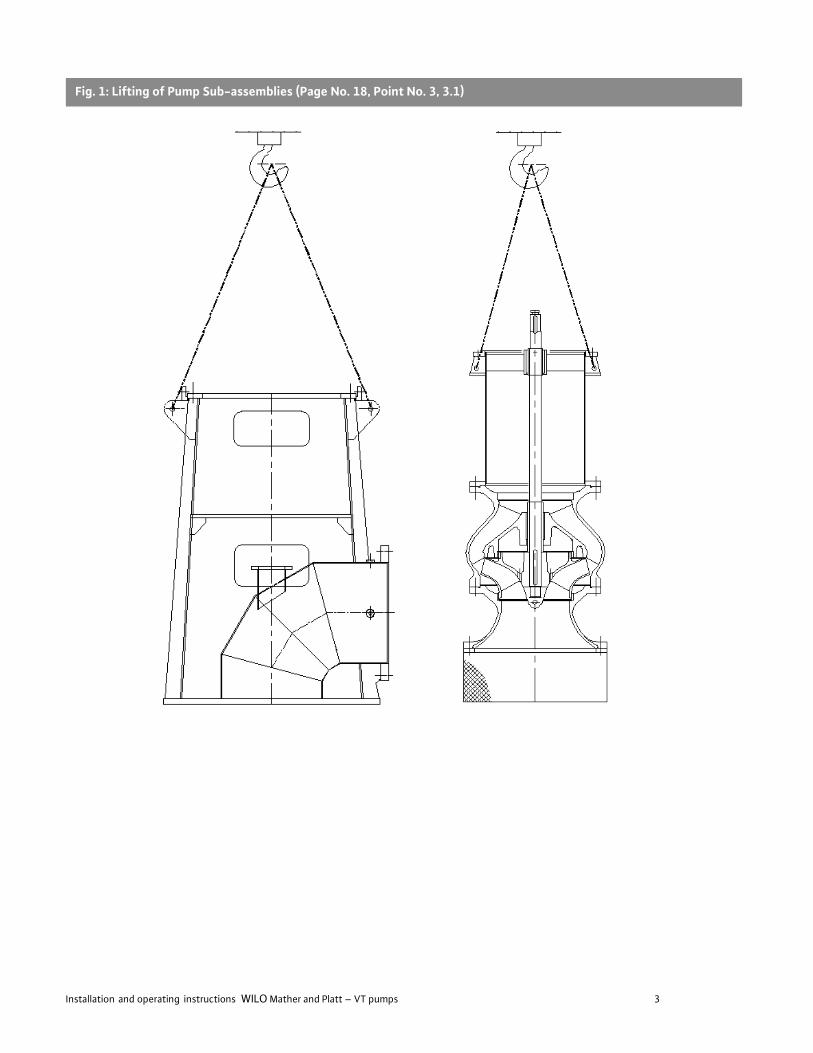
Fig. 1: Lifting of Pump Sub-assemblies (Page No. 18, Point No. 3, 3.1)
Installation and operating instructions WILO Mather and Platt – VT pumps 4
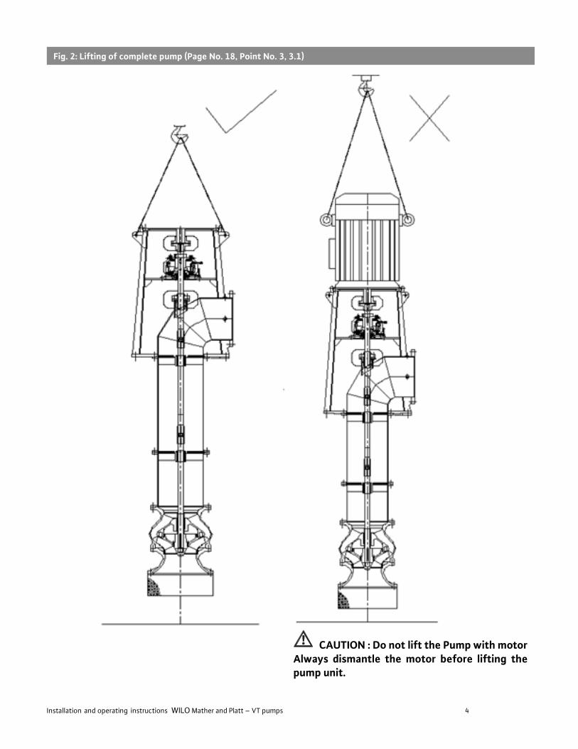
CAUTION : Do not lift the Pump with motor Always dismantle the motor before lifting the pump unit.
Fig. 2: Lifting of complete pump (Page No. 18, Point No. 3, 3.1)
Installation and operating instructions WILO Mather and Platt – VT pumps 5
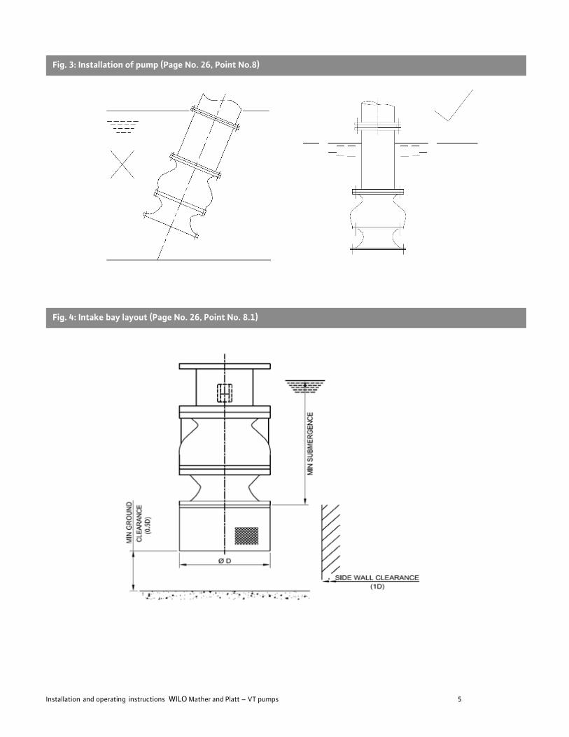
Fig. 3: Installation of pump (Page No. 26, Point No.8)
Fig. 4: Intake bay layout (Page No. 26, Point No. 8.1)
Installation and operating instructions WILO Mather and Platt – VT pumps 6
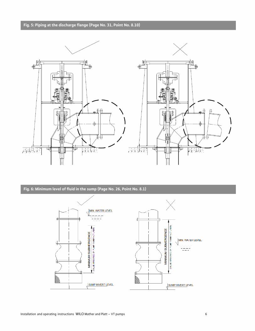
Fig. 5: Piping at the discharge flange (Page No. 31, Point No. 8.10)
Fig. 6: Minimum level of fluid in the sump (Page No. 26, Point No. 8.1)
Installation and operating instructions WILO Mather and Platt – VT pumps 7
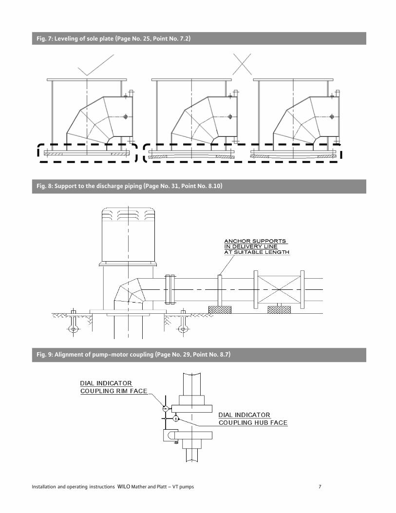
Fig. 7: Leveling of sole plate (Page No. 25, Point No. 7.2)
Fig. 8: Support to the discharge piping (Page No. 31, Point No. 8.10)
Fig. 9: Alignment of pump-motor coupling (Page No. 29, Point No. 8.7)

Installation and operating instructions WILO Mather and Platt – VT pumps 8
Fig. 10: Above Floor Discharge Arrangement (Page No. 21, Point No. 5)
Installation and operating instructions WILO Mather and Platt – VT pumps 9
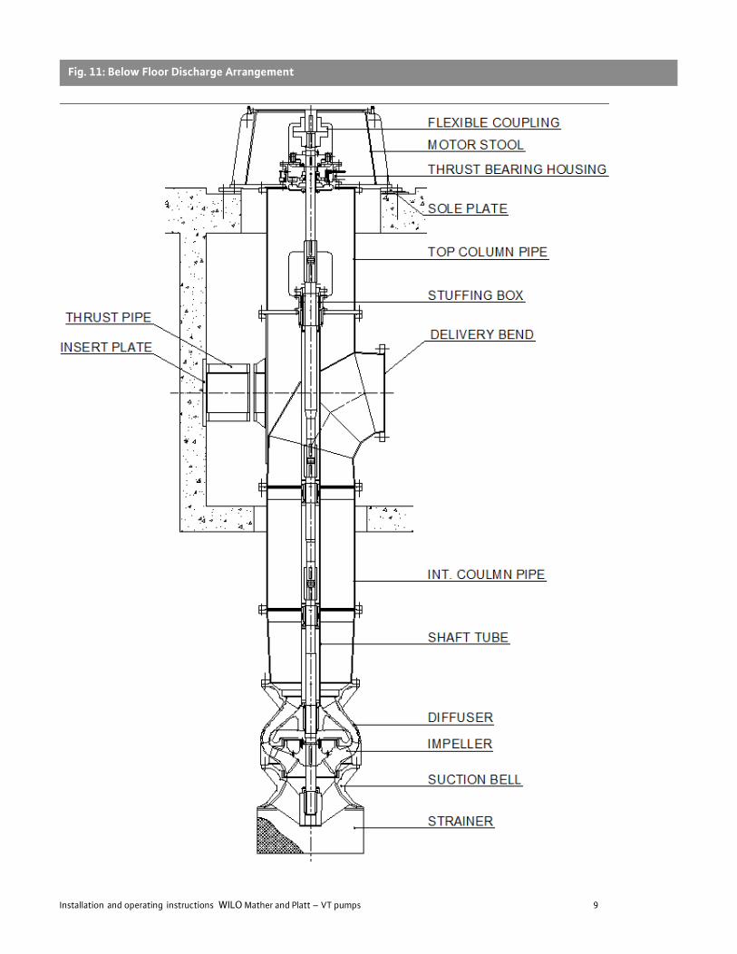
Fig. 11: Below Floor Discharge Arrangement

Installation and operating instructions WILO Mather and Platt – VT pumps 10
Fig. 12: Cutting of gland packing (Page No. 31, Point No. 8.11)
Fig. 13 : Thrust Pipe Arrangement in Below Floor (Page No. 22 & 28, Point No. 5.8 & 8.5)
Installation and operating instructions WILO Mather and Platt – VT pumps 11
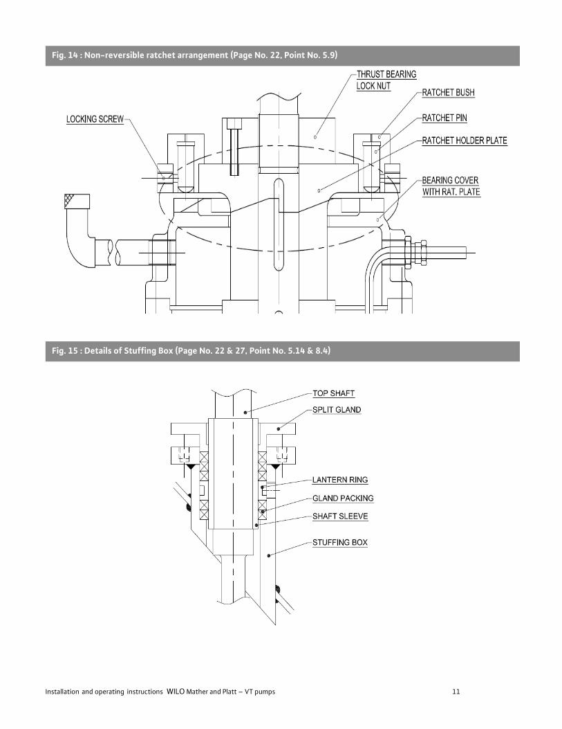
Fig. 14 : Non-reversible ratchet arrangement (Page No. 22, Point No. 5.9)
Fig. 15 : Details of Stuffing Box (Page No. 22 & 27, Point No. 5.14 & 8.4)

Installation and operating instructions WILO Mather and Platt – VT pumps 12
Fig. 16: Details of Flexible coupling (Page No. 23 & 28, Point No. 6.2 & 8.6)
Fig. 17: Details of Bowl assembly (Page No. 21, Point No. 5)
Fig. 18: Details of Muff coupling assembly (Page No. 23 & 27, Point No. 6.4 & 8.3)
Installation and operating instructions WILO Mather and Platt – VT pumps 13
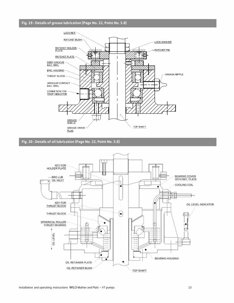
Fig. 19 : Details of grease lubrication (Page No. 22, Point No. 5.8)
Fig. 20 : Details of oil lubrication (Page No. 22, Point No. 5.8)

Installation and operating instructions WILO Mather and Platt – VT pumps 14
Fig 21: Arrangement for Oil lubricated pumps (Page No. 29, Point No. 8.8)
Fig 22: Schematic for forced water lubrication system (Page No. 29, Point No. 8.8)

Installation and operating instructions WILO Mather and Platt – VT pumps 15
Fig 23 : Delivery Bend Connection Details (Page No. 43, Point No. 11.7 Pump Technical Data)
Fig 24 : Oil Lubrication Bearing Connection Details (Page No. 44, Point No. 12)
Fig 25: Grease Lubrication Bearing Connection Details (Page No. 44, Point No. 12)

Installation and operating instructions WILO Mather and Platt – VT pumps 16
INDEX 1 General Information…………………………………………………………………………………………………... 17 2 Safety……………………………………………………………………………………………………………………….. 17
2.1 Safety symbols………………………...……………………………………….……………………………………………………………………………… 17 2.2 Personnel qualifications…………………………………………………………………………………………………………………..................... 17 2.3 Danger in event of non-observance of the safety instructions……………………………………………………………………. 17 2.4 Safety instructions for the operator………………………………………………………………………………………………………………… 17 2.5 Safety instructions for installation and maintenance work…………………………………………………………………………..... 18 2.6 Unauthorized modification and manufacture of spare parts…………………………………………………………………………… 18 2.7 Improper use…………………………………………………………………………………………………………………………………………………..… 18 2.8 Safety & control devices…………………………………………………………………………………………………………………………………... 18
3 Transport and interim storage…………………………………………………………………………………….. 18 3.1 Handling……………………………………………………………………………………………………………………………………………………………. 18 3.2 Delivery……………………………………………………………………………………………………………………………………………………………… 19 3.3 Storage………………………………………………………………………………………………………………………………………………………………. 19 3.4 Pump returning back to the supplier……………………………………………………………………………………………………………..… 19 3.5 Intended use……………………………………………………………………………………………………………………………………………………... 19 4 Product information…………………………………………………………………………………………………… 20 4.1 Data plate………………………………………………………………………………………………………………………………………………………….. 20 4.2 Standard product Range…………………………………………………………………………………………………………………………………… 20 4.3 Scope of delivery………………………………………………………………………………………………………………………………………………. 21 4.4 Accessories……………………………………………………………………………………………………………………………………………………….. 21
5 Product Description ………………….………………………………………………………………………………. 21
6 Selection of motor and pump components ……………………………………………………………………… 23 6.1 Electrical motor selection………………………………………………………………………………………………………………………………… 23 6.2 Coupling Selection ………………………………………………………………………………………………………………………………………….. 23 6.3 Selection of Mechanical Seal …………………………………………………………………………………………………………………………… 23 6.4 Selection of forced water lubrication system …………………………………………………………………………………………………. 23
7 Preparing Foundation …………………………………………………….…………………………………………………………….. 25 7.1 Sole plate installation ………………………………………………………………………………………………………………………………………. 25 7.2 Leveling of Sole plate ………………………………………………………………………………………………………………………………………. 25
8 Installation ………………………………………………………………………………………………………………………………………………………… 26 9 Electrical connections ……………………………………………………………………………………………….. 32
10 Commissioning…………………………………………………………………………………………………………….. 32 10.1 List of Essential items……………………………………………………………………………………………………………………………………….. 32 10.2 Cleaning prior to start……………………………………………………………………………………………………………………………………….. 32 10.3 Filling and venting…………………………………………………………………………………………………………………………………………….. 33 10.4 Starting the pump……………………………………………………………………………………………………………………………………………… 33
11 Maintenance……………………………………………………………………………………………………………. 35 11.1 Routine maintenance and frequency of inspection………………………………………………………………………………………….. 35 11.2 Overhaul maintenance………………………………………………………………………………………………………………………………………. 36
Acceptable field vibration limit chart………………………………………………………………………………………………… 36
11.3 Disassembling the pump…………………………………………………………………………………………………………………………………… 37 11.4 Examination of Internal Components……………………………………………………………………………………………………………….. 38 11.5 Reassembling the pump……………………………………………………………………………………………………………………………………. 39 11.6 Recommended spare parts……………………………………………………………………………………………………………………………….. 40
11.7 VT Pumps Technical Data……………………………………………………………………………………………. 41
12 Pump Lubrication and Connection Data.…………………………………………………………………….. 42 13 Recommended lubricants ………………………………………………………………………………………….. 42
14 Decommissioning and recycling……………………………………………………………………………….… 42
15 Faults, causes and remedies …………………………………………………………………………………….… 43
16 Pre-Commissioning & Commissioning formats……………………………………………………….… 45
Installation and operating instructions WILO Mather and Platt – VT pumps 17
1. General Information About this document The language of the original operating instructions is English.
All other languages of these instructions are translations of the
original operating instructions.
These installation and operating instructions are an integral part of the product. They must be kept readily available at the place where the product is installed. Strict adherence to these instructions is a precondition for the proper use and correct operation of the product. These installation and operating instructions correspond to the
relevant version of the product and the underlying safety
standards valid at the time of going to print. Supplied pump will
operate trouble free and satisfactorily on the condition that, it
is installed with due care and maintained properly. For hassle free operating life, it is recommended that the pump
should operate under specified “Operating conditions”. Pump
operating conditions are mentioned on the “Nameplate”
affixed to the pump.
If operating parameters deviate from the specified parameters
as on the “Nameplate”, please contact manufacturer.”
CE Marking Certification is available on request.
2. Safety These operating instructions contain basic information which
must be adhered to during installation and operation. For this reason, these operating instructions must, without fail, be read
by the service technician and the responsible operator before
installation and commissioning. The machine operator list must
be filled out completely. By signing this list, all persons working
on or with the product confirms that they have received, read
and understood this operating & maintenance manual.
It is not only the general safety instructions listed under the
main point "safety" that must be adhered to but also the
special safety instructions with danger symbols included under
the following main points.
2.1 Safety Symbols:
General danger symbol:
This symbol indicates safety instructions where non-compliance would affect personal safety and could result in loss of life.
Danger due to electrical voltage This symbol indicates electrical safety instructions where non-compliance will involve a high risk to personal safety or the loss of life. NOTE: ... This is not a safety symbol but indicates useful information on using the product. It also draws attention to the possible problems.
Signal words:
DANGER! Acutely dangerous situation. Non-observance results in death or the most serious of
injuries.
WARNING! The user can suffer (serious) injuries. “Warning” implies
that (serious) injury to persons is probable if this
information is disregarded.
CAUTION! There is a risk of damaging the pump/installation.
“Caution” implies that damage to the product is likely if
the information is disregarded.
2.2 Personnel qualifications
All personnel involved in the operation, installation,
inspection and maintenance of the unit must be qualified to carry out the work involve.
If the personnel in question do not possess the necessary
knowledge and skill, appropriate knowledge and training
must be provided.
2.3 Danger in event of non-observance of the
safety instructions Non-observance of safety instructions provided in these operating instructions can result in the following risks:
• Failure of important product/installation functions
• Failure of required maintenance and repair procedures
• Danger to persons from electrical, mechanical and
bacteriological influences
• Property damage
• Loss of any claims to damages
• WILO Mather and Platt does not accept any liability for damage, failures or losses arising due to improper
installations, maintenance, repair works, modifications
without our consultation and non-observance of safety
instructions mentioned in this IOM.
2.4 Safety instructions for the operator This appliance is not intended for use by persons
(including children) with reduced physical, sensory or
mental capabilities, or lack of experience and knowledge,
unless they have been given supervision or instruction
concerning use of the appliance by a person responsible
for their safety. Children should be supervised to ensure
that they do not play with the appliance.
• If hot or cold components on the product/the unit lead to hazards, local measures must be taken to guard them
against touching.
• Guards protecting against touching moving
components (such as the coupling) must not be
removed whilst the product is in operation.
• Leakages (e.g. from the shaft seals) of hazardous fluids
(which are explosive, toxic or hot) must be led away so
that no danger to persons or to the environment arises.
Installation and operating instructions WILO Mather and Platt – VT pumps 18
National statutory provisions are to be complied with.
• Highly flammable materials are always to be kept at a safe
distance from the product.
• Danger from electrical current must be eliminated. Local directives or general directives [e.g. IEC, VDE etc.] and
local power supply companies must be adhered to.
• Depending on the type, size and capacity (kW), the
products produce a sound pressure up to 75 dB (A) to 110
dB (A).
• The actual sound pressure, however, depends on several
factors. These include, for example, type of prime mover,
installation type, fastening of accessories and pipeline,
operating site condition, background noise, etc.
• Once the product has been installed, we recommend that
the operator makes additional measurements under all
operating conditions.
2.5 Safety instructions for installation and
maintenance work
The operator must ensure that all installation and maintenance work is carried out by authorized and qualified
personnel, who are sufficiently informed from their own
detailed study of the operating instructions. Work on the product/unit must only be carried out when at
a standstill. It is mandatory that the procedure described in
the installation and operating instructions for shutting
down the product/unit be complied with.
Immediately on conclusion of the work, all safety and
protective devices must be put back in position and/or re-
commissioned.
2.6 Unauthorized modification and manufacture of
spare parts Unauthorized modification and manufacture of spare parts
will impair the safety of the product/ personnel and will
make void the manufacturer's declarations regarding safety.
Modifications to the product are only permissible after consultation with the manufacturer. Original spare parts
and accessories authorized by the manufacturer ensure safety. The use of other parts will absolve us of liability for
consequential events.
2.7 Improper use The operating safety of the supplied product only
guaranteed for conventional use in accordance with Section
4 of the operating instructions. The limit values on any account must not fall under or exceed those specified in the
catalogue/data sheet.
2.8 Safety & control devices Direct controls are applicable when the pump is supplied along with motor/panels. When motor/ panel is in end user’s
scope of supply, it is advised to go for CE approved motors
/panels. Environmental safety
Disposal of any unwanted/scrap material should be disposed in appropriate way so as not to cause any harm to
the environment. No hazardous material is used in WILO
Mather & Platt pumps.
NOTE
To avoid ambiguity in the use of the word
„replace” the words „replace” and „renew” are used in
this manual in the following context: Replace - To put
back, in its existing state, a part or component that has
previously been removed. Renew - To substitute a new
part of component for a worn or damaged one.
3. Transport & Interim storage
Immediately check the pump and transport packaging for damage in transit upon receipt. Take the necessary steps within the period defined by the transport company in the event of damage in transit.
DANGER! Risk of getting crushed! The installation or removal of the product must not be
performed by one person alone. Measures should be
taken to bar persons from standing beneath a
suspended load. Furthermore, it is also prohibited to
move suspended loads over exposed workplaces where
people are present. The fastening devices should be
adapted to the conditions at hand (weather, hooking
system, load, etc.) Use suitable fastening devices to
handle the weight of the product.
CAUTION! Risk of damage to the pump! Risk of damage due to improper handling during
transport and storage.
The pump should be protected against humidity, frost
and mechanical damage during transport and interim
storage.
3.1 Handling (Fig: 1& 2 Pg. No. 3&4)
CAUTION! Risk of damage to the pump! Risk of falling! Pumps should never be lifted with motor mounted on motor stool. Lifting lugs provided on motor stool are to be used only for lifting the pump during maintenance. Pump to be lifted /inserted in part by part. Safe working load of wire ropes reduces with increase in included angle. Never put down or pick up the product when it is not secured. Tilting of the product should be avoided at all costs.
Only suitable lifting gear and load carrying equipment
with valid test certificates and adequate lifting capacity
for the loads involved (such as belts/ wire ropes/slings)
should be used for lifting & transporting the product.
If chains are used, they should be secured against slipping
along with protective cover to prevent damage to the
product, paint and/or injury to personnel. When lifting,
care to be taken so that pump flanges, shaft extensions,
suction, bellmouth, etc. are not damaged.

Installation and operating instructions WILO Mather and Platt – VT pumps 19
To lift the pump see lifting diagrams - see also general
safety Information, Point 2). These must have sufficient
load bearing capacity to ensure that the product can be transported safely.
3.2 Delivery
On arrival, the delivered items must be inspected for
Damage and a check made that all parts are present.
If any parts are damaged or missing, the transport
company or the manufacturer must be informed on the day of delivery. Any claim made at a later date will be
deemed invalid. Damage to parts must be noted on the delivery or freight documentation.
3.3 Storage
Our vertical pumps require preparation for storage &
regular maintenance during storage. The pump should be
considered in storage when it has been delivered to the job site & waiting for installation.
It is suggested that the check of parts & material against
the bill of materials be made jointly with the WILO Mather and Platt’s representative & customer representative.
NO CLAIMS FOR SHORTAGES WILL BE HONORED BY WILO MATHER AND PLATT, AFTER THE MATERIAL HAS BEEN PLACED IN STORAGE.
3.3.1 Short-term storage (less than 3 month)
The equipments as shipped should have adequate
protection for short-term storage in a covered, dry and ventilated location at the job site prior to installation.
If the pump is not installed immediately after delivery, it
must be stored in a dry and clean place with sufficient ventilation, no vibration, no freezing and the temperature
variations must be smooth. Bearings and couplings must be protected against sand, dust and foreign bodies.
To avoid corrosion and jamming, please lubricate the
pump and make turn the rotating elements for several
turns at least once a week. Pre-packed desiccants may be used to absorb moisture & keep the pump dry. It must be
removed before putting the pump on operation.
3.3.2 Long-term storage (more than 3 month) If the equipment will be subject to extended storage condition
prior to installation, then the manufacturer must be informed
about storage duration, so that special protection can be
recommended.
• The machine must be protected from direct sunlight, heat,
dust, and frost.
• The rotors or propellers must be turned at regular intervals. This
prevents the bearing from locking.
• Heavy components must be placed on supports to kept them
off the ground
• Shafting must be removed from the boxes & coated with
preservative, then re-boxed with preservative paper.
3.4 Pump returning back to the supplier Products, which are delivered back to the plant, must be clean
and correctly packaged. In this context, clean means that
impurities have been removed and decontaminated if it has
been used with materials, which are hazardous to health.
The packaging must protect the product against damage.
CAUTION! Guarantee not applicable! Products, which are not suitably packaged for delivery back,
are no longer covered by guarantee!
3.5 Intended use The pump supplied is intended for specific fluid. Refer pump
data sheet and order confirmation. For any change in pumped
fluid refer WILO Mather and Platt beforehand. Vertical turbine
pumps are used in water supply, water circulating systems,
injection water, spray pond, condensate extraction, water
treatment, firefighting, booster systems etc. If the operating
conditions are different of the specifications given in the
order, (i.e. type of liquid, temperature or duty point), the end user must ask a written agreement to WILO Mather and Platt
on the new operating conditions before starting the pump.

Installation and operating instructions WILO Mather and Platt – VT pumps 20
4. Product information 4.1 Data plate
4.1.1 Key Type:
CNE 18 x 2 / 1480 / C.W
30 VMF x 3 / 740 / A.C.W CNE Name of the range VMF Name of the range 2/3 No of stages 1480/ 740 Speed in RPM
CW/ ACW Direction of Rotation when viewed from top
4.2 Standard product range
The technical features of the product have been
described in the offer made for this product, especially
the fluid compatibility.
Please refer to this:
Property Value Remarks
Speed 2900, 1800, 1480, 980, 740, 590, 490, 420, 390, 330 Rev/min Model dependent
Discharge nominal diameters DN 100 mm to 2000 mm Model dependent Flange standard ANSI Others on request Limits of ambient temperature (min/max) [°C] up to +40 Others on request Ambient humidity < 90 % Others on request Max. operating pressure on request Model dependent Motor insulation class F Other on request Motor protection level IP 55 Electrical protection for motor –
required in place (in accordance with local regulation)
Acoustic pressure level, (In accordance with motor performances)
Refer to the data plate on the motor
or in technical leaflets
Standard fluid allowed
Condensate, Cooling water, Clear Water, Raw Water. Contact WILO Mather Platt for all other fluids
Standard version
Electrical connections
3~230V, 50Hz 3~415V, 50Hz
Other frequency, voltages, Please contact M+P
Installation and operating instructions WILO Mather and Platt – VT pumps 21
4.3 Scope of delivery Pump can be delivered,
• As a complete pump set including electrical motor, Sole
plate, coupling
• Either without motor or as bare shaft pump without sole plate in case of existing sole plate and foundation
4.4 Accessories
• Companion Flange
• Foundation bolts
• Shims
5. Product Description
Vertical turbine pump can be single stage or multistage in construction. The pump is a vertical suction pump. The unit is divided into three basic elements:
a. The pumping stages including bowl assembly. b. Intermediate piping works and extension shafting.
c. Delivery bend & motor stool assembly.
The pumping stages are freely suspended from the delivery bend by intermediate pipework, depending upon the site conditions. In surface discharge installation, the delivery bend & motor stool are placed above floor level. The thrust bearing situated in the motor stool assembly supports the static weight of the rotating assembly and also absorbs any axial thrust that is developed within the unit during operation. (Refer Fig. 10 & 17, Pg. No. 8 & 12) When the pump is in operation, fluid is guided by a suction cover into the impeller eye (inlet). Rotation of the impeller vanes imparts energy to the fluid. This kinetic energy is converted into pressure energy as the liquid flows through diffuser vanes.
5.1 Casing
Casing consists of suction bellmouth and diffuser attached together with impeller and replenishable rings. Casing carries bush bearings to support shaft at regular intervals. Depending on need bush bearings can be provided in suction bellmouth. The top flange surface of casing carries groove for O-ring for liquid sealing. Also, spigot is provided on top flange for locating the components accurately.
5.2 Impeller
Impellers may be of mixed flow, Radial flow (open or close). Refer specifications/datasheet/General arrangement drawing/cross sectional drawing for details. The impeller varies in size according to capacity of the individual pump. Close type impellers are hydraulically balanced to reduce axial thrust. Impeller carries balance holes and back vane for thrust balancing. Balance holes can be plugged depending upon the need. In case of open type of impeller, throat line is provided below impeller. The gap between the same is maintained as per pump manufacturer’s recommendations.
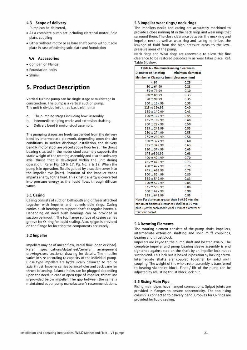
5.3 Impeller wear rings / neck rings
The impellers necks and casing are accurately machined to provide a close running fit in the neck rings and wear rings that surround them. The close clearance between the neck ring and impeller neck as well as wear ring and casing minimizes the leakage of fluid from the high-pressure areas to the low-pressure areas of the pump.
Neck rings and Wear rings are renewable to allow this fine clearance to be restored periodically as wear takes place. Ref. Table 6 below,
5.4 Rotating Elements
The rotating element consists of the pump shaft, impellers, intermediate extension shafting and solid muff couplings, bearing and thrust block.
Impellers are keyed to the pump shaft and located axially. The complete impeller and pump bearing sleeve assembly is end tightened against step on the shaft by an impeller lock nut at suction end. This lock nut is locked in position by locking screw. Intermediate shafts are coupled together by solid muff coupling. The weight of the whole rotor assembly is transferred to bearing via thrust block. Float / lift of the pump can be adjusted by adjusting thrust block lock nut.
5.5 Rising Main Pipe
Rising main pipes have flanged connections. Spigot joints are provided in flanges to ensure concentricity. The top rising column is connected to delivery bend. Grooves for O-rings are provided for liquid sealing.
Installation and operating instructions WILO Mather and Platt – VT pumps 22
5.6 Delivery Bend
Delivery Bend/ Delivery tee which forms discharge branch of the pump unit is a fabricated component and situated above operating floor level. The bottom flange of the delivery bends supports rising main pipe and pump bowl assembly. It accommodates the stuffing box and split gland assembly/ mechanical seal arrangement for sealing the top shaft.
In sub-surface discharge configuration, delivery tee is located below operating floor. If space permits, delivery tee accommodates the stuffing box and split gland assembly/Mechanical seal arrangement for sealing the top shaft. Alternatively, stuffing box can be provided in bottom flange of motor stool. Thrust Pipe, if provided, is located opposite to delivery branch in below floor arrangement. Tapping is provided near discharge flange of delivery bend to accommodate pressure gauge. Delivery bend is fitted onto a soleplate or top flange of canister when provided.
5.7 Motor Stool It is a fabricated structure. In surface discharge installation, motor stool rests on the top of delivery bend. The top flange of motor stool supports the drive motor. Also thrust bearing assembly, non-reverse ratchet assembly (when provided) and coupling between pump and motor are mounted in the motor stool. Openings are provided to access the parts housed in motor stool.
When hollow shaft motor is provided with combined thrust bearing for pump and motor, motor stool and coupling to connect pump - motor shafts are not provided.
5.8 Thrust bearing Assembly
It consists of thrust bearing to take up axial and radial thrust. Small vertical pumps have grease lubricated bearings while medium to large vertical pumps have oil lubricated bearings. Oil level should be checked prior to starting of pump. (Fig: 13, Pg. No. 10)
5.9 Non-Reverse Ratchet Arrangement
Non-Reverse Ratchet is mechanical device to prevent the reverse rotation of pump, motor during flow reversal condition. It consists of a fixed ratchet and rotating pins as shown in enlarged details.
The ratchet plate teeth allow pins to slide up during normal direction of rotation. However, during reversal, the pins engage with the teeth and prevent reverse rotation. A pump could be offered optionally without Non reverse arrangement if reverse rotation detection system and non-return valve is provided. (Fig: 14 Pg. No. 11)
5.10 Thrust Pipe Arrangement
Thrust pipe arrangement is provided to absorb back thrust generated in below floor discharge arrangements. Thrust pipe is bolted to delivery bend on one side and welded to insert plate fixed in column on other side. An adaptor pipe may be provided in between to adjust the lengths. Insert plate is to be fixed with anchor bolts to column. Refer Fig 13 Pg. No. 10 above.
5.11 Line Shafts
Line shaft shall be of suitable diameter and length as per pump manufacturer’s recommendation with 30% margin on both sides for critical speed with interchangeable sections of standard lengths of 1, 1.5, 2, 2.5, 3m. To ensure correct alignment shafts should be straight within 0.125mm for 3 m length total dial indicator reading. Line shafts are coupled together with the help of rigid coupling.
Maximum permissible error in the axial alignment of the axis with the axis of shaft shall be 0.05 mm in 150 mm. Line shaft are provided with sleeves to be supported in line shaft bearing at suitable intervals.
5.12 Line Shaft bearing
Line shaft bearing could be of Thordon, Cutless rubber, Feroform, Finocot, Bronze or any other special material depending upon application and shall be spaced at suitable interval securely in bearing spider located between column pipes. The bearings shall consist of grooves to allow water and oil flow to the bearing below. In case of oil lubricated pump with shaft enclosing tubes, bearing bronze material is to be used.
5.13 Shaft enclosing tubes
Shaft enclosing tubes are used in forced water and oil lubricated pumps. Shaft tube is generally supported on bearing carriers between bearing spiders with a sealing ring provided at both ends to prevent leakage. Shaft tube should be selected such that sufficient clearance is maintained between shaft tube internal diameter and shaft rigid coupling outer diameter allowing required quantity of water / oil to pass to bearing below. Bottom most shaft tube should be located in diffuser/ casing with an adaptor.
5.14 Stuffing Box
Stuffing box may be provided either with gland packing or mechanical seal as per client’s requirements. Gland packing of plaited cotton and colloidal graphite is provided as standard material, others may be provided on request. Stuffing box also acts as a bearing support for head shaft; hence a sleeve is provided to accommodate the rubbing. Logging ring / lantern ring is provided in stuffing box is provided for lubrication and bypassing additional fluid via leak off connection. Throttle bush may be provided in stuffing box in case if high pressure pumps to prevent mechanical seal faces from being damaged. (Refer Fig. 15 Pg. No. 11)
Installation and operating instructions WILO Mather and Platt – VT pumps 23
6. Selection of Motor and Pump Components
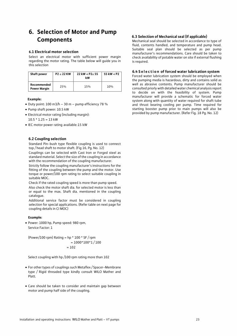
6.1 Electrical motor selection
Select an electrical motor with sufficient power margin regarding the motor rating. The table below will guide you in this selection
Shaft power P2 ≤ 22 KW 22 kW < P2≤ 55
kW 55 kW < P2
Recommended Power Margin
25% 15% 10%
Example:
• Duty point: 100 m3/h – 30 m – pump efficiency 78 %
• Pump shaft power: 10.5 kW
• Electrical motor rating (including margin):
10.5 * 1.25 = 13 kW
• IEC motor power rating available: 15 kW
6.2 Coupling selection
Standard Pin-bush type flexible coupling is used to connect top / head shaft to motor shaft. (Fig 16, Pg. No. 12)
Couplings can be selected with Cast Iron or Forged steel as standard material. Select the size of the coupling in accordance with the recommendation of the coupling manufacturer.
Strictly follow the coupling manufacturer’s instructions for the fitting of the coupling between the pump and the motor. Use torque or power/100 rpm rating to select suitable coupling in suitable MOC.
Check if the rated coupling speed is more than pump speed.
Also check the motor shaft dia. for selected motor is less than or equal to the max. Shaft dia. mentioned in the coupling catalogue.
Additional service factor must be considered in coupling selection for special applications. (Refer table on next page for coupling details in CI MOC)
Example:
• Power: 1000 hp, Pump speed: 980 rpm,
Service Factor: 1
(Power/100 rpm) Rating = hp * 100 * SF / rpm
= 1000*100*1 / 100
= 102
Select coupling with hp /100 rpm rating more than 102
• For other types of couplings such Metaflex / Spacer-Membrane
type / Rigid threaded type kindly consult WILO Mather and
Platt.
• Care should be taken to consider and maintain gap between
motor and pump half side of the coupling.
6.3 Selection of Mechanical seal (If applicable) Mechanical seal should be selected in accordance to type of fluid, contents handled, and temperature and pump head. Suitable seal plan should be selected as per pump manufacturer’s recommendations. Care should be taken to check availability of potable water on site if external flushing is required.
6.4 S e l e c t i o n of forced water lubrication system Forced water lubrication system should be employed when the pumping media is hazardous, dirty and contains solid as well as abrasive contents. Pump manufacturer should be consulted priorly with detailed water chemical analysis report to decide on with the feasibility of system. Pump manufacturer will provide a schematic for forced water system along with quantity of water required for shaft tube and thrust bearing cooling per pump. Time required for starting booster pump prior to main pumps will also be provided by pump manufacturer. (Refer Fig. 18 Pg. No. 12)

Installation and operating instructions WILO Mather and Platt – VT pumps 24
COUPLING SELECTION CHART FOR STD PIN-BUSH COUPLING
Notes:
• For Forged Steel / Cast Steel MOC kindly contact WILO Mather and Platt.
• Specified gap to be maintained between pump and motor half coupling.
Installation and operating instructions WILO Mather and Platt – VT pumps 25
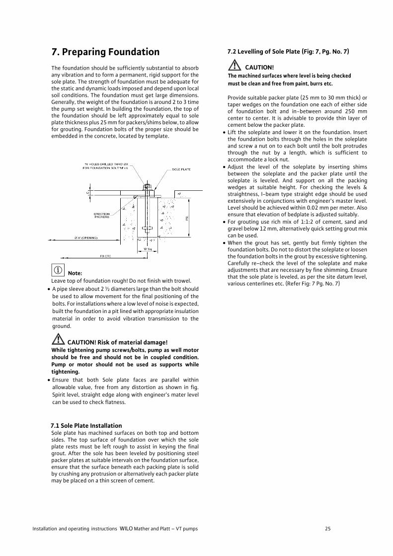
7. Preparing Foundation
The foundation should be sufficiently substantial to absorb any vibration and to form a permanent, rigid support for the sole plate. The strength of foundation must be adequate for the static and dynamic loads imposed and depend upon local soil conditions. The foundation must get large dimensions. Generally, the weight of the foundation is around 2 to 3 time the pump set weight. In building the foundation, the top of the foundation should be left approximately equal to sole plate thickness plus 25 mm for packers/shims below, to allow for grouting. Foundation bolts of the proper size should be embedded in the concrete, located by template.
Note:
Leave top of foundation rough! Do not finish with trowel.
• A pipe sleeve about 2 ½ diameters large than the bolt should be used to allow movement for the final positioning of the
bolts. For installations where a low level of noise is expected,
built the foundation in a pit lined with appropriate insulation
material in order to avoid vibration transmission to the
ground.
CAUTION! Risk of material damage! While tightening pump screws/bolts, pump as well motor should be free and should not be in coupled condition. Pump or motor should not be used as supports while tightening.
• Ensure that both Sole plate faces are parallel within allowable value, free from any distortion as shown in fig.
Spirit level, straight edge along with engineer’s mater level
can be used to check flatness.
7.1 Sole Plate Installation Sole plate has machined surfaces on both top and bottom sides. The top surface of foundation over which the sole plate rests must be left rough to assist in keying the final grout. After the sole has been leveled by positioning steel packer plates at suitable intervals on the foundation surface, ensure that the surface beneath each packing plate is solid by crushing any protrusion or alternatively each packer plate may be placed on a thin screen of cement.
7.2 Levelling of Sole Plate (Fig: 7, Pg. No. 7)
CAUTION! The machined surfaces where level is being checked
must be clean and free from paint, burrs etc. Provide suitable packer plate (25 mm to 30 mm thick) or taper wedges on the foundation one each of either side of foundation bolt and in-between around 250 mm center to center. It is advisable to provide thin layer of cement below the packer plate.
• Lift the soleplate and lower it on the foundation. Insert the foundation bolts through the holes in the soleplate and screw a nut on to each bolt until the bolt protrudes through the nut by a length, which is sufficient to accommodate a lock nut.
• Adjust the level of the soleplate by inserting shims between the soleplate and the packer plate until the soleplate is leveled. And support on all the packing wedges at suitable height. For checking the levels & straightness, I-beam type straight edge should be used extensively in conjunctions with engineer’s master level. Level should be achieved within 0.02 mm per meter. Also ensure that elevation of bedplate is adjusted suitably.
• For grouting use rich mix of 1:1:2 of cement, sand and gravel below 12 mm, alternatively quick setting grout mix can be used.
• When the grout has set, gently but firmly tighten the foundation bolts. Do not to distort the soleplate or loosen the foundation bolts in the grout by excessive tightening. Carefully re-check the level of the soleplate and make adjustments that are necessary by fine shimming. Ensure that the sole plate is leveled, as per the site datum level, various centerlines etc. (Refer Fig: 7 Pg. No. 7)

Installation and operating instructions WILO Mather and Platt – VT pumps 26
8. Installation (Fig: 3, Pg. No. 5) (Motor / Pump coupling system)
DANGER! Risk of getting crushed! The installation or removal of the product must not be performed by one person alone. Measures should be taken to bar persons from standing beneath a suspended load. Furthermore, it is also prohibited to move suspended loads over exposed workplaces where people are present. The fastening devices should be adapted to the conditions at hand (weather, hooking system, load, etc.) Use suitable fastening devices to handle the weight of the product.
WARNING! Danger of personal injury! The installation and electrical connection should be performed only by qualified personnel in compliance with local regulations. This section provides instructions on the recommended methods of installing pumping sets on to concrete foundations. Careful attention must be paid to the customer and contractor’s installation drawings during the installation procedures to ensure that the pumping set is accurately positioned on the correct datum levels. The existing accident prevention regulations must be observed
WARNING! Danger of electric shock! Any hazards from electrical current should be ruled out. Any instructions from local or general directives [e.g. IEC, VDE etc.] or directives of the local electricity supply companies must be observed
8.1 Sump Verification (Fig: 4&6 Pg. No. 5&6)
• Pump sump intake bay should be designed in such a way that
flow evenly distributed and vortex free. Enough back wall and side wall clearances should be left for the pump to perform
satisfactorily. Baffles formed inlet and other flow improving
arrangements should be employed in case of restricted or
constrained sump conditions.
• The special attention must be paid to sump design. When
two or more nos. of pumps are operated in combinations of
working & standby conditions. It is recommended that when
space & site constraints do not allow the suction sump design
as per recommendation of HIS, the suction sump design should be verified by a model study.
• Whenever model study has been carried out previously for
optimizing sump design, its recommendation regarding
corrective structures should be fully implemented.
• Care should be always taken to maintain minimum submergence condition for satisfactory performance of
pump. Cavitations, vibrations etc. can occur in absence of the
same.
• Sufficient bottom clearance should be maintained below
suction bell as per HIS.
• It is recommended to install a strainer to keep unwanted solids out of the pump. Strainer may be installed at the
suction bell end. These strainers usually introduce a
moderate drop in pressure when choked up. Suction bell
strainers typically clear themselves by back flow in the
pump column when the unit is stopped. For large pumps,
trash racks and screens are typically provided in intake
structure.
• It is recommended that a strainer is with a filter surface of at least 2.5 times the suction bell dia. and more in case of
firefighting applications.
8.2 Necessary steps before pump installation
• Before any installation work is carried out, the machine
should be inspected for damage that may have
occurred during handling, transport & storage.
• Installation within a building: install the pump in a dry,
well ventilated and frost-resistant room.
• Pumping machinery should have adequate access and
working room for maintenance operations. Adequate
overhead space for lifting devices and working
clearance must be provided.
• Installation outside a building (outdoor installation):
• Install the pump with a suitable protection to avoid
rainfalls strong wind and particles which can damage
the pump or motor.
• Avoid exposure of the pump to direct sunlight.
• An appropriate solution to avoid frost must be
implemented.
CAUTION! Risk of material damage! Ensure sufficient ventilation/heating if the ambient
temperature exceeds/falls below the permitted limit
values.
• Carry out all welding and soldering work prior to the
installation of the pump.
• Provide shut off valve and non-return valve in pump
delivery line.
Installation and operating instructions WILO Mather and Platt – VT pumps 27
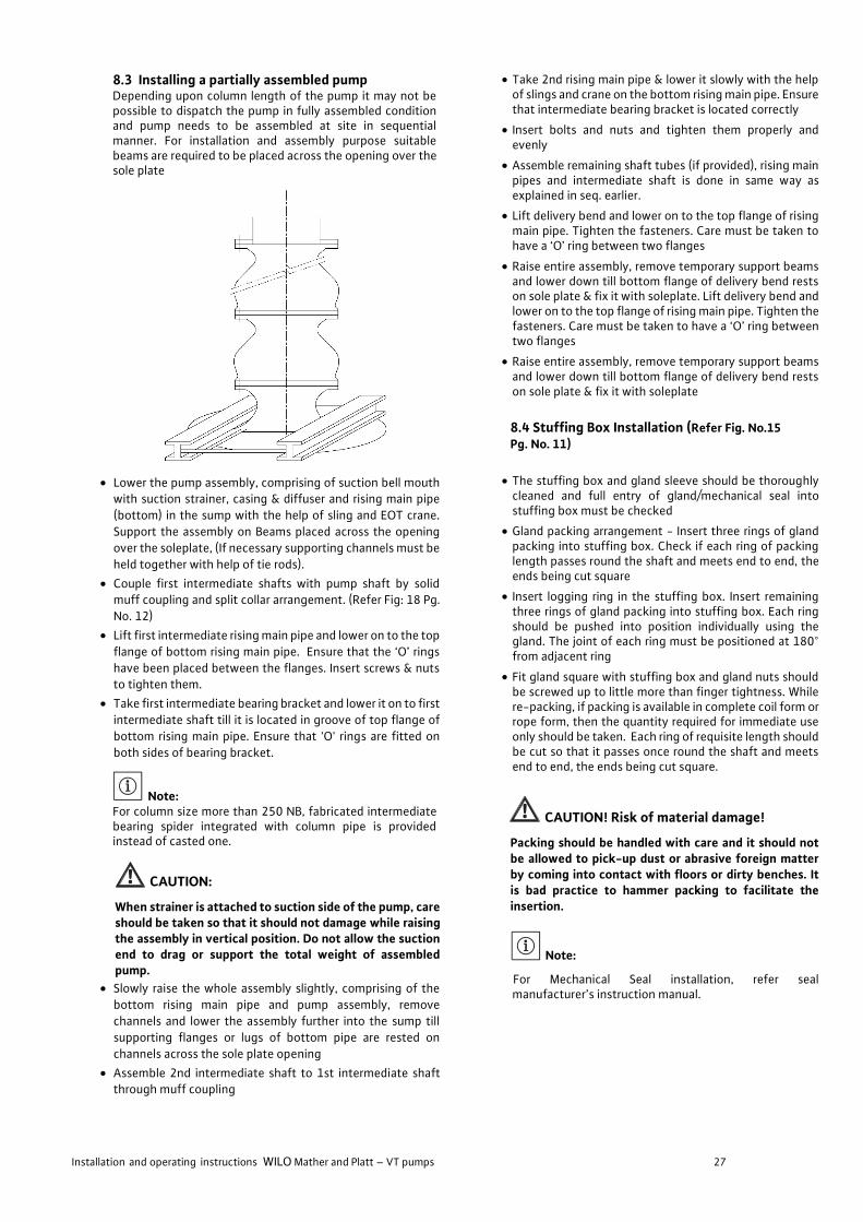
8.3 Installing a partially assembled pump Depending upon column length of the pump it may not be possible to dispatch the pump in fully assembled condition and pump needs to be assembled at site in sequential manner. For installation and assembly purpose suitable beams are required to be placed across the opening over the sole plate
• Lower the pump assembly, comprising of suction bell mouth with suction strainer, casing & diffuser and rising main pipe
(bottom) in the sump with the help of sling and EOT crane.
Support the assembly on Beams placed across the opening
over the soleplate, (If necessary supporting channels must be
held together with help of tie rods).
• Couple first intermediate shafts with pump shaft by solid muff coupling and split collar arrangement. (Refer Fig: 18 Pg.
No. 12)
• Lift first intermediate rising main pipe and lower on to the top
flange of bottom rising main pipe. Ensure that the ‘O’ rings
have been placed between the flanges. Insert screws & nuts to tighten them.
• Take first intermediate bearing bracket and lower it on to first
intermediate shaft till it is located in groove of top flange of
bottom rising main pipe. Ensure that 'O' rings are fitted on
both sides of bearing bracket.
Note: For column size more than 250 NB, fabricated intermediate bearing spider integrated with column pipe is provided instead of casted one.
CAUTION:
When strainer is attached to suction side of the pump, care should be taken so that it should not damage while raising the assembly in vertical position. Do not allow the suction end to drag or support the total weight of assembled pump.
• Slowly raise the whole assembly slightly, comprising of the
bottom rising main pipe and pump assembly, remove
channels and lower the assembly further into the sump till
supporting flanges or lugs of bottom pipe are rested on
channels across the sole plate opening
• Assemble 2nd intermediate shaft to 1st intermediate shaft through muff coupling
• Take 2nd rising main pipe & lower it slowly with the help of slings and crane on the bottom rising main pipe. Ensure that intermediate bearing bracket is located correctly
• Insert bolts and nuts and tighten them properly and evenly
• Assemble remaining shaft tubes (if provided), rising main pipes and intermediate shaft is done in same way as explained in seq. earlier.
• Lift delivery bend and lower on to the top flange of rising main pipe. Tighten the fasteners. Care must be taken to have a ‘O’ ring between two flanges
• Raise entire assembly, remove temporary support beams and lower down till bottom flange of delivery bend rests on sole plate & fix it with soleplate. Lift delivery bend and lower on to the top flange of rising main pipe. Tighten the fasteners. Care must be taken to have a ‘O’ ring between two flanges
• Raise entire assembly, remove temporary support beams and lower down till bottom flange of delivery bend rests on sole plate & fix it with soleplate
8.4 Stuffing Box Installation (Refer Fig. No.15 Pg. No. 11)
• The stuffing box and gland sleeve should be thoroughly cleaned and full entry of gland/mechanical seal into stuffing box must be checked
• Gland packing arrangement - Insert three rings of gland packing into stuffing box. Check if each ring of packing length passes round the shaft and meets end to end, the ends being cut square
• Insert logging ring in the stuffing box. Insert remaining three rings of gland packing into stuffing box. Each ring should be pushed into position individually using the gland. The joint of each ring must be positioned at 180° from adjacent ring
• Fit gland square with stuffing box and gland nuts should be screwed up to little more than finger tightness. While re-packing, if packing is available in complete coil form or rope form, then the quantity required for immediate use only should be taken. Each ring of requisite length should be cut so that it passes once round the shaft and meets end to end, the ends being cut square.
CAUTION! Risk of material damage!
Packing should be handled with care and it should not be allowed to pick-up dust or abrasive foreign matter by coming into contact with floors or dirty benches. It is bad practice to hammer packing to facilitate the insertion.
Note:
For Mechanical Seal installation, refer seal manufacturer’s instruction manual.
Installation and operating instructions WILO Mather and Platt – VT pumps 28
8.5 Thrust pipe arrangement installation
• In case of below floor delivery arrangement, an arrangement
is provided to absorb back thrust. Initially fix the insert plate
in column wall as per dimensions shown on GA drawing with
the help of provided anchor bolts. Match the pump delivery center line with insert plate and thrust pipe center line. Once
the centers of all three have been matched, weld the thrust
pipe onto insert plate; ensure that thrust pipe flange face is
perpendicular to delivery center line. First ensure complete
delivery line is connected to discharge tee without any piping
/ pulling stress.
• Fasten the thrust pipe against the delivery bend as shown in
figure. Adjust and lock the delivery bend in place by adjusting
the locknut provided between the both. 50 mm or less
difference can be maintained between the both depending
upon site conditions. (Refer Fig. 13 Pg. No. 10)
8.6 Thrust Bearing and Coupling Installation (Refer Fig No. 16 Pg. No. 12)
CAUTION! Risk of material damage!
Pump oil level to be checked and maintained at as per pump manufacturer’s recommendation. Low oil level can result in bearing damage and high oil level will cause excessive oil leakage.
• Thrust bearing assembly provided on this pump comprises of
bearing housing, cover, thrust block, locknut, Oil lubricated
spherical roller thrust bearing or Grease lubricated deep
groove ball bearing as Guide bearing, angular contact ball
bearing as Thrust bearing. The outer race of bearing is fitted
in the housing whereas the inner race is fitted on the thrust
block.
• For grease lubricated bearing the top surface of thrust block is provided with 6 or 8 equispaced holes into which the
locking screw can be engaged. The rotating element is set at
desired position by engaging the locking screw in the nearest
hole, after rotating the lock nut through requisite number of
turns.
• This thrust bearing assembly requires very little maintenance other than occasional feeding up of lubricating Oil/Grease.
The thrust bearing assembly should be completely
dismantled, cleaned and reassembled after 8000 hours
approximately (Grease lubricated bearings) and 2000 hrs.
approximately or as required by site conditions (Oil lubricated
bearings).
• For oil-lubricated bearings when level of oil goes down below required level, the fresh lubricating oil should be filled up to
the required quantity. For Grease lubricated bearings the
fresh lubricating grease should be filled up to the required
quantity with help of grease gun after every 1000 hrs.
running of pump. Before greasing, the grease drain plug
should be opened so that while filling the fresh grease, the
deteriorated grease drains out.
• During assembly of thrust bearing (oil lubricated) follow the
following procedure:
• Fit oil retaining bush to bearing housing. Then fit inner race
of thrust bearing on thrust block & outer race in bearing
housing. Mount the bearing housing to motor stool. Fit thrust
block on top shaft so that inside diameter of thrust bearing
fits on thrust block and attach the cooling coil. Tighten the
thrust bearing lock nut. Finally fit the bearing cover cum
ratchet plate to bearing housing.
• Once the ratchet plate has been fixed in place mount the ratchet holder plate with pin and bushes on top / head shaft
• Fit pump half coupling on top shaft. An adjusting ring is
provided below pump half coupling. This ring can be
machined to maintain the recommended gap between pump
half and motor half coupling. Place the motor on top flange
of motor stool and complete the alignment.
Note:
During tightening of thrust bearing locknut, maintain the total float of pump as per pump manufacturer’s recommendation. Refer table for details. Finally lock the lock nut to thrust block via lock screw.
For 2000 VMF Pump refer the following:
• Check motor stool face distance from top shaft face
• Fit pump coupling to the top shaft
• Fit spacer lock nut on top shaft
• Lift top shaft with hook /crane as of required height
• Tight spacer lock nut with matching Pump Side (PH) coupling and coupling holes
• Give support to pump side coupling from bottom side through stuffing box by jacking screws.
• Release hook from top shaft
• Check distance between pump shaft face to motor stool face and reset if required.
• Lift motor with Motor half coupling fitted on it by using crane
• Keep it on motor stool
• Touch the motor half coupling face to pump half coupling face
• Rotate motor body to match the holes with motor stool holes
• Fit the fasteners with motor & motor stool
• Fit the coupling fasteners with pump half & motor half
• Release the jacking screws from stuffing box
• Check the freeness of rotor
• Release the motor from hook/crane
• Do the electric work as per wiring diagram

Installation and operating instructions WILO Mather and Platt – VT pumps 29
8.7 Alignment of the pumps and its driving units
• When the sole plate is leveled and the satisfactory alignment
is completed, proceed with connection of suction & delivery
piping. Recheck the alignment after piping and run the final
grout beneath the base plate. Allow minimum seven days’
time for curing. Grout mix in the proportion specified earlier
for foundation bolt grouting should be used. It is further
recommended that all hollow pockets in the base plate shall
be filled after curing of earlier grout.
• The following procedures outline recommended practice
given in BS-3170 in 1972 (Appendix A) for checking shaft
alignment. This method is independent of the truth of the coupling or shaft and is therefore not affected by canted
coupling faces or eccentricity of the outside diameter of the
coupling. Before commencing the alignment, rotate each
shaft independently to check that the bearings run freely and
that the shaft is true to 0.1mm or better. Check that no
damage can be caused when the shaft of the driven unit is
turned. Coupling should be loosely coupled, and the halves
must be free to move relative to each other, otherwise
Indicators can be incorrect. Where, tightly fitting pins gauge
or spring prevent loose coupling, the springs or pins should
be removed, a line scribed across both half couplings and
readings taken only when the two marks are aligned.
Angular alignment
• After isolating the driven unit from its power supply, clamp two dial indicators are dramatically opposite points on one
half coupling or to the shaft behind it with the plunger resting
on the back of the other half coupling as shown in (Fig. 9 Pg.
No. 7) Rotate the coupling unit the gauges are in line
vertically and set the dial to read zero. Rotate the coupling by
180° and record the readings on each gauge. The readings
should be identical, though not necessarily zero. Either
positive or negative readings are acceptable provided they
are equally positive or negative. Adjust the position of one of
the units if necessary. Rotate the couplings unit the gauges
are in the line horizontally and adjust the dial to zero. Repeat
the operation outlined above by rotating the coupling by
180°. In case where fitment of dial gauge is not feasible check
gap between two coupling halves with the help of filler gauge.
Radial alignment
• Clamp a dial gauge on one of the couplings or to the shaft as
shown in (figure 9 Pg. No. 7), with the plunger resting on the
rim of the other half coupling. Set the dial zero. Rotate the
coupling and note the reading at each quarter revolution. Any variation in the readings indicates the deviation from
alignment and the position of one of the units must be
adjusted until the readings at each quarter revolution are
identical or within the tolerances given below.
CAUTION! Risk of material damage!
Oil level in reservoir to be checked and maintained regularly to prevent damage to line shaft and bowl bush bearing.
Alignment Tolerances:
Pump Speed Angular Alignment Radial alignment
A<1000 rpm to 1800 rpm
0.15 mm TIR 0.15 mm TIR
B 1000 rpm 0.1 mm TIR 0.15 mm TIR
C 1800 rpm to 3000 rpm
0.1 mm TIR 0.1 mm TIR
TIR- Total Indicated Reading
NOTE:
All the alignments (angular as well as radial) have to be carried out by using 3 dial indicators simultaneous
8.8 Forced water and oil lubricated pump pre checks
• In case of forced water lubricated pump start the booster pumps initially to fill in the shaft tubes prior of starting the main pumps. Check the regulated pressure at both shaft tube and thrust bearing cooling inlet end. Suitable throttling should be carried out before providing the supply for bearing cooling.
• Potable or fresh water should be used. If dirty water or raw water from pump delivery is to be used special self-cleaning strainers and pressure filters should be employed. A sufficient size overhead tank should be selected for supplying of potable water. Level switches should be employed to prevent water in tank from falling below low level, thus preventing the system from breakdown.
• In case of oil lubricated pumps, oil should be filled till top of the shaft tube priorly before starting of main water pumps. A reservoir of suitable size is provided which should be mounted firmly to motor stool with the help of bracket. Oil flow to shaft tube and level in reservoir is regulated with the help of an automatic solenoid valve. Care to taken to only use bronze bearing bushes in oil lubricated pumps. (Refer Fig. 21, Pg. No. 14)
NOTE: Always refer forced water schematic provided by pump manufacturer. (Fig 22 Pg. No. 14)
CAUTION! Risk of material damage!
Oil level in reservoir to be checked and maintained regularly to prevent damage to line shaft and bowl bush bearing.

Installation and operating instructions WILO Mather and Platt – VT pumps 30
MAXIMUM ALLOWABLE FORCES AND MOMENTS ON VT PUMPS
Forces (N) and Moments (N-m)
8.9 Pipe work
No stress must be imposed on the pump on delivery side by the pipe
work; neither by the weight of the pipes nor by the tightening of badly
fitting pipes (Refer Fig: 5). All pipe worked attached to the pump must
be fully supported and the mating faces of the pipe flanges must be
parallel and all bolt holes coinciding with each other. (See table of
maximum forces on flanges) It is important; therefore, that alignment
of the pump and motor should be rechecked after the pipes are finally
fitted. Resetting or supporting the pipes must correct any deviation in
the alignment.
Flange Nozzle size [mm]
100 150 200 250 300 350 400 450 500 600 700
Forces [N]
Fx 1427 2497 3790 5350 6688 7134 8472 9364 10032 11370 12374
Fy 1784 3121 4905 6688 8026 8918 10255 11147 12262 13823 15160
Fz 1248 2051 3121 4459 5350 5796 6688 7358 7914 9029 9810
Moments [Nm]
Mx 1331 2309 3532 5027 6114 6386 5338 7744 8016 8424 8968
My 679 1182 1766 2445 2990 3125 3668 3940 4212 4415 4823
Mz 1005 1766 2581 3804 4620 4755 5434 5774 6114 6453 6793
Flange Nozzle size [mm]
800 900 1000 1100 1200 1400 1500 1600 1800 2000
Forces [N]
Fx 12819 13154 13622 14135 14648 15529 15716 15892 16285 147058
Fy 16052 16388 16989 17591 18237 19365 19600 15127 15784 20797
Fz 10255 10701 11415 12195 12998 14489 14803 19836 20307 16500
Moments [Nm]
Mx 9511 10054 10659 11297 11970 13194 13450 13587 14254 14823
My 4959 5163 5523 5903 3611 7053 7210 7377 7711 8064
Mz 6997 7337 7805 8308 8838 9800 10006 10222 10644 11095

Installation and operating instructions WILO Mather and Platt – VT pumps 31
8.10 Discharge line (Fig: 5&8, Pg. No. 6&7)
CAUTION! Damage to the pump
Pump can rotate in reverse direction in the absence of a
non-return valve. A back flow can seriously damage the
bearings, mechanical seal and other pump internals.
Discharge piping should be anchored, supported and
restrained near the pump to avoid application of forces and
moments in excess of those permitted by the pump
manufacturer.
If it is necessary to use an expansion joint, it is
recommended that a pipe anchor to be located between it
and pump. Note that an anchor provides axial restraint,
whereas a pipe support or guide does not.
8.11 Stuffing box packing (Fig. 12 Pg. No. 10)
CAUTION! Risk of quick wear or leakages
Packing should be handled with care and it should not be
allowed to pick up the dust or abrasive matter by coming
into contact with floors or dirty benches. It is bad practice
to hammer packing to facilitate the insertion.
Pumps are dispatched from our works with the stuffing
boxes unpacked; otherwise packing will be aged. The
packing is packed with greaseproof paper and dispatched
with the pump. The softest possible packing i.e. plaited
cotton impregnated with oil and colloidal graphite is
recommended for most duties. Required number of and lengths of packing should be cut off so that each length will
pass once round the shaft sleeve line and meet to end. The
ends of packing must be cut at 45°.
After cleaning the stuffing box and shaft sleeves the
packing should be inserted into the stuffing box. Each ring
should be pushed into position individually using the glands
joint of each ring must be positioned 180˚ from joints of its
neighbor. A logging ring included in the arrangement;
should be inserted into the stuffing box at the appropriate
time during the packing sequence so that it is aligned with
the cooling water connection. The gland should now be
fitted square with the motor stool and the nut should be
screwed up to little more than finger tightness.
8.12 Mechanical seal
CAUTION! Damage to the pump Never start the pump without liquid inside otherwise the
mechanical seal will be damaged instantaneously.
No real operation is required during the setup of the pump.
Only filling and venting the pump are mandatory before
switching on the main
8.13 Pressure gauge connections
CAUTION! Risk of leakage of the fluid! Never connect a pressure gauge onto the pump when the system is under pressure. Pressure gauge connections are available on motor stool close to the delivery flange. Then pressure gauge can be connected on discharge side.
8.14 Air release valves
For vertical pumps an automatic air release and vacuum release valve is recommended. The valve should be located on pump discharge nozzle. This valve prevents a large volume of air being compressed, and then setting up a severe shock wave when suddenly released with potential for serious equipment damage. The air release valve also prevents air from entering the pressurized system.

Installation and operating instructions WILO Mather and Platt – VT pumps 32
9. Electrical connections
WARNING! Danger of electric shock
The electrical connection should be established by an
electrician approved by the local electricity supply
company in compliance with the applicable local
regulations [e.g. VDE regulations].
• Current type and voltage of the mains connection must correspond to the specifications on the name plate.
• Refer to the motor and panels instruction manual at the
time of installation and connection. Motors or electrical
control panels are operated with alternating or industrial
high-voltage current.
• The electrical connection is established via a fixed mains connection line.
• The local regulations must be adhered to, ensure that there
is a provision for isolation of all energy sources and locking.
If the machine has been switched off by, a protective device, it must not be switched on again until the error has
been corrected.
• The electrical system (machine including protective devices
and operating position) must always be grounded. Refer
pump GA drawing & respective manuals of motor/electrical
control panel for connecting earthing suitable as per motor
rating and relevant regulations and standards including
proper earthing lug size and fasteners.
• Under no circumstances may any connecting cables touch the pipeline or the pump or motor housing.
• If there is a possibility that people can come into contact with the machine and the pumped liquid (e.g. at
construction sites), the grounded connection must be
additionally equipped with a fault current protection
device.
• To ensure drip water protection and strain relief of the cable
connections, use cables with an appropriate outer diameter
and screw the cable glands tight. Furthermore, any cables
nearby screwed connections for outlet loops should be
bent in order to divert any accumulating drip water. Close any unassigned cable glands with the existing sealing discs
and screw them tight.
9.1 Operation with frequency converter
The rotation speed can be adjusted in the operating limits
of the pump given in the technical data. The electrical
motors can be driven by a frequency converter in order to
adapt the pump performance at the duty point required.
Please contact WILO Mather and Platt before connecting
the frequency converter to the motor to make sure that the
electrical motor is compatible with this driver. In any case,
please inform WILO Mather and Platt at the quotation stage
if the pump set will be driven by a frequency converter, this
might influence the motor selection.
• Strictly follow the Frequency converter manufacturer
instructions
• The minimum rotation speed of the pump should never go below 40% of the nominal speed.
10. Commissioning
WARNING! Danger of injury
The devices whether on pump/motor/electrical panels
must never be dismantled or disabled. They must be
checked by an authorized technician for proper
functioning before, start-up. Refer to motor & electrical
panel instruction manuals for electrical safety & control
devices information.
WARNING! Danger of pump damage!
Do not operate the pump away from specified operating
range. Operating beyond duty point may not pose a risk to
the operator but will reduce the efficiency of the pump or
damage the pump itself. Operation more than 5 minutes,
at close valve condition is not recommended. For hot
liquids this is not recommended at all. Ensure that always
site NPSH-A is more than NPSH-R.
10.1 List of Essentials to made available at site prior to start commissioning
• Set of I-Beams of erection.
• Set of Slings, Shackles, wire ropes, eye bolts, wrenches.
• Set of spanners, Allen keys, hammer, scrapper, screw drivers.
• Skilled manpower, ladder, sufficient lighting, Helmet, Safety jacket, Safety Shoes etc.
10.2 Cleaning prior to start
10.2.1 Pipe work flushing
Before the pumps are brought into service, either on initial
commissioning or on re-commissioning after overhaul, the
pipe work associated with the pumps must be flushed
through. This will clear deposits or scales which may have
accumulated in the pipes, and which could damage the
internal components of the pumps.
10.2.2 Cleaning of Bearings
VT pumps can be supplied with oil or grease lubricated
bearing depending upon the suitability. If the unit has been
in store for a long period before commissioning, the bearings
should be cleaned and flushed out with clean white spirit or
good quality paraffin. Waste oil/paraffin & used cotton cloth
should not be used for this purpose, as particles of foreign
matter may be left behind which would cause damage when
the bearing is in service. Bearings should be then filled with
recommended grade and quality of fresh lubricant to the
level. Refer list of lubricants at the end of this manual.
Ball and roller bearings are given an initial charge of grease
before leaving WILO Mather & Platt works and do not require
any attention beyond the normal greasing routine before
the first servicing period. Only greases recommended by
pump manufacturer or their equivalent should be used.
Bearings should never be over grease.
Installation and operating instructions WILO Mather and Platt – VT pumps 33
10.3 Filling and venting
Fill and vent the system correctly, through air cock. Brief dry
running will damage the pump. Please also note that these
pumps are not self-priming, which means that the impeller
& casing must always be fully filled with fluid to be handled
before putting in operation
WARNING! Danger of injury!
There is a risk of burns if the pump is touched! The entire
pump may become very hot, depending on the operating
state of the pump or system (fluid temperature).
CAUTION! Danger sealing system damage!
Any attempt to run the pump dry or partially full may
result in seizure of the rotating internal components.
10.3.1 Availability of liquid
Efficient operation of the pump depends upon fine running
clearance that is lubricated by the pumped fluid. Sufficient
fluid must be available to ensure that the pump is flooded at all times to prevent seizure of the internal components.
Wherever external flushing/lubrication is provided it should be available before starting the pump.
If on starting, a pump fails to generate at its rated delivery
head, as indicated on the pump nameplate, it must be
stopped immediately; the cause must be ascertained and rectified, before re-starting.
Ensure that minimum submergence is available as
recommended. Open all ancillary inlet and outlet isolating valves such as, bearing cooling systems, gland sealing, or
cooling systems, air vents, leak-off connections etc. The efficient operation of a centrifugal pump depends upon fine
running clearances, which are lubricated by the pumped
liquid. These pumps must therefore be properly primed before starting, with venting of all the air, gases, vapor etc.
10.3.2 Pumps handling hot liquids
Pumps handling hot liquids are usually so arranged that the
liquid flow into the pump is under pressure. If the saturation
pressure of such liquids is above atmospheric pressure, any
attempt to prime the pump will result in the liquid "flashing"
from the air cocks. For these reasons, the air cocks at the top
of the pump casing should be left slightly open when priming
hot media pumps until air has been driven out of the casing
completely.
The cooling water services of a pump handling hot liquids
should be turned on before the pump is primed. These
services may supply cooling water to the bearings and / or
stuffing boxes. Where the services are functioning, open the
inlet valves and start warming the pump throughout. Never
cut off the water services while the pump is "on temperature".
Where bearings are water-cooled, adjust the cooling water supply until the bearings have a running heat. Over-cooling
may lead to condensation of moisture from the atmosphere
inside the bearing with consequent contamination of the oil.
The delivery valve must be in closed condition.
10.4 Starting the pump 10.4.1 Direction of rotation
Disconnect the drive coupling and run the motor to check its
direction of rotation. A directional arrow is provided on the
pump unit.
10.4.2 Pre-starting checks
• Check that sufficient submergence level is maintained.
• Check that there is no blockage in the strainer at the suction bell end.
• Check for free rotation of the unit when coupled.
• Check that delivery pressure gauge is connected.
• Check that discharge line is having non-return valve & get
valve installed.
• Test and make available all protection devices like alarm, signals, interlock systems incorporated in the auxiliary and
main pumping control system.
• Ensure that all electrical checks on motor, relay setting in
panel etc. have been carried out in accordance with the
instructions of motor manufacturer.
• Ensure that cooling water arrangement is provided bearing
cooling and stuffing box.

Installation and operating instructions WILO Mather and Platt – VT pumps 34
10.4.3 Normal starting and running checks
• When all the foregoing prestart checks are satisfactory, Start the pump and check the direction of rotation (indicated by a
direction arrow on the motor stool) otherwise stop the pump
immediately for correction of direction of rotation. Then run
the pump at its rated speed.
• Check the ammeter reading to ensure that the motor is not being overloaded.
• If applicable, ensure that the stuffing box is not overheating
and that there is slight leakage from the gland (about 1 drop
per second). There may be at first a tendency for the stuffing
boxes to run warm because of the high viscosity lubricant in
the packing. During the first few minutes of running with new
packing, a small quantity of very viscous fluid will be
extruded, but the flow should reduce when the packing has settled down.
• Check that the bearing is not overheating. Bearings will
normally run at a temperature of 30 ˚C to 35 ˚C above
ambient temperature. The ideal running temperature of
bearings is 40 ˚C to 60 ˚C for ball bearings and 40 ˚C to 55 ˚C
for spherical roller bearings. The temperature should never
exceed 85 ˚C for bearings. If the bearings are overheating its
cause should be investigated immediately.
• If the foregoing checks are satisfactory, open the delivery valve slowly and bring the pump gradually up to its rated
parameters indicated in the data sheet/name plate and based
on pressure gauge and ammeter readings. Unless the pump is
fitted with a special leak off device, it should not be run for a
long period against a closed delivery valve. Check that the
driving unit is not being overloaded during valve opening.
Overloading may occur if the pump is discharging into an
empty system. If the pumping unit fails to generate at least
its rated delivery pressure it must be stopped immediately,
the cause ascertained,
• Check vibration of pump set and ensure that vibration level is
within limits specified as per HIS standard (see page no. 38 for
reference)
• The pumps may be run for 8 hours trial operation and all the parameters like delivery pressure, current, bearing
temperature, etc. Be recorded periodically. Make the
following checks at regular intervals. It is recommended that
they be made at every change of shift.
• Check the suction and discharge pressure gauge for normal
operating pressure, if there is significant drop in the suction
or discharge pressure the pump may have lost its supply. In the event of this fault occurring, the pump must be stopped
immediately, and the cause of liquid loss eliminated.
• Check the mechanical seal or stuffing box assembly for
overheating.
10.4.4 Sealing system
Gland packing
CAUTION! Risk of damaging the pump! If the gland plate is too tight, the packing stuff will be
immediately damage.
At the beginning of the operation, the leak at the gland
packing should be important. It should reduce
progressively after several hours by a balanced and
reasonable tightening the gland plate. The gland packing
must operate without excessive temperature. The correct
setting of the gland packing let a permanent leak around
40 to 60 drops per minute. If this leak is too much and cannot be adjusted with the
gland plate, the packing stuff are worn and must be
replaced.
Mechanical seal
CAUTION! Risk of damaging the pump! A mechanical seal must never operate without fluid and
lubrication even for a short period of time.
Ensure that the pump is completely full of water and
vented before starting the pump. Small leakages can
occur during the period of running-in, they should
disappear after several hours of operation. If the leakages
don’t stop, shut down the pump disassemble the
mechanical seal and control their condition.
10.4.5 Normal shutdown
WARNING! Risk of Burns! If the fluid temperature and system pressure is high,
close the isolation valves upstream (in case of barrel
pumps) and downstream of the pump. Initially let the
pump cool.
• Stop the driver of the pump.
• When the pump has come to rest, close the delivery valve.
• Isolate any ancillary supplies.
10.4.6 Emergency Shutdown
In the event of any malfunction of the equipment, switch
off the pump set. When the pump has come to rest, close
the discharge valves, isolate the driving unit power supply
& rectify the fault.
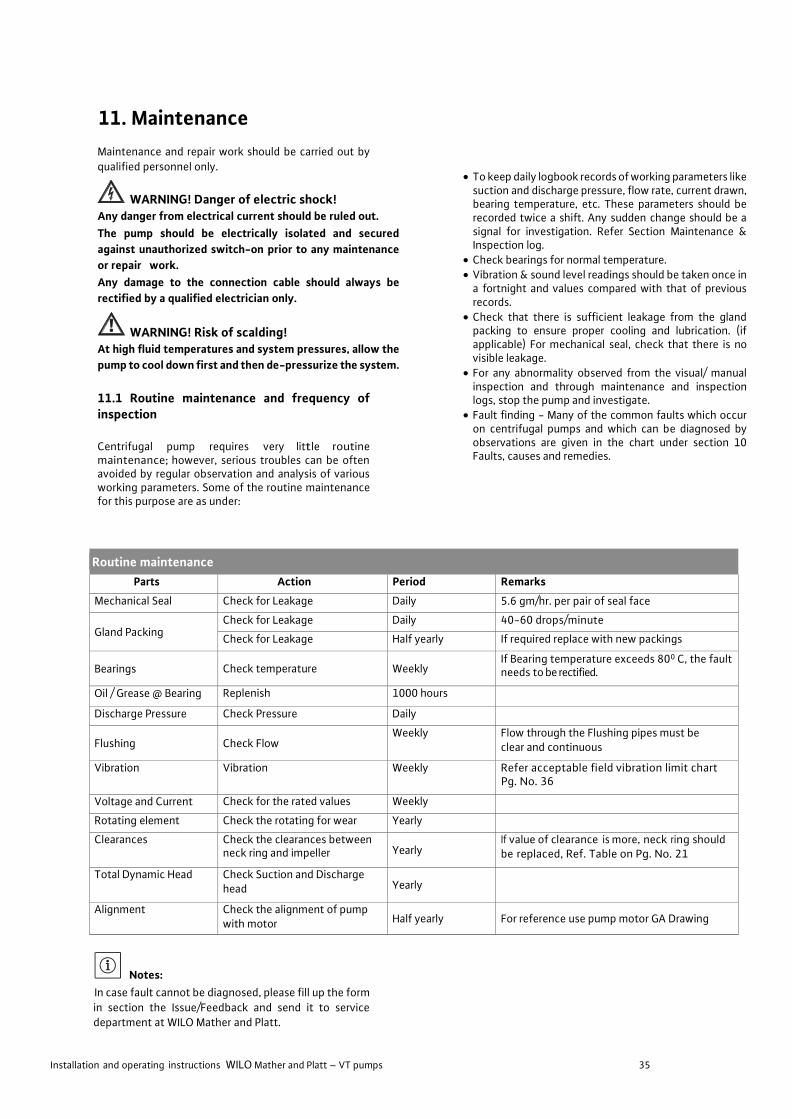
Installation and operating instructions WILO Mather and Platt – VT pumps 35
11. Maintenance
Maintenance and repair work should be carried out by
qualified personnel only.
WARNING! Danger of electric shock! Any danger from electrical current should be ruled out.
The pump should be electrically isolated and secured
against unauthorized switch-on prior to any maintenance
or repair work.
Any damage to the connection cable should always be
rectified by a qualified electrician only.
WARNING! Risk of scalding! At high fluid temperatures and system pressures, allow the
pump to cool down first and then de-pressurize the system.
11.1 Routine maintenance and frequency of inspection
Centrifugal pump requires very little routine maintenance; however, serious troubles can be often avoided by regular observation and analysis of various working parameters. Some of the routine maintenance for this purpose are as under:
Notes:
In case fault cannot be diagnosed, please fill up the form
in section the Issue/Feedback and send it to service department at WILO Mather and Platt.
• To keep daily logbook records of working parameters like suction and discharge pressure, flow rate, current drawn, bearing temperature, etc. These parameters should be recorded twice a shift. Any sudden change should be a signal for investigation. Refer Section Maintenance & Inspection log.
• Check bearings for normal temperature. • Vibration & sound level readings should be taken once in
a fortnight and values compared with that of previous records.
• Check that there is sufficient leakage from the gland packing to ensure proper cooling and lubrication. (if applicable) For mechanical seal, check that there is no visible leakage.
• For any abnormality observed from the visual/ manual inspection and through maintenance and inspection logs, stop the pump and investigate.
• Fault finding - Many of the common faults which occur on centrifugal pumps and which can be diagnosed by observations are given in the chart under section 10 Faults, causes and remedies.
Routine maintenance Parts Action Period Remarks
Mechanical Seal Check for Leakage Daily 5.6 gm/hr. per pair of seal face
Gland Packing Check for Leakage Daily 40-60 drops/minute
Check for Leakage Half yearly If required replace with new packings
Bearings Check temperature Weekly If Bearing temperature exceeds 800 C, the fault needs to be rectified.
Oil / Grease @ Bearing Replenish 1000 hours
Discharge Pressure Check Pressure Daily
Flushing Check Flow Weekly Flow through the Flushing pipes must be
clear and continuous
Vibration Vibration Weekly Refer acceptable field vibration limit chart Pg. No. 36
Voltage and Current Check for the rated values Weekly
Rotating element Check the rotating for wear Yearly
Clearances Check the clearances between neck ring and impeller Yearly
If value of clearance is more, neck ring should be replaced, Ref. Table on Pg. No. 21
Total Dynamic Head Check Suction and Discharge head Yearly
Alignment Check the alignment of pump with motor Half yearly For reference use pump motor GA Drawing
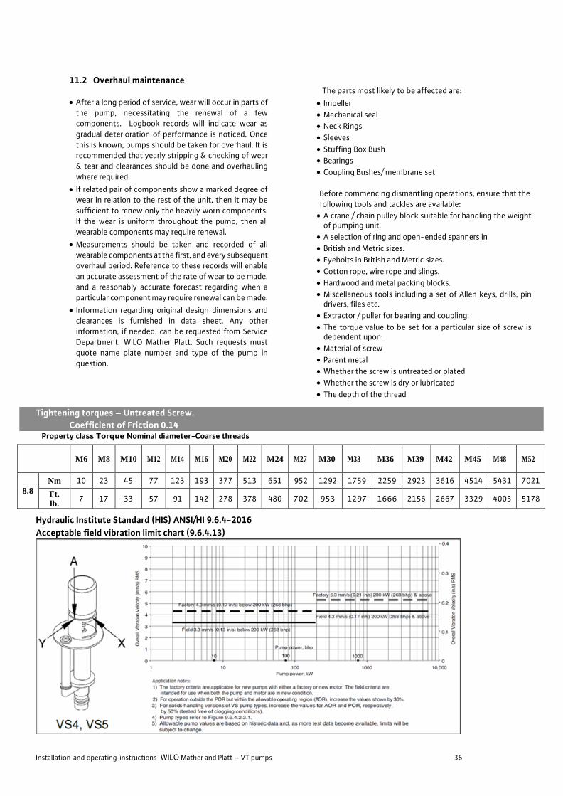
Installation and operating instructions WILO Mather and Platt – VT pumps 36
M6 M8 M10 M12 M14 M16 M20 M22 M24 M27 M30 M33 M36 M39 M42 M45 M48 M52
8.8
Nm 10 23 45 77 123 193 377 513 651 952 1292 1759 2259 2923 3616 4514 5431 7021
Ft.
lb. 7 17 33 57 91 142 278 378 480 702 953 1297 1666 2156 2667 3329 4005 5178
11.2 Overhaul maintenance
• After a long period of service, wear will occur in parts of
the pump, necessitating the renewal of a few
components. Logbook records will indicate wear as
gradual deterioration of performance is noticed. Once
this is known, pumps should be taken for overhaul. It is recommended that yearly stripping & checking of wear
& tear and clearances should be done and overhauling
where required.
• If related pair of components show a marked degree of
wear in relation to the rest of the unit, then it may be
sufficient to renew only the heavily worn components.
If the wear is uniform throughout the pump, then all
wearable components may require renewal.
• Measurements should be taken and recorded of all wearable components at the first, and every subsequent
overhaul period. Reference to these records will enable
an accurate assessment of the rate of wear to be made,
and a reasonably accurate forecast regarding when a
particular component may require renewal can be made.
• Information regarding original design dimensions and clearances is furnished in data sheet. Any other
information, if needed, can be requested from Service
Department, WILO Mather Platt. Such requests must
quote name plate number and type of the pump in
question.
The parts most likely to be affected are:
• Impeller
• Mechanical seal
• Neck Rings
• Sleeves
• Stuffing Box Bush
• Bearings
• Coupling Bushes/ membrane set
Before commencing dismantling operations, ensure that the
following tools and tackles are available:
• A crane / chain pulley block suitable for handling the weight of pumping unit.
• A selection of ring and open-ended spanners in
• British and Metric sizes.
• Eyebolts in British and Metric sizes.
• Cotton rope, wire rope and slings.
• Hardwood and metal packing blocks.
• Miscellaneous tools including a set of Allen keys, drills, pin drivers, files etc.
• Extractor / puller for bearing and coupling.
• The torque value to be set for a particular size of screw is dependent upon:
• Material of screw
• Parent metal
• Whether the screw is untreated or plated
• Whether the screw is dry or lubricated
• The depth of the thread
Tightening torques – Untreated Screw.
Coefficient of Friction 0.14 Property class Torque Nominal diameter-Coarse threads
Hydraulic Institute Standard (HIS) ANSI/HI 9.6.4-2016
Acceptable field vibration limit chart (9.6.4.13)

Installation and operating instructions WILO Mather and Platt – VT pumps 37
11.3 Disassembling the Pump
11.3.1 Disassembling the top Motor
• Isolate the pump motor electrically
• Isolate the pump system hydraulically
• Clear the area of any equipment that might impede the free lifting of the pump
• Disconnect the electrical supply cables from the motor
terminal block
• Disconnect and remove the driver couplings.
• Attach slings and lifting apparatus to the motor lifting
attachments
• Remove the screws / bolts, or nuts, from the motor flange and lift the motor off the combined delivery bend
& motor stool. Support the motor on timber packing
blocks with the coupling hub clear off the ground
11.3.2 Disassembling of top and intermediate assembly
• Remove the pump coupling, spacer, key and dismantle
the coupling assembly
• Remove lock nut lock screw to bring the rotor lift in downward position.
• Remove ratchet plate holder, rachet pin, ratchet bush and remove the ratchet plate
• Drain the oil (if applicable) from bearing housing and remove bearing housing cover and gasket
• Remove cooling coil (if applicable) and the connections
• Remove the bearings, thrust block and bearing housing and the oil retainer bush
• Remove gland, gland packings / mechanical seal, leak valve and pipeline
• Remove motor stool and top shaft along with muff coupling and split collar, shaft key and the grub screw
• Remove the rising main pipe (top) / discharge bend column pipe and rest the entire rotor assembly on C clamps.
• Remove the rising main pipe (int.) one by one along with Intermediate shaft, intermediate bearing assembly, split collar, muff coupling, grub screw until arrival of bottom rising main pipe bottom
• Again, lift the rest of pump assembly and till the next column pipe rests on beams. Follow the same steps till pump casing level is reached.

Installation and operating instructions WILO Mather and Platt – VT pumps 38
11.3.3 Disassembling of pumping stages
• Pumping stages assembly consists of strainer, suction bell mouth, diffuser casing, impeller, pump shaft, rising main
pipe (bottom), etc.
• Remove the fasteners securing to diffuser casing and the
rising main pipe (bottom) and lift the rising main pipe off the pump shaft.
• Remove rising main pipe (bottom)
• Lift the rotor assembly and put it horizontally on the floor
• Remove the strainer and the suction bell mouth
• Remove diffuser/bowl assembly and the impeller nose cap/ impeller lock nut.
• Remove the impellers one by one, neck ring and wear ring
(if required and found damaged / not suitable for further
usage) along with grub screw from diffuser casing as per
the drawing. It may be necessary to apply heat to the
impeller for removal. Apply heat uniformly from the
shrouds inwards towards the hub. Before removing the
impeller put a reference mark on the shaft for ease of re-
assembly at correct center position.
• Remove the pump retainer rings, bush from the
diffuser/bowl assembly if required and found damaged /
not suitable for further usage).
11.4 Examination of Internal Components
• With the disassembled rotating element, the internal
components, sleeves and clearances can be checked
(replace if required and found damaged / not suitable for
further usage)
11.4.1 Casing neck ring
Use an internal micrometer to measure the bore of
casing ring, taking measurements at intervals around the
circumference to check for uneven wear. A comparison
between this dimension and that of the impeller neck will
indicate the amount of diametrical clearance between
the casing neck ring and the impeller neck. If this
clearance is 150% or more than the original design
clearance, or if the deterioration in hydraulic
performances has been such that no further
deterioration can be tolerated during the next operation period, the neck ring should be replaced.
The impeller-wearing ring to casing neck ring clearance
must be restored to the original design value by fitting
small- in-bore neck rings, bored out to suit the diameter
of the impeller.
11.4.2 Shaft Sleeves
The shaft sleeve should be examined to see if it is
grooved or generally worn. The outside diameter of the
sleeve should be measured, and a comparison made with
the bore of the stuffing box bush through which the
sleeve passes. The amount of clearance between the two
can thus be checked to determine whether or not it is
within acceptable limits.
11.4.3 Impeller
Inspect the impeller as follows:
• Examine the impeller for damage.
• For corrosive /erosion pitting.
• Cavitations pitting.
• Bent or cracked vanes, inlet and outlet vane end wear.
If damage is extensive, impeller may need replacement. Further information should be sought from WILO Mather and Platt before any decision on repair work is undertaken.
Around the eye, wearing rings protects the impeller. Examine around the eye at neck portion for grooving in alignment with spindle axis; slight grooving is acceptable, but deep or profuse grooving must be remedied by machining the impeller by taking a polish cut on wearing ring. Spare wear rings are supplied with excess outside diameter to facilitate machining after fitting. The wear rings are shrink fitted on impeller neck and are screwed to check wear around the impeller neck, use precision instruments such as outside micrometer to accurately measure the outside diameter. Measurements should be taken at intervals around the circumference to check the uneven wear. Differences between the neck OD and the neck ring ID measured will give us the clearance between the two. Clearance thus obtained should not be more than 150% of maximum designed clearance.
11.4.4 Shaft & keys
Shaft should be checked for the trueness, or any other mechanical damage and corrosion. If the shaft is not true within 0.1 mm TIR (Total Indicated Reading), it should be replaced / repaired. Examine the shaft keys and keyways. Remove damaged or worn out keys.
11.4.5 Bearings
Check that bearing rotates freely and smoothly, verify that the outer ring presents no abrasions or discoloration. If there is any doubt regarding the serviceability of the bearing it should be replaced.
The re-filling must take place each 1000 hours of operation and the grease fully replaced every 3000 hours or earlier if the local prescription requires it.
For oil lubricated bearing oil should be replaced for every 2000 hours of operation.
11.4.6 Mechanical seal
Ensure that the sliding face do not present any scratches or abnormal wear. Verify that the driving collar is well screwed on the shaft at the right place. Check that no material blocks the spring action.

Installation and operating instructions WILO Mather and Platt – VT pumps 39
11.5 Re-assembly of Pump
• Prepare the foundation block as per the dimension mentioned in GA drawings of the pump.
• Install the sole plate and check the levelling of sole plate with master level. The acceptable limit for the sole plate levelling is within 0.05 mm.
• Then install canister pipe* (*only if applicable as per the GA Drg.) and check that the sole plate levelling is not disturbed.
• Fix strainer to suction bell mouth. Add casing neck ring to suction bell and in the diffuser/bowl. Insert the O-ring in grooves provided on both suction bell and diffuser/bowl.
• Add wearing ring on both sides of impeller and bearing bushes in diffuser/bowl.
• Add pump bearing sleeve on pump shaft and then slide in the impeller and lock it in position via a key and impeller lock nut from bottom.
• Place this assembly vertically in suction bell, suitable support should be provided to shaft to be suspended vertically.
• Slide in the diffuser/bowl from top followed by bottom column pipe. Then insert the pump bearing bracket with bush fitted in it. O-ring should be fitted on both side of bearing bracket. Then connect the taper piece to the diffuser/bowl assembly.
• Assemble the intermediate bearing bracket and bush to diffuser/bowl assembly.
• Connect the forced lubrication pipe* (*only if applicable as per the GA Drg.) coming from discharge bend/external pump as per drawing.
• Assemble the split collar to connect the bottom shaft to the intermediate shaft and then assemble the muff coupling along with grub screw.
• Now lower the intermediate column pipe with the help of slings on bottom pipe. Tighten all intermediate column pipe nuts and bolts. Repeat the above procedure till column length assembly is achieved as per the GA Drawing.
• Fix the top pipe to delivery bend and the first intermediate column pipe along with the bearing bush assembly from the top.
• Fix the loose stuffing box onto the motor stool with packing, logging ring.
• Fix oil retainer bush, retainer plate and lower bearing race in bearing housing and mount this housing onto the motor stool.
• Initially connect head/top shaft to intermediate shaft. Gland sleeve to be fitted in shaft. Now motor stool should be inserted slowly via slings till the bottom machined face of bottom plate of motor stool rests on top face of column pipe flange. Secure the assembly with the help of studs.
• Once this is done, lower the motor stool onto the sole plate and firmly secure it with the help of studs. Check the levelling of motor stool after fitment on the sole plate. The acceptable limit for the sole plate levelling is within 0.05 mm.
• Care to be taken to insert water thrower on the head shaft while lowering the motor stool.
• Now assemble the oil retainer bush, bearing housing and then fix the upper race of bearing followed by thrust block, ratchet plate/housing cover, ratchet bush and pins, lock nut and locking screw. Then adjust the float of the pump as per the GA drawings.
• Rest the pump half of flexible coupling on the top shaft with adjusting ring below. Thickness of the adjusting ring to be maintained based on the gap between the coupling half mentioned in GA drawings. Machine the adjusting ring if the gap is less than the required. Refer the below procedure -
• Fix the coupling halves of the pump and motor.
• Assemble the motor on the motor stool.
• Check the gap between the coupling halves with the feeler gauges.
• If the gap is less dis-assemble the motor and then machine the adjusting ring.
• Care to be taken to maintain recommended gap between both coupling faces.
• Thickness of the adjusting ring can be varied as per assembly requirement.
• Then fix the gland and other accessories such as pressure gauge, air release valve, vibration sensor etc. on the motor stool.
• Ensure the cooling pipeline is completed/connected for cooling coil.
• Ensure the stuffing box leak-off connection are done if gland leakage is heavy.
Re-assembly of a below floor installation pump
• Prepare the foundation block as per the dimension mentioned in GA drawings of the pump.
• Install thrust pipe on the column/slab/channel as shown in the GA Drawing.
• Assemble the delivery bend/tee column pipe to the intermediate column pipe along with the bearing bush assembly.
• Fix strainer to suction bell. Add casing neck ring to suction bell and in diffuser. Insert the O-ring in grooves provided on both suction bell and diffuser.
• Add wearing ring on both sides of impeller and bearing bushes in diffuser.
• Add pump bearing sleeve on pump shaft and then slide in the impeller and lock it in position via a key and impeller lock nut from bottom.
• Place this assembly vertically in suction bell, suitable support should be provided to shaft to be suspended vertically.
• Slide in the diffuser from top followed by bottom column pipe. Then insert the pump bearing bracket with bush fitted in it. O-ring should be fitted on both side of bearing bracket. Then connect the taper piece to the bowl assembly.
• Assemble the intermediate bearing bracket and bush to diffuser/bowl assembly.
• Assemble the split collar to connect the bottom shaft to the intermediate shaft and then assemble the muff coupling along with grub screw.
• Now lower the intermediate column pipe with the help of slings on bottom pipe. Tighten all intermediate column pipe nuts and bolts. Repeat the above procedure till column length assembly is achieved as per the GA Drawing.
• Assemble the delivery bend/tee column pipe to the first intermediate column pipe along with the bearing bush assembly.
• Install the sole plate and check the levelling of sole plate with master level. The acceptable limit for the sole plate levelling is within 0.05 mm.
• Assemble the motor stool and top shaft along with muff coupling and split collar, shaft key and the grub screw
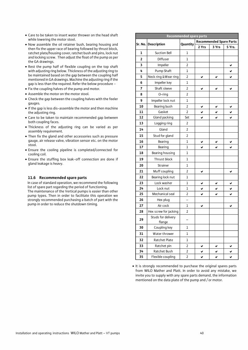
Installation and operating instructions WILO Mather and Platt – VT pumps 40
• Care to be taken to insert water thrower on the head shaft while lowering the motor stool.
• Now assemble the oil retainer bush, bearing housing and then fix the upper race of bearing followed by thrust block, ratchet plate/housing cover, ratchet bush and pins, lock nut and locking screw. Then adjust the float of the pump as per the GA drawings.
• Rest the pump half of flexible coupling on the top shaft with adjusting ring below. Thickness of the adjusting ring to be maintained based on the gap between the coupling half mentioned in GA drawings. Machine the adjusting ring if the gap is less than the required. Refer the below procedure -
• Fix the coupling halves of the pump and motor.
• Assemble the motor on the motor stool.
• Check the gap between the coupling halves with the feeler gauges.
• If the gap is less dis-assemble the motor and then machine the adjusting ring.
• Care to be taken to maintain recommended gap between both coupling faces.
• Thickness of the adjusting ring can be varied as per assembly requirement.
• Then fix the gland and other accessories such as pressure gauge, air release valve, vibration sensor etc. on the motor stool.
• Ensure the cooling pipeline is completed/connected for cooling coil.
• Ensure the stuffing box leak-off connection are done if gland leakage is heavy.
11.6 Recommended spare parts In case of standard operation, we recommend the following list of spare part regarding the period of functioning. The maintenance of the Vertical pumps is easier than other pump types. Then in order to facilitate this operation we strongly recommended purchasing a batch of part with the pump in order to reduce the shutdown timing.
• It is strongly recommended to purchase the original spares parts from WILO Mather and Platt. In order to avoid any mistake, we
invite you to supply with any spare parts demand, the information mentioned on the data plate of the pump and / or motor.
2 Yrs 3 Yrs 5 Yrs.
1 Suction Bell 1
2 Diffuser 1
3 Impeller 2 a
4 Pump Shaft 1 a
5 Neck ring &Wear ring 2 a a a
6 Impeller key 1
7 Shaft sleeve 2 a a a
8 O-ring 2
9 Impeller lock nut 1
10 Bearing bush 2 a a a
11 Gasket 2 a a a
12 Gland packing Set a a a
13 Logging ring 2
14 Gland 2
15 Stud for gland 2
16 Bearing 1 a a a
17 Bearing 1 a a a
18 Bearing housing 1
19 Thrust block 1
20 Strainer 1
21 Muff coupling 2 a a
22 Bearing lock nut 1
23 Lock washer 1 a a a
24 Lock nut 1 a a a
25 Mechanical seal 2 a a a
26 Hex plug –
27 Air cock 1 a a
28 Hex screw for jacking 2
29Studs for delivery
flange–
30 Coupling key 1
31 Water thrower 1
32 Ratchet Plate 1
33 Ratchet pin 2 a a a
34 Ratchet Bush 2 a a a
35 Flexible coupling 2 a a a
Recommended spare parts
Sr. No. Description QuantityRecommended Spare Parts

Installation and operating instructions WILO Mather and Platt – VT pumps 41

Installation and operating instructions WILO Mather and Platt – VT pumps 42
12. Pump Lubrication and Connection Data (Refer Fig. No. 24 & 25, Pg. No. 15 for connection details)
Oil and GREASE LUBRICATED BEARING CONNECTION DATA
13. Recommended Lubricants
Manufacturer Oil Lubricated Bearings Grease Lubricated Bearing
Indian Oil Corporation Servo System-46 Servogem-2/3
Hindustan Petroleum Enclo-46 Lithon-2/3
Bharat Petroleum Hydrol-46 / Hydrol 220 Multipurpose Grease-3
Note: For oil Lubrication: • ISO Grade 46 oil. • All above oils are compatible with each other when fresh. • It is unsafe to mix oil of two or more grades for use in bearings. • Number 46 is Viscosity at 40 degree centigrade in centistokes.
For Grease Lubrication:
• Only lithium base Grease to be used. • Numbers mentioned stands for consistency. • Grease of two different grades should not be used.
14. Decommissioning and recycling The disposal of all material or debris must be done in order to protect the environment. WILO Mather and Platt pumps do not contain any dangerous substances. The major part of the pump is recyclable. The disposal and recycling of the pump sets must be done in accordance with the local in force regulations
The dismounting must be done by qualified personal. Clean and de contamination must be achieved before any transportation or recycling.

Installation and operating instructions WILO Mather and Platt – VT pumps 43
15. Faults, Causes and Remedies
Symptoms Possible cause of trouble and remedies
(Each number is defined in the table below)
-- Pump does not deliver water. 1,2,3,4,6,11,14,16,17,22,23 -- Insufficient capacity delivered. 2,3,4,5,6,7,8,9,10.11.14.17,20,22,23.29,30,31
-- Insufficient pressure developed 5,14,16,17,20,22,29,30,31
-- Pump loses prime after starting. 2,3,5,6,7,8,11,12,13
-- Pump requires excessive power. 15,16,17,18,19,20,23,24.26,27,29,33,34,37 -- Stuffing box leaks excessively. 12,13,24,26,32,33,34,35,36,38.39,40
-- Pump vibrates or it is noisy. 2,3,4,9,10,11,21.23,24,25.26.27,28,30,35,41,42,43, 44, 45,46,47
-- Bearings have short life. 24,26,27,28,35,36,41,42,43,44,45,46,47
-- Pump overheats and seizes. 1,4,21,22,24.27,28,35,36,41
Causes Remedies
1 Pump not primed Ensure that casing is fully filled and water comes out from air- cock
2 Pump column pipe not completely filled with Check water level and blockages at strainer liquid
3 Suction lift too high Reduce by lowering pump elevation or increase Water level
4 Insufficient margin between pressure and vapor Check that NPSH available is at least 1 meter more 1 meter pressure more than NPSH required
5 Excessive amount of air in liquid Check the reasons and eliminate. Gas gets entrapped in liquid. Air may be entering through suction joints
6 Air pocket in suction line Ensure that air release valve is open
7 Air leaks into suction line Tighten pipe joints with solution
8 Air leaks into pump through stuffing boxes Ensure stuffing box sealing
9 Strainer broken Replace
10 Strainer partially clogged Shut off the pump, strainer usually gets cleaned due reverse flow
11 Inlet of suction pipe insufficiently submerged Ensure adequate submergence level as per pump manufacturers recommendation
12 Water seal pipe clogged Clean or change
13 Logging ring is improperly located in stuffing Position logging ring centrally under sealing holes of stuffing box, preventing sealing fluid from entering to box form seal
14 Speed too low Check motor RPM, supply frequency, Motor nameplate speed should be as specified on pump nameplate
15 Speed too high Check motor RPM and supply frequency.
16 Direction of rotating wrong Check correct direction of rotation for motor before coupling to motor
17 Total head of system higher than design head of Check the causes and refer to M&P. Measure with pressure pump gauge
18 Total head of system lower than pump design Check the causes and refer to M&P. Measure with pressure head gauge
19 Specific gravity of liquid different from design Refer to WILO Mather and Platt
20 Viscosity of liquid different from design Refer to WILO Mather and Platt
21 Operation at very low capacity Check the causes and refer to M&P, operate pump at rated Duty
22 Parallel operation of pumps unsuitable for such Refer to WILO Mather and Platt with characteristics curves of pump Operation
23 Foreign matter in impeller Open and clean
24 Misalignment Check with Dial gauge should be within limits and without undue pipe stresses
25 Foundations not rigid Check, vibration on soleplate, check hollowness
26 Shaft bent Dismantle and check, Replace shaft

Installation and operating instructions WILO Mather and Platt – VT pumps 44
Causes Remedies
27 Rotating part rubbing on stationary part Incorrect assembly, correct the assembly 28 Bearing worn Check lubrication, shaft run out, alignment, replace if required
29 Wearing rings worn Replace
30 Impeller damaged Replace
31 Casing gasket defective, permitting internal Replace leakage
32 Shaft or shaft sleeves worn or scored at packing Replace
33 Packing improperly installed Use correct grade and size of packing
34 Type of packing incorrect for operating Use correct grade and size of packing condition
35 Shaft running' out of center because of worn Rectify bearings or misalignment
36 Rotor out of balance, causing vibration Balance the rotor
37 Gland too tight, resulting in no flow of liquid to Adjust gland. Ensure sealing water flow lubricate packing
38 Cooling liquid not being provided to water- Provide cooled stuffing boxes
39 Excessive clearance at bottom of stuffing box Check pumps assembly between shaft and casing, causing packing to be forced into the pump
40 Dirt or grit in sealing, liquid leading to scoring of Provide clean liquid for flushing shaft or shaft sleeve
41 Excessive thrust caused by mechanical failure Check pump operation and assembly inside pump or by failure of hydraulic balancing device, if any (in case of multistage pump etc.)
42 Excessive grease or oil in antifriction bearing Attend housing or lack of cooling, causing excessive bearing temperature
43 Lack of lubrication Provide proper lubrication
44 Improper installation of antifriction bearings Rectify or replace bearing (damage, incorrect assembly of stacked bearings, use of unmatched bearings as a pair etc.)
45 Dirt in bearings Investigate the cause and clean bearing.
46 Rusting of bearings from water in housing Arrest water ingress
47 Excessive cooling of water- cooled bearing, Reduce cooling water flow resulting in condensation of atmospheric moisture in bearing housing

Installation and operating instructions WILO Mather and Platt – VT pumps 45
Annexure-2
Pre-commissioning checklist Pump with Motor
Sr. No.
Activities Checked on Remarks
1 Levelling of Pump set
2 Alignment with and without piping 3 Flushing of pipelines and ensures no leakages 4 Availability of sufficient liquid in sump/suction as per specifications
5
Installation of all instruments Suction and delivery pressure gauges Pressure switches Temperature gauges Any other as supplied/specified
6 Operation of suction, delivery and inline valves 7 Proper supports for piping and other allied equipment 8 Availability of flushing/sealing liquid for stuffing box 9 Availability of sufficient cooling liquid for bearings as specified
10 Free rotation of pump and drive shafts 11 Lubrication of bearings 12 Checking of insulation resistance of motor (if supplied by WILO M&P) 13 Proper cable termination (Clients Scope) 14 Motor Protection Relay Setting (Check with Clients) 15 Check all interlocks as specified/provided
16 No load trial operation of drive Direction of rotation is ok
Noise and vibration are within limits Bearing temperatures and winding temperatures are within limits Overall operation is satisfactory 17 Coupling of pump and drive and free rotation of shafts in coupled condition 18 Suction valve is fully opened 19 Pump is fully primed, and all air is vented 20 Delivery valve is closed (if required) 21 Emergency shutdown is possible
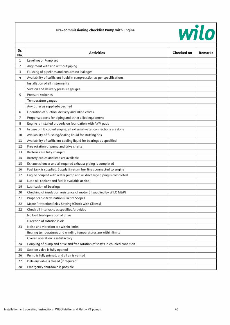
Installation and operating instructions WILO Mather and Platt – VT pumps 46
Pre-commissioning checklist Pump with Engine
Sr. No.
Activities Checked on Remarks
1 Levelling of Pump set
2 Alignment with and without piping 3 Flushing of pipelines and ensures no leakages 4 Availability of sufficient liquid in sump/suction as per specifications
5
Installation of all instruments Suction and delivery pressure gauges Pressure switches Temperature gauges Any other as supplied/specified
6 Operation of suction, delivery and inline valves 7 Proper supports for piping and other allied equipment 8 Engine is installed properly on foundation with AVM pads 9 In case of HE cooled engine, all external water connections are done
10 Availability of flushing/sealing liquid for stuffing box 11 Availability of sufficient cooling liquid for bearings as specified 12 Free rotation of pump and drive shafts 13 Batteries are fully charged 14 Battery cables and lead are available 15 Exhaust silencer and all required exhaust piping is completed 16 Fuel tank is supplied. Supply & return fuel lines connected to engine 17 Engine coupled with water pump and all discharge piping is completed 18 Lube oil, coolant and fuel is available at site 19 Lubrication of bearings 20 Checking of insulation resistance of motor (if supplied by WILO M&P) 21 Proper cable termination (Clients Scope) 22 Motor Protection Relay Setting (Check with Clients) 22 Check all interlocks as specified/provided
23
No load trial operation of drive Direction of rotation is ok Noise and vibration are within limits Bearing temperatures and winding temperatures are within limits Overall operation is satisfactory
24 Coupling of pump and drive and free rotation of shafts in coupled condition 25 Suction valve is fully opened 26 Pump is fully primed, and all air is vented 27 Delivery valve is closed (if required) 28 Emergency shutdown is possible
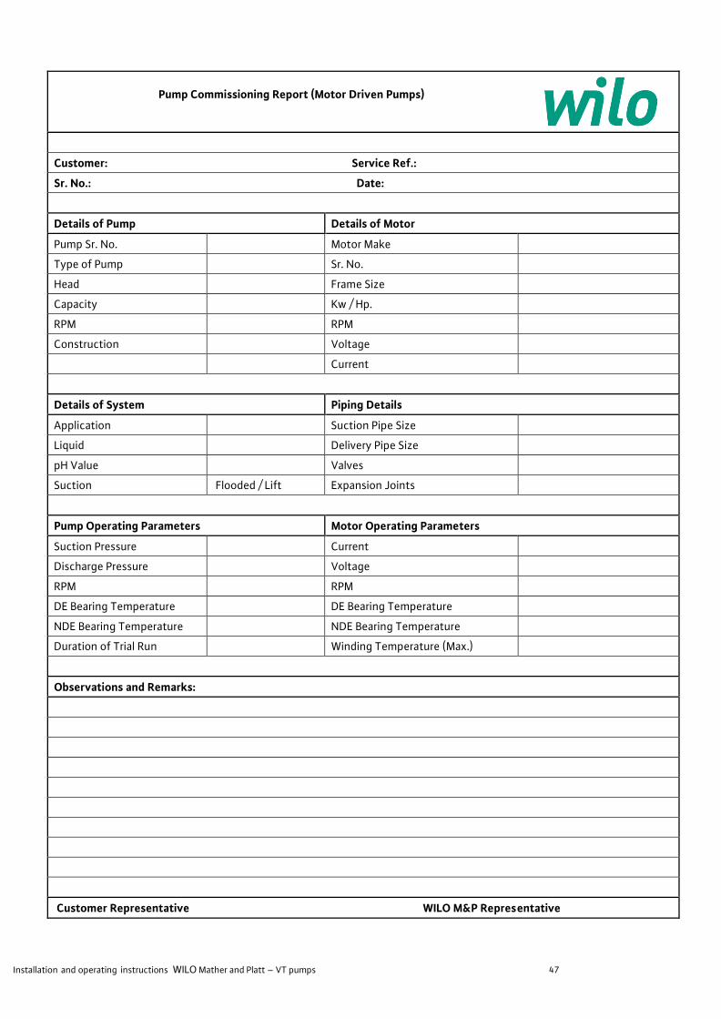
Installation and operating instructions WILO Mather and Platt – VT pumps 47
Pump Commissioning Report (Motor Driven Pumps)
Customer: Service Ref.:
Sr. No.: Date:
Details of Pump Details of Motor
Pump Sr. No. Motor Make
Type of Pump Sr. No.
Head Frame Size
Capacity Kw / Hp.
RPM RPM
Construction Voltage
Current
Details of System Piping Details
Application Suction Pipe Size
Liquid Delivery Pipe Size
pH Value Valves
Suction Flooded / Lift Expansion Joints
Pump Operating Parameters Motor Operating Parameters
Suction Pressure Current
Discharge Pressure Voltage
RPM RPM
DE Bearing Temperature DE Bearing Temperature
NDE Bearing Temperature NDE Bearing Temperature
Duration of Trial Run Winding Temperature (Max.)
Observations and Remarks:
Customer Representative WILO M&P Representative

Installation and operating instructions WILO Mather and Platt – VT pumps 48
Pump Commissioning Report (Engine Driven Pumps)
Customer: Service Ref.:
Sr. No.: Date:
Details of Pump Details of Engine
Pump Sr. No. Engine Make
Type of Pump Sr. No.
Head Type / Model
Capacity BHP
RPM RPM
Construction Cooling System
Details of System Piping Details
Application Suction Pipe Size
Liquid Delivery Pipe Size
pH Value Valves
Suction Flooded / Lift Expansion Joints
Pump Operating Parameters Engine Operating Parameters
Suction Pressure RPM
Discharge Pressure Oil Pressure
RPM Water Temperature
DE Bearing Temperature Lubricating Oil Temperature
NDE Bearing Temperature Gear Box Temperature
Duration of Trial Run
Observations and Remarks:
Auto Mode / Manual Mode
Customer Representative WILO M&P Representative

Installation and operating instructions WILO Mather and Platt – VT pumps 49
Pump set Levelling Record
Required accuracy of pump set levelling is 0.05 mm
Result:
Customer Representative WILO M&P Representative

Installation and operating instructions WILO Mather and Platt – VT pumps 50
Pump and Motor / Engine / Turbine Alignment Record
A: Before Connecting Suction and Delivery Piping:
Gap Between Coupling Halves: mm Actual Gap: mm
B: After Connecting Suction and Delivery Piping:
Gap Between Coupling Halves: mm Actual Gap: mm
Customer Representative WILO M&P Representative
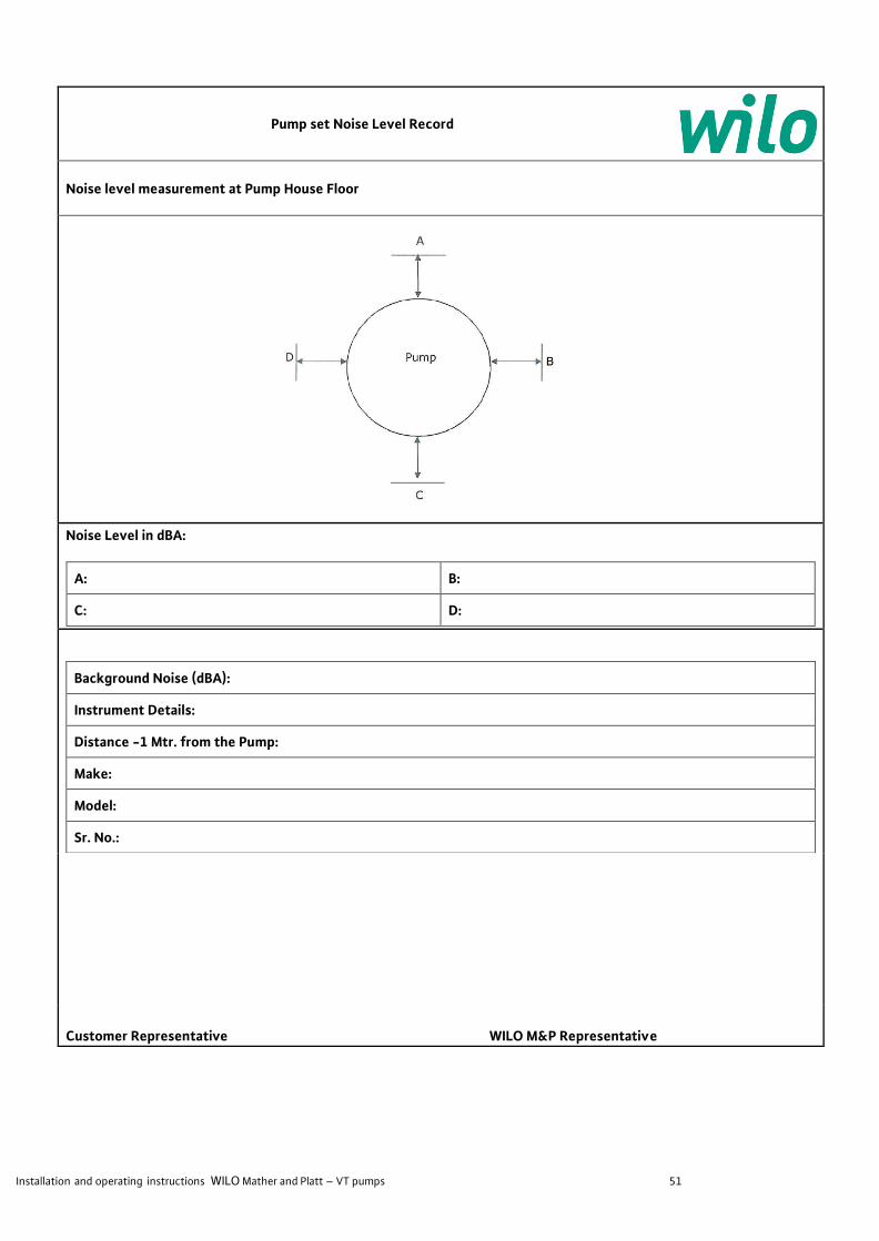
Installation and operating instructions WILO Mather and Platt – VT pumps 51
Pump set Noise Level Record
Noise level measurement at Pump House Floor
Noise Level in dBA:
A: B:
C: D:
Background Noise (dBA):
Instrument Details:
Distance -1 Mtr. from the Pump:
Make:
Model:
Sr. No.:
Customer Representative WILO M&P Representative
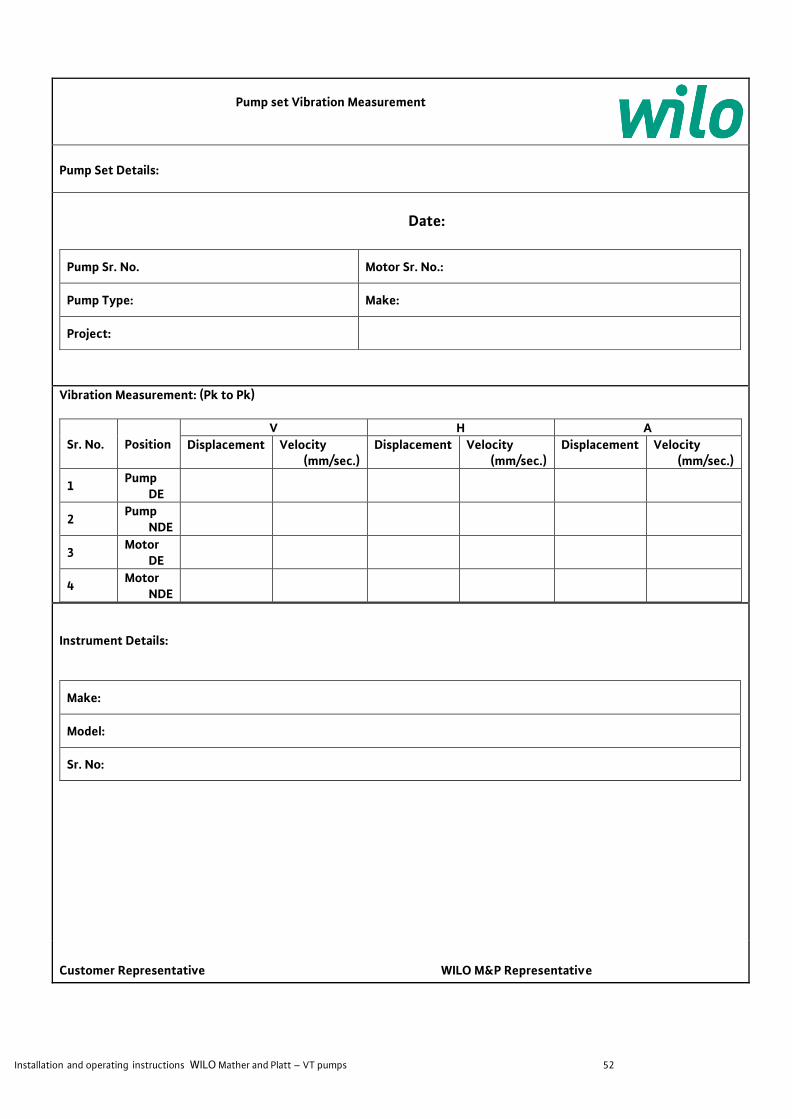
Installation and operating instructions WILO Mather and Platt – VT pumps 52
Pump set Vibration Measurement
Pump Set Details:
Date:
Pump Sr. No. Motor Sr. No.:
Pump Type: Make:
Project:
Vibration Measurement: (Pk to Pk)
Sr. No. Position V H A
Displacement Velocity (mm/sec.)
Displacement Velocity (mm/sec.)
Displacement Velocity (mm/sec.)
1 Pump
DE
2 Pump
NDE
3 Motor
DE
4 Motor
NDE
Instrument Details:
Make:
Model:
Sr. No:
Customer Representative WILO M&P Representative

Installation and operating instructions WILO Mather and Platt – VT pumps 53
Pump set Bearing Temperature Measurement
Pump Set Details:
Date:
Pump Sr. No. Motor Sr. No.:
Pump Type: Make:
Project:
Bearing Temperature:
Sr. No. Position Temperature Ambient Temperature
Remarks
1 Pump DE
2 Pump NDE
3 Motor DE
4 Motor NDE
Instrument Details:
Make:
Model:
Sr. No:
Customer Representative WILO M&P Representative

Installation and operating instructions WILO Mather and Platt – VT pumps 54
NOTES

Installation and operating instructions WILO Mather and Platt – VT pumps 55
NOTES

Installation and operating instructions WILO Mather and Platt – VT pumps 56
___________________________________________________________________________________________________________________
WILO Mather and Platt Pumps Private Ltd.
Mumbai-Pune Road, Chinchwad,
Pune- 411 019, Maharashtra (India)
Tel: +91 20 27442100/1/2/3/4,
Toll Fee Service: 1-800-266-8866
Fax: +91 2027442111
www.wilo.in