Wheels, Tires & Hubs
93
Heavy Equipment Technician First Period Module 190102d Suspension, Wheels and Systems Wheels, Tires and Hubs
-
Upload
khangminh22 -
Category
Documents
-
view
2 -
download
0
Transcript of Wheels, Tires & Hubs
Heavy Equipment Technician
First Period
Module 190102d
Suspension, Wheels and Systems
Wheels, Tires and Hubs

Identify common wheel types and
mounting designs..
Explain tire construction, care and
maintenance in relation to design..
State the safety procedures required
when handling tires and wheels..
Objectives
1.
2.
3.

Objectives
4.
5.
6.
Perform wheel removal, inspection
and installation..
Explain wheel balancing..
Diagnose wheel and tire faults.

Objective One
Identify common wheel types and mounting
designs.

Spoke wheels are
mounted with two
bearings on the axle
shaft, and may have three, five or six spokes..
Spoke Wheels:
Wheel Types:
The brake drum is bolted to the spider.
Brake
Drum
Spoke
WheelA spoke wheel is a
heavy casting, and
may be called a spider
or a Dayton Wheel..
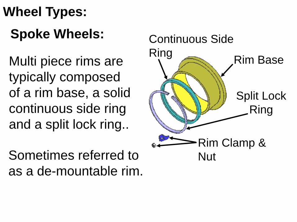
Multi piece rims are
typically composed
of a rim base, a solid
continuous side ring
and a split lock ring..
Wheel Types:
Rim Base
Split Lock
Ring
Continuous Side
Ring
Rim Clamp &
NutSometimes referred to
as a de-mountable rim.
Spoke Wheels:

Wheel Types:
Brake Drum
Spoke
Wheel
Rim Base
Split Lock Ring
Continuous
Side Ring
Rim Clamp & Nut
Rim and tire assembly
are attached to the
spider studs by wedge
shaped clamps and
nuts.
Spoke Wheels:
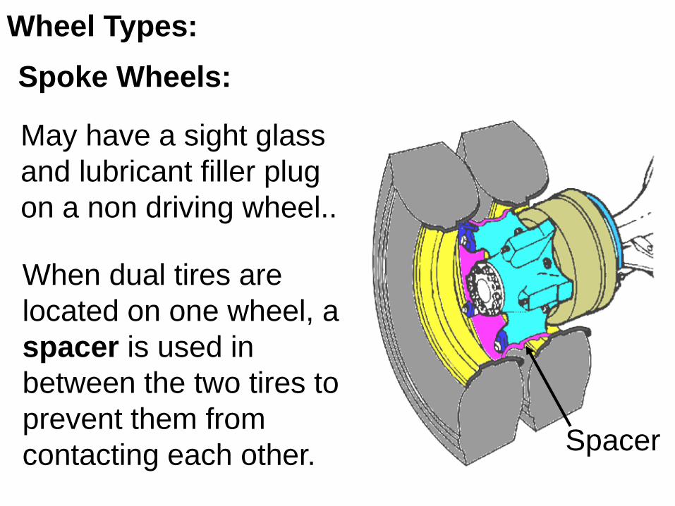
When dual tires are
located on one wheel, a
spacer is used in
between the two tires to
prevent them from
contacting each other.
Wheel Types:
Spoke Wheels:
Spacer
May have a sight glass
and lubricant filler plug
on a non driving wheel..
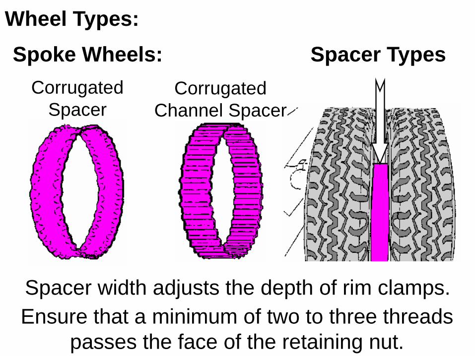
Corrugated
SpacerCorrugated
Channel Spacer
Spacer Types
Wheel Types:
Spacer width adjusts the depth of rim clamps.
Ensure that a minimum of two to three threads
passes the face of the retaining nut.
Spoke Wheels:
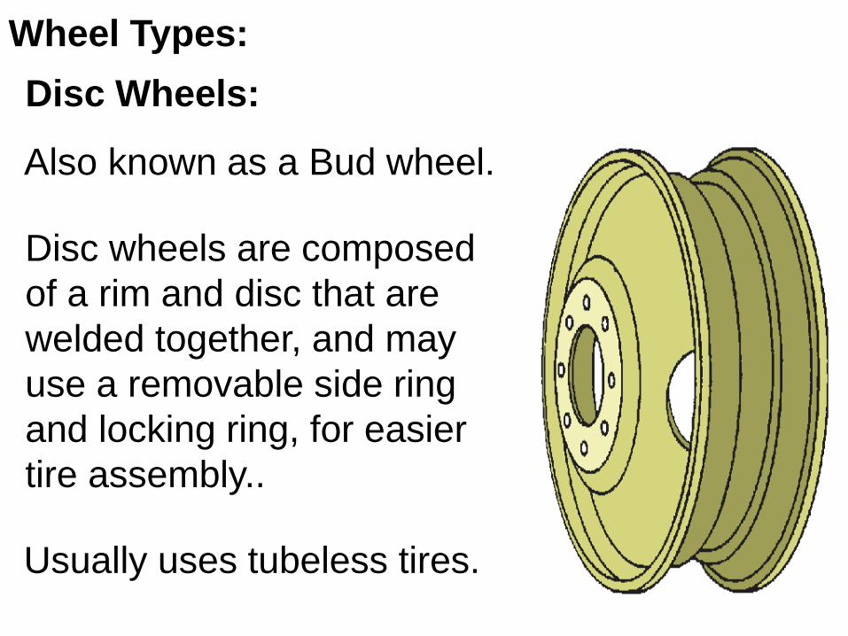
Disc wheels are composed
of a rim and disc that are
welded together, and may
use a removable side ring
and locking ring, for easier
tire assembly..
Wheel Types:
Also known as a Bud wheel.
Usually uses tubeless tires.
Disc Wheels:

Inboard Brake Drum Wheel Types:
The hub is separate
from the wheel,
unlike the spoke
wheel’s hub which
is part of the wheel.
Disc Wheels:
Wheel
Bearings
Wheel
Hub
Wheel
Hub Seal
Adjusting
Nut
Spindle
Brake
Drum
Washer
Disc Wheel
Stud BoltAn inboard Brake
Drum mounting is
located to the rear
of the wheel hub.
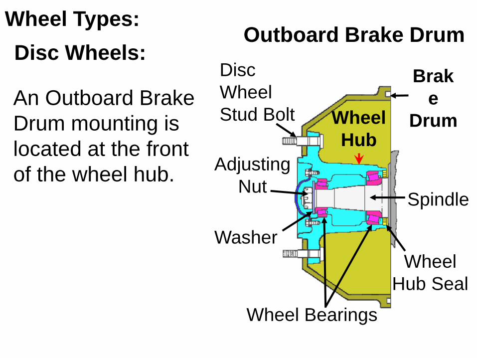
Outboard Brake Drum Wheel Types:
Disc Wheels:
Wheel Bearings
Wheel
Hub
Wheel
Hub Seal
Adjusting
NutSpindle
Brak
e
Drum
Washer
Disc
Wheel
Stud BoltAn Outboard Brake
Drum mounting is
located at the front
of the wheel hub.

Stud piloted disc wheels have
cone shaped recessed stud
holes, and the hub is mounted
and centered by the studs and
cone shaped wheel nuts..
Wheel Types:
Stud Piloted Disc Wheels:
Wheel Nut
Head Type
Wheel
Stud
It is critical that the tapered
portion of the nut enters the
tapered stud hole of the disc
wheel, or the wheel will come
loose.
Taper

When dual wheels are
used, a special nut is
required to secure the
inside wheel and provide
a threaded surface for
the outer wheel nut..
The special nut has two
tapered shoulders to center the inner wheel and
outer wheel, and is also threaded to act as a
stud for the outer wheel and nut.
Inner
Wheel
Hub
Wheel Types:
Stud Piloted Disc Wheels:
Taper
Taper

Uses the center section of
the hub itself, to center the
wheel or wheels..
Wheel Types:
Hub Piloted Disc Wheels:
Flange
Nut
Body
Nut Threads
Hub
Disc Wheels
The nuts are for clamping
the wheel to hub only.
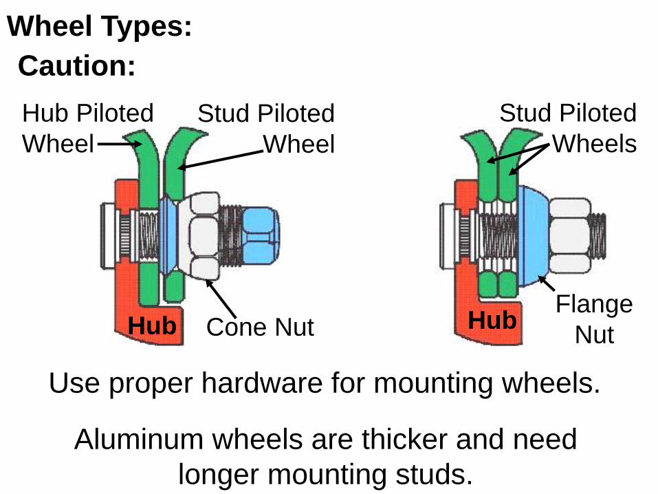
Use proper hardware for mounting wheels.
Stud Piloted
Wheels
Hub Piloted
Wheel
Cone Nut HubFlange
Nut
Wheel Types:
Caution:
Stud Piloted
Wheel
Aluminum wheels are thicker and need
longer mounting studs.
Hub

Objective Two
Explain tire construction, care and
maintenance in relation to design
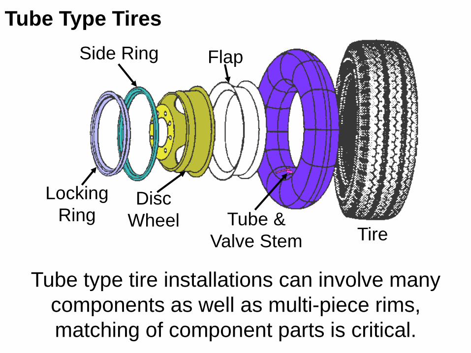
Tube type tire installations can involve many
components as well as multi-piece rims,
matching of component parts is critical.
Tube Type Tires
Locking
Ring
Side Ring
Disc
Wheel
Flap
Tube &
Valve Stem Tire

Tubeless Type Tires
Disc Wheel
& Valve
Stem
Tire
Fewer parts simplifies tire
installation, reduced
service time (required for
careful matching of wheel
and rim components) which
reduces cost.
Very common.

Tread Breakers
Inner
Tube
Cord
Body
Flap
Rim Assembly
Side
Walls
Tube Type Tires
Off-road Tires:
Off-road tires, either
tube or tubeless, are
designed to withstand
heavy loads and shocks
during operation..
Breakers may be made
of shredded steel for
added puncture
protection and strength.

Tread Breakers
Cord Body
Bead
Rim Side
Walls
Tube Type Tires
Off-road Tires:
Inner
Flange
Outer
FlangeO-ring
Seal
Bead
Seat
Band
Off-road tires may
travel at relatively
low speeds as
compared to an
on-road tire, but
their cargo weight is
enormous..

Off-road Tires
Caterpillar 797 truck carries 360 tons of payload
plus the weight of the truck, for a total of about
615 tons on 6 tires.

Tires for motor grader application may have the
same tread design for steering and traction.
Front tires treads may be mounted in the
opposite direction to the rear, for steering
stability.
Directional tires (usually identified by direction
of rotation arrow) are often used for better
traction as well as their self cleaning tread
ability..
Off-road Tires

Some equipment may use solid type tires,
where ride quality is not as important as load
carrying capacity.
Solid Type Tires

Tire Tread Design
On-highway steering and trailer axles usually
use the rib design, while most driving axles
use the block design, because of its better
traction ability..
Rib
Design
Block
Design
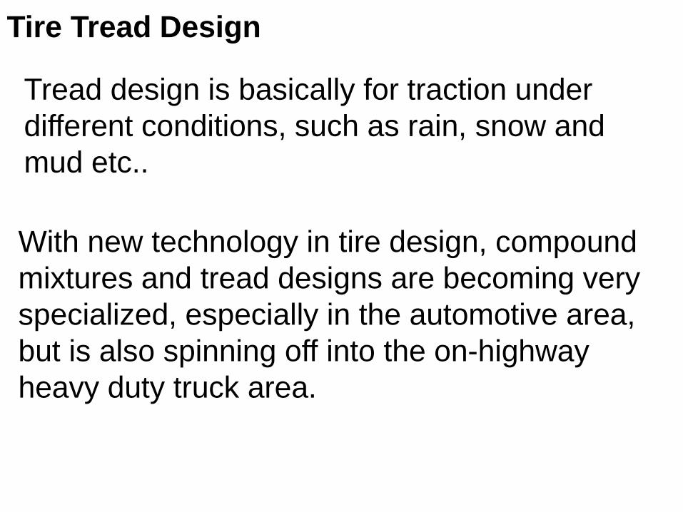
Tread design is basically for traction under
different conditions, such as rain, snow and
mud etc..
Tire Tread Design
With new technology in tire design, compound
mixtures and tread designs are becoming very
specialized, especially in the automotive area,
but is also spinning off into the on-highway
heavy duty truck area.
Tire Construction
Two types of tire construction:
Bias Ply Tire
Radial Tire
1.
2.

Have internal plies or cords
overlapping at an angle,
which makes for a strong
but stiff tire.
The plies or cords are made of rayon, nylon or
polyester, the casing or body is made of natural
or synthetic rubber and a bead of steel cable.
Bias Ply Tire:
The number of plies or
cords give the tire its load
carrying capacity. Cords

The ply arrangement is
the same in the sidewall
as well as the tread area.
Thickness of plies in the
sidewall causes friction
movement within the
plies, which builds up
heat, eventually resulting
in tire failure.
Bead Side
Wall
Plies
Tread
Bias Ply Tire:

The ply arrangement is
the same in the sidewall
as well as the tread area.
Thickness of plies in the
sidewall causes friction
movement within the
plies, which builds up
heat, eventually resulting
in tire failure.
Bead Side
Wall
Plies
Tread
Bias Ply Tire:

The stiffness of a bias ply allows for little or no
sidewall flexing.
This lack of flexing may
cause the loss of tread
contact with the road
causing instability and
loss of traction.
Bias Ply Tire:
Bias ply tires are best suited for low speed and lower load operation.

Radial ply tires use steel in
the body cords (plies) and
steel reinforcing belts..
Steel belts help to protect
the tire from road hazards.
The plies are laid at 90° to
the bead, for good flexibility..
Radial Ply Tire:
Tire Construction
Reinforcing Belts
Tire Casing
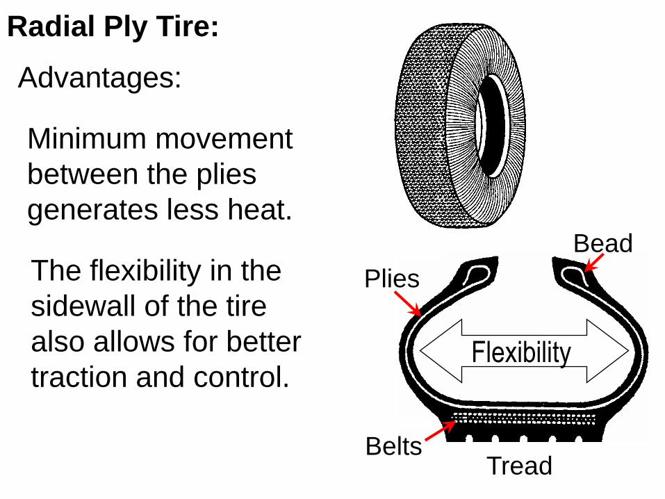
Minimum movement
between the plies
generates less heat.
Radial Ply Tire:
Bead
Plies
Belts Tread
Flexibility
The flexibility in the
sidewall of the tire
also allows for better
traction and control.
Advantages:

Less rolling resistance increases fuel
economy.
Reduces shock loads, resulting in less wear
on steering components and enhances ride
quality.
Higher speed and load capability.
Less repair costs due to puncture resistance.
Radial Ply Tire:
Advantages:

Tire Sizing
Tire size 10.00R20
10.00 is the Section
Width of the tire in
inches..
20 is the rim
diameter in inches
that the tire fits on.

Single Tires:
Tire Matching
Matching tires increases
tire life.
It reducing uneven
loading and steering
problems, such as
pulling to one side.

Tire manufactures allow a maximum difference
in size on the same axle of:
Tire Matching
A B A B
Maximum Circumference
Difference
A – B = ¾” (19.1 mm)
Maximum Diameter
Difference
A – B = ¼” (6.4 mm)

Dual Tires:
Tire Matching
When the same axle has a dual tire arrangement the sizing is also critical..
The specifications for dual tires is the same as for single tires..

Straight Edge
Dual Tires:
Tire Matching
String Gauge
Remove weight off
the tires to ensure
accuracy..
If vehicle load is
evenly distributed,
matching tires
ensures equal tire
loading and longevity.
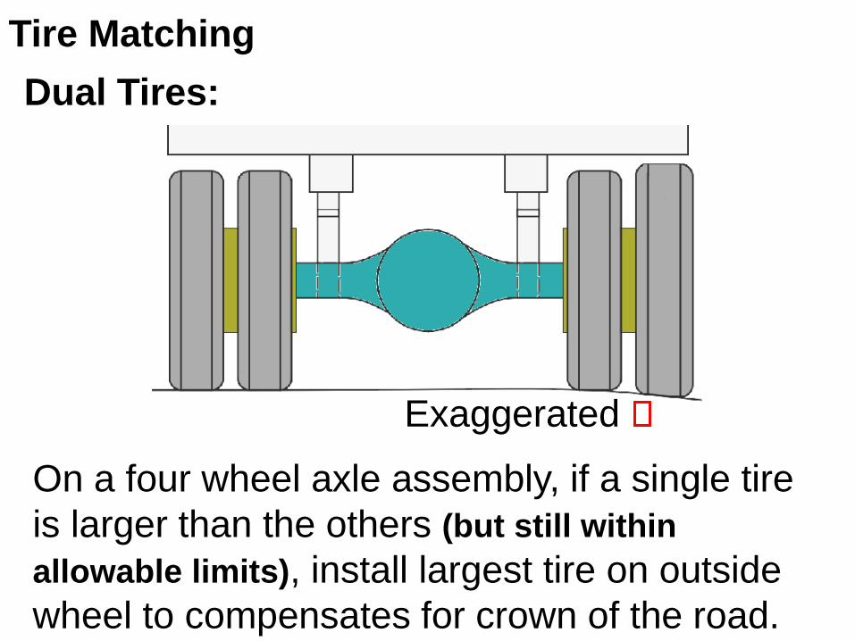
On a four wheel axle assembly, if a single tire
is larger than the others (but still within
allowable limits), install largest tire on outside
wheel to compensates for crown of the road.
Exaggerated
Dual Tires:
Tire Matching

Tire Care
Under-
inflation
Over-
inflation
Under-inflation:
Over-inflation:
Causes abnormal tire
deflection, heat build-up and
tire shoulder wear..
Causes harsher ride, transmits
more shock loads to steering
and suspension components,
and tire centre wear.

Tire Care
Proper
Inflation
Results in proper tire to
road contact for traction,
braking, safety and
even tire wear..
Proper Inflation:
Caution
Ensure a clean and dry air supply for inflation,
to prevent internal wheel and tire damage.
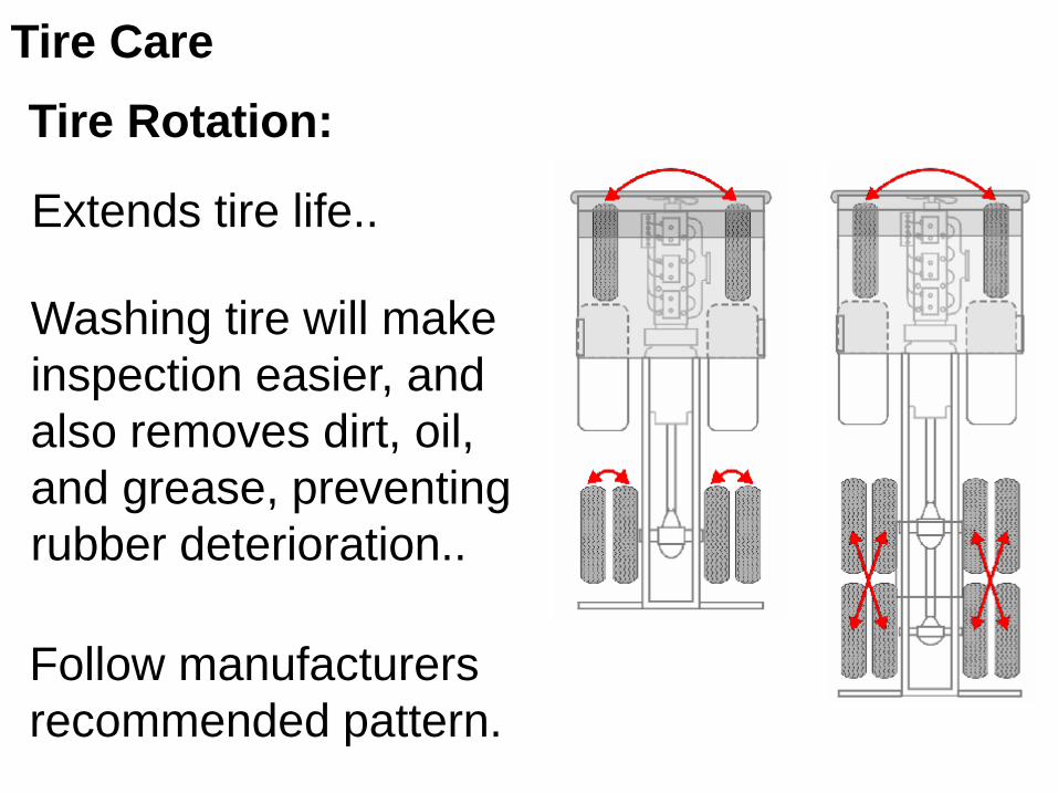
Tire Care
Tire Rotation:
Extends tire life..
Follow manufacturers
recommended pattern.
Washing tire will make
inspection easier, and
also removes dirt, oil,
and grease, preventing
rubber deterioration..

Objective Three
State the safety procedures required when
handling tires and wheels.

Potential paths for explosive forces.
Safety Precautions
Release all air from the tire, before removing
side ring, lock ring, or a tire assembly from
a vehicle, for service work.

Safety Precautions
Release tire air pressure by the valve core to
approximately 40 psi, then remove valve
core.In cold temperatures, moist air may freeze
the valve stem opening closed, ensure no
air pressure by inserting a wire into the
valve stem.
Disassemble wheel/rim assembly as per
manufacturer’s instruction, using proper tools
to prevent personal injury and damage.

Safety Precautions
Sprung
Side
Ring
Cracks
Broken
Side Ring Wheel Nut Damage
Clean components and visually inspect tire, rim,
wheel and mounting components for signs of
overheating, cracks, distortion and damage.

Safety Precautions
Following manufacturer’s instructions regarding
matching parts, ensure use of proper
pieces that match rim.

Always use a safety cage.
Safety Precautions
Visually inspect to ensure that the tire beads
and side ring or lock ring are properly seated.
Use a clip-on air chuck on
an extended hose with a
remote inflate/deflate
mechanism when inflating
a tire, in case deflation is
necessary.

Never add air to a tire that was run while flat, or
at 80% or less of recommended air pressure..
It Must be disassembled and inspected
for damage..
Never assemble mismatched tires and wheel /
rim assemblies.
Never hammer or pry on any type of tire that
is partially inflated..
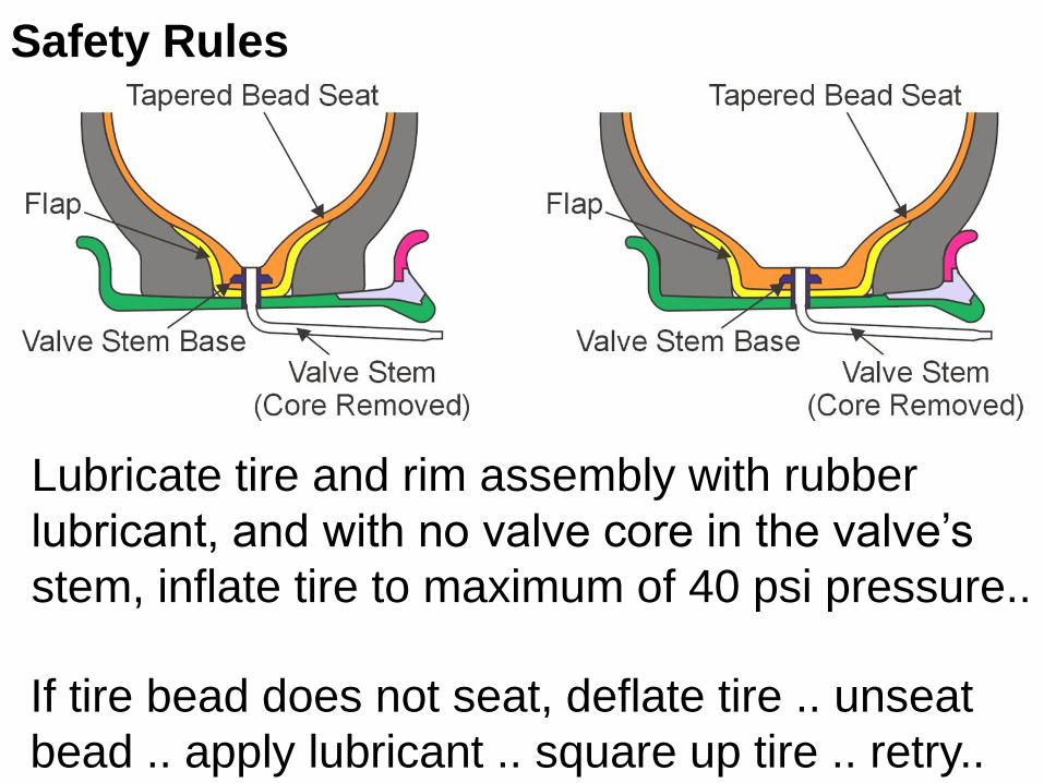
Safety Rules
Safety Rules
Lubricate tire and rim assembly with rubber
lubricant, and with no valve core in the valve’s
stem, inflate tire to maximum of 40 psi pressure..
If tire bead does not seat, deflate tire .. unseat
bead .. apply lubricant .. square up tire .. retry..

Off-load inflated tires with care, damaged
components may cause the assembly to fly apart.
Safety Rules

1. Loosenin
g the
bead.
2. Forcing the
bead into
the rim
well.
3. Prying the
rim out of
the tire.
4. Valve stem
installation.
Work the
lower bead onto the
rim.
Work the
upper bead onto the rim.
Safety Rules
5.
6.
Valve Stem
Rim

Safety Rules
Bead breaking equipment
is easier and safer when
servicing a rim attached
to the machine..
In off-road applications the
rim may have more
components, so matching
parts correctly is critical.

Safety Rules
When removing and
installing tires, smooth
clean tools prevent rim
and tire damage..
Work carefully when
installing side rings and
lock rings..

Safety Rules
Always use a restraining
device when removing the
tire.
Cleanliness prevents
abrasive materials
entering the tire and
reducing tire life..
Use lubricant when
installing tire..

Safety Rules
Cross section of a five piece rim assembly.
Locator – Demountable Rim Only
Lock Ring Driver
Gutter Notch for
Lock Ring Driver
5° Bead Seat
Band, Taper Ring
Tubeless Valve Hole
Lock Ring
Pry Bar
Slot
Flanges
(Side
Ring)
O-ring
Gasket
Bead
Seat
Band Toe
Rim Base

Occupational Health and Safety Regulations
General Hazard Requirements Document
Read it
Safety Rules

Objective Four
Perform wheel removal, inspection and
installation

Wheel hubs are
supported by two
wheel bearings..
Axle Hub Mounting
Steering axles and
trailer axles are usually dead axles.
The wheel hub rotates
around a stationary
spindle that is
attached to the axle..
Dead Axle:Disc
Wheel
Wheel
Nut
Wheel
Stud
Hub
Hub
Cap
Brake
Drum
Outer
Wheel
Bearing
Inner
Wheel
Bearing
Axle
Spindle
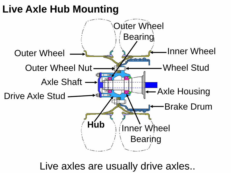
Live Axle Hub Mounting
Outer Wheel Nut Wheel Stud
Hub
Axle Shaft
Brake Drum
Axle Housing
Inner Wheel
Drive Axle Stud
Live axles are usually drive axles..
Outer Wheel
Outer Wheel
Bearing
Inner Wheel
Bearing

Inner Wheel
Bearing
Hub
Axle
Shaft Housing
Outer Wheel
Bearing
The hub is supported by two wheel bearings
that rotate on the axle housing..
The hub is driven by the axle shaft, through
the center of the axle housing.
Spindle
Live Axle Hub Mounting
Axle

A removable brake
drum style of axle hub,
with drum pilot and
wheel pilot notches..
Axle Hub Removal
Wheel
Pilot
Drum
Pilot
Wear proper breathing
mask, the brake dust
may contain asbestos.
Hub and bearings must be kept free of dust,
dirt, and lubricated properly when installing.
Pilot Pad

Most axle shafts are retained by split tapered
dowel wedges, Do Not remove nuts until
dowel wedges are loose.
Dowel Wedge
Flat
Washer
Nut Axle Shaft Flange
Clearance
Axle Hub Removal
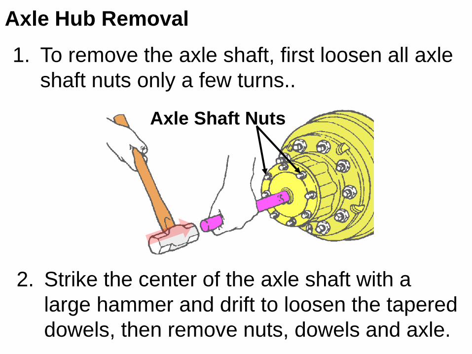
To remove the axle shaft, first loosen all axle
shaft nuts only a few turns..
Axle Hub Removal
Strike the center of the axle shaft with a
large hammer and drift to loosen the tapered
dowels, then remove nuts, dowels and axle.
Axle Shaft Nuts
1.
2.

Inspect all parts
for serviceability..
Brake Drum
Mounting
Studs
Axle Shaft
Mounting Studs
Hub cleanliness
is essential for
component
longevity..
Axle Hub Inspection
Stud Nut
Install lubricated bearing assembly and seal in
the hub, to prepare for installation onto the
axle housing spindle.

Axle Hub Inspection
Shiny spots on spindle’s
bearing mounting surface
may be caused by bearing
creep..
Normally bearing creep allows the bearing’s
inner ring to slowly turn on the spindle to
prevent spot loading of the bearing.
Clean all spindle mounted
parts with non-petroleum
based product..
Axle Hub Inspection
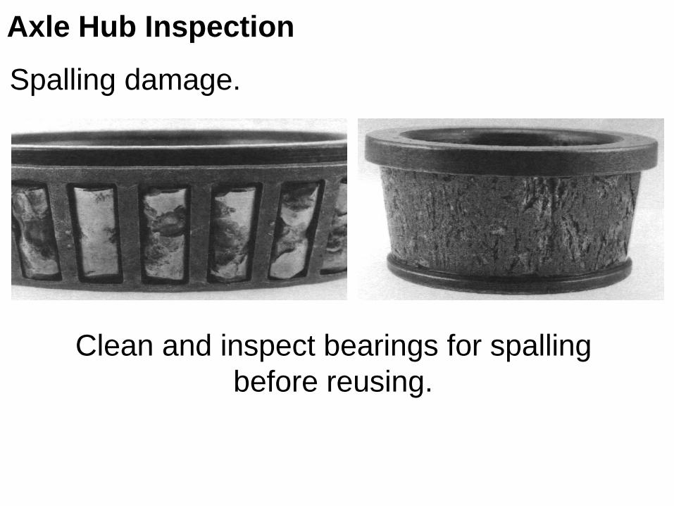
Clean and inspect bearings for spalling
before reusing.
Spalling damage.

Crack damage
may be caused
by improper stud
installation.
Axle Hub Inspection
The ends of the studs may be stamped with
“L” or “R”, to designate left or right hand thread.
Crack
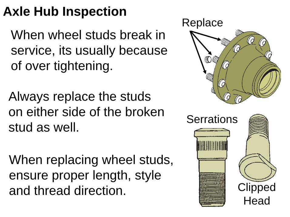
When wheel studs break in
service, its usually because
of over tightening.
Always replace the studs
on either side of the broken
stud as well.
Replace
When replacing wheel studs,
ensure proper length, style
and thread direction.
Serrations
Clipped
Head
Axle Hub Inspection

Using proper steel
tools, install lubricated
bearing cup, and seal
in the right direction.
Axle Hub Installation
Outrunner
Handle
Outrunner
Adapter
Plate
Bearing
Centering
Tool
Seal
Do not use brass tools,
they chip easily and
contaminate the
assembly process.

Axle Hub Installation
Hub retaining devices such as adjustment nuts
and locking devices should be properly set.

Fill the hub cavity with
recommended lubricant,
before axle installation.
Some hub assemblies are
equipped with see through
sight glass, for lubrication oil
level identification.
Axle Hub Installation

RimStud
ClampSpacer
On a dual wheel
assembly, ensure
spacer is of the
correct width for the
application.
On flange style wheel nuts, use
two drops of oil between the
flange and the hex..Oil
Axle Hub Installation
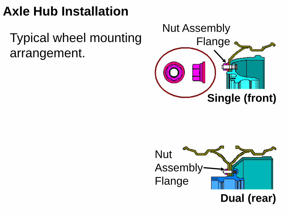
Typical wheel mounting
arrangement.
Single (front)
Dual (rear)
Nut Assembly
Flange
Nut
Assembly
Flange
Axle Hub Installation

1
25
43
1
2
3 4
5
6
1
2
3
4
56
7
8
9
10
Axle Hub Installation
Typical Wheel Tightening Patterns
Torque in three steps, 1/3, 2/3, and full torque,
according to manufacture’s torque specification..
Recheck torqued wheel nuts after 100 – 150 km.
Objective Five
Explain wheel balancing.

Wheel Balancing
Wheel balancing is required to maximize tire
life and to eliminate unnecessary vibrations..
Two main types of wheel balance problems
can exist..
Static Unbalance..
Wheel balancing is accomplished by using a computerized machine..
Dynamic Unbalance..
1.
2.
Few shops have hand type balancers.

Is a heavy spot in the center
of the tire which causes the
wheel to bounce, tramp or
hop..
Static unbalance may cause
localized tire tread wear,
shock absorber failure, poor
braking and steering,
because of loss of tire to
road contact.
Static Balance Problems
Bounce:
Heavy
Spot
Centreline of
Spindle

Dynamic Balance Problems
Is a heavy spot off center of
the tread, which causes a
shimmy or wiggle.
Dynamic unbalance may
cause tire wear (scuffing),
steering tie rod component
failure, as well as steering
problems.
Heavy
Spot
Shimmy:
Centreline of
Spindle

Check Wheel
Radial
Runout
Check Wheel Lateral
Runout
Check Total
Radial Runout
Check
Total Lateral Runout
Runout
Using a roller tip dial indicator, check
for total radial and lateral runout.
Radial Runout Lateral Runout

Cone Type Static Wheel Balancer
Balancer
Cone
Side View
(exaggerated) Top View
Light Side
(bubble not centered)
Tire Disc
Wheel Centre
Static Tire Balancing

At 180° opposite the heavy spot, place one half of
the required weight on each side of the rim,
Static Tire Balancing
Add Balance Weights Here
Heavy Spot
Corrective Weights:

Dynamic Tire Balancing
Can be done on or off the vehicle depending
on type of wheel balancer device used.
Cleanliness of the wheel and tire assembly is
critical for accurate balancing.
If balancing larger, lug type tire assemblies,
balance one side first, then the other side.
May be more accurate and less time
consuming.

Dynamic Tire Balancing
Corrective Weights:
Add Balance Weights Here
Heavy Spot
Always recheck tire balance after adding
recommended balance weight.

Objective Six
Diagnose wheel and tire faults.

Rear axle housing out of alignment can
cause tire scuffing and pulling to one side.
Introduction
Front
Axle
Rear
Axle
Leading End
Trailing End
Tire damage is most often caused by human
error, such as overloading, excessive speeds
and operating off-road..
Tire Damage
Tire damage may also be caused by:
Incorrect alignment settings..
Road hazards (rocks, nails, pot holes, etc).
Suspension damage..
Improper matching of tires..
ℴ
ℴ
ℴ
ℴ

Tire Damage
Tire damage may also be caused by:
Under-inflation Over-inflation

Feathered Edge
Tire Damage
A worn tie rod generally causes a feathered
edge. (Affects Toe)

Tire Damage
Punctures can affect tires
differently depending on
their construction design.
Sizing tires correctly on
each axle, ensures even
loading of the individual
tires.
Damaged
Bias Ply
Damaged
Radial

Wheel / Rim Damage
Flat spot on a wheel caused by
heavy loads and impacts, which reduces the air
retaining ability of the wheel or rim.
Chording –

THE
END