What Robotics can Learn from Spiders and vice versa
207
ETH Library Locomotion of Spiders - What Robotics can Learn from Spiders and vice versa Doctoral Thesis Author(s): Göttler, Chantal Publication date: 2021 Permanent link: https://doi.org/10.3929/ethz-b-000502395 Rights / license: Creative Commons Attribution 4.0 International This page was generated automatically upon download from the ETH Zurich Research Collection . For more information, please consult the Terms of use .
-
Upload
khangminh22 -
Category
Documents
-
view
1 -
download
0
Transcript of What Robotics can Learn from Spiders and vice versa
ETH Library
Locomotion of Spiders - WhatRobotics can Learn from Spidersand vice versa
Doctoral Thesis
Author(s):Göttler, Chantal
Publication date:2021
Permanent link:https://doi.org/10.3929/ethz-b-000502395
Rights / license:Creative Commons Attribution 4.0 International
This page was generated automatically upon download from the ETH Zurich Research Collection.For more information, please consult the Terms of use.
DISS. ETH NO. 27370
Locomotion of Spiders - What Roboticscan Learn from Spiders and vice versa
A thesis submitted to attain the degree of
DOCTOR OF SCIENCES of ETH ZURICH
(Dr. sc. ETH Zurich)
presented by
Chantal GöttlerM.Sc., University of Stuttgart
born on 12.10.1993citizen of Germany
accepted on the recommendation of
Prof. Dr. Roland Siegwart, ExaminerProf. Dr. Metin Sitti, Co-examiner
Prof. Dr. Marco Hutter, Co-examinerProf. Dr. Guillermo Amador, Co-examiner
2021

Abstract
The locomotion of spiders has been fascinating researchers and engineers for over acentury. Different to insects and humans, spiders use muscles to flex, but hydraulicpressure to extend their legs. Fluidic actuation, known for fast and high-poweroutputs, are receiving a rising interest in the last decade for soft, lightweight andcompliant robotic implementations. These robots have application fields in safe-human-robotic interactions, actuation through narrow inaccessible terrain for rescuepurposes or adaptable manipulation of complex and delicate shapes for manufacturingand production facilities, but also medical applications.In this thesis, the detailed joint structure, functioning and material properties of
the femur-patella joint of jumping spiders (Phidippus regius) was analyzed. Unlikehumans and insects, spiders use a combination of muscles and blood pressure to movetheir limbs. In this process, flexion is produced by a large number of muscles, whileextension is produced by the hydraulic pressure of the body fluid (hemolymph). Thefocus of this work was to gain a better understanding of morphological componentsin order to translate them into a technical application, more specifically a fluidicactuator. The properties of the articular membrane, which plays an essential rolein hydraulic stretching, were given special attention. Various optical methods, suchas light, scanning and laser microscopy, were used to visualize the functioning ofthe joint membrane as well as surface properties. Micro structures were discovered,which are distributed in alternating sections on the membrane and could play arole in communication, self-cleaning and friction reduction. The disappearanceof these micro structures after deproteinization of the exoskeleton indicates thatthe microstructures are likely formed by proteins in the outermost layer of theexoskeleton, the epicuticle. UV light analysis further indicates that differences inprotein incorporation exist between the two alternate domains, possibly incorporatingthe elastic protein, resilin. Material properties, such as stiffness and hardness of thearticular membrane, were analyzed by nanoindentation and a significant differencebetween the alternating micro structural parts was found. Histological sections andX-ray images suggest that thickness and density differences between the alternatingparts is another cause for their different material properties. The results confirmthe hypothesis of a so-called anisotropic articular membrane. It can be suggestedthat the stiffened segments or half-rings allow controlled and guided folding of themembrane during flexion of the joint and prevent unintentional inflation of the
i
Abstract
membrane when large pressures are applied during extension. The translation of thehinge membrane folding mechanism, as well as the stiffened elements, into a flexible3D-printed prototype have shown, that the absence of stiffening elements would notallow a controlled folding, but rather result in tip-induced wrinkling. This ultimatelyleads to material failure and thus prevents longevity of the membrane.In general, the fabrication and implementation of the spider-inspired actuator
took today’s requirements for soft, fluidic actuators into account. These include highflexibility and compliance, a lightweight and modular design, and durability andenvironmental sustainability. As the demand for small implementations increases, thefabrication and materials were chosen in such a way to allow smaller actuators to bemanufactured in the future. The presented prototype was fabricated using filament-based 3D printing technology from flexible and robust themoplastic polyurethane(TPU) and sealed internally with latex. Water was used for hydraulic extension andwires for flexion to simulate the interaction of muscles and hydraulic stretching. Thespider-inspired principle achieved working angles of 125◦, which far exceeds previousimplementations (60-90◦) and approaches the capabilities of spiders (140◦). Analysisof the pressure and force relationships have shown that the actuator motion can beaccomplished via linear relationships. The results further showed that a single 6-10g articulated segment was able to lift weight elements of 600 - 1kg against gravity ata hydraulic pressure of 200-300 kPa. The rapid, radial deployment of the articulatedsegment also enabled high torque transmission, which was demonstrated by jumps.The 120g platform was able to achieve jumps of up to 10 cm in height and 10 cmin width. The analyses showed that when the joint is opened quickly, there is animmediate drop in pressure, which may be explained by the inertia of the fluid. Sucha pressure drop could generate losses in force and torque transmission and also leadto material damage.Therefore, to understand whether this phenomena would also appear in spiders,
the fluid This included the fluid speed, shear rates and viscosity property of thehemolymph under different pressures and the flow behavior inside the femur-patellajoint. The exact fluid flow was visualized and a non-Newtonian (shear-thinning)behavior of the hemolymph was detected. Such a property could explain why rapidvolume displacement is possible during spider leg extension. This would avoidcavitation when the leg springs open during jumping. For hydraulic applications,such a fluid could increase mechanical efficiency at high pressures while keeping thevolumetric efficiency (transfer rate of the fluid) constant over a wide range.
Finally, the successful, functional implementation of the spider-inspired actuatorthus not only enables its application in the field of prostheses or robots in the future,but also yields new questions and insights into the behavior and functioning of spidermotion.
ii

Zusammenfassung
Die vorliegende Doktorarbeit handelt von der detaillierten Analyse des Gelenkauf-baus, der Funktionsweise und der Materialeigenschaften des Femur-Patella Gelenksvon Springspinnen der Gattung Phidippus regius. Im Gegensatz zu Menschen undInsekten benutzen Spinnen eine Kombination aus Muskeln und Blutdruck für dieBewegung ihrer Gliedmaßen. Dabei erfolgt die Beugung über eine große Anzahl anMuskeln, während die Streckung über den hydraulischen Druck der Körperflüssigkeit(Hämolymphe) erzeugt wird. Der Fokus dieser Arbeit bestand darin, ein besseresVerständnis von morphologischen Komponenten zu bekommen, um diese in einetechnische Anwendung, genauer gesagt einen fluidischen Aktor, umzusetzen. DieEigenschaften der Gelenkmembran, welche bei der hydraulischen Streckung eineessentielle Rolle spielt, wurden hierbei besonders beachtet. Verschiedene optischeMethoden, wie Licht-, Raster- und Lasermirkoskopie wurden eingesetzt um die Funk-tionsweise der Gelenkmembran sowie Oberflächeneigenschaften darzustellen. Dabeiwurden Mikrostrukturen entdeckt, welcher in alternierenden Abschnitten auf derMembran verteilt sind und eine Rolle in der Kommunikation, Selbstreinigung undReibungsreduzierung spielen könnten. Das Verschwinden dieser Mirkostrukturennach einer Deproteinierung des Exoskeletts weist darauf hin, dass die Mikrostruk-turen wahrscheinlich von Proteinen in der äußersten Schicht des Exoskeletts, derEpikutikula, gebildet werden. UV-Licht Analysen zeigen weiterhin, dass Unterschiedein der Proteineinlagerung zwischen den zwei alternierenden Bereichen bestehen undmöglicherweise das elastische Protein, Resilin, eingelagert ist. Materialeigenschaften,wie die Steifigkeit und Härte der Gelenkmembran wurden mittels Nanoindentationanalysiert und es konnte ein signifikanter Unterschied zwischen den alternierendenMikrostrukturbereichen festgestellt werden. Histologische Schnitte und Röntgen-strahl Aufnahmen lassen vermuten, dass Dicke und Dichtigkeitsunterschiede zwischenden alternierenden Bereichen eine weitere Ursache für deren unterschiedliche Materi-aleigenschaften ist. Die Ergebnisse bestätigen die Hypothese einer sog. anisotropenGelenkmembran. Es lässt sich vermuten, dass die versteiften Segmente bzw. Halb-Ringe eine kontrollierte und geführte Faltung der Membran während der Beugung desGelenks ermöglicht und ein ungewolltes Aufblasen der Membran bei großen Druckein-wirkung während der Streckung verhindert. Die Übersetzung des Faltmechanismusder Gelenkmembran, sowie der versteiften Elemente in einen flexiblen, 3D-gedrucktenPrototypen haben gezeigt, dass das Fehlen von Versteifungselementen eine kontrol-
iii

Zusammenfassung
lierte Faltung nicht ermöglichen würden und es zu spitzzuflaufenden Knitterungenkommt, welche letztenendes zu Materialversagen führen und somit eine Langlebigkeitder Membran verhindert. Im Allgemeinen wurde für die Fabrikation und Umsetzungdes spinnen-inspirierten Aktors die heutigen Anforderungen für soft, fluidische Ak-toren beachtet. Dazu gehören eine hohe Flexibilität und Nachgiebigkeit, ein leichterund modularer Aufbau sowie Langlebigkeit und Umweltverträchlichkeit. Da dieNachfrage nach immer kleineren Implementierungen steigt, wurde auch versuchtdie Fabrikation und das Material so zu wählen, dass in Zukunft kleinere Aktorenhergestellt werden können. Der vorgestellte Prototyp wurde mittels Filament basierter3D Druck Technologie aus flexiblen und robusten themoplastischem Polyurethan(TPU) hergestellt und mit Latex innenseitig abgedichtet. Wasser wurde zur hydraulis-chen Kraftübertragung und Fäden zur Beugung benutzt, um das Zusammenspielvon Muskeln und hydraulischer Streckung zu simulieren. Das spinnen-inspiriertePrinzip ermöglicht einen Arbeitswinkel von 125◦, welches vorherige Umsetzungen(60-90◦) weit übertrifft und der Spinnenfähigkeiten (140◦) näher kommt. Die Anal-yse der Druck und Kraft Verhältnisse haben gezeigt, dass sich die Bewegung desAktors über lineare Verhältnisse bewerkstelligen lässt. Es konnte gezeigt werden,dass ein einzelnes 6-10 g schweres Gelenksegment Gewichtelemente von 600 - 1kgbei einem hydraulischen Druck von 200-300 kPa gegen die Schwerkraft anhebenkann. Das schnelle, radiäre Aufschnellen des Gelenksegments ermöglicht zudemeine hohe Übertragung des Drehmoments, welches mittels Sprüngen demonstriertwerden konnte. Die 120g schwere Plattform konnte dabei Sprünge von bis zu 10 cmHöhe und 10 cm Weite erzielen. Die Analysen ergaben, dass bei einem schnellenAufschnellen des Gelenks, es zu einem sofortigen Druckabfall kommt, welches sichmöglicherweise durch die Trägheit der Flüssigkeit erklären lässt. Ein solcher Druck-verlust könnte zu Verlusten bei der Kraft und Drehmomentübertragung erzeugenund auch zu Materialschäden führen. Um das Flüssigkeitsverhalten in der Spinnezu verstehen wurden deswegen die Viskositätseigenschaft der Hämolymphe unterverschiedenen Drücken und das Flussverhalten im Bein untersucht. Es konnte dergenaue Flüssigkeitsstrom im Gelenk dargestellt und ein nicht-newtonisches bzw.ein scherverdünnendes Verhalten der Hämolymphe festgestellt werden. Eine solcheEigenschaft könnte erklären, weshalb eine schnelle Volumenverschiebung währendder Streckung der Spinnenbeine möglich ist und es nicht zu einer Kavitation beimAufschnellen während des Sprungs bzw. zur Sauerstoffunterversorgung der Muskelnund Organe bei hoher Aktivität kommt. Für hydraulische Anwendungen könnte einesolche Flüssigkeit die mechanische Effizienz bei hohen Drücken erhöhen, wobei dievolumetrische Effizienz, also die Übertragungrate der Flüssigkeit über einen großenBereich konstant gehalten werden kann. Die erfolgreiche, funktionelle Umsetzung desspinnen-inspirierten Aktors ermöglicht somit nicht nur die Anwendung im Bereichvon Prothesen oder Robotern in Zukunft, aber ergibt auch neue Fragestellungen und
iv
Einsichten in das Verhalten und die Funktionsweise der Bewegung von Spinnen.
v

Acknowledgements
I would like to thank Prof. Dr. Metin Sitti for the opportunity to work on this veryinterdisciplinary and interesting topic, the financial support and for the scientificdiscussions and feedback on my research.
I would like to express my very great appreciation to Prof. Dr. Roland Sieg-wart for the great opportunity to work at the Autonomous Systems Lab, ETH Zurich,for his interesting questions and ideas, for the financial and networking support, theopportunity to attend World.minds and the wonderful time in Zurich.
I am particularly grateful for the scientific support by Prof. Dr. Guillermo Amador,for the great and fruitful discussions on my research, the support in my scientificcareer and for being part of my committee.
My special thanks to Prof. Dr. Marco Hutter for being part of my committeeand taking the time to read about my research.
I would like to thank Prof. Dr. Bernhard Schölkopf and Prof. Dr. ThomasHofman for financial support and creating the Center for Learning systems.
I am very thankful for the constant emotional and scientific support during myPhD by Dr. Karin Elflein, for all the insights on spider dissection and histologymethods and for the late night discussions about spiders and life.
I would like to acknowledge Prof. Dr. Abdon Pena-Francesch for his great supporton the fabrication of microstructured surfaces, his constant excite on this topic andbeing a great support during my PhD thesis.
I would like to express my gratitude to Dr. Thomas van de Kamp for 3D scanningthe spider legs at KIT, introduction into Amira and Biomedisa, invitation to theGraduiertenforum Morphologie and to the Westdeutscher Entomologentag and forall the great and interesting conversations about insects, especially ants.
I would like to thank Prof. Dr. Joachim Spatz and Ioanis Grigoridis for the
vii

Acknowledgements
introduction and use of the SEM.
I appreciate the feedback offered by Dr. Lionel Ott and his support on my pa-pers, always having an open ear and being a great roommate.
I have greatly benefited from Dr. Juan Nieto and Dr. Nicholas Lawrance asmy go-to-persons at the ETH, providing me with feedback on my papers, alwaysbeing supportive, being fast responders and always in for fun ideas.
I am deeply grateful to Dr. Jen Jen Chung for being super supportive, for de-tailed feedback on my paper and talks about career and future.
I received generous support from Achim Diem in assistance and analysis of thenano-indentation experiments.
I would like to thank Nagaraj Krishna-Subbaiah and Anitha Shiva for their help inthe fabrication of micro channels and micro structures.
I would like to offer my special thanks to Lisa Böhler for her work as my HiWi,her support in care-taking my spiders, for assisting me during high speed and OCTrecordings.
I would like to thank Prof. Dr. Stelian Coros for giving me the advise to useTPU as printing material.
I am very grateful for the support by Prof. Dr. Zoey Davidson, on discussingthe role of microstructures and his general advice.
I would like to thank Prof. Dr. Kirstin Petersen and Dr. Alexander Spröwitzfor their initial support on my PhD topic and the ICRA publication.
I am thankful for the support and encouragement by Prof. Dr. Guozhan Lum,for giving great advice about research and showing us the great world of Singapore.
I appreciate the feedback and help offered by Dr. Marcus Zuber and for assis-tance in CT scans of the spiders.
I would like to express my gratitude to Janes Odar for support in Amira, emo-tional support and fun times during scanning in Karlsruhe.
viii

I have greatly benefited from Philipp Lösel, who introduced me to Biomedisa.
Special thanks to Dr. Abel Gawel for welcoming me in Zurich, for his support,for the great time in Singapore and being a great friend!
I am grateful for insights provided by Dr. Bekim Berisha and Philipp Wilhelmabout tensile tests and FEM analysis.
I would like to offer my special thanks to Dr. Thomas Braun for providing in-sights into contact angle measurements with nanodroplets on peltier elements.
I have greatly benefited from Dr. Nino Läubli and Dr. Jan Burri as assistance inhandling the Femto tool.
I would like to offer my special thanks to Michael Riener for his help and sup-port and just being a great Swiss guy!
I am really thankful for the support by Muhammad Yunusa, for being the sec-ond PhD suffering with me from the beginning! Thanks for being supportive throughout all the time!
I received generous support from Prof. Dr. Martin Adams, his wife and family andwould like to thank them for giving me a great time and very nice memories in Zurich.
I would like to generally thank my roommates, accepting me and my chaos.
Furthermore, I would like to thank the whole PI, ASL and CLS including thestaff members for their constant support and a great time. Especially, Lucy, Cornelia,Janina, Patricia, Jutta, Sarah, Sara, Leila and Magdalena for their great support inmaking my life easier. I would also like to thank my BOGY and Bachelor studentsfor the great time and remembering me about the fun side of science.
I am more than thankful for all my close colleagues and friends; Berk, Varun,Donghoon, Sukho, Yunwoo, Amir, Hamed, Ville, Josh, Wendong, Xiaoguang,Matthew, Dirk, Onder, Oncay, Ceren and Victoria for being a great emotionalsupport during my time in Stuttgart, the fun discussions during lunch and dinner,Chinese Restaurant at Schwaben Galerie, Bowling, (Korean) BBQ, soccer tourna-ments, ping pong, Singapore and karaoke nights!
My deepest appreciation goes also to Julian, Ken, Michel, Hermann, Vivian, Teja,
ix
Acknowledgements
Fadri, TJ, Helen, Rene, Gianluca, Lukas, Rik, Weixuan, Matthias, Karen and Mar-garita for being a great emotional support during my time in Zurich, the fun boardgame nights, ping pong, dance nights, the street food festival, sushi!, the snoringnights during the Skitrip, the great Avengers countdown and the fun ChristmasVideo making!
I would like to show my greatest appreciation to Mehdi, Partha, Anurag, Alex,Shoubik, Kamil and Timmy for the fun fun discussions during the retreat, thememorable and epic board game nights in Tübingen and many more unforgettableevents that reinforced our friendship!
Also, special thanks to Wolf, Carola, Fabienne, Simone, Damir, Tobias, Ann-Catrinand Patrick for being good friends, staying interested on my research and my lifealthough we were all busy as always.
I am particularly grateful for the support by Dr. Herbert Ammann, who wasthe best landlord one can only wish for and organized memorable wine-eveningsabove the Zurich lake.
I am very thankful for the support by Vanessa Oehmig, who was my "spider dealer"and provided me with advice for breeding and keeping jumping spiders.
I owe a very important debt to all the spiders, who supported my research.
I would like to express my sincere thanks to my grandparents for caring aboutme and asking me now and then whether I am still alive, also to my mother-in law,Annette, for being understanding and supportive!
I am very thankful for my siblings, Annique, Henry, Richard, who were alwayssupporting me, helping me with 3D printing maintenance, image editing, discussionabout my research and being my personal crew. Don’t know what I would do withoutyou.
I am deeply thankful for my parents for always believing in and pushing me toachieve my dreams and goals, for supporting me in every stage of my life, so that Icould concentrate on my research. Thank you for everything. I love you.
And finally, without my husband Thorsten, his emotional support, his late night as-sistance, being taxi driver, dinner cook, food supplier, spider daddy, and his patiencefor discussion, more discussions, endless discussions about my research and life this
x

thesis would not have been possible. I love you and I cannot thank you enough.
Thanks to everybody and everyone I forgot.
August 26, 2021 Chantal Göttler
Financial SupportThe research leading to these results has received funding from the Max PlanckSociety, ETH Zurich and the Max Planck ETH Center of Learning Systems.
xi


Contents
Abstract i
Zusammenfassung iii
Acknowledgements vii
Preface 1
1 Introduction 51.1 Motivation and Objectives . . . . . . . . . . . . . . . . . . . . . . . . 61.2 Approach . . . . . . . . . . . . . . . . . . . . . . . . . . . . . . . . . 61.3 Contribution . . . . . . . . . . . . . . . . . . . . . . . . . . . . . . . . 7
1.3.1 Findings and Developments . . . . . . . . . . . . . . . . . . . 71.4 Contribution . . . . . . . . . . . . . . . . . . . . . . . . . . . . . . . . 10
1.4.1 Findings and Developments . . . . . . . . . . . . . . . . . . . 101.5 Thesis Outline . . . . . . . . . . . . . . . . . . . . . . . . . . . . . . . 12
2 Biology of Spiders 152.1 Outside Morphology (Eidonomy) . . . . . . . . . . . . . . . . . . . . 17
2.1.1 Exoskeleton . . . . . . . . . . . . . . . . . . . . . . . . . . . . 192.2 Inside Morphology (Anatomy) . . . . . . . . . . . . . . . . . . . . . . 212.3 Visual System . . . . . . . . . . . . . . . . . . . . . . . . . . . . . . . 222.4 Respiratory System . . . . . . . . . . . . . . . . . . . . . . . . . . . . 242.5 Circulatory System . . . . . . . . . . . . . . . . . . . . . . . . . . . . 28
3 Locomotion of Spiders 313.1 Locomotion Behavior . . . . . . . . . . . . . . . . . . . . . . . . . . . 31
3.1.1 Gait Pattern . . . . . . . . . . . . . . . . . . . . . . . . . . . . 323.1.2 Body Movement . . . . . . . . . . . . . . . . . . . . . . . . . . 343.1.3 Dancing on a String . . . . . . . . . . . . . . . . . . . . . . . 373.1.4 Jumping Behavior . . . . . . . . . . . . . . . . . . . . . . . . 38
3.2 Jumping Kinematic Modeling . . . . . . . . . . . . . . . . . . . . . . 413.2.1 Model by Parry and Brown . . . . . . . . . . . . . . . . . . . 413.2.2 Model by Blickhan and Zentner . . . . . . . . . . . . . . . . . 42
xiii

Contents
3.3 Spider Legs . . . . . . . . . . . . . . . . . . . . . . . . . . . . . . . . 463.3.1 Morphology of Spider Legs . . . . . . . . . . . . . . . . . . . . 463.3.2 Femur-Patella Joint . . . . . . . . . . . . . . . . . . . . . . . . 493.3.3 Arcuate Sclerite . . . . . . . . . . . . . . . . . . . . . . . . . . 503.3.4 Articular Membrane . . . . . . . . . . . . . . . . . . . . . . . 51
3.4 Hydraulics . . . . . . . . . . . . . . . . . . . . . . . . . . . . . . . . . 643.4.1 Pump Source . . . . . . . . . . . . . . . . . . . . . . . . . . . 643.4.2 Control, Valve and Resistance . . . . . . . . . . . . . . . . . . 643.4.3 Hemolymph Characterization . . . . . . . . . . . . . . . . . . 69
4 Robotic Implementation 854.1 The Symbiosis of Biology and Technology . . . . . . . . . . . . . . . 854.2 Hydraulics . . . . . . . . . . . . . . . . . . . . . . . . . . . . . . . . . 884.3 Spider-inspired Research and Actuators . . . . . . . . . . . . . . . . . 894.4 Other Studies of Interest . . . . . . . . . . . . . . . . . . . . . . . . . 944.5 Design and Fabrication of a Spider-Inspired Extension Mechanism . . 96
4.5.1 Fabrication Methods Review . . . . . . . . . . . . . . . . . . . 974.5.2 Sealing Methods Review . . . . . . . . . . . . . . . . . . . . . 1004.5.3 Design of Spider-Rotary actuator . . . . . . . . . . . . . . . . 1014.5.4 Design Ideas for a Flexing Mechanism . . . . . . . . . . . . . 105
4.6 Characterization of the Prototype . . . . . . . . . . . . . . . . . . . . 1094.6.1 Comparison of folding behavior . . . . . . . . . . . . . . . . . 1094.6.2 Flexing . . . . . . . . . . . . . . . . . . . . . . . . . . . . . . . 1114.6.3 Extension . . . . . . . . . . . . . . . . . . . . . . . . . . . . . 1144.6.4 Demonstration . . . . . . . . . . . . . . . . . . . . . . . . . . 1174.6.5 Future Studies . . . . . . . . . . . . . . . . . . . . . . . . . . 119
5 Discussion 125
6 Material and Methods 1356.1 Behavioural Observation . . . . . . . . . . . . . . . . . . . . . . . . . 135
6.1.1 Spider Keeping and Breeding Condition . . . . . . . . . . . . 1356.1.2 High Speed . . . . . . . . . . . . . . . . . . . . . . . . . . . . 135
6.2 Outside Morphological Characterization of Spider Leg . . . . . . . . . 1366.2.1 Stereo Microscopy . . . . . . . . . . . . . . . . . . . . . . . . . 1366.2.2 Scanning-Electron-Microscopy SEM . . . . . . . . . . . . . . . 1366.2.3 Computer-tomography CT . . . . . . . . . . . . . . . . . . . . 138
6.3 Inside Morphological Characterization of Spider Leg . . . . . . . . . . 1396.3.1 Histology . . . . . . . . . . . . . . . . . . . . . . . . . . . . . 1396.3.2 Topology and Tomography Scans . . . . . . . . . . . . . . . . 1416.3.3 Optical Coherent Tomography (OCT) . . . . . . . . . . . . . 142
xiv
Contents
6.4 Mechanical Property Analysis of Articular Membrane . . . . . . . . . 1436.4.1 Nanoindentation . . . . . . . . . . . . . . . . . . . . . . . . . 1436.4.2 Nanoindentation of Hydrated Samples . . . . . . . . . . . . . 1466.4.3 Resilin Test . . . . . . . . . . . . . . . . . . . . . . . . . . . . 146
6.5 Microstructure Analysis . . . . . . . . . . . . . . . . . . . . . . . . . 1466.5.1 Microstructure Fabrication . . . . . . . . . . . . . . . . . . . . 1466.5.2 Contact Angle Measurement . . . . . . . . . . . . . . . . . . . 1496.5.3 Lasermicroscopy . . . . . . . . . . . . . . . . . . . . . . . . . . 1496.5.4 Deproteinization . . . . . . . . . . . . . . . . . . . . . . . . . 149
6.6 Hemolymph Analysis . . . . . . . . . . . . . . . . . . . . . . . . . . . 1516.6.1 Hemolymph Collection Method . . . . . . . . . . . . . . . . . 1516.6.2 Microrheology . . . . . . . . . . . . . . . . . . . . . . . . . . . 1526.6.3 Aspiration . . . . . . . . . . . . . . . . . . . . . . . . . . . . . 1536.6.4 Calculation . . . . . . . . . . . . . . . . . . . . . . . . . . . . 1546.6.5 Error propagation . . . . . . . . . . . . . . . . . . . . . . . . . 160
6.7 Design and Fabrication of Actuator . . . . . . . . . . . . . . . . . . . 1626.7.1 Robotic Design and Fabrication . . . . . . . . . . . . . . . . . 1626.7.2 Previous tested Fabrication Methods and Materials . . . . . . 1636.7.3 Characterization . . . . . . . . . . . . . . . . . . . . . . . . . 1636.7.4 Jumping Performance Estimation . . . . . . . . . . . . . . . . 1666.7.5 Material Behavior Comparison . . . . . . . . . . . . . . . . . . 167
Bibliography 169
xv

List of Figures
2.1 Jumping spider Phiddipus regius . . . . . . . . . . . . . . . . . . . . . 162.2 Body parts of the Jumping Spider Phiddipus regius . . . . . . . . . . 172.3 Chelicerae - Fangs of Phidippus regius . . . . . . . . . . . . . . . . . . 182.4 Layout of spider exoskeleton . . . . . . . . . . . . . . . . . . . . . . . 202.5 Schematic drawing of inner morphology . . . . . . . . . . . . . . . . . 212.6 Visual system of Arthropods . . . . . . . . . . . . . . . . . . . . . . . 232.7 Respiratory system . . . . . . . . . . . . . . . . . . . . . . . . . . . . 252.8 Circulatory system of spiders . . . . . . . . . . . . . . . . . . . . . . 282.9 Hemocytes inside the hemolymph . . . . . . . . . . . . . . . . . . . . 30
3.1 Example of schematic representation of different step patterns . . . . 323.2 Schematic description of center of mass (COM) movement . . . . . . 353.3 Turnaround of Phidippus regius . . . . . . . . . . . . . . . . . . . . . 363.4 Jumping spider walks on a nylon wire . . . . . . . . . . . . . . . . . . 383.5 Jumping of Phidippus regius . . . . . . . . . . . . . . . . . . . . . . . 393.6 Initial preparation before jumping . . . . . . . . . . . . . . . . . . . . 413.7 Femur-patella joint of jumping spider . . . . . . . . . . . . . . . . . . 463.8 Morphology of the jumping spider Phiddipus regius leg . . . . . . . . 473.9 3D-reconstruction of femur-patella joint . . . . . . . . . . . . . . . . . 493.10 The arcuate sclerite of the femur-patella joint . . . . . . . . . . . . . 503.11 Scanning electron microscopy of articular membrane . . . . . . . . . . 533.12 Animation of articular membrane folding behavior . . . . . . . . . . . 543.13 Material property characterization of articular membrane . . . . . . . 563.14 Stiffness characterization of hydrated samples . . . . . . . . . . . . . 573.15 Autofluorescence respond of articular membrane under UV light . . . 593.16 Thickness and density variance along the articular membrane . . . . . 593.17 Microstructures on articular membrane of wolf spiders . . . . . . . . . 603.18 Height characterization of microstructures . . . . . . . . . . . . . . . 613.19 Artificial microstructured surfaces . . . . . . . . . . . . . . . . . . . . 623.20 Contact angle measurement of water on artificial microstructured
membrane . . . . . . . . . . . . . . . . . . . . . . . . . . . . . . . . . 623.21 Contact angle measurement of water on articular membrane of jumping
spider . . . . . . . . . . . . . . . . . . . . . . . . . . . . . . . . . . . 63
xvii
List of Figures
3.22 Cross section through 3D Scan . . . . . . . . . . . . . . . . . . . . . . 703.23 Optical coherent tomography (OCT) recordings of femur-patella joint 713.24 Pressure-velocity behavior of spider hemolymph . . . . . . . . . . . . 723.25 Log-Log-plot of shear rate and shear stress . . . . . . . . . . . . . . . 733.26 Viscosity at different shear rates . . . . . . . . . . . . . . . . . . . . . 743.27 Pressure-viscosity behavior of hemolymph . . . . . . . . . . . . . . . 753.28 Optimal operating parameters depending on revolution speed . . . . . 813.29 Theoretical calculation of volumetric and mechanical efficiency, torque
and effective flow of fluids with different viscosities . . . . . . . . . . 83
4.1 Ancient Greek hydraulic automata . . . . . . . . . . . . . . . . . . . 884.2 Level 1 Spider Inspiration . . . . . . . . . . . . . . . . . . . . . . . . 904.3 Level 2 Spider Inspiration . . . . . . . . . . . . . . . . . . . . . . . . 914.4 Level 3 Spider Inspiration . . . . . . . . . . . . . . . . . . . . . . . . 924.5 Level 4 Spider Inspiration . . . . . . . . . . . . . . . . . . . . . . . . 934.6 2D to 3D membrane fabrication . . . . . . . . . . . . . . . . . . . . . 974.7 Intermediate status of spider inspired design . . . . . . . . . . . . . . 1034.8 Evolution of actuator design . . . . . . . . . . . . . . . . . . . . . . . 1054.9 Spider inspired prototype . . . . . . . . . . . . . . . . . . . . . . . . . 1064.10 Working principle of ratchet release mechanism . . . . . . . . . . . . 1074.11 Conceptual design of magnetic release mechanism . . . . . . . . . . . 1084.12 Cycling testing of prototypes . . . . . . . . . . . . . . . . . . . . . . . 1104.13 Flexing of spider inspired actuator . . . . . . . . . . . . . . . . . . . . 1114.14 Angle-pressure-load characterization of spider inspired design . . . . . 1134.15 Experimental platform . . . . . . . . . . . . . . . . . . . . . . . . . . 1144.16 Angle-pressure-load characterization of latex sealed spider inspired
design . . . . . . . . . . . . . . . . . . . . . . . . . . . . . . . . . . . 1154.17 Jumping simulation . . . . . . . . . . . . . . . . . . . . . . . . . . . . 1164.18 Weight lifting demonstration . . . . . . . . . . . . . . . . . . . . . . . 1174.19 Jumping platform demonstration . . . . . . . . . . . . . . . . . . . . 1184.20 Fabrication of silk fibroin membrane with stiffness variance . . . . . . 1214.21 Future studies and applications . . . . . . . . . . . . . . . . . . . . . 123
5.1 Comparison of spider inspired fluidic actuators. . . . . . . . . . . . . 133
6.1 Deflated femur-patella joint . . . . . . . . . . . . . . . . . . . . . . . 1366.2 Scanning electron microscopy images of wolf spider femur-patella joint 1376.3 Histological dissection . . . . . . . . . . . . . . . . . . . . . . . . . . 1396.4 Measurement of cell flow using OCT . . . . . . . . . . . . . . . . . . 1426.5 Microstructured silk fibroin film . . . . . . . . . . . . . . . . . . . . . 1476.6 Fabrication protocol of silk fibroin sheet with parylene coating . . . . 148
xviii
List of Figures
6.7 Deproteinized juvenile jumping spider . . . . . . . . . . . . . . . . . . 1496.8 Deproteinized legs of juvenile jumping spider . . . . . . . . . . . . . . 1506.9 Hemolymph collection . . . . . . . . . . . . . . . . . . . . . . . . . . 1526.10 Error propagation with individual error values . . . . . . . . . . . . . 1616.11 Experimental setup of characterization measurements . . . . . . . . . 163
xix

List of Tables
6.1 Nanoindentation settings for Nanoindenter . . . . . . . . . . . . . . . 1436.2 Statistical analysis of nanoindentation measurements . . . . . . . . . 1456.3 Observational errors used for error propagation . . . . . . . . . . . . 1606.4 3D printing parameters . . . . . . . . . . . . . . . . . . . . . . . . . . 1626.5 Tested materials and fabrication methods . . . . . . . . . . . . . . . . 1646.6 Tested sealing materials and methods . . . . . . . . . . . . . . . . . . 1656.7 Linear fit for load-pressure behavior estimation . . . . . . . . . . . . 167
xxi

Preface
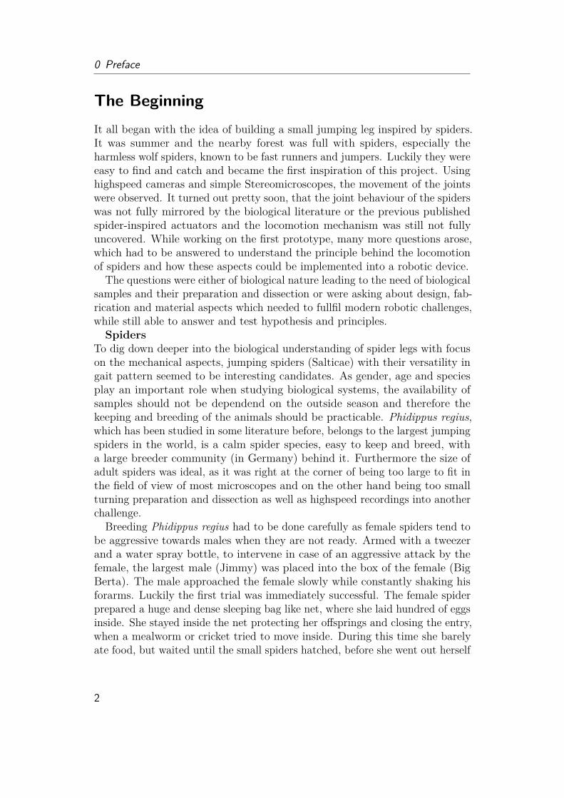
To my friends, my husband and familyto the spiders with two legs too many
to my little six-legged creaturefor the good and the better in future
I wonder, if things are how they should be?But isn’t that the real mystery.Not knowing what life will bring.
Doesn’t this drive us to do a thing?Ten years ago, I had no idea
that my life will end up, being hereStill, I have settled the fundamentSo probably it was no accidentBuilding up, brick by brick
another step in my life, so quickWhere has time gone so fast?
Will anything ever last?What comes next? You may ask-I can tell you, it’s a difficult task!Swimming in the lake of academy?struggeling to found my own family?
So listener, I’ll thank you a lotfor reading my entire plot
of research I have done hithertoI hope it was a joy to you!
1
0 Preface
The BeginningIt all began with the idea of building a small jumping leg inspired by spiders.It was summer and the nearby forest was full with spiders, especially theharmless wolf spiders, known to be fast runners and jumpers. Luckily they wereeasy to find and catch and became the first inspiration of this project. Usinghighspeed cameras and simple Stereomicroscopes, the movement of the jointswere observed. It turned out pretty soon, that the joint behaviour of the spiderswas not fully mirrored by the biological literature or the previous publishedspider-inspired actuators and the locomotion mechanism was still not fullyuncovered. While working on the first prototype, many more questions arose,which had to be answered to understand the principle behind the locomotionof spiders and how these aspects could be implemented into a robotic device.
The questions were either of biological nature leading to the need of biologicalsamples and their preparation and dissection or were asking about design, fab-rication and material aspects which needed to fullfil modern robotic challenges,while still able to answer and test hypothesis and principles.Spiders
To dig down deeper into the biological understanding of spider legs with focuson the mechanical aspects, jumping spiders (Salticae) with their versatility ingait pattern seemed to be interesting candidates. As gender, age and speciesplay an important role when studying biological systems, the availability ofsamples should not be dependend on the outside season and therefore thekeeping and breeding of the animals should be practicable. Phidippus regius,which has been studied in some literature before, belongs to the largest jumpingspiders in the world, is a calm spider species, easy to keep and breed, witha large breeder community (in Germany) behind it. Furthermore the size ofadult spiders was ideal, as it was right at the corner of being too large to fit inthe field of view of most microscopes and on the other hand being too smallturning preparation and dissection as well as highspeed recordings into anotherchallenge.
Breeding Phidippus regius had to be done carefully as female spiders tend tobe aggressive towards males when they are not ready. Armed with a tweezerand a water spray bottle, to intervene in case of an aggressive attack by thefemale, the largest male (Jimmy) was placed into the box of the female (BigBerta). The male approached the female slowly while constantly shaking hisforarms. Luckily the first trial was immediately successful. The female spiderprepared a huge and dense sleeping bag like net, where she laid hundred of eggsinside. She stayed inside the net protecting her offsprings and closing the entry,when a mealworm or cricket tried to move inside. During this time she barelyate food, but waited until the small spiders hatched, before she went out herself
2

to catch prey. The little juvenile spiders stayed in place for a couple of daysbefore they start wandering around searching for small animals as e.g. aphids.Juvenile Phidippus regius have to be fed continously when not kept individuallyas they would start hunting their siblings when reaching a specific age andsize. While started with a population of 100 spiders, predatory siblings, deaththrough dryness, too large water droplets, fights with larger prey or moldingproblems have occured until around 50 spiders reached adulthood after 8-10month.Actuator fabricationThe fabrication of a functional actuator was another main field of questions.While letting prototypes be fabricated by other companies would save work timefor sure, it often comes with the cost of limiting understanding of the fabricationproblems, limiting parameters to tune, limiting materials, high cost and largewaiting time until a prototype is finished. Therefore only a small number ofprototypes and materials could be tested. As the design of the actuator wasstill in early stage and should be adapted in parallel to new biological findings,the decision of in-house, self-fabricated prototypes was made early. During thattime, additive manufacturing was a rising star in prototype technology and 3Dprinting became the technology of choice. Beside its popularity, 3D printingbrings many advantages for fast prototyping. In theory, any conceivable shapecould be designed and fabricated, while casting processes or screwing objectstogether are limited in avaible shapes, need special tools and often result inlong finishing hours. But although 3D printing seemed to be the way to go, itstill took many cycles, testing and trying until the most suitable material forprototyping was found and the desired shape designed.
3

Chapter1Introduction
Bioinspired robotics has risen in popularity since the early 2010’s. New materi-als and fabrication methods on the robotic side in combination with advancedrecording and analytic methods to study the locomotion, behavior and materialof the biological counterpart has pushed this research field into focus, enoughto even found a new journal, Science Robotics, in 2016. Interestingly, mostideas have been formulated already in the 1980s by the father of "Bionik",Werner Nachtigall, but not all were implemented successfully as there waseither still a large lack in understanding the biological inspiration or technol-ogy was far behind the requirements needed. New developments in artificalintelligence, gene-editing tools as CRISPR (Clustered Regularly InterspacedShort Palindromic Repeats), the rise of soft robotics for safe human-robotinteractions and extraordinary jumps in microscopy resolution as well as highspeed technology in combination with the human desire to still stay close tonature while technology is becoming more and more part of our everyday life,have been pushing the field of bioinspiration into the spotlight. Needless tosay, expectations are high, but there is still a lot to learn for biologists andengineers to allow successful communication and implementation of these twodifferent fields, so that both sides could benefit during this evolution.
This work covers one special subject of the wide range of bioinspiration, thelocomotion of spiders. Scientists have been fascinated by these creature ofnightmares for centuries as they are equipped with many tools and behaviors tosurvive and hunt preys including their venomous claws, their sticky silk wirednets, their hairy feet allowing crawling on glass or - a very recent discovery -the feeding of juvenile spiders with a mother milk like substance [27]. Jumpingspiders, the spotlight animal in this thesis, are furthermore equipped with welldeveloped eyes, which are constantly tracking their prey, before they catch itwith a well-planned and precise jump. This specialization in active hunting
5

1 Introduction
preys makes jumping spiders an interesting model for studying locomotion.To give the reader a detailed look into both parts of the research project,
the work is divided into three main chapters. The first part focuses on thebiological aspects of the locomotion study. The reader will be introduced intothe relevant biological terms, along with new research results and discoveriesmade during this PhD. The second part covers the robotic implementation. Anoverview of spider-inspired actuators and robots will be given together withthe newest approach based on the biological findings from the chapter before.The last part provides a detailed discussion of approaches, open questions, howbiology and engineering can benefit from each other and where the future ofthis field lies.
1.1 Motivation and Objectives• Understanding and presentation of joint membrane folding involved in
fast and large working angle movements
• Analyzing material properties of joint membrane for proving reinforcementhypothesis
• Understandig the 3D construct and hydraulic extension mechanism
• Analyzing the body fluid properties and its advantage as hydraulic fluid
• Implementation of joint mechanism into robotic fluidic actuator
• Understandig the benefits of such a design
1.2 ApproachTo accomplish the objectives, I grouped this thesis into two parts. The first partwas mainly conducted at the Max Planck Institute and focuses on biologicalaspects. To get a deeper insight into the morphological and geometrical set-up of the spider leg, different microscopical methods (Stereo-, Laser-, andScanning Electrion Microscopy), high speed recording, histological sectionsand 3D X-ray reconstruction have been used. These studies gave new insightsabout the folding principle of the joint, about the surface roughness, andabout the inner structure of the leg. Material properties were then analyzedwith nanoindentation methods and the refabrication of certain aspects (e.g.microstructures). The findings of these studies resulted in a recently acceptedjournal publication [43]. Hemolymph velocity inside the leg was further detected
6
1.3 Contribution
with optical coherent tomography and the physical properties (viscosity) wereanalyzed by collecting hemolymph and studying its velocity under differentpressures inside a microchannel. The results of the hemolymph study are inpreparation for publication.The second part of this thesis focuses on the design and fabrication of a
spider-inspired fluidic actuator. A first early prototype was published in thebeginning of my PhD [120], which bases on stiff shell element sliding and onlya superficial understanding of the working principle of the spider joint and itsbenefits. A constant development of the prototype was carried out along sidenew findings on the biological side. The robotic implementation was finalizedat the ETH Zurich. The implementation of the spider-inspired folding anddesign principle was also published in [43]. The fabrication and analysis ofthe developed actuator gave better understanding of the advantage of severaldesign aspects (e.g. reinforcement hoops) and also about challenges the spidermight be exposed to when using hydraulic actuation in biological systems.
1.3 ContributionWhile the results and methods of this thesis will be presented and discussedin the scope of this work arranged around all influences on the locomotion ofspiders and spider-inspired robots, I would like to give the reader a first insightinto the focus of my work, its contribution to the community and the majorfindings and developed methods without further discussion at this point. Thereader can then find the linked chapter and sections to read about each point indetail and find an in-depth discussion about it in the final discussion chapter.
1.3.1 Findings and DevelopmentsIn this work,
• I have reviewed locomotion-related literature and pointed out problemsand hypotheses from each of these fields including respiratory system,gait pattern, body motion and jumping behavior. Although outside ofthe focus of my thesis, I have conducted high speed recordings whichsupport some the brought up arguments and hypotheses.
• I have successfully developed a new SEM (scanning election microscopy)preparation method for inflated biological soft structures to allow highresolution imaging of the femur-patella joint and its articular membrane.The SEM images led to the discovery of alternating microstructures onthe surface.
7
1 Introduction
• I have discussed the function of the microstructures on the articularmembrane for communication, self-cleaning and low friction as well asadhesion motion and I have proposed and developed experiments to studytheir influence in future.
• I have conducted experimental studies on the mechanical properties of thearticular membrane covering the femur-patella joint to prove reinforcementstructures which are essential for the folding of the articular membrane.
• I have provided the first detailed microscopy video recordings to completeschematic drawings from elder literature and to give a better understand-ing on the folding characteristics of the articular membrane in livingjumping spiders. I showed, that the 3D folding of the membrane does notresemble a traditional bellow, but is arranged like a stroller sun shade,where the reinforced parts of the membrane slide into each other like inan ice-cream-scooper.
• I have modified traditional histolocial methods to allow the thin filmmicrotome cutting of samples with high stiffness gradients. This methodshowed the inner composition of the femur-patella joint and the articularmembrane.
• I have used high resolution X-ray scans to visualize the 3D set-up of theunfolded femur-patella joint, showing the articular membrane in detailand to give information about geometry and fluid flow. Proposed arterialvalve systems from elder literature were not discovered, however I haveproposed an alternative mechanism for pressure control involving thearcuate sclerite.
• I have used optical coherent tomography to conduct a non-invasive studyon the body fluid flow of the femur-patella joint on living animals. Thismethod works without any addition of chemical substances to enhancethe imaging. I was able to show fluid flow direction and velocity andfound an interesting spiral flow inside the femur-patella joint, which havenot been reported before.
• I have experimentally studied the fluid behavior of the inner body fluid,hemolymph, using microchannels at different pressures mimicking thefluid environments inside the spider arteria. I derived the relationships ofpressure and velocity to determine the viscosity from the experimentaldata and showed that the hemolymph exhibits a non-Newtonian behavior.I have discussed the influence of viscosity and shear-changing behavioron hydraulic systems.
8

1.3 Contribution
• I have designed a folding mechanism inspired by the articular membraneof spiders for rotatory motion. The design allows one degree of freedom(DoF) rotation with working angles of 125◦ along a given hinge joint. Theworking angle exceeds previous spider-inspired designs by 30-80◦withoutadditional material or overextension of the material.
• I have evaluated materials and methods for the fabrication and sealing ofa flexible rotatory actuator. I have modified FDM (fused deposition mod-eling) printing parameters for the printing of thermoplastic polyurethaneand defined curing protocols of Latex milk for sealing purposes of thefinal fabrication of a lightweight, flexible, chemical resistant, modular,low-cost and environment-friendly fluidic actuator.
• I have shown that the reinforcement design of the folding membrane notonly allow a guided motion to avoid undesired wrinkles and damages, butcan also contribute to the storage of elastic energy.
• I have designed a flexing mechanism, which allow the coupling of flexingand fluid collection, furthermore I have proposed a magnetic flexing design,which allows to switch between locomotion modes (walking and jumping)and reduce the number of motors in the system for future integration.
• I have characterized the prototype and showed that at pressures of 200kPa, forces of 10 N (torque: 0.3 Nm) can be generated. The operatingpressure is thereby 10-1000 times smaller than in other proposed fluidicspider-inspired designs. The stable positions and the use of water insteadof air further reduces the "wobbeling" motion, which can be often observedin soft pneumatic systems due to the compressibility of air. While thecontrol of soft actuators could be complex and non-linear due to e.g.the hyperelasticity of the material, the characterized pressure-angle-forcebehaviour of the prototype shows a simple linear to quadradic behavior.
• I have demonstrated complete lifting and jumping abilites. A singleactuator of 6 g is thereby able to completely lift 600 g against gravity.For jumping demonstration, I have constructed a jumping platform andachieved similar jumping capabilities as derived from the simulations.
• I have discussed, the advantages of the rotary fluidic prototype and whyspiders might use this mechanism rather than muscles or elastic proteinsto create precise and strong motions.
9
1 Introduction
1.4 ContributionWhile the results and methods of this thesis will be presented and discussedin the scope of this work arranged around all influences on the locomotion ofspiders and spider-inspired robots, I would like to give the reader a first insightinto the focus of my work, its contribution to the community and the majorfindings and developed methods without further discussion at this point. Thereader can then find the linked chapter and sections to read about each point indetail and find an in-depth discussion about it in the final discussion chapter.
1.4.1 Findings and DevelopmentsIn this work,
• I have reviewed locomotion-related literature and pointed out problemsand hypotheses from each of these fields including respiratory system,gait pattern, body motion and jumping behavior. Although outside ofthe focus of my thesis, I have conducted high speed recordings whichsupport some the brought up arguments and hypotheses.
• I have successfully developed a new SEM (scanning election microscopy)preparation method for inflated biological soft structures to allow highresolution imaging of the femur-patella joint and its articular membrane.The SEM images led to the discovery of alternating microstructures onthe surface.
• I have discussed the function of the microstructures on the articularmembrane for communication, self-cleaning and low friction as well asadhesion motion and I have proposed and developed experiments to studytheir influence in future.
• I have conducted experimental studies on the mechanical properties of thearticular membrane covering the femur-patella joint to prove reinforcementstructures which are essential for the folding of the articular membrane.
• I have provided the first detailed microscopy video recordings to completeschematic drawings from elder literature and to give a better understand-ing on the folding characteristics of the articular membrane in livingjumping spiders. I showed, that the 3D folding of the membrane does notresemble a traditional bellow, but is arranged like a stroller sun shade,where the reinforced parts of the membrane slide into each other like inan ice-cream-scooper.
10
1.4 Contribution
• I have modified traditional histolocial methods to allow the thin filmmicrotome cutting of samples with high stiffness gradients. This methodshowed the inner composition of the femur-patella joint and the articularmembrane.
• I have used high resolution X-ray scans to visualize the 3D set-up of theunfolded femur-patella joint, showing the articular membrane in detailand to give information about geometry and fluid flow. Proposed arterialvalve systems from elder literature were not discovered, however I haveproposed an alternative mechanism for pressure control involving thearcuate sclerite.
• I have used optical coherent tomography to conduct a non-invasive studyon the body fluid flow of the femur-patella joint on living animals. Thismethod works without any addition of chemical substances to enhancethe imaging. I was able to show fluid flow direction and velocity andfound an interesting spiral flow inside the femur-patella joint, which havenot been reported before.
• I have experimentally studied the fluid behavior of the inner body fluid,hemolymph, using microchannels at different pressures mimicking thefluid environments inside the spider arteria. I derived the relationships ofpressure and velocity to determine the viscosity from the experimentaldata and showed that the hemolymph exhibits a non-Newtonian behavior.I have discussed the influence of viscosity and shear-changing behavioron hydraulic systems.
• I have designed a folding mechanism inspired by the articular membraneof spiders for rotatory motion. The design allows one degree of freedom(DoF) rotation with working angles of 125◦ along a given hinge joint. Theworking angle exceeds previous spider-inspired designs by 30-80◦withoutadditional material or overextension of the material.
• I have evaluated materials and methods for the fabrication and sealing ofa flexible rotatory actuator. I have modified FDM (fused deposition mod-eling) printing parameters for the printing of thermoplastic polyurethaneand defined curing protocols of Latex milk for sealing purposes of thefinal fabrication of a lightweight, flexible, chemical resistant, modular,low-cost and environment-friendly fluidic actuator.
• I have shown that the reinforcement design of the folding membrane notonly allow a guided motion to avoid undesired wrinkles and damages, butcan also contribute to the storage of elastic energy.
11

1 Introduction
• I have designed a flexing mechanism, which allow the coupling of flexingand fluid collection, furthermore I have proposed a magnetic flexing design,which allows to switch between locomotion modes (walking and jumping)and reduce the number of motors in the system for future integration.
• I have characterized the prototype and showed that at pressures of 200kPa, forces of 10 N (torque: 0.3 Nm) can be generated. The operatingpressure is thereby 10-1000 times smaller than in other proposed fluidicspider-inspired designs. The stable positions and the use of water insteadof air further reduces the "wobbeling" motion, which can be often observedin soft pneumatic systems due to the compressibility of air. While thecontrol of soft actuators could be complex and non-linear due to e.g.the hyperelasticity of the material, the characterized pressure-angle-forcebehaviour of the prototype shows a simple linear to quadradic behavior.
• I have demonstrated complete lifting and jumping abilites. A singleactuator of 6 g is thereby able to completely lift 600 g against gravity.For jumping demonstration, I have constructed a jumping platform andachieved similar jumping capabilities as derived from the simulations.
• I have discussed, the advantages of the rotary fluidic prototype and whyspiders might use this mechanism rather than muscles or elastic proteinsto create precise and strong motions.
1.5 Thesis OutlineIn the following chapters, the contributions of this thesis will be presented.The thesis is divided into five major parts: Biology of Spiders, Locomotion ofSpiders, Robotic Implementation, Discussion, Material and Methods.
The first chapter (Biology of Spiders) introduces the reader into importantterms from the outer and inner morphology as well as the "gadgets" of spiders.Especially for readers outside the field, this chapter could help to get a betterunderstanding of the functioning and behavior of spiders. Aspects, which needspecial caution when reading, where extended by a comment section to explaindifficulties.
The second chapter (Locomotion of Spiders) could be divided into two parts.The first part (Locomotion Behavior and Jumping Kinematic Modeling) givean overview about behavioral studies as e.g. gait patterns or body motions.
12

1.5 Thesis Outline
This part provides the reader with background information of previous researchon the locomotion of spiders and my additional insights.
The second part of this chapter (Spider Leg and Hydraulics) forms the heartof this work. It provides information about the design and functioning of thesemi-hydraulic femur-patella joint. New experimental results on the three di-mensional (3D) geometrical set-up, the material properties, the folding behaviorand micro structures of this joint are presented. Furthermore, the fluid flow,speed, shear rate and viscosity of the hemolymph of spiders is presented. Theseresult provide new insights into the advantage of hemolymph as hydraulic fluid.
Leading to the third chapter (Robotic Implementation), which is divided intothree main parts. The first part gives a short introduction for the symbiosisof biology and technology, hydraulic actuation and existing spider-inspiredwork. The second part provides the design criteria for a spider-inspired fluidicactuator and a short summary on all fabrication methods tested in this work.Finally, the characterization of the prototype shows the performance includingtorque, working angle, pressure resistance, durability and jumping performance.
The forth chapter provides an overall discussion about the biological androbotic aspects covered in this work. Here, insights gathered from biologicaland robotic experiments are discussed and placed into previous work. Theperformance of the here presented prototype is finally compared to previousworks spider-inspired actuators.
The last chapter provides additional information on material and methodsused in this thesis. As many experimental set-ups had to be developed ormodified to be able to measure the small samples of spiders and to fabricatethe prototype, this part does not only supplement the thesis, but can be seenas additional important results. Researchers who would like to perform similarexperiments could benefit on these details.
13

Chapter2Biology of Spiders
Arthropods as insects, arachnids and crustacean have been around for over550 million years and share a lot of similarities in morphology and behavior.While many arthropods are herbivores, specialized in feeding on plants, cropsor nectar, some others ended up on the predator side of the scale, huntingfor living. Spiders, forming the largest order among the arachnid class, arehunters par excellence. With a small number of exceptions, all spiders feedon arthropods, some even on small vertebrates, by catching their preys withphenomenal techniques. Common spiders are known for their beautiful stickysilk webs in house corners, causing shivers running down people’s spine whendoing the mission impossible abseil while attacked by a scream and a broom.However, this is not the only technique mother nature has equipped spiderswith to keep the number of flies in balance. Net casting, luring by mimickingbehavior or mating pheromones of preys, building trap doors or directly huntingwith their claws on water or on land are just a small list out of their bag oftricks.The studied jumping spiders (fig. 2.1) belong to one of the most agile and
well-equipped species among spiders [37]. Sensor hairs on the legs notice anyvibration in their surroundings. Once the source of vibration is recognized,two large eyes keep following it, never losing track even when it shortly movesoutside the field of view. These sensory information are constantly sent andevaluated by a fast processing nervous system. When identified as a prey,jumping spiders slowly approach it. Their hairy feet even allow them to walkupside down on leaves or glass. Finding the perfect position, they anchor asafety wire into the ground and prepare their legs to allow precise targetingnot only in horizontal jumps, but also from horizontal into vertical position orfrom upside down. The safety wire keeps the spider body in position during thejump and prevents somersaults at landing. During the jumping flight phase,
15

2 Biology of Spiders
Figure 2.1: Jumping spider Phiddipus regius. From left to right: 1.Big Bertha (adult female), waiting for food. 2. Big Bertha and FlycatcherJim (largest adult male), after mating, in Bertha’s home "cuddling". Berthadid not attack Jim before or during mating, but kicked him out after a while.3. Isabella (female adult), with a very large abdomen after mating with Jim.Unfortunately died before laying eggs (got eaten by crickets and meal worms)during pregnancy. 4. R3 (female adult), "red form", origin unknown, notfrom Florida as the other three, presumably Cuba, was therefore not used forbreeding or experiments.
the front legs form a "catching basket" which hug around the prey, before thespiders ram their venomous claws into it, to dissolve the prey’s innards. Theday-active, sun loving jumping spiders are also quite communicative. Whenmeeting a conspecific, their front legs are often waving in lifted position asthey would say "hello" or "goodbye", but actually try to protect themselvesfrom attacking each other. Similar behaviors can be observed when malesapproach females during mating seasons. The peacock jumping spider showseven a complete dance pattern to impress the females. While jumping spidersdo not build catching webs, they do use their silk to create sleeping bags, wherethey hide to rest at night, during molting and mating, for birth and protectingthe newborns and when they just want to slurp their meal worm cocktail inpeace. As a little anecdote, during my PhD, latter behavior of the kept spiders(Phiddipus regius), often ended up in a pile of empty or half empty corpseslying on the ground below the sleeping bag, which was sometimes even revisitedby the spiders to have another sip, when hungry, but lazy.
Although non-biologists often count spiders as insects, the eight-legged spiders(Araneae) differ very strongly in their morphology on the inside and outsidefrom their six-legged cousins. This is important to know, as not all preparationmethods widely used in entomology for insects can be directly transferred tospiders. Furthermore the comparison between data gathered from insects andspiders should always be carefully conducted as small differences in morphologycan already have great impacts on their properties and therefore change usage
16

2.1 Outside Morphology (Eidonomy)
Figure 2.2: Body parts of the Jumping Spider Phiddipus regius.. Left:Spiders are covered with hair, which can have a sensory, protection or adhesionfunction. The characteristics of jumping spiders (Salticidae) are their largefront eyes and short thick legs. The image shows a CT (computer tomography)scan of a Phidippus regius male recorded at KIT, Karlsruhe with Marcus Zuber.Scale bar: 0.5 cm. Right: Spiders consist of two body parts (prosoma andabdomen), which are connected via the petiole. The soft, sack-like abdomencontains the heart, a dense digestive network, reproductive and respiratoryorgans and the "silk factory". The front body part consists of two shells(carapace and sternum), with eight legs and the fangs (chelicerae) fitted inbetween. The prosoma holds a large nervous system, necessary to process allthe visual signals. Furthermore it is packed with muscles for locomotion andthe suction stomach. Image shows a cross-section through the CT scan.
purposes, behavior and locomotion patterns of the animals To dig a littledeeper into the functioning of spider bodies and to understand how spidersdo, what they do, the following section will give a closer introduction into themorphology of spiders. Knowing how spiders are built up is essential to designpreparation methods, dissect specific parts and interpret dissections and 3Dscans. Furthermore it gives information about its functioning, which is of greatimportance for abstracting the (bio-inspired) working principle to implement itinto a e.g. robotic device.
2.1 Outside Morphology (Eidonomy)Different to insects, spiders do not consist of three, but only two body parts(prosoma and abdomen), which are connected via a thin tube-like shaft (petiole,also called pedicel) (fig. 2.2). The front body part (prosoma, also calledcephalothorax) is divided into an upper (dorsal) and lower (ventral) shell.The legs and other appendages as the fangs (chelicerae) are attached betweenthese two shells (carapace and sternum). The orientation of spider fangs areimportant to characterize spiders. The so called jackknife fangs can be divided
17
2 Biology of Spiders
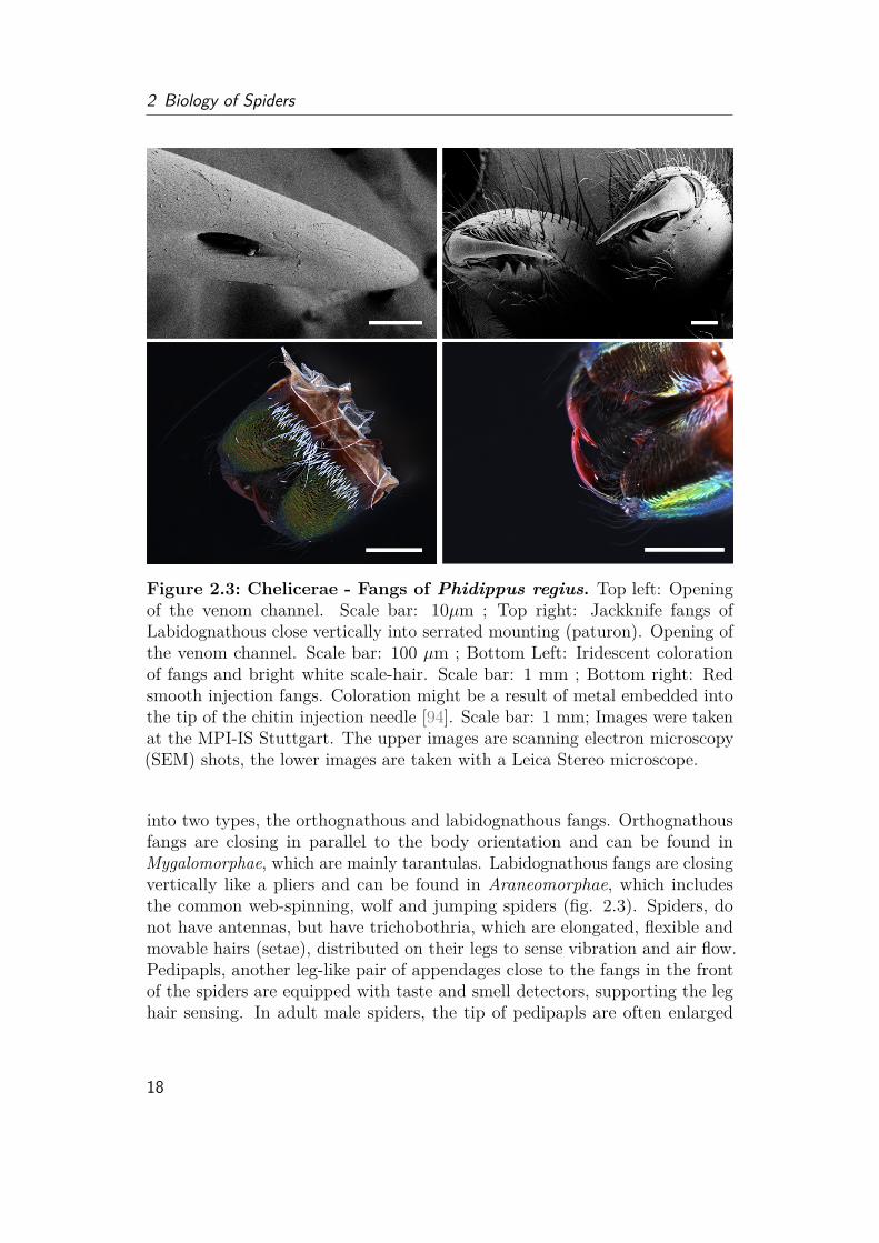
Figure 2.3: Chelicerae - Fangs of Phidippus regius. Top left: Openingof the venom channel. Scale bar: 10µm ; Top right: Jackknife fangs ofLabidognathous close vertically into serrated mounting (paturon). Opening ofthe venom channel. Scale bar: 100 µm ; Bottom Left: Iridescent colorationof fangs and bright white scale-hair. Scale bar: 1 mm ; Bottom right: Redsmooth injection fangs. Coloration might be a result of metal embedded intothe tip of the chitin injection needle [94]. Scale bar: 1 mm; Images were takenat the MPI-IS Stuttgart. The upper images are scanning electron microscopy(SEM) shots, the lower images are taken with a Leica Stereo microscope.
into two types, the orthognathous and labidognathous fangs. Orthognathousfangs are closing in parallel to the body orientation and can be found inMygalomorphae, which are mainly tarantulas. Labidognathous fangs are closingvertically like a pliers and can be found in Araneomorphae, which includesthe common web-spinning, wolf and jumping spiders (fig. 2.3). Spiders, donot have antennas, but have trichobothria, which are elongated, flexible andmovable hairs (setae), distributed on their legs to sense vibration and air flow.Pedipapls, another leg-like pair of appendages close to the fangs in the frontof the spiders are equipped with taste and smell detectors, supporting the leghair sensing. In adult male spiders, the tip of pedipapls are often enlarged
18

2.1 Outside Morphology (Eidonomy)
into boxer glove like structures (palpal bulb), which serve as sexual organ totransfer sperm into the female during mating.
The upper shell (carapace) resembles a helmet-like shell, with a characteristicfurrow on the top. The carapace is often detached from the prosoma in molts,revealing the sternum and holes of the appendages on the inside. Furthermore,this helmet holds up to eight eyes, which are not divided into compounds asin insects, but are single lens eyes (fig. 2.6). Jumping spiders have very-welldeveloped and significantly enlarged front (anterior median) eyes, giving thema "cute" characteristic.The second body part (abdomen, also called opisthosoma) resembles an
inflated, soft bag, carrying most of the organs. On the under (ventral) side,two spiracle openings of the book lungs can be found. The female genital(epigyne) lies in between these two openings. Close to the anus at the end(posterior) of the abdomen, lies the spinneret, consisting of two to four pairsof telescopic, movable structures, extruding, like the nozzle of 3D printers,thin fibers with different material properties, which are then combined andinterwoven to produce various types of silk for different purposes.
2.1.1 ExoskeletonInvertebrates do not have an inner skeleton in their body and limbs, allowingmany invertebrates as octopus, snails and worms to deform and squeeze theirbody into various shapes. To protect their body and interact with the environ-ment, many invertebrates have hard and stiff parts in addition. Examples aretools for ingestion and locomotion (teeth of snails, bristle hair in earth worms)or shells for protection (housing of snails or sea shells). The largest groupamong invertebrates, the arthropods, have an exoskeleton (cuticle) made outof layers of chitin microfibers "glued" together by proteins. This exoskeletoncovers the skin (epidermis) and protects the inner organs from damage. Itdoes not grow, therefore arthropods have to constantly molt and produce newcuticle during their development. By variation of the hierarchical structure andmaterial composition of the chitin-protein construct, the exoskeleton can have avarious number of characteristics as soft and compliant (maggots, caterpillars),flexible but robust (wings of beetles and dragonflies) or stiff and tough (shrimpshell or beetle elytra).
The exoskeleton can be divided into three distinct parts: the epi-, exo- andendocuticle (fig. 2.4). The epicuticle is a thin waxy layer on the outside,protecting arthropods from dehydration. The exocuticle is often highly scle-rotized (stiffened due to cross-linking of proteins). The endocuticle forms theinnermost part of the exoskeleton, containing non-sclerotized soft microfiber-chitin-protein-layers. It plays an important role in the growth of arthropods
19
2 Biology of Spiders
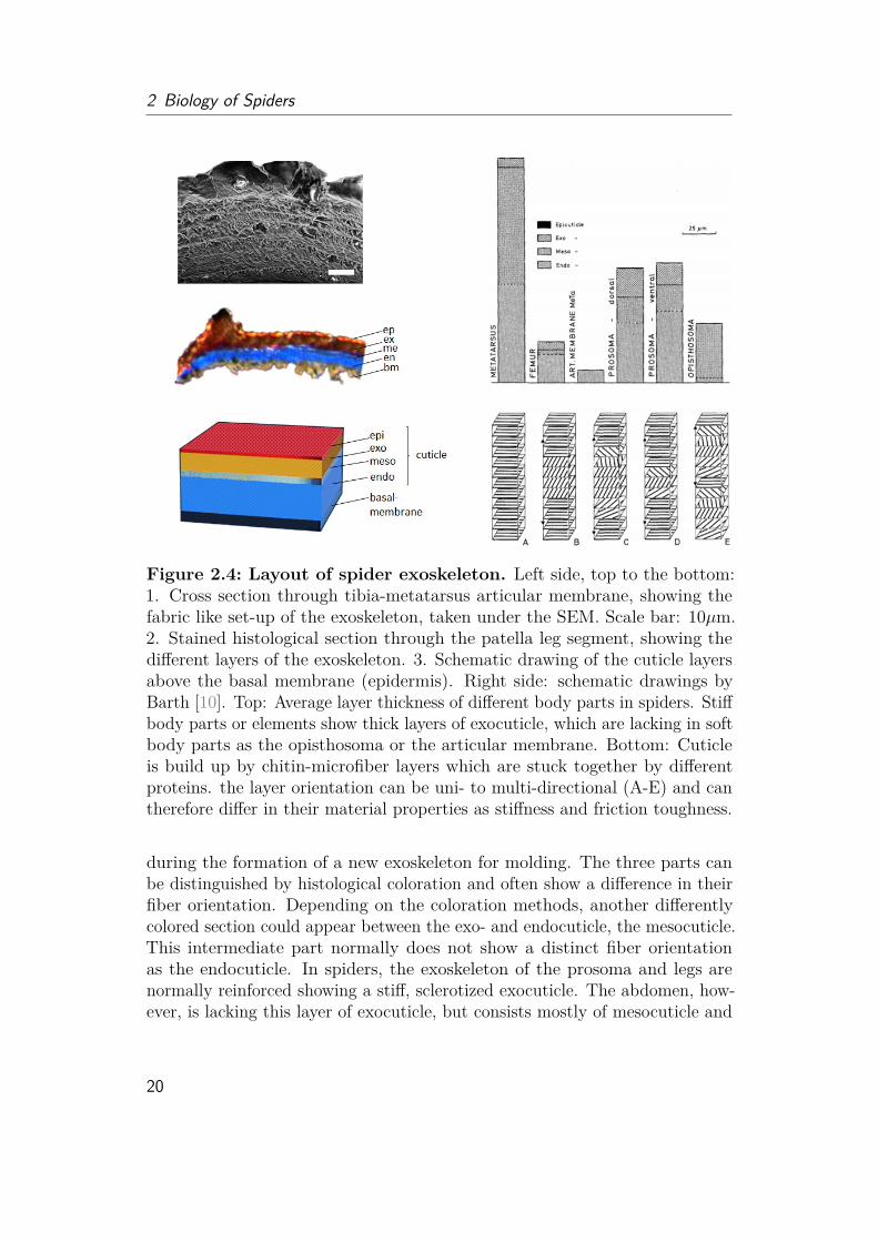
Figure 2.4: Layout of spider exoskeleton. Left side, top to the bottom:1. Cross section through tibia-metatarsus articular membrane, showing thefabric like set-up of the exoskeleton, taken under the SEM. Scale bar: 10µm.2. Stained histological section through the patella leg segment, showing thedifferent layers of the exoskeleton. 3. Schematic drawing of the cuticle layersabove the basal membrane (epidermis). Right side: schematic drawings byBarth [10]. Top: Average layer thickness of different body parts in spiders. Stiffbody parts or elements show thick layers of exocuticle, which are lacking in softbody parts as the opisthosoma or the articular membrane. Bottom: Cuticleis build up by chitin-microfiber layers which are stuck together by differentproteins. the layer orientation can be uni- to multi-directional (A-E) and cantherefore differ in their material properties as stiffness and friction toughness.
during the formation of a new exoskeleton for molding. The three parts canbe distinguished by histological coloration and often show a difference in theirfiber orientation. Depending on the coloration methods, another differentlycolored section could appear between the exo- and endocuticle, the mesocuticle.This intermediate part normally does not show a distinct fiber orientationas the endocuticle. In spiders, the exoskeleton of the prosoma and legs arenormally reinforced showing a stiff, sclerotized exocuticle. The abdomen, how-ever, is lacking this layer of exocuticle, but consists mostly of mesocuticle and
20

2.2 Inside Morphology (Anatomy)
Figure 2.5: Schematic drawing of inner morphology. Spider consists oftwo body parts which are densely filled with organs. Drawing1 originally fromJohn Henry Comstock and description according to [37].)
endocuticle. The absence of the stiff exocuticle gives the abdomen a softercharacteristic and enables it to expand, when the spider has a large food intakeor during pregnancy. The material properties of the exoskeleton are importantto understand as the functional purposes of body segments as it could have animpact on energy storage, flexibility and behavior. The material properties ofthe joint membrane will be of special interest in latter sections.
2.2 Inside Morphology (Anatomy)The spider body is filled with multiple organs (fig. 2.51). Especially the heartand digestive system are often reflected by the color patterns of spiders, makingthem essential for species identification. The tubular heart on the upper (dorsal)side of the abdomen, pumps the inner body fluid (hemolymph) through a netof arteries into the body. Beneath the heart lies the intestine, which splits intoseveral thinner structures, forming a spongy like mass for effective digestion.The intestines are connected to a fecal reservoir (stercoral pocket) directlyending into the anus. Malphagian tubules support the excretion as they havea similar role as the human kidney, collecting waste products and formingurine. The abdomen also holds up to several hundreds of silk glands producingdifferent types of "raw material" for silk wire manufacture. Muscles control themovement of the spinneret. Muscles for leg steering and locomotion can be
1https://en.wikipedia.org/wiki/Spider; last accessed on: 19th Dec. 2020
21
2 Biology of Spiders
found in the prosoma. A fan-shaped muscle connects the sucking stomach tothe furrow (fovea) of the carapace. Venom glands close to the fangs, producethe spider’s venom, which is injected through venom channels into the prey forexternal digestion. The liquefied meal is then sucked into the body where itis internally digested by the stomach, which further branches into structuresinside the legs (digestive cecum) and the intestine organs in the abdomen.The sucking stomach is important to create the fluid flow from the mouth,
through the food pipe (esophagus) into the digestive organs. The esophagus isencircled by the nervous system of the spiders. While insects have a nervoussystem which is prolonged through the body ("Strickleiternervensystem"), spi-ders in contrast have a brain centralized completely in the prosoma. Dependingon the behavior, the brain parts for touch sensitivity or visual processing couldbe enlarged [37].
2.3 Visual SystemAs the studied jumping spiders show a well-developed visual system, this willalso be shortly covered. The neural part taking care of the visual input (opticalganglia) is taking over 30% in space of the jumping spiders brain. Spider eyesare separated into two types, the two front eyes (principal or anterior eyes) andthe smaller secondary eyes. In jumping spiders, the enlarged principal eyes (fig.2.6) allow them to observe and track their preys, while the secondary eyes aremostly used as motion detectors.The structure of spider eyes differs significantly from insect or mammal
eyes. The compound eyes of insects are divided into hundreds to thousands ofsmaller hexagonal units (ommatidia), providing single images as pixels on aphoto or single dots on an impressionistic painting to the brain. Some insectsas wasps have three tiny, "simple eyes" (dorsal ocelli) on their forehead formotion detection. Spider eyes are also "simple eyes" (ocelli) but differ highly inform and function and are very well adapted to their behavior. Studies on theoptics of jumping spiders (Portia spec.) have shown that their eyes have twolenses and a tubular shape, resembling binoculars [46]. This forms a telephotosystem, which allows the jumping spiders to even observe and track distantobjects. The retina ("image sensor") consists of several stacked layers of photoreceptors allowing color vision (green, blue, ultra-violet) and enables jumpingspiders to distinguish two objects with a distance of 0.12 mm from 20 cm apart.Their resolution (0.04◦) is therefore ten times higher than the resolution ofthe best performing dragonflies (0.4◦) with similar eye size and only five timeslower, when compared to humans (0.007◦). Latter finding is astonishing whenconsidering that human eyes are not only larger in size but consist of more
22

2.3 Visual System
Figure 2.6: Visual system of Arthropods. Upper row: Spider, Phiddipusregius; Left: Large anterior eye of juvenile jumping spider under the SEM takentogether with BoGY students in 2017. The image shows that the eye is notdivided into compounds. Scale bar: 10 µm. Middle: Photography of male, alive,juvenile jumping spider taken under the Leica Stereo microscope together withmy student Lisa Böhler in 2018. The two front eyes are significantly enlarged incomparison to the side eyes, which is very common for jumping spiders. Right:Photography of "Flycatcher Jim", large adult male spider, father of the secondgeneration of lab spiders, taken under the Leica Stereo microscope after hisnatural death in 2018. Photography shows secondary eyes on the side, whichare mostly used for motion detection. Lower row: Butterfly, Nessaea aglaura;Left: The butterfly eye is divided into thousands of compounds. Scale bar:20 µm. Middle: The compounds are shaped in regular hexagons. Scale bar:10 µm. Each compound is covered by thousands of pillars, which are againnano-structured. Scale bar: 20 nm. All three SEM images of the butterfly weretaken in 2015 together with my colleague Nikolai Rosenthal.
than 150 million photo receptor cells while in jumping spiders this numberlies in thousands. Although the focused area (fovea centralis) is rather smallin jumping spiders, eye muscles can move the tubular eyes around to observelarge objects or track prey. Another fascinating aspect of jumping spider visionis their ability to precisely estimate distances to catch their prey.Although equipped with two main eyes as humans, spiders cannot use the
information to construct a 3D image (stereopsis). While birds (with eyeson the sides) move their eyes up and down and overlay these images for 3Dreconstruction, spiders have developed their own technique called "blurry vision"
23
2 Biology of Spiders
for depth perception. Thereby green light and their stacked retina structureplay a special role. While green light hits the first layer of photo receptors infocus, it is blurred on the second layer. Interestingly, the level of blur dependson the distance of the object, the closer, the fuzzier the image on the secondlayer [79]. While tests show that jumping spiders fail judging distance underonly red light, an adaption on short green light makes sense when consideringthat in dense forests, where jumping spider lives, most red light is absorbed bythe plants.
2.4 Respiratory SystemAs jumping spiders are very agile and active spiders, their muscles and nerveshave to be provided with enough oxygen. While insects highly depend on oxygendiffusion through trachea (silvery shimmering fine tubes running through thebody), large tarantulas use two pair of book lungs for breathing (fig. 2.7). Booklungs are leaf-like constructs (lamellae) which are stacked like the pages of abook. Air enters through a spiracle opening into a chamber (atrium) and fillsup the lamellae with air. The spider "blood" (hemolymph) flows between thebook lung constructs, gaining oxygen by diffusion.
Interestingly, common spiders (most Araneomorphae) as web-spinning, wolfand jumping spiders use a combination of book lungs and trachea (bi-modalbreathing) [107]. Trachea are postulated to prevent water loss and supportoxygen intake at areas of high oxygen demands [105]. Web-spinning spiders,needing long leg activities to envelop their prey, show trachea directly enteringthe legs, which are however lacking in jumping and wolf spiders, although theyare known for running and jumping behaviors in hunting. Instead, jumpingspiders show trachea entering their nervous system, which could support thevisual processing of their large eyes. Wolf spiders show less trachea comparedto jumping spiders [108], but also a less developed visual system. Crab spiders,which lurk on preys by camouflaging plants and often do not use any silk wires,have a very dense tracheal system [105] in the abdomen, which might support aneffective digestion as the behavior of crab spiders can lead to long waiting andstarving periods. Interestingly, the water spider Argyroneta aquatica body isfully covered with trachea additionally to their book lungs. Considering its wayof life under water, mostly breathing from a silk web caught air bubble (divingbell) or by lifting the abdomen into the water surface, air diffusion throughmany trachea into the body might provide a better oxygen support than onlytwo spiral holes from the book lungs under limited air supply condition.Interpretation of the advantages and disadvantages of book lungs, trachea
or the bi-modal breathing are in general challenging as many parameters e.g.
24
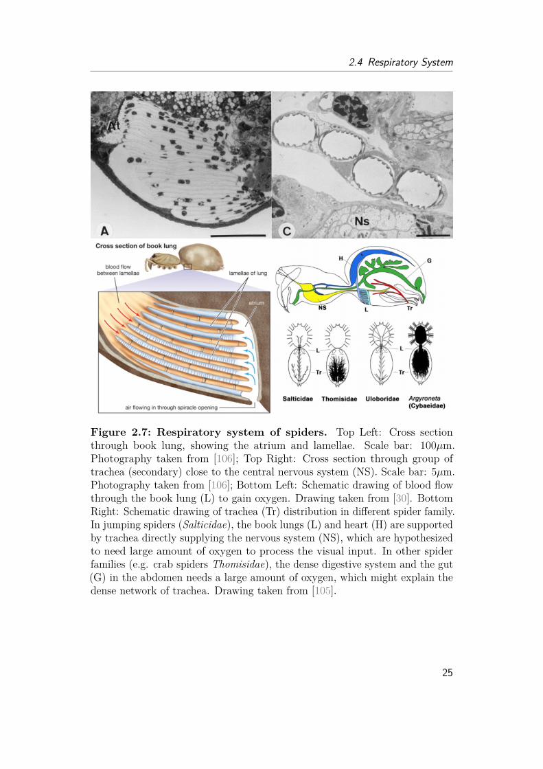
2.4 Respiratory System
Figure 2.7: Respiratory system of spiders. Top Left: Cross sectionthrough book lung, showing the atrium and lamellae. Scale bar: 100µm.Photography taken from [106]; Top Right: Cross section through group oftrachea (secondary) close to the central nervous system (NS). Scale bar: 5µm.Photography taken from [106]; Bottom Left: Schematic drawing of blood flowthrough the book lung (L) to gain oxygen. Drawing taken from [30]. BottomRight: Schematic drawing of trachea (Tr) distribution in different spider family.In jumping spiders (Salticidae), the book lungs (L) and heart (H) are supportedby trachea directly supplying the nervous system (NS), which are hypothesizedto need large amount of oxygen to process the visual input. In other spiderfamilies (e.g. crab spiders Thomisidae), the dense digestive system and the gut(G) in the abdomen needs a large amount of oxygen, which might explain thedense network of trachea. Drawing taken from [105].
25
2 Biology of Spiders
molting, sex, size, body mass, behavior as well as oxygen and prey availabilityhave an influence on the respiratory system [105]. Direct comparison of runningspiders [104] are challenging as behavior can vary among tested animals duringan experiment depending on starvation, size and "desire". Therefore measuredoxygen intake and recovery time can vary largely. Furthermore, the circulatorysystem could have an influence on the respiratory need. Interestingly, spiderswith trachea in the front body part (prosoma), show lower heart rates incomparison to those with trachea only limited to the abdomen [105].Detailed information about the circulatory system of many species are still
lacking as 3D analysis was only possible with performance improvements ofcomputer tomography technologies and therefore have been performed in thelast decades. Systematic analysis in combination with behavioral, morphologi-cal and anatomical studies might provide a detailed answer why spiders havebook lungs or still have book lungs.
Authors comment on respiratory system literatureCareful reading is necessary when going through spider literature. Confusioncan be caused by the naming of species. The German "Tarantel" actually de-scribes larger wolf spiders (Lycosa tarantula) belonging to the "modern" spiders(Araneomorphae). The meaning of "tarantula" has, however, changed in theEnglish speaking community, now describing Theraphosidae, so "Vogelspinnen".While wolf spiders have trachea to support their book lungs, tarantula donot have any trachea. This could lead to confusions, when wolf spiders aredescribed as (mainly) lung-breathing spiders [103].Furthermore, researchers have hypothesized that a "less-well developed"
circulatory system might be the reason for the development of trachea [103].However, with a lack in a definition what "less-well developed" means and inbiological data about the circulatory system, this conclusion has to be handledwith caution, as physical effects due to size differences (e.g. regarding the airdiffusion) may also play a role.Due to the size of tarantula (in German "Vogelspinne") the analysis of
anatomical structure as the circulatory or respiratory system is comparablyeasier when only classical histology and microscopy methods were availableand are still today when resolution is limited on devices. While many data isavailable about tarantula, their often slow behavior and lack of trachea has tobe kept in mind when "getting inspired" by spider research. Using all biologicalstudies on spiders without distinguishing species and behavior could lead towrong assumptions or problematic interpretations.
Tarantula are often referred as the more "basal and older" type of spiders,especially in older literature. Therefore, features of tarantula are often inter-
26

2.4 Respiratory System
preted as less adapted and disadvantaged, when compared to "modern" smallerspiders, the Araneomorphae. As evolutionary studies have majorly improveddue to new molecular biological techniques, the classification keeps changing,making the interpretation of "better" or "more adapted" features based onevolution challenging. In contrast to the tarantulas, representatives of the oftensmaller, "modern" type as jumping spiders have only one pair of book lungsand additional trachea. As insects are also using trachea, most interpretationare in favor of trachea [38], keeping the question open, why book lungs are stillpresent in agile and well adapted spiders.When reading through literature, the following evolutionary interpretation
came to my mind: Spiders and insects both have evolved around 300 millionyears ago during Carboniferous period, when oxygen level covered 35% of theatmospheric volume. The higher oxygen level compared to today (21%) is oneof the main arguments, why insects were larger in size, when oxygen intake isjust dependent on diffusion through trachea. Insects have probably evolvedfrom water living crustacean. The internal gills of crustacean where then reusedand modified into trachea. For early insects (as large dragon flies), coveringthe body with many air filled tracheal tubes could reduce weight and supportoxygen intake at energy consuming areas during flight, but also under waterfor the aquatic larval stages, without relying on the circulatory system. Earlyspiders, which did not fly or swim, but hunt large prey on land, have developedbook lungs which are assumed to have evolved from outside lying book gills ofwater living ancestors. As the inner body is not filled with tracheal tubes, thebody could be filled with other gadgets as a dense digestion network or silkand venom glands. Furthermore, the walls of trachea are limited in mechanicalstability and therefore cannot withstand high hydrostatic pressures [53].A lack of trachea in spider bodies might have allowed the evolution of
hydraulic leg extension to lift heavy prey and strong flexing muscles for grasping.With decrease in oxygen level, oxygen intake through book lungs might becomeinsufficient for smaller spiders, when large energy consumption is needed,explaining the development of trachea in spiders. This idea matches withthe fact, that many generally small representatives of arachnids as mites andharvestmen developed trachea, while larger species as scorpions still have booklungs. One larger exception are camel spiders (Solifugae, do not belong to the"real" spiders!), with a well-developed tracheal system [38] and no book lungs.An explanation might again be the way of living, as camel spiders live in thedesert (water loss) and are speed runners (oxygen support). Research has alsoreported air sacs, which might lower the weight of the claws (chelicerae) andprovide extra oxygen supply for the large muscles inside [38].
27
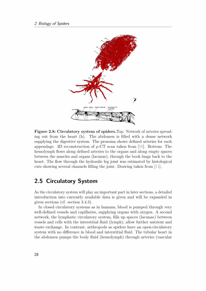
2 Biology of Spiders
Figure 2.8: Circulatory system of spiders.Top: Network of arteries spread-ing out from the heart (h). The abdomen is filled with a dense networksupplying the digestive system. The prosoma shows defined arteries for eachappendage. 3D reconstruction of µ-CT scan taken from [50]. Bottom: Thehemolymph flows along defined arteries to the organs and along empty spacesbetween the muscles and organs (lacunae), through the book lungs back to theheart. The flow through the hydraulic leg joint was estimated by histologicalcuts showing several channels filling the joint. Drawing taken from [14].
2.5 Circulatory System
As the circulatory system will play an important part in later sections, a detailedintroduction into currently available data is given and will be expanded ingiven sections (cf. section 3.4.3).In closed circulatory systems as in humans, blood is pumped through very
well-defined vessels and capillaries, supplying organs with oxygen. A secondnetwork, the lymphatic circulatory system, fills up spaces (lacunae) betweenvessels and cells with the interstitial fluid (lymph), allow further nutrient andwaste exchange. In contrast, arthropods as spiders have an open-circulatorysystem with no difference in blood and interstitial fluid. The tubular heart inthe abdomen pumps the body fluid (hemolymph) through arteries (vascular
28

2.5 Circulatory System
system) into the cavities (lacunar system) of the body. The heart is not dividedinto valve-separated chambers as in insects or humans, but has openings (ostia)to let fluid flow inside and close during contraction. One main artery (anterioraorta) connects hemolymph flow from the heart into the front body part, whereit splits into smaller channels entering into the legs and organs (fig. 2.8).The abdomen is provided with hemolymph by another aorta (posterior aorta),which splits further and further into a dense network supplying the intestine,reproductive glands (gonads) and the silk glands. Interestingly, although one-way fluid flow should be guaranteed to avoid a mixture in oxygen-rich andoxygen-poor hemolymph (as the human blood by defined arteries, veins, theheart valves and venous valves), arterial valves have been postulated but notverified. When the heart relaxes, oxygen-poor hemolymph travels back passingthe lamellae (leaf-likes pages) of the book lungs to gain oxygen and reenter theheart through the ostia.
In those spiders that have been studied so far (mostly tarantula), hemolymphvolume fills up around 20% of the body [122] and the heart rate ranges from30 to 200 beats per minute depending on activity level and species [37, 91].In tarantula, a hemolymph volume of 50 µl is pushed out with every heartbeat [37]. The pressure inside the body was shown to vary from 6 kPa duringresting to 60 kPa during activity [7, 89, 123]. Observations from 1989 [91]further showed that in resting spiders, the heart seems to change the pumpingdirection occasionally. During activity however, the hemolymph flows fromheart to prosoma seems to be reduced or even stopped, while the backwardsflow into the opisthosoma seems to be increased.
Freshly collected hemolymph appears slightly bluish. This color is given bythe respiratory pigment hemocyanin, which, unlike the red hemoglobin, usescopper rather than iron to bind oxygen. Instead of blood cells, hemocytesare free floating inside the hemolymph, beside many nutrients as sugar, salt,amino acids and proteins. These hemocytes are part of the immune system andreported to prevent stronger bleeding, when spiders drop off a leg (autotomy),induce coagulation and support wound healing. There are four different typesof hemocytes: plasmatocytes, granulocytes, cyanocytes and prohemocytes (fig.2.9) [2, 60]. Plasmatocytes have an oval or spindle shape with a length of 17 µmand play an important role in the blood-clotting (coagulation) of hemolymph.The round granulocytes are with a diameter of 15 µm, help to stop hemolymphloss and produce antimicrobial peptide. Cyanocytes are large circular cellswith diameters of 20 - 30 µm. They do not appear in high frequencies, butare important in the hemocyanin (pigment) fabrication. Proemocytes are thesmallest cells with a size a diameter of 8 µm. They are released by the cellwall, act like stem cells and can develop into any of the other three cell types.
29
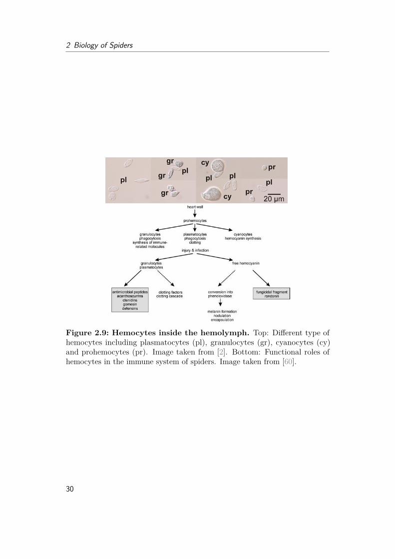
2 Biology of Spiders
Figure 2.9: Hemocytes inside the hemolymph. Top: Different type ofhemocytes including plasmatocytes (pl), granulocytes (gr), cyanocytes (cy)and prohemocytes (pr). Image taken from [2]. Bottom: Functional roles ofhemocytes in the immune system of spiders. Image taken from [60].
30

Chapter3Locomotion of Spiders
There are many aspects to investigate when looking into the locomotion ofspiders. Gait patterns, body movement, as well as speed and jump kinematics,foot adhesion and material and design. The most stunning fact is that spidersuse hydraulics for leg extension, highly in contrast to their six-legged cousins,the insects. While insects use muscles to flex and extend their limbs, the eightlegs of spiders show a large amount of flexor muscles, but lack in extensormuscles in two of their joints. The next section will give a short overview aboutstudies in locomotion and jumping behavior including my own observationsand open questions. Then I will dive deeper into the functional morphology ofspider legs and the hydraulic mechanism, including major findings made in thisthesis. Finally, I will present new insights into the body fluid (hemolymph) flowand physical properties and theoretically discuss how these properties couldhave an effect on hydraulic systems.
3.1 Locomotion Behavior
Behavioral studies are important to get a feeling of what spiders are capableof and what techniques they use to achieve e.g. hunting, escaping or diggingmovements. They also provide information on how well the biological systemperforms under different circumstances, which is important to interpret data andthe bio-inspired implementation purposes. To abstract a principle and transferit to a (technological) system for a similar or even totally different purpose,the deep understanding of the inspired principle is necessary to know whichparameters are of importance, so that desired parameters can be thoughtfullychanged.
31

3 Locomotion of Spiders
Figure 3.1: Example of schematic representation of different steppatterns. Spiders usually walk in tetrapod (4-pod) and double quadropod(8-pod) step patterns. The description on the left describe the legs (L1 = frontleft leg). Blue marks in a column are marking those legs that are touchingthe ground at the same time. Ant-like spiders have been proposed to walk asants in tripod patterns with the two front legs lifted (yellow). However, thishypothesis has been dismissed. Speed running cockroaches appear to havemetachronal wave gait pattern (here shown for eight instead of six legs).
3.1.1 Gait Pattern
Traditional gait pattern analysis was done by letting insects and spiders runthrough carbon black powder and follow the foot steps of the animals on a whitepaper. With new high speed technologies in the 1980s, locomotion of animalswere studied intensively, but there is still a large lack of knowledge about manyspecies. Many studies on arthropods have only appeared recently, as highspeed recording and 3D tracking technologies have improved and bio-inspiredlocomotion became a popular field not only for robotics, but also to understandanimal behavior.
One of the most iconic locomotion pattern is the one from the desert wheelspider (Cebrennus rechenbergi), which does fast "flic flac" rolls, probably toreduce foot contact with the hot desert sand. Discovered in 2006 by IngoRechenberg, another big name in the founding of bio-inspired principles andoptimization algorithms, the combination of rolling and crawling has inspired en-gineers at Festo and other groups [125] to imitate the locomotion ten years later.
Different gait patterns can allow arthropods to dig into soil, run fast, tra-verse over various terrain or even mimic other animals. The jumping spider
32
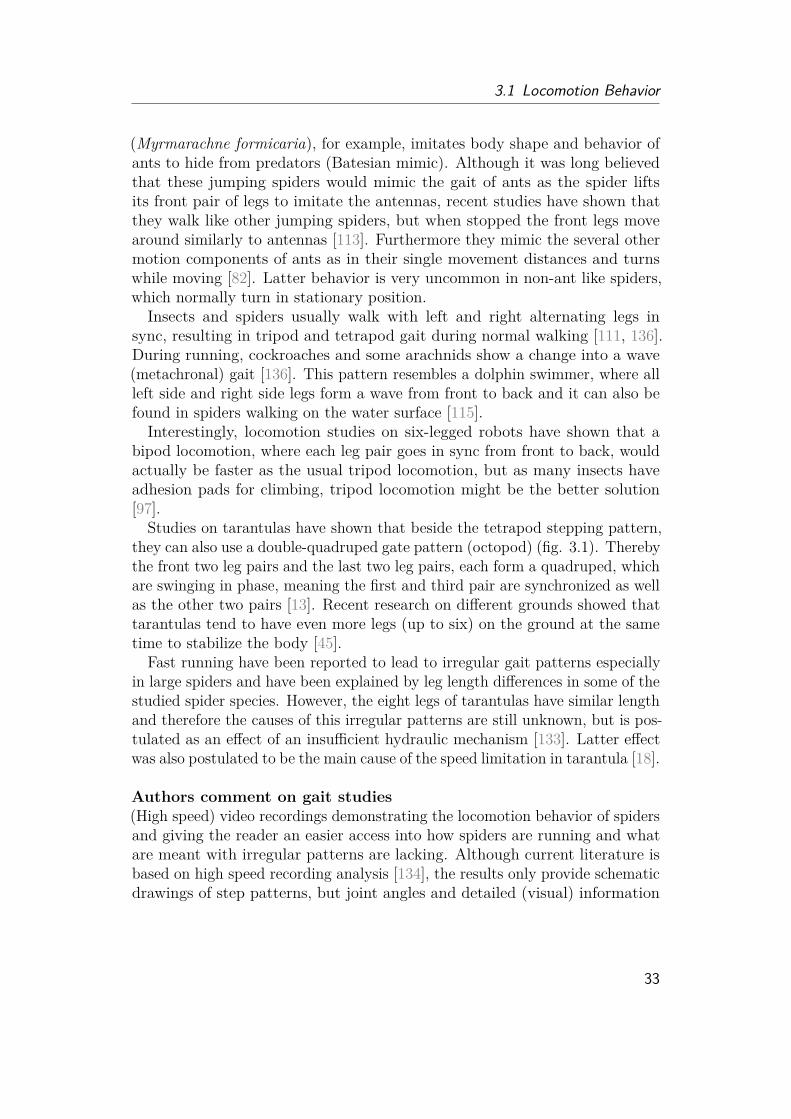
3.1 Locomotion Behavior
(Myrmarachne formicaria), for example, imitates body shape and behavior ofants to hide from predators (Batesian mimic). Although it was long believedthat these jumping spiders would mimic the gait of ants as the spider liftsits front pair of legs to imitate the antennas, recent studies have shown thatthey walk like other jumping spiders, but when stopped the front legs movearound similarly to antennas [113]. Furthermore they mimic the several othermotion components of ants as in their single movement distances and turnswhile moving [82]. Latter behavior is very uncommon in non-ant like spiders,which normally turn in stationary position.
Insects and spiders usually walk with left and right alternating legs insync, resulting in tripod and tetrapod gait during normal walking [111, 136].During running, cockroaches and some arachnids show a change into a wave(metachronal) gait [136]. This pattern resembles a dolphin swimmer, where allleft side and right side legs form a wave from front to back and it can also befound in spiders walking on the water surface [115].Interestingly, locomotion studies on six-legged robots have shown that a
bipod locomotion, where each leg pair goes in sync from front to back, wouldactually be faster as the usual tripod locomotion, but as many insects haveadhesion pads for climbing, tripod locomotion might be the better solution[97].
Studies on tarantulas have shown that beside the tetrapod stepping pattern,they can also use a double-quadruped gate pattern (octopod) (fig. 3.1). Therebythe front two leg pairs and the last two leg pairs, each form a quadruped, whichare swinging in phase, meaning the first and third pair are synchronized as wellas the other two pairs [13]. Recent research on different grounds showed thattarantulas tend to have even more legs (up to six) on the ground at the sametime to stabilize the body [45].
Fast running have been reported to lead to irregular gait patterns especiallyin large spiders and have been explained by leg length differences in some of thestudied spider species. However, the eight legs of tarantulas have similar lengthand therefore the causes of this irregular patterns are still unknown, but is pos-tulated as an effect of an insufficient hydraulic mechanism [133]. Latter effectwas also postulated to be the main cause of the speed limitation in tarantula [18].
Authors comment on gait studies(High speed) video recordings demonstrating the locomotion behavior of spidersand giving the reader an easier access into how spiders are running and whatare meant with irregular patterns are lacking. Although current literature isbased on high speed recording analysis [134], the results only provide schematicdrawings of step patterns, but joint angles and detailed (visual) information
33

3 Locomotion of Spiders
about which joints are mostly involved and what behavior the animals haveare missing.
Although hydraulic effects have been determined to reduce speed performanceand cause irregularities, the underlying principles which lead to this conclusionhave to be read carefully. Speed limitations in tarantula are affiliated withlack of oxygen as the animals need to recover after runs. The researchersargument that during fast movements, the hydraulic mechanism hinders bodyfluid (hemolymph) transfer, which leads to a lack of oxygen and therefore limitspeeds and cause irregular motion [135]. However, the cause of a lack of oxygencould also be a result of the respiratory system, instead. While tarantulas onlydepend on book lungs, large huntsman spiders and wolf spiders are known torun much faster speeds, but have developed trachae to support oxygen intake.Web spiders, which are not known for their running abilities but for quick, fastand constant leg movements to wrap their prey are even known to have trachaedirectly entering their leg muscles to support oxygen transport. Furthermore,information about the circulatory system is lacking, which could also have agreat influence on the oxygen transport. Irregular gait patterns in fast runscould also be a result of adhesion pads, which might be avoided during runs orcause problems due to their stickiness.It is important to know, that the interpretation of "recovery or resting"
behavior is also problem as experimental animals are often triggered with foodand can just lose interest. As fast running can be caused by "scaring" the spiderto trigger escape runs, this might also result in uncoordinated movement as ifthe spider would "stumble away". Therefore the motion behavior could differlargely to controlled hunting runs.
3.1.2 Body MovementThere are several models describing the center of mass (COM) movement duringanimal movement: the inverted pendulum, bouncing ball, and the pendulummodel (fig. 3.2)[87].
Human bipedal locomotion can be described by the inverted pendulum modelwhere the center of mass is lifted by kinetic energy acting on a stiffened leg.The created potential energy can then be recovered into kinetic energy resultingin a constant up and down of the center of mass.The bouncing ball model or spring-loaded inverted pendulum model shows
similar up and down movement of the center of mass. However, the leg actslike a spring, which gets compressed by gravity. The elastic energy propels thecenter of mass then back up again. This type of movement can be observed inrunning vertebrates and has been reported for insects and daddy-long-legs.
The regular pendulum model describes the usage of potential energy to create
34

3.1 Locomotion Behavior
Figure 3.2: Schematic description of center of mass (COM) movement.Left: In humans, the bipedal motion can be described by the inverted pendulummotion. The stiff legs lift the COM against gravitation creating potentialenergy. Middle: Insects and daddy-long legs show legs that act as springs andstore elastic energy for forward movement, resembling a bouncing ball motion.Interestingly, when observing spiders walking on the ground their COM motionrather resembles a "wheel-like" motion, as the body shows almost no verticalbouncing. Right: Spiders walking on the ceiling are assumed to follow a regularpendulum motion. The energy conversion of potential energy to kinetic energycan thereby be compared to brachiation of monkeys or children. Drawing wasmade according to [87].
kinetic energy and swing into the next position. It is similar to the invertedpendulum model despite the fact that the leg position lies higher than thecenter of mass. The locomotion of hanging web spiders has been postulated tofit this model [76], but experimental data are lacking.
When observing ground spiders moving, the first thing that stands out isthat the center of mass seems to almost not move in vertical direction. Theirmovement reminds more of a ’wheel like’ motion, making spider toys withmovable legs, but wheels to move horizontal quite "convincing". Studies onlarge (ground) spiders as tarantulas, but also the large wander spider (Cupi-ennius salei) have shown that they do not show any flight phase even duringrunning [13]. The locomotion model was first postulated to fit best to theinverted pendulum model. However, the vertical motion of the COM is so smallresulting in a very low estimated energy recovery of only 8 - 12% [133], whichcontradicts the large horizontal movement and ballistic behavior of the COM.As there is no characteristic bouncing of the COM and no elastic structures in
35

3 Locomotion of Spiders
Figure 3.3: Turnaround of Phidippus regius. This image sequence showsa Phidippus regius climbing around an edge from the upright to upside downposition. A safety wire might be attached, but could not be observed in thevideo. Leg pairs 2 and 3 are holding on the edge, pivoting the spider aroundwhile the leg pairs 1 loses contact in the beginning and pair 4 at the end whenflipping around.
the legs have been reported to store and release elastic energy, the researchesalso excluded the spring-loaded model for large spiders. However the structuresand mechanism to create the horizontal movement are not clear.
Authors comment on body motionAlthough no elastic structures have been reported for spiders at the time ofbody motion studies, it has to be said that other arthropods show cuticle(exoskeleton) to support their hydraulic extension [112, 116, 117]. Furthermorethe hydraulic joint itself could be seen as a spring, when assuming that thefluid is not compressible and therefore volume decrease by muscles or gravitycould lead to pressure increase and, or a deformation of body parts whichmight not directly lie at the legs. The joints are covered with a thin membranewhich folds and unfolds during movement. Elastic energy storage could also bepartially provided by this membrane.Studies on body motion of jumping spiders during running, climbing and
walking are lacking. An interesting behavior can be observed when jumpingspiders are tracking a prey by their eyes and need to turn their body to keepthe prey in sight. By quickly moving the legs around the body, the body seemsto spin around one single axis. Further studies on this behavior could providemore information about the body movement model and maybe even inspirequick turns or edge crawling (fig. 3.3) for legged-robots.
36
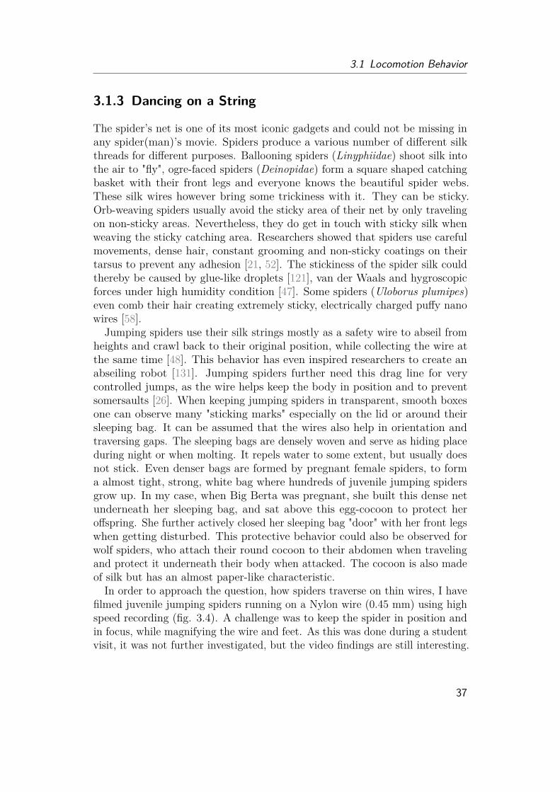
3.1 Locomotion Behavior
3.1.3 Dancing on a String
The spider’s net is one of its most iconic gadgets and could not be missing inany spider(man)’s movie. Spiders produce a various number of different silkthreads for different purposes. Ballooning spiders (Linyphiidae) shoot silk intothe air to "fly", ogre-faced spiders (Deinopidae) form a square shaped catchingbasket with their front legs and everyone knows the beautiful spider webs.These silk wires however bring some trickiness with it. They can be sticky.Orb-weaving spiders usually avoid the sticky area of their net by only travelingon non-sticky areas. Nevertheless, they do get in touch with sticky silk whenweaving the sticky catching area. Researchers showed that spiders use carefulmovements, dense hair, constant grooming and non-sticky coatings on theirtarsus to prevent any adhesion [21, 52]. The stickiness of the spider silk couldthereby be caused by glue-like droplets [121], van der Waals and hygroscopicforces under high humidity condition [47]. Some spiders (Uloborus plumipes)even comb their hair creating extremely sticky, electrically charged puffy nanowires [58].
Jumping spiders use their silk strings mostly as a safety wire to abseil fromheights and crawl back to their original position, while collecting the wire atthe same time [48]. This behavior has even inspired researchers to create anabseiling robot [131]. Jumping spiders further need this drag line for verycontrolled jumps, as the wire helps keep the body in position and to preventsomersaults [26]. When keeping jumping spiders in transparent, smooth boxesone can observe many "sticking marks" especially on the lid or around theirsleeping bag. It can be assumed that the wires also help in orientation andtraversing gaps. The sleeping bags are densely woven and serve as hiding placeduring night or when molting. It repels water to some extent, but usually doesnot stick. Even denser bags are formed by pregnant female spiders, to forma almost tight, strong, white bag where hundreds of juvenile jumping spidersgrow up. In my case, when Big Berta was pregnant, she built this dense netunderneath her sleeping bag, and sat above this egg-cocoon to protect heroffspring. She further actively closed her sleeping bag "door" with her front legswhen getting disturbed. This protective behavior could also be observed forwolf spiders, who attach their round cocoon to their abdomen when travelingand protect it underneath their body when attacked. The cocoon is also madeof silk but has an almost paper-like characteristic.
In order to approach the question, how spiders traverse on thin wires, I havefilmed juvenile jumping spiders running on a Nylon wire (0.45 mm) using highspeed recording (fig. 3.4). A challenge was to keep the spider in position andin focus, while magnifying the wire and feet. As this was done during a studentvisit, it was not further investigated, but the video findings are still interesting.
37
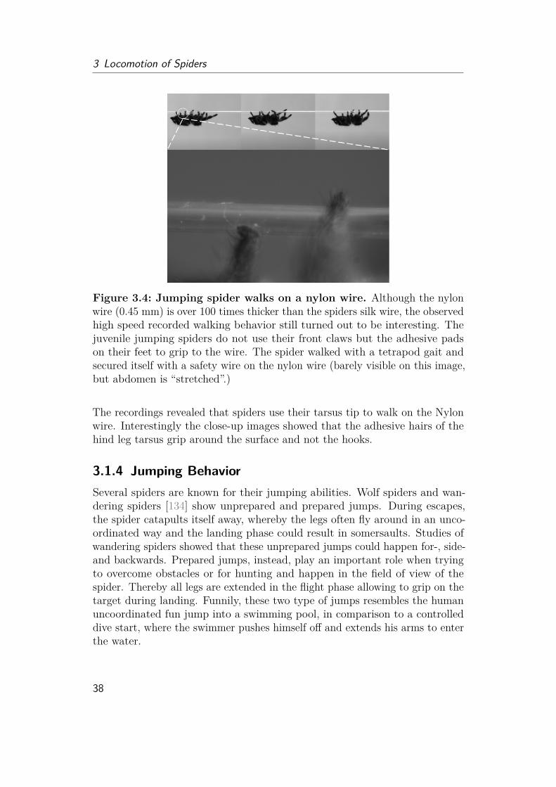
3 Locomotion of Spiders
Figure 3.4: Jumping spider walks on a nylon wire. Although the nylonwire (0.45 mm) is over 100 times thicker than the spiders silk wire, the observedhigh speed recorded walking behavior still turned out to be interesting. Thejuvenile jumping spiders do not use their front claws but the adhesive padson their feet to grip to the wire. The spider walked with a tetrapod gait andsecured itself with a safety wire on the nylon wire (barely visible on this image,but abdomen is “stretched”.)
The recordings revealed that spiders use their tarsus tip to walk on the Nylonwire. Interestingly the close-up images showed that the adhesive hairs of thehind leg tarsus grip around the surface and not the hooks.
3.1.4 Jumping BehaviorSeveral spiders are known for their jumping abilities. Wolf spiders and wan-dering spiders [134] show unprepared and prepared jumps. During escapes,the spider catapults itself away, whereby the legs often fly around in an unco-ordinated way and the landing phase could result in somersaults. Studies ofwandering spiders showed that these unprepared jumps could happen for-, side-and backwards. Prepared jumps, instead, play an important role when tryingto overcome obstacles or for hunting and happen in the field of view of thespider. Thereby all legs are extended in the flight phase allowing to grip on thetarget during landing. Funnily, these two type of jumps resembles the humanuncoordinated fun jump into a swimming pool, in comparison to a controlleddive start, where the swimmer pushes himself off and extends his arms to enterthe water.
38

3.1 Locomotion Behavior
Figure 3.5: Jumping of Phidippus regius. Jumping spider secures itselfby attaching a safety wire on the substrate. This safety wire also prevents thespider from somersaults during landing. Before jumping, the spider lifts thefirst two pairs of legs. The third pair acts as pivot point, while the last pair oflegs extends for jumping. During jumping the spider forms a catching basketto fully cover the prey or landing place.
Jumping spiders (Salticidae) form one of the most diverse family of spidersequipped with big eyes and the ability to catch their prey with very precisejumps (fig. 3.5). Studies have even showed that jumping spiders (salticids) areable to adapt their jumping performance under low gravity condition in space[49].The salticid’s jump starts with the attaching of a safety wire onto the
substrate and the extension of the front four legs (fig. 3.6). It then launchesitself onto a ballistic trajectory. The eight legs extend and form a "catchingbasket" around the prey. The drag line does not only serve as safety wire,but prevents the jumping spider from doing uncontrolled somersaults duringlanding [26] and seem to also be used as a brake to decelerate the body. Latterobservation is supported by the fact that the silk of jumping spider draglines have a higher yield stress than web-spinning spiders silk due to increasedcrystallization. This allows the drag line to absorb more energy. Studies showedthat the silk converts over 65% of kinetic energy into heat rather than elasticrecoil [98]. As the jumping spiders seem to constantly extend the silk wireduring jumps and actively apply a friction brake, jumping spider do not bouncelike a bungee jumper when landing in air.
Jumping spiders, also called, salticids, are able to vary their jumping speedand direction relative to the target position, so that they can end in precisejumps even from a ceiling upside down to a prey on the ground. Interestingly,unlike most insects capable of jumping, salticids do not show any obviousspecialization in their legs [90]. Insects often have developed an elastic protein,resilin, or strong extension muscles in hind legs to create jumping. Recentstudies suggested that the jumping performances resemble more the jumpsinsects with muscle created jumps, rather than insects with resilin [77]. Theyconcluded that muscles are the driving force behind the jumping principle,
39

3 Locomotion of Spiders
rather than hydraulics, although previous researchers reported erected legspines, which are probably resulting from an increase in pressure.
While the front two pairs of legs are extended right before the jump in jump-ing spiders and therefore not involved in the propulsion process, the studies onwandering spiders, suggested that the second pair of legs seem to be involvedin the jumping procedure [134]. However, they could play a similar role as thethird pair of legs of jumping spiders, which are proposed to serve as a pivotpoint against the ground.
Authors comment on jumping literatureImproved high speed recording techniques in recent years allowed simplifiedstudies and detailed observations of jumping spiders. However this tend toresult in quick assumptions taken from video data. David E. Hill, who hasconstantly worked on the jumping principles of salticids since the early 2000s,has reviewed the jumping studies of salticids many times over the years. Inhis last review, in 2018, he pointed out that the research published in thesame year about the comparison of insect and salticid jumping shows a majorproblem. Although the jumping performances seem to be similar to insectswhich use muscle-generated extension for jumps rather than those using resilin,concluding that jumping spiders use muscles rather than hydraulics is a hugeproblem. First of all, comparing the controlled jumps of spiders with insectswhich only use their jumps for escapes is already an issue.
As jumping spiders control their ballistic trajectory by a drag line, the jumpscan be much lower or less wide as in insects, which just try to catapult themselvesaway as far as possible. Moreover, the main joints involved in jumping (femur-patella and tibia-metatarsus) are not equipped with any extensor muscles. Evenif the body-leg joint is somehow involved, which was postulated by Weihmannet al., concluding that hydraulics might not be the only mechanism to allowjumps in large spiders, hydraulics is still the main mechanism to allow legextension. When looking carefully into the mentioned study from 2018, onecan quickly see that all jumping analysis were only based on one spider asthe researchers failed to let the other three spiders jump. Furthermore, theresearchers themselves also pointed out that due to "time constraints on theexperimental work [...], it was only possible to obtain a single example jump fora given jumping task (15 tasks/jumps in total)"[77].
From a statistical point of view, the results actually have no significantstatement. In public press, this work was widely sold as "researchers successfullytrained spiders to jump", as the researchers claimed, they have not use anystimulation as prey or air blow to enforce jumping. However, it has to be said,that jumping spiders do jump from edge to edge when forced over the plank,
40
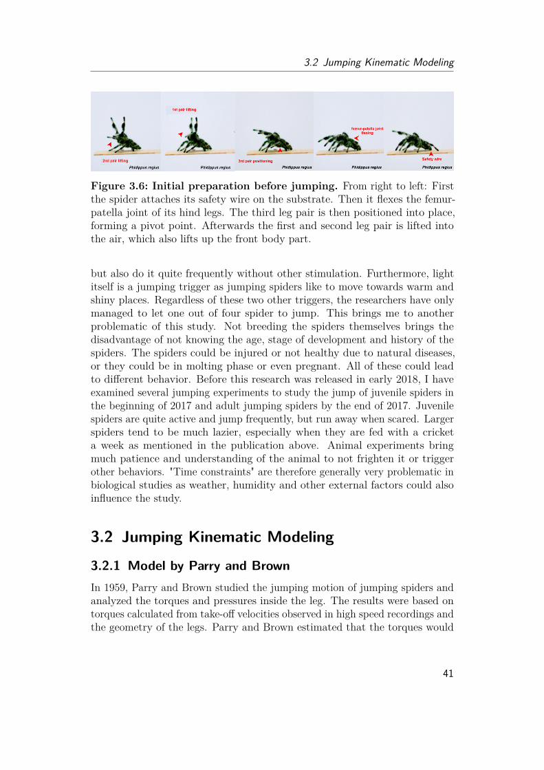
3.2 Jumping Kinematic Modeling
Figure 3.6: Initial preparation before jumping. From right to left: Firstthe spider attaches its safety wire on the substrate. Then it flexes the femur-patella joint of its hind legs. The third leg pair is then positioned into place,forming a pivot point. Afterwards the first and second leg pair is lifted intothe air, which also lifts up the front body part.
but also do it quite frequently without other stimulation. Furthermore, lightitself is a jumping trigger as jumping spiders like to move towards warm andshiny places. Regardless of these two other triggers, the researchers have onlymanaged to let one out of four spider to jump. This brings me to anotherproblematic of this study. Not breeding the spiders themselves brings thedisadvantage of not knowing the age, stage of development and history of thespiders. The spiders could be injured or not healthy due to natural diseases,or they could be in molting phase or even pregnant. All of these could leadto different behavior. Before this research was released in early 2018, I haveexamined several jumping experiments to study the jump of juvenile spiders inthe beginning of 2017 and adult jumping spiders by the end of 2017. Juvenilespiders are quite active and jump frequently, but run away when scared. Largerspiders tend to be much lazier, especially when they are fed with a cricketa week as mentioned in the publication above. Animal experiments bringmuch patience and understanding of the animal to not frighten it or triggerother behaviors. "Time constraints" are therefore generally very problematic inbiological studies as weather, humidity and other external factors could alsoinfluence the study.
3.2 Jumping Kinematic Modeling
3.2.1 Model by Parry and BrownIn 1959, Parry and Brown studied the jumping motion of jumping spiders andanalyzed the torques and pressures inside the leg. The results were based ontorques calculated from take-off velocities observed in high speed recordings andthe geometry of the legs. Parry and Brown estimated that the torques would
41
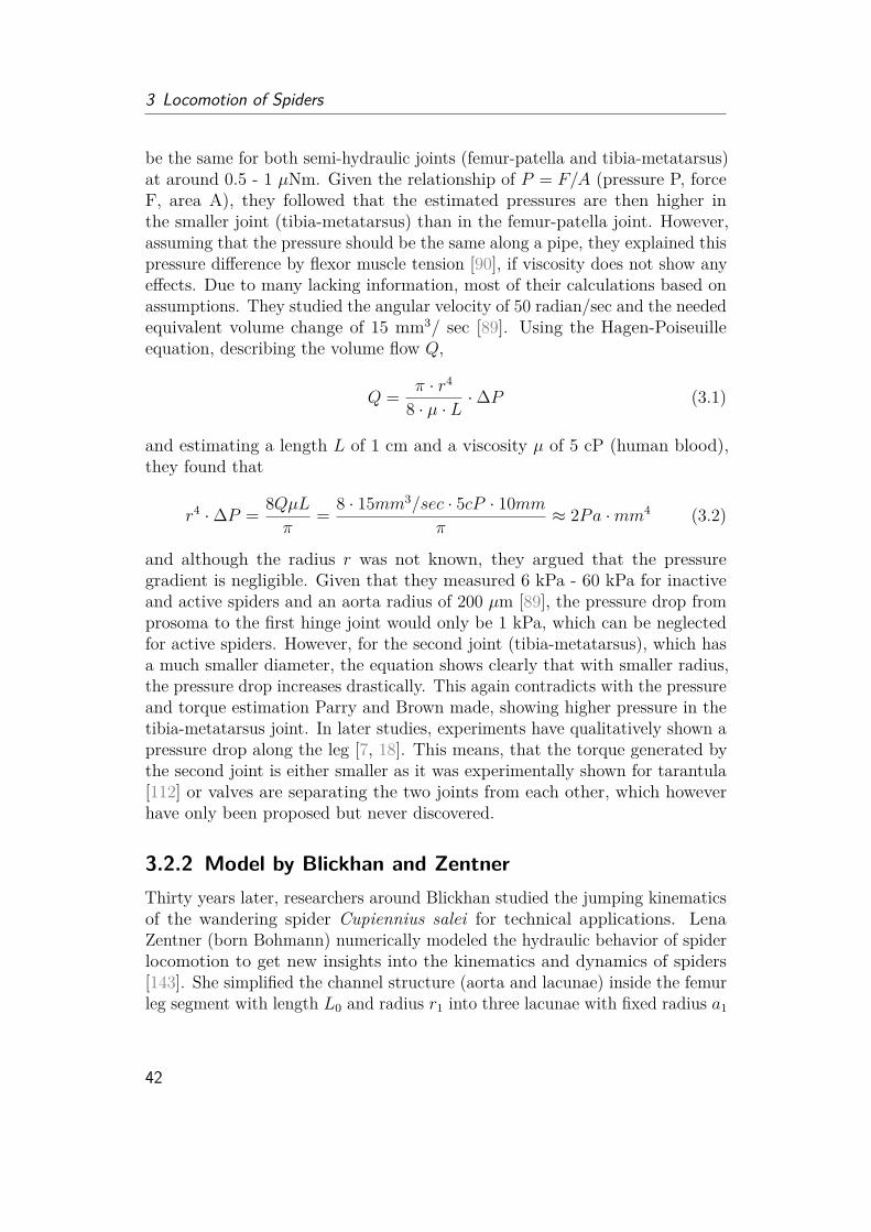
3 Locomotion of Spiders
be the same for both semi-hydraulic joints (femur-patella and tibia-metatarsus)at around 0.5 - 1 µNm. Given the relationship of P = F/A (pressure P, forceF, area A), they followed that the estimated pressures are then higher inthe smaller joint (tibia-metatarsus) than in the femur-patella joint. However,assuming that the pressure should be the same along a pipe, they explained thispressure difference by flexor muscle tension [90], if viscosity does not show anyeffects. Due to many lacking information, most of their calculations based onassumptions. They studied the angular velocity of 50 radian/sec and the neededequivalent volume change of 15 mm3/ sec [89]. Using the Hagen-Poiseuilleequation, describing the volume flow Q,
Q = π · r4
8 · µ · L ·∆P (3.1)
and estimating a length L of 1 cm and a viscosity µ of 5 cP (human blood),they found that
r4 ·∆P = 8QµLπ
= 8 · 15mm3/sec · 5cP · 10mmπ
≈ 2Pa ·mm4 (3.2)
and although the radius r was not known, they argued that the pressuregradient is negligible. Given that they measured 6 kPa - 60 kPa for inactiveand active spiders and an aorta radius of 200 µm [89], the pressure drop fromprosoma to the first hinge joint would only be 1 kPa, which can be neglectedfor active spiders. However, for the second joint (tibia-metatarsus), which hasa much smaller diameter, the equation shows clearly that with smaller radius,the pressure drop increases drastically. This again contradicts with the pressureand torque estimation Parry and Brown made, showing higher pressure in thetibia-metatarsus joint. In later studies, experiments have qualitatively shown apressure drop along the leg [7, 18]. This means, that the torque generated bythe second joint is either smaller as it was experimentally shown for tarantula[112] or valves are separating the two joints from each other, which howeverhave only been proposed but never discovered.
3.2.2 Model by Blickhan and ZentnerThirty years later, researchers around Blickhan studied the jumping kinematicsof the wandering spider Cupiennius salei for technical applications. LenaZentner (born Bohmann) numerically modeled the hydraulic behavior of spiderlocomotion to get new insights into the kinematics and dynamics of spiders[143]. She simplified the channel structure (aorta and lacunae) inside the femurleg segment with length L0 and radius r1 into three lacunae with fixed radius a1
42

3.2 Jumping Kinematic Modeling
(same to inital radius a0) in the middle of the leg and calculated the pressuredrop again via Hagen-Poiseuille equation:
P0 − P1 = 8µπa4
0L0V (3.3)
whereby the volume flow changes with angle φ (and φ as inital angle):
V = (πr21)r1φ (3.4)
Using differential motion equations, she modeled the joint behavior:
Jφ = −mgLssinφ+ A · P1r1√
2− kφ−Mc (3.5)Mc = c · (φ− φ0) (3.6)A = 3πa2
1 (3.7)
for a leg with the mass m, lacunae cross area A, a mass moment of inertia Jand a distance of the mass center from the rotation center of Ls. The musclebehavior were integrated by a spring-damper construct, given through thedamping coefficient k and the spring element Mc through the spring stiffness c.Citing Parry and Brown [90], she used the viscosity of human blood and
later the viscosity of water for the simulation. Although many parameters werestill missing, she was able to give qualitative information about the jumpingbehavior. She showed that a linear increasing cross-section area to openingangle behavior would increase the take-off velocity. She further investigatedthe initial position needed to achieve the highest take-off velocities and verticaljumps. She concluded that with given parameters, a spider weighing above3 g should not be able to jump if it is only using hydraulics due to "segmentoscillation" and muscle "damping".
Authors comment on jumping modeling The simulation and conclu-sions taken from the simulations are based on many assumptions and arelacking major influences. That is why conclusions taken out from these shouldbe carefully elaborated.In general, spiders lift their front body part for jumping, which could shift
their center of mass, influencing the jumping behavior, the influence of "silkbraking" was also not known and also often ignored in later jumping studies.Viscosity effects were not taken into account, as there were no data available,but viscosity could have large impact on volume shifts, temperature dependentbehavior and performance. Furthermore, the flow inside the leg and joint wasnot known and cross sectional area as well as volume shifts were estimated by
43
3 Locomotion of Spiders
the empty space "lacunae" inside the leg and "artificial" experiments, wherecut off leg were extended by filling them with fluid via a syringe. All theseparameters could have a great impact on the Hagen-Poiseuille equation, theresulting pressure drop and torque. Looking into the modeling by Zentner,the seven-jointed-leg locomotion were reduced to the three main joints (hip,femur-patella and tibia-metatarsus) and leg segment lengths were determinedfrom a tarantula for simulation purpose. However, it is not clear whether or notthe foot (tarsus) was integrated or not integrated into the leg segment length.The studies assumed that the force is acting via the tip of the foot (tarsus) onthe ground.Video recordings show that the studied wandering spiders C. salei barely
touch the ground with the rest of the tarsus, however the metatarsus-tarsusis not straight, but bent in a specific angle, which is not considered in thesimulation. The model shows three parts with almost similar length, but it canbe assumed that the third part, the part touching the ground is actually smalleras the tarsus is bent around. This might also explain, why the initial positionof the simulated spiders shows highly flexed tibia-metatarsus joints and almostopen femur-patella joints, which is the opposite in real spiders. Experimentalstudies by Weihmann and Karner showed this much steeper flexing angle forcoordinated, prepared jumps.
The modeling parameters introduced by Zentner are based on leg parametersof tarantulas. At this point, I need to say, that tarantulas, wandering, wolfor jumping spiders show completely different weight distributions, leg lengthand hunting behavior. Using conclusions interchangeably are therefore notnecessarily useful. It is not clear, why Zentner used tarantula legs, but it mightbe as due to their size, they were easier to study. However, tarantulas are notoptimized for jumping, as it is not in their frequent behavioral repertoire. Andstill, tarantulas with a weight over 120 g (much larger the 3 g limit set byZentner) were able to be triggered into "jumps" of 2-3 cm [135]. Weihmann andSens however assume that these jumps might be supported by the muscles fromthe hip joint, questioning the advantage of hydraulics [111, 135]. I hypothesizethat not muscles but the elastic properties of the joint membrane might supportthe hydraulic jumping and that tarantulas neither have enough muscle power towithstand the pressure needed for lifting their weight, nor the right leg geometry.Humans and Kangaroos both have muscles. Still kangaroos can jump muchmore impressive than humans, concluding that muscles are the problem in thisequation would therefore probably not be the first choice, however somehowspider research continuously does this.While Parry and Brown [90] assumed that the jump of spiders is scalable
from smaller to larger spiders, Weihmann [135] hypothesized that viscosity
44

3.2 Jumping Kinematic Modeling
could cause delays in volume shifts in larger spiders, reducing its performance.I assume that non-Newtonian fluid behavior might resolve this problem.Zentner introduced the term of "segment oscillation" and the "necessary
muscle damping" would also increase with animal size according to simulationsand therefore reduce the jumping ability [15, 135]. However it is not clear howthe "segment oscillation" occur on real spiders and I was not able to find anydetailed information about this term.
With the insights provided in this thesis, a much more detailed simulationwith better computational tools should be conducted in future to shine lightinto the real jumping kinematics of jumping spiders.
45
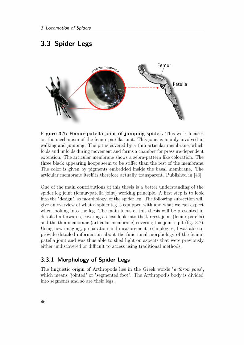
3 Locomotion of Spiders
3.3 Spider Legs
Figure 3.7: Femur-patella joint of jumping spider. This work focuseson the mechanism of the femur-patella joint. This joint is mainly involved inwalking and jumping. The pit is covered by a thin articular membrane, whichfolds and unfolds during movement and forms a chamber for pressure-dependentextension. The articular membrane shows a zebra-pattern like coloration. Thethree black appearing hoops seem to be stiffer than the rest of the membrane.The color is given by pigments embedded inside the basal membrane. Thearticular membrane itself is therefore actually transparent. Published in [43].
One of the main contributions of this thesis is a better understanding of thespider leg joint (femur-patella joint) working principle. A first step is to lookinto the "design", so morphology, of the spider leg. The following subsection willgive an overview of what a spider leg is equipped with and what we can expectwhen looking into the leg. The main focus of this thesis will be presented indetailed afterwards, covering a close look into the largest joint (femur-patella)and the thin membrane (articular membrane) covering this joint’s pit (fig. 3.7).Using new imaging, preparation and measurement technologies, I was able toprovide detailed information about the functional morphology of the femur-patella joint and was thus able to shed light on aspects that were previouslyeither undiscovered or difficult to access using traditional methods.
3.3.1 Morphology of Spider LegsThe linguistic origin of Arthropods lies in the Greek words "arthron pous",which means "jointed" or "segmented foot". The Arthropod’s body is dividedinto segments and so are their legs.
46

3.3 Spider Legs
Figure 3.8: Morphology of the jumping spider Phiddipus regius leg.Left: The hairy leg of spiders is divided into seven segments. The leg naturallyfolds into fully flexed position, when it is disconnected from the body or whenthe spider is dead. Two of the joints (femur-patella and tibia-metatarsus) usehydraulics for extension and are highly involved in jumping, walking or grippingmotions. The foot (tarsus) is covered with adhesive hairs (scopula (2)) allowingspiders two climb upside down on smooth surfaces. Furthermore comb-likeclaws (1) give additional support on rough terrain and allow the spider to combthe silk wire in order to change its properties. It is also hypothesized that thecomb is necessary to allow efficient climbing up a silk string. Spines on themetatarsus could either function as sensors or give support during jumping orlanding.
Regardless of the spider species, spiders have eight legs, which are dividedinto seven segments (coxa, trochanter, femur, patella, tibia, metatarsus, tarsus)(fig. 3.8). Thereby, four joints are mainly guiding the locomotion of the spiders:the muscle-driven joints at the hip (body-coxa-trochanter joint construct) andthe foot (metatarsus-tarsus) and the two hydraulically extending joints (femur-patella, tibia-metatarsus). The hip joint enables stance and pan movement[64]. The foot joint allows interaction with the substrate. For spiders withadhesive pads, the foot joint is essential during attachment to and detachmentfrom the surface. The semi-hydraulic joints are lacking in extensor muscles,but are filled with flexor muscles and are highly involved in running, jumpingand grasping. While orb-weaver spiders are known for their long and delicate
47
3 Locomotion of Spiders
legs, which spin the silk wires around their prey, jumping spiders and tarantulatend to have short and thick legs in contrast. All spiders have in common thattheir legs will never appear in advertisements to promote smooth skin. Theirhairiness and spikiness is rather a common cause to trigger arachnophobia.Many of these hairs are actually tactile hairs reacting to objects in their
surroundings. Some tactile hairs and inner sensory cells close to the leg jointseven provide information about the joint position and receive feedback aboutspeed and direction when the joint position changes. Beside hairs, spider legsare equipped with another interesting sensor, the slit sensor. This slit sensor isa slit-shaped dent on the exoskeleton, which gives information about mechanicaldeformation of the surrounded exocuticle. While single slits can appear allover the body, these slit sensors are often arranged in parallel groups (lyriformorgans) close to the leg joints, providing information about the joint movementduring walking and about distance and orientation. Furthermore, lyriformorgans are shown to react to vibrations in specific frequencies, allowing spidersto distinguish prey from leaves caught in their net and to communicate duringmating [37].
In general, spider legs are densely packed with muscles (fig. 3.9). Over thirtymuscles can be counted inside the spider’s leg [37]. This number is significantlyhigher than in other arthropods (insects: 10; scorpions and crustacea: 16 legmuscles [37]). While insects have antagonistic working muscles, spider legsare filled with flexor muscles. Researchers therefore assume that the mainreason for a hydraulic extension is a larger space for these flexor muscles toallow fast, strong and precise grasping movement [37]. Beside the muscles,three main (peripheral) nerves run through the spider legs. The purely sensorynerve is the largest among these three, which intercepts the signals of the manysensors a spider leg is equipped with. In addition, there is the slightly smallerpurely motor nerve, which sends signals to the muscles and the third fine, thinmixed-type (sensory and motor) nerve.The muscles and nerves divide the tightly packed spider legs into different
sections through which the body fluid (hemolymph) flows. Cross-sections showa main artery, which provides the muscle and nerve cells with oxygen andnutrients. Other spaces between the muscles have been assigned as the so-calledlacunae, which are filled with hemolymph and allow the hemolymph to flowback to the heart. Unlike humans, the spiders have no defined veins to collectthe oxygen-deficient "blood".
The focus of this work will lie on the femur-patella segment, which is the maincontributor to jumping in the studied spiders and shows the largest working
48
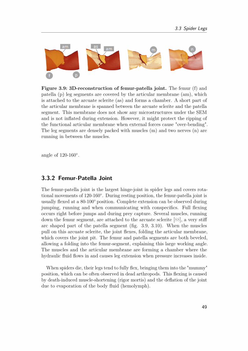
3.3 Spider Legs
Figure 3.9: 3D-reconstruction of femur-patella joint. The femur (f) andpatella (p) leg segments are covered by the articular membrane (am), whichis attached to the arcuate sclerite (as) and forms a chamber. A short part ofthe articular membrane is spanned between the arcuate sclerite and the patellasegment. This membrane does not show any microstructures under the SEMand is not inflated during extension. However, it might protect the ripping ofthe functional articular membrane when external forces cause "over-bending".The leg segments are densely packed with muscles (m) and two nerves (n) arerunning in between the muscles.
angle of 120-160◦.
3.3.2 Femur-Patella Joint
The femur-patella joint is the largest hinge-joint in spider legs and covers rota-tional movements of 120-160◦. During resting position, the femur-patella joint isusually flexed at a 80-100◦ position. Complete extension can be observed duringjumping, running and when communicating with conspecifics. Full flexingoccurs right before jumps and during prey capture. Several muscles, runningdown the femur segment, are attached to the arcuate sclerite [88], a very stiffarc shaped part of the patella segment (fig. 3.9, 3.10). When the musclespull on this arcuate sclerite, the joint flexes, folding the articular membrane,which covers the joint pit. The femur and patella segments are both beveled,allowing a folding into the femur-segment, explaining this large working angle.The muscles and the articular membrane are forming a chamber where thehydraulic fluid flows in and causes leg extension when pressure increases inside.
When spiders die, their legs tend to fully flex, bringing them into the "mummy"position, which can be often observed in dead arthropods. This flexing is causedby death-induced muscle-shortening (rigor mortis) and the deflation of the jointdue to evaporation of the body fluid (hemolymph).
49
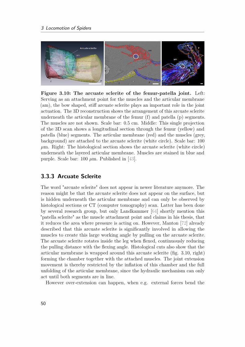
3 Locomotion of Spiders
Figure 3.10: The arcuate sclerite of the femur-patella joint. Left:Serving as an attachment point for the muscles and the articular membrane(am), the bow shaped, stiff arcuate sclerite plays an important role in the jointactuation. The 3D reconstruction shows the arrangement of this arcuate scleriteunderneath the articular membrane of the femur (f) and patella (p) segments.The muscles are not shown. Scale bar: 0.5 cm. Middle: This single projectionof the 3D scan shows a longitudinal section through the femur (yellow) andpatella (blue) segments. The articular membrane (red) and the muscles (grey,background) are attached to the arcuate sclerite (white circle). Scale bar: 100µm. Right: The histological section shows the arcuate sclerite (white circle)underneath the layered articular membrane. Muscles are stained in blue andpurple. Scale bar: 100 µm. Published in [43].
3.3.3 Arcuate Sclerite
The word "arcuate sclerite" does not appear in newer literature anymore. Thereason might be that the arcuate sclerite does not appear on the surface, butis hidden underneath the articular membrane and can only be observed byhistological sections or CT (computer tomography) scan. Latter has been doneby several research group, but only Landkammer [64] shortly mention this"patella sclerite" as the muscle attachment point and claims in his thesis, thatit reduces the area where pressure is acting on. However, Manton [72] alreadydescribed that this arcuate sclerite is significantly involved in allowing themuscles to create this large working angle by pulling on the arcuate sclerite.The arcuate sclerite rotates inside the leg when flexed, continuously reducingthe pulling distance with the flexing angle. Histological cuts also show that thearticular membrane is wrapped around this arcuate sclerite (fig. 3.10, right)forming the chamber together with the attached muscles. The joint extensionmovement is thereby restricted by the inflation of this chamber and the fullunfolding of the articular membrane, since the hydraulic mechanism can onlyact until both segments are in line.However over-extension can happen, when e.g. external forces bend the
50

3.3 Spider Legs
leg extremely or during jumping the leg is excelled in high speed and opensrapidly. I hypothesize that the fold of the articular membrane created by thearcuate sclerite and the membrane stretched between the arcuate sclerite andthe patella segment, separate when the leg is overextended to help absorbexternal energy, preventing the chamber from ripping, which would be fatal forthe hydraulic actuation. Interestingly the membrane between patella segmentand arcuate sclerite does not show any microstructures when observed underthe SEM. Further studies on this particular segment and the role of the arcuatesclerite are needed to completely understand its functioning.
3.3.4 Articular MembraneThere are several different definitions of the word membrane, which are im-portant to know when communicating between scientists and engineers toavoid misunderstanding. In chemistry, thin boundary layers such as filtersare usually called membranes, which separate structures from each other andoften allow limited permeability of certain substances. Such structures can befound at cellular level, including the cell membrane or basal membrane. Theyoften play an important role in the transmission of signal and informationas in nerve cells or energy (ATP) generation. Such membranes can also befound in battery technology, where they are often referred to as separators.In physics, one also finds the so-called oscillating membranes, which oscillatewhen external force is applied. The eardrum or membrane of a speaker belongto this type of membranes. For a similar reason, the wing skin of bats arealso called flight membranes. In measurement technology, pressure membranesdescribe a thin, impermeable sealing layer that deforms when pressure is ap-plied. In construction technology, on the other hand, thin, foil-like materialsare called membranes, which are slightly plastically deformable and often usedfor wide-span roofs.In the following sections, I would like to provide detailed images of the
articular membrane to give the reader a feeling about what type of membranewe are talking about. I would like to show the reader why the articularmembrane is of importance for the locomotion of spiders and show them howit supports the movement of the joint by its mechanical properties. Finally, Ihave looked into several more interesting aspects, which have popped up duringthe analysis of the articular membrane.
3.3.4.1 Morphology of articular membrane
The articular membrane is neither permeable nor does it have a swingingfunction. It actually is part of the exoskeleton (cuticle) of spiders and describes
51
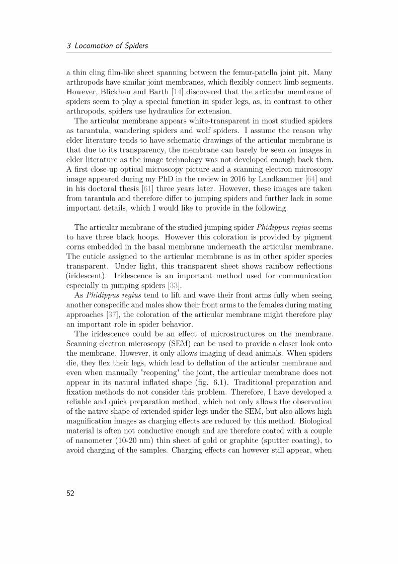
3 Locomotion of Spiders
a thin cling film-like sheet spanning between the femur-patella joint pit. Manyarthropods have similar joint membranes, which flexibly connect limb segments.However, Blickhan and Barth [14] discovered that the articular membrane ofspiders seem to play a special function in spider legs, as, in contrast to otherarthropods, spiders use hydraulics for extension.The articular membrane appears white-transparent in most studied spiders
as tarantula, wandering spiders and wolf spiders. I assume the reason whyelder literature tends to have schematic drawings of the articular membrane isthat due to its transparency, the membrane can barely be seen on images inelder literature as the image technology was not developed enough back then.A first close-up optical microscopy picture and a scanning electron microscopyimage appeared during my PhD in the review in 2016 by Landkammer [64] andin his doctoral thesis [61] three years later. However, these images are takenfrom tarantula and therefore differ to jumping spiders and further lack in someimportant details, which I would like to provide in the following.
The articular membrane of the studied jumping spider Phidippus regius seemsto have three black hoops. However this coloration is provided by pigmentcorns embedded in the basal membrane underneath the articular membrane.The cuticle assigned to the articular membrane is as in other spider speciestransparent. Under light, this transparent sheet shows rainbow reflections(iridescent). Iridescence is an important method used for communicationespecially in jumping spiders [33].
As Phidippus regius tend to lift and wave their front arms fully when seeinganother conspecific and males show their front arms to the females during matingapproaches [37], the coloration of the articular membrane might therefore playan important role in spider behavior.The iridescence could be an effect of microstructures on the membrane.
Scanning electron microscopy (SEM) can be used to provide a closer look ontothe membrane. However, it only allows imaging of dead animals. When spidersdie, they flex their legs, which lead to deflation of the articular membrane andeven when manually "reopening" the joint, the articular membrane does notappear in its natural inflated shape (fig. 6.1). Traditional preparation andfixation methods do not consider this problem. Therefore, I have developed areliable and quick preparation method, which not only allows the observationof the native shape of extended spider legs under the SEM, but also allows highmagnification images as charging effects are reduced by this method. Biologicalmaterial is often not conductive enough and are therefore coated with a coupleof nanometer (10-20 nm) thin sheet of gold or graphite (sputter coating), toavoid charging of the samples. Charging effects can however still appear, when
52
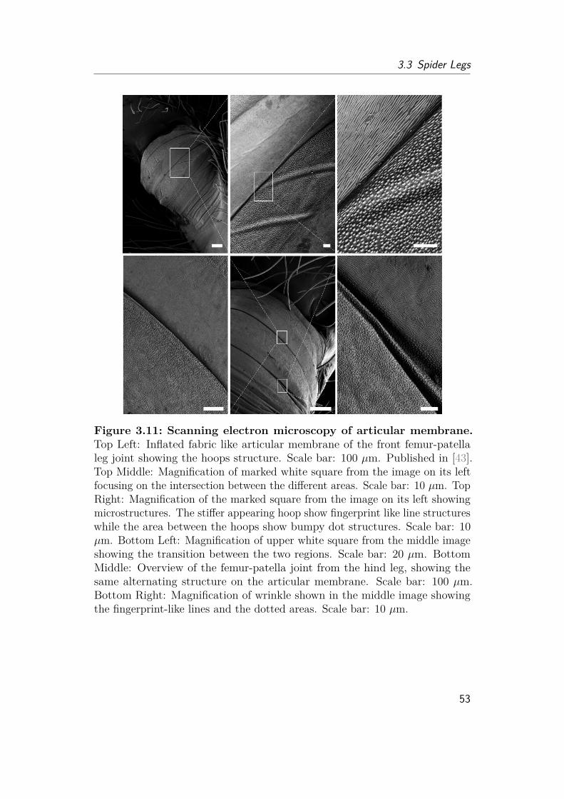
3.3 Spider Legs
Figure 3.11: Scanning electron microscopy of articular membrane.Top Left: Inflated fabric like articular membrane of the front femur-patellaleg joint showing the hoops structure. Scale bar: 100 µm. Published in [43].Top Middle: Magnification of marked white square from the image on its leftfocusing on the intersection between the different areas. Scale bar: 10 µm. TopRight: Magnification of the marked square from the image on its left showingmicrostructures. The stiffer appearing hoop show fingerprint like line structureswhile the area between the hoops show bumpy dot structures. Scale bar: 10µm. Bottom Left: Magnification of upper white square from the middle imageshowing the transition between the two regions. Scale bar: 20 µm. BottomMiddle: Overview of the femur-patella joint from the hind leg, showing thesame alternating structure on the articular membrane. Scale bar: 100 µm.Bottom Right: Magnification of wrinkle shown in the middle image showingthe fingerprint-like lines and the dotted areas. Scale bar: 10 µm.
53
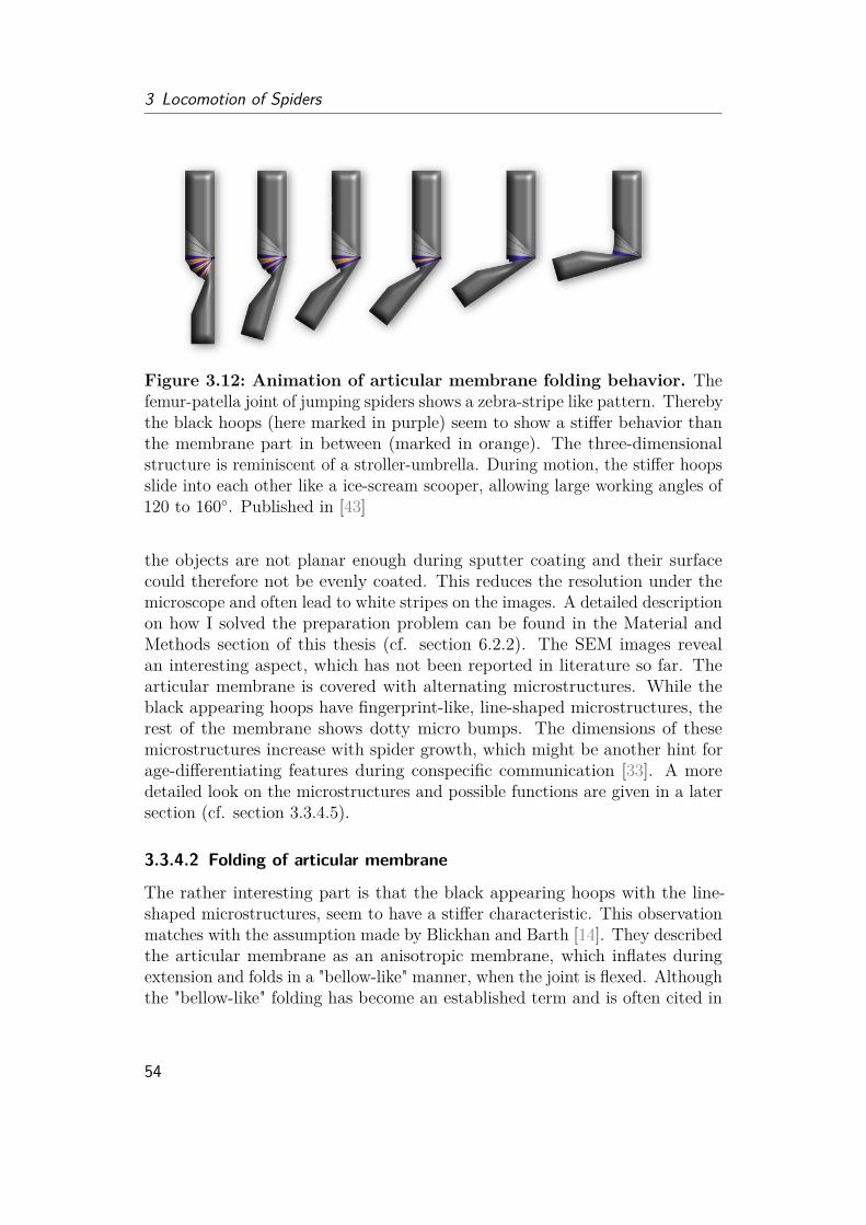
3 Locomotion of Spiders
Figure 3.12: Animation of articular membrane folding behavior. Thefemur-patella joint of jumping spiders shows a zebra-stripe like pattern. Therebythe black hoops (here marked in purple) seem to show a stiffer behavior thanthe membrane part in between (marked in orange). The three-dimensionalstructure is reminiscent of a stroller-umbrella. During motion, the stiffer hoopsslide into each other like a ice-scream scooper, allowing large working angles of120 to 160◦. Published in [43]
the objects are not planar enough during sputter coating and their surfacecould therefore not be evenly coated. This reduces the resolution under themicroscope and often lead to white stripes on the images. A detailed descriptionon how I solved the preparation problem can be found in the Material andMethods section of this thesis (cf. section 6.2.2). The SEM images revealan interesting aspect, which has not been reported in literature so far. Thearticular membrane is covered with alternating microstructures. While theblack appearing hoops have fingerprint-like, line-shaped microstructures, therest of the membrane shows dotty micro bumps. The dimensions of thesemicrostructures increase with spider growth, which might be another hint forage-differentiating features during conspecific communication [33]. A moredetailed look on the microstructures and possible functions are given in a latersection (cf. section 3.3.4.5).
3.3.4.2 Folding of articular membrane
The rather interesting part is that the black appearing hoops with the line-shaped microstructures, seem to have a stiffer characteristic. This observationmatches with the assumption made by Blickhan and Barth [14]. They describedthe articular membrane as an anisotropic membrane, which inflates duringextension and folds in a "bellow-like" manner, when the joint is flexed. Althoughthe "bellow-like" folding has become an established term and is often cited in
54

3.3 Spider Legs
"spider-inspired" studies, I would like to use a different way to describe thefolding mechanism. The reason is, that the term "bellow" is set to a definedshape in the (soft) engineering context, which does not fully reflect the jointfolding of spiders and lead to confusion in spider-inspired work. I would ratherintroduce an old description from 1958 by Manton [72], which unfortunately fellinto oblivion. She described the articular (arthrodial) membrane as a constructwhich is "stiffened by five hoops of more fully sclerotized cuticle", which "are soarranged that they shuffle over one another when the joint flexes, the limperarthrodial membrane folding between them" [72].
At this point, I would like to mention that all of these descriptions are mainlydone by words and drawings. For a reader who has never seen how a spiderfolds its leg, it is rather difficult to imagine the working principle. Therefore, Iprovide video-sequences in combination with a simple schematic drawing toshow how the folding works (fig.3.12).
The folding is induced by muscles pulling at the arcuate sclerite, wherethe membrane is attached to. Similar to Manton’s description [72], the three(and not five) hoops slide under each other like the inner ring of an ice-creamscoop. The folding resembles the sun-shade of a stroller, with the differencethat the diameter of each ring slightly decreases, to allow the sliding into eachother. Landkammer [64] described the sliding as a Z-shaped fold. However, heassumed only one large Z-fold which rolls out during extension, although he hasassigned the three presumably reinforced (stiff) structures on the membrane.This description is only based on observation and Landkammer did not provideany detailed video sequences of the folding mechanism nor did he experimentallyproof the actual reinforcement of the membrane.
3.3.4.3 Stiffness and hardness characterization of articular membrane
As the stiffness difference and anisotropy of the membrane seems to play a keyrole in a controlled folding and unfolding of the articular membrane and maybealso energy storage. I have conducted different indentation measurements tolook into the mechanical properties of the different parts.Nanoindentation results (fig. 3.13) support the hypothesis of a difference
in the mechanical properties between the dot and line areas, showing a meanYoung’s modulus E of 3.8 GPa for the dot and 5.0 GPa for the line area.Furthermore, the hardness H appears to be more than twice as high for theline area than the dot area, with means of 0.12 GPa for the dot and 0.29 GPafor the line area.The mechanical properties of spider exoskeleton has been examined in the
late 80s by Blickhan and Barth [14], who showed that the stiff leg segments
55

3 Locomotion of Spiders
Figure 3.13: Material property characterization of articular mem-brane. The mechanical properties stiffness and hardness of the articularmembrane were measured via nanoindentation. Therefore, the membrane(∼ 1 mm2) was dissected, flatten on an aluminium block and displaced by aBerkovich tip. The results show that the stiffness and hardness show significant(asterisk) between the area with dotted microstructures (n = 57) and with linestructures (n = 101). Published in [43]
could have a stiffness of 18 GPa. Barth showed that the composition of theexoskeleton has a large influence on the mechanical properties [10]. Legs,which have a thick exocuticle are rather stiff in comparison to the abdomenor articular membrane which are lacking this exocuticle, but have a ratherlaminar arranged thick layer of endocuticle. Barth estimated according to thelayer structure of the articular membrane [10], that its stiffness lies between 3-5GPa and is therefore close to the stiffness measured for dragonfly wings [119].
The histological cuts through the femur-patella joint revealed that the artic-ular membrane lacks in the stiff exocuticle explaining the lower stiffness of thearticular membrane in comparison to the leg segment (e.g. femur).
While the traditional nanoindentation measurements are conducted on drysample material, which may have an influence on the mechanical properties, Ihave later found a method to measure the hydrated mechanical properties ofthe spiders articular membrane.Using the femto tool1 developed by the ETH group around Brad Nelson, I
was able to measure the mechanical properties of hydrated sample (fig. 3.14),1https://www.femtotools.com/; last accessed on 19th Dec. 2020
56
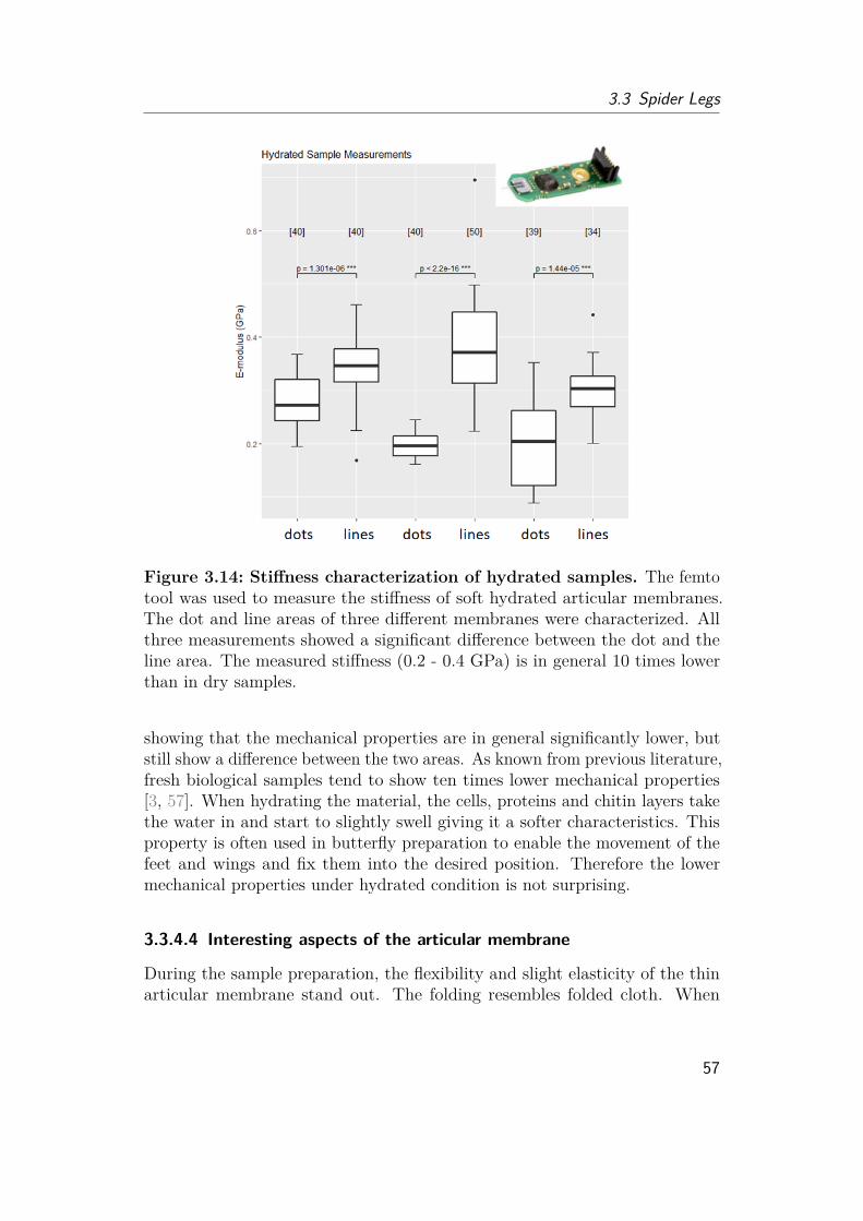
3.3 Spider Legs
Figure 3.14: Stiffness characterization of hydrated samples. The femtotool was used to measure the stiffness of soft hydrated articular membranes.The dot and line areas of three different membranes were characterized. Allthree measurements showed a significant difference between the dot and theline area. The measured stiffness (0.2 - 0.4 GPa) is in general 10 times lowerthan in dry samples.
showing that the mechanical properties are in general significantly lower, butstill show a difference between the two areas. As known from previous literature,fresh biological samples tend to show ten times lower mechanical properties[3, 57]. When hydrating the material, the cells, proteins and chitin layers takethe water in and start to slightly swell giving it a softer characteristics. Thisproperty is often used in butterfly preparation to enable the movement of thefeet and wings and fix them into the desired position. Therefore the lowermechanical properties under hydrated condition is not surprising.
3.3.4.4 Interesting aspects of the articular membrane
During the sample preparation, the flexibility and slight elasticity of the thinarticular membrane stand out. The folding resembles folded cloth. When
57

3 Locomotion of Spiders
dissected out of the joint, the articular membrane reveals a cling-film likecharacteristic, whereby the membrane unfolds completely and any wrinklesdisappear when transferred onto a water surface. The membrane appearsto be quite robust and the question arose whether the elastic protein resilinis incorporated into the membrane. Resilin can be found in the articularmembranes of insects [74, 75] and in the joints of many jumping insects asin locusts [22] or frog hopper insects [23] and is also speculated to be in clickbeetles [23].The literature does not provide any information about resilin in spiders, so
I decided to quickly run the indirect resilin test to see whether or not resilinmight be added into the membrane to support the jump of spiders and storeelastic energy. Resilin shows strong blue fluorescence under UV light [23]. Thequick test revealed that the membrane does show light blue fluorescence, butonly in the line region and not in the dotted (fig. 3.15). However, resilinmight not be the source of the observed very light blue fluorescence (fig.3.15, middle), but rather a result of high nitrogen-content (e.g. nitrogen richproteins) in that area [138]. While resilin has not been reported in arachnidstudies, researchers have observed blue fluorescence in scorpion exoskeleton [39].Similar to the coloration and patterning, this fluorescence might be involved incommunication and recognition with conspecifics [39]. I assume that not resilin,but the nitrogen-rich proteins in the epicuticle are responsible for the twodifferent mechanical characteristics of the articular membrane. Furthermore,the thickness can emphasize the mechanical difference between the dot andthe line area. Histological sections lead to the assumption that the articularmembrane shows a higher number of layers in the line area compared to thedot area (fig. 3.16). This hypothesis is supported by the fact that the line areaappears much denser and clearer under X-ray scanning.
3.3.4.5 Microstructures on different regions of the articular membrane
Although the main work of this thesis focuses on the jumping spider Phidippusregius, I have also taken images of the running and jumping wolf spiders in thebeginning of my PhD (fig. 3.17). The joint pit of wolf spiders does not showa zebra stripe coloration pattern, but the microstructures do alternate alongthe membrane. While the folding region still similar bumps, the stiffened areadoes not show finger print like lines, but rather Mercedes stars to dog bonearranged structures. It can be assumed that the spider species have structuresadapted to their behavior to allow their preferred type of motion.
Microstructures have been reported to cover a wide range of functions. Theycan reduce wettability for water collecting self-cleaning purposes. Microstruc-tures can also reduce the reflection of light, creating highly transparent wings
58
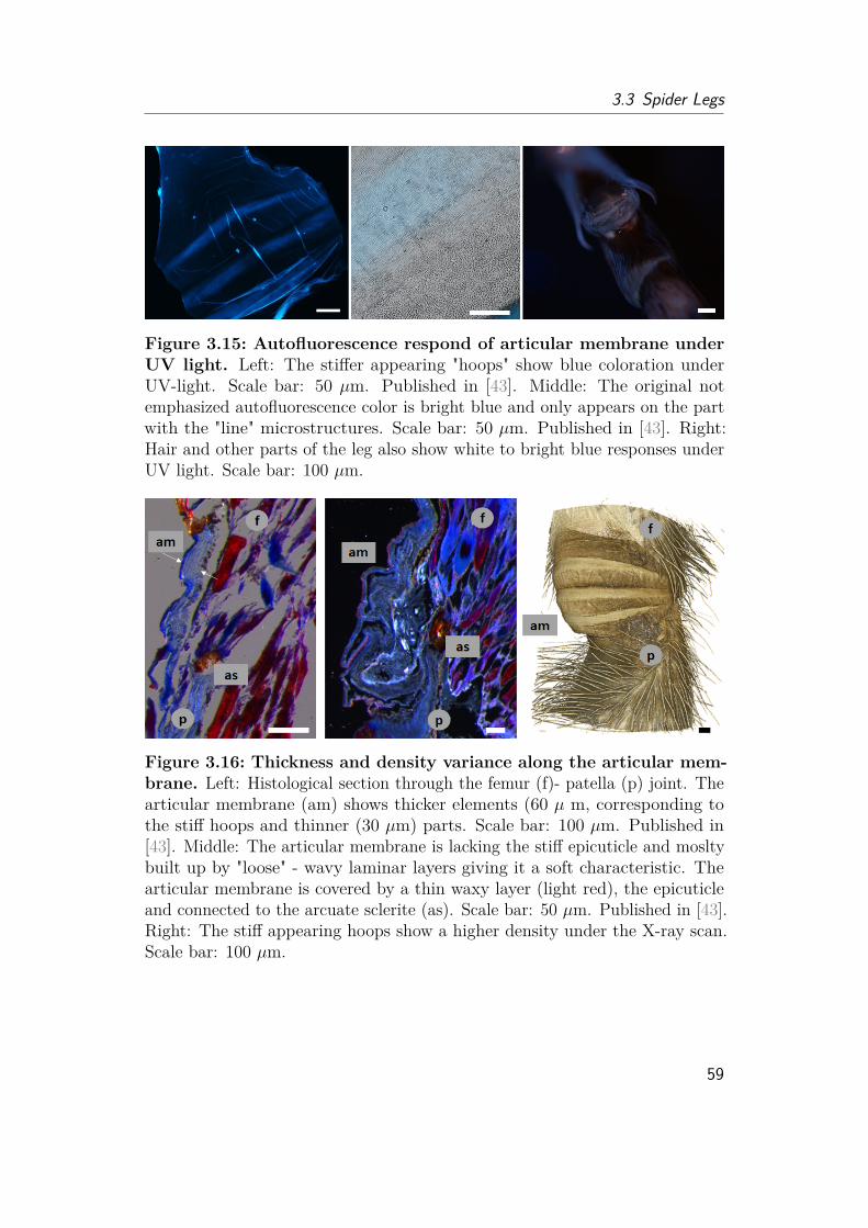
3.3 Spider Legs
Figure 3.15: Autofluorescence respond of articular membrane underUV light. Left: The stiffer appearing "hoops" show blue coloration underUV-light. Scale bar: 50 µm. Published in [43]. Middle: The original notemphasized autofluorescence color is bright blue and only appears on the partwith the "line" microstructures. Scale bar: 50 µm. Published in [43]. Right:Hair and other parts of the leg also show white to bright blue responses underUV light. Scale bar: 100 µm.
Figure 3.16: Thickness and density variance along the articular mem-brane. Left: Histological section through the femur (f)- patella (p) joint. Thearticular membrane (am) shows thicker elements (60 µ m, corresponding tothe stiff hoops and thinner (30 µm) parts. Scale bar: 100 µm. Published in[43]. Middle: The articular membrane is lacking the stiff epicuticle and mosltybuilt up by "loose" - wavy laminar layers giving it a soft characteristic. Thearticular membrane is covered by a thin waxy layer (light red), the epicuticleand connected to the arcuate sclerite (as). Scale bar: 50 µm. Published in [43].Right: The stiff appearing hoops show a higher density under the X-ray scan.Scale bar: 100 µm.
59
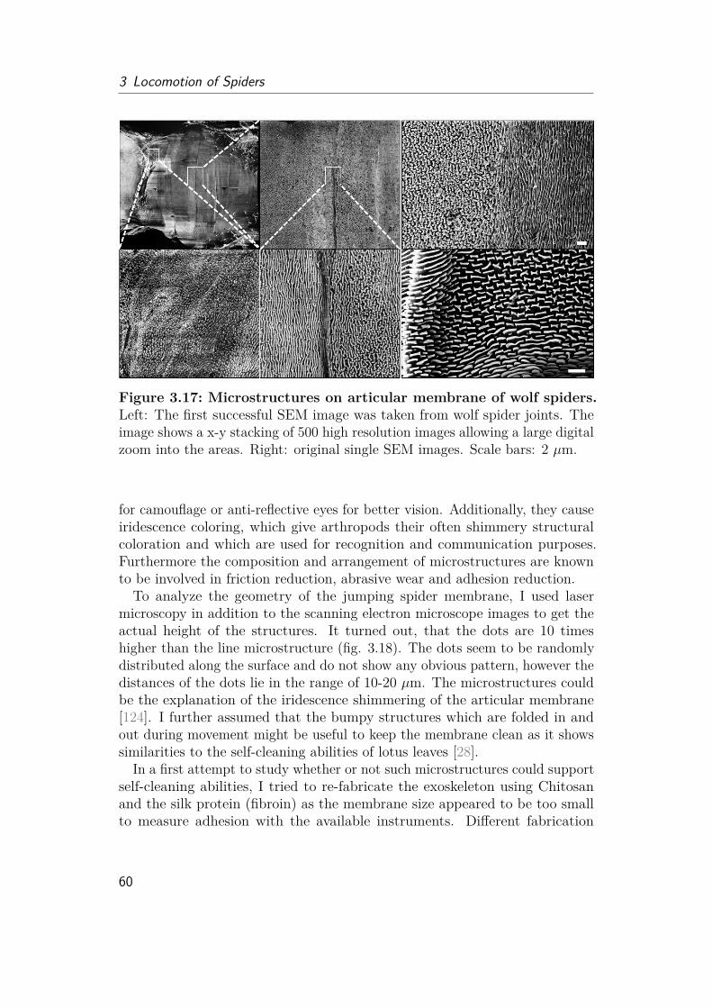
3 Locomotion of Spiders
Figure 3.17: Microstructures on articular membrane of wolf spiders.Left: The first successful SEM image was taken from wolf spider joints. Theimage shows a x-y stacking of 500 high resolution images allowing a large digitalzoom into the areas. Right: original single SEM images. Scale bars: 2 µm.
for camouflage or anti-reflective eyes for better vision. Additionally, they causeiridescence coloring, which give arthropods their often shimmery structuralcoloration and which are used for recognition and communication purposes.Furthermore the composition and arrangement of microstructures are knownto be involved in friction reduction, abrasive wear and adhesion reduction.To analyze the geometry of the jumping spider membrane, I used laser
microscopy in addition to the scanning electron microscope images to get theactual height of the structures. It turned out, that the dots are 10 timeshigher than the line microstructure (fig. 3.18). The dots seem to be randomlydistributed along the surface and do not show any obvious pattern, however thedistances of the dots lie in the range of 10-20 µm. The microstructures couldbe the explanation of the iridescence shimmering of the articular membrane[124]. I further assumed that the bumpy structures which are folded in andout during movement might be useful to keep the membrane clean as it showssimilarities to the self-cleaning abilities of lotus leaves [28].
In a first attempt to study whether or not such microstructures could supportself-cleaning abilities, I tried to re-fabricate the exoskeleton using Chitosanand the silk protein (fibroin) as the membrane size appeared to be too smallto measure adhesion with the available instruments. Different fabrication
60
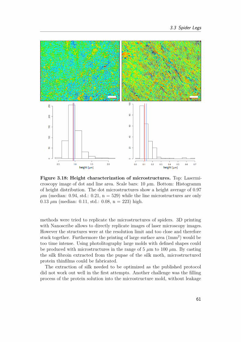
3.3 Spider Legs
Figure 3.18: Height characterization of microstructures. Top: Lasermi-croscopy image of dot and line area. Scale bars: 10 µm. Bottom: Histogrammof height distribution. The dot microstructures show a height average of 0.97µm (median: 0.94, std.: 0.21, n = 529) while the line microstructures are only0.13 µm (median: 0.11, std.: 0.08, n = 223) high.
methods were tried to replicate the microstructures of spiders. 3D printingwith Nanoscribe allows to directly replicate images of laser microscopy images.However the structures were at the resolution limit and too close and thereforestuck together. Furthermore the printing of large surface area (1mm2) would betoo time intense. Using photolitography large molds with defined shapes couldbe produced with microstructures in the range of 5 µm to 100 µm. By castingthe silk fibroin extracted from the pupae of the silk moth, microstructuredprotein thinfilms could be fabricated.The extraction of silk needed to be optimized as the published protocol
did not work out well in the first attempts. Another challenge was the fillingprocess of the protein solution into the microstructure mold, without leakage
61

3 Locomotion of Spiders
Figure 3.19: Artificial microstructured surfaces.Top: MicrostructuredChitosan thin film with bump structures (10 µm). Scale bar: 250 µm. Bottom:Lasermicroscope image of successful microstructured silk fibroin sheets withdot (5 µm) and line (5 µm) microstructures.
Figure 3.20: Contact angle measurement of water on artificial mi-crostructured membrane. Water droplet on microstructured parylene coatedartificial membrane (5 µm). Preliminary analysis showed contact angles of 100- 115◦. Scale bar: 0.5 mm.
and without trapping air bubbles. After several trials and errors to optimizethe fabrication process, the fabrication of microstructured transparent sheetswere successful (fig. 3.19). To mimic the waxy epicuticle, these sheets werecovered with a thin parylene coating.
62
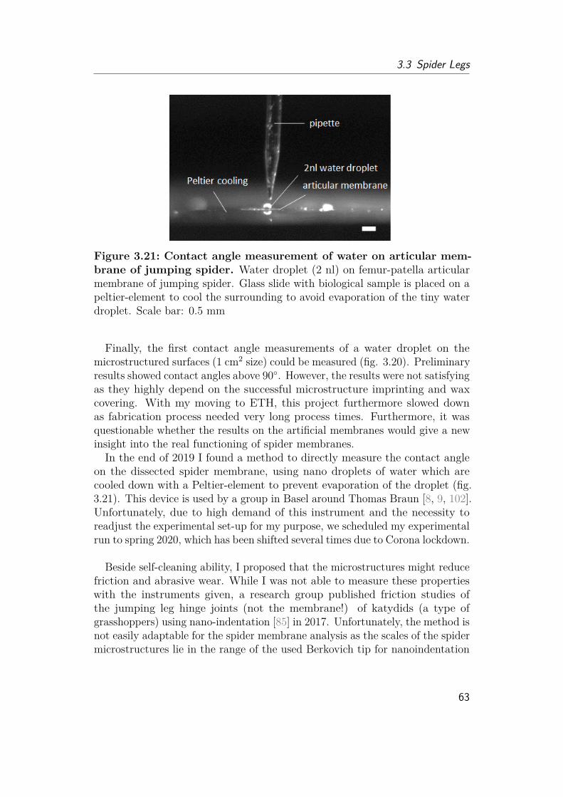
3.3 Spider Legs
Figure 3.21: Contact angle measurement of water on articular mem-brane of jumping spider. Water droplet (2 nl) on femur-patella articularmembrane of jumping spider. Glass slide with biological sample is placed on apeltier-element to cool the surrounding to avoid evaporation of the tiny waterdroplet. Scale bar: 0.5 mm
Finally, the first contact angle measurements of a water droplet on themicrostructured surfaces (1 cm2 size) could be measured (fig. 3.20). Preliminaryresults showed contact angles above 90◦. However, the results were not satisfyingas they highly depend on the successful microstructure imprinting and waxcovering. With my moving to ETH, this project furthermore slowed downas fabrication process needed very long process times. Furthermore, it wasquestionable whether the results on the artificial membranes would give a newinsight into the real functioning of spider membranes.In the end of 2019 I found a method to directly measure the contact angle
on the dissected spider membrane, using nano droplets of water which arecooled down with a Peltier-element to prevent evaporation of the droplet (fig.3.21). This device is used by a group in Basel around Thomas Braun [8, 9, 102].Unfortunately, due to high demand of this instrument and the necessity toreadjust the experimental set-up for my purpose, we scheduled my experimentalrun to spring 2020, which has been shifted several times due to Corona lockdown.
Beside self-cleaning ability, I proposed that the microstructures might reducefriction and abrasive wear. While I was not able to measure these propertieswith the instruments given, a research group published friction studies ofthe jumping leg hinge joints (not the membrane!) of katydids (a type ofgrasshoppers) using nano-indentation [85] in 2017. Unfortunately, the method isnot easily adaptable for the spider membrane analysis as the scales of the spidermicrostructures lie in the range of the used Berkovich tip for nanoindentation
63

3 Locomotion of Spiders
(1µm). Furthermore, the studied katydid samples were 10-100 times greaterthan the spider membrane and the studied structures were at least 5-10 timeslarger. However, the findings might still be true for spiders. The researchersshowed that in the hinge connection of the katydids, smooth-smooth contactwhich could cause high adhesion due to Van der Waals effects and rough-rough contact which could cause high friction and abrasive wear, could notbe observed, but smooth-rough contact was observed at any time of motion,suggesting very well-adapted surfaces for fast jumping extension of the joint.
3.4 HydraulicsNot even a hundred years ago, researchers still believed that spiders use onlymuscles for leg actuation. Studies in the early 1900s [7, 92] showed thatalthough the spider’s leg is packed with muscles, somehow the extensor musclesare lacking for the large joints of the legs. The erection of the leg hair (setae)and the absence of an extension when cutting the tip of the leg, led to thepresumption that spiders use an increase in pressure for actuation forty yearslater [35]. Finally, in the 1960s , researchers were able to show experimentallythat the pressure inside the body increases when the spider moves around [88].
3.4.1 Pump SourceEven though the increase in pressure was found to be the driving force behindthe extension of spider legs, the pressure source was not fully identified. Itquickly became clear, that the heart which is responsible for the general flow ofthe hemolymph, can only generate pressures of 1-2 kPa [37], and therefore couldnot be the main source behind this pressure increase, as the measured pressuresinside the legs were higher (6 - 60 kPa [7]). Instead a volume reduction of thefront body part (prosoma) by large muscles (musculi laterales) was postulatedto cause an increase in pressure inside the legs [141]. Only in 2019, researchers3D reconstructed the muscles inside different spiders and were able to trackdown several muscles which are presumably involved in this pressure generation.Their data suggest that the muscle involved for generation might have evolvedover time and therefore highly differ among species [100].
3.4.2 Control, Valve and Resistance3.4.2.1 Valves between the two body parts
The prosoma consists of two stiff shells (carapace, sternum) which are con-sidered as ideal to create large forces and withstand the pressure. However,
64

3.4 Hydraulics
the abdomen is described as a soft bag which can inflate during large foodintake or after mating when the spider is pregnant. As the fluid inside theprosoma and the abdomen are connected, every volume increase of the abdomencounteracts the pressure increase. This would mean, that anytime the spideris increasing pressure inside, its abdomen expands to the maximum size atwhich the exoskeleton material can still withstand this pressure. The musclesin the prosoma generating the pressure have to therefore perform higher workcompared to an only stiff system [139–141].A solution might be a valve to separate the front and back part during
pressure increase. This would however mean, that the flow between the twobody parts is interrupted, which could cause a lack of oxygen in the front.Considering the large central nervous system in the prosoma of jumping spiders,a lack in oxygen could also be fatal, although thin trachae might support theoxygen transport during this time. Despite the flow problem, a valve betweenthe two body parts has only been postulated [59] but not been described.Early studies [141] observed muscle contraction inside the abdomen during
the movement of the prosoma and postulated that these muscles might notprevent, but at least reduce hemolymph back flow. Nevertheless, the studies alsoobserved a volume increase of the abdomen when the prosoma is compressedand they further showed that the volume displaced by the compressed prosomawould not be sufficient to extend all legs and the abdomen at the same time.They assumed that in long activity periods the loss of volume into the abdomenwould result in a break down of the hydraulic system. Known as the hydraulicinsufficiency hypothesis [141] there are still many studies today citing this issueand questioning the efficiency of this hydraulic actuation in comparison to onlymuscle based insects. Researchers assumed that this insufficiency is the reasonwhy spiders seem to fatigue after 2 minutes of stimuli and need to recoverfor 5-10 minutes afterwards. Having said this, it has to always be kept inmind that behavioral studies have to be taken with caution. An observation offatigue can have various reasons as sore muscles due to lack of oxygen or otherbiochemical causes or fatigue of the stimuli-neural response. Furthermore itcould highly depend on the fitness, weight, size, sex and stage of developmentof the animal. Studies in the 1980s [7, 95, 123] showed that pressure levelsare high throughout the complete activity of the spider, contradicting theinsufficiency problem. Furthermore biochemical studies [95] on the lactate level,which are an important indicator for muscle activity, showed that the issue forfatigue would rather lie in the muscles than in the break down of the hydraulicpressure.
Despite all these studies, it would still be necessary to show the flow betweenthe two body parts during resting and activity and compare it with pressure
65

3 Locomotion of Spiders
measurements and muscle activity. High resolution images of the inside of theliving animal will be key to get more information and answer how spiders aregenerating pressure and whether or not there are valves between the two bodyparts or not.
3.4.2.2 Valves inside the leg
Beside the question on where the pressure is generated inside the spider legs,the multi-legged locomotion and the multi-joint control of several segmentsat each leg is another problem to solve. Up to now, only descriptions andpostulations were made of the complete spider locomotion mechanism. The"inverted marionette" model [59], describes the spider as an inflated body,where all legs are extended simultaneously when the pressure is increased.Muscles are counter-acting as the marionette’s string to flex the legs into thedesired position. However, this would mean, that the muscles are constantlyacting against the high pressure inside the legs. Furthermore, the legs areprovided with hydraulic fluid via defined arteries which flow back throughspaces (lacuna) formed between the muscles. A system without valves wouldwork in theory, but would mean that back flow from the hydraulic chamberinto the arteries could happen. As arteries usually bring oxygen-rich blood,a back flow of used, oxygen-poor blood is avoided. In humans, there aredefined veins, but also venous valves to support the upwards flow againstgravity. While the heart of spiders does have heart valves to open and closeduring contraction, valves inside the arteries have only been postulated butnever found [59]. Researchers therefore argued that the muscles which are fill-ing up the leg change the diameter and therefore change fluid resistance [14, 69].
Authors comment on pump, control, valve and resistance At thispoint the reader might have realized that there are still many questions openand there will be many more experiments necessary to completely understandhow spiders walk, generate pressure inside their body and prevent back flowwithout valves. Reading through the literature, I sometimes get the feelingthat spiders should not even be able to walk considering the hypothesis createdalong this way, as the bumblebee was considered not be able to fly. As with thebumblebee, there are some key elements missing for a complete understandinghow spiders do what they do. The literature provides many puzzle pieces and Iwould like to gather them together and try to fit them into a working principleabout the possible mechanism of the spider locomotion. In this section, I wouldlike to break ideas into smaller bits and define which experiments are necessaryto finally prove how spiders are walking.
1. Flow direction and pressure without valves
66
3.4 Hydraulics
Along the human circulatory system, the pressure drops continuouslyfrom the arteries to the veins down to zero. Assuming this type of pressuredrop for spiders, it can be argued that valves would not be necessaryfor the general flow as the hemolymph would always follow the pressuregradient. Furthermore the heart is actively pumping the fluid in onedirection. As veins are not existing in spiders and the flow does not fightagainst large height differences, valves might therefore not be necessary.When the pressure is increased by padd in the prosoma without any changein volume or geometry, the absolute pressure drop ∆p and flow directionwould still remain, while the static pressure increases by padd. This couldexplain why the measured pressure values inside the abdomen are smallerthan in prosoma or legs, but still all body parts show a peak duringactivity [123].
2. Pressure generation and leg extensionFor leg extension, volume needs to flow inside the leg joint. When theprosoma is compressed, all legs thereby extend simultaneously, which isnot the case when pushing the soft abdomen. The volume inside the legsegments is therefore considered to be provided by prosoma compression.When assuming that the complete prosoma is depressed, this could resultin problematic back flow as the hemolymph could be displaced from thelacunae back into the leg joints or the sexual organ (pedipalps) as wellas the abdomen could be unintentionally inflated, which means that theprosoma has to be compressed largely to fill up all relevant volumes andthe muscles need to flex a lot to create enough volume flow and pressure.A large compression of the prosoma could further lead to lack of oxygenfor nerves, stomach and muscles inside the prosoma and could cause thepostulated hydraulic insufficiency.
Assuming only the aorta being compressed by muscles, this would stillincrease pressure in all legs simultaneously. As the pressure value insidethe abdomen is in total lower due to fluid resistance, the total pressuremight be further low enough to not expand the abdomen cuticle. Thenagain, the volume could be shifted into the brain or pedipalp rather intothe legs. This is why researchers have assumed that the hip segment(coxa) is compressed by muscles to create direct volume flow into each leg.However, this theory was dismissed as there are no muscles that coulddirectly compress the coxa segment [100].
An alternative hypothesis could be that the single leg arteries are di-
67

3 Locomotion of Spiders
rectly compressed, providing the volume for the femur patella and tibia-metatarsus extension. This would match to the observation that a slightcompression of the femur patella segment is enough to cause the legto expand. The musculi laterales inside the prosoma is arranged in astar-shaped form right next to each leg segment and could, when flexed,provide the volume for each of the leg segments.
Although they were reported to be only a short muscles and thereforetheir ability to work as muscle pump was questioned, these muscles couldbe responsible for volume shifts during prosoma compression, while othermuscles (e.g. sternum-coxa-articulation) can be added to provide extrapressure, if necessary. The flow direction would be sustained and onlythe necessary small amount of volume would be displaced towards theleg joints to extend the legs. To get a first hint whether this is possibleor not, the complete volume filling up the joints and arteries needs tobe measured and compared with the displaced volume to see whetherthey match or not. Live observations of muscle contraction, as well ashemolymph flow and leg extension could provide further informationabout the pump mechanism. Furthermore pressures inside the differentbody parts should be measured with modern techniques as the resolutionof the older literature might be not high enough and could also containartifacts due to indirect measurement methods.
It has to be mentioned, that the heart is also covered by a network ofarteries, which take care of the digestive, reproductive and silk organs.This means that the pressure inside the abdomen depends highly onthe place of measurement. Observed increase of pressure and musclecontraction of the abdomen can therefore also be totally independent ofthe hydraulic extension.
3. Leg flexing and inverted marionetteWhen the legs are flexed, the diameter in muscles increase and thediameter for channels decrease and therefore friction and pressure lossalong the channels increase. This could result in a local pressure dropalong the joints and therefore less pressure-induced forces acting on thejoint, which might allow an easier flexing while still keeping the pressurehigh in all the other legs. This would support the "inverted marionette"theory as the muscles do not necessarily need to continuously work againsthigh pressure, due to fluid resistance generated pressure loss. The largerpressure gradient might also help to guide the fluid into the right direction.Furthermore geometrical constructs e.g. by the arcuate sclerite and the
68
3.4 Hydraulics
folding of the articular membrane and a pressure-dependence of theviscosity could also have an influence in flexing efficiency as well as backflow hindering.
3.4.3 Hemolymph CharacterizationAs already illustrated in a previous section (cf. section 2.5), spiders have an opencirculatory system which pumps oxygen-enriched hemolymph from the heartto other organs through predetermined arteries. The oxygen-poor hemolymphgets back to the heart via spaces between the inner organs (lacunae) and passthe book lungs to gain oxygen. Similar to the blood of humans, hemolymphplays various roles beside the oxygen supply, including nutrient supply, immunesystem functions, wound healing and the hydraulic extension of the legs. Manyof the functional roles of hemolymph are performed by a various number ofproteins and cells whirling inside the hemolymph. The flow of hemolymphand inside cells and the physical properties of hemolymph are studied in thefollowing.
3.4.3.1 Hemolymph flow inside the legs
First simulations of the fluid flow, pressure and velocity inside the tarantulaleg showed that there is a large pressure drop along the joints. However, thesimulation works with a lot of simplifications and assumptions [69]. The authorsof that work also pointed out that the simulated pressure drops down to -30kPa does not reflect the true values inside the leg. As they have only simulatedthe pressure drop along the tibia-metatarsus segment, the boundary valuesfor pressure taken from the literature might not reflect the pressure at thatposition. They further did not include the direction of flow and hemolymphwas considered as Newtonian with viscosity values from human blood.
In the study of Blickhan and Barth [14] the general arteries and lacunae wereidentified and drawn in a schematic figure (fig. 2.8). However, photography ofhistological sections have not been provided in literature as cutting through thearticular membrane turned out difficult due to its thinness, transparency andsoftness. In this work several methods have been tested and adapted to presentthin (4 µm) cross-sections of the legs (fig. 3.16). Using 3D reconstructions ofthe legs (fig. 3.22) the space between muscles and nerves could be presented,showing the area where hemolymph could traverse. As both of these methodsneeds dead spiders to achieve high resolution, question about hemolymph flowdirection inside the legs could not be answered.
Optical coherent tomography (OCT), which has a maximal measurement
69

3 Locomotion of Spiders
Figure 3.22: Cross section through 3D scan. 3D-reconstruction of femursegment (light red), patella segment (red) and the articular membrane (orange).The membrane (outer part: orange, inner part: light orange) and muscles(yellow) are attached to the arcuate sclerite (dark red) and form a chamberbetween the two leg segments. The empty spaces (black) form potentialpathways of hemolymph flow between muscles and nerves (white). Top images,scale bar: 50 µm, bottom images, scale bar: 100 µm
depth of 3.5 mm, allowed the observation of particle flow inside the legs in livingspiders (fig. 3.23), without feeding contrast agent or inject air into their bloodstream [66]. The size (10-15 µm) of the observed particles correspond to thesizes of hemocytes [2, 60] floating inside the hemolymph. As the penetrationdepth is limited, juvenile spiders were used to scan the complete leg. Carbondioxide was used to sedate the spider, to attach it upside down on a petri dish.High carbon dioxide concentration can have an influence on the hemolymphcomposition [80]. To avoid this, we did not directly expose the spider in a fullyCarbon dioxide environment, but used a balloon filled with carbon dioxideto diffuse into the tube until the spider falls asleep. This method takes lessthan a minute, before the spider stops to move, but the spider also wakes upafter 2-3 min. The cell flow were tracked, revealing cell speeds of 3.37 m/s(median: 2.67, std.: 2.29, n = 36) inside the artery, which would correspondto shear rates of 105 1/s considering an artery diameter of 100 µm. Whileprevious calculations of shear rates inside locusts were limited by the videorecording speed [66], resulting in shear rate estimations of 105 1/s [56] for insecthemolymph flow, the OCT recordings presented in this work was taken at 76kHz and demonstrated much higher fluid speed and shear rates inside the legs.
70

3.4 Hydraulics
Figure 3.23: Optical coherent tomography (OCT) recordings of femur-patella joint. Left: Screen-shot of OCT recording of femur (f)- patella (p)joint showing the flow direction of hemolymph inside the leg. Cells floatinginside a well defined artery between the muscles flow towards the leg tip, whilecells inside the lacunae (empty space close to the joint connection) travel backto the body. The flow inside the pocket underneath the articular membranecan not be described from this view. Scale bar: 100 µm Middle: Cross-sectionthrough the leg shows the circular artery. Interestingly the cells travel clockwiseinside the pocket below the articular membrane (am). In some recordings thecell flow seems to stop, accumulating inside this pocket until the muscles move.Scale bar: 50 µm. Right: longitudinal section overlay of the femur-patellajoint showing cell movement at different time stamps (t1-t4). OCT videos wererecorded at 76 kHz, revealing a cell speed of ∼3 m/s inside the artery. Scalebar: 100 µm.
3.4.3.2 Physical Analysis of Hemolymph
Another interesting aspect is the viscosity and physical behavior of hemolymph.Although it is not red as human blood, it does show similar biochemicalcompositions which is hinting to similar non-Newtonian behavior.The viscosity has a great impact on hydraulic systems in performance and
material wear. A detailed analysis of the importance of fluid characteristicsin hydraulic systems for machines and robots can be found in the followingchapter (cf. section 3.4.3.3).
So far, there is no study about the viscosity of spider hemolymph and kine-
71
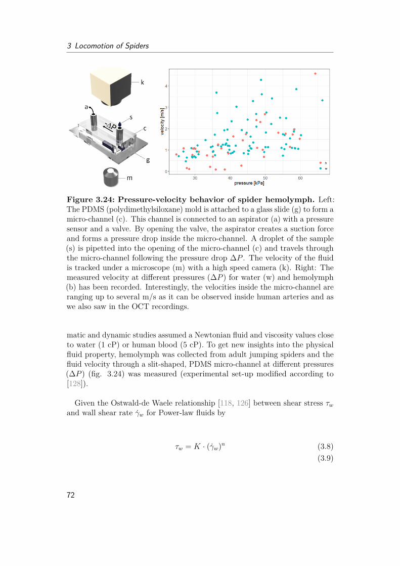
3 Locomotion of Spiders
Figure 3.24: Pressure-velocity behavior of spider hemolymph. Left:The PDMS (polydimethylsiloxane) mold is attached to a glass slide (g) to form amicro-channel (c). This channel is connected to an aspirator (a) with a pressuresensor and a valve. By opening the valve, the aspirator creates a suction forceand forms a pressure drop inside the micro-channel. A droplet of the sample(s) is pipetted into the opening of the micro-channel (c) and travels throughthe micro-channel following the pressure drop ∆P . The velocity of the fluidis tracked under a microscope (m) with a high speed camera (k). Right: Themeasured velocity at different pressures (∆P ) for water (w) and hemolymph(b) has been recorded. Interestingly, the velocities inside the micro-channel areranging up to several m/s as it can be observed inside human arteries and aswe also saw in the OCT recordings.
matic and dynamic studies assumed a Newtonian fluid and viscosity values closeto water (1 cP) or human blood (5 cP). To get new insights into the physicalfluid property, hemolymph was collected from adult jumping spiders and thefluid velocity through a slit-shaped, PDMS micro-channel at different pressures(∆P ) (fig. 3.24) was measured (experimental set-up modified according to[128]).
Given the Ostwald-de Waele relationship [118, 126] between shear stress τwand wall shear rate γw for Power-law fluids by
τw = K · (γw)n (3.8)(3.9)
72

3.4 Hydraulics
Figure 3.25: Log-Log-plot of shear rate and shear stress. The slopeof the linear fit through the log-log relationship of shear rate and shear stressis needed to estimate the fluid flow behavior index (n). Left: Water shows aflow behavior index of 0.93 (close to 1) describing its Newtonian behavior andnon-shear rate depending viscosity. Right: Hemolymph shows a flow behaviorindex of 0.5 corresponding to non-Newtonian, shear thinning behavior.
with
γw = 2n+ 13n · γa;
γa = 3v2H ;
(3.10)
and
τw = ∆P ·H2L ;
with γa describing the apparent shear rate, H the height (70 µm), L the length(30 mm) of the channel, v the measured fluid velocity and ∆P the set pressuredifference.
Detailed derivation of these relations for slit shaped channels are elaboratedin the Material and Method section (cf. section 6.6.4). The equations allowdetermination of the flow behavior index n and the flow consistency index Kfrom the experimental measurements by plotting the log-log relationships ofshear stress and shear rate. The dynamic viscosity µ can then be determinedfrom
µ = K · (γw)n−1 (3.11)
For n = 1, the term of the shear rate disappears, showing that the fluidviscosity does not change with the shear rate, which is true for Newtonian
73

3 Locomotion of Spiders
Figure 3.26: Viscosity at different shear rates. Left: The experimentaldata revealed wall shear rates up to 105 1/s corresponding to the speeds observedin the living spiders via OCT. While water (w) shows a shear-independentbehavior, hemolymph (b) viscosity changes from 6 cP at low shear rates downto 1 cP during activity. Right: The measured viscosity value of water is0.6 - 0.8 cP larger than literature values [12] (0.95-1.05 cP at 18-22◦C). Thiserror could be explained by small systematical errors in geometrical values(dimension of microchannel) or sensor sensitivity which propagate through thedata evaluation.
fluids as water (fig. 3.26, blue).
For n > 1, the effective fluid viscosity increases rapidly with shear rate.This behavior is described as shear thickening of dilatant fluids as the cornstarch-water mixture or silica-particles in polyglycerol for body armor.
For n < 1, the fluid shows shear thinning behavior and are called pseudoplastic fluids. Especially polymer solutions as paint, blood or ketchup show adecrease in viscosity with shear rate. The experimental results for hemolymphsuggest a shear-thinning behavior with an estimated fluid behavior index of0.5 (fig. 3.25, 3.26, red). The calculated viscosity ranges from 6 cPoise atpressures of 30 kPa down to 1 cPoise at 60 kPa (fig. 3.27). In comparision,water measurements revealed almost constant (dynamic) viscosities of 1.6 - 1.8cP.
74
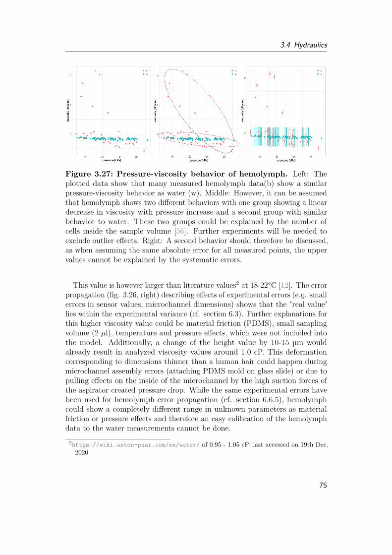
3.4 Hydraulics
Figure 3.27: Pressure-viscosity behavior of hemolymph. Left: Theplotted data show that many measured hemolymph data(b) show a similarpressure-viscosity behavior as water (w). Middle: However, it can be assumedthat hemolymph shows two different behaviors with one group showing a lineardecrease in viscosity with pressure increase and a second group with similarbehavior to water. These two groups could be explained by the number ofcells inside the sample volume [56]. Further experiments will be needed toexclude outlier effects. Right: A second behavior should therefore be discussed,as when assuming the same absolute error for all measured points, the uppervalues cannot be explained by the systematic errors.
This value is however larger than literature values2 at 18-22◦C [12]. The errorpropagation (fig. 3.26, right) describing effects of experimental errors (e.g. smallerrors in sensor values, microchannel dimensions) shows that the "real value"lies within the experimental variance (cf. section 6.3). Further explanations forthis higher viscosity value could be material friction (PDMS), small samplingvolume (2 µl), temperature and pressure effects, which were not included intothe model. Additionally, a change of the height value by 10-15 µm wouldalready result in analyzed viscosity values around 1.0 cP. This deformationcorresponding to dimensions thinner than a human hair could happen duringmicrochannel assembly errors (attaching PDMS mold on glass slide) or due topulling effects on the inside of the microchannel by the high suction forces ofthe aspirator created pressure drop. While the same experimental errors havebeen used for hemolymph error propagation (cf. section 6.6.5), hemolymphcould show a completely different range in unknown parameters as materialfriction or pressure effects and therefore an easy calibration of the hemolymphdata to the water measurements cannot be done.
2https://wiki.anton-paar.com/en/water/ of 0.95 - 1.05 cP; last accessed on 19th Dec.2020
75
3 Locomotion of Spiders
When plotting the viscosity over pressure, hemolymph seems to show thesame behavior as water (fig. 3.27). However, looking closely into the data, onecan assume a second behavior of the measurements, showing a linear decrease ofviscosity from 6.0 cP at low pressures to 1.0 cP at 60 kPa. This second behaviorcould be a result of a large amount of cells inside the hemolymph, while alack of these cells could result to similar fluid behavior as water. Due to thesmall sample volume of max. 50 µl per spider and only 2 µl per experimentalrun different amount of cells inside the sample could occur. Although moremeasurement data will be needed to exclude outliers such a two type behavior ofhemolymph has been reported for caterpillars [56]. The study showed that theplasma, so hemolymph with cells removed, shows viscosities of 2 cP, while fullhemolymph viscosity ranges between 1-4 cP. Different to the caterpillar study,the measurements presented in this work simulate similar hydraulic diametersof 140 µm as observed for spider arteries (100 - 200 µm) and high in shear rates(105) corresponding to 100-1000 times higher than measured and estimated inprevious research [56]. The estimated shear rate inside locusts of around 150s−1 was based on the speed of artificial air bubbles inside tracked inside thecirculatory system of locusts and reported pressure values generated inside thelocust heart [66]. However, this research was limited in the speed they wereable to track as they were not using high speed cameras, and when looking intotheir video recordings, one could see that there were many more air bubblesblurring out. While the non-hydraulic actuation of locusts and caterpillarscould further show differences in shear rates, our fluid characterization fits toour flow studies with recorded speeds of cells inside the leg of ∼ 3 m/s.
Using our methods, we were therefore not only able to show shear-thinningbehavior for spider hemolymph, but determine the flow behavior index n ex-perimentally showed that the velocity speeds up and the viscosity lowers by 6fold with higher pressure. These values and behavior have never been takeninto account when estimating the kinematics and dynamics of spiders.
In the following section, I would like to theoretically discuss how the non-Newtonian behavior could have an impact on hydraulic actuation.
3.4.3.3 Hydraulic Motor
Considering the spider leg system as a hydraulic motor, the volumetric efficiencyηvol for rotational transmission is given by [1]
ηvol = 11 +G∆p
nµ
(3.12)
76
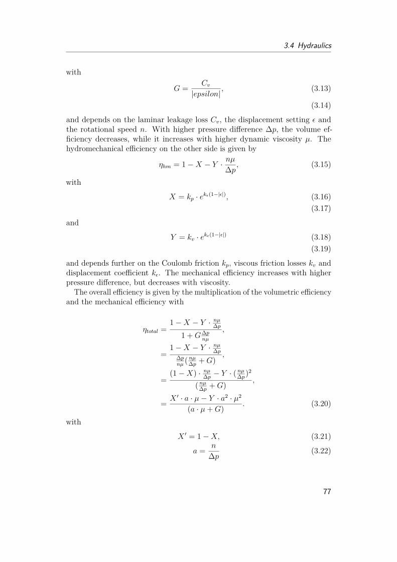
3.4 Hydraulics
with
G = Cv|epsilon|
, (3.13)
(3.14)
and depends on the laminar leakage loss Cv, the displacement setting ε andthe rotational speed n. With higher pressure difference ∆p, the volume ef-ficiency decreases, while it increases with higher dynamic viscosity µ. Thehydromechanical efficiency on the other side is given by
ηhm = 1−X − Y · nµ∆p, (3.15)
with
X = kp · ekε(1−|ε|), (3.16)(3.17)
and
Y = kv · ekε(1−|ε|) (3.18)(3.19)
and depends further on the Coulomb friction kp, viscous friction losses kv anddisplacement coefficient kε. The mechanical efficiency increases with higherpressure difference, but decreases with viscosity.
The overall efficiency is given by the multiplication of the volumetric efficiencyand the mechanical efficiency with
ηtotal =1−X − Y · nµ∆p
1 +G∆pnµ
,
=1−X − Y · nµ∆p
∆pnµ
( nµ∆p +G),
=(1−X) · nµ∆p − Y · (
nµ∆p)2
( nµ∆p +G) ,
= X ′ · a · µ− Y · a2 · µ2
(a · µ+G) . (3.20)
with
X ′ = 1−X, (3.21)
a = n
∆p (3.22)
77
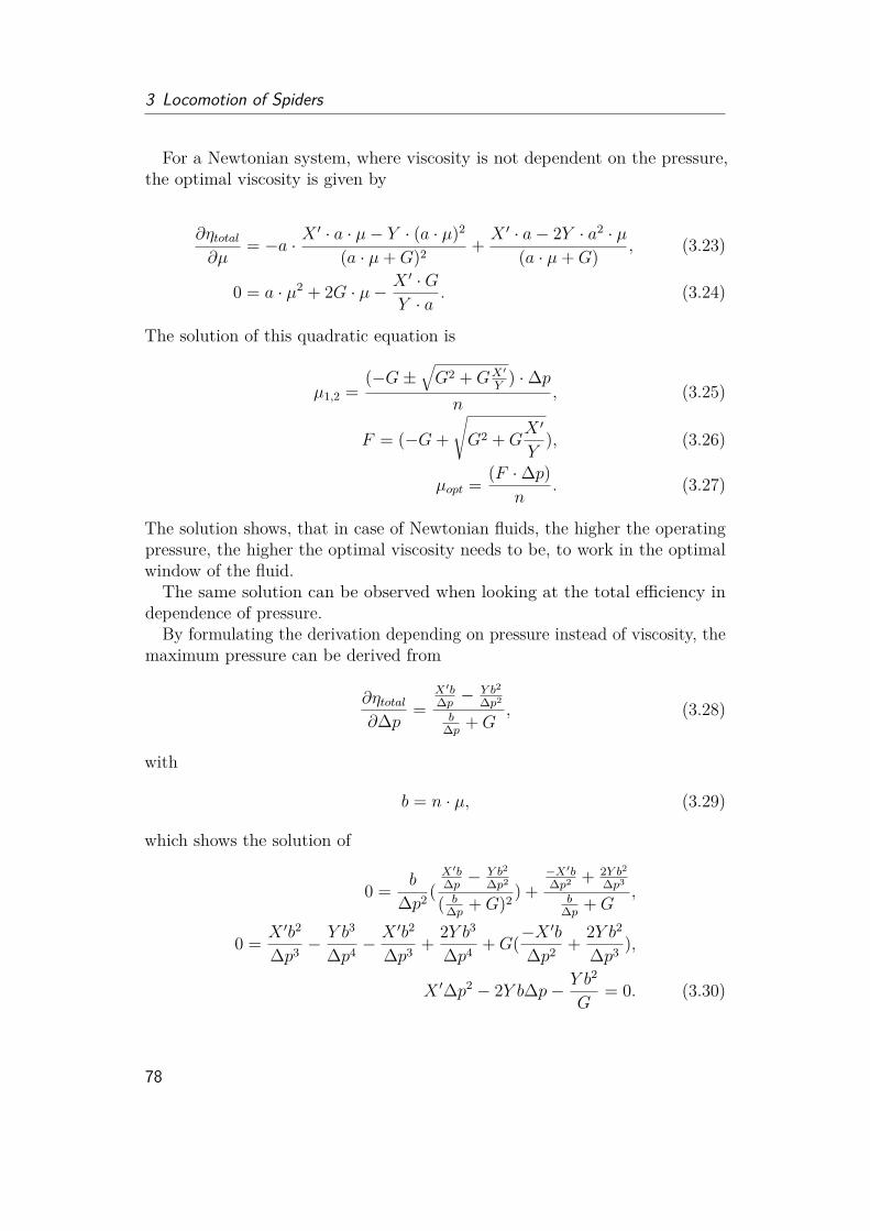
3 Locomotion of Spiders
For a Newtonian system, where viscosity is not dependent on the pressure,the optimal viscosity is given by
∂ηtotal∂µ
= −a · X′ · a · µ− Y · (a · µ)2
(a · µ+G)2 + X ′ · a− 2Y · a2 · µ(a · µ+G) , (3.23)
0 = a · µ2 + 2G · µ− X ′ ·GY · a
. (3.24)
The solution of this quadratic equation is
µ1,2 =(−G±
√G2 +GX′
Y) ·∆p
n, (3.25)
F = (−G+√G2 +G
X ′
Y), (3.26)
µopt = (F ·∆p)n
. (3.27)
The solution shows, that in case of Newtonian fluids, the higher the operatingpressure, the higher the optimal viscosity needs to be, to work in the optimalwindow of the fluid.
The same solution can be observed when looking at the total efficiency independence of pressure.
By formulating the derivation depending on pressure instead of viscosity, themaximum pressure can be derived from
∂ηtotal∂∆p =
X′b∆p −
Y b2
∆p2
b∆p +G
, (3.28)
with
b = n · µ, (3.29)
which shows the solution of
0 = b
∆p2 (X′b∆p −
Y b2
∆p2
( b∆p +G)2 ) +
−X′b∆p2 + 2Y b2
∆p3
b∆p +G
,
0 = X ′b2
∆p3 −Y b3
∆p4 −X ′b2
∆p3 + 2Y b3
∆p4 +G(−X′b
∆p2 + 2Y b2
∆p3 ),
X ′∆p2 − 2Y b∆p− Y b2
G= 0. (3.30)
78
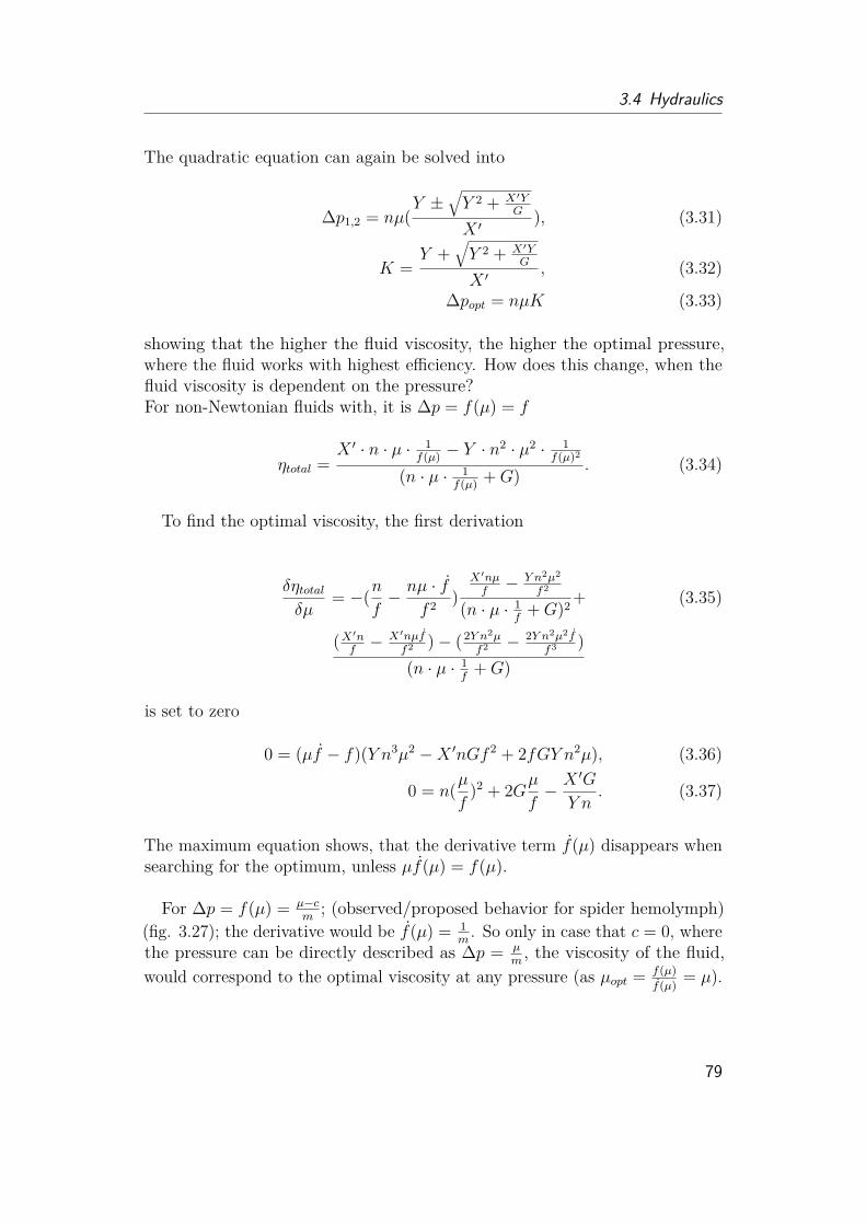
3.4 Hydraulics
The quadratic equation can again be solved into
∆p1,2 = nµ(Y ±
√Y 2 + X′Y
G
X ′), (3.31)
K =Y +
√Y 2 + X′Y
G
X ′, (3.32)
∆popt = nµK (3.33)
showing that the higher the fluid viscosity, the higher the optimal pressure,where the fluid works with highest efficiency. How does this change, when thefluid viscosity is dependent on the pressure?For non-Newtonian fluids with, it is ∆p = f(µ) = f
ηtotal =X ′ · n · µ · 1
f(µ) − Y · n2 · µ2 · 1
f(µ)2
(n · µ · 1f(µ) +G) . (3.34)
To find the optimal viscosity, the first derivation
δηtotalδµ
= −(nf− nµ · f
f 2 )X′nµf− Y n2µ2
f2
(n · µ · 1f
+G)2 + (3.35)
(X′nf− X′nµf
f2 )− (2Y n2µf2 − 2Y n2µ2f
f3 )(n · µ · 1
f+G)
is set to zero
0 = (µf − f)(Y n3µ2 −X ′nGf 2 + 2fGY n2µ), (3.36)
0 = n(µf
)2 + 2Gµf− X ′G
Y n. (3.37)
The maximum equation shows, that the derivative term f(µ) disappears whensearching for the optimum, unless µf(µ) = f(µ).
For ∆p = f(µ) = µ−cm
; (observed/proposed behavior for spider hemolymph)(fig. 3.27); the derivative would be f(µ) = 1
m. So only in case that c = 0, where
the pressure can be directly described as ∆p = µm, the viscosity of the fluid,
would correspond to the optimal viscosity at any pressure (as µopt = f(µ)f(µ) = µ).
79

3 Locomotion of Spiders
If c 6= 0, the solution for the optimal viscosity can be described as
[ µ
f(µ) ]1,2 =−G±
√G2 +GX′
Y
n,
=−G±
√G2 +GX′
Y
n,
[ µ
f(µ) ]1 = F
n. (3.38)
For ∆p = µ−cm
; m, c 6= 0; it follows that
µ = c
1− nmF
(3.39)
with c, describing the viscosity at ∆p = 0. For slow rotational speed n, thehighest efficiency is achieved at viscosities close to c. In Newtonian fluids, theoptimal viscosity increases drastically the lower the rotational speed (fig. 3.28,3.29).
Considering that the derivative term does not influence the maximum, theoptimal values can be directly calculated from the solutions for Newtonianfluids: For µ = m∆p+ c
µ = F ·∆pn
(3.40)
m∆p+ c = F ·∆pn
∆p = c
(Fn−m)
(3.41)
or∆p = n(m∆p+ c)K
∆p = c
( 1nK−m) (3.42)
→ F = 1K
(geometrical parameters)
The optimal operating pressure increases with speed. The viscosity of New-tonian fluids affects the optimal operating pressure needed to achieve highestefficiency. Low viscous fluids perform best at low pressures in comparison tohigh viscous fluid (fig. 3.28). In non-Newtonian fluids, the optimal pressureapproaches −c
mwith high speed.
80

3.4 Hydraulics
Figure 3.28: Optimal operating parameters depending on revolutionspeed. Left: Theoretical behavior of optimal operating pressure in Newtonianfluids with different viscosities (1-10 cP) compared to a fluid with linearpressure-viscosity behavior (red) as proposed for spiders. The results show thatNewtonian fluids need high operating pressures for fast motions. Proposedbehavior for spider hemolymph could create fast motions without a linearincrease of pressure. As all parameters were estimated, the absolute pressureand speed values are only for demonstration. Low viscous fluids show in generalless steep pressure increases with higher revolution speed. Right: Theoreticalbehavior of optimal viscosity for different operating pressures (10-60 kPa)and speeds. Systems with a wide range of revolution speed tend to needhydraulic fluids with drastically higher viscosities to perform efficient in lowspeed actuation. The theoretical behavior of the spider hemolymph would onlyincrease linearly in viscosity to achieve optimal efficiency at lower speeds.
Comparing the optimal viscosity for maximum efficiency in Newtonian andnon-Newtonian fluids it can be seen, that in case of Newtonian fluids, theoptimal viscosity has to be chosen according to the operating pressure androtational speed. In case of non-Newtonian fluids, the viscosity is almostindependent from the rotational speed. Spiders perform at a various rangeof rotational speed for walking, running and jumping. Looking into the highspeed recordings, a rotational speed of 80 - 140 rev/s could be estimated. Asthe generated pressure of the spider, depends on the moving of the prosomashells and the volume that can be displaced, the operating pressure is limited.Choosing a non-Newtonian fluid µ = m∆p+ c, with −c
mclose to the maximum
or highly used operating pressure, would allow the fluid to always work at itsoptimal efficiency. High total efficiency can normally be generated with highviscous fluids (fig. 3.29). However, torque can be reduced, when the viscosityis too high as the output torque Mout is given by
81
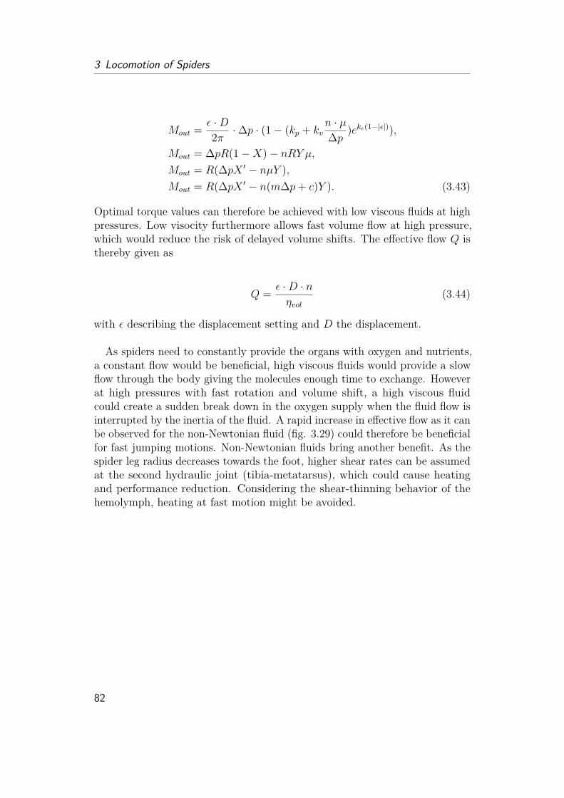
3 Locomotion of Spiders
Mout = ε ·D2π ·∆p · (1− (kp + kv
n · µ∆p )ekε(1−|ε|)),
Mout = ∆pR(1−X)− nRY µ,Mout = R(∆pX ′ − nµY ),Mout = R(∆pX ′ − n(m∆p+ c)Y ). (3.43)
Optimal torque values can therefore be achieved with low viscous fluids at highpressures. Low visocity furthermore allows fast volume flow at high pressure,which would reduce the risk of delayed volume shifts. The effective flow Q isthereby given as
Q = ε ·D · nηvol
(3.44)
with ε describing the displacement setting and D the displacement.
As spiders need to constantly provide the organs with oxygen and nutrients,a constant flow would be beneficial, high viscous fluids would provide a slowflow through the body giving the molecules enough time to exchange. Howeverat high pressures with fast rotation and volume shift, a high viscous fluidcould create a sudden break down in the oxygen supply when the fluid flow isinterrupted by the inertia of the fluid. A rapid increase in effective flow as it canbe observed for the non-Newtonian fluid (fig. 3.29) could therefore be beneficialfor fast jumping motions. Non-Newtonian fluids bring another benefit. As thespider leg radius decreases towards the foot, higher shear rates can be assumedat the second hydraulic joint (tibia-metatarsus), which could cause heatingand performance reduction. Considering the shear-thinning behavior of thehemolymph, heating at fast motion might be avoided.
82

3.4 Hydraulics
Figure3.29:The
oretical
calculationof
volumetrican
dmecha
nicaleffi
cien
cy,t
orqu
ean
deff
ective
flow
offlu
idswithdiffe
rent
viscosities.
The
efficien
cies
andpe
rform
ancesof
New
tonian
fluidswith
viscosity
values
betw
een1-10
cPan
dlin
earviscosity
-pressureflu
idforprop
osed
spider
hemolym
ph(red)at
four
diffe
rent
revolutio
nspeeds
(1,10,50,90)
were
simulated.The
used
parameter
values
arelistedon
theleft.
83

Chapter4Robotic Implementation
In this thesis, the fundamental folding principle of the spider joint was analyzedand adapted into a rotary actuation model. While the spider shows quiteimpressively what it is capable of, the question was whether the observedprinciples can be successfully implemented into a technical application andwhich advantages does it bring. Looking from the engineering aspect, a burningquestion arose, how spiders actually control so many different joints and legsand how the physical properties of their hydraulic fluid looks like and whatdifference it may mean for hydraulic devices. So on the one hand, a rotaryfluidic actuator was designed, but on the other hand, new biological hypothesisarose and could also be tested, using the robotic platform and engineeringmethods.
Before diving into the world of spider-inspired implementations, I would liketo give a short overview about terminologies used in the field of bio-inspiration.Afterwards, I will provide a short introduction into the principle of hydraulics,before specific spider-inspired approaches are covered, followed by the desginand fabrication of my own prototype.
4.1 The Symbiosis of Biology and TechnologyDriven by the idea that biology had plenty of time during their evolutionto adapt and develop optimal solutions to given problems, bio-mimetics, bio-mimicry, bio-inspiration and bionics became popular fields over the last decades.All of these terms seem to be rather similar and standardized definitions donot existing, but vary highly over time and in different communities [51]. Bio-mimicry can either describe the detailed copying of the biological model evendown to the molecular level, but is also used to describe a rather lose "mim-icking" of the biological model for a greater accessibility to a general public.
85
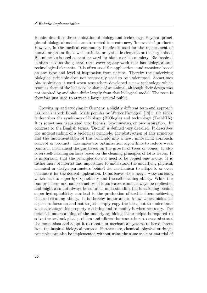
4 Robotic Implementation
Bionics describes the combination of biology and technology. Physical princi-ples of biological models are abstracted to create new, "innovation" products.However, in the medical community bionics is used for the replacement ofhuman organs or limbs with artificial or synthetic elements or their symbiosis.Bio-mimetics is used as another word for bionics or bio-mimicry. Bio-inspiredis often used as the general term covering any work that has biological andtechnological elements. It is often used for applications and creations basedon any type and level of inspiration from nature. Thereby the underlyingbiological principle does not necessarily need to be understood. Sometimesbio-inspiration is used when researchers developed a new technology whichreminds them of the behavior or shape of an animal, although their design wasnot inspired by and often differ largely from that biological model. The term istherefore just used to attract a larger general public.
Growing up and studying in Germany, a slightly different term and approachhas been shaped: Bionik. Made popular by Werner Nachtigall [78] in the 1980s,it describes the symbioses of biology (BIOlogie) and technology (TechNIK).It is sometimes translated into bionics, bio-mimetics or bio-inspiration. Incontrast to the English terms, "Bionik" is defined very detailed. It describesthe understanding of a biological principle, the abstraction of this principleand the implementation of this principle into a new, innovating approach,concept or product. Examples are optimization algorithms to reduce weakpoints in mechanical designs based on the growth of trees or bones. It alsocovers self-cleaning surfaces based on the cleaning principles of lotus leaves. Itis important, that the principles do not need to be copied one-to-one. It israther more of interest and importance to understand the underlying physical,chemical or design parameters behind the mechanism to adapt to or evenenhance it for the desired application. Lotus leaves show rough, waxy surfaces,which lead to super-hydrophobicity and the self-cleaning ability. While thebumpy micro- and nano-structure of lotus leaves cannot always be replicatedand might also not always be suitable, understanding the functioning behindsuper-hydrophobicity can lead to the production of textile fibers achievingthis self-cleaning ability. It is thereby important to know which biologicalaspect to focus on and not to just simply copy the idea, but to understandwhat advantage this property can bring and to modify it when necessary. Thedetailed understanding of the underlying biological principle is required tosolve the technological problem and allows the researchers to even abstractthe mechanism and adapt it to robotic or mechanical systems rather differentfrom the inspired biological purpose. Furthermore, chemical, physical or designprinciples can also be implemented without using the same scale or material of
86
4.1 The Symbiosis of Biology and Technology
the biological model.Knowing the principle also allows to change parameters and to even enhance
desired properties or to improve the technological adaption. In general twodifferent approaches are distinguished: Bottom-Up and Top-Down. Bottom-Updescribes the discovery and analysis of a biological phenomena, which shall beimplemented into a technical application. An example is beside the lotus effect,the hairy feet of Geckos for reusable adhesives or structural coloration of beetlesand butterflies for longer lasting colors. The Top-Down principle starts froma technical problem and searches for a solution in nature. Examples are thewinglets of birds that were implemented into airplanes to reduce air resistanceor a new design for wall anchors based on the mouth of ticks. In the process ofdevelopment, both approaches often merge into a fruitful circle leading to newquestions for technological implementations or biological functions.
Recently, technological implementations are even used to quantitatively ana-lyze and understand biological behavior and structures and to proof hypothesiswhich cannot be easily tested on the biological model itself. However thisapproach is not established enough yet to have its own term. It often fails whentoo many aspects are tested at the same time as scale, material and complexityof the implementation differ highly from the biological model. It is thereforeimportant to pick out a detailed (physical) parameter which should be tested.One simple example: Let’s formulate the hypothesis that wing-lets of birdshave to always look upwards to reduce air resistance. By building simple airplanes with different wing-let orientation the design aspect can already bequantified. While trying to answer the question why birds always have thewing-lets upwards, which could be rather difficult to be answered, it might beeasier to break this question down into material, design and structure questions.By changing these parameters, the importance of each for the functioning canbe evaluated and one after another hypothesis can be rejected.
In this work, I will use spider-inspiration as a general term to describeresearch inspired by the working principle of spiders. I would classify my ownwork as mostly in the area of the bottom-up approach in understanding theunderlying spider locomotion principles and adapting it into a new application.However, I would go a little further and say, true to Feynman’s motto "learningcomes with creating", that by creating a technological implementation, a deeperunderstanding of the biological system is given.
87
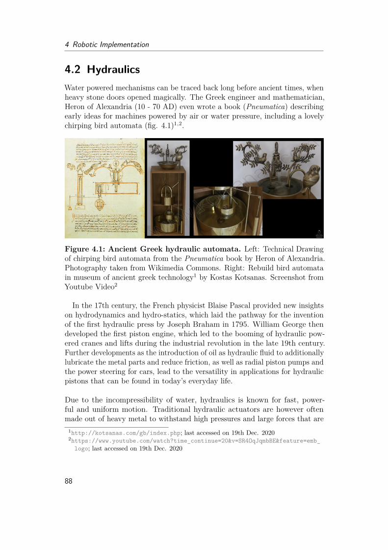
4 Robotic Implementation
4.2 HydraulicsWater powered mechanisms can be traced back long before ancient times, whenheavy stone doors opened magically. The Greek engineer and mathematician,Heron of Alexandria (10 - 70 AD) even wrote a book (Pneumatica) describingearly ideas for machines powered by air or water pressure, including a lovelychirping bird automata (fig. 4.1)1,2.
Figure 4.1: Ancient Greek hydraulic automata. Left: Technical Drawingof chirping bird automata from the Pneumatica book by Heron of Alexandria.Photography taken from Wikimedia Commons. Right: Rebuild bird automatain museum of ancient greek technology1 by Kostas Kotsanas. Screenshot fromYoutube Video2
In the 17th century, the French physicist Blaise Pascal provided new insightson hydrodynamics and hydro-statics, which laid the pathway for the inventionof the first hydraulic press by Joseph Braham in 1795. William George thendeveloped the first piston engine, which led to the booming of hydraulic pow-ered cranes and lifts during the industrial revolution in the late 19th century.Further developments as the introduction of oil as hydraulic fluid to additionallylubricate the metal parts and reduce friction, as well as radial piston pumps andthe power steering for cars, lead to the versatility in applications for hydraulicpistons that can be found in today’s everyday life.
Due to the incompressibility of water, hydraulics is known for fast, power-ful and uniform motion. Traditional hydraulic actuators are however oftenmade out of heavy metal to withstand high pressures and large forces that are
1http://kotsanas.com/gb/index.php; last accessed on 19th Dec. 20202https://www.youtube.com/watch?time_continue=20&v=SR4OqJqmbBE&feature=emb_
logo; last accessed on 19th Dec. 2020
88

4.3 Spider-inspired Research and Actuators
produced. Furthermore leakage and cavitation can be problems, which couldmake hydraulics either too expensive or not useful for certain applications.Pneumatics (the use of air pressure) has become an alternative approach
for lighter actuators and leakage would not induce environmental harm. Thecompliance of pneumatic actuators due to the compressibility of air, can on theone can lead to safer human-machine interactions, but can on the other handcome with the cost in precision and generated force. Nevertheless, the companyFesto developed high-precision pneumatic actuators and matching controlelements, sensors and valves for manufacturing and automation purposes.Their pneumatic flexible artificial muscle can further be found for medicalapplications. Such soft and flexible pneumatic or hydraulic actuators arenowadays rising in popularity to allow easy and safe human-robot interaction(HRI) enhancing flexibility and productivity in industry and everyday life [32].
Depending on materials and design, soft fluidic actuators fulfill many ben-eficial characteristics as lightweight design, compliance, adaptiveness, easyintegration and environmental friendliness. The hydraulic principle in powertransmission is further scalable, making it also attractive for small roboticapplications. With the discovery of the semi-hydraulic actuation of spiders,researchers and engineers started to develop spider-inspired actuators [64]. Inthe following section, I will provide an overview about existing actuators, theirapproach ideas and their advantages and, more import, their problems. Iwould like to further introduce interesting actuators and techniques, that areimportant to evaluate and classify my work. The design and fabrication ofthis spider-inspired actuator was another main part of this work and will becovered in details afterwards.
4.3 Spider-inspired Research and ActuatorsA detailed review on spider-inspired actuators was given by Landkammer in2016 [64]. While I do not want to repeat this review, I would rather like to talkabout ideas and approaches they have in common.
As illustrated in detail in the section before, bio-inspiration covers any typeof inspirations. Therefore when searching for spider-inspired research thereare many more actuators than covered in Landkammer’s review [64]. One candistinguish between four different levels of inspiration. The first level wouldbe research focusing on replicating locomotion behaviors as the jumping orthe eight-legged gait to e.g. investigate the advantage of multi-legged systems(fig. 4.2). These researchers often do not replicate the mechanism of spiderlocomotion, but have either simple springs or rubber bands to simulate the
89

4 Robotic Implementation
Figure 4.2: Level 1 Spider Inspiration. Top left: Jumping performancedepending on the leg angle [36]. Top right: Omnidirectional, realistic spiderrobot (Robugtix, T8X)4 using servomotor joints. Bottom left: ARAC ETHfocus project5,6 using tendon driven legs. Bottom right: Festo BionicWheelBot3
uses spring-motor actuators to allow rolling and walking motion inspired bythe desert spider Cebrennus rechenbergi.
jumping or use servomotor-based, piston-based joints to actuate. The secondlevel describes spider-inspired actuators which use a balloon or a silicon-basedchamber in the joint to achieve a fluidic based actuation (fig. 4.3). The thirdlevel covers spider-inspired actuators which use bellows in their joints to mimicthe "bellow-like" folding mechanism [14] of the spider joint membrane (fig. 4.4).The last level covers the design of a mechanism with elements that slides intoeach other (fig. 4.5 [43, 72], corresponding to the mechanism described in theprevious chapters (fig. 3.12).
The first level (fig. 4.2) is useful to compare new developed actuator principleswith already established technologies. What are the advantages of a hydraulicactuated system to a spring, wire or complete servo-based actuators? Howdoes a hydraulic piston differ from the spider system and which advantages ordisadvantages does it have? Level 1 approaches are also important for studyingbiological aspects which seem to be not directly dependent on the exact jointdesign and mechanism, they could also help to better understand the real spiderjoint mechanism by e.g. excluding aspects and they help to give information
90
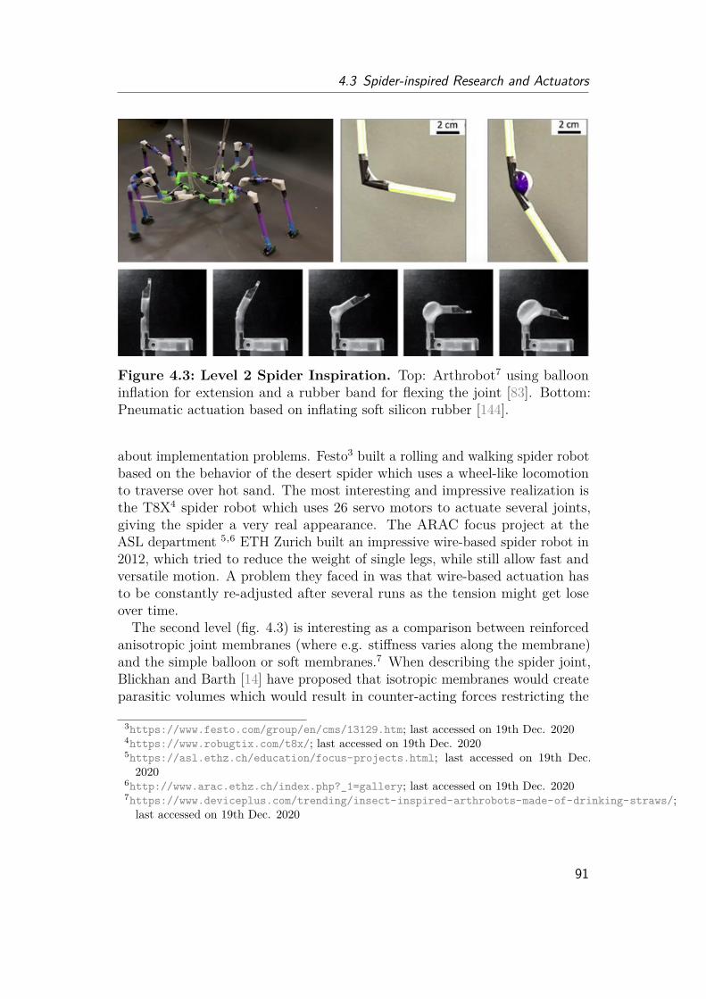
4.3 Spider-inspired Research and Actuators
Figure 4.3: Level 2 Spider Inspiration. Top: Arthrobot7 using ballooninflation for extension and a rubber band for flexing the joint [83]. Bottom:Pneumatic actuation based on inflating soft silicon rubber [144].
about implementation problems. Festo3 built a rolling and walking spider robotbased on the behavior of the desert spider which uses a wheel-like locomotionto traverse over hot sand. The most interesting and impressive realization isthe T8X4 spider robot which uses 26 servo motors to actuate several joints,giving the spider a very real appearance. The ARAC focus project at theASL department 5,6 ETH Zurich built an impressive wire-based spider robot in2012, which tried to reduce the weight of single legs, while still allow fast andversatile motion. A problem they faced in was that wire-based actuation hasto be constantly re-adjusted after several runs as the tension might get loseover time.
The second level (fig. 4.3) is interesting as a comparison between reinforcedanisotropic joint membranes (where e.g. stiffness varies along the membrane)and the simple balloon or soft membranes.7 When describing the spider joint,Blickhan and Barth [14] have proposed that isotropic membranes would createparasitic volumes which would result in counter-acting forces restricting the
3https://www.festo.com/group/en/cms/13129.htm; last accessed on 19th Dec. 20204https://www.robugtix.com/t8x/; last accessed on 19th Dec. 20205https://asl.ethz.ch/education/focus-projects.html; last accessed on 19th Dec.2020
6http://www.arac.ethz.ch/index.php?_1=gallery; last accessed on 19th Dec. 20207https://www.deviceplus.com/trending/insect-inspired-arthrobots-made-of-drinking-straws/;last accessed on 19th Dec. 2020
91
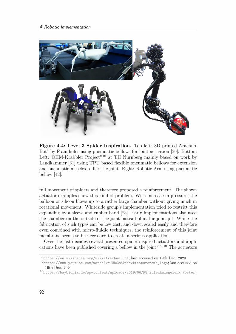
4 Robotic Implementation
Figure 4.4: Level 3 Spider Inspiration. Top left: 3D printed Arachno-Bot8 by Fraunhofer using pneumatic bellows for joint actuation [20]. BottomLeft: OHM-Krabbler Project9,10 at TH Nürnberg mainly based on work byLandkammer [61] using TPU based flexible pneumatic bellows for extensionand pneumatic muscles to flex the joint. Right: Robotic Arm using pneumaticbellow [42].
full movement of spiders and therefore proposed a reinforcement. The shownactuator examples show this kind of problem. With increase in pressure, theballoon or silicon blows up to a rather large chamber without giving much inrotational movement. Whiteside group’s implementation tried to restrict thisexpanding by a sleeve and rubber band [83]. Early implementations also usedthe chamber on the outside of the joint instead of at the joint pit. While thefabrication of such types can be low cost, and down scaled easily and thereforeeven combined with micro-fluidic techniques, the reinforcement of this jointmembrane seems to be necessary to create a serious application.Over the last decades several presented spider-inspired actuators and appli-
cations have been published covering a bellow in the joint.8,9,10 The actuators
8https://en.wikipedia.org/wiki/Arachno-Bot; last accessed on 19th Dec. 20209https://www.youtube.com/watch?v=JUB6c84rbbw&feature=emb_logo; last accessed on19th Dec. 2020
10https://baybionik.de/wp-content/uploads/2019/06/P8_Eulenhalsgelenk_Poster.
92
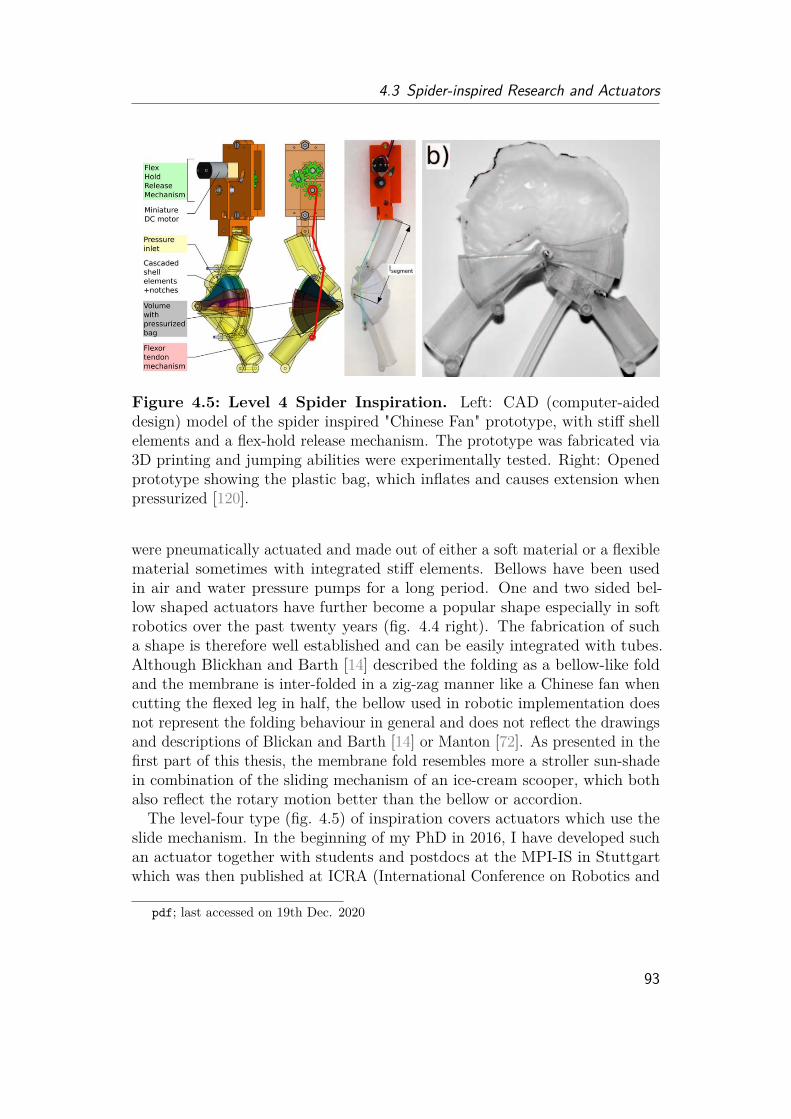
4.3 Spider-inspired Research and Actuators
Figure 4.5: Level 4 Spider Inspiration. Left: CAD (computer-aideddesign) model of the spider inspired "Chinese Fan" prototype, with stiff shellelements and a flex-hold release mechanism. The prototype was fabricated via3D printing and jumping abilities were experimentally tested. Right: Openedprototype showing the plastic bag, which inflates and causes extension whenpressurized [120].
were pneumatically actuated and made out of either a soft material or a flexiblematerial sometimes with integrated stiff elements. Bellows have been usedin air and water pressure pumps for a long period. One and two sided bel-low shaped actuators have further become a popular shape especially in softrobotics over the past twenty years (fig. 4.4 right). The fabrication of sucha shape is therefore well established and can be easily integrated with tubes.Although Blickhan and Barth [14] described the folding as a bellow-like foldand the membrane is inter-folded in a zig-zag manner like a Chinese fan whencutting the flexed leg in half, the bellow used in robotic implementation doesnot represent the folding behaviour in general and does not reflect the drawingsand descriptions of Blickan and Barth [14] or Manton [72]. As presented in thefirst part of this thesis, the membrane fold resembles more a stroller sun-shadein combination of the sliding mechanism of an ice-cream scooper, which bothalso reflect the rotary motion better than the bellow or accordion.The level-four type (fig. 4.5) of inspiration covers actuators which use the
slide mechanism. In the beginning of my PhD in 2016, I have developed suchan actuator together with students and postdocs at the MPI-IS in Stuttgartwhich was then published at ICRA (International Conference on Robotics and
pdf; last accessed on 19th Dec. 2020
93

4 Robotic Implementation
Automation) 2017 [120]. This actuator covers a thin plastic bag on the inside,which inflates with pressure and pushes the stiff "Chinese fan shell elements"open. The leg was flexed by a flex-hold release mechanism and, by suddenrelease, we showed that the leg could jump to 11.7 cm height within 100 ms.Although the underlying mechanism is scalable in theory, limitations comefrom fabrication and design. The stiff shell elements are connected by hooks,which have to be strong enough to withstand the sudden opening during jumpsand can therefore not be 3D printed smaller. The shell elements need to befurther printed with a 1-2 mm thickness as the cleaning of the elements couldalready destroy the material (Veroclear). The thickness restricts the overallworking angle as the shells have to be folded into each other and the spaceinside is limited.
The shell elements are further hinged together along a metal pin. This hingejoint could break easily after landing. The inside plastic (polyethylen) bagis custom made by soldering two layers into the desired shape. This methodallows easy fabrication and testing but brings many down sides. The bag canonly withstand pressures up to 50 kPa before starting to rip or the the materialstarts to undesirably blow up and thin out. Another disadvantage of the insidebag is that it causes friction during the opening and closing process, limitingthe performance of the system as well. Follow up studies by the postdocs11
reveal that silicon or fabric material on the inside can help to withstand higherpressure, but also increase friction. Furthermore sleeves of latex or silicon canreduce the fabrication size, but leads to blowing up of the material as in canalso observed in the level three inspiration models.Along my biological research, I tried several approaches with the available
3D printable rubber material (tango black) and also combinations of both thestiff (veroclear) and the rubber material. However, the rubber material showeda high stickiness and often ripped during cleaning. All these observation infabrication problems had a great impact on the final fabrication process andwill be discussed in depth in section 6.7.2.
4.4 Other Studies of InterestBesides spider-related research, there are a couple of different robotic researchdirections and robotic actuators which are closely related to the here presentedwork or show some similarities in problems and implementations. The mostobvious related research are works on other arthropod-inspired robots. Thetail and legs of lobsters has inspired researchers to design rotary actuators [25],11https://cpb-us-w2.wpmucdn.com/sites.coecis.cornell.edu/dist/0/60/files/
2017/12/arachnabot-spider-inspired-13dj8wg.pdf, last accessed on 19th Dec. 2020
94
4.4 Other Studies of Interest
where I have provided biological insights into the morphology and functioningof the lobster. However the legs of lobsters differ significantly from spiders, asalthough they have a membrane between their joints, this membrane does notshow any micro-structures, nor stiffness difference nor any folding behavior.Considering that the lobsters are not the fastest animal and are not reportedto using hydraulics for leg extension, this kind of adaption might thereforenot be necessary. The arthrodial membrane of insects has been studied onthe biological side, allowing joint movement, but also the expansion of insectabdomen after feeding (honeypot ants) or during pregnancy (locusts). Althoughthe formfitting expansion of the termite queen abdomen of up to 15 times ofthe non-fertilized princess [19, 78], has given the idea (Werner Nachtigall [78])to find flexible and growing material for e.g. packaging and the unfolding ofthe arthrodial membrane does again play an essential role in this expansion,the arthrodial membrane has not been further investigated for robotic research.The material (Chitin), the hierarchical structure, its properties and the foldingbehavior might play an important role in future soft robotics studies.
Soft actuators have been considered as the next step in robotics. Caterpillar-inspired rolling robots [68] and octopus-arm like water actuators [65] have beeninvestigated and show that the adaptivity of soft robotics and actuators makethem interesting approaches to store elastic energy, squeeze into small tubes,grip complex shapes and allow safe human-robotic interaction. Soft actuatorscan be driven by various techniques including tendons, magnetic field, light,heat and moisture. The most common approach is pneumatics and hydraulics.Soft fluidic actuators often use the hyper-elasticity of the silicon-based material,to cause extension or rotation due to expansion of the material under pressure.With pressure release, the material returns back to its original shape. Theexpansion, however, often comes with the cost of large balloon like volumecreation. Therefore most soft actuators are supported with integrated stiffelements, to allow a better control and prediction of the system. Linear softactuators as artificial muscles, e.g. the McKibben artificial muscle [5, 127], usea network of wires around an inflatable inside which restricts the expansiondirection.
Silicon-rotary actuators have been designed for gripping purposes and also fullsoft robots [32, 101, 114, 137]. The casting method of silicon allows fabricationof fluidic actuators in various sizes. The soft material and compliance of theinside air allows the robot to withstand great impact (as the weight of a cardriving over the robot legs). A downside of these type of soft robots is that ithas to lift its own body weight, which often needs high pressure as the torquereduces when the material expands. In combination with the compressibiltiy ofair, this results in a compliant but slow and wobbly walking robot. Alternative
95
4 Robotic Implementation
materials as PET-based actuators, paper-based origami-inspired folding and3D-printed fabric-like structures are further approaches to allow a combinationof higher material stiffness, reduction of undesired expansion, but still keepingthe flexibility of the actuator. Fabrication and scalability of these materialsand methods can however be limited on the other hand. Beside air, smallexplosions inside soft actuators have been used to show jumping capabilities[11]. Biochemical reactions are further investigated to create air pressure foractuation for micro-scale approaches [132].
The oil-based Hasel-actuator and dielectric elastomer acutators (DEA) furtherallow electrical instead of fluidic actuation, but work at high voltage (5-10kV) [55]. Approaches with liquid crystals have shown to reduce the requiredvoltage down to (1-3 kV) [31]. It can be proposed that with smaller batteries,future tiny soft robotics can be fully on-board controlled and actuated withoutrequiring large pumps, compressors, batteries or other devices to actuate.
4.5 Design and Fabrication of a Spider-InspiredExtension Mechanism
Before designing a new actuator, it has to be clear what kind of requirementsneed to be fulfilled. While design-wise, the spider mechanism shall be integratedin this work, there are several external aspects that have an impact on thematerial choice and fabrication method. On the fabrication side, low-cost andreproducibility are of importance. Especially in the prototyping phase, fast,on-site fabrication methods allow a high throughput of different designs. Asthe choice of actuation is hydraulics, sealing and pressure resistance have to betaken into account as well. Further requirements given by the (soft) roboticscommunity are large deformation, fast motion and lightweight design [137]. Asnone of these requirements are directly contradicting with the spider-inspiredmechanism, they will be implemented into the design and fabrication process.Scalability and environmentally friendly approaches were further criteria I setmyself, although they were not first priority goals.Along my PhD, I have tested a various number of fabrication methods and
designs and would like to give a short summary and critical review of each ofthe methods in the following. An overview of all tested method are given intab. 6.5.
96
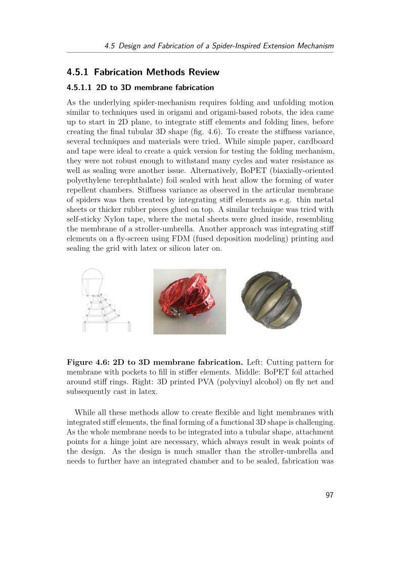
4.5 Design and Fabrication of a Spider-Inspired Extension Mechanism
4.5.1 Fabrication Methods Review4.5.1.1 2D to 3D membrane fabrication
As the underlying spider-mechanism requires folding and unfolding motionsimilar to techniques used in origami and origami-based robots, the idea cameup to start in 2D plane, to integrate stiff elements and folding lines, beforecreating the final tubular 3D shape (fig. 4.6). To create the stiffness variance,several techniques and materials were tried. While simple paper, cardboardand tape were ideal to create a quick version for testing the folding mechanism,they were not robust enough to withstand many cycles and water resistance aswell as sealing were another issue. Alternatively, BoPET (biaxially-orientedpolyethylene terephthalate) foil sealed with heat allow the forming of waterrepellent chambers. Stiffness variance as observed in the articular membraneof spiders was then created by integrating stiff elements as e.g. thin metalsheets or thicker rubber pieces glued on top. A similar technique was tried withself-sticky Nylon tape, where the metal sheets were glued inside, resemblingthe membrane of a stroller-umbrella. Another approach was integrating stiffelements on a fly-screen using FDM (fused deposition modeling) printing andsealing the grid with latex or silicon later on.
Figure 4.6: 2D to 3D membrane fabrication. Left: Cutting pattern formembrane with pockets to fill in stiffer elements. Middle: BoPET foil attachedaround stiff rings. Right: 3D printed PVA (polyvinyl alcohol) on fly net andsubsequently cast in latex.
While all these methods allow to create flexible and light membranes withintegrated stiff elements, the final forming of a functional 3D shape is challenging.As the whole membrane needs to be integrated into a tubular shape, attachmentpoints for a hinge joint are necessary, which always result in weak points ofthe design. As the design is much smaller than the stroller-umbrella andneeds to further have an integrated chamber and to be sealed, fabrication was
97
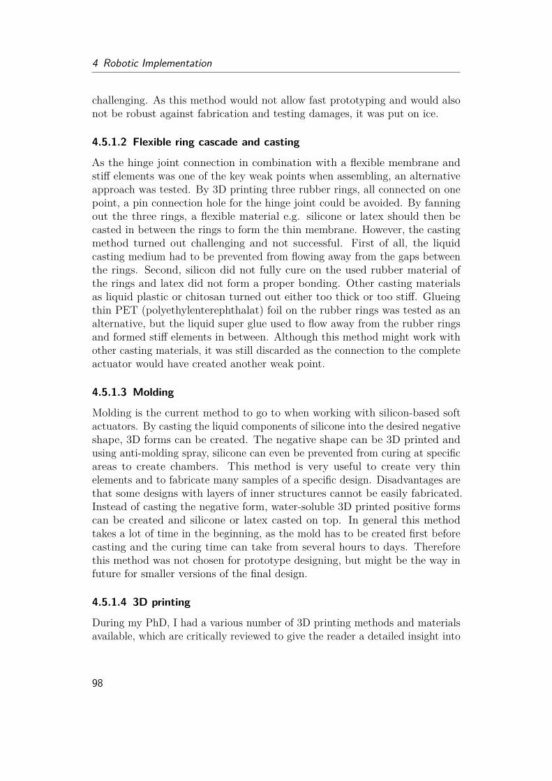
4 Robotic Implementation
challenging. As this method would not allow fast prototyping and would alsonot be robust against fabrication and testing damages, it was put on ice.
4.5.1.2 Flexible ring cascade and casting
As the hinge joint connection in combination with a flexible membrane andstiff elements was one of the key weak points when assembling, an alternativeapproach was tested. By 3D printing three rubber rings, all connected on onepoint, a pin connection hole for the hinge joint could be avoided. By fanningout the three rings, a flexible material e.g. silicone or latex should then becasted in between the rings to form the thin membrane. However, the castingmethod turned out challenging and not successful. First of all, the liquidcasting medium had to be prevented from flowing away from the gaps betweenthe rings. Second, silicon did not fully cure on the used rubber material ofthe rings and latex did not form a proper bonding. Other casting materialsas liquid plastic or chitosan turned out either too thick or too stiff. Glueingthin PET (polyethylenterephthalat) foil on the rubber rings was tested as analternative, but the liquid super glue used to flow away from the rubber ringsand formed stiff elements in between. Although this method might work withother casting materials, it was still discarded as the connection to the completeactuator would have created another weak point.
4.5.1.3 Molding
Molding is the current method to go to when working with silicon-based softactuators. By casting the liquid components of silicone into the desired negativeshape, 3D forms can be created. The negative shape can be 3D printed andusing anti-molding spray, silicone can even be prevented from curing at specificareas to create chambers. This method is very useful to create very thinelements and to fabricate many samples of a specific design. Disadvantages arethat some designs with layers of inner structures cannot be easily fabricated.Instead of casting the negative form, water-soluble 3D printed positive formscan be created and silicone or latex casted on top. In general this methodtakes a lot of time in the beginning, as the mold has to be created first beforecasting and the curing time can take from several hours to days. Thereforethis method was not chosen for prototype designing, but might be the way infuture for smaller versions of the final design.
4.5.1.4 3D printing
During my PhD, I had a various number of 3D printing methods and materialsavailable, which are critically reviewed to give the reader a detailed insight into
98

4.5 Design and Fabrication of a Spider-Inspired Extension Mechanism
why the final method was chosen. When starting with the first prototype, theMax-Planck-Institute had a 3D printer (Stratasys Objet 226), which allowed3D printing of rubber (Tangoblack) and stiff (VeroClear) polymers. This 3Dprinter was used to design the first stiff prototype published at ICRA 2017.While the 3D printer allowed fast, precise and multi-material prototyping, ithas a downside for the designs I was trying to achieve. When printing a hollowstructure, this printing method uses support material on the inside, whichneeds to be washed out carefully. Thin and delicate membranes and piecescan get damaged or ripped during this process. Cleaning in Sodiumhydroxidehelped to avoid this damage but resulted in long waiting and washing processesand a large waste production. Although water soluble support material was indevelopment by the company, I never had the chance to test it. Furthermore,the available rubber material started to get sticky after washing, which wouldhave created undesirable friction. I further tested the in house SLA (stere-olithography apparatus) printing (Formlabs) service. However the availablerubber material showed similar stickiness issues and prints tended to have anunpleasant smell.
With the switch to ETH Zurich, I was able to access a SLS (selective lasersintering) printer (HP Jet Fusion 3D 4200) at Wyss. This method allowed to3D print lightweight structures, which were also water tight at the end, howeverthe flexibility of the material was limited and the total time from orderingto receiving the 3D print took 4-5 days, which was too long to allow quickprototyping, beside the cost of 15-25 CHF per print.
Although FDM printing was considered not as precise as the other approaches,low price 3D printers with high precision and new available materials havecome into the market during the period of my PhD. FDM printable siliconewas freshly available, but unfortunately the material could not be printedvery thin (below 0.5 mm) yet. Furthermore prices per print ranged from 60- 100 Euros, which made silicone FDM printing not the method of choice forprototyping. Talking to several researchers at ETH, including to the ComplexMaterial Group, who were working on silicone printing, they suggested touse thermoplastic polyurethane (TPU), a rising star in flexible FDM printingmaterial. However, the suggestion came with a warning, that the printingconditions are highly depended on the brand and the used 3D printer.
The in house Ultimaker FDM 3D printer was tried at first. This 3D printercan print two different materials, using two different nozzles. While this 3Dprinter allowed precise 3D printing of the common PLA (Polylactic acid)material, TPU needed special adaptation in parameters. As the 3D printer wasfrequently used for other student projects, the second nozzle therefore needed to
99

4 Robotic Implementation
be frequently calibrated and parameter adjustments were limited. A commonproblem was material clogging as PLA and TPU have a slightly differentmelting point and nozzle cleaning of the Ultimaker is very time consuming. Inthe end, I decided to use my own 3D printer (Creality Ender) in order to testdifferent print settings and to use it only for the given TPU material. For TPUprinting, I needed to find the right printing heat, so that the material melts,but hardens quick enough. This 3D printer allowed me to vary and controlprinting speed, cooling fan power, material flow, bed heat and nozzle heat onthe fly, so that I was able to find the optimal printing parameters. Traditionalbowden extrusion, where the material is pushed forward through a long tube,turned out not to provide consistent material flow when using flexible TPUfilament. Therefore I changed the printing head of my 3D printer into directextrusion, so that the material is directly pushed into the nozzle (fig. 6.11).
4.5.2 Sealing Methods ReviewWhen working with hydraulic mechanisms, sealing is one of the great challengesto overcome, especially when handling dynamic objects and the material isconstantly exposed to stress when used. While TPU is water-repellent itselfand the 3D print can hold liquid without leakage, small irregularities can leadto water loss under pressure. As sealing methods for 3D printing are notwell-established yet, several methods and materials were tried (tab. 6.6) andreviewed in the following sections.
4.5.2.1 Dipping
Dipping 3D prints into color or water resistant liquids is a common approachto give PLA prints a specific finish. Therefore, dipping the TPU print intoliquid and flexible rubber material seemed to be the most promising way.Unfortunately silicone is not meant for curing on polyurethane surfaces. Latexand Plastidip worked easily. By letting the excess material drip off and curingat room temperature, very thin sheets were created. However, the viscosityof Latex and Plastidip can vary with temperature and batch, therefore theresulting thickness can vary a lot. Natural latex milk is normally mixed withammonia to make it more liquid and lower viscosity. The ammonia level canalso have an influence on the latex layer thickness. Thick cover layers have agreat impact on the folding behavior and prevent the actuator from workingproperly and should therefore be avoided.Another downside of Plastidip is its environmental harmfulness and the
penetrating smell of petrol which makes it uncomfortable to work with. Theammonia in latex milk also causes an unpleasant smell and therefore only low
100
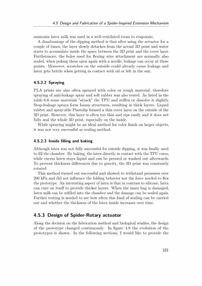
4.5 Design and Fabrication of a Spider-Inspired Extension Mechanism
ammonia latex milk was used in a well-ventilated room to evaporate.A disadvantage of the dipping method is that after using the actuator for a
couple of times, the layer slowly detaches from the actual 3D print and waterstarts to accumulate inside the space between the 3D print and the cover layer.Furthermore, the holes used for flexing wire attachment are normally alsosealed, when poking them open again with a needle, leakage can occur at thesepoints. Moreover, scratches on the outside could already cause leakage andlatex gets brittle when getting in contact with oil or left in the sun.
4.5.2.2 Spraying
PLA prints are also often sprayed with color or rough material, thereforespraying of anti-leakage spray and soft rubber was also tested. As listed in thetable 6.6 some materials "attack" the TPU and stiffen or dissolve it slightly.Stop-leakage sprays form foamy structures, resulting in thick layers. Liquidrubber and spray-able Plastidip formed a thin cover layer on the outside of the3D print. However, this layer is often too thin and rips easily and it does notfully seal the whole 3D print, especially on the inside.While spraying might be an ideal method for color finish on larger objects,
it was not very successful as sealing method.
4.5.2.3 Inside filling and baking
Although latex was not fully successful for outside dipping, it was finally usedto fill the chamber. By baking, the latex directly in contact with the TPU cures,while excess latex stays liquid and can be pressed or washed out afterwards.To prevent thickness differences due to gravity, the 3D print was constantlyrotated.This method turned out successful and showed to withstand pressures over
200 kPa and did not influence the folding behavior nor the force needed to flexthe prototype. An interesting aspect of latex is that in contrast to silicone, latexcan cure on itself to provide thicker layers. When the inner bag is damaged,latex milk can be refilled into the chamber and the damage can be sealed again.Further testing is needed to see how often this kind of sealing can be carriedout and whether the thickness of the latex inside increases over time.
4.5.3 Design of Spider-Rotary actuatorAlong the decision on the fabrication method and biological studies, the designof the prototype changed continuously. In figure 4.8 the evolution of theprototypes is shown. In the following sections, I would like to provide the
101
4 Robotic Implementation
conceptual ideas behind each of the evolution steps and the lessons learnedfrom each step.
4.5.3.1 First trials
First drawings and prototypes have been designed with Solidworks. Although Ihave gained some experiences in drawing standard shapes and single elementswith CAD (computer-aided design) programs, the challenge was here to designa complete functional actuator without any assembling elements. At this point,the 3D reconstruction of the jumping spider joint was not yet finished anddirectly transferring dimensions of the jumping spider joint seemed not tobe useful anyway, as thickness will variate and muscles are not integrated.Furthermore it was not about drawing a spider leg model, but rather designinga functional prototype with features inspired by the spider. The only interestinggeometrical number I tried to transfer was the angular distance between thedifferent hoops. A finger-sized prototype was aimed for, as this is a reasonabledimension to work with, without getting into fabrication limitations especiallywhen things still need to be manually fixed or changed. Four problems neededto be tackled. The first one is the design of a foldable membrane, the secondis sealing of the leg for actuation by e.g. a chamber, the third focuses on thehinge joint itself, which needs to be able to follow the complete folding motionand the fourth problem comes with the idea to print the complete membranewithout support.
The membrane needed to be thin enough to stay flexible for the folding,however the thinness of the membrane is limited by the 3D printer’s resolu-tion and also depends on the printing angle. In contrast to designs publishedby other researchers, the idea was to integrate the membrane directly into achamber as it could be observed also in the spider joint itself. This wouldreduce the amount of fluid that is needed to be displaced during motion, re-duces the overall weight of the prototype and the hinge joint can be designedseparately. The reason why I wanted to avoid support is that the thin mem-brane element could get destroyed during cleaning and any support remnantswould influence the folding behavior. Water-soluble support material wastested on the Ultimaker 3D printer, but normally doubled the printing timeand the material had to be dissolved afterwards. Furthermore the change be-tween TPU and the support material (PVA) was not always successful at verythin structures, which led to holes in the print. Printing without support withan integrated chamber only allowed one printing direction at the end (fig. 6.11).
The first printing tests showed several issues. First of all the bottom layerwas loose and with the increase in Z-axis, the leg started to wobble due to the
102
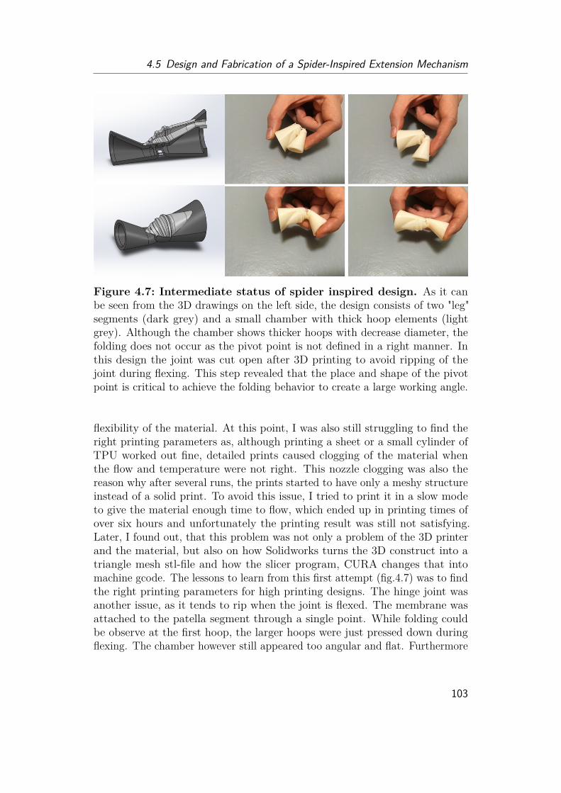
4.5 Design and Fabrication of a Spider-Inspired Extension Mechanism
Figure 4.7: Intermediate status of spider inspired design. As it canbe seen from the 3D drawings on the left side, the design consists of two "leg"segments (dark grey) and a small chamber with thick hoop elements (lightgrey). Although the chamber shows thicker hoops with decrease diameter, thefolding does not occur as the pivot point is not defined in a right manner. Inthis design the joint was cut open after 3D printing to avoid ripping of thejoint during flexing. This step revealed that the place and shape of the pivotpoint is critical to achieve the folding behavior to create a large working angle.
flexibility of the material. At this point, I was also still struggling to find theright printing parameters as, although printing a sheet or a small cylinder ofTPU worked out fine, detailed prints caused clogging of the material whenthe flow and temperature were not right. This nozzle clogging was also thereason why after several runs, the prints started to have only a meshy structureinstead of a solid print. To avoid this issue, I tried to print it in a slow modeto give the material enough time to flow, which ended up in printing times ofover six hours and unfortunately the printing result was still not satisfying.Later, I found out, that this problem was not only a problem of the 3D printerand the material, but also on how Solidworks turns the 3D construct into atriangle mesh stl-file and how the slicer program, CURA changes that intomachine gcode. The lessons to learn from this first attempt (fig.4.7) was to findthe right printing parameters for high printing designs. The hinge joint wasanother issue, as it tends to rip when the joint is flexed. The membrane wasattached to the patella segment through a single point. While folding couldbe observe at the first hoop, the larger hoops were just pressed down duringflexing. The chamber however still appeared too angular and flat. Furthermore
103
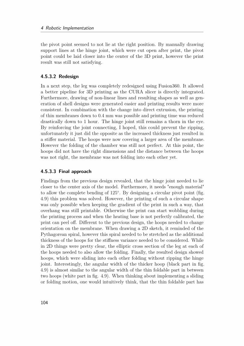
4 Robotic Implementation
the pivot point seemed to not lie at the right position. By manually drawingsupport lines at the hinge joint, which were cut open after print, the pivotpoint could be laid closer into the center of the 3D print, however the printresult was still not satisfying.
4.5.3.2 Redesign
In a next step, the leg was completely redesigned using Fusion360. It alloweda better pipeline for 3D printing as the CURA slicer is directly integrated.Furthermore, drawing of non-linear lines and resulting shapes as well as gen-eration of shell designs were generated easier and printing results were moreconsistent. In combination with the change into direct extrusion, the printingof thin membranes down to 0.4 mm was possible and printing time was reduceddrastically down to 1 hour. The hinge joint still remains a thorn in the eye.By reinforcing the joint connecting, I hoped, this could prevent the ripping,unfortunately it just did the opposite as the increased thickness just resulted ina stiffer material. The hoops were now covering a larger area of the membrane.However the folding of the chamber was still not perfect. At this point, thehoops did not have the right dimensions and the distance between the hoopswas not right, the membrane was not folding into each other yet.
4.5.3.3 Final approach
Findings from the previous design revealed, that the hinge joint needed to liecloser to the center axis of the model. Furthermore, it needs "enough material"to allow the complete bending of 125◦. By designing a circular pivot point (fig.4.9) this problem was solved. However, the printing of such a circular shapewas only possible when keeping the gradient of the print in such a way, thatoverhang was still printable. Otherwise the print can start wobbling duringthe printing process and when the heating base is not perfectly calibrated, theprint can peel off. Different to the previous design, the hoops needed to changeorientation on the membrane. When drawing a 2D sketch, it reminded of thePythagorean spiral, however this spiral needed to be stretched as the additionalthickness of the hoops for the stiffness variance needed to be considered. Whilein 2D things were pretty clear, the elliptic cross section of the leg at each ofthe hoops needed to also allow the folding. Finally, the resulted design showedhoops, which were sliding into each other folding without ripping the hingejoint. Interestingly, the angular width of the thicker hoop (black part in fig.4.9) is almost similar to the angular width of the thin foldable part in betweentwo hoops (white part in fig. 4.9). When thinking about implementing a slidingor folding motion, one would intuitively think, that the thin foldable part has
104
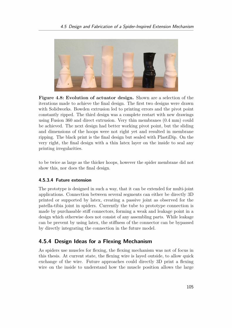
4.5 Design and Fabrication of a Spider-Inspired Extension Mechanism
Figure 4.8: Evolution of actuator design. Shown are a selection of theiterations made to achieve the final design. The first two designs were drawnwith Solidworks. Bowden extrusion led to printing errors and the pivot pointconstantly ripped. The third design was a complete restart with new drawingsusing Fusion 360 and direct extrusion. Very thin membranes (0.4 mm) couldbe achieved. The next design had better working pivot point, but the slidingand dimensions of the hoops were not right yet and resulted in membraneripping. The black print is the final design but sealed with PlastiDip. On thevery right, the final design with a thin latex layer on the inside to seal anyprinting irregularities.
to be twice as large as the thicker hoops, however the spider membrane did notshow this, nor does the final design.
4.5.3.4 Future extension
The prototype is designed in such a way, that it can be extended for multi-jointapplications. Connection between several segments can either be directly 3Dprinted or supported by latex, creating a passive joint as observed for thepatella-tibia joint in spiders. Currently the tube to prototype connection ismade by purchasable stiff connectors, forming a weak and leakage point in adesign which otherwise does not consist of any assembling parts. While leakagecan be prevent by using latex, the stiffness of the connector can be bypassedby directly integrating the connection in the future model.
4.5.4 Design Ideas for a Flexing MechanismAs spiders use muscles for flexing, the flexing mechanism was not of focus inthis thesis. At current state, the flexing wire is layed outside, to allow quickexchange of the wire. Future approaches could directly 3D print a flexingwire on the inside to understand how the muscle position allows the large
105

4 Robotic Implementation
Figure 4.9: Spider inspired prototype. Published in [43]. Left: 3Drendering of spider-inspired design. The actuator consists of three thicker hoopswith folding lines and form a chamber inside which extends when filled withwater. The finger-sized prototype has a length of 6 cm and width of 2 cm.Top Right: Schematic drawing of spider-inspired design. The pivot point isdesigned in such a way that it enables a working angle of 125◦. The chamberwhich is filled with water during extension is marked in blue. The femur leghas a length (L) of 3 cm. Bottom Right: The 3D printed TPU prototype has a0.4 - 0.45 mm thick folding membrane. By increasing the pressure P, the leg isextended, flexing is induced by pulling on a flexing wire (Fpull).
working angle of up to 160◦. Beside using wires as tendon for flexing, springs,artificial muscles and or a similar folding mechanism, as used for extension,could be implemented instead. Using wires antagonistically to the hydraulicmechanism brings the advantage that the joint angle can be controlled easilyas it is proportional to the wire length. Furthermore, motion speed can bevaried depending on how fast the wire is released or retracted. Furthermore itallows to hold the legs in flexed position, while increasing the pressure inside.The wire does not increase the weight at the joint, nor does it need a bulkyconstruct which might reduce mobility. The downside of wires might be thatafter some time of usage, they can wear out, which would decrease precisionof the mechanism, if the wire length is used to predict the joint angle. Thatis why braided fishing line was used as flexing wire as it is known to not bestretchable, but robust and abrasion resistant. Still, the attachment point ofthe wire is exposed to great stress, which could lead to stretching of the flexiblematerial after several cycles of usage and therefore decrease in precision.To allow multi-locomotion including walking and jumping, the control of
106
4.5 Design and Fabrication of a Spider-Inspired Extension Mechanism
Figure 4.10: Working principle of ratchet release mechanism. Left:The ratchet (green) can be loaded be turning anti-clockwise. It is blocked by apin (yellow) to avoid unwrapping. This pin is held in position by a spring (red).Right: By pulling on the pin through a motor (grey), the spring is compressedand the ratchet is released and turns clockwise.
wire flexing in combination with hydraulic extension need to work in tandem.Several design ideas will be introduced in the following.
4.5.4.1 Controlling semi-hydraulic actuators
While pulling a wire can be easily controlled by a linear actuator or by rotationaround a cylinder, the displaced liquid needs to be pushed back into a reservoir.And this water needs to be again pushed back from the reservoir into thechamber for extension. By designing a rotational chamber (fig. 6.11) with aninternal latex chamber for sealing, the liquid can be collected by increasing thisvolume while reducing the wire length when rotated around this chamber. Byclosing the reservoir shells, the volume inside decreases, while the wire getsreleased again and the water is pushed back into the leg. Not intentionallyinspired, the reservoir shells somehow resemble the prosoma of spiders, whichare assumed to decrease the volume inside by pushing the two prosoma shellstowards each other and move the volume into the legs.While in spiders, the muscles and prosoma reservoir are disconnected, the
proposed mechanism has the disadvantage to not allow an increase in pressureinside while holding the muscle in position, an idea would be a hook mechanism,which holds the wire in position while the liquid is pushed back into the legsand which can unlock for jumping.
4.5.4.2 Ratchet mechanism
For demonstrating jumping motion, where high pressure needed to be build upwhile the legs are in flexed position, a ratchet was used for flexing several legssimultaneously (fig. 4.10, 4.19). The legs were locked in this flexed position,
107

4 Robotic Implementation
Figure 4.11: Conceptual design of magnetic release mechanism. Theidea is create a switch between three stages (flex, hold, release), which canbe used continuously to create different modes of (multi-legged) motion. In"flex" the wire is wrapped around a cylinder by a motor. By switching to"hold", the current state of wire shortening is fixed as the wire is now decoupledfrom the motor motion. By changing into "release" mode, the flexing wire canimmediately unwrap, allowing a fast extension motion for e.g. jumps. Thethree different modes should be created by a solenoid switching small magnetpins into the different positions.
while pressure could be increased independently using a syringe or a pump.Afterwards a release mechanism pulling the ratchet stopper, allowed the legs toextend almost immediately, enabling the jumping motion. The ratchet did notallow slow motion as proposed in the previous system and the flexing motionwas not coupled to the fluid flow and pump mechanism. This means thatduring flexing, the syringe or reservoir needed to open continuously, to collectthe water.
108
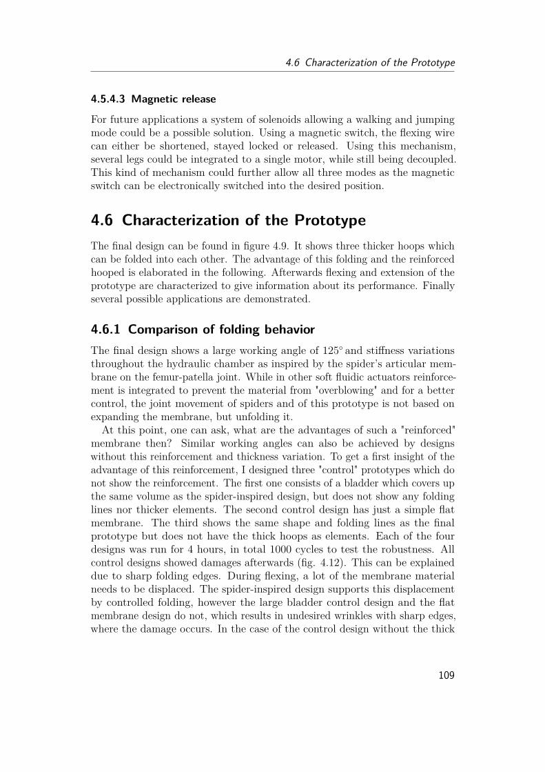
4.6 Characterization of the Prototype
4.5.4.3 Magnetic release
For future applications a system of solenoids allowing a walking and jumpingmode could be a possible solution. Using a magnetic switch, the flexing wirecan either be shortened, stayed locked or released. Using this mechanism,several legs could be integrated to a single motor, while still being decoupled.This kind of mechanism could further allow all three modes as the magneticswitch can be electronically switched into the desired position.
4.6 Characterization of the PrototypeThe final design can be found in figure 4.9. It shows three thicker hoops whichcan be folded into each other. The advantage of this folding and the reinforcedhooped is elaborated in the following. Afterwards flexing and extension of theprototype are characterized to give information about its performance. Finallyseveral possible applications are demonstrated.
4.6.1 Comparison of folding behaviorThe final design shows a large working angle of 125◦ and stiffness variationsthroughout the hydraulic chamber as inspired by the spider’s articular mem-brane on the femur-patella joint. While in other soft fluidic actuators reinforce-ment is integrated to prevent the material from "overblowing" and for a bettercontrol, the joint movement of spiders and of this prototype is not based onexpanding the membrane, but unfolding it.At this point, one can ask, what are the advantages of such a "reinforced"
membrane then? Similar working angles can also be achieved by designswithout this reinforcement and thickness variation. To get a first insight of theadvantage of this reinforcement, I designed three "control" prototypes which donot show the reinforcement. The first one consists of a bladder which covers upthe same volume as the spider-inspired design, but does not show any foldinglines nor thicker elements. The second control design has just a simple flatmembrane. The third shows the same shape and folding lines as the finalprototype but does not have the thick hoops as elements. Each of the fourdesigns was run for 4 hours, in total 1000 cycles to test the robustness. Allcontrol designs showed damages afterwards (fig. 4.12). This can be explaineddue to sharp folding edges. During flexing, a lot of the membrane materialneeds to be displaced. The spider-inspired design supports this displacementby controlled folding, however the large bladder control design and the flatmembrane design do not, which results in undesired wrinkles with sharp edges,where the damage occurs. In the case of the control design without the thick
109

4 Robotic Implementation
Figure 4.12: Cycling Testing of prototypes. Published in [43]. Besidethe spider-inspired, reinforced structure, three control structures were usedfor testing the folding. While the spider-inspired design folds properly anddoes not show any damages after 1000 cycles, the control structures withoutreinforcements or folds show undesired wrinkles which finally lead to rupture.
hoops, but with the folding lines, the membrane does fold, but cracks occur atthe folding lines as the 3D print itself creates sharp edges already. In the case ofthe flat membrane, not only is the chamber damaged but the hinge joint cracks.It can be proposed, that the reinforcement of the articular membrane of spidersis supporting the material to withstand high pressure, but more importantly itallows a proper folding of the membrane and therefore reduces damages whichwould be fatal for the hydraulic actuation. In spiders, damages directly at thehinge joint connection are normally avoided by a short and thin membraneextension connected between the arcuate sclerite and patella segment. Howevertiny damages at the hinge joint have been observed, when the joint is benttoo strongly, which happens when the animal falls from large heights withoutsecuring its body with its usual safety wire. As the main membrane is notdamaged and the tiny droplet of body fluid quickly coagulates at the hingejoint, the spiders were still able to walk without any fatal damage.
110

4.6 Characterization of the Prototype
Figure 4.13: Flexing of spider inspired actuator. Published in [43]. Totest the flexing and releasing behavior, the actuator was clamped inside aplatform and manually flexed by a string. Red markers were used to track theangle in parallel to measurements of a pressure and force sensor. The flexingbehavior can be divided into three parts (A, B, C). The initial pulling (A)does not influence the inner chamber. Pulling direction is almost orthogonal tothe moving direction. (B) Pulling above 20◦ leads to the folding of the firstand second ring. Pulling and moving direction are in parallel. (C) In a laststep, the third ring is bend into the material, which creates large elastic energy.Pulling direction is furthermore almost orthogonal to moving direction again.While flexed, the actuator can be pressurized (D) before releasing (E).
4.6.2 FlexingIn a first step, the needed flexing behavior was characterized. Therefore, theleg was attached to a load sensor and flexed by rotating a water collectionchamber to couple the flexing with the water collection. The experimental datashows that the flexing of the prototype can be divided into 3 phases (fig. 4.13,4.14). When the leg is completely stretched out, the force needed to flex theleg increases up to 2 N. The next phase describes flexing angles of 20-100◦.Here the measured flexing forces are staying around 1.5 N corresponding totorques of 0.05 Nm. The last phase describes the last infold where flexing forcesincrease drastically up to 5 N (0.15 Nm). This increase can be explained by thelarge area of material that needs to be bend and the thickness of the material.The measured flexing force further depends on the attachment points of thewire and the relative angle the wire is pulling at. When spanning the wirethrough the holes of the leg and pulling, the folding direction and the pullingdirection are almost in parallel for angles between 20-100◦. This is not thecase for folding above 100◦, as the second leg segment (patella) is now closerto the first (femur) and therefore the folding direction is almost orthogonalto the pulling direction. This effect can be seen more clearly when the wireis not threaded through the side holes of the femur segments. In this case,the forces needed increase linearly at each "hoop" for 3-4 N, so that for thefinal fold forces of up to 10 N are necessary. As spiders have their muscles on
111

4 Robotic Implementation
the inside, an interesting question for future studies could be, how the muscleattachment points and the rotating arcuate sclerite reduce flexing forces. It canbe assumed, that the rotation of the arcuate sclerite continuously reduces thedistance between the two spanning points of the muscle and therefore supportthe overall shortening of the muscles. Interestingly this measurements alsoreveals that when holding the leg segments in flexed positions, then pressurizingup to 50 kPa and release the flexing wire in a sudden, the pressure drops intonegative values for a short time.
112
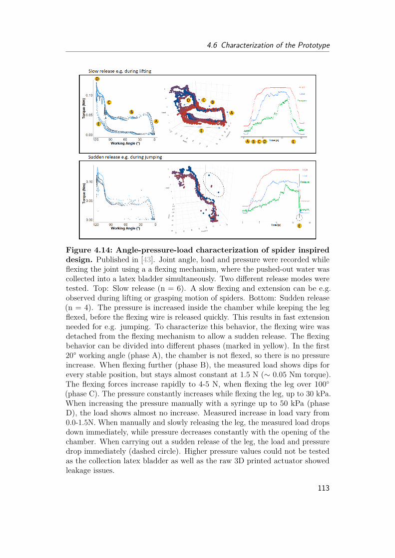
4.6 Characterization of the Prototype
Figure 4.14: Angle-pressure-load characterization of spider inspireddesign. Published in [43]. Joint angle, load and pressure were recorded whileflexing the joint using a a flexing mechanism, where the pushed-out water wascollected into a latex bladder simultaneously. Two different release modes weretested. Top: Slow release (n = 6). A slow flexing and extension can be e.g.observed during lifting or grasping motion of spiders. Bottom: Sudden release(n = 4). The pressure is increased inside the chamber while keeping the legflexed, before the flexing wire is released quickly. This results in fast extensionneeded for e.g. jumping. To characterize this behavior, the flexing wire wasdetached from the flexing mechanism to allow a sudden release. The flexingbehavior can be divided into different phases (marked in yellow). In the first20° working angle (phase A), the chamber is not flexed, so there is no pressureincrease. When flexing further (phase B), the measured load shows dips forevery stable position, but stays almost constant at 1.5 N (∼ 0.05 Nm torque).The flexing forces increase rapidly to 4-5 N, when flexing the leg over 100◦(phase C). The pressure constantly increases while flexing the leg, up to 30 kPa.When increasing the pressure manually with a syringe up to 50 kPa (phaseD), the load shows almost no increase. Measured increase in load vary from0.0-1.5N. When manually and slowly releasing the leg, the measured load dropsdown immediately, while pressure decreases constantly with the opening of thechamber. When carrying out a sudden release of the leg, the load and pressuredrop immediately (dashed circle). Higher pressure values could not be testedas the collection latex bladder as well as the raw 3D printed actuator showedleakage issues.
113

4 Robotic Implementation
4.6.3 Extension
Figure 4.15: Experimental platform. Published in [43]. Similar to collapsi-ble silicone bowls, the prototype shows five stable positions (0, 40, 75, 100, 125)created by the design and elastic material. The angles correspond to openingdistances, for a (“patella”)-segment length of 30 mm. Spiders show leg anglesbetween the shown position 40 and 100 during walking and resting. Full closing(position 125) can be observed in dead spiders, when muscles are flexed, aswell as in jump initialization. Spiders communicate with completely opened(position 0) front legs, showing their articular membrane to their fellow species.Fully extended femur-patella joints can also be observed during jumps. Tomeasure the pressure-load-angle behavior at the stable positions, the prototypewas clamped between the two plates to a given angle. The bigger plate isattached to a load sensor, the leg to a syringe and pressure sensor. Sensor datawere recorded with an Arduino Uno, while pressure was increased with thesyringe. Scale bar: 10 mm.
By using the measuring apparatus from the previous section, it could be seenthat the torque is released almost immediately after the leg is released, slowlyor suddenly. Interestingly, a sudden release could cause a negative pressure fora short moment, which can be explained by the fluid intertia and viscosity, aswater needs to be shifted into the opening volume. This effect is known forhydraulic pistons, causing cavitation, where sudden air bubbles form, burst
114

4.6 Characterization of the Prototype
and damage the surfaces. One can now be asked, whether spiders also have tostruggle with such a dramatic change in pressure during a jump and whetherthe properties of the hemolymph prevent such behavior. Different to hydraulicpistons, spider have a continuous flow, which might support a volume shiftalready.
To test the highest forces that can be produced for extension, the experimentalsetup was changed (fig. 4.15) as the previous design could only allow pressuresup to 50 kPa before the tube connection failed. Keeping the leg flexed in aspecific degree and position, the water was now directly pushed into the leg bya syringe. Force and pressure were measured and jumping heights simulated(fig. 4.16, 4.17).
Figure 4.16: Angle-pressure-load characterization of latex sealedspider inspired design. Published in [43]. Left: The load and pressure atthe stable positions (40◦, 75◦, 100◦, 125◦) have been measured. The value ofangles was always defined as 0◦ in extended position and 125◦ in fully flexedposition. Loads at zero pressure, reflecting the elastic forces of the material,were verified by the weight needed to flex the leg into a specific position (tab.6.7). Linear fits show a factor of 0.013, which for P = F/A would result inan effective area of A = 13mm2. Middle: By transforming the measured loadinto its corresponding weight, the experimental data predict full lifting of 600g at 200 kPa. Furthermore, up to 1 kg can be lifted for 20 degrees. Right: Bytransforming the angle into opening distances (fig. 4.15), the work generatedby a single leg can be calculated.
The experimental data shows that weights up to 600 g can be fully liftedwith pressures of 200 kPa. Furthermore lifting of weights over 1 kg from flexedposition into 90◦can still be achieved.The generated work W of a single leg can be approximated by
W = 105.86 · s2 + 1.6731 · s (4.1)
115
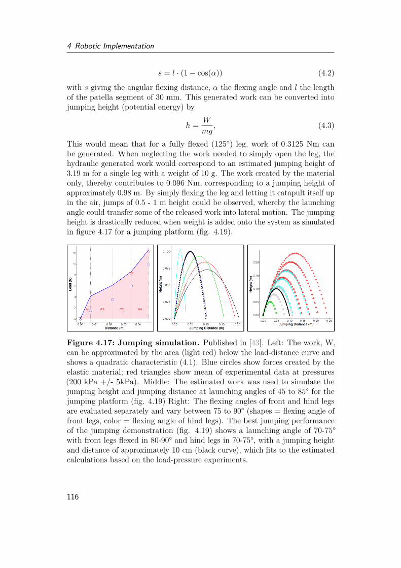
4 Robotic Implementation
s = l · (1− cos(α)) (4.2)
with s giving the angular flexing distance, α the flexing angle and l the lengthof the patella segment of 30 mm. This generated work can be converted intojumping height (potential energy) by
h = W
mg, (4.3)
This would mean that for a fully flexed (125◦) leg, work of 0.3125 Nm canbe generated. When neglecting the work needed to simply open the leg, thehydraulic generated work would correspond to an estimated jumping height of3.19 m for a single leg with a weight of 10 g. The work created by the materialonly, thereby contributes to 0.096 Nm, corresponding to a jumping height ofapproximately 0.98 m. By simply flexing the leg and letting it catapult itself upin the air, jumps of 0.5 - 1 m height could be observed, whereby the launchingangle could transfer some of the released work into lateral motion. The jumpingheight is drastically reduced when weight is added onto the system as simulatedin figure 4.17 for a jumping platform (fig. 4.19).
Figure 4.17: Jumping simulation. Published in [43]. Left: The work, W,can be approximated by the area (light red) below the load-distance curve andshows a quadratic characteristic (4.1). Blue circles show forces created by theelastic material; red triangles show mean of experimental data at pressures(200 kPa +/- 5kPa). Middle: The estimated work was used to simulate thejumping height and jumping distance at launching angles of 45 to 85° for thejumping platform (fig. 4.19) Right: The flexing angles of front and hind legsare evaluated separately and vary between 75 to 90° (shapes = flexing angle offront legs, color = flexing angle of hind legs). The best jumping performanceof the jumping demonstration (fig. 4.19) shows a launching angle of 70-75°with front legs flexed in 80-90° and hind legs in 70-75°, with a jumping heightand distance of approximately 10 cm (black curve), which fits to the estimatedcalculations based on the load-pressure experiments.
116
4.6 Characterization of the Prototype
4.6.4 Demonstration
Figure 4.18: Weight lifting demonstration. Published in [43]. By pressinga syringe, the water is pushed inside the joint chamber, increasing the pressurep inside the chamber, allowing the leg to fully lift 600 g. Heavier weight canonly be lifted up to 90◦.
To verify the estimated numbers from the previous sections, two demonstrationset-ups have been build up. The first one shows how much weight a singleactuator could lift using hydraulic power. In a second attempt the jumpingperformance of the actuator shall be demonstrated.The leg was mounted vertically and flexed by hanging different weights on
the second (patella) segment. By pushing water into the leg via a syringe,the pressure is increased allowing to lift the iron weights. 500 to 600 g werecompletely lifted as predicted. Weights of 0.8 to 1.0 kg could only be lifted upthe position of 90-100◦. Impulsive pumping could increase the lifting heightas the weight starts swinging. Weights over 1 kg can therefore still be liftedup to the 100◦position. However, weights above 2 kg can lead to high internalpressures of 250 to 300 kPa, which could lead to leakage at connection pointsor the membrane. The lifting demonstration is fully reflected by the estimationof the previous section.
117
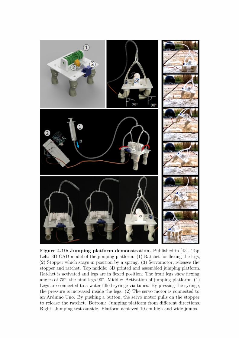
Figure 4.19: Jumping platform demonstration. Published in [43]. TopLeft: 3D CAD model of the jumping platform. (1) Ratchet for flexing the legs,(2) Stopper which stays in position by a spring. (3) Servomotor, releases thestopper and ratchet. Top middle: 3D printed and assembled jumping platform.Ratchet is activated and legs are in flexed position. The front legs show flexingangles of 75◦, the hind legs 90◦. Middle: Activation of jumping platform. (1)Legs are connected to a water filled syringe via tubes. By pressing the syringe,the pressure is increased inside the legs. (2) The servo motor is connected toan Arduino Uno. By pushing a button, the servo motor pulls on the stopperto release the ratchet. Bottom: Jumping platform from different directions.Right: Jumping test outside. Platform achieved 10 cm high and wide jumps.

4.6 Characterization of the Prototype
As the launching angle for a single leg, without an attached flexing mechanismand launching platform is difficult to control and the speed is very fast (20rev/s angular speed), a jumping platform was designed to demonstrate thejumping ability. The jumping platform consists of 4 legs for a stable standingposition, a flexing ratchet to hold the legs in flexed position while increasing thepressure and to allow a simultaneous release of all four legs via a servo motor.The total platform weighs roughly 120 g. As the legs are single jointed, thedemonstration platform only allows a flexing between 70-90◦as further flexedlegs would not touch the ground and just hit the ground when released, ratherthan contribute to jumping. The elastic work generated by the material is notenough to make the platform jump, but allows the unfolding of all for legs andlift the platform from "squatting" into standing position. This means, thatit can be assumed that the elastic work corresponds to the work needed tostand up the platform and therefore it needs to be subtracted from the overallwork to estimate the jumping height. Given these parameters a maximumjumping height of 23 cm can be estimated for all four legs flexed into 70◦ angle.However during jumping demonstration it could be observed, that the frontlegs are flexed in position 70-75◦, while the hind legs are opened a little moreto position 80-90◦. The maximum jumping performance at 75◦ launching anglewas 10 cm height and 10 cm of jumping distance. Fitting the flexing positionsinto the simulation, it can be seen that the estimated jumping behavior is verywell reflected by the calculated data.
4.6.5 Future Studies4.6.5.1 Further robotic extension
Although first step demonstrations have been conducted in this work, it isstill a long way to go to build a full robotic system. The integration of afunctional pump system with fluid collection chamber, a flexing motor, batteryand sensors would be on the electronic and hardware side. On the softwareside, the control of pressure and flexing for each of the legs would be necessary.Although valves have not been reported for spiders, it might still simplify therobotic implementation. Flexing mechanisms as proposed in previous sectionsneed to be integrated in such a way that multi-locomotion behavior (gripping,walking, jumping) can be allowed by the system, which might result in highercomplexity for the control of the interaction of pressure and flexing force.Considering the torques and pressures measured for the proposed prototypedesign, heavy pumps and flexing motors needed to be integrated along with ahigh energy source. While this is the reason why most of today’s research onsoft robotics have external power sources as they normally run on 10-100 times
119

4 Robotic Implementation
higher pressures, the demonstrated prototype is shown to be able to lift largeweight, so that a fully on-board multi-legged system might be possible to build.Another step which needs to be integrated would be a hip joint which wouldallow lateral motion. In spiders, the hip joint is realized by muscles pullingin one or the other direction, so it was not in focus of this study. A roboticimplementation for a hip joint could be a simple servo or stepper motor, a wire- based joint similar to the mechanism used in low-cost prosthesis or again ahydraulic or semi-hydraulic joint.Designed in a modular manner, the extension into a multi-joint leg would
also be possible, but increase the complexity in control as more flexing wiresare coming into play.
4.6.5.2 Fluid Flow
The experimental study on the influence of viscosity on the hydraulic perfor-mance is definitely another wide ranging research question to answer. As thepresented sudden release shows a negative pressure peak, it might be inter-esting to see how fluids with higher viscosity as e.g. hydraulic oil or fluidswith non-Newtonian behavior, as observed for spiders, influence the system.This could be done by combining standard fluid flow simulations with directexperiments on the here developed prototype with fluids varying from shearthinning behavior as ketch-up or blood, to shear thickening fluids as starch pulp.In general traditional hydraulic fluids for metal hydraulic pistons are chosenaccording to their specific purpose and the used viscosity depends highly on thedesired working temperature, the dynamic range and the need of lubrication.Experimental studies on non-Newtonian fluid effects are however lacking andmight not be only interesting to understand the spider locomotion better, butalso to increase performances of (soft) fluidic actuators. Interestingly, a recenttheoretical study [4] proposed shear-thickening fluids for hydraulic systems toprevent sudden loading or backflow, shear-thinning fluids however, were notcovered in this work.
4.6.5.3 Finite element analysis (FEA)
Using finite element methods to study the material behavior during foldingwould be an interesting addition to the experimental results presented in thisthesis. FEA could give information about weak points of the design and helpto optimize the chamber shape. Furthermore it could be further studied howthe difference in stiffness and thickness of the membrane would effect thefolding behavior and performance of the joint. A particular difficulty for theFEA would be the hyperelastic behavior of the material and the 3D printed
120
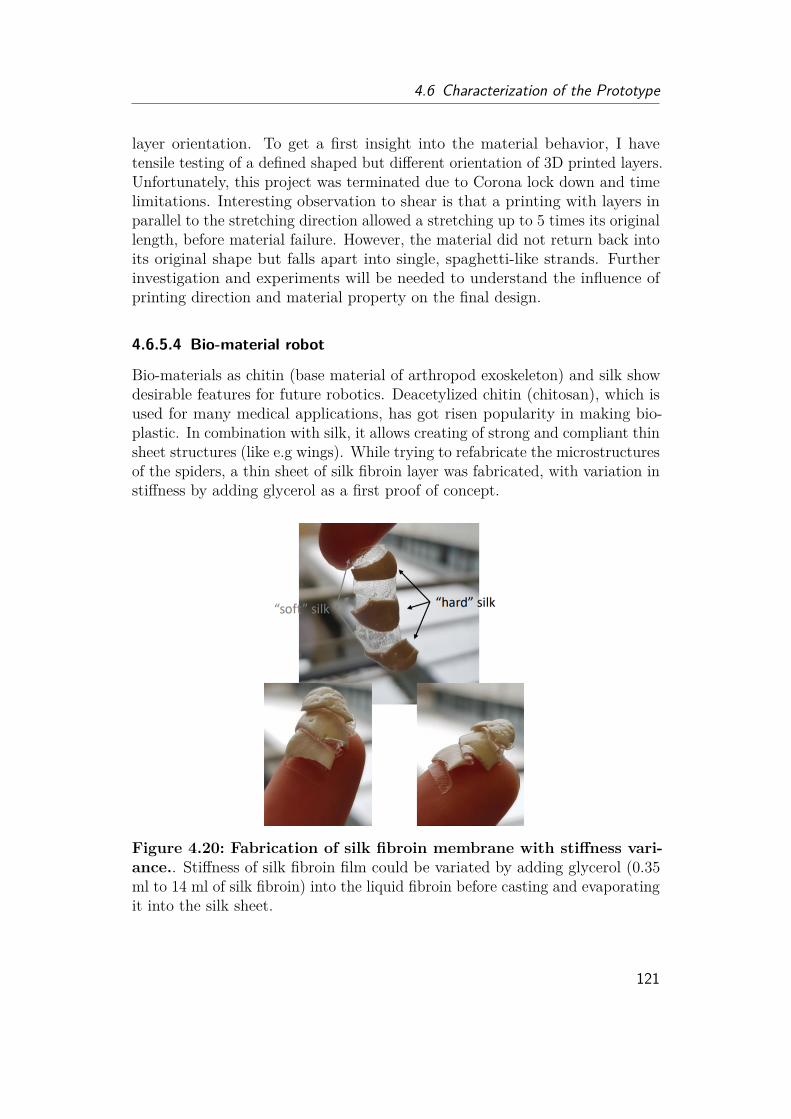
4.6 Characterization of the Prototype
layer orientation. To get a first insight into the material behavior, I havetensile testing of a defined shaped but different orientation of 3D printed layers.Unfortunately, this project was terminated due to Corona lock down and timelimitations. Interesting observation to shear is that a printing with layers inparallel to the stretching direction allowed a stretching up to 5 times its originallength, before material failure. However, the material did not return back intoits original shape but falls apart into single, spaghetti-like strands. Furtherinvestigation and experiments will be needed to understand the influence ofprinting direction and material property on the final design.
4.6.5.4 Bio-material robot
Bio-materials as chitin (base material of arthropod exoskeleton) and silk showdesirable features for future robotics. Deacetylized chitin (chitosan), which isused for many medical applications, has got risen popularity in making bio-plastic. In combination with silk, it allows creating of strong and compliant thinsheet structures (like e.g wings). While trying to refabricate the microstructuresof the spiders, a thin sheet of silk fibroin layer was fabricated, with variation instiffness by adding glycerol as a first proof of concept.
Figure 4.20: Fabrication of silk fibroin membrane with stiffness vari-ance.. Stiffness of silk fibroin film could be variated by adding glycerol (0.35ml to 14 ml of silk fibroin) into the liquid fibroin before casting and evaporatingit into the silk sheet.
121

4 Robotic Implementation
4.6.5.5 Future Applications
In the beginning of my PhD, I had the chance to join a interdisciplinary groupworking on different fields of agriculture (fig. 4.21). The vision was to use aheterogeneous group or swarm of robots which are adapted to specific tasksto allow agriculture in a non-structured terrain. While today’s agriculturalfields are shaped to fit to requirements of the farming robots, often leading tomono-cultured fields, the idea was to adapt robots to a more healthier multi-dimensional cultivation. In the proposed scenario, larger transport wheel robots,inspection and transport drones, worm-like suction robots and spider robotsform a multi-agent system. The proposed work for the spider robots wouldhave been delicate grasping tasks as for berries, wine grapes, but also removalof weeds or plant fitted fertilization. By splitting the tasks, the individual robotonly needs to fulfill a limited number of tasks, which reduces the individualcomplexity. E.g. considering a lightweight spider robot, which is capable ofgrasping, drones could be used to transport them onto specific plants and backfor harvesting or recharging.The proposed project is not bound to the spider-inspired mechanism, but
I personally still think it is an interesting idea to mention, considering thatautonomous robots for agriculture become more and more importantly. And Iwould be more than happy to have a robot taking out the dandelions from myparents garden that I used to dig out for hours every spring. A personal visionI have and which would benefit from the flexibility and speed of the proposedspider-inspired fluidic actuator would be a hand prosthesis (fig. 4.21). Growingup playing piano and having a sister as a professional pianist, the biggest fearwas always to injure or even lose a hand. Playing piano involves the interplay offinger, wrist, arm and shoulder movement. While hitting the keys in the rightorder can definitely performed much simpler by e.g. 88 little servo motors, itdoes not necessarily give back the music one would enjoy but rather mechanicalsounds. It further does not achieve the "wow" moment when the hands andfingers are flying along the keys to fulfill the devil’s composition. Beside all themusical aspect, it is the dynamic and delicacy of the hand, combined with theprecise haptic feedback, which are still lacking in any of today’s prosthesis orrobotic arms. Although studies on brain-information recognition is increasingto allow patients to control more complex systems, and machine learning toolsare pushing the agility of robotic hands, these studies would all benefit froman underlying platform which itself could already perform faster and strongermotion, but still being lightweight, compliant or soft.The most obvious research application of the proposed prototype would be
the study of spider locomotion. By varying material, surface coating, designand size, questions regarding friction, mechanical properties and dynamics can
122
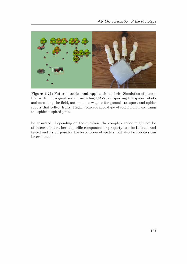
4.6 Characterization of the Prototype
Figure 4.21: Future studies and applications. Left: Simulation of planta-tion with multi-agent system including UAVs transporting the spider robotsand screening the field, autonomous wagons for ground transport and spiderrobots that collect fruits. Right: Concept prototype of soft fluidic hand usingthe spider inspired joint.
be answered. Depending on the question, the complete robot might not beof interest but rather a specific component or property can be isolated andtested and its purpose for the locomotion of spiders, but also for robotics canbe evaluated.
123


Chapter5Discussion
In this work a variety of things have been tested and brought into context withthe current state of research. To give the reader the quintessence of this work,I would like to discuss the main contributions, which I have summarized in thevery beginning of this thesis and presented through out this work.
To get a clearer picture of the working principle behind the locomotion of spi-ders, I have used many different imaging techniques to get detailed information.While not all of them provided "quantitative" results, the development andoptimization of preparation techniques to take these detailed images have been alarge and time-consuming part of my thesis. I used close-up high-speed imagingrecordings to get a qualitative view on the flexing and extending behavior ofthe spider legs as the data was not available in the beginning of my thesis. Thevideos revealed the fast extension of the femur-patella joint, emphasizing itsimportance for the jumps of jumping spiders. Furthermore, the recordings showthe interplay of the four leg pairs, especially the third and forth pair and alsothe fixation process of the safety wire, which is essential for a targeted jump.The articular membrane, which unfolds rapidly during the jump, was the focusof this thesis and therefore characterized in detail. To get information aboutthe three dimensional construct, I fully 3D reconstructed the femur-patellajoint and its articular membrane using X ray scans. The articular membraneis usually missing in the published 3D scans due to its thinness, its wrinklingafter death and special preparation requirements. Using stereo microscopy, Iwas able to observe the natural folding of the membrane on living spiders andtook highly magnified images. In elder literature, photo images of the articularmembrane are not very detailed due to the transparency of this membrane andthe limited camera resolution. Therefore, the folding has only been describedin schematic 2D drawings in previous literature, making it difficult to design afunctional spider-inspired actuator. The frequently cited work of Blickhan and
125

5 Discussion
Barth [14] describes the articular membrane as an anisotropic construct, whichfolds like a bellow. However, my video recordings revealed that the foldingdoes not resemble bellows commonly used in today’s technical applications.
The articular membrane appeared to be a thin fabric or cling film like sheetwith stiffer elements (hoops) integrated. The folding mechanism reminds moreof a stroller-umbrella, but with the difference that these hoops slide into eachother like in an ice-cream scooper or a silicone salad bowl. These hoops werehypothesized to be stiff reinforcements [64] of the articular membrane. There-fore, I directly analyzed the mechanical properties of the articular membraneby nanoindentation and experimentally proved the anisotropic construct of themembrane. To get a better understanding of the cause of this stiffness variation,I conducted traditional thin histological cuts of the spider leg to characterizethe membrane thickness and composition. Although exact matching of areaswas not possible, the images suggested that the stiffer areas were thicker thanthe rest of the membrane, which would also coincide with the 3D reconstructionwhere the stiffer "hoops" appeared denser. As the elastic protein, resilin, isoften incorporated into leg joints of jumping insects, I performed the indirectoptical testing for resilin under UV light. The test revealed that the stifferparts show a light blue autofluorescence response, which could be a hint forresilin. However, as resilin existence in spiders have not been reported so far,the light blue color might rather be a result of different cross-linked proteinsembedded inside the outer most layer (epicuticula) of the membrane [138], giv-ing another explanation for the anisotropy of the membrane. The integration ofresilin inside the membrane would increase elastic energy stored during folding,supporting jumping and fast movement and could help to restore the shape ofthe membrane.
Additionally, I developed an SEM preparation method, which allowed me toget high detailed images of the articular membrane surface. Previous worksfailed to provide electron microscopy images of the native membrane, as thespiders flex their legs after death, deflating the membrane. With the SEMimaging, I discovered the microstructures, which changed with the stiffnessvariation. Deproteinization of the leg showed, that the microstructures areprobably formed by proteins in the epicuticula of the exoskeleton, giving an-other explanation for the difference in membrane stiffness. I proposed thatthese microstructures could further be involved in communication due to theiriridescent effect, as the jumping spiders have well-developed visual systems andextend and wave their front legs when meeting conspecifics. As the structureslook similar to lotus-leaf surfaces [28], self-cleaning abilities might also beanother function, given the constant and fast folding and unfolding duringlocomotion. The spiders furthermore do not seem to have any lubricants on
126

the surface of the articular membrane, so the microstructures might also beinvolved in friction reduction. Although, I was not able to conduct friction,adhesion and contact angle measurements in the scope of this work, I proposedmethods and ideas to allow the measuring of these properties. Future studiesof the microstructure on the articular membrane might reveal an evolutionaryadaptation of these structures according to the behavior of the spider speciesas I showed that different species have different type of microstructures. Sincesurface-micro-patterning becomes more and more important for technologicalpurposes [34, 44, 71] the study and understanding of the microstructures func-tion could help to design new structures and surfaces.
The video recordings, live images and reconstructions provided detailedinformation for the design of a spider-inspired semi hydraulic actuator. Theheart of this design was the "articular membrane" which showed thick and stiffhoops that slide into each other during folding. This folding allowed the hingejoint to cover a large working angle of 120◦, performing in the same range as inthe observed jumping spiders. I showed that a lack of these stiff hoops couldlead to undesired wrinkles, causing damages and rupture of the membrane afterfrequent use, which would be fatal for the hydraulic locomotion. I furthermorecharacterized the folding and unfolding behavior of the prototype and showedthat the flexing and extension can be controlled by simple linear equations asthe generated torque is directly proportional to the input pressure (up to 300kPa). In contrast to this, previous, soft silicon-based spider-inspired implemen-tations, which extend by inflating and "blowing" up the material, normally workunder pressures 10-100 times higher and tend to have unpredictable volumeincrease. Latter reduces the generated torque and increases the difficulty incontrol, which is why soft actuators tend to have wire-reinforcements to increasepredictability of the motion, however that often comes with the cost in workingangle and performance. The demonstrated lightweight actuator was able to lift600 g against gravity and produced torques up to 0.4 Nm. For demonstrationpurposes, I built a jumping platform and showed that the resulting jumps werevery well predicted by the jumping models. Although the jump of spiders hasbeen studied several times and even new research work has been publishedduring my PhD by other research groups, it is still not 100% clear, how spidersjump, which legs are actually involved and how much torque each of the jointscontribute. Calculations and simulations for spider jumps are therefore stilllacking many essential information about the leg behavior, angles and thefluid flow, resulting in the "doubt of hydraulics", as the estimated hydraulicperformance seemed to be not efficient enough [133].
127
5 Discussion
The demonstrated jumping platform might not fully resemble the actualspider, however it could help to test hypothesis and give a better understandingof the system. Estimating and demonstrating the jumping performance of therobotic actuator revealed, that by simply holding the legs, internally increasingthe pressure and suddenly releasing the flexing wire, enough elastic energyis generated for jumping. Given that the legs are filled with flexor muscles,it can be assumed that spiders have enough flexing force to hold against therising internal pressure. Comparing this hydraulic jumping to elastic protein ormuscle-based jumping, it can be said, that the spring constant can be adjustedby the internal pressure. This means, a spring system with a given springconstant can only achieve a specific height when flexed to a specific angle.In contrast to this, the semi-hydraulic system allows to adjust the jumpingperformance by pressure while keeping the joint flexed at the same position.This might explain, why spiders have much better control over their jumpingperformance, essential for successful hunting, while insects normally just needa fast jump as far away as possible for escape, but not necessarily a goodcontrol. Resilin jumpers as leaf or grass hoppers, normally have their jumpingleg already locked in flexed position and do not use them for walking so thatthey can catapult themselves away when needed. As the fourth leg pair ofspiders is highly involved in the walking and running, a different jumpingmechanism is necessary. For controlled jumps, spiders take the time to anchorthe safety wire and flex their hind legs into position. For escape behavior,this preparation time might not be given, but as the legs can be immediatelyextended, by drastically increasing the pressure, fast (uncontrolled) jumps canstill be conducted and even combined with high speed running.The hydraulic performance might however be limited by the speed in volumeshift. The sudden release characterization of the prototype showed, that thepressure drops even into negative values when the joint snaps open in highspeed. This effect is known for hydraulic pistons, where it can cause cavition,leading to damage of the material and performance limitations.
However this might not be the case in spiders, as the physical properties ofhemolymph could adjust in such a way, that a delay in volume shift is avoided.To study this, I looked into the hemolymph flow of the spiders. The
hemolymph flow constantly provides researchers with headaches, as it seemsthat spiders should not be able to do what they are doing. Although spiders area two body parted, multi-legged, multi jointed system and one would assumethat valves would be used for control, no valves have been reported so far. It isknown that the heart pumps the hemolymph from the lungs to all the essentialorgans and that the prosoma increases the pressure inside the legs, but it still
128

remains unclear how the heart works against the high prosoma pressure. Alsothe fluid flow inside the leg is completely unknown. Researchers have assumedfor a long time that the reduce in volume of the prosoma during pressureincrease would lead to the loss of hemolymph to the abdomen. They furtherconcluded that this would result in a lack of oxygen supply for the organs insidethe prosoma, which would force the spider to recover after a short period ofrunning or jumping. This problem is referred as the "hydraulic insufficiencyhypothesis" [59]. Subsequent works have however provided evidence againstthis theory, by showing that spiders can perform high speed running for severalminutes and that rather biochemical factors are limiting factors [80]. Thehydraulic efficiency is however still questioned due to simulations showing thatspiders over 3 g should not be able to jump when only using hydraulics [143].However, all estimations were lacking essential information, which I tried toprovide in this thesis.
Completing the schematic drawings given in elder literature, my 3D recon-struction and histological cuts revealed the inner composition and space insidethe leg, especially in the joint region. However, I was not satisfied as thismethods could only be conducted on dead animals and did not provide anyinformation about the internal flow. I found that although the penetrationdepth is limited, optical coherence tomography (OCT) was able to show thefluid flow of the hemolymph cells inside the leg joint. The video recordingrevealed the different fluid path and speed inside the leg and joint for the firsttime. Furthermore an interesting spiral flow in the joint region was observed.Although, I was not able to find any of the proposed muscle ring-like valvestructures [59], the observations might indicate that the arcuate sclerite playsa valve-like role. However, further investigations will be needed to fully provethis.
While for simulations, a large volume shift was assumed to be necessary forleg extension, the recordings show that only a small fraction of the leg jointforms the "extension chamber" under the articular membrane, necessary forextension and that not all space and channels inside the leg actually lead tothe chamber.
Another important fluid property, the viscosity and its behavior under differ-ent pressure, was lacking in literature and the simulations. Viscosity is a keyfactor in traditional hydraulic systems as it helps to lubricate the system andtherefore reduces wear and friction, cools the system during overheating andhelps to avoid oxidation. Latter is the reason why water is usually not used inmetal-based hydraulic systems since large amount of air is dissolved in water.Neglecting these effects, viscosity still directly influences the mechanical and
129

5 Discussion
volumetric efficiency, making it necessary to choose the right hydraulic fluidfor the working range of the system. High viscous fluids normally show a largevolumetric efficiency, but low mechanical efficiency, while low viscous fluidsbehave the opposite way. Now considering the spider leg as an hydraulic motor,the optimal viscosity changes over the pressure range. When operating atlow pressures during resting, the fluid is pumped through the body, providingoxygen and nutrients to all organs, therefore high volumetric efficiency is ofimportance, while the mechanical efficiency can be low. Highly viscous fluids areat this point of advantage. During normal walking, the pressure is now at nor-mal working level, torque needs to be generated, therefore mechanical efficiencyshould be larger, while volumetric efficiency should stay as high as possible asmost fluids are still only pumped through the body by the heart. When thespider rapidly increases pressure as for fast running or sudden jumps, the legsextend in a fast manner, resulting in the sudden opening of volume that needsto be filled. At this point, the effective flow needs to increase immediately to fillup this volume, furthermore, generated torque and mechanical efficiency shouldbe as high as possible. This means at high operating pressure, during largemotion, a low viscous fluid would be more beneficial. In conclusion, a fluid thatshows decreasing viscosity with increasing pressure would be optimal for spiders.
Using microchannels, I was able to show non-Newtoninan, shear-thinningbehavior of the hemolymph as it has been observed for human blood. Theviscosity of hemolymph decreases, while the velocity increases with pressure,which would prevent a sudden pressure drop observed for the robotic prototypeand commonly known to cause cavitation, resulting damages and inefficiencies.It would be interesting to test different viscous fluids with different shearbehaviors on the robotic prototype in the future, to see how large the influencewould be on its performance and whether non-Newtonian fluids have a benefiton hydraulic actuators.
A major difference between previous spider-inspired actuators to the mech-anism proposed in this thesis and observed in spiders is the fluidic medium.Pneumatic actuation is often used instead of water or oil based hydraulics.Air brings the benefits of already being low-cost, lightweight, safe, compliant,environment-friendly and causes less leakage problems. For prototyping, pneu-matics is therefore easier to implement as small leakage can be compensatedby higher flow rate and fluid storage chambers are not necessary as air can betaken from the surrounding.Since air is compressible, pneumatic systems are less susceptible to shock
damage. This property however brings also the main disadvantage of pneumatic
130
actuation. To create high operating pressures, the air needs to be compressedby a compressor, which is often large and bulky. When moving or lifting heavyloads, pneumatic actuators furthermore show spongy movement caused by thecompression. In combination with soft materials, this can cause undesired jerky,"wobble" motion, making a controlled positioning very difficult. To comparethe performances of the existing actuators, I have listed their working angle,torques, operating pressures and effective area (fig. 5.1). As torque increasesproportionally to area and pressure, larger actuators with high operating pres-sures would automatically have larger torque values. To give a rough value forcomparison, I have introduced two performance values, which normalize thetorque to the area (performance 1) and additionally to the pressue (performance2). Although elastic energy, friction, the real effective area and leakage mightalso impact the measured torque, these factors are neglected as the data forthese values are not given for the actuators. To give a fair comparison, I didnot use the evaluated effective area (13 mm2) but the cross-sectional area(100-140 mm2) of the fluid chamber, as this was the only value available forthe other actuators. It is no surprise to see, that those actuators, which areonly based on the balloon-like inflation of rubber material (Schwörer [110],Zentner [16, 17, 143–145], Menon [73]), show a lower level in performance thanthose with a reinforcement. The actuation of the Arthrobots (Nemiroski [83]),build by researchers around G. Whiteside, are also based on the inflation of aballoon. However the highest torque values shown here were achieved whenthe inflation was restricted by a sleeve. As proposed by Blickhan and Barth[14] isotropic membranes would lead to bulging volumes and the creation ofcounteracting torque, reducing the performance. The standard-bellow shapedactuators (Schulz [40, 41, 54, 96], Becker [20], Landkammer [62, 63, 109, 142])show a similar value in performance 1. Landkammer used a flexible material(TPU), which might explain the low operating pressure for material extensionand the higher perfomance 2 value. The sliding-shell-model (Spröwitz [120]),which was developed in the beginning of my PhD, is based loosely on imagesI made of wolf spiders. The operating pressure was limited by the internalplastic bag, which is inflated during extension. While the performance 1 valueis significantly lower in comparison to the prototype presented in this thesis(Göttler 2020), the performance 2 value is almost the same. An explanationcould be that the flexible material, which brings the advantage of complianceand less damage after impact, need a higher operating pressure to withstandhigher load. Alternatively, the cross-sectional area of the proposed actuatorwas estimated too large.
One significant difference between the proposed design to previous actuators
131
5 Discussion
is the working angle. While only angles up to 90◦where achieved before, theinterfolding mechanism developed in this work allows a working angle up to 120- 125◦, which comes close to the working angle observed for the jumping spider(130-140◦). Interestingly, the estimated performance range of the jumpingspider Phidippus regius lies in the same range. As the pressure value inside thespider leg could be much higher during jumps than assumed, future detailedmeasurement of the inner pressure are required to get a better understandingof the locomotion principle.
132

Figure5.1:
Com
parisonof
spider
inspired
fluidic
actuators.
Red
dotted
lines
markthepe
rform
ance
value
oftheprototyp
edemon
stratedin
this
thesis
(Göttle
r2020).
Working
angles
aregivenin
degrees,
othervalues
arefollo
wingthelogarit
hmic
scale.
Perfo
man
ce1is
calculated
from
thetorque
norm
alized
tothecrosssectiona
larea.Pe
rform
ance
2is
themax
.torque
norm
alized
tothemax
imal
operatingpressure
andthecrosssectiona
larea.
Actua
torvalues
aretakenfro
m[63,
64,8
3,96].
OnlyMenon
,Nem
iroskia
ndGöttle
rused
hydrau
licsinsteadof
pneu
matics.
Spider
torque
wasroug
hlycalculated
with
data
from
[77,
90],cross-sectiona
l-areawa
sestim
ated
from
OCT
recordings
andop
eratingpressure
wasassumed
tobe
arou
nd50
kPaas
measuredin
otherspider
species[90].
Areaan
dpressure
might
diffe
rhigh
lyfro
mthereal
value.
133

Chapter6Material and Methods
6.1 Behavioural Observation
6.1.1 Spider Keeping and Breeding Condition
In biological studies, species, age, sex and fitness are important parameters toknow, to avoid any side effects influencing the features of interest. That is why Idecided to keep and breed my own spiders under controlled conditions instead ofcatching them from the outside forest as done in many studies. An interestingstudy species for actuation would be jumping spiders as they show a highversatility in locomotion behavior. The first generation of juvenile jumpingspiders Phidippus regius were purchased from a local breeder. The secondgeneration was bred in-house. After the spiders molded for two to three times(N2-N3 stage), they were separated from each other and kept in individualboxes to avoid interspecies attacking. As this species originally comes fromFlorida, the temperature was set between 25 to 35 ◦C with a nine-hours-daylightcycle and boxes were frequently sprayed with water. The spiders were fed withfruit flies (Drosophila sp.), meal worms and crickets matching their stage indevelopment and size. The molding stage and any problems were documented.If not otherwise stated, adult spiders were used for experiments.
6.1.2 High Speed
To observe the jumping motion of the spiders, they were recorded at 1000frames per second (Phantom Miro M140, 8032), with exposure time at 400 µsand resolution of 1024 x 768.
135
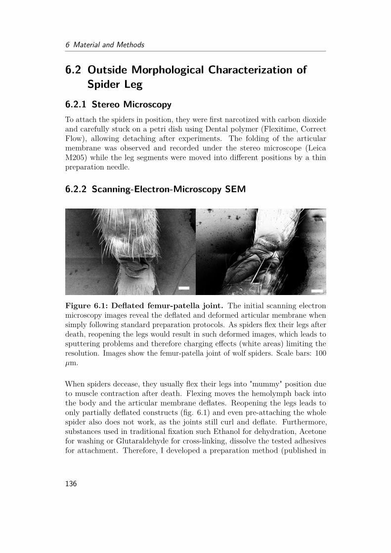
6 Material and Methods
6.2 Outside Morphological Characterization ofSpider Leg
6.2.1 Stereo MicroscopyTo attach the spiders in position, they were first narcotized with carbon dioxideand carefully stuck on a petri dish using Dental polymer (Flexitime, CorrectFlow), allowing detaching after experiments. The folding of the articularmembrane was observed and recorded under the stereo microscope (LeicaM205) while the leg segments were moved into different positions by a thinpreparation needle.
6.2.2 Scanning-Electron-Microscopy SEM
Figure 6.1: Deflated femur-patella joint. The initial scanning electronmicroscopy images reveal the deflated and deformed articular membrane whensimply following standard preparation protocols. As spiders flex their legs afterdeath, reopening the legs would result in such deformed images, which leads tosputtering problems and therefore charging effects (white areas) limiting theresolution. Images show the femur-patella joint of wolf spiders. Scale bars: 100µm.
When spiders decease, they usually flex their legs into "mummy" position dueto muscle contraction after death. Flexing moves the hemolymph back intothe body and the articular membrane deflates. Reopening the legs leads toonly partially deflated constructs (fig. 6.1) and even pre-attaching the wholespider also does not work, as the joints still curl and deflate. Furthermore,substances used in traditional fixation such Ethanol for dehydration, Acetonefor washing or Glutaraldehyde for cross-linking, dissolve the tested adhesivesfor attachment. Therefore, I developed a preparation method (published in
136
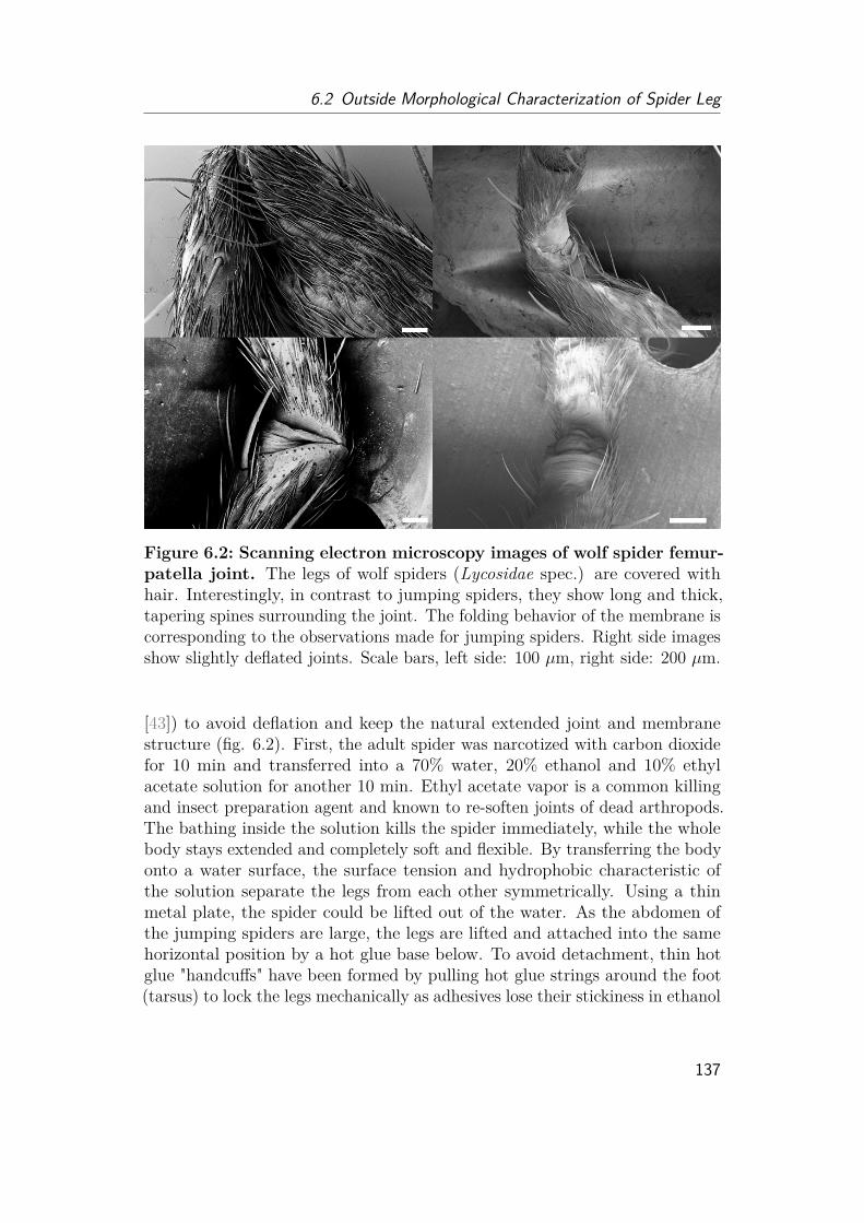
6.2 Outside Morphological Characterization of Spider Leg
Figure 6.2: Scanning electron microscopy images of wolf spider femur-patella joint. The legs of wolf spiders (Lycosidae spec.) are covered withhair. Interestingly, in contrast to jumping spiders, they show long and thick,tapering spines surrounding the joint. The folding behavior of the membrane iscorresponding to the observations made for jumping spiders. Right side imagesshow slightly deflated joints. Scale bars, left side: 100 µm, right side: 200 µm.
[43]) to avoid deflation and keep the natural extended joint and membranestructure (fig. 6.2). First, the adult spider was narcotized with carbon dioxidefor 10 min and transferred into a 70% water, 20% ethanol and 10% ethylacetate solution for another 10 min. Ethyl acetate vapor is a common killingand insect preparation agent and known to re-soften joints of dead arthropods.The bathing inside the solution kills the spider immediately, while the wholebody stays extended and completely soft and flexible. By transferring the bodyonto a water surface, the surface tension and hydrophobic characteristic ofthe solution separate the legs from each other symmetrically. Using a thinmetal plate, the spider could be lifted out of the water. As the abdomen ofthe jumping spiders are large, the legs are lifted and attached into the samehorizontal position by a hot glue base below. To avoid detachment, thin hotglue "handcuffs" have been formed by pulling hot glue strings around the foot(tarsus) to lock the legs mechanically as adhesives lose their stickiness in ethanol
137
6 Material and Methods
during the critical point drying (1 h, slow speed, 28◦ on Leica EM CPD300Automated Critical Point Dryer). To avoid charging effects, the spider wassputter-coated with 20 nm gold (Leica EM ACE200) and observed under theelectron microscope (Zeiss Ultra Plus) with working distances of 10-15mm andelectron high tension (EHT) of 3-5 kV.
6.2.3 Computer-tomography CTA dead adult spider was carefully placed into an Eppendorf tube filled with 70%ethanol and two drops of iodide solution to enhance the contrast. Micro-CTscans were performed at the KIT, ANKA, IPS imaging laboratory for computedlaminography and computed tomography with Marcus Zuber. An X-ray tube(XRay-WorX XWT-225), producing an cone beam, and a flat panel detector(PerkinElmer XRD 1621 CN14 ES) were used for the measurements. The X-raytube was operated with an acceleration voltage of 50 kV and at a target powerof 10 W. The sample was positioned and moved by a custom made samplemanipulator. In total 2048 projections were acquired over an angular range of360◦. Each projection was exposed for 4s. The projection was reconstructedinto slices with Octopus 8.6 (Inside Matters, Gent, Belgium). The geometricalmagnification results in an effective pixel/voxel size of 7.07 µm.
138
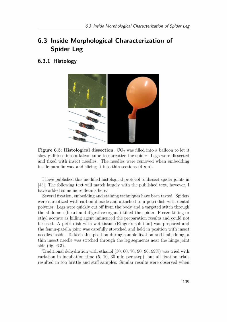
6.3 Inside Morphological Characterization of Spider Leg
6.3 Inside Morphological Characterization ofSpider Leg
6.3.1 Histology
Figure 6.3: Histological dissection. CO2 was filled into a balloon to let itslowly diffuse into a falcon tube to narcotize the spider. Legs were dissectedand fixed with insect needles. The needles were removed when embeddinginside paraffin wax and slicing it into thin sections (4 µm).
I have published this modified histological protocol to dissect spider joints in[43]. The following text will match largely with the published text, however, Ihave added some more details here.
Several fixation, embedding and staining techniques have been tested. Spiderswere narcotized with carbon dioxide and attached to a petri dish with dentalpolymer. Legs were quickly cut off from the body and a targeted stitch throughthe abdomen (heart and digestive organs) killed the spider. Freeze killing orethyl acetate as killing agent influenced the preparation results and could notbe used. A petri dish with wet tissue (Ringer’s solution) was prepared andthe femur-patella joint was carefully stretched and held in position with insectneedles inside. To keep this position during sample fixation and embedding, athin insect needle was stitched through the leg segments near the hinge jointside (fig. 6.3).
Traditional dehydration with ethanol (30, 60, 70, 90, 96, 99%) was tried withvariation in incubation time (5, 10, 30 min per step), but all fixation trialsresulted in too brittle and stiff samples. Similar results were observed when
139

6 Material and Methods
fixated with glutaraldehyde and osmium. A fixation with picric acid (Bouinsolution [10]) resulted in bright yellow samples (fig. 6.3). Although this methodwas great for microscopic observations, the picric acid has to be washed outwith ethanol after staining. Therefore, to spare the samples, Hartman’s fixative(also Davidson’s fixative, Sigma-Aldrich H0290) often used in vertebrate tissuefixation, was used. The fixative contains acetic acid, alcohol and formalin.Samples were fixated overnight. Embedding in epoxy (Technovit) and spurrwas tested, but microtome cutting (with (sheet) glass, razor blades and (cryo)diamond knife, 4 mm, 45 ◦, Leica) resulted in rupture of the articular membranedue to too large cutting thickness (∼2 µm), the thinness of the membrane andlarge differences between the stiffness of the sample and the embedding material.Paraffin embedding was therefore chosen and carried out in the standard way.Paraffin wax was heated in a beaker and filled into small clear lockable glasssample vials and left on the heating plate. Samples were incubated in a glassvial filled with xylene (also xylol, Sigma-Aldrich, isometric mixture, 1.08298)for 10 min. Longer incubation could lead to brittleness of the sample. Sampleswere transferred into a 1:1 xylol-paraffin wax mixture and incubated for 10min.
Experiments were conducted under the fume hood with proper safety equip-ment (gloves, goggles, lab coat) and separate, close waste disposal to avoidhealth issues from xylene. Heating plate was set at the melting point ofparaffin, so that the wax just stayed liquid. Samples were incubated for 30mins and transferred to fresh paraffin twice. For cutting purposes, sampleswere transferred into stainless steel histology embedding molds, covered withthe backside of a plastic histology cassette (fitting to microtome holder) andcarefully filled with liquid paraffin. After cooling in air (1-2 min), molds werecooled in the fridge (-20◦C) overnight. The embedding mold was carefullyremoved the day after. Samples were kept in fridge until microtome cutting.Wax molds were attached to the microtome (RM2245, Leica) and excess waxwas cut away until biological sample appeared on the surface. Slices of 4-5 with4 µm thickness were transferred with a brush to a heated water bath (35-40◦C)and afterwards carefully lifted on a glass slide. After air drying and removal ofexcess water with a tissue, glass slides were baked at 45-50◦C overnight. Forstaining, paraffin wax was removed by bathing the slides in xylene (10 min),hydrated with ethanol washing (96%, 70%, 60%, 5-10 mins per step) and rinsedwith aqua dest. afterwards. Three different staining methods were tried out,Mallory (Morphisto, Mallory Kit, 10270), Masson-Goldner and Azan staining.Best staining results were obtained with a modified Masson-Goldner Trichromestaining.Staining jars were used for all staining steps. Weigert’s iron hematoxylin
140
6.3 Inside Morphological Characterization of Spider Leg
solution from the traditional Masson-Goldner staining was not used as it isfor nuclei staining. Samples were bathed in a 1:2 mixture of 1% acid fuchsine(Morphisto, Masson A, 10357) and 1% Ponceau de Xylidine (Morphisto, MassonB, 11518) for 5 min and carefully washed with 1% acetic acid and aquadest. afterwards. Samples were then shortly (1-2min) dipped in a solution ofPhosphormolybdic acid and Orange-G (Morphisto, 11195) and washed withacetic acid and aqua dest. again. After another staining step with anilin blue(Morphisto, Masson C, 10141) and washing, samples were quickly dehydratedwith ethanol (96%, 5 min, twice) and xylene (2 min) and left under the fumehood for drying and total evaporation of xylene. Cover slides for microscopywere mounted with mounting medium (Morphisto, 12318) onto the glass slides.Coloration results show similarities to Azan staining after Heidenhain. The thinepicuticule, which is not stained in many staining protocols, is stained dark redwith this method. The stiff exocuticule appears brown, while the endocuticle isstained blue. A mesocuticle, which does not show fiber orientation differencesto the endocuticle but can be differently stained [10], was not distinguishablewith this method.
6.3.2 Topology and Tomography ScansIn order to observe the 3D structure of the spider joints, detailed X-ray imagingwas conducted at LAS (Laboratory of Applications of Synchrotron Radiation),synchrotron ANKA in Karlsruhe together with Thomas van de Kamp. Themicrotomography is performed using a parallel polychromatic X-ray beamproduced by a 1.5 T bending magnet. The beam was spectrally filtered by 0.2mm aluminum with a spectrum peak at about 15 keV and a full-width at halfmaximum bandwidth of about 10 keV. A fast indirect detector system consistingof an 18 µm LSO:Tb scintillator [24], diffraction limited optical microscope(Optique Peter) and a 12bit pco.dimax high speed camera with 2016 x 2016pixels was employed. For the tomographic scan we took 3,000 projections at200 frames per second and chose an optical magnification of 10X, resulting inan effective pixel size of 1.22 µm. We used the control system concert [130] forautomated data acquisition. Tomographic reconstruction was done using theUFO framework [129]. Structures were presegmented with Amira (version 5.5)and refined with Biomedisa for 3D reconstruction.
141
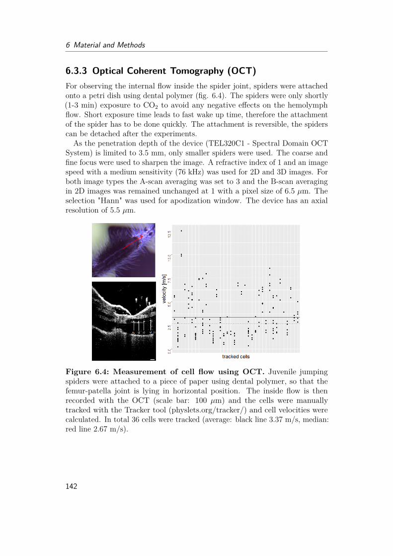
6 Material and Methods
6.3.3 Optical Coherent Tomography (OCT)For observing the internal flow inside the spider joint, spiders were attachedonto a petri dish using dental polymer (fig. 6.4). The spiders were only shortly(1-3 min) exposure to CO2 to avoid any negative effects on the hemolymphflow. Short exposure time leads to fast wake up time, therefore the attachmentof the spider has to be done quickly. The attachment is reversible, the spiderscan be detached after the experiments.
As the penetration depth of the device (TEL320C1 - Spectral Domain OCTSystem) is limited to 3.5 mm, only smaller spiders were used. The coarse andfine focus were used to sharpen the image. A refractive index of 1 and an imagespeed with a medium sensitivity (76 kHz) was used for 2D and 3D images. Forboth image types the A-scan averaging was set to 3 and the B-scan averagingin 2D images was remained unchanged at 1 with a pixel size of 6.5 µm. Theselection "Hann" was used for apodization window. The device has an axialresolution of 5.5 µm.
Figure 6.4: Measurement of cell flow using OCT. Juvenile jumpingspiders were attached to a piece of paper using dental polymer, so that thefemur-patella joint is lying in horizontal position. The inside flow is thenrecorded with the OCT (scale bar: 100 µm) and the cells were manuallytracked with the Tracker tool (physlets.org/tracker/) and cell velocities werecalculated. In total 36 cells were tracked (average: black line 3.37 m/s, median:red line 2.67 m/s).
142
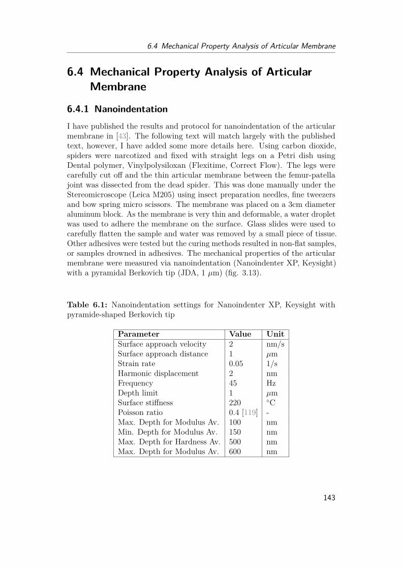
6.4 Mechanical Property Analysis of Articular Membrane
6.4 Mechanical Property Analysis of ArticularMembrane
6.4.1 NanoindentationI have published the results and protocol for nanoindentation of the articularmembrane in [43]. The following text will match largely with the publishedtext, however, I have added some more details here. Using carbon dioxide,spiders were narcotized and fixed with straight legs on a Petri dish usingDental polymer, Vinylpolysiloxan (Flexitime, Correct Flow). The legs werecarefully cut off and the thin articular membrane between the femur-patellajoint was dissected from the dead spider. This was done manually under theStereomicroscope (Leica M205) using insect preparation needles, fine tweezersand bow spring micro scissors. The membrane was placed on a 3cm diameteraluminum block. As the membrane is very thin and deformable, a water dropletwas used to adhere the membrane on the surface. Glass slides were used tocarefully flatten the sample and water was removed by a small piece of tissue.Other adhesives were tested but the curing methods resulted in non-flat samples,or samples drowned in adhesives. The mechanical properties of the articularmembrane were measured via nanoindentation (Nanoindenter XP, Keysight)with a pyramidal Berkovich tip (JDA, 1 µm) (fig. 3.13).
Table 6.1: Nanoindentation settings for Nanoindenter XP, Keysight withpyramide-shaped Berkovich tip
Parameter Value UnitSurface approach velocity 2 nm/sSurface approach distance 1 µmStrain rate 0.05 1/sHarmonic displacement 2 nmFrequency 45 HzDepth limit 1 µmSurface stiffness 220 ◦CPoisson ratio 0.4 [119] -Max. Depth for Modulus Av. 100 nmMin. Depth for Modulus Av. 150 nmMax. Depth for Hardness Av. 500 nmMax. Depth for Modulus Av. 600 nm
143
6 Material and Methods
The hardness and Young’s modulus of the two distinguishable parts (dotand line area) of the membrane were determined by the continuous stiffnessmeasurement (CSM) method. As mentioned above, aluminum was used as asubstrate and the sample was attached to the surface via the adhesion of awater droplet, which was removed afterwards. As the indenter had only a fixed20x magnification, it was difficult to find the small and transparent membraneunder the microscope. Therefore, a black marker arrow was drawn next tothe sample on the aluminum block, before the aluminum block was taredinside the sample holder. Indentation points were chosen randomly among thesurfaces but avoiding wrinkles. For noise balancing and calibration, 5 indentson a silicon wafer have been taken and for each area of the membrane 5-10test indents have been performed to mark the x,y position of the differentparts. An indentation depth of 1 µm was chosen, corresponding 2-10% of themembrane thickness avoiding substrate effects. Further parameters for thenanoindentation experiment are summarized in tab. 6.1.
Two experimental runs were performed. In the first run 50 and in the second100 indentation runs for each area were done. Due to long surface approachingtimes, the last experimental run took 3 days and was performed over weekend,avoiding external vibrations due to e.g. elevators. Finally, only experimentsin accordance with theory [67, 86, 93] have been chosen for calculation, toensure successful contact finding and avoiding substrate effect. At the end, 57measurements for the dot and 101 for black line area were analyzed. Statisticalanalyses (tab. 6.2) have been done using R internal statistic libraries.
144

6.4 Mechanical Property Analysis of Articular Membrane
Table 6.2: Statistical analysis of nanoindentation measurements. Thedistribution of Young’s Modulus E and Hardness H experimental data wereanalyzed. Statistical testing was conducted with R. Normal distribution istested with the Shapiro-Wilk-Test and the F-Test compares variances of twonormal distributed groups. P-values above the significance level of 0.05 inthese two tests are marked with an asterisk, indicating normal distribution orno difference in variance. Biological samples are often considered as normaldistributed with similar variance, even when experimental data show different.As both, Shapiro- and F-Test are not clearly supporting normal distributionand similar variances, a standard t-test cannot be used to test similarity inmeans. Therefore, the Welch’s t-Test is used, which considers differences invariances and the Wilcoxon-Test compares groups without assuming normaldistribution. P-values, below the significance level 0.05 are marked with anasterisk, indicating a difference in means of the dot and line area.Young’s-Modulus E(GPa)
Mean(GPa) Median (GPa) StandardDeviation(GPa)
Shapiro-Wilk-Test p –value
dot area (D) 3.81 3.80 0.538 0.24 *line area (L) 5.00 4.90 0.960 0.000114
F-Test ratio of vari-ance
0.31
p-Value 6.23e-06
Welch’s t-Test 95% con-fidenceinterval
[-1.42, -0.95]
p-Value <2.20e-16 *Mann-WhitneyWilcoxon Test
p-Value 6.40e-15 *
Hardness H (GPa) Mean (GPa) Median (GPa) StandardDeviation(GPa)
Shapiro-Wilk-Test p –value
dot area (D) 0.12 0.11 0.041 0.000446line area (L) 0.29 0.29 0.045 0.22 *
F-Test ratio of vari-ance
0.85
p-Value 0.509 *
Welch’s t-Test 95% con-fidenceinterval
[-0.18, -0.15]
p-Value <2.20e-16 *Mann-WhitneyWilcoxon Test
p-Value <2.20e-16 *
145
6 Material and Methods
6.4.2 Nanoindentation of Hydrated SamplesWhen I moved to ETH for the second part of my PhD, I found a tool called"FemtoTool" which is designed to measure the material properties of biologicalsamples like cells. Out of interest, I wanted to give this method a try. Femto-Tools is designed to measure the stiffness of rather soft material. As it turnedout quickly during the experiments, dry samples of the articular membrane areto stiff and deflect the "hair" too much to measure any difference. Howeverby rehydrating the samples, the membrane starts swelling and transforms intoa much softer construct. I measured three different membranes and differentpositions from the line and dot area. The stiffness was calculated via theHERTZ model. Similar to the nanoindentation method, the hydrated samplesshow a stiffness difference between the line and the dot area. With the linearea being the stiffer area.
6.4.3 Resilin TestI have published the resilin analysis of the articular membrane in [43]. Thefollowing text could match with the published text. Using the autofluorescenceproperty of resilin under UV light (385nm) [23, 138] the existence of resilin canbe tested. Optical observation was done under a stereomicroscope (Leica, M205FA) with fluorescent light source (EL600, mercury lamp) and filter (EX 395/25nm, EM 435 LP). Higher magnified images were observed under an inversemicroscope (Zeiss Axio Obser.A1) with UV light (385 nm) and filter (Ex 390/40,Em 450/40). Strong blue fluorescence indicates resilin existence, however theobserved light blue color might be a result of nitrogen-rich cross-links in theepicuticle [138]. As the membrane is very small and still need to be used forfurther experiments, were not conducted, as the membrane tends to flush awayinside larger droplets. However, pH-dependence of the autofluorescence couldhelp to verify the existence of resilin [81].
6.5 Microstructure Analysis
6.5.1 Microstructure FabricationThe microstructure of spiders are part of the outside layer (epicuticular) ofthe exoskeleton and consists of protein and a thin wax layer. To refabricatethe microstructures, silk fibroin was used as a base protein and covered withparylene. Silk fibroin was gained from silk pupae of the silk worm Bombyxmori (fig. 6.5) according to standard protocols [99]. Silk pupae (VON DERPLANITZ product development, Bayreuth, Germany) were cut into small
146
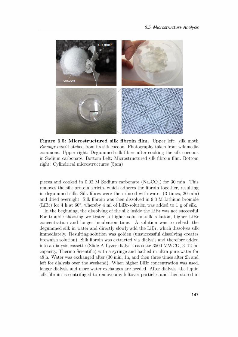
6.5 Microstructure Analysis
Figure 6.5: Microstructured silk fibroin film. Upper left: silk mothBombyx mori hatched from its silk cocoon. Photography taken from wikimediacommons. Upper right: Degummed silk fibers after cooking the silk cocoonsin Sodium carbonate. Bottom Left: Microstructured silk fibroin film. Bottomright: Cylindrical microstructures (5µm)
pieces and cooked in 0.02 M Sodium carbonate (Na2CO3) for 30 min. Thisremoves the silk protein sericin, which adheres the fibroin together, resultingin degummed silk. Silk fibres were then rinsed with water (3 times, 20 min)and dried overnight. Silk fibroin was then dissolved in 9.3 M Lithium bromide(LiBr) for 4 h at 60◦, whereby 4 ml of LiBr-solution was added to 1 g of silk.
In the beginning, the dissolving of the silk inside the LiBr was not successful.For trouble shooting we tested a higher solution-silk relation, higher LiBrconcentration and longer incubation time. A solution was to rebath thedegummed silk in water and directly slowly add the LiBr, which dissolves silkimmediately. Resulting solution was golden (unsuccessful dissolving createsbrownish solution). Silk fibroin was extracted via dialysis and therefore addedinto a dialysis cassette (Slide-A-Lyzer dialysis cassette 3500 MWCO, 3–12 mlcapacity, Thermo Scientific) with a syringe and bathed in ultra pure water for48 h. Water was exchanged after (30 min, 1h, and then three times after 2h andleft for dialysis over the weekend). When higher LiBr concentration was used,longer dialysis and more water exchanges are needed. After dialysis, the liquidsilk fibroin is centrifuged to remove any leftover particles and then stored in
147
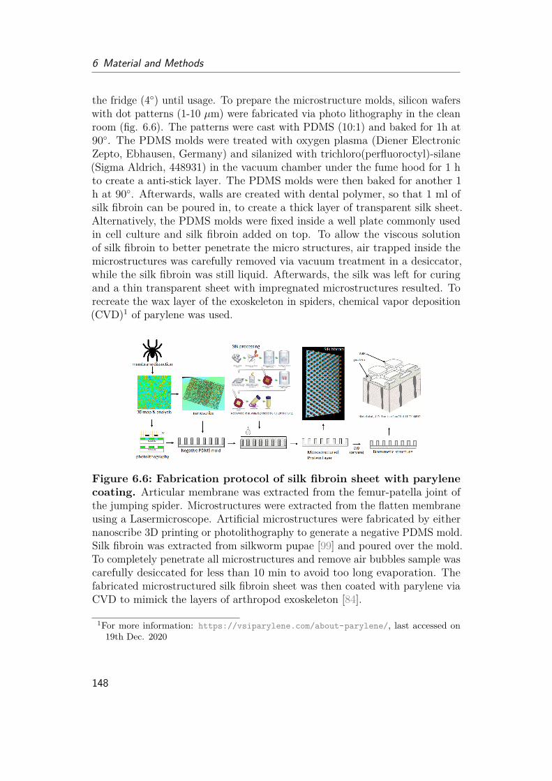
6 Material and Methods
the fridge (4◦) until usage. To prepare the microstructure molds, silicon waferswith dot patterns (1-10 µm) were fabricated via photo lithography in the cleanroom (fig. 6.6). The patterns were cast with PDMS (10:1) and baked for 1h at90◦. The PDMS molds were treated with oxygen plasma (Diener ElectronicZepto, Ebhausen, Germany) and silanized with trichloro(perfluoroctyl)-silane(Sigma Aldrich, 448931) in the vacuum chamber under the fume hood for 1 hto create a anti-stick layer. The PDMS molds were then baked for another 1h at 90◦. Afterwards, walls are created with dental polymer, so that 1 ml ofsilk fibroin can be poured in, to create a thick layer of transparent silk sheet.Alternatively, the PDMS molds were fixed inside a well plate commonly usedin cell culture and silk fibroin added on top. To allow the viscous solutionof silk fibroin to better penetrate the micro structures, air trapped inside themicrostructures was carefully removed via vacuum treatment in a desiccator,while the silk fibroin was still liquid. Afterwards, the silk was left for curingand a thin transparent sheet with impregnated microstructures resulted. Torecreate the wax layer of the exoskeleton in spiders, chemical vapor deposition(CVD)1 of parylene was used.
Figure 6.6: Fabrication protocol of silk fibroin sheet with parylenecoating. Articular membrane was extracted from the femur-patella joint ofthe jumping spider. Microstructures were extracted from the flatten membraneusing a Lasermicroscope. Artificial microstructures were fabricated by eithernanoscribe 3D printing or photolithography to generate a negative PDMS mold.Silk fibroin was extracted from silkworm pupae [99] and poured over the mold.To completely penetrate all microstructures and remove air bubbles sample wascarefully desiccated for less than 10 min to avoid too long evaporation. Thefabricated microstructured silk fibroin sheet was then coated with parylene viaCVD to mimick the layers of arthropod exoskeleton [84].
1For more information: https://vsiparylene.com/about-parylene/, last accessed on19th Dec. 2020
148
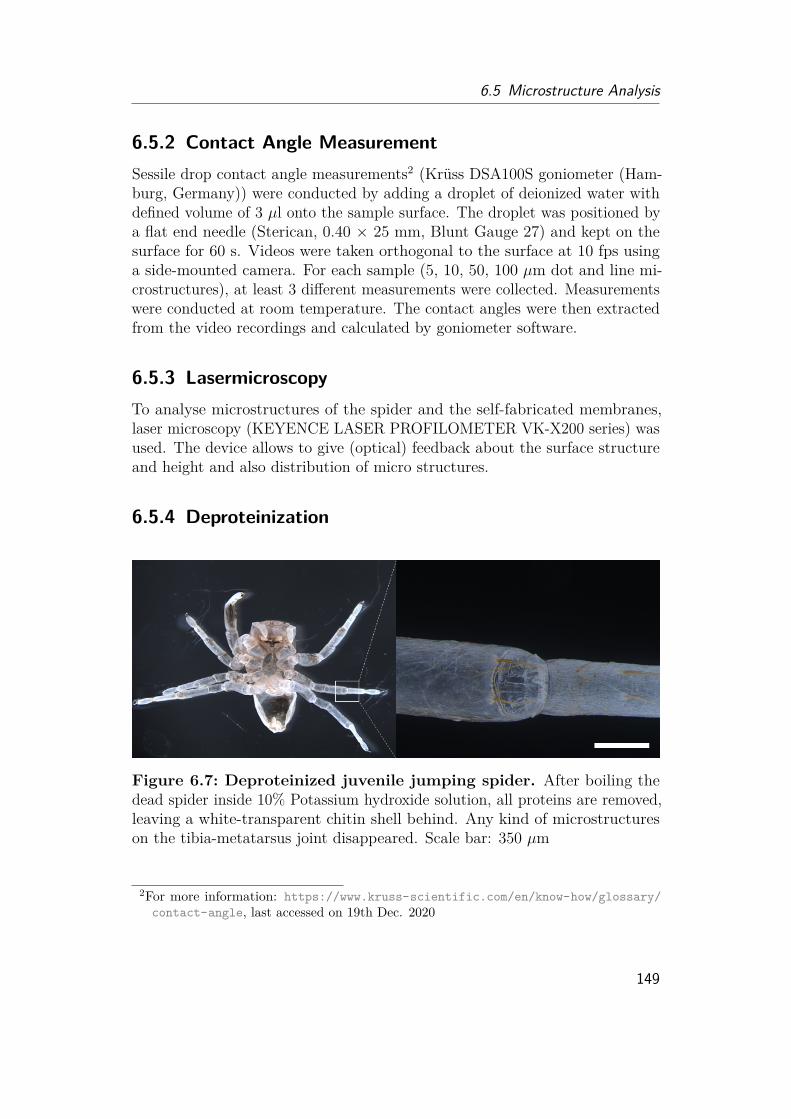
6.5 Microstructure Analysis
6.5.2 Contact Angle MeasurementSessile drop contact angle measurements2 (Krüss DSA100S goniometer (Ham-burg, Germany)) were conducted by adding a droplet of deionized water withdefined volume of 3 µl onto the sample surface. The droplet was positioned bya flat end needle (Sterican, 0.40 × 25 mm, Blunt Gauge 27) and kept on thesurface for 60 s. Videos were taken orthogonal to the surface at 10 fps usinga side-mounted camera. For each sample (5, 10, 50, 100 µm dot and line mi-crostructures), at least 3 different measurements were collected. Measurementswere conducted at room temperature. The contact angles were then extractedfrom the video recordings and calculated by goniometer software.
6.5.3 LasermicroscopyTo analyse microstructures of the spider and the self-fabricated membranes,laser microscopy (KEYENCE LASER PROFILOMETER VK-X200 series) wasused. The device allows to give (optical) feedback about the surface structureand height and also distribution of micro structures.
6.5.4 Deproteinization
Figure 6.7: Deproteinized juvenile jumping spider. After boiling thedead spider inside 10% Potassium hydroxide solution, all proteins are removed,leaving a white-transparent chitin shell behind. Any kind of microstructureson the tibia-metatarsus joint disappeared. Scale bar: 350 µm
2For more information: https://www.kruss-scientific.com/en/know-how/glossary/contact-angle, last accessed on 19th Dec. 2020
149
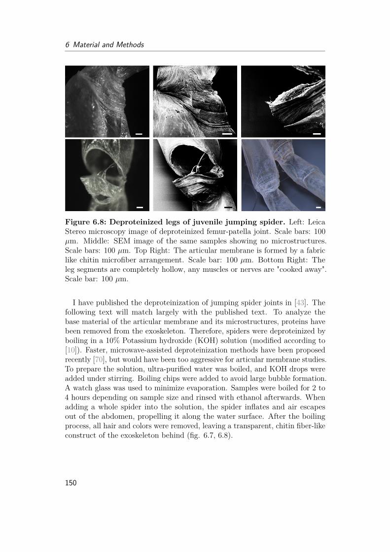
6 Material and Methods
Figure 6.8: Deproteinized legs of juvenile jumping spider. Left: LeicaStereo microscopy image of deproteinized femur-patella joint. Scale bars: 100µm. Middle: SEM image of the same samples showing no microstructures.Scale bars: 100 µm. Top Right: The articular membrane is formed by a fabriclike chitin microfiber arrangement. Scale bar: 100 µm. Bottom Right: Theleg segments are completely hollow, any muscles or nerves are "cooked away".Scale bar: 100 µm.
I have published the deproteinization of jumping spider joints in [43]. Thefollowing text will match largely with the published text. To analyze thebase material of the articular membrane and its microstructures, proteins havebeen removed from the exoskeleton. Therefore, spiders were deproteinized byboiling in a 10% Potassium hydroxide (KOH) solution (modified according to[10]). Faster, microwave-assisted deproteinization methods have been proposedrecently [70], but would have been too aggressive for articular membrane studies.To prepare the solution, ultra-purified water was boiled, and KOH drops wereadded under stirring. Boiling chips were added to avoid large bubble formation.A watch glass was used to minimize evaporation. Samples were boiled for 2 to4 hours depending on sample size and rinsed with ethanol afterwards. Whenadding a whole spider into the solution, the spider inflates and air escapesout of the abdomen, propelling it along the water surface. After the boilingprocess, all hair and colors were removed, leaving a transparent, chitin fiber-likeconstruct of the exoskeleton behind (fig. 6.7, 6.8).
150
6.6 Hemolymph Analysis
6.6 Hemolymph Analysis
6.6.1 Hemolymph Collection MethodWe started with the hemolymph of wolf spiders and crickets as I had only asmall amount of jumping spiders at this point and they were not all adultyet. For the wolf spiders we used a method, which is commonly used to gainhemolymph from Drosophila flies, by poking a tiny hole into the exoskeleton andcentrifuge the spider. The spider was shortly narcotized before. For crickets, thecentrifuge method was not suitable as the gut content would also be collected.Therefore we collected hemolymph from the legs for testing. Later, for the adultjumping spiders, centrifuging was also not used due to the gut content, insteadthe ventral side of the spider prosoma is known to contain a large amount ofhemolymph, where we collected it from (fig. 6.9). The amount of hemolymphwas thereby always only in the 10th of µl maximum which was not enough forshear measurements under the viscosimeter. We started with analyzing thespeed of micro beads inside the fluid. However, the fluid started to evaporateat the corners of the droplet influencing the observed speed, furthermore thismethod did not allow us to test the pressure-influence on the physical propertiesof hemolymph. In a next step we used thin glas capillaries attached to a suctionpump commonly used in cell biology and analyzed the speed of the fluid througha defined section with high speed camera and microscopy. This method wasimproved, by adding a pressure sensor and using micro channels instead of theglass capillaries at the end. The first experimental results seemed promising,however at this point we were only able to use channels with grooves for ourexperiments and the control measurements had too many outliers. With theleave of my colleague to Netherlands in November 2017, the project was hold onice until I was able to redesign and order a new mask for micro channels withoutthe grooves, fabricate my own silicon wavers using photolitography and cast thefinal PDMS micro channels myself. Shortly before I left to ETH, in September2018, I was able to collect hemolymph from adult jumping spiders and runthe experiments. In the meanwhile another research group was analyzing theviscosity values of the hemolymph of finger-sized Tabacco Hornworm caterpillarManduca sexta) in dependency of temperature. In contrast to our study, theywere able to use the viscosimeter as the amount of hemolymph in the largecaterpillar was much higher. They showed that with temperature increase, theviscosity of insect hemolymph viscosity decreases to 2-3 cP at room temperature.Although not in the focus of their study, the results further suggest a Non-Newtonian behavior of hemolymph, showing a slight decrease in viscosity withincrease in shear rate. However, they did not further investigate or discuss thisaspect and the value for spiders might be completely different.
151

6 Material and Methods
Figure 6.9: Hemolymph collection. Adult jumping spiders were narcotizedwith CO2 and attached to a Petridish with dental polymer. A small holeis poked into the soft attachment membrane between the last leg pair, thesternum and the petiole and flowing out hemolymph was collected. Hemolymphcollected from leg joints can show a darker color (as shown on the photography).Scale bar: 1 mm.
6.6.2 Microrheology
This method is only elaborated shortly, as it was not used as the final ap-proach. The movement of spherical polystyrene microbeads (Polysciences, Inc.,Washington, PA, USA; 0.99 ± 0.03 µm) inside the hemolymph sample wasobserved. For this purpose, microbeads were deposit onto a glasslide, a dropletof hemolymph sample was added and particle velocities tracked under the micro-scope. The microbead-glasslide was prepared according to standard protocols[6, 29]. The beads were washed to remove any surfactants and suspended inwater. The glasslide was treated with oxygen plasma (Diener Electronic Zepto,Ebhausen, Germany) to increase hydrophilicity to allow an easier spreadingof the water micro-particle drop (5 µl). The particles were flash frozen intoposition using liquid nitrogen and water was sublimated using a freeze dryer(Dieter Piatkowski Forschungsgeräte P4K Freeze Drier with JUMO IMAGOF3000 controller unit, Petershausen, Germany) to create a uniform particlemonolayer. For testing purposes droplets (20 µl) of water or cricket hemolymphwas used.
152
6.6 Hemolymph Analysis
6.6.3 AspirationIn a first attempt, thin glass capillaries (D = 0.3 mm) were used to mimic thecircular channels of spiders. The capillaries were attached to an aspirator (Inte-gra Bioscience 158300 Vacusafe Comfort Plus), commonly used for cellbiologicalpurposes. As the fluid tends to stay inside the glass, the glass capillaries weresilanized by bathing in water with three droplets of trichloro(perfluoroctyl)-silane (Sigma Aldrich, 448931) for 1h and baked in the 90◦oven for 30 min todry out water inside the glass capillary. Droplets of hemolymph were filledinto the capillary and by opening the valve, the fluid was sucked through theglas capillary. After several trials, even with longer capillaries or by placingthe droplet in front of the capillary, this method was discarded as it led tonon-laminar flow inside the glass capillary.Alternatively, micro channels were designed (length: 30mm, width: 1mm)
for photolitography. And molds with 70 µm depth were produced on a siliconwafer (see next subsection). The silicon wafer molds were used to create PDMSmicro channels. The ingredients for PDMS (Polydimethylsiloxan) were mixed(10:1, elastomer:hardener) with spatula for 1 min in a beaker. Trapped air wasremoved by vacuum pumping of the PDMS inside a dessicator for 15-20min.A plastic ring was fixed on a Petri dish with dental polymer to provide aborder for the PDMS infill (∼ 0.5 cm PDMS thickness) and PDMS was pouredover the silicone waver. If air is trapped inside the mold, vacuum treatmentcould help. Otherwise, any air bubbles on the surface were removed witha thin needle and PDMS was cured by baking at 90◦ for 1h. Afterwards,PDMS was carefully removed from the silicone wafer and excess material cutoff to receive a rectangular PDMS with the microchannel. Oxygen plasmatreatment (1 min exposure) was used to enhance the stickiness of PDMS onthe glass coverslide. Latter was used as the base of the microchannel. PDMSon the glasslide was baked inside the oven for 30 min. Circular endings ofthe microchannels were punctured with a needle and thin metal straws wereinserted (1 mm) for connection purposes. One side is connected to the aspirator,with a pressure sensor and the other side is used to pipette a droplet of 2 µl ofspider hemolymph which is sucked into the microchannel.
6.6.3.1 Photolithography Protocol
The SUSS MicroTec MJB4 Mask Aligner was used to fabricate molds withthe Photoresist SU8-50 on Silicon wafers (Siegert Wafers and P-type and<100>orientation). The following protocol was developed at the Max PlanckInstitute for Intelligent Systems, Physical Intelligence Department to fabricatemicrostructures or microchannels inside the clean room.
153
6 Material and Methods
Step 1: Cleaning and spin coatingSilicon wafers were cleaned in Acetone and then in Isopropanol alcohol for5 minutes each and carefully rinsed with DI water afterwards. Then, thesilicone wafer were placed on a hot plate(Precision hotplate Präzitherm) at250◦C for 10 min for dehydration baking (critical). After letting the wafercooling down to room temperature, it was placed onto the spin coater (LaurellWS-650-23NPP Modular Spin processor). Photoresist was dispensed in thecenter of the wafer and span at 1500rpm (Step 1: 500rpm, 5 sec, Step 2: 2500rpm 40 sec, acceleration 100 rpm, Step 3: 500 rpm, 5 sec). After carefullyremoving the silicon wafer and placed on the hot plate for pre-baking (first at65◦C for 10 min and slowly ramped up to 95◦C and leave for 30 min) excessmaterial on the inside of the spin coater was cleaned. The wafer was againcooled down to room temperature after pre-bakingStep 2: UV Expose
The desired photomask was load into the mask aligner. Using Vacuum contact ascontact mode, the photoresist coated wafer was exposed for 15 sec (Wavelengthof UV is 365 nm and Intensity is 13 mW/cm2)Step 3: Post bake and Develop
The silicon wafer was carefully removed and placed onto the hot plate (firstat 65◦C for 1 min and slowly ramped up to 95◦C and leave it for 10 min).After it cooled down to room temperature, the wafer is immersed in the mr-600developer with slight agitation (for 10 min) and afterwards carefully rinsed inIsopropanol for 2 min to remove any excess.Step 4: Hard bake
In the final step, the patterns were hard baked by placing the wafer again onthe hot plate for 30 min at 100◦C.
The thickness of the patters was measured using a Laser microscope afterwards.
6.6.4 CalculationConsidering a flowing, incompressible fluid and neglecting friction, the totalsum of energy along a streamline which keeps the fluid flowing remains constant.The sum of energy thereby consists of the following components: kinetic energyEkin, the potential energy Epot and the enthalpy H. Latter term can be splitapart into the inner energy U , which is heat dependent and the work W neededto overcome the pressure when moving a specific volume V of matter. Therefore
∑energy = Ekin + Epot +H
= Ekin + Epot + U +W
154
6.6 Hemolymph Analysis
= 12mv
2 +mgh+ U + PV (6.1)
= const .
By neglecting the inner energy U when neglecting thermal energy loss, theBernoulli principle describing the energy along a pipe can be derived by dividingthe term through mass m and the gravity constant g
∑energypipe = v2
2g + h+ P
g
V
m
= v2
2g + h+ P
gρfor ρ = m/V (6.2)
= const .
Looking at two points along a pipe for an incompressible fluid with the densityρ, the Bernoulli equation says:
v21
2g + h1 + P1
gρ= v2
22g + h2 + P2
gρ. (6.3)
This term, however, does not include the influence on pipe friction, which cancreate head loss HL between the two points, described by the Darcy-Weisbachequation:
HL = fD ·L
Dh
· v2
2g . (6.4)
Thereby fD describes the friction factor depending on the pipe materialfriction and the Reynolds number, L describes the distance between the twopoints, Dh the hydraulic diameter of the pipe, v the fluid velocity and g thegravity constant.Considering this head loss HL the fluid relationship (6.3) along the stream
line changes to:
v21
2g + h1 + P1
gρ= v2
22g + h2 + P2
gρ+HL
v21
2g + h1 + P1
gρ= v2
22g + h2 + P2
gρ+ fD ·
L
Dh
· v22
2g . (6.5)
In a horizontal pipe the height and velocity does not change along the pipe(h1 = h2, v1 = v2). Therefore the equation can be further reduced to describe
155

6 Material and Methods
the pressure gradient along the pipe.
P1
gρ= P2
gρ+ fD ·
L
Dh
· v2
2g
P1 − P2 = ∆P = fD ·Lρv2
2Dh
. (6.6)
In literature, this relation is often cited as the actual Darcy-Weisbach equationfor pipes and becomes relevant for our experiments, written in a slightly differentway:
∆PL
= fD ·ρ
2 ·v2
Dh
. (6.7)
describing the pressure gradient along a pipe with length L and hydraulicdiameter Dh for a fluid with density ρ and measured flow velocity v. Thepressure gradient thereby depends on the the pipe friction and Reynolds numberRe which is summarized in the Darcy friction coefficient fD [118, 126] as
fD = β
Re(6.8)
Re = ρ
µ· v ·Dh. (6.9)
The Reynolds number differs with the fluid velocity v, density ρ and viscosityµ as well as the the shape of the pipe. In a rectangular micro channel, β is not64, as commonly used for laminar flow, but can be calculated from
β = 24 · (1− 1.3553α + 1.9467α2− (6.10)1.7012α3 + 0.9564α4 − 0.2537α5)
α = H
W, (6.11)
with α given as the ratio between height H and width W. For slit-shapedchannels with a large width and a small height, β is close to 24. Furthermore,the hydraulic diameter Dh is defined as
Dh = 4AU
, (6.12)
with A describing the cross-sectional area of the flow and U the wetted perimeterof the cross-section. For a rectangular channel with height H and width W, the
156

6.6 Hemolymph Analysis
hydraulic diameter is therefore
Dh = 4(W ·H)2(W +H)
= 2(W ·H)(W +H)
≈ 2 ·H for W >> H . (6.13)
To analyze the experimental data based on velocity, measured at differentpressure gradients, the Darcy-Weisbach equation needs to be reformulated intothe terms of shear stress and shear rate. The relation of the pressure and wallshear stress τw is given by
∆P · Across = τw · Awall∆P ·W ·H = τw · 2 · (WL+HL)
≈ τw · 2 · (WL) for W >> H (6.14)∆PL
= τw ·2(W +H)W ·H
∆PL
= τw ·4Dh
τw ≈∆P ·H
2 · L for W >> H . (6.15)
Integrating this relationship into the Darcy-Weisbach equation (6.7), it follows
∆PL
= fD ·ρ
2 ·v2
Dh
∆P ·Dh
4 · L = τw = fD ·ρ · v2
8
= β
Re· ρ · v
2
8
= β · µρ · v ·Dh
· ρ · v2
8
= µ · β · v8 ·Dh
τw = µ · γa , (6.16)
where γa describes the apparent shear rate for Newtonian fluids, normallydefined via the Hagen-Poiseuille relation. The more generic Ostwald-de Waeleequation describes the relation between shear stress and shear rate, also includ-
157
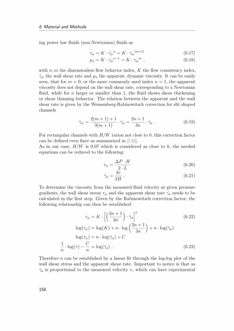
6 Material and Methods
ing power law fluids (non-Newtonian) fluids as
τw = K · γwn = K · γw(m+1) (6.17)µa = K · γwn−1 = K · γwm , (6.18)
with n,m the dimensionless flow behavior index, K the flow consistency index,γw the wall shear rate and µa the apparent, dynamic viscosity. It can be easilyseen, that for m = 0, or the more commonly used index n = 1, the apparentviscosity does not depend on the wall shear rate, corresponding to a Newtonianfluid, while for n larger or smaller than 1, the fluid shows shear thickeningor shear thinning behavior. The relation between the apparent and the wallshear rate is given by the Weissenberg-Rabinowitsch correction for slit shapedchannels
γw = 2(m+ 1) + 13(m+ 1) · γa = 2n+ 1
3n · γa . (6.19)
For rectangular channels with H/W ration not close to 0, this correction factorcan be defined even finer as summarized in [126].As in our case, H/W is 0.07 which is considered as close to 0, the neededequations can be reduced to the following:
τw = ∆P ·H2 · L (6.20)
γa = 3v2H . (6.21)
To determine the viscosity from the measured fluid velocity at given pressuregradients, the wall shear stress τw and the apparent shear rate γa needs to becalculated in the first step. Given by the Rabinowitsch correction factor, thefollowing relationship can then be established:
τw = K ·[(2n+ 1
3n
)· γa
]n(6.22)
log(τw) = log(K) + n · log(2n+ 1
3n
)+ n · log(γa)
log(τw) = n · log(γa) + C
1n· log(τ)− C
n= log(γa) . (6.23)
Therefore n can be established by a linear fit through the log-log plot of thewall shear stress and the apparent shear rate. Important to notice is that asγa is proportional to the measured velocity v, which can have experimental
158
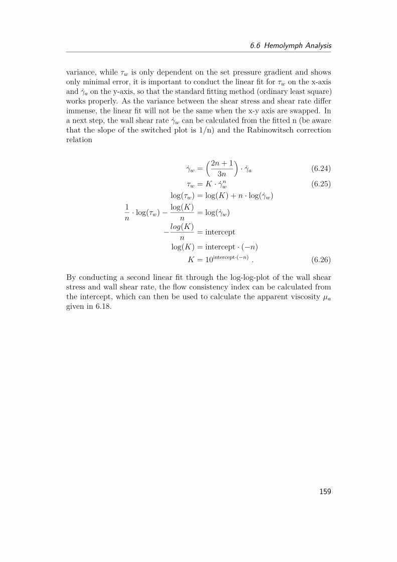
6.6 Hemolymph Analysis
variance, while τw is only dependent on the set pressure gradient and showsonly minimal error, it is important to conduct the linear fit for τw on the x-axisand γa on the y-axis, so that the standard fitting method (ordinary least square)works properly. As the variance between the shear stress and shear rate differimmense, the linear fit will not be the same when the x-y axis are swapped. Ina next step, the wall shear rate γw can be calculated from the fitted n (be awarethat the slope of the switched plot is 1/n) and the Rabinowitsch correctionrelation
γw =(2n+ 1
3n
)· γa (6.24)
τw = K · γnw (6.25)log(τw) = log(K) + n · log(γw)
1n· log(τw)− log(K)
n= log(γw)
− log(K)n
= intercept
log(K) = intercept · (−n)K = 10intercept·(−n) . (6.26)
By conducting a second linear fit through the log-log-plot of the wall shearstress and wall shear rate, the flow consistency index can be calculated fromthe intercept, which can then be used to calculate the apparent viscosity µagiven in 6.18.
159
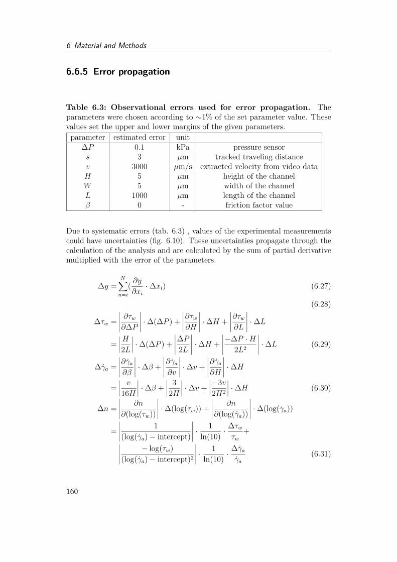
6 Material and Methods
6.6.5 Error propagation
Table 6.3: Observational errors used for error propagation. Theparameters were chosen according to ∼1% of the set parameter value. Thesevalues set the upper and lower margins of the given parameters.parameter estimated error unit
∆P 0.1 kPa pressure sensors 3 µm tracked traveling distancev 3000 µm/s extracted velocity from video dataH 5 µm height of the channelW 5 µm width of the channelL 1000 µm length of the channelβ 0 - friction factor value
Due to systematic errors (tab. 6.3) , values of the experimental measurementscould have uncertainties (fig. 6.10). These uncertainties propagate through thecalculation of the analysis and are calculated by the sum of partial derivativemultiplied with the error of the parameters.
∆y =N∑n=i
( ∂y∂xi·∆xi) (6.27)
(6.28)
∆τw =∣∣∣∣∣ ∂τw∂∆P
∣∣∣∣∣ ·∆(∆P ) +∣∣∣∣∣∂τw∂H
∣∣∣∣∣ ·∆H +∣∣∣∣∣∂τw∂L
∣∣∣∣∣ ·∆L=∣∣∣∣H2L
∣∣∣∣ ·∆(∆P ) +∣∣∣∣∣∆P2L
∣∣∣∣∣ ·∆H +∣∣∣∣∣−∆P ·H
2L2
∣∣∣∣∣ ·∆L (6.29)
∆γa =∣∣∣∣∣∂γa∂β
∣∣∣∣∣ ·∆β +∣∣∣∣∣∂γa∂v
∣∣∣∣∣ ·∆v +∣∣∣∣∣∂γa∂H
∣∣∣∣∣ ·∆H=∣∣∣∣ v
16H
∣∣∣∣ ·∆β +∣∣∣∣ 32H
∣∣∣∣ ·∆v +∣∣∣∣−3v2H2
∣∣∣∣ ·∆H (6.30)
∆n =∣∣∣∣∣ ∂n
∂(log(τw))
∣∣∣∣∣ ·∆(log(τw)) +∣∣∣∣∣ ∂n
∂(log(γa))
∣∣∣∣∣ ·∆(log(γa))
=∣∣∣∣∣ 1(log(γa)− intercept)
∣∣∣∣∣ · 1ln(10) ·
∆τwτw
+∣∣∣∣∣ − log(τw)(log(γa)− intercept)2
∣∣∣∣∣ · 1ln(10) ·
∆γaγa
(6.31)
160

6.6 Hemolymph Analysis
∆γw =∣∣∣∣∣∂γw∂n
∣∣∣∣∣ ·∆n+∣∣∣∣∣∂γw∂γa
∣∣∣∣∣ ·∆γa=∣∣∣∣(−1
3n2
)· γa
∣∣∣∣ ·∆n+∣∣∣∣2n+ 1
3n
∣∣∣∣ ·∆γa (6.32)
∆(log(K)) = 1(ln(10)) ·
∆KK
∆(log(K)) =∣∣∣∣∣∂(log(K))∂(log(τw))
∣∣∣∣∣ ·∆(log(τw))+∣∣∣∣∣ ∂(log(K))∂(log(γw))
∣∣∣∣∣ ·∆(log(γw))+∣∣∣∣∣∂(log(K))∂n
∣∣∣∣∣ ·∆n= 1
ln(10) ·∆τwτw
+ | − n| · 1ln(10) ·
∆γwγw
+ | − log(γw)| ·∆n (6.33)
∆µa =∣∣∣∣∣ ∂µ∂γw
∣∣∣∣∣ ·∆γw +∣∣∣∣∣∂µ∂n
∣∣∣∣∣ ·∆n+∣∣∣∣∣ ∂µ∂K
∣∣∣∣∣ ·∆K=∣∣∣(n− 1)Kγn−2
w
∣∣∣ ·∆γw +∣∣∣K · ln(γw) · γ(n−1)
w
∣∣∣ ·∆n+∣∣∣γ(n−1)w
∣∣∣ ·∆K (6.34)
Figure 6.10: Error propagation with individual error values. Whenconsidering single error values per each measurement point, larger values wouldresult in larger errors. For experimental discussions, it is assumed that thesystematic error is the same throughout all measurement points (fig. 3.27,3.26). The median of the here plotted single calculated errors was chosen asvalue to reflect the general systematic viscosity error.
161

6 Material and Methods
6.7 Design and Fabrication of Actuator6.7.1 Robotic Design and FabricationI have published the robotic design and fabrication of the spider-inspired jointdesign in [43]. The following text will match largely to the published text.3D modeling was first performed with Solidworks, but to optimize fabricationand 3D printing results, Autodesk Fusion 360 was used in the final design.Construction was made according to 3D observations of the spider femur-patellajoint. The models were sliced using the Ultimaker software CURA for the3D FDM printer (Creality Ender-3 Pro) to generate the machine Gcode for3D printing. Printing parameters can be found in tab. 6.4. The chosen TPUfilament (EoFlex by EOLAS, Reference 1009600000) has a tensile strength of 40MPa and a shore hardness of 94A. To improve performance for flexible materialprints, the bowden extruder was moved directly on top of the printing head.For flexing the actuator, fishing yarn (0.12 mm, Spiderwire, Stealth Smooth 8)was used. To seal irregularities of the 3D print Latex milk (Laguna, naturalliquid latex rubber, low ammonia (<0.3%), 60% solid content) was filled insidethe chamber and cured for 30 min at 50◦ in the oven, to form a thin layer.
Table 6.4: 3D printing parameters. Published in [43]. Parameters usedfor fused deposition modeling (FDM) with Creality Ender-3 Pro. 3D modeldesigned in Autodesk Fusion 360 and stl-file directly exported to CURA (Ulti-maker). The software slices the model and generates G-codes for 3D printing.Parameter Value Unit R-value p-valueLayer Height 0.2 mm 0.931 <2.2e-16Wall Thickness 1.0 mm 0.890 <2.2e-16Print Thin Walls Enabled - 0.795 <2.2e-16Infill Density 100 % 0.905 <2.2e-16Infill Pattern Concentric -Printing Temperature 205 °CBuild Plate Temperature 25 °C 0.750 1.2e-15Flow 100-150 % 0.576 2.9e-07Print Speed 50.0 mm/s 0.520 6.0e-14Retraction Disabled - 0.627 1.6e-12Fan Speed 100-120 mm/sBuild Plate Adhesion Type Skirt
162

6.7 Design and Fabrication of Actuator
6.7.2 Previous tested Fabrication Methods and MaterialsSeveral materials and methods were tested for fabrication and sealing purposesas listed in tab. 6.5 and tab. 6.6.
6.7.3 Characterization
Figure 6.11: Experimental setup of characterization measurements.Published in [43]. Left: Experimental set-up for prototype characterizationincludes, the prototype with red tracking markers (1), a rotating flexing mech-anism (2), a force sensor (3), a pressure sensor (4), a connection for a syringeto increase pressure (5), an Arduino Uno for sensor processing (6), a computerfor recording (7), a remote control for changing into calibration mode (8) anda camera, recording folding angle (9). Top middle: 3D model of spider-joint-inspired actuator prototype is printed in vertical direction (femur to patella)to avoid support material inside the chamber. Bottom middle: The flexingmechanism consists of an inner latex bladder that inflates and collects thewater, when the leg is flexed. Right: Bowden extruder head was rebuilt todirect extrusion, allowing better 3D printing of flexible material as rubbermaterial show discontinued material pushing due to its elasticity properties.
I have published the experimental set-up for the characterization of the spider-inspired joint design in [43]. The following text will match largely to thepublished text. For the folding behavior and durability test, the flexing wirewas attached to a 12 V-stepper motor (NEMA 17) and flexing runs (2 x500 cycles) for each leg were performed (run time: 2 s/ cycle). For flexingcharacterization, an experimental set-up was 3D printed (PLA), including aload sensor platform and a rotational flexing chamber. A force sensor (5 kg
163

6 Material and Methods
Table 6.5: Tested materials and fabrication methods. Several materialsand fabrication methods were tested to investigate the most promising approachfor a spider-inspired 3D prototype. The table summarizes observations andlimitations of tested methods. Published in [43].
Material CommentTextile · If not water repellent, sealing with different methods as wax or
glue necessary· Limitation: thick material, stiffness variance by creating inletswith e.g. metal sticks as in stroller sunshades is time consumingand not scalable, high friction
PE foil · Cheap· Bags can be formed using heat or glue· Good prototyping material· limitation in (air) pressure and sealing
Other foils Nylon· Stitching, laser or glue processing· Limitations: sealing issuesFoil balloons· Easy processing material with heat· Limitation: only one side can be heat treated
Silicon · Not for fast prototyping due to time consuming molding/casting· Pressure resistance (“blowing up”) and thinness might be limited· Good sealing quality· Useful as comparative material for future work for given design· 3D printing techniques are now evolving
Latex · Not for fast prototyping due to time consuming molding/casting· Pressure resistance (“blowing up”) and thinness might be limited· Good sealing quality, can be resealed· Useful as comparative material for future work for given design
Carbon fiber · Time consuming in fabrication· Too thick or not flexible enough for desired purposes
Paper · Complex 3D shapes by origami techniques· Easy processing for “quick and dirty” prototype testing· Limitation: Sealing, fractures forming after several usage· Might be useful in combination with a good sealing material
Tango Black · Flexible, but sticky· High resolution and two material printing due to PolyJet tech-nique possible· Not completely sealed· Limitation in thinness, rips easily during 3D print cleaning, non-water-soluble support material leads to time consuming washing· Useful as comparative material for future work for given design
TPU · Available for FDM 3D printing, allowing fast prototyping andcomplex shapes· Comparatively cheap flexible material and fabrication method· Limitation: 3D printing set-up not fully evolved, can differhighly from 3D printer type, 3D prints need to be fully sealed asirregularities can occur
164
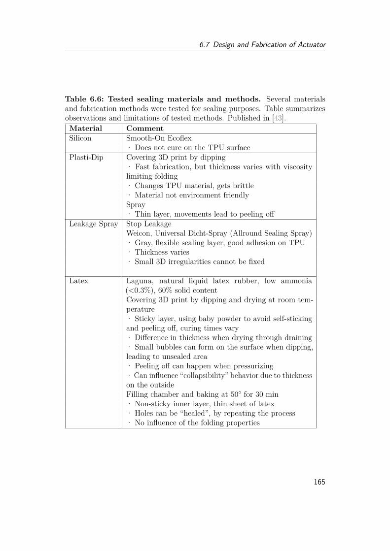
6.7 Design and Fabrication of Actuator
Table 6.6: Tested sealing materials and methods. Several materialsand fabrication methods were tested for sealing purposes. Table summarizesobservations and limitations of tested methods. Published in [43].Material CommentSilicon Smooth-On Ecoflex
· Does not cure on the TPU surfacePlasti-Dip Covering 3D print by dipping
· Fast fabrication, but thickness varies with viscositylimiting folding· Changes TPU material, gets brittle· Material not environment friendlySpray· Thin layer, movements lead to peeling off
Leakage Spray Stop LeakageWeicon, Universal Dicht-Spray (Allround Sealing Spray)· Gray, flexible sealing layer, good adhesion on TPU· Thickness varies· Small 3D irregularities cannot be fixed
Latex Laguna, natural liquid latex rubber, low ammonia(<0.3%), 60% solid contentCovering 3D print by dipping and drying at room tem-perature· Sticky layer, using baby powder to avoid self-stickingand peeling off, curing times vary· Difference in thickness when drying through draining· Small bubbles can form on the surface when dipping,leading to unsealed area· Peeling off can happen when pressurizing· Can influence “collapsibility” behavior due to thicknesson the outsideFilling chamber and baking at 50° for 30 min· Non-sticky inner layer, thin sheet of latex· Holes can be “healed”, by repeating the process· No influence of the folding properties
165
6 Material and Methods
load cell with HX711 AD amplifier) and pressure sensor (30 PSI, ∼ 200 kPa,stainless steel, GS01525, DC-5V) attached to an Arduino Uno (fig. 6.11) wereused to measure load and pressure. Before every measurement, the force andpressure sensor were calibrated. The flexing mechanism consisted of a waterreservoir with a Latex inner bladder, which fills up when the joins fold. Duringflexing, the wire rolls around the cylinder. By releasing the wire, the bladderis pushed by an inner cylinder, so that the water fills the joint. As flexingwire, a fishing yarn (Spiderwire, Stealth Smooth 8) was used to avoid curling.This rotational flexing mechanism has to be further tested in future, to allowhigher pressure (failure in latex bladder connection at pressures above 50 kPa).Tracking markers were attached to the leg and the base (fixation) and the legmovement was recorded. The tracking angle was analyzed using the softwareTracker (physlets.org/tracker/). The video and the sensor measurement weresynchronized by hitting the force sensor with a pen to achieve a visual signalthat could be correlated to a spike in the force sensors. Legs were flexedand released slowly (6 experimental runs) and suddenly (4 experimental runs)by detaching the wire from the flexing mechanism. For characterization ofthe extension property a hinge platform (fig. 4.15) was 3D printed (PLA).Legs were hold in the stable positions (40◦, 75◦, 100◦, 125◦) and pressure wasincreased with a syringe up to 200-300 kPa. The load was recorded. For eachposition, 3 experimental runs were conducted. At position 75◦, tube leakageoccurred during one experimental run and was therefore excluded from analyses.Position 100◦ was tested 5 times in total as it was considered as the criticalposition for jumping and lifting experiments. All sensors (pressure sensor: 100PSI, ∼690 kPa; load cell: 5 kg, ∼50 N) were attached to an Arduino Uno.Leakages through tube connections were minimized by shorter PVC tubes andpush-in tube connectors. As commonly done for hydraulic systems, pressuresensor attachment sealing was improved by roughening the tube connectorthread and covering it with PTFE tape.
6.7.4 Jumping Performance EstimationI have published the jumping performance estimation of the spider-inspiredprototype in [43]. The following text will match largely to the published text.Pressure is defined as the force acting on a surface area. To estimate theload - pressure behavior of our system, a constant contact area at each stableposition (fig. 4.15) was assumed, resulting in a proportional increase of loadwith pressure. Linear fits through the experimental data at each stable positionhave been carried out (tab. 6.7). Displayed linear functions show linear fits (fig.4.16) with a mean slope of 0.013 N/kPa, corresponding to a contact surface of13 mm2. This surface would match to the surface at the entry of the chamber,
166

6.7 Design and Fabrication of Actuator
Table 6.7: Linear fit for load-pressure behavior estimation Publishedin [43]position (°) fixed intercept (N) fitted slope (N/kPa) R-value p-value40 1.5 0.017 0.931 <2.2e-1675 3.5 0.012 0.890 <2.2e-16100 6.0 0.012 0.795 <2.2e-16125 10.0 0.012 0.905 <2.2e-16
mean 0.01311004fitted intercept
40 1.47 0.017 0.750 1.2e-1575 4.29 0.007 0.576 2.9e-07100 5.89 0.012 0.520 6.0e-14125 10.57 0.009 0.627 1.6e-12
were water supply is connected to. Further studies of this surface area haveto be done in following works. The mean slope value was used to calculatethe load at 200 kPa and the resulting work, mirrored by the sum of the areabelow the curve (W1, W2, W3, W4) (fig. 4.17). The resulting work shows aquadratic behavior with opening distance as
W = 105.86s2 + 1.6731s . (6.35)
As the work is the integral of force over distance, a linear force-distancebehavior, would explain this quadratic function and shows that the initialflexing position s of the legs have a great impact on the jumping performance.This formula was used to estimate the jumping height, whereby the workcreated by the elastic material was subtracted as it is needed to just lift theplatform. The elastic work for four legs lies between 0.17 Nm to 0.42 Nmfor legs flexed between positions 75◦ and 100◦. For calculation purposes, themean-value (0.30 Nm) was used. The work left after deduction was treated aspotential energy of the system, to estimate the jumping height as
h = ∆Wmg
. (6.36)
6.7.5 Material Behavior ComparisonI have published the material behavior comparison of TPU und spider cutcilein [43]. The following text will match largely to the published text. The chosen
167
6 Material and Methods
TPU filament shows a Shore Hardness of 94A, which corresponds to a Young’smodulus E of approximately 0.005GPa (4.8 MPa) from
E = e(ShoreA·0.0235−0.6403) . (6.37)
For comparison, to achieve the same displacement s when bending two beams,one with the measured stiffness of spider membrane (5 GPa) and one with thestiffness of TPU (5 MPa), keeping length L, width b and applied force F of thebeams the same, the thickness d of the TPU beam has to be 10 times higherthan the spider membrane, computed from:
s = −4L3
Ed3bF. (6.38)
Assuming the measured stiffness for the articular membrane could be 10times lower under hydrated condition, it would still result in a ratio of 5. Thismeans, to fabricate a membrane similar in the length scale of jumping spiders,a thickness of 250 µm of TPU membrane is needed to be comparable in itsbending behavior to a 50 µm thick spider membrane.
168

Bibliography
[1] Formula Book for Hydraulics and Pneumatics. Fluid and Mechanical Engi-neering Systems Department of Management and Engineering, LinköpingUniversity, 2008. https://people.utm.my/shamsul/wp-content/blogs.dir/949/files/2015/11/FormulaBook_HydraulicsPneum.pdf.
[2] Functional differentiation of spider hemocytes by light and transmissionelectron microscopy, and {MALDI}-{MS}-imaging. Developmental &Comparative Immunology, 43(1):59–67, mar 2014. URL http://www.sciencedirect.com/science/article/pii/S0145305X13002991.
[3] B. Aberle, R. Jemmali, and J.-H. Dirks. Effect of sample treatmenton biomechanical properties of insect cuticle. Arthropod structure &development, 46(1):138–146, 2017.
[4] M. F. Ahamed and S. Chauhan. Hydraulic actuator systems with non-newtonian working fluid. Bonfring International Journal of IndustrialEngineering and Management Science, 6(4):135–139, 2016.
[5] J. Allen. Design and application of external power and control of orthoticdevices. Rancho Los Amigos Hospital, 1962.
[6] G. J. Amador, T. Endlein, and M. Sitti. Soiled adhesive pads shear cleanby slipping: a robust self-cleaning mechanism in climbing beetles. Journalof The Royal Society Interface, 14(131):20170134, 2017.
[7] J. Anderson and K. Prestwich. The fluid pressure pumps of spiders(chelicerata, araneae). Zeitschrift für Morphologie der Tiere, 81(4):257–277, 1975.
[8] S. A. Arnold, S. Albiez, A. Bieri, A. Syntychaki, R. Adaixo, R. A. McLeod,K. N. Goldie, H. Stahlberg, and T. Braun. Blotting-free and losslesscryo-electron microscopy grid preparation from nanoliter-sized proteinsamples and single-cell extracts. Journal of Structural Biology, 197(3):220–226, 2017.
169
https://people.utm.my/shamsul/wp-content/blogs.dir/949/files/2015/11/FormulaBook_HydraulicsPneum.pdf
Bibliography
[9] S. A. Arnold, S. A. Müller, C. Schmidli, A. Syntychaki, L. Rima,M. Chami, H. Stahlberg, K. N. Goldie, and T. Braun. Miniaturizing emsample preparation: Opportunities, challenges, and “visual proteomics”.Proteomics, 18(5-6):1700176, 2018.
[10] F. G. Barth. Microfiber reinforcement of an arthropod cuticle. Zeitschriftfür Zellforschung und Mikroskopische Anatomie, 144(3):409–433, 1973.
[11] N. W. Bartlett, M. T. Tolley, J. T. Overvelde, J. C. Weaver, B. Mosadegh,K. Bertoldi, G. M. Whitesides, and R. J. Wood. A 3d-printed, functionallygraded soft robot powered by combustion. Science, 349(6244):161–165,2015.
[12] K. Bett and J. Cappi. Effect of pressure on the viscosity of water. Nature,207(4997):620–621, 1965.
[13] C. M. Biancardi, C. G. Fabrica, P. Polero, J. F. Loss, and A. E. Minetti.Biomechanics of octopedal locomotion: kinematic and kinetic analysis ofthe spider grammostola mollicoma. Journal of Experimental Biology, 214(20):3433–3442, 2011.
[14] R. Blickhan and F. G. Barth. Strains in the exoskeleton of spiders.Journal of Comparative Physiology A, 157(1):115–147, 1985.
[15] R. Blickhan, S. Petkun, T. Weihmann, and M. Karner. Schnelle bewe-gungen bei arthropoden: Strategien und mechanismen. In AutonomesLaufen, pages 19–45. Springer, 2005.
[16] V. Böhm, L. Zentner, and N. Turkevi-Nagy. Stoffschlüssige gelenke nachbiologischem vorbild. Proceedings of the Wissenschaftliche Mitteilungender, 14:19–27, 2002.
[17] L. Bohmann and R. Blickhan. Der hydraulische mechanismus des sprungeseiner spinne. Forschung im Ingenieurwesen, 63(7-8):224–230, 1997.
[18] N. Booster, F. Su, S. Adolph, and A. Ahn. Effect of temperature on legkinematics in sprinting tarantulas (aphonopelma hentzi): high speed maylimit hydraulic joint actuation. Journal of Experimental Biology, 218(7):977–982, 2015.
[19] C. Bordereau. Ultrastructure and formation of the physogastric termitequeen cuticle. Tissue and cell, 14(2):371–396, 1982.
170
Bibliography
[20] J. Breuninger, R. Becker, A. Wolf, S. Rommel, and A. Verl. GenerativeFertigung mit Kunststoffen: Konzeption und Konstruktion für SelektivesLasersintern. Springer-Verlag, 2012.
[21] R. Briceño and W. Eberhard. Spiders avoid sticking to their webs:clever leg movements, branched drip-tip setae, and anti-adhesive surfaces.Naturwissenschaften, 99(4):337–341, 2012.
[22] M. Burrows and G. P. Sutton. Locusts use a composite of resilin andhard cuticle as an energy store for jumping and kicking. Journal ofExperimental Biology, 215(19):3501–3512, 2012.
[23] M. Burrows, S. R. Shaw, and G. P. Sutton. Resilin and chitinous cuticleform a composite structure for energy storage in jumping by froghopperinsects. BMC biology, 6(1):41, 2008.
[24] A. Cecilia, A. Rack, P.-A. Douissard, T. Martin, T. dos Santos Rolo,P. Vagovič, E. Hamann, T. van de Kamp, A. Riedel, M. Fiederle, et al.Lpe grown lso: Tb scintillator films for high-resolution x-ray imaging ap-plications at synchrotron light sources. Nuclear Instruments and Methodsin Physics Research Section A: Accelerators, Spectrometers, Detectorsand Associated Equipment, 648:S321–S323, 2011.
[25] Y. Chen, H. Chung, B. Chen, B. Baoyinjiya, and Y. Sun. A lobster-inspired bending module for compliant robotic applications. Bioinspira-tion & Biomimetics, 2020.
[26] Y.-K. Chen, C.-P. Liao, F.-Y. Tsai, and K.-J. Chi. More than a safety line:jump-stabilizing silk of salticids. Journal of The Royal Society Interface,10(87):20130572, 2013.
[27] Z. Chen, R. T. Corlett, X. Jiao, S.-J. Liu, T. Charles-Dominique, S. Zhang,H. Li, R. Lai, C. Long, and R.-C. Quan. Prolonged milk provisioning ina jumping spider. Science, 362(6418):1052–1055, 2018.
[28] Y. T. Cheng, D. Rodak, C. Wong, and C. Hayden. Effects of micro-andnano-structures on the self-cleaning behaviour of lotus leaves. Nanotech-nology, 17(5):1359, 2006.
[29] C. J. Clemente, J. M. Bullock, A. Beale, and W. Federle. Evidence forself-cleaning in fluid-based smooth and hairy adhesive systems of insects.Journal of Experimental Biology, 213(4):635–642, 2010.
171
Bibliography
[30] J. Culin and M. L. Goodnight. Arachnid respiration, 2018. https://www.britannica.com/animal/arachnid/Respiration.
[31] Z. S. Davidson, H. Shahsavan, A. Aghakhani, Y. Guo, L. Hines, Y. Xia,S. Yang, and M. Sitti. Monolithic shape-programmable dielectric liquidcrystal elastomer actuators. Science advances, 5(11):eaay0855, 2019.
[32] R. Deimel and O. Brock. A novel type of compliant and underactuatedrobotic hand for dexterous grasping. The International Journal of RoboticsResearch, 35(1-3):161–185, 2016.
[33] S. M. Doucet and M. G. Meadows. Iridescence: a functional perspective.Journal of The Royal Society Interface, 6, 2009.
[34] D.-M. Drotlef, M. Amjadi, M. Yunusa, and M. Sitti. Bioinspired compositemicrofibers for skin adhesion and signal amplification of wearable sensors.Advanced materials, 29(28):1701353, 2017.
[35] C. Ellis. The mechanism of extension in the legs of spiders. The biologicalbulletin, 86(1):41–50, 1944.
[36] H. Faraji, R. Tachella, and R. L. Hatton. Aiming and vaulting: Spiderinspired leaping for jumping robots. In 2016 IEEE International Con-ference on Robotics and Automation (ICRA), pages 2082–2087. IEEE,2016.
[37] R. Foelix. Biology of spiders. OUP USA, 2011.
[38] S. Franz-Guess, B.-J. Klußmann-Fricke, C. S. Wirkner, L. Prendini, andJ. M. Starck. Morphology of the tracheal system of camel spiders (che-licerata: Solifugae) based on micro-ct and 3d-reconstruction in exemplarspecies from three families. Arthropod structure & development, 45(5):440–451, 2016.
[39] D. D. Gaffin, L. A. Bumm, M. S. Taylor, N. V. Popokina, and S. Mann.Scorpion fluorescence and reaction to light. Animal Behaviour, 83(2):429–436, 2012.
[40] I. Gaiser, S. Schulz, A. Kargov, H. Klosek, A. Bierbaum, C. Pylatiuk,R. Oberle, T. Werner, T. Asfour, G. Bretthauer, et al. A new anthropo-morphic robotic hand. In Humanoids 2008-8th IEEE-RAS InternationalConference on Humanoid Robots, pages 418–422. IEEE, 2008.
172
Bibliography
[41] I. Gaiser, S. Schulz, H. Breitwieser, and G. Bretthauer. Enhanced flexiblefluidic actuators for biologically inspired lightweight robots with inherentcompliance. In 2010 IEEE International Conference on Robotics andBiomimetics, pages 1423–1428. IEEE, 2010.
[42] I. Gaiser, R. Wiegand, O. Ivlev, A. Andres, H. Breitwieser, S. Schulz, andG. Bretthauer. Compliant robotics and automation with flexible fluidicactuators and inflatable structures. In Smart Actuation and SensingSystems-Recent Advances and Future Challenges. IntechOpen, 2012.
[43] C. Göttler, K. Elflein, R. Siegwart, and M. Sitti. Spider origami: Foldingprinciple of jumping spider leg joints for bioinspired fluidic actuators.Advanced Science, 8(5):2003890, 2021.
[44] M. J. Hancock, K. Sekeroglu, and M. C. Demirel. Bioinspired direc-tional surfaces for adhesion, wetting, and transport. Advanced functionalmaterials, 22(11):2223–2234, 2012.
[45] X. Hao, W. Ma, C. Liu, Y. Li, Z. Qian, L. Ren, and L. Ren. Analysisof spiders’ joint kinematics and driving modes under different groundconditions. Applied Bionics and Biomechanics, 2019, 2019.
[46] D. P. Harland and R. R. Jackson. Eight-legged cats and how they see:A review of recent research on jumping spiders (araneae: Salticidae).Cimbebasia, 16:231–240, 2000.
[47] A. C. Hawthorn and B. D. Opell. van der waals and hygroscopic forces ofadhesion generated by spider capture threads. Journal of ExperimentalBiology, 206(22):3905–3911, 2003.
[48] D. E. Hill. The behavior of eris militaris (araneae: Slaticidae). Peckhamia,24:1–8, 1996.
[49] D. E. Hill. Jumping spiders in outer space (araneae: Salticidae). Peck-hamia, 146:1–7, 2016.
[50] K. Huckstorf, G. Kosok, E.-A. Seyfarth, and C. S. Wirkner. Thehemolymph vascular system in cupiennius salei (araneae: Ctenidae).Zoologischer Anzeiger-A Journal of Comparative Zoology, 252(1):76–87,2013.
[51] A. Iouguina, J. Dawson, B. Hallgrimsson, and G. Smart. Biologicallyinformed disciplines: a comparative analysis of bionics, biomimetics,biomimicry, and bio-inspiration among others. International Journal ofDesign & Nature and Ecodynamics, 9(3):197–205, 2014.
173

Bibliography
[52] A.-C. Joel, M. Meyer, J. Heitz, A. Heiss, D. Park, H. Adamova, andW. Baumgartner. Biomimetic combs as antiadhesive tools to manipulatenanofibers. ACS Applied Nano Materials, 3(4):3395–3401, 2020.
[53] K. Jürgens and G. Gros. Phylogeny of gas exchange systems. Anasthesi-ologie, Intensivmedizin, Notfallmedizin, Schmerztherapie: AINS, 37(4):185, 2002.
[54] A. Kargov, T. Werner, C. Pylatiuk, and S. Schulz. Development of aminiaturised hydraulic actuation system for artificial hands. Sensors andActuators A: Physical, 141(2):548–557, 2008.
[55] N. Kellaris, V. G. Venkata, G. M. Smith, S. K. Mitchell, and C. Keplinger.Peano-hasel actuators: Muscle-mimetic, electrohydraulic transducers thatlinearly contract on activation. Science Robotics, 3(14):eaar3276, 2018.
[56] M. C. Kenny, M. N. Giarra, E. Granata, and J. J. Socha. How temperatureinfluences the viscosity of hornworm hemolymph. Journal of ExperimentalBiology, 221(21), 2018.
[57] D. Klocke and H. Schmitz. Water as a major modulator of the mechanicalproperties of insect cuticle. Acta biomaterialia, 7(7):2935–2942, 2011.
[58] K. Kronenberger and F. Vollrath. Spiders spinning electrically chargednano-fibres. Biology letters, 11(1):20140813, 2015.
[59] C. Kropf. Hydraulic system of locomotion. In Spider ecophysiology, pages43–56. Springer, 2013.
[60] L. Kuhn-Nentwig and W. Nentwig. The immune system of spiders. InSpider {Ecophysiology}, pages 81–91. Springer, 2013.
[61] S. Landkammer. Grundsatzuntersuchungen, mathematische modellierungund ableitung einer auslegungsrichtlinie für gelenkantriebe nach demspinnenbeinprinzip. 2019.
[62] S. Landkammer and R. Hornfeck. Drehantrieb, german patent applica-tion: 20.12. 2013, reference number: De 10, r.: 114 660 a1. TechnischeHochschule Nürnberg Georg Simon Ohm, Applicant, 2013.
[63] S. Landkammer, D. Schneider, F. Winter, P. Hess, and R. Hornfeck. Staticmodeling of antagonistic pneumatic actuator for robotic applications. In2015 IEEE International Workshop of Electronics, Control, Measurement,Signals and their Application to Mechatronics (ECMSM), pages 1–6.IEEE, 2015.
174

Bibliography
[64] S. Landkammer, F. Winter, D. Schneider, and R. Hornfeck. Biomimeticspider leg joints: a review from biomechanical research to compliantrobotic actuators. Robotics, 5(3):15, 2016.
[65] C. Laschi, M. Cianchetti, B. Mazzolai, L. Margheri, M. Follador, andP. Dario. Soft robot arm inspired by the octopus. Advanced Robotics, 26(7):709–727, 2012.
[66] W.-K. Lee and J. J. Socha. Direct visualization of hemolymph flow inthe heart of a grasshopper (Schistocerca americana). BMC physiology, 9(1):1–11, 2009.
[67] X. Li and B. Bhushan. A review of nanoindentation continuous stiffnessmeasurement technique and its applications. Materials characterization,48(1):11–36, 2002.
[68] H.-T. Lin, G. G. Leisk, and B. Trimmer. Goqbot: a caterpillar-inspiredsoft-bodied rolling robot. Bioinspiration & biomimetics, 6(2):026007,2011.
[69] C. Liu, S. Chen, C. Sheng, P. Ding, Z. Qian, and L. Ren. The art of ahydraulic joint in a spider’s leg: modelling, computational fluid dynam-ics (cfd) simulation, and bio-inspired design. Journal of ComparativePhysiology A, 205(4):491–504, 2019.
[70] T. Machałowski, M. Wysokowski, M. V. Tsurkan, R. Galli, C. Schimpf,D. Rafaja, E. Brendler, C. Viehweger, S. Żółtowska-Aksamitowska, I. Pe-trenko, et al. Spider chitin: an ultrafast microwave-assisted method forchitin isolation from caribena versicolor spider molt cuticle. Molecules,24(20):3736, 2019.
[71] N. A. Malvadkar, M. J. Hancock, K. Sekeroglu, W. J. Dressick, and M. C.Demirel. An engineered anisotropic nanofilm with unidirectional wettingproperties. Nature materials, 9(12):1023–1028, 2010.
[72] S. Manton and J. Harding. Hydrostatic pressure and leg extension inarthropods, with special reference to arachnids. Annals and Magazine ofNatural History, 1(3):161–182, 1958.
[73] C. Menon and C. Lira. Active articulation for future space applicationsinspired by the hydraulic system of spiders. Bioinspiration & biomimetics,1(2):52, 2006.
175
Bibliography
[74] J. Michels and S. Gorb. Detailed three-dimensional visualization of resilinin the exoskeleton of arthropods using confocal laser scanning microscopy.Journal of microscopy, 245(1):1–16, 2012.
[75] J. Michels, E. Appel, and S. N. Gorb. Functional diversity of resilin inarthropoda. Beilstein journal of nanotechnology, 7(1):1241–1259, 2016.
[76] J. Moya-Laraño, D. Vinković, E. De Mas, G. Corcobado, and E. Moreno.Morphological evolution of spiders predicted by pendulum mechanics.PLoS One, 3(3):e1841, 2008.
[77] M. R. Nabawy, G. Sivalingam, R. J. Garwood, W. J. Crowther, and W. I.Sellers. Energy and time optimal trajectories in exploratory jumps of thespider phidippus regius. Scientific reports, 8(1):1–15, 2018.
[78] W. Nachtigall. Bionik-grundlagen und beispiele für ingenieure und natur-wissenschaftler (1998), 2002.
[79] T. Nagata, M. Koyanagi, H. Tsukamoto, S. Saeki, K. Isono, Y. Shichida,F. Tokunaga, M. Kinoshita, K. Arikawa, and A. Terakita. Depth percep-tion from image defocus in a jumping spider. Science, 335(6067):469–471,2012.
[80] S. Navarro and A. Friedlander. The effect of carbon dioxide anesthe-sia on the lactate and pyruvate levels in the hemolymph of ephestiacautella (wlk.) pupae. Comparative Biochemistry and Physiology Part B:Comparative Biochemistry, 50(1):187–190, 1975.
[81] D. Neff, S. F. Frazier, L. Quimby, R.-T. Wang, and S. Zill. Identificationof resilin in the leg of cockroach, periplaneta americana: confirmationby a simple method using ph dependence of uv fluorescence. ArthropodStructure & Development, 29(1):75–83, 2000.
[82] X. J. Nelson and A. Card. Locomotory mimicry in ant-like spiders.Behavioral Ecology, 27(3):700–707, 2016.
[83] A. Nemiroski, Y. Y. Shevchenko, A. A. Stokes, B. Unal, A. Ainla,S. Albert, G. Compton, E. MacDonald, Y. Schwab, C. Zellhofer, et al.Arthrobots. Soft robotics, 4(3):183–190, 2017.
[84] J. Nickerl, M. Tsurkan, R. Hensel, C. Neinhuis, and C. Werner. The multi-layered protective cuticle of collembola: a chemical analysis. Journal ofThe Royal Society Interface, 11(99):20140619, 2014.
176
Bibliography
[85] J. K. Oh, S. T. Behmer, R. Marquess, C. Yegin, E. A. Scholar, andM. Akbulut. Structural, tribological, and mechanical properties of thehind leg joint of a jumping insect: Using katydids to inform bioinspiredlubrication systems. Acta Biomaterialia, 62:284–292, 2017.
[86] W. C. Oliver and G. M. Pharr. An improved technique for determin-ing hardness and elastic modulus using load and displacement sensingindentation experiments. Journal of materials research, 7(6):1564–1583,1992.
[87] B. C. Palmquist. The itsy-bitsy spider: An analysis of spider locomo-tion. National Center for Case Study Teaching in Science. Universityat Buffalo, State University of New York. Buffalo, New York, USA.http://sciencecases. lib. buffalo. edu/cs/collection/detail. asp, 2015.
[88] D. Parry. Spider leg-muscles and the autotomy mechanism. Journal ofCell Science, 3(43):331–340, 1957.
[89] D. Parry and R. Brown. The hydraulic mechanism of the spider leg.Journal of Experimental Biology, 36(2):423–433, 1959.
[90] D. Parry and R. Brown. The jumping mechanism of salticid spiders.Journal of Experimental Biology, 36(4):654–664, 1959.
[91] R. Paul, K. Tiling, P. Focke, and B. Linzen. Heart and circulatoryfunctions in a spider (eurypelma californicum): the effects of hydraulicforce generation. Journal of Comparative Physiology B, 158(6):673–687,1989.
[92] A. Petrunkevitch. Contributions to our knowledge of the anatomy andrelationships of spiders. Annals of the Entomological Society of America,2(1):11–21, 1909.
[93] G. Pharr and W. Oliver. Measurement of thin film mechanical propertiesusing nanoindentation. Mrs Bulletin, 17(7):28–33, 1992.
[94] Y. Politi, M. Priewasser, E. Pippel, P. Zaslansky, J. Hartmann, S. Siegel,C. Li, F. G. Barth, and P. Fratzl. A spider’s fang: how to designan injection needle using chitin-based composite material. AdvancedFunctional Materials, 22(12):2519–2528, 2012.
[95] K. N. Prestwich. The constraints on maximal activity in spiders. Journalof Comparative Physiology B, 158(4):437–447, 1988.
177
Bibliography
[96] C. Pylatiuk, A. Kargov, I. Gaiser, T. Werner, S. Schulz, and G. Bretthauer.Design of a flexible fluidic actuation system for a hybrid elbow orthosis.In 2009 IEEE International Conference on Rehabilitation Robotics, pages167–171. IEEE, 2009.
[97] P. Ramdya, R. Thandiackal, R. Cherney, T. Asselborn, R. Benton,A. J. Ijspeert, and D. Floreano. Climbing favours the tripod gait overalternative faster insect gaits. Nature communications, 8(1):1–11, 2017.
[98] A. Rising, H. Nimmervoll, S. Grip, A. Fernandez-Arias, E. Storckenfeldt,D. P. Knight, F. Vollrath, and W. Engström. Spider silk proteins–mechanical property and gene sequence. Zoological science, 22(3):273–281,2005.
[99] D. N. Rockwood, R. C. Preda, T. Yücel, X. Wang, M. L. Lovett, and D. L.Kaplan. Materials fabrication from bombyx mori silk fibroin. Natureprotocols, 6(10):1612, 2011.
[100] J. Runge and C. S. Wirkner. A unified morphological scenario for theevolution of haemolymph pressure generation in spiders (araneae: Arach-nida). Zoological Journal of the Linnean Society, 186(2):353–384, 2019.
[101] D. Rus and M. T. Tolley. Design, fabrication and control of soft robots.Nature, 521(7553):467–475, 2015.
[102] C. Schmidli, S. Albiez, L. Rima, R. Righetto, I. Mohammed, P. Oliva,L. Kovacik, H. Stahlberg, and T. Braun. Microfluidic protein isolationand sample preparation for high-resolution cryo-em. Proceedings of theNational Academy of Sciences, 116(30):15007–15012, 2019.
[103] A. Schmitz. Metabolic rates during rest and activity in differently tra-cheated spiders (arachnida, araneae): Pardosa lugubris (lycosidae) andmarpissa muscosa (salticidae). Journal of Comparative Physiology B, 174(7):519–526, 2004.
[104] A. Schmitz. Spiders on a treadmill: influence of running activity onmetabolic rates in pardosa lugubris (araneae, lycosidae) and marpissamuscosa (araneae, salticidae). Journal of Experimental Biology, 208(7):1401–1411, 2005.
[105] A. Schmitz. Respiration in spiders (araneae). Journal of ComparativePhysiology B, 186(4):403–415, 2016.
178

Bibliography
[106] A. Schmitz and S. Perry. Respiratory system of arachnids i: morphologyof the respiratory system of salticus scenicus and euophrys lanigera(arachnida, araneae, salticidae). Arthropod structure & development, 29(1):3–12, 2000.
[107] A. Schmitz and S. F. Perry. Bimodal breathing in jumping spiders:morphometric partitioning of the lungs and tracheae in salticus scenicus(arachnida, araneae, salticidae). Journal of Experimental Biology, 204(24):4321–4334, 2001.
[108] A. Schmitz and S. F. Perry. Respiratory organs in wolf spiders: morpho-metric analysis of lungs and tracheae in pardosa lugubris (l.)(arachnida,araneae, lycosidae). Arthropod Structure & Development, 31(3):217–230,2002.
[109] D. Schneider, S. Landkammer, R. Valek, and R. Hornfeck. Integratedangle measurement for bio-inspired joints with fluidic actuation. InProceedings of the Applied Research Conference 2014, volume 4, pages350–353, 2014.
[110] M. Schwörer, M. Kohl, and W. Menz. Fluidic microjoints based on spiderlegs. In Conf. on New Actuators (Bremen), 1998.
[111] J. Sens. Funktionelle Anatomie und Biomechanik der Laufbeine einerVogelspinne (Grammostola spatulata FO Pickard-Cambridge). PhD thesis,Verlag nicht ermittelbar, 1996.
[112] A. T. Sensenig and J. W. Shultz. Mechanics of cuticular elastic energystorage in leg joints lacking extensor muscles in arachnids. Journal ofExperimental Biology, 206(4):771–784, 2003.
[113] P. S. Shamble, R. R. Hoy, I. Cohen, and T. Beatus. Walking like an ant:a quantitative and experimental approach to understanding locomotormimicry in the jumping spider myrmarachne formicaria. Proceedings ofthe Royal Society B: Biological Sciences, 284(1858):20170308, 2017.
[114] J. Shintake, V. Cacucciolo, D. Floreano, and H. Shea. Soft roboticgrippers. Advanced Materials, 30(29):1707035, 2018.
[115] J. W. Shultz. Walking and surface film locomotion in terrestrial andsemi-aquatic spiders. Journal of Experimental Biology, 128(1):427–444,1987.
179
Bibliography
[116] J. W. Shultz. Evolutionary morphology and phylogeny of araghnida.Cladistics, 6(1):1–38, 1990.
[117] J. W. Shultz. Evolution of locomotion in arachnida: the hydraulic pressurepump of the giant whipscorpion, mastigoproctus giganteus (uropygi).Journal of Morphology, 210(1):13–31, 1991.
[118] Y. Son. Determination of shear viscosity and shear rate from pressuredrop and flow rate relationship in a rectangular channel. Polymer, 48(2):632–637, 2007.
[119] F. Song, K. Xiao, K. Bai, and Y. Bai. Microstructure and nanomechanicalproperties of the wing membrane of dragonfly. Materials Science andEngineering: A, 457(1-2):254–260, 2007.
[120] A. Spröwitz, C. Göttler, A. Sinha, C. Caer, M. U. Öoztekin, K. Petersen,and M. Sitti. Scalable pneumatic and tendon driven robotic joint inspiredby jumping spiders. In 2017 IEEE International Conference on Roboticsand Automation (ICRA), pages 64–70. IEEE, 2017.
[121] S. D. Stellwagen, B. D. Opell, and K. G. Short. Temperature mediatesthe effect of humidity on the viscoelasticity of glycoprotein glue withinthe droplets of an orb-weaving spider’s prey capture threads. Journal ofExperimental Biology, 217(9):1563–1569, 2014.
[122] D. M. Stewart and A. W. Martin. Blood and fluid balance of the commontarantula, dugesiella hentzi. Zeitschrift für vergleichende Physiologie, 70(3):223–246, 1970.
[123] D. M. Stewart and A. W. Martin. Blood pressure in the tarantula,dugesiella hentzi. Journal of comparative physiology, 88(2):141–172, 1974.
[124] J. Sun, B. Bhushan, and J. Tong. Structural coloration in nature. RscAdvances, 3(35):14862–14889, 2013.
[125] N. Tan, R. E. Mohan, and K. Elangovan. Scorpio: A biomimetic reconfig-urable rolling–crawling robot. International Journal of Advanced RoboticSystems, 13(5):1729881416658180, 2016.
[126] S. K. Tiwari, S. Bhat, and K. K. Mahato. Design and Fabrication ofLow-cost Microfluidic Channel for Biomedical Application. ScientificReports, 10(1):1–14, 2020.
[127] B. Tondu. Modelling of the mckibben artificial muscle: A review. Journalof Intelligent Material Systems and Structures, 23(3):225–253, 2012.
180

Bibliography
[128] C. Trejo-Soto, E. Costa-Miracle, I. Rodriguez-Villarreal, J. Cid, M. Castro,T. Alarcon, and A. Hernandez-Machado. Front microrheology of the non-Newtonian behaviour of blood: scaling theory of erythrocyte aggregationby aging. Soft Matter, 13(16):3042–3047, 2017.
[129] M. Vogelgesang, S. Chilingaryan, T. dos_Santos Rolo, and A. Kop-mann. Ufo: A scalable gpu-based image processing framework for on-linemonitoring. In 2012 IEEE 14th International Conference on High Perfor-mance Computing and Communication & 2012 IEEE 9th InternationalConference on Embedded Software and Systems, pages 824–829. IEEE,2012.
[130] M. Vogelgesang, T. Farago, T. F. Morgeneyer, L. Helfen, T. dos San-tos Rolo, A. Myagotin, and T. Baumbach. Real-time image-content-basedbeamline control for smart 4d x-ray imaging. Journal of synchrotronradiation, 23(5):1254–1263, 2016.
[131] L. Wang, U. Culha, and F. Iida. A dragline-forming mobile robot inspiredby spiders. Bioinspiration & biomimetics, 9(1):016006, 2014.
[132] M. Wehner, R. L. Truby, D. J. Fitzgerald, B. Mosadegh, G. M. Whitesides,J. A. Lewis, and R. J. Wood. An integrated design and fabrication strategyfor entirely soft, autonomous robots. Nature, 536(7617):451–455, 2016.
[133] T. Weihmann. Crawling at high speeds: steady level locomotion in thespider cupiennius salei—global kinematics and implications for centre ofmass dynamics. PLoS One, 8(6):e65788, 2013.
[134] T. Weihmann, M. Karner, R. J. Full, and R. Blickhan. Jumping kine-matics in the wandering spider cupienniussalei. Journal of ComparativePhysiology A, 196(6):421–438, 2010.
[135] T. Weihmann, M. Günther, and R. Blickhan. Hydraulic leg extension isnot necessarily the main drive in large spiders. Journal of ExperimentalBiology, 215(4):578–583, 2012.
[136] T. Weihmann, P.-G. Brun, and E. Pycroft. Speed dependent phaseshifts and gait changes in cockroaches running on substrates of differentslipperiness. Frontiers in zoology, 14(1):1–15, 2017.
[137] G. M. Whitesides. Soft robotics. Angewandte Chemie InternationalEdition, 57(16):4258–4273, 2018.
181

Bibliography
[138] W. D. Wiesenborn. Uv-excited fluorescence on riparian insects excepthymenoptera is associated with nitrogen content. Psyche, 2011, 2011.
[139] R. Wilson. The heart-beat of the spider, heteropoda venatoria. Journalof Insect Physiology, 13(9):1309–1326, 1967.
[140] R. Wilson. Some comments on the hydrostatic system of spiders (che-licerata, araneae). Zeitschrift für Morphologie der Tiere, 68(4):308–322,1970.
[141] R. Wilson and J. Bullock. The hydraulic interaction between prosomaand opisthosoma in amaurobius ferox (chelicerata, araneae). Zeitschriftfür Morphologie der Tiere, 74(3):221–230, 1973.
[142] F. Winter, S. Landkammer, R. Hornfeck, P. Heß, and K. Paetzold. Opti-mized leg proportion to enhance rough terrain mobility of a biomimeticwalking robot. In International Conference on Robotics in Alpe-AdriaDanube Region, pages 320–327. Springer, 2016.
[143] L. Zentner. Modelling and application of the hydraulic spider leg mecha-nism. In Spider Ecophysiology, pages 451–462. Springer, 2013.
[144] L. Zentner and V. Böhm. On the mechanical compliance of technicalsystems. Mechanical Engineering; Gokcek, M., Ed.; INTECH OpenScience: Morn Hill, UK, pages 341–352, 2012.
[145] L. Zentner, V. Böhm, and N. Turkevi-Nagy. Fluidisch angetriebenesstoffschlüssiges gelenkelement. Offenlegungsschrift, Deutsches Patent-undMarkenamt, DE, 103(16):959, 2004.
182