WELDING PROCEDURE SPECIFICATION No. EPI-11
25
WELDING PROCEDURE SPECIFICATION No. EPI-11- WP9 Rev. 1 January 29, 2012 Company: Enbridge Pipelines Inc., PO Box 398, 10201 Jasper Avenue, Edmonton, AB T5J 2J9 Scope: This welding procedure specification details the procedure to be followed for Thru-Wall or Partial Wall Repair Welding of pipe as required by CSA Standard Z662-11 Oil and Gas Pipeline Systems. Service Restrictions: Sweet or Sour Temperature Restrictions: Notch Toughness Tested to -5°C (23°F) Note: This revision added supporting PQR (EPI-08-WP9) to extend welding parameter range to cap pass only. 1. WELDING PROCESS & METHOD Shielded Metal Arc Welding (SMAW) - Manual Method 2. JOINT GEOMETRY a) Joint Type: Groove – Single Vee Butt b) Bevel Angle: See Drawing c) Root Face: 1.6 mm (0.063 in.), ±0.8 mm (0.032 in.) d) Root Gap: 1.6 mm (0.063 in.), ±0.8 mm (0.032 in.) The surfaces to be welded shall be smooth, uniform, free of fins, laminations, tears, scale, slag, grease, paint or other foreign matter, which may adversely affect the welding. 3. BASE MATERIAL a) Composition: This specification applies to pipe and/or component material manufactured in accordance with, or listed as “Acceptable Alternative Materials” in any of the following standards: CSA Z662, Oil and Gas Pipeline Systems CAN/CSA-Z245.1 Steel Line Pipe CAN/CSA-Z245.11, Steel Fittings CAN/CSA-Z245.12, Steel Flanges CAN/CSA-Z245.15, Steel Valves b) Material Grades 483 MPa (SMYS) or less c) Wall Thickness Qualified: 4.0 to 27.8 mm (0.157 to 1.10 in.) inclusive d) Pipe Diameter Qualified: 457 mm (18 in.) OD minimum e) CSA Carbon Equivalent: 0.32 maximum for >Gr.386 (SMYS) 4. FILLER METAL CLASSIFICATION & SIZE a) Root Pass: E6010; 4.0 mm (5/32 in.) b) Hot Pass: E8010-G; 4.0 mm or 5.0 mm (5/32 or 3/16 in.) c) Fill Pass (es): E8018-C3; 2.4, 3.2 or 4.0 mm (3/32, 1/8 or 5/32 in.) d) Cap Pass (es): E8018-C3; 2.4, 3.2 or 4.0 mm (3/32, 1/8 or 5/32 in.) 5. POSITION & DIRECTION OF WELDING a) Position: 5G (Pipe Horizontal, Fixed Position) b) Direction of Welding: Vertical Down
-
Upload
khangminh22 -
Category
Documents
-
view
4 -
download
0
Transcript of WELDING PROCEDURE SPECIFICATION No. EPI-11

WELDING PROCEDURE SPECIFICATION No. EPI-11- WP9 Rev. 1 January 29, 2012
Company: Enbridge Pipelines Inc., PO Box 398, 10201 Jasper Avenue, Edmonton, AB T5J 2J9 Scope: This welding procedure specification details the procedure to be followed for Thru-Wall or
Partial Wall Repair Welding of pipe as required by CSA Standard Z662-11 Oil and Gas Pipeline Systems.
Service Restrictions: Sweet or Sour Temperature Restrictions: Notch Toughness Tested to -5°C (23°F)
Note: This revision added supporting PQR (EPI-08-WP9) to extend welding parameter range to cap pass only.
1. WELDING PROCESS & METHOD
Shielded Metal Arc Welding (SMAW) - Manual Method
2. JOINT GEOMETRY
a) Joint Type: Groove – Single Vee Butt b) Bevel Angle: See Drawing c) Root Face: 1.6 mm (0.063 in.), ±0.8 mm (0.032 in.) d) Root Gap: 1.6 mm (0.063 in.), ±0.8 mm (0.032 in.)
The surfaces to be welded shall be smooth, uniform, free of fins, laminations, tears, scale, slag, grease, paint or other foreign matter, which may adversely affect the welding.
3. BASE MATERIAL
a) Composition: This specification applies to pipe and/or component material manufactured in accordance with, or listed as “Acceptable Alternative Materials” in any of the following standards:
CSA Z662, Oil and Gas Pipeline Systems CAN/CSA-Z245.1 Steel Line Pipe CAN/CSA-Z245.11, Steel Fittings CAN/CSA-Z245.12, Steel Flanges CAN/CSA-Z245.15, Steel Valves
b) Material Grades 483 MPa (SMYS) or less c) Wall Thickness Qualified: 4.0 to 27.8 mm (0.157 to 1.10 in.) inclusive d) Pipe Diameter Qualified: 457 mm (18 in.) OD minimum e) CSA Carbon Equivalent: 0.32 maximum for >Gr.386 (SMYS)
4. FILLER METAL CLASSIFICATION & SIZE
a) Root Pass: E6010; 4.0 mm (5/32 in.) b) Hot Pass: E8010-G; 4.0 mm or 5.0 mm (5/32 or 3/16 in.) c) Fill Pass (es): E8018-C3; 2.4, 3.2 or 4.0 mm (3/32, 1/8 or 5/32 in.) d) Cap Pass (es): E8018-C3; 2.4, 3.2 or 4.0 mm (3/32, 1/8 or 5/32 in.)
5. POSITION & DIRECTION OF WELDING
a) Position: 5G (Pipe Horizontal, Fixed Position) b) Direction of Welding: Vertical Down
Welding Procedure EPI-11-WP9 Rev. 1
Page 2 of 3
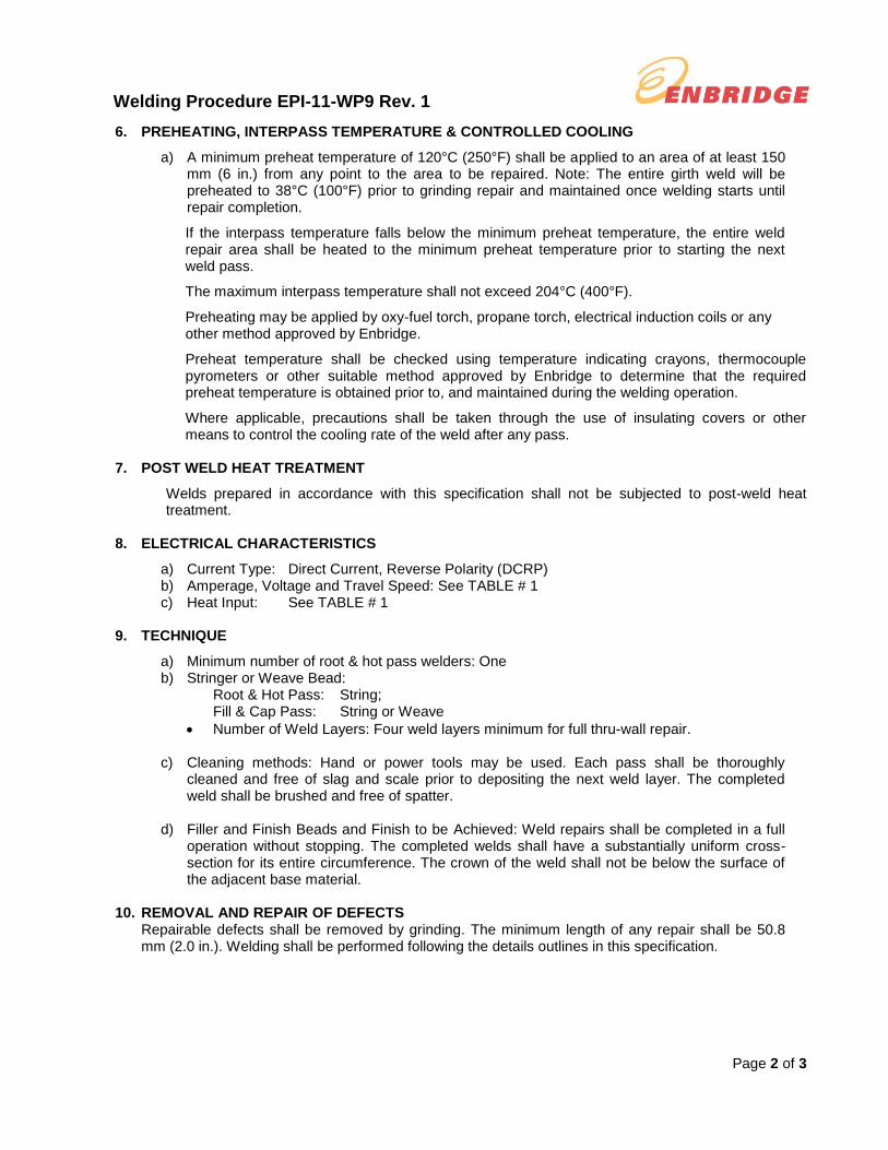
6. PREHEATING, INTERPASS TEMPERATURE & CONTROLLED COOLING
a) A minimum preheat temperature of 120°C (250°F) shall be applied to an area of at least 150 mm (6 in.) from any point to the area to be repaired. Note: The entire girth weld will be preheated to 38°C (100°F) prior to grinding repair and maintained once welding starts until repair completion.
If the interpass temperature falls below the minimum preheat temperature, the entire weld repair area shall be heated to the minimum preheat temperature prior to starting the next weld pass.
The maximum interpass temperature shall not exceed 204°C (400°F).
Preheating may be applied by oxy-fuel torch, propane torch, electrical induction coils or any other method approved by Enbridge.
Preheat temperature shall be checked using temperature indicating crayons, thermocouple pyrometers or other suitable method approved by Enbridge to determine that the required preheat temperature is obtained prior to, and maintained during the welding operation.
Where applicable, precautions shall be taken through the use of insulating covers or other means to control the cooling rate of the weld after any pass.
7. POST WELD HEAT TREATMENT
Welds prepared in accordance with this specification shall not be subjected to post-weld heat treatment.
8. ELECTRICAL CHARACTERISTICS
a) Current Type: Direct Current, Reverse Polarity (DCRP) b) Amperage, Voltage and Travel Speed: See TABLE # 1 c) Heat Input: See TABLE # 1
9. TECHNIQUE
a) Minimum number of root & hot pass welders: One b) Stringer or Weave Bead:
Root & Hot Pass: String; Fill & Cap Pass: String or Weave
Number of Weld Layers: Four weld layers minimum for full thru-wall repair.
c) Cleaning methods: Hand or power tools may be used. Each pass shall be thoroughly cleaned and free of slag and scale prior to depositing the next weld layer. The completed weld shall be brushed and free of spatter.
d) Filler and Finish Beads and Finish to be Achieved: Weld repairs shall be completed in a full operation without stopping. The completed welds shall have a substantially uniform cross-section for its entire circumference. The crown of the weld shall not be below the surface of the adjacent base material.
10. REMOVAL AND REPAIR OF DEFECTS
Repairable defects shall be removed by grinding. The minimum length of any repair shall be 50.8 mm (2.0 in.). Welding shall be performed following the details outlines in this specification.

Welding Procedure EPI-11-WP9 Rev. 1
Page 3 of 3
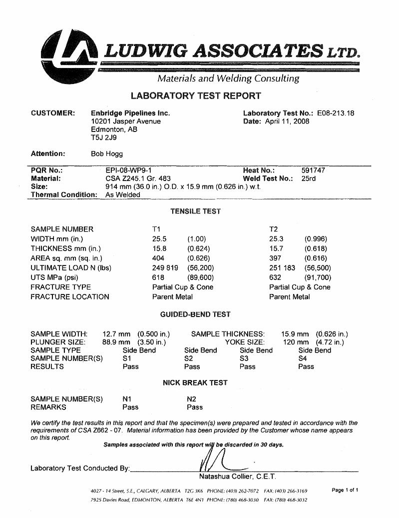
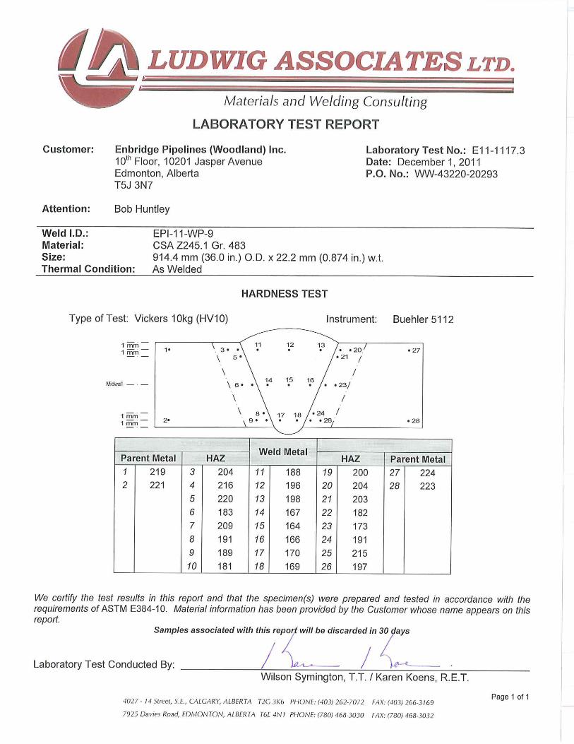
11. ATTACHMENTS a) Procedure Qualification Test Records: EPI-11-WP-9 & EPI-08-WP9-1 b) Laboratory Test Reports: E11-1117.3 & E08-213.18 c) NDT Examination Results: RTD AUT Report No. 7 17-11-2011 RTD RT Report No. PS12805 & Report No’s 12522 & 2585 d) Material Test Report: PCK Heat # 11201828 & Evraz Heat # 591747
TABLE # 1 WELDING PARAMETERS
Bead Number
Electrode Welding
Progression
Amperage Range
amperes
Voltage Range volts
Travel Speed mm/min (in./min)
Heat Input J/mm (J/in.)
Size mm (in.)
AWS Class
Root 4.0 (5/32) E6010 Down 92 – 144 21 – 34 127 – 241 (5.0 – 9.5) 0.80 – 1.35
(20,415 – 34,171)
Hot 4.0 (5/32)
or 5.0 (3/16)
E8010-G Down 113 – 190 22 – 35 258–467 (10.2 – 18.2) 0.57 – 0.85
(14,389 – 21,704)
Fill(s) 2.4 (3/32)
or 3.2 (1/8)
E8018-C3 Up 78 – 169 17 – 31 41 – 127 (1.6 – 5.0) 1.11 – 4.13
(27,936 – 105,336)
Cap 2.4 (3/32)
or 3.2 (1/8)
E8018-C3 Up 98 – 186 18 – 28 34 – 107 (1.2 – 4.2) 1.92 – 4.68
(48,836 – 122,760)
Note – The use of stripper passes is optional.
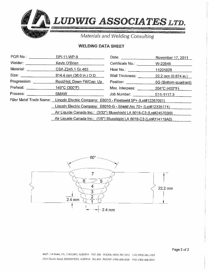
JOINT COMPLETION AND PASS SEQUENCE:
~3.5 mm
1.6 mm±0.8 mm
1.6 mm±0.8 mm

PQR # EPI-11-Wp-9 ELECTRODE LINCOLN 5 P+ E6010 Root Pass
DATE LINCOLN 8P+ E8010-G HP
WELDERS Brooks Aitken Not Available E8018-C3 Fill & Cap
Kevin O'Brien POWER SUPPLY Not Available
BASE MATERIAL CSA Z245.1
PIPE GRADE 483 Cat. 1 POLARITY Direct Current, Reverse Polarity
PIPE MANUFACTURER PCK
HEAT # 11201828 NOTES:
CSA Z662 CARBON EQUIVALENT 0.27 Weld Parameters sampled per full side completed
DIMENSIONS NPS 36" X 22.2mm Preheat checked - Contact Thermocouple, Tempil Stick, IR Thermometer
WELDING PROGRESSION Downhill Interpass Cleaning, Grind or Powerbrush as required
POSITION 5G Time between Bead and HP: 10 mins
PRE HEAT / MIN INTERPASS 149°c minimum Time between HP & First Fill: 7 - 34 mins
MAX INTERPASS 200°C maximum Time between Fill & Cap: 4 - 9 mins
Root Opening 1.6 - 2.4 mm
WELD PARAMETERS
Preheat
(Celcius)
in. mm High Low High Low Distance Time (s) IPM Celcius High Low
Bead-T E6010 5P+ 1/8 3.2 #DIV/0! 140 #DIV/0! #DIV/0!
Bead-B E6010 5P+ 1/8 3.2 #DIV/0! 140 #DIV/0! #DIV/0!
HP-T E8010-G 5/32 4.0 #DIV/0! 135 #DIV/0! #DIV/0!
HP-B E8010-G 5/32 4.0 #DIV/0! 135 #DIV/0! #VALUE!
Fill 1-T E8018-C3 3/32 2.4 #DIV/0! 140 #DIV/0! #DIV/0!
Fill 1-B E8018-C3 3/32 2.4 #DIV/0! 130 #DIV/0! #DIV/0!
Fill 2-T E8018-C3 3/32 2.4 #DIV/0! 130 #DIV/0! #DIV/0!
Fill 2-B E8018-C3 3/32 2.4 #DIV/0! 140 #DIV/0! #DIV/0!
Fill 3-T E8018-C3 3/32 2.4 #DIV/0! 140 #DIV/0! #DIV/0!
Fill 3-B E8018-C3 3/32 2.4 #DIV/0! 145 #DIV/0! #DIV/0!
Fill 4-T E8018-C3 3/32 2.4 #DIV/0! 145 #DIV/0! #DIV/0!
Fill 4-B E8018-C3 1/8 3.2 #DIV/0! 135 #DIV/0! #DIV/0!
Fill 5-B E8018-C3 1/8 3.2 #DIV/0! 130 #DIV/0! #DIV/0!
Cap 1-T E8018-C3 1/8 3.2 #DIV/0! 130 #DIV/0! #DIV/0!
Cap 1-B E8018-C3 1/8 3.2 #DIV/0! 135 #DIV/0! #DIV/0!
SEE LUDWIG WELDING DATA SHEET REF:
E11-1117.3
Heat Input (KJ/mm)
Class
Diameter
Pass
Electrode Voltage Amperage Travel Speed
ENBRIDGE PROCEDURE QUALIFICATION TEST REPORT
17-Nov-11
JOINT DESIGN
Joint Geometry and Fit-Up Joint Completetion and Pass Sequence

ENBRIDGE PIPELINES INC. Weld Parameter Calculations
Weld PQR: EPI-11-WP-9Pass Class Size (mm) Amperage Voltage mm/min in/min kJ/mm J/inch
Root-T E6010 3.2 120 28.0 201 7.9 1.00 25,519 Heat Input Calculated by using:
Root-B E6010 3.2 115 26.0 159 6.3 1.13 28,476
Hot-T E8010-G 4.0 158 29.0 389 15.2 0.71 18,087 Average Recorded Amps x Average Recorded Volts x 60
Hot-B E8010-G 4.0 141 27.0 323 12.7 0.71 17,986
Fill-1-T E8018-C3 2.4 100 26.0 106 4.2 1.47 37,143
Fill-1-B E8018-C3 2.4 97 21.0 88 3.5 1.39 34,920
Fill-2-T E8018-C3 2.4 110 25.0 89 3.5 1.85 47,143
Fill-2-B E8018-C3 2.4 104 22.0 51 2.0 2.69 68,640
Fill-3-T E8018-C3 3.2 141 24.0 99 3.9 2.05 52,062
Fill-3-B E8018-C3 3.2 128 22.0 63 2.5 2.68 67,584
Fill-4-T E8018-C3 3.2 141 23.0 82 3.2 2.37 60,806
Fill-4-B E8018-C3 3.2 133 22.0 51 2.0 3.44 87,780
Fill-5-T E8018-C3 3.2 141 23.0 52 2.1 3.74 92,657
Fill-5-B E8018-C3 3.2 133 22.0 51 2.0 3.44 87,780
Cap-1-T E8018-C3 3.2 136 23.0 55 2.2 3.41 85,309
Cap-1-B E8018-C3 3.2 124 22.0 42 1.6 3.90 102,300
Class Size (mm) Minimum Maximum Minimum Maximum
ROOT E6010 3.2 92 144 21 34 127 241 5.0 9.5 0.80 1.35 20415 34171
HOT E8010-G 4.0 113 190 22 35 258 467 10.2 18.2 0.57 0.85 14389 21704
FILL-1 E8018-C3 2.4 78 120 17 31 70 127 2.8 5.0 1.11 1.77 27936 44571
FILL-2 E8018-C3 2.4 83 132 18 30 41 107 2.0 4.2 1.48 3.23 37714 82368
FILL-3 E8018-C3 3.2 102 169 18 29 43 119 2.0 4.7 1.64 3.22 41649 81101
FILL-4 E8018-C3 3.2 106 169 18 28 41 98 1.6 3.8 1.90 4.13 48645 105336
FILL-5 E8018-C3 3.2 106 160 18 26 41 61 1.6 2.4 2.75 4.13 70224 105336
CAP-1 E8018-C3 3.2 99 163 18 28 34 66 1.2 2.6 2.73 4.68 68247 122760
Actual Arc Speed
PROCEDURE QUALIFICATION RECORD-WELDING PARAMETERS VALUES-MANUAL SMAW WELDING
Insert Actual
Values Here
CSA Tolerance
Amps,Volts &
Arc Speed,
Heat Input; +/-
20%)
Weld Pass
Electrode Amperage Voltage
Arc Speed Heat Input
Minimum
(mm/min)
Maximum
(mm/min)
Minimum
(in/min)
Maximum
(in/min)
Minimum
(kJ/mm)
Maximum
(kJ/mm)
Minimum
(J/inch)
Maximum
(J/inch)
Electrode Arc Speed Heat Input


Page: 1
huntleyb
Rectangle

Page: 2