Welding Journal - September 2012 - Certification
132
PUBLISHED BY THE AMERICAN WELDING SOCIETY TO ADVANCE THE SCIENCE, TECHNOLOGY, AND APPLICATION OF WELDING AND ALLIED JOINING AND CUTTING PROCESSES WORLDWIDE, INCLUDING BRAZING, SOLDERING, AND THERMAL SPRAYING September 2012
-
Upload
khangminh22 -
Category
Documents
-
view
0 -
download
0
Transcript of Welding Journal - September 2012 - Certification

PUBLISHED BY THE AMERICAN WELDING SOCIETY TO ADVANCE THE SCIENCE, TECHNOLOGY, AND APPLICATION OF WELDINGAND ALLIED JOINING AND CUTTING PROCESSES WORLDWIDE, INCLUDING BRAZING, SOLDERING, AND THERMAL SPRAYING
September 2012
WE
LD
ING
JOU
RN
AL
• VO
LU
ME
91 NU
MB
ER
9 • SE
PT
EM
BE
R 2012
September 2012 Cover_4/06 Cover 8/13/12 1:17 PM Page C1

...Select-Arc.
Setting the Gold Standard in Nickel Alloy
Electrodes…
...SeleSelect-Arc, Inc. has intr
emium class of SelectAlloy
elect-Arc.c, Inc. has introduced a
emium class of SelectAlloy
plants, piping systems, furequipment and petrpower generation plants.
plants, piping systems, furnaceequipment and petrochemical and power generation plants.
such as heat exchangers, and inffoffshore and marine applications.
Whatever your demanding application,
such as heat exchangers, and ine and marine applications.
Whatever your demanding application,
premium class of SelectAlloynickel-based, all position, flux corelectrodes developed for a wide rangeof critical welding applications. Theseoutstanding nickel alloy wirexcellent mechanical prbroad range of temperaturexceptional corrdeliver significantly higher out-of-position deposition rates than stickelectrodes or solid wir
emium class of SelectAlloynickel-based, all position, flux cored
odes developed for a wide rangeof critical welding applications. Theseoutstanding nickel alloy wires provideexcellent mechanical properties over a
oad range of temperatures, featureexceptional corrosion resistance anddeliver significantly higher out-of-position deposition rates than stick
odes or solid wires. They include:
SelectAlloy C276-APexceptional rcorrwelding performance in pipelines, pressurprocessing plants, offacilities and marine envir
SelectAlloy 622-APdesigned marine envir
SelectAlloy C276-AP – deliversexceptional resistance to crevice corrosion and pitting for outstanding welding performance in pipelines,
essure vessels, chemicalffocessing plants, offshore and gas
facilities and marine environments.
SelectAlloy 622-AP – speciallydesigned for welding in ffoffshore and marine environments, chemical and
osion and pitting for outstanding
and onments, chemical and
Whatever your demanding application,Select-Ar ffc offers just the riSelectAlloy nickel alloy electrmeet your exacting requirements.
So discover for yourself why SelectAlloynickel alloy electrodes from Select-Arthe standard for welding excellence. Callus today at 1-800-341-5215website at w.www.select-arc.com
Whatever your demanding application,fers just the right
SelectAlloy nickel alloy electrode toements.
So discover for yourself why SelectAlloyom Select-Arc set
d for welding excellence. Call1-800-341-5215 or visit our
c.com.
electrodes or solid wir
SelectAlloy 82-APexcellent resistance to pitting and stress-corrosion cracking making itideal for welding in desalination
odes or solid wires. They include:
SelectAlloy 82-AP ff– offersesistance to pitting and osion cracking making it
ideal for welding in desalination
power generation equipment andpetr
SelectAlloy 625-APweld deposit prresistance in harsh envir
power generation equipment andpetroleum refining.
SelectAlloy 625-AP – the NiCrMo weld deposit provides corrosion esistance in harsh environments,
– the NiCrMo
For Info go to www.aws.org/ad-index
select arc_FP_TEMP 8/7/12 9:12 AM Page C2

Walter ENDURO-FLEX™ fl ap discs go further than any other brand. Our new proprietary grain formula delivers 50% longer life. That means fewer discchanges, increased productivity and cost savings for you and your crew.
Plus you get: Trimmable backing that increases life and performance Minimal vibration for enhanced user comfort Consistent metal removal throughout the life of the disc Longest life and highest total material removal in the industry
FEWER CHANGES LEAD TOBETTER PERFORMANCE
Go ORANGE and fi nish faster with 50% fewer stops.
Take ENDURO-FLEX™ for a spin and wina Richard Petty Driving Experience! Every purchase of ENDURO-FLEX™ fl ap discs gives you a chance to win. Or enter online at walter.com No purchase necessary. Full details available online.
For Info go to www.aws.org/ad-index
walter surface tech._FP_TEMP 8/8/12 7:21 AM Page 1

For Info go to www.aws.org/ad-index
camfil farr_FP_TEMP 8/7/12 9:25 AM Page 2

3WELDING JOURNAL
CONTENTS26 Good Design Plus Early Inspection Equals High Productivity
There is an inspection method that puts weld quality determination at the start of the fabricating process, andnot at the end, when it is too lateJ. Noruk and J.-P. Boillot
32 Choosing a Surface Coating TechnologyTwo surfacing technologies, high-velocity oxyfuel spray andlaser cladding, are comparedT. Peters and T. Glynn
36 Phased Array Testing of Resistance Spot WeldsInspection technology takes on the challenge of determiningspot weld integrity in advanced high-strength steelsJ. K. Na
41 Thermal Spray Wins as a Green TechnologyRestoring parts to like-new condition with thermal spray conserves materials and energy that would be used to produce a brand-new componentR. S. Brunhouse, P. Foy, and D. R. Moody
46 The Welding Journal: Digitized and Ready to TravelThere are more ways to enjoy reading the Welding JournalnowC. Guzman
Welding Journal (ISSN 0043-2296) is publishedmonthly by the American Welding Society for$120.00 per year in the United States and posses-sions, $160 per year in foreign countries: $7.50per single issue for domestic AWS members and$10.00 per single issue for nonmembers and$14.00 single issue for international. AmericanWelding Society is located at 8669 Doral Blvd.,Doral, FL 33166; telephone (305) 443-9353. Peri-odicals postage paid in Miami, Fla., and additionalmailing offices. POSTMASTER: Send addresschanges to Welding Journal, 8669 Doral Blvd.,Doral, FL 33166. Canada Post: Publications MailAgreement #40612608 Canada Returns to be sentto Bleuchip International, P.O. Box 25542,London, ON N6C 6B2
Readers of Welding Journal may make copies ofarticles for personal, archival, educational or research purposes, and which are not for sale orresale. Permission is granted to quote from arti-cles, provided customary acknowledgment of authors and sources is made. Starred (*) items excluded from copyright.
Departments
Editorial ............................4Press Time News ..................6News of the Industry ..............8International Update ............14Stainless Q&A ....................16RWMA Q&A ......................18Product & Print Spotlight ......20Conferences ......................52Coming Events....................54Certification Schedule ..........58Society News ....................59Tech Topics ......................60Guide to AWS Services ........75
Personnel ........................78American WelderLearning Track ..................93Fact Sheet ......................98
Thermal Spray Profiles ........100Classifieds ......................104Advertiser Index ................105
237-s Study on Vacuum Brazing of Glass to Kovar® Alloy with Cu-Ni-Sn-PThe best time and temperature combination for optimum shear strength was determinedZ. Zhong et al.
241-s Selecting Processes to Minimize Hexavalent Chromiumfrom Stainless Steel WeldingDifferent welding processes were studied to see which offered the least exposure to hexavalent chromiumM. Keane et al.
247-s Estimating the Cooling Rates of a Spot Welding Nugget in Stainless SteelA way to determine the cooling rate will relate directly to weld nugget shape and mechanical propertiesY. Zhang et al.
252-s Design Considerations of Graded Transition Joints for Welding Dissimilar AlloysModels were developed to help predict the performance of dissimilar welds between ferritic and austenitic alloys using a composite material in the jointG. J. Brentrup et al.
Features
Welding Research Supplement
The American Welder
26
87
32
September 2012 • Volume 91 • Number 9 AWS Web site www.aws.org
On the cover: High-velocity oxyfuel appli-cation of tungsten carbide to a lumber roll.(Photo courtesy of Sulzer Metco CoatingServices.)
81 Spot and Projection Welding BasicsThis overview helps in the understanding of resistance weldingL. H. McDevitt
87 Building Demand for TradeswomenA program founded in 1981 provides support and training towomen to help them enter trades traditionally held by men
September 2012_Layout 1 8/9/12 3:15 PM Page 3

EDITORIAL
It is currently projected that the United States will need an additional 238,000 weld-ing-related professionals by 2019. Since 2007, when AWS made welder workforce devel-opment a strategic direction and aligned it with the AWS Foundation’s scholarship activ-ity, the Society has continued to develop programs to enhance the image of welding andis focused on recruiting welders to ease this national shortage. These efforts have includ-ed the use of national spokespersons; student recruitment collateral; a careers Web siteat www.CareersInWelding.com; a job-search Web site at www.JobsInWelding.com; profes-sional development events for career counselors; workforce development grants for edu-cation/industry partnerships; a Careers in Welding mobile exhibit; and more. We havecollaborated with Weld-Ed, the National Center for Welding Education & Training,under a grant funded by the National Science Foundation, as well as with the NationalAssociation of Manufacturers (NAM) and its portable, stackable certification program.
A collaborative effort undertaken late last year was organization of The State of theWelding Industry Workforce Roundtable. This event — cosponsored by AWS, AWSFoundation, and Weld-Ed — included 16 executive panelists and some 70 audience partic-ipants. I served as the moderator for the morning panel discussion, which included industryrepresentatives from Caterpillar, Vermeer, Huntington-Ingalls, Bechtel, Westinghouse,RoMan Engineering, AWISCO, ESAB, Lincoln, ITW, and education representatives fromUA Local 597, Texas State Technical College, Lorain County Community College, andUniversity of Alberta. The AWS and NAM were also part of the executive panel.
The panelists shared challenges their organizations face in recruiting, training, andretaining welding professionals, as well as organizational impacts from new technologies,advancements in welding, and globalization. Ideas and frameworks for pilot projects thataddress the stated challenges were formulated in later small group discussions. A reporton the roundtable centered around three main priorities: Build Enthusiasm for Welding,Expand Industry/Education Collaboration, and Flexibility in Education and Training.
Building upon this successful event, AWS has identified seven priority projects onwhich it is focusing its efforts for future welder workforce development initiatives,including the following:• Branding of the profession and messaging specific to each market segment includingyoung students (K–12), young adults (18–26 and military), incumbent workforce (transi-tioning workers), gender-specific strategies, new Americans (being mindful of languagebarriers)• Fast Track Program for Military — enlisted and transitioning• Focus on Women of Gases & Welding • SkillsUSA and World Skills — increased recognition• Collaboration with existing career exploration networks• “Master Certification” designation program with all NAM-Endorsed ManufacturingSkills Certification system partners.
Activities are well underway for several of these initiatives. Meetings with branches ofthe military have resulted in a plan to implement SENSE Level 1 and the CertifiedWelder programs at the Army’s Fort Lee training facility. In addition, the military’sCOOL and CERT Web sites have been updated to provide the current certificationinformation for active and transitioning service people. Women of Gases & Welding, ajoint initiative between AWS and GAWDA, was formed last fall. A luncheon featuringAWS Vice President Nancy Cole as the keynote speaker was held at GAWDA’s Spring
Management Conference in April. A strategic plan-ning committee has been formed and a networkingevent is being planned for FABTECH this November.
Your AWS will continue to focus its initiatives onthese priorities. We will look for new collaborations aswell as expand our current ones. Working together, wecan and must address the welding skills shortage andensure our industry is well positioned for growth andsuccess for the future.
SEPTEMBER 20124
OfficersPresident William A. Rice Jr.
OKI Bering
Vice President Nancy C. ColeNCC Engineering
Vice President Dean R. Wilson
Vice President David J. LandonVermeer Mfg. Co.
Treasurer Robert G. PaliJ. P. Nissen Co.
Executive Director Ray W. ShookAmerican Welding Society
DirectorsT. Anderson (At Large), ITW Global Welding Tech. Center
J. R. Bray (Dist. 18), Affiliated Machinery, Inc.
J. C. Bruskotter (Past President), Bruskotter Consulting Services
G. Fairbanks (Dist. 9), Fairbanks Inspection & Testing Services
T. A. Ferri (Dist. 1), Victor Technologies
D. A. Flood (Dist. 22), Tri Tool, Inc.
R. A. Harris (Dist. 10), Total Quality Testing
D. C. Howard (Dist. 7), Concurrent Technologies Corp.
J. Jones (Dist. 17), Victor Technologies
W. A. Komlos (Dist. 20), ArcTech, LLC
R. C. Lanier (Dist. 4), Pitt C.C.
T. J. Lienert (At Large), Los Alamos National Laboratory
J. Livesay (Dist. 8), Tennessee Technology Center
M. J. Lucas Jr. (At Large), Belcan Engineering
D. E. Lynnes (Dist. 15), Lynnes Welding Training
C. Matricardi (Dist. 5), Welding Solutions, Inc.
D. L. McQuaid (At Large), DL McQuaid & Associates
J. L. Mendoza (Past President), Lone Star Welding
S. P. Moran (At Large), Weir American Hydro
K. A. Phy (Dist. 6), KA Phy Services, Inc.
W. R. Polanin (Dist. 13), Illinois Central College
R. L. Richwine (Dist. 14), Ivy Tech State College
D. J. Roland (Dist. 12), Marinette Marine Corp.
N. Saminich (Dist. 21), Desert Rose H.S. and Career Center
N. S. Shannon (Dist. 19), Carlson Testing of Portland
T. A. Siewert (At Large), NIST (ret.)
H. W. Thompson (Dist. 2), Underwriters Laboratories, Inc.
R. P. Wilcox (Dist. 11), ACH Co.
M. R. Wiswesser (Dist. 3), Welder Training & Testing Institute
D. Wright (Dist. 16), Zephyr Products, Inc.
Founded in 1919 to Advance the Science,Technology and Application of Welding
Addressing the WeldingSkills Shortage
Dean R. WilsonAWS Vice President
Editorial September 2012_Layout 1 8/9/12 2:47 PM Page 4

The NEW Fabricator® 211i is the latest to join the
3-in-1 series of multi-process welding systems.
With multiple input voltages and integrated 12"
spool capacity, it’s the most versatile welding
system on the market...Period!
THERMAL ARC® IS A VICTOR TECHNOLOGIES™ BRAND.
NEW
211i F
abric
ator
MULTI-VOLTAGEMULTI-PROCESSNOW YOU CAN MULTI-TASK
For more information
visit VictorTechnologies.com/3in1
For Info go to www.aws.org/ad-index
victor technologies_FP_TEMP 8/7/12 9:20 AM Page 5

PRESS TIMENEWS
Lincoln Electric Announces Leadership Transition
Lincoln Electric Holdings, Inc.,Cleveland, Ohio, recently announcedthat effective Dec. 31, John M. StropkiJr., who has been chairman, president,and chief executive officer since 2004,will become executive chairman of theboard, and Christopher L. Mapes willbe named president and chief execu-tive officer of the company.
As executive chairman, Stropkiwill work closely with Mapes to en-
sure a seamless transition for Lincoln Electric’s shareholders, global employee base, keycustomers, industry associations, and community and government relationships. Mapeshas been serving as chief operating officer of the company since September 1, 2011, andhas been a member of the board of directors since February 2010.
“This leadership transition is a direct result of the board’s and John’s conscientiousfocus on developing a deep, talented, and experienced management team at Lincoln Elec-tric,” said Harold L. Adams, lead director and chair of the nominating and corporate gov-ernance committee. He added, “Chris has demonstrated outstanding leadership skills,strategic insight, and operational expertise during his time as a director and as a memberof the company’s executive management team, with responsibility for all of Lincoln’s globalbusinesses and product development initiatives.”
AWS Reveals Matching Gift Program for EndowedScholarships and Expands International Services
The American Welding Society (AWS), Doral, Fla., recently announced that, for a lim-ited time, all donations to existing Named Scholarships or new Named Scholarships will bematched dollar for dollar. The AWS Board of Directors approved the matching programto provide more students with the opportunity to cover their welding education tuition.
“The AWS matching gift program provides an excellent opportunity for businesses andindividuals to make a donation that will benefit the future of the welding industry,” saidSam Gentry, executive director, AWS Foundation. “This is an excellent program to estab-lish a scholarship in your name, your company’s name, or your District or Section’s name.”
Since 1991, the AWS Foundation has awarded more than $5.3 million in scholar-ships, and this year will award 400 students with more than $390,000. To learn more,visit www.aws.org/foundation or contact Sam Gentry at [email protected].
In other news, with international membership on the rise, AWS has launched a series ofcountry-specific Web sites known as microsites for members to access information in theirnative languages. Multilingual microsites are now live for Mexico at www.aws.org/mexico,China at www.aws.org/china, and Canada at www.aws.org/canada. They feature informationon services offered by AWS in each specific country, membership benefits, exposition in-formation, online education, and access to AWS publications and technical standards. Othercountries will continue to be added.
“Over the past few years, AWS has seen a significantly increasing interest from acrossthe globe in attaining AWS certifications, standards, and membership. We’ve launched aglobal initiative that will allow us to better serve the international welding community, andthe country-specific Web sites are just one of the steps that we are taking to become moreaccessible to our members wherever they are,” said Ray Shook, executive director, AWS.
Manufacturing Day Slated for October 5
The Fabricators & Manufacturers Association, Int’l, U.S. Commerce Department’sHollings Manufacturing Extension Partnership, Wisconsin MEP, and Illinois Manufac-turing Extension Center are launching Manufacturing Day on October 5. It will high-light the importance of manufacturing to the nation’s economy and draw attention tothese available high-skill jobs. Through open houses, public tours, career workshops,and other events held at participating facilities on that day, the sponsors hope to intro-duce as many people as possible to the role played by manufacturing in local communi-ties and the nation. To learn more, visit www.mfgday.com. Also, organizations wantingto become involved as official sponsors should e-mail [email protected].◆
SEPTEMBER 20126
MEMBER
Publisher Andrew Cullison
Publisher Emeritus Jeff Weber
Editorial Editorial Director Andrew Cullison
Editor Mary Ruth JohnsenAssociate Editor Howard M. Woodward
Associate Editor Kristin CampbellEditorial Asst./Peer Review Coordinator Melissa Gomez
Design and Production Production Manager Zaida Chavez
Senior Production Coordinator Brenda FloresManager of International Periodicals and
Electronic Media Carlos Guzman
AdvertisingNational Sales Director Rob Saltzstein
Advertising Sales Representative Lea PanecaSenior Advertising Production Manager Frank Wilson
SubscriptionsSubscriptions Representative Sylvia Ferreira
American Welding Society8669 Doral Blvd., Doral, FL 33166(305) 443-9353 or (800) 443-9353
Publications, Expositions, Marketing CommitteeD. L. Doench, ChairHobart Brothers Co.
S. Bartholomew, Vice ChairESAB Welding & Cutting Prod.
J. D. Weber, SecretaryAmerican Welding Society
T. Birky, Lincoln Electric Co.D. Brown, Weiler BrushJ. Deckrow, Hypertherm
D. DeCorte, RoMan Mfg.J. R. Franklin, Sellstrom Mfg. Co.
F. H. Kasnick, PraxairD. Levin, Airgas
E. C. Lipphardt, ConsultantR. Madden, Hypertherm
D. Marquard, IBEDA SuperflashJ. Mueller, Victor Technologies International
J. F. Saenger Jr., ConsultantS. Smith, Weld-Aid Products
N. C. Cole, Ex Off., NCC EngineeringJ. N. DuPont, Ex Off., Lehigh University
L. G. Kvidahl, Ex Off., Northrup Grumman Ship SystemsS. P. Moran, Ex Off., Weir American Hydro
E. Norman, Ex Off., Southwest Area Career CenterR. G. Pali, Ex Off., J. P. Nissen Co.R. Ranc, Ex Off., Superior Products
W. A. Rice, Ex Off., OKI BeringR. W. Shook, Ex Off., American Welding Society
D. Wilson, Ex Off.
Copyright © 2012 by American Welding Society in both printed and elec-tronic formats. The Society is not responsible for any statement made oropinion expressed herein. Data and information developed by the authorsof specific articles are for informational purposes only and are not in-tended for use without independent, substantiating investigation on thepart of potential users.
Christopher L. Mapes John M. Stropki Jr.
PTN September 2012_Layout 1 8/9/12 3:02 PM Page 6

Call us at 800-782-2110 for a free quote on yournext project.www.greinerindustries.com
STRUCTURAL STEEL FABRICATION
We can roll a beam up to 40 inches the “easy way”and pipe up to 20
inches. Our press brake has 2,750 tons of power with a 40-foot bed. Our
CNC horizontal boring mill has a 12-foot high by 30-foot long machining
envelope. Our G&L bay boasts a 50-ton lifting capacity with 31-foot hook
height of overhead cranes. Our 30-foot by 50-foot, permanently installed,
leveling bed allows us to level to within fifteen thousandths of an inch.
INDUSTRIAL BLASTING & COATING
Our capabilities include 81,000 square feet of capacity, 34-foot by 34-foot
doors and a 100-ton four-point pick-and-carry crane.
You can count on Greiner!
• Structural Steel Fabrication• Steel Plate & Sheet Metal Fabrication• Miscellaneous Metals• Machining• Rolling & Forming Services• Cutting Services• Industrial Coatings• Industrial & Electrical Contracting• Crane Rental & Trucking Services• Heat-Bending Services(AISC Certified for Major SteelBridge Fabrication)
Capacity. Precision. Strength.
24-foot hammerhead columns and baseplates for theWorld Trade Center’s newTransportation Hub.
133-ton transfer girder for aNewYork City high-rise.
Greiner has someof thebiggest equipmentof its kind in theEasternUnited States and certifications for handling just aboutany large,heavy-duty steel fabrication job for you.
25-inch diameter steel node connectorsat JFK International Airport.
For Info go to www.aws.org/ad-index
greiner industries_FP_TEMP 8/7/12 9:10 AM Page 7

SEPTEMBER 20128
NEWS OF THEINDUSTRY
SkillsUSA Competitors Earn Medalsat 2012 Championships
The welding winners of the annual SkillsUSA Championshipswere revealed on June 27 at the award session of the nationalleadership and skills conference held in Kansas City, Mo.
The high school welding medalists were Dillon Belair, Pio-neer Technology Center, Ponca City, Okla. (gold); Cole Witte,Pike Central High School, Petersburg, Ind. (silver); and KurtisRice, Jefferson Scranton High School, Jefferson, Iowa (bronze).
The following college/postsecondary students also won weld-ing medals: Tanner R. Tipsword, Eastern Wyoming College, Tor-rington, Wyo. (gold); Jacob Hughes, Jefferson College ATS, Hills-boro, Mo. (silver); and Simon Rowe, Cuesta Community Col-lege, San Luis Obispo, Calif. (bronze).
The welding competitors received contest drawings and a setof Welding Procedure Specifications. All drawings, welding sym-bols, and welding terms conformed to American Welding Soci-ety (AWS) standards.
Contestants were tested on various aspects, including meas-uring weld replicas, using weld measuring gauges; laying out aplate and using oxyacetylene equipment to cut several holes thatwould be checked for accuracy and quality; gas metal arc weld-ing on steel in which they made welds in various positions usingpulse transfer; and using a combination machine capable of pro-viding the correct welding current for shielded metal arc and gastungsten arc welding. Competitors completed the steel project
Airbus will establish a manufacturing facil-ity in the United States to assemble and deliver A320 family aircraft. Located at theBrookley Aeroplex in Mobile, Ala., it will bethe company’s first U.S.-based production facility.
A319, A320, and A321 aircraft will be as-sembled there. Construction of the assemblyline is expected to begin next summer. Aircraftassembly is planned to start in 2015, with firstdeliveries from the Mobile facility beginningin 2016. The company further anticipates thefacility will produce between 40 and 50 aircraftper year by 2018.
“The time is right for Airbus to expand inAmerica,” said Fabrice Brégier, Airbus presi-dent and CEO. He added the United States isthe largest single-aisle aircraft market in theworld with a projected need for 4600 aircraftover the next 20 years.
Alabama Governor Robert Bentley said,“This project will create 1000 stable, well-paying jobs that the people of this area needand deserve.”
Airbus already operates an EngineeringCenter in Mobile as well as a military customerservices operation supporting U.S. CoastGuard aircraft.
Airbus to Establish U.S. Assembly Line
Airbus President and CEO Fabrice Brégier (left) is joined by Alabama GovernorRobert Bentley after announcing the decision to create an A320 family final assem-bly line at Mobile’s Brookley Aeroplex. (Photo © Airbus S.A.S 2012.)
Shown are the welding winners and some of the technical commit-tee members at the 2012 SkillsUSA Championships: (front row,from left) national technical committee member, Nick Peterson;high school medalists Cole Witte (silver), Dillon Belair (gold), andKurtis Rice (bronze); plus national technical committee members,including AWS Education Services, Director, Operations MarticaVentura, Paul Cleveland, and Ed Norman. Also shown (back row,from left) are national technical committee member, BrandenMuehlbrandt; postsecondary/college medalists Jacob Hughes (sil-ver), Tanner Tipsword (gold), and Simon Rowe (bronze); alongwith national technical committee member, Steve Theesen. (Photocourtesy of Clay Allen, SkillsUSA photographer.)
NI September 2012_Layout 1 8/9/12 3:28 PM Page 8

9WELDING JOURNAL
and welded a stainless steel project in various positions using avariety of filler metals.
Judges were provided by the AWS Kansas City Section. Con-testants were judged while assembling and welding the project.Certified Welding Inspectors judged the completed project. In-spection methods included visual and liquid penetrant techniques.
To view a video of the event’s welding competition, visithttp://tinyurl.com/7pft6dr. In addition, awards were presented incategories for welding fabrication and welding sculpture.
WorldSkills Germany will host the 42nd WorldSkills Compe-titions in Leipzig, Germany, July 2–7, 2013, at the Leipzig TradeFair and Exhibition Center.
New Welders at Sabre Industries toBenefit from Customized Training
Western Iowa Tech Community College has partnered withSabre Industries, Inc., a tower, pole, and shelter manufacturer,to provide customized training for nearly 200 new jobs being cre-ated by the company’s expansion plans in Sioux City, Iowa.
The welding program, created as a training opportunity forSabre’s new welders, is four weeks long and features an orienta-tion plan strong in blueprint reading and safety.
The company revealed its multiphased expansion in the city’snew Southbridge Business Park earlier this year. The initial phasewill include approximately 200 new jobs added to the 208 exist-ing employees and an $18 million capital investment. Additionalphases anticipate a total investment of $28 million and 532 jobs.
Sabre’s Sioux City operations will include positions in weld-ing, manufacturing, executive management, administration, sales,operations, human resources, and shipping/receiving. Its Website provides employment details at www.sabreindustries.com.
U.S.REGULATORSUniweld. Still building the
Regulators you wantright here in the U.S.A.
RV8010 Heavy DutySingle Stage
FOR U.S. JOBS
QUALITY TOOLS THAT GO TO WORK WITH YOU®
Uniweld can build any regulator you need: Heavy Duty, Medium Duty, Single Stage, Two Stage, Oxygen, all Fuels and every gauge you’ll need to go with ‘em …all 100% tested.
UNIWELD PRODUCTS, INC.2850 RAVENSWOOD ROAD
FORT LAUDERDALE, FL 33312 U.S.A.
800.323.2111Call or email for catalog.
U..SS GUEGUREG.R.SU
SBO JSUROFATATALA RSORSTOTOTULU
SS SB O J. .UROF
For info go to www.aws.org/ad-index
For info go to www.aws.org/ad-index
NI September 2012_Layout 1 8/9/12 3:29 PM Page 9

SEPTEMBER 201210
SmithCo Awards Contract to ManufactureSide-Dump Trailer Components
Radius Steel Fabrication – SOO Tractor, Sioux City, Iowa, hasrecently been awarded an agreement by SmithCo Mfg. Co., LeMars, Iowa, to build steel components for trailers to meet pay-load requirements for the Canadian mining industry. The steelfabrication, welding, and blast/paint technologies provider willmanufacture large components for the side-dump trailers.
“I see this project as an opportunity to not only support U.S.manufacturing, but to create jobs for Americans,” said Ida Covi,CEO of Radius Steel.
Radius Steel – SOO Tractor’s owner, Allen Mahaney, withthe company’s engineering department, designed a custom weldfixture that will attach to the hydraulic roll-over positioner. It re-duces the welding time of each component by more than 2 h andtakes into consideration the worker’s ergonomic position.
Miller Launches Job Weld Done Giveaway
Miller Electric Mfg. Co., Appleton, Wis., launched the JobWeld Done Giveaway. Those interested can review the officialrules and enter at MillerWelds.com/win once monthly until Dec.31, 2012, to increase chances of winning. Among the prizes arewelding machines. Also, three individual grand prize packageswill be awarded in January 2013, including a custom-built EPICchopper, NASCAR trip to Bristol, Tenn., and a trip to Las Vegasincluding an inside look at the SEMA Show. Ten winners will beawarded a Miller t-shirt during each monthly entry period as well.
North American Robotics IndustryPosts Best Quarter Ever
North American robotics companies sold more industrial ro-bots in the second quarter of 2012 than any previous quarter inhistory, according to new statistics released by the Robotic In-dustries Association, Ann Arbor, Mich.
A total of 5556 robots valued at $403.1 million were sold toNorth American companies, a jump of 14% in units and 28% indollars over the same quarter in 2011. Orders in the first half of2012 totaled 10,652 robots valued at $747 million, increases of20% in units and 29% in dollars over the same period last year.
Orders for spot welding robots, used primarily in automotivesolutions, jumped 68% in the first half of 2012. Other large jumpswere seen in coating and dispensing, arc welding, and assembly.
For info go to www.aws.org/ad-index
Radius Steel Fabrication – SOO Tractor has been awarded an agree-ment by SmithCo to build steel components for trailers to meet pay-load requirements for the Canadian mining industry. As shownabove, welders use a roll-over positioner.
NI September 2012_Layout 1 8/9/12 3:29 PM Page 10

The Tweco Tradition of CreatingPewter Figurines Continues
Ray Townsend, founder of the Townsend Welding EquipmentCo., better known as Tweco, began a pewter figurine tradition
that started at the 1975 convention in San Francisco, Calif., forthe National Welding Supply Association, which later becameGAWDA. Figurines are created each year to represent a histori-cal person or icon of the host city; the first one commemoratedthe miner/49er to pay homage to the California Gold Rush of1849.
The pewter figurines have become collectable items for at-tendees with 700 to 1200 produced annually. The attraction stems,in part, from the craftsmanship of the Soldier Factory. For the2011 GAWDA Annual Convention in New York City, a first re-sponders figurine was created. Most recently, a bear figurine wasbuilt for the 65th Annual Assembly & International Conferenceof the International Institute of Welding in Denver, Colo.
Central McGowan Provides WeldingSupplies to Local Career Academy
Central McGowan, Inc. (CMI), a distributor of welding andcutting equipment, along with industrial gases and MRO sup-plies in central Minnesota, recently fulfilled a request from Cen-tral Minnesota Jobs and Training Services, Inc., Monticello,Minn., for welding supplies and other equipment needed to runits 2012 Central Minnesota Career Academy.
For the second year in a row, Jeff Skumautz, CMI’s president,committed welding wire, contact tips, and safety glasses. He alsoappointed two employees, Erin Brum and Dean Kiffmeyer, torepresent the company and ensure a successful academy experi-ence. In addition, CMI involved a business partner to help sup-port this event. Kiffmeyer reached out to Midsota Manufactur-ing, Inc., in Avon to secure welding coupons.
The academy offers an opportunity for youth, ages 16 to 21,who have an interest in manufacturing but have not yet decided
11WELDING JOURNAL
/ Battery Charging Systems / Welding Technology / Solar Electronics
/ The relatively simple principle behind DeltaSpot is the indexing process tape which runs between the electrode and the work piece. With each spot, the process tape indexes one step forward; it’s like welding every spot with a brand new electrode, making the quality 100% predictable. Join aluminum to aluminum or steel to steel, even dissimilar metals.Want to know more? Check out: www.fronius-usa.com
For info go to www.aws.org/ad-index
This custom-designed, pewter bear figurine was made for the 65thAnnual Assembly & International Conference of the InternationalInstitute of Welding held July 8–13 in Denver, Colo.
NI September 2012_Layout 1 8/9/12 3:29 PM Page 11

their career path. Attendees try a manufacturing career throughhands-on projects on the shop floor and in a college classroom;tour manufacturing companies and college campuses; learn fromindustry specialists; and use equipment. They experience weld-ing, metals and plastics machining, laser programming, computer-aided design, electronics, and basic automotive technology.
Raybel Compres Named OutstandingWelder of the Year at U.A. Graduation
Raybel Compres, a resident of Silver Spring, Md., and anAmerican Combustion Industries (ACI) employee for more thanfive years, has been named Outstanding Welder of the Year atthe United Association (U.A.) Mechanical Trade School gradu-ation, Local 602.
To earn this honor, Compres completed more than 1100 class-room hours and 10,100 h of on-the-job training at ACI. He also
earned nine welding qualifications and spent most of his appren-ticeship working under one of the company’s most distinguishedjourneymen, Ray Cary. Primarily, Compres worked on large-scaleheating, ventilation, and air-conditioning projects at construc-tion sites and for existing customer facilities. He maintained a 96.46 GPA, ranking him 13th in a graduating class of 109 steamfitters.
TMK Breaks Ground on New Facility
TMK IPSCO has begun developing a new 69,000-sq-ft facilityin Odessa, Tex. Consisting of two main buildings, the facilitieswill host ULTRA™ premium connection manufacturing, includ-ing both pipe preprocessing and threading. It is expected severalskilled labor jobs will be created. The site is projected to be fullyoperational by the end of the year.
In addition, the 37-acre site will streamline the company’s operations, which are currently spread out. Consolidating these
SEPTEMBER 201212
“
Find out how Progressive Surface can exceedyour expectations, Procisely! ®
progressivesurface.com
Each step in Progressive’s Procise Process is detailedand meaningful. As a result of their approach, they consistently exceed expectations.”“I wish all of our suppliers
offers an aerospace customer. “Progressive sets the bar for, not only focusing on the needs of the customer, but always being accessible and open to input along the way.”
conducted business this way,”
“Simply pros!”
“E“EaE teach st pPPrProrocicep inPriseProroc
l f hrerand meaninesultofthe
Prrorogo regi d
veessive’ses’s’escec
grn Pess is detailedgfg
il.ful. As ang
roeirapproach
rericothey c
esult of theh onsist
exp ctectationscoc ctonducteted business this w
rooach,ppltet tlent
eir apprxcly exceceed
s.ns.”“I wish all of our suppliersffeo” roers an aerospace cust r.omer.
“P“ roPr reogr veessiv foe sets the bar f r,or,lynot onl foy focusing on the needs
toof the cust r,omer, but alwawaysccbeing accec toessible and open to
waw y,ay,, off”
Find out how Progressivyoyour e ctxpectations,Proc
progreressiv
essive Sur ceface can exceedcisely!®
vevesurfaf ceace.c.cocom
wainput along the w y.ay.”
“S“SiS roimply pros!”
For info go to www.aws.org/ad-index
Raybel Compres earned theOutstanding Welder of theYear title at the United Asso-ciation Mechanical TradeSchool graduation, Local602. (Photo courtesy of Amer-ican Combustion Industries.)
Central Minnesota Career Academy students Derek Rivers and Tessia Silbernagel proudly display their new welding skills.
— continued on page 80
NI September 2012_Layout 1 8/9/12 3:30 PM Page 12
Just About the Only Type of Positioner We Don’t Make.
Just About the Only Type of Positioner We Don’t Make.
Koike Aronson, Inc./Ransome Arcade, NY USA 800-252-5232
www.koike.com
HT SeriesHead – Tailstock
TR SeriesTurning Rolls
HD SeriesGear DrivenPositioner
Locust I & IIWelding Head Manipulators
Koike Aronson positioning equipment can’t tee up your
392-dimple favorite, but we have you covered nearly everywhere else —
from 100 lbs. to 4 million lbs., at any angle. Koike Aronson/Ransome can help you
weld just about any type of piece more profitably. Call us to find out how we
can make your welding operation more efficient.
Visit us at Booth #N4131 at FABTECH in Las Vegas.
Follow us on
For Info go to www.aws.org/ad-index
koike aronson_FP_TEMP 8/7/12 9:10 AM Page 13

INTERNATIONALUPDATE
TRUMPF Opens Disk Laser Facility in Japan
The TRUMPF Group, a manufacturer of sheet metal fabrica-tion machinery and industrial lasers, recently opened a productionfacility for disk lasers in Yokohama, Japan, its third worldwide.
One hundred twenty people attended the official inaugurationof the latest TruDisk production location on June 1, 2012. Accord-ing to the company, the new location will not only contribute to theexpansion of disk laser technology in the Japanese market, but willallow customers to observe TRUMPF’s production processes andproducts first-hand.
Dr. Christof Lehner, general manager of TRUMPF LaserTechnology Center in Plymouth, Mich., said, “Disk lasers are inhigh demand, especially when integrated into our TruLaser Cell8030 multiaxis laser cutting system, which was designed specifi-cally for the hot formed cutting market. In the United States, wecontinue to add employees and grow in an effort to meet this de-mand. Increased global manufacturing capacity will help to easedelivery constraints and allow us to better serve the North Amer-ican market.”
Wall Colmonoy Opens Machine Shop in Wales
Wall Colmonoy, a materials engineering group of companiesengaged in the manufacturing of surfacing and brazing products,castings, and engineered components, recently opened a state-of-the-art machine shop in Pontardawe, Wales. The 23,500-sq-ftfacility was inaugurated by Carwyn Jones, M.P., First Minister ofWales.
According to the company, the new machining site will addcapacity, advanced processes, and equipment while increasingthe quality, speed, and efficiency of production. Jones said, “Thedecision to expand here in Pontardawe is a great boost for man-ufaturing in Wales.”
Women Who Weld Program Launched inQueensland
The Women Who Weld program, an initiative to encourageyoung women to take up a welding apprenticeship, launched onJuly 24th in Queensland, Australia. Women from their late-teensto mid-30s, and a range of backgrounds, are participating in thepilot program held at Atlas Heavy Engineering’s facility atNarangba. They will be attending orientation workshops focusedon the engineering trades. Upon completion of the course, theywill be presented with a Statement of Achievement.
Women Who Weld is a partnership between the AustralianIndustry Group, QMI Solutions, and Atlas Heavy Engineering.The alliance was formed on International Women’s Day 2012 togive young women an opportunity to experience welding andother engineering trades in a real-world manufacturing setting.Jim Walker, CEO of QMI Solutions, said, “This program willventure into Queensland schools to seek out young women whomight be intereted in pursuing a trade as a welder but didn’t quiteknow how to kick off the process.”
Hydrex Performs Several On-Site ShipRepairs
Over the last few months, Hydrex divers and technicians havebeen sent to perform vessel repairs in Belgium, The Netherlands,and Cameroon. Repairs were carried out according to the Hy-drex class approved procedure for the welding of inserts in a ves-sel’s shell plating while afloat.
In Zeebrugge, Belgium, a 560-mm crack in the bottom shellplating of a 203-m roll-on-/roll-off vessel needed repairing. TheHydrex team, upon inspection of the onboard and water-sideshell plating, installed a cofferdam over the affected area. Theythen cut the shell plating and secured a new insert plate with acomplete-joint-penetration weld.
In Amsterdam, a leak in one of the ballast tanks of a 144-mtanker was stopped by inserting a round plug with a diameter of300 mm. The diver and technician team then also installed a cof-ferdam over the rack, and installed a new insert with a complete-joint-penetration weld.
In Douala, Cameroon, similar repairs were performed on a228-m tanker. The cavitated area on the flat bottom in the bal-last tank was removed, and a new insert plate was installed andwelded.
These permanent repairs meant no further attention to thehull cracks was required, and because of the on-site teams, thevessels did not need to go to drydock, and were able to continuetheir schedules.♦
Dr. Peter Leibinger, vice chairman of TRUMPF GmbH+ Co. KGand president of the laser technology and electronics division,speaks at the inauguration of the company’s new facility in Japan.
Wall Colmonoy’s its new machining facility in Pontardawe, Wales.
SEPTEMBER 201214
A Hydrex technician performs an on-site weld repair on a vessel.
International Update Sept_Layout 1 8/9/12 3:03 PM Page 14

For Info go to www.aws.org/ad-index
weld engineering_FP_TEMP 8/7/12 9:13 AM Page 15

STAINLESSQ&A BY DAMIAN J. KOTECKI
Q: We have done some cladding withstainless steel covered electrodes of AWSA5.4 class E309LMo-16. Recently, for thefirst time, we purchased stainless steelwire for submerged arc cladding that wasadvertised as ER309LMo. But when ourincoming material inspection took place,the wire was rejected on the ground that itdid not meet AWS A5.9 Class ER309LMocomposition requirements. In particular,the chromium was low (a little more than21%) and the nickel was high (around15%). Subsequently, we tried to find an-other source that met ER309LMo re-quirements, but were not successful. Itseems that every product we can find thatis advertised as ER309LMo fits this samepattern of low chromium and high nickel.What is going on here, and what can we doto find real ER309LMo?
A: Unless you purchase metal-coredEC309LMo, I doubt that you can find sub-merged arc wire (or gas metal arc weldingwire, for that matter) on the market thatmeets AWS A5.9 ER309LMo composi-tion requirements. This situation is driven
by market economics. That requires someexplaining. First, you should realize thatthe covered electrodes of the E309LMo-16 class are not made from 309LMo corewire. They are most likely made from 309Lcore wire, or even from a leaner alloy than 309L, and a lot of alloy is found in thecoating.
There are two main reasons for want-ing to use ER309LMo as specified in AWSA5.9. The first is to obtain a rather highcalculated ferrite content in undilutedweld metal (typically 20 to 30 FN using theWRC-1992 Diagram) in order to allow fora lot of dilution in a dissimilar metal jointor cladding on carbon steel or low-alloysteel. The high calculated wire ferrite con-tent permits solidification of the dilutedweld metal in the primary ferrite solidifi-cation mode, which provides for high re-sistance to solidification cracking. The sec-ond reason is to provide for some molyb-denum in the diluted first layer of claddingso that a second layer, deposited withER316L, can achieve the 2% minimumMo of a 316L weld metal.
The economic problem with
ER309LMo is that the high-ferrite com-position is difficult to draw into wire, oreven to roll into rod stock prior to drawinginto wire. The material behaves more likea duplex stainless steel than an austeniticstainless steel, which makes it rather ex-pensive to produce. It requires more fre-quent and more careful annealing than or-dinary austenitic stainless steel composi-tions. The more frequent annealing is dueto the high strength and rapid work hard-ening of the higher-ferrite material, andthe care in annealing is due to need to con-trol temperatures to avoid sigma phaseformation in the rod or wire as it is beingreduced in diameter. Europe, Japan, andothers reacted to this situation by produc-ing wire of the sort that you purchased andrejected. Since chromium promotes fer-rite while nickel promotes austenite, thelower-chromium and higher-nickel resultsin a lower calculated ferrite content for thewire, on the order of 15 FN as calculatedfrom the WRC-1992 Diagram. This modi-fied composition is less resistant to exces-sive dilution and resulting solidificationcracking tendencies than the AWS A5.9
SEPTEMBER 201216
For info go to www.aws.org/ad-index
Stainless Q+A Sept._Layout 1 8/9/12 2:00 PM Page 16

ER309LMo composition, so it requiresmore limitation on dilution, the first rea-son for specifying ER309LMo. But, itserves the second reason well, because itprovides for the molybdenum in a firstcladding layer to help achieve 2% Mo min-imum in a second layer deposited usingER316L.
Until now, the AWS A5.9 specificationhas not embraced this modified composi-tion. It can be found in the current ISO14343 specification and in the olderEN12072 specification. The AWS A5Committee on Filler Metals and AlliedMaterials, through its A5D Subcommit-tee, seems to be on a path to adopting ISO14343 as AWS A5.9 in the not very distantfuture. This step will put the modifiedcomposition into the AWS A5.9 specifica-tion and ultimately into the ASME Codeif all proceeds according to plan.
Table 1 provides a comparison of thecomposition of the AWS A5.9 ER309LMocomposition requirements with those ofthe ISO 14343 S 23 12 2 L. This latter com-position is, almost certainly, what you ac-tually purchased and rejected.
You can see that there is a great deal ofoverlap in the two sets of compositionranges. In fact, the ER309LMo composi-tion range is entirely inside of the S 22 122 L composition range. You might thinkthat the two alloys are basically the same.However, you need to appreciate thatstainless steel melting no longer uses mid-range targets for individual alloy elementsas it once did. If the S 22 12 2 L rod stockwere melted to mid-range, it would also bevery high in ferrite. But today’s suppliersinvariably aim for the low end of thechromium range and the high end of thenickel range in these alloys, to reduce theneed both for the number of anneals andfor care in annealing as the cast material isprocessed into rod stock and eventuallyinto wire. So these two alloys are really notthe same in practice.
If you can limit dilution, and if you canconvince your customer to accept use ofthe modified composition, then youshould be able to use the modified com-position of the S 22 12 2 L classification inISO 14343 in place of the current AWSA5.9 class ER309LMo.
If you cannot do these things, then youronly alternative, I believe, is to purchaseAWS A.9 Class EC309LMo metal coredwire. Metal cored wire, in this compositionrange for submerged arc welding, is likely
to be produced from low-carbon mild steelstrip, with all of the alloying elementspresent in the core. In smaller diameters,as for GMAW, it is likely to be producedfrom 304L or 316L strip, with the remain-ing alloy elements in the metal core. If themetal cored wire is produced from mildsteel strip, the wire will be quite soft andhave very different feeding characteristicsfrom those of solid stainless steel wire.You are likely to need U-grooved gear-drive rolls to avoid crushing or flatteningthe wire, and low drive roll pressure. Thefragility of high-alloy metal cored wiremade from mild steel strip requires sometenderness in handling and feeding thewire. On the other hand, if you findEC309LMo wire made from 304L or 316Lstrip, it will be considerably less fragile andwill require less care in feeding. Also, beaware that deformation of metal coredhigh-alloy wires is likely to lead to fill leak-
age, which can wear contact tips and, inthe extreme, can result in low alloy contentin the weld metal.◆
17WELDING JOURNAL
DAMIAN J. KOTECKI is president,Damian Kotecki Welding Consultants, Inc.He is treasurer of the IIW and a member ofthe A5D Subcommittee on Stainless SteelFiller Metals, D1K Subcommittee on Stain-less Steel Structural Welding; and WRCSubcommittee on Welding Stainless Steelsand Nickel-Base Alloys. He is a past chair ofthe A5 Committee on Filler Metals and Al-lied Materials, and served as AWS president(2005–2006). Send questions to [email protected], or Damian Kotecki,c/o Welding Journal Dept., 8669 DoralBlvd., Doral, FL 33166.
Table 1 — Comparison of AWS A5.9 Class ER309LMo and ISO 14343-A Class S 22 12 2 L
Class Composition (wt-%) (single value is a maximum)C Mn P S Si Cr Ni Mo Cu
ER309LMo 0.03 1.0–2.5 0.03 0.03 0.30–0.65 23.0–25.0 12.0–14.0 2.0–3.0 0.75S 22 12 2 L 0.03 1.0–2.5 0.03 0.02 1.0 21.0–25.0 11.0–15.5 2.0–3.5 0.75
For info go to www.aws.org/ad-index
Stainless Q+A Sept._Layout 1 8/9/12 2:01 PM Page 17
SEPTEMBER 201218
RWMAQ&A BY ROGER HIRSCH
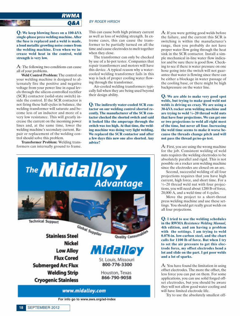
Q: We keep blowing fuses on a 100-kVAsingle-phase press welding machine. Afterthe fuse is replaced and a weld is made,a loud metallic growling noise comes fromthe welding machine. Even when we in-crease weld heat in the control, weldstrength is very low.
A: The following two conditions can causeall of your problems.
Weld Control Problem: The control onyour welding machine is designed to al-ternately fire the positive and negativevoltage from your power line in equal lev-els through the silicon-controlled rectifier(SCR) contactor (solid-state switch) in-side the control. If the SCR contactor isnot firing these half-cycles in balance, thewelding transformer will saturate and be-come less of an inductor and more of avery low resistance. This will greatly in-crease the current on the incoming powerlines and, at the same time, lower thewelding machine’s secondary current. Re-pair or replacement of the welding con-trol should solve this problem.
Transformer Problem: Welding trans-formers can internally ground to frame.
This can cause both high primary currentas well as loss of welding strength. In ex-treme cases, this can cause the trans-former to be partially turned on all thetime and cause electrodes to melt togetherwhen they close.
The transformer can only be checkedby use of a hi-pot tester. Companies thatrepair transformers and motors will havethis device. A typical reason why a water-cooled welding transformer fails in thisway is lack of proper cooling water flow-ing through the transformer.
Air-cooled welding transformers typi-cally fail when they are being used beyondtheir design ability.
Q: The indirectly water-cooled SCR con-tactor on our welding control shorted re-cently. The manufacturer of the SCR con-tactor checked the shorted switch and saidit looked like the amperage through theswitch was too high. At that time, the weld-ing machine was doing very light welding.We replaced the SCR contactor and aftera few days this new one also shorted. Anyadvice?
A: If you were getting good welds beforethe failure, and the current this SCR isswitching is within the manufacturer’srange, then you probably do not haveproper water flow going through the heatsink in the SCR contactor. Install a sim-ple mechanical in-line water flow indica-tor and be sure there is good flow. Check-ing to see if there is water pressure on onehose going into the switch will not guar-antee that water is flowing since there canbe either a blockage in water passage ofthe cooling base, or there might be highbackpressure on the water line.
Q: We are able to make very good spotwelds, but trying to make good weld nutwelds is driving us crazy. We are using a30-kVA rocker arm welding machine andare trying to weld ¼–20 thread weld nutsthat have four projections. We can get oneor two projections to weld all right mostof the time, but never all four. Increasingthe weld time seems to make it worse be-cause the threads change pitch and willnot pass the thread go/no-go test.
A: First, you are using the wrong machinefor the job. Consistent welding of weldnuts requires the welding electrodes to beabsolutely parallel and rigid. This is notpossible on a rocker arm welding machinesince the electrodes are closed on an arc.
Second, successful welding of all fourprojections requires that you have highcurrent, high force, and short time. For a¼–20 thread weld nut with four projec-tions, you will need about 1200 lb of force,20,000 A, and a weld time of 4 cycles.
Move the project to a short-throatpress welding machine and use these set-tings. You should get really great welds onall four projections.
Q: I tried to use the welding schedulesin the RWMA Resistance Welding Manual,4th edition, and am having a problemwith the settings. I am trying to weld0.078-in. low-carbon steel, and the chartcalls for 1100 lb of force. But when I tryto set the air pressure to get this elec-trode force, my offset electrodes bend alot and slide on the part. I get poor weldsand a lot of sparks.
A: You have found the limitation in usingoffset electrodes. The more the offset, theless force you can put on them. For someapplications, you can use solid forged off-set electrodes, but you should be awarethey will not allow good water cooling andwill have limited electrode life.
Try to use the absolutely smallest off-For info go to www.aws.org/ad-index
RWMA September 2012_Layout 1 8/9/12 3:04 PM Page 18

19WELDING JOURNAL
set possible for the part being welded. Ifthe welding chart force is still too high forthe offset electrode, you will have to findan alternate welding schedule. Table 7.3in the RWMA Resistance Welding Manual,4th edition, has Class “A,” “B,” and “C”weld setups that might help you.
For 0.078-in. low-carbon steel, theClass A schedule calls for 1100 lb offorce, 21 cycles of weld time, and 13,300A of welding current. The Class B sched-ule calls for 650 lb of force, 36 cycles weldtime, and 10,400 A of welding current.The Class C schedule calls for 325 lb offorce, 58 cycles of weld time, and 7900 Aof welding current.
You could use the B or C schedules,but know that the weld strength (averagetensile shear strength) will be 3225 lb forthe Class A schedule, 3025 lb for the classB schedule, and 2900 lb for the Class Cschedule. Also, using much longer weld-ing time will decrease electrode life andrequire electrode dressing more often.
Q: I am installing a 100-kVA, 230-V, sin-gle-phase resistance welding machine andneed to operate it from a 440 to 220-V step-down transformer. My electrician said Ineed a 100-kVA step-down transformer.Is that correct?
A: There is often confusion about resist-ance welding machine transformer rat-ings. If you look closely, you will see thatthe transformer, if built to RWMA stan-dards, is rated at 100 kVA but at 50%duty cycle. This means the transformercan be used at the maximum thermal out-put for up to 30 s every min. The step-down transformer is rated at 100% dutycycle, which means it can operate contin-uously at the rated kVA without over-heating the windings.
To size a power line or step-downtransformer, multiply the kVA of thewelding machine by the square root ofthe duty cycle. In this case, the calcula-tion would be:
Step-down transformer = 100 kVA× √0.50 = 100 kVA × 0.707 = 70.7 kVA.
Therefore, a 75-kVA transformer willwork fine.
Minimum wire primary amps of thewelding machine can be calculated by di-viding this kVA by the machine’s line voltage.
For wires going into the welding ma-chine transformer, the calculation is
70,700/220 = 321 A.
For wires going from the power sourceinto the input of the step-down trans-former, the calculation is
70,700/440 = 161 A.
The required minimum wire size canbe found in the RWMA Resistance Weld-ing Manual, 4th edition, Table 21.2.◆
ROGER HIRSCH is immediate pastchair of the Resistance Welding Man-ufacturing Alliance (RWMA), a stand-ing committee of the American Weld-ing Society. He is also president of Uni-trol Electronics, Inc., Northbrook, Ill.Send your comments and questions toRoger Hirsch at [email protected], or mail to Roger Hirsch,c/o Welding Journal, 8669 Doral Blvd.,Doral, Fl 33166.
For info go to www.aws.org/ad-index
RWMA September 2012_Layout 1 8/9/12 3:04 PM Page 19

PRODUCT & PRINTSPOTLIGHT
Video Camera ContainsBuilt-in Borescope Coupler
The Luxxor® portable video cameraquickly attaches to any Hawkeye® rigidor flexible borescope and most othermajor borescope brands. It allows usersto view internal visual inspection imageson portable/benchtop video monitors oron laptop/desktop computers. Videofootage and still photos can be viewed liveas well as saved, documented, and e-mailed. Also, the camera has a 1⁄4-in. colorCCD; built-in, 25-mm borescope coupler;768 × 494 pixel resolution; and can be at-
tached to the Luxxor portable video mon-itor or to any computer or video monitor.
Gradient Lens Corp.www.gradientlens.com/lpc(585) 235-2620
Light Source Usefulfor NDE
The Spectroline® EK-3000 Eagle-Eye™ UV-A/white-light LED inspectionkit (patents pending) is for fluorescentmagnetic particle and penetrant testingalong with other uses. It features the palm-
sized, cool-running EagleEye inspectionlamp with two ultrahigh-intensity UV-A(365-nm) LEDs useful for NDE, plus athree-LED white-light assembly. An ad-justable strap allows the lamp to be wornon a hard hat or on the head. A lampmount/sprayer attachment permits thelamp and a spray can to be mounted forsingle-handed fluorescent yoke inspec-tion. The lamp produces a nominal steady-state UV-A intensity of 4500 μW/cm² at15 in. The kit comes with a lanyard, tworeplacement splash guards with integralparticulate filters, three spare batteries, abattery charging cradle with AC and DCcord sets, and UV-absorbing spectacles.Components come in a soft carrying case.
Spectroline®www.spectroline.com(800) 274-8888
Oxyfuel Safety DVD Offeredin English and Spanish
A 36-min-long video, titled Oxy-FuelSafety: It’s Your Responsibility, and supple-mental training materials are designed to
SEPTEMBER 201220
Weld Inspection Scanner Offers High Probability of Detection
The portable, time-of-flight-diffraction in-spection system allows users to view weld qual-ity quickly. It positions two angle beam trans-ducers facing each other to transmit and receivethe diffraction of ultrasonic waves generated inthis technique. The hand-held scanner needsonly one person to operate and is sensitiveenough that an external preamplifier is notneeded. Used with the company’s Pocket UTTM
battery-operated, hand-held, C-scan acquisitionsystem, users can display the scan, plus storeand measure indications in terms of height,length, and position. The B-scan image best rep-resents the real-time data captured for evalua-tion. Additional benefits include a high proba-bility of detection, hand-held magnetic wheelscanner, touch-screen operation, multiple lan-guage results, auto data file saving, adjustableprobe center separation, and ports to UTWinadvanced weld inspection technique.
MISTRAS Group, Inc.www.mistrasgroup.com(609) 716-4000
P and P September 2012_Layout 1 8/9/12 12:41 PM Page 20

21WELDING JOURNAL
support safety programs in schools, tech-nical colleges, and industry. Included area leader’s guide to facilitate group discus-sions and a participant’s guide with reviewquestions and helpful resources. TheDVD and all contents are available inEnglish or Spanish. The topics includesafety and personal responsibility, gases,regulators and hoses, torches, lighting thetorch, and a cutting demonstration. Thevideo displays the proper methods to in-spect, set up, light, and safety shut downan oxyfuel system using acetylene and al-ternate fuels such as propylene. While thevideo uses the company’s torches andEDGE regulators, it is nonpromotionaland the techniques shown can be appliedto any equipment brand. The entire videomay be viewed online on YouTube. Searchfor “Victor Gas.” The DVD and trainingmaterials may be obtained from your localcompany representative or inquire at yourgases and welding supply distributor.
Victor Technologies Internationalwww.victortechnologies.com(800) 426-1888
Wires Meet D1.8 SeismicCode Requirements
The company offers 16 metal-coredand flux-cored (gas- and self-shielded)wires that meet AWS D1.8/D1.8M, Struc-tural Welding Code — Seismic Supplementfor demand critical welds in seismic mo-ment frame welded connections. Thesefiller metals have been three-lot tested inaccordance with AWS D1.8/D1.8M:2009testing requirements and meet the re-quirements specific for their diameter andshielding gas (where applicable). They areconsidered prequalified for seismic appli-cations and can be used by contractorswithout additional filler metal testing. The
extra testing also ensures the depositedweld metal has adequate strength andtoughness at the specified heat input en-velope for the low and high heat inputsaccording to individual diameter sizes. In-cluded in the offering are the Hobart®Fabshield® XLR-8 self-shielded flux-cored wire, Tri-Mark® Metalloy® Van-tage™ metal-cored wire, and Hobart®FabCO® Hornet gas-shielded flux-coredwire.
Hobart Brotherswww.hobartbrothers.com(800) 532-2618 (technical department)
Metal Analyzers IncludeUV Probe for Arc Operation
The Spectrotest mobile metal analyz-ers offer an ergonomic design, plasmagenerator, and intelligent calibration logicsystem that monitors the correct state ofthe measuring system independently fromexternal influences. In addition, companyengineers designed a pluggable probe withan integrated UV optic that can be usedfor spark and arc excitation. By incorpo-rating a lightweight transport trolley, de-sign engineers cut the instrument’s weight
The all new S1 TITAN
Positive Material Identification Fast alloy ID and chemistry Completely non-destructive Prevents material mix-up Lightweight – only 1.44kg / 3.17 lbs,
including battery
fie all new S1
ight and ex
nition of Pr
ceptionally accurTIT
recision
ceptionally accurate TATAN
Innovation with Integrity
or
[email protected]/s1titan
y of virtually any alloy.y analyzer which provides grade ID and element
Handheld XRF
uk r-er-Elemental.net
vides grade ID and elemental
Handheld XRF
For info go to www.aws.org/ad-index
P and P September 2012_Layout 1 8/9/12 12:42 PM Page 21

SEPTEMBER 201222
in half. The analyzer further features a 15-in. display. The software only shows theuser the context-dependent functions re-quired for the current operation; and it issuited for identifying low-alloy steels usingthe carbon content in the rapid arc exci-tation mode.
Spectro Analytical Instrumentswww.spectro.com(800) 548-5809
Pipe Milling End-Prep ToolFeatures One Mandrel
The Commander MILLHOG® pipemilling end-prep tool can perform anyangle of weld prep, including compoundand multiangle preps on stainless steel,superduplex, P-91, and other hard alloyedpipes. Featuring one mandrel and sevensets of clamps for the 3.75-in. ID to 14-in.
OD range of the tool, it pulls a thick chipwithout cutting oils. Available with pneu-matic or hydraulic motors, it is built forfabricating and maintaining high-temper-ature and high-pressure piping systems.Standard features include dual-opposedtapered roller bearings and oversizedclamps with six contact points.
Esco Toolwww.escotool.com(800) 343-6926
New Video ShowcasesCNC Plasma Technologies
A 3-min video presents new CNCplasma technologies. This Impact Movie,being distributed worldwide, showcasesthe company’s technologies, including
For info go to www.aws.org/ad-index For info go to www.aws.org/ad-index
P and P September 2012_Layout 1 8/9/12 12:42 PM Page 22

Precision Hole Technology, Smart Volt-age Height Control, and SmartCycle.Viewers can watch the film at the follow-ing link.
ESAB Cutting Systemsesabna.com/cncmovie(800) 372-2123
Brazing TechnologySpanish Site Launched
The company’s Global Brazing Solu-tions has launched a Spanish version ofits corporate Web site in recognition ofthe company’s growing need to provideSpanish language support for Latin Amer-ica. Spanish is the third language the Website has been translated to and all sitescontain the same information.
Lucas-Milhaupt, Inc.www.lucasmilhaupt.com/es-MX/(414) 769-6000
Grinding Tool PreparesTungsten Electrodes
The Sharpshooter™ grinds tungstenelectrodes to exacting tolerances in an en-
closed chamber while quietly and safelystoring all dust. Also, it recently receiveda listing from ETL Intertek after under-going rigorous safety evaluations and test-ing associated with earning a listing froma nationally recognized testing laboratory.To the best of the company’s knowledge,the product is the only listed tungstengrinding tool in the world.
Pro-Fusion Technologieswww.pro-fusiononline.com(800) 747-9353
Vacuum Lifter ProtectsHeavy Pipe and Tube
The VPFL4 vacuum lifter for heavypipe and tube features nylon centeringguides and oval rubber suction cups toprevent anything other than nylon or rub-ber from touching the load. Designed tocompensate for unevenly packed loadswith staggered rows, it has a 500-lb capac-ity and can pick up two, three, or fourpipes or tubes from the top simultane-ously. Eliminating hooks, slings, and ex-cessive handling that can cause damage,the lifter is offered in air-powered or elec-tric units that only need 8 in. of headroom.Standard features include an all-welded
23WELDING JOURNAL
For info go to www.aws.org/ad-index
P and P September 2012_Layout 1 8/9/12 12:43 PM Page 23

steel frame, adjustable handle with built-in controls, a vacuum gauge, and audio-visual vacuum leakage detector system.
Anver Corp.www.anver.com(800) 654-3500
Cutoff Wheel Suited forThin-Walled Railing
The A 60 TZ Special, a fast and smoothultrathin cutoff wheel, utilizes a hard bond
for extended life and a burr-free cut, whileits cool cut reduces the risk of contamina-tion and prevents discoloration. It is mostuseful in stainless steel applications andcutting thin-walled tube, pipe, and railing.The wheel is available in Type 1 (flat) andType 27 (depressed center) forms in 41⁄2 or5 in. diameter and 0.045 in. thick.
Klingsporwww.klingspor.com(800) 645-5555
Gun Available with OptionalDual Schedule Switch
The Dura-Flux™ self-shielded flux-cored arc welding (FCAW-S) gun with re-placeable power cable liner provides op-erators 350 A of welding capability at a60% duty cycle. Its handle design helpsreduce downtime associated with user fa-tigue. In addition, it is available with anoptional dual schedule switch that allowseasy wire feed speed adjustment whilewelding. The trigger absorbs less heat toincrease arc-on time, lower heat input,and extend component life. Extra featuresinclude a rotatable Hi-Viz™ neck to im-prove weld pool visibility, and the com-pany’s Quik Tip™ series consumables de-
signed with a threaded taper lock that in-creases contact tip life.
Bernardwww.bernardwelds.com(800) 946-2281
Welding Line Detailed inBrochure
An 80-page, full-color brochure, TheUltimate Welding Combo, features thecompany’s full line of professional-qual-ity welding machines and accessories. In-
SEPTEMBER 201224
— continued on page 80
For info go to www.aws.org/ad-index
P and P September 2012_Layout 1 8/9/12 12:43 PM Page 24

For Info go to www.aws.org/ad-index
otc daihen_FP_TEMP 8/7/12 9:12 AM Page 25

SEPTEMBER 201226
When you hear the words “weneed to improve our weld qual-ity,” the following are a few of
the things that typically come to mind:• We will need to do more inspection
and so will need to hire more people• Improving quality will most likely
reduce productivity, increase costs, andtake more time
• There will be a mountain of extrapaperwork and reports required.
Utilizing a weld quality managementmethodology will erase these concernsby improving the overall productivity andquality of welding fabrication. Such amethodology utilizes the following tools:
1. Design for Manufacturing (DFM)for upfront planning to ensure the prod-uct can be manufactured effectively andefficiently with the processes planned forthe production floor.
2. Total cost of quality, which meas-ures the four cost categories of preven-tion, analysis, repair, and scrap.
3. Overall equipment effectiveness(OEE) , which tracks uptime, productiv-ity, and quality for actual productionmonitoring, control, and continuous im-provement.
Prevention Is Key
The typical quality control functionutilized today for determining weld qual-ity requirements and assessing whetherthey have been met starts at the end of
the overall manufacturing process. Thatis totally backward because it means thatmost of the work has been put into in-spection, rework/repair, and managingscrap rather than into preventing a badproduct from being made in the firstplace. The focus needs to be reversed sothat most of the planning is put into pre-venting defects and analysis of historicaldata so that work can be done up front toestablish robust processes that will be ableto handle as much variation in manufac-turing as possible. Figure 1 shows the typ-ical breakdown of costs in industry todayand how this cost breakdown would lookin a “pro-active” world. It is a fact thatthe cost to fix a defect in a product in-creases exponentially the farther it proceeds through the manufacturingprocess.
Looking specifically at welding oper-ations, we can use DFM methodology toimprove productivity and quality by pre-venting, or at least identifying, a prob-lem as early in the process as possible.Specifically, DFM is used for
1. Ensuring the product is designed tobe efficiently manufactured. In addition,we should strive to design whenever pos-sible for a high level of automation be-cause this reduces the variability inher-ent with human involvement.
2. Facilitating the gathering of histor-ical process capability data of the sameor surrogate welding processes to deter-mine what level of productivity (like
travel speed, cycle time) and quality(first-pass yield, parts per million) can beexpected with the methods, people, andequipment planned.
3. With the knowledge from Nos. 1and 2, we can now look at what new tech-nology can be introduced to improve thestatus quo.
Variability: A Challengeand an Opportunity
Today, most testing and prove-out ofwhat a weld process can do is performedin the perfect world of a lab. Welding pro-cedure specifications (WPSs) are doneunder controlled conditions and then wereach the real world and everything is dif-ferent than expected, which adversely af-fects both productivity and quality. Whydoes this occur? Two reasons:
1. Poorly understood upstream vari-ability that is not reflected in the weld-ing procedure specification.
2. Not using the right technology toovercome the limitations present in yourproduct manufacturing.
Let’s walk through the seven weldquality assurance steps shown in Fig. 2.
Step 1: BenchmarkingExisting WeldingOperations.
A portable laser scanning weld in-spection system can be used at the point
Good Design Plus EarlyInspection EqualsHigh Productivity
JEFF NORUK(j.noruk@servorobot. com) isPresident, Servo-Robot Corp.,
Milwaukee, Wis.JEAN-PAUL BOILLOT
([email protected]) isCEO, Servo-Robot Group, St-
Bruno, PQ, Canada.
This quantitative method ties thewelding process quality results tothe actual welding parameters used
BY JEFF NORUK ANDJEAN-PAUL BOILLOT
Noruk Feature September 2012_Layout 1 8/8/12 11:06 AM Page 26

27WELDING JOURNAL
where the parts are stamped, cut, or ma-chined to determine whether the properedge preparation is present, which affectsdownstream fitup quality. From there,you can check every fixtured or tackedpart presented to the welding operationto determine how well the joints conformto what they should be. If you are doingrobotic welding, simply hook up an au-tomatic laser scanning weld inspectionsystem to the face plate of the robot asshown in Fig. 3 and then measure thecomplete variability of the weld jointsand welds. Information about the jointincludes variability of fitup (root open-ing, mismatch, etc.), as well as the vari-ability of the joint in space, which is com-posed of part and fixture changes. Thisbenchmarking gives you an understand-ing as to the level of the incoming vari-ability, which then can be used when youmake the test samples for the WPS. Like-wise, for weld inspection and measure-
ment, you can determine the variabilityin the geometry and presence of defectsthat are typical in production (see Fig. 4,which shows an inspector performing apart-to-part weld quality audit). Finally,you can use this information to deter-mine what the main problems are — forexample, undersized welds, undercut —and then dig even deeper to determinewhy, where, who, etc.
Step 2: ContinuousImprovement.
With the information from step one,you can decide whether new methods,techniques, equipment, people, orprocesses need to be developed or uti-lized. This may even involve doing somedevelopment to improve an existingprocess or introduce a whole new weld-ing method. A portable laser scanningweld inspection system can quickly andefficiently help gauge whether any of
these changes and/or improvementsraised the quality level because it is easyto link the process change with its effecton weld quality.
Typically, you can get to a certain pointwith your variation reduction effort onyour existing process where no more im-provement is possible. If this level is “ac-ceptable,” then you are good to go. How-ever, if the actual production require-ments are higher than you can nowachieve, then you need to look at the nextlevel of technology.
For example, instead of living with thejoint variability, which will always keepyou from being able to optimize theprocess, you can now add technologysuch as vision to overcome this limita-tion. Figure 5 shows an example of laservision joint tracking, which can be usedto negate most of the inherent excessivevariability in the manufacturing opera-tion. This is accomplished by giving the
Fig. 1 — Cost of quality today and in a SixSigma world.
Fig. 2 — Seven weld quality assurance steps.
Fig. 3 — Automated weld inspection.
1
2
3
Noruk Feature September 2012_Layout 1 8/8/12 11:06 AM Page 27

robot “eyes” so it will always follow thejoint to maintain optimum weld wire po-sition and stickout. Going one step fur-ther, adaptive welding methods can beutilized to automatically change thewelding parameters (current, travelspeed, etc.) to accommodate variationgreater than what can be handled with afixed weld schedule. Figure 6 shows howa change in root opening is handled usingadaptive welding techniques so produc-tivity and quality are optimized.
Step 3: Welding ProcedureSpecificationDevelopment.
Because you have the informationneeded to simulate real-world conditionsand to determine how the inputs affectthe welding process, you can now de-velop a robust welding process capableof managing anticipated inputs. All theinformation, including test plate jointfitup, welding parameters, and inspec-tion results, can be combined to providea complete record of the WPS work. Fig-ure 7 shows the process inputs and out-puts and how they are related to the endgoal of optimizing the welding.
Step 4: Training, Qualification, andCertification of Personnel.
The people aspect of the welding op-eration is equally important to that of thetechnology and equipment used.Whether it is manual or automated weld-ing, you need an efficient and timelymeans of determining whether the peo-ple involved are qualified to run theequipment to maximize performance.The portable laser scanning weld inspec-tion system can be used to help selectpeople to be trained as welders, it can as-sist in the training by giving actual scoreson their performance, and it can even beused to help welders who need some re-medial training to improve their skills.Likewise, the same-type system can beused in a manual or robotic auditingmode to determine if the robots havebeen programmed correctly and whetherthis level is being maintained.
Step 5: From Robot CellDesign to IntegratorRunoff.
An important step associated withpurchasing new automated weldingequipment to improve the existing weld-ing operation is to understand what thereal baseline is, so that you can determinewhether the improvement required isachievable, and once installed, achieved.This relates to the previously discussedbenchmarking phase where you can get
real data on what level of productivityand quality is presently being achieved inthe factory. This information needs to besupplied to the integrators quoting onnew automation so they know how toproperly design and build the system andwhat the realistic cost will need to be.Then, during the runoff at the integrator,you have real metrics to compare to soyou know if the goal was achieved. At thisstage, the integrator can use simulationto determine when the weld inspectionneeds to occur in the production cycle tokeep the process in control.
Step 6: Production Runoffin Customer Factory.
This runoff is done to ensure the au-tomated system can produce an accept-able level of quality parts when faced withall the variability that will occur on a reg-ular basis. A laser scanning weld inspec-tion system can be used either manuallyor on a robot to inspect every part in theearly runoff stages to establish the actualprocess capability and the parts per mil-lion defect rate. Figure 8 shows a typicalauditing exercise showing an inspectionreport developed through the use of aWikiScan/Robo portable laser scanningweld inspection system from Servo-Robot Corp.
Step 7: Ongoing QualityAudits of Production.
Periodic auditing makes sure the qual-ity level is okay, and if not, helps deter-
SEPTEMBER 201228
Fig. 4 — Automated vs. old-fashioned manual inspection.
Fig. 5 — Real-time laser vision joint tracking.
Noruk Feature September 2012_Layout 1 8/8/12 11:06 AM Page 28

mine where the problem is and how bestto get to the root cause.
While it is best to prevent any poten-tial defect from being planned into theoverall manufacturing process, the weldquality assurance methodology plans forongoing inspection in the factory. How-ever, there is good/effective inspectionand bad/ineffective inspection. Let’s re-view the latter first.
How many times have you walkedthrough a factory and seen either a man-ual or automated inspection station at theend of the production line? No matterhow sophisticated or automated this sta-tion may be, it is really just an attempt tokeep bad products from leaving the fac-tory and getting to the final customer.Any repair (sometimes called rework tomake it sound like some value is beingadded) at this point is extremely expen-sive and disruptive to Just-in-Time (JIT)efforts and delivery schedules. The worstpart of this inspection, especially if donemanually, is that it is extremely subjec-tive and can even result in repairing aproduct that is actually acceptable. Noone wants to be held responsible for a badproduct leaving the factory so peopleoverinspect and thus force more weld re-pair to occur.
Now let’s look at the characteristics ofeffective weld inspection that actuallypays for itself. These include the following:
• Inspection is done at the point ofwelding, or as close as possible, so imme-diate feedback to the operator, or processitself, occurs resulting in a minimum
29WELDING JOURNAL
Fig. 6 — Adaptive welding techniques.
Fig. 7 —Weld process inputs/outputs.
Fig. 8 — Robotic weld inspection.
7
8
6
Noruk Feature September 2012_Layout 1 8/8/12 11:07 AM Page 29

quantity of bad welds being made. Figure9 shows a robot cell where any of the weld-ing robots can decide to pick up a weldinspection system to check the weld qual-ity before proceeding to make the nextweld or put in the next layer. This emu-lates a welder lifting his helmet and look-ing at the weld or pulling out his gauge tocheck the size and quality of the weld.
• The inspection is automated asmuch as possible so there is minimalhuman interference and it is done asquickly as possible.
• Inspection is done by actually meas-uring the weld geometry directly so thatnot only go/no-go results are availablebut there is also the ability to store thedata and analyze it to see why there isvariability. From there you can developways to reduce the variability.
• The results are available to be fedback into the planning cycle for productimprovement and future new products.This means the real data can be used todevelop the next WPS, as well as to planfor new technology — Fig. 10.
• The information is readily availableto everyone from the welder or operatorto the president of the company, ifneeded. It is even possible to connect toany laser scanning weld inspection sys-tem from your smart tablet device andsee the latest quality assessment or down-load the results and look for trends andevaluate the process capability.
SummaryWhile weld quality assurance method-
ology is not radical or perhaps even new,it is simply the right way to manage weldquality. Historically, it has been difficultfor people to achieve the desired resultsdue to the lack of a quantitative methodto tie the welding process quality resultsto the actual welding parameters usedwhether in the R&D area, welding pro-cedure development phase, or in produc-tion out in the factory. This methodology,combined with new tools, helps to turnraw data into actionable information.◆
SEPTEMBER 201230
Manufacturing Flux Cored
Welding Wire
COBALT
NICKEL
HARDFACE
STAINLESS
ALLOY STEEL
TOOL STEEL
MAINTENANCE
FORGE ALLOYS
CUSTOM ALLOYS
COR-MET, INC. 12500 Grand River Rd.
Brighton, MI 48116 PH: 800-848-2719 FAX: 810-227-9266
www.cor-met.com [email protected]
COBALTLTWelding WFlux Cored
Manufacturin
elding WireFlux Cored
uring
TASTAINLESS
HARDFACE
NICKEL
INLESS
E
FORGE ALLO
MAINTENAN
TOOL STEE
ALLOY Y STEEL
OYS
CE
EEL
EEL
12500 Grand River Rd.MET, INC.-COR
CUSTOM ALLOYS
FORGE ALLO
and River Rd., INC.
OYS
OYS
met.co-sales@cor
met.com-wwwww.cor9266-227-FAFAX: 81027-848-PH: 800
Brighton, MI 481
t.com
t.com9266
719116
Fig. 9— Robot arm with weld inspection system.
Fig. 10 — Comprehensive on-board inspection report.
For info go to www.aws.org/ad-index
Noruk Feature September 2012_Layout 1 8/8/12 11:10 AM Page 30

For Info go to www.aws.org/ad-index
fibre metal_FP_TEMP 8/7/12 10:19 AM Page 31

SEPTEMBER 201232
When various surface technolo-gies have many similarities, itcan be difficult to choose the
most appropriate for specific jobs. This occurs frequently when deciding be-tween laser cladding and thermal spray,specifically high-velocity oxyfuel spray(HVOF).
Once considered radically different,both technologies have advanced to thepoint that either is suitable for certainapplications. High-velocity oxyfuel coat-
ings are growing thicker, while lasercladding coatings are becoming thinner.Additionally, HVOF has reduced poros-ity to levels that verge on being consid-ered fully dense.
Still, the technologies behind HVOFand laser cladding — and the majority ofapplications — remain fundamentallydistinct. Coating with HVOF involvesspraying the material at a high velocityand temperature, which softens the par-ticles and forms a mechanical bond with
the roughened substrate. In contrast,laser cladding melts both the materialbeing applied and the surface of the sub-strate to form a metallurgical bond.
Functional Similarities
Both laser cladding and HVOF willcontinue to converge for the next two tofive years, which will then create a shiftin commercial assessment. Presently,HVOF is the only technology for thinner
Choosing a Surface Coating Technology
HVOF application of tungsten carbideapplied to a lumber roll using a DJ-2600 spray gun. Coating is forabrasion and corrosion resistance.
Peters Feature September 2012_Layout 1 8/9/12 7:02 AM Page 32

33WELDING JOURNAL
coatings, such as 200 to 300 µm (0.008 to0.012 in.). However, despite HVOF ad-vances in producing thicker coatings inexcess of 0.5 mm (0.02 in.), laser claddingis preferred over HVOF for thicker coat-ings — Fig. 1.
Another area of convergence is poros-ity. The fundamental principle behindthermal spray necessitates that particlesare softened by heating and compactedin a solid state, leaving small spaces be-tween them that result in a porous coat-ing. Porosity levels for HVOF have beenreduced to less than 0.5%, which is nearlyfully dense. Still, these pockets can causepenetration of the coating when parts areexposed to high-pressure environmentsor long-duration tests. Despite HVOF’sdecreasing porosity levels, laser claddingis a completely dense surfacing solution.
Both coating technologies can createresidual stress on the substrate, distort-ing it and potentially forming cracks inthe coating and/or the substrate. Whena laser cladding material is heated,
melted, and solidified, it shrinks, andthese temperature fluctuations cause in-ternal stresses that can warp a thin part.Though laser cladding has advanced tominimize distortion levels, HVOF stillcauses less stress and distortion risk be-cause the material is neither fully meltednor metallurgically bonded. The internalstresses in HVOF coatings are what limitthe thickness.
Difference inApplication
One major application difference be-tween these two technologies has to dowith how the coatings adhere to the sub-strate. High-velocity oxyfuel creates amechanical bond between the coatingand substrate surface, allowing manufac-turers to use any material. Laser claddingcreates an intermetallic alloy in the in-terface zone between substrate and coat-ing material and, as a result, is limited by
being able to bond only to materials thatare weldable. Manufacturers should en-sure that the selected materials will cre-ate a successful metallurgical bond, suchas a nickel deposit to iron substrate tocreate a nickel-iron alloy. Materials thatare not compatible, such as titanium andiron, could result in a weak intermetalliclayer that can easily crack.
Additionally, laser cladding has asmall melt pool, meaning the applicationprocess can take longer than HVOF.Thus, extra time for the application oflaser cladding materials can offset othercost savings. High-velocity oxyfuel stillhas a significantly higher deposition ratebut adds time with the increasing thick-ness of the coating.
Surface Conditions
The part’s surface conditions play arole in determining the appropriate coat-ing. High-velocity oxyfuel’s limited bondstrength is less ideal for parts that will besubjected to high stress or impact load-ing. The mechanical bond may cause thecoating to shatter or spall if subjected totoo much stress, particularly point-loaded stresses such as with a hammer.The stress may weaken laser cladding’salloyed coating but will likely not causeit to debond.
The same rule of thumb can be ap-plied to parts that will endure many ther-mal cycles. Fluctuating temperaturescause different metals to expand and con-tract independently. This thermal shock
Fig. 1 — Key surface enhancementprocesses.
Knowing the strengths andweaknesses of high-velocityoxyfuel thermal spray andlaser cladding will help youchoose the right processfor your application
THOMAS PETERS is projectmanager, Business Development
Laser Cladding, Sulzer Metco,and THOMAS GLYNN
([email protected]) isproduct line manager, Metals
and Alloys, Sulzer Metco, Westburg, N.Y. Photo courtesy ofSulzer Metco Coating Services.
BY THOMAS PETERS ANDTHOMAS GLYNN
Peters Feature September 2012_Layout 1 8/9/12 7:03 AM Page 33

can stress and weaken the HVOF bondinterface, but this is not the case withlaser cladding because it creates a met-allurgical bond.
Corrosion
Coatings are also vulnerable to corro-sion, which can be aggravated by poros-ity. Despite advances in HVOF, the lin-gering pores if interconnected, renderthe coating vulnerable to environmentalpressures that deteriorate the surface.For example, a valve coated with the min-imally porous HVOF would eventuallysuccumb to harsh seawater leakingthrough the coating, causing corrosion atthe interface.
Such high-pressure environmentsoften necessitate laser cladding to pro-duce a fully dense coating but these arelimited to materials that are weldable.
Manufacturing
Environment
Both coating technologies also havedifferent requirements in regard to man-ufacturing environments. Compared tolaser cladding, HVOF covers a largerspray area but is less precise. The rela-tive velocities of the spray gun and partneed to be moved quickly or the coatingwill accumulate too rapidly, which willcreate excessive residual stress and bondfailure.
While thermal spray can be appliedboth manually and via automated tech-nology, laser cladding requires an auto-mated factory environment for safetyreasons and because of the applicationprecision. Each weld track has to be po-sitioned with tolerances below 1 mm(0.04 in.), necessitating a robot to applythe coating. With such a small coveragearea, what laser cladding gains in preci-sion it loses in application time. Compar-ing the two technologies, laser coatingsare applied in a narrow but relativelythick layer while HVOF uses many widerbut thinner layers.
However, because HVOF is appliedin fine layers to mitigate the stress andshrinkage issues, care must be exercisedto properly cool the part during the sprayprocess or the substrate may overheat.This is not typically a concern with lasercladding. With some HVOF coatings re-quiring 50 passes, this process can de-crease efficiency. Laser cladding mayalso require a waiting period for the partto cool as the materials are heated locallybeyond the melting temperature.
As mentioned previously, the differ-ences in deposition rates, or materialmass per unit of time, are notably largewith HVOF having a significantly higherrate. Though HVOF coatings can reach0.5 mm (0.02 in.), laser cladding tends tobe more efficient — often only one layeris required.
When both technologies are auto-mated and implemented using standardindustrial robots, the comparison be-comes more apples to apples. Lasercladding previously required compli-cated manipulation using copper mirrors.Now it uses the more simplified fiber-optic bundles to control the laser beams.On the other hand, a thermal spray guncan easily be mounted at the end of arobot or manually manipulated.
Thermal spray also requires speedymanipulators and when covering a largearea, a large robot. However, this pres-ents a paradox as a very large robot is alsoslower.
Safety
When incorporating such potent tech-nologies, safety is at the forefront of con-sideration. Both laser cladding andHVOF have their respective safety pre-cautions for workers and are always en-closed in an isolated cell. Laser claddingrequires compliance with general laserregulations, such as protecting eyes withspecial glasses, shielding the workers,and safeguarding against welding fumesand laser light wavelength.
With HVOF generating heat loads upto 1 million BTUs, thermal spray boothstypically require large volumes of air ex-change to keep temperatures within rea-sonable limits. Another requirement is adust collector with closed-circuit air fil-ters to vacuum the dust generated fromsub-25 µm particles. The gun also gener-ates extremely high temperatures and apiercing noise that registers above safelevels, so workers need to wear appropri-ate protective gear if manually applyingthe coating.
Energy and Material
Efficiency
Both technologies consume energyand materials at different rates. Lasercladding was previously a notorious en-ergy consumer with an efficiency of lessthan 10%. For example, a 5-kW laserwould demand 50 kW to power it. Fortu-nately, laser cladding is now 30% effi-cient, a radical enough improvement to
be considered power efficient. Because of the energy-intensive gas
stream needed to heat the particles,HVOF spray is considered less efficientthan laser cladding.
From a material standpoint, lasercladding is more than 90% efficient, out-performing thermal spray’s 40 to 60% ef-ficiency. This is due to the imprecisionof the HVOF spray cone, which does notproject some of the particles at a fast-enough velocity. As a result, many parti-cles bounce off the substrate and fail tobond.
Though laser cladding and HVOF usepowder-based materials at similar pricepoints and availability, the particle sizesdiffer. Laser cladding particles arecoarser and heavy enough that no filtra-tion device is needed. Thermal spray’sfiner particles are light enough to becomeairborne, necessitating the dust collectorand air filters. Another component ofHVOF overspray waste is that some par-ticles are so lightweight, they blow awayand never reach the substrate.
Application Equipment
The thermal spray gun can be easilymoved — up, down, and into awkwardcorners — while the target part remainsstationary. If the part has a more compli-cated design, the HVOF gun can be eas-ily maneuvered to cover all contours. Inaddition to manual application, HVOFis versatile in that it can be also used withan automated system. Because thermalspray essentially blankets an area with acontinuous coating, the automated programming is relatively simple in mostapplications.
On the other hand, laser cladding ismuch more complex. Each weld track in-volves a repeated start-stop approachwhere the laser starts and stops. As men-tioned previously, each laser applicationis comparably precise. Thus, the pro-gramming effort is much more sophisti-cated and requires the precise locationand dimensions of the part. Crucial to re-ducing this time-consuming process, offline programming tools are needed.
Access
Both technologies are line-of-sightprocesses with different distance require-ments. While the laser cladding powdernozzle needs to be less than 25 mm (1 in.)from the substrate for HVOF, a typicaldistance range from 150 to 300 mm (6 to12 in.) is common. When coating thesmall space inside of a tube, thermal
SEPTEMBER 201234
Peters Feature September 2012_Layout 1 8/9/12 7:03 AM Page 34

spray can turn to the plasma sprayprocess as specialized internal spray gunscan be easily placed into a 100-mm part.However, this is another area of conver-gence as laser heads are continually be-coming smaller and can presently fit in-side a 3-in. bore.
Both guns operate at extremely hightemperatures, which affect the applica-tion processes. Laser cladding createslocal temperatures above the meltingpoint of the material.
When laser cladding, the powder noz-zle must be cooled because one-third ofthe laser light is reflected toward the pro-cessing head and not absorbed by themelting process. The closer the powdernozzle is located to the substrate, thegreater the risk of harming it.
The HVOF gun uses air and/or watercooling to dissipate the heat of combus-tion from the internal gun components.
Maintenance
With typical use, the laser itself isdurable enough to operate without main-tenance for several months. There areneither moving parts nor sensitive opti-cal components. Because of the robot’smovement, the fiber-optic cables even-tually need replacement but that is oftenmeasured in years. Depending on the ma-terial being used, powder nozzles mayneed to be replaced after 100–500 hours.
With HVOF, the extremely high tem-peratures and velocities cause the com-ponents to wear quickly, measuring noz-zle life in hours. Though frequent, noz-zle replacements are simple and quick.The materials used also determine thechange-out frequency. Abrasive materi-als such as carbides are applied at a muchhigher velocity, making the HVOF bar-rels and nozzles wear out sooner thanwith metallic materials, with which thenozzles last several days.
Conclusion
There are many factors to enter intothe equation of whether to use HVOF orlaser cladding. Some are obvious choices,such as if a thick and fully dense coatingis needed or if material compatability isa concern. As these technologies con-tinue to evolve, their applicability willbroaden. In the meantime, it is criticalthat users work with material and equip-ment suppliers that are knowledgeableabout both technologies to ensure a suc-cessful coating application with the mostefficient and cost-effective surface solution.◆
35WELDING JOURNAL
For info go to www.aws.org/ad-index
For info go to www.aws.org/ad-index
Peters Feature September 2012_Layout 1 8/9/12 7:04 AM Page 35

SEPTEMBER 201236
To reduce vehicle weight and im-prove fuel efficiency, advancedhigh-strength steels (AHSS) have
been introduced to the automotive in-dustry. Advanced high-strength steelscontinue to gain momentum in the in-dustry as a result of initiatives to increasebody rigidity (driving performance), im-prove crash ratings, and improve fueleconomy (reduce weight to meet CAFÉlegislation requirements). These steelshave challenged manufacturing practicesin a variety of ways, from forming to join-ing to inspecting.
A major issue with these higher-strength, thinner materials is integrity ofspot welds. Typically, there are between4000 and 7000 resistance spot welds onU.S. manufactured automobiles, and thereliability of the structure and safety ofpassengers relies heavily upon soundwelds. It has been found that the stressstate at the weld, fracture toughness ofthe weldment, and presence of pores,cracks, and embrittled regions in AHSSare driving factors that result in differ-ing failure modes from conventionalsteels, especially interface-type failures(Ref. 1). It has been recognized that tra-ditional resistance spot weld (RSW) de-
structive test methods (pry-bar or chiselcheck and peel test, see Fig. 1) are costlyand inaccurate when applied to AHSS.The automotive industry dictates for bet-ter nondestructive means to be devel-oped as a replacement for current de-structive testing in order to ensure safeimplementation of AHSS steels.
Some advanced nondestructive exam-ination (NDE) techniques that can pro-vide solutions to the automotive marketalready exist in other markets. Unfortu-nately, a rapid technology transfer ofNDE techniques, already used in theaerospace and power generation indus-tries, to the automotive industry is lim-ited because of fundamental differencesbetween these markets (Ref. 2). Thereis still a gap to validate and correlateNDE technique findings. The desiredstatus is to reduce the time for valida-tion and increase the confidence in cor-relation methodology with less engineer-ing and laboratory time. To reduce therepeatability gap, the automotive indus-try desires improved robustness of NDEtechniques and little or no operator de-pendence (Ref. 2).
These problems have been addressedby using ultrasonic matrix pulsed array
An ultrasonic, 3-D matrix phased array probe has been designed and tested for performingnondestructive examination of resistance spotwelds on automotive chassis
JEONG K. NA ([email protected])is technology leader, NDE
Group, Edison Welding Institute,Columbus, Ohio.
Phased Array Testing ofResistance Spot Welds
BY JEONG K. NA
Fig. 1 — Destructive testing meth-ods for resistance spot welds onthin sheet metals: A — Drive test; B — peel test.
1A
1B
Na Feature September 2012_Layout 1 8/8/12 3:27 PM Page 36

37WELDING JOURNAL
(MPA) technology as an alternative to de-structive testing of AHSS. Initially, a two-dimensional MPA probe was designed andtested for validation purposes for the tech-nology in terms of sizing weld nuggets andlocating flaws in the weldments. By shap-
ing the probe surface that fits to the gen-erally concave shape of resistance spotwelds, it was found that the total numberof elements and operating frequency couldbe lowered. This, in turn, helps to lowerthe cost of the probe and electronics.
A New High-FrequencyMPA Probe
To reduce the cost and time for devel-oping a reliable high-frequency MPAprobe with an appropriate delay line thatprovides an optimum propagation dis-tance for the ultrasonic beam to besteered and focused onto a spot weld,computational modeling and simulationswere performed upfront. A commerciallyavailable CIVA modeling package wasused for this work.
Probe Modeling andSimulations
It was necessary to define parameterssuch as material thickness and spot welddiameter for which the probe would beused. A literature review and discussionswith clients in the automotive industryrevealed that the majority of spot weldapplications are for materials in thethickness range of 0.7 to 2 mm having anominal weld diameter of 5 to 7 mm.Some initial beam modeling calculationswere done to determine general param-eters for a probe that would be capableof inspecting spot welds in the targetedrange. Consideration was also given tocurrent MPA instrumentation capabili-ties. Many MPA instruments on the mar-ket today have a maximum limit on thenumber of elements in the order of 128.Figure 2 shows a schematic of a 2-D MPAprobe element with some probe param-eters evaluated using the beam modelingtools. The same probe parameters applyto 3-D probes with additions of curvatureshape and radius.
To achieve good focusing at a depthof 0.7 to 2 mm, it was necessary for theprobe to have a physical delay distancebetween the probe element and the partsurface. Since water can offer the abilityto conform to surface deformations
Fig. 2 — Schematic of a 2-D matrixphased array probe element.
Fig. 3 — Modeling results of thewater path length dependence at thewater and metal interface.
Fig. 4 — Modeling results of waterpath lengths at the interface of two2-mm metal sheets.
2
3
4
Na Feature September 2012_Layout 1 8/8/12 3:27 PM Page 37

SEPTEMBER 201238
caused by the welding electrodes, thedelay line tip was assumed to be filledwith water. The images in Fig. 3 showbeam profile results using a 3 × 3 aper-ture at different water path lengths as thesound passes through the water andmetal interface. By observing these im-ages, it can be seen that a water pathlength of 18 mm produces a narrow beamwith minimum side lobes. Quality of theultrasonic beam within the metal sheetswas also simulated for different waterpath lengths with a 3 × 3 aperture. Asshown in the images in Fig. 4, at the waterpath length of 18 mm, the best beam fo-cusing effect was achieved with small sidelobes.
Based on the two modeling resultsshown in Figs. 3 and 4, a hand-held probewas designed and fabricated with a waterdelay line cavity at the end of the probe.A subsequent modeling investigation fora 64-element probe with 8 × 8 matrixconfiguration operating at a frequencyof 12 MHz proved that the same waterdelay line could be used. In this case, theprobe element was shaped to have a con-vex curvature with a radius of 50 mm. Themodeling result of beam quality and aschematic drawing of the 3-D MPA probeare shown in Fig. 5.
NDE and Statistical Validation
Resistance Spot WeldedSample Preparation
Two sets of spot weld samples with twosheet stackups having thicknesses at thetheoretical lower limit (0.7-mm-thicksheet metal) of the probe design wereprepared. Two rows of nine spot weldswere made on test sample No. 1. For thissample, a constant current of 6 kA wasapplied for all welds while the number ofcycles was varied from 1 to 9 at an incre-ment of 1 cycle for each weld. For thesample set No. 2, weld current was ad-justed such that three welded conditionswere obtained: “stuck” weld, where therewas localized melt and resolidification ofthe zinc coating; a small nugget condi-tion, where the button pulled was smallerthan the generally accepted 4 √ t in di-ameter; and a good weld condition,where the button pulled was larger than4√ t in diameter. Spot welds on both sam-ple sets were tested using the MPA in-spection system and then destructivelyexamined to determine the actual weldcondition and to measure the weld
Fig. 5 — CIVA modeling result forthe ultrasonic beam quality andschematic drawing of a 3-D MPAprobe. A — Beam quality of 3-DMPA probe; B — schematic of a 3-Dprobe.
Fig. 6 — Images of resistance spotwelds of both test sample sets. A —Resistance spot weld NDE sampleNo. 1; B — example spot welds oftest sample set No. 2.
5A
5B
6A
6B
Na Feature September 2012_Layout 1 8/8/12 3:28 PM Page 38

nugget size just for the sample set No. 2.The test sample set No. 1 and an exam-ple piece of sample set No. 2 are shownin Fig. 6.
Test Results andDiscussions
The MPA ultrasonic inspection resultsfor the sample set No. 1 are shown in Fig.7. The number in the upper-left cornerof each image indicates the number ofelectric current cycles used to form theweld nuggets. In both upper and lowerrows, a good acceptable size spot weldwas measured after four cycles. The leftand right numbers shown in the upperportion of each ultrasonic image indicatenondestructively estimated nugget diam-eter and area, respectively. It was noticedthat the nugget size did not improve as
much after five cycles. For both rows, theoverall increase in nugget size was lessthan 10% after five cycles. Each inspec-tion took less than 10 s.
The welds in sample set No. 2 wereexamined first with the MPA inspectionsystem before the planar metallographytechnique — where one of the weldedsheets was ground away to reveal theweld nugget — was used to estimate thenugget size destructively. This methodprovided a full planar view of the weldregion without distorting the weld but-ton. The NDE results are plotted againstthe destructively measured data as shownin Fig. 8.
The test result of set No. 2 in Fig. 8shows a good correlation with the actualnugget size. The dotted line in the graphindicates the 95% safety limit against un-dersizing (LUS), which is a combined pa-rameter between systematic (average)
error and standard deviation. A slight un-dersizing trend (positive false call) is ob-served from these data and the calculatedLUS was approximately 1 mm. This LUSvalue in the range of 1 mm is consideredto be a good NDE reliability.
Conclusions
A high-frequency, ultrasonic, 3-DMPA probe designed to perform nonde-structive examination of resistance spotwelds on automotive chassis has been de-veloped and tested. The NDE results ofspot welds made on two 0.7-mm metalsheets with different cycle numbers at aconstant electrical current level showedthat a good weld nugget with an accept-able diameter and area can be formedafter four or five cycles. This means thatthe number of cycles currently used onautomotive chassis could be reduced tosave time and cost without overweldingwith extra numbers of cycles. The PoD in-vestigation performed on the two 0.7-mmstackups showed a tight nugget size dis-tribution between 4 and 6 mm with a goodcorrelation between the NDE results andthe destructive results with an undersiz-ing factor of 1 mm. Additional benefitsobtained from a 3-D MPA probe designare thought to be lowering the operatingfrequency and total number of elements,which can play major roles in reducingthe costs of probe and electronics.♦
References
1. Gould, J., and Peterson, W. 2005.Advanced materials require advancedknowledge — Understanding resistancespot weld performance on AHSS. TheFabricator Vol. 35, No. 8.
2. Hopkins, D., and the USAMP NDESteering Committee. 2007. Reliability inhigh volume manufacturing: An automo-tive perspective. Materials Evaluation.
39WELDING JOURNAL
Fig. 7 — Ultrasonic images of spotweld nuggets for sample set No. 1. A — Upper row; B — lower row.
Fig. 8 — Probablity of detection(PoD) result for test sample set No. 2.
7B
8
7A
Na Feature September 2012_Layout 1 8/8/12 3:28 PM Page 39

Las Vegas Convention CenterLas Vegas, NV
November 13th – November 14th
The
Em
met
A. C
raig
R
esis
tanc
e W
eldi
ng S
choo
l
AWS WELDING FMA SME PMA METALFORM
Space is limited.www.aws.org/rwma/school.html
Las V
gas ConeLas VVe
ention Centervgas Con
ention Center
ention Center
Las V
November 13Las V
gas ConeLas VVe
awswwwwSpace is limited.
– November 14thNovember 13gas, NVes VVe
ention Centervgas Con
.aws.org/rwma/school.htmlSpace is limited.
th – November 14gas, NV
ention Center
.aws.org/rwma/school.html
ention Center
.aws
PMA MET
wwww.
SMEFMAWS WELDINGAAW
.aws.org/rwma/school.html
ALFORMPMA MET
.aws.org/rwma/school.html
rwma school_FP_TEMP 8/7/12 11:18 AM Page 40

Thermal spraying is not usually re-garded as a “green technology”that helps to conserve the environ-
ment and natural resources. Yet, theprocess has been at the forefront of con-servation of materials and energy since itwas first developed in the early 1900s. Forexample, thermal spray has provided asecond or “green” life to products byrestoring or remanufacturing damagedparts associated with everything from
aerospace to zoos.Thermal spraying is defined (Ref. 1)
as “a group of processes in which finelydivided metallic or nonmetallic surfacingmaterials are deposited in a molten orsemimolten condition on a substrate toform a thermal spray deposit. The sur-facing material may be in the form ofpowder, rod, cord, or wire.”
Remanufacturing is defined (Ref. 2)as “an industrial process in which worn-
out products are restored to like-newcondition. In contrast, a repaired prod-uct normally retains its identity, and onlythose parts that have failed or are badlyworn are replaced or serviced.”
When to Remanufacture
There are several “green” reasons toconsider remanufacturing, including thefollowing:
41WELDING JOURNAL
Thermal Spray Wins as a Green TechnologyRemanufacturing worn parts using thermal spraytechnologies can be a lucrative business that can conserve materials, energy, and time
BY RICHARD S. BRUNHOUSE,PETER FOY, AND DALE R. MOODY
RICHARD S. BRUNHOUSE, PETER FOY, and DALE R. MOODY ([email protected]) are with Plasma Powders and Systems,Inc., Marlboro, N.J.
Thermal spray was used at the Xiaolangdi Power Dam site in Chinato cover welds with tungsten car-bide to protect them from the abra-sive sand in the Yellow River.
Thermal Spray Sept_Layout 1 8/9/12 7:26 AM Page 41

1. The reuse of the core or base ma-terials conserves natural resources.
2. A significant portion of the energyconsumed to configure the original partis conserved.
3. Reduced cycle time. For thermalspray operations, the time to remanufac-ture a part is significantly less than thetime needed to order and receive a re-placement part.
Remanufacturing can be considered awin-win-win situation compared withmanufacturing: the customer pays less,the remanufacturer earns more, and theenvironment is protected (Ref. 3). Thesepoints are illustrated in Fig. 1 (Ref. 4).
For thermal spray operations, there isan additional element to the life-cycle di-agram. That has to do with specializedmachinery for thermal spray; for exam-ple, chambered or controlled-atmos-phere thermal spray systems. Often,these specialized systems are “recycled”to the remanufacturer for a second life.
In Fig. 1, note that remanufacturing isthe most labor-intensive operation of thethree Rs (Reuse, Remanufacture, Recy-cle). It has been estimated that the re-manufacturing process is, in general,three to five times more labor-intensivethan manufacturing of the same product.The stripping, cleaning, inspection, andsorting are activities that are not presentin manufacturing. Also, the batch sizesare much smaller and the degree of au-tomation is lower than in manufacturing.Therefore, the core value has to be highfor remanufacturing to be cost-effective.
Typical Thermal Spray Cycle
A typical thermal spray remanufactur-ing cycle is diagrammed in Fig. 2. The
steps shown in the figure may differ fromthe those associated with other remanu-facturing operations. In many remanu-facturing procedures, cleaning is doneprior to inspection in order to reveal de-fects. For thermal spray, cleaning typi-cally follows inspection since faults thatwould cause rejection of the core are usu-ally apparent before cleaning, and thethermal spraying is usually performed ona freshly cleaned (grit-blasted) part to en-sure coating integrity.
A number of studies have been carriedout to gain a better understanding of re-manufacturing and its implementation(Refs. 5–8). An objective of this article isto apply and expand some of those find-ings to the thermal spray industry, specif-ically, what is needed to put into practicethe recommendations from these studies.
Types of Remanufacturers
These studies considered three typesof remanufacturers: original equipmentmanufacturers, contracted remanufactur-ers, and independent remanufacturers.
Original Equipment Manufacturers(OEMs) may remanufacture their owncomponents. Many diesel engine and gasturbine manufacturers (such as Caterpil-lar and GE) perform their own remanu-facturing. The OEM remanufacturer has
the advantage of having detailed infor-mation regarding the thermal sprayprocess needed for the component. TheOEM may also have access to specializedmachinery such as controlled-atmos-phere thermal spray systems. In addition,by carrying out their own remanufactur-ing, the OEM maintains control of anyproprietary materials and processes. Thedistribution is also easier since, in manycases, the OEM has a direct relationshipwith the end user. The disadvantage thatthe OEM remanufacturer has is usuallyhigher overhead resulting in higherprices for the remanufactured product.One engine manufacturer indicated that,despite its higher overhead, it attributedits competitiveness to factory methodscarried over from the OEM, resulting inhigher worker productivity. This com-pany also claimed higher efficiencies re-garding use of equipment, facilities, andenergy (Ref. 6).
Contracted remanufacturers includecompanies that have an established con-tract to remanufacture components foran OEM. Some gas turbine manufactur-ers have set up separate companies forthis purpose in order to maintain controlof the remanufacturing without conflict-ing with their own OEM operations. TheOEM-owned or controlled remanufac-turer usually has less restrictive businessrequirements compared to the OEM and,therefore, can hold the costs down.
SEPTEMBER 201242
Fig. 2 — Diagram of the remanufacturing steps forthermal spray.
Fig. 1 — Diagram of a product life cycle.
Receive Inspect Clean Spray Machine Inspect Ship
Thermal Spray Sept_Layout 1 8/9/12 7:26 AM Page 42

Independent remanufacturers forthermal spray operations are typically jobshops that remanufacture componentssupplied to them by their customers. In afew cases, the thermal spray job shop maypurchase the cores from one party andthen sell the remanufactured componentto another company. The operations usu-ally have very limited association with theOEM but a close relationship with thecustomer. A good example of this type ofremanufacture is the thermal spray oper-ation serving the pulp and paper industry.It is often preferable to thermal spray andmachine large calendar rolls, boilers, anddigesters in situ to avoid the time and ex-pense of removing and shipping them.The independent thermal spray opera-tors serving the pulp and paper industryare able to provide this service since theyhave the portable equipment required tomake the repairs.
End-User Operations
In addition, thermal spray has a fourthtype of remanufacturer not discussed inthese studies, the owner or end user. Theowner or end user, including many air-lines such as American, Delta, andUnited, have their own thermal sprayshops for remanufacturing aircraft com-ponents. This arrangement is feasible be-cause the airlines are closely associatedwith the aircraft manufacturer from theconception of an aircraft, and thereforecan plan on and control the remanufac-turing requirements (design for remanu-facturing). Airlines often need a quickturnaround of parts and must avoid thedelays associated with shipping the partsto another shop. Airlines need to be fa-miliar with the equipment for mainte-nance and safety, and therefore are posi-tioned to remanufacture the parts.Airlines have a significant number of air-craft to justify maintaining a stock of re-manufactured parts.
This airline-aircraft association hasbeen beneficial to the ecosystem in an-other respect. It was this association thatled to the Hard Chrome AlternativesTeam (HCAT) program that developed(green) alternatives for using hard-chrome coatings on landing gear strutsand other components. This environmen-tally friendly process also allows for rapidturnaround of these critical parts.
Use by Power CompaniesSome land-based power companies
attempted to follow this same business
model but ran into many problems whenthey tried to bring the remanufacturingof turbine engine components in-house.For example, the company had relativelyfew gas turbines from a number of differ-ent manufacturers (see point 4 in the fol-lowing list). The company had limitedknowledge of the manufacturing meth-ods, many of which were proprietary (seepoint 3 in the following list). The com-pany did not have the specialized equip-ment needed for a number of the reman-ufacturing operations (see point 3 in thefollowing list).
Conditions for Success
The following is a list of conditionsthat are necessary to ensure the successof any remanufacturing operation.
1. Availability of a core that has valueand can be reused.
2. The cost to remanufacture the coremust be significantly less than the valueof the end product.
3. The technology is available to re-store the core to as-new condition.
4. The part can be mass-produced in afactory environment (unless it is a high-value part such as a calendar roll).
5. The value of the remanufacturedpart is close to the value of a new part.
6. The part is not prone to obsoles-cence.
The studies also noted several obsta-cles encountered by independent reman-ufacturers, including the following.
1. The OEM usually has to deal withonly a few models at any given time. Onthe other hand, the remanufacturer oftenhas to deal with numerous models or vari-ations extending over a period of time.
2. Special components or materialsmay not be available to the independentremanufacturer.
3. The need for long-lead-time orcustom materials imposes delays.
Other problems encountered in re-manufacturing are poorly defined acces-sibility to used products to be remanu-factured, and a poorly defined, variableremanufacturing process.
Advantages of Using Thermal Spray
Remanufacturing using thermal sprayhas several advantages compared toother remanufacturing operations. Most
components to be remanufactured usingthermal spray operations generally donot experience rapid obsolescence.Moreover, thermal spray is a matureprocess that does not experience a highrate of technical innovations. In fact,some thermal spray operators success-fully use equipment that is 50 years old.Therefore, some level of technical fore-casting is possible.
The Three Main Concerns
The three main challenges that a ther-mal spray remanufacturer faces are corecollection, the labor-intensive process,and redistribution.
Core collection for thermal spray op-erations is often voluntarily performed bythe end user due to the high value of thecore. The main problem for the remanu-facturer is to identify the end users anddevelop a relationship for acquiring thecores. A remanufacturing firm typicallyhas a large number of core sources,meaning they have to bring together alarge number of small-volume flows thatincreases the collection complexity. Controlling the quality, quantity, andtiming of the returned products is key forcreating a profitable remanufacturingoperation.
The labor-intensive thermal sprayprocess is exacerbated by the strippingand special cleaning (grit blasting) oper-ations normally not present in other man-ufacturing processes. In addition, specialquality assurance requirements, such asspraying, preparing, and evaluating testcoupons, may be necessary.
The uncertainty in core quality alsoadds challenges to the thermal spray re-manufacturing process. Two returnedproducts that are identical except forquality might require two different sets ofremanufacture programs, which makeplanning and control more difficult. Also,when looking at one type of productwithin the same remanufacturing facility,the processing steps are, to a large de-gree, dependent on the condition of theproduct. Unlike manufacturing, remanu-facturing does not have a fixed sequenceof production steps.
Redistribution. A typical remanufac-turing firm serves a number of small mar-kets and uses a variety of products andstrategies to serve these markets. Theseare often different from each other. Also,the recovered products often are distrib-uted to a large number of customers.Complications can be caused by manydifferent products being in the same sup-
43WELDING JOURNAL
Thermal Spray Sept_Layout 1 8/9/12 7:27 AM Page 43

ply chain and in different phases of theproduct life-cycle. In one study (Ref. 4),Cummings OER, a Toronto remanufac-turer of gasoline engines, was evaluated.With its association with the OEM oper-ations, Cummings OER was able to pro-vide flexibility to market demands with aquality product.
Entering the Business
Anyone thinking about entering or ex-panding into the remanufacturing busi-ness should start with a detailed businessfinance model. This model can start witha business plan overview and then be de-veloped over the three remanufacturingdivisions previously discussed. Whenconsidering entering several differentmarkets, it would be well to develop aseparate plan for each market.
Begin with a mission statement as towhich market to pursue (i.e., remanufac-turing of printing rollers). Include astatement as to where you plan on posi-tioning your organization in the market(price, responsiveness, quality demon-strated by offering a warranty, etc.). Thiswould be a place to identify the competi-tion along with estimates regarding quan-tities, market share, and pricing. Includethe OEM as a competitor.
The plan should also include a state-ment regarding business readiness; areany permits needed, is the required ther-mal spray equipment available, are qual-ified operators in place, are any specialquality control or lab services needed?Other considerations include the follow-ing areas listed below.
Collection. How do you plan to collectthe cores (printing rollers is being used asan example). This would include the fol-lowing: Where are the cores when re-tired? How many, how often? Who ownsthe cores following retirement? If youown them, how will they be inventoried,stored, etc.? Is there anything your or-ganization can do to encourage collec-tion of the cores? For example, provide aprepaid shipping container. What are theconditions of the cores when shipped?For example, are the bearings in place onthe rollers? What protection is neededfor the cores during shipment? Is there aneed to maintain the identity of eachcore?
Process. The process steps must bedetailed and correlated to the machinesand the operators. The process startswith the receipt of the cores through thedelivery of remanufactured cores. Itneeds to include stripping of the old coat-
ing, examination of the part prior to coat-ing, postcoating machining or polishing,and replacing other elements, such as thebearings on a printing roll.
Redistribution. How will the remanu-factured part be distributed: placed instock for later sale, or sent directly to thecustomer? Will there be any follow-upitems such as commissioning or runningin the part?
Once developed, the business modelshould be reviewed, revised, and kept up to date as a true reflection of the business.
Conclusions
Remanufacturing can be a win-win-win situation. It can make your customerhappy, the environment cleaner, andyour bank balance healthier. This articlereferences several studies that include in-terviews with successful remanufacturerswho present ideas that should be consid-ered by everyone contemplating enteringthe remanufacturing business.◆
References
1. AWS A3.0M/A3.0:2010, StandardWelding Terms and Definitions. 2010.American Welding Society. Miami, Fla.
2. The Association for OperationsManagement (APICS). www.apics.org.
3. Lundmar, P., et al. Industrial chal-lenges within the remanufacturing sys-tem. Linköping University.
4. Nasr, N., et al. Remanufacturing: Akey enabler to sustainable product sys-tems. Rochester Institute of Technology.
5. Sundi, E. Product and process de-sign for successful remanufacturing.Linköping Studies in Science and Technol-ogy. Dissertation No. 906.
6. Adler, D. P., et al. 2007. Comparingenergy and other measures of environ-mental performance in the original man-ufacturing and remanufacturing of en-gine components. Proceedings of the 2007International Manufacturing Science andEngineering Conference.
7. Subramoniam, R., et al. 2009. Re-manufacturing for the automotive after-market-strategic factors: Literature re-view and future research needs. Journalof Cleaner Production 17: 1163–1174.
8. Subramoniam, R., et al. 2010. Af-termarket remanufacturing strategicplanning decision-making framework:Theory and practice. Journal of CleanerProduction 18: 1575–1586.
SEPTEMBER 201244
For info go to www.aws.org/ad-index
Thermal Spray Sept_Layout 1 8/9/12 7:27 AM Page 44

NCAA Decal Series By
For Info go to www.aws.org/ad-index
arc one_FP_TEMP 8/7/12 8:55 AM Page 45

The Welding Journal:Digitized and Ready to Travel
SEPTEMBER 201246
Not since the introduction of desktop publishing in the 1980shas the world of publishing been revolutionized so pro-foundly as with the popularization of smart phones and
tablets. Current mobile devices have changed the way we purchaseand consume reading material — from magazines and newspapersto books and encyclopedias — and the digital publishing revolutionis here to stay.
Although printing is still alive and well in most magazine cate-gories, digital editions are on the rise and growing in tandem withthe steady increment in smart phones and, especially, tablet sales.
The American Welding Society (AWS) is pleased to present thenew digital edition of the Welding Journal. For those of you who maynot know, the digital edition has been offered (for desktop reading)
The new digital edition of the Welding Journal offers anenhanced reading experience both on desktop computersand mobile devices, and Apple iOS users get a dedicatedreading app for the iPad and iPhone
BY CARLOS GUZMAN
([email protected]) is editor,Welding Journal en Español.
Fig. 1 — Some of the features of the reading window are adjustable page zooming, highlighted active Web links and email addresses,and jumping to a specific page by entering the page number.
Fig. 2 — The menu in the upperright corner offers the following functions:
1. Show table of contents2. Save issue to your desktop for offline reading3. Print4. Help using the reading window, menus, and options5. Access and search the archives6. Full screen mode7. Download as a PDF.
1 32 4 5 6 7
Guzman Layout 2_Layout 1 8/7/12 3:35 PM Page 46

On the Go with Mobile WebBrowsers
One of the niftiest features of the newdigital edition comes to life when the is-sues are accessed through a mobile de-vice (smartphone or tablet), which auto-matically detects and formats thebrowser to add functionality similar tothe reading window of the desktop digi-tal edition. The mobile browser Web appgives you direct access to the archives(dating back to December 2011), lets youhighlight any active links in the page, andgives you the option to save the issue inyour mobile device as a PDF file for of-fline reading — Fig. 3. The Web app iscompatible with mobile browsers in iOSdevices (iPad and iPhone), Android (2.2,2.3, or 4.0), Blackberry OS 6, and Ama-zon Kindle Fire.
47WELDING JOURNAL
Fig. 3 — The Web app automatically recognizes that the issue is being accessedthrough a mobile browser (A) and addsfunctions such as page navigation (B).
to all international and student members since 2009, mainly tosave trees, fuel, and the expense of printing and mailing hardcopies. However, AWS recently switched to a new digital pub-lishing vendor that offers a greatly improved reading interfaceon desktop — and particularly — a highly functional Web appthat runs within most mobile browsers (more on this later), so ithas been decided to expand the distribution of this new and im-proved digital edition to all AWS members.
If you want to receive this new digital edition, do nothing:You’ve probably already received a notification via e-mail in-troducing you to this news. But if you haven’t received a notifi-cation, it means that either we don’t have your e-mail addresson file, or your e-mail system is filtering our e-mail notifications.Please be sure to include the e-mail address [email protected] in your safe list, and get in touch with ourmembership department to update your records in case youhaven’t received the notification [(800) 443-9353, ext. 480, or e-mail [email protected]]. If you’d rather not receive the digital edi-tion, simply hit the unsubscribe link at the bottom of the e-mailnotification. Domestic members will continue receiving the hardcopy as usual.
We also are pleased to introduce our new Apple iOS reading
app for iPad and iPhone. If you own one of these devices, we aresure you will appreciate the added convenience of a reading app.The Welding Journal iOS app is available through iTunes by typ-ing in the search window the words “welding journal,” or youmay have received our e-mail notification already with the direct link. Read on for more details about these new readingplatforms.
Reading in Your Desktop: A Great Experience
Digital publishing of magazines has been around since the1990s, and although it has not developed into the revolution thatmobile publishing has created, it is an important media that of-fers a lot of practicality to the experience of reading a magazine.Beside the fact that some of us find our computer screen irre-sistible to look at, reading a magazine on your desktop offerssome unique advantages, such as a global search that can includeone or all the issues in the archive, and a convenient way to keepall your issues handy in one place. It is also a great research tool,as having a library of the Welding Journal available at your fin-gertips can save you time, and the active Web and e-mail linksallow you to easily interact with the content — Figs. 1 and 2.
A
B
Guzman Layout 2_Layout 1 8/7/12 3:35 PM Page 47
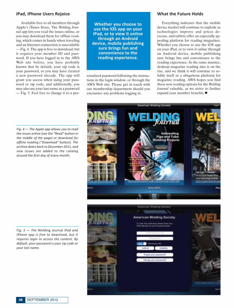
iPad, iPhone Users Rejoice
Available free to all members throughApple’s iTunes Store, The Welding Jour-nal app lets you read the issues online, oryou may download them for offline read-ing, which comes in handy when travelingand an Internet connection is unavailable— Fig. 4. The app is free to download, butit requires your member ID and pass-word. If you have logged in to the AWSWeb site before, you have probablyknown that by default, your zip code isyour password, or you may have createda new password already. The app willgrant you access when using your pass-word or zip code, and additionally, youmay also use your last name as a password— Fig. 5. Feel free to change it to a per-
sonalized password following the instruc-tions in the login window, or through theAWS Web site. Please get in touch withour membership department should youencounter any problems logging in.
What the Future Holds
Everything indicates that the mobiledevice market will continue to explode astechnologies improve and prices de-crease, and tablets offer an especially ap-pealing platform for reading magazines.Whether you choose to use the iOS appon your iPad, or to view it online throughan Android device, mobile publishingsure brings fun and convenience to thereading experience. In the same manner,desktop magazine reading also is on therise, and we think it will continue to so-lidify itself as a ubiquitous platform formagazine reading. AWS hopes you findthese new reading options for the WeldingJournal valuable, as we strive to furtherexpand your member benefits.◆
SEPTEMBER 201248
Fig. 4 — The Apple app allows you to readthe issues online (see the “Read” button inthe middle of the page) or download foroffline reading (“Download” button). Thearchive dates back to December 2011, andnew issues are added to the catalogaround the first day of every month.
Fig. 5 — The Welding Journal iPad andiPhone app is free to download, but it requires login to access the content. Bydefault, your password is your zip code oryour last name.
Whether you choose touse the iOS app on youriPad, or to view it online
through an Androiddevice, mobile publishing
sure brings fun andconvenience to the reading experience.
Guzman Layout 2_Layout 1 8/7/12 3:36 PM Page 48

REGISTER NOW at fabtechexpo.com
FABTECH 2012.
Scan this code to watch
an exciting preview of
FABTECH. Follow us: Cosponsors:
LASERSHOWS.
FIREWORKS.
ROLLERCOASTERS.
HTME
EO ST TNEVE ENE OH TONITAATCIRBA FLATTAME
ATTACEPT SSOE MHE TE.YGONOLHCE CEBTAF
RALUCA.201 2HC
s Largest Metal Forming,th America’Nor
Experience the ultimate thril
and compare cutting-edge equipment and technology in action. Check out
l the new products, network with industral
smar
Nos Largest Metal Forming,
l of FExperience the ultimate thril
and compare cutting-edge equipment and technology in action. Check out
l the new products, network with industr
e. There’ter and be more competitivsmar
ember 12-14, 2012 | Las VvNo
ABTECH 2012—a place where yl of F
and compare cutting-edge equipment and technology in action. Check out
y pros and find solutions to work l the new products, network with industr
s nothing else like it! e. There’
ention Centeregas Convember 12-14, 2012 | Las V
ou can see ABTECH 2012—a place where y
and compare cutting-edge equipment and technology in action. Check out
y pros and find solutions to work
ention Center
Scan this code to watch
an exciting preview of
ABTECH.F
s Largest Metal Forming,elding and Finishing EvFabricating, W
REGISTER NOW
Scan this code to watch
an exciting preview of
s Largest Metal Forming,entelding and Finishing Ev
low us:Fol
REGISTER NOW at fabtechexpo.com
low us: Cosponsors:
at fabtechexpo.com
Cosponsors:
fabtech attendee_FP_TEMP 8/7/12 11:26 AM Page 49

Hosted by:
Earn PDHs toward your AWS recertification or renewal when you attend the conference!
For the latest conference information, visit our website at www.aws.org/conferences or call 800-443-9353, ext. 264.
September 20 – 21, 2011Fort Lauderdale, Fla.
Attendee RegistrationAWS Members: $550Nonmembers: $680
Exhibitor Registration AWS Members: $750Nonmembers: $880
At this conference, a distinguished panel of aluminum-industry experts will survey the state of the art in aluminum welding technology and practice. The 14th Aluminum Welding Conference will also provide several opportunities for you to network informally with speakers and other participants, as well as visit an exhibition showcasing products and services available to the aluminum welding industry.
Hosted by:
A distinguished panel of aluminum-industry experts will survey the state of the artin aluminum welding technology and practice during this two-day conference.
September 18th - 19th
Register today
Members $675 / Non-Members $805
For the latest conference information and registration visit our web site at www.aws.org/conferences or call 800-443-9353, ext. 264.
Earn PDHs toward your AWS recertification when you attend the conference.
September 18
th - 19thSeptember 18
For the latest conference information and registration visit our web site at
.aws.org/conferenceFor the latest conference information and registration visit our web site at
or call 800-443-9353, ext. 264. .aws.org/conferenceFor the latest conference information and registration visit our web site at
or call 800-443-9353, ext. 264. For the latest conference information and registration visit our web site at
For the latest conference information and registration visit our web site at
Earn PDHs toward your
WS recertification when you attend the conference.AEarn PDHs toward your
.aws.org/confeww.ww
WS recertification when you attend the conference.
or call 800-443-9353, ext. 264. s.aws.org/conference
WS recertification when you attend the conference.
or call 800-443-9353, ext. 264.
WS recertification when you attend the conference.
educ aluminum_FP_TEMP 8/7/12 1:32 PM Page 50

Welcome and OverviewTony Anderson, Conference Committee Chair
The Aluminum Designation System Frank Armao, The Lincoln Electric Co.
Aluminum Welding MetallurgyBruce Anderson, MAXAL International
Design and Performance of Aluminum WeldsBruce Anderson, MAXAL International
Filler Alloy Selection Primary CharacteristicsPatrick Berube, MAXAL International
Metal Preparation for Aluminum WeldingGreg Doria, The Lincoln Electric Co.
Gas Metal Arc Welding of Aluminum AlloysFrank Armao, The Lincoln Electric Co.
The Fundamentals of GTAW Welding of AluminumBrent Williams, Miller Electric Mfg. Co.
Aluminum Weld Discontinuities: Causes and CuresTony Anderson, ITW Welding North America
Application of the AWS D1.2 Structural Welding Code–AluminumThom Burns, AlcoTec Wire Corp.
Friction Stir Welding and Processing of Aluminum AlloysChristopher B. Smith, Friction Stir Link Inc.
Technology Advancements and Automation in the Aluminum Welding IndustryKevin Summers, Miller Welding Automation
Increasing Performance and Production in Aluminum GMAW WeldingThom Burns, AlcoTec Wire Corp.
Welding Aluminum for Marine ApplicationsJerry Mirgain, AlcoTec Wire Corp.
Low Heat Input GMAW of Thin-Gauge Aluminum StructuresMike Ludwig, Fronius USA
Real Welds, Real Problems, Real SolutionsRob Krause, AlcoTec Wire Corp.
Techniques for Soldering Aluminum AlloysDr. Yehuda Baskin and William Avery, Superior Flux & Mfg. Co.
Engineering Design and Strength Assessment of Aluminum Weldments for Static and Cyclic LoadingMike Weaver, Weaver Engineering
The Fundamentals of GT
Armao, Frank Metal Arc Gas
Greg Doria, Metal Preparation for
Patrick Be
elding of W WAAWndamentals of GTTA
The Lincoln Electric Co.Armao, of Aluminum Alloyselding WMetal Arc
The Lincoln Electric Co.Greg Doria, Aluminum WMetal Preparation for
Internationalerube, MAXAL
Aluminumelding of
of Aluminum Alloys
eldingAluminum W
Christopher B. Smith, Friction Stir Link Inc.
Thom Bur
Friction Stir W
Thom BurApplication of the
Anderson, ITW Wony TToAluminum W
Brent Williams, Miller Electric Mfg. Co.
Christopher B. Smith, Friction Stir Link Inc.
ec Wire Corp
elding and Processing of Friction Stir W
ec Wire Corp.AlcoTAlcoTTeTerns, rns WS D1.2 StruAAWApplication of the
Americaelding North erson, ITW WWeeld Discontinuities: Causes and CuresAluminum W
Brent Williams, Miller Electric Mfg. Co.
Christopher B. Smith, Friction Stir Link Inc.
elding Code–Aluminum
AlloysAluminum elding and Processing of
WS D1.2 Structural W
Americaeld Discontinuities: Causes and Cures
elding of
Alloys
elding Code–Aluminum
echnolT
Christopher B. Smith, Friction Stir Link Inc.
Advancements and logy
Christopher B. Smith, Friction Stir Link Inc.
Aluminum WAutomation in the
Christopher B. Smith, Friction Stir Link Inc.
elding IndustryAluminum W
educ aluminum_FP_TEMP 8/7/12 1:40 PM Page 51

CONFERENCES
Conference on U.S. and European WeldingStandards: Structural, Pressure Piping,
Pipelines, Railroad, NDTOctober 22, 23
Munich, Germany
The American Welding Society has partnered with Ger-many’s Gesellschaft für Schweißtechnik International (GSI)to deliver this conference, in which U.S. and European weld-ing standards will be presented, compared, and discussed. Withincreased globalization and complexity of supply chains, morecompanies have realized the need to be knowledgeable aboutmultiple national and international fabrication codes and stan-dards. Engineers, inspectors, supervisors, and quality controlpersonnel who are familiar with one set of standards, but whoneed to know more about the other set of standards, will findthis of benefit. The conference will be conducted in English.The format will be that one expert presentation on the U.S.standards will be followed by an expert presentation on the com-parable European standards for each topic.
FABTECH 2012,November 12–14Las Vegas, Nev.
North America’s largest metal forming, fabricating, welding,and finishing event heads to the Las Vegas Convention Center. Ifyour job requires you to look for new ways to work smarter, oper-ate leaner, and boost productivity, then you and your team need toattend FABTECH. Make plans now to attend your industry’s mainevent where you’ll find the products, resources, and ideas tostrengthen your business and achieve your manufacturing goals.Following are conferences to be offered at the Show.
Activity Picks up in Underwater WeldingNovember 12
Installations in the Gulf of Mexico in particular are increas-ing and the divers in those areas are making sure that everythingis okay in all of the welds connected to the offshore platforms.Uwe Aschemeier will be on hand to discuss the performance ofwet welding electrodes as well as tell you about some underwa-ter repair work.
Covering the Many Aspects in Health and Safety
November 13
As industry awaits the next ruling on fumes from manganese,companies have their work cut out for them in such areas as thecontrol of radiation, ventilation, welder comfort and visibility,plasma cutting, and the light from lasers. There is much to keeptabs on. This conference will focus on many of the solutions.
What Are Some of the New Wrinkles inNondestructive Testing?
November 14
Such processes as alternating current field measurement(ACFM), time of flight diffraction (TOFD), computed radiogra-phy, and the many types of phased array methods are moving moreand more into critical inspection lines. This conference will alsoprovide information on the new technologies that are being ap-proved for use in the demanding work under the ASME Code.◆
For more information, please contact the AWS Conferencesand Seminars Business Unit at (800) 443-9353, ext. 264, or e-mail [email protected]. You can also visit the Conference De-partment Web site at www.aws.org/conferences for upcomingconferences and registration information.
SEPTEMBER 201252
COMPLETE PRODUCT PORTFOLIOSUPPLYING THE
THERMAL SPRAY INDUSTRYWORLDWIDE SINCE 1980
VISIT OUR WEBSITE FOR WEEKLY SPECIALS
228 BOUNDARY RD, MARLBORO, NJ 07746Phone: 800-358-4287Phone: 732-431-0992
Fax: 732-308-1075
MMention this add to get 10% off your first Order
Plasma Powders, Providing the Tools Neededto Build the Future!
For info go to www.aws.org/ad-index
Conferences September 2012_Layout 1 8/9/12 3:05 PM Page 52

welder member_FP_TEMP 8/7/12 8:04 AM Page 53

COMINGEVENTS
GAWDA Annual Convention. Sept. 9–12. The Broadmoor, Col-orado Springs, Colo. Gases and Welding Distributors Assn.www.gawda.org.
IMTS 2012, Int’l Manufacturing Technology Show. Sept. 10–15.McCormick Place, Chicago, Ill. Association for ManufacturingTechnology. www.IMTS.com.
6th Int’l Quenching and Control of Distortion Conf. Sept. 10–13.Radisson Blu Aqua Hotel, Chicago, Ill. ASM International HeatTreating Society. www.asminternational.org/content/Events/qcd/.
♦15th Annual Aluminum Welding Conf. Sept. 18, 19, Seattle,Wash. Industry experts will survey the state of the art in aluminumwelding technology and practice. American Welding Society.www.aws.org/conferences.
ICALEO, 31st Int’l Congress on Applications of Lasers andElectro-Optics. Sept. 23–27. Anaheim Marriott Hotel, Anaheim,Calif. Laser Institute of America. www.icaleo.org.
8th Annual Northeast Shingo Prize Conf.: Learning to Share.Sept. 25, 26. DCU Center, Worcester, Mass. (617) 287-7630;www.neshingoprize.org.
2nd Int’l Conf. Welding Trainer 2012, ‘The Future of Education.’Sept. 26, 27. GSI, Duisburg, Germany. www.weldingsimulation.eu/en/home/.
Northern Welding Trade Show. Sept. 26, 27. Materials Joining In-novation Centre, Northern College, Kirkland Lake, Ont.,Canada. www.northernweldingtradeshow.com.
2012 Int’l Conf. on Advances in Materials Science and Engineer-ing. Sept. 27, 28. Bangkok, Thailand. Singapore Society of Me-chanical Engineers. www.smss-sg.org/amse2012/index.htm.
♦Sheet Metal Welding Conf. XV. Oct. 2–5, VisTaTech Center,Livonia, Mich. This is the premier conference dedicated to ad-vancing the science and technology of sheet metal welding. Spon-sored by the AWS Detroit Section. www.awsdetroit.org.
2nd Int’l Welding and Joint Technologies Congress and 19thTechnical Welding Sessions. Oct. 3–5. Civil Engineering School,Polytechnic University of Madrid, Spain. Sponsored by the Span-ish Welding Association. www.cesol.es/jornadas2012.htm.
2nd Int’l Conf. on Mechanical Materials and Manufacturing En-gineering. Oct. 5, 6. Dalian, China. www.icmmme-conf.org.
TITANIUM 2012, 28th Annual Conf. and Expo. Oct. 7–10. HiltonAtlanta Hotel, Atlanta, Ga. International Titanium Association.www.titanium.org.
METALCON Int’l 2012. Oct. 9–11. Donald E. Stephens Conven-tion Center, Chicago, Ill. www.metalcon.com.
NOTE: A DIAMOND ( ♦) DENOTES AN AWS-SPONSORED EVENT.
SEPTEMBER 201254
For info go to www.aws.org/ad-index For info go to www.aws.org/ad-index
CE September_Layout 1 8/9/12 3:52 PM Page 54

55WELDING JOURNAL
Aluminum Week 2012. Oct. 15–18. Renaissance Chicago Down-town Hotel, Chicago, Ill. Co-locating events for The AluminumAssn., Aluminum Extruders Council, and Aluminum AnodizersCouncil. www.aluminum.org.
♦AWS/GSI Conf. on U.S. and European Welding Standards:Structural, Pressure Piping, Pipelines, Railroad, NDT. Oct. 22,23, Munich, Germany. www.aws.org/conferences.
EuroBLECH 2012, 22nd Int’l Sheet Metal Working TechnologyExhibition. Oct. 23–27. Hanover Exhibition Grounds, Hanover,Germany. www.euroblech.com.
LME 2012, Lasers for Manufacturing Event. Oct. 23, 24, Renais-sance Schaumburg Convention Center Hotel, Schaumburg, Ill.Laser Institute of America. www.lia.org/lmesd.
Manufacturing with Composites. Oct. 23, 24, Charleston Con-vention Center, North Charleston, S.C. Society of Manufactur-ing Engineers. www.sme.org/mfgcomposites.
National FFA Convention and Expo. Oct. 24–27. Indianapolis,Ind. Future Farmers of America. www.ffa.org.
ASNT Fall Conf. Oct. 29–Nov. 2. Rosen Shingle Creek Resort, Or-lando, Fla. American Society for Nondestructive Testing.www.asnt.org/events/conferences/fc12.htm.
EXPO IAS 2012, 6th Conf. on Uses of Steel, 19th Rolling Conf.Nov. 6–8. City Center, Rosario, Santa Fe, Argentina. www.siderur-gia.org.ar/conf12/Home.html.
Fischer’s Feritscope® FMP30 is the ideal solution for fast, precise measurement of ferritecontent of constructional steels,welded claddings, austenitic stainless steels and duplex steels.
• Non-destructive measurement in the range of 80% Fe or 0-120WRC number.
• Battery or AC powered• Large, backlit display• Automatic probe recognition • Statistical evaluation• USB interface• Multiple application memories• FISCHER DataCenter Software
1-800-243-8417 • 1-860-683-0781 • Fax: 1-860-688-8496www.Fischer-Technology.com • [email protected]
Measurementof the Ferrite Content in Austenitic
and Duplex Steel
FERITSCOPE® FMP30
For info go to www.aws.org/ad-index
For info go to www.aws.org/ad-indexFor info go to www.aws.org/ad-index
CE September_Layout 1 8/9/12 3:52 PM Page 55

SEPTEMBER 201256
Welder training and qualification coupons
Destructive test equipmentFull testing services
SERIOUS AIR FOR SERIOUS PLACES
A powerhouse ventilator for the toughest jobs.
20th National Quality Education Conf. Nov. 11, 12. Hyatt Re-gency Louisville, Louisville, Ky. American Society for Quality.(800) 248-1946; www.asq.org.
♦Advanced Visual Inspection Workshop. Nov. 12. Las Vegas Con-vention Center, Las Vegas, Nev. American Welding Society.www.fabtechexpo.com; www.aws.org/conferences; (800/305) 443-9353, ext. 264.
♦ASME Section IX Code Clinic. Nov. 12, 13. Las Vegas Conven-tion Center, Las Vegas, Nev. American Welding Society.www.fabtechexpo.com; www.aws.org/conferences; (800/305) 443-9353, ext. 264.
♦Brazing Symposium. Nov. 12. Las Vegas Convention Center,Las Vegas, Nev. American Welding Society. www.fabtechexpo.com; www.aws.org/conferences; (800/305) 443-9353, ext. 264.
♦FABTECH. Nov. 12–14. Las Vegas Convention Center, LasVegas, Nev. This exhibition is the largest event in North Americadedicated to showcasing the full spectrum of metal forming, fab-ricating, tube and pipe, welding equipment, and myriad manufac-turing technologies. American Welding Society. www.fabtech-expo.com; www.aws.org/conferences; (800/305) 443-9353, ext. 264.
♦Thermal Spray Basics Conf. Nov. 12. Las Vegas ConventionCenter, Las Vegas, Nev. American Welding Society. www.fabtech-expo.com; www.aws.org/conferences; (800/305) 443-9353, ext. 264.
♦Underwater Welding and Cutting Conf. Nov. 12. Las Vegas Con-vention Center, Las Vegas, Nev. American Welding Society.www.fabtechexpo.com; www.aws.org/conferences; (800/305) 443-9353, ext. 264.
♦D1.1 Code Clinic (Spanish). Nov. 13. Las Vegas ConventionCenter, Las Vegas, Nev. American Welding Society. www.fabtech-expo.com; www.aws.org/conferences; (800/305) 443-9353, ext. 264.
♦Friction Stir Welding and Solid-State Processes. Nov. 13. LasVegas Convention Center, Las Vegas, Nev. American Welding So-ciety. www.fabtechexpo.com; www.aws.org/conferences; (800/305)443-9353, ext. 264.
♦RWMA Resistance Welding School. Nov. 13, 14. Las Vegas Con-vention Center, Las Vegas, Nev. American Welding Society.www.fabtechexpo.com; www.aws.org/conferences; (800/305) 443-9353, ext. 264.
♦Underwater Welding and Cutting Conf. Nov. 13. Las Vegas Con-vention Center, Las Vegas, Nev. American Welding Society.www.fabtechexpo.com; www.aws.org/conferences; (800/305) 443-9353, ext. 264.
♦D1.5 Bridge Code Clinic. Nov. 14. Las Vegas Convention Cen-ter, Las Vegas, Nev. American Welding Society. www.fabtech-expo.com; www.aws.org/conferences; (800/305) 443-9353, ext. 264.
♦Trends in Nondestructive Testing Conf. Nov. 14. Las Vegas Con-vention Center, Las Vegas, Nev. American Welding Society.www.fabtechexpo.com; www.aws.org/conferences; (800/305) 443-9353, ext. 264.
♦Welding Stainless Steel (Avoiding Weld Defects). Nov. 14. LasVegas Convention Center, Las Vegas, Nev. American Welding So-ciety. www.fabtechexpo.com; www.aws.org/conferences; (800/305)443-9353, ext. 264.
For info go to www.aws.org/ad-index For info go to www.aws.org/ad-index
CE September_Layout 1 8/9/12 3:53 PM Page 56

57WELDING JOURNAL
Indian Industrial Trade Fairs. Nov. 21–24. India Expo Centre,Delhi, India. Hannover Messe/CeMAT. www.cemat-india.com.
Power-Gen Int’l Show. Dec. 11–13. Orange County ConventionCenter, Orlando, Fla. www.power-gen.com.
Int’l Conf. on Advanced Material and Manufacturing Science(ICAMMS 2012). Dec. 20, 21. High-Tech Mansion BUPT, Beijing,China. www.icamms-conf.org.
Int’l Conf. on Frontiers of Mechanical Engineering, Materials,and Energy (ICFMEME 2012). Dec. 20, 21. Beijing, China.www.icfmeme.org. Conference general contact is Dr. Zheng,[email protected].
The Automate 2013 Show and Conf. Jan. 21–24. McCormickPlace, Chicago, Ill. Robotics Industries Assn., Advancing Vision+ Imaging, and Motion Control Assn. www.automate2013.com.
♦LAM — 5th Annual Laser Additive Manufacturing Workshop.Feb. 12, 13, 2013. Hilton Houston North Hotel, Houston, Tex.American Welding Society is a cooperating society in this event.AWS members receive discounted registration. www.lia.org/con-ferences/lam.
ILSC® Int’l Laser Safety Conf. March 18–21, 2013. Doubletreeby Hilton, Orlando, Fla. Laser Institute of America.www.lia.org/ilsc.
AeroDef Manufacturing Expo and Conf. March 19–21, 2013.Long Beach Convention Center, Long Beach, Calif. Society ofManufacturing Engineers. www.sme.org; (800) 733-4763.
♦ JOM-17, Int’l Conf. on Joining Materials. May 5–8, 2013. Kon-ventum Lo Skolen, Helsingør, Denmark. Institute for the Joiningof Materials (JOM) in association with the IIW. Cosponsored byAWS, TWI, Danish Welding Society, Welding Technology Insti-tute of Australia, University of Liverpool, Cranfield University,Force Technology, and ABS (Brazilian Welding Assn.). E-mailOsama Al-Erhayem at [email protected]; www.jominsti-tute.com/side6.html.
ASM Heat Treating Society Conf. and Expo. Sept. 16–18, 2013. In-diana Convention Center, Indianapolis, Ind. www.asminterna-tional.org/content/Events/heattreat/.
WESTEC. Oct. 15–17, 2013. Los Angeles Convention Center, LosAngeles, Calif. The Society of Manufacturing Engineers.www.westeconline.com; (800) 733-4763.
Educational OpportunitiesFirst Wall Colmonoy India-based Brazing School. Sept. 11, 12.Pune Marriott Hotel and Convention Centre, Pune, India.Contact Lucy Williams, Wall Colmonoy, Marketing Manager,Europe, [email protected],+44 (0) 1792 860251.
EWI/TMS Workshop: Applying ICME to Solve ManufacturingChallenges. Sept. 19, 20, Edison Welding Institute, Columbus,Ohio. www.ewi.org.
Fundamentals of Brazing Seminar. Sept. 19, Sheraton ChicagoO’Hare Airport Hotel, Chicago, Ill.; Sept. 25–27, Wyndham
For info go to www.aws.org/ad-index
— continued on page 260-s
CE September_Layout 1 8/9/12 3:53 PM Page 57

CERTIFICATIONSCHEDULE
Certified Welding Inspector (CWI)LOCATION SEMINAR DATES EXAM DATE
Corpus Christi, TX Exam only Sept. 8 Houston, TX Sept. 9–14 Sept. 15St. Louis, MO Sept. 9–14 Sept. 15New Orleans, LA Sept. 9–14 Sept. 15Miami, FL Sept. 9–14 Sept. 15Anchorage, AK Exam only Sept. 22 Miami, FL Exam only Oct. 18Tulsa, OK Oct. 14–19 Oct. 20Long Beach, CA Oct. 14–19 Oct. 20Newark, NJ Oct. 14–19 Oct. 20Nashville, TN Oct. 14–19 Oct. 20Portland, OR Oct. 21–26 Oct. 27Roanoke, VA Oct. 21–26 Oct. 27Detroit, MI Oct. 21–26 Oct. 27Cleveland, OH Oct. 21–26 Oct. 27Atlanta, GA Oct. 28–Nov. 2 Nov. 3Corpus Christi, TX Exam only Nov. 3Dallas, TX Oct. 28–Nov. 2 Nov. 3Sacramento, CA Oct. 28–Nov. 2 Nov. 3Spokane, WA Oct. 28–Nov. 2 Nov. 3Shreveport, LA Nov. 4–9 Nov. 10 Las Vegas, NV Exam only Nov. 14Syracuse, NY Dec. 2–7 Dec. 8Houston, TX Dec. 2–7 Dec. 8Reno, NV Dec. 2–7 Dec. 8Los Angeles, CA Dec. 2–7 Dec. 8Miami, FL Dec. 2–7 Dec. 8
Certified Welding Supervisor (CWS)LOCATION SEMINAR DATES EXAM DATEMiami, FL Sept. 10–14 Sept. 15Norfolk, VA Oct. 15–19 Oct. 20CWS exams are also given at all CWI exam sites.
9–Year Recertification Seminar for CWI/SCWIFor current CWIs and SCWIs needing to meet educationrequirements without taking the exam. The exam can be takenat any site listed under Certified Welding Inspector.LOCATION SEMINAR DATES EXAM DATEDenver, CO Sept. 10–15 No examDallas, TX Oct. 15–20 No examNew Orleans, LA Oct. 29–Nov. 3 No examMiami, FL Nov. 26–Dec. 1 No exam
Certified Radiographic Interpreter (CRI)LOCATION SEMINAR DATES EXAM DATEChicago, IL Sept. 10–14 Sept. 15Pittsburgh, PA Oct. 15–19 Oct. 20The CRI certification can be a stand-alone credential or canexempt you from your next 9-Year Recertification.
Certified Welding Sales Representative (CWSR)CWSR exams will be given at CWI exam sites.
Certified Welding Educator (CWE)Seminar and exam are given at all sites listed under CertifiedWelding Inspector. Seminar attendees will not attend the CodeClinic portion of the seminar (usually the first two days).
Certified Robotic Arc Welding (CRAW)WEEKS OF, FOLLOWED BY LOCATION AND PHONE NUMBER
Nov. 9 atABB, Inc., Auburn Hills, MI; (248) 391–8421
Dec. 3 atGenesis-Systems Group, Davenport, IA; (563) 445-5688
Oct. 22, Oct. 26 at Lincoln Electric Co., Cleveland, OH; (216) 383-8542
Oct. 15 atOTC Daihen, Inc., Tipp City, OH; (937) 667-0800
Sept. 10, Nov. 5 atWolf Robotics, Fort Collins, CO; (970) 225-7736
On request at: MATC, Milwaukee, WI; (414) 297-6996
Certified Welding Engineer (CWEng) and Senior CertifiedWelding Inspector (SCWI)Exams can be taken at any site listed under Certified WeldingInspector. No preparatory seminar is offered.
International CWI Courses and Exams SchedulesPlease visit www.aws.org/certification/inter_contact.html.
SEPTEMBER 201258
IMPORTANT: This schedule is subject to change without notice. Applications are to be received at least six weeks prior to the semi-nar/exam or exam. Applications received after that time will be assessed a $250 Fast Track fee. Please verify application deadlinedates by visiting our website www.aws.org/certification/docs/schedules.html. Verify your event dates with the Certification Dept. to con-firm your course status before making travel plans. For information on AWS seminars and certification programs, or to register on-line, visit www.aws.org/certification or call (800/305) 443-9353, ext. 273, for Certification; or ext. 455 for Seminars. Apply early to avoidpaying the $250 Fast Track fee.
AWS Certification ScheduleCertification Seminars, Code Clinics, and Examinations
Cert Schedule SEPT_Layout 1 8/9/12 9:33 AM Page 58

SOCIETYNEWSSOCIETYNEWS
59WELDING JOURNAL
Leadership Symposium Presented in Doral
The 14th annual AWS Leadership Symposium was held July29–Aug. 1 at AWS headquarters in Doral, Fla. Leaders represent-ing 21 of the 22 AWS Districts participated in the training.
The purpose of the symposium is to develop leadership andcommunication skills to enhance each attendees’s effectivenessin the performance of their Section duties.
Listed here are the District number, attendee’s name, and Sec-tion. 1) Steve Goodrow, Connecticut; 2) Kenneth Temme, Philadel-phia; 3) Kenneth Ring, Washington, D.C.; 4) David Kincaid, SWVirginia; 5) Bob Guenther, South Florida; and Jennifer Skyles,N. Central Florida; 6) no attendee; 7) Nolan Allbritain, Colum-bus; 8) George Smith, NE Mississippi; 9) Michael J. Zoghby Jr.,Mobile; 10) Paul Revolinsky, Cleveland; 11) James Koster, W.Michigan; and Dan Wellman, Detroit; 12) Anni Van Dyke, Mil-waukee; 13) Marle Yarno, J.A.K.; 14) Jon Stephens, MississippiValley; David Beers, St. Louis; and Bud Merrill, Louisville; 15)Randall Washenesky, Arrowhead; 16) Jason Miles, Kansas City;
and Eric Nordhues, Nebraska; 17) Donnie Williams, North Texas;18) Justin Gordy and Alejandro Alvarez, Houston; 19) ChrisVrolyk, Alberta; and Ken Johnson, Puget Sound; 20) Gerald Hen-derson, New Mexico; and Joe Stavinoha, Idaho/Montana; 21)George Moore, San Diego; and 22) Pat Linggi and Kerry Shatell,Sacramento.
The Leadership Symposium is conducted each year by RonGilbert, senior partner and principal management consultant forGilbert Education & Management Systems, www.gilbertems.com,and a professor of management in the Chapman Graduate Schoolof Business at Florida International University.
Assisting Dr. Gilbert again this year was Lee Kvidahl, an AWSpast president, and manager of welding/manufacturing engineer-ing at Huntington Ingalls Industries, Pascagoula, Miss. The par-ticipating AWS staff members included Cassie Burrell, deputyexecutive director; Rhenda Kenny, director, Member ServicesDept.; and Alfred Nieves, coordinator, Member Services.
BY HOWARD [email protected]
The Annual Meeting of the membersof the American Welding Society will beheld on Monday, Nov. 12, 2012, begin-ning at 9:00 AM at the Las Vegas Con-
vention Center, Las Vegas, Nev.The regular business of the Society will
be conducted, including the election ofofficers and nine members of the Board
of Directors. Any business properlybrought before the membership will beconsidered.
Notice of Annual Meeting, American Welding Society
AWS Life Members are urged to takeadvantage of their complimentary freeadmission to the upcoming FABTECHshow plus free registration to the entireProfessional Program (a $325 value),scheduled for Nov. 12–14, 2012, at theLas Vegas Convention Center in LasVegas, Nev.
The free Professional Program regis-
tration entitles AWS Life Members to at-tend any of the technical sessions occur-ring during the three-day period. Regis-tration forms are available in issues ofthe Welding Journal, as well as in the Ad-vance Program that was mailed to mem-bers previously. You may request a formfrom the Membership Dept. (305/800)443-9353, ext. 260. To obtain your free
registration, mark “AWS Life Member:Free Registration” at the top of your Reg-istration Form. Then FAX both sides ofthe form to (305) 443-5647, Attention:Rhenda Kenny, membership director, ormail the form to Rhenda Kenny, Ameri-can Welding Society, 8669 Doral Blvd.,Doral, FL 33166.
AWS Life Members Offered Free Registration for Professional Program
Society News September_Layout 1 8/9/12 2:50 PM Page 59

SEPTEMBER 201260
Tech TopicsNew Standard Projects
Development work has begun on thefollowing revised standards. Affected in-dividuals are invited to contribute to thedevelopment of these standards. For in-formation, contact the staff engineerlisted with the document. Participationon AWS Technical Committees and Sub-committees is open to all persons.
D3.6M:20XX, Underwater WeldingCode. This document covers the require-ments for underwater welding of struc-tures or components in both dry and wetenvironments. Clauses 1–6 constitute thegeneral requirements and clauses 7–9contain the special requirements appli-cable to three individual classes of welds:Class A — Comparable to above-waterwelding; Class B — For less critical ap-plications; and Class O — To meet the re-quirements of another designated codeor specification. Stakeholders: Underwa-ter welding industry associates. B. Mc-Grath, ext. 311.
D8.1M:20XX, Specification for Auto-motive Weld Quality-Resistance Spot Weld-ing of Steel. This document contains bothvisual and measurable acceptance crite-ria for resistance spot welds in steels. Theinformation contained herein may beused as an aid by designers, resistancewelding equipment manufacturers,welded product producers, and others in-volved in the automotive industry and re-sistance spot welding of steels. Stake-holders: Member of the resistance weld-ing and automotive communities E.Abrams, ext. 307.
Standards for Public ReviewAWS was approved as an accredited
standards-preparing organization by theAmerican National Standards Institute(ANSI) in 1979. AWS rules, as approvedby ANSI, require that all standards beopen to public review for comment dur-ing the approval process. The followingstandards are submitted for public reviewwith the expiration dates shown. A draftcopy may be obtained from R. O’Neill,[email protected], ext. 451.
A5.8M/A5.8:2011-AMD1, Specificationfor Filler Metals for Brazing and BrazeWelding. $30. 9/17/12.
A5.10/A5.10M:20XX (ISO 18273:2004MOD), Welding Consumables — Wire Elec-trodes, Wire and Rods for Welding of Alu-minum and Aluminum — Alloys — Clas-sification. $66. 9/3/12.
C2.25/C2.25M:20XX, Specification forThermal Spray Feedstock — Wire and Rods.Revised. $25. 8/20/12.
D15.2/D15.2M:20XX, RecommendedPractices for Welding of Rails and RelatedRail Components for Use by Rail Vehicles.Revised. $38.50. 8/27/12.
D17.2/D17.2M:20XX, Specification forResistance Welding for Aerospace Applica-tions. Revised. $32.50. 8/27/12.
G2.1M/G2.1:20XX, Guide for the Join-ing of Wrought Nickel-Based Alloys.Re-vised. $36.50. 9/10/12.
Technical Committee MeetingsAll AWS technical committee meet-
ings are open to the public. To attend ameeting, contact the committee secretaryas listed below. Call (800/305) 443-9353
at the extention shown. Visit www.aws.org/technical/jointechcomm.html to learnmore about what technical committeesdo, membership requirements, and toapply for membership online.
Sept. 12, C1 Committee on ResistanceWelding. Dearborn, Mich. Contact E.Abrams, ext. 307.
Sept.12, J1 Committee on ResistanceWelding Equipment. Dearborn, Mich.Contact: E. Abrams, ext. 307.
Sept. 19, 20, B4 Committee on Me-chanical Testing of Welds. Charleston,S.C. Contact B. McGrath, ext. 311.
Sept. 25, B2D Subcommittee on Stan-dard Welding Procedure Specifications.Coraopolis, Pa. Contact A. Diaz, ext. 304.
Sept. 26, B2A Subcommittee on Braz-ing Qualifications. Coraopolis, Pa. Con-tact A. Diaz, ext. 304.
Sept. 26, B2B Subcommittee on Weld-ing Qualification. Coraopolis, Pa. Con-tact A. Diaz, ext. 304.
Sept. 26, B2C Subcommittee on Ma-terials. Coraopolis, Pa. Contact A. Diaz,ext. 304.
Sept. 26, B2E Subcommittee on Sol-dering Qualifications. Coraopolis, Pa.Contact A. Diaz, ext. 304.
Sept. 27, B2 Committee on Procedureand Performance Qualifications.Coraopolis, Pa. Contact A. Diaz, ext. 304.
Oct. 3–5, A2 Committee and Subcom-mittees on Definitions and Symbols.Wheeling, W.Va. Contact S. Borrero, ext.334.
Oct. 23, 24, D15 Committee and Sub-committees on Railroad Welding. Miami,Fla. Contact S. Borrero, ext. 334.
Thermal SprayC2 Committee on Thermal Spraying
seeks educators, general interest, andusers seeks members to help update itsdocuments. E. Abrams, [email protected];ext. 307.
Robotic and Automatic WeldingThe D16 Committee on Robotic and
Automatic Welding seeks general interestand educators to help revise its documents.B. McGrath, bmcgrath@ aws.org; ext. 311.
Soldering; Joining Nickel AlloysThe G2C Subcommittee on Nickel Al-
loys seeks members to help reviewB2.3/B2.3M, Specification for SolderingProcedures and Performance Qualification.S. Hedrick, steveh@ aws.org; ext. 305.
Local Heat Treating of Pipe WorkThe D10P Subcommittee for Local
Heat Treating of Pipe seeks members. B.McGrath, [email protected]; ext. 311.
Magnesium Alloy Filler Metals A5L Subcommittee on Magnesium
Alloy Filler Metals seeks members to as-sist in updating its document. R. Gupta,[email protected], ext. 301.
Oxyfuel Gas Welding and CuttingC4 Committee on Oxyfuel Gas Welding
and Cutting seeks general interest and ed-ucators to help revise its documents. E.Abrams, [email protected]; ext. 307.
Surfacing Industrial Mill RollsD14H Subcommittee on Surfacing and
Reconditioning of Industrial Mill Rollsseeks members to help revise AWS D14.7,Recommended Practices for Surfacing andReconditioning of Industrial Mill Rolls. A.Davis, [email protected], ext. 466.
Automotive WeldingThe D8 Committee on Automotive
Welding seeks members to help preparestandards on all aspects of welding in theautomotive industry. E. Abrams,[email protected]; ext. 307.
Resistance Welding EquipmentThe J1 Committee on Resistance Weld-
ing Equipment seeks educators, generalinterest, and users to help develop its doc-uments on controls, installation, mainte-nance, calibration, and resistance weldingfact sheets. E. Abrams, [email protected];ext. 307.
Welding HandbookVolunteers with experitse in welding
copper, lead, zinc, and titanium aresought to help update Welding Handbook.A. O’Brien, aobrien@ aws.org; ext. 303.
Opportunities to Contribute to AWS Welding Standards and Codes
NOTE: LEARN MORE ABOUT TECHNICAL COMMITTEES AND APPLY FOR MEMBERSHIP ONLINE AT www.aws.org/technical/jointechcomm.html.
Society News September_Layout 1 8/9/12 2:50 PM Page 60

61WELDING JOURNAL
Membership Winners NamedThe Houston Section, District 18, has
been awarded the Henry C. Neitzel Na-tional Membership Award for the great-est net numerical increase in membershipfor the year 2011–2012.
The winner of the Henry C. Neitzel Na-tional Membership Award for the great-est net percentage increase for 2011–2012is the Reading Section, District 3.
Following are Sections in each Districtthat achieved the greatest percentage in-crease in membership for the year.
District No. — Section Name1 — Maine2 — New York3 — Reading4 — Northeastern Carolina5 — Columbia6 — Twin Tiers7 — Cincinnati8 — Western Carolina9 — Birmingham
10 — Stark Central11 — Central Michigan12 — Racine-Kenosha13 — Chicago14 — Indiana15 — Saskatoon16 — Siouxland17 — Central Arkansas18 — Sabine19 — Inland Empire20 — Colorado21 — Arizona22 — Sierra Nevada
District 14 Awards AnnouncedRobert Richwine, District 14 director,
has nominated the following members forthis award:
Rick Ferguson — IndianaEric Cooper — IndianaTim Atchley — Mississippi ValleyJon Stephens — Mississippi ValleyBobby Wilson — Mississippi Valley Keith Cusey — Sangamon ValleyTim Neubauer — Sangamon ValleyEric Gleason — Sangamon ValleyDavid Beers — St. Louis SectionMike Arand — LouisvilleJoyce Kent — Louisville Brent Wright — Tri-RiverKarl Watson — LexingtonCoy Hall — LexingtonGordon Holl — Lexington This award provides a means for Dis-
trict directors to recognize individuals andcorporations who have contributed theirtime and effort to the affairs of their localSection and/or District.
The AWS Weldmex, FABTECH Mexico, and Metalform Mexico event was recently named thewinner of Best Event of the Year, Best Industrial Show, and Best Industrial Show Organizers.Cintermex made the announcements at a special awards-presentation program held at theCintermex Expo Center in Monterrey, Mexico.
Weldmex Show Wins Three Prestigious Awards
Member-Get-A-Member Campaign
Listed are the members participating inthe 2012–2013 Member-Get-a-Membercampaign. Standings are as of July 20, 2012.See page 65 of this Welding Journal for acomplete list of rules and a prize list, orvisit www.aws.org/mgm. Call the AWSMembership Dept. at (800) 443-9353, ext.480, with any questions about your mem-ber-proposer status.
Winners’ CircleListed below are the sponsors of 20 or
more Individual Members per year, sinceJune 1, 1999. The superscript denotes thenumber of years the member has earnedWinners’ Circle status if more than once.E. Ezell, Mobile9
J. Compton, San Fernando Valley7
J. Merzthal, Peru2
G. Taylor, Pascagoula2
L. Taylor, Pascagoula2
B. Chin, AuburnS. Esders, DetroitM. Haggard, Inland EmpireM. Karagoulis, DetroitS. McGill, NE TennesseeB. Mikeska, HoustonM. Pelegrino, ChicagoW. Shreve, Fox ValleyT. Weaver, Johnstown/Altoona
G. Woomer, Johnstown/AltoonaR. Wray, Nebraska
President’s RoundtableSponsored 9–19 new members
R. Fulmer — Twin Tiers — 10A.Tous — Costa Rica — 9
President’s ClubSponsored 3–8 new members
W. Komlos — Utah — 7C. Becker — Northwest — 5A. Bernard — Sabine — 3D. Jessop — Mahoning Valley — 3
President’s Honor RollSponsored 1 or 2 new members
E. Norman — Ozark — 2A. Sam — Trinidad — 2
Student Member SponsorsR. Munns — Utah — 18S. Lindsey — San Diego — 17E. Norman — Ozark — 16R. Udy — Utah — 7G. Siepert — Kansas — 4R. Zabel — SE Nebraska — 4J. Boyer — Lancaster — 3G. Von Lunen — Kansas City — 3
American Welding Society memberswill receive a discounted fee to attend theLaser Institute of America (LIA) 5th An-nual Laser Additive Manufacturing Work-
shop to be held Feb. 12, 13, 2013, at HiltonHouston North Hotel in Houston, Tex.The two societies have signed a cooperat-ing society agreement wherein AWS is
listed as a Cooperating Society for theevent and AWS members receive the LIAmember discount. For complete informa-tion, visit www.lia.org/conferences/lam.
AWS Members Offered Discounted Fee for Laser Additive Manufacturing Workshop
Society News September_Layout 1 8/9/12 2:51 PM Page 61

SEPTEMBER 201262
Thirty-eight Colorado-area Boy Scoutsreceived their welding merit badges, July 9,10, in Denver during the 65th Annual Inter-national Institute of Welding Assembly. TheScouts spent four hours with the merit badgecounselor going through safety procedures,demonstrating care of equipment, discussingwhat they learned from the Welding MeritBadge pamphlet, and describing the advan-tages and limitations of two weldingprocesses. Each scout selected a process andset up the equipment, which was inspectedand approved by the counselor. Then, eachscout performed several experiments. Fi-nally, the scouts discussed the role of the
American Welding Society in the weldingprofession and described three career oppor-tunities in the welding field.
Assisting the scouts were Steve Bruce,Tom Kienbaum (Colorado Section), GordonReynolds (Utah Section), Russell Rux(Wyoming Section), and Robert Ulibarri(New Mexico Section). On site for the eventwere the Miller Road Show and the Careersin Welding Mobile Exhibit.
The welding merit badge and the Careersin Welding trailer are both part of recent ef-forts by AWS to bring attention to the criti-cal shortage of welders in the United States.An analysis of projected data gathered
through Weld-Ed, a National Science Foun-dation funded center, shows that by 2019,there will be a shortage of more than 238,000new and replacement welding professionals.
“Welding is such an important part of ournation’s growth and stability,” said JaniceDowney, senior innovation manager, BoyScouts of America. “The welding merit badgeis a good fit with preparing Scouts for theirfuture and offers them a fun way to exploreskills that can grow into a hobby or career.There was significant enough interest shownin a youth interest survey to add a weldingmerit badge to the more than 120 meritbadges currently in the series.”
Boy Scouts Earn Welding Merit Badges during IIW in Denver
AWS Distinguished Members Tony Brosio(left) and Gary Dugger.
Tony Brosio and Gary D. Dugger, vet-eran members of the Indiana Section,have attained the status of DistinguishedMember for their participation in the So-ciety’s leadership and professional-devel-opment programs and member-recruit-ing achievements.
To qualify for Distinguished Memberstatus, applicants must accrue a minimumof 35 points from these four categories:National AWS leadership, local AWS lead-ership, professional development, andAWS member recruitment. If you believeyou qualify for Distinguished Member sta-tus, contact Rhenda Kenny, AWS Mem-bership Dept., [email protected], (800/305)443-9353, ext. 260.
November 5, 2012, is the deadline forsubmitting nominations for the 2013 Prof.Koichi Masubuchi Award.
This award is presented each year toone person, 40 years old or younger, whohas made significant contributions to theadvancement of materials joining throughresearch and development. Nominationsshould include a description of the candi-date’s experience, list of publications, hon-ors, and awards, and at least three lettersof recommendation from fellow re-searchers. This award is sponsored by theDept. of Ocean Engineering at Massachu-setts Institute of Technology (M.I.T.), thisaward includes a $5000 honorarium.
E-mail your nomination package toTodd A. Palmer, assistant professor, The Pennsylvania State University,[email protected].
Two Attain Distinguished Member Status in Indiana SectionM.I.T. Award Candidates Sought
Society News September_Layout 1 8/9/12 2:51 PM Page 62

63WELDING JOURNAL
SECTIONNEWSSECTIONNEWS
District 1Thomas Ferri, director(508) [email protected]
Participants at the District 3 conference were (from left) Steve Hill, Mike Schweinberg, Tracy Davenport, District 3 Director Mike Wiswesser,AWS staff representative Monica Pfarr, Ken Ring, Merilyn McLaughlin, Justin Heistand, John Ganoe, and Mike Sebergandio.
Tom Ferri (right), District 1 director, andDoug Desrochers are shown at the District1 conference in May.
Shown at the Maine Section event are (from left) Joel Stanley, Tom Millet, Pat Kein, andDave Hartley.
Shown at the Green & White Mountains Sec-tion event are Rob Coulstring (left) andGeoff Putnam.
District 1 ConferenceMAY 9Activity: Tom Ferri, District 1 director,conducted the meeting at Fireside Inn andResort in West Lebanon, N.H. Service cer-tificates of appreciation were presented toRay Henderson, chair, Green & WhiteMts.; and Doug Desrochers, Central Mass.and R.I. Section treasurer and secretary.
GREEN & WHITE MTS.JULY 2Activity: The Section members met at Tri-angle Engineering in Hanover, Mass., topresent an appreciation award for the com-pany’s continued support of the SkillsUSAwelding competitions and donations of testcoupons.
MAINEJUNE 18Activity: Pat Kein, vice chair, hosted asend-off event for Tom Millet, the state ofMaine SkillsUSA welding representative,to compete in the national contest. At-tending were Joel Stanley of FASTCOCorp. and David Hartley, welding instruc-tor at Northern Penobscot Technical HighSchool.
District 3 ConferenceJUNE 8Speaker: Monica Pfarr, AWS corporate di-rector, workforce developmentTopic: AWS Foundation, national eventsActivity: The meeting, conducted by MikeWiswesser, District 3 director, was held atthe Heritage Hills Conference Center inYork, Pa.
District 2Harland W. Thompson, director(631) [email protected]
District 3Michael Wiswesser, director(610) [email protected]
Society News September_Layout 1 8/9/12 2:51 PM Page 63

SEPTEMBER 201264
District 4Roy C. Lanier, director(252) [email protected]
District 5Carl Matricardi, director(770) [email protected]
District 7Don Howard, director(814) [email protected]
District 6Kenneth Phy, director(315) [email protected]
READINGAPRIL 25Speaker: Mike Wiswesser, Dist. 3 directorAffiliation: Welder Training InstituteTopic: AWS update, awards presentationsActivity: The Section hosted its awardsbanquet at Dutch Way Restaurant in My-erstown, Pa. Patricia Davenport and BryanShenk served as emcees. Thomas Daven-port received a $750 Section scholarshipfrom Scholarship Chair Allen Quigg tocontinue his studies at LeTourneau Uni-versity. Awards were presented to the stu-
HOLSTON VALLEYMAY 10Activity: Matthew Thompson, the goldmedalist in the Tennessee SkillsUSA weld-ing contest, received funds to travel toKansas City, Mo., to compete in the Na-tional SkillsUSA welding competition. Theaward was presented by Dale Hicks, awelding instructor at Tennessee Technol-ogy Center in Elizabethon, Tenn.
dents participating in the March weldingcontest, headed by the three first-placewinners Frank Mohr, Zach Trimble, andDan Moldovan. Other award winners in-cluded Joseph Markle, Jan Roldan, AustinWohlfeil, John Van Rohr, Diego Jimenez,Taylor Kunkel, Corey Appleby, JamieBange, Elyjahwuan Blake, Ryan Achey,and Brian Kuhn. Tracy Davenport re-ceived an award for his services as chair,presented by past chair David Hibshman.
Thomas Davenport (right) receives a Read-ing Section scholarship from Allen Quigg.
Reading Section Chair Tracy Davenport(right) is shown with David Hibshman.
Tom Sparschu (left) is shown with speakerSteve Sciatto at the Detroit Section in May.
Welding gold medalist Matthew Thompson(left) is shown with Dale Hicks at the Hol-ston Valley Section program.
Felix Bevilacqua displays the AWS GoldMember Certificate presented to him by theMahoning Valley Section.
Shown at the Reading Section are the three first-place welding contest winners (from left)Frank Mohr, Zach Trimble, and Dan Moldovan.
District 8Joe Livesay, director(931) 484-7502, ext. [email protected]
Society News September_Layout 1 8/9/12 2:53 PM Page 64

67WELDING JOURNAL
District 9George Fairbanks Jr., director(225) [email protected]
MAHONING VALLEYJUNE 29Activity: Felix Bevilacqua received his LifeMember Certificate for 50 years of serv-ice to the Society during a special awardsluncheon held for him at StonebridgeGrille & Tavern in Boardman, Ohio.Bevilacqua was a part owner of NortheastFabricators in Youngstown, Ohio.
MILWAUKEEJUNE 20Activity: The Section announced it has es-tablished the John Hinrichs Memorial En-dowment with $110,000 with AWS Foun-dation matching funds. The memorial isexpected to provide $5000 in scholarshipsannually. Hinrichs, who died June 5, wasthe founder of the National Robotic ArcWelding Conference and a mentor of manyin the engineering and robotics disciplines.
DETROITMAY 17Speaker: Steve Sciatto, managerAffiliation: Roush IndustriesTopic: The growth of welding at RoushActivity: Following the talk, a team ofRoush welding experts answered questionsposed by the 86 attendees. The event con-cluded with visits to the company’s mu-seum and gift shop and demonstrationsfrom Miller and Lincoln Electric. JohnBohr and Mike Palko received District 11Meritorious Awards. The event was heldat Roush Industries in Livonia, Mich.
JUNE 9Activity: The Section hosted an executivecommittee meeting to recognize those whocontributed their efforts to the Section’ssupport. Don Maatz, outgoing chair, in-troduced incoming Chair Mike Palko.Maatz received a certificate of apprecia-tion for his services as chair from MikeKaragoulis, a past chair. Other past chairs
in attendance were Tom Sparschu, BernieBastian, Fred Ellicott, Richard DuCharme, Carl Hildebrand, Paul D’Angelo,David Beneteau, James Osborne, and KenKramer.
Detroit Section past chairs are shown at the June 9 event. From left are Tom Sparschu, Bernie Bastian, Fred Ellicott, Richard DuCharme,Carl Hildebrand, Paul D’Angelo, David Beneteau, James Osborne, Mike Karagoulis, Don Maatz, and Ken Kramer.
District 10Richard A. Harris, director(440) [email protected]
Mike Rotary (left) is shown with Mike Palkoat the Detroit Section program.
Shown at the Detroit Section June 9 program are (from left) Mike Karagoulis, Chair DonMaatz, and Mike Palko, incoming chair.
District 11Robert P. Wilcox, director(313) [email protected]
District 12Daniel J. Roland, director(715) 735-9341, ext. [email protected]
Society News September_Layout 1 8/9/12 2:53 PM Page 67

SEPTEMBER 201268
District 13W. Richard Polanin, director(309) [email protected]
District 14Robert L. Richwine, director(765) [email protected]
RACINE-KENOSHAJUNE 20Activity: The Section members touredRacine Flame Spray, Inc., in Racine, Wis.,to see its machine shop, sound-attenuatedbooths, 8-axis robots, and specialized rollequipment led by Peter Patterson, prod-uct development manager. Dr. Pattersondemonstrated spray and coating applica-tions using the HVOF, plasma arc, andthermal spray technologies.
JULY 14Speaker: Dan Crifase, Racine-KenoshaSection chairAffiliation: Ark Welding Inspection Serv-icesTopic: Careers in welding and inspectionActivity: Crivase made his presentation tostudents and welding instructor BenSorensen at Plum City High School inPlumb City, Wis.
rector, hosted the meeting at Kroc Com-munity Center in Quincy, Ill. The AWSstaff representative was Fernando Tun,controller. Chosen to attend the Leader-ship Symposium were Jon Stephens, Mis-sissippi Valley Section; David Beers, St.Louis Section; and Bud Merrill, LouisvilleSection as Section-sponsored representa-tives. See the Leadership Symposium storyand group photo on the first page of Soci-ety News (page 59).
ST. LOUISJUNE 4Activity: The Section hosted its annual golfouting at Fox Creek Golf Course in Ed-wardsville, Ill. The top performers wereTom Graham, Kent Zimmer, Lyle Shorkey,Vic Shorkey, Larry Closterman, BeauVuagniaux, James Coleman, JohnMageiro, Jeff Palazzolo, Eric Bischof,Jerry Hilf, and Craig Johnson.
CHICAGOJULY 6Activity: The Section held a board meet-ing at Hackney’s Restaurant in Palos Park,Ill. Attending were Chair Craig Tichelar,Cliff Iftimie, Peter Host, and Eric Purkey.
Shown during the Racine-Kenosha Section June 20 tour are (from left) presenter Peter Patterson, Anders Farr, Ken Karwowski, Joe Kaw-czynski, Renee Karwowski, Annette Crifase, and Chair Dan Crifase.
Dan Crifase (far right), Racine-Kenosha Section chair, discussed welding-related careers for Plum City High School class in July.
District 14 ConferenceJUNE 2Activity: Robert Richwine, District 14 di-
Society News September_Layout 1 8/9/12 2:54 PM Page 68

69WELDING JOURNAL
Shown at the Chicago Section board meeting are (from left) Chair Craig Tichelar, Cliff Iftimie, Peter Host, and Eric Purkey.
Shown at the District 14 conference are (from left) District 14 Director Bob Richwine, Dave Jackson, Gary Tucker, Gary Dugger, BennieFlynn, Jon Stephens, Keith Cusey, Coy Hall, Karl Watson, Tully Parker, and Fernando Tun.
St. Louis Section members queue up for their annual golf outing June 4.
TRI-RIVERJUNE 14Activity: The Section hosted its past chair-men’s night event at Bosse Field to watchthe Evansville Otters baseball game.
Tully Parker (left) and Vic Shorkey areshown at the St. Louis golf outing.
Jeff Palazzolo (left) and Eric Bischof wereamong the best St. Louis Section golfers.
Tri-River Section Past Chairs Steve Eidson(left) and Earl Young cheered for the Evans-ville Otters at the ballpark.
District 15David Lynnes, director(701) [email protected]
District 16Dennis Wright, director(913) [email protected]
Society News September_Layout 1 8/9/12 2:54 PM Page 69

SEPTEMBER 201270
District 17J. Jones, director(940) [email protected]
OKLAHOMA CITYJUNE 19Activity: The Section held its annual golfouting at Cimarron National Golf Club inGuthrie, Okla. First-place team honorswent to Dustin Andrews, Dillon Andrews,Dakota Andrews, and Dan Andrews. Sec-ond- and third-place team honors went toTerry Morse, Randy Morse, Brennan,Morse, Joe Cansler, Ray Adams, JessieLoyd, Sammie Ramos, and JamieWilliams. Last place was secured by MikeHeinrichs, Robby Hageman, Matt Terell,and Scott Bivins.
District 18 ConferenceMAY 5Activity: The Houston Section hosted themeeting at the Hyatt at Market Street, TheWoodlands, Tex., for 20 participants. Dis-trict 18 Director John Bray conducted theprogram. Special guests were District 14Director Bob Richwine and Sam Gentry,AWS Foundation executive director.
CORPUS CHRISTIMARCH 22, 23Activity: The Section participated in thestate SkillsUSA welding competition atCraft Training Center of the Coastal Bendin Corpus Christi, Tex. The judges includedDan Jones, Barney Burks Jr., and JohnBray, District 18 director. Section appre-ciation certificates were presented to ChairChris Long, Misty Ralls, Oscar Medina,and Jim Miller.
The Oklahoma City Section golf champs are (from left) Dustin Andrews, Dillon Andrews,Dakota Andrews, and Dan Andrews.
Scored high, but had fun anyway; the Oklahoma City Section’s last-place team membersare (from left) Mike Heinrichs, Robby Hageman, Matt Terell, and Scott Bivins.
Shown at the District 18 conference are (standing, from left) Derek Stelly, Barney Burks Jr., Houston Section Chair Dennis Eck, John Hus-feld, Alex Alvarez, District 18 Director John Bray. Seated is Justin Gordy, incoming Houston Section chair.
Shown at the Corpus Christi Section event are (from left) Misty Ralls, Oscar Medina, ChairChris Long, Jim Miller, and John Bray, District 18 director.
District 18John Bray, director(281) [email protected]
Society News September_Layout 1 8/9/12 2:54 PM Page 70

71WELDING JOURNAL
District 18 delegates are shown at the annual conference in May.
Houston Section golf experts are (from left) Calvin Nolen, District 18 Director John Bray,Bob Ashlock, and Homer Ballard.
Shown at the Lake Charles Section event are (from left) Terry Buxton, Chris Caldarera,James Bobo, Drew Fontenot, Chair Tac Edwards, and Kermit Babaz.
Shown at the Houston Section May 4 event are (from left) Brian Suarez, Andrew Lilley, Tara Napolillo, Barney Burks, Albert Stredney,Event Chair Dan Jones, Andre Horn, Justin Kirby, and Tripp Fulmer.
HOUSTONAPRIL 16Activity: The Section held its golf outingat Black Horse Golf Club in Cypress,Tex. Dennis Eck chaired the event for 64participants.
MAY 4Activity: The Houston Section held its stu-dent welder certification day at San Jac-into College in Pasadena, Tex., for 98 weld-ing students from the greater Houstonarea. Dan Jones (Gas and Supply) chairedthe event. CWIs Barney Burks (Sowesco)and Brian Suarez (Matheson Gas) per-formed the visual inspections and ScottWitkowski (Maverick Laboratories) didthe bend testing. Others participating wereAndrew Lilley, Tara Napolillo, AlbertStredney, Andre Horn, Justin Kirby, TrippFulmer, and San Jacinto College staffmembers Hector Carmona, Juan Con-teras, and Tiburcio Parras.
MAY 11Activity: The Houston Section held a fam-ily night out to watch the Sugar LandSkeeters baseball team play at the new Con-stellation Field in Sugar Land, Tex.
Society News September_Layout 1 8/9/12 2:55 PM Page 71

SEPTEMBER 201272
District 19Neil Shannon, director(503) [email protected]
District 20William A. Komlos, director(801) [email protected]
District 21Nanette Samanich, director(702) [email protected]
District 22Dale Flood, director(916) 288-6100, ext. [email protected]
LAKE CHARLESAPRIL 18Activity: The Section held its annual craw-fish boil event in Lake Charles, La., for 75attendees. Chair Tac Edwards and JohnBray, District 18 director, presentedawards to Chris Caldarera (Section Mer-itorious), Aaron Toups (Section Educa-tor), Terry Buxton (Section CWI), andJames Bobo (District Director). Tac Ed-wards received an appreciation certificatefor serving as District 18 deputy director.
RIO GRANDE VALLEYAPRIL 11
Activity: John Bray, District 18 director,presented awards to Richard Salinas(Section Educator), Fernando Garcia(Section Meritorious), and Hector Ren-don (District Director Award). The meet-ing was held at Casa Del Taco in Weslaco,Tex.
SABINEAPRIL 17Activity: The Section members touredthe Trinity Industrial Services facility inBeaumont, Tex. Matthew Jowett, shopmanager, conducted the program for 23attendees.
Attendees are shown the Rio Grande Valley Section program in April.
Shown at the Rio Grande Valley program are (from left) John Bray, District 18 director, Fer-nando Garcia, and Hector Rendon.
Sabine Section Chair John McKeehan (left) is shown with Mike Smith (center) and CharlesBales.
SAN ANTONIOAPRIL 10Speaker: Christopher WrightAffiliation: Trinity Specialty Products, Inc.,plant managerTopic: Trinity’s welding and safety pro-gramsActivity: John Bray, District 18 director,presented District Director Awards toChair Cornelio Ontiveros, Clifton Rogers,and Tom Settle. The meeting was held atDon Pedro Mexican Restaurant in San An-tonio, Tex.
L.A./INLAND EMPIREJUNE 19Activity: The meeting was held at Multi-plaz® LLC welding and cutting facility inSanta Monica, Calif.
Society News September_Layout 1 8/9/12 2:55 PM Page 72

73WELDING JOURNAL
Sabine Section members are shown at the April program.
Shown at the San Antonio Section are (from left) John Bray, District 18 director, Chair Cornelio Ontiveros, Clifton Rogers, and Tom Settle.
Chair Cornelio Ontiveros (left) is shown withspeaker Christopher Wright at the San An-tonio Section program.
George Rolla (left), L.A./Inland EmpireSection chair, is shown with Oscar Garcia.
GERMANYAnnual Meeting Notice
Sept. 18. The Section will hold its an-nual planning meeting from 12:30 to 1:30PM during the DVS Annual Conferencein Saarbruecken, Germany. ContactChristian Ahrens, e-mail at [email protected].
Sept. 26, 27. Int’l Conf. Welding Trainer2012, Duisburg, Germany.
Oct. 22, 23. AWS/GSI Int’l Conf. onU.S. and European Welding Standards.Munich, Germany. For complete informa-tion, visit www.aws.org/w/a/conferences/index.html.
SAUDI ARABIAJUNE 24Activity: The Section held its election ofofficers and planning meeting in Khobar,Saudi Arabia. Officers include Khaled Ali,chair; Osama Khalil, first vice chair; In-ayat Koya, secretary and second vice chair;Mazen Melhem, publicity chair; and Ab-dullah Alhuzaim, technical representative.
Shown at the Saudi Arabia Section meeting are (from left) Mazen Melhem, Osama Khalil,Chair Khaled Ali, Inayat Koya, and Abdullah Alhuzaim.
InternationalSections
Society News September_Layout 1 8/9/12 2:55 PM Page 73

SEPTEMBER 201274
New AWS Supporters
Sustaining MembersAmmonia Refrigeration Service, Inc.
2509 Wigle Creek Rd., Homer, NE 68030Representative: Larry Bledsoe
www.ammoniarefrigeration.comAmmonia Refrigeration Service, estab-
lished in 1972, designs, installs, and servicesindustrial refrigeration systems. It offerscompetitive pricing on all equipment andparts.
HAKS Engineers, Architects & Land Surveyors P.C.
40 Wall St., 11 Fl., New York, NY 10005Representative: Fereshtech Hayihassani
www.haks.netHAKS is a multidisciplined special in-
spection agency and engineering firm.Formed in 1991 in New York City, most ofits more than 400 employees are licensedprofessionals and certified inspectors. Itshighly trained field staff are certified to con-duct all special inspections.
Oscar J. Boldt Construction2525 N. Roemer Rd., Appleton WI 54912
Representative: Nathan Jacobsonwww.theboldtcompany.com
The Boldt Company provides facilitiessolution services to customers in a varietyof industrial, institutional, healthcare, com-mercial, and renewable-energy markets. Itis renowned as a sustainable (green) con-struction and integrated Lean Project De-livery®. It has 13 offices nationwide.
Supporting Companies3M - Abrasive Systems Div.3M Center, Bldg. 223-6N-01
Saint Paul, MN 55144
Bender U.S. 2150 E. 37th St., Vernon, CA 90058
Byron Products 3781 Port Union Rd., Fairfield, OH 45014
Donaldson Torit MS #365, 9250 W. Bloomington Freeway
Bloomington, MN 55431
Ellison Surface Technologies 8093 Columbia Rd., Ste. #201
Mason, OH 45040
F.W. Gartner Thermal Spraying 25 Southbelt Industrial Dr.
Houston, TX 77047
Ferrothermal Spray Coating Avenida San Nicolas 3500 Norte
Colonia VidrieraMonterrey, NL 64520, Mexico
Fujimi126 East Wing St. # 279
Arlington Heights, IL 60004
Genie Products, Inc.Old Hwy. 64 E., POB 1028
Rosman, NC 28772
Green Belting Industries Ltd.381 Ambassador Dr.
Mississauga, ON L5T 2J3, Canada
HAI Advanced Material Specialist, Inc.1688 Sierra Madre Cir.
Placentia, CA 92870
Harper Corp. of AmericaPOB 38490, Charlotte, NC 28278
Hausner Hard-Chrome3090 Medley Rd., Owensboro, KY 42301
Haynes International158 N. Egerton Rd.
Mountain Home, NC 28758
Hayden Corp. 333 River St.
West Springfield, MA 01089
Plasma Technology, Inc.1754 Crenshaw Blvd., Torrance, CA 90501
PM Recovery, Inc.106 Calvert St., Harrison, NY 10528
Saint-Gobain Ceramic MaterialsOne New Bond St., POB 15008
Worcester, MA 01615
Savoy Technical Services, Inc.4301 Hwy. 27 S., Sulphur, LA 70665
Thermal Spray Technologies, Inc.515 Progress Way, Sun Prairie, WI 53590
Affiliate CompaniesBGI Contractors
PO Box 22077, Beaumont TX 77720
Brookville Equipment Corp.175 Evans St., Brooksville, PA 15825
L-3 Unidyne3835 E. Princess Anne Rd.
Norfolk, VA 23502
Partogarane Sanate Khayyam WeldingBesat Blvd., Front of 32nd Besat St.
Neyshabur 9314735456, Iran
PT Welding & Fabricating28500 Calvert Rd., Tomball, TX 77377
Sisneros Bros. Mfg.2300 Roldan Dr., Belen NM 87002
Temp Control Mechanical Corp.4800 N. Channel Ave., Portland, OR 97217
United Marine Shipyard LLCPO Box 22077, Beaumont, TX 77720
Educational Institutions Academy of Welding Technology
Dalia Complex, Palaithazham Rd.Kalpetta, Kerala 673121, India
Baraka Middle East Inspection & Quality Services
Office #5, 10th Fl., W. 14th St.Borj Bldg. Kianpars Ave.
Ahwaz, Khuzestan 6155865537, Iran
Canyon Independent School District8800 Valleyview Dr., Amarillo, TX 79118
Magnolia High SchoolPOB 428, 14350 FM 1488
Magnolia, TX 77354
Magnolia West High SchoolPOB 426, 42202 FM 1775
Magnolia, TX 77354
Mercer County Technical School1085 Old Trenton Road
Trenton, NJ 08690
Middlesex County Vo-Tec School112 Rues Ln., East Brunswick, NJ 08816
WQC Institute of NDT and Inspection Technology
Arjun Tower, Cusat Rd., Cusat Po,Pin 682022, South Kalamassey
Ernakulam, Kerala 682022, India
AWS Member CountsAugust 1, 2012
GradesSustaining ......................................539Supporting .....................................354Educational ...................................604Affiliate..........................................473Welding Distributor........................52Total Corporate ..........................2,022 Individual .................................59,210Student + Transitional ...............10,280Total Members .........................69,490
Society News September_Layout 1 8/9/12 2:56 PM Page 74

75WELDING JOURNAL
Guide to AWS Services8669 Doral Blvd., Doral, FL 33166; (800/305) 443-9353; FAX (305) 443-7559; www.aws.org
Staff extensions are shown in parentheses.
AWS PRESIDENTWilliam A. Rice
[email protected] Connell Rd.
Charleston, WV 25314
ADMINISTRATIONExecutive Director
Ray W. Shook.. [email protected] . . . . . . . . . .(210)
Sr. Associate Executive DirectorCassie R. Burrell.. [email protected] . . . . . .(253)
Sr. Associate Executive DirectorJeff Weber.. [email protected] . . . . . . . . . . . . .(246)
Chief Financial OfficerGesana Villegas.. [email protected] . . . . . .(252)
Executive Assistant for Board ServicesGricelda Manalich.. [email protected] . . . . .(294)
Administrative ServicesManaging Director
Jim Lankford.. [email protected] . . . . . . . . . . . . .(214)
IT Network DirectorArmando [email protected] . .(296)
DirectorHidail Nuñ[email protected] . . . . . . . . . . . .(287)
Director of IT OperationsNatalia [email protected] . . . . . . . . . .(245)
Human ResourcesDirector, Compensation and Benefits
Luisa Hernandez.. [email protected] . . . . . . . . .(266)
Director, Human Resources Dora A. Shade.. [email protected] . . . . . . . . .(235)
International Institute of WeldingSenior Coordinator
Sissibeth Lopez . . [email protected] . . . . . . . . .(319)Liaison services with other national and internationalsocieties and standards organizations.
GOVERNMENT LIAISON SERVICESHugh K. Webster . . . . . . . . [email protected], Chamberlain & Bean, Washington, D.C.,(202) 785-9500; FAX (202) 835-0243. Monitors fed-eral issues of importance to the industry.
CONVENTION and EXPOSITIONSJeff Weber.. [email protected] . . . . . . . . . . . . .(246)
Director, Convention and Meeting ServicesMatthew [email protected] . . . . . . .(239)
ITSA — International Thermal Spray Association
Senior Manager and EditorKathy [email protected] . . .(232)
RWMA — Resistance Welding Manufacturing Alliance
Management SpecialistKeila [email protected] . . . .(444)
WEMCO — Association of Welding Manufacturers
Management SpecialistKeila [email protected] . . . .(444)
Brazing and Soldering Manufacturers’ Committee
Jeff Weber.. [email protected] . . . . . . . . . . . . .(246)
GAWDA — Gases and Welding Distributors Association
Executive DirectorJohn Ospina.. [email protected] . . . . . . . . . .(462)
Operations ManagerNatasha Alexis.. [email protected] . . . . . . . . .(401)
INTERNATIONAL SALESManaging Director, Global Exposition Sales
Joe [email protected] . . . . . . . . . . . . . . . .(297)
Corporate Director, International SalesJeff P. [email protected] . . . . . . .(233)Oversees international business activities involving cer-tification, publication, and membership.
PUBLICATION SERVICESDepartment Information . . . . . . . . . . . . . . . . .(275)
Managing DirectorAndrew Cullison.. [email protected] . . . . . .(249)
Welding JournalPublisher
Andrew Cullison.. [email protected] . . . . . .(249)
EditorMary Ruth Johnsen.. [email protected] . .(238)
National Sales DirectorRob Saltzstein.. [email protected] . . . . . . . . . . .(243)
Society and Section News EditorHoward [email protected] . .(244)
Welding HandbookEditor
Annette O’Brien.. [email protected] . . . . . . .(303)
MARKETING COMMUNICATIONSDirector
Ross Hancock.. [email protected] . . . . . . .(226)
Public Relations ManagerCindy [email protected] . . . . . . . . . . . .(416)
WebmasterJose [email protected] . . . . . . . . .(456)
Section Web EditorHenry [email protected] . . . . . . . . .(452)
MEMBER SERVICESDepartment Information . . . . . . . . . . . . . . . . .(480)
Sr. Associate Executive DirectorCassie R. Burrell.. [email protected] . . . . . .(253)
DirectorRhenda A. Kenny... [email protected] . . . . . .(260) Serves as a liaison between Section members and AWSheadquarters.
CERTIFICATION SERVICESDepartment Information . . . . . . . . . . . . . . . . .(273)
Managing DirectorJohn L. Gayler.. [email protected] . . . . . . . . . .(472)Oversees all certification activities including all inter-national certification programs.
Director, Certification OperationsTerry [email protected] . . . . . . . . . . . . .(470)Oversees application processing, renewals, and examscoring.
Director, Certification ProgramsLinda [email protected] . . . . . . . .(298)Oversees the development of new certification pro-grams, as well as AWS-Accredited Test Facilities, andAWS Certified Welding Fabricators.
EDUCATION SERVICES Director, Operations
Martica Ventura.. [email protected] . . . . . .(224)
Director, Education DevelopmentDavid Hernandez.. [email protected] . . .(219)
AWS AWARDS, FELLOWS, COUNSELORSSenior Manager
Wendy S. Reeve.. [email protected] . . . . . . . .(293)Coordinates AWS awards, Fellow and Counselornominees.
TECHNICAL SERVICESDepartment Information . . . . . . . . . . . . . . . . .(340)
Managing DirectorAndrew R. Davis.. [email protected] . . . . . . .(466)International Standards Activities, American Coun-cil of the International Institute of Welding (IIW),Structural Welding, Machinery, and Equipment
Director, National Standards ActivitiesAnnette Alonso.. [email protected] . . . . . . .(299)
Manager, Safety and HealthStephen P. Hedrick.. [email protected] . . . . . .(305)Metric Practice, Safety and Health, Joining of Plas-tics and Composites, Welding Iron Castings, Weldingin Sanitary Applications, Personnel and FacilitiesQualification
Senior Manager, Technical PublicationsRosalinda O’Neill.. [email protected] . . . . . . .(451)AWS publishes about 200 documents widely usedthroughout the welding industry.
Senior Staff EngineerRakesh Gupta.. [email protected] . . . . . . . . . .(301)Filler Metals and Allied Materials, International FillerMetals, UNS Numbers Assignment, Arc Welding andCutting Processes
Staff Engineers/Standards Program ManagersEfram Abrams.. [email protected] . . . . . . . .(307)Thermal Spray, Automotive Resistance Welding, Oxy-fuel Gas Welding and Cutting
Stephen Borrero... [email protected] . . . . .(334)Brazing and Soldering, Brazing Filler Metals andFluxes, Brazing Handbook, Soldering Handbook,Railroad Welding, Definitions and Symbols
Alex Diaz.... [email protected] . . . . . . . . . . . . . .(304)Welding Qualification, Sheet Metal Welding, Aircraftand Aerospace, Joining of Metals and Alloys
Brian McGrath .... [email protected] . . . . .(311)Methods of Inspection, Mechanical Testing of Welds,Welding in Marine Construction, Piping and Tubing,Friction Welding, Robotics Welding, High-EnergyBeam Welding
Notes: Official interpretations of AWS standards maybe obtained only by sending a request in writing to An-drew R. Davis, managing director, Technical Services,[email protected]. Oral opinions on AWS standardsmay be rendered, however, oral opinions do not con-stitute official or unofficial opinions or interpretationsof AWS. In addition, oral opinions are informal andshould not be used as a substitute for an official in-terpretation.
AWS FOUNDATION, INC.www.aws.org/w/a/foundation
General Information(800/305) 443-9353, ext. 212, [email protected]
Chairman, Board of TrusteesGerald D. Uttrachi
Executive Director, FoundationSam Gentry.. [email protected]. . . . . . . . . . . . . . . (331)
Corporate Director, Workforce Development Monica Pfarr.. [email protected]. . . . . . . . . . . . . . . . (461)
The AWS Foundation is a not-for-profit corporation es-tablished to provide support for the educational and scien-tific endeavors of the American Welding Society.
Promote the Foundation’s work with your financial sup-port. Call (800) 443-9353 for information.
Society News September_Layout 1 8/9/12 2:56 PM Page 75

found scholarship_FP_TEMP 8/7/12 1:51 PM Page 76

found scholarship_FP_TEMP 8/7/12 1:51 PM Page 77

PERSONNEL
SEPTEMBER 201278
TRUMPF Names Managers
TRUMPF, Inc., Farmington, Conn., hasappointed Shane Simpson regional man-ager of machine tool sales for the mid-Atlantic region of the United States, andTom Bailey product manager, TruBendProduct Group in North America. Simpson,with the company for 17 years, will managesales of the company’s laser cutting, punch-ing, combination punch-laser, and pressbrake technologies. Bailey, who previouslyserved as a sales engineer for laser machinetools, will now manage the TruBend andBendMaster product lines.
Battelle Names Director
Battelle, Columbus, Ohio, an independ-ent scientific research and technology de-velopment organization, has elected FrankL. Douglas to its board of directors. Dou-glas is president and CEO of Austen BioIn-novation Institute, a collaboration of fiveleading medical and educational institu-tions based in Akron, Ohio.
RMT Robotics Names Customer Care Manager
RMT Robotics®, Grimsby, Ont.,Canada, a Cimcorp Oy company, has ap-pointed Andrew Bell customer care man-ager. New to the customer care team, Bellformerly worked for five years as a projectmanager.
Robotics Sales EngineerAppointed at PRE-TEC
PRE-TEC, a division of WillametteValley Co., Eugene, Ore., has hired ShawnLoftus as a sales engineer, robotics. In thiscapacity, Loftus, with more than 20 yearsof experience in the field, will serve tobridge the link between customers and thecompany’s engineering group. Based inOhio, he will be responsible for customersupport throughout the eastern half of theUnited States. Loftus previously workedwith Motoman Robotics and other roboticintegrators, most recently with a packag-ing systems house in Spokane, Wash.
Wagner Companies HiresSales Representative
The Wagner Companies, Milwaukee,Wis., a manufacturer of metal products forarchitectural and industrial applications,has appointed Connie Knaak outside salesrepresentative for the southwestern
United States. With the company for 24years, Knaak most recently served as man-ager of employee development. She willbe based in Austin, Tex.
GreenWizard Hires Renewable Energy Pro
GreenWizard, Charleston, S.C., a cloud-based product management andproject collaboration solution that simpli-fies building efficient and sustainablebuildings, has hired Greg Kats as a strate-gic advisor. Kats, an authority in renew-able energy, green buildings, and theLEED® standard, is president of CapitalE, a clean energy and investment advisoryfirm. He also served five years as directorof financing for Energy Efficiency and Re-newable Energy at the U.S. Departmentof Energy.
Coleman Cable AnnouncesOrganization Changes
Coleman Cable,Inc., Waukegan,Ill., has appointedKathy Jo Van exec-utive vice presi-dent, distributiongroup, with an ex-panded role for thecompany’s indus-trial and electricaldistribution busi-nesses in the
United States and Canada. With the com-pany since 2000, she previously served as ex-ecutive vice president, retail business. DaveOriatti has been named vice president,product development, including oversightfor distribution of welding, industrial,HVAC, and irrigation products. Gene Stanghas assumed the new position of vice presi-dent, customer supply chain. Stang’s role in-cludes serving as the primary liaison be-tween customers and the company’s engi-neering, manufacturing, and distributionteams. During his 26 years with the com-pany, he has served in a variety of sales andmanufacturing roles.
Shane Simpson Tom Bailey
Dave Oriatti
Kathy Jo Van
Gene Stang
For info go to www.aws.org/ad-index
Personnel September_Layout 1 8/9/12 2:42 PM Page 78

Obituaries
Edward J. Nittiskie Jr.
Edward Joseph Nittiskie Jr., 54, diedJuly 8 at his home in Gainesville, Va. AnAWS member since 1999, he was affiliatedwith the Washington, D.C., Section. Nit-tiskie was born in Poughkeepsie, N.Y. Heserved in the United States Air Force fornine years where he began as a flight linehydraulics mechanic and then advanced toflight simulation. After leaving the AirForce in 1985, he continued in the flightsimulation field. He held many roles inthis field for Sperry Unisys, Hughes, NLX,and Rockwell Collins, including engineer,programmer, and electrical designer. Nit-tiskie was a private pilot, a certifiedwelder, and a hunter safety instructor. Heenjoyed skiing, golfing, rifle matches,mountain climbing, and repairing cars. Heis survived by his wife Leslie, his mother,two brothers, and two nephews.
Briggs Smith
Briggs Smith, 53, died July 23 in Chat-
tanooga, Tenn.,where he was alifelong resident.He was a memberof the AWS Chat-tanooga Sectionand an activemember of theAWS EducationCommittee. Smithgraduated fromthe University ofTennessee at
Knoxville then earned his master’s degreein administration and eduction from theUniversity of Tennessee at Chattanooga.He was a teacher in the Bradley CountySchool System and served as director of Ca-reer and Technical Education in BradleyCounty. He later became director of Careerand Technical Education for HamiltonCounty Schools. Smith was recognized asChattanooga’s Father of the Year, Teacherof the Year for Bradley County Schools, andmost recently the SkillsUSA Administratorof the Year.
William P. Stevenson
William (Bill) Stevenson, 68, died June
27 in Centreville,Va. An AWSmember since1979, he servedon the executivecommittee of theWa s h i n g t o n ,D.C., Section.Following highschool, Steven-son worked inthe constructionindustry. He en-
tered the U.S. Navy in 1964 where he par-ticipated in Operation Deep Freeze inAntarctica. Following active duty, he at-tended Spartan College of Aeronauticsand Technology in Tulsa, Okla. He subse-quently worked as a helicopter mechanicservicing oil rig platforms in the Gulf ofMexico. He later worked in the MarineCorps Museum for a short period beforejoining the Smithsonian National Air andSpace Museum (NASM) where he workedas a welder and fabricator restoring mu-seum artifacts for many years. Stevensonis survived by his wife, Thalia, and abrother. Donations may be made toNASM, Udvar-Hazy Collections Div.,Restoration Shop, 14390 Air & SpaceMuseum Pkwy., Chantilly, VA 20151.♦
For info go to www.aws.org/ad-index
Briggs SmithWilliam Stevenson
79WELDING JOURNAL
Personnel September_Layout 1 8/10/12 1:23 PM Page 79

cluded is information on the Versa-Cutplasma arc cutting machine and acces-sories. Product categories include paint-ing, specialty coatings, rust solutions,abrasive blasting, body and fender, pow-der coating, and metal fabrication. To re-quest a catalog, order online or call.
Eastwood Co.www.eastwood.com(800) 345-1178
Abrasive Products Picturedin Catalog
The 2012–2013 Time Saving SolutionsCatalog illustrates the company’s nonwo-ven cotton-fiber abrasive products, grind-ing wheels, cut-off wheels, mountedpoints, and other products. Featured areabrasive products for weld removal andblending, edge-breaking, grinding, finish-ing, and cutting stainless steel and alu-mium. Included are an easy-to-use index,product photos, descriptions, specifica-tions, and primary applications for eachproduct. This 30-page catalog can bedownloaded at the Web site shown, or ahard copy may be requested from the fol-lowing contact information.
Rex-Cut Abrasiveswww.rexcut.com(800) 225-8182
SEPTEMBER 201280
DO YOUR OWN TESTING
www.fischerengr.com ! (937)754-1750
Bend Testers - Bend Specimen Cutting
Fixtures - Coupons -Tensile Testers
BT1C
BT1B
Visit our website
for all sizes and
models available
BSC-1PLT
TT1
For info go to www.aws.org/ad-index
PRODUCT & PRINTSPOTLIGHT
— continued from page 24
operations will provide improved production and reduced response times. The high-tech equipment will include quality labs, laser length measuring systems, a bar codepipe tracking system, climate-controlled operations, and modern employee amenities.The site will also have three pipe threading lines and one tubing line, which will con-tinue to cover the Odessa plant’s current capabilities of 23⁄8 to 133⁄8 in. size range.
Industry Notes
• Jet Edge, Inc., St. Michael, Minn., became one of the first U.S. companies to takeadvantage of the United States’ new free trade agreement with South Korea, ship-ping two containers of industrial ultrahigh-pressure waterjet equipment valued atmore than $700,000 to the Republic of Korea.
• Tech Air, Danbury, Conn., a distributor of industrial, medical, and specialty gases andrelated welding supplies, is acquiring Pennsylvania-based Dressel Welding Supply.
• Based on its recent analysis of the computed radiography inspection systems mar-ket, Frost & Sullivan recognized Carestream NDT with the 2012 Global Frost &Sullivan Award for Product Differentiation Excellence.
• Northeast Iowa Community College, Iowa Workforce Development, and area com-panies are introducing a new welding certificate program in Cresco. Alum-Line,Featherlite, and McNeilus partnered with the college to create a curriculum.
• Matheson, Basking Ridge, N.J., acquired the assets and business of US Airweld,Inc., Phoenix, Ariz., and also opened a new facility in Joplin, Mo., with 1400-sq-ftof sales display and demo space to replace the structure lost in the tornado.
• Rolled Alloys intends to open a facility in South Carolina. The 33,000-sq-ft servicecenter will feature an inventory of stainless and alloy bar products and processingequipment.
• Tormach LLC, Waunakee, Wis., launched TeachSTEMNow.com, an online resourcethat promotes Science Technology Engineering and Mathematics in education.
• Laboratory Testing, Inc., expanded its accreditation with The American Associa-tion for Laboratory Accreditation. Many testing services under the umbrellas ofmechanical as well as chemical testing have been added.
NEWS OF THE INDUSTRY
— continued from page 12
— continued on page 99
P and P September 2012_Layout 1 8/9/12 3:25 PM Page 80

THE AMERICAN WELDER
81WELDING JOURNAL
It is essential to grasp the fundamen-tals of resistance spot and projectionwelding to better perform these
processes. In doing so, users canimprove in the key areas of production,supervision, engineering, quality control,and maintenance. This article featuresan overview of the factors to take intoconsideration.
Reviewing ModernWelding Practices
From its discovery, metal has beenvalued for its strength, durability, andability to perform tasks under the influ-ence of heat and pressure. It can beformed into shapes, welded together,
and joined using heat and force. This isthe method used by blacksmiths whenthey heated metal with coal-fired forgesand made welds by applying pressurewith hammer blows.
Modern resistance welding is stillachieved using pressure and heat. Amodern resistance welding machineapplies pressure with an air cylinder sup-ported by a steel frame and compressedair causing a ram to apply pressure onthe two pieces of metal to be welded.
Electricity is passed through a trans-former also supported in the same framethat supports the air cylinder. The elec-trical current creates the heat requiredto make the welds. Secondary voltageand current are controlled with tapswitches mounted remotely or on the
transformer. The welding current is con-trolled by turning a solid-state switch(silicon-controlled rectifier or SCR) onand off. The current is passed throughcopper secondary conductors, weldingarms, and the welding electrodes.
In the past, ignitron tubes were usedbefore the invention of SCRs. Today’smodern midfrequency DC weldingmachines use diode packs built into thetransformers and insulated gate bipolartransistors in the controls to control thecurrent and convert it into direct current.
How to Create Satisfactory Welds
All the parameters required to makesatisfactory welds today are run with asolid-state, digitally operated weld con-trol that turns the switch (SCR or igni-tron tube) on and off.
Most basic controls set the time andwelding amps, and the air pressure is setwith the remote regulator on the weldingmachine. An option for most modernweld controls is a built-in force monitor,and with the addition of a programmableregulator, the weld force can be set as
Spot and Projection Welding Basics
Presented is a detailed look at these twomethods, plus the various types of
machines offered for making these welds
BY LARRY H. MCDEVITT
LARRY H. McDEVITT([email protected]) is an application
engineer with Weld SystemsIntegrators, Inc., Cleveland, Ohio.
Fig. 1 — A — Here’s an exampleof a direct weld featuringbalanced electrodes and a goodweld nugget position; B — direct weld showing imbalanced electrodes and apoor weld nugget location.
A B
AW McDevItt Feature September 2012_Layout 1 8/7/12 1:16 PM Page 81

THE AMERICAN WELDER
SEPTEMBER 201282
part of the weld schedule. Controls canbe set to fire based on time, or for fastproduction times and with the forceoption, they can be programmed to firewhen the weld force is reached.
The four elements required to make asatisfactory weld are heat (H) in theworkpiece, electrical current (I) in theworkpiece, resistance (R) of the metalbeing welded, and time (T). The com-mon formula for weld development is H= I²RT. You can vary the heat by chang-ing any of the elements in the formula.
Evaluating the Categoriesof Basic Resistance Welding
Basic resistance welding is generallybroken into four methods: spot, projec-tion, seam, and flash welding.
Which method is best for a particularapplication is based on the shape of theparts, weld strength required, and econ-omy. For instance, an example of econo-my is making spot and projection weldson similar machines so it would be morecost effective to make multiple projec-tion welds in one hit vs. the same num-ber of single welds.
Spot Welding Characteristics
When making a spot weld, the areabeing welded is the area clampedbetween the two electrodes. The size andshape of the electrodes will determinethe size of the weld nugget. The weld willform in the interface between the elec-trodes. With the same size and shapeelectrodes, the nugget will form equallyin both sheets of the same thicknessmetal. The weld nugget can be locatedcloser to one electrode or the other bychanging the diameter or the shape ofthe electrodes. There may be cases whereyou want the nugget to form closer to one
interface than the other, and you can dothis by changing the electrodes.
A flat electrode on one side and adomed electrode on the other will give acleaner, less visible weld on the sidebacked up with the flat electrode. Youcan also use this combination of largeand small electrode diameters whenwelding dissimilar thicknesses to movethe nugget so that it will be located at theinterface between the two metal thick-nesses. This method is often used whenthe appearance of one of the sheets ismore critical than the other.
Exploring Direct, Series, andIndirect Welding
Direct welding, where the currentpasses from the transformer to a topelectrode directly through the materialinto a bottom electrode and back to thetransformer, is the most commonly usedprocess — Fig. 1A, B.
When we are unable to back up theworkpiece or the size or shape of theworkpiece dictates using a flat backupshunt bar, it is suggested the series weld-ing process be used — Fig. 2. In thiscase, the two electrodes are connected tothe opposite poles of the transformer,and the current passes through the trans-former, the one electrode through theworkpiece into a copper backup shuntbar, then back out to the second elec-trode and back to the transformer.
Series welding is recommended forjoining only 18-gauge and thinner materi-als. Thicker materials may not allow thecurrent to reach the weld interface andcan cause undesirable surface heating.When the material thickness is over 16gauge, indirect welding is recommended.
With indirect welding, the two elec-
trodes are connected to the opposite polesof the transformer, and the current passesthrough the transformer to one electrodethrough the workpiece into a copper back-up shunt bar and back out to a contact gunand back to the transformer — Fig. 3.
A Focus on Press Style,Rocker Arm, and MultigunWelding Machines
Typical press-style welding machinesrecommended for direct and series spotwelding use are size 0–2 press weldingmachines providing weld forces from 250to 3600 lb — Fig. 4. The maximum second-ary current ranges from 20,000 to 65,000 A.
Rocker arm welding machines usedtypically for sheet metal welding rangefrom 250 to 1500 lb force and provide upto 25,000 A maximum secondary current— Fig. 5.
For many automotive applications,multigun welding machines are used.They can be designed for high-produc-tion applications in both sheet metal andassembly applications, and fitted withmany different sizes of double and tripleair or air over oil operated guns andcompact fixture style transformers.Multigun welding machines can bedesigned and set up for direct welding,series welding, and indirect welding.
The guns can also be programmed todo single or multiple welds in cascade orin sequence. Cascade welding is when allthe weld guns are energized at the sametime, and they are fired by a control withmultiple SCRs one at a time. Sequentialwelding is when the guns are energizedand the SCRs are fired one at a time.Cascade welding usually offers the fastestcycle time of all the methods available.
For projection welding applications,
Fig. 2 — This series welddisplays a good weld nugget.
Fig. 3 — An indirect weld (left)and the ground pad arepresented.
2 3
AW McDevItt Feature September 2012_Layout 1 8/7/12 1:17 PM Page 82

THE AMERICAN WELDER
83WELDING JOURNAL
the same welding machines can be fittedwith tooling to locate the parts and sizedproperly for the projection weldingprocess.
Projection Welding Details
While with spot welding the electrodefaces determined the size and shape ofthe welds, in projection welding, the sizeand shape of the workpiece are thedetermining factors.
Embossed projections provide thesmallest cross-sectional area in the cir-cuit. This creates the greatest resistanceto the flow of current, causing the tem-perature rise to begin at the projection,ensuring that the weld interface willdevelop at that point between the work-pieces. Several projections may be weld-ed at the same time because similar pro-jections require the same weld force andcurrent.
Because the geometry of the parts tobe welded can vary considerably, the fol-lowing projections can be designed forvarious styles: button, elongated, chisel,line, and edge. Another method of pro-jection welding is cross wire weldingwhen the wire diameter as the projectionis used. Ring, shoulder ring, chamferring, and domed projections are thestandard projection styles commonlyused; a majority can be welded usingstandard projection welding machineswith special tooling for most projectionwelding applications.
The height of the projections will bedetermined by material thickness.Handbooks published by the ResistanceWelding Manufacturing Alliance andAmerican Welding Society should be
consulted when designing projections.Many manufacturers will supply datathat can be used for projection design.Typical tooling used for projection weld-ing will be platen mounted, water-cooledcopper blocks with welding die insertsand parts locators.
A key to successful projection weld-ing is proper fitup of the parts to bewelded. It is imperative that the toolingbe square and parallel, and the clear-ances and tolerances are correct to pre-vent shunting, which will affect the qual-ity of the weld. Proper setup of the weld-ing dies is especially important when-welding multiple projections becauseequal current and pressure are requiredto make quality welds. Ring projectionsshould be within 0.001 in. parallelismwhen a hermetic seal is required.◆
Fig. 4 — A press-style weldingmachine works for creatingdirect and series spot welds.
Fig. 5 — A rocker arm weldingmachine makes welds on sheetmetal.
4 5
Toll Free: (877) WELDHGR (877) 935-3447 Fax: (480) 940-9366Visit our website at: www.weldhugger.com
LLC
Simulated nozzle flow
WELDHUGGERCOVER GAS DISTRIBUTION SYSTEMS
Bendable!Th
ey’re
Includes 6nozzles &
straight gas flowmanifold
Includes 6nozzles, manifold,
gooseneckassembly &
magnet
$249.95
Includes 6 nozzles& manifold
• Flows gas evenly over and behind the weld pool.
• Reduces oxidation and discolorization
• Designed for trailing shield and a variety of other applications.
• 316L Stainless steel nozzles and manifolds.
$349.95
Snake Kit
Trailing Shield Kit
$249.95
Basic Kit
For info go to www.aws.org/ad-index
AW McDevItt Feature September 2012_Layout 1 8/7/12 1:18 PM Page 83

November 12-14, 2012 | Las Vegas Convention CenterREGISTER NOW at fabtechexpo.com
Scan this code to watch an exciting preview of FABTECH.
North America’s Largest Metal Forming,Fabricating, Welding and Finishing Event
Follow us: Cosponsors:
CONNECT.
LEARN.
COLLABORATE.
Experience the dynamic learning environment of FABTECH 2012 – a place where you can exchange best practices and discover new ideas and trends to take your business to the next level. Network with peers, learn from top industry experts and be inspired by the 100+ targeted educational sessions. Th ere’s nothing else like it!
THE ONE EVENT TO GAIN CRITICAL KNOWLEDGE AND ENHANCE YOUR TECHNICAL EXPERTISE.FABTECH 2012.
fabtech educ program_FP_TEMP 8/8/12 11:07 AM Page 84

®
fabtech educ program_FP_TEMP 8/8/12 11:09 AM Page 85

Welding Fundamentals
AWS’s American Welding Online is introducing a self-paced online seminar designed to provide technical knowledge and insight to non-welders who work in the welding and fabricating industry.
Welding Fundamentals is an approximately 14-hour course that can be taken at your own speed and convenience. The course provides a fundamental overview of welding, focusing on the most widely used welding processes. Fundamental instruction is presented onwelding theory, equipment, safety, weld design, metallurgy, welding inspection, and qualitycontrol.
Professional Development Hours and a certificate of completion will be provided uponcompletion.
For more information, visit American Welding Online at
www.aws.org
New online course
educ (awo fundamentals)_FP_TEMP 8/7/12 11:24 AM Page 86

THE AMERICAN WELDER
87WELDING JOURNAL
Chicago Women in Trades (CWIT)improves women’s economic equi-ty by increasing their participation
in well-paid, skilled trade jobs traditional-ly held by men and eliminating the barri-ers that deter women from entering andsucceeding in these fields.
To accomplish these goals, CWIT pro-vides support, advocacy, and education totradeswomen; works to increase trainingfor women and girls to enter nontradi-tional jobs; provides technical assistanceto employers, unions, and other serviceproviders; documents trends in the non-traditional workplace; and advocates forimproved policies and practices that sup-port women’s access to and retention innontraditional training and jobs.
Founded by tradeswomen in 1981,CWIT celebrated its 30th anniversary lastyear. Today, it is the only organization inIllinois working consistently on issuesconcerning equitable employment condi-tions and policies for women in the con-struction trades and other nontraditionaloccupations. This article not only detailsits vast training opportunities but alsolooks into the personal stories of four suc-cessful participants.
Features of the TechnicalOpportunities Program
Outreach and Career Education
Chicago Women in Trades conductsweekly information sessions and two tothree orientation/career fairs annually tointroduce women to careers in the con-struction trades and other nontraditionaloccupations.
Building Demand for Tradeswomen At a Chicago-based organization, women
prepare for nontraditional careers in weldingand construction to help fill current shortages
Article contributed by the ChicagoWomen in Trades.
For more information, visitwww.chicagowomenintrades.org.
The Chicago Women in Trades weld-ing training program offers SMAW,GMAW, GTAW, and oxyfuel cuttinginstruction. Pictured above is gradu-ate Charlita Mason.
Chicago Women AW September 2012_Layout 1 8/8/12 3:19 PM Page 87
THE AMERICAN WELDER
SEPTEMBER 201288
Also, the program provides freecareer education materials, training,technical assistance, and on-site presen-tations to community colleges and otherorganizations seeking to inform and pre-pare women for construction careers.
Preapprenticeship Tutorial
Established in 1987, the technicalopportunities program (TOP) offers afree 190-h course designed to preparewomen to compete for and succeed inapprenticeship programs and otherskilled blue-collar occupations.
The curriculum includes math andtest preparation, workplace readiness,physical conditioning, and basic con-struction skills/hands-on experience in avariety of trades. The full curriculum canbe viewed at www.chicagowomenintrades.org/top/top_home.html.
Welding
Formal welding training began atCWIT in 2009 to prepare women tomeet the projected shortage of skilledwelders in the construction and manu-facturing industries.
The program provides approximately100 h of instruction in shielded metal arcwelding (SMAW), gas metal arc welding(GMAW), and gas tungsten arc welding(GTAW) as well as oxyfuel cutting.Training can also be customized to respondto specific employment opportunities.
Employment Services
The CWIT connects aspiring andexperienced tradeswomen to apprentice-ship programs, contractors, and othernontraditional employers. In addition, itmaintains a large database of qualifiedapplicants, including preapprenticeshipgraduates, qualified welders, andtradeswomen.
Employers may contact the organiza-tion to list job announcements and/orrequest to interview prescreened appli-cants to meet specific job requirements.
Policy and AdvocacyComplementing its direct service pro-
grams, the organization serves as a voicefor tradeswomen’s issues through policyand advocacy initiatives.
The goals of CWIT’s policy work areto remove institutional barriers andredress the persistent discriminationthat maintains women’s poverty andexclusion from high-wage, nontradition-al careers. It promotes policies and pro-vides models for preparing and connect-ing women to these careers, buildingdemand for tradeswomen in the work-place, and supporting their long-termretention in the construction industry.
Welding Training Program Details
The basic welding training programat CWIT is a ten-week session focusingon SMAW. The end goal is to have par-ticipants certify in the 3F position on ½-in. plate. The program has been modi-fied to include procedures used in thePipe Fitters, Ironworkers, and SheetMetal Workers training programs. It alsouses ideas from the American WeldingSociety’s (AWS) Schools Excellingthrough National Skill StandardsEducation (SENSE) training program.
As with most training programs, safe-ty and generally accepted industry prac-tices are stressed. Being prepared toenter the workforce with an understand-ing of what employers expect is essential.
The basic training program alsoincludes blueprint welding symbols, useof measuring tools, layout and fituppractices, and practical application ofwelded joints. Participants are given abroad overview of oxyfuel torch usagewith a demonstration in oxyfuel gaswelding, brazing, and soldering tech-niques. Daily practice occurs with cut-ting mild steel to specific dimensions,including holes of various sizes.Currently, its facility is not equippedwith a plasma arc cutting device, sotraining in this process will be incorpo-rated when one is acquired.
Today’s economy has left a reducedopportunity for the organization’s par-ticipants to join various constructionunions, but fortunately, the manufactur-ing segment is rebounding. As a conse-quence, it is revising the curriculum toinclude GMAW training specific to thisopportunity.
In addition, CWIT is working with theNational Association of Manufacturersto train participants in the skills manu-
So far this year, CWIT has seen twocandidates complete the Pipe Fittershybrid welding training program.
Sonia Valdes, a 38-year-old singlemother of four children, graduated fromthe Local Union 597 Chicago PipeFitters and finished the program withtwo qualifications — Fig. 1. She is nowan apprentice pipe fitter with A.M.S.Mechanical, Burr Ridge, Ill.
Darlene Munoz, who has a BA in lib-eral arts, also accomplished two qualifi-cations — Fig. 2. Currently, she is anapprentice pipe fitter for MecconIndustries, Inc., Lansing, Ill.
While waiting to get into the PipeFitters program, another participant,Arlena Tucker-Hampton, a 40-year-oldsingle mom, was drafted by Caterpillaras a production worker. She is now inthe Sheet Metal Workers apprenticeprogram, works as a sheet metal pre-apprentice with F. E. Moran, and is amember of Local Union 73 — Fig. 3.Tucker-Hampton started her weldingcareer with Freedman Seating, Chicago,Ill., and further developed her skillswhile working with Interlake Metallux,Pontiac, Ill.
Charlita Mason is waiting on deckfor the next opening in the Pipe Fittershybrid welding program while employedas a production gas metal arc welder —see lead photo and Fig. 4.
Networking has been a key ingredientin the eventual success of CWIT’s candi-dates. Tucker-Hampton was one of itsfirst welding program graduates to get ajob as a production gas metal arc welderwith Freedman Seating on the west sideof Chicago. While at Freedman, she metValdes and told her about the organiza-tion’s training. Valdes joined CWIT’stechnical opportunities program, com-pleted welding training, and was accept-ed immediately to the Pipe Fitters hybridwelding program. The opening left atFreedman by Valdes was filled by anoth-er technical opportunities program andwelding program graduate, CharlitaMason. Because Mason was not finan-cially ready to enter the next hybrid weld-ing opening, another technical opportu-nities program graduate, Munoz, tookthis entry and finished the hybrid weldingprogram at the top of her class.
Recent Success Stories
Chicago Women AW September 2012_Layout 1 8/8/12 3:23 PM Page 88

THE AMERICAN WELDER
89WELDING JOURNAL
Fig. 1 — Sonia Valdes, a singlemother of four children, serves asan apprentice pipe fitter with A.M.S.Mechanical, Burr Ridge, Ill.
Fig. 2 — Darlene Munoz enjoys op-erating as an apprentice pipe fitterfor Meccon Industries in Lansing, Ill.
Fig. 3 — Arlena Tucker-Hampton isshown welding and with her daugh-ter. She is a sheet metal preappren-tice with F. E. Moran.
Fig. 4 — Charlita Mason presentlyworks for Freedman Seating andawaits an opening to the Pipe Fittershybrid welding program.
Sonia Valdes Darlene Munoz
Charlita Mason
Arlena Tucker-Hampton
Chicago Women AW September 2012_Layout 1 8/8/12 3:23 PM Page 89

THE AMERICAN WELDER
SEPTEMBER 201290
facturers require. It hopes to establish aninternship program where clients willreceive on-the-job training while contin-uing to learn in its facility to improvetheir knowledge and skills. This couldpotentially end in a win/win situation foreveryone. Employers will get employeestrained for free and the organization’sparticipants will receive a position withan employer who recognizes and valuestheir skills.
Successful candidates would then beeligible for additional training atCWIT’s facility in GTAW. For theemployer, this would raise their employ-ees’ skill levels at no training cost tothem. Ideally, a contractual agreementsimilar to armed forces recruiting couldsecure employment for participants andensure continuing improvement in skillsfor employers.
Looking to the Future
The state of our current economy,and the ever-looming threat of cutbacks
in funding, puts CWIT’s program in atentative position. While most wouldagree that training and education areimperative to a productive workforce,who should fund them is debatable.From the return-on-investment view-point, most employers could not providethe training it provides at a lower cost. Italso frees up their operations fromincluding a program they don’t needcontinuously. Employers have a largerpool of candidates to select from withmeasurable skills to meet their needs.
With continued funding, trade pro-grams can expand and be continuallymodified to provide the talent requiredto meet the needs and changes in ourblue collar world. Partnering with indus-try would foster the original idea of thetrades. A person would get a basic edu-cation in a skill (apprentice); move on todevelop, improve, and refine their skills(journeyman); and eventually become amaster craftsperson. The master couldthen be the instructor for the next gener-ation of tradespeople. This practice
needs to be revisited to at least maintainour workforce, if not improve it.
The welding profession has a largenumber about to retire, and new weldersare needed to take up their legacy. It isvaluable for these master craftspeople torepay the success they have enjoyed andinstill the ethic that they lived by.
Who Will Take up theLegacy?
Chicago Women in Trades believesthe breeding ground of our future lies inelementary education. It is important forfemales to be exposed and cultured in theways of industrial workplace operations.
Education for all students needs toinclude math, measurement, mechanicaloperation, verbal comprehension, logic,and problem-solving skills. People whocome prepared with these primary abili-ties will progress at a much quicker andeasier pace, be comfortable in theirtraining, and enjoy their work. Thosewho are uncomfortable with their train-ing see it as a struggle they wish to avoid.Conversely, those comfortable in theirtraining embrace the challenge and excelin their development.
Women are considered a minority inthe workforce, especially the trades. Thereality is that they outnumber malesthroughout the world. Women in thetrades are considered nontraditional,meaning that these are jobs women donot normally seek or aspire to. Theorganization believes it is time to removethis gender-based stigma and let the bestqualified and most enthusiastic give theworld what it needs and deserves.
Many other careers show the validityof women in the workplace. Female doc-tors, lawyers, physicists, and engineersare making great contributions to oursociety and the welfare of all mankind.The only thing keeping women from awelding career is their ability to know itis available to them and the training nec-essary to do the job.◆
Acknowledgment
John Leen, who has been instrumen-tal in the success of CWIT’s programboth in getting candidates approved andsupplying practice materials, and theLocal Union 597 Chicago Pipe Fittersare gratefully acknowledged.
For info go to www.aws.org/ad-index
Chicago Women AW September 2012_Layout 1 8/8/12 3:24 PM Page 90

general corporate_FP_TEMP 8/7/12 8:03 AM Page 91

buyer's guide pu from aug_FP_TEMP 8/7/12 8:03 AM Page 92

THE AMERICAN WELDERLEARNING TRACK
93WELDING JOURNAL
Northern College School ofWelding Engineering Technology(SWET), located in Kirkland
Lake, in northeastern Ontario, Canada,provides students with a balanced blendof practical skills and theoretical knowl-edge and a low student-teacher ratio thatpermit graduates to perform exceptional-ly well as engineering team members.
The optional industry-supported co-op program allows students to earn whilethey learn and put into practice the the-ory and skills acquired in class.Additionally, they gain valuable workexperience and business contacts. Thechallenging curriculums provide gradu-ates with solid foundations in mathemat-ics, science, metallurgy, and weldingprocess technology.
The college’s welding engineeringtechnology program, established in 1970,boasts more than 90% of its two- andthree-year program graduates areemployed in a related field. The collegenotes that about 70% of its technologystudents have jobs waiting for themwhen they graduate in the automotive,aerospace, construction, manufacturing,petrochemical, and power industries.The faculty members have working rela-tionships with employers and other job-placement contacts enabling them tohelp students find employment.
The welding course materials arereviewed by an Advisory Committeecomprised of representatives from aca-demia, private consulting firms,Canadian Welding Bureau, Lincoln
Electric, ESAB, CANMET, CanadianInstitute of Steel Construction, NationalResearch Council of Canada, and Rofin-Baasel, Inc., who ensure the courses areupdated and pertinent to the currentneeds of industry. The welding curricu-lum is recognized by the OntarioAssociation of Certified Technicians andTechnologists. Graduates may apply foraccreditation after two years of workexperience and use the professional des-ignations C.Tech and CET, respectively.
The general descriptions of the weld-ing courses currently offered in theSWET welding program follow.
The Welding Fitter Program
A welding fitter interprets blueprintsin order to cut, fit, assemble, and weldmetal components while meeting coderequirements. The training is presentedas a two-semester, full-time course thatawards an Ontario College Certificate.The subjects include applied blueprintreading, trade practices, weld theory,welding quality, welding and cutting,trade mathematics, welding skills, andcommunications. The program requirescompletion of several practical hands-onprojects to ensure graduates are ready towork in industry.
Northern College Grads FindRewarding Jobs in Welding
HOWARD M. WOODWARD([email protected]) is associate
editor of the Welding Journal.
Fig. 1 — The Northern College weld-ing technology faculty members are(from left) Josh Fuller, AbdulHameed, and David Rogalsky.
BY HOWARD M. WOODWARDThis Canadian college boasts 90% of its graduatesare employed in a welding-related field and 70% oftechnology majors have jobs waiting for themwhen they graduate
Northern College Sept LT_Layout 1 8/9/12 7:10 AM Page 93

THE AMERICAN WELDER
SEPTEMBER 201294
Welding EngineeringTechnician — Inspection
This program is a four-semester, full-time course that awards an OntarioCollege Diploma. It provides a back-ground in science and technology relatedto welding to enable graduates to inter-act with engineers and scientists whilemaintaining the practical skills necessaryto supervise trades personnel. Stressedare weldment design, welding variables,materials engineering, and the variouswelding processes. The courses includecomputer applications, mathematics,welding drafting, welding electrical fun-damentals, inspection codes and stan-dards, materials joining, mechanic/stat-ics, computer-aided fixture design, mate-rials preparation, strength of materials,nondestructive examination, and weld-ing processes. Graduates may opt toenter the workforce or continue theirstudies for an additional two semestersin the Welding Engineering Technologyprogram.
Welding EngineeringTechnology
This six-semester program builds onthe previous course of study awardinggraduates an Ontario College AdvancedDiploma. The additional studies includecourses in welding physics, robotic weld-ing and automation, calculus, principlesof statistical process control and failureanalysis, and business management andorganizational behavior. Some studentsopt to take advantage of the co-op, nine-semester, work-study program to earnwhile they learn and further enhancetheir experience and skills. Studentslearn to develop, qualify, and implementwelding procedures, and design andinspect welded structures using theirknowledge of welding, metallurgy,mechanics, and electrical engineering.
International WeldingDesign
The International Welding DesignCertificate program prepares graduatesfor an international career by qualifyingthem to write the exam for either theInternational Welding TechnologistDiploma or the International WeldingEngineer Diploma, depending on theapplicant’s previous studies. The admis-sion requirement for this program is anOntario College Advanced Diplomafrom an engineering technology pro-gram, such as mechanical, manufactur-ing, civil, structural, or electrical, or anequivalent credential. The three-semes-ter course includes studies in weldingprocesses and equipment, metallurgy,construction and design, and applica-tions engineering, and is supported bythe International Institute of Welding.
Welding StaffJosh Fuller is a professor and Jack
Pacey is technical advisor at theMaterials Joining Innovation Centre.
Fuller teaches the mathematicscourses for the welding engineering pro-grams, and also acts as coordinator.Recently, SWET alumnus DavidRogalsky took over the responsibilitiesof instructing core welding technologycourses from Jack Pacey. Six years ago,Abdul Hameed joined the full-time staff,bringing with him a wealth of industrialand international experience and a
strong background in metallurgy andnondestructive examination — Fig. 1.
The Training Facilities
The welding facilities occupy about10,000 sq ft. The fully equipped weldingshop features 24 welding booths (Fig. 2),a metallurgy lab with specimen-prepara-tion equipment, industrial-size shears,press brake, rolls, punch, etc., as well asa microscopy suite, and heat-treatmentovens. The Nondestructive ExaminationLab is outfitted with a variety of inspec-tion technology including X-ray, ultra-sonic inspection units, a magnetic parti-cle bench, and liquid dye penetrant sup-plies. The Robotics Lab provides an edu-
Fig. 2 — A student hones his gasmetal arc welding skills using a metalcored electrode.
Fig. 3 — A welding student adjusts thesettings on a Lincoln NA-5 automaticwire feeder for a submerged arc weld-ing assignment.
2
3
Northern College Sept LT_Layout 1 8/9/12 7:13 AM Page 94

THE AMERICAN WELDER
95WELDING JOURNAL
cational welding robot and an industrial-size welding robot. The WeldingProcesses Lab is equipped with powersources to facilitate resistance welding,GMA, GTA, FCA, SA, and SMA weld-ing — Figs. 3, 4. The Materials TestingLab features a 400,000-lb-capacity ten-sile testing machine, Charpy V-notchimpact testing machine, and associatedtools.
Student Success Centers
A valuable resource offered by thecollege is the Student Success Centersprovided to offer quiet environments forstudying, peer tutoring, and faculty men-toring. The services include specific
course assistance and access to profes-sors and student tutors in all courses andprograms of study. Students can applyonline to request a tutor’s services or tosubmit an application to serve as a tutor.
Living on Campus
A professionally managed co-ed resi-dence with furnished semiprivate andprivate rooms designed specifically forstudents is available at the NorthernCollege Kirkland Lake campus. Thefacility includes common areas fittedwith a kitchen, snack shop, cable TV,high-speed Internet, utilities, coin-oper-ated laundry, and telephone service tocall anywhere within the United Statesand Canada. Security is maintained withsurveillance cameras, staffed front desk,and locked entry. The reasonably pricedrooms may be booked online by thesemester or for short term.
More Money Matters
The Welding Engineering Technologyprogram tuition including all fees forlocal students for the 2012–2013 year isabout $3325, plus $250 for the co-opoption. International students pay about$12,072, plus $250 for the co-op option.
The college has an EmploymentCenter on campus to assist studentslocating co-op jobs, part-time jobs, andfull-time careers upon graduation.
Students normally do not work part-time jobs since they make substantial
money during co-op placements. Thereis a high demand for the students. Therecent co-op employers include GeneralDynamics Land Systems, Babcock &Wilcox, Lincoln Electric, MAGNA, andChicago Bridge & Iron. In cases wherestudents need a part-time job, there areoften opportunities to work as peertutors, or to work at the campus libraryduring evenings.
Financial assistance is available fromseveral sources. The Canadian WeldingBureau awards ten scholarships annual-ly, each valued at $2000, to outstandingstudents who wish to pursue a career inwelding fabricating. Candidates submit afaculty recommendation and a 1000-word technical essay related to weldingor the welding industry in general.Northern’s students generally base theirsubmissions on their technical report, aculminating project in the third year ofthe program.
College Open to Changes
In 2008, the college helped launch theMaterials Joining Innovation Centre(MaJIC), an independent, not-for-profitresearch center located at the college’sKirkland Lake Campus. MaJIC offers acomplete range of services in weldingprocedure development, code interpre-tation, applied research, materials char-acterization, welder qualifications test-ing, and specialized training. The collegehas access to these facilities — Fig. 5.
The SWET is North America’s firstAuthorized Training Body for theInternational Institute of Welding (IIW).Certification as an InternationalWelding Technologist through theCanadian Welding Bureau (CWB), theAuthorized National Body for the IIW,provides its technology graduates withjob opportunities in 56 IIW-membercountries worldwide.
Fig. 4 — A welding process lab assign-ment requires students to regulate apulsed gas metal arc welding setupusing computer-controlled waveformtechnology.
Fig. 5 — At the Northern CollegeMaterials Joining Innovation Centre, anMTS 647 hydraulic testing machine isused to evaluate basic metal properties.
4
5
Northern College Sept LT_Layout 1 8/9/12 7:15 AM Page 95

Jack Pacey, with 34 years of teachingexperience in Northern’s programs, hasbeen committed to the implementationof IIW standards.
“It’s a passport to opportunity,” saidPacey. “It will help promote uniformityin Canadian credentialing. We need con-sistency in welding credentials across thespectrum from welder to engineer.”
During his years with Northern’swelding program, Pacey has witnessed alot of changes. “In the 1970s, the pro-gram focused primarily on heavy-platefabrication for structural applications,pressure vessels, and shipbuilding, insupport of heavy industry,” he said. “Theprogram has since evolved to placeincreased emphasis on fabrication usinglighter-gauge materials and automation,in support of the industrial changes.”
A Historical Summary
Originating in 1970 as a three-yearwelding engineering technology pro-gram, SWET introduced the two-year
welding engineering technician (inspec-tion) program in 1979 and optional co-op programs for both diplomas in 1995.
The president of Lincoln ElectricCanada together with leaders atDominion Bridge and other industries,were members of the founding ProgramAdvisory Committee.
Current Lincoln Electric CanadaPresident Joe Doria, an alumnus of theprogram, said, “Because there was sucha need, Northern had the vision todevelop this program. We supported andcontinue to support that vision. Our soleinterest is the joining, welding, and cut-ting of metals. We need the technologyto ensure that welding, as a key compo-nent of virtually all manufactured prod-ucts, is considered the best choice tolower costs and build our economy.”
A strong engineering concentrationhas been the foundation of the technol-ogy programs since inception. The pro-gram’s instructors are professional engi-neers and certified engineering technol-ogists who draw upon engineering prin-ciples and practices. The criteria of thecurriculums are analysis, critical think-ing, problem-solving, and team buildingin the design of welding procedures andinspection of welded structures, with aconstant regard for the cost-qualityequation.
The co-operative learning option,introduced in 1995, is a win-win-win addi-tion to the SWET program. First, stu-dents have the opportunity to reinforcetheir classroom learning and laboratoryexperiences during work terms within thewelding industry. Work provides studentswith income, practical experience, indus-trial contacts, and exposure to the diver-sity of professional careers in the weldingindustry. Second, the college benefits bylearning from the co-op students andtheir employers about improvements thatcould be made to program offerings.Third, employers benefit by verifying theeffectiveness of the college program byobserving how well the students performon the job. After graduation, the studentsare often well positioned to be hired bythe company.
Accommodating the varied abilitiesof co-op students can be a challenge, butfor those industries that make the time,it’s worth the effort. “We see it as col-laborative relationship,” said AnthonyLong, senior weld engineer atMultimatic Structures and Suspension –
Inmet division in Richmond Hill, Ont.“We have enjoyed an excellent experi-ence with Northern College. A NorthernCollege student brings enthusiasm anddedication toward learning and makingan impact in the welding industry.” Longexplained, “Our involvement in the pro-gram allows us to influence its develop-ment to better support our needs. Inaddition, we have the opportunity todonate equipment to Northern’s pro-gram, which better prepares students forour work environment. In the long run,Northern’s co-op program will save ustime and money.”
Alumnus Corby Nicholson, workingfor MDS Nordion, said, “The skills andknowledge gained at Northern haveresulted in a very challenging andrewarding career. The welding technolo-gist plays an important role in theCanadian welding industry, often serv-ing to bridge the gap between the designoffice and the shop floor or job site.”
The Locale
Prior to World War II, Kirkland Lakewas a bustling open-pit gold-miningregion nicknamed “The Mile of Gold”and the “Hub of the North.” Today,although gold is still mined to a lesserdegree in the area, the town (population8133 in 2011), surrounded by a mixedboreal forest with clean lakes, is betterknown as a place where students canpursue myriad disciplines while enjoyingthe best of the great outdoors.
Northern College, via its four cam-puses, provides learning opportunities toa region the size of France, and to aneven wider area via its satellite-basedlearning centers.♦
THE AMERICAN WELDER
SEPTEMBER 201296
Our Specialities include:
Alloy Powders for Welding
Jinzhou Institute of
Contact us today for more information and great customer service.
[email protected]+86 416 4675064
Fax: +86 416 4593100
Metal Material has beena professional raw material supplier to global welding industry for more than tenyears. We can meet special
industry requirements by virtue of our highly developed new product research capabilities.
• Carbide and Nitride PowderCrC B C Cr N FeCrN MnN TiN TiC ZrC FeMoC FeTiC
• Ferroalloy PowderHC-FeCr LC-FeCr Fe-W Fe-Nb Fe-V Fe-B Fe-Mn Fe-Si-B
• Pure Metal PowderCr V Zr Ni Mn Fe
• Special Alloy PowderZrAl FeZr ZrSiFe
For info go to www.aws.org/ad-index
Northern CollegeSchool of Welding Engineering
Kirkland Lake Campus140 Government Rd. E.
Kirkland Lake, ON P2N 3L8, Canadawww.northernc.on.ca/welding
[email protected]: (705) 567-9291, ext. 3750
FAX: (705) 567-8186
Northern College Sept LT_Layout 1 8/9/12 7:15 AM Page 96

www.AmericanWeldingOnline.com
Online Welding Safety Certificate Course
Earn PDHs and increase your ability to improve safety and health of your welding operations.Three-hour self-paced course covers electric shock, vision and skin protection,
ventilation, fire protection, handling of gases, and much more.
Sample seminar at awo.aws.org/seminars/safety
OSHA estimates that4 out of every 1,000welders willexperience a fatalinjury or accident overtheir working lifetime
Online W g Safety Certificate CourseeldinOnline W g Safety Certificate Course
injury or accident overexperience a fatalwelders will4 out of every 1,000
estimates thatOSHA
g Safety Certificate Courseg Safety Certificate Course
Three-hour self-paced course covers electric shock, vision and skin protection, Earn PDHs and increase your ability to improve safety and health of your welding operations.
their working lifetime
Three-hour self-paced course covers electric shock, vision and skin protection, Earn PDHs and increase your ability to improve safety and health of your welding operations.
their working lifetime
Three-hour self-paced course covers electric shock, vision and skin protection, Earn PDHs and increase your ability to improve safety and health of your welding operations.
their working lifetimeinjury or accident overtheir working lifetime
Three-hour self-paced course covers electric shock, vision and skin protection, Earn PDHs and increase your ability to improve safety and health of your welding operations.
Three-hour self-paced course covers electric shock, vision and skin protection, Earn PDHs and increase your ability to improve safety and health of your welding operations.
Sample seminar at awo.aws.org/seminars/safetySample seminar at awo.aws.org/seminars/safetySample seminar at awo.aws.org/seminars/safety
educ (awo safety)_FP_TEMP 8/7/12 11:17 AM Page 97

THE AMERICAN WELDER
SEPTEMBER 201298
FACT SHEET
Sprayed coatings applied to enhanceor extend performance in severe ther-mal, wear-intensive, or corrosive envi-ronments remain the mainstay of thethermal spray industry. The thickness ofthe deposited layer for applications typi-
cally is in the range of 0.125–1.0 mm(0.005–0.040 in.). Much thicker spraydeposits of more than 25 mm can be pro-duced with some spray materials, andthermal spraying sometimes is used tomake freestanding shapes. For example,injection molding dies can be producedby spraying onto removable patterns ormandrels.
In a generic thermal spray process,electrical or chemical energy is used tocreate small molten or semimoltendroplets from powder, wire, rod, or cordfeedstock. The droplets are propelledonto a workpiece surface (the substrate)by a subsonic or supersonic stream of gas— Fig. 1. On impact, the droplets spreadout and quickly solidify, cooling at ratesranging from 104 deg per second to 108
deg per second. The solidified droplets,called splats, randomly stack up on oneanother (much like randomly stacked
playing cards) to form the layered orlamellar microstructure that is charac-teristic of most thermal-spray-depositedmaterials. Note that, technically, onlythe first layer lands on the substrate;subsequently deposited material actuallylands on previously deposited material.
The quality of the interfaces betweenthe solidified splats, called splat bound-aries, strongly influences the physicaland mechanical properties of the spray-deposited material, much like grainboundaries influence the properties ofcast or wrought materials. Depositionrates vary widely with different process-es, materials, and applications.
Thermal spraying is commonly car-ried out in an ambient air environment,and a major advantage is the ability tospray-coat very large items in place.Table 1 shows some examples of applica-tions for thermal spray.♦
Table 1 — Some Representative Examples of Industrial Thermal Spraying Applications
Industry Application Coating Purpose Spray Process Coating
Automotive Seam welds Filler Arc Silicon-bronzePiston cylinders Wear resistance Plasma SteelPiston rings Wear resistance Plasma MolybdenumShift forks Wear resistance Flame MolybdenumOxygen sensors Thermal barrier Flame SpinelHeat exchangers Corrosion resistance Arc Zinc
Pulp and Paper Yankee dryer rolls Wear resistance Arc FeCrBSiCenter press rolls Wear resistance Plasma Chrome-oxideCalendar rolls Wear resistance High-Velocity Oxyfuel (HVOF) Chrome-carbideBoiler tubes Wear, corrosion resistance Arc Nickel-chromeCorrugated rolls Wear resistance HVOF Tungsten-carbideDigesters Wear, corrosion resistance Arc Alloy 625ID fans Wear resistance HVOF Tungsten-carbide
Aerospace Aircraft engines Thermal barrier Plasma Yttria-zirconiaAircraft engines Abradable clearance control Flame Aluminum-polyesterAircraft engines Wear resistance HVOF Tungsten-carbideAircraft engines Dimension restoration Arc Nickel-aluminumLanding gear Wear, corrosion resistance HVOF Tungsten-carbideAirframe Conductivity Flame AluminumAirframe Flap tracks HVOF Tungsten-carbide
Petrochemical Ball valves Wear, corrosion resistance HVOF Tungsten-carbideGate valves Wear, corrosion resistance HVOF Tungsten-carbideChoke stems Wear, corrosion resistance HVOF Tungsten-carbidePiston rods Wear resistance Flame Chrome-oxideOffshore oil rigs Corrosion resistance Flame AluminumPump housings Dimension restoration Arc Aluminum-bronzeCompressor cylinders Dimension restoration Arc 420 stainless steelProcessing tanks Corrosion resistance Flame Aluminum
Thermal Spray Basics
Excerpted from the Welding Handbook, Vol. 3, ninth edition.
Fig. 1 — Generic thermal spray device withclose-up view of spray deposit.
Fact Sheet September 2012_Layout 1 8/9/12 3:37 PM Page 98

• Welding Alloys USA acquired ST Alloys, Mobile, Ala. It addsfive employees to Welding Alloys’ 50 in Florence, Ky. Thecompany plans to hire five more for the Mobile facility andspend about $300,000 on equipment improvements/upgrades.
• Victor Technologies, St. Louis, Mo., recently acquired all ofthe capital stock of Robotronic Oy, the parent company ofProMotion Controls, Inc., a maker of intelligent CNC con-trollers used in shape-cutting machines.
• EWI, Columbus, Ohio, has been selected to win a 2012 R&D100 Award for AcousTech™ Machining, its patent-pendingultrasonic-assisted machining technology.
• The CNA Foundation, Chicago, Ill., is donating $15,000 toNuts, Bolts and Thingamajigs, the educational foundationof FMA, in support of its summer manufacturing camps.
• Praxair Canada, Inc., acquired Canadian Cylinder & Gases,Inc., Prince George, British Columbia, an independent dis-tributor of industrial/specialty gases and welding equipment.
• A new manufacturing training program, Mobile OutreachSkills Training (M.O.S.T®), that includes welding is launch-ing in Philadelphia. It begins with an employer commitmentto hire individuals completing an initial two-week training.
• Coxreels is moving to a new location not far from its currentfacility and will remain in Tempe, Ariz. Fabrication, machine,and welding departments have already relocated and are functional.
• EDAC Technologies Corp., Farmington, Conn., acquiredEBTEC Corp., Agawam, Mass., a provider of manufacturingprocesses and fabrication systems, for approx. $11 million.
• The Michigan Economic Development Corp. revealed theMichigan Strategic Fund approval of loans. RWC, Inc., a de-signer and producer of manufacturing systems that also per-forms welding, received $1,247,500 in loan enhancement andplans to hire an additional 24 workers over the next five years.
• The Harris Products Group’s Mason, Ohio, facility receivedthe 2011 Environmental Health Safety Chairman’s Award byits parent company, Lincoln Electric, for maintaining a safeand environmentally conscious manufacturing environment.
• Caster Concepts, Inc., Albion, Mich., acquired the assets and select liabilities of Larcaster/Owl Welding, Selkirk, Manitoba.
• Hobart Brothers, Troy, Ohio, received the European Con-formity Mark for its TM-881K2 and TM-791 gas-shieldedflux-cored wires in 1.2 mm diameters.
• Rentapen, Inc., a specializer in reducing weld fixtures costsfor manufacturers, achieved certification as a Woman-OwnedBusiness Enterprise through the State of Wisconsin Depart-ment of Administration.◆
99WELDING JOURNAL
NEWS OF THE INDUSTRY— continued from page 80
The AWS Careers in Welding Trailer offers many at-tractive features to get young people excited about weld-ing industry careers.
In particular, the mobile exhibit showcases the following:
• Five of The Lincoln Electric Co.’s VRTEX® 360welding simulators that feed computer-generated datawith a virtual welding gun and helmet equipped with in-ternal monitors;
• Interactive educational exhibits, including a displaywall featuring 11 industry segments with trivia questions,fun facts, and industry artifacts;
• “Day in the Life of a Welder” exhibit with videosdepicting real-life environments in which welders work;
• Life-size welder highlighting welding as a safe profession;
• Social media kiosk; and• Welding scholarship information.The 53-ft, single expandable trailer designed and built
by MRA experiential tours and equipment covers 650-sq-ft of exhibit space.
It is expected the trailer will be on the road for 18–24weeks in 2012. To learn more and view its schedule, visitwww.explorewelding.com.
[email protected] 866.879.9144 or
AWS Debuts Careers in Welding Trailer
P and P September 2012_Layout 1 8/9/12 12:44 PM Page 99

ABC Testing IncorporatedFounded 1981
ABC Testing Incorporated was founded byCarleton A. Richardson out of his home inBridgewater, Massachusetts. The businesshas remained in the family with his sonBruce taking over in 2003. He is a 1982Northeastern University graduate with a degree in mechanical engineering, ASNTcertified level III, AWS certified welding inspector (CWI), and NYDOT certified ultrasonic inspector. We celebrated our 30th year in business in 2011. Our number 1 commitment is customer service. ABC Test-ing Incorporated is certified as ASNT SNTTC 1A, level III in ultrasonic, radiography,magnetic particle, liquid penetrant, and visual. We have several AWS certified welding inspectors on staff. We can provideinspectors certified by the NYDOT in ultra-sonic testing. We are also certified by ABSto perform ship hull thickness surveys. Weare Veriforce certified for inspection of gaspipelines. Visit our web site to see what we have to offer or contact us with any questions you may have.
ABC Testing Incorporated95 First Street
Post Office Box 868 Bridgewater, MA 02324
(508) 697-6068Fax: (508) 697-6154
www.abcndt.com
Ardleigh Minerals, Inc.Founded 1994
Ardleigh Minerals is a specialty recycler pro-viding one-stop recycling services. Ardleighcan ship all your recyclables on one truck, atone time. Since 1994 Ardleigh has been specializing in the recycling of raw materialsgenerated in thermal spray preparation andprocessing, including aluminum oxide, silicon carbide, glass, plastic, bicarb blastmedia, metal chips, solids, grindings, turn-ings, steel, stainless, zinc shot/dust, thermalspray, plasma spray, cold spray, and HVOFoverspray powders, dusts, solids, and sludgecontaining chromium, cobalt, copper, indium, molybdenum, nickel, rhenium andtungsten carbide. Ardleigh proudly servesthe aerospace, automotive, catalytic, electronic, and thermal spray industries.Ardleigh’s corporate offices are located in Beachwood, Ohio. Ardleigh also has facilities in Cleveland, Charlotte, Houstonand Phoenix.
Bay State Surface Technologies
Founded 1968
Make Bay State your complete source forthermal spray equipment, materials, andservices. We've been in business for morethan 40 years and we are known for our highquality and affordable plasma spray systems,power feeders, twin wire arc metallizingequipment, thermal spray powder, and wire. We offer turnkey solutions and a broad array of auxiliary equipment.AS9100/ISO 9001 registered and award win-ning quality and service. Check out our new40-kw plasma system, which is value pricedfor those companies that are just starting out with plasma spraying. See special offers online.
201 Washington StreetAuburn, MA 01501
(508) [email protected]
www.baystatesurfacetech.com
CenterLine (Windsor) LTD.Founded 1957
CenterLine’s Supersonic Spray TechnologyDivision (SST™) supplies patented low-pressure cold gas dynamic spray (ColdSpray) metal coating equipment and supplies to the aerospace, defense, glass andautomotive industries. Cold spray is a costeffective, practical process that applies extremely machine-able, high density, metalcoatings to a variety of substrates. ColdSpray technology is fast becoming a pre-ferred coating choice for many applicationssince it is performed at much lower temper-atures than thermal spray. This solid statemetal coatings technology offers the abilityto restore and rebuild worn, corroded andabused metal, as well as many compositesurfaces, without significant heat input intothe parts and little to no masking/prep requirements. CenterLine offers severalcold spray equipment choices ranging fromportable and manual to fully automated turnkey production systems. As well, SSTcomponents products such custom powders, nozzles, spray guns and powder feeding systems are also available.
(519) [email protected]
www.supersonicspray.com
THERMAL SPRAY PROFILES (advertisements)
SEPTEMBER 2012100
ThermalSprayProfile2012_April School Profiles 2007 8/7/12 9:29 AM Page 100

Fisher Products LLCFounded 1965
Fisher products robotic hard coatingprocesses: JP5000 HVOF, plasma spray andPTA. Other processes: spray and fuse, oxyfuel rod weld and metalized coatings.Precision machined: pump shafts, wearrings, sleeves, bushings, stage pieces andplungers. Under pressure with prematurewear on parts and you need them to lastlonger! Call our technical sales support team today.
•Quick turnaround shop available upon request.
ISO 9001:2000FAA Repair Station # IF2R896K
1320 West 22nd PlaceTulsa, OK 74107(918) 582-2204
Hayden CorporationFounded 1919
Hayden Corporation's expertise in wear protection spans three generations and multi-ple industries. Our experience with thestrictest tolerances and standards (military,aerospace, proprietary applications, etc.)helps us solve clients' engineering challenges,not just their service needs. Specialized capa-bilities make Hayden a unique resource in theNortheast: 1) Our own metallurgy lab; 2) In-the-field thermal spray service, eliminatingtime and shipping expenses; and 3) CNC-guided laser cladding services for intricatewear surfaces. In addition to the full range of thermal spray coating processes, Hayden also has in-house machining capabilityfor preparing and finish grinding customercomponents.
333 River St.West Springfield, MA 01089-3603
(413) 734-4981 Fax: (413) 785-5052
www.haydencorp.com
Hausner Hard-Chrome
HHC Inc. business is providing surface modifications that will enhance componentperformance, increase life and repair damage. Along with our core competency ofhard chrome plating, we provide alternativessuch as thermal spray coatings and brushplating both in-house and onsite. A new Hausner Hard Chrome business unit, HHCOn-Site Services, was established in 2010.This new on-site service provides thermalspray, brush plating, welding machining,grinding and polishing services. HHC is fullycommitted to addressing your industryneeds throughout the world.
3094 Medley Road Owensboro, KY (270) 684-2279
670 Greenleaf Ave.Elk Grove Village, IL 6007
(847) 439-6010www.hausnerinc.com
International Thermal Spray Association
Founded 1947
The International Thermal Spray Association is a professional organization dedicated to expanding the use of thermal spray technologiesfor the benefit of industry and society. Onceknown as Metallizing Service Contractors, theassociation has been closely tied to almost allmajor advances in thermal spray technology,equipment and materials, industry events, education, standards, and market developmentin North and South America. ITSA member-ship represents a broad spectrum of thermalspray markets throughout the world. Contact usfor copies of our “What Is Thermal Spray?” andSPRAYTIME™ newsletter publications.
For more information, contact Kathy Dusa
(440) 357-5400Fax: (440) 357-5430
P.O. Box 1638 Painesville, OH [email protected] www.thermalspray.org
THERMAL SPRAY PROFILES (advertisements)
101WELDING JOURNAL
ThermalSprayProfile2012_April School Profiles 2007 8/7/12 9:30 AM Page 101

THERMAL SPRAY PROFILES (advertisements)
SEPTEMBER 2012102
Plasma Technology Inc.The Surface Engineering Co.
When it comes to advanced thermal Spraycoatings, the world’s toughest customers cometo PTI, a recognized leader in the coatingfield. We have two modern, state-of-the-artfacilities, with 24 fully operational spraybooths equipped with advanced robotic systems for precise – uniform application ofHVOF, Plasma, Arc and Flame Spray coat-ings, machining, diamond grinding and superfinishing, and laboratory testing. PTI is approved by NADCAP, FAA, JAA, the USmilitary and over 100 of the largest aerospaceand industrial companies. PTI applies over300 different coatings for surface engineeringsolutions such as Wear Protection, ThermalBarriers, Corrosion/Oxidation Protection, Dielectric, Conductive, EMI Shielding, etc.PTI also offers thin film PVD coatings foraerospace and automotive applications.
1754 Crenshaw Blvd.Torrance, CA 90501
(310) 320-3373Fax: (310) 533-1677
70 Rye Street South Windsor, CT 06074
(860) 282-0659 Fax: (860) 528-2631
www.ptise.com
Polymet CorporationPolymet is a world-class manufacturer ofhigh-performance welding, hardfacing andthermal spray wire. Our manufacturingprocesses include a patented hot extrudedforged wire process, rolling, die drawing,and alloy cored wire fabrication. Polymet’smultiple wire processing capabilities allowsit to be an innovator in problem solving. Thehigh quality products provide protectionagainst abrasion, corrosion, impact and high temperature application for theaerospace, automotive, chemical, petro-chemical, cement, mining, lumber, powergenerating, and other industries.
Progressive SurfaceFounded 1968
Progressive Surface is a full service thermalspray equipment supplier that developscoating processes and turnkey systems forthe thermal spray community. Our 100HEcoating system can achieve significantlyhigher particle velocities and depositionrates, which enhances the capabilities andefficiency of the spray process. We continueto advance the thermal spray field throughongoing projects researching the emergingtechnologies of solution and suspensionplasma spraying.
4695 Danvers Drive SE, Grand Rapids,Michigan 49512-4018 USA
(800) 968-0871 or (616) 957-0871Fax: (616) 957-3484
Saint-GobainFounded 1920
Saint-Gobain is a world class manufacturerof equipment and consumables for the thermal spray coatings industry. Our expansive equipment experience dates backto 1920 with the development of the firstoxy-acteylene flame wire gun followed byRokide® Spray Systems, Plasma Spray Systems, PTA and many innovative materi-als. We offer a wide range of consumablesin the form of powder, flexible cords,Rokide® rods and wire for use in many different applications and industries. Wesupply our own raw materials and this enables us to develop a product to meet yourexact needs.
Visit our website atwww.coatingsolutions.saint-gobain.com.
1 New Bond StreetWorcester, MA 01615
(800) 243-0028 (508) 795-2380
coatingsolutions@saint-gobain.comwww.coatingsolutions.saint-gobain.com
ThermalSprayProfile2012_April School Profiles 2007 8/7/12 9:31 AM Page 102

Stronghold CoatingsFounded 1920
Stronghold Coatings LTD. provides custompolymeric products and process developmentfor thermal spray coating applications, including ARC, Plasma and HVOF. We specialized in complex problem-solving involving issues of wear, friction, adhesion,and corrosion. Metallic and ceramic coatingsdeveloped by Stronghold are applicable up to½” thick; the heat and pressure inherent in our processes produces a finish that is excep-tionally hard, smooth and low in porosity.Standard Stronghold coatings include Dichtol, a capillary sealer that impregnatesmicropores and hairline cracks on any alloywithout vacuum pressure, and a high-perfor-mance hex chrome replacement. Advancedmet lab; technical programs, R&D and expert on-site training available. Specialistsin commercial, aviation and military projects.For ultimate performance, get a StrongholdSolution! A veteran-owned business
8634 Lesourdsville W C Rd.West Chester, OH 45069
(937) 746-7632www.strongholdone.com
Sulzer Metco
Sulzer Metco is the worldwide leader for ad-vanced thermal spray materials, integratedsystems, and equipment for all thermal sprayprocesses, specialized coating and surfacingservices, high quality braze and weld hard-facing materials, and global customer support services. Contact Sulzer Metco tounravel your toughest surface engineeringand joining applications.
Sulzer Metco (US) Inc.1101 Prospect Ave.
Westbury, NY 11590(516) 334-1300
Fax: (516) 338-2414www.sulzermetco.com
HAI Inc.
HAI is a recognized leader in the thermalspray industry and a leading supplier of thermal spray equipment and consumablessince 1979. Our products are used by hundreds of companies, worldwide in theaerospace, airline, automotive, printing, textile, petro-chemical, pulp and paper, semi-conductor and electronics industries for extending product life, increasing productperformance and reducing production andmaintenance costs. We offer a wide selectionof pure metal, metal alloys, ceramic, carbideand speciality metal powders and wires alongwith plasma, twin-wire arc, combustion andHVOF equipment and replacement parts.We are committed to partnering with you toprovide a coating solution for your completethermal spray operation. Whether you needto equip a basic thermal spray shop or a complete high production advanced technol-ogy thermal spray cell, HAI can analyze yourrequirements and match them up with the proper systems to optimize your production. In addition, our staff of highly-trained material science engineers can provide on-site training, engineering services, metallurgical evaluations, and system integration. Visit us on the web at www.haiinc.com for more information or call1-877-411-8971.
Visit us at Fabtech, Nov. 12-14, in Las Vegas, booth N2319.
1688 Sierra Madre CirclePlacentia, CA 92870
(877) 411-8971Fax: (877) 411-8778
www.haiinc.com
THERMAL SPRAY PROFILES (advertisements)
103WELDING JOURNAL
ATTENTION THERMAL SPRAY MARKETEERS
We would like to thank you for advertising in the fourth thermalspray profile that the AWS WeldingJournal has published.
If you would like more informationon how to include your company in the next Thermal Spray profile,please contact us by email [email protected] or [email protected]. You can also call us at 1-800-443-9353 ext. 243 or 220.
Put Your Products andServices to Work in
January 2013Generate new sales leads by show-casing your full-color product photowith a product description or othersales literature, along with your com-pany contact information. The WeldingMarketplace reaches 80,000 qualifiedbuyers. Its great exposure for just pennies per contact.
Then double down at no extra costand reach thousands more when we place it on our AWS Web site with active links to your web site at no extra cost and email it to our AWS Members.
Closing date isNovember 15, 2012
Call the AWS sales team at:(800) 443-9353
Rob Saltzstein at ext. [email protected]
Lea Paneca at ext. [email protected]
ThermalSprayProfile2012_April School Profiles 2007 8/7/12 9:31 AM Page 103

SERVICES
Oxygen Analyzers, Purge Dams, Flow Meters
www.OrbitalWelding.com
for Pipe Welding
408-567-0232
EQUIPMENT FOR SALE OR RENT
For sale or rent
The world’s verybest portable end
prep tools and abrasive saws
800-343-6926www.escotool.com
SEPTEMBER 2012104
CLASSIFIEDS
The world's first and only completely online NDT & CWI training program!NDT Training to meet global standards
including SNT-TC-1A, ISO 9712, etc.Visit www.worldspec.org today and save
$100 instantly by entering the discount code: aws59c2
Call toll free: 1-877-506-7773
CERTIFICATION& TRAINING
CWI PREPARATORYGuarantee – Pass or Repeat FREE!
80+ HOUR COURSEMORE HANDS–ON/PRACTICAL APPLICATIONS
Pascagoula, MS Sept. 10–21 & Nov. 25–Dec. 7Houston, TX Sept. 24–Oct. 5 & Nov. 4–17
Ellijay, GA Oct. 15–26 & Dec. 9–21
56+ HOUR COURSEEXTRA INSTRUCTION TO GET A HEAD START
Pascagoula, MS Sept. 13–21 & Nov. 28–Dec. 7Houston, TX Sept. 27–Oct. 5 & Nov. 7–17
Ellijay, GA Oct. 18–26 & Dec. 12–21
40 HOUR COURSEGET READY – FAST PACED COURSE!
Pascagoula, MS Sept. 17–21 & Dec. 3–7Houston, TX Oct. 1–5 & Nov. 13–17Ellijay, GA Oct. 22–26 & Dec. 17–21
Test follows on Saturday at same facility &includes additional self study for weekend
FOR DETAILS CALL OR E-MAIL:(800) 489-2890
[email protected] offering: 9–Year CWI Recertification,
RT Film Interpretation, MT/PT/UT Thickness,Welding Procedure Fundamentals,
CWS, SCWI, Advanced Inspection Courses
2012
Place Your Classified Ad Here!
Contact Frank Wilson,Senior Advertising
Production Manager
(800) 443-9353, ext. 465
SEPT 2012 WJ CLASSIFIEDS_Classified Template 8/9/12 2:57 PM Page 104

JOE FULLER LLCWe manufacture tank turning rolls
3–ton through 120–ton rollswww.joefuller.com
email: [email protected]: (979) 277-8343Fax: (281) 290-6184
Our products are made in the USA
EQUIPMENT FOR SALE OR RENT (cont’d)
105WELDING JOURNAL
MITROWSKI RENTSMade in U.S.A.
Welding Positioners1-Ton thru 60-Ton
Tank Turning RollsUsed Equipment for Salewww.mitrowskiwelding.com
[email protected](800) 218-9620(713) 943-8032
ADVERTISERINDEX
ArcOne . . . . . . . . . . . . . . . . . . . . . . . . . . . . . . . . . . . . . . . .45www.Arc1Weldsafe.com . . . . . . . . . . . . . . . .(800) 223-4685
Arcos Industries, LLC . . . . . . . . . . . . . . . . . . . . . . . . . .IBCwww.arcos.us . . . . . . . . . . . . . . . . . . . . . . . . .(800) 233-8460
Atlas Welding Accessories, Inc. . . . . . . . . . . . . . . . . . . . .90www.atlaswelding.com . . . . . . . . . . . . . . . . .(800) 962-9353
AWS Education Services . . . . . . . . . . . . . . . . .50–51, 86, 97 www.aws.org/education/ . . . . . . . . . . . . . . . .(800) 443-9353
AWS Foundation . . . . . . . . . . . . . . . . . . . . . . . . . . . . .76–77www.aws.org/foundation/ . . . . . . . . . . . . . . .(800) 443-9353
AWS Membership Services . . . . . . . . . . . . . . . . .53, 91, 92 www.aws.org/membership/ . . . . . . . . . . . . . .(800) 443-9353
Bay State Surface Technologies, Inc. . . . . . . . . . . . . . . . .10www.baystatesurfacetech.com . . . . . . . . . . .(800) 772-0104
Bruker . . . . . . . . . . . . . . . . . . . . . . . . . . . . . . . . . . . . . . . . .21www.bruker.com/s1titan . . . . . . . . . . . . . . . .(978) 439-9899
Camfil Farr Air Polution Control . . . . . . . . . . . . . . . . . . .2www.camfilfarrapc.com . . . . . . . . . . . . . . . .(800) 479-6801
Champion Welding Alloys . . . . . . . . . . . . . . . . . . . . . . . .78www.championwelding.com . . . . . . . . . . . . .(800) 321-9353
Commercial Diving Academy . . . . . . . . . . . . . . . . . . . . . .35www.commercialdivingacademy.com . . . . .(888) 974-2232
Cor-Met . . . . . . . . . . . . . . . . . . . . . . . . . . . . . . . . . . . . . . .30www.cor-met.com . . . . . . . . . . . . . . . . . . . . .(800) 848-2719
Diamond Ground Products, Inc. . . . . . . . . . . . . . . . . . . .19www.diamondground.com . . . . . . . . . . . . . .(805) 498-3837
Divers Academy International . . . . . . . . . . . . . . . . . . . . .17www.diversacademy.com . . . . . . . . . . . . . . .(800) 238-3483
Dynaflux Quality Products . . . . . . . . . . . . . . . . . . . . . . . .54www.dynaflux.com . . . . . . . . . . . . . . . . . . . .(800) 334-4420
FABTECH 2012 . . . . . . . . . . . . . . . . . . . . . . . . . . .49, 84–85www.fabtechexpo.com . . . . . . . . . .(800) 443-9353, ext. 297
SEPT 2012 WJ CLASSIFIEDS_Classified Template 8/9/12 2:58 PM Page 105

SEPTEMBER 2012106
Fibre-Metal by Honeywell . . . . . . . . . . . . . . . . . . . . . . . . .31www.Fibre-Metal.com . . . . . . . . . . . . . . . . .(800) 430-4110
Fischer Engineering Co. . . . . . . . . . . . . . . . . . . . . . . . . . .80www.fischerengr.com . . . . . . . . . . . . . . . . . .(937) 754-1750
Fischer Technology, Inc. . . . . . . . . . . . . . . . . . . . . . . . . . .55www.fischer-technology.com . . . . . . . . . . . .(800) 243-8417
Flexovit Abrasive Products . . . . . . . . . . . . . . . . . . . . . . . .22www.flexovitabrasives.com . . . . . . . . . . . . .(800) 689-3539
Fronius Perfect Welding . . . . . . . . . . . . . . . . . . . . . . . . . .11www.fronius-usa.com . . . . . . . . . . . . . . . . . .(810) 220-4414
Fusion, Inc. . . . . . . . . . . . . . . . . . . . . . . . . . . . . . . . . . . . . .35www.fusion-inc.com . . . . . . . . . . . . . . . . . . .(800) 626-9501
Gedik Welding . . . . . . . . . . . . . . . . . . . . . . . . . . . . . . . . . .57www.gedikwelding.com . . . . . . . . . . . . . .+90 216 378 50 00
Greiner Industries . . . . . . . . . . . . . . . . . . . . . . . . . . . . . . . .7www.greinerindustries.com . . . . . . . . . . . . .(800) 782-2110
Gullco International, Inc. - U.S.A. . . . . . . . . . . . . . . . . . .55www.gullco.com . . . . . . . . . . . . . . . . . . . . . . .(440) 439-8333
Hobart Inst. of Welding Technology . . . . . . . . . . . . . . . .22www.welding.org . . . . . . . . . . . . . . . . . . . . . .(800) 332-9448
Intercon Enterprises, Inc. . . . . . . . . . . . . . . . . . . . . . . . . .44www.intercononline.com . . . . . . . . . . . . . . .(800) 665-6655
InterTest, Inc. . . . . . . . . . . . . . . . . . . . . . . . . . . . . . . . . . . .16www.intertest.com . . . . . . . . . . . . . . . . . . . .(908) 496-8008
Jinzhou Institute of Metal Material . . . . . . . . . . . . . . . .96www.jzmm.com . . . . . . . . . . . . . . . . . . . . .+86 416 4675064
Koike Aronson, Inc./Ransome . . . . . . . . . . . . . . . . . . . . .13www.koike.com . . . . . . . . . . . . . . . . . . . . . . .(800) 252-5232
Lincoln Electric Co. . . . . . . . . . . . . . . . . . . . . . . . . . . .OBCwww.lincolnelectric.com . . . . . . . . . . . . . . . .(216) 481-8100
Metalcon International . . . . . . . . . . . . . . . . . . . . . . . . . . .24www.metalcon.com . . . . . . . . . . . . . . . . . . . .(800) 537-7765
Midalloy . . . . . . . . . . . . . . . . . . . . . . . . . . . . . . . . . . . . . . .18www.midalloy.com . . . . . . . . . . . . . . . . . . . . .(800) 776-3300
NDT Seals, Inc. . . . . . . . . . . . . . . . . . . . . . . . . . . . . . . . . .54www.ndtseals.com . . . . . . . . . . . . . . . . . . . . .(800) 261-6261
OTC Daihen, Inc. . . . . . . . . . . . . . . . . . . . . . . . . . . . . . . .25www.daihen-usa.com . . . . . . . . . . . . . . . . . .(888) 682-7626
Plasma Powders Systems, Inc. . . . . . . . . . . . . . . . . . . . . .52www.plasmapowders.com . . . . . . . . . . . . . .(800) 358-4287
Progresive Surface . . . . . . . . . . . . . . . . . . . . . . . . . . . . . . .12www.progressivesurface.com . . . . . . . . . . . .(616) 285-8338
Revco Industries, Inc. . . . . . . . . . . . . . . . . . . . . . . . . . . . .23www.blackstallion.com . . . . . . . . . . . . . . . . .(800) 527-3826
Schaefer Ventilation Equipment . . . . . . . . . . . . . . . . . . .56www.schaeferfan.com . . . . . . . . . . . . . . . . . .(800) 779-3267
RWMA/Resistance Welding Manufacturing Alliance . .40www.aws.org . . . . . . . . . . . . . . . . . . . . . . . . .(800) 443-9353
Select Arc, Inc. . . . . . . . . . . . . . . . . . . . . . . . . . . . . . . . .IFCwww.select-arc.com . . . . . . . . . . . . . . . . . . . .(937) 295-5215
Special Metals Welding Products, Co. . . . . . . . . . . . . . . .9www.specialmetalswelding.com . . . . . . . . . .(800) 624-3411
Thermach, Inc. . . . . . . . . . . . . . . . . . . . . . . . . . . . . . . . . . .79www.thermach.com . . . . . . . . . . . . . . . . . . . .(920) 779-4299
Triangle Engineeriing, Inc. . . . . . . . . . . . . . . . . . . . . . . . .56www.trieng.com . . . . . . . . . . . . . . . . . . . . . . .(781) 878-1500
Uniweld Products, Inc. . . . . . . . . . . . . . . . . . . . . . . . . . . . .9www.uniweld.com . . . . . . . . . . . . . . . . . . . . .(800) 323-2111
Victor Technologies . . . . . . . . . . . . . . . . . . . . . . . . . . . . . . .5www.victortechnologies.com/3in1 . . . . . . . .(866) 279-2628
Walter Surface Technologies . . . . . . . . . . . . . . . . . . . . . . .1www.walter.com . . . . . . . . . . . . . . . . . . . . . . .(800) 522-0321
Weld-Aid . . . . . . . . . . . . . . . . . . . . . . . . . . . . . . . . . . . . . . .55www.weldaid.com . . . . . . . . . . . . . . . . . . . . .(800) 935-3243
Weld Engineering . . . . . . . . . . . . . . . . . . . . . . . . . . . . . . .15www.weldengineering.com . . . . . . . . . . . . . .(508) 842-2224
Weld Hugger, LLC . . . . . . . . . . . . . . . . . . . . . . . . . . . . . . .83www.weldhugger.com . . . . . . . . . . . . . . . . . .(877) 935-3447
THERMAL SPRAY PROFILES
ABC Testing, Inc. . . . . . . . . . . . . . . . . . . . . . . . . . . . . . . .100Ardleigh Minerals, Inc. . . . . . . . . . . . . . . . . . . . . . . . . . .100Bay State Surface Technologies . . . . . . . . . . . . . . . . . . .100CenterLine (Windsor) Ltd. . . . . . . . . . . . . . . . . . . . . . . .100Fisher Products LLC . . . . . . . . . . . . . . . . . . . . . . . . . . .101Hayden Corp. . . . . . . . . . . . . . . . . . . . . . . . . . . . . . . . . . .101Hausner Hard-Chrome . . . . . . . . . . . . . . . . . . . . . . . . . .101International Thermal Spray Assoc. . . . . . . . . . . . . . . .101Plasma Technology, Inc. . . . . . . . . . . . . . . . . . . . . . . . . .102Polymet Corp. . . . . . . . . . . . . . . . . . . . . . . . . . . . . . . . . .102Progressive Surface . . . . . . . . . . . . . . . . . . . . . . . . . . . . .102Saint-Gobain . . . . . . . . . . . . . . . . . . . . . . . . . . . . . . . . . .102Stronghold Coatings . . . . . . . . . . . . . . . . . . . . . . . . . . . .103Sulzer Metco . . . . . . . . . . . . . . . . . . . . . . . . . . . . . . . . . .103HAI, Inc. . . . . . . . . . . . . . . . . . . . . . . . . . . . . . . . . . . . . . .103
IFC = Inside Front CoverIBC = Inside Back CoverOBC = Outside Back Cover
Visit the AWS Interactive Ad Index: www.aws.org/ad-index
SEPT 2012 WJ CLASSIFIEDS_Classified Template 8/9/12 2:58 PM Page 106
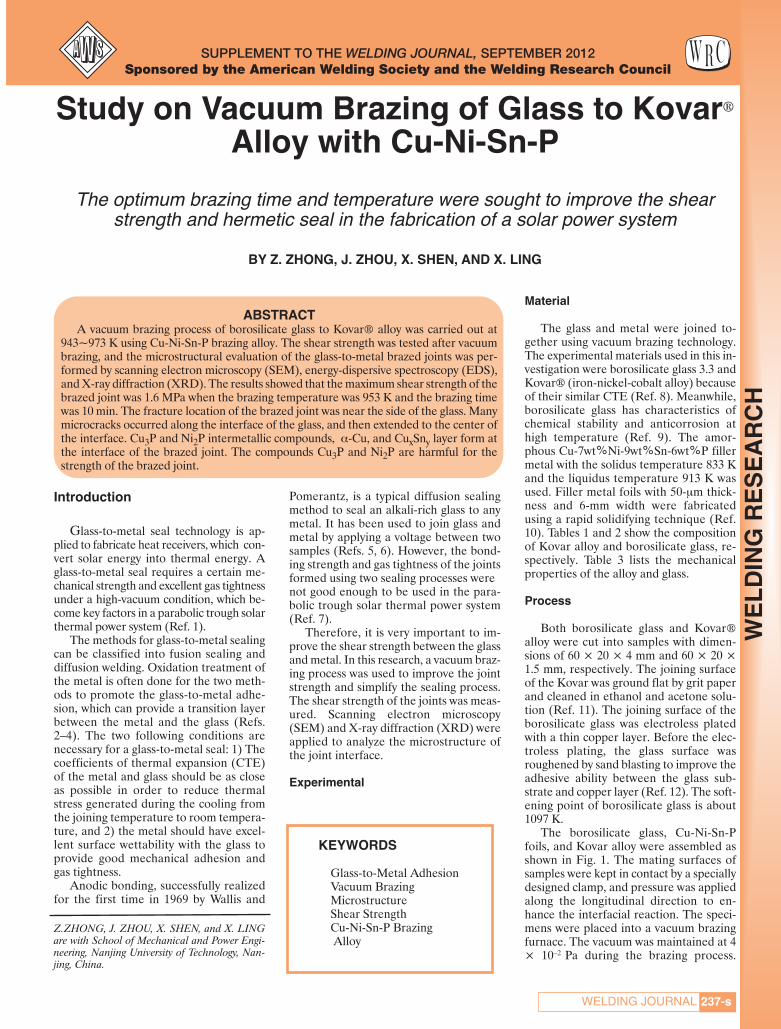
Introduction
Glass-to-metal seal technology is ap-plied to fabricate heat receivers, which con-vert solar energy into thermal energy. Aglass-to-metal seal requires a certain me-chanical strength and excellent gas tightnessunder a high-vacuum condition, which be-come key factors in a parabolic trough solarthermal power system (Ref. 1).
The methods for glass-to-metal sealingcan be classified into fusion sealing anddiffusion welding. Oxidation treatment ofthe metal is often done for the two meth-ods to promote the glass-to-metal adhe-sion, which can provide a transition layerbetween the metal and the glass (Refs.2–4). The two following conditions arenecessary for a glass-to-metal seal: 1) Thecoefficients of thermal expansion (CTE)of the metal and glass should be as closeas possible in order to reduce thermalstress generated during the cooling fromthe joining temperature to room tempera-ture, and 2) the metal should have excel-lent surface wettability with the glass toprovide good mechanical adhesion andgas tightness.
Anodic bonding, successfully realizedfor the first time in 1969 by Wallis and
Pomerantz, is a typical diffusion sealingmethod to seal an alkali-rich glass to anymetal. It has been used to join glass andmetal by applying a voltage between twosamples (Refs. 5, 6). However, the bond-ing strength and gas tightness of the jointsformed using two sealing processes were not good enough to be used in the para-bolic trough solar thermal power system(Ref. 7).
Therefore, it is very important to im-prove the shear strength between the glassand metal. In this research, a vacuum braz-ing process was used to improve the jointstrength and simplify the sealing process.The shear strength of the joints was meas-ured. Scanning electron microscopy(SEM) and X-ray diffraction (XRD) wereapplied to analyze the microstructure ofthe joint interface.
Experimental
Material
The glass and metal were joined to-gether using vacuum brazing technology.The experimental materials used in this in-vestigation were borosilicate glass 3.3 andKovar® (iron-nickel-cobalt alloy) becauseof their similar CTE (Ref. 8). Meanwhile,borosilicate glass has characteristics ofchemical stability and anticorrosion athigh temperature (Ref. 9). The amor-phous Cu-7wt%Ni-9wt%Sn-6wt%P fillermetal with the solidus temperature 833 Kand the liquidus temperature 913 K wasused. Filler metal foils with 50-μm thick-ness and 6-mm width were fabricatedusing a rapid solidifying technique (Ref.10). Tables 1 and 2 show the compositionof Kovar alloy and borosilicate glass, re-spectively. Table 3 lists the mechanicalproperties of the alloy and glass.
Process
Both borosilicate glass and Kovar®alloy were cut into samples with dimen-sions of 60 × 20 × 4 mm and 60 × 20 ×1.5 mm, respectively. The joining surfaceof the Kovar was ground flat by grit paperand cleaned in ethanol and acetone solu-tion (Ref. 11). The joining surface of theborosilicate glass was electroless platedwith a thin copper layer. Before the elec-troless plating, the glass surface wasroughened by sand blasting to improve theadhesive ability between the glass sub-strate and copper layer (Ref. 12). The soft-ening point of borosilicate glass is about1097 K.
The borosilicate glass, Cu-Ni-Sn-Pfoils, and Kovar alloy were assembled asshown in Fig. 1. The mating surfaces ofsamples were kept in contact by a speciallydesigned clamp, and pressure was appliedalong the longitudinal direction to en-hance the interfacial reaction. The speci-mens were placed into a vacuum brazingfurnace. The vacuum was maintained at 4× 10⁻² Pa during the brazing process.
SUPPLEMENT TO THE WELDING JOURNAL, SEPTEMBER 2012Sponsored by the American Welding Society and the Welding Research Council
Study on Vacuum Brazing of Glass to Kovar®Alloy with Cu-Ni-Sn-P
The optimum brazing time and temperature were sought to improve the shearstrength and hermetic seal in the fabrication of a solar power system
BY Z. ZHONG, J. ZHOU, X. SHEN, AND X. LING
KEYWORDS
Glass-to-Metal AdhesionVacuum Brazing Microstructure Shear StrengthCu-Ni-Sn-P BrazingAlloy
Z.ZHONG, J. ZHOU, X. SHEN, and X. LINGare with School of Mechanical and Power Engi-neering, Nanjing University of Technology, Nan-jing, China.
ABSTRACTA vacuum brazing process of borosilicate glass to Kovar® alloy was carried out at
943~973 K using Cu-Ni-Sn-P brazing alloy. The shear strength was tested after vacuumbrazing, and the microstructural evaluation of the glass-to-metal brazed joints was per-formed by scanning electron microscopy (SEM), energy-dispersive spectroscopy (EDS),and X-ray diffraction (XRD). The results showed that the maximum shear strength of thebrazed joint was 1.6 MPa when the brazing temperature was 953 K and the brazing timewas 10 min. The fracture location of the brazed joint was near the side of the glass. Manymicrocracks occurred along the interface of the glass, and then extended to the center ofthe interface. Cu3P and Ni2P intermetallic compounds, α-Cu, and CuxSny layer form atthe interface of the brazed joint. The compounds Cu3P and Ni2P are harmful for thestrength of the brazed joint.
237-sWELDING JOURNAL
WE
LD
ING
RE
SE
AR
CH
Zhong 9-12_Layout 1 8/9/12 3:06 PM Page 237

Then, the specimens were heated to thebrazing temperatures of 933, 943, 953, 963,and 973 K, respectively, and the heatingrate was 10 K/min. The brazing times were5, 10, 15, 20, and 30 min, respectively. Inorder to reduce the brazed residualstresses, the samples were cooled at therate of 3 K/min from the joining tempera-ture to 573 K and then cooled to roomtemperature in the furnace. The tempera-ture change during the vacuum brazing ex-periment is shown in Fig. 2.
After vacuum brazing, shear strengthsof five samples were measured at a con-stant speed of 0.5 mm/min in the MTStesting machine. The average value of fivesamples was taken as the shear strength.The microstructure of the brazed joint wasexamined using SEM and XRD to investi-gate the phase composition in the area ofthe brazed joint. Meanwhile, the elementdistribution on the interface was measured
using energy-dispersive spectroscopy(EDS).
Results and Discussion
Shear Strength of the Brazed Joint
To obtain the mechanical property ofthe brazed joint, the shear strength wasmeasured by means of a digital press test-ing machine. The relationship between thebrazing temperature and shear strength isshown in Fig. 3. It can be seen that thebrazing temperature has a marked effecton shear strength of the joint. The shearstrength gradually increases from 6 to 11.6MPa when the heating temperature in-creases from 933 to 953 K. The main rea-son is that the atom diffusion near theinterface can be sufficient to form an ex-cellent metallurgical combination at ele-vated temperatures. However, shear
strength decreases due to coarseness ofthe microstructure when the brazing tem-perature continually increases.
The relationship between the brazingtime and shear strength is shown in Fig. 4.As shown in Fig. 4, the shear strength ofthe joint brazed at 953 K rapidly increaseswith an increase in brazing time, and abrazed joint with a shear strength of 11.6MPa can be obtained at 953 K for 10 min.However, the shear strength of the brazedjoint reduces when the brazing time islonger than 10 min. The brazing time hasan important effect on the shear strengthof the joint. If the brazing time is shorterthan 10 min, the brazing filler metal justmelts, and the diffusion of the brazingfiller metal and base metal isn’t uniform,which leads to the low shear strength ofthe joint. If the brazing time is longer than10 min, the brazing filler metal is easilylost and forms brittle compounds, which
SEPTEMBER 2012, VOL. 91238-s
WE
LD
ING
RE
SE
AR
CH
Fig. 1 — Map of the glass-to-metal brazing setting. Fig. 2 — Technical requirement graph of the vacuum brazing ex-periment.
Fig. 3 — Relationship between the brazing temperature and shear strength. Fig. 4 — Relationship between the brazing time and shearstrength.
Table 1 — Chemical Composition of Kovar Alloy (wt-%)
C P S Mn Si Cu Cr Mo Ni Co Fe≤0.03 ≤0.02 ≤0.02 ≤0.5 ≤0.3 ≤0.3 ≤0.2 ≤0.2 28.5~29.5 16.8~17.8 base
Table 2 — Chemical Composition of Borosili-cate Glass (wt-%)
SiO2 B2O3 Na2O Al2O3 CaO
80.9 12.7 4 2.3 0.1
Zhong 9-12_Layout 1 8/9/12 3:06 PM Page 238

make the shear strength of the joint de-crease. Therefore, it is necessary to con-trol the brazing time to ensure thediffusion of the brazing filler metal andbase metal is complete while avoiding theformation of brittle compounds during thevacuum brazing of the borosilicate glassand Kovar alloy.
Figure 5 shows the typical fracture pat-tern of a sample measured using the ten-sile test. Figure 6 shows the rupture pathof the brazed joint. The results indicatethat the fracture occurs near the glass, andthe shear rupture is cleavage fracture withlittle brittle fracture. Most microcrackspropagate along the interface near theside of the glass, and sometimes microcracks are close to the center of the inter-face. A similar situation occurs in samplesusing other sealing processes (Ref. 13).Large shear stress induced at the interfacesuppresses the crack propagation alongthe interface (Ref. 14). Residual thermalstresses within the joint are induced due tothe CTE mismatch and different re-sponses of the glass and the metal, whichcould weaken the brazed joint strength.Generally, the lower the thermal residualstresses are, the higher the allowable stressto the fracture of the joint (Ref. 15).
Microstructure of the Brazed Joint
The cross-section microstructure of thebrazed joint is shown in Fig. 7. The crosssection is divided into three regionsmarked by E, F, and G. The EDS analysesof the three regions are shown in Figs. 8, 9,and 10, respectively. As shown in Fig. 8,region E is near the copper-coated glass,which mainly consists of the elements Cu,Ni, Sn, and P. There is a zone enriching Cuand Sn near region F and region G — Fig.9. However, P is not found. Therefore, Cuand Ni are prevented from forming Cu3P
and Ni2P due to the decrease of P. Asshown in Fig. 10, Au is found in the EDSanalysis because of the gold spraying onthe surface of the sample before EDSanalysis, and region G is composed of Cu,Sn, Fe, and Ni. As we know, P can reducethe melting point of Cu filler metal andhave a self-cleaning effect on the surfaceof metal. Phosphorus will react with theoxidation layer of the Kovar alloy andform P2O5 near the Kovar alloy side.Meanwhile, P has a high-vapor pressureand evaporates during brazing, whichleads to enriching Cu and Sn near Regions
239-sWELDING JOURNAL
WE
LD
ING
RE
SE
AR
CH
Fig. 5 — Macromorphology of shear crack on a brazed joint.
Fig. 7 — Microstructure of the joining interfaces for glass/braz-ing alloy/Kovar alloy.
Fig. 6 — Map of rupture crack path of a brazed joint.
Fig. 8 — EDS analysis of a small area component of theglass-to-brazing alloy interface (Region E).
Table 3 — Thermal and Mechanical Properties of Borosilicate Glass and Kovar Alloy
Material Temperature Young’s Modulus Poisson’s Ratio CTE Yield Stress(K) (GPa) (10-6/K) (MPa)
Borosilicate 64 0.20 3.3 35~120Glass
293 134 0.37 6.5 340Kovar Alloy 473 141 0.37 5.9 200
(4J29) 673 155 0.37 5.1 110
240 Cu
Cou
nts
00.100
CC
keV 10.340
Cu
Cu
SnNi
Zhong 9-12_Layout 1 8/9/12 3:06 PM Page 239

F and G. However, P also diffuses with Cunear the copper-coated glass and formsCu3P and Ni2P, besides partly evaporating.Cu3P and Ni2P are brittle compounds thatreduce the mechanical strength of thebrazed joints.
It can be seen that the metal elementdoes not react with the glass. A reactionlayer is necessary for adequate wettabilityof the filler metal on the copper-coatedglass. However, the negative effect of theexcessive growth of the reaction layershould also be considered. The formationof a brittle intermetallic in the condensedzone usually reduces the mechanicalstrength of the joint. The reaction layershould be thin and dense to inhibit furtherinteraction between the reactive metals ofthe filler metal and the Kovar alloy as adiffusion barrier, which limits the forma-tion of brittle phases.
According to XRD results (Fig. 11), thereaction products are mainly composed ofα-Cu, Ni2P, Cu2P (or Cu3P) and CuxSny.The mechanism of interface formation in-volving metallized glass differs from that ofactive filler metals. In metallized glass, Cuis already in contact with the glass surface,whereas the use of active filler metal re-quires the migration of Cu from the alloy tothe glass.
Conclusions
Glass to metal wasbrazed at 943~973 Kusing Cu-Ni-Sn-P fillermetal in vacuum, andshear strength tests andmicrostructure analyseswere performed. Thebrazing process was opti-mized successfully. Themain results are as fol-lows:
1) The shear strengthof the brazed joint de-pended on the brazingtemperature and thebrazing time. The shearstrength reached 11.6MPa when the brazingtemperature and thebrazing time were 680 K
and 10 min, respectively.2) The shear test results indicated that
the fracture location of the brazed jointwas near the side of the glass. Many mi-crocracks occurred along the interface ofthe glass, then extended to the center ofthe interface.
3) It was determined that Cu3P andNi2P intermetallic compounds, α-Cu, andCuxSny layer formed at the interface of thebrazed joint. The brittle compounds Cu3Pand Ni2P are mainly responsible for low-ering the strength of the brazed joints.
Acknowledgments
The authors gratefully acknowledgethe financial support rendered by the Na-tional Natural Science Foundation ofChina (Grant No. 10672072) and Hi-TechResearch Program Foundation of Jiangsu(Grant No. BG 2006040) in carrying outthis investigation.
References
1. Zhang, Y. N., Liu, H., and Yuan, J. 2004.Sealing of glass to metal. Glass & Enamel 32(6):34–37.
2. Susan, D. F., Van Den Avyle, J. A., Mon-
roe, S. L., Sorensen, N. R., McKenzie, B. B.,Christensen, J. E., Michael, J. R., and Walker,C. A. 2009. The effects of pre-oxidation andalloy chemistry of austenitic stainless steels onglass/metal sealing. Oxidation of Metals 73(1-2):311–335.
3. Chanmuang, C., Naksata, M., Chairu-angsri, T., Jain, H., and Lyman, C. E. 2008. Mi-croscopy and strength of borosilicateglass-to-Kovar alloy joints. Materials Scienceand Engineering 474(1-2): 218–224.
4. Lagtenberg, R., Bouwstra, S., and Elwen-spoek, M. 1991. Low temperature glass bond-ing for sensors applications using boron oxidefilms. Journal of Micromechanics and Micro-engineering 1: 157–160.
5. Wallis, G., and Pomerantz, D. I. 1969.Field-assisted glass-metal sealing. Journal of Ap-plied Physics 40: 3946–3949.
6. Wallis, G. 1970. Direct current polariza-tion during field-assisted glass-metal sealing.Journal of the American Ceramic Society 53(10):563–567.
7. Lei, D. Q., Wang, Z. F., and Du., F. L.2007. The glass-to-metal sealing process inparabolic trough solar receivers. Proceedings ofISES World Congress, Beijing: 740–744.
8. Shen, X. H., and Ling, X. 2008. Damageanalysis of glass-to-metal diffusion weldedjoints. Advanced Materials Research 44-46:765–772.
9. Xu, D., and Ling, X. 2008. Numerical sim-ulation of residual stress in the glass-to-metaldiffusion seals. Materials Science Forum 575-578: 666–671.
10. Zhang, B. W., Shu, X. L., Zhu, S. Y., andLiao, S. Z. 1999. Study on the thermal stabilityof Cu-P based amorphous alloy systems. Jour-nal of Materials Processing Technology 91: 90–94.
11. Wang, Y., Feng, J. C., Zhang, L. X., He,P., and Zhang, J. H. 2007. Microstructure of alu-mina ceramic/Ag-Cu-Ti brazing alloy/Kovaralloy joint. Materials Science and Technology23(3): 320–323.
12. Song, Y. W., Zhao, B., and Sun, C. X.1999. Electroless copper plating and its appli-cation to glass industry. Glass & Enamel 27(5):47–51.
13. Selcuk, A., Atkinson, A., and Senerver-atne, D. 1999. Mechanical strength of glass-to-metal joints. Metal Abstract 32: 202–206.
14. Bartlett, A., Evans, A. G., and Ruhle,M. 1991. Residual stress cracking of metal/ce-ramic bonds. Acta Metallurgica et Materialia39(7): 1579–1585.
15. Park, J. W., Mendez, P. F., and Eagar, T.W. 2002. Strain energy distribution in ceramic-to-metal joints. Acta Materialia 50(5): 883–899.
SEPTEMBER 2012, VOL. 91240-s
WE
LD
ING
RE
SE
AR
CH
Fig. 9 — EDS analysis of a small area component of the braz-ing alloy (Region F).
Fig. 11 — XRD patterns of the fracture interface.
Fig. 10 — EDS analysis of a small area component of the braz-ing alloy-to-Kovar interface (Region G).
200 Cu
Cou
nts
0.1000
keV 10.340
Cu
Cu
AuSn
Ni
200
Cou
nts
00.100
Cu
CAu Sn
Ni
keV
Fe
Cu
Cu
10.340
Zhong 9-12_Layout 1 8/10/12 9:03 AM Page 240

241-sWELDING JOURNAL
WE
LD
ING
RE
SE
AR
CH
Introduction
Welding is a major occupational activ-ity in the United States and worldwide,and includes workers in manufacturing,construction, and a number of other in-dustrial sectors. In excess of 462,000 U.S.workers do some welding as part of theirduties (Ref. 1), and about two-thirds ofthese workers are in manufacturing indus-tries. Welding produces a number of haz-ards during operation, including fumes,gases, and physical agents such as heat andultraviolet and infrared radiation. Occu-pational health studies indicate a numberof occupationally related adverse healtheffects, such as lung disease (Ref. 2). Mostwelding operations are performed on low-alloy or high-carbon steels, but stainless
steel may account for up to 5% of welding(Ref. 3), and is an important segment ofsome industries, such as food processingequipment manufacturers, chemicalsmanufacturing, and shipbuilding.
However, welding on stainless steelpresents an additional occupational-riskexposure; the known carcinogens hexva-lent chromium (Cr6+) and nickel (Ni) havebeen identified in stainless steel weldingfumes (Ref. 4). A review by the Interna-tional Agency for Research on Cancer
(Ref. 3), along with an additional Envi-ronmental Protection Agency review(Ref. 5) found a very wide range of Cr6+
concentrations; this suggested that differ-ent welding processes and conditionscould account for the 20:1 range of Cr6+
concentrations. The general purpose ofthis study was to identify the weldingprocess that minimizes exposure to Cr6+
by determining its concentration in arange of common welding processes.
Common Welding Configurations
Analysis of welding-based hazards isdependent on an understanding of therange of welding processes and condi-tions. More than 80 different weldingprocesses (Ref. 6) are commonly found,but most welding is done with electricalarc welding processes. The most preva-lently used variations, based on materialsusage, are shielded metal arc welding(SMAW) ~ 45%; gas metal arc welding(GMAW), ~34%; and flux cored arcwelding (FCAW), ~17% (Ref. 5).
The SMAW process has the simplestequipment requirements: a power supply,an electrode holder, welding rods, and aground clamp. The welding rods have acoating over the filler metal rod that pro-vides a shielding environment to minimizedegradation of the weld by atmosphericoxygen or nitrogen. The GMAW processuses more complex equipment; besides apower supply, it uses a gas-shielded gunand the electrode is a consumable wire ofthe desired filler metal fed by a motorizedfeeder. The shielding gas is externally sup-plied from cylinders. Shielding gasesrange from the completely inert argon(Ar), helium (He), and their mixtures toso-called active gases, which include car-bon dioxide (CO2), Ar mixtures with CO2or oxygen (O2), and other gas mixtures.These gases may have chemical interac-tions with the weld or fume. The FCAWprocess uses equipment similar toGMAW, but the wire electrode has an in-ternal flux material for weld shielding; theprocess may be used with or without an ex-ternal shielding gas.
Selecting Processes to Minimize HexavalentChromium from Stainless Steel Welding
Eight welding processes/shielding gas combinations were assessed for generationof hexavalent chromium in stainless steel welding fumes
BY M. KEANE, A. SIERT, S. STONE, B. CHEN, J. SLAVEN, A. CUMPSTON, AND J. ANTONINI
ABSTRACT
Eight welding processes/shielding gas combinations were assessed for generationof hexavalent chromium (Cr6+) in stainless steel welding fumes. The processes exam-ined were gas metal arc welding (GMAW) (axial spray, short circuit, and pulsed spraymodes), flux cored arc welding (FCAW), and shielded metal arc welding (SMAW).The Cr6+ fractions were measured in the fumes; fume generation rates, Cr6+ genera-tion rates, and Cr6+ generation rates per unit mass of welding wire were determined.A limited controlled comparison study was done in a welding shop including SMAW,FCAW, and three GMAW methods. The processes studied were compared for costs,including relative labor costs. Results indicate the Cr6+ in the fume varied widely, froma low of 2800 to a high of 34,000 ppm. Generation rates of Cr6+ ranged from 69 to7800 μg/min, and Cr6+ generation rates per unit of wire ranged from 1 to 270 μg/g.The results of field study were similar to the findings in the laboratory. The Cr6+ (ppm)in the fume did not necessarily correlate with the Cr6+ generation rate. Physical prop-erties were similar for the processes, with mass median aerodynamic diameters rang-ing from 250 to 336 nm, while the FCAW and SMAW fumes were larger (360 and 670nm, respectively). Conclusion: The pulsed axial spray method was the best choice ofthe processes studied based on minimal fume generation, minimal Cr6+ generation,and cost per weld. This method is usable in any position, has a high metal depositionrate, and is relatively simple to learn and use.
M. KEANE ([email protected]), S. STONE, B.CHEN, A. CUMPSTON, and J. ANTONINI arewith National Institute for Occupational Safetyand Health (NIOSH), Health Effects LaboratoryDiv., Morgantown, W.Va. J. SLAVEN is withNIOSH and Indiana University, Indianapolis,Ind. A. SIERT is with Xcel Energy, Denver, Colo.
KEYWORDS
Hexavalent ChromiumStainless SteelGas Metal Arc Welding
(GMAW)Flux Cored Arc Welding
(FCAW)Shielded Metal Arc Welding
(SMAW)Welding Fume
Keane Supplement Sept 2012_Layout 1 8/10/12 9:04 AM Page 241

242-s
WE
LD
ING
RE
SE
AR
CH Metal Transfer Modes in GMAW
Gas metal arc welding differs fromother arc welding processes in that morethan one mode of metal transfer from theelectrode into the weld pool is possible. Atrelatively low applied voltage, the processis called short-circuit gas metal arc weld-ing (GMAW-S). The end of the electrodewire is in direct contact with the weld pool,and a portion melts and is transferred intothe weld pool. The melting breaks theshort circuit, and the arc forms. The arc isintermittent (up to 200 times/s), and notperfectly stable; this may generate spatter,where relatively large droplets may be re-leased outside the weld bead.
When the voltage is increased abovethe short circuit range, another mode ofoperation known as globular transfer oc-curs. The wire end melts, forming largedrops that typically are larger than thewire diameter. The droplets fall by gravityinto the weld pool. This limits usage to flator horizontal welding positions; this modeis generally avoided because of severe
spatter problems.With shielding gases containing high
percentages of Ar, there is a transition toaxial spray (AXS) transfer mode as the ap-plied voltage is increased. Metal leaves theelectrode wire tip and is transferred as avery fine spray into the weld pool. Thisproduces a high-quality weld with lowerspatter. The technique is used primarily inflat or horizontal applications; overheador vertical use may have drip problems. Avariation of spray transfer is pulsed spraytransfer (GMAW-P), where current pulsesare added to a steady-state backgroundcurrent. This allows the total current toperiodically exceed the required transitioncurrent and permit spray mode. This pro-duces high-quality welds in any positionwith lower heat input, and a low fume-generation rate.
The study objectives were to assess awide spectrum of arc welding processesfor fume generation and Cr6+ generationrates, and identify the best choice orchoices one could select to minimize Cr6+
exposures at the source.
Methods and Materials
The basic welding system included amultiprocess welding machine (an MP350from The Lincoln Electric Co., Cleveland,Ohio) with a wire feeder capable of rates to300 in./min (762 cm/min). Welding was con-ducted in a conical chamber based on anAmerican Welding Society (AWS) designfor a chamber to measure fume-generationrates (Ref. 7). A photograph of the cham-ber in operation is shown in Fig. 1. The testchamber was validated to AWS perform-ance standards and met the performancecriteria. Aerosols were drawn from thechamber with a pump at 200 L/min. The ap-proximate chamber aerosol concentrationwas monitored with a DataRAM 4000(Thermo Electron, Franklin, Mass.). Stain-less steel welding wire was AWS A5.9 ClassER308LSi 0.045 in. (1.14 mm) in diameter,fed from an 11.4-kg (25-lb) reel. TheGMAW samples analyzed for Cr6+ in thisstudy were sampled from a single lot of wire.The manufacturer’s nominal compositionof the wire is 2% Mn, 19–25% Cr, 10–13%
Fig. 1 — American Welding Society-type welding chamber in use. Fig. 2 — Welding fume-generation rates for eight welding processes, in mg/min.
Fig. 3 — Hexavalent chromium content in welding fumes from eightprocesses, in mg/kg.
Fig. 4 — Hexavalent chromium generation rates for eight welding processes, inμg Cr6+/min.
SEPTEMBER 2012, VOL. 91
Keane Supplement Sept 2012_Layout 1 8/10/12 9:04 AM Page 242

243-sWELDING JOURNAL
WE
LD
ING
RE
SE
AR
CH
Ni, and the remainder Fe. Flux cored arcwelding used AWS A5.22 Class E308LT0-1wire, while SMAW generation used AWSA5.4 Class E308L-16 3⁄16-in. (4.8-mm) rods.
Shielding gas was taken from pressure-regulated cylinders at a flow rate of 19L/min. The welding material in the base-plates was ½-in.- (12.7-mm-) thick 304stainless steel, 22-in.- (56-cm-) diameterdisks. Operation with all shielding gasesand welding process types used similarconditions, but was adapted to good weld-ing practice, generally as recommended bywelding machine manufacturers. All weld-ing operations were adjusted for goodbead appearance with good penetration ofthe base plates and good toe wetting andwithout undercut. Baseplates were ro-tated at the desired rotary speed to pro-vide a travel rate compatible with goodwelds. A commercial welding turntablewas modified for external control by theLabview (National Instruments, Austin,Tex.) program; rotary speed was detectedby an encoder on the output shaft andinput to the program, and the travel ratedisplayed continuously during operation.Welding machine operation was initiatedunder program control to precisely con-
trol arc time.Operating variables are
shown in Table 1.
Sampling Strategies
Fumes from the weld areawere sampled through a 102-mm filter at the top of thechamber at 200 L/min. Thefilter material wasHollingsworth and Vose(East Walpole, Mass.) elec-trostatic medium (PE13060NA), cut to fit the filterhousing. The flow was measured with amass flow meter (TSI, Shoreview, Minn.)before sampling. After sampling was com-pleted, filters were removed from thehousing, folded inward, weighed to thenearest 0.1 mg, and put in sealed antista-tic polyethylene bags.
Sample Recovery and Processing
Welding fume particulate matter wasrecovered from the filters by gentle suc-tion onto a 47-mm, 0.8-μm polycarbonatefilter. The 47-mm stainless steel filter
hous-ing had a short piece of 6-mm ID siliconetubing, cut at 45 deg on the inlet end, anda house vacuum was connected to the out-let end. Using a gentle blotting action,most of the particulate fume was removedfrom the filter. Sufficient quantity was col-lected for analysis of Cr6+ and other met-als, but quantitative recovery was not nec-essary. After completion, thepolycarbonate filter was removed from thehousing over a tared 75 × 75-mm weigh-ing boat, and material brushed from thefilter and housing interior with a #3artist’s brush. The fume was treated withan antistatic device at this point to preventlosses. The dust was then ground in ametal-free apparatus to homogenize thesample for replicate analyses. Preliminaryresults indicated large differences be-tween replicate samples weighed frommaterial recovered from filters and subse-quently analyzed, with coefficients of vari-ation typically >20% for replicate sam-ples. The process below resulted in muchbetter precision for replicate samples,with coefficients of variation of typically5–10%. The system used was a disposable13-mm-diameter × 25-mm-long polyeth-ylene vial with two 3.2-mm (1⁄8-in.) siliconnitride coated ceramic balls, shaken for 30s in a Wig-L-Bug grinder. After grinding,the material was antistatic treated again,
Table 1 — Operating Variables for Generated Welding Fume Samples
Shielding Gas Gas Flow Weld Mode Wire Feed Voltage (V) Current (A)cm/min
Ar/CO2 99%/1% 19 L/min Short circuit 320 17–18 120Ar/O2 99%/1% 19 L/min Short circuit 320 17–18 125
He/Ar/CO290%/7.5%/2.5% 19 L/min Short circuit 320 19.5 100Ar/CO2 99%/1% 19 L/min Axial spray 760 25 200Ar/O2 99%/1% 19 L/min Axial spray 760 23 200Ar/O2 98%/2% 19 L/min Pulsed spray 760 0.9 V trim (pulsed)
Ar/CO2 75%/25% 19 L/min FCAW 760 26 160none none SMAW 361(a) ~20 150
(a) Equivalent wire feed speed based on an equal mass consumption rate.
Fig. 5 — Hexavalent chromium generation rates for eight welding processes, inµg Cr6+/g of welding wire consumed.
Fig. 6 — Hexavalent chromium exposures inside welder’s helmets inμg Cr6+/m3 for five welding processes.
Keane Supplement Sept 2012_Layout 1 8/10/12 9:04 AM Page 243

and weighed into 20-mL scintillation vialswith PTFE-lined caps. Storage in the vialswas at room temperature, in air, and vialsremained sealed unless samples were re-moved for analysis. A previous study (Ref.8) indicated samples were stable afterthree-months’ storage using this proce-dure. For Cr6+ analysis, 5.0-mg sampleswere weighed into 15-mL polycarbonatecentrifuge tubes.
Field Study
The controlled comparison study wasdone in a large welding shop using bead-on-plate welding on 0.25-in. 309 stainless steelin the flat position, to maximize exposures.Welding was kept at 50% arc time for allprocesses tested, which included SMAW,FCAW, and GMAW (short-circuit, spray,and pulsed spray modes). There were 8 ob-servations for SMAW, 16 for FCAW, 6 forGMAW-SC, 8 for GMAW-spray, and 7 forGMAW-pulsed spray modes. All weldersdid each type of welding in the study. Sam-ples were collected inside the welding hel-mets, and the welders wore half-face respi-rators with P100 filters during welding.Short-term trials were conducted to main-tain 8-h time-weighted average exposurelevels below the OSHA Cr6+ permissible ex-posure level (PEL).
Analysis for Cr6+
Samples were treated and analyzedusing NIOSH Physical and ChemicalAnalysis Method 7605, HexavalentChromium by Ion Chromatography (Ref.9). The estimated limit of detection is 0.02μg, and the method range is 0.05 to 20 μgof Cr6+. Five mL of extraction solution(3% Na2CO3/2% NaOH) were added toeach 5-mg sample, and the tubes sonicatedin a bath for 30 min. This procedure ex-tracts both soluble and insoluble Cr6+
present in the fumes. Samples were re-moved and centrifuged for 15 min at 3500× g. The supernatant was transferred to25-mL volumetric flask and diluted withH2O. Samples were analyzed by ion chro-matography using a Dionex HPIC-AS7column with 250 mM (NH4)2SO4/100 mMNH4OH mobile phase and a postcolumnreagent (2.0 mM diphenylcarbazide/10%methanol/1N H2SO4) with absorbance de-tection at 540 nm. Four concentrations ofstandards were made from a certified Cr6+
solution, covering a range of 0.4–4 μg/mL.
Particle Size Distributions
Particle size distributions of differentwelding fumes were determined by usingtwo Micro-Orifice Uniform Deposit Im-pactors (MOUDI and Nano-MOUDI,MSP Models 110 and 115; MSP Corp.,Shoreview, Minn.). By combining the twoimpactors, the particles were size-classi-
fied and collected into 15 fractions rang-ing from more than 18 μm down to 10 nm.Besides the special feature of being able toclassify nano-size particles, the MOUDIhas rotating stages to obtain a nearly uni-form particle deposit on the collectionsubstrates, which reduces particle bounceand improves subsequent analysis. Thetotal flow rate for the impactors was 30L/min, and they were operated for 4 mintotal sampling time.
Statistical Approaches
The data did not follow a normal dis-tribution, and were extremely skewed.Therefore, the Kruskal-Wallis nonpara-metric test was used to look for statisticallysignificant differences between groups.Statistical results were considered signifi-cant at a p-value of 0.05.
Results
Fume-generation rates for four runsare displayed graphically in Fig. 2. The re-sults in Figs. 2–5 are presented as arith-metic means ± standard error of the
mean. Results range from 16 mg/min(GMAW-P) to 228 mg/min (SMAW). TheCr6+ fractions in the fume, in mg/kg (ppm)are displayed in Fig. 3. The results are thearithmetic means ± standard error ofthree replicate samples for each of thefour welding runs. Results range from2800 ppm (GMAW-S using He/Ar/CO2shielding gas) to 34000 (SMAW). TheCr6+ generation rates were calculated asthe product of the fume-generation rateand the Cr6+ fraction in the fume, and aredisplayed in Fig. 4. Additionally, some ofthe differences in total fume-generationrate and Cr6+ generation rates were influ-enced by the different wire-feed rates nec-essary to maintain optimal welds. The nor-malized generation rate is related to awelder’s exposure for any given weld,since the weld is not complete until suffi-cient metal is deposited to meet the re-quirements of that weld. Therefore, thegeneration rates were renormalized withrespect to wire feed rates; results areshown in Fig. 5. The results normalized forwire-feed rates were calculated as theproduct of the Cr6+ generation rate andthe reciprocal of the wire-feed rate in
244-s
WE
LD
ING
RE
SE
AR
CH
Table 2 — Mass Median Aerodynamic Diameters (MMADs) and Geometric StandardDeviations (GSDs) of Welding Fumes for Different Shielding Gases and Processes, from MOUDIData
Shielding Gas Process MMAD (nm) GSD
Ar/CO2 99%/1% Short circuit 340 1.46Ar/O2 99%/1% Short circuit 280 1.53
He/Ar/CO2 Short circuit 330 1.4790%/7.5%/2.5%Ar/CO2 99%/1% Axial spray 260 1.23Ar/O2 99%/1% Axial spray 250 1.37
Ar/CO2 98%/2% Pulsed spray 320 1.58Ar/CO2 75%/25% FCAW 363 1.35
— SMAW 600 1.34
Fig. 7 — Particle size distribution of a typical welding fume in this study using a MOUDI device.
SEPTEMBER 2012, VOL. 91
Keane Supplement Sept 2012_Layout 1 8/10/12 9:06 AM Page 244
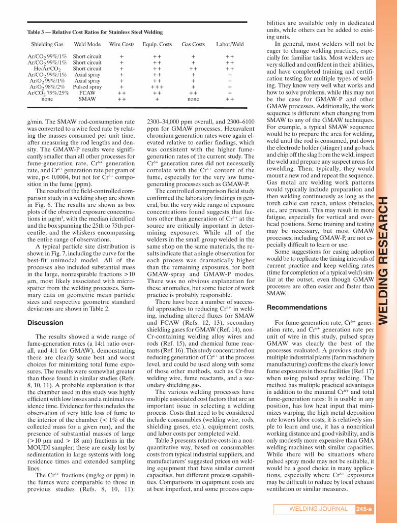
g/min. The SMAW rod-consumption ratewas converted to a wire feed rate by relat-ing the masses consumed per unit time,after measuring the rod lengths and den-sity. The GMAW-P results were signifi-cantly smaller than all other processes forfume-generation rate, Cr6+ generationrate, and Cr6+ generation rate per gram ofwire, p< 0.0004, but not for Cr6+ compo-sition in the fume (ppm).
The results of the field-controlled com-parison study in a welding shop are shownin Fig. 6. The results are shown as boxplots of the observed exposure concentra-tions in μg/m3, with the median identifiedand the box spanning the 25th to 75th per-centile, and the whiskers encompassingthe entire range of observations.
A typical particle size distribution isshown in Fig. 7, including the curve for thebest-fit unimodal model. All of theprocesses also included substantial massin the large, nonrespirable fractions >10μm, most likely associated with micro-spatter from the welding processes. Sum-mary data on geometric mean particlesizes and respective geometric standarddeviations are shown in Table 2.
Discussion
The results showed a wide range offume-generation rates (a 14:1 ratio over-all, and 4:1 for GMAW), demonstratingthere are clearly some best and worstchoices for minimizing total fume expo-sures. The results were somewhat greaterthan those found in similar studies (Refs.8, 10, 11). A probable explanation is thatthe chamber used in this study was highlyefficient with low losses and a minimal res-idence time. Evidence for this includes theobservation of very little loss of fume tothe interior of the chamber (< 1% of thecollected mass for a given run), and thepresence of substantial masses of large(>10 μm and > 18 μm) fractions in theMOUDI sampler; these are easily lost bysedimentation in large systems with longresidence times and extended samplinglines.
The Cr6+ fractions (mg/kg or ppm) inthe fumes were comparable to those inprevious studies (Refs. 8, 10, 11):
2300–34,000 ppm overall, and 2300–6100ppm for GMAW processes. Hexavalentchromium generation rates were again el-evated relative to earlier findings, whichwas consistent with the higher fume-generation rates of the current study. TheCr6+ generation rates did not necessarilycorrelate with the Cr6+ content of thefume, especially for the very low fume-generating processes such as GMAW-P.
The controlled comparison field studyconfirmed the laboratory findings in gen-eral, but the very wide range of exposureconcentrations found suggests that fac-tors other than generation of Cr6+ at thesource are critically important in deter-mining exposures. While all of thewelders in the small group welded in thesame shop on the same materials, the re-sults indicate that a single observation foreach process was dramatically higherthan the remaining exposures, for bothGMAW-spray and GMAW-P modes.There was no obvious explanation forthese anomalies, but some factor of workpractice is probably responsible.
There have been a number of success-ful approaches to reducing Cr6+ in weld-ing, including altered fluxes for SMAWand FCAW (Refs. 12, 13), secondaryshielding gases for GMAW (Ref. 14), non-Cr-containing welding alloy wires androds (Ref. 15), and chemical fume reac-tants (Ref. 16). This study concentrated onreducing generation of Cr6+ at the processlevel, and could be used along with someof those other methods, such as Cr-freewelding wire, fume reactants, and a sec-ondary shielding gas.
The various welding processes havemultiple associated cost factors that are animportant issue in selecting a weldingprocess. Costs that need to be consideredinclude consumables (welding wire, rods,shielding gases, etc.), equipment costs,and labor costs per completed weld.
Table 3 presents relative costs in a non-quantitative way, based on consumablescosts from typical industrial suppliers, andmanufacturers’ suggested prices on weld-ing equipment that have similar currentcapacities, but different process capabili-ties. Comparisons in equipment costs areat best imperfect, and some process capa-
bilities are available only in dedicatedunits, while others can be added to exist-ing units.
In general, most welders will not beeager to change welding practices, espe-cially for familiar tasks. Most welders arevery skilled and confident in their abilities,and have completed training and certifi-cation testing for multiple types of weld-ing. They know very well what works andhow to solve problems, while this may notbe the case for GMAW-P and otherGMAW processes. Additionally, the worksequence is different when changing fromSMAW to any of the GMAW techniques.For example, a typical SMAW sequencewould be to prepare the area for welding,weld until the rod is consumed, put downthe electrode holder (stinger) and go backand chip off the slag from the weld, inspectthe weld and prepare any suspect areas forrewelding. Then, typically, they wouldmount a new rod and repeat the sequence.Gas metal arc welding work patternswould typically include preparation andthen welding continuously as long as thetorch cable can reach, unless obstacles,etc., are present. This may result in morefatigue, especially for vertical and over-head positions. Some training and testingmay be necessary, but most GMAWprocesses, including GMAW-P, are not es-pecially difficult to learn or use.
Some suggestions for easing adoptionwould be to replicate the timing intervals ofcurrent practice and keep welding rates(time for completion of a typical weld) sim-ilar at the outset, even though GMAWprocesses are often easier and faster thanSMAW.
Recommendations
For fume-generation rate, Cr6+ gener-ation rate, and Cr6+ generation rate perunit of wire in this study, pulsed sprayGMAW was clearly the best of theprocesses evaluated. A previous study inmultiple industrial plants (farm machinerymanufacturing) confirms the clearly lowerfume exposures in those facilities (Ref. 17)when using pulsed spray welding. Themethod has multiple practical advantagesin addition to the minimal Cr6+ and totalfume-generation rates: It is usable in anyposition, has low heat input that mini-mizes warping, the high metal depositionrate lowers labor costs, it is relatively sim-ple to learn and use, it has a noncriticalworking distance and good visibility, and isonly modestly more expensive than GMAwelding machines with similar capacities.While there will be situations wherepulsed spray mode may not be suitable, itwould be a good choice in many applica-tions, especially where Cr6+ exposuresmay be difficult to reduce by local exhaustventilation or similar measures.
245-s
WE
LD
ING
RE
SE
AR
CH
Table 3 — Relative Cost Ratios for Stainless Steel Welding
Shielding Gas Weld Mode Wire Costs Equip. Costs Gas Costs Labor/Weld
Ar/CO2 99%/1% Short circuit + ++ + ++Ar/CO2 99%/1% Short circuit + ++ + ++
He/Ar/CO2 Short circuit + ++ ++ ++Ar/CO2 99%/1% Axial spray + ++ + +Ar/O2 99%/1% Axial spray + ++ + +Ar/O2 98%/2% Pulsed spray + +++ + +
Ar/CO2 75%/25% FCAW ++ ++ ++ +none SMAW ++ + none ++
WELDING JOURNAL
Keane Supplement Sept 2012_Layout 1 8/10/12 9:04 AM Page 245

Disclaimer
The findings and conclusions in thispaper are those of the author and do notnecessarily represent the views of the Na-tional Institute for Occupational Safetyand Health. The mention of any companynames or products does not imply an en-dorsement by NIOSH or the Centers forDisease Control and Prevention, nor doesit imply that alternative products are un-available, or unable to be substituted afterappropriate evaluation.
References
1. Bureau of Labor Statistics, U.S. Depart-ment of Labor: Welding, soldering, and brazingworkers. Occupational Outlook Handbook,2006-07 [Online] at www.bls.gov/oco/ocos226.htm.
2. Antonini, J. M. 2003. Crit. Rev. Toxicology33(1): 61–103.
3. IARC. 1990. Monographs on the evalua-tion of carcinogenic risks to humans, Volume 49:Chromium, nickel, and welding. Lyon, France.
4. NIOSH. 2005. Pocket Guide to ChemicalHazards, DHHS (NIOSH) Publication 2005-149.
5. U.S. Environmental Protection Agency:Chapter 12: Metallurgical Industry. AP 42, Section12.19: Development of Particulate and HazardousEmission Factors for Electric Arc welding. [Online]at www.epa.gov/ttn/chief/ ap42/index.html.
6. NIOSH. 1988. Criteria for a Recom-mended Standard: Welding, Brazing, and Ther-mal Cutting, DHHS (NIOSH) Publication No.88-110 (Cincinnati, Ohio), or available atwww.cdc.gov/niosh/topics/hexchrom/.
7. AWS F1.2, Laboratory Method for Meas-uring Fume Generation Rates and Total FumeEmission of Welding and Allied Processes. 2006.Miami, Fla.: American Welding Society.
8. Keane, M., Stone, S., Chen, B., Slaven, J.,Schwegler-Berry, D., and Antonini, J. 2009. J.Env. Mon. 11: 418–424.
9. NIOSH Analytical Methods Manual, 4thedition, Method 7605, Hexavalent chromiumby ion chromatography; available atwww.cdc.gov/niosh/nmam/default.html.
10. Moreton, J., Smars, E. A., and Spiller, K.R. 1985. Metal Construction 17: 794–798.
11. Yoon, S. Y., Paik, N. W., and Kim, J. H.2003. Ann. Occ. Hyg. 47: 671–680.
12. Dennis, J. H., French, M. J., et al. 2002.Ann. Occup. Hyg. 46(1): 33–42.
13. Kimura, S., Kobayashi, M., Godai, T.,and Minato, S. 1979. Welding Journal 58: 195-sto 203-s.
14. Dennis, J. H., French, M., Hewitt, P.,Mortazavi, S., and Redding, C. 2002. Ann. Occ.Hyg. 46: 43–48.
15. Sowards, J. W., Liang, D., Alexandrov, B.T., Frankel, G. S., and Lippold, J. C. 2011. Weld-ing Journal 90: 63-s to 76-s.
16. Topham, N., Kalivoda, M., Hsu, C.-Y.,Oh, S., and Cho, K. 2010. J. Aerosol Sci. 41:326–330.
17. Wallace, M., Landon, D., Song, R., andEcht, A. 2001. Appl. Occ. Environ. Hyg. 16:93–97.
246-s
WE
LD
ING
RE
SE
AR
CH
Authors: Submit Research Papers Online
Peer review of research papers is now managed through an onlinesystem using Editorial Manager software. Papers can be submittedinto the system directly from the Welding Journal page on the AWSWeb site (www.aws.org) by clicking on “submit papers.” You can alsoaccess the new site directly at www.editorialmanager.com/wj/. Followthe instructions to register or log in. This online system streamlinesthe review process, and makes it easier to submit papers and tracktheir progress. By publishing in the Welding Journal, more than68,000 members will receive the results of your research.
Additionally, your full paper is posted on the American WeldingSociety Web site for FREE access around the globe. There are nopage charges, and articles are published in full color. By far, the mostpeople, at the least cost, will recognize your research when youpublish in the world-respected Welding Journal.
CAN WE TALK?The Welding Journal staff encourages an exchange of ideas with you, our read-
ers. If you’d like to ask a question, share an idea or voice an opinion, you can call,write, e-mail or fax. Staff e-mail addresses are listed below, along with a guide to helpyou interact with the right person.
PublisherAndrew Cullison [email protected] 249Article Submissions
EditorMary Ruth [email protected] 238Feature Articles
Associate Editor Howard [email protected] 244Society NewsPersonnel
Associate Editor Kristin [email protected],Extension 257New ProductsNews of the Industry
Managing Editor Zaida [email protected] 265Design and Production
Senior Production Coordinator
Brenda [email protected] Extension 330Design and Production
Advertising Sales Director
Rob Saltzstein [email protected] 243Advertising Sales
Advertising Sales & Promotion Coordinator
Lea [email protected] 220Production andPromotion
Advertising ProductionManager
Frank [email protected] 465Advertising Production
Peer Review Coordinator Melissa [email protected] 475Peer Review of Research Papers
Welding Journal Dept. 550 N.W. LeJeune Rd. Miami, FL 33126 (800) 443-9353FAX (305) 443-7404
SEPTEMBER 2012, VOL. 91
Keane Supplement Sept 2012_Layout 1 8/10/12 9:04 AM Page 246

Introduction
Resistance spot welding utilizes the in-herent resistance of metal pieces to jointwo or more sheets of metal by the flow ofelectrical current, which passes throughthe metal sheets and generates the weld-ing heat. As a traditional welding tech-nique, resistance spot welding is a majormetal-connecting method in the automo-tive, consumer electronics, and aircraft in-dustries (Ref. 1).
For resistance spot welding, its coolingcrystallization of liquid metal in a nuggetis consistent with the general rules of a so-lidification process; the nugget shape orstructure after solidification is closely re-lated to the cooling rate of the solidifica-tion of the liquid metal and directly deter-mines the performance of the spot weldedjoint (Ref. 2).
However, it is currently impossible to de-termine the cooling rate directly with nor-mal test methods, such as thermocouple,optical temperature measurement, or high-speed photography, which have been widelyused in the research field of rapid solidifi-cation. The reason behind this is the nuggetcrystallization of spot welding is instanta-neously completed in a closed plastic ring,and the spot weld nuggets in sheet metalsare usually small. Therefore, there are fewopen publications in this field to directly de-termine the cooling rate of a spot welding
nugget. It was reported that under spotwelding conditions, the cooling rate of low-carbon steel had been roughly inferred fromthe phenomenon of hardened martensite inthe welding nugget (Ref. 3). In addition, byusing an X-ray, Elmer (Ref. 4) observed thesolidification and cooling processes of stain-less steel spot welding.
According to the secondary dendritearm spacing method, a cooling rate couldbe indirectly determined based on the cor-relation between the cooling rate and di-mensional characteristics of microstruc-ture after rapid solidification (Ref. 5).This method is widely and successfully ap-plied in the research area for rapid solidi-fication technology (Refs. 6–8).
Due to the fact that the crystallizationtemperature range in stainless steel is rel-atively narrow and its dendrites can growfully, it is relatively easy to measure theirsecondary dendrite arm spacing. As such,1Cr18Ni9Ti stainless steel was taken asthe research material. Based on the meas-urement of the secondary dendrite armspacing in the spot welding nugget of thismaterial, the cooling rates in differentareas of the nugget were estimated ac-
cording to rapid solidification theory.
The Test Material, Equipment,and Method
The test material was a rolled stainlesssteel 1Cr18Ni9Ti sheet with a specimensize of 100 × 20 × 1 mm. Its chemical com-position is shown in Table 1. Figure 1 il-lustrates the microstructure of the basemetal showing equiaxed austenite grains.
The spot welding machine used was aDN-200-4 equipped with type KD(T)-4spot welding microcomputer controller.The upper and lower electrodes of the ma-chine were made of chrome-zirconium-cop-per alloys in a truncated cone shape with atip diameter of 5 mm, which were cooled in-side by room-temperature circulating waterwith a flow rate of 0.02 m3/min. A single im-pulse procedure was used in this spot weld-ing machine simply because the austeniticstainless steel can be spot welded in highquality without any special technical treat-ments. The welding parameters used wereas follows: welding current 6 kA, weldingtime 0.14 s, and electrode force 3800 N.
After welding, the weld nugget was cutin the center for metallographic examina-tion. The etching solution was made from 5mL hydrochloric acid, 10 mL nitric acid, 10g ferric chloride, and 100 mL water. Themeasurement of nugget dendrite arm spac-ing was carried out using an OlympusPMG3 optical microscope. To reduce meas-uring errors of the secondary dendrite armspacing, the selected measure points shouldbe away from the dendrite tips. Further-more, the third dendrite arms were ignoredduring the distance measurement of a sec-ondary dendrite to its primary dendrite forthe sake of consistency. The average of mul-tiple measurements was taken as the meas-uring result.
Secondary Dendrite ArmSpacing Model
The secondary dendrite arm spacing(SDAS) is a distance between the second-ary dendrite arms. Based on Fick’s law andGibbs-Thompson’s equation, Furer andWunderlin proposed the SDAS theoreti-
Estimating the Cooling Rates of aSpot Welding Nugget in Stainless Steel
In this study, the projected results show the cooling rate from the nugget edgeto nugget center decreases gradually from 105 to 104 K/s
BY Y. ZHANG, T.-J. MA, H.-X. XIE, Y.-M. TAN, AND P.-Y. LI
KEYWORDS
Spot WeldingNuggetCooling RateSecondary Dendrite ArmSpacing
1Cr18Ni9Ti Stainless SteelY. ZHANG ([email protected]), T.-J. MA,H.-X. XIE, Y.-M. TAN, and P.-Y. LI are with theShaanxi Key Laboratory of Friction Welding Tech-nologies, Northwestern Polytechnical University,Xi’an, China.
ABSTRACT
Cooling rates at different areas of a spot welded nugget in a 1Cr18Ni9Ti stain-less steel material were investigated based on the rapid solidification theory andFurer-Wunderlin secondary dendrite arm spacing (SDAS) model. In the calcula-tion of the cooling rates by using a SDAS method, only the diffusion of carbonatoms, which spread rapidly as a solute element in the solid phase, was consid-ered. The experimental results show that the SDAS values in a 1Cr18Ni9Ti spotwelded nugget exhibited significant variation even for those on the same primarydendrite axis. The estimated cooling rate from the nugget edge to nugget centerdecreased from an order of magnitude 105 to 104 K/s.
247-sWELDING JOURNAL
WE
LD
ING
RE
SE
AR
CH
Zhang et al Supplement September 2012_Layout 1 8/9/12 3:14 PM Page 247

cal model (Ref. 9).Furer and Wunderlin suggested that
with remelting of small secondary den-drites, the distance or spacing of the biggersecondary dendrite arms will increase, asshown in Fig. 2, where λ2 is the SDAS. Thecoarsening mechanism assumed that thefiner second dendrite arms would bemelted while the other bigger brancheswould become thicker. Whenever a finesecondary arm is melted, the local second-ary dendrite spacing will be doubled. Thedriving force of this process is the differ-ence of interfacial energy between grainswith different curvatures. Based on this as-sumption, the following Furer and Wun-derlin equation is obtained:
λ2 = 5.5(Atf)1⁄3 (1)
Where λ2 is secondary dendrite arm spac-ing (μm); tf is local solidification time (s);and A is coarsening coefficient (s/K).
Here, the coarsening coefficient Acould be calculated by following formula:
A = ΓDLln(CL/C0)/mL(1 – k)(C0 – CL) (2)
Where Γ is Gibbs-Thompson coefficient(K·m); DL is diffusion coefficient of solutein liquid phase; CL is liquid concentration(wt-%); C0 is the original concentration ofthe liquid alloy (wt-%); mL is liquidusslope; and k is distribution ratio at equilibrium.
In Equation 1, the local solidificationtime tf is defined as the time when eachdendrite arm contacts the liquid phase,which is a function of the growth rate, tem-perature gradient, and alloy compositions.The following formula can be used for cal-culating the local solidification time tf, i.e.,
tf = ΔT ′/|Ṫ| = ΔT ′/GV (3)
Where ΔT ′ is nonequilibrium solidificationtemperature range (K); G is temperaturegradient (K/m); V is dendrite growth veloc-ity (m/s); and |Ṫ| is the cooling rate. Theproduct of G and V equals to the coolingrate Ṫ, so that Equation 3 can also be ex-pressed as the following:
tf = ΔT ′/|Ṫ| = ΔT ′/Ṫ (4)
Cooling Rate Calculation of1Cr18Ni9Ti Nugget Solidification
Determination of the Secondary DendriteMicrostructures and Solute Elements forCalculating the Cooling Rate
Secondary Dendrite Microstructures of1Cr18Ni9Ti Spot Welding Nugget
Figure 3A–C shows the dendritic mi-crostructures of 1Cr18Ni9Ti spot weldingnugget, respectively, in the areas fromnugget edge to nugget center. In eachimage, there is an arrow pointing to theposition where the secondary dendritesegment is selected for the SDAS meas-urement. As soon as the welding current isturned off, the welding zone will begin tocool down due to no more heat generationto compensate the heat loss; as a result,crystallization will start from the partialmelting crystalline grains around the edgeof the nugget. This crystallization occursin a form of dendrite, and this dendritegrows toward the center core along the op-posite direction of heat dissipation.
If the axis direction of the dendritebranch is the same as the axis of heat dis-sipation, then the heat flow will be betterand the dendritic growth will also be
faster; consequently, the best direction forthe dendritic growth is along the elec-trodes of the spot welding machine. Thegrowth of these dendrites will usually besufficient due to no external electromag-netic stirring behavior during the crystal-lization (Refs. 10, 11).
The SDAS measured from Fig. 3 is gen-erally between 1~5 μm, the dendrite armspacing is small, and each of them is differ-ent. From the edge to the core of the weldnugget, the average dendrite arm spacingincreases. One reason is that the crystalliza-tion at spot welding begins generally from atthe partial melting zone around the nuggetwith a lower temperature and better coolingcondition, where the crystallization temper-ature can be reached first, i.e., it begins fromthe nucleus of the partial melting grain sur-face with lowest surface energy. These den-drites grow in the opposite direction of heatdissipation. Due to the relatively small ther-mal conductivity of stainless steel, the latentheat of crystallization released during thesolidification process will lower the temper-ature gradient in the nugget as the dendritesapproach the nugget center. The lower tem-perature gradient and lower cooling ratenear the nugget center make the dendritesgrow slower, and thus, smaller average den-drite arm spacing.
Determination of Solutes for Calculating theCooling Rate
It is difficult to accurately determinethe thermodynamic parameters for a com-plicated alloy system like 1Cr18Ni9Tistainless steel with many alloy elements.Only three alloy elements — Fe, Cr, andNi — will be considered in the calculationof physical parameters. For the calculationof cooling rate, the following parametersneed to be known: the liquidus tempera-ture, the solidus temperature, and the liq-uidus slope for each precipitated single el-ement. Under normal cooling conditions,the thermal diffusion rate of a casting partis about in an order of magnitude 10–6 m2/s,but for a solute atom in an alloy liquid, its
SEPTEMBER 2012, VOL. 91248-s
WE
LD
ING
RE
SE
AR
CH
Fig. 1 — Microstructure of the base metal 1Cr18Ni9Ti stainlesssteel.
Fig. 2 — Secondary dendrite arm spacing.
Table 1 — Chemical Composition of 1Cr18Ni9Ti Stainless Steel (wt-%)
Material C Si Mn P S Cr Ni N1Cr18Ni9Ti 0.052 0.465 1.26 0.0005 0.0028 19.6 8.54 0.06
Zhang et al Supplement September 2012_Layout 1 8/9/12 3:18 PM Page 248
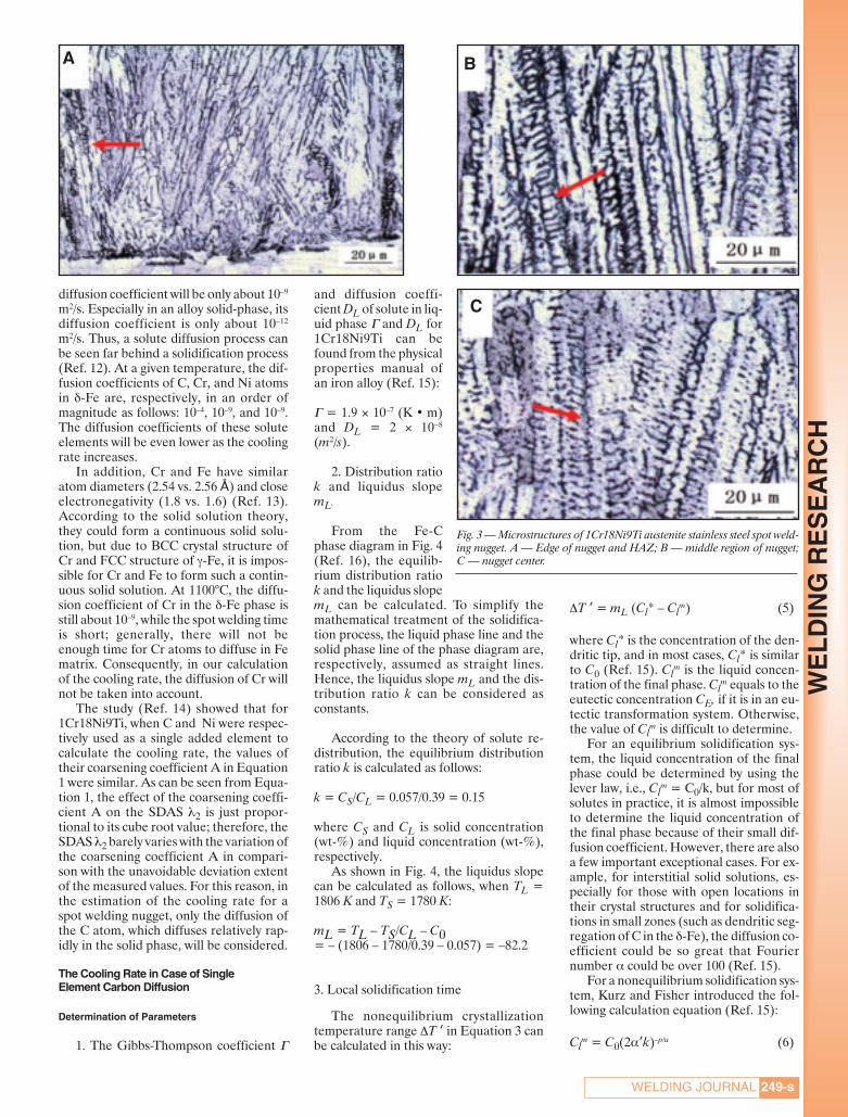
diffusion coefficient will be only about 10–9
m2/s. Especially in an alloy solid-phase, itsdiffusion coefficient is only about 10–12
m2/s. Thus, a solute diffusion process canbe seen far behind a solidification process(Ref. 12). At a given temperature, the dif-fusion coefficients of C, Cr, and Ni atomsin δ-Fe are, respectively, in an order ofmagnitude as follows: 10–4, 10–9, and 10–9.The diffusion coefficients of these soluteelements will be even lower as the coolingrate increases.
In addition, Cr and Fe have similaratom diameters (2.54 vs. 2.56 Å) and closeelectronegativity (1.8 vs. 1.6) (Ref. 13).According to the solid solution theory,they could form a continuous solid solu-tion, but due to BCC crystal structure ofCr and FCC structure of γ-Fe, it is impos-sible for Cr and Fe to form such a contin-uous solid solution. At 1100°C, the diffu-sion coefficient of Cr in the δ-Fe phase isstill about 10–9, while the spot welding timeis short; generally, there will not beenough time for Cr atoms to diffuse in Fematrix. Consequently, in our calculationof the cooling rate, the diffusion of Cr willnot be taken into account.
The study (Ref. 14) showed that for1Cr18Ni9Ti, when C and Ni were respec-tively used as a single added element tocalculate the cooling rate, the values oftheir coarsening coefficient A in Equation1 were similar. As can be seen from Equa-tion 1, the effect of the coarsening coeffi-cient A on the SDAS λ2 is just propor-tional to its cube root value; therefore, theSDAS λ2 barely varies with the variation ofthe coarsening coefficient A in compari-son with the unavoidable deviation extentof the measured values. For this reason, inthe estimation of the cooling rate for aspot welding nugget, only the diffusion ofthe C atom, which diffuses relatively rap-idly in the solid phase, will be considered.
The Cooling Rate in Case of SingleElement Carbon Diffusion
Determination of Parameters
1. The Gibbs-Thompson coefficient Γ
and diffusion coeffi-cient DL of solute in liq-uid phase Γ and DL for1Cr18Ni9Ti can befound from the physicalproperties manual ofan iron alloy (Ref. 15):
Γ = 1.9 × 10⁻⁷ (K • m)and DL = 2 × 10⁻⁸
(m2/s).
2. Distribution ratiok and liquidus slopemL.
From the Fe-Cphase diagram in Fig. 4(Ref. 16), the equilib-rium distribution ratiok and the liquidus slopemL can be calculated. To simplify themathematical treatment of the solidifica-tion process, the liquid phase line and thesolid phase line of the phase diagram are,respectively, assumed as straight lines.Hence, the liquidus slope mL and the dis-tribution ratio k can be considered asconstants.
According to the theory of solute re-distribution, the equilibrium distributionratio k is calculated as follows:
k = CS/CL = 0.057/0.39 = 0.15
where CS and CL is solid concentration(wt-%) and liquid concentration (wt-%),respectively.
As shown in Fig. 4, the liquidus slopecan be calculated as follows, when TL =1806 K and TS = 1780 K:
mL = TL – TS/CL – C0= – (1806 – 1780/0.39 – 0.057) = –82.2
3. Local solidification time
The nonequilibrium crystallizationtemperature range ΔT ′ in Equation 3 canbe calculated in this way:
ΔT ′ = mL (Cl* – Clm) (5)
where Cl* is the concentration of the den-dritic tip, and in most cases, Cl* is similarto C0 (Ref. 15). Cl
m is the liquid concen-tration of the final phase. Cl
m equals to theeutectic concentration CE, if it is in an eu-tectic transformation system. Otherwise,the value of Cl
m is difficult to determine.For an equilibrium solidification sys-
tem, the liquid concentration of the finalphase could be determined by using thelever law, i.e., Cl
m = C0/k, but for most ofsolutes in practice, it is almost impossibleto determine the liquid concentration ofthe final phase because of their small dif-fusion coefficient. However, there are alsoa few important exceptional cases. For ex-ample, for interstitial solid solutions, es-pecially for those with open locations intheir crystal structures and for solidifica-tions in small zones (such as dendritic seg-regation of C in the δ-Fe), the diffusion co-efficient could be so great that Fouriernumber α could be over 100 (Ref. 15).
For a nonequilibrium solidification sys-tem, Kurz and Fisher introduced the fol-lowing calculation equation (Ref. 15):
Clm = C0(2α′k)–p/u (6)
249-sWELDING JOURNAL
WE
LD
ING
RE
SE
AR
CH
A B
C
Fig. 3 — Microstructures of 1Cr18Ni9Ti austenite stainless steel spot weld-ing nugget. A — Edge of nugget and HAZ; B — middle region of nugget;C — nugget center.
Zhang et al Supplement September 2012_Layout 1 8/9/12 3:53 PM Page 249

Where u = 1 – 2αʹk, p = 1 – k, and αʹ isthe reverse diffusion parameter and afunction of tf.
α′ = α [1 – exp (–1/α)]– 1/2 exp – (1/2α) (7)
in Equation 7, α is the dimensionless time(Fourier number) and can be obtained asfollows:
α = DStf/L2 = 4DStf /λ2 (8)
The parameter α has the followingcharacteristics (Ref. 13): When the valueof α is less than 0.1, then α′ = α; when αvalue is greater than 50, then α′ = 0.5.Based on the experiential data, it can beestimated roughly that the value of α inEquation 8 is quite big. When α′= 0.5, Cl
m
can be obtained as Clm = 0.33. Therefore,
in this paper only, the effect of a C atomon the solidification process will be con-sidered, and the solidification is assumedin equilibrium. Hence, ΔT′ can beachieved as follows:
ΔT ′ = mL(Cl* – Clm)
= –82.2 × (0.057 – 0.39) ≈ 27°C
Calculation of Cooling Rate
From the measurement of the dendritesegments indicated by the arrow in Fig. 3,the average values of SDAS can be ob-tained at different areas in a weld nugget
as listed in Table 2. Putting the SDAS av-erage values and the afore-calculated pa-rameters Γ, DL, k, mL, ΔT ′ into Equations1–4, the solidification time tf, and the cool-ing rate CR, can consequently be obtainedand listed in Table 2. As shown in Table 2,for 1Cr18Ni9Ti spot nugget solidification,the cooling rates from nugget edge tonugget center decrease gradually from anorder of magnitude 105 K/s at the nuggetedge to 104 K/s at the middle region andthe nugget center.
Discussion
Measuring the secondary dendrite armspacing enables gaining information onthe local solidification in a nugget. Figure5 shows the morphology of local second-ary dendrite in the middle region of thenugget. The significant difference of thesecondary dendrite arm spacing can beseen for those secondary dendrites fromdifferent primary dendrites in the samearea. A few secondary dendrite arms canobviously be observed with a clear shapeof dendrites, while others are so fine thatit is difficult to distinguish their dendritearm spacing. In addition, Fig. 5 shows thatthe secondary dendrite arms on a primarydendrite have different lengths. This is be-cause a secondary dendrite will alwaysgrow up as long as its length is less thanhalf the length of a primary dendrite armspacing, and at the same time, these sec-ondary dendrites will also devour each
other. Once the growing tip of a secondarydendrite meets that of a neighboring den-drite, the growth of the secondary den-drite will be stopped.
As can be clearly seen in Fig. 5, valuesof the secondary dendrite arm spacing ona given primary dendrite also have a rela-tively big variation due to the differenceon the release of the latent heat duringcrystallization and the behavior of soluteelements in dendrite interactions. Figure6A presents the measuring results for eachsegment of secondary dendrite arm spac-ing for the location marked in Fig. 5. Theestimated corresponding cooling rates areplotted in Fig. 6B.
As can be observed from Fig. 6, sec-ondary dendrite arm spacing values ex-hibit a significant variation from 0.97 to3.7 μm. Accordingly, the cooling ratevaries from about 1 × 10⁴ to 10 × 104 K/s.The big variation of cooling rates may berelated to the solidification process of thewelding nugget. Due to the release of thelatent heat of crystallization, the tempera-ture between dendrites will rise. As a re-sult, a few relatively small secondary armsin two adjacent secondary dendrites willmelt and disappear to promote the growthof a few big dendrite branches. Further-more, unlike the primary dendrite armspacing in the solidification process, thesecondary dendrite arm spacing dependslargely on the gradual cooling process dur-ing their growth (Ref. 9).
Conclusions
The cooling rates at different areas ofthe spot welding nugget for 1Cr18Ni9Tiwere estimated by using the secondarydendrite arm spacing method as well asconsidering the characteristics of the spotwelding process and the situation of anatom’s diffusion (atom C was selected asan independent solute in solvent Fe). Theestimated results show that the cooling
SEPTEMBER 2012, VOL. 91250-s
WE
LD
ING
RE
SE
AR
CH
Table 2 — The Values of Cooling Rate in Only Considering C Diffusion
Average SDAS Solidification Time Cooling RatePosition SDAS in Fig. 3 λ2/μm tf /s CR/K/s
Nugget edge and HAZ 1.29 1.5 × 10⁻⁴ 4.19 × 10⁵
Middle region of nugget 2.151 7.07 × 10⁻⁴ 9.05 × 10⁴
Nugget center 3.036 1.9 × 10⁻³ 3.22 × 10⁴
Fig. 4 — Fe-Fe3C phase diagram. Fig. 5 — Section of local secondary dendrite arm microstructure.
Zhang et al Supplement September 2012_Layout 1 8/9/12 3:13 PM Page 250

rate from the nugget edge to nugget cen-ter decreases gradually from an order ofmagnitude 105 to 104 K/s.
For the 1Cr18Ni9Ti spot weldingnugget, there are a lot of variations for thesecondary dendrite arm spacing; it largelydepends on the relative location in thenugget for its primary dendrite and loca-tion inside the primary dendrite. The sec-ondary dendrite arm length on a given pri-mary dendrite changes with the location,and their secondary dendrite arm spacingwill vary consequently.
Acknowledgment
The authors would like to thank the fi-nancial support from the 111 Project(B08040).
References
1. Cho, Y., and Rhee, S. 2002. Primary cir-cuit dynamic resistance monitoring and its ap-plication to quality estimation during resist-
ance spot welding. Welding Journal 81(6): 104-s to 111-s.
2. The Resistance Council of the ChineseWelding Society. 1994. The theory and practiceof resistance welding. Beijing, China. MachinePress.
3. Bi, H. Q. 1981. Welding methods andequipments. Beijing, China. Machine Press.
4. Elmer, W. J. 2000. In-situ observations ofphase transformations during solidification andcooling of austenitic stainless steel welds usingtime-resolved X-ray diffraction. Scripta Materi-alia 43: 751–757.
5. Zhou, Y. H. 1998. Solidification technol-ogy. Beijing, China. Machine Press.
6. Cheng, M. T., Tang, Z. H., and Ni, M. S.1993. Relationship between cooling rate andsecondary dendrite arm spacing for steel No.45. Journal of Iron and Steel Research 5(4): 1–4.
7. Turhal, M. S., and Savaskan, T. 2003. Re-lationships between secondary dendrite armspacing and mechanical properties of Zn-40Al-Cu alloys. Journal of Materials Science 38:2639–2646.
8. Zhang, D. F., Lan, W., Zeng, D. D., andZhang, B. P. 2008. Quantitative relationship be-tween secondary dendrite arm spacing and so-lidification cooling rate of AZ31 magnesiumalloy. Heat Treatment of Metals 33(3): 1–3.
9. Li, H. X., Guo, T. M., Li, R. D., Li, R. X.,and San, J. C. 2004. Research on secondary den-drite arm spacing. Foundry 53(12): 1011–1014.
10. Alcini, W. V. 1990. Experimental meas-urement of liquid nugget heat convection inspot welding. Welding Journal 69(5): 177-s to180-s.
11. Li, Y. B., Lin, Z. Q., Lai, X. M., Chen,G. L., and Zhang, K. 2010. Induced electro-magnetic stirring behavior in a resistance. Sci-ence China Technological Sciences 53(5):1271–1277.
12. Pen, G. W., Liu, J., Li, L., and Zeng, B.2005. Progress of technic and theory of direc-tional solidification. Research Studies onFoundry Equipment (4): 44–47.
13. Xiao, J. M. 1983. The metallographyproblems of the stainless steel. Beijing, China.Metallurgical Industry Press.
14. Li, P. Y. 2011. Cooling rate calculationand microstructure characterization on spotwelding nugget of stainless steels. Master’s dis-sertation. Xi’an, China. Northwestern Poly-technical University.
15. Kurz, W., and Fisher, D. J. 1987. Solidi-fication Theory. Xi’an, China. NorthwesternPolytechnical University Press.
16. Dai, Y. N. 2009. Binary alloy phase dia-gram. Beijing. China Science Press.
251-sWELDING JOURNAL
WE
LD
ING
RE
SE
AR
CH
Fig. 6 — The curves of secondary dendrite arms and cooling rate in Fig. 5. A — The curve of the second arm spacing; B — the curve of the cooling rate.
A B
Looking for a Welding Job?
The American Welding Society has enhanced its Jobs In Welding Web site at www.jobsinwelding.com.The redesigned career portal includes additional capabilities for companies seeking workers and individuals
looking for jobs.Through relationships with many job boards and distributors, it offers direct access to more than 88% of the
welding-related jobs posted on the Internet.Users may search various openings for welders, Certified Welding Inspectors, engineers, technicians, and man-
agers/supervisors.In addition, the Web site contains the following highlights:
• The home page displays featured welding jobs along with the companies looking to fill them and city/statelocations.
• The job seeker section connects individuals to new career opportunities by allowing them to post an anonymousrésumé, view jobs, and make personal job alerts. This area has résumé tips, certification information, and aschool locator.
• The employer area enables association with qualified applicants. Résumés, job postings, and products/pricingoptions may be viewed here.Visit the Web site to create or access job seeker and employer accounts.
Zhang et al Supplement September 2012_Layout 1 8/9/12 3:13 PM Page 251

Introduction
Many engineering components todayhave service conditions that require theproperties to vary with position (Ref. 1).Differing stresses, temperatures, and en-vironments necessitate a range of materialproperties that often cannot be achievedin a component with a single composition.One solution is to replace these compo-nents with functionally graded materials(FGMs), which are composite materialsengineered with different phases whosecomposition changes gradually with posi-tion (Ref. 2). In FGMs, abrupt changes incomposition or properties that can act asstress concentrations are eliminated, de-
creasing the possibility of failure (Ref. 1).Unfortunately, graded materials are notregularly integrated into industrial com-ponents because the design and manufac-turing processes include many unresolvedchallenges. In terms of design, optimiza-tion routines must be developed to iden-tify the gradient in properties that pro-vides superior component performancefor a given set of service conditions. Thecomponent then needs to be manufac-
tured correctly to produce the microstruc-tural gradient leading to the predeter-mined property gradient.
Functionally graded materials can alsobe useful for joining dissimilar alloys thathave large differences in thermal and me-chanical properties. For example, dissimi-lar metal welds (DMWs) between ferriticlow-alloy steels and austenitic alloys arecommonly used in fossil-fired powerplants. The less-expensive, low-alloy steelsare used in the low-temperature regions ofthe plant, while the higher temperatures inthe superheater regions require the supe-rior corrosion resistance and greater creepstrength of more expensive austenitic al-loys. A typical power plant can containthousands of DMWs. The DMWs areprone to premature failure due to sharpgradients in chemical composition, ther-mal expansion, and creep strength be-tween the two alloys (Refs. 3, 4). Prema-ture failure of these DMWs can result inforced plant outages that can cost a powercompany up to $850,000 per day in lostrevenue (Ref. 5). A transition joint thatgradually changes from the “pure”austenitic alloy to the “pure” ferritic steelcould replace the one dissimilar weld withtwo similar welds. By continuously gradingthe joint composition, the sharp changesin microstructure and properties of tradi-tional DMWs would be eliminated, thusimproving the high-temperature performance.
The different microstructures ofDMWs in the as-welded condition are dueto a sharp chemical concentration gradi-ent across the weld interface that sepa-rates the ferritic and austenitic alloys. TheDMW will contain two different weld in-terfaces — one separating the (primarilyaustenitic) fusion zone and ferritic alloy,and another separating the austenitic fu-sion zone and austenitic alloy. The weldinterface between the fusion zone and fer-ritic alloy is of primary interest in DMWsand is discussed throughout this article.During fusion welding, the combination ofthe high alloy content of the austeniticfiller metal and fast cooling rate producea hard martensite band along the weld in-terface (Refs. 4, 6, 7). The partial mixing
SEPTEMBER 2012, VOL. 91252-s
WE
LD
ING
RE
SE
AR
CH
Design Considerations of Graded TransitionJoints for Welding Dissimilar Alloys
Models were developed and utilized for designing functionally graded transitionjoints for joining ferritic to austenitic alloys
BY G. J. BRENTRUP, B. S. SNOWDEN, J. N. DUPONT, AND J. L. GRENESTEDT
KEYWORDS
Dissimilar Metal WeldingFunctionally Graded MaterialsFinite Element ModelsThermodynamic and Kinetic
ModelsG. J. BRENTRUP and J. N. DUPONT([email protected]) are with Dept. of MaterialsScience & Engineering, Lehigh University,Bethelehem, Pa. B. S. SNOWDEN and J. L.GRENESTEDT are with Dept. of MechanicalEngineering, Lehigh University, Bethelehem, Pa.
ABSTRACT
Functionally graded materials have potential for joining dissimilar materials inmany applications. In this work, models have been developed and utilized for design-ing functionally graded transition joints for joining ferritic and austenitic alloys. Finiteelement (FE) models were used to optimize the graded length and geometry of thetransition joint in order to minimize stresses due to thermal expansion mismatch.Thermodynamic and kinetic models were used to determine the length of gradeneeded to reduce chemical potential gradients and carbon migration. Results from theFE simulations of a conventional dissimilar weld demonstrate that localized stressesas high as ~ 240 MPa can exist at 650°C when a nominal tensile stress of ~ 32 MPa isapplied. The high local stress is due primarily to coefficient of thermal expansion(CTE) mismatch between the ferritic and austenitic alloys. Mechanical property mis-match between the two alloys plays a much smaller role. Similar FE model results fromgraded joints demonstrate that these local stresses can be reduced significantly to ~ 50 MPa for a 120-mm grade length that consists of at least 30 layers within the tran-sition zone. Further stress reduction down to ~ 40 MPa is possible by increasing thewall thickness of the transition joint in high stress locations. Thermo-Calc model re-sults of the chemical potential of carbon in a T22-Alloy 800-347 graded transition showthat the chemical potential gradient is steepest between the T22 and Alloy 800, and isdue to the large differences in chromium content between the two materials. Resultsfrom kinetic simulations demonstrate that a 25-mm grade length should significantlyreduce carbon migration at 500°C. Higher operating temperatures will require in-creased joint lengths to provide similar reductions in carbon migration. These resultsare useful for fabricating optimized graded transition joints to replace failure-pronedissimilar metal welds (DMWs) in the power-generation industry.
Brentrup Supplement Sept 2012_Layout 1 8/9/12 3:20 PM Page 252

in the liquid state results in a high harden-ability leading to the formation of themartensite layer (Ref. 4). Microhardnessresults (Ref. 8) show that the heat-affected zone (HAZ) and base metal havesimilar hardness, but the weld interface isharder than either of the base metals. Themartensite and a high carbon concentra-tion both lead to the hardness gradients inDMWs. The martensite layer occurs re-gardless of whether a stainless steel or Ni-based filler metal is used (Ref. 9). Thehardness gradients that exist directly afterwelding due to the presence of martensitecan be nearly eliminated with a properlydesigned postweld heat treatment(PWHT) as shown by Laha et al. (Ref. 10).
High temperatures encountered duringeither PWHT or service provide the activa-tion energy for carbon diffusion to occurdown the chemical potential gradient fromthe ferritic steel toward the austenitic alloy,leading to formation of carbon-enrichedand depleted zones, as well as nucleationand growth of carbides on the austeniticside that have very high hardness (Refs. 3,8–13). The chemical potential gradientarises from either concentration gradientsor differences in solid solubility (Ref. 11),both of which are present in dissimilar metalwelds. Reports published to date haveshown (Refs. 8, 12, 14–16) the majority ofDMW failures exhibit the carbon-depletedzone in the ferritic steel and the carbon-en-riched zone in the stainless steel or Ni fillermetal (Refs. 8, 13).
The primary driving force for carbonmigration is the chemical composition dif-ference between the ferritic and austeniticsteels (Ref. 12), specifically chromium.The austenitic filler metals contain signif-icantly more chromium than the low-alloyferritic steels. Additionally, the changingchromium concentration, due to the re-moval of chromium from solution and theprecipitation of chromium carbides, af-fects the solubility, and therefore the dif-fusion rate, of carbon (Ref. 10).
The carbon that has migrated into theaustenitic material sets up a concentrationgradient that extends from the weld inter-
face (high C) into the austenitic fusionzone (low C). This concentration gradientpromotes further diffusion away from theweld interface and into the austenitic ma-terial (Ref. 12). As carbon migrates to thehigh-alloy side of the fusion zone, the car-bon concentration increases up until thesolubility limit. Once the solubility limit isreached, carbide precipitation will occur(Ref. 12). Precipitation of M23C6 andM7C3 on the austenitic side of the weld in-terface has been commonly observed(Ref. 10). The difference in hardnessacross the weld interface increases with in-creasing aging time due to nucleation andgrowth of the interfacial carbides.
These large differences in microstruc-ture and hardness occur over very shortdistances across the weld interface(~50–100 μm) (Refs. 4, 8, 15). At the sametime, stresses develop in the DMW fromthe differences in creep strength and ther-mal expansion coefficients of the steels.Austenitic stainless steels have a coeffi-cient of thermal expansion approximately40% higher than the ferritic steels. Thediffering expansions will induce high localstress at the HAZ-weld metal interface(Ref. 14). The thermal stresses generatedfrom the CTE mismatch are created fromthe numerous startups and shutdowns thatoccur in the lifetime of a power plant (Ref.17). The number of thermal cycles variesfor each plant and controls the failuremechanism. Additionally, austenitic stain-less steel can have creep strength two tothree times higher than ferritic steel (Refs.18–20). As a consequence of the hardnessand strength gradients, these stresses areconcentrated in the weak carbon-depletedzone near the weld interface (as discussedpreviously), generating creep voidsaround carbides that lead to eventualcreep rupture (Refs. 14, 21).
It is important to note that microstruc-tural changes due to carbon diffusion,combined with high localized stresses dueto CTE mismatch, are primary factors thatcontribute to premature failure of DMWs.Each of these factors can be significantlyminimized with graded transition joints.
This paper describes the development anduse of models to determine the optimalgradients in composition and geometry fordesign of graded transition joints that canbe used for joining ferritic alloys toaustenitic alloys. Finite element modelsare used to optimize the grade length andgeometry in order to minimize stressesdue to thermal expansion mismatch, whilethermodynamic and kinetic models areused to identify grade lengths needed toreduce chemical potential gradients andcarbon migration.
Procedure
Stress Analysis
Stress analysis was first conducted on aconventional DMW design commonlyused in fossil-fired power plants. These re-sults served as a baseline in order to assessthe effectiveness of a graded transitionjoint for minimizing stresses due to CTEmismatch. The DMW design is shown inFig. 1. The CAD file and dimensions ofthe DMW are shown in Fig. 1A and B, re-spectively. A total of 2845 elements wereused in the mesh, and 1000 were in thetransition zone. A total of 9000 nodes wereused, with approximately 3000 in the tran-sition zone. The joint is approximately 160mm in length and joins a section of ASTMA213 T22 (2.25Cr-1Mo) steel with a sec-tion of AISI 347H (18Cr-12Ni-Nb) stain-less steel with an interlayer of Incoloy®Alloy 800. The two sections of tube vary inboth their inner and outer diameters. Thestainless section has an inside diameter(ID) of 25.8 mm and outside diameter
253-sWELDING JOURNAL
WE
LD
ING
RE
SE
AR
CH
Fig. 1 — A — CAD model of the original DMW joint utilized for FEA modeling; B — original DMW jointshown with pertinent dimensions; C — mesh used in the transition zone.
A B C160.020
67.948
C
25.781
38.100
24 68.072
44.450
19.685
SECTION C-C
C
Brentrup Supplement Sept 2012_Layout 1 8/9/12 3:20 PM Page 253

(OD) of 38.1 mm, while the low-alloy steelsection has an ID of 19.7 mm and an ODof 44.5 mm. High-temperature materialproperty data for the Alloy 800, T22 low-alloy ferritic steel, and 347 stainless steelwere found in the literature and imple-mented in the model (Refs. 18, 19). Thenominal compositions of these alloys canbe found in Table 1. As a first approxima-tion, the mechanical properties of thegraded region were modeled as a linear in-terpolation between the three known materials.
Finite element (FE) models of the con-ventional DMW and graded transitionjoints were created using the ANSYS fi-nite element software (version 11.0) to de-termine the Von Mises stress distributionin the joints. The joints were assumed tobe stress free at 0°C. Residual stressesfrom welding were ignored. The jointswere assumed to be operating at 650°C,and the stress from the weight of the tubeswas simulated by application of a 20,000-N tensile load to one end while holding theother end fixed. The rotational symmetryallowed a 2D model to be made for the 3Dgeometry. The hatch-marked face in Fig.1A shows the shape of the actual FEmodel. The mesh in the transition regionis shown in Fig. 1c. The sizes of the twotubes on either side of the joint were fixedfor this optimization. A joint composed ofa single homogeneous material of T22steel with identical geometry to the DMW
joint was also chosen for stress analysis inorder to separate the effects of changes ingeometry and materials on the resultantstress distribution.
Stress distributions in the graded jointswere determined by modeling the systemas a layered structure. In this case, the jointis made up of a series of layers in which theproperties within each layer are constant,but the properties vary continuously fromlayer to layer within the joint. A reductionof the layer thickness (which is analogousto an increase in the number of layerswithin the joint) has the effect of smooth-ing out the mismatch in material proper-ties and thus reducing the stress. This ap-proach is justified based on the expectedfeatures of actual transition joints thathave recently been fabricated by dual-wiregas tungsten arc welding (Ref. 22) in whichthe composition (and therefore proper-ties) of each layer within the joint are con-stant. As shown by the results in the nextsection, this also permits stress minimiza-tion by control of the layer thickness. Thelength of the transition joint was held fixedat 120 mm, and the number of layers wasvaried from 10 to 120. The element sizewas held at 1 mm, so the element size wasnever larger than the layer thickness. Thiswas shown to be sufficient to produce con-vergence in the stress analysis.
For the graded transition joints, the Op-trix program (Ref. 23) was used to minimizethe Von Mises stress within the joint. Optrix
is an optimization platform capable of lo-cating a minimum to a problem by observ-ing how design variables affect an objectivefunction. In this case, the design variableswere the number of material layers andphysical dimensions of the joint. The objec-tive function here is the maximum VonMises stress within the joint. Optrix beginsby slightly perturbing each design variableto determine its influence on the output (inthis case, the Von Mises stress), essentiallyfinding approximations for the first deriva-tive of the objective function with respect tothe design variables. Based on the values ofthe objective function and their derivatives,an approximate optimization problem isformulated and solved. The design variablesare then updated and the new joint is ana-lyzed. This continues iteratively until thereis essentially no change in the objectivefunction. The number of iterations requiredfor convergence in this work varied between3 and 15. The converged solution is notguaranteed to be a global optimum. How-ever, in all cases the optimization greatly re-duced the maximum Von Mises stress in thejoint relative to the original DMW.
Physical constraints were imposed onthe transition joint geometry in order toproduce practical results. First, the crosssections at each end of the optimized jointmatched those of the ends of the DMW.Second, the inner diameter was held con-stant at the smaller of the two inner diam-eters of the DMW (19.7 mm) in order toavoid flow restriction in the tube. Third,the outer diameter could not be increasedbeyond 44.5 mm, the largest size in theDMW joint. Last, the length of the entiretransition joint was held constant at 120mm. These constraints essentially ensurethat at any location where a DMW joint ofthis type is presently used, a graded tran-sition joint could be installed without sig-nificant modification to the existing tubes.
SEPTEMBER 2012, VOL. 91254-s
WE
LD
ING
RE
SE
AR
CH
Fig. 2 — Results from simulation of a uniform tube model with 100% T22material showing the Von Mises stress distribution for a 20,000-N appliedtensile load at 650°C.
Fig. 3 — Results from original DMW joint model showing Von Mises stress dis-tribution with 20,000-N applied tensile load at 650°C.
Table 1 — Nominal Compositions (wt-%) of the Alloys Used in this Research
Material C Cr Fe Mo Ni
T22 0.05–0.15 1.9–2.6 Bal 0.87–1.13 —Alloy 800H 0.06–0.10 19–23 Min 39.5 — 30–35347H Stainless 0.04–0.10 17–20 Bal — 9–13
Brentrup Supplement Sept 2012_Layout 1 8/9/12 3:20 PM Page 254

Carbon Diffusion Modeling
Thermo-Calc thermodynamic software(Ref. 24) with the TCFE5 database wereutilized to model the chemical potentialgradient of C across the graded transitionjoints (Refs. 14, 21, 25, 26). A linear com-position profile was assumed in gradingbetween the three alloys. Calculationswere performed at ten equally spaced in-tervals along the graded joint, where thecomposition at point 1 was the nominal
T22 composition, point5 was the nominal Alloy800 composition, point10 was the nominal 347composition, and allother points were amixed compositionbased on the lineargrading. In an addi-tional simulation, the Crcomposition withinAlloy 800 was hypothet-ically reduced to 10 wt-
% to determine the effect of Cr composi-tion on the C chemical potential gradient.
Carbon diffusion as a function of timeand temperature was modeled usingDICTRA kinetic software (Ref. 27). Themodel used here is similar to that de-scribed in the literature (Refs. 28, 29). Thesystem was modeled with fcc as a continu-ous matrix phase and bcc, M23C6, M7C3,and sigma phases as second-phase spher-oidal particles. The homogenization func-tion within DICTRA (Ref. 30), which sim-ulates long-range diffusion through a
multiphase mixture, was employed with arule of mixtures to approximate the localkinetics. The composition, operating time,and temperature were input as variablesto determine the length of the graded re-gion necessary to minimize carbon migra-tion from the T22 low-alloy steel to theAlloy 800. The temperatures studied were500°, 550°, 600°, and 650°C, with a simu-lated operating time of 0 to 20 years. A lin-ear composition gradient was used as afirst approximation. The TCFE5 andMOB2 databases were used (Refs. 32, 33).
Results and Discussion
Stress Analysis Results
Figure 2 shows the Von Mises stressdistribution for a joint of the dimensionsshown for the DMW in Fig. 1, but with uni-form material of T22 steel. As with all thestress analyses, the joint was assumed tobe stress free at 0°C. In Fig. 2, the stressdistribution is shown when the tempera-ture is raised to 650°C and a 20,000-N ten-
255-sWELDING JOURNAL
WE
LD
ING
RE
SE
AR
CH
Fig. 4 — Results from simulation of original DMW joint shown with vary-ing tensile loads (0, 4000, 12,000, and 20,000- N) applied at 20°C.
Fig. 5 — Results from simulation of original DMW joint shown at varyingtemperatures (20°, 200°, 400°, and 650°C), with no tensile load applied.
Fig. 6 — Results from FEA model of linear grading scheme shown for vary-ing number of grade layers with 20,000-N applied tensile load at 650°C.
Fig. 7 — Plot of the maximum Von Mises stress in a graded joint as a functionof the number of layers, which illustrates a decrease in maximum stress as thenumber of layers increases.
Brentrup Supplement Sept 2012_Layout 1 8/9/12 3:20 PM Page 255

sile load is applied. The maximum stressshown in Fig. 2 occurs in the thinner-walled tube and is 36 MPa. This stress isslightly higher than the 32.4 MPa esti-mated by simply dividing the total load(20,000 N) by the room-temperaturecross-sectional area of the thinner-walledtube. The slight increase is due to the ta-pered geometry of the joint. (It should benoted that the surface irregularity shownin the transition region of Fig. 2 (and Fig.3 below) is associated with the pro-grammed shape used in ANSYS to repre-sent the transition area. Midway throughthe transition zone, there is a small hori-zontal component used to mimic the ac-tual irregular shape of the weld. Theimage pixels tend to exaggerate this fea-ture, but the actual deviation is verysmall.)
Figure 3 shows the stress distribution inthe DMW. Note that high Von Misesstresses form around the dissimilar mate-rial interfaces and reach a maximum valueof ~ 240 MPa. As previously described, itis well known that DMWs fail at the weldinterface between the ferritic andaustenitic alloys. The FE results shown inFig. 3 are consistent with these observa-tions, since the stress is highest at this location.
Figure 4 shows the stress distributionobtained when the load is increased to20,000 N while holding the temperaturefixed at 20°C. (Note that the top figure
shows a small amount of stress generatedat no load and 20°C. This occurs becausethe weld was assumed to be stress free at0°C. Thus, the small stress shown at 20°Cis due to CTE mismatch.) Figure 5 showsthe opposite case in which the tempera-ture is increased to 650°C while no load isapplied. The maximum stress is only ~ 33MPa with the application of just the load.In contrast, the maximum stress due toCTE mismatch caused by the increasedtemperature is nearly 240 MPa, which issimilar to the effects from the combinedload and temperature increase that wasshown in Fig. 3. This result highlights thesignificance of CTE mismatch in produc-ing high local stresses in DMWs.
The stress concentrations exhibited inFig. 4 occur due to changes in mechanicalproperties and geometry. Coefficient ofthermal expansion mismatch is not opera-tive here since the temperature was notchanged. The pertinent mechanical prop-erties are Young’s modulus (E) and Pois-son’s ratio (v). A homogeneous tube ofuniform cross section (A) loaded by a ten-sile force (F) will experience a stress (σy)in the axial direction (y-direction) givensimply by
σy = F/A
The axial stress will generate an axialstrain (εy) along the y-direction that isgiven by
εy = σy/E
The elongation along the length of thejoint is not of particular interest for thisapplication. However, the transversestrain (εx) is very important, as two differ-ent materials will tend to contract differ-ently. The Poisson’s ratio (v) defines therelationship between axial strain andtransverse strain in a given material as
εx = –vεy
In this case, the low-alloy steel (AS) has aPoisson’s ratio of 0.29 while the stainlesssteel (SS) has a Poisson’s ratio of 0.27. Bycombining the previous equations, it is ap-parent that Poisson’s ratio and the modu-lus of elasticity of each material determinewhether they will contract by the same ordifferent amounts. If
EAS/ESS ≠ υAS/υSS
then the two materials will try to contractdifferent amounts and stress concentra-tions occur. Similar to the thermal effectsoutlined above, the difference in expan-sion between the two materials can only betaken up by each imparting a force on theother, generating additional stress. Thesedifferences, in combination with changesin geometry, produce the stresses shown inFig. 4.
Figure 6 shows the stress distributionfor several graded transitions with variousnumbers of layers in the joint. The totallength of the joint is fixed at 120 mm.Thus, the individual layer thickness isgiven simply by the total joint length (120mm) divided by the number of layers in thejoint. Note that the maximum stress withinthe graded joint decreases as the numberof layers increases. Figure 7 plots the max-imum Von Mises stress as a function of thenumber of layers within the joint. There isa significant reduction in stress down to~50 MPa relative to ~ 240 MPa for theDMW joint exposed to the same condi-tions (650°C, 20,000-N tensile load).These results are also significant in thatmost of the stress reduction occurs whenthe number of layers is increased to ~ 30,with very little improvement observed foradditional layers.
It is possible to provide further reduc-tions in stress level by locally increasingthe wall thickness in high-stress locations.This can be done by allowing the width ofeach layer to also vary within Optrix,
SEPTEMBER 2012, VOL. 91256-s
WE
LD
ING
RE
SE
AR
CH
Fig. 8 — Results from FEA simulation of a fully op-timized joint. A volume reduction of 50% and stressreduction of 80% were realized when comparing thisdesign to a standard dissimilar metal weld joint.
Fig. 9 — Results from Thermo-Calc model of T22-Alloy 800-347H graded transitionjoint with a linear change in composition at 500°C. Notice steep gradient between T22-Alloy 800, the region of interest.
Brentrup Supplement Sept 2012_Layout 1 8/9/12 3:20 PM Page 256

which effectively represents a local in-crease in wall thickness. The result of thisoptimization is shown in Fig. 8 and furtherminimizes the stress to ~ 40 MPa, which isclose to the materially homogenous joint(Fig. 2) of ~ 36 MPa. Also note that thehigh stress levels are distributed through-out the joint along its length, rather thanconfined to small concentrated areas.
Carbon Diffusion Modeling Results
The chemical potential of carbon as afunction of position in the graded joint isshown in Fig. 9. The results shown are fora transition joint that is graded betweenT22 ferritic steel, Alloy 800, and 347Hstainless steel, with a linear compositiongradient. The chemical potential gradientcontrols the rate of carbon migration. Byreducing this gradient, carbon migrationcan be reduced, thus minimizing the un-desirable microstructural changes thatlead to the formation of a creep-suscepti-ble microstructure. The results demon-strate that the largest gradient in thechemical potential is between T22 andAlloy 800, indicating that the focus shouldbe on minimizing the gradient in this re-gion of the joint. Because there is no sig-nificant gradient between Alloy 800 and347 (due to the similar Cr contents), thisregion is not as significant.
It is known that the Cr content has astrong effect on the C chemical potentialgradient (Refs. 3, 8, 11, 12, 15). Thus, thesimulation was repeated with a hypotheti-cal Cr content of 10% in the Alloy 800 inan attempt to reduce the chemical poten-tial gradient. As seen in the top curve inFig. 9, the gradient between T22 and Alloy800 is reduced significantly for the lowerCr composition. For example, the gradientwithin the first three mm (where the gra-dient is the steepest) is reduced by ap-proximately 50%. A new gradient devel-ops between the Alloy 800 and 347stainless steel due to the large differencesin Cr content. However, this should notpose a problem since this area representsa transition between two austenitic alloys,and these alloys are commonly joinedwithout problems of premature failure.
These results demonstrate that Cr has amajor effect on the C chemical potentialgradient, and controlling the Cr contentcould be one possible solution for reduc-ing carbon migration in DMWs andgraded joints.
The T22/Alloy 800 interface exhibitsthe steepest C chemical potential gradientand is therefore most susceptible to car-bon migration. This result is consistentwith that observed in practice, where car-bon diffusion is most rapid across the fer-ritic/austenitic weld interface, and this isthe region where failure occurs (Refs. 8,11, 12, 15, 21, 31). Thus, this area was con-sidered for the kinetic calculations. Inorder to determine a baseline for compar-ison, a simulation was conducted for T22(left side) to Alloy 800 (right side) with alinear composition gradient. The operat-
ing temperature of 500°C and exposuretimes of 2 and 20 years were implementedas variables to simulate carbon migrationover a distance of 1 mm, which is observedin traditional DMWs. The results areshown in Fig. 10, where T22 is on the leftside of the plot and Alloy 800 is on theright side. Thus, the T22/Alloy 800 inter-face begins at the 0-mm position. Notethat after 20 years at 500°C, the carboncontent of the T22 drops from 0.12 to lessthan 0.04 wt-%. In addition, in Fig. 10Athere is a spike in carbon content at ~0.3mm with the carbon concentration in-creasing from ~ 0.115 to ~ 0.135 wt-% inthe intermediate section of the weld. Thiscarbon peak corresponds to a peak in theM23C6 mol fraction plotted in Fig. 10B.This trend is consistent with that observedin practice, where a carbon-
257-sWELDING JOURNAL
WE
LD
ING
RE
SE
AR
CH
Fig. 10 — Results from DICTRA simulation of a DMW between T22 and Alloy 800 after 0, 2, and 20 years of simulated service at 500°C showing the follow-ing: A — How the carbon concentration changes across the weld; B — the evolution of M23C6 carbides; C — the phase fraction.
A B CW
eigh
t Per
cent
Car
bon
Wei
ght P
erce
nt C
arbo
n
0.14
0.12
0.1
0.08
0.06
0.04
0.02
0
0.035
0.03
0.025
0.02
0.015
0.01
0.005
0
1
0.90.8
0.70.6
0.5
0.4
0.30.20.1
00 0.2 0.4 0.6 0.8 1 0 0.2 0.4 0.6 0.8 1 0 0.2 0.4 0.6 0.8 1
← ←← ←
←
←
←
←
←
Time = 20 years
Time = 2 yearsTime = 0 Time = 0
Time = 2 yearsTime = 20 years
Distance (mm) Distance (mm) Distance (mm)
Mol
Fra
ctio
n M
23C
6
sigma
fcc
bcc
Fig. 11 — Results from DICTRA simulations of T22-Alloy 800 graded joint at 500°C: A — Plot of thecarbon concentration profile at 0 and 20 years for a 5-mm joint; B — plot of the carbon concentrationprofile at 0 and 20 years for a 25-mm joint.
A B
Fig. 12 — Results from DICTRA simulations of T22-Alloy 800 graded joint at 550°C: A — Plot of thecarbon concentration profile at 0 and 20 years for a 25-mm joint; B — plot of the carbon concentrationprofile at 0 and 20 years for a 100-mm joint.
B
Wei
ght P
erce
nt C
arbo
n
Wei
ght P
erce
nt C
arbo
n
Distance (mm) Distance (mm)0 1 2 3 4 5 0 5 10 15 20 25
0.14
0.13
0.12
0.11
0.1
0.09
0.08
0.14
0.13
0.12
0.11
0.1
0.09
0.08
Time = 0
Time = 0 Time = 2 yearsTime = 20 years
Time = 20 years
↓ ↓
↓
↓
↓
Wei
ght P
erce
nt C
arbo
n
Wei
ght P
erce
nt C
arbo
n
0 5 10 15 20 25
0 20 40 60 80 100
0.14
0.13
0.12
0.11
0.1
0.09
0.08
0.14
0.13
0.12
0.11
0.1
0.09
0.08
Time = 0
Time = 0
Time = 0
Time = 2 yearsTime = 20 years
Time = 20 years
↓↓↓
↓↓
Distance (mm)Distance (mm)
A
Brentrup Supplement Sept 2012_Layout 1 8/9/12 3:20 PM Page 257

depleted region forms along the weld in-terface in the ferritic material and a car-bon-enriched band of carbides formsalong the weld interface in the austeniticmaterial (Refs. 9, 10, 21, 31). The plot inFig. 10C shows the relative amounts ofbcc, fcc, and sigma phases across the weld.As expected, the T22 composition on theleft end is almost 100% bcc. The fcc phasestarts to form at a distance of ~0.25 mmand increases until ~0.7 mm, at whichpoint sigma phase starts to form, leadingto a final 0.90 fcc + 0.10 sigma mi-crostructure in the Alloy 800 on the rightside of the joint. The phase fraction andcarbide plots are representative of thoseobserved for all of the graded joint simu-lations as well.
Figure 11 shows the C concentration
profile for a transition joint that is gradedbetween T22 ferritic steel and Alloy 800.Figure 11A shows results for a 5-mm jointlength in which there is carbon migrationat 500°C after 20 years. The C content de-creases from 0.12 to less than 0.09 wt-% inthe T22 material. Most importantly, Fig.11B shows that increasing the joint lengthto 25 mm significantly minimizes carbonmigration. This is attributed to the re-duced carbon chemical potential that oc-curs with the larger grade length.
As the temperature increases, a corre-sponding increase in carbon diffusionshould be observed. This is demonstratedin Fig. 12A where a 25-mm grade length isno longer sufficient to prevent carbon mi-gration when the temperature is increasedto 550°C. As shown in Fig. 12B, the jointlength must be increased to 100 mm to re-duce carbon migration. Results for simu-lations conducted at 600° and 650°C (Figs.13, 14) exhibit similar trends, where the re-quired joint length to minimize carbon mi-gration increases to a total length of 200mm for 600°C and 500 mm at 650°C. Forjoints of at least 500 mm, no carbon-de-pleted zone forms, and the carbon-enriched region is smaller and is enrichedto a lower overall composition. Addition-ally, the fraction of sigma phase present onthe Alloy 800 side of the joints continuesto decrease from 0.1 down to ~0.01 withincreasing temperature.
The kinetic results are summarized inFig. 15, where the transition length requiredto reduce carbon migration to less than 10%
for a given temperature is shown. Manyjoints made between ferritic steels andaustenitic alloys are made with an operatingtemperature of ~ 500°C, which is set by thesafe operating temperature for the ferriticsteel. For this temperature, a joint length of~100 mm significantly reduces the carbonmigration problem.
Conclusions
Model calculations have been pre-sented for designing and optimizing func-tionally graded transition joints based onminimization of mechanical stresses andcarbon diffusion. The following conclu-sions can be drawn from the results:
1. Localized stresses as high as ~240MPa are expected in conventional DMWsat 650°C when a nominal tensile stress of~32 MPa is applied. The high local stressis due primarily to CTE mismatch be-tween the ferritic and austenitic alloys;mechanical property mismatch betweenthe two alloys plays a much smaller role.
2. Similar FE model results fromgraded joints demonstrate that these localstresses can be reduced significantly to~50 MPa for a 120-mm grade length thatconsists of at least 30 layers within thetransition zone, and further stress reduc-tion down to ~40 MPa is possible by in-creasing the wall thickness of the transi-tion joint in high-stress locations.
3. Thermo-calc models show that thecarbon chemical potential gradient issteepest between the T22 and Alloy 800materials, providing the greatest drivingforce for carbon migration in this region.Chromium was shown to play a crucialrole in the chemical potential gradient,which ultimately controls the carbon diffusion.
4. For a 650°C operating temperature,a 500-mm transition joint was shown to re-duce carbon migration to less than 10%after 20 years of simulated service. For areduced temperature of 500°C, the transi-tion joint length can be reduced to 100 mmwith the same effect.
Acknowledgments
The authors gratefully acknowledge fi-nancial support through National ScienceFoundation Grant No. CMMI-0758622,PPL Corp., Contract 00474836, and thePennsylvania Infrastructure TechnologyAlliance. Useful technical discussions withRuben Choug and Robert Schneider ofPPL Corp. are also gratefully appreciated.
References
1. Mortensen, A., and Suresh, S. 1995. Func-tionally graded materials and metal-ceramiccomposites: Part 1 Processing. International
SEPTEMBER 2012, VOL. 91258-s
WE
LD
ING
RE
SE
AR
CH
Fig. 13 — Results from DICTRA simulations of T22-Alloy 800 graded joint at 600°C: A — Plot of thecarbon concentration profile at 0 and 20 years for a 100-mm joint; B — plot of the carbon concentrationprofile at 0 and 20 years for a 200-mm joint.
Fig. 14 — Results from DICTRA simulations of T22-Alloy 800 graded joint at 650°C: A — Plot of thecarbon concentration profile at 0 and 20 years for a 100-mm joint; B — plot of the carbon concentrationprofile at 0 and 20 years for a 500-mm joint.
Fig. 15 — Plot showing the length of graded jointrequired to keep carbon-migration below 10% after20 years of simulated service for temperatures be-tween 500° and 650°C.
A
A
B
B
Wei
ght P
erce
nt C
arbo
nW
eigh
t Per
cent
Car
bon
Wei
ght P
erce
nt C
arbo
nW
eigh
t Per
cent
Car
bon
0 20 40 60 80 100 0 50 100 150 200
0 20 40 60 80 100 0 100 200 300 400 500
0.14
0.13
0.12
0.11
0.1
0.09
0.08
0.14
0.13
0.12
0.11
0.1
0.09
0.08
0.14
0.13
0.12
0.11
0.1
0.09
0.08
0.07
0.06
0.14
0.13
0.12
0.11
0.1
0.09
0.08
Time = 2 years
Time = 2 years
Time = 20 years
Time = 20 years
Time = 20 yearsTime = 20 years
Time = 0
Time = 0
Time = 0
Time = 0
↓ ↓↓ ↓
↓ ↓↓↓↓
↓
Distance (mm) Distance (mm)
Distance (mm) Distance (mm)
Temperature (°C)
Len
gth
of G
rade
d Jo
int (
mm
)
Brentrup Supplement Sept 2012_Layout 1 8/9/12 3:20 PM Page 258

Materials Reviews 40, pp. 239–265.2. Markworth, A. J., Ramesh, K., and Parks,
W. 1995. Review: Modelling studies applied tofunctionally graded materials. Journal of Mate-rials Science 30, pp. 2183–2193.
3. Campbell, G., Elmer, J., and Gibbs, W.1981. Evaluation of factors controlling hightemperature service life of 21⁄4 Cr-1 Mo steel toaustenitic stainless steel weldments. Trends inWelding Research in the United States, pp.443–470.
4. Klueh, R. L., and King, J. F. 1982.Austenitic stainless steel-ferritic steel weldedjoint failures. Welding Journal 61(9): 302-s to311-s.
5. Dooley, R., and Chang, P. 1997. The cur-rent status of boiler tube failures in fossil plants.International Conference on Boiler Tube Failuresin Fossil Plants, Nashville, Tenn.
6. DuPont, J., and Kusko, C. 2007. Marten-site formation in austenitic/ferritic dissimilaralloy welds. Welding Journal 86(2): 54-s to 57-s.
7. Bala Srinivasan, P., and Satish Kumar, M.2008. Characterisation of thin section dissimilarweld joint comprising austenitic and ferriticstainless steels. Materials Science and Technol-ogy 24, pp. 392–398.
8. Gittos, M., and Gooch, T. 1992. The in-terface below stainless steel and nickel-alloycladdings. Welding Journal 71(12): 461-s to 472-s.
9. Sireesha, M., Albert, S. K., and Sundare-san, S. 2005. Influence of high-temperature ex-posure on the microstructure and mechanicalproperties of dissimilar metal welds betweenmodified 9Cr-1Mo steel and Alloy 800. Metal-lurgical and Materials Transactions A 36A: 1495–1506.
10. Laha, K., et al. 2001. An assessment ofcreep deformation and fracture behavior of2.25Cr-1Mo similar and dissimilar weld joints.Metallurgical and Materials Transactions A 32pp.115–124.
11. Eckel, J. F. 1964. Diffusion across dis-similar metal joints. Welding Journal 43(4): 170-s to 178-s.
12. Christoffel, R., and Curran, R. 1956.Carbon migration in welded joints at elevatedtemperatures. Welding Journal 35: 457-s to 468-s.
13. Gauzzi, F., and Missori, S. 1988. Mi-crostructural transformations in austenitic-fer-ritic transition joints. Journal of Materials Sci-ence 23, pp. 782–789.
14. Parker, J. D. 1994. High temperaturefailure of thick-section, low alloy steel to stain-less steel transition weld. Materials at High Tem-peratures 12, pp. 25–33.
15. Lundin, C. D. 1982. Dissimilar metalwelds — Transition joints literature review.Welding Journal 61(2): 58-s to 63-s.
16. Ornath, F., et al. 1981. Weld pool segre-gation during the welding of low alloy steelswith austenitic electrodes. Welding Journal60(11): 227-s to 230-s.
17. Bhaduri, A. K., et al. 1992. Performanceof a trimetallic transition joint. Materials at HighTemperatures 10: 45–50.
18. Data Sheets on the Elevated-TemperatureProperties of 18Cr-12Ni-Nb Stainless Steel Tubesfor Boilers and Heat Exchangers (SUS 347H TB).1-3 (National Research Institute for Metals,Japan: 2001).
19. Data Sheets on the Elevated-TemperatureProperties of Quenched and Tempered 2.25Cr-1Mo Steel Plates for Pressure Vessels (ASTMA542/A542M). 1-3 (National Research Institutefor Metals, Japan: 2003).
20. Nath, B. 1982. Creep rupture and creepcrack growth behavior of transition joints. In-ternational Conference on Welding Technologyfor Energy Applications, pp. 597–621.
21. Parker, J. D., and Stratford, G. C. 2001.The high-temperature performance of nickel-based transition joints: I. Deformation behav-iour. Materials Science and Engineering A 299:
pp. 164–173.22. Brentrup, G., et al. 2009. Preventing dis-
similar metal weld failures: Application of newfunctionally graded transition joints. Proceed-ings of Materials Science and Technology 2009,pp. 2554–2562.
23. Snowden, B. 2010. Dissimilar Metal JointOptimization.
24. Thermo-Calc. Thermo-Calc, Inc.: Stock-holm, Sweden.
25. Rutherford, J. J. 1959. Welding stainlesssteel to carbon or low-alloy steel. Welding Jour-nal 38: 19-s to 26-s.
26. King, J. F., Sullivan, M. D., and Slaugh-ter, G. M. 1977. Development of an improvedstainless steel to ferritic steel transition joint.Welding Journal 56(11): 354-s to 358-s.
27. DICTRA. Thermo-Calc, Inc.: Stock-holm, Sweden.
28. Engstrom, A., Hoglund, L., and Agren,J. 1994. Computer simulation of diffusion inmultiphase systems. Metallurgical and MaterialsTransactions A 25: pp. 1127–1134.
29. Helander, T., Agren, J., and Nilsson, J.1997. An experimental and theoretical investi-gation of diffusion across a joint of two multi-component steels. ISIJ International 37, pp.1139–1145.
30. Larsson, H., and Engstrom, A. 2006. Ahomogenization approach to diffusion simula-tions applied to [alpha] + [gamma] Fe-Cr-Nidiffusion couples. Acta Materialia 54, pp.2431–2439.
31. Parker, J. D., and Stratford, G. C. 2001.The high-temperature performance of nickel-based transition joints: II. Fracture behaviour.Materials Science and Engineering A 299: pp.174–184.
32. TCFE5–TCS Steels/Fe-Alloys Data-base, version 5. Thermo-Calc, Inc.: Stockholm,Sweden.
33. MOB2–TCS Alloys Mobility Database.Thermo-Calc, Inc.: Stockholm, Sweden.
259-sWELDING JOURNAL
WE
LD
ING
RE
SE
AR
CH
Call for Papers
You are invited to submit papers for the 17th JOM International Conference on the Joiningof Materials to be held May 5–8, 2013, at Konventum Lo Skolen, Helsingor, Denmark.Date: May 5 - May 8, 2013 VenueThe conference program will cover all aspects of developments in joining and material technology but papers are especially invited on the following topics:
• Recent developments in joining technology: welding, soldering, brazing, • Advances in materials, metallurgy, and weldability • Mathematical modeling and simulation • Process monitoring, sensors, control.• Structural integrity and inspection • Applications with relevance to industry needs, automotive, oil & gas, power generation,• New developments in conservation, energy efficiency, and alternative energy resources • Weld quality, structural properties, and environmental considerations • Education, training, Qualification and Certification of welding personnel
Submit your name, address, and title of your presentation, along with a short abstract by No-vember 2, 2012, to Osama Al-Erhayem, JOM, Gilleleje Strandvej 28, DK-3250 Gilleleje,DENMARK or e-mail to [email protected]
Brentrup Supplement Sept 2012_Layout 1 8/9/12 3:20 PM Page 259

SEPTEMBER 2012260-s
Hotel San Jose, San Jose, Calif. Lucas Milhaupt®, a Handy &Harman Co. (800) 558-3856. www.lucasmilhaupt.com.
Wall Colmonoy Modern Furnace Brazing School. Oct. 9–11,Aerobraze Engineered Technologies, Cincinnati, Ohio.www.wallcolmonoy.com/brazingschool.
Best Practices for High-Strength Steel Repairs. I-CAR coursesfor vehicle repair and steel structural technicians. www.i-car.com.
Canadian Welding Bureau Courses. Welding inspection coursesand preparation courses for Canadian General Standards Boardand Canadian Nuclear Safety Commission certifications. TheCWB Group, www.cwbgroup.org.
ASM Int’l Courses. Numerous classes on welding, corrosion, fail-ure analysis, metallography, heat treating, etc., presented inMaterials Park, Ohio, online, webinars, on-site, videos, andDVDs; www.asminternational.org, search for “courses.”
Automotive Body in White Training for Skilled Trades andEngineers. Orion, Mich. A five-day course covers operations,troubleshooting, error recovery programs, and safety proceduresfor automotive lines and integrated cells. Applied Mfg.Technologies; (248) 409-2000; www.appliedmfg.com.
Basic and Advanced Welding Courses. Cleveland, Ohio. TheLincoln Electric Co.; www.lincolnelectric.com.
Basics of Nonferrous Surface Preparation. Online course, sixhours includes exam. Offered on the 15th of every month by TheSociety for Protective Coatings. Register at www.sspc.org/training.
Boiler and Pressure Vessel Inspectors Training Courses andSeminars. Columbus, Ohio; www.nationalboard.org; (614) 888-8320.
CWI/CWE Course and Exam. Troy, Ohio. A two-week prepara-tion and exam program. Hobart Institute of Welding Technology;(800) 332-9448; www.welding.org.
CWI/CWE Prep Course and Exam and NDT Inspector TrainingCourses. An AWS Accredited Testing Facility. Courses held year-round in Allentown, Pa., and at customers’ facilities. WelderTraining & Testing Institute; (800) 223-9884; [email protected];www.wtti.edu.
CWI Preparatory and Visual Weld Inspection Courses. Classespresented in Pascagoula, Miss., Houston, Tex., and Houma andSulphur, La. Real Educational Services, Inc.; (800) 489-2890;[email protected].
Consumables: Care and Optimization. Free online e-courses onthe basics of plasma consumables for plasma operators, sales,and service personnel; www.hyperthermcuttinginstitute.com.
Crane and Hoist Training for Operators. Konecranes TrainingInstitute, Springfield, Ohio; www.konecranesamericas.com; (262)821-4001.
Dust Collection Seminars. Free, full-day training on industrialventilation basics and OSHA, EPA, and NFPA regulations.Presented throughout the year at numerous locations nation-wide. Call Camfil Farr APC, (800) 479-6801.
EPRI NDE Training Seminars. Training in visual and ultrasonicexamination and ASME Section XI. Sherryl Stogner (704) 547-6174; [email protected].
Environmental Online Webinars. Free, online, real-time semi-nars conducted by industry experts. For topics and schedule, visitwww.augustmack.com.
Essentials of Safety Seminars. Two- and four-day courses held atlocations nationwide to address federal and California OSHAsafety regulations. American Safety Training, Inc.; (800) 896-8867; www.trainosha.com.
Fabricators and Manufacturers Assn. and Tube and Pipe Assn.Courses. (815) 399-8775; visit www.fmanet.org.
Gas Detection Made Easy Courses. Online and classroom cours-es for managing a gas monitoring program from gas detection toconfined-space safety. Industrial Scientific Corp.; (800) 338-3287; www.indsci.com.
Hellier Nondestructive Examination Courses. For schedules andlocations, visit www.hellierndt.com; call toll-free (888) 282-3887.
Inspection Courses on ultrasonic, eddy current, radiography, dyepenetrant, magnetic particle, and visual at Levels 1–3. Meet SNT-TC-1A and NAS-410 requirements. TEST NDT, LLC, (714) 255-1500; www.testndt.com.
Hypertherm Cutting Institute Online. Includes video tutorials,interactive e-learning courses, discussion forums, and blogs. Visitwww.hyperthermcuttinginstitute.com.
INTEG Courses. Courses in NDE disciplines to meet certifica-tions to Canadian General Standards Board or CanadianNuclear Safety Commission. The Canadian Welding Bureau;(800) 844-6790; www.cwbgroup.org.
Laser Safety Online Courses. Courses include Medical LaserSafety Officer, Laser Safety Training for Physicians, IndustrialLaser Safety, and Laser Safety in Educational Institutions. LaserInstitute of America; (800) 345-3737; www.laserinstitute.org.
Laser Safety Training Courses. Courses based on ANSI Z136.1,Safe Use of Lasers, Orlando, Fla., or customer’s site. LaserInstitute of America; (800) 345-3737; www.laserinstitute.org.
Laser Vision Seminars. Two-day classes, offered monthly and onrequest, include tutorials and practical training. Presented atServo-Robot, Inc., St. Bruno, QC, Canada. For schedule, cost,and availability, send your request to [email protected].
Machine Safeguarding Seminars. Rockford Systems, Inc.; (800)922-7533; visit www.rockfordsystems.com.
Machining and Grinding Courses. TechSolve, www.TechSolve.org.
NACE Int’l Training and Certification Courses. National Assoc.of Corrosion Engineers; (281) 228-6223; www.nace.org.
NDE and CWI/CWE Courses and Exams. Allentown, Pa., andcustomers’ locations. Welder Training and Testing Institute, (800)223-9884; www.wtti.edu.
NDT Courses and Exams. Brea, Calif., and customers’ locations.Level I and II and refresher courses in PA, UT, MP, radiationsafety, radiography, visual, etc. Test NDT, LLC; www.testndt.com;(714) 255-1500.◆
COMING EVENTS— continued from page 57
CE September_Layout 1 8/9/12 3:53 PM Page 260

When critical welding conditions necessitate performance without compromise, you can depend on Arcos to provide you with a comprehensive line of premium quality high alloy, stainless and nickel electrodes to conform to your stringent requirements.
You can be assured of our commitment to superior welding products because Arcos quality meets or exceeds demanding military and nuclear application specifications. Arcos’ dedication to excellence has earned these prestigious certifications:
ASME Nuclear Certificate # QSC448 ISO 9001: Certified Mil-I 45208A Inspection Navy QPL
We Can Meet Yours, Too!To learn more about the many reasons you should insist on Arcos high alloy, stainless and nickel electrodes for your essential welding applications, call us today at 800-233-8460 or visit our website at www.arcos.us.
Arcos Industries, LLC
Arcos ElectrodesMeet Exacting Militaryand Nuclear Standards.
For Info go to www.aws.org/ad-index
arcos_FP_TEMP 8/7/12 8:55 AM Page C3

AR11-96 © The Lincoln Electric Co. All Rights Reserved.
Welding products and solutions that meet the most demanding requirements —Yours.
For Info go to www.aws.org/ad-index
lincoln_FP_TEMP 8/7/12 9:11 AM Page C4