Wek'Łezhh - Mackenzie Valley Land and Water Board
316
Wek’Lezhh Land and Water Board Box 32; WekweŒtI. NT XOE IWO TeL 867-71325OO Fax: 867JI325O2 wwwwwbca july 20, 2006 File: MV2004L8-0001 Mr. Ron Breadmore Indian and Northern Affairs Canada Contaminants and Remediation Directorate P0 Box 1500 YELLOWKNIFE, NT XIA 2R3 Dear Mr. Breadmore: Fax: 867 6692721 Hazardous Waste Management Plan Contaminates and Remediation Directorate - Colomac Mine Remediation The Wek’Lezhii Land and Water Board acknowledges the receipt of your letter dated July 14, 2006 with attached Hazardous Waste Management Plan as per Part D, Item 18 of Water License MV2004L8-0001. Your report will be reviewed and you will be contacted should additional information or clarification be required. If you have any questions, contact me at 867 669-0506 or email Yours sincerely Adrian Paradis Regulatory Officer Copied to: Ed Hornby, South Mackenzie District, DIAND copy of document Kathleen Racher, Water Resources Division, DIAND - copy of document Sarah Baines, Wek’Œezhui Land and Water Board
-
Upload
khangminh22 -
Category
Documents
-
view
0 -
download
0
Transcript of Wek'Łezhh - Mackenzie Valley Land and Water Board
Wek’ŁezhhLand and Water Board
Box 32; WekweŒtI. NT XOE IWOTeL 867-71325OO Fax: 867JI325O2 wwwwwbca
july 20, 2006 File: MV2004L8-0001
Mr. Ron BreadmoreIndian and Northern Affairs CanadaContaminants and Remediation DirectorateP0 Box 1500YELLOWKNIFE, NT XIA 2R3
Dear Mr. Breadmore:
Fax: 867 6692721
Hazardous Waste Management PlanContaminates and Remediation Directorate - Colomac Mine Remediation
The Wek’Łezhii Land and Water Board acknowledges the receipt of your letter dated July 14, 2006with attached Hazardous Waste Management Plan as per Part D, Item 18 of Water LicenseMV2004L8-0001.
Your report will be reviewed and you will be contacted should additional information orclarification be required. If you have any questions, contact me at 867 669-0506 or email
Yours sincerely
Adrian ParadisRegulatory Officer
Copied to: Ed Hornby, South Mackenzie District, DIAND copy of documentKathleen Racher, Water Resources Division, DIAND - copy of documentSarah Baines, Wek’Œezhui Land and Water Board
Date:
To:
Organization:
Fax Number:
Copied To:
Wek’ŁezhiLand and Water Board
July 21, 2006
From:
Number of pages including cover
Remarks:
Mr. Ron Breadmore
Box 32. WekweŁti. NT XOE 1W0TeL 867-713-2500 Fax: 867-713-2502www.wlwb,ca
FILE NUMBER: MV2004L8-0001
Indian and Northern Affairs Canada
867 669-2721Ed Hornby, South Mackenzie District, DIANDKathleen Racher, Water Resources Division, DIAND
Janna for Adrian Paradis, Regulatory Officer
2
Hazardous Waste Management Plan - Contaminatesand Remediation Directorate - Colomac MineRemediation
fl Enclosures
fl As requested
Z For your information
fl For your comment
fl For your approval
Delivered by
____
Z Mail
Date
LI CourierHand
LI Delivered
Z Fax July 21/06
Note: the document accompanying this transmission contains confidential information intended for a specific individual and purpose.The information is private, and is legally protected by law. If you are not the intended recipient, you are hereby notified that anydisclosure, copying, distribution, or the taking of any action in reference to the contents of this elecopied information is strictlyprohibited. tf you have received this communication in error, please noti6’ the above person immediately by telephone and return theoriginal to by regular mail to address above.

Job number 057 *** SEND SUCCESSFUL ***
tt’? 502 -wwwwiwb- ca
VILE P-UiMSEfl:
__________
Date: JLSIY 21, 2005
To Mr. Eon Breadmci’s
Organization: Indian and Northern Affairs Canada
Fax Number: SeT 869-27’1ea i-iornby, South Iviackenale District, DIAND
Copied To: Kathleen flache r. Water Feaotjrces Division * OISNO
From: Janna for Adrian laradia. flegulatory Officer
Numi,er of pages including cover 2
ftemarkS
l-iaa i-do usa AIaate lUla nagerrient Pien - Conta.,,inatea [J Enclosuresand flemedlation Directorate - Coloinac AlOneftemedlatlon ci ts requested
For your information
U For your comment
U For /Our approvalfleilered h Date
I Mail
______________
U Courier
_____________________
i-landCl Delivered
_______________
I FOX July 21/05
rhe doc,.aionr acccmpanyi’sg tuls ttansmss4oa eonah.s aanfidsntha infbrfls.ttan intandsa turn sj, saute nd4s4dai 00 purpn-s-rho inAwrnstion is ptsute. and s Iesnll’ atsatad by late, If yon are not the intondod incIpient. you si-n namby notified ‘lint anydutsarn. anpying. discribntlon. - the salting 0f any ttcdon tn -oraisne. to the connote ar dii’ teleesipisti sasbontition ts sn-icilynmohlbi,csL tryon h sroee4eed this egma ioatinninnrer.please nesifl- the aboec person imniedinish’ hi’ telephone and return rhooriginal to by regular ptafl to address above.
Group Send Report
Page :001Date & Time: 21-Jul-2006 10:58Line I : +8678736610Line 2Machine ID : MVLWB
Job number 057
Date 21-Jul 10:55
Number of pages : 002
Start time : 21-Jul 10:55
End time : 21-Jul 10:58
Successful nbrs.
One touch numbers
57 669272058 6692716
Fax numbers
86692721
Unsuccessful nbrs. Pages sent
ndian and Northern Affaires indiennest Affairs Canada et du Nord Canada
www.inac.gc.ca www.anc.gc.ca
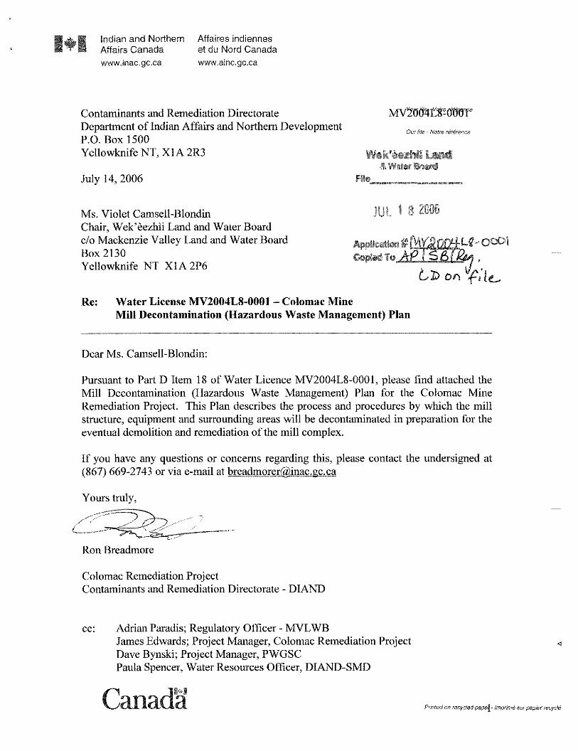
Contaminants and Remediation Directorate MVSJOITt1rc1OOVDepartment of Indian Affairs and Northern Development
Our 1,/a - Won-c reference
P.O. Box 1500Yellowknife NT, X1A 2R3 Wek’iezhil Land
& Water SaidJuly 14, 2006
____ ____
Ms. Violet Camsell-Blondin JUL 182006Chair, Wek’Œezhii Land and Water Boarddo Mackenzie Valley Land and Water Board CaUOn#YOLQ 0001Box 2130 CopIedToAj[.Yellowkmfe NT X1A 2P6
ton FkRe: Water License MV2004L8-0001 - Colomac Mine
Mill Decontamination Hazardous Waste Management Plan
Dear Ms. Camsell-Blondin:
Pursuant to Part D Item 18 of Water Licence MV2004L8-0001, please find attached theMill Decontamination Hazardous Waste Management Plan for the Colomac MineRemediation Project. This Plan describes the process and procedures by which the millstructure, equipment and surrounding areas will be decontaminated in preparation for theeventual demolition and remediation of the mill complex.
If you have any questions or concerns regarding this, please contact the undersigned at867 669-2743 or via e-mail at breadmorerlIUnac.gc.ca
Yours truly,
Ron Breadmore
Colomac Remediation ProjectContaminants and Remediation Directorate - DIAND
cc: Adrian Paradis; Regulatory Officer - MVLWBJames Edwards; Project Manager, Colomac Remediation ProjectDave Bynski; Project Manager, PWGSCPaula Spencer, Water Resources Officer, DIAND-SMD
IaIIIaIIIa. Premed on recycled papal- lmpninth cur papier recycle

Colomac Mine Remediation Water License MV2004L8-0001 Mill Decontamination Plan Prepared for Public Works and Government Services Canada Prepared by Aboriginal Engineering Ltd.
July 17, 2006
Colomac Site Remediation Plan Water License MV2004L8-0001 Mill Decontamination Plan
Prepared for: Public Works and Government Services Canada Prepared by: Aboriginal Engineering Ltd. Unit 20, 100 Borden Drive Box 133 Yellowknife, NT X1A 2N1
June 17, 2006

Colomac Site Remediation Plan Water License MV2004L8-0001 Mill Decontamination Plan – Post Review
iii
Executive Summary Purpose The following Mill decontamination plan has been prepared for regulatory review as per Part G Item 4 of Water License MV2004L8 – 0001 and NWT WCB recommendations. Only the decontamination of the Mill in preparation for major demolition is to take place. No major structures or equipment are to be removed.
Overview of the Colomac Mine Milling Process The Colomac Mill extracted gold and some silver from low grade open pit ore. Ore was milled at a rate of approximately 10,000 tons/day through the use of conventional whole ore cyanidation coupled with Carbon in Pulp extraction. The gold contained within the ore was free milling and did not require pre-roasting prior to cyanidation. As such, arsenic trioxide contamination is not an environmental or human health issue at the Colomac mine. The overall milling process can be divided into the following individual circuits:
Crushing Circuits: Primary and Secondary; Wet Grinding: Primary and Secondary; Reagent Addition: Cyanide, Lime, Caustic, Acid, Flocculant; Cyanidation; Recovery: Carbon Loading, Carbon Stripping, Carbon Regeneration, Electrowinning and Refining; Reclaim; and Utilities: Water, Compressed Air and Fuel
The above listed milling circuits are discussed in detail within Appendix B. The milling circuit is used throughout the report as the basis for the development of plans.
Waste – Potentially Present An extensive literature review was undertaken by Aboriginal Engineering Ltd (AEL) to satisfy the workers right to know by identifying wastes that could potentially be contained within the Mill and/or crushing buildings. The potentially present wastes are listed in Table 27 through to Table 38, of Appendix A. MSDS sheets were obtained for all listed wastes and are available upon request.1
Waste - Classification Wastes were classified as Mill Process Reagents, Mill Process Residuals, Lubricants, Solvents, Hydraulic, Heat Exchange, Electrical Insulator, Explosive, Compressed Gas, Hazardous Building Materials and Miscellaneous. Mill Process Residuals are further classified as saturated solids (tailings that are saturated with process water), pore water (the water contained within the pores of the saturated solid), free water (the water ponding on the saturated solids) and tailings/ore dust (dry tailing or ore dust).
Waste – Specifically Identified in the Mill In addition, a specific inventory of wastes positively identified within the Mill and crusher buildings was generated as a sub-set of the overall potential waste list. Table 4 of Section 4 presents the inventory. 1 Inclusion of the MSDS sheets for the 90+ inventoried wastes would cumbersome and difficult to reproduce for all parties. MSDS sheets will be provided for individual wastes as requested. For those wastes identified as present within the Mill and extensive list of properties is appended.
Colomac Site Remediation Plan Water License MV2004L8-0001 Mill Decontamination Plan – Post Review
iv
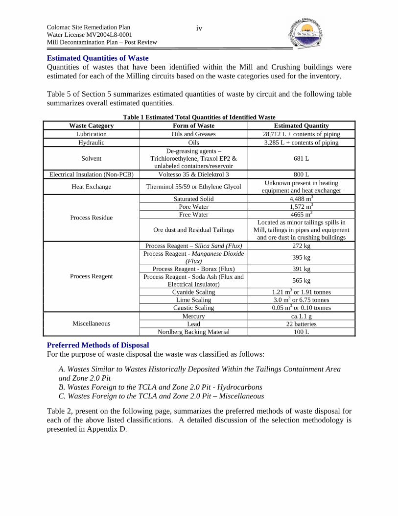
Estimated Quantities of Waste Quantities of wastes that have been identified within the Mill and Crushing buildings were estimated for each of the Milling circuits based on the waste categories used for the inventory. Table 5 of Section 5 summarizes estimated quantities of waste by circuit and the following table summarizes overall estimated quantities.
Table 1 Estimated Total Quantities of Identified Waste Waste Category Form of Waste Estimated Quantity
Lubrication Oils and Greases 28,712 L + contents of piping Hydraulic Oils 3.285 L + contents of piping
Solvent De-greasing agents –
Trichloroethylene, Traxol EP2 & unlabeled containers/reservoir
681 L
Electrical Insulation (Non-PCB) Voltesso 35 & Dielektrol 3 800 L
Heat Exchange Therminol 55/59 or Ethylene Glycol Unknown present in heating equipment and heat exchanger
Saturated Solid 4,488 m3 Pore Water 1,572 m3 Free Water 4665 m3 Process Residue
Ore dust and Residual Tailings Located as minor tailings spills in
Mill, tailings in pipes and equipment and ore dust in crushing buildings
Process Reagent – Silica Sand (Flux) 272 kg Process Reagent - Manganese Dioxide
(Flux) 395 kg
Process Reagent - Borax (Flux) 391 kg Process Reagent - Soda Ash (Flux and
Electrical Insulator) 565 kg
Cyanide Scaling 1.21 m3 or 1.91 tonnes Lime Scaling 3.0 m3 or 6.75 tonnes
Process Reagent
Caustic Scaling 0.05 m3 or 0.10 tonnes Mercury ca.1.1 g
Lead 22 batteries Miscellaneous Nordberg Backing Material 100 L
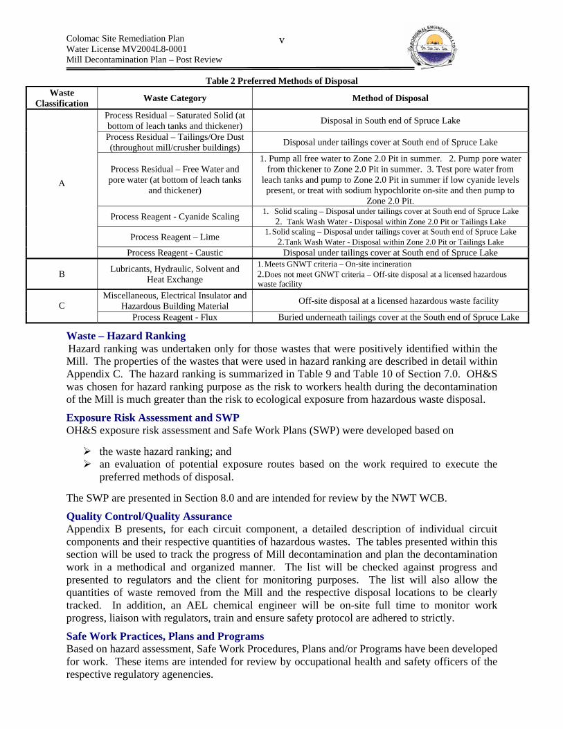
Preferred Methods of Disposal For the purpose of waste disposal the waste was classified as follows:
A. Wastes Similar to Wastes Historically Deposited Within the Tailings Containment Area and Zone 2.0 Pit B. Wastes Foreign to the TCLA and Zone 2.0 Pit - Hydrocarbons C. Wastes Foreign to the TCLA and Zone 2.0 Pit – Miscellaneous
Table 2, present on the following page, summarizes the preferred methods of waste disposal for each of the above listed classifications. A detailed discussion of the selection methodology is presented in Appendix D.
Colomac Site Remediation Plan Water License MV2004L8-0001 Mill Decontamination Plan – Post Review
v
Table 2 Preferred Methods of Disposal Waste
Classification Waste Category Method of Disposal
Process Residual – Saturated Solid (at bottom of leach tanks and thickener) Disposal in South end of Spruce Lake
Process Residual – Tailings/Ore Dust (throughout mill/crusher buildings) Disposal under tailings cover at South end of Spruce Lake
Process Residual – Free Water and pore water (at bottom of leach tanks
and thickener)
1. Pump all free water to Zone 2.0 Pit in summer. 2. Pump pore water from thickener to Zone 2.0 Pit in summer. 3. Test pore water from
leach tanks and pump to Zone 2.0 Pit in summer if low cyanide levels present, or treat with sodium hypochlorite on-site and then pump to
Zone 2.0 Pit.
Process Reagent - Cyanide Scaling 1. Solid scaling – Disposal under tailings cover at South end of Spruce Lake 2. Tank Wash Water - Disposal within Zone 2.0 Pit or Tailings Lake
Process Reagent – Lime 1. Solid scaling – Disposal under tailings cover at South end of Spruce Lake 2. Tank Wash Water - Disposal within Zone 2.0 Pit or Tailings Lake
A
Process Reagent - Caustic Disposal under tailings cover at South end of Spruce Lake
B Lubricants, Hydraulic, Solvent and Heat Exchange
1. Meets GNWT criteria – On-site incineration 2. Does not meet GNWT criteria – Off-site disposal at a licensed hazardous waste facility
Miscellaneous, Electrical Insulator and Hazardous Building Material Off-site disposal at a licensed hazardous waste facility C
Process Reagent - Flux Buried underneath tailings cover at the South end of Spruce Lake
Waste – Hazard Ranking Hazard ranking was undertaken only for those wastes that were positively identified within the Mill. The properties of the wastes that were used in hazard ranking are described in detail within Appendix C. The hazard ranking is summarized in Table 9 and Table 10 of Section 7.0. OH&S was chosen for hazard ranking purpose as the risk to workers health during the decontamination of the Mill is much greater than the risk to ecological exposure from hazardous waste disposal.
Exposure Risk Assessment and SWP OH&S exposure risk assessment and Safe Work Plans (SWP) were developed based on
the waste hazard ranking; and an evaluation of potential exposure routes based on the work required to execute the
preferred methods of disposal. The SWP are presented in Section 8.0 and are intended for review by the NWT WCB.
Quality Control/Quality Assurance Appendix B presents, for each circuit component, a detailed description of individual circuit components and their respective quantities of hazardous wastes. The tables presented within this section will be used to track the progress of Mill decontamination and plan the decontamination work in a methodical and organized manner. The list will be checked against progress and presented to regulators and the client for monitoring purposes. The list will also allow the quantities of waste removed from the Mill and the respective disposal locations to be clearly tracked. In addition, an AEL chemical engineer will be on-site full time to monitor work progress, liaison with regulators, train and ensure safety protocol are adhered to strictly.
Safe Work Practices, Plans and Programs Based on hazard assessment, Safe Work Procedures, Plans and/or Programs have been developed for work. These items are intended for review by occupational health and safety officers of the respective regulatory agenencies.

Colomac Site Remediation Plan Water License MV2004L8-0001 Mill Decontamination Plan – Post Review
vi
Table of Contents Executive Summary ....................................................................................................................... iii 1.0 Introduction............................................................................................................................... 1
1.1 Overview – Colomac Mine................................................................................................... 1 1.2 Aboriginal Capacity Building ............................................................................................... 1
2.0 Project Scope ............................................................................................................................ 2 2.1 Previous Mill Decontamination Work – Royal Oak Mines – 1998...................................... 2 2.2 2006 Final Mill Decontamination – Description of CWorkC.................................................... 3 2.3 Intended Outcome................................................................................................................. 3 2.4 Justification of Decontamination Prior to Major Demolition ............................................... 3
3.0 Regulatory Regime ................................................................................................................... 5 3.1 Environment.......................................................................................................................... 5 3.2 Occupational Health and Safety............................................................................................ 6 3.3 Resolution of Regulatory Conflicts ...................................................................................... 6 3.4 Availability of Regulatory Information ................................................................................ 6 3.5 Work Place Health and Safety Committees.......................................................................... 6 3.6 Training................................................................................................................................. 7 3.7 Supervision ........................................................................................................................... 8 3.8 Medic .................................................................................................................................... 8 3.9 Availability of OH&S Information....................................................................................... 8 3.9 Hazardous Substances & Chemical Exposure Limits........................................................... 9 3.10 Hazard Communication ...................................................................................................... 9
4.0 The Colomac Milling Process................................................................................................. 10 3.1 Description of the Overall Milling Process ........................................................................ 10 3.2 Description of the Individual Milling Circuits.................................................................... 13 3.3 Circuits – Basic Units for Plan Development ..................................................................... 14
5.0 Waste Assessment................................................................................................................... 16 5.1 Information Sources............................................................................................................ 16 5.2 General Categories.............................................................................................................. 16 5.3 List of Potentially Present Hazardous Wastes .................................................................... 16 5.4 Hazardous Wastes Identified Specifically Within the Mill ................................................ 17
6.0 Circuits –Estimated Hazardous Waste Quantities and Footprint............................................ 19 6.1 Information Sources............................................................................................................ 19 6.2 Summary of Estimated Hazardous Waste Quantities ......................................................... 19
7.0 Hazardous Waste Disposal Options........................................................................................ 22 7.1 Current On-Site Waste Water Treatment – Enhanced Natural Removal ........................... 22 7.2 Classification of Hazardous Wastes For Disposal Purposes............................................... 22 7.3 Preferred Disposal Options ................................................................................................. 24
8.0 Hazard Ranking ...................................................................................................................... 29 8.1 Purpose................................................................................................................................ 29 8.2 Hazard Ranking System – Chemical Contaminants ........................................................... 29 8.3 Hazard Ranking – Chemical Contaminants........................................................................ 29 8.4 Physical Hazard Ranking.................................................................................................... 31 8.5 Biological Hazard Ranking................................................................................................. 32
9.0 Safe Work Practices and Procedures ...................................................................................... 33 9.1 Introduction......................................................................................................................... 33 9.2 Order of Work..................................................................................................................... 34 9.3 AEL Organizational Structure – Management and Employees.......................................... 35

Colomac Site Remediation Plan Water License MV2004L8-0001 Mill Decontamination Plan – Post Review
vii
9.4 Occupational Exposure Limits............................................................................................ 39 9.5 SWP – Cyanide Circuit Decontamination .......................................................................... 41 9.6 SWP – Lime Circuit Decontamination ............................................................................... 49 9.7 SWP – Caustic Circuit Decontamination............................................................................ 54 9.8 SWP – Acid Circuit Decontamination................................................................................ 56 9.9 SWP – Flocculant Circuit ................................................................................................... 57 9.10 SWP – Carbon Circuit Decontamination.......................................................................... 57 9.11 SWP – Refinery Circuit Decontamination........................................................................ 58 9.12 SWP – Removal of Process Residuals.............................................................................. 59 9.13 SWP – Removal of Residual Tailings & Ore Dust........................................................... 65 9.14 SWP – Removal and Incineration of Hydrocarbons......................................................... 67 9.15 SWP – Cleaning and Maintaining the HEPA Vacuum..................................................... 71 9.16 SWP – Confined Space Entry ........................................................................................... 73 9.17 SWP – Trenching & Excavation....................................................................................... 78 9.18 SWP – Mill Entry for Preparation Work and Monitoring/Inspection.............................. 79 9.19 SWP – Heavy Equipment Operation ................................................................................ 81 9.20 SWP – Lock out & Tag Out.............................................................................................. 83 9.21 SWP – Hot Work .............................................................................................................. 85 9.22 SWP – Drum Handling ..................................................................................................... 86 9.23 SWP Transportation of Hazardous Goods From the Mill to the Tailings Containment.. 88 9.23 SWP – Handling Lead and Mercury................................................................................. 90 9.24 SWP Referenced in Aboriginal Engineering Ltd. Health, Safety & Environment Program................................................................................................................................................... 90
(a) Fall Restraint and Arrest;................................................................................................. 91 (b) Ladders;........................................................................................................................... 91 (c) Working with Hand Tools (non-powered); and .............................................................. 91 (d) Lifting.............................................................................................................................. 91
9.25 Respiratory Protection Program........................................................................................ 91 9.26 Analytical Testing Program – Occupational Exposure and QC ....................................... 98 9.28 Decontamination Plan..................................................................................................... 103
10.0 Contingency Plans .............................................................................................................. 121 10.1 Emergency Response Plan.............................................................................................. 121 10.2 Spill Response Plan......................................................................................................... 123 10.3 Fire Response Plan.......................................................................................................... 130 10.4 Wildlife Plan ................................................................................................................... 134
11.0 Record Keeping .................................................................................................................. 136 12.0 Site Security ........................................................................................................................ 137 13.0 Management of Change ...................................................................................................... 138 14.0 Site Communication............................................................................................................ 139 Appendix A – List of Potential Hazardous Wastes .................................................................... 140 Appendix B – Milling Circuits – Identification of Hazard and Estimated Chemical Quantities 147
B1 - Crushing Circuits ............................................................................................................ 147 B2 - Wet Grinding Circuit(s) and Classification .................................................................... 158 B3 - Reagent Addition Circuit(s)............................................................................................ 168 B4 - Leaching Circuit (Cyanidation) – Extraction.................................................................. 182 B5 - Recovery Circuit(s) (Carbon in Pulp) ............................................................................. 187 B6 - Utility Circuits ................................................................................................................ 198 B7 - Hazardous Building Materials ........................................................................................ 201
Colomac Site Remediation Plan Water License MV2004L8-0001 Mill Decontamination Plan – Post Review
viii
B8 - Powerhouse ..................................................................................................................... 201 B9 - Miscellaneous Hazardous Wastes Located Within Mill ................................................. 202
Appendix C – Hazardous Properties of Wastes Identified Within the Mill ............................... 206 Appendix D – Development of Hazardous Waste Disposal Options ......................................... 265
D.1 Disposal Scenarios ........................................................................................................... 265 Appendix E – WHIMIS, TDGA and MSDS .............................................................................. 285 Appendix F – Safe Work Plans Included in the AEL Safety Manual ........................................ 287
(a) Fall Restraint and Arrest;............................................................................................... 287 (b) Ladders;......................................................................................................................... 287 (c) Working with Hand Tools (non-powered); and ............................................................ 287 (d) Lifting............................................................................................................................ 287
Colomac Site Remediation Plan Water License MV2004L8-0001 Mill Decontamination Plan – Post Review
ix
List of Figures Figure 1 Simplified Mill Process Flow Sheet ............................................................................... 12 Figure 2 Aerial view of Mill - Summer 1997 - Looking Northwest Source: Colomac Mine Interim Abandonment and Restoration Plan (Draft) (Royal Oak Mines, April 1998) ................. 14 Figure 3 AEL Organizational Structure - Managers and Employees ........................................... 35 Figure 4 Method of accessing thickener or leach tank residual tailings ....................................... 61 Figure 5 Methods for Cleaning a Full Face-Piece Respirator Reference – North Safety Supplies....................................................................................................................................................... 95 Figure 6 Components of Continuous Flow Air Supplied Respirators (ASR)............................... 98 Figure 7 Contamination Reduction Zone and Contamination Reduction Corridor – Source: Handbook for Occupational Health and Safety During Hazardous Waste Activities ................ 106 Figure 8 Example of a Contamination Reduction Corridor........................................................ 106 Figure 9 Exclusion Zone and CRC for Cyanide Decontamination............................................. 110 Figure 10 CRC and Exclusion Zone for Lime and Caustic and Tailings and Ore Dust/Flocculant/General Dust and Hydrocarbons ...................................................................... 111 Figure 11 Primary and Secondary Crushing Process Flow Diagrams........................................ 148 Figure 12 Footprint and Location of Chemical Hazards- Primary Crushing Circuit ................. 150 Figure 13 Footprint and Location of Chemical Hazards- Secondary Crushing Circuit ............. 155 Figure 14 Primary Grinding Circuit - SAG Mill ........................................................................ 159 Figure 15 Secondary Grinding Circuit Process Flow Sheet– Ball Mills ................................... 160 Figure 16 Secondary Crusher - Footprint and Location of Key Chemical Hazards................... 165 Figure 17 Reagent Process Flow Diagrams ................................................................................ 169 Figure 18 Footprint - Cyanide Reagent Addition Circuit – Plan View ...................................... 171 Figure 19 Footprint Cyanide Reagent Addition Circuit – Front View ....................................... 172 Figure 20 Footprint - lime and caustic lines ............................................................................... 176 Figure 21 Leaching Circuit ......................................................................................................... 183 Figure 22 Footprint - Leaching Circuit ....................................................................................... 185 Figure 23 Recovery Circuit - Carbon Loading ........................................................................... 188 Figure 24 Recovery Circuit - Carbon Stripping, Carbon Regeneration and Electrowinning ..... 189 Figure 25 Carbon Loading, Stripping and Regeneration - Footprint.......................................... 191 Figure 26 Footprint - Electrowinning and Refining ................................................................... 196 Figure 27 Location of Auxiliary Fuel Line................................................................................. 205 Figure 28 Sodium Cyanide - NIOSH Guide to chemical risk .................................................... 209 Figure 29 Hydrogen Cyanide - NIOSH Pocket Guide to Chemical Hazards ............................. 210 Figure 30 HCN/CN- concentration versus pH. Source: Edumine, Cyanide in Mining .............. 213 Figure 31 Natural degradation - the cyanide cycle. Source: Edumine, Cyanide in Mining ....... 216 Figure 32 Solubility of sodium cyanide in water – Source: DuPont .......................................... 216 Figure 33 Calcium Oxide - NIOSH Pocket Guide to Chemical Risk......................................... 219 Figure 34 Sodium Hydroxide - NIOSH Pocket Guide to Chemical Risk................................... 220 Figure 35 Sodium Hydroxide - NIOSH Pocket Guide to Chemical Hazards............................. 224 Figure 36 Hydrochloric Acid - NIOSH Pocket Guide to Chemical Hazard............................... 228 Figure 37 Borax - NIOSH Pocket Guide to Chemical Hazard ................................................... 233 Figure 38 Analytical Results for Tailings Solids........................................................................ 242 Figure 39 XRF results for tailings: Source – Colomac Geochemical Characterization (SRK).. 243 Figure 40 Ethylene Glycol - NIOSH Pocket Guide to Chemical Hazards ................................. 254
Colomac Site Remediation Plan Water License MV2004L8-0001 Mill Decontamination Plan – Post Review
x
List of Tables Table 1 Estimated Total Quantities of Identified Waste................................................................ iv Table 2 Preferred Methods of Disposal .......................................................................................... v Table 3 Category of Wastes for Hazard/Risk Assessment and Development of SWP ................ 16 Table 4 Inventory of Wastes Identified Within the Mill............................................................... 17 Table 5 Estimated Quantities of Hazardous Wastes within Mill and Crusher Buildings............. 20 Table 6 Hazardous Wastes that have been Deposited Within the TCA ....................................... 23 Table 7 Estimated quantities Hazardous wastes foreign to the TCA - Hydrocarbons.................. 23 Table 8 Estimated quantities Hazardous wastes foreign to the TCA – Miscellaneous ................ 23 Table 9 Waste Hazard Ranking System........................................................................................ 29 Table 10 Waste Hazard Assessment ............................................................................................. 30 Table 11 Physical Hazard Assessment and Mitigative Actions.................................................... 31 Table 12 Occupational Exposure Limits – Air Born Concentrations ........................................... 40 Table 13 PPE - Cyanide Circuit – Removal of Piping and Residual Scaling and Washing with Prepared Hypochlorite Elevated pH Solution............................................................................... 45 Table 14 Selected PPE - Preparation of Cyanide Decontamination Solution ............................. 46 Table 15 Specific Training Requirements - Cyanide Circuit........................................................ 48 Table 16 Selected PPE - Lime Circuit Removal of Scaling and Washing Tanks......................... 52 Table 17 Training Requirements for the Lime Circuit Decontamination..................................... 53 Table 18 Training Required for the Acid Circuit.......................................................................... 56 Table 19 Selected PPE - Ore Dust ................................................................................................ 59 Table 20 Selected PPE - Removal of Process Residuals from the Leach Tanks and Thickener Tank .............................................................................................................................................. 64 Table 21 Selected PPE - Ore Dust ................................................................................................ 66 Table 22 Selected PPE - Tailings Dust Removal.......................................................................... 66 Table 23 Selected PPE - Hydrocarbons ........................................................................................ 70 Table 24 Selected PPE - Mill Preparation .................................................................................... 80 Table 25 Allowable Concentrations of Components for Compressed Breating Air .................... 97 Table 26 Applicability of Properties of Fire Extinguisher.......................................................... 131 Table 27 Mill Process Reagents.................................................................................................. 141 Table 28 Process Residuals......................................................................................................... 142 Table 29 Fuels............................................................................................................................. 142 Table 30 Lubricants .................................................................................................................... 142 Table 31 Solvents........................................................................................................................ 143 Table 32 Hydraulic ..................................................................................................................... 143 Table 33 Heat Exchange ............................................................................................................. 144 Table 34 Electrical Insulator....................................................................................................... 144 Table 35 Explosives.................................................................................................................... 144 Table 36 Compressed Gases ....................................................................................................... 144 Table 37 Hazardous Building Materials ..................................................................................... 144 Table 38 Miscellaneous Chemicals ............................................................................................ 145 Table 39 Primary Crushing - Estimated Volumes of Hazardous Waste..................................... 149 Table 40 Primary Crushing Circuit Components - Chemical Hazards and Estimated Quantities..................................................................................................................................................... 151 Table 41 Secondary Crushing - Estimated Quantities of Hazardous Waste............................... 154 Table 42 Secondary Crushing Circuit Components- Hazardous Wastes, Estimated Quantities 156 Table 43 Primary Grinding - Estimated Quantities of Hazardous Waste................................... 161 Table 44 Primary Grinding -Circuit Components and Physical/Chemical Hazards................... 162

Colomac Site Remediation Plan Water License MV2004L8-0001 Mill Decontamination Plan – Post Review
xi
Table 45 Secondary Grinding and Classification - Estimated Quantities of Hazardous Waste . 164 Table 46 Secondary Crushing and Classification - Circuit Components Chemical Hazards and Estimated Quantities ................................................................................................................... 166 Table 47 Cyanide Reagent Addition Circuit - Estimated Quantities of Chemical Hazards ....... 170 Table 48 Cyanide Reagent Addition Circuit (leach tanks, ball mill, CIP tanks and primary screen area) Components – Chemical Hazards and Estimated Quantities............................................. 173 Table 49 Cyanide Reagent Addition Components – Chemical Hazards, Estimated Quantities. 174 Table 50 Lime and Caustic Reagent Addition Circuit - Estimated Quantities of Chemical Hazards ....................................................................................................................................... 175 Table 51 Lime circuit components - chemical hazards and quantities ....................................... 177 Table 52 Caustic soda circuit components - chemical hazards and quantities ........................... 178 Table 53 Hydrochloric acid circuit components - chemical hazards and quantities................... 179 Table 54 Flocculant - Circuit Components and Chemical Hazards............................................ 180 Table 55 Leaching Circuit - Estimated Quantities of Hazardous Materials ............................... 184 Table 56 Leaching circuit components - chemical hazards and quantities................................. 186 Table 57 Carbon Loading, Stripping and Regeneration - Estimated Quantities of Hazardous Materials ..................................................................................................................................... 190 Table 58 Carbon Loading - Circuit Components and Chemical Hazards .................................. 192 Table 59 Carbon Stripping Circuit Components - Chemical Hazards and Estimated Quantities..................................................................................................................................................... 193 Table 60 Carbon Regeneration Circuit Components - Chemical Hazards and Estimated Quantities .................................................................................................................................... 194 Table 61 Electrowinning and Refining - Estimated Quantities of Hazardous Materials............ 195 Table 62 Electrowinning Circuit Components - Chemical Hazards and Estimated Quantities . 197 Table 63 Refining - Chemical Hazards and Estimated Quantities ............................................. 197 Table 64 Water Circuit - Hazardous Waste and Estimated Quantities....................................... 199 Table 65 Auxiliary Compressed Air - Chemical Hazards and Estimated Quantities ................. 201 Table 66 Auxiliary Fuel Circuit – Chemical Hazards and Estimated Quantities ....................... 201 Table 67 Miscellaneous Wastes Identified Within the Mill ....................................................... 202 Table 68 Approved Water Quality Guidelines (BC 1998) ......................................................... 213 Table 69 Additional important cyanide reactions. Source: Edumine, Cyanide in Mining ........ 215 Table 70 Tailings Pond Water Total Cyanide Data (1990 to 1998) n= 52................................. 239 Table 71 Tailings Pore Water - Historical Cyanide Concentrations........................................... 239 Table 72 Process Slurry Free Water - Analytical Results........................................................... 241 Table 73 Leach tank and thickener free water COC concentrations and volumes ..................... 266 Table 74 Leach tank and thickener pore water COC concentrations and volumes .................... 266 Table 75 Effect of transferring free and pore water from leach tanks and thickener to Tailings Lake............................................................................................................................................. 267 Table 76 Effect of transferring free and pore water from leach tanks and thickener to Zone 2.0 Pit..................................................................................................................................................... 267 Table 77 Disposal options for free water, pore water and tailings/ore dust ............................... 269 Table 78 Disposal options for the cyanide circuit ...................................................................... 271 Table 79 Disposal options for the Lime Circuit.......................................................................... 275 Table 80 Remedial Options for Disposal of the Caustic Circuit ................................................ 279

Colomac Site Remediation Plan Water License MV2004L8-0001 Mill Decontamination Plan – Post Review
xii
List of Photographs Photograph 1 Flocculant Storage Tank (Foreground) and Mixing Tank (Background) ............ 181 Photograph 2 Flocculant Sump Pump Within the Flocculant Sump .......................................... 181 Photograph 3 Flocculant Hopper ................................................................................................ 181 Photograph 4 Plant Water Pump - Oil Reservoirs are Full ......................................................... 200 Photograph 5 Reclaim Water Circuit - 5 Inline Small CIP Tanks.............................................. 200 Photograph 6 Diesel Powered Generator - Contains Lubricants and has Leaked Lubricants onto Surrounding Floor....................................................................................................................... 202
Colomac Site Remediation Plan Water License MV2004L8-0001 Mill Decontamination Plan – Post Review
1
1.0 Introduction
1.1 Overview – Colomac Mine The Colomac Mine is an open pit gold mine that was operational from 1990 to 1997. In 1999, Indian and Northern Affairs Canada (INAC) assumed control of the site, following the insolvency of the former owner. INAC manages the Colomac site through the Contaminants and Remediate Directorate (CARD).2 In March 2004, as per the Mackenzie Valley Land and Water Board (MVLWB) water license MV2004L8-0001 conditions, CARD submitted to the MVLWB the Colomac Site Remediation Plan.
1.2 Aboriginal Capacity Building The Mill Decontamination Project is planned to be completed with over 85% aboriginal employment in positions such as Site Superintendent, Site Foreman, decontamination labourers, and heavy equipment operators. The project will provide job opportunities for aboriginal residents from the local communities (Behchoko, Gameti, and Wekweti). Approximately 2 shifts of crews the size of 15 people will be employed during the project, which is estimated to be 5 months in duration. Therefore 30 residents of the local communities will gain employment through this project. The personnel involved in cyanide and chemical cleanup will be trained on the Hazardous Waste Operations and Emergency Response (HAZWOPER) 40 hour course, which is an internationally recognized course for chemical safety, and working with chemical hazards. Having the HAZWOPER course in their skills set will open up many of the employees to a number of other job opportunities within a) contaminated sites; and b) process plants. Advanced training will also be provided for other aspects of occupational health and safety such as confined space entry and hot work permitting. In addition, the experience gained in decontaminating an abandoned mill will transfer over to other contaminated sites throughout the NWT such as the Tundra Mine, the Silver Bear Mines, and many others. Thus, a skilled aboriginal workforce will be developed, capably of carrying out decontamination work.
2 Water License MV2004L8-0001 Colomac Site Remediation Plan Final Report March 2004

Colomac Site Remediation Plan Water License MV2004L8-0001 Mill Decontamination Plan – Post Review
2
2.0 Project Scope
2.1 Previous Mill Decontamination Work – Royal Oak Mines – 1998 The following discussion regarding the previous mill decontamination was extracted entirely from the report titled “Colomac Mine Interim Abandonment and Restoration Plan (Draft)” (Royal Oak Mines, April 1998).
“In preparation for shutdown, all mill processing equipment has been washed and cleaned of ore residues in order to recover gold values from this material. The thickener tank and leach tanks have been cleaned, although there is some sludge remaining at the bottom of the thickener tank. Sludge also remains in the Mill Leach Berm both from a spill in November 1995 and from some recent pipeline draining and the draining of the leach tanks. The CIP tanks were cleaned and any sand/carbon has been washed out. The barren tank and the pregnant tank were cleaned of any sludges. The filter press was scraped and the floor around the press was vacuum cleaned. The CIP screen was completely cleaned. The liners in the two ball mills were stripped, scraped and washed. All liners and grates were stripped from the SAG mill with the exception of the center core liners. The mill shells were also scraped. The ball mills and SAG mill were jacked up in order to release pressure on any critical parts. The electric circuit and grease lube systems were disconnected and, for the long term protection, oil additives were added to the drives All mill floors and sumps were cleaned out and all the material collected was sent to the tailings pumps. The refinery area was thoroughly vacuumed. The electro-winning cell basins were scraped and washed, and all cathodes were burnt and refined.
All water pipes in the mill building, including the sprinkler system, were drained and the fresh water tank was emptied.
All process fluid lines have been purged and hazardous and flammable goods removed to secure storage areas. The following systems have been drained and flushed:
1. Lime mixing tanks and distribution system 2. Cyanide mixing tanks and distribution system 3. Caustic mixing tanks and distribution system 4. Muriatic acid distribution system 5. Stripping and regeneration circuits
The following items have been removed from site:
1. Cyclones 2. 2 sump pumps 3. Trash steel magnet”

Colomac Site Remediation Plan Water License MV2004L8-0001 Mill Decontamination Plan – Post Review
3
In addition, following decommissioning actions have also been undertaken in relation to Mill decommissioning:
1. water pipes within the crusher building were drained to avoid damage from freezing; 2. the three hydrostroke feeders were covered with waste rock to prevent inadvertent falls; 3. oil additives were added to the drives and gearboxes of the pebble crusher and its
tension springs were removed (additive most likely ESSO Procon); 4. the dilute HCL mixing tank was removed from the site;
Although some discrepancies with the above information were identified, especially with respect to the removal of process residues and the flushing of the lime circuit, the majority of the work described appears to have been completed.
2.2 2006 Final Mill Decontamination – Description of CWork C The 1998 Mill decontamination work focused on preparing the Mill for shutdown and was preliminary in nature. The focus of the initial decontamination work was to “mothball” the Mill, leaving equipment in a state suitable for potential return to operations. As such, residual process chemical scaling formed by evaporation/precipitation, bulk process chemicals, ore dust, heat exchange fluids and hydrocarbons are currently existing within the Mill. The Mill Decontamination Plan will outline the work required for the Final decontamination of the Mill, prior to major demolition. This will include:
1. the identification of potential wastes; 2. a detailed quantification of wastes present within the Mill; 3. the development of waste disposal options; 4. waste hazard assessment from an OH&S perspective for the wastes present within the
Mill (ecological hazards are considered to be minimal); 5. the assessment of human risk of exposure to hazards; and 6. the development of Safe Work Practices;
Items #1, #2, & #3are intended for review by the WLWB prior to permitting and items #4, #5 & #6 are intended for review by WCB prior to work.
2.3 Intended Outcome Following the decontamination work, the mill will be free, to the extent practically possible, of hazardous materials. The intention is to reduce the risk of exposure to hazardous materials to acceptable levels for the implementation of major demolition. Minor equipment and structures such as pumps, piping and regent mixing/storage tanks will have been removed for either disposal or salvage. The mill steel structure, siding and foundation will remain in tact as will the major equipment such as the CSemi C-Autogenous (SAG) mill, ball mills, leach tanks, CIP tanks etc.
2.4 Justification of Decontamination Prior to Major Demolition The separation of the Mill decontamination and major demolition, with respect to timeline, will greatly reduce the human and ecological risk associated with the overall Mill decommissioning by:
Colomac Site Remediation Plan Water License MV2004L8-0001 Mill Decontamination Plan – Post Review
4
1. Allowing the separation of labour with respect to hazard by
(a) restricting access to all decontamination work area(s) to only those workers trained in hazardous waste abatement Safe Work Practices (SWP); and (b) restricting access to the all major demolition work areas to only those workers experienced and properly trained in major demolition SWP
2. Allowing the development of work plans that
(a) minimize congestion within the limited mill work space(s) by distributing work load with time and thus the required point loading of labour and equipment; and (b) allow for sufficient time for the contractor to properly implement HAZMAT operations in accordance to approved work plans, while minimizing distraction related to other Non HAZMAT related work.
The potential down time between the two activities could also be used to train Aboriginal Community Members in the skills required to complete demolition of major mill structures, such as heavy duty equipment operation
Colomac Site Remediation Plan Water License MV2004L8-0001 Mill Decontamination Plan – Post Review
5
3.0 Regulatory Regime The Colomac Mine is a federal site located within the boundaries of Wekeezhii, the resource management limits outlined within the Tlicho land claim agreement. In addition, the contractor performing the Mill decontamination is regulated by the territorial agency “Northwest Territories (NWT) Workers Compensation Board (WCB)”, while federal employees are regulated by the federal agency “Human Resources and Skills Development Canada (HRSDC)” The multi-jurisdictional regulatory regime that applies to the Colomac Mill Decontamination project requires that all applicable legislation be examined and a plan be developed that meets the needs of all regulatory bodies. The following discusses how AEL will address the various legislation and ensure that the project remains compliant.
3.1 Environment (i) Mackenzie Valley Land and Water Board – Aboriginal Land Claim The Mackenzie Valley Land and Water Board (MVLWB) was created from land claim commitments under the Mackenzie Valley Resource Management Act (MVRMA). The board issues land use permits and water licenses to and acts as a preliminary screening body for:
1. transboundary development/projects within the Mackenzie Valley; and 2. developments/projects within the un-settled land claims of the Mackenzie Valley.
(ii) Land and Water Board – Aboriginal Land Claim Wekeezhii Land and Water Board The Wek’eezhii Land and Water Board (WLWB) was established by section 57.1 of the Mackenzie Valley Resource Management Act to meet conditions of the Tlicho Land Claim. The board allows the Tlicho citizens to co-manage their resource by issuing land use permits and water licenses for developments within the Wekeezhii limits of the Monfwi Gogha De Niitlee.
Mackenzie Valley Land and Water Board The remediation of the Colomac Mine began prior to the establishment of the Tlicho Land Claim (i.e., WLWB), as such the remediation plan was submitted to the MVLWB for permitting and licensing. The MVLWB accepted the Colomac Remediation Plan subject to various conditions. One such condition, Part G Item 4, states that the Licensee is to prepare a detailed plan for the management of hazardous waste that may be a by-product of the demolition of any building or equipment. This requirement was issued to ensure that adequate planning occurs for the treatment and disposal of any waste resulting from the decommissioning of the buildings.3 To this end, the following Colomac Mill (Mill) Decontamination Plan is presented. However, the Colomac Mine currently exists within the boundaries of the Tlicho Land Claim and is therefore under the jurisdiction of the WLWB. As such, the following plan will be submitted to the WLWB for licensing and permitting.
Water License and Land Use Permits
3 MVLWB Water License MV2004L8-0001
Colomac Site Remediation Plan Water License MV2004L8-0001 Mill Decontamination Plan – Post Review
6
AEL will track all water consumption and waste deposit as per water license and land use permits.
(iii) Canadian Environmental Protection Act - Federal Furthermore, the Colomac Mine is a federal site and therefore subject to the conditions of the Canadian Environmental Protection Act (CEPA).
3.2 Occupational Health and Safety Territorial – Northwest Territories Workers Compensation Board In addition, the Mill Decontamination Plan includes hazard analysis and Safe Work Plans (SWP) for review and approval by the Workers Compensation Board of the Northwest Territories (WCB). This is required as OH&S of Aboriginal Engineering employees are territorially regulated and are thus protected by the NWT WCB under the NWT Mines Health and Safety Act. Work plans have been developed to anticipate, recognize, evaluate, and control workplace conditions that may cause workers' injury or illness.
Federal – Human Resources and Skills Development Canada Furthermore, OH&S also falls under the jurisdiction of the Federal Human Resources and Skills Development Canada (HRSDC) under the Canada Labour Code (CLC), Part II, Canadian Occupational Health and Safety. Although AEL’s employees are territorially regulated, the federal legislation is applicable as the site is on Crown land and is administered by Indian and Northern Affairs Canada (INAC) through the Contaminants and Remediation Directorate (CARD). AEL will adhere to the standards of the federal HRSDC CLC Part II, Canadian Occupational Health and Safety and the Territorial NWT Mines Health and Safety Act. Including both the territorial and federal regulations will satisfy the “general duty clause” of the employer, i.e., “Every employer shall take all reasonable precautions and adopt and carry out all reasonable techniques and procedures to ensure the health and safety of every person in his or her establishment” - Safety Act R.S.N.W.T. 1988,c. S-1
3.3 Resolution of Regulatory Conflicts In the event of a discrepancy, either: both the HRSDC and NWT WCB inspectors will be contacted for clarification and/or the most stringent regulation will apply.
3.4 Availability of Regulatory Information Copies of the Water Licence, NWT Mines Health and Safety Act, NWT MHSA Regulations CEPA, CLC Part II and the Canada Occupational Health and Safety Regulations will be available on-site for ease of reference, upon request.
3.5 Work Place Health and Safety Committees It is anticipated that between approximately 15 to 20 AEL employees will be involved in the decontamination of the Colomac Mill.

Colomac Site Remediation Plan Water License MV2004L8-0001 Mill Decontamination Plan – Post Review
7
CLC Part II The CLC Part II Section 135. (1) requires that employers with 20 or more employees establish a work place health and safety committee and subject to section 135.1, select and appoint its members. Section 135.1 also stipulates that the committee must at least two persons in size and be composed of equal numbers of management and employees.
WCB MHSA In addition, Section 11. (1) of the NWT Mines Health and Safety Act requires that a mine with more than 15 employees establish an occupational health and safety committee. Section 11 (2) requires that the number of management and employee members be equal. Management members are to be appointed by management and the employee members are to be elected by the employees. Moreover, Section 3.02. (1) (a) of the WCB Mines Act Regulations requires that the health and safety committee be composed of 4 members for mine with greater than 15 and less then 100 employees
Selected Form of Work Place Health and Safety Committee The committee will consist of four members, of which two will be an employees who do not exercise managerial functions and have been selected by the employees. The other two committee members will be selected by the manager from the management staff. From the respective portion of the committee, the employees will elect an employee co-chairperson and the management will elect a management co-chairperson. The committee members will be representative of the work being conducted. The two selected employees and two selected management representatives will be trained in their duties as a member of the work place health and safety committee, as per CLC Section 135. (7) (a) to (l) and WCB MHSA Regulations Sections 3.11 to 3.28. The committee shall meet:
1. prior to the beginning of work; 2. at a minimum once per month at regular intervals; and 3. prior to the start of each major circuit decontamination or other major work task.
Committee meetings are to be held during regular working hours and each committee member will be given one hour of paid time to prepare for the meetings. However, under special circumstances meetings can be held outside regular working hours, if required. Each monthly meeting will include an inspection of all workplaces. A report will be generated regarding the findings of each inspection and the report will be placed in a conspicuous place.
3.6 Training The primary purpose of training is to prevent work place accidents and occupational disease. More specifically, training will prepare employees for safe work, outline employee/employer responsibilities and rights and describe lines of communication/conflict resolution. Employees will receive training on the following sections of the regulations:
1. HAZWOPER 40 Hour Training Course; 2. HAZWOPER Field Technician; 3. Specific Safe Work Practices;
Colomac Site Remediation Plan Water License MV2004L8-0001 Mill Decontamination Plan – Post Review
8
4. Sections of the Canada Occupational Health and Safety Regulations (COHSR) and the WCB MHSA Regulations applicable to work – specific training is addressed in Section 8.0 “Safe Work Practices”;
5. Workplace Hazardous Materials Information System (WHMIS) 6. Workers right to know, Right to Participate and Right to Refuse (CLC Section 128 &
WCB MHSA Section 18); 7. Duties of Employees (CLC Section 126); 8. Duties of Employers (CLC Section 124 & 125; 9. Work Place Health and Safety Committees (CLC Section 135); 10. Internal Complaint Resolution Process (CLC Section 127); 11. Offences and Punishments; 12. Investigations of Hazardous Occurrences.
In addition, Part 6 of the NWT MHSA Regulations outlines the requirements for general training programs. These specifications will be used as a framework for training. Copies of the training will be available on-site for ease of access by the mines inspector. Workplace Health and Safety Committee members will receive additional training in all work practices.
3.7 Supervision As per Section 5.02 (1) (a) of the NWT MHSA Regulations, a supervisor with a Level 2 Open Pit Supervisors Ticket, will be on-site at all time during work. No blasting is to take place during the decontamination of the Mill. Section 5.07 (a) to (k) of the NWT MHSA Regulations, outlines the duties of supervisors. All supervisors are to be trained in these requirements. Section 5.08 of the NWT MHSA Regulations outlines the duties of persons senior to supervisors. All such persons shall be trained in these requirements.
3.8 Medic As per Section 8.48 of the NWT MHSA Regulations, a St. Johns Ambulance First Aid, Level 2 Certificate will be on-site during all work and the first aid station will meet the requirements of Schedule 2. In addition, as per Section 8.51 of the NWT MHSA Regulations, 1/10 of the above ground workers and all supervisors will hold a valid St. Johns Ambulance Standard First Aid Certificate and will be trained in Cardiac Pulmonary Resuscitation (CPR) . Tlicho Logistics, the Colomac Care and Maintenance Supervisor, will be providing on-site medical services.
3.9 Availability of OH&S Information Information relating to OH&S will be made readily available to Work Place Health and Safety Committee (WPHSC) members and inspectors upon request. Employees can access OH&S information through a request to the WPHSC. However, information subject to personal privacy laws, such as medical records, will not be provided. Information will stored on-site. Specific requirements for obtaining and storing information are included within the SWPs of Section 8.0. Any information that affects all employees, such as water quality results, inspection reports (committee and regulatory), results of air quality testing, hazard assessment etc. will be posted in

Colomac Site Remediation Plan Water License MV2004L8-0001 Mill Decontamination Plan – Post Review
9
a conspicuous location for employees to view. MSDS sheets will be stored in a binder at the area of work where hazardous substances are encountered and at the main office.
3.9 Hazardous Substances & Chemical Exposure Limits The decontamination of the Colomac Mill requires working with various hazardous substances (refer to Table 10). The COHSR addresses hazardous substances in Part X “Hazardous Substances” and the WCB MHSA Regulations address hazardous substances Part IX “Working Environment and Industrial Hygiene”. Section 9.02. (1) of the WCB MHSA Regulations and Section 10.19 (1) (a) of the COHSR prescribe the “Threshold Limit Values (TLV) for Chemical Substances and Physical Agents and Biological Exposure Indices” published by the American Conference of Governmental Industrial Hygienists (ACGIH) as occupational exposure limits. In the absence of ACGIH TLV criteria, U.S. Occupational Safety and Health Administration Permissible Exposure Limits (OSHA PEL), U.S. National Institute for Occupational Safety and Health Recommended Exposure Limits (NIOSH REL), Deutsche Forschungsgemeinschaft Maximum Concentrations Values in the Workplace (DFG MAK) or American Industrial Hygiene Association Workplace Environmental Exposure Levels (AIHA WEEL) criteria will be applied. Section 10.19 (3) (a) to (d) of the COHSR reference the methods by which sampling occupational sampling is to be undertaken
3.10 Hazard Communication Information regarding chemical hazards within the work place will be communicated using the WHMIS regulations. During transport off-site, chemical hazard will be communicated using the federal Transportation of Dangerous Goods Act (TDGA) regulations. The communication of physical hazards will employ various techniques, that are discussed within the SWPs of Section 8.0. Training in identification will be provided if unique markers are required. Training will also be provided regarding the specific hazardous related to each job task. This training is discussed for each SWP in Section 8.0.
Colomac Site Remediation Plan Water License MV2004L8-0001 Mill Decontamination Plan – Post Review
10
4.0 The Colomac Milling Process
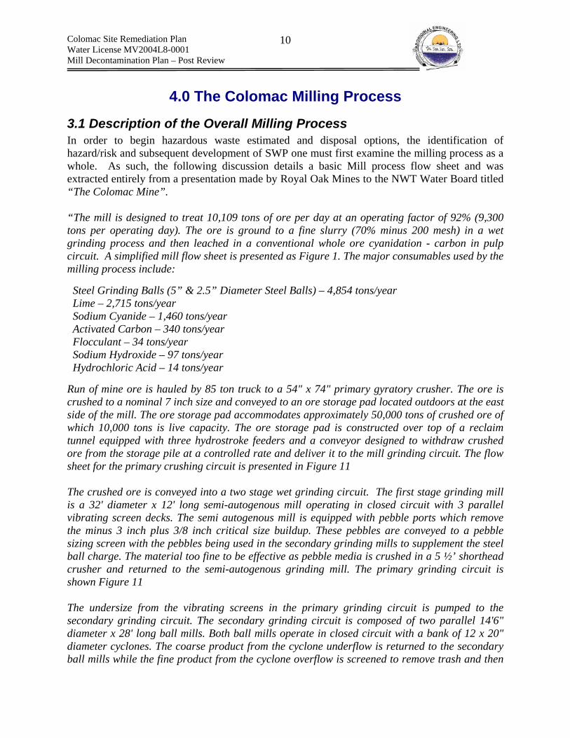
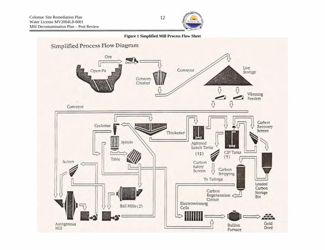
3.1 Description of the Overall Milling Process In order to begin hazardous waste estimated and disposal options, the identification of hazard/risk and subsequent development of SWP one must first examine the milling process as a whole. As such, the following discussion details a basic Mill process flow sheet and was extracted entirely from a presentation made by Royal Oak Mines to the NWT Water Board titled “The Colomac Mine”.
“The mill is designed to treat 10,109 tons of ore per day at an operating factor of 92% (9,300 tons per operating day). The ore is ground to a fine slurry (70% minus 200 mesh) in a wet grinding process and then leached in a conventional whole ore cyanidation - carbon in pulp circuit. A simplified mill flow sheet is presented as Figure 1. The major consumables used by the milling process include: Steel Grinding Balls (5” & 2.5” Diameter Steel Balls) – 4,854 tons/year Lime – 2,715 tons/year Sodium Cyanide – 1,460 tons/year Activated Carbon – 340 tons/year Flocculant – 34 tons/year Sodium Hydroxide – 97 tons/year Hydrochloric Acid – 14 tons/year
Run of mine ore is hauled by 85 ton truck to a 54" x 74" primary gyratory crusher. The ore is crushed to a nominal 7 inch size and conveyed to an ore storage pad located outdoors at the east side of the mill. The ore storage pad accommodates approximately 50,000 tons of crushed ore of which 10,000 tons is live capacity. The ore storage pad is constructed over top of a reclaim tunnel equipped with three hydrostroke feeders and a conveyor designed to withdraw crushed ore from the storage pile at a controlled rate and deliver it to the mill grinding circuit. The flow sheet for the primary crushing circuit is presented in Figure 11
The crushed ore is conveyed into a two stage wet grinding circuit. The first stage grinding mill is a 32' diameter x 12' long semi-autogenous mill operating in closed circuit with 3 parallel vibrating screen decks. The semi autogenous mill is equipped with pebble ports which remove the minus 3 inch plus 3/8 inch critical size buildup. These pebbles are conveyed to a pebble sizing screen with the pebbles being used in the secondary grinding mills to supplement the steel ball charge. The material too fine to be effective as pebble media is crushed in a 5 ½’ shorthead crusher and returned to the semi-autogenous grinding mill. The primary grinding circuit is shown Figure 11
The undersize from the vibrating screens in the primary grinding circuit is pumped to the secondary grinding circuit. The secondary grinding circuit is composed of two parallel 14'6" diameter x 28' long ball mills. Both ball mills operate in closed circuit with a bank of 12 x 20" diameter cyclones. The coarse product from the cyclone underflow is returned to the secondary ball mills while the fine product from the cyclone overflow is screened to remove trash and then
Colomac Site Remediation Plan Water License MV2004L8-0001 Mill Decontamination Plan – Post Review
11
sent to a thickener to remove excess water. A bleed stream is removed from the cyclone underflow on cyclopack and passed through two parallel gravity circuits designed to recover the coarser particles of free gold. The gravity circuit consists of rougher and cleaner Reichert spirals with the spiral concentrate being processed on a concentrating table. The table concentrate is refined to dore bullion in the mill refinery. The secondary grinding and gravity concentration circuits are shown in Figure 15
The final product from the grinding circuit is nominally 70% minus 200 mesh (74 microns). The-pH of this slurry is adjusted to 11.0 using lime and the material is thickened to 50% solids in the primary thickener. The excess water from the thickener overflow is recycled to the mill process water tank for reuse in the grinding circuit. A flocculant (percol E10) is used to enhance the rate of settling in the thickener. The thickener underflow is pumped to the cyanide leach circuit. The leach circuit is comprised of 12 x 52' diameter x 56' high agitated leach tanks providing a total retention time of 64 hours. Sodium cyanide, lime and oxygen in the form of low pressure compressed air is added to the leach circuit to enable the contained gold to be leached from the ore into solution as a gold cyanide complex.
The overflow from the last leach tank is transferred to a Carbon In-Pulp Circuit (CIP). The CIP circuit consists of 5 x 36’ diameter x 36’ high agitated tanks each equipped with two parallel EPAC screen launders. A 12 mesh sized activated carbon is added to the fifth stage tank of the CIP circuit and moved upstream counter-current to the slurry flow. The activated carbon physically adsorbs the gold cyanide complex from solution. The EPAC screens prevent the carbon from moving between the stages of the CIP circuit, while allowing the slurry to pass through. Carbon is transferred upstream by means of submersed recessed impeller transfer pumps. The slurry overflowing the final stage of the CIP circuit is again screened on a 12 square meter Delkor linear safety screen designed to recover any carbon escaping the CIP EPAC screens. The activated carbon removed from the first CIP tank is loaded with absorbed gold to a concentration ranging between 2,000 and 3,500 grams of gold per ton of carbon. This carbon is screened to separate the carbon from the carrying slurry. The screened loaded carbon is then sent to a pressure stripping circuit for gold recovery. The flow sheet for the leach and CIP circuit are presented as Figure 23 The loaded activated carbon is batch treated in a pressure stripping circuit. The gold is desorbed from the activated carbon using a 2% caustic soda solution at elevated temperature and pressure. The resulting gold bearing or “pregnant” liquor is passed through an electrowinning cell where gold is plated onto stainless steel wire wool cathodes. The stripped or "barren" solution is recycled to the carbon stripping circuit. The wire wool cathodes are periodically removed from the electrowinning cells and cleaned of their gold content by a high pressure water wash. The gold sludge is filtered, dried and then melted to cast dore bullion bars.
The stripped carbon is periodically acid washed and then thermally regenerated before being recycled to the CIP circuit for reuse. The flow sheet for the carbon stripping and refining circuit are presented as Figure 24”
Colomac Site Remediation Plan Water License MV2004L8-0001 Mill Decontamination Plan – Post Review
12
Figure 1 Simplified Mill Process Flow Sheet

Colomac Site Remediation Plan Water License MV2004L8-0001 Mill Decontamination Plan – Post Review
13
3.2 Description of the Individual Milling Circuits Individual milling circuits serve a specific function within the milling process as a whole. Milling circuits can be defined physically by the footprint of the individual circuit components and conceptually by the function that they serve. The circuit will form the basis of plan development. The following presents a description of the individual milling circuits present within the Colomac Mill.
Crushing Circuits – Primary and Secondary The crushing circuits reduce run of mill ore to a grain size distribution suitable for primary and secondary grinding. The circuits consist of a primary crushing circuit (gyratory crusher) and the secondary pebble mill crushing circuit (short-head cone crusher). Key circuit components include a gyratory crusher, a short-head crusher, feeders, conveyor belts and storage bins. Table 40 and Table 42, of Appendix B, describe each of circuit components in detail.
Wet Grinding and Classification – Primary and Secondary The wet grinding circuits physically reduces the crushing circuit feed to a grain size distribution suitable for downstream physical and chemical separation of gold. The circuits consist of the primary grinding circuit (Semi-Autogenous Mill) and the secondary grinding circuit (ball mill). Both are closed circuits. Important circuit components include a thickener, 2x ball mills, a SAG mill, cyclones, a concentrating table, spirals, and various pumps and tanks/pump boxes. Table 44 and Table 45, of Appendix B, present a detailed description of each of the grinding/classification circuits. In addition, cyanide and lime were added to the secondary mill feeds in order to start the leaching process. Lime and flocculant were added to the thickener tank to adjust pH and thicken the slurry, respectively.
Reagent Addition – Cyanide, Lime, Caustic, Acid & Flocculant The reagent addition circuits mix and distribute reagents to various other circuits within the Mill. Circuits include: the cyanide, lime, caustic, acid and flocculant circuits. Key circuit components include: mixing tanks, storage tanks, distribution lines, distribution and transfer pumps and agitators. Table 48, Table 49, (cyanide) Table 51 (lime), Table 52 (caustic), Table 53 (acid) and Table 54 (flocculant) describe in detail the reagent addition circuit components. The tables are presented in Appendix B.
Cyanidation The leaching circuit is a conventional cyanidation circuit that functions to dissolve gold into solution as a soluble gold/cyanide complex. Key Circuit components include 12 x leach tanks, 12 x agitators, compressors and compressed air lines. The leaching circuit receives the following reagent additions: cyanide, lime and compressed air (sparged). Table 56, of Appendix B, presents a detailed description of the leaching circuit components.
Recovery – Carbon Loading, Carbon Stripping, Carbon Regeneration, Electrowinning & Refining The recovery circuit removes gold from solution through adsorption to the surface of activated carbon. Following adsorption, the gold is stripped from the carbon and refined. The activated carbon is periodically regenerated through dilute acid washing and thermal methods. The circuits include the carbon loading, carbon stripping, carbon regeneration, electrowinning and refining circuits. Key circuit components include the stripping vessel, the acid regeneration

Colomac Site Remediation Plan Water License MV2004L8-0001 Mill Decontamination Plan – Post Review
14
vessel, various screens, the carbon regeneration kiln, various tanks and pumps, heat exchangers and 5 CIP tanks. Table 58, Table 59, Table 60, Table 62 and Table 63 of Appendix B, present detailed description of the loading, stripping, regeneration, electrowinning and refinery circuit components, respectively.
Reclaim The reclaim circuit returns water from the tailings pond to the Mill for use in processing and various additional applications. The key circuit components include pumps, pipes, a large plant water storage tank and 5 small Carbon-In-Solution (CIS) tanks.
Utilities – Waster, Compressed Air & Fuel The utility circuits consist of the water, compressed air and fuel circuits. Figure 2, presented below, displays the relative location of the first six listed circuits. The utilities are distributed throughout the Mill complex. As stated previously, Appendix B presents detailed descriptions of each of the circuits and corresponding circuit components.
Figure 2 Aerial view of Mill - Summer 1997 - Looking Northwest Source: Colomac Mine Interim Abandonment and Restoration Plan (Draft) (Royal Oak Mines, April 1998)
3.3 Circuits – Basic Units for Plan Development The above discussed individual Mill circuits will form the basis for the development of hazardous waste quantity estimates and disposal options, hazard identification/risk assessment
Grinding Recovery Reagents
Leaching
Crushing
Reclaim
Note: Arrow points to conveyor, the primary crushing building is located at the end of the
conveyor, outside the limits of the picture

Colomac Site Remediation Plan Water License MV2004L8-0001 Mill Decontamination Plan – Post Review
15
and Mill decontamination SWP(s). This form of Mill classification will allow the development of SWP based on both the risk/hazard of the individual components and the circuit as a whole.
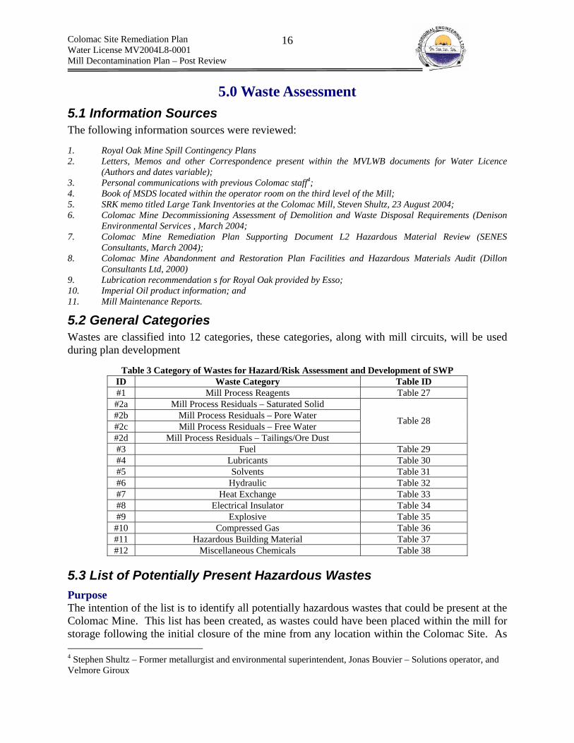
Colomac Site Remediation Plan Water License MV2004L8-0001 Mill Decontamination Plan – Post Review
16
5.0 Waste Assessment 5.1 Information Sources The following information sources were reviewed: 1. Royal Oak Mine Spill Contingency Plans 2. Letters, Memos and other Correspondence present within the MVLWB documents for Water Licence
(Authors and dates variable); 3. Personal communications with previous Colomac staff4; 4. Book of MSDS located within the operator room on the third level of the Mill; 5. SRK memo titled Large Tank Inventories at the Colomac Mill, Steven Shultz, 23 August 2004; 6. Colomac Mine Decommissioning Assessment of Demolition and Waste Disposal Requirements (Denison
Environmental Services , March 2004; 7. Colomac Mine Remediation Plan Supporting Document L2 Hazardous Material Review (SENES
Consultants, March 2004); 8. Colomac Mine Abandonment and Restoration Plan Facilities and Hazardous Materials Audit (Dillon
Consultants Ltd, 2000) 9. Lubrication recommendation s for Royal Oak provided by Esso; 10. Imperial Oil product information; and 11. Mill Maintenance Reports.
5.2 General Categories Wastes are classified into 12 categories, these categories, along with mill circuits, will be used during plan development
Table 3 Category of Wastes for Hazard/Risk Assessment and Development of SWP ID Waste Category Table ID #1 Mill Process Reagents Table 27 #2a Mill Process Residuals – Saturated Solid #2b Mill Process Residuals – Pore Water #2c Mill Process Residuals – Free Water #2d Mill Process Residuals – Tailings/Ore Dust
Table 28
#3 Fuel Table 29 #4 Lubricants Table 30 #5 Solvents Table 31 #6 Hydraulic Table 32 #7 Heat Exchange Table 33 #8 Electrical Insulator Table 34 #9 Explosive Table 35
#10 Compressed Gas Table 36 #11 Hazardous Building Material Table 37 #12 Miscellaneous Chemicals Table 38
5.3 List of Potentially Present Hazardous Wastes Purpose The intention of the list is to identify all potentially hazardous wastes that could be present at the Colomac Mine. This list has been created, as wastes could have been placed within the mill for storage following the initial closure of the mine from any location within the Colomac Site. As 4 Stephen Shultz – Former metallurgist and environmental superintendent, Jonas Bouvier – Solutions operator, and Velmore Giroux
Colomac Site Remediation Plan Water License MV2004L8-0001 Mill Decontamination Plan – Post Review
17
decontamination proceeds these wastes could be encountered. The list will reduce the risk of exposing workers to unidentified hazardous wastes and will aid in satisfying the workers right to know. Since the list is very detailed, it has been included as Appendix A. Table 3 relates each waste category to its respective table in Appendix A.
5.4 Hazardous Wastes Identified Specifically Within the Mill Based on the list of potential hazardous wastes, a review of literature and a site visit, an inventory of hazardous wastes specifically present within the Mill was generated. The inventory represents hazardous wastes that are guaranteed to be encountered during the Mill decontamination. These are the hazardous wastes that will specifically be addressed during plan development. The following presents the inventory:
Table 4 Inventory of Wastes Identified Within the Mill
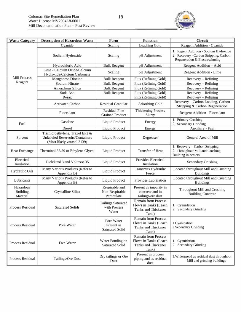
Colomac Site Remediation Plan Water License MV2004L8-0001 Mill Decontamination Plan – Post Review
18
Waste Category Description of Hazardous Waste Form Function Circuit
Cyanide Scaling Leaching Gold Reagent Addition - Cyanide
Sodium Hydroxide Scaling pH Adjustment 1. Regent Addition - Sodium Hydroxide 2. Recovery –Carbon Stripping, Carbon
Regeneration & Electrowinning Hydrochloric Acid Bulk Reagent pH Adjustment Reagent Addition – Acid
Lime - Calcium Oxide/Calcium Hydroxide/Calcium Carbonate Scaling pH Adjustment Reagent Addition - Lime
Manganese Dioxide Bulk Reagent Flux (Refining Gold) Recovery – Refining Sodium Nitrate Bulk Reagent Flux (Refining Gold) Recovery – Refining
Amorphous Silica Bulk Reagent Flux (Refining Gold) Recovery – Refining Soda Ash Bulk Reagent Flux (Refining Gold) Recovery – Refining
Borax Flux (Refining Gold) Recovery – Refining
Activated Carbon Residual Granular Adsorbing Gold Recovery – Carbon Loading, Carbon Stripping & Carbon Regeneration
Mill Process Reagent
Flocculant Residual Fine Grained Product
Thickening Process Slurry Reagent Addition - Flocculant
Gasoline Liquid Product Energy 1. Primary Crushing 2. Secondary Grinding Fuel
Diesel Liquid Product Energy Auxiliary - Fuel
Solvent Trichloroethylene, Traxol EP2 & Unlabeled Reservoirs/Containers
(Most likely varasol 3139) Liquid Product Degreaser General Area of Mill
Heat Exchange Therminol 55/59 or Ethylene Glycol Liquid Product Transfer of Heat 1. Recovery – Carbon Stripping 2. Throughout Mill and Crushing Building in heaters
Electrical Insulation Dielektrol 3 and Voltesso 35 Liquid Product Provides Electrical
Insulation Secondary Crushing
Hydraulic Oils Many Various Products (Refer to Appendix B) Liquid Product Transmits Hydraulic
Force Located throughout Mill and Crushing
Buildings
Lubricants Many Various Products (Refer to Appendix B) Liquid Product Provides Lubrication Located throughout Mill and Crushing
Buildings Hazardous Building Material
Crystalline Silica Respirable and Non-Respirable
Particulate
Present as impurity in concrete and in tailings/ore dust
Throughout Mill and Crushing Building Concrete
Process Residual Saturated Solids Tailings Saturated
with Process Water
Remain from Process Flows in Tanks (Leach Tanks and Thickener
Tank)
1. Cyanidation 2. Secondary Grinding
Process Residual Pore Water Pore Water Present in
Saturated Solid
Remain from Process Flows in Tanks (Leach Tanks and Thickener
Tank)
1. Cyanidation 2. Secondary Grinding
Process Residual Free Water Water Ponding on Saturated Solid
Remain from Process Flows in Tanks (Leach Tanks and Thickener
Tank)
1. Cyanidation 2. Secondary Grinding
Process Residual Tailings/Ore Dust Dry tailings or Ore Dust
Present in process piping and as residual
dust
1. Widespread as residual dust throughout Mill and grinding buildings
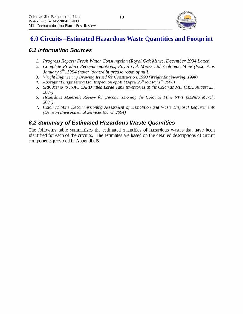
Colomac Site Remediation Plan Water License MV2004L8-0001 Mill Decontamination Plan – Post Review
19
6.0 Circuits –Estimated Hazardous Waste Quantities and Footprint
6.1 Information Sources
1. Progress Report: Fresh Water Consumption (Royal Oak Mines, December 1994 Letter) 2. Complete Product Recommendations, Royal Oak Mines Ltd. Colomac Mine (Esso Plus
January 6th, 1994 (note: located in grease room of mill) 3. Wright Engineering Drawing Issued for Construction, 1998 (Wright Engineering, 1998) 4. Aboriginal Engineering Ltd. Inspection of Mill (April 25th to May 1st, 2006) 5. SRK Memo to INAC CARD titled Large Tank Inventories at the Colomac Mill (SRK, August 23,
2004) 6. Hazardous Materials Review for Decommissioning the Colomac Mine NWT (SENES March,
2004) 7. Colomac Mine Decommissioning Assessment of Demolition and Waste Disposal Requirements
(Denison Environmental Services March 2004)
6.2 Summary of Estimated Hazardous Waste Quantities The following table summarizes the estimated quantities of hazardous wastes that have been identified for each of the circuits. The estimates are based on the detailed descriptions of circuit components provided in Appendix B.

Colomac Site Remediation Plan Water License MV2004L8-0001 Mill Decontamination Plan – Post Review
20
Table 5 Estimated Quantities of Hazardous Wastes within Mill and Crusher Buildings Circuit Waste Category Waste Description Estimated Quantity
Lubrication Variable (Refer to Appendix B) 3,720 L + Piping Hydraulic Variable (Refer to Appendix B) 2645 L + Piping Primary Crushing Circuit
(Gyratory Crusher) Fuel Variable (Refer to Appendix B) 283 L
Lubrication Variable (Refer to Appendix B) 3831 L + Piping Hydraulic Variable (Refer to Appendix B) 540 L + Piping
Electrical Insulating (non-PCB) Voltesso 35 800 L
Heat Exchange Ethylene Glycol Unknown – Could be in 2 heaters and piping
Secondary Crushing Circuit (Short Head Cone
Crusher)
Miscellaneous Nordberg Backing Material 100 L Lubrication Variable (Refer to Appendix B) 5804 L + Piping Primary Grinding Circuit
(SAG Mill) Hydraulic Variable (Refer to Appendix B) 100 L + Piping Lubrication Variable (Refer to Appendix B) 4513 L + Piping
Process Residual Saturated Solid 2260 m3
Process Residual Pore Water 791 m3
Secondary Grinding (Ball Mill) and Classification
Circuit Process Residual Free Water 80 m3
Lubrication Variable (Refer to Appendix B) 100 L Cyanide Circuit Process Reagent Cyanide Scaling 1.21 m3 or 1.91 tonnes
Lubrication Variable (Refer to Appendix B) 210 L Lime Circuit Process Reagent Lime Scaling 3.0 m3 or 6.75 tonnes
Caustic Circuit Process Reagent Caustic Scaling 0.05 m3 or 0.10 tonnes
HCL Acid Circuit Process Reagent Liquid Muriatic Acid as Free Product 205 L
Lubrication Variable (Refer to Appendix B) 5560 m3 Process Residual Saturated Solid 2,228 m3 Process Residual Pore Water 781 m3 Process Residual Free Water 4,585 m3
Leaching Circuit
Process Residual Tailings 465 m3 Lubrication Variable (Refer to Appendix B) 1974 L
Process Reagent Caustic Scaling
Minor amounts of scaling present on piping pumps
etc. – most notable on pipes containing heated solution
Carbon Loading, Stripping and
Regeneration Circuit
Heat Exchange Therminol 55/59 Unknown Lubrication Variable (Refer to Appendix B) 200 L
Process Reagent Caustic & Cyanide Scaling
Minor amounts of caustic scaling and potential
cyanide scaling on the electrowinning cells
(releases free cyanide from cyanide-gold complex – also causes cyanide to
breakdown to ammonia) Process Reagent Silica 272.4 kg Process Reagent Manganese Dioxide 395 kg Process Reagent Borax 391 kg Process Reagent Soda Ash 565 kg
Refining and Electrowinning
Heat Exchange Ethylene Glycol Potential anti freeze in lines
of induction furnace cooling system
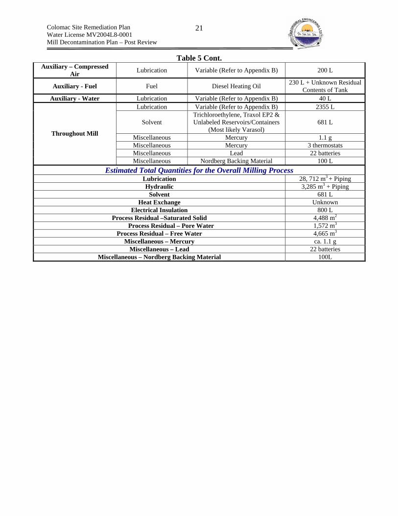
Colomac Site Remediation Plan Water License MV2004L8-0001 Mill Decontamination Plan – Post Review
21
Table 5 Cont. Auxiliary – Compressed
Air Lubrication Variable (Refer to Appendix B) 200 L
Auxiliary - Fuel Fuel Diesel Heating Oil 230 L + Unknown Residual Contents of Tank
Auxiliary - Water Lubrication Variable (Refer to Appendix B) 40 L Lubrication Variable (Refer to Appendix B) 2355 L
Solvent Trichloroethylene, Traxol EP2 & Unlabeled Reservoirs/Containers
(Most likely Varasol) 681 L
Miscellaneous Mercury 1.1 g Miscellaneous Mercury 3 thermostats Miscellaneous Lead 22 batteries
Throughout Mill
Miscellaneous Nordberg Backing Material 100 L Estimated Total Quantities for the Overall Milling Process
Lubrication 28, 712 m3 + Piping Hydraulic 3,285 m3 + Piping
Solvent 681 L Heat Exchange Unknown
Electrical Insulation 800 L Process Residual –Saturated Solid 4,488 m2
Process Residual – Pore Water 1,572 m3 Process Residual – Free Water 4,665 m3
Miscellaneous – Mercury ca. 1.1 g Miscellaneous – Lead 22 batteries
Miscellaneous – Nordberg Backing Material 100L

Colomac Site Remediation Plan Water License MV2004L8-0001 Mill Decontamination Plan – Post Review
22
7.0 Hazardous Waste Disposal Options
7.1 Current On-Site Waste Water Treatment – Enhanced Natural Removal In 1999, INAC assumed control of the Colomac Mine, following the insolvency of the former owner. The transfer of ownership resulted in INAC assuming the liability associated with two impacted bodies of water. More specifically INAC assumed responsibility for:
1. Tailings Lake: process slurry that was directly deposited into Tailings Lake during the operational period of the mine impacted the lake water;
2. Zone 2.0 Pit: 3.8 million m3 of impacted water from the Tailings Lake was transferred to the Zone 2.0 pit to preserve Tailings Lake freeboard levels, thus preventing discharge of impacted water into the receiving environment.
At the time that the Crown assumed responsibility for the Colomac Mine, both water bodies contained elevated concentrations of residual process chemicals, of which cyanide compounds (primary thiocyanate) and cyanide degradation products (ammonia, nitrate and nitrite) were of greatest concern (i.e., Contaminants of Concern (COCs)). As part of an overall water management strategy for the Colomac Mine, INAC implemented an Enhanced Natural Removal (ENR) program, aimed at removing the COCs from the Tailings Lake and Zone 2.0 Pit. A growth limiting nutrient, phosphorus waste added (last addition in 2003), thus increasing the rate of natural biological activity related to contaminant removal. The ENR program is expected to result in concentrations of COCs acceptable for discharge directly to the receiving environment. The ENR program has undergone risk assessment and has been permitted by the MVLWB and accepted by the Dogrib First Nations. The Colomac Site Remediation Plan presents specific details regarding the ENR program.
7.2 Classification of Hazardous Wastes For Disposal Purposes For the purpose of disposal, the hazardous wastes that will be generated during the decontamination of the Mill can be classified as follows:
A. Hazardous Wastes Similar to Wastes Historically Deposited Within the Tailings Containment Area and Zone 2.0 Pit This classification consists of hazardous wastes with properties similar to hazardous wastes that were deposited within the Tailings Containment Area (TCA) (i.e., spruce and tailings lake) during the mines operational period. The ENR program has proven capable of removing these hazardous wastes from the water column. The following table lists the hazardous wastes that fall within this category and compares their estimated quantities to historical consumptions during mine operations.
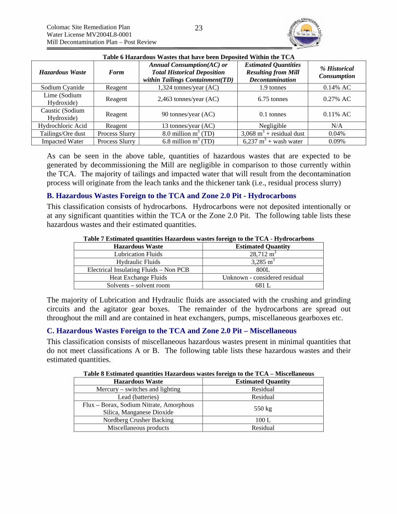
Colomac Site Remediation Plan Water License MV2004L8-0001 Mill Decontamination Plan – Post Review
23
Table 6 Hazardous Wastes that have been Deposited Within the TCA
Hazardous Waste Form Annual Consumption(AC) or Total Historical Deposition
within Tailings Containment(TD)
Estimated Quantities Resulting from Mill Decontamination
% Historical Consumption
Sodium Cyanide Reagent 1,324 tonnes/year (AC) 1.9 tonnes 0.14% AC Lime (Sodium
Hydroxide) Reagent 2,463 tonnes/year (AC) 6.75 tonnes 0.27% AC
Caustic (Sodium Hydroxide) Reagent 90 tonnes/year (AC) 0.1 tonnes 0.11% AC
Hydrochloric Acid Reagent 13 tonnes/year (AC) Negligible N/A Tailings/Ore dust Process Slurry 8.0 million m3 (TD) 3,068 m3 + residual dust 0.04% Impacted Water Process Slurry 6.8 million m3 (TD) 6,237 m3 + wash water 0.09%
As can be seen in the above table, quantities of hazardous wastes that are expected to be generated by decommissioning the Mill are negligible in comparison to those currently within the TCA. The majority of tailings and impacted water that will result from the decontamination process will originate from the leach tanks and the thickener tank (i.e., residual process slurry)
B. Hazardous Wastes Foreign to the TCA and Zone 2.0 Pit - Hydrocarbons This classification consists of hydrocarbons. Hydrocarbons were not deposited intentionally or at any significant quantities within the TCA or the Zone 2.0 Pit. The following table lists these hazardous wastes and their estimated quantities.
Table 7 Estimated quantities Hazardous wastes foreign to the TCA - Hydrocarbons Hazardous Waste Estimated Quantity Lubrication Fluids 28,712 m3 Hydraulic Fluids 3,285 m3
Electrical Insulating Fluids – Non PCB 800L Heat Exchange Fluids Unknown - considered residual
Solvents – solvent room 681 L The majority of Lubrication and Hydraulic fluids are associated with the crushing and grinding circuits and the agitator gear boxes. The remainder of the hydrocarbons are spread out throughout the mill and are contained in heat exchangers, pumps, miscellaneous gearboxes etc.
C. Hazardous Wastes Foreign to the TCA and Zone 2.0 Pit – Miscellaneous This classification consists of miscellaneous hazardous wastes present in minimal quantities that do not meet classifications A or B. The following table lists these hazardous wastes and their estimated quantities.
Table 8 Estimated quantities Hazardous wastes foreign to the TCA – Miscellaneous Hazardous Waste Estimated Quantity
Mercury – switches and lighting Residual Lead (batteries) Residual
Flux – Borax, Sodium Nitrate, Amorphous Silica, Manganese Dioxide 550 kg
Nordberg Crusher Backing 100 L Miscellaneous products Residual
Colomac Site Remediation Plan Water License MV2004L8-0001 Mill Decontamination Plan – Post Review
24
7.3 Preferred Disposal Options The following sections discuses the preferred option for disposal of hazardous wastes generated by the decontamination of the Colomac Mill. A detailed discussion of the selection process, including environmental effects and alternative options is presented in Appendix D.
A. Hazardous Wastes Similar to Wastes Historically Deposited Within the Tailings Containment Area and Zone 2.0 Pit
(a) Cyanide Circuit Pipes, Pumps and Valves Piping, pumps and valves will be covered with 0.1 to 0.15 mm polyethylene. Once bagged, pipes, pumps and valves will be transported to the South end of the Spruce Lake tailings and buried beneath the water table in a trench. The disposal area is adjacent to the historical dump. All material will be placed in an organized manner and piping will be cut into segments, as short as safely possible with a hand held hack saw. Heat generated by torches could release toxic HCN gas. OH&S consideration could result in piping longer than 3’ in length, however all attempts will be taken to keep piping length to less than 3’ in length.
Tanks Primary Mixing and Storage Tanks The primary cyanide mixing and storage tanks will be removed from the Mill. Removal will eliminate any risk of exposing demolition workers to cyanide during the demolition of the major Mill structures. The large size of the primary steel mixing and storage tanks, require that these two tanks be cut up prior to removal. In order to safely cut the tanks they must be treated with sodium hypochlorite and subsequently washed. Sodium hypochlorite oxidizes cyanide to cyanate, which is much less toxic and easier to deal with during washing. In addition, oxidation of cyanide with sodium hypochlorite is a common and proven method of batch treating cyanide spills and small quantities of cyanide impacted water. The efficiency of removal is quoted in the literature at >99.7%5. The treatment and washing will remove residual cyanide and thus the risk of generating hydrogen cyanide gas during tank cutting. The high torch heat can cause residual cyanide to form hydrogen cyanide gas during cutting. The small volume of treatment water, the low concentration of cyanide requiring oxidation and the lack of additional sinks for oxidants (i.e., organic materials, impurities etc) all combine to effect a treatment strategy that requires small amounts of sodium hypochlorite. In addition, the batch treatment process is very simple to implement and can be done within the primary tanks. As such, treatment is feasible to complete. This process will also effectively batch treat the wash water prior to disposal. Treatment and washing will also require pH adjustment to a pH of 11.0 or greater. To accomplish this, caustic will be added to the water prior to treatment and washing. Following washing and treatment The tanks will then be cut up into sections no greater than 3’ x 3’ and placed into the bone yard, adjacent to truck lake. A detailed description of tank washing and treatment is provided in section 8.0. Small amounts of caustic and sodium hypochlorite reagents will have be brought to site. Caustic will form solution of pH 12 at 0.05% solution. If the tanks were filled to capacity (38m3) then 19 5 Destruction of Cyanogen Bromide and Inorganic Cyanides (George Lunn and Eric B. Sansone 1984.
Colomac Site Remediation Plan Water License MV2004L8-0001 Mill Decontamination Plan – Post Review
25
kg or 0.0089 m3 (8.9 L volume container) would be required per tank to treat the interiors of the tanks. Following treatment the tank contents would be pumped from the tank into a tanker truck and trucked to and disposed of within Tailings Lake. The quantities of water and mass loading of cyanide and caustic to Tailings Lake are insignificant from an environmental point of view.
Secondary 6’ x 6’ Cyanide Tank The smaller 6’ x 6’ mixing tank has been cut in half and covered with plastic will be removed as a whole. This method is practical as the size of the tank is small and its plastic construction facilitates ease of compaction. The concentrations of cyanide, if any, within the tank are unknown and as such present a risk to worker health. HCN could potentially have built up within the covered tank, which could be quickly released when opened. As such, this tank will be covered with additional plastic and removed in whole and transported to the Southern end of Spruce lake and crushed within the disposal area using heavy equipment. The contents will be buried beneath the water table, in a trench. This method of disposal removes the worker from the risk of exposure related to the unknown contents. It should be noted that the potential forms concentrations and forms of cyanide within the tank are only a risk to worker health do not present a risk to the environment.
Residual Scaling and Dust Residual cyanide scaling and dust present within and surrounding the general mixing area will be dry collected using a HEPA vacuum. Manual collecting of hardened scaling could be required. The HEPA bag will be buried beneath the water table at the South end of the Spruce Lake tailings. Following dry collection, the floors will be washed with a dilute solution of calcium hypochlorite (essentially bleach). Next, the floors will be rinsed with water. The liquids will be collected with an industrial vacuum and deposited within Tailings Lake or Zone 2.0 Pit.
(b) Lime Circuit Pipes and Pumps The distribution piping runs parallels to the cyanide distribution piping. As such, the piping for both circuits will be removed simultaneously. The piping will be covered, cut, removed and transported to the South end of the Spruce Lake tailings for disposal. The piping will be cut into no longer than 3’ sections using a hand hacksaw. The sections will be buried beneath the water table in a trench and covered with tailings and then the tailings cover. Gross scaling will be removed from the pumps and bagged, the oil from the pumps will then be drained and incinerated along with additional hydrocarbons. The pumps will be removed and transported to the South end of Spruce Lake and buried beneath the tailings cover, at a depth below the water table.
(2x) Mixing Tanks The gross scaling present on the mixing tanks will be removed via industrial pressure washers, until no gross scaling is visually present. No chemical or physical adjustment of the wash water will be required. Wash water will be contained within the bermed area that surrounds the two mixing tanks and will be collected using an industrial vacuum. The wash water will be transported to and disposed of within the Tailings Lake or the Zone 2.0 Pit. Following washing, the tanks will be cut up and the clean metal will be placed in the bone yard adjacent to Truck
Colomac Site Remediation Plan Water License MV2004L8-0001 Mill Decontamination Plan – Post Review
26
Lake. Weakening of the tanks and subsequent demolition with a piece of equipment such as a backhoe is also an acceptable method of tank demolition.
Cyclone Gross scaling will be removed and bagged. The cyclone will then be wrapped and removed. Both bagged lime and the cyclone will be transported to the Southern end of Spruce Lake tailings and buried at a depth below the water table.
Ball Mill Slaker Gross scaling will be removed from the exterior of the Ball Mill slaker and bagged. The Ball Mill slaker will then be covered in plastic. A small piece of heavy equipment will then lift the Ball Mill onto a flat deck truck. Both the bagged scaling and the Ball Mill will be transported to the Southern end of Spruce Lake tailings and buried at a depth below the water table. Once placed in the trench, the Ball Mill slaker will be compacted to the greatest extent possible, prior to covering. This could require the use of the excavator impact hammer attachment to weaken the tank prior to compaction.
General Scaling General scaling present on the walls and the floor of the Mixing and slaking areas will dry collected and placed in bags. The bags will be transported to the Southern end of Spruce Lake tailings and buried at a depth below the water table. Next the floor and wall will be washed down with a pressure washer and the slurry will be collected with an industrial vacuum. The wash water will be transported to and disposed of within the Tailings Lake or the Zone 2.0 Pit.
(c) Caustic Circuit Pipes and Pumps Pipes will be wrapped and cut into 3’ sections. Pumps will be drained of hydrocarbons and wrapped in plastic. The piping and the pumps will be transported to the Southern end of Spruce Lake tailings and buried at a depth below the water table.
Mixing Tank The mixing tank will be covered and lifted onto a flat deck truck using a small piece of heavy equipment such as a Case loader. The tank will be transported to the Southern end of Spruce Lake tailings and buried at a depth below the water table. Compaction of the tanks will take place prior to covering.
(d) Acid Circuit Bulk Reagent The Hazardous waste associated with the acid circuit is a 45 gallon or 205L plastic drum of muriatic acid. The drum will be labeled according to WHMIS and TDGA and will be properly stored and secured in preparation for off-site disposal at a licensed hazardous waste disposal facility. Off-site shipping will occur over the 2006/2007 winter road.
(e) Flocculant Circuit Flocculant is non-toxic, however it does represent a significant slip and trip hazard when wet. As such, decontamination will focus on removal of flocculant residual from the floor.
General Residual Product
Colomac Site Remediation Plan Water License MV2004L8-0001 Mill Decontamination Plan – Post Review
27
The area surrounding the flocculant mixing and storage tanks will be vacuumed using a HEPA vacuum. The collected flocculant will be very small in quantity and is not expected to fill a HEPA vacuum bag. As such the vacuum will be used to collect residual tailings dust following flocculant collection and the mixed bagged contents will be disposed of underneath the tailings cover at the Southern end of Spruce Lake.
(f) Carbon Circuit The piping and pumps that transported the caustic stripping solution contain residual caustic scaling. The pipes will be covered and cut into 3” sections. The pumps will be drained of hydrocarbons and covered with plastic. Both the piping and pumps will be transported to the Southern end of Spruce Lake tailings and buried at a depth below the water table. The pressure vessels were cleaned satisfactorily by Royal Oak during mothballing of the Mill. The hazardous waste associated with the carbon regeneration circuit is residual caustic scaling of piping and pumps that transported caustic solution. The fuel contained within the kiln will be dealt with during the decontamination of the auxiliary fuel circuit. The pressure vessels were cleaned satisfactorily during the initial mothballing of the Mill by Royal Oak. The piping and pumps that transported the caustic stripping solution contain residual caustic scaling. The pipes will be covered and cut into 3” sections. The pumps will be drained of hydrocarbons and covered with plastic. Both the piping and pumps will be transported to the Southern end of Spruce Lake tailings and buried at a depth below the water table.
(g) Process Residuals Saturated solids (tailings) and free water is present at the base of each of the 12 leach tanks as well as the thickener tank. The preferred method of disposal for the free water is to pump the free water directly into Zone 2.0 Pit. Although the concentrations of cyanide will increase slightly in Zone 2.0 Pit, the ENR will be able to degrade the cyanide, and the pumping will increase mixing in the pit, as the discharge hose is to be located well under the water level of the pit. Analytical data for the pore water in the tailings will need to be assessed on-site. Efforts will be made to remove as much pore water as possible from the tailings, by trenching and other means of dewatering. The pore water will be sampled, and if it is of appreciably high concentration (> 100 ppm), it shall be pumped into one of the CIP tanks, and sodium hypochlorite will be added to degrade the cyanide to non-toxic CNO. Once the cyanide levels are lowered, the treated pore water can be pumped to Zone 2.0 Pit. However, it should be noted that the treatment would be applicable to the leach tanks only, as the thickener tank tailings pore water is sufficiently low in cyanide levels, that it can be pumped directly from the thickener to Zone 2.0 pit. Tailings can be removed during the summer, by cutting openings in the sides of the tanks, and using a light piece of equipment with low ground pressure to remove the tailings (post-dewatering), and the tailings would be deposited at the south end of Spruce Lake. This can be done with the thickener tank as cyanide levels are sufficiently low that there is no explosion risk due to low levels of HCN gas generation in the thickener tank.

Colomac Site Remediation Plan Water License MV2004L8-0001 Mill Decontamination Plan – Post Review
28
As for the leach tanks, the pore water must first be sampled to determine whether the tailings removal can be done in the summer. If cyanide levels are sufficiently high, and there is an explosive risk, it is best to remove the tailings frozen in the winter, where HCN gas generation from the remaining pore water will not be an issue. The frozen tailings would also be placed in the south end of Spruce Lake tailings.
(h) Residual Tailings/Ore Dust Residual ore dust is widespread throughout both of the crusher buildings. Residual tailings dust is widespread throughout the Mill. Both ore dust and tailings dust will be dry collected either by hand and shovel or through the use of an industrial vacuum. The ore dust and tailings dust will be deposited underneath the tailings cover at the Southern end of Spruce Lake tailings.
B. Hazardous Wastes Foreign to the TCLA and Zone 2.0 Pit - Hydrocarbons
(i) Hydrocarbons Lubricating fluids, heat exchange fluids, greases, and oils are present within all of the equipment within the mill and both crusher buildings. An assessment has been done to determine what types of hydrocarbons are present in each piece of equipment, and only three products were found to exceed GNWT limits for incineration. There are presently 2 waste oil incinerators on-site at Colomac (1 needs to be repaired, and 1 needs to be assembled), and the bulk of the hydrocarbons can be incinerated on-site. Greases which may be too viscous to pump into the waste oil incinerator can be mixed with less viscous oils.
Waste products deemed unfit for incineration (exceeding GNWT incineration guidelines) will be packaged in sealed drums for off-site disposal or recycling, and the drums can be removed from site during the 2006-2007 winter road.
C. Hazardous Wastes Foreign to the TCA and Zone 2.0 Pit – Miscellaneous
(j) Refining Flux The refining fluxes, borax, sodium nitrate, magnesium, Amorphous Silica and Soda Ash, will be deposited beneath the tailings cover at the Southern end of the Spruce Lake tailings.
(k) All other Miscellaneous Hazardous Wastes All other miscellaneous hazardous wastes will be collected, containerized and stored as per manufacturer recommendations. The stored contents will be shipped off-site to a licensed hazardous waste facility via the 2006/2007 winter road.

Colomac Site Remediation Plan Water License MV2004L8-0001 Mill Decontamination Plan – Post Review
29
8.0 Hazard Ranking
8.1 Purpose The following section will determine the level of OH&S hazard, for wastes from the inventory that have been clearly identified as being present within the mill.
8.2 Hazard Ranking System – Chemical Contaminants A numerical value will be assigned to each of the wastes that have been identified within the Mill based on their potential health hazard to workers. The ranking is independent of potential for exposure. The ranking system is as follows:
Table 9 Waste Hazard Ranking System
Qualitative Descriptor Quantitative Ranking Reasoning
Very Low Hazard 1 1. No adverse effects are expected
Low Hazard 2 2. irritant but does not cause permanent damage to health or cause injury. Not a significant fire hazard 3. Oxidizer
Hazardous 3
1. Potential carcinogen 2. Corrosive 3. Strong Oxidizer 4. Incompatible with other identified waste
Very Hazardous 4
1. Immediately dangerous to life. 2. Wastes that have little to no information available that could be hazardous and therefore must be approached with caution 3. Extremely corrosive 4. Extremely flammable 5. Highly reactive
8.3 Hazard Ranking – Chemical Contaminants Chemically Unaltered Wastes of Commercially Available Products Hazard determination and the documentation of human health a hazards will be straight forward for wastes that were once commercial goods and have not been altered in chemical form. For these wastes Material Safety Data Sheets, CHEMINFO sheets and NIOSH pocket guide to chemical hazard summaries are available that clearly provide the necessary information. Such wastes include: bulk reagents, regent scaling present in reagent distribution circuit components (i.e. precipitate that chemically resembles original commercial product), lubricants, fuels, hazardous building materials, hydraulic fluids the identified miscellaneous chemicals and heat exchange fluids. Only select information from the literature will be presented in Appendix C.
Mixed and/or Chemically Altered Wastes However, for the process residual, hazard identification is not as straight forward. For example, once cyanide enters the process slurry6, the free cyanide ion (CN- and HCN) can undergo various chemical reactions that result in differing cyanide species (Weak Acid Dissociable (WAD), strong metal complexes, thiocyanate, cyanate etc.) or degradation products of cyanide (ammonia, 6 It is assumed that cyanide remains mostly as sodium cyanide salts within the reagent distribution lines and has not formed compounds.

Colomac Site Remediation Plan Water License MV2004L8-0001 Mill Decontamination Plan – Post Review
30
nitrate/nitrite etc.). These altered chemical forms are all less hazardous than free cyanide and will have differing chemical properties such as solubility and the ability to reform free cyanide in solution. Wastes such as these will require a literature search to identify their associated health and ecological hazards and chemical/physical properties.
Table 10 Waste Hazard Assessment Table 10 summarizes the hazard ranking for each of the identified wastes. Ranking were assigned based on the properties of the wastes presented in Appendix C
Table 10 Waste Hazard Assessment
Waste Hazard Ranking Reasoning
Cyanide (Sodium and Hydrogen) 4
1. Low concentration of sodium cyanide are immediately dangerous to life through multiple exposure routes.
2. HCN extremely flammable.
Sodium Hydroxide 4
1. Extremely Corrosive. 2. Highly reactive – heat generated during reaction can cause nearby
materials to ignite. 3. Reaction with metals releases extremely flammable hydrogen gas 4. Incompatible with HCL and flammable liquids
Hydrochloric Acid 4 1. Extremely Corrosive 2. Incompatible with hydroxides and alkali
Calcium Oxide 4 1. Corrosive 2. Reacts violently with water releasing heat 3. Incompatible with acids
Manganese Dioxide 4 1. Strong Oxidizer 2. Reacts with water or steam to produce hydrogen 3. inhalation can cause metal flu
Gasoline 4 1. Carcinogen 2. Extremely flammable liquid and vapor
Process slurry – pore water 4
1. No analytical results available 2. Could contain high concentrations of cyanide 3. Could produce HCN gas when disturbed or exposed to ambient
pressures
Nordberg crusher backing material 4
1. Insufficient information to fully evaluate health effects 2. Toxic properties 3. Corrosive
Process slurry – ponding water (leach
tanks) 3 1. Contains elevated concentrations of cyanide
Tailings solids and ore dust 3 1. Could contain high concentrations of respirable crystalline silica
Calcium Hydroxide 3 1. Corrosive 2. Incompatible with acids
Diesel fuel 3 1. Carcinogen 2. Flammable liquid
Ethylene glycol 3 1. potentially fatal if ingested Solvents
(Trichloroethylene, Traxol EP2, Varasol
3139)
3 1. Potential Embryotoxicity and teratogenicity
Crystalline silica 3 1. Can cause silicosis through inhalation Therminol 59 2 1. Irritant

Colomac Site Remediation Plan Water License MV2004L8-0001 Mill Decontamination Plan – Post Review
31
Sodium Nitrate 2 1. Oxidizer Process slurry – free
water (thickener tank) 2 1. Very low levels of cyanide
Amorphous Silica 2 1. Could potentially contain small quantities of crystalline silica Hydraulic oils 2 1. Irritant Esso Procon 2 1. Irritant
Soda Ash 2 1. Irritant Lubricants 2 1. Irritant
Activated Carbon 2
1. No expected health effects. 2. Dust can potentially be flammable 3. When saturated can adsorb O2, thus leading to low O2 in confined
spaces Therminol 55 2 1. Irritant Dielektrol 3 1 1. No adverse effects are expected
Flocculant – Percol E10 1 1. No adverse effects are expected Calcium Carbonate 1 1. No adverse effects are expected
Borax 1 1. No adverse effects are expected
8.4 Physical Hazard Ranking Table 11 assess the physical hazards associated with the decontamination of the Colomac mill and provides mitigative actions. SWP address the physical hazards. All workers will be trained in the various hazards and mitigative measures in an overall manner and also prior to the start of each job activity that could put him or her at risk to exposure to the physical hazard.
Table 11 Physical Hazard Assessment and Mitigative Actions Physical Hazard Magnitude of Risk Probability Mitigative Response
Poor Lighting High – Related to All Work
High – Present if not addressed Fixed and portable lighting powered by generator
Slips and Trips Medium to Low Medium
Slip and trip hazards are to be cleaned up immediately and historically present slip and trips hazards such as oil staining is to be cleaned up prior to work. No water is to be added to flocculant when collecting with HEPA Vacuum. Walking and working surfaces will be inspected prior to work for irregularities and any items that may make access difficult or that could cause slips and trips.
Working from Heights High Medium
Rails and footboards are to be inspected prior to work and any deficiencies in stability or lack of presence will be addressed. Fall arrest is to be used when working at heights greater than 10 ft. Work with ladders is to be conducted as per the SWP.
Sound Low Low
The only potential for overexposure to sound is when working with the vacuum equipment, the powered hack saw and operation of heavy equipment. Workers conducting this work will be provided disposable ear plugs. In, addition, the ambient sound levels will be monitored to ensure that exposure in excess of 86.6 dBA is not occurring over a 12 hour time period.
Sumps and Open Pits High Medium
Various open sumps exist in the Mill. These areas will be assessed prior to work and visually identified using high visibility tape and barricaded at a distance of 2m from the leading edge, as barricading is not permanent.
Falling Objects High Low
Workers are not to leave any tools within 2m of the leading edge of an elevated surface above any work. The physical stability of equipment positioned at heights above work within the Mill and crusher building will be assessed. Unsafe items will be locked out. Any elevated surface

Colomac Site Remediation Plan Water License MV2004L8-0001 Mill Decontamination Plan – Post Review
32
above work is to be inspected for risk of falling objects prior to work
Crushing High Low
The ore bin in the primary crusher building could contain significant quantities of ore. The ore bin could release this ore. Workers are not to disturb the ore and are not to enter the area of the conveyor to which the ore exits. An inspection of the ore bin will be attempted, if safe to do so under the conditions associated with the decontamination work.
Electrical Medium to High Low
No electricity is currently supplied to the Mill. This will be verified by an electrician prior to work. Electricity will be supplied by line exiting from an on site generator. All electrical equipment is to be grounded and locked out if work is to be conducted on the equipment.
Explosion High Low
Any work with substances that can emit vapors such that explosive conditions are created will be done so without the presence of ignition. The only exception is the work in the leach tanks, for which ventilation will supply a suitable atmosphere. No smoking is to be permitted within 20 m of any fueling area or work with flammable substances and a specific smoking area will be identified. No personal sources of ignition such as lighters/matches are to be carried during any work.
8.5 Biological Hazard Ranking The decontamination work does not involve exposure to biological infectious substances such as harmful bacteria and/or viruses. Wildlife monitors will monitor for wildlife during work. The primary wildlife risk is bear encounters, although wolverines have been spotted in the general area.

Colomac Site Remediation Plan Water License MV2004L8-0001 Mill Decontamination Plan – Post Review
33
9.0 Safe Work Practices and Procedures
9.1 Introduction As was the case with disposal options, mill circuits will form the primary basis for the development of the majority of Safe Work Practices (SWP). The circuit has been selected as:
Chemical and physical hazards are specific to circuits and can be addressed in a controlled manner by decontaminating the individual circuit components; and
Circuits have specific footprints that allow work to be focused in location, thus easing management and tracking of progress
The following circuits will require SWP for decontamination:
Within the Limits of the Mill building – Ranked in Order of Highest to Lowest Hazard 1. Cyanide Circuit (including CIP sump, lime piping adjacent to cyanide piping); 2. Refinery Circuit (potentially contains cyanide on electrowinning cell and manganese
dioxide); 3. Caustic Circuit (Sodium Hydroxide); 4. Acid Circuit (Hydrochloric Acid); 5. Lime Circuit (Calcium Oxide) (remaining lime mixing area as piping removed with
cyanide); 6. Primary/Secondary Grinding Circuits ; 7. Carbon Circuit; and 8. Flocculant Circuit
Exterior to the Mill – Ranked in Order of Highest to Lowest Hazard 1. Leach Circuit (including thickener tank – high levels of cyanide and confined space); and 2. Primary and Secondary Crushing Circuits (tailings/ore dust/hydrocarbons)
Additional SWP Plans – Supporting tasks The following SWP will be required to be completed as sub tasks within the decontamination of the Colomac Mill.
1. Removal of Process Residuals; 2. Removal of Residual Tailings and Ore Dust; 3. Removal and Incineration of Hydrocarbons; 4. Cleaning and Maintaining HEPA Vacuum; 5. Confined Space Entry; 6. Trenching and Excavation; 7. Heavy Equipment Operation; 8. Lock Out & Tag Out; 9. Hot Work; 10. Drum Handling; 11. Bagging of Pipes; 12. Transportation of Hazardous Goods From the Mill to the Tailings Containment; 13. Fall Restraint and Arrest;
Colomac Site Remediation Plan Water License MV2004L8-0001 Mill Decontamination Plan – Post Review
34
14. Ladders; 15. Working With Hand Tools (Non-Powered); 16. Lifting.
Programs and Plans Required for Safe Work The following programs and plans require clarification to ensure SWP.
1. Respiratory Protection Plan; 2. Analytical Testing Program; and 3. Decontamination Plan.
9.2 Order of Work The order of work has been planned to reduce risk by addressing the most toxic circuits first, thus potentially introducing less workers into high hazard work. The following summarizes the overall order of work for the Colomac Mill Decontamination.
Step #1 – Preparation of Mill
Work The mill will initially be prepared for hazardous waste abatement. A detailed scope of work is presented in the corresponding SWP
Outcome The Mill work areas will be prepared to begin safe Hazmat operations.
Step #2 – Removal of Cyanide
Work Decontamination of Cyanide Circuit, including: (a) the CIP sump; (b) the lime distribution piping that parallels the cyanide distribution piping; (c) the electrowinning cells; and (d) all associated washing and cyanide destruction with a dilute high pH/sodium hypochlorite solution.
Outcome The cyanide circuit and additional items contaminated with cyanide will have been removed or decontaminated. The exclusion zone no longer requires Level B PPE.
Step #3 – Removal of Acids and Bases
Work Decontamination of the Lime Mixing area, Caustic Circuit and Carbon Circuit will occur as they both require the same level of PPE. The barrel containing Muriatic Acid can also be removed at this point. However, the worker completing this task will have to wear differing air purifying cartridges as per the SWP
Outcome Acids and Bases will be removed from the mill, thus further reducing the risk to workers in the exclusion zone.
Step #4 – Removal of the Flocculant Circuit, Residual Tailings and Hydrocarbons
Step #5 – Final Rinsing and Cleaning of Residual Dust
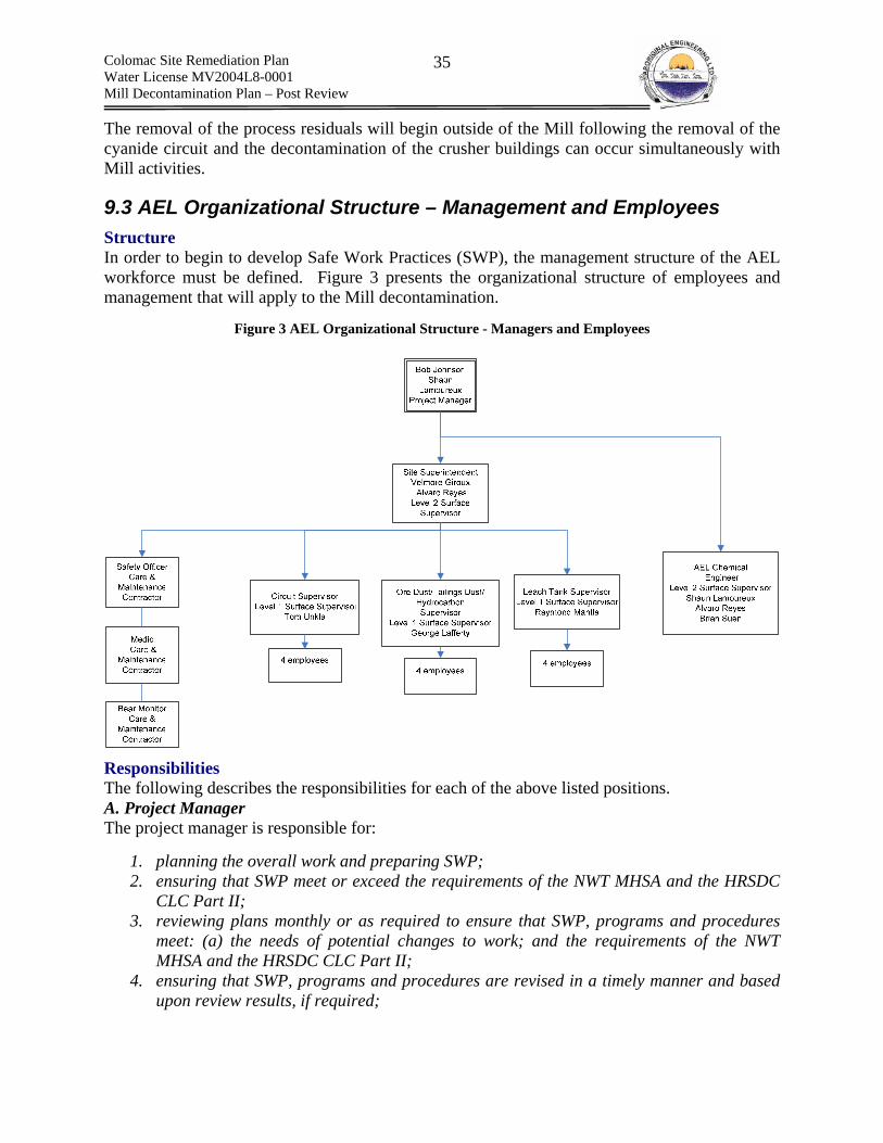
Colomac Site Remediation Plan Water License MV2004L8-0001 Mill Decontamination Plan – Post Review
35
The removal of the process residuals will begin outside of the Mill following the removal of the cyanide circuit and the decontamination of the crusher buildings can occur simultaneously with Mill activities.
9.3 AEL Organizational Structure – Management and Employees Structure In order to begin to develop Safe Work Practices (SWP), the management structure of the AEL workforce must be defined. Figure 3 presents the organizational structure of employees and management that will apply to the Mill decontamination.
Figure 3 AEL Organizational Structure - Managers and Employees
Responsibilities The following describes the responsibilities for each of the above listed positions. A. Project Manager The project manager is responsible for:
1. planning the overall work and preparing SWP; 2. ensuring that SWP meet or exceed the requirements of the NWT MHSA and the HRSDC
CLC Part II; 3. reviewing plans monthly or as required to ensure that SWP, programs and procedures
meet: (a) the needs of potential changes to work; and the requirements of the NWT MHSA and the HRSDC CLC Part II;
4. ensuring that SWP, programs and procedures are revised in a timely manner and based upon review results, if required;
Colomac Site Remediation Plan Water License MV2004L8-0001 Mill Decontamination Plan – Post Review
36
5. ensuring that training programs are: (a) established and executed in a timely manner; and (b) meet both the needs of the employees and the requirements of the NWT MHSA and the HRSDC CLC, Part II;
6. developing the project schedule; 7. identifying human resource, equipment and supply needs; 8. developing logistical plans; 9. establishing an OH&S plan; 10. establishing an Emergency Response Plan; 11. establishing a Spill Response Plan; 12. establishing a Fire Response Plan; 13. establishing a Wildlife Plan; 14. establishing the management structure; 15. establish an internal process for monitoring compliance with the above listed plans; 16. revising the above plans according to the results of the internal monitoring 17. liaison with and reporting to the client; 18. liaison with WCB and HRSDC; 19. establishing the management portion of the Workers Health and Safety Committee
(WPHSC); 20. monitoring the progress of the WPHSC; 21. ensuring the necessary project supplies and resources are available when needed to
ensure safe and efficient progress of work; 22. monitoring the project at regular intervals and according to key milestones; 23. ensuring that the project is delivered safe, on-time, and within budget 24. establishing complaint resolution procedures; 25. adhering to stop work procedures; 26. establishing chain of command for Contingency response; 27. reporting environmental infractions to hotlines and client; and 28. ensuring the environmental infractions are addressed and closed in a manner that
satisfies the requirements of the client and the applicable regulatory bodies.
B. Site Supervisor (Level 2 NWT MHSA Surface Mine Supervisor) 1. Understanding all aspects of work; 2. Coordinating all work on a daily basis to ensure safety and efficient progress; 3. Developing, executing and tracking daily morning safety meetings with assistance from
the Care and Maintenance Contractor (CAMC), supervisors and medical/safety staff; 4. When necessary, developing, executing and tracking coordinated safety meetings with all
persons on-site; 5. liaison with Major Civil Works contractor to ensure no conflicts in work activities; 6. ensuring that all persons on-site are informed of off-limit areas and progress of work
when required to protect their health and safety; 7. ensuring that all areas of danger are identified, labeled, barricaded etc. prior to the start
of work; 8. developing Job Hazard Analysis (JHA) with the level 1 supervisors and employees who
are scheduled to conduct the work; 9. scheduling of employees; 10. liaison with employees to ensure that they are aware of scheduling;
Colomac Site Remediation Plan Water License MV2004L8-0001 Mill Decontamination Plan – Post Review
37
11. immediately reporting any safety infractions, non compliance to work or other issues to the project manager;
12. disciplining staff based on internal policy and reporting from the Level 1 supervisors; 13. monitoring the health and safety and environmental practices of the Level 1 supervisors
through daily inspections of all work areas and weekly formal assessments; 14. if possible, immediately correct improper work/environmental practices and report to
project manager; 15. if not possible to immediately correct, stop work, and if safe to do so, re-assign
employees and report to project manager; 16. not allowing work to continue until new protocol has been put in place or the unsafe
situation has been removed; 17. ensure any revisions to plans put in place by project manager are adhered to; 18. ensuring that complaint resolution process is properly adhered to; and 19. ensuring that stop work requests are properly addressed. 20. supervising confined space entry
C. Chemical Engineer 1. addressing on-site technical issues such as any required washing, water treatment etc.; 2. assisting the project superintendent in planning and delivering safe work in a timely
manner; 3. conducting internal hazard analysis and reporting results to project manager and site
superintendent. Internal assessments are to be completed at a minimum once per month and in cooperation with the WPHSC.;
4. assisting project manager in developing any required revisions to project plans/documents based on hazard assessment results;
5. acting as initial site contact to address any environmental issues such as spills; 6. conducting an assessment of decontamination efficiency; 7. conducting an air quality assessment of HAMAT Worker breathing zones; 8. interpreting results of personal air quality monitoring; 9. conducting all other analytical analysis; 10. reporting the results of internal assessments and analytical monitoring to the project
manager, WPHSC and site superintendent 11. assisting safety officer in audits of safe work practices; 12. reviewing JHA prior to submittal to CAMC; 13. conducting physical and chemical hazard assessment for mill decontamination work
prior to the start of the decontamination work; 14. coordinating HAZWOPER training; and 15. calibration and maintenance of analytical field equipment.
D. Circuit Supervisor (Level 1 NWT MHSA Surface Mine Supervisor)
1. understanding the issues associated with decontaminating the circuits; 2. developing, executing and tracking daily toolbox meeting with decontamination staff; 3. on a daily basis and in conjunction with the site superintendent and chemical engineer,
coordinating circuit decontamination work; 4. monitoring the PPE practices of staff;
Colomac Site Remediation Plan Water License MV2004L8-0001 Mill Decontamination Plan – Post Review
38
5. immediately reporting any safety infractions, non compliance to work or other issues related to the staff to the site superintendent;
6. stopping work and subsequently addressing unsafe or environmentally harmful work conditions/practices immediately;
7. if possible, correcting the unsafe work or environmentally harmful work and reporting to site superintendent;
8. not starting work until unsafe work or environmental practices have been resolved; 9. following complain resolution process; 10. completing JHA; 11. immediately responding to environmental infractions as per spill response plan; and 12. following stop work protocol.
E. Ore Dust/Tailings Dust/Hydrocarbon Supervisor (Level 1 NWT MHSA Surface Mine Supervisor)
1. understanding the issues associated with removing tailings/ore dust and hydrocarbons; 2. developing, executing and tracking daily toolbox meeting with respective staff; 3. on a daily basis and in conjunction with the site superintendent and chemical engineer,
coordinating the removal of the Ore Dust/Tailings Dust and Hydrocarbons; 4. immediately reporting any safety infractions, non compliance to work or other issues
related to the staff to the site superintendent; 5. stopping work and subsequently addressing unsafe or environmentally harmful work
conditions/practices immediately; 6. if possible, correcting the unsafe work or environmentally harmful work and reporting to
site superintendent; 7. not starting work until unsafe work or environmental practices have been resolved; 8. following complain resolution process; 9. following stop work protocol; 10. immediately responding to environmental infractions as per spill response plan; and 11. completing JHA;
F. Leach Tank Supervisor (Level 1 NWT MHSA Surface Mine Supervisor)
1. understanding the issues associated with decontaminating the leach circuit and thickener tank;
2. on a daily basis and in conjunction with the site superintendent and chemical engineer, coordinating leach tank decontamination work;
3. immediately reporting any safety infractions, non compliance to work or other issues related to the staff to the site superintendent;
4. stopping work and subsequently addressing unsafe or environmentally harmful work conditions/practices immediately;
5. if possible, correcting the unsafe work or environmentally harmful work and reporting to site superintendent;
6. not starting work until unsafe work or environmental practices have been resolved; 7. following complain resolution process; 8. following stop work protocol; 9. immediately addressing environmental infractions as per spill response plan; and 10. completing JHA.
Colomac Site Remediation Plan Water License MV2004L8-0001 Mill Decontamination Plan – Post Review
39
G. Employee
1. conducting work as per training, SWP, supervisor instructors and in a safe manner; 2. immediately reporting any potentially or currently unsafe situations, incidents, accidents
or near misses to their respective supervisor; 3. immediately responding to environmental infractions as per spill response plan; 4. immediately correcting and reporting any unsafe work practices of other employees; 5. following proper complaint resolution process; 6. following proper stop work process; and 7. reporting for work as per schedule;
H. Medic
1. immediately responding to any medical situations that may arise during work; 2. ensuring that medical supplies are up to date and readily available for responding to any
medical emergencies on-site; 3. developing a plan to track supplies and update contents as required; and 4. assisting in the development of daily safety meetings.
I. Safety Officer
1. conducting at regular intervals and as required, audits of safety practices of staff; 2. reporting results to the site superintendent; 3. assisting in the development of daily safety meetings; and 4. administrating the respiratory protection program.
J. Bear Monitor
1. Monitoring during work for the presence of any wildlife; 2. when detected, addressing the wildlife issues as to protect the safety of staff; and 3. reporting wildlife sightings or signs of wildlife immediately to project manager.
9.4 Occupational Exposure Limits WCB and HRSDC have adopted the occupational exposure limits listed in the “Threshold Limit Values for Chemical Substances and Physical Agents and Biological Exposure Indices” published by the American Conference of Governmental Industrial Hygienists (ACGIH). Table 12 lists the selected occupational exposure limits for hazardous wastes that will be present during the decontamination of the Colomac Mill. If available ACGIH TLV values are listed. In the absence of ACGIH values the table refers to the U.S. Occupational Safety and Health Administration Permissible Exposure Limits (OSHA PEL), U.S. National Institute for Occupational Safety and Health Recommended Exposure Limits (NIOSH REL), Deutsche Forschungsgemeinschaft Maximum Concentrations Values in the Workplace (DFG MAK) or American Industrial Hygiene Association Workplace Environmental Exposure Levels (AIHA WEEL)
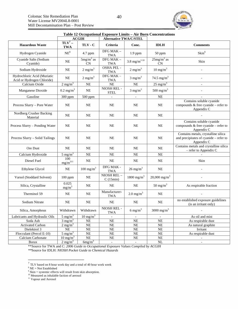
Colomac Site Remediation Plan Water License MV2004L8-0001 Mill Decontamination Plan – Post Review
40
Table 12 Occupational Exposure Limits – Air Born Concentrations ACGIH Alternative TWA/C/STEL
Hazardous Waste TLV7 – TWA TLV - C Criteria Conc. IDLH Comments
Hydrogen Cyanide NE8 4.7 ppm DFG MAK – TWA 1.9 ppm 50 ppm Skin9
Cyanide Salts (Sodium Cyanide) NE 5mg/m3 as
CN DFG MAK –
TWA 3.8 mg/m3 10 25mg/m3 as CN Skin
Sodium Hydroxide NE 2 mg/m3 OSHA PEL - TWA 2 mg/m3 10 mg/m3 -
Hydrochloric Acid (Muriatic Acid or Hydrogen Chloride) NE 2 mg/m3 DFG MAK –
TWA 3 mg/m3 74.5 mg/m3 -
Calcium Oxide 2 mg/m3 NE NE NE 25 mg/m3 -
Manganese Dioxide 0.2 mg/m3 NE NIOSH REL - STEL 3 mg/m3 500 mg/m3 -
Gasoline 300 ppm 500 ppm - - NE -
Process Slurry – Pore Water NE NE NE NE NE Contains soluble cyanide
compounds & free cyanide – refer to Appendix C
Nordberg Crusher Backing Material NE NE NE NE NE -
Process Slurry – Ponding Water NE NE NE NE NE Contains soluble cyanide
compounds & free cyanide – refer to Appendix C
Process Slurry – Solid Tailings NE NE NE NE NE Contains metals, crystalline silica
and precipitates of cyanide – refer to Appendix C
Ore Dust NE NE NE NE NE Contains metals and crystalline silica – refer to Appendix C
Calcium Hydroxide 5 mg/m3 NE NE NE NE -
Diesel Fuel 100 mg/m311 NE NE NE NE Skin
Ethylene Glycol NE 100 mg/m3 DFG MAK - TWA 26 mg/m3 NE -
Varsol (Stoddard Solvent) 100 ppm NE NIOSH REL – C (15min) 1800 mg/m3 20,000 mg/m3 -
Silica, Crystalline 0.025 mg/m3 NE NE NE 50 mg/m3 As respirable fraction
Therminol 59 NE NE Manufacturer- TWA 2.0 mg/m3 NE -
Sodium Nitrate NE NE NE NE NE no established exposure guidelines (is an irritant only)
Silica, Amorphous Withdrawn Withdrawn NIOSH REL - TWA 6 mg/m3 3000 mg/m3 -
Lubricants and Hydraulic Oils 5 mg/m3 10 mg/m3 - - - As oil and mist Soda Ash 3 mg/m3 NE NE NE NE As respirable dust
Activated Carbon 2 mg/m3 NE NE NE NE As natural graphite Dielektrol 3 NE NE NE NE NE Irritant
Flocculant (Percol E-10) 5 mg/m3 NE NE NE NE As respirable dust Calcium Carbonate 10 mg/m3 NE NE NE NE -
Borax 2 mg/m3 6mg/m3 - - NL - **Source for TWA and C: 2006 Guide to Occupational Exposure Values Compiled by ACGIH **Source for IDLH: NIOSH Pocket Guide to Chemical Hazards
7 TLV based on 8 hour work day and a total of 40 hour work week 8 NE = Not Established 9 Skin = systemic effects will result from skin absorption. 10 Measured as inhalable faction of aerosol 11 Vapour and Aerosol

Colomac Site Remediation Plan Water License MV2004L8-0001 Mill Decontamination Plan – Post Review
41
9.5 SWP – Cyanide Circuit Decontamination A. Reference Information The components of the cyanide circuit are discussed in detail within Table 47 and Table 48 of Appendix B. The footprint is presented in Figure 18 (Plan View) and Figure 19 (Side View) (Appendix B). The chemical properties and hazards of cyanide are discussed in Appendix C and the occupational exposure limits are presented in Table 12. Figure 9 presents the exclusion zone applicable to cyanide work. B. Description of Work The decontamination of the cyanide circuit will require the following work items to be completed.
(a) Removal of Scaling and Dust from the Mixing Tank Area
Estimated Quantity Cyanide scaling is present surrounding the mixing tank and within the hopper that feeds the mixing tank. The quantities are minimal.
Removal The scaling surrounding the mixing tank will be dry collected using a HEPA vacuum and transferred to the Spruce Lake tailings for disposal in a trench, below the water table and underneath the tailings cover. The hopper, screw feeder and top of the tank will either be (a) vacuumed, then wrapped in polyethylene, lifted in tact and placed on a flat deck truck or into an end-dump truck and transported to the Spruce Lake tailings; or (b) washed with pH adjusted hypochlorite solution then removed. Either process will avoid the necessity to reach into the hopper/screwfeeder area and thus exposing the breathing zone of the workers. The exact method will be determined in the field. Any scaling present on the exterior of the tank that is bonded to the surface sufficiently to avoid removal by the suction of the vacuum will be dry collected and placed in bags. One worker will remove the scaling, while another worker will apply auxiliary exhaust ventilation to the scaling area, to collect any air born particulate prior to its entry into the workplace atmosphere. This scaling will also be buried in a trench under the Spruce Lake tailings cover. The flow of the auxiliary exhaust ventilation will be checked with a smoke stick to ensure that flows are as anticipated. The entire area is to be washed in a high pH dilute hypochlorite solution to destroy residual cyanide and the subsequently rinsed with water.
(b) Removal of the Cyanide Distribution Pumps, Transfer Pump & Sump Pump
Estimated Quantity Cyanide scaling is present on and within the two cyanide distribution pumps, a sump pump and a transfer pump. The estimate quantity of cyanide is minimal.
Removal Initially, excess cyanide scaling/dust will be removed using a HEPA vacuum. The cyanide pumps will be individually covered with polyethylene and transferred to the Spruce Lake tailings for disposal underneath the tailings cover. The hydrocarbons will not be drained, as the quantities present in the pumps do not justify the risk of worker exposure.
(c) Removal of the Cyanide Distribution Piping
Estimated Quantity

Colomac Site Remediation Plan Water License MV2004L8-0001 Mill Decontamination Plan – Post Review
42
Cyanide scaling is assumed to be present within the distribution piping. The linear length of piping is ca. 575 m of piping (1” PVC = 50 m, 1.5” carbon steel = 100 m & 425m = 3” PVC). An estimated 1.21 m3 of scaling could be present throughout the interior of the piping.
Removal Sections of the Piping will be bagged and cut. The individual sections will be transferred to the Spruce Lake tailings for disposal underneath the tailings cover. A powered hack saw will be used to cut the PVC piping. Using a hacksaw will avoid decomposing sodium cyanide salts if a torch were to be used (i.e., thermal degradation due to intense heat from torch) Carbon steel piping will be removed in manufactured sections by manually removing the piping connectors. No attempt to cut the carbon steel piping will be attempted, as the heat of a cutting torch or cut saw could cause the release of HCN gas.
(d) Cleaning, Cutting and Removal of the Primary Cyanide Mixing Tank
Estimated Quantity The primary cyanide mixing tank has dimensions of ca. 3.7m (diameter) x 3.7 m (length) and a volume of ca. 40 m3.
Cleaning The size of the mixing tank eliminates to option of direct disposal in the Spruce Lake tailings and subsequent compaction. As such, the primary mixing tank will require cleaning prior to cutting and removal. Tank wash water will be generated on-site by mixing caustic and sodium hypochlorite with raw water within an auxiliary mixing tank. Wash water pH will be raised to 11.5 prior to use to avoid the generation of hydrogen cyanide (HCN) gas. Wash water will also contain a dilute concentration of sodium hypochlorite, which shall oxidize the CN, and thus form the much less toxic CNO. Exact addition rates will be determined on-site through experimentation. A pressure washer will be used to spray down the interior of the tank, which can be done from the top of the tank, eliminating the necessity to enter the tank which could present confined space conditions. Rinsing will continue until the collected wash water does not contain greater than 0.2 mg/L free cyanide for three consecutive rinses(Guidelines for Canadian Drinking Water Quality - Summary Table) and there is no visual presence of cyanide (Subject to revision and subsequent approval of alternative method by the Client).
Cutting and Removal Cutting of the tank will commence following washing of the tanks, and transfer of the wash water from the tanks to a water truck has been completed. The water truck shall transfer the wash water to Tailings Lake. Once the washing has been completed, the tank may be cut using cutting torches, and steel shall be placed in the bone yard on site.
(e) Cleaning, Cutting and Removal of the Primary Cyanide Storage Tank Refer to (d)
(f) Removal of the Secondary Cyanide Mixing Tank
Estimated Quantity The secondary cyanide mixing tank is made of plastic and has been cut in half and the top has been sealed with a plastic cover. The tanks current dimensions are 1.8 m (diameter) and 1.8m

Colomac Site Remediation Plan Water License MV2004L8-0001 Mill Decontamination Plan – Post Review
43
(height). The current tank contents are unknown and there is a potential for release of Hydrogen Cyanide if residual contents and moisture are present at pH lower than 11.5.
Tank Removal The selected method of tank removal is to ensure that the tank is properly covered and then transferred to the Spruce Lake Tailings. The tank will then be compressed in place by heavy equipment and buried, thus removing the worker from exposure. This method of tank removal is feasible due to the small tank size and construction with plastic (i.e., easily compressible with an excavator).
(g) Cleaning of Floors Analytical results of the dust present on the ground near the cyanide areas shows that there are high concentrations of cyanide present. Analytical results are appended. The dust will be collected with an industrial vacuum containing a HEPA filter. In some locations scaling may be dislodged and collected in conjunction with the vacuum. Once all cyanide equipment and piping has been removed, the floors may be washed using a pressure washer at low flow mode with the high pH wash water containing a dilute concentration of sodium hypochlorite. Wash water shall be collected in sumps, and transferred to a water truck, and disposed of in Tailings Lake. Rinsing will continue until the collected wash water does not contain greater than 0.2 mg/L free cyanide for three consecutive rinses(Guidelines for Canadian Drinking Water Quality - Summary Table) and there is no visual presence of cyanide.
After washing floors and containment areas with high pH and sodium hypochlorite wash water, the floors and containment areas will be rinsed with regular water once it is shown that there are negligible concentrations.
C. Occupational Exposure Routes of Exposure Of primary importance with respect to cyanide exposure is that all routes of exposure have identical systemic effects (i.e., reduces cellular uptake of oxygen – referred to as Histotoxic Hypoxia). Cyanide solutions are also caustic during direct dermal/eye contact. (i) Inhalation Inhalation of sodium cyanide dust or scaling particulate matter could occur during the removal of dust from the general area, scaling and piping. Inhalation of HCN gas could occur if solution pH drops below pH 11.5 (i.e., is becomes wet, without pH adjustment of wash water). Inhalation could also result if wash water is agitated vigorously, leading to the generation of a liquid mist. Inhalation can result in rapid inability of cells to utilize oxygen. (ii) Dermal Contact Dermal contact could occur during the removal of dust, scaling and piping. Dermal contact can lead to caustic burns of skin and eyes and rapid reduction of the ability of cells to utilize oxygen, following absorption. Dermal contact for open sores, cuts etc. if of greater concern.
(iii) Ingestion Ingestion of cyanide salts could occur from activities such as eating in the work area, chewing finger nails, smoking and direct ingestion. Ingestion can lead to caustic burns and rapid inability of cells to utilize oxygen.
Colomac Site Remediation Plan Water License MV2004L8-0001 Mill Decontamination Plan – Post Review
44
The airborne concentrations of sodium cyanide dust and hydrogen cyanide gas cannot be measured prior to the execution of work. As such, conservative estimates will have to be made regarding health and safety. For the purpose of planning it will be assumed that concentrations of cyanide will be above the NIOSH TLV-TWA criteria and is at a concentration for which the required protection factor is 10,000 times the TLV-TWA (i.e., CSA standard Z94.4-02 requires use of supplied air) This situation is similar to that of responding to a spill of cyanide and as such the levels of protection for workers will be similar.
Exposure Limits Refer to Table 12
D. Exposure Controls (i) Substitution Substitution is not applicable to the work.
(ii) Engineering Controls Localized ventilation will be provided by means of vacuum when any disturbance of cyanide dust is anticipated. The vacuum will be placed adjacent to the local disturbance to remove any potential dust. Dust will be trapped in a HEPA filter located within the vacuum. The flow will be tested prior to use of vacuum using smoke sticks to ensure that the air is being removed via the anticipated flow paths.
(iii) Administrative Controls Workers will be rotated, on a four hour basis, between cyanide decontamination and other job duties such as removal of hydrocarbons/ore dust/tailings dust from the crusher buildings or participating in the decontamination line. This will reduce the expose time period of workers and will reduce the risk of heat exhaustion from wearing PPE. The work plan requires the piping to be bagged, thus reducing the release of air born dust. Areas of concern such as the hopper screw feeder and the plastic sodium mixing tank that has been cut in half will be vacuumed bagged and removed as a whole or washed in elevated pH/hypochlorite solution.
(iv) Personal Protective Equipment PPE is required as administrative and engineering controls will not reduce the risk to an acceptable level. In addition, the concentrations of cyanide exposure are unknown and will not be constant with time.
Removal of Piping and Residual Scaling and Washing with Prepared Solution LEVEL B PPE has been selected. Table 13 contains the selected PPE for use by all persons removing the cyanide circuit.
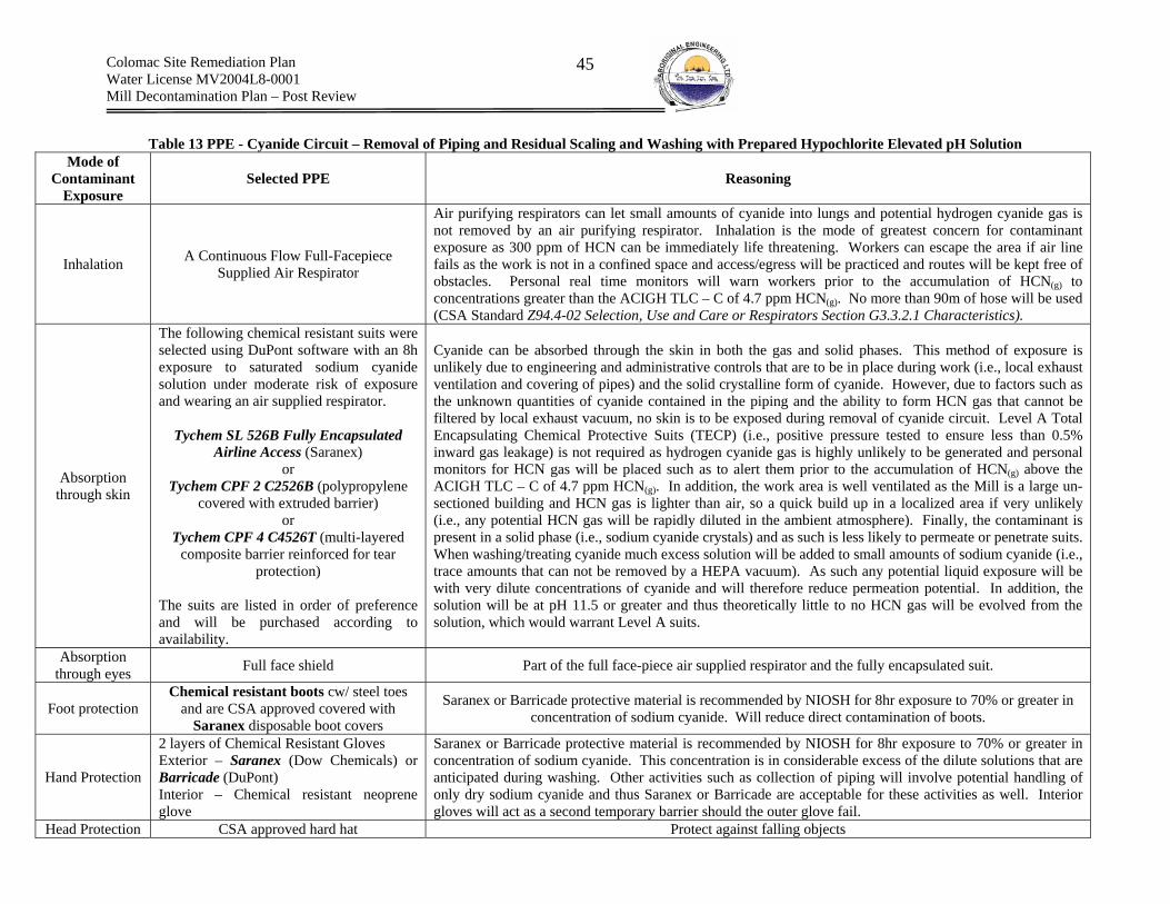
Colomac Site Remediation Plan Water License MV2004L8-0001 Mill Decontamination Plan – Post Review
45
Table 13 PPE - Cyanide Circuit – Removal of Piping and Residual Scaling and Washing with Prepared Hypochlorite Elevated pH Solution
Mode of Contaminant
Exposure Selected PPE Reasoning
Inhalation A Continuous Flow Full-Facepiece Supplied Air Respirator
Air purifying respirators can let small amounts of cyanide into lungs and potential hydrogen cyanide gas is not removed by an air purifying respirator. Inhalation is the mode of greatest concern for contaminant exposure as 300 ppm of HCN can be immediately life threatening. Workers can escape the area if air line fails as the work is not in a confined space and access/egress will be practiced and routes will be kept free of obstacles. Personal real time monitors will warn workers prior to the accumulation of HCN(g) to concentrations greater than the ACIGH TLC – C of 4.7 ppm HCN(g). No more than 90m of hose will be used (CSA Standard Z94.4-02 Selection, Use and Care or Respirators Section G3.3.2.1 Characteristics).
Absorption through skin
The following chemical resistant suits were selected using DuPont software with an 8h exposure to saturated sodium cyanide solution under moderate risk of exposure and wearing an air supplied respirator.
Tychem SL 526B Fully Encapsulated
Airline Access (Saranex) or
Tychem CPF 2 C2526B (polypropylene covered with extruded barrier)
or Tychem CPF 4 C4526T (multi-layered
composite barrier reinforced for tear protection)
The suits are listed in order of preference and will be purchased according to availability.
Cyanide can be absorbed through the skin in both the gas and solid phases. This method of exposure is unlikely due to engineering and administrative controls that are to be in place during work (i.e., local exhaust ventilation and covering of pipes) and the solid crystalline form of cyanide. However, due to factors such as the unknown quantities of cyanide contained in the piping and the ability to form HCN gas that cannot be filtered by local exhaust vacuum, no skin is to be exposed during removal of cyanide circuit. Level A Total Encapsulating Chemical Protective Suits (TECP) (i.e., positive pressure tested to ensure less than 0.5% inward gas leakage) is not required as hydrogen cyanide gas is highly unlikely to be generated and personal monitors for HCN gas will be placed such as to alert them prior to the accumulation of HCN(g) above the ACIGH TLC – C of 4.7 ppm HCN(g). In addition, the work area is well ventilated as the Mill is a large un-sectioned building and HCN gas is lighter than air, so a quick build up in a localized area if very unlikely (i.e., any potential HCN gas will be rapidly diluted in the ambient atmosphere). Finally, the contaminant is present in a solid phase (i.e., sodium cyanide crystals) and as such is less likely to permeate or penetrate suits. When washing/treating cyanide much excess solution will be added to small amounts of sodium cyanide (i.e., trace amounts that can not be removed by a HEPA vacuum). As such any potential liquid exposure will be with very dilute concentrations of cyanide and will therefore reduce permeation potential. In addition, the solution will be at pH 11.5 or greater and thus theoretically little to no HCN gas will be evolved from the solution, which would warrant Level A suits.
Absorption through eyes Full face shield Part of the full face-piece air supplied respirator and the fully encapsulated suit.
Foot protection Chemical resistant boots cw/ steel toes
and are CSA approved covered with Saranex disposable boot covers
Saranex or Barricade protective material is recommended by NIOSH for 8hr exposure to 70% or greater in concentration of sodium cyanide. Will reduce direct contamination of boots.
Hand Protection
2 layers of Chemical Resistant Gloves Exterior – Saranex (Dow Chemicals) or Barricade (DuPont) Interior – Chemical resistant neoprene glove
Saranex or Barricade protective material is recommended by NIOSH for 8hr exposure to 70% or greater in concentration of sodium cyanide. This concentration is in considerable excess of the dilute solutions that are anticipated during washing. Other activities such as collection of piping will involve potential handling of only dry sodium cyanide and thus Saranex or Barricade are acceptable for these activities as well. Interior gloves will act as a second temporary barrier should the outer glove fail.
Head Protection CSA approved hard hat Protect against falling objects
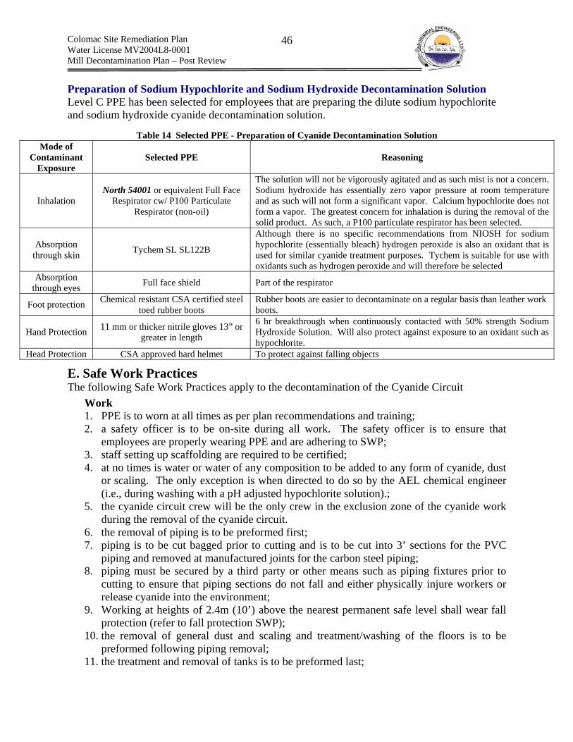
Colomac Site Remediation Plan Water License MV2004L8-0001 Mill Decontamination Plan – Post Review
46
Preparation of Sodium Hypochlorite and Sodium Hydroxide Decontamination Solution Level C PPE has been selected for employees that are preparing the dilute sodium hypochlorite and sodium hydroxide cyanide decontamination solution.
Table 14 Selected PPE - Preparation of Cyanide Decontamination Solution Mode of
Contaminant Exposure
Selected PPE Reasoning
Inhalation North 54001 or equivalent Full Face
Respirator cw/ P100 Particulate Respirator (non-oil)
The solution will not be vigorously agitated and as such mist is not a concern. Sodium hydroxide has essentially zero vapor pressure at room temperature and as such will not form a significant vapor. Calcium hypochlorite does not form a vapor. The greatest concern for inhalation is during the removal of the solid product. As such, a P100 particulate respirator has been selected.
Absorption through skin Tychem SL SL122B
Although there is no specific recommendations from NIOSH for sodium hypochlorite (essentially bleach) hydrogen peroxide is also an oxidant that is used for similar cyanide treatment purposes. Tychem is suitable for use with oxidants such as hydrogen peroxide and will therefore be selected
Absorption through eyes Full face shield Part of the respirator
Foot protection Chemical resistant CSA certified steel toed rubber boots
Rubber boots are easier to decontaminate on a regular basis than leather work boots.
Hand Protection 11 mm or thicker nitrile gloves 13” or greater in length
6 hr breakthrough when continuously contacted with 50% strength Sodium Hydroxide Solution. Will also protect against exposure to an oxidant such as hypochlorite.
Head Protection CSA approved hard helmet To protect against falling objects
E. Safe Work Practices The following Safe Work Practices apply to the decontamination of the Cyanide Circuit
Work 1. PPE is to worn at all times as per plan recommendations and training; 2. a safety officer is to be on-site during all work. The safety officer is to ensure that
employees are properly wearing PPE and are adhering to SWP; 3. staff setting up scaffolding are required to be certified; 4. at no times is water or water of any composition to be added to any form of cyanide, dust
or scaling. The only exception is when directed to do so by the AEL chemical engineer (i.e., during washing with a pH adjusted hypochlorite solution).;
5. the cyanide circuit crew will be the only crew in the exclusion zone of the cyanide work during the removal of the cyanide circuit.
6. the removal of piping is to be preformed first; 7. piping is to be cut bagged prior to cutting and is to be cut into 3’ sections for the PVC
piping and removed at manufactured joints for the carbon steel piping; 8. piping must be secured by a third party or other means such as piping fixtures prior to
cutting to ensure that piping sections do not fall and either physically injure workers or release cyanide into the environment;
9. Working at heights of 2.4m (10’) above the nearest permanent safe level shall wear fall protection (refer to fall protection SWP);
10. the removal of general dust and scaling and treatment/washing of the floors is to be preformed following piping removal;
11. the treatment and removal of tanks is to be preformed last;

Colomac Site Remediation Plan Water License MV2004L8-0001 Mill Decontamination Plan – Post Review
47
12. during treatment, pH of the wash water is to be above pH 11.5 units at all times and monitored with portable pH hand held units;
13. estimates of the required addition rates for caustic and hypochlorite are to be obtained in the lab, prior to mixing of wash solution.
14. only a AEL chemical engineer shall mix the wash water; 15. no wash water is to be used prior to the consent of the AEL chemical engineer; 16. All contents on top of the tank (cover, agitator, screw feeder, hopper etc.) are to be either
(a) bagged with polyethylene and removed prior to washing; or (b) washed prior to washing the interior of the tank. The wash water is to be mixed in a designated tank, independent of the cyanide tank. The tank is to be located so as not to interfere with work;
17. Piping will transfer wash water from the support zone to a secondary distribution tank in the hot zone, adjacent to the washing area;
18. All washing equipment is to perform properly under caustic and oxidizing conditions for a 30 day period;
19. All washing equipment will remain in the exclusion zone until no longer required. Upon removal it shall be decontaminated;
20. wash water will be collected within the exclusion zone using sump pumps; 21. wash water containers will then be pumped from the exclusion zone into a secondary
storage tank located outside of the Mill, adjacent to the leach tanks or into the leach tanks, depending upon the progress of the removal of process residuals;
22. wash water will then be transferred to a truck and disposed of in the Tailings Lake or pumped directly into the Zone 2.0 pit;
23. a temporary tank at the Spruce Lake tailings will contain clean wash water; 24. the clean wash water will clean the transport container and truck upon the last load of the
shift; 25. Prior to, during and following transport of any material form the Mill to the tailings
deposit area, the Care and Maintenance Contractor, the Major Civil Works contractor and any other parties on-site are to be contacted for the purpose of securing use of the transport road to the tailings area. Only the AEL transport truck is to travel along the tailings road during the transport of hazardous materials.
Emergency Response 1. a medic must be present during any work with cyanide. The medic must remain in radio
contact with workers and the safety officer is to report to the medic at regular intervals. the medic must have on hand, in working order and ready to use: a cyanide antidote kit, oxygen, a stretcher to remove unconscious persons, a NWT approved industrial first aid kit, emergency numbers, a working satellite phone and a working radio. The medic must be aware of medi-vac procedures for remote sites and must be trained in cyanide specific first aid.
2. a cyanide antidote emergency response kit must be present in sufficient quantities and within immediate proximity to the work area (amyl nitrite, sodium nitrite and sodium thiosulfate). In addition, a full supply of oxygen must be located within the immediate proximity of the work area in quantities sufficient to treat 4 persons;
3. staff working in cyanide-containing areas are to be trained in emergency response procedures with respect to cyanide;
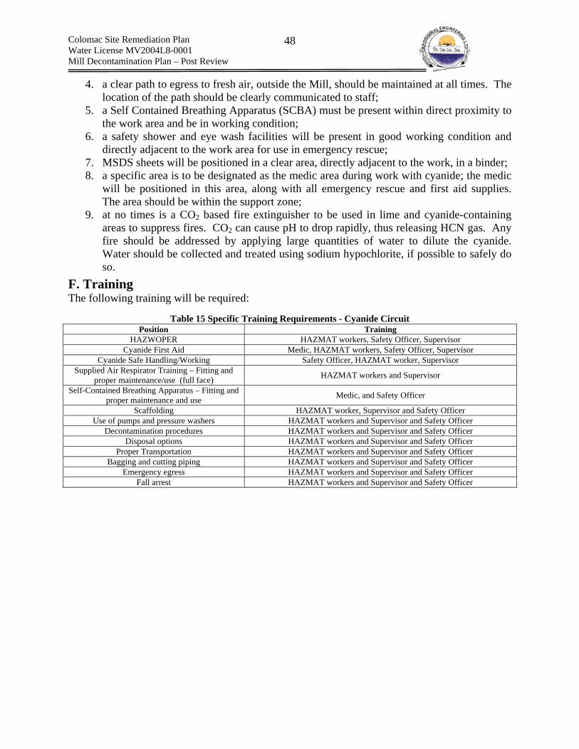
Colomac Site Remediation Plan Water License MV2004L8-0001 Mill Decontamination Plan – Post Review
48
4. a clear path to egress to fresh air, outside the Mill, should be maintained at all times. The location of the path should be clearly communicated to staff;
5. a Self Contained Breathing Apparatus (SCBA) must be present within direct proximity to the work area and be in working condition;
6. a safety shower and eye wash facilities will be present in good working condition and directly adjacent to the work area for use in emergency rescue;
7. MSDS sheets will be positioned in a clear area, directly adjacent to the work, in a binder; 8. a specific area is to be designated as the medic area during work with cyanide; the medic
will be positioned in this area, along with all emergency rescue and first aid supplies. The area should be within the support zone;
9. at no times is a CO2 based fire extinguisher to be used in lime and cyanide-containing areas to suppress fires. CO2 can cause pH to drop rapidly, thus releasing HCN gas. Any fire should be addressed by applying large quantities of water to dilute the cyanide. Water should be collected and treated using sodium hypochlorite, if possible to safely do so.
F. Training The following training will be required:
Table 15 Specific Training Requirements - Cyanide Circuit Position Training
HAZWOPER HAZMAT workers, Safety Officer, Supervisor Cyanide First Aid Medic, HAZMAT workers, Safety Officer, Supervisor
Cyanide Safe Handling/Working Safety Officer, HAZMAT worker, Supervisor Supplied Air Respirator Training – Fitting and
proper maintenance/use (full face) HAZMAT workers and Supervisor
Self-Contained Breathing Apparatus – Fitting and proper maintenance and use Medic, and Safety Officer
Scaffolding HAZMAT worker, Supervisor and Safety Officer Use of pumps and pressure washers HAZMAT workers and Supervisor and Safety Officer
Decontamination procedures HAZMAT workers and Supervisor and Safety Officer Disposal options HAZMAT workers and Supervisor and Safety Officer
Proper Transportation HAZMAT workers and Supervisor and Safety Officer Bagging and cutting piping HAZMAT workers and Supervisor and Safety Officer
Emergency egress HAZMAT workers and Supervisor and Safety Officer Fall arrest HAZMAT workers and Supervisor and Safety Officer
Colomac Site Remediation Plan Water License MV2004L8-0001 Mill Decontamination Plan – Post Review
49
9.6 SWP – Lime Circuit Decontamination A. Reference Information The components of the Lime circuit are discussed in detail in Table 51 of Appendix B. The footprint is presented in Figure 20 of Appendix B. The chemical properties and hazards of lime are discussed in Appendix C.
B. Description of Work The decontamination of the lime circuit will require the following items to be completed.
(a) Removal of Scaling Present on Walls and Floors
Estimated Quantity Scaling is present on the walls and floors and covering piping within the general area of the lime mixing area. The quantity is considered to be minimal.
Removal Excess scaling will be dry collected and placed in bags and will be removed first during the decontamination of the lime circuit. A HEPA vacuum will collect the remaining dust. The bags of scaling/dust will be disposed of under the Spruce Lake tailings cover, below the water table.
(b) Removal of (x2) Distribution Pumps, Transfer Pump and Sump Pump
Estimated Quantity The exterior and interior of the pumps are heavily encrusted in lime scaling. However, the estimated total quantity of scaling is minimal.
Removal Hydrocarbons will be removed from the pump casing, tested for GNWT criteria and either: (a) collected for off-site disposal at a licensed hazardous waste facility; or (b) incinerated on-site. The excess scaling from the exterior of the pumps will be dry collected by hand, bagged and transported to Spruce Lake for disposal under the tailings cover. The pumps will then be individually covered with polypropylene and transported to the Spruce Lake for disposal under the tailings cover, below the water table.
(c) Removal of the Cyclone Mixer, Screw Feeder and Hopper
Estimated Quantity The exterior and interior of the cyclone, screw feeder and hopper are heavily encrusted in lime scaling. However, the estimated total quantity of scaling is minimal.
Removal The excess exterior scaling will be dry collected via a HEPA vacuum and/or by hand, placed in bags and disposed of within Spruce Lake, underneath the tailings cover. The cyclone, screw feeder and feed box will be covered separately and disposed under the Spruce Lake tailings cover.
(d) Removal of the Ball Mill Slaker
Estimated Quantity

Colomac Site Remediation Plan Water License MV2004L8-0001 Mill Decontamination Plan – Post Review
50
The exterior and interior of the ball mill slaker is heavily encrusted in scaling. The estimated total quantity of scaling is 1.0 m3. 100L of hydrocarbons could be present within the gears and motor.
Removal The excess scaling will be removed and bagged. Hydrocarbons will be drained from reservoirs and incinerated along with other collected hydrocarbons. The ball mill will then be covered and removed as a whole. To remove the ball mill a small crane or piece of heavy equipment will be required to lift the ball mall onto a flat deck truck. The area is easily accessible to equipment. The ball mill and the bagged excess scaling will be transported to Spruce Lake and disposed of underneath the tailings cover, below the water table. The ball mill will require crushing prior to covering, to consolidate its mass. An excavator will be used to crush the ball mill. This could require the use of the excavator equipped with the impact hammer.
(e) Washing and Removal of the (2x) Mixing Tanks
Estimated Quantity Scaling is present on the exterior and interior walls of the mixing tank, as well as on the mixer blade assembly. The quantity of scaling is minor. Each tank has dimensions of 4.2 m (diameter) x 4.6 m (height) and a volume of 62 m3.
Washing The tanks interiors and exteriors will be washed to the extent possible using a power washer. The interiors will be washed from the walkways overlying the tanks and the exteriors will be washed from within the bermed area surrounding the tanks. The wash water will be allowed to flow from the tanks into the bermed area. Lime wash water will be contained within the bermed area and collected using a an industrial wet vacuum. The tanks will be washed to the greatest extent possible. The use of industrial power washing units will limit the amount of wash water that is to be generated. The industrial power washer will generate a washing stream with variable pressure and a maximum pressure of >3000 psi. Increased pressure is necessary as the lime is only sparingly soluble in water and will require physical force to remove from the tank. The unit will consume approximately 5 gpm or 0.019 m3/min of raw water. It is estimated that at most a 12 hour shift with one pressure washer will be required to clean the lime tanks. At this rate, with continuous washing, ca. 12 m3 of wash waster will be generated.
Cutting and Disposal Once cleaned, the tanks will be cut in place, using either an acetylene torch or a plasma torch. The tank will be cut into pieces no more that 3’ x 3’ and transported to the bone yard for disposal. Weakening and subsequent demolition of the tanks with a piece of heavy equipment that can pass easily through the access doors is also acceptable.
(f) Removal of Distribution Piping
Estimated Quantity The distribution piping has a total linear length of approximately 450m and is plugged completely with lime. Some sections have broken due to the expansion of the lime within the piping. The total estimated volume of lime contained within the piping is 2.0 m3. Scaling is not present in any significant quantity on the exterior of the piping.

Colomac Site Remediation Plan Water License MV2004L8-0001 Mill Decontamination Plan – Post Review
51
Removal The lime distribution piping and cyanide distribution piping will be removed simultaneously as their footprints are parallel to one another. Segments of the lime piping will be covered and cut. The cut sections will be transported to the Spruce Lake tailings deposit and buried beneath the tailings cover.
C. Occupational Exposure Routes of Exposure Of primary importance with respect to lime exposure is that it may irritate skin, and breathing pathways. Inhalation Inhalation of lime dust or scaling particulate matter could occur during the removal of dust from the general area, scaling and piping. Inhalation of vapors or gas is not considered a pathway as calcium hydroxide, calcium oxide or calcium carbonate do not produce any significant vapors. Dermal Contact Dermal contact could occur during the removal of dust, scaling and piping. Dermal contact can lead to caustic burns of skin and eyes. Dermal contact for open sores, cuts etc. are of greater concern. Absorption is not a major concern.
Ingestion Ingestion of lime could occur from activities such as eating in the work area, chewing finger nails, smoking and direct ingestion. Ingestion can lead to caustic burns.
Exposure Limits Refer to Table 12 for ACIGH TLV exposure limits for calcium oxide, calcium hydroxide and calcium carbonate.
D. Exposure Controls (i) Substitution Substitution is not applicable to the work.
(ii) Engineering Controls Localized ventilation will be provided by means of vacuum when any disturbance of lime dust is anticipated. The vacuum will be placed adjacent to the local disturbance to remove any potential dust. Dust will be trapped in a HEPA filter located within the vacuum. The flow will be tested prior to use of vacuum using smoke sticks to ensure that the air is being removed via the anticipated flow paths.
(iii) Administrative Controls The lime piping will be removed along with the cyanide piping to ensure that workers do not have to work from scaffolding twice.
(iv) Personal Protective Equipment PPE is required as administrative and engineering controls will not reduce the risk to an acceptable level. In addition, the concentrations of lime exposure are unknown and will not be constant with time.
Removal of Scaling and Washing Tanks

Colomac Site Remediation Plan Water License MV2004L8-0001 Mill Decontamination Plan – Post Review
52
Level C PPE has been selected for the removal of lime scaling and the washing of the lime mixing tanks. Refer to Table 16.
Table 16 Selected PPE - Lime Circuit Removal of Scaling and Washing Tanks Mode of
Contaminant Exposure
Selected PPE Reasoning
Inhalation North 54001 or equivalent Full Face
Respirator cw/ P100 Particulate Respirator (non-oil)
Lime does not form a vapor and is therefore only particulate matter is of concern. Auxiliary exhaust ventilation will be provided by a HEPA vacuum if any scaling has to be physically disturbed. Loose lime and lime dust will be collected using a HEPA vacuum. NORTH safety products software recommends a full faced air purifying particulate respirator for air borne concentrations between 200 mg/m3 and 1000 mg/m3. These concentrations are in much excess of what is to be expected given the engineering controls in place.
Absorption through skin Tychem SL SL122B
No water will be used in the removal of lime, with the exception of washing the tanks. Tychem is suitable for both the dry collection and wet washing procedures.
Absorption through eyes Full face shield Part of the respirator
Foot protection Chemical resistant CSA certified steel toed rubber boots
Rubber boots are easier to decontaminate on a regular basis than leather work boots.
Hand Protection 11 mm or thicker nitrile gloves 13” or greater in length
6 hr breakthrough when continuously contacted with 50% strength Sodium Hydroxide Solution. Sodium Hydroxide is much more corrosive than lime and as such the selected gloves are appropriate for use in the decontamination of the lime circuit.
Head Protection CSA approved hard helmet To protect against falling objects
Removal of Lime Distribution Piping Level B PPE identical to that of the cyanide PPE has been selected for the removal of the lime distribution piping. This is due to the fact that both the lime and cyanide distribution piping will be removed simultaneously. Refer to Table 13 for cyanide PPE recommendations.
E. Safe Work Practices Work 1. a safety officer is to be on-site during all work. The safety officer is to ensure that
employees are properly wearing PPE and are adhering to SWP; 2. workers shall wear all PPE during the removal of lime distribution piping as per training
specific to cyanide, as the majority of lime piping is directly adjacent to cyanide piping, and lime hazards are covered by the cyanide PPE;
3. lime distribution piping will be removed simultaneously with the cyanide distribution piping.
4. all safety measures applicable to the removal of the cyanide piping shall apply to the removal of the lime piping;
5. lime scaling and the lime mixing tanks will be removed after the cyanide circuit has been removed;
6. workers shall properly wear lime Level C PPE during the removal of lime scaling and the washing of the lime mixing tanks;
7. scaffolding is to be set up only by qualified and trained personnel;
Colomac Site Remediation Plan Water License MV2004L8-0001 Mill Decontamination Plan – Post Review
53
8. untreated water is to be pumped from the process water tank and into a secondary tank located within the exclusion zone for lime, adjacent to the lime mixing tanks;
9. collected wash waster is to be pumped from the lime sump into either: (a) a storage tank outside the mill, adjacent to the leach tanks; or (b) directly into the leach tanks, depending upon the progress of process residual removal form the leach tanks;
10. collected wash water will be pumped to either; (a) Zone 2.0 pit; or (b) Tailings Lake; 11. the transportation truck, if required, is to be washed at the end of each shift. 12. Prior to, during and following transport of any material form the Mill to the tailings
deposit area, the Care and Maintenance Contractor, the Major Civil Works contractor and any other parties on-site are to be contacted for the purpose of securing use of the transport road to the tailings area. Only the AEL transport truck is to travel along the tailings road during the transport of hazardous materials.
Emergency Response 13. a medic must be present during any work on lime piping adjacent to cyanide piping. The
medic must remain in radio contact with workers and the safety officer is to report to the medic at regular intervals. the medic must have on hand, in working order and ready to use: a cyanide antidote kit, oxygen, a stretcher to remove unconscious persons, a NWT approved industrial first aid kit, emergency numbers, a satellite phone and a working radio. The medic must be aware of medi-vac procedures for remote sites and must be trained in cyanide specific first aid.
14. a cyanide antidote emergency response kit must be present in sufficient quantities and within immediate proximity to the work area (amyl nitrite, sodium nitrite and sodium thiosulfate);
15. staff working with lime distribution piping adjacent to cyanide-containing piping are to be trained in emergency response procedures with respect to cyanide;
16. a clear path to fresh air, outside the Mill, should be maintained at all times. The location of the path should be clearly communicated to staff;
17. a Self Contained Breathing Apparatus (SCBA) must be present within direct proximity to the work area and be in working condition;
18. a safety shower and eye wash facilities will be present in good working condition and directly adjacent to the work area for use in emergency rescue;
19. MSDS sheets will be positioned in a clear area, directly adjacent to the work, in a binder; 20. a specific area is to be designated as the medic area during work with cyanide; the medic
will be positioned in this area, along with all emergency rescue and first aid supplies. The area should will be located in the support zone, outside of the hot zone for cyanide; and
21. at no times is a CO2 based fire extinguisher to be used in lime and cyanide-containing areas to suppress fires. CO2 can cause pH to drop rapidly, thus releasing HCN gas. Any fire should be addressed by applying large quantities of water to dilute the cyanide. Water should be collected and treated using sodium hypochlorite, if possible to safely do so.
F. Training Table 17 Training Requirements for the Lime Circuit Decontamination
Position Training HAZWOPER HAZMAT workers, Safety Officer, Supervisor
Colomac Site Remediation Plan Water License MV2004L8-0001 Mill Decontamination Plan – Post Review
54
Cyanide First Aid Medic, HAZMAT workers, Safety Officer, Supervisor Cyanide Safe Handling/Working Safety Officer, HAZMAT worker, Supervisor
Supplied Air Respirator Training – Fitting and proper maintenance/use (full face) HAZMAT workers and Supervisor
Self-Contained Breathing Apparatus – Fitting and proper maintenance and use Medic, and Safety Officer
Scaffolding HAZMAT worker, Supervisor and Safety Officer Use of pumps and pressure washers HAZMAT workers and Supervisor and Safety Officer
Decontamination procedures HAZMAT workers and Supervisor and Safety Officer Disposal options HAZMAT workers and Supervisor and Safety Officer
Proper Transportation HAZMAT workers and Supervisor and Safety Officer Bagging and cutting piping HAZMAT workers and Supervisor and Safety Officer
Emergency egress HAZMAT workers and Supervisor and Safety Officer Fall arrest HAZMAT workers and Supervisor and Safety Officer
9.7 SWP – Caustic Circuit Decontamination A. Reference Information The components of the caustic circuit are discussed in detail within Table 52 of Appendix B. The footprint is presented in Figure 20 (Plan View) of Appendix B. The chemical properties and hazards of caustic are discussed in Appendix C.
B. Work Plan The decontamination of the caustic circuit will require the following work items to be completed.
(a) Removal of Pipes and Pumps The majority of caustic piping is PVC, and the caustic is only added to the barren and loaded eluate tanks. Therefore, the piping does not travel along cyanide-contaminated areas. Piping can be cut via chop saw, or other methods, as thermal degradation of caustic is not an issue. Sections of piping 3’ long will be bagged and transferred to the southern end of Spruce Lake Tailings and buried in a pit along with the rest of the cyanide and lime piping. Typically this work will require 2 workers, one worker to perform cutting, while the other acts as a spotter, holding the piping in place. Fall arrest will be necessary, as the caustic feed lines to the barren and loaded eluate tanks are at the top of the tanks. The piping can be accessed via ladders, scaffolding, or by using a manlift, and either option can be used, depending on availability of the equipment. Refer to safe work practices for ladders. Scaffolding can be set up only by trained and qualified personnel, and man lifts may only be operated by trained personnel. Pumps will be drained of oils and hydrocarbons (see SWP for Removal of Hydrocarbons). The oil reservoirs will be accessed by opening and partially disassembling the pumps using hand tools. The pumps will be bagged and transported to the southern end of Spruce Lake as well.
(b) Removal of Mix Tank Gross contamination surrounding the mix tank will be bagged and removed, and the mix tank support bolts will be removed so that the mix tank can be lifted and removed as one piece. The tank is sufficiently small that it can be lifted with a loader and transported on a flat deck truck. Once transported to the southern end of Spruce Lake Tailings, the tank can be crushed with a backhoe and buried at a depth below the water table. This could require the use of the impact hammer attachment for the excavator

Colomac Site Remediation Plan Water License MV2004L8-0001 Mill Decontamination Plan – Post Review
55
C. Occupational Exposure Routes of Exposure Refer to Lime Occupational exposure
Exposure Limits Refer to Table 12
D. Exposure Controls (i) Substitution Substitution is not applicable to the work.
(ii) Engineering Controls Localized ventilation will be provided by means of vacuum when any disturbance of caustic dust is anticipated. The vacuum will be placed adjacent to the local disturbance to remove any potential dust. Dust will be trapped in a HEPA filter located within the vacuum. The air flow will be tested using smoke sticks to ensure that the air is being removed via the anticipated flow paths.
(iii) Administrative Controls No specific administrative controls have been developed.
(iv) Personal Protective Equipment PPE is required as administrative and engineering controls will not reduce the risk to an acceptable level. In addition, the concentrations of caustic exposure are unknown and will not be constant with time. The same PPE selected for preparing the elevated pH/sodium hypochlorite cyanide wash water will applied to the removal of the caustic circuit. The creation of the wash water involves directly working with concentrated solid sodium hydroxide and as such requires the same level of protection as working with concentrations sodium hydroxide precipitate. Refer to Table 14 for the selected PPE.
E. Safe Work Practices Work 1. A safety officer is to be on-site during all work. The safety officer is to ensure that
employees are properly wearing PPE and are adhering to SWP; 2. Staff shall wear all PPE during any work in manner as per training specific to hazards
with acids and bases; 3. Staff setting up scaffolding are required to be done by qualified and trained personnel; 4. The piping is to be removed first; 5. The removal of general dust and scaling and treatment/washing of the floors is to be
preformed second; 6. All contents on top of the tank are to be removed prior to washing. The wash water is to
be mixed in a designated tank, independent of the cyanide tank; 7. The caustic circuit, the barrel of acid and the residual lime in the lime mixing area can be
removed simultaneously. Emergency Response
Colomac Site Remediation Plan Water License MV2004L8-0001 Mill Decontamination Plan – Post Review
56
8. If workers are exposed dermally to caustic scale they shall notify the site supervisor and site medic, and shall proceed to the shower system to wash off affected area for a minimum of 15 minutes.
9. If workers are exposed by inhalation, the worker must be removed from the area, taken to the on-site medic, and given respiratory support.
10. If workers accidentally ingest caustic material, they shall require immediate attention from the on-site medic.
9.8 SWP – Acid Circuit Decontamination A. Reference Information The components of the acid circuit are discussed in detail within Table 53. The entire circuit was removed from the mill, and therefore the only concerns are one 45 gallon plastic drum that was identified in the mill.
B. Description of Work The only work that must be done to close out the acid circuit is the removal of a drum. The drum shall be removed from the mill and stored as hazardous material, for off-site disposal. The drum shall be ensured to be sealed, and if it is not completely sealed then it can be overpacked. The drum will then be properly placarded and sent to an off-site disposal facility.
C. Safe Work Practices Work 1. before transporting the barrel, placards must be obtained and placed on the barrel; and 2. barrel must be transported safely to avoid breaking or damaging the barrel, transporting
by dolly where applicable, and it may be lowered from one level to another inside of the mill using a rope and pulley system.
PPE 1. staff shall wear PPE similar to that of the PPE required to work with sodium hydroxide
(refer to Table 14). However, the cartridges for the full face-piece air purifying respirator must be rated for hydrochloric acid, which is also referred to commonly as hydrogen chloride. (i.e., RT21 and RT21P100 cartridges have end-of-service life indicators)
Emergency Procedures 1. if the barrel is damaged and causes a spill, the site specific spill contingency plan will be
used as a reference for cleaning up the spill; 2. if the barrel is damaged and causes exposure to the worker, the worker must be
immediately taken to the safety shower in the case of dermal exposure, given respiratory assistance in the case of inhalation, and given immediate medical care in the case of accidental ingestion.
D. Training Table 18 Training Required for the Acid Circuit
Position Training HAZWOPER HAZMAT workers, Safety Officer, Supervisor
Disposal options HAZMAT workers and Supervisor and Safety Officer TDGR and WHIMIS Labeling and Regulations HAZMAT workers and Supervisor and Safety Officer
Colomac Site Remediation Plan Water License MV2004L8-0001 Mill Decontamination Plan – Post Review
57
9.9 SWP – Flocculant Circuit A. Reference Information The components of the Flocculant circuit are discussed in detail within Table 54 of Appendix B. The flocculant used in the process is non-toxic, and only presents a health and safety risk as a slip and trip hazard.
B. Description of Work (a) Removal of dust The area surrounding the flocculant mixing and storage tanks contains residual flocculant in the dust. The material shall be removed by using an industrial vacuum with a HEPA filter assembly. The material will be collected in bags and stockpiled in the mill until a full truckload or flat deck load full can be loaded and then transported to the South End of Spruce Lake for disposal.
(b) Decontamination of Flocculant Circuit equipment As noted previously, the flocculant on the floors and inside of the bermed area surrounding the flocculant tank shall be removed not because of a contamination issue, but for health and safety issues (i.e., wet flocculant is an extreme slip and trip hazard). However, transfer pumps and piping shall be removed, because during the demolition, spills of the flocculant material could create health and safety risks due to the extreme slip and trip hazard associated with wetted flocculant. Bagging of the pumps and piping is not required. Hydrocarbons will be drained from pumps and incinerated.
C. Exposure Controls Level C PPE has been selected for the decontamination of the Flocculant Circuit. Flocculant is not hazardous, however it does readily from a dust and can therefore be a cause for concern if inhaled. As such a half mask air purifying with P100 particulate filters has been selected along with Tyvek coveralls, CSA approved steel toed rubber boots, CSA approved safety glasses and a CSA approved hard hat.
D. Safe Work Practices Work 1. No sweeping, either wet or dry is permitted; 2. flocculant is to be collected with a HEPA vacuum; and 3. no water is to be applied to the flocculant.
9.10 SWP – Carbon Circuit Decontamination A. Reference Information The components of the Carbon Stripping and Regeneration circuits are discussed in detail within Table 59 and Table 60 of Appendix B. The main chemical hazards are caustic, as both the stripping and regeneration circuits contained caustic solution.
B. Description of Work The decontamination of the carbon stripping and regeneration circuits will require the following work items to be completed.
(a) Removal of Pipes and Pumps

Colomac Site Remediation Plan Water License MV2004L8-0001 Mill Decontamination Plan – Post Review
58
Essentially the same work procedure as for removal of caustic pipes and pumps will be used for removal of pipes and pumps from the carbon stripping and regeneration circuits.
C. Exposure Controls Refer to Sodium Hydroxide Circuit Decontamination
D. Safe Work Practices Refer to Sodium Hydroxide Circuit Decontamination
9.11 SWP – Refinery Circuit Decontamination A. Reference Information Chemical hazards present in the refining room are the refining fluxes – borax, sodium nitrate, magnesium, amorphous silica, and soda ash. Caustic scaling and potentially cyanide scaling are present on the electrowinning cells and feed pumps to the electrowinning cells. In addition, lubrication and heat transfer fluids are found in the refining room.
B. Work Plan The refining room chemicals including flux, borax, sodium nitrate, manganese dioxide, amorphous silica, and soda ash are presently stored either in bags, or in containers. The refining room chemicals shall be transferred into separate sealable drums to reduce the possibility of material being spilled during transport of the refining room chemicals. A HEPA vacuum will be used for this purpose. No sweeping of any form is permitted. The refining room chemicals will then be trucked to the south end of Spruce Lake, and then deposited of in a trench underneath the tailings cap, with the exception of sodium nitrate, which is an oxidant. Sodium nitrate will be stored for subsequent off-site disposal at a licensed hazardous waste facility.
The electrowinning cells must be decontaminated to remove caustic and potentially cyanide contamination. Figure 26 shows the caustic and potential cyanide scale material on the electrowinning cells. All workers working on the electrowinning cells must wear full cyanide PPE. The preferred method would be to remove all gross contamination and scaling using an industrial vacuum with a HEPA filter, and remove cathode and anode plates individually, bag them, and bury in the south end of Spruce Lake. The same procedures for dismantling cyanide piping and pumps apply here, and shall be followed. The equipment will then be washed using a dilute hypochlorite/elevated pH solution to neutralize any remaining cyanide.
There also exist lubrication fluids, and heat exchange fluids within the refining room, which will be addressed in the hydrocarbon removal SWP. Occupational Exposure Inhalation Inhalation of particulate matter is of concern for both caustic and cyanide scaling/dust.
Dermal Contact Dermal contact of dusts is of concern only as an irritant for the fluxes. Dermal absorption of cyanide and burns from caustic of concern when decontaminating the electrowinning equipment.
Ingestion Ingestion could occur from activities such as eating in the work area, chewing finger nails, smoking and direct ingestion.

Colomac Site Remediation Plan Water License MV2004L8-0001 Mill Decontamination Plan – Post Review
59
D. Exposure Control (i) Substitution Substitution is not applicable to the work.
(ii) Engineering Controls No engineering controls are in place
(iii) Administrative Controls Workers are to follow SWP.
(iv) Personal Protective Equipment
Removal of Flux Level C PPE with Tyvek hooded coveralls has been selected for the removal of the fluxes.
Table 19 Selected PPE - Ore Dust Mode of
Contaminant Exposure
Selected PPE Reasoning
Inhalation Air purifying half mask respirator cw/. P100 particulate cartridge
Inhalation of particulate matter and subsequent irritation of the respiratory tract is of concern.
Absorption through skin Tyvek hooded coveralls Of primary concern is nuisance dust.
Absorption through eyes CSA approved safety glasses Avoids impact of eyes with particulate matter
Foot protection Steel toed CSA approved rubber boots Will require boot washing for hygiene purposes and as such rubber boots are more easily washed than leather work boots.
Hand Protection Work gloves Nitrile gloves Head Protection CSA approved hard helmet To protect against falling objects
Decontamination of Electrowinning Equipment Refer to Table 13 for cyanide decontamination PPE
Safe Work Practices The following Safe Work Practices apply to the decontamination of the refining room.
Work 1. A safety officer is to be on-site during all work. The safety officer is to ensure that
employees are properly wearing PPE and are adhering to SWP; 2. Staff are to wear all appropriate PPE; 3. All caustic and cyanide containing equipment shall be decontaminated first, to remove
the highest risk of contamination first; 4. Fluxes and refining room chemicals shall be removed thereafter, with reduced PPE
requirements; and 5. No sweeping is allowed at any time. Particulate matter is to be vacuumed using a HEPA
vacuum; 6. Hydrocarbons, lubrication fluids, and heat exchange fluids shall be removed after all
other chemical hazards have been removed from the refining room.
9.12 SWP – Removal of Process Residuals A. Reference Information

Colomac Site Remediation Plan Water License MV2004L8-0001 Mill Decontamination Plan – Post Review
60
Process Residuals refers to the residual tailings and pore and ponding water found in each of the 12 leach tanks, as well as the thickener tank. The primary chemical hazard when working in these areas is cyanide. Refer to Appendix B for a detailed discussion regarding: (a) the forms of cyanide present; and (b) the differences in concentrations between the pore water and ponding water (i.e., the pore water is potentially more toxic than the ponding water) and between the leach tanks and thickener tank (i.e., the leach tanks contain higher concentration of cyanide than the thickener tank due to the direct addition of cyanide to the leaching circuit).
B. Work Plan The removal of the process residuals from the process tanks an thickener tank will be completed in the following manner:
(a) Transfer of free water It is proposed that free water from each of the 12 leach tanks be pumped directly to Zone 2.0 Pit. The Appendix includes calculations estimating the effect on Zone 2.0 Pit from the addition of ponding water.
An access into the leach tanks will need to be cut in order to position the suction line of a pump into the free water. Cuts could be made using cutting torches, and cuts would be the shape of a half oval, as to avoid the pressure points that develop from linear cuts. The LEL of HCN(g) is to be negligible when conducting hot work. Water would then be pumped using either lay flat hose, or the existing tailings piping that is available on site. The tailings pipes could be re-fused, and placed from the leach tanks into Zone 2.0 Pit.
A primary diesel powered pump would be used, and if required, secondary booster pumps would be positioned along the line, to transfer the water to Zone 2.0 Pit. The outlet of the piping or hose would be placed well beneath the water level, and this could be done by positioning the outlet using a boat. Placing the outlet beneath the water level in Zone 2.0 Pit would create circulation and mixing. Pumping would cease once the free water level drops to the level of the saturated solids. The pump is to be capable of pumping a slurry.
The atmosphere inside, and outside of the leach tanks would be monitored for HCN(g) concentrations. In addition, O2 will be monitored to ensure that the concentration of O2 is greater than 10%, as to allow the proper functioning of LEL monitors. The LEL will have to be 10% of the HCN(g) LEL. The same procedure would be done for transferring free water from the thickener tank.
(b) Transfer of pore water Firstly, the majority of the pore water could be removed by trenching the saturated solids. The trenches could be done through additional openings cut into the sides of the leach tanks and thickener tank, and using a small backhoe to reach in through the opening and excavate the trench. The pore water could then be pumped from the trench to a pre-determined location. A perforated pipe wrapped in cloth would be placed into the tailings, within which the suction hose would be placed.
At present, insufficient information is available concerning the concentration of cyanide that could be present within the pore water of the saturated solids at the bottom of the leach tanks and thickener tank. There is the possibility that the cyanide could be at high levels, which would impact the water quality of Zone 2.0 Pit appreciably, compared to the impact of transferring only the free water. In this case, it is proposed that on-site treatment be used, followed by transfer of
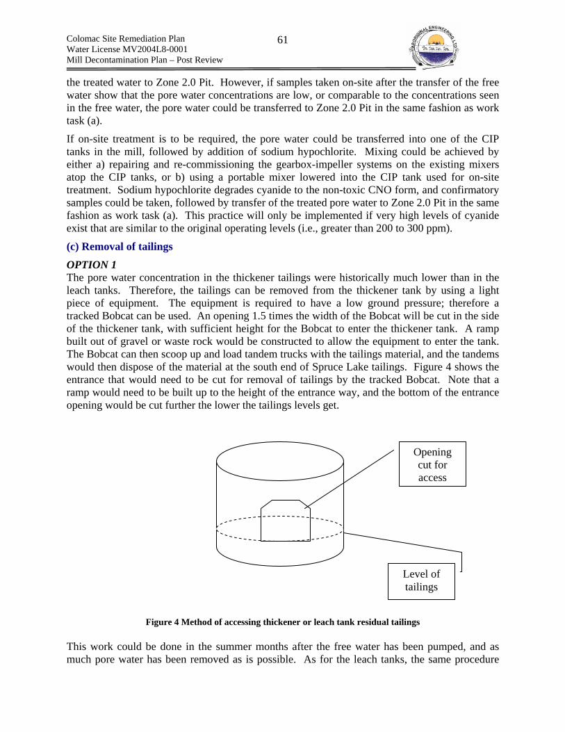
Colomac Site Remediation Plan Water License MV2004L8-0001 Mill Decontamination Plan – Post Review
61
the treated water to Zone 2.0 Pit. However, if samples taken on-site after the transfer of the free water show that the pore water concentrations are low, or comparable to the concentrations seen in the free water, the pore water could be transferred to Zone 2.0 Pit in the same fashion as work task (a).
If on-site treatment is to be required, the pore water could be transferred into one of the CIP tanks in the mill, followed by addition of sodium hypochlorite. Mixing could be achieved by either a) repairing and re-commissioning the gearbox-impeller systems on the existing mixers atop the CIP tanks, or b) using a portable mixer lowered into the CIP tank used for on-site treatment. Sodium hypochlorite degrades cyanide to the non-toxic CNO form, and confirmatory samples could be taken, followed by transfer of the treated pore water to Zone 2.0 Pit in the same fashion as work task (a). This practice will only be implemented if very high levels of cyanide exist that are similar to the original operating levels (i.e., greater than 200 to 300 ppm).
(c) Removal of tailings
OPTION 1 The pore water concentration in the thickener tailings were historically much lower than in the leach tanks. Therefore, the tailings can be removed from the thickener tank by using a light piece of equipment. The equipment is required to have a low ground pressure; therefore a tracked Bobcat can be used. An opening 1.5 times the width of the Bobcat will be cut in the side of the thickener tank, with sufficient height for the Bobcat to enter the thickener tank. A ramp built out of gravel or waste rock would be constructed to allow the equipment to enter the tank. The Bobcat can then scoop up and load tandem trucks with the tailings material, and the tandems would then dispose of the material at the south end of Spruce Lake tailings. Figure 4 shows the entrance that would need to be cut for removal of tailings by the tracked Bobcat. Note that a ramp would need to be built up to the height of the entrance way, and the bottom of the entrance opening would be cut further the lower the tailings levels get.
Figure 4 Method of accessing thickener or leach tank residual tailings
This work could be done in the summer months after the free water has been pumped, and as much pore water has been removed as is possible. As for the leach tanks, the same procedure
Level of tailings
Opening cut for access

Colomac Site Remediation Plan Water License MV2004L8-0001 Mill Decontamination Plan – Post Review
62
can be used to remove the residual tailings from the bottom of the leach tanks if the pore water concentrations are confirmed to be low, and that there would be no explosion risk or health hazards due to HCN gas generation and atmospheric concentrations of O2 are between 19.5% and 23%.
CN(aq) < 100 ppm Air monitoring and water sampling of the pore water is essential to determine whether this work can be done within the leach tanks. It is recommended that this work be done only if the pore water concentration in the process residuals is lower than 100 ppm CN(aq). At concentrations lower than this the potential HCN concentration in the air due to vapour-liquid equilibria is expected to be lower than the LEL of HCN, which is 5.6%. However the concentration must be 10% of the LEL or 0.56% for entry to be permitted. If the pore water concentration is found to be lower than 100 ppm CN(aq), and gas testing shows that the LEL is below the LEL of HCN, the tailings removal from the leach tanks can be done in the same manner as for the thickener tanks. However, minor additions of ventilation could be required if HCN(g) concentrations remain an OH&S concern.
CN(aq) > 100 ppm If the pore water concentration are found to be higher than 100 ppm, or gas readings show the LEL to be comparable to the LEL of HCN, the work could still be done in the same fashion if auxiliary ventilation is applied to the tanks by inserting air blowers into the tanks in sufficient capacity to .maintain acceptable atmospheric concentrations of HCN(g). If the LEL is confirmed to be lower than 10% of LEL of HCN(g), work can proceed, however continuous: (a) LEL; and (b) occupational concentration of HCN(g) monitoring would be required through personal air monitors. In addition, emergency escape SCBA respirators will be required to be available adjacent to the tanks for use in rescue.
Confined Space Entry The leach tanks and the thickener tank are both considered confined spaces. Refer to the confined space SWP.
OPTION 2 If pore water within the process residuals is > 100 ppm CN(aq), and the LEL is higher than the LEL of HCN and secondary ventilation does not reduce the LEL, then the work is be to complete in the winter, when the tailings are frozen, and thus the potential for the release of HCN is very low. This would require that the tanks be demolished and cut to the level of the tailings. Ramps would be built up to access the tailings with a large hydraulic excavator. Once confirmed that the tailings are frozen, ice teeth could be fitted to the excavator bucket, and the tailings could be excavated and transferred to tandem trucks, which would then dispose of the tailings in the south end of Spruce Lake. It should be noted that not all of the tailings would be removed due to the limitations of the hydraulic excavator, and it is likely that the remaining tailings would need to be removed in the summer after the remaining material thaws.
Preferred Option Option 1 would be a more economic and logistically feasible option, because the sequence would be decontamination followed by demolition of the leach tanks. Option 2 would require initial demolition activities, followed by decontamination, followed by final demolition.
C. Occupational Exposure
Colomac Site Remediation Plan Water License MV2004L8-0001 Mill Decontamination Plan – Post Review
63
Routes of Exposure Inhalation Inhalation of: (a) the solid tailings portion of the process residuals (i.e., metals; residual CN compounds and crystalline silica) (b) any mists generated by agitating solutions of the pore water/ponding water (i.e., metals and aqueous CN compounds); or (c) HCN(g) vapors evolving from the pore water/ponding water. The higher the concentration of CN(aq),the greater the temperature and the lower the pH the higher the rate and total equilibrium generation of HCN(g). Dermal Contact Dermal contact can occur through: (a) direct contact with the tailings or the pore water/ponding water and the skin/eyes of the workers; and (b) dermal contact with HCN(g). Of most importance for both situations is the absorption of CN through the skin.
Ingestion Ingestion could occur from activities such as eating in the work area, chewing finger nails, smoking and direct ingestion.
Exposure Limits Refer to Table 12 for ACIGH TLV exposure limits for HCN(g). In addition the LEL of HCN(g) (i.e., 5.6%) and the safe concentrations of O2 in the atmosphere (i.e.,19.5 to 23% O2) are important with respect to confined space entry.
D. Exposure Controls (i) Substitution Substitution is not applicable to the work.
(ii) Engineering Controls Ventilation could be applied to the tanks if hazardous atmospheres exist. Ventilation would be drawn from the exterior of the tanks, thus exchanging with the interior atmosphere.
(iii) Administrative Controls Confined space entry permits will be required prior to entry into any tank(s) by any worker. Confined spaces will be visually marked and secured from inadvertent entry. Training will be provided to all persons involved in confined space entry.
(iv) Personal Protective Equipment PPE is required as administrative and engineering controls will not reduce the risk to an acceptable level.
D. Exposure Control Entry into the Tanks Following Verification of TLV TWA, O2 and LEL levels
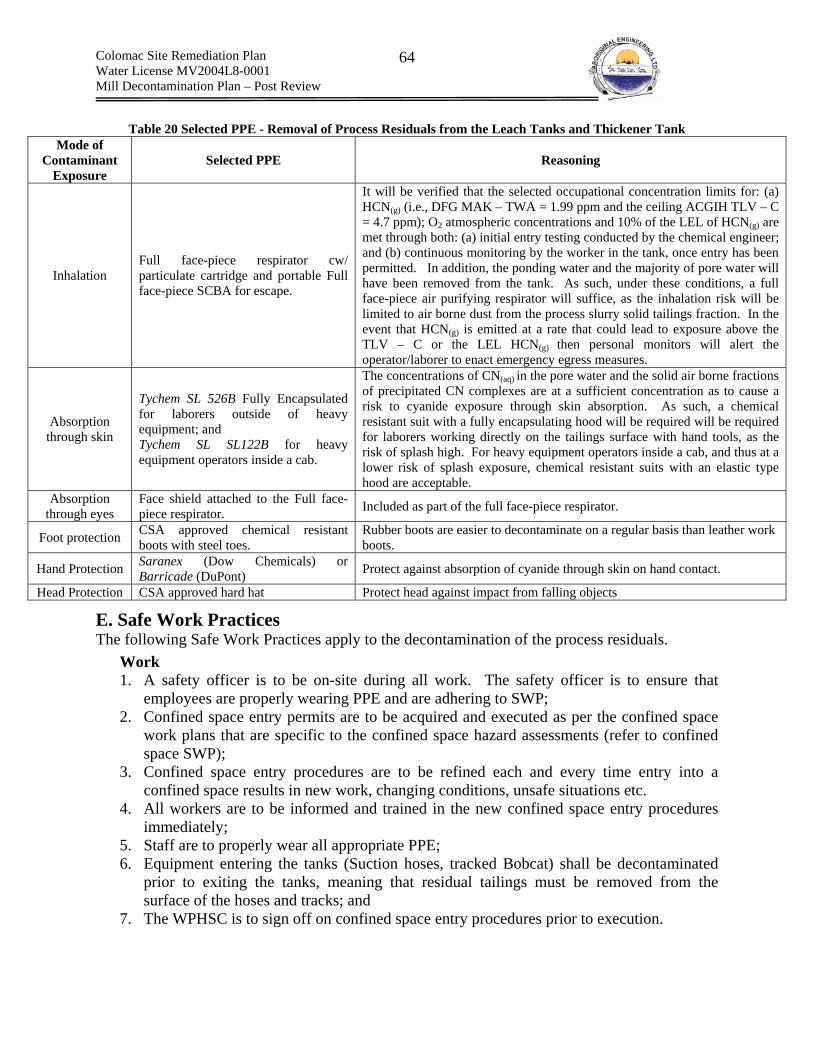
Colomac Site Remediation Plan Water License MV2004L8-0001 Mill Decontamination Plan – Post Review
64
Table 20 Selected PPE - Removal of Process Residuals from the Leach Tanks and Thickener Tank
Mode of Contaminant
Exposure Selected PPE Reasoning
Inhalation Full face-piece respirator cw/ particulate cartridge and portable Full face-piece SCBA for escape.
It will be verified that the selected occupational concentration limits for: (a) HCN(g) (i.e., DFG MAK – TWA = 1.99 ppm and the ceiling ACGIH TLV – C = 4.7 ppm); O2 atmospheric concentrations and 10% of the LEL of HCN(g) are met through both: (a) initial entry testing conducted by the chemical engineer; and (b) continuous monitoring by the worker in the tank, once entry has been permitted. In addition, the ponding water and the majority of pore water will have been removed from the tank. As such, under these conditions, a full face-piece air purifying respirator will suffice, as the inhalation risk will be limited to air borne dust from the process slurry solid tailings fraction. In the event that HCN(g) is emitted at a rate that could lead to exposure above the TLV – C or the LEL HCN(g) then personal monitors will alert the operator/laborer to enact emergency egress measures.
Absorption through skin
Tychem SL 526B Fully Encapsulated for laborers outside of heavy equipment; and Tychem SL SL122B for heavy equipment operators inside a cab.
The concentrations of CN(aq) in the pore water and the solid air borne fractions of precipitated CN complexes are at a sufficient concentration as to cause a risk to cyanide exposure through skin absorption. As such, a chemical resistant suit with a fully encapsulating hood will be required will be required for laborers working directly on the tailings surface with hand tools, as the risk of splash high. For heavy equipment operators inside a cab, and thus at a lower risk of splash exposure, chemical resistant suits with an elastic type hood are acceptable.
Absorption through eyes
Face shield attached to the Full face-piece respirator. Included as part of the full face-piece respirator.
Foot protection CSA approved chemical resistant boots with steel toes.
Rubber boots are easier to decontaminate on a regular basis than leather work boots.
Hand Protection Saranex (Dow Chemicals) or Barricade (DuPont) Protect against absorption of cyanide through skin on hand contact.
Head Protection CSA approved hard hat Protect head against impact from falling objects
E. Safe Work Practices The following Safe Work Practices apply to the decontamination of the process residuals.
Work 1. A safety officer is to be on-site during all work. The safety officer is to ensure that
employees are properly wearing PPE and are adhering to SWP; 2. Confined space entry permits are to be acquired and executed as per the confined space
work plans that are specific to the confined space hazard assessments (refer to confined space SWP);
3. Confined space entry procedures are to be refined each and every time entry into a confined space results in new work, changing conditions, unsafe situations etc.
4. All workers are to be informed and trained in the new confined space entry procedures immediately;
5. Staff are to properly wear all appropriate PPE; 6. Equipment entering the tanks (Suction hoses, tracked Bobcat) shall be decontaminated
prior to exiting the tanks, meaning that residual tailings must be removed from the surface of the hoses and tracks; and
7. The WPHSC is to sign off on confined space entry procedures prior to execution.

Colomac Site Remediation Plan Water License MV2004L8-0001 Mill Decontamination Plan – Post Review
65
Emergency Response 1. All cyanide emergency response measures apply as do confined space entry
emergency response plans.
9.13 SWP – Removal of Residual Tailings & Ore Dust A. Reference Information Residual ore dust is prevalent throughout both of the crusher buildings, and residual tailings can be found throughout the mill. In addition, spilled tailings surround the leach tank, within the bermed limits. The ore dust results from the crushing and handling of ore prior to the addition of process chemicals. Tailings result as the final product of crushing/grinding of ore and are the matrix to which process chemicals are added. Both tailings and ore dust contain slightly elevated concentrations of metals and crystalline silica fractions, as they originate from the same or similar rock. However, only tailings have remaining process chemical precipitates, as no chemicals are added to the ore dust. More details can be found in Appendix B. The health and safety plan for the tailings removal that was previously conducted adjacent to the leach tanks required Level C PPE following risk assessment for working with tailings. AEL will adhere to this recommendation with one exception. For tailings Tychem SL instead of Tyvek hooded suits will be used. For ore dust the Tyvek suits are acceptable. This is further discussed in the following Exposure Control section. Finally, risk assessment conducted by SENES concluded that the tailings dust does not pose a considerable risk to worker OH&S.
B. Work Plan Residual tailings found in the mill can be removed by shovel or industrial wet/dry vacuum with a HEPA filter. A small backhoe could be used to load tandem trucks, if access is possible. The tailings slurry pipes will have to be partially disassembled, as solid tailings were found to be plugged in the lines. Residual tailings found on the floors of the mill can be removed using an industrial vacuum. These tailings can be transferred and disposed of in the south end of Spruce Lake.
Ore dust is also prevalent throughout both crusher buildings. The same procedure can be used, and a crew of equal size will be required.
C. Exposure Assessment Inhalation Inhalation of particulate air born dust can occur Dermal Contact Dermal contact can occur through splashing from saturated tailings or the deposition of dust on the skin. Free cyanide and cyanide complexes within the tailings could be absorbed through the skin
Ingestion Ingestion of tailings/ore dust could occur from activities such as eating in the work area, chewing finger nails, smoking and direct ingestion.
Exposure Limits No specific exposure limits exist
D. Exposure Control

Colomac Site Remediation Plan Water License MV2004L8-0001 Mill Decontamination Plan – Post Review
66
(i) Substitution Substitution is not applicable to the work.
(ii) Engineering Controls HEPA vacuums will be used for very fine and dry dust to prevent air born dispersion. An industrial wet/dry vacuum will be used to collect saturated or partially saturated tailings.
(iii) Administrative Controls Workers are to follow SWP.
(iv) Personal Protective Equipment
Ore Dust – Crusher Buildings Level C PPE with Tyvek hooded coveralls has been selected for the removal of ore dust from the crusher buildings.
Table 21 Selected PPE - Ore Dust Mode of
Contaminant Exposure
Selected PPE Reasoning
Inhalation Air purifying half mask respirator cw. P100 particulate filter
Respirable silica is most likely present within the ore dust as the ore was contained within quartz. In addition, elevated levels of some metals are present (Refer to Appendix B). No cyanide or other process residual chemicals are present within the ore dust. A half mask air purifying respirator with P100 particulate filters will protect workers from inhaling respirable portions of the ore dust.
Absorption through skin Tyvek hooded coveralls The primary focus of body protection will be protection workers from
nuisance dust. As such Tyvek suits are acceptable Absorption
through eyes CSA approved safety glasses Primary concern is to protect workers eyes from impact injuries. No absorption issues are present.
Foot protection Steel toed CSA approved rubber boots Will require boot washing for hygiene purposes and as such rubber boots are more easily washed than leather work boots.
Hand Protection Work gloves No chemical resistance is required Head Protection CSA approved hard helmet To protect against falling objects
Tailings Dust – Mill Level C PPE with Tychem SL hooded coveralls has been selected for the removal of ore dust from the primary crusher building.
Table 22 Selected PPE - Tailings Dust Removal Mode of
Contaminant Exposure
Selected PPE Reasoning
Inhalation Air purifying half mask respirator cw. P100 particulate filter
A full face-piece respirator is not required as the risk of splashing the face with tailings slurry is very low (i.e., no water is initially going to be used to wash the tailings dust (some water may be used for a final rinse). Even if a solution of tailings were to splash the face, the dilution of the cyanide would be such that promptly washing the exposed area would suffice to avoid facial skin absorption. However, inhalation of the dust is of concern. As the dust will not from a vapor, a high efficiency P100 particulate respirator will protect workers from inhalation risks. In addition, silica respirable dust is present in the tailings. The P100 filter will protect from inhalation.
Absorption through skin Tychem SL hooded coveralls
Although the majority of cyanide has degraded or formed less toxic degradation products, some residual concentrations of free cyanide can dissolve when the tailings dust is wetted to a solution. As such, workers must be protected from cyanide absorption. Refer to appendix for analytical

Colomac Site Remediation Plan Water License MV2004L8-0001 Mill Decontamination Plan – Post Review
67
results.
Absorption through eyes CSA approved safety glasses
As stated previously, a highly concentrated splash of tailings in solution to the facial area is highly unlikely. As such CSA approved safety glasses are sufficient for exposure control. Air borne concentrations of particulate matter are not expected to be such that absorption through the eyes from air borne dust will occur. Natural irritation from dust will alert the workers if tailings do come into contact with the eyes, at which point flushing with water will remove the particulate matter.
Foot protection Steel toed CSA approved rubber boots Will require boot washing for hygiene purposes and as such rubber boots are more easily washed than leather work boots.
Hand Protection Nitrile rubber gloves Workers are to wear disposable nitrile gloves to avoid absorbing cyanide through the skin.
Head Protection CSA approved hard helmet To protect against falling objects
E. Safe Work Practices The following Safe Work Practices apply to the decontamination of the process residuals.
Work 1. the level 1 supervisor will ensure that no other high risk hazmat is concurrently being
undertaken within the area, as to avoid cross contamination and unintentional contamination such as dropping materials on lower level workers;
2. the crew shall notify the safety officer and site superintendent as to the location of the mill where they will be removing tailings and ore dust;
3. tailings are not to be removed when the cyanide circuit is being removed. 4. safe lifting practices shall be followed by the crew; 5. where possible, the crew shall stockpile tailings and ore dust for access by a small
backhoe, which can then be used to load tandem trucks; 6. in tight locations, tailings and ore dust can be loaded into a quad trailer, which can be
used for transport; and 7. in the crusher buildings, work shall be done from the top level down. This will avoid the
risk of unintentional contamination of lower level workers; 8. Staff are to wear all appropriate PPE;
9.14 SWP – Removal and Incineration of Hydrocarbons A. Reference Information The many different hydrocarbons are discussed in detail within Tables 15, 16, 18, 19, and 20 in Appendix A.
B. Description of Work The removal and disposal of hydrocarbons will require the following work items to be completed.
(a) Removal of Lubrication Lubricating oils and greases are present in their original shipping containers, reservoirs, equipment, and piping. Lubricating oils and greases found in their original shipping containers will be transported to the on-site incinerators. Lubricating greases will be too thick to flow into the incinerator so they must first be mixed with the lubricating oils until they flow easily.

Colomac Site Remediation Plan Water License MV2004L8-0001 Mill Decontamination Plan – Post Review
68
Lubricating oils and greases found within small oil reservoirs will be drained and the equipment will be manually disassembled. Oils and greases found in piping will be flushed and manually disconnected. Workers are to work above the level of the exit opening of the pipe to ensure that hydrocarbons do not splash or spill onto himself or herself when opening pipes for draining. Any piping that cannot be disconnected manually will be cut by an electric hacksaw into 3 foot sections. Hydrocarbons will be drained prior to cutting and combustible limits within the closest open end of the pipe will be checked prior to cutting. All drained oils and greases will be transported to the incinerator for disposal. The small reservoirs and piping will be cleaned by high pressure steam in an empty concrete bermed area. Cleaned reservoirs and piping will be transported to the bone yard for disposal. The oily water from the steam cleaning will pass through an oil water separator. The water from the separator will then be tested as per water license conditions. Large oil reservoirs will be pumped out with an oil transfer pump. High pressure steam will clean the reservoirs in place and the oily water from the cleaning will pass through the oil water separator. Again, the water from the separator will be analyzed for water license parameters.
(b) Removal of Hydraulic fluids Hydraulic fluids are present in their original shipping containers, oil reservoirs, equipment and piping. The hydraulic fluids in their original shipping containers will be transported to the on-site incinerators. Small oil reservoirs and pieces of equipment will be disassembled and drained of any hydraulic fluids. The reservoirs and equipment will then be sent to an empty concrete bermed area for high pressure steam cleaning. The clean equipment will be transported to the bone yard for disposal, while the oily water will be passed through an oil water separator. The water from the separator will be tested for compliance to water license conditions. The large oil reservoirs of equipment will be drained using an oil transfer pump. The reservoir will be steam cleaned in place and its oily water contents transferred to the oil water separator. The water from the separator will be analyzed for water license parameters.
(c) Removal of Electrical Insulator fluid Dielectric insulating fluid was found to be non-PCB containing, however the material will be tested for chorine, and the other regulated parameters to determine whether the material can be incinerated with the waste oils. If not, the material will be prepared for off-site disposal.
(d) Removal of Heat Exchange fluids Heat exchange fluids, mostly Therminol 55 or Therminol 59, will be collected from piping and reservoirs. The boiler will be drained of any hydrocarbons. The reservoirs, piping and boilers will be washed using pressurized steam. The heat exchange and hydrocarbon fluids will be incinerated on-site as per manufacturer recommendations. The piping and reservoirs will be cut up and transported to the bone yard. Some heat exchange fluids might be ethylene glycol which will not be incinerated. Ethylene glycol will be placed in drums and subsequently disposed of off-site at a licensed hazardous waste facility.
(e) Fuels and Solvents Gasoline and diesel fuel will be incinerated on-site. Solvents will be containerized and shipped off-site to a licensed hazardous waste disposal facility.
Colomac Site Remediation Plan Water License MV2004L8-0001 Mill Decontamination Plan – Post Review
69
(e) Clean-up of Spills and Leaks Hydrocarbon spills on the exterior of equipment will be removed by scrubbing them with absorbent pads and disposing of the pads in hazmat drums to be removed off-site or to be disposed of in the on-site incinerator. Hydrocarbon spills on the floor will be removed by absorbent booms or powder absorbent. These will be placed in a hazmat drum for off-site disposal. At anytime where hydrocarbons are being transferred a hydrocarbon spill kit will be in the area to quickly clean-up any spills that may occur. Workers will be trained in spill response.
(f) Hydrocarbon Containers Any hydrocarbons that are in their original shipped containers and meet guidelines will be transported to the incinerators. Hydrocarbons drained from oil reservoirs and pipes will be contained in 45 gallon drums. These drums will be categorized and clearly labeled as: (a) Incinerator; or (b) off-site. Absorbent pads, absorbent booms, and powder absorbent will be placed in the hazmat drums and taken off-site for disposal. All hydrocarbons drained from oil reservoirs and pipes will be contained in the drums labeled ‘Incinerator’ and the disposed of into the incinerators. Waste water from the oil water separator that exceed water license criteria will be placed into drums, properly labeled and either: (a) placarded for disposal off-site, using backhauls on the 2006-2007 winter road; or (b) incinerated on-site. In addition, when working at heights, the containment drums will only be filled to a half of their maximum capacity in order to ease transportation methods. Pulleys will be used in a safe manner to lower and lift drums from heights.
(g) Incineration of Hydrocarbons Verification with each hydrocarbon’s manufacturer has shown that three hydrocarbons cannot be incinerated due to substances exceeding GNWT Guidelines. These three hydrocarbons are: Esso Thredkote 706, Mobilux EP 111, and Essolube XD-3. The hydrocarbons that are still in their original shipping containers will be disposed of off-site. In addition, Mobilux EP 111 is indicated in documentation as being used in the lime circuit ball mill. Therefore, the lubricants in the ball mill will be drained and disposed of off-site. There are currently two Westland Environmental Services Ltd. CY-25-WO incinerators on-site. Both will be assessed before operation; however one may be in-operable due to it missing some parts. Each incinerator is designed to process 25 GPH of waste oil.
(h) Oil Water Separator The first system to the oil water separation is to pass the oily water through a density separator. There, most of the oil will be separated from the water. An adsorption system, such as activated carbon, will then be used to adsorb any residual TPH and BTEX. An adsorption system, manufactured and supplied by Terry Ruddy Sales is presently available at Colomac, and a density separator can be purchased and connected upstream of the adsorption system. The oil stream from the oil/water separator will be sent to the incinerator, while the separated water will be tested for water license conditions and discharged on site if it meets discharge

Colomac Site Remediation Plan Water License MV2004L8-0001 Mill Decontamination Plan – Post Review
70
criteria as per the water license. If wash water does not meet the water license criteria it will either be retreated or incinerated.
C. Occupational Exposure Inhalation Inhalation of hydrocarbon vapors could occur during the draining and cleaning of oil reservoirs and from leaks and spills. Inhalation can lead to coughing, and hardness of breath and can have central nervous system effects. Of considerable concern is inhalation of vapors from solvents and gasoline, both of which are very volatile liquids (i.e., the rate of vapor formation is rapid). Chlorinated solvents are of most concern, due to their ability to bioaccumulate and impact the atmosphere through ozone depleting effects. Greases, lubricants and heat exchange fluids do not produce considerable vapors and are therefore of less concern with respect to inhalation.
Dermal Contact Dermal contact could occur during the draining and cleaning of oil reservoirs, and leaks. Once again, dermal contact for solvents and gasoline are of greatest concern, as they could contain soluble fractions of aromatic hydrocarbons such as benzene, which is a confirmed human carcinogens.
Ingestion Ingestion of hydrocarbons could occur from activities such as eating in the work area, chewing finger nails, smoking and direct ingestion. Ingestion can lead to drowsiness, coma, and seizures. Ingestion of chlorinated solvents such as trichloroethylene are of greatest concern, due to their ability to bioaccumulate.
D. Exposure Control (i) Substitution Substitution is not applicable to the work.
(ii) Engineering Controls No engineering controls are in place
(iii) Administrative Controls Workers are to follow SWP.
(iv) Personal Protective Equipment Level C PPE with Tyvek hooded coveralls has been selected for the removal of hydrocarbons.
Table 23 Selected PPE - Hydrocarbons Mode of
Contaminant Exposure
Selected PPE Reasoning
Inhalation
Air purifying half mask respirator cw/. organic vapor cartridge.
Solvents – Full faced-air purifying respirator cw/ organic vapor cartridge
Organic vapors will be encountered when working with hydrocarbons. As such workers are to wear half mask respirators when working in situations where hydrocarbons are exposed to the atmosphere and can produce vapors. In addition, it is especially important to wear air-purifying respirators when opening any barrels, reservoirs, pipes etc. that contain hydrocarbons as accumulated vapors within a head space could quickly vent to the atmosphere, thus exposing a worker to an inhalation risk.
Absorption through skin Tyvek hooded coveralls
The primary focus of body protection will be protecting workers from absorption through the skin. If splashed by hydrocarbons, the suit is to be removed and a new tyvek suit is to be donned.

Colomac Site Remediation Plan Water License MV2004L8-0001 Mill Decontamination Plan – Post Review
71
Absorption through eyes CSA approved safety glasses Primary concern is to protect workers eyes from impact injuries. Eyes will be
covered by full faced air-purifying respirator when working with solvents.
Foot protection Steel toed CSA approved rubber boots Will require boot washing for hygiene purposes and as such rubber boots are more easily washed than leather work boots.
Hand Protection Work gloves Silver shield /4H, Viton or equivalent Head Protection CSA approved hard helmet To protect against falling objects
E. Safe Work Practices Work 1. A safety officer is to be on-site during all work. The safety officer is to ensure that
employees are properly wearing PPE and are adhering to SWP; 2. Staff setting up scaffolding are to be qualified and trained personnel; 3. No smoking is allowed within 20 meters of any hydrocarbon removal or incineration
operations; 4. All contents on top of oil reservoirs are to be removed prior to washing; 5. solvents and gasoline containers, reservoirs, pipes etc. are only to be opened in highly
vented atmospheres. If required, they are to be moved to an open area prior to opening. Other staff are to be warned when work with solvents is occurring;
6. Containers are to be properly sealed and only filled partially when removing hydrocarbons from elevated areas such as atop the leach tanks. This is required to allow ease of lowering the product to the ground; and
7. Barrels storing hydrocarbons are to be labeled clearly using the WHMIS labeling. Drums awaiting off-site shipment to a licensed hazardous waste facility are to be labeled according to both WHMIS and TDGA.
Emergency Response 1. A clear path to fresh air, outside the Mill, should be maintained at all times. The location
of the path should be clearly communicated to staff; 2. A safety shower and eye wash facilities will be present in good working condition and
directly adjacent to the work area for use in emergency rescue; 3. MSDS sheets will be positioned in a clear area, directly adjacent to the work, in a binder; 4. A fire extinguisher and spill kit will be on hand at all times, however; CO2 fire
extinguishers will not be permitted in hydrocarbon removal near cyanide containing areas.
9.15 SWP – Cleaning and Maintaining the HEPA Vacuum The cleaning and Maintenance of the HEPA vacuum requires the following work items to be completed.
A. Work (a) Removal of the disposable polyethylene bag The vacuum will first be turned off and the system will be locked-out/tagged-out during maintenance and cleaning. HEPA vacuums collect debris into a disposable polyethylene bag automatically. The worker will wait 15 minutes before removing the disposable bag to allow any dust to settle. Once the disposable bag is full, the bag will be removed, taped shut and disposed of in the Spruce Lake tailings in a trench underneath the tailings cover. During the removal, extreme care will be taken by the worker to not agitate the debris in the bag until the bag is

Colomac Site Remediation Plan Water License MV2004L8-0001 Mill Decontamination Plan – Post Review
72
sealed. The same PPE as required during work with the contaminant shall be used when removing a bag containing the respective contaminant. All work is to be done within a designated area of the exclusion zone.
(b) Removal of the filters The HEPA vacuum consists of two filters. The first filter is a polyester felt bag filter. The polyester filter will remove 99.97% of all particulates at 0.8µm. The second filter is a HEPA filter that will remove 99.97% of the contaminants at 0.3µm. The cyclonic separator unit needs to be opened to remove the polyester and the HEPA filter. Once the polyester filter and the HEPA filter are removed they will be place in a disposable polyethylene bag and placed in a trench underneath the tailings cover in the Spruce Lake tailings. Extreme care will be taken by the worker to not agitate the contaminants on the filters during removal until the filters are placed within the bag and sealed. The same PPE as required during work with the contaminant shall be used when removing a bag containing that has come into contact with the respective contaminant. Cyanide contaminated filters used during the decontamination of the cyanide circuit will be collected separately from all other contaminants. Separate filters for the following groups of chemicals are required:
(a) cyanide dust removed during the cyanide circuit decontamination; (b) lime and caustic dust; and (c) Tailings/ore dust, flocculant and general dust; (d) Sodium Nitrate; and (e) Other fluxes.
B. Exposure Assessment (a) Exposure Routes
Inhalation Inhalation of sodium cyanide dust, lime dust, caustic, tailings/ore and flocculant dust could occur during the maintenance and cleaning of the HEPA vacuums.
Dermal Contact Dermal contact with sodium cyanide, lime, caustic tailings/ore and flocculant dust could occur during the maintenance and cleaning of the HEPA vacuum. Dermal contact can result in caustic burns to the skin and eyes and the rapid inhibition of the ability of cells to utilize oxygen, following absorption of cyanide. Dermal contact to open sores, cuts, etc. are of greater concern.
Ingestion Ingestion of sodium cyanide, lime, and flocculants could occur from activities such as eating, chewing finger nails, smoking and direct ingestion in the work area. Ingestion can lead to caustic burns and the rapid inhibition of the ability of cells to utilize oxygen.
C. Exposure Control (i) Substitution Substitution is not applicable to the work.
(ii) Engineering Controls No engineering controls are in place
Colomac Site Remediation Plan Water License MV2004L8-0001 Mill Decontamination Plan – Post Review
73
(iii) Administrative Controls Workers are to follow SWP.
(iv) Personal Protective Equipment The level of PPE is dependent upon the contaminant that has been vacuumed. For example, when working with cyanide, cyanide PPE must be used to change the polyethylene and filters.
D. Safe Work Practices The following SWP apply to the maintaining and cleaning of the HEPA vacuum. The same PPE as required during work with the contaminant shall be used when removing a bag/filter containing the respective contaminant. Refer to the applicable SWP for PPE selection.
Work 1. A safety officer will be on site during all work. The safety officer is to ensure that all
workers are wearing proper PPE and are adhering to the SWP; 2. Staff shall wear all PPE during any work in the manner as per training specific to the
chemical that has been collected; 3. The vacuum unit shall be turned off and locked-out/tagged-out during cleaning and
maintenance of the unit; 4. The polyester felt filter bags will need more frequent removal and replacement than the
HEPA filters. When the polyester filter bags need to be replaced, they will be removed and placed within a polyethylene plastic bag for disposal in a trench in the Spruce Lake tailings underneath the tailings cover;
5. When the HEPA filter needs to be replaced, the HEPA filter will be removed and placed within a polyethylene plastic bag, taped close with chemical tape and placed in a larger polyethylene secondary storage bag;
6. Once the secondary polyethylene plastic bag is full of debris, it will be removed and replaced with a new polyethylene bag. The full bag will be taped closed using Chem-Tape and placed in a trench in the Spruce Lake tailings underneath the tailings cover;
7. All bags will be decontaminated prior to leaving the hot zone; 8. A specific area will be designated for removing polyethylene bags and HEPA filters; 9. Filters must be changed when switching from one type of chemical to the other, refer to
(b) removal of filters.
9.16 SWP – Confined Space Entry (a) Definition Section 11.1 of the CLC, Part II defines a confined space as: “confined space” means an enclosed or partially enclosed space that (a) is not designed or intended for human occupancy except for the purpose of performing work, (b) has restricted means of access and egress, and (c) may become hazardous to any person entering it owing to
(i) its design, construction, location or atmosphere, (ii) the materials or substances in it, or (iii) any other conditions relating to it.
(b) Mill Confined Spaces The following areas/structures/equipment within the mill are considered confined spaces:

Colomac Site Remediation Plan Water License MV2004L8-0001 Mill Decontamination Plan – Post Review
74
1. all tanks; 2. all pump boxes; 3. any equipment that a person can enter; 4. large sumps; 5. underground tunnels; 6. ball mills; 7. SAG mill; 8. any enclosed areas over conveyor belts and feeders; 9. trenches; and 10. the grease room under the sag mill.
A confined space is considered to be entered when a persons head passes into the plane defining the confined space (i.e., a person places head in access port to inspect a tank).
(b) Roles The following positions are applicable to confined space entry:
Entrant (employee)– the employee(s) entering the confined space; - to filled by trained employee(s)
Standby (employee) – the employee(s) monitoring the condition of the worker inside the tank; - to be filled by trained employee(s)
Hazard Analyst (chemical engineer)– the qualified person developing the safe work practice for entering the confined space;
Supervisor (Site Superintendent) – the qualified person in charge of issuing confined space entry permits and reviewing the confined space entry plan; and
Emergency Responder (AEL employee/CAMC employee) – the qualified employees responsible for responding to a confined space emergency situation.
(c) Responsibilities
Entrant 1. ensuring that all PPE is worn as per training; 2. filling out entry permit along with supervisor; 3. performing work as per the entry permit; 4. participating fully in confined space entry training; 5. immediately leaving the confined space if conditions change, are not as per permit or
new tasks are identified during the entry; 6. partaking in pre-briefing information sessions and safety discussions; 7. properly monitoring environment within the confined space; and 8. monitoring the conditions of any other staff entering the tank.
Standby 1. continuously monitoring the responsiveness of the entrant(s); 2. not leaving his/her post at any time; 3. being focused on the entrant at all times when confined space work is underway. 4. ensuring the correct emergency PPE are available and in working condition; and
Colomac Site Remediation Plan Water License MV2004L8-0001 Mill Decontamination Plan – Post Review
75
5. immediately responding to emergency situations in a safe manner that does not put his/her health in danger as well.
Hazard Analyst – Chemical Engineer 1. identifying confined spaces; 2. assessing the chemical and physical hazards associated with each confined space that
must be entered; 3. developing safe work practices for entering the confined space, based on hazard
assessment results; 4. monitoring the performance of ventilation during a confined space entry; 5. partaking in pre-briefing information sessions and safety discussions 6. reviewing confined space entry plans on a monthly basis and prior to entry; 7. communicating risks to entrant, standby, supervisor and emergency responders
Supervisor – Site Superintendent 1. securing all confined spaces on-site to avoid accidental entry 2. reviewing confined space entry plan prior to issuing confined space entry permit; 3. filling out all portions of confined entry permit; 4. ensuring the atmosphere is as anticipated through air monitoring; 5. ensuring the entry does not occur unless absolutely essential and no other means is
available to complete the work; 6. ordering stop work if conditions become dangerous, differ from permit or new tasks
become apparent upon entry; and 7. alerting emergency staff
Emergency Responder 1. to be prepared to respond once notified; 2. to immediately respond to an emergency situation in a manner that does not put his/her
health in additional danger.
(d) Hazard Assessment A hazard assessment must be conducted for a confined space prior to any entry by any person at any time. The hazard assessment is to be preformed by the chemical engineer. The output of a hazard assessment will be a SWP for entering the specific confined space. The hazard assessment is to address the hazardous conditions within the confined space due to the design, use, contents and work required within the confined space. Specific hazards include, but are not limited to:
Oxygen enrichment or deficiency The concentration of O2 must be within 19.5% to 23%. In addition if O2 is expected to differ from 20.9% (normal ambient concentration) than the reasons for the variance must be clearly defined to ensure that the difference is constant with time and not a result of changing O2 with time (i.e., chemical/biological reaction consuming oxygen, gas purging oxygen etc.);
Flammable Gas, Vapor or Mist Any flammable vapors, gases and/or mists and their respective sources must be identified. The LEL for each substance must be clearly specified. Methods for eliminating the flammable substance or venting flammable gas from the confined space must be ascertained. In addition, methods for monitoring the LEL must be described.
Colomac Site Remediation Plan Water License MV2004L8-0001 Mill Decontamination Plan – Post Review
76
Combustible Dust Any potential substances that could form concentrations of dust that are flammable must be identified. Methods for preventing the formation of dust or removing the substance from the confined space are to be identified. Ventilation could negatively affect the concentrations of dust due to entrainment of dust in the flow path of the ventilation.
Other Hazardous Atmospheres Chemicals that could be present in concentrations above their ACIGH TLV-TWA are to be identified. Methods for removing the chemicals prior to entry or methods of ventilation that remove the hazardous atmosphere are to be developed. In addition, methods for monitoring the concentrations of the hazardous substance are to be listed.
Additional Hazards Additional hazards to those listed above also need to be addressed. Additional hazards include, but are not limited to, engulfment or entrapment, pooling water (i.e., drowning hazard), contained pressure in pipes, methods of egress, noise exposure, thermal extremes, slip and trip and lighting.
Changing Conditions Consideration should be given to situations that could cause the atmospheric conditions to rapidly change during confined space entry. Such conditions include, disturbing material, opening barrels, reservoirs etc. during sampling, changes in temperature and humidity, the addition of water, etc. Methods for avoiding change and monitoring change are to be identified.
Hazard Ranking The hazard assessor is to rank the confined space environment as either:
(a) Low-hazard atmosphere An atmosphere that is shown by pre-entry testing or otherwise known to contain clean respirable air immediately prior to entry to a confined space and which is not likely to change during the work activity, as determined by the qualified person after consideration of the design, construction, and use of the confined space, the work activities preformed, and all engineering controls required the Occupational Health and Safety Regulation;
(b) Moderate- hazard atmosphere An atmosphere that is not clean respirable air but is not likely to impair the ability of the worker to escape unaided from a confined space, in the event of a failure of the ventilation system or respirator.
(c) High-hazard atmosphere An atmosphere that may expose a worker to risk of death, incapacitation, injury, acute illness or otherwise impair the ability of the worker to escape unaided from a confined space, in the event of a failure of the ventilation system or respirator.
The above three definitions were extract from the document titled “Confined Space Entry Program A Reference Manual” (Worksafe BC). The level of hazard associated with the confined space determines the level of safety and controls that must be implemented.
Written Procedure The chemical engineer is to develop a SWP or written procedure for entering a confined space, based on the specific hazards of the confined space. The procedure is to clearly identify
Colomac Site Remediation Plan Water License MV2004L8-0001 Mill Decontamination Plan – Post Review
77
mitigative measures to address the above described variables and reduce atmospheres to low hazard, if possible. Respirators are only to be used if the atmosphere cannot be adjusted satisfactorily throughout the time period of entry. The written plan is to be reviewed by the site superintendent and the WPHSC.
(e) Securing Access Prior to work, the site superintendent, based on recommendations from the chemical engineer, is to secure all access to confined spaces. When possible the entry to the confined space is to be permanently secured. However, barricading and clearly identifying the entrance to a confined space will suffice.
(f) Training Prior to any work, and based on the hazard assessment, workers are to receive training on the location of all confined spaces, the protocol for entering confined spaces, emergency response and written procedures specific to working within a confined space. Training is to incorporate physical hands on training in simulated situations prior to any confined space work.
(g) Confined Space Entry Permit A confined space entry permit is to be filled out by the site superintendent and the employees involved in the confined space entry, prior to any confined space work. The permit is to be clearly displayed on the exterior of the entrance to the confined space. A confined space entry permit is to include:
Date When the work is to be completed is to be listed;
Location of work States where the work is to take place;
Purpose of Entry Declares as to why workers are required to enter the confined space. A brief description of why other alternatives that do not require confined space entry have been ruled should be included;
Names of Key Positions Who is responsible for what position and their responsibilities should be clearly defined. This will allow order to be established and safety discussions to be focused;
Permit Start and Stop Times Confined space entry permits are only valid for a period of time. This period is to be clearly stated;
Atmospheric Hazard Level The specific hazards associated with the confined space are to be listed and the mitigative measures put in place to address the hazardous environment are to declared (i.e., PPE);
Monitoring The equipment used for and methods employed to monitor the atmosphere are to be described for each atmospheric hazard. Standard methods are to be referenced and attached if required; The required frequency of testing is also to be defined;
Ventilation

Colomac Site Remediation Plan Water License MV2004L8-0001 Mill Decontamination Plan – Post Review
78
The forms of ventilation and the reasons for using ventilation are to be declared. Proper procedures for operating the ventilation are to be referenced and attached if required;
Lockout Hazards that require lockout are to be identified along with the lockout procedure and steps;
Entry/Exit List The No. and names of persons entering and leaving the confined space are to be tracked during the entry to ensure that all persons are accounted for;
Special Considerations Any special considerations specific to the confined space are to be clearly identified
When filling out the confined space entry permit, all persons are to contribute in the process and discuss the circumstances prior to entry.
Signing Off The Site Supervisor is to sign off on the confined space entry permit prior to entry.
(h) Confined Spaces Related to the Mill Decontamination The following confined spaces are to be entered during the decontamination work:
1. Leach Tanks; 2. Thickener Tank; and 3. Grease Room Below the SAG mill.
The leach tanks present the greatest hazard as they are difficult to access (i.e., require cutting to enter); contain the process slurry with the highest concentrations of cyanide (i.e., HCN(g) could potentially enter the atmosphere and cause toxicity and flammable/explosive conditions). The thickener tank is much wider than it is high and as such has a large open surface area to vent evolved vapors/gases. In addition, the process slurry contains much lower concentrations of cyanide. The grease room will only be considered confined space when the hydrocarbons are being drained within its interior. Currently, the hydrocarbons are contained and thus will not evolve vapors into the atmosphere. Separate hazard assessments will be preformed, by the chemical engineer, for each confined space listed above, prior to any entry. Only qualified persons will be allowed to partake in confined space entry. Entry permits will issued and displayed as per previously discussed.
9.17 SWP – Trenching & Excavation (a) Description The only trenching that is to occur will take place within the Spruce Lake tailings. The purpose of the trench is to provide a means of burial for the hazardous wastes, as described in Section 6.0. The trench is to be extended below the water table, as such pore water will be exposed, ponding at the base. A pump will remove the ponding water to keep the excavation dry during disposal. The water will be pumped back onto the exposed tailings and thus will not be discharged. into the receiving environment. No underground utilities or other piping exist as the trench will be located within the tailings area.
Colomac Site Remediation Plan Water License MV2004L8-0001 Mill Decontamination Plan – Post Review
79
(b) Entry into the Trench At no times under any circumstances is any person to enter any area of the trench. The trench will be accessed by the excavator arm. The ground water table is expected to be sufficiently
(c) Safe Work Practices Work
1. A safety officer is to be on-site during all work. The safety officer is to ensure that employees are properly wearing PPE and are adhering to SWP;
2. No person is to enter the trench under any circumstances, as it will be extended into depths of tailings that contain higher concentrations of cyanide and the pore water will seep into the trench;
3. Pore water is to be regularly pumped from the base of the trench and deposited onto open tailings in a location that does not interfere with work or pose a risk for worker exposure.
4. The trench is to be surrounded by barricading and identified with highly visible reflective taping or other suitable material. The barricading is to be placed at a minimum of 2m from the edge of the excavation.
5. No debris or other material is to be placed within 1m of the edge of an excavation; 6. if the excavation is > 1.4 m in depth, the walls must slope at an angle of less than 45o
9.18 SWP – Mill Entry for Preparation Work and Monitoring/Inspection A. Description of Work The Mill will require preparation, prior to decontamination work, in order to address various issues such as:
1. Welding of various railings to ensure walkways meet WCB and HRSDC regulations; 2. Erecting barriers around open sumps and in-front of confined space access points; 3. Creating and erecting warning signs; 4. Planning and placing lighting; 5. Erecting and plumbing the Support Zone trailer; 6. Removing slip and trip obstacles in uncontaminated areas; 7. Placing warning signs adjacent to grease spills that are slip and trip hazards; 8. Moving the incinerator; 9. Preparing supplies; 10. Removal of drums that have been previously identified and are properly sealed to a lay-
down area in preparation of winter shipping off-site or incineration; 11. Pre work training etc.
B. Occupational Exposure Inhalation Inhalation of dust is a concern for any activity in the mill as air borne particulate matter is present at all times. As workers will not be disturbing any contaminants during work this is the only exposure route that is of concern.
Dermal Contact The only concern for dermal contact is nuisance dust. Only barrels that are physically stable and safe to move will be moved to a laydown area.
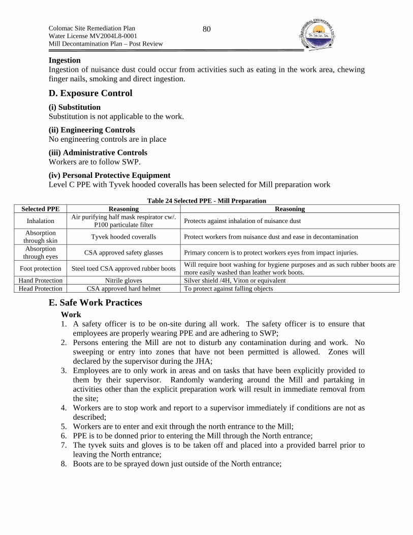
Colomac Site Remediation Plan Water License MV2004L8-0001 Mill Decontamination Plan – Post Review
80
Ingestion Ingestion of nuisance dust could occur from activities such as eating in the work area, chewing finger nails, smoking and direct ingestion.
D. Exposure Control (i) Substitution Substitution is not applicable to the work.
(ii) Engineering Controls No engineering controls are in place
(iii) Administrative Controls Workers are to follow SWP.
(iv) Personal Protective Equipment Level C PPE with Tyvek hooded coveralls has been selected for Mill preparation work
Table 24 Selected PPE - Mill Preparation
Selected PPE Reasoning Reasoning
Inhalation Air purifying half mask respirator cw/. P100 particulate filter Protects against inhalation of nuisance dust
Absorption through skin Tyvek hooded coveralls Protect workers from nuisance dust and ease in decontamination
Absorption through eyes CSA approved safety glasses Primary concern is to protect workers eyes from impact injuries.
Foot protection Steel toed CSA approved rubber boots Will require boot washing for hygiene purposes and as such rubber boots are more easily washed than leather work boots.
Hand Protection Nitrile gloves Silver shield /4H, Viton or equivalent Head Protection CSA approved hard helmet To protect against falling objects
E. Safe Work Practices Work 1. A safety officer is to be on-site during all work. The safety officer is to ensure that
employees are properly wearing PPE and are adhering to SWP; 2. Persons entering the Mill are not to disturb any contamination during and work. No
sweeping or entry into zones that have not been permitted is allowed. Zones will declared by the supervisor during the JHA;
3. Employees are to only work in areas and on tasks that have been explicitly provided to them by their supervisor. Randomly wandering around the Mill and partaking in activities other than the explicit preparation work will result in immediate removal from the site;
4. Workers are to stop work and report to a supervisor immediately if conditions are not as described;
5. Workers are to enter and exit through the north entrance to the Mill; 6. PPE is to be donned prior to entering the Mill through the North entrance; 7. The tyvek suits and gloves is to be taken off and placed into a provided barrel prior to
leaving the North entrance; 8. Boots are to be sprayed down just outside of the North entrance;

Colomac Site Remediation Plan Water License MV2004L8-0001 Mill Decontamination Plan – Post Review
81
9. Respirator are to be washed following work with soap and water in the bathroom facilities;
10. Staff are to shower following work immediately within the general shower facilities of the camp;
11. A Mill entry permit is to be obtained prior to any entry into the Mill for preparation work.
9.19 SWP – Heavy Equipment Operation Introduction The following document shall serve as a general safe work plan for heavy equipment operations. Only trained heavy equipment operators (HEO) shall operate heavy equipment at the Colomac site, and their performance shall be monitored by the site superintendent. The HEO shall be trained on the Heavy Equipment Operations SWP.
Training Upon employment by AEL as an HEO all HEO shall sign off on how many hours they have spent on the following pieces of equipment:
• Tandem truck; • Excavator; • Loader; • Dozer; • Grader;
Also, prior to doing any work with heavy equipment, the HEO will be required to view a number of equipment safety videos which shall be obtained from WCB. The site superintendent shall monitor the performance of the HEO, and record the number of hours that the HEO spends on each piece of equipment throughout the duration of the project. Should employees require training on heavy equipment, the senior HEO and/or site superintendent shall provide basic training. The HEO in training shall also be required to read the equipment operation and maintenance manual in its entirety. The site superintendent shall ensure that the trainee has read and understood the manual, and shall monitor the performance of the trainee during a conditional period of 2 weeks. Again, the site superintendent shall record the number of hours that the trainee spends on each piece of equipment, and as per the WCB Mine Health and Safety Act, a training log shall be provided to the trainee upon termination of his/her employment. AEL shall arrange for specialized training and certification on other pieces of equipment such as manlifts. All cranes must be operated by a certified crane operator.
Maintenance Prior to each shift, HEO shall perform an inspection of the equipment that they are to operate. Each HEO shall fill out an equipment log sheet. The log sheet shall be presented to and signed off by either the site superintendent or site mechanic prior to the equipment being operated during the shift.

Colomac Site Remediation Plan Water License MV2004L8-0001 Mill Decontamination Plan – Post Review
82
The log sheet shall include the following fields in which the HEO shall check off whether each item has been inspected:
Common • Engine oil level & leaks • Hydraulic oil level & leaks • Fuel system & leaks • Coolant level & leaks • Tires inflation & condition • V-Belt condition • Air cleaner, intake & exhaust system • Parking, service & emergency brake • Retarder • Wheel chocks • Air system, tank, air leaks & drain water • Steering & secondary system • Transmission oil level & operation • Light, electrical system & back up alarm • Cab gauges & instruments • Horn, glass & mirrors • Wipers & heater • Fire extinguisher & supp. System • Steps & railings • Wheel lugs & nuts • Radio communication operational • Suspension & main frame • Lubrication system • ROPS & Seat belt
Grader • Cutting Edge & Teeth • Blade linkage & cylinders • Circle drive & articulation
Dozer & Excavator • Cutting Edge & cylinders • Bucket, teeth & segment • Sprockets, idlers & rollers • Tracks adjustment • Under-carriage cover & guard
Tandem Truck • Dump body
Loader • Bucket, teeth & segment

Colomac Site Remediation Plan Water License MV2004L8-0001 Mill Decontamination Plan – Post Review
83
• Cylinders In addition to these inspection items, the equipment hours shall be recorded at start up and shut down. The HEO shall be responsible for performing regular maintenance, such as applying grease to grease nipples. Other deficiencies shall be the responsibility of the site mechanic.
Safe Work Practices • If a non-equipment operator is to enter an area in which equipment is being operated, the
person(s) shall communicate to the HEOs that they are entering the work area. • If inspecting excavations, persons on foot shall stay out of the reach of the excavator
boom, and gain eye contact with the operator prior to approaching the equipment. • All slopes shall be graded to ensure ground stability, as excavations shall be graded to a
1:1 slope. • All HEO must wear appropriate PPE including hearing protection.
9.20 SWP – Lock out & Tag Out Application Lock-out procedures are required to prevent injury to workers during repair, maintenance, or work on equipment. The equipment is locked out so that the equipment cannot be turned on or used by an unaware worker. The following is a list of equipment that will be locked-out and tagged-out:
(a) Piping The PVC piping will need to be cut and removed in 3’ sections or smaller. During this work, there exists the potential that the piping will become loose and fall from their original supports. Therefore, before a section of piping is cut, a worker will attach hangers, anchors, etc. to support the pipe. These supports will be locked-out such that the supports will not be removed until it is safe to do so. In addition, the pumps that feed the piping will be locked-out. This will prevent any flow of material threw the piping.
(c) Pumps, Mixers, and Gear Boxes Pumps, mixers, and gear boxes inside the mill need to be removed and dismantled to remove any hydrocarbons contained within them. The electrical system to these pieces of equipment will be locked out so that work can be performed. In addition, the piping and tubing connected to the pumps will be locked-out by manual valves to prevent the piping contents from spilling while work is being performed.
(d) HEPA Vacuum The HEPA vacuum will be locked-out during cleaning and maintenance.
(e) Electrical Junction Boxes The electrical junction boxes will be locked-out during any work in the mill. This will prevent the accidental energization of mill equipment while work is being performed. An ohm-meter will be used to check that no electrical current is flowing in the system.
(f) Lock-out Tag The following is a list of items to be included on the lock-out tag:
Colomac Site Remediation Plan Water License MV2004L8-0001 Mill Decontamination Plan – Post Review
84
• The name and company of the employee who will perform the work; • The date the lock is placed; • The time the lock is placed; • The equipment the lock is placed on; and • The type of work being done on the equipment.
Before any work is done, a worker will obtain a lock-out tag and fill it out. The first person to work on the equipment will check that the power source is turned off and install a personal lock with the lock-out tag. This is the only worker allowed to remove the lock and tag.
Safe Work Practice The following SWP apply to lock-out procedures:
Work 1. A supervisor will be on site during all work. The supervisor is to ensure that all workers
are wearing proper PPE and are adhering to the SWP; 2. Staff shall wear all PPE during any work in the manner as per training specific to the
work being performed; 3. The first person to work on the equipment will fill out a lock-out tag with their name,
date and time the lock is placed, the piece of equipment the work is being done on, and the type of work ding done.
4. The worker will check that the power source is off, and install a personal lock with the lock-out tag. The worker will then switch on the power to see if the equipment is actually de-energized.
5. If the equipment is still energized, the worker will check the power source again. If the equipment continues to be energized, an electrician/mechanic shall be called in to de-energize the equipment.
6. After the work is completed on the equipment and all personnel are clear of the danger area, the worker that locked-out the equipment will remove the lock. The lock-out tag can be removed once the lock is removed. The equipment can then be re-energized. Only the worker that placed the lock and lock-out tag may remove these items from the equipment.
Personal Protective Equipment 1. All workers will wear proper PPE related to the work they are performing.
Emergency Response 1. The medic must remain in radio contact with workers and the safety officer is to report to
the medic at regular intervals. The medic must have on hand, in working order and ready to use: a cyanide antidote kit, oxygen, a stretcher to remove unconscious persons, a NWT approved industrial first aid kit, emergency numbers and a working radio. The medic must be aware of medi vac procedures for remote sites and must be trained in cyanide specific first aid;
2. A cyanide antidote emergency response kit must be present in sufficient quantities and within immediate proximity to the work area (amyl nitrite, sodium nitrite and sodium thiosulfate);
3. A clear path to fresh air, outside the Mill, should be maintained at all times. The location of the path should be clearly communicated to staff;
Colomac Site Remediation Plan Water License MV2004L8-0001 Mill Decontamination Plan – Post Review
85
9.21 SWP – Hot Work Application Hot work permits are required for activities involving cutting torches and/or welders or any other work that produces heat energy sufficient to act as source of ignition.
Safe Work Practice The following SWP apply to hot work,
Work 1. A supervisor will be on site during all work. The supervisor is to ensure that all workers
are wearing proper PPE and are adhering to the SWP; 2. Staff shall wear all PPE during any work in the manner as per training specific to the
work being performed; 3. Hot work is only to be conducted in decontaminated areas; 4. Any contaminated surfaces must be decontaminated prior to conduction hot work (i.e.,
cyanide tanks washed with high pH and hypochlorite solution prior to cutting). 5. The floor shall be swept clean within 35 ft. of the hot work, prior to work; 6. Cracks or holes in the walls and/or floor are to be covered or plugged with an appropriate
material, prior to work; 7. Compressed gas cylinder and stored fuel are to be at a distance greater than 50ft from
work or are to be properly protected if permanent or difficult to move; 8. Flammable and combustive materials will be removed to a distance greater than 35 ft. ore
covered with flame resistant materials, prior to work; 9. Permanent structures adjacent to work, such as walls, floors or ceilings, will be checked
prior to work for the presence of combustible construction materials; 10. Walls, floor or ceiling containing combustible materials are to be properly protected if
they cannot be permanently or temporarily removed; 11. All hot work requires a hot work permit; 12. Permits are to be valid for the time period of work and are not to exceed 24 h in length; 13. Following work, hot work permits are to be provided to the supervisor and subsequently
stored on-site; 14. Hot work permits will be filed and displayed prior to any hot work; 15. A fire spotter will be present when hot work is undertaken; 16. Fire watch is to be undertaken for a period of 30 min following hot work; 17. Staff are to immediately report and address fires as per the fire contingency plan; 18. No hot work is to be conducted on elevated surfaces when other employees are working
in the area below; 19. Cutting and welding equipment is to be checked prior to use to ensure all items are in
good working condition and all consumables such as gases and welding rods are in sufficient supply;
20. Hot work is only to be conducted when absolutely necessary.
Personal Protective Equipment
Welding 1. Welding mask with P100 particulate filter and Nomex or equivalent coveralls
Cutting
Colomac Site Remediation Plan Water License MV2004L8-0001 Mill Decontamination Plan – Post Review
86
1. Welding goggles, half mask air supplied respirator cw/ P100 particulate cartridge and Nomex coveralls.
Emergency Response 1. The medic must remain in radio contact with workers and the safety officer is to report to
the medic at regular intervals. The medic must have on hand, in working order and ready to use: a cyanide antidote kit, oxygen, a stretcher to remove unconscious persons, a NWT approved industrial first aid kit, emergency numbers and a working radio. The medic must be aware of medi vac procedures for remote sites and must be trained in cyanide specific first aid;
2. A cyanide antidote emergency response kit must be present in sufficient quantities and within immediate proximity to the work area (amyl nitrite, sodium nitrite and sodium thiosulfate);
3. A clear path to fresh air, outside the Mill, should be maintained at all times. The location of the path should be clearly communicated to staff;
4. Appropriate fire suppression equipment is to be located adjacent to the hot work area. 5. The spotter and hot work employee are to be trained in appropriate fire response, prior to
work.
9.22 SWP – Drum Handling Work Plan The handling of drums will require the following work items to be completed:
(a) Inspection Before any drum is handled, the worker will visually inspect the drum. The worker will identify the following on the drum:
• Drum labels; • Chemical residue such as oil, crystals, etc. on the drum; • Bulging or swelling on the drum; • Cracks, rust, leaks, or holes on the drum; and • A properly sealed drum lid.
(b) Unlabeled Drums Drums that are unlabeled will be considered to contain hazardous materials. These drums must be handled with care until the contents are identified and the drum is labelled.
(c) Air Monitoring Vapours from drums are potentially explosive and dangerous to a worker’s health. Therefore, a worker will test and monitor the air around drums for O2, LEL, and toxic substances before the drum is handled. Workers handling the drums will wear personal air monitors that analyze the workers breathing zone.
(d) Moving Drums Drums located on skids will be moved using a forklift. The drums will be strapped together to reduce the chance of drums tipping over. The skid will be placed on a pickup truck and transported to the barrel laydown area. Once at the barrel laydown area, a forklift will remove the skid from the truck and place the skid at a predetermined location.

Colomac Site Remediation Plan Water License MV2004L8-0001 Mill Decontamination Plan – Post Review
87
Individual drums will be moved using a drum dolly. The worker will slowly tip the dolly to avoid back injury. The worker will then walk the drum and dolly to an empty skid where a forklift will place the skid on a pickup truck. The pickup truck will deliver the skid to the barrel laydown area. Once at the barrel laydown area, a forklift will remove the skid from the truck and place the skid at a predetermined location. For the transportation of the drums on the pickup truck, refer to the Transportation of Hazardous Goods Plan.
(e) Spill Containment Refer to spill plan.
(f) Storage The drums will be stored such that incompatible chemicals are not grouped together. Chemical incompatibilities are listed on the chemical’s MSDS. Drums will be staged such that drum labels are facing outwards. In addition, skids will be stored in rows. Rows will also be separated by a walkway large enough for a worker to access drums.
Safe Work Practice The following SWP apply to drum handling procedures:
Work 1. A supervisor will be on site during all work. The supervisor is to ensure that all workers
are wearing proper PPE and are adhering to the SWP; 2. Staff shall wear all PPE during any work in the manner as per training specific to the
work being performed; 3. The worker will inspect the drum for a label, leaks, cracks, bulges, chemical residue on
the drum, and a sealed bung; 4. If there is no label, the worker will assume the drum contains hazardous materials; 5. All work will be performed with a spill kit and a fire extinguisher ready; 6. A forklift will be used to move drums on a skid. The drums will be strapped together to
prevent spills; 7. A drum dolly will be used to move drums not on a skid. The worker will walk the drum
and dolly to an empty skid and place the drum on the skid. The barrels on the skid will be strapped together;
8. A forklift will place the skid onto a pickup truck for transport to the barrel laydown area; 9. Once at the barrel laydown area, a forklift will remove the skid from the truck and place
the skid at a predetermined area; 10. The skids will be stored such that incompatible chemicals are stored at separate locations.
In addition, the skids will be staged such that the barrel labels are facing outwards and workers are able to easily access the barrels.
Personal Protective Equipment 1. All workers will wear hardhats, steel toed boots, safety glasses, a half mask respirator
with HEPA and VOC filter, hi-viz vest, and nitrile gloves.
Emergency Response 1. A medic must be present during any drum handling;

Colomac Site Remediation Plan Water License MV2004L8-0001 Mill Decontamination Plan – Post Review
88
2. The medic must remain in radio contact with workers and the safety officer is to report to the medic at regular intervals. The medic must have on hand, in working order and ready to use: a NWT approved industrial first aid kit, emergency numbers, and a working radio;
3. A clear path to fresh air, outside the Mill, should be maintained at all times. The location of the path should be clearly communicated to staff;
4. A Self Contained Breathing Apparatus (SCBA) must be present within direct proximity to the work area and be in working condition;
5. A safety shower and eye wash facilities will be present in good working condition and directly adjacent to the work area for use in emergency rescue;
6. MSDS sheets will be positioned in a clear area, directly adjacent to the work, in a binder; 7. At no times is a CO2 based fire extinguisher to be used in lime and cyanide-containing
areas to suppress fires. CO2 can cause the pH to drop rapidly, thus releasing HCN gas.
9.23 SWP Transportation of Hazardous Goods From the Mill to the Tailings Containment Work Plan The transportation of hazardous goods will require the following work items to be completed:
(a) Vehicle Inspection All vehicles will be inspected at the beginning of each work shift to assure that the parts of the vehicle are in proper working condition. Parts to inspect include but are not limited to:
• Brakes; • Tires; • Steering wheel; • Horn; • Seat belt; • Lights/reflectors; • First air kit; • Fire extinguisher; • Back-up alarms; and • Windshield wipers;
All defects will be corrected before the vehicle is operated.
(b) Hazardous Material Identification All hazardous materials to be transported will be clearly labelled and identified prior to transportation. A copy of the chemical’s MSDS will be given to the driver. The driver will also be informed about the chemicals he will be transporting. Non-compatible materials will be transported separately.
(c) Handling Hazardous Goods All hazardous goods will be contained in 45 gallon drums. The drums will be strapped together on a skid to prevent the drums from tipping over. A forklift will place the skidded drums onto a pickup truck. Once on the truck, the drums will be tied down to the truck to prevent the drums from moving around during transport. The vehicle will never exceed the posted speed limit.

Colomac Site Remediation Plan Water License MV2004L8-0001 Mill Decontamination Plan – Post Review
89
(d) Spill Containment and Response Refer to Spill Contingency Plan
(e) Coordinating Road Access Hazardous waste will be stored in the exclusion zone until sufficient quantities have been stockpiled for transport. This practice will reduce the frequency and the total number of trips required to transport the hazardous wastes. Once a truck has been properly loaded the supervisor will contact both the Care and Maintenance Contractor and the Major Civil Works contractor to coordinate a time to use the road to transport the material. Only AEL is to use the road when transporting the hazardous materials. The driver is to conduct a radio check at the entrance next to truck lake, when entering the tailings compound and as required.
Safe Work Practices The following SWP apply to drum handling procedures:
Work 1. A supervisor will be on site during all work. The supervisor is to ensure that all workers
are wearing proper PPE and are adhering to the SWP; 2. Staff shall wear all PPE during any work in the manner as per training specific to the
work being performed; 3. The worker will inspect the drum for a label, leaks, cracks, bulges, chemical residue on
the drum, and a sealed bung; 4. The driver will be given a copy of the MSDS and informed on the type of chemicals
being transported; 5. All drums will be labelled to easily identify its contents; 6. If there is no label, the worker will assume the drum contains hazardous materials; 7. Incompatible chemicals will be transported separately; 8. All work will be performed with a spill kit and a fire extinguisher ready; 9. A forklift will be used to move drums on a skid. The drums will be strapped together to
prevent spills; 10. A forklift will place the skid onto a pickup truck for transport. Once on the pickup, the
drums will be secured to the pickup via a strap or bungee; 11. A forklift will remove the skid from the pickup truck.
Personal Protective Equipment 1. All workers will wear hardhats, steel toed boots, safety glasses, a half mask respirator
with HEPA and VOC filter, hi-viz vest, and nitrile gloves.
Emergency Response 1. A medic must be present during any drum handling; 2. The medic must remain in radio contact with workers and the safety officer is to report to
the medic at regular intervals. The medic must have on hand, in working order and ready to use: a NWT approved industrial first aid kit, emergency numbers, and a working radio;
3. A clear path to fresh air, outside the Mill, should be maintained at all times. The location of the path should be clearly communicated to staff;
4. A Self Contained Breathing Apparatus (SCBA) must be present within direct proximity to the work area and be in working condition;
Colomac Site Remediation Plan Water License MV2004L8-0001 Mill Decontamination Plan – Post Review
90
5. A safety shower and eye wash facilities will be present in good working condition and directly adjacent to the work area for use in emergency rescue;
6. MSDS will be positioned in a clear area, directly adjacent to the work, in a binder. A copy of the MSDS will also be given to the driver;
7. At no times is a CO2 based fire extinguisher to be used in lime and cyanide-containing areas to suppress fires. CO2 can cause the pH to drop rapidly, thus releasing HCN gas.
9.23 SWP – Handling Lead and Mercury Work Lead is present within batteries and mercury is present within florescent light tubes and switches. Both products will require removal and subsequent off-site disposal at a licensed hazardous waste facility.
PPE The products that contain both lead and mercury containerize the contaminants. As such direct exposure by any means is highly unlikely unless the product was damaged or is damaged during work. However, the batteries may splash acid if improperly handled. Batteries – Small Batteries that are Completely Containerized Such as Batteries for Electronics Refer to PPE for Mill Entrance for Preparation and Inspection;
Large Batteries that Have Openings PPE for small containerized batteries plus a acid resistant splash apron, acid resistant splash goggles and acid resistant gloves
Mercury in Switches and Light Tubes PPE Mill Entrance for Preparation and Inspection with the substitution of a mercury vapor cartridge coupled with a P100 particulate filter.
Safe Work Practices 1. A supervisor will be on site during all work. The supervisor is to ensure that all workers
are wearing proper PPE and are adhering to the SWP; 2. Staff shall wear all PPE during any work in the manner as per training specific to the
work being performed; 3. Staff are to place the mercury in a separate metal drum for other wastes; 4. Staff are to place the batteries on pallets or in a plastic drum, depending upon size; 5. Staff are not to break or physically alter the batteries/light fixtures and/or switches in any
manner, unless specifically instructed to do so by a supervisor; 6. Removal of lead and mercury is to take place following the removal of the cyanide, lime
and caustic circuits.
9.24 SWP Referenced in Aboriginal Engineering Ltd. Health, Safety & Environment Program The following safe work plans were referenced from the Aboriginal Engineering Ltd. Health, Safety & Environment Program. The individual Plans are appended.

Colomac Site Remediation Plan Water License MV2004L8-0001 Mill Decontamination Plan – Post Review
91
(a) Fall Restraint and Arrest;
(b) Ladders;
(c) Working with Hand Tools (non-powered); and
(d) Lifting
9.25 Respiratory Protection Program (a) Introduction Section 12.7 (1) of the CLC, Part II, states that: “Where there is a hazard of an airborne hazardous substance or an oxygen deficient atmosphere in a work place, the employer shall provide a respiratory protective device that is listed in the NIOSH Certified Equipment List published on February 13, 1998 by the National Institute for Occupational Safety and Health, as amended from time to time, and that protects against the hazardous substance or oxygen deficiency, as the case may be.”
Section 12.7 (2) refers to the CSA standard Z 94.4 Selection, Use and Care of Respirators for respirator selection. In addition, Section 12.7 (3) (a) refers to 5.5.2 to 5.5.11 of CSA Standard CAN3-Z180.1-M85, Compressed Breathing Air and Systems for standards applicable to supplied air. Respirator protection shall only be considered when administrative and engineering controls are unavailable or unfeasible. The following section outlines the management of respirator protection, including respirator selection, use and care. Mechanisms have been put in place to routinely review the effectiveness of the Respiratory Protection Program (RPP).
(b) Program Administrator The Health and Safety Officer, with assistance from the Chemical Engineer, will administer the RPP. In addition, the WPHSC will review and approve the respirator selections and will assist during inspections for compliance.
(c) Responsibilities
Project Manager The responsibilities of the project manager include:
1. ensuring that the necessary resources for training in the respiratory program are available;
2. ensuring that the necessary resources for implementing the respiratory plan are available;
3. ensuring that the project safety officer and the chemical engineer are meeting their responsibilities;
4. ensuring that revisions to the RPP are undertaken and implemented in a timely manner
Project Safety Officer The responsibilities of the safety officer include:
1. ensuring that all staff using respirators have been qualitatively fit test;

Colomac Site Remediation Plan Water License MV2004L8-0001 Mill Decontamination Plan – Post Review
92
2. ensuring that the results are stored on-site in a controlled manner; 3. ensuring that proper resources are available; 4. managing respiratory protection plan resources efficiently and as per SWP 5. if resources are scarce or expected to become scarce, request to the project manager
additional supplies required to meet needs; 6. conduct a monthly review, or as required, of the respirator program not including air
monitoring; 7. supply results of review to project manager, site superintendent, chemical engineer and
WPHSC; 8. revise, in co-operation, with the chemical engineer and the WPHSC, the RPP, when
required and based on results of inspections; 9. confirm regularly through daily informal inspections of all work sites that program
requirements are actively being implemented, such as proper respirator selection for the job, proper use of respirators, proper understanding of why the type of respirator is being used, proper maintenance and proper storage of respirators;
10. ensuring that respiratory training is up to date; 11. address any unsafe work practices related to the use of respirators immediately once
identified; 12. ensure that appropriate record keeping is undertaken – records include: results of
respirator fit testing, results of formal inspections and follow up actions (i.e., report) and any infractions that have occurred and the respective corrective actions;
13. report results of infractions to the project manager; and
Chemical Engineer The chemical engineer is responsible for
1. assisting the safety officer in the technical aspects of his/her responsibilities; 2. conducting an air monitoring review of the workers atmospheres to ensure that the
selected respirators are appropriate.
Medic
1. ensuring that medical surveillance forms are filled out prior to fit testing; 2. performing qualitative fit tests when required; 3. referring any person to a medial examination if the screening form indicates that wearing
a respirator may be harmful to his/her health; and 4. storing and managing medical results to ensure privacy laws are adhered to.
Employee – Respirator User
1. accurately filling out screening forms; 2. actively participating in training, including fit testing; 3. properly wearing respirators as per SWP at all times during work; 4. properly cleaning and maintaining respirators as per RPP; and 5. immediately reporting any problems or issues regarding respiratory protection to the
their respective supervisor.
(c) Medical Surveillance

Colomac Site Remediation Plan Water License MV2004L8-0001 Mill Decontamination Plan – Post Review
93
Prior to fit testing a medical surveillance form will be filled out by the respirator user. The medical surveillance form is intended to screen employees for any psychological or physiological conditions that may preclude him or her from being assigned the use of a selected respirator. If any conditions exist that are a cause for concern with respect to the ability of an employee to wear a respirator, then a medical exam by a physician will be required prior to any use of a respirator by an employee. Medical surveillance forms are confidential and will be maintained in a controlled manner to prevent access to information by anyone other than the medic who is responsible for reviewing the screening forms.
(d) Respirator Training All workers will be required to participate in the HAZWOPER training course which trains workers on the proper selection, fitting, inspection, and maintenance of respirator protection such as air purifying, SCBA, SAR, etc. This will include the fit testing of a half mask air-purifying respirator, the donning and use of SCBA and ASR. Additional fit testing, if required will be conducted on the employee by the Medic, prior to the use of the respirator by the employee.
(e) Selection The effectiveness of respirator protection depends on the type of respirator selected. The type of respirator selected depends on the hazards the workers will face. The hazardous conditions of the work environment will be investigated and monitored. Considerations such as the oxygen concentration, immediately dangerous to life and health (IDLH) conditions, and the hazardous substances threshold limit value (TLV) will determine the type of respirator used. Respirators specific to each job have been identified within the respective SWP.
(f) Fit Testing A respirator will only be effective if there is a proper seal between the face piece of the respirator and the worker’s face. A qualitative (i.e., bitrex or saccharin) fit test will first be performed to determine whether there is a proper seal. A quantitative test using saccharin or bitrex will be performed on each worker that wears a respirator. This test will be performed before any work is done. A positive and negative pressure test shall be done each time a respirator is donned and before each respirator is used in the field to test the seals. The positive pressure test checks for leaks at valves and other points on the respirator. The negative pressure test checks for leaks at the face piece to face seal.
(g) Inspection All workers will visually inspect their respirator before and after using it. The following lists key features that require examination:
(i) Air-Purifying Respirators
1. check the overall respirator for signs of damage; 2. for a full face-piece air purifying respirator ensure that the face shield is not damaged; 3. ensure that seal flange is not distorted; 4. ensure that the valve flaps for the inhalation and exhalation valves are intact and in the
proper position; 5. ensure that the straps are not damaged; and 6. ensure the filters are properly attached and are not at the end of their life.
Colomac Site Remediation Plan Water License MV2004L8-0001 Mill Decontamination Plan – Post Review
94
(ii) Supplied Air Respirators
1. check the face piece as per (i) (1-5) 2. check the hose for any damage and poor positioning (i.e., blocking access, trip hazard,
obstructions that could pinch hose etc.); 3. check the valves for damage; and 4. check the location of the compressor to ensure it is an approved location.
(iii) Self Contained Breathing Apparatus
1. check the condition of the face piece as per (i) (1-5); 2. the condition of the tanks. Any signs of external damage shall result in immediate
removal of the tank from use; 3. condition of the hose and valves; 4. level of gas remaining in the tanks;
(h) Maintenance The Contaminant Reduction Corridor (CRC) worker will clean the face piece of the respirator using a soap and water. Cleaning shall be undertaken during each and every decontamination of employees. For SCBAs and SARs, the face piece, hose, harness, and air tank will be rinsed with disinfectant soap and water. The respirators will be air dried. In order to avoid damage, the respirator will be stored in the manufacturers supplied packaging when not in use. Special care to the air tank valve will be taken so that no pressure is placed on the valve when moving and storing the tank.
All workers using a respirator shall be clean shaven of any facial hair that may impair a good face piece seal. In addition, workers with prescription eyeglasses will need contact lenses or a special eyeglass kit when using full face respirators because glasses will cause the face piece seals to leak. Supplied Air Respirators Any work involving cyanide will require a full face-piece continuous flow Supplied Air Respirator (SAR). A maximum of three SARs can be connected to one 1.5 HP ambient air pump, but this number will vary depending on the workers distance traveled away from the air pump and the required rate of oxygen delivery. A greater distance away from the air pump will require fewer SARs connected to the air pump. The maximum length of the hose is to be no more than 90m per SAR. Pressure shall not exceed 125 psi at the point where the hose attaches to the air supply. At the lowest pressure and longest length of hose, the device must not deliver under 115 LPM and at the highest pressure and shortest length of hose, the device must not supply greater than 425 LPM.(applicable only to sealed face piece SAR). The ambient air pumps will be placed in the uncontaminated atmospheres suitable for breathing. Ambient air must meet the criteria of Table 1 of CSA Standard CAN3-Z180.1-M85, Compressed Breathing Air and Systems. A certified lab will be used to analyze collected air samples from the intake location. The following Figure lists the allowable concentrations of components for compressed breathing air.

Colomac Site Remediation Plan Water License MV2004L8-0001 Mill Decontamination Plan – Post Review
95

Colomac Site Remediation Plan Water License MV2004L8-0001 Mill Decontamination Plan – Post Review
96
Figure 5 displays the procedures for cleaning a full face-piece air supplied respirator. Methods are similar for other face pieces. Any damaged and/or malfunctioning respirator or respirator attachments are to be immediately tagged out and/or destroyed. The Supervisor is to reissue the same type of respirator and/or respirator attachment as soon as possible.
(i) Decontamination All portions of respiratory equipment entering an exclusion zone will be properly decontaminated prior to leaving the hot zone into the support zone.
(j) Respirator Use
Half Mask/Full-Face Air Purifying Respirators The half mask/full-face air purifying respirators will be supplied with the correct cartridge. Air Purifying Respirators will not be used in areas with cyanide, concentrations that exceed protection factors, IDLH environments or oxygen deficient environments. The proper uses and limitations to this type of respirator will be communicated to all workers. Before the respirators are donned, the workers will inspect them for any rips or tares. The valves on the respirators will also be checked. After using the respirators, the CRC workers will wash down the face pieces and store the respirators in a sealable plastic bag. In addition, the ends of the respirator cartridges will be taped with Chem-Tape to eliminate the escape of dusts in the cartridges. The cartridges will be replaced as required (i.e., end of life indicator = organic vapor cartridge, difficulty breathing = particulate).
Supplied Air Respirators Any work involving cyanide will require a full face-piece continuous flow Supplied Air Respirator (SAR). A maximum of three SARs can be connected to one 1.5 HP ambient air pump, but this number will vary depending on the workers distance traveled away from the air pump and the required rate of oxygen delivery. A greater distance away from the air pump will require fewer SARs connected to the air pump. The maximum length of the hose is to be no more than 90m per SAR. Pressure shall not exceed 125 psi at the point where the hose attaches to the air supply. At the lowest pressure and longest length of hose, the device must not deliver under 115 LPM and at the highest pressure and shortest length of hose, the device must not supply greater than 425 LPM.(applicable only to sealed face piece SAR). The ambient air pumps will be placed in the uncontaminated atmospheres suitable for breathing. Ambient air must meet the criteria of Table 1 of CSA Standard CAN3-Z180.1-M85, Compressed Breathing Air and Systems. A certified lab will be used to analyze collected air samples from the intake location. The following Figure lists the allowable concentrations of components for compressed breathing air.

Colomac Site Remediation Plan Water License MV2004L8-0001 Mill Decontamination Plan – Post Review
97
Figure 5 Methods for Cleaning a Full Face-Piece Respirator Reference – North Safety Supplies

Colomac Site Remediation Plan Water License MV2004L8-0001 Mill Decontamination Plan – Post Review
98
Table 25 Allowable Concentrations of Components for Compressed Breating Air Results of air quality will be posted in a conspicuous location. The compressor will be a model suitable for use in supplying air to respirators. Areas found adequate will be secured and marked and access will be limited to persons operating the SAR. When selecting the air intake location consideration will be given to: wind direction, local ambient sources of pollution and distance from work. All workers in SARs shall perform their duties in the buddy system. The workers will monitor each others air supply hose such that there are no kinks in the hose, the hose is not caught on anything, and that the hose will not be cut by any sharp objects. In addition, workers in SARs will have undergone HAZWOPER training such that they are familiar with proper respirator use and maintenance. A system of communication such as radios and hand signals will also be used by the workers. To avoid heat stress and heat stroke, workers will work 30 minutes within a SAR and then take a break. The proper use and limitations to this respirator will be communicated to all workers.
Self Contained Breathing Apparatus
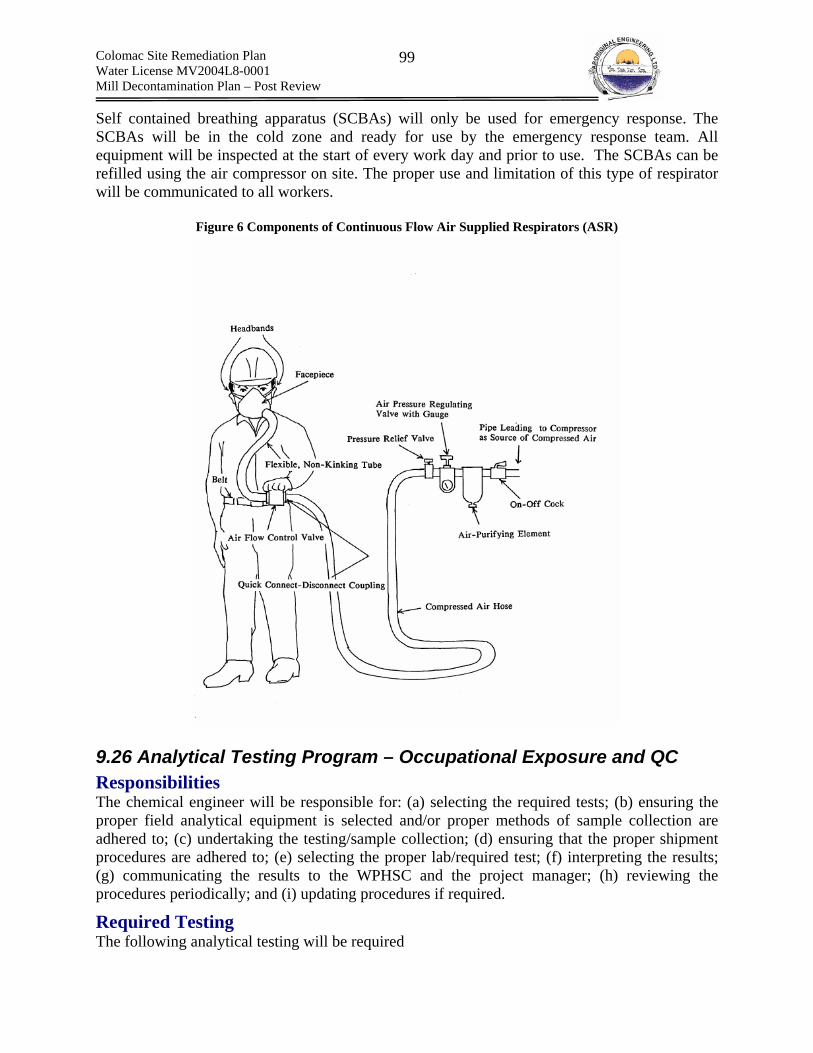
Colomac Site Remediation Plan Water License MV2004L8-0001 Mill Decontamination Plan – Post Review
99
Self contained breathing apparatus (SCBAs) will only be used for emergency response. The SCBAs will be in the cold zone and ready for use by the emergency response team. All equipment will be inspected at the start of every work day and prior to use. The SCBAs can be refilled using the air compressor on site. The proper use and limitation of this type of respirator will be communicated to all workers.
Figure 6 Components of Continuous Flow Air Supplied Respirators (ASR)
9.26 Analytical Testing Program – Occupational Exposure and QC Responsibilities The chemical engineer will be responsible for: (a) selecting the required tests; (b) ensuring the proper field analytical equipment is selected and/or proper methods of sample collection are adhered to; (c) undertaking the testing/sample collection; (d) ensuring that the proper shipment procedures are adhered to; (e) selecting the proper lab/required test; (f) interpreting the results; (g) communicating the results to the WPHSC and the project manager; (h) reviewing the procedures periodically; and (i) updating procedures if required.
Required Testing The following analytical testing will be required

Colomac Site Remediation Plan Water License MV2004L8-0001 Mill Decontamination Plan – Post Review
100
Air Quality Monitoring; Swipe Testing; Testing of Materials; Water Quality Testing; and Noise Testing.
(a) Air Quality Monitoring Requirements Air quality monitoring will consist of the following activities:
1. verifying that atmospheric conditions within the workers breathing zone are within the concentrations anticipated for use in selecting PPE (Note: very conservative assumptions were used as direct reading was not possible);
2. verifying that ambient air quality in the surrounding environment is not being affected by the Mill decontamination process;
3. monitoring the levels of dust created by any tailings removal activities; 4. monitoring potentially hazardous environments; (a) periodically prior to entry into
confined spaces; (b) continuously while in a confined space; and (c) continuously while working with cyanide; and
5. ensuring that supplied air meets the requirements set out in Table 1 of CSA Standard CAN3-Z180.1-M85, Compressed Breathing Air and Systems.
1.) Breathing Zone Monitoring
Application The breathing zone of workers will be monitoring during work with cyanide and lime. For cyanide both real time continuous monitoring of cyanide gas and periodic monitoring of cyanide dust within the breathing zone is required. For lime only periodic monitoring of particulate lime in the breathing zone is required.
Purpose Real time monitoring of HCN(g) is required as the suits that have been selected are not pressure tested type A suits. As such, trace amounts of HCN(g) could enter the suits if exposed to high HCN(g) concentrations. As such, workers are required to leave the work area when concentrations of HCN(g) are at or above the ACGIH TLC – C of 4.7 ppm HCN(g). Air monitoring of dust concentrations for cyanide and lime are to ensure that work practices designed to reduce the creation of airborne dust are effective (i.e., local exhaust ventilation during collection of dust and using HEPA vacuums).
Equipment
(i) Cyanide – HCN(g)
Battery operated personal alarm system capable of sounding an alarm at the TLV – C of 4.7 ppm HCN(g). The alarm is to be single constituent in nature as to avoid confusion in application. An alarm is required for each person working directly with cyanide

Colomac Site Remediation Plan Water License MV2004L8-0001 Mill Decontamination Plan – Post Review
101
(ii) Cyanide –NaCN (dust)
Battery operated air pump cw/ air line and clips onto workers belt Particulate filter cassette
(iii) Lime – CaOH (dust)/CaCO3(dust)/CaO(dust)
Battery operated air pump cw/ air line and clips onto workers belt Particulate filter cassette
Procedures Testing and operation of equipment will be undertaken as per manufactures recommendations. The filter cartridge (i.e., air intake) is to be placed within the workers breathing zone). At no times is a worker to tamper with the air monitor or falsely spike the sample by placing the air intake at any other location that that positioned by the chemical engineer. Any malfunction/disturbance of the sampling equipment is to be reported to the engineer immediately. The sampling is to occur over the entire length of one shift. Workers are to conduct their work as they would if no sampling were occurring, as to avoid false readings due to differing work practices. standard sampling practices required to prevent sample contamination are to be adhered to.
2.) Ambient Air Sampling and Dust Monitoring
Application The ambient air will be sampled within the main camp facility, the cold zone within the Mill and the shop area.
Purpose Ambient air sampling will ascertain if the atmosphere outside of the hot zone for cyanide has become contaminated due to work practices. In addition, ambient air testing will occur
Equipment
Battery operated air pump cw/ air line and clips onto workers belt Particulate filter cassette
Procedures Testing and operation of equipment will be undertaken as per manufactures recommendations. The location of air testing. The exact location of the air sampling equipment will be determined and documented in the field. At no times is a worker to tamper with the air monitor or falsely spike the sample by placing the air intake at any other location that that positioned by the chemical engineer. Any malfunction/disturbance of the sampling equipment is to be reported to the engineer immediately. The sampling is to occur over the entire length of one shift. Workers are to conduct their work as they would if no sampling were occurring, as to avoid false readings due to differing work practices. standard sampling practices required to prevent sample contamination are to be adhered to.

Colomac Site Remediation Plan Water License MV2004L8-0001 Mill Decontamination Plan – Post Review
102
3.) Dangerous Atmospheres
Application The monitoring of dangerous atmospheres prior to and during entry into confined spaces such as the leach tanks is required. HCN(g) concentration, HCN(g) LEL and O2 concentration will have to be monitored prior to and during entry into the leach tanks
Purpose To ensure that the atmosphere within a confined space is safe to enter prior to and during work.
Equipment
1. Personal real time O2 sensor capable of sounding an alarm when O2 concentrations fall outside of the range between 19.5% to 23.0%. For use inside confined space;
2. Battery operated personal alarm system capable of sounding an alarm at the TLV – C of 4.7 ppm HCN(g).
3. Battery operated personal alarm system capable of sounding an alarm at the TLV – C of 4.7 ppm HCN(g).
4. General air quality monitor that senses all three of the above in one unit. For use in assessing the atmosphere prior to entry into a confined space.
Procedures Testing and operation of equipment will be undertaken as per manufactures recommendations. The filter cartridge (i.e., air intake) is to be placed within the workers breathing zone). At no times is a worker to tamper with the air monitor or falsely spike the sample by placing the air intake at any other location that that positioned by the chemical engineer. Any malfunction/disturbance of the sampling equipment is to be reported to the engineer immediately. The sampling is to occur over the entire length of one shift. Workers are to conduct their work as they would if no sampling were occurring, as to avoid false readings due to differing work practices. standard sampling practices required to prevent sample contamination are to be adhered to.
4.) Supplied Compressed Air
Application Ambient sources of supplied air must be tested prior to being supplied to workers.
Purpose To ensure that the supplied air is suitable for breathing and therefore use in supplied air respirators.
Equipment
1. Cylinders for sampling will be supplied by the analytical laboratory.
Procedures Sampling procedures supplied by the analytical laboratory will be adhered to.
Colomac Site Remediation Plan Water License MV2004L8-0001 Mill Decontamination Plan – Post Review
103
(b) Swipe Testing Requirements Swipe testing will be required to:
1. verify that surfaces within eating areas, living areas, equipment and supplies, the surface of packaged waste and the cold zone have not become contaminated and thus decontamination procedures are working effectively;
Purpose To determine is decontamination procedures are functioning as expected and thus cyanide contamination of areas outside the hot zone is not occurring.
Equipment Swipes
Procedures Surface areas will be swiped and the swipe will be stored as per lab instructions. The exact locations of the surfaces to be swiped will be selected and documented in the field and will be based upon observed behavior patterns of the employees. standard sampling practices required to prevent sample contamination are to be adhered to.
(c) Testing of Materials – Destructive Testing Requirements Testing of materials will be required to:
1. verify by testing random cut pieces of the exterior surface of PPE to ensure that decontamination practices are effectively removing contaminants from the surface of PPE that is being decontaminated and re-used. This will verify that contaminants are not permeating into the PPE and not being removed during decontamination.
Purpose To verify that the decontamination of non-disposable PPE is effective.
Equipment
No special analytical field equipment is required. The sample will be cut and shipped ot the lab.
Procedures No special field procedures are required. However, standard sampling practices required to prevent sample contamination are to be adhered to.
(d) Water Quality Testing Requirements Water quality testing will be required to:
1. test levels of cyanide remaining in collected wash water; 2. test the pH of wash water; 3. test the wash water resulting from steam cleaning for Oil and Grease; and 4. testing the rinse water from the decontamination station
Colomac Site Remediation Plan Water License MV2004L8-0001 Mill Decontamination Plan – Post Review
104
Equipment
1. DREL 2800 complete water quality lab cw/ cyanide reagent test kit (Pyridine-Pyrazolone method)
2. HACH HQ40d Dual-Input Multi-Parameter Digital Meter cw/ Combination pH IntelliCAL Probe
Procedure Refer to manufactures procedures for use.
Standard Sampling Plans Standard Sampling Plans (SSP) will be developed for each of the above testing requirements. SSP will be based on manufactures recommendations and will address the following:
1. proper sample collection methods to avoid contaminating samples – both method and sample container;
2. quality Control/Quality Assurance 3. calibration; 4. equipment Standard Operating Procedures; 5. methods of sample preservation; 6. methods of sample shipping; 7. interferences; 8. sample identification; 9. chain of custody; 10. accuracy & precision.
Reporting Analytical test results will be clearly posted for all employees to view. In addition, hard copies of results will be stored on site.
9.28 Decontamination Plan Decontamination is very important. All the extensive efforts to protect emergency responders or HAZMAT workers from exposures to hazardous materials are wasted if decontamination is not effective.
A. Definition OSHA 1910.120(a)(3) defines decontamination as follows: Decontamination means the removal of hazardous substances from employees and their equipment to the extent necessary to preclude the occurrence of foreseeable adverse health effects.
B. Purpose The importance of a decontamination plan cannot be understated. Failure to properly plan and/or execute a decontamination plan can lead to contamination of living, eating and recreational areas and thus exposure of unprotected workers to various contaminants involved in the decontamination. All items entering the work zone or exclusion zone shall be properly decontaminated. No HAZMAT work shall commence until the decontamination zone has been constructed and decontamination personnel are prepared.
Colomac Site Remediation Plan Water License MV2004L8-0001 Mill Decontamination Plan – Post Review
105
C. Contamination Reduction Corridor Decontamination takes place through a decontamination line, within the Contamination Reduction Corridor (CRC). The decontamination line is an organized series of procedures performed in a specific sequence to reduce levels of contamination on personnel, PPE, equipment and additional items such as the exterior of waste bags. Each procedure is preformed at a separate station within a Contamination Reduction Corridor (CRC) The stations are arranged linearly in order of decreasing contamination (i.e., the items with the highest potential for contamination are decontaminated first such as boot covers and exterior gloves). The CRC consists of a hotline, hot and warm zone a cold zone and a support zone. The exclusion zone is located adjacent to the hot zone. The CRC is located within the larger Contamination Reduction Zone (CRZ), the margin surrounding the hazard in which contamination decreases from the interior to the exterior, eventually reaching acceptable levels. The CRZ can be though of as a buffer surrounding the entire exclusion zone (location of hazard). The CRC consists of a defined section which spans the CRZ, through which workers enter and exit from the exclusion zone, in a controlled manner, while being decontaminated. The CRC is to be located in an area that is sufficiently far from the work within the exclusion zone, so as to reduce the risk of exposing CRC workers. HAZMAT PPE that has been issued for use is to remain within the CRC at all times unless it has been properly packaged for off-site disposal or properly decontaminated and approved by the chemical engineer for removal from the CRC. The CRC must facilitate:
1. Personnel and equipment decontamination (e.g., separate lines for workers and heavy equipment such as tractors, earth-moving equipment, and trucks);
2. Emergency response functions (including transport of injured personnel, first-aid equipment, and containment equipment);
3. Equipment re-supply; 4. Sample packaging and preparation for onsite or offsite laboratories; 5. Location of worker temporary rest areas; 6. Drainage of water and other liquids used in the decontamination process; 7. Waste minimization; and 8. Reduction or elimination of mixed waste production.
(a) Exclusion Zone The exclusion zone is the area were the decontamination work occurs and thus the hazard is present. The size and configuration of the exclusion zone is determined by the nature of the work, the physical and chemical hazards associated with the contaminant, environmental conditions such as wind and general topography, work practices aimed at containing contaminants, the structural configuration of the work area and the location of access and egress points. Full PPE is required within the exclusion zone, as specified by safe work practices. The limits of the exclusion zone is to be clearly marked and access into and from is to be strictly controlled through warnings or physical barricades. Once inside the exclusion zone (i.e., crossed the hotline), independent of time, all workers will require decontamination prior to returning to the cold zone and/or outside area.
(b) Hotline The hotline separates the hot zone within the CRC and the exclusion or work zone. Once crossed (hot to exclusion) all persons will require decontamination through the CRC. The hotline defines the perimeter of the exclusion zone.

Colomac Site Remediation Plan Water License MV2004L8-0001 Mill Decontamination Plan – Post Review
106
(c) Hot Zone and Warm Zone The hot zone and warm zone are the areas in which decontamination within the CRC occurs. Within the hot zone exterior, more heavily contaminated clothing is decontaminated and removed. In the warm zone, less heavily contaminated clothing is decontaminated and removed. Contamination decreases as one moves from the hot zone to the warm zone. Hot zone workers require a greater level of protection from hazards than do the warm zone workers.
(d) Cold Zone The cold zone is free of contamination. Within this area the worker is freed from interior gloves and face pieces and is medically assisted if required.
(e) Contamination Control Line Defines the boundary between the CRZ and the support zone.
(f) Support Zone The support zone is an area free of contamination in which no HAZMAT PPE is required (general work PPE is required). The support zone houses administrative and support staff and equipment necessary to maintain effective operation of the exclusion zone and the CRC.
(g) Access and Exit Points Access and entry points are a key component of the CRC. Access and exit points specifically and clearly locate where workers and to enter into and exit from the exclusion zone. The pre defined entrance and exit points are to be the only locations where entry and exit from the exclusion zone is to take place. Entry from alternate locations is strictly forbidden and will result in immediate removal from the site. In addition, to specifying access and exit points, the flow of personnel through the CRC must also be preplanned and carefully executed. Failure to do so could result in confusion within the CRC due to a congested work place and/or the exposure of employees who enter or exit the exclusion zone improperly. Separate access and exit points are to be created for personnel and heavy equipment.
(h) Worker Rest Area Worker rest zones are located in predetermined areas of the exclusion zone and are constructed to allow a HAZMAT worker to take intermittent breaks while remaining in full PPE. Figure 7 Contamination Reduction Zone and Contamination Reduction Corridor – Source: Handbook for Occupational Health and Safety During Hazardous Waste Activities

Colomac Site Remediation Plan Water License MV2004L8-0001 Mill Decontamination Plan – Post Review
107
Figure 8 and Figure 8, present examples of the relative location of the CRZ and CRC and the detailed layout of a CRC, respectively.

Colomac Site Remediation Plan Water License MV2004L8-0001 Mill Decontamination Plan – Post Review
108
Figure 7 Contamination Reduction Zone and Contamination Reduction Corridor – Source: Handbook for Occupational Health and Safety During Hazardous Waste Activities
Figure 8 Example of a Contamination Reduction Corridor
Colomac Site Remediation Plan Water License MV2004L8-0001 Mill Decontamination Plan – Post Review
109
C. Work Practices – Preventing Contamination A proper decontamination plan considers the reduction of direct exposure to chemicals, prior to decontamination, as well as the removal of chemicals from PPE, equipment etc. during decontamination. Safe Work Practices have been designed to remove the worker from direct contaminant exposure, to the extent practical. For example, (a) HEPA vacuums will be used to collect dust, rather than sweeping, which presents a high risk of exposure due to the generation of air born particulate matter; and the exterior of piping will be wrapped in polyethylene plastic prior to cutting, to contain any air borne particulate. In addition, workers are to avoid such activities as walking directly through contaminated plumes or any other activity that directly brings himself/herself into contact with concentrated hazardous materials in any phase. Furthermore, if possible, equipment such as analytical equipment will be placed in temporary bags, from which the sensing portion will protrude. This practice will avoid costly and time consuming decontamination of analytical equipment, which can also be damaging to delicate sensors. If possible, workers are not to directly touch contaminants and are to properly use tools that are provided, which allow remote handling. For work with cyanide, disposable boot coverings will be used to allow ease of boot decontamination.
D. Positions and Responsibilities The following positions are required to operate the CRC
(a) HEPA Vacuum Operator (Hot Zone)– removes particulate matter adhered to the exterior of PPE (suit, gloves, boot);
(b) Washer (Warm Zone)– initially washes the exterior of PPE to flush contaminants contained in pockets and irregularities in the PPE; Inspects PPE for rips, tears, wearing or other deformities prior to application of wash water; and decontaminates waste bags, tools etc, left in the drop area.
(c) Rinser (Warm Zone) – rinses the exterior of PPE, equipment and waste bags, following washing. Assists worker in doffing chemical protective clothing.
(d) Medic (Support Zone)– during cyanide removal is stationed in the support zone and is ready to respond to any cyanide related emergencies. All other times, located within close proximity to CRC as to allow immediate response to Medical Emergencies. The medic is responsible for ensuring medical supplies are stock in sufficient quantity and working order.
(e) Chemical Engineer – responsible for ensuring that decontamination procedures are effective through analytical monitoring and supervision of the process from the support zone.\
(f) Support Zone Supervisor (Site Superintendent) – responsible for co-coordinating the Mill/crusher building and Leach tank work, ensuring resources are made available when required, communication with other personnel at the site such as Major Civil Works contractor and Care and Maintenance contractor, leading emergency response.
E. Entering/Exiting the Exclusion Zone Personnel All personnel, equipment and supplies must enter/exit into and from the exclusion zone through the CRC. The warm zone is then entered from the cold zone, next the hot zone is entered from
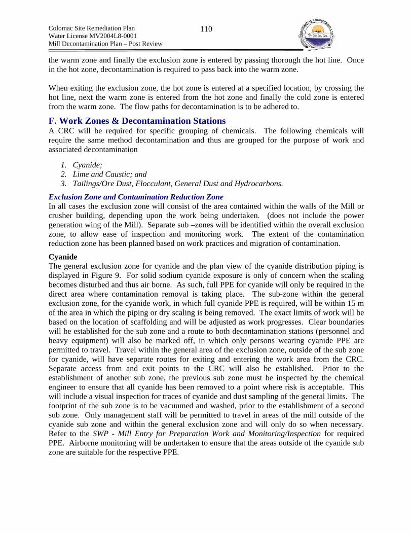
Colomac Site Remediation Plan Water License MV2004L8-0001 Mill Decontamination Plan – Post Review
110
the warm zone and finally the exclusion zone is entered by passing thorough the hot line. Once in the hot zone, decontamination is required to pass back into the warm zone. When exiting the exclusion zone, the hot zone is entered at a specified location, by crossing the hot line, next the warm zone is entered from the hot zone and finally the cold zone is entered from the warm zone. The flow paths for decontamination is to be adhered to.
F. Work Zones & Decontamination Stations A CRC will be required for specific grouping of chemicals. The following chemicals will require the same method decontamination and thus are grouped for the purpose of work and associated decontamination
1. Cyanide; 2. Lime and Caustic; and 3. Tailings/Ore Dust, Flocculant, General Dust and Hydrocarbons.
Exclusion Zone and Contamination Reduction Zone In all cases the exclusion zone will consist of the area contained within the walls of the Mill or crusher building, depending upon the work being undertaken. (does not include the power generation wing of the Mill). Separate sub –zones will be identified within the overall exclusion zone, to allow ease of inspection and monitoring work. The extent of the contamination reduction zone has been planned based on work practices and migration of contamination.
Cyanide The general exclusion zone for cyanide and the plan view of the cyanide distribution piping is displayed in Figure 9. For solid sodium cyanide exposure is only of concern when the scaling becomes disturbed and thus air borne. As such, full PPE for cyanide will only be required in the direct area where contamination removal is taking place. The sub-zone within the general exclusion zone, for the cyanide work, in which full cyanide PPE is required, will be within 15 m of the area in which the piping or dry scaling is being removed. The exact limits of work will be based on the location of scaffolding and will be adjusted as work progresses. Clear boundaries will be established for the sub zone and a route to both decontamination stations (personnel and heavy equipment) will also be marked off, in which only persons wearing cyanide PPE are permitted to travel. Travel within the general area of the exclusion zone, outside of the sub zone for cyanide, will have separate routes for exiting and entering the work area from the CRC. Separate access from and exit points to the CRC will also be established. Prior to the establishment of another sub zone, the previous sub zone must be inspected by the chemical engineer to ensure that all cyanide has been removed to a point where risk is acceptable. This will include a visual inspection for traces of cyanide and dust sampling of the general limits. The footprint of the sub zone is to be vacuumed and washed, prior to the establishment of a second sub zone. Only management staff will be permitted to travel in areas of the mill outside of the cyanide sub zone and within the general exclusion zone and will only do so when necessary. Refer to the SWP - Mill Entry for Preparation Work and Monitoring/Inspection for required PPE. Airborne monitoring will be undertaken to ensure that the areas outside of the cyanide sub zone are suitable for the respective PPE.

Colomac Site Remediation Plan Water License MV2004L8-0001 Mill Decontamination Plan – Post Review
111
Lime and Caustic The general exclusion zone for cyanide and the plan view of the cyanide distribution piping is displayed in Figure 10. Similar methods, as discussed for the cyanide circuit, will be used to establish sub zones where work is occurring. However the required CRZ will only be 10 m. This is due to the lower toxicity and similarity of the lime/caustic PPE to that of Mill entry for inspection PPE.
Tailings/Ore Dust, Flocculant, General Dust and Hydrocarbons No specific sub zones will be required for work with respect to tailings/ore dust, flocculant, general dust and hydrocarbons. However, the worker is to stay within the general area in which he/she is working and is not to travel into other general areas of work. Work will be assigned by group and groups are to stay together in the same work area until re-assigned to another work area.

Colomac Site Remediation Plan Water License MV2004L8-0001 Mill Decontamination Plan – Post Review
112
Figure 9 Exclusion Zone and CRC for Cyanide Decontamination
Storage Tank
Mixing Tank
3” To the Vibratory Screens on Level 3
1” To the Vibratory Screens on Level 3
3” PVC from
3” PVC cyanide loop
(distribution
3” PVC distribution to the first three
T f r line
Air actuated flow
Manually
1 5” carbon
Walkway
1” Plastic line to
Area of Direct Exposure to
Hot Zone Warm Zone
Cold Zone
Hot Line
Personnel CRC
Heavy Equipment and waste CRC
Example of Sub-Zone Requiring Full Cyanide PPE (15 buffer surrounding piping
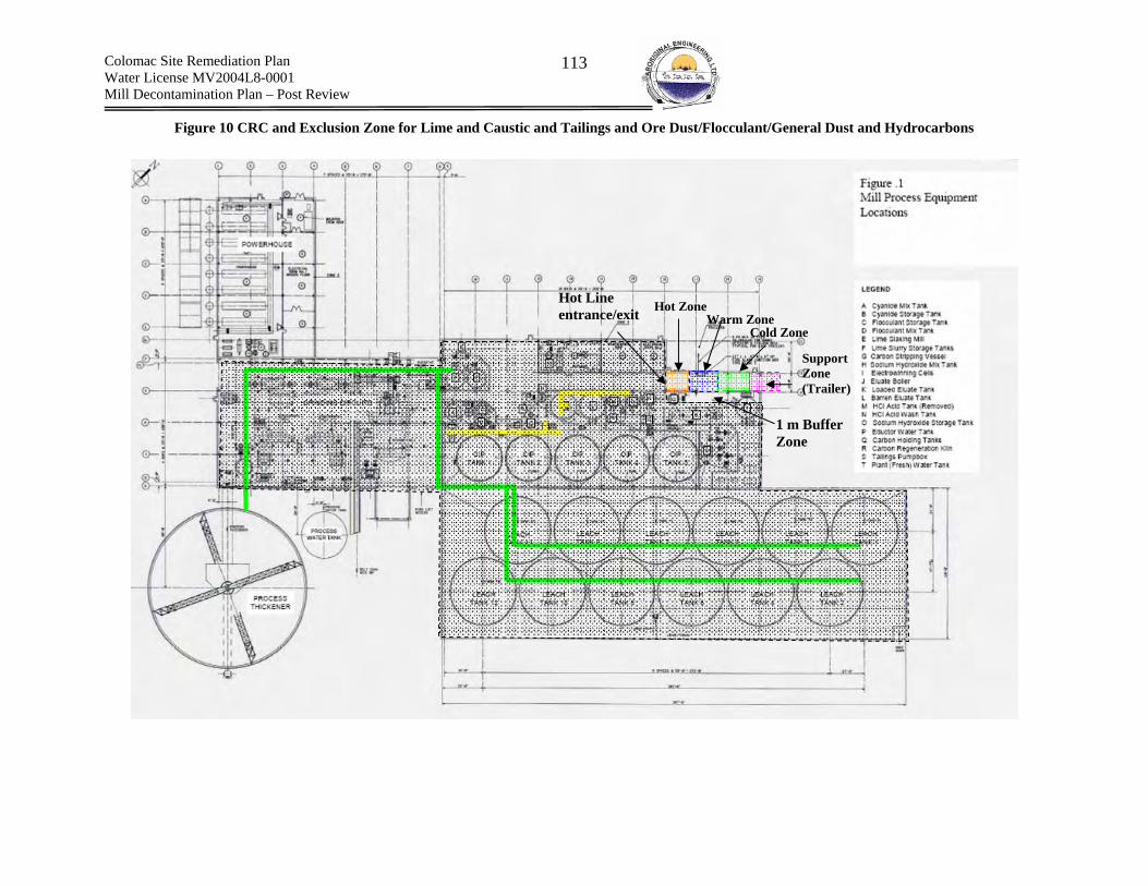
Colomac Site Remediation Plan Water License MV2004L8-0001 Mill Decontamination Plan – Post Review
113
Figure 10 CRC and Exclusion Zone for Lime and Caustic and Tailings and Ore Dust/Flocculant/General Dust and Hydrocarbons
1 m Buffer Zone
Hot Line entrance/exit Hot Zone
Warm Zone Cold Zone
Support Zone (Trailer)

Colomac Site Remediation Plan Water License MV2004L8-0001 Mill Decontamination Plan – Post Review
114
Decontamination Method
(a) Cyanide
Hotzone The HAZMAT worker will enter the hot zone from the exclusion zone at the specified locatoin. In the hot zone, the following activities will be completed:
Sub – zone #1: any waste that is not to be directly removed from the Mill will be dropped for temporary storage (i.e., contaminated HEPA filters.
Sub – zone #2: equipment will be dropped and bagging around analytical equipment will be removed and disposed of. Analytical equipment probes will be removed and placed in a storage box.
Sub – zone #3: suit, exterior gloves and boots covers will be vacuumed using a HEPA vacuum to remove as much dust as possible from the exterior, prior to washing.
Sub – zone #4: gloves and boot coverings will be washed and any tape will be removed.
Sub – zone #5: boot covers will then be removed;
Sub – zone #6: exterior gloves will be removed;
Warm Zone Workers will enter the warm zone from a fixed point in the hot zone/warm zone boundary.
Sub – zone #1: Suit and interior rubber boot washed with soap and water;
Sub – zone #2: Suit and interior boot will be rinsed using clean water;
Sub – zone #3: safety boots will be removed
Sub – zone #4: fully encapsulating suit is to be removed along with the hard hat
Sub – zone #5: inner glove wash with soap and water;
Sub – zone #6: inner glove rinse with clean water;
Cold Zone Sub – zone #1: face piece removal;
Sub – zone #2: inner glove removal;
Sub – zone #3: inner clothing removal (occurs in receiving end of decontamination trailer)
Support Zone
Sub – zone #1: shower;
Sub – zone #2: redress;
(b) Lime and Caustic Hotzone The HAZMAT worker will enter the hot zone from the exclusion zone. In the hot zone, the following activities will be completed:
Colomac Site Remediation Plan Water License MV2004L8-0001 Mill Decontamination Plan – Post Review
115
Sub – zone #1: any waste that is not to be directly removed from the Mill will be dropped for temporary storage (i.e., contaminated HEPA filters).
Sub – zone #2: equipment will be dropped and bagging around analytical equipment will be removed and disposed of. Analytical equipment probes will be removed and placed in a storage box.
Sub – zone #3: suit will be vacuumed using a HEPA vacuum to remove as much dust as possible from the exterior, prior to washing.
Warm Zone Workers will enter the warm zone from a fixed point in the hot zone/warm zone boundary.
Sub – zone #1: Suit and rubber boots and gloves washed with soap and water;
Sub – zone #2: Suit and rubber boots and gloves will be rinsed using clean water;
Sub – zone #3: safety boots will be removed;
Sub – zone #4: suit is to be removed along with the hard hat.
Cold Zone Sub – zone #4: face piece removal;
Sub – zone #6: glove removal;
Sub – zone #7: inner clothing removal (occurs in receiving end of decontamination trailer)
Support Zone Sub – zone #8 shower;
Sub – zone #9: redress;
(c) Tailings and Ore Dust, Flocculant and General Dust and Hydrocarbons Hotzone The HAZMAT worker will enter the hot zone from the exclusion zone. In the hot zone, the following activities will be completed:
Sub – zone #1: any waste that is not to be directly removed from the Mill will be dropped for temporary storage (i.e., contaminated HEPA filters).
Sub – zone #2: equipment will be dropped and bagging around analytical equipment will be removed and disposed of. Analytical equipment probes will be removed and placed in a storage box.
Warm Zone Workers will enter the warm zone from a fixed point in the hot zone/warm zone boundary.
Sub – zone #1: Suit and rubber boots and gloves washed with soap and water;
Sub – zone #2: Suit and rubber boots and gloves will be rinsed using clean water;
Sub – zone #3: safety boots will be removed;
Sub – zone #4: suit is to be removed along with the hard hat.

Colomac Site Remediation Plan Water License MV2004L8-0001 Mill Decontamination Plan – Post Review
116
Cold Zone Sub – zone #1: face piece removal;
Sub – zone #2: glove removal;
Sub – zone #3: inner clothing removal (occurs in receiving end of decontamination trailer)
Support Zone Sub – zone #1: shower;
Sub – zone #2: redress;
(d) Decontamination of CRC workers The vacuum operator is to be decontaminated by the same method as the HAZMAT worker. The rinser will then wash and rinse the washer. Next the washer will decontaminate the rinser.
H. Decontamination Equipment (a) Cyanide
Hotzone
Sub – zone #1: 45 gallon drum containing a large polypropylene bag for storing bagged waste such as
HEPA vacuum filters – only 1 bag is to be placed at a time to allow ease of management of decontamination of waste collection bag and accumulation of waste.
Sub – zone #2: ca. 12’ x 12’ sheet of 12 mm polyethylene sheet; a 45 gallon drum containing a large polypropylene bag for collecting the wrapping of
any decontamination equipment; a box for collecting probes from analytical equipment.
Sub – zone #3: HEPA Vacuum.
Sub – zone #4: decontamination shower station; bucket for soapy water for use by decontamination worker; waste water collection basin cw/ plumbing; soap source; clean water line supplied from source in clean zone or plant water tank adjacent to the
CRC;
Sub – zone #5: 45 gallon drum containing a large polypropylene bag for storing washed boot covers
Sub – zone #6: 45 gallon drum containing a large polypropylene bag for storing washed exterior gloves

Colomac Site Remediation Plan Water License MV2004L8-0001 Mill Decontamination Plan – Post Review
117
Warm Zone
Sub – zone #1:
Soft bristled brush cw/ telescopic handle;
wash basin for collecting wash water
wash water storage container for temporary storage prior to disposal;
bucket for mixing and use of soap/water;
source of soap;
source of clean water imported from support zone
Sub – zone #2: spray gun;
wash basin for collecting rinse water;
rinse storage container for temporary storage prior to disposal;
source of clean water imported from support zone.
Sub – zone #3: storage bin for boots
Sub – zone #4: a seat for assisting the removal of suits; tarp for placing suits on.
Sub – zone #5: basin for washing gloves; source of clean water; source of soap; collection tank to store temporary wash water
Sub – zone #7: basin for rinsing gloves; source of clean water; collection tank to store temporary rinse water
Cold Zone
Sub – zone #1: box to store face piece; area to clean face piece with basin and clean water and soap provided along with
method of collecting wash and rinse water
Sub – zone #2: bag for disposing of inner gloves
Sub – zone #3: inner clothing removal (occurs in receiving end of decontamination trailer) personal locker for storing inner work clothes

Colomac Site Remediation Plan Water License MV2004L8-0001 Mill Decontamination Plan – Post Review
118
Support Zone Sub – zone #1: shower;
personal showering area; soap and shampoo; and towels.
Sub – zone #2: redress; personal lockers for storing outside clothes
(b) Lime and Caustic Hotzone
Sub – zone #1: 45 gallon drum containing a large polypropylene bag for storing bagged waste such as
HEPA vacuum filters – only 1 bag is to be placed at a time to allow ease of management of decontamination of waste collection bag and accumulation of waste.
Sub – zone #2: ca. 12’ x 12’ sheet of 12 mm polyethylene sheet; a 45 gallon drum containing a large polypropylene bag for collecting the wrapping of
any decontamination equipment; a box for collecting probes from analytical equipment.
Sub – zone #3 HEPA Vacuum.
Warm Zone Workers will enter the warm zone from a fixed point in the hot zone/warm zone boundary.
Sub – zone #1: Soft bristled brush cw/ telescopic handle;
wash basin for collecting wash water
wash water storage container for temporary storage prior to disposal;
bucket for mixing and use of soap/water;
source of soap;
source of clean water imported from support zone
Sub – zone #2: spray gun;
wash basin for collecting rinse water;
rinse storage container for temporary storage prior to disposal;
source of clean water imported from support zone.
Colomac Site Remediation Plan Water License MV2004L8-0001 Mill Decontamination Plan – Post Review
119
Sub – zone #3: container for storing boots
Sub – zone #4: seat for assisting in removing suits
Cold Zone
Sub – zone #1: box to store face piece; area to clean face piece with basin and clean water and soap provided along with
method of collecting wash and rinse water
Sub – zone #2: bag for disposing of inner gloves
Sub – zone #3: inner clothing removal (occurs in receiving end of decontamination trailer) personal locker for storing inner work clothes
Support Zone Sub – zone #1: shower;
personal showering area; soap and shampoo; and towels.
Sub – zone #2: redress; personal lockers for storing outside clothes
(b) Tailings and Ore Dust, Flocculant and General Dust and Hydrocarbons Hotzone
Sub – zone #1: 45 gallon drum containing a large polypropylene bag for storing bagged waste such as
HEPA vacuum filters – only 1 bag is to be placed at a time to allow ease of management of decontamination of waste collection bag and accumulation of waste.
Sub – zone #2: ca. 12’ x 12’ sheet of 12 mm polyethylene sheet; a 45 gallon drum containing a large polypropylene bag for collecting the wrapping of
any decontamination equipment; a box for collecting probes from analytical equipment.
Warm Zone Workers will enter the warm zone from a fixed point in the hot zone/warm zone boundary.
Sub – zone #1:
Soft bristled brush cw/ telescopic handle;
wash basin for collecting wash water
wash water storage container for temporary storage prior to disposal;
bucket for mixing and use of soap/water;
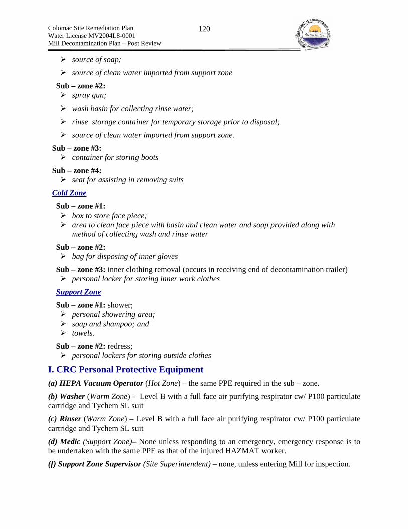
Colomac Site Remediation Plan Water License MV2004L8-0001 Mill Decontamination Plan – Post Review
120
source of soap;
source of clean water imported from support zone
Sub – zone #2: spray gun;
wash basin for collecting rinse water;
rinse storage container for temporary storage prior to disposal;
source of clean water imported from support zone.
Sub – zone #3: container for storing boots
Sub – zone #4: seat for assisting in removing suits
Cold Zone
Sub – zone #1: box to store face piece; area to clean face piece with basin and clean water and soap provided along with
method of collecting wash and rinse water
Sub – zone #2: bag for disposing of inner gloves
Sub – zone #3: inner clothing removal (occurs in receiving end of decontamination trailer) personal locker for storing inner work clothes
Support Zone Sub – zone #1: shower;
personal showering area; soap and shampoo; and towels.
Sub – zone #2: redress; personal lockers for storing outside clothes
I. CRC Personal Protective Equipment (a) HEPA Vacuum Operator (Hot Zone) – the same PPE required in the sub – zone.
(b) Washer (Warm Zone) - Level B with a full face air purifying respirator cw/ P100 particulate cartridge and Tychem SL suit
(c) Rinser (Warm Zone) – Level B with a full face air purifying respirator cw/ P100 particulate cartridge and Tychem SL suit
(d) Medic (Support Zone)– None unless responding to an emergency, emergency response is to be undertaken with the same PPE as that of the injured HAZMAT worker.
(f) Support Zone Supervisor (Site Superintendent) – none, unless entering Mill for inspection.

Colomac Site Remediation Plan Water License MV2004L8-0001 Mill Decontamination Plan – Post Review
121
Disposing of Waste Water and Disposable PPE Waste water will be collected, pumped to a temporary storage tank (same as the tank for storing general wash water). The contents of the temporary storage tank will be deposited into the tailings lake.
J. Emergency Decontamination A portable wash unit that can rinse down a critically injured HAZMAT worker will be made available. The Emergency responder is to rinse the injured worker thoroughly and then remove PPE and then administer first aid. The worker is to be removed from the sub zone within the exclusion zone, if possible to safely do. When responding to an Emergency with cyanide, the emergency responder is to wear a SCBA.
Compatibility of Wash Solution with Chemical Hazards The only concern with respect to non-compatibility between washing/rinsing decontamination solution and the chemicals contaminants being removed is with respect to the formation of HCN(g) when cyanide is exposed to low pH water. The majority of cyanide will be removed by vacuuming and as such a water only solution will be sufficient for washing/rinsing cyanide workers. The first washing/rinsing will be done in the hot zone with persons in full cyanide PPE, and will be monitoring with a gas detector. This will be undertaken prior to full use of the water for washing and rinsing of cyanide workers in the warm zone.
Disposal and Laundering The Tychem suits will be decontaminated and reused, until visible wear and tear makes them unsuitable for use. The safety officer is to inspect the suits on a regular basis. Since cyanide is the only chemical for which absorption by skin eye contact is an issue, the suits will be monitored on a daily basis when conduction cyanide related decontamination. In addition, since cyanide is to be removed first. The suits will be in their best condition during this time period. Suits deemed not appropriate for use will be immediately removed from circulation following decontamination, placed into a barrel and shipped to Yellowknife for disposal in the solid waste land fill. Laundering of clothes under PPE will be done in the general washing facilities.
Hygiene Workers are to practice proper hygiene when working with Hazardous wastes. Proper hygiene includes:
1. No smoking until fully decontaminated; 2. No eating until fully decontaminated; 3. Do not put hand in mouth and/or chew finger nails; 4. Workers must shower in the portable showering facilities, prior to entering the support
zone/general facilities; 5. Workers are not to use the bathroom facilities in the portable trailer, unless fully
decontaminated; 6. Workers are to fully decontaminated prior to: lunch breaks and the end of working with a
hazardous waste; 7. PPE is not to be transferred between employees, unless instructed to do so by the
chemical engineer.
K. Tracking PPE
Colomac Site Remediation Plan Water License MV2004L8-0001 Mill Decontamination Plan – Post Review
122
All PPE is to be tracked by an ID number specific to the employee. This will ensure that the length of use is known, that cross contamination does not occur between employees, and that hygiene practices are adhered to. The following variables will be tracked:
1. An ID number specific to the employee; 2. The date that the PPE was issued to the employee; 3. The job that the PPE is required for; 4. The date that the job specific to the PPE was completed; and 5. Methods of daily and post job decontamination.
ID #s are to be placed on PPE as to not affect its performance. PPE must be tracked per job and between jobs. For each new job duty, PPE must be reassessed and re-issued, even if the same PPE is required for both job duties.

Colomac Site Remediation Plan Water License MV2004L8-0001 Mill Decontamination Plan – Post Review
123
10.0 Contingency Plans
10.1 Emergency Response Plan Introduction An Emergency Response Plan (ERP) is to be developed and implemented for the mill decontamination work to be done at the Colomac Mine Site by Aboriginal Engineering Ltd. (AEL). AEL shall adhere to the Tli Cho Logistics (TCL) Site Specific Health and Safety Plan, however the ERP is specific to activities in and around the mill facility.
Emergency Response Team The entire crew shall be trained on the Emergency Response Plan (ERP). However, the Emergency Response Team (ERT) shall consist of supervisors, and other personnel to assume responsibilities to coordinate evacuations, and conduct emergency response procedures. Key members of the ERT shall be:
Site Superintendent Site Engineer Lead Hand Field Medic
The ERT key members shall be responsible for taking control of emergency situations and ensuring that the crews adhere to and follow the ERP.
Emergencies Emergencies can be grouped into the following categories:
1. Natural Events 2. Physical hazards and accidents 3. Chemical hazards and accidents 4. Confined Spaces 5. Emergency Decontamination
Natural events include extreme weather conditions, which may include floods, storms, heavy snow fall, and extreme winds. If these conditions are deemed to pose a risk to the work being done inside the mill facility, an evacuation will be deemed necessary. Physical hazards and accidents could include unstable structures, damage to structural support beams of the mill facility, partial or total collapse of structures, etc. Emergency of such nature may require partial or full evacuation, and may require equipment to be used. Chemical hazards and accidents include the accidental release of hazardous chemicals either found in the mill, or used during decontamination activities. The highest risk is that of cyanide, which is present in the mill. Other chemical hazards may include accidents involving acids and bases, as well as oxidants such as sodium hypochlorite. The entire crew will be trained on the
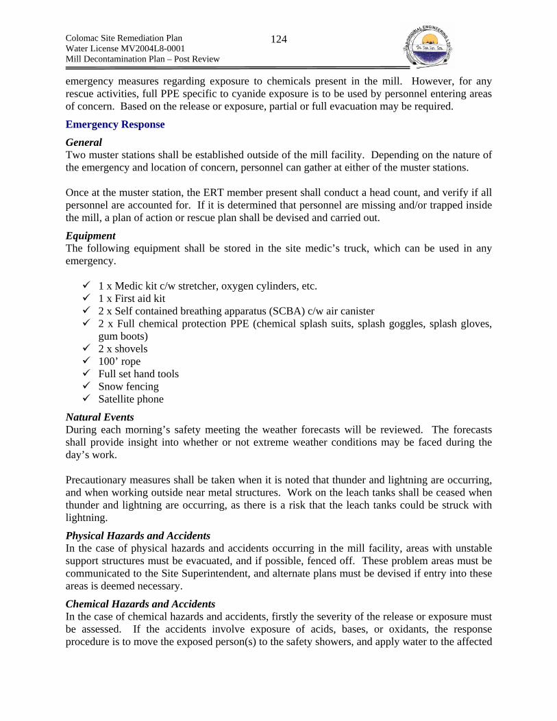
Colomac Site Remediation Plan Water License MV2004L8-0001 Mill Decontamination Plan – Post Review
124
emergency measures regarding exposure to chemicals present in the mill. However, for any rescue activities, full PPE specific to cyanide exposure is to be used by personnel entering areas of concern. Based on the release or exposure, partial or full evacuation may be required.
Emergency Response
General Two muster stations shall be established outside of the mill facility. Depending on the nature of the emergency and location of concern, personnel can gather at either of the muster stations. Once at the muster station, the ERT member present shall conduct a head count, and verify if all personnel are accounted for. If it is determined that personnel are missing and/or trapped inside the mill, a plan of action or rescue plan shall be devised and carried out.
Equipment The following equipment shall be stored in the site medic’s truck, which can be used in any emergency.
1 x Medic kit c/w stretcher, oxygen cylinders, etc. 1 x First aid kit 2 x Self contained breathing apparatus (SCBA) c/w air canister 2 x Full chemical protection PPE (chemical splash suits, splash goggles, splash gloves,
gum boots) 2 x shovels 100’ rope Full set hand tools Snow fencing Satellite phone
Natural Events During each morning’s safety meeting the weather forecasts will be reviewed. The forecasts shall provide insight into whether or not extreme weather conditions may be faced during the day’s work. Precautionary measures shall be taken when it is noted that thunder and lightning are occurring, and when working outside near metal structures. Work on the leach tanks shall be ceased when thunder and lightning are occurring, as there is a risk that the leach tanks could be struck with lightning.
Physical Hazards and Accidents In the case of physical hazards and accidents occurring in the mill facility, areas with unstable support structures must be evacuated, and if possible, fenced off. These problem areas must be communicated to the Site Superintendent, and alternate plans must be devised if entry into these areas is deemed necessary.
Chemical Hazards and Accidents In the case of chemical hazards and accidents, firstly the severity of the release or exposure must be assessed. If the accidents involve exposure of acids, bases, or oxidants, the response procedure is to move the exposed person(s) to the safety showers, and apply water to the affected
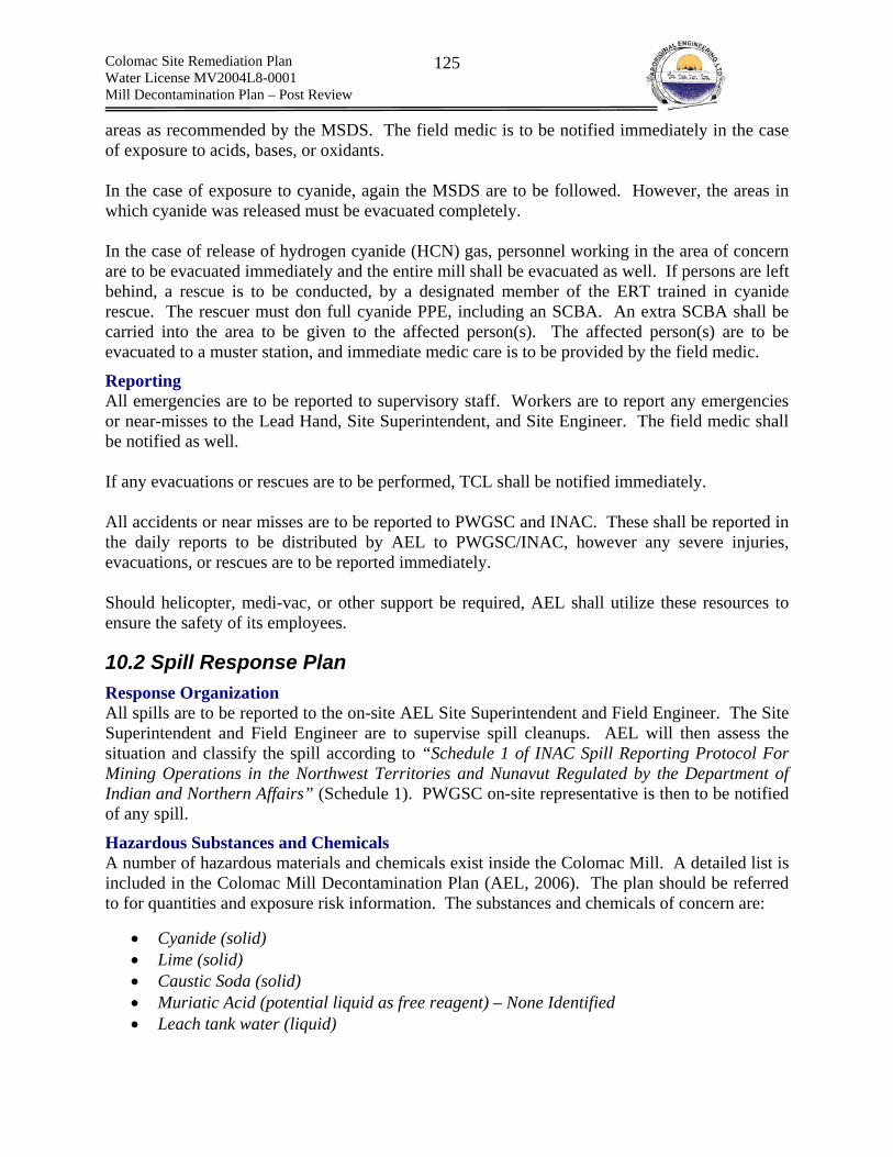
Colomac Site Remediation Plan Water License MV2004L8-0001 Mill Decontamination Plan – Post Review
125
areas as recommended by the MSDS. The field medic is to be notified immediately in the case of exposure to acids, bases, or oxidants. In the case of exposure to cyanide, again the MSDS are to be followed. However, the areas in which cyanide was released must be evacuated completely. In the case of release of hydrogen cyanide (HCN) gas, personnel working in the area of concern are to be evacuated immediately and the entire mill shall be evacuated as well. If persons are left behind, a rescue is to be conducted, by a designated member of the ERT trained in cyanide rescue. The rescuer must don full cyanide PPE, including an SCBA. An extra SCBA shall be carried into the area to be given to the affected person(s). The affected person(s) are to be evacuated to a muster station, and immediate medic care is to be provided by the field medic.
Reporting All emergencies are to be reported to supervisory staff. Workers are to report any emergencies or near-misses to the Lead Hand, Site Superintendent, and Site Engineer. The field medic shall be notified as well. If any evacuations or rescues are to be performed, TCL shall be notified immediately. All accidents or near misses are to be reported to PWGSC and INAC. These shall be reported in the daily reports to be distributed by AEL to PWGSC/INAC, however any severe injuries, evacuations, or rescues are to be reported immediately. Should helicopter, medi-vac, or other support be required, AEL shall utilize these resources to ensure the safety of its employees.
10.2 Spill Response Plan Response Organization All spills are to be reported to the on-site AEL Site Superintendent and Field Engineer. The Site Superintendent and Field Engineer are to supervise spill cleanups. AEL will then assess the situation and classify the spill according to “Schedule 1 of INAC Spill Reporting Protocol For Mining Operations in the Northwest Territories and Nunavut Regulated by the Department of Indian and Northern Affairs” (Schedule 1). PWGSC on-site representative is then to be notified of any spill.
Hazardous Substances and Chemicals A number of hazardous materials and chemicals exist inside the Colomac Mill. A detailed list is included in the Colomac Mill Decontamination Plan (AEL, 2006). The plan should be referred to for quantities and exposure risk information. The substances and chemicals of concern are:
• Cyanide (solid) • Lime (solid) • Caustic Soda (solid) • Muriatic Acid (potential liquid as free reagent) – None Identified • Leach tank water (liquid)
Colomac Site Remediation Plan Water License MV2004L8-0001 Mill Decontamination Plan – Post Review
126
• Leach tank tailings (solid/slurry) • Mill tailings (solid) • Hydrocarbon oils and greases (liquid)
From the above list, the chemical hazards are obvious, except for the leach tank water, which contains residual cyanide. During the decontamination work, the following potentially hazardous substances may be created:
• Wash water (liquid) o Containing residual cyanide o Containing residual lime o Containing residual caustic o Containing residual acid o Water From oil/water separator
Mobile Equipment and Other Point Sources The following is an itemized list of mobile equipment that may be utilized for work pertaining to the Colomac Mill Decontamination.
• 2 ATV’s; • 2 diesel pickup trucks; • 1 gasoline pickup truck; • 1 Kenworth tandem truck; • 1 Kenworth tandem truck c/w 3000 gal. insulated water tank; • 1 Sterling plow truck; • 1 Freightliner tandem truck; • 1 CAT 966 loader; • 1 CAT 416 backhoe/loader • 1 Hitachi 270 Excavator • 1 Genie Z60 manlift • 1 Ingersoll-Rand light plant
Spill related to the above listed mobile equipment can be directly attributed to their state of repair. Poorly maintained equipment or equipment nearing their applicable lifespan may be prone to leaking of engine, transmission oil etc. A mechanic has been contracted to repair mobile equipment.
Spill Prevention Spill prevention is applicable to all material transfer procedure, during the decontamination of the mill and its process equipment. Work done inside of the mill will be done within containment berms, and cleanup equipment will be present such as industrial vacuums, pumps, etc. However, a large quantity of work will involve transferring substances and chemical products from the mill to designated disposal areas. Transfer operations will include a) transfer of wash water via water truck; b) pumping of liquids; c) trucking of solids; and d) removal of oils and greases. Standard Operating Procedures (SOP)
Colomac Site Remediation Plan Water License MV2004L8-0001 Mill Decontamination Plan – Post Review
127
will be developed to mitigate spills during the material transfer operations. Below are mitigative measures to be taken.
(a) Transfer of wash water via water truck A water truck will be used to transfer wash water from the mill to a designated disposal area. The mitigative procedures apply to transfer of all wash water, which may contain residual cyanide, lime, caustic, muriatic acid, or water from the oil/water separator. The following general mitigative methods will be used to prevent spills from the water truck:
Filling tank • Water truck operator to ensure outlet valve(s) on water truck tank are closed prior to
transferring water into the tank; • Radio communication maintained between water truck operator and pump operators
during filling of water truck tank; • Water truck operator to monitor the water level in the water tank during filling; • Water truck operator to instruct pump operator to stop pumps when water level is 2’ from
top of water tank; • Water truck operator to record height of liquid in tank after each filling operation, and
report daily data to Site Superintendent; • Water truck operator to disconnect hoses and close all openings and valve(s); • Hoses to remain inside mill to allow for drainage of residual liquid;
Emptying tank • Water truck operator to maintain radio communication with Site Superintendent during
travel time to disposal area; • Water truck to be maintained at safe speeds outlined in the Site Specific Health and
Safety Plan; • Water truck operator to park water truck, and apply wheel chocks at disposal area; • Water truck operator and assistant to set up hoses, extending hoses to disposal area; • Water truck operator to open outlet valve(s) and start pump, and empty tank; • Once emptied, water truck operator to close all valves and disconnect hoses. • Hoses are to be left at disposal area to allow for complete drainage of residual liquid.
(b) Pumping of liquids Some disposal methods may entail pumping liquids over long distances from the mill to an approved disposal location. The following mitigative measures will be taken to prevent spills during pumping operations:
• Site Superintendent and Mechanic to inspect all hoses/piping on the inlet and outlet of each pump, and sign off on the integrity of the hoses/piping after each setup of the pump(s);
• Site Superintendent and Mechanic to inspect connections to the pump, as well as pump seals, and sign off on the integrity of the pump;
• Outlet of hoses/piping to be placed at approved disposal location, and location to be verified and signed off prior to pumping;
• When pump is started, AEL to inspect entire length of line for leaks, and ensure that flow is directed to approved disposal area;
Colomac Site Remediation Plan Water License MV2004L8-0001 Mill Decontamination Plan – Post Review
128
o If any leaks detected, pumps are to be stopped immediately and Site Superintendent and Field Engineer are to be notified immediately
• After pumping operations have been completed, hoses/piping are to be drained into source, or designated disposal area, prior to disassembling hoses/piping.
(c) Trucking of solids Solid materials will also be removed from the mill site. These include a) mill tailings; b) leach tank tailings; and c) cyanide, lime, caustic, and acid free product. The tailings (a and b) will follow the mitigative measures outlined below:
• All tailings are to be sufficiently dewatered using sumps and sump pumps to minimize pore water volumes;
• Tailings to be loaded into tandem truck boxes using a loading device (excavator, loader, or backhoe/loader);
• Bucket on loading device to be washed clean, with wash water collected in a sump; • Tandem truck boxes to have tailgates attached at all times when hauling tailings.
Cyanide, lime, caustic, and acid free product will be transported after being double-bagged and taped shut. When placed in the disposal area, these materials are to be placed with minimal void space in between bags to reduce the footprint of the waste.
(d) Removal of oils and greases A large quantity of oils and greases will be removed from the mill. Oils shall be transferred into empty 45 gallon drums, with the drums sealed and transported to the waste oil incinerator, or laydown area for off-site disposal. A spill kit will be on hand at all times during transfer operations, and spill pads will be used to handle oil-stained equipment. The filled 45 gallon drums will be transported to the waste oil incinerator or off-site disposal laydown using pickup trucks, and all barrels will be strapped to the pickups to prevent them from moving or sliding off the truck box.
Spill Response The first person at the scene of the spill is to make all necessary efforts to protect human and environmental health. However this person is not to take actions that will endanger his or her safety. Actions include the following:
• evacuate persons from the area if the spill is to be considered a direct risk to workers safety;
• inform the immediate work area supervisor; • make an initial assessment of the spill and of the magnitude of the related hazards; and • take initial containment actions such as:
o minimize or control hazards to worker safety; o cover of fill drains and drainage paths; o construct or place berms; and o deploy booms and/or sorbents.

Colomac Site Remediation Plan Water License MV2004L8-0001 Mill Decontamination Plan – Post Review
129
(a) Cyanide Spills Any spills of cyanide-containing materials shall be addressed as serious incidents, as they pose a risk to the health and safety of nearby worker(s). If cyanide material is spilled en route during a transfer operation, crew is to notify the Site Superintendent and evacuate the area. The Superintendent and Field Engineer must then estimate the quantity of spilled material, and coordinate a cleanup plan. As per the Accidental Release Measures section of the MSDS for cyanide, the area must be ventilated – if the spill occurs outdoors, no additional ventilation is required; if indoors, forced air via a fan must be applied. Personnel must wear full PPE protection including chemical splash goggles, gum boots, chemical splash suits, and full face respirators. The material (if solid) shall be gathered and double-bagged for disposal. If a liquid spill occurs, spill absorbent shall be spread, and a backhoe can be used to excavate overburden or gravel that has been contaminated by the spill. In order to properly respond to potential spills when handling cyanide material, workers will be equipped with the following items when transporting and/or handling cyanide material:
• Chemical splash suit; • Gum boots; • Chemical-resistant gloves; • Splash goggles; • Full face air-supplied respirator; • Shovel; • Absorbent; and • Cyanide poisoning kit
All workers will be trained on the use of the cyanide antidote kit.
(b) Tailings Spills Spill of solid tailings can be easily removed by use of a backhoe and/or shovel. Basic PPE includes use of half mask respirator. If tailings slurries are spilled, overburden or gravel must be over-excavated to remove all contaminated material. Material shall be placed in a tandem truck box, and trucked to designated disposal area.
(c) Acid and Base Spills Any spills regarding acids and bases will require the same PPE: chemical splash suit, gloves, gum boots, splash goggles, and half mask respirator. Solid material may be shoveled and/or excavated for removal. Liquid material may be cleaned up using absorbent, and then over-excavating the affected area.
(d) Hydrocarbon Spills Contaminated soils will be excavated. If free product is present, the material will be collected, placed in a sealed drum and stored at the on-site hazardous waste storage facility. Larger spills will also be excavated immediately or placed in drums, sealed and then stored within the offsite
Colomac Site Remediation Plan Water License MV2004L8-0001 Mill Decontamination Plan – Post Review
130
disposal laydown; booms or berms will be placed as needed. Spill clean containers (spill kit CSK-F45 225 L spill station)12 are available for responding to petroleum based spills. Each spill kit consists of the following items:
• 5 sorbent socks (3”X4”) • 50 sorbent pads (17”X19”); • 3 sorbent booms (5”X120”); • 1 drain cover (36”X36”); • 5 disposal bags (24”X36”); • 1 spleenkleen adsorbent (25lb bag); • 2 Tyvek suits; • 1 pair of goggles; • 2 pair of nitrile gloves; and • 1 shovel.
Spill Reporting Procedure Any reportable spill13 (Schedule 1) will be immediately reported to the NWT/Nunavut 24 hour emergency spill hotline at the following number: 1 (867) 920 8130. Field Engineer, and PWGSC representatives will be notified immediately. All other spills will be logged internally and available for review by inspectors upon request.
12 spillklean website www.spilkleen.com 13 A reportable spill is defined as a release of substance that poses and imminent environmental or human health hazard or meets or exceeds the volumes in schedule 1 (INAC Spill Reporting Protocol For Mining Operations in the Northwest Territories and Nunavut Regulated by the Department of Indian and Northern Affairs)

Colomac Site Remediation Plan Water License MV2004L8-0001 Mill Decontamination Plan – Post Review
131
Schedule 1 Reportable Spills

Colomac Site Remediation Plan Water License MV2004L8-0001 Mill Decontamination Plan – Post Review
132
List of Emergency Response Numbers NWT/Nunavut 24h Emergency Spill Line 1 867 920 8130 Yellowknife fire department 1 867 873 2222 Poison Control 1 867 669 4100 Bob Johnson 1 867 444 1445 Aboriginal Engineering Ltd Office 1 867 669 9481 Air Tindi 1 867 669 8200 Medical Emergency (Hospital) 1 867 669 4111 RCMP 1 867 669 1111 Northern Steel Envirotank 1 888 NSI TANK Spillkleen 1 877 455 3336 Northgate (propane) 1 780 448 9222
10.3 Fire Response Plan Introduction The following is the fire safety plan for the proposed decontamination work to be done on the Colomac mill. The plan outlines equipment and procedures to be utilized in the event of a fire during the decontamination work. Personnel are to be trained on fire safety procedures.
Equipment The following equipment shall be available on-site for working with flammable substances, or for responding to fires.
• ABC fire extinguishers • Nomex ® flame resistant coveralls • 1’’ fire pumps + hose • Water tanks and/or reservoirs • Dust masks and carbon cartridge filters • Face shields • First aid kit • Medic kit c/w oxygen for oxygen therapy
Fire Extinguishers The work crew shall be properly trained on the use of fire extinguishers. The following table will be posted inside the camp, and other pertinent areas for reference.
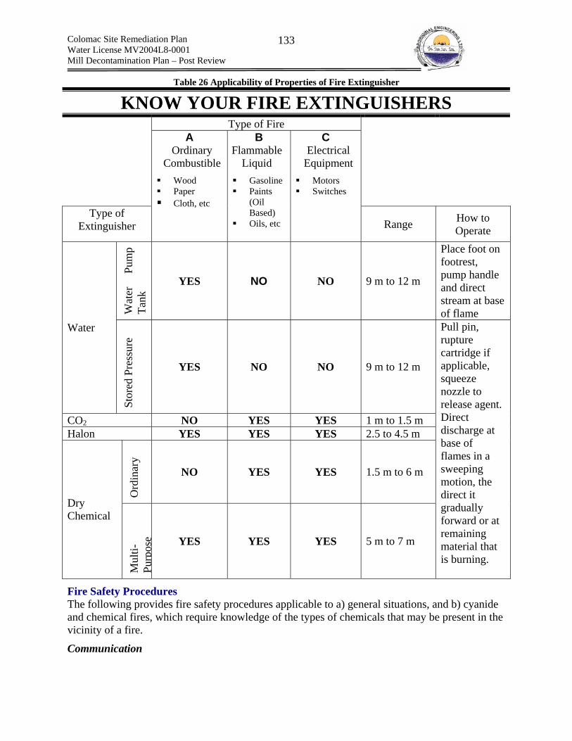
Colomac Site Remediation Plan Water License MV2004L8-0001 Mill Decontamination Plan – Post Review
133
Table 26 Applicability of Properties of Fire Extinguisher
KNOW YOUR FIRE EXTINGUISHERS Type of Fire
Type of Extinguisher
A Ordinary
Combustible Wood Paper Cloth, etc
B Flammable
Liquid Gasoline Paints
(Oil Based)
Oils, etc
C Electrical
Equipment Motors Switches
Range How to Operate
Wat
er
Pum
p Ta
nk YES NO NO 9 m to 12 m
Place foot on footrest, pump handle and direct stream at base of flame
Water
Stor
ed P
ress
ure
YES NO NO 9 m to 12 m
CO2 NO YES YES 1 m to 1.5 m Halon YES YES YES 2.5 to 4.5 m
Ord
inar
y
NO YES YES 1.5 m to 6 m
Dry Chemical
Mul
ti-Pu
rpos
e YES YES YES 5 m to 7 m
Pull pin, rupture cartridge if applicable, squeeze nozzle to release agent. Direct discharge at base of flames in a sweeping motion, the direct it gradually forward or at remaining material that is burning.
Fire Safety Procedures The following provides fire safety procedures applicable to a) general situations, and b) cyanide and chemical fires, which require knowledge of the types of chemicals that may be present in the vicinity of a fire.
Communication

Colomac Site Remediation Plan Water License MV2004L8-0001 Mill Decontamination Plan – Post Review
134
• A person discovering a fire shall report immediately to site superintendent, site authority, and fire department and remain on site to direct fire fighting crews.
• No burning permitted on site unless authorized by the site superintendent. Job Hazard Analysis (JHA) is required prior to any controlled burning to be done.
General Proper Fuelling Procedures
• hose connections will be monitored for leaking • fuel storage tanks will be vented and tested to ensure no leakage • cargo hose will be grounded • all machinery will be cooled off before fuelling • personal safety equipment will issued to fuelling personnel • all cab spaces are closed during fuelling to minimize any leakage from
enclosed spaces to prevent explosion • all enclosed areas are opened after fuelling to vent any fumes that may be
present • sufficient fire extinguishers will be readily accessible but far away enough
from the fuelling area to effectively suppress the fire, if required • spillage of fuel or lubricants will be monitored • should spills occur, they will be immediately cleaned up • appropriate labels will be displayed if more than one fuel is available • all fuel must be stored in National Fire Code (NFC) and Canadian Standards
Association (CSA) approved storage vessels • all storage tanks will be securely fastened • general area will be kept clean and orderly
Additional Considerations
• all flammable and combustible liquids are to be handled, stored, transported and used according to regulatory requirements
• transfer of flammable liquids will not be carried out in the vicinity of open flames or any type of heat producing devices
• flammable liquids having a flash point below 38°C, such as naphtha or gasoline will not be used as solvents or cleaning agents
• flammable and combustible waste liquids will be stored in approved containers and located in a safe, ventilated area.
• quantities of flammable and combustible waste liquids will be kept to a minimum
Training All personnel on site will have some basic understanding of the following elements:
• basic fire detection procedures and assessment • proper procedure to initiate the emergency response process • basic principles of structural and forest fire fighting suppression techniques • fuel handling training
Colomac Site Remediation Plan Water License MV2004L8-0001 Mill Decontamination Plan – Post Review
135
• basic heavy equipment operations and safety • fire extinguisher training • knowledge of safe handling, storage and use of handling hand tools • instruction in the appropriate manner in using personal protective equipment • occupational health and safety training • WHMIS and TDG training • proper use of hazardous materials and cleanup kit • physical fitness is encouraged • proper maintenance and servicing of all equipment on site
Heavy Equipment Considerations
• Site safety meetings conducted daily on site • all equipment have at least one 20 lb. ABC Fire Extinguisher readily
accessible away from engine and fuel tank • equipment well maintained and kept clean to ensure optimum performance
and prevent all liquids from leaking • heavy equipment parked in designated spot when not being used • all exhaust systems equipped with spark arrestors • machinery never operated in fine fuel areas for extended periods of time to
eliminate risk of starting a fire
Emergency Response
General Fires Not in the Presence of Hazardous Materials Includes small electrical fires on/near equipment, wood/paper fires, but not including fires caused by flammable liquids.
• Area to be evacuated, and communication established with site superintendent • Fire extinguishers to be used to extinguish fires.
Flammable Liquids – Water Immiscible Includes fires caused by combustible liquids such as fuel and/or oil.
• For small fires dry chemical or CO2 fire extinguishers to be used. • For large fires, water spray or fog to be used, and do not use straight streams. • For fires involving tanks, fight fire from maximum distance, and cool containers with
flooding quantities of water. • Move victims to fresh air, and administer first and second aid, if necessary. Oxygen
therapy may be required. Medivac may be required if recommended by the site medic.
Gases – Toxic & Flammable (Extreme Hazad) Areas containing cyanide piping and equipment are also prone to fire. If hydrogen cyanide (HCN) gas is generated it can produce a toxic and explosive environment. CO2 based fire extinguishers are inadequate for responding to fires in cyanide areas, as CO2 can facilitate the generation of HCN gas by lowering pH.

Colomac Site Remediation Plan Water License MV2004L8-0001 Mill Decontamination Plan – Post Review
136
The following procedures shall be followed:
• Water spray to be used and flooding amounts of water shall be applied. • Self contained breathing apparatus (SCBA) to be worn by response personnel • Fight fire from maximum distance. • For small fires:
o Isolate in all directions a distance of 60 m. o Protect persons downwind a distance of 0.2 km during day time, and 0.7 km
during night time. • For large fires:
o Isolate in all directions a distance of 390 m. o Protect persons downwind a distance of 1.3 km during day time, and 4.9 km
during night time. • Move victims to fresh air, and administer first and second aid, if necessary. Oxygen
therapy may be required. Medivac may be required if recommended by the site medic.
10.4 Wildlife Plan Building security All doorways to the mill facility will be closed after the end of each shift, and are to be opened at the beginning of each shift to prevent wildlife from seeking shelter inside of the mill. Prior to each shift the wildlife monitor shall inspect the entire perimeter of the mill prior to opening up doorways to ensure that wildlife have not entered via siding of the building. At the beginning of the shift, the wildlife monitor shall also inspect the interior of the mill.
Firearms A defender shotgun will be present on-site at all times. A trigger lock will be placed on the firearm and the Supervisor and wildlife monitor will be provided with the key. Ammunition will be stored separate from the firearm. The firearm is to be operated by a person who is in possession of a valid firearm license. The wildlife monitor shall be equipped with an ATV, the defender shotgun, bear spray, and bear bangers. The wildlife monitor shall monitor the perimeter of the mill and surrounding areas during the work shift.
General Conduct 1. Field workers shall not work alone with a minimum of 2 persons per crew. 2. Field crews shall carry portable radios connected to site frequencies, where applicable. 3. Field workers shall not carry food or drinks, other than water on their person. When
working in camp locations, food shall not be carried in their vehicles. 4. All field crews will complete Aboriginal Engineering bear awareness courses. These
courses will outline areas that can be listed as traditional predatory bear zones. Specifically in the barren land, low lying areas or areas covered with small tree growth with migratory paths for caribou running through them will be zoned as predatory zones. These zones will be inspected for bear activity prior to entering or one worker will carry a
Colomac Site Remediation Plan Water License MV2004L8-0001 Mill Decontamination Plan – Post Review
137
fire arm for bear defense. All areas south of the tree line will be zoned as bear zones. 5. Work is to be carried out as to not disturb or injure the local wildlife.
Potential Encounters The most likely wildlife encounters include: 1. Caribou; 2. Moose; 3. Bears (black bears and grizzly bears); and 4. Small animals (martens, birds, etc.) Work is to be redirected to an alternative area is Caribou are present in site and the work is expected to disturb the animal. Due to the unseasonable warm weather, bears will be considered to be a risk. Employees will be trained in bear awareness.
Reporting All wildlife encounters are to be reported by employees to the Site Supervisor immediately. All staff are then to be made aware of the presence, type, and assessed danger of the wildlife. The encounter will then be posted within the camp in a visible area.

Colomac Site Remediation Plan Water License MV2004L8-0001 Mill Decontamination Plan – Post Review
138
11.0 Record Keeping Records are to be kept on-site in both a hard and electrical copy. The only confidential documents are the medical screening forms and any other medical documentation. Records other than medical records are to be made available to inspectors and the WPHSC upon request. The following records will be maintained:
1. respirator screening forms (medial conditions apply); 2. training screening forms and records of training; 3. contact information for employees; 4. results of internal hazard assessments; 5. results of analytical testing; 6. any formal disciplinary actions; 7. work permits; and 8. documentation relating to the work such as regulations and work plans.
Records will be kept under lock and key in the AEL support trailer. Electronic copies will be stored under password on the computer within the support trailer. The support trailer will be locked when not occupied by management with permission to enter the trailer.
Colomac Site Remediation Plan Water License MV2004L8-0001 Mill Decontamination Plan – Post Review
139
12.0 Site Security Access to and from the work areas or exclusion zones will be clearly marked and their locations and use will be clearly communicated to workers. Access will only be permitted from these points. All other access areas will be physically blocked and signs stating no entry will be posted. Checklists will be constructed to track entry into the Mill. Entry by a person not on the list is not to be permitted. Only the site supervisor or the chemical engineer have the authority to create or modify access lists. The site supervisor or the chemical engineer are required to sign the access permit and to ensure that all persons entering the Mill have clear job duties assigned and that their training is appropriate for the work. During the night, no formal security will be undertaken as the site is remote and the Mill is off limits to persons other than those permitted by the Care and Maintenance Contractor to undertake work. Access points will be secured at the end of shift.
Colomac Site Remediation Plan Water License MV2004L8-0001 Mill Decontamination Plan – Post Review
140
13.0 Management of Change Progress of decontamination will be tracked using the equipment lists provided in Appendix A. The number of equipment and type of equipment will be used to assess the time period required for work to be completed. This will allow one to track the progress for each work item on a daily basis. Key milestones for the project will be monitored by the project manager and if a milestone is missed then mitigative measures will be taken by the project manager to ensure that the project is returned to schedule. Mitigative measures include but are not limited to:
1. Issuing addition supplies or labor; 2. Initiating double shifting over a 24h period; 3. Revising work plans; and 4. Training
If work extends into cold periods, then consideration will be given to supplying heating to the work areas in safe and efficient manner. The cyanide and the leach tanks will be decontaminated first, as they require the pumping of water and thus cannot be efficiently conducted in the Winter (Assumes tailings meet safety considerations and thus winter removal of tank contents is not an option selected).
Colomac Site Remediation Plan Water License MV2004L8-0001 Mill Decontamination Plan – Post Review
141
14.0 Site Communication Communication will require the following work items to be completed:
(a) Communication when in PPE Verbal communication between workers wearing half mask respirators or full face masks will be difficult. Therefore, simple hand signals will be used as communication. These hand signals will include a method to signify if the worker is okay, if the worker is running out of air, if the worker cannot complete the task, or if the worker needs help. In addition, workers in PPE will have a hand held radio at all times to maintain in radio contact with the supervisor, medic, other workers, and the camp.
(b) Hand Held Radios All workers, medic, supervisor, and camp will remain in radio contact with each other throughout any work. Three separate radio channels will be used. The first channel will be designated for work. This channel will be used for communication between AEL workers and the AEL supervisor. The second channel will be designated for the medic. All emergency situations will be communicated through this channel to the medic. The third channel will be designated for the entire site. This channel will be used by the supervisor to stay in communication with all other people at the Colomac site.
(c) Medic Radio Channel The medic will always have a radio with him at all times. This radio will be tuned to the medic channel. All emergency situations will be communicated on the medic channel. The worker will broadcast “Medic, medic, medic”, the name of the worker, location, and description of the situation on this channel.
(d) Satellite Phone The AEL camp will always have a satellite phone to remain in contact with external support services.
(e) General Communication Between CAMC and Major Civil Works Contractor Communication between AEL and other site contractors, with respect to safety and other such items required to co-ordinate work, will be undertaken by the Level 1 Supervisor or the Level 2 Site Superintendent. Results are to be communicated to employees by the respective supervisor
(f) Request for Aid From Care and Maintenance Contractor All requests made for resources or labor from the Care and Maintenance Contractor will be issued to the PWGSC representative. The PWGSC will then request the aid from the Care and Maintenance Contractor and subsequently report the results to the Project Manager.

Colomac Site Remediation Plan Water License MV2004L8-0001 Mill Decontamination Plan – Post Review
142
Appendix A – List of Potential Hazardous Wastes The following tables present a detailed list of Hazardous wastes that could be present within the Colomac Mill. The lists were generated to satisfy the workers right to know and thus reduce the risk of exposure to unknown hazardous wastes during the decontamination of the Colomac Mill.
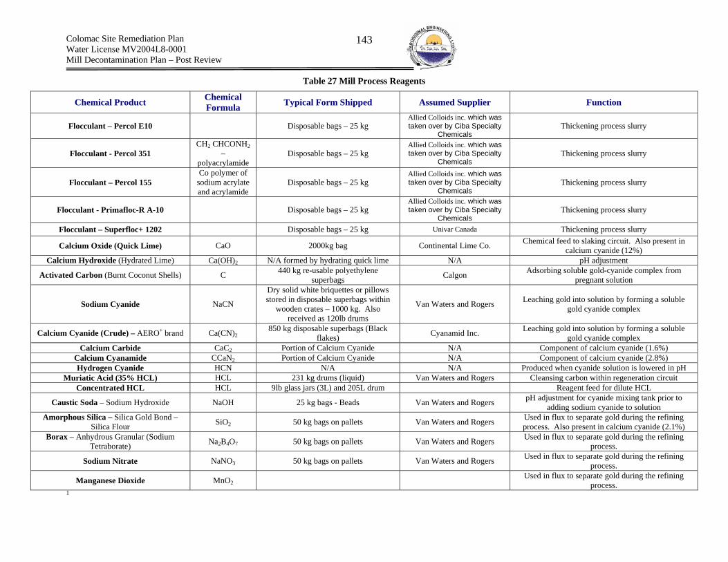
Colomac Site Remediation Plan Water License MV2004L8-0001 Mill Decontamination Plan – Post Review
143
Table 27 Mill Process Reagents
1
Chemical Product Chemical Formula Typical Form Shipped Assumed Supplier Function
Flocculant – Percol E10 Disposable bags – 25 kg Allied Colloids inc. which was taken over by Ciba Specialty
Chemicals Thickening process slurry
Flocculant - Percol 351 CH2 CHCONH2
– polyacrylamide
Disposable bags – 25 kg Allied Colloids inc. which was taken over by Ciba Specialty
Chemicals Thickening process slurry
Flocculant – Percol 155 Co polymer of
sodium acrylate and acrylamide
Disposable bags – 25 kg Allied Colloids inc. which was taken over by Ciba Specialty
Chemicals Thickening process slurry
Flocculant - Primafloc-R A-10 Disposable bags – 25 kg Allied Colloids inc. which was taken over by Ciba Specialty
Chemicals Thickening process slurry
Flocculant – Superfloc+ 1202 Disposable bags – 25 kg Univar Canada Thickening process slurry
Calcium Oxide (Quick Lime) CaO 2000kg bag Continental Lime Co. Chemical feed to slaking circuit. Also present in calcium cyanide (12%)
Calcium Hydroxide (Hydrated Lime) Ca(OH)2 N/A formed by hydrating quick lime N/A pH adjustment
Activated Carbon (Burnt Coconut Shells) C 440 kg re-usable polyethylene superbags Calgon Adsorbing soluble gold-cyanide complex from
pregnant solution
Sodium Cyanide NaCN
Dry solid white briquettes or pillows stored in disposable superbags within
wooden crates – 1000 kg. Also received as 120lb drums
Van Waters and Rogers Leaching gold into solution by forming a soluble gold cyanide complex
Calcium Cyanide (Crude) – AERO+ brand Ca(CN)2 850 kg disposable superbags (Black
flakes) Cyanamid Inc. Leaching gold into solution by forming a soluble gold cyanide complex
Calcium Carbide CaC2 Portion of Calcium Cyanide N/A Component of calcium cyanide (1.6%) Calcium Cyanamide CCaN2 Portion of Calcium Cyanide N/A Component of calcium cyanide (2.8%) Hydrogen Cyanide HCN N/A N/A Produced when cyanide solution is lowered in pH
Muriatic Acid (35% HCL) HCL 231 kg drums (liquid) Van Waters and Rogers Cleansing carbon within regeneration circuit Concentrated HCL HCL 9lb glass jars (3L) and 205L drum Reagent feed for dilute HCL
Caustic Soda – Sodium Hydroxide NaOH 25 kg bags - Beads Van Waters and Rogers pH adjustment for cyanide mixing tank prior to adding sodium cyanide to solution
Amorphous Silica – Silica Gold Bond – Silica Flour SiO2 50 kg bags on pallets Van Waters and Rogers Used in flux to separate gold during the refining
process. Also present in calcium cyanide (2.1%) Borax – Anhydrous Granular (Sodium
Tetraborate) Na2B4O7 50 kg bags on pallets Van Waters and Rogers Used in flux to separate gold during the refining process.
Sodium Nitrate NaNO3 50 kg bags on pallets Van Waters and Rogers Used in flux to separate gold during the refining process.
Manganese Dioxide MnO2 Used in flux to separate gold during the refining process.

Colomac Site Remediation Plan Water License MV2004L8-0001 Mill Decontamination Plan – Post Review
144
Table 28 Process Residuals
Chemical Product Chemical Formula Typical Form Shipped Assumed Supplier Function
Process Residual - Ore Dust Analytical Data Available N/A N/A Generated primarily by grinding/crushing
Process Residual - Saturated Solid Analytical Data Available N/A N/A Tailings saturated with process water. Found at the base of the cyanidation and thickener tanks.
Process Residual - Pore Water Analytical Data Available N/A N/A Generated when tailings solids become saturated (time
necessary for equilibrium between solids/pore water to form). Present in leach tanks.
Process Residual - Free Water Analytical Data Available N/A N/A Present as ponding water on saturated tailings (excess precipitation into leach tanks)
Table 29 Fuels
Chemical Product Chemical Formula Typical Form Shipped Assumed Supplier Function
Diesel Fuel- P40 Refer to MSDS Bulk tankers Esso Fuel Diesel Fuel – P50 Refer to MSDS Bulk Tankers Esso Fuel
Diesel Fuel – 1 Clear Refer to MSDS Bulk Tankers Esso Fuel Gasoline – Unleaded BP Plus Refer to MSDS Bulk Tankers Esso Fuel
Gasoline - Leaded Refer to MSDS Bulk Tankers Esso Fuel Gasoline – Unleaded US Export Refer to MSDS Bulk Tankers Esso Fuel
Jet B fuel Refer to MSDS Bulk Tankers Esso Fuel
Table 30 Lubricants Chemical Product Chemical Formula Typical Form
Shipped Assumed Supplier Function
Arox EP22 Refer to MSDS 205L drum Esso Extreme pressure lubricating oil used to operate tools such as pneumatic rock drills
Arox EP 100 Refer to MSDS 205 L drum Esso Extreme pressure lubricating oil used to operate tools such as pneumatic rock drills
ATF Dexron 11 Refer to MSDS 205 L drum Texaco Industries Inc. Automatic transmission lubrication oil Cat Hydraulic Oil 10W Refer to MSDS Esso Engine oil for gasoline and light duty diesel engines
Cat Trans & Drive Train Oil 30 Refer to MSDS Esso Oil for drive trains and transmissions
Compressor Oil 68 Refer to MSDS 205 L drum Esso Lubrication for the crankcase and cylinders of water cooled reciprocating type air compressors
Epic EP 102 Refer to MSDS 20 L Pail/400 g tubes/55 kg keg Esso Premium all season grease for used in plain and anti-friction
bearings gears, slides etc.
Epic EP Moly Refer to MSDS 55 kg keg Esso Same as EP 102 with 3.0 wt% molybdenum disulfide for enhanced wear protection in reciprocating or oscillating contacts
Dynagear Extra Refer to MSDS 205 L Esso All season lubricant for open gears Envirolube Heavy, Can 69 (Chlorinated - 10 to 30%
trichloroethylene) Refer to MSDS
Whitmore Manufacturing
Company Open gear lubricant
IOLUBE MDX 40 Refer to MSDS 205L drum Esso Premium marine diesel engine oil for use in two and four-cycle diesel engines
Lonax Moly Refer to MSDS 400g tubes Esso Lithium soap grease for user in plain or anti-friction bearings Matex RDO 302 Refer to MSDS 205L drum Control Chemical Vegetable oil based rock drill lubricant
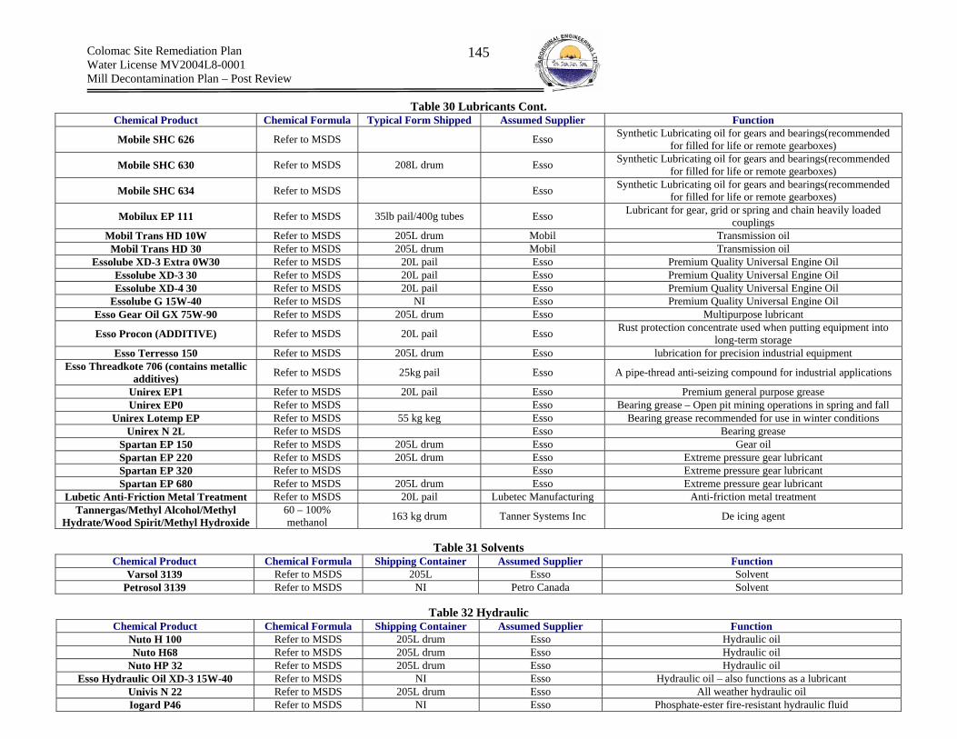
Colomac Site Remediation Plan Water License MV2004L8-0001 Mill Decontamination Plan – Post Review
145
Table 30 Lubricants Cont. Chemical Product Chemical Formula Typical Form Shipped Assumed Supplier Function
Mobile SHC 626 Refer to MSDS Esso Synthetic Lubricating oil for gears and bearings(recommended for filled for life or remote gearboxes)
Mobile SHC 630 Refer to MSDS 208L drum Esso Synthetic Lubricating oil for gears and bearings(recommended for filled for life or remote gearboxes)
Mobile SHC 634 Refer to MSDS Esso Synthetic Lubricating oil for gears and bearings(recommended for filled for life or remote gearboxes)
Mobilux EP 111 Refer to MSDS 35lb pail/400g tubes Esso Lubricant for gear, grid or spring and chain heavily loaded couplings
Mobil Trans HD 10W Refer to MSDS 205L drum Mobil Transmission oil Mobil Trans HD 30 Refer to MSDS 205L drum Mobil Transmission oil
Essolube XD-3 Extra 0W30 Refer to MSDS 20L pail Esso Premium Quality Universal Engine Oil Essolube XD-3 30 Refer to MSDS 20L pail Esso Premium Quality Universal Engine Oil Essolube XD-4 30 Refer to MSDS 20L pail Esso Premium Quality Universal Engine Oil
Essolube G 15W-40 Refer to MSDS NI Esso Premium Quality Universal Engine Oil Esso Gear Oil GX 75W-90 Refer to MSDS 205L drum Esso Multipurpose lubricant
Esso Procon (ADDITIVE) Refer to MSDS 20L pail Esso Rust protection concentrate used when putting equipment into long-term storage
Esso Terresso 150 Refer to MSDS 205L drum Esso lubrication for precision industrial equipment Esso Threadkote 706 (contains metallic
additives) Refer to MSDS 25kg pail Esso A pipe-thread anti-seizing compound for industrial applications
Unirex EP1 Refer to MSDS 20L pail Esso Premium general purpose grease Unirex EP0 Refer to MSDS Esso Bearing grease – Open pit mining operations in spring and fall
Unirex Lotemp EP Refer to MSDS 55 kg keg Esso Bearing grease recommended for use in winter conditions Unirex N 2L Refer to MSDS Esso Bearing grease
Spartan EP 150 Refer to MSDS 205L drum Esso Gear oil Spartan EP 220 Refer to MSDS 205L drum Esso Extreme pressure gear lubricant Spartan EP 320 Refer to MSDS Esso Extreme pressure gear lubricant Spartan EP 680 Refer to MSDS 205L drum Esso Extreme pressure gear lubricant
Lubetic Anti-Friction Metal Treatment Refer to MSDS 20L pail Lubetec Manufacturing Anti-friction metal treatment Tannergas/Methyl Alcohol/Methyl
Hydrate/Wood Spirit/Methyl Hydroxide 60 – 100% methanol 163 kg drum Tanner Systems Inc De icing agent
Table 31 Solvents
Chemical Product Chemical Formula Shipping Container Assumed Supplier Function Varsol 3139 Refer to MSDS 205L Esso Solvent
Petrosol 3139 Refer to MSDS NI Petro Canada Solvent
Table 32 Hydraulic Chemical Product Chemical Formula Shipping Container Assumed Supplier Function
Nuto H 100 Refer to MSDS 205L drum Esso Hydraulic oil Nuto H68 Refer to MSDS 205L drum Esso Hydraulic oil
Nuto HP 32 Refer to MSDS 205L drum Esso Hydraulic oil Esso Hydraulic Oil XD-3 15W-40 Refer to MSDS NI Esso Hydraulic oil – also functions as a lubricant
Univis N 22 Refer to MSDS 205L drum Esso All weather hydraulic oil Iogard P46 Refer to MSDS NI Esso Phosphate-ester fire-resistant hydraulic fluid

Colomac Site Remediation Plan Water License MV2004L8-0001 Mill Decontamination Plan – Post Review
146
Table 33 Heat Exchange Chemical Product Chemical Formula Form Shipped Assumed Supplier Function Ethylene Glycol Refer to MSDS Refer to MSDS Refer to MSDS Heat exchange fluid for heating infrastructure
Therminol 55 Heat Exchanging Fluid Refer to MSDS 181 kg drum Solutia Inc. Heat exchange fluid for cooling process flows Therminol 59 Heat Exchanging Fluid Refer to MSDS 181 kg drum Solutia Inc. Heat exchange fluid for cooling process flows
Dowtherm ® SR-1 Heat Transfer Fluid Refer to MSDS Refer to MSDS Refer to MSDS Heat exchange fluid for cooling process flows VWR Heat Transfer Fluid Refer to MSDS 205 L drum Refer to MSDS Heat exchange fluid for cooling process flows
Ucartherm Clear Heat Transfer Fluid Refer to MSDS Refer to MSDS Van Waters and Rogers Ethylene glycol mixture
Esso HD Antifreeze Refer to MSDS 205L drum Esso Glycol based antifreeze
Table 34 Electrical Insulator Chemical Product Chemical Formula Shipping Container Assumed Supplier Function
Voltesso 35 Refer to MSDS 20L pail Esso Electrical insulating oil
Dielektrol 3 Fluid (Phenyl Xylyl Ethane C16H18 Unknown General Electric Company
Electrical insulator used in primary crusher power distribution system
Table 35 Explosives
Chemical Product Chemical Formula Form Shipped Assumed Supplier Function
Ammonium Nitrate NH4NO3 Re-usable polyethylene “super bags” – 1000 kg C.I.L. When mixed with fuels forms blasting agent. Used to
blast ore from open pit
Table 36 Compressed Gases Chemical Product Chemical Formula Form Shipped Assumed Supplier Function
Acetylene Refer to MSDS Cylinders NI General use throughout site for cutting Oxygen O2 Compressed gas cylinders Used as an oxidizer Propane Refer to MSDS Refer to MSDS Refer to MSDS Fuel for heating Helium He Refer to MSDS Refer to MSDS Refer to MSDS
Nitrogen N2 Refer to MSDS Refer to MSDS Refer to MSDS
Table 37 Hazardous Building Materials Chemical Product Chemical Formula Form Shipped Assumed Supplier Function Silica – Crystalline Refer to MSDS Refer to MSDS Refer to MSDS Present in concrete
Chrysotile – Assay Lab - transite panels Refer to MSDS Refer to MSDS Refer to MSDS Insulation from heat Mercury – Florescent Tubes and H.I.D.
Lamps and potentially thermostats Hg Refer to MSDS Refer to MSDS Used in lighting and switches

Colomac Site Remediation Plan Water License MV2004L8-0001 Mill Decontamination Plan – Post Review
147
Table 38 Miscellaneous Chemicals
Chemical Product Chemical Formula Form Shipped Assumed Supplier Function
Soda Ash Na2CO3 Refer to MSDS Refer to MSDS Salt for electrolyte rheostat solution used to vary resistance during SAG Mill soft start
Sodium Chromate - Electrolyte Fluid Na2CRO4 25 kg bags of solid salt Refer to MSDS Preservative in Electrolyte solution for SAG mill soft start up
Ferrous Sulphate Refer to MSDS Refer to MSDS Refer to MSDS Most likely present on-site as a water treatment
reagent (precipitant) employed when treating tailings lake water that was being transferred to Zone 2.0 pit.
Ferric Sulphate Refer to MSDS Refer to MSDS Refer to MSDS Most likely present on-site as a water treatment
reagent (precipitant) employed when treating tailings lake water that was being transferred to Zone 2.0 pit.
Cement Refer to MSDS Refer to MSDS Refer to MSDS Construction material Bentonite (Hydrated Aluminum Silicate) Refer to MSDS Refer to MSDS Refer to MSDS Construction material
Road Salt Refer to MSDS Refer to MSDS Refer to MSDS Refer to MSDS ABS 66y Solvent Cement Refer to MSDS Refer to MSDS Refer to MSDS Refer to MSDS
Acetic Acid Refer to MSDS Refer to MSDS Refer to MSDS Refer to MSDS Acetone Refer to MSDS Refer to MSDS Refer to MSDS Refer to MSDS
Anti-Seize Compound Refer to MSDS Refer to MSDS Refer to MSDS Refer to MSDS Compressed Argon Refer to MSDS Refer to MSDS Refer to MSDS Refer to MSDS Barium Chloride Refer to MSDS Refer to MSDS Refer to MSDS Refer to MSDS
Buffer Solution (4.0) Refer to MSDS Refer to MSDS Refer to MSDS Refer to MSDS Buffer Solution (10.0) Refer to MSDS Refer to MSDS Refer to MSDS Refer to MSDS
Potassium Hydroxide KOH Refer to MSDS Molecular Products Ltd. Refer to MSDS
Celatom (Crystillinc Silica) Refer to MSDS Refer to MSDS Refer to MSDS Refer to MSDS Aluminum Alloys Refer to MSDS Refer to MSDS Refer to MSDS Refer to MSDS
Electrosolve Refer to MSDS Refer to MSDS Refer to MSDS Refer to MSDS Welding Electrode Refer to MSDS Refer to MSDS Refer to MSDS Refer to MSDS
Floor Dry Refer to MSDS Refer to MSDS Refer to MSDS Refer to MSDS Fluid Tufcotte Refer to MSDS Refer to MSDS Refer to MSDS Refer to MSDS
Free Chlorine Reagent (DPD) Refer to MSDS Refer to MSDS Refer to MSDS Refer to MSDS Hilti Spray Refer to MSDS Refer to MSDS Refer to MSDS Refer to MSDS
Iron Refer to MSDS Refer to MSDS Refer to MSDS Refer to MSDS Ioguard P 46 Refer to MSDS Refer to MSDS Refer to MSDS Refer to MSDS
Lanthanum Chloride Refer to MSDS Refer to MSDS Refer to MSDS Refer to MSDS Lead Plus Refer to MSDS Refer to MSDS Refer to MSDS Refer to MSDS
Lead Acetate Refer to MSDS Refer to MSDS Refer to MSDS Refer to MSDS Lead Acetate Trihydrate Refer to MSDS Refer to MSDS Refer to MSDS Refer to MSDS
Lithium Chloride Refer to MSDS Refer to MSDS Refer to MSDS Refer to MSDS GWC-Machine Bond Epoxy Resin
Grout, Components A, B & C Refer to MSDS Refer to MSDS Refer to MSDS Refer to MSDS
Manganese Dioxide Refer to MSDS Refer to MSDS Refer to MSDS Refer to MSDS Mercuric Nitrate Refer to MSDS Refer to MSDS Refer to MSDS Refer to MSDS
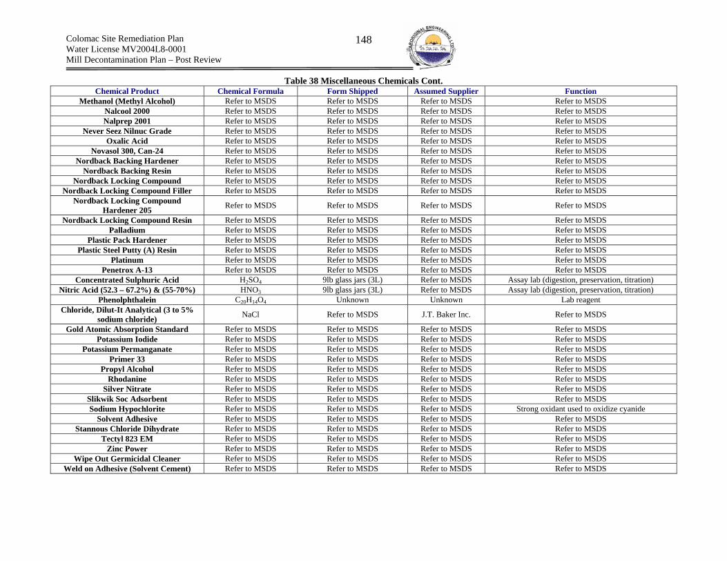
Colomac Site Remediation Plan Water License MV2004L8-0001 Mill Decontamination Plan – Post Review
148
Table 38 Miscellaneous Chemicals Cont. Chemical Product Chemical Formula Form Shipped Assumed Supplier Function
Methanol (Methyl Alcohol) Refer to MSDS Refer to MSDS Refer to MSDS Refer to MSDS Nalcool 2000 Refer to MSDS Refer to MSDS Refer to MSDS Refer to MSDS Nalprep 2001 Refer to MSDS Refer to MSDS Refer to MSDS Refer to MSDS
Never Seez Nilnuc Grade Refer to MSDS Refer to MSDS Refer to MSDS Refer to MSDS Oxalic Acid Refer to MSDS Refer to MSDS Refer to MSDS Refer to MSDS
Novasol 300, Can-24 Refer to MSDS Refer to MSDS Refer to MSDS Refer to MSDS Nordback Backing Hardener Refer to MSDS Refer to MSDS Refer to MSDS Refer to MSDS
Nordback Backing Resin Refer to MSDS Refer to MSDS Refer to MSDS Refer to MSDS Nordback Locking Compound Refer to MSDS Refer to MSDS Refer to MSDS Refer to MSDS
Nordback Locking Compound Filler Refer to MSDS Refer to MSDS Refer to MSDS Refer to MSDS Nordback Locking Compound
Hardener 205 Refer to MSDS Refer to MSDS Refer to MSDS Refer to MSDS
Nordback Locking Compound Resin Refer to MSDS Refer to MSDS Refer to MSDS Refer to MSDS Palladium Refer to MSDS Refer to MSDS Refer to MSDS Refer to MSDS
Plastic Pack Hardener Refer to MSDS Refer to MSDS Refer to MSDS Refer to MSDS Plastic Steel Putty (A) Resin Refer to MSDS Refer to MSDS Refer to MSDS Refer to MSDS
Platinum Refer to MSDS Refer to MSDS Refer to MSDS Refer to MSDS Penetrox A-13 Refer to MSDS Refer to MSDS Refer to MSDS Refer to MSDS
Concentrated Sulphuric Acid H2SO4 9lb glass jars (3L) Refer to MSDS Assay lab (digestion, preservation, titration) Nitric Acid (52.3 – 67.2%) & (55-70%) HNO3 9lb glass jars (3L) Refer to MSDS Assay lab (digestion, preservation, titration)
Phenolphthalein C20H14O4 Unknown Unknown Lab reagent Chloride, Dilut-It Analytical (3 to 5%
sodium chloride) NaCl Refer to MSDS J.T. Baker Inc. Refer to MSDS
Gold Atomic Absorption Standard Refer to MSDS Refer to MSDS Refer to MSDS Refer to MSDS Potassium Iodide Refer to MSDS Refer to MSDS Refer to MSDS Refer to MSDS
Potassium Permanganate Refer to MSDS Refer to MSDS Refer to MSDS Refer to MSDS Primer 33 Refer to MSDS Refer to MSDS Refer to MSDS Refer to MSDS
Propyl Alcohol Refer to MSDS Refer to MSDS Refer to MSDS Refer to MSDS Rhodanine Refer to MSDS Refer to MSDS Refer to MSDS Refer to MSDS
Silver Nitrate Refer to MSDS Refer to MSDS Refer to MSDS Refer to MSDS Slikwik Soc Adsorbent Refer to MSDS Refer to MSDS Refer to MSDS Refer to MSDS Sodium Hypochlorite Refer to MSDS Refer to MSDS Refer to MSDS Strong oxidant used to oxidize cyanide
Solvent Adhesive Refer to MSDS Refer to MSDS Refer to MSDS Refer to MSDS Stannous Chloride Dihydrate Refer to MSDS Refer to MSDS Refer to MSDS Refer to MSDS
Tectyl 823 EM Refer to MSDS Refer to MSDS Refer to MSDS Refer to MSDS Zinc Power Refer to MSDS Refer to MSDS Refer to MSDS Refer to MSDS
Wipe Out Germicidal Cleaner Refer to MSDS Refer to MSDS Refer to MSDS Refer to MSDS Weld on Adhesive (Solvent Cement) Refer to MSDS Refer to MSDS Refer to MSDS Refer to MSDS
Colomac Site Remediation Plan Water License MV2004L8-0001 Mill Decontamination Plan – Post Review
149
Appendix B – Milling Circuits – Identification of Hazard and Estimated Chemical Quantities
B1 - Crushing Circuits The crushing circuit can be further broken down into the following circuits:
(a) Primary Crushing – Gyratory Crusher (b) Secondary Crushing – Short Head Cone Crusher
Figure 11presents the Process Flow Diagram (PFD) for the primary and secondary crushing circuits.

Colomac Site Remediation Plan Water License MV2004L8-0001 Mill Decontamination Plan – Post Review
150
Figure 11 Primary and Secondary Crushing Process Flow Diagrams
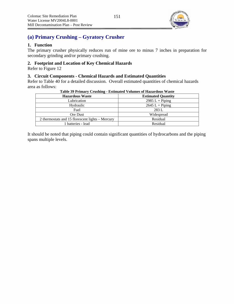
Colomac Site Remediation Plan Water License MV2004L8-0001 Mill Decontamination Plan – Post Review
151
(a) Primary Crushing – Gyratory Crusher
1. Function The primary crusher physically reduces run of mine ore to minus 7 inches in preparation for secondary grinding and/or primary crushing.
2. Footprint and Location of Key Chemical Hazards Refer to Figure 12
3. Circuit Components - Chemical Hazards and Estimated Quantities Refer to Table 40 for a detailed discussion. Overall estimated quantities of chemical hazards area as follows:
Table 39 Primary Crushing - Estimated Volumes of Hazardous Waste Hazardous Waste Estimated Quantity
Lubrication 2985 L + Piping Hydraulic 2645 L + Piping
Fuel 283 L Ore Dust Widespread
2 thermostats and 15 florescent lights – Mercury Residual 1 batteries - lead Residual
It should be noted that piping could contain significant quantities of hydrocarbons and the piping spans multiple levels.

Colomac Site Remediation Plan Water License MV2004L8-0001 Mill Decontamination Plan – Post Review
152
Figure 12 Footprint and Location of Chemical Hazards- Primary Crushing Circuit
Teledyne rock breaker and front view of primary crushing building
View of conveyor No.1 from primary crushing building
SAG mill
Portable fuel tank. Note ca. 6” of ice covering floor
One of two air to oil crusher oil coolers
Pile of fine grained ore
Gyratory crusher Farval lubrication system
Apron feeder pillow block bearing centralized greasing unit
Apron feeder hydraulic power unit – reservoir, two pumps and drive motor
Note residual ore dust
Extensive oil staining on floor in front of crusher lubrication reservoir and
crusher hydroset reservoir
Rock breaker hydraulic power pack

Colomac Site Remediation Plan Water License MV2004L8-0001 Mill Decontamination Plan – Post Review
153
Table 40 Primary Crushing Circuit Components - Chemical Hazards and Estimated Quantities
Equipment Primary Components Manufacturer or (model #) Quantifier Function/Comment Chemical Hazard Chemical Quantity Chemical Product
Hydraulic Rock Breaker Teledyne Canada (TM-25/TB 750X 50 HP Breaks run of mine ore and feeds Grizzly screen Lubrication &
Hydraulic
Grease - located on equipment and surrounding internal lubrication points – Residual
.Hydraulic Fluid - Located in Equipment Hydraulic Lines - Unknown
Hydraulic fluid (Winter) – UNIVIS N15
Hydraulic fluid (Summer) – UNIVIS N22
Tool lubrication – (Gun Dist.) EPIC EP MOLY
All season greasing (Gun Dist.) EPIC EP 102
Power Pack - Pump, Reservoir and Piping Teledyne Canada - Provides lubrication to the Teledyne rock breaker Hydraulic Reservoir - 350 L
Piping – Unknown
Hydraulic fluid (Winter) – UNIVIS N15
Hydraulic fluid (Summer) – UNIVIS N22
Pump - Hydraulic Fluid Cooling (viscosity control) Teledyne Canada - Removes heat from the hydraulic fluid to regulate
viscosity Hydraulic Will be coated when removed - Residual
Hydraulic fluid (Winter) – UNIVIS N15
Hydraulic fluid (Summer) – UNIVIS N22
Immersion Heater –Hydraulic Fluid Heating (viscosity
control) Teledyne Canada - Heats hydraulic fluid to regulate viscosity Hydraulic Will be coated with hydraulic fluid - Residual
Hydraulic fluid (Winter) – UNIVIS N15
Hydraulic fluid (Summer) – UNIVIS N22
Floor Surrounding Power Pack Reservoir N/A - Comment: Hydraulic oil staining present surrounding
power pack reservoir Hydraulic Residual staining – Residual
Hydraulic fluid (Winter) – UNIVIS N15
Hydraulic fluid (Summer) – UNIVIS N22
Teledyne Hydraulic
Rock Breaker
Estimated Quantity of Hazardous Waste Hydraulic = 350 L + piping
Gyratory Crusher Allis Chalmers Canada Ruttan Mine
54” x 74” – 600 HP
Crushes ore to minus 7” in preparation for secondary crushing or primary grinding
Ore dust & Lubrication Oil staining from various sources - Residual Potentially – Spartan EP 320,
Spartan EP 68, EPIC EP Moly
Shaft Bushings Auto Lube System - Automatically lubricates the shaft bushings Lubrication
2 x 55k/50L barrels – 100L Pump and piping – Unknown (Note located close to
crusher so quantities will be low) EPIC EP MOLY
Pinion Shaft Assembly - - Transfers mechanical energy to shaft Lubrication Contained within shaft of pinion (bath) - Unknown Spartan EP 68
Spider Bearing Oil Seal - - Seals the area between crushing area and the spider bearing Lubrication (bath) - unknown Spartan EP 320
Crusher Lube Package – Circulating Oil and
Hydroset -
Lubricates bearings, bushings and gears Hydroset provides hydraulic force to raise and lower
main shaft Lubrication
Reservoir – 1,440 L Pumps and Piping – Unknown (Note: reservoir
located on floor below crusher. As such contents in piping could be significant if present).
Spartan EP 68 or Arox EP 100
2x Crusher Oil Cooler Bolliden-Allis (air to oil) Cools the gyratory crusher Lubrication Internal contents of radiator and piping – Unknown Residual staining - Minor Spartan EP 68
Gyratory Crusher Drive Motor - - Powers the crusher Lubrication Unknown Unknown
Floor N/A - Comment: Oil staining present on concrete of level housing the primary crusher (second floor beneath
ground level) Lubrication Unknown Potentially – Spartan EP 320,
Spartan EP 68, EPIC EP Moly
Floor N/A Comment: Extensive free product surrounding crushing lube package Lubrication Estimated at 5 cm thick x 15m2 = 750 L Most Likely Spartan EP 68
Surge Bin - 170 ton live Stores ore prior to transport to the live ore storage bin Ore dust and Coarse Ore
Residual and Coarse Ore – Unknown and widespread Unknown
Dump Pocket N/A - Collects ore from end dumps prior to primary crushing – located between crusher and apron feeder
Ore dust & Coarse ore
Residual and Coarse Ore – Unknown and widespread Unknown
Allis Chalmers Canada
Gyratory Crusher
Estimated Quantity of Hazardous Waste Lubrication = 1,540 L +piping

Colomac Site Remediation Plan Water License MV2004L8-0001 Mill Decontamination Plan – Post Review
154
Table 40 Cont.
Equipment Primary Components Manufacturer or (model #) Quantifier Function/Comment Chemical Hazard Chemical Quantity Chemical Product
Air Compressor Hydrovane Comp Co. (128 K08-108)
80 CFM 100 PSIG Provided compressed air for crushing plant Lubrication Reservoir 15L - appears to have been removed Compressor Oil 68
Electric Motor 25 HP Provides energy to compress air Lubrication gun Residual UNIREX N2L Dryer Compair Canada (TW 25) Dried compressed air provided to crushing plant None Oil extraction filter - Residual Compressor Oil 68
Air Compressor
Estimated Quantity of Hazardous Waste Lubrication = 15 L
Apron Feeder FMC of Canada Limite (TK5501-A7) 60” x 14’ 25 HP Transfer ore to the No.1 conveyor Ore dust
Exterior covered in ore dust along with some piles of ore dust located to the side of the feeder –
Unknown and widespread N/A
Hydraulic Power Unit - - Provides hydraulic power to apron feeder Hydraulic Reservoir – 740 L Piping - Unknown UNIVIS N22
Drive Motor - - Provides power Lubrication gun - Residual UNIREX N2L Pillow Block Bearings –
centralized greasing - - Reduce friction Lubrication barrels – 50 L or 55kg piping and pump - Unknown EPIC EP102
Apron Feeder
Estimated Quantity of Hazardous Waste Lubrication = 50L + piping Hydraulic = 740 L + piping contents
No.1 Conveyor Continental Conveyor (Series H) 850’L x 48” W Coarse Ore - Transports ore to the live storage ore
stockpile Ore dust Piles of ore dust adjacent to conveyor on conveyor – Unknown and widespread N/A
No. 2 Conveyor Continental Conveyor (Series H) 458’L x 48” Primary Mill Feed - Transports ore to the SAG mill Lubrication Residual Unknown
Conveyor No.1 and 2 Electric Motors - - Powers conveyors Lubrication gun – Residual Note: Conveyor No.2 flooded Unirex N2L
Conveyor No.1 and No.2 Pulley Bearings - - Reduces conveyor friction Lubrication gun – Residual Note: Conveyor No.2 flooded EPIC EP102
Conveyor No.1 and No. 2 Gear Reducer - - Reduces speed of rotation Lubrication bath – 2 * 300L = 600L Note: Conveyor No.2
flooded Mobil SHC 630
3 x Hydrastroke Feeder Universal Engine Corp (TR-1100) 10’L x 48” W Feeds ore from the live ore stockpile to the No.2
conveyor belt Lubrication Residual Unknown
Hydrastroke Hydraulic Reservoir - - Stores hydraulic fluid Hydraulic Reservoir – 3 * 450L = 1350L
Piping – Unknown NUTO 68
Hydrastroke Drive Motor - - Powers Hydrastroke Lubrication gun - Residual UNIREX N2L Hydrastroke Feeder Discharge
Chute S. Bay Design &
Construction - Feeds ore onto the No.1 Conveyor Ore dust Residual N/A - Flooded
Conveyors
Estimated Quantity of Hazardous Waste Lubrication = 600L Hydraulic = 1350L + piping
Dust Collector Wheelabrator Canada (#MPF #46 Pulse 20-2770) 9250 CFM Collect and filters dust from the primary crusher Ore dust Coating of dust – Residual N/A
Dust Collection Ducting - - Heating and ventilation Ore dust Coating of dust – Residual N/A
Screw Conveyor Wheelabrator Canada 1 Hp Transfers the collected dust to the No.1 conveyor Ore dust & Lubrication
Electric motor (gun) – Residual General greasing (gun) – Residual
Electric motor – UNIREX N2L General greasing – UNIREX EP2
Exhaust Fan Buffalo Forge 22 1/4 Removes dust from the building interior Ore dust Motor – Residual Shaft bearings – Residual
Exhaust Stack - - Transfers filtered air to atmosphere Ore dust & Lubrication
Electric motor (gun) – Residual Dodge gear reducer (bath) –10L
Electric motor (gun) – UNIREX N2L Dodge gear reducer (bath) –Mobil
SHC 630
Dust Collector
Estimated Quantity of Hazardous Materials Lubrication = 10 L

Colomac Site Remediation Plan Water License MV2004L8-0001 Mill Decontamination Plan – Post Review
155
Table 40 Cont.
Table 40 Cont.
Equipment Primary Components Manufacturer or (model #) Quantifier Function/Comment Chemical Hazard Chemical Quantity Chemical Product
Weigh Scale #1 20-20/10-201 Series 1020-A - Weighs the primary ore feed from the live ore stock
pile Flooded - N/A
Weigh Scale#2 Ramsey Ltd. 10-20-2 - Weighs primary ore feed and secondary grinding mill discharge Flooded - N/A
Make up air pump ITT Fluid Products Bell & Gassett Provides make up air Lubrication Unknown but assumed - Residual Unknown
2 x Transformer General Electric 120/208 – 600Volt Transforms electrical energy Electrical Insulator
– Non PCB Unknown Dielektrol 3 Fluid
Ceiling Exhaust Fan - - Removes air from interior of building Lubrication Bearings – Residual Electrical Motor - Residual
Bearings - unspecified Electrical motor – UNIREX
N2L
Electrical Room Pressurization Fan Provides positive pressure for electrical room Lubrication Bearings – Residual
Electrical Motor - Residual
Bearings - unspecified Electrical motor – UNIREX
N2L
Vertical Sump Pump Galigher Ash 2.5” Dia Transfers water from reclaim tunnel to SAG mill Note: piping identified but pump located in flooded area Lubrication Unknown Unknown
Grizzly Screen - 600 HP Screens broken rock to a size acceptable for the primary gyratory crusher
Lubrication & Hydraulic Unknown Unknown
2 x Electric Heaters - - Heats building - None N/A Portable Fuel Box - - Stores fuel Fuel Reservoir – 283L Diesel fuel
General
Estimated Quantity of Hazardous Waste Electrical Insulation =
Unknown Fuel = 283L
Category Item Chemical Hazard Chemical Quantity 15 florescent light tubes Mercury -
2 x thermostat Mercury - 1 x battery Lead -
UNIVIS N22 45 gal. drum Hydraulic 205L 1 Gerry can gasoline Fuel -
1 x 5L pail grease Lubricant 5L 2 x AROX EP 45 gal. drum Lubricant 410 L
Unknown grease 45 gal. Lubrication 205L 2 x Pails EPIC EP 102 Lubrication 150L
Free Product
Estimated Quantity of Hazardous Waste Lubrication = 770 L Hydraulic = 205 L
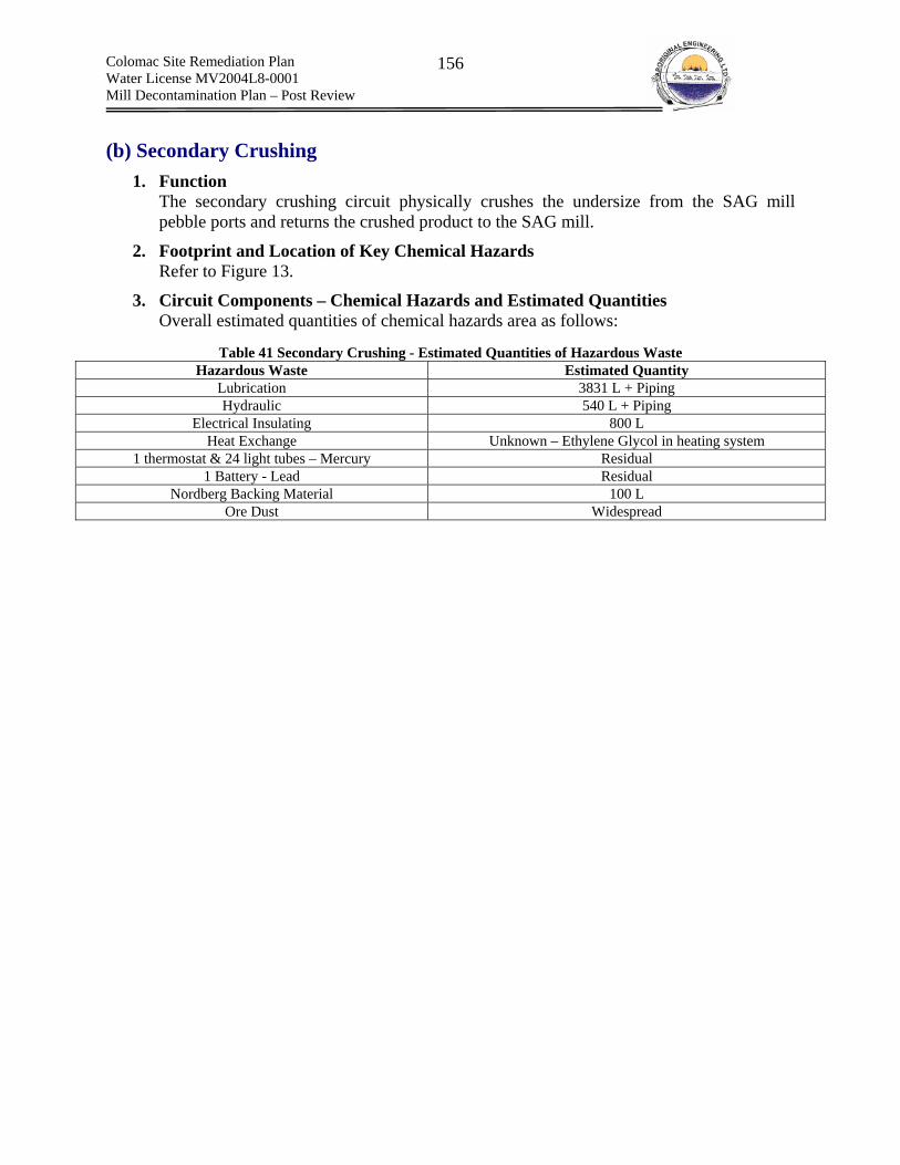
Colomac Site Remediation Plan Water License MV2004L8-0001 Mill Decontamination Plan – Post Review
156
(b) Secondary Crushing 1. Function
The secondary crushing circuit physically crushes the undersize from the SAG mill pebble ports and returns the crushed product to the SAG mill.
2. Footprint and Location of Key Chemical Hazards Refer to Figure 13.
3. Circuit Components – Chemical Hazards and Estimated Quantities Overall estimated quantities of chemical hazards area as follows:
Table 41 Secondary Crushing - Estimated Quantities of Hazardous Waste
Hazardous Waste Estimated Quantity Lubrication 3831 L + Piping Hydraulic 540 L + Piping
Electrical Insulating 800 L Heat Exchange Unknown – Ethylene Glycol in heating system
1 thermostat & 24 light tubes – Mercury Residual 1 Battery - Lead Residual
Nordberg Backing Material 100 L Ore Dust Widespread
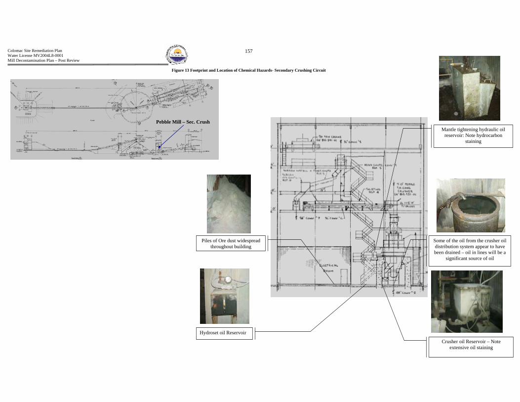
Colomac Site Remediation Plan Water License MV2004L8-0001 Mill Decontamination Plan – Post Review
157
Crusher oil Reservoir – Note extensive oil staining
Some of the oil from the crusher oil distribution system appear to have been drained – oil in lines will be a
significant source of oil
Mantle tightening hydraulic oil reservoir: Note hydrocarbon
staining
Hydroset oil Reservoir
Piles of Ore dust widespread throughout building
Figure 13 Footprint and Location of Chemical Hazards- Secondary Crushing Circuit
Pebble Mill – Sec. Crush

Colomac Site Remediation Plan Water License MV2004L8-0001 Mill Decontamination Plan – Post Review
158
Table 42 Secondary Crushing Circuit Components- Hazardous Wastes, Estimated Quantities
Equipment Primary Components Manufacturer (Model #) Quantifier Function/Comment Chemical Hazard Chemical Quantity Chemical Product
Crushing Unit Nordberg/Noranda Horne Mine ( 7FT SH HD) 7’ Crushes the underflow from the pebble screens. Discharge = - 3/8“ Ore dust Unknown and widespread N/A
Oil Circulating System Nordberg/Noranda Minerals Inc. - Provides lubrication for the crusher Lubrication Reservoir – 830 L
Piping - Unknown Spartan EP 69
Oil pump - - Pumps the oil for lubricating the crusher Lubrication Bath - Unknown Spartan EP 220 Hydraulic Clamp & Lock - - Tightens the crusher mantle Hydraulic Reservoir – 500L Spartan EP 68
Feed Distributor Gear - - Alters rotational speed Lubrication Bath - Unknown Spartan EP 320 Locking Collar, Nut - - Lubrication Gun - Residual EPIC EP MOLY
Electric Motor Westinghouse 350 HP Powers crusher Lubrication Gun - Residual UNIREX N2L
Crusher Cone Adjustor Les Usinage Indust.. - Adjusts cone crusher Lubrication & Hydraulic Electric motor (Gun) – Residual
Hydraulic clamping –(centralized) – 40L
Electric motor (Gun) –UNIREX N2L Hydraulic clamping – Spartan EP 68
Crusher Cooling System Nordberg/Noranda Minerals Inc. Cools crusher oil Lubrication Electric motor bearings (gun) -
Residual UNIREX N2L
Nordberg Shorthead cone
crusher
Estimated Quantity of Hazardous Waste Lubrication = 830 L + piping + bath +residual Hydraulic = 540L
No.3 Conveyor Belt Continental Conveyor 36” x 10’ Primary Mill Discharge - Collect discharge from SAG mill pebble port Ore dust - - No. 4 Conveyor Belt Continental Conveyor 42” x 32’ Pebble Transfer - Transfers ore from No.3 Conveyor belt to the crusher Ore dust - - No. 5 Conveyor Belt Continental Conveyor 36” x 314’ Transfers minus 3” plus 3/8” ore from SAG mill pebble ports Ore dust - -
Conveyor No.3, 4 and 5 Electric Motors - - Powers conveyors Lubrication gun – Residual Note: Conveyor No.2
flooded Unirex N2L
Conveyor No3, 4 and 5 Pulley Bearings - - Reduces conveyor friction Lubrication gun – Residual Note: Conveyor No.2
flooded EPIC EP102
Conveyor No3, 4 and 5 Gear Reducer - - Reduces speed of rotation Lubrication bath – 30L Note: Conveyor No.2
flooded (No. 1) Mobil SHC 630 (No.2) Spartan EP220
Bypass Vertical Conveyor - - Bypasses the crusher and directs feed to Conveyor No.2 Ore dust & Lubrication
Ore dust –widespread Lubrication - Assume same as
Conveyors No.1 to 7 Assume same as Conveyors No.1 to 7.
Conveyor No. 5 Screen Feed - - Feeds ore to the pebble screen Ore dust & Lubrication Ore dust –widespread
Gear reducer (bath) – 10L Mobile SHC 630
Conveyor No. 6 Cone Feed - - Feeds ore to the cone Ore dust & Lubrication
Ore dust – Unknown and widespread
Gear reducer (bath) -10L
Electric motor (gun) – UNIREX N2L Head & tail bearings (gun) – EPIC EP 102
Gear reducer (bath) –Mobil SHC 630
Conveyor No.7 Pebble Bin Feed - - Feeds ore to the pebble bin Ore dust & Lubrication
Ore dust – Unknown and widespread
Electric motor (gun) – Residual Head & tail bearings (gun) – Residual
Gear reducer (bath) -10L
Electric motor (gun) – UNIREX N2L Head & tail bearings (gun) – EPIC EP 102
Gear reducer (bath) –Mobil SHC 630
Conveyor No.4 Electromagnet
Eriez of Canada Ltd. (SE: 7717 700 Series) - Conveyor No.4 – Collects metal out of conveyor feeds Lubrication & Electrical
Insulator – Non PCB
Bearings (gun) – Residual Transformer (reservoir) – 800L Electric motor (gun) – Residual
Gear box (reservoir) – 1L
Bearings (gun) –EPIC EP 102 Transformer (reservoir) – VOLTESSO 35
Electric motor (gun) – UNIREX N2L Gear box (reservoir) – Mobil SHC 630
Conveyor No.3 Magnetic Head Pulley - - Pulley for magnet head Lubrication Bearings (gun) - Residual EPIC EP 102
Coarse Ore Stockpile Sump Pump - - Pumps sump from coarse ore reclaim tunnel to SAG mill Lubrication Electric motor (gun) - Residual
General greasing (gun) - Residual Electric motor (gun) – UNIREX N2L
General greasing (gun) – UNIREX EP2 Conveyor No. 5 & No.6
Metering Gate Power Pack
- Provides hydraulic power to metering gate Lubrication & Hydraulic Electric motor (gun) – Residual Reservoir (tank) – Unknown
Electric motor (gun) – UNIREX N2L Reservoir (tank) winter – UNIVIS N22 Reservoir (tank) winter – UNIVIS N15
-Conveyors
Estimated Quantity of Hazardous Waste Lubrication = 61 L Electrical Insulator = 800 L
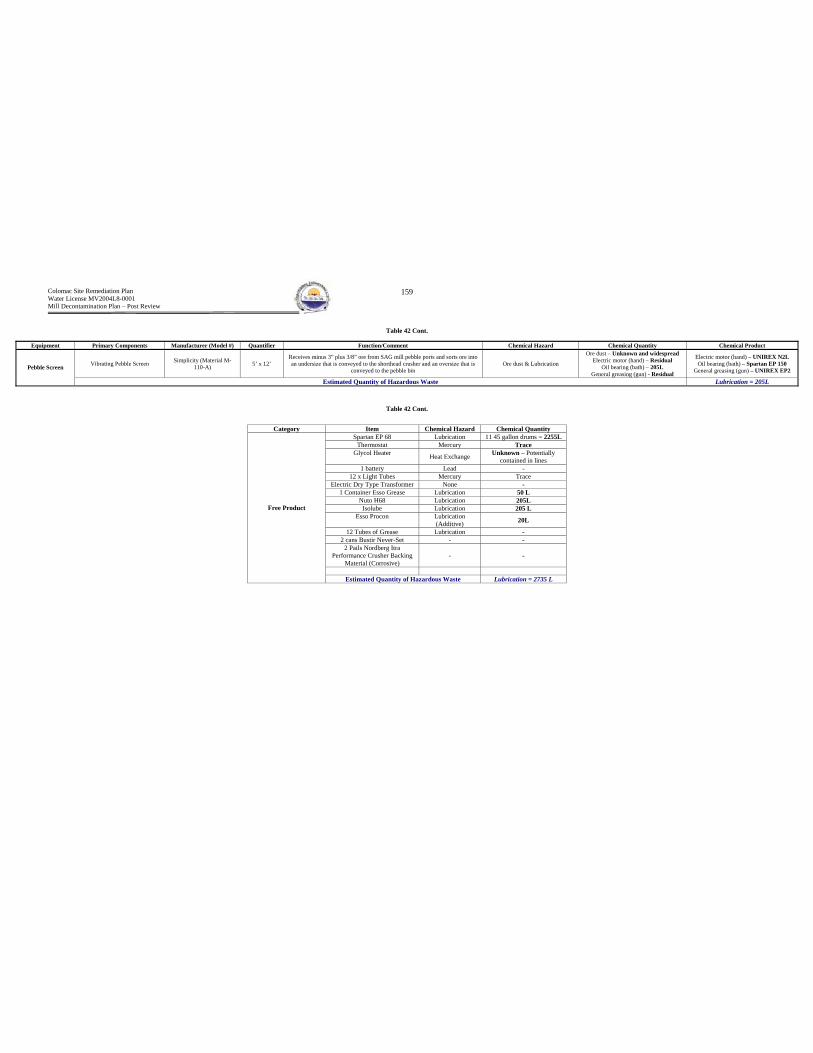
Colomac Site Remediation Plan Water License MV2004L8-0001 Mill Decontamination Plan – Post Review
159
Table 42 Cont.
Table 42 Cont.
Equipment Primary Components Manufacturer (Model #) Quantifier Function/Comment Chemical Hazard Chemical Quantity Chemical Product
Vibrating Pebble Screen Simplicity (Material M-110-A) 5’ x 12’
Receives minus 3” plus 3/8” ore from SAG mill pebble ports and sorts ore into an undersize that is conveyed to the shorthead crusher and an oversize that is
conveyed to the pebble bin Ore dust & Lubrication
Ore dust – Unknown and widespread Electric motor (hand) – Residual
Oil bearing (bath) – 205L General greasing (gun) - Residual
Electric motor (hand) – UNIREX N2L Oil bearing (bath) – Spartan EP 150
General greasing (gun) – UNIREX EP2 Pebble Screen
Estimated Quantity of Hazardous Waste Lubrication = 205L
Category Item Chemical Hazard Chemical Quantity Spartan EP 68 Lubrication 11 45 gallon drums = 2255L
Thermostat Mercury Trace Glycol Heater Heat Exchange Unknown – Potentially
contained in lines 1 battery Lead -
12 x Light Tubes Mercury Trace Electric Dry Type Transformer None -
1 Container Esso Grease Lubrication 50 L Nuto H68 Lubrication 205L
Isolube Lubrication 205 L Esso Procon Lubrication
(Additive) 20L
12 Tubes of Grease Lubrication - 2 cans Bustir Never-Set - -
2 Pails Nordberg Itra Performance Crusher Backing
Material (Corrosive) - -
Free Product
Estimated Quantity of Hazardous Waste Lubrication = 2735 L
Colomac Site Remediation Plan Water License MV2004L8-0001 Mill Decontamination Plan – Post Review
160
B2 - Wet Grinding Circuit(s) and Classification The wet grinding circuit can be further classified into the following circuits:
(a) Primary Grinding (b) Secondary Grinding
Figure 14 and Figure 15, presented on the following pages, display the PFDs for the primary and secondary grinding circuits.

Colomac Site Remediation Plan Water License MV2004L8-0001 Mill Decontamination Plan – Post Review
161
Figure 14 Primary Grinding Circuit - SAG Mill
Primary Grinding Circuit – SAG Mill

Colomac Site Remediation Plan Water License MV2004L8-0001 Mill Decontamination Plan – Post Review
162
Figure 15 Secondary Grinding Circuit Process Flow Sheet– Ball Mills
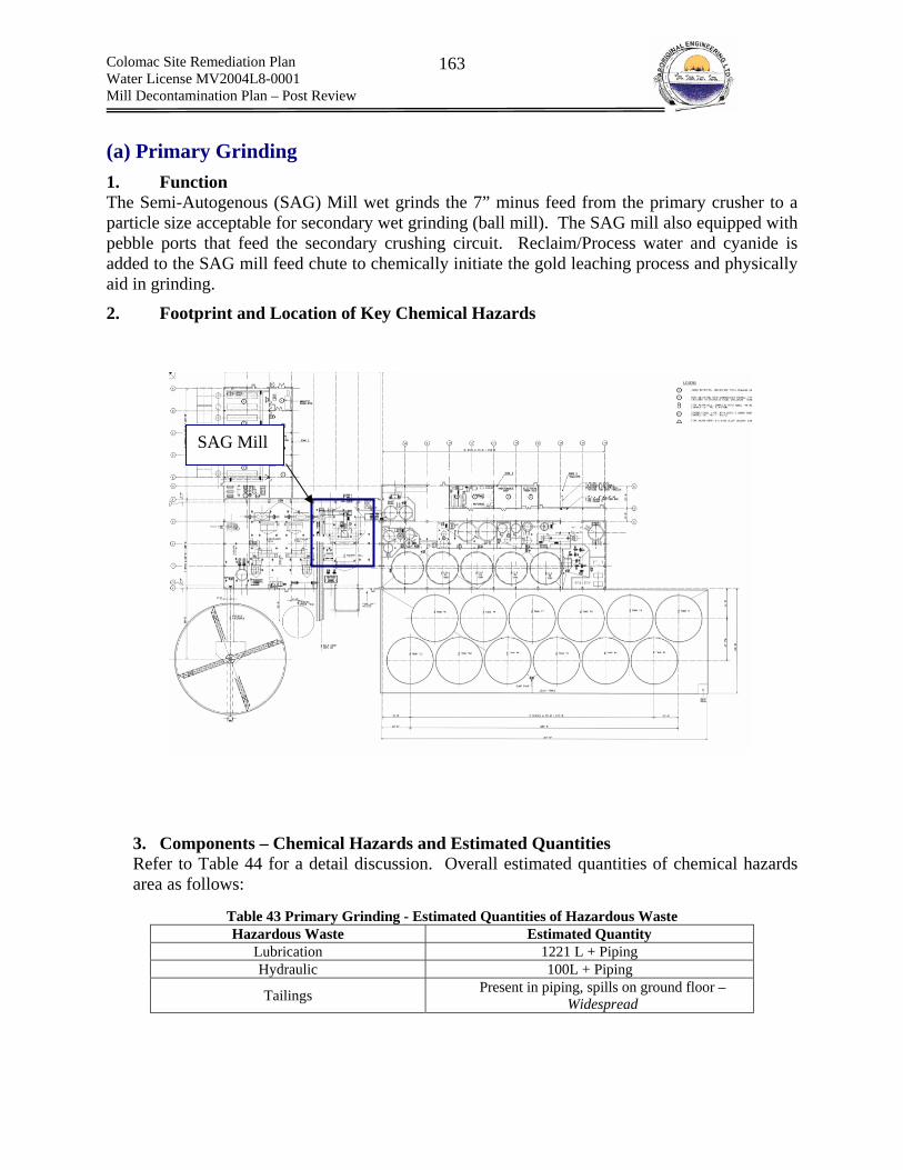
Colomac Site Remediation Plan Water License MV2004L8-0001 Mill Decontamination Plan – Post Review
163
(a) Primary Grinding 1. Function The Semi-Autogenous (SAG) Mill wet grinds the 7” minus feed from the primary crusher to a particle size acceptable for secondary wet grinding (ball mill). The SAG mill also equipped with pebble ports that feed the secondary crushing circuit. Reclaim/Process water and cyanide is added to the SAG mill feed chute to chemically initiate the gold leaching process and physically aid in grinding.
2. Footprint and Location of Key Chemical Hazards 3. Components – Chemical Hazards and Estimated Quantities Refer to Table 44 for a detail discussion. Overall estimated quantities of chemical hazards area as follows:
Table 43 Primary Grinding - Estimated Quantities of Hazardous Waste Hazardous Waste Estimated Quantity
Lubrication 1221 L + Piping Hydraulic 100L + Piping
Tailings Present in piping, spills on ground floor – Widespread
SAG Mill
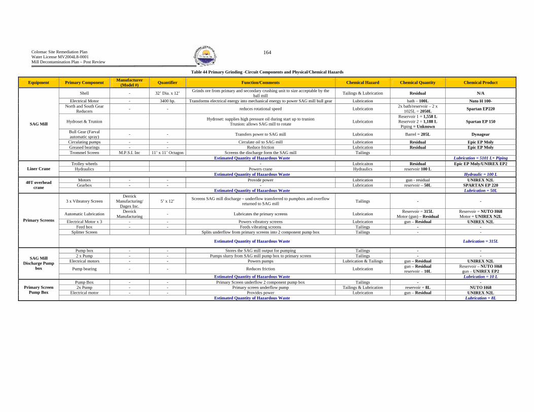
Colomac Site Remediation Plan Water License MV2004L8-0001 Mill Decontamination Plan – Post Review
164
Table 44 Primary Grinding -Circuit Components and Physical/Chemical Hazards
Equipment Primary Component Manufacturer (Model #) Quantifier Function/Comments Chemical Hazard Chemical Quantity Chemical Product
Shell - 32’ Dia. x 12’ Grinds ore from primary and secondary crushing unit to size acceptable by the ball mill Tailings & Lubrication Residual N/A
Electrical Motor - 3400 hp. Transforms electrical energy into mechanical energy to power SAG mill bull gear Lubrication bath – 100L Nuto H 100- North and South Gear
Reducers - - reduces rotational speed Lubrication 2x bath/reservoir – 2 x 1025L = 2050L Spartan EP220
Hydroset & Trunion Hydroset: supplies high pressure oil during start up to trunion Trunion: allows SAG mill to rotate Lubrication
Reservoir 1 = 1,558 L Reservoir 2 = 1,188 L
Piping = Unknown Spartan EP 150
Bull Gear (Farval automatic spray) - - Transfers power to SAG mill Lubrication Barrel = 205L Dynagear
Circulating pumps - - Circulate oil to SAG mill Lubrication Residual Epic EP Moly Greased bearings - - Reduce friction Lubrication Residual Epic EP Moly Trommel Screen M.P.S.I. Inc 11’ x 11’ Octagon Screens the discharge form the SAG mill Tailings
SAG Mill
Estimated Quantity of Hazardous Waste Lubrication = 5101 L+ Piping Trolley wheels - Lubricaiton Residual Epic EP Moly/UNIREX EP2
Hydraulics Powers crane Hydraulics reservoir 100 L Liner Crane Estimated Quantity of Hazardous Waste Hydraulic = 100 L
Motors - - Provide power Lubrication gun - residual UNIREX N2L Gearbox - - - Lubrication reservoir – 50L SPARTAN EP 220 40T overhead
crane Estimated Quantity of Hazardous Waste Lubrication = 50L
3 x Vibratory Screen Derrick
Manufacturing/ Dagex Inc.
5’ x 12’ Screens SAG mill discharge – underflow transferred to pumpbox and overflow returned to SAG mill Tailings - -
Automatic Lubrication Derrick Manufacturing - Lubricates the primary screens Lubrication Reservoir = 315L
Motor (gun) – Residual Reservoir = NUTO H68 Motor = UNIREX N2L
Electrical Motor x 3 - - Powers vibratory screens Lubrication gun – Residual UNIREX N2L Feed box - - Feeds vibrating screens Tailings - -
Splitter Screen Splits underflow from primary screens into 2 component pump box Tailings - -
Primary Screens
Estimated Quantity of Hazardous Waste Lubrication = 315L
Pump box - - Stores the SAG mill output for pumping Tailings - - 2 x Pump - - Pumps slurry from SAG mill pump box to primary screen Tailings - -
Electrical motors - - Powers pumps Lubrication & Tailings gun – Residual UNIREX N2L
Pump bearing - - Reduces friction Lubrication gun – Residual reservoir – 10L
Reservoir – NUTO H68 gun – UNIREX EP2
SAG Mill Discharge Pump
box
Estimated Quantity of Hazardous Waste Lubrication = 10 L Pump Box - - Primary Screen underflow 2 component pump box Tailings - - 2x Pump - - Primary screen underflow pump Tailings & Lubrication reservoir = 8L NUTO H68
Electrical motor - - Provides power Lubrication gun – Residual UNIREX N2L Primary Screen
Pump Box Estimated Quantity of Hazardous Waste Lubrication = 8L
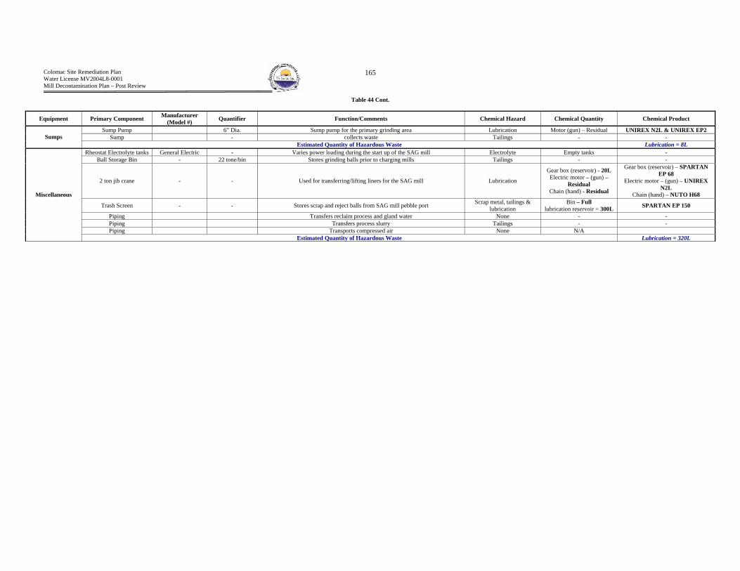
Colomac Site Remediation Plan Water License MV2004L8-0001 Mill Decontamination Plan – Post Review
165
Table 44 Cont.
Equipment Primary Component Manufacturer (Model #) Quantifier Function/Comments Chemical Hazard Chemical Quantity Chemical Product
Sump Pump 6” Dia. Sump pump for the primary grinding area Lubrication Motor (gun) – Residual UNIREX N2L & UNIREX EP2 Sump - collects waste Tailings - - Sumps
Estimated Quantity of Hazardous Waste Lubrication = 8L Rheostat Electrolyte tanks General Electric - Varies power loading during the start up of the SAG mill Electrolyte Empty tanks -
Ball Storage Bin - 22 tone/bin Stores grinding balls prior to charging mills Tailings - -
2 ton jib crane - - Used for transferring/lifting liners for the SAG mill Lubrication
Gear box (reservoir) - 20L Electric motor – (gun) –
Residual Chain (hand) - Residual
Gear box (reservoir) – SPARTAN EP 68
Electric motor – (gun) – UNIREX N2L
Chain (hand) – NUTO H68
Trash Screen - - Stores scrap and reject balls from SAG mill pebble port Scrap metal, tailings & lubrication
Bin – Full lubrication reservoir = 300L SPARTAN EP 150
Piping Transfers reclaim process and gland water None - - Piping Transfers process slurry Tailings - - Piping Transports compressed air None N/A
Miscellaneous
Estimated Quantity of Hazardous Waste Lubrication = 320L

Colomac Site Remediation Plan Water License MV2004L8-0001 Mill Decontamination Plan – Post Review
166
(b) Secondary Grinding 1. Function
The ball mill reduces the grain size of the primary SAG mill slurry discharge to a distribution suitable for downstream chemical leaching of gold (70% minus 200 mesh).
2. Footprint and Location of Key Chemical Hazards Refer to Figure 16
3. Components – Description and Chemical Hazards Refer to for a detail discussion. Overall estimated quantities of chemical hazards area as follows:
Table 45 Secondary Grinding and Classification - Estimated Quantities of Hazardous Waste
Hazardous Waste Estimated Quantity Lubrication 4103 L + Piping
Tailings Present in piping, spills on ground floor – Widespread Process Residual – Saturated Solids 2260 m3 (SRK Upper Estimate)
Process Residual - Pore Water 791 m3
Process Residual - Free Water 80 m3
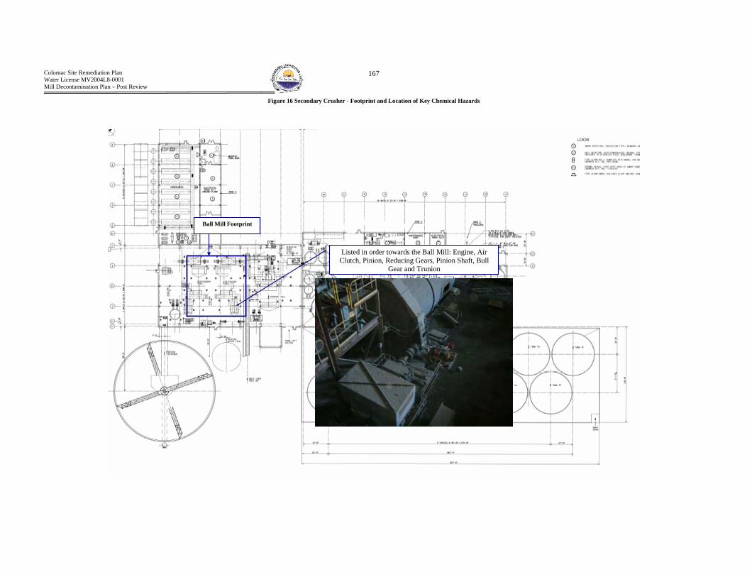
Colomac Site Remediation Plan Water License MV2004L8-0001 Mill Decontamination Plan – Post Review
167
Figure 16 Secondary Crusher - Footprint and Location of Key Chemical Hazards
Ball Mill Footprint
Listed in order towards the Ball Mill: Engine, Air Clutch, Pinion, Reducing Gears, Pinion Shaft, Bull
Gear and Trunion
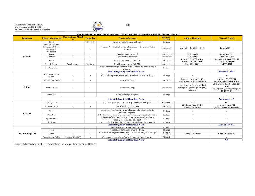
Colomac Site Remediation Plan Water License MV2004L8-0001 Mill Decontamination Plan – Post Review
168
Table 46 Secondary Crushing and Classification - Circuit Components Chemical Hazards and Estimated Quantities
Equipment Primary Component Manufacturer (Model #) Quantifier Function/Comment Chemical
Hazard Chemical Quantity Chemical Product
Shell - 14’6” x 28’ Grinds ore to 70% minus 200 mesh Tailings - - Trunion, feed and
discharge –Hydroset and general lubrication
- - Hydroset -Provides high pressure lubrication to the trunion during start up Lubrication reservoir – 4 x 500L = 2000L Spartan EP 150
Reducer - - Reduces rotational speed Lubrication bath – 400L Spartan EP 220 Reducer - - Reduces rotation speed Lubrication bath – 400L Spartan EP 220
Pinion - - Transfers energy to the Ball Mill Lubrication Reservoir 2 x 300L = 600L Farval – 2 x205L = 410L
Reservoir = Spartan EP 150 Farval = Dynagear
Electric Motor Westinghouse 1500 rpm Provides power to the Ball Mill Lubrication 2 x 100L = 200L NUTO H68
2 x Pump Box Collects slurry discharge from ball mills and from the primary screen underflow Tailings - -
Ball Mill
Estimated Quantity of Hazardous Waste Lubrication = 3600 L Rough and Clean
spirals - - Physically separates heavier gold particles from process slurry Tailings - -
2 x Discharge Pumps - - Pumps the slurry Lubrication bearings – (reservoir) – 8L electric motor – (gun) - residual
bearings – NUTO H68 electric (gun) – UNIREX N2L
Feed Pumps - - Pumps the slurry Lubrication electric motor (gun) – residual
bearings and general grease (gun) - residual
electric motor (gun) – UNIREX N2L
bearings and general grease (gun) – UNIREX EP2
Pump box Spiral discharge pumpbox Tailings - -
Spirals
Estimated Quantity of Hazardous Waste Lubrication = 8 L
12 x Cyclones - - Cyclones gravity separate coarse grained fraction of gold Removed N/A N/A
4 x Feed pump - - Transfers slurry to cyclone Lubrication Gearings (reservoir) 40L General – Residual
bearings - Nuto H68 general – UNIREX EP2/N2L
Tank Stores slurry originating from cyclone underflow for transfer to concentrating table Tailings - -
Tank/box Collects overflow from cyclones prior to screening in the trash screens Tailings - -
Splitter Box Splits underflow from the cyclones into two streams, one to the spirals, one to the ball mill input Tailings - -
Bleed Box Stores underflow from the cyclones for transport to the SAG mill Tailings - -
Cyclone
Estimated Quantity of Hazardous Waste Lubrication = 40 L Tank - - Stores slurry prior to separation on table Tailings - - Tank - - Stores table concentrate prior to refining Tailings - -
Pump - - Transfers table recycle concentrate to the concentrating table storage tank
Tailings & Lubrication General – Residual UNIREX EP2/N2L
Concentration Table Knelson KC-CD30 - Concentrates heavy/large free gold through physical sorting Cleaned - -
Concentrating Table
Estimated Quantity of Hazardous Waste N/A
Figure 16 Secondary Crusher - Footprint and Location of Key Chemical Hazards

Colomac Site Remediation Plan Water License MV2004L8-0001 Mill Decontamination Plan – Post Review
169
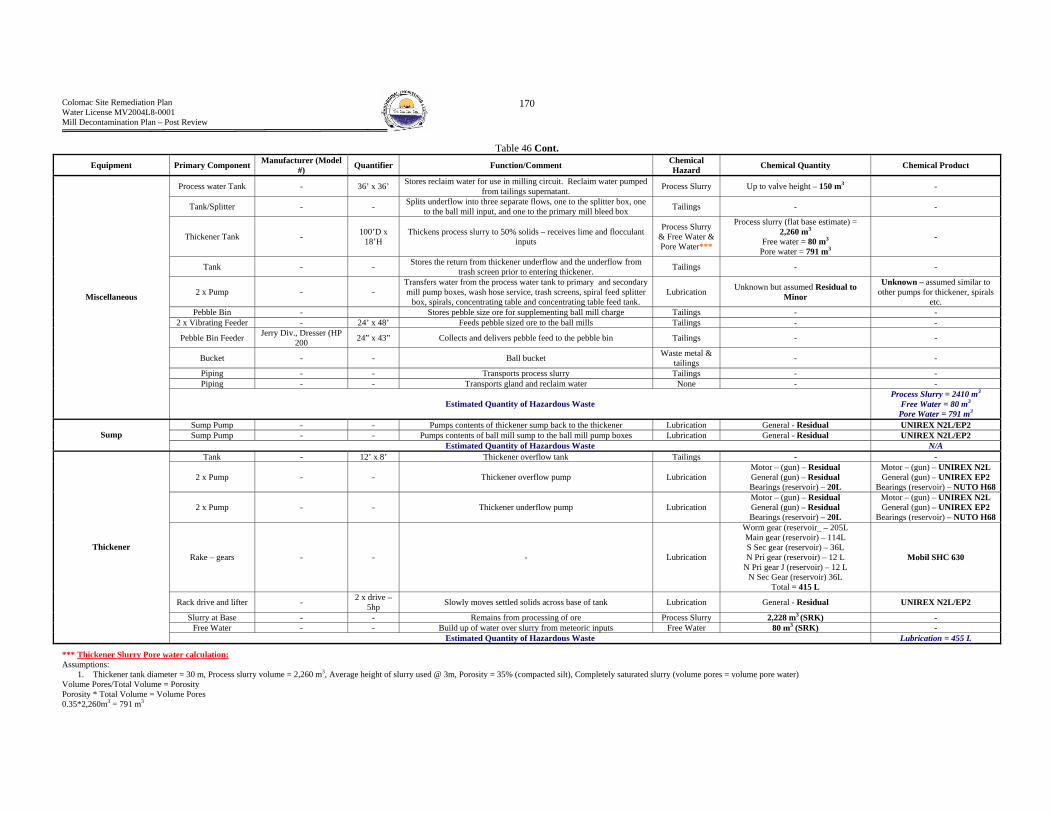
Colomac Site Remediation Plan Water License MV2004L8-0001 Mill Decontamination Plan – Post Review
170
Table 46 Cont. Equipment Primary Component Manufacturer (Model
#) Quantifier Function/Comment Chemical Hazard Chemical Quantity Chemical Product
Process water Tank - 36’ x 36’ Stores reclaim water for use in milling circuit. Reclaim water pumped from tailings supernatant. Process Slurry Up to valve height – 150 m3 -
Tank/Splitter - - Splits underflow into three separate flows, one to the splitter box, one to the ball mill input, and one to the primary mill bleed box Tailings - -
Thickener Tank - 100’D x 18’H
Thickens process slurry to 50% solids – receives lime and flocculant inputs
Process Slurry & Free Water & Pore Water***
Process slurry (flat base estimate) = 2,260 m3
Free water = 80 m3 Pore water = 791 m3
-
Tank - - Stores the return from thickener underflow and the underflow from trash screen prior to entering thickener. Tailings - -
2 x Pump - - Transfers water from the process water tank to primary and secondary mill pump boxes, wash hose service, trash screens, spiral feed splitter
box, spirals, concentrating table and concentrating table feed tank. Lubrication Unknown but assumed Residual to
Minor
Unknown – assumed similar to other pumps for thickener, spirals
etc. Pebble Bin - Stores pebble size ore for supplementing ball mill charge Tailings - -
2 x Vibrating Feeder - 24’ x 48’ Feeds pebble sized ore to the ball mills Tailings - -
Pebble Bin Feeder Jerry Div., Dresser (HP 200 24” x 43” Collects and delivers pebble feed to the pebble bin Tailings - -
Bucket - - Ball bucket Waste metal & tailings - -
Piping - - Transports process slurry Tailings - - Piping - - Transports gland and reclaim water None - -
Miscellaneous
Estimated Quantity of Hazardous Waste Process Slurry = 2410 m3
Free Water = 80 m3 Pore Water = 791 m3
Sump Pump - - Pumps contents of thickener sump back to the thickener Lubrication General - Residual UNIREX N2L/EP2 Sump Pump - - Pumps contents of ball mill sump to the ball mill pump boxes Lubrication General - Residual UNIREX N2L/EP2 Sump
Estimated Quantity of Hazardous Waste N/A Tank - 12’ x 8’ Thickener overflow tank Tailings - -
2 x Pump - - Thickener overflow pump Lubrication Motor – (gun) – Residual General (gun) – Residual Bearings (reservoir) – 20L
Motor – (gun) – UNIREX N2L General (gun) – UNIREX EP2
Bearings (reservoir) – NUTO H68
2 x Pump - - Thickener underflow pump Lubrication Motor – (gun) – Residual General (gun) – Residual Bearings (reservoir) – 20L
Motor – (gun) – UNIREX N2L General (gun) – UNIREX EP2
Bearings (reservoir) – NUTO H68
Rake – gears - - - Lubrication
Worm gear (reservoir_ – 205L Main gear (reservoir) – 114L S Sec gear (reservoir) – 36L N Pri gear (reservoir) – 12 L
N Pri gear J (reservoir) – 12 L N Sec Gear (reservoir) 36L
Total = 415 L
Mobil SHC 630
Rack drive and lifter - 2 x drive – 5hp Slowly moves settled solids across base of tank Lubrication General - Residual UNIREX N2L/EP2
Slurry at Base - - Remains from processing of ore Process Slurry 2,228 m3 (SRK) - Free Water - - Build up of water over slurry from meteoric inputs Free Water 80 m3 (SRK) -
Thickener
Estimated Quantity of Hazardous Waste Lubrication = 455 L
*** Thickener Slurry Pore water calculation: Assumptions:
1. Thickener tank diameter = 30 m, Process slurry volume = 2,260 m3, Average height of slurry used @ 3m, Porosity = 35% (compacted silt), Completely saturated slurry (volume pores = volume pore water) Volume Pores/Total Volume = Porosity Porosity * Total Volume = Volume Pores 0.35*2,260m3 = 791 m3

Colomac Site Remediation Plan Water License MV2004L8-0001 Mill Decontamination Plan – Post Review
171
B3 - Reagent Addition Circuit(s) The Recovery circuit can be further broken down into the following circuits:
(a) Sodium Cyanide (b) Lime and Caustic (c) Hydrochloric Acid (d) Flocculant
Figure 17, presented on the following page, displays the PFD’s for the reagent addition circuits

Colomac Site Remediation Plan Water License MV2004L8-0001 Mill Decontamination Plan – Post Review
172
Figure 17 Reagent Process Flow Diagrams

Colomac Site Remediation Plan Water License MV2004L8-0001 Mill Decontamination Plan – Post Review
173
(a) Sodium Cyanide (NaCN) 1. Function
Sodium cyanide is used as a lixivant.. Sodium cyanide forms a strong soluble complex with gold, thus leaching it from the ore and into the slurry solution. The circuit delivers dissolved sodium cyanide (free cyanide) to the cyanidation or leaching circuit.
2. Footprint and Location of Key Chemical Hazards Refer to Figure 18 and Figure 19
3. Circuit Components - Chemical Hazard Identification and Estimated Quantities Refer to and Table 49 for a detailed description. The following summarizes the estimated quantities of chemical hazards
Table 47 Cyanide Reagent Addition Circuit - Estimated Quantities of Chemical Hazards
Hazardous Waste Estimated Quantity Lubrication 100 L
Cyanide Scaling (Piping) 1.21m3 or 1.9 tonnes

Colomac Site Remediation Plan Water License MV2004L8-0001 Mill Decontamination Plan – Post Review
174
Figure 18 Footprint - Cyanide Reagent Addition Circuit – Plan View
Storage Tank
Mixing Tank
3” To the Vibratory Screens on Level 3
1” To the Vibratory Screens on Level 3
3” PVC from sludge pump to the primary
3” PVC cyanide loop (distribution pump at storage tank to ball mill pump box to
leach tanks and returning to the mixing tank
3” PVC distribution to the first three CIP tanks (splits off of
loop inlet to leach circuit)
Transfer line
Air actuated flow controlled valves for cyanide delivery
Manually actuated valves for cyanide delivery
1.5” carbon steel
Walkway
1” Plastic line to primary screen area
Area of Direct Exposure to Concentrated Cyanide Salts
Potential cyanide scaling from pipe
rupture
Scaling on cyanide distribution pumps Carbon steel transfer
line to CIP sump
Close up view of reagent mixing and storage area
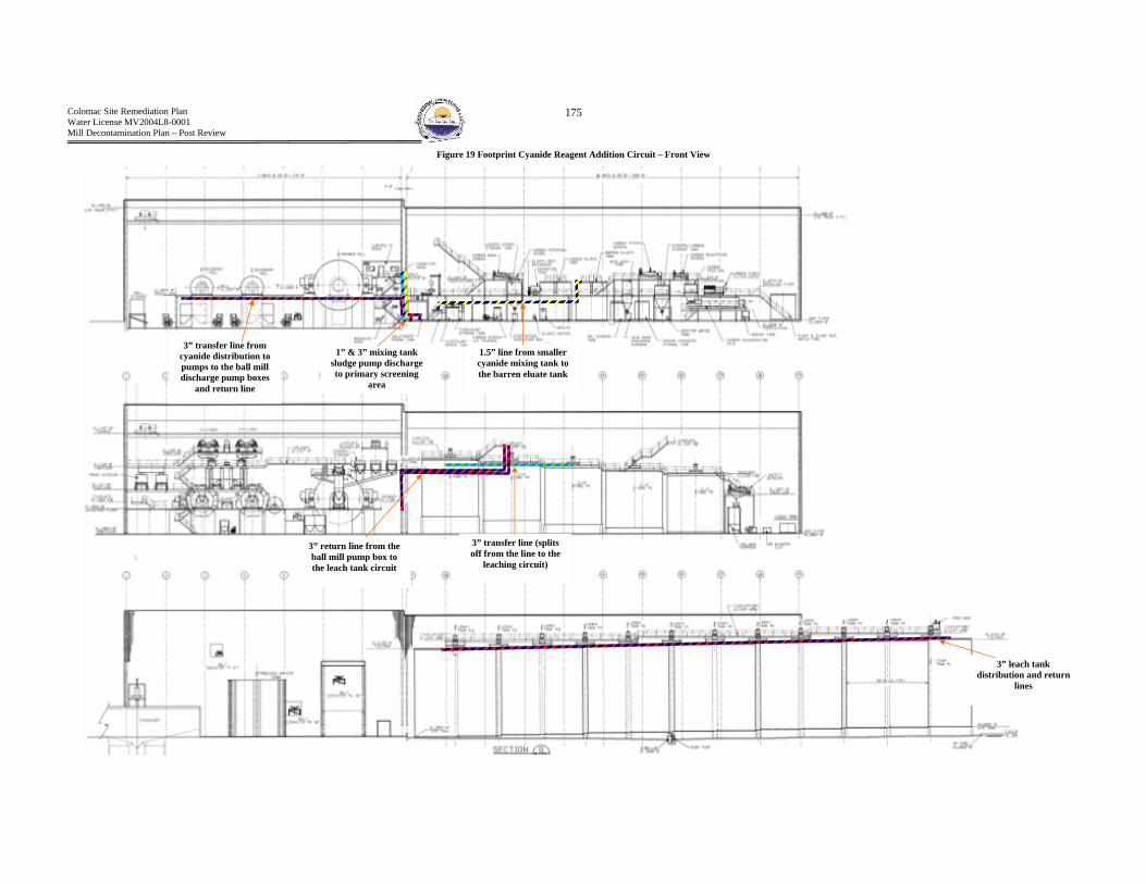
Colomac Site Remediation Plan Water License MV2004L8-0001 Mill Decontamination Plan – Post Review
175
Figure 19 Footprint Cyanide Reagent Addition Circuit – Front View
1” & 3” mixing tank sludge pump discharge to primary screening
area d
3” transfer line from cyanide distribution to pumps to the ball mill discharge pump boxes
and return line
1.5” line from smaller cyanide mixing tank to the barren eluate tank
3” return line from the ball mill pump box to the leach tank circuit
3” transfer line (splits off from the line to the
leaching circuit)
3” leach tank distribution and return
lines

Colomac Site Remediation Plan Water License MV2004L8-0001 Mill Decontamination Plan – Post Review
176
Table 48 Cyanide Reagent Addition Circuit (leach tanks, ball mill, CIP tanks and primary screen area) Components – Chemical Hazards and Estimated Quantities
Equipment Primary Component Manufacturer (Model No.) Quantifier Function/Comment Chemical Hazard Chemical Quantity Chemical Product
Sludge Pump - N/A Removed N/A N/A N/A
2 x Distribution Pump - 3" Distributes Sodium cyanide to the leach tanks and CIP tanks and SAG mill (1” PVC line ends at primary screen)
Reagent Scaling*** & Lubrication
Reagent Scaling = Residual Lubrication = (reservoir) –
20L Lubrication general -
Residual
Reservoir = NUTO H68
General = UNIREX N2L
Transfer Pump - - Transfers mixed cyanide to cyanide storage tank Reagent Scaling & Lubrication
Reagent Scaling = Residual Lubrication = (reservoir) –
20L
Reservoir = NUTO H68
Sump Pump - - Transfers contents of sump back to cyanide tanks Reagent Scaling & Lubrication
Reagent Scaling = Residual Lubrication = (gun) –
Residual UNIREX N2L/EP2
Pumps
Estimated Quantity of Hazardous Waste Lubrication = 40L Hopper Transfers contents of bulk reagents to the screw feeder Reagent Scaling Residual -
Screw Conveyor 6” Dia. x 8’ 3” Transfers solid sodium cyanide from the hopper to the mix tank Reagent Scaling Unknown -
Agitator Mixes sodium cyanide in the mix tank Reagent Scaling & Lubrication
Chemical Scaling – Residual Lubrication - Residual Unknown
Hopper/Agitator
Estimated Quantity of Hazardous Waste N/A
Monorail Hoist - 2 ton Transfers bulk bags of sodium cyanide to the hopper Lubrication Reservoir – 50L Engine – (gun) –Residual
Reservoir Spartan EP 68
Engine – UNIREX N2L
Fan - - Transfers HCN gas to the outside atmosphere Lubrication General (gun) - Residual UNIREX N2L/EP2 Sump - - Collects cyanide spills for subsequent pumping Tailings **High Cyanide Residual Sodium Cyanide
Miscellaneous
Estimated Quantity of Hazardous Waste Lubrication = 50L Primary Mixing Tank - 12' x 12' Provides containment for mixing sodium cyanide prior to storage Reagent Scaling Residual - Primary Storage Tank - 10' x 12' Stores mixed sodium cyanide prior to distribution Reagent Scaling Residual -
Pipe - 3" PVC Transfers mixed reagent Reagent Scaling*** 1.38m3 or 2.2 tonnes Sodium Cyanide Pipe -- - Transfers gland water and process water Reagent Scaling None expected -
Tanks and Pipes
Estimated Quantity of Hazardous Waste Chemical Scaling = 1.38m3 or 2.2 tonnes
*** Reagent scaling is assumed to have the properties of the bulk free product. *** Cyanide Pipe Scaling Calculation Assume: 3” pipe diameter, 575 m of piping (linear), 1cm of scaling coats the entire inside of the piping, dry specific gravity of cyanide = 1.6 Diameter outer = 0.0762m, Diameter inner = 0.0562 m Area outer = pi()R2 = 3.14*0.03812 = 0.0046m2, Area inner = 0.0025m2, Cross Sectional Area of Scaling = 0.0046m2 – 0.0025m2 = 0.0021m2 Volume of cyanide scaling = 1.21 m3 Weight of cyanide scaling = 1.21m3 * 1600kg/m3 * 1000kg/tonne = 1.9 tonnes
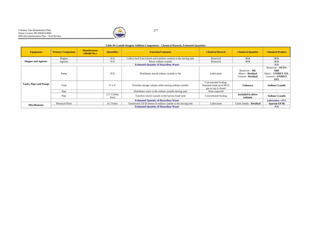
Colomac Site Remediation Plan Water License MV2004L8-0001 Mill Decontamination Plan – Post Review
177
Table 49 Cyanide Reagent Addition Components – Chemical Hazards, Estimated Quantities
Equipment Primary Component Manufacturer (Model No.) Quantifier Function/Comment Chemical Hazard Chemical Quantity Chemical Product
Hopper N/A Collect feed from barrels and transfers contents to the mixing tank Removed N/A N/A Agitator N/A Mixes sodium cyanide Removed N/A N/A Hopper and Agitator
Estimated Quantity of Hazardous Waste N/A
Pump N/A Distributes mixed sodium cyanide to the Lubrication Reservoir – 10L
Motor – Residual General - Residual
Reservoir – NUTO H68
Motor – UNIREX N2L General – UNIREX
EP2
Tank 6’ x 6’ Provides storage volume while mixing sodium cyanide Concentrated Scaling.
Potential build up of HCN gas as top is closed
Unknown Sodium Cyanide
Pipe Distributes water to the sodium cyanide mixing tank None expected - -
Pipe 1.5” Carbon Steel Transfers mixed cyanide to the barren eluate tank Concentrated Scaling Included in above
estimate Sodium Cyanide
Tanks, Pipes and Pumps
Estimated Quantity of Hazardous Waste Lubrication =10 L Monorail Hoist 0.5 Tonne Transferred 120 lb drums of sodium cyanide to the mixing tank Lubrication Chain (hand) – Residual Spartan EP 68 Miscellaneous Estimated Quantity of Hazardous Waste N/A

Colomac Site Remediation Plan Water License MV2004L8-0001 Mill Decontamination Plan – Post Review
178
(b) CLimeC – Quicklime/Calcium Oxide (CaO) and Caustic (NaOH) 1. Function
The lime distribution circuit provides pH adjustment to the thickener and the secondary grinding (ball mill) pump boxes. The caustic circuit provides pH adjustment to the cyanide mixing tanks, barren eluate tanks and the dilute caustic tank.
2. Footprint and Location of Key Chemical Hazards Figure 20.
3. Circuit Components - Chemical Hazards and Estimated Quantities Refer to Table 51 & Table 52 for and detailed description for each circuit component. The follow table summarizes the estimated quantities of hazardous materials.
Table 50 Lime and Caustic Reagent Addition Circuit - Estimated Quantities of Chemical Hazards
Hazardous Waste Estimated Quantity Lubrication 250 L
Lime Scaling (Piping) 2.0 m3 or 4.50 tonnes Lime Scaling (Slaking Tank and Cyclone) 1.0 m3 or 2.25 tonnes
Lime Scaling (General Area) Unknown – Widespread throughout entire lime area Caustic Scaling Contained Within Piping 0.05m3 or 0.10 tonnes
Caustic Scaling (Piping) 0.05m3 or 0.10 tonne

Colomac Site Remediation Plan Water License MV2004L8-0001 Mill Decontamination Plan – Post Review
179
Lime scaling – interior of mixing/storage tanks
Residual Scaling On Ball Mill Slaker
View of tanks and pumps – Note the corrosion
Figure 20 Footprint - lime and caustic lines ``

Colomac Site Remediation Plan Water License MV2004L8-0001 Mill Decontamination Plan – Post Review
180
Table 51 Lime circuit components - chemical hazards and quantities
Equipment Primary Component Quantifier Manufacturer (Model No.) Function/Comment Chemical Hazard Chemical Quantity Chemical Product
Shell - 3’ 11” x 6’ 11” Slakes hydrated lime to form Assume 10% full – Reagent Scaling 1.0 m3 or 2.25 tonnes Lime
Gears and Motor - - Powers ball mill Lubrication General – Residual Reservoir – 100L
General – Unirex N2L/EP2 & MOBILUX EP111
Reservoir – SPARTAN EP 200
Ball Mill
Estimated Quantity of Hazardous Waste
Sump Pump 2.5" Transfers contents of lime sump to the cyclone feed pump Lubrication General Greasing - Residual
General Greasing –UNIREX N2L/EP2
2 x Tank 14' x 15' Stores slaked lime prior to distribution Reagent Scaling Residual Lime Screw feeder 6” Dia x 9’ 3” Transfers output from hopper to the mix tank Reagent Scaling Residual Lime
Hopper 4 ton capacity Collects contents of 2 ton lime bag Reagent Scaling Residual Lime
Pump 3" Distributes slaked lime to grinding mills and the leaching tank Reagent Scaling and Lubrication
Scaling – Residual Lubrication – (reservoir)
10L
Lime NUTO H68
Pump Cyclone feed pump transfers contents of lime ball mill to the cyclone Reagent Scaling and Lubrication
Scaling – Residual Lubrication – (reservoir)
50L
Lime SPARTAN EP 220
Pipe Transfers mixed lime to other circuits Reagent Scaling*** 2.0 m3 or 4.50 tonnes Lime
Pipe Transfers process water to mix lime None None -
Tanks Pumps & Pipes
Estimated Quantity of Hazardous Waste Lubrication- 200 L Lime – 3.0 m3 or 6.75 tonnes
2 x Cyclone 3" Separates lime based on particle size and sends underflow (oversize) to slaker and overflow to storage tanks Reagent Scaling Residual Lime
O/F Launder Collects overflow from the cyclones and the return from the lime and distributes to the storage tanks Reagent Scaling Residual Lime
U/F Box Collects underflow from the cyclones Reagent Scaling Residual Lime
2 x Agitator Mixes the contents of the lime mixing tank Reagent Scaling & Lubrication
Reagent Scaling – Residual
Lubrication –(reservoir) – 40L
Lime MOBIL SHC 630
Cyclone, Hopper, Agitator Etc.
Estimated Quantity of Hazardous Waste Lubrication- 40L General working area Note: General area is covered in lime Reagent Scaling Unknown - Miscellaneous
Estimated Quantity of Hazardous Waste N/A *** Lime Pipe Scaling Calculation Assume: 3” pipe diameter, 450 m of piping (linear), scaling plugs the inside of the piping, dry specific gravity of Lime = 2.24 Calculation: Cross Sectional area of pipe = pi() R2 = 3.14*(0.0381m)2 = 0.0046m2 Volume of cyanide scaling = 0.0046m2 * 450m = 2.0 m3 Weight of cyanide scaling = 2.0m3 * 2240kg/m3 * 1000kg/tonne = 4.5 tonnes
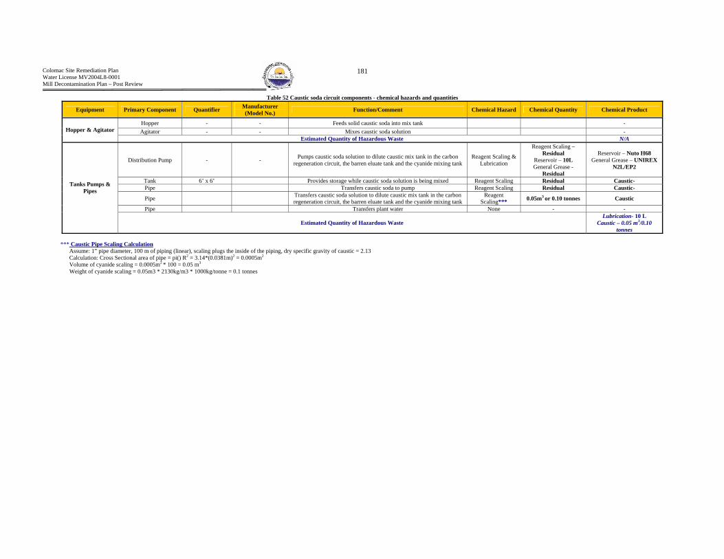
Colomac Site Remediation Plan Water License MV2004L8-0001 Mill Decontamination Plan – Post Review
181
Table 52 Caustic soda circuit components - chemical hazards and quantities
Equipment Primary Component Quantifier Manufacturer (Model No.) Function/Comment Chemical Hazard Chemical Quantity Chemical Product
Hopper - - Feeds solid caustic soda into mix tank - Agitator - - Mixes caustic soda solution - Hopper & Agitator
Estimated Quantity of Hazardous Waste N/A
Distribution Pump - - Pumps caustic soda solution to dilute caustic mix tank in the carbon regeneration circuit, the barren eluate tank and the cyanide mixing tank
Reagent Scaling & Lubrication
Reagent Scaling – Residual
Reservoir – 10L General Grease -
Residual
Reservoir – Nuto H68 General Grease – UNIREX
N2L/EP2
Tank 6’ x 6’ Provides storage while caustic soda solution is being mixed Reagent Scaling Residual Caustic- Pipe Transfers caustic soda to pump Reagent Scaling Residual Caustic-
Pipe Transfers caustic soda solution to dilute caustic mix tank in the carbon regeneration circuit, the barren eluate tank and the cyanide mixing tank
Reagent Scaling*** 0.05m3 or 0.10 tonnes Caustic
Pipe Transfers plant water None - -
Tanks Pumps & Pipes
Estimated Quantity of Hazardous Waste Lubrication- 10 L
Caustic – 0.05 m3/0.10 tonnes
*** Caustic Pipe Scaling Calculation Assume: 1” pipe diameter, 100 m of piping (linear), scaling plugs the inside of the piping, dry specific gravity of caustic = 2.13 Calculation: Cross Sectional area of pipe = pi() R2 = 3.14*(0.0381m)2 = 0.0005m2 Volume of cyanide scaling = 0.0005m2 * 100 = 0.05 m3
Weight of cyanide scaling = 0.05m3 * 2130kg/m3 * 1000kg/tonne = 0.1 tonnes

Colomac Site Remediation Plan Water License MV2004L8-0001 Mill Decontamination Plan – Post Review
182
(c) HHHydrochloric Acid (Muriatic Acid = HCL 35%) 1. Function
The muriatic acid circuit provides acid to the carbon regeneration circuit to clean the carbon 2. Circuit Components and Chemical Hazard Identification One 45 gallon drum or 205 L of Muriatic Acid was identified within the Mill
Table 53 Hydrochloric acid circuit components - chemical hazards and quantities
Primary Component
Manufacturer (Model No.) Quantifier Function/Comment Chemical Hazard Chemical
Quantity Chemical Product
Drum Pump - - Pumps muriatic acid to the dilute HCL storage tank Removed - -
Pipe - - Transfers muriatic acid to the dilute HCL storage tank Removed - -
The muriatic acid system has been removed from the Mill. As such no further consideration of this circuit will be undertaken.

Colomac Site Remediation Plan Water License MV2004L8-0001 Mill Decontamination Plan – Post Review
183
(d) Flocculant 1. Function
The flocculant circuit provides a flocculant to the thickener tank, prior to the leaching circuit.
2. Circuit Components and Chemical Hazard Identification
Table 54 Flocculant - Circuit Components and Chemical Hazards
Equip. Primary Comp. Quant. Function/Comments Chemical
Hazard Chemical Quantity Chemical Product
Tank 8’ x 8’ Provides storage during the mixing of the flocculant None - -
Tank - Provides temporary storage for the flocculant prior to distribution None - -
Pump 2.5 “ Dia. Flocculant sump vertical sump pump Motor – Residual General - Residual
Motor – UNIREX N2L General – UNIREX EP2
Transfer Pump 25 gpm Transfers mixed flocculant storage tank Lubricant Motor – Residual General - Residual
Motor – UNIREX N2L General – UNIREX EP2
Flocculant Metering
Pump - Meters flocculant to thickener tank Lubricant Motor – Residual
General - Residual Motor – UNIREX N2L
General – UNIREX EP2
Pipe - Transfers plant water None - - Pipe - Transfers mixed flocculant None - -
Tanks & Pipes
Estimated Quantity of Hazardous Waste N/A Wetting Cone - Wets the flocculant prior to entering the
mixing tank None - -
Feed Hopper c/w bag
splitter and feeder
- Feeds flocculant to the Mixing tank None - -
Agitator Mixes the contents of the flocculant mixing tank None - -
Hopper &
Agitator
Estimated Quantity of Hazardous Waste N/A The flocculant circuit is considered to be a very low chemical hazard. However, when in solution, flocculant is extremely slippery and is a considerable slip and trip hazard. Photographs are presented on the following page.

Colomac Site Remediation Plan Water License MV2004L8-0001 Mill Decontamination Plan – Post Review
184
Photograph 1 Flocculant Storage Tank (Foreground) and Mixing Tank (Background)
Photograph 2 Flocculant Sump Pump Within the Flocculant Sump
Photograph 3 Flocculant Hopper

Colomac Site Remediation Plan Water License MV2004L8-0001 Mill Decontamination Plan – Post Review
185
B4 - Leaching Circuit (Cyanidation) – Extraction

Colomac Site Remediation Plan Water License MV2004L8-0001 Mill Decontamination Plan – Post Review
186
Figure 21 Leaching Circuit

Colomac Site Remediation Plan Water License MV2004L8-0001 Mill Decontamination Plan – Post Review
187
1. Function Provides residence time for cyanide to complex with gold, thus leaching gold into solution.
2. Footprint Refer to Figure 22.
3. Circuit Components -Chemical Hazards and Estimated Quantities Refer to Table 56 for and detailed description for each circuit component. The follow table summarizes the estimated quantities of hazardous materials.
Table 55 Leaching Circuit - Estimated Quantities of Hazardous Materials
Hazardous Waste Estimated Quantity Lubrication 5,400 m3
Process Residual – Saturated Solid 2,228 m3 Pore Water 781 m3 Free Water 4,585 m3
Tailings 465 m3

Colomac Site Remediation Plan Water License MV2004L8-0001 Mill Decontamination Plan – Post Review
188
Leach Circuit Footprint
Figure 22 Footprint - Leaching Circuit
Leach Tanks Footprint
Air Compressors Oil remains within compressors
and is also present as staining on the floor
2 x Leach Tank Air Compressors

Colomac Site Remediation Plan Water License MV2004L8-0001 Mill Decontamination Plan – Post Review
189
Table 56 Leaching circuit components - chemical hazards and quantities
Leach Tank Slurry Pore water Calculation: Assumptions: 1. Leach tank diameter = 16 m, Process slurry volume = 186m3/tank, Porosity = 35% (compacted silt), Completely saturated slurry (volume pores = volume pore water) Volume Pores/Total Volume = Porosity Porosity * Total Volume = Volume Pores 0.35*186m3 = 65.1 m3/tank * 12 tanks = 781.2 m3
Tailings Contained within Sump Calculation: Area of sump = 3885 m2 , total cross sectional area of the leach tanks = 2112 m2 total void cross sectional area = 3885m2 – 2112m2 = 1773m2 Assume 1m of tailings then volume = 1773 m3
Primary Component Quantifier Function/Comment Chemical Hazard Chemical Quantity Chemical Product
12 x Tank 52’ Dia. x 56’
Provides storage and residence time for leaching of gold from process
slurry
Process Slurry, Pore Water and Free Water
Process Slurry = 2,228 m3
Pore Water*** = 781.2 m3 Tailings = 1446.8 m3
-
12 x Agitator 125 HP Mixes the contents of the leach tanks Tailings & Lubrication
Reservoir 12 x 450 L = 5400L
General (gun) – Residual Electric Motor - Residual
Reservoir – Mobil SHC 630 General (gun) – EPIC EP
102 Electric Motor – UNIREX
N2L
Sump Pump - Pumps contents of the leach tank sump to the leach tanks Tailings & Lubrication General – Residual General – UNIREX
N2L/EP2
Sump - Stores spill slurries/liquids prior to sump pumping Tailings Residual -
Pipe - Transfers Process Slurry Tailings Tailings - Pipe Transfers compressed air to spargers None - -
2 x Leach Air Compressor - Provides compressed air for
Sparging leach tanks Lubrication Reservoir – 160 L Compressor Oil 68
Leach tank area sump - Collects spills Tailings - -
Tailings spilled in
sump - Resulted from tank overflow and
from tank draining Tailings - 465 m3
Estimated Quantity of Hazardous Waste
Lubrication = 5400L Process Slurry = 2,228 m3
Pore Water = 781 m3 Tailings = 465 m3

Colomac Site Remediation Plan Water License MV2004L8-0001 Mill Decontamination Plan – Post Review
190
B5 - Recovery Circuit(s) (Carbon in Pulp) The Recovery circuit can be further broken down into the following circuits:
(a) Carbon Loading, Carbon Stripping and Carbon Regeneration (b) Electrowinning and Refining

Colomac Site Remediation Plan Water License MV2004L8-0001 Mill Decontamination Plan – Post Review
191
Figure 23 Recovery Circuit - Carbon Loading
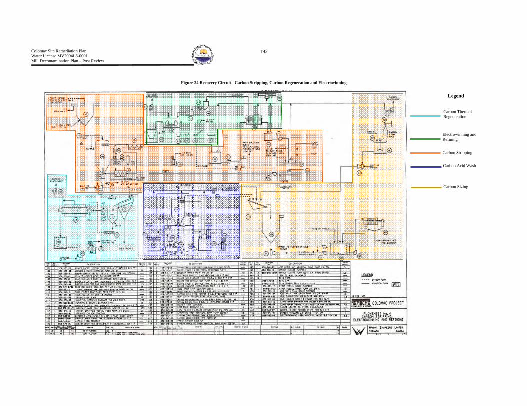
Colomac Site Remediation Plan Water License MV2004L8-0001 Mill Decontamination Plan – Post Review
192
Figure 24 Recovery Circuit - Carbon Stripping, Carbon Regeneration and Electrowinning
Carbon Sizing
Carbon Stripping
Carbon Acid Wash
Electrowinning and Refining
Carbon Thermal Regeneration
Legend

Colomac Site Remediation Plan Water License MV2004L8-0001 Mill Decontamination Plan – Post Review
193
(a) Carbon Loading, Carbon Stripping and Carbon Regeneration 1. Function The carbon loading circuit adsorbs the gold/cyanide complex from solution onto activated carbons surface binding sites. The carbon stripping circuit removes the gold/cyanide complex from the carbon binding sites through the use of an eluate. The carbon regeneration circuit removes impurities that have adsorbed onto the carbon binding sites, thus regenerating the activated carbon.
2. Footprint Refer to Figure 25
3. Circuit Components and Chemical Hazard Identification Refer to Table 58, Table 59 and Table 60 for and detailed description or each circuit component. The follow table summarizes the estimated quantities of hazardous wastes.
Table 57 Carbon Loading, Stripping and Regeneration - Estimated Quantities of Hazardous Materials
Hazardous Waste Estimated Quantity Lubrication 1924 L
Reagent Scaling (Caustic) Residual Caustic is present on pumps, valves in minor amounts Heat Exchange Unknown
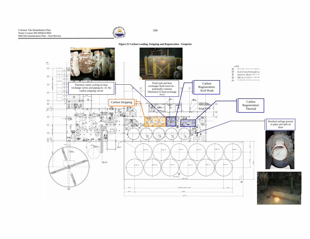
Colomac Site Remediation Plan Water License MV2004L8-0001 Mill Decontamination Plan – Post Review
194
Carbon Regeneration:
Thermal
Carbon Regeneration:
Acid Wash
Electrowinning
Carbon Stripping
` Figure 25 Carbon Loading, Stripping and Regeneration - Footprint
Residual tailings present in pipes and spilt on
floor
Potential caustic scaling on heat exchange valves and piping etc. of the
carbon stripping circuit
Flash tank and heat exchanger fluid reservoir –
potentially contains Therminol 55 heat exchange
fluid

Colomac Site Remediation Plan Water License MV2004L8-0001 Mill Decontamination Plan – Post Review
195
Table 58 Carbon Loading - Circuit Components and Chemical Hazards
Equipment Primary Component
Manufacturer (Model No.) Quantifier Function/Comment Chemical
Hazard Chemical Quantity Chemical Product
Tank - 9’ ID Loaded carbon storage tank Reagent Scaling Residual Caustic Loaded carbon
pump - 2’x2’ Loaded carbon transfer pump Tailings & Lubrication General - Residual UNIREX N2L/H68
Washing Screen Underflow Pump - - Transfers carbon screen underflow Tailings &
Lubrication General – Residual
Reservoir – 4L General – UNIREX N2L Reservoir – NUTO H68
5 x CIP Agitator - - Agitates the slurry/carbon solution Lubrication Reservoir – 1000L General - Residual
Reservoir – Mobil SHC 630 General – UNIREX N2L and
EPIC EP 102 Conditioning
(attrition) Tank Agitator
- - Agitates the carbon/water slurry Lubrication Reservoir – 50L Mobil SHC 630
CIP Sump pump - - Transfers contents of sump back to CIP tanks Lubrication & Reagent Scaling
Lubrication – Residual
Scaling - Residual
Lubrication – UNIREX N2L/EP2
Scaling – Cyanide (cyanide)
6 x Tailings Pumps Allis Chalmers Canada - Pumps barren slurry to tailings deposit Tailings &
Lubrication Tailings – Residual
Reservoir – 50L NUTO H68
Carbon Handling Area Sump Pump - - Transfers contents of carbon handling area Lubrication Residual -
Tanks, Pumps Piping and
Agitator
Estimated Quantity of Hazardous Waste Lubrication – 1054 L
Washing Screen - - Washes carbon Lubrication Reservoir – 100L General - Residual
Reservoir – Spartan EP 150 General – UNIREX N2L/EP2
Safety Screen - - Screens carbon following loading Lubrication & Tailings
Tailings - Residual Reservoir – 100L
General - Residual
Reservoir – Spartan EP 150 General – UNIREX N2L/EP2
Sizing Screens - - Sizes the carbon Lubrication Reservoir – 200L General - Residual
Reservoir – Spartan EP 150 General – UNIREX N2L/EP2
CIP Launder Air Blowers - - Use pressurized air to clean screens Lubrication Reservoir – 30L
General - Residual Reservoir – Terresso 150
General - UNIREX N2L/H68
1 ton jib crane - - Used for lifting Lubrication General – Residual Reservoir – 20L
General – Spartan EP 68/ UNIREX N2L
Reservoir – Spartan EP 68
Screens and Miscellaneous
Estimated Quantity of Hazardous Waste Lubrication – 450 L

Colomac Site Remediation Plan Water License MV2004L8-0001 Mill Decontamination Plan – Post Review
196
Table 59 Carbon Stripping Circuit Components - Chemical Hazards and Estimated Quantities
Equipment Primary Component
Manufacturer (Model No.) Quantifier Function/Comments Chemical Hazard Chemical Quantity Chemical Product
Pump 2’x2’ Loaded carbon transfer pump Lubrication & Reagent Scaling
General Lube – Residual
Reservoir – 10L Scaling - Residual
General – UNIREX N2L/EP2 Reservoir – NUTO H68
Scaling - Caustic
Eluate Heater Pump Pumps thermal fluid through eluate heater Lubrication Reservoir – 10L
General - Residual Reservoir – TERESSO 150
General - UNIREX N2L/EP2 Sump Pump - - Transfers contents of sump Lubrication Residual UNIREX N2L/EP2 Drum Pump Eluate Drum Pump Lubrication Residual UNIREX N2L
Vessel 6’ ID Carbon stripping vessel Reagent Scaling Residual Caustic Pump box Stripping vessel drain pump box – houses pump Reagent Scaling Residual Caustic
Drain Pump 1.5 hp, 3’’ x 2’’x6’’ Stripping vessel drain pump Lubrication &
Chemical Scaling
Scaling – Residual Lubrication –
reservoir – 10L General - Residual
Scaling – Caustic General – UNIREX N2L/EP2
Reservoir – NUTO H68
Loaded carbon pump Transfers loaded carbon Lubrication General – Residual
Reservoir – 10L General – UNIREX N2L Reservoir – NUTO H68
Estimated Quantity of Hazardous Waste Lubrication =40L Heat
Exchanger 85 ft2 Eluate heat exchanger Heat Exchange Reservoir - Unknown Therminol 55
Tank 31.5’’ dia x 87’’, 270 gal Eluate heater expansion tank Heat Exchange Unknown Therminol 55
Pump 150 USGPM max Eluate heater thermal fluid circ. Pump (moves heat X fluid) Heat Exchange Unknown Therminol 55
Heater 4 MMBTU/HR Eluate heater, oil fired (provides heating for heat X network) Lubrication Residual Unknown
Heater Eluate tank heater Lubrication Reservoir – 10L General - Residual
Reservoir – NUTO H68 General - UNIREX N2L/EP2
Heat Exchange
Estimated Quantity of Hazardous Waste Lubrication =10L
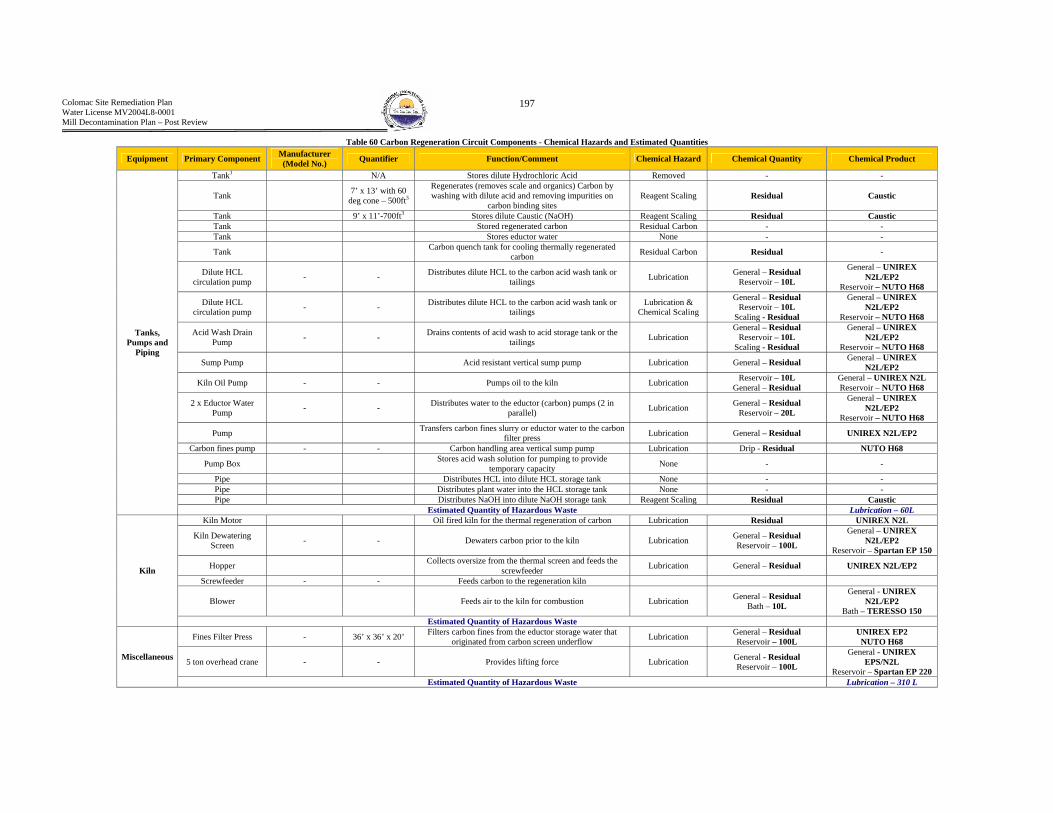
Colomac Site Remediation Plan Water License MV2004L8-0001 Mill Decontamination Plan – Post Review
197
Table 60 Carbon Regeneration Circuit Components - Chemical Hazards and Estimated Quantities
Equipment Primary Component Manufacturer (Model No.) Quantifier Function/Comment Chemical Hazard Chemical Quantity Chemical Product
Tank1 N/A Stores dilute Hydrochloric Acid Removed - -
Tank 7’ x 13’ with 60 deg cone – 500ft3
Regenerates (removes scale and organics) Carbon by washing with dilute acid and removing impurities on
carbon binding sites Reagent Scaling Residual Caustic
Tank 9’ x 11’-700ft3 Stores dilute Caustic (NaOH) Reagent Scaling Residual Caustic Tank Stored regenerated carbon Residual Carbon - - Tank Stores eductor water None - -
Tank Carbon quench tank for cooling thermally regenerated carbon Residual Carbon Residual -
Dilute HCL circulation pump - - Distributes dilute HCL to the carbon acid wash tank or
tailings Lubrication General – Residual Reservoir – 10L
General – UNIREX N2L/EP2
Reservoir – NUTO H68
Dilute HCL circulation pump - - Distributes dilute HCL to the carbon acid wash tank or
tailings Lubrication &
Chemical Scaling
General – Residual Reservoir – 10L
Scaling - Residual
General – UNIREX N2L/EP2
Reservoir – NUTO H68
Acid Wash Drain Pump - - Drains contents of acid wash to acid storage tank or the
tailings Lubrication General – Residual
Reservoir – 10L Scaling - Residual
General – UNIREX N2L/EP2
Reservoir – NUTO H68
Sump Pump Acid resistant vertical sump pump Lubrication General – Residual General – UNIREX N2L/EP2
Kiln Oil Pump - - Pumps oil to the kiln Lubrication Reservoir – 10L General – Residual
General – UNIREX N2L Reservoir – NUTO H68
2 x Eductor Water Pump - - Distributes water to the eductor (carbon) pumps (2 in
parallel) Lubrication General – Residual Reservoir – 20L
General – UNIREX N2L/EP2
Reservoir – NUTO H68
Pump Transfers carbon fines slurry or eductor water to the carbon filter press Lubrication General – Residual UNIREX N2L/EP2
Carbon fines pump - - Carbon handling area vertical sump pump Lubrication Drip - Residual NUTO H68
Pump Box Stores acid wash solution for pumping to provide temporary capacity None - -
Pipe Distributes HCL into dilute HCL storage tank None - - Pipe Distributes plant water into the HCL storage tank None - - Pipe Distributes NaOH into dilute NaOH storage tank Reagent Scaling Residual Caustic
Tanks, Pumps and
Piping
Estimated Quantity of Hazardous Waste Lubrication – 60L Kiln Motor Oil fired kiln for the thermal regeneration of carbon Lubrication Residual UNIREX N2L
Kiln Dewatering Screen - - Dewaters carbon prior to the kiln Lubrication General – Residual
Reservoir – 100L
General – UNIREX N2L/EP2
Reservoir – Spartan EP 150
Hopper Collects oversize from the thermal screen and feeds the screwfeeder Lubrication General – Residual UNIREX N2L/EP2
Screwfeeder - - Feeds carbon to the regeneration kiln
Blower Feeds air to the kiln for combustion Lubrication General – Residual Bath – 10L
General - UNIREX N2L/EP2
Bath – TERESSO 150
Kiln
Estimated Quantity of Hazardous Waste
Fines Filter Press - 36’ x 36’ x 20’ Filters carbon fines from the eductor storage water that originated from carbon screen underflow Lubrication General – Residual
Reservoir – 100L UNIREX EP2
NUTO H68
5 ton overhead crane - - Provides lifting force Lubrication General - Residual Reservoir – 100L
General - UNIREX EPS/N2L
Reservoir – Spartan EP 220
Miscellaneous
Estimated Quantity of Hazardous Waste Lubrication – 310 L

Colomac Site Remediation Plan Water License MV2004L8-0001 Mill Decontamination Plan – Post Review
198
(b) Electrowinning and Refining 1. Function
The electrowinning circuit precipitates gold from the pregnant eluate solution onto wire wool cathodes. The cathode wire is periodically removed from the electrowinning cells and power washed of gold. The gold sludge is then filtered dried and sent to the refining circuit. The refinery separates the gold from other metal impurities through physical separation with heat and flux. The final product is gold dore.
2. Footprint Refer to
3. Circuit Components -Chemical Hazard and Estimated Quantities
Table 61 Electrowinning and Refining - Estimated Quantities of Hazardous Materials
Hazardous Waste Estimated Quantity Lubrication 200 L
Reagent Scaling Caustic and potentially cyanide scaling present on cells and pumps
Silica Sand 12 x 22 kg bags = 272.4 kg Manganese Dioxide 1 Drum (2’L x 16”D) = 395 kg
Borax 391 kg Soda Ash 565 kg
Potential Anti Freeze in Induction Furnace Cooling Lines – Assumed Glycol Based Unknown
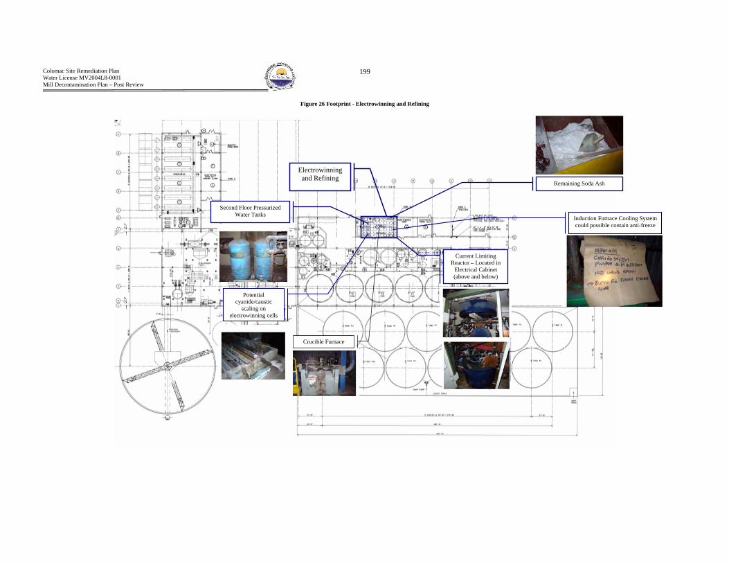
Colomac Site Remediation Plan Water License MV2004L8-0001 Mill Decontamination Plan – Post Review
199
Figure 26 Footprint - Electrowinning and Refining
Electrowinning and Refining
Remaining Soda Ash
Current Limiting Reactor – Located in
Electrical Cabinet (above and below)
Induction Furnace Cooling System could possible contain anti-freeze
Second Floor Pressurized Water Tanks
Potential cyanide/caustic
scaling on electrowinning cells
Crucible Furnace
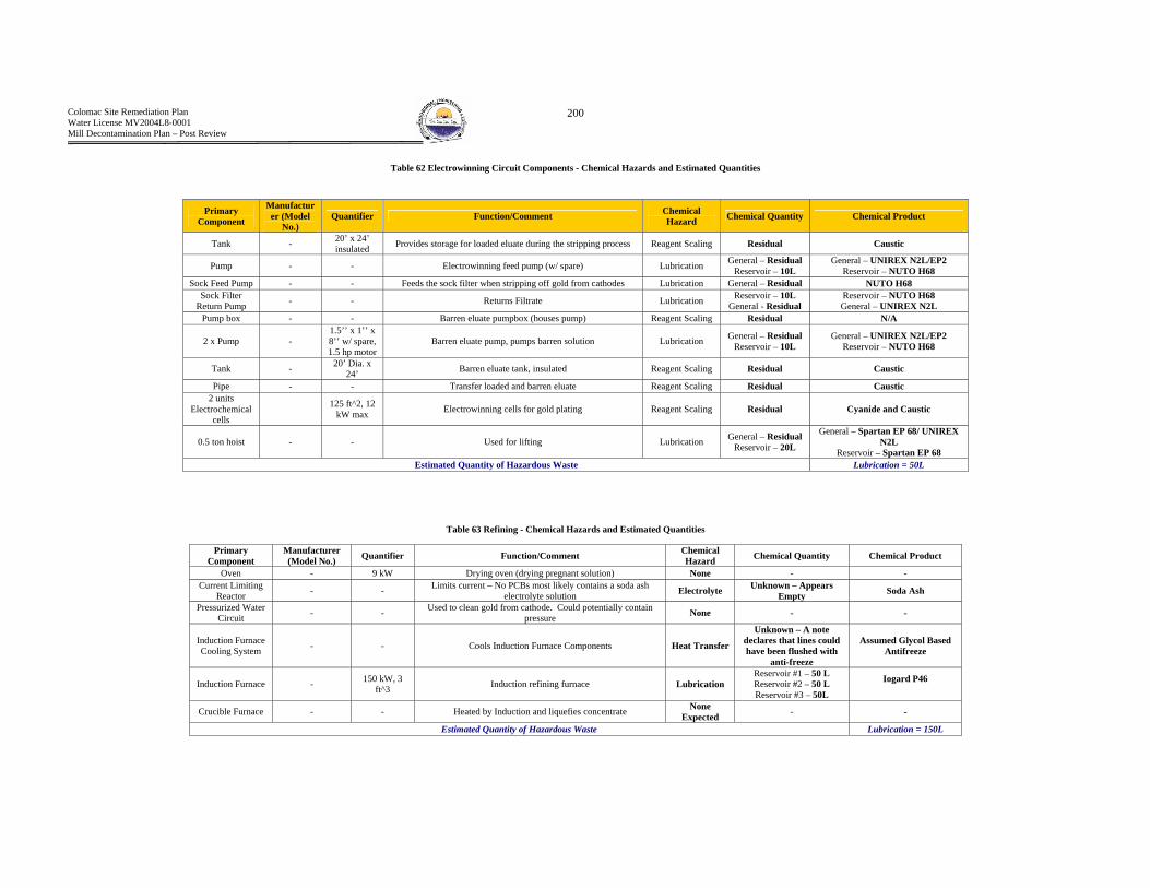
Colomac Site Remediation Plan Water License MV2004L8-0001 Mill Decontamination Plan – Post Review
200
Table 62 Electrowinning Circuit Components - Chemical Hazards and Estimated Quantities
Table 63 Refining - Chemical Hazards and Estimated Quantities
Primary Component
Manufacturer (Model
No.) Quantifier Function/Comment Chemical
Hazard Chemical Quantity Chemical Product
Tank - 20’ x 24’ insulated Provides storage for loaded eluate during the stripping process Reagent Scaling Residual Caustic
Pump - - Electrowinning feed pump (w/ spare) Lubrication General – Residual Reservoir – 10L
General – UNIREX N2L/EP2 Reservoir – NUTO H68
Sock Feed Pump - - Feeds the sock filter when stripping off gold from cathodes Lubrication General – Residual NUTO H68 Sock Filter
Return Pump - - Returns Filtrate Lubrication Reservoir – 10L General - Residual
Reservoir – NUTO H68 General – UNIREX N2L
Pump box - - Barren eluate pumpbox (houses pump) Reagent Scaling Residual N/A
2 x Pump - 1.5’’ x 1’’ x 8’’ w/ spare, 1.5 hp motor
Barren eluate pump, pumps barren solution Lubrication General – Residual Reservoir – 10L
General – UNIREX N2L/EP2 Reservoir – NUTO H68
Tank - 20’ Dia. x 24’ Barren eluate tank, insulated Reagent Scaling Residual Caustic
Pipe - - Transfer loaded and barren eluate Reagent Scaling Residual Caustic 2 units
Electrochemical cells
125 ft^2, 12 kW max Electrowinning cells for gold plating Reagent Scaling Residual Cyanide and Caustic
0.5 ton hoist - - Used for lifting Lubrication General – Residual Reservoir – 20L
General – Spartan EP 68/ UNIREX N2L
Reservoir – Spartan EP 68 Estimated Quantity of Hazardous Waste Lubrication = 50L
Primary Component
Manufacturer (Model No.) Quantifier Function/Comment Chemical
Hazard Chemical Quantity Chemical Product
Oven - 9 kW Drying oven (drying pregnant solution) None - - Current Limiting
Reactor - - Limits current – No PCBs most likely contains a soda ash electrolyte solution Electrolyte Unknown – Appears
Empty Soda Ash
Pressurized Water Circuit - - Used to clean gold from cathode. Could potentially contain
pressure None - -
Induction Furnace Cooling System - - Cools Induction Furnace Components Heat Transfer
Unknown – A note declares that lines could have been flushed with
anti-freeze
Assumed Glycol Based Antifreeze
Induction Furnace - 150 kW, 3 ft^3 Induction refining furnace Lubrication
Reservoir #1 – 50 L Reservoir #2 – 50 L Reservoir #3 – 50L
Iogard P46
Crucible Furnace - - Heated by Induction and liquefies concentrate None Expected - -
Estimated Quantity of Hazardous Waste Lubrication = 150L

Colomac Site Remediation Plan Water License MV2004L8-0001 Mill Decontamination Plan – Post Review
201
B6 - Utility Circuits The utility circuits can be divided into the following circuits
(a) Water – Raw, Process and Reclaim water (Mill Interior) (b) Compressed Air (c) Fuel
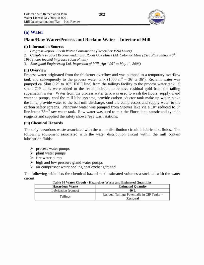
Colomac Site Remediation Plan Water License MV2004L8-0001 Mill Decontamination Plan – Post Review
202
(a) Water Plant/Raw Water/Process and Reclaim Water – Interior of Mill (i) Information Sources 1. Progress Report: Fresh Water Consumption (December 1994 Letter) 2. Complete Product Recommendations, Royal Oak Mines Ltd. Colomac Mine (Esso Plus January 6th, 1994 (note: located in grease room of mill) 3. Aboriginal Engineering Ltd. Inspection of Mill (April 25th to May 1st, 2006)
(ii) Overview Process water originated from the thickener overflow and was pumped to a temporary overflow tank and subsequently to the process water tank (1000 m3 – 36’ x 36’). Reclaim water was pumped ca. 5km (12” to 10” HDPE line) from the tailings facility to the process water tank. 5 small CIP tanks were added to the reclaim circuit to remove residual gold from the tailing supernatant water. Water from the process water tank was used to wash the floors, supply gland water to pumps, cool the mill lube systems, provide carbon eductor tank make up water, slake the lime, provide water to the ball mill discharge, cool the compressors and supply water to the carbon safety screens. Plant/raw water was pumped from Steeves lake via a 10” reduced to 6” line into a 75m3 raw water tank. Raw water was used to mix the Flocculant, caustic and cyanide reagents and supplied the safety shower/eye wash stations.
(iii) Chemical Hazards The only hazardous waste associated with the water distribution circuit is lubrication fluids. The following equipment associated with the water distribution circuit within the mill contain lubrication fluids:
process water pumps plant water pumps fire water pump high and low pressure gland water pumps air compressor water cooling heat exchanger; and
The following table lists the chemical hazards and estimated volumes associated with the water circuit
Table 64 Water Circuit - Hazardous Waste and Estimated Quantities Hazardous Waste Estimated Quantity
Lubrication (pumps) 40 L
Tailings Residual Tailings Potentially in CIP Tanks - Residual

Colomac Site Remediation Plan Water License MV2004L8-0001 Mill Decontamination Plan – Post Review
203
Photograph 4 Plant Water Pump - Oil Reservoirs are Full
Photograph 5 Reclaim Water Circuit - 5 Inline Small CIP Tanks
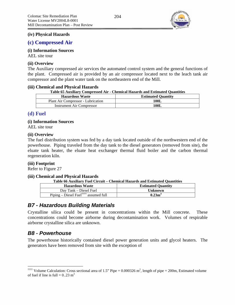
Colomac Site Remediation Plan Water License MV2004L8-0001 Mill Decontamination Plan – Post Review
204
(iv) Physical Hazards
(c) Compressed Air (i) Information Sources AEL site tour
(ii) Overview The Auxiliary compressed air services the automated control system and the general functions of the plant. Compressed air is provided by an air compressor located next to the leach tank air compressor and the plant water tank on the northeastern end of the Mill.
(iii) Chemical and Physical Hazards Table 65 Auxiliary Compressed Air - Chemical Hazards and Estimated Quantities
Hazardous Waste Estimated Quantity Plant Air Compressor - Lubrication 100L
Instrument Air Compressor 100L
(d) Fuel (i) Information Sources AEL site tour
(ii) Overview The fuel distribution system was fed by a day tank located outside of the northwestern end of the powerhouse. Piping traveled from the day tank to the diesel generators (removed from site), the eluate tank heater, the eluate heat exchanger thermal fluid boiler and the carbon thermal regeneration kiln.
(iii) Footprint Refer to Figure 27
(iii) Chemical and Physical Hazards Table 66 Auxiliary Fuel Circuit – Chemical Hazards and Estimated Quantities
Hazardous Waste Estimated Quantity Day Tank – Diesel Fuel Unknown
Piping – Diesel Fuel†††† assumed full 0.23m3
B7 - Hazardous Building Materials Crystalline silica could be present in concentrations within the Mill concrete. These concentrations could become airborne during decontamination work. Volumes of respirable airborne crystalline silica are unknown.
B8 - Powerhouse The powerhouse historically contained diesel power generation units and glycol heaters. The generators have been removed from site with the exception of
†††† Volume Calculation: Cross sectional area of 1.5” Pipe = 0.000326 m2, length of pipe = 200m, Estimated volume of fuel if line is full = 0..23 m3

Colomac Site Remediation Plan Water License MV2004L8-0001 Mill Decontamination Plan – Post Review
205
B9 - Miscellaneous Hazardous Wastes Located Within Mill A diesel powered generator is located within the mill. The diesel engine will contain lubrication fluids in reservoirs and as miscellaneous greasing. The engine has also leaked oil onto the surrounding concrete. Photograph 6 Diesel Powered Generator - Contains Lubricants and has Leaked Lubricants onto Surrounding
Floor
Table 67 Miscellaneous Wastes Identified Within the Mill Item Chemical Hazard Quantity Location
Diesel Engine Lubrication 100L Central Area of Mill 1 45 gallon drum transmission fluid Lubrication 205L Grease Room
Unidentified purple liquid Unknown 100 ml Grease Room 2 Battery Lead - Electrical Room
20 Florescent Light Tubes Mercury Trace Solvent Room 1 battery Lead - Solvent Room
Reservoir (Rapid Clean) ¾ full of solvent – Some leaking from
drainage valve
Solvent (Varsol or Petrosol 3139) 230 L Solvent Room
Various cans of weld on Solvent 1L Solvent Room 9 Batteries Lead - Refining Room
14 Florescent Light Tubes Mercury Trace Refinery 1 can (455 mL) Relton Rapid Tap
Heavy Duty Cutting Fluid (does not contain 1;1,-
trichlorotethane) - 455 ml 2nd Level Electronics Room
5 cans (70.7 g) Smoke Detector Tester fluid - 0.353kg 2nd Level Electronics Room
1 tube (283.5 g) Lubriplate Grease - 283.5g 2nd Level Electronics Room 1 tube UL Pipe Sealant w/ Teflon
1 can spray paint - - 2nd Level Electronics Room
1 can M.G. Chemicals NU-TROL - - 2nd Level Electronics Room
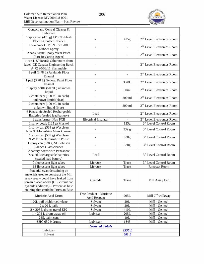
Colomac Site Remediation Plan Water License MV2004L8-0001 Mill Decontamination Plan – Post Review
206
Contact and Central Cleaner & Lubricant
1 spray can (425 g) LPS No Flash Electro Contact Cleaner - 425g 2nd Level Electronics Room
1 container CIMENT SC 2000 Rubber Epoxy - - 2nd Level Electronics Room
2 cans Alanx Epoxy Wear Patch (Part B: Curing Agent) - - 2nd Level Electronics Room
1 can L-5918A(5) Other notes from label: GE Canada Engineering Batch
#472 90/06/11, flammable - - 2nd Level Electronics Room
1 pail (3.78 L) Acklands Floor Enamel - - 2nd Level Electronics Room
1 pail (3.78 L) General Paint Floor Enamel - 3.78L 2nd Level Electronics Room
1 spray bottle (50 mL) unknown liquid - 50ml 2nd Level Electronics Room
2 containers (100 mL in each) unknown liquid (clear) - 200 ml 2nd Level Electronics Room
2 containers (100 mL in each) unknown liquid (blue) - 200 ml 2nd Level Electronics Room
6 Panasonic Sealed Rechargeable Batteries (sealed lead battery) Lead - 2nd Level Electronics Room
1 transformer- Non PCB Electrical Insulator - 2nd Level Electronics Room 1 spray bottle (125 g) Muskol - 125g 3rd Level Control Room 1 spray can (539 g) Wesclean
N.W.T. Moonshine Glass Cleaner - 539 g 3rd Level Control Room
1 spray can (539 g) Wesclean N.W.T. Sleek Furniture Polish - 538g 3rd Level Control Room
1 spray can (538 g) SC Johnson Glance Glass cleaner - 538g 3rd Level Control Room
2 battery boxes with Panasonic Sealed Rechargeable batteries
(sealed lead battery) Lead - 3rd Level Control Room
7 fluorescent light tubes Mercury Trace 3rd Level Control Room 12 florescent light tubes Mercury Trace Rheostat Room
Potential cyanide staining on materials used to construct the Mill assay area – could have leaked from screen placed above (CIP circuit had cyanide additions) – Present as blue staining that could be Prussian Blue
Cyanide Trace Mill Assay Lab
Muriatic Acid Drum Free Product – Muriatic Acid Reagent 205L Mill 2nd walkway
1 20L pail trichloroethylene Solvent 20L Mill - General 2 x 20 L pails Solvent 20L Mill - General
2 x 205 L drums traxol EP2 Solvent 410L Mill - General 1 x 205 L drum waste oil Lubricant 205L Mill - General
2 5L paint cans - 10L Mill - General SHC 630 9 drums Lubricant 1845 Mill - General
General Totals Lubricant 2355 L Solvent 681 L

Colomac Site Remediation Plan Water License MV2004L8-0001 Mill Decontamination Plan – Post Review
207
Acid 205 L Mercury (assume 12 mg/tube * 53
tubes 636 mg
Lead Batteries 20 Batteries
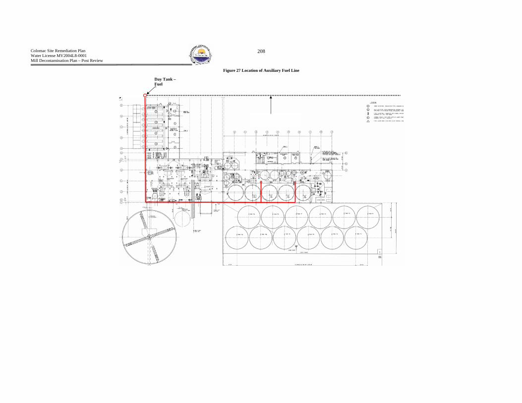
Colomac Site Remediation Plan Water License MV2004L8-0001 Mill Decontamination Plan – Post Review
208
Figure 27 Location of Auxiliary Fuel Line
Day Tank – Fuel St

Colomac Site Remediation Plan Water License MV2004L8-0001 Mill Decontamination Plan – Post Review
209
Appendix C – Hazardous Properties of Wastes Identified Within the Mill
The following appendix presents properties for all of the wastes identified within the Mill. The following information will be referenced when determining the potential for exposure to the wastes through various pathways (i.e., vapor pressure, physical form etc. are all key properties related to exposure potential). The general waste categories presented in the waste inventory will be used to group the identified wastes for hazard assessment.
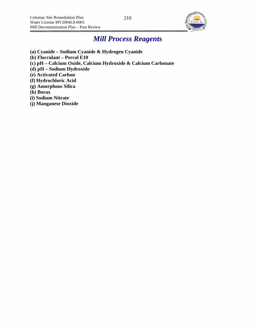
Colomac Site Remediation Plan Water License MV2004L8-0001 Mill Decontamination Plan – Post Review
210
Mill Process Reagents (a) Cyanide – Sodium Cyanide & Hydrogen Cyanide (b) Flocculant – Percol E10 (c) pH – Calcium Oxide, Calcium Hydroxide & Calcium Carbonate (d) pH – Sodium Hydroxide (e) Activated Carbon (f) Hydrochloric Acid (g) Amorphous Silica (h) Borax (i) Sodium Nitrate (j) Manganese Dioxide

Colomac Site Remediation Plan Water License MV2004L8-0001 Mill Decontamination Plan – Post Review
211
(a) Sodium Cyanide & Hydrogen Cyanide Note: Hydrogen cyanide is a byproduct of the application of sodium cyanide and is not directly a process reagent.
Information Sources
1. CCOHS CHEMINFO 2. MSDS 3. Cyanidecode – www.cyanidecode.org/cyanide_environmental.php 4. Infomine professional development course – Cyanide in Mining 5. The Management of Cyanide in Gold Extraction (International Council on Metals and the
Environment, 1999) 6. http://www.gasdetection.com/TECH/hcn.html 7. DuPont Sodium Cyanide Properties, Uses, Storage and Handling 8. NIOSH
Overview Sodium Cyanide was used as a lixivant to extract gold by forming a soluble gold-cyanide complex. Cyanide refers to a large family of chemical compounds. Each chemical in this family contains a chemical unit called the cyanide ion (CN-). Cyanide-metal complexes can be classified as follows:
1. Free Cyanide: HCN, CN- and simple cyanide salt that readily dissolve in water to from free cyanide. Generally cyanide complexes with Na, K, and Ca.
2. Weak and Moderately Strong Cyanide Complexes: Cyanide complexes that decompose in a weak acid solution to release free cyanide. Generally cyanide complexes with Cu, CD, Zn, Ag and Ni.
3. Strongly Bound Cyanide Complexes: Cyanide complexes that are stable under ambient conditions. Generally cyanide complexes with Au, Fe and Co.
The free cyanide ion is responsible for the toxic effects of cyanide. The form of cyanide employed within the Colomac Milling process was sodium cyanide. Sodium cyanide can readily hydrolyze to hydrogen cyanide. The following discusses the properties of both sodium and hydrogen cyanide.
Sodium Cyanide The following is an overview taken from the CCOHS CHEMINFO sheet that describes calcium cyanide and its toxic properties.
“White granules, flakes or lumps; odorless when dry; slight odor of bitter almonds in moist air or when damp. Deliquescent (absorbs moisture from the air and forms wet solid or solution). Does not burn. Contact with acid quickly releases extremely toxic and very flammable hydrogen cyanide gas. (Avoid contact with acids at all times). Decomposes slowly to hydrogen cyanide in presence of moisture and/or carbon dioxide in moist air (do not use CO2 fire extinguisher directly on cyanide as will evolve HCN gas due to pH depression). VERY TOXIC. May be fatal if absorbed through the skin or swallowed. Inhalation of hydrogen cyanide, which is formed when sodium cyanide reacts with moisture or carbon dioxide, may be fatal. The early symptoms of cyanide poisoning may include

Colomac Site Remediation Plan Water License MV2004L8-0001 Mill Decontamination Plan – Post Review
212
headache, nausea, dizziness, drowsiness, anxiety, rapid breathing, in-coordination and confusion. More severe exposures can cause red skin color, labored breathing, convulsions, collapse and death. Inhalation of the dust can be very irritating to the nose and throat. CORROSIVE to the skin and eyes. May cause permanent scarring or blindness (always wear splash goggles when disturbing piping or working within the area).”
Hydrogen Cyanide The following is an overview taken from the CCOHS CHEMINFO sheet that describes hydrogen cyanide and its toxic properties. “Colorless or pale blue liquid or colorless gas above 25.7 deg C; faint, bitter almond odor. EXTREMELY FLAMMABLE LIQUID (below 25.7 deg C) or EXTREMELY FLAMMABLE GAS (above 25.7 deg C). Burns in air with a blue flame. Can form explosive mixtures with air over a wide concentration range, and will readily ignite at room temperature. Low ignition energy. Gas can be ignited by a static charge. DANGEROUSLY REACTIVE. Unstabilized liquid or gas may polymerize explosively on contact with alkaline materials, if heated above 50 deg C, if more than 2-5% water is present, if stored longer than 90 days or if impure. During a fire, irritating/toxic nitrogen oxides may be generated. Cylinders or tanks may rupture and explode if heated. VERY TOXIC. May be fatal if inhaled or absorbed through the skin. The early symptoms of cyanide poisoning may include headache, nausea, dizziness, drowsiness, anxiety, rapid breathing, in coordination and confusion. More severe exposures can cause red skin color, labored breathing, convulsions, collapse and death.”
NIOSH Pocket Book to Chemical Risk
Sodium Cyanide Figure 28 Sodium Cyanide - NIOSH Guide to chemical risk
Sodium cyanide (as CN) CAS 143-33-9
NaCN RTECS VZ7525000
Synonyms & Trade Names Sodium salt of hydrocyanic acid
DOT ID & Guide 1689 157 (solid) 3414 157 (solution)
NIOSH REL*: C 5 mg/m3 (4.7 ppm) [10-minute] [*Note: The REL also applies to other cyanides (as CN) except Hydrogen cyanide.]
Exposure Limits
OSHA PEL*: TWA 5 mg/m3 [*Note: The PEL also applies to other cyanides (as CN) except Hydrogen cyanide.]
IDLH 25 mg/m3 (as CN) See: cyanides
Conversion
Physical Description White, granular or crystalline solid with a faint, almond-like odor.
MW: 49.0 BP: 2725°F MLT: 1047°F Sol(77°F): 58%
VP: 0 mmHg (approx) IP: NA Sp.Gr: 1.60
Fl.P: NA UEL: NA LEL: NA
Noncombustible Solid, but contact with acids releases highly flammable hydrogen cyanide.

Colomac Site Remediation Plan Water License MV2004L8-0001 Mill Decontamination Plan – Post Review
213
Incompatibilities & Reactivities Strong oxidizers (such as acids, acid salts, chlorates & nitrates) [Note: Absorbs moisture from the air forming a syrup.]
Measurement Methods NIOSH 6010, 7904 See: NMAM or OSHA Methods
Personal Protection & Sanitation (See protection) Skin: Prevent skin contact Eyes: Prevent eye contact Wash skin: When contaminated Remove: When wet or contaminated Change: Daily Provide: Eyewash, Quick drench
First Aid (See procedures) Eye: Irrigate immediately Skin: Soap wash immediately Breathing: Respiratory support Swallow: Medical attention immediately
Respirator Recommendations NIOSH/OSHA Up to 25 mg/m3: (APF = 10) Any supplied-air respirator (APF = 50) Any self-contained breathing apparatus with a full facepiece Emergency or planned entry into unknown concentrations or IDLH conditions: (APF = 10,000) Any self-contained breathing apparatus that has a full facepiece and is operated in a pressure- demand or other positive-pressure mode (APF = 10,000) Any supplied-air respirator that has a full facepiece and is operated in a pressure-demand or other positive-pressure mode in combination with an auxiliary self-contained positive-pressure breathing apparatus Escape: (APF = 50) Any air-purifying, full-facepiece respirator (gas mask) with a chin-style, front- or back-mounted canister providing protection against the compound of concern and having an N100, R100, or P100 filter. Click here for information on selection of N, R, or P filters./Any appropriate escape-type, self-contained breathing apparatus Important additional information about respirator selection
Exposure Routes inhalation, skin absorption, ingestion, skin and/or eye contact
Symptoms Irritation eyes, skin; asphyxia; lassitude (weakness, exhaustion), headache, confusion; nausea, vomiting; increased respiratory rate; slow gasping respiration; thyroid, blood changes
Target Organs Eyes, skin, cardiovascular system, central nervous system, thyroid, blood
Hydrogen Cyanide Figure 29 Hydrogen Cyanide - NIOSH Pocket Guide to Chemical Hazards
Hydrogen cyanide CAS 74-90-8
HCN RTECS MW6825000
Synonyms & Trade Names Formonitrile, Hydrocyanic acid, Prussic acid
DOT ID & Guide 1051 117 (>20% solution) 1051 117 (anhydrous) 1613 154 (< or =20% solution)
Exposure NIOSH REL: ST 4.7 ppm (5 mg/m3) [skin]
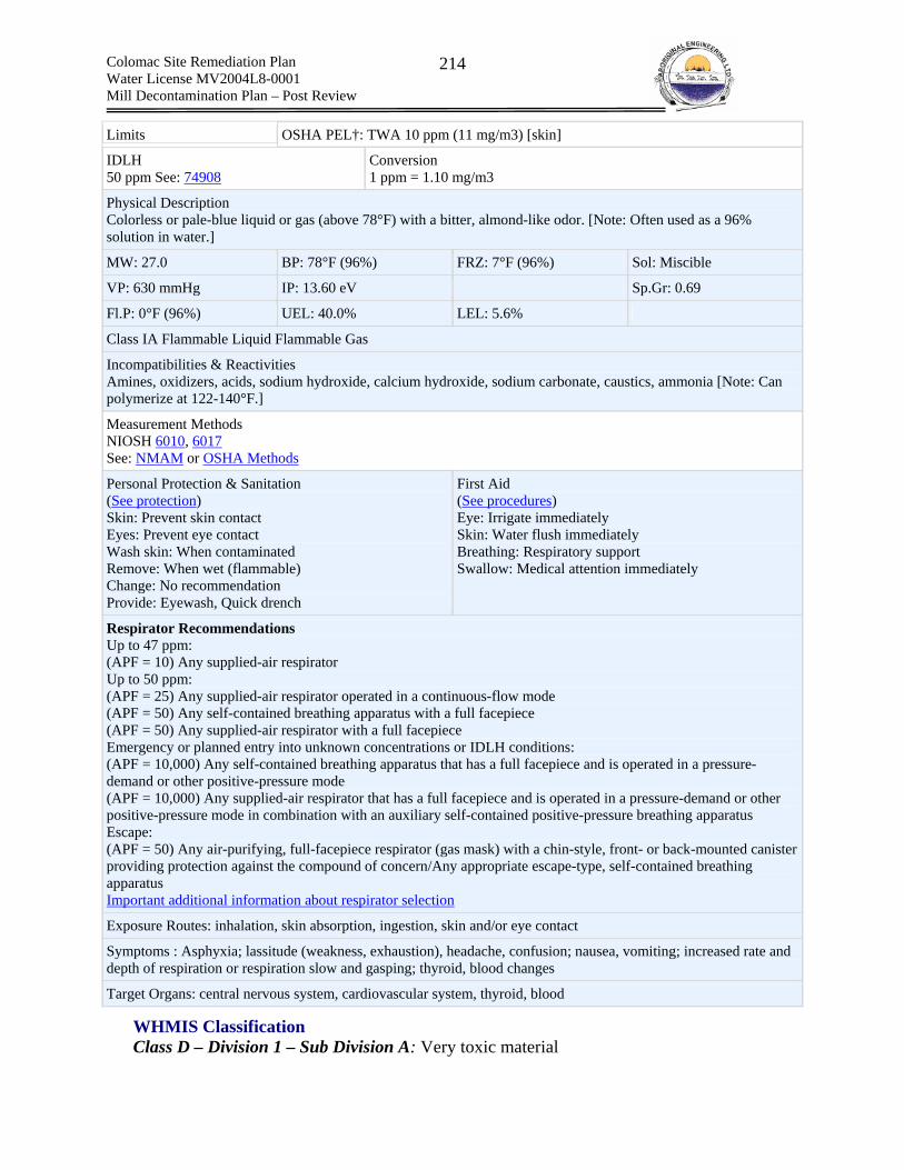
Colomac Site Remediation Plan Water License MV2004L8-0001 Mill Decontamination Plan – Post Review
214
Limits OSHA PEL†: TWA 10 ppm (11 mg/m3) [skin]
IDLH 50 ppm See: 74908
Conversion 1 ppm = 1.10 mg/m3
Physical Description Colorless or pale-blue liquid or gas (above 78°F) with a bitter, almond-like odor. [Note: Often used as a 96% solution in water.]
MW: 27.0 BP: 78°F (96%) FRZ: 7°F (96%) Sol: Miscible
VP: 630 mmHg IP: 13.60 eV Sp.Gr: 0.69
Fl.P: 0°F (96%) UEL: 40.0% LEL: 5.6%
Class IA Flammable Liquid Flammable Gas
Incompatibilities & Reactivities Amines, oxidizers, acids, sodium hydroxide, calcium hydroxide, sodium carbonate, caustics, ammonia [Note: Can polymerize at 122-140°F.]
Measurement Methods NIOSH 6010, 6017 See: NMAM or OSHA Methods
Personal Protection & Sanitation (See protection) Skin: Prevent skin contact Eyes: Prevent eye contact Wash skin: When contaminated Remove: When wet (flammable) Change: No recommendation Provide: Eyewash, Quick drench
First Aid (See procedures) Eye: Irrigate immediately Skin: Water flush immediately Breathing: Respiratory support Swallow: Medical attention immediately
Respirator Recommendations Up to 47 ppm: (APF = 10) Any supplied-air respirator Up to 50 ppm: (APF = 25) Any supplied-air respirator operated in a continuous-flow mode (APF = 50) Any self-contained breathing apparatus with a full facepiece (APF = 50) Any supplied-air respirator with a full facepiece Emergency or planned entry into unknown concentrations or IDLH conditions: (APF = 10,000) Any self-contained breathing apparatus that has a full facepiece and is operated in a pressure-demand or other positive-pressure mode (APF = 10,000) Any supplied-air respirator that has a full facepiece and is operated in a pressure-demand or other positive-pressure mode in combination with an auxiliary self-contained positive-pressure breathing apparatus Escape: (APF = 50) Any air-purifying, full-facepiece respirator (gas mask) with a chin-style, front- or back-mounted canister providing protection against the compound of concern/Any appropriate escape-type, self-contained breathing apparatus Important additional information about respirator selection
Exposure Routes: inhalation, skin absorption, ingestion, skin and/or eye contact
Symptoms : Asphyxia; lassitude (weakness, exhaustion), headache, confusion; nausea, vomiting; increased rate and depth of respiration or respiration slow and gasping; thyroid, blood changes
Target Organs: central nervous system, cardiovascular system, thyroid, blood
WHMIS Classification Class D – Division 1 – Sub Division A: Very toxic material

Colomac Site Remediation Plan Water License MV2004L8-0001 Mill Decontamination Plan – Post Review
215
Class E: Corrosive material
TDGA Classification Class 6.1 – Toxic Substance – Packing Group 1 – UN# 1689
Health Hazards – Exposure Routes Critical importance - cyanide toxic effects are the same for all routes of entry into the body (adsorption, ingestion, inhalation or puncture). Cyanide is rapidly absorbed into the body and is fast acting. Cyanide forms a stable complex with a form of cytochrome oxidase and inhibits the cells ability to utilize oxygen, thus leading to central nervous system depression that can result in respiratory arrest and death. Inhalation
HCN gas formed by low pH exposure in solution – highly toxic, potentially fatal Particulate dust – highly toxic, potentially fatal Mist from agitated solutions – highly toxic, potentially fatal
Skin – Absorption – highly toxic, potentially fatal. also potential for caustic burns. Eye – Absorption – highly toxic, potentially fatal. Also potential for caustic burns. Ingestion – Absorption – highly toxic, potentially fatal. Also potential for caustic burns. Ingestion will lead to a bitter burning taste in mouth like almonds and tightness and numbness of the throat Carcinogen – No Accumulation - No
Occupational Exposure Limits – Cyanide OSHA PEL - TWA: 5 mg/m3, as CN, 8 Hr. Skin* ACGIH TLV-C: 5 mg/m3, as CN, Skin AEL (DuPont): 5 mg/m3, 15 minute TWA, as CN, Skin ERPG -2: 10 ppm (HCN) ERPG -3: 25 ppm (HCN)
Oral LD50: 15 mg/kg in rats Dermal LD50: 1.28-14.63 mg/kg in rabbits Inhalation LC50: no information found but considered to be highly toxic as CN by inhalation
*Note Skin denotes that vapors and particulate matter can absorb through or penetrate skin Criteria for Human Protection:
In Drinking Water: 0.2mg/L (US and Canada); 0.05 mg/L (EU); 0.07 mg/L (WHO) In Diet: 50 mg/kg In Air: 5 mg/m3
In solution: about 3 to 5 mg of cyanide/kg body weight is lethal In respiratory exposure to hydrocyanic acid (HCN-gas), death occurs at 0.1 to 0.3 g/m3
Ecological Hazards 96 hour LC50 - fathead minnows: 0.43-0.66 mg/L 96 hour LC50 - rainbow trout: 046-.075 mg/L 96 hour LC50 - bluegill sunfish: 0.28 mg/L Water License MV2004L8-0001 criteria – 0.48 mg/L (total cyanide) & 0.16 mg/L (WAD cyanide) – both are maximum permissible limits for grab samples
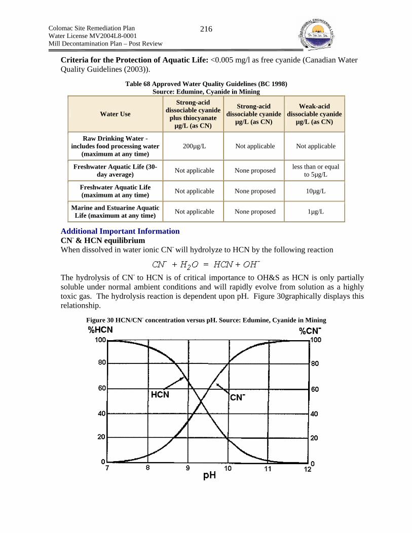
Colomac Site Remediation Plan Water License MV2004L8-0001 Mill Decontamination Plan – Post Review
216
Criteria for the Protection of Aquatic Life: <0.005 mg/l as free cyanide (Canadian Water Quality Guidelines (2003)).
Table 68 Approved Water Quality Guidelines (BC 1998)
Source: Edumine, Cyanide in Mining
Water Use
Strong-acid dissociable cyanide
plus thiocyanate µg/L (as CN)
Strong-acid dissociable cyanide
µg/L (as CN)
Weak-acid dissociable cyanide
µg/L (as CN)
Raw Drinking Water - includes food processing water
(maximum at any time) 200µg/L Not applicable Not applicable
Freshwater Aquatic Life (30-day average) Not applicable None proposed less than or equal
to 5µg/L
Freshwater Aquatic Life (maximum at any time) Not applicable None proposed 10µg/L
Marine and Estuarine Aquatic Life (maximum at any time) Not applicable None proposed 1µg/L
Additional Important Information CN- & HCN equilibrium When dissolved in water ionic CN- will hydrolyze to HCN by the following reaction The hydrolysis of CN- to HCN is of critical importance to OH&S as HCN is only partially soluble under normal ambient conditions and will rapidly evolve from solution as a highly toxic gas. The hydrolysis reaction is dependent upon pH. Figure 30graphically displays this relationship.
Figure 30 HCN/CN- concentration versus pH. Source: Edumine, Cyanide in Mining

Colomac Site Remediation Plan Water License MV2004L8-0001 Mill Decontamination Plan – Post Review
217
As can be seen, acidic conditions favor hydrolysis, while alkaline conditions inhibit hydrolysis. As such, cyanide solutions should be maintained at pH >11 to avoid the generation of toxic HCN gas. In gold mining, this is generally accomplished through the addition of sodium hydroxide to reagent solution and calcium hydroxide (slaked lime) to slurry.
Table 69 presents additional important cyanide reactions.
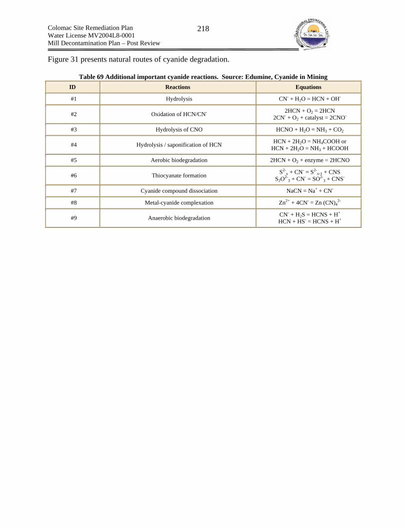
Colomac Site Remediation Plan Water License MV2004L8-0001 Mill Decontamination Plan – Post Review
218
Figure 31 presents natural routes of cyanide degradation.
Table 69 Additional important cyanide reactions. Source: Edumine, Cyanide in Mining ID Reactions Equations
#1 Hydrolysis CN- + H2O = HCN + OH-
#2 Oxidation of HCN/CN- 2HCN + O2 = 2HCN 2CN- + O2 + catalyst = 2CNO-
#3 Hydrolysis of CNO HCNO + H2O = NH3 + CO2
#4 Hydrolysis / saponification of HCN HCN + 2H2O = NH4COOH or HCN + 2H2O = NH3 + HCOOH
#5 Aerobic biodegradation 2HCN + O2 + enzyme = 2HCNO
#6 Thiocyanate formation S2-x + CN- = S2-
x-1 + CNS S2O2-
3 + CN- = SO2-3 + CNS-
#7 Cyanide compound dissociation NaCN = Na+ + CN-
#8 Metal-cyanide complexation Zn2+ + 4CN- = Zn (CN)42-
#9 Anaerobic biodegradation CN- + H2S = HCNS + H+
HCN + HS- = HCNS + H+

Colomac Site Remediation Plan Water License MV2004L8-0001 Mill Decontamination Plan – Post Review
219
Figure 31 Natural degradation - the cyanide cycle. Source: Edumine, Cyanide in Mining
Figure 32 Solubility of sodium cyanide in water – Source: DuPont
OH &S Hazard Ranking Very Hazardous = 4
Colomac Site Remediation Plan Water License MV2004L8-0001 Mill Decontamination Plan – Post Review
220
(b) Flocculant – Percol E10 Information Sources
1. MSDS
Overview Flocculant was used to thicken the process slurry prior to leaching through cyanidation. Flocculant is a free flowing white powder that was shipped to the site in disposable 25kg bags. Flocculants are used as process thickening agents. They are not flammable and do not exhibit a flash point. Typically of grain size 90% > 20 mesh. 1% solutions are noted to be slightly acidic (4.5 to 6.5 pH units). When mixed with water, flocculants are extremely slippery and represent a high slip and trip hazard.
WHMIS Classification Not a controlled product
TDGA Classification Not a dangerous good
Health Hazards – Exposure Route Inhalation – mild irritant Skin – mild irritant Eye – mild irritant Ingestion – non toxic Carcinogen – No Accumulation – No Note: Chronic Effects are not known to occur
Occupational Exposure Limits ACGIH 8 hour TWA for Total Inhalable Dust: 10 mg/m3 OSHA PEL: 10 mg/m3 Manufacturer Recommendation: 10 mg/m3
OH&S Hazard Ranking Very Low Hazard = 1

Colomac Site Remediation Plan Water License MV2004L8-0001 Mill Decontamination Plan – Post Review
221
(c) Calcium Oxide (Quick Lime)/Calcium Hydroxide (Slaked Lime)/Calcium Carbonate
Information Sources 1. MSDS 2. CCOHS CHEMINFO 3. NIOSH
Overview Calcium oxide was slaked to form Calcium hydroxide, which was used as slurry pH control. Calcium carbonate forms when calcium hydroxide reacts with carbon dioxide in the atmosphere.
Calcium Oxide The following is an overview taken from the CCOHS CHEMINFO sheet that describes calcium oxide and its toxic properties.
“White, greyish-white, pale yellow or pale gray lumps or granular powder. Commercial grade has a yellowish or brownish tint, due to the presence of iron. Does not burn. Reacts violently with water. Very irritating to the respiratory tract. CORROSIVE to the eyes and skin. Causes severe skin and eye burns. May cause blindness and permanent scarring”. The material is odorless and is shipped at 90 -95% purity. Contact with acids and water should be avoided. Release heat when reacting with water.
Calcium Hydroxide The following is an overview taken from the CCOHS CHEMINFO sheet that describes calcium hydroxide and its toxic properties.
“White, odorless crystals or soft powder or granules; impure material has gray or buff color. Does not burn. Can decompose at high temperatures forming irritating calcium oxide. Very irritating to the respiratory tract. CORROSIVE. Causes severe skin and eye burns. May cause blindness and permanent scarring.” A saturated solution of Calcium Hydroxide has a pH of 12.5 to 12.7. Calcium Hydroxides solubility in water is as follows: 0.185 g/100 mL at 0oC & 0.071 g/100 mL at 100oC. The material readily adsorbs CO2 from the air to form calcium carbonate (CaCO3) and is odorless. High temperature (580oC) can result in the release of strong corrosive fumes of calcium oxide (decomposition). Avoid contact with strong acids.
Calcium Carbonate The following is an overview taken from the CCOHS CHEMINFO sheet that describes calcium carbonate and its toxic properties.
“White, odorless powder or colorless crystals. Impurities produce a variety of colors. Impure material may have a musty or earthy odor. Non- combustible. Essentially non-toxic.”
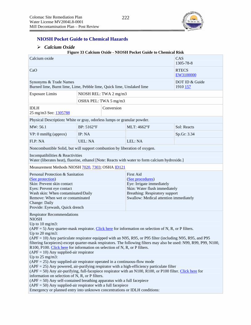
Colomac Site Remediation Plan Water License MV2004L8-0001 Mill Decontamination Plan – Post Review
222
NIOSH Pocket Guide to Chemical Hazards
Calcium Oxide Figure 33 Calcium Oxide - NIOSH Pocket Guide to Chemical Risk
Calcium oxide CAS 1305-78-8
CaO RTECS EW3100000
Synonyms & Trade Names Burned lime, Burnt lime, Lime, Pebble lime, Quick lime, Unslaked lime
DOT ID & Guide 1910 157
NIOSH REL: TWA 2 mg/m3 Exposure Limits
OSHA PEL: TWA 5 mg/m3
IDLH 25 mg/m3 See: 1305788
Conversion
Physical Description: White or gray, odorless lumps or granular powder.
MW: 56.1 BP: 5162°F MLT: 4662°F Sol: Reacts
VP: 0 mmHg (approx) IP: NA Sp.Gr: 3.34
Fl.P: NA UEL: NA LEL: NA
Noncombustible Solid, but will support combustion by liberation of oxygen.
Incompatibilities & Reactivities Water (liberates heat), fluorine, ethanol [Note: Reacts with water to form calcium hydroxide.]
Measurement Methods NIOSH 7020, 7303; OSHA ID121
Personal Protection & Sanitation (See protection) Skin: Prevent skin contact Eyes: Prevent eye contact Wash skin: When contaminated/Daily Remove: When wet or contaminated Change: Daily Provide: Eyewash, Quick drench
First Aid (See procedures) Eye: Irrigate immediately Skin: Water flush immediately Breathing: Respiratory support Swallow: Medical attention immediately
Respirator Recommendations NIOSH Up to 10 mg/m3: (APF = 5) Any quarter-mask respirator. Click here for information on selection of N, R, or P filters. Up to 20 mg/m3: (APF = 10) Any particulate respirator equipped with an N95, R95, or P95 filter (including N95, R95, and P95 filtering facepieces) except quarter-mask respirators. The following filters may also be used: N99, R99, P99, N100, R100, P100. Click here for information on selection of N, R, or P filters. (APF = 10) Any supplied-air respirator Up to 25 mg/m3: (APF = 25) Any supplied-air respirator operated in a continuous-flow mode (APF = 25) Any powered, air-purifying respirator with a high-efficiency particulate filter (APF = 50) Any air-purifying, full-facepiece respirator with an N100, R100, or P100 filter. Click here for information on selection of N, R, or P filters. (APF = 50) Any self-contained breathing apparatus with a full facepiece (APF = 50) Any supplied-air respirator with a full facepiece Emergency or planned entry into unknown concentrations or IDLH conditions:
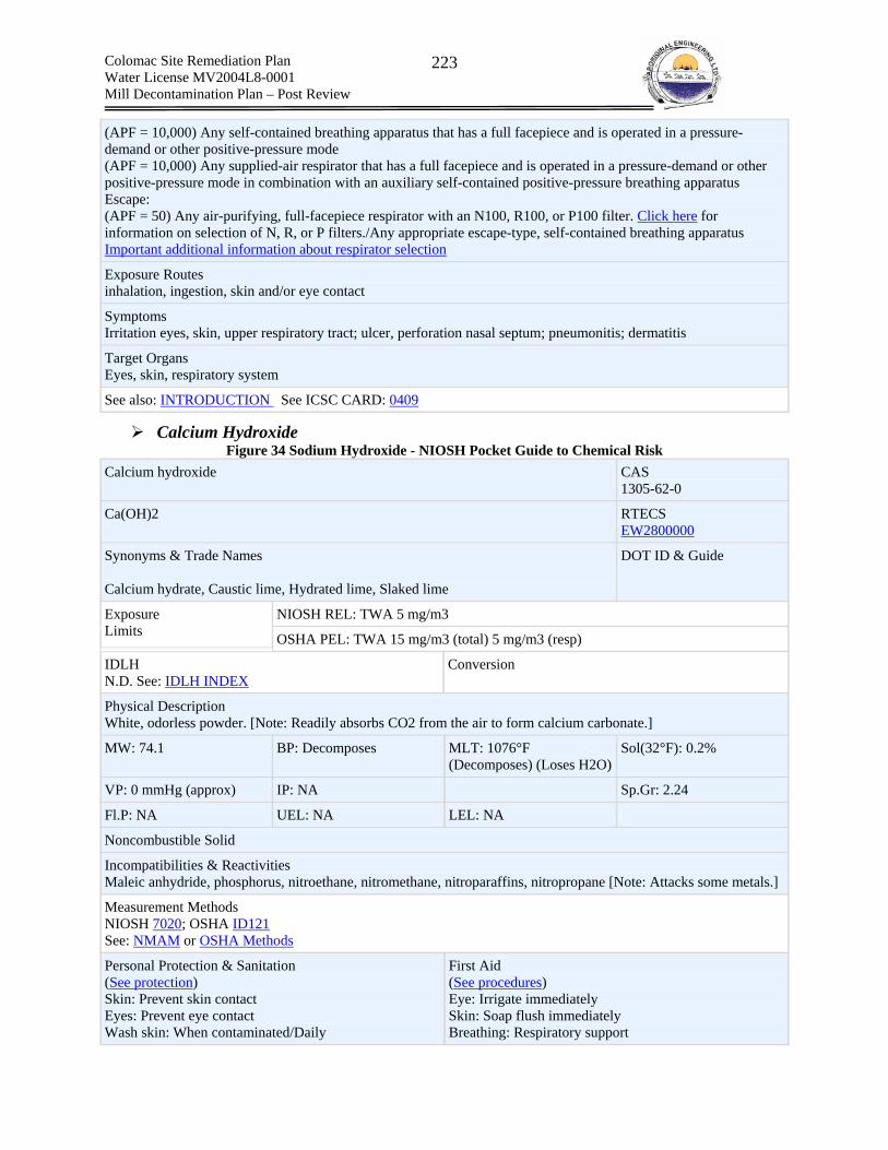
Colomac Site Remediation Plan Water License MV2004L8-0001 Mill Decontamination Plan – Post Review
223
(APF = 10,000) Any self-contained breathing apparatus that has a full facepiece and is operated in a pressure-demand or other positive-pressure mode (APF = 10,000) Any supplied-air respirator that has a full facepiece and is operated in a pressure-demand or other positive-pressure mode in combination with an auxiliary self-contained positive-pressure breathing apparatus Escape: (APF = 50) Any air-purifying, full-facepiece respirator with an N100, R100, or P100 filter. Click here for information on selection of N, R, or P filters./Any appropriate escape-type, self-contained breathing apparatus Important additional information about respirator selection
Exposure Routes inhalation, ingestion, skin and/or eye contact
Symptoms Irritation eyes, skin, upper respiratory tract; ulcer, perforation nasal septum; pneumonitis; dermatitis
Target Organs Eyes, skin, respiratory system
See also: INTRODUCTION See ICSC CARD: 0409
Calcium Hydroxide Figure 34 Sodium Hydroxide - NIOSH Pocket Guide to Chemical Risk
Calcium hydroxide CAS 1305-62-0
Ca(OH)2 RTECS EW2800000
Synonyms & Trade Names Calcium hydrate, Caustic lime, Hydrated lime, Slaked lime
DOT ID & Guide
NIOSH REL: TWA 5 mg/m3 Exposure Limits OSHA PEL: TWA 15 mg/m3 (total) 5 mg/m3 (resp)
IDLH N.D. See: IDLH INDEX
Conversion
Physical Description White, odorless powder. [Note: Readily absorbs CO2 from the air to form calcium carbonate.]
MW: 74.1 BP: Decomposes MLT: 1076°F (Decomposes) (Loses H2O)
Sol(32°F): 0.2%
VP: 0 mmHg (approx) IP: NA Sp.Gr: 2.24
Fl.P: NA UEL: NA LEL: NA
Noncombustible Solid
Incompatibilities & Reactivities Maleic anhydride, phosphorus, nitroethane, nitromethane, nitroparaffins, nitropropane [Note: Attacks some metals.]
Measurement Methods NIOSH 7020; OSHA ID121 See: NMAM or OSHA Methods
Personal Protection & Sanitation (See protection) Skin: Prevent skin contact Eyes: Prevent eye contact Wash skin: When contaminated/Daily
First Aid (See procedures) Eye: Irrigate immediately Skin: Soap flush immediately Breathing: Respiratory support

Colomac Site Remediation Plan Water License MV2004L8-0001 Mill Decontamination Plan – Post Review
224
Remove: When wet or contaminated Change: Daily Provide: Eyewash, Quick drench
Swallow: Medical attention immediately
Respirator Recommendations Not available. Important additional information about respirator selection
Exposure Routes inhalation, ingestion, skin and/or eye contact
Symptoms Irritation eyes, skin, upper respiratory system; eye, skin burns; skin vesiculation; cough, bronchitis, pneumonitis
Target Organs Eyes, skin, respiratory system
See also: INTRODUCTION See ICSC CARD: 0408
Calcium Carbonate Calcium carbonate CAS
471-34-1 (synthetic) 1317-65-3 (natural)
CaCO3 RTECS EV9580000
Synonyms & Trade Names Calcium salt of carbonic acid [Note: Occurs in nature as limestone, chalk, marble, dolomite, aragonite, calcite & oyster shells.]
DOT ID & Guide
NIOSH REL: TWA 10 mg/m3 (total) TWA 5 mg/m3 (resp) Exposure Limits OSHA PEL: TWA 15 mg/m3 (total) TWA 5 mg/m3 (resp)
IDLH N.D. See: IDLH INDEX
Conversion
Physical Description White, odorless powder or colorless crystals.
MW: 100.1 BP: Decomposes MLT: 1517-2442°F (Decomposes)
Sol: 0.001%
VP: 0 mmHg (approx) IP: NA Sp.Gr: 2.7-2.95
Fl.P: NA UEL: NA LEL: NA
Noncombustible Solid
Incompatibilities & Reactivities Acids, alum, ammonium salts, mercury & hydrogen, fluorine, magnesium
Measurement Methods NIOSH 7020, 7303; OSHA ID121 See: NMAM or OSHA Methods
Personal Protection & Sanitation (See protection) Skin: No recommendation
First Aid (See procedures) Eye: Irrigate immediately

Colomac Site Remediation Plan Water License MV2004L8-0001 Mill Decontamination Plan – Post Review
225
Eyes: No recommendation Wash skin: No recommendation Remove: No recommendation Change: No recommendation
Skin: Soap wash Breathing: Fresh air
Respirator Recommendations Not available. Important additional information about respirator selection
Exposure Routes inhalation, skin and/or eye contact
Symptoms Irritation eyes, skin, respiratory system; cough
Target Organs Eyes, skin, respiratory system
See also: INTRODUCTION See ICSC CARD: 1193
WHMIS
Calcium Oxide Class E – Corrosive material
Calcium Hydroxide Class E – Corrosive material
Calcium Carbonate Does not meet criteria
TDGA
Calcium Oxide Class 8 – Corrosive (note: regulated only by aircraft)
Calcium Hydroxide Not specifically listed
Calcium Carbonate Not specifically listed
Health Hazards – Exposure Route
Calcium Oxide Inhalation – strong irritant Skin – corrosive Eye – corrosive (can cause blindness and permanent scarring) Ingestion – most likely result in severe pain and burning of mouth, cramps, vomiting and diarrhea. No animal information is available. Carcinogen – No Accumulation – No LD50 (oral, rat): 7340 mg/kg LD50 (oral, mouse): 7300 mg/kg (unconfirmed)

Colomac Site Remediation Plan Water License MV2004L8-0001 Mill Decontamination Plan – Post Review
226
Calcium Hydroxide Inhalation – strong irritant Skin – corrosive Eye – corrosive (can cause blindness and permanent scarring) Ingestion – very low toxicity but can result in burning, cramps, diarrhea and vomiting Carcinogen – No Accumulation – No
Calcium Carbonate Inhalation – mild irritant Skin – mild irritant Eye – irritant Ingestion – very low toxicity but can result in burning, cramps, diarrhea and vomiting Carcinogen – No Accumulation – No LD50 (oral, rat): 6450 mg/kg (unconfirmed)
Occupational Exposure Limits
Calcium Oxide OSHA PEL TWA: 5 mg/m3 (total dust); 5 mg/m3 (respirable fraction) ACIGH TLV TWA: 2 mg/m3 (irritation) IDHL: 25 mg/m3
Calcium Hydroxide OSHA PEL TWA: 15 mg/m3 (total dust); 5 mg/m3 (respirable fraction) ACIGH TLV TWA: 5mg/m3 (irritation) Respiratory Guidelines: None available. Recommended to contact manufacturer.
Calcium Carbonate OSHA PEL TWA: 15 mg/m3 (total dust); 5 mg/m3 (respirable fraction) ACIGH TLV TWA: 10 mg/m3 (irritation) Respiratory Guidelines: None available. Recommended to contact manufacturer.
Important Additional Information The following presents the reactions that occur as calcium oxide forms calcium hydroxide and subsequently calcium carbonate.
OH&S Hazard Ranking Order of Hazard: Calcium oxide > Calcium Hydroxide > Calcium Carbonate
Calcium Oxide: Very Hazardous = 4 Calcium Hydroxide: Hazard = 3 Calcium Carbonate: Very Low hazardous = 1
CaO(s) + H2O(l) Calcium Oxide
Ca(OH)2(s) Calcium Hydroxide Ca(OH)2(s) + CO2(g)
CaCO3(s) + H2O(l) Calcium Carbonate

Colomac Site Remediation Plan Water License MV2004L8-0001 Mill Decontamination Plan – Post Review
227
(d) Sodium Hydroxide (Caustic Soda) Information Sources
1. MSDS 2. CCHOS CHEMINFO 3. NIOSH
Overview Sodium hydroxide was used in the milling process to rapidly adjust pH in the cyanide and carbon regeneration circuits. The following is an overview taken from the CCOHS CHEMINFO sheet that describes calcium carbonate and its toxic properties. “White, odorless, non-volatile solid. Commonly used as clear solution. Deliquescent. Will not burn. Highly reactive. Can react violently with water and numerous commonly encountered materials, generating enough heat to ignite nearby combustible materials. Contact with many organic and inorganic chemicals may cause fire or explosion. Reaction with metals releases flammable hydrogen gas. EXTREMELY CORROSIVE. Can cause blindness, permanent scarring and death. Aerosols can cause lung injury--effects may be delayed.”. Sodium hydroxide has no odor and has a solubility of 111g/100ml in water at 20oC. The vapour pressure of Sodium hydroxide is essentially zero at room temperature. Avoid contact with water and acids.
NIOSH Pocket Guide to Chemical Hazard
Figure 35 Sodium Hydroxide - NIOSH Pocket Guide to Chemical Hazards Sodium hydroxide CAS
1310-73-2
NaOH RTECS WB4900000
Synonyms & Trade Names Caustic soda, Lye, Soda lye, Sodium hydrate
DOT ID & Guide 1823 154 (dry, solid) 1824 154 (solution)
NIOSH REL: C 2 mg/m3 Exposure Limits OSHA PEL†: TWA 2 mg/m3
IDLH 10 mg/m3 See: 1310732
Conversion
Physical Description Colorless to white, odorless solid (flakes, beads, granular form).
MW: 40.0 BP: 2534°F MLT: 605°F Sol: 111%
VP: 0 mmHg (approx) IP: NA Sp.Gr: 2.13
Fl.P: NA UEL: NA LEL: NA
Noncombustible Solid, but when in contact with water may generate sufficient heat to ignite combustible materials.
Incompatibilities & Reactivities Water; acids; flammable liquids; organic halogens; metals such as aluminum, tin & zinc; nitromethane [Note: Corrosive to metals.]
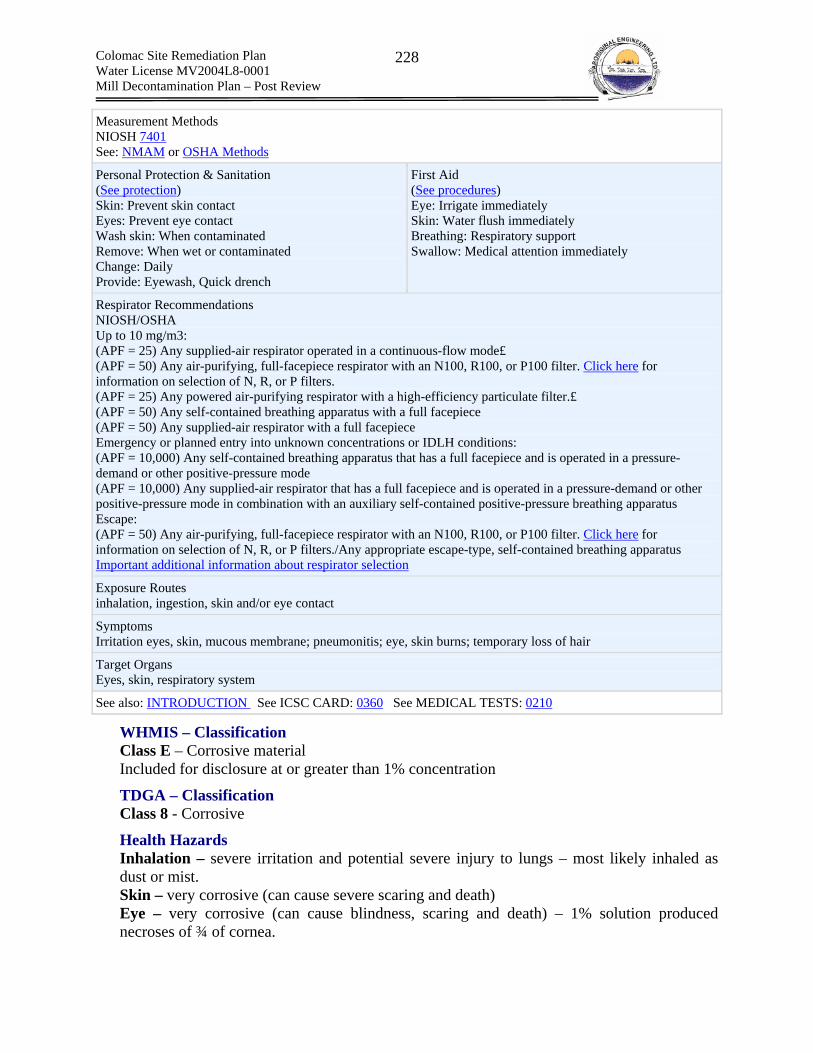
Colomac Site Remediation Plan Water License MV2004L8-0001 Mill Decontamination Plan – Post Review
228
Measurement Methods NIOSH 7401 See: NMAM or OSHA Methods
Personal Protection & Sanitation (See protection) Skin: Prevent skin contact Eyes: Prevent eye contact Wash skin: When contaminated Remove: When wet or contaminated Change: Daily Provide: Eyewash, Quick drench
First Aid (See procedures) Eye: Irrigate immediately Skin: Water flush immediately Breathing: Respiratory support Swallow: Medical attention immediately
Respirator Recommendations NIOSH/OSHA Up to 10 mg/m3: (APF = 25) Any supplied-air respirator operated in a continuous-flow mode£ (APF = 50) Any air-purifying, full-facepiece respirator with an N100, R100, or P100 filter. Click here for information on selection of N, R, or P filters. (APF = 25) Any powered air-purifying respirator with a high-efficiency particulate filter.£ (APF = 50) Any self-contained breathing apparatus with a full facepiece (APF = 50) Any supplied-air respirator with a full facepiece Emergency or planned entry into unknown concentrations or IDLH conditions: (APF = 10,000) Any self-contained breathing apparatus that has a full facepiece and is operated in a pressure-demand or other positive-pressure mode (APF = 10,000) Any supplied-air respirator that has a full facepiece and is operated in a pressure-demand or other positive-pressure mode in combination with an auxiliary self-contained positive-pressure breathing apparatus Escape: (APF = 50) Any air-purifying, full-facepiece respirator with an N100, R100, or P100 filter. Click here for information on selection of N, R, or P filters./Any appropriate escape-type, self-contained breathing apparatus Important additional information about respirator selection
Exposure Routes inhalation, ingestion, skin and/or eye contact
Symptoms Irritation eyes, skin, mucous membrane; pneumonitis; eye, skin burns; temporary loss of hair
Target Organs Eyes, skin, respiratory system
See also: INTRODUCTION See ICSC CARD: 0360 See MEDICAL TESTS: 0210
WHMIS – Classification Class E – Corrosive material Included for disclosure at or greater than 1% concentration
TDGA – Classification Class 8 - Corrosive
Health Hazards Inhalation – severe irritation and potential severe injury to lungs – most likely inhaled as dust or mist. Skin – very corrosive (can cause severe scaring and death) Eye – very corrosive (can cause blindness, scaring and death) – 1% solution produced necroses of ¾ of cornea.

Colomac Site Remediation Plan Water License MV2004L8-0001 Mill Decontamination Plan – Post Review
229
Ingestion – no occupational instances however expected to cause sever burning symptoms. Carcinogen – Not listed. Scarring or burning have been implicated in delayed onset of cancer. Accumulation – No
Occupational Exposure Limits ACGIH TLV-C: 2 mg/m3 (irritation) OSHA PEL – TWA: 2 mg/m3 ERPG -1: 0.5 mg/m3 ERPG -2: 5 mg/m3
ERPG -3: 50 mg/m3
OH&S Hazard Ranking Very hazardous = 4
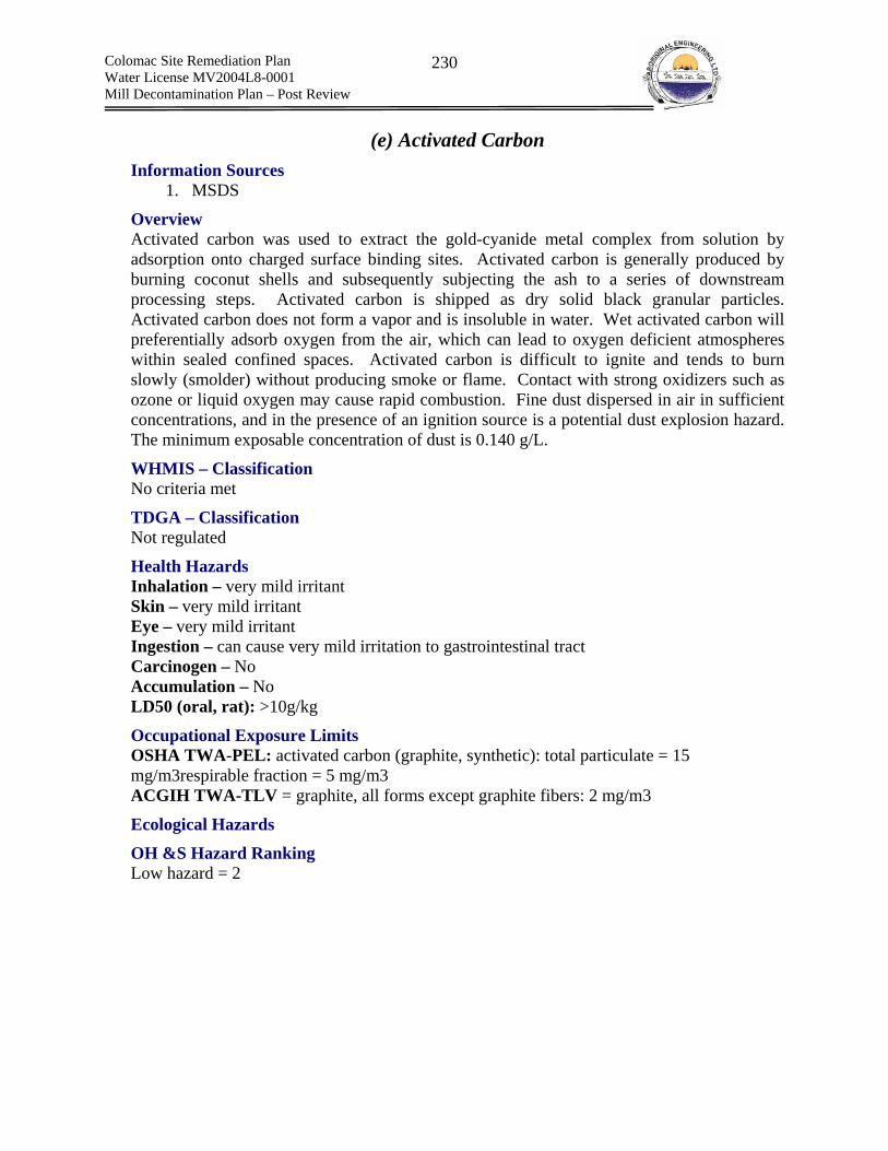
Colomac Site Remediation Plan Water License MV2004L8-0001 Mill Decontamination Plan – Post Review
230
(e) Activated Carbon Information Sources
1. MSDS
Overview Activated carbon was used to extract the gold-cyanide metal complex from solution by adsorption onto charged surface binding sites. Activated carbon is generally produced by burning coconut shells and subsequently subjecting the ash to a series of downstream processing steps. Activated carbon is shipped as dry solid black granular particles. Activated carbon does not form a vapor and is insoluble in water. Wet activated carbon will preferentially adsorb oxygen from the air, which can lead to oxygen deficient atmospheres within sealed confined spaces. Activated carbon is difficult to ignite and tends to burn slowly (smolder) without producing smoke or flame. Contact with strong oxidizers such as ozone or liquid oxygen may cause rapid combustion. Fine dust dispersed in air in sufficient concentrations, and in the presence of an ignition source is a potential dust explosion hazard. The minimum exposable concentration of dust is 0.140 g/L.
WHMIS – Classification No criteria met
TDGA – Classification Not regulated
Health Hazards Inhalation – very mild irritant Skin – very mild irritant Eye – very mild irritant Ingestion – can cause very mild irritation to gastrointestinal tract Carcinogen – No Accumulation – No LD50 (oral, rat): >10g/kg
Occupational Exposure Limits OSHA TWA-PEL: activated carbon (graphite, synthetic): total particulate = 15 mg/m3respirable fraction = 5 mg/m3 ACGIH TWA-TLV = graphite, all forms except graphite fibers: 2 mg/m3
Ecological Hazards
OH &S Hazard Ranking Low hazard = 2
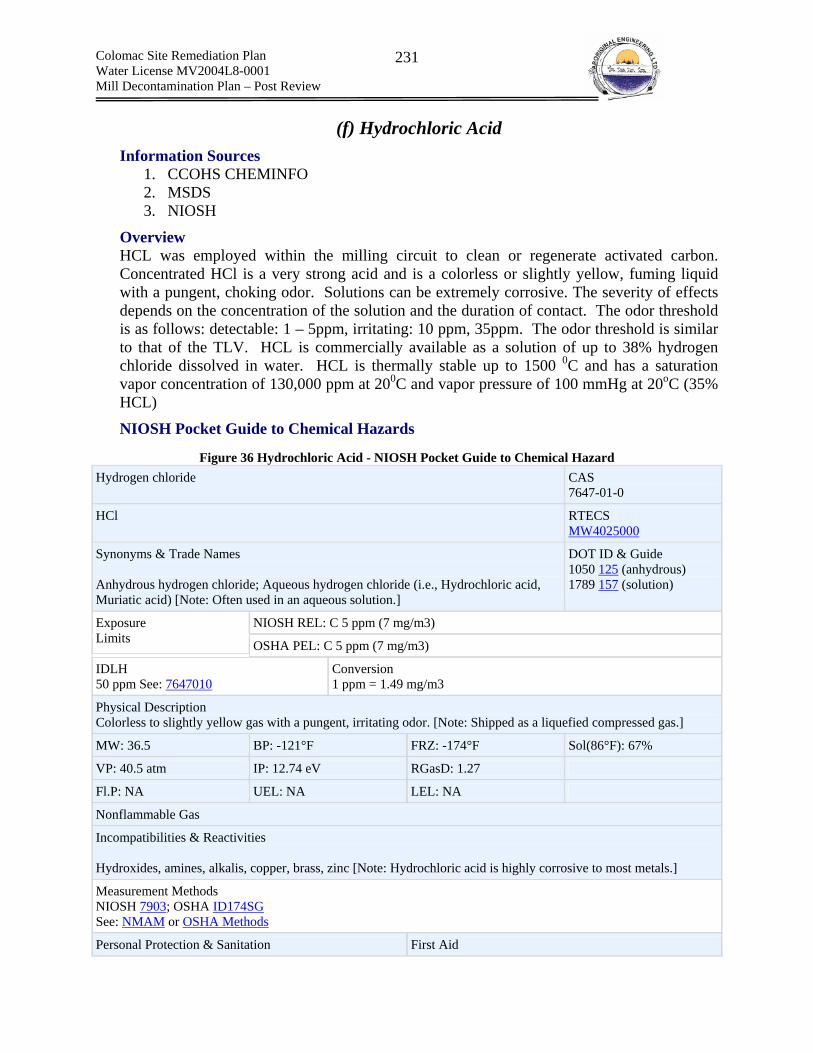
Colomac Site Remediation Plan Water License MV2004L8-0001 Mill Decontamination Plan – Post Review
231
(f) Hydrochloric Acid Information Sources
1. CCOHS CHEMINFO 2. MSDS 3. NIOSH
Overview HCL was employed within the milling circuit to clean or regenerate activated carbon. Concentrated HCl is a very strong acid and is a colorless or slightly yellow, fuming liquid with a pungent, choking odor. Solutions can be extremely corrosive. The severity of effects depends on the concentration of the solution and the duration of contact. The odor threshold is as follows: detectable: 1 – 5ppm, irritating: 10 ppm, 35ppm. The odor threshold is similar to that of the TLV. HCL is commercially available as a solution of up to 38% hydrogen chloride dissolved in water. HCL is thermally stable up to 1500 0C and has a saturation vapor concentration of 130,000 ppm at 200C and vapor pressure of 100 mmHg at 20oC (35% HCL)
NIOSH Pocket Guide to Chemical Hazards
Figure 36 Hydrochloric Acid - NIOSH Pocket Guide to Chemical Hazard Hydrogen chloride CAS
7647-01-0
HCl RTECS MW4025000
Synonyms & Trade Names Anhydrous hydrogen chloride; Aqueous hydrogen chloride (i.e., Hydrochloric acid, Muriatic acid) [Note: Often used in an aqueous solution.]
DOT ID & Guide 1050 125 (anhydrous) 1789 157 (solution)
NIOSH REL: C 5 ppm (7 mg/m3) Exposure Limits OSHA PEL: C 5 ppm (7 mg/m3)
IDLH 50 ppm See: 7647010
Conversion 1 ppm = 1.49 mg/m3
Physical Description Colorless to slightly yellow gas with a pungent, irritating odor. [Note: Shipped as a liquefied compressed gas.]
MW: 36.5 BP: -121°F FRZ: -174°F Sol(86°F): 67%
VP: 40.5 atm IP: 12.74 eV RGasD: 1.27
Fl.P: NA UEL: NA LEL: NA
Nonflammable Gas
Incompatibilities & Reactivities Hydroxides, amines, alkalis, copper, brass, zinc [Note: Hydrochloric acid is highly corrosive to most metals.]
Measurement Methods NIOSH 7903; OSHA ID174SG See: NMAM or OSHA Methods
Personal Protection & Sanitation First Aid

Colomac Site Remediation Plan Water License MV2004L8-0001 Mill Decontamination Plan – Post Review
232
(See protection) Skin: Prevent skin contact (solution)/Frostbite Eyes: Prevent eye contact/Frostbite Wash skin: When contaminated (solution) Remove: When wet or contaminated (solution) Change: No recommendation Provide: Eyewash (solution), Quick drench (solution), Frostbite wash
(See procedures) Eye: Irrigate immediately (solution)/Frostbite Skin: Water flush immediately (solution)/Frostbite Breathing: Respiratory support Swallow: Medical attention immediately (solution)
Respirator Recommendations NIOSH/OSHA Up to 50 ppm: (APF = 10) Any chemical cartridge respirator with cartridge(s) providing protection against the compound of concern* (APF = 50) Any air-purifying, full-facepiece respirator (gas mask) with a chin-style, front- or back-mounted canister providing protection against the compound of concern (APF = 25) Any powered, air-purifying respirator with cartridge(s) providing protection against the compound of concern* (APF = 10) Any supplied-air respirator* (APF = 50) Any self-contained breathing apparatus with a full facepiece Emergency or planned entry into unknown concentrations or IDLH conditions: (APF = 10,000) Any self-contained breathing apparatus that has a full facepiece and is operated in a pressure-demand or other positive-pressure mode (APF = 10,000) Any supplied-air respirator that has a full facepiece and is operated in a pressure-demand or other positive-pressure mode in combination with an auxiliary self-contained positive-pressure breathing apparatus Escape: (APF = 50) Any air-purifying, full-facepiece respirator (gas mask) with a chin-style, front- or back-mounted acid gas canister/Any appropriate escape-type, self-contained breathing apparatus Important additional information about respirator selection
Exposure Routes inhalation, ingestion (solution), skin and/or eye contact
Symptoms Irritation nose, throat, larynx; cough, choking; dermatitis; solution: eye, skin burns; liquid: frostbite; in animals: laryngeal spasm; pulmonary edema
Target Organs Eyes, skin, respiratory system
See also: INTRODUCTION See ICSC CARD: 0163 See MEDICAL TESTS: 0116
WHMIS – Classification Class E – Corrosive material Class D – Division 1 – Sub Division A: Very toxic material
TDGA – Classification Class 8: Corrosive
Health Hazards Inhalation – severe irritant. long exposure can cause ulcers and burns to the nose and throat. mists of pH < 3 are serious health concern. 1000 – 2000 ppm can lead to life threatening accumulation of fluid in the lungs. Symptoms of fluid accumulation can be delayed for hours. Skin – very corrosive (can cause severe scaring and death)

Colomac Site Remediation Plan Water License MV2004L8-0001 Mill Decontamination Plan – Post Review
233
Eye – very corrosive (can cause blindness, scaring and death) – vapor or mist of 10 – 35 ppm can be immediately irritating to the eyes Ingestion – very corrosive Carcinogen – Unclassifiable – several studies have linked occupational exposure to the development of cancer Accumulation – No LC50 and LD50 for Mists of HCL: LC50 (rat): 8300 mg/m3 (5666 ppm) (30-minute exposure) LC50 (rat): 45600 mg/m3 (31008 ppm) (5-minute exposure) LC50 (mouse): 3100 mg/m3 (2142 ppm) (30-minute exposure) LC50 (mouse): 16500 mg/m3 (11238 ppm) (5-minute exposure)
For above: Symptoms include irritation of eyes, skin and mucous membranes, and corrosive eye damage. Death was due to lung injury LD50 (oral, rabbit): 900 mg/kg
Occupational Exposure Limits ACGIH TLV-C: 2 mg/m3 (irritation & corrosion) OSHA PEL – TWA: not established OSHA PEL-C: 5ppm (7mg/m3) ERPG -1: 3 ppm ERPG -2: 20 ppm
ERPG -3: 150 mg/m3
OH&S Hazard Ranking Very hazardous = 4
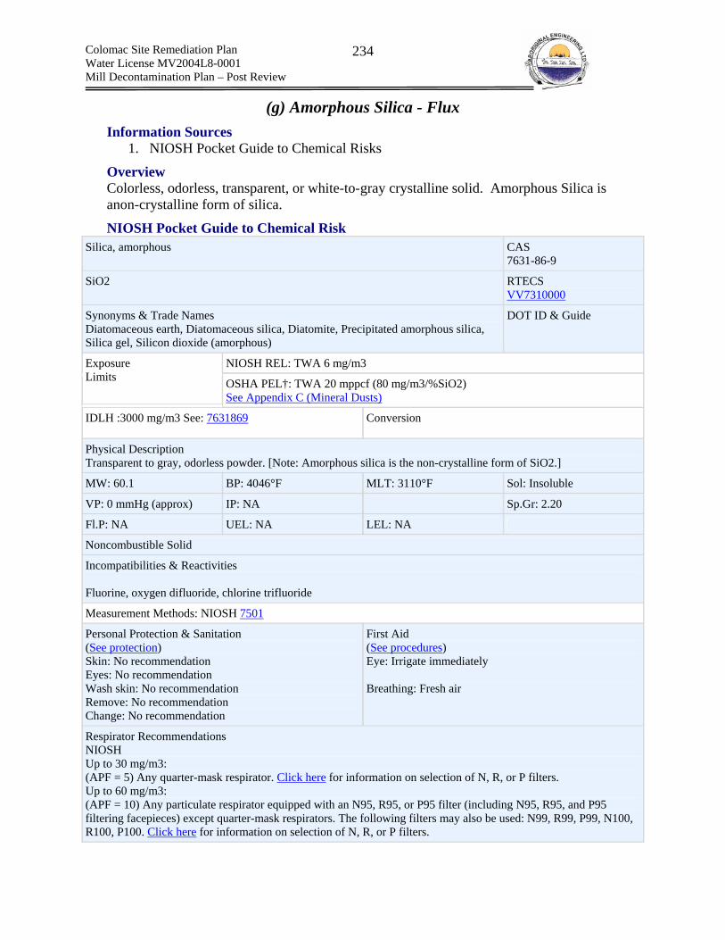
Colomac Site Remediation Plan Water License MV2004L8-0001 Mill Decontamination Plan – Post Review
234
(g) Amorphous Silica - Flux Information Sources
1. NIOSH Pocket Guide to Chemical Risks
Overview Colorless, odorless, transparent, or white-to-gray crystalline solid. Amorphous Silica is anon-crystalline form of silica.
NIOSH Pocket Guide to Chemical Risk Silica, amorphous CAS
7631-86-9
SiO2 RTECS VV7310000
Synonyms & Trade Names Diatomaceous earth, Diatomaceous silica, Diatomite, Precipitated amorphous silica, Silica gel, Silicon dioxide (amorphous)
DOT ID & Guide
NIOSH REL: TWA 6 mg/m3 Exposure Limits OSHA PEL†: TWA 20 mppcf (80 mg/m3/%SiO2)
See Appendix C (Mineral Dusts)
IDLH :3000 mg/m3 See: 7631869 Conversion
Physical Description Transparent to gray, odorless powder. [Note: Amorphous silica is the non-crystalline form of SiO2.]
MW: 60.1 BP: 4046°F MLT: 3110°F Sol: Insoluble
VP: 0 mmHg (approx) IP: NA Sp.Gr: 2.20
Fl.P: NA UEL: NA LEL: NA
Noncombustible Solid
Incompatibilities & Reactivities Fluorine, oxygen difluoride, chlorine trifluoride
Measurement Methods: NIOSH 7501
Personal Protection & Sanitation (See protection) Skin: No recommendation Eyes: No recommendation Wash skin: No recommendation Remove: No recommendation Change: No recommendation
First Aid (See procedures) Eye: Irrigate immediately Breathing: Fresh air
Respirator Recommendations NIOSH Up to 30 mg/m3: (APF = 5) Any quarter-mask respirator. Click here for information on selection of N, R, or P filters. Up to 60 mg/m3: (APF = 10) Any particulate respirator equipped with an N95, R95, or P95 filter (including N95, R95, and P95 filtering facepieces) except quarter-mask respirators. The following filters may also be used: N99, R99, P99, N100, R100, P100. Click here for information on selection of N, R, or P filters.

Colomac Site Remediation Plan Water License MV2004L8-0001 Mill Decontamination Plan – Post Review
235
(APF = 10) Any supplied-air respirator Up to 150 mg/m3: (APF = 25) Any supplied-air respirator operated in a continuous-flow mode (APF = 25) Any powered air-purifying respirator with a high-efficiency particulate filter. Up to 300 mg/m3: (APF = 50) Any air-purifying, full-facepiece respirator with an N100, R100, or P100 filter. Click here for information on selection of N, R, or P filters. (APF = 50) Any supplied-air respirator that has a tight-fitting facepiece and is operated in a continuous-flow mode (APF = 50) Any powered, air-purifying respirator with a tight-fitting facepiece and a high-efficiency particulate filter (APF = 50) Any self-contained breathing apparatus with a full facepiece (APF = 50) Any supplied-air respirator with a full facepiece Up to 3000 mg/m3: (APF = 1000) Any supplied-air respirator operated in a pressure-demand or other positive-pressure mode Emergency or planned entry into unknown concentrations or IDLH conditions: (APF = 10,000) Any self-contained breathing apparatus that has a full facepiece and is operated in a pressure-demand or other positive-pressure mode (APF = 10,000) Any supplied-air respirator that has a full facepiece and is operated in a pressure-demand or other positive-pressure mode in combination with an auxiliary self-contained positive-pressure breathing apparatus Escape: (APF = 50) Any air-purifying, full-facepiece respirator with an N100, R100, or P100 filter. Click here for information on selection of N, R, or P filters./Any appropriate escape-type, self-contained breathing apparatus Important additional information about respirator selection
Exposure Routes: inhalation, skin and/or eye contact
Symptoms : Irritation eyes, pneumoconiosis
Target Organs: Eyes, respiratory system
WHMIS – Classification Not classified
TDGA – Classification Does not meet any criteria
Health Hazards Inhalation – Respiratory tract irritation – prolonged inhalation can lead to silicosis Skin – Very mild irritant Eye – mechanical irritation Ingestion – Non-hazardous Carcinogen – Not classified Accumulation -No
Occupational Exposure Limits Refer NIOSH Pocket Guide for Chemical Hazard
OH&S Hazard Ranking Low Hazard = 2
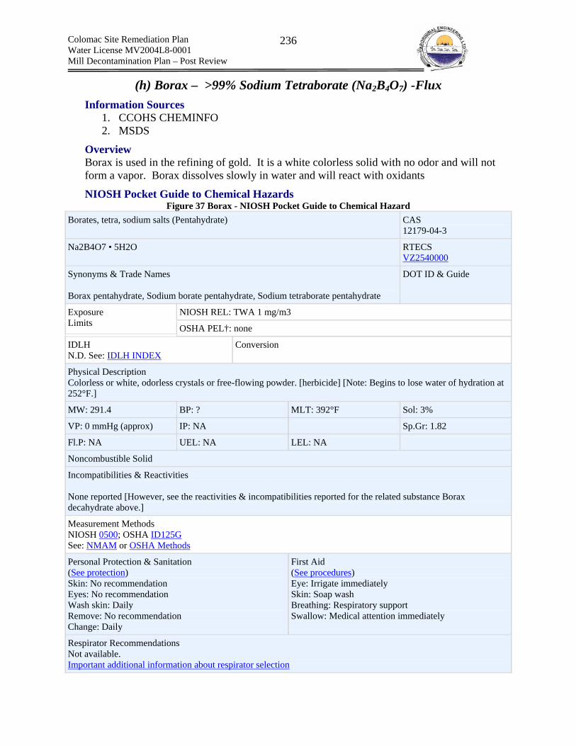
Colomac Site Remediation Plan Water License MV2004L8-0001 Mill Decontamination Plan – Post Review
236
(h) Borax – >99% Sodium Tetraborate (Na2B4O7) -Flux Information Sources
1. CCOHS CHEMINFO 2. MSDS
Overview Borax is used in the refining of gold. It is a white colorless solid with no odor and will not form a vapor. Borax dissolves slowly in water and will react with oxidants
NIOSH Pocket Guide to Chemical Hazards Figure 37 Borax - NIOSH Pocket Guide to Chemical Hazard
Borates, tetra, sodium salts (Pentahydrate) CAS 12179-04-3
Na2B4O7 • 5H2O RTECS VZ2540000
Synonyms & Trade Names Borax pentahydrate, Sodium borate pentahydrate, Sodium tetraborate pentahydrate
DOT ID & Guide
NIOSH REL: TWA 1 mg/m3 Exposure Limits OSHA PEL†: none
IDLH N.D. See: IDLH INDEX
Conversion
Physical Description Colorless or white, odorless crystals or free-flowing powder. [herbicide] [Note: Begins to lose water of hydration at 252°F.]
MW: 291.4 BP: ? MLT: 392°F Sol: 3%
VP: 0 mmHg (approx) IP: NA Sp.Gr: 1.82
Fl.P: NA UEL: NA LEL: NA
Noncombustible Solid
Incompatibilities & Reactivities None reported [However, see the reactivities & incompatibilities reported for the related substance Borax decahydrate above.]
Measurement Methods NIOSH 0500; OSHA ID125G See: NMAM or OSHA Methods
Personal Protection & Sanitation (See protection) Skin: No recommendation Eyes: No recommendation Wash skin: Daily Remove: No recommendation Change: Daily
First Aid (See procedures) Eye: Irrigate immediately Skin: Soap wash Breathing: Respiratory support Swallow: Medical attention immediately
Respirator Recommendations Not available. Important additional information about respirator selection
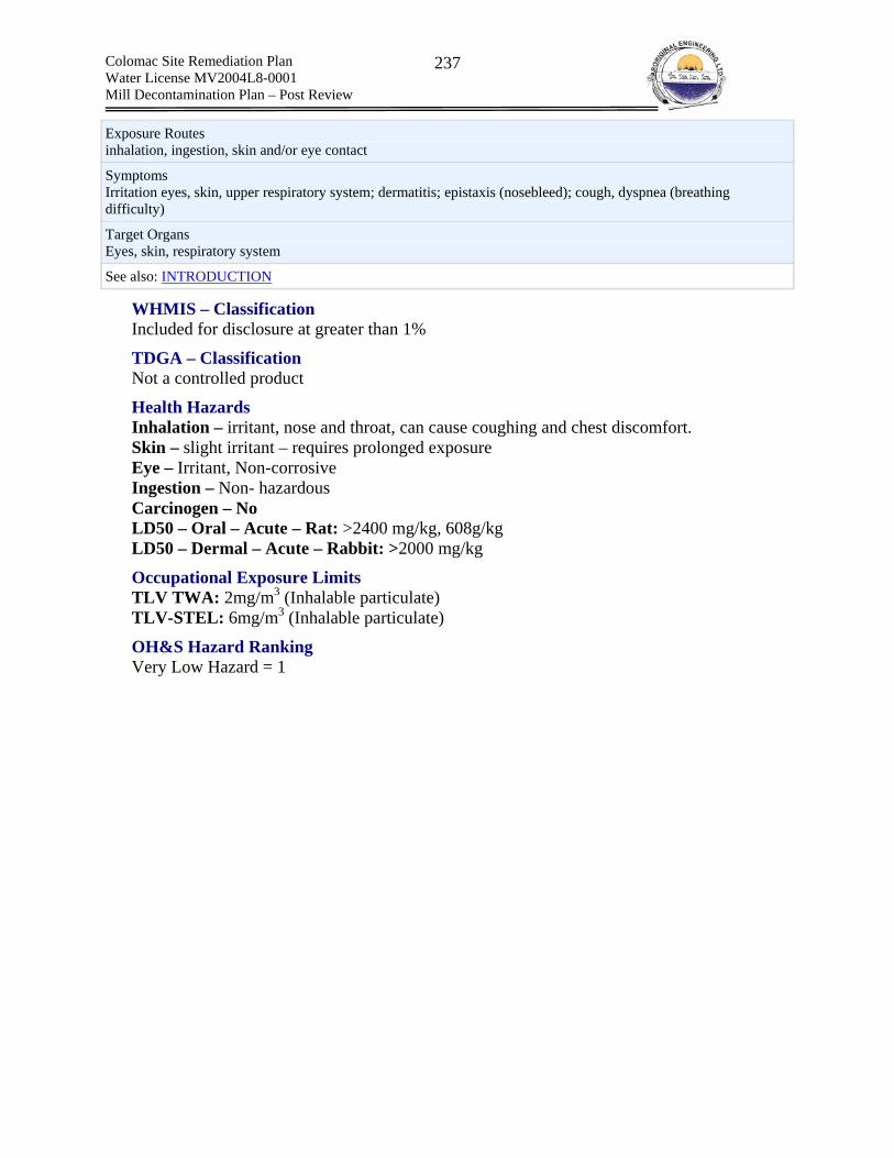
Colomac Site Remediation Plan Water License MV2004L8-0001 Mill Decontamination Plan – Post Review
237
Exposure Routes inhalation, ingestion, skin and/or eye contact
Symptoms Irritation eyes, skin, upper respiratory system; dermatitis; epistaxis (nosebleed); cough, dyspnea (breathing difficulty)
Target Organs Eyes, skin, respiratory system
See also: INTRODUCTION
WHMIS – Classification Included for disclosure at greater than 1%
TDGA – Classification Not a controlled product
Health Hazards Inhalation – irritant, nose and throat, can cause coughing and chest discomfort. Skin – slight irritant – requires prolonged exposure Eye – Irritant, Non-corrosive Ingestion – Non- hazardous Carcinogen – No LD50 – Oral – Acute – Rat: >2400 mg/kg, 608g/kg LD50 – Dermal – Acute – Rabbit: >2000 mg/kg
Occupational Exposure Limits TLV TWA: 2mg/m3 (Inhalable particulate) TLV-STEL: 6mg/m3 (Inhalable particulate)
OH&S Hazard Ranking Very Low Hazard = 1

Colomac Site Remediation Plan Water License MV2004L8-0001 Mill Decontamination Plan – Post Review
238
(i) Sodium Nitrate – NaNO3 - Flux Information Sources
1. CCOHS CHEMINFO 2. MSDS
Overview Sodium nitrate is used in the refining of gold and is a white to light yellow, odorless, crystalline powder. Sodium nitrate is an oxidizer and will therefore enhance the burning and can cause the spontaneous ignition of combustible materials.
WHMIS – Classification Included for disclosure at greater than 1%
TDGA – Classification Class 5.1, packing group 3
Health Hazards Inhalation – irritant, nose and throat, can cause coughing and chest discomfort. Skin – irritant Eye – irritant Ingestion – gastro-enteritis and abdominal pain Carcinogen – Not evaluated
Occupational Exposure Limits No established limits
OH&S Hazard Ranking Low Hazard = 2
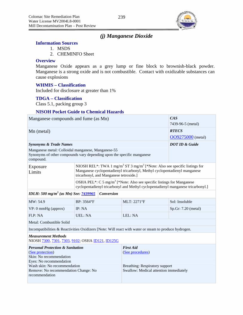
Colomac Site Remediation Plan Water License MV2004L8-0001 Mill Decontamination Plan – Post Review
239
(j) Manganese Dioxide Information Sources
1. MSDS 2. CHEMINFO Sheet
Overview Manganese Oxide appears as a grey lump or fine block to brownish-black powder. Manganese is a strong oxide and is not combustible. Contact with oxidizable substances can cause explosions
WHMIS – Classification Included for disclosure at greater than 1%
TDGA – Classification Class 5.1, packing group 3
NISOH Pocket Guide to Chemical Hazards Manganese compounds and fume (as Mn) CAS
7439-96-5 (metal)
Mn (metal) RTECS OO9275000 (metal)
Synonyms & Trade Names Manganese metal: Colloidal manganese, Manganese-55 Synonyms of other compounds vary depending upon the specific manganese compound.
DOT ID & Guide
NIOSH REL*: TWA 1 mg/m3 ST 3 mg/m3 [*Note: Also see specific listings for Manganese cyclopentadienyl tricarbonyl, Methyl cyclopentadienyl manganese tricarbonyl, and Manganese tetroxide.]
Exposure Limits
OSHA PEL*: C 5 mg/m3 [*Note: Also see specific listings for Manganese cyclopentadienyl tricarbonyl and Methyl cyclopentadienyl manganese tricarbonyl.]
IDLH: 500 mg/m3 (as Mn) See: 7439965 Conversion
MW: 54.9 BP: 3564°F MLT: 2271°F Sol: Insoluble
VP: 0 mmHg (approx) IP: NA Sp.Gr: 7.20 (metal)
Fl.P: NA UEL: NA LEL: NA
Metal: Combustible Solid
Incompatibilities & Reactivities Oxidizers [Note: Will react with water or steam to produce hydrogen.
Measurement Methods NIOSH 7300, 7301, 7303, 9102; OSHA ID121, ID125G
Personal Protection & Sanitation (See protection) Skin: No recommendation Eyes: No recommendation Wash skin: No recommendation Remove: No recommendation Change: No recommendation
First Aid (See procedures) Breathing: Respiratory support Swallow: Medical attention immediately
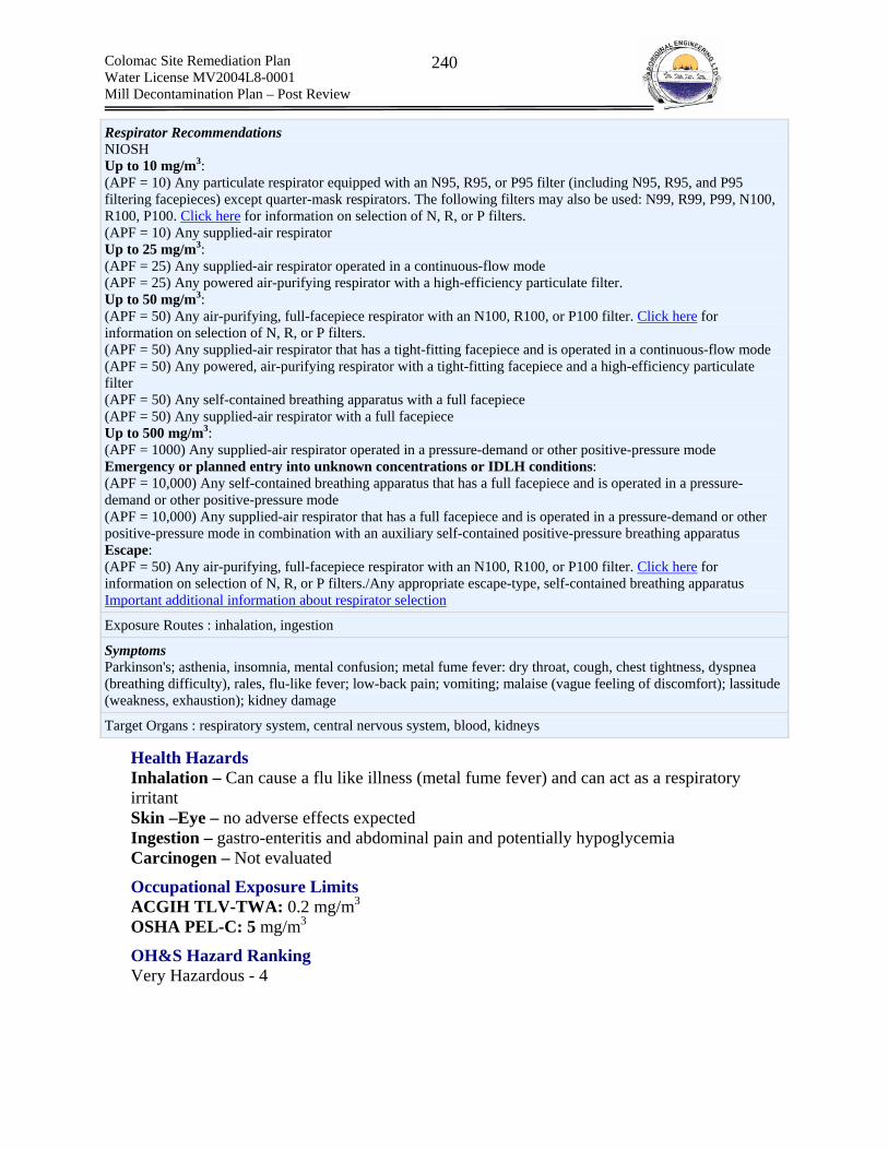
Colomac Site Remediation Plan Water License MV2004L8-0001 Mill Decontamination Plan – Post Review
240
Respirator Recommendations NIOSH Up to 10 mg/m3: (APF = 10) Any particulate respirator equipped with an N95, R95, or P95 filter (including N95, R95, and P95 filtering facepieces) except quarter-mask respirators. The following filters may also be used: N99, R99, P99, N100, R100, P100. Click here for information on selection of N, R, or P filters. (APF = 10) Any supplied-air respirator Up to 25 mg/m3: (APF = 25) Any supplied-air respirator operated in a continuous-flow mode (APF = 25) Any powered air-purifying respirator with a high-efficiency particulate filter. Up to 50 mg/m3: (APF = 50) Any air-purifying, full-facepiece respirator with an N100, R100, or P100 filter. Click here for information on selection of N, R, or P filters. (APF = 50) Any supplied-air respirator that has a tight-fitting facepiece and is operated in a continuous-flow mode (APF = 50) Any powered, air-purifying respirator with a tight-fitting facepiece and a high-efficiency particulate filter (APF = 50) Any self-contained breathing apparatus with a full facepiece (APF = 50) Any supplied-air respirator with a full facepiece Up to 500 mg/m3: (APF = 1000) Any supplied-air respirator operated in a pressure-demand or other positive-pressure mode Emergency or planned entry into unknown concentrations or IDLH conditions: (APF = 10,000) Any self-contained breathing apparatus that has a full facepiece and is operated in a pressure-demand or other positive-pressure mode (APF = 10,000) Any supplied-air respirator that has a full facepiece and is operated in a pressure-demand or other positive-pressure mode in combination with an auxiliary self-contained positive-pressure breathing apparatus Escape: (APF = 50) Any air-purifying, full-facepiece respirator with an N100, R100, or P100 filter. Click here for information on selection of N, R, or P filters./Any appropriate escape-type, self-contained breathing apparatus Important additional information about respirator selection
Exposure Routes : inhalation, ingestion
Symptoms Parkinson's; asthenia, insomnia, mental confusion; metal fume fever: dry throat, cough, chest tightness, dyspnea (breathing difficulty), rales, flu-like fever; low-back pain; vomiting; malaise (vague feeling of discomfort); lassitude (weakness, exhaustion); kidney damage
Target Organs : respiratory system, central nervous system, blood, kidneys
Health Hazards Inhalation – Can cause a flu like illness (metal fume fever) and can act as a respiratory irritant Skin –Eye – no adverse effects expected Ingestion – gastro-enteritis and abdominal pain and potentially hypoglycemia Carcinogen – Not evaluated
Occupational Exposure Limits ACGIH TLV-TWA: 0.2 mg/m3
OSHA PEL-C: 5 mg/m3
OH&S Hazard Ranking Very Hazardous - 4

Colomac Site Remediation Plan Water License MV2004L8-0001 Mill Decontamination Plan – Post Review
241
Process Slurry and Ore Dust (a) Process Slurry – Pore Water (b) Process Slurry – Free Water (c) Solid Tailings and Ore Dust
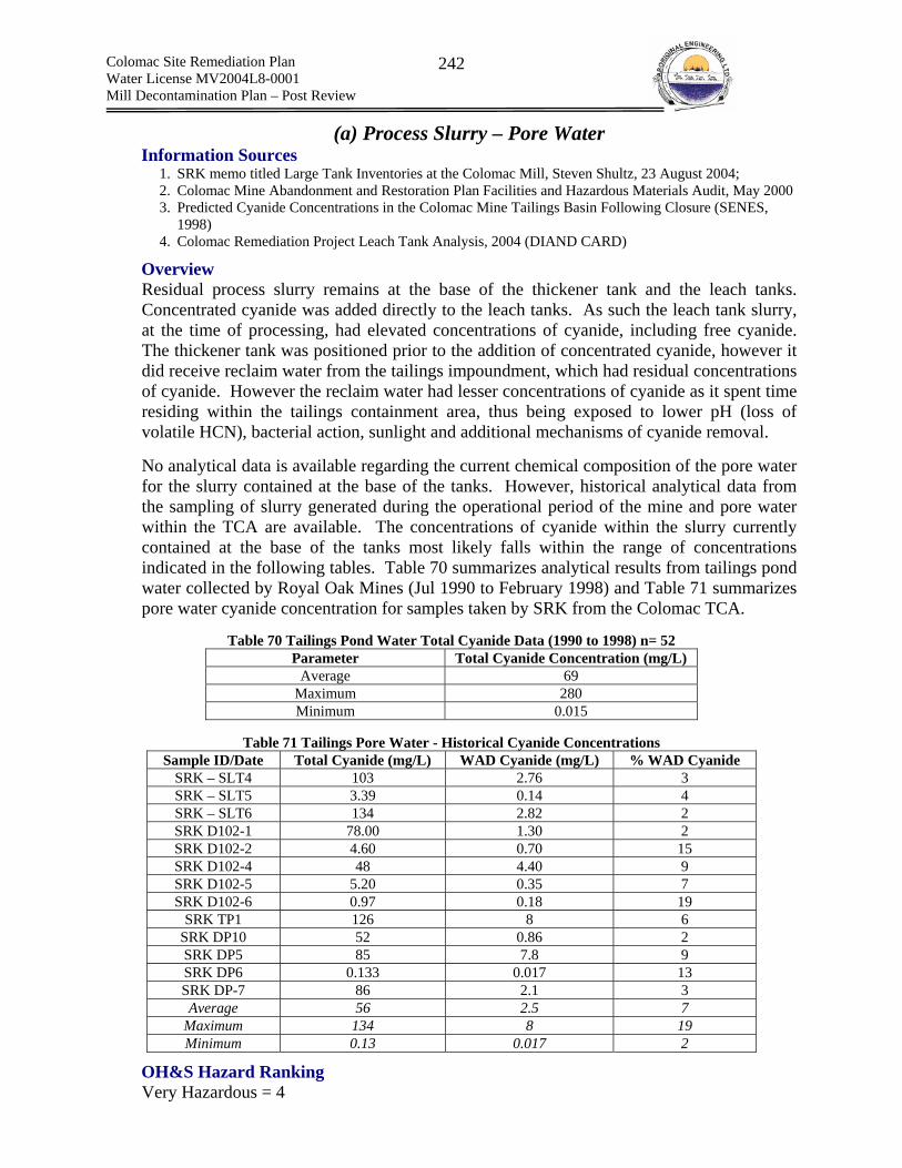
Colomac Site Remediation Plan Water License MV2004L8-0001 Mill Decontamination Plan – Post Review
242
(a) Process Slurry – Pore Water Information Sources
1. SRK memo titled Large Tank Inventories at the Colomac Mill, Steven Shultz, 23 August 2004; 2. Colomac Mine Abandonment and Restoration Plan Facilities and Hazardous Materials Audit, May 2000 3. Predicted Cyanide Concentrations in the Colomac Mine Tailings Basin Following Closure (SENES,
1998) 4. Colomac Remediation Project Leach Tank Analysis, 2004 (DIAND CARD)
Overview Residual process slurry remains at the base of the thickener tank and the leach tanks. Concentrated cyanide was added directly to the leach tanks. As such the leach tank slurry, at the time of processing, had elevated concentrations of cyanide, including free cyanide. The thickener tank was positioned prior to the addition of concentrated cyanide, however it did receive reclaim water from the tailings impoundment, which had residual concentrations of cyanide. However the reclaim water had lesser concentrations of cyanide as it spent time residing within the tailings containment area, thus being exposed to lower pH (loss of volatile HCN), bacterial action, sunlight and additional mechanisms of cyanide removal. No analytical data is available regarding the current chemical composition of the pore water for the slurry contained at the base of the tanks. However, historical analytical data from the sampling of slurry generated during the operational period of the mine and pore water within the TCA are available. The concentrations of cyanide within the slurry currently contained at the base of the tanks most likely falls within the range of concentrations indicated in the following tables. Table 70 summarizes analytical results from tailings pond water collected by Royal Oak Mines (Jul 1990 to February 1998) and Table 71 summarizes pore water cyanide concentration for samples taken by SRK from the Colomac TCA.
Table 70 Tailings Pond Water Total Cyanide Data (1990 to 1998) n= 52 Parameter Total Cyanide Concentration (mg/L)
Average 69 Maximum 280 Minimum 0.015
Table 71 Tailings Pore Water - Historical Cyanide Concentrations
Sample ID/Date Total Cyanide (mg/L) WAD Cyanide (mg/L) % WAD Cyanide SRK – SLT4 103 2.76 3 SRK – SLT5 3.39 0.14 4 SRK – SLT6 134 2.82 2 SRK D102-1 78.00 1.30 2 SRK D102-2 4.60 0.70 15 SRK D102-4 48 4.40 9 SRK D102-5 5.20 0.35 7 SRK D102-6 0.97 0.18 19
SRK TP1 126 8 6 SRK DP10 52 0.86 2 SRK DP5 85 7.8 9 SRK DP6 0.133 0.017 13 SRK DP-7 86 2.1 3 Average 56 2.5 7
Maximum 134 8 19 Minimum 0.13 0.017 2
OH&S Hazard Ranking Very Hazardous = 4
Colomac Site Remediation Plan Water License MV2004L8-0001 Mill Decontamination Plan – Post Review
243
(b) Process Slurry - Free Water Information Sources
1. Results of Leach Tank Sampling – June 2004 (DIAND CSO)
Overview Free water covers the process slurry within the leach tanks and the thickener. Table 72 presents the complete analytical results for the DIAND June 2004 sampling of the free water. With respect to OH&S, cyanide represents the contaminant of concern. Total cyanide concentrations range from 0.003 mg/L (thickener tank) to 38 mg/L, WAD from 0.006 mg/L (thickener tank) to 2.48 mg/L and Thiocyanate from 0.7 mg/L (thickener tank) to 79.4 mg/L. Of greatest concern is the WAD fraction as this portion of the Total cyanide is the most likely to form free cyanide. Lower pH values tend to have lower concentrations of total cyanide (HCN volatilization)
OH&S Hazard Ranking Hazardous = 3 (leach tanks) Low Hazard = 2 (thickener)

Colomac Site Remediation Plan Water License MV2004L8-0001 Mill Decontamination Plan – Post Review
244
Table 72 Process Slurry Free Water - Analytical Results Parameter Units Tank1 Tank2 Tank3 Tank4 Tank5 Tank6 Tank7 Tank8 Tank9 Tank10 Tank11 Thickener Physicals Conductivity uS/cm 104 121 317 182.3 157.1 41.6 307 37.1 379 41 63.9 706 pH unit 8.05 8.44 8.91 9.42 8.21 7.53 8.48 7.41 8.81 6.75 6.96 7.65 Nutrients Ammonia as N mg/L N 0.895 0.907 1.83 1.65 1.26 0.226 2.18 0.243 2.65 0.282 0.839 0.005 Major Ions Chloride mg/L 1.4 1.2 49 22 17 0.8 51 0.7 66 0.9 1.6 4.1 Sulphate mg/L 20 19 110 38 45 6.9 130 8.8 160 8.8 13 310 Organics Total CN mg/L 4.4 0.44 36.3 18 7 1.1 26 0.7 38 0.9 1 0.003 Cyanide, WAD mg/L 0.31 0.088 1.34 2.48 0.098 0.098 0.72 0.084 1.68 0.102 0.084 0.006 Thiocyanate mg/L 61.1 18.4 16.3 3.3 63.5 2.8 79.4 3 2.7 0.7 Total Metals Aluminum mg/L 0.171 0.1 0.048 0.066 0.03 0.043 0.03 0.03 0.03 0.03 0.039 0.112 Antimony mg/L 0.0011 0.0007 0.0006 0.0008 0.0007 0.0006 0.0005 0.0006 0.0006 0.0007 0.0014 0.0009 Arsenic mg/L 0.003 0.001 0.007 0.017 0.001 0.001 0.001 0.001 0.006 0.001 0.001 0.001 Barium mg/L 0.0021 0.0014 0.0014 0.0023 0.0018 0.0024 0.0016 0.0035 0.0007 0.0041 0.0042 0.0171 Beryllium mg/L 0.0001 0.0001 0.0001 0.0001 0.0001 0.0001 0.0001 0.0001 0.0001 0.0001 0.0001 0.0001 Cadmium mg/L 0.0001 0.0001 0.0001 0.0001 0.0001 0.0001 0.0001 0.0001 0.0001 0.0001 0.0001 0.0001 Cesium mg/L 0.0001 0.0001 0.0001 0.0001 0.0001 0.0001 0.0001 0.0001 0.0001 0.0001 0.0001 0.0001 Chromium mg/L 0.0009 0.0005 0.0006 0.0006 0.0004 0.0004 0.0003 0.0004 0.0004 0.0003 0.0027 0.0003 Cobalt mg/L 0.0017 0.0008 0.0102 0.0038 0.0023 0.0006 0.0112 0.0005 0.0121 0.0006 0.0008 0.0005 Copper mg/L 0.0263 0.0056 0.407 0.166 0.0057 0.004 0.0962 0.0029 0.64 0.006 0.0044 0.0039 Gold mg/L 0.011 0.001 0.051 0.037 0.001 0.001 0.035 0.001 0.069 0.001 0.001 0.001 Iron mg/L 2.832 1.818 4.1 3.63 0.942 1.31 1.36 1.46 3.37 1.19 1.01 0.224 Lead mg/L 0.0033 0.0017 0.0049 0.0029 0.0023 0.0027 0.0012 0.0035 0.002 0.0023 0.0017 0.0006 Lithium mg/L 0.0003 0.0003 0.0003 0.0003 0.0003 0.0003 0.0003 0.0003 0.0003 0.0003 0.0003 0.0014 Manganese mg/L 0.0853 0.0802 0.0446 0.0639 0.0432 0.0781 0.0212 0.0854 0.021 0.0655 0.0489 0.076 Molybdenum mg/L 0.002 0.0019 0.0127 0.004 0.0052 0.0009 0.0101 0.0007 0.0139 0.0013 0.0022 0.0132 Nickel mg/L 0.0045 0.0007 0.0245 0.0137 0.0046 0.0008 0.0376 0.0004 0.0434 0.0008 0.0019 0.0005 Rubidium mg/L 0.0001 0.0001 0.0001 0.0001 0.0001 0.0001 0.0001 0.0001 0.0001 0.0001 0.0002 0.0029 Selenium mg/L 0.001 0.001 0.003 0.001 0.001 0.001 0.002 0.001 0.003 0.001 0.001 0.001 Silver mg/L 0.0016 0.0003 0.0095 0.0116 0.0001 0.0002 0.0004 0.0001 0.0064 0.0002 0.0001 0.0001 Strontium mg/L 0.0033 0.004 0.0037 0.0054 0.0056 0.0056 0.0048 0.0056 0.0037 0.0052 0.0055 0.206 Thallium mg/L 0.0001 0.0001 0.0001 0.0001 0.0001 0.0001 0.0001 0.0001 0.0001 0.0001 0.0001 0.0001 Titanium mg/L 0.0039 0.0021 0.0013 0.0014 0.0006 0.0016 0.0005 0.0004 0.0004 0.0009 0.0012 0.0024 Uranium mg/L 0.0001 0.0001 0.0002 0.0001 0.0001 0.0001 0.0001 0.0001 0.0001 0.0001 0.0001 0.0006 Vanadium mg/L 0.0004 0.0002 0.0002 0.0004 0.0001 0.0001 0.0001 0.0001 0.0001 0.0001 0.0001 0.0001 Zinc mg/L 0.01 0.01 0.013 0.038 0.01 0.013 0.01 0.028 0.01 0.015 0.033 0.015
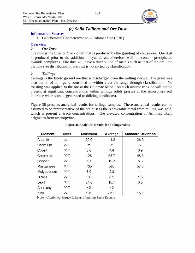
Colomac Site Remediation Plan Water License MV2004L8-0001 Mill Decontamination Plan – Post Review
245
(c) Solid Tailings and Ore Dust Information Sources
1. Geochemical Characterization – Colomac Site (SRK)
Overview Ore Dust
Ore dust is the fines or “rock dust” that is produced by the grinding of course ore. Ore dust is produced prior to the addition of cyanide and therefore will not contain precipitated cyanide complexes. Ore dust will have a distribution of metals such as that of the ore. the particle size distribution of ore dust is not sorted by classification.
Tailings Tailings is the finely ground ore that is discharged from the milling circuit. The grain size distribution of tailings is controlled to within a certain range through classification. No roasting was applied to the ore at the Colomac Mine. As such arsenic trioxide will not be present at significant concentrations within tailings solids present at the atmosphere soil interface where dust is generated (oxidizing conditions). Figure 38 presents analytical results for tailings samples. These analytical results can be assumed to be representative of the ore dust as the recoverable metal from milling was gold, which is present at trace concentrations. The elevated concentration of As most likely originates from arsenopyrite.
Figure 38 Analytical Results for Tailings Solids

Colomac Site Remediation Plan Water License MV2004L8-0001 Mill Decontamination Plan – Post Review
246
Figure 39 XRF results for tailings: Source – Colomac Geochemical Characterization (SRK)
Of considerable importance to OH&S is the concentration of quarts within the ore (results from quartz-carbonate veining). As such, a fraction of the finely ground tailings/ore dust could contain respirable crystalline silica (<10um).
Health Hazard
Tailings and Ore Dust Inhalation – Severe acute exposures and chronic low exposure to respirable crystalline silica can result in silicosis. The respirable dust fractions containing elevated metals such as arsenic may also represent a health hazard. However, risk assessment with respect to the inhalation of metals contained within tailings dust concluded that this exposure route was not a health risk.
Occupational Exposure Limit Refer to summary of crystalline silica
OH&S Hazard Ranking Hazardous = 3

Colomac Site Remediation Plan Water License MV2004L8-0001 Mill Decontamination Plan – Post Review
247
Fuels (a) Diesel Fuel (b) Gasoline

Colomac Site Remediation Plan Water License MV2004L8-0001 Mill Decontamination Plan – Post Review
248
Diesel Fuel Information Sources
1. Product data sheet 2. MSDS
Overview Diesel is a clear yellowish oily liquid with a mild petroleum odor. Diesel fuel is a complex mixture of aliphatic, olefinic, naphthenic and aromatic hydrocarbons from a variety of chemical processes blended to meet standardized product specifications. Composition varies greatly and includes C9 to C20 hydrocarbons with a boiling range of about 325-675oF. Diesel vapor is heavier than air with a vapor density of 4 (air = 1) and does not form a significant vapor pressure (4 kPa at 380C) The flash point is > 40oC and the LEL and UEL are 0.7 and 6.5%, respectively. Avoid contact with strong oxidants.
WHMIS – Classification Class D Division 2 Subdivision B – Toxic Material (Causing other than immediate and serious toxic effects) Class B Division 3 – Combustible Liquid
TDGA – Classification Class 3 – Flammable Liquid
Health Hazards Inhalation – CNS depressant. Vapours can also be irritating to the eyes, nose and throat. At normal ambient temperature the vapor inhalation risk is negligible. Skin – irritant (will not cause damage) Eye – Irritant Ingestion – gastro-enteritis and abdominal pain Carcinogen – Potential LD50 > 5000 mg/kg (Rat, oral) LD50 > 2000 mg/kg (Rabbit, dermal) LC50 > 2500 mg/m3 (Rat)
Occupational Exposure Limits ACGIH – 100mg/m3 (vapor and aerosol as total hydrocarbons) Manufacturer Recommendation: 500mg/m3 (total vapor/aerosol) and 5mg/m3 as a stable aerosol.
OH &S Hazard Ranking Hazardous = 3

Colomac Site Remediation Plan Water License MV2004L8-0001 Mill Decontamination Plan – Post Review
249
Gasoline Information Sources
1. Product data sheet 2. MSDS
Overview The following is an overview taken from the CCOHS CHEMINFO sheet that describes unleaded gasoline and its toxic properties. It should be noted that leaded gasoline could have been used during the operation of the Colomac Mine as it was identified within MSDS lists. “Colorless liquid with characteristic odor. May be dyed yellow. EXTREMELY FLAMMABLE LIQUID AND VAPOUR. Liquid can accumulate static charge by flow or agitation. Vapour is heavier than air and may spread long distances. Distant ignition and flash back are possible. Liquid can float on water and may spread to distant locations and/or spread fire. POSSIBLE CANCER HAZARD. May cause cancer, based on animal data. Central nervous system depressant. High vapour concentrations may cause headache, nausea, dizziness, drowsiness, unconsciousness and death. Aspiration hazard. Swallowing or vomiting of the liquid may result in aspiration into the lungs.”. Gasoline has a variable and significant vapor pressure of 400 to 775 mmHg at 20oC and is more dense than air with a vapor density range of 2.5 to 3.7 (air =1). The saturation vapor concentration is 100% and evaporation rate is rapid. Gasoline is insoluble in water. The flash point of gasoline ranges from -43oC to -30oC and the LEL and UEL are 0.6% and 8.0%, respectively.
NIOSH Pocket Book of Chemical Hazards Gasoline CAS
8006-61-9
Synonyms & Trade Names Motor fuel, Motor spirits, Natural gasoline, Petrol [Note: A complex mixture of volatile hydrocarbons (paraffins, cycloparaffins & aromatics).]
DOT ID & Guide 1203 128
NIOSH REL: Ca See Appendix A Exposure Limits OSHA PEL†: none
Physical Description Clear liquid with a characteristic odor.
MW: 110 (approx) BP: 102°F FRZ: ? Sol: Insoluble
VP: 38-300 mmHg IP: ? Sp.Gr(60°F): 0.72-0.76
Fl.P: -45°F UEL: 7.6% LEL: 1.4%
Class IB Flammable Liquid: Fl.P. below 73°F and BP at or above 100°F.
Incompatibilities & Reactivities Strong oxidizers such as peroxides, nitric acid & perchlorates
Measurement Methods : OSHA PV2028 Personal Protection & Sanitation (See protection) Skin: Prevent skin contact
First Aid (See procedures) Eye: Irrigate immediately

Colomac Site Remediation Plan Water License MV2004L8-0001 Mill Decontamination Plan – Post Review
250
Eyes: Prevent eye contact Wash skin: When contaminated Remove: When wet (flammable) Change: No recommendation Provide: Eyewash, Quick drench
Skin: Soap flush immediately Breathing: Respiratory support Swallow: Medical attention immediately
Respirator Recommendations NIOSH At concentrations above the NIOSH REL, or where there is no REL, at any detectable concentration: (APF = 10,000) Any self-contained breathing apparatus that has a full facepiece and is operated in a pressure-demand or other positive-pressure mode (APF = 10,000) Any supplied-air respirator that has a full facepiece and is operated in a pressure-demand or other positive-pressure mode in combination with an auxiliary self-contained positive-pressure breathing apparatus Escape: (APF = 50) Any air-purifying, full-facepiece respirator (gas mask) with a chin-style, front- or back-mounted organic vapor canister/Any appropriate escape-type, self-contained breathing apparatus Important additional information about respirator selection
Exposure Routes inhalation, skin absorption, ingestion, skin and/or eye contact
Symptoms : Irritation eyes, skin, mucous membrane; dermatitis; headache, lassitude (weakness, exhaustion), blurred vision, dizziness, slurred speech, confusion, convulsions; chemical pneumonitis (aspiration liquid); possible liver, kidney damage; [potential occupational carcinogen]
Target Organs : Eyes, skin, respiratory system, central nervous system, liver, kidneys Cancer Site : [in animals: liver & kidney cancer]
WHMIS – Classification Class B Division 2: Flammable Liquid Class D Division 2 Subdivision A: Carcinogenic and Very Toxic
TDGA – Classification Class 3: Flammable Liquid
Health Hazards Inhalation – Central Nervous System (CNS) depression - Skin: irritant Eye – Irritant Ingestion – Mildly toxic Carcinogen – Possibly
Occupational Exposure Limits ACGIH TLV-TWA: 300 ppm (irritation & CNS) ACGIH TLV-STEL: 500 ppm (irritation & CNS) OSHA PEL – TWA: 300 ppm OSHA PEL-STEL: 500ppm
OH &S Hazard Ranking Very Hazardous = 4

Colomac Site Remediation Plan Water License MV2004L8-0001 Mill Decontamination Plan – Post Review
251
Hydraulic Oils Univis, Nuto H & Iogard P46
Information Sources 1. Product data sheet 2. MSDS
Overview The lubricating oils consist of a mixture of saturated and unsaturated hydrocarbons derived from paraffinic distillate, and additives. Hydraulic oils are used to transfer hydraulic power through hydraulic systems. Hydraulic oils are yellow liquids with a petroleum odor. At room temperature the hydraulic oils have vapor pressures <1 kPa. Flash points are greater than 1500C
WHMIS – Classification Not a controlled product
TDGA – Classification Not regulated in Canada
Health Hazards Inhalation – Vapor is a very low hazard at expected working temperatures Skin – slightly irritating will not injure the eye Eye – Slightly irritating Ingestion – Low toxicity
Occupational Exposure Limits ACGIH - Oil mists – 5mg/m3
OH &S Hazard Ranking Low Hazard = 2

Colomac Site Remediation Plan Water License MV2004L8-0001 Mill Decontamination Plan – Post Review
252
Lubrication Compressor oil 68, Epic, Arox, Spartan Iolube, Mobile SHC, Unirex
Information Sources 1. Product data sheets 2. MSDS
Overview Lubricants are various mixtures of paraffinic and/or napthenic hydrocarbons with trace amounts of aromatic hydrocarbons and additives. They are produced in liquid (oil) or paste (grease) forms. Lubricants have a petroleum odor. Lubrication oils and greases represent a low hazard to human health under normal ambient working conditions as they have low vapour pressures, are insoluble in water, have high flash points and low toxicological properties. However, when exposed to high temperatures they can become flammable (above flash point), releasing toxic gases and/or can decompose to form toxic and flammable gases. Care should be taken to avoid contact with strong oxidants.
WHMIS Not a controlled product under the WHMIS regulations.
TDGA Not regulated in Canada
Health Hazards Inhalation – Vapor is a very low hazard at expected working temperatures Skin – Low toxicity Eye – Slightly irritating Ingestion – Low toxicity
Occupational Exposure Limit ACGIH - Oil mists – 5mg/m3
OH &S Hazard Ranking Low Hazard = 2
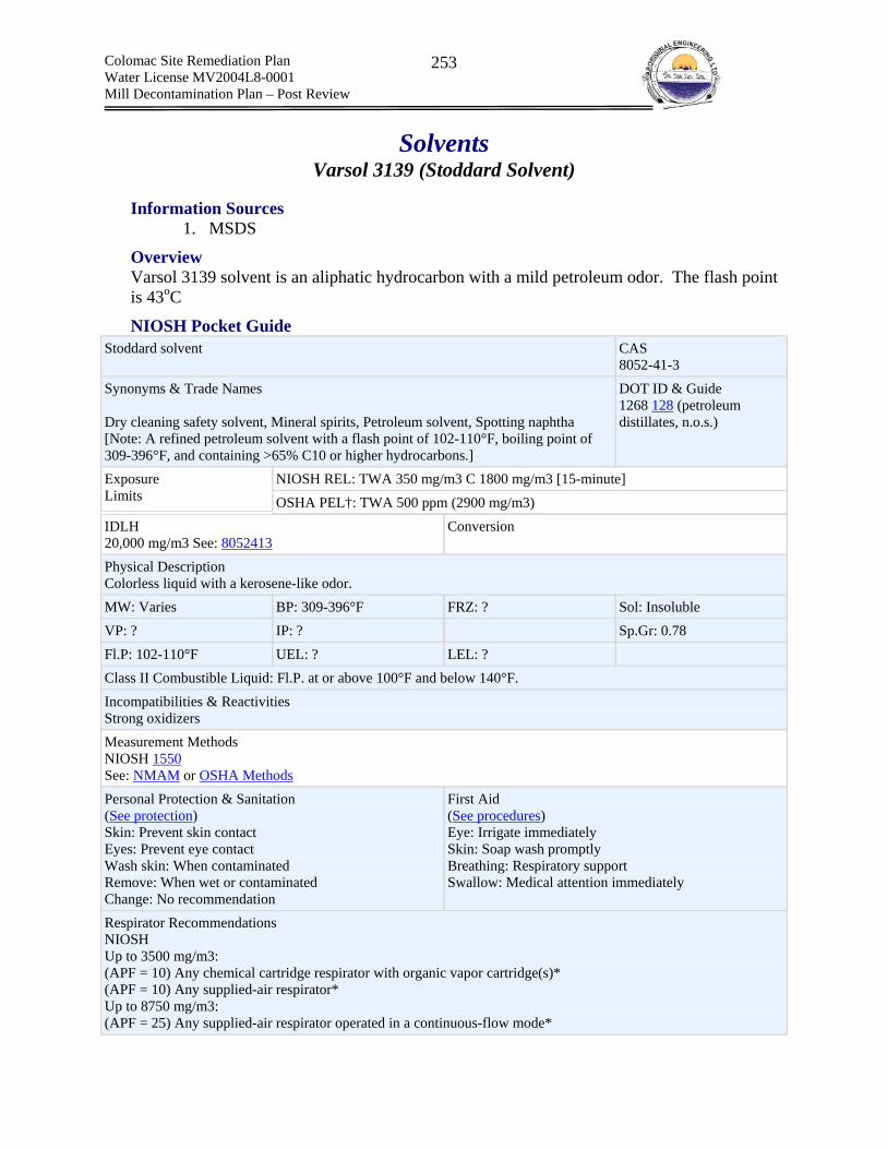
Colomac Site Remediation Plan Water License MV2004L8-0001 Mill Decontamination Plan – Post Review
253
Solvents Varsol 3139 (Stoddard Solvent)
Information Sources 1. MSDS
Overview Varsol 3139 solvent is an aliphatic hydrocarbon with a mild petroleum odor. The flash point is 43oC
NIOSH Pocket Guide Stoddard solvent CAS
8052-41-3 Synonyms & Trade Names Dry cleaning safety solvent, Mineral spirits, Petroleum solvent, Spotting naphtha [Note: A refined petroleum solvent with a flash point of 102-110°F, boiling point of 309-396°F, and containing >65% C10 or higher hydrocarbons.]
DOT ID & Guide 1268 128 (petroleum distillates, n.o.s.)
NIOSH REL: TWA 350 mg/m3 C 1800 mg/m3 [15-minute] Exposure Limits OSHA PEL†: TWA 500 ppm (2900 mg/m3) IDLH 20,000 mg/m3 See: 8052413
Conversion
Physical Description Colorless liquid with a kerosene-like odor. MW: Varies BP: 309-396°F FRZ: ? Sol: Insoluble VP: ? IP: ? Sp.Gr: 0.78 Fl.P: 102-110°F UEL: ? LEL: ? Class II Combustible Liquid: Fl.P. at or above 100°F and below 140°F. Incompatibilities & Reactivities Strong oxidizers Measurement Methods NIOSH 1550 See: NMAM or OSHA Methods Personal Protection & Sanitation (See protection) Skin: Prevent skin contact Eyes: Prevent eye contact Wash skin: When contaminated Remove: When wet or contaminated Change: No recommendation
First Aid (See procedures) Eye: Irrigate immediately Skin: Soap wash promptly Breathing: Respiratory support Swallow: Medical attention immediately
Respirator Recommendations NIOSH Up to 3500 mg/m3: (APF = 10) Any chemical cartridge respirator with organic vapor cartridge(s)* (APF = 10) Any supplied-air respirator* Up to 8750 mg/m3: (APF = 25) Any supplied-air respirator operated in a continuous-flow mode*

Colomac Site Remediation Plan Water License MV2004L8-0001 Mill Decontamination Plan – Post Review
254
(APF = 25) Any powered, air-purifying respirator with organic vapor cartridge(s)* Up to 17,500 mg/m3: (APF = 50) Any chemical cartridge respirator with a full facepiece and organic vapor cartridge(s) (APF = 50) Any air-purifying, full-facepiece respirator (gas mask) with a chin-style, front- or back-mounted organic vapor canister (APF = 50) Any powered, air-purifying respirator with a tight-fitting facepiece and organic vapor cartridge(s)* (APF = 50) Any self-contained breathing apparatus with a full facepiece (APF = 50) Any supplied-air respirator with a full facepiece Up to 20,000 mg/m3: (APF = 2000) Any supplied-air respirator that has a full facepiece and is operated in a pressure-demand or other positive-pressure mode Emergency or planned entry into unknown concentrations or IDLH conditions: (APF = 10,000) Any self-contained breathing apparatus that has a full facepiece and is operated in a pressure-demand or other positive-pressure mode (APF = 10,000) Any supplied-air respirator that has a full facepiece and is operated in a pressure-demand or other positive-pressure mode in combination with an auxiliary self-contained positive-pressure breathing apparatus Escape: (APF = 50) Any air-purifying, full-facepiece respirator (gas mask) with a chin-style, front- or back-mounted organic vapor canister/Any appropriate escape-type, self-contained breathing apparatus Important additional information about respirator selection Exposure Routes inhalation, ingestion, skin and/or eye contact Symptoms Irritation eyes, nose, throat; dizziness; dermatitis; chemical pneumonitis (aspiration liquid); in animals: kidney damage Target Organs Eyes, skin, respiratory system, central nervous system, kidneys See also: INTRODUCTION See ICSC CARD: 0361 See MEDICAL TESTS: 0212
WHMIS Class B Division 3 – Combustible Liquid Class D Division 2 Subdivision B: Toxic Material
TDGA Class 3 – Flammable Liquid
Health Hazards Inhalation – irritating to the eyes and respiratory tract and may cause dizziness and CNS effects and can result in death Skin – irritant Eye – slightly irritating but will not injure Ingestion – minimal toxicity Carcinogen – Possible carcinogen (contains Ethylbenzene)
Occupational Exposure Limit
ACGIH RECOMMENDS: For Trimethylbenzene, 25 ppm (123 mg/m3). For Stoddard Solvent, 100 ppm (525 mg/m3). For Xylene, 100 ppm (434 mg/m3). For Ethyl Benzene, 100 ppm (434 mg/m3).
Colomac Site Remediation Plan Water License MV2004L8-0001 Mill Decontamination Plan – Post Review
255
For Napthalene, skin, 10 ppm (52 mg/m3)
MANUFACTURER RECOMMENDS: TWA of 400 mg/m3 (73 ppm) based on total hydrocarbon. LD50 (rat,oral): >5g/kg LC50 (rat): >5g/m3
OH &S Hazard Ranking Low Hazard = 3

Colomac Site Remediation Plan Water License MV2004L8-0001 Mill Decontamination Plan – Post Review
256
Heat Exchange Fluids (a) Ethylene Glycol (b) Therminol 55 & Therminol 59
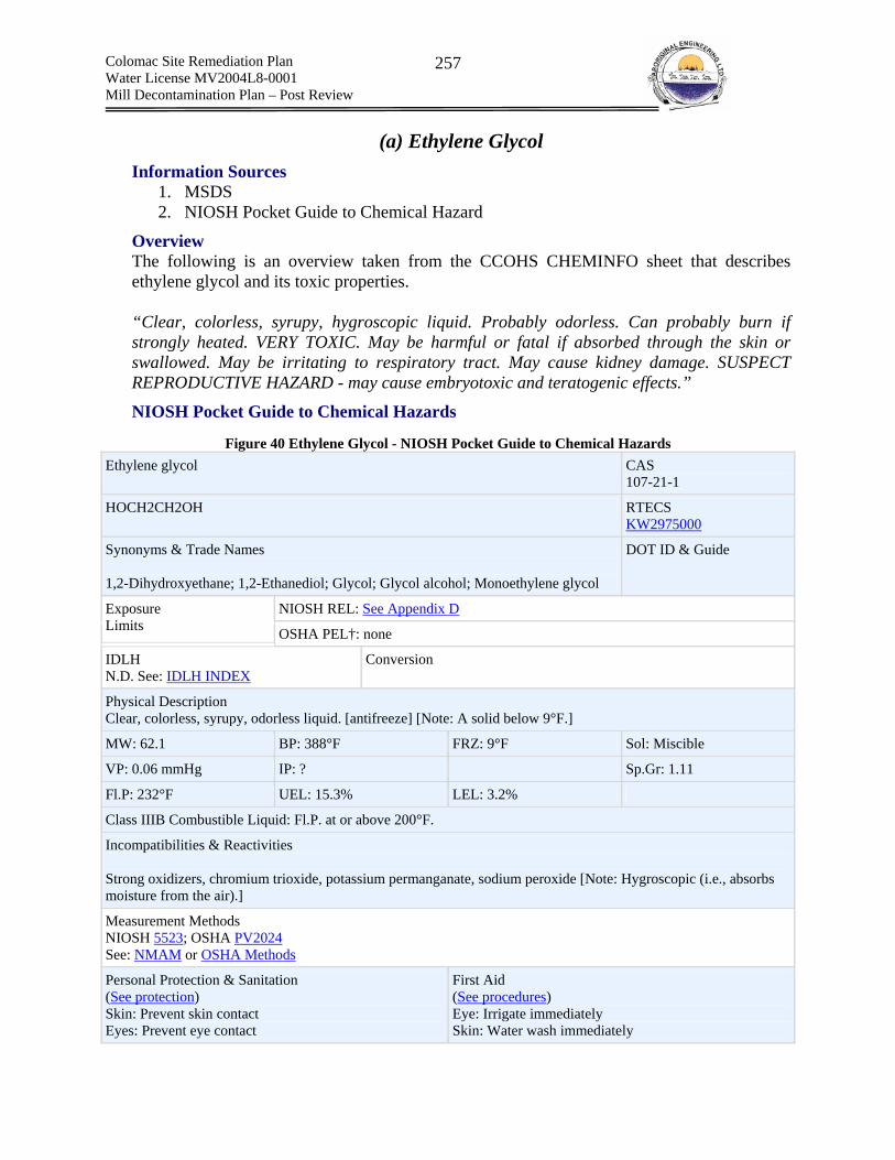
Colomac Site Remediation Plan Water License MV2004L8-0001 Mill Decontamination Plan – Post Review
257
(a) Ethylene Glycol Information Sources
1. MSDS 2. NIOSH Pocket Guide to Chemical Hazard
Overview The following is an overview taken from the CCOHS CHEMINFO sheet that describes ethylene glycol and its toxic properties. “Clear, colorless, syrupy, hygroscopic liquid. Probably odorless. Can probably burn if strongly heated. VERY TOXIC. May be harmful or fatal if absorbed through the skin or swallowed. May be irritating to respiratory tract. May cause kidney damage. SUSPECT REPRODUCTIVE HAZARD - may cause embryotoxic and teratogenic effects.”
NIOSH Pocket Guide to Chemical Hazards
Figure 40 Ethylene Glycol - NIOSH Pocket Guide to Chemical Hazards Ethylene glycol CAS
107-21-1
HOCH2CH2OH RTECS KW2975000
Synonyms & Trade Names 1,2-Dihydroxyethane; 1,2-Ethanediol; Glycol; Glycol alcohol; Monoethylene glycol
DOT ID & Guide
NIOSH REL: See Appendix D Exposure Limits OSHA PEL†: none
IDLH N.D. See: IDLH INDEX
Conversion
Physical Description Clear, colorless, syrupy, odorless liquid. [antifreeze] [Note: A solid below 9°F.]
MW: 62.1 BP: 388°F FRZ: 9°F Sol: Miscible
VP: 0.06 mmHg IP: ? Sp.Gr: 1.11
Fl.P: 232°F UEL: 15.3% LEL: 3.2%
Class IIIB Combustible Liquid: Fl.P. at or above 200°F.
Incompatibilities & Reactivities Strong oxidizers, chromium trioxide, potassium permanganate, sodium peroxide [Note: Hygroscopic (i.e., absorbs moisture from the air).]
Measurement Methods NIOSH 5523; OSHA PV2024 See: NMAM or OSHA Methods
Personal Protection & Sanitation (See protection) Skin: Prevent skin contact Eyes: Prevent eye contact
First Aid (See procedures) Eye: Irrigate immediately Skin: Water wash immediately
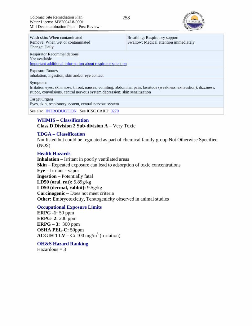
Colomac Site Remediation Plan Water License MV2004L8-0001 Mill Decontamination Plan – Post Review
258
Wash skin: When contaminated Remove: When wet or contaminated Change: Daily
Breathing: Respiratory support Swallow: Medical attention immediately
Respirator Recommendations Not available. Important additional information about respirator selection
Exposure Routes inhalation, ingestion, skin and/or eye contact
Symptoms Irritation eyes, skin, nose, throat; nausea, vomiting, abdominal pain, lassitude (weakness, exhaustion); dizziness, stupor, convulsions, central nervous system depression; skin sensitization
Target Organs Eyes, skin, respiratory system, central nervous system
See also: INTRODUCTION See ICSC CARD: 0270
WHMIS – Classification Class D Division 2 Sub-division A – Very Toxic
TDGA – Classification Not listed but could be regulated as part of chemical family group Not Otherwise Specified (NOS)
Health Hazards Inhalation – Irritant in poorly ventilated areas Skin – Repeated exposure can lead to adsorption of toxic concentrations Eye – Irritant - vapor Ingestion – Potentially fatal LD50 (oral, rat): 5.89g/kg LD50 (dermal, rabbit): 9.5g/kg Carcinogenic – Does not meet criteria Other: Embryotoxicity, Teratogenicity observed in animal studies
Occupational Exposure Limits ERPG -1: 50 ppm ERPG- 2: 200 ppm ERPG – 3: 300 ppm OSHA PEL-C: 50ppm ACGIH TLV – C: 100 mg/m3 (irritation)
OH&S Hazard Ranking Hazardous = 3

Colomac Site Remediation Plan Water License MV2004L8-0001 Mill Decontamination Plan – Post Review
259
(b) Therminol 55, 59 – Benzene C14 – C30 Alkyl Derivatives Information Sources
1. MSDS
Overview
Therminol 55 Therminol 55 is a clear to pale yellow heat transfer liquid with a pH between 10.5 and 12.5 that exhibits a characteristic odor. The product is stable and will not polymerize and is not know to be incompatible with any materials. Avoid heat, open flames and ignition sources. Therminol 55 has a flash point of 177 0C. Therminol 55 is composed of C14-30-alkylaromatic derivatives (100%)
Therminol 59 Therminol 55 is a clear to pale yellow heat transfer liquid with an aromatic hydrocarbon smell. Therminol 59 is composed of the following:
Ethyl Diphenyl Ethane CAS No. 64800-83-5 concentration: >=30.0 - <=60.0 %
Diphenyl Ethane CAS No. 38888-98-1 Concentration: <=30.0 %
Diethyl Diphenyl Ethane CAS No. 68398-19-6 Concentration: >=10.0 - <=30.0 %
Ethylbenzene Polymer CAS No. 27536-89-6 Concentration: >=7.0 - <=13.0 %
Therminol 59 has a low vapor pressure (0.003 kPa), low solubility in water (0.00055 g/L @ 20C) and a flash point of > 138C.
WHMIS – Classification
Therminol 55 Class D Division 2 Subdivision B – Material causing other toxic effects
Therminol 59 Class D Division 2 Subdivision B – Material causing other toxic effects
TDGA – Classification
Therminol 55 Not regulated
Therminol 59 Not regulated

Colomac Site Remediation Plan Water License MV2004L8-0001 Mill Decontamination Plan – Post Review
260
Health Hazards
Therminol 55 Inhalation – Elevated temperatures can cause vapors and mists – irritating if inhaled Skin – Moderate irritation Eye – Moderate irritation Ingestion – Incidental ingestion under normal circumstances are not likely to cause injury. Carcinogen – Not listed Acute Oral LD 50 (Rat) - >15,800 mg/kg Acute Dermal LD 50 (Rabbit) – >7,940 mg/kg Acute Inhalation LC 50 – Not available Additional Info - Experiments did not produce any reproductive effects in laboratory animals or mutagenic effects in bacterial or animal cells.
Therminol 59 Inhalation – Elevated temperatures can cause vapors and mists – irritating if inhaled Skin – Highly irritating Eye – Slightly irritating Ingestion – Incidental ingestion under normal circumstances are not likely to cause injury. Carcinogen – Not listed
Occupational Exposure Limits
Therminol 55 No exposure guidelines have been set
Therminol 59 Solutia recommendation: 2.0 mg/m3 8hr TWA
OH&S Hazard Ranking
Therminol 55 Low Hazard = 2
Therminol 59 Low Hazard = 3
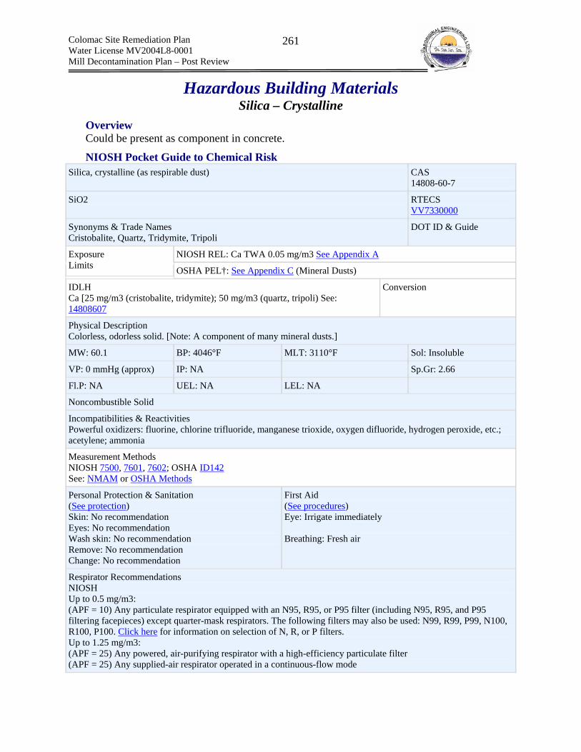
Colomac Site Remediation Plan Water License MV2004L8-0001 Mill Decontamination Plan – Post Review
261
Hazardous Building Materials Silica – Crystalline
Overview Could be present as component in concrete.
NIOSH Pocket Guide to Chemical Risk Silica, crystalline (as respirable dust) CAS
14808-60-7
SiO2 RTECS VV7330000
Synonyms & Trade Names Cristobalite, Quartz, Tridymite, Tripoli
DOT ID & Guide
NIOSH REL: Ca TWA 0.05 mg/m3 See Appendix A Exposure Limits OSHA PEL†: See Appendix C (Mineral Dusts)
IDLH Ca [25 mg/m3 (cristobalite, tridymite); 50 mg/m3 (quartz, tripoli) See: 14808607
Conversion
Physical Description Colorless, odorless solid. [Note: A component of many mineral dusts.]
MW: 60.1 BP: 4046°F MLT: 3110°F Sol: Insoluble
VP: 0 mmHg (approx) IP: NA Sp.Gr: 2.66
Fl.P: NA UEL: NA LEL: NA
Noncombustible Solid
Incompatibilities & Reactivities Powerful oxidizers: fluorine, chlorine trifluoride, manganese trioxide, oxygen difluoride, hydrogen peroxide, etc.; acetylene; ammonia
Measurement Methods NIOSH 7500, 7601, 7602; OSHA ID142 See: NMAM or OSHA Methods
Personal Protection & Sanitation (See protection) Skin: No recommendation Eyes: No recommendation Wash skin: No recommendation Remove: No recommendation Change: No recommendation
First Aid (See procedures) Eye: Irrigate immediately Breathing: Fresh air
Respirator Recommendations NIOSH Up to 0.5 mg/m3: (APF = 10) Any particulate respirator equipped with an N95, R95, or P95 filter (including N95, R95, and P95 filtering facepieces) except quarter-mask respirators. The following filters may also be used: N99, R99, P99, N100, R100, P100. Click here for information on selection of N, R, or P filters. Up to 1.25 mg/m3: (APF = 25) Any powered, air-purifying respirator with a high-efficiency particulate filter (APF = 25) Any supplied-air respirator operated in a continuous-flow mode
Colomac Site Remediation Plan Water License MV2004L8-0001 Mill Decontamination Plan – Post Review
262
Up to 2.5 mg/m3: (APF = 50) Any air-purifying, full-facepiece respirator with an N100, R100, or P100 filter. Click here for information on selection of N, R, or P filters. (APF = 50) Any powered, air-purifying respirator with a tight-fitting facepiece and a high-efficiency particulate filter Up to 25 mg/m3: (APF = 1000) Any supplied-air respirator operated in a pressure-demand or other positive-pressure mode Emergency or planned entry into unknown concentrations or IDLH conditions: (APF = 10,000) Any self-contained breathing apparatus that has a full facepiece and is operated in a pressure-demand or other positive-pressure mode (APF = 10,000) Any supplied-air respirator that has a full facepiece and is operated in a pressure-demand or other positive-pressure mode in combination with an auxiliary self-contained positive-pressure breathing apparatus Escape: (APF = 50) Any air-purifying, full-facepiece respirator with an N100, R100, or P100 filter. Click here for information on selection of N, R, or P filters./Any appropriate escape-type, self-contained breathing apparatus Important additional information about respirator selection
Exposure Routes inhalation, skin and/or eye contact
Symptoms Cough, dyspnea (breathing difficulty), wheezing; decreased pulmonary function, progressive respiratory symptoms (silicosis); irritation eyes; [potential occupational carcinogen]
Target Organs Eyes, respiratory system
Cancer Site [in animals: lung cancer]
OH&S Hazard Ranking Hazardous = 3

Colomac Site Remediation Plan Water License MV2004L8-0001 Mill Decontamination Plan – Post Review
263
Electrical Insulator Dielektrol 3 Fluid
Information Sources 1. Product data sheets 2. MSDS
Overview Dielektrol 3 (D3) fluid is an electrical insulator that does not contain PCB’s. D3 has low viscosity, water-white liquid with a woody odor. D3 has a very low vapor pressure (0.01 mmHg, atmospheric pressure = 760 mmHg). The chemical name of D3 is Phenyl Xylyl Ethane (PXE) and the chemical formula is C16H18.
WHMIS Not a controlled product under the WHMIS regulations.
TDGA Not regulated in Canada
Health Hazards Inhalation – Excessive exposure to vapors is moderately irritating Skin – slightly irritating Eye – Slightly irritating Ingestion – Low toxicity LD50 (rat,oral): 2g/kg
Occupational Exposure Limit None identified
OH &S Hazard Ranking Low Hazard = 2

Colomac Site Remediation Plan Water License MV2004L8-0001 Mill Decontamination Plan – Post Review
264
Miscelaneous Chemicals (a) Nordberg Ultra Performance Crusher Backing Material (b) Soda Ash – Sodium Carbonate (c) Esso Procon
Colomac Site Remediation Plan Water License MV2004L8-0001 Mill Decontamination Plan – Post Review
265
(a) Nordberg Ultra Performance Crusher Backing Material Information Sources
1. Product Packaging
Overview Nordberg Ultra Performance Crusher Backing Material (NBM) is a
WHMIS Not a controlled product under the WHMIS regulations.
TDGA Unknown but most likely Class 8 – Corrosive and possible Class 6: Toxic substance
Health Hazards Inhalation – Unknown Skin – Unknown Eye – Unknown Ingestion – Unknown
Occupational Exposure Limit Unknown
OH &S Hazard Ranking Low Hazard = 4
Colomac Site Remediation Plan Water License MV2004L8-0001 Mill Decontamination Plan – Post Review
266
(b) Soda Ash-Sodium Carbonate Information Sources
1. MSDS
Overview Soda ash is used as an electrolyte solution within the SAG mill rheostat. The soda ash solution was manually prepared. Soda ash is a white powder or dust with a pH of 11.4 when prepared as a dilute solution. Soda ash has a very low vapor pressure and is odorless and soluble in water.
WHMIS Class D Division 2 Subdivision B – Toxic Material (other effects)
TDGA
Health Hazards Inhalation – particulate inhalation can lead to pulmonary fibrosis, chronic bronchitis and bronchial asthma. Skin – slightly irritating Eye – Mild irritation Ingestion – Low toxicity LD50 (rat,oral): 4.9g/kg LC50 (inh,mus): 1.2mg/m3/2h
Occupational Exposure Limit OSHA PEL-TWA: 5 mg/m3 respirable dust ACGIH TLV-TWA: 3 mg/m3 respirable dust
OH &S Hazard Ranking Low Hazard = 2
Colomac Site Remediation Plan Water License MV2004L8-0001 Mill Decontamination Plan – Post Review
267
Esso Procon Information Sources
1. MSDS
Overview Procon is a rust inhibitor PROCON can be added at a 2% treat to the existing oil in engines, manual transmissions, final drives, hydraulic systems, circulating systems and gear boxes that will not be required for an extended period. Esso Procon is a mixture of mineral oil and additives. Procon contains Polyethylene glycol nonylphenyl-ether (1-5v%). Procon is 100% soluble in water at 250C. PROCON is a dark amber liquid with a petroleum odour. Its flashpoint is 1000C.
WHMIS Class D Division 2 Subdivision B – Toxic Material (other effects)
TDGA Not regulated in Canada
Health Hazards
Procon Inhalation – negligible up to 38oC Skin – slightly irritating Eye – Mild irritation. Will not damage Ingestion – Low toxicity LD50 (rat,oral): >5g/kg LD50 (rabbit,dermal): >2g/kg
Polyethylene glycol nonylphenyl-ether LD50 (oral,rabbit) 3.78 g/kg LD50 (skin,rabbit): >2.0g/kg
Occupational Exposure Limit Manufacturer Recommendation: Total organic vapor 1200mg/m3 (184ppm) ACGIH TLV Oils and Mists: 5mg/m3
OH &S Hazard Ranking Low Hazard = 2
Colomac Site Remediation Plan Water License MV2004L8-0001 Mill Decontamination Plan – Post Review
268
Appendix D – Development of Hazardous Waste Disposal Options
D.1 Disposal Scenarios A. Hazardous Wastes Similar to Wastes Historically Deposited Within the
Tailings Containment Area and Zone 2.0 Pit The following sub-sections present the reasoning for each of the selected hazardous waste disposal options. Process Slurry – Free Water, Pore Water and Tailings Solids/Ore Dust Circuit Primarily Leaching Secondary Grinding Residual Contents present as dust and spills in all circuits
Hazardous Waste Form Process slurry is saturated tailings mixed with residual process reagents. It is comprised of both solid tailings and pore water. The pore water contains cyanide, various cyanide-metal complexes and the products of cyanide decomposition. The tailings solids is comprised of finely ground ore and residual cyanide metal complexes that have precipitated from solution. The 12 leach tanks and the thickener tanks all contain residual volumes of process slurry at their base. In addition, snow melt and rain water has ponded on top of the process slurry. Contaminants have dissolved from the pore water into the ponded water, thus impacting its quality. Ore dust is generated by the crushing of ore within the primary crushing buildings. Ore dust is very similar in nature to tailings solids and is therefore considered as a tailings solid for disposal purposes.
Estimated Hazardous Waste Quantities Leach Tanks Tailings Solids = 1,449 m3 Pore Water = 781 m3 Free Water = 4,585 m3 Thickener Tank Tailings Solids = 1,469 m3
Pore Water = 791 m3 Free Water = 80m3
On-Site Disposal – Environmental Impacts (Tailings Lake and Zone 2.0 Pit) Free and Pore Water
In order to estimate the mass loading of contaminants to the tailings lake and/or Zone 2.0 Pit the conservative estimates of no degradation or external loss of contaminants will be used for calculations. The free water quality data was provided by DIAND CARD and can be referenced in Table 72. The total cyanide concentrations for the pore water were estimated based on data sets extracted from the Royal Oak Colomac Mine Remediation Plan and can be referenced in Table 70.

Colomac Site Remediation Plan Water License MV2004L8-0001 Mill Decontamination Plan – Post Review
269
The following tables present the volumes of free water, and pore water in each leach tank, as well as concentrations of Contaminants of Concern (COC) total CN, thiocyanate, and ammonia. Volumes and water quality data for the free water were obtained from the SRK Memo entitled “Large Tank Inventories at the Colomac Mill” (August 2004), and it is estimated that 35% of the volume of saturated solids is comprised of pore water.
Table 73 Leach tank and thickener free water COC concentrations and volumes Tank No. Volume of Free
Water (m3) Total CN (mg/L)
Thiocyanate (mg/L)
Ammonia (mg/L)
1 371 4.4 0 0.895 2 366 0.44 0 0.907 3 476 36.3 61.1 1.83 4 466 18 18.4 1.65 5 331 7 16.3 1.26 6 286 1.1 3.3 0.226 7 356 26 63.5 2.18 8 431 0.7 2.8 0.243 9 341 38 79.4 2.65 10 777 0.9 3 0.282 11 386 1 2.7 0.839 12 0
Thickener 80 0.003 0.7 0.005 Total mass (kg) 57.3 98.3 5.1
Table 74 Leach tank and thickener pore water COC concentrations and volumes
Tank No. Volume of Saturated Solids
(m3)
Volume of pore water
(m3)
Total CN (mg/L)
1 281 98.35 150 2 165 57.75 150 3 200 70 150 4 160 56 150 5 110 38.5 150 6 100 35 150 7 145 50.75 150 8 165 57.75 150 9 90 31.5 150 10 251 87.85 150 11 85 29.75 150 12 474 165.9 150
Thickener 2260 791 30 Total mass (kg) 132.8
It can be noted that the total CN concentration in pore water is estimated to be higher than that of the free water. This is because the cyanide concentration in the leach circuit was approximately 300 mg/L. At the time of the mill shut down, it could be possible that the pore water concentration be 300 mg/L, but over eight years have passed since the mill shut down, and
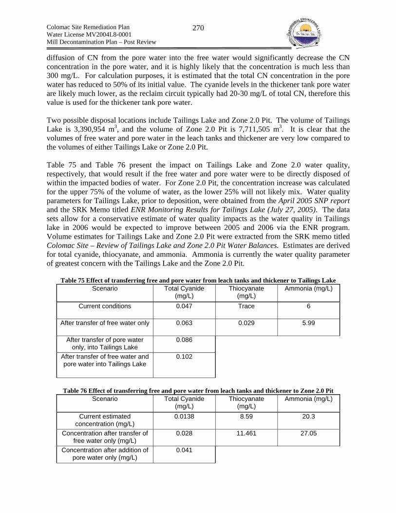
Colomac Site Remediation Plan Water License MV2004L8-0001 Mill Decontamination Plan – Post Review
270
diffusion of CN from the pore water into the free water would significantly decrease the CN concentration in the pore water, and it is highly likely that the concentration is much less than 300 mg/L. For calculation purposes, it is estimated that the total CN concentration in the pore water has reduced to 50% of its initial value. The cyanide levels in the thickener tank pore water are likely much lower, as the reclaim circuit typically had 20-30 mg/L of total CN, therefore this value is used for the thickener tank pore water. Two possible disposal locations include Tailings Lake and Zone 2.0 Pit. The volume of Tailings Lake is 3,390,954 m3, and the volume of Zone 2.0 Pit is 7,711,505 m3. It is clear that the volumes of free water and pore water in the leach tanks and thickener are very low compared to the volumes of either Tailings Lake or Zone 2.0 Pit. Table 75 and Table 76 present the impact on Tailings Lake and Zone 2.0 water quality, respectively, that would result if the free water and pore water were to be directly disposed of within the impacted bodies of water. For Zone 2.0 Pit, the concentration increase was calculated for the upper 75% of the volume of water, as the lower 25% will not likely mix. Water quality parameters for Tailings Lake, prior to deposition, were obtained from the April 2005 SNP report and the SRK Memo titled ENR Monitoring Results for Tailings Lake (July 27, 2005). The data sets allow for a conservative estimate of water quality impacts as the water quality in Tailings lake in 2006 would be expected to improve between 2005 and 2006 via the ENR program. Volume estimates for Tailings Lake and Zone 2.0 Pit were extracted from the SRK memo titled Colomac Site – Review of Tailings Lake and Zone 2.0 Pit Water Balances. Estimates are derived for total cyanide, thiocyanate, and ammonia. Ammonia is currently the water quality parameter of greatest concern with the Tailings Lake and the Zone 2.0 Pit.
Table 75 Effect of transferring free and pore water from leach tanks and thickener to Tailings Lake Scenario Total Cyanide
(mg/L) Thiocyanate
(mg/L) Ammonia (mg/L)
Current conditions 0.047 Trace 6
After transfer of free water only 0.063 0.029 5.99
After transfer of pore water only, into Tailings Lake
0.086
After transfer of free water and pore water into Tailings Lake
0.102
Table 76 Effect of transferring free and pore water from leach tanks and thickener to Zone 2.0 Pit
Scenario Total Cyanide (mg/L)
Thiocyanate (mg/L)
Ammonia (mg/L)
Current estimated concentration (mg/L)
0.0138 8.59 20.3
Concentration after transfer of free water only (mg/L)
0.028 11.461 27.05
Concentration after addition of pore water only (mg/L)
0.041
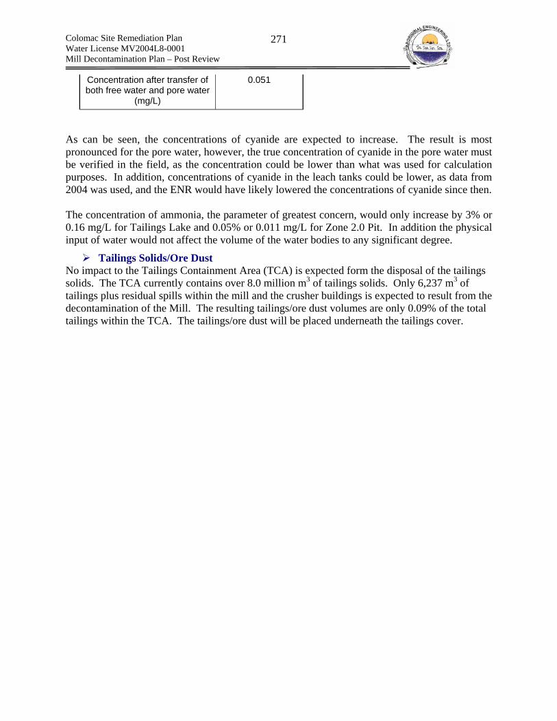
Colomac Site Remediation Plan Water License MV2004L8-0001 Mill Decontamination Plan – Post Review
271
Concentration after transfer of both free water and pore water
(mg/L)
0.051
As can be seen, the concentrations of cyanide are expected to increase. The result is most pronounced for the pore water, however, the true concentration of cyanide in the pore water must be verified in the field, as the concentration could be lower than what was used for calculation purposes. In addition, concentrations of cyanide in the leach tanks could be lower, as data from 2004 was used, and the ENR would have likely lowered the concentrations of cyanide since then. The concentration of ammonia, the parameter of greatest concern, would only increase by 3% or 0.16 mg/L for Tailings Lake and 0.05% or 0.011 mg/L for Zone 2.0 Pit. In addition the physical input of water would not affect the volume of the water bodies to any significant degree.
Tailings Solids/Ore Dust No impact to the Tailings Containment Area (TCA) is expected form the disposal of the tailings solids. The TCA currently contains over 8.0 million m3 of tailings solids. Only 6,237 m3 of tailings plus residual spills within the mill and the crusher buildings is expected to result from the decontamination of the Mill. The resulting tailings/ore dust volumes are only 0.09% of the total tailings within the TCA. The tailings/ore dust will be placed underneath the tailings cover.
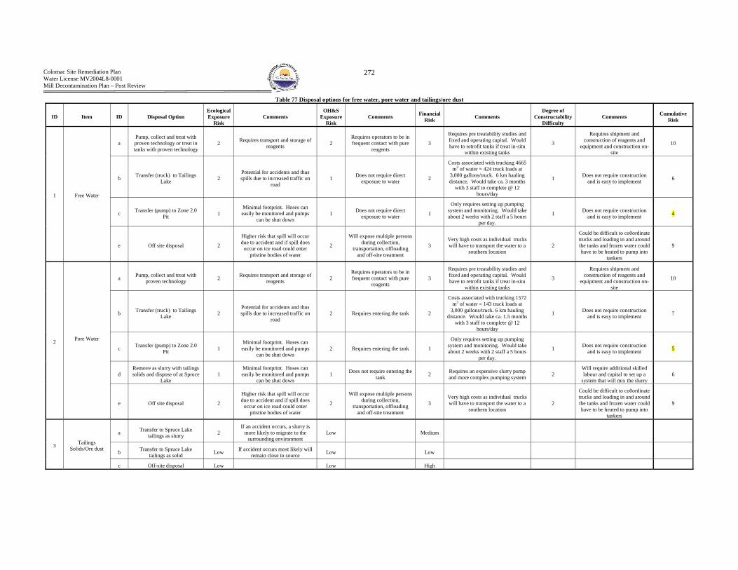
Colomac Site Remediation Plan Water License MV2004L8-0001 Mill Decontamination Plan – Post Review
272
Table 77 Disposal options for free water, pore water and tailings/ore dust
ID Item ID Disposal Option Ecological Exposure
Risk Comments
OH&S Exposure
Risk Comments Financial
Risk Comments Degree of
Constructability Difficulty
Comments Cumulative Risk
a Pump, collect and treat with proven technology or treat in tanks with proven technology
2 Requires transport and storage of reagents 2
Requires operators to be in frequent contact with pure
reagents 3
Requires pre treatability studies and fixed and operating capital. Would have to retrofit tanks if treat in-situ
within existing tanks
3
Requires shipment and construction of reagents and
equipment and construction on-site
10
b Transfer (truck) to Tailings Lake 2
Potential for accidents and thus spills due to increased traffic on
road 1 Does not require direct
exposure to water 2
Costs associated with trucking 4665 m3 of water = 424 truck loads at
3,000 gallons/truck. 6 km hauling distance. Would take ca. 3 months
with 3 staff to complete @ 12 hours/day
1 Does not require construction and is easy to implement 6
c Transfer (pump) to Zone 2.0 Pit 1
Minimal footprint. Hoses can easily be monitored and pumps
can be shut down 1 Does not require direct
exposure to water 1
Only requires setting up pumping system and monitoring. Would take about 2 weeks with 2 staff a 5 hours
per day.
1 Does not require construction and is easy to implement 4
1 Free Water
e Off site disposal 2
Higher risk that spill will occur due to accident and if spill does
occur on ice road could enter pristine bodies of water
2
Will expose multiple persons during collection,
transportation, offloading and off-site treatment
3 Very high costs as individual trucks will have to transport the water to a
southern location 2
Could be difficult to co0ordinate trucks and loading in and around the tanks and frozen water could have to be heated to pump into
tankers
9
a Pump, collect and treat with proven technology 2 Requires transport and storage of
reagents 2 Requires operators to be in frequent contact with pure
reagents 3
Requires pre treatability studies and fixed and operating capital. Would have to retrofit tanks if treat in-situ
within existing tanks
3
Requires shipment and construction of reagents and
equipment and construction on-site
10
b Transfer (truck) to Tailings Lake 2
Potential for accidents and thus spills due to increased traffic on
road 2 Requires entering the tank 2
Costs associated with trucking 1572 m3 of water = 143 truck loads at
3,000 gallons/truck. 6 km hauling distance. Would take ca. 1.5 months
with 3 staff to complete @ 12 hours/day
1 Does not require construction and is easy to implement 7
c Transfer (pump) to Zone 2.0 Pit 1
Minimal footprint. Hoses can easily be monitored and pumps
can be shut down 2 Requires entering the tank 1
Only requires setting up pumping system and monitoring. Would take about 2 weeks with 2 staff a 5 hours
per day.
1 Does not require construction and is easy to implement 5
d Remove as slurry with tailings solids and dispose of at Spruce
Lake 1
Minimal footprint. Hoses can easily be monitored and pumps
can be shut down 1 Does not require entering the
tank 2 Requires an expensive slurry pump and more complex pumping system 2
Will require additional skilled labour and capital to set up a
system that will mix the slurry 6
2 Pore Water
e Off site disposal 2
Higher risk that spill will occur due to accident and if spill does
occur on ice road could enter pristine bodies of water
2
Will expose multiple persons during collection,
transportation, offloading and off-site treatment
3 Very high costs as individual trucks will have to transport the water to a
southern location 2
Could be difficult to co0ordinate trucks and loading in and around the tanks and frozen water could have to be heated to pump into
tankers
9
a Transfer to Spruce Lake tailings as slurry 2
If an accident occurs, a slurry is more likely to migrate to the
surrounding environment Low Medium
b Transfer to Spruce Lake tailings as solid Low If accident occurs most likely will
remain close to source Low Low 3 Tailings
Solids/Ore dust
c Off-site disposal Low Low High

Colomac Site Remediation Plan Water License MV2004L8-0001 Mill Decontamination Plan – Post Review
273
Sodium Cyanide– Solid Reagent Scaling Circuit Cyanide Reagent Addition
Hazardous Waste Form Sodium cyanide is present as solid scaling on pipes, tanks, pumps and valves contained within the cyanide reagent distribution circuit. Refer to Table 48 and Table 49 for a detailed description of the sodium cyanide reagent distribution circuit components.
Estimated Hazardous Waste Quantities 1.2 m3 of scaling could be present on and within pumps, piping, valves and tanks.
On-Site Disposal – Environmental Impacts (Spruce Lake Tailings) If disposed of on-site, equipment and pipes containing sodium cyanide salts are to be buried below the water table at the Southern end of Spruce Lake (near the former dump location). Burial at a depth below the water table will greatly reduce the risk of the cyanide dissolving and resurfacing with the overflow runoff to Tailings Lake. At a depth below the water table, dissolved cyanide would predominately enter the slow moving ground water. The dissolved free cyanide would be subject to various degradation methods in the subsurface. In addition, the rate of cyanide loading to Tailings Lake would be limited to the rate of subsurface flow (low groundwater gradient present in Spruce Lake). As such, ENR would have sufficient time to remove the cyanide and cyanide degradation products, prior to their release into the surrounding environment.
Selection of Preferred Disposal Option Refer to Table 78 to review the selection method.

Colomac Site Remediation Plan Water License MV2004L8-0001 Mill Decontamination Plan – Post Review
274
Table 78 Disposal options for the cyanide circuit
ID Item ID Option ID Disposal Option Ecological Exposure Risk Reasoning
OH&S Exposure
Risk Reasoning Financial
Risk Reasoning Constructability (Difficulty) Reasoning Total Risk
i
Remove and bag exterior scaling and wash interior scaling from pipes, pumps and valves. Dispose of
washed pipes pumps and valves in bone yard. Collect and treat wash
water
2
Risk of spill increases when scaling is put into solution.
Also increases volumes Reagent will have to be used to treat water (i.e.,
acids to neutralize)
3
Pipes cannot be washed in place as the lines are broken. Workers
would have to remove piping and then wash in a wash station.
Washing interior of piping could lead to many splashes as water may
splash back if pipes are plugged
3
Labour intensive. Requires washing and collecting and treating
the wash water
2
Will have to locate a suitable tank and
agitation system for mixing the wash water
during treatment
10
ii
Remove and bag exterior scaling and wash interior scaling from pipes, pumps and valves. Dispose of
washed pipes pumps and valves in bone yard. Collect and dispose of
scaling and wash water on site
2
Risk of spill increases when scaling is put into solution.
Also increases volumes. Will have to transfer wash water to tailings lake on
high traffic road
3
Pipes cannot be washed in place as the lines are broken. Workers
would have to remove piping and then wash in a wash station.
Washing interior of piping could lead to many splashes as water may
splash back if pipes are plugged
3
Labour intensive. Requires washing and the
collecting and transporting the wash water in tanker trucks.
1 Not difficult to implement 9
a
Wash
iii
Remove and bag exterior scaling and wash interior scaling from pipes, pumps and valves. Dispose of
washed pipes pumps and valves in bone yard. Collect and dispose of
scaling and wash water on site
2
Risk of spill increases when scaling is put into solution. As increases volumes. Will have to transfer wash water
to tailings lake on high traffic road
3
Pipes cannot be washed in place as the lines are broken. Workers
would have to remove piping and then wash in a wash station.
Washing interior of piping could lead to many splashes as water may
splash back if pipes are plugged
3
Labour intensive. Requires washing and the
collecting and transporting the wash water in tanker trucks.
1 Not difficult to implement 9
i
Remove and bag gross scaling. Cover piping, remove and dispose of under
tailings cover at the North end of Spruce Lake adjacent to historical
dump area.
1
Reagent scaling would be covered and in solid form. Any spills would remain near source and would
easily be dealt with. Quantities of scaling are
minimal.
1
Caustic would not become soluble. Covering piping removes chance of
dust forming. Auxiliary exhaust used when collecting residual
scaling to prevent dust
1 Would reduce overall
labour inputs as no washing or transport
1 Not difficult to implement 4
1
Pump, Pipes and
Valves
b
Do not Wash
ii Remove and bag gross scaling. Cover piping, remove and dispose of off site 1
Reagent scaling would be covered and in solid form. Any spills would remain near source and would
easily be dealt with. Quantities of scaling are
minimal.
2
Involves two additional parties. Trucking company and off-site
disposal company employees. Also requires double handling of
hazardous waste
3
Requires shipping by truck to offsite disposal facility and additional
disposal fees.
1 Not difficult to implement 7

Colomac Site Remediation Plan Water License MV2004L8-0001 Mill Decontamination Plan – Post Review
275
Table 78 Cont.
ID Item ID Option ID Disposal Option Ecological Exposure Risk Reasoning
OH&S Exposure
Risk Reasoning Financial
Risk Reasoning Constructability (Difficulty) Reasoning Total Risk
i
Remove and bag exterior scale and wash interior of tank. Cut up and
dispose of tank in bone yard. Collect and dispose of scaling and wash water
off site or scaling off site and treat wash water
2 (transport spills and additional reagents)
Risk of spill increases when scaling is put into solution.
Also increases volumes Reagent will have to be used to treat water (i.e.,
acids to neutralize)
2
Wash water would be contained inside of tank during washing.
Removal of scaling would involve auxiliary ventilation However if treat acids have to be used and if
dispose of off-site additional parties are involved and at risk for
exposure
3
Treatment requires purchasing reagents and
equipment. Off-site disposal requires
trucking
2 Treatment would require additional
planning and execution 9
a
Wash
ii
Remove and bag exterior scale and wash interior of tank. Cut up and
dispose of tank in bone yard. Collect and dispose of scaling and wash water
on –site. Wash water in Tailings Lake or zone 2.0 pit and scaling at
North end of Spruce Lake
2 (transport spills)
Risk of spill increases when scaling is put into solution.
Also increases volumes. Potential for accident and spill if dispose in Tailings Lake as travel across road
with high traffic.
1 Wash water would be contained
inside of tank. Removal of scaling would involve auxiliary ventilation
2 Requires additional labor inputs 1 Not difficult to
implement 6
i Cut up tank with scaling and dispose
of under the tailings cover at the North end of the Spruce Lake
1
Reagent scaling would be covered and in solid form. Any spills would remain near source and would
easily be dealt with. Quantities of scaling are
minimal.
3
Intense heat from torch could cause calcium hydroxide to thermally
decompose to strong, highly corrosive calcium oxide fumes and create a high inhalation hazard for
the immediate and surrounding workers
1 Not expensive to implement 1 Not difficult to
implement 6
2 Tanks
b Do not Wash
ii
Cover tank, remove as whole. Transport to North end of Spruce
Lake. Compress with heavy equipment and cover with tailings
cover.
1
Reagent scaling would be covered and in solid form. Any spills would remain near source and would
easily be dealt with. Quantities of scaling are
minimal.
1 Workers would not be exposed to scaling 3
A large tank such as the lime tanks cannot be
compacted as a whole to levels sufficient to avoid
void spaces when disposed of under the
cover. This could lead to failure of the cover over
the burial area.
3 Due to the size (14’ x 14’) of the tank this option is not feasible
8
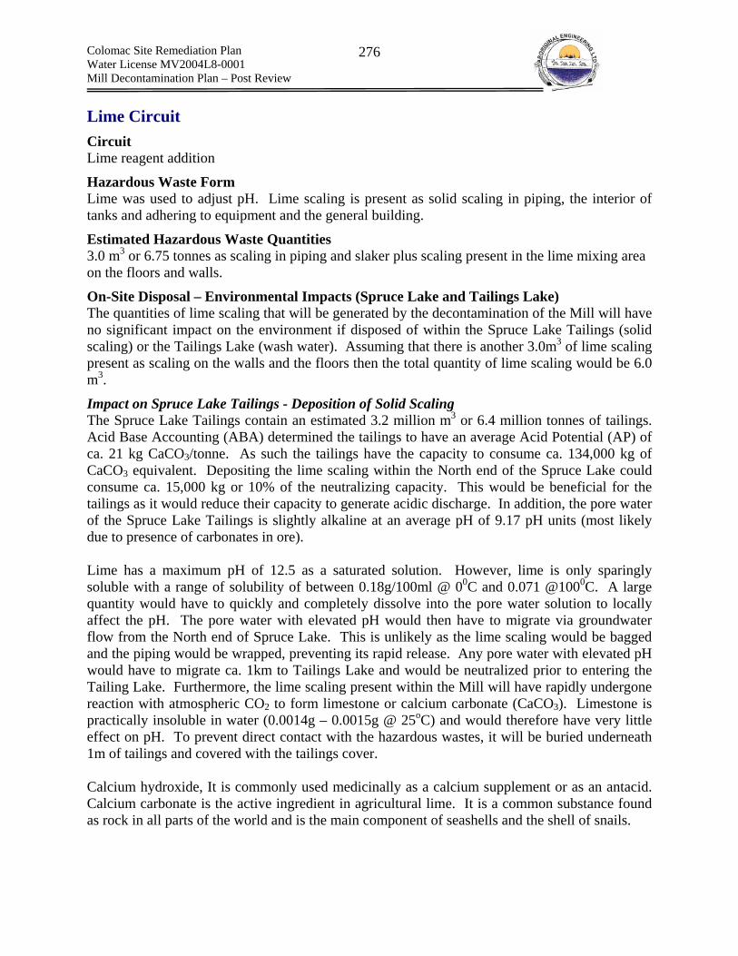
Colomac Site Remediation Plan Water License MV2004L8-0001 Mill Decontamination Plan – Post Review
276
Lime Circuit Circuit Lime reagent addition
Hazardous Waste Form Lime was used to adjust pH. Lime scaling is present as solid scaling in piping, the interior of tanks and adhering to equipment and the general building.
Estimated Hazardous Waste Quantities 3.0 m3 or 6.75 tonnes as scaling in piping and slaker plus scaling present in the lime mixing area on the floors and walls.
On-Site Disposal – Environmental Impacts (Spruce Lake and Tailings Lake) The quantities of lime scaling that will be generated by the decontamination of the Mill will have no significant impact on the environment if disposed of within the Spruce Lake Tailings (solid scaling) or the Tailings Lake (wash water). Assuming that there is another 3.0m3 of lime scaling present as scaling on the walls and the floors then the total quantity of lime scaling would be 6.0 m3.
Impact on Spruce Lake Tailings - Deposition of Solid Scaling The Spruce Lake Tailings contain an estimated 3.2 million m3 or 6.4 million tonnes of tailings. Acid Base Accounting (ABA) determined the tailings to have an average Acid Potential (AP) of ca. 21 kg CaCO3/tonne. As such the tailings have the capacity to consume ca. 134,000 kg of CaCO3 equivalent. Depositing the lime scaling within the North end of the Spruce Lake could consume ca. 15,000 kg or 10% of the neutralizing capacity. This would be beneficial for the tailings as it would reduce their capacity to generate acidic discharge. In addition, the pore water of the Spruce Lake Tailings is slightly alkaline at an average pH of 9.17 pH units (most likely due to presence of carbonates in ore). Lime has a maximum pH of 12.5 as a saturated solution. However, lime is only sparingly soluble with a range of solubility of between 0.18g/100ml @ 00C and 0.071 @1000C. A large quantity would have to quickly and completely dissolve into the pore water solution to locally affect the pH. The pore water with elevated pH would then have to migrate via groundwater flow from the North end of Spruce Lake. This is unlikely as the lime scaling would be bagged and the piping would be wrapped, preventing its rapid release. Any pore water with elevated pH would have to migrate ca. 1km to Tailings Lake and would be neutralized prior to entering the Tailing Lake. Furthermore, the lime scaling present within the Mill will have rapidly undergone reaction with atmospheric CO2 to form limestone or calcium carbonate (CaCO3). Limestone is practically insoluble in water (0.0014g – 0.0015g @ 25oC) and would therefore have very little effect on pH. To prevent direct contact with the hazardous wastes, it will be buried underneath 1m of tailings and covered with the tailings cover. Calcium hydroxide, It is commonly used medicinally as a calcium supplement or as an antacid. Calcium carbonate is the active ingredient in agricultural lime. It is a common substance found as rock in all parts of the world and is the main component of seashells and the shell of snails.
Colomac Site Remediation Plan Water License MV2004L8-0001 Mill Decontamination Plan – Post Review
277
Preferred Disposal Option
Pipes, Valves and Pumps 1a(i) – Remove and bag gross scaling and cover piping valves pumps etc. with polyethylene and remove. Dispose of bagged scaling and pipes, pumps and valves under the tailings cover at the North end of Spruce Lake adjacent to the historical dumping area. Oils will have to removed from the pumps prior to disposal and following the removal of gross scaling
Tanks 2b(i) or 2a(ii) – Selected option = 2a(ii) – Justification: Risk to worker exposure if not washed prior to cutting is too high. Gross exterior scaling will be removed and bagged and disposed of under the tailings cover at the North end of Spruce Lake, adjacent to the historical dumping area. The interior of the tank will be power washed to remove lime scaling. The power washing will reduce the total volume of water required for washing. The cleaned tank will then be cut up into sections of size appropriate for disposal and placed in the bone yard
Slaker and Cyclone Gross scaling will be removed from the exterior and bagged. The exteriors will then be covered in polypropylene. The units will be transported to the North end of Spruce Lake compacted and placed under the tailings cover
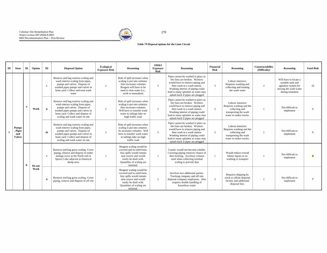
Colomac Site Remediation Plan Water License MV2004L8-0001 Mill Decontamination Plan – Post Review
278
Table 79 Disposal options for the Lime Circuit
ID Item ID Option ID Disposal Option Ecological Exposure Risk Reasoning
OH&S Exposure
Risk Reasoning Financial
Risk Reasoning Constructability (Difficulty) Reasoning Total Risk
i
Remove and bag exterior scaling and wash interior scaling from pipes, pumps and valves. Dispose of
washed pipes pumps and valves in bone yard. Collect and treat wash
water
2
Risk of spill increases when scaling is put into solution.
Also increases volumes Reagent will have to be used to treat water (i.e.,
acids to neutralize)
3
Pipes cannot be washed in place as the lines are broken. Workers
would have to remove piping and then wash in a wash station.
Washing interior of piping could lead to many splashes as water may
splash back if pipes are plugged
3
Labour intensive. Requires washing and collecting and treating
the wash water
2
Will have to locate a suitable tank and
agitation system for mixing the wash water
during treatment
10
ii
Remove and bag exterior scaling and wash interior scaling from pipes, pumps and valves. Dispose of
washed pipes pumps and valves in bone yard. Collect and dispose of
scaling and wash water on site
2
Risk of spill increases when scaling is put into solution.
Also increases volumes. Will have to transfer wash water to tailings lake on
high traffic road
3
Pipes cannot be washed in place as the lines are broken. Workers
would have to remove piping and then wash in a wash station.
Washing interior of piping could lead to many splashes as water may
splash back if pipes are plugged
3
Labour intensive Requires washing and the
collecting and transporting the wash water in tanker trucks.
1 Not difficult to implement 9
a
Wash
iii
Remove and bag exterior scaling and wash interior scaling from pipes, pumps and valves. Dispose of
washed pipes pumps and valves in bone yard. Collect and dispose of
scaling and wash water on site
2
Risk of spill increases when scaling is put into solution. As increases volumes. Will have to transfer wash water
to tailings lake on high traffic road
3
Pipes cannot be washed in place as the lines are broken. Workers
would have to remove piping and then wash in a wash station.
Washing interior of piping could lead to many splashes as water may
splash back if pipes are plugged
3
Labour intensive Requires washing and the
collecting and transporting the wash water in tanker trucks.
1 Not difficult to implement 9
i
Remove and bag gross scaling. Cover piping, remove and dispose of under
tailings cover at the North end of Spruce Lake adjacent to historical
dump area.
1
Reagent scaling would be covered and in solid form. Any spills would remain near source and would
easily be dealt with. Quantities of scaling are
minimal.
1
Caustic would not become soluble. Covering piping removes chance of
dust forming. Auxiliary exhaust used when collecting residual
scaling to prevent dust
1 Would reduce overall
labour inputs as no washing or transport
1 Not difficult to implement 4
1
Pumps, Pipes
and Valves
b
Do not Wash
ii Remove and bag gross scaling. Cover piping, remove and dispose of off site 1
Reagent scaling would be covered and in solid form. Any spills would remain near source and would
easily be dealt with. Quantities of scaling are
minimal.
2
Involves two additional parties. Trucking company and off-site
disposal company employees. Also requires double handling of
hazardous waste
3
Requires shipping by truck to offsite disposal facility and additional
disposal fees.
1 Not difficult to implement 7
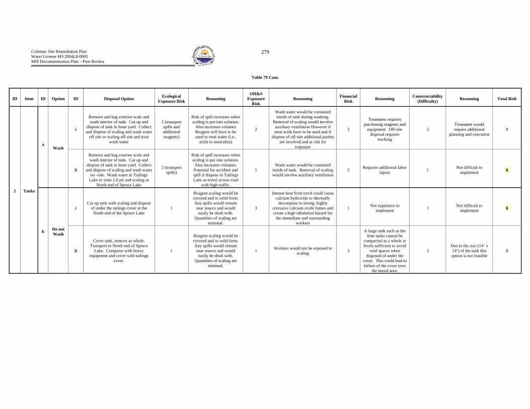
Colomac Site Remediation Plan Water License MV2004L8-0001 Mill Decontamination Plan – Post Review
279
Table 79 Cont.
ID Item ID Option ID Disposal Option Ecological Exposure Risk Reasoning
OH&S Exposure
Risk Reasoning Financial
Risk Reasoning Constructability (Difficulty) Reasoning Total Risk
i
Remove and bag exterior scale and wash interior of tank. Cut up and
dispose of tank in bone yard. Collect and dispose of scaling and wash water
off site or scaling off site and treat wash water
2 (transport spills and additional reagents)
Risk of spill increases when scaling is put into solution.
Also increases volumes Reagent will have to be used to treat water (i.e.,
acids to neutralize)
2
Wash water would be contained inside of tank during washing.
Removal of scaling would involve auxiliary ventilation However if treat acids have to be used and if
dispose of off-site additional parties are involved and at risk for
exposure
3
Treatment requires purchasing reagents and
equipment. Off-site disposal requires
trucking
2 Treatment would require additional
planning and execution 9
a
Wash
ii
Remove and bag exterior scale and wash interior of tank. Cut up and
dispose of tank in bone yard. Collect and dispose of scaling and wash water
on –site. Wash water in Tailings Lake or zone 2.0 pit and scaling at
North end of Spruce Lake
2 (transport spills)
Risk of spill increases when scaling is put into solution.
Also increases volumes. Potential for accident and spill if dispose in Tailings Lake as travel across road
with high traffic.
1 Wash water would be contained
inside of tank. Removal of scaling would involve auxiliary ventilation
2 Requires additional labor inputs 1 Not difficult to
implement 6
i Cut up tank with scaling and dispose
of under the tailings cover at the North end of the Spruce Lake
1
Reagent scaling would be covered and in solid form. Any spills would remain near source and would
easily be dealt with. Quantities of scaling are
minimal.
3
Intense heat from torch could cause calcium hydroxide to thermally
decompose to strong, highly corrosive calcium oxide fumes and create a high inhalation hazard for
the immediate and surrounding workers
1 Not expensive to implement 1 Not difficult to
implement 6
2 Tanks
b Do not Wash
ii
Cover tank, remove as whole. Transport to North end of Spruce
Lake. Compress with heavy equipment and cover with tailings
cover.
1
Reagent scaling would be covered and in solid form. Any spills would remain near source and would
easily be dealt with. Quantities of scaling are
minimal.
1 Workers would not be exposed to scaling 3
A large tank such as the lime tanks cannot be
compacted as a whole to levels sufficient to avoid
void spaces when disposed of under the
cover. This could lead to failure of the cover over
the burial area.
3 Due to the size (14’ x 14’) of the tank this option is not feasible
8

Colomac Site Remediation Plan Water License MV2004L8-0001 Mill Decontamination Plan – Post Review
280
Table 79 Cont.
ID Item ID Option ID Disposal Option Ecological Exposure Risk Reasoning
OH&S Exposure
Risk Reasoning Financial
Risk Reasoning Constructability (Difficulty) Reasoning Total Risk
i
Remove and bag exterior scale and wash interior Cut up and dispose of in bone yard. Collect and dispose of
scaling and wash water off site or scaling off site and treat wash water
2 (transport spills and additional reagents))
Risk of spill increases when scaling is put into solution.
Also increases volumes Reagent will have to be used to treat water (i.e.,
acids to neutralize)
2
Wash water would be contained inside of tank during washing.
Removal of scaling would involve auxiliary ventilation However if treat acids have to be used and if
dispose of off-site additional parties are involved and at risk for
exposure
3
Treatment requires purchasing reagents and
equipment. Off-site disposal requires
trucking
2 Treatment would require additional
planning and execution 9
a
Wash
ii
Remove and bag exterior scale and wash interior k. Cut up and dispose of in bone yard. Collect and dispose of scaling and wash water on –site.
Wash water in Tailings Lake or zone 2.0 pit and scaling at North end of
Spruce Lake
2 (transport spills)
Risk of spill increases when scaling is put into solution.
Also increases volumes. Potential for accident and spill if dispose in Tailings Lake as travel across road
with high traffic.
1 Wash water would be contained
inside of tank. Removal of scaling would involve auxiliary ventilation
2 Requires additional labor inputs 1 Not difficult to
implement 6
i Cut up tank with scaling and dispose
of under the tailings cover at the North end of the Spruce Lake
1
Reagent scaling would be covered and in solid form. Any spills would remain near source and would
easily be dealt with. Quantities of scaling are
minimal.
3 Intense heat from torch could generate very dangerous fumes 1 Not expensive to
implement 1 Not difficult to implement 6
2 Cyclone
and Slaker
b Do not Wash
ii
Remove gross exterior scaling. Cover tank, remove as whole. Transport to North end of Spruce Lake. Compress with heavy equipment and cover with
tailings cover.
1
Reagent scaling would be covered and in solid form. Any spills would remain near source and would
easily be dealt with. Quantities of scaling are
minimal.
1 Workers would not be exposed to scaling 1
A large tank such as the lime tanks cannot be
compacted as a whole to levels sufficient to avoid
void spaces when disposed of under the
cover. This could lead to failure of the cover over
the burial area.
1 Due to the size (14’ x 14’) of the tank this option is not feasible
4
Colomac Site Remediation Plan Water License MV2004L8-0001 Mill Decontamination Plan – Post Review
281
Caustic Scaling Circuit Caustic reagent addition
Hazardous Waste Form Caustic scaling is present within piping and as scaling on pumps, valves etc.
Estimated Hazardous Waste Quantities 0.05 m3 or 0.10 tonnes
On-Site Disposal – Environmental Impacts (Spruce Lake and Tailings Lake) The quantities of caustic are insignificant.
Preferred Disposal Option
Pipes, Valves and Pumps 1b(i) The piping, pumps and valves will be covered in polyethylene plastic and placed 1m under tailings. The tailings cover will overly the buried contents.
Tanks 2b(ii) The tank will be covered in polyethylene and taken to the North end of Spruce Lake. Heavy equipment will compress the tank and bury it along side of the piping.
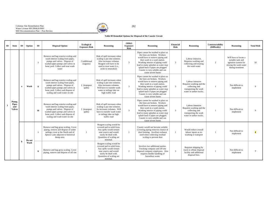
Colomac Site Remediation Plan Water License MV2004L8-0001 Mill Decontamination Plan – Post Review
282
Table 80 Remedial Options for Disposal of the Caustic Circuit
ID Item ID Option ID Disposal Option Ecological Exposure Risk Reasoning
OH&S Exposure
Risk Reasoning Financial
Risk Reasoning Constructability (Difficulty) Reasoning Total Risk
i
Remove and bag exterior scaling and wash interior scaling from pipes, pumps and valves. Dispose of
washed pipes pumps and valves in bone yard. Collect and treat wash
water
2 (additional reagents)
Risk of spill increases when scaling is put into solution.
Also increases volumes Reagent will have to be used to treat water (i.e.,
acids to neutralize)
3
Pipes cannot be washed in place as the lines are broken. Workers
would have to remove piping and then wash in a wash station.
Washing interior of piping could lead to many splashes as water may
splash back if pipes are plugged Caustic is very soluble and can
cause severe burns
3
Labour intensive. Requires washing and collecting and treating
the wash water
2
Will have to locate a suitable tank and
agitation system for mixing the wash water
during treatment
10
ii
Remove and bag exterior scaling and wash interior scaling from pipes, pumps and valves. Dispose of
washed pipes pumps and valves in bone yard. Collect and dispose of
scaling and wash water on site
2 (transport spills)
Risk of spill increases when scaling is put into solution.
Also increases volumes. Will have to transfer wash water to tailings lake on
high traffic road
3
Pipes cannot be washed in place as the lines are broken. Workers
would have to remove piping and then wash in a wash station.
Washing interior of piping could lead to many splashes as water may
splash back if pipes are plugged Caustic is very soluble and can
cause severe burns
3
Labour intensive Requires washing and the
collecting and transporting the wash water in tanker trucks.
1 Not difficult to implement 9 a Wash
iii
Remove and bag exterior scaling and wash interior scaling from pipes, pumps and valves. Dispose of
washed pipes pumps and valves in bone yard. Collect and dispose of
scaling and wash water on site
2 (transport spills)
Risk of spill increases when scaling is put into solution. As increases volumes. Will have to transfer wash water
to tailings lake on high traffic road
3
Pipes cannot be washed in place as the lines are broken. Workers
would have to remove piping and then wash in a wash station.
Washing interior of piping could lead to many splashes as water may
splash back if pipes are plugged. Caustic is very soluble and can
cause severe burns
3
Labour intensive Requires washing and the
collecting and transporting the wash water in tanker trucks.
1 Not difficult to implement 9
i
Remove and bag gross scaling. Cover piping, remove and dispose of under
tailings cover at the North end of Spruce Lake adjacent to historical
dump area.
1
Reagent scaling would be covered and in solid form. Any spills would remain near source and would
easily be dealt with. Quantities of scaling are
minimal.
1
Caustic would not become soluble. Covering piping removes chance of
dust forming. Auxiliary exhaust used when collecting residual
scaling to prevent dust
1 Would reduce overall
labour inputs as no washing or transport
1 Not difficult to implement 4
1
Pump, Pipes and
Valves
b Do not Wash
ii Remove and bag gross scaling. Cover piping, remove and dispose of off site 1
Reagent scaling would be covered and in solid form. Any spills would remain near source and would
easily be dealt with. Quantities of scaling are
minimal.
2
Involves two additional parties. Trucking company and off-site
disposal company employees. Also requires double handling of
hazardous waste
3
Requires shipping by truck to offsite disposal facility and additional
disposal fees.
1 Not difficult to implement 7

Colomac Site Remediation Plan Water License MV2004L8-0001 Mill Decontamination Plan – Post Review
283
Table 80 Cont.
ID Item ID Option ID Disposal Option Ecological Exposure Risk Reasoning
OH&S Exposure
Risk Reasoning Financial
Risk Reasoning Constructability (Difficulty) Reasoning Total Risk
i
Remove and bag exterior scale and wash interior of tank. Cut up and
dispose of tank in bone yard. Collect and dispose of scaling and wash water
off site or scaling off site and treat wash water
2 (transport spills or
additional reagents)
Risk of spill increases when scaling is put into solution.
Also increases volumes Reagent will have to be used to treat water (i.e.,
acids to neutralize)
2
Wash water would be contained inside of tank during washing.
Removal of scaling would involve auxiliary ventilation However if treat acids have to be used and if
dispose of off-site additional parties are involved and at risk for
exposure Caustic is very soluble and can cause severe burns
3
Treatment requires purchasing reagents and
equipment. Off-site disposal requires
trucking
2 Treatment would require additional
planning and execution 9
a Wash
ii
Remove and bag exterior scale and wash interior of tank. Cut up and
dispose of tank in bone yard. Collect and dispose of scaling and wash water
on –site. Wash water in Tailings Lake or zone 2.0 pit and scaling at
North end of Spruce Lake
2 (transport spills)
Risk of spill increases when scaling is put into solution.
Also increases volumes. Potential for accident and spill if dispose in Tailings Lake as travel across road
with high traffic.
3
Wash water would be contained inside of tank. Removal of scaling would involve auxiliary ventilation
Caustic is very soluble and can cause severe burns
2 Requires additional labor inputs 1 Not difficult to
implement 8
i Cut up tank with scaling and dispose
of under the tailings cover at the North end of the Spruce Lake
1
Reagent scaling would be covered and in solid form. Any spills would remain near source and would
easily be dealt with. Quantities of scaling are
minimal.
3 Intense heat from torch could generate very dangerous fumes 1 Not expensive to
implement 1 Not difficult to implement 6
2 Tanks
b Do not Wash
ii
Cover tank, remove as whole. Transport to North end of Spruce
Lake. Compress with heavy equipment and cover with tailings
cover.
1
Reagent scaling would be covered and in solid form. Any spills would remain near source and would
easily be dealt with. Quantities of scaling are
minimal.
1 Workers would not be exposed to scaling 1 Not expensive to
implement 1
Due to the size (6’x6’) of and easy access to the tank this option
would not be difficult
4

Colomac Site Remediation Plan Water License MV2004L8-0001 Mill Decontamination Plan – Post Review
284
HCL Circuit The Hydrochloric Acid System has been removed and therefore no consideration of disposal methods in needed for the circuit.
Colomac Site Remediation Plan Water License MV2004L8-0001 Mill Decontamination Plan – Post Review
285
B. Hazardous Wastes Foreign to the TCLA and Zone 2.0 Pit - Hydrocarbons
Circuit Primary and Secondary Grinding Primary and Secondary Crushing Leaching
Hazardous Waste Form Hydrocarbons include lubricants - oils and greases, hydraulic fluids and heat exchange fluids. These products are present in equipment reservoirs, baths and residual staining on equipment and floors
Estimated Quantities of Hazardous Waste Lubrication = 28,712 L + Piping Hydraulic = 3,285 L Solvent = 681 L Heat Exchange = Unknown but not significant
Environmental Effects The process of removing and disposing of hydrocarbons is straight forward and proven. As such formal assessment of risk is not required. Either on-site incineration or off-site disposal will be implemented. Disposal of hydrocarbons within the Spruce Lake or Tailings Lake is not an acceptable method of waste disposal nor is on-site storage.
Preferred Method of Disposal
On-Site Incineration and Off-site Disposal The majority of hydrocarbon wastes resulting from the decontamination of the Colomac Mill are suitable for on-site incineration. Esso (Imperial oil) the primary distributor for hydrocarbons to the Colomac Mill, and other manufacturers have been consulted for best practices and recommendations on incineration of their hydrocarbon products. An incinerator is available on-site at the Colomac Mine and was mobilized to burn other waste hydrocarbons stored in the waste rock area. However, some hydrocarbons will require off-site disposal as according to criteria outlined within the “GNWT Used Oil and Waste Fuel Management Regulations” and manufacturer recommendations. Sampling of bulked product will determine if the hydrocarbons meet or fail to meet the GNWT criteria. The criteria are as follows: Cadmium 2 ppm, Chromium 10 ppm, Lead 100 ppm, Total Organic Halogens (Chlorine) 1000 ppm, PCB’s 2ppm and Ash Content 0.6 wt%. Both free products removed from equipment or present in drums and product resulting from the removal of residual staining will require incineration/off-site disposal. The following describes how the free product and residual product will be collected for incineration.
Collection of Free Product The reservoirs, piping, gear baths etc. associated with the circuit components will be drained and collected using a portable pump and 45 gallon drums. The collected free product will transferred to the area within the waste rock dump where free hydrocarbons are currently stored.
Removal of Residual Product and Staining Residual waste greases, oils and fuels will be removed through steam cleaning, wiping with hydrophobic clothes, or the use of surfactants. Surfactants use will be limited to cleaning the interior of reservoirs and will be avoided to the extent possible.
Colomac Site Remediation Plan Water License MV2004L8-0001 Mill Decontamination Plan – Post Review
286
C. Hazardous Wastes Foreign to the TCLA and Zone 2.0 Pit – Miscellaneous
Circuit Located throughout all circuits
Hazardous Waste Form Mercury is present within light tubes and thermostats. Lead is present in batteries. Various additional hazardous wastes are present as free product within their original shipping containers
Estimated Quantities of Hazardous Waste Refer to

Colomac Site Remediation Plan Water License MV2004L8-0001 Mill Decontamination Plan – Post Review
287
Table 5
Environmental Effects Miscellaneous wastes will be shipped off-site to a licensed hazardous waste facility
Preferred Method of Disposal Miscellaneous wastes will be shipped off-site to a licensed hazardous waste facility
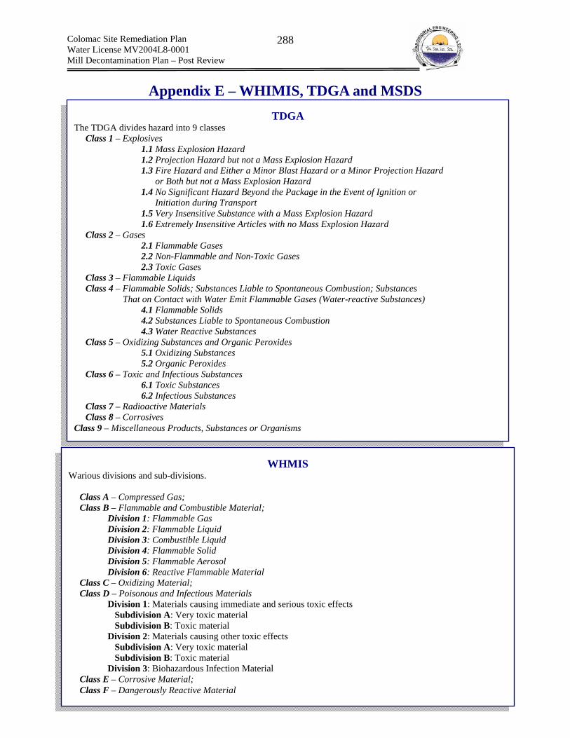
Colomac Site Remediation Plan Water License MV2004L8-0001 Mill Decontamination Plan – Post Review
288
TDGA The TDGA divides hazard into 9 classes
Class 1 – Explosives 1.1 Mass Explosion Hazard 1.2 Projection Hazard but not a Mass Explosion Hazard 1.3 Fire Hazard and Either a Minor Blast Hazard or a Minor Projection Hazard or Both but not a Mass Explosion Hazard 1.4 No Significant Hazard Beyond the Package in the Event of Ignition or Initiation during Transport 1.5 Very Insensitive Substance with a Mass Explosion Hazard 1.6 Extremely Insensitive Articles with no Mass Explosion Hazard Class 2 – Gases 2.1 Flammable Gases 2.2 Non-Flammable and Non-Toxic Gases 2.3 Toxic Gases Class 3 – Flammable Liquids Class 4 – Flammable Solids; Substances Liable to Spontaneous Combustion; Substances That on Contact with Water Emit Flammable Gases (Water-reactive Substances) 4.1 Flammable Solids 4.2 Substances Liable to Spontaneous Combustion 4.3 Water Reactive Substances Class 5 – Oxidizing Substances and Organic Peroxides 5.1 Oxidizing Substances 5.2 Organic Peroxides Class 6 – Toxic and Infectious Substances 6.1 Toxic Substances 6.2 Infectious Substances Class 7 – Radioactive Materials Class 8 – Corrosives
Class 9 – Miscellaneous Products, Substances or Organisms
WHMIS Warious divisions and sub-divisions.
Class A – Compressed Gas; Class B – Flammable and Combustible Material;
Division 1: Flammable Gas Division 2: Flammable Liquid Division 3: Combustible Liquid Division 4: Flammable Solid Division 5: Flammable Aerosol Division 6: Reactive Flammable Material
Class C – Oxidizing Material; Class D – Poisonous and Infectious Materials
Division 1: Materials causing immediate and serious toxic effects Subdivision A: Very toxic material Subdivision B: Toxic material Division 2: Materials causing other toxic effects Subdivision A: Very toxic material Subdivision B: Toxic material Division 3: Biohazardous Infection Material
Class E – Corrosive Material; Class F – Dangerously Reactive Material
Appendix E – WHIMIS, TDGA and MSDS

Colomac Site Remediation Plan Water License MV2004L8-0001 Mill Decontamination Plan – Post Review
289
MSDS Material Safety Data Sheets (MSDS) are intended to provide persons with sufficient information to ensure safe use of chemical products. More specifically MSDS Sheets provide information:
1. Chemical product and company identification; 2. Composition and Information on ingredients; 3. Hazard identification; 4. First aid measures; 5. Fire fighting measures; 6. Accidental release measures; 7. Handling and storage 8. Exposure control and personal protection; 9. Physical and chemical properties; 10. Stability and reactivity; 11. Toxicological information; 12. Ecological information; 13. Disposal considerations; 14. Transport information; 15. Regulatory information; and 16. Other information
Colomac Site Remediation Plan Water License MV2004L8-0001 Mill Decontamination Plan – Post Review
290
Appendix F – Safe Work Plans Included in the AEL Safety Manual
(a) Fall Restraint and Arrest;
(b) Ladders;
(c) Working with Hand Tools (non-powered); and
(d) Lifting

Aboriginal Engineering Ltd. Health, Safety & Environment Program
Planks should be secured from movement by cleats or by being wired in place.
Planks are to be kept clean and free of any obstructions that could cause slipping or tripping hazards.
Planking must be construction grade No. 1 fir (or equivalent material), measuring at least 38 mm by 235 mm (2” X 10”).
The maximum span should not exceed 2.3 m (7.5’) for heavy duty use and 3.1 m (10’) for medium and light duty use. Planking used for working surfaces should be of uniform thickness and tightly laid.
Guardrail Requirements
Guardrails are installed between 1 m (3’) and 1.5 m (5’) above floor, ground or platform level, with a mid-rail halfway in between. Toe boards are a minimum of 10 cm (4”) in height.
Top rail surfaces are smooth. Guardrails are constructed and mounted so that they are capable of
supporting at least 90 kg (200 lbs.) of lateral force. Hand rails measure between 75 and 85 cm (30-33”). Handrails receiving
additional stress from employees or materials are further supported by the closer spacing of posts or by additional bracing.
3.6 Fall Restraint and Arrest This practice is followed when there is a potential to fall from 3 m (10’) or more. Fall restraint equipment prevents an employee from falling to a lower level by restricting the employee’s movement. Fall arrest equipment limits an employee’s fall to a maximum of 1.2 m (4’), using a full body harness. In addition to fall restraints or fall arrest equipment a hard hat must be worn. Fall Arrest and Fall Restraint Requirements.
Employees working at elevations higher than 3 m (10’), where there is a risk of injury from falls, must include (but are not limited to):
− inspect walls, floors, railings, and standard guardrail systems
− inspect bridges and large vessels
− use personal fall restraint or fall arrest equipment
2006-02-03 21 4:55 PM

Aboriginal Engineering Ltd. Health, Safety & Environment Program
Identify specific fall protection needs prior to the start of the project. Implement the fall protection plan and provide ongoing training as needed. Identify fall hazards on an ongoing basis and review fall equipment needs. Review the plan and consider the procedures for assembly maintenance,
inspection, and disassembly of equipment. Develop training for fall protection to include job orientation, instruction on
fall restraint, and fall arrest as well as the fitting of personal protective equipment.
Ensure that there are adequate attachment points available at each location where fall protection systems are used.
Rules
When working in fall hazard areas, work site-specific fall protection procedures are used. Contact the Safety Officer for information and the equipment appropriate for your work area.
Personal protective equipment is always worn when passing through an active overhead work area.
Always use measures to control or restrict access when working below or around other employees working overhead.
Fall protection equipment is not to be used by employees until they have been adequately instructed in the safe use and handling of the equipment and have demonstrated that they understand the instruction.
Fall Restraint Guidelines
Fall restraint is rigged to allow the movement of employees only as far as the sides and edges of the working area. As part of the rigging, anchorage points conforming to the intended load criteria (800 lb.) must be provided for each fall restraint device in use.
Hold a pre-job meeting to address and discuss the fall protection requirements. This includes training on the use of fall protection equipment or review of the use of fall protection equipment.
Inspect all restraint components before use to ensure that there is no excessive wear or damage, and no other deterioration. Defective components are removed from use and marked to prevent others from using them.
Confirm that all fall restraint devices are compatible.
2006-02-03 22 4:55 PM
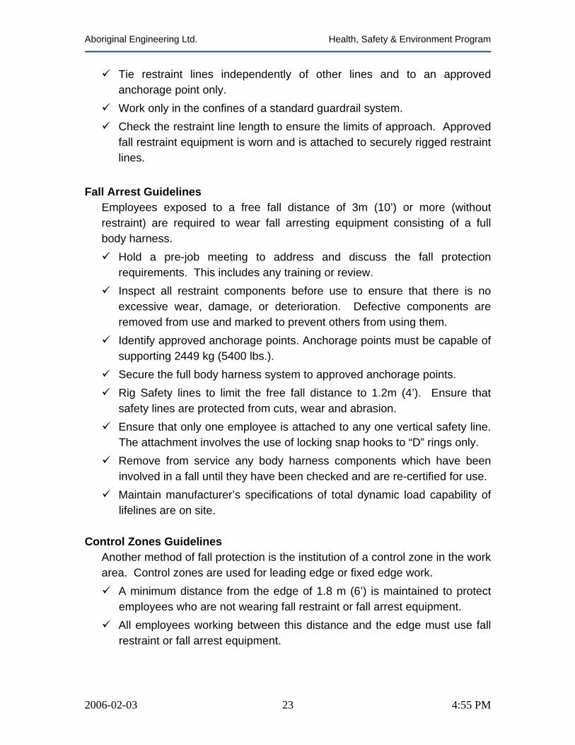
Aboriginal Engineering Ltd. Health, Safety & Environment Program
Tie restraint lines independently of other lines and to an approved anchorage point only.
Work only in the confines of a standard guardrail system. Check the restraint line length to ensure the limits of approach. Approved
fall restraint equipment is worn and is attached to securely rigged restraint lines.
Fall Arrest Guidelines
Employees exposed to a free fall distance of 3m (10’) or more (without restraint) are required to wear fall arresting equipment consisting of a full body harness.
Hold a pre-job meeting to address and discuss the fall protection requirements. This includes any training or review.
Inspect all restraint components before use to ensure that there is no excessive wear, damage, or deterioration. Defective components are removed from use and marked to prevent others from using them.
Identify approved anchorage points. Anchorage points must be capable of supporting 2449 kg (5400 lbs.).
Secure the full body harness system to approved anchorage points. Rig Safety lines to limit the free fall distance to 1.2m (4’). Ensure that
safety lines are protected from cuts, wear and abrasion. Ensure that only one employee is attached to any one vertical safety line.
The attachment involves the use of locking snap hooks to “D” rings only. Remove from service any body harness components which have been
involved in a fall until they have been checked and are re-certified for use. Maintain manufacturer’s specifications of total dynamic load capability of
lifelines are on site. Control Zones Guidelines
Another method of fall protection is the institution of a control zone in the work area. Control zones are used for leading edge or fixed edge work.
A minimum distance from the edge of 1.8 m (6’) is maintained to protect employees who are not wearing fall restraint or fall arrest equipment.
All employees working between this distance and the edge must use fall restraint or fall arrest equipment.
2006-02-03 23 4:55 PM
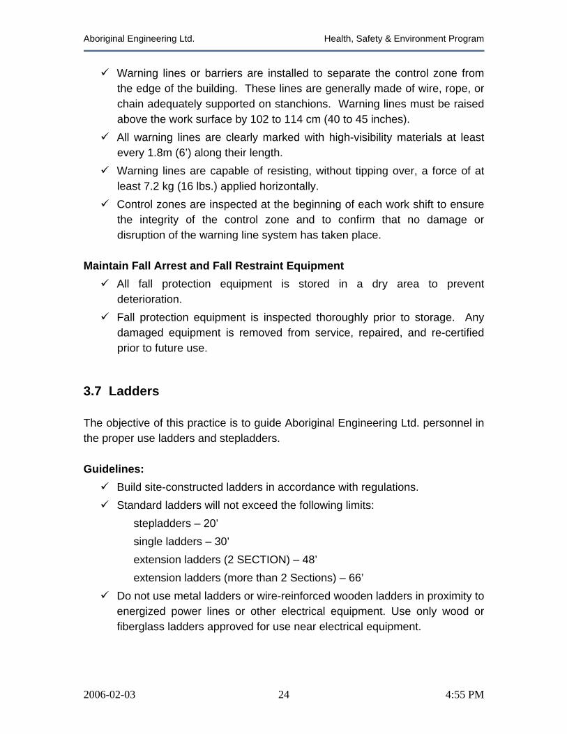
Aboriginal Engineering Ltd. Health, Safety & Environment Program
Warning lines or barriers are installed to separate the control zone from the edge of the building. These lines are generally made of wire, rope, or chain adequately supported on stanchions. Warning lines must be raised above the work surface by 102 to 114 cm (40 to 45 inches).
All warning lines are clearly marked with high-visibility materials at least every 1.8m (6’) along their length.
Warning lines are capable of resisting, without tipping over, a force of at least 7.2 kg (16 lbs.) applied horizontally.
Control zones are inspected at the beginning of each work shift to ensure the integrity of the control zone and to confirm that no damage or disruption of the warning line system has taken place.
Maintain Fall Arrest and Fall Restraint Equipment
All fall protection equipment is stored in a dry area to prevent deterioration.
Fall protection equipment is inspected thoroughly prior to storage. Any damaged equipment is removed from service, repaired, and re-certified prior to future use.
3.7 Ladders The objective of this practice is to guide Aboriginal Engineering Ltd. personnel in the proper use ladders and stepladders. Guidelines:
Build site-constructed ladders in accordance with regulations. Standard ladders will not exceed the following limits:
stepladders – 20’ single ladders – 30’ extension ladders (2 SECTION) – 48’ extension ladders (more than 2 Sections) – 66’
Do not use metal ladders or wire-reinforced wooden ladders in proximity to energized power lines or other electrical equipment. Use only wood or fiberglass ladders approved for use near electrical equipment.
2006-02-03 24 4:55 PM

Aboriginal Engineering Ltd. Health, Safety & Environment Program
Use only industrial or heavy-duty grade extension ladders. Broken or damaged ladders must not be used. Remove ladders with loose, broken, or missing rungs, split side rails, or other defects from service.
All portable ladders must be secured against movement and never placed against moveable objects.
Set the ladder at the proper angle of one (1) horizontal to every (4) vertical.
Do not paint wooden ladders, paint may hide unsafe wear and tear. Use only transparent protective coatings, if necessary. Place the lower ends of the ladder on a firm and level base. Single and extension ladders must be equipped with non-slip safety feet,
tied off, or otherwise secured to prevent “kicking out” or slipping. Rest the upper part of the side rails on a bearing surface of ample strength
to support the load of the ladder and other applied loads. Avoid the use of metal ladders when performing electrical work. Ladders projecting into passageways or doorways where they can be
struck by personnel, moving equipment or materials must be protected by barricades or guards.
Face the ladder at all times when ascending or descending. Do not carry materials in your free hand when ascending a ladder. Use a
hand line. Both hands must be free when climbing or descending. Do not stand on the top two rungs of a ladder. Use polypropylene ropes on extension ladders in corrosive plant areas.
Stepladders:
Ensure that the stepladder is in good condition and is the right ladder for the job to be performed.
Inspect all portable ladders prior to each use. Only use stepladders on clean, even surfaces. Do not work from the top two steps of a stepladder. The pail shelf is not a
step. Only use a stepladder in the fully opened position with the spreader bars
locked. Do not use stepladders as supports for scaffolds.
2006-02-03 25 4:55 PM
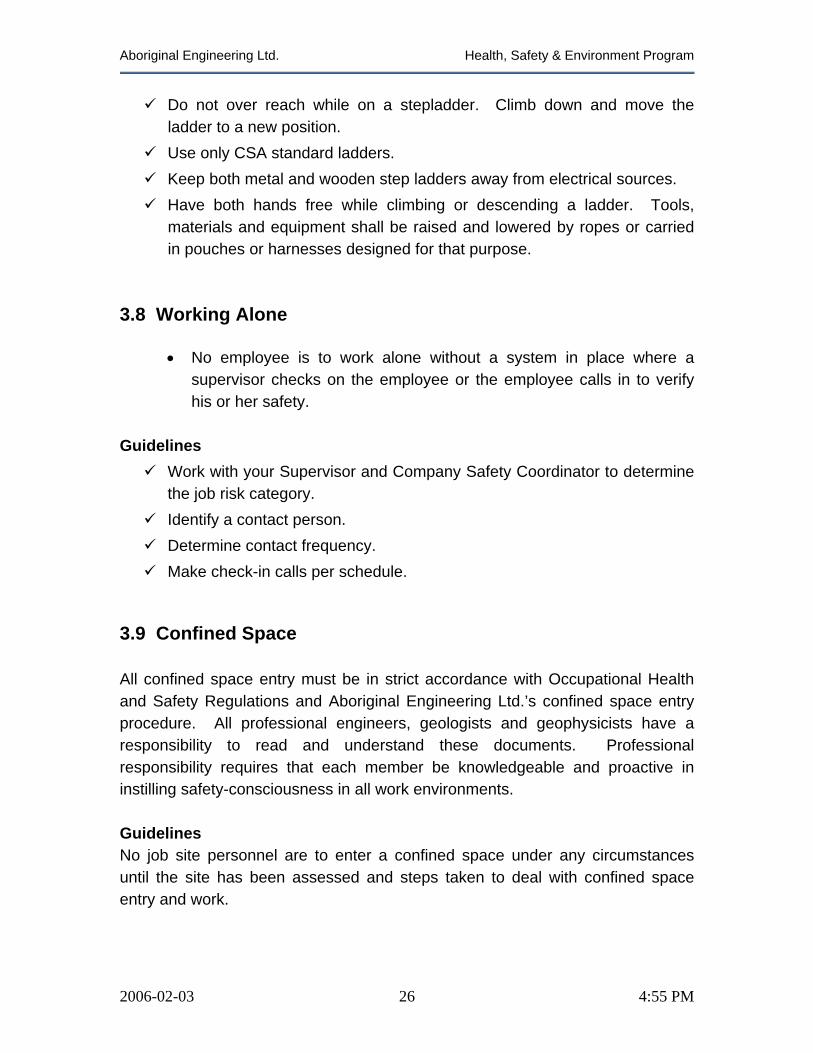
Aboriginal Engineering Ltd. Health, Safety & Environment Program
Do not over reach while on a stepladder. Climb down and move the ladder to a new position.
Use only CSA standard ladders. Keep both metal and wooden step ladders away from electrical sources. Have both hands free while climbing or descending a ladder. Tools,
materials and equipment shall be raised and lowered by ropes or carried in pouches or harnesses designed for that purpose.
3.8 Working Alone
• No employee is to work alone without a system in place where a supervisor checks on the employee or the employee calls in to verify his or her safety.
Guidelines
Work with your Supervisor and Company Safety Coordinator to determine the job risk category.
Identify a contact person. Determine contact frequency. Make check-in calls per schedule.
3.9 Confined Space All confined space entry must be in strict accordance with Occupational Health and Safety Regulations and Aboriginal Engineering Ltd.’s confined space entry procedure. All professional engineers, geologists and geophysicists have a responsibility to read and understand these documents. Professional responsibility requires that each member be knowledgeable and proactive in instilling safety-consciousness in all work environments.
Guidelines No job site personnel are to enter a confined space under any circumstances until the site has been assessed and steps taken to deal with confined space entry and work.
2006-02-03 26 4:55 PM
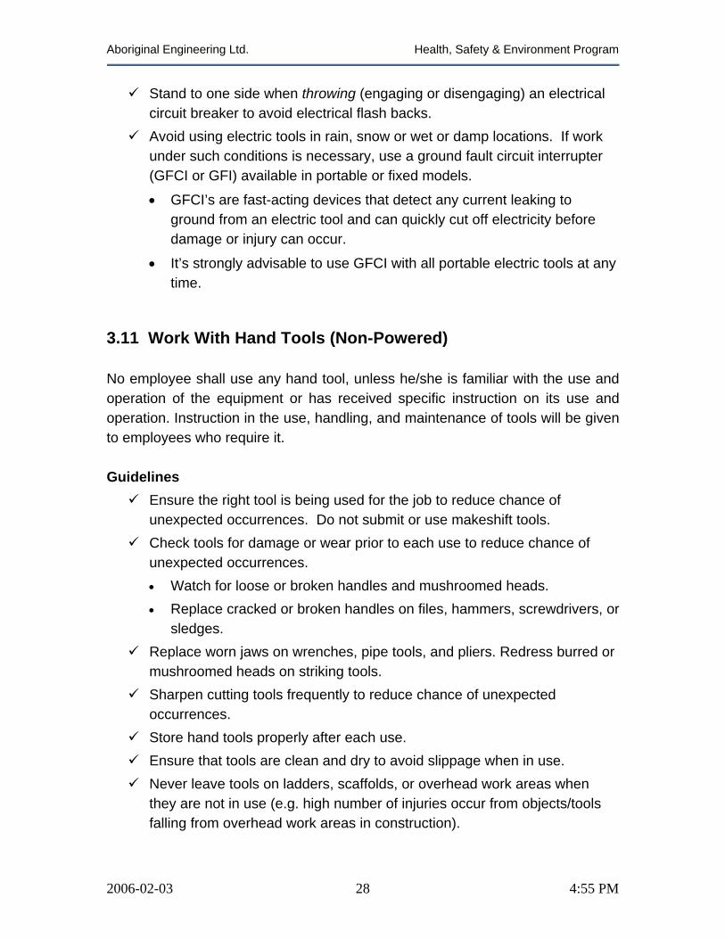
Aboriginal Engineering Ltd. Health, Safety & Environment Program
Stand to one side when throwing (engaging or disengaging) an electrical circuit breaker to avoid electrical flash backs.
Avoid using electric tools in rain, snow or wet or damp locations. If work under such conditions is necessary, use a ground fault circuit interrupter (GFCI or GFI) available in portable or fixed models.
• GFCI’s are fast-acting devices that detect any current leaking to ground from an electric tool and can quickly cut off electricity before damage or injury can occur.
• It’s strongly advisable to use GFCI with all portable electric tools at any time.
3.11 Work With Hand Tools (Non-Powered) No employee shall use any hand tool, unless he/she is familiar with the use and operation of the equipment or has received specific instruction on its use and operation. Instruction in the use, handling, and maintenance of tools will be given to employees who require it. Guidelines
Ensure the right tool is being used for the job to reduce chance of unexpected occurrences. Do not submit or use makeshift tools.
Check tools for damage or wear prior to each use to reduce chance of unexpected occurrences. • Watch for loose or broken handles and mushroomed heads. • Replace cracked or broken handles on files, hammers, screwdrivers, or
sledges. Replace worn jaws on wrenches, pipe tools, and pliers. Redress burred or
mushroomed heads on striking tools. Sharpen cutting tools frequently to reduce chance of unexpected
occurrences. Store hand tools properly after each use. Ensure that tools are clean and dry to avoid slippage when in use. Never leave tools on ladders, scaffolds, or overhead work areas when
they are not in use (e.g. high number of injuries occur from objects/tools falling from overhead work areas in construction).
2006-02-03 28 4:55 PM
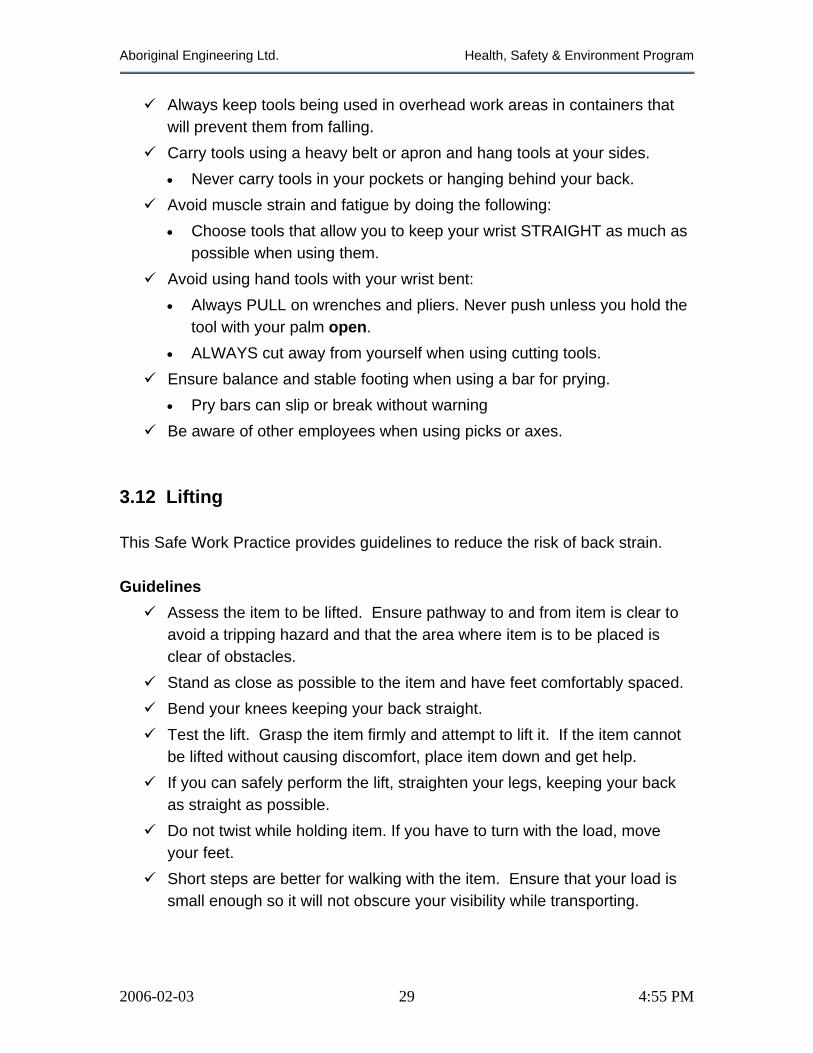
Aboriginal Engineering Ltd. Health, Safety & Environment Program
Always keep tools being used in overhead work areas in containers that will prevent them from falling.
Carry tools using a heavy belt or apron and hang tools at your sides. • Never carry tools in your pockets or hanging behind your back.
Avoid muscle strain and fatigue by doing the following: • Choose tools that allow you to keep your wrist STRAIGHT as much as
possible when using them. Avoid using hand tools with your wrist bent: • Always PULL on wrenches and pliers. Never push unless you hold the
tool with your palm open. • ALWAYS cut away from yourself when using cutting tools.
Ensure balance and stable footing when using a bar for prying. • Pry bars can slip or break without warning
Be aware of other employees when using picks or axes.
3.12 Lifting This Safe Work Practice provides guidelines to reduce the risk of back strain. Guidelines
Assess the item to be lifted. Ensure pathway to and from item is clear to avoid a tripping hazard and that the area where item is to be placed is clear of obstacles.
Stand as close as possible to the item and have feet comfortably spaced. Bend your knees keeping your back straight. Test the lift. Grasp the item firmly and attempt to lift it. If the item cannot
be lifted without causing discomfort, place item down and get help. If you can safely perform the lift, straighten your legs, keeping your back
as straight as possible. Do not twist while holding item. If you have to turn with the load, move
your feet. Short steps are better for walking with the item. Ensure that your load is
small enough so it will not obscure your visibility while transporting.
2006-02-03 29 4:55 PM
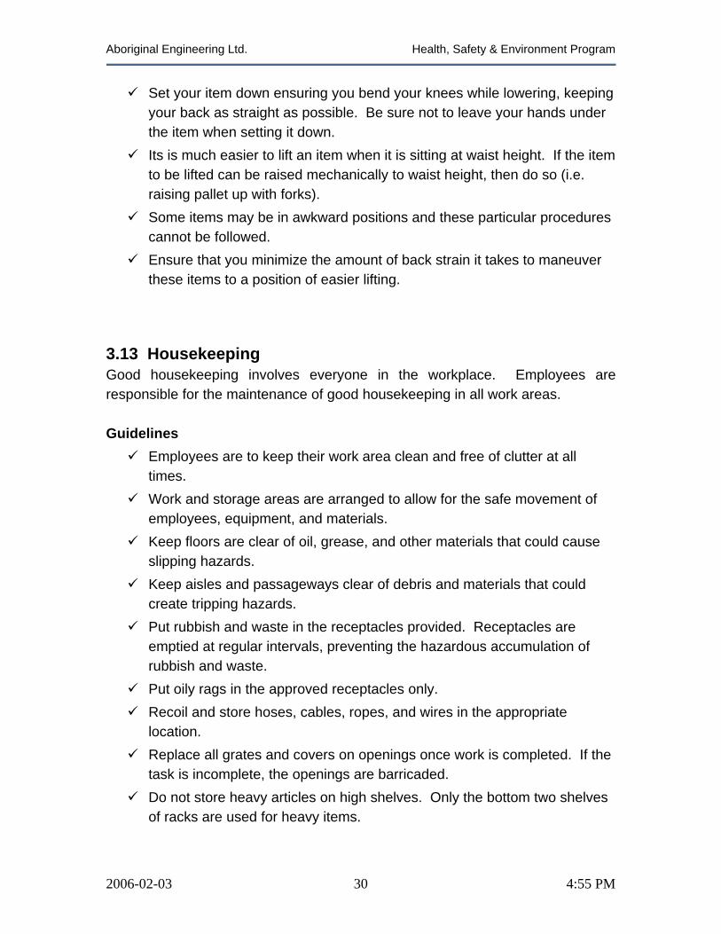
Aboriginal Engineering Ltd. Health, Safety & Environment Program
Set your item down ensuring you bend your knees while lowering, keeping your back as straight as possible. Be sure not to leave your hands under the item when setting it down.
Its is much easier to lift an item when it is sitting at waist height. If the item to be lifted can be raised mechanically to waist height, then do so (i.e. raising pallet up with forks).
Some items may be in awkward positions and these particular procedures cannot be followed.
Ensure that you minimize the amount of back strain it takes to maneuver these items to a position of easier lifting.
3.13 Housekeeping Good housekeeping involves everyone in the workplace. Employees are responsible for the maintenance of good housekeeping in all work areas. Guidelines
Employees are to keep their work area clean and free of clutter at all times.
Work and storage areas are arranged to allow for the safe movement of employees, equipment, and materials.
Keep floors are clear of oil, grease, and other materials that could cause slipping hazards.
Keep aisles and passageways clear of debris and materials that could create tripping hazards.
Put rubbish and waste in the receptacles provided. Receptacles are emptied at regular intervals, preventing the hazardous accumulation of rubbish and waste.
Put oily rags in the approved receptacles only. Recoil and store hoses, cables, ropes, and wires in the appropriate
location. Replace all grates and covers on openings once work is completed. If the
task is incomplete, the openings are barricaded. Do not store heavy articles on high shelves. Only the bottom two shelves
of racks are used for heavy items.
2006-02-03 30 4:55 PM