Wednesday, February 5, 2020 - Procurement - Government of Nova ...
125
METROPOLITAN REGIONAL HOUSING AUTHORITY INVITES BIDS ON TENDER DOCUMENT NO. 19-163 Unit Renovation #2 CLOSING DATE: Wednesday, February 5, 2020
-
Upload
khangminh22 -
Category
Documents
-
view
4 -
download
0
Transcript of Wednesday, February 5, 2020 - Procurement - Government of Nova ...

METROPOLITAN REGIONAL HOUSING AUTHORITY
INVITES BIDS ON
TENDER DOCUMENT NO. 19-163
Unit Renovation #2
CLOSING DATE:
Wednesday, February 5, 2020
Metropolitan Regional Housing Authority Tender No. 19-163 Unit Renovation #2
Table of Contents
PAGES
Section One
Scheduled Tour Date
Mandatory Requirements
1
2
Instructions to Bidders 3 - 6
Bid Form 7 - 9
General Conditions of the Contract 10 - 28
Asbestos Disclosure Materials Letter: January 2014 29
Drawings / Sketches
A-0 Cover Page 30
A-1 General Notes & Scope of Work 31
A-2 Partial Site Plan and Details 32
A-3 Main Floor Plan – Demolition 33
A-4 Main Floor Plan – New Layout 34
A-5 Main Floor Plan & Elevations – New Kitchen 35
A-6 Partial Floor Plan & Elevations - New Bathroom 36
A-7 Millwork Section Details & Specifications 37
A-8 Project Schedules 38
A-9 Section Details 39
M-1 Mechanical Main Floor Plan – New Layout 40
E-1 Existing / Demo Electrical Plan 41
E-2 New Electrical Plan 42
E-3 Electrical Plan 43
Specifications 3492 McAlpine – Mechanical Scope of Work 44-47
Product Specification Sheets 48-72
Electrical Specifications: PF-2019-170C McAlpine Ave. Accessible Unit Conversion
73-88
Section 03.11.00 Concrete Formwork 89-90
Section 03.30.00 Cast-In-Place Concrete 91-98
Section 03.30.53 Concrete Walks, Curbs and Gutters 99-102
Section 08.10.00 Entrance Door Insulated Pre-Hung 103-106
Section 09.65.16 Resilient Vinyl Sheet Flooring -Supply – Single Units and Houses 107-108
Section 08.53.13 Paint Supply & Install 109-113Appendix A Asbestos in the Workplace – A Guide to Removal of Friable Asbestos
Containing Material 114-119
Appendix B Agreement (For Information Purposes Only) 120-122
Appendix C Product Approval Form 123
Total pages for this tender 123

Metropolitan Regional Housing Authority Tender No. 19-163 Unit
Renovation #2 Site Tour
(Attendance is NOT mandatory)
1. Organized Tour Date
.1 All bidders note:
.1 The tour is scheduled for Friday, January 31, 2020 at 2:00 PM
2. Site Location Information.1 Property
3492 McALPINE AVE, HALIFAX, N.S.
.2 Starting Address: 3492 McALPINE AVE, HALIFAX, N.S.
Tender No. 19-163 Unit Renovation #2 Page 1 of 123

Metropolitan Regional Housing Authority
MET19-163 Unit Renovation #2
SECTION ONE - MANDATORY REQUIREMENTS
The following are the mandatory requirements of a formal bid and failure to meet one or more shall result in the bid being disqualified:
.1 the Bid document shall be signed and witnessed;
.2 if bidders have been requested to provide Bid Security, security shall be provided in Canadian funds in the amount required in one of the following forms only: a certified cheque, a certified bank draft, Government of Canada bearer bonds, or a Surety Bid Bond. No other form of bid security shall be accepted;
.3 all unit prices shall be included in unit price contracts;
.4 the Bid package shall be on Metropolitan Regional Housing Authority documents;
.5 any Bid based on modifying, qualifying or re-writing any of the terms or conditions of the Tender, the General Conditions or the Supplementary Conditions documents shall be disqualified; and,
.6 the Tender Submission shall contain all pages of the Bid Form.
Tender No. 19-163 Unit Renovation #2 Page 2 of 123

Metropolitan Regional Housing Authority MET19-163 Unit Renovation #2
SECTION ONE - INSTRUCTIONS TO BIDDERS
1. Bid Closing Address
The Bid Closing Address is S u i t e 3 , 3770 Kempt Road, Halifax, Nova Scotia. Bids deliveredto the Bid Closing Address must be in a sealed envelope marked “Bid” and bear the name of thebidder and the project “Description of Work”. Bids are to be placed in the Metropolitan RegionalHousing Authority Tender Submission Drop Box, located in the front entrance of Suite 3, 3770Kempt Road, Halifax (door located to the left of Subway). Bids will be received up to 2:00 PM localtime and opened at 2:00 PM local time Wednesday, February 5, 2020.
2. Bid Form
Bids shall be submitted on the original Bid Forms as provided by the Metropolitan Regional HousingAuthority. These forms must be completely filled out in ink, or by typewriter, with the signatures inlonghand, witnessed and shall be signed as follows:
.1 Sole Proprietorship: Signature of sole proprietor in the presence of a witness who will sign whereindicated. Insert the words "Sole Proprietor" under titles;
.2 Partnership: Signature of all partners in the presence of a witness or witnesses who will sign where indicated. Insert the word "Partner" against each signature under titles; or,
.3 Limited Company: If the bid is submitted by a Limited Company, the bid must be signed by duly authorized signing officers of the Company in their normal signatures designating against each signature the official capacity in which the signing officer acts. Signatures are to be made in the presence of a witness who will sign where indicated. The Corporate Seal of the Company shall be affixed to the bid. If the bid is signed by Officials other than the President or Secretary-Treasurer of the Company, a copy of the by-law or resolution of the Board of Directors authorizing them to do so must be submitted with the bid.
The completed form shall be without interlineations, alterations, or erasures.
3. Right to Reject
The right to reject any or all Bids or to accept any Bid deemed most satisfactory is reserved by theMetropolitan Regional Housing Authority. The Metropolitan Regional Housing Authority reserves theright to waive any informality in any or all Bids.
The Metropolitan Regional Housing Authority reserves the right to consider the following in theevaluation of tenders:
.1 past experience with the bidder and / or its management, including, but not limited to thefollowing:
.1 compliance with the terms and conditions of past contracts between the Metropolitan Regional Housing Authority or the Government of Nova Scotia and the bidder; and,
.2 timely completion of past tenders awarded to the bidder.
.2 information received in response to enquiries of credit, customer and industry references; and,
.3 the experience and qualifications of the bidders’ senior management and project management.
Tender No. 19-163 Unit Renovation #2 Page 3 of 123

Metropolitan Regional Housing Authority MET19-163 Unit Renovation #2
SECTION ONE - INSTRUCTIONS TO BIDDERS
4. Modifications to Bids
Modifications may be made to bids by facsimile (fax) message to 902.420.7586 or by email to [email protected], provided the following requirements are met:
.1 modifications must be received at the address indicated in Paragraph 1 of Instructions to Bidder, prior to Bid Closing Time;
.2 modifications made by fax or email shall immediately be followed up by the original document being delivered to the Metropolitan Regional Housing Authority and signed as outlined in Paragraph 2 of Instructions to Bidder; and,
.3 modifications should not include the total original or revised bid amount.
Note: Messages received by telephone shall not be considered.
5. Bid Security
The Bid, together with the Bid Security hereinafter described, must be delivered in a sealed self-addressed envelope. Note:
.1 Bid Security must be in Canadian funds; and,
.2 Bid Security in the form of cash will not be accepted.
6. Bidders’ Responsibility
Bidders will be held to have examined the drawings; to have visited the site; and to have informed themselves as to existing conditions and limitations. Bids shall cover the execution of the whole of the Work as described in the Specifications, as shown on the Drawings / Sketches and as described in any Addendums that may be issued.
7. Registered Contractor / Subcontractors
The Contractor and Subcontractors (whether incorporated or not) shall be individuals or companies registered in the Province of Nova Scotia under the Acts administered by the Registry of Joint Stock Companies. Firms not currently registered shall be required to register as condition of award.
8. Security Deposit
Security deposits shall be based on an amount of not less than ten percent (10%) of the total amount of the Bid.
For bids less than $1,000,000 (one million Canadian dollars), each contractor submitting a Bid must submit the required amount of security deposit in one of the following forms:
.1 a certified cheque or bank draft made payable to the "Metropolitan Regional Housing Authority";
.2 Government of Canada bearer bonds; or,
Tender No. 19-163 Unit Renovation #2 Page 4 of 123
Metropolitan Regional Housing Authority MET19-163 Unit Renovation #2
SECTION ONE - INSTRUCTIONS TO BIDDERS
.3 a Surety Bid Bond.
For bids of more than $1,000,000 (one million Canadian dollars), each contractor submitting a Bid must submit the required amount of security deposit in the form of a Surety Bid Bond only. This shall be either:
.1 a Bid Bond shall be supplied on, or similar to, t he CCDC Form 220 and shall be signed and sealed by the Bonding Company and the Contractor; or,
.2 a Surety Bond may be submitted, in the amount of ten percent (10%) of the Bid price, and the successful Bidder must deliver, upon winning the award, to the Metropolitan Regional Housing Authority a Performance Bond and a Labour and Material Bond each in the amount of fifty percent (50%) of the amount payable under the Contract.
The Metropolitan Regional Housing Authority may require of any Bidder proof of financial and technical capability to undertake the work for which their Bid is submitted.
A certified cheque or other security, when received, will be retained by the Metropolitan Regional Housing Authority as contract security in accordance with the provisions of Paragraph 5.1 of Instructions to Bidders. Bid security for the three lowest bids will be retained by the Metropolitan Regional Housing Authority until such time as the Metropolitan Regional Housing Authority approves an award of Contract. Bid security for all other bids will be returned immediately following the close of Bid.
9. Agreement
The successful Bidder shall enter into an Agreement with the Metropolitan Regional Housing Authority to deliver such goods and services as outlined within the Tender.
10. Acceptance
The Acceptance letter shall be issued, by:
.1 delivering a letter by hand to the Contractor at either the address as set out in the Bid document, the Head Office of the Contractor, or to any officer of the Contractor, in which case acceptance shall be deemed to be the day the letter is delivered.
11. Construction Safety
Prior to contract award, the successful bidder must provide a Certificate of Recognition or Letter of Good Standing issued by an occupational health and safety organization approved by the Workers’ Compensation Board of Nova Scotia.
Tender No. 19-163 Unit Renovation #2 Page 5 of 123

Metropolitan Regional Housing Authority MET19-163 Unit Renovation #2
SECTION ONE - INSTRUCTIONS TO BIDDERS
9. Addenda
It is the responsibility of the bidder to periodically check for any addenda issued for this tender.
General questions, please call:
Bruce Chaisson at tel: 902.420.2108 or email: [email protected]
10. Communications
.1 Enquiries shall be directed to [email protected]
Tender No. 19-163 Unit Renovation #2 Page 6 of 123

Metropolitan Regional Housing Authority MET19-163 Unit Renovation #2
SECTION ONE - BID FORM
TO: METROPOLITAN REGIONAL HOUSING AUTHORITY
FROM:
Contractor's Full Business Name
1. The undersigned Bidder has carefully examined the site of the proposed work described herein, has become familiar with local conditions and the character and extent of the work, has carefully examined every part of the proposed contract and thoroughly understands its stipulations, requirements and provisions, and has carefully examined the following documents, which shall be incorporated into and form part of the Agreement that the Contractor shall enter into with the Metropolitan Regional Housing Authority:
Mandatory Requirements Instructions to Bidders Bid Form General Conditions Asbestos Disclosure Materials Letter: January 2014 Specifications Drawings Appendix A – Agreement (For Information Purposes Only) Addendum No. dated
Addendum No. dated
Addendum No. dated
2. This contract is to provide for the the labor and materials relating to:
Tender No. MET19-163 Unit Renovation #2
3. The undersigned Bidder has determined the quality, quantity and source of supply of all materials
required, has investigated labour conditions, and, has noted that sales taxes are not to be included
in the "Bulk Sum Price" mentioned below in accordance with Paragraph 43 of the General
Conditions of the Contract.
4. The undersigned Bidder agrees:
.1 BULK SUM PRICE: To provide all labour, tools, equipment, materials and incidentals necessary to complete the work in accordance with the Contract and agrees to accept, therefore, as payment in full the "Bulk Sum Price" of
__________________________________________________________________________ ( $ ), and to undertake all changes or extra work required during the period of construction in accordance with the provisions of Article 23 of the General Conditions of the Contract.
Tender No. 19-163 Unit Renovation #2 Page 7 of 123
Metropolitan Regional Housing Authority MET19-163 Unit Renovation #2
SECTION ONE - BID FORM
.2 if awarded the Contract on this Bid Form, the Bidder is to begin work within ten (10) days of notification of Contract Award and to complete the Work within Sixty (60) days of award.
.3 to use the Subcontractors hereinafter listed on the various phases of the work, and not to change or substitute these subcontractors, excepting under the provisions of Article 41 of the General Conditions of the Contract, without prior written permission of the Project Manager.
.4 please list all subcontractors. Subcontractors will be reviewed as part of the tender evaluation. If needed, include a separate sheet listing Subcontractors.
Subcontractor:
Subcontractor:
Subcontractor:
5. The Bulk Sum Price set out above is made up as follows:
.2 estimated cost of materials; and, $
.3 all other charges including labour, contractors’ profits and overhead $
.4 Total of bulk sum price, excluding taxes $
6. Accompanying this Bid Form, the undersigned Bidder is submitting a Security Deposit in one of the following forms:
.1 a certified cheque or bank draft made payable to the "Metropolitan Regional Housing Authority" in the amount of $ (see Instructions to Bidders);
.2 Government of Canada Bearer Bonds in the amount of $ ; or,
.3 a Surety (Bid) Bond in the amount of $ .
.4 The undersigned Bidder agrees that, if this Bid is accepted within sixty (60) days from the closing date and the undersigned Bidder declines to enter into a contract in accordance with this Bid, then;
.1 if I / we have submitted a security deposit in the form of a certified cheque or Government of Canada Bearer Bonds it shall be forfeited; or
.2 if I / we have submitted a Surety (Bid) Bond, the surety shall be liable in accordance with the terms of the Bond.
7. The Acceptance letter shall be issued at the option of the Metropolitan Regional Housing Authority by;
. 1 delivering a letter by hand to the Contractor at either: the address set out in the Bid Form document, the Head Office of the Contractor, or to any officer of the Contractor, in which case acceptance shall be deemed to be the day the letter is delivered.
8. made without connection with any other person or persons, submitting bids for the same work,
Tender No. 19-163 Unit Renovation #2 Page 8 of 123

Metropolitan Regional Housing Authority MET19-163 Unit Renovation #2
SECTION ONE - BID FORM
and is in all respects fair and without collusion. Contractor’s Full Business Address
Contractor’s Full Business Name Street Address
City, Province, Postal Code
Contractor’s Signature Business Telephone Number
Contractor’s Name Contractor’s E-mail Address
Signed, Sealed and Delivered on behalf of the Contractor this day of _______________ 2020, in the presence of
Witness’ Title
AFFIX SEAL
Witness’ Signature
Witness’ Name
Tender No. 19-163 Unit Renovation #2 Page 9 of 123

Metropolitan Regional Housing Authority
MET19-163 Unit Renovation #2
SECTION ONE - GENERAL CONDITIONS OF THE CONTRACT
INDEX
1. Definitions 2. Documents 3. Detail Drawings and Instructions 4. Copies Furnished 5. Shop Drawings 6. Drawings & Specifications of the Work 7. Ownership of Drawings & Models 8. Samples 9. Project Manager and Contractor 10. The Project Manager's Decisions 11. Foreman, Supervision 12. Materials, Appliances, Employees 13. Inspection of Work 14. Correction before Final Payment 15. Deductions for Uncorrected Work 16. Guarantee Warranty 17. Protection of Work and Property 18. Emergencies 19. Contractor's Liability Insurance 20. Fire Insurance 21. Contract Security 22. Cash Allowances 23. Changes in Work 24. Valuation of Changes 25. Claims against Contractor, Subcontractors
of Suppliers
26. Payments 27. Liens 28. Permits, Notices, Laws 29. Patent Fees 30. Use of Premises 31. Cleaning Up 32. Cutting, Patching and Digging 33. Delays 34. Assessments and Damages for Late
Completion 35. Metropolitan Regional Housing
Authority's Right to do Work 36. Owner's Right to Terminate Contract 37. Contractor's Right to Stop Work or
Terminate Contract 38. Mutual Responsibility of Contractors 39. Separate Contracts 40. Assignment 41. Subcontracts 42. Relations of Contractor and Sub-
Contractor 43. Taxes 44. Progress Estimates 45. Workers’ Compensation 46. Discounts and Rebates
Tender No. 19-163 Unit Renovation #2 Page 10 of 123

Metropolitan Regional Housing Authority
MET19-163 Unit Renovation #2
SECTION ONE - GENERAL CONDITIONS OF THE CONTRACT
1. Definitions
.1 The contract documents consist of the Agreement, the General Conditions of the Contract, the Specifications, Drawings and/or Sketches, including all modifications thereof plus any Addendums incorporated in the documents before their execution. These constitute the Contract when signed by the Metropolitan Regional Housing Authority and Contractor.
.2 The Metropolitan Regional Housing Authority, the Contractor and the Project Manager are those named as such in the Agreement.
.3 The term "Subcontractor" includes only a person, firm or corporation having a contract for the execution of a part or parts of the Work included in the general contract, and a person, firm, or corporation furnishing materials called for in the general contract and worked to a special design according to the plans and specifications, but does not include one who merely furnished material so worked.
.4 Instructions shall be deemed to have been duly given if issued in writing, at the option of the Metropolitan Regional Housing Authority, by either:
.1 forwarding by registered mail a letter to the Contractor, to the last business address known to the Metropolitan Regional Housing Authority, in which case instructions shall be deemed to have been duly given on the day this letter is deposited in the mail, or;
.2 delivering a letter by hand to the Contractor at either the address set out in the Bid Form, the Head Office of the Contractor, or to any officer of the Contractor, in which case acceptance shall be deemed to be the day the letter is delivered.
.5 The term "Work" of the Contractor or Subcontractor includes all labour and materials shown or described in the Contract Specifications or Drawings and/or Sketches plus any Addendums that may have been issued.
.6 The term "Other Contractors" means any person or firm or corporation employed by, or having a contract directly or indirectly with, the Metropolitan Regional Housing Authority otherwise than through the Contractor.
.7 National Building Code, National Research Council of Canada, shall apply unless otherwise indicated in the Drawings and/or Sketches or Project Specifications.
.8 Municipal by-laws shall apply where they supersede CMHC Technical Builder's Bulletin.
.9 The Contract is deemed to be "substantially performed":
.1 when the work or improvement is ready for use or is being used for the purpose intended; and,
.2 when the work to be done under the Contract is capable of completion or correction at a cost of not more than two and one-half percent (2.5%) of the Contract price.
Tender No. 19-163 Unit Renovation #2 Page 11 of 123
Metropolitan Regional Housing Authority
MET19-163 Unit Renovation #2
SECTION ONE - GENERAL CONDITIONS OF THE CONTRACT
1. Documents
.1 The Contract documents are complementary, and what is called for by anyone shall be binding as if called for by all. The intention of the documents is to include all labour and materials reasonably necessary for the proper execution of the Work. It is not intended, however, that materials or work not covered by or properly inferable from any heading, section or trade in the Specifications shall be supplied unless distinctly so noted on the Drawings and/or Sketches. Descriptions of materials or work in words which so applied having well-known technical or trade meaning shall be held to refer to such recognized standards.
.2 Should the Specifications conflict with the Drawings and/or Sketches, the Specifications shall govern. In the case of discrepancies between Drawings, those of larger scale, or if the scales are the same, those of a later date shall govern. All Drawings and/or Sketches and Specifications shall be interpreted in conformity with the Agreement and those General Conditions of the Contract which shall govern.
2. Detail Drawings and Instructions
.1 The Project Manager shall furnish as necessary for the execution of the Work additional instructions, by means of drawings or otherwise. All such additional instructions shall be consistent with the Contract documents. The Work shall be executed in conformity therewith and the Contractor shall do no work without such additional instructions. In giving such additional instructions, the Project Manager shall have authority to make minor changes in the Work, not inconsistent with the Contract.
.2 The Contractor and the Project Manager, if either so requests, shall jointly prepare a schedule, subject to change from time to time in accordance with the progress of the Work, fixing the dates at which the various detail drawings will be required, and the Project Manager shall furnish them in accordance with the schedule. Under like conditions, a schedule shall be prepared, fixing the dates for the submission of shop drawings, for the beginning of manufacture and installation of materials and for the completion of the various parts of the work.
3. Copies Furnished
.1 In addition to the signed duplicates of the Contract documents, the Metropolitan Regional Housing Authority shall furnish to the Contractor, free of charge, eight (8) copies of all Drawings and/or Sketches and Specifications applicable to the Work.
4. Shop Drawings
.1 The Contractor shall furnish to the Project Manager, at proper times, all shop and setting drawings or diagrams which the Project Manager may deem necessary in order to make clear the work intended or to show its relation to adjacent work of other trades. The Contractor shall make any changes in such drawings or diagrams which the Project Manager may require consistent with the Contract, and shall submit two copies of the revised prints to the Project Manager, one of which shall be returned to the Contractor and the other retained by the Project Manager. When submitting such shop and setting
Tender No. 19-163 Unit Renovation #2 Page 12 of 123

Metropolitan Regional Housing Authority
MET19-163 Unit Renovation #2
SECTION ONE - GENERAL CONDITIONS OF THE CONTRACT
drawings, the Contractor shall notify the Project Manager in writing of changes made therein from the Project Manager's drawings or specifications. The Project Manager's approval of such drawings, or of the revised drawings, shall not relieve the Contractor from responsibility for errors made by the Contractor therein or for changes made from the Project Manager's drawings or specifications not covered by the Contractor's written notification to the Project Manager. All models and templates submitted shall conform to the spirit and intent of the Contract documents.
1. Drawings and Specifications of the Work
.1 The Contractor shall keep one copy of all Drawings and/or Sketches and Specifications of the Work, in good order, available to the Project Manager and to his/her representatives.
2. Ownership of Drawings and Models
.1 All Drawings and/or Sketches, Specifications and copies thereof and all models furnished by the Project Manager are his/her property. They are not to be used on other work and, with the exception of the signed Contract set of the Drawings and/or Sketches and Specifications, all furnished Drawings and/or Sketches and Specifications are to be returned to him/her upon request on the completion of the Work.
3. Samples
.1 The Contractor shall furnish for the Project Manager's approval such samples as he/she may reasonably require. The Work shall be in accordance with approved samples.
4. Project Manager and Contractor
.1 The Project Manager shall be responsible for administering the Contract, but the Contractor shall have complete control of the Work on site (subject to Paragraph 11 of Section One – General Conditions of the Contract).
5. The Project Manager's Decisions .1 The Project Manager shall decide on questions arising under the contract documents,
whether as to the performance of the Work or the interpretation of the Specifications and Drawings and/or Sketches, but should the Contractor hold such decisions to be at variances with the Contract documents, or to involve changes in work already built, fixed, ordered or in hand, to be in excess of the contract or to be given in error, he/she shall notify the Project Manager in writing before proceeding to carry them out.
6. Foreman, Supervision
.1 The Contractor shall keep on the Work, during its progress, a competent foreman and any necessary assistants, all satisfactory to the Project Manager. The foreman shall not be changed except with the consent of the Project Manager, unless the foreman proves to be unsatisfactory to the Contractor and ceases to be in his/her employ. The foreman shall represent the Contractor in his/her absence and directions on minor matters given to him shall be held to be given to the Contractor. Important directions shall be given in writing
Tender No. 19-163 Unit Renovation #2 Page 13 of 123

Metropolitan Regional Housing Authority
MET19-163 Unit Renovation #2
SECTION ONE - GENERAL CONDITIONS OF THE CONTRACT
to the Contractor. The Contractor shall give efficient supervision to the Work, using his/her best skill and attention.
7. Materials, Appliances, Employees
.1 Unless otherwise stipulated, the Contractor shall provide and pay for all materials, labour, water, tools, equipment, light and power necessary for the execution of work.
.2 Unless otherwise specified, all materials shall be new. Both workmanship and materials shall be of the quality specified.
.3 The Contractor shall not employ on the Work any unfit person or anyone not skilled in the work assigned to him.
8. Inspection of Work
.1 The Metropolitan Regional Housing Authority or the Project Manager on his/her behalf and their representative shall at all times have access to the Work, wherever it is in preparation or progress, and the Contractor shall provide proper facilities for such access and for inspection.
.2 If the Specifications, the Project Manager's instructions, laws, ordinances or any public authorities require any work to be specially tested or approved, the Contractor shall give the Project Manager timely notice of its readiness for inspection, and if the inspection is by an authority other than the Project Manager, of the date and time fixed for such inspection. Inspections by the Project Manager shall be promptly made. If any work should be covered up without approval or consent of the Project Manager, it must, if required by the Project Manager, be uncovered for examination, and made good at the Contractor's expense.
.3 Re-examination of questioned work may be ordered by the Project Manager. If such works are found in accordance with the Contract, the Metropolitan Regional Housing Authority shall pay the cost of re-examination and replacement. If such works are found not in accordance with the Contract, through the fault of the Contractor, the Contractor shall pay such cost.
9. Correction Before Final Payment
.1 The Contractor shall promptly remove from the premises all material condemned by the Project Manager as failing to conform to the Contract whether incorporated in the Work or not, and the Contractor shall promptly replace and re-execute his/her own work in accordance with the Contract and without expense to the Metropolitan Regional Housing Authority and shall bear the expense of making good all work of other contractors destroyed or damaged by such removal or replacement.
.2 If the Contractor does not remove such condemned materials or work within the time fixed by written notice, the Metropolitan Regional Housing Authority may remove and may store such materials at the expense of the Contractor. If the Contractor does not pay the expense of such removal within five days thereafter, the Metropolitan Regional Housing Authority may, upon ten (10) days' written notice, sell such materials at auction or at
Tender No. 19-163 Unit Renovation #2 Page 14 of 123

Metropolitan Regional Housing Authority
MET19-163 Unit Renovation #2
SECTION ONE - GENERAL CONDITIONS OF THE CONTRACT
private sale and shall account for the net proceeds thereof, after deducting all costs and expenses incurred in the removal, storage and sale of the material and any other costs and expenses that should have been borne by the Contractor.
10. Deductions for Uncorrected Work
.1 If in the opinion of the Project Manager, it is not expedient to correct defective work or work not done in accordance with the Contract documents, the Metropolitan Regional Housing Authority may deduct from the Contract price the difference in value between the Work as done and that called for by the Contract, the amount of which shall be determined in the first instance by the Project Manager.
11. Guarantee Warranty
.1 Warranty coverage shall be provided by a guarantee warranty on all materials and workmanship for a period of one (1) year from the date of completion. Performance of the Contractor over the one (1) year period shall be guaranteed by the retention by the Metropolitan Regional Housing Authority of one percent (1%) of the contract price, or $2,500 (two thousand, five hundred Canadian dollars), whichever amount is greater.
.2 The Contractor shall in addition to any specific warranty or guarantee called for, warrant and guarantee, for a period of one (1) year from the date of completion, all work performed and called for on the Drawings and/or Sketches and the Specifications, including any additional work approved and accepted as an extra to the Contract. The Contractor shall at his/her own expense, rectify any defects latent or patent that arise, as a result of poor, or improper, workmanship or defective materials, fixtures or apparatus during this one (1) year period. Performance of the Contractor over the one (1) year period shall be guaranteed, by the retention by the Metropolitan Regional Housing Authority of one percent (1%) of the contract price, or $2,500 (two thousand, five hundred Canadian dollars), whichever amount is the greater. Neither the final certificate nor payment thereunder, nor any provisions in the Contract shall relieve the Contractor from the responsibility for faulty materials or workmanship which shall appear during this one (1) year period.
.3 Cracks in plaster, drywall, masonry, stucco, and concrete which occur during the warranty period will be considered defects in workmanship and materials, and shall be rectified at the Contractor's expense including the expense of repainting necessary to complete the finished product. Where touch-up painting does not match existing paint, the entire surface shall be repainted.
.4 Neither the final certificate, nor payment under this contract, nor any provisions in the contract shall relieve the Contractor from responsibility for latent defects in materials or workmanship which appear after this one (1) year warranty period.
.5 In the event that the Contractor places in use certain apparatus, machinery or electrical equipment, prior to the completion date, it shall remain the Contractor's responsibility to maintain the guarantee period as stated above, regardless of the possibility that the manufacturers' guarantee may have expired previously.
Tender No. 19-163 Unit Renovation #2 Page 15 of 123
Metropolitan Regional Housing Authority
MET19-163 Unit Renovation #2
SECTION ONE - GENERAL CONDITIONS OF THE CONTRACT
.6 Notwithstanding the provisions of this article, if any statute in force in the Province of Nova Scotia creates a more extended liability for faulty materials or workmanship, the provisions of such statutes shall apply.
.7 For the purposes of this article, completion of the project shall be the latter of either the date of project handover, or the date of the certificate of substantial completion.
12. Protection of Work and Property
.1 The Contractor shall maintain continuously adequate protection of all his/her work from damage and shall protect the Metropolitan Regional Housing Authority's property from all injury arising in connection with this Contract. He/She shall make good any such damage or injury, except such as may be directly due to errors in the Contract documents. He/She shall adequately protect adjacent property as required by law and the Contract documents.
13. Emergencies
.1 The Project Manager has authority to stop the progress of the Work whenever, in his/her opinion, such stoppage may be necessary to ensure its proper execution. In an emergency affecting or threatening the safety of life, or of the structure, or of adjoining property, he/she has authority to make such changes and to order such work extra to the Contract or otherwise as may in his/her opinion be necessary.
14. Contractor's Liability Insurance
.1 The Contractor shall maintain such insurance or pay such assessments as will protect him and the Metropolitan Regional Housing Authority from claims under Workers’ Compensation Acts. In addition, the Contractor shall maintain insurance to protect him and the Metropolitan Regional Housing Authority from any other claims for bodily injury or property damage. This insurance coverage shall be Comprehensive General Liability at least as broad as the Insurers Advisory Organization Form GL-2002, including a rider for products and completed operations coverage for one (1) year period following completion of all works. Endorsements must also be provided for Broad Form Property Damage, Cross Liability Clause and thirty (30) days’ notice of any cancellation by registered mail.
.2 The use of explosives must be covered by the policy, if blasting by explosives is required.
.3 The Contactor shall also maintain liability insurance for all owned and non-owned automobiles, either licensed for highway use or unlicensed.
.4 The limits of liability coverage shall be not less than $2,000,000 (two million Canadian dollars) inclusive for bodily injury or property damage per occurrence. Certificates of such insurance showing “HOUSING NOVA SCOTIA and METROPOLITAN REGIONAL HOUSING
AUTHORITY” as named insured shall be filed with the Metropolitan Regional Housing Authority and shall be subject to approval as to adequacy of protection. Such insurance shall be maintained until the Project Manager certifies that the Work is complete.
.5 The Contractor's liability policy shall be endorsed with an undertaking from the insurance company that such insurance shall not be cancelled or changed without twenty-one (21)
Tender No. 19-163 Unit Renovation #2 Page 16 of 123

Metropolitan Regional Housing Authority
MET19-163 Unit Renovation #2
SECTION ONE - GENERAL CONDITIONS OF THE CONTRACT
days prior notice by registered mail to the Metropolitan Regional Housing Authority.
20. Fire Insurance
.1 The Contractor shall maintain and pay for fire insurance in the joint names of the Metropolitan Regional Housing Authority and the Contractor totalling not less than one hundred percent (100%) of the Contract Award Amount, so that any loss under such policies of insurance will be payable to the Metropolitan Regional Housing Authority and the Contractor as their respective interests appear, and he/she shall furnish a copy of such policy to the Metropolitan Regional Housing Authority. Should a fire loss be sustained, the Contractor shall act on behalf of the Metropolitan Regional Housing Authority and himself for the purpose of adjusting the amount of such loss with the insurance companies. As soon as such adjustment has been satisfactorily completed, the Contractor shall proceed to repair the damage and complete the Work and shall be entitled to receive from the Metropolitan Regional Housing Authority in addition to the total Contract price, the amount at which the Metropolitan Regional Housing Authority's interest has been appraised in the adjustment made with the insurance companies as referred to above, said amount to be paid to the Contractor as the work of restoration proceeds. Any loss or damage by fire which may occur shall not affect the rights and obligations of either party under the Contract documents except that in such event the Contractor shall be entitled to a reasonable extension of time for the performance of the Work. Upon completion of the Work or on occupancy by the Metropolitan Regional Housing Authority, whichever shall first occur, the Contractor's obligation (if any) to maintain the fire insurance shall cease, and the Metropolitan Regional Housing Authority shall assume full responsibility for insuring the whole of the Work against loss or damage by fire. The date of such transfer of responsibility shall be the date on which the Metropolitan Regional Housing Authority is notified of the issue by the Project Manager of this Final Certificate, or the date the Metropolitan Regional Housing Authority occupies the premises, as the case may be.
21. Contract Security
.1 The successful Contactor must submit a Performance Bond and a Labour and Material Bond, each in the amount of fifty percent (50%) of the Contract, such Performance Bond and Labour and Material Bond are to be delivered to the Metropolitan Regional Housing Authority prior to signing of the Contract and shall be on the form enclosed as part of these documents, or to like effect.
.2 Where the contract amount is less than $1,000,000 (one million Canadian dollars), the Metropolitan Regional Housing Authority will accept a certified cheque, bank draft, or Government of Canada Bearer Bonds, in an amount of ten percent (10%) of the Contract price.
.3 If the successful Bidder elects to provide security other than the Performance, Labour and Material Bonds and has provided security in the form of Government of Canada Bearer Bonds, certified cheque, or bank draft, then said security must be fully paid for, assigned to the Metropolitan Regional Housing Authority and deposited with the Metropolitan
Tender No. 19-163 Unit Renovation #2 Page 17 of 123

Metropolitan Regional Housing Authority
MET19-163 Unit Renovation #2
SECTION ONE - GENERAL CONDITIONS OF THE CONTRACT
Regional Housing Authority in trust. Contracts in excess of $1,000,000 (one million Canadian dollars) can only be secured by Performance, Labour and Material Bonds.
.4 If the Work is taken out of the Contractor's hands, or if the Contract is terminated pursuant to the General Conditions, or if the Contractor is in breach or in default under the Contract, the Metropolitan Regional Housing Authority may negotiate the security deposit, in the case of bonds, or Term Deposit Certificate, or convert the security deposit to its own use, in the case of negotiable security, and the amount realized by the Metropolitan Regional Housing Authority shall be deemed to be a debt payable by the Metropolitan Regional Housing Authority to the Contractor and the Metropolitan Regional Housing Authority shall have the right of set-off against the debt any sum or amount which the Contractor may be liable to pay to the Metropolitan Regional Housing Authority and the balance of the debt, if any, after the right of set-off has been exercised, and if such balance, in the opinion of the Project Manager, is not required for the purposes of the Contract shall be paid by the Metropolitan Regional Housing Authority to the Contractor.
.5 If the Contractor is not in breach of, or default under, the Contract at the time the Project Manager's Interim Certificate of Completion is issued by the Regional or Project Manager, the Metropolitan Regional Housing Authority will return the security deposit to the Contractor. Notwithstanding the above, the Metropolitan Regional Housing Authority, may, under circumstances where it is considered advantageous, release the security deposit to the Contractor prior to one hundred percent (100%) completion but in no event at less than ninety percent (90%) completion. Such a release at less than ninety-five percent (95%) completion of the project shall be submitted to the Metropolitan Regional Housing Authority and have approval.
22. Cash Allowances
.1 The Contractor shall include in the Contract sum all cash allowances mentioned in the Specifications, which allowances shall be expended in whole or in part as the Project Manager shall direct, the amount of the Contract sum adjusted in conformity therewith. The Contract sum includes such sums for expenses and profit on account of such cash allowances as the Contractor requires. The Contractor shall not be required to employ for any such work, persons against whom he/she has a reasonable objection.
23. Changes in Work
.1 The Metropolitan Regional Housing Authority or the Project Manager, without invalidating the Contract, may make changes by altering, adding to, or deducting from the Work, the Contract sum being adjusted accordingly. All such work shall be executed under the conditions of the original Contract except that any claim for extension or reduction of time caused thereby shall be adjusted at the time of ordering such change.
.2 Except as provided in Paragraph 18 of Section One – General Conditions of the Contract, no change shall be made unless it is made pursuant to a written order from the Project Manager, and no claim for an addition to or a deduction from the Contract sum shall be valid unless so order.
Tender No. 19-163 Unit Renovation #2 Page 18 of 123

Metropolitan Regional Housing Authority
MET19-163 Unit Renovation #2
SECTION ONE - GENERAL CONDITIONS OF THE CONTRACT
24. Valuation of Changes
.1 The valuation of any changes in the Work shall be determined in one or more of the following ways:
.1 by estimate and acceptance in a lump sum, submitted with Subcontractors’ and suppliers' signed quotations and breakdown of estimates for material and labour;
.2 for changes where the individual trade cost is anticipated to be less than $1000 (one thousand Canadian dollars), the requirement for the detailed cost breakdowns may be waived but the individual trade quotation must be supplied;
.3 by unit prices agreed upon or as listed in the Contract; or,
.4 cost of work and percentage or by cost and fixed fee.
.2 In cases of additional work to be paid for under method Paragraph 24.1.3 of Section One – General Conditions of the Contract, the Contractor shall keep and present in such form as the Project Manager may direct, a correct account of the net cost of labour and materials, together with vouchers. The Project Manager shall certify to the amount due to the Contractor including the profit and overhead as described in the Schedule. Pending final determination of value, payments on account of changes shall be made on the Project Manager's certificate.
.3 In determining methods Paragraph 24.1.1 or Paragraph 24.1.3 of Section One – General Conditions of the Contract, the labour costs shall be calculated by the actual estimated hours at an hourly rate calculated as follows:
.1 the hourly labour rate shall be the total payroll costs including hourly wage, statutory contributions to UIC, WCB and CPP and other applicable labour burdens paid directly by the employer such as vacation pay, holiday pay and pension plan;
.2 the Owner reserves the right to verify the payroll costs by independent audit; and,
.3 the following percentages shall apply to the total payroll costs:
.1 small tools/expenditures: five percent (5%) on payroll costs; and,
.2 site supervision: five percent (5%) on payroll costs.
.4 In determining methods Paragraph 24.1.1 and Paragraph 24.1.3 of Section One – General Conditions of the Contract, the material costs shall be calculated as follows:
.1 Contractor’s net costs, including contractor discounts from suppliers, freight on board (FOB) to the project site, plus applicable taxes.
.5 In determining methods Paragraph 24.1.1 and Paragraph 24.1.3 of Section One – General Conditions of the Contract, equipment rental costs for major pieces of equipment required shall be at local industry rates.
.6 In determining methods Paragraph 24.1.1 and Paragraph 24.1.3 of Section One – General Conditions of the Contract, overhead and fees shall be calculated as follows:
Tender No. 19-163 Unit Renovation #2 Page 19 of 123
Metropolitan Regional Housing Authority
MET19-163 Unit Renovation #2
SECTION ONE - GENERAL CONDITIONS OF THE CONTRACT
.1 The cost of any authorized change shall be determined by the net total of labour and material or equipment as outlined in Paragraph 24.3.1, Paragraph 24.3.2 and Paragraph 24.3.3 of Section One – General Conditions of the Contract on which the percentage mark-up shall be determined as follows:
.1 For Each Change Up To $5,000 (Five Thousand Dollars): Subcontractors’ own work - Overhead & Fee: 15% (fifteen percent) total General Contractor’s own work - Overhead & Fee: 15% (fifteen percent) total General Contractor on Subcontractors work: 10% (ten percent) total (No percentage mark-up shall be applied to deductions)
.2 For Each Change Above $5,000 (Five Thousand Dollars): Subcontractors’ own work - Overhead & Fee: 10% (ten percent) total General Contractor’s own work - Overhead & Fee: 10% (ten percent) total General Contractor on Subcontractors work: 8% (eight percent) total (No percentage mark-up shall be applied to deductions)
25. Claims Against Contractor, Subcontractors or Suppliers
.1 The Contractor shall ensure that Subcontractors, suppliers, and all others supplying labour, materials or services to the project are promptly paid. Such payments shall be made at the time payment for the same are made to the Contractor by the Metropolitan Regional Housing Authority.
.2 Should the Metropolitan Regional Housing Authority be advised that a Subcontractor or supplier has not been paid for material, service, or labour provided to the project, the Metropolitan Regional Housing Authority may hold back, in addition to any other holdback stipulated in this Contract, sufficient monies as the Metropolitan Regional Housing Authority deems necessary to make such payments.
.3 This right to hold back additional monies shall apply where:
.1 Contractor, Subcontractors, or suppliers have been adjudged bankrupt;
.2 Contractor, Subcontractors, or suppliers have made a general assignment;
.3 Contractor, Subcontractors, or suppliers have had a receiver appointed;
.4 payment for work is in dispute; and,
.5 for any other reason, payment has not been made.
.4 It is the responsibility of the Contractor, his/her successor, trustee, receiver or assigns to settle all such claims and liens made on the Metropolitan Regional Housing Authority and the Metropolitan Regional Housing Authority shall hold all monies retained until advised by the claimants that the accounts have been settled. If claims are not settled by the Contractor or successors within a reasonable time, the Metropolitan Regional Housing Authority may pay for labour, services and materials claimed, whether supported by liens or not, from any date to any date and to any amount which may be claimed, or the Metropolitan Regional Housing Authority may make application to the courts, to pay any amounts held for such claims into court for the court to determine who should be paid and in what amount. Any monies so paid by the Metropolitan Regional Housing Authority shall
Tender No. 19-163 Unit Renovation #2 Page 20 of 123
Metropolitan Regional Housing Authority
MET19-163 Unit Renovation #2
SECTION ONE - GENERAL CONDITIONS OF THE CONTRACT
be deducted from any monies that may be due, or that thereafter may become due, to the Contractor or successor.
.5 Before final settlement is made for work executed and materials furnished under the Contract, the Contractor shall furnish evidence, satisfactory to the Metropolitan Regional Housing Authority, that the work and all its parts are free and clear from lawful claims or liens under any law, for labour, services, materials and otherwise. The Contractor must also furnish evidence that no claim exists, in respect to which a claim or lien upon the Work could or might attach. The Contractor shall indemnify and hold harmless the Metropolitan Regional Housing Authority and all his/her property from any kind of liens accruing from labour and services performed and materials supplied in or about the work.
26. Payments
.1 Cash payments equal to percentage stipulated in the agreement of the value of the work done, as valued by the Project Manager, will be made to the Contractor monthly, as the work progresses, on the written Certificate of the Project Manager that the Work, for or on account of which the certificate is granted, has been duly executed to his/her satisfaction, and stating the value of such work as computed by him/her, and insurance policies for the project are in force. The said certificate shall be a condition precedent to the right of the Contractor to be paid the said percentage, or any part thereof. No such monthly payment shall be construed to be an acceptance of any defective work or improper materials.
.2 Whenever the Work is performed completely, according to the Builders Lien Act and according to the plans and specifications and to the satisfaction of the Project Manager, the Project Manager shall make and certify the final estimate for the same. The Metropolitan Regional Housing Authority will then pay to the Contractor after sixty-five ( 65 ) days have expired from the execution of the said final certificate the remainder which shall be found to be due, excepting therefrom such sum or sums as may be lawfully deducted or retained under any of the provisions of the Contract. The written Certificate of the Project Manager certifying to the final completion of the said Work to his/her entire satisfaction shall be a condition precedent to the right of the Contractor to receive or to be paid the balance due, of any part thereof. The right is reserved by the Metropolitan Regional Housing Authority to reject the whole or any part of the Work, should the said certificate be found to be inconsistent with the terms of the Contract, or otherwise improperly given.
.3 The Project Manager's progress certificates, and the payment of progress estimates based upon the same, shall not be construed as an acceptance or approval of the Work but only as temporary advances to the Contractor; and he/she shall be bound, notwithstanding such progress estimates, to well and truly complete, finish and hand over in good condition, and to the entire satisfaction of the Project Manager, by the time specified and in accordance with the terms and conditions of the Specification, the whole of the Work included therein; and all the percentage retained by the Metropolitan Regional Housing Authority shall be retained until the said full and satisfactory completion has been formally certified by the Project Manager.
Tender No. 19-163 Unit Renovation #2 Page 21 of 123

Metropolitan Regional Housing Authority
MET19-163 Unit Renovation #2
SECTION ONE - GENERAL CONDITIONS OF THE CONTRACT
27. Liens
.1 The Contractor shall be bound by the terms of the Builders Lien Act R.S., c. 277, s. 1; 2004, c. 14, s. 2.
28. Permits, Notices, Laws
.1 The Contractor shall obtain and pay for all necessary permits or licenses required for the execution of the Work (but this shall not include the obtaining of permanent easements).
.2 The Contractor shall give all necessary notices and pay all fees required by law and comply with all laws, ordinances, rules and regulations relating to the Work and to the preservation of the public health and safety and if the Specifications and Drawings are at variance therewith any resulting additional expense incurred by the Contractor shall constitute an addition to the Contract price.
29. Patent Fees
.1 The Contractor shall pay all royalties and license fees and shall save the Metropolitan Regional Housing Authority harmless from loss on account of suits or claims which may arise by reason of the work for infringement of patents.
30. Use of Premises
.1 The Contractor shall confine his/her apparatus, the storage of materials and the operations of his/her workmen to limits indicated by law, ordinances, permits or directions of the Project Manager and shall not unreasonably encumber the premises with his/her materials.
.2 The Contractor shall not load or permit any part of the structure to be loaded with a weight that will endanger its safety.
.3 The Contractor shall enforce the Project Manager's instructions regarding signs, advertisements, fires and smoking.
31. Cleaning Up
.1 The Contractor shall at all times keep the premises free from accumulation of waste materials or rubbish caused by the employees or work, and at the completion of the Work he/she shall remove all his/her rubbish from and about the building and all his/her tools, scaffolding and surplus materials, and shall leave his/her work "Broom Clean" or its equivalent, unless more exactly specified. In case of dispute the Metropolitan Regional Housing Authority may remove the rubbish and charge the cost to the Contractor as the Project Manager shall determine to be just.
32. Cutting, Patching And Digging
.1 The Contractor shall do all cutting, fitting or patching of work that may be required to make parts come together properly and fit to receive or be received by work of other contractors shown, or implied by, the Contract documents and make good, as the Project Manager may direct.
Tender No. 19-163 Unit Renovation #2 Page 22 of 123
Metropolitan Regional Housing Authority
MET19-163 Unit Renovation #2
SECTION ONE - GENERAL CONDITIONS OF THE CONTRACT
.2 Any cost caused by ill-timed work shall be borne by the party responsible therefore.
.3 The Contractor shall not endanger any existing work by cutting, digging or otherwise and shall not cut or alter the work of any other contactor save with the consent of the Project Manager.
33. Delays
.1 If the Contractor should be delayed in the completion of Work by any act or neglect of the Metropolitan Regional Housing Authority or Project Manager or of any employee of either, or by any other contractor employed by the Metropolitan Regional Housing Authority or by changes ordered in Work, or by strikes, lockouts, fire, unusual delay by common carriers or unavoidable casualties or by any other cause or any kind beyond the Contractor's control or by any cause within the Contractor's control which the Project Manager shall decide as justifying delay, then the time of completion shall be extended for such reasonable time as the Project Manager may decide.
.2 No such extension shall be made for delay occurring more than seven days before claim therefore is made in writing to the Project Manager, provided, however, that in the case of a continuing cause of delay, only one claim shall be necessary.
.3 If no schedule is made under Paragraph 4 of Section One – General Conditions of the Contract, no claim for delay shall be allowed on account of failure to furnish Drawings until two (2) weeks after demand for such Drawings and not then unless such claim be reasonable.
.4 The Project Manager shall not, except by written notice to the Contractor, stop or delay any part of the main Contract work pending decision of proposed changes.
34. Assessments and Damages for Late Completion
.1 The Work of the Contract is completed on schedule provided the Contract is "substantially performed" on or before the date for completion under Article 2.3 in the Agreement attached for information purposes only as Appendix A to this Tender, or the latest revision to this date authorized by change order. Any period of time required for "substantial com-pletion" in excess of the above noted latest date shall be considered a period of delay.
.2 During this period of delay, the Contractor shall be liable to the Metropolitan Regional Housing Authority for damages in an amount equal to the aggregate of:
.1 all salaries, charges, and travelling expenses of Metropolitan Regional Housing Authority staff and outside consultants overseeing the performance of the Work;
.2 the costs incurred by the Metropolitan Regional Housing Authority as a result of the inability to use the completed Work during the period of delay; and,
.3 all other expenses, including interest charges, and damages incurred or sustained by the Metropolitan Regional Housing Authority during the period of delay as a result of the Work not being completed.
.3 The Metropolitan Regional Housing Authority reserves the right to waive, in whole or in part, the amount payable by the Contractor under this article.
Tender No. 19-163 Unit Renovation #2 Page 23 of 123
Metropolitan Regional Housing Authority
MET19-163 Unit Renovation #2
SECTION ONE - GENERAL CONDITIONS OF THE CONTRACT
35. Metropolitan Regional Housing Authority's Right to do Work
.1 If the Contractor should neglect to prosecute the Work properly or fail to perform any provisions of this Contract, the Metropolitan Regional Housing Authority, after three (3) days' written notice to the Contractor, may without prejudice to any other remedy he/she may have, make good such deficiencies and may deduct the cost thereof from the payment then or thereafter due the Contractor.
36. Owner's Right to Terminate Contract
.1 If the Contractor should be adjudged as bankrupt, or if he/she should make a general assignment for the benefit of his/her creditors, or if a receiver should be appointed on account of his/her insolvency or if he/she should, except in cases recited in Paragraph 33 of Section One – General Conditions of the Contract, refuse or fail to supply enough properly skilled workmen or proper materials after having received seven (7) days' notice in writing from the Project Manager to supply additional workmen or materials, or if he/she should fail to make prompt payment to subcontractors for material or labour, or persistently disregard laws, ordinances or the instructions of the Project Manager, or otherwise be guilty of a substantial violation of the provisions of the contract then the Metropolitan Regional Housing Authority may, without prejudice to any other right or remedy, by giving the Contractor written notice, terminate the employment of the Contractor and take possession of the premises and of all materials, tools and appliances thereon and finish the work by whatever method which may be deemed expedient, but without undue delay or expense. In such case the Contractor shall not be entitled to receive any further payment until the Work is finished. If the unpaid balance of the contract price shall exceed the expense of finishing the Work such excess shall be paid to the Contractor. If such expense shall exceed such unpaid balance the Contractor shall pay the difference to the Metropolitan Regional Housing Authority.
Tender No. 19-163 Unit Renovation #2 Page 24 of 123

Metropolitan Regional Housing Authority
MET19-163 Unit Renovation #2
SECTION ONE - GENERAL CONDITIONS OF THE CONTRACT
37. Contractor's Right to Stop Work or Terminate Contract
.1 If the work should be stopped under an order of any court, or other public authority, through no act or fault of the Contractor or of anyone employed by him, then the Contractor may, upon three (3) days' written notice to the Metropolitan Regional Housing Authority and the Project Manager, stop work or terminate this contract and recover from the Metropolitan Regional Housing Authority payment for all work executed and any loss sustained upon any plant or material with reasonable profit and damages.
38. Mutual Responsibility of Contractors
.1 Should the Contractor suffer damage by any act, neglect or default of any other contractor employed by the Metropolitan Regional Housing Authority upon the Work, the Metropolitan Regional Housing Authority shall be responsible therefore but shall be subrogated to the rights of the damaged Contractor against the contractor causing the damages. The Contractor shall make his/her claim in writing against the Metropolitan Regional Housing Authority within forty-eight (48) hours after the happening of the event causing such damage to the Contractor.
.2 Should the Contactor cause damage to any other contractor on the Work, the Contactor agrees, upon due notice, to settle with such other contractor by agreement if he/she will so settle. If such other contractor sues the Metropolitan Regional Housing Authority on account of any damage alleged to have been so sustained, the Metropolitan Regional Housing Authority shall notify the Contractor, who shall defend such proceedings at his/her own expense and if any judgement against the Metropolitan Regional Housing Authority arises therefrom, the Contractor shall be responsible and shall pay such judgement promptly together with all costs incurred by the Metropolitan Regional Housing Authority.
39. Separate Contracts
.1 The Metropolitan Regional Housing Authority reserves the right to let other contracts in connection with the undertaking of which the Work is a part and the Contractor shall connect properly and co-ordinate his/her work with that of other contractors. If any part of the Contractor's work depends for its proper execution or result upon the work of another contractor, the Contractor shall report promptly to the Project Manager any defects in the Work of such other contractor as may interfere with the proper execution of the Contractor's work. Should the Contractor fail so to inspect and report, he/she shall have no claim against the Metropolitan Regional Housing Authority by reason of the defective or unfinished work of any other contractor except as to latent defects not reasonably noticeable at the time of the commencement of the Contractor's work.
40. Assignment
.1 The Contractor shall not assign the Contract or assign any monies due to accruing under the Contract under any circumstances.
Tender No. 19-163 Unit Renovation #2 Page 25 of 123

Metropolitan Regional Housing Authority
MET19-163 Unit Renovation #2
SECTION ONE - GENERAL CONDITIONS OF THE CONTRACT
41. Subcontracts
.1 The Contractor must use the Subcontractors listed in the Bid Form. If the change of any names on this list is considered necessary by the Contractor, this request, giving reasons for the change, shall be submitted in writing to the Project Manager and the proposed change will be official after written approval by the Project Manager. If additional Subcontractors are required for the principal parts of the Work, the Contractor shall notify the Project Manager in writing of the names of the Subcontractors proposed and shall not employ any to whom the Project Manager may reasonably object.
.2 If the change of any names on such list is required by the Project Manager, and the Work has to be awarded to a higher bidder, the Contract Price shall be increased by the difference between the two bids.
.3 The Project Manager shall on request furnish to any Subcontractor wherever practicable, evidence of the amounts certified to on his/her account.
42. Relations of Contractor and Subcontractor
.1 The Contractor agrees to bind every Subcontractor by the terms of the General Conditions, Drawings and Specifications as far as applicable to his/her work.
43. Taxes
.1 Harmonized Sales Tax
.1 The Contractor shall not include in the Bid Form Amount Harmonized Sales Tax (HST), but shall pay HST on all materials and services on which the tax is charged. The Contractor shall show the amount of the HST to be paid on the Bulk Sum Price separately.
44. Progress Estimates
.1 Progress claims submitted for payment must be broken down in accordance with the Metropolitan Regional Housing Authority’s standard progress claim form.
.2 Claims for material on site but not installed, must be supported by suppliers’ invoices showing their unit prices, including provincial and municipal taxes. The amount for HST shall also be included separately. When material has been taken from Contractors’ or Subcontractors’ general stock on hand, they shall supply invoices priced at current trade prices without Contractors’ or Subcontractors’ profit.
45. Workers’ Compensation
.1 The Contractor shall carry Workers’ Compensation coverage on all employees engaged under this contract. The Contactor shall supply the Metropolitan Regional Housing Authority with a letter of Good Standing from the Workers’ Compensation Board and their Revenue Canada Business Number prior to the Work commencing.
Tender No. 19-163 Unit Renovation #2 Page 26 of 123
Metropolitan Regional Housing Authority
MET19-163 Unit Renovation #2
SECTION ONE - GENERAL CONDITIONS OF THE CONTRACT
46. Discounts from Manufacturers / Principal
.1 Suppliers and contractors are expected to pass on discounts or rebates obtained from their principals or manufacturers to Metropolitan Regional Housing Authority while submitting their bids. Examples of such discounts or rebates could come from Efficiency Nova Scotia, manufacturers of goods and equipment, service providers, etc.
.2 Invoice shall identify if rebate was already or not passed onto the contractor. It can be a collective invoice for all items such as multiple pumps, but all items need to be identified separately.
.3 ID Information of each item shall be included on the invoice record: brand and model number, design designation label.
.4 Contractor Equipment Invoice Provisions with Respect to Efficiency Nova Scotia Rebate.
The following provisions apply to products or services which may be eligible for
rebates/incentives through various programs including those offered by Efficiency
Nova Scotia. Eligible products and services may include, but are not limited to:
• Heating equipment (e.g. heat pumps);
• Lighting equipment and technologies;
• High efficiency circulator pumps;
• Insulation (e.g. exterior rigid, attic etc.);
• Windows and doors;
• Heat Recovery Ventilation (HRV);
• Energy Recovery Ventilator (ERV), and
• Air-sealing.
Provision 1: Supplier to Contractor Invoice
The Contractor shall provide a copy of supplier invoices for the following products:
• High-efficiency circulator pumps (i.e. pumps
containing permanent magnet motors and VFD
technologies), and
• Lighting equipment (i.e. bulbs and fixtures).
All eligible product(s) shall be identified on the invoice c/w description
(model/make), quantity, and design designation label. The location in which
the product will be installed shall be identified by the Contractor.
Tender No. 19-163 Unit Renovation #2 Page 27 of 123

Metropolitan Regional Housing Authority
MET19-163 Unit Renovation #2
SECTION ONE - GENERAL CONDITIONS OF THE CONTRACT
Provision 2: Quotations/Estimates
At the request of the RHA and/or HNS, the Contractor shall provide
quotations/estimates that show the installed price of all eligible
product(s) and services prior to commencing any work. All eligible
product(s) shall be identified in the quotation/estimate with the following
information:
• Quantity of product(s);
• Manufacturer;
• Model number;
• Material cost per unit;
• Labour as a separate line item, and
• Applicable taxes.
Provision 3: Contractor to Housing Authority Invoice
At the request of the RHA and/or HNS, the Contractor shall provide an
invoice that shows the installed price of all eligible product(s) and
services. All eligible product(s) shall be identified in the invoice with the
details listed under Provision 2.
The Housing Authority and/or Housing Nova Scotia reserve the
right to request invoicing with detailed material and labour
breakdown. Breakdowns may be required by building, or by
residential unit.
-END OF GENERAL CONDITIONS-
Tender No. 19-163 Unit Renovation #2 Page 28 of 123

Metropolitan Regional Housing Authority
MET19-163 Unit Renovation #2
ASBESTOS DISCLOSURE MATERIALS LETTER: JANUARY 2014
January 2014 To Whom It May Concern,
This is to advise that certain building materials used in the construction of apartment buildings,
office buildings and homes between the years 1946-1986 may contain asbestos fibres. Asbestos
may typically be found in drywall filler, texture coats (stucco), floor tiles, tile adhesive, gaskets,
hard board, plaster, ceiling tiles, caulking and seamless flooring. Asbestos can be a hazard if
the fibres in the building material are released or separated from the material or become air
borne. In order for asbestos fibres to be released from this material, it must be sanded or
crumbled into small pieces.
Asbestos is not otherwise poisonous, and it does not off-gas any toxic chemicals. Under normal
conditions of day-to-day usage, these materials do not pose a risk to occupants, as they are not
releasing dust.
As many of the Metropolitan Regional Housing Authority (MRHA) buildings were constructed prior
to 1986, we are advising that asbestos may be present in the building materials. When properly
managed these materials are not a cause for concern.
Typically, if asbestos is found in MRHA buildings it is in the drywall filler (the material used to cover
the seams where two (2) pieces of gyproc meet or the corners of a room or where the ceiling and
walls meet), stucco or plaster. Gyproc itself does not contain asbestos.
The following responsibilities fall upon any contractor whose work may results in the disturbance
of any asbestos-containing or contaminated materials or surfaces:
1. Before commencing work, ensure all contractors employees and supervisory staff have
been informed as to the presence and approximate location of all asbestos-containing
materials that may become subject to disturbance (whether intentional or not);
2. Only workers trained and authorized in Type 1, 2, or 3 asbestos work procedures are
assigned to work involving exposure to material containing asbestos;
3. File with the Metropolitan Regional Housing Authority a signed and executed copy of a
Contractor's Notification & Acknowledgement form as provided at the end of this document;
4. Perform work in such a manner as to avoid the disturbance of any asbestos-containing or
contaminated surfaces or materials other than those materials intentionally contracted to
remove, repair, encapsulate or enclose;
5. Upon discovery of any unidentified asbestos-containing or suspect asbestos-containing
materials, secure the area, suspend all activities that may disturb such materials and do
not proceed with work in the area until it has been determined if the material in question
contains asbestos and written authorization to proceed is obtained from the Metropolitan
Regional Housing Authority;
6. Prior to proceeding with any asbestos disturbance for Type 2 and Type 3 work (i.e. removal,
clean-up or repair) ensure a signed and duly executed Asbestos Work Permit is obtained
from the Metropolitan Regional Housing Authority;
7. Ensure all work that may disturb any asbestos-containing or contaminated surfaces is
completed in accordance with current regulatory requirements; and,
8. As required, provide the Metropolitan Regional Housing Authority with a copy of all
executed Asbestos Waste Transportation Manifests, verifying the safe and proper disposal
of asbestos waste generated.
Tender No. 19-163 Unit Renovation #2 Page 29 of 123
DATE:
CHECKED BY:
SHEET NUMBER:
DRAWN BY:
PROJECT NO:
SCALE
PR
OJE
CT
NOVA SCOTIAProperty & Facilities
ACCESSIBLE UNIT CONVERSION
3492 McAlpine, HALIFAX, N.S.
PF-2019-170C
JAN 14, 2020
JK
MC
A-0
AS NOTED
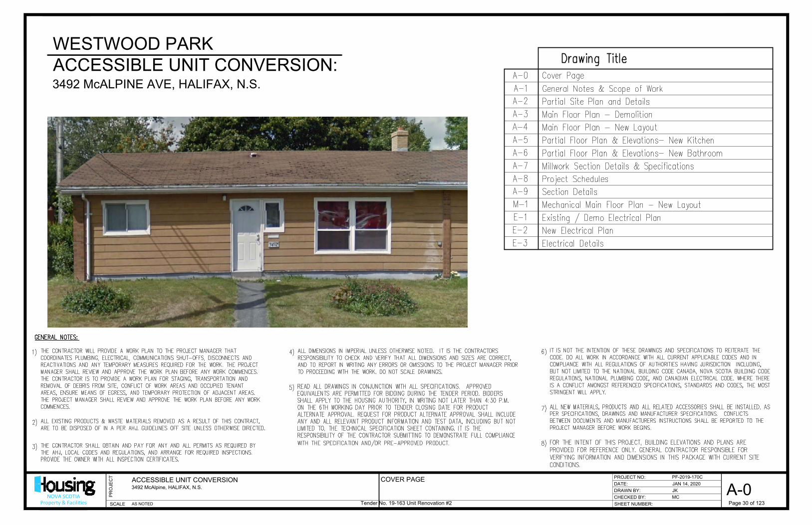
WESTWOOD PARK
ACCESSIBLE UNIT CONVERSION:
3492 McALPINE AVE, HALIFAX, N.S.
COVER PAGE
Tender No. 19-163 Unit Renovation #2 Page 30 of 123
AutoCAD SHX Text
Drawing Title
AutoCAD SHX Text
Cover Page
AutoCAD SHX Text
A-3
AutoCAD SHX Text
A-4
AutoCAD SHX Text
A-1
AutoCAD SHX Text
A-0
AutoCAD SHX Text
A-2
AutoCAD SHX Text
Main Floor Plan - New Layout
AutoCAD SHX Text
General Notes & Scope of Work
AutoCAD SHX Text
Main Floor Plan - Demolition
AutoCAD SHX Text
A-5
AutoCAD SHX Text
A-6
AutoCAD SHX Text
Partial Site Plan and Details
AutoCAD SHX Text
A-7
AutoCAD SHX Text
Millwork Section Details & Specifications
AutoCAD SHX Text
A-8
AutoCAD SHX Text
A-9
AutoCAD SHX Text
Project Schedules
AutoCAD SHX Text
Section Details
AutoCAD SHX Text
E-1
AutoCAD SHX Text
E-2
AutoCAD SHX Text
New Electrical Plan
AutoCAD SHX Text
M-1
AutoCAD SHX Text
Partial Floor Plan & Elevations- New Kitchen
AutoCAD SHX Text
THE CONTRACTOR WILL PROVIDE A WORK PLAN TO THE PROJECT MANAGER THAT COORDINATES PLUMBING, ELECTRICAL, COMMUNICATIONS SHUT-OFFS, DISCONNECTS AND REACTIVATIONS AND ANY TEMPORARY MEASURES REQUIRED FOR THE WORK. THE PROJECT MANAGER SHALL REVIEW AND APPROVE THE WORK PLAN BEFORE ANY WORK COMMENCES. THE CONTRACTOR IS TO PROVIDE A WORK PLAN FOR STAGING, TRANSPORTATION AND REMOVAL OF DEBRIS FROM SITE, CONFLICT OF WORK AREAS AND OCCUPIED TENANT AREAS, ENSURE MEANS OF EGRESS, AND TEMPORARY PROTECTION OF ADJACENT AREAS. THE PROJECT MANAGER SHALL REVIEW AND APPROVE THE WORK PLAN BEFORE ANY WORK COMMENCES.
AutoCAD SHX Text
ALL EXISTING PRODUCTS & WASTE MATERIALS REMOVED AS A RESULT OF THIS CONTRACT, ARE TO BE DISPOSED OF IN A PER AHJ. GUIDELINES OFF SITE UNLESS OTHERWISE DIRECTED.
AutoCAD SHX Text
1)
AutoCAD SHX Text
2)
AutoCAD SHX Text
THE CONTRACTOR SHALL OBTAIN AND PAY FOR ANY AND ALL PERMITS AS REQUIRED BY THE AHJ, LOCAL CODES AND REGULATIONS, AND ARRANGE FOR REQUIRED INSPECTIONS. PROVIDE THE OWNER WITH ALL INSPECTION CERTIFICATES.
AutoCAD SHX Text
3)
AutoCAD SHX Text
ALL DIMENSIONS IN IMPERIAL UNLESS OTHERWISE NOTED. IT IS THE CONTRACTORS RESPONSIBILITY TO CHECK AND VERIFY THAT ALL DIMENSIONS AND SIZES ARE CORRECT, AND TO REPORT IN WRITING ANY ERRORS OR OMISSIONS TO THE PROJECT MANAGER PRIOR TO PROCEEDING WITH THE WORK. DO NOT SCALE DRAWINGS.
AutoCAD SHX Text
4)
AutoCAD SHX Text
READ ALL DRAWINGS IN CONJUNCTION WITH ALL SPECIFICATIONS. APPROVED EQUIVALENTS ARE PERMITTED FOR BIDDING DURING THE TENDER PERIOD. BIDDERS SHALL APPLY TO THE HOUSING AUTHORITY, IN WRITING NOT LATER THAN 4:30 P.M. ON THE 6TH WORKING DAY PRIOR TO TENDER CLOSING DATE FOR PRODUCT ALTERNATE APPROVAL. REQUEST FOR PRODUCT ALTERNATE APPROVAL SHALL INCLUDE ANY AND ALL RELEVANT PRODUCT INFORMATION AND TEST DATA, INCLUDING BUT NOT LIMITED TO, THE TECHNICAL SPECIFICATION SHEET CONTAINING. IT IS THE RESPONSIBILITY OF THE CONTRACTOR SUBMITTING TO DEMONSTRATE FULL COMPLIANCE WITH THE SPECIFICATION AND/OR PRE-APPROVED PRODUCT.
AutoCAD SHX Text
5)
AutoCAD SHX Text
IT IS NOT THE INTENTION OF THESE DRAWINGS AND SPECIFICATIONS TO REITERATE THE CODE. DO ALL WORK IN ACCORDANCE WITH ALL CURRENT APPLICABLE CODES AND IN COMPLIANCE WITH ALL REGULATIONS OF AUTHORITIES HAVING JURISDICTION INCLUDING, BUT NOT LIMITED TO THE NATIONAL BUILDING CODE CANADA, NOVA SCOTIA BUILDING CODE REGULATIONS, NATIONAL PLUMBING CODE, AND CANADIAN ELECTRICAL CODE. WHERE THERE IS A CONFLICT AMONGST REFERENCED SPECIFICATIONS, STANDARDS AND CODES, THE MOST STRINGENT WILL APPLY.
AutoCAD SHX Text
6)
AutoCAD SHX Text
ALL NEW MATERIALS, PRODUCTS AND ALL RELATED ACCESSORIES SHALL BE INSTALLED, AS PER SPECIFICATIONS, DRAWINGS AND MANUFACTURER SPECIFICATIONS. CONFLICTS BETWEEN DOCUMENTS AND MANUFACTURERS INSTRUCTIONS SHALL BE REPORTED TO THE PROJECT MANAGER BEFORE WORK BEGINS.
AutoCAD SHX Text
7)
AutoCAD SHX Text
GENERAL NOTES:
AutoCAD SHX Text
FOR THE INTENT OF THIS PROJECT, BUILDING ELEVATIONS AND PLANS ARE PROVIDED FOR REFERENCE ONLY. GENERAL CONTRACTOR RESPONSIBLE FOR VERIFYING INFORMATION AND DIMENSIONS IN THIS PACKAGE WITH CURRENT SITE CONDITIONS.
AutoCAD SHX Text
8)
AutoCAD SHX Text
Partial Floor Plan & Elevations- New Bathroom
AutoCAD SHX Text
Mechanical Main Floor Plan - New Layout
AutoCAD SHX Text
Existing / Demo Electrical Plan
AutoCAD SHX Text
E-3
AutoCAD SHX Text
Electrical Details

DATE:
CHECKED BY:
SHEET NUMBER:
DRAWN BY:
PROJECT NO:
SCALE
PR
OJE
CT
NOVA SCOTIAProperty & Facilities
ACCESSIBLE UNIT CONVERSION
3492 McAlpine, HALIFAX, N.S.
PF-2019-170C
JAN 14, 2020
JK
MC
A-1
AS NOTED
-
GENERAL NOTES AND SCOPE OF WORK
Tender No. 19-163 Unit Renovation #2 Page 31 of 123
AutoCAD SHX Text
1. EXISTING STRUCTURE AND MATERIALS TO REMAIN SHALL BE INSPECTED PRIOR EXISTING STRUCTURE AND MATERIALS TO REMAIN SHALL BE INSPECTED PRIOR TO INSTALLATION OF NEW MATERIALS. CONTRACTOR SHALL REPORT AND DAMAGED OR DETERIORATING MATERIAL TO THE PROJECT MANAGER. 2. REMOVE ALL EXISTING CABINETS/ PLUMBING FIXTURES FROM KITCHEN AND REMOVE ALL EXISTING CABINETS/ PLUMBING FIXTURES FROM KITCHEN AND BATHROOM 3. REMOVE ALL EXISTING ELECTRICAL RECEPTACLES/ SWITCHES/ LIGHTS/ ETC AS REMOVE ALL EXISTING ELECTRICAL RECEPTACLES/ SWITCHES/ LIGHTS/ ETC AS REQUIRED FOR NEW CONSTRUCTION -SEE DRAWING E-1 4. ALL INTERIOR WALLS PARTITIONS / DOORS SHOWN DASHED TO BE REMOVED ALL INTERIOR WALLS PARTITIONS / DOORS SHOWN DASHED TO BE REMOVED COORDINATE WITH DRAWING A-3. 5. REMOVE AND DISPOSE ALL BASEBOARD THROUGHOUT UNIT REMOVE AND DISPOSE ALL BASEBOARD THROUGHOUT UNIT 6. EXISTING EXTERIOR WALLS, DOOR AND WINDOWS SHOWN DASHED ON PLAN EXISTING EXTERIOR WALLS, DOOR AND WINDOWS SHOWN DASHED ON PLAN SHALL BE REMOVED/RELOCATED OR DISPOSED OF AS INDICATED BY WORK NOTE. 7. INSTALL NEW EXHAUST FANS BATHROOM/RANGE HOODS, DUCTWORK AS PER INSTALL NEW EXHAUST FANS BATHROOM/RANGE HOODS, DUCTWORK AS PER MECHANICAL DRAWINGS 8. BUILD NEW INTERIOR PARTITIONS AS PER DRAWING A-4 BUILD NEW INTERIOR PARTITIONS AS PER DRAWING A-4 9. INSTALL/ ROUGH-IN IN ALL ELECTRICAL/ PLUMBING/ VENTILATION AS INSTALL/ ROUGH-IN IN ALL ELECTRICAL/ PLUMBING/ VENTILATION AS SPECIFIED. 10. MUD, PRIME AND PAINT ALL GYPSUM BOARD AS PER SPECIFICATIONS. MUD, PRIME AND PAINT ALL GYPSUM BOARD AS PER SPECIFICATIONS. 11. INSTALL ALL INTERIOR DOORS AND HARDWARE AS PER SCHEDULE INSTALL ALL INTERIOR DOORS AND HARDWARE AS PER SCHEDULE 12. INSTALL NEW FLOORING/ BASEBOARDS AND TRIM AS PER SCHEDULE INSTALL NEW FLOORING/ BASEBOARDS AND TRIM AS PER SCHEDULE 13. INSTALL NEW KITCHEN CABINETS/ BATHROOM CABINETS/ PLUMBING INSTALL NEW KITCHEN CABINETS/ BATHROOM CABINETS/ PLUMBING FIXTURES/ ELECTRICAL AND MECHANICAL FINISHES. 14. EXISTING EXTERIOR FRONT ASPHALT WALKWAY TO BE REMOVED AS PER PLAN. EXISTING EXTERIOR FRONT ASPHALT WALKWAY TO BE REMOVED AS PER PLAN. NEW CONCRETE WALKWAYS AT TWO NEW DOOR LOCATIONS. 15. CONSTRUCT TWO NEW ACCESSIBLE ENTRANCE RAMPS (FRONT AND BACK CONSTRUCT TWO NEW ACCESSIBLE ENTRANCE RAMPS (FRONT AND BACK ENTRY DOORS) COORDINATE WITH DWG A-2 16. NEW ELECTRICAL AS PER DRAWINGS AND SCOPE OF WORK NEW ELECTRICAL AS PER DRAWINGS AND SCOPE OF WORK 17. NEW MECHANICAL AS PER DRAWINGS AND SCOPE OF WORK NEW MECHANICAL AS PER DRAWINGS AND SCOPE OF WORK
AutoCAD SHX Text
GENERAL CONSTRUCTION SCOPE OF WORK:
AutoCAD SHX Text
REFERENCE STANDARDS: 1. ALL WORK IN THE PROJECT SHALL BE CONDUCTED IN COMPLIANCE WITH THE LATEST ALL WORK IN THE PROJECT SHALL BE CONDUCTED IN COMPLIANCE WITH THE LATEST VERSION OF ALL APPLICABLE CODES, STANDARDS, AND AUTHORITY HAVING JURISDICTION (AHJ) REGULATIONS, NOT LIMITED TO THE FOLLOWING: 2. NATIONAL BUILDING CODE OF CANADA (NBC); NATIONAL BUILDING CODE OF CANADA (NBC); 3. NOVA SCOTIA BUILDING CODE (NSBC); NOVA SCOTIA BUILDING CODE (NSBC); 4. CANADIAN ELECTRICAL CODE (CEC); CANADIAN ELECTRICAL CODE (CEC); 5. NATIONAL FIRE CODE OF CANADA (NFC); NATIONAL FIRE CODE OF CANADA (NFC); 6. ALL APPLICABLE BULLETINS FROM THE NOVA SCOTIA DEPARTMENT OF LABOUR AND ALL APPLICABLE BULLETINS FROM THE NOVA SCOTIA DEPARTMENT OF LABOUR AND ADVANCED EDUCATION; 7. ALL APPLICABLE STANDARDS AND BULLETINS FROM NOVA SCOTIA POWER INC.; ALL APPLICABLE STANDARDS AND BULLETINS FROM NOVA SCOTIA POWER INC.; 8. ALL APPLICABLE STANDARDS FROM UNDERWRITERS LABORATORIES CANADA (ULC); ALL APPLICABLE STANDARDS FROM UNDERWRITERS LABORATORIES CANADA (ULC); 9. ALL APPLICABLE STANDARDS FROM CANADIAN STANDARDS ASSOCIATION (CSA); ALL APPLICABLE STANDARDS FROM CANADIAN STANDARDS ASSOCIATION (CSA); PERMITS: 1. THE CONTRACTOR SHALL OBTAIN AND PAY FOR ALL PERMITS REQUIRED BY THE AHJ, THE CONTRACTOR SHALL OBTAIN AND PAY FOR ALL PERMITS REQUIRED BY THE AHJ, LOCAL CODES AND REGULATIONS, AND ARRANGE FOR REQUIRED INSPECTIONS. WARRANTY: 1. THE CONTRACTOR SHALL PROVIDE WRITTEN WARRANTY OF ALL NEW MATERIALS AND THE CONTRACTOR SHALL PROVIDE WRITTEN WARRANTY OF ALL NEW MATERIALS AND WORKMANSHIP, INCLUDING RE-LOCATED ITEMS, FOR A PERIOD OF ONE (1) YEAR FROM THE DATE OF ACCEPTANCE BY THE HNS PROJECT MANAGER. SEE DISCIPLINE SPECIFIC SCOPE FOR ANY VARIANCES. SUBMITTALS: : THE CONTRACTOR SHALL PROVIDE SUBMITTALS FOR THE HOUSING NOVA SCOTIA THE CONTRACTOR SHALL PROVIDE SUBMITTALS FOR THE HOUSING NOVA SCOTIA (HNS) PROJECT MANAGER'S APPROVAL WITHIN FOURTEEN (14) DAYS OF AWARD OF CONTRACT AND PRIOR TO INSTALLATION, INDICATING PRODUCT INFORMATION, PARTICULARLY THE FOLLOWING: 1. ENERGY RECOVERY VENTILATOR SUPPLY AND EXHAUST GRILLS AND WALL END CAPS ENERGY RECOVERY VENTILATOR SUPPLY AND EXHAUST GRILLS AND WALL END CAPS 2. FLOOR FINISHES FLOOR FINISHES 3. INTERIOR/EXTERIOR DOORS AND HARDWARE INTERIOR/EXTERIOR DOORS AND HARDWARE 4. MILLWORK, CABINETS & HARDWARE. MILLWORK, CABINETS & HARDWARE. 5. BATHROOM FIXTURES AND ACCESSORIES BATHROOM FIXTURES AND ACCESSORIES CLOSE-OUT SUBMITTALS: : 1. THE CONTRACTOR SHALL SUBMIT TO THE HNS PROJECT MANAGER, AT LEAST TWO THE CONTRACTOR SHALL SUBMIT TO THE HNS PROJECT MANAGER, AT LEAST TWO (2) (ORIGINAL + PHOTOCOPY) SETS OF CLOSE-OUT DOCUMENTATION, THAT INCLUDES THE FOLLOWING DOCUMENTS AT MINIMUM: 2. ORIGINAL COPY OF THE OCCUPANCY PERMIT ORIGINAL COPY OF THE OCCUPANCY PERMIT 3. ORIGINAL COPY OF ALL FINAL INSPECTION CERTIFICATES INCLUDING BUT NOT LIMITED ORIGINAL COPY OF ALL FINAL INSPECTION CERTIFICATES INCLUDING BUT NOT LIMITED TO ELECTRICAL, MECHANICAL, AND PASSIVE HOUSE STANDARD. 4. ORIGINAL WRITTEN STATEMENT OF WARRANTY POLICY AND WARRANTY ORIGINAL WRITTEN STATEMENT OF WARRANTY POLICY AND WARRANTY DOCUMENTATION ON ALL INSTALLED PRODUCTS, EQUIPMENT, MATERIALS, AND WORKMANSHIP. 5. OWNER'S MANUAL OF ALL INSTALLED PRODUCTS AND EQUIPMENT. OWNER'S MANUAL OF ALL INSTALLED PRODUCTS AND EQUIPMENT. 6. AS-BUILT- DRAWINGS IDENTIFYING REVISIONS TO THE DRAWINGS AS INSTALLED AND AS-BUILT- DRAWINGS IDENTIFYING REVISIONS TO THE DRAWINGS AS INSTALLED AND DRAWINGS IDENTIFYING REVISIONS TO THE DRAWINGS AS INSTALLED AND INCLUDING ALL APPROVED MODIFICATIONS TO THE CONTRACT DRAWINGS. APPROVED MODIFICATIONS TO THE CONTRACT DRAWINGS. 7. ORIGINAL CERTIFICATION OF TESTING AND COMMISSIONING OF RESIDENTIAL ORIGINAL CERTIFICATION OF TESTING AND COMMISSIONING OF RESIDENTIAL STRUCTURED WIRING SYSTEM AND COMMUNICATIONS INFRASTRUCTURE. SYSTEM AND COMMUNICATIONS INFRASTRUCTURE. 8. ORIGINAL CERTIFICATION OF TESTING AND COMMISSIONING OF RESIDENTIAL ORIGINAL CERTIFICATION OF TESTING AND COMMISSIONING OF RESIDENTIAL MECHANICAL SYSTEMS. 9. ALL CLOSE-OUT SUBMITTALS SHALL BE REVIEWED BY THE HNS PROJECT MANAGER, ALL CLOSE-OUT SUBMITTALS SHALL BE REVIEWED BY THE HNS PROJECT MANAGER, AND SHALL BE SUBJECT TO SUBSEQUENT REVISION BY THE CONTRACTOR (WHEN REQUIRED). 10. THE CONTRACTOR SHALL SUBMIT ALL DOCUMENTATION FOR ONE SET IN A BINDER THE CONTRACTOR SHALL SUBMIT ALL DOCUMENTATION FOR ONE SET IN A BINDER C/W IDENTIFICATION COLOR-CODE DISK CHART. GENERAL REQUIREMENTS: 1. THE CONTRACTOR SHALL PLAN, SCHEDULE, AND PERFORM WORK IN CO-OPERATION THE CONTRACTOR SHALL PLAN, SCHEDULE, AND PERFORM WORK IN CO-OPERATION WITH OTHER TRADES. 2. ALL DRAWINGS, SCOPE, AND SPECIFICATIONS SHALL BE READ IN CONJUNCTION WITH ALL DRAWINGS, SCOPE, AND SPECIFICATIONS SHALL BE READ IN CONJUNCTION WITH THOSE OF OTHER TRADES. 3. THE CONTRACTOR SHALL REVIEW THE CONTENT AND NOTES OF ALL DRAWINGS, THE CONTRACTOR SHALL REVIEW THE CONTENT AND NOTES OF ALL DRAWINGS, SCOPE SPECIFICATIONS AND RELATED WORK SPECIFIED ELSEWHERE FOR THE PROJECT.THE CONTRACTOR SHALL REPORT TO THE PROJECT MANAGER ANY ERRORS OR OMISSIONS BEFORE PROCEEDING. 4. ANY DISCREPANCY BETWEEN MATERIAL DESCRIPTIONS SHALL BE BROUGHT TO THE ANY DISCREPANCY BETWEEN MATERIAL DESCRIPTIONS SHALL BE BROUGHT TO THE ATTENTION OF THE HNS PROJECT MANAGER IMMEDIATELY. 5. THE CONTRACTOR SHALL OBTAIN APPROVAL FROM THE HNS PROJECT MANAGER FOR THE CONTRACTOR SHALL OBTAIN APPROVAL FROM THE HNS PROJECT MANAGER FOR ALL SUBSTITUTIONS. THE CONTRACTOR SHALL BE RESPONSIBLE FOR ALL SUBSTITUTIONS. 6. ALL PRODUCTS, EQUIPMENT, MATERIAL, AND HARDWARE SHALL BE NEW AND ALL PRODUCTS, EQUIPMENT, MATERIAL, AND HARDWARE SHALL BE NEW AND APPROVED FOR ITS INTENDED APPLICATION BY CSA, ULC, AND/OR AHJ APPROVED AGENCY. 7. THE CONTRACTOR SHALL USE PRODUCTS, EQUIPMENT, AND MATERIALS FROM SINGLE THE CONTRACTOR SHALL USE PRODUCTS, EQUIPMENT, AND MATERIALS FROM SINGLE MANUFACTURER, WHERE POSSIBLE. 8. ALL WORK SHALL BE PERFORMED BY LICENSED TRADES PERSONS AND APPRENTICES ALL WORK SHALL BE PERFORMED BY LICENSED TRADES PERSONS AND APPRENTICES REGISTERED WITH THE NOVA SCOTIA DEPARTMENT OF LABOUR AND ADVANCED EDUCATION. 9. ALL EQUIPMENT, MATERIALS, AND HARDWARE SHALL BE INSTALLED IN COMPLIANCE ALL EQUIPMENT, MATERIALS, AND HARDWARE SHALL BE INSTALLED IN COMPLIANCE WITH ALL APPLICABLE CODES, STANDARDS, AHJ REGULATIONS, AND THE MANUFACTURER'S INSTRUCTIONS. 10. THE CONTRACTOR SHALL SEAL ALL PENETRATIONS THROUGH WALLS, CEILINGS, AND THE CONTRACTOR SHALL SEAL ALL PENETRATIONS THROUGH WALLS, CEILINGS, AND FLOORS CAUSED BY INSTALLATION OF SYSTEMS FROM ANY TRADE DISCIPLINE TO RESTORE INSULATION RATINGS, AND MAKE WEATHER TIGHT IN COMPLIANCE WITH ALL APPLICABLE CODES, STANDARDS, AHJ REGULATIONS, 11. THE PROPONENT SHALL PROVIDE ASSISTANCE IN SOURCING AND ACCESSING ANY THE PROPONENT SHALL PROVIDE ASSISTANCE IN SOURCING AND ACCESSING ANY AVAILABLE FUNDING PROGRAMS TO ASSIST WITH FINANCING THIS PROJECT, INCLUDING THOSE PROGRAMS WHICH MAY BE OFFERED THROUGH EFFICIENCY NOVA SCOTIA. SUCH ASSISTANCE SHALL INCLUDE PROVIDING QUANTITIES, DATA SHEETS, AND INVOICES FOR MATERIAL AND LABOUR FOR THE CONCERNED MEASURES. 12. THE CONTRACTOR SHALL PROVIDE AT THE DISCRETION OF THE CLIENT A BREAKDOWN THE CONTRACTOR SHALL PROVIDE AT THE DISCRETION OF THE CLIENT A BREAKDOWN OR BREAKOUT OF FULL OR PARTIAL CONSTRUCTION COSTS, INCLUDE BUT NOT LIMITED TO LABOR AND MATERIAL 13. CONTRACTORS ADVISEMENT THAT THIS BUILDING WAS CONSTRUCTED WITH ACM IN CONTRACTORS ADVISEMENT THAT THIS BUILDING WAS CONSTRUCTED WITH ACM IN THE JOINT COMPOUND IN THE GYPSUM BOARD, FLOOR TILES AND PAPER SURROUNDING THE HEATING DUCTS. REFER TO THE ATTACHED "APPENDIX A" FOR A REFER TO THE ATTACHED "APPENDIX A" FOR A FOR A GUIDE TO THE REMOVAL OF FRIABLE ASBESTOS CONTAINING MATERIAL
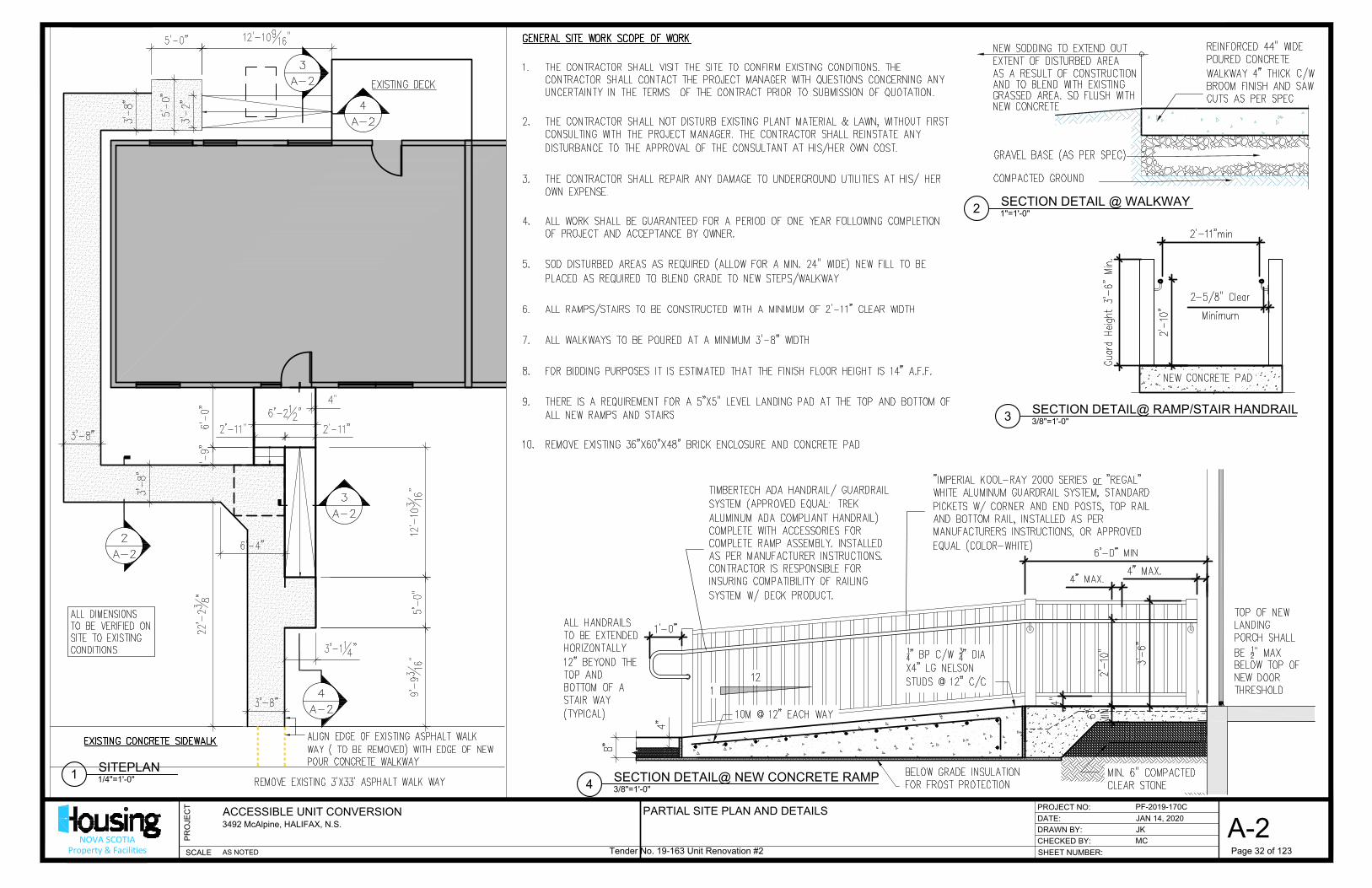
DATE:
CHECKED BY:
SHEET NUMBER:
DRAWN BY:
PROJECT NO:
SCALE
PR
OJE
CT
NOVA SCOTIAProperty & Facilities
ACCESSIBLE UNIT CONVERSION
3492 McAlpine, HALIFAX, N.S.
PF-2019-170C
JAN 14, 2020
JK
MC
A-2
AS NOTED
1/4"=1'-0"
SITEPLAN
1
1"=1'-0"
SECTION DETAIL @ WALKWAY
2
PARTIAL SITE PLAN AND DETAILS
3/8"=1'-0"
SECTION DETAIL@ NEW CONCRETE RAMP
4
3/8"=1'-0"
SECTION DETAIL@ RAMP/STAIR HANDRAIL
3
Tender No. 19-163 Unit Renovation #2 Page 32 of 123
AutoCAD SHX Text
ALIGN EDGE OF EXISTING ASPHALT WALK WAY ( TO BE REMOVED) WITH EDGE OF NEW POUR CONCRETE WALKWAY
AutoCAD SHX Text
REMOVE EXISTING 3'X33' ASPHALT WALK WAY
AutoCAD SHX Text
ALL DIMENSIONS TO BE VERIFIED ON SITE TO EXISTING CONDITIONS
AutoCAD SHX Text
GRAVEL BASE (AS PER SPEC)
AutoCAD SHX Text
COMPACTED GROUND
AutoCAD SHX Text
AS A RESULT OF CONSTRUCTION
AutoCAD SHX Text
AND TO BLEND WITH EXISTING
AutoCAD SHX Text
EXTENT OF DISTURBED AREA
AutoCAD SHX Text
NEW SODDING TO EXTEND OUT
AutoCAD SHX Text
GRASSED AREA. SO FLUSH WITH
AutoCAD SHX Text
NEW CONCRETE
AutoCAD SHX Text
REINFORCED 44" WIDE POURED CONCRETE WALKWAY 4" THICK C/W BROOM FINISH AND SAW CUTS AS PER SPEC
AutoCAD SHX Text
"IMPERIAL KOOL-RAY 2000 SERIES or "REGAL" or "REGAL" "REGAL" WHITE ALUMINUM GUARDRAIL SYSTEM, STANDARD PICKETS W/ CORNER AND END POSTS, TOP RAIL AND BOTTOM RAIL, INSTALLED AS PER MANUFACTURERS INSTRUCTIONS, OR APPROVED EQUAL (COLOR-WHITE)
AutoCAD SHX Text
MIN. 6" COMPACTED CLEAR STONE
AutoCAD SHX Text
BELOW GRADE INSULATION FOR FROST PROTECTION
AutoCAD SHX Text
10M @ 12" EACH WAY
AutoCAD SHX Text
TOP OF NEW LANDING PORCH SHALL BE " MAX 12" MAX BELOW TOP OF NEW DOOR THRESHOLD
AutoCAD SHX Text
1
AutoCAD SHX Text
12
AutoCAD SHX Text
14" BP C/W " DIA 34" DIA X4" LG NELSON STUDS @ 12" C/C
AutoCAD SHX Text
TIMBERTECH ADA HANDRAIL/ GUARDRAIL SYSTEM (APPROVED EQUAL: TREK ALUMINUM ADA COMPLIANT HANDRAIL) COMPLETE WITH ACCESSORIES FOR COMPLETE RAMP ASSEMBLY. INSTALLED AS PER MANUFACTURER INSTRUCTIONS. CONTRACTOR IS RESPONSIBLE FOR INSURING COMPATIBILITY OF RAILING SYSTEM W/ DECK PRODUCT.
AutoCAD SHX Text
ALL HANDRAILS TO BE EXTENDED HORIZONTALLY 12" BEYOND THE TOP AND BOTTOM OF A STAIR WAY (TYPICAL)
AutoCAD SHX Text
2-5/8" Clear
AutoCAD SHX Text
2-5/8" Clear
AutoCAD SHX Text
NEW CONCRETE PAD
AutoCAD SHX Text
GENERAL SITE WORK SCOPE OF WORK 1. THE CONTRACTOR SHALL VISIT THE SITE TO CONFIRM EXISTING CONDITIONS. THE THE CONTRACTOR SHALL VISIT THE SITE TO CONFIRM EXISTING CONDITIONS. THE CONTRACTOR SHALL CONTACT THE PROJECT MANAGER WITH QUESTIONS CONCERNING ANY UNCERTAINTY IN THE TERMS OF THE CONTRACT PRIOR TO SUBMISSION OF QUOTATION. 2. THE CONTRACTOR SHALL NOT DISTURB EXISTING PLANT MATERIAL & LAWN, WITHOUT FIRST THE CONTRACTOR SHALL NOT DISTURB EXISTING PLANT MATERIAL & LAWN, WITHOUT FIRST CONSULTING WITH THE PROJECT MANAGER. THE CONTRACTOR SHALL REINSTATE ANY DISTURBANCE TO THE APPROVAL OF THE CONSULTANT AT HIS/HER OWN COST. 3. THE CONTRACTOR SHALL REPAIR ANY DAMAGE TO UNDERGROUND UTILITIES AT HIS/ HER THE CONTRACTOR SHALL REPAIR ANY DAMAGE TO UNDERGROUND UTILITIES AT HIS/ HER OWN EXPENSE. 4. ALL WORK SHALL BE GUARANTEED FOR A PERIOD OF ONE YEAR FOLLOWING COMPLETION ALL WORK SHALL BE GUARANTEED FOR A PERIOD OF ONE YEAR FOLLOWING COMPLETION OF PROJECT AND ACCEPTANCE BY OWNER. 5. SOD DISTURBED AREAS AS REQUIRED (ALLOW FOR A MIN. 24" WIDE) NEW FILL TO BE SOD DISTURBED AREAS AS REQUIRED (ALLOW FOR A MIN. 24" WIDE) NEW FILL TO BE NEW FILL TO BE PLACED AS REQUIRED TO BLEND GRADE TO NEW STEPS/WALKWAY 6. ALL RAMPS/STAIRS TO BE CONSTRUCTED WITH A MINIMUM OF 2'-11" CLEAR WIDTH ALL RAMPS/STAIRS TO BE CONSTRUCTED WITH A MINIMUM OF 2'-11" CLEAR WIDTH 7. ALL WALKWAYS TO BE POURED AT A MINIMUM 3'-8" WIDTH ALL WALKWAYS TO BE POURED AT A MINIMUM 3'-8" WIDTH 8. FOR BIDDING PURPOSES IT IS ESTIMATED THAT THE FINISH FLOOR HEIGHT IS 14" A.F.F. FOR BIDDING PURPOSES IT IS ESTIMATED THAT THE FINISH FLOOR HEIGHT IS 14" A.F.F. 9. THERE IS A REQUIREMENT FOR A 5"X5" LEVEL LANDING PAD AT THE TOP AND BOTTOM OF THERE IS A REQUIREMENT FOR A 5"X5" LEVEL LANDING PAD AT THE TOP AND BOTTOM OF ALL NEW RAMPS AND STAIRS 10. REMOVE EXISTING 36"X60"X48" BRICK ENCLOSURE AND CONCRETE PADREMOVE EXISTING 36"X60"X48" BRICK ENCLOSURE AND CONCRETE PAD
AutoCAD SHX Text
EXISTING CONCRETE SIDEWALK
AutoCAD SHX Text
EXISTING DECK
AutoCAD SHX Text
4
AutoCAD SHX Text
A-2
AutoCAD SHX Text
A-2
AutoCAD SHX Text
2
AutoCAD SHX Text
A-2
AutoCAD SHX Text
3
AutoCAD SHX Text
3
AutoCAD SHX Text
A-2
AutoCAD SHX Text
4
AutoCAD SHX Text
A-2
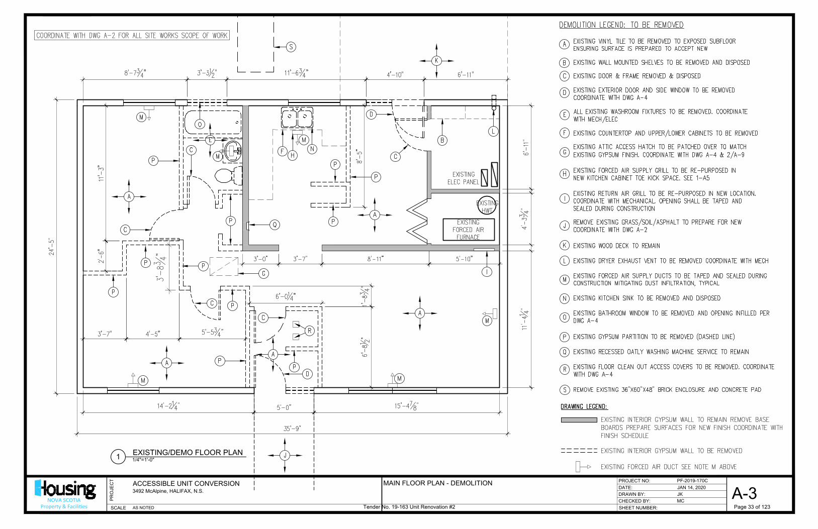
DATE:
CHECKED BY:
SHEET NUMBER:
DRAWN BY:
PROJECT NO:
SCALE
PR
OJE
CT
NOVA SCOTIAProperty & Facilities
ACCESSIBLE UNIT CONVERSION
3492 McAlpine, HALIFAX, N.S.
PF-2019-170C
JAN 14, 2020
JK
MC
A-3
AS NOTED
1/4"=1'-0"
EXISTING/DEMO FLOOR PLAN
1
MAIN FLOOR PLAN - DEMOLITION
Tender No. 19-163 Unit Renovation #2 Page 33 of 123
AutoCAD SHX Text
EXISTING FORCED AIR FURNACE
AutoCAD SHX Text
EXISTING HWT
AutoCAD SHX Text
EXISTING ELEC PANEL
AutoCAD SHX Text
B
AutoCAD SHX Text
D
AutoCAD SHX Text
C
AutoCAD SHX Text
D
AutoCAD SHX Text
C
AutoCAD SHX Text
C
AutoCAD SHX Text
C
AutoCAD SHX Text
C
AutoCAD SHX Text
F
AutoCAD SHX Text
R
AutoCAD SHX Text
E
AutoCAD SHX Text
P
AutoCAD SHX Text
G
AutoCAD SHX Text
I
AutoCAD SHX Text
N
AutoCAD SHX Text
H
AutoCAD SHX Text
A
AutoCAD SHX Text
A
AutoCAD SHX Text
A
AutoCAD SHX Text
K
AutoCAD SHX Text
P
AutoCAD SHX Text
P
AutoCAD SHX Text
P
AutoCAD SHX Text
P
AutoCAD SHX Text
P
AutoCAD SHX Text
P
AutoCAD SHX Text
P
AutoCAD SHX Text
P
AutoCAD SHX Text
Q
AutoCAD SHX Text
P
AutoCAD SHX Text
P
AutoCAD SHX Text
O
AutoCAD SHX Text
J
AutoCAD SHX Text
L
AutoCAD SHX Text
M
AutoCAD SHX Text
M
AutoCAD SHX Text
M
AutoCAD SHX Text
M
AutoCAD SHX Text
M
AutoCAD SHX Text
M
AutoCAD SHX Text
A
AutoCAD SHX Text
A
AutoCAD SHX Text
S
AutoCAD SHX Text
A
AutoCAD SHX Text
EXISTING VINYL TILE TO BE REMOVED TO EXPOSED SUBFLOOR ENSURING SURFACE IS PREPARED TO ACCEPT NEW
AutoCAD SHX Text
DEMOLITION LEGEND: TO BE REMOVED
AutoCAD SHX Text
B
AutoCAD SHX Text
C
AutoCAD SHX Text
EXISTING WALL MOUNTED SHELVES TO BE REMOVED AND DISPOSED
AutoCAD SHX Text
D
AutoCAD SHX Text
E
AutoCAD SHX Text
F
AutoCAD SHX Text
EXISTING DOOR & FRAME REMOVED & DISPOSED
AutoCAD SHX Text
EXISTING EXTERIOR DOOR AND SIDE WINDOW TO BE REMOVED COORDINATE WITH DWG A-4
AutoCAD SHX Text
G
AutoCAD SHX Text
ALL EXISTING WASHROOM FIXTURES TO BE REMOVED. COORDINATE WITH MECH/ELEC
AutoCAD SHX Text
EXISTING COUNTERTOP AND UPPER/LOWER CABINETS TO BE REMOVED
AutoCAD SHX Text
EXISTING ATTIC ACCESS HATCH TO BE PATCHED OVER TO MATCH EXISTING GYPSUM FINISH. COORDINATE WITH DWG A-4 & 2/A-9
AutoCAD SHX Text
H
AutoCAD SHX Text
REMOVE EXISTING GRASS/SOIL/ASPHALT TO PREPARE FOR NEW COORDINATE WITH DWG A-2
AutoCAD SHX Text
I
AutoCAD SHX Text
EXISTING WOOD DECK TO REMAIN EXISTING DRYER EXHAUST VENT TO BE REMOVED COORDINATE WITH MECH EXISTING FORCED AIR SUPPLY DUCTS TO BE TAPED AND SEALED DURING CONSTRUCTION MITIGATING DUST INFILTRATION, TYPICAL EXISTING KITCHEN SINK TO BE REMOVED AND DISPOSED EXISTING BATHROOM WINDOW TO BE REMOVED AND OPENING INFILLED PER DWG A-4 EXISTING GYPSUM PARTITION TO BE REMOVED (DASHED LINE) EXISTING RECESSED OATLY WASHING MACHINE SERVICE TO REMAIN EXISTING FLOOR CLEAN OUT ACCESS COVERS TO BE REMOVED. COORDINATE WITH DWG A-4 REMOVE EXISTING 36"X60"X48" BRICK ENCLOSURE AND CONCRETE PAD
AutoCAD SHX Text
J
AutoCAD SHX Text
K
AutoCAD SHX Text
L
AutoCAD SHX Text
M
AutoCAD SHX Text
N
AutoCAD SHX Text
O
AutoCAD SHX Text
EXISTING FORCED AIR SUPPLY GRILL TO BE RE-PURPOSED IN NEW KITCHEN CABINET TOE KICK SPACE. SEE 1-A5
AutoCAD SHX Text
P
AutoCAD SHX Text
Q
AutoCAD SHX Text
EXISTING RETURN AIR GRILL TO BE RE-PURPOSED IN NEW LOCATION. COORDINATE WITH MECHANICAL. OPENING SHALL BE TAPED AND SEALED DURING CONSTRUCTION
AutoCAD SHX Text
R
AutoCAD SHX Text
S
AutoCAD SHX Text
EXISTING INTERIOR GYPSUM WALL TO BE REMOVED EXISTING FORCED AIR DUCT SEE NOTE M ABOVE
AutoCAD SHX Text
EXISTING INTERIOR GYPSUM WALL TO REMAIN REMOVE BASE BOARDS PREPARE SURFACES FOR NEW FINISH COORDINATE WITH FINISH SCHEDULE
AutoCAD SHX Text
DRAWING LEGEND:
AutoCAD SHX Text
COORDINATE WITH DWG A-2 FOR ALL SITE WORKS SCOPE OF WORK

DATE:
CHECKED BY:
SHEET NUMBER:
DRAWN BY:
PROJECT NO:
SCALE
PR
OJE
CT
NOVA SCOTIAProperty & Facilities
ACCESSIBLE UNIT CONVERSION
3492 McAlpine, HALIFAX, N.S.
PF-2019-170C
JAN 14, 2020
JK
MC
A-4
AS NOTED
1/4"=1'-0"
PROPOSED FLOOR PLAN
1
A-5
4
4
A-6
MAIN FLOOR PLAN - NEW LAYOUT
Tender No. 19-163 Unit Renovation #2 Page 34 of 123
AutoCAD SHX Text
EXISTING FORCED AIR FURNACE
AutoCAD SHX Text
EXISTING HWT
AutoCAD SHX Text
EXISTING ELEC PANEL
AutoCAD SHX Text
MODELNUMBER
AutoCAD SHX Text
TRADENAME
AutoCAD SHX Text
PRODUCT
AutoCAD SHX Text
MATERIAL
AutoCAD SHX Text
102
AutoCAD SHX Text
103
AutoCAD SHX Text
104A
AutoCAD SHX Text
100
AutoCAD SHX Text
101
AutoCAD SHX Text
102A
AutoCAD SHX Text
W3
AutoCAD SHX Text
9 "78"
AutoCAD SHX Text
4"
AutoCAD SHX Text
W2
AutoCAD SHX Text
W1
AutoCAD SHX Text
W1
AutoCAD SHX Text
KITCHEN
AutoCAD SHX Text
BEDROOM 1
AutoCAD SHX Text
LIVING RM
AutoCAD SHX Text
BEDROOM 2
AutoCAD SHX Text
BATHROOM
AutoCAD SHX Text
PANTRY
AutoCAD SHX Text
A
AutoCAD SHX Text
A
AutoCAD SHX Text
A
AutoCAD SHX Text
A
AutoCAD SHX Text
W1
AutoCAD SHX Text
B
AutoCAD SHX Text
B
AutoCAD SHX Text
C
AutoCAD SHX Text
D
AutoCAD SHX Text
E
AutoCAD SHX Text
K
AutoCAD SHX Text
F
AutoCAD SHX Text
F
AutoCAD SHX Text
F
AutoCAD SHX Text
I
AutoCAD SHX Text
I
AutoCAD SHX Text
I
AutoCAD SHX Text
J
AutoCAD SHX Text
L
AutoCAD SHX Text
M
AutoCAD SHX Text
M
AutoCAD SHX Text
M
AutoCAD SHX Text
M
AutoCAD SHX Text
M
AutoCAD SHX Text
O
AutoCAD SHX Text
N
AutoCAD SHX Text
O
AutoCAD SHX Text
P
AutoCAD SHX Text
P
AutoCAD SHX Text
P
AutoCAD SHX Text
P
AutoCAD SHX Text
P
AutoCAD SHX Text
P
AutoCAD SHX Text
H
AutoCAD SHX Text
(SEE A8, TYP)
AutoCAD SHX Text
R
AutoCAD SHX Text
W4
AutoCAD SHX Text
103
AutoCAD SHX Text
104
AutoCAD SHX Text
A
AutoCAD SHX Text
NEW VINYL SHEET FLOORING (AS PER SPEC)
AutoCAD SHX Text
NEW WORK LEGEND:
AutoCAD SHX Text
B
AutoCAD SHX Text
C
AutoCAD SHX Text
SUPPLY AND INSTALL NEW EXTERIOR DOOR-SEE DWG A-8
AutoCAD SHX Text
D
AutoCAD SHX Text
E
AutoCAD SHX Text
F
AutoCAD SHX Text
SUPPLY AND INSTALL NEW 2'-0" SIDE LIGHT WINDOW SAME HEIGHT AS EXTERIOR DOOR ( SEE SPEC)
AutoCAD SHX Text
EXISTING RETURN GRILLE DUCT TO BE RELOCATED AS PER MECHANICAL S.O.W. ENCLOSE NEW DUCT WORK WITH GWB BULK HEAD
AutoCAD SHX Text
G
AutoCAD SHX Text
SUPPLY AND INSTALL NEW BATHROOM FIXTURES AND ACCESSORIES AS PER DRAWINGS AND SPECIFICATIONS COORDINATE WITH DWG A-6
AutoCAD SHX Text
SUPPLY AND INSTALL NEW KITCHEN COUNTERS/CABINETS AS PER DRAWINGS AND SPECIFICATIONS COORDINATE WITH DWG A-5
AutoCAD SHX Text
SUPPLY AND INSTALL NEW ATTIC ACCESS HATCH COORDINATE WITH DWG 2/A-9
AutoCAD SHX Text
H
AutoCAD SHX Text
NEW KITCHEN APPLIANCE (AS PER SPEC) COORDINATE WITH DWG A-5
AutoCAD SHX Text
I
AutoCAD SHX Text
NEW ACCESSIBLE RAMP/PORCH AND WALKWAY TO CITY SIDEWALK AS COORDINATE WITH DWG A-2 EXISTING WOOD DECK TO REMAIN SUPPLY AND INSTALL NEW DRYER EXHAUST SEE MECHANICAL SUPPLY AND INSTALL NEW SWITCHES/CONTROLS SEE ELECTRICAL SUPPLY AND INSTALL NEW KITCHEN SINK ( AS PER SPEC) SUPPLY AND INSTALL NEW WALL ASSEMBLY & FRAMING OVER EXISTING WINDOW OPENING TO MATCH SURROUNDING FINISHES APPLY PRIMER AND PAINT (AS PER SPEC) TO WALLS AND CEILING SURFACES RE-PURPOSED EXISTING OATLY WASHING MACHINE SERVICE TO REMAIN INSTALL NEW ACUDOR FT-8080 12"X12" NON HINGED FLOOR DOOR PANEL W/ FIELD INSTALLED GASKET, PROVIDE NEW FRAMING AS REQUIRED
AutoCAD SHX Text
J
AutoCAD SHX Text
K
AutoCAD SHX Text
L
AutoCAD SHX Text
M
AutoCAD SHX Text
N
AutoCAD SHX Text
O
AutoCAD SHX Text
EXISTING FORCED AIR SUPPLY GRILL TO BE REPURPOSED IN NEW CABINET TOE KICK SPACE
AutoCAD SHX Text
P
AutoCAD SHX Text
Q
AutoCAD SHX Text
R
AutoCAD SHX Text
NEW INTERIOR GYPSUM PARTITION WALL FINISHED AS PER DWG A-8 EXISTING RE-PURPOSED FORCED AIR DUCT SEE NOTE H ABOVE
AutoCAD SHX Text
EXISTING RE-PURPOSED INTERIOR GYPSUM WALL. FINISHES AS PER DWG A-8
AutoCAD SHX Text
DRAWING LEGEND:
AutoCAD SHX Text
COORDINATE WITH DWG A-2 FOR ALL SITE WORKS SCOPE OF WORK

”
2
A-5
1
A-5
3
A-5
DATE:
CHECKED BY:
SHEET NUMBER:
DRAWN BY:
PROJECT NO:
SCALE
PR
OJE
CT
NOVA SCOTIAProperty & Facilities
ACCESSIBLE UNIT CONVERSION
3492 McAlpine, HALIFAX, N.S.
PF-2019-170C
JAN 14, 2020
JK
MC
A-5
AS NOTED
3/8"=1'-0"
INTERIOR ELEVATION
1
3/8"=1'-0"
KITCHEN FLOOR PLAN
4
3/8"=1'-0"
INTERIOR ELEVATION
2
3/8"=1'-0"
INTERIOR ELEVATION
3
PARTIAL FLOOR PLAN & ELEVATIONS- NEW KITCHEN
Tender No. 19-163 Unit Renovation #2 Page 35 of 123
AutoCAD SHX Text
KITCHEN APPLIANCES/MISC SPECIALTIES SINK FAUCET - MOEN 'CHATEAU' SINGLE HANDLE KITCHEN MOEN 'CHATEAU' SINGLE HANDLE KITCHEN FAUCET (NO SPRAYER), MODEL# 7425 KITCHEN SINK - DOUBLE BOWL, STAINLESS STEEL, MAX BOWL DOUBLE BOWL, STAINLESS STEEL, MAX BOWL DEPTH 6” (ADA COMPLIANT), 3 FAUCET (ADA COMPLIANT), 3 FAUCET HOLES. ACCEPTABLE MODEL: KINDRED MODEL# PDS603, OR APPROVED EQUAL. REFRIGERATOR- GE 30" WIDE 20.9 CU.FT BOTTOM FREEZER (WHITE) ENERGUIDE RATING 488 KWH/YR MODEL#GEE21AGKWW COOKTOP- CALORIC 30INCH 4-BURNER INDUCTION COOKTOP IN BLACK CALORIC 30INCH 4-BURNER INDUCTION COOKTOP IN BLACK MODEL# CICT305 WALL OVEN- GE 27" ELECTRIC SMART BUILT-IN SINGLE WALL OVEN (WHITE) GE 27" ELECTRIC SMART BUILT-IN SINGLE WALL OVEN (WHITE) MODEL# JKS3000DNWW RANGEHOOD- BROAN 30" UNDER CABINET VENT HOOD (WHITE) BROAN 30" UNDER CABINET VENT HOOD (WHITE) MODEL# QP130 series
AutoCAD SHX Text
FIXED PANEL
AutoCAD SHX Text
EXISTING WINDOW
AutoCAD SHX Text
AIR EXHAUST GRILL
AutoCAD SHX Text
TOP OF COUNTER
AutoCAD SHX Text
TOP OF TOE KICK
AutoCAD SHX Text
U/S OF CABINET
AutoCAD SHX Text
TOP OF CABINET
AutoCAD SHX Text
REMOVABLE BASE CABINET
AutoCAD SHX Text
RANGE HOOD (AS PER SPEC)
AutoCAD SHX Text
COOKTOP (AS PER SPEC)
AutoCAD SHX Text
FIXED PANEL
AutoCAD SHX Text
ELEC BOX FOR RANGE HOOD SWITCH
AutoCAD SHX Text
WASHER N.I.C
AutoCAD SHX Text
WALL OVEN (AS PER SPEC)
AutoCAD SHX Text
REMOVABLE BASE CABINET
AutoCAD SHX Text
TOP OF COUNTER
AutoCAD SHX Text
TOP OF TOE KICK
AutoCAD SHX Text
U/S OF CABINET
AutoCAD SHX Text
TOP OF CABINET
AutoCAD SHX Text
REFRIGERATOR BOTTOM FREEZER (AS PER SPEC)
AutoCAD SHX Text
ELEC OUTLET SEE ELECTRICAL
AutoCAD SHX Text
FIXED PANEL
AutoCAD SHX Text
TOP OF COUNTER
AutoCAD SHX Text
TOP OF TOE KICK
AutoCAD SHX Text
U/S OF CABINET
AutoCAD SHX Text
REMOVABLE BASE CABINET
AutoCAD SHX Text
WASHER N.I.C
AutoCAD SHX Text
TOP OF CABINET
AutoCAD SHX Text
EXISTING FORCED AIR FURNACE
AutoCAD SHX Text
EXISTING HWT
AutoCAD SHX Text
EXISTING ELEC PANEL
AutoCAD SHX Text
101
AutoCAD SHX Text
NEW SINK (AS PER SPEC)
AutoCAD SHX Text
WALL OVEN (AS PER SPEC)
AutoCAD SHX Text
REFRIGERATOR BOTTOM FREEZER (AS PER SPEC)
AutoCAD SHX Text
FUTURE WASHING MACHINE
AutoCAD SHX Text
COOK TOP (AS PER SPEC)
AutoCAD SHX Text
LINE OF GWB BUILT OUT BULKHEAD ABOVE
AutoCAD SHX Text
A
AutoCAD SHX Text
A-7
AutoCAD SHX Text
A-7
AutoCAD SHX Text
B
AutoCAD SHX Text
C
AutoCAD SHX Text
A-7
AutoCAD SHX Text
D
AutoCAD SHX Text
A-7
AutoCAD SHX Text
A-7
AutoCAD SHX Text
C
AutoCAD SHX Text
F
AutoCAD SHX Text
A-7
AutoCAD SHX Text
E
AutoCAD SHX Text
A-7
AutoCAD SHX Text
KITCHEN GENERAL NOTE: ALL ITEMS SHOWN SHALL BE SUPPLIED AS PER SPECIFICATION AND INSTALLED AS PER MANUFACTURES INSTRUCTIONS AND RECOMMENDATIONS. CONTRACTOR TO SUBMIT SHOP DRAWINGS AND CUT SHEETS FOR REVIEW PRIOR TO ORDER.

2
A-5
1
A-5
3
A-5
DATE:
CHECKED BY:
SHEET NUMBER:
DRAWN BY:
PROJECT NO:
SCALE
PR
OJE
CT
NOVA SCOTIAProperty & Facilities
ACCESSIBLE UNIT CONVERSION
3492 McAlpine, HALIFAX, N.S.
PF-2019-170C
JAN 14, 2020
JK
MC
A-6
AS NOTED
3/8"=1'-0"
INTERIOR ELEVATION
1
3/8"=1'-0"
INTERIOR ELEVATION
2
3/8"=1'-0"
INTERIOR ELEVATION
3
3/8"=1'-0"
INTERIOR ELEVATION
4
PARTIAL FLOOR PLAN & ELEVATIONS- NEW BATHROOM
Tender No. 19-163 Unit Renovation #2 Page 36 of 123
AutoCAD SHX Text
kit
AutoCAD SHX Text
kohlor
AutoCAD SHX Text
####
AutoCAD SHX Text
1
AutoCAD SHX Text
5
AutoCAD SHX Text
6
AutoCAD SHX Text
7
AutoCAD SHX Text
14
AutoCAD SHX Text
12
AutoCAD SHX Text
13
AutoCAD SHX Text
16
AutoCAD SHX Text
17
AutoCAD SHX Text
MODELNUMBER
AutoCAD SHX Text
TRADENAME
AutoCAD SHX Text
PRODUCT
AutoCAD SHX Text
MATERIAL
AutoCAD SHX Text
MODELNUMBER
AutoCAD SHX Text
TRADENAME
AutoCAD SHX Text
PRODUCT
AutoCAD SHX Text
MATERIAL
AutoCAD SHX Text
1
AutoCAD SHX Text
2
AutoCAD SHX Text
3
AutoCAD SHX Text
4
AutoCAD SHX Text
5
AutoCAD SHX Text
6
AutoCAD SHX Text
7
AutoCAD SHX Text
9
AutoCAD SHX Text
10
AutoCAD SHX Text
TOP OF COUNTER
AutoCAD SHX Text
111
AutoCAD SHX Text
14
AutoCAD SHX Text
15
AutoCAD SHX Text
12
AutoCAD SHX Text
C
AutoCAD SHX Text
L
AutoCAD SHX Text
1
AutoCAD SHX Text
5
AutoCAD SHX Text
8
AutoCAD SHX Text
8
AutoCAD SHX Text
16
AutoCAD SHX Text
12
AutoCAD SHX Text
14
AutoCAD SHX Text
MODELNUMBER
AutoCAD SHX Text
TRADENAME
AutoCAD SHX Text
PRODUCT
AutoCAD SHX Text
MATERIAL
AutoCAD SHX Text
103
AutoCAD SHX Text
W3
AutoCAD SHX Text
1
AutoCAD SHX Text
16
AutoCAD SHX Text
13
AutoCAD SHX Text
14
AutoCAD SHX Text
5
AutoCAD SHX Text
2
AutoCAD SHX Text
3
AutoCAD SHX Text
111
AutoCAD SHX Text
8
AutoCAD SHX Text
8
AutoCAD SHX Text
9
AutoCAD SHX Text
10
AutoCAD SHX Text
4
AutoCAD SHX Text
15
AutoCAD SHX Text
W2
AutoCAD SHX Text
W2
AutoCAD SHX Text
W4
AutoCAD SHX Text
W2
AutoCAD SHX Text
W2
AutoCAD SHX Text
BATH/SPECIALTIES ROLL IN SHOWER STANDARD MULTI-PIECE BARRIER FREE ROLL IN SHOWER ACRYLX ELLA BY STANDARD MULTI-PIECE BARRIER FREE ROLL IN SHOWER ACRYLX ELLA BY ELLA'S BUBBLES 5 PIECE ROLL IN SHOWER MODEL#6036 B 5P .75 C WH STD CENTER DRAIN OR APPROVED EQUAL. SHOWER UNIT SHALL BE COMPLETE UNIT SHALL BE COMPLETE WITH SIMULATED TILE WITH RECESSED MOLDED SOAP LEDGES. SHOWER UNIT COMES COMPLETE WITH COLLAPSIBLE DAM AND 2" CHROME STRAINER BRASS DRAIN TOILET - KOHLER CIMARRON, COMFORT HEIGHT TWO PIECE ELONGATED 1.6 GPF KOHLER CIMARRON, COMFORT HEIGHT TWO PIECE ELONGATED 1.6 GPF COLOR WHITE MODEL# K-3589-0 BY KOHLER OR APPROVED EQUAL VANITY SINK - KOHLER PINOIR WALL MOUNT BATHROOM SINK MODEL# K-2035-1 KOHLER PINOIR WALL MOUNT BATHROOM SINK MODEL# K-2035-1 COLOR WHITE, SINGLE FAUCET HOLE. COLOR WHITE, SINGLE FAUCET HOLE. VANITY FAUCET - MOEN CHATEAU SINGLE HANDLE LAVATORY FAUCET, MODEL# L4621 MOEN CHATEAU SINGLE HANDLE LAVATORY FAUCET, MODEL# L4621 HAND HELD SHOWER KOHLER AWAKEN SERIES OR APPROVED EQUAL KOHLER AWAKEN SERIES OR APPROVED EQUAL 24"SLIDE BAR MODEL# K-983421-GCP 72" RIBBON HOSE MODEL#K-45981-CP HAND HELD SHOWER HEAD MODEL#72421-GCP PRESSURE-BALANCING KOHLER RITE TEMP MODEL# K-8304-KS-NS OR APPROVED EQUAL VALVE VALVE BODY, CARTRIDGE KIT WITH SERVICE STOPS VALVE BODY, CARTRIDGE KIT WITH SERVICE STOPS SHOWER VALVE TRIM KOHLER RITE TEMP SHOWER VALVE TRIM MODEL#K-TS74042-4-CP KOHLER RITE TEMP SHOWER VALVE TRIM MODEL#K-TS74042-4-CP OR APPROVED EQUAL TOWEL BAR - 24", MOEN 'ASPEN' #5824CH, CHROME FINISH OR APPROVED EQUAL . TOWEL RING - MOEN 'ASPEN' #5886 CH, CHROME FINISH OR APPROVED EQUAL MIRROR - BOBRICK RECESSED CABINET, MODEL # B-397 OR APPROVED EQUAL MOUNTED AT 39-1/4" A.F.F 24" GRAB BARS - BOBRICK STRAIGHT GRAB BAR MODEL# B-5806 X24 SATIN FINISH WITH BOBRICK STRAIGHT GRAB BAR MODEL# B-5806 X24 SATIN FINISH WITH PEENED GRIP SURFACE OR APPROVED EQUAL 36" GRAB BARS - BOBRICK STRAIGHT GRAB BAR MODEL# B-5806 X36 SATIN FINISH WITH BOBRICK STRAIGHT GRAB BAR MODEL# B-5806 X36 SATIN FINISH WITH PEENED GRIP SURFACE OR APPROVED EQUAL 48" GRAB BAR - BOBRICK STRAIGHT GRAB BAR MODEL# B-5806 X48 SATIN FINISH WITH BOBRICK STRAIGHT GRAB BAR MODEL# B-5806 X48 SATIN FINISH WITH PEENED GRIP SURFACE OR APPROVED EQUAL 42" GRAB BAR - BOBRICK STRAIGHT GRAB BAR MODEL# B-6806.99 X42 BOBRICK STRAIGHT GRAB BAR MODEL# B-6806.99 X42 SATIN FINISH WITH PEENED GRIP SURFACE OR APPROVED EQUAL 30" FLIP UP GRAB BAR- MOEN FLIP UP GRAB BAR MODEL#R8962FD STAINLESS STEEL PEENED MOEN FLIP UP GRAB BAR MODEL#R8962FD STAINLESS STEEL PEENED FINISH WITH TOILET PAPER HOLDER INCLUDED OR APPROVED EQUAL FOLDING SHOWER SEAT BOBRICK FOLDING SHOWER SEAT MODEL# B-5191 OR APPROVED EQUAL BOBRICK FOLDING SHOWER SEAT MODEL# B-5191 OR APPROVED EQUAL COMPLETE WITH MANUFACTURES RECOMMENDED FASTENERS AND BLOCKING. COMPLETE WITH MANUFACTURES RECOMMENDED FASTENERS AND BLOCKING. RECESSED SHOWER ELLA'S BUBBLES ACRYLIC RECESSED SOAP DISH 6-3/4" X 6-1/4" X 3" ELLA'S BUBBLES ACRYLIC RECESSED SOAP DISH 6-3/4" X 6-1/4" X 3" SOAP DISH (OR APPROVED EQUAL) (OR APPROVED EQUAL)
AutoCAD SHX Text
111
AutoCAD SHX Text
122
AutoCAD SHX Text
133
AutoCAD SHX Text
14
AutoCAD SHX Text
155
AutoCAD SHX Text
166
AutoCAD SHX Text
177
AutoCAD SHX Text
G
AutoCAD SHX Text
A-7

DATE:
CHECKED BY:
SHEET NUMBER:
DRAWN BY:
PROJECT NO:
SCALE
PR
OJE
CT
NOVA SCOTIAProperty & Facilities
ACCESSIBLE UNIT CONVERSION
3492 McAlpine, HALIFAX, N.S.
PF-2019-170C
JAN 14, 2020
JK
MC
A-7
AS NOTED
3/8"=1'-0"
SECTION DETAIL AT CABINETS
1
A B C D E F G
MILLWORK SECTION DETAILS & SPECIFICATIONS
Tender No. 19-163 Unit Renovation #2 Page 37 of 123
AutoCAD SHX Text
GYPSUM BOARD BULKHEAD CABINET UPPER CABINETS (AS PER SPEC) ADJUSTABLE SHELF (AS PER SPEC) PLASTIC LAMINATE TOP (AS PER SPEC) CABINET LOWER CABINETS (AS PER SPEC) BACK SPLASH (AS PER SPEC) NEW SINK AND FAUCET SEE DWG A-5 (AS PER SPEC) FIXED DRAWER FRONT (AS PER SPEC) GFI ELECTRICAL OUTLET (AS PER ELEVATIONS AND ELECTRICAL) ) REMOVABLE BASE CABINET PLASTIC LAMINATE APRON NEW BATHROOM VANITY SINK SEE DWG A-6 ENSURE ADEQUATE SUPPORT FOR WALL MOUNTED COUNTER. NO GABLES WILL BE ACCEPTED
AutoCAD SHX Text
A
AutoCAD SHX Text
B
AutoCAD SHX Text
C
AutoCAD SHX Text
D
AutoCAD SHX Text
E
AutoCAD SHX Text
F
AutoCAD SHX Text
G
AutoCAD SHX Text
H
AutoCAD SHX Text
I
AutoCAD SHX Text
J
AutoCAD SHX Text
K
AutoCAD SHX Text
WASHER N.I.C
AutoCAD SHX Text
WALL OVEN (AS PER SPEC)
AutoCAD SHX Text
COOKTOP (AS PER SPEC)
AutoCAD SHX Text
NOTE: * CABINET LAYOUTS FOR KITCHEN/BATHROOM SHALL BE VERIFIED WITH FIELD MEASUREMENTS. GENERAL CONTRACTOR SHALL SUBMIT SHOP DRAWINGS OF MILLWORK FOR THE APPROVAL OF PM PRIOR TO FABRICATION * GENERAL (CABINETS): 1. MILLWORK TO THE QUALITY STANDARDS OF THE ARCHITECTURAL WOODWORK MANUFACTURES ASSOCIATION OF CANADA, AWMAC, CUSTOM GRADE. 2. MATERIALS, WORKMANSHIP AND PERFORMANCE STANDARDS TO CAN/CSA A278 KITCHEN CABINETS AND BATHROOM VANITIES. 3. COUNTERTOPS: PLASTIC LAMINATE, COMPLY WITH CAN3 A172 APPENDIX A. 4. HARDWARE: TO CAN/CGSB 69.25 AND AS SPECIFIED HEREIN. 5. MEDIUM DENSITY FIBREBOARD (MDF): TO ANSI 208.1-1999 & ANSI 208.2-2002. 6. BIRCH PLYWOOD: 3/4" TO ANSI 208.2-2002. PRODUCTS: 1. EUROPEAN DESIGN, FACTORY FABRICATED UNITS CONSISTING OF THERMOPLASTIC COATED MDF TYPE MATERIAL FOR DOORS & DRAWER FRONTS. PLASTIC LAMINATE FINISH FOR GABLES. ALL CABINETS ARE TO HAVE A PLASTIC LAMINATE FINISH. DOORS & DRAWER FRONTS SHALL BE PREMOULE THERMO, MODEL 764, COLOR C92W. PREMOULE THERMO, MODEL 764, COLOR C92W. 2. SHELVES OF SAME MATERIAL AS GABLES, TO BE PIN-SUPPORTED, ADJUSTABLE IN HEIGHT, TWO IN WALL CABINET, ONE IN BASED CABINET. 3. IN CORNERS, BASE CABINETS SHALL HAVE FULL SHELVING, ACCESSIBLE FROM PIANO HINGED CORNER DOOR. 4. DRAWER UNITS TO BE FRAMED WITH HARDWOOD OR MELAMINE, FINISHED ON ALL SIDES AND SUSPENDED ON BALL ROLLER BEARING FULL EXTENSION RUNNER TO HETTICH - QUADRO V6 (OR EQUAL). 5. COUNTERTOPS: 5/8" THICK PARTICLE BOARD FACED WITH 0.050" POST FORMING GRADE LAMINATE TO CSA A172. KITCHEN COUNTERTOP IS TO BE 25" DEEP, & VANITY TOPS TO BE 22" DEEP, OR TO MANUFACTURE'S STANDARD. 6. HINGES: BLUM BLUMOTION QUIET CLOSE (OR EQUAL), 170 DEG. OPENING, METAL SCREW ATTACHED. 7. DOOR & DRAWER PULLS: RICHILIEU #425145 OR ONWARD #1083NVB (OR APPROVED EQUAL), 3" CENTERS, BRUSHED NICKEL FINISH. EXECUTION: 1. INSTALL CABINETS AS SHOWN ON DRAWINGS AND SHOP DRAWINGS. 2. SET AND SECURE WORK IN PLACE, LEVEL, PLUMB AND STRAIGHT. 3. PROVIDE HEAVY-DUTY FASTENINGS SECURELY ANCHORED IN FLOOR AND WALLS. 4. SCRIBE AND CUT AS REQUIRED TO FIT PROPERLY INTO RECESSES AND TO ACCOMMODATE PIPING, COLUMNS, FIXTURES AND OUTLETS.
AutoCAD SHX Text
GENERAL NOTES:
AutoCAD SHX Text
L
AutoCAD SHX Text
A
AutoCAD SHX Text
A
AutoCAD SHX Text
A
AutoCAD SHX Text
A
AutoCAD SHX Text
A
AutoCAD SHX Text
A
AutoCAD SHX Text
B
AutoCAD SHX Text
B
AutoCAD SHX Text
B
AutoCAD SHX Text
B
AutoCAD SHX Text
B
AutoCAD SHX Text
C
AutoCAD SHX Text
C
AutoCAD SHX Text
C
AutoCAD SHX Text
C
AutoCAD SHX Text
C
AutoCAD SHX Text
D
AutoCAD SHX Text
D
AutoCAD SHX Text
D
AutoCAD SHX Text
D
AutoCAD SHX Text
E
AutoCAD SHX Text
F
AutoCAD SHX Text
F
AutoCAD SHX Text
F
AutoCAD SHX Text
F
AutoCAD SHX Text
G
AutoCAD SHX Text
H
AutoCAD SHX Text
H
AutoCAD SHX Text
H
AutoCAD SHX Text
I
AutoCAD SHX Text
C
AutoCAD SHX Text
J
AutoCAD SHX Text
J
AutoCAD SHX Text
J
AutoCAD SHX Text
K
AutoCAD SHX Text
L
AutoCAD SHX Text
M
AutoCAD SHX Text
M
AutoCAD SHX Text
RANGEHOOD (AS PER SPEC)

” ”” ”
·
·
·
·
·
·
·
·
·
·
·
·
·
·
·
·
··
DATE:
CHECKED BY:
SHEET NUMBER:
DRAWN BY:
PROJECT NO:
SCALE
PR
OJE
CT
NOVA SCOTIAProperty & Facilities
ACCESSIBLE UNIT CONVERSION
3492 McAlpine, HALIFAX, N.S.
PF-2019-170C
JAN 14, 2020
JK
MC
A-8
AS NOTED
PROJECT SCHEDULES
Tender No. 19-163 Unit Renovation #2 Page 38 of 123
AutoCAD SHX Text
DOOR SCHEDULE
AutoCAD SHX Text
DOOR#
AutoCAD SHX Text
Type
AutoCAD SHX Text
DOOR
AutoCAD SHX Text
LOCATION
AutoCAD SHX Text
Width
AutoCAD SHX Text
Hgt
AutoCAD SHX Text
Thk
AutoCAD SHX Text
36 " 80" 1 "34"
AutoCAD SHX Text
36 " 80" 1 "34"
AutoCAD SHX Text
36 " 80" 1 "34"
AutoCAD SHX Text
Swing
AutoCAD SHX Text
LH
AutoCAD SHX Text
EXTERIOR
AutoCAD SHX Text
EXTERIOR
AutoCAD SHX Text
BEDROOM
AutoCAD SHX Text
BEDROOM CLOSET
AutoCAD SHX Text
100
AutoCAD SHX Text
101
AutoCAD SHX Text
102
AutoCAD SHX Text
102A
AutoCAD SHX Text
104
AutoCAD SHX Text
104A
AutoCAD SHX Text
BEDROOM
AutoCAD SHX Text
36 " 80" 1 "34"
AutoCAD SHX Text
32 " 80" 1 34"
AutoCAD SHX Text
BEDROOM CLOSET
AutoCAD SHX Text
LH
AutoCAD SHX Text
RH
AutoCAD SHX Text
FLOOR LEVEL
AutoCAD SHX Text
EAST
AutoCAD SHX Text
WALLS
AutoCAD SHX Text
WEST
AutoCAD SHX Text
FLOOR
AutoCAD SHX Text
LOCATION
AutoCAD SHX Text
VS
AutoCAD SHX Text
NORTH
AutoCAD SHX Text
SOUTH
AutoCAD SHX Text
BASE BOARD
AutoCAD SHX Text
LIVING RM
AutoCAD SHX Text
KITCHEN
AutoCAD SHX Text
PANTRY
AutoCAD SHX Text
BATHROOM
AutoCAD SHX Text
NOTES
AutoCAD SHX Text
BEDROOM 1
AutoCAD SHX Text
BEDROOM 2
AutoCAD SHX Text
ACCESSIBLE UNIT
AutoCAD SHX Text
LEGEND GB = PAINTED GYPSUM BOARD (AS PER SPEC) VB = VINYL BASE COVE (AS PER SPEC)
AutoCAD SHX Text
CEILING
AutoCAD SHX Text
VS
AutoCAD SHX Text
GB
AutoCAD SHX Text
GB
AutoCAD SHX Text
GB
AutoCAD SHX Text
GB
AutoCAD SHX Text
GB
AutoCAD SHX Text
GB
AutoCAD SHX Text
GB
AutoCAD SHX Text
GB
AutoCAD SHX Text
GB
AutoCAD SHX Text
GB
AutoCAD SHX Text
GB
AutoCAD SHX Text
GB
AutoCAD SHX Text
GB
AutoCAD SHX Text
GB
AutoCAD SHX Text
GB
AutoCAD SHX Text
GB
AutoCAD SHX Text
GB
AutoCAD SHX Text
GB
AutoCAD SHX Text
GB
AutoCAD SHX Text
GB
AutoCAD SHX Text
GB
AutoCAD SHX Text
GB
AutoCAD SHX Text
GB
AutoCAD SHX Text
GB
AutoCAD SHX Text
WB
AutoCAD SHX Text
1
AutoCAD SHX Text
CEILING HEIGHT
AutoCAD SHX Text
1
AutoCAD SHX Text
1
AutoCAD SHX Text
1
AutoCAD SHX Text
1
AutoCAD SHX Text
1
AutoCAD SHX Text
8'-0"
AutoCAD SHX Text
8'-0"
AutoCAD SHX Text
8'-0"
AutoCAD SHX Text
8'-0"
AutoCAD SHX Text
8'-0"
AutoCAD SHX Text
P
AutoCAD SHX Text
VB
AutoCAD SHX Text
VB
AutoCAD SHX Text
VB
AutoCAD SHX Text
--
AutoCAD SHX Text
--
AutoCAD SHX Text
--
AutoCAD SHX Text
--
AutoCAD SHX Text
NOTES: GENERAL CONTRACTOR IS RESPONSIBLE FOR THE SUPPLY AND INSTALL OF 1 CONTINUOUS " MDF SHELF FOR 34" MDF SHELF FOR EACH CLOSET COMPLETE WITH CONTINUOUS LEDGERS AND SUPPORT BRACKETS. HEIGHT OF SHELF NOT TO EXCEED 54"A.F.F. 1 CONTINUOUS CLOSET BAR FOR EACH CLOSET IN THE SCOPE OF WORK SHALL BE MOUNTED NO HIGHER THAN 3'-11"
AutoCAD SHX Text
WD = WOOD BASE (CLEAR PINE) VS= VINYL SHEET (AS PER SPEC) P = PAINT (AS PER SPEC)
AutoCAD SHX Text
BATHROOM
AutoCAD SHX Text
103
AutoCAD SHX Text
36 " 80" 1 "34"
AutoCAD SHX Text
CLOSET SPACE TO BE FINISHED SAME AS ROOM
AutoCAD SHX Text
RH
AutoCAD SHX Text
RH
AutoCAD SHX Text
RH
AutoCAD SHX Text
VS
AutoCAD SHX Text
EXISTING
AutoCAD SHX Text
VS
AutoCAD SHX Text
VS
AutoCAD SHX Text
WB
AutoCAD SHX Text
WB
AutoCAD SHX Text
8'-0"
AutoCAD SHX Text
CLOSET SPACE TO BE FINISHED SAME AS ROOM
AutoCAD SHX Text
(2)24" (2)80" (2)1 34"
AutoCAD SHX Text
RH/LH
AutoCAD SHX Text
D1
AutoCAD SHX Text
D1
AutoCAD SHX Text
D2
AutoCAD SHX Text
(2)D3
AutoCAD SHX Text
D2
AutoCAD SHX Text
D2
AutoCAD SHX Text
D3
AutoCAD SHX Text
Hardware
AutoCAD SHX Text
H1, H2, H3,
AutoCAD SHX Text
H4, H8
AutoCAD SHX Text
DOOR TYPE: (OR APPROVED EQUALS) D1 - EXTERIOR STEEL INSULATED DOOR (SEE SPECIFICATION). D2 -SOLID CORE, MASONITE, MOLDED PANEL, 'SAFE 'N SOUND', 2 PANEL SMOOTH, 1 3/8” THICK, 80” HIGH THICK, 80” HIGH HIGH D3 -HOLLOW CORE, MASONITE, MOULDED PANEL, 2 PANEL SMOOTH, 1 3/8” THICK, 80” HIGH THICK, 80” HIGH HIGH LOCKSETS: (OR APPROVED EQUALS) L1 - SCHLAGE, SATURN SERIES LEVER, GRADE 2, KEYED CORE, SATIN CHROME FINISH (626) L2 - SCHLAGE, ELAN SERIES, GRADE 2, DUMMY SET, SATIN CHROME FINISH (626) SCHLAGE, ELAN SERIES, GRADE 2, DUMMY SET, SATIN CHROME FINISH (626) L3 - SCHLAGE SINGLE CYLINDER DEADBOLT, COMMERCIAL, SATIN CHROME HARDWARE: (OR APPROVED EQUALS) H1 - 3" FULL MORTISE BUTT HINGE, 3/4" SCREWS, 3 HINGES PER DOOR (ONWARD1820BCB OR 3" FULL MORTISE BUTT HINGE, 3/4" SCREWS, 3 HINGES PER DOOR (ONWARD1820BCB OR APPROVED EQUAL) H2 - DOOR VIEWER, RICHLIEU, #105ULCIP, CHROME DOOR VIEWER, RICHLIEU, #105ULCIP, CHROME H3 - RIGID DOOR STOP, RICHELIEU, #2163SCV, SATIN CHROME RIGID DOOR STOP, RICHELIEU, #2163SCV, SATIN CHROME H4 - HINGE PIN DOOR STOP, RICHELIEU, #2215BCR, BRUSHED CHROME HINGE PIN DOOR STOP, RICHELIEU, #2215BCR, BRUSHED CHROME H5 - ADJUSTABLE BALL CATCH, RICHELIEU, #5037BCV, BRUSHED CHROME ADJUSTABLE BALL CATCH, RICHELIEU, #5037BCV, BRUSHED CHROME H6 - POCKET DOOR FRAME SYSTEM, RICHELIEU #149150BC1, C/W POCKET DOOR STOP #1476XIP POCKET DOOR FRAME SYSTEM, RICHELIEU #149150BC1, C/W POCKET DOOR STOP #1476XIP POCKET DOOR STOP #1476XIP H7 - DOOR HANDLES, ASSA ABLOY ROCKWOOD RM 3010 NEOMATRIX 12" DOOR HANDLES, ASSA ABLOY ROCKWOOD RM 3010 NEOMATRIX 12" H8 - FROST KING E/O 2"X36" SILVER REINFORCED RUBBER DOOR SWEEPFROST KING E/O 2"X36" SILVER REINFORCED RUBBER DOOR SWEEP
AutoCAD SHX Text
H1, H3, H4, H8
AutoCAD SHX Text
H6, H7
AutoCAD SHX Text
H6, H7
AutoCAD SHX Text
H6, H7
AutoCAD SHX Text
H1,
AutoCAD SHX Text
L1, L3
AutoCAD SHX Text
Lockset
AutoCAD SHX Text
L1, L3
AutoCAD SHX Text
L2
AutoCAD SHX Text
L2
AutoCAD SHX Text
H1,
AutoCAD SHX Text
POCKET DOOR
AutoCAD SHX Text
POCKET DOOR
AutoCAD SHX Text
POCKET DOOR
AutoCAD SHX Text
Comments
AutoCAD SHX Text
REQUIRES BARRIER FREE SILL
AutoCAD SHX Text
REQUIRES BARRIER FREE SILL
AutoCAD SHX Text
WALL PARTITION SCHEDULE
AutoCAD SHX Text
TYPE
AutoCAD SHX Text
WALL ASSEMBLIES
AutoCAD SHX Text
TYPICAL BATHROOM WALL (WOOD): 1/2" PROROC MOISTURE RESISTANT GYPSUM BOARD (BATHROOM SIDE) 34" PLYWOOD 2"X2" WOOD BLOCKING FASTENED TO WALL FRAMING 2"x6" WOOD STUDS @16"o/c 1/2" GYPSUM BOARD
AutoCAD SHX Text
TYPICAL PARTITION WALL: 1/2" GYPSUM BOARD 2 x 4 WOOD STUDS @16"o/c 1/2" GYPSUM BOARD
AutoCAD SHX Text
W1
AutoCAD SHX Text
W2
AutoCAD SHX Text
FINISH SCHEDULE
AutoCAD SHX Text
DOUBLE DOOR
AutoCAD SHX Text
P
AutoCAD SHX Text
P
AutoCAD SHX Text
P
AutoCAD SHX Text
P
AutoCAD SHX Text
P
AutoCAD SHX Text
REQUIRES 2'-8" CLEAR OPENING
AutoCAD SHX Text
REQUIRES 2'-8" CLEAR OPENING
AutoCAD SHX Text
REQUIRES 2'-8" CLEAR OPENING
AutoCAD SHX Text
DOOR TYPE D3
AutoCAD SHX Text
DOOR TYPE D2
AutoCAD SHX Text
DOOR TYPE D1
AutoCAD SHX Text
SERVICE PARTITION WALL: ( BATHROOM, KITCHEN SHARED WALL) 1/2" PROROC MOISTURE RESISTANT GYPSUM BOARD (BATHROOM SIDE) 34" PLYWOOD 1/2" GYPSUM BOARD (EXISTING) 2 x 4 WOOD STUDS @16"o/c (EXISTING) 1/2" GYPSUM BOARD (EXISTING)
AutoCAD SHX Text
W4
AutoCAD SHX Text
PLUMBING WALL (SHOWER AREA): 1/2" PROROC MOISTURE RESISTANT GYPSUM BOARD (SHOWER SIDE) 34" PLYWOOD 2"X2" WOOD BLOCKING FASTENED TO WALL FRAMING 2"x6" WOOD STUDS @ 16"o/c EXISTING EXTERIOR WALL
AutoCAD SHX Text
W3
AutoCAD SHX Text
TYPE
AutoCAD SHX Text
WALL ASSEMBLIES
AutoCAD SHX Text
EXISTING INTERIOR WALL
AutoCAD SHX Text
EXISTING EXTERIOR WALL

DATE:
CHECKED BY:
SHEET NUMBER:
DRAWN BY:
PROJECT NO:
SCALE
PR
OJE
CT
NOVA SCOTIAProperty & Facilities
ACCESSIBLE UNIT CONVERSION
3492 McAlpine, HALIFAX, N.S.
PF-2019-170C
JAN 14, 2020
JK
MC
A-9
AS NOTED
1"=1'-0"
SECTION DETAIL @ CABINET BULKHEAD
1
1-1/2"=1'-0"
SECTION DETAIL @ ATTIC HATCH
2
1-1/2"=1'-0"
SECTION DETAIL @ DUCT BULKHEAD
3
SECTION DETAILS
Tender No. 19-163 Unit Renovation #2 Page 39 of 123
AutoCAD SHX Text
CEILING HEIGHT @ 8'-0 A.F.F
AutoCAD SHX Text
NEW 5/8" THICK GWB AND WOOD FRAME BULKHEAD. TAPE/ MUD AND PRIME AND PAINT FINISH
AutoCAD SHX Text
NEW UPPER CABINETS TO BE FASTENED TO WALL AND BULKHEAD
AutoCAD SHX Text
PROVIDE CORNER BEAD
AutoCAD SHX Text
KITCHEN WALL SURFACE TO BE PAINTED AS PER SCHEDULE
AutoCAD SHX Text
22" X 36" ATTIC ACCESS HATCH: RIGID INSULATION (R 40) ON 3/8" PLYWOOD 6 MIL. POLYETHYLENE VAPOUR BARRIER 5/8" FIRECODE GYPSUM BOARD c/w METAL DRYWALL STOP-ON EXPOSED RAW EDGES.
AutoCAD SHX Text
WEATHERSTRIPPING AROUND PERIMETER OF HATCH
AutoCAD SHX Text
FLAT STOCK PINE. CORNERS OF FRAME TO BE MITERED & WELDED. c/w PAINTED FINISH.
AutoCAD SHX Text
PLYWOOD FILLED AROUND OPENING
AutoCAD SHX Text
CEILING HEIGHT @ 8'-0 A.F.F
AutoCAD SHX Text
2"X2" WOOD FRAMED (1) LAYER 5/8" GYPSUM BULKHEAD
AutoCAD SHX Text
NEW RETURN AIR DUCT CONCEALED WITHIN NEW GWB BULKHEAD COORDINATE WITH MECHANICAL
AutoCAD SHX Text
WIDTH
AutoCAD SHX Text
MINIMUM
AutoCAD SHX Text
CEILING HEIGHT @ 8'-0 A.F.F
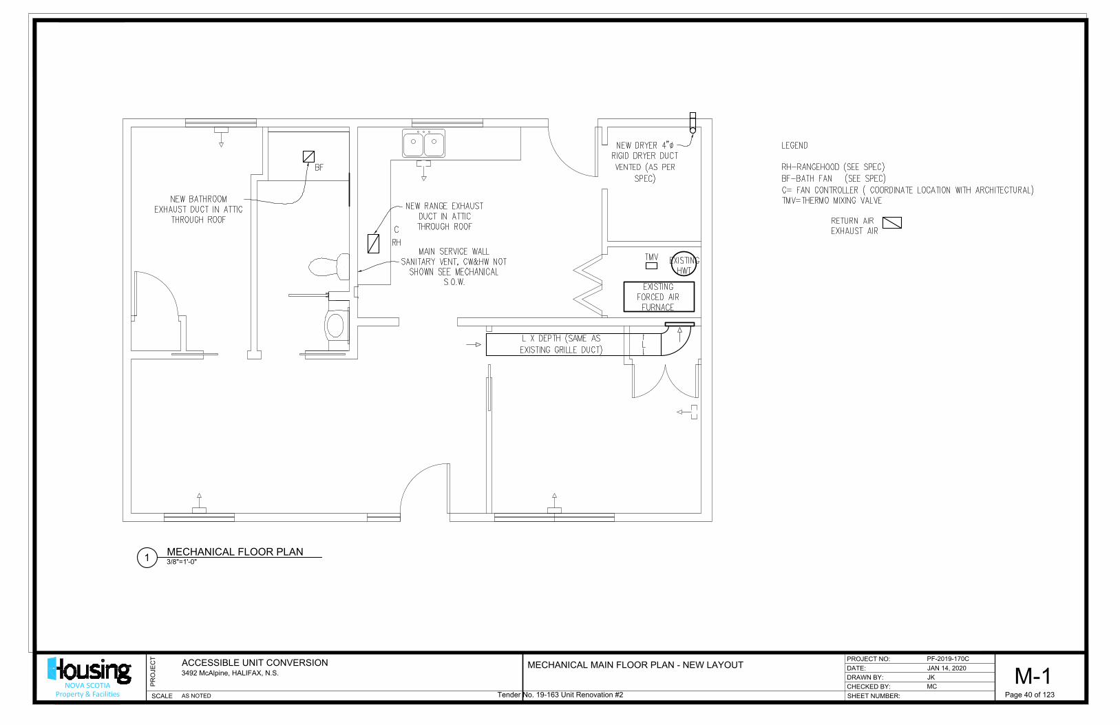
DATE:
CHECKED BY:
SHEET NUMBER:
DRAWN BY:
PROJECT NO:
SCALE
PR
OJE
CT
NOVA SCOTIAProperty & Facilities
ACCESSIBLE UNIT CONVERSION
3492 McAlpine, HALIFAX, N.S.
PF-2019-170C
JAN 14, 2020
JK
MC
M-1
AS NOTED
3/8"=1'-0"
MECHANICAL FLOOR PLAN
1
MECHANICAL MAIN FLOOR PLAN - NEW LAYOUT
Tender No. 19-163 Unit Renovation #2 Page 40 of 123
AutoCAD SHX Text
EXISTING FORCED AIR FURNACE
AutoCAD SHX Text
EXISTING HWT
AutoCAD SHX Text
MODELNUMBER
AutoCAD SHX Text
TRADENAME
AutoCAD SHX Text
PRODUCT
AutoCAD SHX Text
MATERIAL
AutoCAD SHX Text
L X DEPTH (SAME AS EXISTING GRILLE DUCT)
AutoCAD SHX Text
NEW DRYER 4" RIGID DRYER DUCT VENTED (AS PER SPEC)
AutoCAD SHX Text
MAIN SERVICE WALL SANITARY VENT, CW&HW NOT SHOWN SEE MECHANICAL S.O.W.
AutoCAD SHX Text
NEW RANGE EXHAUST DUCT IN ATTIC THROUGH ROOF
AutoCAD SHX Text
NEW BATHROOM EXHAUST DUCT IN ATTIC THROUGH ROOF
AutoCAD SHX Text
LEGEND RH-RANGEHOOD (SEE SPEC) BF-BATH FAN (SEE SPEC) C= FAN CONTROLLER ( COORDINATE LOCATION WITH ARCHITECTURAL) TMV=THERMO MIXING VALVE RETURN AIR EXHAUST AIR
AutoCAD SHX Text
TMV
AutoCAD SHX Text
L
AutoCAD SHX Text
RH
AutoCAD SHX Text
BF
AutoCAD SHX Text
C

DATE:
CHECKED BY:
SHEET NUMBER:
DRAWN BY:
PROJECT NO:
SCALE
PR
OJE
CT
NOVA SCOTIAProperty & Facilities
ACCESSIBLE UNIT CONVERSION
3492 McAlpine, HALIFAX, N.S.
PF-2019-170C
Dec. 30, 2019
TK
MC
E-1
AS NOTED3 OF 11
1/4"=1'-0"
EXISTING/DEMO FLOOR PLAN
1
30/DEC/2019 ISSUED FOR REVIEW
EXISTING / DEMO ELECTRICAL PLAN
03/JAN/2020 ISSUED FOR TENDER
Tender No. 19-163 Unit Renovation #2 Page 41 of 123
AutoCAD SHX Text
T
AutoCAD SHX Text
S
AutoCAD SHX Text
S
AutoCAD SHX Text
R
AutoCAD SHX Text
D
AutoCAD SHX Text
GFI
AutoCAD SHX Text
S
AutoCAD SHX Text
S
AutoCAD SHX Text
S
AutoCAD SHX Text
S
AutoCAD SHX Text
ALUMINUM MAIL SLOT
AutoCAD SHX Text
SA
AutoCAD SHX Text
E1
AutoCAD SHX Text
E1
AutoCAD SHX Text
WPC
AutoCAD SHX Text
M
AutoCAD SHX Text
EXISTING FORCED AIR FURNACE
AutoCAD SHX Text
EXISTING HWT
AutoCAD SHX Text
I2
AutoCAD SHX Text
I2
AutoCAD SHX Text
I2
AutoCAD SHX Text
I2
AutoCAD SHX Text
I1
AutoCAD SHX Text
I1
AutoCAD SHX Text
I1
AutoCAD SHX Text
I1
AutoCAD SHX Text
I1
AutoCAD SHX Text
S
AutoCAD SHX Text
I1
AutoCAD SHX Text
3
AutoCAD SHX Text
S
AutoCAD SHX Text
S
AutoCAD SHX Text
3
AutoCAD SHX Text
S
AutoCAD SHX Text
NOTE 1
AutoCAD SHX Text
NOTE 1
AutoCAD SHX Text
NOTE 2
AutoCAD SHX Text
RL
AutoCAD SHX Text
RL
AutoCAD SHX Text
RL
AutoCAD SHX Text
RL
AutoCAD SHX Text
R
AutoCAD SHX Text
R
AutoCAD SHX Text
R
AutoCAD SHX Text
R
AutoCAD SHX Text
R
AutoCAD SHX Text
R
AutoCAD SHX Text
R
AutoCAD SHX Text
R
AutoCAD SHX Text
R
AutoCAD SHX Text
R
AutoCAD SHX Text
R
AutoCAD SHX Text
R
AutoCAD SHX Text
RL
AutoCAD SHX Text
R
AutoCAD SHX Text
RL
AutoCAD SHX Text
R
AutoCAD SHX Text
R
AutoCAD SHX Text
R
AutoCAD SHX Text
R
AutoCAD SHX Text
R
AutoCAD SHX Text
R
AutoCAD SHX Text
RL
AutoCAD SHX Text
RL
AutoCAD SHX Text
RL
AutoCAD SHX Text
RM
AutoCAD SHX Text
RL
AutoCAD SHX Text
R
AutoCAD SHX Text
RL
AutoCAD SHX Text
RL
AutoCAD SHX Text
RL
AutoCAD SHX Text
RL
AutoCAD SHX Text
RL
AutoCAD SHX Text
RL
AutoCAD SHX Text
RL
AutoCAD SHX Text
RL
AutoCAD SHX Text
RL
AutoCAD SHX Text
RL
AutoCAD SHX Text
RL
AutoCAD SHX Text
RM
AutoCAD SHX Text
RL
AutoCAD SHX Text
R
AutoCAD SHX Text
R
AutoCAD SHX Text
NOTE 3
AutoCAD SHX Text
LEGEND - DEMOLITION: EXISTING, ELECTRICAL PANELS EXISTING, NSP METER EXISTING, EXTERIOR COMMUNICATIONS SERVICE ENTRANCE ELECTRICAL RECEPTACLE, 15A, 120V, MTD @18" A.F.F., UNLESS NOTED OTHERWISE ELECTRICAL RECEPTACLE, 15A/20A, 120V, COUNTER-TOP, MTD. @40" A.F.F. ELECTRICAL RECEPTACLE, 15A, 120V, GFI TYPE. MTD. @ 48" A.F.F. ELECTRIC RANGE RECEPTACLE, 50A, 240V, MTD @ 6" A.F.F. ELECTRIC DRYER RECEPTACLE, 30A, 240V, MTD @ 6" A.F.F. EXISTING, COMMUNICATIONS OUTLET, MTD @ 18" A.F.F., UNLESS NOTED OTHERWISE WALL MOUNTED / CEILING MOUNTED LIGHT FIXTURE. I, E - INTERIOR OR EXTERIOR 1,2 - NUMBER OF LAMPS IN THE FIXTURE SMOKE ALARM LIGHT SWITCH, 15A, 120V. SINGLE-GANG, DOUBLE-GANG, 3-WAY NOTED ACCORDINGLY. THERMOSTAT TO REMAIN TO BE REMOVED. REMOVE WIRING BACK TO THE SOURCE. TO BE RELOCATED. EXTEND WIRING AS REQUIRED.
AutoCAD SHX Text
M
AutoCAD SHX Text
WPC
AutoCAD SHX Text
GFI
AutoCAD SHX Text
R
AutoCAD SHX Text
D
AutoCAD SHX Text
SA
AutoCAD SHX Text
S
AutoCAD SHX Text
S
AutoCAD SHX Text
S
AutoCAD SHX Text
3
AutoCAD SHX Text
T
AutoCAD SHX Text
R
AutoCAD SHX Text
RM
AutoCAD SHX Text
RL
AutoCAD SHX Text
NOTES: 1. EXISTING INSTALLED @ 48" A.F.F. EXISTING INSTALLED @ 48" A.F.F. 2. DIRECTLY FED FROM JUNCTION BOX. NO LIGHT DIRECTLY FED FROM JUNCTION BOX. NO LIGHT SWITCH CONTROL. 3. REMOVE THE CIRCUIT BREAKER WHICH POWERS REMOVE THE CIRCUIT BREAKER WHICH POWERS THE ELECTRIC RANGE
AutoCAD SHX Text
EXISTING INTERIOR GYPSUM WALL TO BE REMOVED
AutoCAD SHX Text
EXISTING INTERIOR GYPSUM WALL TO REMAIN
AutoCAD SHX Text
WALL LEGEND:

DATE:
CHECKED BY:
SHEET NUMBER:
DRAWN BY:
PROJECT NO:
SCALE
PR
OJE
CT
NOVA SCOTIAProperty & Facilities
ACCESSIBLE UNIT CONVERSION
3492 McAlpine, HALIFAX, N.S.
PF-2019-170C
Dec. 30, 2019
TK
MC
E-2
AS NOTED4 OF 11
1/4"=1'-0"
NEW FLOOR PLAN
1
30/DEC/2019 ISSUED FOR REVIEW
NEW ELECTRICAL PLAN
03/JAN/2020 ISSUED FOR TENDER
Tender No. 19-163 Unit Renovation #2 Page 42 of 123
AutoCAD SHX Text
EXISTING FORCED AIR FURNACE
AutoCAD SHX Text
EXISTING ELEC PANEL
AutoCAD SHX Text
E1
AutoCAD SHX Text
E-RL
AutoCAD SHX Text
I1
AutoCAD SHX Text
E-RL
AutoCAD SHX Text
I2
AutoCAD SHX Text
E-R
AutoCAD SHX Text
I2
AutoCAD SHX Text
E-R
AutoCAD SHX Text
I1
AutoCAD SHX Text
E-R
AutoCAD SHX Text
D
AutoCAD SHX Text
E-R
AutoCAD SHX Text
S
AutoCAD SHX Text
E-RL
AutoCAD SHX Text
S
AutoCAD SHX Text
E-RL
AutoCAD SHX Text
S
AutoCAD SHX Text
E-RL
AutoCAD SHX Text
A
AutoCAD SHX Text
S
AutoCAD SHX Text
I2
AutoCAD SHX Text
E-R
AutoCAD SHX Text
S
AutoCAD SHX Text
3
AutoCAD SHX Text
E-R
AutoCAD SHX Text
S
AutoCAD SHX Text
3
AutoCAD SHX Text
E-R
AutoCAD SHX Text
NOTE 1
AutoCAD SHX Text
NOTE 2
AutoCAD SHX Text
I2
AutoCAD SHX Text
E-RL
AutoCAD SHX Text
A
AutoCAD SHX Text
S
AutoCAD SHX Text
E-RL
AutoCAD SHX Text
E-RL
AutoCAD SHX Text
E-RL
AutoCAD SHX Text
T
AutoCAD SHX Text
E-RL
AutoCAD SHX Text
E-RL
AutoCAD SHX Text
E-RL
AutoCAD SHX Text
E-RL
AutoCAD SHX Text
E-RL
AutoCAD SHX Text
E-RL
AutoCAD SHX Text
GFI
AutoCAD SHX Text
E-RL
AutoCAD SHX Text
E-RL
AutoCAD SHX Text
NOTE 3
AutoCAD SHX Text
E-RL
AutoCAD SHX Text
SA
AutoCAD SHX Text
E-RL
AutoCAD SHX Text
CO
AutoCAD SHX Text
S
AutoCAD SHX Text
NOTE 4
AutoCAD SHX Text
NOTE 4
AutoCAD SHX Text
EXISTING HWT
AutoCAD SHX Text
E
AutoCAD SHX Text
S
AutoCAD SHX Text
R
AutoCAD SHX Text
NOTE 5
AutoCAD SHX Text
NOTE 6
AutoCAD SHX Text
SEE DWG E-3
AutoCAD SHX Text
B
AutoCAD SHX Text
B
AutoCAD SHX Text
NOTE 7
AutoCAD SHX Text
NOTE 7
AutoCAD SHX Text
NOTE 8
AutoCAD SHX Text
MODELNUMBER
AutoCAD SHX Text
TRADENAME
AutoCAD SHX Text
PRODUCT
AutoCAD SHX Text
MATERIAL
AutoCAD SHX Text
LEGEND - NEW: EXISTING, ELECTRICAL PANELS ELECTRICAL RECEPTACLE 15A, 120V, C/W WALL PLATE MTD @18" A.F.F., UNLESS NOTED OTHERWISE. EXISTING, ELECTRICAL RECEPTACLE, 15/20A, 120V, COUNTER-TOP, MTD. @40" A.F.F. EXISTING, ELECTRICAL RECEPTACLE, 15A, 120V, GFI-TYPE, MTD. @ 6" ABOVE SINK. EXISTING, ELECTRIC DRYER RECEPTACLE, 30A, 240V, MTD @ 6" A.F.F. EXISTING, COMMUNICATIONS OUTLET, MTD @ 18" A.F.F., UNLESS NOTED OTHERWISE WALL MOUNTED / CEILING MOUNTED LIGHT FIXTURE. I, E - EXISTING INTERIOR OR EXTERIOR 1,2 - NUMBER OF LAMPS IN THE FIXTURE A - NEW LIGHT FIXTURE, APPROVED PRODUCT: HAMPTON BAY, MODEL # 001-8012 PT OR APPROVED EQUAL B - NEW LIGHT FIXTURE, APPROVED PRODUCT: HAMPTON BAY, MODEL # RFSW50030LAPC-PCIR OR APPROVED EQUAL EXISTING, SMOKE ALARM ELECTRICAL RECEPTACLE 15A, 120V, C/W WALL PLATE MTD @40" A.F.F., FOR BARRIER-FREE PURPOSES. COMBINATION SMOKE/CO ALARM. APPROVED PRODUCT: KIDDIE 900-0119 OR APPROVED EQUAL. LIGHT SWITCH, 15A, 120V. SINGLE-GANG, DOUBLE-GANG, 3-WAY NOTED ACCORDINGLY. 120V, ELECTRICAL BOX C/W COVER PLATE AND WIRING FOR CONNECTION TO RANGEHOOD. FLUSH MOUNTED @ 30" A.F.F. EXISTING, THERMOSTAT 120V, HARD-WIRED, CONNECTION BOX C/W COVER PLATE FOR RANGEHOOD C/W WIRING AND CONNECTION TO NEW, DEDICATED 15A/1P CIRCUIT BREAKER. 240V, HARD-WIRED, CONNECTION BOX C/W COVER PLATE FOR STOVE-TOP & WALL-OVEN C/W WIRING AND CONNECTION TO NEW, DEDICATED, 40A/2P CIRCUIT BREAKER. EXISTING EQUIPMENT TO REMAIN C/W RELEVANT WIRING & CONTROLS. EXTEND OR ADD NEW WIRING AS REQUIRED. EXISTING EQUIPMENT TO BE RELOCATED. EXTEND WIRING AS REQUIRED. WASHROOM EXHAUST FAN (SEE MECHANICAL) EXHAUST FAN CONTROL (SEE MECHANICAL)
AutoCAD SHX Text
GFI
AutoCAD SHX Text
D
AutoCAD SHX Text
CO
AutoCAD SHX Text
S
AutoCAD SHX Text
S
AutoCAD SHX Text
S
AutoCAD SHX Text
3
AutoCAD SHX Text
S
AutoCAD SHX Text
T
AutoCAD SHX Text
GENERAL: A. ALL LAMPS IN EXISTING, LIGHT FIXTURES SHALL BE REPLACED WITH COMPATIBLE, A-TYPE, ALL LAMPS IN EXISTING, LIGHT FIXTURES SHALL BE REPLACED WITH COMPATIBLE, A-TYPE, ENERGY STAR RATED, 14W, MEDIUM BASE, 3500K, LED LAMPS. LAMPS IN EXTERIOR LIGHT FIXTURES SHALL BE RATED FOR WET LOCATION. B. ALL ELECTRICAL RECEPTACLES WHICH ARE PART OF THE RENOVATION (EXISTING & NEW) ALL ELECTRICAL RECEPTACLES WHICH ARE PART OF THE RENOVATION (EXISTING & NEW) SHALL BE INSTALLED AT MOUNTING HEIGHT OF 18" A.F.F., UNLESS NOTED OTHERWISE. C. ALL ELECTRICAL SWITCHES & THERMOSTATS WHICH ARE PART OF THE RENOVATION ALL ELECTRICAL SWITCHES & THERMOSTATS WHICH ARE PART OF THE RENOVATION (EXISTING & NEW) SHALL BE INSTALLED AT MOUNTING HEIGHT OF 44" A.F.F., UNLESS NOTED OTHERWISE.
AutoCAD SHX Text
NOTES: 1. SUPPLY & INSTALL COMPATIBLE WIRE MOULD TO PROTECT THE DRYER RECEPTACLE WIRING. SUPPLY & INSTALL COMPATIBLE WIRE MOULD TO PROTECT THE DRYER RECEPTACLE WIRING. 2. CONNECT THE LIGHT FIXTURE TO LIGHT SWITCH AS SHOWN. CONNECT THE LIGHT FIXTURE TO LIGHT SWITCH AS SHOWN. 3. REPLACE THE EXISTING RECEPTACLE WITH COMPATIBLE GFCI TYPE RECEPTACLE. ACCEPTABLE REPLACE THE EXISTING RECEPTACLE WITH COMPATIBLE GFCI TYPE RECEPTACLE. ACCEPTABLE PRODUCT: LEVITON GFTR2-W OR APPROVED EQUAL. 4. THE NEW WASHER & FRIDGE RECEPTACLES SHALL BE MOUNTED AT 36" A.F.F. AND FED VIA THE NEW WASHER & FRIDGE RECEPTACLES SHALL BE MOUNTED AT 36" A.F.F. AND FED VIA DEDICATED BRANCH CIRCUITS & CIRCUIT BREAKERS. ACCEPTABLE PRODUCT: LEVITON T5320-W OR APPROVED EQUAL. 5. THE EMERGENCY FURNACE SHUT-DOWN SWITCH SHALL BE PAINTED "RED" C/W COVER PLATE THE EMERGENCY FURNACE SHUT-DOWN SWITCH SHALL BE PAINTED "RED" C/W COVER PLATE AND PROVIDE LAMICOID LABELING IN "WHITE" LETTERS TO INDICATE "EMERGENCY FURNACE SHUT-DOWN" AS REQUIRED PER APPLICABLE CODES, STANDARDS, AND AHJ REGULATIONS. 6. CONNECT TO EXISTING LIGHTING CIRCUIT FOR THE WASHROOM. IF GFCI PROTECTION REQUIRED CONNECT TO EXISTING LIGHTING CIRCUIT FOR THE WASHROOM. IF GFCI PROTECTION REQUIRED FOR THE EXHAUST FAN THEN CONNECT DOWNSTREAM FROM THE EXISTING, GFCI RECEPTACLE CIRCUIT IN COMPLIANCE WITH CEC REGULATIONS. 7. CONNECT TO THE EXISTING, EXTERIOR LIGHTING BRANCH CIRCUIT. OPERATION SHALL NOT BE CONNECT TO THE EXISTING, EXTERIOR LIGHTING BRANCH CIRCUIT. OPERATION SHALL NOT BE SWITCH OPERABLE, BUT VIA BUILT-IN PHOTOCELL. 8. RECEPTACLE INSTALLED ON FIXED PANEL IN REMOVABLE BASE CABINET (SEE ARCHITECTURAL). RECEPTACLE INSTALLED ON FIXED PANEL IN REMOVABLE BASE CABINET (SEE ARCHITECTURAL). USE MIN. 2C#14 AWG CU AC90 CONDUCTOR WITH SUPPORT FOR WIRING.
AutoCAD SHX Text
LEGEND - NEW: EXISTING, ELECTRICAL PANELS ELECTRICAL RECEPTACLE 15A, 120V, C/W WALL PLATE MTD @18" A.F.F., UNLESS NOTED OTHERWISE. EXISTING, ELECTRICAL RECEPTACLE, 15/20A, 120V, COUNTER-TOP, MTD. @40" A.F.F. EXISTING, ELECTRICAL RECEPTACLE, 15A, 120V, GFI-TYPE, MTD. @ 6" ABOVE SINK. EXISTING, ELECTRIC DRYER RECEPTACLE, 30A, 240V, MTD @ 6" A.F.F. EXISTING, COMMUNICATIONS OUTLET, MTD @ 18" A.F.F., UNLESS NOTED OTHERWISE WALL MOUNTED / CEILING MOUNTED LIGHT FIXTURE. I, E - EXISTING INTERIOR OR EXTERIOR 1,2 - NUMBER OF LAMPS IN THE FIXTURE A - NEW LIGHT FIXTURE, APPROVED PRODUCT: HAMPTON BAY, MODEL # 001-8012 PT OR APPROVED EQUAL B - NEW LIGHT FIXTURE, APPROVED PRODUCT: HAMPTON BAY, MODEL # RFSW50030LAPC-PCIR OR APPROVED EQUAL EXISTING, SMOKE ALARM ELECTRICAL RECEPTACLE 15A, 120V, C/W WALL PLATE MTD @40" A.F.F., FOR BARRIER-FREE PURPOSES. COMBINATION SMOKE/CO ALARM. APPROVED PRODUCT: KIDDIE 900-0119 OR APPROVED EQUAL. LIGHT SWITCH, 15A, 120V. SINGLE-GANG, DOUBLE-GANG, 3-WAY NOTED ACCORDINGLY. 120V, ELECTRICAL BOX C/W COVER PLATE AND WIRING FOR CONNECTION TO RANGEHOOD. FLUSH MOUNTED @ 30" A.F.F. EXISTING, THERMOSTAT 120V, HARD-WIRED, CONNECTION BOX C/W COVER PLATE FOR RANGEHOOD C/W WIRING AND CONNECTION TO NEW, DEDICATED 15A/1P CIRCUIT BREAKER. 240V, HARD-WIRED, CONNECTION BOX C/W COVER PLATE FOR STOVE-TOP & WALL-OVEN C/W WIRING AND CONNECTION TO NEW, DEDICATED, 40A/2P CIRCUIT BREAKER. EXISTING EQUIPMENT TO REMAIN C/W RELEVANT WIRING & CONTROLS. EXTEND OR ADD NEW WIRING AS REQUIRED. EXISTING EQUIPMENT TO BE RELOCATED. EXTEND WIRING AS REQUIRED. WASHROOM EXHAUST FAN (SEE MECHANICAL) EXHAUST FAN CONTROL (SEE MECHANICAL)
AutoCAD SHX Text
SA
AutoCAD SHX Text
E-R
AutoCAD SHX Text
E-RL
AutoCAD SHX Text
E

DATE:
CHECKED BY:
SHEET NUMBER:
DRAWN BY:
PROJECT NO:
SCALE
PR
OJE
CT
NOVA SCOTIAProperty & Facilities
ACCESSIBLE UNIT CONVERSION
3492 McAlpine, HALIFAX, N.S.
PF-2019-170C
Dec. 30, 2019
TK
MC
E-3
N.T.S.5 OF 11
30/DEC/2019 ISSUED FOR REVIEW
ELECTRICAL DETAILS
03/JAN/2020 ISSUED FOR TENDER
Tender No. 19-163 Unit Renovation #2 Page 43 of 123
AutoCAD SHX Text
HARD WIRED BOX FOR RANGEHOOD
AutoCAD SHX Text
POWER SOURCE
AutoCAD SHX Text
GROUND
AutoCAD SHX Text
HOT WIRE
AutoCAD SHX Text
NEUTRAL CONDUCTORS
AutoCAD SHX Text
ELECTRICAL BOX FOR FUTURE SWITCH INSTALLATION FLUSH MOUNT & CAPPED WITH COMPATIBLE WALL/COVER PLATE
AutoCAD SHX Text
NOTES FOR RANGE-HOOD SWITCH ROUGH-IN: 1. THE RANGE HOOD HARDWIRE BOX SHALL BE WIRED VIA THE RANGE HOOD HARDWIRE BOX SHALL BE WIRED VIA A FLUSH MOUNTED, ELECTRICAL BOX C/W COMPATIBLE, BLANK, COVER/WALL PLATE. REFER DETAIL. 2. IF THE ELECTRICAL BOX IS FLUSH MOUNTED IN THE IF THE ELECTRICAL BOX IS FLUSH MOUNTED IN THE WALL, THEN USE RW90 CONDUCTOR. IF THE ELECTRICAL BOX IS FLUSH MOUNTED IN A FIXED PANEL WITH OPEN AREA BETWEEN THE NEAREST WALL/FLOOR PENETRATION TO THE HARDWIRE BOX, THEN USE AC90 CONDUCTOR WITH APPROPRIATE SUPPORT.

Metropolitan Regional Housing Authority
Tender No. 19-163 Unit Renovation #2
3492 McAlpine – Mechanical Scope of Work _____________________________________________________________________________________
General
1. Maintain access to the city water supply access cover in former entry way closet. 2. Maintain access to the building sanitary main access cover in former entry way closet. 3. Provide reinstatement of finish to existing surroundings or better, or as per specified in drawings
ad notes Demo Work Remove existing as follows. Provide reinstatement of finish to existing surroundings or better, or as per specified in drawings ad notes:
1. Dryer existing exhaust duct and vent trap. 2. Remove the one return air grill and stub duct through wall as far as is necessary to furnace
plenum to accept new return air ductwork. 3. Remove and/or modify all water supplies, vent and sanitary services as required to accommodate
new services and their new locations. 4. Remove and dispose of tub-shower as required to accommodate new services and their new
locations. New Work: Provide:
1. Range Hood and all exhaust ductwork, connections and sealing: a. Model # Broan QP130 series, white – colour to PM approval. b. Exhaust duct shall be rigid 22 Ga galvanized steel, 3 ¼” x 10” size and configuration. It shall
have vertical mounting to range hood and run through ceiling into attic space and through the roof.
c. Provide exhaust hood: VMAX-CT-10. d. Provide exterior and interior sealing as per drawing, specifications and notes. e. All sealing as per SMACNA guidelines. f. Contractor shall insulate ductwork which is in attic space. Note: There is a fire rated wall in attic, dividing one apartment from the other, that is a
continuation of the separation fire wall between dwellings. With the rangehood duct passing through ceiling and into attic space there is not the requirement for a fire damper at the kitchen ceiling.
g. Controls for range hood shall be hard wired to height location required for accessibility code. Electrician shall wire rocker controls for light and fan speed to accessibility height. Blank off the rangehood controls location.
2. Bathroom fan and all exhaust ductwork:
a. Provide new Broan AE110 capable of 60 CFM @ 0.45” SP, sones level at 1.0, Energy Star rated. b. Exhaust duct shall be minimum 4” diameter rigid 26 Ga galvanized steel. It shall be run
through ceiling into attic space and through the roof. c. Provide exhaust hood: VMAX-CT-4. d. Provide exterior and interior sealing as per drawing, specifications and notes. e. Provide Bath fan controller: Leviton # 1PHS5-1LW. Controls for fan shall allow for ON and OFF:
by manual and for time period, and auto humidity sensing ON and OFF when below threshold. f. All sealing as per SMACNA guidelines.
Tender No. 19-163 Unit Renovation #2 Page 44 of 123

Metropolitan Regional Housing Authority
Tender No. 19-163 Unit Renovation #2
3492 McAlpine – Mechanical Scope of Work _____________________________________________________________________________________
g. Contractor shall insulate ductwork which is in attic space.
3. Shower: Provide new shower and faucet controls as per drawings and notes. a. Remove and dispose of existing as is necessary to accommodate new works. b. Provide Valve Trim, Rough Valve works and Shower Head: Coordinate with architecture. c. Inlets and outlets at 1/2". d. CSA Posi-temp pressure balance control e. Max high temperature lock / limit stop f. Stops for CW and HW in valve body: thread-in stops or 1/4 turn water stops with integral check
valves g. Accessibility handle - 1 Lever Temperature dial h. 2.5 GPM or less i. All appliance components to be Chrome metal.
4. Fixtures: Cold Water, Hot Water, Sanitary and Vent Works: Use the main service wall to run new fixtures requirements and access existing CW, HW supply lines, sanitary and vent piping. a. Sink: Provide new as per drawing notes.
i. Remove and dispose of existing as is necessary to accommodate new works. ii. Location as per drawings and notes.
iii. Continue CW and HW copper piping with new isolation valves to flex lines to fixture supplies.
iv. Continue new sanitary and connect to existing. v. Continue vent piping and connect to existing. Provide Trap and vent as necessary.
b. Toilet: Provide new as per drawing notes. i. Remove and dispose of existing as is necessary to accommodate new works.
ii. Location as per drawings and notes. iii. Continue CW copper piping to new isolation valve to flex line to fixture supply. iv. Continue new sanitary and connect to existing. Make size and material adaptations as
necessary. v. Continue vent piping and connect to existing. Provide Trap and vent as necessary.
vi. Refinish and seal floor for all sanitary work: demo and new. c. Laundry Washer: Provide as per drawing notes.
i. Oatley Box – Existing shall be repurposed, for new location of CW & HW and Sanitary Drain setup in service wall.
ii. Continue CW and HW copper piping services to new location complete with isolation valves.
iii. Continue new sanitary and connect to existing. Make size and material adaptations as necessary. Provide Trap and vent as necessary.
d. Shower: Provide new as per drawing notes. i. Continue CW and HW copper piping services to new location complete with isolation
valves. Piping is to run through inside 2x6 constructed studded wall built inside exterior wall.
ii. Piping for shower head shall be copper and supported with bracing in wall. No dissimilar metals next to copper shall be used.
Tender No. 19-163 Unit Renovation #2 Page 45 of 123
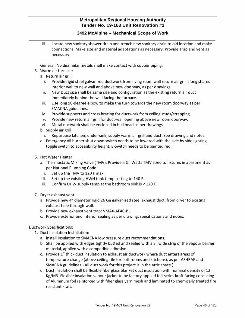
Metropolitan Regional Housing Authority
Tender No. 19-163 Unit Renovation #2
3492 McAlpine – Mechanical Scope of Work _____________________________________________________________________________________
iii. Locate new sanitary shower drain and trench new sanitary drain to old location and make connections. Make size and material adaptations as necessary. Provide Trap and vent as necessary.
General: No dissimilar metals shall make contact with copper piping.
5. Warm air furnace: a. Return air grill:
i. Provide rigid steel galvanized ductwork from living room wall return air grill along shared interior wall to new wall and above new doorway, as per drawings.
ii. New Duct size shall be same size and configuration as the existing return air duct immediately behind the wall facing the furnace.
iii. Use long 90-degree elbow to make the turn towards the new room doorway as per SMACNA guidelines.
iv. Provide supports and cross bracing for ductwork from ceiling studs/strapping. v. Provide new return air grill for duct-wall opening above new room doorway.
vi. Metal ductwork shall be enclosed in bulkhead as per drawings. b. Supply air grill:
i. Repurpose kitchen, under-sink, supply warm air grill and duct. See drawing and notes. c. Emergency oil burner shut down switch needs to be lowered with the side by side lighting
toggle switch to accessibility height. E-Switch needs to be painted red.
6. Hot Water Heater: a. Thermostatic Mixing Valve (TMV): Provide a ¾” Watts TMV sized to fixtures in apartment as
per National Plumbing Code. i. Set up the TMV to 120 F max.
ii. Set up the existing HWH tank temp setting to 140 F. iii. Confirm DHW supply temp at the bathroom sink is < 120 F.
7. Dryer exhaust vent: a. Provide new 4” diameter rigid 26 Ga galvanized steel exhaust duct, from dryer to existing
exhaust hole through-wall. b. Provide new exhaust vent trap: VMAX-AF4C-BL. c. Provide exterior and interior sealing as per drawing, specifications and notes.
Ductwork Specifications:
1. Duct Insulation Installation: a. Install insulation to SMACNA low pressure duct recommendations. b. Shall be applied with edges tightly butted and sealed with a 3" wide strip of the vapour barrier
material, applied with a compatible adhesive. c. Provide 1” thick duct insulation to exhaust air ductwork where duct enters areas of
temperature change (above ceiling tile for bathrooms and kitchens), as per ASHRAE and SMACNA guidelines. (All duct work for this project is in the attic space.)
d. Duct insulation shall be flexible fiberglass blanket duct insulation with nominal density of 12 Kg/M3. Flexible insulation vapour jacket to be factory applied foil-scrim-kraft facing consisting of Aluminum foil reinforced with fiber glass yarn mesh and laminated to chemically treated fire resistant kraft.
Tender No. 19-163 Unit Renovation #2 Page 46 of 123
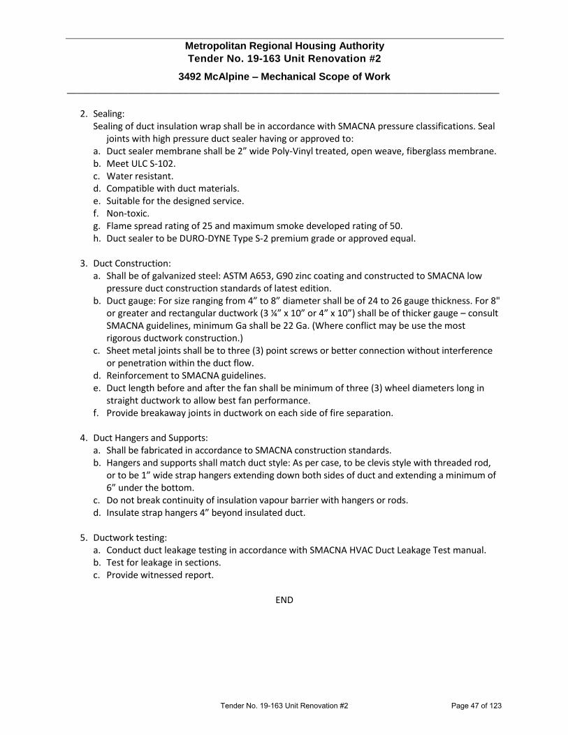
Metropolitan Regional Housing Authority
Tender No. 19-163 Unit Renovation #2
3492 McAlpine – Mechanical Scope of Work _____________________________________________________________________________________
2. Sealing:
Sealing of duct insulation wrap shall be in accordance with SMACNA pressure classifications. Seal joints with high pressure duct sealer having or approved to:
a. Duct sealer membrane shall be 2” wide Poly-Vinyl treated, open weave, fiberglass membrane. b. Meet ULC S-102. c. Water resistant. d. Compatible with duct materials. e. Suitable for the designed service. f. Non-toxic. g. Flame spread rating of 25 and maximum smoke developed rating of 50. h. Duct sealer to be DURO-DYNE Type S-2 premium grade or approved equal.
3. Duct Construction:
a. Shall be of galvanized steel: ASTM A653, G90 zinc coating and constructed to SMACNA low pressure duct construction standards of latest edition.
b. Duct gauge: For size ranging from 4” to 8” diameter shall be of 24 to 26 gauge thickness. For 8" or greater and rectangular ductwork (3 ¼” x 10” or 4” x 10”) shall be of thicker gauge – consult SMACNA guidelines, minimum Ga shall be 22 Ga. (Where conflict may be use the most rigorous ductwork construction.)
c. Sheet metal joints shall be to three (3) point screws or better connection without interference or penetration within the duct flow.
d. Reinforcement to SMACNA guidelines. e. Duct length before and after the fan shall be minimum of three (3) wheel diameters long in
straight ductwork to allow best fan performance. f. Provide breakaway joints in ductwork on each side of fire separation.
4. Duct Hangers and Supports:
a. Shall be fabricated in accordance to SMACNA construction standards. b. Hangers and supports shall match duct style: As per case, to be clevis style with threaded rod,
or to be 1” wide strap hangers extending down both sides of duct and extending a minimum of 6” under the bottom.
c. Do not break continuity of insulation vapour barrier with hangers or rods. d. Insulate strap hangers 4” beyond insulated duct.
5. Ductwork testing:
a. Conduct duct leakage testing in accordance with SMACNA HVAC Duct Leakage Test manual. b. Test for leakage in sections. c. Provide witnessed report.
END
Tender No. 19-163 Unit Renovation #2 Page 47 of 123

REFERENCE QTY. REMARKS Project
Location
Architect
Engineer
Contractor
Submitted by Date
Broan Hartford, Wisconsin www.broan.com 800-558-1711Venmar Ventilation ULC Drummondville (Quebec), Canada www.broan.ca 877-896-1119
SPECIFICATION SHEET
91D 99045296G
MODELS AE50, AE80 & AE110FLEXTM SERIES FANS
DESCRIPTIONBLOWER:• Plug-in, permanently lubricated motor - engineered for
continuous operation• Dynamically balanced centrifugal blower wheel for quiet,
efficient performance• Low RPM for quiet operation
HOUSING:• Rugged, 26 gauge, galvanized steel construction• Polymeric, 4” duct connector with tapered sleeve and no
metallic clatter• 5¾” height allows for 2” x 6” ceiling installations• Sturdy, easy, four-point mounting directly to joist• Can be mounted in ceilings up to 7/12 pitch• Can be installed in a wall if mounted 8-ft. or more above
the floor
GRILLE:• Polymeric construction• Innovative design - the result of extensive research with
designers and consumers
CONTROLS (Purchase separately):• Refer to Broan’s catalog for a complete line of
accessories to effectively adapt these fans to your construction requirements.
U.L. Listed for use over bathtubs and showers when connected to a GFCI protected branch circuit (ceiling mount only).3-Year Warranty
TYPICAL SPECIFICATIONFan shall be Broan Model AE50 (AE80) (AE110).
Fan shall have corrosion resistant galvanized steel housing with four-point mounting capability. It shall be ducted to a roof or wall cap using 4” round ductwork.
Blower assembly shall be removable, have a centrifugal-type blower wheel and a permanently lubricated motor designed for continuous operation.
Non-metallic damper/duct connector shall be included.
Air delivery shall be no less than the airflow values and no greater than the sound level values listed in the HVI Performance Specifications provided in this specification (see following chart). All air and sound ratings shall be certified by HVI.
Ceiling Ventilator shall be U.L. Listed for use over bathtubs and showers when connected to a GFCI protected branch circuit.
Tender No. 19-163 Unit Renovation #2 Page 48 of 123

PERFORMANCE RATINGSFLEXTM SERIES FANS
AIR FLOW PERFORMANCE
HVI-2100 CERTIFIED RATINGS comply with new testing technologies and procedures prescribed by the Home Ventilating Institute, for off-the-shelf products, as they are available to consumers. Product performance is rated at 0.1 in. static pressure, based on tests conducted in a state-of-the-art test laboratory. Sones are a measure of humanly-perceived loudness, based on laboratory measurements.
HVI PERFORMANCE
ELECTRICAL & WEIGHT
0.0
0.1
0.2
0.3
0.4
0.5
0 10 20 30 40 50 60 70 80 90
Sta
tic
Pre
ssu
re(i
n. H
2O -
Inch
es o
f Wat
er G
aug
e)
Air Flow (CFM - Cubic Feet per Minute)
Model AE80
NOTE: Dimensions shown are in inches.
Model0.1 Ps - Static Pressure (in H2O) 0.25 Ps
Airflow (CFM)
Sound(Sones)
Power(Watts)
Efficacy(CFM / W)
Airflow(CFM
AE50 50 0.5 20.0 3.55 37
AE80 80 0.8 26.9 2.97 60
AE110 110 1.0 23.4 4.71 92
Model Volts Hz AmpsShippingWeight
AE50 120 60 0.2 10.0 lb.
AE80 120 60 0.3 10.0 lb.
AE110 120 60 0.3 10.0 lb.
0.0
0.1
0.2
0.3
0.4
0.5
0.6
0.7
0 10 20 30 40 50 60 70 80 90 100 110 120
Sta
tic
Pre
ssu
re(i
n. H
2O In
ches
of
Wat
er G
aug
e)
Air Flow (CFM - Cubic Feet per Minute)
Model AE110
Model AE50
0.0
0.1
0.2
0.3
0.4
0.5
0 10 20 30 40 50 60
Sta
tic
Pre
ssu
re(i
n. H
2O In
ches
of
Wat
er G
aug
e)
Air Flow (CFM - Cubic Feet per Minute)
0.6
Broan Hartford, Wisconsin www.broan.com 800-558-1711Venmar Ventilation ULC Drummondville (Quebec), Canada www.broan.ca 877-896-1119
Tender No. 19-163 Unit Renovation #2 Page 49 of 123
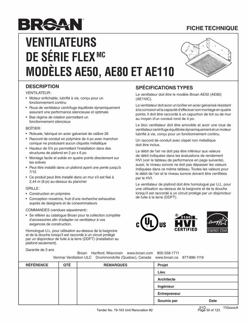
Broan Hartford, Wisconsin www.broan.com 800-558-1711Venmar Ventilation ULC Drummondville (Quebec), Canada www.broan.ca 877-896-1119
RÉFÉRENCE QTÉ REMARQUES Projet
Lieu
Architecte
Ingénieur
Entrepreneur
Soumis par Date
FICHE TECHNIQUE
VENTILATEURS DE SÉRIE FLEX MC
MODÈLES AE50, AE80 ET AE110DESCRIPTIONVENTILATEUR :• Moteur enfichable, lubrifié à vie, conçu pour un
fonctionnement continu• Roue de ventilateur centrifuge équilibrée dynamiquement
assurant une performance silencieuse et optimale• Bas régime de rotation permettant un
fonctionnement silencieux
BOÎTIER :• Robuste, fabriqué en acier galvanisé de calibre 26• Raccord de conduit en polymère de 4 po avec manchon
conique ne produisant aucun cliquetis métallique• Hauteur de 5¾ po permettant l'installation dans des
structures de plafond en 2 po x 6 po• Montage facile et solide en quatre points directement sur
les solives• Peut être installé dans un plafond ayant une pente jusqu’à
7/12• Ce produit peut être installé dans un mur s’il est fixé à
2,44 m (8 pi) au-dessus du plancher
GRILLE :• Construction en polymère• Conception novatrice, fruit d’une recherche exhaustive
auprès de designers et de consommateurs
COMMANDES (vendues séparément) :• Se référer au catalogue Broan pour la collection complète
d’accessoires afin d’adapter ce ventilateur à vos exigences de construction.
Homologué U.L. pour utilisation au-dessus de la baignoire et de la douche lorsqu’il est raccordé à un circuit protégé par un disjoncteur de fuite à la terre (DDFT) (installation au plafond seulement).
Garantie de 3 ans
SPÉCIFICATIONS TYPESLe ventilateur doit être le modèle Broan AE50 (AE80) (AE110C).
Le ventilateur doit avoir un boîtier en acier galvanisé résistant à la corrosion et la capacité d'effectuer son montage en quatre points. Il doit être raccordé à un capuchon de toit ou de mur au moyen d’un conduit rond de 4 po.
Le bloc ventilateur doit être amovible et avoir une roue de ventilateur centrifuge équilibrée dynamiquement et un moteur lubrifié à vie, conçu pour un fonctionnement continu.
Un raccord de conduit avec clapet non métallique doit être inclus.
Le débit de l'air ne doit pas être inférieur aux valeurs de débit indiquées dans les évaluations de rendement HVI (voir le tableau de performance en page suivante), aussi, le niveau sonore ne doit pas dépasser les valeurs indiquées dans ce même tableau. Toutes les valeurs pour le débit de l’air et le niveau sonore doivent être certifiées par le HVI.
Le ventilateur de plafond doit être homologué par U.L. pour une utilisation au-dessus de la baignoire et de la douche lorsqu’il est raccordé à un circuit protégé par un disjoncteur de fuite à la terre (DDFT).
91D 110xxxxATender No. 19-163 Unit Renovation #2 Page 50 of 123

ÉVALUATIONS DE RENDEMENTVENTILATEURS DE SÉRIE FLEX MC
PERFORMANCE HVI
Modèle
0,1 Ps - Pression statique (po H2O) 0,25 Ps
Débit de l'air
(pi3/min)
Niveausonore(sone)
Puissance(Watts)
Efficacité(pi3/min / W)
Débit de l'air
(pi3/min)
AE50 50 0,5 20,0 3,55 37
AE80 80 0,8 26,9 2,97 60
AE110 110 1,0 23,4 4,71 92
Modèle Volts Hz AmpèresPoids à
l'expédition
AE50 120 60 0,2 10,0 lb
AE80 120 60 0,3 10,0 lb
AE110 120 60 0,3 10,0 lb
NOTE : Les dimensions indiquées sont en pouces.
RÉSULTATS HOMOLOGUÉS HVI-2100 conformes aux nouvelles technologies de test et aux procédures prescrites par le Home Ventilating Institute pour les produits offerts sur le marché, tels qu’ils sont présentés aux consommateurs. La performance du produit est calibrée à 0,1 po de pressionstatique, basée sur les tests dirigés par un laboratoire de pointe. Un sone est une unité de mesure de bruit perçu par l’oreille humaine, basée sur des mesures en laboratoire.
ÉLECTRICITÉ ET POIDS
RENDEMENT DU DÉBIT DE L'AIR
Broan Hartford, Wisconsin www.broan.com 800-558-1711Venmar Ventilation ULC Drummondville (Quebec), Canada www.broan.ca 877-896-1119
0.0
0.1
0.2
0.3
0.4
0.5
0 10 20 30 40 50 60
0.6
Pre
ssio
n s
tati
qu
e(p
o H
2O -
Po
uce
s d
’eau
)
Débit de l’air (pi3/min - Pieds cubes par minute)
Modèle AE50
0.0
0.1
0.2
0.3
0.4
0.5
0 10 20 30 40 50 60 70 80 90
Pre
ssio
n s
tati
qu
e(p
o H
2O -
Po
uce
s d
’eau
)
Débit de l’air (pi3/min - Pieds cubes par minute)
Modèle AE80
0.0
0.1
0.2
0.3
0.4
0.5
0.6
0.7
0 10 20 30 40 50 60 70 80 90 100 110 120
Pre
ssio
n s
tati
qu
e(p
o H
2O -
Po
uce
s d
’eau
)
Débit de l’air (pi3/min - Pieds cubes par minute)
Modèle AE110
Tender No. 19-163 Unit Renovation #2 Page 51 of 123

FLEXIBILITY for the new construction and room-side retrofit from one fan.
More features from one fan.
FoldAwayTM Mounting Ears are precisely positioned for new construction and fold flat for room-side retrofits.
EzDuctTM Connector enables room-side installation without attic access.
LED Lighting offers greater energy efficiency and longevity, and adds a unique design detail to this hard-working fan.
With our TrueSealTM Damper Technology, Flex fans reduce air leakage by up to 50% compared to competitive models1.
Versatile Installation. Airtight Performance. LED Lighting.Flex Series gives professionals smart options for new construction or roomside retrofits in one, hard-working product line. Flex is about innovations such as FoldAwayTM mounting ears TruSealTM Damper Technology that improves building airtightness like never before. With fresh grille designs and a full range of operating points, there’s a Flex Series solution for every installation.
1 Testing reflects total fan housing air tightness. See Broan.ca for details. Tender No. 19-163 Unit Renovation #2 Page 52 of 123

Broan.caVenmar Ventilation ULC, 550 Lemire Blvd, Drummondville, Canada J2C 7W9 1-877-896-1119 88
042
06/
19
Incandescent Fan/Light with A19 Base (bulb not included). Model: AR70LC.
LED Fan/Light with 11 watts, 800 Lumens, 3000K, 80 CRI integrated module. Models: AE80L, AER110LC.
Fan models: A80, A110, AE80, AE110, AE80B, AER50C, AE80S, AE110S.
Flex Fan & Fan/Lights
NEW Snap-Fit Flange2
Both new construction installation and retrofit upgrades just got easier. Add the flange by simply snapping it on the side of the fan housing or go flangeless.
100 20 30
STANDARD FAN HOUSING
CFM
*THAN STANDARD FAN HOUSINGS
Flex
UP TO50% LESS AIR LEAKAGE*
FLEX FAN MODELSNewModel CFM Sones ENERGY STAR®
AER50C 50 0.5 Yes
AE80B 80 1.5 Yes
AE80 80 0.8 Yes
AE110 110 1.0 Yes
A110 110 3.0 No
A80 80 2.0 No
AE80S 80 0.8 Yes
AE110S 110 1.0 Yes
FLEX FAN/LIGHT MODELSNew Model CFM Sones Lighting ENERGY STAR®
AE80L 80 0.8 LED YesAER110LC 110 1.0 LED Yes
AR70LC 70 2.0 Incandescent A19 Base* No
*Bulb not included
FLEX FAN FINISH PACKS (MASTER OF 4 UNITS)New Model CFM Sones ENERGY STAR®
AE50F1 50 0.5 Yes
AE80BF1 80 1.5 Yes
AE80F1 80 0.8 Yes
AE110F1 110 1.0 Yes
A110F1 110 3.0 No
A80F1 80 2.0 No
FLEX HOUSING PACKS (MASTER OF 4 UNITS)
New Model Description
A000HFKTC Fan Housing with Hanger Bars
2 Included in the housing pack only (A000HFKTC)
NEW Flex Housing• 50% more airtight than standard ventilation fans to help
meet rigorous codes and standards.
• Snap-Fit Flange Kit will cover the edges of the cutout for a more professional finish and a tighter, leak free seal.
53/4"
10" 9 "1/4
4"
Tender No. 19-163 Unit Renovation #2 Page 53 of 123

OPTION - To mount housing anywhere between ceiling framing: Use optional Hanger Bar Kit (sold separately from local distributors or website). Follow mounting instructions included with kit.
1. Remove blower and all packing material from fan housing.
2. Remove wiring panel from fan housing.
3. Attach damper/duct connector to fan housing.
4. Mount housing to ceiling structure.
ROOF CAP* (with built-in damper)
WALL CAP*(with built-in
damper)4-IN. ROUNDELBOWS*
FANHOUSING
Seal gapsaround
housing.
Seal duct jointswith tape.
INSULATION(Place around andover fan housing.)
POWERCABLE *
* Purchase separately.
OR
Keep ductruns short.
4-IN. ROUNDDUCT*
TABS
5. Connect 4-in. round duct.
ALL INSTALLATIONS Start here.
IMPORTANT - The ducting from this fan to the outside of the building has a strong effect on the air flow, noise and energy use of the fan. Use the shortest, straightest duct routing possible for best performance, and avoid installing the fan with smaller ducts than recommended. Insulation around the ducts can reduce energy loss and inhibit mold growth. Fans installed with existing ducts may not achieve their rated airflow.
WARNING TO REDUCE THE RISK OF FIRE, ELECTRIC SHOCK, OR INJURY TO PERSONS, OBSERVE THE FOLLOWING:1. Use this unit only in the manner intended by the manufacturer. If you have
questions, contact the manufacturer at the address or telephone number listed in the warranty.
2. Before servicing or cleaning unit, switch power off at service panel and lock the service disconnecting means to prevent power from being switched on accidentally. When the service disconnecting means cannot be locked, securely fasten a prominent warning device, such as a tag, to the service panel.
3. Installation work and electrical wiring must be done by a qualified person(s) in accordance with all applicable codes and standards, including fire-rated construction codes and standards.
4. Sufficient air is needed for proper combustion and exhausting of gases through the flue (chimney) of fuel burning equipment to prevent backdrafting. Follow the heating equipment manufacturer’s guideline and safety standards such as those published by the National Fire Protection Association (NFPA), and the American Society for Heating, Refrigeration and Air Conditioning Engineers (ASHRAE), and the local code authorities.
5. When cutting or drilling into wall or ceiling, do not damage electrical wiring and other hidden utilities.
6. Ducted fans must always be vented to the outdoors.7. Acceptable for use over a tub or shower when connected to a GFCI (Ground
Fault Circuit Interrupter) - protected branch circuit (ceiling installation only).
8. This unit must be grounded.
CAUTION 1. For general ventilating use only. Do not use to exhaust hazardous or
explosive materials and vapors.2. This product can be installed in a wall if mounted 8-ft. or more above the
floor.3. To avoid motor bearing damage and noisy and/or unbalanced impellers,
keep drywall spray, construction dust, etc. off power unit.4. Please read specification label on product for further information and
requirements.
CLEANING & MAINTENANCEFor quiet and efficient operation, long life, and attractive appearance - lower or remove grille and vacuum interior of unit with the dusting brush attachment.The motor is permanently lubricated and never needs oiling. If the motor bearings are making excessive or unusual noises, replace the blower assembly (includes motor and impeller).
OPERATIONUse an on/off switch or speed control to operate this ventilator. See “Connect Wiring” for details.
READ AND SAVE THESE INSTRUCTIONS
SERIES FAN
Push connector through opening from inside of housing.Engage tabs and secure with screw from parts bag.
Make sure bottom of housing will be flush with finished ceiling.For proper location using ½” ceiling material: Bend out housing tabs to fit against bottom of structure.Secure housing through mounting ears with appropriate fasteners. (Some models include mounting screws.)If mounting housing to I-joist, use wood blocking as shown.
NEW CONSTRUCTION INSTALLATION
HOUSING TABS
CookingEquipment
Floor
COOKING AREADo not install above or
inside this area.
45o 45o
NOT FOR USE INA COOKING AREA.
For Warranty Statement, Service Parts, Technical Support, or to Register your product, please visit our website or call:In the United States - Broan.com 800-637-1453 or NuTone.com 888-336-6151In Canada - Broan.ca or NuTone.ca 877-896-1119
For Retrofit Installation - Skip to back page.
Tender No. 19-163 Unit Renovation #2 Page 54 of 123
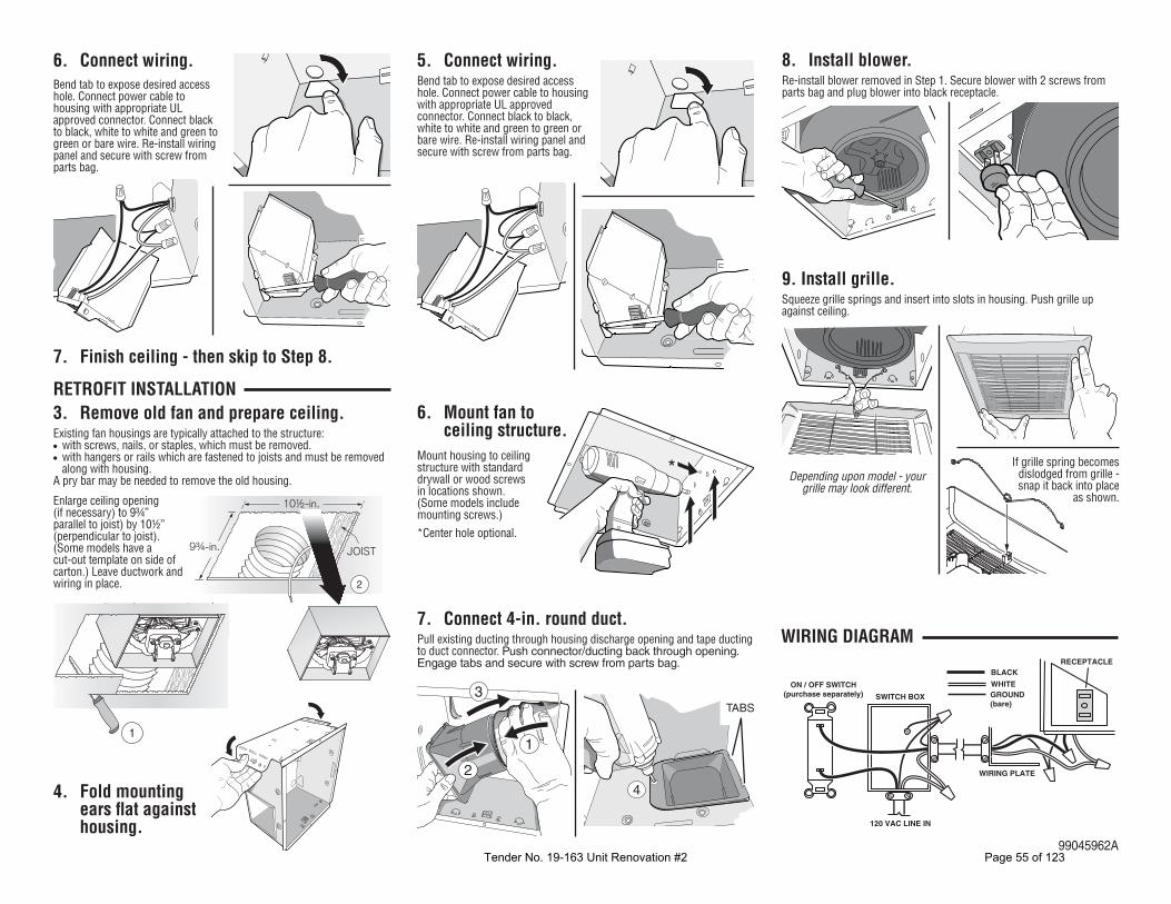
2
10½-in.
9¾-in. JOIST
9. Install grille.Squeeze grille springs and insert into slots in housing. Push grille up against ceiling.
3. Remove old fan and prepare ceiling.Existing fan housings are typically attached to the structure:• with screws, nails, or staples, which must be removed.• with hangers or rails which are fastened to joists and must be removed
along with housing.A pry bar may be needed to remove the old housing.
7. Connect 4-in. round duct.Pull existing ducting through housing discharge opening and tape ducting to duct connector. Push connector/ducting back through opening. Engage tabs and secure with screw from parts bag.
6. Mount fan to ceiling structure.
SWITCH BOX
ON / OFF SWITCH(purchase separately)
WHITE
BLACK
GROUND(bare)
WIRING PLATE
120 VAC LINE IN
RECEPTACLE
1
2
3
4
TABS
1
*
4. Fold mounting ears flat against housing.
8. Install blower.Re-install blower removed in Step 1. Secure blower with 2 screws from parts bag and plug blower into black receptacle.
RETROFIT INSTALLATION
5. Connect wiring.Bend tab to expose desired access hole. Connect power cable to housing with appropriate UL approved connector. Connect black to black, white to white and green to green or bare wire. Re-install wiring panel and secure with screw from parts bag.
WIRING DIAGRAM
99045962A
6. Connect wiring.Bend tab to expose desired access hole. Connect power cable to housing with appropriate UL approved connector. Connect black to black, white to white and green to green or bare wire. Re-install wiring panel and secure with screw from parts bag.
Depending upon model - your grille may look different.
Mount housing to ceiling structure with standard drywall or wood screws in locations shown. (Some models include mounting screws.)*Center hole optional.
If grille spring becomes dislodged from grille - snap it back into place
as shown.
7. Finish ceiling - then skip to Step 8.
Enlarge ceiling opening (if necessary) to 9¾” parallel to joist) by 10½” (perpendicular to joist). (Some models have a cut-out template on side of carton.) Leave ductwork and wiring in place.
Tender No. 19-163 Unit Renovation #2 Page 55 of 123

SPECIFICATION SHEET
PRODUCT SPECIFICATIONS SUBJECT TO CHANGE WITHOUT NOTICE.
PROJECT REMARKS
LOCATION
MODEL NO.
QTY.
SUBMITTED BY
DATE
VENMAR VENTILATION ULC, DRUMMONDVILLE, QUÉBEC WWW.BROAN.CA 1-877-896-1119
QP130 SERIES
QP130d180418
HK0052
AIR FLOW PERFORMANCE
DIMENSIONSSPECIFICATIONS
NOTE: DIMENSIONS SHOWN ARE IN INCHES.
HVI-2100 CERTIFIED RATINGS comply with new testing technologies and procedures prescribed by the Home Ventilating Institute, for off-the-shelf products, as they are available to consumers. Product performance is rated at 0.1 in. (2.54 mm) static pressure, based on tests conducted in a state-of-the-art test laboratory. Sones are a measure of humanly-perceived loudness, based on laboratory measurements.
MODEL QP130 SERIES
VOLTS 120 VAC
HZ 60
AMPS 2.3
CFM (HIGH SPEED) 300
CFM (LOW SPEED) 120
SONES (HIGH SPEED) 5.0
SONE (LOW SPEED) 0.8
DUCTING SIZE 7" ROUND OR 3¼" X 10"
4 SHIELDED
HALOGEN BULBS, INCLUDED
MR16, 120 V,35 W, WITH GU10 BASE
WARRANTY 2 YEARS
HG0066A
STA
TIC P
RES
SUR
E (IN
. W.G
.)
AIR FLOW RATE (CFM)
0.0
0.1
0.2
0.3
0.4
0.5
0.6
0.7
0.8
0 50 100 150 200 250 300 350 400
HOR. HIGH SPEED 3¼" X 10"
VERT. HIGH SPEED 3¼" X 10"
VERT. HIGH SPEED 7" ROUND
Tender No. 19-163 Unit Renovation #2 Page 56 of 123

Features• Includes valve body, pressure balance cartridge, rough-in guide
and mud guard• 1/2" Universal NPT & direct sweat inlets & outlets, with stops• Service stops include integral check valves• 5.0 gpm (18.9 l/min) maximum flow rate at 45 psi• Single lever design cycles from off through cold to hot• Provides temperature regulation and automatic anti-scald
protection• One piece cartridge design simplifies installation and
maintenance• Adjustable high temperature limit stop to control maximum water
temperature• Requires valve trim to complete installation (sold separately). Codes/StandardsMaterial ASME A112.18.1/CSA B125.1
ASSE 1016/ASME A112.1016/CSA B125.16• Forged De-zincification Resistant Brass body provides longterm reliability and resistance to aggressive water conditions
KOHLER® Faucet Lifetime LimitedWarrantyTechnology
• Pressure-balancing diaphragm technology maintains outlettemperature within +/- 3 degrees Fahrenheit during waterpressure fluctuations
See website for detailed warranty information.
Installation• Designed for use in standard, back to back and thin wall
installations• Valve body features integral mounting locations and symmetrical
valve inlets to simplify installation• Cartridge is reversible for installations where hot and cold
supplies are reversed.• Rough-in guide designed for both standard and thin wall
installations• Installed valve rough-in can be flushed and pressure tested to
150psi max (air or water) without cartridge, using K-10351 TestCap
Optional Products/AccessoriesK-10350 Deep Rough-In Kit For K-8305 CartridgesK-10351 Test Cap For K-8300 Series Valve Bodies
1-800-4KOHLER (1-800-456-4537)Kohler Co. reserves the right to make revisions without notice to product specifications.For the most current Specification Sheet, go to www.kohler.com.12-7-2019 18:38 - US/CA
Rite-Temp®
Valve Body & Cartridge Kit CompleteK-8304-KS
Tender No. 19-163 Unit Renovation #2 Page 57 of 123

2-15/16"(75 mm)
2-3/16"(56 mm)
5-7/8" (149 mm)
9/16"(14 mm)
Outlet Port
3-1/2"(89 mm)
2-3/4"(70 mm)
1-15/16"(49 mm)
1-15/16"(49 mm)
Max Finished WallMin Finished Wall
Inlet Port1/2"-14 NPT and 5/8" IDfor 1/2" NominalCopper Tubing
Outlet Port1/2"-14 NPT and 5/8" IDfor 1/2" NominalCopper Tubing
Ø 1"(25 mm)
Cut Line
Cut Line
Ø 4" (102 mm)
Ø 4-1/2" (114 mm)
7/8" (22 mm)
Ø 5" (127 mm)
Cutout for finished wallsgreater than 3/4" (19 mm)
Cutout for finished wallsless than 3/4" (19 mm)
NotesTechnical InformationInstall this product according to the installationguide.
All product dimensions are nominal.
Shower Valve:Avoid cross-flow conditions. Do not install shut-offdevice on either valve outlet.20 psi (1.4 bar)Min. pressure IN:
Machined-brassValve body: Cap the shower outlet if deck-mount spout,diverter, or handshower is connected to the spoutoutlet.Install straight pipe or tube drop of 7" (178 mm)to 18" (457 mm) with single elbow between thevalve and wall-mount spout.For finished walls greater than 3/4" (19 mm) andless than 1-1/2" (38 mm), install support(s) 2" (51mm) from the stud face.For finished walls greater than 1-1/2" (38 mm),install support(s) 3" (76 mm) from the face of thefinished wall.
1-800-4KOHLER (1-800-456-4537)Kohler Co. reserves the right to make revisions without notice to product specifications.For the most current Specification Sheet, go to www.kohler.com.12-7-2019 18:38 - US/CA
Rite-Temp®
Valve Body & Cartridge Kit CompleteK-8304-KS
Tender No. 19-163 Unit Renovation #2 Page 58 of 123

Features• Handshower features transitional nature-inspired design.• Three spray functions with ADA non-positive shut off.• Wide coverage spray produces an encompassing spray for
everyday use.• Intense drenching spray delivers a forceful spray ideal for rinsing
soap from hair.• Targeted spray is a focused stream for targeting sore muscles
or use as a utility spray.• Thumb tab allows for a smooth transition between sprays.• Spray nozzles cover full area of sprayhead.• Combination of balance, weight, grip, and angle makes this
handshower comfortable and easy to use.• MasterClean™ sprayface is easy to clean.
CSA B651 OBC
• 1.75 gpm (gallons per minute) flow rate.
Material• KOHLER finishes resist corrosion and tarnishing.
Installation Codes/StandardsASME A112.18.1/CSA B125.1• Bracket or slidebar required for wall-mount installation.DOE - Energy Policy Act 1992• Deck-mount holder required for deck-mount installation.EPA WaterSense®
Water Conservation & Rebates California Energy Commission (CEC)ADA• WaterSense®-labeled 1.75-gpm handshowers use up to 30
percent less water than standard 2.5-gpm handshowers, whilestill meeting strict performance guidelines.
ICC/ANSI A117.1CSA B651OBC• This product can help a building earn Water Efficiency points
in the LEED® Green Building Rating System.KOHLER® Faucet Lifetime LimitedWarrantyRequired Products/Accessories
K-8593 72" Shower Hose See website for detailed warranty information. or
K-9514 60" Shower Hose
Available Colors/Finishes or
K-45981 72" ribbon hoseColor tiles intended for reference only. or
K-45982 60" ribbon hose DescriptionCodeColor
Polished ChromeCP
Vibrant® Brushed NickelBN
Oil-Rubbed Bronze2BZ
1-800-4KOHLER (1-800-456-4537)Kohler Co. reserves the right to make revisions without notice to product specifications.For the most current Specification Sheet, go to www.kohler.com.12-7-2019 17:11 - US/CA
Awaken® B110Multifunction Handshower
K-72421-G
Tender No. 19-163 Unit Renovation #2 Page 59 of 123

G1/2 Thread
Ø 4-5/8" (117 mm)
10-1/2"(267 mm)
3-3/16"(81 mm)
NotesTechnical InformationInstall this product according to the installationinstructions.
All product dimensions are nominal.
Handshower:Plumbing codes require approved backflowprevention devices to be installed in-line to1.75 gal/min (6.6 l/min)Rated maximum flow:
handshowers. Please consult with local plumbingofficials.Plumbing codes require an atmospheric vacuumbreaker (such as Kohler Model K-9660) beinstalled in-line with handshowers. Please consultwith local plumbing officials.ADA, OBC, CSA B651 compliant when installedto the specific requirements of these regulations.
1-800-4KOHLER (1-800-456-4537)Kohler Co. reserves the right to make revisions without notice to product specifications.For the most current Specification Sheet, go to www.kohler.com.12-7-2019 17:11 - US/CA
Awaken® B110Multifunction Handshower
K-72421-G
Tender No. 19-163 Unit Renovation #2 Page 60 of 123

Features• Pressure-balancing diaphragm technology maintains outlet
temperature within +/-3°F during water pressure fluctuations.• Provides temperature regulation and automatic anti-scald
protection.• Single handle controls both on/off activation and temperature
setting.• Includes faceplate with ADA-compliant metal lever handle.• For use with any KOHLER® showerhead (sold separately).• Coordinates with Hint™ bathroom sink faucets and bath faucets.
Material• Premium material construction with metal handle ensures
reliability and durability.CSA B651 OBC• KOHLER finishes resist corrosion and tarnishing.
Installation Codes/Standards• Trim only; requires valve to complete installation (sold
separately).ASME A112.18.1/CSA B125.1ADAICC/ANSI A117.1
Required Products/AccessoriesK-8304/K-P8304 Series Rite-Temp® Valve & Cartridge Kits
CSA B651OBC
orK-8300/K-P8300 Series Rite-Temp® Valve Body Rough-insK-8305/K-P8305 Series Rite-Temp® Cartridges
KOHLER® Faucet Lifetime LimitedWarranty
Optional Products/AccessoriesK-10350 Deep Rough-In Kit For K-8305 CartridgesK-10351 Test Cap For K-8300 Series Valve Bodies
See website for detailed warranty information.
Available Colors/FinishesColor tiles intended for reference only.
DescriptionCodeColor
Polished ChromeCP
Vibrant® Brushed NickelBN
1-800-4KOHLER (1-800-456-4537)Kohler Co. reserves the right to make revisions without notice to product specifications.For the most current Specification Sheet, go to www.kohler.com.12-7-2019 23:43 - US
Rite-Temp® shower valve trimK-TS74042-4
Tender No. 19-163 Unit Renovation #2 Page 61 of 123

Ø 6-3/8" (162 mm)
3-3/8"(86 mm)
If 3-1/2" (89 mm) to4-1/4" (108 mm) usedeep roughing-in kit.
CL of Valve Inlet
3-11/16" (94 mm)
NotesTechnical InformationFor use with automatic compensating valves ratedat 1.6 gal/min (6.1 l/min) or less.
All product dimensions are nominal.NoDrain included:
Install this product according to the installationinstructions.Showerhead/Body Spray:
1.75 gal/min (6.6 l/min)Rated maximum flow: Install straight pipe or tube drop of 7" (178 mm)to 18" (457 mm) with single elbow between thevalve and the wall-mount spout.
80 psi (5.5 bar)Pressure:
ADA, OBC, CSA B651 compliant when installedto the specific requirements of these regulations.
1-800-4KOHLER (1-800-456-4537)Kohler Co. reserves the right to make revisions without notice to product specifications.For the most current Specification Sheet, go to www.kohler.com.12-7-2019 23:43 - US
Rite-Temp® shower valve trimK-TS74042-4
Tender No. 19-163 Unit Renovation #2 Page 62 of 123

Product Bulletin for Humidity Sensor and Fan Control
Humidity Sensor and Fan Control
The Leviton Humidity Sensor and Fan Control automatically detects excess humidity in a room and activates the ventilation fan to lessen condensation which helps reduce mold and mildew.
The sensor uses a microprocessor combined with state-of-the-art digital sensing technology to continuously monitor and manage humidity levels in areas of the home prone to condensation and mildew. It features user-friendly controls to adjust sensitivity, humidity level and time out settings. The sensor can replace a single pole switch and can be used with most bathroom or ventilation fans or fan/light combinations. It is designed to fit within a standard wallbox and requires a neutral wire for operation.
ApplicationsContemporary in design, the Humidity Sensor and Fan Control is the ideal solution for controlling ventilation in areas of high humidity, dampness or rooms prone to condensation and mildew such as:- Bathrooms- Basements- Laundry Rooms- Home Spas
The sensor also helps reduce energy usage by automatically operating the fan only when needed to control excess humidity.
General OperationAutomatic Humidity Control Mode – The sensor will automatically turn the fan ON upon detecting excess humidity. The sensor will continue to monitor the ambient air and automatically turn the fan OFF when the humidity level has dropped.
Manual Operation – For immediate ventilation needs, the user can manually switch the fan ON or OFF by pressing the fan icon. The fan will run for 10 minutes and automatically turn OFF (time out period can be adjusted). If humidity levels change, the sensor will shift into automatic mode and time out accordingly.
Air Cycle Mode – The Air Cycle mode automatically turns ON a ventilation fan for a set period of time and repeats the cycle hourly. (eg. 20 minutes ON/40 minutes OFF each hour). This feature may be used in areas requiring periodic ventilation on a continuous basis such as basements, spas or public restrooms.
Tender No. 19-163 Unit Renovation #2 Page 63 of 123

Features and BenefitsGeneral
Replaces a single pole switch for control of a ventilation fan or a fan/light combination Neutral wire is required for operation Microprocessor control with digital sensing technology Can be used to comply with the requirements of 2016 California Title 24, Part 6, Indoor Air Quality and Mechanical Ventilation
Can be used to comply with the requirements of 2016 CALGREEN, Part II, Indoor Air Quality and Exhaust Automatic ventilation/Air Cycle mode for continuous operation with hourly pre-set time outs Green LED functions as a status indicator (Fan ON/OFF, Air Cycle mode, Manual Override) Compatible with Incandescent, LED, CFL and Fluorescent lighting loads Use with existing or new ventilation fans up to 1/6 HP, 3 Amp Screw terminals for easy installation Compatible with Decora® and Decora PlusTM wallplates Available in White, Ivory and Light Almond. Color change kits available
Automatic Fan Control The sensor automatically detects excess humidity and activates a ventilation fan for control of excess condensation* Built-in timer sets the “minimum ON time” for the ventilation fan. The sensor timer settings can be custom set to 10, 20, 30 or 45 minute intervals The sensor will continue to operate the fan for the minimum set time or until there is a reduction in room humidity level. This greatly reduces the chance of condensation developing Sensitivity level adjustment allows the user to adjust the sensitivity level of the sensor to prevent false cycling
Manual Fan Control The device can be manually turned on by pressing the fan icon to address immediate ventilation needs. The fan will turn OFF automatically after 10 minutes or the set time out
* The Leviton Humidity Sensor and Fan Control will not independently eliminate condensation. It must be used with a properly sized and rated ventilation fan in an enclosed space.
Ratings 120VAC, 60Hz, Single Pole 600W Incandescent 150W LED, CFL 1/6 HP, (3A) Fan 400VA MLV/Fluorescent
Agency Standards and Compliance cULus Standards UL 873 and C22.2 No. 24 File No. E79658 Can be used to comply with the requirements of 2016 California Title 24, Part 6, Indoor Air Quality and Mechanical Ventilation Can be used to comply with the requirements of 2016 CALGREEN, Part II, Indoor Air Quality and Exhaust Meets requirements of ASHRAE 62.2
Installation Recommendations for Bath Fan Control It is recommended that in large spaces the IPHS5 Humidity Sensor and Fan Control be placed within close proximity to the shower/tub (steam/vapor source) to most effectively measure/monitor for excess humidity Ceiling heights in excess of 8 feet may affect the sensors’ ability to properly detect shower/tub steam The sensor requires a closed room to properly operate. Opening a door during operation may temporarily interrupt the operating cycle Changes in season may affect operation of the sensor due to ambient air temperature and humidity. Please review the sensor instructions for sensitivity and humidity adjustment if required
Tender No. 19-163 Unit Renovation #2 Page 64 of 123

Dimensional Drawing1.7544.5
4.13104.8
3.8196.8
3.2883.3
0.379.3
1.2230.9
2.7269
Cat. No. IPHS5
Wiring Diagram
User Adjustable Settings
Hot (Black)
Neutral (White)Required For Operation
BKWH
Sensor
Black
White
RD
GreenGround
Line 120 VAC, 60Hz
RESETRESET
TESTTEST
2 2
1 32 3
1 4
20off
LoMd
offHi
cycle80
Sensitivity
Lo Md
Off
Off
HiTime Humidistat
2 3
1 4
20 80
cycle(10 min.) (45 min.)
(20 min.) (30 min.)(Stop Mark)
1
2 3
1 SENSITIVITY Adjust low, medium or high the sensitivity to ambient humidity changes
2 TIME Adjust the minimum ON time of fan
3 HUMIDISTAT Turn ON the air cycle or adjust the humidity set points
Tender No. 19-163 Unit Renovation #2 Page 65 of 123
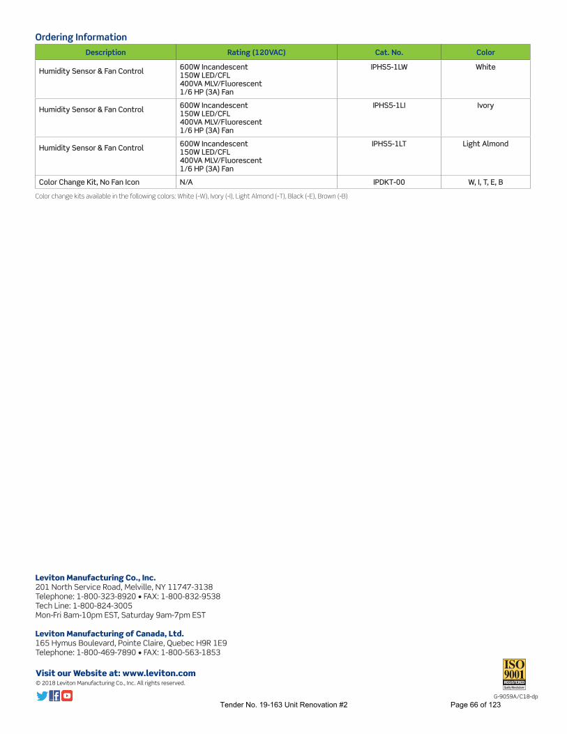
Visit our Website at: www.leviton.com© 2018 Leviton Manufacturing Co., Inc. All rights reserved.
G-9059A/C18-dp
Ordering Information
Description Rating (120VAC) Cat. No. Color
Humidity Sensor & Fan Control 600W Incandescent150W LED/CFL400VA MLV/Fluorescent1/6 HP (3A) Fan
IPHS5-1LW White
Humidity Sensor & Fan Control 600W Incandescent150W LED/CFL400VA MLV/Fluorescent1/6 HP (3A) Fan
IPHS5-1LI Ivory
Humidity Sensor & Fan Control 600W Incandescent150W LED/CFL400VA MLV/Fluorescent1/6 HP (3A) Fan
IPHS5-1LT Light Almond
Color Change Kit, No Fan Icon N/A IPDKT-00 W, I, T, E, B
Color change kits available in the following colors: White (-W), Ivory (-I), Light Almond (-T), Black (-E), Brown (-B)
Leviton Manufacturing Co., Inc.201 North Service Road, Melville, NY 11747-3138Telephone: 1-800-323-8920 • FAX: 1-800-832-9538Tech Line: 1-800-824-3005 Mon-Fri 8am-10pm EST, Saturday 9am-7pm EST
Leviton Manufacturing of Canada, Ltd.165 Hymus Boulevard, Pointe Claire, Quebec H9R 1E9Telephone: 1-800-469-7890 • FAX: 1-800-563-1853
Tender No. 19-163 Unit Renovation #2 Page 66 of 123

QP130 SERIES RANGE HOODS
Page 1
WARNING
CAUTION !
TO REDUCE THE RISK OF FIRE, ELECTRIC SHOCK, OR INJURY TO PERSONS, OBSERVE THE FOLLOWING:
1. Use this unit only in the manner intended by the manufacturer.If you have questions, contact the manufacturer at the address or telephone number listed in the warranty.
2. Before servicing or cleaning unit, switch power off at ser-vice panel and lock the service disconnecting means to pre-vent power from being switched on accidentally. When the service disconnecting means cannot be locked, securely fasten a prominent warning device, such as a tag, to the service panel.
3. Installation work and electrical wiring (including switch location)must be done by a qualified person(s) in accordance with all applicable codes and standards, including fire-rated construction.
4. Provide sufficient air for proper combustion and exhausting of gases through the flue (chimney) of fuel burning equipment to prevent backdrafting. Follow the combustion equipmentstandards such as those published by the National Fire Protection Association (NFPA), the American Society for Heating, Refrigeration and Air Conditioning Engineers (ASHRAE), and local codes.
5. This product may have sharp edges. Be careful to avoid cuts and abrasions during installation and cleaning.
6. When cutting or drilling into wall or ceiling, do not damage electrical wiring and other hidden utilities.
7. Ducted fans must always be vented to the outdoors.8. Use only metal ductwork.9. Do not use this fan with any solid-state speed control device.10. As an alternative, this product may be installed with the
UL-approved cord kit designated for the product, following instructions packed with the cord kit.
11. This unit must be grounded.
TO REDUCE THE RISK OF A RANGE TOP GREASE FIRE:
1. Never leave surface units unattended at high settings. Boilovers cause smoking and greasy spillovers that may ignite. Heat oils slowly on low or medium settings.
2. Always turn hood ON when cooking at high heat or when cooking flaming foods (i.e. Crepes Suzette, Cherries Jubilee, Peppercorn Beef Flambé).
3. Clean ventilating fans frequently. Grease should not be al-lowed to accumulate on fan or filter.
4. Use proper pan size. Always use cookware appropriate for the size of the surface element.
EVOLUTIONTM
1QP130 Series Range Hoods
READ AND SAVE THESE INSTRUCTIONS
! FOR DOMESTIC COOKING ONLY !WARNING
TO REDUCE THE RISK OF INJURY TO PERSONS IN THE EVENT OF A RANGE TOP GREASE FIRE, OBSERVE THE FOLLOWING:*
1. SMOTHER FLAMES with a close-fitting lid, cookie sheet, or metal tray, then turn off the burner. BE CAREFUL TO PREVENT BURNS. If the flames do not go out immediately, EVACUATE AND CALL THE FIRE DEPARTMENT.
2. NEVER PICK UP A FLAMING PAN — You may be burned or spread the fire.
3. DO NOT USE WATER, including wet dishcloths or towels - violent steam explosion will result.
4. Use an extinguisher ONLY if:A. You know you have a Class ABC extinguisher and you
already know how to operate it.B. The fire is small and contained in the area where it started.C. The fire department is being called.D. You can fight the fire with your back to an exit.
* Based on “Kitchen Fire Safety Tips” published by NFPA.
Installer: Leave this manual with the homeowner.Homeowner: Cleaning, Maintenance and Operating
instructions on page 2.
NOTE If hood is to be installed non-ducted:
Purchase a set of (2) non-ducted filters from your local distributor or retailer and attach them to the aluminum mesh filters.
HB0076
Register your product online at: www.broan.ca/register
1. For indoor use only.2. For general ventilating use only. Do not use to exhaust
hazardous or explosive materials and vapors.3. To avoid motor bearing damage and noisy and/or unbal-
anced impeller, keep drywall spray, construction dust, etc., off power unit.
4. Do not use over cooking equipment greater than 60,000 BTU/hr. as the blower motor will shut down intermittantly.
5. Your hood motor has a thermal overload which will automatically shut off the motor if it becomes overheat-ed. The motor will restart when it cools down. If the motor continues to shut off and restart, have the hood serviced.
6. The top of the hood MUST NOT BE LESS than 24” and at a maximum of 30” above cooktop for best capture of cooking impurities.
7. This hood is not intended to be used as a shelf.8. Please read specification label on product for further
information and requirements.
23453 rev. 01Tender No. 19-163 Unit Renovation #2 Page 67 of 123
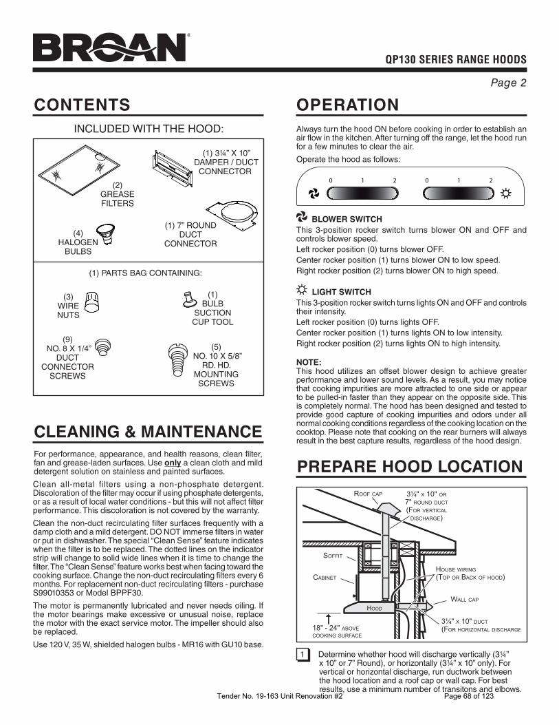
QP130 SERIES RANGE HOODS
Page 2
OPERATION
Always turn the hood ON before cooking in order to establish an air flow in the kitchen. After turning off the range, let the hood run for a few minutes to clear the air.
Operate the hood as follows:
1 20 1 20
BLOWER SWITCH
This 3-position rocker switch turns blower ON and OFF and controls blower speed.Left rocker position (0) turns blower OFF.Center rocker position (1) turns blower ON to low speed.Right rocker position (2) turns blower ON to high speed.
LIGHT SWITCH
This 3-position rocker switch turns lights ON and OFF and controls their intensity.Left rocker position (0) turns lights OFF.Center rocker position (1) turns lights ON to low intensity.Right rocker position (2) turns lights ON to high intensity.
NOTE:This hood utilizes an offset blower design to achieve greater performance and lower sound levels. As a result, you may notice that cooking impurities are more attracted to one side or appear to be pulled-in faster than they appear on the opposite side. This is completely normal. The hood has been designed and tested to provide good capture of cooking impurities and odors under all normal cooking conditions regardless of the cooking location on the cooktop. Please note that cooking on the rear burners will always result in the best capture results, regardless of the hood design.
CLEANING & MAINTENANCE
For performance, appearance, and health reasons, clean filter, fan and grease-laden surfaces. Use only a clean cloth and mild detergent solution on stainless and painted surfaces.
Clean all-metal filters using a non-phosphate detergent. Discoloration of the filter may occur if using phosphate detergents, or as a result of local water conditions - but this will not affect filter performance. This discoloration is not covered by the warranty.
Clean the non-duct recirculating filter surfaces frequently with a damp cloth and a mild detergent. DO NOT immerse filters in water or put in dishwasher. The special “Clean Sense” feature indicates when the filter is to be replaced. The dotted lines on the indicator strip will change to solid wide lines when it is time to change the filter. The “Clean Sense” feature works best when facing toward the cooking surface. Change the non-duct recirculating filters every 6 months. For replacement non-duct recirculating filters - purchase S99010353 or Model BPPF30.
The motor is permanently lubricated and never needs oiling. If the motor bearings make excessive or unusual noise, replace the motor with the exact service motor. The impeller should also be replaced.
Use 120 V, 35 W, shielded halogen bulbs - MR16 with GU10 base.
CONTENTS
(2)GREASEFILTERS
(1) 3¼” X 10”DAMPER / DUCT
CONNECTOR
(1) 7” ROUNDDUCT
CONNECTOR(4)
HALOGENBULBS
(1)BULB
SUCTIONCUP TOOL
(1) PARTS BAG CONTAINING:
(3)WIRENUTS
INCLUDED WITH THE HOOD:
(9) NO. 8 X 1/4”
DUCTCONNECTOR
SCREWS
(5) NO. 10 X 5/8”
RD. HD.MOUNTINGSCREWS
PREPARE HOOD LOCATION
SOFFIT
18" - 24" ABOVECOOKING SURFACE
CABINET
3¼" X 10" DUCT(FOR HORIZONTAL DISCHARGE
WALL CAP
ROOF CAP 3¼" X 10" OR7" ROUND DUCT(FOR VERTICAL
DISCHARGE)
HOUSE WIRING(TOP OR BACK OF HOOD)
HOOD
1 Determine whether hood will discharge vertically (3¼” x 10” or 7” Round), or horizontally (3¼” x 10” only). For vertical or horizontal discharge, run ductwork between the hood location and a roof cap or wall cap. For best results, use a minimum number of transitons and elbows.
Tender No. 19-163 Unit Renovation #2 Page 68 of 123

QP130 SERIES RANGE HOODS
Page 3
3¼” X 10”
HORIZONTAL DUCTING
HD274A
CABINETBOTTOM
CABINET FRONT
HORIZONTAL DUCTACCESS HOLE
5¼”
HOODMOUNTINGSCREWS (5)
ELECTRICALACCESS HOLE
(in wall)
4”
CENTERLINE
WOOD SHIMS(recessed-bottom
cabinets only)
115/8” 11⅝” 8½”
1½” ⅜”4⅞” *
5¼”
ELECTRICALACCESS HOLE
(in cabinet bottom)
23/8"
115/8" (30" hood) 115/8" (30" hood)
8½"107/8"
25/8"
HOOD MOUNTING SCREWS (5)
45/8"
7-IN. ROUND7-IN. ROUNDDUCTDUCT
ACCESSACCESSHOLEHOLE
7-IN. ROUNDDUCT
ACCESSHOLE
8" DIA.HOLE
47/8" *
7-IN. ROUND
DUCTING
PREPARE THE HOOD
ALUMINUMFILTERS
5 Remove the Aluminum Filters from the hood.
(2)LIFTOUT
(1)PULL
DOWN
4 Remove all protective polyfilm from the hood (stainless steel hoods only).
3 Remove parts bag from inside the foam packaging end cap.
VERTICAL DUCTACCESS HOLE
¾”
10⅞”5¼”5¼”
CENTERLINE
HOOD MOUNTING SCREWS (5)
ELECTRICALACCESS HOLE
(in cabinet bottom)WOOD SHIMS
(recessed-bottomcabinets only)
CABINET FRONT
CABINETBOTTOM
4½”2⅜”
11⅝”
2⅝”
11⅝”
8½”
4⅞”*
3¼” X 10”
VERTICAL DUCTING
2 Use the proper diagram below, for placement of ductwork and electrical cutout in cabinet or wall. For a non-ducted installation, DO NOT cut a duct access hole.
* Note the extra wood shim and mounting screw near the cabinet front, 4-7/8” to the right of the cabinet center line.
6 Remove 2 screws holding Damper / Duct Connector to hood. Remove damper/duct connector from inside the hood.
FOR DUCTED INSTALLATIONS - Skip to Step 9.
DAMPER /DUCT CONNECTOR
Tender No. 19-163 Unit Renovation #2 Page 69 of 123
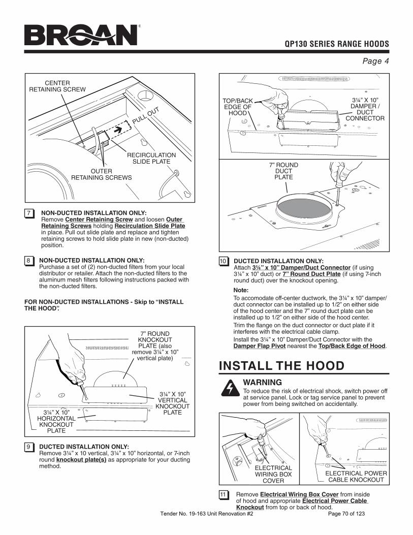
QP130 SERIES RANGE HOODS
Page 4
9 DUCTED INSTALLATION ONLY:Remove 3¼” x 10 vertical, 3¼” x 10” horizontal, or 7-inch round knockout plate(s) as appropriate for your ducting method.
10 DUCTED INSTALLATION ONLY:Attach 3¼” x 10” Damper/Duct Connector (if using 3¼” x 10” duct) or 7” Round Duct Plate (if using 7-inch round duct) over the knockout opening.
3¼” X 10”HORIZONTALKNOCKOUT
PLATE
3¼” X 10”VERTICAL
KNOCKOUTPLATE
7” ROUNDKNOCKOUTPLATE (also
remove 3¼” x 10” vertical plate)
3¼” X 10”DAMPER /
DUCTCONNECTOR
7” ROUND DUCTPLATE
Note:
To accomodate off-center ductwork, the 3¼” x 10” damper/duct connector can be installed up to 1/2” on either side of the hood center and the 7” round duct plate can be installed up to 1/2” on either side of the hood center.Trim the flange on the duct connector or duct plate if it interferes with the electrical cable clamp.Install the 3¼” x 10” Damper/Duct Connector with the Damper Flap Pivot nearest the Top/Back Edge of Hood.
TOP/BACKEDGE OF
HOOD
7 NON-DUCTED INSTALLATION ONLY:Remove Center Retaining Screw and loosen Outer Retaining Screws holding Recirculation Slide Plate in place. Pull out slide plate and replace and tighten retaining screws to hold slide plate in new (non-ducted) position.
RECIRCULATIONSLIDE PLATE
CENTERRETAINING SCREW
PULL OUT
8 NON-DUCTED INSTALLATION ONLY:Purchase a set of (2) non-ducted filters from your local distributor or retailer. Attach the non-ducted filters to the aluminum mesh filters following instructions packed with the non-ducted filters.
FOR NON-DUCTED INSTALLATIONS - Skip to “INSTALL THE HOOD”.
OUTERRETAINING SCREWS
INSTALL THE HOOD
WARNING To reduce the risk of electrical shock, switch power off at service panel. Lock or tag service panel to prevent power from being switched on accidentally.
ELECTRICAL WIRING BOX
COVER
11 Remove Electrical Wiring Box Cover from inside of hood and appropriate Electrical Power Cable Knockout from top or back of hood.
ELECTRICAL POWERCABLE KNOCKOUT
Tender No. 19-163 Unit Renovation #2 Page 70 of 123

QP130 SERIES RANGE HOODS
Page 5
CONNECT THE WIRING
E0059
15 Connect House Power Cable to range hood wiring - BLACK to BLACK, WHITE to WHITE, and GREEN or BARE WIRE to Ground Screw. Replace electrical wiring box cover.
HOUSEPOWERCABLE
GROUNDSCREW
12 Run House Power Cable between service panel and hood location. Attach power cable to hood using appropriate clamp.
13 Hang hood from (5) mounting screws driven part-way into cabinet locations (shown in illustrations under “PREPARE HOOD LOCATION”). Mounting screws are included in parts bag. Slide hood back towards wall until mounting screw heads are engaged in narrow end of keyhole slots in top of hood. Tighten screws securely.
14 DUCTED INSTALLATION ONLY:Connect ductwork to hood and use duct tape to make joints secure and air-tight. Make sure the damper / duct connector enters the ductwork and that the damper opens and closes freely.
HOUSEPOWER CABLE
INSTALL LIGHT BULBS
16 Install (4) Halogen Bulbs. Use 120 V, 35 W, shielded halogen bulbs - MR16 with GU10 base (included).
NOTE: Suction Cup Tool (included with hood) can be used to install and remove light bulbs.
Align pins on bulb with large diameter opening on socket, then push bulb in towards hood and rotate clockwise until firmly seated.
The position of the bulb socket (depth) is adjustable and may be necessary when:
a) certain brands of bulbs are difficult to install. b) the bulb protrudes too far below the light panel.
(1)PUSH IN
! CAUTION: Bulbs may be hot. Refer to bulb packaging for further information.
(2)ROTATE
CLOCKWISE
SUCTIONCUP TOOL
HALOGENBULB
17 DUCTED INSTALLATION ONLY:Re-install aluminum filters removed in Step 5.
NON-DUCTED INSTALLATION ONLY:Install aluminum filters and non-ducted filters - purchased and assembled in Step 8.
To change the depth of bulb sockets: - Remove 2 Light Panel Screws. Set screws aside. - Loosen 2 Screws holding Lamp Socket Bracket to
Light Panel. - Adjust socket/bracket to desired depth. - Re-tighten screws securely. - Re-attach light panel.
LIGHT PANELSCREWS
LIGHT PANEL
LAMP SOCKETBRACKET
SCREWSLIGHTPANEL
Tender No. 19-163 Unit Renovation #2 Page 71 of 123

QP130 SERIES RANGE HOODS
Page 6
SERVICE PARTS
Order replacement parts by PART NO. - not by KEY NO.
KEY NO. PART NO. DESCRIPTION
1 97017727 7” Round Duct Plate (includes mounting hardware) 2 97017729 Switch Assembly White (includes 2 switches, nameplate, mounting hardware) 97017730 Switch Assembly Black (includes 2 switches, nameplate, mounting hardware) 3 99526653 Nameplate, White 99526652 Nameplate, Black 4 97017736 Capacitor Kit (includes wire nuts, mounting screw) 5 97017753 Non-duct Slide, White (includes mounting hardware) 97017821 Non-duct Slide, Black (includes mounting hardware) 6 97017755 Light Panel RH White (includes mounting hardware) 97017756 Light Panel RH Black (includes mounting hardware) 97017757 Light Panel RH Stainless (includes mounting hardware)” 7 97017720 Filter Kit for 30”” Hood (2 per bag) 8 97017754 Venturi Ring (includes mounting hardware) 9 97017734 Blower Wheel (includes mounting nut) 10 97017732 Motor Kit (includes motor, isolators, mounting hardware) 11 97017728 Damper / Duct Connector (includes mounting hardware) 12 97017758 Light Panel LH White (includes mounting hardware) 97017759 Light Panel LH Black (includes mounting hardware) 97017760 Light Panel LH Stainless (includes mounting hardware) 13 97017731 Lamp Socket (includes lamp socket, wire nuts, mounting screws) 14 97018233 Lamp Socket Bracket (includes mounting hardware) Not Shown 97017735 Parts Bag Not Shown 99010353 Non-Duct Filter Kit for 30” Hood (2 charcoal filters and 8 filter clips)Not Shown 99526707 Suction Cup ToolNot Shown 97018234 Light Diode (includes wire nuts)Not Shown 99526798 35W Halogen GU10 Bulb
1
11
23
10
12
97
4
6
8
13
5
14
Replacement parts can now be ordered on our website. Please visit us
at www.broan.ca
WARRANTY
Two-Year Limited WarrantyBroan-NuTone warrants to the original consumer purchaser of its products that such products will be free from defects in materials or workmanship for a period of two (2) years from the date of original purchase. THERE ARE NO OTHER WARRANTIES, EXPRESS OR IMPLIED, INCLUDING, BUT NOT LIMITED TO, IMPLIED WARRANTIES OF MERCHANTABILITY OR FITNESS FOR A PARTICULAR PURPOSE. During this two-year period, Broan-NuTone will, at its option, repair or replace, without charge, any product or part which is found to be defective under normal use and service. THIS WARRANTY DOES NOT EXTEND TO FLUORESCENT LAMP STARTERS, TUBES, HALOGEN AND INCANDESCENT BULBS, FUSES, FILTERS, DUCTS, ROOF CAPS, WALL CAPS AND OTHER ACCESSORIES FOR DUCTING. This warranty does not cover (a) normal maintenance and service or (b) any products or parts which have been subject to misuse, negligence, accident, improper maintenance or repair (other than by Broan-NuTone), faulty installation or installation contrary to recommended installation instructions.The duration of any implied warranty is limited to the two-year period as specified for the express warranty. Some states do not allow limitation on how long an implied warranty lasts, so the above limitation may not apply to you.BROAN-NUTONE’S OBLIGATION TO REPAIR OR REPLACE, AT BROAN-NUTONE’S OPTION, SHALL BE THE PURCHASER’S SOLE AND EXCLUSIVE REMEDY UNDER THIS WARRANTY. BROAN-NUTONE SHALL NOT BE LIABLE FOR INCIDENTAL, CONSEQUENTIAL OR SPECIAL DAMAGES ARISING OUT OF OR IN CONNECTION WITH PRODUCT USE OR PERFORMANCE. Some states do not allow the exclusion or limitation of incidental or consequential damages, so the above limitation or exclusion may not apply to you. This warranty gives you specific legal rights, and you may also have other rights, which vary from state to state. This warranty supersedes all prior warranties.To qualify for warranty service, you must (a) notify Broan-NuTone at the address or telephone number below, (b) give the model number and part identification and (c) describe the nature of any defect in the product or part. At the time of requesting warranty service, you must present evidence of the original purchase date. Venmar Ventilation ULC, 550 Lemire Blvd. Drummondville Québec Canada J2C 7W9 www.broan.ca 877-896-1119
Tender No. 19-163 Unit Renovation #2 Page 72 of 123

Electrical Specifications: PF-2019-170C McAlpine Ave. Accessible Unit Conversion
Part – 1 GENERAL:
1.1. Reference Standards:
1. All work shall be conducted in compliance with the most recent versions of all applicable
codes and standards at the time of tender closing, but not limited to the following:
1. National Building Code of Canada (NBC);
2. Nova Scotia Building Code (NSBC);
3. Canadian Electrical Code (CEC);
4. National Fire Code of Canada (NFC);
5. All applicable bulletins from the Nova Scotia Chief Electrical Inspector, Fire
Marshal’s Office, and Nova Scotia Department of Labour and Advanced Education;
6. All applicable bulletins from Nova Scotia Power Inc.;
7. All applicable standards from Underwriters Laboratories of Canada (ULC);
8. All applicable standards from Canadian Standards Association (CSA);
1.2. Scope of Work:
1. The specifications complement the drawings in describing the supply, installation, and
modification of the electrical system(s). These systems shall include, but not be limited
to the following:
1. 120V lighting system and controls;
2. 120/240V, 1- ø power systems wiring and devices;
3. Communications (Voice/Data/Cable) wiring and devices;
2. The Contractor shall provide all labour, materials, equipment, hardware, tools,
instruments, and consumables as required to deliver a complete, functional, and safe
electrical installation c/w required testing, verification, commissioning, and placing into
service of all electrical equipment and systems including the electrical portions of
systems provided by others;
3. The Contractor shall size (where not provided), supply, and install all materials including
conductors, conduits, junction boxes, electrical boxes, supports, etc. required for all
installed systems/equipment to provide complete, functional, and safe electrical
installation in compliance with all applicable codes, standards, Authority Having
Jurisdiction (AHJ) regulations, and manufacturer’s instructions;
1.3. Definitions:
1. The Project Manager shall be a person designated to represent the Housing Authority
(HA) in all matters dealing with this contract;
2. The Contractor shall be the person / company approved by the HA to render services
under this Contract;
1.4. Contract Materials:
Tender No. 19-163 Unit Renovation #2 Page 73 of 123
1. All contract materials, equipment, consumables, etc. (unless specified otherwise), shall
be new, best quality, CSA/ULC certified or AHJ approved for intended application, and
supplied via authorized distributors;
1.5. Contract Drawings:
1. No omissions in the drawings and/or specifications are intended and the Contractor shall
give due consideration to this matter. Any work or material referred to in the drawings
and not in the specifications, or vice-versa, shall be provided and installed as though fully
covered in both;
2. Any error or omission shall be referred to the Project Manager whose decision shall be
final;
3. Building dimensions shall not be scaled from the Electrical drawings, but shall be
obtained from Architectural and/or on-site measurements;
1.6. Site Conditions:
1. Prior to submitting the bid, the Contractor shall visit the site and familiarize
himself/herself with all matters which may effect the work. No consideration shall be
given to items arising from the Contractor’s failure to do so;
1.7. Quality Control:
1. For the purpose of uniformity similar materials shall be of one (1) manufacturer (where
feasible);
1.8. Other Trades:
1. The Contractor shall co-operate and investigate with other trades to make maximum use
of the spaces;
2. The Contractor shall co-operate with other Contractors on the site and carry out their
work in a manner, as not to obstruct or hold-up the work of other trades;
1.9. General Requirements:
1. Whenever it is proposed to make a change or changes in the design or type of equipment
called for in the specifications, the Contractor shall estimate the cost (material + labour)
and submit detailed itemized estimate of the costs (material + labour), entering into the
change or substitution, at no cost to the HA. Work shall be conducted only upon approval
from the Project Manager;
2. All power and/or system shutdown shall be coordinated with the Project Manager;
3. The Contractor shall identify and re-use existing spare equipment/material (where
feasible), only if deemed safe for operation and without deficiencies, by the Contractor.
The Contractor shall provide min. one (1) year labour and material warranty for all re-
used material;
4. It shall be the responsibility of the Contractor to contact the Project Manager for
inspections during construction such as above ceiling inspections prior to installation of
Tender No. 19-163 Unit Renovation #2 Page 74 of 123

ceiling tile or drywall, inspection of devices installed on the walls prior to drywall
construction, etc.;
5. Maintain circuit continuity to existing equipment where disrupted/relocated by
renovation. Re-locate existing electrical equipment (where required) to suit new
construction, upon approval from the Project Manager;
6. At the completion of the project, the Contractor shall test and operate all equipment
installed (new and existing) in the project to ensure it operates as expected and correct
all deficiencies (as required) at that time. Provide written report for the Project Manager
to review at this time;
7. Devices mounted on exterior walls shall be installed in a manner to maintain the integrity
of existing/new vapor barrier;
8. The Contractor shall:
1. Verify the content of the Scope of Work and specifications herein, prior to submitting
the bid. The Contractor shall report any errors or omissions to the Project Manager
prior to submitting the bid;
2. Confirm all existing site conditions, systems, equipment prior, scope of work, and
specifications, prior to submitting the bid;
3. Be notified of any omissions/deficiencies in work, non-conformance issues of work
according to Scope of Work, and non-approval of work by the Project Manager, upon
review of all submittals;
4. Provide for all labour, transportation, materials, tools, and equipment required to
render services stated in the Contract;
5. Bear all losses resulting to him or the HA on account of the amount or character of
work, or because of the nature of the area in or on which the work being done is
different from what was estimated/expected by the Contractor, or account of weather,
elements or other causes;
6. Submit to the Project Manager upon request, a roster of employees (including copies
of documents confirming their qualifications) engaged in providing service(s) under
this Contract. Other person(s) shall be permitted to perform service(s) only with the
written approval of the Project Manager;
7. Ensure that its personnel(s) during the course of the Contract term are expected to
conduct themselves in a polite and professional manner at all times. Discussions with
residents (where applicable) regarding the work shall be limited to only aspects of
the work that bears directly on the residents;
8. Conduct all project work by certified and registered journeypersons with the Nova
Scotia Department of Labour and Advanced Education. If a work specialty being an
unregulated trade is required, then person(s) conducting such work shall have a
minimum of five (5) years’ experience in that specialty with suitable references. If
helpers are required and of whom do not have the specialty’s required experience or
trade certification then written approval shall be obtained from the Project Manager.
Helpers shall be registered apprentices for that trade, if so regulated. Apprentices and
helpers shall be supervised by journeypersons according to all applicable Provincial
Acts & Regulations, including the Provincial Labour Act;
Tender No. 19-163 Unit Renovation #2 Page 75 of 123

9. Be responsible to ensure the workers conducting all work as part of the Contract are
safety certified with qualified, safety organization registered in Nova Scotia;
10. Seek written approval from the Project Manager, prior to commencing any work that
requires running through the structural members of the building;
11. Inquire with the Project Manger about presence of asbestos, if any in the work area(s)
prior to commencing any work in the Contract term. The Contractor shall be
responsible for notifying their employees and sub-contractors of the presence of
asbestos, if found in the work area(s). The Contractor shall not disturb known or
assumed asbestos containing materials. If the Contractor suspects presence of
asbestos containing material in the building that has not been identified, the
Contractor shall stop all work and notify the issue to the Project Manager
immediately and shall not commence work prior to seeking approval from the Project
Manager. If the Contractor disturbs asbestos containing material identified in the
work area(s), then they shall be responsible for the cost of the clean-up and de-
contamination and shall bear all other induced costs;
1.10. Qualification/References:
1. All work shall be conducted by qualified trade personnel (construction electrician,
communications technician, etc.) registered with the Nova Scotia Department of Labour
and Advanced Education, with Journeyperson certification and with minimum three (3)
years of experience;
2. The Contractor shall provide supervision and sufficiently qualified foreman to ensure
that the work proceeds in a proper and efficient manner;
3. The Contractor and all pertinent sub-trades shall maintain all required qualifications and
certifications to conduct all work stated in the Contract, for the entire duration of the
Contract term;
4. The Contractor shall provide at least three (3) references of projects completed within
the last five (5) years of similar size and complexity c/w location, contact names, contact
details, telephone numbers, etc.;
1.11. Permits and Fees:
1. The Contractor shall obtain all required permits and inspections in compliance with all
applicable codes, standards, and AHJ regulations;
2. Submit to the Nova Scotia Power, Electrical Inspection Department and Supply
Authority, all drawings and specifications required for examination and approval, prior
to commencement of work;
3. The Contractor shall obtain all required certificates of such permits/inspections and shall
pay all charges in connecter therewith;
4. The final certificate of inspection shall be obtained before final payment for work shall
be considered due;
5. Notify the Project Manager of changes required by the AHJ, prior to implementing them;
1.12. Delivery, Storage, Handling, Disposal, and Cleaning:
Tender No. 19-163 Unit Renovation #2 Page 76 of 123
1. The Contractor shall:
1. Deliver materials in the manufacturer’s original, unopened, undamaged, containers
with identification labels intact;
2. Comply with the manufacturer’s ordering instructions and lead-time requirements to
avoid delays;
3. Coordinate with the Project Manager to find a suitable storage space prior to delivery
of the system equipment to site;
4. Store and handle materials in compliance to the manufacturer’s recommendations to
ensure that their performance requirements are not affected by abrasions, dust,
humidity, or extreme temperatures;
5. Be responsible for loss of materials through theft, breakage, or damage prior to
acceptance of work by the Project Manager;
6. Properly dispose of materials generated out of all work performed within this contract
in compliance with Municipal, Provincial, and Federal regulations;
7. Remove all debris and leave the site neat and tidy, upon completion of work;
1.13. Identification:
1. New typewritten directory shall be provided on the inside of the existing electrical
panel(s), showing the location and loads connected to the branch circuit(s). Existing
panel directories shall be kept on-site for reference;
2. Communications wiring shall be labelled at termination ends at the unit communications
panel as well as the outlet, identifying the area served. Wiring from the unit
communications panel to the main communications panel shall be labelled to identify the
apartment unit. Use best industry standards for labeling;
3. All new electrical equipment such as switchboards, panels, disconnect switches,
transformers, control panels, etc. shall be provided with “lamicoid” nameplates;
4. Lamicoid nameplates shall be 1/8” thick plastic engraving sheet with black letters on
white face for all electrical systems except fire alarm and receptacles fed from generator
circuits which shall have white letters on red face;
5. All junction and/or pull boxes and their respective cover plates shall be colour coded as
per the following:
1. 51 to 240v – Yellow
2. Fire alarm – Red
3. Telephone – Black
4. Ground or bond – Green
5. Data – Blue/White
6. Cable TV – Yellow/White
6. Branch circuit wiring shall be identified by circuit number at both ends at all panel
boards, pull and junction boxes, outlet and equipment connections, and all wiring
devices. Labels shall be Panduit PLD-1 or PDL-2 as required. Labels shall be installed
in such a manner as to present area with information in “flagged” position;
Tender No. 19-163 Unit Renovation #2 Page 77 of 123

7. All electrical distribution equipment shall have ARC flash labels installed to meet AHJ
requirements;
8. Identify conduit at 50’ intervals or where they enter walls, ceiling, or floors;
1.14. Cutting and Patching:
1. Cutting and patching shall be performed by skilled trades’ personnel. Make every effort
to minimize cutting and patching;
2. Excavation and backfilling for electrical, controls, and communications cabling as well
as cutting and patching of all penetrations shall be the responsibility of the General
Contractor;
1.15. Fire Stopping:
1. Where conduits and/or cables pass through fire separations and sound rated separations
including floors, walls, membranes, etc., provide a metallic sleeve or core drill to 1”
radius larger than the conduit or cable. Construct a ceramic fiber insulation dam(s) as
required and fill the penetration with 3M “Putty 303” or 3M “Caulk CP25”. A minimum
of 2” of putty or caulk shall be required. Installation shall be in strict compliance with
manufacturer’s instructions and ULC requirements;
1.16. Submittals:
1. General:
1. All electronic submittals shall be in PDF format and of adequate clarity as deemed
by the Project Manager, else re-submission shall be required;
2. All submittals shall be reviewed and stamped by the Contractor to confirm the
accuracy of the information submitted;
3. Maintain project “As-Built” record drawings and accurately record significant
deviations from the Contract documents, caused by the site conditions or change in
the Contract. Mark changes on White prints in “Red”. At the completion of the
project and prior to final inspection, neatly transfer “As-Built” corrections and
notations to a clean set of drawings and submit to the engineer for review;
2. Shop Drawings:
1. The Contractor shall prepare shop drawings showing in detail the design and
construction of all equipment, panels, cabinets, lighting fixtures, wiring devices, etc.
One (1) hard copy and one (1) electronic copy in PDF format of such drawings shall
be submitted to the Project Manager for review and approval prior to ordering and
any execution of work;
2. All shop drawings, other than standard manufacturer’s datasheets, shall bear the
stamp of a Nova Scotia registered Professional Engineer, who shall be fully
responsible for the engineering content of such drawings;
3. Prior to submission, the Contractor shall carefully check all shop drawings to ensure
that they comply with the drawings and specifications in both intent and detail. No
Tender No. 19-163 Unit Renovation #2 Page 78 of 123
consideration shall be given to shop drawings submitted without this approval and
review from the Contractor;
3. Closeout Submittals:
1. The Contractor shall provide one (1) original hard copy and one (1) electronic copy
in PDF format of the following document set which shall include but not be limited
to:
1. Utility interim/final electrical inspection report;
2. Operations & Maintenance manuals for all new equipment supplied & installed
within the Contract;
3. System testing, verification, and commissioning report(s) for all new equipment
supplied & installed within the Contract;
4. Written statement of warranty policy and warranty documents from the
manufacturer and the Contractor for all materials and labour provided within the
Contract;
5. “As-Built” drawings;
1.17. Warranty:
1. The Contractor shall:
1. Provide minimum one (1) year of written warranty (unless indicated otherwise) on
all equipment, materials, and labour provided under the Contract to maintain the
system in full operation, from the date of acceptance by the Project Manager;
2. Provide free of charge, product firmware, and software upgrades throughout the
warranty period for any product feature enhancements available to equipment
installed in the Contract;
3. Replace equipment or component found to be defective within the warranty period at
no cost to the HA, including equipment, material, and labour;
4. Ensure the warranty covers all system performance difficulties and adjustments
during the warranty period at no cost to the HA. Any service and correction work
shall continue by the Contractor as part of the warranty until the Project Manager is
satisfied that the system works as intended;
Part – 2 PRODUCTS:
2.1. General:
1. All material, equipment, devices, etc., provided and installed under this Contract, shall
be new, of best available quality, and listed by CSA/ULC and/or AHJ approved agency,
for its intended application;
2. All material, equipment, devices, software, hardware, etc. provided and installed under
this Contract, shall be non-proprietary type i.e. all items supplied and installed within
this Contract shall be serviceable by qualified third-party Contractors;
Tender No. 19-163 Unit Renovation #2 Page 79 of 123
3. The Contractor may provide alternate product/material/equipment, only upon written
approval from the Project Manager;
2.2. Conduits:
1. Thin wall type “EMT” conduit shall conform to the most recent revision of CSA C22.2
No. 83, galvanized, sized as per CEC requirements;
2. Flexible galvanized steel liquid tight conduit shall conform to the most recent revision of
CSA C22.2 No. 56, sized as per CEC requirements;
3. All spare conduit runs shall contain a propylene pull cord to accommodate future
installations;
4. Surface mount conduit systems shall be provided for surface mount device boxes;
2.3. Wire and Cables:
1. All wires and cables shall be in compliance with the most recent CSA, Electrical and
Electronic Manufacturers of Canada (EEMAC), the Insulated Power Cable Engineers
Association (IPCEA), and the American Society of Testing Materials (ASTM) standards;
2. Wring on circuits exceeding 50V to ground shall be soft drawn stranded copper of 98%
conductivity (rated at 600V) and of full size and AWG gauge. Insulation shall be cross-
linked Polyethylene RW90 rated 600V. Minimum wire size for lights and power systems
shall be No. 12 AWG, unless specified / required otherwise. Wiring shall be colour coded
as follows:
1. Phase A – Red
2. Phase B – Black
3. Phase C – Blue
4. Neutral – White
5. Ground – Green
3. AC90 cables shall be soft drawn solid copper of 98% conductivity and of full size and
AWG gauge. Outer armor shall be of interlocking aluminum. Colour coding shall be as
follows:
1. Phase conductors – Black or Red
2. Neutral conductors – White
3. Ground conductors – Bare
4. Current carrying neutral conductors for all systems rated 600V or less, shall have RW90
– XLPE type insulation rated accordingly;
5. NMD cables shall not be permitted for installation for this project;
2.4. Outlet boxes, conduit boxes, and fittings:
1. Outlet boxes for use in dry concealed construction shall be one piece, galvanized, pressed
steel, where wire fill dictates larger boxes for outlets use suitably sized square boxes with
raised “tile ring” style extension;
2. Provide blank cover plates for boxes without wiring devices;
Tender No. 19-163 Unit Renovation #2 Page 80 of 123

3. Provide combination boxes with barriers where outlets for more than one (1) system are
grouped;
2.5. Wiring devices:
1. Switches:
1. Line voltage switches shall be:
1. Commercial Grade;
2. Toggle type;
3. Flush mounted (where possible);
4. AC rated;
5. Switch handles shall be white c/w compatible cover/wall plates;
6. Acceptable manufacturers: Leviton, Lutron, Hubbell, or Approved Equal;
2. Standard duplex receptacles shall be:
1. Ratings and configurations (5-15R/5-20R) as noted on the drawing;
2. AC rated;
3. Specification grade;
4. Tamper Resistant;
5. U-ground;
6. Parallel slots with double wiping contacts;
7. Back and side wire terminals c/w ground terminal;
8. Break-off features for split wiring;
9. Compatible for back wiring of #10 AWG conductors;
10. One piece body;
11. Provided with compatible wall/cover plates;
12. Acceptable manufacturers: Hubbell, Leviton, Lutron, or Approved Equal;
3. Cover/Wall Plates:
1. Indoor:
1. Type 302 stainless steel for surface/flush mounted devices in
mechanical/electrical/communications room and relevant corridor(s);
2. Plastic/Nylon wall plates for surface/flush mounted devices in all other areas;
3. Single and multi-gang plates to match devices and boxes;
4. Acceptable manufacturers: Leviton, Hubbell, or Approved Equal;
2. Outdoor:
1. Black PVC weatherproof for surface/flush mounted devices, designed for outdoor
use c/w gasket and weatherproof, extra-duty marked/rated, receptacle covers;
2. Acceptable manufacturers: Leviton, Hubbell, or Approved Equal;
4. Equipment from the same manufacturer shall be used for the entire Project.
Tender No. 19-163 Unit Renovation #2 Page 81 of 123

2.6. Wire and box connectors (0-1000V):
1. Use spring type pressure wire connectors for all branch circuit wiring sized #10 AWG
and smaller. Current carrying parts shall be copper or copper alloy c/w an appropriately
sized insulating cap. Cap shall completely fit or cover all enclosed conductors as
required;
2. Joints for all other wiring shall be made using T&B colour keyed compression type
connectors, 54000 series, and TBM series compression tools. Approved manufacturers
are Hubbell, Pass & Seymour, and Leviton;
2.7. Circuit Breakers:
1. Circuit breakers shall:
1. Be bolt-on/snap-on type, as compatible with the existing electrical panel(s);
2. Multi-pole breakers shall have single handle. Tie-bars shall not be permitted;
3. Quick Make-Quick Break type for manual and automatic operation. They shall be
suitable for inverse-time thermal and instantaneous magnetic operation;
4. Have de-ionizing arc chambers;
5. Be trip-free of operating handles on overloads with a definite indication when
tripping has taken place;
6. Have interrupting ratings in compliance with the most recent version of applicable
CSA and EMMAC standards;
2. Mini-type circuit breakers shall not be acceptable;
3. Approved Manufacturers: Same as the existing electrical panel(s);
2.8. Panelboards:
1. Re-use existing;
2.9. Supporting devices:
1. Supporting of electrical systems raceway shall be independent of any non-electrical
support systems;
2. Supply all required inserts, rods, channels, brackets, etc., to form a support system
capable of carrying at least twice the weight of equipment or material supported;
3. In concrete, use cast-in threaded inserts wherever possible. Should additional inserts be
required, use a “red-head” type insert capable of carrying at least 500lbs.;
4. All hanger rods shall be 3/8” diameter standard mild steel, cut to required lengths and
threaded;
5. Supports for all conduit work shall be one-hole steel pipe straps; uni-strut or equal, with
necessary fittings; caddy clips or equal, approved for their intended application;
6. Fastening devices for cabinets, boxes, supports, etc. shall be nut and bolt;
7. Fastening devices for outlet boxes shall be nut and bolt, ram-set, expansion shields,
wedge anchors, or caddy clips. Size and number shall suit the application;
Tender No. 19-163 Unit Renovation #2 Page 82 of 123
2.10. Lighting:
1. All light fixtures shall be compatible to respective ceiling and wall type(s). Required
manufacturer approved fittings and/or mounting accessories shall be provided;
2. Colour Temperature of all lamps used in the project shall suit application and be
compatible with other existing and/or new light fixtures in the area within line-of-sight,
where not specified;
3. On completion of the project, provide at least 10% spare lamps for each type of fixture
installed in the project;
Part – 3 EXECUTION:
3.1. General:
1. All equipment, products, devices, materials, etc., installed in the project shall be in
compliance with the most recent version of applicable codes, standards, AHJ regulations,
and manufacturer’s instructions;
3.2. Conduits:
1. Thin wall type “EMT” shall be used for all branch circuit wiring and all systems where
exposed;
2. All concealed and exposed conduits shall be kept parallel to building lines;
3. Flexible conduit, not smaller than 3/8” I.D. or flexible armoured cable with separate
ground conductor c/w insulating anti-shorts shall be used between lighting fixtures and
their respective junction boxes, and where “EMT” conduit cannot be used, such as in
cabinet work;
4. Liquid tight flexible conduit, not smaller than 3/8” I.D. shall be used for connections to
all vibrating equipment and/or mechanical equipment;
5. Conduits shall not be run directly between outlets on opposite sides of a common
partition, to prevent sound transmission;
6. Set screw steel connectors c/w insulated throats shall be utilized;
7. Provide appropriate fittings, couplings, bushings, connectors, accessories, and supports
for each conduit system as required to provide a complete installation;
8. Install cabling and conduits so as to conserve headroom and not interfere with work of
other trades;
9. Where practicable all installation shall be concealed;
10. Use steel fittings and couplings on EMT. Die cast fittings shall not be permitted;
11. Install bonding conductor in compliance with the most recent version of CEC, in all
conduit systems;
12. Use EMT for all wiring including telecommunications and low voltage, unless specified
otherwise;
13. Use rain tight connectors and couplings on all vertical runs of exposed conduit runs
terminating into the top of electrical equipment with drip shields and hoods to safeguard
against possible infiltration of water into the electrical equipment;
14. EMT shall be used for all panel feeds in the electrical room;
Tender No. 19-163 Unit Renovation #2 Page 83 of 123

15. Where raceway is exposed to the exterior, it shall be PVC with expansion joints as
required;
16. Do not locate conduits less than 3” parallel to steam or hot water lines with minimum of
1” at crossovers;
3.3. Wire and Cables:
1. All circuits shall be run to ensure that the voltage drop in no case exceeds 3% of the line
voltage;
2. Where pulling wires in conduit, use of a manufacturer approved lubricant shall only be
permitted;
3. Tye-wrapping of the neutral conductor with its respective phase conductors shall be made
at the closest point of entry “within” all panel boards, pull boxes, junction boxes, outlet
boxes, etc.;
4. All Teck cables shall be terminated with proper teck connectors;
5. All types of “armoured” cables shall be installed concealed, parallel, and perpendicular
to building lines and shall be adequately secured to the building structure at not less than
60” intervals or as per CEC (whichever more stringent), in such manner as to ensure they
are protected from potential mechanical damage. Install independent supports for cabling
in ceiling spaces, and do not use that of other trades. Do not secure cables to mechanical
systems piping, ducts, or suspended ceiling support wires. The laying of “un-supported”
cables directly atop the ceiling grid system is strictly prohibited;
6. Bonding and grounding conductors shall always be copper;
7. Aluminum Conductor Material (ACM) wiring shall not be used in any part of the
building’s distribution system downstream from the main incoming circuit breaker;
8. AC90 cable may be used for all branch circuit wiring where concealed in dry construction
in ceilings and wall runs parallel to building lines and secured in compliance with the
CEC;
9. Test all wiring, included in the contract, to ensure there are no shorts or grounded
conductors;
10. Provide separate neutrals for all circuits feeding receptacles adjacent to voice/data
outlets;
3.4. Outlet boxes, conduit boxes, and fittings:
1. When installing flush boxes in metal drywall partitions, where grouping of multiple
device boxes is required, support the box between the studs with a box mounting bracket.
Caddy RBS series box mounting brackets or Caddy SGB series box brackets or equal
shall be approved for this application. Where a single flush box is installed, this box may
be supported by the wall stud without any additional support required.
2. Wiring installed on any exposed type surfaces shall always be completely installed in
raceways as per following guidelines:
1. Use EMT conduit in unfinished areas
Tender No. 19-163 Unit Renovation #2 Page 84 of 123
2. Use aesthetic type surface raceway in finished areas where it is impossible to conceal
conduits.
3. Ceiling mounted conduit/raceway shall be secured directly to overhead structure
and/or related structural steel as high as possible in the ceiling space, and as close as
practicable to the underside of the deck.
4. Wall mounted conduit/raceway shall be secured directly to, or directly on, exposed
walls.
5. AC90 and/or other types of systems pliable cables shall not be installed on exposed
walls and/or ceilings without conduit/raceway. This applies to all systems, including
controls wiring.
3. At each receptacle, provide and install a standard pressed steel outlet box unless
specifically noted otherwise. Boxes shall not be mounted back to back, but separated by
a minimum of 12”, to prevent noise transmission;
4. In centering outlets, the Contractor is cautioned to allow for radiation, pipes, ducts, etc.,
and for variation in arrangement and thickness of finishes, etc.;
5. Cast type “FS” or “FD” boxes shall be utilized for all surface wiring of devices installed
lower than 8” A.F.F. (regardless of system type involved) c/w matching steel type “FS”
metal device plates unless specifically indicated otherwise. Cover plates shall be
specifically made for FS & FD boxes and shall utilize four (4) point fastening;
6. Flush installed 4” square, or 4-11/16” square box being used as a junction or pull box
that requires a blank metal cover plate shall have an appropriately sized, square welded
one or two gang “tile ring” installed on the same. This permits the use of standard, one
or two gang (blank) metal finish cover plate to be used instead of custom made oversized
cover plate;
7. Condulet fittings (LB, LL, LR) and their respective covers/plates shall be painted (colour
coded) and where concealed, have their locations identified with appropriate colour
coded self adhering discs applied directly to T-bar splines and/or access opening frames
in same manner as required for identifying concealed junction and/or pull boxes;
8. The use of either, corner pulling “ells” or corner pulling “elbows” in lieu of acceptable
“condulet” fittings shall be strictly prohibited;
9. Gang boxes where wiring devices are grouped;
10. Support boxes independently of connecting conduits;
11. All outlet boxes mounted on the exterior walls shall have vapor seals installed around
them and sealed to the box to provide a continuous vapor barrier;
3.5. Wiring devices:
1. Switches:
1. All switches and their wall/cover plates shall be installed plumb, with switch handle
in the “UP” position, when the switch is closed. Pig-tail branch circuit conductors
shall be used for connection to switches in multi-gang outlets;
2. Unless indicated otherwise, mounting height of all switches shall be 48” above the
finished floor;
Tender No. 19-163 Unit Renovation #2 Page 85 of 123
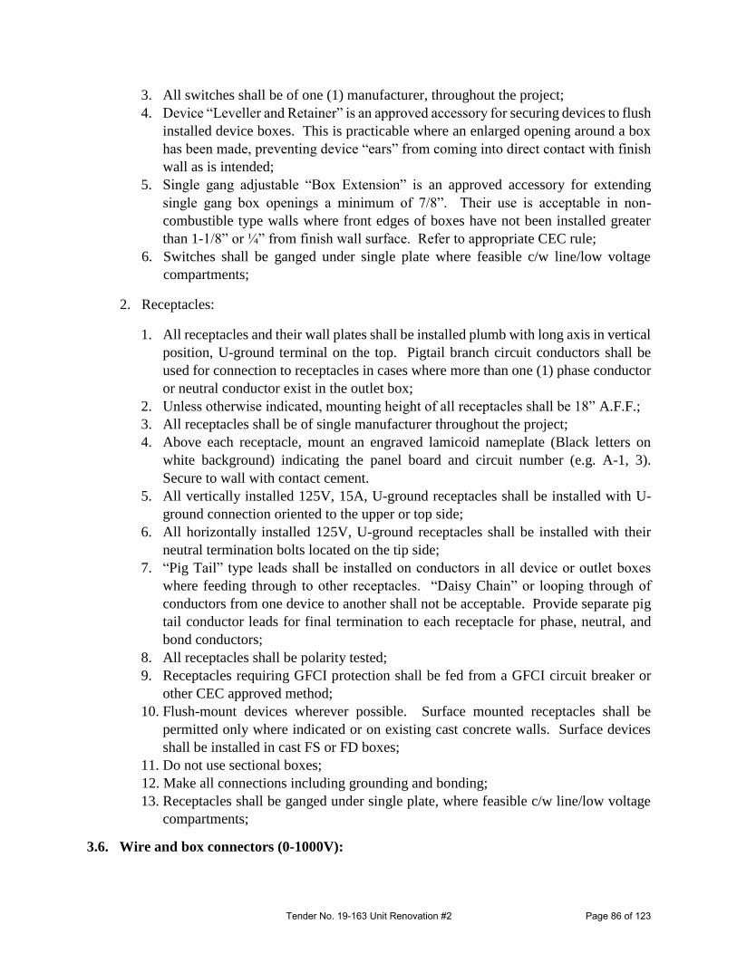
3. All switches shall be of one (1) manufacturer, throughout the project;
4. Device “Leveller and Retainer” is an approved accessory for securing devices to flush
installed device boxes. This is practicable where an enlarged opening around a box
has been made, preventing device “ears” from coming into direct contact with finish
wall as is intended;
5. Single gang adjustable “Box Extension” is an approved accessory for extending
single gang box openings a minimum of 7/8”. Their use is acceptable in non-
combustible type walls where front edges of boxes have not been installed greater
than 1-1/8” or ¼” from finish wall surface. Refer to appropriate CEC rule;
6. Switches shall be ganged under single plate where feasible c/w line/low voltage
compartments;
2. Receptacles:
1. All receptacles and their wall plates shall be installed plumb with long axis in vertical
position, U-ground terminal on the top. Pigtail branch circuit conductors shall be
used for connection to receptacles in cases where more than one (1) phase conductor
or neutral conductor exist in the outlet box;
2. Unless otherwise indicated, mounting height of all receptacles shall be 18” A.F.F.;
3. All receptacles shall be of single manufacturer throughout the project;
4. Above each receptacle, mount an engraved lamicoid nameplate (Black letters on
white background) indicating the panel board and circuit number (e.g. A-1, 3).
Secure to wall with contact cement.
5. All vertically installed 125V, 15A, U-ground receptacles shall be installed with U-
ground connection oriented to the upper or top side;
6. All horizontally installed 125V, U-ground receptacles shall be installed with their
neutral termination bolts located on the tip side;
7. “Pig Tail” type leads shall be installed on conductors in all device or outlet boxes
where feeding through to other receptacles. “Daisy Chain” or looping through of
conductors from one device to another shall not be acceptable. Provide separate pig
tail conductor leads for final termination to each receptacle for phase, neutral, and
bond conductors;
8. All receptacles shall be polarity tested;
9. Receptacles requiring GFCI protection shall be fed from a GFCI circuit breaker or
other CEC approved method;
10. Flush-mount devices wherever possible. Surface mounted receptacles shall be
permitted only where indicated or on existing cast concrete walls. Surface devices
shall be installed in cast FS or FD boxes;
11. Do not use sectional boxes;
12. Make all connections including grounding and bonding;
13. Receptacles shall be ganged under single plate, where feasible c/w line/low voltage
compartments;
3.6. Wire and box connectors (0-1000V):
Tender No. 19-163 Unit Renovation #2 Page 86 of 123

1. All connections shall be made electrically and mechanically secure;
3.7. Panelboards:
1. A typed directory under transparent cover shall be provided shall be provided on the
inside of each panel showing the location and load controlled to each circuit;
2. Wiring in the panelboards shall extend beyond the respective breakers, forming a 6” /
152mm loop before returning to connect the breaker terminals, so there will be flexibility
for reconnecting within the panel. Wiring shall be secured using best industry practice
means to present a neat workmanlike appearance;
3. Conduct Megger Test to check for short circuits;
4. Upon completion of the project, the Contractor shall measure total phase currents for all
the phases of applicable panel(s) under normal loads and rework circuiting to ensure a
balanced system. These measurements shall be completed with the panel under full-load
operation, including mechanical systems. ‘As-built’ record drawings shall reflect all
revisions made;
3.8. Supporting devices:
1. Secure all equipment such that no distortion or undue stress is caused in any components;
2. Supporting of electrical systems raceway shall be independent of any non-electrical
systems supports;
3. Support of any equipment shall not rely on the strength of plaster or plasterboard
construction;
4. Use of ty-wraps for supporting purposes is strictly prohibited;
3.9. Lighting:
1. All light fixtures shall be installed in compliance with manufacturer recommended
clearances, all applicable codes, standards, and AHJ regulations;
2. Install all light fixtures in such a manner that their attachment to the ceiling and wall,
shall be secure in all respects. Approved type of independent supports shall be provided
to avoid surface distortion due to weight of the fixtures (where required);
3. Fixtures shall not be hung directly from plasterboard ceilings/walls/floors, but shall
derive their support from channels mounted independently in the relevant space;
4. Any supporting angles, channels, etc., required to secure adequately and support the
fixtures shall be provided and installed by the Contractor;
5. Multiple light switches along the same wall space shall be installed in compatible gang-
box;
6. Successfully demonstrate lighting controls;
3.10. Grounding and Bonding:
1. All grounding and bonding requirements shall be in compliance with all applicable CEC
codes and AHJ regulations, whichever is more stringent;
Tender No. 19-163 Unit Renovation #2 Page 87 of 123

2. All equipment and exposed non-current-carrying metal conduits and parts shall be
permanently and effectively grounded to meet all applicable requirements of the most
recent version of the CEC;
3. The feed bonding conductor shall be secured (wrapped around unbroken) to the
grounding screw of each outlet/box, before connecting to the other grounding conductors,
and/or providing a pig-tail lead for device terminations;
4. All ground wires shall be twisted together with a screw-on type wire connector, and then
placed in rear of outlet box in such a manner as to minimize obstructions;
5. All conduits for all electrical systems shall contain a minimum #12 AWG copper bond
wire. Bonding jumpers shall be permitted for conduit stubbed into a T-bar ceiling. All
metallic conduit stubs shall be bonded regardless of length;
3.11. Testing:
1. Insulate and conceal work only after testing and approval by AHJ or Project Manager.
Conduct tests in presence of AHJ or Project Manager or person authorized by Project
Manager. All test results shall be recorded on appropriate typewritten forms and be
signed and dated by person carrying out the test as well as the AHJ or Project Manager
or person authorized by the Project Manager;
2. Costs for re-testing, making good, replacing defective material or equipment, and
repairing joints using new material shall be borne by the Contractor;
3. Prior to tests, isolate all equipment or components that are not intended to be tested, nor
designed to withstand test pressures or test medium;
END OF SPECIFICATIONS
Tender No. 19-163 Unit Renovation #2 Page 88 of 123

MRHA Concrete Formwork Section 03 11 00 Unit Renovation #2 Page 1 of 2 MET19-163 Revised May 2018
PART 1 - GENERAL 1.1 Related Work .1 Cast-In-Place Concrete: Section 03 30 00 1.2 References .1 Do concrete formwork in accordance CAN3-A23.1-M04 except where
specified otherwise. PART 2 - PRODUCTS 2.1 Materials .1 Formwork Lumber: Plywood and wood formwork materials to CAN3-
A23.1-M04.
.2 Formwork Tolerances: To CAN3-A23.1-M04, CSA S269.3 and CSA S269.1
.3 Form Ties: Removable or snap off metal ties, fixed or adjustable length,
free of devices leaving holes larger than 1" diameter in concrete surface.
.4 Form Release Agent: Chemically active release agents containing compounds that react with free lime present in concrete to provide water insoluble soaps, preventing concrete from sticking to forms. Form release agents much be compatible with waterproofing systems where applicable. Agents to be non-toxic, biodegradable, and have zero or low VOCs.
PART 3 - EXECUTION 3.1 Erection .1 Verify lines, levels, and column centres before proceeding with formwork,
and ensure dimensions agree with drawings.
.2 Construct forms to produce finished concrete conforming to shape, dimensions, locations, and levels indicated within tolerances required by CSA-A23.1.
.3 Earth forms not permitted. .4 Align form joints and make watertight. Keep form joints to minimum.
.5 Form chases, slots, openings, drops, recesses, expansion and control
joints as indicated.
.6 Leave formwork in place for the following minimum periods of time after placing concrete. .1 5 days for walls. .2 7 days for columns. .3 3 days for footings.
.7 Re-use of formwork and falsework subject to requirements of CSA
A23.1.
Tender No. 19-163 Unit Renovation #2 Page 89 of 123

MRHA Concrete Formwork Section 03 11 00 Unit Renovation #2 Page 2 of 2 MET19-163 Revised May 2018
3.2 Placement- Driveways & Walkways
.1 All concrete shall be minimum of 4” thick, air-entrained, with towelled edges and broom finish.
.2 Walkways shall have an expansion joint every 20’-0” and saw cut every 5’-0”
.3 Drive way shall have a 5000psi concrete mix, complete with wire mesh 6x6x6/6 and saw cut in to 4 equal sections.
.4 All concrete shall be poured and finished to current standards.
.5 All surfaces are to be cleaned of all dirt, dust, grease & apply two coats of concrete surface sealer as per manufactures recommendation.
** END OF SECTION **
Tender No. 19-163 Unit Renovation #2 Page 90 of 123

MRHA Cast-in-Place Concrete Section 03 30 00 Unit Renovation #2 Page 1 of 8
MET19-163 Revised June 2018
Part 1 – General
1.1 Related Sections
.1 Concrete Formwork Section
.2 Concrete Reinforcement Section
1.2 Measurement Procedures
.1 Measure cast in place concrete in cubic metres calculated from neat dimensions as
indicated
.1 Concrete played beyond dimensions will not be measured.
.2 Supply and installation of anchor bolts, nuts, and washers and bolt grouting will not be
measured but considered incidental work.
.3 Measure, supply, and installation of waterstops in linear metres installed.
1.3 Reference
.1 American Society for Testing and Materials International (ATSM)
.1 ASTM C260 – [06], Standard Specification for Air-Entraining Admixtures for Concrete
.2 ATSM C309 – [07], Standard Specification for Liquid Membrane-Forming
Compounds for Curing Concrete
.3 ASTM C330 – [17], Standard Specifications for Lightweight Aggregates for Structural
Concrete
.4 ASTM C494/C494M – [08a]. Standard Specifications for Chemical Admixtures for
Concrete
.5 ASTM C939 – [16a], Test Methods for Flow Grout for Preplaced-Aggregate Concrete
.6 ASTM C1017/C1017M – [07], Standard Specification for Chemical Admixtures for
Use in Producing Flowing Concrete
.7 ASTM D412 – [06ae1], Standard Test Methods for Vulcanized Rubber and
Thermoplastic Elastomers-Tension
.8 ASTM D624 – [00(2007)] Standard Test Method for Teat Strength of Conventional
Vulcanized Rubber and Thermoplastic Elastomer.
.9 ASTM D1653 – [13], Test Methods for Water Vapour Transmission of Organic
Coating Films.
.10 ASTM D1751 – [04], Standard Specification for Preformed Expansion Joint Filler for
Concrete Paving and Structural construction (Nonextruding and Resilient Bituminous
Types)
Tender No. 19-163 Unit Renovation #2 Page 91 of 123

MRHA Cast-in-Place Concrete Section 03 30 00 Unit Renovation #2 Page 2 of 8
MET19-163 Revised June 2018
.11 ATSM D172 – [04a]. Standard Specification for Preformed Sponge Rubber Cork and
Recycled PVC Expansion Joint Fillers for Concrete Paving and Structural
Construction.
.2 Canadian General Standards Board (CGSB)
.1 CAN/CGSB – 37.2 – [MM8], Emulsified Asphalt, Mineral Colloid-Type, Unfilled, for
Dampproofing and Waterproofing and for Rain Coating
.2 CAN/CGSB – 51.34 – [M86(R1988)], Vapour Barrier, Polyethylene Sheet for Use in
Building Construction
.3 Canadian Standards Association (CSA International)
.1 CAN/CSA-A5, Portland cement
.2 CAN/CSA-A23.1 - [2004], Concrete Materials and Methods of Concrete Construction
.3 CAN/CSA-A23.1 - [2004], Methods of Test for Concrete
.4 CSA A283 – [06], Qualification Code for Concrete Testing Laboratories
.5 CSA A363 – [2003], Cementitious Hydraulic Slag
.6 CAN/CSA-A3000 – [13], Cementitious Materials Compendium (consists of A3001,
A3002, A3003, A3004, and A3005).
1.4 Submittals
.1 Provide certification that mix proportion selected will provide concrete of quality, yield, and
strength as specified in concrete mixes, and that will comply with CAN/CSA-A23.1.
.2 Provide certification that plant, equipment, and materials to be used in concrete comply
with requirements of CAN/CSA-A23.1. Ready-mix plant must be a member of Atlantic
Provinces Ready Mixed Concrete Association and must hold a current “Certificate of Ready
Mixed Production Facilities” as issued by the Association.
Part 2 – Products
2.1 Materials
.1 Portland cement with fly ash replacement to CAN/CSA-A5.
.2 Supplementary cementing materials to CAN/CSA-A3001.
.3 Cementitious hydraulic slag: to CAN/CSA-A363.
.4 Water to CAN/CSA-A23.1.
Tender No. 19-163 Unit Renovation #2 Page 92 of 123
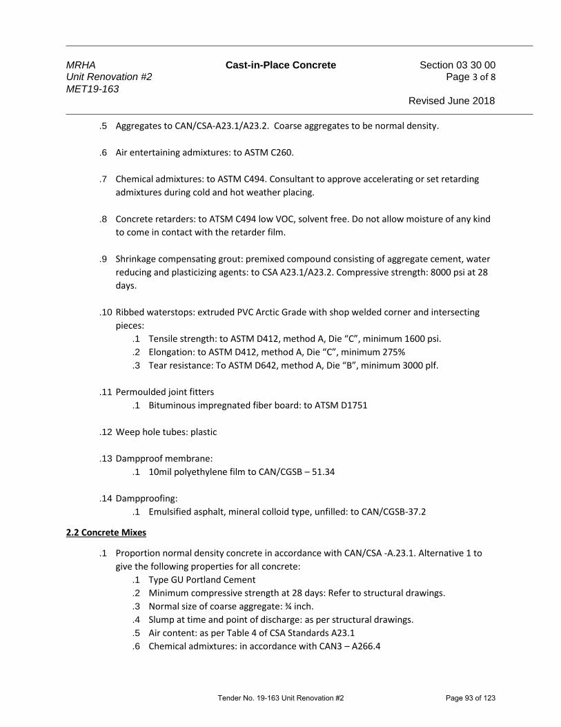
MRHA Cast-in-Place Concrete Section 03 30 00 Unit Renovation #2 Page 3 of 8
MET19-163 Revised June 2018
.5 Aggregates to CAN/CSA-A23.1/A23.2. Coarse aggregates to be normal density.
.6 Air entertaining admixtures: to ASTM C260.
.7 Chemical admixtures: to ASTM C494. Consultant to approve accelerating or set retarding
admixtures during cold and hot weather placing.
.8 Concrete retarders: to ATSM C494 low VOC, solvent free. Do not allow moisture of any kind
to come in contact with the retarder film.
.9 Shrinkage compensating grout: premixed compound consisting of aggregate cement, water
reducing and plasticizing agents: to CSA A23.1/A23.2. Compressive strength: 8000 psi at 28
days.
.10 Ribbed waterstops: extruded PVC Arctic Grade with shop welded corner and intersecting
pieces:
.1 Tensile strength: to ASTM D412, method A, Die “C”, minimum 1600 psi.
.2 Elongation: to ASTM D412, method A, Die “C”, minimum 275%
.3 Tear resistance: To ASTM D642, method A, Die “B”, minimum 3000 plf.
.11 Permoulded joint fitters
.1 Bituminous impregnated fiber board: to ATSM D1751
.12 Weep hole tubes: plastic
.13 Dampproof membrane:
.1 10mil polyethylene film to CAN/CGSB – 51.34
.14 Dampproofing:
.1 Emulsified asphalt, mineral colloid type, unfilled: to CAN/CGSB-37.2
2.2 Concrete Mixes
.1 Proportion normal density concrete in accordance with CAN/CSA -A.23.1. Alternative 1 to
give the following properties for all concrete:
.1 Type GU Portland Cement
.2 Minimum compressive strength at 28 days: Refer to structural drawings.
.3 Normal size of coarse aggregate: ¾ inch.
.4 Slump at time and point of discharge: as per structural drawings.
.5 Air content: as per Table 4 of CSA Standards A23.1
.6 Chemical admixtures: in accordance with CAN3 – A266.4
Tender No. 19-163 Unit Renovation #2 Page 93 of 123
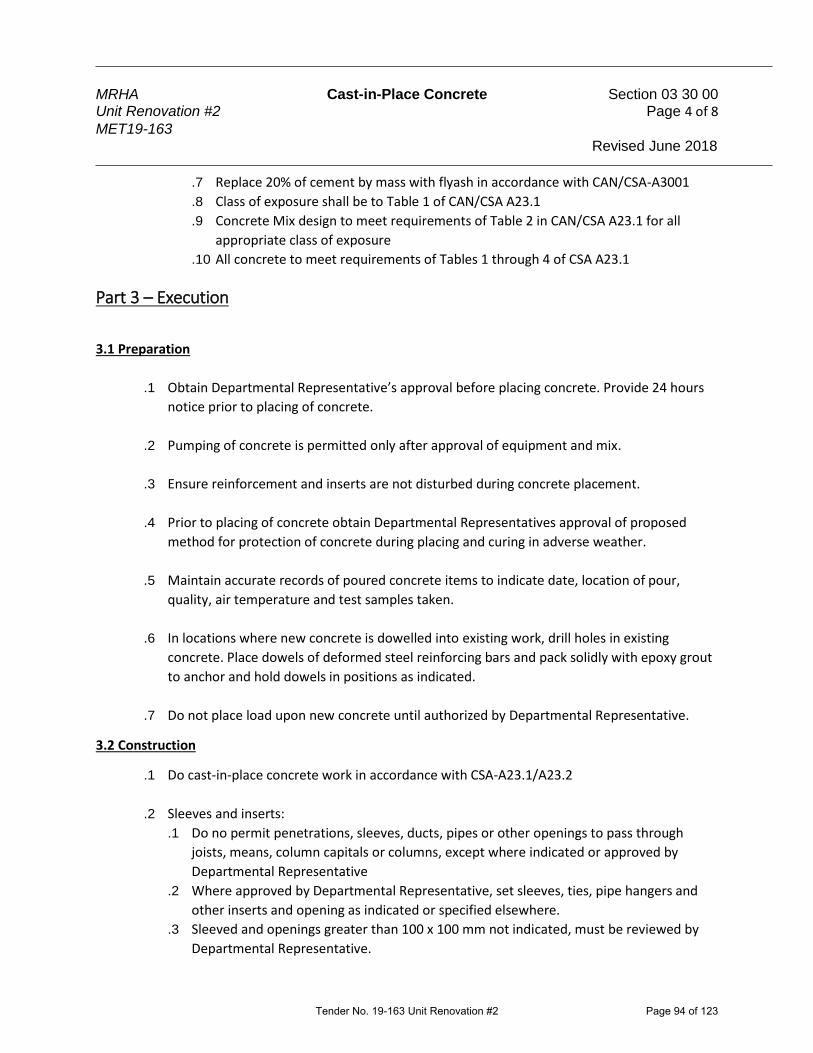
MRHA Cast-in-Place Concrete Section 03 30 00 Unit Renovation #2 Page 4 of 8
MET19-163 Revised June 2018
.7 Replace 20% of cement by mass with flyash in accordance with CAN/CSA-A3001
.8 Class of exposure shall be to Table 1 of CAN/CSA A23.1
.9 Concrete Mix design to meet requirements of Table 2 in CAN/CSA A23.1 for all
appropriate class of exposure
.10 All concrete to meet requirements of Tables 1 through 4 of CSA A23.1
Part 3 – Execution
3.1 Preparation
.1 Obtain Departmental Representative’s approval before placing concrete. Provide 24 hours
notice prior to placing of concrete.
.2 Pumping of concrete is permitted only after approval of equipment and mix.
.3 Ensure reinforcement and inserts are not disturbed during concrete placement.
.4 Prior to placing of concrete obtain Departmental Representatives approval of proposed
method for protection of concrete during placing and curing in adverse weather.
.5 Maintain accurate records of poured concrete items to indicate date, location of pour,
quality, air temperature and test samples taken.
.6 In locations where new concrete is dowelled into existing work, drill holes in existing
concrete. Place dowels of deformed steel reinforcing bars and pack solidly with epoxy grout
to anchor and hold dowels in positions as indicated.
.7 Do not place load upon new concrete until authorized by Departmental Representative.
3.2 Construction
.1 Do cast-in-place concrete work in accordance with CSA-A23.1/A23.2
.2 Sleeves and inserts:
.1 Do no permit penetrations, sleeves, ducts, pipes or other openings to pass through
joists, means, column capitals or columns, except where indicated or approved by
Departmental Representative
.2 Where approved by Departmental Representative, set sleeves, ties, pipe hangers and
other inserts and opening as indicated or specified elsewhere.
.3 Sleeved and openings greater than 100 x 100 mm not indicated, must be reviewed by
Departmental Representative.
Tender No. 19-163 Unit Renovation #2 Page 94 of 123

MRHA Cast-in-Place Concrete Section 03 30 00 Unit Renovation #2 Page 5 of 8
MET19-163 Revised June 2018
.4 Do not eliminate or displace reinforcement to accommodate hardware. If inserts cannot
be located as specified obtain approval of modifications from Departmental
Representative before placing concrete.
.5 Check locations and sizes of sleeves and openings shown on drawings.
.6 Set special inserts for strength testing as indicated and as required by non-destructive
method of testing concrete.
.3 Anchor bolts:
.1 Set anchor bolts to templates under supervision of appropriate trade prior to placing
concrete.
.2 With approval of Departmental Representative, grout anchor bolts in preformed holes
or holes drilled after concrete has set.
.3 Protect anchor holt holes from water accumulations, snow and ice build-ups.
.4 Set bolts and fill holes with epoxy grout.
.5 Locate anchor bolts used in connection with expansion shoes, rollers, and rockers with
due regard to ambient temperature at time of erection.
.4 Drainage holes and weep holes:
.1 Form weep holes and drainage holes in accordance with Section XX Concrete Forming.
If wood forms are used, remove them after concrete has set.
.2 Install weep hole tubes and drain as indicated.
.5 Grout under base plates and machinery using procedures in accordance with manufacturer’s
recommendations which result in 100% contact over grouted area.
.6 Finishing:
.1 Finish concrete in accordance with CAN/CSA A23.1/A23.2
.2 Use curing compounds compatible with applied finish on concrete surfaces. Provide
written documentation that compounds are compatible.
.3 Finish concrete floor surfaces with a non-slip broom finish, immediately after troweling.
.4 Provide screed finish unless otherwise indicated.
.7 Rub exposed sharp edges of concrete with carborundum to produce 1/8 inch radius edges
unless otherwise indicated.
.8 Toppings:
.1 In pouring base course, make allowances for bonded overlay topping thickness.
.2 Place bonded topping over hardener base course in accordance with CAN/CSA-A23.1
and topping manufacturer’s recommendations.
Tender No. 19-163 Unit Renovation #2 Page 95 of 123

MRHA Cast-in-Place Concrete Section 03 30 00 Unit Renovation #2 Page 6 of 8
MET19-163 Revised June 2018
.3 Follow instructions by Departmental Representative in case conflicting requirements
arise between CAN/CSA-A23.1 and manufacturer’s recommendations.
.4 Ensure that joints in topping are the same as those in the base course. Also ensure that
their locations precisely match those in base course. Provide dividers, edge strips and
reinforcing mesh as indicated.
.9 Waterstop:
.1 Install waterstops to provide continuous water seal. Do not distort or pierce waterstop
in such a way as to hamper performance. Do not displace reinforcement when installing
waterstops. Use equipment to manufacturer’s requirements to field splice waterstops.
Tie waterstops rigidly in place.
.2 Use only straight heat sealed butt joints in field. Use factory welded corners and
intersections unless otherwise approved by Departmental Representative.
.10 Joints:
.1 Construction joints – Walls and Structural Slabs:
.1 In general, incorporate either horizontal or vertical construction joins, in
accordance with CAN/CSA-A23.1
.2 Immediately before next pour, clean construction join and brush with grout of
neat cement.
.3 Run reinforcement through construction joints
.4 Construction joints to be keyed.
.2 Construction Joints – Slabs on Grade:
.1 In general, incorporate construction joints, in accordance with CAN/CSA-A23.1
.2 Immediately before next pour, clean construction joint and brush with grout of
neat cement.
.3 Do not continue reinforcing through Construction Joint. At slab mid-depth,
provide ½ inch diameter plain dowels, greased one side, at 24 inches c.c.
.4 Construction joints are to be keyed.
.3 Slab on Grade Isolation joints:
.1 Do not install isolation joints in structural slabs.
.2 Isolation joints around all columns to form a square or round panel. Square
isolation joints shall be orientated so all corners of the square align with slab
control joints.
.4 Slab on Grade Control Joints/Saw cuts:
.1 Discontinue reinforcing at saw cut location by stopping reinforcing 3 inches
from each side of the saw cut location.
.2 Saw 1/8 inch ide control joints into surface of concrete, ¼ the depth of slabs.
.3 Locate control joints in slab on grade at 26 feet max spacing in each direction. If
drawings note lesser spacing, the drawing will govern.
Tender No. 19-163 Unit Renovation #2 Page 96 of 123

MRHA Cast-in-Place Concrete Section 03 30 00 Unit Renovation #2 Page 7 of 8
MET19-163 Revised June 2018
.4 Align control joints with columns when possible. Provide control joints in two
directions at all inside corners.
.5 Timing of cutting control joints is crucial. Cut joints as soon as possible after
casting slab. Timing of cutting control joints after casting of slab will vary as
weather conditions, concrete mixes, etc. change.
.6 Within four weeks of cutting joints, fill them with epoxy joint sealer. Completely
clean side joint surfaces of dirt, oil, grease, and similar contaminants. Mask floor
surfaces at joints while pouring. Prime side joint surfaces with compatible
primer as required for sealer type if surfaces are not completely dry.
.7 At floors over which finish flooring will be installed, fill joint solidly with latex
cement and trowel smooth.
.11 Joint Fillers:
.1 Furnish filler for each joint in single piece for depth and width required for joint, unless
otherwise authorized by Departmental Representative.
.2 When more than one piece is required for join, fasten abutting ends and hold securely
to shape by stapling or other positive fastening.
.3 Locate and form in isolation, construction and expansion joints as indicated.
.4 Install joint filler.
.12 Dampproof Membrane
.1 Install dampproof membrane under concrete slabs-on-grade inside building.
.2 Lap dampproof membrane minimum 150mm at joints and seal
.3 Seal punctures in dampproof membrane before placing concrete.
.4 Use patching material at least 150mm larger than puncture and seal.
3.3 Surface Tolerances
.1 Concrete tolerance in accordance with CAN/CSA-A23.1 straight edge method. Unless
otherwise required in the design, ensure minimum level of finished concrete floors are
within 3/16 inch of established elevations in an 20 foot square area, and is sufficiently even
to contact a 10 foot long straightedge with a tolerance of 3/16 inch.
3.4 Field Quality Control
.1 Inspection and testing of concrete materials will be carried out by a Testing Laboratory
designated by Owner in accordance with CAN/CSA-A23.1.
.2 Owner will pay for cost of testing.
.3 Testing Laboratory will take additional test cylinders during cold weather concreting. Cure
cylinders on job site under same conditions as concrete which they represent.
Tender No. 19-163 Unit Renovation #2 Page 97 of 123

MRHA Cast-in-Place Concrete Section 03 30 00 Unit Renovation #2 Page 8 of 8
MET19-163 Revised June 2018
.4 Non-destructive Methods for Testing concrete shall be in accordance with CAN/CSA-A23.2.
.5 Inspection or testing will not actually augment or replace Contractor quality control nor
relieve him of his contractual responsibility.
Tender No. 19-163 Unit Renovation #2 Page 98 of 123

MRHA Concrete Walks, Curbs and Gutters Section 03 30 53 Unit Renovation #2 Page 1 of 4
MET19-163 Revised June 2018
Part 1 – General
1.1 Reference
.1 American Society for Testing Materials International (ATSM)
.1 ATSM C117-[04]. Test Method for Materials Finer that 75µm (No. 200) Sieve in
Mineral Aggregates by Washing
.2 ATSM C136-[05]. Method for Sieve Analysis of Fine and Course Aggregates.
.3 ATSM D698-[00ae1]. Test Method for Laboratory Compaction Characteristics of Soil
Using Standard Effort (600 kN-m/m3).
.2 Canadian General Standards Board (CGSB)
.1 CAN/CGSB-8.1-[88], Sieves Testing, Woven Wire, Inch Series.
.2 CAN/CGSB-8.2-[M88]. Sieves Testing, Woven Wire, Metric
.3 Canadians Standards Association (CSA International)
.1 CSA-A23.1-[04]/A23.2[04], Concrete Materials and Methods of Concrete
Construction/Methods of Test and Standard Practices for Concrete
Part 2 – PRODUCTS
2.1 Materials
.1 Concrete mixes and materials: in accordance with Section - Cast in Place Concrete.
.2 Concrete reinforcement: Welded wire mesh w10 x w10 with cross bars 150mm x 150mm on
center in each direction.
.3 Joint filler in accordance with Section -Cast in Place Concrete
.4 Granular base: material Section - Aggregate Materials and the following requirements:
.1 NSTIR Type I or Type II Gravels.
.2 Crushed stone or gravel
.3 Gradations: within limits specified when tested to ASTM C136, ATSM C117, and
Sieve sizes to CAN/CGSB-8.1
.5 Non-staining mineral type form release agent: chemically active release agents containing
compounds that react with free lime to provide water-soluble soap.
Tender No. 19-163 Unit Renovation #2 Page 99 of 123

MRHA Concrete Walks, Curbs and Gutters Section 03 30 53 Unit Renovation #2 Page 2 of 4
MET19-163 Revised June 2018
.6 Fill material to Section - Aggregate materials and the following requirements:
.1 NSTIR Type I or Type II Gravels
.2 Crushed stone or gravel
.3 Gradations: within limits specified when tested to ASTM C136, ASTM C117, and
Sieve sizes to CAN/CGSB-8.1
Part 3 – Execution
3.1 Grade Preparation
.1 Do grade preparation in accordance with Section - Excavating, Trenching, and Backfilling.
.2 Construct embankments using excavated material free from organic matter or other
objectionable materials.
.1 Dispose of surplus and unsuitable excavated material off site.
.3 When constructive embankment provide a minimum 0.5m shoulders, where applicable,
outside the neat lines of concrete.
.4 Place fill in maximum 150mm layers and compact to at least 95% of maximum dry density to
ASTM D698
3.2 Granular Base
.1 Obtain Departmental Representative’s approval of subgrade before placing granular base.
.2 Place granular base material to lines, widths, and depths as indicated.
.3 Compact granular base in maximum 150mm layers of at least 95% of maximum density to
ASTM D698.
3.3 Concrete
.1 Obtain Departmental Representative’s approval of granular base and reinforcing steel prior
to placing concrete.
.2 Do concrete work in accordance with Section - Cast in Place Concrete.
.3 Immediately after floating, give sidewalk surface uniform broom finish to produce regular
corrugations not exceeding 2mm deep, by drawing broom in direction normal to centre line.
.4 Provide edging as indicated.
Tender No. 19-163 Unit Renovation #2 Page 100 of 123
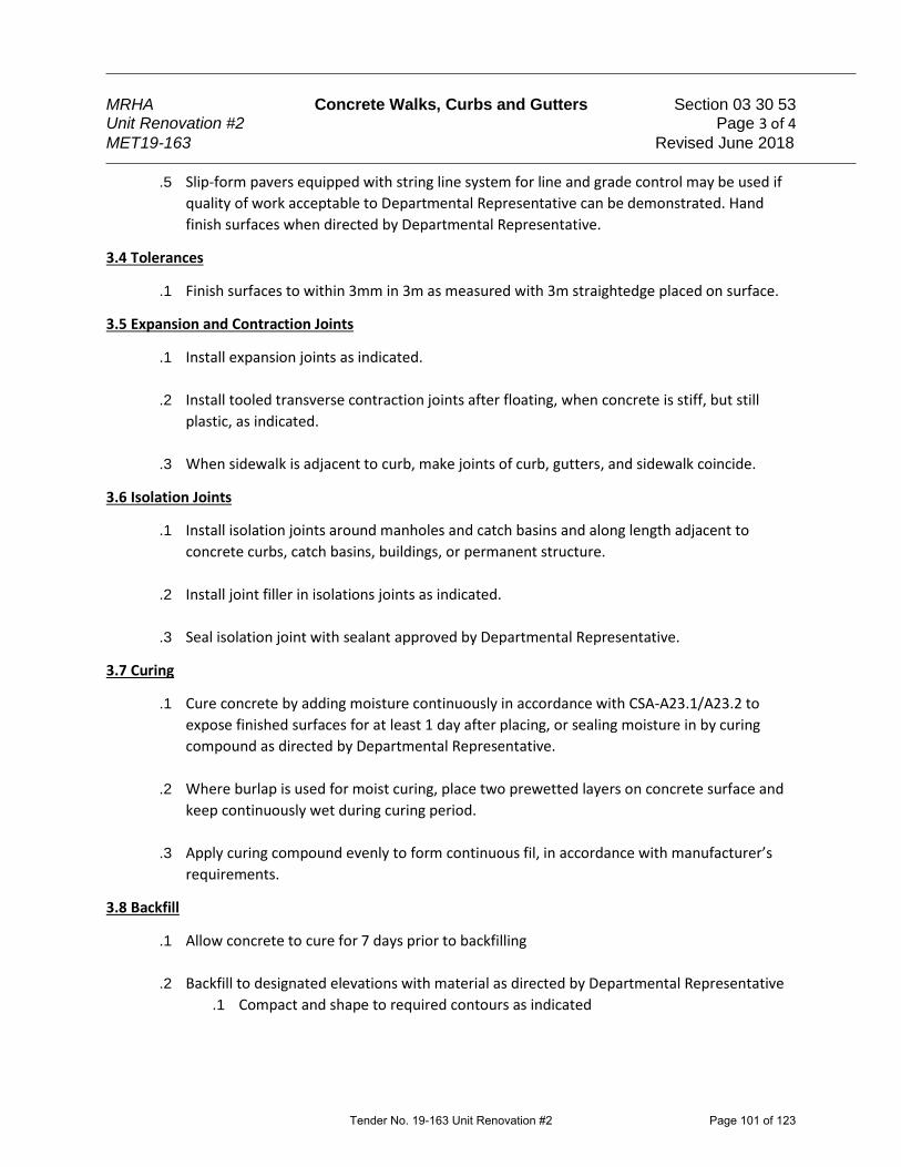
MRHA Concrete Walks, Curbs and Gutters Section 03 30 53 Unit Renovation #2 Page 3 of 4
MET19-163 Revised June 2018
.5 Slip-form pavers equipped with string line system for line and grade control may be used if
quality of work acceptable to Departmental Representative can be demonstrated. Hand
finish surfaces when directed by Departmental Representative.
3.4 Tolerances
.1 Finish surfaces to within 3mm in 3m as measured with 3m straightedge placed on surface.
3.5 Expansion and Contraction Joints
.1 Install expansion joints as indicated.
.2 Install tooled transverse contraction joints after floating, when concrete is stiff, but still
plastic, as indicated.
.3 When sidewalk is adjacent to curb, make joints of curb, gutters, and sidewalk coincide.
3.6 Isolation Joints
.1 Install isolation joints around manholes and catch basins and along length adjacent to
concrete curbs, catch basins, buildings, or permanent structure.
.2 Install joint filler in isolations joints as indicated.
.3 Seal isolation joint with sealant approved by Departmental Representative.
3.7 Curing
.1 Cure concrete by adding moisture continuously in accordance with CSA-A23.1/A23.2 to
expose finished surfaces for at least 1 day after placing, or sealing moisture in by curing
compound as directed by Departmental Representative.
.2 Where burlap is used for moist curing, place two prewetted layers on concrete surface and
keep continuously wet during curing period.
.3 Apply curing compound evenly to form continuous fil, in accordance with manufacturer’s
requirements.
3.8 Backfill
.1 Allow concrete to cure for 7 days prior to backfilling
.2 Backfill to designated elevations with material as directed by Departmental Representative
.1 Compact and shape to required contours as indicated
Tender No. 19-163 Unit Renovation #2 Page 101 of 123

MRHA Concrete Walks, Curbs and Gutters Section 03 30 53 Unit Renovation #2 Page 4 of 4
MET19-163 Revised June 2018
3.9 Cleaning
.1 On completion and verification of performance installation, remove surplus materials,
excess materials, rubbish, tools, and equipment.
.2 When sidewalk is adjacent to curb, make joints of curb, gutters, and sidewalk coincide.
Tender No. 19-163 Unit Renovation #2 Page 102 of 123
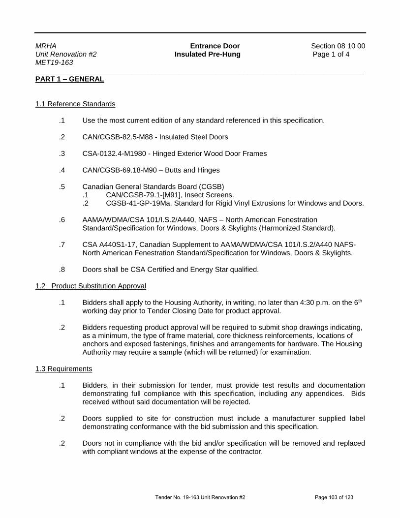
MRHA Entrance Door Section 08 10 00 Unit Renovation #2 Insulated Pre-Hung Page 1 of 4 MET19-163 Revised April 2017 __________________________________________________________________________________
PART 1 – GENERAL 1.1 Reference Standards .1 Use the most current edition of any standard referenced in this specification.
.2 CAN/CGSB-82.5-M88 - Insulated Steel Doors .3 CSA-0132.4-M1980 - Hinged Exterior Wood Door Frames .4 CAN/CGSB-69.18-M90 – Butts and Hinges .5 Canadian General Standards Board (CGSB)
.1 CAN/CGSB-79.1-[M91], Insect Screens.
.2 CGSB-41-GP-19Ma, Standard for Rigid Vinyl Extrusions for Windows and Doors.
.6 AAMA/WDMA/CSA 101/I.S.2/A440, NAFS – North American Fenestration Standard/Specification for Windows, Doors & Skylights (Harmonized Standard).
.7 CSA A440S1-17, Canadian Supplement to AAMA/WDMA/CSA 101/I.S.2/A440 NAFS-
North American Fenestration Standard/Specification for Windows, Doors & Skylights. .8 Doors shall be CSA Certified and Energy Star qualified.
1.2 Product Substitution Approval
.1 Bidders shall apply to the Housing Authority, in writing, no later than 4:30 p.m. on the 6th working day prior to Tender Closing Date for product approval.
.2 Bidders requesting product approval will be required to submit shop drawings indicating,
as a minimum, the type of frame material, core thickness reinforcements, locations of anchors and exposed fastenings, finishes and arrangements for hardware. The Housing Authority may require a sample (which will be returned) for examination.
1.3 Requirements .1 Bidders, in their submission for tender, must provide test results and documentation
demonstrating full compliance with this specification, including any appendices. Bids received without said documentation will be rejected.
.2 Doors supplied to site for construction must include a manufacturer supplied label
demonstrating conformance with the bid submission and this specification. .2 Doors not in compliance with the bid and/or specification will be removed and replaced
with compliant windows at the expense of the contractor.
Tender No. 19-163 Unit Renovation #2 Page 103 of 123

MRHA Entrance Door Section 08 10 00 Unit Renovation #2 Insulated Pre-Hung Page 2 of 4 MET19-163 Revised April 2017 __________________________________________________________________________________
1.4 Warranty and Maintenance
.1 Glass, Frame, Slab & Hardware - Minimum 10 years (Manufacturer); .2 Installation/Operation - Minimum 1 year (Installer) PART 2 - PRODUCTS
2.1 Materials .1 Slab: Insulated, Steel; factory painted white unless otherwise noted by Project Manager.
Tempered thermal pane with polystyrene frame 4-paneled door unless otherwise approved by Project Manager.
.2 Hinges: Minimum three standard weight stainless steel hinges sized per manufacturers
recommendation. Provide tamper proof hinges if outswing configuration; .4 Locksets and deadbolts: reuse existing or to be supplied by Housing Authority; Consult
with Project Manager on required lockset and deadbolt spacing and hole sizes; doors to be drilled accordingly and reinforced with solid blocking for both the lockset and deadbolt;
.5 Frame: Cellular PVC .6 Sill: Aluminium threshold, PVC thermal break, and composite sub-sill
.7 Sill Accessibility: Doors meeting the performance requirements as outlined in this specification are to have the manufacturers tested sill replaced with an approved Accessible compliant aluminium sill where required and as directed by the Project Manager.
2.2 Performance
.1 Performance Requirement, per Fenestration Canada calculator http://www.fenestrationcanada.ca/calculator/a44os1-17 for project location):
.1 Minimum Performance Class Rating ___40__ .2 Minimum Positive Design Pressure _1920__Pa .3 Minimum Negative Design Pressure _1920__Pa .4 Minimum Water Penetration Resistance Test Pressure __400__Pa .5 Minimum Canadian Air Infiltration/Exfiltration ___A2__ .2 Energy Star Rating: Zone 2
Tender No. 19-163 Unit Renovation #2 Page 104 of 123

MRHA Entrance Door Section 08 10 00 Unit Renovation #2 Insulated Pre-Hung Page 3 of 4 MET19-163 Revised April 2017 __________________________________________________________________________________
PART 3 - EXECUTION
3.1 Removal .1 Remove existing doors, frames, casings etc., and dispose off site, in accordance with
Authorities Having Jurisdiction; .2 Examine building sheathing and framing, and report any rot or deficiencies to Project
Manager.
3.2 Installation/Application .1 Install door, frame and hardware (existing or new as supplied by Housing Authority) in
accordance with CAN/CSA-A440.4, “Window, Door, and Skylight Installation”, manufacturer’s instructions, applicable codes/regulations, as shown on drawings, hardware templates and the following:
.2 Comply with manufacturer’s written recommendations or specifications, including
product technical bulletins, handling, storage and installation and datasheets; .3 Seal, tape and apply material around door as required to maintain continuity of interior
vapour barrier and exterior weather resistant barrier (air barrier or building paper); .4 Install new sill pan flashing at door openings per details
.5 Apply minimum two beads of high quality acrylic latex caulk/sealant to seal and fill all voids between floor and sill. Caulk around the entire exterior perimeter of the frame and sill; between rough opening and frame, fill voids with low expansion closed cell foam;
.6 Install door plumb, level and square so door swings freely and hardware functions
properly. Provide even margins between doors and jambs, and doors and finished floor and thresholds;
.7 Adjust doors to close smoothly, fully engaging weather-stripping and for hardware to
function smoothly and securely;
3.4 Reinstatement when Existing Doors are Replacements
.1 Reinstate disturbed areas including drywall, siding, caulking, membranes, casing, sills and related finishes with compatible materials if matching are no longer available. Supply and install new interior door trim, match existing trim in quality, material and dimensions. If existing trim type is not readily available, submit alternatives to Project
Tender No. 19-163 Unit Renovation #2 Page 105 of 123
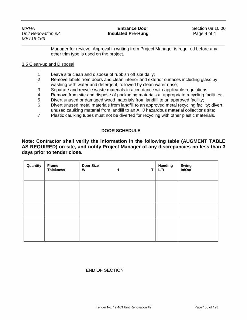
MRHA Entrance Door Section 08 10 00 Unit Renovation #2 Insulated Pre-Hung Page 4 of 4 MET19-163 Revised April 2017 __________________________________________________________________________________
Manager for review. Approval in writing from Project Manager is required before any other trim type is used on the project.
3.5 Clean-up and Disposal .1 Leave site clean and dispose of rubbish off site daily;
.2 Remove labels from doors and clean interior and exterior surfaces including glass by washing with water and detergent, followed by clean water rinse;
.3 Separate and recycle waste materials in accordance with applicable regulations; .4 Remove from site and dispose of packaging materials at appropriate recycling facilities; .5 Divert unused or damaged wood materials from landfill to an approved facility;
.6 Divert unused metal materials from landfill to an approved metal recycling facility; divert unused caulking material from landfill to an AHJ hazardous material collections site;
.7 Plastic caulking tubes must not be diverted for recycling with other plastic materials.
DOOR SCHEDULE
Note: Contractor shall verify the information in the following table (AUGMENT TABLE AS REQUIRED) on site, and notify Project Manager of any discrepancies no less than 3 days prior to tender close.
Quantity
Frame Thickness
Door Size W H T
Handing L/R
Swing In/Out
END OF SECTION
Tender No. 19-163 Unit Renovation #2 Page 106 of 123

MRHA Resilient Vinyl Sheet Flooring Section 09 65 16 Unit Renovation #2 SUPPLY Page 1 of 2 MET19-163
Single Units and Houses Revised November 2017
1
PART 1 GENERAL 1.1 Reference Standards .1 Materials are to be certified in accordance with the applicable and the latest applicable edition of codes and standards. .2 ASTM F925 – 13 Standard Test Method for Resistance to Chemicals of Resilient Flooring .3 ASTM F1303, Standard Specification for Sheet Vinyl Flooring With Backing .4 ASTM F1913, Standard Specification for Vinyl Sheet Floor Covering Without Backing .5 CAN/ULC-S102.2, Standard Method of Test for Surface Burning Characteristics of Flooring, Floor Covering and Miscellaneous Materials and Assemblies .6 ASTM F 970, Standard Test Method for Measuring Recovery Properties of Floor Coverings after Static Loading– 500 PSI .7 ASTM E 648, Standard Test Method for Critical Radiant Flux of Floor-Covering Systems Using a Radiant Heat Energy Source, Class I .8 FloorScore certified, or shall be LEED certified. 1.2 Submittals .1 Submit two duplicate sample pieces of sheet material for each color selected by Project Manager .2 Manufacturers product data, maintenance and installation instructions 1.3 Approved Equal .1 Bidders shall apply to the Housing Authority, in writing not later than 4:30 p.m. on the 6th working day prior to Tender Closing Date for product approval. .2 Request for approval shall include a technical specification sheet demonstrating compliance with this specification. 1.4 Warranty
.1 Minimum 10 years
1.5 Delivery, Storage and Handling .1 Store resilient products and installation materials in dry spaces protected from the weather, with ambient temperatures maintained within range recommended by manufacturer .2 Deliver, unload and place material as directed by Housing Authority
Tender No. 19-163 Unit Renovation #2 Page 107 of 123

MRHA Resilient Vinyl Sheet Flooring Section 09 65 16 Unit Renovation #2 SUPPLY Page 2 of 2 MET19-163
Single Units and Houses Revised November 2017
2
PART 2 PRODUCTS
2.1 Materials .1 Minimum overall thickness: 2.0 mm (80 mils) .2 Minimum Wear Layer thickness: 0.25 mm (10 mils) .3 Urethane Top Coat, PVC Wear Layer, Low Gloss, No-Wax finish Type 1, Grade 3. .4 Provide underlayment per flooring manufacturer’s instructions, as required for job. .5 Product to be supplied in widths to minimize number of seams .6 Minimum colour selection: 10 .7 Sheet flooring shall be labelled with manufacturer’s name and flooring type .8 Backing shall be non-foamed plastic, Class C 2.2 Approved Products (Residential) .1 Tarkett FiberFloor Fresh Start Collection .2 Armstrong Cushionstep Good .1 Alternate products will be considered during the prescribed time period at tender. See Approved Equal Section 1.3. PART 3 - EXECUTION SEE INSTALLATION SPECIFICATION
END OF SECTION
Tender No. 19-163 Unit Renovation #2 Page 108 of 123
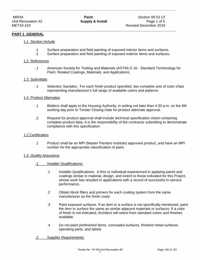
__________________________________________________________________________________
MRHA Paint Section 08 53 13
Unit Renovation #2 Supply & Install Page 1 of 5 MET19-163 Revised December 2019
__________________________________________________________________________________
1
PART 1 GENERAL
1.1 Section Include .1 Surface preparation and field painting of exposed interior items and surfaces.
.2 Surface preparation and field painting of exposed exterior items and surfaces.
1.2 References
.1 American Society for Testing and Materials (ASTM) D 16 - Standard Terminology for Paint, Related Coatings, Materials, and Applications.
1.3 Submittals
.1 Selection Samples: For each finish product specified, two complete sets of color chips representing manufacturer's full range of available colors and patterns.
1.4 Product Alternates
.1 Bidders shall apply to the Housing Authority, in writing not later than 4:30 p.m. on the 6th working day prior to Tender Closing Date for product alternate approval.
.2 Request for product approval shall include technical specification sheet containing
complete product data. It is the responsibility of the contractor submitting to demonstrate compliance with this specification
1.2 Certification
.1 Product shall be an MPI (Master Painters Institute) approved product, and have an MPI number for the appropriate classification of paint.
1.3 Quality Assurance .1 Installer Qualifications:
.1 Installer Qualifications: A firm or individual experienced in applying paints and coatings similar in material, design, and extent to those indicated for this Project, whose work has resulted in applications with a record of successful in-service performance.
.2 Obtain block fillers and primers for each coating system from the same
manufacturer as the finish coats.
.3 Paint exposed surfaces. If an item or a surface is not specifically mentioned, paint the item or surface the same as similar adjacent materials or surfaces. If a color of finish is not indicated, Architect will select from standard colors and finishes available.
.4 Do not paint prefinished items, concealed surfaces, finished metal surfaces,
operating parts, and labels.
.2 Supplier Requirements:
Tender No. 19-163 Unit Renovation #2 Page 109 of 123
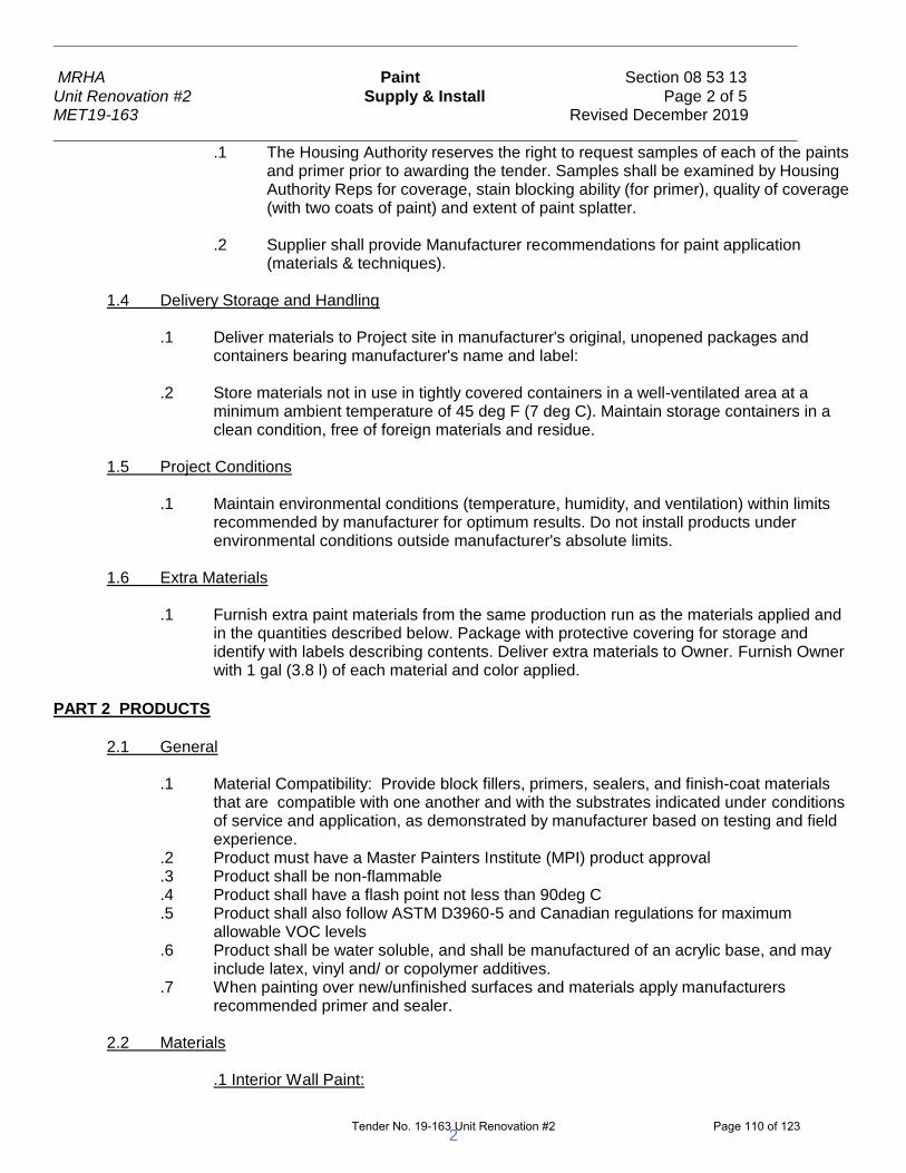
__________________________________________________________________________________
MRHA Paint Section 08 53 13
Unit Renovation #2 Supply & Install Page 2 of 5 MET19-163 Revised December 2019
__________________________________________________________________________________
2
.1 The Housing Authority reserves the right to request samples of each of the paints and primer prior to awarding the tender. Samples shall be examined by Housing Authority Reps for coverage, stain blocking ability (for primer), quality of coverage (with two coats of paint) and extent of paint splatter.
.2 Supplier shall provide Manufacturer recommendations for paint application
(materials & techniques). 1.4 Delivery Storage and Handling
.1 Deliver materials to Project site in manufacturer's original, unopened packages and containers bearing manufacturer's name and label:
.2 Store materials not in use in tightly covered containers in a well-ventilated area at a
minimum ambient temperature of 45 deg F (7 deg C). Maintain storage containers in a clean condition, free of foreign materials and residue.
1.5 Project Conditions
.1 Maintain environmental conditions (temperature, humidity, and ventilation) within limits recommended by manufacturer for optimum results. Do not install products under environmental conditions outside manufacturer's absolute limits.
1.6 Extra Materials
.1 Furnish extra paint materials from the same production run as the materials applied and in the quantities described below. Package with protective covering for storage and identify with labels describing contents. Deliver extra materials to Owner. Furnish Owner with 1 gal (3.8 l) of each material and color applied.
PART 2 PRODUCTS
2.1 General
.1 Material Compatibility: Provide block fillers, primers, sealers, and finish-coat materials that are compatible with one another and with the substrates indicated under conditions of service and application, as demonstrated by manufacturer based on testing and field experience.
.2 Product must have a Master Painters Institute (MPI) product approval
.3 Product shall be non-flammable
.4 Product shall have a flash point not less than 90deg C
.5 Product shall also follow ASTM D3960-5 and Canadian regulations for maximum allowable VOC levels
.6 Product shall be water soluble, and shall be manufactured of an acrylic base, and may include latex, vinyl and/ or copolymer additives.
.7 When painting over new/unfinished surfaces and materials apply manufacturers recommended primer and sealer.
2.2 Materials
.1 Interior Wall Paint:
Tender No. 19-163 Unit Renovation #2 Page 110 of 123

__________________________________________________________________________________
MRHA Paint Section 08 53 13
Unit Renovation #2 Supply & Install Page 3 of 5 MET19-163 Revised December 2019
__________________________________________________________________________________
3
.1 Product shall be have an Eggshell finish (MPI gloss level 2 or 3). VOC levels shall be 100 g/L or less, or have an MPI VOC range classification of E2 or E3. Solids by volume shall be minimum 34%. .2 Approved products:
. .1 PPG Paints Speedhide 6-411 .2 Benjamin Moore EcoSpec WB F374 .3 Benjamin Moore Ultra Spec 500 K538 .4 Dulux Ultra Zero VOC 97900 .5 Glidden Pro 20044 .6 Beauti-Tone Natura Interior Latex Eggshell 500-series .7 Sherwin Williams ProMar 200 Zero VOC (B20W02651,
B20W02653) .8 Sico Expert 833-6XX .9 Behr Pro i300 Interior Eggshell #330
.2 Interior Ceiling Paint:
.1 Product shall have a Flat finish (MPI gloss level 1). Ceilings: VOC levels shall be 50 g/L or less, or have an MPI VOC range classification of E3. Volume Solids shall be minimum 32% .2 Approved Products
.1 Benjamin Moore Ultra Spec K536
.2 Dulux Ultra Zero VOC 97500
.3 PPG Paints Speedhide 6-70
.4 SICO Performa 610-550
.5 Behr Pro i300 Interior Dead Flat #PR310
.3 Interior Trim:
.1 Product shall have a semi-gloss finish . VOC levels shall be 100 g/L or less, or have an MPI VOC range classification of E2 or E3. Product shall be have a semi-gloss finish (MPI gloss level 5). Solids by volume shall be minimum 33%.
.2 Approved products:
.1 Benjamin Moore Ultra Spec K539
.2 Benjamin Moore Eco Spec WB F376
.3 Dulux Lifemaster 59211
.4 PPG Paints Speedhide 6-500
.5 Sherwin Williams ProMar 200 Zero VOC Interior Latex Semi-Gloss (B31W04651, B31W04653)
.6 Sico Ecosource 857-6XX
.7 Behr Pro i300 Interior Semi-Gloss #PR370
.4 Exterior:
.1 Product shall have a semi-gloss finish (MPI gloss level 5). VOC levels shall be 150 g/L or less, or have an MPI VOC range classification of E2 or E3. Solids by volume shall be minimum 33%.
Tender No. 19-163 Unit Renovation #2 Page 111 of 123

__________________________________________________________________________________
MRHA Paint Section 08 53 13
Unit Renovation #2 Supply & Install Page 4 of 5 MET19-163 Revised December 2019
__________________________________________________________________________________
4
.2 Approved products: .1 Benjamin Moore Ben K543 .2 Benjamin Moore Ultra Spec Ext K449 .3 PPG Paints Sun Proof 78-45 .4 Dulux Weatherguard 1550 .5 Sico Expert 977-6XX .6 Behr Pro i300 Exterior Semi-Gloss #5850
.5 Exterior Floor:
.1 Product shall have a satin finish. VOC levels shall be 150 g/L or less, or have an MPI VOC range classification of E2 or E3. Solids by volume shall be minimum 31%. .2 Approved products:
.1 Benjamin Moore Floor & Patio Enamel K122
.2 PPG Paints Porch & Floor Enamel 3-510 Series
.3 ICI Dulux X-Pert 247010
.4 Behr Premium Plus Porch & Floor Paint 6050
.5 Para Ultra 1600
.6 SICO Int/Ext for Floors
.7 Sherwin Williams ArmoSeal Tread-Plex B90 Series
PART 3 EXECUTION 3.1 Examination & Preparation
.1 Protect areas not to be painted including but not limited to furniture, appliances and tenant personal property by providing adequate covering with drop cloths, polyethylene film and masking. Remove hardware and hardware accessories, plates, machined surfaces, lighting fixtures, and similar items already installed that are not to be painted. If removal is impractical or impossible because of size or weight of the item, provide surface-applied protection before surface preparation and painting. After completing painting operations in each space or area, reinstall items removed using workers skilled in the trades involved.
.3 Clean and prepare surfaces to be painted according to manufacturer's written
instructions for each particular substrate condition and as specified. Examine drywall surfaces, remove and repair picture hangers, nail holes, cracks, “nail pops” and other minor defects using patching compound, and sand smooth. Said areas are to be primed using the appropriate wall or ceiling paint. All surfaces to be painted shall be clear of dust and dry. Surfaces painted with defects shall be repaired and repainted at Contractor’s expense.
.3 Wood trim areas to be painted should have nail holes, cracks and other minimal faults
filled with putty, and should be sanded to a smooth surface. Peeling paint shall be scraped & sanded smooth. A primer coat of trim paint is to be applied to the sanded areas.
.5 Commencement of work shall be construed as acceptance of conditions.
Tender No. 19-163 Unit Renovation #2 Page 112 of 123

__________________________________________________________________________________
MRHA Paint Section 08 53 13
Unit Renovation #2 Supply & Install Page 5 of 5 MET19-163 Revised December 2019
__________________________________________________________________________________
5
3.2 Application
.1 Prime all areas to be painted with one coat of stain blocking primer.
.2 Apply one coat of paint in accordance with manufacturer’s recommendations to all
surfaces that were previously painted. Apply two finish coats of paint to all newly installed & primed surfaces.
.3 Apply coatings by brush, roller, spray, or other applicators per manufacturer's written
instructions
.3 Painted surface shall receive full coverage and be free of brush marks, sags, streaks, runs, voids or pinholes.
3.3 Cleaning .1 Remove rubbish and waste from site daily.
.2 All paint splatter is to be completely removed from all surfaces, furnishings, appliances
and tenant belongings. .3 Protect work of other trades, whether being painted or not, against damage from
painting. Correct damage by cleaning, repairing or replacing, and repainting, as approved by Project Manager.
.4 Provide "Wet Paint" signs to protect newly painted finishes. After completing painting
operations, remove temporary protective wrappings provided by others to protect their work.
.5 After work of other trades is complete, touch up and restore damaged or defaced painted
surfaces.
END OF SECTION
Tender No. 19-163 Unit Renovation #2 Page 113 of 123

Page 1 of 6
Asbestos in the Workplace:
A Guide to Removal of Friable Asbestos Containing Material
Revised November 21, 2013
Application – Code of Practice
Where asbestos is present or believed to be present in a workplace to which the Occupational
Health and Safety Act applies, the owner of the building and any employer whose workplace in
the building may contain asbestos have a duty under the Act to take all reasonable precautions
to ensure the health and safety of persons at or near that workplace. Employees have a similar duty to protect their own health in their workplace.
This document may be used as guidance for any establishment considering the removal of friable
asbestos. In addition, this document may be adopted as a code of practice by an employer who
is removing friable asbestos and is ordered to establish or adopt a code of practice by the
Director of the Occupational Health and Safety Division, or a delegate of the Director, under Section 66 of the Occupational Health and Safety Act.
Definitions
“100-class filter” means a filter certified as being
(a) in the “100” class; and
(b) of the “N”, “R” or “P” class, as appropriate, as defined in Chapter 42, Part 84 of the
United States Code of Federal Regulations.
“Airlock" means a system consisting of two-curtained doorways that allows the passage of
persons in and out of a contaminated area without permitting the movement of air out of the contaminated area.
“Asbestos containing material” means any material identified by an appropriate laboratory
analytical method (e.g. EPA 600/R-93/116, NIOSH 9000, or NIOSH 9002) to contain at least
0.5% of any type of asbestos, and vermiculite that is identified to contain any amount of
asbestos using EPA method 600/R-04/004 if other analytical methods do not identify the
presence of asbestos.
“Friable asbestos” means any asbestos-containing material that, when dry, may be crumbled,
pulverized, or reduced to powder by hand pressure. The term “friable asbestos” includes
previously non-friable asbestos-containing material that has become damaged to the extent that it may be crumbled, pulverized, or reduced to powder by hand pressure.
“Glove bag” means a pre-fabricated bag that is equipped with integral gloves and designed to contain asbestos.
“HEPA filter” means a high efficiency particulate aerosol filter that is designed to capture at least 99.97 percent of particles with an average aerodynamic diameter of 0.3 microns.
“HEPA negative air unit” means a mechanical ventilation unit that passes air through a HEPA filter and exhausts the air.
Tender No. 19-163 Unit Renovation #2 Page 114 of 123
bruce
Typewritten Text
Appendix "A"

Page 2 of 6
“HEPA unit test" means a procedure that is carried out by a competent person in accordance with
standard industry practice to assess whether a filtration system is functioning with the same efficiency as a HEPA filter.
“Wet removal” means soaking asbestos containing material with water that contains a non-ionic
surfactant in a quantity that is sufficient to control the release of dust and asbestos fibres
during the removal of friable asbestos.
“Work area" means the immediate area where asbestos-containing material may be disturbed.
Specific Requirements
1. Site Preparation
(1) Where removal of friable asbestos is performed, a glove bag must be used, or a
temporary enclosure must be constructed to prevent asbestos fibres from leaving the
work area.
(2) An enclosure used during the removal of friable asbestos must
(a) be constructed of polyethylene sheeting that is at least 0.15 millimetres thick,
(b) be labeled with signs to restrict entry to authorized personnel,
(c) include provisions for an airlock, clean room, shower area, decontamination
room, and holding area for waste materials;
(d) be maintained under negative pressure using HEPA negative air units, 24-hours
per day for the duration of the work and until the area has passed clearance
testing after cleanup;
(e) have a minimum of 4 air changes per hour or a static pressure of negative five
(-5) Pascal’s relative to pressure outside the enclosure, as measured inside the
enclosure at a point furthest from the exhaust fan; and
(f) have at least one observation window made of a transparent material that,
where reasonably practicable, enables a person who is located outside of the
enclosure to see work activity that is taking place inside the enclosure.
2. Ventilation - HEPA Testing
(1) Aside from specific HEPA negative air units that are used to exhaust air from inside the
enclosure, all ventilation systems that service the work area must be isolated from the
enclosure to prevent contamination by
(a) sealing ventilation duct supply and return air openings with poly sheeting; and
(b) where reasonably practicable, turning off the air handling systems that service
ithe work area.
(2) All vacuums and HEPA negative air units that are used to exhaust air from inside the
enclosure to any area outside of the enclosure must successfully pass a HEPA unit test
(a) after a HEPA filter is replaced; and
(b) at least once every 12 months.
Tender No. 19-163 Unit Renovation #2 Page 115 of 123

Page 3 of 6
(3) All HEPA negative air units that are used to exhaust air from inside the enclosure to an
indoor-area that is outside of the enclosure must successfully pass a HEPA unit test, on-
site, immediately prior to use at a given site.
(4) HEPA testing must include
(a) a visual inspection to identify any apparent damage and to examine the integrity
of the seal in the filter frame; and
(b) a filter testing procedure using dioctyl phthalate (DOP) or other appropriate
challenge test material to verify the unit is functioning as the manufacturer
intended.
(5) HEPA testing records must be maintained, including the name of the testing agency, the
name of the tester, the date of testing, and the result of the test.
(6) The employer is also required to maintain all HEPA filters in ventilation systems and
vacuum cleaners in accordance with manufacturer's instructions, or as specified by a
professional engineer, to ensure that they remain effective.
3. Personal Protective Equipment
(1) Where a glove bag is used, employees must wear full-body protective coveralls and a
half-facepiece, air-purifying, non-powered respirator equipped with a 100-class filter, or
equipment offering equal or greater protection.
(2) Where wet removal of friable asbestos is to be performed without the use of a glove bag,
employees must wear full-body protective coveralls (including hood) and a full-facepiece
powered air-purifying respirator equipped with a 100-class filter, or equipment offering
equal or greater protection.
(3) Where dry removal of friable asbestos is to be performed
(a) monitoring must be conducted in accordance with Section 4;
(b) employees must wear full-body protective coveralls (including hood) and are
permitted to use a full-facepiece powered air-purifying respirator equipped with
a 100-class filter unless the results from monitoring during removal indicate
that an employee’s exposure is greater than 100 fibres per cubic centimeter;
and
(c) where exposures are 100 fibres per cubic centimeter or greater, an atmosphere-
supplying respirator that has an assigned protection factor of 10000 is required.
(4) Where respiratory protection is required, the employer must ensure compliance with the
latest version of CSA Standard Z94.4, “Selection, Use, and Care of Respirators” for the
selection, use, maintenance, and testing of a respirator, as well as the training of
employees who use a respirator. This standard specifies that employees who wear a
tight-fitting respirator must be clean-shaven, and that quantitative fit-testing must be
carried out if a protection factor of 1000 is to be achieved with a full-facepiece powered
air-purifying respirator.
4. Dust Control and Monitoring
(1) Dry removal of friable asbestos-containing materials may be performed only where wet
removal is shown to present a hazard to employees.
(2) When dry removal is conducted and where a full-facepiece powered air-purifying respirator equipped with a 100-class filter is used for worker protection, personal
Tender No. 19-163 Unit Renovation #2 Page 116 of 123

Page 4 of 6
sampling for airborne asbestos fibres must be conducted on a daily basis during removal
to verify the airborne concentrations do not exceed 100 fibres per cubic centimeter.
(3) Where dry or wet asbestos removal is conducted, a glove bag is not used, and the air
from inside the enclosure is exhausted to an indoor area that is outside of the enclosure,
(a) daily sampling for airborne asbestos fibres must be conducted outside of the
enclosure.
(b) immediate action must be taken if the concentration of airborne asbestos is
found to exceed 0.01 fibres per cubic centimeter of air in an indoor area that is
outside of the enclosure.
(4) All samples for airborne asbestos fibres must be collected, prepared, analyzed, and
reported in accordance with the NIOSH Method 7400, Issue 2: Asbestos and Other Fibers
by PCM (August 15, 1994), or NIOSH Method 7402, Issue 2: Asbestos by TEM (August
15, 1994), or by a method that provides for an equivalent or greater level of precision
and accuracy.
(5) Samples must be analyzed within 24 hours and the committee or representative must be
notified of the testing, in accordance with Section 35 of the Occupational Health and
Safety Act. Where an increase in airborne concentration is detected, the personal
protective equipment required must be reviewed and upgraded in accordance with this
document.
(6) Monitoring for airborne asbestos fibres must be conducted during clearance testing, as
specified in Section 8.
(7) The employer must maintain a record of all air sampling data in accordance with
subsection 1.15(1) of the Workplace Health and Safety Regulations.
5. Personal Hygiene
(1) Where a glove bag is used, coveralls and other contaminated clothing must be removed
and prepared for disposal prior to removing any respirator or leaving the work area.
(2) Where removal of friable asbestos-containing material is performed without a glove bag
(a) street clothes must be removed and left in the clean area of the enclosure;
(b) protective clothing, as set out in Section 3, must be worn in the work area;
(c) coveralls and other contaminated clothing must be removed and prepared for
disposal or cleaning prior to removing any respirator or leaving the work area;
(d) a shower with both warm and cold running water must be provided; and
(e) respirators must be worn until the hair and body have been thoroughly wetted.
(3) Toilet facilities must be provided in or near the clean room on the decontaminated side of
the enclosure.
(4) No eating, drinking, or smoking is permitted in the work area.
(5) Where washable coveralls are used, arrangements for the proper storage, transportation
and cleaning must be made and followed to ensure that asbestos material does not leave
the remediation site uncontrolled.
Tender No. 19-163 Unit Renovation #2 Page 117 of 123

Page 5 of 6
6. Waste Disposal
(1) Asbestos waste must be disposed of in accordance with all applicable provincial or federal
asbestos disposal requirements.
(2) All asbestos waste must be placed in 0.15 millimetre polyethylene bags with printed
asbestos warning labels.
(3) Bags containing asbestos waste must be closed, and the outside cleaned before being
taken to the decontamination area.
(4) Bags containing asbestos waste must be placed within a second, 0.15 millimetre, labeled
bag or a labeled drum. Alternatively, the material must be packaged and placed in
accordance with a method approved in writing by the Department of Environment and
sent to an approved disposal site.
(5) When asbestos waste is brought to a disposal site, the employer or representative at the
disposal site must be notified of any materials that are suspected to contain asbestos.
7. Clean-Up
(1) Following the removal of friable asbestos containing materials the work area, the inner
surfaces of the enclosure, as well as all tools and equipment, must be cleaned by
(a) damp wiping; or
(b) vacuuming with a vacuum that has successfully passed a HEPA unit test in
accordance with the HEPA unit test after each filter change, and at least once
per year.
(2) Any residual asbestos containing materials that will remain inside the work area after the
enclosure is removed must be adequately sealed with a suitable encapsulant.
8. Visual Inspection & Clearance Test
(1) Following the clean-up requirements noted in Section 7, and prior to removing an
enclosure that is not a glove bag, a visual inspection of the work area inside the
enclosure must be carried out by a competent person to ensure that there is no
reasonable possibility of asbestos fibres becoming airborne. The employer must maintain
a record of these inspections in accordance with subsection 1.15(2) of the Workplace
Health and Safety Regulations.
(2) Before sampling for airborne asbestos fibres inside the enclosure, forced air equipment,
such as a leaf blower, must be operated for at least 5 minutes per 90 square metres of
floor area to dislodge fibres from any walls, ceilings, floors, ledges, and other surfaces
inside the enclosure.
(3) At least one sample for airborne asbestos fibres must be collected for every 270 cubic
metres of containment.
(4) All samples for airborne asbestos fibres must be collected, prepared, analyzed, and
reported in accordance with the NIOSH Method 7400, Issue 2: Asbestos and Other Fibers
by PCM (August 15, 1994), or NIOSH Method 7402, Issue 2: Asbestos by TEM (August
15, 1994), or by a method that provides for an equivalent or greater level of precision
and accuracy.
Tender No. 19-163 Unit Renovation #2 Page 118 of 123
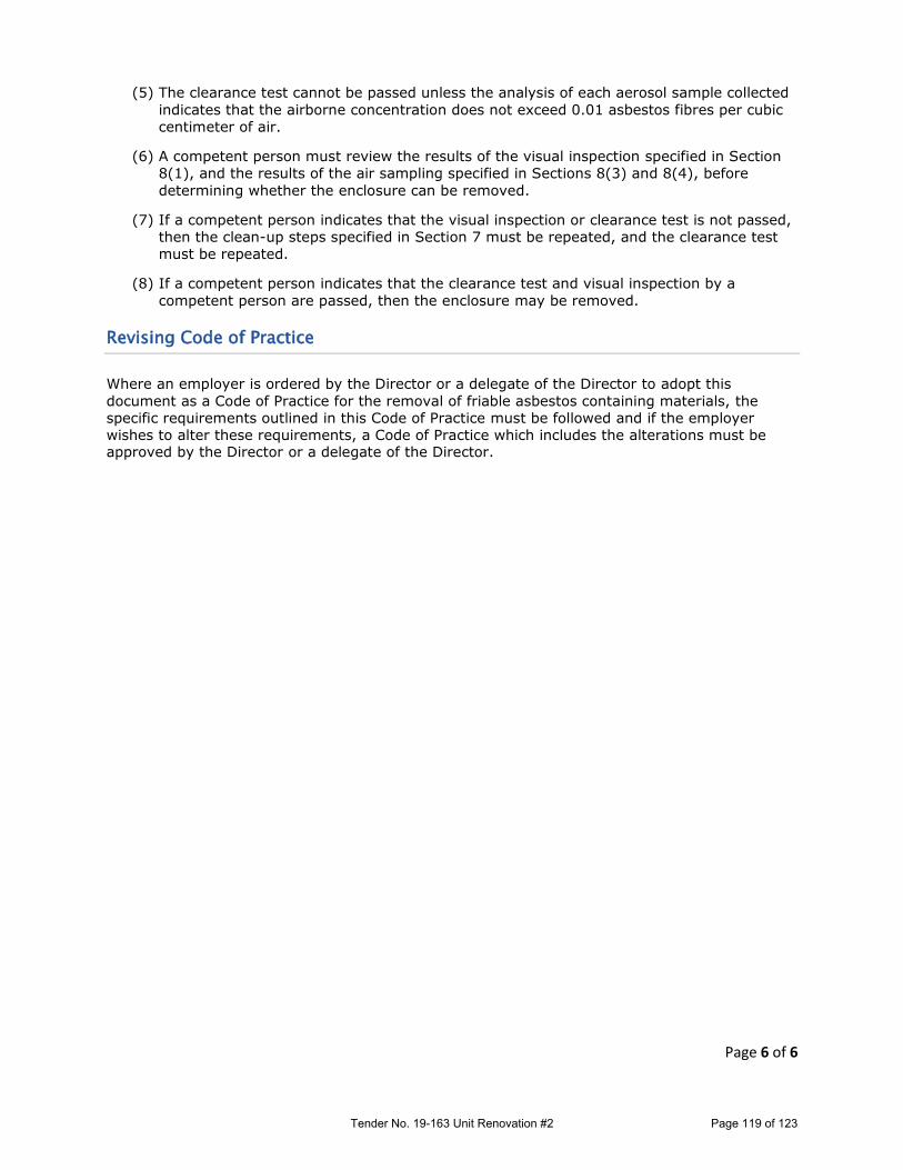
Page 6 of 6
(5) The clearance test cannot be passed unless the analysis of each aerosol sample collected
indicates that the airborne concentration does not exceed 0.01 asbestos fibres per cubic
centimeter of air.
(6) A competent person must review the results of the visual inspection specified in Section
8(1), and the results of the air sampling specified in Sections 8(3) and 8(4), before
determining whether the enclosure can be removed.
(7) If a competent person indicates that the visual inspection or clearance test is not passed,
then the clean-up steps specified in Section 7 must be repeated, and the clearance test
must be repeated.
(8) If a competent person indicates that the clearance test and visual inspection by a
competent person are passed, then the enclosure may be removed.
Revising Code of Practice
Where an employer is ordered by the Director or a delegate of the Director to adopt this
document as a Code of Practice for the removal of friable asbestos containing materials, the
specific requirements outlined in this Code of Practice must be followed and if the employer
wishes to alter these requirements, a Code of Practice which includes the alterations must be approved by the Director or a delegate of the Director.
Tender No. 19-163 Unit Renovation #2 Page 119 of 123

Metropolitan Regional Housing Authority Contract No. < ## > < Tender Title >
APPENDIX B– AGREEMENT (FOR INFORMATION PURPOSES ONLY)
THIS AGREEMENT made in Duplicate this __th day of ______, 2017
BETWEEN METROPOLITAN REGIONAL HOUSING AUTHORITY, of the
Province of Nova Scotia on behalf of Her Majesty the Queen in Right of the Province, pursuant to the Housing Act, Revised Statutes of Nova Scotia, 1989, Chapter 211, (Hereinafter called the "Metropolitan Regional Housing Authority") of the One Part
- and –
< BID WINNER’S FULL LEGAL BUSINESS NAME >
(Hereinafter called the "Contractor") of the Other Part
AGREEMENT WITNESSETH:
That the Contractor and the Metropolitan Regional Housing Authority for the consideration hereinafter expressed, undertake and agree as follows:
ARTICLE 1
The General Conditions of Contract and any Addendums as issued as part of the Tender are to be read herewith and form part of this agreement as fully and completely as though all the stipulations thereof have been embodied herein.
ARTICLE 2
The Contractor undertakes and agrees:
.1 to provide all the materials and to perform all the work shown as described in the Specifications,
the Drawings and/or Sketches and any Addendums forming the Tender Document titled
TENDER No. < ## > < TENDER TITLE >
which have been signed in duplicate for identification by, or on behalf of, both the parties, and which were prepared by METROPOLITAN REGIONAL HOUSING AUTHORITY acting as and herein (and in the General Conditions) entitled the "Project Manager”;
.2 to do and fulfil everything indicated by the Agreement and the General Conditions of the Contract
and the Specifications and the Drawings and/or Sketches; and,
.3 to complete substantially all the Work not later than < Date >.
Tender No. 19-163 Unit Renovation #2 Page 120 of 123

Metropolitan Regional Housing Authority Contract No. < ## > < Tender Title >
APPENDIX A – AGREEMENT (FOR INFORMATION PURPOSES ONLY)
ARTICLE 3 The Metropolitan Regional Housing Authority undertakes and agrees:
.1 to pay the Contractor in lawful money of Canada for the performance of the Contract
< Written Dollar Amount of Winning Bid > DOLLARS and _____ CENTS
( $ < Numerical Dollar Amount > ), plus applicable taxes, subject to additions and deductions as provided in the General Conditions of the Contract.
.2 to make payments on account thereof upon the Project Manager's certificate ( and when the
Metropolitan Regional Housing Authority is satisfied that payments due to Subcontractors have been made ) as follows: .1 within a reasonable time of receipt by the Metropolitan Regional Housing Authority of a
bona fide claim for payments, ninety percent ( 90% ) of the value, proportional to the amount of the Contract, of labour and materials incorporated in the work or materials on the site to be incorporated in the work, as estimated by the Contractor and approved by the Project Manager less the aggregate of previous payments;
.2 the ten percent (10%) of the value of the work, service and materials shall be retained by the
Metropolitan Regional Housing Authority for a period of sixty-five ( 65 ) days after the Metropolitan Regional Housing Authority is of the opinion that the Contract is substantially performed, as defined in the General Conditions;
.3 sixty-five ( 65 ) days after the Contract is substantially performed, the Metropolitan Regional
Housing Authority may reduce the amount retained to two and one-half percent ( 2.5% ) of the value of the work, services and materials, or the Metropolitan Regional Housing Authority may retain the full ten percent ( 10% ), until all required work is performed completely, as determined by the Metropolitan Regional Housing Authority;
.4 notwithstanding the foregoing, the Metropolitan Regional Housing Authority shall be entitled
to retain the warranty for a period of one ( 1 ) year, which sum is calculated as one percent ( 1% ) of the contract price or two thousand five hundred Canadian dollars ( $2,500.00 ), whichever is greater; and,
.5 also notwithstanding the foregoing, the Metropolitan Regional Housing Authority is entitled to
make other deductions as provided in the General Conditions of the Contract. .3 if on account of climatic or other conditions reasonably beyond the Contractor's control, there are
items of work that cannot readily be completed, the payment in full for the work which has been completed shall not be delayed on account thereof, but the Metropolitan Regional Housing Authority may withhold a sufficient and reasonable sum until the uncompleted work is finished and such sum as will in the opinion of the Metropolitan Regional Housing Authority adequately protect the Metropolitan Regional Housing Authority.
ARTICLE 4
The Contractor and the Metropolitan Regional Housing Authority for themselves, their successors,
Tender No. 19-163 Unit Renovation #2 Page 121 of 123
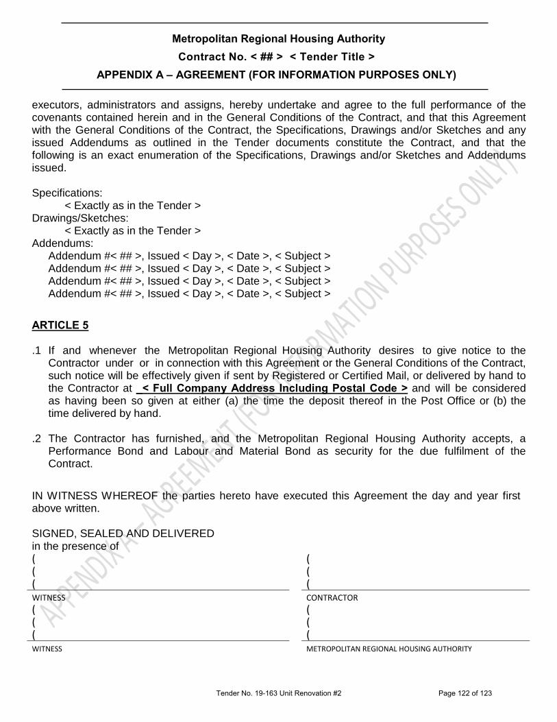
Metropolitan Regional Housing Authority Contract No. < ## > < Tender Title >
APPENDIX A – AGREEMENT (FOR INFORMATION PURPOSES ONLY)
executors, administrators and assigns, hereby undertake and agree to the full performance of the covenants contained herein and in the General Conditions of the Contract, and that this Agreement with the General Conditions of the Contract, the Specifications, Drawings and/or Sketches and any issued Addendums as outlined in the Tender documents constitute the Contract, and that the following is an exact enumeration of the Specifications, Drawings and/or Sketches and Addendums issued. Specifications:
< Exactly as in the Tender > Drawings/Sketches:
< Exactly as in the Tender > Addendums:
Addendum #< ## >, Issued < Day >, < Date >, < Subject > Addendum #< ## >, Issued < Day >, < Date >, < Subject > Addendum #< ## >, Issued < Day >, < Date >, < Subject > Addendum #< ## >, Issued < Day >, < Date >, < Subject >
ARTICLE 5
.1 If and whenever the Metropolitan Regional Housing Authority desires to give notice to the Contractor under or in connection with this Agreement or the General Conditions of the Contract, such notice will be effectively given if sent by Registered or Certified Mail, or delivered by hand to the Contractor at _< Full Company Address Including Postal Code > and will be considered as having been so given at either (a) the time the deposit thereof in the Post Office or (b) the time delivered by hand.
.2 The Contractor has furnished, and the Metropolitan Regional Housing Authority accepts, a
Performance Bond and Labour and Material Bond as security for the due fulfilment of the Contract.
IN WITNESS WHEREOF the parties hereto have executed this Agreement the day and year first above written.
SIGNED, SEALED AND DELIVERED in the presence of ( ( ( ( ( ( WITNESS CONTRACTOR ( ( ( ( ( ( WITNESS METROPOLITAN REGIONAL HOUSING AUTHORITY
Tender No. 19-163 Unit Renovation #2 Page 122 of 123

Metropolitan Regional Housing Authority
Tender No. 19-163 Unit Renovation #2
APPENDIX C – Request for Product Approval
REQUEST FOR PRODUCT APPROVAL Note: 1 Sheet Per Product
Date: Number of Pages
(including cover sheet)
Re: Tender Number MET19-163 Closing date and time:
(description of work/goods)
A request for approval for the following product has been received from the named supplier for this Bid. Attached is the information package received in support of this request.
Company Name: Address: Phone & E-mail Contact Person
Date Request Made Product Attachments:
□ product samples being forwarded separately
Please advise by (date) of the results of the evaluation
Housing Authority: Phone & E-mail Attn: Signed:
(Shaded area to be filled in by Head Office)
PRODUCT
APPROVED NOT APPROVED
INITIAL
DATE
Tender No. 19-163 Unit Renovation #2 Page 123 of 123